Basic structural units in carbon fibers: Atomistic models and tensile behavior Evgeni S. Penev, Vasilii I. Artyukhov, Boris I. Yakobson * Department of Materials Science and NanoEngineering, Department of Chemistry, The Richard E. Smalley Institute for Nanoscale Science and Technology, Rice University, Houston, TX 77005, United States ARTICLE INFO Article history: Received 8 October 2014 Accepted 18 December 2014 Available online 24 December 2014 ABSTRACT Understanding the atomistic mechanisms of tensile failure in carbon fibers is important for fiber manufacturing and applications. Here we design structural faults with atomistic details, pertaining to polyacrylonitrile (PAN) derived fibers, and probe them using large- scale molecular dynamics simulations to uncover trends and gain insight into the effect of local structure on the strength of the basic structural units (BSUs) and the role of inter- faces between regions with different degrees of graphitization. Besides capturing the expected strength degrading with increasing misalignment, the designed basic structural units reveal atomistic details of local structural failure upon tensile loading. Fracture initi- ation is nearly always associated with the interface of the misoriented crystallite and its environment. Ó 2015 Elsevier Ltd. All rights reserved. 1. Introduction Carbon fibers [1] have long been one of the technologically most important carbon-based materials. More than half a century of research and development, manufacturing, and applications have resulted in a bulk of accumulated knowl- edge on virtually any aspect of fiber structure and properties [2,3]. As applications, from sporting goods to automobile parts [4] to aircraft components etc., get progressively more sophis- ticated, the demand for thorough understanding of fiber structure–property relations [5,6] is steadily increasing and becomes critical for further performance boost. Despite the impressive specific tensile strength, the break- ing stress of current fibers is well below the theoretical lim- it ðYc=dÞ 1=2 [2,7], with Y being the Young’s modulus, c the surface energy of the atomic planes normal to the loading, and d the equilibrium distance between the latter. Under- standing such behavior calls for detailed knowledge of fiber structure. Although there is an overwhelming amount of studies [1] the level of understanding of carbon fiber structure still lacks the exquisite details known for carbon nanotubes and graphene [8]. Ideally, one would like to design specific microscopic structural features and probe their effect through atomistic simulations [9] at a larger length scale. The utility of such a bottom-up approach crucially depends on the physical adequacy of the input atomic geometry and its computational feasibility. Among carbon fibers, those derived from a polyacryloni- trile (PAN) precursor are of particular importance, presently holding a major share of the overall fiber production/market [10,11]. Unlike catalytically grown carbon nanotubes, the PAN polymer chain, Fig. 1(a), is transformed into a planar aro- matic structure via a complex multistage thermal processing involving pyrolysis, stabilization, denitrogenation, carboniza- tion, and eventually graphitization [12,1]. The sp 2 -carbon planes stack up to further form graphitic crystallites, consid- ered to be the basic structural units (BSUs) of PAN-based fibers. However, these crystallites are usually imperfect. First, http://dx.doi.org/10.1016/j.carbon.2014.12.067 0008-6223/Ó 2015 Elsevier Ltd. All rights reserved. * Corresponding author at: Department of Materials Science and NanoEngineering, Rice University, Houston, TX 77005, United States. E-mail addresses: [email protected] (E.S. Penev), [email protected] (V.I. Artyukhov), [email protected] (B.I. Yakobson), . CARBON 85 (2015) 72 – 78 Available at www.sciencedirect.com ScienceDirect journal homepage: www.elsevier.com/locate/carbon

Welcome message from author
This document is posted to help you gain knowledge. Please leave a comment to let me know what you think about it! Share it to your friends and learn new things together.
Transcript
C A R B O N 8 5 ( 2 0 1 5 ) 7 2 – 7 8
.sc iencedi rect .com
Avai lab le at wwwScienceDirect
journal homepage: www.elsev ier .com/ locate /carbon
Basic structural units in carbon fibers: Atomisticmodels and tensile behavior
http://dx.doi.org/10.1016/j.carbon.2014.12.0670008-6223/� 2015 Elsevier Ltd. All rights reserved.
* Corresponding author at: Department of Materials Science and NanoEngineering, Rice University, Houston, TX 77005, UniteE-mail addresses: [email protected] (E.S. Penev), [email protected] (V.I. Artyukhov), [email protected] (B.I. Yakobson), .
Evgeni S. Penev, Vasilii I. Artyukhov, Boris I. Yakobson *
Department of Materials Science and NanoEngineering, Department of Chemistry, The Richard E. Smalley Institute for Nanoscale Science
and Technology, Rice University, Houston, TX 77005, United States
A R T I C L E I N F O A B S T R A C T
Article history:
Received 8 October 2014
Accepted 18 December 2014
Available online 24 December 2014
Understanding the atomistic mechanisms of tensile failure in carbon fibers is important for
fiber manufacturing and applications. Here we design structural faults with atomistic
details, pertaining to polyacrylonitrile (PAN) derived fibers, and probe them using large-
scale molecular dynamics simulations to uncover trends and gain insight into the effect
of local structure on the strength of the basic structural units (BSUs) and the role of inter-
faces between regions with different degrees of graphitization. Besides capturing the
expected strength degrading with increasing misalignment, the designed basic structural
units reveal atomistic details of local structural failure upon tensile loading. Fracture initi-
ation is nearly always associated with the interface of the misoriented crystallite and its
environment.
� 2015 Elsevier Ltd. All rights reserved.
1. Introduction
Carbon fibers [1] have long been one of the technologically
most important carbon-based materials. More than half a
century of research and development, manufacturing, and
applications have resulted in a bulk of accumulated knowl-
edge on virtually any aspect of fiber structure and properties
[2,3]. As applications, from sporting goods to automobile parts
[4] to aircraft components etc., get progressively more sophis-
ticated, the demand for thorough understanding of fiber
structure–property relations [5,6] is steadily increasing and
becomes critical for further performance boost.
Despite the impressive specific tensile strength, the break-
ing stress of current fibers is well below the theoretical lim-
it � ðYc=dÞ1=2 [2,7], with Y being the Young’s modulus, c the
surface energy of the atomic planes normal to the loading,
and d the equilibrium distance between the latter. Under-
standing such behavior calls for detailed knowledge of fiber
structure. Although there is an overwhelming amount of
studies [1] the level of understanding of carbon fiber structure
still lacks the exquisite details known for carbon nanotubes
and graphene [8]. Ideally, one would like to design specific
microscopic structural features and probe their effect through
atomistic simulations [9] at a larger length scale. The utility of
such a bottom-up approach crucially depends on the physical
adequacy of the input atomic geometry and its computational
feasibility.
Among carbon fibers, those derived from a polyacryloni-
trile (PAN) precursor are of particular importance, presently
holding a major share of the overall fiber production/market
[10,11]. Unlike catalytically grown carbon nanotubes, the
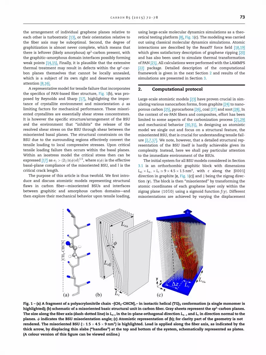
PAN polymer chain, Fig. 1(a), is transformed into a planar aro-
matic structure via a complex multistage thermal processing
involving pyrolysis, stabilization, denitrogenation, carboniza-
tion, and eventually graphitization [12,1]. The sp2-carbon
planes stack up to further form graphitic crystallites, consid-
ered to be the basic structural units (BSUs) of PAN-based
fibers. However, these crystallites are usually imperfect. First,
d States.
C A R B O N 8 5 ( 2 0 1 5 ) 7 2 – 7 8 73
the arrangement of individual graphene planes relative to
each other is turbostratic [13], or their orientation relative to
the fiber axis may be suboptimal. Second, the degree of
graphitization is almost never complete, which means that
there is leftover (likely amorphous) sp3-carbon present, with
the graphitic–amorphous domain interfaces possibly forming
weak points [14,15]. Finally, it is plausible that the extensive
thermal treatment may result in defects within the sp2-car-
bon planes themselves that cannot be locally annealed,
which is a subject of its own right and deserves separate
attention [8,16].
A representative model for tensile failure that incorporates
the specifics of PAN-based fiber structure, Fig. 1(b), was pro-
posed by Reynolds and Sharp [17], highlighting the impor-
tance of crystallite environment and misorientation / as
limiting factors for mechanical performance. These misori-
ented crystallites are essentially shear stress concentrators.
It is however the specific structure/arrangement of the BSU
and the environment that ‘‘inhibits’’ the release of the
resolved shear stress on the BSU through shear between the
misoriented basal planes. The structural constraints on the
BSU due to the surrounding regions effectively convert the
tensile loading to local compressive stresses. Upon critical
tensile loading failure then occurs within the basal planes.
Within an isostress model the critical stress then can be
expressed [17] as rk > ð2c=sð/ÞplÞ1=2, where sð/Þ is the effective
basal–plane compliance of the misoriented BSU, and l is the
critical crack length.
The purpose of this article is thus twofold. We first intro-
duce and discuss atomistic models representing structural
flaws in carbon fiber—misoriented BSUs and interfaces
between graphitic and amorphous carbon domains—and
then explore their mechanical behavior upon tensile loading,
(b)(a)
Fig. 1 – (a) A fragment of a polyacrylonitrile chain –[CH2-CHCN]n–
highlighted); (b) schematic of a misoriented basic structural unit
The size along the fiber axis (dash-dotted line) is Lak, in the in-pla
planes. / indicates the BSU misorientation angle; (c) Atomistic
rendered. The misoriented BSU (’ 1:5� 4:5� 9 nm3) is highligh
thick arrow, by displacing thin slabs (‘‘handles’’) at the top and
(A colour version of this figure can be viewed online.)
using large-scale molecular dynamics simulations as a theo-
retical testing platform [8], Fig. 1(c). The modeling was carried
out using classical molecular dynamics simulations. Atomic
interactions are described by the ReaxFF force field [18,19]
which gives satisfactory description of graphene ripping [20]
and has also been used to simulate thermal transformation
of PAN [21]. All calculations were performed with the LAMMPS
[22] package. Detailed description of the computational
framework is given in the next Section 2 and results of the
simulations are presented in Section 3.
2. Computational protocol
Large-scale atomistic models [23] have proven crucial in sim-
ulating various nanocarbon forms, from graphite [24] to nano-
porous carbon [25], pyrocarbons [26], coal [27] and soot [28]. In
the context of ex-PAN fibers and composites, effort has been
limited to some aspects of the carbonization process [21,29]
and mechanical behavior [30,31]. In designing an atomistic
model we single out and focus on a structural feature, the
misoriented BSU, that is crucial for understanding tensile fail-
ure [2,7,17]. We note, however, that a detailed structural rep-
resentation of the BSU itself is hardly achievable given its
complexity. Instead, here we shall pay particular attention
to the immediate environment of the BSUs.
The initial system for all BSU models considered in Section
3.1 is an orthorhombic graphitic block with dimensions
Lak � La? � Lc ’ 9� 4:5� 1:5 nm3, with c along the [0001]
direction in graphite [z, Fig. 1(c)] and k being the zigzag direc-
tion ðyÞ. The block is then ‘‘misoriented’’ by transforming the
atomic coordinates of each graphene layer only within the
zigzag plane f10 �10g using a sigmoid function fðyÞ. Different
misorientations are achieved by varying the displacement
x
z
y
(c)
in isotactic helical (TG)3 conformation (a single monomer is
in carbon fiber. Gray sheets represent the sp2-carbon planes.
ne orthogonal direction La?, and Lc in direction normal to the
representation of (b); for clarity part of the geometry is not
ted. Load is applied along the fiber axis, as indicated by the
bottom of the system, schematically represented as plates.
74 C A R B O N 8 5 ( 2 0 1 5 ) 7 2 – 7 8
Dz for fðLakÞ ¼ 1, Fig. 1(c). This procedure also results in a loss
of the initial Bernal stacking thus partially mimicking a tur-
bostratic arrangement [13].
Here we consider four sets of geometries f/ng generated by
Dz ¼ 2nd0; n ¼ 0; 1; 2;3; ð1Þ
with d0 being the interplanar distance in graphite. This choice
results in initial geometries with maximal misorientation
angles
/max � tan�1 f 0��Lak=2
� �� 0–30�; ð2Þ
the prime denoting first derivative in y. The unit is then
‘‘sandwiched’’ by a block of graphite with size ’ La? along x
to ensure that the misoriented unit is in contact with an
aligned graphitic block for any /.
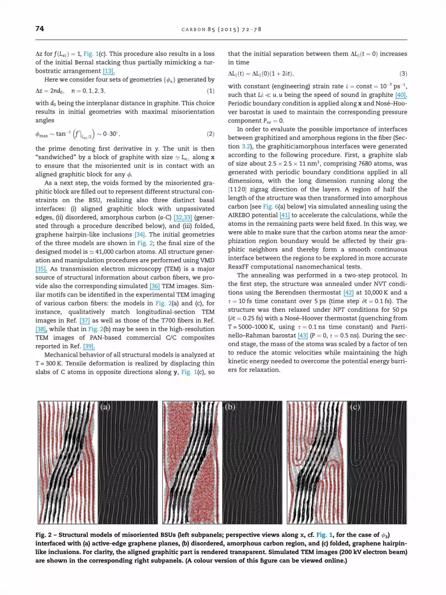
As a next step, the voids formed by the misoriented gra-
phitic block are filled out to represent different structural con-
straints on the BSU, realizing also three distinct basal
interfaces: (i) aligned graphitic block with unpassivated
edges, (ii) disordered, amorphous carbon (a-C) [32,33] (gener-
ated through a procedure described below), and (iii) folded,
graphene hairpin-like inclusions [34]. The initial geometries
of the three models are shown in Fig. 2; the final size of the
designed model is ’ 41,000 carbon atoms. All structure gener-
ation and manipulation procedures are performed using VMD
[35]. As transmission electron microscopy (TEM) is a major
source of structural information about carbon fibers, we pro-
vide also the corresponding simulated [36] TEM images. Sim-
ilar motifs can be identified in the experimental TEM imaging
of various carbon fibers: the models in Fig. 2(a) and (c), for
instance, qualitatively match longitudinal-section TEM
images in Ref. [37] as well as those of the T700 fibers in Ref.
[38], while that in Fig. 2(b) may be seen in the high-resolution
TEM images of PAN-based commercial C/C composites
reported in Ref. [39].
Mechanical behavior of all structural models is analyzed at
T = 300 K. Tensile deformation is realized by displacing thin
slabs of C atoms in opposite directions along y, Fig. 1(c), so
(a) (
Fig. 2 – Structural models of misoriented BSUs (left subpanels;
interfaced with (a) active-edge graphene planes, (b) disordered,
like inclusions. For clarity, the aligned graphitic part is rendered
are shown in the corresponding right subpanels. (A colour vers
that the initial separation between them DLkðt ¼ 0Þ increases
in time
DLkðtÞ ¼ DLkð0Þð1þ 2_etÞ; ð3Þ
with constant (engineering) strain rate _e ¼ const ¼ 10�3 ps�1,
such that L_e� u;u being the speed of sound in graphite [40].
Periodic boundary condition is applied along x and Nose–Hoo-
ver barostat is used to maintain the corresponding pressure
component Pxx ¼ 0.
In order to evaluate the possible importance of interfaces
between graphitized and amorphous regions in the fiber (Sec-
tion 3.2), the graphiticjamorphous interfaces were generated
according to the following procedure. First, a graphite slab
of size about 2:5� 2:5� 11 nm3, comprising 7680 atoms, was
generated with periodic boundary conditions applied in all
dimensions, with the long dimension running along the
½11 �20� zigzag direction of the layers. A region of half the
length of the structure was then transformed into amorphous
carbon [see Fig. 6(a) below] via simulated annealing using the
AIREBO potential [41] to accelerate the calculations, while the
atoms in the remaining parts were held fixed. In this way, we
were able to make sure that the carbon atoms near the amor-
phization region boundary would be affected by their gra-
phitic neighbors and thereby form a smooth continuous
interface between the regions to be explored in more accurate
ReaxFF computational nanomechanical tests.
The annealing was performed in a two-step protocol. In
the first step, the structure was annealed under NVT condi-
tions using the Berendsen thermostat [42] at 10,000 K and a
s ¼ 10 fs time constant over 5 ps (time step dt ¼ 0:1 fs). The
structure was then relaxed under NPT conditions for 50 ps
(dt ¼ 0:25 fs) with a Nose–Hoover thermostat (quenching from
T = 5000–1000 K, using s ¼ 0:1 ns time constant) and Parri-
nello–Rahman barostat [43] (P ¼ 0, s ¼ 0:5 ns). During the sec-
ond stage, the mass of the atoms was scaled by a factor of ten
to reduce the atomic velocities while maintaining the high
kinetic energy needed to overcome the potential energy barri-
ers for relaxation.
b) (c)
perspective views along x, cf. Fig. 1, for the case of /3)
amorphous carbon region, and (c) folded, graphene hairpin-
transparent. Simulated TEM images (200 kV electron beam)
ion of this figure can be viewed online.)
C A R B O N 8 5 ( 2 0 1 5 ) 7 2 – 7 8 75
3. Results and discussion
3.1. Tensile failure of a misoriented basic structural unit
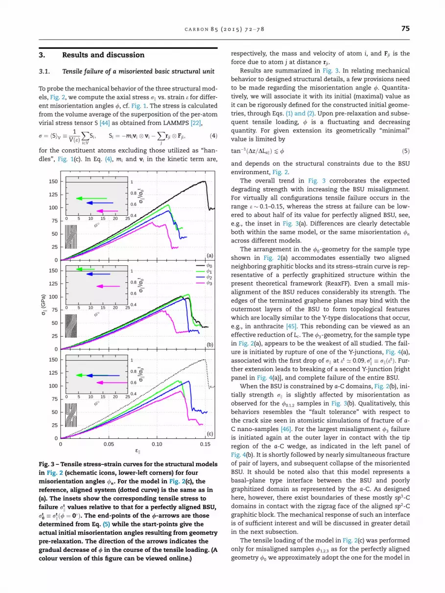
To probe the mechanical behavior of the three structural mod-
els, Fig. 2, we compute the axial stress rk vs. strain e for differ-
ent misorientation angles /, cf. Fig. 1. The stress is calculated
from the volume average of the superposition of the per-atom
virial stress tensor S [44] as obtained from LAMMPS [22],
r ¼ hSiV �1
VðeÞXi2V
Si; Si ¼ �mivi vi �X
j
rji Fji; ð4Þ
for the constituent atoms excluding those utilized as ‘‘han-
dles’’, Fig. 1(c). In Eq. (4), mi and vi in the kinetic term are,
Fig. 3 – Tensile stress–strain curves for the structural models
in Fig. 2 (schematic icons, lower-left corners) for four
misorientation angles /n. For the model in Fig. 2(c), the
reference, aligned system (dotted curve) is the same as in
(a). The insets show the corresponding tensile stress to
failure rtk values relative to that for a perfectly aligned BSU,
rt0 � rt
kð/ ¼ 0�Þ. The end-points of the /-arrows are those
determined from Eq. (5) while the start-points give the
actual initial misorientation angles resulting from geometry
pre-relaxation. The direction of the arrows indicates the
gradual decrease of / in the course of the tensile loading. (A
colour version of this figure can be viewed online.)
respectively, the mass and velocity of atom i, and Fji is the
force due to atom j at distance rji.
Results are summarized in Fig. 3. In relating mechanical
behavior to designed structural details, a few provisions need
to be made regarding the misorientation angle /. Quantita-
tively, we will associate it with its initial (maximal) value as
it can be rigorously defined for the constructed initial geome-
tries, through Eqs. (1) and (2). Upon pre-relaxation and subse-
quent tensile loading, / is a fluctuating and decreasing
quantity. For given extension its geometrically ‘‘minimal’’
value is limited by
tan�1ðDz=DLakÞK / ð5Þ
and depends on the structural constraints due to the BSU
environment, Fig. 2.
The overall trend in Fig. 3 corroborates the expected
degrading strength with increasing the BSU misalignment.
For virtually all configurations tensile failure occurs in the
range e � 0.1–0.15, whereas the stress at failure can be low-
ered to about half of its value for perfectly aligned BSU, see,
e.g., the inset in Fig. 3(a). Differences are clearly detectable
both within the same model, or the same misorientation /n
across different models.
The arrangement in the /0-geometry for the sample type
shown in Fig. 2(a) accommodates essentially two aligned
neighboring graphitic blocks and its stress–strain curve is rep-
resentative of a perfectly graphitized structure within the
present theoretical framework (ReaxFF). Even a small mis-
alignment of the BSU reduces considerably its strength. The
edges of the terminated graphene planes may bind with the
outermost layers of the BSU to form topological features
which are locally similar to the Y-type dislocations that occur,
e.g., in anthracite [45]. This rebonding can be viewed as an
effective reduction of Lc. The /3-geometry, for the sample type
in Fig. 2(a), appears to be the weakest of all studied. The fail-
ure is initiated by rupture of one of the Y-junctions, Fig. 4(a),
associated with the first drop of rk at et ’ 0:09;rtk � rkðetÞ. Fur-
ther extension leads to breaking of a second Y-junction [right
panel in Fig. 4(a)], and complete failure of the entire BSU.
When the BSU is constrained by a-C domains, Fig. 2(b), ini-
tially strength rk is slightly affected by misorientation as
observed for the /0;1;2 samples in Fig. 3(b). Qualitatively, this
behaviors resembles the ‘‘fault tolerance’’ with respect to
the crack size seen in atomistic simulations of fracture of a-
C nano-samples [46]. For the largest misalignment /3 failure
is initiated again at the outer layer in contact with the tip
region of the a-C wedge, as indicated in the left panel of
Fig. 4(b). It is shortly followed by nearly simultaneous fracture
of pair of layers, and subsequent collapse of the misoriented
BSU. It should be noted also that this model represents a
basal–plane type interface between the BSU and poorly
graphitized domain as represented by the a-C. As designed
here, however, there exist boundaries of these mostly sp3-C
domains in contact with the zigzag face of the aligned sp2-C
graphitic block. The mechanical response of such an interface
is of sufficient interest and will be discussed in greater detail
in the next subsection.
The tensile loading of the model in Fig. 2(c) was performed
only for misaligned samples /1;2;3 as for the perfectly aligned
geometry /0 we approximately adopt the one for the model in

Fig. 5 – Simulation snapshots capturing the sequential
failure (from left to right) of the misoriented graphene-like
planes for the BSU model in Figs. 2 and 4(c). Corresponding
strain values ek (cf. also the curve for the /3-geometry in
Fig. 3(c)) are indicated in the lower-right corners and color
coding [47] corresponds to the ryz shear stress component.
(A colour version of this figure can be viewed online.)
(a) (b) (c)
Fig. 4 – Representative snapshots (views along x) of subsequent stages in the tensile failure of the initially most misoriented
samples (/3) for the three models studied; see corresponding panels in Fig. 2. Left subpanels show the failure initiation
(circled area). The outer BSU layer along with narrow slab of the surrounding material are highlighted in red. For clarity, the
aligned graphitic part is rendered transparent, similar to Fig. 2. (A colour version of this figure can be viewed online.)
76 C A R B O N 8 5 ( 2 0 1 5 ) 7 2 – 7 8
Fig. 2(a). The initial misorientation angle for the /3 sample is
the largest realized here [cf. inset in Fig. 3(c)] and the corre-
sponding stress–strain curve, Fig. 3(c), appears distinct from
those of all other models. Note that at ek ¼ 0:1 a slight kink
in the curve occurs. We find it to be a signature of an effect
related to the high curvature of the constraining hairpin-like
inclusion. At that extension, the outer plane of the BSU
‘‘unzips’’ along x and slips normally to bind with the tip of
the narrow hairpin-like inclusion, as indicated in Fig. 4(c).
This restructuring survives further loading but ultimately ini-
tiates the overall failure of the BSU, right subpanel in Fig. 4(c).
Structural failure for all models in Fig. 4, having largest ini-
tial misorientations / � 20–25�, occurs earliest in the course
of loading as compared to all other less misoriented geome-
tries. In real fibers / displays certain (experimentally accessi-
ble) distribution and therefore large local tiltings of BSUs
which are twice or higher than the mean value for the fiber
are probable. Within the Reynolds–Sharp model [17], the mis-
oriented BSU represents a critical shear stress concentrator,
owing to the specifics of local fiber structure. The atomistic
details discussed above may be considered as possible micro-
scopic mechanisms through which local structure can initiate
fracture of the misoriented BSU. In Fig. 5, the distribution of
the ryz shear stress component is illustrated for selected
sequential states of the BSU model of Fig. 2(c) undergoing a
tensile failure. Clearly, ryz is mainly concentrated within the
misaligned BSU.
3.2. Nanomechanical response of the sp2-C/a-C interface
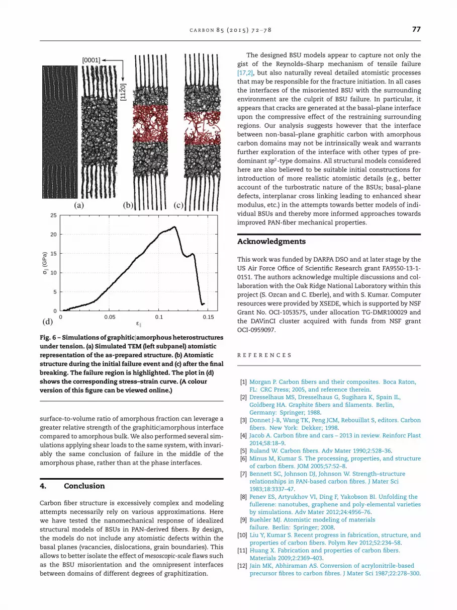
The as-annealed structure, shown in Fig. 6(a) as a simulated
TEM image and atomistic structural model, was used for nano-
mechanical failure simulations with ReaxFF, preceded by a
short NPT re-equilibration from 3000 K to 300 K over 10 ps with
dt ¼ 0:25 fs. The structure was then pulled for 100 ps up to 15%
strain with zero-pressure boundary conditions in the trans-
verse direction. At a strain of 11.5%, the onset of breaking is
observed, producing a configuration shown in Fig. 6(b). This
is soon followed by complete failure at 13.5% strain, Fig. 6(c),
whereupon the two halves of the system remain connected
only through several dangling carbon chains [48].
The slope of the stress–strain curve in Fig. 6(d) is notably
shallower than of those in Fig. 3. This reflects the relative soft-
ness of a-C as described by ReaxFF. The different slope at very
small deformation may reflect the residual intrinsic strain
remaining from incomplete equilibration. However, the main
result of our simulation is that the fracture occurs near the
middle of the a-C region. Therefore, the boundary between
the graphitic and amorphous domains apparently does not
represent a natural weak spot in the structure as one might
expect from a two-phase interface [49]. In this regard, our
simulation predicts that a fixed amount of a-C in the sample
will be more beneficial to distribute between many small
(nanoscale, of size comparable to interface thickness) inclu-
sions, as opposed to few but larger ones. Thus, maximized
(a) (b) (c)
(d)
Fig. 6 – Simulations of graphiticjamorphous heterostructures
under tension. (a) Simulated TEM (left subpanel) atomistic
representation of the as-prepared structure. (b) Atomistic
structure during the initial failure event and (c) after the final
breaking. The failure region is highlighted. The plot in (d)
shows the corresponding stress–strain curve. (A colour
version of this figure can be viewed online.)
C A R B O N 8 5 ( 2 0 1 5 ) 7 2 – 7 8 77
surface-to-volume ratio of amorphous fraction can leverage a
greater relative strength of the graphiticjamorphous interface
compared to amorphous bulk. We also performed several sim-
ulations applying shear loads to the same system, with invari-
ably the same conclusion of failure in the middle of the
amorphous phase, rather than at the phase interfaces.
4. Conclusion
Carbon fiber structure is excessively complex and modeling
attempts necessarily rely on various approximations. Here
we have tested the nanomechanical response of idealized
structural models of BSUs in PAN-derived fibers. By design,
the models do not include any atomistic defects within the
basal planes (vacancies, dislocations, grain boundaries). This
allows to better isolate the effect of mesoscopic-scale flaws such
as the BSU misorientation and the omnipresent interfaces
between domains of different degrees of graphitization.
The designed BSU models appear to capture not only the
gist of the Reynolds–Sharp mechanism of tensile failure
[17,2], but also naturally reveal detailed atomistic processes
that may be responsible for the fracture initiation. In all cases
the interfaces of the misoriented BSU with the surrounding
environment are the culprit of BSU failure. In particular, it
appears that cracks are generated at the basal–plane interface
upon the compressive effect of the restraining surrounding
regions. Our analysis suggests however that the interface
between non-basal–plane graphitic carbon with amorphous
carbon domains may not be intrinsically weak and warrants
further exploration of the interface with other types of pre-
dominant sp2-type domains. All structural models considered
here are also believed to be suitable initial constructions for
introduction of more realistic atomistic details (e.g., better
account of the turbostratic nature of the BSUs; basal–plane
defects, interplanar cross linking leading to enhanced shear
modulus, etc.) in the attempts towards better models of indi-
vidual BSUs and thereby more informed approaches towards
improved PAN-fiber mechanical properties.
Acknowledgments
This work was funded by DARPA DSO and at later stage by the
US Air Force Office of Scientific Research grant FA9550-13-1-
0151. The authors acknowledge multiple discussions and col-
laboration with the Oak Ridge National Laboratory within this
project (S. Ozcan and C. Eberle), and with S. Kumar. Computer
resources were provided by XSEDE, which is supported by NSF
Grant No. OCI-1053575, under allocation TG-DMR100029 and
the DAVinCI cluster acquired with funds from NSF grant
OCI-0959097.
R E F E R E N C E S
[1] Morgan P. Carbon fibers and their composites. Boca Raton,FL: CRC Press; 2005, and reference therein.
[2] Dresselhaus MS, Dresselhaus G, Sugihara K, Spain IL,Goldberg HA. Graphite fibers and filaments. Berlin,Germany: Springer; 1988.
[3] Donnet J-B, Wang TK, Peng JCM, Rebouillat S, editors. Carbonfibers. New York: Dekker; 1998.
[4] Jacob A. Carbon fibre and cars – 2013 in review. Reinforc Plast2014;58:18–9.
[5] Ruland W. Carbon fibers. Adv Mater 1990;2:528–36.[6] Minus M, Kumar S. The processing, properties, and structure
of carbon fibers. JOM 2005;57:52–8.[7] Bennett SC, Johnson DJ, Johnson W. Strength–structure
relationships in PAN-based carbon fibres. J Mater Sci1983;18:3337–47.
[8] Penev ES, Artyukhov VI, Ding F, Yakobson BI. Unfolding thefullerene: nanotubes, graphene and poly-elemental varietiesby simulations. Adv Mater 2012;24:4956–76.
[9] Buehler MJ. Atomistic modeling of materialsfailure. Berlin: Springer; 2008.
[10] Liu Y, Kumar S. Recent progress in fabrication, structure, andproperties of carbon fibers. Polym Rev 2012;52:234–58.
[11] Huang X. Fabrication and properties of carbon fibers.Materials 2009;2:2369–403.
[12] Jain MK, Abhiraman AS. Conversion of acrylonitrile-basedprecursor fibres to carbon fibres. J Mater Sci 1987;22:278–300.
78 C A R B O N 8 5 ( 2 0 1 5 ) 7 2 – 7 8
[13] Biscoe J, Warren BE. An X-ray study of carbon black. J ApplPhys 1942;13:364–71.
[14] Arshad SN, Naraghi M, Chasiotis I. Strong carbon nanofibersfrom electrospun polyacrylonitrile. Carbon 2011;49(5):1710–9.
[15] Naraghi M, Chawla S. Carbonized micro- and nanostructures:can downsizing really help? Materials 2014;7:3820–33.
[16] Artyukhov VI, Penev ES, Yakobson BI. Unpublished.[17] Reynolds WN, Sharp JV. Crystal shear limit to carbon fibre
strength. Carbon 1974;12:103–10.[18] van Duin ACT, Dasgupta S, Lorant F, Goddard III WA. ReaxFF:
a reactive force field for hydrocarbons. J Phys Chem A2001;105(41):9396–409.
[19] Mueller JE, van Duin ACT, Goddard III WA. Development andvalidation of ReaxFF reactive force field for hydrocarbonchemistry catalyzed by nickel. J Phys Chem C2010;114(11):4939–49.
[20] Kim K, Artyukhov VI, Regan W, Liu Y, Crommie MF, YakobsonBI, et al. Ripping graphene: preferred directions. Nano Lett2011;12:293–7.
[21] Saha B, Schatz GC. Carbonization in polyacrylonitrile (PAN)based carbon fibers studied by ReaxFF molecular dynamicssimulations. J Phys Chem B 2012;116:4684–92.
[22] Plimpton S. Fast parallel algorithms for short-rangemolecular dynamics. J Comput Phys 1995;117(1):1–19. URL:http://lammps.sandia.gov.
[23] Vashishta P, Kalia RK, Nakano A. Large-scale atomisticsimulations of dynamic fracture. Comput Sci Eng1999;1:56–65.
[24] Omeltchenko A, Yu J, Kalia RK, Vashishta P. Crack frontpropagation and fracture in a graphite sheet: a molecular-dynamics study on parallel computers. Phys Rev Lett1997;78:2148–51.
[25] Acharya M, Strano MS, Mathews JP, Billinge SJL, Petkov V,Subramoney S, et al. Simulation of nanoporous carbons: achemically constrained structure. Phil Mag B1999;79:1499–518.
[26] Leyssale J-M, Costa J-PD, Germain C, Weisbecker P, VignolesG. Structural features of pyrocarbon atomistic modelsconstructed from transmission electron microscopy images.Carbon 2012;50:4388–400.
[27] Mathews JP, van Duin ACT, Chaffee AL. The utility of coalmolecular models. Fuel Process Technol 2011;92:718–28.
[28] Fernandez-Alos V, Watson JK, vander Wal R, Mathews JP. Sootand char molecular representations generated directly fromHRTEM lattice fringe images using Fringe3D. Combust Flame2011;158:1807–13.
[29] Papkov D, Beese AM, Goponenko A, Zou Y, Naraghi M,Espinosa HD, et al. Extraordinary improvement of thegraphitic structure of continuous carbon nanofiberstemplated with double wall carbon nanotubes. ACS Nano2013;7:126–42.
[30] Zhu C, Liu X, Yu X, Zhao N, Liu J, Xu J. A small-angle X-rayscattering study and molecular dynamics simulation ofmicrovoid evolution during the tensile deformation of carbonfibers. Carbon 2012;50:235–43.
[31] Ito A, Okamoto S. Using molecular dynamics to assessmechanical properties of PAN-based carbon fibers
comprising imperfect crystals with amorphous structures.Int J Mech Aero Ind Mechatron Eng 2013;7:771–6.
[32] Marks N. Amorphous carbon and related materials. In:Colombo L, Fasolino A, editors. Computer-based modeling ofnovel carbon systems and their properties. Carbon materials:chemistry and physics, vol. 3. Berlin: Springer; 2010. p.129–69. Chapter 5.
[33] Tanaka F, Okabe T, Okuda H, Ise M, Kinloch IA, Mori T, et al.The effect of nanostructure upon the deformationmicromechanics of carbon fibres. Carbon 2013;52:372–8.
[34] Jian K, Yan A, Kulaots I, Crawford GP, Hurt RH. Reconstructionand hydrophobicity of nanocarbon surfaces composed solelyof graphene edges. Carbon 2006;44:2102–6.
[35] Humphrey W, Dalke A, Schulten K. VMD – visual moleculardynamics. J Mol Graph 1996;14:33–8. URL: http://www.ks.uiuc.edu/Research/vmd.
[36] Koch CT. Determination of core structure periodicity andpoint defect density along dislocations, Ph.D. thesis, ArizonaState University, Phoenix; 2002.
[37] Deurbergue A, Oberlin A. TEM study of some recent highmodulus PAN-based carbon fibers. Carbon 1992;30:981–7.
[38] Zhou G, Liu Y, He L, Guo Q, Ye H. Microstructure differencebetween core and skin of T700 carbon fibers in heat-treatedcarbon/carbon composites. Carbon 2011;49:2883–92.
[39] Ozcan S, Tezcan J, Filip P. Microstructure and elasticproperties of individual components of C/C composites.Carbon 2009;47:3403–14.
[40] Bosak A, Krisch M, Mohr M, Maultzsch J, Thomsen C.Elasticity of single-crystalline graphite: inelastic X-rayscattering study. Phys Rev B 2007;75:153408.
[41] Stuart SJ, Tutein AB, Harrison JA. A reactive potential forhydrocarbons with intermolecular interactions. J Chem Phys2000;112:6472–86.
[42] Berendsen HJC, Postma JPM, van Gunsteren WF, DiNola A,Haak JR. Molecular dynamics with coupling to an externalbath. J Chem Phys 1984;81:3684–90.
[43] Parrinello M, Rahman A. Polymorphic transitions in singlecrystals: a new molecular dynamics method. J Appl Phys1981;52:7182–90.
[44] Zimmerman JA, Webb III EB, Hoyt JJ, Jones RE, Klein PA,Bammann DJ. Calculation of stress in atomistic simulation.Model Simul Mater Sci Eng 2004;12:S319–32.
[45] Sun Y, Alemany LB, Billups WE, Lu J, Yakobson BI. Structuraldislocations in anthracite. J Phys Chem Lett 2011;2:2521–4.
[46] Lu Q, Marks N, Schatz GC, Belytschko T. Nanoscale fracture oftetrahedral amorphous carbon by molecular dynamics: Flawsize insensitivity. Phys Rev B 2008;77:014109.
[47] Stukowski A. Visualization and analysis of atomisticsimulation data with OVITO—the open visualization tool.Model Simul Mater Sci Eng 2010;18:015012. URL: http://ovito.org.
[48] Yakobson BI, Campbell MP, Brabec CJ, Bernholc J. High strainrate fracture and C-chain unraveling in carbon nanotubes.Comp Mater Sci 1997;8:341–8.
[49] Yoon CS, Megusar J. Molecular dynamic simulation ofamorphous carbon and graphite interface. Interface Sci1995;3:85–100.
Related Documents