1 INSTRUCTION MANUAL INSTALLATION, OPERATION & MAINTENANCE PRECAUTIONS • Please read this manual carefully prior to using the pump. • Keep the manual in a location easily accessible to anyone using the equipment. • The manufacturer bears no responsibility of using the Equipment at specifications other than original specifications HYDRODYNE NON SEAL CANNED MOTOR PUMP TYPE HD – BASIC PUMP

Welcome message from author
This document is posted to help you gain knowledge. Please leave a comment to let me know what you think about it! Share it to your friends and learn new things together.
Transcript
1
Page
- 0
-
INSTRUCTION MANUAL
INSTALLATION, OPERATION & MAINTENANCE
PRECAUTIONS
• Please read this manual carefully prior to using the pump.
• Keep the manual in a location easily accessible to anyone using the equipment.
• The manufacturer bears no responsibility of using the Equipment at specifications other than original specifications
HYDRODYNE NON SEAL CANNED MOTOR PUMP TYPE HD – BASIC PUMP
- 1 -
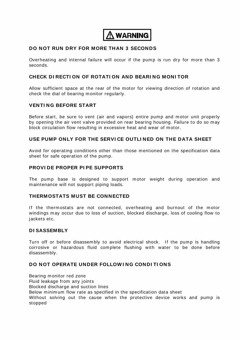
DO NOT RUN DRY FOR MORE THAN 3 SECONDS Overheating and internal failure will occur if the pump is run dry for more than 3 seconds. CHECK DIRECTION OF ROTATION AND BEARING MONITOR Allow sufficient space at the rear of the motor for viewing direction of rotation and check the dial of bearing monitor regularly. VENTING BEFORE START Before start, be sure to vent (air and vapors) entire pump and motor unit properly by opening the air vent valve provided on rear bearing housing. Failure to do so may block circulation flow resulting in excessive heat and wear of motor. USE PUMP ONLY FOR THE SERVICE OUTLINED ON THE DATA SHEET Avoid for operating conditions other than those mentioned on the specification data sheet for safe operation of the pump. PROVIDE PROPER PIPE SUPPORTS The pump base is designed to support motor weight during operation and maintenance will not support piping loads. THERMOSTATS MUST BE CONNECTED If the thermostats are not connected, overheating and burnout of the motor windings may occur due to loss of suction, blocked discharge, loss of cooling flow to jackets etc. DISASSEMBLY Turn off or before disassembly to avoid electrical shock. If the pump is handling corrosive or hazardous fluid complete flushing with water to be done before disassembly. DO NOT OPERATE UNDER FOLLOWING CONDITIONS Bearing monitor red zone Fluid leakage from any joints Blocked discharge and suction lines Below minimum flow rate as specified in the specification data sheet Without solving out the cause when the protective device works and pump is stopped
- 2 -
TABLE OF CONTENTS
TITLE PAGE INTRODUCTION 3 Basic Type HD Construction 3
SECTION 1
INSTALLATION Inspection 6 Suction & Discharge Piping 7 Electrical Wiring 9
SECTION 2
OPERATION
Preparation for starting 15 Start up Procedure 15 Routine Inspection during Operation 17 Procedure to stop 17 Starting after extended period of non use 18 Minimum Flow Rate 19
SECTION 3
MAINTENANCE
Daily Check 20 Periodic check 21 Bearing Replacement 22
SECTION 4
SAFETY FEATURES
Bearing Monitor (Mechanical) 23 E-Monitor 24 Dry run protection 25 Thermowell
SECTION 5
ASSEMBLY AND DISASSEMBLY 27
SECTION 6
TROUBLESHOOTING CHART 36
- 3 -
INTRODUCTION
The instructions in this manual are provided to aid in installation, operation and servicing of the pump. The manual should be read entirely for proper and safe handling of the pump before any maintenance and start up is attempted.
The rotor and stator windings are sealed by SS316L or Hastalloy can. A Mechanical bearing monitor is installed in the motor end of the pump. The monitor helps to detect the bearing wear and corrosion. In all instances, a heat exchanger is required for motor cooling. The motor is protected by thermostat embedded in the windings. The operating point of thermostat is determined by the insulation class of the motor.
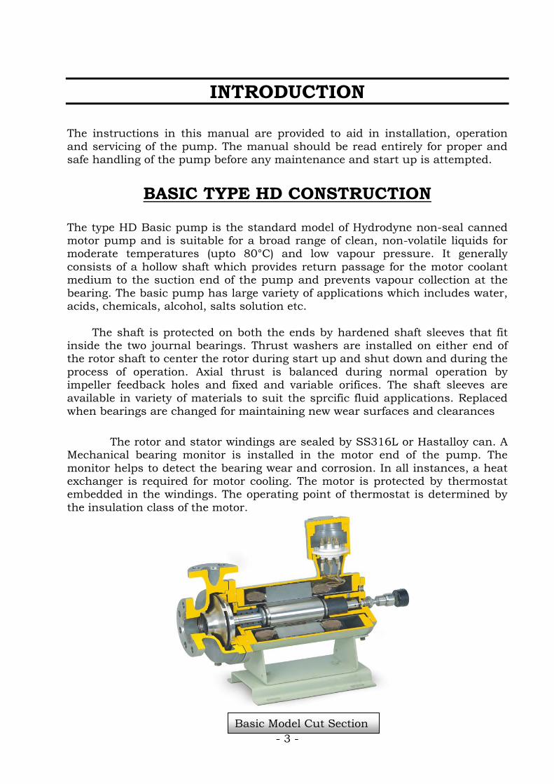
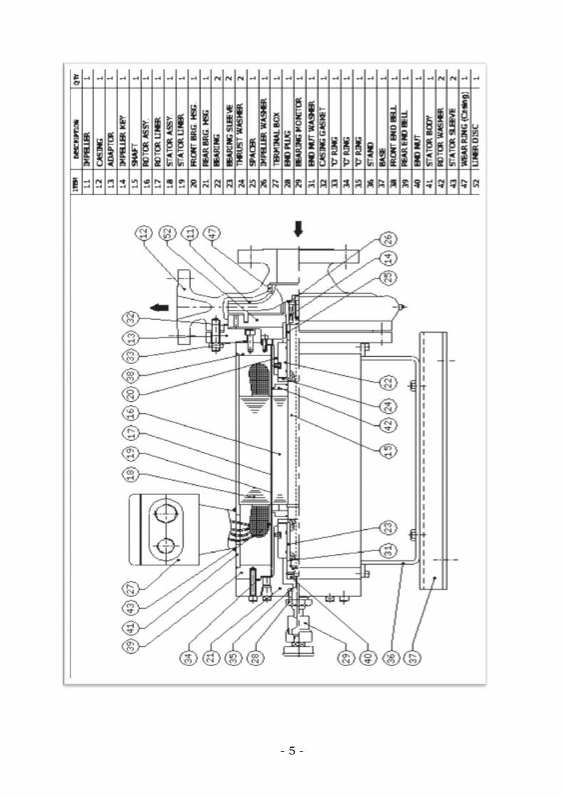
BASIC TYPE HD CONSTRUCTION The type HD Basic pump is the standard model of Hydrodyne non-seal canned motor pump and is suitable for a broad range of clean, non-volatile liquids for moderate temperatures (upto 80°C) and low vapour pressure. It generally consists of a hollow shaft which provides return passage for the motor coolant medium to the suction end of the pump and prevents vapour collection at the bearing. The basic pump has large variety of applications which includes water, acids, chemicals, alcohol, salts solution etc. The shaft is protected on both the ends by hardened shaft sleeves that fit inside the two journal bearings. Thrust washers are installed on either end of the rotor shaft to center the rotor during start up and shut down and during the process of operation. Axial thrust is balanced during normal operation by impeller feedback holes and fixed and variable orifices. The shaft sleeves are available in variety of materials to suit the sprcific fluid applications. Replaced when bearings are changed for maintaining new wear surfaces and clearances
Basic Model Cut Section

- 4 -
PR
INC
IPL
E O
F O
PE
RA
TIO
N O
F B
AS
IC P
UM
P
- 5 -

- 6 -
1. INSPECTION :
CROSS SECTIONAL DRAWING OF BASIC PUMP
I. INSTALLATION
• At the time of unloading the pump inspect the shipping container for any damage if
any visible damage is seen it should be note. If possible photograph the damage which would be helpful if the extent of damage is uncertain.
• While receiving the pump, check if required spares, accessories and instruction
manual are made available. • Note the item no of spares and accessories. • Do not remove the seal at the pump suction and discharge side, to avoid entry of
foreign particle into the pump. • Care should be taken while unloading the pump for any damage.
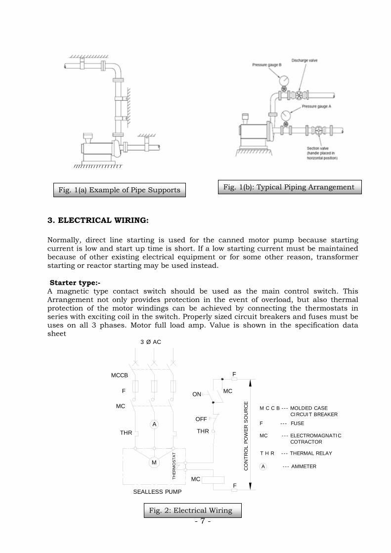
2. SUCTION AND DISCHARGE PIPING: • The pump should be located as near to the supply tank as possible to lower the
NPSH required. Also allow sufficient working area around the pump for maintenance and disassembly.
• All piping must be supported independent of the pump. Please take care not to load
the pump with the weight of piping. Avoid all unnecessary elbow, bends and fittings as they increase frictional losses in the piping.
• For pipes of different diameter, use expander or reducer as required to prevent air
pocket.
• Fix a pressure gauge on the suction and discharge side of the pump to monitor operation as shown in fig. 1(b). It is extremely helpful at the time of start up and for monitoring the performance of the pump.
• Use a strainer of 60 to 80 meshes if entry of particles is expected at steady
operation. Since Strainer will offer resistance to the flow it is important to select strainer of proper mesh. Depending on particle sizes and it should be cleaned at suitable intervals to prevent clogging of the strainer.
• Special attention should be paid to keep suction piping air tight in order to avoid air
entrapment and also to satisfy the condition of NPSH.
• The use of elbows near the suction flange should be avoided. When used, elbows should have a large radius. A straight pipe run of atleast ten times the diameter of pipe is recommended between and elbow and the suction flange.
- 7 -
3. ELECTRICAL WIRING: Normally, direct line starting is used for the canned motor pump because starting current is low and start up time is short. If a low starting current must be maintained because of other existing electrical equipment or for some other reason, transformer starting or reactor starting may be used instead. Starter type:- A magnetic type contact switch should be used as the main control switch. This Arrangement not only provides protection in the event of overload, but also thermal protection of the motor windings can be achieved by connecting the thermostats in series with exciting coil in the switch. Properly sized circuit breakers and fuses must be uses on all 3 phases. Motor full load amp. Value is shown in the specification data sheet
3 Ø AC
MCCB
F
THR
SEALLESS PUMP
ON
OFF
THR
F
F
CO
NTRO
L PO
WER S
OU
RCE
M C C B --- MOLDED CASE CIRCUIT BREAKER
F --- FUSE MC --- ELECTROMAGNATIC COTRACTOR T H R --- THERMAL RELAY A --- AMMETER
MC
MC
A
M
TH
ERM
OSTAT
MC
Fig. 2: Electrical Wiring
Fig. 1(b): Typical Piping Arrangement Fig. 1(a) Example of Pipe Supports
- 8 -
B. Thermostat Protection:-
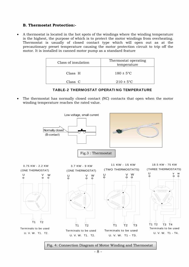
• A thermostat is located in the hot spots of the windings where the winding temperature is the highest, the purpose of which is to protect the motor windings from overheating. Thermostat is usually of closed contact type which will open out as at the precautionary preset temperature causing the motor protection circuit to trip off the motor. It is installed in canned motor pump as a standard feature
TABLE-2 THERMOSTAT OPERATING TEMPERATURE
• The thermostat has normally closed contact (NC) contacts that open when the motor winding temperature reaches the rated value.
Class of insulation Thermostat operating temperature
Class H
Class C
180 ± 5°C
210 ± 5°C
Fig.3 : Thermostat
Fig. 4: Connection Diagram of Motor Winding and Thermostat
U v w
T1 T2 T4T3
18.5 KW - 75 KW
(THREE THERMOSTATS)
Terminals to be used
U. V. W. T1 - T4.
3.7 KW - 9 KW
U V W
T1 T2
(ONE THERMOSTAT)
Terminals to be used
U. V. W. T1. T2.
U V W
T1 T2 T3
11 KW - 15 KW
(TWO THERMOSTATS)
Terminals to be used
U. V. W. T1 - T3.
U V W
T1 T2
0.75 KW - 2.2 KW
(ONE THERMOSTAT)
Terminals to be used
U. V. W. T1. T2.
- 9 -
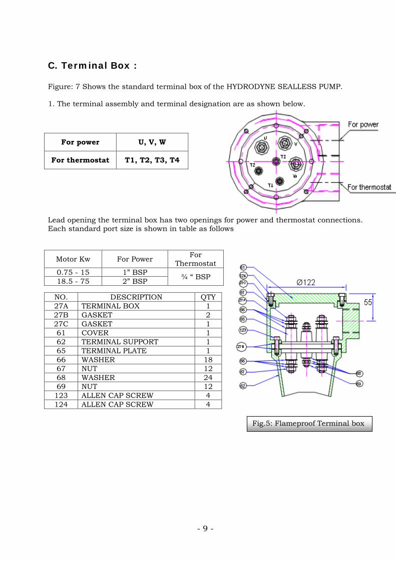
C. Terminal Box : Figure: 7 Shows the standard terminal box of the HYDRODYNE SEALLESS PUMP. 1. The terminal assembly and terminal designation are as shown below.
Lead opening the terminal box has two openings for power and thermostat connections. Each standard port size is shown in table as follows
For power U, V, W
For thermostat T1, T2, T3, T4
Motor Kw For Power For Thermostat
0.75 - 15 1” BSP ¾ “ BSP 18.5 - 75 2” BSP
NO. DESCRIPTION QTY 27A TERMINAL BOX 1 27B GASKET 2 27C GASKET 1 61 COVER 1 62 TERMINAL SUPPORT 1 65 TERMINAL PLATE 1 66 WASHER 18 67 NUT 12 68 WASHER 24 69 NUT 12 123 ALLEN CAP SCREW 4 124 ALLEN CAP SCREW 4
Fig.5: Flameproof Terminal box
- 10 -
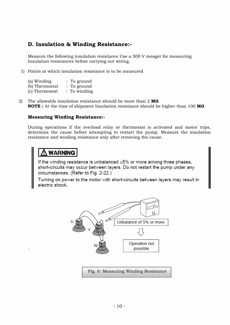
D. Insulation & Winding Resistance:- Measure the following insulation resistance Use a 500 V meager for measuring Insulation resistances before carrying out wiring.
1) Points at which insulation resistance is to be measured (a) Winding : To ground (b) Thermostat : To ground (c) Thermostat : To winding
2) The allowable insulation resistance should be more than 2 MΩ NOTE : At the time of shipment Insulation resistance should be higher than 100 MΩ Measuring Winding Resistance:- During operations if the overload relay or thermostat is activated and motor trips, determine the cause before attempting to restart the pump. Measure the insulation resistance and winding resistance only after removing the cause. .
Fig. 8: Measurement of Winding Resistance
Fig. 6: Measuring Winding Resistance
- 11 -
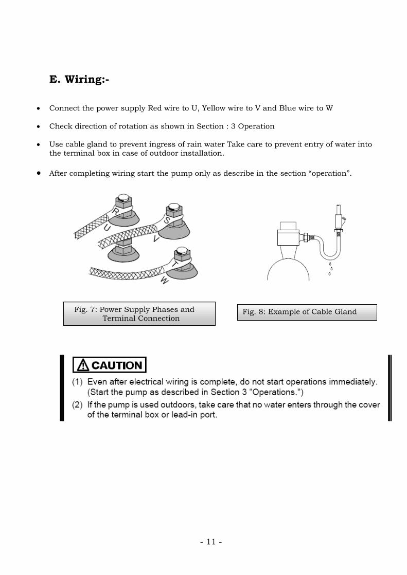
E. Wiring:-
• Connect the power supply Red wire to U, Yellow wire to V and Blue wire to W
• Check direction of rotation as shown in Section : 3 Operation
• Use cable gland to prevent ingress of rain water Take care to prevent entry of water into the terminal box in case of outdoor installation.
• After completing wiring start the pump only as describe in the section “operation”.
Fig. 7: Power Supply Phases and Terminal Connection
Fig. 8: Example of Cable Gland
- 12 -
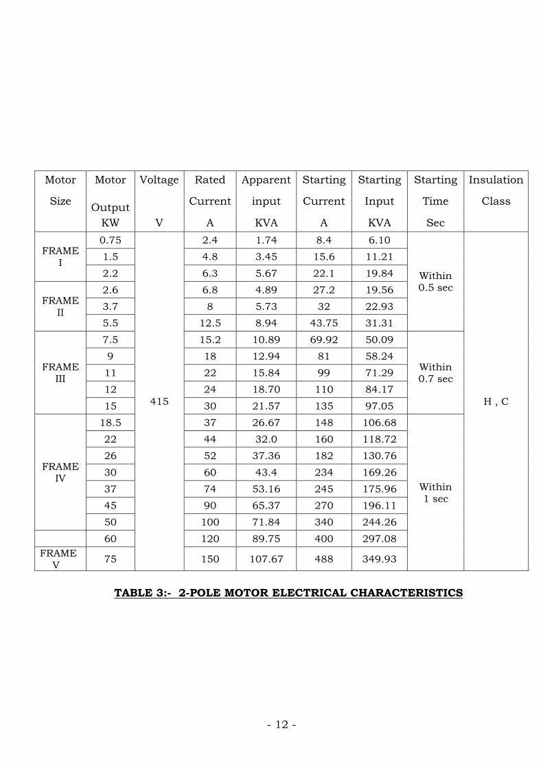
TABLE 3:- 2-POLE MOTOR ELECTRICAL CHARACTERISTICS
Motor Motor Voltage Rated Apparent Starting Starting Starting Insulation
Size Output Current input Current Input Time Class
KW V A KVA A KVA Sec
FRAME I
0.75
415
2.4 1.74 8.4 6.10
Within 0.5 sec
H , C
1.5 4.8 3.45 15.6 11.21 2.2 6.3 5.67 22.1 19.84
FRAME II
2.6 6.8 4.89 27.2 19.56 3.7 8 5.73 32 22.93 5.5 12.5 8.94 43.75 31.31
FRAME III
7.5 15.2 10.89 69.92 50.09
Within 0.7 sec
9 18 12.94 81 58.24 11 22 15.84 99 71.29 12 24 18.70 110 84.17 15 30 21.57 135 97.05
FRAME IV
18.5 37 26.67 148 106.68
Within 1 sec
22 44 32.0 160 118.72 26 52 37.36 182 130.76 30 60 43.4 234 169.26 37 74 53.16 245 175.96 45 90 65.37 270 196.11 50 100 71.84 340 244.26
60 120 89.75 400 297.08 FRAME V 75 150 107.67 488 349.93
- 13 -
Do not run dry !
shut-off operation
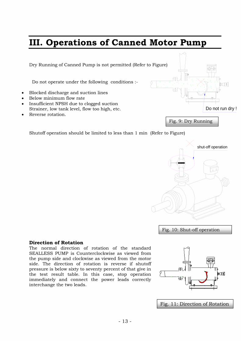
III. Operations of Canned Motor Pump Dry Running of Canned Pump is not permitted (Refer to Figure) Do not operate under the following conditions :-
• Blocked discharge and suction lines • Below minimum flow rate • Insufficient NPSH due to clogged suction
Strainer, low tank level, flow too high, etc. • Reverse rotation.
Shutoff operation should be limited to less than 1 min (Refer to Figure) Direction of Rotation The normal direction of rotation of the standard SEALLESS PUMP is Counterclockwise as viewed from the pump side and clockwise as viewed from the motor side. The direction of rotation is reverse if shutoff pressure is below sixty to seventy percent of that give in the test result table. In this case, stop operation immediately and connect the power leads correctly interchange the two leads.
Fig. 9: Dry Running
Fig. 10: Shut-off operation
Fig. 11: Direction of Rotation
- 14 -
Suction valvefully-opened
ON-OFF Butto
n
ON
First o
f all,
start f
rom
jogging.
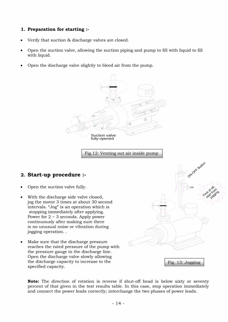
1. Preparation for starting :-
• Verify that suction & discharge valves are closed.
• Open the suction valve, allowing the suction piping and pump to fill with liquid to fill
with liquid.
• Open the discharge valve slightly to bleed air from the pump.
2. Start-up procedure :-
• Open the suction valve fully.
• With the discharge side valve closed, jog the motor 3 times at about 30 second intervals. “Jog” is an operation which is stopping immediately after applying. Power for 2 ~ 3 seconds. Apply power continuously after making sure there is no unusual noise or vibration during jogging operation. .
• Make sure that the discharge pressure reaches the rated pressure of the pump with the pressure gauge in the discharge line. Open the discharge valve slowly allowing the discharge capacity to increase to the specified capacity.
Note: The direction of rotation is reverse if shut-off head is below sixty or seventy percent of that given in the test results table. In this case, stop operation immediately and connect the power leads correctly; interchange the two phases of power leads.
Fig.12: Venting out air inside pump
Fig. 13: Jogging

- 15 -
• Pay attention to the clog of strainer by checking the pressure change at suction side.
• The operation of SEALLESS PUMP, under normal use, is so quiet and vibrations so low little that it can hardly be judged whether the pump is operating or not. When operating the pump, check the following points.
(a) Check that the flow rate and discharge pressure are correct as specified. (b) Check for any abnormal noise.
Note: When pump suction is under vacuum, open the discharge valve partly and leave it for 15 min.
(c) Check the pump for cavitations conditions. When opening the discharge valve gradually, the abnormal sound and vibration will occur in the pump, and the flow rate will not increase even if the discharge valve is opened further; this is known as “CAVITATION”. Note: Never operate the SEALLESS PUMP under the condition of cavitations.
(d) Check that the electric current of the motor is under the rated value. SEALLESS PUMP motor is selected so as not to be overloaded against the specifications required. If the flow rate exceeds the specified value, the pump may be overloaded. Then, reduce the flow rate and adjust the current within the rated current value.
(e) Ensure that cooling line of motor, is working correctly. Check the difference of temperature at the out let and inlet.
• When operating the heating medium pump at a ambient temperature with high viscosity, reduce the discharge valve opening and adjust the current within the rated current value until the temperature reaches to the specified level.
• When abnormal condition occurs, stop the pump operation immediately and follow the troubleshooting chart.
3. Routine Inspection during operation :- The following items should be checked on a routine schedule to verify pump operation.
• Check discharge pressure against original design specification.
• Check ammeter readings compared to initial readings start up readings.
• Check for abnormal noise and any increase in vibration levels.
• Check the bearing monitor to ensure that it is in the safe operating range and not in the red zone.
• Check the cooling water in and out line for a temperature differential.
- 16 -
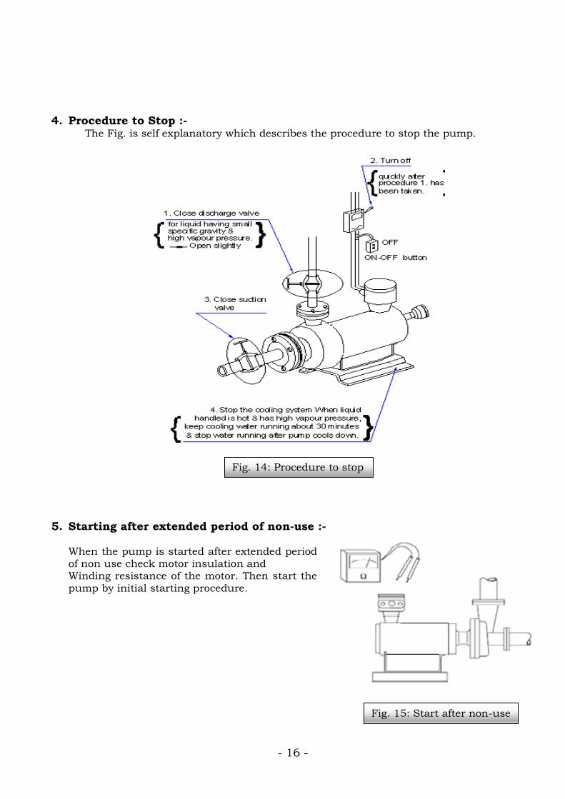
4. Procedure to Stop :- The Fig. is self explanatory which describes the procedure to stop the pump.
5. Starting after extended period of non-use :- When the pump is started after extended period of non use check motor insulation and Winding resistance of the motor. Then start the pump by initial starting procedure.
Fig. 15: Start after non-use
Fig. 14: Procedure to stop
- 17 -
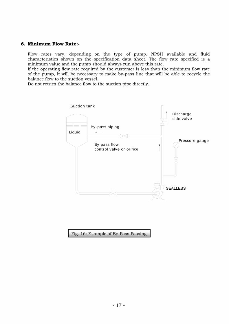
6. Minimum Flow Rate:- Flow rates vary, depending on the type of pump, NPSH available and fluid characteristics shown on the specification data sheet. The flow rate specified is a minimum value and the pump should always run above this rate. If the operating flow rate required by the customer is less than the minimum flow rate of the pump, it will be necessary to make by-pass line that will be able to recycle the balance flow to the suction vessel. Do not return the balance flow to the suction pipe directly.
Liquid
Suction tank
By-pass piping
Dischargeside valve
Pressure gauge
SEALLESS
By pass flowcontrol valve or orifice
Fig. 16: Example of By-Pass Passing
- 18 -
III. Maintenance
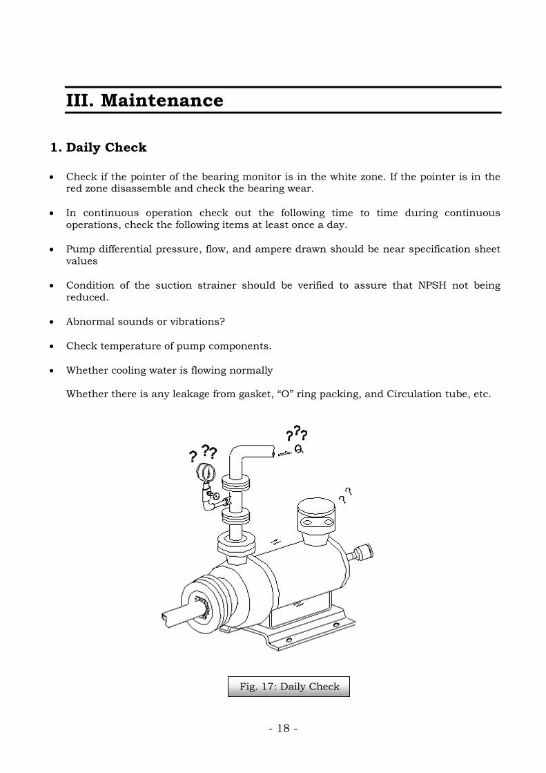
1. Daily Check
• Check if the pointer of the bearing monitor is in the white zone. If the pointer is in the red zone disassemble and check the bearing wear.
• In continuous operation check out the following time to time during continuous operations, check the following items at least once a day.
• Pump differential pressure, flow, and ampere drawn should be near specification sheet values
• Condition of the suction strainer should be verified to assure that NPSH not being reduced.
• Abnormal sounds or vibrations?
• Check temperature of pump components.
• Whether cooling water is flowing normally Whether there is any leakage from gasket, “O” ring packing, and Circulation tube, etc.
Fig. 17: Daily Check
- 19 -
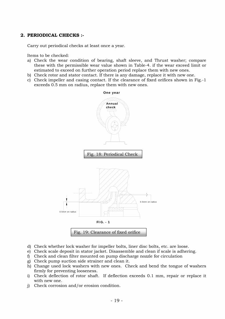
2. PERIODICAL CHECKS :- Carry out periodical checks at least once a year. Items to be checked: a) Check the wear condition of bearing, shaft sleeve, and Thrust washer; compare
these with the permissible wear value shown in Table-4. if the wear exceed limit or estimated to exceed on further operation period replace them with new ones.
b) Check rotor and stator contact. If there is any damage, replace it with new one. c) Check impeller and casing contact. If the clearance of fixed orifices shown in Fig.-1
exceeds 0.5 mm on radius, replace them with new ones. d) Check whether lock washer for impeller bolts, liner disc bolts, etc. are loose. e) Check scale deposit in stator jacket. Disassemble and clean if scale is adhering. f) Check and clean filter mounted on pump discharge nozzle for circulation g) Check pump suction side strainer and clean it. h) Change used lock washers with new ones. Check and bend the tongue of washers
firmly for preventing looseness. i) Check deflection of rotor shaft. If deflection exceeds 0.1 mm, repair or replace it
with new one. j) Check corrosion and/or erosion condition.
0.5mm on radius
0.5mm on radius
FIG. - 1
Annual check
One year
Fig. 18: Periodical Check
Fig. 19: Clearance of fixed orifice

- 20 -
L
ØD
THRUST WASHERBEARING
SHAFT SLEEVE
Checking of Bearing:- In case of SEALLESS PUMP, bearing wear beyond its limit cause contact of the rotor sleeve and stator liner and result in serious damage of motor finally. Pay attention to check bearing monitor. Periodical checks are essential for bearing maintenance. The same sized bearing is adopted at front and rear side of pump. 1) Life of Bearing
Since bearings are used in the liquid, its life depends on the characteristic, temperature, Etc. of the liquid. Usually, the bearings are durable enough for more than one year (Approx. 8,500 Hours) of continuous operation in liquid equivalent to water. Check the wearing condition of the bearings after a year or 8,500 hours operation and Estimate the life under the individual condition. Don’t fail to check the bearing after disassembling pump when a strange sound or Vibration is found during operation, and when periodical check of pump is made limit of bearing wear is shown in Table as follows, and according to this table, replace the worn out bearings with new ones.
TABLE 4: BEARING WEAR LIMIT
Note: When the thrust supporting surface of the bearing on the rear side, the main impeller starts to contact the liner disc before reaching to L size on the Table above. When replacing bearing, check also shaft sleeves and thrust washers. When there is any damage on the surface of shaft sleeve and thrust washer, replace them, too.
Motor Size (kW)
Maximum Value of Bearing
Inside Dia. ØD (mm)
Minimum Value of
overall Length L (mm)
0.75 - 2.2 28.4 39.5 2.6 – 5.5 34.5 59.5 7.5 - 15 41.5 79.5 18.5 - 50 54.5 105
ABOVE 50 80.4 109.5
Fig. 20: Bearing wear limit

- 21 -
RB HOUSING
DUMMY PLUG A
21
BEARING MONITOR 29
Fig. 21: Mounting of Bearing Monitor
IV. SAFETY FEATURES
1. Bearing Monitor (Mechanical) :- When a bearing monitor is delivered separately, a dummy plug is inserted in the hole for bearing monitor on rear bearing housing. Remove the dummy plug, then install the bearing monitor to pump before operation. Mounting Method of Bearing Monitor Remove dummy plug A. After inserting the tip of sensor in to an eccentric hole of end nut (40) while slanting bearing monitor (29), place it on RB housing (21) in the correct position and fit the monitor in socket portion of RB housing, and after that, mount the monitor straightly at the centre of the pump and tighten nut (28), where mounting of monitor is completed.
Function of Bearing Monitor:- The Bearing Monitor signals that the bearing wear is close to breaking point allowing for bearings to be replaced in time, thus preventing excessive damage. The monitor is a gauge filled with gas and mounted on the rear bearing housing. The probe or the bearing monitor is inserted into the end nut of the shaft. When the bearing wear exceeds the set limit the probe strikes against the end nut and breaks realizing the gas and reducing the pressure in the monitor, indicating an abnormal state on the indicator. The monitor which indicates the red zone cannot be used again as shown in fig.24. Use a new one.
- 22 -
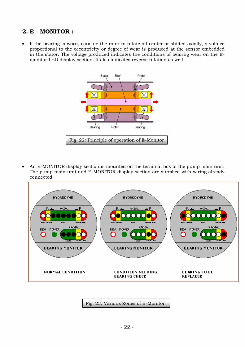
Fig. 22: Principle of operation of E-Monitor
Fig. 23: Various Zones of E-Monitor
2. E - MONITOR :-
• If the bearing is worn, causing the rotor to rotate off-center or shifted axially, a voltage
proportional to the eccentricity or degree of wear is produced at the sensor embedded in the stator. The voltage produced indicates the conditions of bearing wear on the E-monitor LED display section. It also indicates reverse rotation as well.
• An E-MONITOR display section is mounted on the terminal box of the pump main unit. The pump main unit and E-MONITOR display section are supplied with wiring already connected.
Fig. 25: Various Zones of E-Monitor
electronic
HYDRODYNE HYDRODYNE HYDRODYNE
electronic electronic
- 23 -
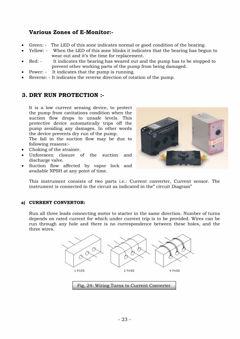
Fig. 24: Wiring Turns to Current Converter
Various Zones of E-Monitor:-
• Green: - The LED of this zone indicates normal or good condition of the bearing. • Yellow: - When the LED of this zone blinks it indicates that the bearing has begun to
wear out and it’s the time for replacement. • Red: - It indicates the bearing has weared out and the pump has to be stopped to
prevent other working parts of the pump from being damaged. • Power: - It indicates that the pump is running. • Reverse: - It indicates the reverse direction of rotation of the pump.
3. DRY RUN PROTECTION :- It is a low current sensing device, to protect the pump from cavitations condition when the suction flow drops to unsafe levels. This protective device automatically trips off the pump avoiding any damages. In other words the device prevents dry run of the pump. The fall in the suction flow may be due to following reasons:-
• Choking of the strainer. • Unforeseen closure of the suction and
discharge valve. • Suction flow affected by vapor lock and
available NPSH at any point of time. This instrument consists of two parts i.e.: Current converter, Current sensor. The instrument is connected in the circuit as indicated in the” circuit Diagram”
a) CURRENT CONVERTOR:
Run all three leads connecting motor to starter in the same direction. Number of turns depends on rated current for which under current trip is to be provided. Wires can be run through any hole and there is no correspondence between these holes, and the three wires.
- 24 -
Determine the number of primary conductor runs through the holes and Setting tap from Table – 6 above. EXAMPLE For a “Dry Run Protection to be provided for a motor trip below 4Amps. Motor current, the current setting range should be 2 – 5 A, the Number of runs through the holes is 4 and setting tap is 20. The Current scale multiplying factor is 0.5. In the tap setting, insert a setting Screw into the required tap hole with a screw driver. After setting, be sure to replace the cover.
b) CURRENT SENSOR : Current sensor front and rear view are shown in the enclosed drawing. Leads 1,2,3,4,5,6,7 & 8 of the current sensor are connected in the Manner as shown in the circuit diagram of “Dry Run Protection “. Start the pump with liquid and note the SHUTT OFF current. The DRP should than be set to 0.5 AMP. Reading below SHUTT OFF current.
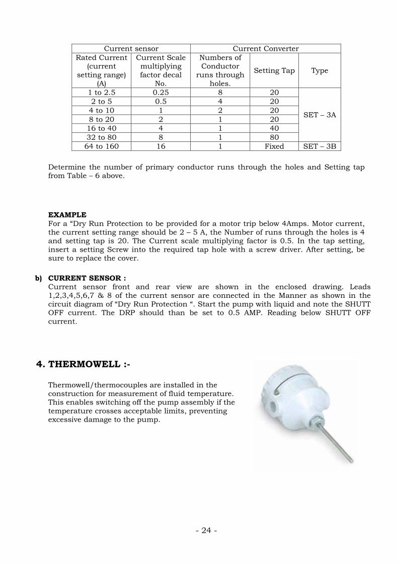
4. THERMOWELL :- Thermowell/thermocouples are installed in the construction for measurement of fluid temperature. This enables switching off the pump assembly if the temperature crosses acceptable limits, preventing excessive damage to the pump.
Current sensor Current Converter Rated Current
(current setting range)
(A)
Current Scale multiplying factor decal
No.
Numbers of Conductor
runs through holes.
Setting Tap Type
1 to 2.5 0.25 8 20
SET – 3A
2 to 5 0.5 4 20 4 to 10 1 2 20 8 to 20 2 1 20 16 to 40 4 1 40 32 to 80 8 1 80 64 to 160 16 1 Fixed SET – 3B
- 25 -
U
V
W
T2 T1
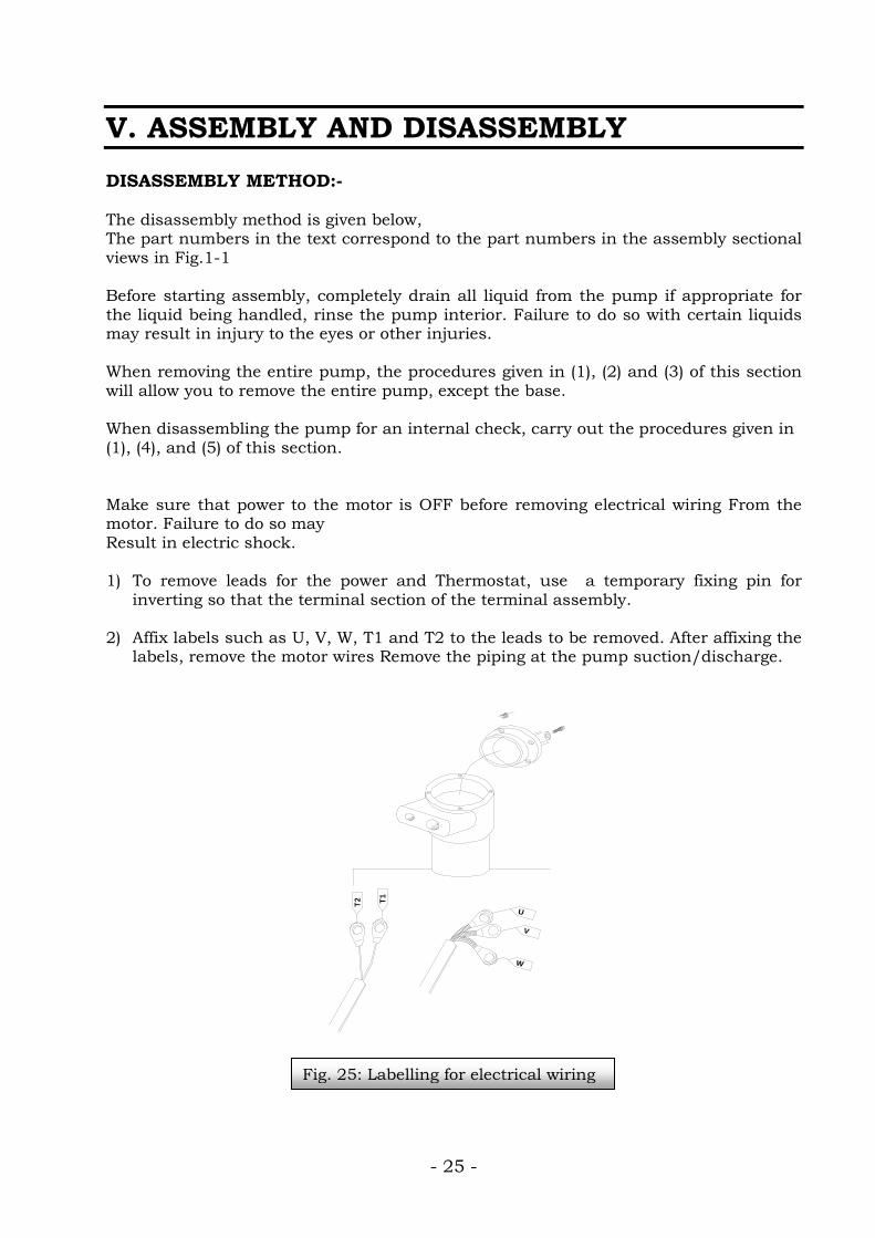
V. ASSEMBLY AND DISASSEMBLY DISASSEMBLY METHOD:- The disassembly method is given below, The part numbers in the text correspond to the part numbers in the assembly sectional views in Fig.1-1 Before starting assembly, completely drain all liquid from the pump if appropriate for the liquid being handled, rinse the pump interior. Failure to do so with certain liquids may result in injury to the eyes or other injuries. When removing the entire pump, the procedures given in (1), (2) and (3) of this section will allow you to remove the entire pump, except the base. When disassembling the pump for an internal check, carry out the procedures given in (1), (4), and (5) of this section. Make sure that power to the motor is OFF before removing electrical wiring From the motor. Failure to do so may Result in electric shock. 1) To remove leads for the power and Thermostat, use a temporary fixing pin for
inverting so that the terminal section of the terminal assembly.
2) Affix labels such as U, V, W, T1 and T2 to the leads to be removed. After affixing the labels, remove the motor wires Remove the piping at the pump suction/discharge.
Fig. 25: Labelling for electrical wiring
- 26 -
Base
Stand
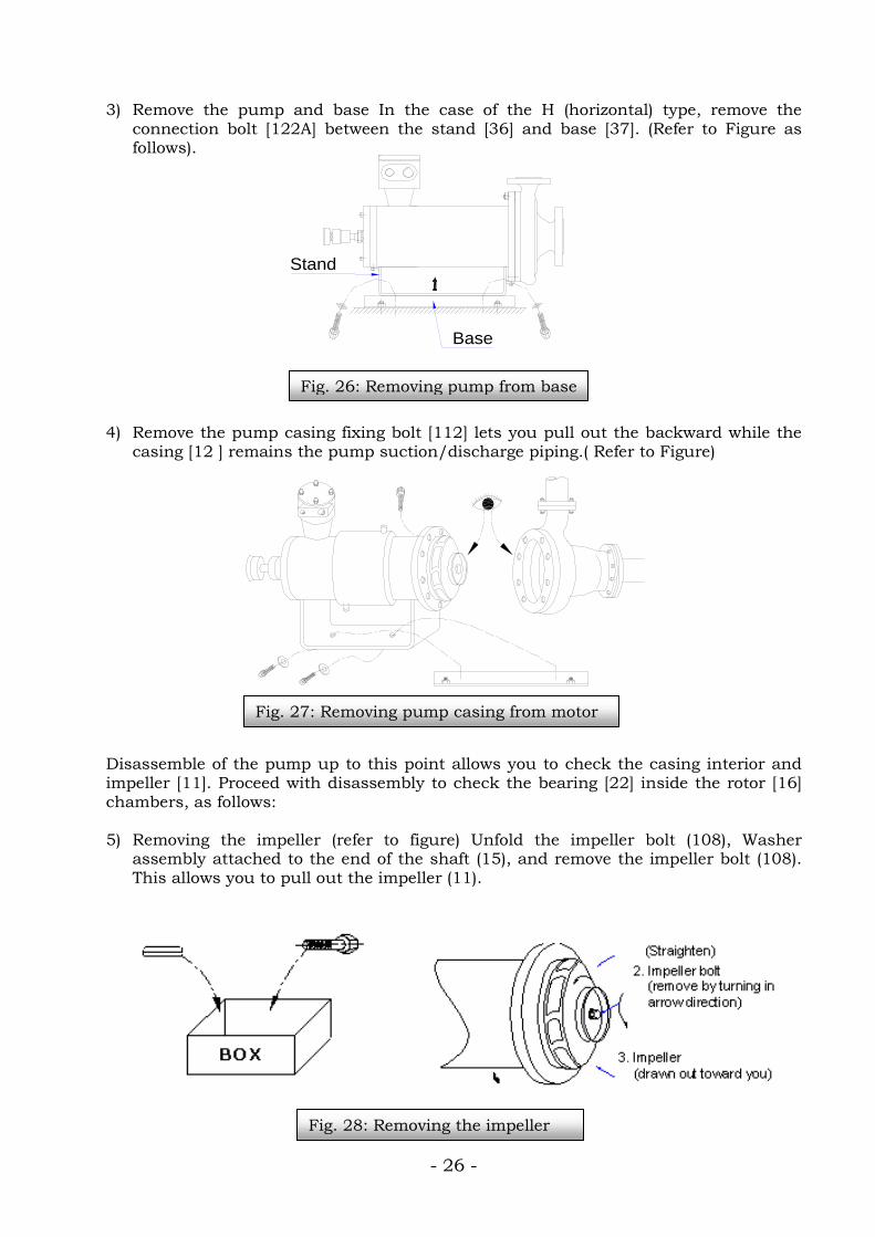
3) Remove the pump and base In the case of the H (horizontal) type, remove the
connection bolt [122A] between the stand [36] and base [37]. (Refer to Figure as follows).
4) Remove the pump casing fixing bolt [112] lets you pull out the backward while the
casing [12 ] remains the pump suction/discharge piping.( Refer to Figure) Disassemble of the pump up to this point allows you to check the casing interior and impeller [11]. Proceed with disassembly to check the bearing [22] inside the rotor [16] chambers, as follows: 5) Removing the impeller (refer to figure) Unfold the impeller bolt (108), Washer
assembly attached to the end of the shaft (15), and remove the impeller bolt (108). This allows you to pull out the impeller (11).
Fig. 26: Removing pump from base
Fig. 27: Removing pump casing from motor
Fig. 28: Removing the impeller
- 27 -
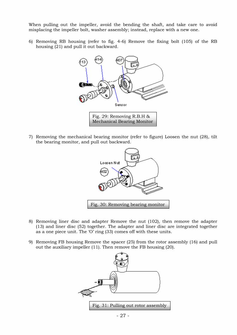
When pulling out the impeller, avoid the bending the shaft, and take care to avoid misplacing the impeller bolt, washer assembly; instead, replace with a new one. 6) Removing RB housing (refer to fig. 4-6) Remove the fixing bolt (105) of the RB
housing (21) and pull it out backward. 7) Removing the mechanical bearing monitor (refer to figure) Loosen the nut (28), tilt
the bearing monitor, and pull out backward. 8) Removing liner disc and adapter Remove the nut (102), then remove the adapter
(13) and liner disc (52) together. The adapter and liner disc are integrated together as a one piece unit. The ‘O’ ring (33) comes off with these units.
9) Removing FB housing Remove the spacer (25) from the rotor assembly (16) and pull
out the auxiliary impeller (11). Then remove the FB housing (20).
Fig. 30: Removing bearing monitor
Fig. 29: Removing R.B.H & Mechanical Bearing Monitor
Fig. 31: Pulling out rotor assembly
- 28 -
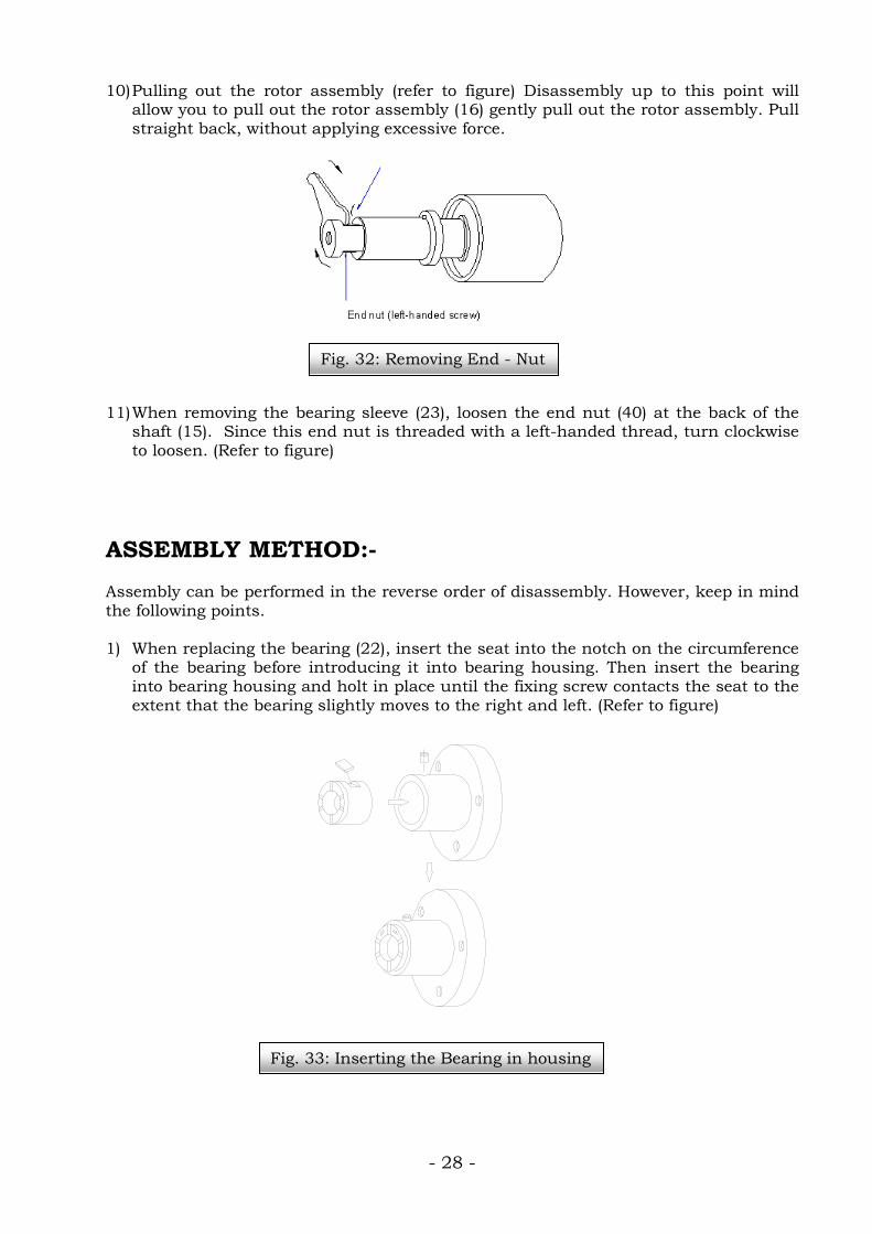
10) Pulling out the rotor assembly (refer to figure) Disassembly up to this point will allow you to pull out the rotor assembly (16) gently pull out the rotor assembly. Pull straight back, without applying excessive force.
11) When removing the bearing sleeve (23), loosen the end nut (40) at the back of the
shaft (15). Since this end nut is threaded with a left-handed thread, turn clockwise to loosen. (Refer to figure)
ASSEMBLY METHOD:- Assembly can be performed in the reverse order of disassembly. However, keep in mind the following points. 1) When replacing the bearing (22), insert the seat into the notch on the circumference
of the bearing before introducing it into bearing housing. Then insert the bearing into bearing housing and holt in place until the fixing screw contacts the seat to the extent that the bearing slightly moves to the right and left. (Refer to figure)
Fig. 32: Removing End - Nut
Fig. 33: Inserting the Bearing in housing
- 29 -
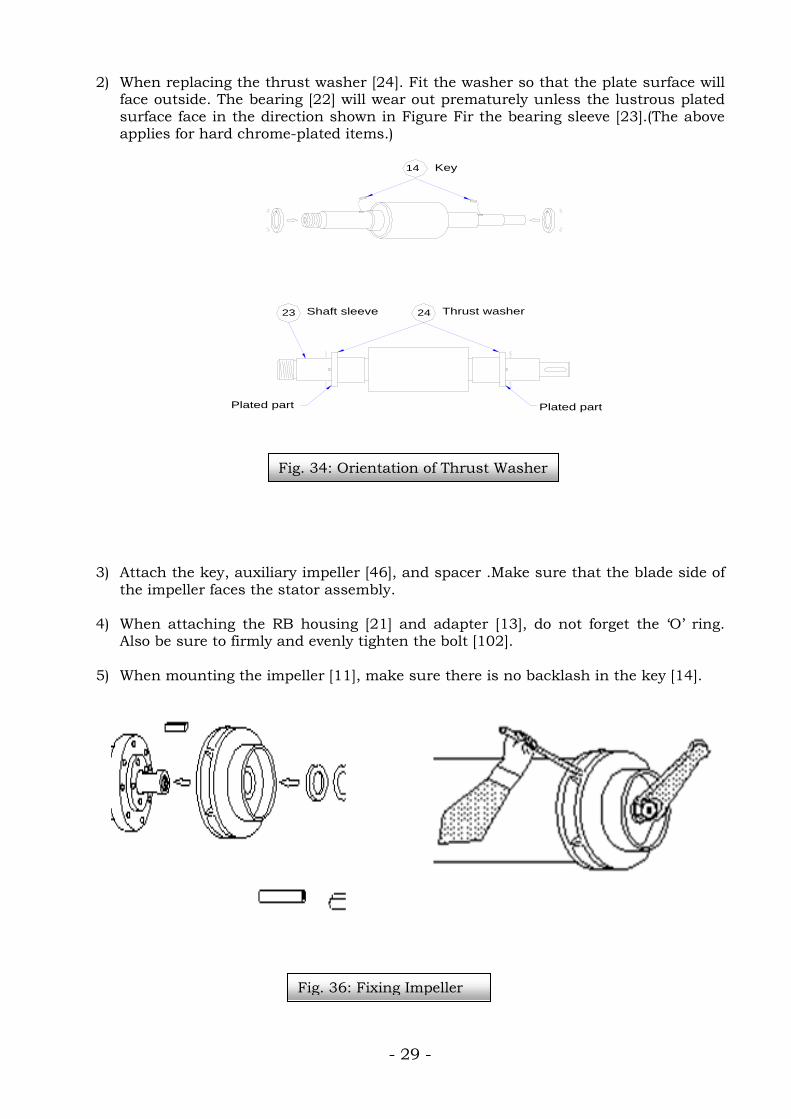
2) When replacing the thrust washer [24]. Fit the washer so that the plate surface will face outside. The bearing [22] will wear out prematurely unless the lustrous plated surface face in the direction shown in Figure Fir the bearing sleeve [23].(The above applies for hard chrome-plated items.)
3) Attach the key, auxiliary impeller [46], and spacer .Make sure that the blade side of
the impeller faces the stator assembly. 4) When attaching the RB housing [21] and adapter [13], do not forget the ‘O’ ring.
Also be sure to firmly and evenly tighten the bolt [102]. 5) When mounting the impeller [11], make sure there is no backlash in the key [14].
Shaft sleeve
Plated part
23
Plated part
Thrust washer24
14 Key
Fig. 34: Orientation of Thrust Washer
Fig. 36: Fixing Impeller
- 30 -
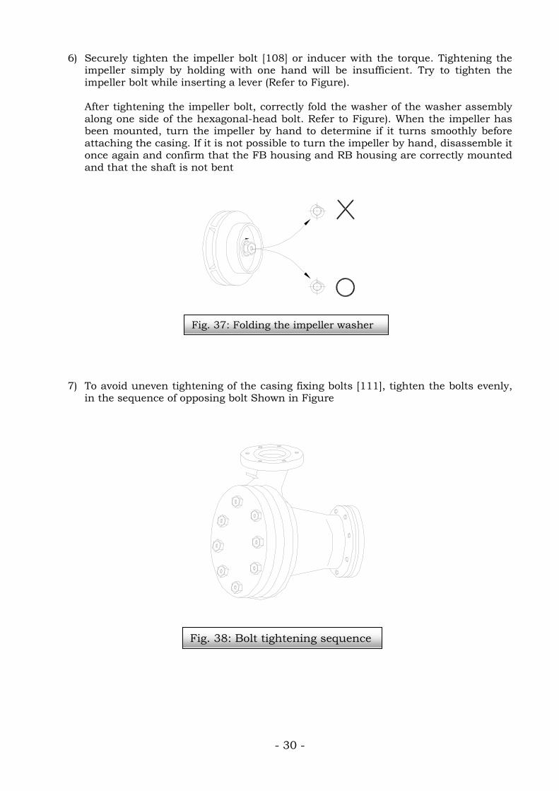
6) Securely tighten the impeller bolt [108] or inducer with the torque. Tightening the impeller simply by holding with one hand will be insufficient. Try to tighten the impeller bolt while inserting a lever (Refer to Figure). After tightening the impeller bolt, correctly fold the washer of the washer assembly along one side of the hexagonal-head bolt. Refer to Figure). When the impeller has been mounted, turn the impeller by hand to determine if it turns smoothly before attaching the casing. If it is not possible to turn the impeller by hand, disassemble it once again and confirm that the FB housing and RB housing are correctly mounted and that the shaft is not bent
7) To avoid uneven tightening of the casing fixing bolts [111], tighten the bolts evenly,
in the sequence of opposing bolt Shown in Figure
Fig. 37: Folding the impeller washer
Fig. 38: Bolt tightening sequence
- 31 -

- 32 -
VI. TROUBLE SHOOTING CHART

- 33 -
HYDRODYNE CANNED MOTOR PUMP
TYPE HD – BASIC PUMP INSTRUCTION MANUAL
MANUAL NO. : - HD-2010 REVISED EDITION: - June 7, 2010 PUBLISHER: - HYDRODYNE (INDIA) PVT. LTD. B-47, PARAMOUNT, NEW LINK ROAD, ANDHERI (W) MUMBAI-400053 © HYDRODYNE (INDIA) PVT. LTD. Printed in India. All Rights Reserved
NO PART OF THIS PUBLICATION MAY BE REPRODUCED OR MODIFIED OR TRANSMITTED IN ANY FORM OR BY ANY MEANS WITHOUT PRIOR CONSENT FROM HYDRODYNE INDIA PVT. LTD.
Related Documents