Basic Principles and Current Trends in Colloidal Synthesis of Highly Luminescent Semiconductor Nanocrystals Pavel Samokhvalov, [a] Mikhail Artemyev,* [a, b] and Igor Nabiev* [a, c] # 2013 Wiley-VCH Verlag GmbH&Co. KGaA, Weinheim Chem. Eur. J. 2013, 19, 1534 – 1546 1534 DOI: 10.1002/chem.201202860

Welcome message from author
This document is posted to help you gain knowledge. Please leave a comment to let me know what you think about it! Share it to your friends and learn new things together.
Transcript

Basic Principles and Current Trends in Colloidal Synthesis of HighlyLuminescent Semiconductor Nanocrystals
Pavel Samokhvalov,[a] Mikhail Artemyev,*[a, b] and Igor Nabiev*[a, c]
� 2013 Wiley-VCH Verlag GmbH & Co. KGaA, Weinheim Chem. Eur. J. 2013, 19, 1534 – 15461534
DOI: 10.1002/chem.201202860
Introduction
Semiconductor nanocrystals or quantum dots (QDs) arewidely used in bio-labeling applications, as efficient lightconverters for light-emitting diodes or photovoltaic devices.In bulk semiconductors, absorbed photons excite electron–hole pairs, which later either dissociate, resulting in macro-scopic conductance, or recombine, irradiating photons. Atthe initial stage, an electron–hole pair is bound by Coulombinteraction and forms a virtual hydrogen-atom-like species,that is, an exciton. Unlike their bulk counterparts, excitonsin semiconductors in the nanosized regime undergo confine-ment effects,[1–3] with their wave functions trapped in a smallnanocrystal space, dramatically enhancing the probability ofradiative recombination.
For biological applications, it is important to have semi-conductor QDs with narrow emission lines, a high quantumyield (QY) close to that of standard organic dyes, and ahigh photostability and chemical stability. Today, the mostpromising materials are core–shell QDs, in which a photolu-minescence (PL)-active core is capped with an inorganicshell. Core–shell nanocrystals usually exhibit much strongerluminescence than bare cores. The role of the inorganicshell in PL improvement is the passivation of surface traps,that is, dangling bonds that quench excitonic luminescence,as well as protection from chemical damage caused by the
environment. The use of a material with a higher band gapfor the shell enables one to energetically confine excitons inthe nanocrystal core and, hence, reduce the nonradiativedecay. This review covers the key issues of the synthesis ofAIIBVI cores and core–shell colloidal QDs with bright photo-luminescence that are stable in different environments.Since 2000, a number of comprehensive reviews on the syn-thesis of AIIBVI and other semiconductor nanocrystals havebeen published.[4–9] Both aqueous and nonaqueous synthesesof CdSe, CdTe, CdS, ZnSe, InP, PbS, and PbSe core andcore–shell nanoparticles have been discussed in terms of theinfluence of the precursors, temperature, solvents, injectionversus noninjection methods, etc. on the mean size, size de-viation, spectral linewidth, and the PL quantum yield. Inthis review, we discuss in detail most promising strategiesfor obtaining defect-free semiconductor cores by the fabrica-tion and growth of magic-size nanocrystals followed by cap-ping them with a gradient wide-gap shell.
Synthesis of Luminescent Core Nanocrystals byInjection and Noninjection Methods and by Using
Magic-Size Seeds
The core of QDs is the key element determining the opticalproperties of the entire system. A high crystallinity and theabsence of internal defects in the core are necessary condi-tions for achieving a high luminescence QY. Since the nano-crystal itself is a metastable object because of its ultrasmallsize, postsynthetic treatments, such as thermal annealing orrecrystallization, may result in core coalescence and loss ofits unique optical properties. Therefore, the quality of thecore strictly depends on the methods of synthesis, reactionkinetics, and reagents.
Colloidal fabrication of high-quality semiconductor nano-crystals with controllable shape, size, and PL properties re-quires controllable nucleation and growth of nanocrystals.Differentiation between the nucleation and growth stages isa prerequisite for the formation of high-quality nanocrys-tals.[4] When nucleation occurs competitively with thegrowth of nanocrystals, their size distribution is often broad
Abstract: The principal methods for the synthesis ofhighly luminescent core–shell colloidal quantum dots(QDs) of the most widely used CdSe, CdS, ZnSe, andother AIIBVI nanocrystals are reviewed. One-pot versusmultistage core synthesis approaches are discussed. Thenoninjection one-pot method ensures slow, controllablegrowth of core nanocrystals starting from magic-size seedrecrystallization, which yields defect-free cores with strict-ly specified sizes and shapes and a high monodispersity.Subsequent injection of shell precursors allows the forma-tion of gradient core–shell QDs with a smooth potential
barrier for electrons and holes, without strains or interfa-cial defects, and, as a consequence, a luminescence quan-tum yield (QY) approaching 100 %. These general ap-proaches can also be applied to semiconductor core–shellQDs other than AIIBVI ones to cover the broad spectralrange from the near-UV to IR regions of the optical spec-trum, thus displacing fluorescent organic dyes from theirapplication areas.
Keywords: core–shell structure · magic-size seeds · nano-technology · one-pot synthesis · quantum dots
[a] Dr. P. Samokhvalov, Dr. M. Artemyev, Prof. Dr. I. NabievLaboratory of Nano-BioengineeringMoscow Engineering Physics Institute31 Kashirskoe sh., 115409 Moscow (Russian Federation)Fax: (+375) 172-264696E-mail : [email protected]
[b] Dr. M. ArtemyevInstitute for Physico-Chemical Problems ofBelarusian State University220030 Minsk (Belarus)
[c] Prof. Dr. I. NabievEuropean Technological Platform Semiconductor NanocrystalsInstitute of Molecular Medicine, Trinity College DublinJames�s Street, Dublin 8 (Ireland)
Chem. Eur. J. 2013, 19, 1534 – 1546 � 2013 Wiley-VCH Verlag GmbH & Co. KGaA, Weinheim www.chemeurj.org 1535
MINIREVIEW

and, hence, PL bandwidths are too wide. The large varietyof available synthetic procedures for QD synthesis could begenerally categorized into two major approaches: injectionmethods,[10,11] and noninjection ones.[12,13] Injection methodsare based on fast injection of room-temperature or mildlyheated precursors (a metal, a chalcogenide, or both of them)into a hot solvent. Since the injection is usually done slightlyabove the thermal nucleation threshold, the temperaturedrop induced by injection of a cold solution allows one toquench nanocrystal nucleation and start the growth. Thus,rapid nucleation and subsequent slow growth restricted bysurfactant molecules (TOP/TOPO, fatty acids, or amines)allows the preparation of highly monodisperse QD ensem-bles.[14] A number of detailed investigations on colloidalnanocrystal fabrication by hot-injection methods have beenperformed, and detailed information on the experimentalconditions is available. In reference [15], the effects of vari-ous reaction parameters on the changes in the PL QY ofCdSe nanocrystal ensembles with time have been studied,and it has been established that the QY reaches its maxi-mum at a certain point and then gradually fades (Figure 1).This is a good illustration of the complex reaction kineticsof the nanocrystal formation and growth.
A plethora of kinetic factors, such as temperature instabil-ity, mixture heterogeneity, and overall high rates of injec-tion-based reactions, often hinder reproducible preparationof high-quality PL nanocrystals. These fast reaction kineticsand limited mass-transfer rates largely affect the quality ofthe final products and impede large-scale QD produc-tion.[16,17] This obstacle forces researchers to seek for other
Dr. Pavel Samokhvalov was born in Arza-mas-16 (Russia). He received his Ph.D.degree in Chemistry from Moscow StateUniversity in 2010. His research in theNanochemistry Group of the Laboratoryof Nano-Bioengineering of Moscow Engi-neering Physics Institute is related to thesynthesis and functionalization of AIIBVI
semiconductor quantum dots with the goalto make them adaptable to biological ap-plications.
Dr. Mikhail Artemyev was born in Minsk(Belarus) and received his Ph.D. degree inPhysical Chemistry in 1999 from Belarusi-an State University (BSU). In 1999–2000he was a research fellow at the ChemistryDepartment of the Massachusetts Instituteof Technology. In 2009 he received aD.Sci. degree in Physical Chemistry fromBSU. Currently he is the head of the Labo-ratory of Nanochemistry of the Institutefor Physico-Chemical Problems of BSUand the member of the NanochemistryGroup of the Laboratory of Nano-Bioen-gineering of Moscow Engineering PhysicsInstitute (Russia). His scientific interests include the synthesis of semicon-ductor and metal nanocrystals and their applications to optics, optoelec-tronics, and biomedicine.
Prof. Igor Nabiev was born in Palanga(Lithuania). He received his Ph.D. degreein Physics and Mathematics in 1983 fromMoscow State University and his D.Sci.degree in Chemistry from Shemyakin Insti-tute of Bioorganic Chemistry of the Russi-an Academy of Sciences. After invited pro-fessorships in the USA and France, he wasnominated as a Professor of Biophysics inthe University of Reims Champagne-Ard-enne (France). In 2008–2009 Prof. Nabievwas a recipient of the Walton Award fromthe Science Foundation of Ireland. Since2010 he is Director of Technological Plat-form Semiconductor Nanocrystals in the framework of the “Large” Euro-pean Project NAMDIATREAM in the Institute of Molecular Medicine,Dublin (Ireland). In the late 2011 Prof. Nabiev received a MEGA-grantfrom the Government of the Russian Federation (Program of Attraction ofthe World Leading Scientists to the Russian Institutions) and founded theLaboratory of Nano-Bioengineering in Moscow Engineering Physics Insti-tute (www.lnbe.mephi.ru/en/about).
Figure 1. Temporal evolution of quantum dots (QD) photoluminescence(PL) band full-width-at-half-maximum (FWHM), PL quantum yield, andPL peak position for four reactions with different initial Cd to Se ratio ofthe precursors (indicated at the top). For all four reactions, the initialconcentration of the two precursors was fixed at 1411 mmol kg�1. Theother conditions were the same as those of the typical synthesis. Trendlines (solid lines) are drawn in each plot to guide the eye. Adapted withpermission from reference [15]. Copyright 2002 American Chemical Soci-ety.
www.chemeurj.org � 2013 Wiley-VCH Verlag GmbH & Co. KGaA, Weinheim Chem. Eur. J. 2013, 19, 1534 – 15461536
M. Artemyev, I. Nabiev and P. Samokhvalov
methods of large-scale QD preparation, in particular, nonin-jection syntheses.
Noninjection syntheses, including aqueous ones, being his-torically the first methods to produce colloidal QDs, areconsidered to yield worse nanocrystals in terms of crystallin-ity, monodispersity, and PL properties. In this synthetic ap-proach, all reagents are premixed in a single reaction pot,and the nanocrystal nucleation and growth are initiatedeither thermally, chemically,[16, 17] or by physical impact (e.g.,microwave irradiation[18]). Routinely, these reactions areconducted at mild temperatures, below 200 8C. One-pot syn-theses of high-quality QDs using this technique has beenperformed in some recent studies.[16, 19]
It has been reported that nucleation occurs even at roomtemperature if the reaction pot is kept intact for a certaintime.[20] Nucleation has been found to significantly increasethe PL QY after successive nanocrystal growth. The absorb-ance spectra recorded during this room-temperature nuclea-tion stage have several excitonic peaks that do not exhibitthe time-dependent, continuous red shift that usually indi-cates nanocrystal growth. Instead, there is intensity “ex-change,” when long-wavelength peaks grow at the expenseof short-wavelength ones. This effect was previously ob-served in the case of magic-sized nanocrystals (MSNCs) ornanoclusters.[21–23] MSNCs are typically small nanoparticles(<2 nm) that are considered to be thermodynamically meta-stable[24,25] (Figure 2).
According to the configurational model proposed in refer-ence [24], clusters of a certain geometry and size fall intoenergy minima of the energy–size curve. A high temporalstability in the reaction mixture even allowed the isolationand direct identification of several MSNC families by meansof single-crystal X-ray crystallography.[23] As mentionedabove, a common signature of MSNCs in a reaction mixtureis the existence of sharp excitonic absorption peaks showingno red shift in the course of reaction.
This exchange of the peak intensities originates from“hopping” of cluster ensembles from one potential well to
another. The exact mechanism of this process is still underdebate, but the main possible routes are dissolution of small-er nanoclusters and growth of larger ones, or growth by coa-lescence.[26]
MSNCs possess a unique feature: due to their thermody-namic metastability, their polydispersity is quite low. Al-though there are usually several families of nanoclusters inthe reaction mixture, it is possible to obtain monodispersenanocrystal ensembles under certain reaction condi-tions.[21, 27] This has been clearly demonstrated in ultra-narrow (8–10 nm) PL peaks of series of magic-sizedCdSe,[27,28] CdS,[29] CdTe,[30] Cd3P2,
[31] and even alloyedCdTeSe[32] nanocrystals. Although this ultra-narrow PLmight seem attractive for a plethora of applications, espe-cially for multiplexing in biological imaging, it is importantto note that in the case of MSNCs the PL QY is quite low(1–10 %).[27–32] What may be more important is that PLStoke�s shifts have been found to be near-zero, which maycause PL reabsorption and reduce the sample emission. It isinteresting to note that the magic-sized CdSe QDs synthe-sized by noninjection one-pot reaction between Cd acetateand elemental Se in 1-octadecene in the presence of long-chain aliphatic acids seem to be CdSe platelets of “magic-number” thickness, rather than spherical MSNCs.[28] Suchplatelets were also discovered later[33,34] by using similar syn-thetic conditions and it was found that they have almostidentical PL and absorption spectra those given in refer-ence [28].
Magic-sized nanocrystals can be fabricated both by injec-tion[24,26, 35–38] and noninjection, one-pot, methods.[27–32,39–42]
Generally, MSNC formation is observed at relatively lowtemperatures at the initial stages of injection reactions, andthe use of low-reactivity precursors, such as mixed cadmiumacetate and long-chain acid salts with tunable metal–acidbonding strength and mobility,[27] is necessary. In refer-ence [26], the growth conditions of ZnTe MSNCs were in-vestigated in detail. It was found that MSNCs grew in typi-cal colloidal synthesis below a critical temperature (260 8C),and transition to continuous growth was observed at highertemperatures. Surface passivating ligands play the crucialrole; for example, primary long-chain amines were found tobe suitable for MSNC growth, while continuous nanocrystalgrowth was observed when trioctylphosphine oxide(TOPO), trioctylphosphine (TOP), or secondary/tertiaryamine were used as ligands. This phenomenon was attribut-ed to the steric hindrance effect of bulky ligands and poorsurface passivation by them. It is worth noting that therewas an excess of the zinc precursor (Zn/Te=2.4) in thatstudy, in contrast to the commonly adopted excess of thechalcogenide precursor, but in accordance with the obtainedMSNC stoichiometry with a Zn to Te ratio of 1.4. An excessof the cadmium precursor was also found to be necessaryfor production of magic-sized CdS nanocrystals in noninjec-tion routine.[29] Low-temperature synthesis of CdSe MSNCsin the TOPO medium along with other surface passivatingligands is reported in reference [43]. Different families ofMSNCs are observed along with variations in growth kinet-
Figure 2. Schematic illustration of the size and configuration dependenceof the relative chemical potential of crystals/clusters in the extremelysmall-sized regime. Adapted with permission from reference [24]. Copy-right 2002 American Chemical Society.
Chem. Eur. J. 2013, 19, 1534 – 1546 � 2013 Wiley-VCH Verlag GmbH & Co. KGaA, Weinheim www.chemeurj.org 1537
MINIREVIEWSemiconductor Nanocrystals
ics, depending on strength of cadmium-ion–ligand binding.The latter factor also determines the type of the PL emis-sion spectrum, either purely broad-band or combined with asharp band-edge, in the case of strongly surface-bindingoleylamine.
Detailed investigation of thermodynamic parameters re-sponsible for the formation of MSNCs or regular quantumdots in nonijection syntheses of CdSe, including the degreeof supersaturation (DS) of monomers and temperature, ispresented in references [44,45]. The precursors adopted inthese studies were cadmium acetate reacting with fatty acidand phosphine or 1-octadecene selenium complex. Depend-ing on the acetate to fatty acid ratio, the monomers ob-tained have drastically different solubilities in the reactionmedium, which determines the overall degree of mixture su-persaturation. In the case of a high DS, the formation ofMSNCs is favored in the temperature range of 100–160 8C.The transition of the MSNC growth into a regular QDgrowth occurs at higher temperatures or a low DS. A similarresearch on PbSe MSNC formation is reported in refer-ence [46].
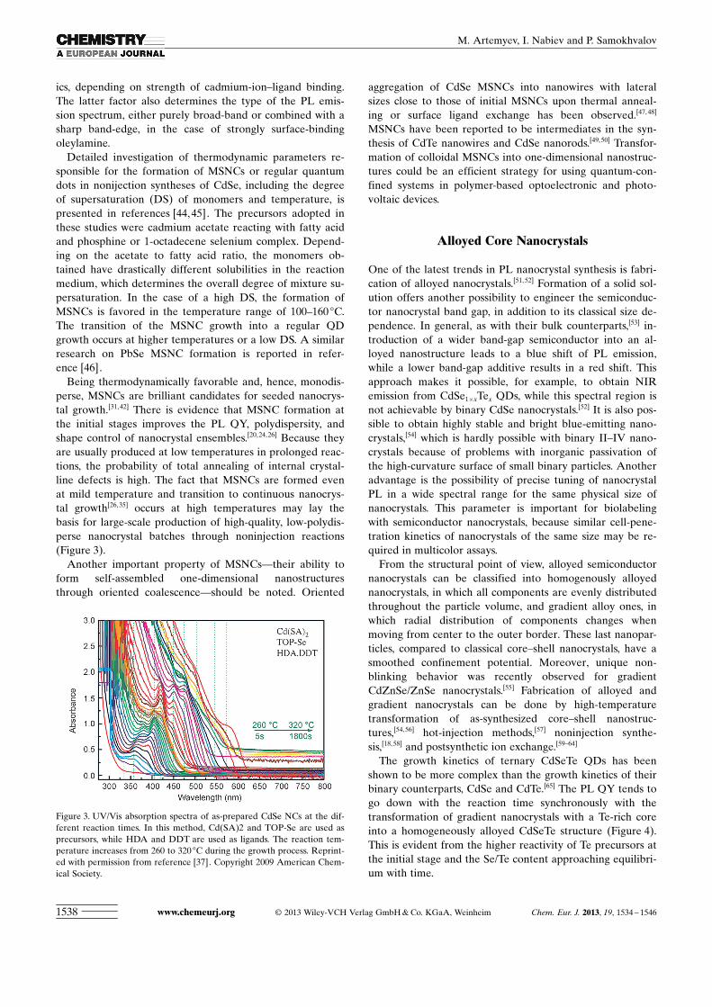
Being thermodynamically favorable and, hence, monodis-perse, MSNCs are brilliant candidates for seeded nanocrys-tal growth.[31,42] There is evidence that MSNC formation atthe initial stages improves the PL QY, polydispersity, andshape control of nanocrystal ensembles.[20,24,26] Because theyare usually produced at low temperatures in prolonged reac-tions, the probability of total annealing of internal crystal-line defects is high. The fact that MSNCs are formed evenat mild temperature and transition to continuous nanocrys-tal growth[26,35] occurs at high temperatures may lay thebasis for large-scale production of high-quality, low-polydis-perse nanocrystal batches through noninjection reactions(Figure 3).
Another important property of MSNCs—their ability toform self-assembled one-dimensional nanostructuresthrough oriented coalescence—should be noted. Oriented
aggregation of CdSe MSNCs into nanowires with lateralsizes close to those of initial MSNCs upon thermal anneal-ing or surface ligand exchange has been observed.[47, 48]
MSNCs have been reported to be intermediates in the syn-thesis of CdTe nanowires and CdSe nanorods.[49,50] Transfor-mation of colloidal MSNCs into one-dimensional nanostruc-tures could be an efficient strategy for using quantum-con-fined systems in polymer-based optoelectronic and photo-voltaic devices.
Alloyed Core Nanocrystals
One of the latest trends in PL nanocrystal synthesis is fabri-cation of alloyed nanocrystals.[51, 52] Formation of a solid sol-ution offers another possibility to engineer the semiconduc-tor nanocrystal band gap, in addition to its classical size de-pendence. In general, as with their bulk counterparts,[53] in-troduction of a wider band-gap semiconductor into an al-loyed nanostructure leads to a blue shift of PL emission,while a lower band-gap additive results in a red shift. Thisapproach makes it possible, for example, to obtain NIRemission from CdSe1�xTex QDs, while this spectral region isnot achievable by binary CdSe nanocrystals.[52] It is also pos-sible to obtain highly stable and bright blue-emitting nano-crystals,[54] which is hardly possible with binary II–IV nano-crystals because of problems with inorganic passivation ofthe high-curvature surface of small binary particles. Anotheradvantage is the possibility of precise tuning of nanocrystalPL in a wide spectral range for the same physical size ofnanocrystals. This parameter is important for biolabelingwith semiconductor nanocrystals, because similar cell-pene-tration kinetics of nanocrystals of the same size may be re-quired in multicolor assays.
From the structural point of view, alloyed semiconductornanocrystals can be classified into homogenously alloyednanocrystals, in which all components are evenly distributedthroughout the particle volume, and gradient alloy ones, inwhich radial distribution of components changes whenmoving from center to the outer border. These last nanopar-ticles, compared to classical core–shell nanocrystals, have asmoothed confinement potential. Moreover, unique non-blinking behavior was recently observed for gradientCdZnSe/ZnSe nanocrystals.[55] Fabrication of alloyed andgradient nanocrystals can be done by high-temperaturetransformation of as-synthesized core–shell nanostruc-tures,[54,56] hot-injection methods,[57] noninjection synthe-sis,[18,58] and postsynthetic ion exchange.[59–64]
The growth kinetics of ternary CdSeTe QDs has beenshown to be more complex than the growth kinetics of theirbinary counterparts, CdSe and CdTe.[65] The PL QY tends togo down with the reaction time synchronously with thetransformation of gradient nanocrystals with a Te-rich coreinto a homogeneously alloyed CdSeTe structure (Figure 4).This is evident from the higher reactivity of Te precursors atthe initial stage and the Se/Te content approaching equilibri-um with time.
Figure 3. UV/Vis absorption spectra of as-prepared CdSe NCs at the dif-ferent reaction times. In this method, Cd(SA)2 and TOP-Se are used asprecursors, while HDA and DDT are used as ligands. The reaction tem-perature increases from 260 to 320 8C during the growth process. Reprint-ed with permission from reference [37]. Copyright 2009 American Chem-ical Society.
www.chemeurj.org � 2013 Wiley-VCH Verlag GmbH & Co. KGaA, Weinheim Chem. Eur. J. 2013, 19, 1534 – 15461538
M. Artemyev, I. Nabiev and P. Samokhvalov

Aqueous synthesis of cysteine-capped ZnxCd1�xSe alloyedQDs has been performed.[58] The obtained nanocrystals arereported to be homogenously alloyed according to XRDdata, the optical properties strongly depending on the Zn toCd ratio. Noteworthy, post-irradiation of the obtained QDsleads to the formation of a thin inorganic shell via sulfur in-corporation and sufficient PL improvement (with the QY in-creasing from 13 to 26.5 %, that is, by a factor of two). Ter-nary alloyed ZnxCd1�xS nanocrystals synthesized in a non-coordinating solvent exhibit ultimately narrow and composi-tion-tunable emission.[66] Inhomogeneous broadening, whichis responsible for broad emission in common nanocrystal en-sembles, is almost absent because of the weak quantum con-finement effect (here, the particle radius is equal to orslightly higher than the Bohr radius of the exciton for bulkmaterial). Formation of an alloyed nanostructure is evi-denced by a continuous shift of XRD diffraction peaks withincreasing Zn content according to Vegard�s law, as well as asystematic blue shift of the PL emission maximum. The ach-ieved QY is about 25–50 %.
Equilibration and lattice ordering give rise to a largeband-gap reduction and strong red shifts of both absorbanceand PL peaks. Heat treatment of as-prepared CdSe/ZnSecore–shell nanocrystals led to the formation of alloyed nano-structures.[54] Note that alloying was not observed in the
cases of CdSe/ZnS nanocrystals(in which both the cation andthe anion in the core–shellstructure are different) andCdSe/CdS nanocrystals (inwhich different anions wereused), which means that onlycation diffusion in these sys-tems is fast enough to result inalloying. Incorporation of Zncations into CdSe nanocrystalscauses a blue shift of the emis-sion wavelength while preserv-ing the high emission QY char-acteristic of CdSe/ZnS nano-crystals in the green-yellowregion.
Favorable changes in thenanocrystal structure as a resultof alloying may be summarizedas follows: large CdZnSe parti-cles have 1) a less surface-strained and 2) a more crystal-line structure compared to thebinary CdSe system, whichleads to a more stable and effi-cient emission. It is worth men-tioning that the bond strength-ening in the CdZnSe system isalso responsible for minimizingthe possible nanocrystal latticedefects, such as plastic deforma-
tions. Finally, spatial compositional fluctuations provide po-tential steps for electrons and holes, which enhance the exci-ton confinement and improves the PL properties.
Formation of alloyed nanocrystals was also observedwhen a dopant element (Cd or Zn) was injected into the re-action mixture after nucleation of parent nanocrystals (ZnSeor CdSe).[67] This technique, referred to as embryonic nuclei-induced alloying process, allows reproducible synthesis ofhighly luminescent nanocrystals with QY in the range 45–70 % and tunable emission in the blue spectral region. Sepa-rate nucleation of parent nanocrystals was found to be nec-essary to escape second-phase nucleation and growth. ThePL peak position and its spectral linewidth were monitoredduring the reaction. It was established that alloying led tosurprisingly (temporally and thermally) stable PL. Ternaryalloyed nanocrystals may be also fabricated via the postsyn-thetic route.
Quaternary-alloyed ZnCdSSe QDs prepared by injectionof the precursors into liquid paraffin cover a very broadspectral emission range from 450 to 650 nm with a PL QYof about 50 % and narrow size distribution and spectral line-width.[68]
An alternative way to obtain tunable PL with a high QYbased on the strategy of fine band-gap tuning throughcation exchange has been reported.[59] In particular, homoge-
Figure 4. Temporal evolution of A) the normalized UV/Vis absorption spectra and B) PL emission spectra(lex =400 nm) of CdTeSe QDs growing at 220 8C with a feed ratio of 5Cd:0.5Te:0.5Se. The sample concentra-tions were identical during the measurement of the PL spectra; hence, the relative PL intensity reflects the PLQY. C) Summarization of the temporal evolution of the PL peak position and PL QY of the growing CdTeSesamples. D) The ICP AES analyses of the Te and Se relative contents during the growth of the sample. Re-printed with permission from reference [65]. Copyright 2011 Elsevier.
Chem. Eur. J. 2013, 19, 1534 – 1546 � 2013 Wiley-VCH Verlag GmbH & Co. KGaA, Weinheim www.chemeurj.org 1539
MINIREVIEWSemiconductor Nanocrystals

nous substitution of Hg2+ for cadmium ions in a reaction of2.3–4 nm CdTe QDs with mercury octanethiolate leads to acontrollable red shift of the PL maximum, while preservinga PL QY as high as 80 % in nonpolar solvents and 60 % inaqueous media after inorganic capping and surface coatingwith a multidentate polymeric ligand. The high PL QY isconsidered to be determined by a high crystallinity of boththe initial CdTe core and the epitaxial shell.
In addition to AIIBVI, nanocrystals of other semiconduc-tors can be synthesized in an alloyed form with a high lumi-nescence QY in multigram quantities, for example,InPZnS.[69] Thus, alloying is a powerful technique for band-gap engineering and PL tuning, while hardly altering thenanocrystal size and polydispersity at all. Alloyed QDs arethe best candidates for a variety of applications, from mer-cury-free NIR-emitting biological probes and environmen-tally friendly solar-cell applications to short-wavelength op-toelectronic devices.
Doped AIIBVI Quantum Dots
Semiconductor QDs doped with ions may be often consid-ered as an extreme case of alloyed QDs, when the concen-tration of the ions approaches one ion per QD. In the caseof ternary alloyed QDs, such as ZnCdSe and CdSSe, the var-iations in the Zn/Cd or S/Se ratio result in smooth changesin the optical properties of these QDs. In contrast, the intro-duction of some ions, such as Mn, into ZnSe, ZnS, and CdSQDs results in the appearance of a new PL band due to ra-diative recombination via the internal d–d levels of Mn.There are numerous publications on doped AIIBVI QDs; thedetails of the physical mechanisms of excitation and relaxa-tion in Mn-doped QDs can be found, for example, in refer-ences [70,71] and references therein. In this Minireview,however, we will consider only the principles of the forma-tion of doped QDs with a high PL QY, which is a crucial pa-rameter for practical applications.
Norris, et al.[72] were among the first to describe the syn-thesis of luminescent ZnSe QDs doped with Mn ions. Theseauthors prepared ZnSe:Mn QDs by high-temperature orga-nometallic synthesis using dimethylmanganese and diethyl-zinc as the precursors of metals. A room-temperature PLQY of about 22 % at the Mn band was achieved. The Mnion was located presumably on the surface of the ZnSe core,and the formation of a wide-gap ZnS shell was necessary inorder to achieve higher chemical stability and photostabili-ty.[73] Detailed study on the influence of spatial localizationof Mn ions inside core–shell QDs made it possible to ach-ieve a PL QY higher than 50 % at the Mn PL band, which iscomparable with common nondoped AIIBVI core–shellQDs.[74] This principle has been demonstrated on the basisof CdS/ZnS core–shell QDs with Mn ions located inside theZnS shell. Both the total concentration of Mn ions insidethe ZnS shell and their distance from the CdS core playedimportant roles. The highest QY was obtained for Mn ionconcentration of about 0.5 atomic percent and their distance
from the nanocrystal core equal to the width of nearly3.2 ZnS monolayers.
However, the methods of direct introduction of Mn ionsinto a growing core or shell were too sensitive to differentparameters of the synthesis and not easily reproducible. An-other approach for the synthesis of manganese-doped ZnSeQDs has been demonstrated in reference [75]; it is based onthe initial formation of MnSe seeds followed by chemicalsubstitution of Mn by Zn at a high temperature in organicmedia. Initially, a moderate PL QY of about 10–30 % wasfurther improved to 50–70 % by varying the parameters forthe synthesis of the MnSe core and ZnSe shell followed bythe annealing procedure (Figure 5).[76, 77]
This approach has been successfully used for the synthesisof other highly luminescent Mn-doped QDs, such asZnS:Mn.[78] The success in the synthesis of Mn-doped ZnSeand ZnS QDs with PL QYs higher than 50 % at room tem-perature is based on the possibility of highly efficient energytransfer from excited excitonic states in the QD core to Mnions followed by efficient radiative recombination throughinternal d–d levels of Mn ions. Manganese ions are almostunique dopants for AIIBVI QDs exhibiting efficient PL atroom temperature. Rare examples of other dopants are Cuions in Cu:ZnxCd1�xS QDs[79] prepared by the classicalmethod of simultaneous reaction of Zn, Cd, and Cu precur-sors with sulfur at a high temperature in 1-octadecene,which have a PL QY of about 65 % after additional cappingof the doped core with a ZnS shell. The mechanism of thishighly efficient radiative relaxation in Cu-doped QDs differsfrom that in Mn-doped QDs and is based on the recombina-
Figure 5. High-quality Mn:ZnSe/ZnS core/shell and Mn:ZnSeS shell-al-loyed doped nanocrystals (d-dots) with a photoluminescence (PL) quan-tum yield (QY) as high as 50% have been synthesized using the phos-phine-free nucleation doping strategy. After annealing at 240 C for30 min, the core/shell Mn:ZnSe/ZnS d-dots evolved to Mn:ZnSeS shell-alloyed d-dots with a high PL QY. Adapted with permission from refer-ence [76]. Copyright 2011 American Chemical Society.
www.chemeurj.org � 2013 Wiley-VCH Verlag GmbH & Co. KGaA, Weinheim Chem. Eur. J. 2013, 19, 1534 – 15461540
M. Artemyev, I. Nabiev and P. Samokhvalov

tion of electrons in the conduction band of the host materialand holes in the Cu-mediated state. Unlike d–d levels ofMn, the energy of hole states in Cu-doped QDs depends onthe band gap of the host QDs; therefore, the emission wave-length can be tuned within a wide spectral range by chang-ing the Zn/Cd ratio.[79]
Core–Shell Nanocrystals with a Single-ComponentEpitaxial Shell
Core QDs prepared through the high-temperature reactionin either organic media or aqueous solutions are not imme-diately suitable for practical applications where both brightPL and photo- and thermostability play crucial roles (fluo-rescent markers, light converters, etc.). Photogenerated car-riers can be easily captured by surface defects, adsorbedmolecules, water, and oxygen, which leads to a drastic deg-radation of these crucial parameters. This is especially im-portant for smallest QDs in a strong quantum confinementregime. The natural solution to this problem is to cap thecore with an inorganic protecting shell. The shell will protectthe photogenerated carriers from interaction with themedium and form the potential barrier into which both elec-tron and hole will be confined. In principle, a SiO2, glass, orpolymeric shell may play the role of chemical and potentialbarrier. However, a better way is to grow an inorganic epi-taxial shell made from the material of the same family,except that it should be a dielectric rather than a semicon-ductor, for example, a ZnS shell atop a CdSe or CdS core(both are AIIBVI materials). Different aspects of the shellgrowth are considered, for example, in reference [80].
As far as we know, the first protocol for the synthesis ofall-inorganic core–shell QDs was suggested by Spanhelet al.[81] It was developed for CdS-core QDs prepared in anaqueous solution through a reaction between cadmium per-chlorate and H2S in the presence of sodium polyphosphateas an inorganic polymeric sol stabilizer and pH of about 7–8.[81] Initially, CdS-core QDs exhibited an excitonic PL QYof about 1 %; however, after addition of NaOH in the pres-ence of excess Cd ions, the PL QY quickly rose to 50 %.The authors claimed that this procedure yielded a thin cad-mium hydroxide shell atop the CdS core, which was a wide-gap material. This shell not only created the potential barri-er for an excited electron–hole pair, but also eliminated sur-face nonradiative recombination traps. This method was suc-cessfully applied to the synthesis of strongly emitting PbSQDs passivated with a CdS layer.[82]
The cadmium hydroxide shell provides only moderatephotostability and chemical stability, mostly due to its rela-tively high chemical reactivity and non-epitaxial pattern ofgrowth: Cd(OH)2 has a crystalline structure different fromthose of wurtzite and zinc-blende CdS. Other early ap-proaches to the synthesis of core–shell QDs employedCdSe/ZnSe- and CdSe/ZnS-layered nanoparticles preparedin reverse micelles at room temperature.[83,84] In this case,pairs of compounds of the same AIIBVI type were used for
both the core and the shell, which ensured a practically epi-taxial shell growth. However, the total PL QY remained rel-atively low, probably, due to numerous remaining interfacedefects.
Afterwards, high-temperature protocols of the synthesisof highly luminescent CdSe-, CdS-, and ZnSe-core QDswere developed, and a new round of the attempts at grow-ing defect-free epitaxial shells started. Hines et al. devel-oped a protocol for epitaxial ZnS growth in the sameTOPO/TOP media that was used for the synthesis of CdSe-core QDs and dimethylzinc and bis(trimethylsilyl) sulfide asZn and S precursors, respectively.[85] A 50 % PL quantumyield, with fluorescence remaining stable for months andfairly insensitive to the environment was easily achieved.Detailed investigation on the optimal conditions for ZnS ep-itaxial growth in a TOPO/TOP system revealed that thetemperature is critical for successive deposition of ZnS.[86]
Below a certain temperature, the reaction between the Znand S precursors is incomplete and the shell formed is ofpoor quality. The use of too high temperatures resulted inthe Ostwald ripening of CdSe seeds and formation of sepa-rate ZnS nanoparticles in the reaction mixture. Another im-portant finding was that the PL quantum yield first in-creased with the ZnS shell thickness to a maximum of 50 %at a thickness of about 1.3 monolayers and then went downto approximately 30 % at a thickness of 5 monolayers ofZnS. The reduction in PL QY was attributed to the forma-tion of misfit dislocations due to a 12 % lattice mismatch be-tween bulk CdSe and ZnS and a high curvature of 4 nmCdSe cores (Figure 6).
Figure 6. Photoluminescence (PL) spectra for series of ZnS-overcoatedquantum dots (QDs) with CdSe cores 42 � in diameter. The spectra arefor a) 0, b) 0.65, c) 1.3, d) 2.6, and e) 5.3 monolayers of ZnS coverage.The position of the maximum in the PL spectrum shifts towards the redregion, and the spectrum broadens with increasing ZnS coverage. (inset)The PL quantum yield (QY) is charted as a function of ZnS coverage.The line is merely a guide to the eye. Adapted with permission from ref-erence [86]. Copyright 1997 American Chemical Society.
Chem. Eur. J. 2013, 19, 1534 – 1546 � 2013 Wiley-VCH Verlag GmbH & Co. KGaA, Weinheim www.chemeurj.org 1541
MINIREVIEWSemiconductor Nanocrystals

CdSe/ZnSe core–shell QDs were prepared by similarmethods, as reported in reference [87], in which diethylzincand TOP-Se were used as precursors. The PL QY of thestarting bare CdSe QDs was very low (about 0.05 %) and in-creased to 0.4 % after ZnSe overcoating. The X-ray diffrac-tion patterns of 4 nm CdSe seeds revealed a wurtzite struc-ture, while the crystalline phase of the ZnSe shell was notclearly seen. Considering that bulk ZnSe normally exhibits azinc-blende structure, a large amount of crystalline defectsbehaving as nonradiative recombination traps may havebeen generated during the overcoating.
An original approach was used in reference [88], in whichthe pre-synthesized CdSe core QDs have been treated withpyridine overnight. The authors claimed that this procedurecompletely removed TOPO and other molecules from theCdSe surface, thereby making it “clean” and highly reactivetoward CdS epitaxial growth under very mild conditions(100 8C, dimethylcadmium and bis(trimethylsilyl) sulfide asprecursors). A PL QY between 50 and nearly 100 % wasachieved there for different CdSe core sizes, and the QYreached the maximum at a CdS coating thickness of abouttwo monolayers. High-resolution TEM revealed a wurtzitestructure of both the CdSe core and the CdS shell and somestacking faults extending across the entire nanocrystal. Thisindicates that any stacking faults initially existing in the corewere preserved during the shell growth and propagatedthrough the shell. HRTEM showed no signs of CdSeS alloy-ing under so mild epitaxial growth conditions.
A number of studies described different variations in thestandard protocol for ZnS, CdS, or ZnSe overcoatings.[14,89–91]
The addition of aliphatic amines into the reaction mixturedrastically increases the PL QY of core–shell CdSe/ZnSQDs.[14,89, 90] This method is useful not only for QDs, but alsofor CdSe nanorods.[91] Of special interest is the idea of CdSecore pretreatment with dodecylamine (DDA) at 100 8C for24 h before growing the ZnS shell. The amine pretreatmentresults in the TOPO to DDA exchange and increase in thePL QY of CdSe cores to 50 %, which is comparable to thatfor CdSe nanocrystals covered with inorganic shells. This en-hancement of the band edge emission from nanocrystalsmay be due to strong bonding of the amines to the nano-crystal surface, which allows its better passivation.[14]
Simultaneous injection of a mixture of shell precursorsinto the solution of CdSe seeds often results in homogene-ous nucleation of the shell material (ZnS or CdS) in the re-action volume and inhomogeneous shell growth on differentseeds, due to high local concentrations of reagents and var-iations in the temperature during the injection. In order toavoid these problems, the successive ion layer adsorptionand reaction (SILAR) method has been developed.[89] Themethod is based on successive injection of portions of metal(Cd) and chalcogen (S) precursors into the reaction mixturecontaining CdSe seeds to form of a single CdS layer duringeach injection cycle. A relatively high temperature (220–240 8C) is essential to complete the SILAR procedure. Atlow temperatures, the Cd precursor accumulates in the solu-tion, because of the energy barrier for epitaxial growth.
After the subsequent injection of the S precursors into thereaction solution, the accumulated Cd precursors react withS to form isolated CdS nanocrystals. The PL QY of CdSe/CdS core–shell QDs grows with the number of CdS layersup to 40–50 %. The PL QY can be additionally increased bythermal or UV annealing.[89, 91,92] The advantage of theSILAR procedure is a controllable number of shell layersthat can be grown atop core QDs without affecting the coremonodispersity or PL spectral linewidth.
The above methods include an intermediate step of thecore nanocrystal extraction from the reaction media, fol-lowed by shell formation in a fresh solution. Apparently, thetransfer of the core nanocrystals from one solution to anoth-er even in an inert atmosphere may negatively affect thesurface of nanocrystals and provoke trap formation. One-pot synthesis of core–shell QDs would be less time-consum-ing and yield nanocrystals with a brighter PL. This idea wasimplemented and reported in reference [93]; the CdSe/CdScore–shell QDs were synthesized in a TOPO/TOP/hexade-cylamine mixture using organometallic and “greener” (Cdsalts instead of dimethylcadmium) precursors. The CdS shellwas grown atop the CdSe core in the same crude solutionusing either organometallic precursors or H2S as a source ofsulfur at a mild temperature (140 8C). In this case, green-emitting CdSe/CdS QDs were obtained with a PL QY ofabout 85 % at room temperature. For larger CdSe-core QDsemitting in the red region, the QY of core–shell nanocrystalsobtained using the same protocol was about 50 %. The in-creased thickness of the CdS shell progressively shifts thePL maximum towards the red region by 30–40 nm for about3.5 monolayers of CdS, the PL QY remaining almost con-stant (about 60–70 %); thus, additional fine tuning of thespectral region of emission is possible during the shellgrowth. XRD analysis shows that both CdSe core and CdSe/CdS core–shell nanocrystals have a wurtzite structure, whichis inherent in both bulk CdSe and CdS; that is, the shellgrows epitaxially.
How may the crystalline structure of the CdSe core affectthe shell growth? The zinc-blende structure of CdSe core ismore isotropic, which may provoke the shell material togrow more isotropically, with less surface defects.[94] In thisstudy, ZnS, ZnSe, and CdS shells were grown atop a zinc-blende CdSe core by the SILAR technique. XRD analysisshowed that all types of core and core–shell QDs had thesame zinc-blende structure. Due to a smaller lattice mis-match, ZnSe and CdS shells show coherent epitaxial growth,as compared to more anisotropic growth of the ZnS shell.For all types of shells atop a zinc-blende CdSe core, the PLQY gradually rises with increasing shell thickness, indicatingcoherent epitaxial growth. This is not so with core–shellQDs with a wurtzite CdSe core, for which the PL QY has amaximum at about 1.3 monolayers of ZnS.[86] The type ofmaterials used for the shell may also affect the character ofpotential barriers for excited excitons in the core created bythe shell. The ZnS shell forms potential barriers for bothelectron and hole and effectively suppresses the excitonleakage, providing a high PL QY of about 70 %. The ZnSe
www.chemeurj.org � 2013 Wiley-VCH Verlag GmbH & Co. KGaA, Weinheim Chem. Eur. J. 2013, 19, 1534 – 15461542
M. Artemyev, I. Nabiev and P. Samokhvalov

shell results in expansion of the valence band and leads to abetter exciton overlap, ensuring a very high QY (>80 %),while the CdS shell expanding the conduction band reducesthe exciton overlap, which results in only a moderate QY ofabout 50 % (Figure 7).[94]
Solubilization of core–shell QDs with mercaptopropionicacid is a good method for examining the uniformity of theshell, because thiols and water strongly quench the PL inthe case of direct contact with the core surface. All synthe-sized zinc-blende CdSe/ZnS, CdSe/CdS, and CdSe/ZnSeQDs exhibit only a moderate drop in the PL QY to about50 %. In contrast, wurtzite CdSe/ZnS QDs usually exhibit amuch weaker PL emission in water.[94]
Not only Cd-containing QDs, but also zinc selenide nano-crystls can be successfully capped with ZnS shells. The zinc-blende crystalline structure is inherent in ZnSe. The ZnSshell can be grown either by single-solution injection or bySILAR.[76,95] ZnSe/ZnS QDs are characterized by the samegeneral trend as zinc-blende CdSe/ZnS; specifically, an in-crease in the ZnS shell thickness results in a several-foldrise of the PL QY for both undoped and Mn-doped ZnSeQDs. In the latter case, an about 20 % molar excess of Znover S-containing precursors is required to obtain thebrightest emission. The addition of excess sulfur to the col-loidal reaction solution considerably quenches the photolu-minescence due to the introduction of surface hole traps re-lated to the dangling bonds of S2� moieties.
The importance of the surface states in the radiative andnonradiative recombination processes in AIIBVI QDs can beillustrated by ultrasmall CdSe QDs often exhibiting both ex-citonic and deep-trap emissions.[96] A comprehensive bibliog-raphy on the precursors, ligands, growth techniques, andtemperature, and PL QYs of AIIBVI, AIVBVI, and AIIIBV
core–shell QDs can be found in reference [97].
Graded and Gradient Epitaxial Shells
There are some problems with the use of the single-compo-nent epitaxial shells atop core QDs on the way to achievethe highest PL QY. For most popular CdSe cores, the suita-ble material for a shell is ZnS, CdS, or ZnSe. A ZnS shellproduces a stronger potential barrier for the photoexcitedelectron and hole, but it can result in strain and defects dueto a large mismatch of crystalline lattices. CdS has a betteraffinity for CdSe in terms of coherent epitaxial growth, butit provides a weaker potential barrier, which is critical forsurface chemical modifications of QDs (solubilization inwater by hydrophilic thiols). ZnSe is an optimum choice insome respects; however, it usually requires a much highertemperatures to grow than CdS and ZnS do. A way to solvethis problem is combination of two materials in the shell,with, for example, the inner layer made from CdS and theouter layer made from ZnS (for a CdSe core).[98, 99] This ap-proach allows the elimination of the strain and the defects,while preserving the strong potential barrier for electron–hole pairs. The growth of multicomponent or graded CdS/ZnS shells atop CdSe nanorods has been achieved by simul-taneous injection of Zn, Cd, and S precursors (in the givencase, diethylzinc, dimethylcadmium, and bis(trimethylsilyl)sulfide) into the reaction mixture containing core CdSenanorods.[100] First, the CdS shell was formed (the authorsmade use of a higher Cd reactivity and a lower solubility ofCdS as compared to ZnS); then, the ZnS layer was grownatop the CdS shell. Additional laser annealing made it possi-ble to increase the PL QY from 1 % for core CdSe nanorodsto about 20 % for CdSe/CdS/ZnS nanorods with a gradedshell. The laser annealing procedure is likely to result inphotoinduced structural transformations inside the gradedshell and at the core–shell interface. The graded CdS/ZnS
Figure 7. Absorption and emission spectra of organic-soluble nanocrys-tals: a) CdSe/ZnS, b) CdSe/ZnSe/ZnS, and c) CdSe/CdS/ZnS nanocrystalsdissolved in chloroform. Quantum yield (QY) is measured relative toRhodamine B in methanol (85 % QY). d) The PL spectra of nanocrystalsmeasured at 5 K. The percentage of deep trap emission is indicated in pa-rentheses. e) The shell-to-shell variation of the first exciton absorptionpeak (solid symbols), the emission maximum (open symbols), and thesize of nanocrystals. Bars represent emission bandwidths (full width athalf-maximum). f) A simplified band-offset picture for the core/shellstructure. Dotted lines show wave functions for the electron and the hole.ML= monolayer. Reprinted with permission from reference [94]. Copy-right 2008 American Chemical Society.
Chem. Eur. J. 2013, 19, 1534 – 1546 � 2013 Wiley-VCH Verlag GmbH & Co. KGaA, Weinheim www.chemeurj.org 1543
MINIREVIEWSemiconductor Nanocrystals
shell atop CdSe QDs and nanorods also ensures a betterphotostability in aqueous solutions and PL quenching bythiols.[91] The “greener” coating of QD and nanorod CdSecores with a CdZnS shell utilizes Cd and Zn salts instead ofdimethylcadmium and diethylzinc.[101] Another example is aMnSe core capped with a graded ZnSe/ZnS shell thermallyannealed to form an alloyed ZnSeS one, which increases thePL QY through the d–d levels of Mn to 50 % at room tem-perature.[76] InP/GaP/ZnS nanocrystals are examples of non-AIIBVI QDs with a graded shell.[102] Partial In-to-Ga surfacechemical exchange results in a QY of about 15–35 %, whilean additional ZnS shell increases this value to 85 %.
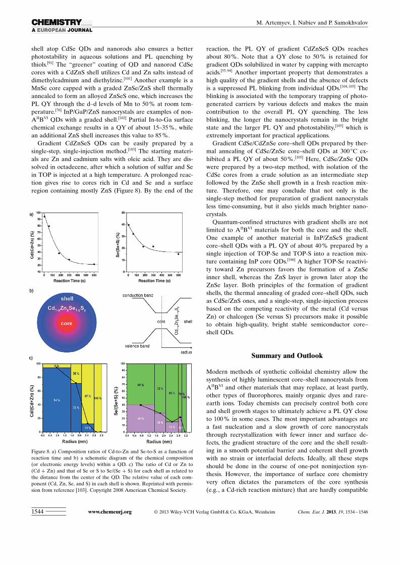
Gradient CdZnSeS QDs can be easily prepared by asingle-step, single-injection method.[103] The starting materi-als are Zn and cadmium salts with oleic acid. They are dis-solved in octadecene, after which a solution of sulfur and Sein TOP is injected at a high temperature. A prolonged reac-tion gives rise to cores rich in Cd and Se and a surfaceregion containing mostly ZnS (Figure 8). By the end of the
reaction, the PL QY of gradient CdZnSeS QDs reachesabout 80 %. Note that a QY close to 50 % is retained forgradient QDs solubilized in water by capping with mercaptoacids.[55, 94] Another important property that demonstrates ahigh quality of the gradient shells and the absence of defectsis a suppressed PL blinking from individual QDs.[104,105] Theblinking is associated with the temporary trapping of photo-generated carriers by various defects and makes the maincontribution to the overall PL QY quenching. The lessblinking, the longer the nanocrystals remain in the brightstate and the larger PL QY and photostability,[105] which isextremely important for practical applications.
Gradient CdSe/CdZnSe core–shell QDs prepared by ther-mal annealing of CdSe/ZnSe core–shell QDs at 300 8C ex-hibited a PL QY of about 50 %.[105] Here, CdSe/ZnSe QDswere prepared by a two-step method, with isolation of theCdSe cores from a crude solution as an intermediate stepfollowed by the ZnSe shell growth in a fresh reaction mix-ture. Therefore, one may conclude that not only is thesingle-step method for preparation of gradient nanocrystalsless time-consuming, but it also yields much brighter nano-crystals.
Quantum-confined structures with gradient shells are notlimited to AIIBVI materials for both the core and the shell.One example of another material is InP/ZnSeS gradientcore–shell QDs with a PL QY of about 40 % prepared by asingle injection of TOP-Se and TOP-S into a reaction mix-ture containing InP core QDs.[106] A higher TOP-Se reactivi-ty toward Zn precursors favors the formation of a ZnSeinner shell, whereas the ZnS layer is grown later atop theZnSe layer. Both principles of the formation of gradientshells, the thermal annealing of graded core–shell QDs, suchas CdSe/ZnS ones, and a single-step, single-injection processbased on the competing reactivity of the metal (Cd versusZn) or chalcogen (Se versus S) precursors make it possibleto obtain high-quality, bright stable semiconductor core–shell QDs.
Summary and Outlook
Modern methods of synthetic colloidal chemistry allow thesynthesis of highly luminescent core–shell nanocrystals fromAIIBVI and other materials that may replace, at least partly,other types of fluorophores, mainly organic dyes and rare-earth ions. Today chemists can precisely control both coreand shell growth stages to ultimately achieve a PL QY closeto 100 % in some cases. The most important advantages area fast nucleation and a slow growth of core nanocrystalsthrough recrystallization with fewer inner and surface de-fects, the gradient structure of the core and the shell result-ing in a smooth potential barrier and coherent shell growthwith no strain or interfacial defects. Ideally, all these stepsshould be done in the course of one-pot noninjection syn-thesis. However, the importance of surface core chemistryvery often dictates the parameters of the core synthesis(e.g., a Cd-rich reaction mixture) that are hardly compatible
Figure 8. a) Composition ratios of Cd-to-Zn and Se-to-S as a function ofreaction time and b) a schematic diagram of the chemical composition(or electronic energy levels) within a QD. c) The ratio of Cd or Zn to(Cd + Zn) and that of Se or S to Se/ ACHTUNGTRENNUNG(Se + S) for each shell as related tothe distance from the center of the QD. The relative value of each com-ponent (Cd, Zn, Se, and S) in each shell is shown. Reprinted with permis-sion from reference [103]. Copyright 2008 American Chemical Society.
www.chemeurj.org � 2013 Wiley-VCH Verlag GmbH & Co. KGaA, Weinheim Chem. Eur. J. 2013, 19, 1534 – 15461544
M. Artemyev, I. Nabiev and P. Samokhvalov

with the subsequent one-pot gradient shell (e.g., CdSe/CdZnS/ZnS) growth. The nearly 100 % PL QY was not ach-ieved thus far for binary QDs of all colors, especially in theextreme cases of the smallest (blue) and largest (deep-red)CdSe QDs. Alloyed ternary QDs should be used in thiscase, and an additional parameter, the chemical compositionof the core, makes this problem even more complex thoughstill soluble.
Acknowledgements
This study was supported Ministry of Higher Education and Science ofthe Russian Federation (grant 11.G34.31.0050) and the European Com-mission through the FP7 Cooperation Program (grant NMP-2009-4.0-3-246479 NAMDIATREAM). M.A. acknowledges the support of theCHEMREAGENTS program and the Belarusian Foundation of BasicScience (grant X11MC-027). The authors thank Mr. Vladimir Ushakovfor the help in manuscript preparation.
[1] A. L. Efros, D. J. Lockwood, L. Tsybeskov, Semiconductor Nano-crystals : From Basic Principles to Applications, Springer, NewYork, 2003, p. 290.
[2] V. I. Klimov, Nanocrystal Quantum Dots, 2nd ed., Taylor & Francis,Boca Raton, 2010, p. 469.
[3] R. W. Knoss, Quantum Dots: Research, Technology and Applica-tions, Nova Science, New York, 2009, p. 691.
[4] C. B. Murray, C. R. Kagan, M. G. Bawendi, Annu. Rev. Mater. Sci.2000, 30, 545 –610.
[5] D. V. Talapin, J.-S. Lee, M. V. Kovalenko, E. V. Shevchenko, Chem.Rev. 2010, 110, 389 –458.
[6] N. Gaponik, S. G. Hickey, D. Dorfs, A. L. Rogach, A. Eychm�ller,Small 2010, 6, 1364 – 1378.
[7] P. Reiss, M. Proti�re, L. Li, Small 2009, 5, 154 –168.[8] X. Peng, Acc. Chem. Res. 2010, 43, 1387 – 1395.[9] A. Rogach, Semiconductor Nanocrystal Quantum Dots, Springer,
Wien, 2008, p. 372.[10] C. B. Murray, D. J. Norris, M. G. Bawendi, J. Am. Chem. Soc. 1993,
115, 8706 – 8715.[11] X. Peng, J. Wickham, A. P. Alivisatos, J. Am. Chem. Soc. 1998, 120,
5343 – 5344.[12] Y. A. Yang, H. Wu, K. R. Williams, Y. C. Cao, Angew. Chem. 2005,
117, 6870 – 6873; Angew. Chem. Int. Ed. 2005, 44, 6712 – 6715.[13] A. L. Rogach, T. Franzl, T. A. Klar, J. Feldmann, N. Gaponik, V.
Lesnyak, A. Shavel, A. Eychm�ller, Yu. P. Rakovich, J. F. Done-gan, J. Phys. Chem. C 2007, 111, 14628 – 14637.
[14] D. V. Talapin, A. L. Rogach, A. Kornowski, M. Haase, H. Weller,Nano Lett. 2001, 1, 207 –211.
[15] L. Qu, X. Peng, J. Am. Chem. Soc. 2002, 124, 2049 – 2055.[16] Y. C. Cao, J. Wang, J. Am. Chem. Soc. 2004, 126, 14336 –14337.[17] M. Proti�re, N. Nerambourg, O. Renard, P. Reiss, Nanoscale Res.
Lett. 2011, 6, 472; V. Tarabara, I. Nabiev, A. Feofanov, Langmuir1998, 14, 1092 –1098.
[18] H. Qian, X. Qiu, L. Li, J. Ren, J. Phys. Chem. B 2006, 110, 9034 –9040.
[19] D. Pan, Q. Wang, S. Jiang, X. Ji, L. An, Adv. Mater. 2005, 17, 176 –179.
[20] D. Zhou, J. Han, Y. Liu, M. Liu, X. Zhang, H. Zhang, B. Yang, J.Phys. Chem. C 2010, 114, 22487 – 22492.
[21] T. Vossmeyer, L. Katsikas, M. Giersig, I. G. Popovic, K. Diesner,A. Chemseddine, A. Eychm�ller, H. Weller, J. Phys. Chem. 1994,98, 7665 –7673.
[22] V. N. Soloviev, A. Eichhofer, D. Fenske, U. Banin, J. Am. Chem.Soc. 2000, 122, 2673 –2674.
[23] V. N. Soloviev, A. Eichhofer, D. Fenske, U. Banin, J. Am. Chem.Soc. 2001, 123, 2354 –2364.
[24] Z. A. Peng, X. J. Peng, J. Am. Chem. Soc. 2002, 124, 3343 –3353.[25] A. Kasuya, R. Sivamohan, Yu. A. Barnakov, I. M. Dmitruk, T. Nir-
asawa, V. R. Romanyuk, V. Kumar, S. V. Mamykin, K. Tohji, B.Jeyadevan, K. Shinoda, T. Kudo, O. Terasaki, Z. Liu, R. V. Beloslu-dov, V. Sundararajan, Y. Kawazoe, Nat. Mater. 2004, 3, 99 –102.
[26] E. Groeneveld, S. van Berkum, A. Meijerink, C. de Mello Donega,Small 2011, 7, 1247 – 1256.
[27] K. Yu, J. Ouyang, Md. B. Zaman, D. Johnston, F. J. Yan, G. Li, C. I.Ratcliffe, D. M. Leek, X. Wu, J. Stupak, Z. Yakubek, D. Whitfield,J. Phys. Chem. C 2009, 113, 3390 – 3401.
[28] J. Ouyang, Md. B. Zaman, F. J. Yan, D. Johnston, G. Li, X. Wu, D.Leek, C. I. Ratcliffe, J. A. Ripmeester, K. Yu, J. Phys. Chem. C2008, 112, 13805 –13811.
[29] M. Li, J. Ouyang, C. I. Ratcliffe, L. Pietri, X. Wu, D. M. Leek, I.Moudrakovski, Q. Lin, B. Yang, K. Yu, ACS Nano 2009, 3, 3832 –3838.
[30] R. Wang, J. Ouyang, S. Nikolaus, L. Brestaz, Md. B. Zaman, X.Wu, D. Leek, C. I. Ratcliffe, K. Yu, Chem. Commun. 2009, 962 –964.
[31] R. Wang, C. I. Ratcliffe, X. Wu, O. Voznyy, Y. Tao, K. Yu, J. Phys.Chem. C 2009, 113, 17979 – 17982.
[32] R. Wang, O. Calvignanello, C. I. Ratcliffe, X. Wu, D. M. Leek,Md. B. Zaman, D. Kingston, J. A. Ripmeester, K. Yu, J. Phys.Chem. C 2009, 113, 3402 – 3408.
[33] S. Ithurria, B. Dubertret, J. Am. Chem. Soc. 2008, 130, 16504 –16505.
[34] S. Ithurria, G. Bosquet, B. Dubertret, J. Am. Chem. Soc. 2011, 133,3070 – 3077.
[35] A. D. Dukes, J. R. McBridge, S. J. Rosenthal, Chem. Mater. 2010,22, 6402 –6408.
[36] Z. Deng, O. Schulz, S. Lin, B. Ding, X. Liu, X. Wei, R. Ros, H.Yan, Y. Liu, J. Am. Chem. Soc. 2010, 132, 5592 –5593.
[37] M. Sun, X. Yang, J. Phys. Chem. C 2009, 113, 8701 – 8709.[38] M. V. Artemyev, A. I. Bibik, L. I. Gurinovich, S. V. Gaponenko, U.
Woggon, Phys. Rev. B 1999, 60, 1504 – 1506.[39] L.-J. Zhang, X.-C. Shen, H. Liang, J.-T. Yao, J. Phys. Chem. C 2010,
114, 21921 – 21927.[40] B. M. Cossairt, J. S. Owen, Chem. Mater. 2011, 23, 3114 –3119.[41] Q. Yu, C.-Y. Liu, J. Phys. Chem. C 2009, 113, 12766 – 12771.[42] Z. Li, Y. Ji, R. Xie, S. Y. Grisham, X. Peng, J. Am. Chem. Soc.
2011, 133, 17248 –17256.[43] J. C. Newton, K. Ramasamy, M. Mandal, G. K. Joshi, A. Kumbhar,
R. Sardar, J. Phys. Chem. C 2012, 116, 4380 – 4389.[44] K. Yu, M. Z. Hu, R. Wang, M. Le Piolet, M. Frotey, Md. B. Zaman,
X. Wu, D. M. Leek, Y. Tao, D. Wilkinson, C. Li, J. Phys. Chem. C2010, 114, 3329 –3339.
[45] K. Yu, Adv. Mater. 2012, 24, 1123 –1132.[46] K. Yu, J. Ouyang, D. M. Leek, Small 2011, 7, 2250 –2262.[47] F. S. Riehle, R. Bienert, R. Thomann, G. A. Urban, M. Kruger,
Nano Lett. 2009, 9, 514 –518.[48] S. Sengupta, D. Sarma, S. Acharya, J. Mater. Chem. 2011, 21,
11585 – 11591.[49] P. Dagtepe, V. Chikan, J. Phys. Chem. A 2008, 112, 9304 –9311.[50] Z.-J. Jiang, D. F. Kelley, ACS Nano 2010, 4, 1561 –1572.[51] R. E. Bailey, S. Nie, J. Am. Chem. Soc. 2003, 125, 7100 –7106.[52] M. D. Regulacio, M.-Y. Han, Acc. Chem. Res. 2010, 43, 621 – 630.[53] H. C. Poon, Z. C. Feng, Y. P. Feng, M. F. Li, J. Phys. Condens.
Matter 1995, 7, 2783 –2799.[54] X. Zhong, M. Han, Z. Dong, T. J. White, W. Knoll, J. Am. Chem.
Soc. 2003, 125, 8589 –8594.[55] X. Wang, X. Ren, K. Kahen, M. A. Hahn, M. Rajeswaran, S. Mac-
cagnano-Zacher, J. Silcox, G. E. Cragg, A. L. Efros, T. D. Krauss,Nature 2009, 459, 686 – 689.
[56] H. Lee, P. H. Holloway, H. J. Yang, J. Chem. Phys. 2006, 125,164711.
[57] E. Jang, S. Jun, L. Pu, Chem. Commun. 2003, 2964 –2965.[58] F. C. Liu, T. L. Cheng, C. C. Shen, W. L. Tseng, M. Y. Chiang,
Langmuir 2008, 24, 2162 –2167.[59] A. M. Smith, S. Nie, J. Am. Chem. Soc. 2011, 133, 24 –26.
Chem. Eur. J. 2013, 19, 1534 – 1546 � 2013 Wiley-VCH Verlag GmbH & Co. KGaA, Weinheim www.chemeurj.org 1545
MINIREVIEWSemiconductor Nanocrystals
[60] A. Prudnikau, M. Artemyev, M. Molinari, M. Troyon, A. Sukhano-va, I. Nabiev, A. V. Baranov, S. A. Cherevkov, A. V. Fedorov,Mater. Sci. Eng. B 2012, 177, 744 – 749.
[61] A. L. Rogach, A. Euchm�ller, S. G. Hickey, S. V. Kershaw, Small2007, 3, 536 –557.
[62] F.-C. Liu, Y.-M. Chen, J.-H. Lin, W.-L. Tseng, J. Colloid InterfaceSci. 2009, 337, 414 – 419.
[63] H. Qian, C. Dong, J. Peng, X. Qiu, Y. Xu, J. Ren, J. Phys. Chem. C2007, 111, 16852 –16857.
[64] S. Taniguchi, M. Green, T. Lim, J. Am. Chem. Soc. 2011, 133,3328 – 3331.
[65] L. Liao, H. Zhang, X. Zhong, J. Lumin. 2011, 131, 322 – 327.[66] X. Zhong, Y. Feng, W. Knoll, M. Han, J. Am. Chem. Soc. 2003,
125, 13559 – 13563.[67] X. Zhong, Z. Zhang, S. Liu, M. Han, W. Knoll, J. Phys. Chem. B
2004, 108, 15552 –15559.[68] Z. Deng, H. Yan, Y. Liu, J. Am. Chem. Soc. 2009, 131, 17744 –
17745.[69] T. Kim, S. W. Kim, M. Kang, S.-W. Kim, J. Phys. Chem. Lett. 2012,
3, 214 –218.[70] R. Beaulac, P. I. Archer, S. T. Ochsenbein, D. R. Gamelin, Adv.
Funct. Mater. 2008, 18, 3873 – 3891.[71] R. Beaulac, P. I. Archer, D. R. Gamelin, J. Solid State Chem. 2008,
181, 1582 – 1589.[72] D. J. Norris, N. Yao, F. T. Charnock, T. A. Kennedy, Nano Lett.
2001, 1, 3–7.[73] R. Thakar, Y. Chen, P. T. Snee, Nano Lett. 2007, 7, 3429 – 3432.[74] Y. Yang, O. Chen, A. Angerhofer, Y. C. Cao, J. Am. Chem. Soc.
2006, 128, 12428 –12429.[75] N. Pradhan, D. Goorskey, J. Thessing, X. Peng, J. Am. Chem. Soc.
2005, 127, 17586 –17587.[76] R. Zeng, T. Zhang, G. Dai, B. Zou, J. Phys. Chem. C 2011, 115,
3005 – 3010.[77] R. Zeng, M. Rutherford, R. Xie, B. Zou, X. Peng, Chem. Mater.
2010, 22, 2107 –2113.[78] W. Zhang, Y. Li, H. Zhang, X. Zhou, X. Zhong, Inorg. Chem. 2011,
50, 10432 – 10438.[79] W. Zhang, X. Zhou, X. Zhong, Inorg. Chem. 2012, 51, 3579 – 3587.[80] S. Kudera, L. Maus, M. Zanella, W. J. Parak, in Comprehensive
Nanoscience and Technology, Vol. 1, Elsevier, Oxford, 2011,pp. 271 –285.
[81] L. Spanhel, M. Haase, H. Weller, A. Henglein, J. Am. Chem. Soc.1987, 109, 5649 –5655.
[82] M. J. Fern�e, A. Watt, J. Warner, S. Cooper, N. Heckenberg, H. Ru-binsztein-Dunlop, Nanotechnology 2003, 14, 991 –997.
[83] C. F. Hoener, K. A. Allan, A. J. Bard, A. Campion, M. A. Fox,T. E. Mallouk, S. E. Webber, J. M. White, J. Phys. Chem. 1992, 96,3812 – 3811.
[84] A. R. Kortan, R. Hull, R. L. Opila, M. G. Bawendi, M. L. Steiger-wald, P. J. Carroll, L. E. Brus, J. Am. Chem. Soc. 1990, 112, 1327 –1332.
[85] M. A. Hines, P. Guyot-Sionnest, J. Phys. Chem. 1996, 100, 468 –471.[86] B. O. Dabbousi, J. Rodriguez-Viejo, F. V. Mikulec, J. R. Heine, H.
Mattoussi, R. Ober, K. F. Jensen, M. G. Bawendi, J. Phys. Chem. B1997, 101, 9463 –9475.
[87] M. Danek, K. F. Jensen, C. B. Murray, M. G. Bawendi, Chem.Mater. 1996, 8, 173 –180.
[88] X. Peng, M. C. Schlamp, A. V. Kadavanich, A. P. Alivisatos, J. Am.Chem. Soc. 1997, 119, 7019 –7029.
[89] J. J. Li, Y. A. Wang, W. Guo, J. C. Keay, T. D. Mishima, M. B. John-son, X. Peng, J. Am. Chem. Soc. 2003, 125, 12567 –12575.
[90] P. Reiss, J. Bleuse, A. Pron, Nano Lett. 2002, 2, 781 – 784.[91] J. M. Tsay, S. Doose, F. Pinaud, S. Weiss, J. Phys. Chem. B 2005,
109, 1669 – 1674.[92] T. Mokari, U. Banin, Chem. Mater. 2003, 15, 3955 –3960.[93] I. Mekis, D. V. Talapin, A. Kornowski, M. Haase, H. Weller, J.
Phys. Chem. B 2003, 107, 7454 –7462.[94] S. J. Lim, B. Chon, T. Joo, S. K. Shin, J. Phys. Chem. C 2008, 112,
1744 – 1747.[95] H. S. Chen, B. Lo, J. Y. Hwang, G. Y. Chang, C. M. Chen, S. J. Tasi,
S. J. J. Wang, J. Phys. Chem. B 2004, 108, 17119 –17123.[96] A. M. Smith, S. Nie, Acc. Chem. Res. 2010, 43, 190 – 200.[97] H. Zhong, T. Mircovic, G. D. Scholes, in Comprehensive Nano-
science and Technology, Vol. 5, Elsevier, Oxford, 2011, p. 186.[98] D. V. Talapin, I. Mekis, S. Gçtzinger, A. Kornowski, O. Benson, H.
Weller, J. Phys. Chem. B 2004, 108, 18826 –18831.[99] H. Zhu, A. Prakash, D. N. Benoit, C. J. Jones, V. L. Colvin, Nano-
technology 2010, 21, 255604.[100] L. Manna, E. C. Scher, L. S. Li, A. P. Alivisatos, J. Am. Chem. Soc.
2002, 124, 7136 –7145.[101] P. Yang, M. Ando, T. Taguchi, N. Murase, J. Phys. Chem. C 2011,
115, 14455 – 14460.[102] S. Kim, T. Kim, M. Kang, S. K. Kwak, T. W. Yoo, L. S. Park, I.
Yang, S. Hwang, J. E. Lee, S. K. Kim, S. W. Kim, J. Am. Chem. Soc.2012, 134, 3804 –3809.
[103] W. K. Bae, K. Char, H. Hur, S. Lee, Chem. Mater. 2008, 20, 531 –539.
[104] D. Ratchford, K. Dziatkowski, T. Hartsfield, X. Li, Y. Gao, Z.Tang, J. Appl. Phys. 2011, 109, 103509.
[105] S. K. Panda, S. G. Hickey, C. Waurisch, A. Eychm�ller, J. Mater.Chem. 2011, 21, 11550 –11555.
[106] J. Lim, W. K. Bae, D. Lee, M. K. Nam, J. Jung, C. Lee, K. Char, S.Lee, Chem. Mater. 2011, 23, 4459 – 4463.
Published online: January 10, 2013
www.chemeurj.org � 2013 Wiley-VCH Verlag GmbH & Co. KGaA, Weinheim Chem. Eur. J. 2013, 19, 1534 – 15461546
M. Artemyev, I. Nabiev and P. Samokhvalov
Related Documents