1 Presentation to JSAC Member

Welcome message from author
This document is posted to help you gain knowledge. Please leave a comment to let me know what you think about it! Share it to your friends and learn new things together.
Transcript

1
Presentation to
JSAC Member
2
Satellite Communication
3
Satellite Communication: In satellite communication we used
Geo stationary satellites for communication in SHF(super high
frequency) range of RF spectrum.
Note: Super High Frequency Range: 3Ghz to 30Ghz
Q-What is Geo stationary Satellite?
Ans-1. A geostationary satellite is an earth-orbiting satellite,
placed at an altitude of approximately 35,800 kilometers (22,300
miles) directly over the equator, that revolves in the same
direction the earth rotates (west to east).
2. At this altitude, one orbit takes 24 hours, the same length of
time as the earth requires to rotate once on its axis.
3. The term geostationary comes from the fact that such a satellite
appears nearly stationary in the sky as seen by a ground-based
observer.

4
4. A geostationary satellite can cover approx 40 percent of the earth
Surface.
5. Three such satellites, each separated by 120 degrees of longitude,
can provide coverage of the entire planet
6. The distance that an electromagnetic (EM) signal must travel to
and from a geostationary satellite is a minimum of 71,600(2x35800)
kilometers or 44,600 miles. Thus, a latency of at least 240
milliseconds is introduced when an EM signal, traveling at 300,000
kilometers per second (186,000 miles per second), makes a round
trip from the surface to the satellite and back i.e.
Time= Distance/Speed, As we know EM wave travels with the light
speed.
5
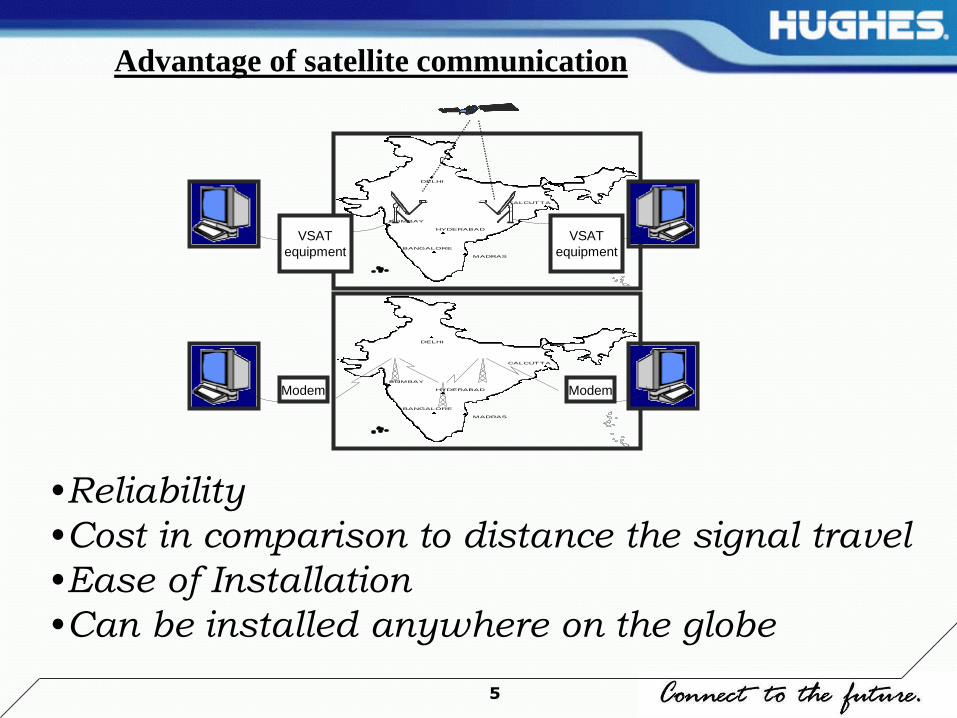
DELHI
BOMBAY
CALCUTTA
MADRAS
HYDERABAD
BANGALORE
DELHI
BOMBAY
CALCUTTA
MADRAS
HYDERABAD
BANGALORE
VSAT
equipment
Modem Modem
VSAT
equipment
•Reliability
•Cost in comparison to distance the signal travel
•Ease of Installation
•Can be installed anywhere on the globe
Advantage of satellite communication

6
Q- What is a Satellite?
Ans-In general, a satellite is anything that orbits something else,
as, for example, the moon orbits the earth.
In a communications context, a satellite is a specialized wireless
receiver/transmitter that is launched by a rocket and placed in
orbit around the earth.
So we can say, a satellite is regenerative repeater or active
amplifier i.e it receives the signals, amplify then down convert
the same then again amplify the signals and broadcast to the
earth.

7
Sun Outages
The sun is directly behind the satellite, so the earth station
Antenna directly towards the sun.
Noise increase has deleterious effects on the reception.
Communication degradation lasts for a few minutes once a day
for a few days near the time of the spring and fall equinox.
Sun outages are fully predictable in time and duration.

8
Overview of VSAT
(Very Small Aperture Terminal)

9
VSAT is the combination
of following units-
1. ODU (Outdoor Unit)
2. IDU (Indoor Unit)
3. Interconnecting Cable
Parts of VSAT
10
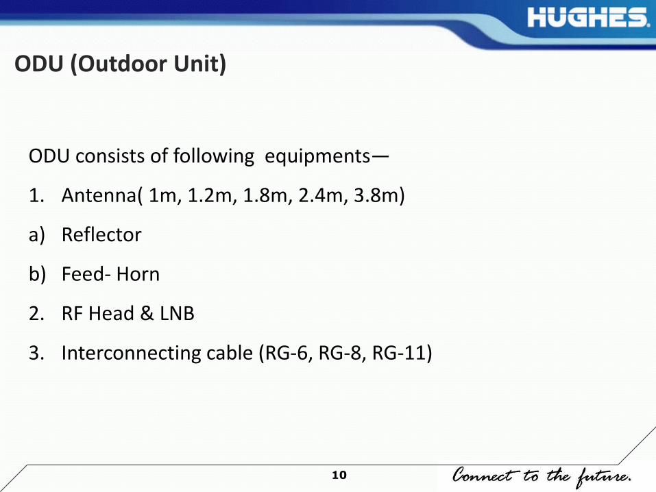
ODU consists of following equipments—
1. Antenna( 1m, 1.2m, 1.8m, 2.4m, 3.8m)
a) Reflector
b) Feed- Horn
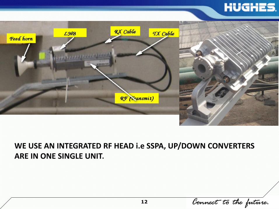
2. RF Head & LNB
3. Interconnecting cable (RG-6, RG-8, RG-11)
ODU (Outdoor Unit)
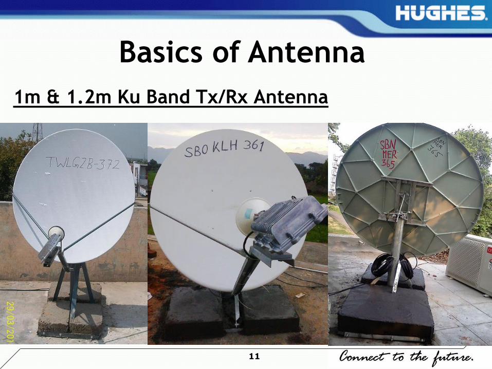
11
1m & 1.2m Ku Band Tx/Rx Antenna
Basics of Antenna
12
WE USE AN INTEGRATED RF HEAD i.e SSPA, UP/DOWN CONVERTERS ARE IN ONE SINGLE UNIT.
13
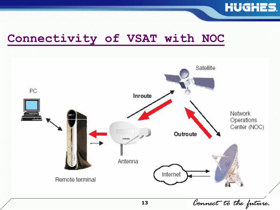
Connectivity of VSAT with NOC
14
1. Modem( Modulator & Demodulator)
For Example---
a) HN7K Series
b) HN92/94 Series.
IDU (Indoor Unit)

15
HN9400/9460 & HN9200/9260
HN94/92 Series IDU FRONT & REAR PANEL
16
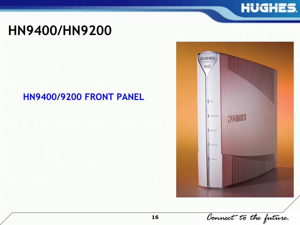
HN9400/HN9200
HN9400/9200 FRONT PANEL
17
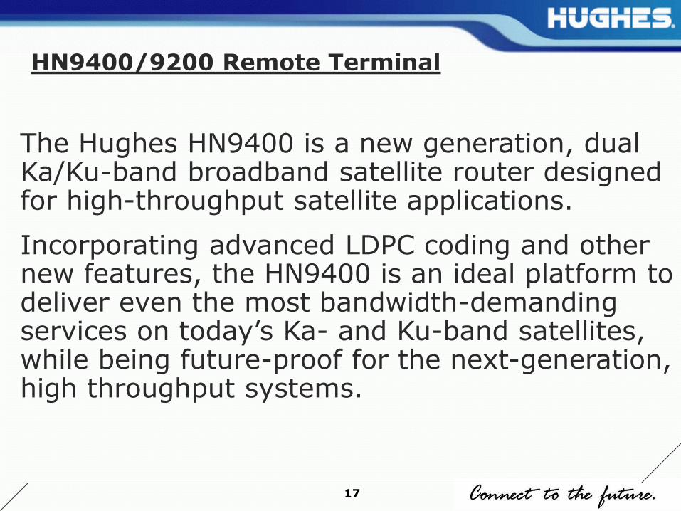
HN9400/9200 Remote Terminal
The Hughes HN9400 is a new generation, dual Ka/Ku-band broadband satellite router designed for high-throughput satellite applications.
Incorporating advanced LDPC coding and other new features, the HN9400 is an ideal platform to deliver even the most bandwidth-demanding services on today’s Ka- and Ku-band satellites, while being future-proof for the next-generation, high throughput systems.

18
HN9400/9200 Product Feature
• Adaptive LDPC coding on return channel
• High throughput satellite modem featuring throughput of
Up to 60 Mbps multicast
Up to 45 Mbps UDP
Up to 15 Mbps TCP
Up to 5,000 packets per second
• Bi-directional data compression
• Acts as a local router providing:
Static and dynamic addressing
DHCP server or relay
DNS caching
Full RIPV2 and BGP routing support
VRRP
Multicasts to the LAN by using IGMP
NAT/PAT
End-to-end VLAN support with configurable QOS per VLAN
Firewall support through integrated access control lists
• Universal power supply supports international voltage ranges

19
Trouble Shooting the
Remote Site
20
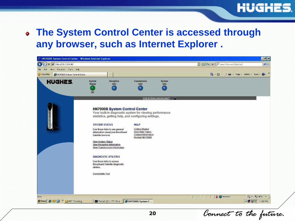
The System Control Center is accessed through
any browser, such as Internet Explorer .

21
System Indicators
The system indicators appear at the top of the home page and are described below.
Status provides access to the System Status page.The System Status page displays general system status information such as signal strength and commissioning status. If the indicator is green and OK appears Vsat is working fine.

22
Reception Info provides access to the Reception Information page. The Reception Information page displays remote terminal receive data.
Transmission Info provides access to the Transmission Information page. The Transmission Information page displays remote terminal transmit data.
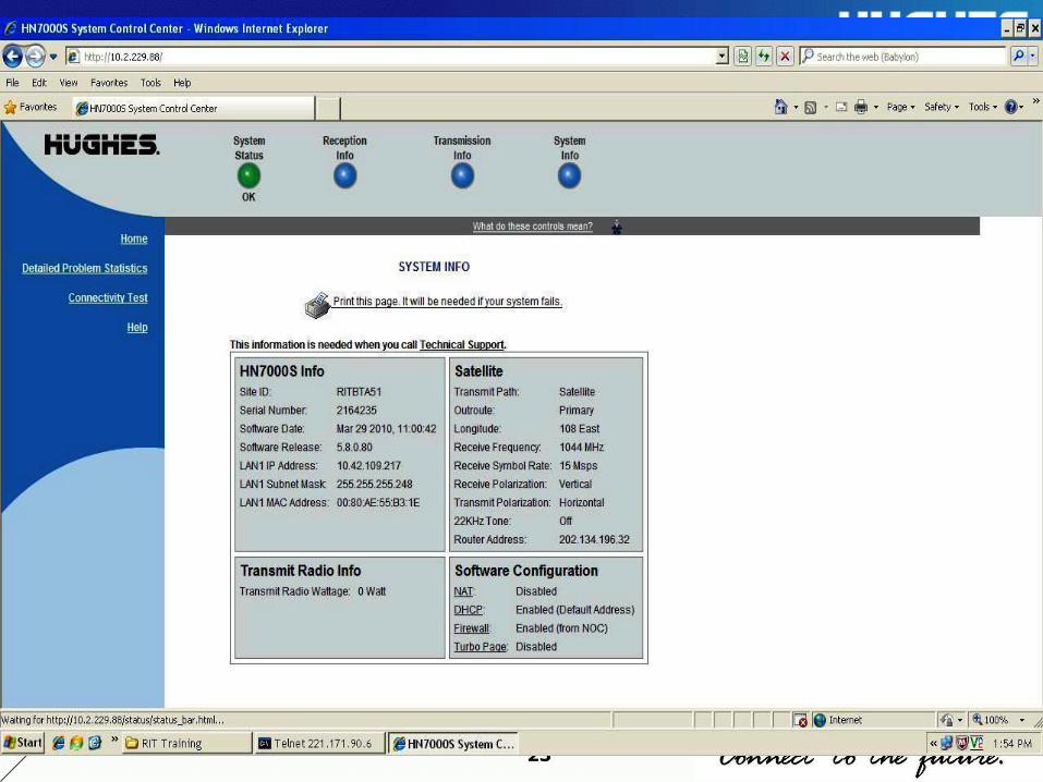
System Info provides access to the System Information page.The System Information page displays system information such as the remote terminal IP address, Site Account Number (SAN), and the site ID.
23

24
System Status Page
Signal Strength - receive signal strength in normal case it should be greater then 33.
Transmit Status - indicates whether the transmit data path is operational.In normal case it should be 8.

25
Receive Status - indicates if the receive data path is operational. In normal case it should be 5.
Software Download Status - indicates whether remote terminal software and configuration is up-to-date.In normal case it should show “All Files are Up to Date”.
Commission Status - indicates if the unit is commissioned.
TCP Acceleration Status - indicates if TCP Acceleration is operational. TCP acceleration provides the expected performance on a remote terminal.
26
Web Acceleration Status - indicates if Web
Acceleration is operational. Web Acceleration
is operational if you are browsing HTTP-
based web sites. Web Acceleration may be
inactive if you are browsing on a secure HTTP
site (https).

27
Rx CodesCode Message Corrective Action
1 The receiver is in
pointing mode.
This condition indicates the installer is performing antenna
pointing.
3 The receiver is not
locked to a signal.
If the remote terminal had been operating previously, this
status is probably due to inclement weather conditions and
may be corrected when the weather improves.
4 The receiver is locked
to the wrong network.
This condition should only be seen during installation and
occurs when the receiver is locked to an incorrect
satellite.
5 The receiver is
operational
This is the normal operating state where the receiver
is receiving data from the NOC.
7 The receiver is locked
to an unknown
network.
This condition should only be seen during installation and
occurs when the receiver is locked to a non-Hughes
satellite.
6 The receiver is not
detecting a signal .
This condition occurs when the unit is not detecting any
type of radio signal from the Antenna. Check that the
cables are firmly connected on the remote terminal.
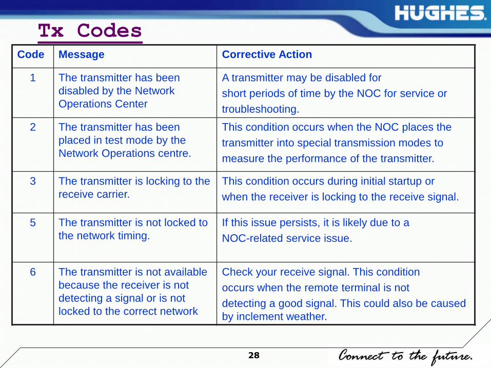
28
Tx CodesCode Message Corrective Action
1 The transmitter has been
disabled by the Network
Operations Center
A transmitter may be disabled for
short periods of time by the NOC for service or
troubleshooting.
2 The transmitter has been
placed in test mode by the
Network Operations centre.
This condition occurs when the NOC places the
transmitter into special transmission modes to
measure the performance of the transmitter.
3 The transmitter is locking to the
receive carrier.
This condition occurs during initial startup or
when the receiver is locking to the receive signal.
5 The transmitter is not locked to
the network timing.
If this issue persists, it is likely due to a
NOC-related service issue.
6 The transmitter is not available
because the receiver is not
detecting a signal or is not
locked to the correct network
Check your receive signal. This condition
occurs when the remote terminal is not
detecting a good signal. This could also be caused
by inclement weather.

29
Contd…
Code Message Corrective Actione actions
8 The transmitter is
available.
This is normal state & transmitter is ready to use.
9 The transmitter is
adjusting for
optimal network
timing.
This condition typically occurs when the remote terminal is
first commissioned or the first time it is used for data traffic.
10 The transmitter is
unable to
communicate with
the Network
Operations Center.
This condition indicates that the unit has stopped attempting
to transmit user data because there were a number of failures
in sending data to the NOC over the satellite link. This could
be the result of weather conditions causing lost packets or,
rarely, return channel equipment failures in the NOC.
13 The transmitter is
unable to range
because it cannot
communicate with
the Network
Operations Center
Ranging is the process that adjusts the satellite transmitter
timing and power. This condition can indicate any of the
following: a>The NOC is not receiving ranging information
from the transmitter. This may indicate a transmit problem at
the NOC.b> The transmitter is unable to achieve enough
transmit power to send ranging information to the NOC.
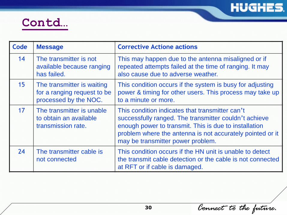
30
Contd…
Code Message Corrective Actione actions
14 The transmitter is not
available because ranging
has failed.
This may happen due to the antenna misaligned or if
repeated attempts failed at the time of ranging. It may
also cause due to adverse weather.
15 The transmitter is waiting
for a ranging request to be
processed by the NOC.
This condition occurs if the system is busy for adjusting
power & timing for other users. This process may take up
to a minute or more.
17 The transmitter is unable
to obtain an available
transmission rate.
This condition indicates that transmitter can’t
successfully ranged. The transmitter couldn’t achieve
enough power to transmit. This is due to installation
problem where the antenna is not accurately pointed or it
may be transmitter power problem.
24 The transmitter cable is
not connected
This condition occurs if the HN unit is unable to detect
the transmit cable detection or the cable is not connected
at RFT or if cable is damaged.
31
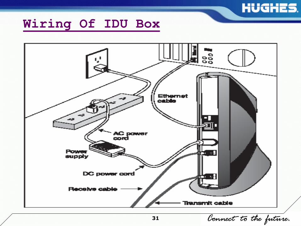
Wiring Of IDU Box
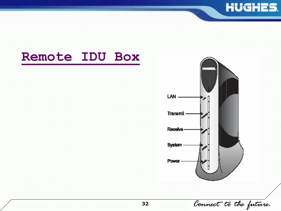
32
Remote IDU Box

33
Description of LED Display
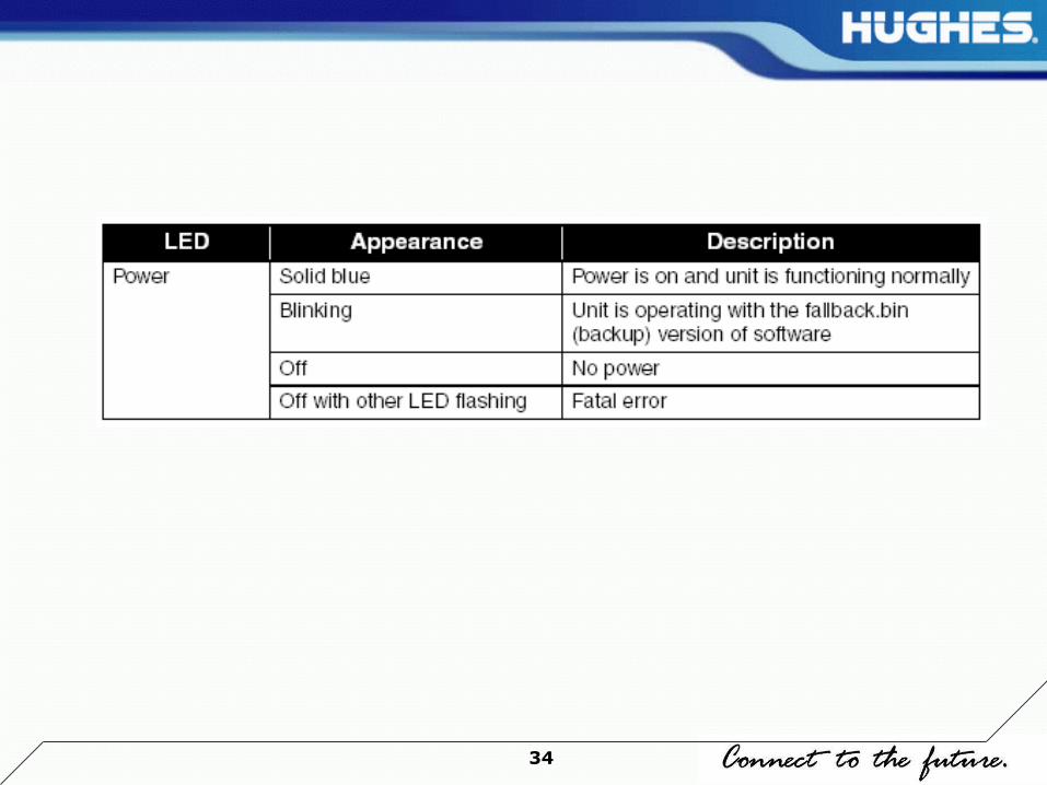
34

35
Fatal Error Indication
Follow these steps if the Power LED is off and one or more of the other LEDs is flashing:
1. Power cycle the remote terminal:
Unplug the remote terminal’s power cord from the power source.
Wait 10 seconds.
Plug the power cord back into the power source.
Continue with step 2 if the problem persists.
2. Disconnect the receive and transmit cables from the remote terminal.
If any of the LEDs come on and remain on, continue with Step 3.
If the Power LED is still off and one or more of the other LEDs is still flashing, continue with step 5.
36
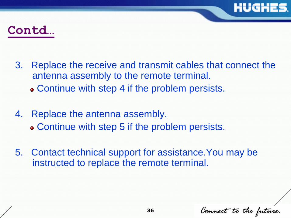
Contd…
3. Replace the receive and transmit cables that connect the antenna assembly to the remote terminal.
Continue with step 4 if the problem persists.
4. Replace the antenna assembly.
Continue with step 5 if the problem persists.
5. Contact technical support for assistance.You may be instructed to replace the remote terminal.
37
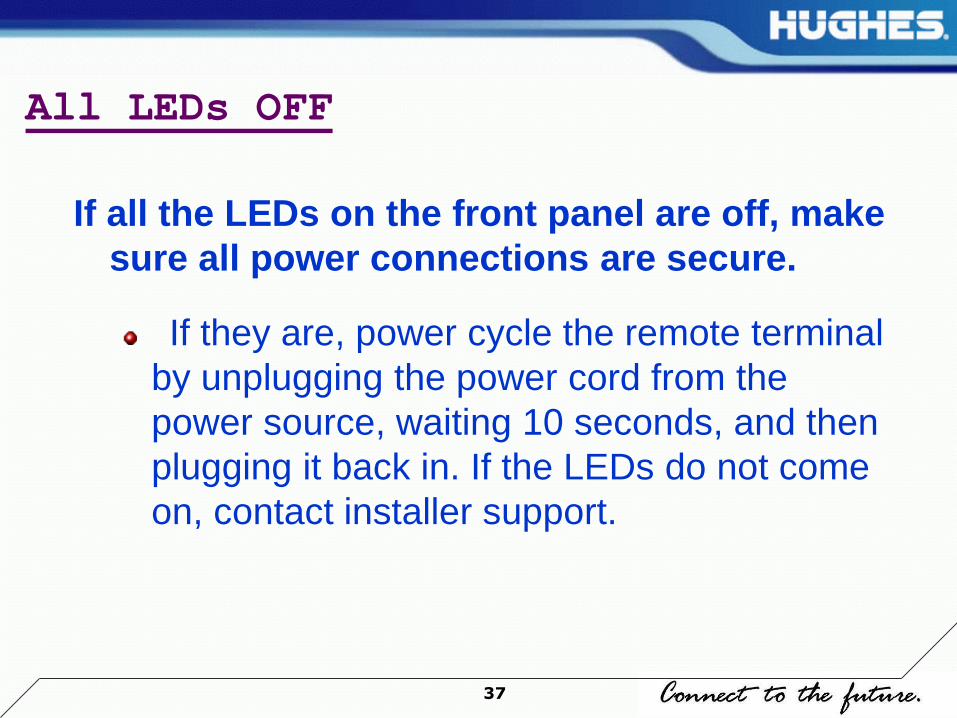
All LEDs OFF
If all the LEDs on the front panel are off, make
sure all power connections are secure.
If they are, power cycle the remote terminal
by unplugging the power cord from the
power source, waiting 10 seconds, and then
plugging it back in. If the LEDs do not come
on, contact installer support.

38
Checking the Power LED
Check the Power LED on the front panel. If it is lit, proceed to the next troubleshooting step. If it is not lit, perform the following steps.
1. Power cycle the remote terminal by unplugging the power cord from the power source, waiting 10 seconds, and plugging it back in.
2. If the Power LED is still not lit, make sure the DC power cord is tightly connected to the remote terminal.
3. If the Power LED is still not lit, plug a small appliance, such as a radio, into both the power strip or surge protector and the wall outlet or other power source. If it works, the power sources are functional. Call installer support for assistance.

39
Checking the LAN LED
Check the LAN LED on the front panel. If it is lit, proceed to the next troubleshooting step. If it is not lit, perform the following steps:
1. Check that the Ethernet cable is connected to the remote terminal LAN port and to the computer’s Ethernet port.
2. If the LAN LED is still not lit, power cycle the remote terminal by unplugging the power cord from the power source, waiting 10 seconds, and plugging it back in.
3. If the LAN LED is still not lit, check the Windows Device Manager to see if your computer's NIC is installed correctly.
4. If the LAN LED is still not lit, try connecting the remote terminal to another computer. If the Power and LAN LEDs are lit, the problem is with your computer. If they are not lit,contact installer support.
40
Problem: Receive LED not ON
If the remote terminal is not operating normally and the
receive LED is not lit, follow these steps:
Check all cable connections.Tighten any that seem loose.
If the LED still does not come on, power cycle the remote
terminal by unplugging the power cord from the power
source, waiting 10 seconds, and plugging it back in.
If the problem persists, contact installer support.

41
Problem: Transmit LED not ON
If the Transmit is not On then follow these steps:
Tighten transmit cable if that seems loose.
If the LED still does not come on, power cycle the
remote terminal by unplugging the power cord
from the power source, waiting 10 seconds, and
plugging it back in.
If the problem persists, contact installer support.

42
Problem: System LED not Lit
If the System LED is not on, but the Transmit and Receive LEDs are on, there may be a problem at the NOC. Take the following steps.
Wait 15 minutes. If there is a problem at the NOC, it may soon be corrected and the System LED comes on. You can then resume normal operation.
If the LED does not come on after you have waited 15
minutes, power cycle the remote terminal by unplugging the power cord from the power source, waiting 10 seconds, and plugging it back in.
If the problem persists, contact installer support.

43
Power LED not ON
If the Power LED is not lit, take the following steps. Note that if the Power LED is not on, other LEDs may not be on or come on.
Check to make sure the power cable is securely attached.
If securing the power cable does not solve the problem, check all cable connections. Tighten any that seem loose.
If the Power LED still does not come on continuously, power cycle the remote terminal by unplugging the power cord from the power source, waiting10 seconds, and plugging it back in.
If the problem persists, contact installer support.

44
Power LED blinking
If the Power LED is blinking, take the following steps.
Check to make sure the power cable is securely attached.
Wait for 15 minutes before proceeding to the next step because the terminal may need to finish downloading its configuration files from the NOC.
If securing the power cable does not solve the problem, check all cable connections. Tighten any that seem loose.
If the Power LED still does not come on continuously, power cycle the remote terminal by unplugging the power cord from the power source, waiting 10 seconds, and plugging it back in.
If the problem persists, contact installer support.

45
DO’S Information
Maintain the room temperature.
Use On line UPS.
Good quality earthing to be maintained. (E-N Should be less than equal to 3v)
Dust free environment to be maintained.
Sufficient air circulation & access to IDU be there.
Switch on the VSAT first and switch on other accessories.
Report any problem related to any equipments to Helpdesk.
While doing so report full problems and complete observations to Helpdesk
Log all activities related to equipment failures engineer visits in a Log Book.
Sign all site visit reports of HCIL Engineer visits to site.
Allow authorized and trained people only to operate the system.
46
Don’ts information
Do not switch on the VSAT immediately after switch off.
Do not move the IDU after installation.
Do not keep any article on IDU.
Do not obstruct the air vents in front of the IDU.
Do not keep any copier / printer in IDU room.
Do not Use air cooler (water) for cooling.
Do not bend IFL cable.
Do not do any local servicing of the equipments.
Do not shift the equipments from one place to another with out HCIL Engineer.

47
Thank You
Related Documents