User's Manual Mitsubishi Programmable Logic Controller Basic Model QCPU(Q Mode) (Function Explanation, Program Fundamentals)

Welcome message from author
This document is posted to help you gain knowledge. Please leave a comment to let me know what you think about it! Share it to your friends and learn new things together.
Transcript
Basic M
odel QC
PU
(Q M
ode) User's M
anual (Function E
xplanation, Program
Fundam
entals)
UUser's Manual (Function Explanation, Program Fundamentals) User's Manual
Mitsubishi Programmable Logic Controller
Specifications subject to change without notice.
MODEL
MODELCODE
SQCPU(Q)-U-KI-E
13JR44
SH(NA)-080188-A(0108)MEE
Basic Model QCPU(Q Mode) Basic Model QCPU(Q Mode)
(Function Explanation, Program Fundamentals)
When exported from Japan, this manual does not require application to theMinistry of Economy, Trade and Industry for service transaction permission.
HEAD OFFICE : 1-8-12, OFFICE TOWER Z 14F HARUMI CHUO-KU 104-6212,JAPANNAGOYA WORKS : 1-14 , YADA-MINAMI 5 , HIGASHI-KU, NAGOYA , JAPAN

A - 1 A - 1
• SAFETY INSTRUCTIONS •(Always read these instructions before using this equipment.)
When using Mitsubishi equipment, thoroughly read this manual and the associated manuals introduced inthis manual. Also pay careful attention to safety and handle the module properly.These SAFETY PRECAUTIONS classify the safety precautions into two categories: "DANGER" and"CAUTION".
! DANGER
CAUTION!
Indicates that incorrect handling may cause hazardous conditions,resulting in death or severe injury.
Indicates that incorrect handling may cause hazardous conditions, resulting in medium or slight personal injury or physical damage.
Note that the ! CAUTION level may lead to a serious consequence according to the circumstances.Always follow the instructions of both levels because they are important to personal safety.
Please save this manual to make it accessible when required and always forward it to the end user.
[Design Precautions]! DANGER
• Install a safety circuit external to the PLC that keeps the entire system safe even when there areproblems with the external power supply or the PLC module. Otherwise, trouble could resultfrom erroneous output or erroneous operation.
(1) Outside the PLC, construct mechanical damage preventing interlock circuits such asemergency stop, protective circuits, positioning upper and lower limits switches andinterlocking forward/reverse operations.
(2) When the PLC detects the following problems, it will stop calculation and turn off all output inthe case of (a). In the case of (b), it will stop calculation and hold or turn off all outputaccording to the parameter setting.(a) The power supply module has over current protection equipment and over voltage
protection equipment.(b) The PLC CPUs self-diagnostic functions, such as the watchdog timer error, detect
problems.In addition, all output will be turned on when there are problems that the PLC CPU cannotdetect, such as in the I/O controller. Build a fail safe circuit exterior to the PLC that will makesure the equipment operates safely at such times. Refer to " LOADING ANDINSTALLATION" in Basic Model QCPU (Q Mode) User’s Manual (Hardware Design,Maintenance and Inspection) for example fail safe circuits.
(3) Output could be left on or off when there is trouble in the outputs module relay or transistor.So build an external monitoring circuit that will monitor any single outputs that could causeserious trouble.

A - 2 A - 2
[Design Precautions]! DANGER
• When overcurrent which exceeds the rating or caused by short-circuited load flows in the outputmodule for a long time, it may cause smoke or fire. To prevent this, configure an external safetycircuit, such as fuse.
• Build a circuit that turns on the external power supply when the PLC main module power isturned on. If the external power supply is turned on first, it could result in erroneous output orerroneous operation.
• When there are communication problems with the data link, refer to the corresponding data linkmanual for the operating status of each station.Not doing so could result in erroneous output or erroneous operation.
• When connecting a peripheral device to the CPU module or connecting a personal computer orthe like to the intelligent function module to exercise control (data change) on the running PLC,configure up an interlock circuit in the sequence program to ensure that the whole system willalways operate safely.Also before exercising other control (program change, operating status change (status control))on the running PLC, read the manual carefully and fully confirm safety.Especially for the above control on the remote PLC from an external device, an immediateaction may not be taken for PLC trouble due to a data communication fault.In addition to configuring up the interlock circuit in the sequence program, corrective and otheractions to be taken as a system for the occurrence of a data communication fault should bepredetermined between the external device and PLC CPU.
! CAUTION• Do not bunch the control wires or communication cables with the main circuit or power wires, or
install them close to each other. They should be installed 100 mm (3.94 inch) or more from eachother.Not doing so could result in noise that would cause erroneous operation.
• When controlling items like lamp load, heater or solenoid valve using an output module, largecurrent (approximately ten times greater than that present in normal circumstances) may flowwhen the output is turned OFF to ON.Take measures such as replacing the module with one having sufficient rated current.

A - 3 A - 3
[Installation Precautions]
! CAUTION• Use the PLC in an environment that meets the general specifications contained in Basic Model
QCPU (Q Mode) User’s Manual (Hardware Design, Maintenance and Inspection). Using thisPLC in an environment outside the range of the general specifications could result in electricshock, fire, erroneous operation, and damage to or deterioration of the product.
• Hold down the module loading lever at the module bottom, and securely insert the module fixinghook into the fixing hole in the base module. Incorrect loading of the module can cause amalfunction, failure or drop.When using the PLC in the environment of much vibration, tighten the module with a screw.Tighten the screw in the specified torque range.Undertightening can cause a drop, short circuit or malfunction.Overtightening can cause a drop, short circuit or malfunction due to damage to the screw ormodule.
• When installing more cables, be sure that the base module and the module connectors areinstalled correctly.After installation, check them for looseness.Poor connections could cause an input or output failure.
• Completely turn off the external power supply before loading or unloading the module.Not doing so could result in electric shock or damage to the product.
• Do not directly touch the module's conductive parts or electronic components.Touching the conductive parts could cause an operation failure or give damage to the module.
[Wiring Precautions]
! DANGER• Completely turn off the external power supply when installing or placing wiring.
Not completely turning off all power could result in electric shock or damage to the product.
• When turning on the power supply or operating the module after installation or wiring work, besure that the module's terminal covers are correctly attached.Not attaching the terminal cover could result in electric shock.
A - 4 A - 4
[Wiring Precautions]! CAUTION
• Be sure to ground the FG terminals and LG terminals to the protective ground conductor. Notdoing so could result in electric shock or erroneous operation.
• When wiring in the PLC, be sure that it is done correctly by checking the product's rated voltageand the terminal layout.Connecting a power supply that is different from the rating or incorrectly wiring the product couldresult in fire or damage.
• External connections shall be crimped or pressure welded with the specified tools, or correctlysoldered.Imperfect connections could result in short circuit, fires, or erroneous operation.
• Tighten the terminal screws with the specified torque.If the terminal screws are loose, it could result in short circuits, fire, or erroneous operation.Tightening the terminal screws too far may cause damages to the screws and/or the module,resulting in fallout, short circuits, or malfunction.
• Be sure there are no foreign substances such as sawdust or wiring debris inside the module.Such debris could cause fires, damage, or erroneous operation.
• The module has an ingress prevention label on its top to prevent foreign matter, such as wireoffcuts, from entering the module during wiring.Do not peel this label during wiring.Before starting system operation, be sure to peel this label because of heat dissipation.
[Startup and Maintenance precautions]! DANGER
• Do not touch the terminals while power is on.Doing so could cause shock or erroneous operation.
• Correctly connect the battery. Also, do not charge, disassemble, heat, place in fire, short circuit,or solder the battery.Mishandling of battery can cause overheating or cracks which could result in injury and fires.
• Switch all phases of the external power supply off when cleaning the module or retightening theterminal or module mounting screws. Not doing so could result in electric shock.Undertightening of terminal screws can cause a short circuit or malfunction.Overtightening of screws can cause damages to the screws and/or the module, resulting infallout, short circuits, or malfunction.

A - 5 A - 5
[Startup and Maintenance precautions]! CAUTION
• The online operations conducted for the CPU module being operated, connecting the peripheraldevice (especially, when changing data or operation status), shall be conducted after themanual has been carefully read and a sufficient check of safety has been conducted.Operation mistakes could cause damage or problems with of the module.
• Do not disassemble or modify the modules.Doing so could cause trouble, erroneous operation, injury, or fire.
• Use a cellular phone or PHS more than 25cm (9.85 inch) away from the PLC.Not doing so can cause a malfunction.
• Switch all phases of the external power supply off before mounting or removing the module.If you do not switch off the external power supply, it will cause failure or malfunction of themodule.
[Disposal Precautions]! CAUTION
• When disposing of this product, treat it as industrial waste.

A - 6 A - 6
REVISIONS The manual number is given on the bottom left of the back cover.
Print Date * Manual Number RevisionAug., 2001 SH (NA) 080188-A First edition
Japanese Manual Version SH-080185-B
This manual confers no industrial property rights or any rights of any other kind, nor does it confer any patentlicenses. Mitsubishi Electric Corporation cannot be held responsible for any problems involving industrial propertyrights which may occur as a result of using the contents noted in this manual.
2001 MITSUBISHI ELECTRIC CORPORATION
A - 7 A - 7
INTRODUCTION
Thank you for choosing the Mitsubishi MELSEC-Q Series of General Purpose Programmable Controllers.Please read this manual carefully so that equipment is used to its optimum.
CONTENTSSAFETY INSTRUCTIONS ...........................................................................................................................................A- 1REVISIONS....................................................................................................................................................................A- 6CONTENTS....................................................................................................................................................................A- 7About Manuals............................................................................................................................................................... A-15How to Use This Manual.............................................................................................................................................. A-16About the Generic Terms and Abbreviations............................................................................................................. A-17
1 OVERVIEW 1- 1 to 1-10
1.1 Features...................................................................................................................................................................1- 31.2 Program Storage and Calculation.........................................................................................................................1- 51.3 Convenient Programming Devices and Instructions ..........................................................................................1- 7
2 SYSTEM CONFIGURATION FOR SINGLE CPU SYSTEM 2- 1 to 2- 7
2.1 System Configuration.............................................................................................................................................2- 12.1.1 Q00JCPU .......................................................................................................................................... 2- 12.1.2 Q00/Q01CPU .................................................................................................................................... 2- 32.1.3 Configuration of GX Developer.......................................................................................................................2- 5
2.2 System Precaution .................................................................................................................................................2- 62.3 Confirming Serial Numbers and Function Versions............................................................................................2- 7
3 PERFORMANCE SPECIFICATION 3- 1 to 3- 3
4 SEQUENCE PROGRAM CONFIGURATION & EXECUTION CONDITIONS 4- 1 to 4-25
4.1 Sequence Program ................................................................................................................................................4- 14.1.1 Main routine program....................................................................................................................... 4- 34.1.2 Sub-routine programs ...................................................................................................................... 4- 44.1.3 Interrupt programs............................................................................................................................ 4- 5
4.2 Concept of Scan Time............................................................................................................................................4- 94.3 Operation Processing.............................................................................................................................................4-10
4.3.1 Initial processing............................................................................................................................... 4-104.3.2 I/O refresh (I/O module refresh processing).................................................................................... 4-114.3.3 Automatic refresh of the intelligent function module ....................................................................... 4-114.3.4 END processing ............................................................................................................................... 4-11
4.4 RUN, STOP, PAUSE Operation Processing.......................................................................................................4-12

A - 8 A - 8
4.5 Operation Processing during Momentary Power Failure...................................................................................4-134.6 Data Clear Processing ...........................................................................................................................................4-144.7 Input/Output Processing and Response Lag ......................................................................................................4-15
4.7.1 Refresh mode................................................................................................................................... 4-154.7.2 Direct mode ...................................................................................................................................... 4-18
4.8 Numeric Values which Can Be Used in Sequence Program............................................................................4-204.8.1 BIN (Binary Code) ............................................................................................................................ 4-224.8.2 HEX (Hexadecimal).......................................................................................................................... 4-234.8.3 BCD (Binary Coded Decimal) .......................................................................................................... 4-24
4.9 Character String Data.............................................................................................................................................4-25
5 ASSIGNMENT OF I/O NUMBERS 5- 1 to 5-19
5.1 Relationship Between the Number of Stages and Slots of the Expansion Base Unit ....................................5- 15.1.1 Q00JCPU ......................................................................................................................................... 5- 15.1.2 Q00CPU/QO1CPU........................................................................................................................... 5- 2
5.2 Installing Extension Base Units and Setting the Number of Stages .................................................................5- 35.3 Base Unit Assignment (Base Mode) ....................................................................................................................5- 45.4 What are I/O Numbers?.........................................................................................................................................5- 85.5 Concept of I/O Number Assignment.....................................................................................................................5- 9
5.5.1 I/O numbers of main base unit and extension base unit5.5.2 Remote station I/O number.............................................................................................................. 5-11
5.6 I/O Assignment by GX Developer.........................................................................................................................5-125.6.1 Purpose of I/O assignment by GX Developer ................................................................................. 5-125.6.2 Concept of I/O assignment using GX Developer ............................................................................ 5-13
5.7 Examples of I/O Number Assignment..................................................................................................................5-165.8 Checking the I/O Numbers ....................................................................................................................................5-19
6 FILES HANDLED BY BASIC MODEL QCPU 6- 1 to 6-13
6.1 About the Basic model QCPU's Memory.............................................................................................................6- 26.2 Program Memory....................................................................................................................................................6- 46.3 About the Standard ROM......................................................................................................................................6- 56.4 Executing Standard ROM Program (Boot Run) and Writing Program Memory to ROM...............................6- 6
6.4.1 Executing Standard ROM Program................................................................................................. 6- 66.4.2 Write the program memory to ROM ................................................................................................ 6- 8
6.5 About the Standard RAM.......................................................................................................................................6- 96.6 Program File Configuration....................................................................................................................................6-106.7 GX Developer File Operation and File Handling Precautions ...........................................................................6-11
6.7.1 File operation.................................................................................................................................... 6-116.7.2 File handling precautions ................................................................................................................. 6-126.7.3 File size............................................................................................................................................. 6-13

A - 9 A - 9
7 FUNCTION 7- 1 to 7-48
7.1 Function List ............................................................................................................................................................7- 17.2 Constant Scan.........................................................................................................................................................7- 27.3 Latch Functions.......................................................................................................................................................7- 57.4 Setting the Output (Y) Status when Changing from STOP Status to RUN Status .........................................7- 77.5 Clock Function ........................................................................................................................................................7- 97.6 Remote Operation ..................................................................................................................................................7-12
7.6.1 Remote RUN/STOP......................................................................................................................... 7-127.6.2 Remote PAUSE................................................................................................................................ 7-157.6.3 Remote RESET................................................................................................................................ 7-177.6.4 Remote Latch Clear ......................................................................................................................... 7-197.6.5 Relationship of the remote operation and Basic model QCPU RUN/STOP switch....................... 7-20
7.7 Selection of Input Response Time of the Q Series-Compatible Input Module and Interrupt Module (I/OResponse Time) .....................................................................................................................................................7-21
7.7.1 Selection of input response time of the input module ...................................................................... 7-217.7.2 Selection of input response time of the high-speed input module.................................................. 7-227.7.3 Selection of input response time of the interrupt module................................................................ 7-23
7.8 Setting the Switches of the Intelligent-Function Module.....................................................................................7-247.9 Writing Data in the Ladder Mode during the RUN Status..................................................................................7-257.10 Multiple-user monitoring function........................................................................................................................7-277.11 Watchdog Timer (WDT) ......................................................................................................................................7-287.12 Self-Diagnosis Function.......................................................................................................................................7-30
7.12.1 LED display when error occurs...................................................................................................... 7-337.12.2 Cancel error.................................................................................................................................... 7-33
7.13 Failure History.......................................................................................................................................................7-347.14 System Protect......................................................................................................................................................7-35
7.14.1 Password registration..................................................................................................................... 7-357.15 GX Developer system monitor............................................................................................................................7-377.16 LED Display...........................................................................................................................................................7-397.17 Serial Communication Function (Usable with the Q00CPU or Q01CPU) .....................................................7-41
8 COMMUNICATION WITH INTELLIGENT FUNCTION MODULE 8- 1 to 8- 6
8.1 Communication Between Basic model QCPU and Q-series Intelligent Function Modules............................8- 18.2 Initial setting and automatic refresh setting using GX Configurator ..................................................................8- 28.3 Communication using the intelligent function module device............................................................................8- 48.4 Communication using the instructions dedicated for intelligent function modules ..........................................8- 58.5 Communication using FROM/TO instruction.......................................................................................................8- 6
9. PARAMETER LIST 9- 1 to 9- 8

A - 10 A - 10
10 DEVICES 10- 1 to 10-50
10.1 Device List...........................................................................................................................................................10- 110.2 Internal User Devices.........................................................................................................................................10- 3
10.2.1 Inputs (X) ...................................................................................................................................... 10- 510.2.2 Outputs (Y) ................................................................................................................................... 10- 810.2.3 Internal relays (M) ........................................................................................................................10-1010.2.4 Latch relays (L).............................................................................................................................10-1110.2.5 Anunciators (F).............................................................................................................................10-1210.2.6 Edge relay (V)...............................................................................................................................10-1610.2.7 Link relays (B)...............................................................................................................................10-1710.2.8 Special link relays (SB) ................................................................................................................10-1810.2.9 Step relays (S)..............................................................................................................................10-1810.2.10 Timers (T)...................................................................................................................................10-1910.2.11 Counters (C)...............................................................................................................................10-2410.2.12 Data registers (D).......................................................................................................................10-2810.2.13 Link registers (W) .......................................................................................................................10-2910.2.14 Special link registers (SW).........................................................................................................10-30
10.3 Internal System Devices....................................................................................................................................10-3110.3.1 Function devices (FX, FY, FD) ....................................................................................................10-3110.3.2 Special relays (SM) ......................................................................................................................10-3310.3.3 Special registers (SD) ..................................................................................................................10-34
10.4 Link Direct Devices (J \ ) ..............................................................................................................................10-3510.5 Intelligent Function Module Devices (U \G )..............................................................................................10-3810.6 Index Registers (Z).............................................................................................................................................10-39
10.6.1 Switching between main routine/sub-routine program and interrupt program...........................10-4010.7 File Registers (R)................................................................................................................................................10-4210.8 Nesting (N) ..........................................................................................................................................................10-4410.9 Pointers (P)..........................................................................................................................................................10-4510.10 Interrupt Pointers (I)..........................................................................................................................................10-4610.11 Other Devices...................................................................................................................................................10-48
10.11.1 Network No. designation device (J)...........................................................................................10-4810.11.2 I/O No. designation device (U)...................................................................................................10-4810.11.3 Macro instruction argument device (VD)...................................................................................10-49
10.12 Constants ..........................................................................................................................................................10-5010.12.1 Decimal constants (K)................................................................................................................10-5010.12.2 Hexadecimal constants (H)........................................................................................................10-5010.12.3 Character string ( " ) ...................................................................................................................10-50
11 PROCESSING TIMES OF THE BASIC MODEL QCPU 11- 1 to 11- 5
11.1 Scan Time Structure ..........................................................................................................................................11- 111.2 Concept of Scan Time .......................................................................................................................................11- 211.3 Other Processing Times....................................................................................................................................11- 5
A - 11 A - 11
12 PROCEDURE FOR WRITING PROGRAMS TO BASIC MODEL QCPU 12- 1 to 12- 3
12.1 Items to Consider when Creating Program.....................................................................................................12- 112.2 Procedure for writing program to the Basic model QCPU.............................................................................12- 2
APPENDICES App - 1 to App - 13
APPENDIX 1 Special Relay List.............................................................................................................................App - 1APPENDIX 2 Special Register List ........................................................................................................................App - 5APPENDIX 3 List of Interrupt Pointer Nos. and Interrupt Factors ......................................................................App -12
INDEX Index- 1 to Index- 2

A - 12 A - 12
(Related manual).........................QCPU (Q Mode) User's Manual (Hardware Design,Maintenance and Inspection)
CONTENTS
1. OVERVIEW
1.1 Features
2. SYSTEM CONFIGURATION
2.1 System Configuration2.1.1 Q00JCPU2.1.2 Q00/Q01CPU2.1.3 Configuration of GX Developer
2.2 Precaution on System Configuration2.3 Comfirming Serial Number
3. GENERAL SPECIFICATIONS
4. HARDWARE SPECIFICATION OF THE CPU MODULE
4.1 Performance Specification4.2 Part Names
4.2.1 Q00JCPU4.2.2 Q00CPU, Q01CPU
4.3 Switch operation after Program write4.4 Reset operation4.5 Latch clear operation
5. POWER SUPPLY MODULE
5.1 Specification5.1.1 Power supply module specifications5.1.2 Selecting the power supply module5.1.3 Precaution when connecting the uninterruptive power supply
5.2 Part Names and Settings
6. BASE UNIT AND EXTENSION CABLE
6.1 Base Unit Specification Table6.2 Extension Cable Specification Table6.3 The Names of The Parts of The Base Unit6.4 Setting the Extension Base Unit6.5 Input/Output Allocations6.6 Guideline for Use of Extension Base Units (Q5!B)

A - 13 A - 13
7. MEMORY CARD AND BATTERY
7.1 Battery Specifications7.2 Installation of Battery
8. EMC AND LOW-VOLTAGE DIRECTIVES
8.1 Requirements for conformance to EMC Directive8.1.1 Standards applicable to the EMC Directive8.1.2 Installation instructions for EMC Directive8.1.3 Cables8.1.4 Power supply module, Q00JCPU power supply section8.1.5 Others
8.2 Requirement to Conform to the Low-Voltage Directive8.2.1 Standard applied for MELSEC-Q series8.2.2 MELSEC-Q series PLC selection8.2.3 Power supply8.2.4 Control box8.2.5 Grounding8.2.6 External wiring
9. LOADING AND INSTALLATION
9.1 General Safety Requirements9.2 Calculating Heat Generation by PLC9.3 Module Installation
9.3.1 Precaution on installation9.3.2 Instructions for mounting the base unit9.3.3 Installation and removal of module
9.4 Setting the Stage Number of the Extension Base Unit9.5 Connection and Disconnection of Extension Cable9.6 Wiring
9.6.1 The precautions on the wiring9.6.2 Connecting to the power supply module
10. MAINTENANCE AND INSPECTION
10.1 Daily Inspection10.2 Periodic Inspection10.3 Battery Replacement
10.3.1 Battery service life10.3.2 Battery replacement procedure
A - 14 A - 14
11. TROUBLESHOOTING
11.1 Troubleshooting Basics11.2 Troubleshooting
11.2.1 Troubleshooting flowchart11.2.2 Flowchart for when "POWER" LED is turned off11.2.3 Flowchart for when the "RUN" LED is turned off11.2.4 When the "RUN" LED is flashing11.2.5 Flowchart for when "ERR." LED is on/flashing11.2.6 Flowchart for when output module LED is not turned on11.2.7 Flowchart for when output load of output module does not turn on11.2.8 Flowchart for when unable to read a program11.2.9 Flowchart for when unable to write a program11.2.10 Flowchart for when program is rewritten11.2.11 Flowchart for when UNIT VERIFY ERR. occurs11.2.12 Flowchart for when CONTROL BUS ERR. occurs
11.3 Error Code List11.3.1 Procedure for reading error codes11.3.2 Error code list
11.4 Canceling of Errors11.5 Input/Output Module Troubleshooting
11.5.1 Input circuit troubleshooting11.5.2 Output circuit troubleshooting
11.6 Special Relay List11.7 Special Register List
APPENDICES
APPENDIX 1 Error Code Return to Origin During General Data ProcessingAPPENDIX 1.1 Error code overall explanationAPPENDIX 1.2 Description of the errors of the error codes (4000H to 4FFFH)
APPENDIX 2 External Dimensions DiagramAPPENDIX 2.1 CPU moduleAPPENDIX 2.2 Power supply moduleAPPENDIX 2.3 Main base unitAPPENDIX 2.4 Extension base unit
INDEX

A - 15 A - 15
About Manuals
The following manuals are also related to this product.
In necessary, order them by quoting the details in the tables below.
Related Manuals
Manual Name Manual Number(Model Code)
Basic Model QCPU (Q Mode) User's Manual (Hardware Design, Maintenance andInspection)
This manual provides the specifications of the CPU modules, power supply modules, base units,
extension cables and others. (Option)
SH-080187(13JL97)
QCPU (Q Mode)/QnACPU Programming Manual (Common Instructions)Describes how to use the sequence instructions, basic instructions, advanced instructions, and micro-
computer programs. (Option)
SH-080039(13JF58)
A - 16 A - 16
How to Use This Manual
This manual is prepared for users to understand memory map, functions, programsand devices of the CPU module when you use Basic model QCPU (Q00J/Q00/Q01CPU).
The manual is classified roughly into three sections as shown below.
(1) Chapters 1 and 2 Describe the outline of the CPU module and the systemconfiguration. The feature of CPU module and the basicsof the system configuration of CPU are described.
(2) Chapters 3 to 6 Describe the performance specifications, executableprogram, I/O No. and memory of the CPU module.
(3) Chapter 7 Describes the functions of the CPU modules.
(4) Chapter 8 Describes communication with intelligent function modules.
(5) Chapters 9 and 10 Describe parameter and devices used in the CPUmodules.
(6) Chapter 11 Describes the CPU module processing time.
(7) Chapter 12 Describes the procedure for writing parameter andprogram created at the GX Developer to the CPU module.
REMARK
This manual does not explain the functions of power supply modules, base units,extension cables and batteries.For these functions, refer to the manual shown below.• Basic Model QCPU (Q Mode) User's Manual (Hardware Design, Maintenance and
Inspection)

A - 17 A - 17
About the Generic Terms and Abbreviations
The following abbreviations and general names for Basic model QCPU are used in the manual.
Generic Term/Abbreviation DescriptionBasic model QCPUCPU module
General name for Q00JCPU, Q00CPU and Q01CPU modules.
Q00/Q01CPU Abbreviation for Q00CPU, Q01CPU
Q00J/Q00/Q01CPU Abbreviation for Q00JCPU, Q00CPU, Q01CPU
High Performance model QCPU General name for Q02CPU, Q02HCPU, Q06HCPU, Q12HCPU, Q25HCPU
Q Series Abbreviation for Mitsubishi MELSEC-Q Series PLC.
GX Developer Abbreviation for GX Developer Version 7 or later.
Q3 BGeneral name for Q33B, Q35B, Q38B and Q312B type main base units that acceptQ00CPU/Q01CPU, Q series power supply module, input/output module andintelligent function module.
Q5 B General name for Q52B and Q55B type extension base unit with Q Seriesinput/output module, intelligent function module attachable.
Q6 B General name for Q63B, Q65B, Q68B and Q612B type extension base unit with QSeries power module, input/output module, intelligent function module attachable.
Main base unitGeneral name for Q33B, Q35B, Q38B, and Q312B type main base unit Q00JCPU(base unit) with Q Series power module, input/output module, intelligent functionmodule attachable.
Extension base unit General name for Q5 B and Q6 B.
Base unit General name for Main base unit and extension base unit.
Extension cable General name for QC05B, QC06B, QC12B, QC30B, QC50B, QC100B type extensioncable.
Power supply module General name for Q61P-A1, Q61P-A2 type power supply module, Q00JCPU (powersupply section).
Battery General name for battery for Q6BAT type battery.

A - 18 A - 18
MEMO

1 - 1 1 - 1
MELSEC-Q1 OVERVIEW
11 OVERVIEW
This Manual describes the internal memory, function, program, and device of the Basicmodel QCPU (Q00J/Q00/Q01CPU).
Refer to the following functions for details on power supply modules, base units,extension cables, battery specifications and other information.Basic Model QCPU (Q mode) User's Manual (Hardware Design, Maintenance andInspections)
(1) Q00JCPU• The Q00JCPU is a CPU module consisting of a CPU module, a power supply
module and a main base unit (five slots).• This CPU allows connection of up to two extension base units to accept up to
16 input/output and intelligent function modules.• The number of input/output points controllable by the main and extension base
units is 256.(2) Q00CPU, Q01CPU
• The Q00CPU and Q01CPU are stand-alone CPU modules loaded on a mainbase unit.
• Either of these CPUs allows connection of up to four extension base units toaccept up to 24 input/output and intelligent function modules.
• The number of input/output points controllable by the main and extension baseunits is 1024.

1 - 2 1 - 2
MELSEC-Q1 OVERVIEW
1
The following table indicates differences between the Basic model QCPU.Item Q00JCPU Q00CPU Q01CPU
CPU moduleCPU module, Power supply
module, Main base unit(5 slots) Integrated type
Stand-alone CPU module
Main base unit Unnecessary Necessary (Q33B, Q35B, Q38B, Q312B)Extension base unit Connectable (Q52B, Q55B, Q63B, Q65B, Q68B, Q612B)Number of extension stages Up to 2 stages Up to 4 stagesNumber of input/output modules to beinstalled 16 modules 24 modules
Power supply moduleMain base unit Unnecessary Necessary (Q61P-A1, Q61P-A2, Q62P, Q63P)
Q52B, Q55B UnnecessaryExtensionbase unit Q63B, Q65B, Q68B, Q612B Necessary (Q61P-A1, Q61P-A2, Q62P, Q63P)
Extension cable QC05B, QC06B, QC12B, QC30B, QC50B, QC100BMemory card interface No
RS-232 Yes (transmission rate: 9.6kbps, 19.2kbps, 38.4kbps, 57.6kbps, 115.2 kbps)External interface USB NoLD X0 0.20µs 0.16µs 0.10µsProcessing speed
(Sequence instruction) MOV D0 D1 0.70µs 0.56µs 0.35µsProgram capacity 8k steps (32 kbyte) 8k steps (32 kbyte) 14k steps (56 kbyte)
Program memory 58 kbyte 94 kbyteStandard RAM —— 64 kbyteMemory
capacity Standard ROM 58 kbyte 94 kbyteDevice memory capacity The number of device points can be changed within the range of 16.4 kbyteNumber of input/output devices points(Remote I/O is contained.) 2048 points
Number of input/output points 256 points 1024 pointsFile register No Yes (32k points fixed)
Serial communication function No Yes(using the RS-232 interface of the CPU module)
: 1 step of the program capacity is 4 Bytes.
1 - 3 1 - 3
MELSEC-Q1 OVERVIEW
1.1 Features
(1) Many controllable input/output pointsAs the number of input/output points accessible to the input/output modulesloaded on the base units, 256 points (X/Y0 to FF) are supported by theQ00JCPU and 1024 points (X/Y0 to 3FF) by the Q00CPU/Q01CPU.Up to 2048 points (X/Y0 to 7FF) are supported as the number of input/outputdevice points usable for refreshing the remote input/output of CC-Link and thelink inputs and outputs (LX, LY) of MELSECNET/H.
(2) Lineup according to program capacityThe optimum CPU module for the program capacity to be used can be selected.Q00JCPU, Q00CPU : 8k stepsQ01CPU : 14k steps
(3) Fast processingThe LD instruction processing speeds are the following values.Q00JCPU : 0.20µsQ00CPU : 0.16µsQ01CPU : 0.10µs
In addition, the high-speed system bus of the MELSEC-Q series base unitspeeds up access to an intelligent function module and the link refresh of anetwork.MELSECNET/H link refresh processing : 2.2ms/2k words 1
*1 This speed only applies when the SB/SW is not used with the Q01CPU andthe MELSECNET/H network module is used as the main base unit.
(4) Increase in debugging efficiency through high-speedcommunication with GX DeveloperThe RS-232 interface of the Basic model QCPU enables program write/read ormonitor at a maximum of 115.2kbps.
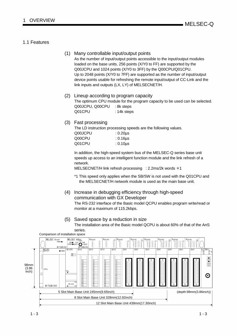
(5) Saved space by a reduction in sizeThe installation area of the Basic model QCPU is about 60% of that of the AnSseries.
1SX10 1SY50 1SX41 1SY41 1SX81 1SY81 1SX42 1SY42
98mm(3.86inch)
5 Slot Main Base Unit 245mm(9.65inch)
8 Slot Main Base Unit 328mm(12.92inch)
12 Slot Main Base Unit 439mm(17.30inch)
(depth:98mm(3.86inch))
Comparison of installation space

1 - 4 1 - 4
MELSEC-Q1 OVERVIEW
(6) Connection of up to four/two extension base units(a) The Q00JCPU can connect up to two extension base units (three base units
including the main) and accepts up to 16 modules.
(b) The Q00/Q01CPU can connect up to four extension base units (five baseunits including the main) and accepts up to 24 modules.
(c) The overall distance of the extension cables is up to 13.2m to ensure highdegree of extension base unit arrangement.
POINTWhen bus-connecting the GOT, the number of extension base units connecteddecreases by one since the GOT uses one stage of the above base units.
(7) Serial communication function for communication with personalcomputer or display deviceWith the RS-232 interface of the Q00CPU or Q01CPU connected with a personalcomputer, display device or the like, the MELSEC communication protocol(hereafter refered to as the MC protocol) can be used to make communication.
RS-232 cable
Communication in MC protocol
Personal computer, display device
The serial communication function only allows communication in the MC protocol(QnA-compatible 3C frame (format 4), QnA-compatible 4C frame (format 4, 5)).The serial communication function does not allow communication in thenonprocedure protocol or bidirectional protocol.Refer to the following manual for the MC protocol.• Q Corresponding MELSEC Communication Protocol Reference Manual
(8) Built-in standard ROMThe flash ROM for storing parameters and sequential program is installed as astandard feature for easier protection of important program.
(9) Easy operation of CC-Link systemThe I/O signals for up to 32 remote I/O stations can be controlled withoutparameters when one master module of the CC-Link system is used.The remote I/O stations can be controlled in a similar manner to controlling theinput/output modules installed on the base unit.
(10) Blocking an invalid access using the file passwordProgram can be prevented from being altered through invalid access bypresetting the access level (reading prohibited, writing prohibited) in the filepassword.

1 - 5 1 - 5
MELSEC-Q1 OVERVIEW
1.2 Program Storage and Calculation
(1) Program storageProgram created at GX Developer can be stored in Basic model QCPU'sprogram memory or standard ROM.
Q00JCPU Q00/Q01CPU
Program memory
ProgramComment
Standard ROM 1Parameters 3
Program
Comment
Standard RAM 2
File registers
Parameters 3Program memory
ProgramComment
Parameters 3
Standard ROM 1Parameters 3
Program
Comment
1: The standard ROM is used when parameters, program and commentare written to ROM.
2: The standard RAM is used for file registers.3: Including the intelligent parameters of the intelligent function module
set on GX Configurator.
(2) The Basic model QCPU processes program which are stored in theprogram memory.
Program memory Execution of program in program memory
Q00J/Q00/Q01CPU
ParameterProgram
1 - 6 1 - 6
MELSEC-Q1 OVERVIEW
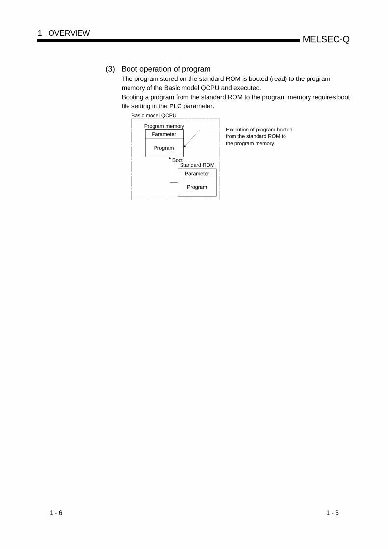
(3) Boot operation of programThe program stored on the standard ROM is booted (read) to the programmemory of the Basic model QCPU and executed.Booting a program from the standard ROM to the program memory requires bootfile setting in the PLC parameter.
Boot
Execution of program booted from the standard ROM to the program memory.
Basic model QCPU
Program memoryParameter
Program
Standard ROMParameter
Program
1 - 7 1 - 7
MELSEC-Q1 OVERVIEW
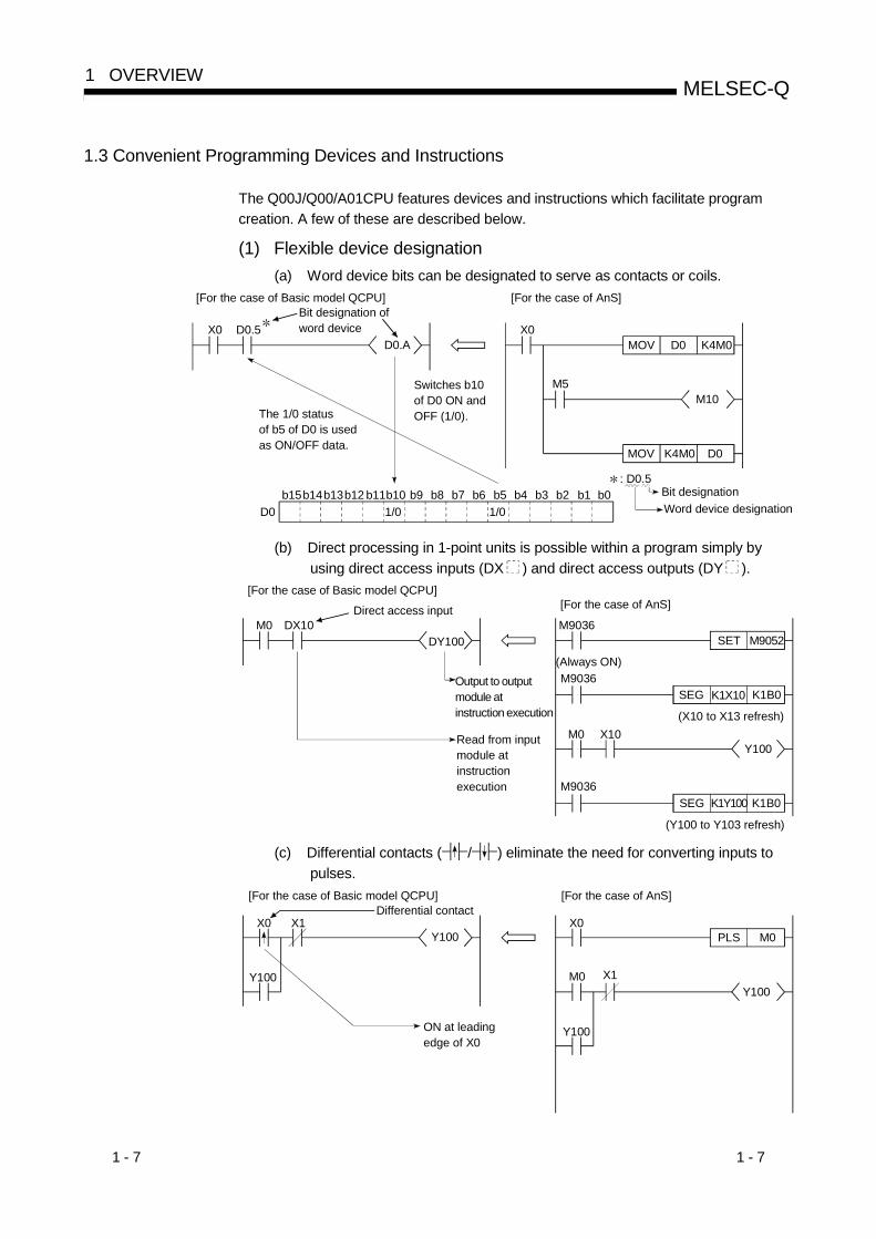
1.3 Convenient Programming Devices and Instructions
The Q00J/Q00/A01CPU features devices and instructions which facilitate programcreation. A few of these are described below.
(1) Flexible device designation(a) Word device bits can be designated to serve as contacts or coils.
Switches b10 of D0 ON and OFF (1/0).The 1/0 status
of b5 of D0 is used as ON/OFF data.
b13D0
b14b15 b12 b11b101/0
b9 b8 b7 b6 b51/0
b4 b3 b2 b1 b0
[For the case of Basic model QCPU]
X0D0.A
[For the case of AnS]
X0K4M0
D0
D0MOV
K4M0MOV
M5M10
: D0.5Bit designationWord device designation
Bit designation of word deviceD0.5
(b) Direct processing in 1-point units is possible within a program simply byusing direct access inputs (DX ) and direct access outputs (DY ).
Output to output module at instruction execution
[For the case of Basic model QCPU]
M0 DX10DY100
[For the case of AnS]
M9036K1B0
K1B0
K1X10SEG
K1Y100SEG
X10Y100
M9036M9052SET
M0
M9036
(X10 to X13 refresh)
(Y100 to Y103 refresh)
(Always ON)
Read from input module at instruction execution
Direct access input
(c) Differential contacts ( / ) eliminate the need for converting inputs topulses.
ON at leading edge of X0
[For the case of Basic model QCPU]
X0 X1Y100
[For the case of AnS]
M0
X0M0PLS
Y100
Y100X1Y100
Differential contact
1 - 8 1 - 8
MELSEC-Q1 OVERVIEW
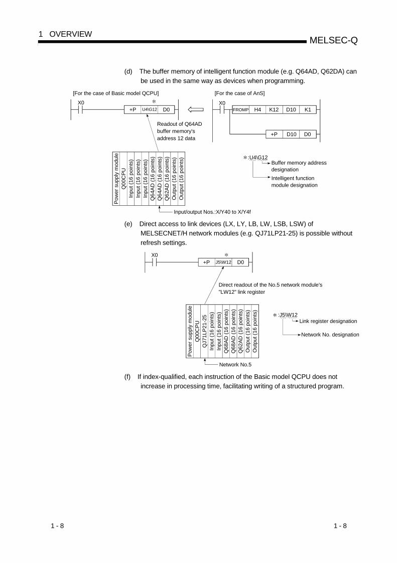
(d) The buffer memory of intelligent function module (e.g. Q64AD, Q62DA) canbe used in the same way as devices when programming.
Readout of Q64AD buffer memory's address 12 data
[For the case of Basic model QCPU]
X0
[For the case of AnS]
X0K1D10K12H4FROMP
D0D10+P
D0U4\G12+P
:U4\G12Buffer memory addressdesignationIntelligent function module designation
Input/output Nos.:X/Y40 to X/Y4f
Pow
er s
uppl
y m
odul
eQ
00C
PUIn
put (
16 p
oint
s)In
put (
16 p
oint
s)In
put (
16 p
oint
s)Q
64AD
(16
poin
ts)
Q64
AD (1
6 po
ints
)Q
62AD
(16
poin
ts)
Out
put (
16 p
oint
s)O
utpu
t (16
poi
nts)
(e) Direct access to link devices (LX, LY, LB, LW, LSB, LSW) ofMELSECNET/H network modules (e.g. QJ71LP21-25) is possible withoutrefresh settings.
Direct readout of the No.5 network module's "LW12" link register
X0D0J5\W12+P
Network No.5
:J5\W12Link register designation
Network No. designation
Pow
er s
uppl
y m
odul
eQ
00C
PUQ
J71L
P21-
25In
put (
16 p
oint
s)In
put (
16 p
oint
s)Q
68AD
(16
poin
ts)
Q68
AD (1
6 po
ints
)Q
62AD
(16
poin
ts)
Out
put (
16 p
oint
s)O
utpu
t (16
poi
nts)
(f) If index-qualified, each instruction of the Basic model QCPU does notincrease in processing time, facilitating writing of a structured program.
1 - 9 1 - 9
MELSEC-Q1 OVERVIEW
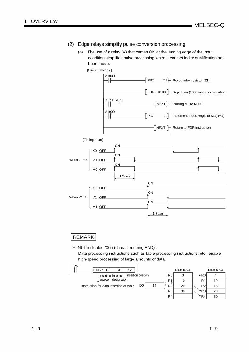
(2) Edge relays simplify pulse conversion processing(a) The use of a relay (V) that comes ON at the leading edge of the input
condition simplifies pulse processing when a contact index qualification hasbeen made.
X0Z1 V0Z1M0Z1
K1000FOR
Z1RST
Z1INC
NEXT
M1000
M1000
[Circuit example]
Reset index register (Z1)
Repetition (1000 times) designation
Pulsing M0 to M999
Increment Index Register (Z1) (+1)
Return to FOR instruction
When Z1=0
X0 OFF
V0 OFF
M0 OFF
ON
ON
ON
1 Scan
[Timing chart]
When Z1=1
X1 OFF
V1 OFF
M1 OFF
ON
ON
ON
1 Scan
REMARK
: NUL indicates "00H (character string END)".Data processing instructions such as table processing instructions, etc., enablehigh-speed processing of large amounts of data.
X0K2R0D0FINSP
Insertion source
R0FIF0 table
R1R2R3
3102030
R4
Insertion designation
Insertion position R0FIF0 table
R1R2R3
410152030R4
D0 15Instruction for data insertion at table

1 - 10 1 - 10
MELSEC-Q1 OVERVIEW
(4) Easy shared use of sub-routine programsSubroutine call instructions with arguments will make it easier to create asubroutine programs that makes several calls.
Argument designationM10
100
M0R0K4X00 W0P0CALLP
R10K4X10W10P0CALLP
Argument from FD2Argument to FD1Argument to FD0
Argument from FD2Argument to FD1Argument to FD0
Argument designation
Subroutine program designation
FEND
Sub-routine program
FD2FD1MOV
SM400FD2FD0MOV
RET
M0
M0P0
AlwaysON
source dataDestination data
END
Main routine program
REMARK
For details regarding the argument input/output condition, refer to Section 10.3.1.
2 - 1 2 - 1
MELSEC-Q2 SYSTEM CONFIGURATION
2
2. SYSTEM CONFIGURATION
This section describes the system configuration of the Basic model QCPU, cautions onuse of the system, and configured equipment.
2.1 System Configuration
2.1.1 Q00JCPU
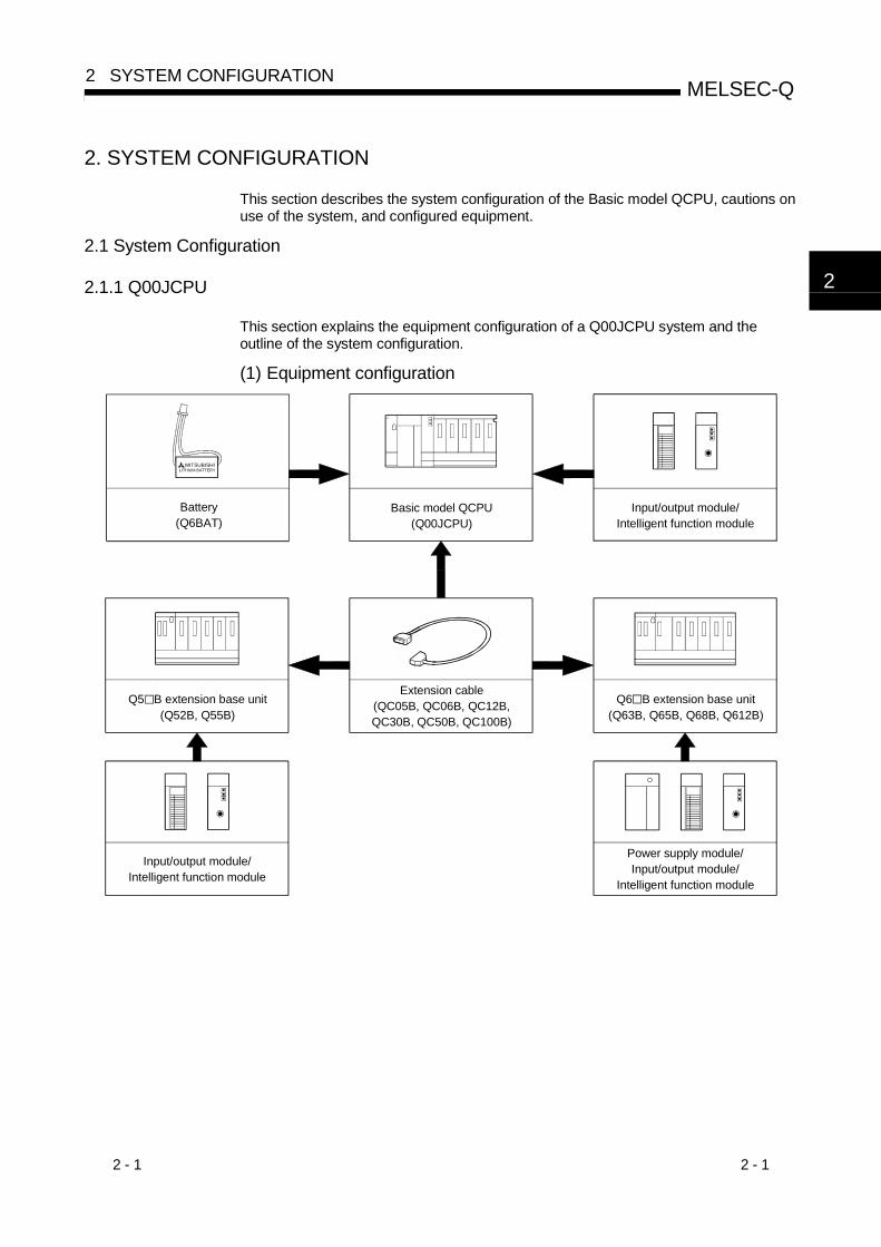
This section explains the equipment configuration of a Q00JCPU system and theoutline of the system configuration.
(1) Equipment configuration
Q6 B extension base unit(Q63B, Q65B, Q68B, Q612B)
Battery(Q6BAT)
Basic model QCPU(Q00JCPU)
Input/output module/Intelligent function module
Extension cable(QC05B, QC06B, QC12B,QC30B, QC50B, QC100B)
Input/output module/Intelligent function module
MITSUBISHILITHIUM BATTERY
Q5 B extension base unit(Q52B, Q55B)
Power supply module/Input/output module/
Intelligent function module

2 - 2 2 - 2
MELSEC-Q2 SYSTEM CONFIGURATION
2
(2) Outline of system configuration
System configuration
Extension 2
CPU
00
0F
10
1F
20
2F
30
3F
40
4F
0 1 2 3 4
Extension base unit (Q68B)12111098765
50
5F
151413D0
DF
1211109876550
5F
Extensioncable
Slot number
OUT
IN
OUT
Extension 1 Extension 1
OUT
IN
OUT
IN
Extension base unit (Q65B)
Extension base unit (Q68B)
60
6F
70
7F
80
8F
90
9F
A0
AF
B0
BF
C0
CF
E0
EF
F0
FF
(a) System including extension base units
Inhi
bite
d
Extension cable connectorLoading will cause error
(b) System including extension base unit and GOT
Number of extension units: 2Slot No. : 0
Inhi
bite
d
Pow
er s
uppl
ym
odul
eP
ower
sup
ply
mod
ule
CPU
00
0F
10
1F
20
2F
30
3F
40
4F
0 1 2 3 4
OUTExtension
cable
60
6F
70
7F
80
8F
90
9F
A0
AF
B0
BF
C0
CF
Both of the above systems assume that each slot of the main and extension base units isloaded with a 16-point module.
Pow
er s
uppl
ym
odul
e
Maximum number ofExtension Stages Two Extension Stages
Maximum number ofinput/output modules tobe installed
16 modules
Maximum number ofinput/output points 256
Main base unit UnnecessaryExtension base unit Q52B, Q55B, Q63B, Q65B, Q68B, Q612BExtension cable QC05B, QC06B, QC12B, QC30B, QC50B, QC100B
Notes
(1) Do not use an extension cable longer than an overall extension length of 13.2m(43.31ft.).(2) When using an extension cable, do not bind it together with the main circuit (high voltage and
heavy current) line or do not lay down them closely to each other.(3) When setting the No. of the expansion stages, set it in the ascending order so that the same
No. is not set simultaneously by two extension base units.(4) The QA1S6 B/QA65B cannot be connected as an extension base unit.(5) Connect the extension cable from OUT of the extension cable connector of the base unit to IN
of the extension base unit on the next stage.(6) If 17 or more modules are installed, an error will occur.(7) When bus-connected, the GOT occupies one extension stage and one slot.(8) The Q00JCPU processes the GOT as a 16-point intelligent function module. Hence, connection
of one GOT decreases the number of controllable points on base units by 16 points.(9) The bus extension connector box (A9GT-QCNB) cannot be connected to the Q00JCPU. It
should be connected to the extension base unit.

2 - 3 2 - 3
MELSEC-Q2 SYSTEM CONFIGURATION
2.1.2 Q00/Q01CPU
This section explains the equipment configuration of a Q00/Q01CPU system and theoutline of the system configuration.
(1) Equipment configuration
Q6 B extension base unit(Q63B, Q65B, Q68B, Q612B)
Basic model QCPU(Q00CPU, Q01CPU)
Battery(Q6BAT)
Main base unit(Q33B, Q35B, Q38B, Q312B)
Power supply module/ Input/output module/
Intelligent function module
Extension cable(QC05B, QC06B, QC12B,QC30B, QC50B, QC100B)
Input/output module/Intelligent function module
MITSUBISHILITHIUM BATTERY
Q5 B extension base unit(Q52B, Q55B)
Power supply module/ Input/output module/
Intelligent function module

2 - 4 2 - 4
MELSEC-Q2 SYSTEM CONFIGURATION
(2) Outline of system configuration
System configuration
CPU
00
1F
20
3F
40
5F
60
7F
80
9F
A0
BF
C0
DF
E0
FF
100
11F
120
13F
140
15F
160
17F
0 1 2 3 4 5 6 7 8 9 10 11
Extension base unit (Q68B)1918171615141312260
27F
240
25F
220
23F
200
21F
1E0
1FF
1C0
1DF
180
19F
1A0
1BF
232221202E0
2FF
2C0
2CF
2A0
2BF
280
29F
Extensioncable
Slot No.
OUT
IN
OUT
Main base unit (Q312B)
OUT
IN
Extension base unit (Q65B)
Inhi
bite
d
Extension 1
Extension 2
Loading will cause errorThe above system assumes that each slot is loading with a 32-point module.
Pow
er s
uppl
ym
odul
ePo
wer
sup
ply
mod
ule
Pow
er s
uppl
ym
odul
e
Maximum number ofExtension Stages Four Extension Stages
Maximum number ofinput/output modules tobe installed
24 modules
Maximum number ofinput/output points 1024
Main base unit Q33B, Q35B, Q38B, Q312BExtension base unit Q52B, Q55B, Q63B, Q65B, Q68B, Q612BExtension cable QC05B, QC06B, QC12B, QC30B, QC50B, QC100B
Notes
(1) Do not use an extension cable longer than an overall extension length of 13.2m(43.31ft.).(2) When using an extension cable, do not bind it together with the main circuit (high voltage and
heavy current) line or do not lay down them closely to each other.(3) When setting the No. of the expansion stages, set it in the ascending order so that the same
No. is not set simultaneously by two extension base units.(4) The QA1S6 B/QA65B cannot be connected as an extension base unit.(5) Connect the extension cable from OUT of the extension cable connector of the base unit to IN
of the extension base unit on the next stage.(6) If 25 or more modules are installed, an error will occur.(7) When bus-connected, the GOT occupies one extension stage and one slot.(8) The Q00/Q01CPU processes the GOT as a 16-point intelligent function module. Hence,
connection of one GOT decreases the number of controllable points on base units by 16 points.

2 - 5 2 - 5
MELSEC-Q2 SYSTEM CONFIGURATION
2.1.3 Configuration of GX Developer
Basic model QCPU(Q00CPU, Q01CPU)
RS-232 cable(QC30R2)
Basic model QCPU(Q00JCPU)
Personal ComputerGX Developer
(Version 7 or later)
2 - 6 2 - 6
MELSEC-Q2 SYSTEM CONFIGURATION
2.2 Precaution on System Configuration
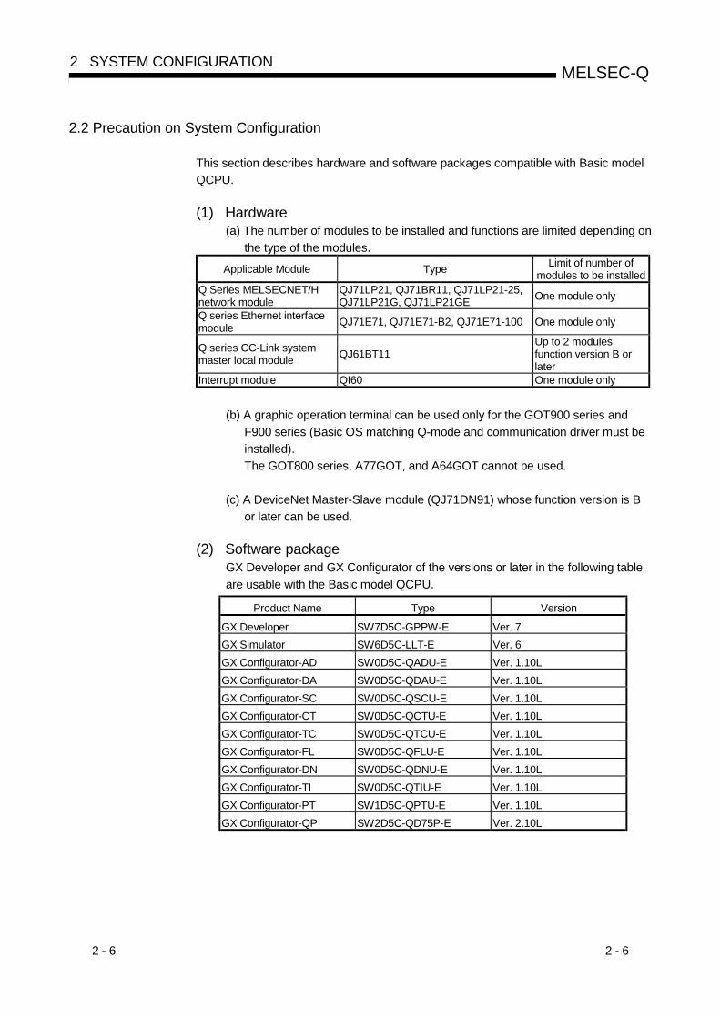
This section describes hardware and software packages compatible with Basic modelQCPU.
(1) Hardware(a) The number of modules to be installed and functions are limited depending on
the type of the modules.
Applicable Module Type Limit of number ofmodules to be installed
Q Series MELSECNET/Hnetwork module
QJ71LP21, QJ71BR11, QJ71LP21-25,QJ71LP21G, QJ71LP21GE One module only
Q series Ethernet interfacemodule QJ71E71, QJ71E71-B2, QJ71E71-100 One module only
Q series CC-Link systemmaster local module QJ61BT11
Up to 2 modulesfunction version B orlater
Interrupt module QI60 One module only
(b) A graphic operation terminal can be used only for the GOT900 series andF900 series (Basic OS matching Q-mode and communication driver must beinstalled).The GOT800 series, A77GOT, and A64GOT cannot be used.
(c) A DeviceNet Master-Slave module (QJ71DN91) whose function version is Bor later can be used.
(2) Software packageGX Developer and GX Configurator of the versions or later in the following tableare usable with the Basic model QCPU.
Product Name Type Version
GX Developer SW7D5C-GPPW-E Ver. 7GX Simulator SW6D5C-LLT-E Ver. 6GX Configurator-AD SW0D5C-QADU-E Ver. 1.10LGX Configurator-DA SW0D5C-QDAU-E Ver. 1.10LGX Configurator-SC SW0D5C-QSCU-E Ver. 1.10LGX Configurator-CT SW0D5C-QCTU-E Ver. 1.10LGX Configurator-TC SW0D5C-QTCU-E Ver. 1.10LGX Configurator-FL SW0D5C-QFLU-E Ver. 1.10LGX Configurator-DN SW0D5C-QDNU-E Ver. 1.10LGX Configurator-TI SW0D5C-QTIU-E Ver. 1.10LGX Configurator-PT SW1D5C-QPTU-E Ver. 1.10LGX Configurator-QP SW2D5C-QD75P-E Ver. 2.10L

2 - 7 2 - 7
MELSEC-Q2 SYSTEM CONFIGURATION
2.3 Confirming the function version
The Basic model QCPU function version can be confirmed on the rating nameplateand GX Developer's system monitor.(1) Confirming the function version on the rating nameplate
The function version is indicated on the rating nameplate.
Serial No. (First five digits)Function version
MADE IN JAPAN
LISTED 80M1 IND.CONT.EQ.
MODEL
SERIAL 03051 0000000000-A
(2) Confirming the function version on the system monitor (productinformation List)The product information list in the system monitor of GX Developer allows you toconfirm the function version of the Basic model QCPU.The product information list of the system monitor also allows you to confirm thefunction versions of the intelligent function modules.
Serial No. Function version

3 - 1 3 - 1
MELSEC-Q3 PERFORMANCE SPECIFICATION
3
3. PERFORMANCE SPECIFICATION
The table below shows the performance specifications of the Basic model QCPU.
Performance SpecificationsModel
ItemQ00JCPU Q00CPU Q01CPU
Remark
Control method Repetitive operation of stored program
I/O control method Refresh mode
Direct input/output ispossible by directinput/outputspecification (DX ,DY )
Programming language(Sequence control dedicatedlanguage)
Relay symbol language, logic symbolic language The SFC function isnot applicable.
LD X0 0.20µs 0.16µs 0.10µsProcessing speed(Sequence instruction) MOV D0 D1 0.70µs 0.56µs 0.35µs
Total number of instructions249
(excluding intelligent function module dedicatedinstructions)
Constant scan(Function to make the scan timeconstant)
2 to 2000 ms (configurable in increments of 1 ms) Set parameter valuesto specify
Program 1 2capacity
8k steps(32 kbyte)
8k steps(32 kbyte)
14k steps(56 kbyte)
Program memory(Drive 0) 58 kbyte 94 kbyte 94 kbyte
Standard RAM(Drive 3) 0 64 kbyte 64 kbyteMemory
capacityStandard ROM(Drive 4) 58 kbyte 94 kbyte 94 kbyte
Program memory 1 1 1Number ofstoredprograms Standard ROM 1 1 1
Number ofstored fileregisters
Standard RAM —— 1 1
Number of I/O devices points 2048 points (X/Y0 to 7FF) Number of devicesusable on program
Number of I/O points 256 points(X/Y0 to FF)
1024 points(X/Y0 to 3FF)
Number of pointsaccesible toinput/output modules
1: "1 step" in program capacity equals 4 bytes.2: The maximum number of steps that can be executed can be obtained as follows:
(Program capacity) - (File header size (Default: 34 steps))

3 - 2 3 - 2
MELSEC-Q3 HARDWARE SPECIFICATION OF THE CPU MODULE
3
Performance Specifications (continued)Model
Item Q00JCPU Q00CPU Q01CPU Remark
Internal relay [M] Default 8192 points (M0 to 8191)Latch relay [L] Default 2048 points (L0 to 2047)Link relay [B] Default 2048 points (B0 to 7FF)
Timer [ T ]
Default 512 points (T0 to 511) (for low / high speed timer)Select between low / high speed timer by instructions.The measurement unit of the low / high speed timer is setwith parameters.(Low speed timer : 1 to 1000ms, 1ms/unit , default 100ms)(High speed timer : 0.1 to 100ms, 0.1ms/unit , default 10ms)
Retentive timer [ ST ]
Default 0 point(for low / high speed retentive timer)Switchover between the low / high speed retentive timer isset by instructions.The measurement unit of the low speed retentive timer andhigh speed retentive timer is set with parameters.(Low speed retentive timer : 1 to 1000ms, 1ms/unit , default 100ms)(High speed retentive timer : 0.1 to 100ms, 0.1ms/unit , default 10ms)
Counter [C]• Normal counter default 512 points (C0 to 511)• Interrupt counter maximum 128 points
(default 0 point, set with parameters)Data register [D] Default 11136 points (D0 to 11135)Link register [W] Default 2048 points (W0 to 7FF)Annunciator [F] Default 1024 points (F0 to 1023)Edge relay [V] Default 1024 points (V0 to 1023)
Number of use pointsis set withparameters.
[R] None 32768 points (R0 to 32767)
Num
ber o
f dev
ice
poin
ts
File Register[ZR] None 32768 points (ZR0 to 32767)

3 - 3 3 - 3
MELSEC-Q3 HARDWARE SPECIFICATION OF THE CPU MODULE
Performance Specifications (continued)Model
Item Q00JCPU Q00CPU Q01CPU Remark
Special link relay [SB] 1024 points (SB0 to 3FF)Special link register [SW] 1024 points (SW0 to 3FF)Step relay [S] 3 2048 points (S0 to 2047)Index register [Z] 10 points (Z0 to 9)Pointer [P] 300 points (P0 to 299)
Interrupt pointer [ I ]
128 points (I0 to 127)The specified intervals of the system interrupt pointers I28 to
I31 can be set with parameters.(0.5 to 1000ms, Cunit in 0.5 ms)Default I28 : 100ms I29 : 40ms I30 : 20ms I31 : 10ms
Special relay [SM] 1024 points (SM0 to 1023)Special register [SD] 1024 points (SD0 to 1023)Function input [FX] 16 points (FX0 to F)Function output [FY] 16 points (FY0 to F)
Num
ber o
f dev
ice
poin
ts
Function register[FD] 5 points (FD0 to 4)
The number of devicepoints is fixed.
Link direct device
Device for direct access to link device.MELSECNET/H use only.Specified form at : J \X , J \Y , J \W ,
J \B , J \SW , J \SB
Intelligent function module deviceDevice for direct access to the buffer memory of theintelligent function module. Specified form at : U \G
Latch (power failure conpensation)range
L0 to 2047 (default)(Latch range can be set for B, F, V, T, ST, C, D, and W.)
Remote RUN/PAUSE contactRUN and PAUSE contacts can be set from among X0 to7FF, respectively.
Set parameter valuesto specify
Clock function
Year, month, day, hour, minute, second, day of the week(leap year automatic distinction)Accuracy -3.2 to +5.27s (TYP. +1.98s) /d at 0°CAccuracy -2.57 to +5.27s(TYP. +2.22s)/d at 25°CAccuracy -11.68 to +3.65s(TYP. -2.64s)/d at 55°C
Allowable momentary stop timeMax. 20ms
(Min. 100VAC)Varies according to the type of power
supply module.5VDC internal current consumption 0.22A 4 0.25A 0.27AWeight 0.66kg 5 0.13kg 0.13kg
H 98mm (3.86in.) 98mm (3.86in.)W 245mm (9.65in.) 27.4mm (1.08in.)External dimensionsD 97mm (3.82in.) 89.3mm (3.52in.)
3: The "step relay" is a device for the SFC function.This cannot be used as the SFC function is not applicable to the Basic model QCPU.
4: This value includes the CPU module and base unit.5: This value includes the CPU module, base unit, and power supply module.

4 - 1 4 - 1
MELSEC-Q
4 SEQUENCE PROGRAM CONFIGURATION & EXECUTIONCONDITIONS
4
4 SEQUENCE PROGRAM CONFIGURATION & EXECUTION CONDITIONS
Programs that can be executed by the Basic model QCPU are sequence programsonly.This chapter describes the sequence program configuration and execution conditions.
4.1 Sequence Program
(1) Definition of sequence program(a) A sequence program is created using sequence instructions, basic
instructions, and application instructions, etc.Sequence instruction
T0
X0
X1
X41
M0 K100T0
Y30
BIN K4X10 D0
FROM H5 K0 D10 K1
Basic instruction
Application instruction
(b) There are 3 types of sequence program: main routine programs, sub-routineprograms, and interrupt programs.For details regarding these programs, refer to the following sections of thismanual:• Main routine programs : Section 4.1.1• Sub-routine programs : Section 4.1.2• Interrupt programs : Section 4.1.3
MAIN
Main routine program
Sub-routine program
FEND
Interrupt program
RET
IRET
END
P0
I0
REMARK
For details regarding the sequence instructions, basic instructions, and applicationinstructions, refer to the " QCPU (Q Mode)/QnACPU Programming Manual(Common Instructions)".
4 - 2 4 - 2
MELSEC-Q
4 SEQUENCE PROGRAM CONFIGURATION & EXECUTIONCONDITIONS
4
(2) Sequence program writing formatProgramming for sequence programs is possible using either ladder mode, or listmode.
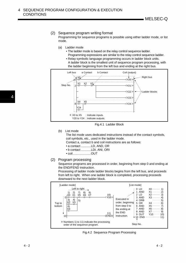
(a) Ladder mode• The ladder mode is based on the relay control sequence ladder.
Programming expressions are similar to the relay control sequence ladder.• Relay symbolic language programming occurs in ladder block units.
A ladder block is the smallest unit of sequence program processing, withthe ladder beginning from the left bus and ending at the right bus.
Y21
Y22
Y23
Y24
X1Y20
X2 X3
X4 X5
Y24
X00
2
8
Left bus
Step No.
Right bus
Ladder blocks
X0 to X5 : Indicate inputs. Y20 to Y24 : Indicate outputs.
a Contact b Contact Coil (output)
Fig.4.1 Ladder Block
(b) List modeThe list mode uses dedicated instructions instead of the contact symbols,coil symbols, etc., used in the ladder mode.Contact a, contact b and coil instructions are as follows:• a contact ............LD, AND, OR• b contact ............LDI, ANI, ORI• coil......................OUT
(2) Program processingSequence programs are processed in order, beginning from step 0 and ending atthe END/FEND instruction.Processing of ladder mode ladder blocks begins from the left bus, and proceedsfrom left to right. When one ladder block is completed, processing proceedsdownward to the next ladder block.
0 LD 1 AND 2 LD 3 AND 4 ORB 5 OR 6 AND 7 AND 8 AND 9 OUT 10 END
Top to bottom
Numbers 1) to 11) indicate the processing order of the sequence program.
[Ladder mode]Left to right
1)X0
2)X1
7)X5
8)X6
9)X7
3)X2
4)X3
6)X4
10)Y100
10
5)
11)END
[List mode]
Executed in order, beginning from step 0 to the ending at the END instruction.
Step No.
X0X1X2X3 X4X5X6X7 Y10
1) 2) 3) 4) 5) 6) 7) 8) 9)10)11)
Fig.4.2 Sequence Program Processing

4 - 3 4 - 3
MELSEC-Q
4 SEQUENCE PROGRAM CONFIGURATION & EXECUTIONCONDITIONS
4.1.1 Main routine program
(1) Definition of main routine program(a) A main routine program is a program which begins from step 0 and ends at
the END/FEND instruction. 1(b) The main routine program execution begins from step 0 and ends at the
END/FEND instruction.When the END/FEND instruction is executed in the main routine program,END processing is performed and operation is then restarted from step 0.
END/FEND
Main routine program
Step 0
END/FEND
END processing
Program execution
Returns to step 0
(2) Execution of main routine programThe main routine program is executed every scan.
REMARK
1: For details regarding the END/FEND instruction, refer to the "QCPU (Qmode)/QnACPU Programming Manual (Common Instructions)".

4 - 4 4 - 4
MELSEC-Q
4 SEQUENCE PROGRAM CONFIGURATION & EXECUTIONCONDITIONS
4.1.2 Sub-routine programs
(1) Definition of sub-routine program(a) A sub-routine program is a program which begins from a pointer (P ) and
ends at a RET instruction.(b) A sub-routine program is executed only when called by a CALL instruction
(e.g. CALL(P), FCALL(P)) from the main routine program.(c) Sub-routine program application
1) The overall step count can be reduced by using a sub-routine programas a program which is executed several times in one scan.
2) The step count of a constantly executed program can be reduced byusing a sub-routine program as a program which is executed onlywhen a given condition is satisfied.
(2) Sub-routine program managementSub-routine programs are created after the main routine program (after FENDinstruction), and the combination of main and sub-routine programs is managedas one program.Create a sub-routine program as described below.• A sub-routine program is created between the main routine program's FEND
and END instructions.• Because there are no restrictions regarding the order in which sub-routine
programs are created, there is no need to set the pointers in ascending orderwhen creating multiple sub-routine programs.
MAIN
Sub-routine program
Write
Basic model QCPU
Main routine program
FEND
END
P8
RET
RET
Y10
RET
Y11
Y12
P0
P1
Program memory
Program file

4 - 5 4 - 5
MELSEC-Q
4 SEQUENCE PROGRAM CONFIGURATION & EXECUTIONCONDITIONS
4.1.3 Interrupt programs
(1) Definition of interrupt program(a) An interrupt program is a program which begins at the interrupt pointer
(I ), and ends at the IRET instruction. 1(b) Interrupt programs are executed only when an interrupt factor occurs. 1
(2) Interrupt program managementInterrupt programs are created after the main routine program (after the FENDinstruction), and the combination of main and sub-routine programs is managedas one program.Create an interrupt program as described below.• An interrupt program is created between the main routine program's FEND and
END instructions.• Because there are no restrictions regarding the order in which interrupt
programs are created, there is no need to set the interrupt pointers in ascendingorder when creating multiple interrupt programs.
Basic model QCPU
Program memory
Program file
MAIN
Interrupt program
Write
Interrupt pointer
Main routine program
FEND
END
I32
IRET
IRET
Y10
IRET
Y11
Y12
I0
I28
REMARK
1: See Section 10.10 for details regarding interrupt factors and interrupt pointers.

4 - 6 4 - 6
MELSEC-Q
4 SEQUENCE PROGRAM CONFIGURATION & EXECUTIONCONDITIONS
(3) Executing interrupt programs(a) To run an interrupt program, interrupts must have been enabled by the EI
instruction. 11) If interrupt factors occur before interrupts are enabled, the interrupt
factors that occurred are stored, and the interrupt programscorresponding to the stored interrupt factors are executed as soon asinterrupts are enabled.
2) If the same interrupt factor occurs more than once, the interrupt factorsthat occurred are stored or discarded.
Main routine program
FEND
Interrupt program
Interrupt program
END
Interrupt program for "I0" activated
Interrupt program for "I29" activated
Program execution
FEND
EI
IRET
IRET
END
"I0" interrupt program
"I29" interrupt program
End of main routine program
I0
I29
I0
I29
Interrupt program example Interrupt program execution
Fig.4.3 Interrupt Program Execution(b) When an interrupt factor occurs, the interrupt program with the interrupt
pointer number corresponding to that factor is executed.However, interrupt program execution varies according to the condition atthat time.1) : When multiple interruptions occur simultaneously
When multiple interrupt programs are activated simultaneously, theprograms will be executed in order, beginning from the interruptprogram with the highest priority interrupt pointer number. 2The remaining interrupt programs remain on stand-by until processingof the higher priority interrupt program is completed.If the same interrupt factor as that being executed occurs before theinterrupt program is processed, the interrupt factor is stored in thememory and, after the interrupt program has been processed, thesame interrupt program is executed again.
2) When an instruction is being executed:Interruptions are prohibited during execution of instructions.If an interrupt factor occurs during execution of an instruction, theinterrupt program will be executed after processing of the instruction iscompleted.

4 - 7 4 - 7
MELSEC-Q
4 SEQUENCE PROGRAM CONFIGURATION & EXECUTIONCONDITIONS
3) Interruption during a network refresh:If an interrupt factor occurs during a network refresh operation, thenetwork refresh operation is suspended, and the interrupt program isexecuted.This means that "assurance of blocks in cyclic data at each station"cannot be secured by using a device designated as a destination oflink refresh operation on the MESSECNET/H Network System. 3
Interrupt factor
Interrupt programexecution
Network refreshexecution
10ms 10ms 10ms 10ms
Network refresh operation is suspended, and the interrupt program is executed.
Fig.4.4 Interruption during Network Refresh Operation
4) Interruption during END processing:If an interrupt factor occurs during an END processing waiting periodduring constant scanning, the interrupt program corresponding to thatfactor will be executed.
(c) See Section 10.6.1 for details regarding index register processing whenswitching to an interrupt program from a main routine program or subroutine program.
(4) High-speed execution of an interrupt program and overhead timeBy default, the Basic model QCPU "hides and restores an index register" whenexecuting an interrupt program.The above-listed processes are not performed if an option to "Execute at a HighSpeed" is selected in the PLC System Setting sheet of the PLC Parameter dialog box.This will make it possible to shorten the duration of overhead time required forexecution of an interrupt program.Refer to Section 11.2 for the overhead time of an interrupt program.
REMARK
1: For details regarding the IMASK and EI instructions, refer to the "QCPU (Q mode)/QnACPU Programming Manual (Common Instructions).
2: See Section 10.10 for details regarding the priority ranking of interrupt programs.3: For assurance of station unit blocks in cyclic data, see the "MELECNET/H
Network System Reference Manual."

4 - 8 4 - 8
MELSEC-Q
4 SEQUENCE PROGRAM CONFIGURATION & EXECUTIONCONDITIONS
(5) Program creation restrictions(a) A device which is switched ON by a PLS instruction in an interrupt program
will remain ON until the PLS instruction for the same device is executedagain.
X0 OFFON
M0 OFFON
END 0 IO IRET END 0 END 0 IO IRET END 0
PLS M0X0
PLS M0X0
Switched OFF by PLS M0 instruction
Switched ON by PLS M0 instruction at X0 leading edge (OFF to ON)
(b) During execution of the interrupt program, interrupts are disabled (DI) sothat other interrupt processing is not performed.Do not execute EI/DI instructions in the interrupt program.
(c) Timers cannot be used in interrupt programs.As timers are used at OUT T instructions to update present values andswitch contacts ON and OFF, the use of a timer in the interrupt programwould make a normal time count impossible.
(d) The following instructions cannot be used in interrupt programs.• COM• ZCOM
(e) When the interrupt program is executed when measuring time such as thescan time or execution time, the measured time will become the valueobtained by adding the interrupt program/constant cycle execution typeprogram.Thus, if the interrupt program is executed, the values stored in the followingspecial registers and GX Developer monitor values will become longer thanwhen the interrupt program is not executed.1) Special registers
• SD520, SD521: Current scan time• SD524, SD525: Minimum scan time• SD526, SD527: Maximum scan time• SD540, SD541: END processing time• SD542, SD543: Constant scan wait time
2) GX Developer monitor values• Execution time measurement• Scan time measurement• Constant scan

4 - 9 4 - 9
MELSEC-Q
4 SEQUENCE PROGRAM CONFIGURATION & EXECUTIONCONDITIONS
4.2 Concept of Scan Time
(1) Scan time(a) The "scan time" is a total of following the execution time of program and
END processing.When an interrupt program is executed, the value including the executiontime of the interrupt program will be the scan time.
(b) The scan time present value, minimum value, and maximum value aremeasured at the Basic model QCPU, and the results are stored in specialregisters (SD520, SD521, and SD524 to SD527). 1The scan time can therefore be checked by monitoring the SD520, SD521,and SD524 to SD527 special registers.
Stores less than 1 ms initial scan time (unit s)
Stores the initial scan time in 1 ms units.
SD520
SD524
SD526
Current value
Minimum valueMaximum value
SD521
SD525
SD527
If the SD520 value is 3, and the SD521 value is 400, the initial scan time is 3.4ms.
POINT1: The accuracy of the scan time stored at the special registers is ± 0.1 ms.
The scan time count will continue even if a watchdog time reset instruction(WDT) is executed at the sequence program.
(2) Constant scan setting: 2When constant scanning is designated, the main routine program is executed ateach designated constant scan period.
(3) WDT (Watchdog timer)This is the timer which monitors the scan time, and its default setting is 200 ms.This WDT setting can be designated in a 10 ms to 2000 ms range in the PLCRAS settings of the PLC parameter.(Setting units: 10 ms)
POINTThe WDT measurement error is 10 ms.Therefore, a WDT setting (t) of 10 ms will result in a "WDT ERROR" if the scantime is in the following range: 10 ms < t < 20 ms.
REMARK
1: The “constant scan” function executes the scan type program repeatedly atregular intervals.For details regarding of the constant scan, refer to Section 7.2.

4 - 10 4 - 10
MELSEC-Q
4 SEQUENCE PROGRAM CONFIGURATION & EXECUTIONCONDITIONS
4.3 Operation Processing
4.3.1 Initial processing
This is a preprocessing for sequence operation execution, and is performed only onceas shown in the table below.When the initial processing is completed, the Basic model QCPU goes in theRUN/STOP/RESET switch setting status. (See Section 4.4.)
Basic model QCPU statusInitial processing item When the power
is turned on.When reset is
executed.When STOPto RUN 1
The Input/Output module initializationBoot from the standard ROMDevice initialization of the range not latched(bit device: OFF, word device: 0)Execution of self-diagnosis in the QCPU CPUmodulesAutomatic allocation of the I/O number ofinstalled modulesStart of the MELSECNET/H network informationsetting and network communicationSwitch setting of intelligent function moduleSetting of CC-Link informationSetting of Ethernet informationSetting of serial communication function : executed, : not executed
REMARK
1: When parameters or programs are changed in the STOP status, reset by theRUN/STOP/RESET switch.When the RUN/STOP/RESET switch is turned from STOP to RUN without thereset, RUN LED flashes.When the RUN/STOP/RESET switch is turned from RUN to STOP to RUNagain, the Basic model QCPU goes in the RUN status, and the "When STOP toRUN" status becomes effective.However, fully note that the pulsing instruction (PLS, P) may not operateproperly since the previous information is not continued depending on programmodifications.

4 - 11 4 - 11
MELSEC-Q
4 SEQUENCE PROGRAM CONFIGURATION & EXECUTIONCONDITIONS
4.3.2 I/O refresh (I/O module refresh processing)
In I/O refresh, an input (X) is received from the input module/intelligent functionmodule, and output (Y) of the Basic model QCPU is produced to the outputmodule/intelligent function module.
The I/O refresh is executed before the sequence program operation starts.During constant scan execution, the I/O refresh is executed after the constant scandelay time has elapsed.(The I/O refresh is executed at each constant scan cycle.)
4.3.3 Automatic refresh of the intelligent function module
When automatic refresh of intelligent function modules is set, communication with theintelligent function modules of the designated data is performed.Refer to the manual for the intelligent function modules to use for details regarding ofthe automatic refresh setting of intelligent function modules.
4.3.4 END processing
This is a post-processing to return the sequence program execution to step 0 aftercompleting the whole sequence program operation processing once.• MELSECNET/H or CC-Link refresh processing• Automatic refresh of intelligent function module• Self-diagnostics• Communication with external device such as GX Developer• Processing of intelligent function module dedicated instruction

4 - 12 4 - 12
MELSEC-Q
4 SEQUENCE PROGRAM CONFIGURATION & EXECUTIONCONDITIONS
4.4 RUN, STOP, PAUSE Operation Processing
The Basic model QCPU has three types of operation states; RUN, STOP and PAUSEstates.The Basic model QCPU operation processing is explained below:
(1) RUN Status Operation Processing(a) RUN status is when the sequence program operation is performed from
step 0 to END (FEND) instruction to step 0 repeatedly.(b) When entering the RUN state, the output state saved at STOP by the
parameter output-mode setting during STOP to RUN.(c) The processing time of switching from STOP to RUN until the beginning of
sequence program operation changes with system configurations, butusually is 1 to 3 seconds.However, this time may be longer depending on the conditions.
(2) STOP Status Operation Processing(a) STOP status is when the sequence program operations are stopped with
the RUN/STOP/RESET switch or remote STOP is performed. (Refer toSection 7.6.1 for details regarding of remote STOP function.)The STOP status is also caused by a stopping error.
(b) When entering the STOP state, save the output state and turn off all output.The device memory of other than the output (Y) is retained.
(3) PAUSE Status Operation Processing(a) The PAUSE state is when the sequence program operations are paused by
remote PAUSE function while maintaining the output and device memorystatus. (Refer to Section 7.6.2 for details regarding of remote PAUSEfunction.)
(4) Basic model QCPU Operation Processing with RUN/STOP state
Operationprocessing
RUN/STOPstate
Sequence programoperation processing External output Device memory
(Y, M, L, S, T, C, D)
RUN to STOPExecutes up to theEND instruction andstops.
OS saves the output stateand all output are off.
Maintains the status immediatelybefore the STOP state.
STOP to RUN Starts at step 0.Determined by the outputmode of the PLC parameterat STOP to RUN.
Starts executing the operationfrom the status immediatelybefore the STOP state. When adevice initial value is designated,however, the value is set. Localdevices are cleared.
POINTThe Basic model QCPU performs the following in any of RUN, STOP, and Pausestate:• I/O module refresh processing• Data communication with the GX Developer and serial communication module• Refresh process of MELSECNET/H and CC-LinkFor this reason, I/O monitor and test operation using GX Developer, reading/writingfrom the serial communication, communication with another station usingMELSECNET/H, and communication with a remote station over the CC-Link canbe made even in the STOP or PAUSE status.

4 - 13 4 - 13
MELSEC-Q
4 SEQUENCE PROGRAM CONFIGURATION & EXECUTIONCONDITIONS
4.5 Operation Processing during Momentary Power Failure
The Basic model QCPU detects a momentary power failure to the power module whenthe input power voltage is lower than the regulated ranges.When the Basic model QCPU detects a momentary power failure, the followingoperation processing is performed:
(1) When momentary power failure occurs for less than permittedpower failure time(a) The output is maintained when the momentary power failure occurs, and file
name of the file accessed and error history are logged. Then the systeminterrupts the operation processing. (The timer clock continues.)
(b) When a momentary power failure ends, the operation processing isresumed.
(c) Even if the operation is interrupted due to momentary power failure, thewatchdog timer (WDT) measurement continues. For example, if the GXDeveloper PLC parameter mode WDT setting is set at 200 ms, when amomentary failure of 15 ms occurs at scan time 190 ms, the watchdogtimer error is set.
QCPU interrupts the operation.
ENDPower recoveryMomentary power failure occurrence
ENDEND 0
Fig.4.5 Operation Processing When Momentary Power Failure Occurs
(2) When a power failure occurs for more than the permitted powerfailure timeThe Basic model QCPU starts initially. (PLC power is turned on.)The same operation processing as that after the following operation occurs.• Power ON• Resetting using RUN/STOP/RESET switch• Remote setting using GX Developer

4 - 14 4 - 14
MELSEC-Q
4 SEQUENCE PROGRAM CONFIGURATION & EXECUTIONCONDITIONS
4.6 Data Clear Processing
(1) Data clearThe Basic model QCPU clears all data except for the following, when a resetoperation is performed with RESET/L.CLR switch, or power ON to OFF to ON.(a) Program memory data(b) Device data with latch specification (latch clear valid)(c) Device data with latch specification (latch clear invalid)(d) File register data(e) Failure history data (when special register SD storage)
Data in (b) is cleared using the remote latch clear from the GX Developerfunction.Refer to Section 7.6.4 for details regarding of the remote latch clear.
(2) Device latch specification(a) Specify the device latch (latch range setting) for each device in the device
setting of the PLC parameter.There are two types of latch range settings:1) Valid latch clear key
Sets the latch range that can be cleared with latch-clear operationusing the remote latch clear.
2) Invalid latch clear keySets the latch range that can not be cleared even with latch-clearoperation using the remote latch clear.
(b) The devices that were set to invalid RESET/L.CLR switch can only becleared by an instruction or GX Developer clear operation.1) Instruction to clear method
Reset with the RST instruction or send "0" with the MOV/FMOVinstruction.
2) GX Developer clear methodClear all device memory in the online PLC memory clear (includinglatch).Refer to the GX Developer operating manual for details of the GXDeveloper operation methods.
POINTTo clear file registers or local devices, use the RST instruction to perform a resetoperation, or use the MOV/FMOV instruction to transmit "0".
REMARK
See following manual for the MOV/FMOV instruction.• QCPU (Q mode)/QnACPU Programming Manual (Common instructions)

4 - 15 4 - 15
MELSEC-Q
4 SEQUENCE PROGRAM CONFIGURATION & EXECUTIONCONDITIONS
4.7 Input/Output Processing and Response Lag
The Basic model QCPU features a refresh type input/output processing format inwhich a batch communication with the input/output module occurs at END processing.A direct communication format is also possible by using direct access inputs/outputs atthe sequence program to enable direct communication with the input/output modulewhen the sequence program instructions are executed.For details regarding direct inputs and direct outputs, refer to Sections 10.2.1 and10.2.2, respectively.
4.7.1 Refresh mode
(1) Definition of refresh modeWith the refresh mode, batch communication with the input/output modulesoccurs at END processing.(a) Batch reading of the input module ON/OFF information is executed in the
Basic model QCPU's internal input device memory when END processingoccurs. This ON/OFF data (in the input device memory) is then used forprocessing which occurs when a sequence program is executed.
(b) The processing result of the output (Y) sequence program is output to theBasic model QCPU's internal output device memory, and batch output ofthe ON/OFF data (in output device memory) to the output module isexecuted when END processing occurs.
Input module
Output module
GX Developer input area
For device memory output (Y)
CPU (operation processing area)
1)
2)
4)
5)
Basic model QCPU
At input refresh
At output refresh
3) Input (X) device memory
Area for communication with input module
1) At input refresh
2
Y20Y22
X0 1
Network module
Network module
3
Remote input refresh area
• Input refresh:Input information is read in a batch 1) from the input module at END processing, andis stored in the input (X) device memory by an OR operation in the peripheral deviceinput area.
• Output refresh:Data in the output (Y) device memory is output in a batch 2) to the output module atEND processing.
• When an input contact instruction has been executed:Input information is read 3) from the input (X) device memory, and a sequenceprogram is executed.
• When an output contact instruction has been executed:Output information is read 4) from the output (Y) device memory, and a sequenceprogram is executed.
• When an output OUT instruction has been executed:The sequence program operation result 5) is stored in the output (Y) device memory.
Fig.4.7 Input/Output Information Flow at Refresh Mode

4 - 16 4 - 16
MELSEC-Q
4 SEQUENCE PROGRAM CONFIGURATION & EXECUTIONCONDITIONS
REMARK
1: The GX Developer input area can be switched ON and OFF by the following:• Test operation by the GX Developer• A network refresh by the MELSECNET/H network system• Writhing from a serial communication module• CC-Link automatic refresh
2: The output (Y) device memory can be switched ON and OFF by the following:• Test operation by the GX Developer• A network refresh by the MELSECNET/H network system• Writhing from a serial communication module• CC-Link automatic refresh
3: The remote input/output refresh area indicates the area used when automaticrefresh setting is made to the input (X) with MELSECNET/H and CC-Link.Automatic refresh of the remote input refresh area is executed during ENDprocessing.

4 - 17 4 - 17
MELSEC-Q
4 SEQUENCE PROGRAM CONFIGURATION & EXECUTIONCONDITIONS
(2) Response lagOutput response lags of up to 2 scans can result from input module changes.(See Fig.4.7)
Ladder examples
Ladder for switching the Y5E outputON in response to an X5 input ON.
Y5EX5
55
Fastest possible Y5E ON
OFF
OFF
ON
ON
0
External contact
X5
OFFON
Y5E
OFFON
External load
END 0 56 END 0Input refresh Input refresh Output refresh
Q00J/Q00/Q01CPUdevices
Lag time
(Minimum 1 scan)
The fastest possible Y5E ON occurs if the external contact is switched ONimmediately prior to the refresh operation. X5 then switches ON at the input refresh,Y5E at step 56 switches ON, and the external load switches ON at the output refreshfollowing execution of the END instruction. In this case, the time lag between theexternal contact ON and the external load ON is 1 scan.
Slowest possible Y5E ON
OFF
OFF
ON
ON
0
External contact
X5
OFFON
Y5E
OFFON
External load
END 0 56 END 0Input refresh Input refresh Output refresh
Lag time(Maximum 2 scan)
Q00J/Q00/Q01CPUdevices
The slowest possible Y5E ON occurs if the external contact is switched ONimmediately prior to the refresh operation. X5 then switches ON at the input refresh,Y5E at step 56 switches ON, and the external load switches ON at the output refreshfollowing execution of the END instruction. In this case, the time lag between theexternal contact ON and the external load ON is 2 scan.
Fig.4.6 Output "Y" change in response to input "X" change

4 - 18 4 - 18
MELSEC-Q
4 SEQUENCE PROGRAM CONFIGURATION & EXECUTIONCONDITIONS
4.7.2 Direct mode
(1) Definition of direct modeIn the direct mode the communication with the input/output modules is performedwhen executing sequence program instructions.With Basic model QCPU, direct mode I/O processing can be executed by usingdirect access inputs (DX) and direct access outputs (DY).See 10.2.1 for direct access inputs. See 10.2.2 for direct access outputs.
Input module
Output module
CPU (operation processing area)
2
1)2)3)
4)
5)
Basic model QCPU
Output (Y) devicememory
GX Developerinput areaInput (X)
device memory
DY25Y20
DX0
3
1
Remote input refresh area
• When an input contact instruction has been executed:An OR operation is executed for the input module's input information 1) andperipheral device input area's input information 2), and the result is stored in theinput (X) device memory. This data is then used as input information 3) atsequence program execution.
• When an output contact instruction has been executed:Output information 4) is read from the output (Y) device memory, and a sequenceprogram is executed.
• When an output OUT instruction has been executed:The sequence program's operation result 5) is output to the output module, and isstored in the output (Y) device memory.
Fig.4.8 Input/Output Information Flow at Direct Mode
REMARK
1: The GX Developer input area can be switched ON and OFF by the following:• Test operation by the GX Developer• A network refresh by the MELSECNET/H network system• Writhing from a serial communication module• CC-Link automatic refresh
2: The output (Y) device memory can be switched ON and OFF by the following:• Test operation by the GX Developer• A network refresh by the MELSECNET/H network system• Writhing from a serial communication module• CC-Link automatic refresh
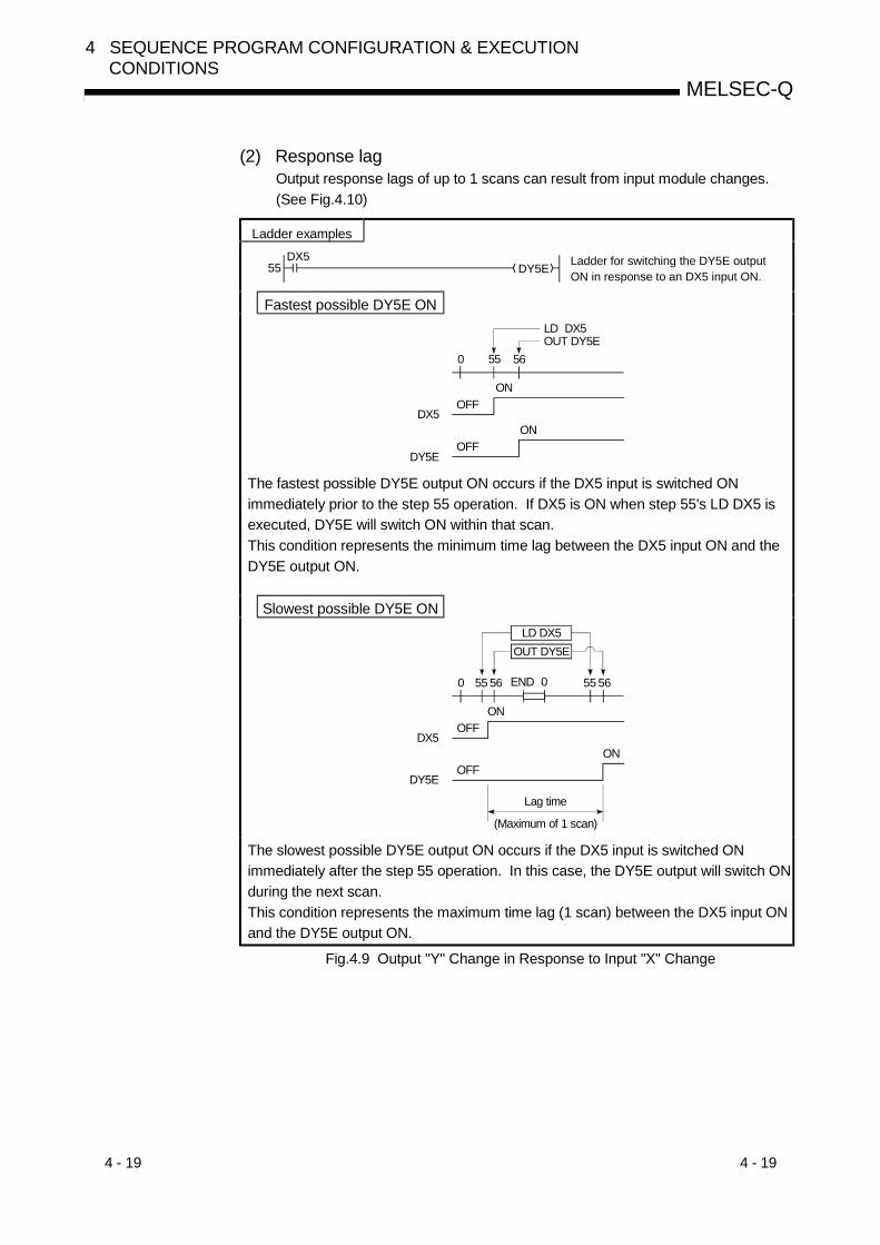
4 - 19 4 - 19
MELSEC-Q
4 SEQUENCE PROGRAM CONFIGURATION & EXECUTIONCONDITIONS
(2) Response lagOutput response lags of up to 1 scans can result from input module changes.(See Fig.4.10)
Ladder examples
Ladder for switching the DY5E outputON in response to an DX5 input ON.DY5E
DX555
Fastest possible DY5E ON
OFF
OFF
ON
ON
LD DX5OUT DY5E
0
DX5
DY5E
55 56
The fastest possible DY5E output ON occurs if the DX5 input is switched ONimmediately prior to the step 55 operation. If DX5 is ON when step 55's LD DX5 isexecuted, DY5E will switch ON within that scan.This condition represents the minimum time lag between the DX5 input ON and theDY5E output ON.
Slowest possible DY5E ON
OFF
OFF
ON
ON
0
DX5
DY5E
END 0
Lag time
(Maximum of 1 scan)
OUT DY5ELD DX5
55 56 55 56
The slowest possible DY5E output ON occurs if the DX5 input is switched ONimmediately after the step 55 operation. In this case, the DY5E output will switch ONduring the next scan.This condition represents the maximum time lag (1 scan) between the DX5 input ONand the DY5E output ON.
Fig.4.9 Output "Y" Change in Response to Input "X" Change
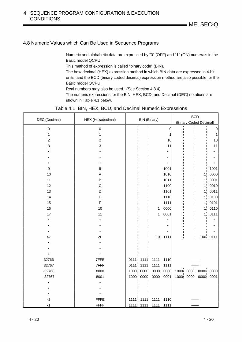
4 - 20 4 - 20
MELSEC-Q
4 SEQUENCE PROGRAM CONFIGURATION & EXECUTIONCONDITIONS
4.8 Numeric Values which Can Be Used in Sequence Programs
Numeric and alphabetic data are expressed by "0" (OFF) and "1" (ON) numerals in theBasic model QCPU.This method of expression is called "binary code" (BIN).The hexadecimal (HEX) expression method in which BIN data are expressed in 4-bitunits, and the BCD (binary coded decimal) expression method are also possible for theBasic model QCPU.Real numbers may also be used. (See Section 4.8.4)The numeric expressions for the BIN, HEX, BCD, and Decimal (DEC) notations areshown in Table 4.1 below.
Table 4.1 BIN, HEX, BCD, and Decimal Numeric Expressions
DEC (Decimal) HEX (Hexadecimal) BIN (Binary)BCD
(Binary Coded Decimal)
0 0 0 01 1 1 12 2 10 103 3 11 11• • • •• • • •• • • •9 9 1001 100110 A 1010 1 000011 B 1011 1 000112 C 1100 1 001013 D 1101 1 001114 E 1110 1 010015 F 1111 1 010116 10 1 0000 1 011017 11 1 0001 1 0111• • • •• • • •• • • •
47 2F 10 1111 100 0111• •• •• •
32766 7FFE 0111 1111 1111 1110 ——32767 7FFF 0111 1111 1111 1111 ——-32768 8000 1000 0000 0000 0000 1000 0000 0000 0000-32767 8001 1000 0000 0000 0001 1000 0000 0000 0001
• •• •• •-2 FFFE 1111 1111 1111 1110 ——-1 FFFF 1111 1111 1111 1111 ——

4 - 21 4 - 21
MELSEC-Q
4 SEQUENCE PROGRAM CONFIGURATION & EXECUTIONCONDITIONS
(1) External numeric inputs to Basic model QCPUWhen designating numeric settings for the Basic model QCPU from an externalsource (digital switch, etc.), a BCD (binary coded decimal) setting can bedesignated which is the same as a decimal setting.However, because the Basic model QCPU operation is based on BIN, if theBasic model QCPU uses values designated in the BCD method as they are, ithandles the values as BIN.The Basic model QCPU operation based on such values will be different from theoperation specified by the designated values.A BIN instruction is therefore provided for the Basic model QCPU to convert BCDinput data to the BIN data which is used by the Basic model QCPU.A program which converts numeric data to BIN data can be created at thesequence program in order to allow numeric settings to be designated from anexternal source without regard to the corresponding BIN values.
BINP K4X0 D0
BCD D5 K4Y30
Digital switch
[Numeric data designation]
BCD input
BIN data
Basic model QCPU
XF X0
1234
Fig.4.10 Digital Switch Data Input to Basic model QCPU
(2) External numeric outputs from Basic model QCPUA digital display can be used to display numeric data which is output from theBasic model QCPU.However, because the Basic model QCPU uses BIN data, it cannot be displayedat the digital display as is.A BCD instruction is therefore provided for the Basic model QCPU to convert theBIN data to BCD data. A program which converts BIN data to BCD data can becreated at the sequence program in order to display the output data in a manneridentical to decimal data.
BINP K4X0 D0
BCD D5 K4Y30
Basic modle QCPU
Digital display
[Numeric data designation]
Y3F Y30
BIN data
BCD output
Fig.4.11 Digital Display of Data from Basic model QCPU
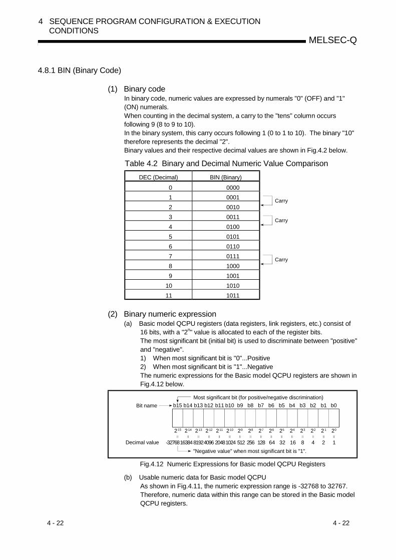
4 - 22 4 - 22
MELSEC-Q
4 SEQUENCE PROGRAM CONFIGURATION & EXECUTIONCONDITIONS
4.8.1 BIN (Binary Code)
(1) Binary codeIn binary code, numeric values are expressed by numerals "0" (OFF) and "1"(ON) numerals.When counting in the decimal system, a carry to the "tens" column occursfollowing 9 (8 to 9 to 10).In the binary system, this carry occurs following 1 (0 to 1 to 10). The binary "10"therefore represents the decimal "2".Binary values and their respective decimal values are shown in Fig.4.2 below.
Table 4.2 Binary and Decimal Numeric Value ComparisonDEC (Decimal) BIN (Binary)
0 00001 00012 0010
Carry
3 00114 0100
Carry
5 01016 01107 01118 1000
Carry
9 100110 101011 1011
(2) Binary numeric expression(a) Basic model QCPU registers (data registers, link registers, etc.) consist of
16 bits, with a "2n" value is allocated to each of the register bits.The most significant bit (initial bit) is used to discriminate between "positive"and "negative".1) When most significant bit is "0"...Positive2) When most significant bit is "1"...NegativeThe numeric expressions for the Basic model QCPU registers are shown inFig.4.12 below.
b15
8192
Bit name
Decimal value
Most significant bit (for positive/negative discrimination)
"Negative value" when most significant bit is "1".16384 4096 20481024 512 256 128 64 32 16 8 4 2 1-32768
215 214 213 212 211 210 29 28 27 26 25 24 23 22 21 20
b14 b13 b12 b11 b10 b9 b8 b7 b6 b5 b4 b3 b2 b1 b0
Fig.4.12 Numeric Expressions for Basic model QCPU Registers
(b) Usable numeric data for Basic model QCPUAs shown in Fig.4.11, the numeric expression range is -32768 to 32767.Therefore, numeric data within this range can be stored in the Basic modelQCPU registers.

4 - 23 4 - 23
MELSEC-Q
4 SEQUENCE PROGRAM CONFIGURATION & EXECUTIONCONDITIONS
4.8.2 HEX (Hexadecimal)
(1) Hexadecimal notationIn the hexadecimal system, 4 bits of binary data are expressed by 1 digit.4 bits of binary data can express 16 values (0 to 15).In the hexadecimal system, values from 0 to 15 are expressed by 1 digit.This is accomplished by using alphabetic characters following "9", with a carryoccurring after "F", as follows:A comparison of binary, hexadecimal, and decimal numeric expressions is shownin Table 4.3 below.
Table 4.3 Comparison of BIN, HEX, and DEC Numeric ExpressionsDEC (Decimal) HEX (Hexadecimal) BIN (Binary)
0 0 01 1 12 2 103 3 11• • •• • •• • •9 9 100110 A 101011 B 101112 C 110013 D 110114 E 111015 F 111116 10 1 0000
Carry
17 11 1 0001• • •• • •• • •
47 2F 10 1111
(2) Hexadecimal numeric expressionBasic model QCPU registers (data registers, link registers, etc.) consist of 16bits.Therefore, as expressed in hexadecimal code, the numeric value range whichcan be stored is 0 to FFFFH.

4 - 24 4 - 24
MELSEC-Q
4 SEQUENCE PROGRAM CONFIGURATION & EXECUTIONCONDITIONS
4.8.3 BCD (Binary Coded Decimal)
(1) BCD notationBCD numeric expressions are binary expressions with a carry format identical tothat of the decimal system.As with the hexadecimal system, BCD expressions are the equivalent of 4 binarybits, although the BCD system does not use the A to F alphabetic characters.A comparison of binary, BCD, and decimal numeric expressions is shown inTable 4.4 below.
Table 4.4 Comparison of BIN, BCD, and DEC Numeric Expressions
DEC (Decimal) BIN (Binary)BCD
(Binary Coded Decimal)
0 0 01 1 12 10 103 11 114 100 1005 101 1016 110 1107 111 1118 1000 10009 1001 100110 1010 1 0000
Carry
11 1011 1 000112 1100 1 0010
(2) BCD numeric expressionBasic model QCPU registers (data registers, link registers, etc.) consist of 16bits.Therefore, as expressed in BCD code, the range of numeric values to be storedis 0 to 9999.

4 - 25 4 - 25
MELSEC-Q
4 SEQUENCE PROGRAM CONFIGURATION & EXECUTIONCONDITIONS
4.9 Character String Data
(1) Character String DataThe Basic model QCPU uses ASCII code data.
(2) ASCII code character stringsASCII code character strings are shown in the Table below."00H" (NUL code) is used at the end of a character string.
0 0 0 0 0 0 0 0 1 1 1 1 1 1 1 10 0 0 0 1 1 1 1 0 0 0 0 1 1 1 10 0 1 1 0 0 1 1 0 0 1 1 0 0 1 10 1 0 1 0 1 0 1 0 1 0 1 0 1 0 1
Column
Low
(Comma)
(Minus)
(Period)
Underline
0 1 2 3 4 5 6 7 8 9 A B C D E Fb8 b7 b6 b5 b4 b3 b2 b1
0 0 0 00 0 0 10 0 1 00 0 1 10 1 0 00 1 0 00 1 1 00 1 1 11 0 0 01 0 0 11 0 1 01 0 1 1
1 1 0 0
1 1 0 1
1 1 1 0
1 1 1 1
0123456789AB
C
D
E
F
NUL (SP) 0 @ P ` p! 1 A Q a q" 2 B R b r# 3 C S c s$ 4 D T d t% 5 E U e u& 6 F V f v' 7 G W g w( 8 H X h x) 9 I Y i y* : J Z j z+ ; K [ k {
, < L l |
- = M ] m }
. > N ^ n
/ ? O _ o
POINTCharacter strings are available for the $MOV instruction only.
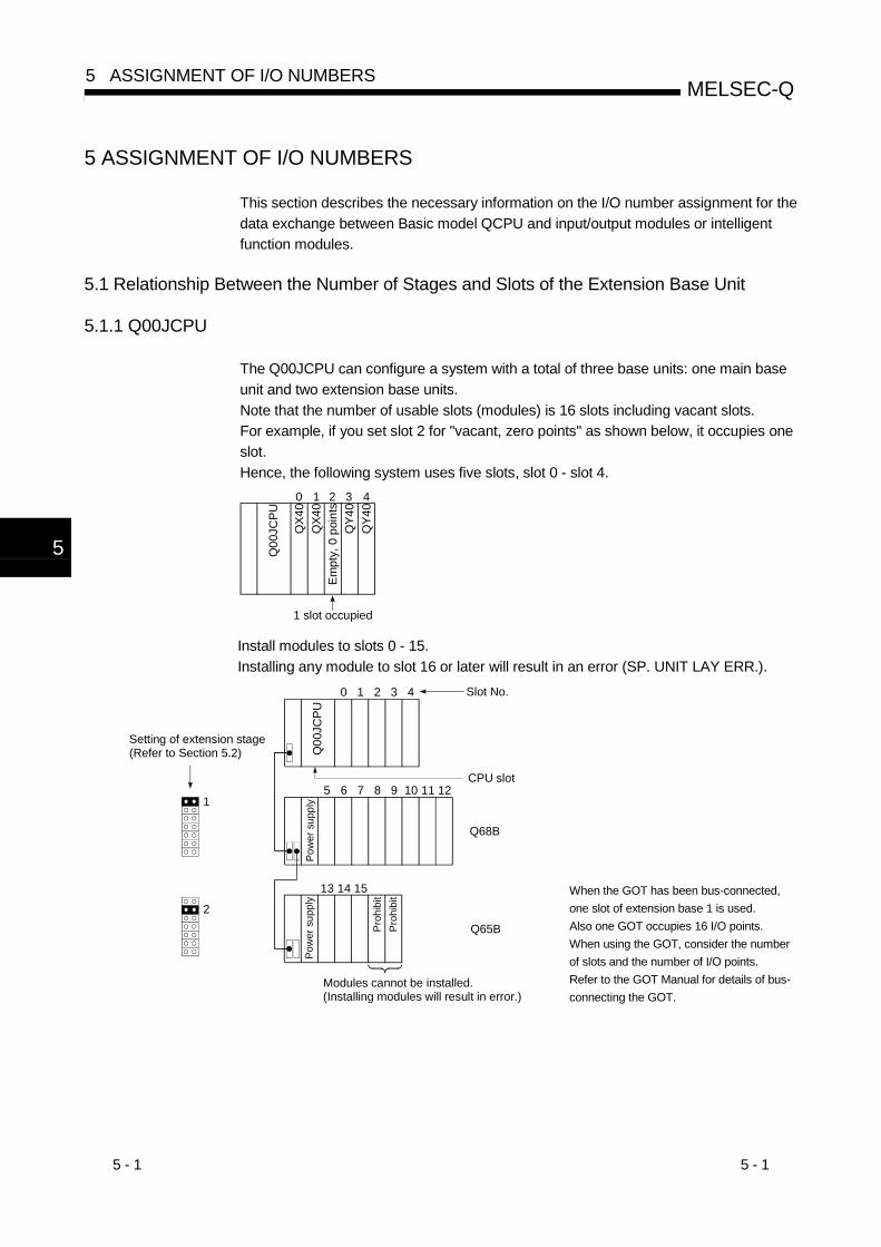
5 - 1 5 - 1
MELSEC-Q5 ASSIGNMENT OF I/O NUMBERS
5
5 ASSIGNMENT OF I/O NUMBERS
This section describes the necessary information on the I/O number assignment for thedata exchange between Basic model QCPU and input/output modules or intelligentfunction modules.
5.1 Relationship Between the Number of Stages and Slots of the Extension Base Unit
5.1.1 Q00JCPU
The Q00JCPU can configure a system with a total of three base units: one main baseunit and two extension base units.Note that the number of usable slots (modules) is 16 slots including vacant slots.For example, if you set slot 2 for "vacant, zero points" as shown below, it occupies oneslot.Hence, the following system uses five slots, slot 0 - slot 4.
Q00
JCPU
QX4
0
QY4
0
0 1 2 3 4
Empt
y, 0
poi
nts
1 slot occupied
QX4
0
QY4
0
Install modules to slots 0 - 15.Installing any module to slot 16 or later will result in an error (SP. UNIT LAY ERR.).
13 14 15
Q00
JCPU
0 1 2 3 4
5 6 7 8 9 10 11 12
Q68B
Q65B
1
2
Modules cannot be installed.(Installing modules will result in error.)
Setting of extension stage(Refer to Section 5.2)
Slot No.
CPU slot
Pow
er s
uppl
y
Proh
ibit
Proh
ibit
Pow
er s
uppl
y
When the GOT has been bus-connected,one slot of extension base 1 is used.Also one GOT occupies 16 I/O points.When using the GOT, consider the numberof slots and the number of I/O points.Refer to the GOT Manual for details of bus-connecting the GOT.

5 - 2 5 - 2
MELSEC-Q5 ASSIGNMENT OF I/O NUMBERS
5
5.1.2 Q00CPU/Q01CPU
The Q00CPU/Q01CPU can configure a system with a total of five base units: one mainbase unit and four extension base units.Note that the number of usable slots (modules) is 24 slots including vacant slots.
Q00
CPU
QX4
0
QY4
0
Pow
er s
uppl
y
1 slot occupied
Empt
y, 0
poi
nts
QX4
0
QY4
0
Install modules to slots 0 - 23.Installing any module to slot 24 or later will result in an error (SP. UNIT LAY ERR.).Hence, the following system uses five slots, slot 0 - slot 4.
20 21 22 23
10 11 12 13 14
Q00
CPU
0 1 2 3 4
Q35
5 6 7 8 9
Q65B
Q65B
Q65B
Q65B
1
2
3
4
15 16 17 18 19
Module cannot be installed.(Installing module will result in error.)
Setting of extension stage(Refer to Section 5.2) Po
wer
sup
ply
Slot No.
CPU slot
Inva
lid
Pow
er s
uppl
yPo
wer
sup
ply
Pow
er s
uppl
yPo
wer
sup
ply
When the GOT has been bus-connected,one slot of extension base 1 is used.Also one GOT occupies 16 I/O points.When using the GOT, consider the numberof slots and the number of I/O points.Refer to the GOT Manual for details of bus-connecting the GOT.

5 - 3 5 - 3
MELSEC-Q5 ASSIGNMENT OF I/O NUMBERS
5.2 Installing Extension Base Units and Setting the Number of Stages
As extension base units, you can use the Q5 B and Q6 B that are designed forinstallation of Q series-compatible modules.The QA1S6 B and QA65B extension base units are unusable.
(1) Setting order of the extension stage numbers for extension baseunitsExtension base units require the setting of the extension stage numbers usingthe stage setting connector.Assign the extension stage numbers starting from 1 to 2/4 to the extension baseunits counting from the one which is connected to the main base unit.
(2) Cautions to assign extension stage numbers to extension baseunits(a) Assign consecutive numbers to extension stages.
If you assign stage numbers to base units in "Auto" mode and assign somestage numbers to no modules, "0" is assigned to the skipped stage as thenumber of slots. Consequently, the number of vacant slots does notincrease. The I/O assignment also assigns "0" to the skipped stage as theI/O points.
(b) It is impossible to set and use the same extension stage number with two ormore extension base units.
(c) You cannot use the system if two or more connector pins are inserted to thestage setting connector.On the contrary, you cannot use the system if no connector pin is insertedto the stage setting connector.
16 17 18 19 20 21 22 23
Setting of extension stage
0 1 2 3 4 5 6 7
Q38B
8 9 10 11 12 13 14 15
Q68B
Q68B
1
2
Main base unit
Stage setting connector
Powe
r sup
ply
Powe
r sup
ply
Powe
r sup
ply
Q00
CPU

5 - 4 5 - 4
MELSEC-Q5 ASSIGNMENT OF I/O NUMBERS
5.3 Base Unit Assignment (Base Mode)
There are "Auto" and "Detail" modes to assign the number of modules of the main andextension base units of Basic model QCPU.
(1) Auto modeIn Auto mode, the number of slots is assigned to the base units according to thatof the installed main and extension base units.The I/O numbers are assigned according to the modules which can be installedto the current base unit.
Since the AnS series main and extension base units were fixed to eight slots, athree/five-slot base unit occupied eight slots.The Basic model QCPU, which occupies only the installable slots of a base unit,occupies only three slots when a three-slot base unit is used.
(a) For 3-slot base unit: 3 slots are occupiedQ33B type main base unit
Q00
CPU
0 1 2
Pow
er s
uppl
y
Five slots are not occupied.
Q63B type extension base unit3 4 5
Pow
er s
uppl
y
Five slots are not occupied.
Q63B type extension base unit6 7 8
Pow
er s
uppl
y
Five slots are not occupied.

5 - 5 5 - 5
MELSEC-Q5 ASSIGNMENT OF I/O NUMBERS
(b) For 5-slot base unit/Q00JCPU: 5 slots are occupiedQ35B type main base unit
Q00
CPU
0 1 2 3 4
Pow
er s
uppl
y
Three slots are not occupied
Q65B type extension base unit5 6 7 8 9
Pow
er s
uppl
y
Three slots are not occupied
Q65B type extension base unit10 11 12 13 14
Pow
er s
uppl
y
Three slots are not occupied
(c) For 8-slot base unit: 8 slots are occupiedQ38B type main base unit
Q00
CPU
0 1 2 3 4
Pow
er s
uppl
y
5 6 7
Q68B type extension base unit8 9 10 11 12
Pow
er s
uppl
y
13 14 15
(d) For 12-slot base unit: 12 slots are occupiedQ312B type main base unit
Q00
CPU
0 1 2 3 4
Pow
er s
uppl
y
5 6 7 8 9 10 11
Q612B type extension base unit12 13 14 15 16
Pow
er s
uppl
y
17 18 19 20 21 22 23

5 - 6 5 - 6
MELSEC-Q5 ASSIGNMENT OF I/O NUMBERS
(2) Detail mode(a) In Detail mode, the number of slots is assigned to the individual base units
(main and extension base units) by setting the I/O assignment of PLCParameter.Use this mode to match the number of slots to the one for the AnS-seriesbase units (8 fixation).Since one slot is occupied if an empty slot is set for zero points in I/Oassignment, this mode is also used to make the slot without a module andlater unrecognized.
(b) Cautions on setting the number of slotsThe number of slots can be set regardless of the number of slots of themodule being used.However, the number of slots must be set for all the base units in use.If the number of slot is not set for all the base units, I/O assignment may notwork correctly.The followings result if the preset number of slots differs from that of theinstalled base units.1) When the designated number of slots is larger than that of the installed
base unit:Among the designated slots, those after the slots occupied by theinstalled base unit will be empty slots.For example, when 8 slots are designated for a 5-slot base unit, 3 slotswill be empty slots.
Q35B type main base unit0 1 2 3 4
Three slots are occupied.
5 6 7
Empt
y
Powe
r sup
ply
Empt
yEm
pty
Q00
CPU
The number of points for the empty slots is the one designated by PLCsystem of PLC Parameter or with I/O assignment. (Default value is 16points.)
2) When the designated number of slots is smaller than that of the baseunit being used:The slots other than those designated are disabled.For example, when 8 slots are designated for a 12-slot base unit, the 4slots on the right of the base unit are disabled.(If a module is installed to the disabled slot, an error [SP. UNIT LAYERR.] occurs.)
Q312B type main base unit0 1 2 3 4 5 6 7 8 9 10 11
When module is installed, an error occurs.
Module can be installed. (When eight slots are set)
Inva
lid
Powe
r sup
ply
Q00
CPU
Inva
lidIn
valid
Inva
lid
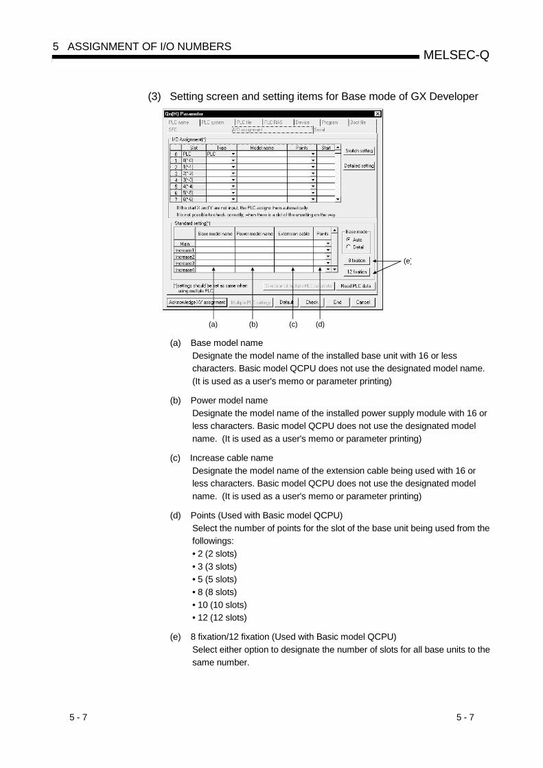
5 - 7 5 - 7
MELSEC-Q5 ASSIGNMENT OF I/O NUMBERS
(3) Setting screen and setting items for Base mode of GX Developer
(a)
(e)
(d)(c)(b)
(a) Base model nameDesignate the model name of the installed base unit with 16 or lesscharacters. Basic model QCPU does not use the designated model name.(It is used as a user's memo or parameter printing)
(b) Power model nameDesignate the model name of the installed power supply module with 16 orless characters. Basic model QCPU does not use the designated modelname. (It is used as a user's memo or parameter printing)
(c) Increase cable nameDesignate the model name of the extension cable being used with 16 orless characters. Basic model QCPU does not use the designated modelname. (It is used as a user's memo or parameter printing)
(d) Points (Used with Basic model QCPU)Select the number of points for the slot of the base unit being used from thefollowings:• 2 (2 slots)• 3 (3 slots)• 5 (5 slots)• 8 (8 slots)• 10 (10 slots)• 12 (12 slots)
(e) 8 fixation/12 fixation (Used with Basic model QCPU)Select either option to designate the number of slots for all base units to thesame number.

5 - 8 5 - 8
MELSEC-Q5 ASSIGNMENT OF I/O NUMBERS
5.4 What are I/O Numbers?
I/O numbers are used in sequence program for reception of ON/OFF data at Basicmodel QCPU and output of ON/OFF data from Basic model QCPU to outsides.Input (X) is used for the reception of ON/OFF data at Basic model QCPU. Output (Y)is used for the output of ON/OFF data from Basic model QCPU.I/O numbers are expressed as hexadecimals.When using 16-point I/O modules, I/O numbers are consecutive numbers that 1 slothas 16 points 0 to F as follows.The module that is mounted in the base unit assigns the following:
• For the input module, "X" is assigned at the beginning of the I/O number.• For the output module, "Y" is assigned at the beginning of the I/O number.
Q00CPU
16 input points
X 0 0 0 X 0 1 0 X 0 2 0 Y 0 3 0 Y 0 4 0
X 0 0 F X 0 1 F X 0 2 F Y 0 3 F Y 0 4 F
For the case of input module For the case of output module
X2C
Power supply module
16 input points
16 input points
16 output points
16 output points

5 - 9 5 - 9
MELSEC-Q5 ASSIGNMENT OF I/O NUMBERS
5.5 Concept of I/O Number Assignment
5.5.1 I/O numbers of main base unit and extension base unit
Basic model QCPU assigns I/O numbers at power-on or reset according to thefollowing items.As a result, you can control Basic model QCPU without using GX Developer for I/Oassignment.To assign I/O numbers, follow the items below:
(1) Number of slots of base unitsThe number of slots of the main and extension base units are set according tothe Base mode setting. (For Base mode, refer to Section 5.3.)(a) In Auto mode, the number of slots is determined as the available number of
modules installed to each base unit.For example, 5 slots are assigned for a 5-slot base unit, and 12 slots areassigned for a 12-slot base unit.
(b) In Detail mode, the number of slots is determined as the one designated byI/O assignment of PLC Parameter.
(2) Order of I/O number assignmentThe I/O numbers are assigned to the modules from left to right consecutively,starting from 0H assigned to the module on the right of the Basic model QCPU inthe main base unit.
(3) Order of I/O number assignment for extension base unitsThe I/O numbers for extension base units are assigned continuing from the lastnumber of the I/O number of the main base unit.The I/O numbers for extension base units are assigned to the units from left (silk-screened I/O 0 of extension base unit) to right consecutively, in the order of thesetting of the stage setting connectors of the extension base units.
(4) I/O numbers of each slotEach slot of base units occupies the points of I/O numbers of the installed I/Omodules or intelligent function modules.When 32-point input module is installed on the right of Basic model QCPU, X0 toX1F are assigned as I/O numbers.
(5) I/O numbers of empty slotsIf the base unit has vacant slots where no I/O modules or no intelligent functionmodules are installed, the points designated by PLC system setting of PLCParameter are assigned to the empty slots. (Default value is 16 points.)
POINTWhen the assignment of base units is conducted in Auto mode, the number ofempty extension stages is not assured even if the extension stage is skipped at thestage number setting connector of the base unit. (Smaller input/output numbers areassigned first.)To reverse empty extension stages for future extension, use the PLC parameter toset the base unit.

5 - 10 5 - 10
MELSEC-Q5 ASSIGNMENT OF I/O NUMBERS
The following shows the example of the I/O number assignment when the base unit isset in Auto mode without I/O assignment:
Pow
er s
uppl
y m
odul
e
0
X00
X0F
1 2 3 4
X10
X1F
X20
X3F
Y40
Y4F
Y50
Y8F
Q35B (5 slots occupied)
IN OUT
6
90
AF
7 8 95
B0
CF
D0
EF
YF0
YFF
100
10F
11
X110
X11F
12 13 14
Q68B (8 slots occupied)
10
X120
X12F
130
14F
150
16F
170
18F
15 16 17
Y190
Y19F
Y1A0
Y1AF
Y1B0
Y1BF
Extension cable
1
Slot No.
Allocate the I/O number with
the I/O points of each slot
I/O numbering direction
The slot numbers of the 1st stage's extension base unit continue from the last slot number of the main base unit.
Empty slot points designated on the PLC system Setting screen under the parameter mode are allocated. (Default: 16 points)
The slot numbers of the 2nd stage's extension base unit continue from the last slot number of the 1st stage's extension base unit.
2
Q65B (5 slots occupied)
.........
.............
16 points
Inpu
t mod
ule
Inpu
t mod
ule
Inpu
t mod
ule
Out
put m
odul
e
Out
put m
odul
e
16 points
32points
16 points
64 points
Pow
er s
uppl
y m
odul
e
Inte
llige
nt
func
tion
mod
ule
Inte
llige
nt
func
tion
mod
ule
Inte
llige
nt
func
tion
mod
ule
Out
put m
odul
e
Empt
y
32 points
32points
32points
16 points
16 points
IN OUT
Pow
er s
uppl
y m
odul
e
Inpu
t mod
ule
Inpu
t mod
ule
Inte
llige
nt
func
tion
mod
ule
Inte
llige
nt
func
tion
mod
ule
Inte
llige
nt
func
tion
mod
ule
Out
put m
odul
e
Out
put m
odul
e
Out
put m
odul
e
16 points
16 points
32points
32points
32 points
16 points
16 points
16 points
Q00
CPU
POINTThe above example shows the case where the intelligent function module has 32I/O points.The number of I/O points may vary depending on the intelligent function module.Refer to the manual of the intelligent function module being used and check thenumber of the I/O points before assigning the I/O numbers.

5 - 11 5 - 11
MELSEC-Q5 ASSIGNMENT OF I/O NUMBERS
5.5.2 Remote station I/O number
In a CC-Link remote I/O system, you can exercise control after assigning the inputs (X)and outputs (Y) of the Basic model QCPU devices to the I/O and intelligent functionmodules of remote stations.Also, the inputs (X) and outputs (Y) are used as the refresh destinations (Basic modelQCPU side devices) of the link inputs and outputs (LX, LY) of the MELSECNET/H.Take care not to overlap the I/O numbers of the MELSECNET/H refresh destinationsand the I/O numbers of the CC-Link remote I/O system.
Pow
er m
odul
e
Remote station
CC-Link
Allocation ofQ00CPU input (X) andoutput (Y) possible
Remote station
Q00
CPU
QJ6
1BT1
1
QJ7
1LP2
1
QX4
1
QY4
1
Q64
AD
When using Basic model QCPU device input (X) and output (Y) in remote stations, I/Onumbers that succeed the numbers used by the main base unit and extension baseunits' input/output modules and intelligent function modules will be allocated.For example, if X/Y0 to X/YFF are being used by the main base unit and extensionbase units' input/output modules and intelligent function modules, then numbers aboveX/Y100 can be used by the remote station.However, the I/O numbers for remote stations should be set in consideration ofadditions to the main base unit and extension base units' input/output modules andintelligent function modules.
(Example) If 256 points from X/Y0 to X/YFF are being used by the main base unit andextension base units, and 256 points from X/Y100 to X/Y1FF are to be held back foruse with future additions, then the situation shown in the diagram below is to beobserved.
X/Y0
X/YFFX/Y100
X/Y1FFX/Y200
X/Y7FF
Input/Output (X/Y)
For CC-Link remotestation
I/O numbers being used by the main base unit andextension base units
Held back for future additions
I/O numbers that can be used by remote stations
to
to
to
POINTIf network parameter setting has not been made in a CC-Link system, 1024 pointsof X/Y400 to X/Y7FF are assigned to the CC-Link master/local module of lower I/Onumbers.

5 - 12 5 - 12
MELSEC-Q5 ASSIGNMENT OF I/O NUMBERS
5.6 I/O Assignment by GX Developer
This section describes the I/O assignment using GX Developer.
5.6.1 Purpose of I/O assignment by GX Developer
I/O assignment by GX Developer is used under the following circumstances.
(1) Reserving points when converting to module other than 16-pointmodulesYou can reserve the number of points in advance so that you do not have tochange the I/O numbers when the current module will be changed to one with adifferent number of I/O points in the future.For example, you can assign a 32-point I/O module to the slot where a 16-pointI/O module is installed at present.
(2) Preventing I/O numbers from changing when converting modulesYou can avoid the change in the I/O numbers when an I/O module other than 16-point module or intelligent function module is removed due to a malfunction.
(3) Changing the I/O numbers to those used in the programWhen the designed programs I/O numbers are different from the actual systemI/O numbers, each modules I/O numbers of base units can be set to program-I/Onumbers.
(4) Setting the input response time of input modules and interruptmodules (I/O response time)To match the input response time of the input modules and interrupt modules tothe system, select "Type" in the I/O assignment beforehand. (For details, refer toSection 7.7.)
(5) Setting the switch of intelligent function modulesTo set the switch of the intelligent function module, select "Type" in the I/Oassignment beforehand. (For details, refer to Section 7.8.)
(6) Setting outputs during Basic model QCPU errorTo set the output status (retain/clear) of the output modules and intelligentfunction modules when the Basic model QCPU stops the operation due to a stoperror, select "Type" in the I/O assignment beforehand.
(7) Setting Basic model QCPU operation during a hardware error ofintelligent function modulesTo set the Basic model QCPU operation (continue/stop) during a hardware errorof an intelligent function module, select "Type" in the I/O assignment beforehand.
POINT(1) The I/O assignment setting of the PLC parameters are made valid when the
PLC is powered on or the Basic model QCPU is reset.When you have changed the PLC parameter values, power on the PLC again orreset the Basic model QCPU.
(2) I/O assignment must be made to set the response time of the input module ormake the switch setting of the intelligent function module.

5 - 13 5 - 13
MELSEC-Q5 ASSIGNMENT OF I/O NUMBERS
5.6.2 Concept of I/O assignment using GX Developer
(1) I/O assignment for each slotYou can designate "Type" (module type), "Points" (number of I/O points), and"Start XY" (head I/O number) individually for each slot of the base unit.For example, to change the number of I/O points of the designated slot, you candesignate only the number of I/O points.The items other than designated are set to the status where the base unit is installed.The I/O assignment is conducted according to the I/O assignment setting of PLCParameter.
(a) (e)(d)(c)(b)
(a) SlotDisplays the slot No. and the ordinal position of the slot in the base unit.If the base unit is not designated in Detail mode, the stage number of thebase unit is shown as " ", and the ordinal number of a slot is countedfrom slot 0 of the main base unit.
(b) Type (Used with Basic model QCPU)Select the type of module being installed from the followings:• Empty (Empty slot)• Input (Input module)• Hi Input (Q series corresponding high speed module)• Output (Output module)• I/O Mix (I/O mixed module)• Intelligent (Intelligent function module)• Interrupt (Q series corresponding interruption module)If the type is not designated, the type of the actually installed module is used.
5 - 14 5 - 14
MELSEC-Q5 ASSIGNMENT OF I/O NUMBERS
(c) Model nameDesignate the model name of the installed module with 16 or lesscharacters. Basic model QCPU does not use the designated model name. (Itis used as a user's memo or for parameter printing.)
(d) Points (Used with Basic model QCPU)To change the number of I/O points of each slot, select it from thefollowings:• 0 (0 point) • 128 (128 points)• 16 (16 points) • 256 (256 points)• 32 (32 points) • 512 (512 points) • 48 (48 points) • 1024 (1024 points) • 64 (64 points)If the number of I/O points is not designated for a slot, the one of theactually installed module is used.
: Setting is enabled for the Q00/Q01CPU only.(Since the number of I/O points of the Q00JCPU is 256, you cannot set512/1024 points.)
(e) Start XY (Used with Basic model QCPU)1) When the I/O number of each slot is changed, you should designate
the head I/O number according to the change.If Start XY is not designated for a slot, the I/O number continuing fromthe last number of the currently designated slot is assigned.
2) Avoid the I/O number designation of each slot from overlapping the I/Onumbers assigned by Basic model QCPU.An error (SP. UNIT LAY ERR.) occurs when the I/O numbers overlap.
(2) Slot status after I/O assignmentWhen the I/O number is assigned to a slot, the assigned I/O number takesprecedence regardless of the actual installation of a module.(a) If the designated number of I/O points is smaller than that of the actually
installed input/output module, some I/O points of the installed module arenot used.For example, if a slot where a 32-point input module is installed isdesignated for a 16-point input module, the latter 16 points of the 32-pointinput module are disabled.
(b) If the designated number of I/O points is larger than that of the actuallyinstalled input/output module, the points exceeding the points of the actuallyinstalled module are set as dummies.
(c) Be sure to set the same module type for the installed module and the I/Oassignment.If the module type of the I/O assignment is different from that of the actuallyinstalled module, a malfunction may result.For the intelligent function module, make sure that the numbers of I/Opoints are the same.

5 - 15 5 - 15
MELSEC-Q5 ASSIGNMENT OF I/O NUMBERS
Actually installed module I/O assignment Result
Input module Output/Empty EmptyOutput module Input/Empty EmptyInput module/output module Intelligent Error (SP. UNIT LAY ERR.)
Empty EmptyIntelligent function module
Input/output Error (SP. UNIT LAY ERR.)Vacant slot Intelligent No error occurs.
(d) "SP. UNIT LAY ERR." occurs if the number of points set is less than thenumber of points of the installed intelligent function module.
(e) Be sure to assign the I/O numbers so that the last I/O number is within therange of FFH/3FFH or less. An error (SP. UNIT LAY ERR.) occurs when thelast I/O number exceeds FFH/3FFH. (System monitor of GX Developershows " " as an I/O address.)

5 - 16 5 - 16
MELSEC-Q5 ASSIGNMENT OF I/O NUMBERS
5.7 Examples of I/O Number Assignment
This section shows the examples of the I/O number assignment using GX Developer.
(1) When changing the number of points of an empty slot from 16 to 32points:Reserve 32 points to the slot position currently empty (slot No. 3) so that theinput/output numbers do not change when a 32-point input module is installed inthe future. (The empty slot for slot No. 12 is not changed from 16 points.) 1
(a) System configuration and I/O number assignment before the I/Oassignment with GX Developer
0 1 2 3 4
Q38B
9 10 11 12
Q68B
8 13 14 15
F0
10F
110
12F
130
14F
150
16F
170
17F
Y180
Y19F
Y1A0
Y1BF
Y1C0
Y1DF
1
5 6 7
X00
X1F
X20
X3F
X40
X5F
60
6F
Y70
Y8F
Y90
YAF
YB0
YCF
YD0
YEF
Pow
er s
uppl
y m
odul
e
Inpu
t mod
ule
Inpu
t mod
ule
Inpu
t mod
ule
Out
put m
odul
e
Out
put m
odul
e
Out
put m
odul
e
Out
put m
odul
e
Empt
y
32points
32points
32points
16points
32 points
32 points
32 points
32 points
Pow
er s
uppl
y m
odul
e
Inte
lligen
t fu
nctio
n m
odul
e
Inte
lligen
t fu
nctio
n m
odul
e
Inte
lligen
t fu
nctio
n m
odul
e
Out
put m
odul
e
Empt
y
Inte
lligen
t fu
nctio
n m
odul
e
Out
put m
odul
e
Out
put m
odul
e
32 points
32points
32points
32points
16 points
32 points
32 points
32 points
IN OUT
Q00
CPU
REMARK
1: This is the case where the number of points for an empty slot is set to 16 withPLC system setting of PLC Parameter.
2: Since the number of I/O points of the Q00JCPU is 256, use it within the rangeX/Y0 to X/YFF.

5 - 17 5 - 17
MELSEC-Q5 ASSIGNMENT OF I/O NUMBERS
(b) I/O assignment with GX DeveloperDesignate slot No. 3 to "32 points" on the I/O assignment screen of GXDeveloper.
Select 32 points.(When the type is not selected,the type of the installed modulewill be selected.)
(c) I/O number assignment after the I/O assignment with GX Developer
0 1 2 3 4
Q38B
9 10 11 12
Q68B
8 13 14 15
100
11F
120
13F
140
15F
160
17F
180
18F
Y190
Y1AF
Y1B0
Y1CF
Y1D0
Y1EF
1
5 6 7
X00
X1F
X20
X3F
X40
X5F
60
7F
Y80
Y9F
YA0
YBF
YC0
YDF
YE0
YFF
Pow
er s
uppl
y m
odul
e
32points
Inpu
t mod
ule
Inpu
t mod
ule
Inpu
t mod
ule
Out
put m
odul
e
Empt
y
32points
32points
32points
32points
Out
put m
odul
e
Out
put m
odul
e
32points
32 points
Out
put m
odul
e32
points
IN OUT
Pow
er s
uppl
y m
odul
e
Inte
lligen
t fu
nctio
n m
odul
e
Inte
lligen
t fu
nctio
n m
odul
e
Inte
lligen
t fu
nctio
n m
odul
e
Out
put m
odul
e
Empt
y
32 points
32points
32points
32 points
16points
Out
put m
odul
e
Out
put m
odul
e
Inte
lligen
t fu
nctio
n m
odul
e
32points
32points
32points
Q00
CPU
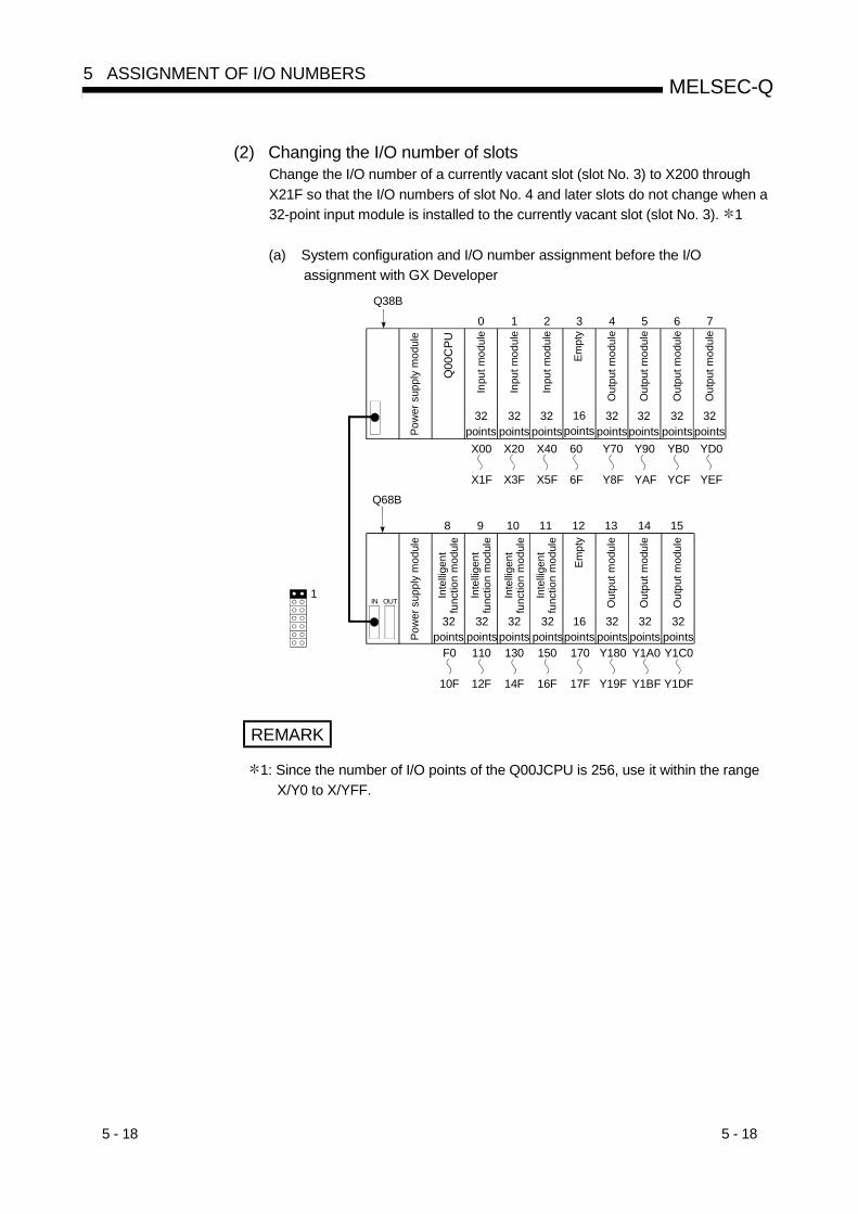
5 - 18 5 - 18
MELSEC-Q5 ASSIGNMENT OF I/O NUMBERS
(2) Changing the I/O number of slotsChange the I/O number of a currently vacant slot (slot No. 3) to X200 throughX21F so that the I/O numbers of slot No. 4 and later slots do not change when a32-point input module is installed to the currently vacant slot (slot No. 3). 1
(a) System configuration and I/O number assignment before the I/Oassignment with GX Developer
0 1 2 3 4
Q38B
9 10 11 12
Q68B
8 13 14 15
F0
10F
110
12F
130
14F
150
16F
170
17F
Y180
Y19F
Y1A0
Y1BF
Y1C0
Y1DF
1
5 6 7
X00
X1F
X20
X3F
X40
X5F
60
6F
Y70
Y8F
Y90
YAF
YB0
YCF
YD0
YEF
IN OUT
Pow
er s
uppl
y m
odul
e
Inte
lligen
t fu
nctio
n m
odul
e
Inte
lligen
t fu
nctio
n m
odul
e
Inte
lligen
t fu
nctio
n m
odul
e
Empt
y
32points
32points
32points
32points
16points
Pow
er s
uppl
y m
odul
e32
points
Inpu
t mod
ule
Inpu
t mod
ule
Inpu
t mod
ule
Out
put m
odul
e
Out
put m
odul
e
32 points
32points
16 points
32points
Out
put m
odul
e
Out
put m
odul
e
32points
32points
32points
Empt
y
Out
put m
odul
e32
pointsO
utpu
t mod
ule
32points
Out
put m
odul
e
32 points
Inte
lligen
t fu
nctio
n m
odul
e
Q00
CPU
REMARK
1: Since the number of I/O points of the Q00JCPU is 256, use it within the rangeX/Y0 to X/YFF.

5 - 19 5 - 19
MELSEC-Q5 ASSIGNMENT OF I/O NUMBERS
(b) I/O assignment with GX DeveloperDesignate the head I/O number of slot No. 3 to "200" and that of slot No. 4to "70" on the I/O assignment screen of GX Developer.
"200" is designated as the head I/O number.
"70" is designated as the headI/O number.(When the head I/O numberis not designated, the I/Onumber following the 3rd slotwill be assigned.)
(c) I/O number assignment after the I/O assignment with GX Developer
0 1 2 3 4
Q38B
9 10 11 12
Q68B
8 13 14 15
F0
10F
110
12F
130
14F
150
16F
170
17F
Y180
Y19F
Y1A0
Y1BF
Y1C0
Y1DF
1
5 6 7
X00
X1F
X20
X3F
X40
X5F
X200
X21F
Y70
Y8F
Y90
YAF
YB0
YCF
YD0
YEF
Pow
er s
uppl
y m
odul
e
32points
Inpu
t mod
ule
Inpu
t mod
ule
Inpu
t mod
ule
Out
put m
odul
e
Out
put m
odul
e
32points
32points
32 points
32points
Out
put m
odul
e
Out
put m
odul
e
32points
32 points
Inpu
t mod
ule
32points
IN OUT
Pow
er s
uppl
y m
odul
e
Inte
lligen
t fu
nctio
n m
odul
e
Inte
lligen
t fu
nctio
n m
odul
e
Out
put m
odul
e
Out
put m
odul
e
Out
put m
odul
e
32points
32 points
32points
32points
16points
32 points
32 points
32points
Inte
lligen
t fu
nctio
n m
odul
e
Inte
lligen
t fu
nctio
n m
odul
e
Empt
y
Q00
CPU
5.8 Checking the I/O Numbers
System monitor of GX Developer allows the check of the installed modules of Basicmodel QCPU and their I/O numbers. (For system monitor, refer to Section 7.18.)
6 - 1 6 - 1
MELSEC-Q6 FILES HANDLED BY BASIC MODEL QCPU
6
6 FILES HANDLED BY BASIC MODEL QCPU
(1) Data handled by Basic model QCPUThe Basic model QCPU stores such data as parameter, program and devicecomments into program memory.When ROM operation is performed, the parameter and program in the programmemory are written to standard ROM.
(2) Write of parameter and program using GX DeveloperSuch data as parameter, program and comment are written to the programmemory of the Basic model QCPU by GX Developer (online write to PLC).For online write to PLC, specify the type (e.g. parameter, program, comment) ofthe data to be written to the Basic model QCPU.
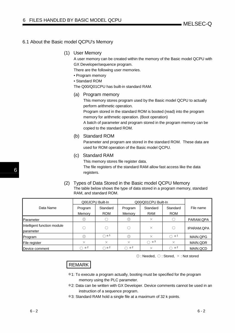
6 - 2 6 - 2
MELSEC-Q6 FILES HANDLED BY BASIC MODEL QCPU
6
6.1 About the Basic model QCPU's Memory
(1) User MemoryA user memory can be created within the memory of the Basic model QCPU withGX Developer/sequence program.There are the following user memories.• Program memory• Standard ROMThe Q00/Q01CPU has built-in standard RAM.
(a) Program memoryThis memory stores program used by the Basic model QCPU to actuallyperform arithmetic operation.Program stored in the standard ROM is booted (read) into the programmemory for arithmetic operation. (Boot operation)A batch of parameter and program stored in the program memory can becopied to the standard ROM.
(b) Standard ROMParameter and program are stored in the standard ROM. These data areused for ROM operation of the Basic model QCPU.
(c) Standard RAMThis memory stores file register data.The file registers of the standard RAM allow fast access like the dataregisters.
(2) Types of Data Stored in the Basic model QCPU MemoryThe table below shows the type of data stored in a program memory, standardRAM, and standard ROM.
Q00JCPU Built-In Q00/Q01CPU Built-InData Name Program
MemoryStandard
ROMProgramMemory
StandardRAM
StandardROM
File name
Parameter PARAM.QPAIntelligent function moduleparameter
IPARAM.QPA
Program 1 1 MAIN.QPGFile register 3 MAIN.QDRDevice comment 2 2 2 2 MAIN.QCD
: Needed, : Stored, : Not stored
REMARK
1: To execute a program actually, booting must be specified for the programmemory using the PLC parameter.
2: Data can be written with GX Developer. Device comments cannot be used in aninstruction of a sequence program.
3: Standard RAM hold a single file at a maximum of 32 k points.

6 - 3 6 - 3
MELSEC-Q6 FILES HANDLED BY BASIC MODEL QCPU
(3) Drive Number(a) The Basic model QCPU uses drive numbers to control program memory,
standard RAM and standard ROM. The GX Developer specifies a selectedmemory (program memory, standard RAM or standard ROM) to executethe read/write of parameter and program from and to the Basic modelQCPU. There is no need to specify the drive number when using the GXDeveloper.
(b) The table below shows the drive numbers used to specify a selectedmemory (program memory, standard RAM or standard ROM) when using asequence program. The drive number must be used to specify a selectedmemory when the read/write is made through access from a serialcommunication module.
Memory Drive Number
Program memory 0Standard RAM 3QCPU built-inStandard ROM 4
(4) Memory Capacity and FormattingThe table below shows the size of a memory of the Basic model QCPU andwhether to format a memory.
Q00JCPU Q00CPU Q01CPU Whether to Format
Standard RAM(kbyte)
None 64 Not required.
Program memory(kbyte)
58 94 94 Not required.
Standard ROM(kbyte)
58 94 94 Not required.
: Before using the Basic model QCPU, always format the memory using GX Developer.(However, if the memory is in an initial status or has been unformatted due to battery (Q6BAT) exhaustion,the Basic model QCPU formats automatically at power-on or reset of the PLC.

6 - 4 6 - 4
MELSEC-Q6 FILES HANDLED BY BASIC MODEL QCPU
6.2 Program Memory
(1) What is the Program Memory?(a) The program memory is an internal RAM that stores program executed by
the Basic model QCPU.
(b) The data storage in the program memory is backed up by Basic modelQCPU's built-in battery (Q6BAT).
(c) Before using the Basic model QCPU, always format the memory using GXDeveloper. 1(However, if the memory is in an initial status or has been unformatted dueto battery (Q6BAT) exhaustion, the Basic model QCPU does formattingautomatically at power-on or reset of the PLC.For details regarding the formatting procedure by the GX Developer, referto GX Developer manuals.
Table 6.1 Memory capacity after formatting 1Model Name Memory Max. Number of Program Stored
Q00JCPU 58 kbyte 1Q00CPU 94 kbyte 1Q01CPU 94 kbyte 1
POINTProgram is stored in the program memory in 4 bytes units.
(2) Data StorageData on parameter and program can be stored in the program memory. For thetypes of data stored in the program memory, see Section 6.1.
REMARK
1: The program memory is formatted by GX Developer when the user setting areain the system area is assigned. (0-3k steps can be set to the user setting areaof the system area in 1k step increments.)The user setting area (data) in the system area is used for registering monitordata from GX Developer connected to serial communication module.The allocation of space for the user setting area will make it much easier toperform monitoring with GX Developer connected to the serial communicationsmodule.Although the designation of a user setting area speeds up monitoring from GXDeveloper connected to serial communication module, it also reduces theamount of space available for user files.

6 - 5 6 - 5
MELSEC-Q6 FILES HANDLED BY BASIC MODEL QCPU
6.3 Standard ROM
(1) What is the standard ROM?(a) The standard ROM is used for the ROM operation of the Basic model
QCPU.
(b) Program stored in the standard ROM and booted (read) to the programmemory after the setting is made in the Boot File sheet of the PLCParameter dialog box.
(c) Write to the standard ROM is performed by "Write the program memory toROM" in online write to PLC (flash ROM) of GX Developer. (Refer toSection 6.4.1)
POINTSWriting program memory to ROM copies the program memory data to the standardROM as-is.
(2) Data StorageA standard ROM stores data such as parameter and program.See Section 6.1 for the data to store in the standard ROM.
(3) Setting of ROM operationWhen performing ROM operation, select "boot operation from standard ROM" inthe boot file setting of PLC parameter.

6 - 6 6 - 6
MELSEC-Q6 FILES HANDLED BY BASIC MODEL QCPU
6.4 Executing Standard ROM Program (Boot Run) and Writing Program Memory to ROM
6.4.1 Executing Standard ROM Program
(1) Executing Basic model QCPU program(a) The Basic model QCPU processes program which is stored in the program
memory.The Basic model QCPU does not perform operation of program stored inthe standard ROM.
(b) The program stored in the standard ROM is booted (read) to the programmemory to perform arithmetic operation.
(2) Preparation for Boot RunPerform the following steps in preparation for boot run:(a) Create a program using GX Developer.
Create a program used for the boot run.
(b) Select a boot file using GX Developer.Select "Do boot from standard ROM" in the boot file setting of PLCparameter.
(c) Write of parameter, program and like to standard ROM using GX Developer1) Using online "write to PLC" of GX Developer, write parameter and
program to the program memory.2) Transfer the parameter and program written in the program memory to
the standard ROM.Refer to Section 6.4.2 for write of parameter, program and the like tothe standard ROM using GX Developer.

6 - 7 6 - 7
MELSEC-Q6 FILES HANDLED BY BASIC MODEL QCPU
(d) Execute a program.Resetting the Basic model QCPU with the RUN/STOP/RESET switch startsboot from the standard ROM.Refer to the following manuals for the reset operation of the Basic modelQCPU.• QCPU (Q Mode) User's Manual (Hardware)• Basic Model QCPU (Q Mode) User's Manual (Hardware Design,
Maintenance and Inspection)
(3) Precautions for Executing Program in the Standard ROM(a) When performing boot run, store parameter (PLC parameter) and program
into the standard ROM.
(b) If program is written in the program memory during the RUN status while aboot run is performed by using a standard ROM, any change made will notbe reflected in program stored in the standard ROM.
(c) If the PLC is powered ON/reset after writing sequence program to theprogram memory, the contents of the program memory may change.This can be caused when the boot run has been set.1) Format the program memory.2) Write the parameter and sequence program to the program memory.3) Transfer the parameter written in the program memory to the ROM.

6 - 8 6 - 8
MELSEC-Q6 FILES HANDLED BY BASIC MODEL QCPU
6.4.2 Write the program memory to ROM
To perform write to the standard ROM with GX Developer, perform "Write the programmemory to ROM" in online Write to PLC (Flash ROM) of GX Developer.Files cannot be written to the standard ROM by online "Write to PLC" of GX Developer.
(1) Write the program memory to ROM(a) The "Write the program memory to ROM" function allows a batch of files
stored in a program memory to be written in a standard ROM.Refer to Section 12.1 for the procedure of writing the program memory toROM.This function writes the debugged program stored in the program memoryto ROM.
(b) When the "Write a memory to ROM" function is executed, all files stored inthe standard ROM are erased before a batch of files stored in a programmemory are written. No files can be added to the standard ROM.
(c) The memory capacity of a standard ROM is the same as that of a programmemory. A memory of a larger size than the memory capacity of a programmemory cannot be used.
(d) For write of the program memory to ROM by GX Developer, check is madein 180 seconds when the time check period of GX Developer is 180seconds or shorter. To execute the "Write the program memory to ROM"function via the CC-Link network by operating from a GX Developer at alocal station, set the length of CC-Link's CPU monitoring time (SW0A) to180 seconds or longer.

6 - 9 6 - 9
MELSEC-Q6 FILES HANDLED BY BASIC MODEL QCPU
6.5 About the Standard RAM
(1) What is the standard RAM?(a) The standard RAM is used when using file registers.
(b) The standard RAM data are backed up by the battery (Q6BAT) fitted to theCPU module.Even if ROM operation is to be performed with a program written to thestandard ROM, the battery is needed when the standard RAM is used bythe file registers.
(c) Be sure to format the program memory by GX Developer before usingBasic model QCPU. (However, Basic model QCPU automatically formats atthe time of PLC power off or reset, if it is in the initial state, or the batteyruns out to cause unstable memory.)Refer to the GX Developer manual, for formatting by GX Developer.
(d) Data can be written onto the standard RAM by using the online function:"Write to PLC."
(2) Stored DataA standard RAM holds one file: file register file. Any other files cannot be writtenonto a standard RAM.

6 - 10 6 - 10
MELSEC-Q6 FILES HANDLED BY BASIC MODEL QCPU
6.6 Program File Configuration
(1) Program File Configuration(a) Program files consist of a file header and an execution program.
File header
Execution program
34 steps(by default)
Areas are reservedin units of 4 bytes
(b) As shown below, the size of a program stored in the Basic model QCPUincludes all the above components.1) File header: The file name, file size, and file creation data, etc., are
stored in this area.The file header size is 34 to 35 steps (136 to 140 bytes).(Default:34steps)
2) Execution program: The created program is stored in this area.1 step is 4 bytes.
(2) The size of the program displayed by GX DeveloperDuring programming at the GX Developer, the program size (the total of the fileheader size and the number of created program steps) is displayed as thenumber of steps as shown below.During programming, the size of the program created is displayed.
"Number of steps used" display
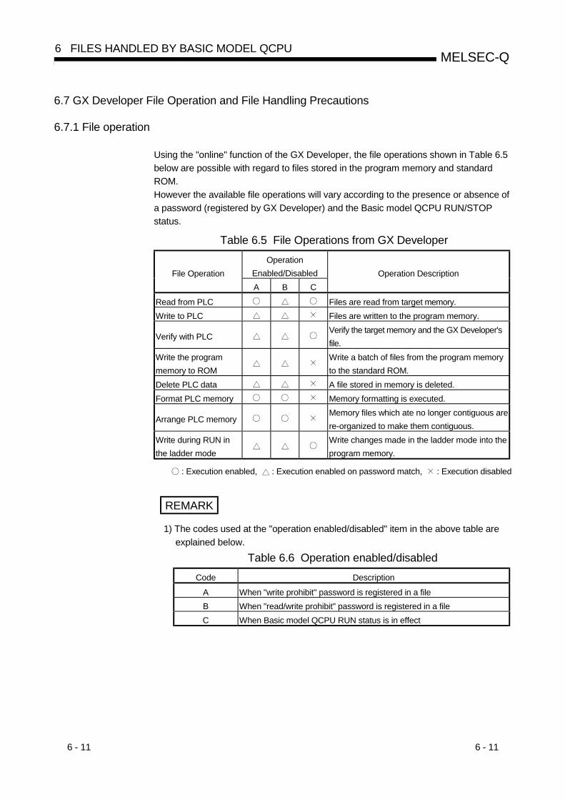
6 - 11 6 - 11
MELSEC-Q6 FILES HANDLED BY BASIC MODEL QCPU
6.7 GX Developer File Operation and File Handling Precautions
6.7.1 File operation
Using the "online" function of the GX Developer, the file operations shown in Table 6.5below are possible with regard to files stored in the program memory and standardROM.However the available file operations will vary according to the presence or absence ofa password (registered by GX Developer) and the Basic model QCPU RUN/STOPstatus.
Table 6.5 File Operations from GX DeveloperOperation
Enabled/DisabledFile OperationA B C
Operation Description
Read from PLC Files are read from target memory.Write to PLC Files are written to the program memory.
Verify with PLCVerify the target memory and the GX Developer'sfile.
Write the programmemory to ROM
Write a batch of files from the program memoryto the standard ROM.
Delete PLC data A file stored in memory is deleted.Format PLC memory Memory formatting is executed.
Arrange PLC memoryMemory files which ate no longer contiguous arere-organized to make them contiguous.
Write during RUN inthe ladder mode
Write changes made in the ladder mode into theprogram memory.
: Execution enabled, : Execution enabled on password match, : Execution disabled
REMARK
1) The codes used at the "operation enabled/disabled" item in the above table areexplained below.
Table 6.6 Operation enabled/disabledCode Description
A When "write prohibit" password is registered in a fileB When "read/write prohibit" password is registered in a fileC When Basic model QCPU RUN status is in effect

6 - 12 6 - 12
MELSEC-Q6 FILES HANDLED BY BASIC MODEL QCPU
6.7.2 File handling precautions
(1) Power OFF (or reset) during program operation(a) If power is switched off during any file operation that will not cause a file
shift, the memory data will be indefinite.
(b) When the battery (Q6BAT) is used for backup on the Basic model QCPU,switching power off during any of the following operations that will cause afile shift will make the program memory data indefinite.• File size change• Arrange PLC memory• New file creation
(2) Simultaneous access of the same file from multiple GX DevelopersThe Basic model QCPU allows access to a single file from a single GXDeveloper only.To make access from multiple GX Developers to the same file, start theprocessing of next GX Developer after completion of the processing of currentGX Developer
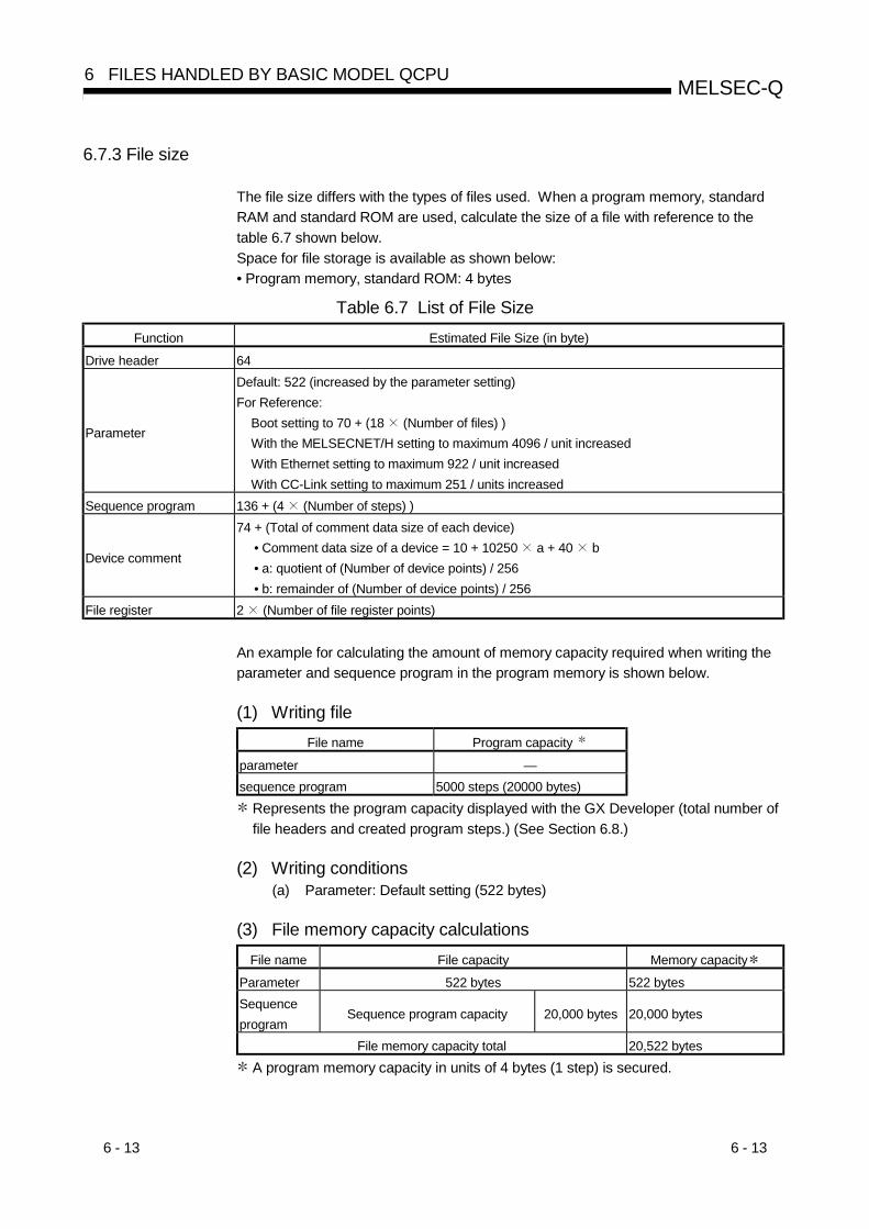
6 - 13 6 - 13
MELSEC-Q6 FILES HANDLED BY BASIC MODEL QCPU
6.7.3 File size
The file size differs with the types of files used. When a program memory, standardRAM and standard ROM are used, calculate the size of a file with reference to thetable 6.7 shown below.Space for file storage is available as shown below:• Program memory, standard ROM: 4 bytes
Table 6.7 List of File SizeFunction Estimated File Size (in byte)
Drive header 64
Parameter
Default: 522 (increased by the parameter setting)For Reference:
Boot setting to 70 + (18 (Number of files) )With the MELSECNET/H setting to maximum 4096 / unit increasedWith Ethernet setting to maximum 922 / unit increasedWith CC-Link setting to maximum 251 / units increased
Sequence program 136 + (4 (Number of steps) )
Device comment
74 + (Total of comment data size of each device)• Comment data size of a device = 10 + 10250 a + 40 b• a: quotient of (Number of device points) / 256• b: remainder of (Number of device points) / 256
File register 2 (Number of file register points)
An example for calculating the amount of memory capacity required when writing theparameter and sequence program in the program memory is shown below.
(1) Writing fileFile name Program capacity
parameter —sequence program 5000 steps (20000 bytes)
Represents the program capacity displayed with the GX Developer (total number offile headers and created program steps.) (See Section 6.8.)
(2) Writing conditions(a) Parameter: Default setting (522 bytes)
(3) File memory capacity calculationsFile name File capacity Memory capacity
Parameter 522 bytes 522 bytesSequenceprogram
Sequence program capacity 20,000 bytes 20,000 bytes
File memory capacity total 20,522 bytes A program memory capacity in units of 4 bytes (1 step) is secured.

7 - 1 7 - 1
MELSEC-Q7 FUNCTION
7
7 FUNCTION
Function of Basic model QCPU module is as follows:
7.1 Function List
Functions of Basic model QCPU are listed below:Item Description ReferenceConstant scan Function to make the scan time constant. Section 7.2Latch function Function to maintain the device data when performing the reset operation during power off. Section 7.3
Selection of output status at switchingfrom STOP to RUN
This function selects the output (Y) status (re-output of status before STOP/output of status afterexecution of operation) when the Basic model QCPU is switched from the STOP status to the RUNstatus.
Section 7.4
Clock function Function to execute the Basic model QCPU internal clock. Section 7.5Remote operation Function to operate the Basic model QCPU from a remote place. Section 7.6
Remote RUN/STOP Function to stop and start operating the Basic model QCPU. Section 7.6.1Remote PAUSE Function to temporarily stop the Basic model QCPU. Section 7.6.2Remote RESET Function to reset the Basic model QCPU. Section 7.6.3Remote latch clear Function to clear the Basic model QCPU latch data. Section 7.6.4
Selection of input response time of QSeries-compatible input module
This function selects the response time of the Q series-compatible input module from among 1ms,5ms, 10ms, 20ms and 70ms. (Default: 10ms)
Section 7.7.1
Selection of input response time ofQ Series-compatible high-speed inputmodule
This function changes the response time of the Q series-compatible high-speed input module toany of 0.1ms, 0.2ms, 0.4ms, 0.6ms and 1ms. (Default: 0.2ms)
Section 7.7.2
Selection of input response time ofQ Series-compatible interrupt module
This function changes the response time of the Q series-compatible interrupt module to any of0.1ms, 0.2ms, 0.4ms, 0.6ms and 1ms. (Default: 0.2ms)
Section 7.7.3
Setting of Q Series compatibleintelligent function module switches
This function makes various settings of an intelligent function module.(Refer to the corresponding intelligent function module for settings.)
Section 7.8
Write during RUN This function writes program when the Basic model QCPU is in the RUN status. Section 7.10
Watchdog timerThis function monitors operational delays caused by Basic model QCPU's hardware and programerrors.
Section 7.14
Self-Diagnosis function This function enables the Basic model QCPU to check for failures. Section 7.15Failure history This function stores a failure history of diagnosis results in the memory. Section 7.16
System protectThis function prevents the program from being altered by the GX Developer communicationmodule.
Section 7.17
Password registrationThis function provides read/write protection for files stored in the Basic model QCPU againstaccess from the GX Developer.
Section 7.17.1
System display This function connects to the GX Developer and monitors system configuration. Section 7.18
LED displayThis function enables the front-mounted LEDs to indicate the operating conditions of the Basicmodel QCPU.
Section 7.19
Serial communication functionThis function makes communication in the MC protocol with the RS-232 interface of the Q00CPU/Q01CPU connected with a personal computer, display device or like by an RS-232 cable.
Section 7.17

7 - 2 7 - 2
MELSEC-Q7 FUNCTION
7
7.2 Constant Scan
(1) What is Constant Scan?The scan time differs because the processing time differs depending on whetherthe instruction, which is used in the sequence program, is executed or not.Constant scan is a function to execute the sequence program repeatedly whilemaintaining the scan time at a constant time.The I/O refresh is executed before the sequence program is executed. So theI/O refresh stays constant even when the execution time of the sequenceprogram varies.
Scan time when constant scan is not used
END
5ms
Sequence program
0 END 0 END 0 END 0END processing
6ms 5ms
Scan time when constant scan setting is set to 7 ms
END
5ms
Sequence program
0 END 0END processing
2msWait time
6ms
END 0
1ms 5ms
END 0
2ms
7ms7ms 7ms
Fig. 7.1 Constant scan operation

7 - 3 7 - 3
MELSEC-Q7 FUNCTION
(2) Setting the constant scan time(a) The constant scan time setting is performed with the parameter mode PLC
RAS.The constant scan setting range is 1 ms to 2000 ms.A setting can be made in modules of 1 ms.• When executing constant scan, set the constant scan time.• When not executing a constant scan, leave the constant scan time blank.
[Example] When the constant scan is set to 10 ms.
(b) Set the set time of the constant scan larger than the maximum scan time ofthe sequence program. Also, set the constant scan set time less than theWDT set time.
(WDT Set Time) > (Constant Scan Set Time) > (Sequence Program maximum Scan Time)
If the sequence program scan time is larger than the constant scan set value,the Basic model QCPU detects PRG.TIME OVER (an error code: 5010), thesequence program is executed with the scan time by ignoring the constantscan.
0 1 2 3 4 1 2 3 4
0 0
1
END 0END
2 3 4 1 2 3 4
0END 0END
3.5ms 0.5ms
4ms 3.7ms
3.5ms0.2ms
3.4ms 0.6ms
4ms
Scan where the constant scan is not normal
Constant scan setting
Constant scan
Sequence program
5.3ms
5 ms
Fig. 7.2 Operation when the Scan Time is More than the Constant Scan
If the value is larger than the WDT set time, the Basic model QCPU detects aWDT error and stops the program execution.

7 - 4 7 - 4
MELSEC-Q7 FUNCTION
(c) Sequence program processing is suspended during the waiting time fromEND processing execution in a sequence program until the start of the nextscan.However, if an interrupt factor occurs after END processing execution, thecorresponding interrupt program is run.
(d) Constant scan accuracyThe following explains the accuracy when the constant scan time has beenset.1) Refer to Chapter 11 for errors produced when the constant scan time
has been set and the interrupt program is not executed.2) The interrupt program is also executed during the constant scan
waiting time.Interruption is disabled during interrupt program execution. Therefore,if the constant scan time is reached during interrupt programexecution, the constant scan cannot be finished unless the interruptprogram ends.When the interrupt program is used, the constant scan time may delayby the interrupt program execution time.
REMARK
Refer to “QCPU (Q mode)/QnACPU Programming Manual (Common Instructions)”for the command processing time.

7 - 5 7 - 5
MELSEC-Q7 FUNCTION
7.3 Latch Functions
(1) What is Latch Functions?(a) The values of each Basic model QCPU device are set back to the default
(bit device: OFF and word device: 0) when;• The PLC power is turned on.• The reset operation is performed.• There is a momentary power failure for more than the permissible amountof time.Latch is a function to maintain the device details when the above conditionsoccur.The availability of latches does not affect the operation performed by aprogram.
(b) Latch can be used to maintain the production count, defective count,address and other data to continue control if the PLC is powered OFF, resetoperation is performed, or an instantaneous power failure occurs for longerthan the permissible time during management of the above data forcontinuous control.
(c) The following devices can use the latch function:(The default latch range is only the latch relay.)
1) Latch relay(L)2) Link relay(B)3) Annunciator(F)4) Edge relay(V)5) Timer(T)6) Retentive timer(ST)7) Counter(C)8) Data register(D)9) Link register(W)
(2) Latch Range SettingThe latch range setting is performed with the PLC parameter mode devicesetting.Latch range setting can be made in two ranges: latch clear (remote latch clearoperation) valid range and invalid range.

7 - 6 7 - 6
MELSEC-Q7 FUNCTION
(3) Clearing the Latch Range Device DataThe following table indicates the device status when latch clear is performed.
Latch Setting Made or Not Cleared or Maintained by Latch Clear
Device without latch range specified ClearedLatch (1) setting (device set to "The clear is possiblewith latch clear.")
Cleared
Latch (2) setting (device set to "The clear is impossiblewith latch clear.")
Maintained
POINTFile registers (R) cannot be cleared with latch clear.(See Section 10.7 for clearing file registers.)
(4) PrecautionsThe device details of the latch range are maintained with the battery (Q6BAT)attached to the Basic model QCPU.
(a) The battery is needed to latch devices if sequence program are stored ontothe standard ROM to perform ROM operation.
(b) Note that if the battery connector is unplugged from the Basic model QCPUconnector during PLC power-off, the device contents in the latch range arenot maintained and will be indefinite values.

7 - 7 7 - 7
MELSEC-Q7 FUNCTION
7.4 Setting the Output (Y) Status when Changing from STOP Status to RUN Status
(1) Output (Y) Status when changing from STOP Status to RUN StatusWhen changing from RUN status to STOP status, the RUN status output (Y) isstored in the sequence and all the outputs (Y) are turned OFF.The state after transition from STOP to RUN can be selected from the followingtwo options with the Basic model QCPU.• The output state prior to STOP is output.• The output is cleared.
(Default: After transition from STOP to RUN, the output (Y) state prior to STOPis output then the program is executed.)
(a) Previous StateAfter the output (Y) status before the STOP status is output, the sequenceprogram calculations are performed.
(b) Recalculate (Output is 1 Scan later)Clears all output (Y) and outputs the output (Y) after executing thesequence program calculations.
STOP status to RUN status
Replay output?
Output the output (Y) status right before changing to STOP status.
Execute the sequence program calculations
NO (Output after calculation execution)
YES (Replay output)
Clear the output (Y) status.
Fig. 7.3 Processing when Change from STOP Status to RUN Status

7 - 8 7 - 8
MELSEC-Q7 FUNCTION
(2) Setting the Output (Y) Status when Changing from STOP Status toRUN StatusThe output (Y) status before the STOP status when switching from STOP statusto Run status can be set in the PLC System sheet of the PLC Parameter dialogbox.
Output mode settingat stop to RUN
(3) PrecautionIf an output (Y) is forcefully turned ON with the Basic model QCPU in the STOPstatus, it will not remain in the ON status even if the STOP status is switched tothe RUN status.The output status is effected as set in the PLC System setting of the output modeat STOP to RUN.

7 - 9 7 - 9
MELSEC-Q7 FUNCTION
7.5 Clock Function
(1) What is Clock Function?(a) The Basic model QCPU has a clock function in the CPU module.
Because the time data from the clock function can be read by the sequenceprogram, the time data can be used for time maintenance.Also, the time data is used for time maintenance for the Basic model QCPUsystem functions such as those for failure history.The clock operations for the clock function are maintained even when thePLC power is off or when there is a momentary power failure for more thanthe permitted time, using the battery (Q6BAT).
(b) Clock DataThe time data is the year, month, day, hour, minute, second, and day of theweek data used for the Basic model QCPU clock element. There are thefollowing:
Data Name Contents
Year Four digits in AD (Countable from 1980 to 2079)Month 1 to 12Day 1 to 31(Automatic leap year calculation)Hour 0 to 23 (24 hours)
Minute 0 to 59Second 0 to 59
0 Sunday
1 Monday
2 Tuesday
3 Wednesday
4 Thursday
5 Friday
Day of the week
6 Saturday
(2) Writing to and Reading from the Time Data Clock Element(a) The following two methods can be used to write to the time data clock
element.1) Method to write from GX Developer
The time data is written in the clock element by displaying "Online" "Set time" window.

7 - 10 7 - 10
MELSEC-Q7 FUNCTION
2) Method to Write from the ProgramThe time data is written in the clock element by using the clockinstruction (DATEWR).A program example to write the time data using the time data writeinstruction (DATEWR).
MOVP D0X0
MOVP D1
MOVP D2
MOVP D3
MOVP D4
MOVP D5
MOVP D6
K2001
K8
K10
K11
K35
K24
K4
DATEWR D0
Year 2001
Month 8
Day 10
Hour 11
Minute 35
Second 24
Day Thursday: 4
0
Write request
Refer to "QCPU (Q mode)/QnACPU Programming Manual (CommonInstructions)" for details of the DATEWR instruction.
(b) Reading Time DataWhen reading the time data to the data register, use the time data readinstruction (DATERD) from the program.The figure below shows an example of a program used to read the clockdata with the DATERD instruction and then store it in D10 to D16.
DATERD D10X1 The time data is read
in D10 to D16.
Read request
Refer to the "QCPU (Q mode)/QnACPU Programming Manual (Commoninstructions) for the details of the DATERD instruction.
REMARK
1) Writing to and Reading from Time Data can be executed by special relays(SM210 to SM213) and special registers (SD210 to SD213). See Appendix 1 for details on special relay. See Appendix 2 for details on specialregisters.
2) : The figure below shows the clock data stored in D10 to D16.D10D11D12D13D14D15D16
4 digits in ADMonthDateHourMinuteSecondDay of the week
Refer to Section 7.5.1(1).
19998
101135244

7 - 11 7 - 11
MELSEC-Q7 FUNCTION
(3) Precautions(a) The clock data is not set before shipment.
The clock data is used by the Basic model QCPU system and intelligentfunction module for failure history and other functions. Be sure to set theaccurate time when operating the Basic model QCPU for the first time.
(b) Even if a part of the time data is being corrected, all data must be written tothe clock again.
(c) The data written in the clock element is checked in the range described in(1) (b) of Section 7.5.For this reason, if improbable clock data in the range described in (1) (b) ofSection 7.5 is written in the clock element, correct clock function isunavailable.
ExampleWriting to clock element CPU module operation state
February 30 Executed
Upon execution of DATEW command:OPERATION ERROR (Error code 4100)
Upon activation of SM210:Activation of SM211
32 of month 13 Not executed Failure to detect error
(4) PrecisionThe precision of the clock function differs with the ambient temperature, asshown below:
Ambient Temperature ( C) Accuracy (Day difference, S)
0 -3.2 to +5.27 (TYP.+1.98)+25 -2.57 to +5.27 (TYP.+2.22)+55 -11.68 to +3.65 (TYP.-2.64)
(5) Comparison of Clock DataTo compare Basic model QCPU's clock data with a sequence program, use theDATERD instruction to read the clock data. The year data is read out in 4 digits.It can be compared as it is by using a compare instruction.

7 - 12 7 - 12
MELSEC-Q7 FUNCTION
7.6 Remote Operation
The Basic model QCPU provides the RUN/STOP/RESET switches for switchingbetween the STOP status and the RUN status. The RUN/STOP/RESET switch alsoprovides the Reset and Latch Clear functions.The Basic model QCPU performs self control of the operation status from an external(GX Developer function, intelligent function module, and remote contact) source.The following four options are available for remote operations:• Remote RUN/STOP• Remote PAUSE• Remote RESET• Remote LATCH CLEAR
REMARK
The serial communication module is used as the example to describe the intelligentfunction module.
7.6.1 Remote RUN/STOP
(1) What is Remote RUN/STOP?(a) The remote RUN/STOP performs RUN/STOP of the Basic model QCPU
from an external source with the Basic model QCPU RUN/STOP/RESETswitch at RUN.
(b) Using remote RUN/STOP for the following remote operations are useful:1) When the Basic model QCPU is at a position out of reach
2) When performing RUN/STOP of the control board Basic model QCPUfrom an external source
(c) Calculations during Remote RUN/STOPThe program calculation that performs remote RUN/STOP is as follows:1) Remote STOP
Executes the program to the END instruction and enters the STOPstate.
2) Remote RUNWhen remote RUN is performed while in the STOP state using remoteSTOP, the state changes to RUN and executes the program fromstep 0.

7 - 13 7 - 13
MELSEC-Q7 FUNCTION
(2) Remote RUN/STOP MethodThere are two ways to perform remote RUN/STOP:(a) Remote RUN contact method
The remote RUN contact is set with the PLC parameter mode PLC systemsetting.The device range that can be set is input X0 to 7FF.By turning the set remote RUN contact ON/OFF, the remote RUN/STOPcan be performed.1) When the remote RUN contact is OFF, the Basic model QCPU enters
the RUN state.
2) When the remote RUN contact is ON, the Basic model QCPU entersthe STOP state.
Remote RUN contactOFF
QCPU: RUN/STOP state RUN
ON
STOP
Step 0 END Step 0 END0
STOP state
Fig. 7.4 Time Chart for RUN/STOP with Remote RUN Contact
(b) Method using the GX Developer function, serial communication module, etc.Basic model QCPU can be performed by the remote RUN/STOP operationfrom the GX Developer function, serial communication module, etc.The GX Developer operation is performed with on-line remote operations.The serial communication module and Ethernet interface module arecontrolled by commands complying with the MC protocol.For details of the MC protocol, refer to the following manual.• Q corresponding MELSEC Communication Protocol Reference Manual
Remote STOP command
Step 0ON
END
OFF
Remote RUN command OFF
RUN/STOP state RUNSTOP
Step 0
ON
END
STOP state
0
GX Developer
Serial communication
module
Fig. 7.5 Remote RUN/STOP Time Chart using GX Developer,serial communication module, etc

7 - 14 7 - 14
MELSEC-Q7 FUNCTION
(3) Precautions(a) Take note of the following, because STOP has priority in Basic model
QCPU:1) The Basic model QCPU enters the STOP state when remote STOP is
performed from remote RUN contact, GX Developer function, or serialcommunication module.
2) When Basic model QCPU is set to the STOP state with remote STOP,all external factors which performed a remote STOP (remote RUNcontact, serial communication module, etc.) must be set to RUN.
REMARK
The RUN/STOP state is described below:• RUN State .................State which repeatedly executes the calculations from step 0
to the END instruction in the sequence program.• STOP State ...............State where the sequence program calculations are stopped
and the output (Y) is all OFF.

7 - 15 7 - 15
MELSEC-Q7 FUNCTION
7.6.2 Remote PAUSE
(1) What is Remote PAUSE?(a) Remote PAUSE performs the Basic model QCPU PAUSE function from an
external source, with the CPU RUN/STOP/RESET switch at RUN position.The PAUSE function stops the Basic model QCPU calculations whilemaintaining the ON/OFF state of all output (Y).
(b) This can be used to maintain the output (Y) on even if the QCPU is changedto the STOP state, in such areas as process control.
POINTThe output (Y) turns OFF at stop error occurrence.To retain the output at stop error occurrence, make the output retention setting inthe I/O assignment PLC parameters.
(2) Remote PAUSE MethodThere are two ways to use remote PAUSE:(a) Remote PAUSE Contact Method
The remote PUASE contact is set in the GX Developer function parametermode PLC system setting.Setting of only the remote PAUSE contact cannot be made.When setting the remote PAUSE contact, also set the remote RUN contact.The device range that can be set is input X0 to 7FF.1) The PAUSE state contact (SM204) is turned on when the END
processing is executed for the scan with both remote PAUSE contactand PAUSE permission flag (SM206) on.
2) When the remote PAUSE contact is off or SM206 is turned off, thePAUSE state is canceled, and the sequence program calculation isperformed again from step 0.
Remote PAUSE contact
OFF
ON0 END
PAUSE state
0 END END 00 END
SM206OFF
ON
SM204OFF
ON
RUN/PAUSE state
RUN
ON when PAUSE condition met
PAUSE
Fig. 7.6 PAUSE Time Chart with Remote PAUSE Contact
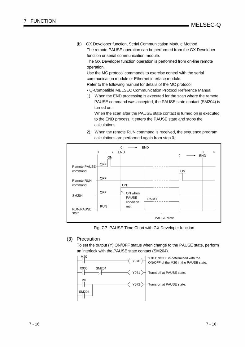
7 - 16 7 - 16
MELSEC-Q7 FUNCTION
(b) GX Developer function, Serial Communication Module MethodThe remote PAUSE operation can be performed from the GX Developerfunction or serial communication module.The GX Developer function operation is performed from on-line remoteoperation.Use the MC protocol commands to exercise control with the serialcommunication module or Ethernet interface module.Refer to the following manual for details of the MC protocol.• Q-Compatible MELSEC Communication Protocol Reference Manual1) When the END processing is executed for the scan where the remote
PAUSE command was accepted, the PAUSE state contact (SM204) isturned on.When the scan after the PAUSE state contact is turned on is executedto the END process, it enters the PAUSE state and stops thecalculations.
2) When the remote RUN command is received, the sequence programcalculations are performed again from step 0.
Remote PAUSE command
OFF
0 END
PAUSE state
0 END
0 END0
Remote RUN command
SM204OFF
ON
RUN/PAUSE state
RUN
ON when PAUSE condition met
PAUSE
ON
OFF
ON
Fig. 7.7 PAUSE Time Chart with GX Developer function
(3) PrecautionTo set the output (Y) ON/OFF status when change to the PAUSE state, performan interlock with the PAUSE state contact (SM204).
M20Y070
X000Y071
M0Y072
SM204
SM204
Y70 ON/OFF is determined with the ON/OFF of the M20 in the PAUSE state.
Turns off at PAUSE state.
Turns on at PAUSE state.

7 - 17 7 - 17
MELSEC-Q7 FUNCTION
7.6.3 Remote RESET
(1) What is Remote RESET?(a) The remote RESET resets the Basic model QCPU from an external source
when the Basic model QCPU is at STOP state.Even if the Basic model QCPU RUN/STOP key switch is at RUN, the resetcan be performed when the Basic model QCPU is stopped and an error thatcan be detected by the self-diagnosis function occurs.
(b) Remote RESET can reset the Basic model QCPU remotely when an erroroccurs for which the Basic model QCPU cannot be operated directly.Remote RESET can be executed only at the STOP state. When the Basicmodel QCPU is at RUN state, use Remote STOP to arrange the STOPstate.
(2) Remote RESET MethodThe remote RESET can only be performed from the GX Developer function orserial communication module operation.To perform the remote RESET, follow the following steps:(a) In the PLC System sheet of the PLC Parameter dialog box, turn on the
"Allow" check box in the "Remote reset" section, and then write parametersonto the Basic model QCPU.
Allow the remote reset
(b) When the Basic model QCPU is at RUN state, use remote STOP to arrangethe STOP state.
(c) Reset Basic model QCPU with the remote RESET operation.1) For the GX Developer function, this is performed in on-line remoteoperation.2) The serial communication module and Ethernet interface module are
controlled by commands complying with the MC protocol.For details of the MC protocol, refer to the following manual.• Q corresponding MELSEC Communication Protocol Reference Manual

7 - 18 7 - 18
MELSEC-Q7 FUNCTION
(3) Precautions(a) To perform the remote RESET, turn on the "Allow" check box of the
"Remote reset" section in the PLC System sheet of the PLC Parameterdialog box, and then write parameters onto the Basic model QCPU. If the"Allow" check box is not checked, a remote RESET operation is notperformed.
(b) Remote RESET cannot be performed when the Basic model QCPU is at theRUN state.
(c) After the reset operation is complete, the Basic model QCPU will enteroperation state set at the RUN/STOP/RESET switch.1) With the RUN/STOP/RESET switch in the "STOP" position, the Basic
model QCPU enters into the "STOP" status.
2) With the RUN/STOP/RESET switch in the "RUN" position, the Basicmodel QCPU enters into the "RUN" status.
(d) Take care that Remote RESET does not reset Basic model QCPU if there isan error in the Basic model QCPU due to noise.If Remote RESET does not reset, use the RUN/STOP/RESET switch toreset or turn the PLC off then on again.
POINT(1) If Remote RESET is executed when the Basic model QCPU is stopped due to
an error, the Basic model QCPU enters the operation state set at theRUN/STOP/RESET switch after it is reset.
(2) Even if the "Allow" check box of the "Remote reset" section in the PLC Systemsheet of the PLC Parameter dialog box, the remote process of the GXDeveloper is completed.However, the reset process does not proceed in the Basic model QCPU andtherefore it is not reset.If the state of the Basic model QCPU does not change though a reset processis performed at the GX Developer, check if the "Allow" check box of the"Remote reset" section in the PLC System sheet of the PLC Parameter dialogbox is turned on.

7 - 19 7 - 19
MELSEC-Q7 FUNCTION
7.6.4 Remote Latch Clear
(1) What is Remote Latch Clear?(a) The remote latch clear resets the device data latched to the Basic model
QCPU using the GX Developer function or other function, when it is at theSTOP state.
(2) Remote Latch Clear MethodThe remote latch clear can only be performed from GX Developer function orserial communication module.To perform the remote latch clear, follow the following steps:(a) Use the RUN/STOP/RESET switch or the remote STOP to place the Basic
model QCPU to the STOP status.
(b) Use the Latch Clear to bring the Basic model QCPU to the Latch Clearstatus.1) The GX Developer function operations are performed with on-line remote
operation.
2) The serial communication module and Ethernet interface module arecontrolled by commands complying with the MC protocol.For details of the MC protocol, refer to the following manual.• Q corresponding MELSEC Communication Protocol Reference Manual
(c) To return the Basic model QCPU to the RUN status after the remote latchclear, perform a remote RUN operation.
(3) Precautions(a) Either remote latch clear cannot be performed when the Basic model QCPU
is at RUN status.
(b) There the latch clear (remote latch clear operation) valid range and invalidrange as the device latch ranges set in the device setting in the parametermode.In the remote latch clear operation, only the device range set as the "latchclear valid" range is reset.Refer to Section 4.6 for the way to reset the device set to latch clear invalid.
(c) Devices that are not latched are cleared when the remote latch clear isexecuted.The data in the failure history storage memory of the Basic model QCPUwill also be cleared by a remote latch clear operation.

7 - 20 7 - 20
MELSEC-Q7 FUNCTION
7.6.5 Relationship of the remote operation and Basic model QCPU RUN/STOP switch
(1) Relationship of the Remote Operation and Basic model QCPUSwitchThe Basic model QCPU operation status is as follows with the combination ofremote operations to RUN/STOP/RESET switch.
Remote operationRUN/STOPswitch
RUN 1 STOP PAUSE 2 RESET 3 Latch clear
RUN RUN STOP PAUSECannot
operate 4Cannot
operate 4
STOP STOP STOP STOP RESET 5 Latch clear
1 When performing the operation with remote RUN contact, "RUN-PAUSE contact" must beset in the parameter mode PLC system setting.
2 When performing the operation with remote PAUSE contact, "RUN-PAUSE contact" mustbe set in the parameter mode PLC system setting. In addition, the remote PAUSE enablecoil (SM206) must be set ON.
3 "Remote reset enable" must be set in the parameter mode PLC system setting.4 RESET or LATCH CLEAR can be performed if the Basic model QCPU changed to the
STOP state from a remote operation.5 This includes a situation where the Basic model QCPU is stopped due to error.
(2) Remote Operations from the Same GX DevelopersWhen remote operations are performed from the same GX Developer, the statusof the remote operation that is executed last will be effective.
(3) Remote Operations from Multiple GX DevelopersWhile a remote operation is being performed by one GX Developer, anotherremote operation cannot be performed by another GX Developer.After a remote operation that is being performed by one GX Developer iscancelled, a new remote operation can be performed by another GX Developer.For example, a remote PAUSE operation is being performed by oneGX Developer, the PAUSE status will remain active even if a remoteSTOP/remote RUN operation is attempted by another GX Developer.When a remote RUN operation is performed by the GX Developer that isperforming a remote PAUSE operation, and then that remote operation iscancelled, a new remote operation can be performed by another GX Developer.

7 - 21 7 - 21
MELSEC-Q7 FUNCTION
7.7 Selection of Input Response Time of the Q Series-Compatible Input Module and InterruptModule (I/O Response Time)
7.7.1 Selection of input response time of the input module
(1) Selection of Input Response TimeSelection of the input response rate of the input module is to change the inputresponse rate of the Q series-compatible input module to 1ms, 5ms, 10ms, 20msor 70ms on a module basis.The input module imports external inputs at the specified input response rate.The default value of the input response rate is set to 10ms.
OFF
OFF
ON
ON
Input response time
External input
Input module
(2) Setting the Input Response TimeSet the input response rate in the I/O assignment PLC parameters.Choose "Input" as the type of the slot to which the input response rate is set.
Select "Input". Select "Detail Setting". Select "Input response time".
(3) Reactions(a) Setting of a higher input response rate increases sensitivity to noise or like.
Take the operating environment into consideration when setting the inputresponse rate.
(b) The setting of the input response rate is made valid when:• The PLC is powered ON; or• CPU module is reset.
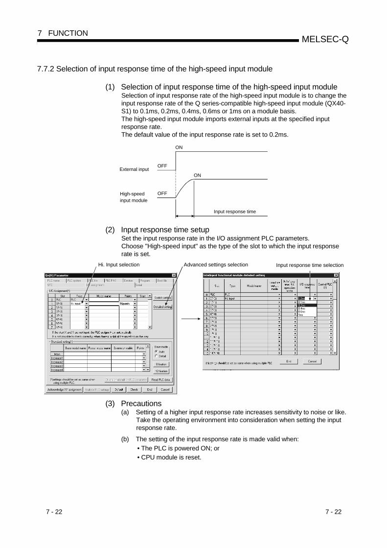
7 - 22 7 - 22
MELSEC-Q7 FUNCTION
7.7.2 Selection of input response time of the high-speed input module
(1) Selection of input response time of the high-speed input moduleSelection of input response rate of the high-speed input module is to change theinput response rate of the Q series-compatible high-speed input module (QX40-S1) to 0.1ms, 0.2ms, 0.4ms, 0.6ms or 1ms on a module basis.The high-speed input module imports external inputs at the specified inputresponse rate.The default value of the input response rate is set to 0.2ms.
OFF
OFF
ON
ON
Input response time
External input
High-speed input module
(2) Input response time setupSet the input response rate in the I/O assignment PLC parameters.Choose "High-speed input" as the type of the slot to which the input responserate is set.
Hi. Input selection Advanced settings selection Input response time selection
(3) Precautions(a) Setting of a higher input response rate increases sensitivity to noise or like.
Take the operating environment into consideration when setting the inputresponse rate.
(b) The setting of the input response rate is made valid when:• The PLC is powered ON; or• CPU module is reset.
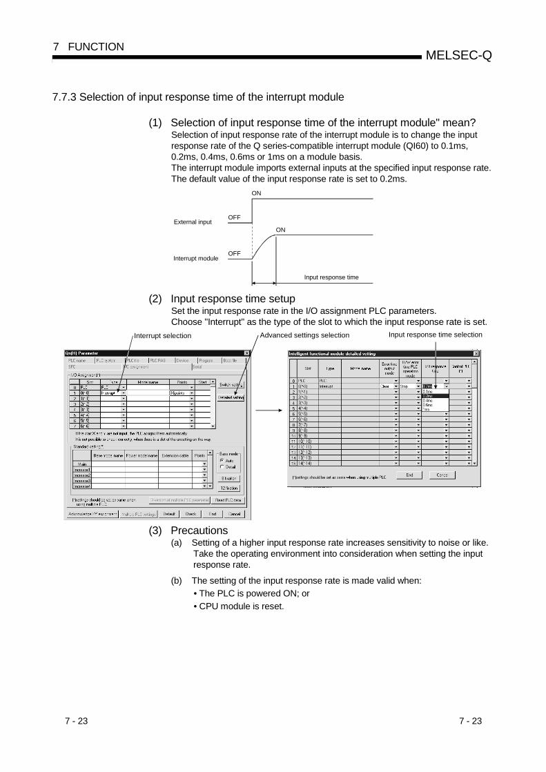
7 - 23 7 - 23
MELSEC-Q7 FUNCTION
7.7.3 Selection of input response time of the interrupt module
(1) Selection of input response time of the interrupt module" mean?Selection of input response rate of the interrupt module is to change the inputresponse rate of the Q series-compatible interrupt module (QI60) to 0.1ms,0.2ms, 0.4ms, 0.6ms or 1ms on a module basis.The interrupt module imports external inputs at the specified input response rate.The default value of the input response rate is set to 0.2ms.
OFF
OFF
ON
ON
Input response time
External input
Interrupt module
(2) Input response time setupSet the input response rate in the I/O assignment PLC parameters.Choose "Interrupt" as the type of the slot to which the input response rate is set.
Interrupt selection Advanced settings selection Input response time selection
(3) Precautions(a) Setting of a higher input response rate increases sensitivity to noise or like.
Take the operating environment into consideration when setting the inputresponse rate.
(b) The setting of the input response rate is made valid when:• The PLC is powered ON; or• CPU module is reset.

7 - 24 7 - 24
MELSEC-Q7 FUNCTION
7.8 Setting the Switches of the Intelligent-Function Module
(1) Setting the Switches of the Intelligent-Function ModuleThe switches of the intelligent-function module is to set the switches of an QCPU-compatible intelligent function module using GX Developer.The settings of the switches set by GX Developer is written from Basic modelQCPU to each intelligent function module at the leading-edge or reset of Basicmodel QCPU.
ParameterSwitch setting of the intelligent function module at the I/O assignment
GX Developer
Parameter Switch setting
Basic model QCPU
Intelligent function module
Write
Power supply On/QCPU module Reset
(2) Setting the Switches of the Intelligent-Function ModuleIn the "I/O assignment" sheet of the PLC Parameter dialog box, specify thedesired switch setting. Select "Intelli." in the "type" column of a slot for which toset the switches of the intelligent function module.
Select "Intelli". Select "Switch Setting".
Designate the contents of the intelligent function module switch.
(3) Precautions(a) Do not apply the switch setting for an intelligent function module.
If the switch setting for an intelligent function module is specified an error(SP.PARA.ERROR) will occur.
(b) Set "Interrupt" as the type to set the switches of the intelligent functionmodule using GX Developer.Refer to the following manual for details of the interrupt module switchsetting.• Building Block Type I/O Module User's Manual
(c) The switch setting is made valid when:• The PLC is powered ON; or• CPU module is reset.

7 - 25 7 - 25
MELSEC-Q7 FUNCTION
7.9 Writing Data in the Ladder Mode during the RUN Status
(1) Writing data in the ladder mode during the RUN Status(a) Writing data in the circuit mode during the RUN status is used to write a
program during the Basic model QCPU RUN status.
(b) Changing the program can be performed without stopping the process inBasic model QCPU program using writing data in the ladder mode duringthe RUN status.
X0 X2
X1Y30
X3 X4
X5SET M10
END
GX Developer
Change by GX Developer and write in Basic model QCPU at the conversion.
(c) Writing to the program during RUN can be performed from a GX Developerfunction peripheral device connected to another station in the network.
Personal computer(GX Developer)
MELSECNET/H
Writing data the ladder mode during the RUN status.
7 - 26 7 - 26
MELSEC-Q7 FUNCTION
(2) PrecautionsTake a note of the following when writing during RUN:(a) The memory that can be written during RUN is only program memory.
If the write during RUN is performed while booting a program from thestandard ROM, the program to be booted will not be changed.Write the contents of the program memory to the standard ROM beforepowering off the PLC or resetting the Basic model QCPU.
(b) A maximum of 512 steps can be written at once during RUN.
(c) Normal operation will not be performed if any of the following instructions iswritten using online write.1) Trailing edge instructions
Any of the following trailing edge instructions is executed if theexecution condition of the trailing edge instruction is OFF oncompletion of write.• LDF• ANDF• ORF• MEF• PLF
2) Leading edge instructionsThe leading edge instruction is not executed if the execution conditionof the leading edge instruction (PLS instruction/ P instruction) is ONon completion of write.The leading edge instruction is executed when the execution conditionturns from OFF to ON again.
3) SCJ instructionIf the execution condition of the SCJ instruction is ON on completion ofwrite, a jump to the specified pointer is made without waiting for onescan.

7 - 27 7 - 27
MELSEC-Q7 FUNCTION
7.10 Multiple-user monitoring function
(1) What is Multiple-User Monitoring Function?(a) The multiple-user monitoring operation can be performed by operating from
multiple GX Developers connected to the Basic model QCPU or the serialcommunications module.
(b) Multiple users can monitor at the same time. By setting a station monitorfile, high-speed monitoring can be performed. (Setting of station monitorfile is not necessary.)
(2) Operation Procedure(a) For multi-user monitoring operation, create a user-defined system file in the
following steps.1) Choose "Online" "Format PLC Memory" to open the Format PLC
Memory dialog box.2) Select "program memory" from the Target Memory list box.3) In the Format section, select "Create a user setting system area..." so
that its radio button is checked.4) Specify the desired K steps in the System Area text box.
(b) The figure below illustrates an example in which "1k step" is specified in theSystem Area text box.
1) A maximum of 15 k steps can be set in 1 k step modules as a systemarea. Only 1 k step can correspond to one station monitor file.Therefore, a maximum of 15 station monitor files can be set.
(3) Precautions(a) Monitoring can be performed even if a station monitor file is not set, but
high-speed monitoring cannot be performed.The system area is in the same area as the program memory, so the areaof the stored program reduced when the system area is set.
(b) Once the user-defined system area is allocated, a single PLC will beaccessible from 16 stations.

7 - 28 7 - 28
MELSEC-Q7 FUNCTION
7.11 Watchdog Timer (WDT)
(1) What is Watchdog Timer (WDT)?(a) The watchdog timer is an internal sequence timer to detect Basic model
QCPU hardware and/or sequence program error.
(b) When the watchdog timer expires, a watchdog timer error occurs.The Basic model QCPU responds to the watchdog timer error in thefollowing way.1) The Basic model QCPU turns off all outputs.2) The front-mounted RUN LED goes off, and the ERR. LED starts
flashing.3) SM1 turns ON and the error code is stored in SD0.
(c) The default value of the watchdog timer is 200 ms.The setting range is 10 to 2000 ms (10ms units).
(2) Watchdog Timer Setting and Reset(a) The PLC RAS setting of the PLC parameter resets the watchdog timer.
(b) Basic model QCPU resets the watchdog timer when the END instruction isexecuted.1) When the END/FEND instruction is executed within the set value of the
watchdog timer in the sequence program and the Basic model QCPUis operating correctly, the watchdog timer does not time out.
2) When there is a Basic model QCPU hardware failure or the sequenceprogram scan time is too long, and the END/FEND instruction couldnot be executed within the set watchdog timer value, the watchdogtimer times out.
(3) Precautions(a) An error of 0 to 10 ms occurs in the measurement time of the watchdog
timer. Set the watchdog timer for a desired value by taking such an errorinto account.
(b) The watchdog timer is reset with the WDT instruction in the sequenceprogram. If the watchdog timer expires while the FOR and NEXTinstructions are repetitiously executed, reset the watchdog time with theWDT instruction.
FOR K1000
WDTM0
NEXT
WDT reset
Program for repetition processingRepetition (1000 times)

7 - 29 7 - 29
MELSEC-Q7 FUNCTION
(c) The scan time value is not reset even if the watchdog timer is reset in thesequence program.The scan time value is measured to the END instruction.
0 END 0
Scan time
Watchdog timer measured time
WDT reset (QCPU internal processing)
Sequence program Internal processing time
Next scan time
END
Internal processing time
WDT reset (QCPU internal processing)
Fig. 7.9 Watchdog Timer Reset
REMARK
Scan time is the time elapsed from the time the Basic model QCPU startsprocessing a sequence program at Step 0 until the it restarts processing anothersequence program with the same filename at Step 0.The scan time is not the same at every scan, and differs, depending on• Whether the commands used are executed or not executed.• Whether to execute or not an interrupt program.Use the constant scan function to execute a program at the same scan time everyscan.Refer to section 7.2 for details of the constant scan function.

7 - 30 7 - 30
MELSEC-Q7 FUNCTION
7.12 Self-Diagnosis Function
(1) What is Self-Diagnosis Function?(a) The self-diagnosis is a function performed by Basic model QCPU itself to
diagnose whether there is an error in the Basic model QCPU.
(b) The self-diagnosis function's objective is to prevent Basic model QCPUerroneous operation and as preventive maintenance.The self-diagnosis processing detects and displays the error when an erroroccurs when the Basic model QCPU power is turned on or during Basicmodel QCPU RUN mode. It also stops Basic model QCPU calculations.
(2) Processing for Error Detection(a) When Basic model QCPU detects an error, it turns on ERR. LEDs. When
an error is detected, special relays (SM0, SM1) are turned ON and an errorcode of the error is stored in the special register SD0. When multiple errorsare detected, error codes of the latest errors are stored in the specialregister SD0. For error detection, use special relays and special registers inprogram so that these devices can interlock with sequencers andmechanical systems.
(b) Basic model QCPU stores 16 latest error codes. (Refer to Section 7.13.)The failure history can be checked in the GX Developer function PLCdiagnostics mode.The failure history can be stored even when the power is shut off using thebattery backup.
(3) Basic model QCPU operation at the time of error detection(a) When an error is detected from the self-diagnosis, there are two types of
modes that the Basic model QCPU operation can change to.1) Basic model QCPU calculation stop mode
Stops the calculation at the point when the error is detected, and turnsoff all output (Y).
2) Basic model QCPU calculation continue modeWhen an error is detected, the program (Instruction) area where theerror occurred is skipped and the rest of the program is executed.
(b) The following errors can set the calculation "continue/stop" in the parametermode PLC RAS.(All parameter defaults are set at "Stop".)1) Operation error2) Expanded command error3) Fuse blown4) I/O unit comparison5) Intelligent function module program execution errorFor example, when the I/O module verification error is set to "continues",the calculations are continued in the I/O address before the error occurred.

7 - 31 7 - 31
MELSEC-Q7 FUNCTION
(4) Error check selectionThe error checking can be set to "yes/no" in the following error checking in theparameter mode PLC RAS setting.(All parameter defaults are set at "Yes".)(a) Battery check(b) Fuse blown check(c) I/O unit comparison
Self-Diagnosis ListDiagnosis description Error message Diagnostic timing
CPU error MAIN CPU DOWN • Always
END instruction not executed END NOT EXECUTE • When the END instruction is executed
RAM check RAM ERROR • When the power is turned on/when reset
Calculation circuit check OPE.CIRCUIT ERR. • When the power is turned on/when reset
Fuse short (default... stop) 1 FUSE BRAKE OFF• When the END instruction is executed(Default... Yes) 2
I/O interrupt error I/O INT ERROR • When an interrupt occurs
Intelligent function module error SP.UNIT DOWN• When the power is turned on/when reset• When the FROM/TO instruction is executed
Control bus error CONTROL-BUS ERROR.• When the power is turned on/when reset• When the END instruction is executed• When the FROM/TO instruction is executed
Momentary stop occurred AC/DC DOWN • Always
Battery low BATTERY ERROR • Always (Default...Yes) 3
Hardware failure
I/0 module verification (Default...Stop) 1 UNIT VERIFY ERROR
• When the END instruction is executed(Default... Yes) 2
Intelligent function module error SP. UNIT ERROR • When an instruction is executed
Intelligent function moduleallocation error
SP.UNIT LAY ERR.• When the power is turned on/when rest• When switched from STOP to RUN
No parameter MISSING PARA. • When the power is turned on/when rest
Boot error BOOT ERROR • When the power is turned on/when rest
Handling error
Instruction execution not possible CAN´T EXE.PRG. • When the power is turned on/when reset
Parameter setting check PARAMETER ERROR• When the power is turned on/when reset• When switched from STOP to RUN
Link parameter error LINK PARA.ERROR• When the power is turned on/when reset• When switched from STOP to RUN
Parameter error
Intelligent function moduleparameter error
SP.PARA.ERROR • When the power is turned on/when reset
1:Can be changed to "Continue" in the GX Developer function parameter setting.2:Can be set to "No" in the GX Developer function parameter setting.3:Can be set to "No" in the GX Developer function parameter setting.

7 - 32 7 - 32
MELSEC-Q7 FUNCTION
Self-Diagnosis List (Continued from the preceding page)Diagnosis description Error message Diagnostic timing
Instruction code check INSTRUCT CODE.ERR.• When the power is turned on/when reset• When switched from STOP to RUN
No END instruction MISSING END INS.• When the power is turned on/when reset• When switched from STOP to RUN
Pointer setting error CAN´T SET(P)• When the power is turned on/when reset• When switched from STOP to RUN
Pointer setting error CAN´T SET(I)• When the power is turned on/when reset• When switched from STOP to RUN
Operation check error (Default...Stop) 1 OPERATION ERROR When an instruction is executed
FOR to NEXT instruction structureerror
FOR NEXT ERROR When an instruction is executed
CALL to RET instruction structureerror
CAN´T EXECUTE(P) When an instruction is executed
Program error
Interrupt program error CAN´T EXECUTE(I) When an instruction is executed
Watchdog error supervision WDT ERROR AlwaysPLC error
Program time exceeded PRG.TIME OVER Always
Annunciator check F When an instruction is executed
1:Can be changed to "continues" in the GX Developer function parameter setting.
7 - 33 7 - 33
MELSEC-Q7 FUNCTION
7.12.1 LED display when error occurs
When an error occurs, the ERR. LED located on the front of Basic model QCPU turnson.Refer to Section 7.19 for the details of the ERR. LED operation.
7.12.2 Cancel error
Basic model QCPU error cancel operation can be performed only for error that cancontinue the Basic model QCPU operation.
(1) Cancellation of error(a) Procedures for cancellation of error
The error cancel is performed in the following manner:1) Resolve the cause of error.
2) Store the error code of the error to be canceled in the special registerSD50.
3) Switch special relay SM50 from OFF to ON.
4) The error is canceled.
(b) Status after cancellation of errorWhen the CPU is recovered from canceling the error, the special relay,special register, and LED affected by the error are set to the state beforethe error occurred.When the same error occurs after canceling the error, it is logged again inthe failure history.
(c) Cancellation of annunciatorFor the cancellation of the annunciator detected multiple times, only the firstdetected "F" is canceled.
POINTWhen error cancellation is performed by storing the code of the error to cancel isstored in SD50, the lower 1 digits of the code number is ignored.

7 - 34 7 - 34
MELSEC-Q7 FUNCTION
7.13 Failure History
The Basic model QCPU can store the failure history (results detected from the self-diagnosis function and the time) in the memory.
POINTThe detection time uses the Basic model QCPU internal clock, so make sure to setthe correct time when first using Basic model QCPU.
(1) Storage AreaThe latest 16 failures are stored in the latched Basic model QCPU failure historystorage memory.
(2) Stored dataIf the same error occurs more than once during PLC power-on, it is stored intothe failure history storage memory only once.
(3) Failure History Clearing MethodThe failure history storage memory are cleared using the failure history clear inthe GX Developer PLC diagnosis mode.Data files stored in Basic model QCPU failure history storage memory can becleared with a failure history clear.
7 - 35 7 - 35
MELSEC-Q7 FUNCTION
7.14 System Protect
Basic model QCPU has a few protection functions (system protect) for the programchanges to processing of general data obtained from a third party other than thedesigner (access processing from GX Developer function or serial communicationmodule).There are the following methods for system protects.
Item to protect Protect valid file Protection description MethodValid
TimingRemarks
File unitProgramDevice commentsDevice initial values
The attributes for a file ischanged to the following:1) Read/Write display prohibit2) Write prohibit
Change the attributes forthe file in the PasswordRegistration.
Always
The control instruction, read/write display, and write are mentioned above are as follows:
Item Description
Read/Write display Program read/write operations.Write Operation that writes the program and tests.
7.14.1 Password registration
Password is used to prohibit the data read and write of the program and comments inBasic model QCPU from a GX Developer peripheral device.The Password Registration is set for the specified memory (program memory/standardmemory) program file, device comment file, and device initial file.There are two descriptions of items to be registered.• The file name is not displayed and read/write cannot be performed as well.• Write cannot be performed to the file. (Read only)If the password is registered, file operations from GX Developer cannot be performedunless the same password is input.

7 - 36 7 - 36
MELSEC-Q7 FUNCTION
(1) Password RegistrationTo perform the password registration, select GX Developer Online Passwordsetup/keyword set up for writing to PLC Register password.
(a)
(f)(e)(d)(c)(b)
Each item is described below:(a) Target memory ....................Set the memory storing the file whose
password is to be registered or changed.
(b) Data type..............................Specifies the type of a file stored in the targetmemory.
(c) Data name ...........................Displays a filename of a file stored in the targetmemory.
(d) Registration..........................Displays an asterisks " " that indicates apassword-protected file.
(e) Password .............................Defines or changes a password.Setting a password allows you to set theregistration condition.
(f) Registration Condition1) Write Protect ................Write operation is restricted by the password.
(Reading is possible.)2) Read/Write protect.......Read/Write operation is restricted by the
password.3) Clear.............................Password is cleared.
(Sets password currently registered in the Password.)
POINT(1) Password-protected files are limited to program files, and device comment files.
Other files cannot be password-protected.(2) The password registered to a file can not read out from the file.
If the password can not be remembered, file operation other than following cannot be performed.• Program memory: PLC memory format• Standard ROM: storage of program memory data onto ROMTake notes of the password registered and keep it on hand.

7 - 37 7 - 37
MELSEC-Q7 FUNCTION
7.15 GX Developer system monitor
It is possible to confirm the following information for Basic model QCPUs connected topersonal computers with the GX Developer system monitor (see illustration below.)• Installed status• Operation status• Module’s detailed information• Product information
(a)
(b)
(c)
(d)
(e)
(f)(g)
(a) Installed statusYou can confirm the types and points of the modules loaded on theselected base unit."Not installed" will be displayed for slots in which modules have not beenmounted.When slots have been set as "Empty" with the PLC parameter's I/Oallocation setting, the module's model will not be displayed when if amodule has been mounted.
(b) Operation statusEnables the I/O number, the module type and the number of modulesmounted for each of the slots on the selected base unit to be confirmed.If the operation status shows 0 empty points and an allocation error isdisplayed, it means that the PC parameter's I/O allocation and the actualstatus are different.In this event, align the PLC parameter's I/O allocation with the actual statusby allocating an I/O.
(c) BaseEnables the status of the modules mounted onto the base unit in use to beconfirmed.The module column displays an error or warning status if even one moduleis faulty.
(d) DiagnosticsThis function is used to confirm the status of Basic model QCPU and errors.

7 - 38 7 - 38
MELSEC-Q7 FUNCTION
(e) Module’s detailed informationThis function is used to confirm the detailed information for selectedmodules.Refer to the instruction manual for the relevant intelligent function modulefor details on the detailed information for intelligent function modules.
(f) Base informationEnables the "Overall Information" and "Base Information" to be confirmed.1) Overall information
Enables the number of base units in use and the number of modulesmounted on the base units to be confirmed.
2) Base informationEnables the base name, the number of slots, the base type and thenumber of modules mounted onto the base for the selected base unit(main base unit, additional base units 1 to 7) to be confirmed.
(g) List of product informationEnables the individual information for mounted CPU module, input/outputmodules and intelligent function modules to be confirmed (Type, Series,Model name, Points, I/O No., Serial No., function version.)
Serial No. Function version

7 - 39 7 - 39
MELSEC-Q7 FUNCTION
7.16 LED Display
The LEDs that indicate the operation statuses of the Basic model QCPU are providedon the front panel of the Basic model QCPU. The indications of the LEDs aredescribed below.
(1) The details of the LED display are shown below:LED name Display Description
RUN
Indicates Basic model QCPU operation status.On : When operating with the RUN/STOP/RESET switch at "RUN".Off : When stopped with the RUN/STOP/RESET switch at "STOP".
Or when an error that stops operation is detected.Flicker : When writing parameters ad program during STOP, and when setting the RUN/STOP/RESET
switch from [STOP] [RUN]. Perform the following operations in order to illuminate the RUNLED after program writing.• Set the RUN/STOP/RESET switch to [RUN] [STOP] [RUN].• Reset the system with the RUN/STOP/RESET switch.• Switch on the power to the PLC again.Perform the following operations in order to illuminate the RUN LED after parameter writing.• Reset the system with the RUN/STOP/RESET switch.• Switch on the power to the PLC again.(When the RUN/STOP/RESET switch has been set to [RUN] [STOP] [RUN] after theparameters have been amended, the parameters related to intelligent function modules andother network parameters will not be reflected back.)
ERR.
Indicates Basic model QCPU error detection status.On : When a self-diagnosis error that does not stop the operation is detected. (Set the operation error
set mode to "continue" in the parameter mode PLC RAS setting.)Off : NormalFlicker : When an error that stops the operation is detected.
When the CPU is reset with the RUN/STOP/RESET switch. Goes off on completion of reset.
POWERIndicates the 5VDC output status of the power supply built in the Q00JCPU.On : Normal output of 5VDCOff : PLC power off or 5VDC output error

7 - 40 7 - 40
MELSEC-Q7 FUNCTION
(2) How to turn off the ERR. LEDTo turn off the ERR. LED that is on, remove the cause of the error and thenoperate the special relay SM50 and special register SD50 to cancel the error.(This does not apply to reset operation.)
REMARK
Refer to Section 7.12.2 for canceling the error.

7 - 41 7 - 41
MELSEC-Q7 FUNCTION
7.17 Serial Communication Function (Usable with the Q00CPU or Q01CPU)
The serial communication function is designed to make communication in the MCprotocol (*1) by connecting the RS-232 interface of the CPU module and personalcomputer, display device or the like by an RS-232 cable.The serial communication function is not used for connection of GX Developer or GXConfigurator and the CPU module.Communication using the serial communication function can be made by the Q00CPUor Q01CPU.(The Q00JCPU does not have the serial communication function.)The following explains the specifications, functions and various settings needed tomake communication with a personal computer, display device or the like using theserial communication function.
Communication in MC protocol
RS-232 cable
Personal computer, display device
1 The MC protocol is the abbreviation of the MELSEC communication protocol.The MELSEC communication protocol is a name of the communication methodto access from the mating equipment to the QCPU in accordance with thecommunication procedure of the Q series PLC (e.g. serial communicationmodule, Ethernet interface module).Serial communication function enables the communication of data in ASCIIformat and Binary format.
POINTThe CPU that can make communication with a personal computer, Display deviceor the like using the serial communication function is only the Q00CPU/Q01CPUthat is connected with the personal computer, Display device or like.Communication cannot be made with the other station of MELSECNET/H, Ethernetor CC-Link via the Q00CPU/Q01CPU that is connected with the personalcomputer, Display device or the like.

7 - 42 7 - 42
MELSEC-Q7 FUNCTION
(1) Specifications(a) Transmission specifications
The following table indicates the transmission specifications of RS-232used for the serial communication function of the CPU module.Use the serial communication function after making sure that thespecifications of the personal computer, Display device or the like matchthose of the following table.
Item Default Setting Range
Communication system Full duplex communication Synchronization system Asynchronous system
Transmission speed 1 19.2kbps9.6kbps, 19.2kbps, 38.4kbps,57.6kbps, 115.2kbps
Data format
Start bit: 1Data bit: 8Parity bit: OddStop bit: 1
MC protocol format 2(Automatic judgment)
Format 4 (ASCII)Format 5 (binary)
Frame 2QnA-compatible 3C frameQnA-compatible 4C frame
Transmission control DTR/DSR control
Sum check 1 No Yes, No
Transmission wait time 1 No waitNo wait, 10ms to 150ms (10msincrements)
Write during RUN setting 1 Not enabled Enabled, Not enabledExtension distance 15m
1: Can be set in the PLC parameter setting of GX Developer.2: The relationships between the MC protocol formats and frames are indicated in the
following table.
Function Format 4 Format 5
QnA-compatible 3C frameCommunication in ASCII codeQnA-compatible 4C frame
Communication in binary code QnA-compatible 4C frame
: Usable, : Unusable

7 - 43 7 - 43
MELSEC-Q7 FUNCTION
(b) RS-232 connector specificationsThe following table indicates the applications of the RS-232 connector ofthe Q00CPU/Q01CPU.
Appearance Pin No. Signal Symbol Signal Name
1 RD (RXD) Receive data2 SD (TXD) Send data3 SG Signal ground4 5 DSR (DR) Data set ready
13
5
24
6
Mini-Din 6 pins(female)
6 DTR (ER) Data terminal ready
(c) RS-232 cableThe following RS-232 cable can be used for connection of theQ00CPU/Q01CPU with the personal computer, GOT or the like.• QC30R2 (cable length: 3m)• FKRK620- (KURAMO ELECTRIC) manufactured
Cable with a mini-DIN connector on one side and without connector onthe other side
indicates the cable length, which can be specified up to 15ms in0.1m increments
13
5
24
6
(Q00/Q01CPU side)
Signal layout of Q00/Q01CPU side connector of FRRK620-***
Effective length
FKRK620-***
Pin No. 1 2 3 4 5 6Signal name RD SD SG — DR ER
Metalshell
Wire core Yellow Brown Black Red Blue Green Shield

7 - 44 7 - 44
MELSEC-Q7 FUNCTION
(2) FunctionsThe serial communication function allows the MC protocol commands in thefollowing table to be executed.Refer to the following manual for details of the MC protocol.• Q-Compatible MELSEC Communication Protocol Reference Manual
Function Command Processing Processing Points
in bits 0401 (00 1)Reads bit devices by 1 point. ASCII: 3584 points
BIN: 7168 pointsReads bit devices by 16 points. 480 words (7680 points)
Batch readin words 0401 (00 0)
Reads word devices by 1 point. 480 words
in bits 1401 (00 1)Writes to bit devices by 1 point. ASCII: 3584 points
BIN: 7168 pointsWrites to bit devices by 16 points 480 words (7680 points)
Batch write 1in words 1401 (00 0)
Writes to word devices by 1 point. 480 wordsReads bit devices by 16 points or 32 points bydesignating the devices at random.
Random read in words 0403 (00 0)Reads word devices by 1 point or 2 points bydesignating the devices at random.
96 points
in bits 1402 (00 1)Sets/resets bit devices by 1 point by designatingthe devices at random.
94 points
Sets/resets bit devices by 16 points or 32 pointsby designating the units at random.
Test 1(Random write)
in words 1402 (00 0)Writes to word devices by 1 point or 2 points bydesignating the devices at random.
2
Registers the bit devices to be monitored by 16points or 32 points.
96 pointsMonitorregistration
in words 0801 (00 0)Registers the word devices to be monitored by 1point or 2 points.
96 points
Dev
ice
mem
ory
Monitor in words 0802 (00 0)Monitors the devices registered for monitoring. Number of points
registered for monitor
1: When performing write during RUN of the CPU module, set write during RUN setting to "Enable".2: Set the number of processing points within the range of the following expression.
(Number of word access points) × 12 + (number of double word access points) × 14 ≤ 960• One point of a bit device corresponds to 16 bits for word access or to 32 bits for double word access.• One point of a word device corresponds to one word for word access or to two words for double word access.

7 - 45 7 - 45
MELSEC-Q7 FUNCTION
(3) Accessible devices
Class Device Device CodeDevice Number
Range 1(Default Value)
Write Read
Function input FX 000000 to 00000FFunction output FY 000000 to 00000FFunction register FD 000000 to 000004Special relay SM 000000 to 001023
Internal systemdevice
Special register SD 000000 to 001023
Input X 000000 to 0007FFOutput Y 000000 to 0007FFInternal relay M 000000 to 008191Latch relay L 000000 to 002047Annunciator F 000000 to 001023Edge relay V 000000 to 001023Link relay B 000000 to 0007FFData register D 000000 to 011135Link register W 000000 to 0007FF
Contact TSCoil TCTimerCurrent value TN
000000 to 000511
Contact SSCoil SC
Retentivetimer
Current value SN
Contact CSCoil CCCounterCurrent value CN
000000 to 000511
Special link relay SB 000000 to 0003FFSpecial link register SW 000000 to 0003FFStep relay 2 S 000000 to 002047Direct input DX 000000 to 0007FFDirect output DY 000000 to 0007FFIndex register Z 000000 to 000009
R 000000 to 032767
Internal userdevice
File registerZR 000000 to 007FFF
: Read/write enabled, : Write disabled1: The device number ranges given in the above table are default values.
When you have changed the number of device points on the Q00CPU or Q01CPU, use the new device number range.2: Since Basic model QCPU is not compatible with the SFC function, the contents of the step relays, if read, cannot be
used as data.

7 - 46 7 - 46
MELSEC-Q7 FUNCTION
(4) Setting of transmission specificationsUse the serial communication setting PLC parameters to set the transmissionspeed, sum check, transmission wait time and write during RUN setting of theserial communication function.
(a) When using the serial communication function to make communication withthe personal computer, Display device or the like, specify "Use serialcommunication".
(b) The default values of the transmission speed, sum check, transmission waittime and write during RUN setting are displayed.You can change the transmission speed, sum check, transmission waittime and write during RUN setting according to the specifications of theexternal device.
Selecting "Use serial communication" allows you to change the settings.
Click here to use the serial communication function.
(5) Instructions(a) Connection can be switched to GX Developer during communication with
the personal computer, Display device or the like using the serialcommunication function.However, the personal computer, Display device or the like that wasmaking communication using the serial communication function results in acommunication error.Refer to the manual of the used device for the way to start the personalcomputer, Display device or the like when the CPU module is reconnectedwith the personal computer, Display device or the like.
(b) When you specify "Use serial communication", the transmission speedchanged using GX Developer is not made valid.
POINTThe data set in serial communication setting is made valid when:• The PLC is powered on; or• The Q00/Q01CPU is reset.
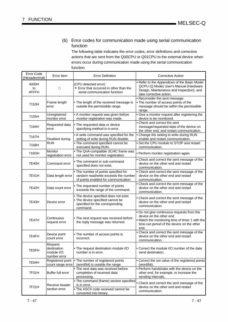
7 - 47 7 - 47
MELSEC-Q7 FUNCTION
(6) Error codes for communication made using serial communicationfunctionThe following table indicates the error codes, error definitions and correctiveactions that are sent from the Q00CPU or Q01CPU to the external device whenerrors occur during communication made using the serial communicationfunction.
Error Code(Hexadecimal) Error Item Error Definition Corrective Action
4000Hto
4FFFH
(CPU detected error) Error that occurred in other than theserial communication function
• Refer to the Appendices of the Basic ModelQCPU (Q Mode) User's Manual (HardwareDesign, Maintenance and Inspection), andtake corrective action.
7153H Frame lengtherror
• The length of the received message isoutside the permissible range.
• Reconsider the sent message.• The number of access points of the
message should be within the permissiblerange.
7155H Unregisteredmonitor error
• A monitor request was given beforemonitor registration was made.
• Give a monitor request after registering thedevice to be monitored.
7164H Requested dataerror
• The requested data or devicespecifying method is in error.
• Check and correct the sentmessage/requested data of the device onthe other end, and restart communication.
7167H • A write command was specified for thesetting of write during RUN disable.
• Change the setting to write during RUNenable and restart communication.
7168H
Disabled duringRUN • The command specified cannot be
executed during RUN.• Set the CPU module to STOP and restart
communication.
716DH Monitorregistration error
• The QnA-compatible 3C/4C frame wasnot used for monitor registration. • Perform monitor registration again.
7E40H Command error • The command or sub-commandspecified does not exist.
• Check and correct the sent message of thedevice on the other end and restartcommunication.
7E41H Data length error• The number of points specified for
random read/write exceeds the numberof points enabled for communication.
• Check and correct the sent message of thedevice on the other end and restartcommunication.
7E42H Data count error • The requested number of pointsexceeds the range of the command.
• Check and correct the sent message of thedevice on the other end and restartcommunication.
7E43H Device error
• The device specified does not exist.• The device specified cannot be
specified for the correspondingcommand.
• Check and correct the sent message of thedevice on the other end and restartcommunication.
7E47H Continuousrequest error
• The next request was received beforethe reply message was returned.
• Do not give continuous requests from thedevice on the other end.
• Match the monitoring time of timer 1 with thetime-out period of the device on the otherend.
7E4FH Device pointcount error
• The number of access points isincorrect.
• Check and correct the sent message of thedevice on the other end and restartcommunication.
7E5FH
Requestdestinationmodule I/Onumber error
• The request destination module I/Onumber is in error.
• Correct the module I/O number of the datasend destination.
7E64H Registered pointcount range error
• The number of registered points(word/bit) is outside the range.
• Correct the set value of the registered points(word/bit).
7F01H Buffer full error• The next data was received before
completion of received dataprocessing.
• Perform handshake with the device on theother end, for example, to increase thesending intervals.
• The command (frame) section specifiedis in error.7F21H Receive header
section error • The ASCII code received cannot beconverted into binary.
• Check and correct the sent message of thedevice on the other end and restartcommunication.

7 - 48 7 - 48
MELSEC-Q7 FUNCTION
Error Code(Hexadecimal) Error Item Error Definition Corrective Action
7F22H Command error• The command or device specified does
not exist.• The remote password length is in error.
• Check and correct the sent message of thedevice on the other end and restartcommunication.
7F23H MC protocolmessage error
• The data (e.g. ETX, CR-LF) specifiedafter the character part does not existor in error.
• Check and correct the sent message of thedevice on the other end and restartcommunication.
7F24H Sum check error • The calculated sum check does notmatch the received sum check.
• Reconsider the sum check of the device onthe other end.
7F67H Overrun error• The next data was received before the
Q00CPU or Q01CPU completedreceive processing.
• Reduce the communication speed andrestart communication.
• Check the Q00CPU or Q01CPU foroccurrence of an instantaneous powerfailure.(For the Q00CPU or Q01CPU, use thespecial register SD53 to check.)When an instantaneous power failure hasoccurred, remove its cause.
7F69H Parity error • The parity bit setting does not match.• Match the setting of the Q00CPU or
Q01CPU with that of the device on the otherend.
7F6AH Buffer full error • The receive buffer of the OS overflew,resulting in skipped receive data.
• Exercise DTR control to makecommunication, preventing a buffer fullerror.
F000H • Error detected by the MELSECNET/Hnetwork system.
• Refer to the Q CorrespondingMELSECNET/H Reference Manual (PLC toPLC Network) and take corrective action.

8 - 1 8 - 1
MELSEC-Q
8
8 COMMUNICATION WITH INTELLIGENT FUNCTION MODULE
8 COMMUNICATION WITH INTELLIGENT FUNCTION MODULE
(1) Description of intelligent function modulesBasic model QCPU allows the use of the Q series-compatible intelligent functionmodules.The intelligent function module is a module that allows Basic model QCPU toprocess analog values or high-speed pulses which cannot be processed with I/Omodules.For example, an analog value is converted into a digital value with theanalog/digital conversion module, one of the intelligent function modules, beforebeing used.
(2) Communication with intelligent function modulesThe intelligent function module is equipped with memory (buffer memory) to storethe data received from or output to external devices.Basic model QCPU reads/writes the data from/to the buffer memory.
8.1 Communication Between Basic model QCPU and Q-series Intelligent Function Modules
The following methods enable the communication between Basic model QCPU andintelligent function modules:
• Initial setting or automatic refresh setting using the GX Configurator• Intelligent function module device• Instructions dedicated for intelligent function modules• FROM/TO instruction
The following table shows the communication timing for the communication methodswith intelligent function modules described above:
Communication timing Storage location 1
Communication method with intelligent function modulesPower ON
BasicmodelQCPUreset
STOP RUN
Instructionexecution
ENDprocessing
2
BasicmodelQCPU
3
Intelligent
Initial setting — — —GX Configurator
Automatic refresh setting — — — — —Intelligent function module device 4 — — — — —
Instructions dedicated for intelligent function modules4 — — — — —
FROM/TO instruction 4 — — — — —
Communication timing .............. : Executed —: Not executedStorage location ........................ : Can be stored —: Cannot be stored
REMARK
1: Indicates whether the data (designated by the GX Configurator, of the deviceinitial value, etc.) is stored in Basic model QCPU or in an intelligent functionmodule.
2: Represents the internal memory of Basic model QCPU.3: "Intelligent" represents an intelligent function module.4: Represents the program using the intelligent function module device, the
FROM/TO instruction, or the instructions dedicated for intelligent functionmodules.

8 - 2 8 - 2
MELSEC-Q
8
8 COMMUNICATION WITH INTELLIGENT FUNCTION MODULE
8.2 Initial setting and automatic refresh setting using GX Configurator
(1) Initial and automatic refresh settings of intelligent function modulesInstalling the GX Configurator compatible with the intelligent function moduleenables the initial setting and automatic refresh setting with GX Developer.When the initial setting and automatic refresh setting of the intelligent functionmodule is designated with GX Developer, you can write/read data withoutcreating the program for the communication with the intelligent function module.Moreover, you can conduct the initial setting or automatic refresh setting withoutdesignating the buffer memory address of the intelligent function module.
(2) Setting using the GX ConfiguratorThis section describes the example to set the initial setting and automatic refreshsetting of A/D conversion module Q64AD.(a) Initial setting
The initial setting of Q64AD offers the following four settings:• Designation of enable/disable A/D conversion• Designation of sampling/averaging processing• Designation of time averaging/execution averaging• Designation of average time/average execution
The initial setting of Q64AD is designated on the following initial settingscreen of GX Configurator.
[Initial setting screen]
The designated initial setting data is stored in the intelligent functionmodule.

8 - 3 8 - 3
MELSEC-Q8 COMMUNICATION WITH INTELLIGENT FUNCTION MODULE
(b) Automatic refresh settingFor the automatic refresh setting, designate the device at Basic modelQCPU to store the following data.
• Digital output of Q64AD• Maximum/minimum values of Q64AD• Error code
The automatic refresh setting of Q64AD is designated on the followingautomatic refresh setting screen of GX Configurator.
[Automatic refresh setting screen]
The designated automatic refresh setting data is stored in the intelligentfunction parameters of Basic model QCPU.
REMARK
For the details of the GX Configurator, refer to the manual of the intelligent functionmodule being used.

8 - 4 8 - 4
MELSEC-Q8 COMMUNICATION WITH INTELLIGENT FUNCTION MODULE
8.3 Communication Using The Intelligent Function Module Device
(1) Intelligent function module deviceThe intelligent function module device is the buffer memory of the intelligentfunction module represented as a device of Basic model QCPU program.It enables reading data stored in the buffer memory of the intelligent functionmodule, or enables writing data to the buffer memory of the intelligent functionmodule.For example, programming can be performed as shown below when "100" iswritten to the buffer memory address 0 of the intelligent function module whoseI/O numbers are X/Y20 to X/Y2F.
[ ]MOV K100 U2\G0Buffer memory addressI/O number X/Y20
(2) Difference from the FROM/TO instructionThe intelligent function module device can be handled as a device of Basicmodel QCPU, enabling the processing of data read from the intelligent functionmodule with one instruction.For example, programming can be performed as show below when the result ofadding the data imported from the intelligent function module and the data of D0is stored into D2.
[ ]+ U2\GO D0 D2
This saves the number of steps in the entire program.The processing speed is the total of the instruction execution time and the accesstime to/from the intelligent function modules.
POINTWhen reading and processing the data of the intelligent function module frequentlyin the program, use the FROM instruction to read the data at one point in theprogram and store and process it in a data register, instead of using the intelligentfunction module device every time.Otherwise, the intelligent function module device accesses the intelligent functionmodule every time the instruction is executed, resulting in longer scan time for theprogram.
REMARK
For the intelligent function module device, refer to Section 10.5.
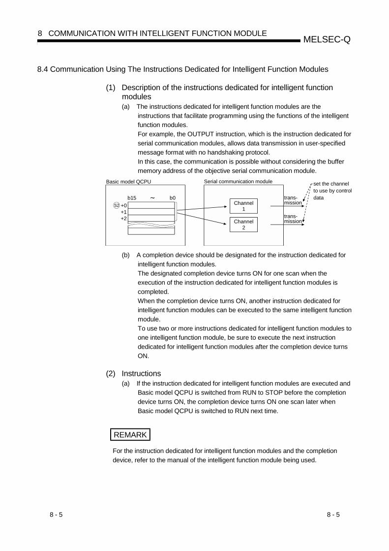
8 - 5 8 - 5
MELSEC-Q8 COMMUNICATION WITH INTELLIGENT FUNCTION MODULE
8.4 Communication Using The Instructions Dedicated for Intelligent Function Modules
(1) Description of the instructions dedicated for intelligent functionmodules(a) The instructions dedicated for intelligent function modules are the
instructions that facilitate programming using the functions of the intelligentfunction modules.For example, the OUTPUT instruction, which is the instruction dedicated forserial communication modules, allows data transmission in user-specifiedmessage format with no handshaking protocol.In this case, the communication is possible without considering the buffermemory address of the objective serial communication module.
b15 b0S2 +0
+1+2
Basic model QCPU Serial communication module
trans-mission
set the channelto use by controldata
Channel1
Channel2
trans-mission
(b) A completion device should be designated for the instruction dedicated forintelligent function modules.The designated completion device turns ON for one scan when theexecution of the instruction dedicated for intelligent function modules iscompleted.When the completion device turns ON, another instruction dedicated forintelligent function modules can be executed to the same intelligent functionmodule.To use two or more instructions dedicated for intelligent function modules toone intelligent function module, be sure to execute the next instructiondedicated for intelligent function modules after the completion device turnsON.
(2) Instructions(a) If the instruction dedicated for intelligent function modules are executed and
Basic model QCPU is switched from RUN to STOP before the completiondevice turns ON, the completion device turns ON one scan later whenBasic model QCPU is switched to RUN next time.
REMARK
For the instruction dedicated for intelligent function modules and the completiondevice, refer to the manual of the intelligent function module being used.

8 - 6 8 - 6
MELSEC-Q8 COMMUNICATION WITH INTELLIGENT FUNCTION MODULE
8.5 Communication Using FROM/TO Instruction
(1) FROM/TO instructionAt the execution of the FROM/TO instruction, the data stored in the buffermemory of the intelligent function module can be read, or data can be written tothe buffer memory of the intelligent function module.The FROM instruction stores the data read from the buffer memory of theintelligent function module to the designated device.The TO instruction writes the data of the designated device to the buffer memoryof the intelligent function module.
REMARK
1) For the details of the FROM/TO instruction, refer to the following manuals.• QCPU (Q mode)/QnACPU Programming Manual (Common Instructions)
2) For the details of the buffer memory of the intelligent function module, refer to themanual of the intelligent function module being used.

9 - 1 9 - 1
MELSEC-Q9 PARAMETER LIST
9
9 PARAMETER LIST
There are two types of promoters used in Basic model QCPU's procedures: "PLCparameters" that are used when operating a PLC and "network parameters" that areused when connecting to the MELSECNET/H, Ethernet or CC-Link system.
This chapter shows a listing of PLC parameters and network parameters used forGX Developer.For details regarding each setting item, refer to the section or manual indicated.For GX Developer setting procedures, see the GX Developer Operating Manual.
The parameters written from the GX Developer will be validated within the Basic modelQCPU in the following cases: ( 1)• When the power supply to the PLC is switched on.• When the Basic model QCPU is reset.• When the Basic model QCPU changes from STOP to RUN.
1 The PLC parameter I/O allocation switch settings and detailed settings and thenetwork parameters will be transmitted to the target intelligent function module atthe following startup of the Basic model QCPU and will be used there.
• When the PLC is powered on• When the Basic model QCPU is reset
POINT(1) When the switch settings of the I/O assignment PLC parameters and the
network parameters have been changed, the PLC must be powered off, then on(ON to OFF to ON) or the Basic model QCPU reset.If the PLC is not powered off, then on (ON to OFF to ON) or the Basic modelQCPU not reset, the new switch settings of the I/O assignment PLC parametersand the new network parameters are not made valid.
(2) When the PLC parameters have been written to the Basic model QCPU, powerthe PLC off, then on (ON to OFF to ON) or reset the Basic model QCPU.
REMARK
When the Basic model QCPU is switched from STOP to RUN, the PLC parameterI/O allocation switch settings and detailed settings are not transmitted to the targetintelligent function module.

9 - 2 9 - 2
MELSEC-Q9 PARAMETER LIST
9
MEMO

9 - 3 9 - 3
MELSEC-Q9 PARAMETER LIST
Table 9.1 Parameter List
Item Description
PLC name settingsDesignate the label and comment for the CPU module to be used.These settings do not affect CPU module operation
Label Designates the label setting (name and use).Comment Designates the comment setting.
PLC system settingsThese are the settings required for using the CPU module.Default values are available for PLC control.
Low-Speed timerTimer setting
High-Speed timerDesignates the low-speed/high-speed timer settings
RUN-PAUSE contactDesignates the contact which controls the CPU's module RUN/PAUSE operation.Setting of only the PAUSE contact cannot be made. (Setting of the RUN contact orRUN contact + PAUSE contact can be made.)
Remote reset Enables/disables the remote reset operation from the GX Developer.
STOP-RUN output mode Designates the output(Y) mode at STOP-RUN switching.
Number of vacant slot points Designates the number of vacant slot points in the base/extension base midule.
Interrupt counter Designates the interrupt counter "first No."Systeminterruptsettings
In Fixed cycleinterval(n: 28 to 31)
Specifies time intervals at which to execute interrupt pointers (I28 to I31).
Interrupt program/fixed scanprogram setting
Specifies whether to perform the high-speed execution of an interrupt program.
Module synchronizationSpecifies whether to bring the start of a CPU module into synchronization with thestart of an intelligent-function module.
PLC RAS settings These settings are used for the RAS function.WDTsettings
WDT setting Set the watchdog timer of the CPU module.
Operation mode at error occurrencesDesignates the CPU module operation mode to be established when an error isdetected.
Error check Designates whether or not to detect a specified error .Constant scan Designates the constant scanning time.

9 - 4 9 - 4
MELSEC-Q9 PARAMETER LIST
Default Value Setting Range Reference Section
— — —
No setting Max. of 10 characters —No setting Max. of 64 characters —
— — —
100 ms 1 ms to 1000 ms(1 ms units) Section 10.2.1010.0 ms 0.1 ms to 100.0 ms Section 10.2.10
No setting X0 to X7FF Section 7.6.1
Disabled Enabled/Disabled Section 7.6.3Previous status (produce the status ofan output (X) before STOP
Produce the status of an output (X) before STOP/Clear theoutput (output is 1 scan later)
Section 7.4
16 points
Q00JCPU: 16 points, 32 points, 64 points, 128 points,256points
Q00CPU/Q01CPU: 16 points, 32 points, 64 points, 128points, 256 points, 512 points, 1024points
Section 5.6.1
No setting C0 to C13408 (Counter setting points can be set up to 128.) Section 10.2.11I28: 100.0 msI29: 40.0 msI30: 20.0 msI31: 10.0 ms
2 to 1000 ms (1 ms units) Section 10.10
The high-speed execution is disabled. Enable/Disable the high-speed execution. Section 4.1.3
The start of an intelligent-functionmodule is synchronized.
Yes/No to synchronize the start of an intelligent-functionmodule.
—
— — —
200 ms 10 ms to 2000 ms (10 ms units) Section 4.2.2
Stop Stop/Continue Section 7.1.5
Checked Checked/Not checked Section 7.15No setting 1 ms to 2000 ms(1 ms units) Section 7.2

9 - 5 9 - 5
MELSEC-Q9 PARAMETER LIST
Table 9.1 Parameter List (continued)
Item Description
Device settings These settings designate the number of points for each device, the latch range,and the local device range.
Number of device points Designates the number of device points used.
Latch (1) first/last(Latch clear valid)
Set the latch range where data can be cleared by remote latch clear operation(first device number/last device number).
Latch (2) first/last(Latch clear invalid)
Set the latch range where data cannot be cleared by remote latch clear operation(first device number/last device number).
Boot file setting Set whether boot will be performed from the standard ROM or not.I/O allocations Designates the installation status for each system module.
Type Set the type of the module loaded.
Model name Set the model name of the module loaded.(CPU module not used. User's memo)
Points Set the number of points of the corresponding slot.I/O allocation
Start XY(First I/O number) Set the first I/O number of the corresponding slot.
Base model name Set the model name of the main or extension base unit used.(CPU module not used. User's memo)
Power modelname
Set the model name of the power supply module loaded on the main or extensionbase unit. (CPU module not used. User's memo)
Increase cablename Set the extension cable model name. (CPU module not used. User's memo)
Base setting
Slots Set the number of slots of the main or extension base unit.Set the number of slots to all base units.
Switch setting Set various switches of the intelligent function module.
Error time outputmodule
Set whether to clear or retain the output when the CPU module results in a stoperror.
H/W error timePLC operationmode
Set whether to stop or continue the operation of the control CPU when thehardware fault of the intelligent function module occurs.Detailed
setting
I/O response time Set the response time of the input module, I/O combined module or high-speedinput module.
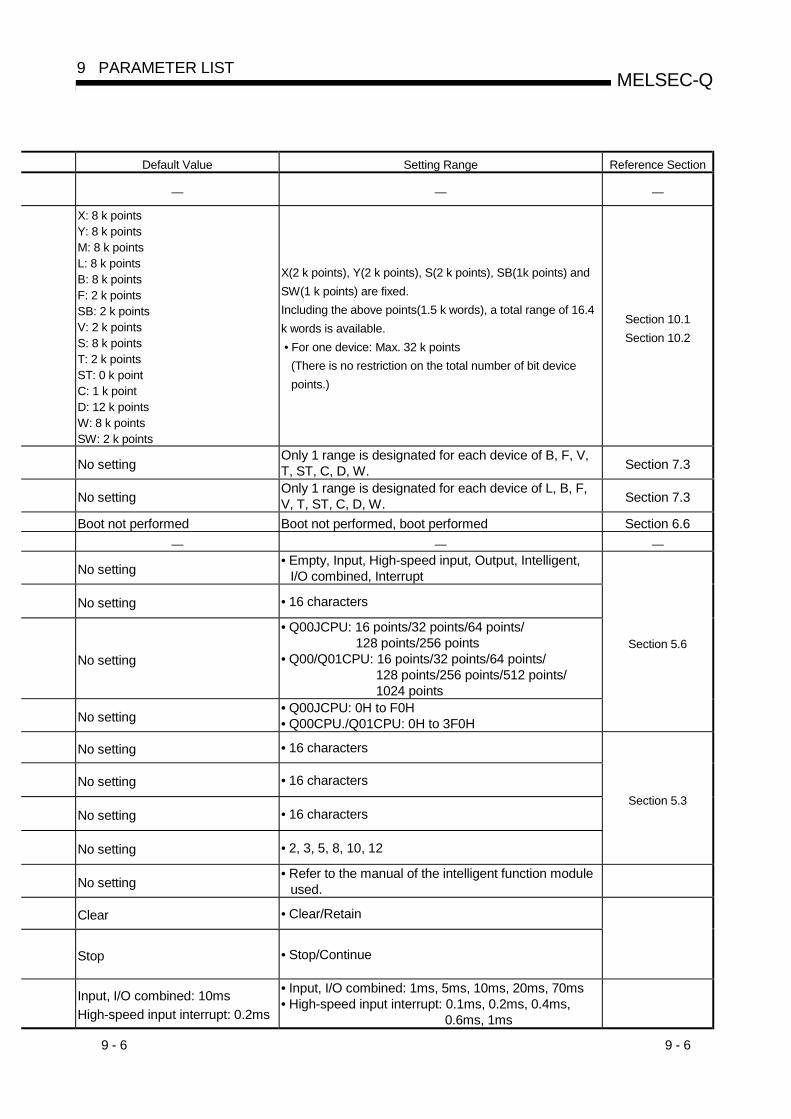
9 - 6 9 - 6
MELSEC-Q9 PARAMETER LIST
Default Value Setting Range Reference Section
— — —
X: 8 k pointsY: 8 k pointsM: 8 k pointsL: 8 k pointsB: 8 k pointsF: 2 k pointsSB: 2 k pointsV: 2 k pointsS: 8 k pointsT: 2 k pointsST: 0 k pointC: 1 k pointD: 12 k pointsW: 8 k pointsSW: 2 k points
X(2 k points), Y(2 k points), S(2 k points), SB(1k points) andSW(1 k points) are fixed.Including the above points(1.5 k words), a total range of 16.4k words is available. • For one device: Max. 32 k points
(There is no restriction on the total number of bit devicepoints.)
Section 10.1Section 10.2
No settingOnly 1 range is designated for each device of B, F, V,T, ST, C, D, W. Section 7.3
No settingOnly 1 range is designated for each device of L, B, F,V, T, ST, C, D, W. Section 7.3
Boot not performed Boot not performed, boot performed Section 6.6— — —
No setting• Empty, Input, High-speed input, Output, Intelligent,
I/O combined, Interrupt
No setting • 16 characters
No setting
• Q00JCPU: 16 points/32 points/64 points/128 points/256 points
• Q00/Q01CPU: 16 points/32 points/64 points/128 points/256 points/512 points/1024 points
No setting• Q00JCPU: 0H to F0H• Q00CPU./Q01CPU: 0H to 3F0H
Section 5.6
No setting • 16 characters
No setting • 16 characters
No setting • 16 characters
No setting • 2, 3, 5, 8, 10, 12
Section 5.3
No setting• Refer to the manual of the intelligent function module
used.
Clear • Clear/Retain
Stop • Stop/Continue
Input, I/O combined: 10msHigh-speed input interrupt: 0.2ms
• Input, I/O combined: 1ms, 5ms, 10ms, 20ms, 70ms• High-speed input interrupt: 0.1ms, 0.2ms, 0.4ms,
0.6ms, 1ms
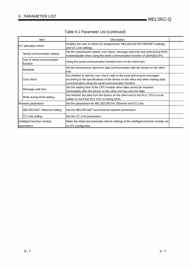
9 - 7 9 - 7
MELSEC-Q9 PARAMETER LIST
Table 9.1 Parameter List (continued)
Item Description
X/Y allocation check Enables the user to check I/O assignments, MELSECNET/ETHERNET settings,and CC-Link settings.
Serial communication setting Set the transmission speed, sum check, message wait time and write during RUNenable/disable when using the serial communication function of Q00/Q01CPU.
Use of serial communicationfunction Using the serial communication function turns on the check box.
Baudrate Set the transmission speed for data communication with the device on the otherend.
Sum checkSet whether to add the sum check code to the send and receive messagesaccording to the specifications of the device on the other end when making datacommunication using the serial communication function.
Message wait time Set the waiting time of the CPU module when data cannot be receivedimmediately after the device on the other end has sent the data.
Write during RUN setting Set whether the data from the device on the other end to the PLC CPU is to bewritten or not if the PLC CPU is during RUN.
Network parameters Set the parameters for MELSECNET/H, Ethernet and CC-Link.
MELSECNET, Ethernet setting Set the MELSECNET and Ethernet network parameters.
CC-Link setting Set the CC-Link parameters.
Intelligent function moduleparameters
Make the initial and automatic refresh settings of the intelligent function module seton GX Configurator.

9 - 8 9 - 8
MELSEC-Q9 PARAMETER LIST
Default Value Setting Range Reference Section
— — —
— — —
— — —
19.2kbps 9.6 kbps/19.2 kbps/38.4 kbps/57.6 kbps/115.2 kbps
Yes No/Yes
No wait No wait/10ms to 150ms (10ms increments)
Not enabled Not enabled/Enabled
Section 7.17
— — —
No setting• See the Q compatible MELSECNET/H and Ethernet
manuals. —
No setting • Refer to the CC-Link Manual. —
No setting Refer to the manual of the intelligent function module used. —
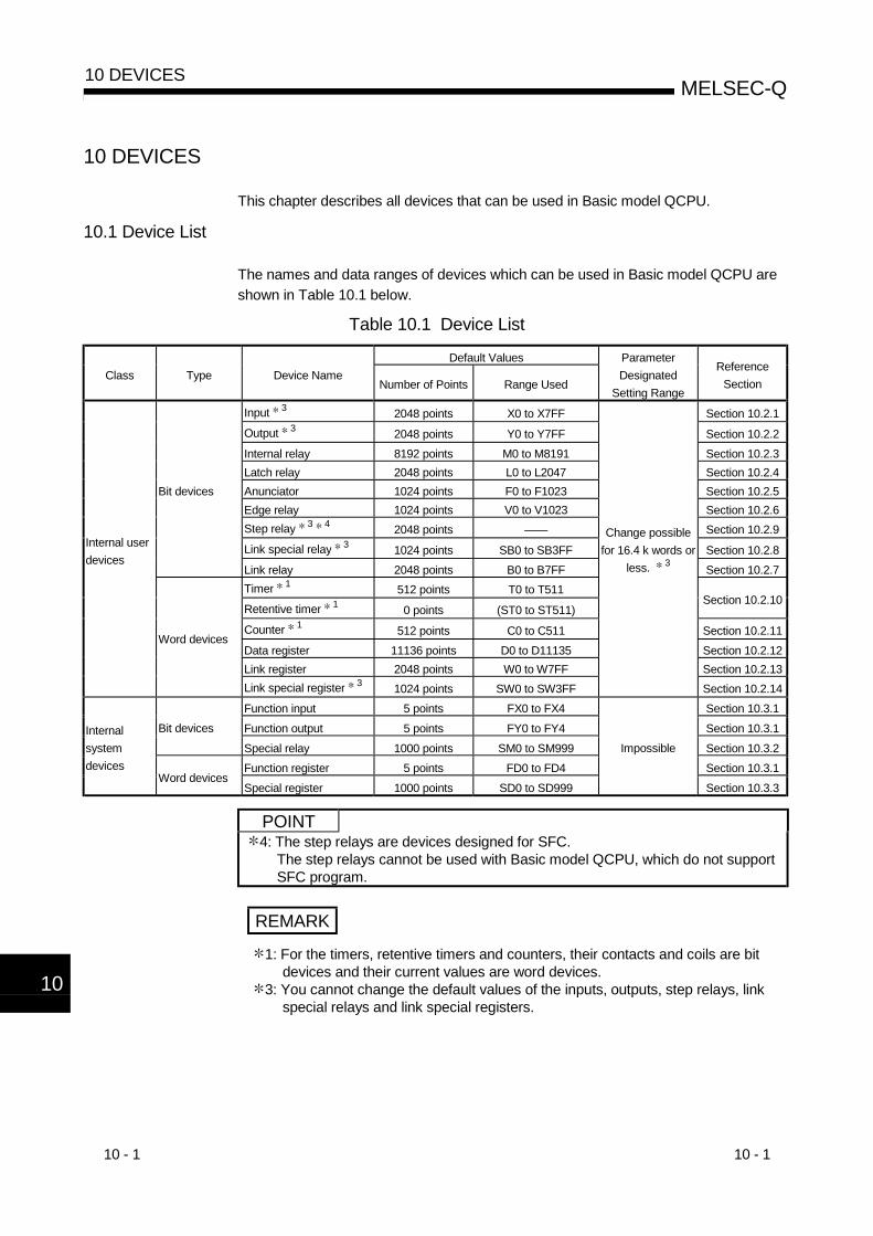
10 - 1 10 - 1
MELSEC-Q10 DEVICES
10
10 DEVICES
This chapter describes all devices that can be used in Basic model QCPU.
10.1 Device List
The names and data ranges of devices which can be used in Basic model QCPU areshown in Table 10.1 below.
Table 10.1 Device List
Default ValuesClass Type Device Name
Number of Points Range Used
ParameterDesignated
Setting Range
ReferenceSection
Input 3 2048 points X0 to X7FF Section 10.2.1Output 3 2048 points Y0 to Y7FF Section 10.2.2Internal relay 8192 points M0 to M8191 Section 10.2.3Latch relay 2048 points L0 to L2047 Section 10.2.4Anunciator 1024 points F0 to F1023 Section 10.2.5Edge relay 1024 points V0 to V1023 Section 10.2.6Step relay 3 4 2048 points —— Section 10.2.9Link special relay 3 1024 points SB0 to SB3FF Section 10.2.8
Bit devices
Link relay 2048 points B0 to B7FF Section 10.2.7Timer 1 512 points T0 to T511Retentive timer 1 0 points (ST0 to ST511)
Section 10.2.10
Counter 1 512 points C0 to C511 Section 10.2.11Data register 11136 points D0 to D11135 Section 10.2.12Link register 2048 points W0 to W7FF Section 10.2.13
Internal userdevices
Word devices
Link special register 3 1024 points SW0 to SW3FF
Change possiblefor 16.4 k words or
less. 3
Section 10.2.14Function input 5 points FX0 to FX4 Section 10.3.1Function output 5 points FY0 to FY4 Section 10.3.1Bit devicesSpecial relay 1000 points SM0 to SM999 Section 10.3.2Function register 5 points FD0 to FD4 Section 10.3.1
Internalsystemdevices
Word devicesSpecial register 1000 points SD0 to SD999
Impossible
Section 10.3.3
POINT4: The step relays are devices designed for SFC.
The step relays cannot be used with Basic model QCPU, which do not supportSFC program.
REMARK
1: For the timers, retentive timers and counters, their contacts and coils are bitdevices and their current values are word devices.
3: You cannot change the default values of the inputs, outputs, step relays, linkspecial relays and link special registers.
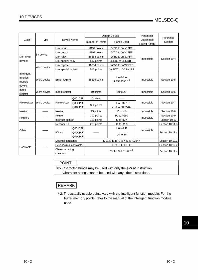
10 - 2 10 - 2
MELSEC-Q10 DEVICES
10
Default ValuesClass Type Device Name
Number of Points Range Used
ParameterDesignated
Setting Range
ReferenceSection
Link input 8192 points Jn\X0 to Jn\X1FFFLink output 8192 points Jn\Y0 to Jn\Y1FFFLink relay 16384 points Jn\B0 to Jn\B3FFF
Bit device
Link special relay 512 points Jn\SB0 to Jn\SB1FFLink register 16384 points Jn\W0 to Jn\W3FFF
Link directdevices
Word deviceLink special register 512 points Jn\SW0 to Jn\SW1FF
Impossible Section 10.4
Intelligentfunctionmoduledevice
Word device Buffer register 65536 pointsUn\G0 to
Un\G65535 2 Impossible Section 10.5
Indexregister
Word device Index register 10 points Z0 to Z9 Impossible Section 10.6
Q00JCPU 0 points ——File register Word device File register Q00CPU/
Q01CPU32k points
R0 to R32767ZR0 to ZR32767
Impossible Section 10.7
Nesting —— Nesting 15 points N0 to N14 Impossible Section 10.8Pointer 300 points P0 to P299 Section 10.9
Pointers ——Interrupt pointer 128 points I0 to I127
ImpossibleSection 10.10
Network No 239 points J1 to J239 Section 10.11.3Q00JCPU U0 to UF
Other ——I/O No Q00CPU/
Q01CPU——
U0 to 3FImpossible
Section 10.11.4
Decimal constants K-2147483648 to K2147483647 Section 10.12.1Hexadecimal constants H0 to HFFFFFFFF Section 10.12.2
Constants ——Character stringconstants
"ABC" and "123" 5 Section 10.12.4
POINT5: Character strings may be used with only the $MOV instruction.
Character strings cannot be used with any other instructions.
REMARK
2: The actually usable points vary with the intelligent function module. For thebuffer memory points, refer to the manual of the intelligent function moduleused.
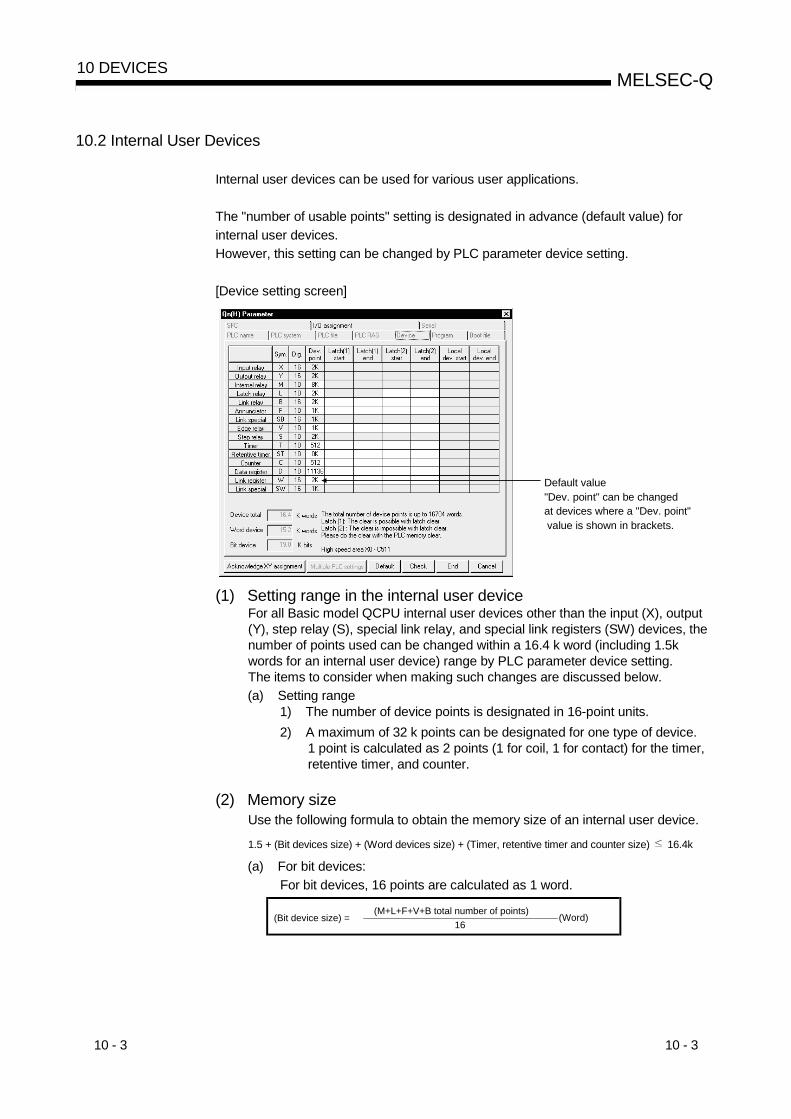
10 - 3 10 - 3
MELSEC-Q10 DEVICES
10.2 Internal User Devices
Internal user devices can be used for various user applications.
The "number of usable points" setting is designated in advance (default value) forinternal user devices.However, this setting can be changed by PLC parameter device setting.
[Device setting screen]
Default value"Dev. point" can be changed at devices where a "Dev. point" value is shown in brackets.
(1) Setting range in the internal user deviceFor all Basic model QCPU internal user devices other than the input (X), output(Y), step relay (S), special link relay, and special link registers (SW) devices, thenumber of points used can be changed within a 16.4 k word (including 1.5kwords for an internal user device) range by PLC parameter device setting.The items to consider when making such changes are discussed below.(a) Setting range
1) The number of device points is designated in 16-point units.2) A maximum of 32 k points can be designated for one type of device.
1 point is calculated as 2 points (1 for coil, 1 for contact) for the timer,retentive timer, and counter.
(2) Memory sizeUse the following formula to obtain the memory size of an internal user device.
1.5 + (Bit devices size) + (Word devices size) + (Timer, retentive timer and counter size) 16.4k
(a) For bit devices:For bit devices, 16 points are calculated as 1 word.
(Bit device size) = (M+L+F+V+B total number of points)
16(Word)

10 - 4 10 - 4
MELSEC-Q10 DEVICES
(b) For timer (T) retentive timer (ST), and Counter (C):For the timer, retentive timer, and counter, 16 points are calculated as 18words.
(Timer, retentive, counter size) = (T, ST, C total number of points)
16 18 (Word)
(c) For word devices:For data registers (D) and link registers (W), 16 points are calculated as 16words.
(Word device size) = (D, W total number of points)
16 16 (Word)
POINT(1) When an internal user device's "number of usable points" setting is changed,
the following files which were created under the previous setting cannot beused as they are.• The sequence programAfter changing the setting, the sequence program must be read from the Basicmodel QCPU to GX Developer, and then they must be written back to it again.

10 - 5 10 - 5
MELSEC-Q10 DEVICES
10.2.1 Inputs (X)
(1) Definition(a) Inputs are commands or data transmitted to the Basic model QCPU from a
peripheral device by push-button switches, selector switches, limit switches,digital switches, etc.
1 2 3
Push-button switch
Selector switch
Digital switch
Input (X)
Sequence operation
(b) The input point is the Xn virtual relay inside the Basic model QCPU, with theprogram using the Xn's N/O contact or N/C contact.
LS2
PB1
X0
X1
XF
PB16 XF
X1
X0Virtual relay
Programmable controller
Input ladder (external device) Program
Figure 10.1 Inputs(X)
(c) There are no restrictions regarding the number of Xn N/O contacts and N/Ccontacts used in a program.
No restrictions regarding the quantity used.
X0Y21X0
X0Y20Y21
Y23
X1X2
X2
Figure 10.2 Input(X) Used in Program

10 - 6 10 - 6
MELSEC-Q10 DEVICES
(2) Reading the inputs(a) There are 2 types of input: "refresh inputs" and "direct access inputs".
1) Refresh inputs are ON/OFF data read from the input module using therefresh mode. 1
X100
CPU module Input moduleAcquisition of ON/OFF data
ON/OFF data
Input refresh area
These inputs are indicated as "X " in the sequence program. Forexample, a "10" input becomes "X10".
2) Direct access inputs are ON/OFF data read from the input moduleusing the direct mode. 2
DX100
Input refresh area
CPU module Input module
Acquisition of ON/OFF data
These inputs are indicated as "DX " in the sequence program.For example, a "10" input becomes "DX10".Direct access input can be made in a LD/AND/OR instruction that usesan input in units of 1 point.
(b) Differences between refresh input and direct access inputSince the direct access input accesses the input module directly atinstruction execution, it imports an input faster than the refresh input.However, the direct access input takes longer instruction processing timethan the refresh input.Moreover, direct access inputs can only be used for inputs used with theinput module and intelligent/special function module which are installed atmain and extension base unit.The refresh and direct input differences are shown in Table 10.2 below.
Table 10.2 Differences Between RefreshItem Refresh Input Direct Access Inputs
Input module installed at base/extensionbase unitInputs of intelligent function moduleinstalled at base/extension base unitInputs of I/O link module installed atbase/extension base unit
Usable Usable
Inputs used at MELSECNET/H networksystem or CC-Link system Usable Unusable
REMARK
1: See Section 4.7.1 for details regarding the refresh mode.

10 - 7 10 - 7
MELSEC-Q10 DEVICES
(c) The same input number can be designated for a refresh input and a directaccess input.If used as a refresh input after being used as a direct access input,operation will be based on the ON/OFF data read at the direct access input.
Y10
DX0Y11
X0Y12
Operation is based on the ON/OFF data read at the END processing input refresh.
Direct access input Operation is based on the ON/OFF data read at the input module.
X0
Operation is based on the ON/OFF data read at the direct access input.
Figure 10.3 Refresh Input & Direct Access Input
POINT(1) When debugging a program, an input (X) can be set to ON/OFF as described
below.• OUT Xn instruction
ON/OFF commandX1
OUT X1
• GX configurator test operation(2) With the CC-Link, an input (x) can be designated as a destination device for the
• RX refresh (on Basic model QCPU side) by using a CC-Link automatic refreshsetting.
• Refresh destination (Basic model QCPU side) device of link input ofMELSECNET/H

10 - 8 10 - 8
MELSEC-Q10 DEVICES
10.2.2 Outputs (Y)
(1) Definition(a) Outputs are program control results which are output to external
destinations (solenoid, electromagnetic switch, signal lamp, digital display,etc.).
Output (Y)
Sequence operation
Signal lamp
Digital display
Contact
(b) Outputs occur at one N/O contact or its equivalent.
(c) There are no restrictions regarding the number of output Yn N/O contactsand N/C contacts used in a program.
M51Load
Programmable controller
No restrictions regarding the quantity used.
Program Out ladder (external device)
Y22
Y21
Y20Y20
X0
X1
Y20
Y20
X3
X2
Figure 10.4 Output(Y) Operation
(2) Using outputs as internal relays (M)"Y" inputs corresponding to vacant slots and slots where input modules areinstalled can serve as internal relays (M).
Pow
er s
uppl
y m
odul
e
OUT Yn
Equivalent to internal relay
CPU
mod
ule
Inpu
t mod
ule
Inpu
t mod
ule
Out
put m
odul
eO
utpu
t mod
ule
Out
put m
odul
e

10 - 9 10 - 9
MELSEC-Q10 DEVICES
(3) Output method(a) There are 2 types of output: "refresh outputs" and "direct access outputs".
1) Refresh outputs are ON/OFF data which is output to the output moduleusing the refresh mode. 1
Output refresh area
CPU module Output moduleON/OFF data output
Y10
0
These outputs are indicated as "Y " in the sequence program.For example, a "10" input becomes "Y10".
2) Direct access outputs are ON/OFF data which is output to the outputmodule using the direct mode. 2
0
DY10
Output refresh area
CPU module Output module
ON/OFF data output
These outputs are indicated as "DY " in the sequence program.For example, a "10" input becomes "DY10".
(b) Differences between refresh outputs and direct access outputsWith direct access outputs, the output module is directly accessed byexecuting an instruction, and the processing speed is therefore slowerthan that for refresh outputs.A refresh output takes longer to process instructions than a directaccess output.Moreover, direct access outputs can only be used for outputs used withthe output module and intelligent function module which are installed atbase unit and extension base unit.The refresh and direct output differences are shown in Table 10.3 below.
Table 10.3 Differences Between Refresh Outputs & Direct Access Outputs
Item Refresh Input Direct Access OutputsOutput module installed at main/extensionbase unitOutputs of intelligent function moduleinstalled at base/extension base unit
Usable Usable
Outputs used at MELSECNET/H networksystem or CC-Link system Usable Unusable
REMARK1: See Section 4.7.1 for details regarding the refresh mode.
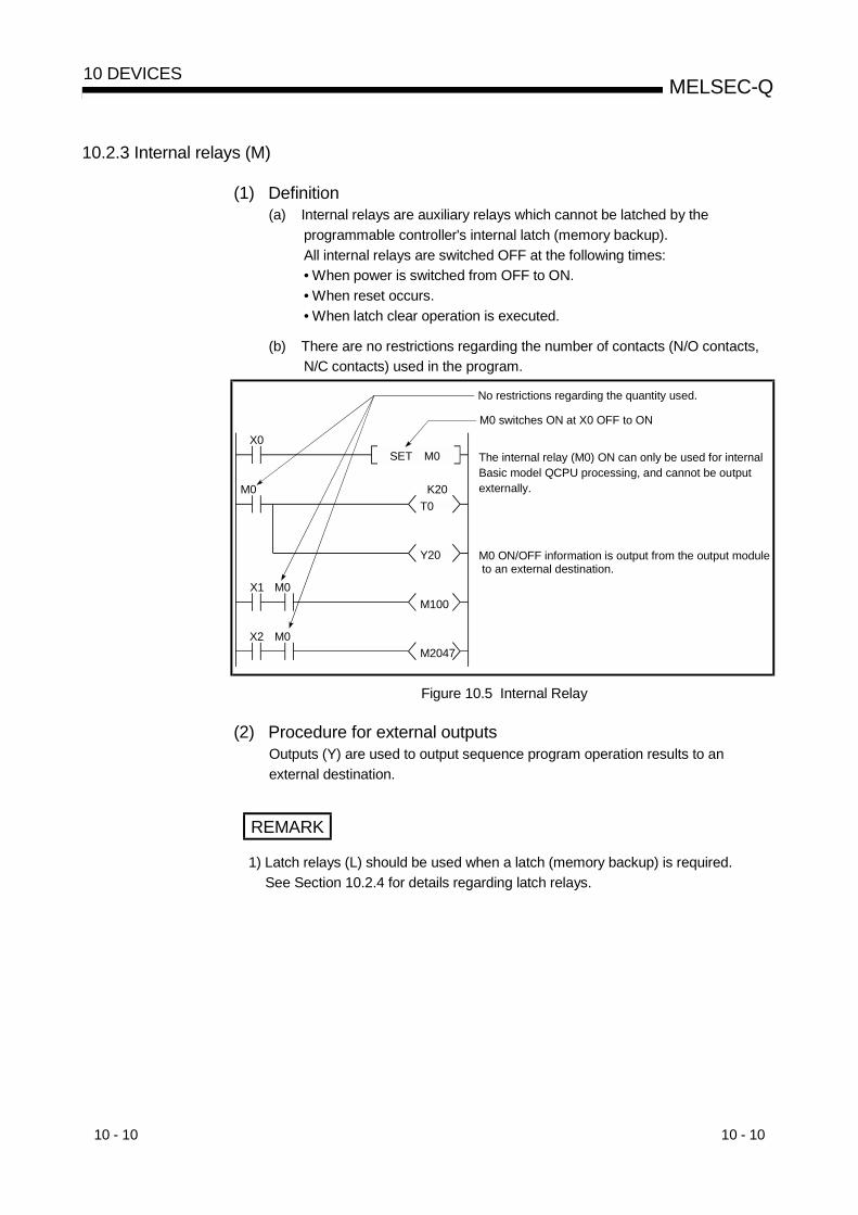
10 - 10 10 - 10
MELSEC-Q10 DEVICES
10.2.3 Internal relays (M)
(1) Definition(a) Internal relays are auxiliary relays which cannot be latched by the
programmable controller's internal latch (memory backup).All internal relays are switched OFF at the following times:• When power is switched from OFF to ON.• When reset occurs.• When latch clear operation is executed.
(b) There are no restrictions regarding the number of contacts (N/O contacts,N/C contacts) used in the program.
X0
M0T0
Y20
X1 M0M100
X2 M0M2047
SET M0
K20
No restrictions regarding the quantity used.
M0 switches ON at X0 OFF to ON
The internal relay (M0) ON can only be used for internal Basic model QCPU processing, and cannot be output externally.
M0 ON/OFF information is output from the output module to an external destination.
Figure 10.5 Internal Relay
(2) Procedure for external outputsOutputs (Y) are used to output sequence program operation results to anexternal destination.
REMARK
1) Latch relays (L) should be used when a latch (memory backup) is required.See Section 10.2.4 for details regarding latch relays.

10 - 11 10 - 11
MELSEC-Q10 DEVICES
10.2.4 Latch relays (L)
(1) Definition(a) Latch relays are auxiliary relays which can be latched by the programmable
controller's internal latch (memory backup).Latch relay operation results (ON/OFF information) are saved even in thefollowing cases:• When power is switched from OFF to ON.• When a Basic model QCPU reset occurs.The latch is backed up by the Basic model QCPU battery.
(b) Performing remote latch clear using GX Developer turns OFF the latchrelay. However, the latch relay that has been set to "Latch (2): Cannot becleared by latch clear" in the device setting PLC parameters cannot beturned OFF if remote latch clear is performed.
(c) There are no restrictions regarding the number of contacts (N/O contacts,N/C contacts) used in the program.
X0
L0T0
Y20
X1 L0L100
X2 L0L2047
SET L0
K20
No restrictions regarding the quantity used.
L0 switches ON at X0 OFF to ON.
The latch relay (L0) ON can only be used for internal Basic model QCPU processing, and cannot be outputexternally.
L0 ON/OFF information is output from the output module to an external destination.
Figure 10.6 Latch Relay
(2) Procedure for external outputsOutputs (Y) are used to output sequence program operation results to anexternal destination.
REMARK
Internal relays (M) should be used when a latch (memory backup) is not required.See Section 10.2.3 for details regarding internal relays.

10 - 12 10 - 12
MELSEC-Q10 DEVICES
10.2.5 Anunciators (F)
(1) Definition(a) Anunciators are internal relays used by the user in fault detection program.
(b) When anunciators switch ON, a special relay (SM62) switches ON, and theNos. and quantity of anunciators which switched ON are stored at thespecial registers (SD62 to SD79).At this time, the "ERR." LED is lit.• Special relay :SM62.................... Switches ON if even one anunciator
switches ON.• Special register:SD62................... No. of first anunciator which switched
ON is stored here.SD63................... The number (quantity) of anunciators
which are ON is stored here.SD64 to SD79 .... Anunciator Nos. are stored in the order
in which they switched ON.(The same anunciator No. is stored atSD62 and SD64.)
The anunciator No. stored at SD62 is also registered in the "fault historyarea".However, only one annunciator number is stored into the failure historystorage area while the PLC power is ON.
(c) The use of anunciators in the fault detection program permits the user tocheck for the presence/absence of fault and to check the fault content(anunciator No.), by monitoring the special registers(SD62 to SD79) whenthe special relay(SM62) switches ON.
ExampleThe program which outputs the No. of the ON annunciator (F5) is shown below.
[Fault detection program]
SD62BCDPSM62
SET F5
K4Y20
X0 X10
Output of annunciator No. which switched ON
Annunciator ON detection
SM62SD62SD63SD64SD65
SD79
OFF to ON0 to 50 to 10 to 50
0
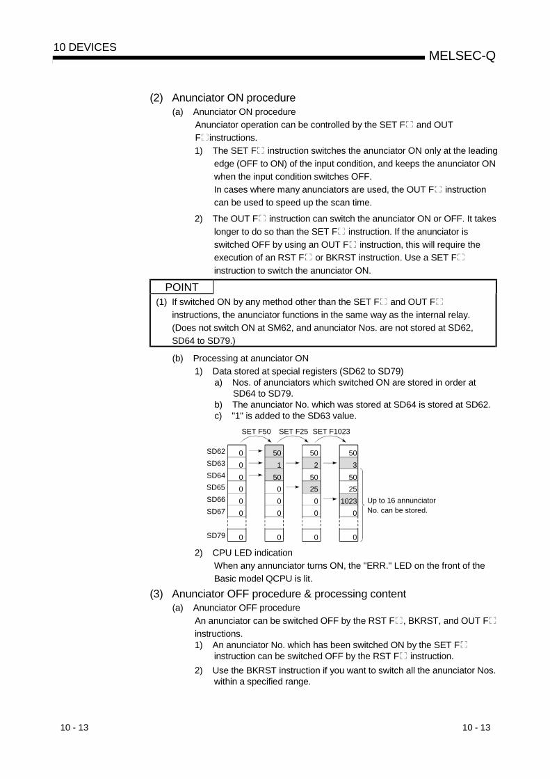
10 - 13 10 - 13
MELSEC-Q10 DEVICES
(2) Anunciator ON procedure(a) Anunciator ON procedure
Anunciator operation can be controlled by the SET F and OUTF instructions.1) The SET F instruction switches the anunciator ON only at the leading
edge (OFF to ON) of the input condition, and keeps the anunciator ONwhen the input condition switches OFF.In cases where many anunciators are used, the OUT F instructioncan be used to speed up the scan time.
2) The OUT F instruction can switch the anunciator ON or OFF. It takeslonger to do so than the SET F instruction. If the anunciator isswitched OFF by using an OUT F instruction, this will require theexecution of an RST F or BKRST instruction. Use a SET Finstruction to switch the anunciator ON.
POINT(1) If switched ON by any method other than the SET F and OUT F
instructions, the anunciator functions in the same way as the internal relay.(Does not switch ON at SM62, and anunciator Nos. are not stored at SD62,SD64 to SD79.)
(b) Processing at anunciator ON1) Data stored at special registers (SD62 to SD79)
a) Nos. of anunciators which switched ON are stored in order atSD64 to SD79.
b) The anunciator No. which was stored at SD64 is stored at SD62.c) "1" is added to the SD63 value.
0 0 0 0 0 0
0
SD62SD63SD64SD65SD66SD67
SD79
50 1
50 0 0 0
0
50 2
50 25 0 0
0
50 3 50 25
1023 0
0
Up to 16 annunciator No. can be stored.
SET F50 SET F25 SET F1023
2) CPU LED indicationWhen any annunciator turns ON, the "ERR." LED on the front of theBasic model QCPU is lit.
(3) Anunciator OFF procedure & processing content(a) Anunciator OFF procedure
An anunciator can be switched OFF by the RST F , BKRST, and OUT Finstructions.1) An anunciator No. which has been switched ON by the SET F
instruction can be switched OFF by the RST F instruction.2) Use the BKRST instruction if you want to switch all the anunciator Nos.
within a specified range.

10 - 14 10 - 14
MELSEC-Q10 DEVICES
3) The OUT F instruction can execute ON/OFF of the anunciator No. bythe same instruction.However, if an anunciator is switched OFF by the OUT F instruction,the "processing at anunciator OFF" (item (b) below) does not occur.Execute the RST F or BKRST instructions after the anunciator hasbeen switched OFF by the OUT F instruction.
1) To switch OFF only the anunciators stored at SD62 and SD64:
SD62 and SD64 annuciators OFFprogram
Display reset inputMOV SD63 Z
Fault detection program(Annunciator ON program)
RST F0Z
2) To switch OFF all anunciators which are ON:
F0 K10Display reset input
F0 to F9 OFF program
Fault detection program(Annunciator ON program)
BKRSTP
REMARK
For details regarding the RST and BKRST instruction, refer to the QCPU(Qmode)/QnACPU Programming Manual(Common Instructions).

10 - 15 10 - 15
MELSEC-Q10 DEVICES
(b) Processing at anunciator OFF1) Special register (SD62 to SD79) data operation when an anunciator is
switched OFF by the RST F instruction• The anunciator No. which was switched OFF is deleted, and all
subsequent anunciator Nos. are moved up to fill the vacant space.• If the anunciator No. stored at SD64 was switched OFF, the new
anunciator No. which is stored at SD64 is stored at SD62.• "-1" is subtracted from the SD63 value.• If the SD63 value is "0", SM62 is switched OFF.
0 0 0 0 0 0
0
SD62SD63SD64SD65SD66SD67
SD79
50 1
50 0 0 0
0
50 2
50 25 0 0
0
50 3
50 25
1023 0
0
SET F50 SET F25 SET F1023
25 2
251023
0 0
0
RST F50
2) Data stored in special registers (SD62 to SD79) when annunciator isturned OFF by execution of BKRST instruction• The annunciator number specified in the BKRST instruction is
deleted and the annunciator numbers stored after the deleted oneare shifted up.
• If the annunciator number stored in SD64 is turned OFF, theannunciator number newly stored in SD64 is stored into SD62.
• The data of SD63 is decremented by the number of resetannunciators.
• If the data of SD63 is 0, SM62 is turned OFF.
3) LED indicationWhen all annunciator numbers in SD64 to SD79 turn OFF, the "ERR."LED is extinguished.

10 - 16 10 - 16
MELSEC-Q10 DEVICES
10.2.6 Edge relay (V)
(1) Definition(a) An edge relay is a device which stores the operation results (ON/OFF
information) from the beginning of the ladder block.Edge relays can only be used at contacts, and cannot be used as coils.
X0 X1 X10 V1
Edge relayStores the X0, X1 and X10 operation results
(b) The same edge relay number cannot be used twice in program executed bythe Basic model QCPU.
(2) Edge relay applicationsEdge relays are used for detecting the leading edge (OFF to ON) in programconfigured using index qualification.
SM400[Ladder example]
X0Z1*1 V0Z1*1
SM400
Z1
M0Z1
K10
Z1
NEXT
K0
FOR
INC
MOV Index register (Z1) OFF
Repetition (10 times) designation
1 scan ON at X0 leading edge
Increment Index Register (Z1) (+1)
Return to FOR instruction
When Z1=0
X0 OFF
V0 OFF
M0 OFF
ON
ON
ON
1 Scan
[Timing chart]
When Z1=1
X1 OFF
V1 OFF
M1 OFF
ON
ON
ON
1 Scan
1 scan ON at X1 leading edge
REMARK
1) 1: The ON/OFF information for X0Z1 is stored at the V0Z1 edge relay.For example, the X0 ON/OFF information is stored at V0, and the X1ON/OFF information is stored at V1.
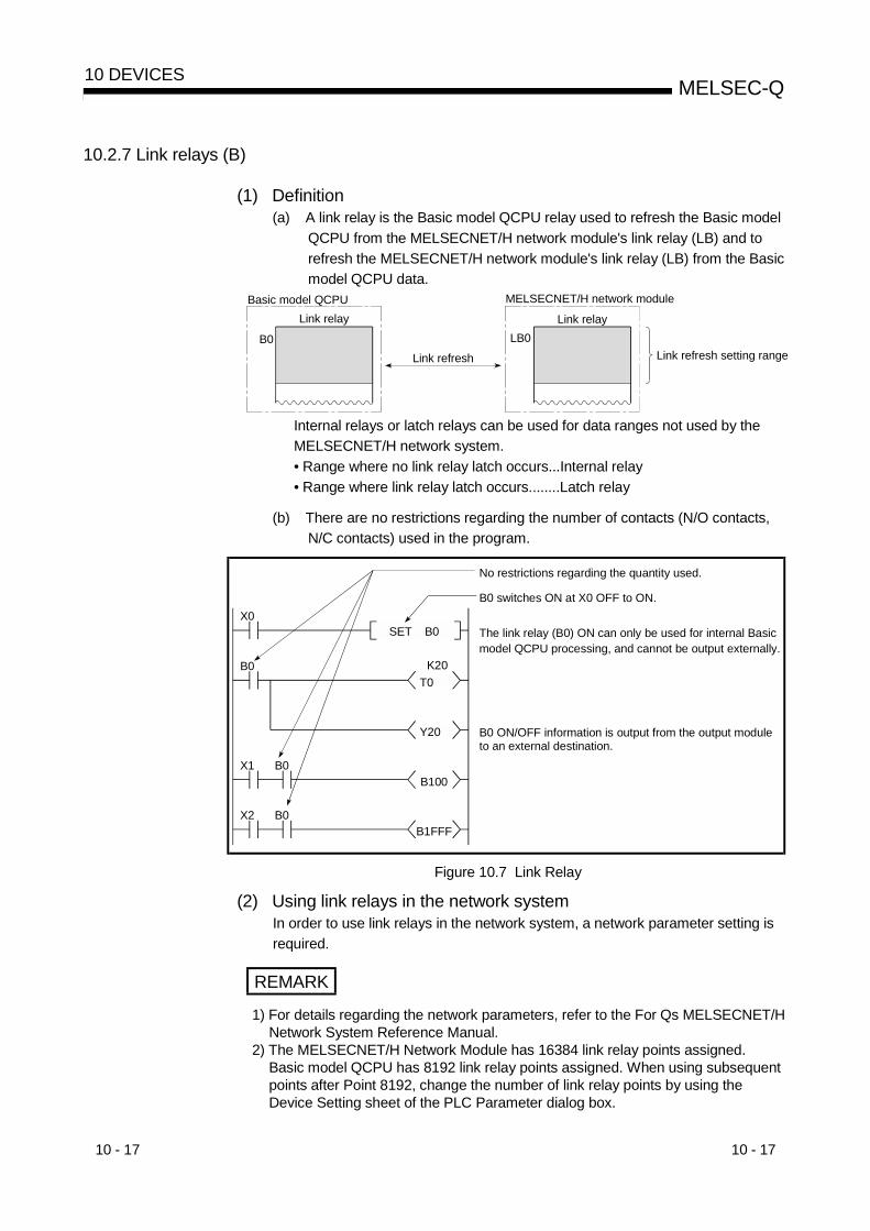
10 - 17 10 - 17
MELSEC-Q10 DEVICES
10.2.7 Link relays (B)
(1) Definition(a) A link relay is the Basic model QCPU relay used to refresh the Basic model
QCPU from the MELSECNET/H network module's link relay (LB) and torefresh the MELSECNET/H network module's link relay (LB) from the Basicmodel QCPU data.
Basic model QCPULink relay
B0
MELSECNET/H network module
Link relayLB0
Link refresh setting rangeLink refresh
Internal relays or latch relays can be used for data ranges not used by theMELSECNET/H network system.• Range where no link relay latch occurs...Internal relay• Range where link relay latch occurs........Latch relay
(b) There are no restrictions regarding the number of contacts (N/O contacts,N/C contacts) used in the program.
X0
B0T0
Y20
X1 B0B100
X2 B0B1FFF
SET B0
K20
No restrictions regarding the quantity used.
B0 switches ON at X0 OFF to ON.
The link relay (B0) ON can only be used for internal Basic model QCPU processing, and cannot be output externally.
B0 ON/OFF information is output from the output module to an external destination.
Figure 10.7 Link Relay
(2) Using link relays in the network systemIn order to use link relays in the network system, a network parameter setting isrequired.
REMARK
1) For details regarding the network parameters, refer to the For Qs MELSECNET/HNetwork System Reference Manual.
2) The MELSECNET/H Network Module has 16384 link relay points assigned.Basic model QCPU has 8192 link relay points assigned. When using subsequentpoints after Point 8192, change the number of link relay points by using theDevice Setting sheet of the PLC Parameter dialog box.

10 - 18 10 - 18
MELSEC-Q10 DEVICES
10.2.8 Special link relays (SB)
(1) Definition(a) A special link relay indicates the communication status and error detection
of an intelligent function module, such as the MELSECNET/10H NetworkModule.
(b) Because special link relays are switched ON and OFF in accordance withvarious problems which may occur during a data link, they serve as a toolfor identifying data link problems.
(2) Number of special link relay pointsThere are a total of 1024 special link relay points between SB0 and SB3FF.Special link relays are assigned at a rate of 512 points per each intelligentfunction module, such as the MELSECNET/10H Network Module.
REMARK
1) For details regarding special link relays used at the Basic model QCPU, refer tothe QCPU (Q mode)/QnACPU Programming Manual (Common Instructions).
10.2.9 Step relays (S)
The step relays are devices designed for SFC.The step relays cannot be used for future expansion.
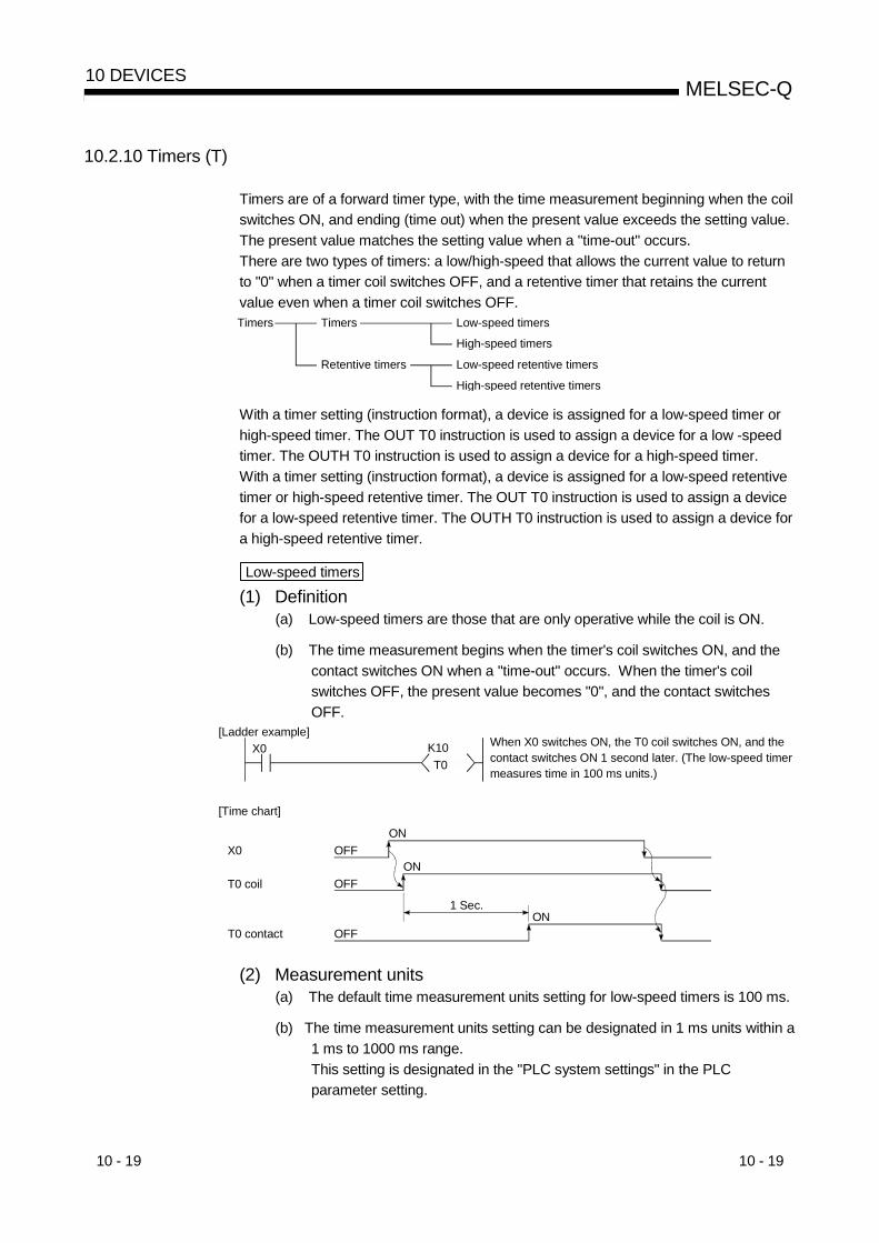
10 - 19 10 - 19
MELSEC-Q10 DEVICES
10.2.10 Timers (T)
Timers are of a forward timer type, with the time measurement beginning when the coilswitches ON, and ending (time out) when the present value exceeds the setting value.The present value matches the setting value when a "time-out" occurs.There are two types of timers: a low/high-speed that allows the current value to returnto "0" when a timer coil switches OFF, and a retentive timer that retains the currentvalue even when a timer coil switches OFF.Timers Timers Low-speed timers
High-speed timers
Retentive timers Low-speed retentive timers
High-speed retentive timers
With a timer setting (instruction format), a device is assigned for a low-speed timer orhigh-speed timer. The OUT T0 instruction is used to assign a device for a low -speedtimer. The OUTH T0 instruction is used to assign a device for a high-speed timer.With a timer setting (instruction format), a device is assigned for a low-speed retentivetimer or high-speed retentive timer. The OUT T0 instruction is used to assign a devicefor a low-speed retentive timer. The OUTH T0 instruction is used to assign a device fora high-speed retentive timer.
Low-speed timers
(1) Definition(a) Low-speed timers are those that are only operative while the coil is ON.
(b) The time measurement begins when the timer's coil switches ON, and thecontact switches ON when a "time-out" occurs. When the timer's coilswitches OFF, the present value becomes "0", and the contact switchesOFF.
X0T0
K10[Ladder example]
When X0 switches ON, the T0 coil switches ON, and the contact switches ON 1 second later. (The low-speed timer measures time in 100 ms units.)
T0 coil
OFF
OFF
OFF
ON
ON
ON1 Sec.
[Time chart]
X0
T0 contact
(2) Measurement units(a) The default time measurement units setting for low-speed timers is 100 ms.
(b) The time measurement units setting can be designated in 1 ms units within a1 ms to 1000 ms range.This setting is designated in the "PLC system settings" in the PLCparameter setting.

10 - 20 10 - 20
MELSEC-Q10 DEVICES
High-speed timers
(1) Definition(a) High-speed timers are timers which are only operative while the coil is ON.
A high-speed timer is marked with a symbol "H".
(b) The time measurement begins when the timer's coil switches ON, and thecontact switches ON when the time elapses. When the timer's coil switchesOFF, the present value becomes "0", and the contact switches OFF.
X0 H
[Ladder example]
When X0 switches ON, the T200 coil switches ON, andthe contact switches ON 2 second later. (The high-speedtimer measures time in 10 ms units.)
K200T200
High-speed timer display
T200 coil
OFF
OFF
OFF
ON
ON
ON2 Sec.
[Time chart]
X0
T200 contact
(2) Measurement units(a) The default time measurement units setting for high-speed timers is
10 ms.
(b) The time measurement units setting can be designated in 0.1ms units withina 0.1 ms to 100 ms range.This setting is designated in the PLC system settings in the PLC parametersetting.

10 - 21 10 - 21
MELSEC-Q10 DEVICES
Retentive timers
(1) Definition(a) Retentive timers measure the "coil ON" time.
(b) The measurement begins when the timer coil switches ON, and the contactswitches ON when a time-out (coil OFF) occurs.Even when the timer coil is OFF, the present value and the contactON/OFF status are saved. When the coil is switched ON again, the timemeasurement resumes from the present value which was saved.
(c) There are 2 retentive timer types: low-speed retentive timer, and high-speedretentive timer.
(d) The RST T instruction is used to clear (reset) the present value andswitch the contact OFF.
X1RST ST0
X0ST0
K200[Ladder example]
When X1 switches ON, the ST0 contact is reset, and the present value is cleared.
X0 ON time is measured as 20 seconds when the timer measures time in 100 ms units.
Retentive timer display
T0 coil
OFF
OFF
ON
ON
ON
15 Sec.
[Time chart]
X0
T0 present value
OFF
OFF
0 to1 151 200to
5 Sec.
0
Contact remains ON when coil switches.
Present value is saved when coil switches.
X1
T0 contact
RST ST0 instruction
150
Instruction execution
ON
(2) Measurement units(a) The measurement units settings for retentive timers are the same as those
for low-speed timers and high-speed timers.• Low-speed retentive timer: Same as low-speed timer• High-speed retentive timer: Same as high-speed timer
REMARK
In order to use retentive timers, a retentive timer "number of points used" settingmust be designated in the PLC parameters device settings.

10 - 22 10 - 22
MELSEC-Q10 DEVICES
Timer Processing & accuracy(a) When an OUT T instruction is executed, the following processing occurs:
timer coil ON/OFF, present value update & contact ON/OFF processing.Timer present value update and contact ON/OFF processing do not occurat END processing.
Processing content Coil ON/OFF Present value update Contact ON/OFF
X0T0
K10[Ladder example]
Sequenceprogram
END OUT T0 END
[Processing at OUT T0 instruction]
(b) When the OUT T instruction is executed, the present value is added tothe scan time measured at the END instruction.If the timer coil is OFF when the OUT T instruction is executed, thepresent value is not updated.
X0T0
H[Ladder example]
K8
QCPU's X0
21 1 1 2 1 1 2 1
2 3 2 3 2 3
2+3=50+2=2 5+2=7 7+3=10
OUT T0END processing
OUT T0 OUT T0 OUT T0 OUT T0 OUT T0
Input reading timing (+1 scan)
Timer accuracy - (1 scan time + timer time limit setting) to 1 scan time
Program
X0 external input
T0 coil
210 ms measurement
T0 contact
Measured value at END instruction
T0 present value
[Present value update timing]
ONOFF
OFF
OFF
ON
ON
OFFON
3 2 3 2 3
END processing
END processing
END processing
END processing
END processing

10 - 23 10 - 23
MELSEC-Q10 DEVICES
(c) The timer response accuracy from the point when input (X) reading occurs,until the point when the output occurs is + (2-scan time + timer time limitsetting).
Precautions when using timers
The following are a few precautions regarding timer use:
(a) A given timer cannot be designated (by OUT T ) more than once in asingle scan.If it is, the timer's present value will be updated at each OUT Tinstruction, resulting in a meaningless measurement.
Sequence program
END ENDOUTT
OUTT
OUTT
OUTT
Present value is updated.1 Scan
OUTT
(b) When a timer (for example. T1) coil is ON, the OUT T1 instruction cannot beskipped using a CJ instruction, etc.If the OUT T instruction is skipped, the timer's present value will not beupdated.
(c) Timers cannot be used in interrupt program.
(d) If the timer set value is "0", the contact goes ON when the OUT Tinstruction is executed.
(e) If the setting value changes to a value which is higher than the presentvalue following a timer "time-out", the "time-out" status will remain in effect,and timer operation will not occur.
(f) If two timers are used, the ON/OFF ladders should be created as shownbelow.
T0M0
T1T0
K10
T0T1
K101 second measurement following T0 ON
1 second measurement when T1 ON
ON/OFF repeated every 1 second

10 - 24 10 - 24
MELSEC-Q10 DEVICES
10.2.11 Counters (C)
Counters are "up counter" types, with the contact being switched ON when the countvalue equals the setting value (count-out condition).There are two counter types: counters which count the number of input condition start-ups (leading edges) in sequence program, and counters which count the number ofinterrupt factor occurrences.
Counters
(1) DefinitionA counter is a device which counts the number of input condition leading edgesin sequence program.
(2) Count processingA counter is a device which counts the number of input condition leading edgesin sequence program.(a) When and OUT C instruction is executed, the following counter
processing occurs: coil ON/OFF, present value update (count value + 1),and contact ON/OFF.Counter present value update and contact ON/OFF processing do notoccur at END processing.
Processing content Coil ON/OFF Present value update Contact ON/OFF
X0C0
K10[Ladder example]
Sequence program
END OUT C0 END
[Processing at OUT C0 Instruction (X0: OFF to ON)]
(b) The present value update (count value + 1) occurs at the leading edge(OFF to ON) of the OUT C instruction.The present value is not updated in the following OUT C instructionstatuses: OFF, ON to ON, ON to OFF
X0C0
K10[Ladder example]
X0 OFF
OFF
ON
ON
[Present value update timing]
END END ENDOUT C0 OUT C0 OUT C0
Present value update Present value update
Sequence program
C0 coil

10 - 25 10 - 25
MELSEC-Q10 DEVICES
(c) Multiple counters can be used within a single scan to achieve the maximumcounting speed.In such cases, the direct access input (DX ) method should be used forthe counter input signals. 1
OUTC
Sequence program
END END
OUT C execution intervals
OUTC
OUTC
OUTC
OUTC
(3) Resetting the counter(a) Counter present values are not cleared even if the OUT C instruction
switches OFF. Use the RST C instruction to clear the counter's presentvalue and switch the contact OFF.
(b) The count value is cleared and the contact is switched OFF at the pointwhen the RST C instruction is executed.
X0[Ladder example]
RST C0
X0 OFF
OFF
ON
Execution
[Counter reset timing]
END END ENDRST C0 RST C0 RST C0
Count value cleared & contact OFF Count value cleared & contact OFF
Sequence program
RST C0 instruction
(4) Maximum counting speedThe counter can count only when the input condition ON/OFF time is longer thanthe execution interval of the corresponding OUT C instruction.The maximum counting speed is calculated by the following formula:
= n
1001T [times/sec]Maximum counting
speed (Cmax)n: Duty(%) 2T: Execution interval of the OUT C instruction
REMARK
1) 1: See Section 10.2.1 for details regarding direct access inputs.2) 2: The "duty" is the count input signal's ON-OFF time ratio expressed as a
percentage value.
When T1 < T2 n = 100
Count input signal OFFON
T1 T2
When T1 T2 n = 100T1+T2
T1
T1+T2T2

10 - 26 10 - 26
MELSEC-Q10 DEVICES
Interrupt counters
(1) DefinitionInterrupt counters are devices which count the number of interrupt factoroccurrences.
(2) Count processing(a) The interrupt counter's present value is updated when an interruption
occurs. It is not necessary to create a program which includes an interruptcounter function.
(b) Interrupt counter operation requires more than the simple designation of asetting value.To use the interrupt counter for control purposes, comparison instructions(=, <=, etc.) must also be used to enable comparisons with the settingvalue, with an internal relay (M), etc., being switched ON or OFF accordingto the comparison result.The figure below shows a sample program in which M0 is switched ONafter 10 interrupt inputs occur. (In this example, "C300" is the interruptcounter No. corresponding to I0.)
= K10 C300 M0
(3) Setting the interrupt counter(a) In order to use interrupt counters, at first interrupt counter No. setting must
be designated in the PLC system settings in the PLC parameter setting.256 points are then allocated for interrupt counters, beginning from the "firstcounter No." which is designated.If C300 is designated as the first interrupt counter No., numbers C300 toC555 will be allocated for interrupt counters.
I0I1I2
I127
C300C301C302
C555
Interrupt counter (127 points)
Values corresponding to the interrupt counter No.
(b) In order to use an interrupt counter, an "interruption permitted" status mustbe established by E1 instruction at the main routine program.

10 - 27 10 - 27
MELSEC-Q10 DEVICES
(4) Precautions(a) One interrupt pointer is insufficient to execute interrupt counter and interrupt
program operation.Moreover, an interrupt program cannot be executed by an interrupt countersetting designated in the PLC system settings in the PLC parameter setting.
(b) If the processing items shown below are in progress when an interruptionoccurs, the counting operation will be delayed until processing of theseitems is completed.The count processing starts after the execution of program is completed.Even if the same interruption occurs again while processing of these itemsis in process, only one interruption will be counted.• During execution of sequence program instructions• During interrupt program execution• During execution of a fixed scan execution type program
(c) The maximum counting speed of the interrupt timer is determined by thelongest processing time of the items shown below.• Instruction with the longest processing time among the instructions used
in the program• Interrupt program processing time• The processing time of a fixed scan execution type program
(d) The use of too many interrupt counters will increase the sequence programprocessing time, and may cause a "WDT ERROR".If this occurs, either reduce the number of interrupt counters, or reduce thecounting speed for the input pulse signal.
(e) The interrupt counter's count value can be reset by using the RST Cinstruction in the sequence program prior to the FEND instruction.
(f) The interrupt counter's count value can be read out by using the sequenceprogram MOV instruction.

10 - 28 10 - 28
MELSEC-Q10 DEVICES
10.2.12 Data registers (D)
(1) Definition(a) Data registers are memory devices which store numeric data (-32768 to
32767, or 0000H to FFFFH).
(b) Data registers consist of 16 bits per point, with reading and writing executedin 16-bit units.
Dnb15 b0
(c) If the data registers are used for 32-bit instructions, the data will be stored inregisters Dn and Dn + 1. The lower 16 bits of data are stored at the dataregister No. (Dn) designated in the sequence program, and the higher 16bits of data are stored in the designated register No. + 1 (Dn + 1). Forexample, if register D12 is designated in the DMOV instruction, the lower16 bits are stored in D12, and the upper 16 bits are stored in D13.
K500000 D12DMOV
D13
Upper 16 bits Lower 16 bits
D12Processing object: D12, D13
Two data registers can store a range of numeric data from -2147483648 to2147483647 or from 0H to FFFFFFFFH.
(d) Data stored by the sequence program is maintained until another data saveoperation occurs.

10 - 29 10 - 29
MELSEC-Q10 DEVICES
10.2.13 Link registers (W)
(1) Definition(a) A link register is the Basic model QCPU memory used to refresh the Basic
model QCPU with data from the link registers (LW) of intelligent functionmodules including MELSECNET/H network module.Link registers are used to store numeric data (-32768 to 32767, or 0000H toFFFFH).
Basic model QCPU
Link registerW0
MELSECNET/H network module
Link registerLW0
Link refresh setting rangeLink refresh
When used outside the MELSECNET/H network system's range, linkregisters can serve as data registers.
(b) Link registers consist of 16 bits per point, with reading and writing executedin 16-bit modules.
Wnb15 b0
(c) If the link registers are used for 32-bit instructions, the data is stored inregisters Wn and Wn + 1. The lower 16 bits of data are stored in the linkregister No. (Wn) designated in the sequence program, and the higher 16bits of data are stored in the designated register No. + 1 (Wn + 1).For example, if link register W12 is designated at the DMOV instruction, thelower 16 bits are stored in W12, and the upper 16 bits are stored in W13.
K500000 W12DMOV
W13
Upper 16 bits Lower 16 bits
W12Processing object: W12, W13
In two link register points, -2147483648 to 2147483647 or 0H toFFFFFFFFH data can be stored.
(d) Data stored by the sequence program is maintained until another data saveoperation occurs.
REMARK
The MELSECNET/H network module has 16384 link register points. The Basicmodel QCPU has 2048 link register points. When subsequent points after Point2048 are used for link registers, change a "number of points" setting of link registerson the Device sheet of the PLC Parameter dialog box.

10 - 30 10 - 30
MELSEC-Q10 DEVICES
(2) Using link registers in a network systemIn order to use link registers in the network system, network parameter settingsmust be made.Link registers not set in the network parameter settings can be used as dataregisters.
REMARK
1) For details regarding network parameters, refer to the Q CorrespondingMELSECNET/H Network System Reference Manual.
10.2.14 Special link registers (SW)
(1) Definition(a) Special link registers are used to store data on the communication status
and errors of an intelligent function
(b) Because the data link information is stored as numeric data, the special linkregisters serve as a tool for identifying the locations and causes of faults.
(2) Number of special link register pointsThere are 1024 special link register points from SW0 to SW3FF. The special linkregister points are assigned at the rate of 512 points per intelligent functionmodule, such as a MELSECNET/H network module.
REMARK
For details regarding special link registers used in the Basic model QCPU, refer tothe QCPU(Q mode)/QnACPU Programming Manual (Common Instructions).

10 - 31 10 - 31
MELSEC-Q10 DEVICES
10.3 Internal System Devices
Internal system devices are devices used for system operations.The allocations and sizes of internal system devices are fixed, and cannot be changedby the user.
10.3.1 Function devices (FX, FY, FD)
(1) Definition(a) Function devices are devices used in sub-routine program with arguments
to permit data transfers between the sub-routine program with argument,and the CALL source for that sub-routine.
ExampleIf FX0 and FD1 are used at the sub-routine program, and if M0 and D0 are designated by the sub-routine CALL instruction, the M0 ON/OFF data is transferred to FX0, and the D0 data is transferred to FD1.
[Sub-routine program CALL source]
M0 D0P0CALL FD1 R0MOV
RET
X0 FX0P0
[Sub-routine program]
(b) Because the function devices used for each sub-routine program CALLsource can be set, the same sub-routine program can be used withoutregard to other sub-routine CALL sources.
(2) Types of function devicesThere are 3 function device types: function input devices (FX), function outputdevices (FY), and function register devices (FD).(a) Function input devices (FX)
• These devices are used to designate inputs of ON/OFF data to a sub-routine program.
• In the sub-routine program, these devices are used for reading andprocessing bit data designated by sub-routine with argument CALLinstruction.
• All the Basic model QCPU bit data designation devices can be used.
(b) Function output devices (FY)• These devices are used to designate outputs of sub-routine program
operation results (ON/OFF data) to the sub-routine program CALL source.• At sub-routine program with arguments, the operation results are stored at
the designated device.• All bit data designation devices except Basic model QCPU inputs (X, DX)
can be used.

10 - 32 10 - 32
MELSEC-Q10 DEVICES
(c) Function registers• Function registers are used to designate data transfers between the sub-routine CALL source and the sub-routine program.
• The function register input/output condition is automatically determined bythe Basic model QCPU. If the sub-routine program data is the source data,the data is designated as sub-routine input data.If the sub-routine program data is the destination data, the data isdesignated as sub-routine output data.
• 1 point occupies 4 words.The number of words used depends on an instruction in a sub-routineprogram.
A one-word instruction requires 1 word.
CALLP P0 D0 MOV R0 FD0P0
The data is stored in one point (D0).
A two-work instruction requires 2 words.
DMOV R0 FD0CALLP P0 D0 P0
The data is stored in two points (D0 and D1).
The destination of 32-bit multiplication/division operation requires 4 words.
CALLP P0 D0 D R0 R10 FD0P0
The data is stored in four points (D0 to D3).
• Active devices cannot be used in a sub-routine program that containsarguments. If devices assigned for function registers are used, values of thefunction registers will not properly be returned to a calling program.
CALLP P0 D0 D R0 R10 FD0P0
MOV K0 D3
Since the points (D0 to D3) are used for FD0, D3 can not be used for the sub-routine program.
•Basic model QCPU's word data devices can be used.
REMARK
1) For a procedure for using function devices, see the QCPU (Q Mode)/QnACPUProgramming Manual (Common Instructions).

10 - 33 10 - 33
MELSEC-Q10 DEVICES
10.3.2 Special relays (SM)
(1) Definition(a) A special relay is used to store High Performance model QCPU status data.
(2) Special relay classificationsSpecial relays are classified according to their applications, as shown below.(a) For fault diagnosis : SM0 to SM99
(b) For serial communication function : SM100 to SM129
(c) System information : SM200 to SM399
(d) System clock/system counter : SM400 to SM499
(e) Scan information : SM500 to SM599
(f) Memory card information : SM600 to SM699
(g) Instruction related : SM700 to SM799
REMARK
1) For details regarding special relays which can be used by the Basic model QCPU,refer to Appendix 1.

10 - 34 10 - 34
MELSEC-Q10 DEVICES
10.3.3 Special registers (SD)
(1) Definition(a) A special register is used to store Basic model QCPU status data (diagnosis
and system information).
(2) Special register classificationsSpecial registers are classified according to their applications, as shown below.(a) For fault diagnosis : SD0 to SD99
(b) For serial communication function : SM100 to SM129
(c) Fuse-blown module : SD130 to SD149
(d) Check of input/output modules : SD150 to SD199
(e) System information : SD200 to SD399
(f) System clock/system counter : SD400 to SD499
(g) Scan information : SD500 to SD599
(h) Memory card information : SD600 to SD699
(i) Instruction related : SD700 to SD799
REMARK
1) For details regarding special relays which can be used by the Basic model QCPU,refer to Appendix 2.

10 - 35 10 - 35
MELSEC-Q10 DEVICES
10.4 Link Direct Devices (J \ )
(1) Definition(a) At END processing, a data refresh (data transfer) operation occurs between
the Basic model QCPU and the MELSECNET/H network system modules.Link direct devices are used at that time to directly access the link devicesin the MELSECNET/H network modules.
(b) Designation method• Link direct devices are designated by network No. and device No.Designation method: J \
Device No. Input...........................X0 Output........................Y0 Link relay.................. B0 Link register...............W0 Link special relay.......SB0 Link special register ..SW0Network No.(1 to 255)
• For link register 10 (W10) of network No.2, the designation would be"J2\W10"
K100 J2W10MOVPNetwork modules at network No.2
W 0
W10
• For a bit device (X, Y, B, SB), digit designation is necessary.Designation example : J1\K1X0, J10\K4B0
(2) Designation rangeLink direct device designations are possible for all the link devices in networkmodules.
Device outside the range specified by the network refreshparameters can also be designated.
(a) Writing1) Writing is executed within that part of the link device range set as the
send range in the common parameters of the network parameters thatis outside the range specified as the "refresh range" in the networkrefresh parameters.
Refresh range
Basic model QCPU Network module
LB 0B 0
send range
Link range
Writing range
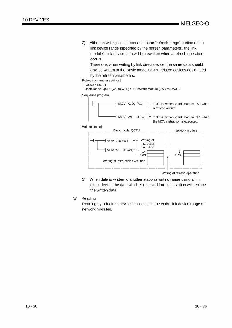
10 - 36 10 - 36
MELSEC-Q10 DEVICES
2) Although writing is also possible in the "refresh range" portion of thelink device range (specified by the refresh parameters), the linkmodule's link device data will be rewritten when a refresh operationoccurs.Therefore, when writing by link direct device, the same data shouldalso be written to the Basic model QCPU related devices designatedby the refresh parameters.
[Sequence program]
"100" is written to link module LW1 when the MOV instruction is executed.
MOV K100 W1
MOV W1 J1\W1
"100" is written to link module LW1 when a refresh occurs.
[Writing timing]
MOV K100
MOV
Writing at instruction executionW0W1 LW1
Writing at instruction execution
Basic model QCPU Network module
Writing at refresh operation
W1
W1 J1\W1
[Refresh parameter settings] Network No. : 1 Basic model QCPU(W0 to W3F) Network module (LW0 to LW3F)
3) When data is written to another station's writing range using a linkdirect device, the data which is received from that station will replacethe written data.
(b) ReadingReading by link direct device is possible in the entire link device range ofnetwork modules.

10 - 37 10 - 37
MELSEC-Q10 DEVICES
(3) Differences between "link direct devices" and "link refresh"The differences between "link direct devices" and "link refresh" are shown inTable 10.4 below.
Table 10.4 Differences Between "Link Direct Devices" and "Link Refresh"
Item Link Direct Device Link Refresh
Link relay J \K4B0 or later B0 or laterLink register J \W0 or later W0 or laterLink special relay J \K4SB0 or later SB0 or later
Programnotationmethod
Link special register J \SW0 or later SW0 or laterNumber of steps 2 steps 1 step
Network module access rangeAll network module linkdevices
Refresh parameterdesignated range
Access data guarantee range Word units (16 bits)
REMARK
1) For details regarding the MELSECNET/H network system, refer to the For QMELSECNET/H Network System Reference Manual.
2) For details regarding network parameters, common parameters, and networkrefresh parameters, refer to the following manuals:• Detailed information : Q Corresponding MELSECNET/H Network System
Reference Manual• Setting procedures : GX Developer Operating Manual, Windows Version

10 - 38 10 - 38
MELSEC-Q10 DEVICES
10.5 Intelligent Function Module Devices (U \G )
(1) Definition(a) The intelligent function module devices allow the Basic model QCPU to
directly access the buffer memories of intelligent function modules whichare installed at the base unit.
(b) Intelligent function module devices are designated by the intelligent functionmodule input/ output No., and the buffer memory address.
Designation method: U \GBuffer memory address (setting range: 0 to16383 (decimal)) 1Intelligent function module/special function module I/O No. Setting: If the input/output No. is a 3-digit value, designate the first 2 digits. For X/YF0.....X/Y1F0 Designate "1F" Setting range: Q00JCPU: 00H to FH
Q00/Q01CPU: 00H to 3FH
When digital output values of channels (CH.1 to CH.4) of the Q64AD TypeAnalog-Digital Conversion Module (X/Y0 to X/YF) installed in Slot 0 of the mainbase unit are stored in D0 to D3, the output/input number and the buffer memoryaddress are specified as shown below.
U0\G11 D0BMOVQ64AD
1213
CH.1 Digital output value11
14
CH.2 Digital output valueCH.3 Digital output valueCH.4 Digital output value
K4
(2) Processing speedThe processing speed for intelligent function module devices is;
(a) Read/write from/to the buffer memory of the intelligent function module isslightly faster than the "processing speed of FROM/TO instruction". (Forexample, "MOV U0\G11 D0")
(b) When using a single instruction to perform read from the buffer memory ofthe intelligent function module and another processing, use the sum of"processing speed of FROM/TO instruction" and "processing speed ofinstruction" as a guideline.(For example, "+ U0\G11 D0 D10")
If the same buffer memory of the same intelligent function module is usedtwo or more times in a sequence program, the processing speed can beincreased by using the FROM instruction to read that buffer memory data toa Basic model QCPU device.
REMARK
1) 1: For details regarding buffer memory addresses and applications, refer to themanual for the intelligent function module in question.

10 - 39 10 - 39
MELSEC-Q10 DEVICES
10.6 Index Registers (Z)
(1) Definition(a) Index registers are used in the sequence program for indirect setting (index
qualification) designations.An index register point is used for index modification.
Index registers consist of 16 bits per point.
X0K5 Z0MOVP
SM400D0Z0 K4Y30BCD
(b) There are 10 index registers (Z0 to Z9).
(c) Index registers consist of 16 bits per point, with reading and writingoccurring in 16-bit modules.
Znb15 b0
(d) If the index registers are used for 32-bit instructions, the data is stored inregisters Zn and Zn +1.The lower 16 bits of data are stored in the index register No. (Zn)designated in the sequence program, and the upper 16 bits of data arestored in the designated index register No. + 1.For example, if register Z2 is designated in the DMOV instruction, the lower16 bits are stored in Z2, and the upper 16 bits are stored at Z3.
D0 Z2DMOV
Z3
Upper 16 bits Lower 16 bits
Z2Processing object: Z2, Z3
REMARK
For index modification using the index register, refer to the following manual.QCPU (Q mode) / QnACPU Programming Manual (Common instructions)

10 - 40 10 - 40
MELSEC-Q10 DEVICES
10.6.1 Switching between main routine/sub-routine program and interrupt program
The PLC System sheet of the PLC Parameter dialog box provides the option to save(protect) or restore index register data (Z0 to Z9) when switching between mainroutine/sub-routine program and a low-speed execution type program or between aninterrupt program.If you do not want to write date onto index registers when using an interrupt program,turn on the "High speed execution" check box in the "Interrupt program fixed programsetting" section of the PLC System sheet in the PLC Parameter dialog box. This willenable you to switch between program quickly.
(1) When the "High-speed execution" check box is OFF:
(a) When the main routine/sub-routine program is switched to the interruptprogram, the main routine/sub-routine program's index register value is firstsaved, and is then transferred to the interrupt program.
(b) When the interrupt program is switched to the main routine/sub-routineprogram, the saved index register value is reset.
Executed program
Index register value
Main routine/sub-routineprogram
Switch-ing
Z0=1
Z0=0 Z0=1Index register storage area
Interrupt program
Z0=1 to Z0=3
Z0=1
Reset
Z0=1
Z0=1
Z0=1
Main routine/sub-routineprogram
Saved Reset
Transf-erred
: For interrupt program, Z0 is changed to 3.
Word devices should be used to transfer index register data from aninterrupt to a main routine/sub-routine program.

10 - 41 10 - 41
MELSEC-Q10 DEVICES
(2) When the "High-speed execution" check box is ON:
(a) If a main routine/sub-routine program is switched to an interrupt program,index register data will not be saved/restored.
(b) If data is written onto index registers by using an interrupt program, thevalues of index registers used for an main routine/sub-routine program willbe corrupted.
Executed program
Index register value
Main routine/ sub-routineprogram
Z0=1
Z0=0 Z0=0Index register storage area
Interrupt program
Z0=1 to Z0=3
Z0=0
Reset
Z0=0
Z0=3
Z0=0
Switch-ing
Transf-erred
Transf-erred
: For interrupt program, Z0 is changed to 3.
Main routine/ sub-routineprogram
(c) Before writing data onto index registers by using an interrupt program, usethe ZPUSH/ZPOP instruction to save/restore the data.
ZPUSH D0SM400
ZPOP D0SM400
IRET
The points after D0 store the data (Z0 to Z9).
The data after D0 is stored in points (Z0 to Z9).
I0

10 - 42 10 - 42
MELSEC-Q10 DEVICES
10.7 File Registers (R)
(1) Definition(a) File registers are expansion devices for data registers.
(b) File register data is stored in files in the CPU standard RAM.1) The standard RAM has 32k points assigned for file registers. File
registers can be used at the same processing speed as data registers.
K100 R2MOV
"100" is written to R2.
Standard RAMFile register
R0R1R2
(c) File registers consist of 16 bits per point, with reading and writing occurringin 16-bit modules.
Rnb15 b0
(d) If the file registers are used for 32-bit instructions, the data will be stored inregisters Rn and Rn + 1.The lower 16 bits of data are stored in the file register No. (Rn) designatedin the sequence program, and the upper 16 bits of data are stored in thedesignated file register No.+ 1.For example, if file register R2 is designated in the DMOV instruction, thelower 16 bits are stored in R2, and the upper 16 bits are stored in R3.
D0 R2DMOV
R3
Upper 16 bits Lower 16 bits
R2Processing object: R2, R3
Two file registers can be used to store numeric data from -2147483648 to2147483647 or from 0H to FFFFFFFFH.
(e) The content of the file register is retained even when the power is turned offor reset. (It is not initialized even if latch clear is conducted.)Use a sequence program to initialize the file register when the power isturned off or reset.For example, to clear the R0 to R2047 file registers upon power-on of thePLC, write "0" using an FMOV instruction.
(f) Specify the file registers as R0 to R32767.The file registers may also be specified as ZR0 to ZR32767.

10 - 43 10 - 43
MELSEC-Q10 DEVICES
(2) Precautions for use of file registersPerforming write/read to/from 32k or more points of file register numbers will notresult in an error.However, note that performing read from file registers will store indefinite data.
(3) File register deletionFile registers can be deleted by performing online PLC data deletion.

10 - 44 10 - 44
MELSEC-Q10 DEVICES
10.8 Nesting (N)
(1) DefinitionNesting devices are used to nest MC or MCR master control instructions whenprogramming operating conditions.
(2) Designation method with master controlThe master control instructions are used to open and close the ladders' commonbus so that switching of ladders may be executed efficiently by the sequenceprogram.Nesting devices must be numbered in descending order (from N0 to N7) ofnested relation.For details on how to use master control, refer to the QCPU(Q mode)/QnACPUProgramming Manual (Common Instructions).
N0 nesting control range
N1 nesting control range
N2 nesting control range
Executed when conditions "A" and "B" are satisfied.
Executed when condition "A" is satisfied.
M15N0
B
C
AM15N0MC
M16N1MC
N2MCR
N1MCR
M17N2MC
N0MC
M16N1
M17N2
Executed when condition "A", "B" and "C" are satisfied. MC2 to 7 are reset.
Executed when conditions "A" and "B" are satisfied.MC1 to 7 are reset.
Executed when condition "A" is satisfied.MC0 to 7 are reset.
Designated in ascending No. order
Designated in descending No. order
Executed regardless ofA, B, C condition statuses.

10 - 45 10 - 45
MELSEC-Q10 DEVICES
10.9 Pointers
(1) DefinitionPointer devices are used in jump instructions (CJ, SCJ, JUMP) or sub-routine callinstructions (CALL, ECALL).A total of 300 pointers can be used.
(2) Pointer applications(a) Pointers are used in jump instructions (CJ, SCJ, JMP) to designate jump
destinations and labels (jump destination beginning).
(b) Pointers are used in sub-routine CALL instructions (CALL, CALLP) todesignate the CALL destination and label (sub-routine beginning).
MAIN
P0
CALL P0
FEND
RET
END
REMARK
For further information on jump instructions and sub-routine call instructions, see theQCPU (Q Mode)/QnACPU Programming Manual (Common Instructions).
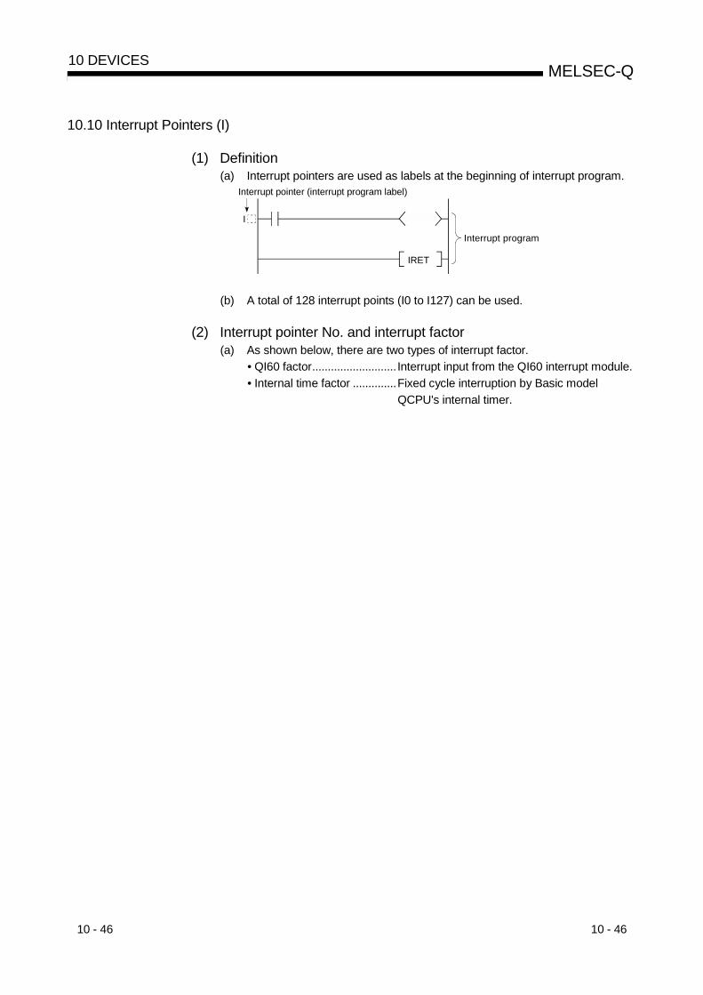
10 - 46 10 - 46
MELSEC-Q10 DEVICES
10.10 Interrupt Pointers (I)
(1) Definition(a) Interrupt pointers are used as labels at the beginning of interrupt program.
Interrupt pointer (interrupt program label)
Interrupt program
IRET
I
(b) A total of 128 interrupt points (I0 to I127) can be used.
(2) Interrupt pointer No. and interrupt factor(a) As shown below, there are two types of interrupt factor.
• QI60 factor........................... Interrupt input from the QI60 interrupt module.• Internal time factor ..............Fixed cycle interruption by Basic model
QCPU's internal timer.
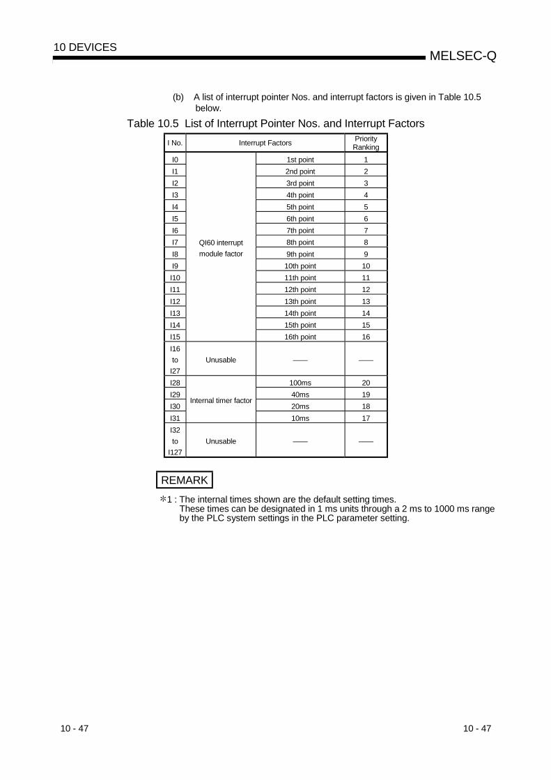
10 - 47 10 - 47
MELSEC-Q10 DEVICES
(b) A list of interrupt pointer Nos. and interrupt factors is given in Table 10.5below.
Table 10.5 List of Interrupt Pointer Nos. and Interrupt FactorsI No. Interrupt Factors Priority
RankingI0 1st point 1I1 2nd point 2I2 3rd point 3I3 4th point 4I4 5th point 5I5 6th point 6I6 7th point 7I7 8th point 8I8 9th point 9I9 10th point 10I10 11th point 11I11 12th point 12I12 13th point 13I13 14th point 14I14 15th point 15I15
QI60 interruptmodule factor
16th point 16I16toI27
Unusable —— ——
I28 100ms 20I29 40ms 19I30 20ms 18I31
Internal timer factor
10ms 17I32to
I127Unusable —— ——
REMARK1 : The internal times shown are the default setting times.
These times can be designated in 1 ms units through a 2 ms to 1000 ms rangeby the PLC system settings in the PLC parameter setting.

10 - 48 10 - 48
MELSEC-Q10 DEVICES
10.11 Other Devices
10.11.1 Network No. designation device (J)
(1) DefinitionThe network No. designation device is used to designate the network No. in datalink instructions.
(2) Designating network No. designation deviceThe network No. designation device is designated in the data link instruction asshown below.
JnJP.READ
Network No. designation device(n: network No.)
S1 S2 S3 D
Instruction nameNetwork No. designation instruction
REMARK
For details regarding data link instructions, refer to the Q CorrespondingMELSECNET/H Network System Reference Manual.
10.11.2 I/O No. designation device (U)
(1) DefinitionI/O No. designation devices are used with intelligent function module instructionmodule instructions to designate I/O numbers.
(2) Designating the I/O No. designation deviceI/O No. designation devices are designated with the intelligent function moduleinstructions as shown below.
UnGP.READ
I/O No. designation device(n: I/O No.)
S1 S2 S3 D
Instruction nameI/O No. designation instruction
REMARK
For details regarding intelligent function module instructions, refer to thecorresponding manual for the intelligent function module to be used.

10 - 49 10 - 49
MELSEC-Q10 DEVICES
10.11.3 Macro instruction argument device (VD)
(1) DefinitionMacro instruction argument devices are used with ladders registered as macros.When a VD setting is designated for a ladder registered as a macro,conversion to the designated device occurs when the macro instruction isexecuted.
(2) Designating macro instruction argument devicesMacro instruction argument devices are designated for those devices set as VDin ladders registered as macro instructions in macro registration at a peripheraldevice. When using macro instructions in a sequence program, designate devices tocorrespond to the instruction argument devices used with the ladders registeredas macros, in ascending order.
Transfer to VD2VD0MOV VD2VD0> VD1D0M.MAX D1 R0
Transfer to VD1Transfer to VD0
VD1MOV VD2VD0<= VD1Name of ladder registered as a macro
Actual sequence program executed at QCPU
Sequence program Ladder registered as a macro (registration name: MAX)
D0MOV R0D0> D1
D1MOV R0D0<= D1
REMARK
1) : With the macro instruction argument device, VD0 to VD9 can be used in oneladder registered as a macro instruction.
2) The GX Developer read mode provides an option to view a program in macroinstruction format.(Choose "View" - "Macro Instruction format display" to viewmacro instructions.)

10 - 50 10 - 50
MELSEC-Q10 DEVICES
10.12 Constants
10.12.1 Decimal constants (K)
(1) DefinitionDecimal constants are devices which designate decimal data in sequenceprogram.They are designated as "K "settings (e.g. K1234), and are stored in the Basicmodel QCPU in binary (BIN) code.See Section 4.8.1 for details regarding binary code.
(2) Designation rangeThe setting ranges for decimal constants are as follows:• For word data (16 bits) ...........K-32768 to K32767• For 2-word data (32 bits) ........K-2147483648 to K2147483647
10.12.2 Hexadecimal constants (H)
(1) DefinitionHexadecimal constants are devices which designate hexadecimal or BCD data insequence program.(For BCD data designations, 0 to 9 digit designations are used.)Hexadecimal constants are designated as "H " settings (e.g. H1234).See Section 4.8.3 for details regarding hexadecimal code.
(2) Designation rangeThe setting ranges for hexadecimal constants are as follows:• For word data (16 bits) .......... H0 to HFFFF (H0 to H9999 for BCD)• For 2-word data (32 bits) ....... H0 to HFFFFFFFF (H0 to H99999999 for BCD)
10.12.3 Character string ( " " )
(1) DefinitionCharacter string constants are devices used to designate character strings insequence program.They are designated by quotation marks (e.g. "ABCD1234").
(2) Usable charactersAll ASCII code characters can be used in character strings.The Basic model QCPU is sensitive to uppercase and lowercase characters.
(3) Number of designated charactersCharacter strings extend from the designated character to the NUL code (00H).You can use up to 32 characters for a character string in an instruction such as$MOV.
POINTCharacter strings may be used with only the $MOV instruction.

11 - 1 11 - 1
MELSEC-Q11 PROCESSING TIMES OF THE BASIC MODEL QCPU
1111 PROCESSING TIMES OF THE BASIC MODEL QCPU
This chapter describes the concept of the processing times of the Basic model QCPU.
11.1 Scan Time Structure
In the RUN status, the Basic model QCPU performs the following processingscyclically.
Processing in RUN status
Sequence program check
I/O refresh
END processing of DUTY instruction(No processing when the DUTY
instruction is not executed)
Sequence program execution
Has the sequence program ended?
CC-Link refresh
Refresh based on the intelligent function module parameters set using
GX Configurator
Error cancel(No processing when the cancel
command is not given)
Service processing
Constant wait processing(No processing when there is no setting)
WDT resetScan time calculation
Operating status judgment
Hardware, system information check (update)
(1) I/O refresh time
(2) Processing time for instruction processed at END
(3) Instruction execution time
(4) Module refresh time
(5) Execution times of various functions processed at END
(6) Service processing time
(7) Common processing time
MELSECNET/H refresh
STOP/PAUSE processing
NO
YES
STOP/PAUSE status
RUN status
Scan time
Numerals in parentheses indicate the item numbers in Section 11.2.
Calendar update processing(No processing when the update
command is not given)

11 - 2 11 - 2
MELSEC-Q11 PROCESSING TIMES OF THE BASIC MODEL QCPU
11
11.2 Concept of Scan Time
The scan time varies with the following elements.• Number of I/O points• Processing times of all instructions executed within one scan• Sum of processing times of user interrupt program executed within one scan• Processing for instruction processed at END• Execution of various functions processed at END• Module refreshes (e.g. refreshes made by MELSECNET/H, CC-Link, etc.)• Service processing• Constant scan setting (parameter setting)
The scan time is the sum of the following processing times.(1) I/O refresh time
(a) Refresh time of I/O data transferred from/to the following modules installedon the main and expansion base units of the Basic model QCPU.• Input module• Output module• Intelligent function module
(b) Calculate the I/O refresh time with the following expression.(I/O refresh time) = (number of input points/16) N1 + (number of output
points/16) N2
Refer to the following table for N1 and N2.
N1( s) N2( s)CPU Type
Q3 B Q6 B Q3 B Q6 B
Q00JCPU 2.5 3.3 1.3 2.3Q00CPU 2.4 3.2 1.3 2.3Q01CPU 2.3 3.1 1.3 2.3
(2) Processing time for instruction processed at END(a) DUTY instruction
Time when the user timing clock (SM420 to SM424) specified for the DUTYinstruction is turned on/off at END processing
CPU Type END Processing Time (ms)
Q00JCPU 0.15 0.21Q00CPU 0.14 0.19Q01CPU 0.12 0.16

11 - 3 11 - 3
MELSEC-Q11 PROCESSING TIMES OF THE BASIC MODEL QCPU
(3) Instruction execution time(a) Sum of the processing times of the instructions used in the program
executed by the Basic model QCPU.Refer to the following manual for the processing times of the correspondinginstructions.• QCPU (Q Mode)/QnACPU Programming Manual (Common Instructions)
(b) An interrupt program has an overhead time at the start of interrupt programand an overhead time at the end of interrupt program.Add an overhead time at the start of interrupt program and an overhead timeat the end of interrupt program to the instruction execution time.1) Overhead time at the start of interrupt program (B1)
Cyclic Interrupt (I28 to I31)Processing
Interrupt Processing from QI60(I0 to I15) 1CPU Type
Without rapid start With rapid start Without rapid start With rapid start
Q00JCPU 175 150 350 325Q00CPU 145 125 285 265
Q01CPU 135 120 270 2551: The values assume that the QI60 is installed on slot 0 of the main base.
2) Overhead time at the end of interrupt program (B2)
CPU Type Without rapid start With rapid start
Q00JCPU 175 150Q00CPU 145 125Q01CPU 135 120
(4) Module refresh time(a) Refresh of MELSECNET/H
Refresh time between the Basic model QCPU and MELSECNET/H networkmodule.Refer to the following manual for the refresh time of the MELSECNET/H.• Q Corresponding MELSECNET/H Network System Reference Manual
(b) Automatic refresh of CC-LinkRefresh time between the Basic model QCPU and CC-Link master/localmodule.Refer to the following manual for the automatic refresh time of CC-Link.• Control & Communication Link System Master/Local Module User's
Manual
(c) Intelligent utility package (Intelligent automatic refresh)1) Refresh time between the intelligent function module and CPU module,
which is designated on “Auto refresh setting” screen of the utilitypackage for the intelligent function module.
2) Calculate the intelligent automatic refresh time with the followingexpression.(Refresh time) = KN1 + KN2 (number of refresh points)

11 - 4 11 - 4
MELSEC-Q11 PROCESSING TIMES OF THE BASIC MODEL QCPU
3) As KN1 and KN2, use the values in the following table.When the intelligent module is installed on the main base unit
CPU Type KN1 ( 10-3ms) KN2 ( 10-3ms)
Q00JCPU 111 55Q00CPU 91 46Q01CPU 85 41
When the intelligent module is installed on the expansion base unit
CPU Type KN1 ( 10-3ms) KN2 ( 10-3ms)
Q00JCPU 113 56Q00CPU 92 48Q01CPU 86 43
(Example)When the number of automatic refresh points is 4 for the analog-digitalconverter module (Q64AD) (when installed on the main base unit ofQ01CPU)0.249 (ms) = 0.085 + 0.041 4
(5) Execution times of various functions processed at END(a) Calendar update processing time
1) Time to write the clock data stored in SD210 to SD213 to the clockelement at END processing when a clock data set request is given(SM210 turns from OFF to ON).
2) Time to read the clock data to SD210 to SD213 at END processingwhen a clock data read request is given (SM213 turns ON).
END Processing Time (ms)CPU Type
At clock data set request At clock data read request
Q00JCPU 0.12 0.04Q00CPU 0.11 0.03Q01CPU 0.10 0.02
(b) Error cancel processingTime to cancel the continuation error stored in SD50 on the leading edge ofSM50 (error cancel) (when it turns from OFF to ON).
Common Processing Time (ms)CPU Type
Annunciator Other error
Q00JCPU 0.17 0.10Q00CPU 0.14 0.09Q01CPU 0.13 0.08

11 - 5 11 - 5
MELSEC-Q11 PROCESSING TIMES OF THE BASIC MODEL QCPU
(6) Service processing time(a) Monitoring using GX Developer
Processing time (unit: ms) for monitoring using GX Developer.Added when monitoring is performed on GX Developer.
When Connected to RS-232 of Host CPUModule When Connected to Other Station 4
FunctionQ00JCPU Q00CPU Q01CPU Q00JCPU Q00CPU Q01CPU
Read of program from PLC 1 1.6 1.3 1.2 2.3 1.9 1.8Device monitor 2 1.2 1.0 0.9 2.4 2.0 1.9Online program correction 3 1.0 1.0 1.0 1.9 1.6 1.5
1: Time taken to read an 8k-step program from program memory2: Time taken when 32 points have been set in registration monitor3: Time taken when a 100-step ladder has been added4: Indicates that access is made via MELSECNET/H, Ethernet, CC-Link or
serial communication module.
(b) Communication with serial communication module or Ethernet interfacemoduleTime to make communication with the serial communication module orEthernet interface module.Refer to the following manual for communication time with thecorresponding module.• Q-Corresponding MELSEC Communication Protocol Reference Manual
(7) Common processing timeCommon processing of the CPU module processed in the system.The common processing times are the values in the following table.
CPU TypeQ00JCPU Q00CPU Q01CPU
Common processing time (ms) 0.70 0.55 0.50
The processing times in the above table assume that the constant scan functionis not used.When the constant scan function is used, wait processing is performed for theperiod of constant scan setting shortage.
11.3 Other Processing Times
(1) Constant scan accuracy
CPU Type Without Monitor,Without User Interrupt
With Monitor, WithoutUser Interrupt
Without Monitor,With User Interrupt With Monitor, With User Interrupt
Q00JCPU 0.20 0.90
Q00CPU 0.12 0.60
Q01CPU 0.10 0.50
Interrupt programexecution time(Refer to (b) in
Section 11.2 (3).)
Sum of the following times1) Time indicated in "With Monitor,
Without User Interrupt" field on the left2) Sum of interrupt program execution
times
Unit: msWith monitor: Indicates the status in which monitor is being performed with
GX Developer connected or communication with the externaldevice is being made using the serial communication function.
Without monitor: Indicates the status in which communication using GXDeveloper or the serial communication function is not beingmade.

12 - 1 12 - 1
MELSEC-Q12 PROCEDURE FOR WRITING PROGRAMS TO BASIC MODEL QCPU
12 PROCEDURE FOR WRITING PROGRAM TO BASIC MODEL QCPU
This chapter describes the procedure for writing program created at the GX Developerto the Basic model QCPU.
12.1 Items to Consider when Creating Program
In order to create a program, the program size, number of device points used, and theprogram file name, etc., must be set in advance.
(1) Program size considerationsCheck that CPU's program capacity is adequate for storing the program andparameter data.The program capacities of the CPUs are shown below:• Q00JCPU : 8 k steps• Q00CPU : 8 k steps• Q01CPU : 14 k steps
(2) Applications of devices and setting of their numbers of pointsConsider the applications of the devices used in a program and their number ofpoints.Refer to Chapter 10 for the devices usable with the Basic model QCPU.
(3) ROM operation considerationsWhen performing ROM operation, make the boot file setting of PLC parameter.
12
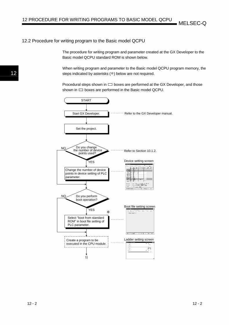
12 - 2 12 - 2
MELSEC-Q12 PROCEDURE FOR WRITING PROGRAMS TO BASIC MODEL QCPU
12
12.2 Procedure for writing program to the Basic model QCPU
The procedure for writing program and parameter created at the GX Developer to theBasic model QCPU standard ROM is shown below.
When writing program and parameter to the Basic model QCPU program memory, thesteps indicated by asterisks ( ) below are not required.
Procedural steps shown in boxes are performed at the GX Developer, and thoseshown in boxes are performed in the Basic model QCPU.
YES
NO
1)
YES
NO
START
Start GX Developer.
Set the project.
Do you change the number of device points used?
Change the number of device points in device setting of PLC parameter.
Do you perform boot operation?
Select "boot from standard ROM" in boot file setting of PLC parameter.
Create a program to be executed in the CPU module.
Ladder setting screen
Refer to the GX Developer manual.
Refer to Section 10.1.2.
Device setting screen
Boot file setting screen

12 - 3 12 - 3
MELSEC-Q12 PROCEDURE FOR WRITING PROGRAMS TO BASIC MODEL QCPU
1)
Make a reset with the RUN/STOP/RESET switch of the CPU module.
Connect GX Developer and CPU module.
Move the RUN/STOP/RESET switch of the CPU module to the STOP position and switch power on.
Choose "Program memory" in online "write to PLC" of GX Developer and write the parameters and created program to the program memory.
Write the program memory to ROM in online write to PLC (flash ROM) of GX Developer to write the program memory data to the standard ROM.
END
Refer to the following manual and make a reset. QCPU (Q Mode) User's Manual (Hardware) Basic Model QCPU (Q Mode) User's Manual (Hardware Setting, Maintenance and Inspection)
Refer to the GX Developer manual.
ERR. LED is lit.
Write to PLC screen
Write program memory to ROM screen

App - 1 App - 1
MELSEC-QAPPENDICES
APPAPPENDICES
APPENDIX 1 Special Relay List
Special relays, SM, are internal relays whose applications are fixed in theprogrammable controller.For this reason, they cannot be used by sequence programs in the same way as thenormal internal relays.However, they can be turned ON or OFF as needed in order to control the CPU andremote I/O modules.
The headings in the table that follows have the following meanings.Item Function of Item
Number • Indicates the number of the special relay.Name • Indicates the name of the special relay.Meaning • Indicates the nature of the special relay.Explanation • Contains detailed information about the nature of the special relay.
Set by (When set)
• Indicates whether the relay is set by the system or user, and, if it is set by the system, whensetting is performed.<Set by>
S : Set by systemU : Set by user (in sequence program or test operation at a peripheral device)S/U : Set by both system and user
<When set> indicated only if setting is done by system.Each END : Set during each END processingInitial : Set only during initial processing
(when power supply is turned ON, or when going from STOP toRUN)
Status change : Set only when there is a change in statusError : Set when error is generatedInstruction execution : Set when instruction is executedRequest : Set only when there is a user request
(through SM, etc.)
For details on the following items, see these manuals:• Networks • Far Q MELSECNET/H Network System Reference Manual (PLC to PLC
network)

App - 2 App - 2
MELSEC-QAPPENDICES
APP
Special Relay List
(1) Diagnostic InformationNumber Name Meaning Explanation Set by (When Set)
SM0 Diagnostic errors OFF: No errorON : Error
• ON if diagnosis results show error occurrence(Includes external diagnosis)
• Stays ON subsequently even if normal operations restoredS (Error)
SM1 Self-diagnosticerror
OFF: No self-diagnosiserrors
ON : Self-diagnosis
• Comes ON when an error occurs as a result of self-diagnosis.• Stays ON subsequently even if normal operations restored S (Error)
SM5 Error commoninformation
OFF: No error commoninformation
ON : Error commoninformation
• When SM0 is ON, ON if there is error common information S (Error)
SM16 Error individualinformation
OFF: No error commoninformation
ON : Error commoninformation
• When SM0 is ON, ON if there is error individual information S (Error)
SM50 Error reset OFF ON : Error reset • Conducts error reset operation U
SM51 Battery low latch OFF: NormalON : Battery low
• ON if battery voltage at CPU drops below rated value.Stays ON subsequently even after normal operation is restored S (Error)
SM52 Battery low OFF: NormalON : Battery low
• Same as SM51, but goes OFF subsequently when battery voltagereturns to normal. S (Error)
• Comes ON it a momentary power interruption of less than 20msoccurred during use of the AC power supply module, and reset byturning the power OFF, then ON.
SM53 AC/DC DOWNdetection
OFF: AC/DC DOWN notdetected
ON : AC/DC DOWNdetected
• Comes ON if a momentary power interruption of less than 10msoccurred during use of the DC power supply module, and reset byturning power OFF, then ON.
S (Error)
SM56 Operation Errors OFF: NormalON : Operation error
• ON when operation error is generated• Stays ON subsequently even if normal operations restored S (Error)
SM60 Blown fusedetection
OFF: NormalON : Module with blown fuse
• Comes ON even if there is only one output module with a blownfuse, and remains ON even after return to normal
• Blown fuse state is checked even for remote I/O station outputmodules.
S (Error)
SM61 I/O moduleverification error
OFF: NormalON : Error
• Comes ON if there is a discrepancy between the actual I/O modulesand the registered information when the power is turned on S (Error)
SM62 Annunciatordetection
OFF: Not detectedON : Detected • Goes ON if even one annunciator F goes ON. S (Instruction execution)
SM100
Serialcommunicationfunction usingflag
OFF: Serial communicationfunction is not used.
ON : Serial communicationfunction is used.
• Stores whether the serial communication function in the serialcommunication setting parameter is used or not. S (Power-on or reset)
SM101Communicationprotocol statusflag
OFF: GX DeveloperON : MC protocol
communication device
• Stores whether the device that is communicating via the RS-232interface is GX Developer or MC protocol communication device. S (RS232 communication)
SM110 Protocol errorOFF: NormalON : Abnormal
• Turns ON when an abnormal protocol was used to makecommunication in the serial communication function.
• Remains ON if the protocol is restored to normal thereafter.S (Error)
SM111 Communicationstatus
OFF: NormalON : Abnormal
• Turns ON when the mode used to make communication wasdifferent from the setting in the serial communication function.
• Remains ON if the mode is restored to normal thereafter.S (Error)
SM112 Error informationclear
ON : Cleared • Turns ON when the error codes stored in SM110, SM111, SD110and SD111 are cleared. (Activated when turned from OFF to ON)
U
SM113 Overrun errorOFF: NormalON : Abnormal
• Turns ON when an overrun error occurred in the serialcommunication error.
S (Error)
SM114 Parity errorOFF: NormalON : Abnormal
• Turns ON when a parity error occurred in the serial communicationerror.
S (Error)
SM115 Framing errorOFF: NormalON : Abnormal
• Turns ON when a framing error occurred in the serialcommunication error.
S (Error)
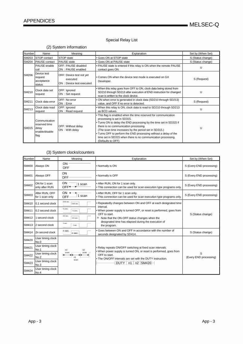
App - 3 App - 3
MELSEC-QAPPENDICES
Special Relay List
(2) System informationNumber Name Meaning Explanation Set by (When Set)SM203 STOP contact STOP state • Goes ON at STOP state S (Status change)SM204 PAUSE contact PAUSE state • Goes ON at PAUSE state S (Status change)
PAUSE enablecoil
OFF: PAUSE disabledON : PAUSE enabled
• PAUSE state is entered if this relay is ON when the remote PAUSEcontact goes ON U
SM206 Device testrequestacceptancestatus
OFF: Device test not yet executed
ON : Device test executed
• Comes ON when the device test mode is executed on GXDeveloper.
S (Request)
SM210 Clock data setrequest
OFF: IgnoredON : Set request
• When this relay goes from OFF to ON, clock data being stored fromSD210 through SD213 after execution of END instruction for changedscan is written to the clock device.
U
SM211 Clock data error OFF: No errorON : Error
• ON when error is generated in clock data (SD210 through SD213)value, and OFF if no error is detected. S (Request)
SM213 Clock data readrequest
OFF: IgnoredON : Read request
• When this relay is ON, clock data is read to SD210 through SD213as BCD values. U
SM315
Communicationreserved timedelayenable/disableflag
OFF: Without delayON : With delay
• This flag is enabled when the time reserved for communicationprocessing is set in SD315.
• Turns ON to delay the END processing by the time set in SD315 ifthere is no communication processing.(The scan time increases by the period set in SD315.)
• Turns OFF to perform the END processing without a delay of thetime set in SD315 when there is no communication processing.(Defaults to OFF)
U
(3) System clocks/countersNumber Name Meaning Explanation Set by (When Set)
SM400 Always ONONOFF • Normally is ON S (Every END processing)
SM401 Always OFFONOFF • Normally is OFF S (Every END processing)
SM402 ON for 1 scanonly after RUN
ONOFF
1 scan • After RUN, ON for 1 scan only.• This connection can be used for scan execution type programs only. S (Every END processing)
SM403 After RUN, OFFfor 1 scan only
ONOFF 1 scan
• After RUN, OFF for 1 scan only.• This connection can be used for scan execution type programs only. S (Every END processing)
SM410 0.1 second clock 0.05 sec.0.05 sec.
SM411 0.2 second clock 0.1sec.0.1sec.
SM412 1 second clock 0.5 sec.0.5 sec.
SM413 2 second clock 1 sec.1 sec.
• Repeatedly changes between ON and OFF at each designated timeinterval.
• When power supply is turned OFF, or reset is performed, goes fromOFF to start.
Note that the ON-OFF status changes when thedesignated time has elapsed during the execution ofthe program.
S (Status change)
SM414 2n second clock n sec.n sec. • Goes between ON and OFF in accordance with the number of
seconds designated by SD414. S (Status change)
SM420 User timing clockNo.0
SM421 User timing clockNo.1
SM422 User timing clockNo.2
SM423 User timing clockNo.3
SM424 User timing clockNo.4
n2scan
n2scan
n1scan
• Relay repeats ON/OFF switching at fixed scan intervals.• When power supply is turned ON, or reset is performed, goes from
OFF to start.• The ON/OFF intervals are set with the DUTY instruction.
DUTY n1 n2 SM420
S(Every END processing)

App - 4 App - 4
MELSEC-QAPPENDICES
Special Relay List
(4) Memory cardsNumber Name Meaning Explanation Set by (When Set)
SM620 Memory card Busable flags
OFF: UnusableON : Use enabled • Always ON S (Initial)
SM621 Memory card Bprotect flag
OFF: No protectON : Protect • Always ON S (Initial)
SM622 Drive 3 flag OFF: No drive 3ON : Drive 3 present • Always ON S (Initial)
SM623 Drive 4 flag OFF: No drive 4ON : Drive 4 present • Always ON S (Initial)
SM640 File register use OFF: File register not in useON : File register in use • Goes ON when file register is in use (Q00CPU, Q01CPU only) S (Status change)
SM660 Boot operation
OFF: Program memoryexecution
ON : Boot operation inprogress
• Goes ON while boot operation is in process S (Status change)
(5) Instruction-Related Special RelaysNumber Name Meaning Explanation Set by (When Set)
SM700 Carry flag OFF: Carry OFFON : Carry ON • Carry flag used in application instruction S (Instruction execution)
SM702 Search method OFF: Search nextON : 2-part search
• Designates method to be used by search instruction.• Data must be arranged for 2-part search. U
SM703 Sort order OFF: Ascending orderON : Descending order
• The sort instruction is used to designate whether data should besorted in ascending order or in descending order. U
SM704 Block comparison OFF: Non-match foundON : All match
• Goes ON when all data conditions have been met for the BKCMPinstruction. S (Instruction execution)
SM715 EI flag 0 : During DI1 : During EI • ON when EI instruction is being executed. S (Instruction execution)
SM721 File beingaccessed
OFF: File not accessedON : File being accessed
• Switches ON while a file is being accessed by the S.FWRITE,S.FREAD, COMRD, PRC, or LEDC instruction. S (Status change)
SM722BIN/DBINinstruction errordisabling flag
OFF: Error detectionperformed
ON : Error detection notperformed
• Turned ON when "OPERATION ERROR" is suppressed for BIN orDBIN instruction. U
SM775
Selection of linkrefreshprocessing duringCOM instructionexecution
OFF: Performs link refreshON : No link refresh
performed
• Select whether or not to perform link refresh processing in caseswhere only general data processing will be conducted during theexecution of the COM instruction.
U

App - 5 App - 5
MELSEC-QAPPENDICES
APPENDIX 2 Special Register List
The special registers, SD, are internal registers with fixed applications in theprogrammable controller.For this reason, it is not possible to use these registers in sequence programs in thesame way that normal registers are used.However, data can be written as needed in order to control the CPU module.Data stored in the special registers are stored as BIN values if no special designationhas been made to it.
The headings in the table that follows have the following meanings.
Item Function of ItemNumber • Indicates special register numberName • Indicates name of special registerMeaning • Indicates contents of special registerExplanation • Discusses contents of special register in more detail
Set by (When set)
• Indicates whether the relay is set by the system or user, and, if it is set by the system, whensetting is performed.<Set by>
S : Set by systemU : Set by user (sequence program or test operation from GX Developer or the like)S/U : Set by both system and user
<When set> Indicated only for registers set by systemEach END : Set during each END processingInitial : Set only during initial processing (when power supply is turned
ON, or when going from STOP to RUN)Status change : Set only when there is a change in statusError : Set when error occursInstruction execution : Set when instruction is executedRequest : Set only when there is a user request (through SM, etc.)
For details on the following items, see these manuals:• Networks • For Q MELSECNET/H Network System Reference Manual (PLC to PLC
network)

App - 6 App - 6
MELSEC-QAPPENDICES
Special Register List(1) Diagnostic Information
Number Name Meaning Explanation Set by (When set)
SD0 Diagnostic errors Diagnosis error code• Error codes for errors found by diagnosis are stored as BIN data.• Contents identical to latest fault history information.
S (Error)
SD1
• Year (last two digits) and month that SD0 data was updated is stored as BCD 2-digit code.
Year (0 to 99) Month (1 to 12)
B15 B7 B0B8to to(Example) : October, 1995 H9510
SD2
• The day and hour that SD0 was updated is stored as BCD 2-digit code.
Day (1 to 31) Hour (0 to 23)B15 B7 B0B8to to (Example)
: 10 p.m. on 25th H2510
SD3
Clock time fordiagnosis erroroccurrence
Clock time fordiagnosis erroroccurrence
• The minute and second that SD0 data was updated is stored as BCD 2-digit code.
Minutes (0 to 59)
B15 B7 B0B8to to (Example) : 35 min. 48 sec. (past the hour) H3548
Seconds (0 to 59)
S (Error)
SD4Error informationcategories
Error informationcategory code
• Category codes which help indicate what type of information is being stored in thecommon information areas (SD5 through SD15) and the individual informationareas (SD16 through SD26) are stored here.
Individual informationcategory codes
Common informationcategory codes
B15 B7 B0B8to to
• The common information category codes store the following codes:0 : No error1 : Unit/module No./ PLC No./Base No.2 : File name/Drive name3 : Time (value set)4 : Program error location
• The individual information category codes store the following codes:0 : No error1 : (Open)2 : File name/Drive name3 : Time (value actually measured)4 : Program error location5 : Parameter number6 : Annunciator number
S (Error)

App - 7 App - 7
MELSEC-QAPPENDICES
Special Register List (Continued)Number Name Meaning Explanation Set by (When set)
SD5
SD6
SD7
SD8
SD9
SD10
SD11
SD12
SD13
SD14
SD15
Error commoninformationError commoninformation
Error commoninformationError commoninformation
• Common information corresponding to the error codes (SD0) is stored here.• The following four types of information are stored here:
1 Slot No.
SD5SD6SD7SD8SD9SD10SD11SD12SD13SD14SD15
MeaningSlot No./Base No.
I/O No.
(Vacant)
Number
(Not used for base No.)
When 0FFFFH is stored in SD6 (I/O No.), the I/O No. may not be identified dueto I/O No. overlapping or like in the I/O assignment parameter. Use SD5 toidentify the error location.
2 File name/Drive name
Number
SD5SD6SD7SD8SD9SD10SD11SD12SD13SD14SD15
MeaningDrive
2EH(.)
File name(ASCII code: 8 characters)
(Vacant)
41H(A) 4DH(M)4EH(N) 49H(I)20H(SP) 20H(SP)20H(SP) 20H(SP)51H(Q) 2EH(.)47H(G) 50H(P)
B15 to B8 B7 to B0
(Example)File name=MAIN. QPG
Extension(ASCII code: 3 characters)
1
3 Time (value set)NumberSD5SD6SD7SD8SD9
SD10SD11SD12SD13SD14SD15
MeaningTime : 1 µs units (0 to 999 µs)
(Vacant)
Time : 1 ms units (0 to 65535 ms)
4 Program error locationNumberSD5SD6SD7SD8SD9
SD10SD11SD12SD13SD14SD15
Meaning
2EH(.)
File name(ASCII code: 8 characters)
Extension(ASCII code: 3 characters)
PatternBlock No.
Step No./transition No.Sequence step No. (L)Sequence step No. (H)
1
2
2 The pattern data is 0 fixed.
S (Error)
1: Refer to REMARK.
REMARK1) Extensions are shown below.
SD10 SD11Higher8 bits Lower8 bits Higher8 bits Extension name File type
51H 50H 41H QPA Parameters51H 50H 47H QPG Sequence program51H 43H 44H QCD Device comment51H 44H 52H QDR File register

App - 8 App - 8
MELSEC-QAPPENDICES
Special Register List (Continued)Number Name Meaning Explanation Set by (When set)
SD16
SD17
SD18
SD19
SD20
SD21
SD22
SD23
SD24
SD25
• Individual information corresponding to error codes (SD0) is stored here.1 File name/Drive name
Number
SD16SD17SD18SD19SD20SD21SD22SD23SD24SD25SD26
MeaningDrive
2EH(.)
File name(ASCII code: 8 characters)
(Vacant)
41H(A)4EH(N)20H(SP)20H(SP)51H(Q)47H(G)
4DH(M)49H(I)
20H(SP)20H(SP)2EH(.)50H(P)
B15 to B8 B7 to B0
(Example)File name=MAIN. QPG
Extension(ASCII code: 3 characters)
2 Time (value actu1ally measured)NumberSD16SD17SD18SD19SD20SD21SD22SD23SD24SD25SD26
MeaningTime : 1 µs units (0 to 999 µs)
(Vacant)
Time : 1 ms units (0 to 65535 ms)
3 Program error locationNumberSD16SD17SD18SD19SD20SD21SD22SD23SD24SD25SD26
Meaning
2EH(.)
File name(ASCII code: 8 characters)
Extension(ASCII code: 3 characters)
PatternBlock No.
Step No./transition No.Sequence step No. (L)Sequence step No. (H)
2
2 The pattern data is 0 fixed.
4 Parameter number 5 Annunciator number 6 Intelligent functionmodule parametererror
SD26
Error individualinformation
Error individualinformation
NumberSD16SD17SD18SD19SD20SD21SD22SD23SD24SD25SD26
MeaningNo.
(Vacant)
NumberSD16SD17SD18SD19SD20SD21SD22SD23SD24SD25SD26
MeaningParameter No.
(Vacant)
Number
SD16SD17
SD18SD19SD20SD21SD22SD23SD24SD25SD26
Meaning
(Vacant)
Parameter No.Error code for intelligentfunction module
3 3
3 For details of the parameter numbers, refer to the user'smanual of the CPU used.
S (Error)

App - 9 App - 9
MELSEC-QAPPENDICES
Special Register List (Continued)Number Name Meaning Explanation Set by (When set)
SD50 Error resetError number thatperforms error reset • Stores error number that performs error reset U
SD51 Battery low latchBit pattern indicatingwhere battery voltagedrop occurred
• All corresponding bits go ON when battery voltage drops.• Subsequently, these remain ON even after battery voltage has been returned to
normal.B0
CPU error0< >-------------------------------------------------
S (Error)
SD52 Battery lowBit pattern indicatingwhere battery voltagedrop occurred
• Same configuration as SD51 above• Subsequently, goes OFF when battery voltage is restored to normal. S (Error)
SD53AC/DC DOWNdetection
Number of times forAC/DC DOWN
• Every time the input voltage falls to or below 85% (AC power)/65% (DC power) ofthe rating during calculation of the CPU module, the value is incremented by oneand stored in BIN.
S (Error)
SD60Blown fusenumber
Number of modulewith blown fuse
• Value stored here is the lowest station I/O number of the module with the blownfuse. S (Error)
SD61I/O moduleverification errornumber
I/O module verificationerror module number
• The lowest I/O number of the module where the I/O module verification numbertook place. S (Error)
SD62Annunciatornumber Annunciator number • The first annunciator number to be detected is stored here.
SD63Number ofannunciators
Number ofannunciators • Stores the number of annunciators searched.
SD64
SD65
SD66
SD67
SD68
SD69
SD70
SD71
SD72
SD73
SD74
SD75
SD76
SD77
SD78
SD79
Table ofdetectedannunciatornumbers
Annunciator detectionnumber
When F goes ON due to OUT F or SET F , the F numbers which goprogressively ON from SD64 through SD79 are registered.F numbers turned OFF by RST F are deleted from SD64 to SD79, and are shiftedto the data register following the data register where the deleted F numbers hadbeen stored.Execution of the LED R instruction shifts the contents of SD64 to SD79 up by one.(This can also be done by using the INDICATOR RESET switch on the front of theCPU of the Q3A/Q4ACPU.)After 16 annunciators have been detected, detection of the 17th will not be storedfrom SD64 through SD79.
SD62 0 50 50 50 50 50 50 50 50 50 50 50 99 ...(Number detected)
SD63 0 1 2 3 2 3 4 5 6 7 8 9 8
0 50 50 50 50 50 50 50 50 50 50 50 99SD64SD65SD66SD67SD68SD69SD70SD71SD72SD73SD74SD75SD76SD77SD78SD79
0 0 25 25 99 99 99 99 99 99 99 99 150 0 0 99 0 15 15 15 15 15 15 15 700 0 0 0 0 0 70 70 70 70 70 70 650 0 0 0 0 0 0 65 65 65 65 65 380 0 0 0 0 0 0 0 38 38 38 38 1100 0 0 0 0 0 0 0 0 110 110 110 1510 0 1510
0 0 0 0 0 0 0 0 151 21000 0 0 0 0 0 0 0 0 0210
0 00 0 0 0 0 0 0 0 0 000 00 0 0 0 0 0 0 0 0 000 00 0 0 0 0 0 0 0 0 000 00 0 0 0 0 0 0 0 0 000 00 0 0 0 0 0 0 0 0 000 00 0 0 0 0 0 0 0 0 000 00 0 0 0 0 0 0 0 0 00
...(Number of annunciators detected)
(Number detected)
SETF50
SETF25
SETF99
RSTF25
SETF15
SETF70
SETF65
SETF38
SETF110
SETF151
SETF210RSTF50
S (Instructionexecution)
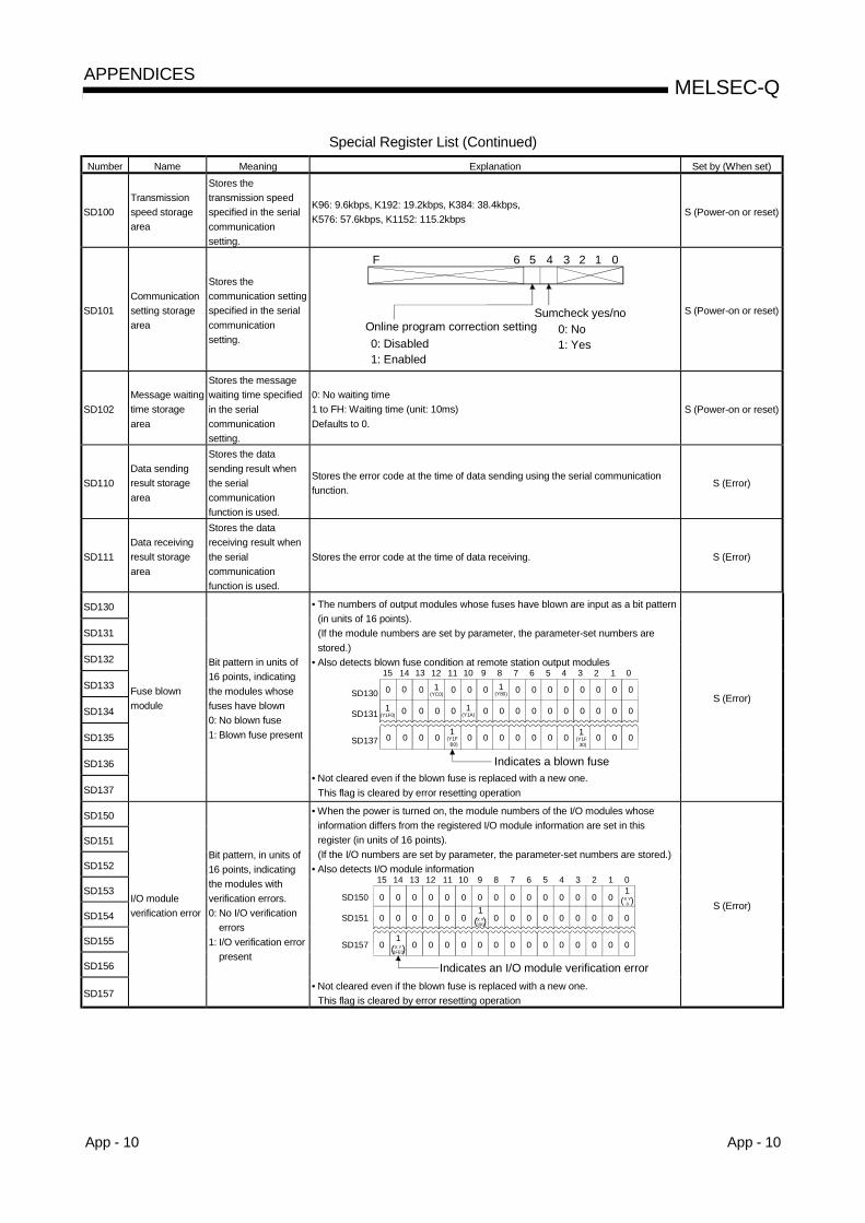
App - 10 App - 10
MELSEC-QAPPENDICES
Special Register List (Continued)Number Name Meaning Explanation Set by (When set)
SD100Transmissionspeed storagearea
Stores thetransmission speedspecified in the serialcommunicationsetting.
K96: 9.6kbps, K192: 19.2kbps, K384: 38.4kbps,K576: 57.6kbps, K1152: 115.2kbps
S (Power-on or reset)
SD101Communicationsetting storagearea
Stores thecommunication settingspecified in the serialcommunicationsetting.
0
Online program correction setting
123456F
Sumcheck yes/no
0: Disabled1: Enabled
0: No1: Yes
S (Power-on or reset)
SD102Message waitingtime storagearea
Stores the messagewaiting time specifiedin the serialcommunicationsetting.
0: No waiting time1 to FH: Waiting time (unit: 10ms)Defaults to 0.
S (Power-on or reset)
SD110Data sendingresult storagearea
Stores the datasending result whenthe serialcommunicationfunction is used.
Stores the error code at the time of data sending using the serial communicationfunction.
S (Error)
SD111Data receivingresult storagearea
Stores the datareceiving result whenthe serialcommunicationfunction is used.
Stores the error code at the time of data receiving. S (Error)
SD130
SD131
SD132
SD133
SD134
SD135
SD136
SD137
Fuse blownmodule
Bit pattern in units of16 points, indicatingthe modules whosefuses have blown0: No blown fuse1: Blown fuse present
• The numbers of output modules whose fuses have blown are input as a bit pattern(in units of 16 points).(If the module numbers are set by parameter, the parameter-set numbers arestored.)
• Also detects blown fuse condition at remote station output modules15 14 13 12 11 10 9 8 7 6 5 4 3 2 1 0
0 0 0 1(YC0) 0 0 0 0 0 0 0 0 0 0 01
(Y80)SD130
0 01(Y1F0) 0 0 0 0 0 0 0 0 0 01
(Y1A)SD131 0 0
0 0 1(Y1F B0)
0 0 0 0 0 0 0 0SD137 0 00 1(Y1F 30)
0
Indicates a blown fuse• Not cleared even if the blown fuse is replaced with a new one.
This flag is cleared by error resetting operation
S (Error)
SD150
SD151
SD152
SD153
SD154
SD155
SD156
SD157
I/O moduleverification error
Bit pattern, in units of16 points, indicatingthe modules withverification errors.0: No I/O verification
errors1: I/O verification error
present
• When the power is turned on, the module numbers of the I/O modules whoseinformation differs from the registered I/O module information are set in thisregister (in units of 16 points).(If the I/O numbers are set by parameter, the parameter-set numbers are stored.)
• Also detects I/O module information15 14 13 12 11 10 9 8 7 6 5 4 3 2 1 0
0 0 0 0 0 0 0 0 0 0 0 0 0SD150
0 0 0 0 0 0 0 0 0 0 0SD151 0 0
0 0 0 0 0 0 0 0 0SD157 0 000
0 0
00
001
( )X Y1FE0
1( )
1( )X Y
190
X Y0
Indicates an I/O module verification error• Not cleared even if the blown fuse is replaced with a new one.
This flag is cleared by error resetting operation
S (Error)

App - 11 App - 11
MELSEC-QAPPENDICES
Special Register List(2) System information
Number Name Meaning Explanation Set by (When set)• The CPU switch status is stored in the following format:
B15 B8 B7 B4 B3 B0
Vacant 2 1
1 : CPU switch status 0: RUN1: STOP
2 : Memory card switch Always OFF
SD200 State of switch State of CPU switchS(Every ENDprocessing)
• The following bit patterns are used to store the statuses of the LEDs on the CPU:B15 B4 B3 B0
2 1Vacant
1 : RUN2 : ERROR
SD201 LED status State of CPU-LED S (Status change)
• The CPU operating state is stored as indicated in the following figure:B15 B12B11 B8 B7 B4 B3 B0
2 1
1 : Operating state of CPU 0 :RUN1 :Vacant2 :STOP3 :PAUSE
2 : STOP/PAUSE cause 0 :Switch1 :Remote contact2 :GX Developer/Serial Communication
Module from some other remote source3 :Internal program instruction
Note: Priority is earliest first 4 :Errors
SD203Operating stateof CPU
Operating state ofCPU
S (Every ENDprocessing)
SD210 Clock dataClock data (year,month)
• The year (last two digits) and month are stored as BCD code at SD210 as shownbelow:
B15 B12B11 B8 B7 B4 B3 B0
Year Month
Example :July 1993H9307
to to to to
SD211 Clock data Clock data (day, hour)
• The day and hour are stored as BCD code at SD211 as shown below:B15 B12B11 B8 B7 B4 B3 B0
Day Hour
Example :31st, 10 a.m.H3110
to to to to
SD212 Clock dataClock data (minute,second)
• The minutes and seconds (after the hour) are stored as BCD code at SD212 asshown below:
Example :B15 B12B11 B8 B7 B4 B3 B0to to to to
Minute Second
35 min., 48 sec.(after the hour)H3548
S/U (Request)
SD213 Clock dataClock data(day of week)
• Stores the year (two digits) and the day of the week in SD213 in the BCD codeformat as shown below:
B15 B12B11 B8 B7 B4 B3 B0to to to to
Higher digits of year (0 to 99)
Day of week0
1
2
3
4
56
Sunday
Monday
Tuesday
Wednesday
Thursday
FridaySaturday
Example :Friday H0005
S/U (Request)

App - 12 App - 12
MELSEC-QAPPENDICES
Special Register List (Continued)Number Name Meaning Explanation Set by (When set)
SD220
SD221
SD222
SD223
SD224
SD225
SD226
SD227
LED displaydata
Display indicator data
• Stores the message (16 characters of ASCII data) at error occurrence (includingannunciator ON).
SD220SD221SD222SD223SD224SD225SD226SD227
15th character from the right13th character from the right11th character from the right9th character from the right7th character from the right5th character from the right3rd character from the right1st character from the right
16th character from the right14th character from the right12th character from the right10th character from the right8th character from the right6th character from the right4th character from the right2nd character from the right
toB15 B8 toB7 B0
The display device data at PRG CHK is not stored.
S (When changed)
SD240 Base mode0: Automatic mode1: Detail mode
• Stores the base mode. S (Initial)
SD241No. ofexpansionbases
0: Basic only1 to 4: No. of
expansionbases
• Stores the maximum number of the expansion bases being installed. S (Initial)
SD242A/Q basedifferentiation
Base typedifferentiation0: None1: Q B is installed
B0
Fixed to 0
Main base
B1B2B4
1st expansion base
to
2nd expansion base
4th expansion base
to
When no expansion base is installed, the value is fixed to 0.
S (Initial)
SD243
SD244No. of base slots No. of base slots
SD243 Expansion 3 Expansion 2 Expansion 1 Main
Expansion 4SD244
B15 B12 B11 B8 B7 B4 B3 B0
Fixed to 0
• As shown above, each area stores the number of slots being installed.
S (Initial)
SD250Loadedmaximum I/O
Loaded maximum I/ONo.
• When SM250 goes from OFF to ON, the upper 2 digits of the final I/O number plus1 of the modules loaded are stored as BIN values.
S (Initial)
SD254Number of modulesinstalled
• Indicates the number of modules installed on MELSECNET/H.
SD255 I/O No. • MELSECNET/H I/O number of first module installedSD256 Network No. • MELSECNET/H network number of first module installed
SD257Groupnumber
• MELSECNET/H group number of first module installed
SD258
MELSECNET/Hinformation
Informa-tionfrom 1stmodule
Station No. • MELSECNET/H station number of first module installed
S (Initial)
SD290Number of pointsallocated for X
• Stores the number of points currently set for X devices
SD291Number of pointsallocated for Y
• Stores the number of points currently set for Y devices
SD292Number of pointsallocated for M
• Stores the number of points currently set for M devices
SD293Number of pointsallocated for L
• Stores the number of points currently set for L devices
SD294Number of pointsallocated for B
• Stores the number of points currently set for B devices
SD295Number of pointsallocated for F
• Stores the number of points currently set for F devices
SD296Number of pointsallocated for SB
• Stores the number of points currently set for SB devices
SD297Number of pointsallocated for V
• Stores the number of points currently set for V devices
SD298
Deviceallocation(Same asparametercontents)
Number of pointsallocated for S
• Stores the number of points currently set for S devices
S (Initial)

App - 13 App - 13
MELSEC-QAPPENDICES
Special Register List (Continued)Number Name Meaning Explanation Set by (When set)
SD299Number of pointsallocated for T
• Stores the number of points currently set for T device
SD300Number of pointsallocated for ST
• Stores the number of points currently set for ST devices
SD301
Deviceallocation(Same asparametercontents) Number of points
allocated for C• Stores the number of points currently set for C devices
S (Initial)
SD302Number of pointsallocated for D
• Stores the number of points currently set for D devices
SD303Number of pointsallocated for W
• Stores the number of points currently set for W devices
SD304
Deviceallocation(Same asparametercontents) Number of points
allocated for SW• Stores the number of points currently set for SW devices
S (Initial)
SD315
Time reservedforcommunicationprocessing
Time reserved forcommunicationprocessing
Reserves the designated time for communication processing with GX Developer orother units.The greater the value is designated, the shorter the response time forcommunication with other devices (GX Developer, serial communication units)becomes.Setting range: 1 to 100 msIf the designated value is out of the range above, it is assumed to no setting.The scan time becomes longer by the designated time.
END processing
SD340No. of modulesinstalled
• Indicates the number of modules installed on Ethernet.
SD341 I/O No. • Indicates the I/O No. of the installed Ethernet.SD342 Network No. • Indicates the network No. of the installed Ethernet.SD343 Group No. • Indicates the group No. of the installed Ethernet.SD344
Ethernetinformation
Station No. • Indicates the station No. of the installed Ethernet.
S (Initial)
(3) System clocks/countersNumber Name Meaning Explanation Set by (When set)
SD4121 secondcounter
Number of counts in1-second units
• Following programmable controller CPU RUN, 1 is added each second• Count repeats from 0 to 32767 to -32768 to 0
S (Status change)
SD4142n second clocksetting
2n second clock units• Stores value n of 2n second clock (Default is 30)• Setting can be made between 1 and 32767
U
SD420 Scan counterNumber of counts ineach scan
• Incremented by 1 for each scan execution after the PLC is set to RUN.• Count repeats from 0 to 32767 to -32768 to 0
S(Every ENDprocessing)

App - 14 App - 14
MELSEC-QAPPENDICES
(4) Scan informationNumber Name Meaning Explanation Set by (When set)
SD520Current scan time(in 1 ms units)
• Stores current scan time (in 1 ms units)Range from 0 to 65535
S (Every ENDprocessing)
SD521
Current scantime Current scan time
(in 100 µs units)
• Stores current scan time (in 100 µs units)Range from 00000 to 900
(Example)A current scan of 23.6 ms would be stored as follows:
D520=23D521=600
S (Every ENDprocessing)
SD524Minimum scan time (in1 ms units)
• Stores minimum value of scan time (in 1 ms units)• Range from 0 to 65535
S (Every ENDprocessing)
SD525
Minimum scantime Minimum scan time (in
100 µs units)• Stores minimum value of scan time (in 100 µs units)• Range of 000 to 900
S (Every ENDprocessing)
SD526Maximum scan time(in 1 ms units)
• Stores maximum value of scan time, excepting the first scan. (in 1 ms units)• Range from 0 to 65535
SD527
Maximum scantime Maximum scan time
(in 100 µs units)• Stores maximum value of scan time, excepting the first scan. (in 100 µs units)• Range of 000 to 900
S (Every ENDprocessing)
SD540END processing time(in 1 ms units)
• Stores time from completion of scan program to start of next scan. (in 1 ms units)• Range from 0 to 65535
SD541
END processingtime END processing time
(in 100 µs units)
• Stores time from completion of scan program to start of next scan. (in 100 µsunits)
• Range of 000 to 900
S (Every ENDprocessing)
SD542Constant scan waittime (in 1 ms units)
• Stores wait time when constant scan time has been set.(in 1 ms units)
• Range from 0 to 65535
SD543
Constant scanwait time
Constant scan waittime (in 100 µs units)
• Stores wait time when constant scan time has been set.(in 100 µs units)
• Range of 000 to 900
S (First ENDprocessing)
SD548Scan programexecution time(in 1 ms units)
• Stores execution time for scan execution type program during 1 scan (in 1 msunits)
• Range from 0 to 65535• Stores each scan
SD549
Scan programexecution time
Scan programexecution time(in 100 µs units)
• Stores execution time for scan execution type program during 1 scan (in 100 µsunits)
• Range of 000 to 900• Stores each scan
S (Every ENDprocessing)

App - 15 App - 15
MELSEC-QAPPENDICES
(5) Memory cardNumber Name Meaning Explanation Set by (When set)
SD620Memory card Bmodels
Memory card Bmodels
• Indicates memory card B models installed
Drive 3(Standard RAM)
Drive 4(Standard ROM)
0: Absent1: Present
Fixed at "3" because of built-in standard ROM.
B4 B3 B0B8 B7B15
0< >0-----------
Drive 4 is fixed to "3" because it has built-in flash ROM.
S (Initial)
SD622Drive 3(Standard RAM)capacity
Drive 3 capacity• Drive 3 capacity is stored in 1kbyte units.
(Fixed to "61" because it has 61kbyte RAM built-in.)S (Initial)
SD623Drive 4(Standard ROM)capacity
Drive 4 capacity • Drive 4 capacity is stored in 1kbyte units. S (Initial)
SD624Drive 3 useconditions
Drive 3 use conditions
• Drive 3 use conditions are stored in bit pattern.B4 B0B15
File register (R)1: In use0: Not used
0 0 0 0 0 0 0S (Status change)
SD640File registerdrive
Drive number: • Stores drive number being used by file register S (Status change) 1
SD641SD642SD643SD644SD645
SD646
File register filename
File register file name
• Stores file register file name (with extension) selected at parameters as ASCIIcode.
SD641SD642SD643SD644SD645
SD646
Second characterFourth characterSixth character
Eighth characterFirst character of extension
Third character of extension
First characterThird characterFifth character
Seventh character2EH(.)
Second character of extension
B15 to B8 B7 to B0
S (Status change) 1
SD647File registercapacity
File register capacity • Stores the data capacity of the currently selected file register in 1 k word units. S (Status change) 1
SD648File registerblock number
File register blocknumber
• Stores the currently selected file register block number. S (Status change) 1
1: The data is set when the CPU is stopped and then RUN or the RSET instruction is executed after parameter execution.
(6) Instruction-Related RegistersNumber Name Meaning Explanation Set by (When set)
SD715
SD716
SD717
IMASKinstruction maskpattern
Mask pattern
• Patterns masked by use of the IMASK instruction are stored in the followingmanner:
SD715SD716SD717
l15 l1 l0l31l47
l17l33
l16l32
B15 B0B1tototo
S (During execution)
SD718SD719
Accumulator Accumulator • For use as replacement for accumulators used in A-series programs. S/U
SD781TOSD785
Mask pattern ofIMASKinstruction
Mask pattern
• Stores the mask patterns masked by the IMASK instruction as follows:
SD781SD782
SD785
l63 l49 l48
l79
l127
l65
l113
l64
l112
B15 B0B1toto
to
to
S (During execution)

App - 16 App - 16
MELSEC-QAPPENDICES
APPENDIX 3 List of Interrupt Pointer Nos. and Interrupt Factors
I No. Interrupt Factors PriorityRanking
I0 1st point 1I1 2nd point 2I2 3rd point 3I3 4th point 4I4 5th point 5I5 6th point 6I6 7th point 7I7 8th point 8I8 9th point 9I9 10th point 10I10 11th point 11I11 12th point 12I12 13th point 13I13 14th point 14I14 15th point 15I15
QI60 interruptmodule factor
16th point 16I16toI27
Unusable —— ——
I28 100ms 20I29 40ms 19I30 20ms 18I31
Internal timer factor
10ms 17I32to
I127Unusable —— ——
REMARK1 : The internal times shown are the default setting times.
These times can be designated in 1 ms units through a 2 ms to 1000 ms rangeby the PLC system settings in the PLC parameter setting.

App - 17 App - 17
MELSEC-QAPPENDICES
MEMO

Index - 1 Index - 1
Ind
INDEX
A]Accuracy of scan time ................................. 4-9Annunciator (F)........................................ 10-12ASCII code................................................. 4-25Auto mode .................................................. 5- 3
[B]Base mode.................................................. 5- 4BCD (Binary coded decimal)..................... 4-24BIN (Binary code) ...................................... 4-22Boot Run..................................................... 6- 6
[C]C (Counter).................................................. 10-24Character string............................................. 4-25Clock function................................................. 7- 9
Precision .................................................... 7-11Concept of I/O assignment ............................ 5- 8Constant scan................................................. 7- 2Constants..................................................... 10-50Counter (C).................................................. 10-24
Count processing..................................... 10-24Maximum counting speed ....................... 10-25
[D]D (Data register).......................................... 10-28Data register (D).......................................... 10-28Decimal constants (K) ................................. 10-50Device list ..................................................... 10- 1Direct access input(DX) ............................... 10- 6Direct access output(DY) ............................. 10- 9Direct mode ................................................... 4-18Drive Number. ................................................ 6- 3Duty.............................................................. 10-25
[E]Edge relay(V)............................................... 10-16END processing ............................................ 4-11
[F]F (Anunciator).............................................. 10-12FD (Function register) ................................. 10-31
File register.................................................. 10-42File size.......................................................... 6-13Function device (FX, FY, FD) ..................... 10-31FX (Function input)...................................... 10-31
FY (Function output) ....................................10-31
[G]GX Configurator ..............................................8- 2GX Developer ............................................... A-17
[H]H (Hexadecimal constants) .........................10-50HEX (Hexadecimal) .......................................4-23Hexadecimal constants (H) .........................10-50High-speed retentive timer (ST) ..................10-21High-speed timer (T)....................................10-20
[I]I (Interrupt pointer) .......................................10-46I/O No. designation device (Un) ..................10-48Index register (Z)..........................................10-39Input response time .......................................7-21Intelligent function module device (U \G ) .10-38Internal relay (M)..........................................10-10Internal system device.................................10-31Internal user device.......................................10- 3Interrupt pointer (I) .......................................10-46Interrupt program ............................................4- 5
[J]J (Network designation device) ...................10-48J \B (Link relay) ...................................10-35J \SB (Link special relay) ....................10-35J \SW (Link special register)...............10-35J \W (Link register)..............................10-35J \X (Link input) ...................................10-35J \Y (Link output).................................10-35
[K]K (Decimal constants)..................................10-50
[L]L (Latch relay) ..............................................10-11Latch function..................................................7- 5Latch relay (L) ..............................................10-11LED display....................................................7-39Link direct device .........................................10-35Link register (W)...........................................10-29Link relay (B) ................................................10-17

Index - 2 Index - 2
Ind
List of Interrupt factors ................................ 10-47App-10
Low-speed retentive timer (ST) .................. 10-21Low-speed timer (T) ................................ 10-19
[M]M (Internal relay) ......................................... 10-10Macro instruction argument device (VD).... 10-49Main routine program.................................... 4- 3
[N]N (Nesting)................................................... 10-44
[O]Output (Y) .................................................... 10- 8
[P]P (Pointer).................................................... 10-45Password....................................................... 7-35Pointer (P).................................................... 10-45Precautions when using timers................... 10-23Processing at annunciator OFF.................. 10-14Processing at annunciator ON.................... 10-12Program memory............................................ 6- 4Purpose of I/O assignment ........................... 5-12Purpose of I/O assignment using
[Q]QI60 ............................................................... 7-23QnCPU ..........................................................A-17QnHCPU........................................................A-17
[R]R (File register)............................................ 10-42Reading from the time data............................ 7- 9Refresh input ................................................ 10- 6Refresh mode................................................ 4-15Refresh output.............................................. 10- 9Remote latch clear ........................................ 7-19Remote operation.......................................... 7-12Remote PAUSE............................................. 7-15Remote RESET............................................. 7-17Remote RUN/STOP...................................... 7-12Remote station I/O number........................... 5-11Retentive timer (OUT ST )....................... 10-21RUN status .................................................... 4-12
[S]S (Step relay)............................................... 10-18SB (Special link relay) ................................. 10-18
Scan time ........................................................4- 9SD (Special register)....................................10-34
SD520, SD521 (Scan time: present value)....4- 9SD524, SD525 (Scan time: Maximum value) .......4- 9
SD526, SD527 (Scan time: Minimum value) ........4- 9Self-diagnosis function...................................7-30Sequence program ........................................4- 1Setting range in the internal user device.....10- 3Setting the number of stages ........................5- 2Special link register (SW) ............................10-30Special link relay (SB)..................................10-18Special register (SD)....................................10-34Special relay (SM)........................................10-33ST (Retentive timer: OUT ST ) ................10-21Standard RAM ................................................6- 9Standard ROM................................................6- 5Step relay (S) ...............................................10-18Sub-routine program......................................4- 4SW (Special link register) ............................10-30Switch setting of intelligent function module .7-24System protect ...............................................7-35
[T]T (Timer).......................................................10-19
Accuracy...................................................10-22Processing................................................10-22
[U]U (I/O No. designation device) ....................10-48U \G (Intelligent function module device)...10-38User memory...................................................6- 2
[V]V (Edge relay) ..............................................10-16VD (Macro instruction argument device).....10-49
[W]W (Link register)...........................................10-29WDT (Watchdog timer)..................................7-28Write during RUN...........................................7-25Writing to the time data .................................7- 9
[X]X (Input)........................................................10- 5
[Y]Y (Output).....................................................10- 8

WARRANTY
Please confirm the following product warranty details before starting use.
1. Gratis Warranty Term and Gratis Warranty RangeIf any faults or defects (hereinafter "Failure") found to be the responsibility of Mitsubishi occurs during use of the productwithin the gratis warranty term, the product shall be repaired at no cost via the dealer or Mitsubishi Service Company.Note that if repairs are required at a site overseas, on a detached island or remote place, expenses to dispatch anengineer shall be charged for.[Gratis Warranty Term]
The gratis warranty term of the product shall be for one year after the date of purchase or delivery to a designatedplace.Note that after manufacture and shipment from Mitsubishi, the maximum distribution period shall be six (6) months, andthe longest gratis warranty term after manufacturing shall be eighteen (18) months. The gratis warranty term of repairparts shall not exceed the gratis warranty term before repairs.
[Gratis Warranty Range](1) The range shall be limited to normal use within the usage state, usage methods and usage environment, etc.,
which follow the conditions and precautions, etc., given in the instruction manual, user's manual and caution labelson the product.
(2) Even within the gratis warranty term, repairs shall be charged for in the following cases.1. Failure occurring from inappropriate storage or handling, carelessness or negligence by the user. Failure caused
by the user's hardware or software design.2. Failure caused by unapproved modifications, etc., to the product by the user.3. When the Mitsubishi product is assembled into a user's device, Failure that could have been avoided if functions
or structures, judged as necessary in the legal safety measures the user's device is subject to or as necessaryby industry standards, had been provided.
4. Failure that could have been avoided if consumable parts (battery, backlight, fuse, etc.) designated in theinstruction manual had been correctly serviced or replaced.
5. Failure caused by external irresistible forces such as fires or abnormal voltages, and Failure caused by forcemajeure such as earthquakes, lightning, wind and water damage.
6. Failure caused by reasons unpredictable by scientific technology standards at time of shipment from Mitsubishi.7. Any other failure found not to be the responsibility of Mitsubishi or the user.
2. Onerous repair term after discontinuation of production(1) Mitsubishi shall accept onerous product repairs for seven (7) years after production of the product is discontinued.
Discontinuation of production shall be notified with Mitsubishi Technical Bulletins, etc.(2) Product supply (including repair parts) is not possible after production is discontinued.
3. Overseas serviceOverseas, repairs shall be accepted by Mitsubishi's local overseas FA Center. Note that the repair conditions at each FACenter may differ.
4. Exclusion of chance loss and secondary loss from warranty liabilityRegardless of the gratis warranty term, Mitsubishi shall not be liable for compensation to damages caused by any causefound not to be the responsibility of Mitsubishi, chance losses, lost profits incurred to the user by Failures of Mitsubishiproducts, damages and secondary damages caused from special reasons regardless of Mitsubishi's expectations,compensation for accidents, and compensation for damages to products other than Mitsubishi products and other duties.
5. Changes in product specificationsThe specifications given in the catalogs, manuals or technical documents are subject to change without prior notice.
6. Product application(1) In using the Mitsubishi MELSEC programmable logic controller, the usage conditions shall be that the application will
not lead to a major accident even if any problem or fault should occur in the programmable logic controller device, andthat backup and fail-safe functions are systematically provided outside of the device for any problem or fault.
(2) The Mitsubishi general-purpose programmable logic controller has been designed and manufactured for applicationsin general industries, etc. Thus, applications in which the public could be affected such as in nuclear power plants andother power plants operated by respective power companies, and applications in which a special quality assurancesystem is required, such as for Railway companies or National Defense purposes shall be excluded from theprogrammable logic controller applications.Note that even with these applications, if the user approves that the application is to be limited and a special quality isnot required, application shall be possible.When considering use in aircraft, medical applications, railways, incineration and fuel devices, manned transportdevices, equipment for recreation and amusement, and safety devices, in which human life or assets could be greatlyaffected and for which a particularly high reliability is required in terms of safety and control system, please consultwith Mitsubishi and discuss the required specifications.

Microsoft Windows, Microsoft Windows NT are registered trademarks of Microsoft Corporation in the United States andother countries.Pentium is a registered trademark of Intel Corporation in the United States and other countries.Ethernet is a registered trademark of Xerox. Co., Ltd in the United States.Other company and product names herein are either trademarks or registered trademarks of their respective owners.

Basic M
odel QC
PU
(Q M
ode) User's M
anual (Function E
xplanation, Program
Fundam
entals)
UUser's Manual (Function Explanation, Program Fundamentals) User's Manual
Mitsubishi Programmable Logic Controller
Specifications subject to change without notice.
MODEL
MODELCODE
SQCPU(Q)-U-KI-E
13JR44
SH(NA)-080188-A(0108)MEE
Basic Model QCPU(Q Mode) Basic Model QCPU(Q Mode)
(Function Explanation, Program Fundamentals)
When exported from Japan, this manual does not require application to theMinistry of Economy, Trade and Industry for service transaction permission.
HEAD OFFICE : 1-8-12, OFFICE TOWER Z 14F HARUMI CHUO-KU 104-6212,JAPANNAGOYA WORKS : 1-14 , YADA-MINAMI 5 , HIGASHI-KU, NAGOYA , JAPAN
Related Documents