Chapter 7 What Is In This Chapter? 1. The basic components of an atom 2. Basic electrical units and symbols 3. The difference between a conductor and an insulator 4. The difference between open and closed circuits 5. The difference between AC and DC power 6. All explanation of single and three phase power 7. How electromagnets work 8. The function of common electrical components found in small water systems 9. Common pump electrical control components Basic Electricity and Motor Controls Key Words • AC • Amperage • Atom • Brake Horsepower • Conductor • DC • Electromagnetism • Electron • EMF • Heater • Hertz • Horsepower • Insulator • Magnetic Breaker • Magnetic Starter • Neutron • Proton • Resistance • Sine Wave • Single Phase Power • Three Phase Power • Voltage

Welcome message from author
This document is posted to help you gain knowledge. Please leave a comment to let me know what you think about it! Share it to your friends and learn new things together.
Transcript

Chapter 7
What Is In This Chapter?1. The basic components of an atom 2. Basic electrical units and symbols 3. The difference between a conductor and an insulator 4. The difference between open and closed circuits5. The difference between AC and DC power 6. All explanation of single and three phase power 7. How electromagnets work 8. The function of common electrical components found in small water systems9. Common pump electrical control components
Basic Electricity and Motor Controls
Key Words
• AC• Amperage• Atom• Brake Horsepower• Conductor • DC
• Electromagnetism• Electron• EMF• Heater• Hertz• Horsepower
• Insulator• Magnetic Breaker• Magnetic Starter• Neutron• Proton• Resistance
• Sine Wave• Single Phase Power• Three Phase Power• Voltage
224 Basic Electricity and Motor ControlsChapter 7
In order to develop a basic understanding of how electrical equipment and motor controls work, we need to review basic electrical theory. And since electrical theory is based on atomic theory, we need to begin with a review of how atoms work.
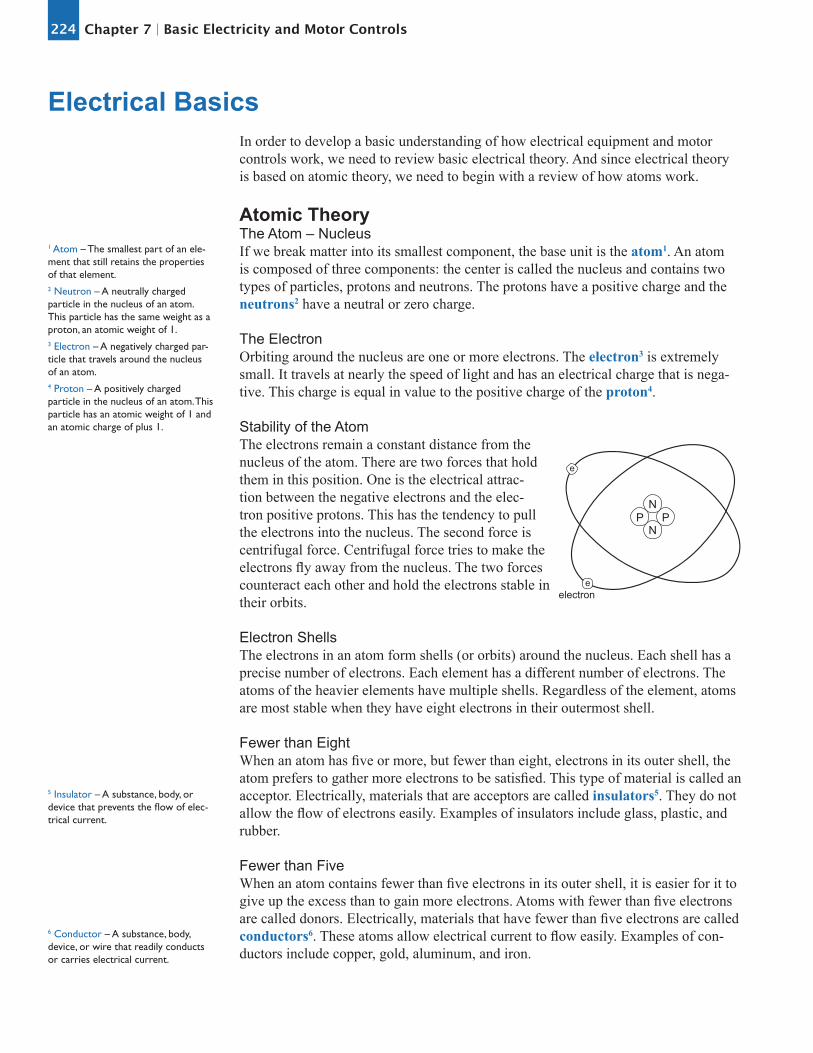
Atomic TheoryThe Atom – NucleusIf we break matter into its smallest component, the base unit is the atom1. An atom is composed of three components: the center is called the nucleus and contains two types of particles, protons and neutrons. The protons have a positive charge and the neutrons2 have a neutral or zero charge.
The ElectronOrbiting around the nucleus are one or more electrons. The electron3 is extremely small. It travels at nearly the speed of light and has an electrical charge that is nega-tive. This charge is equal in value to the positive charge of the proton4.
Stability of the AtomThe electrons remain a constant distance from the nucleus of the atom. There are two forces that hold them in this position. One is the electrical attrac-tion between the negative electrons and the elec-tron positive protons. This has the tendency to pull the electrons into the nucleus. The second force is centrifugal force. Centrifugal force tries to make the electrons fly away from the nucleus. The two forces counteract each other and hold the electrons stable in their orbits.
Electron ShellsThe electrons in an atom form shells (or orbits) around the nucleus. Each shell has a precise number of electrons. Each element has a different number of electrons. The atoms of the heavier elements have multiple shells. Regardless of the element, atoms are most stable when they have eight electrons in their outermost shell.
Fewer than EightWhen an atom has five or more, but fewer than eight, electrons in its outer shell, the atom prefers to gather more electrons to be satisfied. This type of material is called an acceptor. Electrically, materials that are acceptors are called insulators5. They do not allow the flow of electrons easily. Examples of insulators include glass, plastic, and rubber.
Fewer than FiveWhen an atom contains fewer than five electrons in its outer shell, it is easier for it to give up the excess than to gain more electrons. Atoms with fewer than five electrons are called donors. Electrically, materials that have fewer than five electrons are called conductors6. These atoms allow electrical current to flow easily. Examples of con-ductors include copper, gold, aluminum, and iron.
Electrical Basics
1 Atom – The smallest part of an ele-ment that still retains the properties of that element.2 Neutron – A neutrally charged particle in the nucleus of an atom. This particle has the same weight as a proton, an atomic weight of 1.3 Electron – A negatively charged par-ticle that travels around the nucleus of an atom.4 Proton – A positively charged particle in the nucleus of an atom. This particle has an atomic weight of 1 and an atomic charge of plus 1.
5 Insulator – A substance, body, or device that prevents the flow of elec-trical current.
e
eelectron
NPP
N
6 Conductor – A substance, body, device, or wire that readily conducts or carries electrical current.

225Chapter 7 Basic Electricity and Motor Controls
7 EMF (Electromotive Force) – The electrical pressure (voltage) that forces an electric current through a conductor.
9 Resistance – The opposition offered to the flow of electrical current. Usu-ally measured as Ohms.
e
ee
e
e e
e
e
e
ACCEPTOR
DONOR
Making Electrons MoveIn order to cause the electrons of a donor material to leave the atom, sufficient energy must be applied to cause the electron to speed up enough to overcome the attraction of the proton. Energy can be applied mechanically by a generator, by light, by pres-sure, by chemical reactions, and by heat.
BatteryThe simplest way to look at electrical energy is with a battery. A dry cell battery is made from a chemical paste and two electrodes. The chemical reaction between the chemical paste and the electrodes causes an excess of electrons to accumulate on one post, which creates an electrical charge difference between the two posts. If a conductor is connected between the two posts, electrons will flow from one post to another.
Measurements of Electricity PressureThe battery can be viewed as an electrical pump. There is an electrical force differ-ence between the two poles. This electrical difference is called electromotive force or EMF7 for short. If the battery were visualized as a water pump, this difference would be the difference in pressure between the suction and discharge of the pump.
Pressure –VoltsElectrical pressure is called voltage8. The units of measurement are volts. The symbol for volts can be “E” (for EMF) or “V” (for volts). Voltage is measured with a volt meter. A common volt meter used by operators is a VOM (Volt, Ohm, Milliamp Me-ter).
FlowThe flow of electrons from one point to another is called current. Current is measured as amperage (amps for short). Current or amps is similar to flow in gallons per minute in a water line. The electrical symbol for amps is “I” or “A.” Amperage is measured using an amp meter.
ResistanceThe resistance9 to the flow of electrons is called resistance. This is similar to head-loss in a water line. Resistance is measured as ohms. Electrically, the symbol for resistance is “Ω” (the Greek letter omega) or “R.”
+-
CHEMICAL PASTE
ZINCCASE
CARBONROD
8 Voltage – The measurement of EMF between two points.

226 Basic Electricity and Motor ControlsChapter 7
Electrical Measure-ment Units Symbols Water Equivalent Water
Units
Pressure (EMF) Volts E or V Pressure psi
Current Amps I or A Flow gpm
Resistance Ohms Ω or R Headloss feet
Review
1. The item that rotates around the nucleus of an atom is the ______________.
2. The ______________ and the ______________ can be found in the nucleus of an atom.
3. Examples of good electrical conductors include:
4. ______________ is the electrical unit that is related to pressure; ______________ is the electrical unit that is related to flow; and ______________ is the electrical unit that is related to headloss.
5. The symbol for voltage is ______________ or ______________; the symbol for amperage is ______________ or ______________; and the symbol for resistance is ______________ or ______________.
6. EMF stands for ______________ force and is the same as ______________.
Types of CircuitsThere are two types of electrical circuits that we need to be concerned with:
• Open Circuit – An open circuit is similar to having the light switch in the “off” position. There is no electrical current flow. There is no connection between the light and the power system; thus there is no flow of electrons.
• Closed Circuit – A closed circuit is similar to having the light switch in the “on” position. Electrons can flow from the power sources to the light, and the light comes on.
Light
DryCell
I
+ - Light
DryCell
I
+ -
Closed Circuit Open Circuit

227Chapter 7 Basic Electricity and Motor Controls
Types of PowerThere are two basic types of power—direct current (DC10) and alternating current (AC11):
• Direct Current – With direct current, the electrons are always flowing in a single direction. This is the type of current available from a battery. Most electronic equipment, such as computers, the TV, and stereos, use direct cur-rent internally. This is because it is much easier to control.
• Alternating Current – The current we are most familiar with is alternating current (AC). This is what is available at the electrical outlets in the room and what is used to operate the pumping control system and electrical motor. With AC current, the electrons flow back and forth in the line because the potential on the circuit is constantly switched from positive to negative and negative to positive.
Sine WaveIf we could see the pattern produced by DC, it would be a straight line. AC, on the other hand, produces a pattern called a sine wave12. A sine wave shows the oscillation from positive to negative and back to positive. A “complete” sine wave is the repre-sentation of one cycle resulting from switching from positive to negative and back to positive.
o
90
180
360
270
FrequencyFrequency is the number of complete sine wave cycles that are produced in one second. The units of frequency are Hertz13. Normal household current alternates at 60 hertz or 60 times per second.
Sine Wave and TimeThe distance from one end of a sine wave to the other is a measure of time and is marked off in degrees. When the frequency is 60 hertz, the distance in time from one end of a sine wave to the other is l/60th of a second. This 1/60 of a second is then divided into 360 equal parts called degrees.
ConvertersIt is possible to convert DC to AC and AC to DC. This is accomplished using an elec-trical circuit called an inverter. The most common conversion is from AC to DC. We convert AC to DC for electronic equipment, such as computers, the TV, and stereo.
10DC (Direct Current) – A flow of electrons in a single direction at a con-stant rate so that the value remains stable.11AC (Alternating Current) – An electric current of constantly changing value that reverses direction of flow at regular intervals.
12 Sine Wave – The wave traced by the sine of an angle as the angle is rotated through 360°. Alternating current values follow a sine wave with respect to time.
13 Hertz – The frequency at which a cycle repeats within one second. For instance, a repeat of a cycle at a rate of 60 times per second is called 60 Hertz.
228 Basic Electricity and Motor ControlsChapter 7
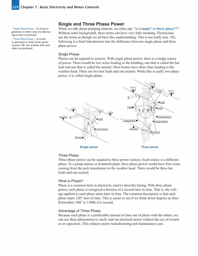
Single and Three Phase PowerWhen we talk about pumping stations, we often ask, “is it single14 or three phase15?” Without some background, these terms can have very little meaning. Electricians use the terms as though we all have this understanding. This is not really true. The following is a brief introduction into the difference between single phase and three phase power.
Single PhasePhases can be equated to sources. With single phase power, there is a single source of power. There would be two wires leading to the building, one that is called the hot lead and one that is called the neutral. Most homes have three lines leading to the weather head. There are two hot leads and one neutral. While this is really two phase power, it is called single phase.
HOT
HOT
NEUTRAL
TRANSFORMER
FUSE
GROUND
HOT
HOT
HOTPhase A
Phase B
Phase C
TRANSFORMER
TRANSFORMERTRANSFORMER
FUSEFUSE
FUSE
GROUND
NEUTRAL
Single phase Three phase
Three PhaseThree phase power can be equated to three power sources. Each source is a different phase. At a pump station or treatment plant, three phase power would have four wires coming from the pole transformer to the weather head. There would be three hot leads and one neutral.
What is Phase?Phase is a common term in electricity used to describe timing. With three phase power, each phase is energized a fraction of a second later in time. That is, the volt-age applied to each phase starts later in time. The common description is that each phase starts 120° later in time. This is easier to see if we think about degrees as time. Remember, 360° is 1/60th of a second.
Advantage of Three PhaseBecause each phase is a predictable amount of time out of phase with the others, we can use these phenomena to easily start an electrical motor without the use of switch-es or capacitors. This reduces motor manufacturing and maintenance cost.
14 Single Phase Power – A circuit or generator in which only one alternat-ing current is produced.15 Three Phase Power – A circuit or generator in which three power sources 120° out of phase with each other are produced.

229Chapter 7 Basic Electricity and Motor Controls
Horsepower16
Doing WorkMoving water from one location to another is defined as work and requires energy. One of the ways to measure the amount of energy required to do work is in foot-pounds. One foot pound of work is the amount of energy required to lift one pound of water one foot in elevation. In pumping situations, the amount of work done will be in the thousands of foot-pounds. Because we do not like to use large numbers, we have defined another term for work.
1 ft/min
1 HORSEPOWER
1 ft/min
33,000lbs
746 WATTS 33,000lbs
Electric MotorsElectric motors are rated in horsepower. The output of the motor is the name plate horsepower and is called brake horsepower17.
Horsepower to ElectricityIn order to provide the horsepower required, electricity is needed. The amount of electricity used is a combination of the voltage and the amperage and is the amount of work or power performed by electricity. It is given in units called watts. There is a relationship between horsepower and watts.
1 HP = 746 watts 1 HP = 0.746 kilowatts
Electromagnetism18
Electromagnetic FieldWhen current is passed through a conduc-tor, an electromagnetic field is developed around the conductor. This field is very much like the field that exists between the north and south poles of a permanent mag-net. It makes no difference if the current passed through the wire is AC or DC; the same electromagnetic field is produced.
Making a MagnetIf we wind a wire around a piece of metal and pass a current through the wire, the piece of metal will become a magnet with a north and south pole.
17 Brake Horsepower – The output horsepower of an electric motor. The representation of the amount of work that the motor can perform. Providing work of 33,000 foot pounds per min-ute is equivalent to one horsepower.
16 Horsepower – When 33,000 foot-pounds of work is performed in one minute.
18 Electromagnetism – (1) The magnetic force produced by an electric cur-rent or (2) the science that studies the interrelation of electricity and magnetism.

230 Basic Electricity and Motor ControlsChapter 7
Turning the Magnet into a SwitchLet’s now use the electromagnet to operate a switch. A simple switch can be made by placing a bar close to the end of the magnet. If we connect the bar to one side of an electrical supply, connect a second bar and light to the other side of an electrical source, and close the switch, the light will come on. When power is applied to the electromagnet, the bar is pulled down by the electromagnetic field, and the light is energized.
120V
120V
ContactorsThere are numerous electromagnetic devices in an electrical panel. These are called relays, contractors, or contact relays. These simple electromagnets are used to close a switch. These same devices are also available to open a switch. There are contrac-tors available with multiple contacts that can turn equipment and lights on and at the same instant turn other equipment and lights off. All of this can be done with a single contractor.
Magnetic StartersA magnetic starter is nothing more than a large contactor. The switch that provides power to the electric motor is closed by applying power to an electromagnet (the coil). In most instances, the power to the motor is much higher voltage (240, 460, 480, etc.) than the power applied to the electromagnet (the coil), which is typically 120 volts.
MOVABLECONTACT
STATIONARY
THERMAL UNIT
MAGNET
COIL
RESET

231Chapter 7 Basic Electricity and Motor Controls
Major Electrical ComponentsTransformersTransformers are found on the electrical pole and in some control panels. Transform-ers are electrical devices that change voltage. They can be used to step voltage up or step voltage down. The transformer on the pole outside of the pumping station or treatment plant is most likely a step down transformer. In most instances, there is a second step down transformer in the control panel to step the voltage down from that needed for the motors to 120 volts for the control system.ContactsContactors, coils, relays, contact relays, and magnetic starters are electromagnetic switches.
SwitchesThere is a wide variety of switches in use in treatment plants and pumping stations. Some of the most common in the small system are float switches, probes, flow switches, and pressure switches.
Float SwitchesThe most common float switch is the mercury float. The float contains a glass vial with two electrodes and a puddle of mercury. When the float is tripped, the mercury runs across the electrodes, and the circuit is closed. This may be used to start or stop a pump.
OFF
LEAD
LAG
ALARM
PVC CASING
WEIGHT
MERCURY SWITCH
ProbesElectrical probes are often used to determine the level of water in a tank and turn pumps on or off. For probes to work, there must be at least two probes. When both probes are in the water, the circuit is closed. When the water level reaches the lower probe, the pump turns on and pumps until the water level reaches the upper (pump off) probe.
PUMP ON
PUMP OFF
REFERENCE

232 Basic Electricity and Motor ControlsChapter 7
Flow SwitchA typical switch in a fluoride system is a flow switch. This switch has a reed or paddle that is in the path of the flow. The forward flow of the water bends the reed and closes a pair of contacts, completing the circuit.
Pressure SwitchTank systems often use pressure switches. These switches are made of a diaphragm and a series of levers and springs. Increases in pressure causes the diaphragm to flex, opening a contact, opening the circuit, and stopping the pump. When the pressure falls, the diaphragm flexes to allow a contact to close, completing the circuit and starting the pump.
CONTACTPOINTS
CONTACTPOINTS
CAMWHEEL
OPERATINGCAMRANGE
SPRING
OPERATINGLEVER
ASSEMBLY
DIFFERENTIALADJUSTING
NUT
PRESSURE FROM PUMP
RUBBERDIAPHRAGM
Flow switch Pressure switch
The electrical system associated with pumping systems is composed of two indepen-dent but associated systems: the power system and the control system.
Power SystemTransformers and DropThe power system starts at the power company’s transformer. The primary side (inlet) of the transformer is fused to prevent a short in the pump station from caus-ing excessive damage to the power system. The lines leading from the transformer to the pumping building are called the drop. The drop connects to the weather head and mast at the pump house.
Disconnect and BreakerThe wires lead down the mast to the disconnect. The disconnect is used to disconnect the power from the entire system. From the disconnect, power goes to the magnetic breaker19 or fuses. In some cases, the disconnect and the magnetic breaker may be the same. The magnetic breaker and fuses both serve the same purpose: over current protection. They prevent a fire in the building or wiring as a result of a short circuit in the wiring system.
Pumping Electrical Systems
19 Magnetic Breaker – An electrically operated mechanical device used for over current protection.

233Chapter 7 Basic Electricity and Motor Controls
Magnetic StarterFrom the breaker, power is wired to the magnetic starter20. The magnetic starter is an electrically operated switch. The switch is closed when an electromagnet is energized. When the electromagnet is de-energized, a spring disconnects the switch. Power to operate the electromagnet is supplied through the control circuit.
Heaters – Thermal OverloadAt the bottom of the magnetic starter is the thermal overload or heater21 assembly. The heaters sense the amount of amperage flowing through the starter by sensing the heat created by this amperage. The electrical controls of the heaters are in the con-trol circuit. Heaters provide overload protection. If the motor draws high current, the heaters will heat up and disconnect the control circuit stopping the motor before it burns up.
Review
1. The frequency of alternating current is measured in what units?
2. Three phase power is like having:
3. Work in water is measured as horsepower. In electricity, this same work is measured a:
4. The device used to operate a magnetic starter is the:
5. What is the name used to identify magnetic starters, contact relays, motor starters, and relays?
6. The _______________ is used to protect the motor from current draw, and the _______________ is used to protect the building and wiring from a short circuit.
Control CircuitPower SourceThe power for the control circuit comes from one leg of the power circuit. This con-trol voltage is usually tapped into the circuit above the magnetic starter. The voltage above the station is usually greater than the 120 volts desired for the control circuit. A step-down transformer is used to obtain the 120 volts.
SwitchesFrom the transformer in the panel, the power leads to a switch or switches. Most pumping stations have a Hand-Off-Auto (H-O-A) switch. In the hand position, all of the remote sensing system is disconnected. From the H-O-A switch, power goes to the control switch in the heater assembly.
ControlThe control circuit includes all of the control system: pressure-sensing switches, flow switches, level sensing switches, and float switches. These switches are primarily used to turn pumps on and off.
20 Magnetic Starter – An electrically operated mechanical switch used to connect power to an electric motor.
21 Heater – A device designed for overload protection of electric mo-tors. The device is heat-sensitive and placed in the power circuit with an electrical connection to the control circuit.

234 Basic Electricity and Motor ControlsChapter 7
Control PanelThe control panel may also contain lights that indicate the status of the pumps, vari-ous alarm conditions, and hour meters.
Maintenance ConsiderationsBasic RoutinesThe maintenance requirements associated with each pumping installation are unique to the installation. However, there are general considerations that can be applied to most pumping installations. These include performing the following activities and gathering the following data at the specified intervals:
• Suction and discharge pressure - Daily• Number of hours operated from the hour meter - Daily• Inspect stuffing box for leakage - Daily• Flow - Monthly• Replace packing - Annually• Amperage and voltage measurements - Quarterly

235Chapter 7 Basic Electricity and Motor Controls
1. What is the name for the flow of electrons in an electric circuit?A. Voltage B. Resistance C. Capacitance D. Current
2. What is the basic unit of electric current?A. The volt B. The watt C. The ampere D. The ohm
3. Which instrument is used to measure electric current?A. An ohmmeter B. A wavemeter C. A voltmeter D. An ammeter
4. What is the name of the pressure that forces electrons to flow through a circuit?A. Magnetomotive force, or inductance B. Electromotive force, or voltage C. Farad force, or capacitance D. Thermal force, or heat
5. What is the basic unit of electromotive force (EMF)?A. The volt B. The watt C. The ampere D. The ohm
6. How much voltage does an automobile battery usually supply?A. About 12 volts B. About 30 volts C. About 120 volts D. About 240 volts
7. How much voltage does a wall outlet usually supply in the U.S.?A. About 12 volts B. About 30 volts C. About 120 volts D. About 480 volts
Basic Electricity and Motor Controls Quiz

236 Basic Electricity and Motor ControlsChapter 7
8. Which instrument is used to measure electric potential or electromotive force?A. An ammeter B. A voltmeter C. A wavemeter D. An ohmmeter
9. What limits the current that flows through a circuit for a particular applied DC voltage?A. Reliance B. Reactance C. Saturation D. Resistance
10. What is the basic unit of resistance?A. The volt B. The watt C. The ampere D. The ohm
11. Which instrument is used to measure resistance?A. An ammeter B. A voltmeter C. An ohmmeter D. A wavemeter
12. What are three good electrical conductors?A. Copper, gold, mica B. Gold, silver, wood C. Gold, silver, aluminum D. Copper, aluminum, paper
13. What are four good electrical insulators?A. Glass, air, plastic, porcelain B. Glass, wood, copper, porcelain C. Paper, glass, air, aluminum D. Plastic, rubber, wood, carbon
14. What does an electrical insulator do?A. It lets electricity flow through it in one direction. B. It does not let electricity flow through it. C. It lets electricity flow through it when light shines on it. D. It lets electricity flow through it.

237Chapter 7 Basic Electricity and Motor Controls
15. Before attempting to work on any electrical appliance you should?A. Have proper trainingB. Observe all state and local safety codesC. Check for improper shorts or groundsD. All of the above
Related Documents