General rights Copyright and moral rights for the publications made accessible in the public portal are retained by the authors and/or other copyright owners and it is a condition of accessing publications that users recognise and abide by the legal requirements associated with these rights. • Users may download and print one copy of any publication from the public portal for the purpose of private study or research. • You may not further distribute the material or use it for any profit-making activity or commercial gain • You may freely distribute the URL identifying the publication in the public portal If you believe that this document breaches copyright please contact us providing details, and we will remove access to the work immediately and investigate your claim. Downloaded from orbit.dtu.dk on: Apr 28, 2018 Basic DTU Wind Energy controller Hansen, Morten Hartvig; Henriksen, Lars Christian Publication date: 2013 Document Version Publisher's PDF, also known as Version of record Link back to DTU Orbit Citation (APA): Hansen, M. H., & Henriksen, L. C. (2013). Basic DTU Wind Energy controller. DTU Wind Energy. (DTU Wind Energy E; No. 0028).

Welcome message from author
This document is posted to help you gain knowledge. Please leave a comment to let me know what you think about it! Share it to your friends and learn new things together.
Transcript

General rights Copyright and moral rights for the publications made accessible in the public portal are retained by the authors and/or other copyright owners and it is a condition of accessing publications that users recognise and abide by the legal requirements associated with these rights.
• Users may download and print one copy of any publication from the public portal for the purpose of private study or research. • You may not further distribute the material or use it for any profit-making activity or commercial gain • You may freely distribute the URL identifying the publication in the public portal
If you believe that this document breaches copyright please contact us providing details, and we will remove access to the work immediately and investigate your claim.
Downloaded from orbit.dtu.dk on: Apr 28, 2018
Basic DTU Wind Energy controller
Hansen, Morten Hartvig; Henriksen, Lars Christian
Publication date:2013
Document VersionPublisher's PDF, also known as Version of record
Link back to DTU Orbit
Citation (APA):Hansen, M. H., & Henriksen, L. C. (2013). Basic DTU Wind Energy controller. DTU Wind Energy. (DTU WindEnergy E; No. 0028).

Dep
artm
ent o
f W
ind
Ener
gy
Rep
ort 2
013
Basic DTU Wind Energy controller
Morten Hartvig Hansen and Lars Christian Henriksen
DTU Wind Energy E-0028
January 2013

Author(s): Morten Hartvig Hansen and Lars ChristianHenriksenTitle: Basic DTU Wind Energy controllerInstitute: Department of Wind Energy
Summary (max. 2000 char.):This report contains a description and documentation,including source code, of the basic DTU Wind Energycontroller applicable for pitch-regulated, variable speedwind turbines. The controller features both partial andfull load operation capabilities as well as switchingmechanisms ensuring smooth switching between the twomodes of operation.The partial and full load controllers are both based onclassical proportional-integral control theory as well asadditional filters such as an optional drive train damperand a notch filter mitigating the influence of rotor speeddependent variations in the feedback. The controller relieson generator speed as the primary feedback sensor.Additionally, the reference generator power is used as afeedback term to smoothen the switching between partialand full load operation. Optionally, a low-pass filteredwind speed measurement can be used for wind speeddependent minimum blade pitch in partial load operation.The controller uses the collective blade pitch angle andelectromagnetic generator torque to control the windturbine. In full load operation a feedback term from thecollective blade pitch angle is used to schedule the gains ofthe proportional-integral controller to counter the effectsof changing dynamics of the wind turbine for differentwind speeds.Blade pitch servo and generator models are not includedin this controller and should be modeled separately, ifthey are to be included in the simulations.
Report Number: DTUWind Energy E-0018Publication Date: January2013
Contract Number: EUDPproject Light Rotor
Project Number:46-43028-Xwp3
Sponsorship: -
ISBN: 978-87-92896-27-8
Cover: -
Pages: 42Tables: 5References: 3
Technical University ofDenmarkDTU Wind EnergyFrederiksborgvej 3994000 RoskildeDenmarkTelephone +45 4677 5085

Contents
1. Controller description 4
1.1. Strategy and architecture . . . . . . . . . . . . . . . . . . . . . . . . . . . . 41.1.1. Partial load operation . . . . . . . . . . . . . . . . . . . . . . . . . . 41.1.2. Full load operation . . . . . . . . . . . . . . . . . . . . . . . . . . . . 51.1.3. Switching between partial and full load operation . . . . . . . . . . . 111.1.4. Drivetrain damper . . . . . . . . . . . . . . . . . . . . . . . . . . . . 11
1.2. Parameters . . . . . . . . . . . . . . . . . . . . . . . . . . . . . . . . . . . . 111.3. Inputs and outputs . . . . . . . . . . . . . . . . . . . . . . . . . . . . . . . . 111.4. Cut-in procedure - start up at any wind speed . . . . . . . . . . . . . . . . . 121.5. Cut-out procedures . . . . . . . . . . . . . . . . . . . . . . . . . . . . . . . . 151.6. Programming . . . . . . . . . . . . . . . . . . . . . . . . . . . . . . . . . . . 16
2. Simulations of DTU 10 MW RWT 17
A. Source code 25
A.1. Main routines in risoe controller.f90 . . . . . . . . . . . . . . . . . . . . . . 25A.2. Functional routines in risoe controller fcns.f90 . . . . . . . . . . . . . . . . . 32
B. Discrete filters 39
B.1. First order filter . . . . . . . . . . . . . . . . . . . . . . . . . . . . . . . . . 39B.2. Second order filters . . . . . . . . . . . . . . . . . . . . . . . . . . . . . . . . 40
DTU Wind Energy E-0018 3

1. Controller description
This chapter contains a description of the controller strategy, architecture, filters, param-eters, and in-/outputs. The controller is a further development of a previous controllerused at DTU Wind Energy under the version 11. The new developments are inspiredby Bossanyi’s controller for the 5MW NREL reference turbine [1], where the power errorfeedback in the pitch controller that keeps the pitch at its minimum below rated poweroperation represents the most significant change.
The controller is only considering low speed shaft (LSS) measures of rotational speeds andtorques, i.e., there is no gearbox on the drivetrain. The controller still be used for turbineswith a gearbox, when the user transforms torques and speeds between the LSS and HSSusing the gear ratio.
1.1. Strategy and architecture
A diagram of the entire controller is shown in Figure 1.1. The routes of this diagramthat are active when the turbine is operating below rated power, herein called partial load
operation, are shown in Figure 1.2. The routes that are active in full load operation areshown in Figure 1.3. These two regions of operation are first described before the switchingbetween is explained. The discrete filters denoted by the functions f1, f2, fp, and fn inthe diagrams are described and tested in Appendix B.
1.1.1. Partial load operation
The strategy for optimal CP tracking in partial load operation is based on a balancebetween generator and aerodynamic torques to obtain a close to optimal tip speed ratio.To avoid the feedback of higher frequency dynamics (e.g. the drivetrain torsion mode),the torque reference Qref,k at the current step k is computed based on a second orderlow-pass filtered LSS generator speed as KΩk. This feedback is enforced by setting thetorque limits for the PID controller to Qg,min,k = Qg,max,k = KΩk whenever the filteredrotational speed Ωk is not close to the minimum speed Ωmin, or the rated speed Ω0. Whenthe rotational speed is close to its bounds, these torque limits will open according to theinterpolation factors σmin,k and σmax,k. The torque reference will then be given by thePID controller based on the speed error eQ,k = Ωk − Ωset,k, where the set point is theminimum, or rated speed. Because the rotor speed is bounded, the power loss can oftenbe minimized be performing some adjustment of the minimum pitch. A first order low-pass filtered wind speed measured at hub height Vk is used as parameter for varying theminimum pitch angle θmin,k = θmin(Vk) based on a look-up table provided by the user.
4 DTU Wind Energy E-0018

The power error feedback of pitch PID controller ensures that the pitch reference is keptat this minimum pitch angle.
The interpolation factors for the opening of the torque limits are based on how close thesecond order low-pass filtered generator speed is from its minimum and rated speeds. Thelimits can be opened gradually over an interval as described by the function
σ (x0, x1;x) =
0 ∀x < x0a3x
3 + a2x2 + a1x+ a0 ∀x ∈ [x0 : x1[
1 otherwise(1.1)
where the coefficients of the spline are
a3 =2
(x0 − x1)3, a2 =
−3 (x0 + x1)
(x0 − x1)3
, a1 =6x1x0
(x0 − x1)3, a0 =
(x0 − 3x1)x20
(x0 − x1)3
(1.2)
The function is programmed such that if x0 ≥ x1 then the σ-function becomes
σ (x0, x0;x) =
0 ∀x < x01 otherwise
(1.3)
Figure 1.4 shows an example of the σ-function where x0 = 1 and x1 = 2. In an actualimplementation of the controller, this smooth function with a third order polynomial maybe an unnecessary complexity, which can replaced by a linear interpolation function.
Figure 1.5 shows the torque limits in partial load operation of the DTU 10 MW RWT,where the minimum speed is 7 rpm and rated speed is 9.6 rpm. The limits are set to beclosed approximately 5 % above the minimum speed and start opening again at 90 % andare fully open at 95 % of the rated speed.
1.1.2. Full load operation
In full load operation, the torque limits are closed around the torque given by the selectedpower control strategy, either constant power P0/Ωk, or constant torque P0/Ω0, where P0
is the rated power. Note that the unfiltered measured LSS generator speed Ωk is used forcomputation of the reference torque in the constant power control.
The pitch reference angle is obtained from a combined PI feedback of the generator speedand power errors, and a possible differential feedback of the speed error. The speed erroris obtained as the difference between the second order low-pass filtered LSS generatorspeed and the rated speed. The power error is the difference between the reference powerPref,k = Qref,kΩk and the rated power P0. Both errors are notch filtered around thefrequency specified by the user as the free-free drivetrain frequency. This frequency isassumed to be constant although HAWCStab2 eigenvalue analysis often show a smallvariation with operational point (wind speed). Note that both errors contribute to thesame proportional term (θP,k) and same integral term (θI,k). The latter is importantbecause it ensures that the reference pitch angle is kept at the minimum pitch angle untilrated power is reached; assuming that the right weighting between the integral speed errorgain kI and power error gain kPI has been selected by the user.
DTU Wind Energy E-0018 5

Mean pitch angle
Second order low-pass filter
Interpolation factors for partial load limits Torque limits in partial load
Speed set point for torque controller
Speed error
Speed error
Power error
Gain scheduling factor
Nonlinear gain factor
Power reference
Total gain factor
Interpolation between limits
Drivetrain damper
Second order notch filter
Second order notch filter
Torque limits in full load
First order low-pass filter Fine pitch adjustment
Proportional term
Integral term
PID feedback with limits
Anti-windup of integral term
Differential term
Proportional term
Differential term
Integral term Anti-windup of integral term
First order low-pass filter
Second order bandpass filter
First order low-pass filt. interpolation switch
Figure 1.1.: Diagram of the discrete controller. Note that k denotes the current time step.
6DTU
WindEnergyE-0018

Mean pitch angle
Second order low-pass filter
Interpolation factors for partial load limits Torque limits in partial load
Speed set point for torque controller
Speed error
Speed error
Power error
Gain scheduling factor
Nonlinear gain factor
Power reference
Total gain factor
Drivetrain damper
Second order notch filter
Second order notch filter
First order low-pass filter Fine pitch adjustment
Proportional term
Differential term
Integral term Anti-windup of integral term
First order low-pass filter
Second order bandpass filter
Proportional term
Integral term
PID feedback with limits
Anti-windup of integral term
Differential term
PID controller for generator torque
Figure 1.2.: Active routes during partial load operation in the controller diagram in Figure 1.1.
DTU
WindEnerg
yE-0018
7

Mean pitch angle
Second order low-pass filter
Speed error
Power error
Gain scheduling factor
Nonlinear gain factor
Power reference
Total gain factor
Drivetrain damper
Second order notch filter
Second order notch filter
Torque limits in full load
First order low-pass filter Fine pitch adjustment
Proportional term
Differential term PID feedback with minimum limit
Integral term Anti-windup of integral term
First order low-pass filter
Second order bandpass filter
Figure 1.3.: Active routes during full load operation in the controller diagram in Figure 1.1.
8DTU
WindEnergyE-0018

0 0.2 0.4 0.6 0.8
1
0 0.5 1 1.5 2 2.5 3 3.5 4S
witc
h va
lue
[-]
Switching variable [-]
Figure 1.4.: Example of the σ-function (1.1) where x0 = 1 and x1 = 2.
0
1
2
3
4
5
6
7
8
9
10
5 6 7 8 9 10
Tor
que
limits
[MN
m]
Rotational speed [rpm]
Minimum torque limitMaximum torque limit
Figure 1.5.: Torque limits in partial load operation of the DTU 10 MW RWT, where theminimum speed is 7 rpm and rated speed is 9.6 rpm. The limits are set to beclosed approximately 5 % above the minimum speed and start opening againat 90 % and are fully open at 95 % of the rated speed.
The anti-windup is performed such that the controller will react quickly with increasedpitch angle if the reference power signal suddenly increased above the rated power level: Ineach time step, the minimum pitch limit is enforced on the reference pitch which is the sumof the proportional, differential, and integral terms θref,k = max (θmin,k, θP,k + θD,k + θI,k).The value of the integral term to be used for the integration in the next time step is thenrecalculated as θI,k = θref,k − θP,k − θD,k, which only makes a change to the integral termif the reference pitch is on the minimum limit θref,k = θmin,k. Below rated power, wherethe proportional term is negative because the rotational speed error is kept close to zeroby the torque PID controller, the integral term will therefore be positive. If the referencepower is increased and becomes close to rated power (due to the reaction of the torquePID controller to an increased wind speed), then the proportional term will then comeclose to zero whereas the integral will still be positive and the resulting pitch referenceangle will be positive, whereby large power and speed variations are avoided. Note thatthe same anti-windup scheme is used in the torque PID controller.
The first order low-pass filtered mean of the blade pitch angles θm,k is used for schedulingof the gains of the pitch PID controller. A quadratic dependency of the aerodynamic
DTU Wind Energy E-0018 9

torque gain with collective pitch angle is assumed as
∂QA
∂θ=
∂QA
∂θ
∣
∣
∣
∣
θ=0
(
1 +θ
K1
+θ2
K2
)
(1.4)
where QA denotes the aerodynamic torque, θ is the collective pitch angle, and ∂QA
∂θ
∣
∣
∣
θ=0
is the aerodynamic gain at zero pitch. The parameters of this expression K1 and K2 canbe obtained from curve fitting to the derivative of the aerodynamic torque with respectto collective pitch angle assuming quasi-steady aerodynamics and frozen wake (constantinduced velocities) as
∂QA
∂θ=
1
2ρB
∫ R
0
c(r)U(r)2(
C ′
L(α(r)) sinϕ(r)− C ′
D(α(r)) cosϕ(r))
rdr (1.5)
where B is the number of blades, R is the outer radius of the rotor, c(r) is the radialchord distribution, U(r) is the mean steady state relative inflow velocity along the blade,C ′
L and C ′
D are the gradients of the lift and drag coefficient curves evaluated at the meansteady state angle of attack α(r) along the blade, and ϕ(r) is the spanwise distribution ofinflow angles relative to the rotor plane.
Figure 1.6 shows the aerodynamic torque gradients obtained from HAWCStab2 for theDTU 10 MW RWT together with the fit of the quadratic expression (1.4). The fitted areparameters shown as inputs number 21 and 22 in Table 1.1 of Section 1.2. Often, a linearfit is sufficient and it is assumed when the user enters K2 = 0 (note that K1 then is theangle where the aerodynamic gain is doubled). The gain scheduling factor based on thefiltered mean pitch angle ηA,k is the inverse of the expression in the parenthesis of (1.4).A nonlinear gain factor ηnl,k based on the generator speed error is also added for increasedsensitivity of the pitch PID controller by large speed excursions.
-6
-5
-4
-3
-2
-1
0
1
0 5 10 15 20 25
Aer
odyn
amic
torq
ue g
ain
[MN
m/d
eg]
Pitch angle [deg]
Gain based on CP surface including blade deformationGain based on constant induced velocities and no blade deformation
Quadratic curve fit
Figure 1.6.: Aerodynamic torque gains for the DTU 10 MW RWT obtained from HAWC-Stab2.
10 DTU Wind Energy E-0018

1.1.3. Switching between partial and full load operation
The switching between partial and full load control of the generator torque is based on afirst order low-pass filtered switching variable σθ,k that is driven by a σ-function evaluationusing the measured mean pitch angle θm. The time constant is the rotational period atrated speed. As explained above, the anti-windup of the combined integral term of thepitch PID controller will ensure that the reference pitch angle raises above its minimumvalue when the torque PID controller of generator speed results in a reference power closeto the rated power level. The user can define at how many degrees above the minimumpitch this switching shall occur. Good experiences have been obtained with a hard switchat θf1 = θf2 = θmin,k + 0.5 deg.
1.1.4. Drivetrain damper
The measured generator LSS speed Ωk is fed through a band-pass filter with the free-free drivetrain torsional frequency ωn as center frequency (see example of the filter inAppendix B). The filtered speed Ωd,k, containing in-phase variations with frequenciesaround this frequency, is then multiplied by a gain factor kdmp and added to the torquefeedback from the PID controller to give the generator torque reference. Note that thisdrivetrain damper is always active when kdmp > 0.
1.2. Parameters
All parameters of the controller are transferred to the DLL using HAWC2 commandsfor the “init” routine of the type2 DLL [2]. Table 1.1 shows the command list from theinput to the DTU 10MW RWT, and some more details of all 38 parameters are given inTable 1.2, where the notation of the parameters used in the diagram of Figure 1.1 andsome additional notations can also be seen.
1.3. Inputs and outputs
As input during simulations, the controller requires the time [s], the generator LSS speed[rad/s], the pitch angles of three blades [rad], and the three components of the wind speedat hub height [m/s], where the first and second of these three components must be thetwo horizontal components that are used internally to compute the horizontal vector sum.Table 1.4 shows the HAWC2 commands that provide these eight controller inputs for theDTU 10 MW RWT. Note that if the rotor only has two blades, then the controller maystill be used by repeating a blade pitch angle output to the controller. However, this trickis only valid if there is no additional cycle, or individual pitch controller appended to thiscontroller.
Table 1.5 contains a list of the controller outputs to the simulation, where the generatortorque reference and pitch angle references for three blades are the
DTU Wind Energy E-0018 11

; Overall parameters
constant 1 10000.0 ; Rated power [kW]
constant 2 0.733 ; Minimum rotor speed [rad/s]
constant 3 1.005 ; Rated rotor speed [rad/s]
constant 4 15.6e6 ; Maximum allowable generator torque [Nm]
constant 5 100.0 ; Minimum pitch angle, theta_min [deg],
; if |theta_min|>90, then a table of <wsp,theta_min> is read ;
; from a file named ’wptable.n’, where n=int(theta_min)
constant 6 90.0 ; Maximum pitch angle [deg]
constant 7 10.0 ; Maximum pitch velocity operation [deg/s]
constant 8 0.2 ; Frequency of generator speed filter [Hz]
constant 9 0.7 ; Damping ratio of speed filter [-]
constant 10 0.64 ; Frequency of free-free DT torsion mode [Hz], if zero no notch filter used
; Partial load control parameters
constant 11 9.5e6 ; Optimal Cp tracking K factor [kNm/(rad/s)^2], ;
; Qg=K*Omega^2, K=eta*0.5*rho*A*Cp_opt*R^3/lambda_opt^3
constant 12 7.33e7 ; Proportional gain of torque controller [Nm/(rad/s)]
constant 13 1.32e7 ; Integral gain of torque controller [Nm/rad]
constant 14 0.0 ; Differential gain of torque controller [Nm/(rad/s^2)]
; Full load control parameters
constant 15 1 ; Generator control switch [1=constant power, 2=constant torque]
constant 16 0.592 ; Proportional gain of pitch controller [rad/(rad/s)]
constant 17 0.133 ; Integral gain of pitch controller [rad/rad]
constant 18 0.0 ; Differential gain of pitch controller [rad/(rad/s^2)]
constant 19 0.4e-8 ; Proportional power error gain [rad/W]
constant 20 0.4e-8 ; Integral power error gain [rad/(Ws)]
constant 21 164.13 ; Coefficient of linear term in aerodynamic gain scheduling, KK1 [deg]
constant 22 702.09 ; Coefficient of quadratic term in aerodynamic gain scheduling, KK2 [deg^2] &
; (if zero, KK1 = pitch angle at double gain)
constant 23 1.3 ; Relative speed for double nonlinear gain [-]
; Cut-in simulation parameters
constant 24 0.1 ; Cut-in time [s]
constant 25 4.0 ; Time delay for soft start of torque [1/1P]
; Cut-out simulation parameters
constant 26 710 ; Cut-out time [s]
constant 27 5.0 ; Time constant for 1st order filter lag of torque cut-out [s]
constant 28 1 ; Stop type [1=linear two pitch speed stop, 2=exponential pitch speed stop]
constant 29 1.0 ; Time delay for pitch stop 1 [s]
constant 30 20.0 ; Maximum pitch velocity during stop 1 [deg/s]
constant 31 1.0 ; Time delay for pitch stop 2 [s]
constant 32 10.0 ; Maximum pitch velocity during stop 2 [deg/s]
; Expert parameters (keep default values unless otherwise given)
constant 33 0.5 ; Lower angle above lowest minimum pitch angle for switch [deg]
constant 34 0.5 ; Upper angle above lowest minimum pitch angle for switch [deg], if equal then hard switch
constant 35 95.0 ; Ratio between filtered speed and reference speed for fully open torque limits [%]
constant 36 5.0 ; Time constant of 1st order filter on wind speed used for minimum pitch [1/1P]
constant 37 5.0 ; Time constant of 1st order filter on pitch angle used for gain scheduling [1/1P]
; Drivetrain damper
constant 38 0.0 ; Proportional gain of active DT damper [Nm/(rad/s)], requires frequency in input 10
Table 1.1.: All parameters of the controller, here shown as the HAWC2 input commandsfor the “init” routine of the controller, see type2 DLL interface description inthe HAWC2 manual. The shown values are taken from the input to the DTU10MW RWT.
1.4. Cut-in procedure - start up at any wind speed
The controller has a very simplified cut-in procedure, which is not intended to model areal cut-in, but rather to enable start-up of normal operation DLCs at any wind speed.The blades are initially pitched out to maximum pitch and then at a given time in the
12 DTU Wind Energy E-0018

Input Additional explanation if assumed needed
1 P0 Rated power [kW].2 Ωmin Minimum rotor speed [rad/s].3 Ω0 Rated rotor speed [rad/s].4 - Maximum allowable generator torque [Nm]. An upper limit set on
the torque reference signal.5 - This number is the minimum pitch angle θmin in degrees, which is
set to a constant if this input is less than 90 deg. Otherwise, theinit routine will search for a file with the name “wptable.n”, where“n” is a character string obtained from the integer value of the input.In the shown example, this file is therefore “wptable.100”. The fileformat is first line contains an integer with the number of subsequentlines, which contain two numbers each, wind speed and minimumpitch angle in degrees. An example is shown in Table 1.3.
6 θmax Maximum pitch angle [deg].7 - Maximum pitch velocity operation [deg/s]. An upper limit set on the
rate of change of the pitch reference signal.8 ωΩ Frequency of generator speed filter [Hz].9 ζΩ Damping ratio of speed filter [-].
10 ωn Frequency of free-free DT torsion mode [Hz], if zero no notch filterused.
11 K Optimal CP tracking factor [Nm/(rad/s)2], K = η 1
2ρACP,optR
3/λ3opt.
12 kgP Proportional gain of torque controller [Nm/(rad/s)].13 kgI Integral gain of torque controller [Nm/rad].14 kgD Differential gain of torque controller [Nm/(rad/s2)].15 - Generator control strategy [1=constant power, 2=constant torque].16 kP Proportional gain of pitch controller [rad/(rad/s)].17 kI Integral gain of pitch controller [rad/rad].18 kD Differential gain of pitch controller [rad/(rad/s2)].19 kPP Proportional power error gain [rad/W].20 kPI Integral power error gain [rad/(Ws)].21 K1 Coefficient of linear term in aerodynamic gain scheduling [deg].22 K2 Coefficient of quadratic term in aerodynamic gain scheduling [deg2].
If this factor K2 is set to zero then the controller will assumed alinear gain scheduling. The K1 is then the pitch angle where theaerodynamic torque gain has doubled from its value at zero pitch.
23 Ω2/Ω0 Normalized speed where the pitch controller gains are doubled.24 - Cut-in time [s], if zero no cut-in simulated.25 - A time delay for the cut-in procedure given in the unit [1/1P] corre-
sponding to the rotational period at rated speed.26 τout Cut-out time [s], if zero no cut-out simulated.27 - Time constant for first order filter lag of torque cut-out [s].28 - Stop type [1=linear two pitch speed stop, 2=exponential pitch speed
stop] as described in Section 1.5.29 τ1 Time delay for pitch stop 1 [s].30 - Maximum pitch velocity during stop 1 [deg/s].31 τ2 Time delay for pitch stop 2 [s].32 - Maximum pitch velocity during stop 2 [deg/s].
DTU Wind Energy E-0018 13

Input Additional explanation if assumed needed
33 θf0 Lower angle above lowest minimum pitch angle for switch [deg].34 θf1 Upper angle above lowest minimum pitch angle for switch [deg].35 γ Percentage of the rated speed when the torque limits are fully opened
Ωmax2= γΩ0 to let PID controller be active, and the opening starts
at Ωmin2= (2γ − 1)Ω0. The same percentage is used for opening the
torque limits for PID control around the minimum rotational speed,where the torque limits start to open at Ωmax1
= Ωmin/γ and fullyopen at Ωmin1
= Ωmin.36 τV Ω0/(2π) Time constant of 1st order filter on wind speed used for minimum
pitch [1/1P].37 τθΩ0/(2π) Time constant of 1st order filter on pitch angle for gain scheduling
[1/1P].38 kdmp Proportional gain of DT damper [Nm/(rad/s)], requires frequency in
input 10.
Table 1.2.: All parameters of the controller related to the parameters shown in the diagramin Figure 1.1 and with additional explanations compared to Table 1.1.
7
0.0 3.0
4.0 3.0
5.0 2.5
6.0 1.7
7.0 0.8
8.0 0.0
50.0 0.0
Table 1.3.: Example of a “wptable.n” file. First line contains an integer with the numberof subsequent lines, which contain two numbers each, wind speed and minimumpitch angle in degrees.
simulation (input 24), the blades are pitched towards minimum pitch with zero generatortorque reference. As the rotor speed increases, a first order filter of the difference themeasured rotational speed and the minimum rotational speed with the time constant of1/1P (one rotational period at rated speed) is updated in each time step k as
∆Ωk = f1 (2π/Ω0;∆Ωk−1,Ωk − Ωmin,Ωk−1 − Ωmin) (1.6)
During this speed-up, the speed error PID terms of the pitch controller is active at aquarter of their normal gains and the set point of it is the minimum rotor speed. Thepower error gains are set to zero, otherwise it will stay at minimum due to the zerogenerator torque reference (the factor of a quarter is chosen based on trial and error). Thepitch controller thereby catches the rotational speed at the minimum speed and when ∆Ωk
become within 2 % of the minimum speed, the acceleration of the rotor is assumed to beunder control and a generator cut-in time is registered. The torque reference is thereafter
14 DTU Wind Energy E-0018

general time ; [s]
constraint bearing1 shaft_rot 1 only 2 ; [rad/s] Generator LSS speed
constraint bearing2 pitch1 1 only 1 ; [rad]
constraint bearing2 pitch2 1 only 1 ; [rad]
constraint bearing2 pitch3 1 only 1 ; [rad]
wind free_wind 1 0.0 0.0 -124.6 ; [m/s] global coords at hub height
Table 1.4.: HAWC2 commands that define the input to the controller DLL. Note that thecommand “wind free wind 1 x y z” will give all three components of the freewind at the point x,y,z, both in global coordinates [2], thus in all eight inputs.
ramped up using the σ-function in Equation (1.1) to its value determined by the normalcontroller at a user-defined time after the generator cut-in time. In the same period, therotational speed set point for the pitch controller is ramped up to the rated speed Ω0, andboth speed and power error gains are ramped up to their values determined by the normalgain scheduling. The controller should thereafter be operating normally, and this start-upwill at moderate to high wind speeds take less than 100 s for the DTU 10 MW RWT.
There should be no need for wind ramping for the controller to start up, however, cautionshould be made on not to start high wind speed (above rated) simulations with too highinitial rotational speed. Too high initial rotor speed may cause the pitch and torquecontrollers to overreact and they may enter a state of competition. If the user can allowlong start-up periods then the most stable way is set a late cut-in time to let the rotorslow down to idling before the cut-in starts. However, at low wind speeds, the start-upwill then take a long time, and a very early cut-in (e.g. 0.1 s) is recommended, combinedwith an initial rotational speed is set to a value 50-75 % of the minimum speed.
1.5. Cut-out procedures
The user may specify a time in the simulation for the cut-out of the generator in input 26(let it be denoted τout). A first order filter will be driven by the torque reference signaluntil this cut-out time, whereafter the filter is let to decay with a user specified timeconstant (input 27), and the torque reference will set equal to this decaying signal.
At the generator cut-out time plus the first user specified time delay in input 29 (let it bedenoted τ1), the blades will start to pitch out by setting the reference pitch angle to themaximum pitch angle (let it be denoted θmax). The user can specify two different typesof pitch velocity schemes, either linear pitching with two different constant speeds, orexponential pitching where the velocity changes as an exponential function. In the linearpitching scheme, the maximum pitch velocity is initial set to the pitch velocity specifiedin input 30. After additional time given by the “time delay of pitch stop 2” in input 31,let it be denoted τ2, the maximum pitch velocity is then set to the pitch velocity specifiedin input 32. In the exponential pitch scheme, the maximum pitch velocity will start at thevelocity given by θmax/τ2, whereafter this velocity will decay as the exponential functionexp (−(t− τout − τ1)/τ2) until (t − τout − τ1)/τ2 > 10, or this decaying maximum pitch
DTU Wind Energy E-0018 15

Channel Description
1 Generator torque reference, Qref,k [Nm]2 Pitch angle reference of blade 1, θref,k [rad]3 Pitch angle reference of blade 2, θref,k [rad]4 Pitch angle reference of blade 3, θref,k [rad]5 Power reference, Pref,k [W]6 Filtered wind speed, Vk [m/s]7 Filtered rotor speed, Ωk [rad/s]8 Filtered rotor speed error for torque, eQ,k [rad/s]9 Bandpass filtered rotor speed, Ωd,k [rad/s]
10 Proportional term of torque controller, QP,k [Nm]11 Integral term of torque controller, QI,k [Nm]12 Minimum limit of torque, Qg,min,k [Nm]13 Maximum limit of torque, Qg,max,k [Nm]14 Torque limit switch based on pitch, σθ,k [-]15 Low-pass filtered rotor speed error for pitch controller, eΩ,k [rad/s]16 Low-pass and notch filtered power error for pitch controller, eP,k [W]17 Proportional term of pitch controller, θP,k [rad]18 Integral term of pitch controller, θI,k [rad]19 Minimum limit of pitch, θmin,k [rad]20 Maximum limit of pitch, θmax [rad]21 Torque reference from DT damper, Qdmp,k [Nm]
Table 1.5.: Outputs from the controller DLL, where only the first two are needed. Therest are for analysis of controller behavior.
velocity is lower than the pitch velocity specified in input 32, which is the value that themaximum pitch velocity will have thereafter.
1.6. Programming
The controller is programmed in Fortran90 using the format of the type2 DLL interface
for HAWC2 [2] and the source code is listed in Appendix A.
16 DTU Wind Energy E-0018

2. Simulations of DTU 10 MW RWT
Figure 2.1 – 2.6 shows selected signals from IEC NTM simulations with HAWC2 of theclass 1A DTU 10 MW RWT at 4, 8, 12, 16, 20, and 24 m/s. All simulations are onlymeant as an example of the controller performance because they are performed using anearlier version of the DTU 10 MW RWT than the published one. The plots include thetransients, which for all but lowest wind speed of 4 m/s have died out before 100 s intothe simulations. Comments to simulations are given in the captions.
DTU Wind Energy E-0018 17

0
1
2
3
4
5
6
7
8
Sig
nal [
m/s
] and
[rpm
]
Wind speedGen. speed
-0.5
0
0.5
1
1.5
2
2.5
Sig
nal [
MW
] and
[MN
m]
TorqueTorque ref.
Switch value [-]Elec. power
-30
-20
-10
0
10
20
30
40
Sig
nal [
MN
m]
Torque ref.Prop. term
Integral termMin. torque
Max. torque
-40
-30
-20
-10
0
10
20
30
40
50
0 100 200 300 400 500 600 700
Sig
nal [
deg]
Time [s]
Pitch of blade 1Pitch reference
Prop. termIntegral term
Min. pitch
Figure 2.1.: Selected signals from IEC NTM simulation of the class 1A DTU 10 MWRWT at 4 m/s. Note the long start-up time (transients) which for low windspeeds can be reduced by setting a higher initial rotor speed. Note also thata minimum pitch angle varies and that the integral pitch term is positive.
18 DTU Wind Energy E-0018

2
4
6
8
10
12
14
Sig
nal [
m/s
] and
[rpm
]
Wind speedGen. speed
0
1
2
3
4
5
6
7
8
9
Sig
nal [
MW
] and
[MN
m]
TorqueTorque ref.
Switch value [-]Elec. power
-30
-20
-10
0
10
20
30
Sig
nal [
MN
m]
Torque ref.Prop. term
Integral termMin. torque
Max. torque
-20
-10
0
10
20
30
40
50
0 100 200 300 400 500 600 700
Sig
nal [
deg]
Time [s]
Pitch of blade 1Pitch reference
Prop. termIntegral term
Min. pitch
Figure 2.2.: Selected signals from IEC NTM simulation of the class 1A DTU 10 MW RWTat 8 m/s. Note the generator is mainly running at its minimum speed. As thespeed increases, the speed set point switches at the speed crosses the averagedbetween rated and this minimum speed, which causes the discontinuities onthe torque limits. The variation of minimum pitch angle with wind speed isalso seen. The integral pitch term is still positive.
DTU Wind Energy E-0018 19

2
4
6
8
10
12
14
16
18
20
Sig
nal [
m/s
] and
[rpm
]
Wind speedGen. speed
0
2
4
6
8
10
12
Sig
nal [
MW
] and
[MN
m]
TorqueTorque ref.
Switch value [-]Elec. power
-30
-20
-10
0
10
20
30
40
Sig
nal [
MN
m]
Torque ref.Prop. term
Integral termMin. torque
Max. torque
-20
-10
0
10
20
30
40
50
0 100 200 300 400 500 600 700
Sig
nal [
deg]
Time [s]
Pitch of blade 1Pitch reference
Prop. termIntegral term
Min. pitch
Figure 2.3.: Selected signals from IEC NTM simulation of the class 1A DTU 10 MWRWT at 12 m/s. At this close to rated wind speeds, the turbine is startingto produce full power. During the transients, the pitch controller controls therotor speed and the larger-than-minimum pitch results in a switch value of 1,whereby the torque reference is set to constant power control. Around 200 s,the wind speed has lowered, resulting in a lowering rotational speed, the pitchcontroller lowers the pitch angle, and eventually the switch goes to zero, i.e.,partial load operation.
20 DTU Wind Energy E-0018

0
5
10
15
20
25
30S
igna
l [m
/s] a
nd [r
pm]
Wind speedGen. speed
0
2
4
6
8
10
12
14
Sig
nal [
MW
] and
[MN
m]
TorqueTorque ref.
Switch value [-]Elec. power
-30
-20
-10
0
10
20
30
Sig
nal [
MN
m]
Torque ref.Prop. term
Integral termMin. torque
Max. torque
-20
-10
0
10
20
30
40
50
0 100 200 300 400 500 600 700
Sig
nal [
deg]
Time [s]
Pitch of blade 1Pitch reference
Prop. termIntegral term
Min. pitch
Figure 2.4.: Selected signals from IEC NTM simulation of the class 1A DTU 10 MW RWTat 16 m/s. The turbine stays in full load operation.
DTU Wind Energy E-0018 21

0
5
10
15
20
25
30
35
Sig
nal [
m/s
] and
[rpm
]
Wind speedGen. speed
0
2
4
6
8
10
12
14
Sig
nal [
MW
] and
[MN
m]
TorqueTorque ref.
Switch value [-]Elec. power
-30
-20
-10
0
10
20
30
Sig
nal [
MN
m]
Torque ref.Prop. term
Integral termMin. torque
Max. torque
-20
-10
0
10
20
30
40
50
0 100 200 300 400 500 600 700
Sig
nal [
deg]
Time [s]
Pitch of blade 1Pitch reference
Prop. termIntegral term
Min. pitch
Figure 2.5.: Selected signals from IEC NTM simulation of the class 1A DTU 10 MW RWTat 20 m/s. The turbine stays in full load operation.
22 DTU Wind Energy E-0018

0
5
10
15
20
25
30
35
40S
igna
l [m
/s] a
nd [r
pm]
Wind speedGen. speed
0
2
4
6
8
10
12
14
Sig
nal [
MW
] and
[MN
m]
TorqueTorque ref.
Switch value [-]Elec. power
-30
-20
-10
0
10
20
30
Sig
nal [
MN
m]
Torque ref.Prop. term
Integral termMin. torque
Max. torque
-20
-10
0
10
20
30
40
50
0 100 200 300 400 500 600 700
Sig
nal [
deg]
Time [s]
Pitch of blade 1Pitch reference
Prop. termIntegral term
Min. pitch
Figure 2.6.: Selected signals from IEC NTM simulation of the class 1A DTU 10 MW RWTat 24 m/s. The turbine stays in full load operation.
DTU Wind Energy E-0018 23

Bibliography
[1] E. Bossanyi. Controller for 5mw reference turbine. Technical Report 11593/BR/04,Garrad Hassan and Partners Limited, Bristol, England, July 2009. UpWind report.
[2] T. J. Larsen and A. M. Hansen. How 2 HAWC2, the user’s manual. DTU WindEnergy, Roskilde, Denmark, 4.3 edition, April 2012. Risø-R-1597.
[3] A. H. Nayfeh and B. Balachandran. Applied Nonlinear Dynamics. Wiley, 1995.
24 DTU Wind Energy E-0018

Appendix A.
Source code
This appendix contains the source of the controller as given by revision no. 6 to the SVNrepository
//repos.gbar.dtu.dk/mhha/Controller/
There are two files, risoe controller.f90 and risoe controller fcns.f90 in this Fortran90 code.This type2 DLL for HAWC2 has been compiled with Intel Fortran 13.0.
A.1. Main routines in risoe controller.f90
subroutine init_regulation(array1,array2)
use risoe_controller_fcns
implicit none
!DEC$ ATTRIBUTES DLLEXPORT, C, ALIAS:’init_regulation’::init_regulation
real*8 array1(1000),array2(1)
! Local vars
integer*4 i,ifejl
character text32*32
real*8 minimum_pitch_angle
logical findes
! Input array1 must contain
!
! ; Overall parameters
! 1: constant 1 ; Rated power [kW]
! 2: constant 2 ; Minimum rotor speed [rad/s]
! 3: constant 3 ; Rated rotor speed [rad/s]
! 4: constant 4 ; Maximum allowable generator torque [Nm]
! 5: constant 5 ; Minimum pitch angle, theta_min [deg],
! ; if |theta_min|>90, then a table of <wsp,theta_min> is read
! ; from a file named ’wptable.n’, where n=int(theta_min)
! 6: constant 6 ; Maximum pitch angle [deg]
! 7: constant 7 ; Maximum pitch velocity operation [deg/s]
! 8: constant 8 ; Frequency of generator speed filter [Hz]
! 9: constant 9 ; Damping ratio of speed filter [-]
! 10: constant 10 ; Frequency of free-free DT torsion mode [Hz], if zero no notch filter used
! ; Partial load control parameters
! 11: constant 11 ; Optimal Cp tracking K factor [Nm/(rad/s)^2],
! ; Qg=K*Omega^2, K=eta*0.5*rho*A*Cp_opt*R^3/lambda_opt^3
! 12: constant 12 ; Proportional gain of torque controller [Nm/(rad/s)]
! 13: constant 13 ; Integral gain of torque controller [Nm/rad]
! 14: constant 14 ; Differential gain of torque controller [Nm/(rad/s^2)]
! ; Full load control parameters
! 15: constant 15 ; Generator control switch [1=constant power, 2=constant torque]
! 16: constant 16 ; Proportional gain of pitch controller [rad/(rad/s)]
! 17: constant 17 ; Integral gain of pitch controller [rad/rad]
! 18: constant 18 ; Differential gain of pitch controller [rad/(rad/s^2)]
DTU Wind Energy E-0018 25

! 19: constant 19 ; Proportional power error gain [rad/W]
! 20: constant 20 ; Integral power error gain [rad/(Ws)]
! 21: constant 21 ; Coefficient of linear term in aerodynamic gain scheduling, KK1 [deg]
! 22: constant 22 ; Coefficient of quadratic term in aerodynamic gain scheduling, KK2 [deg^2]
! ; (if zero, KK1 = pitch angle at double gain)
! 23: constant 23 ; Relative speed for double nonlinear gain [-]
! ; Cut-in simulation parameters
! 24: constant 24 ; Cut-in time [s], if zero no cut-in simulated
! 25: constant 25 ; Time delay for soft start [1/1P]
! ; Cut-out simulation parameters
! 26: constant 26 ; Cut-out time [s], if zero no cut-out simulated
! 27: constant 27 ; Time constant for 1st order filter lag of torque cut-out [s]
! 28: constant 28 ; Stop type [1=linear two pitch speed stop, 2=exponential pitch speed stop]
! 29: constant 29 ; Time delay for pitch stop 1 [s]
! 30: constant 30 ; Maximum pitch velocity during stop 1 [deg/s]
! 31: constant 31 ; Time delay for pitch stop 2 [s]
! 32: constant 32 ; Maximum pitch velocity during stop 2 [deg/s]
! ; Expert parameters (keep default values unless otherwise given)
! 33 constant 33 ; Lower angle above lowest minimum pitch angle for switch [deg]
! 34: constant 34 ; Upper angle above lowest minimum pitch angle for switch [deg]
! 35: constant 35 ; Ratio between filtered and reference speed for fully open torque limits [%]
! 36: constant 36 ; Time constant of 1st order filter on wind speed used for minimum pitch [1/1P]
! 37: constant 37 ; Time constant of 1st order filter on pitch angle for gain scheduling [1/1P]
! 38: constant 38 ; Proportional gain of DT damper [Nm/(rad/s)], requires frequency in input 10
!
! Output array2 contains nothing for init
!
! Overall parameters
Pe_rated =array1( 1)*1.d3
omega_ref_min =array1( 2)
omega_ref_max =array1( 3)
max_lss_torque =array1( 4)
minimum_pitch_angle =array1( 5)*degrad
pitch_stopang =array1( 6)*degrad
PID_pit_var.velmax =array1( 7)*degrad
omega2ordervar.f0 =array1( 8)
omega2ordervar.zeta =array1( 9)
DT_mode_filt.f0 =array1(10)
! Partial load control parameters
Kopt =array1(11)
if (Kopt*omega_ref_max**2.ge.Pe_rated/omega_ref_max) Kopt=Pe_rated/omega_ref_max**3
PID_gen_var.Kpro =array1(12)
PID_gen_var.Kint =array1(13)
PID_gen_var.Kdif =array1(14)
! Full load control parameters
const_power =(int(array1(15)).eq.1)
PID_pit_var.kpro(1) =array1(16)
PID_pit_var.kint(1) =array1(17)
PID_pit_var.kdif(1) =array1(18)
PID_pit_var.kpro(2) =array1(19)
PID_pit_var.kint(2) =array1(20)
PID_pit_var.kdif(2) =0.d0
kk1 =array1(21)*degrad
kk2 =array1(22)*degrad*degrad
rel_limit =array1(23)
! Cut-in simulation parameters
t_cutin =array1(24)
t_cutin_delay =array1(25)*2.d0*pi/omega_ref_max
! Cut-out simulation parameters
t_cutout =array1(26)
torquefirstordervar.tau =array1(27)
pitch_stoptype =int(array1(28))
pitch_stopdelay =array1(29)
pitch_stopvelmax =array1(30)*degrad
pitch_stopdelay2 =array1(31)
pitch_stopvelmax2 =array1(32)*degrad
26 DTU Wind Energy E-0018

! Expert parameters (keep default values unless otherwise given)
switch1_pitang_lower =array1(33)*degrad
switch1_pitang_upper =array1(34)*degrad
rel_sp_open_Qg =array1(35)*1.d-2
wspfirstordervar.tau =array1(36)*2.d0*pi/omega_ref_max
pitchfirstordervar.tau =array1(37)*2.d0*pi/omega_ref_max
! Drivetrain damper
DT_damp_gain =array1(38)
DT_damper_filt.f0 =DT_mode_filt.f0
pwr_DT_mode_filt.f0 =DT_mode_filt.f0
! Default and derived parameters
PID_gen_var.velmax=0.d0 !No limit to generator torque change rate
Qg_rated=Pe_rated/omega_ref_max
switchfirstordervar.tau=2.d0*pi/omega_ref_max
cutinfirstordervar.tau=2.d0*pi/omega_ref_max
! Wind speed table
if (dabs(minimum_pitch_angle).lt.90.d0*degrad) then
Opdatavar.lines=2
Opdatavar.wpdata(1,1)=0.d0
Opdatavar.wpdata(2,1)=99.d0
Opdatavar.wpdata(1,2)=minimum_pitch_angle
Opdatavar.wpdata(2,2)=minimum_pitch_angle
else
write(text32,’(i)’) int(minimum_pitch_angle*raddeg)
inquire(file=’wpdata.’//trim(adjustl(text32)),exist=findes)
if (findes) then
open(88,file=’wpdata.’//trim(adjustl(text32)))
read(88,*,iostat=ifejl) Opdatavar.lines
if (ifejl.eq.0) then
do i=1,Opdatavar.lines
read(88,*,iostat=ifejl) Opdatavar.wpdata(i,1),Opdatavar.wpdata(i,2)
if (ifejl.ne.0) then
write(6,*) ’ *** ERROR *** Could not read lines in minimum ’&
//’pitch table in file wpdata.’//trim(adjustl(text32))
stop
endif
Opdatavar.wpdata(i,2)=Opdatavar.wpdata(i,2)*degrad
enddo
else
write(6,*) ’ *** ERROR *** Could not read number of lines ’&
//’in minimum pitch table in file wpdata.’//trim(adjustl(text32))
stop
endif
close(88)
else
write(6,*) ’ *** ERROR *** File ’’wpdata.’//trim(adjustl(text32))&
//’’’ does not exist in the working directory’
stop
endif
endif
! Initiate the dynamic variables
stepno=0
time_old=0.d0
! No output
array2=0.d0
return
end subroutine init_regulation
!**************************************************************************************************
subroutine update_regulation(array1,array2)
use risoe_controller_fcns
implicit none
!DEC$ ATTRIBUTES DLLEXPORT, C, ALIAS:’update_regulation’::update_regulation
real*8 array1(1000),array2(100)
! Input array1 must contain
!
! 1: general time ; [s]
DTU Wind Energy E-0018 27

! 2: constraint bearing1 shaft_rot 1 only 2 ; [rad/s] Generator LSS speed
! 3: constraint bearing2 pitch1 1 only 1 ; [rad]
! 4: constraint bearing2 pitch2 1 only 1 ; [rad]
! 5: constraint bearing2 pitch3 1 only 1 ; [rad]
! 6-8: wind free_wind 1 0.0 0.0 hub height ; [m/s] global coords at hub height
!
! Output array2 contains
!
! 1: Generator torque reference [Nm]
! 2: Pitch angle reference of blade 1 [rad]
! 3: Pitch angle reference of blade 2 [rad]
! 4: Pitch angle reference of blade 3 [rad]
! 5: Power reference [W]
! 6: Filtered wind speed [m/s]
! 7: Filtered rotor speed [rad/s]
! 8: Filtered rotor speed error for torque [rad/s]
! 9: Bandpass filtered rotor speed [rad/s]
! 10: Proportional term of torque contr. [Nm]
! 11: Integral term of torque controller [Nm]
! 12: Minimum limit of torque [Nm]
! 13: Maximum limit of torque [Nm]
! 14: Torque limit switch based on pitch [-]
! 15: Filtered rotor speed error for pitch [rad/s]
! 16: Power error for pitch [W]
! 17: Proportional term of pitch controller [rad]
! 18: Integral term of pitch controller [rad]
! 19: Minimum limit of pitch [rad]
! 20: Maximum limit of pitch [rad]
! 21: Torque reference from DT damper [Nm]
!
! Local variables
real*8 time,omega,omegafilt,domega_dt_filt,wsp,WSPfilt
real*8 omega_err_filt_pitch,omega_err_filt_speed,omega_dtfilt
real*8 ommin1,ommin2,ommax1,ommax2
real*8 pitang(3),meanpitang,meanpitangfilt,theta_min,e_pitch(2)
real*8 kgain_pitch(3,2),kgain_torque(3),aero_gain,x,dummy,y(2)
real*8 Qg_min_partial,Qg_max_partial,Qg_min_full,Qg_max_full
real*8 Qgen_ref,theta_col_ref,thetaref(3),Pe_ref,Qdamp_ref
!**************************************************************************************************
! Increment time step (may actually not be necessary in type2 DLLs)
!**************************************************************************************************
time=array1(1)
if (time.gt.time_old) then
deltat=time-time_old
time_old=time
stepno=stepno+1
endif
!**************************************************************************************************
! Inputs and their filtering
!**************************************************************************************************
omega=array1(2)
! Mean pitch angle
pitang(1)=array1(3)
pitang(2)=array1(4)
pitang(3)=array1(5)
meanpitang=(pitang(1)+pitang(2)+pitang(3))/3.d0
! Wind speed as horizontal vector sum
wsp=dsqrt(array1(6)**2+array1(7)**2)
! Low-pass filtering of the rotor speed
y=lowpass2orderfilt(deltat,stepno,omega2ordervar,omega)
omegafilt=y(1)
domega_dt_filt=y(2)
! Mean pitch angle
! Low-pass filtering of the mean pitch angle for gain scheduling
meanpitangfilt=min(lowpass1orderfilt(deltat,stepno,pitchfirstordervar,meanpitang),30.d0*degrad)
! Low-pass filtering of the nacelle wind speed
28 DTU Wind Energy E-0018

WSPfilt=lowpass1orderfilt(deltat,stepno,wspfirstordervar,wsp)
! Minimum pitch angle may vary with filtered wind speed
theta_min=GetOptiPitch(WSPfilt)
switch1_pitang_lower=switch1_pitang_lower+theta_min
switch1_pitang_upper=switch1_pitang_upper+theta_min
!**************************************************************************************************
! Speed ref. changes max. <-> min. for torque controller and remains at rated for pitch controller
!**************************************************************************************************
if (omegafilt.gt.0.5d0*(omega_ref_max+omega_ref_min)) then
omega_err_filt_speed=omegafilt-omega_ref_max
else
omega_err_filt_speed=omegafilt-omega_ref_min
endif
!**************************************************************************************************
! PID regulation of generator torque
!**************************************************************************************************
! Limits for full load
if (const_power) then
Qg_min_full=dmin1(Pe_rated/dmax1(omega,1.d-15),max_lss_torque)
Qg_max_full=Qg_min_full
else
Qg_min_full=Qg_rated
Qg_max_full=Qg_rated
endif
! Limits for partial load that opens in both ends
ommin1=omega_ref_min
ommin2=omega_ref_min/rel_sp_open_Qg
ommax1=(2.d0*rel_sp_open_Qg-1.d0)*omega_ref_max
ommax2=rel_sp_open_Qg*omega_ref_max
x=switch_spline(omegafilt,ommin1,ommin2)
Qg_min_partial=dmin1(Kopt*omegafilt**2*x,Kopt*ommax1**2)
x=switch_spline(omegafilt,ommax1,ommax2)
Qg_max_partial=dmax1(Kopt*omegafilt**2*(1.d0-x)+Qg_max_full*x,Kopt*ommin2**2)
! Switch based on pitch
switch1=switch_spline(meanpitang,switch1_pitang_lower,switch1_pitang_upper)
switch1=lowpass1orderfilt(deltat,stepno,switchfirstordervar,switch1)
! Interpolation between partial and full load torque limits based on switch 1
PID_gen_var.outmin=(1.d0-switch1)*Qg_min_partial+switch1*Qg_min_full
PID_gen_var.outmax=(1.d0-switch1)*Qg_max_partial+switch1*Qg_max_full
if (PID_gen_var.outmin.gt.PID_gen_var.outmax) PID_gen_var.outmin=PID_gen_var.outmax
! Compute PID feedback to generator torque
kgain_torque=1.d0
Qgen_ref=PID(stepno,deltat,kgain_torque,PID_gen_var,omega_err_filt_speed)
!-------------------------------------------------------------------------------------------------
! Control of cut-in regarding generator torque
!-------------------------------------------------------------------------------------------------
if (t_cutin.gt.0.d0) then
if (generator_cutin) then
x=switch_spline(time,t_generator_cutin,t_generator_cutin+t_cutin_delay)
Qgen_ref=Qgen_ref*x
else
Qgen_ref=0.d0
endif
endif
!-------------------------------------------------------------------------------------------------
! Control of cut-out regarding generator torque
!-------------------------------------------------------------------------------------------------
if ((t_cutout.gt.0.d0).and.(time.gt.t_cutout)) then
Qgen_ref=lowpass1orderfilt(deltat,stepno,torquefirstordervar,0.d0)
else
dummy=lowpass1orderfilt(deltat,stepno,torquefirstordervar,Qgen_ref)
endif
!-------------------------------------------------------------------------------------------------
! Reference electrical power
!-------------------------------------------------------------------------------------------------
Pe_ref=Qgen_ref*omega
DTU Wind Energy E-0018 29

!-------------------------------------------------------------------------------------------------
! Active DT damping based on notch filtered of rotor speed
!-------------------------------------------------------------------------------------------------
if ((DT_damp_gain.gt.0.d0).and.(DT_damper_filt.f0.gt.0.d0)) then
omega_dtfilt=bandpassfilt(deltat,stepno,DT_damper_filt,omega)
if (t_cutin.gt.0.d0) then
if (generator_cutin) then
x=switch_spline(time,t_generator_cutin+t_cutin_delay,t_generator_cutin+2.d0*t_cutin_delay)
Qdamp_ref=DT_damp_gain*omega_dtfilt*x
Qgen_ref=dmin1(dmax1(Qgen_ref+Qdamp_ref,0.d0),max_lss_torque)
endif
else
Qdamp_ref=DT_damp_gain*omega_dtfilt
Qgen_ref=dmin1(dmax1(Qgen_ref+Qdamp_ref,0.d0),max_lss_torque)
endif
endif
!**************************************************************************************************
! PID regulation of collective pitch angle
!**************************************************************************************************
! Reference speed is equal rated speed
omega_err_filt_pitch=omegafilt-omega_ref_max
! Limits
PID_pit_var.outmin=theta_min
PID_pit_var.outmax=pitch_stopang
! Aerodynamic gain scheduling
if (kk2.gt.0.d0) then
aero_gain=1.d0+meanpitangfilt/kk1+meanpitangfilt**2/kk2
else
aero_gain=1.d0+meanpitangfilt/kk1
endif
! Nonlinear gain to avoid large rotor speed excursion
kgain_pitch=(omega_err_filt_pitch**2/(omega_ref_max*(rel_limit-1.d0))**2+1.d0)/aero_gain
!-------------------------------------------------------------------------------------------------
! Control of cut-in regarding pitch
!-------------------------------------------------------------------------------------------------
if (t_cutin.gt.0.d0) then
if (time.lt.t_cutin) then
PID_pit_var.outmin=pitch_stopang
PID_pit_var.outmax=pitch_stopang
kgain_pitch=0.d0
dummy=lowpass1orderfilt(deltat,stepno,cutinfirstordervar,omega-omega_ref_min)
else
if (.not.generator_cutin) then
kgain_pitch(1:3,1)=0.25d0*kgain_pitch(1:3,1)
kgain_pitch(1:3,2)=0.d0
omega_err_filt_pitch=omegafilt-omega_ref_min
x=lowpass1orderfilt(deltat,stepno,cutinfirstordervar,omega-omega_ref_min)
if (dabs(x).lt.omega_ref_min*1.d-2) then
generator_cutin=.true.
t_generator_cutin=time
endif
else
x=switch_spline(time,t_generator_cutin,t_generator_cutin+t_cutin_delay)
omega_err_filt_pitch=omegafilt-(omega_ref_min*(1.d0-x)+omega_ref_max*x)
kgain_pitch(1:3,1)=0.25d0*kgain_pitch(1:3,1)+kgain_pitch(1:3,1)*0.75d0*x
kgain_pitch(1:3,2)=kgain_pitch(1:3,2)*x
endif
endif
endif
!-------------------------------------------------------------------------------------------------
! Control of cut-out regarding pitch
!-------------------------------------------------------------------------------------------------
if ((t_cutout.gt.0.d0).and.(time.gt.t_cutout+pitch_stopdelay)) then
select case(pitch_stoptype)
case(1) ! Normal 2-step stop situation
PID_pit_var.outmax=pitch_stopang
30 DTU Wind Energy E-0018

PID_pit_var.outmin=pitch_stopang
if (time.gt.t_cutout+pitch_stopdelay+pitch_stopdelay2) then
PID_pit_var.velmax=pitch_stopvelmax2
else
PID_pit_var.velmax=pitch_stopvelmax
endif
case(2) ! Exponential decay approach
PID_pit_var.outmax=pitch_stopang
PID_pit_var.outmin=pitch_stopang
if ((time-(t_cutout+pitch_stopdelay))/pitch_stopdelay2.lt.10.d0) then
PID_pit_var.velmax=pitch_stopang/pitch_stopdelay2&
*dexp(-(time-(t_cutout+pitch_stopdelay))/pitch_stopdelay2)
else
PID_pit_var.velmax=0.d0
endif
if (PID_pit_var.velmax.gt.pitch_stopvelmax) PID_pit_var.velmax=pitch_stopvelmax
if (PID_pit_var.velmax.lt.pitch_stopvelmax2) PID_pit_var.velmax=pitch_stopvelmax2
case default
write(6,’(a,i2,a)’) ’ *** ERROR *** Stop type ’,pitch_stoptype,’ not known’
stop
end select
endif
!-------------------------------------------------------------------------------------------------
! Compute PID feedback to generator torque
!-------------------------------------------------------------------------------------------------
if (DT_mode_filt.f0.gt.0.d0) then
e_pitch(1)=notch2orderfilt(deltat,stepno,DT_mode_filt,omega_err_filt_pitch)
e_pitch(2)=notch2orderfilt(deltat,stepno,pwr_DT_mode_filt,Pe_ref-Pe_rated)
else
e_pitch(1)=omega_err_filt_pitch
e_pitch(2)=Pe_ref-Pe_rated
endif
theta_col_ref=PID2(stepno,deltat,kgain_pitch,PID_pit_var,e_pitch)
thetaref=theta_col_ref
!**************************************************************************************************
! Output
!**************************************************************************************************
array2( 1)=Qgen_ref ! 1: Generator torque reference [Nm]
array2( 2)=thetaref(1) ! 2: Pitch angle reference of blade 1 [rad]
array2( 3)=thetaref(2) ! 3: Pitch angle reference of blade 2 [rad]
array2( 4)=thetaref(3) ! 4: Pitch angle reference of blade 3 [rad]
array2( 5)=Pe_ref ! 5: Power reference [W]
array2( 6)=WSPfilt ! 6: Filtered wind speed [m/s]
array2( 7)=omegafilt ! 7: Filtered rotor speed [rad/s]
array2( 8)=omega_err_filt_speed ! 8: Filtered rotor speed error for torque [rad/s]
array2( 9)=omega_dtfilt ! 9: Bandpass filtered rotor speed [rad/s]
array2(10)=PID_gen_var.outpro ! 10: Proportional term of torque contr. [Nm]
array2(11)=PID_gen_var.outset ! 11: Integral term of torque controller [Nm]
array2(12)=PID_gen_var.outmin ! 12: Minimum limit of torque [Nm]
array2(13)=PID_gen_var.outmax ! 13: Maximum limit of torque [Nm]
array2(14)=switch1 ! 14: Torque limit switch based on pitch [-]
array2(15)=omega_err_filt_pitch ! 15: Filtered rotor speed error for pitch [rad/s]
array2(16)=e_pitch(2) ! 16: Power error for pitch [W]
array2(17)=PID_pit_var.outpro ! 17: Proportional term of pitch controller [rad]
array2(18)=PID_pit_var.outset ! 18: Integral term of pitch controller [rad]
array2(19)=PID_pit_var.outmin ! 19: Minimum limit of pitch [rad]
array2(20)=PID_pit_var.outmax ! 20: Maximum limit of pitch [rad]
array2(21)=Qdamp_ref ! 21: Torque reference from DT damper [Nm]
return
end subroutine update_regulation
!**************************************************************************************************
DTU Wind Energy E-0018 31

A.2. Functional routines in risoe controller fcns.f90
module risoe_controller_fcns
! Constants
real*8 pi,degrad,raddeg
parameter(pi=3.14159265358979,degrad=0.0174532925,raddeg=57.2957795131)
integer*4 maxwplines
parameter(maxwplines=100)
! Types
type Tfirstordervar
real*8 tau,x1,x1_old,y1,y1_old
integer*4 stepno1
end type Tfirstordervar
type Tlowpass2order
real*8 zeta,f0,x1,x2,x1_old,x2_old,y1,y2,y1_old,y2_old
integer*4 stepno1
end type Tlowpass2order
type Tnotch2order
real*8::zeta1=0.1
real*8::zeta2=0.001
real*8 f0,x1,x2,x1_old,x2_old,y1,y2,y1_old,y2_old
integer*4 stepno1
end type Tnotch2order
type Tbandpassfilt
real*8::zeta=0.02
real*8::tau=0.0
real*8 f0,x1,x2,x1_old,x2_old,y1,y2,y1_old,y2_old
integer*4 stepno1
end type Tbandpassfilt
type Tpidvar
real*8 Kpro,Kdif,Kint,outmin,outmax,velmax,error1,outset1,outres1
integer*4 stepno1
real*8 outset,outpro,outdif,error1_old,outset1_old,outres1_old,outres
end type Tpidvar
type Tpid2var
real*8 Kpro(2),Kdif(2),Kint(2),outmin,outmax,velmax,error1(2),outset1,outres1
integer*4 stepno1
real*8 outset,outpro,outdif,error1_old(2),outset1_old,outres1_old,outres
end type Tpid2var
type Twpdata
real*8 wpdata(maxwplines,2)
integer*4 lines
end type Twpdata
! Variables
integer*4 stepno
logical const_power
real*8 deltat,time_old
real*8 omega_ref_max,omega_ref_min,Pe_rated,Qg_rated,pitch_stopang,max_lss_torque
real*8 Kopt,rel_sp_open_Qg
real*8 kk1,kk2,rel_limit
real*8 switch1_pitang_lower,switch1_pitang_upper,switch1
real*8 DT_damp_gain
logical::generator_cutin=.false.
real*8 t_cutin,t_generator_cutin,t_cutin_delay
integer*4 pitch_stoptype
real*8 t_cutout,pitch_stopdelay,pitch_stopdelay2,pitch_stopvelmax,pitch_stopvelmax2
type(Tlowpass2order) omega2ordervar
type(Tnotch2order) DT_mode_filt
type(Tnotch2order) pwr_DT_mode_filt
type(Tbandpassfilt) DT_damper_filt
type(Tpid2var) PID_pit_var
type(Tpidvar) PID_gen_var
type(Twpdata) OPdatavar
type(Tfirstordervar) wspfirstordervar
type(Tfirstordervar) pitchfirstordervar
32 DTU Wind Energy E-0018

type(Tfirstordervar) torquefirstordervar
type(Tfirstordervar) switchfirstordervar
type(Tfirstordervar) cutinfirstordervar
!**************************************************************************************************
contains
!**************************************************************************************************
function switch_spline(x,x0,x1)
implicit none
! A function that goes from 0 at x0 to 1 at x1
real*8 switch_spline,x,x0,x1
if (x0.ge.x1) then
if (x.lt.x0) then
switch_spline=0.d0
else
switch_spline=1.d0
endif
elseif (x0.gt.x1) then
switch_spline=0.d0
else
if (x.lt.x0) then
switch_spline=0.d0
elseif (x.gt.x1) then
switch_spline=1.d0
else
switch_spline=2.d0/(-x1+x0)**3*x**3+(-3.d0*x0-3.d0*x1)/(-x1+x0)**3*x**2&
+6.d0*x1*x0/(-x1+x0)**3*x+(x0-3.d0*x1)*x0**2/(-x1+x0)**3
endif
endif
return
end function switch_spline
!**************************************************************************************************
function interpolate(x,x0,x1,f0,f1)
implicit none
real*8 interpolate,x,x0,x1,f0,f1
if (x0.eq.x1) then
interpolate=f0
else
interpolate=(x-x1)/(x0-x1)*f0+(x-x0)/(x1-x0)*f1
endif
return
end function interpolate
!**************************************************************************************************
function GetOptiPitch(wsp)
implicit none
real*8 GetOptiPitch,wsp
! local vars
real*8 x,x0,x1,f0,f1,pitch
integer*4 i
i=1
do while((OPdatavar.wpdata(i,1).le.wsp).and.(i.le.OPdatavar.lines))
i=i+1
enddo
if (i.eq.1) then
GetOptiPitch=OPdatavar.wpdata(1,2)
elseif (i.gt.OPdatavar.lines) then
GetOptiPitch=OPdatavar.wpdata(OPdatavar.lines,2)
else
x=wsp
x0=OPdatavar.wpdata(i-1,1)
x1=OPdatavar.wpdata(i,1)
f0=OPdatavar.wpdata(i-1,2)
f1=OPdatavar.wpdata(i,2)
Pitch=interpolate(x,x0,x1,f0,f1)
GetOptiPitch=Pitch
endif
return
DTU Wind Energy E-0018 33

end function GetOptiPitch
!**************************************************************************************************
function lowpass1orderfilt(dt,stepno,filt,x)
implicit none
integer*4 stepno
real*8 lowpass1orderfilt,dt,x,y,a1,b1,b0,tau
type(Tfirstordervar) filt
! Step
if ((stepno.eq.1).and.(stepno.gt.filt.stepno1)) then
filt.x1_old=x
filt.y1_old=x
y=x
else
if (stepno.gt.filt.stepno1) then
filt.x1_old=filt.x1
filt.y1_old=filt.y1
endif
tau=filt.tau
a1 = (2 * tau - dt) / (2 * tau + dt)
b0 = dt / (2 * tau + dt)
b1 = b0
y=a1*filt.y1_old+b0*x+b1*filt.x1_old
endif
! Save previous values
filt.x1=x
filt.y1=y
filt.stepno1=stepno
! Output
lowpass1orderfilt=y
return
end function lowpass1orderfilt
!**************************************************************************************************
function lowpass2orderfilt(dt,stepno,filt,x)
implicit none
real*8 lowpass2orderfilt(2),dt,x
integer*4 stepno
type(Tlowpass2order) filt
! local vars
real*8 y,f0,zeta,a1,a2,b0,b1,b2,denom
! Step
if ((stepno.eq.1).and.(stepno.gt.filt.stepno1)) then
filt.x1=x
filt.x2=x
filt.x1_old=filt.x1
filt.x2_old=filt.x2
filt.y1=x
filt.y2=x
filt.y1_old=filt.y1
filt.y2_old=filt.y2
y=x
else
if (stepno.gt.filt.stepno1) then
filt.x1_old=filt.x1
filt.x2_old=filt.x2
filt.y1_old=filt.y1
filt.y2_old=filt.y2
endif
f0=filt.f0
zeta=filt.zeta
denom=3.d0+6.d0*zeta*pi*f0*dt+4.d0*pi**2*f0**2*dt**2
a1=(6.d0-4.d0*pi**2*f0**2*dt**2)/denom
a2=(-3.d0+6.d0*zeta*pi*f0*dt-4.d0*pi**2*f0**2*dt**2)/denom
b0=4.d0*pi**2*f0**2*dt**2/denom
b1=b0
b2=b0
y=a1*filt.y1_old+a2*filt.y2_old+b0*x+b1*filt.x1_old+b2*filt.x2_old
34 DTU Wind Energy E-0018

endif
! Save previous values
filt.x2=filt.x1
filt.x1=x
filt.y2=filt.y1
filt.y1=y
filt.stepno1=stepno
! Output
lowpass2orderfilt(1)=y
lowpass2orderfilt(2)=0.5d0*(y-filt.y2_old)/dt
return
end function lowpass2orderfilt
!**************************************************************************************************
function notch2orderfilt(dt,stepno,filt,x)
implicit none
real*8 notch2orderfilt,dt,x
integer*4 stepno
type(Tnotch2order) filt
! local vars
real*8 y,f0,zeta1,zeta2,a1,a2,b0,b1,b2,denom
! Step
if ((stepno.eq.1).and.(stepno.gt.filt.stepno1)) then
filt.x1=x
filt.x2=x
filt.x1_old=filt.x1
filt.x2_old=filt.x2
filt.y1=x
filt.y2=x
filt.y1_old=filt.y1
filt.y2_old=filt.y2
y=x
else
if (stepno.gt.filt.stepno1) then
filt.x1_old=filt.x1
filt.x2_old=filt.x2
filt.y1_old=filt.y1
filt.y2_old=filt.y2
endif
f0=filt.f0
zeta1=filt.zeta1
zeta2=filt.zeta2
denom=3.d0+6.d0*zeta1*pi*f0*dt+4.d0*pi**2*f0**2*dt**2
a1=(6.d0-4.d0*pi**2*f0**2*dt**2)/denom
a2=(-3.d0+6.d0*zeta1*pi*f0*dt-4.d0*pi**2*f0**2*dt**2)/denom
b0=(3.d0+6.d0*zeta2*pi*f0*dt+4.d0*pi**2*f0**2*dt**2)/denom
b1=(-6.d0+4.d0*pi**2*f0**2*dt**2)/denom
b2=(3.d0-6.d0*zeta2*pi*f0*dt+4.d0*pi**2*f0**2*dt**2)/denom
y=a1*filt.y1_old+a2*filt.y2_old+b0*x+b1*filt.x1_old+b2*filt.x2_old
endif
! Save previous values
filt.x2=filt.x1
filt.x1=x
filt.y2=filt.y1
filt.y1=y
filt.stepno1=stepno
! Output
notch2orderfilt=y
return
end function notch2orderfilt
!**************************************************************************************************
function bandpassfilt(dt,stepno,filt,x)
implicit none
real*8 bandpassfilt,dt,x
integer*4 stepno
type(Tbandpassfilt) filt
! local vars
DTU Wind Energy E-0018 35

real*8 y,f0,zeta,tau,a1,a2,b0,b1,b2,denom
! Step
if ((stepno.eq.1).and.(stepno.gt.filt.stepno1)) then
filt.x1=x
filt.x2=x
filt.x1_old=filt.x1
filt.x2_old=filt.x2
filt.y1=x
filt.y2=x
filt.y1_old=filt.y1
filt.y2_old=filt.y2
y=x
else
if (stepno.gt.filt.stepno1) then
filt.x1_old=filt.x1
filt.x2_old=filt.x2
filt.y1_old=filt.y1
filt.y2_old=filt.y2
endif
f0=filt.f0
zeta=filt.zeta
tau=filt.tau
denom=3.d0+6.d0*zeta*pi*f0*dt+4.d0*pi**2*f0**2*dt**2
a1=-(-6.d0+4.d0*pi**2*f0**2*dt**2)/denom
a2=-(3.d0-6.d0*zeta*pi*f0*dt+4.d0*pi**2*f0**2*dt**2)/denom
b0=-(-6.d0*zeta*pi*f0*dt-12.d0*zeta*pi*f0*tau)/denom
b1=-24.d0*zeta*pi*f0*tau/denom
b2=-(6.d0*zeta*pi*f0*dt-12.d0*zeta*pi*f0*tau)/denom
y=a1*filt.y1_old+a2*filt.y2_old+b0*x+b1*filt.x1_old+b2*filt.x2_old
endif
! Save previous values
filt.x2=filt.x1
filt.x1=x
filt.y2=filt.y1
filt.y1=y
filt.stepno1=stepno
! Output
bandpassfilt=y
return
end function bandpassfilt
!**************************************************************************************************
function PID(stepno,dt,kgain,PIDvar,error)
implicit none
integer*4 stepno
real*8 PID,dt,kgain(3),error
type(Tpidvar) PIDvar
! Local vars
real*8 eps
parameter(eps=1.d-6)
! Initiate
if (stepno.eq.1) then
PIDvar.outset1=0
PIDvar.outres1=0
PIDvar.error1=0
PIDvar.error1_old=0.0
PIDvar.outset1_old=0.0
PIDvar.outres1_old=0.0
endif
! Save previous values
if (stepno.gt.PIDvar.stepno1) then
PIDvar.outset1_old=PIDvar.outset1
PIDvar.outres1_old=PIDvar.outres1
PIDvar.error1_old=PIDvar.error1
endif
! Update the integral term
PIDvar.outset=PIDvar.outset1_old+0.5d0*(error+PIDvar.error1)*Kgain(2)*PIDvar.Kint*dt
36 DTU Wind Energy E-0018

! Update proportional term
PIDvar.outpro=Kgain(1)*PIDvar.Kpro*0.5d0*(error+PIDvar.error1)
! Update differential term
PIDvar.outdif=Kgain(3)*PIDvar.Kdif*(error-PIDvar.error1_old)/dt
! Sum to up
PIDvar.outres=PIDvar.outset+PIDvar.outpro+PIDvar.outdif
! Satisfy hard limits
if (PIDvar.outres.lt.PIDvar.outmin) then
PIDvar.outres=PIDvar.outmin
elseif (PIDvar.outres.gt.PIDvar.outmax) then
PIDvar.outres=PIDvar.outmax
endif
! Satisfy max velocity
if (PIDvar.velmax.gt.eps) then
if ((abs(PIDvar.outres-PIDvar.outres1_old)/dt).gt.PIDvar.velmax) &
PIDvar.outres=PIDvar.outres1_old+dsign(PIDvar.velmax*dt,PIDvar.outres-PIDvar.outres1_old)
endif
! Anti-windup on integral term and save results
PIDvar.outset1=PIDvar.outres-PIDvar.outpro-PIDvar.outdif
PIDvar.outres1=PIDvar.outres
PIDvar.error1=error
PIDvar.stepno1=stepno
! Set output
if (stepno.eq.0) then
PID=0
else
PID=PIDvar.outres
endif
return
end function PID
!**************************************************************************************************
function PID2(stepno,dt,kgain,PIDvar,error)
implicit none
integer*4 stepno
real*8 PID2,dt,kgain(3,2),error(2)
type(Tpid2var) PIDvar
! Local vars
real*8 eps
parameter(eps=1.d-6)
! Initiate
if (stepno.eq.1) then
PIDvar.outset1=0
PIDvar.outres1=0
PIDvar.error1=0
PIDvar.error1_old=0.0
PIDvar.outset1_old=0.0
PIDvar.outres1_old=0.0
endif
! Save previous values
if (stepno.gt.PIDvar.stepno1) then
PIDvar.outset1_old=PIDvar.outset1
PIDvar.outres1_old=PIDvar.outres1
PIDvar.error1_old=PIDvar.error1
endif
! Update the integral term
PIDvar.outset=PIDvar.outset1_old+0.5d0*dt*(Kgain(2,1)*PIDvar.Kint(1)*(error(1)+PIDvar.error1(1))&
+Kgain(2,2)*PIDvar.Kint(2)*(error(2)+PIDvar.error1(2)))
! Update proportional term
PIDvar.outpro=0.5d0*(Kgain(1,1)*PIDvar.Kpro(1)*(error(1)+PIDvar.error1(1))&
+Kgain(1,2)*PIDvar.Kpro(2)*(error(2)+PIDvar.error1(2)))
! Update differential term
PIDvar.outdif=(Kgain(3,1)*PIDvar.Kdif(1)*(error(1)-PIDvar.error1_old(1)))/dt
! Sum to up
PIDvar.outres=PIDvar.outset+PIDvar.outpro+PIDvar.outdif
! Satisfy hard limits
if (PIDvar.outres.lt.PIDvar.outmin) then
DTU Wind Energy E-0018 37

PIDvar.outres=PIDvar.outmin
elseif (PIDvar.outres.gt.PIDvar.outmax) then
PIDvar.outres=PIDvar.outmax
endif
! Satisfy max velocity
if (PIDvar.velmax.gt.eps) then
if ((abs(PIDvar.outres-PIDvar.outres1_old)/dt).gt.PIDvar.velmax) &
PIDvar.outres=PIDvar.outres1_old+dsign(PIDvar.velmax*dt,PIDvar.outres-PIDvar.outres1_old)
endif
! Anti-windup on integral term and save results
PIDvar.outset1=PIDvar.outres-PIDvar.outpro-PIDvar.outdif
PIDvar.outres1=PIDvar.outres
PIDvar.error1=error
PIDvar.stepno1=stepno
! Set output
if (stepno.eq.0) then
PID2=0
else
PID2=PIDvar.outres
endif
return
end function PID2
!**************************************************************************************************
end module risoe_controller_fcns
38 DTU Wind Energy E-0018

Appendix B.
Discrete filters
This appendix contains the derivations of the discrete filters and a test of their validity.Some of the parameters of the filters are hardcoded in the current implementation asshown in the previous appendix. The values of these hardcoded parameters are repeatedherein.
B.1. First order filter
In continuous form the first order low-pass filter can be written as
˙x+ τ x = τx (B.1)
where x = x(t) is the original signal, x(t) is the filtered signal, τ is the user-definedtime constant of the filter, and ˙( ) = /.dt denotes the time derivative. The discrete firstorder low-pass filter used in the controller is derived from this continuous formulation byapproximating the states and their time derivatives as an average based on the previousand current step:
x(t) ≈xk + xk−1
2and x(t) ≈
xk − xk−1
∆t(B.2)
where k is the index of the current time step, and ∆t is the time step length. Substitutioninto (B.1) and rearranging the terms, the f1-function is obtained as
f1 (τ ; xk−1, xk, xk−1) = a1xk−1 + b0xk + b1xk−1 (B.3)
where
a1 =2τ −∆t
2τ +∆t, b0 =
∆t
2τ +∆t, b1 = b0 (B.4)
To test this discrete filter, the Finite-Difference Method for constructing periodic solu-tions [3] has been used to obtain the period solutions to harmonic excitation of the filterwith a large number of different excitation frequencies. Figure B.1 shows the amplitudeand phase of these solutions (red circles) compared to the transfer function obtained bytransformation of the continuous formulation (B.1) into the frequency domain.
DTU Wind Energy E-0018 39

0.1 0.2 0.3 0.4 0.5 0.6 0.7 0.8 0.9 1
Mag
nitu
de [-
]
Discrete filterContinuous filter
-1.6-1.4-1.2 -1
-0.8-0.6-0.4-0.2 0
0 0.2 0.4 0.6 0.8 1
Pha
se [r
ad]
Frequency [Hz]
Figure B.1.: Test of the first order low-pass filter function (B.3) with a time constant ofτ = 1 s and a time step of ∆t = 0.125 s.
B.2. Second order filters
The discrete second filters used in the controller are derived from the continuous formu-lations by approximating the states and their time derivatives as an average based on thetwo previous and current step:
x(t) ≈xk + xk−1 + xk−2
3, x(t) ≈
xk − xk−2
2∆tand x(t) ≈
xk − 2xk−1 + xk−2
∆t2(B.5)
The continuous form of the second order low-pass filter is
¨x+ 2ζω ˙x+ ω2x = ω2x (B.6)
where again x = x(t) and x(t) are the original and filtered signals, respectively. The param-eters ζ and ω are the user-defined damping ratio and frequency of the filter. Substitutionof (B.5) into this equations yields the discrete second order low-pass filter function:
f2 (ζ, ω; xk−1, xk−2, xk, xk−1, xk−2) = a1xk−1 + a2xk−2 + b0xk + b1xk−1 + b2xk−2 (B.7)
where
a1 =6− ω2∆t2
d, a2 =
−3 + 3 ζ ω∆t− ω2∆t2
d,
b0 =ω2∆t2
d, b1 = b0 b2 = b0 (B.8)
where the common denominator is d = 3 + 3ζω∆t+ ω2∆t2.
The continuous form of the second order notch filter is
¨x+ 2ζ1ω ˙x+ ω2x = x+ 2ζ2ωx+ ω2x (B.9)
where ζ1 = 0.1, ζ2 = 0.001 and ω are the hardcoded damping ratios and the user-definedfrequency of the notch filter, respectively. Substitution of (B.5) into this equations yieldsthe discrete second order notch filter function:
fn (ζ1, ζ2, ω; xk−1, xk−2, xk, xk−1, xk−2) = a1xk−1+a2xk−2+b0xk+b1xk−1+b2xk−2 (B.10)
40 DTU Wind Energy E-0018
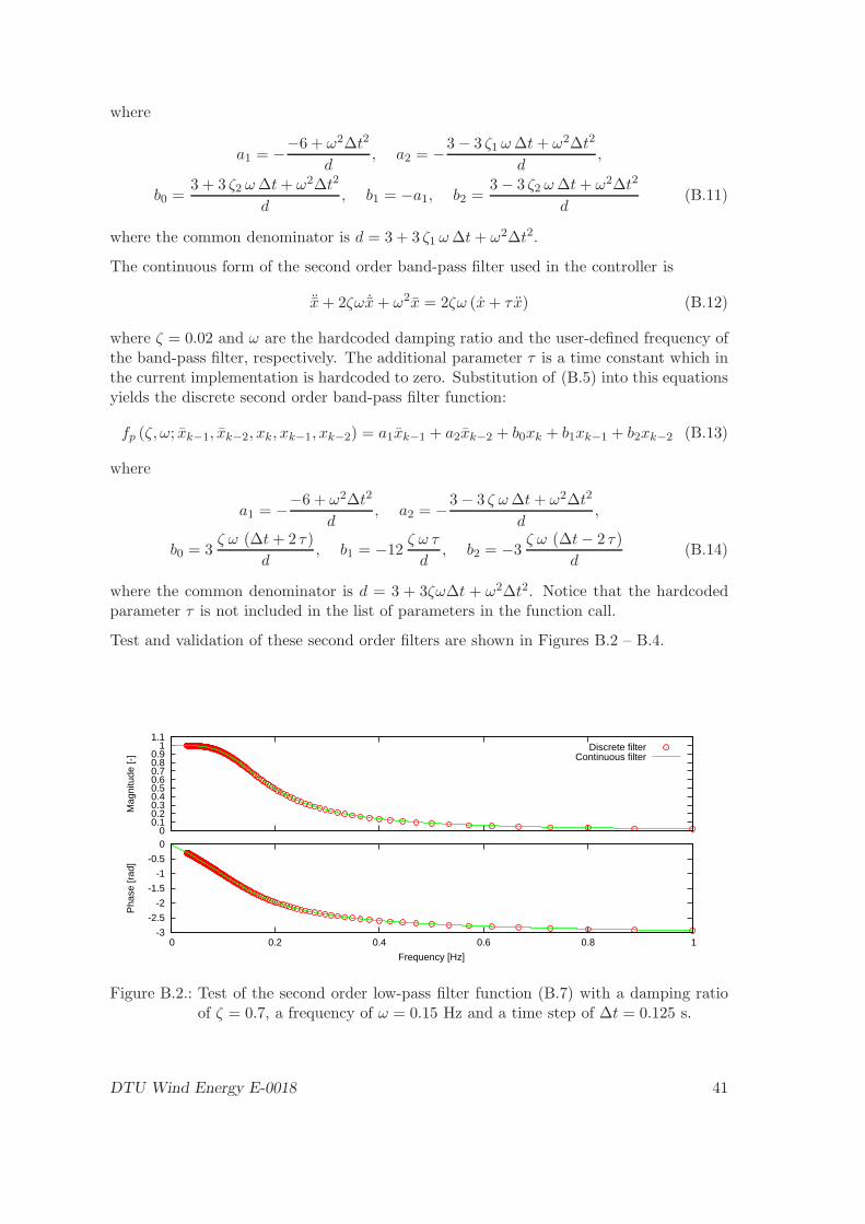
where
a1 = −−6 + ω2∆t2
d, a2 = −
3− 3 ζ1 ω∆t+ ω2∆t2
d,
b0 =3 + 3 ζ2 ω∆t+ ω2∆t2
d, b1 = −a1, b2 =
3− 3 ζ2 ω∆t+ ω2∆t2
d(B.11)
where the common denominator is d = 3 + 3 ζ1 ω∆t+ ω2∆t2.
The continuous form of the second order band-pass filter used in the controller is
¨x+ 2ζω ˙x+ ω2x = 2ζω (x+ τ x) (B.12)
where ζ = 0.02 and ω are the hardcoded damping ratio and the user-defined frequency ofthe band-pass filter, respectively. The additional parameter τ is a time constant which inthe current implementation is hardcoded to zero. Substitution of (B.5) into this equationsyields the discrete second order band-pass filter function:
fp (ζ, ω; xk−1, xk−2, xk, xk−1, xk−2) = a1xk−1 + a2xk−2 + b0xk + b1xk−1 + b2xk−2 (B.13)
where
a1 = −−6 + ω2∆t2
d, a2 = −
3− 3 ζ ω∆t+ ω2∆t2
d,
b0 = 3ζ ω (∆t+ 2 τ)
d, b1 = −12
ζ ω τ
d, b2 = −3
ζ ω (∆t− 2 τ)
d(B.14)
where the common denominator is d = 3 + 3ζω∆t + ω2∆t2. Notice that the hardcodedparameter τ is not included in the list of parameters in the function call.
Test and validation of these second order filters are shown in Figures B.2 – B.4.
0 0.1 0.2 0.3 0.4 0.5 0.6 0.7 0.8 0.9 1 1.1
Mag
nitu
de [-
]
Discrete filterContinuous filter
-3
-2.5
-2
-1.5
-1
-0.5
0
0 0.2 0.4 0.6 0.8 1
Pha
se [r
ad]
Frequency [Hz]
Figure B.2.: Test of the second order low-pass filter function (B.7) with a damping ratioof ζ = 0.7, a frequency of ω = 0.15 Hz and a time step of ∆t = 0.125 s.
DTU Wind Energy E-0018 41

0 0.1 0.2 0.3 0.4 0.5 0.6 0.7 0.8 0.9 1
Mag
nitu
de [-
]
Discrete filterContinuous filter
-1.5
-1
-0.5
0
0.5
1
1.5
0 0.5 1 1.5 2
Pha
se [r
ad]
Frequency [Hz]
Figure B.3.: Test of the second order notch filter function (B.10) with a frequency ofω = 0.625 Hz and a time step of ∆t = 0.04 s.
0 0.1 0.2 0.3 0.4 0.5 0.6 0.7 0.8 0.9 1
Mag
nitu
de [-
]
Discrete filterContinuous filter
-1.5
-1
-0.5
0
0.5
1
1.5
0 0.5 1 1.5 2
Pha
se [r
ad]
Frequency [Hz]
Figure B.4.: Test of the second order band-pass filter function (B.13) with a frequency ofω = 0.625 Hz and a time step of ∆t = 0.04 s.
42 DTU Wind Energy E-0018

DTU Wind Energy is a department of the Technical University of Denmark with a unique integration of research, education, innovation and public/private sector consulting in the field of wind energy. Our activities develop new opportunities and technology for the global and Danish exploitation of wind energy. Research focuses on key technical-scientific fields, which are central for the development, innovation and use of wind energy and provides the basis for advanced education at the education. We have more than 230 staff members of which approximately 60 are PhD students. Research is conducted within 9 research programmes organized into three main topics: Wind energy systems, Wind turbine technology and Basics for wind energy.
Technical University of Denmark DTU Vindenergi Frederiksborgvej 399 Bygning 118 4000 Roskilde Telefon 46 77 50 85 [email protected] www.vindenergi.dtu.dk
Related Documents


![DTU Wind Energy Master of Wind Energy - Hybrid PP Storage€¦ · PP PowerPlant PVPP SolarPhotovoltaicPowerPlant R Correlationcoefficient RES RenewableEnergySource RMSE RootMeanSquareError[MW]](https://static.cupdf.com/doc/110x72/605a7d670672e62a72199343/dtu-wind-energy-master-of-wind-energy-hybrid-pp-storage-pp-powerplant-pvpp-solarphotovoltaicpowerplant.jpg)
