Ethiopian TVET-System INDUSTRIAL ELECTRICAL MACHIN DRIVE TECHNOLOGY Level-II Based on May 2011 Occupational Standards October, 2019

Welcome message from author
This document is posted to help you gain knowledge. Please leave a comment to let me know what you think about it! Share it to your friends and learn new things together.
Transcript
Ethiopian TVET-System
INDUSTRIAL ELECTRICAL MACHIN DRIVE TECHNOLOGY
Level-II
Based on May 2011 Occupational Standards
October, 2019
EEL EMD22
Version:01
Page No.2 Copyright: Ethiopia Federal TVET Agency
Module Title: Installing and terminating wiring system
TTLM Code: EELEMD2TTLM1019
This module includes the following Learning Guides
LG16: Plan and prepare LG Code: EEL EMD2 M05LO1-LG-16
LG17: Perform installation and termination of wiring system LG Code: EEL EMD2 M05LO2-LG-17
LG18: Inspect and notify completion of work LG Code: EEL EMD2 M05LO3-LG-17
LG19: clean- up LG Code:
EEL EMD22
Version:01
Page No.3 Copyright: Ethiopia Federal TVET Agency
This learning guide is developed to provide you the necessary information regarding the following
learning outcome and content coverage
Safety requirements of equipment/tools
Reading and interpreting electrical circuit diagrams
Types and application of termination
Checking Wiring system and components
Procedure of termination
Identifying wiring system components and accessories
Consult work coordination
Tools equipment and Testing Device
This guide will also assist you to attain the learning outcome and contents stated in the cover page.
Specifically, upon completion of this Learning Guide, you will be able to:-
Installation is planned and prepared
Appropriate personnel are consulted
Wiring systems’ components are checked
Fitting Accessories are obtained in accordance with established procedures
Locate in which specific items of accessories, apparatus and circuits are
Installed
Materials necessary to complete the work are obtained
Tools, equipment and testing devices needed to carry out the installation work
are obtained
Learning Instructions:
1. Read the specific objectives of this Learning Guide.
2. Follow the instruction described blew 3 to 6
3. Read the information written in the “Information Sheet 1 up to information 8”.
4. Accomplish the “Self-check 1, self-check 2, Self-check 3, Self-check 4, Self-check 5, Self-check
6, Self-check 7, Self-check 8 ” in page ( 6,13,19,25,30,35,38 and 43 ) respectively.
5. If you earned a satisfactory evaluation from the “Self-check” proceed to “Operation Sheet 1,
Operation 2 in page -45 and 46 respectively.
6. Do the “LAP test” in page – 47 (if you are ready.
Instruction Sheet LG16: Plan and prepare
EEL EMD22
Version:01
Page No.4 Copyright: Ethiopia Federal TVET Agency
Information Sheet-1 Safety requirements of equipment/tool
1. Introduction
Safety is the number one priority in any job. Every year, electrical accidents cause serious injury or
death. Many of these casualties are young people just entering the workplace. They are involved in
accidents that result from carelessness, from the pressures and distractions of a new job, or from a
lack of understanding about electricity. This chapter is designed to develop an awareness of the
dangers associated with electrical power and the potential dangers that can exist on the job or at a
training facility.
1.1 safety equipment
Generally, safety equipment is the protection that is used by workers to avoid injuries, casualties, life
threatening situations etc.. Different types of safety equipment are used by workers depending upon
the nature of risk involved in the work. For example, in a welding operation the dark welding helmets
are used as a piece of safety equipment. In construction operations, hard hats, foot gear and
coveralls are considered safety equipment. All these types of safety equipment fall under the
Personal Protective Equipment (PPE) category.
use equipment safely
All businesses must ensure that their equipment is used and maintained correctly to reduce the risk of
accidents or damage to health and to meet health and safety requirements. Under health and safety
law, employers have a duty to minimize risks to employees.
1.2 General Safety Practices
Only tools and equipment which are in good condition may be used. Tools shall only be used for the
purpose for which they were designed. Employees shall make frequent inspections of tools and
equipment, and immediately remove from service any items found defective.
When using hand tools, the employee shall place himself in such a position that he will avoid injury if
the tool slips.
Only soft faced hammers (brass, plastic, rubber, or similar materials) shall be used on highly
tempered steel tools such as cold chisels, star drills, etc. Proper eye protection must be worn when
performing such an operation.
Files, rasps, and other tools having sharp tangs shall be equipped with approved handles.
Tools which are not in use shall be placed where they will not present a tripping or stumbling hazard.
Pointed tools shall never be carried edge or point up in pockets.
Tools shall not be thrown from one worker to another, or to another working location.
Extensions shall not be used on wrenches to gain leverage unless the wrench is designed to be used
in such a fashion.
EEL EMD22
Version:01
Page No.5 Copyright: Ethiopia Federal TVET Agency
When cutting wire or any other material under tension, the material being cut shall be secured to
prevent the ends from snapping free. Hooks, brushes, vacuums, or special tools shall be used to
remove dust or chips. Compressed air shall not be used.
All machinery must be turned off when unattended. Maintenance, repairs, adjustments, and
measurements must not be made while saws, lathes, grinders, and similar equipment are in
operation.
Compressed air shall never be used to dust off clothing, or be directed toward another person.
Saw blades, gears, sprockets, chains, shafts, pulleys, belts, and similar apparatus shall not be
operated without the proper guarding. Safety glasses, goggles, or face shields shall be worn when
operating power tools.
Electrical termination is the practice of ending a transmission line with a device that matches the
characteristic impedance of the line.
An electrical connector is an electro-mechanical device used to join electrical terminations and create
an electrical circuit. Electrical connectors consist of plugs (male-ended) and jacks (female-ended).
The connection may be temporary, as for portable equipment, require a tool for assembly and
removal, or serve as a permanent electrical joint between two wires or devices
Safety practices to be observed for work on electrical equipment. The following general safety
practices should be observed for work on electrical equipment:
Check before Act
The scope of work and relevant circuit should be checked before starting any electrical work.
Suitable lighting and adequate illumination should be provided for the workplace. The condition of
tools and instruments should also be checked before carrying out electrical work.
Isolate and Lockout
The circuit / equipment under maintenance should be isolated as far as practicable. The relevant
isolator should be locked out. A suitable warning notice should be placed close to the isolator.
De-energize
The circuit/equipment to be worked on should be checked to ensure that it is dead.
Others
The workplace should be kept clean and tidy.
Keep hands away from any circuit or equipment or extraneous conductive parts that
are not being worked on.
Unauthorized people should not stay in the work place.
The requirements stated in any related safety procedures and checklists should be
followed.
EEL EMD22
Version:01
Page No.6 Copyright: Ethiopia Federal TVET Agency
Electrical installations, including but not limited to those newly installed, maintained,
repaired or tripped under fault conditions, should be properly inspected and tested
prior to en enegization.
Hooks, brushes, vacuums, or special tools shall be used to remove dust or chips.
Compressed air shall not be used.
All machinery must be turned off when unattended.
Compressed air shall never be used to dust off clothing, or be directed toward another
person.
Saw blades, gears, sprockets, chains, shafts, pulleys, belts, and similar apparatus shall not be
operated without the proper guarding.
Safety glasses, goggles, or face shields shall be worn when operating power tools.
Electrical termination is the practice of ending a transmission line with a device that matches the
characteristic impedance of the line.
An electrical connector is an electro-mechanical device used to join electrical terminations and create
an electrical circuit. Electrical connectors consist of plugs (male-ended) and jacks (female-ended).
The connection may be temporary, as for portable equipment, require a tool for assembly and
removal, or serve as a permanent electrical joint between two wires or devices
An electrical connector, is an electro-mechanical device used to join electrical terminations and create
an electrical circuit
1.3 POWER TOOLS
There are a few other precautions to follow when working with machinery. Some of the precautions
are as follows:
Never operate a machine with a guard or cover removed.
Never operate mechanical or powered equipment unless you know how to operate them.
When in doubt, consult the appropriate instruction or ask someone who knows.
Always make sure that everyone is clear before starting or operating mechanical equipment.
Cut off the source of power before trying to clear jammed machinery.
Always keep everyone clear when hoisting heavy machinery or equipment by a chain fall.
Guide the hoist with lines attached to the equipment.
Never plug in electric machinery without knowing that the source voltage is the same as that
called for on the nameplate of the machine.
Carefully inspect all portable power tools to be sure they are clean, well-oiled, and in working order
before you use them. The switches should operate normally, and the cords should be clean and free
of defects. Ground the casings of all electrically driven tools. Do not use sparking portable electric
tools in any place where flammable vapors, gases, liquids, or exposed explosives are present.
Check to make sure that power cords do not come in contact with sharp objects. Don’t let cords kink.
Don’t leave them where they might be run over. Don’t let cords contact oil, grease, hot surfaces, or
chemicals. When damaged, replace power cords. When unplugging power tools from receptacles,
you should grasp the plug, not the cord.
EEL EMD22
Version:01
Page No.7 Copyright: Ethiopia Federal TVET Agency
Name: Date:
I. Direction: Answer the following questions.
1. What is safety of equipment?
2. What are the general safety practices should be observed for work on electrical equipment?
3. Why is it important to use equipment safely?
4. Write the precautions to follow when working with machinery?
Note: Satisfactory rating - 4 points Unsatisfactory - below 4 points
Self-Check 1 Written Test
EEL EMD22
Version:01
Page No.8 Copyright: Ethiopia Federal TVET Agency
Information Sheet-2 Reading and interpreting electrical circuit diagrams
2.1 Electrical diagrams
There are a number ways to show electrical circuits. They are wiring, schematic, pictorial and layout
diagrams.
There are several different types of electrical wiring diagrams. They all do essentially the same thing,
which is to show you how circuits are wired. However, the variation in these diagrams shows how
circuits are mapped out in different ways to accomplish different ends. The type of electrical wiring
diagram you use depends on what you want to achieve with it.
An electrical wiring diagram will use different symbols depending on the type, but the components
remain the same. Diagrams will show receptacles, lighting, interconnecting wire routes, and electrical
services within a home. This includes circuit breaker boxes and any alarms that are wired into the
system. Different switches and different types of outlets all have different symbols, and you’ll need to
know these symbols in order to be able to read an electrical wiring diagram. Everything within a home
electrical system will be shown on one of these diagrams. This is to make sure that everything will
operate correctly if the diagram is adhered to and all components are functional.
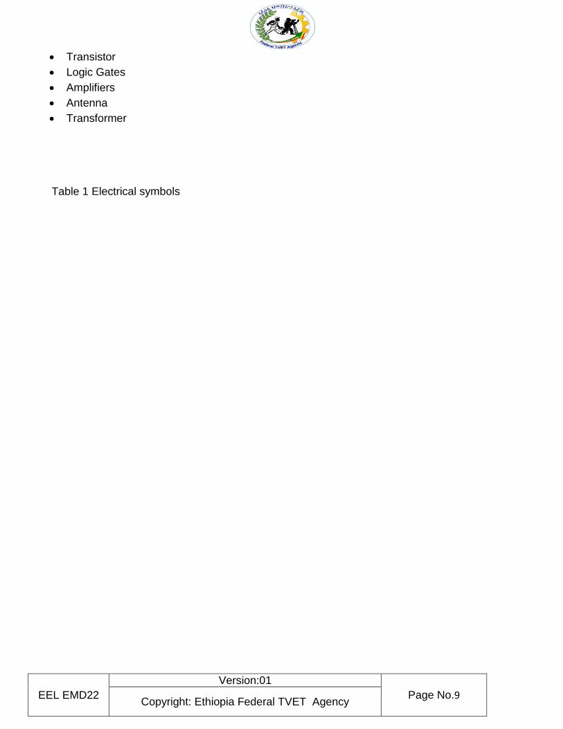
2.1.1 Electrical symbols
Electrical symbols or electronic circuits are virtually represented by circuit diagrams. There are some
standard symbols to represent the components in circuits. This article gives some of the frequently
used symbols for drawing the circuits. There are many electrical and electronic schematic symbols
are used to signify basic electronic or electrical device. These are mostly we used for draw circuit
diagrams.
Below are different kind of symbols we mentioned category wise.
Wires
Switches
Sources
Ground
Resistor
Variable Resistor
Capacitor
Inductors
Diodes
EEL EMD22
Version:01
Page No.9 Copyright: Ethiopia Federal TVET Agency
Transistor
Logic Gates
Amplifiers
Antenna
Transformer
Table 1 Electrical symbols
EEL EMD22
Version:01
Page No.10 Copyright: Ethiopia Federal TVET Agency
EEL EMD22
Version:01
Page No.11 Copyright: Ethiopia Federal TVET Agency
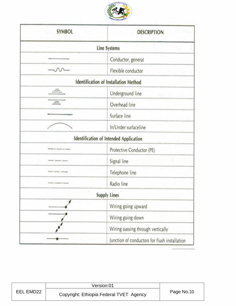
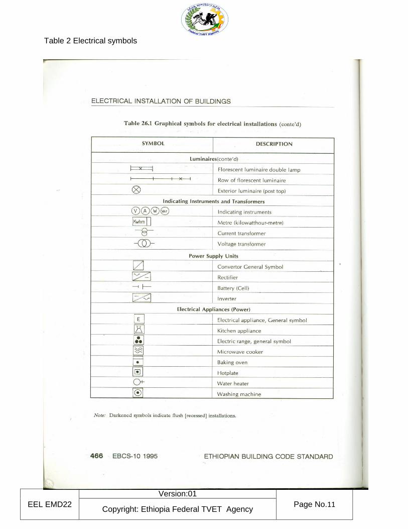
Table 2 Electrical symbols
EEL EMD22
Version:01
Page No.12 Copyright: Ethiopia Federal TVET Agency
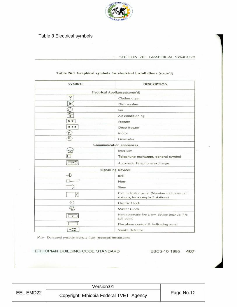
Table 3 Electrical symbols
EEL EMD22
Version:01
Page No.13 Copyright: Ethiopia Federal TVET Agency
2.1.2 Types of electrical circuit
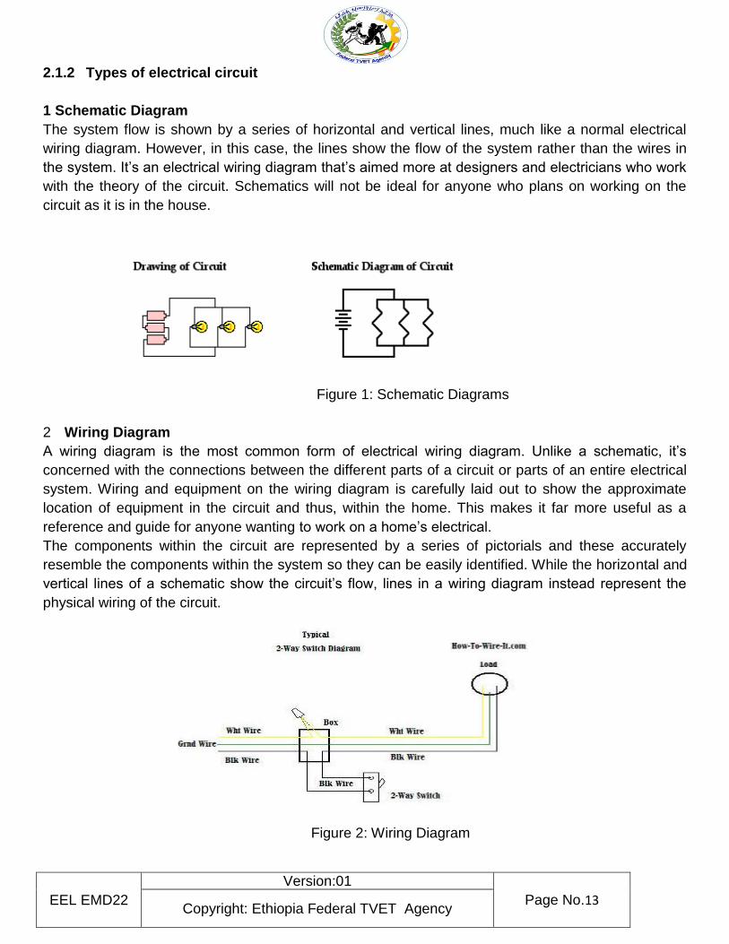
1 Schematic Diagram
The system flow is shown by a series of horizontal and vertical lines, much like a normal electrical
wiring diagram. However, in this case, the lines show the flow of the system rather than the wires in
the system. It’s an electrical wiring diagram that’s aimed more at designers and electricians who work
with the theory of the circuit. Schematics will not be ideal for anyone who plans on working on the
circuit as it is in the house.
Figure 1: Schematic Diagrams
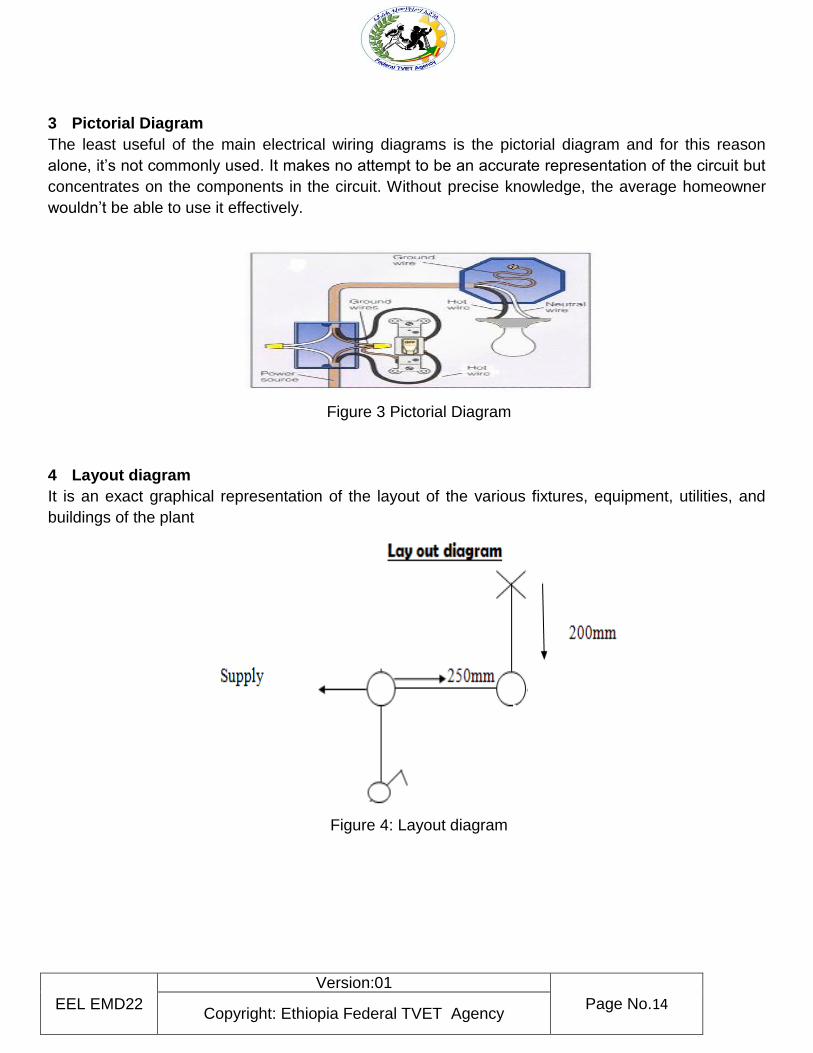
2 Wiring Diagram
A wiring diagram is the most common form of electrical wiring diagram. Unlike a schematic, it’s
concerned with the connections between the different parts of a circuit or parts of an entire electrical
system. Wiring and equipment on the wiring diagram is carefully laid out to show the approximate
location of equipment in the circuit and thus, within the home. This makes it far more useful as a
reference and guide for anyone wanting to work on a home’s electrical.
The components within the circuit are represented by a series of pictorials and these accurately
resemble the components within the system so they can be easily identified. While the horizontal and
vertical lines of a schematic show the circuit’s flow, lines in a wiring diagram instead represent the
physical wiring of the circuit.
Figure 2: Wiring Diagram
EEL EMD22
Version:01
Page No.14 Copyright: Ethiopia Federal TVET Agency
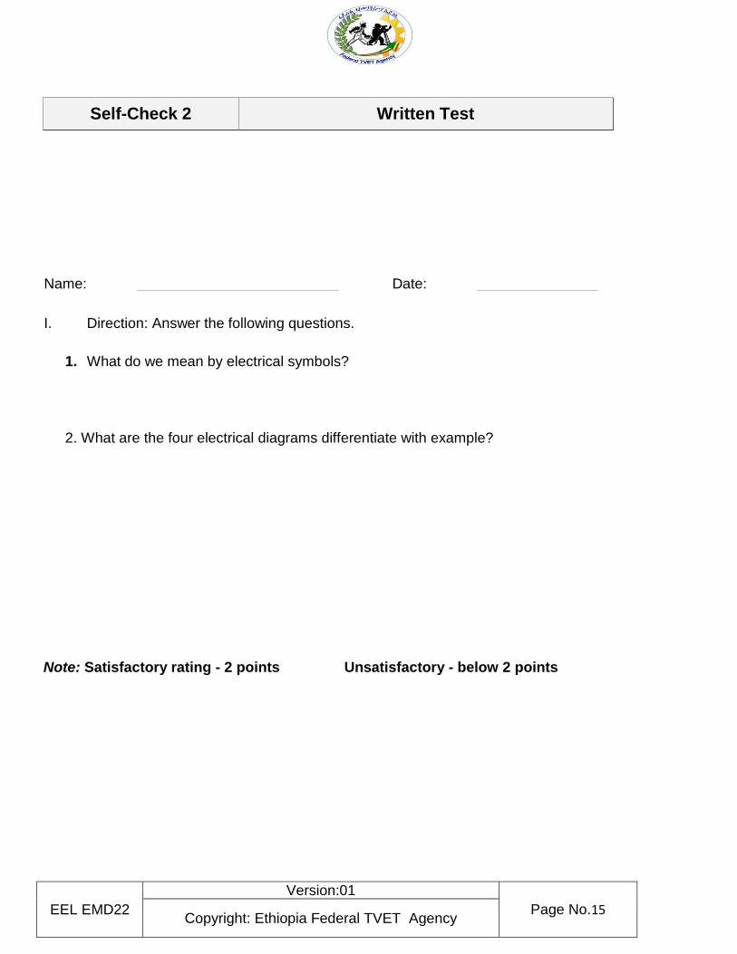
3 Pictorial Diagram
The least useful of the main electrical wiring diagrams is the pictorial diagram and for this reason
alone, it’s not commonly used. It makes no attempt to be an accurate representation of the circuit but
concentrates on the components in the circuit. Without precise knowledge, the average homeowner
wouldn’t be able to use it effectively.
Figure 3 Pictorial Diagram
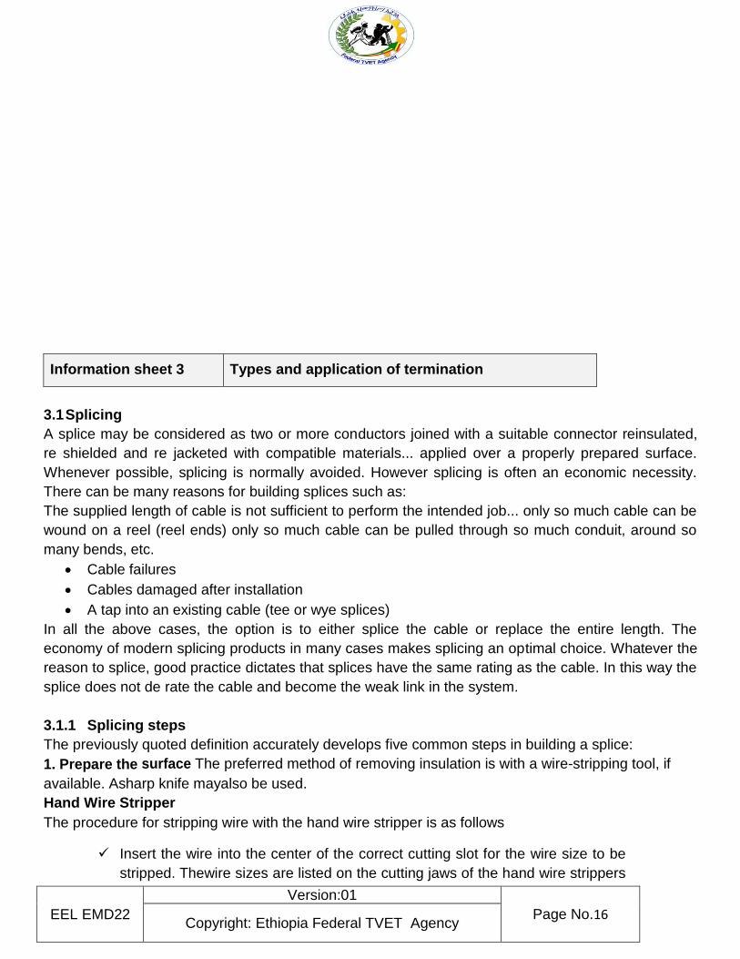
4 Layout diagram
It is an exact graphical representation of the layout of the various fixtures, equipment, utilities, and
buildings of the plant
Figure 4: Layout diagram
EEL EMD22
Version:01
Page No.15 Copyright: Ethiopia Federal TVET Agency
Name: Date:
I. Direction: Answer the following questions.
1. What do we mean by electrical symbols?
2. What are the four electrical diagrams differentiate with example?
Note: Satisfactory rating - 2 points Unsatisfactory - below 2 points
Self-Check 2 Written Test
EEL EMD22
Version:01
Page No.16 Copyright: Ethiopia Federal TVET Agency
Information sheet 3 Types and application of termination
3.1 Splicing
A splice may be considered as two or more conductors joined with a suitable connector reinsulated,
re shielded and re jacketed with compatible materials... applied over a properly prepared surface.
Whenever possible, splicing is normally avoided. However splicing is often an economic necessity.
There can be many reasons for building splices such as:
The supplied length of cable is not sufficient to perform the intended job... only so much cable can be
wound on a reel (reel ends) only so much cable can be pulled through so much conduit, around so
many bends, etc.
Cable failures
Cables damaged after installation
A tap into an existing cable (tee or wye splices)
In all the above cases, the option is to either splice the cable or replace the entire length. The
economy of modern splicing products in many cases makes splicing an optimal choice. Whatever the
reason to splice, good practice dictates that splices have the same rating as the cable. In this way the
splice does not de rate the cable and become the weak link in the system.
3.1.1 Splicing steps
The previously quoted definition accurately develops five common steps in building a splice:
1. Prepare the surface The preferred method of removing insulation is with a wire-stripping tool, if
available. Asharp knife mayalso be used.
Hand Wire Stripper
The procedure for stripping wire with the hand wire stripper is as follows
Insert the wire into the center of the correct cutting slot for the wire size to be
stripped. Thewire sizes are listed on the cutting jaws of the hand wire strippers
EEL EMD22
Version:01
Page No.17 Copyright: Ethiopia Federal TVET Agency
beneath each slot.
After inserting the wire into the proper slot, close the handles together as far
as they will go.
Slowly release the pressure on the handles so as not to allow the cutting
blades to make contact with the stripped conductor. On some of the newer
style hand wire strippers, the cutting jaws have a safety lock that helps prevent
this from happening. Continue to release pressure untilthe gripper jaws
release the stripped wire, then remove.
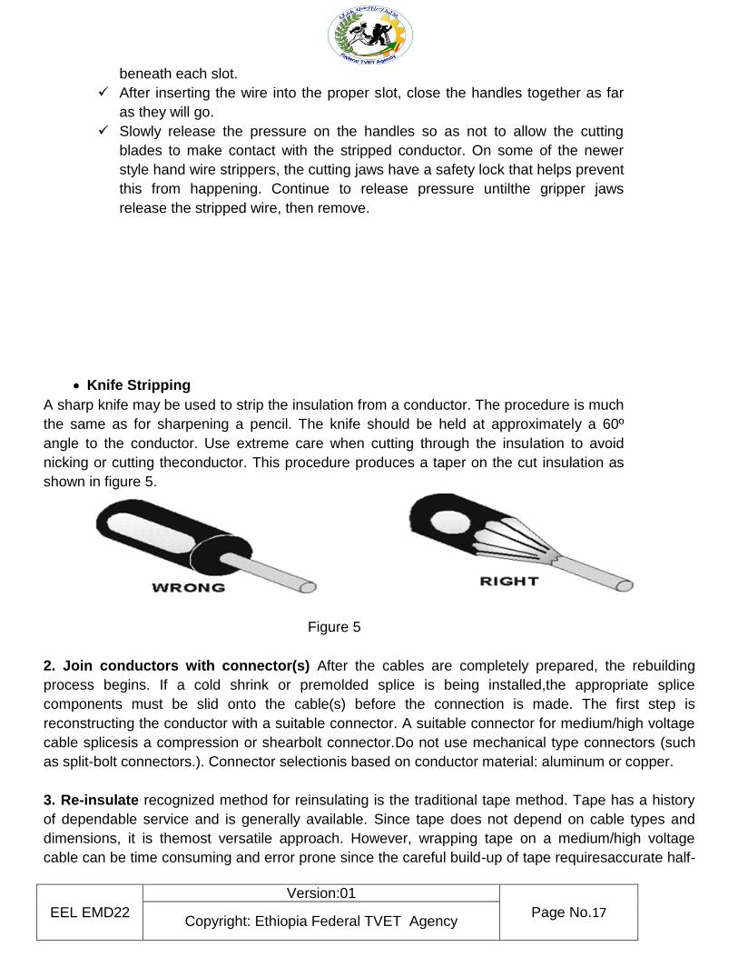
Knife Stripping
A sharp knife may be used to strip the insulation from a conductor. The procedure is much
the same as for sharpening a pencil. The knife should be held at approximately a 60º
angle to the conductor. Use extreme care when cutting through the insulation to avoid
nicking or cutting theconductor. This procedure produces a taper on the cut insulation as
shown in figure 5.
Figure 5
2. Join conductors with connector(s) After the cables are completely prepared, the rebuilding
process begins. If a cold shrink or premolded splice is being installed,the appropriate splice
components must be slid onto the cable(s) before the connection is made. The first step is
reconstructing the conductor with a suitable connector. A suitable connector for medium/high voltage
cable splicesis a compression or shearbolt connector.Do not use mechanical type connectors (such
as split-bolt connectors.). Connector selectionis based on conductor material: aluminum or copper.
3. Re-insulate recognized method for reinsulating is the traditional tape method. Tape has a history
of dependable service and is generally available. Since tape does not depend on cable types and
dimensions, it is themost versatile approach. However, wrapping tape on a medium/high voltage
cable can be time consuming and error prone since the careful build-up of tape requiresaccurate half-
EEL EMD22
Version:01
Page No.18 Copyright: Ethiopia Federal TVET Agency
lapping and constant tension in order to reduce built-in air voids. Linerless splicing tapes reduce both
application time and error.Studies have shown time savings of 30-to-50 percent since there is no
need to stop during taping to tear off liner. This also allows the installer to maintain a constant tape
tension, reducing the possibility of taped-in voids. Tape splice kits can be useful since they contain all
the necessary tapes along with proper instructions. They ensure the propermaterials are available on
the job,which is ideal in an emergency.Another method for reinsulating utilizes molded rubber
technology. These factory-made splices are engineered for the convenience of the installer. In many
cases, these splices are also factory tested and designed to be installed without theuse of special
installation tools.
4. Re-shield The cable’s two shielding systems (strand shield and insulation shield) must be rebuilt
when constructingasplice.The sametwo methods are used as outlined in there insulation process:
tape and molded rubber.Foratapesplice, the cable strand shield in gisre placed by asemi-conductive
tape. This tape is wrapped over the connector area to smooth the crimp indents and connector
edges.The insulation shielding system is replaced by acombination of tapes. Semi-con is replaced
with the same semi-conducting tape used to replace thes trand shield. The cable’s metallic shield is
generally replaced with a flexible wav enmesh of tin-plated copper braid. This braid is for
electrostatic shielding only and is not designed to carry shield currents. For conducting shield
currents, a jumper braid is installed to connect the cables’ metallic shields. This jumper must have
an ampacit rating equal to tha to fthe cables’shields.
5.Re-jackete is accomplished in a tape splice by using a combination of the rubber splicing tape
overwrapped with a vinyl tape In molded rubber splice, re-jacketing is accomplished by proper
design of theoutersemi-conductiverubber,effectively resulting in a semi- conductive jacket.
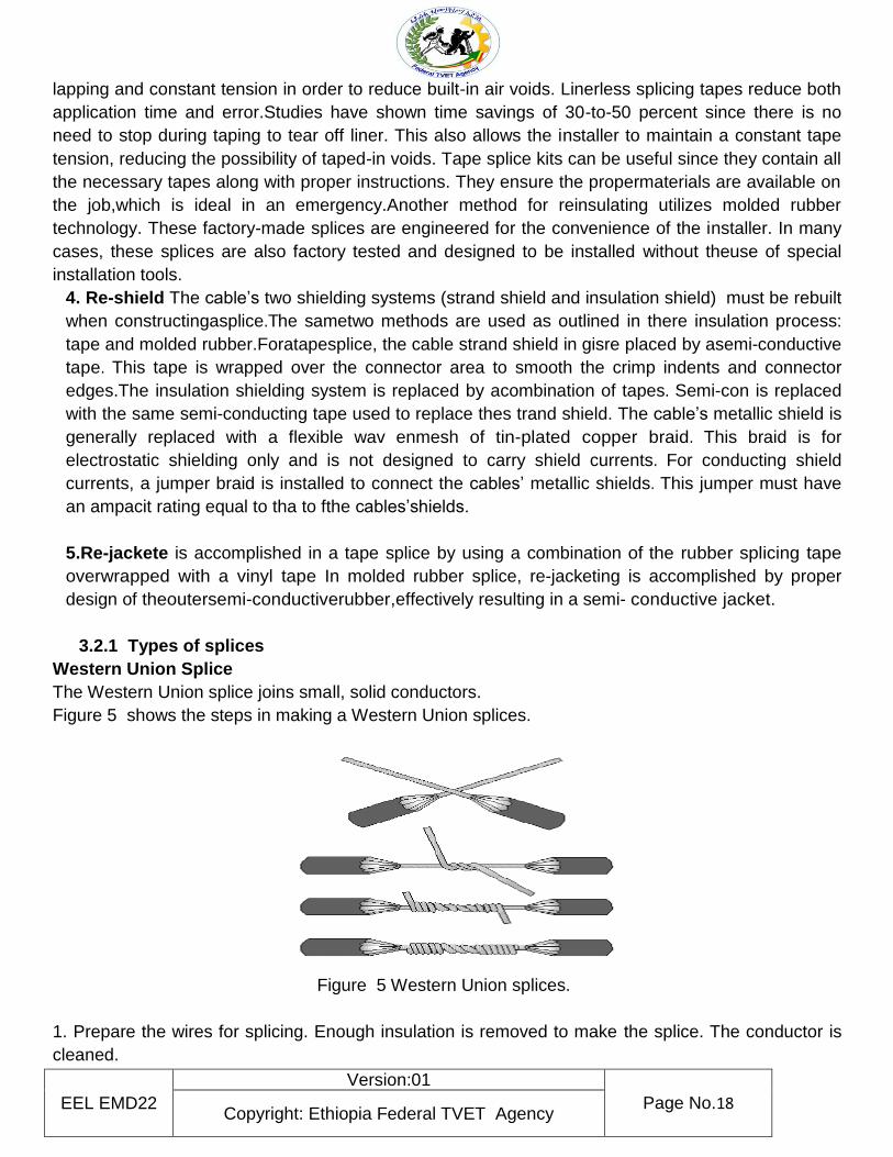
3.2.1 Types of splices
Western Union Splice
The Western Union splice joins small, solid conductors.
Figure 5 shows the steps in making a Western Union splices.
Figure 5 Western Union splices.
1. Prepare the wires for splicing. Enough insulation is removed to make the splice. The conductor is
cleaned.
EEL EMD22
Version:01
Page No.19 Copyright: Ethiopia Federal TVET Agency
2. Bring the wires to a crossed position and make a long twist or bend in each wire.
3. Wrap one end of the wire and then the other end four or five times around the straight portion of
each wire.
4. Press the ends of the wires down as close as possible to the straight portion of the wire. This
prevents the sharp ends from puncturing the tape covering that is wrapped over the splice. The
various types of tape and their uses are discussed later in this chapter.
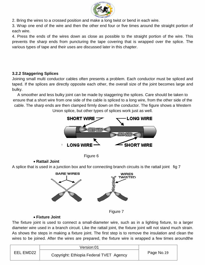
3.2.2 Staggering Splices
Joining small multi conductor cables often presents a problem. Each conductor must be spliced and
taped. If the splices are directly opposite each other, the overall size of the joint becomes large and
bulky.
A smoother and less bulky joint can be made by staggering the splices. Care should be taken to
ensure that a short wire from one side of the cable is spliced to a long wire, from the other side of the
cable. The sharp ends are then clamped firmly down on the conductor. The figure shows a Western
Union splice, but other types of splices work just as well.
Figure 6
Rattail Joint
A splice that is used in a junction box and for connecting branch circuits is the rattail joint fig 7
Figure 7
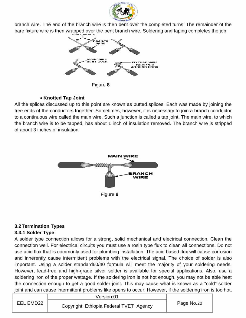
Fixture Joint
The fixture joint is used to connect a small-diameter wire, such as in a lighting fixture, to a larger
diameter wire used in a branch circuit. Like the rattail joint, the fixture joint will not stand much strain.
As shows the steps in making a fixture joint. The first step is to remove the insulation and clean the
wires to be joined. After the wires are prepared, the fixture wire is wrapped a few times aroundthe
EEL EMD22
Version:01
Page No.20 Copyright: Ethiopia Federal TVET Agency
branch wire. The end of the branch wire is then bent over the completed turns. The remainder of the
bare fixture wire is then wrapped over the bent branch wire. Soldering and taping completes the job.
Figure 8
Knotted Tap Joint
All the splices discussed up to this point are known as butted splices. Each was made by joining the
free ends of the conductors together. Sometimes, however, it is necessary to join a branch conductor
to a continuous wire called the main wire. Such a junction is called a tap joint. The main wire, to which
the branch wire is to be tapped, has about 1 inch of insulation removed. The branch wire is stripped
of about 3 inches of insulation.
Figure 9
3.2 Termination Types
3.3.1 Solder Type
A solder type connection allows for a strong, solid mechanical and electrical connection. Clean the
connection well. For electrical circuits you must use a rosin type flux to clean all connections. Do not
use acid flux that is commonly used for plumbing installation. The acid based flux will cause corrosion
and inherently cause intermittent problems with the electrical signal. The choice of solder is also
important. Using a solder standard60/40 formula will meet the majority of your soldering needs.
However, lead-free and high-grade silver solder is available for special applications. Also, use a
soldering iron of the proper wattage. If the soldering iron is not hot enough, you may not be able heat
the connection enough to get a good solder joint. This may cause what is known as a "cold" solder
joint and can cause intermittent problems like opens to occur. However, if the soldering iron is too hot,
EEL EMD22
Version:01
Page No.21 Copyright: Ethiopia Federal TVET Agency
you can cause damage to the components of the system near the connection. This can also cause
the insulation to possibly melt causing the bare primaries to make contact with each other resulting in
a short.
3.3.2 Crimp Type
A crimp type connection allows for quick and simple installation while still maintaining a mechanical
and electrical connection fairly close to a solder type termination. Solid or stranded wire can be used
in this type of termination.
Some of the key points to remember for a good clean connection are as follows:
1. Make sure you use the proper size connector for the type of cable you are using.
2. Make sure all of your cuts and stripping are clean.
3. Avoid nicks as much as possible.
4. Use the proper crimp tool; don’t try to improvise with pliers, etc.
The most common crimp method involves two crimps, one on the insulation for a stronger
mechanical connection and one on the conductor or shield for a good electrical connection. A crimp
tool is designed specifically for this type of termination for the type of connector you are using. This
allows for good connections both mechanical and electrical.
EEL EMD22
Version:01
Page No.22 Copyright: Ethiopia Federal TVET Agency
Name: Date:
I. Direction: Answer the following questions.
1. What is splicing
……………………………………………………………………………………………
…………………………………………………………………………………………….
2. Write the steps of splicing
……………………………………………………………………………………………..
……………………………………………………………………………………………..
………………………………………………………………………………………………
………………………………………………………………………………………………..
3. Types of splices are ………………………………and ………………………………..
4. Types of Termination are……………., and ,, ………………………………..
Note: Satisfactory rating - 4 points Unsatisfactory - below 4 points
Self-Check 3 Written Test Self-Check 3 Written Test
EEL EMD22
Version:01
Page No.23 Copyright: Ethiopia Federal TVET Agency
Information sheet 4 Procedure of Termination
4. Introductions
Cable Termination is the connection of the wire or fiber to a device, such as equipment, panels or a
wall outlet, which allows for connecting the cable to other cables or devices. The three main areas we
will discuss are termination used in Telecom,
A wire termination is the work performed to the end of a wire that allows it to connect to a
device (connector, switch, terminal, etc.). There are many types of terminations in the aircraft
industry, but we can boil them down into two basic categories: crimp and solder.
A crimp termination is performed when the device requires a contact or terminal. The wire insulation
is stripped, and the contact or terminal is attached to the wire using a crimp tool. The tool crimps
the contact or terminal onto the wire conductor. This type of termination is most often used on the
aircraft wiring harnesses and circuit breaker panels
A solder termination is performed when the wire conductors attach directly to the device. This
requires stripping off the wire insulation and applying flux and solder to connect the wire to the device.
(Requirements for Soldered Electrical and Electronic Assemblies) gives the specific details on how to
properly solder.
4.1 Procedure of termination
Soldering method and technique
The following information will aid you in learning basic soldering skills. It should enable you to solder
wires to electrical connectors, splices, and terminal lugs that we have discussed earlier in the chapter.
Special skills and schooling are required for the soldering techniques used in printed circuit boards
and micro-miniature component repair.
Soldering process
Cleanliness is essential for efficient, effective soldering. Solder will not adhere to dirty, greasy, or
oxidized surfaces. Heated metals tend to oxidize rapidly. This is the reason the oxides, scale, and dirt
must be removed by chemical or mechanical means. Grease or oil films can be removed with a
suitable solvent. Connections to be soldered should be cleaned just prior to the actual soldering
operation. Items to be soldered should normally be "tinned" before making a mechanical connection.
Tinning is the coating of the material to be soldered with a light coat of solder. When the surface has
been properly cleaned, a thin, even coating of flux should be placed over the surface to be tinned.
This will prevent oxidation while the part is being heated to soldering temperature. Rosin-core solder
EEL EMD22
Version:01
Page No.24 Copyright: Ethiopia Federal TVET Agency
is usually preferred in electrical work. However, a separate rosin flux may be used instead. Separate
rosin flux is frequently used when wires in cable fabrication are tinned.
Soldering the joint
Clean the iron tip on the damp sponge.
Melt a little solder on the tip of the iron. This helps to transfer the heat to the joint.
Touch both parts to be soldered
Wire and pin.
Feed the solder in from the opposite side. It will melt and quickly flow around the joint.
Remove the solder before the iron.
It should take about three seconds to heat, melt
Insulating
An insulator on the other hand is a material which does not allow an electric current to flow. Rubber
and most plastics are insulators.
Insulation materials
Wires and cables (conductors) are insulated and protected by a variety of materials (insulators) each
one having its own particular properties. The type of material used will be determined by the designer
who will take into account the environment in which a control panel or installation is expected to
operate as well as the application of individual wires within the panel. As part of the insulating
function, a material may have to withstand without failing:
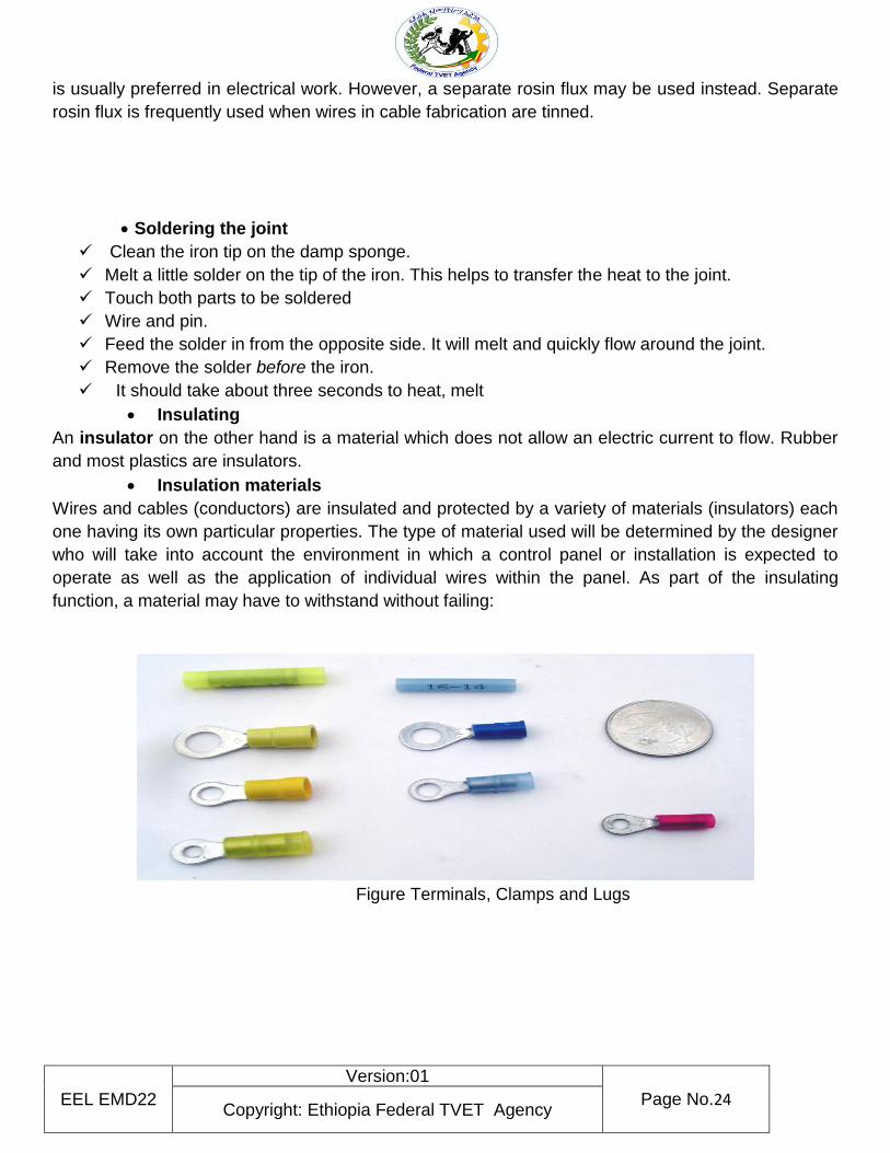
Figure Terminals, Clamps and Lugs
EEL EMD22
Version:01
Page No.25 Copyright: Ethiopia Federal TVET Agency
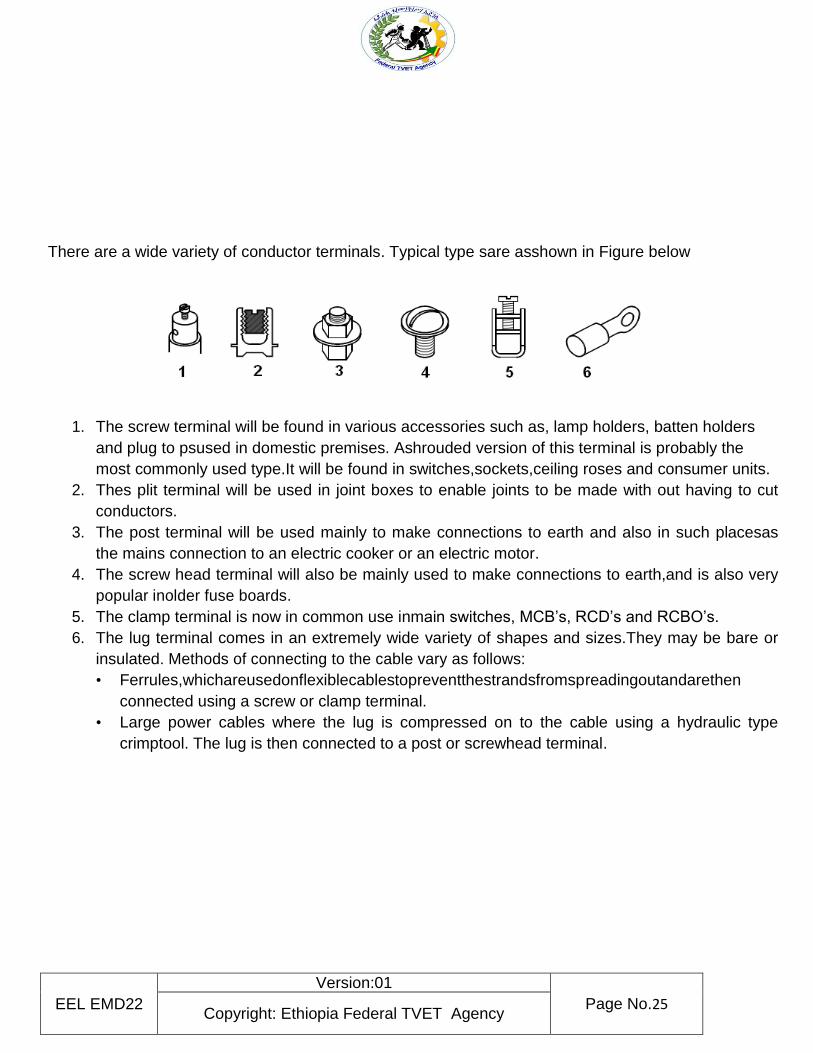
There are a wide variety of conductor terminals. Typical type sare asshown in Figure below
1. The screw terminal will be found in various accessories such as, lamp holders, batten holders
and plug to psused in domestic premises. Ashrouded version of this terminal is probably the
most commonly used type.It will be found in switches,sockets,ceiling roses and consumer units.
2. Thes plit terminal will be used in joint boxes to enable joints to be made with out having to cut
conductors.
3. The post terminal will be used mainly to make connections to earth and also in such placesas
the mains connection to an electric cooker or an electric motor.
4. The screw head terminal will also be mainly used to make connections to earth,and is also very
popular inolder fuse boards.
5. The clamp terminal is now in common use inmain switches, MCB’s, RCD’s and RCBO’s.
6. The lug terminal comes in an extremely wide variety of shapes and sizes.They may be bare or
insulated. Methods of connecting to the cable vary as follows:
• Ferrules,whichareusedonflexiblecablestopreventthestrandsfromspreadingoutandarethen
connected using a screw or clamp terminal.
• Large power cables where the lug is compressed on to the cable using a hydraulic type
crimptool. The lug is then connected to a post or screwhead terminal.
EEL EMD22
Version:01
Page No.26 Copyright: Ethiopia Federal TVET Agency
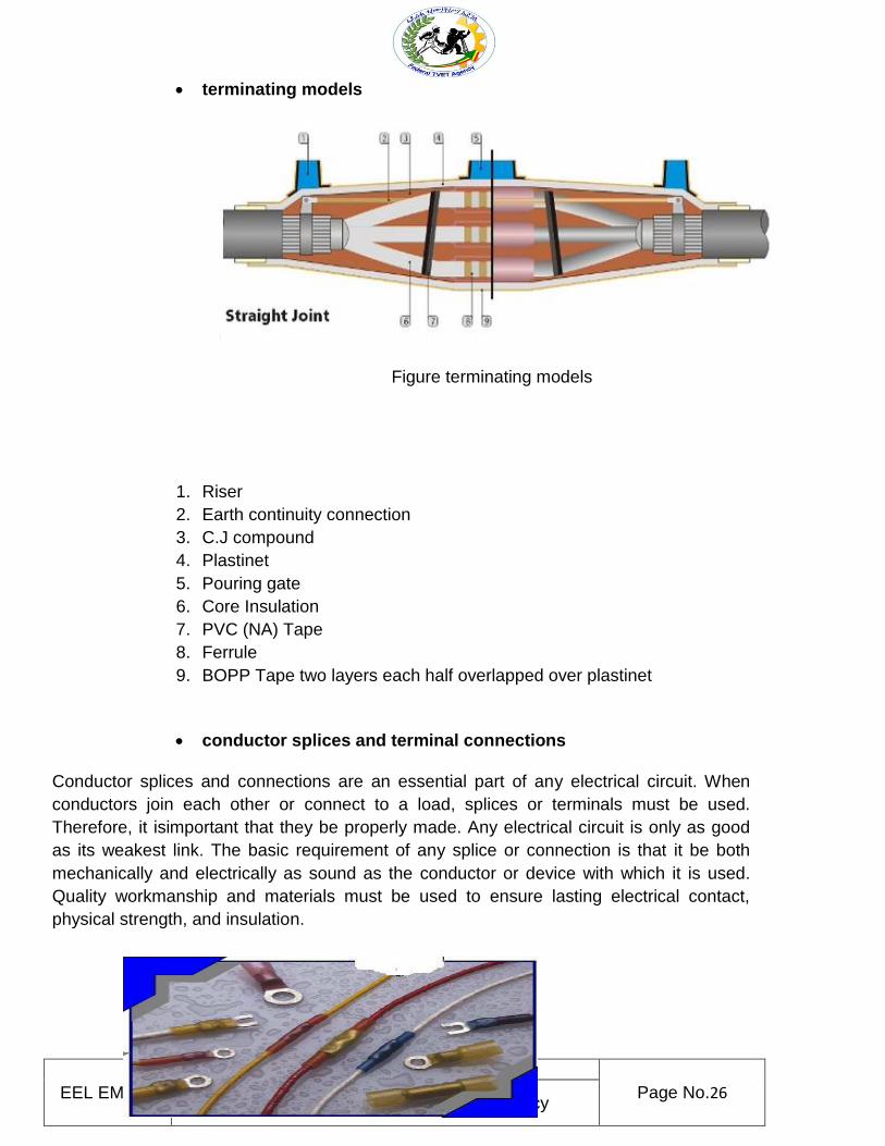
terminating models
Figure terminating models
1. Riser
2. Earth continuity connection
3. C.J compound
4. Plastinet
5. Pouring gate
6. Core Insulation
7. PVC (NA) Tape
8. Ferrule
9. BOPP Tape two layers each half overlapped over plastinet
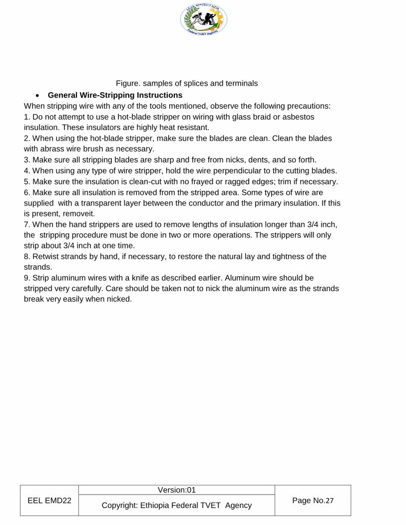
conductor splices and terminal connections
Conductor splices and connections are an essential part of any electrical circuit. When
conductors join each other or connect to a load, splices or terminals must be used.
Therefore, it isimportant that they be properly made. Any electrical circuit is only as good
as its weakest link. The basic requirement of any splice or connection is that it be both
mechanically and electrically as sound as the conductor or device with which it is used.
Quality workmanship and materials must be used to ensure lasting electrical contact,
physical strength, and insulation.
EEL EMD22
Version:01
Page No.27 Copyright: Ethiopia Federal TVET Agency
Figure. samples of splices and terminals
General Wire-Stripping Instructions
When stripping wire with any of the tools mentioned, observe the following precautions:
1. Do not attempt to use a hot-blade stripper on wiring with glass braid or asbestos
insulation. These insulators are highly heat resistant.
2. When using the hot-blade stripper, make sure the blades are clean. Clean the blades
with abrass wire brush as necessary.
3. Make sure all stripping blades are sharp and free from nicks, dents, and so forth.
4. When using any type of wire stripper, hold the wire perpendicular to the cutting blades.
5. Make sure the insulation is clean-cut with no frayed or ragged edges; trim if necessary.
6. Make sure all insulation is removed from the stripped area. Some types of wire are
supplied with a transparent layer between the conductor and the primary insulation. If this
is present, removeit.
7. When the hand strippers are used to remove lengths of insulation longer than 3/4 inch,
the stripping procedure must be done in two or more operations. The strippers will only
strip about 3/4 inch at one time.
8. Retwist strands by hand, if necessary, to restore the natural lay and tightness of the
strands.
9. Strip aluminum wires with a knife as described earlier. Aluminum wire should be
stripped very carefully. Care should be taken not to nick the aluminum wire as the strands
break very easily when nicked.
EEL EMD22
Version:01
Page No.28 Copyright: Ethiopia Federal TVET Agency
Name: Date:
Direction: Write/List down the following
1. Different types of termination
a) ________________
b) ________________
c) ________________
d) ________________
2 General Wire-Stripping Instructions are
________________
________________
Self-Check 4 Written Test
EEL EMD22
Version:01
Page No.29 Copyright: Ethiopia Federal TVET Agency
________________
________________
________________
Note: Satisfactory rating - 8 points Unsatisfactory - below 8 points
5. Introduction
Electrical wiring is the electrical power distribution through the wires in a perfect manner for economic
use of wiring conductors inside a room or building with better load control. Electrical wiring system is
classified into five categories: Cleat wiring. Casing wiring
Perform an Electrical Safety Components Check Home electrical fires are more common than you would think. The problems that cause electrical fires can often be detected during a home electrical inspection. Electrical Safety Foundation International recommends you conduct an electrical system inspection any time here’s what we recommend you look for. Outlets and switches It’s best to check all your outlets and switches prior to moving in any furniture, which may block problem spots. Check first to make sure all outlets are three-pronged and that all outlets and switches have plate covers. If you have babies or toddlers, count the number of outlets as well — you’ll need to buy outlet plugs for all of them. Note any looseness or signs of damage. Loose outlets or switches and cracked plates pose electrocution and fires risks. Discoloration around an outlet or switch or warmth to the touch suggests
Information sheet 5 Checking Wiring system and components
EEL EMD22
Version:01
Page No.30 Copyright: Ethiopia Federal TVET Agency
a dangerous buildup of heat, and that switch or outlet shouldn’t be used until an electrician checks it out. If you hear strange sounds such as buzzing or crackling coming from an outlet or switch, it could indicate an issue with the wiring and should be investigated by an electrician. Light fixtures Check all the light fixtures. Make sure any ceiling- or wall-mounted fixtures are secure. Also, check the wattage and bulbs in every light fixture. If the previous installed a bulb with a greater wattage than the fixture was designed to handle, it could overheat and ignite nearby combustible material such as a cloth or paper lamp shade. Electrical panel The fuses or circuit breakers in electrical panel protect you against fires by preventing electrical system from being overloaded. Make sure each fuse or circuit breaker is the right size for its circuit. The wrong size could result in overheated wiring creating a fire hazard. Check also to see if there are Arc Fault Circuit Interrupters (AFCIs) installed in your panel. These are special circuit breakers that monitor for dangerous electrical arcs that can cause fires and trip the circuit when one is detected.
5.1 Wire /Conductor/
Conductor is the current carrying components are made of copper or aluminum. (Aluminum is less
expensive but less efficient, requiring a larger conductor diameter to carry an equal electrical load
when compared to a copper conductor.)
A conductor should have a current carrying capacity not less than the maximum current
demand it normally carries, be capable of withstanding the prospective fault current, and suitable
for operation in the environment and at the design voltage of the installation.
Factors to be considered in sizing of cable conductors In general, sizing of cable conductors
should take into account the following factors:
the conductor material;
the insulating material;
the ambient temperature in which the cable is installed;
the method of installation;
whether or not the cable is affected by thermal insulating material;
the use and type of protective device;
the voltage drop from the origin of the circuit to the load;
Method of sizing cable conductors In determining the size of cable conductors to be used, the
steps employed, in general, are as follows:
Determine the design current of the circuit under consideration.
Choose a suitable over current protective device
EEL EMD22
Version:01
Page No.31 Copyright: Ethiopia Federal TVET Agency
Choose suitable size of the conductors according to the current carrying capacity
required.
the ambient temperature does not exceed 35°C;
the protective device is not a semi-enclosed fuse; and
the cables are not in contact with any thermal insulation.
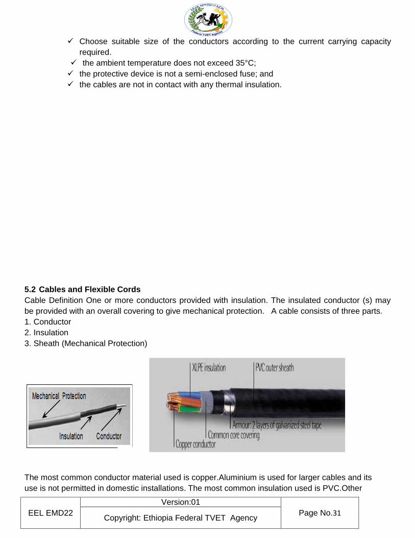
5.2 Cables and Flexible Cords
Cable Definition One or more conductors provided with insulation. The insulated conductor (s) may
be provided with an overall covering to give mechanical protection. A cable consists of three parts.
1. Conductor
2. Insulation
3. Sheath (Mechanical Protection)
The most common conductor material used is copper.Aluminium is used for larger cables and its
use is not permitted in domestic installations. The most common insulation used is PVC.Other
EEL EMD22
Version:01
Page No.32 Copyright: Ethiopia Federal TVET Agency
materials are used as insulation depending on what the cable is being used for and where it is being
installed.
The most common mechanical protection used is PVC .Further protection is provided by installing
cables in locations where they are unlikely to be damaged. Where this is not possible, cables must
be installed inconduit, trunking or ducting. Otherwise a suitably armoured cable must be used.
When cables are installed in conduit o rtrunking they need not have any other for mechanical
protection.
The following is a list of the standard sizes used in domestic installations.
Cross sectional area is the surface area of a section of conductor.
1.5 mm2–2.5 mm2–4 mm2–6 mm2–10 mm2–16 mm2
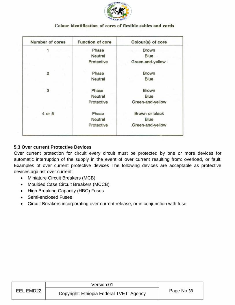
The cable insulation is colour coded asfollows:
Phase ( Live )–Brown
Neutral–Blue
Earth–Green/Yellow
Table: color identification
EEL EMD22
Version:01
Page No.33 Copyright: Ethiopia Federal TVET Agency
5.3 Over current Protective Devices
Over current protection for circuit every circuit must be protected by one or more devices for
automatic interruption of the supply in the event of over current resulting from: overload, or fault.
Examples of over current protective devices The following devices are acceptable as protective
devices against over current:
Miniature Circuit Breakers (MCB)
Moulded Case Circuit Breakers (MCCB)
High Breaking Capacity (HBC) Fuses
Semi-enclosed Fuses
Circuit Breakers incorporating over current release, or in conjunction with fuse.
EEL EMD22
Version:01
Page No.34 Copyright: Ethiopia Federal TVET Agency
N
ame: Date:
Direction: Write/List down the following
1 We conduct an electrical system inspection any time on
________________
_______________
________________
________________
2 A cable consists of three parts.
_______________
________________
________________
3. the most common mechanical protection used is……………………
4 what devices are acceptable as protective devices against over current:
________________
_______________
________________
________________
Note: Satisfactory rating - 10 points Unsatisfactory - below 10 points
Self-Check 5 Written Test
EEL EMD22
Version:01
Page No.35 Copyright: Ethiopia Federal TVET Agency
Information sheet 6
Identifying wiring system components and accessories
6 Introductions
Electricity requires an electric path to flow and there are many conducting materials used for
this purpose. There are many semi conducting materials which are used to reduce the voltage
and also drop the current flow. There are non-conducting materials which are used as insulation
during working on live-lines. In this unit we will study how the household or industrial wiring is done
and what materials are essential for household or industrial wiring. We will also study the different
types of wiring and how they is done.
6.1 Wiring materials
Electrical wire is made of materials like copper, aluminum and silver. As silver is
expensive, mostly copper and aluminum are used in wiring. Materials are classified into three types
according to their properties:
1. Conducting materials
2. Insulating materials
3. Semiconductor material
Conducting Material
Copper
It is a good conductor of electricity. It is used in wiring materials in cables. Its has low resistance
and is used for conduction of electricity at high,medium and low voltage. It is used in wiring and
cable making.
Aluminium
It is light weight and cheaper in comparison to copper. Therefore,this type of conducting materialis
mostly used in electrical wiring. It is silvery–white in colour and it has as oft texture.It is often used
in wiring and making cable.
Insulating Materials
Insulating materials are used for insulating purpose.These types of materials are bad conductors of
current. For example rubber,paper,mica,wood,glass and cotton nature and number of conductors:
EEL EMD22
Version:01
Page No.36 Copyright: Ethiopia Federal TVET Agency
6.2 Wiring Accessories
Wiringaccessoriesareusedforconnectingappliances
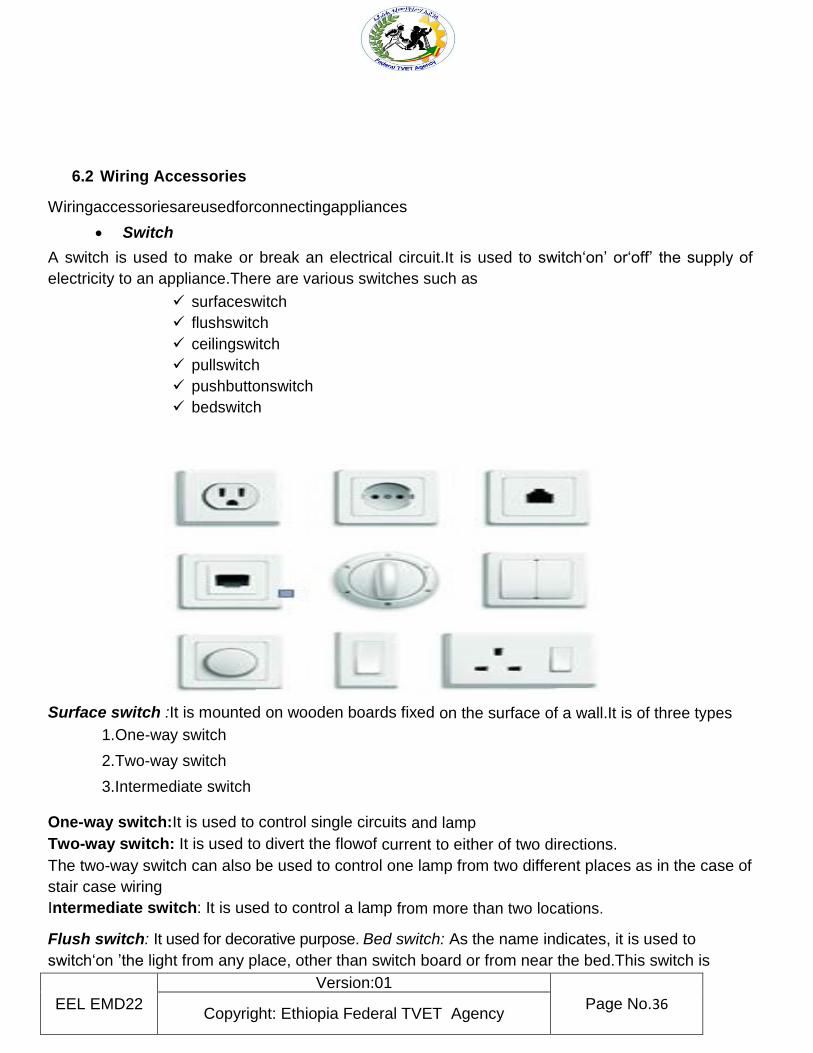
Switch
A switch is used to make or break an electrical circuit.It is used to switch‘on’ or‘off’ the supply of
electricity to an appliance.There are various switches such as
surfaceswitch
flushswitch
ceilingswitch
pullswitch
pushbuttonswitch
bedswitch
Surface switch :It is mounted on wooden boards fixed on the surface of a wall.It is of three types
1.One-way switch
2.Two-way switch
3.Intermediate switch
One-way switch:It is used to control single circuits and lamp
Two-way switch: It is used to divert the flowof current to either of two directions.
The two-way switch can also be used to control one lamp from two different places as in the case of
stair case wiring
Intermediate switch: It is used to control a lamp from more than two locations.
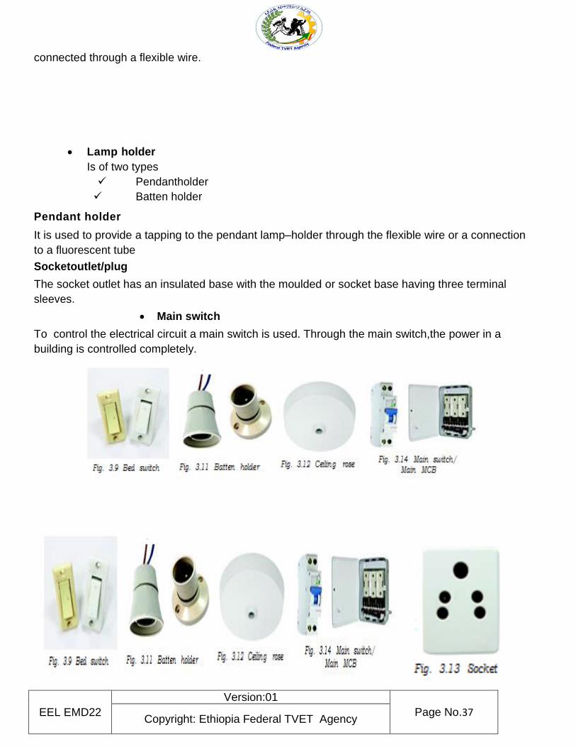
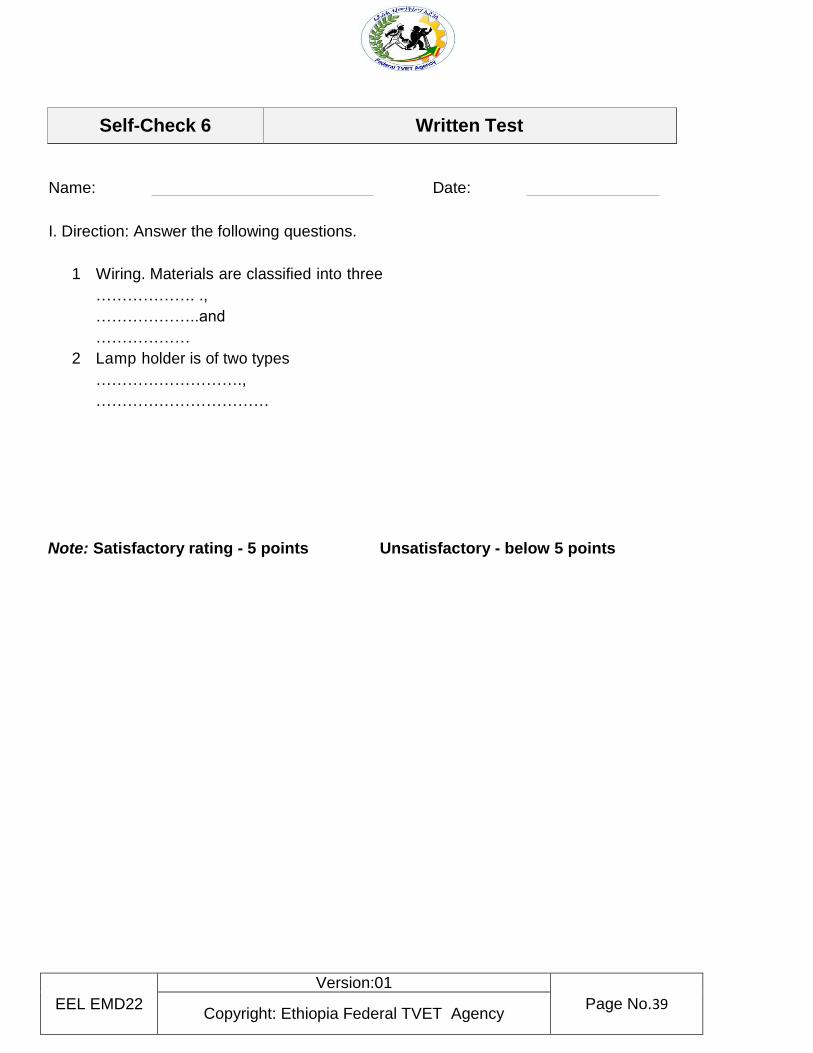
Flush switch: It used for decorative purpose. Bed switch: As the name indicates, it is used to
switch‘on ’the light from any place, other than switch board or from near the bed.This switch is
EEL EMD22
Version:01
Page No.37 Copyright: Ethiopia Federal TVET Agency
connected through a flexible wire.
Lamp holder
Is of two types
Pendantholder
Batten holder
Pendant holder
It is used to provide a tapping to the pendant lamp–holder through the flexible wire or a connection
to a fluorescent tube
Socketoutlet/plug
The socket outlet has an insulated base with the moulded or socket base having three terminal
sleeves.
Main switch
To control the electrical circuit a main switch is used. Through the main switch,the power in a
building is controlled completely.

EEL EMD22
Version:01
Page No.38 Copyright: Ethiopia Federal TVET Agency
EEL EMD22
Version:01
Page No.39 Copyright: Ethiopia Federal TVET Agency
Name: Date:
I. Direction: Answer the following questions.
1 Wiring. Materials are classified into three
………………. .,
………………..and
………………
2 Lamp holder is of two types
……………………….,
……………………………
Note: Satisfactory rating - 5 points Unsatisfactory - below 5 points
Self-Check 6 Written Test
EEL EMD22
Version:01
Page No.40 Copyright: Ethiopia Federal TVET Agency
Information sheet 7 Consulting work coordination
7 work coordination process
Team coordination is a process that involves the use of strategies and patterns of behavior aimed to
integrate actions, knowledge and. goals of interdependent members, in order to achieve common
goals
7.1 coordination in an organization
Co-ordination is the unification, integration, synchronization of the efforts of group members so as to
provide unity of action in the pursuit of common goals.
Management seeks to achieve co-ordination through its basic functions of planning, organizing,
staffing, directing and controlling
7.2 Important Elements of Coordination | Benefits
Balancing: Efforts, jobs and activities of all departments must be balanced. ...
Timing: Timing involves scheduling of operations in a suitable order. ...
Integration: Integration refer to the unification of all unrelated and diverse activities in such a
manner as to accomplish the job efficiently
need for coordination
Coordination helps to bring together the human and material resources of the organization. It helps
to make optimum utilization of resources. These resources are used to achieve the objectives of the
organization. Coordination also minimizes the wastage of resources in the organization
The four common elements of an organization include
common purpose,
coordinated effort,
division of labor, and
hierarchy of authority
Role of Consultant.
The consultant's primary role is to assist your work with certain areas of your inclusiveness work.
While the consultant may act as an educator, a catalyst for deeper change, a resource, or a facilitator,
the leadership of the process remains within your organization
EEL EMD22
Version:01
Page No.41 Copyright: Ethiopia Federal TVET Agency
Consulting effectively
Eight Steps to Consultancy Success
1. Build a balanced relationship. ...
2. Clarify the role. ...
3. Define direction. ...
4. Practice scope control. ...
5. Get them up and running quickly. ...
6. Cement trust with the team. ...
7. Provide feedback. ...
8. Be vigilant
Key skills Consulting Firms Look For
Academic Success. Academic success is a hygiene factor for a job in Consulting. ...
Work Experience. ...
Leadership and Initiative. ...
Perfect Presentation. ...
Consulting Fit. ...
Commercial Awareness. ...
A Natural Communicator. ...
Self-awareness
EEL EMD22
Version:01
Page No.42 Copyright: Ethiopia Federal TVET Agency
Name: Date:
I. Direction: Answer the following questions.
1. Why do we need for coordination?
2 The four common elements of an organization include
3 Eight Steps to Consultancy Success are
Note: Satisfactory rating - 10 points Unsatisfactory - below 10 points
Self-Check 7 Written Test
EEL EMD22
Version:01
Page No.43 Copyright: Ethiopia Federal TVET Agency
Information sheet 8 Tools equipment and Testing Device
8.1 basic electrical tools and their uses
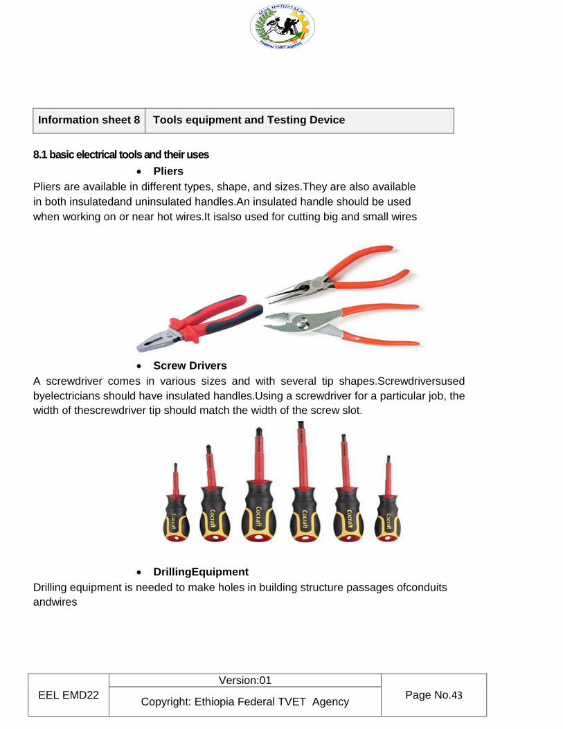
Pliers
Pliers are available in different types, shape, and sizes.They are also available
in both insulatedand uninsulated handles.An insulated handle should be used
when working on or near hot wires.It isalso used for cutting big and small wires
Screw Drivers
A screwdriver comes in various sizes and with several tip shapes.Screwdriversused
byelectricians should have insulated handles.Using a screwdriver for a particular job, the
width of thescrewdriver tip should match the width of the screw slot.
DrillingEquipment
Drilling equipment is needed to make holes in building structure passages ofconduits
andwires

EEL EMD22
Version:01
Page No.44 Copyright: Ethiopia Federal TVET Agency
Sawing and Cutting Tools
Saws commonly used by electricians include the crosscut, keyhole, andHacksaw
Soldering Equipment
In doing electric wiring, splices and taps (connections made to wire) should be
soldered,unless you use solderless connectors.Typical equipments available
for soldering are shown below.
Hammers
Hammers are used with chisels and for nailing and fitting.Below are examples
of carpenter’sclaw hammer,lineman’s hammer, and machinist’sball-peen
hammer.

EEL EMD22
Version:01
Page No.45 Copyright: Ethiopia Federal TVET Agency
Measuring Tools
To measure wire length and other items, the electrician finds considerable use
for measuringtools such as the extension or zigzag rule, push-pull rule and a
steel tape as shown below.
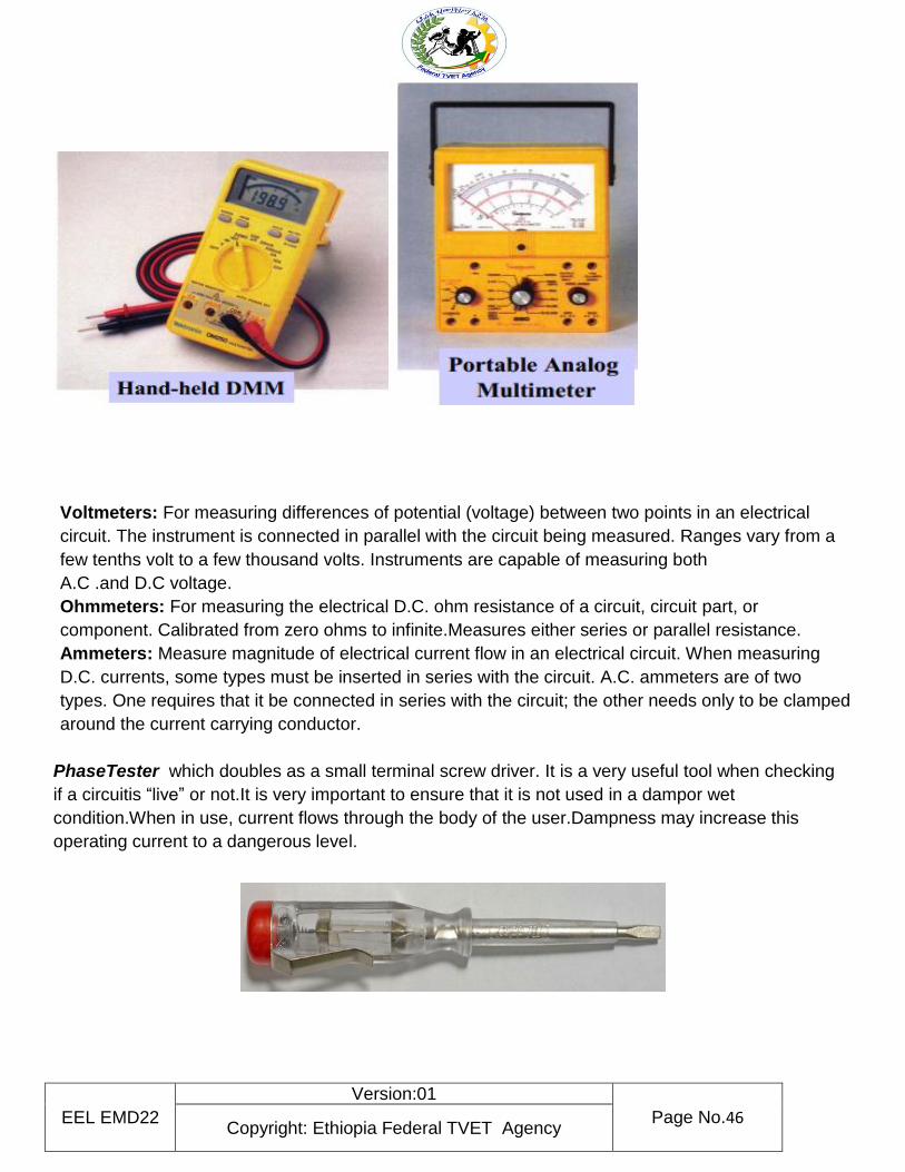
8.2 Testing device
using a multimeter
A multimeter is a device used to measure voltage, resistance and current in electronics & electrical
equipment. It is also used to test continuity b/n two points to verify if there is any break in circuit or
line. There are two types of multimeter: analogue and digital.
Analogue has needle style gauge
Digital has LCD display
Test equipment is necessary for determining proper set-up, adjustment, operation, and maintenance
of electrical systems and control panels.
EEL EMD22
Version:01
Page No.46 Copyright: Ethiopia Federal TVET Agency
Voltmeters: For measuring differences of potential (voltage) between two points in an electrical
circuit. The instrument is connected in parallel with the circuit being measured. Ranges vary from a
few tenths volt to a few thousand volts. Instruments are capable of measuring both
A.C .and D.C voltage.
Ohmmeters: For measuring the electrical D.C. ohm resistance of a circuit, circuit part, or
component. Calibrated from zero ohms to infinite.Measures either series or parallel resistance.
Ammeters: Measure magnitude of electrical current flow in an electrical circuit. When measuring
D.C. currents, some types must be inserted in series with the circuit. A.C. ammeters are of two
types. One requires that it be connected in series with the circuit; the other needs only to be clamped
around the current carrying conductor.
PhaseTester which doubles as a small terminal screw driver. It is a very useful tool when checking
if a circuitis “live” or not.It is very important to ensure that it is not used in a dampor wet
condition.When in use, current flows through the body of the user.Dampness may increase this
operating current to a dangerous level.
EEL EMD22
Version:01
Page No.47 Copyright: Ethiopia Federal TVET Agency
Name: Date:
I. Direction: Answer the following questions.
1 What are basic electrical tools
2 What are the basic Testing device
3 The two types of multimeter……………………..and ……………………..
4 Multimeter is a device used to measure ………………………,…………. And ………………
Note: Satisfactory rating - 4 points Unsatisfactory - below 4 points
Self-Check 8 Written Test
EEL EMD22
Version:01
Page No.48 Copyright: Ethiopia Federal TVET Agency
Operation Sheet 1 Safety requirements of equipment/tools
1.1 Safety requirements of equipment/tools;
Step 1- wear PPE. Step 2- select required testing instrument /digital multimeter/. Steps 3- adjust on zero reading. Step 4- observe 0.00 reading, if not go to step 2 Step 5- clean the area.
Operation Sheet 2 Procedure of termination
1.5 Procedure of termination;
EEL EMD22
Version:01
Page No.49 Copyright: Ethiopia Federal TVET Agency
Step 1- wear PPE. Step 2- select required materials, tools and instruments. Step 3- prepare the wire for splicing Step 4 removes insulation of conductor Step 5 Bring the wires to a crossed Step 6 splices the two terminals Step 7 solders the joints Step 8 terminate the joints with connector Step 9 clean work areas
By using the above procedure do the following LAP test
Name: _____________________________ Date: ________________
Time started: ________________________ Time finished: ________________
Instructions: Given necessary templates, workshop, tools and materials you are required to
perform the following tasks within 8 hours.
Task 1: Safety requirements of equipment/tools
. Task2: Procedure of termination
LAP Test Practical Demonstration
EEL EMD22
Version:01
Page No.50 Copyright: Ethiopia Federal TVET Agency
Instruction Sheet LG17: Perform installation and termination of wiring system
This learning guide is developed to provide you the necessary information regarding the following
learning outcome and content coverage
OHs Police and Procedure
Types of diagram
Installing Wiring system standard and code
Terminating and connecting accessories
Installing wiring system
Responding Unplanned events or conditions
Approving procedure and requirement of termination This guide will also assist you to attain the learning outcome and contents stated in the cover page.
Specifically, upon completion of this Learning Guide, you will be able to:-
Identify Safety requirements of equipment/tools
Reading and interpreting electrical circuit diagrams
Identify Types and application of termination
Perform Procedure of termination
Identifying wiring system components and accessories Learning Instructions:
1. Read the specific objectives of this Learning Guide.
2. Follow the instruction described blew 3 to 6
3. Read the information written in the “Information Sheet 1 up to information 7”.
4. Accomplish the “Self-check 1, self-check 2, Self-check 3, Self-check 4, Self-check 5, Self-check
6, Self-check 7 ” in page ( 6,13,21,24,28,30,and 33 ) respectively.
5. If you earned a satisfactory evaluation from the “Self-check” proceed to “Operation Sheet 1 up to
operation sheet 4 in page -34, 35,36 and 37 respectively.
6. Do the “LAP test” in page – 38 (if you are ready.
7. Reference in page 39

EEL EMD22
Version:01
Page No.51 Copyright: Ethiopia Federal TVET Agency
Information Sheet-1 OHs Police and Procedure
1.1. OHS policies and procedures Your Company Name is committed to the goal of providing and maintaining a healthy and safe working environment, with a view to continuous improvement. This goal is only achievable by adherence to established objectives striving to exceed all obligations under applicable legislation, and by fostering an enthusiastic commitment to health, safety and the environment within Your Company Name personnel, contractors and visitors. In particular:
Management, working in cooperation with the Joint Health and Safety Committee, will strive to
take all reasonable steps to reduce workplace hazards to as low as reasonably achievable.
Supervisors and managers are held accountable for the health and safety of all employees
under their supervision. This includes responsibility for applicable training and instruction,
appropriate follow-up on reported health and safety concerns, and implementation of
recommended corrective action. This accountability is integrated into the performance
appraisal system.
Supervisors, workers and visitors are expected to perform their duties and responsibilities in a
safe and healthful manner, and are accountable for the Health and Safety of themselves and
others.
Your Company Name is committed to providing all necessary training and instruction to ensure
that appropriate work practices are followed on the job, and to promote their use off the job.
If necessary, Your Company Name will take disciplinary action where individuals fail to work in
a healthy and safe manner, or do not comply with applicable legislation or corporate policies
and procedures.
What can you do to protect yourself and others from electrical hazards? Employees can prevent shocks and injuries/electrocution from electrical hazards by:
Following safe work practices
Understanding electric shock and electro caution
Recognizing potential hazards around work involving electricity
Following OHS requirements
Maintaining clearances around panels
Using proper protective devices
Eliminating access to exposed energized parts Using proper PPE
Using proper lockout/tag out procedures
Maintaining proper clearance from overhead lines
Following proper procedures for confined space/enclosed space/underground electrical
work
Following manufacturer’s instructions
When you have to do maintenance work on a machine, take these four steps to protect yourself and your coworkers from injury:
1. De-energize the machine. Positively disconnect it from the power source. If there is more than
one source of power, disconnect them all.
EEL EMD22
Version:01
Page No.52 Copyright: Ethiopia Federal TVET Agency
2. Lock out the disconnect switches. You must be given a lock and key for each disconnect
before you begin working on the machine
3. Tag the disconnect switches. Get tags or accident prevention signs from your supervisor.
4. Test the machine to make sure it won’t start and Keep the key with you
Each worker who works on the machine must lock out and tag the power disconnect. Never assume that the machine you are working on has been disconnected and Locked out unless you have done it yourself. Also remember that the current ratings off use and circuit breakers are at 15 to 30amperes for most residences. These safeguards cannot protect you against shocks. High voltage transmission and distribution lines carry a lot of electricity and if accidently touched it can be fatal. Since farm and construction workers use equipment that can reach high, these employees must be trained on the hazard supposed by high voltage overhead lines. Each year, workers who accidentally make contact with high voltage power lines are either killed or become permanently disabled. Electrically powered equipment is used daily by most workers. Power tools, metal and woodworking machines, restaurant equipment, computers and many other types of electrical equipment are found in the workplace. Failure to use the equipment correctly can create hazards to employees. Generally, there are instructions from the manufacturers on the use and maintenance of each piece of equipment. Workers need to follow the instructions while using and
Replace broken 3-prong plugs and make sure the third prong is properly grounded.
Never use extension cords as permanent wiring.
Do not plug several power cords into one outlet.
Do not disconnect power supplies by pulling or jerking the cords from the outlets.
Always use the correct size fuse or breaker.
Be aware that unusually warm or hot outlets may be a sign that unsafe wiring conditions exists.
Use proper PPE for the electrical job.
Always use ladders made of wood or other non-conductive materials when
Working with or near electricity or power lines
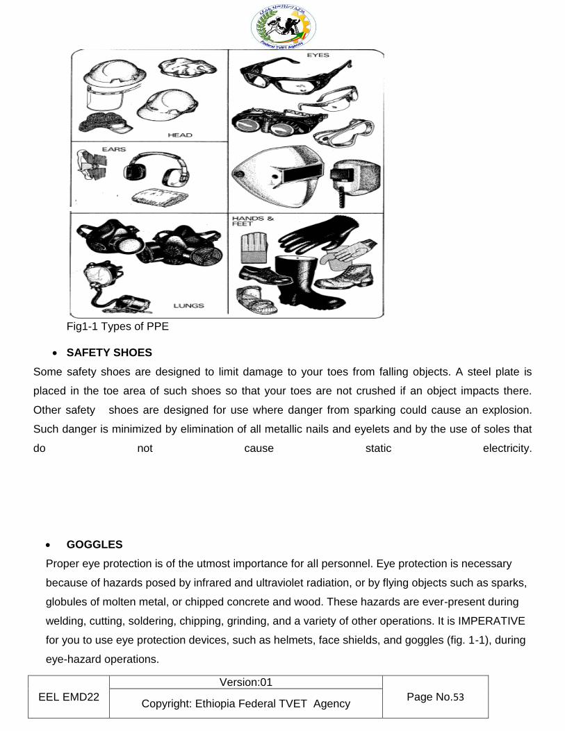
1.2 Personal Protective Equipment (PPE)
Personal Protective Equipment (PPE) is anything used or worn by a person to minimize risk to the
person’s health or safety and includes a wide range of clothing and safety equipment. PPE includes
boots (safety shoes, face masks, hard hats (helmet), ear plugs, respirators, gloves, safety harnesses
and high visibility clothing.
EEL EMD22
Version:01
Page No.53 Copyright: Ethiopia Federal TVET Agency
Fig1-1 Types of PPE
SAFETY SHOES
Some safety shoes are designed to limit damage to your toes from falling objects. A steel plate is
placed in the toe area of such shoes so that your toes are not crushed if an object impacts there.
Other safety shoes are designed for use where danger from sparking could cause an explosion.
Such danger is minimized by elimination of all metallic nails and eyelets and by the use of soles that
do not cause static electricity.
GOGGLES
Proper eye protection is of the utmost importance for all personnel. Eye protection is necessary
because of hazards posed by infrared and ultraviolet radiation, or by flying objects such as sparks,
globules of molten metal, or chipped concrete and wood. These hazards are ever-present during
welding, cutting, soldering, chipping, grinding, and a variety of other operations. It is IMPERATIVE
for you to use eye protection devices, such as helmets, face shields, and goggles (fig. 1-1), during
eye-hazard operations.
EEL EMD22
Version:01
Page No.54 Copyright: Ethiopia Federal TVET Agency
Appropriate use of goggles will limit eye hazards. Some goggles have plastic lenses that resist
shattering upon impact. Others are designed to limit harmful infrared and ultraviolet radiation from
arcs or flames by use of appropriate filter lenses. Remember, eye damage can be excruciatingly
painful. PROTECT YOUR EYES.
GLOVES
Use gloves ((fig. 1-1) whenever you are required to handle rough, scaly, or splintery objects. Special
flameproof gloves are designed for gas and electric-arc welding to limit danger and damage from
sparks and other hot flying objects Personnel in the electrical fields are usually required to wear
insulating rubber gloves. Be sure to follow all regulations prescribed for the use of gloves. Gloves
must not be worn around rotating machinery unless sharp or rough material is being handled. If such
is the case, EXTREME CARE SHOULD BE EXERCISED to prevent the gloves from being caught in
the machinery.
SAFETY BELTS AND STRAPS
The safety strap and body belt shown in figure 1-1 are what might be called your extra hands
when you work aloft. The body belt, strapped around your waist, contains various pockets for small
tools. The safety strap is a leather or neoprene-impregnated nylon belt with a tongue-type buckle at
each end. While you are climbing you will have the safety strap hanging by both ends from the left
ring (called a D-ring because of its shape) on the body belt. When you are at working position, you
unsnap one end of the safety strap, pass it around the supporting structure so there is no danger of
its slipping (at least 18 inches from the top of the part on which it is fastened), and hook it to the right
D-ring on the body belt.
The safety strap must be placed around a part of the structure that is of sufficient strength to sustain
an Abs weight and his or her equipment, and must rest flat against the surface without twists or turns.
It must not be placed around any part of a structure that is being removed. Before placing your weight
on the strap, determine VISUALLY that the snap and D-ring are properly engaged. Do not rely on the
click of the snap-tongue as an indication that the fastening is secure. The body belt and safety strap
require inspection before use. Look for loose or broken rivets; cracks, cuts, nicks, tears or wear in
leather; broken or otherwise defective buckles, such as enlarged tongue-holes, defects in safety-belt
snap hooks and body belt D-rings. If you discover any of these or other defects, turn in your
EEL EMD22
Version:01
Page No.55 Copyright: Ethiopia Federal TVET Agency
equipment and replace it. Perform maintenance periodically according to applicable procedures.
Remember that leather and nylon belts are treated in different manners.
When can PPE be used?
PPE is one of the least effective ways of controlling risks to work health and safety and should only
be used:
• when there are no other practical control measures available (as a last resort)
• as an interim measure until a more effective way of controlling the risk can be used, or
• to supplement higher level control measures (as a back-up).
What standard of PPE is required?
PPE used at a workplace must be:
• selected to minimize risk to work health and safety
• suitable for the nature of the work and any hazard associated with the work
• a suitable size and fit and reasonably comfortable for the person wearing it
• maintained, repaired or replaced so it continues to minimize the worker’s health and safety risk, and
• used or worn by the worker, so far as is reasonably practicable.
How do I choose the right PPE for the job?
Selection processes for choosing the right PPE must involve consultation with workers and their
representatives and should also include:
• a detailed evaluation of the risk and performance requirements for the PPE
• compatibility of PPE items where more than one type of PPE is required (for example ear muffs with
a hard hat)
• Consultation with the supplier to ensure PPE is suitable for the work and workplace conditions, and
preference for PPE that complies with the relevant Ethiopian Standard or equivalent standard.
EEL EMD22
Version:01
Page No.56 Copyright: Ethiopia Federal TVET Agency
Self-check: 1 Written test
Name………………………………………………. Date…………………………………… Direction I. Say true or false for the following questions
1. Supervisors and managers are held accountable for the health and safety of all employees under their supervision.
2. selected to minimize risk to work health and safety is one of standard of PPE required Direction II. Choose best answer
1. Employees can prevent shocks and injuries/electrocution from electrical hazards by: A. Following safe work practices
B. Maintaining clearances around panels
C. Using proper protective devices
D. All
2. Which one of the following is the first requirement to do maintenance work on a machine to
protect yourself and your coworkers from injury:
A. De-energize the machine.
B. Lock out the disconnect switches.
C. Tag the disconnect switches.
D. Test the machine to make sure it won’t start and Keep the key with you
3. ……. Is a type of personal protective device which used to protect Eye from hazards posed
by infrared and ultraviolet radiation, or from flying objects such as sparks.
A. GLOVES C. Safety shoes
B. GOGGLE D. All
EEL EMD22
Version:01
Page No.57 Copyright: Ethiopia Federal TVET Agency
Note: Satisfactory rating - 5 points Unsatisfactory - below 5points
Information Sheet 2 Types of diagram
Types of electrical diagram
Schematic diagram
Pictorial diagram
Wiring diagram
Layout diagram For detail information refer / Learning guide#1 information sheet 2/
EEL EMD22
Version:01
Page No.58 Copyright: Ethiopia Federal TVET Agency
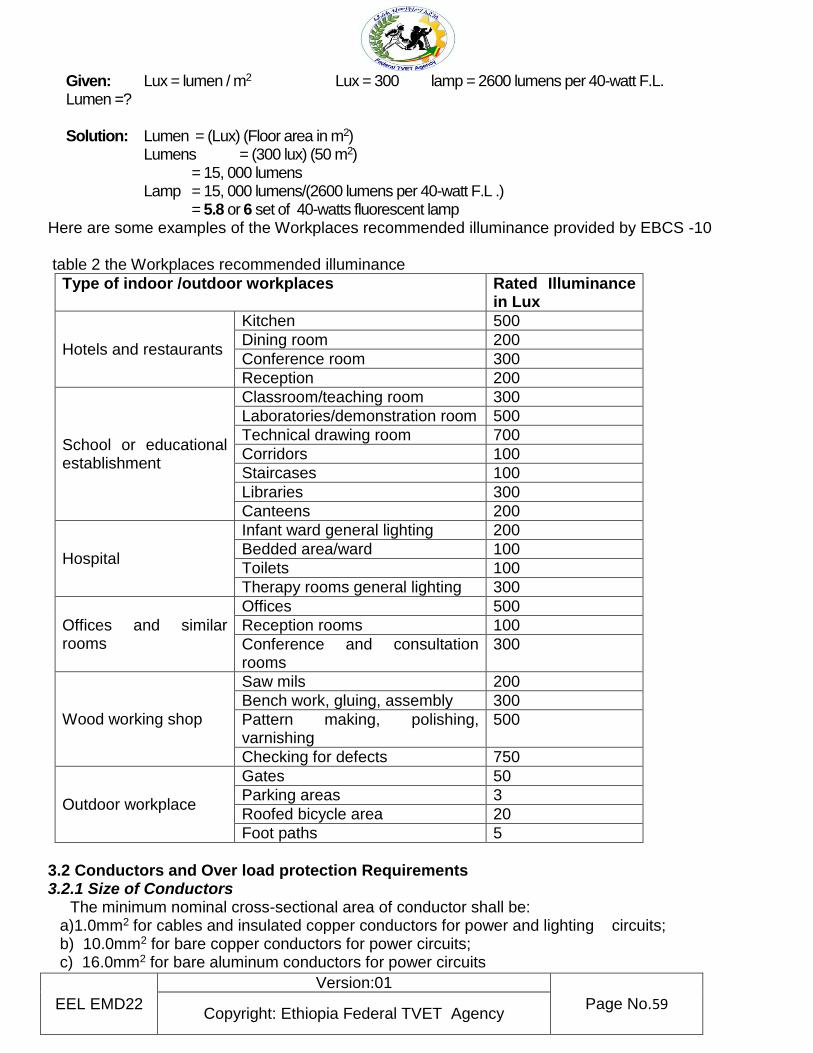
Information Sheet 3 Installing Wiring system standard and code
3.1 Lighting Requirements
The Ethiopian Building Code Standard (EBCS-10) must be followed at all times concerning every electrical design, installation and repair; whether in commercial, industrial or residential buildings.
Lighting Requirements (EBCS under Sec 3. Illumination)
The recommended luminance for different types of interiors, tasks and workspaces are given in Table 3.5 and Table 3.6 shall be taken as the recommended minimum values on which the design and assessment of lighting installations are to be based. 1. Lux can be used as a measure of the brightness of a light source. Lamp illumination and design in
any indoor and outdoor workplaces are expressed in lux. One lux is equal to one lumen per square meter: 1 lux = 1 lumen/m2
2. Lumen is a measure of the total amount of visible light emitted by a source. It is the SI derived unit
of luminous flux. A flux of 1,000 lumens, concentrated into an area of one square meter, lights up that square meter with an illuminance of 1,000 lux. However, the same 1,000 lumens, spread out over ten square meters, produce a dimmer illuminance of only 100 lux.
Therefore, the difference between units lumen and lux is that the lux takes into account the area over which the luminous flux is spread.
3. Common Fluorescent lamp and their average Lumen output Table 1
Type of Fluorescent lamp
Lumen Output Average Lumen per watt
4 feet Linear 25 Watt T8 2209 lumens 88 lumens per watt
4 feet Linear 28 Watt T5 2900 lumens 104 lumens per watt
4 feet Linear 32 Watt T8 2850-3100 lumens 93 lumens per watt
4 feet Linear 34 Watt T12
1930-2800 lumens 70 lumens per watt
4 feet Linear 40 Watt T12
1980-3300 lumens 66 lumens per watt
4 feet Linear 54 Watt T5 5000 lumens 93 lumens per watt
Achieving an illuminance of 500 lux might be possible in a 24m2 house area with four fluorescent light fixture with a combined output of 12,000 lumens. To light a factory floor with dozens of times the area of the house would require dozens of such fixtures. Thus, lighting a larger area to the same level of lux requires a greater number of lumens. The ordinary four feet Linear Fluorescent Bulbs, 40-watt, 220V, T12 has an output average of 2600 lumens. Example: What would be the total number of 40-watts, 220V, T12 fluorescent lamp fixtures to be installed in a 50 m2 area of school library if it requires having a 300 lux illumination?
EEL EMD22
Version:01
Page No.59 Copyright: Ethiopia Federal TVET Agency
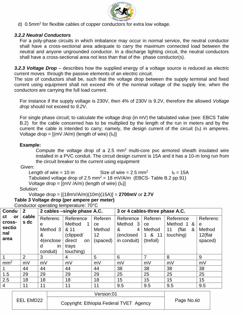
Given: Lux = lumen / m2 Lux = 300 lamp = 2600 lumens per 40-watt F.L. Lumen =? Solution: Lumen = (Lux) (Floor area in m2)
Lumens = (300 lux) (50 m2) = 15, 000 lumens
Lamp = 15, 000 lumens/(2600 lumens per 40-watt F.L .) = 5.8 or 6 set of 40-watts fluorescent lamp Here are some examples of the Workplaces recommended illuminance provided by EBCS -10 table 2 the Workplaces recommended illuminance
Type of indoor /outdoor workplaces Rated Illuminance in Lux
Hotels and restaurants
Kitchen 500
Dining room 200
Conference room 300
Reception 200
School or educational establishment
Classroom/teaching room 300
Laboratories/demonstration room 500
Technical drawing room 700
Corridors 100
Staircases 100
Libraries 300
Canteens 200
Hospital
Infant ward general lighting 200
Bedded area/ward 100
Toilets 100
Therapy rooms general lighting 300
Offices and similar rooms
Offices 500
Reception rooms 100
Conference and consultation rooms
300
Wood working shop
Saw mils 200
Bench work, gluing, assembly 300
Pattern making, polishing, varnishing
500
Checking for defects 750
Outdoor workplace
Gates 50
Parking areas 3
Roofed bicycle area 20
Foot paths 5
3.2 Conductors and Over load protection Requirements 3.2.1 Size of Conductors The minimum nominal cross-sectional area of conductor shall be:
a)1.0mm2 for cables and insulated copper conductors for power and lighting circuits; b) 10.0mm2 for bare copper conductors for power circuits; c) 16.0mm2 for bare aluminum conductors for power circuits
EEL EMD22
Version:01
Page No.60 Copyright: Ethiopia Federal TVET Agency
d) 0.5mm2 for flexible cables of copper conductors for extra low voltage.
3.2.2 Neutral Conductors For a poly-phase circuits in which imbalance may occur in normal service, the neutral conductor shall have a cross-sectional area adequate to carry the maximum connected load between the neutral and anyone ungrounded conductor. In a discharge lighting circuit, the neutral conductors shall have a cross-sectional area not less than that of the· phase conductor(s).
3.2.3 Voltage Drop – describes how the supplied energy of a voltage source is reduced as electric current moves through the passive elements of an electric circuit. The size of conductors shall be, such that the voltage drop between the supply terminal and fixed current using equipment shall not exceed 4% of the nominal voltage of the supply line, when the conductors are carrying the full load current.
For instance if the supply voltage is 230V, then 4% of 230V is 9.2V, therefore the allowed Voltage drop should not exceed to 9.2V. For single phase circuit; to calculate the voltage drop (in mV) the tabulated value (see: EBCS Table B.2) for the cable concerned has to be multiplied by the length of the run in meters and by the current the cable is intended to carry; namely, the design current of the circuit (Ib) in amperes. Voltage drop = [(mV /A/m) (length of wire) (Ib)] Example:
Compute the voltage drop of a 2.5 mm2 multi-core pvc armored sheath insulated wire installed in a PVC conduit. The circuit design current is 15A and it has a 10-m long run from the circuit breaker to the current using equipment
Given: Length of wire = 10 m Size of wire = 2.5 mm2 Ib = 15A
Tabulated voltage drop of 2.5 mm2 = 18 mV/A/m (EBCS- Table B.2 pp.91) Voltage drop = [(mV /A/m) (length of wire) (Ib)]
Solution: Voltage drop = [(18mV/A/m)(10m)(15A)] = 2700mV or 2.7V Table 3 Voltage drop (per ampere per meter) Conductor operating temperature: 70°C
Conduct or cross-sectional area
2 cables dc
2 cables –single phase A.C. 3 or 4 cables-three phase A.C.
Reference Method 3 & 4(enclosed in conduit)
Reference Method 1 & 11 (clipped/ direct on trays touching)
Reference Method 12 (spaced)
Reference Method 3 & 4 (enclosed in conduit)
Reference Method 1 & 11 (trefoil)
Reference Method 1 & 11 (flat & touching)
Reference Method 12(flat spaced)
1 2 3 4 5 6 7 8 9
mm2 mV mV mV mV mV mV mV mV
1 44 44 44 44 38 38 38 38
1.5 29 29 29 29 25 25 25 25
2.5 18 18 18 18 15 15 15 15
4 11 11 11 11 9.5 9.5 9.5 9.5
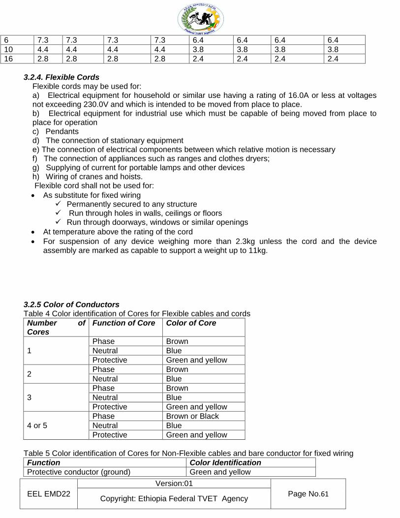
EEL EMD22
Version:01
Page No.61 Copyright: Ethiopia Federal TVET Agency
6 7.3 7.3 7.3 7.3 6.4 6.4 6.4 6.4
10 4.4 4.4 4.4 4.4 3.8 3.8 3.8 3.8
16 2.8 2.8 2.8 2.8 2.4 2.4 2.4 2.4
3.2.4. Flexible Cords
Flexible cords may be used for: a) Electrical equipment for household or similar use having a rating of 16.0A or less at voltages not exceeding 230.0V and which is intended to be moved from place to place. b) Electrical equipment for industrial use which must be capable of being moved from place to place for operation c) Pendants d) The connection of stationary equipment e) The connection of electrical components between which relative motion is necessary f) The connection of appliances such as ranges and clothes dryers; g) Supplying of current for portable lamps and other devices h) Wiring of cranes and hoists.
Flexible cord shall not be used for:
As substitute for fixed wiring Permanently secured to any structure Run through holes in walls, ceilings or floors Run through doorways, windows or similar openings
At temperature above the rating of the cord
For suspension of any device weighing more than 2.3kg unless the cord and the device assembly are marked as capable to support a weight up to 11kg.
3.2.5 Color of Conductors Table 4 Color identification of Cores for Flexible cables and cords
Number of Cores
Function of Core Color of Core
1
Phase Brown
Neutral Blue
Protective Green and yellow
2 Phase Brown
Neutral Blue
3
Phase Brown
Neutral Blue
Protective Green and yellow
4 or 5
Phase Brown or Black
Neutral Blue
Protective Green and yellow
Table 5 Color identification of Cores for Non-Flexible cables and bare conductor for fixed wiring
Function Color Identification
Protective conductor (ground) Green and yellow
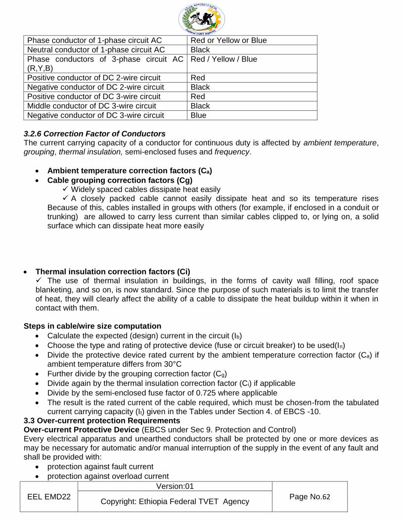
EEL EMD22
Version:01
Page No.62 Copyright: Ethiopia Federal TVET Agency
Phase conductor of 1-phase circuit AC Red or Yellow or Blue
Neutral conductor of 1-phase circuit AC Black
Phase conductors of 3-phase circuit AC (R,Y,B)
Red / Yellow / Blue
Positive conductor of DC 2-wire circuit Red
Negative conductor of DC 2-wire circuit Black
Positive conductor of DC 3-wire circuit Red
Middle conductor of DC 3-wire circuit Black
Negative conductor of DC 3-wire circuit Blue
3.2.6 Correction Factor of Conductors The current carrying capacity of a conductor for continuous duty is affected by ambient temperature, grouping, thermal insulation, semi-enclosed fuses and frequency.
Ambient temperature correction factors (Ca)
Cable grouping correction factors (Cg) Widely spaced cables dissipate heat easily A closely packed cable cannot easily dissipate heat and so its temperature rises
Because of this, cables installed in groups with others (for example, if enclosed in a conduit or trunking) are allowed to carry less current than similar cables clipped to, or lying on, a solid surface which can dissipate heat more easily
Thermal insulation correction factors (Ci) The use of thermal insulation in buildings, in the forms of cavity wall filling, roof space blanketing, and so on, is now standard. Since the purpose of such materials is to limit the transfer of heat, they will clearly affect the ability of a cable to dissipate the heat buildup within it when in contact with them.
Steps in cable/wire size computation
Calculate the expected (design) current in the circuit (Ib)
Choose the type and rating of protective device (fuse or circuit breaker) to be used(In)
Divide the protective device rated current by the ambient temperature correction factor (Ca) if ambient temperature differs from 30°C
Further divide by the grouping correction factor (Cg)
Divide again by the thermal insulation correction factor (Ci) if applicable
Divide by the semi-enclosed fuse factor of 0.725 where applicable
The result is the rated current of the cable required, which must be chosen-from the tabulated current carrying capacity (It) given in the Tables under Section 4. of EBCS -10.
3.3 Over-current protection Requirements Over-current Protective Device (EBCS under Sec 9. Protection and Control) Every electrical apparatus and unearthed conductors shall be protected by one or more devices as may be necessary for automatic and/or manual interruption of the supply in the event of any fault and shall be provided with:
protection against fault current
protection against overload current
EEL EMD22
Version:01
Page No.63 Copyright: Ethiopia Federal TVET Agency
protection against under voltage
protection against earth fault
manually-operable control device 3.3.1 Over-current devices – the safety device that provide over-current protection of either the load or source circuit. The over-current protective devices shall ensure safe operation and shall have interrupting capacity sufficient for the voltage employed and for the anticipated fault current which must be interrupted. The rating or setting of over-current devices shall not exceed the allowable ampacity of the conductors which they protect except:
If the rating of the fuse of circuit breaker is not available the ratings or settings given in may be used;
In case of equipment wire, flexible cord or tinsel cord which will be considered as being protected by 16.0 A over-current device.
Fuse – is a type of very low resistance conductor that provides over-current protection through a metal strip that melts when too much current flows on it.
(EBCS 9.5) – Only fuses and fuse holders of proper rating shall be used, and no bridging or short circuiting of either component shall be permitted. Where plug fuses are used in branch circuits, they shall be of such a type and so installed that they are non-interchangeable with a fuse of larger rating A fuse having a fuse link which is likely to ·be removed or replaced while the supply is connected shall be of a type such that it can be removed or replaced without danger.
Circuit breaker – is an automatically operated electrical switch designed to protect an electrical circuit from damage cause by overload or short circuit. Some circuit breaker has bi-metallic element that can detect a fault condition or over-current flow which will drive the breaker into trip off position resulting to interruption of the current flow.
Circuit breakers shall be of the trip-free type.
Indication shall be provided at the circuit breaker and at the point of operation to show whether the circuit breaker is open or closed.
Circuit breakers shall open the circuit in all unearthed conductors by the manual operation of a single handle and by the action of over-current.
Circuit breakers shall be of such design that any alteration by the user of either the tripping current or the time will be difficult.
2. Earth Fault Protection (EBCS 9.4.2) – Earth-fault protection shall be provided to de-energize all normally earthed conductors of a faulted circuit in the event of an earth fault in those conductors.
3. Control Devices (EBCS 9.7) Control devices shall have ratings suitable for the connected load of the circuits which they control and with the exception of isolating switches, shall be capable of safely establishing and interrupting such loads.
Control devices used in combination with over-current devices or overload devices for the control of circuits or apparatus shall be connected so that the over-current or overload devices will be dead when the control device is in the open position, except where this is impracticable.
Control devices, with the exception of isolating switches, shall be readily accessible.
Control devices, unless located or guarded so as to render them inaccessible to unauthorized persons and to prevent fire hazards, shall have all current-carrying parts in enclosures of metal or other fire-resisting material.
Where electrical equipment is supplied by two or more different transformers or other sources of voltage, then:
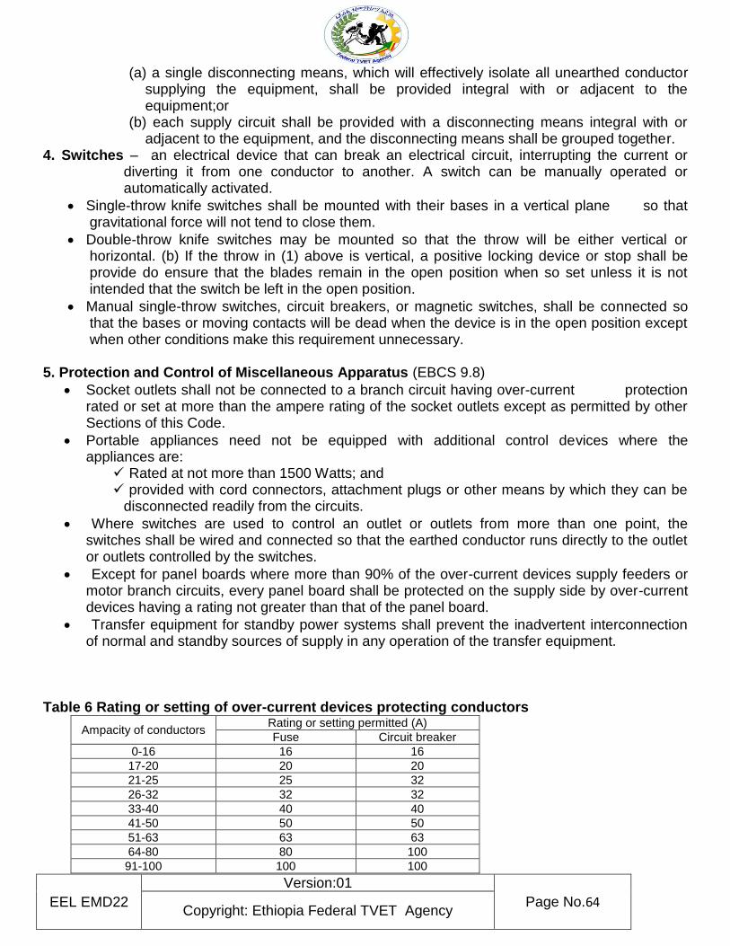
EEL EMD22
Version:01
Page No.64 Copyright: Ethiopia Federal TVET Agency
(a) a single disconnecting means, which will effectively isolate all unearthed conductor supplying the equipment, shall be provided integral with or adjacent to the equipment;or
(b) each supply circuit shall be provided with a disconnecting means integral with or adjacent to the equipment, and the disconnecting means shall be grouped together.
4. Switches – an electrical device that can break an electrical circuit, interrupting the current or diverting it from one conductor to another. A switch can be manually operated or automatically activated.
Single-throw knife switches shall be mounted with their bases in a vertical plane so that gravitational force will not tend to close them.
Double-throw knife switches may be mounted so that the throw will be either vertical or horizontal. (b) If the throw in (1) above is vertical, a positive locking device or stop shall be provide do ensure that the blades remain in the open position when so set unless it is not intended that the switch be left in the open position.
Manual single-throw switches, circuit breakers, or magnetic switches, shall be connected so that the bases or moving contacts will be dead when the device is in the open position except when other conditions make this requirement unnecessary.
5. Protection and Control of Miscellaneous Apparatus (EBCS 9.8)
Socket outlets shall not be connected to a branch circuit having over-current protection rated or set at more than the ampere rating of the socket outlets except as permitted by other Sections of this Code.
Portable appliances need not be equipped with additional control devices where the appliances are:
Rated at not more than 1500 Watts; and provided with cord connectors, attachment plugs or other means by which they can be
disconnected readily from the circuits.
Where switches are used to control an outlet or outlets from more than one point, the switches shall be wired and connected so that the earthed conductor runs directly to the outlet or outlets controlled by the switches.
Except for panel boards where more than 90% of the over-current devices supply feeders or motor branch circuits, every panel board shall be protected on the supply side by over-current devices having a rating not greater than that of the panel board.
Transfer equipment for standby power systems shall prevent the inadvertent interconnection of normal and standby sources of supply in any operation of the transfer equipment.
Table 6 Rating or setting of over-current devices protecting conductors
Ampacity of conductors Rating or setting permitted (A) Fuse Circuit breaker
0-16 16 16 17-20 20 20 21-25 25 32 26-32 32 32 33-40 40 40 41-50 50 50 51-63 63 63 64-80 80 100 91-100 100 100
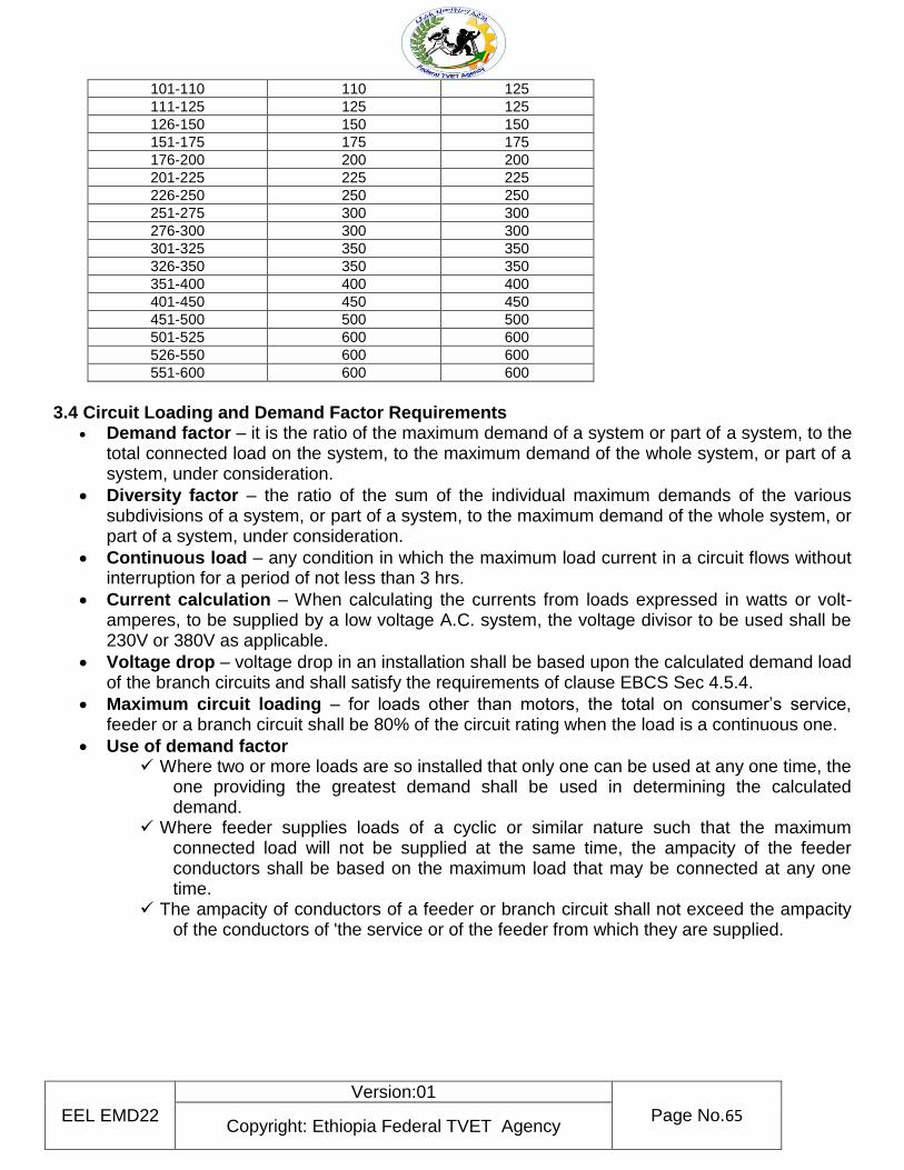
EEL EMD22
Version:01
Page No.65 Copyright: Ethiopia Federal TVET Agency
101-110 110 125 111-125 125 125 126-150 150 150 151-175 175 175 176-200 200 200 201-225 225 225 226-250 250 250 251-275 300 300 276-300 300 300 301-325 350 350 326-350 350 350 351-400 400 400 401-450 450 450 451-500 500 500 501-525 600 600 526-550 600 600 551-600 600 600
3.4 Circuit Loading and Demand Factor Requirements
Demand factor – it is the ratio of the maximum demand of a system or part of a system, to the total connected load on the system, to the maximum demand of the whole system, or part of a system, under consideration.
Diversity factor – the ratio of the sum of the individual maximum demands of the various subdivisions of a system, or part of a system, to the maximum demand of the whole system, or part of a system, under consideration.
Continuous load – any condition in which the maximum load current in a circuit flows without interruption for a period of not less than 3 hrs.
Current calculation – When calculating the currents from loads expressed in watts or volt-amperes, to be supplied by a low voltage A.C. system, the voltage divisor to be used shall be 230V or 380V as applicable.
Voltage drop – voltage drop in an installation shall be based upon the calculated demand load of the branch circuits and shall satisfy the requirements of clause EBCS Sec 4.5.4.
Maximum circuit loading – for loads other than motors, the total on consumer’s service, feeder or a branch circuit shall be 80% of the circuit rating when the load is a continuous one.
Use of demand factor Where two or more loads are so installed that only one can be used at any one time, the
one providing the greatest demand shall be used in determining the calculated demand.
Where feeder supplies loads of a cyclic or similar nature such that the maximum connected load will not be supplied at the same time, the ampacity of the feeder conductors shall be based on the maximum load that may be connected at any one time.
The ampacity of conductors of a feeder or branch circuit shall not exceed the ampacity of the conductors of 'the service or of the feeder from which they are supplied.
EEL EMD22
Version:01
Page No.66 Copyright: Ethiopia Federal TVET Agency
Self-check: 3 Written test
Name ……………………………………………… Date………………………………. Direction I Choose best answer for the following question
1. An automatically operated electrical switch designed to protect an electrical circuit from damage cause by overload or short circuit.
A. Fuse C. switch B. Circuit breaker D. Control Devices
2. According to EBCS coding system in single phase supply the phase line should be A. Green C. Blue B. Yellow D. Brown
3. Which one of the following color is does not represent of live /phase/ in three phase supply
A. Black C. Yellow B. Red D. Blue
4. Steps in cable/wire size computation A. Calculate the expected (design) current in the circuit (Ib) B. Choose the type and rating of protective device (fuse or circuit breaker) to be used(In) C. Divide the protective device rated current by the ambient temperature correction factor (Ca)
if ambient temperature differs from 30°C D. All
5. Conductors and Over load protection Requirements A. Size of Conductors C. Voltage Drop B. Neutral Conductors D. All
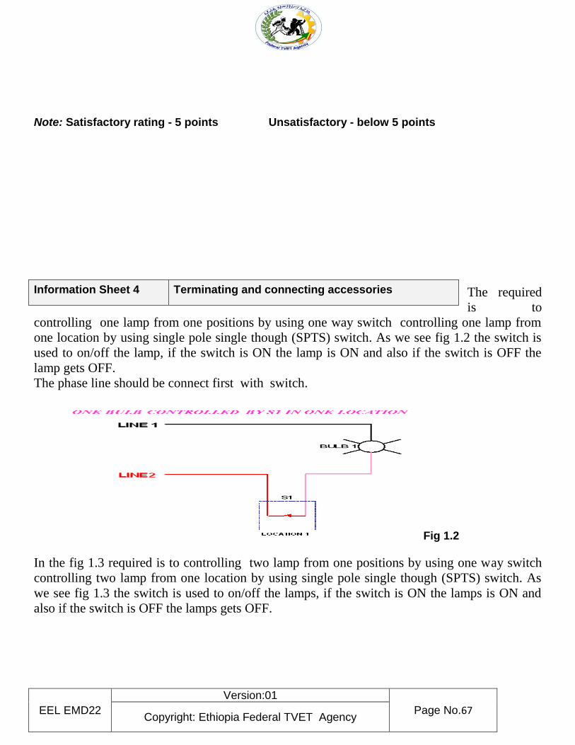
EEL EMD22
Version:01
Page No.67 Copyright: Ethiopia Federal TVET Agency
Note: Satisfactory rating - 5 points Unsatisfactory - below 5 points
The required
is to
controlling one lamp from one positions by using one way switch controlling one lamp from
one location by using single pole single though (SPTS) switch. As we see fig 1.2 the switch is
used to on/off the lamp, if the switch is ON the lamp is ON and also if the switch is OFF the
lamp gets OFF.
The phase line should be connect first with switch.
Fig 1.2
In the fig 1.3 required is to controlling two lamp from one positions by using one way switch
controlling two lamp from one location by using single pole single though (SPTS) switch. As
we see fig 1.3 the switch is used to on/off the lamps, if the switch is ON the lamps is ON and
also if the switch is OFF the lamps gets OFF.
Information Sheet 4 Terminating and connecting accessories
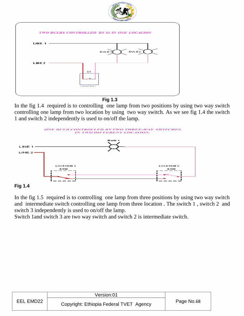
EEL EMD22
Version:01
Page No.68 Copyright: Ethiopia Federal TVET Agency
Fig 1.3
In the fig 1.4 required is to controlling one lamp from two positions by using two way switch
controlling one lamp from two location by using two way switch. As we see fig 1.4 the switch
1 and switch 2 independently is used to on/off the lamp.
Fig 1.4
In the fig 1.5 required is to controlling one lamp from three positions by using two way switch
and intermediate switch controlling one lamp from three location . The switch 1 , switch 2 and
switch 3 independently is used to on/off the lamp.
Switch 1and switch 3 are two way switch and switch 2 is intermediate switch.
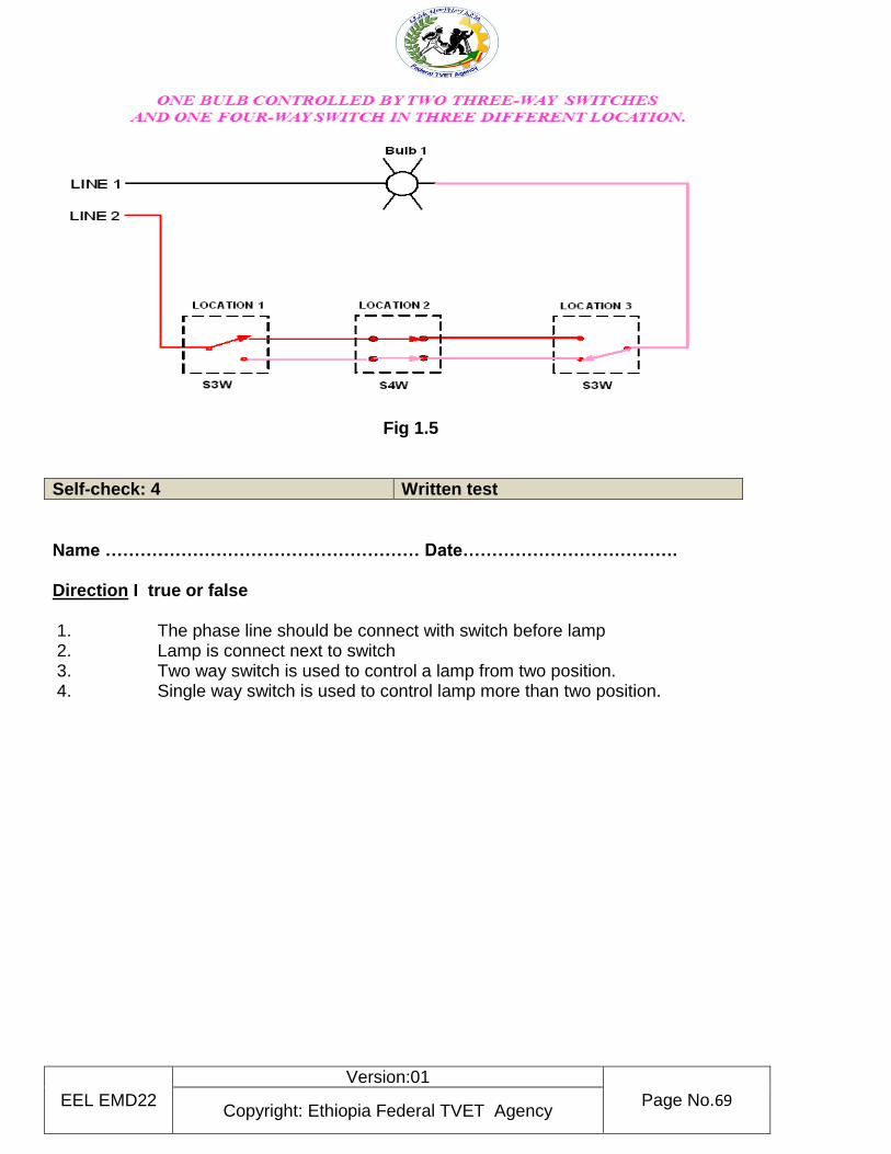
EEL EMD22
Version:01
Page No.69 Copyright: Ethiopia Federal TVET Agency
Fig 1.5
Self-check: 4 Written test
Name ……………………………………………… Date………………………………. Direction I true or false 1. The phase line should be connect with switch before lamp 2. Lamp is connect next to switch 3. Two way switch is used to control a lamp from two position. 4. Single way switch is used to control lamp more than two position.
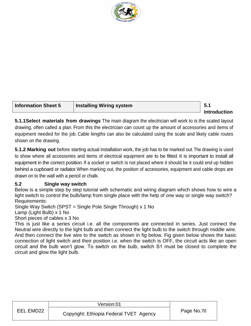
EEL EMD22
Version:01
Page No.70 Copyright: Ethiopia Federal TVET Agency
5.1
Introduction
5.1.1Select materials from drawings The main diagram the electrician will work to is the scaled layout
drawing, often called a plan. From this the electrician can count up the amount of accessories and items of
equipment needed for the job. Cable lengths can also be calculated using the scale and likely cable routes
shown on the drawing.
5.1.2 Marking out before starting actual installation work, the job has to be marked out. The drawing is used
to show where all accessories and items of electrical equipment are to be fitted. It is important to install all
equipment in the correct position. If a socket or switch is not placed where it should be it could end up hidden
behind a cupboard or radiator. When marking out, the position of accessories, equipment and cable drops are
drawn on to the wall with a pencil or chalk.
5.2 Single way switch Below is a simple step by step tutorial with schematic and wiring diagram which shows how to wire a light switch to control the bulb/lamp from single place with the help of one way or single way switch? Requirements: Single Way Switch (SPST = Single Pole Single Through) x 1 No Lamp (Light Bulb) x 1 No Short pieces of cables x 3 No This is just like a series circuit i.e. all the components are connected in series. Just connect the Neutral wire directly to the light bulb and then connect the light bulb to the switch through middle wire. And then connect the live wire to the switch as shown in fig below. Fig given below shows the basic connection of light switch and their position i.e. when the switch is OFF, the circuit acts like an open circuit and the bulb won’t glow. To switch on the bulb, switch S1 must be closed to complete the circuit and glow the light bulb.
Information Sheet 5 Installing Wiring system
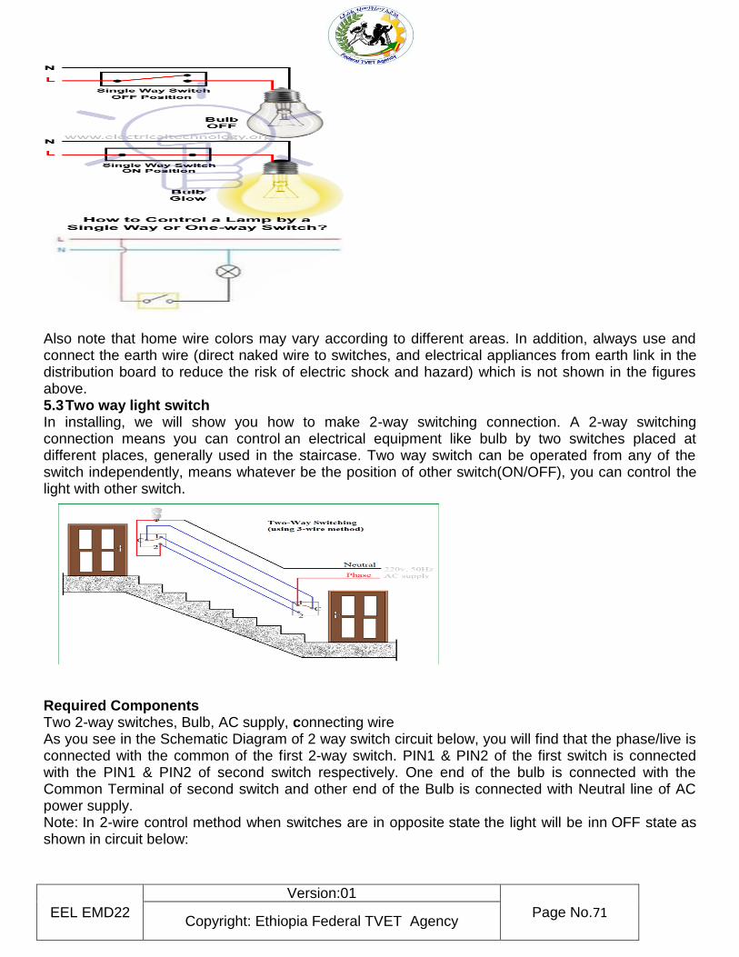
EEL EMD22
Version:01
Page No.71 Copyright: Ethiopia Federal TVET Agency
Also note that home wire colors may vary according to different areas. In addition, always use and connect the earth wire (direct naked wire to switches, and electrical appliances from earth link in the distribution board to reduce the risk of electric shock and hazard) which is not shown in the figures above. 5.3 Two way light switch In installing, we will show you how to make 2-way switching connection. A 2-way switching connection means you can control an electrical equipment like bulb by two switches placed at different places, generally used in the staircase. Two way switch can be operated from any of the switch independently, means whatever be the position of other switch(ON/OFF), you can control the light with other switch.
Required Components Two 2-way switches, Bulb, AC supply, connecting wire As you see in the Schematic Diagram of 2 way switch circuit below, you will find that the phase/live is connected with the common of the first 2-way switch. PIN1 & PIN2 of the first switch is connected with the PIN1 & PIN2 of second switch respectively. One end of the bulb is connected with the Common Terminal of second switch and other end of the Bulb is connected with Neutral line of AC power supply. Note: In 2-wire control method when switches are in opposite state the light will be inn OFF state as shown in circuit below:
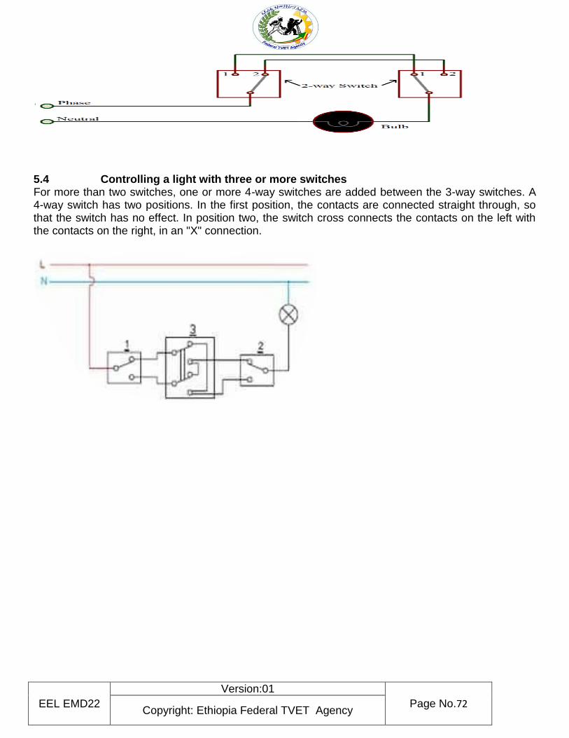
EEL EMD22
Version:01
Page No.72 Copyright: Ethiopia Federal TVET Agency
5.4 Controlling a light with three or more switches For more than two switches, one or more 4-way switches are added between the 3-way switches. A 4-way switch has two positions. In the first position, the contacts are connected straight through, so that the switch has no effect. In position two, the switch cross connects the contacts on the left with the contacts on the right, in an "X" connection.
EEL EMD22
Version:01
Page No.73 Copyright: Ethiopia Federal TVET Agency
Self-check: 5 Written test
Name ………………………………………………. Date……………………………………
Matching
Direction Match the following <A> column with the given <B> column A B
1. Single way switch A. operated from any of the switch independently 2. Two way switch B. over current protective device 3. Intermediate switch C. Single Pole Single Through 4. Circuit breaker D. output device 5. Lamp E. have two input and two output terminal
Note: Satisfactory rating - 5 points Unsatisfactory - below 5 points
6.1
Information Sheet 6 Responding Unplanned events or conditions

EEL EMD22
Version:01
Page No.74 Copyright: Ethiopia Federal TVET Agency
Responding unplanned events or conditions It is essential that the unconditioned events observed in the following aspects:
demonstrate knowledge of the Entertainment and Events Technology equipment and associated disconnection, storage and cleaning requirements
determine work requirements and plan and organize work to fulfill such requirements
identify, select and use tools, equipment and material to complete tasks to specifications
disconnect equipment and cables safely and in accordance with specifications
handle material and equipment safely
identify and report problems promptly and handle them as directed
prepare equipment and storage site
complete cleaning and storage related tasks in accordance with health and safety procedures
Perform inspection and quality checks - interpret and apply technical information to work activities
demonstrate compliance with Occupational Health and Safety regulations applicable to workplace operations
show compliance with organizational quality procedures and processes within the context of disconnecting, cleaning and storing Entertainment and Events Technology equipment
Interactively communicate with others to ensure safe and effective operations
Self-check: 6 Written test
Name …………………………………………………. Date…………………………. Say true if the sentence is correct and say false if the statement is incorrect
1. Interactively communicate with others to ensure safe and effective operations is available if unplanned condition is happen
2. Perform inspection is available to responding unplanned events.
EEL EMD22
Version:01
Page No.75 Copyright: Ethiopia Federal TVET Agency
Note: Satisfactory rating - 2 points Unsatisfactory - below 2 points
Information Sheet 7 Approving procedure and requirement of termination
7.1 How to Create an Approval Process and Workflow In any organization, work often needs to be formally approved before it can begin. Budgets, creative projects, marketing initiatives, invoices, and many other work items all move through a series of approvals before they are considered either ready for kickoff or complete. Many organizations create specific approval processes or workflows that dictate how work should be approved (or rejected) every time to save time and ensure standardization. 7.2 What Is an Approval Process? An approval process is the method an organization uses to approve anything from documents, invoices, budgets, and purchase orders, to a new process that a company wants to institute. Implementing an approval process can standardize an organization’s internal processes, and also save time by creating a dependable, repeatable system. Approval processes are a type of workflow,
EEL EMD22
Version:01
Page No.76 Copyright: Ethiopia Federal TVET Agency
which is any sequence of work from initiation to completion, that you can create to ensure work is approved the same way every time. Creating an approval process can simply mean defining the procedures that you will follow to approve work. 7.3 Elements of an Approval Process While each approval process will differ based on its purpose or the organization’s specific requirements, there are some general tasks that you will likely include when designing your own. These include:
Submission: An approval process usually begins with someone submitting something. You’ll need to create a submission portal where users go to submit their work.
Assign Approvers: you’ll need to identify the person or people who have the final say. If your process has multiple approval levels, define who will approve which aspects of work at each level.
Set Permission Levels: Define the level of authority each user should have. Most systems have features to delineate among viewer, editor, and administrator permissions, so you can control who edits, rejects, or approves submissions.
Set Due Dates: As with any project, it’s important to set deadlines to keep your workflows moving and prevent work backlogs.
Record/Log: Having a record of every step in the approval process is one of its greatest benefits for increasing transparency and ensuring consistency. If you plan on using an automated solution, look for a program that offers the following capabilities:
View User History: See who has made changes, to what, and when.
Lock Record: This will make the record uneditable, so that no user can change the log of actions.
Edit Record: In some cases, you might want the record to be kept editable - for instance, if you made a mistake or need to keep certain information private from other parties. While we’re on the topic of automated workflows, it’s important to note that some programs also offer additional functionality that can create a more customized feel, or help disrupt some of the inflexibility that can come with automation. Some of these functions include:
Task Lists: It can be helpful to build task assignment into the approval process, allowing each employee to clearly see their responsibilities, and informing management of resource allocation. Many of these elements will be present in the approval process you design, regardless of the specific project or type or organization. In the next section, we’ll discuss the software programs that allow you to build approval processes and workflows, and additional features to consider.
EEL EMD22
Version:01
Page No.77 Copyright: Ethiopia Federal TVET Agency
Self-check: 7 Written test
Name …………………………………………………. Date…………………………. Say true if the sentence is correct and say false if the statement is incorrect
1. Approval processes are a type of workflow, which is any sequence of work from initiation to completion, that you can create to ensure work is approved.
2. Record/Log means an approval process usually begins with someone submitting something.
3. In any organization, work often needs to be formally approved before it can begin. Note: Satisfactory rating – 3 points Unsatisfactory - below 3 points
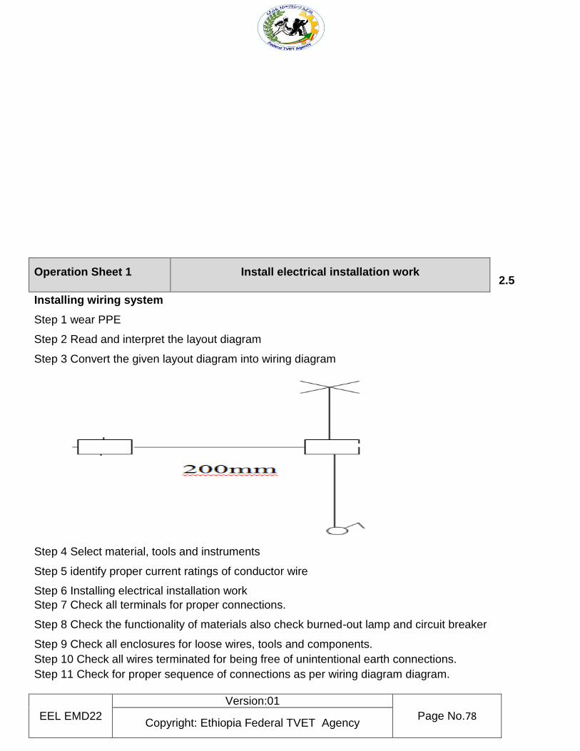
EEL EMD22
Version:01
Page No.78 Copyright: Ethiopia Federal TVET Agency
2.5
Installing wiring system
Step 1 wear PPE
Step 2 Read and interpret the layout diagram
Step 3 Convert the given layout diagram into wiring diagram
Step 4 Select material, tools and instruments
Step 5 identify proper current ratings of conductor wire
Step 6 Installing electrical installation work
Step 7 Check all terminals for proper connections.
Step 8 Check the functionality of materials also check burned-out lamp and circuit breaker
Step 9 Check all enclosures for loose wires, tools and components.
Step 10 Check all wires terminated for being free of unintentional earth connections.
Step 11 Check for proper sequence of connections as per wiring diagram diagram.
Operation Sheet 1 Install electrical installation work
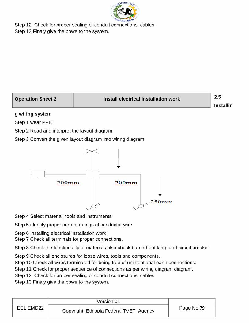
EEL EMD22
Version:01
Page No.79 Copyright: Ethiopia Federal TVET Agency
Step 12 Check for proper sealing of conduit connections, cables.
Step 13 Finaly give the powe to the system.
2.5
Installin
g wiring system
Step 1 wear PPE
Step 2 Read and interpret the layout diagram
Step 3 Convert the given layout diagram into wiring diagram
Step 4 Select material, tools and instruments
Step 5 identify proper current ratings of conductor wire
Step 6 Installing electrical installation work
Step 7 Check all terminals for proper connections.
Step 8 Check the functionality of materials also check burned-out lamp and circuit breaker
Step 9 Check all enclosures for loose wires, tools and components.
Step 10 Check all wires terminated for being free of unintentional earth connections.
Step 11 Check for proper sequence of connections as per wiring diagram diagram.
Step 12 Check for proper sealing of conduit connections, cables.
Step 13 Finaly give the powe to the system.
Operation Sheet 2 Install electrical installation work
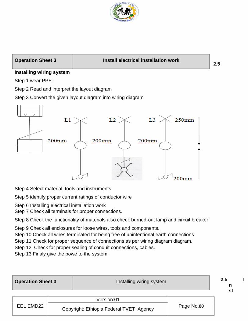
EEL EMD22
Version:01
Page No.80 Copyright: Ethiopia Federal TVET Agency
2.5
Installing wiring system
Step 1 wear PPE
Step 2 Read and interpret the layout diagram
Step 3 Convert the given layout diagram into wiring diagram
Step 4 Select material, tools and instruments
Step 5 identify proper current ratings of conductor wire
Step 6 Installing electrical installation work
Step 7 Check all terminals for proper connections.
Step 8 Check the functionality of materials also check burned-out lamp and circuit breaker
Step 9 Check all enclosures for loose wires, tools and components.
Step 10 Check all wires terminated for being free of unintentional earth connections.
Step 11 Check for proper sequence of connections as per wiring diagram diagram.
Step 12 Check for proper sealing of conduit connections, cables.
Step 13 Finaly give the powe to the system.
2.5 I
nst
Operation Sheet 3 Install electrical installation work
Operation Sheet 3 Installing wiring system
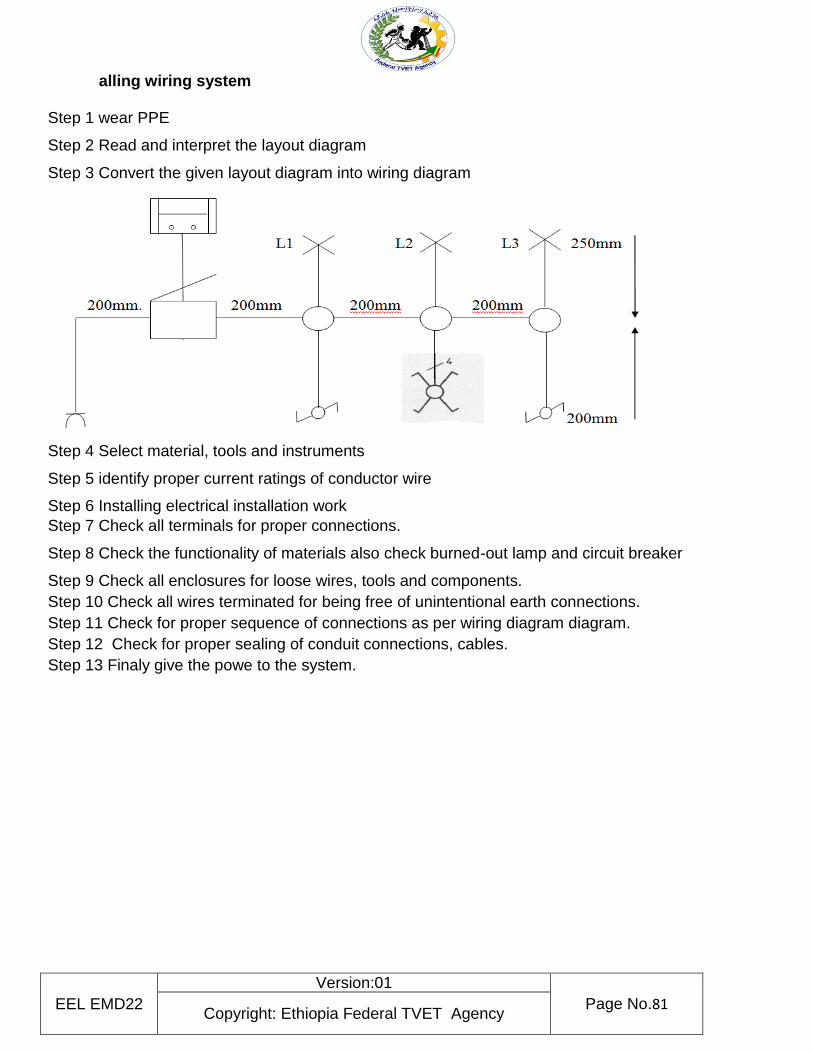
EEL EMD22
Version:01
Page No.81 Copyright: Ethiopia Federal TVET Agency
alling wiring system
Step 1 wear PPE
Step 2 Read and interpret the layout diagram
Step 3 Convert the given layout diagram into wiring diagram
Step 4 Select material, tools and instruments
Step 5 identify proper current ratings of conductor wire
Step 6 Installing electrical installation work
Step 7 Check all terminals for proper connections.
Step 8 Check the functionality of materials also check burned-out lamp and circuit breaker
Step 9 Check all enclosures for loose wires, tools and components.
Step 10 Check all wires terminated for being free of unintentional earth connections.
Step 11 Check for proper sequence of connections as per wiring diagram diagram.
Step 12 Check for proper sealing of conduit connections, cables.
Step 13 Finaly give the powe to the system.
EEL EMD22
Version:01
Page No.82 Copyright: Ethiopia Federal TVET Agency
Name
……………………………………………………….. Date…………………………….
Time started…………………………………………………. Time finished…………………...
Instructions: given necessary templates , tools and materials you are required to perform the
following tasks with 8 hours.
Task 1: Installing wiring system
LAP Test Practical demonistration
EEL EMD22
Version:01
Page No.83 Copyright: Ethiopia Federal TVET Agency
Instruction Sheet LG18: Inspect and notify completion of work
This learning guide is developed to provide you the necessary information regarding the following
learning outcome and content coverage
Inspection of installed apparatus
Functional test of installed apparatus
Notification of completion work
-This guide will also assist you to attain the learning outcome and contents stated in the cover page. Specifically, upon completion of this Learning Guide, you will be able to:-
Inspect installed apparatus
Test the installed apparatus
Notification of completion work
Learning Instructions:
8. Read the specific objectives of this Learning Guide. 9. Follow the instruction described blew 3 to 5 10. Read the information written in the “Information Sheet 1 up to information sheet 3”. 11. Accomplish the “Self-check 1, self-check 2, and Self-check 3, ” in page ( 7, 30 and 32 )
respectively. 12. If you earned a satisfactory evaluation from the “Self-check” proceed to other information sheet.
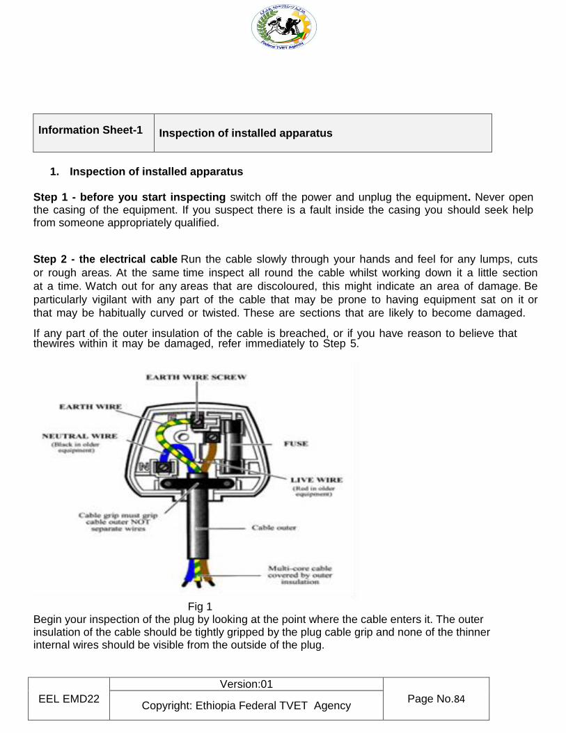
EEL EMD22
Version:01
Page No.84 Copyright: Ethiopia Federal TVET Agency
Information Sheet-1 Inspection of installed apparatus
1. Inspection of installed apparatus
Step 1 - before you start inspecting switch off the power and unplug the equipment. Never open the casing of the equipment. If you suspect there is a fault inside the casing you should seek help from someone appropriately qualified.
Step 2 - the electrical cable Run the cable slowly through your hands and feel for any lumps, cuts
or rough areas. At the same time inspect all round the cable whilst working down it a little section
at a time. Watch out for any areas that are discoloured, this might indicate an area of damage. Be
particularly vigilant with any part of the cable that may be prone to having equipment sat on it or
that may be habitually curved or twisted. These are sections that are likely to become damaged.
If any part of the outer insulation of the cable is breached, or if you have reason to believe that thewires within it may be damaged, refer immediately to Step 5.
Fig 1 Begin your inspection of the plug by looking at the point where the cable enters it. The outer insulation of the cable should be tightly gripped by the plug cable grip and none of the thinner internal wires should be visible from the outside of the plug.
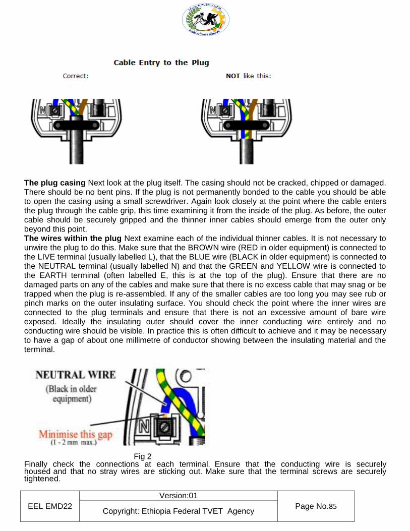
EEL EMD22
Version:01
Page No.85 Copyright: Ethiopia Federal TVET Agency
The plug casing Next look at the plug itself. The casing should not be cracked, chipped or damaged. There should be no bent pins. If the plug is not permanently bonded to the cable you should be able to open the casing using a small screwdriver. Again look closely at the point where the cable enters the plug through the cable grip, this time examining it from the inside of the plug. As before, the outer cable should be securely gripped and the thinner inner cables should emerge from the outer only beyond this point. The wires within the plug Next examine each of the individual thinner cables. It is not necessary to unwire the plug to do this. Make sure that the BROWN wire (RED in older equipment) is connected to the LIVE terminal (usually labelled L), that the BLUE wire (BLACK in older equipment) is connected to the NEUTRAL terminal (usually labelled N) and that the GREEN and YELLOW wire is connected to the EARTH terminal (often labelled E, this is at the top of the plug). Ensure that there are no damaged parts on any of the cables and make sure that there is no excess cable that may snag or be trapped when the plug is re-assembled. If any of the smaller cables are too long you may see rub or pinch marks on the outer insulating surface. You should check the point where the inner wires are connected to the plug terminals and ensure that there is not an excessive amount of bare wire exposed. Ideally the insulating outer should cover the inner conducting wire entirely and no conducting wire should be visible. In practice this is often difficult to achieve and it may be necessary to have a gap of about one millimetre of conductor showing between the insulating material and the terminal.
Fig 2 Finally check the connections at each terminal. Ensure that the conducting wire is securely housed and that no stray wires are sticking out. Make sure that the terminal screws are securely tightened.
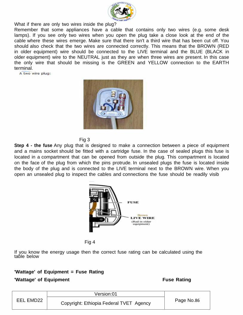
EEL EMD22
Version:01
Page No.86 Copyright: Ethiopia Federal TVET Agency
What if there are only two wires inside the plug? Remember that some appliances have a cable that contains only two wires (e.g. some desk lamps). If you see only two wires when you open the plug take a close look at the end of the cable where these wires emerge. Make sure that there isn't a third wire that has been cut off. You should also check that the two wires are connected correctly. This means that the BROWN (RED in older equipment) wire should be connected to the LIVE terminal and the BLUE (BLACK in older equipment) wire to the NEUTRAL just as they are when three wires are present. In this case the only wire that should be missing is the GREEN and YELLOW connection to the EARTH terminal.
Fig 3
Step 4 - the fuse Any plug that is designed to make a connection between a piece of equipment
and a mains socket should be fitted with a cartridge fuse. In the case of sealed plugs this fuse is
located in a compartment that can be opened from outside the plug. This compartment is located
on the face of the plug from which the pins protrude. In unsealed plugs the fuse is located inside
the body of the plug and is connected to the LIVE terminal next to the BROWN wire. When you
open an unsealed plug to inspect the cables and connections the fuse should be readily visib
Fig 4 If you know the energy usage then the correct fuse rating can be calculated using the table below
'Wattage' of Equipment = Fuse Rating
'Wattage' of Equipment Fuse Rating
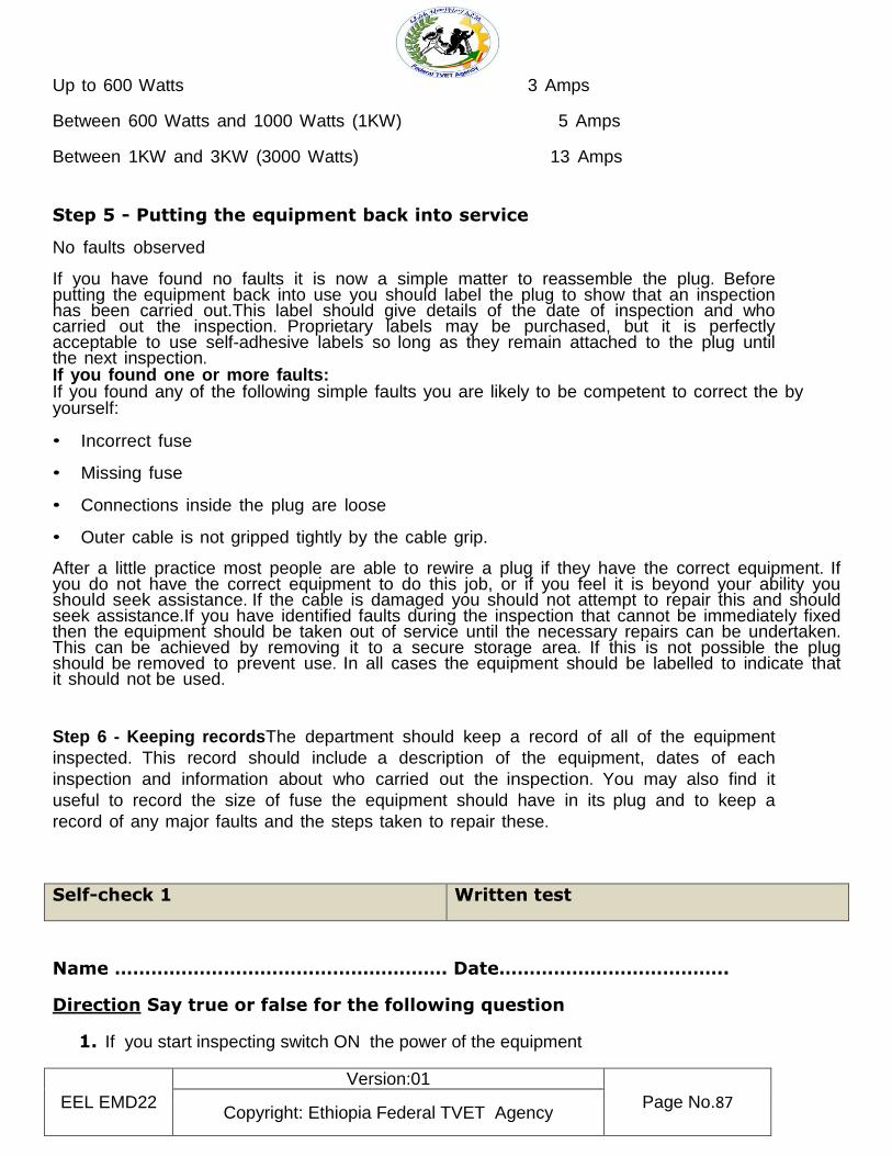
EEL EMD22
Version:01
Page No.87 Copyright: Ethiopia Federal TVET Agency
Up to 600 Watts 3 Amps Between 600 Watts and 1000 Watts (1KW) 5 Amps Between 1KW and 3KW (3000 Watts) 13 Amps
Step 5 - Putting the equipment back into service
No faults observed
If you have found no faults it is now a simple matter to reassemble the plug. Before putting the equipment back into use you should label the plug to show that an inspection has been carried out.This label should give details of the date of inspection and who carried out the inspection. Proprietary labels may be purchased, but it is perfectly acceptable to use self-adhesive labels so long as they remain attached to the plug until the next inspection. If you found one or more faults: If you found any of the following simple faults you are likely to be competent to correct the by yourself: • Incorrect fuse
• Missing fuse
• Connections inside the plug are loose
• Outer cable is not gripped tightly by the cable grip.
After a little practice most people are able to rewire a plug if they have the correct equipment. If you do not have the correct equipment to do this job, or if you feel it is beyond your ability you should seek assistance. If the cable is damaged you should not attempt to repair this and should seek assistance.If you have identified faults during the inspection that cannot be immediately fixed then the equipment should be taken out of service until the necessary repairs can be undertaken. This can be achieved by removing it to a secure storage area. If this is not possible the plug should be removed to prevent use. In all cases the equipment should be labelled to indicate that it should not be used.
Step 6 - Keeping recordsThe department should keep a record of all of the equipment
inspected. This record should include a description of the equipment, dates of each
inspection and information about who carried out the inspection. You may also find it
useful to record the size of fuse the equipment should have in its plug and to keep a
record of any major faults and the steps taken to repair these.
Self-check 1 Written test
Name ………………………………………………. Date………………………………..
Direction Say true or false for the following question
1. If you start inspecting switch ON the power of the equipment
EEL EMD22
Version:01
Page No.88 Copyright: Ethiopia Federal TVET Agency
2. Recording should include a description of the equipment, dates of each inspection
and information about who carried out the inspection.
3. Connections inside the plug loose and Missing are can corrected by yourself: 4. If you have reason to believe that the wires within it may be damaged, refer
to Putting the equipment back into service
Note: Satisfactory rating - 5 points Unsatisfactory – 5 below
Information Sheet-2 Functional test of installed apparatus
2.1 Functional test of installed apparatus 2.1.1 Initial Testing of an Installation Before a utility will connect an installation to its supply network, strict pre-commissioning electrical tests and visual inspections by the authority, or by its appointed agent, must be satisfied. These tests are made according to local (governmental and/or institutional) regulations, which may differ slightly from one country to another. The principles of all such regulations however, are common, and are based on the observance of rigorous safety rules in the design and realization of the installation. IEC 60364-6-61 and related standards included in this guide are based on an international consensus for such tests, intended to cover all the safety measures and approved installation practices normally
EEL EMD22
Version:01
Page No.89 Copyright: Ethiopia Federal TVET Agency
required for residential, commercial and (the majority of) industrial buildings. Many industries however have additional regulations related to a particular product (petroleum, coal, natural gas, etc.). Such additional requirements are beyond the scope of this guide. The pre-commissioning electrical tests and visual-inspection checks for installations in buildings include, typically, all of the following:
Insulation tests of all cable and wiring conductors of the fixed installation, between phases and between phases and earth
Continuity and conductivity tests of protective, equipotential and earth-bonding conductors Resistance tests of earthing electrodes with respect to remote earth Verification of the proper operation of the interlocks, if any Check of allowable number of socket-outlets per circuit Cross-sectional-area check of all conductors for adequacy at the short-circuit levels prevailing,
taking account of the associated protective devices, materials and installation conditions (in air, conduit, etc.)
Verification that all exposed- and extraneous metallic parts are properly earthed (where appropriate)
Check of clearance distances in bathrooms, etc.
2.1.2 Periodic Check Testing of an Installation In many countries, all industrial and commercial-building installations, together with installations in buildings used for public gatherings, must be re-tested periodically by authorized agents.
2.1.3 Testing of the Wiring Installation The test to be performed before a new installation or an addition to an existing installation is connected to the supply mains are as follows.
1) Testing insulation resistance between the wiring and the earth with all fuses and lamps in and all switches 'ON'.
2) The insulation resistance between the conductors with all lamps out and all switches 'ON'. 3) Testing of polarity of non-linked pole switches. 4) Testing of earth continuity path. 5) Testing of earth resistance
1. Testing of Insulation Resistance Between the Wiring and Earth:- The resistance offered to
leakage from conductors to earth is known as insulation resistance between the wiring and the earth. The values of insulation resistance are so high that they are measured in Mega-ohms. The aim of this test is to know weather the wires or cables used in the wiring system are sufficiently insulated to avoid leakage of current. The instrument used to test the insulation resistance is known as Megger. Before making an insulation resistance ensures that: -
i. Main switch is in off position ii. Main fuse is taken out iii. All other fuses are in position iv. All the switches are in 'on' position v. All the lamps are in their position or the holders are short-circuited and vi. Line and neutral terminals are shorted on the insulation resistance.
The measured resistance should not be less than 50 mega-ohms divided by the number of outlets.
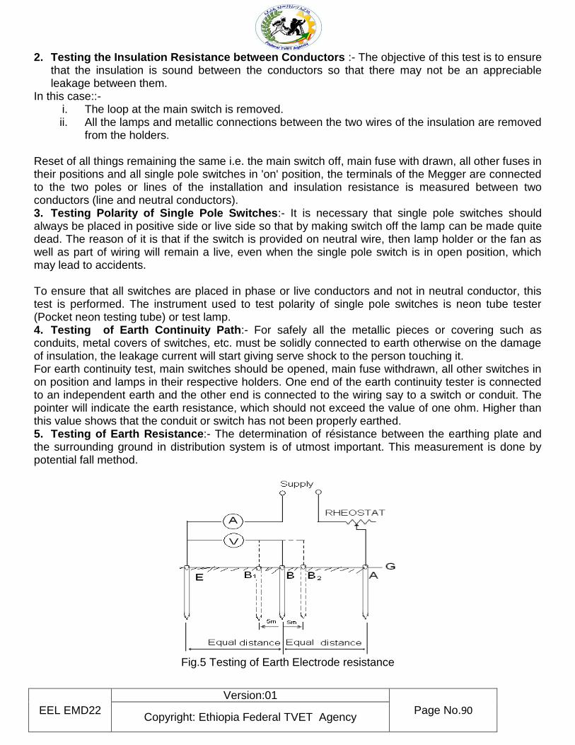
EEL EMD22
Version:01
Page No.90 Copyright: Ethiopia Federal TVET Agency
2. Testing the Insulation Resistance between Conductors :- The objective of this test is to ensure that the insulation is sound between the conductors so that there may not be an appreciable leakage between them.
In this case::- i. The loop at the main switch is removed. ii. All the lamps and metallic connections between the two wires of the insulation are removed
from the holders.
Reset of all things remaining the same i.e. the main switch off, main fuse with drawn, all other fuses in their positions and all single pole switches in 'on' position, the terminals of the Megger are connected to the two poles or lines of the installation and insulation resistance is measured between two conductors (line and neutral conductors). 3. Testing Polarity of Single Pole Switches:- It is necessary that single pole switches should always be placed in positive side or live side so that by making switch off the lamp can be made quite dead. The reason of it is that if the switch is provided on neutral wire, then lamp holder or the fan as well as part of wiring will remain a live, even when the single pole switch is in open position, which may lead to accidents. To ensure that all switches are placed in phase or live conductors and not in neutral conductor, this test is performed. The instrument used to test polarity of single pole switches is neon tube tester (Pocket neon testing tube) or test lamp. 4. Testing of Earth Continuity Path:- For safely all the metallic pieces or covering such as conduits, metal covers of switches, etc. must be solidly connected to earth otherwise on the damage of insulation, the leakage current will start giving serve shock to the person touching it. For earth continuity test, main switches should be opened, main fuse withdrawn, all other switches in on position and lamps in their respective holders. One end of the earth continuity tester is connected to an independent earth and the other end is connected to the wiring say to a switch or conduit. The pointer will indicate the earth resistance, which should not exceed the value of one ohm. Higher than this value shows that the conduit or switch has not been properly earthed. 5. Testing of Earth Resistance:- The determination of résistance between the earthing plate and the surrounding ground in distribution system is of utmost important. This measurement is done by potential fall method.
Fig.5 Testing of Earth Electrode resistance
EEL EMD22
Version:01
Page No.91 Copyright: Ethiopia Federal TVET Agency
The resistance area of an earth electrode is the area of soil around the electrode within which a voltage gradient measurable with commercial instrument exists. In fig. 1, E is the earth electrode under test, A is an auxiliary earth electrode positioned so that two resistance areas do not overlap. B is a second auxiliary electrode placed half way between E and A. An alternating current is passed through the earth path from E to A and the voltage drop between E and B is measured.
I
V
pathearththrouhgCurrent
BandEbetweendropVoltageRceresisearthThe tan
To ensure that the resistance area do not overlap, the auxiliary electrode B is moved to positions B1 and B2 respectively. If resistance values determined are of approximately the same magnitude in all the three cases, the mean of the readings can be taken as the earth resistance of the earth electrode. Otherwise the auxiliary electrode A must be driven in at a point further away from E and the above test repeated until a group of these readings is obtained which are in good agreement. Inspection of Internal Wiring Installation Internal wiring should be inspected once a year and the following points should be checked while carrying out inspection of the wiring installation.
1. Service Connections:- In case of overhead line, check and ensure that i. The lines are terminated a sufficient distance away from the building ii. The fuse wire of correct rating is provided on the phase line iii. The lead-in-wires are of size sufficient to carry the full load current
2. Main Switch Board:- In case of ,main switch board please check up and ensure that
i. The voltage available is correct ii. The main switch is provided close to the point of commencement of supply iii. The fuse of correct size is provided on the live pole iv. The phase and neutral wires are clearly marked for identification v. Caution notice in English or other local language is placed.
3. Miscellaneous:- The points to be checked are i. No branch circuit feeds more than the breaker can feed ii. The single pole switches are provided on the live conductor iii. The metallic frames of all power equipment are earthed by the independent earth
conductors
Fault-Tracing in Circuits and Equipment The types of fault which may occur in an electrical circuit fall into four general groups:
1. Open – circuit fault ( loss of continuity)
2. Earth fault ( low resistance between live conductor and earthed metalwork )
3. Short- circuit fault ( low resistance between phase and neutral conductors)
4. High- value series – resistance fault ( bad joint or loose connection in conduction path)
These fault types occur in lighting and power circuits, appliances, apparatus and electric motors; variations do, occur with the type of electrical equipment. Before any fault can be found and rectified it is necessary for the electrician to adopt a method or system based on a sound knowledge of circuitry and electrical theory, and on experience. The electrician detailed to repair a fault circuit is in many ways like a doctor who makes his diagnosis on the basis of the symptoms revealed through a visual inspection or a test using the correct instruments . Haphazard tests
EEL EMD22
Version:01
Page No.92 Copyright: Ethiopia Federal TVET Agency
carried out at random seldom lead to success in the quick location of faults. The investigation must always be based on an intelligent assessment of the fault and its probable causes, judged from its effects. In many instances, faults arise from installations or circuits which do not in some way or other comply with the requirements of the IEE regulations, or else are used in such a manner that the abuse results in a fault. Most faults are easily located by following up reports such as There was a flash at the lamp; The wires got red hot; The lamp goes dim when it is switched on; or ‘The bedroom light will come on only when the bathroom switch is ON ; By careful questioning, these reports will enable the electrician to locate the fault quickly and restore the circuit to normal operation again. The following are some common installation defects and omissions which eventually lead to faults’;
Fault-tracing in circuits and equipment 1. The provision of double –pole fusing on two wire systems with one pole permanently earthed.
This frequently occurs with final circuit distribution boards when the main and /or sub main
control equipment is single pole and solid neutral.
2. Fuse protection not related to the current rating of cables to be protected . This is very often
due to the equipment manufactures fitting the fuse- carriers with a fuse – element of maximum
rating for the fuse- units in the equipment.
3. Connecting boxes for sheathed- wiring systems placed in inaccessible positions in roof voids
and beneath floors, indiscriminate bunching of too may cables using screw- on or inadequate
connections .
4. Insufficient protection provided for sheathed wiring, e.g. to switch positions and on joints in
roof voids.
5. Incorrect use of materials, not resistant against corrosion, in damp situations (e.g. enameled
conduit and accessories and plain – steel fixing screws).
6. Inadequate or complete omission of segregation between cables and /or connections, hosed
within a common enclosure, supplying systems for extra- low voltage; or telecommunication
and power and /or lighting operating at a voltage excess if extra- low voltage.
7. Insufficient attention given to cleaning ends of conduit and/or providing bushings omission of
bushings to prevent abrasion of cables at tapped entries, particularly at switch positions.
8. Insufficient precautions taken against the entry of water to duct and /or trunking systems
particularly where installed within the floor.
9. Incorrect use of PVC insulated and /or sheathed cables and flexible cords instead of heat-
resistant type, for connections to immersion heaters, heaters, thermal- storage block heaters ,
etc.
10. Incorrect use of braided and twisted flexible cords for bathroom pendant fittings and similar situations subject to damp or condensation .
11. The incorrect use of accessories, apparatus or appliances inappropriate for operating conditions of the situation in which they are required to functions
EEL EMD22
Version:01
Page No.93 Copyright: Ethiopia Federal TVET Agency
12. Installation of cables of insufficient capacity to carry the starting current of motors. Causing excessive volt drop.
13. Incorrect rating of fuse-element to give protection to the cables supplying the motor. Open-circuit faults The instrument used to locate this type of faults is the continuity . The usual effect of this fault is
that the apparatus or lamp in the circuit will not operate. The fault can be ( a) a break in a wire; (b) a very loose or disconnected terminal or joint connection; (c) a blown fuse; (d) a faulty switchblade contact. The fuse should always be easily inspected. The cartridge type can be tested for continuity of the fuse-element. If the fuse has operated, the reason why it has done so must be found out . It is not enough to repair or replace the fuse and leave it at that . A broken wire or a disconnection will show on the continuity tester as an extremely high resistance in the khoum or me gohm ranges. Before each wire in the faulty circuit is tested in turn (live feed, switch- wire and neutral) all mechanical connections should be inspected ( lamp holders , junction box, plug or the metal sheeting of convenient return when testing the continuity of very long conductors . In an all insulated wiring system, other healthy conductor can be used as returns for testing purposes making sure that the aright al connections are restored once the fault has been found .
Earth faults An earth fault between alive conductor and earthed metalwork will have the same effect
as a direct short – circuit : the circuit fuse will blow . To trace the fault . it is necessary to isolate the live conductor from the neutral by removing all lamps etc, and placing all switches in the ON position . An isolation- resistant ( IR) tester is used to trace this fault circuits should be subdivided as far as is possible to finally locate the position of the fault . The reading obtained on the instrument used will be in the low- ohms range. An earth fault on the neutral conductor seldom shows up except by an IR –to earth test on the neutral conductor in most instances this type of fault does not affect the operation of the circuit or the devices or equipment connected to it . However, it is important to rectify any such fault found, otherwise if it is ignored it may cause a shock and fire hazard .
Short – circuit fault On testing the insulation resistance between the live and neutral conductors with an IR tester, the reading will show itself in the low ohms range .again, subdivision of the installation at the distribution board , and subdivision of the faulty circuit is the only way to locate and confirm the position of the faults . Short circuits can occur as the result of damaged insulation bare wire in junction boxes and fittings , or by a conductor becoming loose from terminals and moving so as to come into contact with a conductor of opposite polarity. The result of short circuit is a blown fuse , though if there is a sufficiently current can flow to blow the circuit fuse ) the result will be over heating of the conductors and sparking or arcing at the point of contact . The test involves the removal of all lamps and appliances from the faulty circuit, open all switches, and carry out an IR test between the live and neutral conductors . If the reading obtained is satisfactory , close each circuit switch in turn until the faulty conductor, a switch wire, is located. If a low or near-zero reading is obtained on the first test, the circuit will have to be disconnected at convenient points until the faulty wire is isolated .
High- value series –resistance faults This type of fault is most difficult to trace as it usually means that a connection, joint or termination has become loose . the effect of this is invariably dim lights; or motor going very slowly and heating up : in new installations the demises of the lamps may well be caused by a wrong connection in junction box resulting in two or more lamps being connected in series .
Main faults in new wiring Faults in new wiring are generally the of careless or inadvertent wrong connections which will either blow a fuse , cause lamps to operate dimly as above, not work at all
EEL EMD22
Version:01
Page No.94 Copyright: Ethiopia Federal TVET Agency
or work only when another circuit switch is placed on the ON position . If a lamp lights only when another switch in the same final circuit is ON this indicates that the live feed to the faulty lamp has been looped from the switch – wire side of the previous circuit switch instead of from the live- feed side . The fact that overloading a circuit will blow a fuse should not be overlooked .
Faults in fluorescent –lamp circuits The following tables summaries the faults , effects and the remedies associated with fluorescent –lamp circuits.
Faults in motors and circuits Table 28-4 sum arises briefly the faults . effects and remedies associated with motors and their associated circuitry and control gear. Because the voltage of low – and extra- low voltage circuits is relatively small, small, a poor or dirty contact will immediately prevent bells and similar devices from operating . These faults are thus most difficult to trace, and it is often a matter of systematic checking for continuity ( zero or near –zero) readings . The prevention of faults in ELV circuits is more often than not a matter of regular periodic maintenance attention ( cleaning contacts, tightening connections, etc ) than anything else .
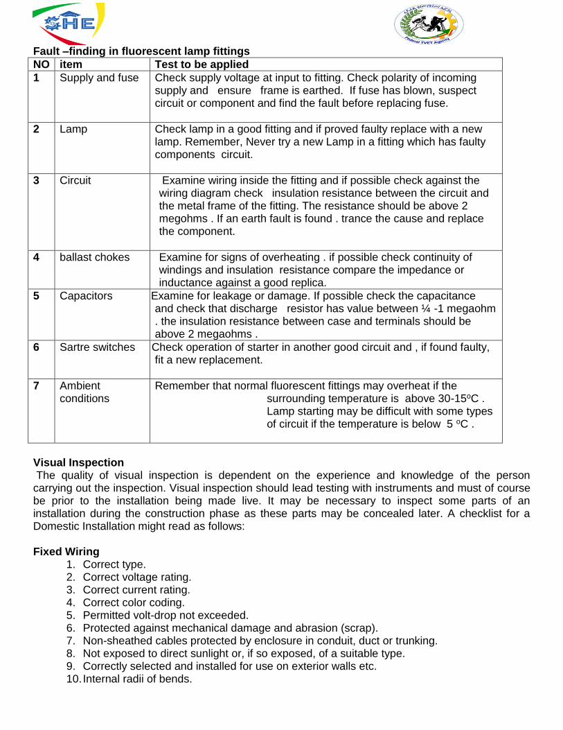
Fault –finding in fluorescent lamp fittings
NO item Test to be applied
1 Supply and fuse Check supply voltage at input to fitting. Check polarity of incoming supply and ensure frame is earthed. If fuse has blown, suspect circuit or component and find the fault before replacing fuse.
2 Lamp Check lamp in a good fitting and if proved faulty replace with a new lamp. Remember, Never try a new Lamp in a fitting which has faulty components circuit.
3 Circuit Examine wiring inside the fitting and if possible check against the wiring diagram check insulation resistance between the circuit and the metal frame of the fitting. The resistance should be above 2 megohms . If an earth fault is found . trance the cause and replace the component.
4 ballast chokes Examine for signs of overheating . if possible check continuity of windings and insulation resistance compare the impedance or inductance against a good replica.
5 Capacitors Examine for leakage Examine for leakage or damage. If possible check the capacitance and check that discharge resistor has value between ¼ -1 megaohm . the insulation resistance between case and terminals should be above 2 megaohms .
6 Sartre switches Check operation of s Check operation of starter in another good circuit and , if found faulty, fit a new replacement.
7 Ambient conditions
Remember that normal fluorescent fittings may overheat if the surrounding temperature is above 30-15oC . Lamp starting may be difficult with some types of circuit if the temperature is below 5 oC .
Visual Inspection The quality of visual inspection is dependent on the experience and knowledge of the person carrying out the inspection. Visual inspection should lead testing with instruments and must of course be prior to the installation being made live. It may be necessary to inspect some parts of an installation during the construction phase as these parts may be concealed later. A checklist for a Domestic Installation might read as follows: Fixed Wiring
1. Correct type. 2. Correct voltage rating. 3. Correct current rating. 4. Correct color coding. 5. Permitted volt-drop not exceeded. 6. Protected against mechanical damage and abrasion (scrap). 7. Non-sheathed cables protected by enclosure in conduit, duct or trunking. 8. Not exposed to direct sunlight or, if so exposed, of a suitable type. 9. Correctly selected and installed for use on exterior walls etc. 10. Internal radii of bends.
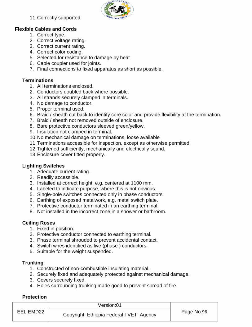
EEL EMD22
Version:01
Page No.96 Copyright: Ethiopia Federal TVET Agency
11. Correctly supported. Flexible Cables and Cords
1. Correct type. 2. Correct voltage rating. 3. Correct current rating. 4. Correct color coding. 5. Selected for resistance to damage by heat. 6. Cable coupler used for joints. 7. Final connections to fixed apparatus as short as possible.
Terminations
1. All terminations enclosed. 2. Conductors doubled back where possible. 3. All strands securely clamped in terminals. 4. No damage to conductor. 5. Proper terminal used. 6. Braid / sheath cut back to identify core color and provide flexibility at the termination. 7. Braid / sheath not removed outside of enclosure. 8. Bare protective conductors sleeved green/yellow. 9. Insulation not clamped in terminal. 10. No mechanical damage on terminations, loose available 11. Terminations accessible for inspection, except as otherwise permitted. 12. Tightened sufficiently, mechanically and electrically sound. 13. Enclosure cover fitted properly.
Lighting Switches
1. Adequate current rating. 2. Readily accessible. 3. Installed at correct height, e.g. centered at 1100 mm. 4. Labeled to indicate purpose, where this is not obvious. 5. Single-pole switches connected only in phase conductors. 6. Earthing of exposed metalwork, e.g. metal switch plate. 7. Protective conductor terminated in an earthing terminal. 8. Not installed in the incorrect zone in a shower or bathroom.
Ceiling Roses
1. Fixed in position. 2. Protective conductor connected to earthing terminal. 3. Phase terminal shrouded to prevent accidental contact. 4. Switch wires identified as live (phase ) conductors. 5. Suitable for the weight suspended.
Trunking
1. Constructed of non-combustible insulating material. 2. Securely fixed and adequately protected against mechanical damage. 3. Covers securely fixed. 4. Holes surrounding trunking made good to prevent spread of fire.
Protection
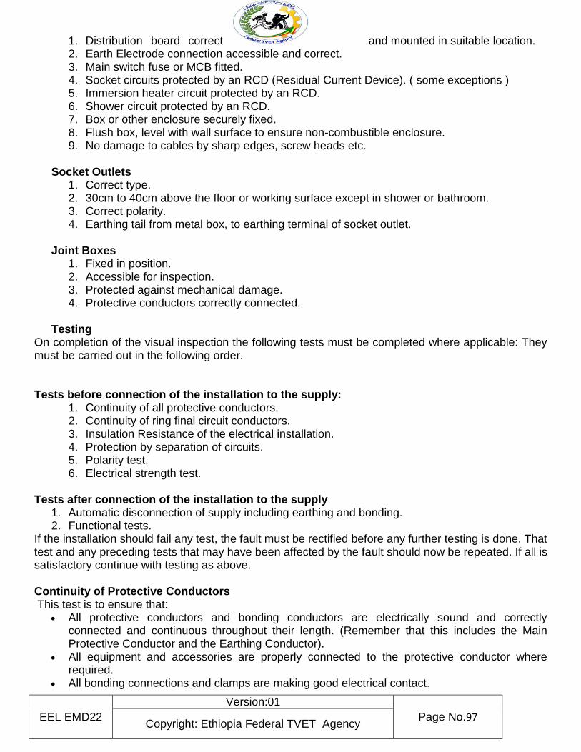
EEL EMD22
Version:01
Page No.97 Copyright: Ethiopia Federal TVET Agency
1. Distribution board correct and mounted in suitable location. 2. Earth Electrode connection accessible and correct. 3. Main switch fuse or MCB fitted. 4. Socket circuits protected by an RCD (Residual Current Device). ( some exceptions ) 5. Immersion heater circuit protected by an RCD. 6. Shower circuit protected by an RCD. 7. Box or other enclosure securely fixed. 8. Flush box, level with wall surface to ensure non-combustible enclosure. 9. No damage to cables by sharp edges, screw heads etc.
Socket Outlets
1. Correct type. 2. 30cm to 40cm above the floor or working surface except in shower or bathroom. 3. Correct polarity. 4. Earthing tail from metal box, to earthing terminal of socket outlet.
Joint Boxes
1. Fixed in position. 2. Accessible for inspection. 3. Protected against mechanical damage. 4. Protective conductors correctly connected.
Testing
On completion of the visual inspection the following tests must be completed where applicable: They must be carried out in the following order. Tests before connection of the installation to the supply:
1. Continuity of all protective conductors. 2. Continuity of ring final circuit conductors. 3. Insulation Resistance of the electrical installation. 4. Protection by separation of circuits. 5. Polarity test. 6. Electrical strength test.
Tests after connection of the installation to the supply
1. Automatic disconnection of supply including earthing and bonding. 2. Functional tests.
If the installation should fail any test, the fault must be rectified before any further testing is done. That test and any preceding tests that may have been affected by the fault should now be repeated. If all is satisfactory continue with testing as above. Continuity of Protective Conductors This test is to ensure that:
All protective conductors and bonding conductors are electrically sound and correctly connected and continuous throughout their length. (Remember that this includes the Main Protective Conductor and the Earthing Conductor).
All equipment and accessories are properly connected to the protective conductor where required.
All bonding connections and clamps are making good electrical contact.
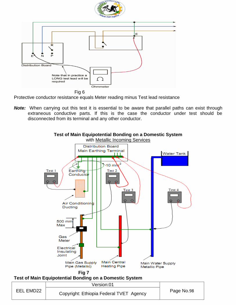
EEL EMD22
Version:01
Page No.98 Copyright: Ethiopia Federal TVET Agency
Fig 6 Protective conductor resistance equals Meter reading minus Test lead resistance Note: When carrying out this test it is essential to be aware that parallel paths can exist through
extraneous conductive parts. If this is the case the conductor under test should be disconnected from its terminal and any other conductor.
Test of Main Equipotential Bonding on a Domestic System with Metallic Incoming Services
Fig 7 Test of Main Equipotential Bonding on a Domestic System
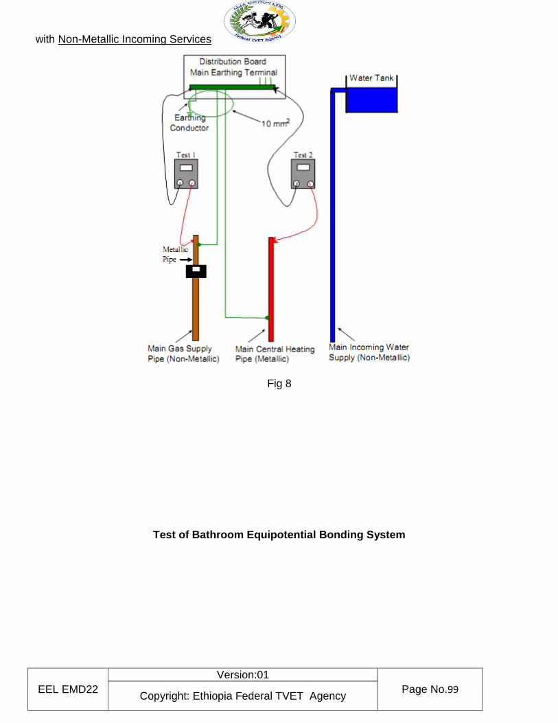
EEL EMD22
Version:01
Page No.99 Copyright: Ethiopia Federal TVET Agency
with Non-Metallic Incoming Services
Fig 8
Test of Bathroom Equipotential Bonding System
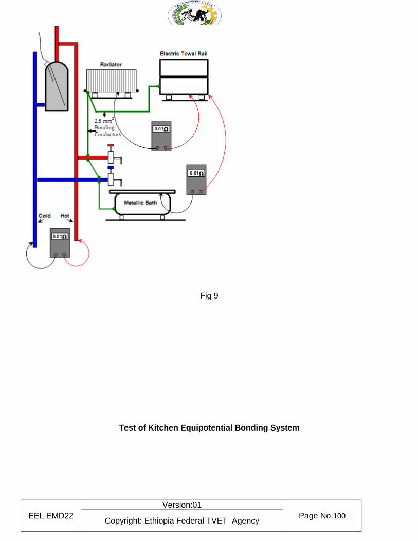
EEL EMD22
Version:01
Page No.100 Copyright: Ethiopia Federal TVET Agency
Fig 9
Test of Kitchen Equipotential Bonding System
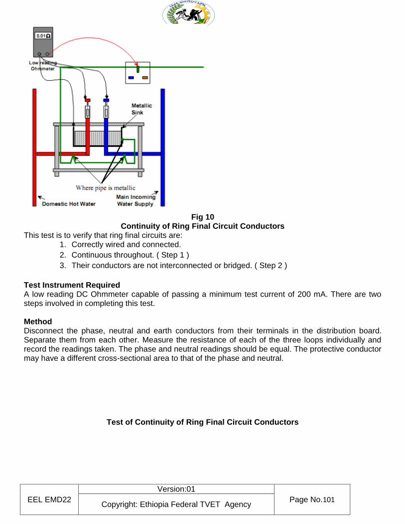
EEL EMD22
Version:01
Page No.101 Copyright: Ethiopia Federal TVET Agency
Fig 10
Continuity of Ring Final Circuit Conductors This test is to verify that ring final circuits are:
1. Correctly wired and connected.
2. Continuous throughout. ( Step 1 )
3. Their conductors are not interconnected or bridged. ( Step 2 )
Test Instrument Required A low reading DC Ohmmeter capable of passing a minimum test current of 200 mA. There are two steps involved in completing this test. Method Disconnect the phase, neutral and earth conductors from their terminals in the distribution board. Separate them from each other. Measure the resistance of each of the three loops individually and record the readings taken. The phase and neutral readings should be equal. The protective conductor may have a different cross-sectional area to that of the phase and neutral.
Test of Continuity of Ring Final Circuit Conductors
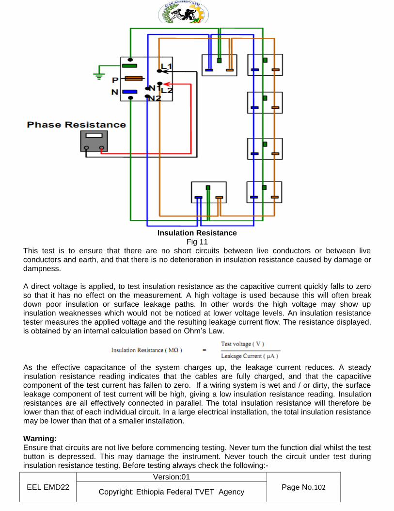
EEL EMD22
Version:01
Page No.102 Copyright: Ethiopia Federal TVET Agency
Insulation Resistance
Fig 11 This test is to ensure that there are no short circuits between live conductors or between live conductors and earth, and that there is no deterioration in insulation resistance caused by damage or dampness.
A direct voltage is applied, to test insulation resistance as the capacitive current quickly falls to zero so that it has no effect on the measurement. A high voltage is used because this will often break down poor insulation or surface leakage paths. In other words the high voltage may show up insulation weaknesses which would not be noticed at lower voltage levels. An insulation resistance tester measures the applied voltage and the resulting leakage current flow. The resistance displayed, is obtained by an internal calculation based on Ohm’s Law.
As the effective capacitance of the system charges up, the leakage current reduces. A steady insulation resistance reading indicates that the cables are fully charged, and that the capacitive component of the test current has fallen to zero. If a wiring system is wet and / or dirty, the surface leakage component of test current will be high, giving a low insulation resistance reading. Insulation resistances are all effectively connected in parallel. The total insulation resistance will therefore be lower than that of each individual circuit. In a large electrical installation, the total insulation resistance may be lower than that of a smaller installation. Warning: Ensure that circuits are not live before commencing testing. Never turn the function dial whilst the test button is depressed. This may damage the instrument. Never touch the circuit under test during insulation resistance testing. Before testing always check the following:-
EEL EMD22
Version:01
Page No.103 Copyright: Ethiopia Federal TVET Agency
The “battery low” indicator is not showing.
There is no visual damage to the tester or test leads.
Check the continuity of the test leads.
To check the continuity of the test leads: Select the continuity function- and the lowest resistance range. Short the test leads together.
The reading should be almost Zero Ohms.
An over-range OR indication will mean that the leads are faulty or the instrument fuse is blown.
Select the required test voltage (250 V, 500 V or 1000 V ) by rotating the function dial. Note: - The test voltage used for low voltage installations is 500 Volts.
Pre Test Procedures and Observations
1. The installation must be disconnected from the supply.
2. The Main Protective Conductor must be disconnected from the supply neutral.
3. All fuses are intact and all MCBs and switches are closed.
4. All current using equipment including lamps, pilot lights, bell transformers, smoke alarm units, timers etc. are disconnected or otherwise excluded from the test between live conductors.
5. Note:- Where disconnection or removal of these items is impractical the control switches should be in the off position. Items left in circuit will cause false low readings.
6. Any equipment containing electronic circuitry must be disconnected or switched off in order to prevent damage by the high test voltage
Insulation Resistance between All Live Conductors and the Protective Conductor
Method
Connect all live and neutral conductors together at the distribution board and test between them and the protective conductor. The reading obtained should be 1 MΩ or greater.
An infinitely high resistance reading would be ideal. Test of Insulation Resistance between all Live Conductors and the Protective
Conductor
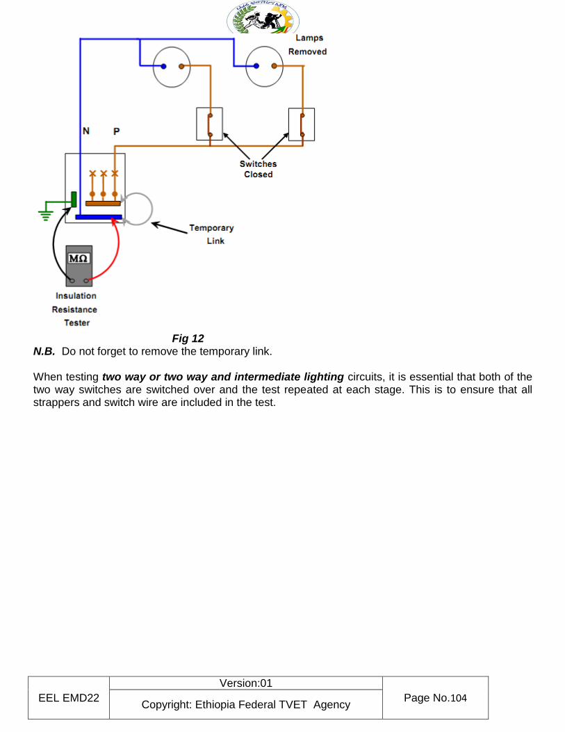
EEL EMD22
Version:01
Page No.104 Copyright: Ethiopia Federal TVET Agency
Fig 12 N.B. Do not forget to remove the temporary link. When testing two way or two way and intermediate lighting circuits, it is essential that both of the two way switches are switched over and the test repeated at each stage. This is to ensure that all strappers and switch wire are included in the test.
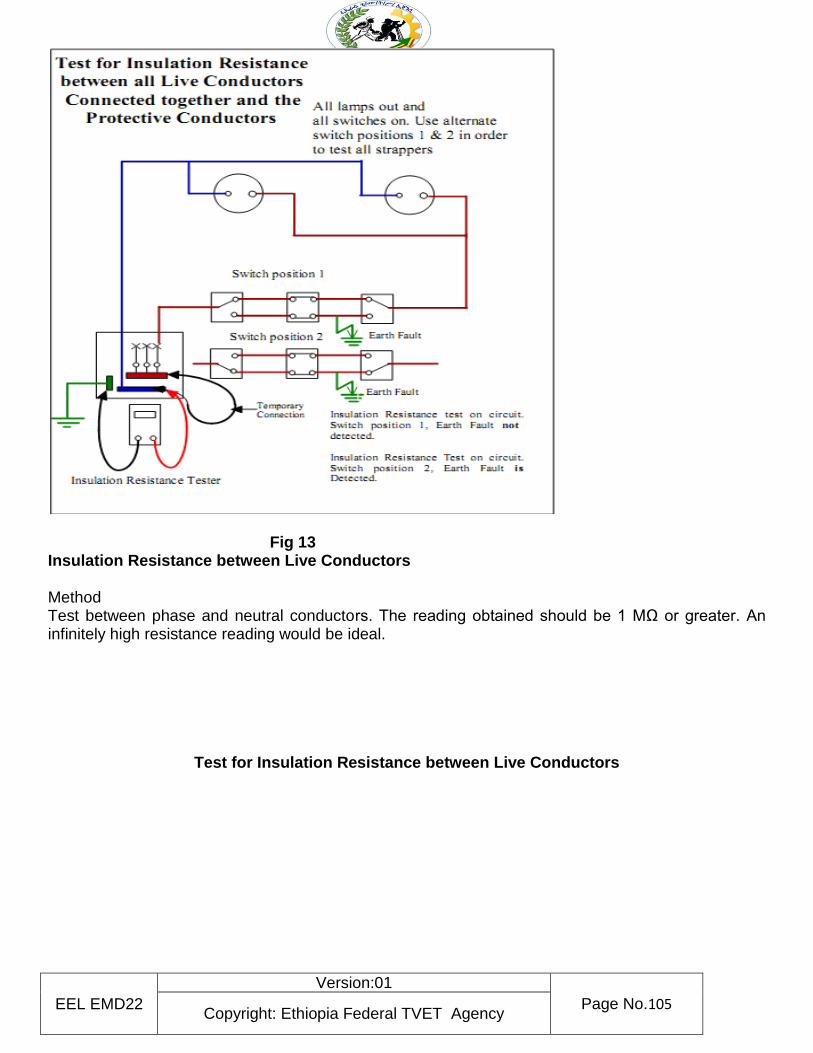
EEL EMD22
Version:01
Page No.105 Copyright: Ethiopia Federal TVET Agency
Fig 13 Insulation Resistance between Live Conductors
Method Test between phase and neutral conductors. The reading obtained should be 1 MΩ or greater. An infinitely high resistance reading would be ideal.
Test for Insulation Resistance between Live Conductors
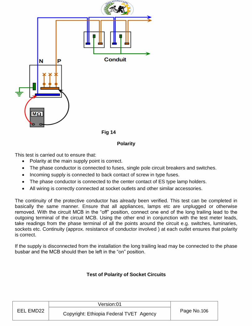
EEL EMD22
Version:01
Page No.106 Copyright: Ethiopia Federal TVET Agency
Fig 14
Polarity This test is carried out to ensure that:
Polarity at the main supply point is correct.
The phase conductor is connected to fuses, single pole circuit breakers and switches.
Incoming supply is connected to back contact of screw in type fuses.
The phase conductor is connected to the center contact of ES type lamp holders.
All wiring is correctly connected at socket outlets and other similar accessories.
The continuity of the protective conductor has already been verified. This test can be completed in basically the same manner. Ensure that all appliances, lamps etc are unplugged or otherwise removed. With the circuit MCB in the “off” position, connect one end of the long trailing lead to the outgoing terminal of the circuit MCB. Using the other end in conjunction with the test meter leads, take readings from the phase terminal of all the points around the circuit e.g. switches, luminaries, sockets etc. Continuity (approx. resistance of conductor involved ) at each outlet ensures that polarity is correct. If the supply is disconnected from the installation the long trailing lead may be connected to the phase busbar and the MCB should then be left in the “on” position.
Test of Polarity of Socket Circuits
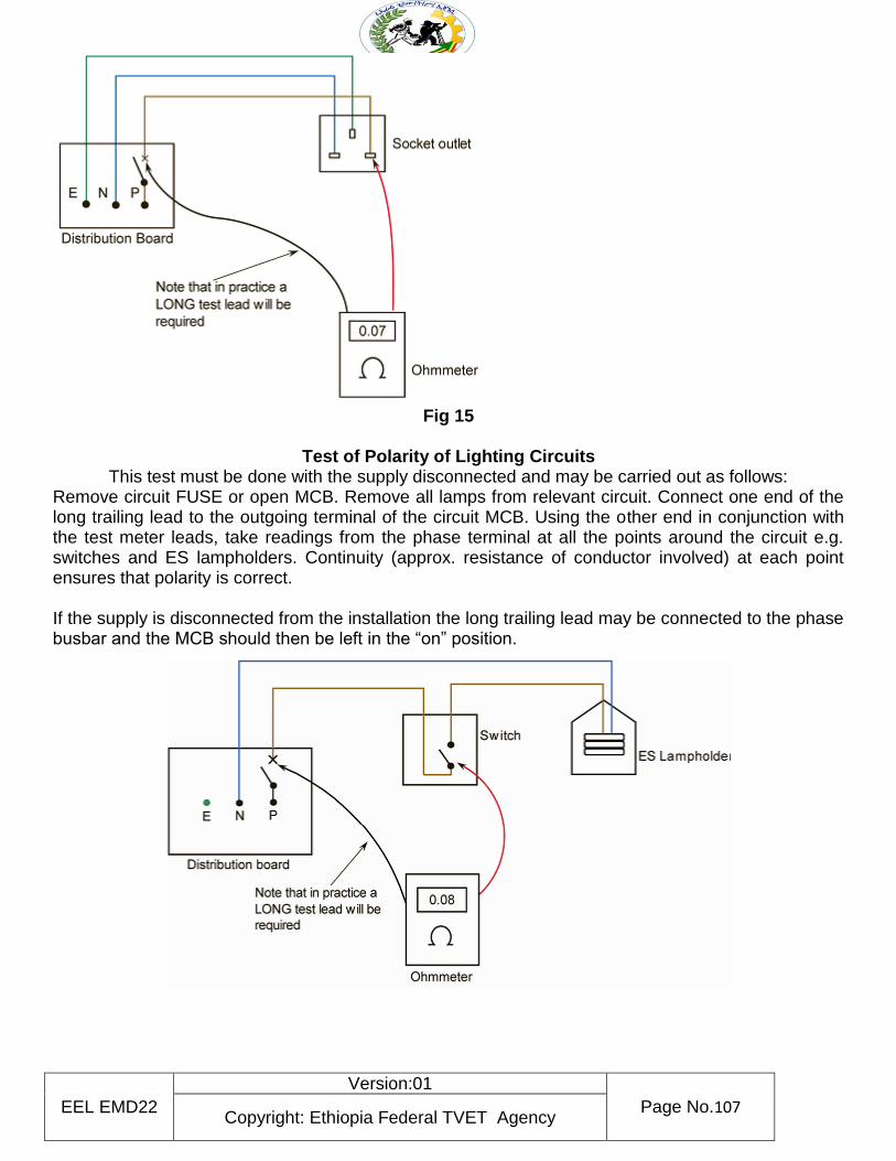
EEL EMD22
Version:01
Page No.107 Copyright: Ethiopia Federal TVET Agency
Fig 15
Test of Polarity of Lighting Circuits
This test must be done with the supply disconnected and may be carried out as follows: Remove circuit FUSE or open MCB. Remove all lamps from relevant circuit. Connect one end of the long trailing lead to the outgoing terminal of the circuit MCB. Using the other end in conjunction with the test meter leads, take readings from the phase terminal at all the points around the circuit e.g. switches and ES lampholders. Continuity (approx. resistance of conductor involved) at each point ensures that polarity is correct. If the supply is disconnected from the installation the long trailing lead may be connected to the phase busbar and the MCB should then be left in the “on” position.
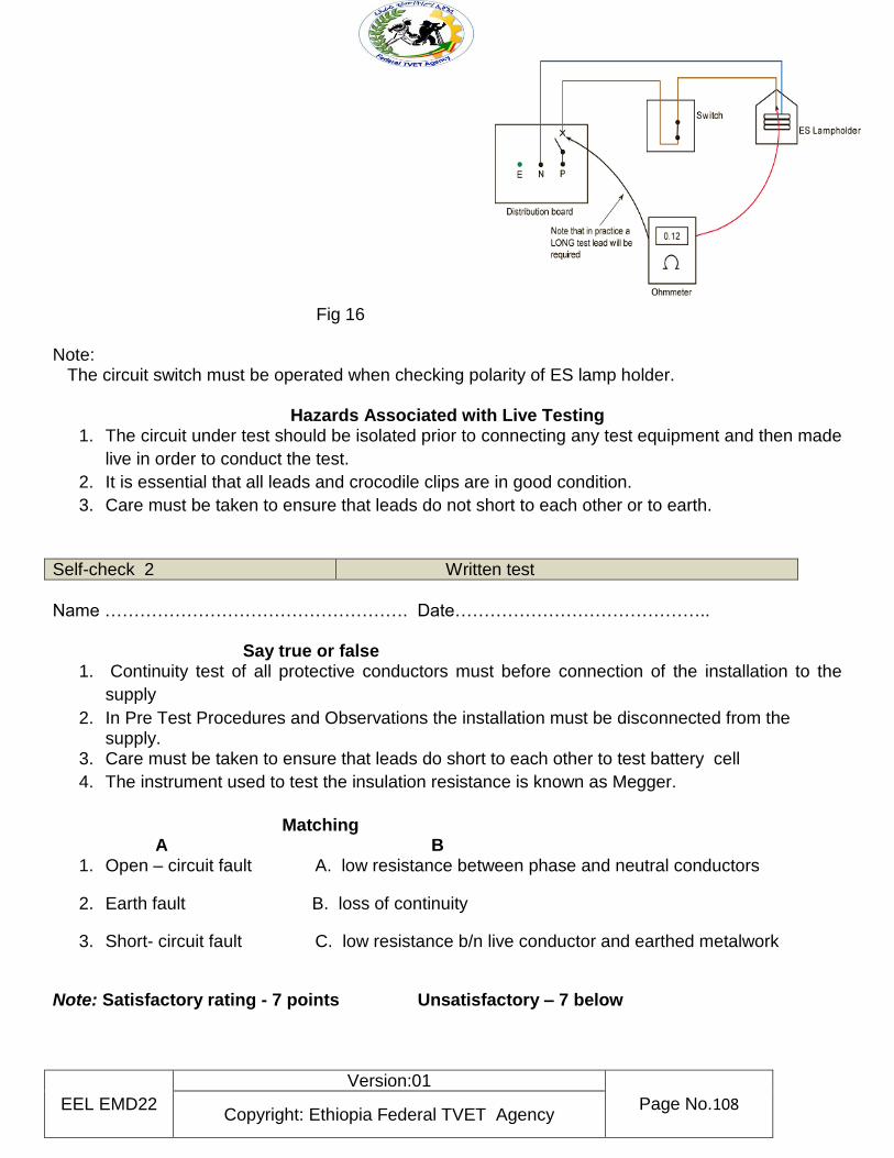
EEL EMD22
Version:01
Page No.108 Copyright: Ethiopia Federal TVET Agency
Fig 16 Note: The circuit switch must be operated when checking polarity of ES lamp holder.
Hazards Associated with Live Testing 1. The circuit under test should be isolated prior to connecting any test equipment and then made
live in order to conduct the test.
2. It is essential that all leads and crocodile clips are in good condition.
3. Care must be taken to ensure that leads do not short to each other or to earth.
Self-check 2 Written test
Name ……………………………………………. Date…………………………………….. Say true or false
1. Continuity test of all protective conductors must before connection of the installation to the
supply
2. In Pre Test Procedures and Observations the installation must be disconnected from the supply.
3. Care must be taken to ensure that leads do short to each other to test battery cell
4. The instrument used to test the insulation resistance is known as Megger.
Matching A B
1. Open – circuit fault A. low resistance between phase and neutral conductors
2. Earth fault B. loss of continuity
3. Short- circuit fault C. low resistance b/n live conductor and earthed metalwork
Note: Satisfactory rating - 7 points Unsatisfactory – 7 below
EEL EMD22
Version:01
Page No.109 Copyright: Ethiopia Federal TVET Agency
Information Sheet-3
Notification of completion work
Verification and Certification
New electrical installations and extensions to existing installations must be inspected and tested. This is done to ensure that all electrical equipment has been correctly selected, installed and interconnected. Two categories of tests must be carried out on an installation. One test is carried out prior to the installation being made live for the first time, and the other when the installation is live. Both tests must be carried out by competent persons using prescribed test equipment. They also must be carried out in a particular sequence. The results of the tests are recorded and a copy given to the installation owner.
How to notify work all notifiable work must be notified using one of the three routes Route 1: Direct notification through Local Authority Building ControlThe homeowner must contact Building Control directly to ensure that a Building Control Officer visits the installation and issues a compliance certificate. The cost for this can vary depending on area.
Route 2: Self-certification through a recognized scheme
Route 3: Certification by a registered Third Party In the latest Approved Document, a provision has been made for an alternative route for installers who are not registered competent persons (Route 2) and wish to appoint a registered third-party certifier to inspect and test the work as necessary. Note that there is no process as yet to facilitate this route for building regulations notification.
The notification process: The core principle of EBCS is to keep the additional paperwork and
hassle that you have to endure to an absolute minimum. To this end, we have implemented a
system whereby all the responsibility of notifying the homeowner and the relevant Local
Authority of the installation is handled by us – all you need to do is inform us once you have
completed the installation. We do not require you to submit the BS7671 test results and
certificates to us.
Who needs to be notified? It is a legal requirement that each notifiable installation carried out by
a registered contractor needs to be notified to three separate bodies:
• The relevant self-certifying scheme
• The relevant Local Authority
• The householder
Self-check 3 Written test
Name ………………………………………..………….. Date………………..
Direction 1 Say true or false
EEL EMD22
Version:01
Page No.110 Copyright: Ethiopia Federal TVET Agency
1. New electrical installations and extensions to existing installations must be inspected and tested.
2. Tests must be carried out by competent persons using prescribed test equipment. Direction 2 Blank space 1. How to notify work
a. …………………………………
b. …………………………………
c. …………………………………
Note: Satisfactory rating - 5 points Unsatisfactory – 5 below
EEL EMD22
Version:01
Page No.111 Copyright: Ethiopia Federal TVET Agency
Instruction Sheet LG19: clean- up
This learning guide is developed to provide you the necessary information regarding the following
learning outcome and content coverage
Checking and maintaining tools and equipment
Cleaning work area
Returning surplus materials ware house
This guide will also assist you to attain the learning outcome and contents stated in the cover page.
Specifically, upon completion of this Learning Guide, you will be able to:-
Check and maintain tools and equipment
Clean works area
Return surplus materials ware house
Learning Instructions:
13. Read the specific objectives of this Learning Guide.
14. Follow the instruction described blew 3 to 5
15. Read the information written in the “Information Sheet 1 up to information sheet 3”.
16. Accomplish the “Self-check 1, self-check 2, and Self-check 3, ” in page ( 5, 10 and 12 )
respectively.
17. If you earned a satisfactory evaluation from the “Self-check” proceed to other information sheet.
Information Sheet-1 Checking and maintaining tools and equipment
EEL EMD22
Version:01
Page No.112 Copyright: Ethiopia Federal TVET Agency
1. Tool work habits
Learning objectives: Describe the Tool Control Program. List several good tool work habits. "A place
for everything and everything in its place" is just good common sense. You cannot do an efficient
repair job if you have to stop and look around for each tool you need. The following rules will make
your job easier and safer.
Keep each tool in its proper storage place.
All divisions have incorporated a Tool Control Program as directed.
The Tool Control Program is based on the concept of a family of specialized toolboxes and pouches
configured for instant inventory before and after each maintenance action. The content and
configuration of each container is tailored to the task, work center, and equipment maintained. Work
center containers are assigned to and maintained within a work center. Other boxes and specialized
tools are checked out from the tool control center (tool room).
Keep your tools in good condition.
Protect them from rust, nicks, burrs, and breakage.
Keep your tool allowance complete.
When you are issued a toolbox, each tool should be placed in it when not in use. When the toolbox is
not actually at the work site, it should be locked and stored in a designated area.
Use each tool only for the job it was designed to do.
Each particular type of tool has a specific purpose. If you use the wrong tool when performing
maintenance or repairs, you may cause damage to the equipment you're working on or damage the
tool itself. Remember, improper use of tools results
in improper maintenance. Improper maintenance results in damage to equipment and possible injury
or death to you or others.
Safe maintenance practices
Always avoid placing tools on or above machinery or an electrical apparatus. Never leave tools
unattended where machinery are running.
Never use damaged tools.
Abused screwdriver may slip and spoil the screw slot, damage other parts, or cause painful injury. A
gauge strained out of shape will result in inaccurate measurements.
Remember, the efficiency of craftsmen and the tools they use are determined to a great extent by the
way they keep their tools. Likewise, they are frequently judged by the manner in which they handle
and care for them. Anyone watching skilled craftsmen at work notices the care and precision with
which they use the tools of their trade. The care of hand tools should follow the same pattern as for
personal articles; that is, always keep hand tools clean and free from dirt, grease, and foreign matter.
After use, return tools promptly to their proper place in the toolbox. Improve your own efficiency by
organizing your tools so that those used most frequently can be reached easily without digging
through the entire contents of the box. Avoid accumulating unnecessary junk.
Care of hand tools
EEL EMD22
Version:01
Page No.113 Copyright: Ethiopia Federal TVET Agency
Tools are expensive; tools are vital equipment. When the need for their use
arises, common sense plus a little preventive maintenance prolongs their usefulness. The following
precautions for the care of tools should be observed:
Clean tools after each use. Oily, dirty, and greasy tools are slippery and dangerous
to use.
NEVER hammer with a wrench.
NEVER leave tools scattered about. When they are not in use, stow them neatly on
racks or in toolboxes.
Apply a light film of oil after cleaning to prevent rust on tools.
INVENTORY tools after use to prevent loss.
Self-check 1 Written test
Name ……………………………………………. Date……………………………..
Direction : Say true or false
1. Keep each tool in its proper storage place
2. Use each tool only for the job it was designed to do
EEL EMD22
Version:01
Page No.114 Copyright: Ethiopia Federal TVET Agency
3. Never avoid placing tools on or above machinery or an electrical apparatus
4. We can use damaged tools.
Note: Satisfactory rating - 4 points Unsatisfactory - below 4 points
You can ask you teacher for the copy of the correct answers.
Information Sheet-2 Cleaning work area
2. Cleaning work area
Work station isdefined as an area, in an office,outfitted with equipment andfurnishings for one or more work
ers. Normally leather goods are operated in awork shop therefore the work station for a leather goods worker w
ould be the workshop. It is necessary for a worker to prepare his work station and the pieces to bedone but bef
ore doing so a worker should be well aware of the safety rules andregulations.
Housekeeping
Good housekeeping involves every phase of industrial operations and should apply
throughout the entire premises, indoors and out. It is more than mere cleanliness.
It requires orderly conditions, the avoidance of congestion, andattention to such details as an orderly l
ayout of the whole workplace, the markingof aisles,

EEL EMD22
Version:01
Page No.115 Copyright: Ethiopia Federal TVET Agency
adequate storage arrangements, and suitable provision for cleaning and maintenance.
Efficient production and a good working environment are complementary.
The elimination of inefficiencies and accident hazards caused by unfavorable
conditions in and about the workplace is essential in getting the job done properly
and safely. The attention to these important details—which may be overlooked
when management’s attention is concentrated upon such amenities as good
cloakrooms, canteens, rest rooms, recreational facilities, etc.—is widely referred
to as “good housekeeping.
A clean, well-ordered, attractive work environment sets the tone of your
establishment. It encourages tidy work habits in employees. It helps reduce
fatigue. It promotes good worker-management relations. It also gives a lift to
morale, which is reflected in the quality of production and overall efficiency. Good
housekeeping is also a good advertisement for your company. Customers and
clients have more confidence in an organization when they we work being carried
out efficiently in clean, pleasant, well ordered surroundings. There’s an even more
important reason why good housekeeping matters — it makes the undertaking a
safer place to work in.
Good housekeeping is a vital factor in preventing accidents. The great majority of
all work accidents are caused during the handling of goods or materials, and by
people falling, being hit by falling objects, or striking against objects in the
workplace. All these causes can be reduced by good housekeeping practices in
fact; good housekeeping is the only cure for hundreds of accidents that occur.
Here are some kinds of accidents commonly caused by bad housekeeping:
Tripping over loose objects on floors, stairs and platforms
Articles dropping from above
Slipping on greasy, wet or dirty surfaces
Striking against projecting, poorly stacked, or misplaced material
Tearing the hands or other parts of the body on projecting nails, wire, steel
strapping on bales or crates, etc.
Typical examples of poor housekeeping that lead to these accidents are:
Excessive material, waste or chips in the working area
Congested aisles
Tools left on machines
Waste containers overflowing
Lockers and workrooms in disorder
Acids in open containers
Broken glass
Electric leads or air lines across aisles
Dirty light fittings, windows and skylights
EEL EMD22
Version:01
Page No.116 Copyright: Ethiopia Federal TVET Agency
Where housekeeping is bad, fire is a constant hazard. It can be caused by many
housekeeping problems such as oil-soaked rags and clothing igniting from
spontaneous combustion; dust collectors not being properly or frequently cleaned;
or piles of paper and other packing materials being allowed to accumulate. Poor
housekeeping can also lead to infestation by pests such as rodents and
cockroaches and create serious health risks.
Elements of a Good Housekeeping
The following are the basic elements of a good housekeeping:
Passageways: Wide enough for traffic movements, marked off by floor lines from work
positions and storage areas.
Space: Insuring sufficient room for the individual to work.
Storage: Adequate and convenient space for materials and tools.
Materials Handling: Layout planned for materials flow, with efficient methods and equipment.
Ventilation: Good general ventilation plus local exhaust ventilation to remove
air contaminants at the source.
Floors and Walls: They need to be constructed with materials that are easy to
clean and if needed easy to repair.
Lighting Welldistributed artificial light and effective use of available daylight.
Amenities: Clean, up-todate washrooms and lockers for clothing, and clean
and inviting lunch room for employees to eat their meals.
Waste Removal: Adequate facilities to prevent congestion and disorr.
Let us look at some of these elements in detail:
Keep Passageways Clear: Passageway space should be reserved for the movement ofperson
nel, products and materials. It should be kept clean and clear and shouldnever be used for “bottlene
ck” or “overflow’’ storage. This also applies to
passageways and emergency exits. Blind corners should be eliminated or beadequately protect
ed by warning signs.
Aisle boundary markings should be drawn to show clearly the space which has
been reserved for traffic. Markings should be sufficiently wide (say a minimum of
30 mm) and of a color to make them clearly visible. Paint or durable plastic strips
can be used.
Improve Storage Facilities: Tidiness and order are essential in overcoming
storage problems, both in storerooms and in the yard. Good storage utilizes air
space instead of floor space, and also saves time-wasting delays. It’s important to
prevent stores and scraps accumulating on the floor and around machines. Never
keep more stores and materials than necessary near machines and provide
proper facilities (such as bins, shelves, boxes, racks, etc.) in which to store them.
Keep Floors Clean: Every year thousands of work injuries are caused by people
falling. Floor conditions are responsible for many of these accidents. When floors
are given the right treatment they are much easier to keep clean and hygienic.Spilt oil and other liquids
should be cleaned up at once. Chips, shavings, dust,
and similar wastes should never be allowed to accumulate. They should be
EEL EMD22
Version:01
Page No.117 Copyright: Ethiopia Federal TVET Agency
removed frequently, or better still, be suitably trapped before they reach the floor
Paint the Walls: Paint is one of the cheapest means of renovating walls, and a
fresh coat of paint can give a boost to morale. Light-colored walls reflect light.
Dirty or dark-colored walls absorb light. Dirty walls have a depressing effect and
encourage dirty habits and sloppy attitudes. Choose suitable colors to paint walls,
ceilings and working surfaces. See that the paintwork is cleaned down
periodically. Color can be harnessed to assist with safety. For example it can be
used to warn of physical hazards and to mark obstructions such as pillars.
Painting handrails, machine guards and other safety equipment renders them
distinctive and also prevents rust. Color can be used to highlight the hazardous
parts of machinery but it can never substitute for a needed guard.
Maintain Light Fittings: Attention to light fittings should be an integral part of any
good housekeeping programme. Dirty lamps and shades, and lamps whose
output has deteriorated with use, deprive employees of essential light. It’s been
found that lighting efficiency may be improved by 20 to 30 percent simply by
cleaning the lamps and reflectors.
Clean the Windows: Clean windows let in light; dirty ones keep it out. Insufficient
light causes eye strain and leads to accidents because employees are unable to
see properly. Ensure that windows are not blocked by stacked
Dispose of Scrap and Prevent Spillage: It’s a common practice to let the floor
catch all the waste and then spend time and energy cleaning it up. It is obviously
better to provide convenient containers for scrap and waste and educate
employees to use them. Safety will benefit, expense will be saved, and the factory
will be a better place in which to work. Oily floors are a common accident and fire
hazard. Splash guards and drip pans should be installed wherever oil spills or
drips may occur. Prevent accidents by keeping oil and grease off the floor.
Get Rid of Dust and Dirt: In some jobs, dust, dirt, chips, etc., are unavoidable. If
they can’t be collected as part of the process (e.g. by enclosure and exhaust
methods) you need a way to clean them up. Vacuum cleaners are suitable for
removing light dust and dirt. Industrial models have special fittings for cleaning
walls, ceilings, ledges, machinery, and other hard-to-reach places where dust and
dirt collect. If light dust is removed by sweeping, floors should be dampened first
rather than swept dry. Oiling floors occasionally with light oil helps to lay the dust
but take care that slipping hazards do not occur. Remember, it is not only floors
that need sweeping. Dust and grime also collect on ledges, shelves, piping,
conduits, lamps, reflectors, windows, cupboards, lockers, and so on and all these
places need attention.
EEL EMD22
Version:01
Page No.118 Copyright: Ethiopia Federal TVET Agency
Self-check 2 Written test
Name ……………………………………………. Date……………………………..
Direction: Blank space
1. List down at least 5 elements of a Good Housekeeping
a. ………………..
b. ……………….
c. ……………….
d. ……………….
e. ……………….
2. List out examples of poor housekeeping that lead to accidents are
a. ………………..
b. ………………..
c. ………………..
d. ………………..
e. ………………..
Note: Satisfactory rating - 10 points Unsatisfactory - below 5 points You can ask you teacher for the copy of the correct answers.
EEL EMD22
Version:01
Page No.119 Copyright: Ethiopia Federal TVET Agency
Information Sheet-3 Returning surplus materials ware house
3.1 Objectives of returning surplus materials ware house
To ensure that surplus materials are properly identified and managed
To ensure adequate and accurate surplus inventory records are maintained at all times
To help accelerate the utilization and disposal of surplus materials to provide clarity about
relevant activities/processes around surplus materials
3.2 Fundamentals for returning surplus materials ware house
All surplus materials should be identified, inspected, labeled, transferred to another project or
returned to Logistics. This can take place during project execution or after project completion and/or
cancellation. All materials planned for return shall be segregated and transferred to relevant storage
facility in accordance with the following criteria:
Items which have potential use but not part of ‘general stock’ (standard materials) and
where required, having shall be returned to surplus storage facilities.
Items which have potential use and are part of ‘general stock’ and where required, having
shall be returned to standard stock storage facilities.
All other materials should be sent to auction yards within the respective area, flagged for
disposal and disposed through sale to other operators or auctioned via public tender.
Any item that can be immediately used on another approved project or transferred to
general stock shall be transferred to the next approved project at the original procurement
cost.
Surplus materials should be properly marked, labeled and preserved at all time in
accordance with procedures and guidelines
EEL EMD22
Version:01
Page No.120 Copyright: Ethiopia Federal TVET Agency
Self-check 3 Written test
Name ……………………………………………. Date……………………………..
Direction: Say true or false
1. All surplus materials should be identified, inspected, labeled, transferred to another project
or returned to Logistics.
2. To help accelerate the utilization and disposal of surplus materials to provide clarity about
relevant activities/processes around surplus materials
3. Materials should not be sent to auction yards within the respective area, flagged for
disposal.
4. Surplus materials should be properly marked, labeled and preserved.
Note: Satisfactory rating - 4 points Unsatisfactory - below 4 points
You can ask you teacher for the copy of the correct answers.
EEL EMD22
Version:01
Page No.121 Copyright: Ethiopia Federal TVET Agency
Reference
Ethiopian Building code standards electrical installation of building
https://www.smartsheet.com/approval-process-workflow
http://ocw.ump.edu.my/pluginfile.php/11228/mod_resource/content/1/ST%20Guid
elines%20For%20Electrical%20Wiring.pdf
https://www.nibusinessinfo.co.uk/content/safety-workplace-machinery-
equipment-and-tools
https://media.distributordatasolutions.com/3M/2018q1/5a9ec41a8b4865eb70059fe
3670116e4d63a4078.pdf
https://wisconsindot.gov/dtsdManuals/traffic-ops/programs/training/slights/03-
slights-electrical-wiring.pdf
https://www.archsd.gov.hk/media/11269/e102.pdf
https://www.ee.co.za/article/basic-electrical-installation-testing.html
https://flh.fhwa.dot.gov/resources/construction/forms/wfl/documents/wflhd-
470.pdf
https://www.ihsa.ca/resources/tool_equip_maintenance.aspx
EEL EMD22
Version:01
Page No.122 Copyright: Ethiopia Federal TVET Agency
Acknowledgement
The FEDERAL TVET BUREAU wishes to extend thanks and appreciation to the trainers who donated their time and expertise to the revised of this
Out Come Based Curriculum and TTLM for the TVET Program Industrial electrical machine drive technology
Level - II.
Moreover, we are pleased to appreciate and thank ALL REGIONAL TVET BUREAU Human
Resource office programmers for active facilitation of the revision of the curriculum.
The trainers (who developed this outcome based curriculum and TTLM)
N0 Name Qualification Region Email
1 ABERA GEBRE Trainer DIRADAWA
2 TADDELE GASHAW Trainer SOMALI
3 FISIHA BIREHANU Trainer AMHARA
4 ESUBALEW AMSALU
Trainer HARER
5 HINDA IBRAHIM Trainer SOMALI
6 MULU DAMANE Trainer ADDIAABEBA
7 MERON HUSEN Trainer HARER
8 YIMER SEID Trainer AFAR
9 SHIMELS CHEKOLE Trainer AMHARA
10 SERKABEBA ABERA Trainer DEBUB
Related Documents