Creating Model 1.First of all run the program and select a location for working directory. I choosed here desktop for my working directory. 2.Then hit the new button in home tab as shown in following picture. A dialogue box will open. Select option named as 'Part'. Change The name of File to Base_Plate or whatever you need. Make sure 'Use default template' is checked as our required units are inches.

Welcome message from author
This document is posted to help you gain knowledge. Please leave a comment to let me know what you think about it! Share it to your friends and learn new things together.
Transcript

Creating Model
1. First of all run the program and select a location for working directory. I choosed here desktop for my working directory.
2. Then hit the new button in home tab as shown in following picture. A dialogue box will open. Select option named as 'Part'. Change The name of File to Base_Plate or whatever you need. Make sure 'Use default template' is checked as our required units are inches.

3. Now in Model tab, select Extrude option as shown in following fig.
4. In the Placement tab, select 'Define....' to create a sketch profile.
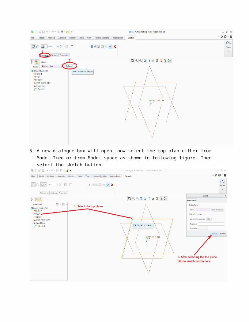
5. A new dialogue box will open. now select the top plan either from Model Tree or from Model space as shown in following figure. Then select the sketch button.
6. Then Press the sketch view button to look at the plane normally.

7. Now select the rectangle option in 'Sketching' tab and make a rectangle starting from the origin as shown in following fig.
8. Now Change the dimensions by double clicking on them. For vertical, write 4.00 and for horizontal write 9.25, after that hit ok.

9. Now select the standard orientation from view panel as shown in figure. Change the dimension t 0.375 in shown in circle 2 and then hit ok.
10. Now select the Hole option from 'Engineering' section in 'Model' tab.

11. Now when hole tab is open select standard hole in circle 1. Then uncheck the "Add tapping" button in circle 2. Then select "Create Clearance Hole" option in circle 3. Note that the circle 3 option will be available only when "Add tapping" Option in circle 2 is off. Now Hit option in circle 4 "Adds Counterbore" and finally click on drop down manue and select through all option shown in circle 6.
12. Select the placement tab and then select the Top face of the model.

13. Now set the Offset references and click on Select item option encircled in red. Then hold down the control or option button on your keyboard and select Front and Right Datum planes while holding it.
14. Now double click on encircled dimensions and change the circle 1 dimension to 8.50 and circle 2 dimension to 0.75 as shown in fig.

15. Now select ISO standard from the list shown in circle 1. then select the tab named as shape as shown in circle 2.
16. After that Put dimensions as shown in following figure.
17. Now to create rest holes, repeat steps 10 to 13. In step 12, select "top datum plane" of the model instead of top face. Use middle mouse button to rotate the model. and then select Flip button shown in picture.

18. Then repeat step 14 with dimensions of 4.875 for right horizontal reference and 3.25 for vertical references as shown in above picture.
19. Now repeat step 15.20. Now put dimensions as follows.

21. Then select the newly created hole in model tree. as you select this, the pattern feature gets highlighted. select it then.
22. In green circle area select Direction from drp down manue and select z-axis for direction in circle 1 and put a dimension of 2.50 in circle 2 area.
23. Now again click on hole in engineering section in model tab.24. Now when hole tab is open select standard hole in circle 1. Then uncheck the "Add tapping" button
in circle 2. Then select "Create Clearance Hole" option in circle 3. Note that the circle 3 option will be available only when "Add tapping" Option in circle 2 is off. Now select option in circle 4 "ISO" and

then click on drop down manue in circle 5 and select through all option. Then select option in ciecle 6 to add counterbore.
25. Then under placement tab select Top Datum Plane. Also hit flip button in circle 8 if you can't see hole produced. For offset references select Right and Front Datum Plane by holding control or option key in your keyboard.
26. Then click on shape tabe and put dimensions as follows.

27. Then Hit Okay to exit to this.28. Again select this newly created hole in model tree and select pattern feature just like in step 21 and
22.29. Now select the drop down manue in circle 1 and select direction as shown in fig. then select X-axis
as direction in circle 2 and finally put a dimension of 1.00 in circle 3 area. and hit okay.
Your part is ready.
Making Drawings
1. First of all select working directory as you did in previous section.2. Now hit new button and select drawing from the list. Make sure that "use default tempelate" option
is unchecked. then hit ok.

3. After that a dialogue box will appear as shown in following pictures. Brows for model and then brows for format file you created before. It is wise to keep all files in a single folder for easy access. After this hit ok.
4. Now drawing environment is open. Under layout tab in Model View panel, select General shown in circle 1. A dialogue box will open. Select no combined state and press ok.
5. Now click anywhere in model space to. You will see your model is placed where you clicked. The model can be in iso metric or tri metric orientation. You can change it by clicking in circle 1 area and you can select "user defined" and then hit okay.

6. A front view of the model will be created. You can change the style of drawing by clicking on option shown in circle 1. select hidden lines from there. after that selct the projection option in model view tab shown in circle 2.
7. then move cursor upward and click somewhere near the model, in this way top view will be created. then select the top view and again select the projection them move cursor towards the right and click some place. hence, side view will be created. see figure below

8. You can show dimensions quickly by selecting a view in drawin tree and right clicking it will open a slid manue. select "show model annotation" it will creat all possible dimensions regarding to that view. just pick the dimensions of your choice and hit okay.

Related Documents