BASCOM-AVR Page 1 of 204 BASCOM-AVR Version 1.0.0.8 Index Installation »Page 6 The BASCOM IDE »Page 17 Running BASCOM-AVR »Page 17 File New »Page 17 File Open »Page 17 File Close »Page 18 File Save »Page 18 File Save As »Page 18 File Print Preview »Page 18 File Print »Page 19 File Exit »Page 19 Edit Undo »Page 19 Edit Redo »Page 19 Edit Cut »Page 19 Edit Copy »Page 19 Edit Paste »Page 20 Edit Find »Page 20 Edit Find Next »Page 20 Edit Replace »Page 20 Edit Goto »Page 20 Edit Toggle Bookmark »Page 20 Edit Goto Bookmark »Page 21 Edit Indent Block »Page 21 Edit Unindent Block »Page 21 Program Compile »Page 21 Program Syntax Check »Page 22 Program Show Result »Page 22 Program Simulate »Page 23 BASCOM-AVR Page 2 of 204 Program Send to Chip »Page 23 Tools Terminal Emultator »Page 25 Tools LCD Designer »Page 26 Options Compiler »Page 27 Options Compiler Chip »Page 27 Options Compiler Output »Page 28 Options Compiler Communication »Page 29 Options Compiler I2C,SPI,1WIRE »Page 30 Options Compiler LCD »Page 31 Options Communication »Page 32 Options Environment »Page 33 Options Simulator »Page 35 Options Programmer »Page 36 Editor Keys »Page 39 BASCOM Developing Order »Page 40 BASCOM and Memory »Page 40 BASCOM Error codes »Page 42 BASCOM and Hardware Additional Hardware »Page 44 AVR Internal Hardware »Page 45 AVR Internal Hardware TIMER0 »Page 48 AVR Internal Hardware TIMER1 »Page 49 AVR Internal Hardware Watchdog timer »Page 50 AVR Internal Hardware PORT B »Page 50 AVR Internal Hardware PORT D »Page 52 AVR Internal Registers »Page 46 Attaching an LCD display »Page 53 Using the I2C protocol »Page 54 Using the 1 Wire protocol »Page 55 Using the SPI protocol »Page 55 Power Up »Page 55 Language Fundamentals »Page 56 Reserved Words »Page 56 BASCOM Language Reference $ASM »Page 64 $BAUD »Page 64 $CRYSTAL »Page 65 $DATA »Page 65 $DEFAULT »Page 66 $EEPROM »Page 67 $EXTERNAL »Page 68 $INCLUDE »Page 69 $LCD »Page 69 $LCDRS »Page 72 $LCDPUTCTRL »Page 70 $LCDPUTDATA »Page 71 $LIB »Page 73 $REGFILE »Page 75 $SERIALINPUT »Page 75 $SERIALINPUT2LCD »Page 77 $SERIALOUTPUT »Page 78 $XRAMSIZE »Page 78 $XRAMSTART »Page 79

Welcome message from author
This document is posted to help you gain knowledge. Please leave a comment to let me know what you think about it! Share it to your friends and learn new things together.
Transcript
BASCOM-AVR Page 1 of 204
BASCOM-AVR
Version 1.0.0.8
Index
Installation »Page 6The BASCOM IDE »Page 17
Running BASCOM-AVR »Page 17File New »Page 17File Open »Page 17File Close »Page 18File Save »Page 18File Save As »Page 18File Print Preview »Page 18File Print »Page 19File Exit »Page 19
Edit Undo »Page 19Edit Redo »Page 19Edit Cut »Page 19Edit Copy »Page 19Edit Paste »Page 20Edit Find »Page 20Edit Find Next »Page 20Edit Replace »Page 20Edit Goto »Page 20Edit Toggle Bookmark »Page 20Edit Goto Bookmark »Page 21Edit Indent Block »Page 21Edit Unindent Block »Page 21
Program Compile »Page 21Program Syntax Check »Page 22Program Show Result »Page 22Program Simulate »Page 23
BASCOM-AVR Page 2 of 204
Program Send to Chip »Page 23
Tools Terminal Emultator »Page 25Tools LCD Designer »Page 26
Options Compiler »Page 27Options Compiler Chip »Page 27Options Compiler Output »Page 28Options Compiler Communication »Page 29Options Compiler I2C,SPI,1WIRE »Page 30Options Compiler LCD »Page 31
Options Communication »Page 32Options Environment »Page 33Options Simulator »Page 35Options Programmer »Page 36
Editor Keys »Page 39BASCOM Developing Order »Page 40BASCOM and Memory »Page 40BASCOM Error codes »Page 42BASCOM and Hardware
Additional Hardware »Page 44AVR Internal Hardware »Page 45AVR Internal Hardware TIMER0 »Page 48AVR Internal Hardware TIMER1 »Page 49AVR Internal Hardware Watchdog timer »Page 50AVR Internal Hardware PORT B »Page 50AVR Internal Hardware PORT D »Page 52AVR Internal Registers »Page 46Attaching an LCD display »Page 53Using the I2C protocol »Page 54Using the 1 Wire protocol »Page 55Using the SPI protocol »Page 55Power Up »Page 55
Language Fundamentals »Page 56Reserved Words »Page 56BASCOM Language Reference
$ASM »Page 64$BAUD »Page 64$CRYSTAL »Page 65$DATA »Page 65$DEFAULT »Page 66$EEPROM »Page 67$EXTERNAL »Page 68$INCLUDE »Page 69$LCD »Page 69$LCDRS »Page 72$LCDPUTCTRL »Page 70$LCDPUTDATA »Page 71$LIB »Page 73$REGFILE »Page 75$SERIALINPUT »Page 75$SERIALINPUT2LCD »Page 77$SERIALOUTPUT »Page 78$XRAMSIZE »Page 78$XRAMSTART »Page 79
BASCOM-AVR Page 3 of 204
1WRESET »Page 801WREAD »Page 811WWRITE »Page 82ABS »Page 84ALIAS »Page 83ASC »Page 85BAUD »Page 85BCD »Page 86BITWAIT »Page 87BYVAL »Page 88CALL »Page 88CHR »Page 90CLS »Page 91CLOCKDIVISION »Page 91CLOSE »Page 92CONFIG »Page 93CONFIG TIMER0 »Page 101CONFIG TIMER1 »Page 103CONFIG LCD »Page 97CONFIG LCDBUS »Page 97CONFIG LCDMODE »Page 98CONFIG 1WIRE »Page 94CONFIG SDA »Page 99CONFIG SCL »Page 100CONFIG DEBOUNCE »Page 94CONFIG SPI »Page 101CONFIG LCDPIN »Page 99CONFIG WATCHDOG »Page 106CONFIG PORT »Page 107COUNTER0 AND COUNTER1 »Page 109CONST »Page 122CRYSTAL »Page 111CPEEK »Page 110CURSOR »Page 112DATA »Page 112DEBOUNCE »Page 114DECR »Page 116DECLARE FUNCTION »Page 116DECLARE SUB »Page 118DEFXXX »Page 119DEFLCDCHAR »Page 119DELAY »Page 120DIM »Page 120DISABLE »Page 123DISPLAY »Page 125DO-LOOP »Page 125ELSE »Page 126ENABLE »Page 126END »Page 127EXIT »Page 128FOR-NEXT »Page 128FOURTHLINE »Page 129FUSING »Page 130GETADC »Page 130GETRC0 »Page 132GETRC5 »Page 133
BASCOM-AVR Page 4 of 204
GOSUB »Page 135GOTO »Page 136HEX »Page 137HEXVAL »Page 137HIGH »Page 138HOME »Page 138I2CRECEIVE »Page 139I2CSEND »Page 139I2CSTART,I2CSTOP,I2CRBYTE,I2CWBYTE »Page 140IDLE »Page 141IF-THEN-ELSE-END IF »Page 142INCR »Page 143INKEY »Page 143INP »Page 144INPUTBIN »Page 144INPUTHEX »Page 145INPUT »Page 146INSTR »Page 200LCD »Page 147LEFT »Page 150LEN »Page 150LOAD »Page 151LOADADR »Page 191LOCAL »Page 152LOCATE »Page 154LOOKUP »Page 154LOOKUPSTR »Page 155LOW »Page 156LOWERLINE »Page 156LTRIM »Page 151MAKEBCD »Page 157MAKEDEC »Page 158MAKEINT »Page 157MID »Page 158ON INTERRUPT »Page 159ON VALUE »Page 160OPEN »Page 161OUT »Page 162PEEK »Page 163POKE »Page 163POWERDOWN »Page 164PRINT »Page 165PRINTBIN »Page 166READ »Page 167READEEPROM »Page 168REM »Page 168RESET »Page 169RESTORE »Page 170RETURN »Page 170RIGHT »Page 171ROTATE »Page 172RTRIM »Page 171SELECT CASE - END SELECT »Page 173SET »Page 173SHIFTCURSOR »Page 175SHIFTIN »Page 175

BASCOM-AVR Page 5 of 204
SHIFTOUT »Page 176SHIFTLCD »Page 177SOUND »Page 177SPACE »Page 178SPIIN »Page 178SPIMOVE »Page 199SPIOUT »Page 180START »Page 180STOP »Page 181STR »Page 182STRING »Page 183SUB »Page 184SWAP »Page 184THIRDLINE »Page 184TRIM »Page 185UPPERLINE »Page 186VAL »Page 186VARPTR »Page 187WAIT »Page 187WAITKEY »Page 188WAITMS »Page 188WAITUS »Page 189WHILE-WEND »Page 189WRITEEEPROM »Page 190
International Resellers »Page 9
Supported Programmers »Page 193
Assembly Mnemonics »Page 194Mixing BASIC with assembly »Page 197
If you have questions, remarks or suggestions please let us know.You can contact us by sending an email to [email protected] website is at http://www.mcselec.com
For info on updates : please read the readme.txt file that is installed into the BASCOM-AVR directory
MCS Electronics may update this documentation without notice.Products specification and usage may change accordingly.
MCS Electronics will not be liable for any mis-information or errors found in this document.
All software provided with this product package is provided ' AS IS' without any warrantyexpressed or implied.
MCS Electronics will not be liable for any damages, costs or loss of profits arising from theusage of this product package.
No part of this document may be reproduced or transmitted in any form or by any means,electronic or mechanical, including photocopying and recording, for any purpose, withoutwritten permission of MCS Electronics.
Copyright MCS Electronics. All rights reserved.
BASCOM-AVR Page 6 of 204
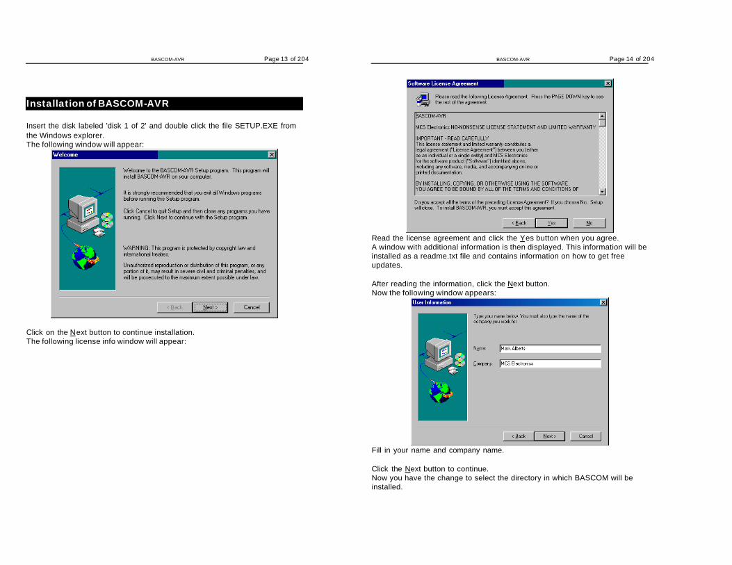
Installation of BASCOM-AVRInsert the disk labeled 'disk 1 of 2' and double click the file SETUP.EXE fromthe Windows explorer.
The following window will appear:
Click on the Next button to continue installation.
The following license info window will appear:
Read the license agreement and click the Yes button when you agree.A window with additional information is then displayed. This information will be

BASCOM-AVR Page 7 of 204
installed as a readme.txt file and contains information on how to get freeupdates.
After reading the information, click the Next button.Now the following window appears:
Fill in your name and company name.Click the Next button to continue.
Now you have the change to select the directory in which BASCOM will beinstalled.
Select the Browse button to change the directory path if required.By default BASCOM-AVR will be installed into:
BASCOM-AVR Page 8 of 204
C:\Program Files\MCS Electronics\BASCOM-AVR
After selecting the installation directory, click the Next button.This time you will be asked in which program group the BASCOM-AVR iconmust be placed.By default, a new program group named MCS Electronics will be made.
After selecting the group, click the Next button to continue.A summary will be showed. You may go back and change your settings.Otherwise, click the Next button to complete the installation of BASCOM-AVR.
When the installation is completed you must click the Finish-button, and
BASCOM-AVR Page 9 of 204
restart Windows.
A sub directory named SAMPLES contains all the BASCOM-AVR samplefiles.A sub directory named LIB contains the Library files.
IMPORTANT FOR THE COMMERCIAL VERSION
The license file is not included in the setup. You must copy this file to the\WINDOWS\SYSTEM directory.The license file is named BSCAVRL.DLL and can be found on the lastinstallation disk named 'DISK 2 of 2'.
To copy from the Explorer:Select the file from disk A and drag it into the \WINDOWS\SYSTEM directory.When the file is not visible turn the 'Show system Files' option on.
Of course the name of your system directory can be \W95\SYSTEM or\WINNT\SYSTEM too.
International Resellers
ArgentinaDINASTIA SOFTOscar H. GonzalezRoca 2239 (1714) – ItuzaingoBuenos AiresARGENTINAPhone: +54-1-4621-0237Fax: +54-1-4621-0237Email: [email protected]: http://www.dinastiasoft.com.ar
Australia & USADONTRONICSDon McKenzieP.O. box 595Tullamarine 3043AUSTRALIAEmail : [email protected]: http://www.dontronics.com
AustriaRIBU ELEKTRONIK GMBHMuehlgasse 18A-8160 WeizAUSTRIAPhone : 03172-64800Fax : 03172-64806Email : [email protected] : http://www.ribu.at
BrazilWF AUTOMAÇÃO INDÚSTRIACOMÉRCIO SERVIÇOS LTDA MEMiguel WisintainerRUA 2 DE SETEMBRO, 733CEP 89052-000
CanadaZanthic Technologies IncSteve Letkeman75 Vintage Meadows Place. S.E.Medicine Hat, AlbertaT1B 4G8 Canada
BASCOM-AVR Page 10 of 204
BLUMENAU S.CBRASILEmail : [email protected]: http://www.blusoft.org.br/wf/
Phone: 403-526-8318Fax : 403-528-9708Email : [email protected]: http://www.zanthic.com
China, Singapore, Malaysia,Taiwan, Thailand andHongkongDIY Electronics (HK) Ltd.Peter CrowcroftP.O. Box 88458,Sham Shui Po, Hong KongCHINAPhone: +852 2720 0255Fax: +852 2725 0610Email: [email protected]: http://kitsrus.com
Croatia, Bosnia, Macedoniaand SloveniaAX ELEKTRONIKA d.o.o.Managing director : Jure Mikelnp.p. 51271001 LjubljanaSLOVENIAPhone: +386-61-14-914-00, -14-914-05Fax : +386-61-485-688Email : [email protected]: http://www.svet-el.si
Czech & SlovakLAMIA s.r.o.Antonin StrakaPorici 20aBlansko678 01CZECH REPUBLICPhone: +00420-506-418726Fax : +00420-506-53988
Germany & SwitserlandConsulting & DistributionDr. - Ing. Claus KuehnelMuehlenstrasse 9D-01257 DresdenGERMANYPhone:+41.1.785.02.38Fax :+41.1.785.02.75Email : [email protected]: http://www.ckuehnel.ch
GermanyElektronikladen Mikrocomputer GmbHMartin DanneWilhelm.-Mellies-Str. 88D- 32758 DetmoldGERMANYPhone: +49 5232-8171Fax : +49 5232-86197E-Mail: [email protected]: www.elektronikladen.deVertriebsbüros in Hamburg, Berlin, Leipzig,Frankfurt, München
HungaryCODIX Ltd, HungaryImre GasparAti l la u 1-3,H-1013 BudapestHUNGARYPhone: +361 156 6330Fax : +361 156 4376Email [email protected] http://www.hpconline.com/codix

BASCOM-AVR Page 11 of 204
ItalyGrifo(R)Salvatore DaminoVia dell'Artigiano 8/640016 S.Giorgio di Piano BOITALYPhone: +39 (51) 892.052Fax : +39 (51) 893.661Email : [email protected]: http://www.grifo.com (Englisch)WWW: http://www.grifo.it (Italian)
Japan (8051 related)MOMIZI DENSHIOsamu HamakawaAOMADANI-NISHI-2-4-8-804MINO-CITYJAPAN 562-0023Phone:+81-727-28-7855Fax: +81-727-28-7855Email [email protected]
Japan (AVR related)International Parts & InformationCo.,Ltd.Shuji NonakaSengen 2-1-6 Tukuba CityIbaraki Pref.JAPAN 305-0047Phone: +81-298-50-3113Fax : +81-298-50-3114Email [email protected] http://www.ipic.co.jp
KoreaSAMPLE Electronics Co.Junghoon Kim306 Jeshin 43-22 Shinkey Youngsan SeoulKoreaPostal code 140-090Phone: 82-2-707-3882Fax : 82-2-707-3884Email : [email protected]: http://www.sample.co.kr
PakistanORRIS MICRO SYSTEMMalik Muhammad Nawaz Awan15/Y, TARIQ BIN ZIAD COLONY, SAHIWAL.PAKISTANPhone: 0441-66982Email : [email protected]
PolandRK-SYSTEMRobert KacprzyckiCHELMONSKIEGO 3005-825 GRODZISK MAZ.POLAND.Phone: +4822 724 30 39Fax: +4822 724 30 37Email [email protected]
Portugal & SpainMultidigital, LdaJoaquim BoavidaP.O. Box 1374435 Rio TintoPORTUGALPhone: +351 - 2 - 6102217Fax : +351 - 2 - 4862173Email: [email protected]: http://www.multidigital.com
Scandinavia (Sweden, Norway,Denmark)High Tech HorizonChristerJohanssonAsbogatan 29 CS-262 51 AngelholmSWEDENPhone: +46 431-41 00 88Fax : +46 431-41 00 88Email: [email protected]: http://www.hth.coml
SwedenLAWICELLars WictorssonKlubbgatan 3SE-282 32 TYRINGESWEDENPhone: +46 (0)451 59877Fax : +46 (0)451 59878WWW: http://www.lawicel.comEmail: [email protected]
BASCOM-AVR Page 12 of 204
SpainIbercompMiquel ZunigaC/. del Parc, numero 8 (bajos)E-07014Palma de MallorcaSPAINPhone: +34 (9) 71 45 66 42Fax : +34 (9) 71 45 67 58Email: [email protected]: http://www.ibercomp.es
TurkeyIBD Limited Sirketi379/1 Sokak A-Blok No: 2/101AFA Sanayi Carsisi - II.Sanayi35100 Bornova - Izmir
Phone: 0090-232-4627477 - 78Fax: 0090-232-4627545E-mail : [email protected] : [email protected] : [email protected] : [email protected] :www.ibd.com.tr
UKTECHMAIL SOLUTIONS LTDDogan Ibrahim14 Dunvegan RoadElthamLondon SE9 1SAPhone: 0171 343 5242 or 0181 488 9689Fax: 0171 821 6744Email: [email protected]:www.users.dircon.co.uk/~dogan/dogan/
USATechniks, Inc.Frank CapellePO Box 463Ringoes, NJ 08551USAPhone: 908-788-8249Fax: 908-788-8837Email: [email protected]: http://www.techniks.com
USAM. Akers EnterprisesMichael W. Akers3800 Vineyard Avenue #EPleasanton, CA 94566-6734USAPhone: +1-925-640-3600Fax: +1-925-640-3600Email: [email protected]: http://www.mwakers.com
USARhombusDavid H. Lawrence1909 Old Mountain Creek RoadGreenville, SC 29609USAPhone: +1-864-233-8330Fax: +1-864-233-8331Email: [email protected]: http://www.rhombusinc.com
BASCOM-AVR Page 13 of 204
Installation of BASCOM-AVR
Insert the disk labeled 'disk 1 of 2' and double click the file SETUP.EXE fromthe Windows explorer.The following window will appear:
Click on the Next button to continue installation.The following license info window will appear:
BASCOM-AVR Page 14 of 204
Read the license agreement and click the Yes button when you agree.A window with additional information is then displayed. This information will beinstalled as a readme.txt file and contains information on how to get freeupdates.
After reading the information, click the Next button.Now the following window appears:
Fill in your name and company name.
Click the Next button to continue.Now you have the change to select the directory in which BASCOM will beinstalled.
BASCOM-AVR Page 15 of 204
Select the Browse button to change the directory path if required.By default BASCOM-AVR will be installed into:C:\Program Files\MCS Electronics\BASCOM-AVRAfter selecting the installation directory, click the Next button.
This time you will be asked in which program group the BASCOM-AVR iconmust be placed.
By default, a new program group named MCS Electronics will be made.
After selecting the group, click the Next button to continue.
A summary will be showed. You may go back and change your settings.Otherwise, click the Next button to complete the installation of BASCOM-AVR.
BASCOM-AVR Page 16 of 204
When the installation is completed you must click the Finish-button, andrestart Windows.A sub directory named SAMPLES contains all the BASCOM-AVR samplefiles.
IMPORTANT FOR THE COMMERCIAL VERSION
The license file is not included in the setup. You must copy this file to the\WINDOWS\SYSTEM directory.The license file is named BSCAVRL.DLL and can be found on the lastinstallation disk named 'DISK 2 of 2'.
To copy from the Explorer:Select the file from disk A and drag it into the \WINDOWS\SYSTEMdirectory.
Of course the name of your system directory can be \W95\SYSTEM or\WINNT\SYSTEM too.
You also need to DELETE the file \windows\system\BASC-AVR.DLL beforeyou install the commercial version over the DEMO version.

BASCOM-AVR Page 17 of 204
Running BASCOM-AVR
Double-click the BASCOM-AVR icon to run BASCOM.The following window will appear. (If this is your first run, the edit window willbe empty.)
The most-recently opened file will be loaded.
File New
This option creates a new window in which you will write your program.
The focus is set to the new window.
File new shortcut: , CTRL + N
File Open
With this option you can load an existing program from disk.BASCOM saves files in standard ASCII format. Therefore, if you want to loada file that was made with another editor be sure that it is saved as an ASCIIfile.
Note that you can specify that BASCOM must reformat the file when it opensit with the Options Environment option. This should only be necessary whenloading files made with another editor.
BASCOM-AVR Page 18 of 204
File open shortcut : , CTRL+O
File Close
Close the current program.When you have made changes to the program, you will be asked to save theprogram first.
File close shortcut :
File Save
With this option, you save your current program to disk under the same filename.If the program was created with the File New option, you will be asked toname the file first. Use the File Save As option to give the file another name.
Note that the file is saved as an ASCII file.
File save shortcut : , CTRL+S
File Save As
With this option, you can save your current program to disk under a differentfile name.
Note that the file is saved as an ASCII file.
File save as shortcut :
File Print Preview
With this option, you can preview the current program before it is printed.
Note that the current program is the program that has the focus.
File print preview shortcut :
BASCOM-AVR Page 19 of 204
File Print
With this option, you can print the current program.
Note that the current program is the program that has the focus.
File print shortcut : , CTRL+P
File Exit
With this option, you can leave BASCOM.
If you have made changes to your program, you can save them upon leavingBASCOM.
File exit shortcut :
Edit Undo
With this option, you can undo the last text manipulation.
Edit Undo shortcut : , CTRL+Z
Edit Redo
With this option, you can redo the last undo.
Edit Redo shortcut : , CTRL+SHIFT+Z
Edit Cut
With this option, you can cut selected text into the clipboard.
Edit cut shortcut : , CTRL+X
Edit Copy
With this option, you can copy selected text into the clipboard.
BASCOM-AVR Page 20 of 204
Edit copy shortcut : , CTRL+C
Edit PasteWith this option, you can paste text from the clipboard into the current cursorposition.
Edit paste shortcut : , CTRL+V
Edit Find
With this option, you can search for text in your program.
Text at the cursor position will be placed in the find dialog box.
Edit Find shortcut : , CTRL+F
Edit Find Next
With this option, you can search for the last specified search item.
Edit Find Next shortcut : , F3
Edit Replace
With this option, you can replace text in your program.
Edit Replace shortcut : , CTRL+R
Edit Goto
With this option, you can immediately go to a line .
Edit go to line shortcut : ,CTRL+G
Edit Toggle Bookmark
BASCOM-AVR Page 21 of 204
With this option, you can set/reset a bookmark, so you can jump in your codewith the Edit Go to Bookmark option. Shortcut : CTRL+K + x where x can be1-8
Edit Goto Bookmark
With this option, you can jump to a bookmark.There can be up to 8 bookmarks. Shortcut : CTRL+Q+ x where x can be 1-8
Edit Indent Block
With this option, you can indent a selected block of text.
Edit Indent Block shortcut : , CTRL+SHIFT+I
Edit Unindent Block
With this option, you can un-indent a block.
Edit Unindent Block shortcut : , CTRL+SHIFT+U
Program Compile
With this option, you can compile your current program.Your program will be saved automatically before being compiled.The following files will be created depending on the Option Compiler Settings.
File Descriptionxxx.BIN Binary file which can be programmed into the microprocessorxxx.DBG Debug file that is needed by the simulator.xxx.OBJ Object file for AVR Studioxxx.HEX Intel hexadecimal file which is needed by some programmers.xxx.ERR Error file. (only when errors are found)xxx.RPT Report file.xxx.EEP EEPROM image file
If a serious error occurs, you will receive an error message in a dialog boxand the compilation will end.All other errors will be displayed at the bottom above the status bar.
BASCOM-AVR Page 22 of 204
When you click on the line with the error info, you will jump to the line thatcontains the error. The margin will also display the sign.At the next compilation, the error window will disappear.
Program compile shortcut : , F7
Program Syntax Check
With this option, your program is checked for syntax errors. No file will becreated except for an error file, if an error is found.
Program syntax check shortcut , CTRL + F7
Program Show Result
Use this option to view the result of the compilation.See the Options Compiler Output for specifying which files must be created.The files that can be viewed are report and error.
File show result shortcut : ,CTRL+W
Information provided in the report:Info DescriptionReport Name of the programDate and time The compilation date and time.Compiler The version of the compiler.Processor The selected target processor.SRAM Size of microprocessor SRAM (internal RAM).EEPROM Size of microprocessor EEPROM (internal EEPROM).ROMSIZE Size of the microprocessor FLASH ROM.ROMIMAGE Size of the compiled program.BAUD Selected baud rate.XTAL Selected XTAL or frequencyBAUD error The error percentage of the baud rate.XRAM Size of external RAM.Stack start The location in memory which the hardware stack points to. The
HW-stack pointer "grows down".S-Stacksize The size of the software stack.S-Stackstart The location in memory which the software stack pointer points
to. The software stack pointer "grows down".Framesize The size of the frame. The frame is used for storing local
variables.Framestart The location in memory where the frame starts.

BASCOM-AVR Page 23 of 204
LCD address The address that must be placed on the bus to enable the LCDdisplay E-line.
LCD RS The address that must be placed on the bus to enable the LCDRS-line
LCD mode The mode the LCD display is used with. 4 bit mode or 8 bitmode.
Program Simulate
With this option, you can simulate your program.
At this moment there is no internal Simulator. It will be added later.You can simulate your programs with AVR Studio for the time being.
Program Simulate shortcut : , F2
Program Send to Chip
This option will bring up the selected programmer or will program the chipdirectly if this option is selected from the Programmer options.
Program send to chip shortcut , F4
The following window will be shown:
BASCOM-AVR Page 24 of 204
Menu item DescriptionFile Exit Return to editorBuffer Clear Clears bufferBuffer Load from file Loads a file into the bufferBuffer Save to file Saves the buffer content to a fileChip Identify Identifies the chipWrite buffer into chip Programs the buffer into the chip ROM or EEPROMRead chipcode intobuffer
Reads the code or data from the chips code memory or datamemory
Chip blank check Checks if the chip is blankChip erase Erase the content of both the program memory and the data
memotyChip verify verifies if the buffer is the same as the chip program or data
memoryChip Set lockbits Writes the selected lock bits LB1 and/or LB2. Only an erase
will reset the lock bitsChip autoprogram Erases the chip and programs the chip. After the
programming is completed, a verification is performed.RCEN Writes a bit to enable the internal oscillator. This RCEN bit is
only available on some AVR chips.
BASCOM-AVR Page 25 of 204
Tools Terminal Emulator
With this option you can communicate via the RS-232 interface to themicrocomputer. The following window will appear :
Information you type and information that the computer board sends aredisplayed in the same window.
Note that you must use the same baud rate on both sides of the transmission.If you compiled your program with the Compiler Settings at 4800 baud, youmust also set the Communication Settings to 4800 baud.The setting for the baud rate is also reported in the report file.
File UploadUploads the current program in HEX format. This option is meant forloading the program into a monitor program.
File EscapeAborts the upload to the monitor program.
File ExitCloses terminal emulator.
Terminal ClearClears the terminal window.
Terminal Open Log
BASCOM-AVR Page 26 of 204
Open or closes a LOG file. When there is no LOG file selected you will beasked to enter or select a filename. All info that is printed to the terminalwindow is captured into the log file. The menu caption will change into 'CloseLog' and when you choose this option the file will be closed.
The terminal emulator has a strange bug that you can't select the menuoptions by using the keyboard. This is an error in the terminal component andI hope the third party will fix this bug.
Tools LCD Designer
With this option you can design special characters for LCD-displays.The following window will appear:
The LCD-matrix has 7x5 points. The bottom row is reserved for the cursor butcan be used.You can select a point by clicking the left mouse button. If a cell was selectedit will be deselected.
Clicking the Set All button will set all points.Clicking the Clear All button will clear all points.
When you are finished you can press the Ok button : a statement will beinserted in your active program-editor window at the current cursor position.The statement looks like this :
Deflcdchar ?,1,2,3,4,5,6,7,8You must replace the ?-sign with a character number ranging from 0-7.

BASCOM-AVR Page 27 of 204
Options Compiler
With this option, you can modify the compiler options.The following TAB pages are available:
Options Compiler Chip »Page 27Options Compiler Output »Page 28Options Compiler Communication »Page 29Options Compiler I2C , SPI, 1WIRE »Page 30Options Compiler LCD »Page 31
Options Compiler Chip
The following options are available:
Options Compiler ChipItem DescriptionChip Selects the target chip. Each chip has a corresponding x.DAT file
with specifications of the chip. Note that some DAT files are notavailable yet.
XRAM Selects the size of the external RAM.Stack size Specifies the size of the software stack.
BASCOM-AVR Page 28 of 204
Each local variable uses 2 bytes. Each variable that is passed in asub program uses 2 bytes too. So when you have used 10 localsin a SUB and the SUB passes 3 parameters, you need 13 * 2 =26 bytes.
Frame size Specifies the size of the frame.Each local is stored in a space that is named the frame.When you have 2 local integers and a string with a length of 10,you need a framesize of (2*2) + 11 = 15 bytes.The internal conversion routines used when you use INPUTnum,STR(),VAL() etc, also use the frame. They need a maximumof 12 bytes. So for this example 15+12 = 27 would be a goodvalue.
XRAM waitstate Select to insert a wait state for the external RAM.Default Press or click this button to use the current Compiler Chip settings
as default for all new projects.
Options Compiler Output
Options Compiler OutputItem DescriptionBinary file Select to generate a binary file. (xxx.bin)Debug file Select to generate a debug file (xxx.dbg)

BASCOM-AVR Page 29 of 204
Hex file Select to generate an Intel HEX file (xxx.hex)Report file Select to generate a report file (xxx.rpt)Error file Select to generate an error file (xxx.err)AVR Studio objectfile
Select to generate an AVR Studio object file (xxx.obj)
Size warning Select to generate a warning when the code size exceeds theFlash ROM size.
Options Compiler Communication
Options Compiler CommunicationItem DescriptionBaud rate Selects the baud rate for the serial statements. You can also type
in a new baud rate.Frequency Select the frequency of the used crystal. You can also type in a
new frequency.
The settings for the internal hardware UART are:No parity8 data bits1 stop bit
BASCOM-AVR Page 30 of 204
Options Compiler I2C, SPI, 1WIRE
Options Compiler I2C, SPI, 1WIREItem DescriptionSCL port Select the port that serves as the SCL-line for the I2C related
statements.SDA port Select the port that serves as the SDA-line for the I2C related
statements.1WIRE Select the port that serves as the 1WIRE-line for the 1Wire
related statements.Clock Select the port that serves as the clock-line for the SPI related
statements.MOSI Select the port that serves as the MOSI-line for the SPI related
statements.MISO Select the port that serves as the MISO-line for the SPI related
statements.SS Select the port that serves as the SS-line for the SPI related
statements.Use hardware SPI Select to use built-in hardware for SPI, otherwise software
emulation of SPI will be used.
BASCOM-AVR Page 31 of 204
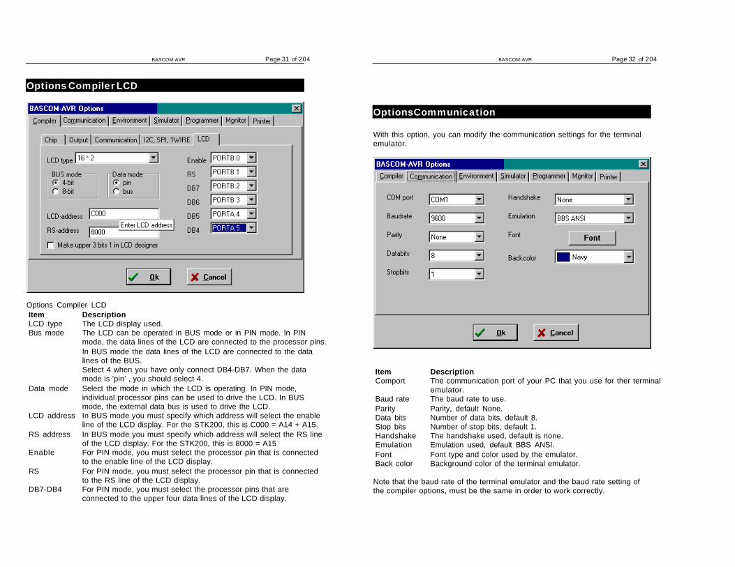
Options Compiler LCD
Options Compiler LCDItem DescriptionLCD type The LCD display used.Bus mode The LCD can be operated in BUS mode or in PIN mode. In PIN
mode, the data lines of the LCD are connected to the processor pins.In BUS mode the data lines of the LCD are connected to the datalines of the BUS.Select 4 when you have only connect DB4-DB7. When the datamode is 'pin' , you should select 4.
Data mode Select the mode in which the LCD is operating. In PIN mode,individual processor pins can be used to drive the LCD. In BUSmode, the external data bus is used to drive the LCD.
LCD address In BUS mode you must specify which address will select the enableline of the LCD display. For the STK200, this is C000 = A14 + A15.
RS address In BUS mode you must specify which address will select the RS lineof the LCD display. For the STK200, this is 8000 = A15
Enable For PIN mode, you must select the processor pin that is connectedto the enable line of the LCD display.
RS For PIN mode, you must select the processor pin that is connectedto the RS line of the LCD display.
DB7-DB4 For PIN mode, you must select the processor pins that areconnected to the upper four data lines of the LCD display.
BASCOM-AVR Page 32 of 204
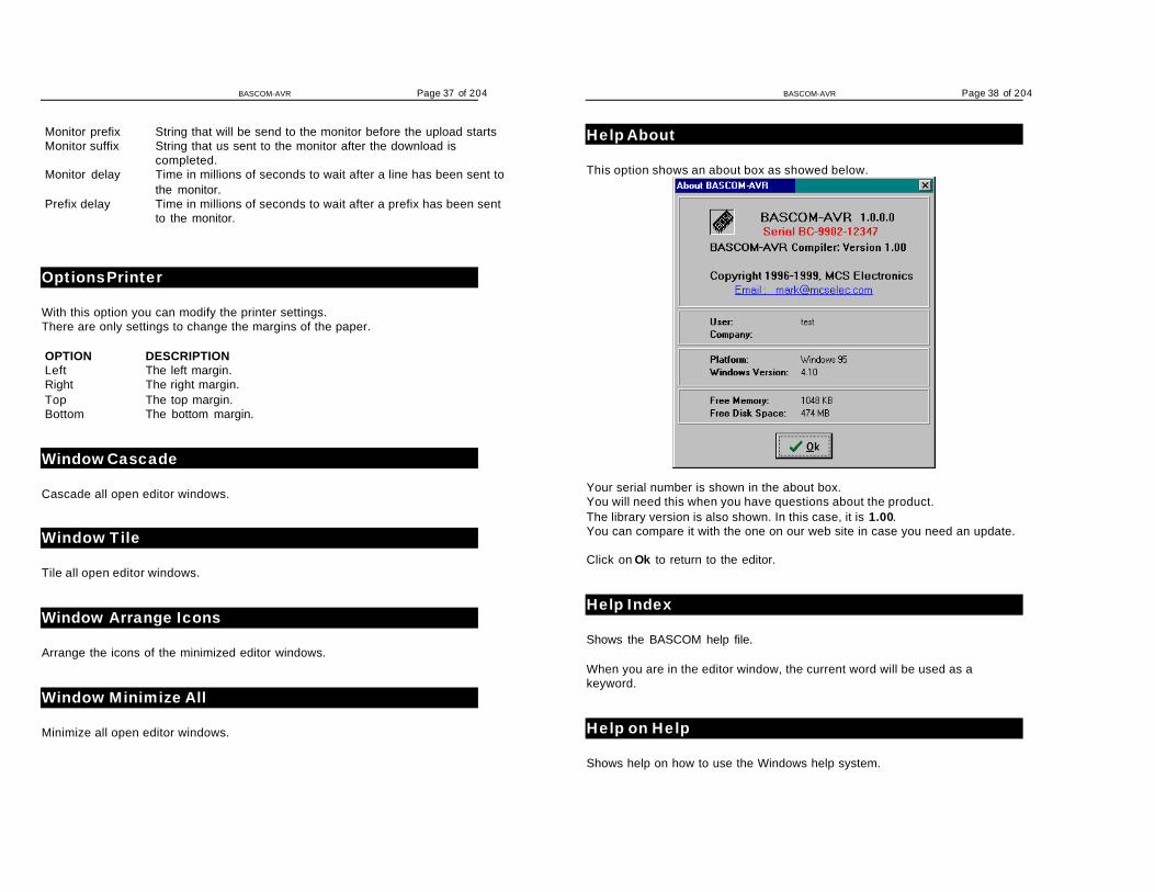
Options Communication
With this option, you can modify the communication settings for the terminalemulator.
Item DescriptionComport The communication port of your PC that you use for ther terminal
emulator.Baud rate The baud rate to use.Parity Parity, default None.Data bits Number of data bits, default 8.Stop bits Number of stop bits, default 1.Handshake The handshake used, default is none.Emulation Emulation used, default BBS ANSI.Font Font type and color used by the emulator.Back color Background color of the terminal emulator.
Note that the baud rate of the terminal emulator and the baud rate setting ofthe compiler options, must be the same in order to work correctly.

BASCOM-AVR Page 33 of 204
Options Environment
OPTION DESCRIPTIONAuto Indent When you press return, the cursor is set to the next line at the
current column positionDon't change case When set, the reformatting won't change the case of the text.
Default is that the text is reformatted so every word begins withupper case.
Reformat BAS files Reformat files when loading them into the editor.This is only necessary when you are loading files that wherecreated with another editor. Normally you won't need to set thisoption.
Reformat code Reformat code when entered in the editor.Smart TAB When set, a TAB will go to the column where text starts on the
previous line.Syntax highlighting This options highlights BASCOM statements in the editor.Show margin Shows a margin on the right side of the editor.Comment The position of the comment. Comment is positioned at the
right of your source code.TAB-size Number of spaces that are generated for a TAB.Keymapping Choose default, Classic, Brief or Epsilon.No reformatextension
File extensions separated by a space that will not bereformatted when loaded.
BASCOM-AVR Page 34 of 204
Size of new editorwindow
When a new editor window is created you can select how it willbe made. Normal or Maximized (full window)
OPTION DESCRIPTIONBackground color The background color of the editor window.Keyword color The color of the reserved words. Default Navy.
The keywords can be displayed in bold too.Comment color The color of comment. Default green.
Comment can be shown in Italic too.ASM color Color to use for ASM statements. Default purple.HW registers color The color to use for the hardware registers/ports. Default
maroon.Editor font Click on this label to select another font for the editor window.

BASCOM-AVR Page 35 of 204
OPTION DESCRIPTIONTooltips Show tooltips.Show toolbar Shows the toolbar with the shortcut icons.Save File As … fornew files.
Will display a dialogbox so you can give new files a namewhen they must be saved. When you dont select this optionthe default name will be give to the file (nonamex.bas). Wherex is a number.
File location Double click to select a directory where your program files arestored. By default Windows will use the My Documents path.
Options SimulatorWith this option you can modify the simulator settings.
OPTION DESCRIPTIONProgram The path with the program name of the simulator.Parameter The parameter to pass to the program. {FILE}.OBJ will
supplie the name of the current program with the extension.OBJ to the simulator.
BASCOM-AVR Page 36 of 204
Options Programmer
With this option you can modify the programmer settings.
OPTION DESCRIPTIONProgrammer Select one from the list.Auto flash Some programmers support auto flash. Pressing F4 will program
the chip without showing the programmer window.Auto verify Some programmers support verifying. The chip content will be
verified after programming.LPT address Port address of the LPT that is connected to the programmer.Send HEX Only for EPROM Simulator on LPT. Select when a HEX file must
be sent instead of the bin file.
Options Monitor
With this option you can modify the monitor settings.
OPTION DESCRIPTIONUpload speed Selects the baud rate used for uploading
BASCOM-AVR Page 37 of 204
Monitor prefix String that will be send to the monitor before the upload startsMonitor suffix String that us sent to the monitor after the download is
completed.Monitor delay Time in millions of seconds to wait after a line has been sent to
the monitor.Prefix delay Time in millions of seconds to wait after a prefix has been sent
to the monitor.
Options Printer
With this option you can modify the printer settings.There are only settings to change the margins of the paper.
OPTION DESCRIPTIONLeft The left margin.Right The right margin.Top The top margin.Bottom The bottom margin.
Window Cascade
Cascade all open editor windows.
Window Tile
Tile all open editor windows.
Window Arrange Icons
Arrange the icons of the minimized editor windows.
Window Minimize All
Minimize all open editor windows.
BASCOM-AVR Page 38 of 204
Help About
This option shows an about box as showed below.
Your serial number is shown in the about box.You will need this when you have questions about the product.The library version is also shown. In this case, it is 1.00.You can compare it with the one on our web site in case you need an update.
Click on Ok to return to the editor.
Help Index
Shows the BASCOM help file.
When you are in the editor window, the current word will be used as akeyword.
Help on Help
Shows help on how to use the Windows help system.

BASCOM-AVR Page 39 of 204
Help Credits
Shows a form with credits to people I would like to thank for their contributionsto BASCOM.
BASCOM Editor Keys
KeyAction
LEFT ARROW One character to the leftRIGHT ARROW One character to the rightUP ARROW One line upDOWN ARROW One line downHOME To the beginning of a lineEND To the end of a linePAGE UP Up one windowPAGE DOWN Down one windowCTRL+LEFT One word to the leftCTRL+RIGHT One word to the rightCTRL+HOME To the start of the textCTRL+END To the end of the textCTRL+ Y Delete current lineINS Toggles insert/overstrike modeF1 Help (context sensitive)F3 Find next textF4 Send to chip (run flash programmer)F5 RunF7 Compile FileF8 StepF9 Set breakpointF10 Run toCTRL+F7 Syntax CheckCTRL+F Find textCTRL+G Go to lineCTRL+K+x Toggle bookmark. X can be 1-8CTRL+L LCD DesignerCTRL+M File SimulationCTRL+N New FileCTRL+O Load FileCTRL+P Print FileCTRL+Q+x Go to Bookmark. X can be 1-8CTRL+R Replace textCTRL+S Save FileCTRL+T Terminal emulatorCTRL+P Compiler Options
BASCOM-AVR Page 40 of 204
CTRL+W Show result of compilationCTRL+X Cut selected text to clipboardCTRL+Z Undo last modificationSHIFT+CTRL+Z Redo last undoCTRL+INS Copy selected text to clipboardSHIFT+INS Copy text from clipboard to editorCTRL+SHIFT+J Indent BlockCTRL+SHIFT+U Unindent BlockSelect text Hold the SHIFT key down and use the cursor keys to select
text. or keep the left mouse key pressed and tag the cursorover the text to select.
Developing Order
• Start BASCOM;• Open a file or create a new one;• Check the chip settings, baud rate and frequency settings for the target
system;• Compile the file;• If an error occurs fix it and recompile (F7);• Run the simulator (AVR Studio at the moment);• Program the chip;
Memory usage
Every variable uses memory. This memory is also called SRAM.The available memory depends on the chip.
A special kind of memory are the registers in the AVR. Registers 0-31 haveaddresses 0-31.Almost all registers are used by the compiler or might be used in the future.Which registers are used depends on the statements you used.
This brings us back to the SRAM.No SRAM is used by the compiler other than the space needed for thesoftware stack and frame.
Each 8 used bits occupy one byte.Each byte occupies one byte.Each integer/word occupies two bytes.Each Long or Single occupies four bytes.Each String occupies at least 2 byes.A string with a length of 10. occupies 11 byes. The extra byte is needed toindicate the end of the string.
BASCOM-AVR Page 41 of 204
Use bits or bytes where you can to save memory. (not allowed for negativevalues)The software stack is used to store the addresses of LOCAL variables and forvariables that are passed to SUB routines.Each LOCAL variable and passed variable to a SUB, uses two bytes to storethe address. So when you have a SUB routine in your program that passes 10variables, you need 10 * 2 = 20 bytes. When you use 2 LOCAL variables inthe SUB program that receives the 10 variables, you need an additional 2 * 2= 4 bytes.The software stack size can be calculated by taking the maximum number ofparameters in a SUB routine, adding the number of LOCAL variables andmultiplying the result by 2. To be safe, add 4 more bytes for internally-usedLOCAL variables.LOCAL variables are stored in a place that is named the frame.When you have a LOCAL STRING with a size of 40 bytes, and a LOCALLONG, you need 41 + 4 bytes = 45 bytes of frame space.The report will show the result of both calculations.When you use conversion routines such as STR(), VAL() etc. that convertfrom numeric to string and vice versa, you also need a frame. It should be 16bytes in that case.
Note that the use of the INPUT statement with a numeric variable, or the useof the PRINT/LCD statement with a numeric variable, will also force you toreserve 16 bytes of frame space. This because these routines use the internalnumeric<>string conversion routines.
XRAMYou can easy add external memory to a 8515. Then XRAM will becomeavailable.(extended memory).When you add a 32KB RAM, the first address wil be 0.But because the XRAM can only start after the SRAM, which is &H0260, thelower memory locations of the XRAM will not be used.
ERAMMost AVR chips have internal EEPROM on board.This EEPROM can be used to store and retrieve data.In BASCOM, this dataspace is called ERAM.An important difference is that an ERAM variable can be written for amaximum of 100.000 times. So only assign an ERAM variable when it isneeded and not in a loop.
Constant code usageConstants are stored in a constant table.Each used constant in your program will end up in the constant table.
For example:
BASCOM-AVR Page 42 of 204
Print "ABCD"Print "ABCD"
This example will only store one constant (ABCD).
Print "ABCD"Print "ABC"
In this example, two constants will be stored because the strings differ.
Error Codes
The following table lists errors that can occur.
Error Description1 Unknown statement2 Unknown structure EXIT statement3 WHILE expected4 No more space for IRAM BIT5 No more space for BIT6 . expected in filename7 IF THEN expected8 BASIC source file not found9 Maximum 128 aliases allowed10 Unknown LCD type11 INPUT, OUTPUT, 0 or 1 expected12 Unknown CONFIG parameter13 CONST already specified14 Only IRAM bytes supported15 Wrong data type16 Unknown Definition17 9 parameters expected18 BIT only allowed with IRAM or SRAM19 STRING length expected (DIM S AS STRING * 12 ,for example)20 Unknown DATA TYPE21 Out of IRAM space22 Out of SRAM space23 Out of XRAM space24 Out of EPROM space25 Variable already dimensioned26 AS expected27 parameter expected28 IF THEN expected29 SELECT CASE expected30 BIT's are GLOBAL and can not be erased
BASCOM-AVR Page 43 of 204
31 Invalid data type32 Variable not dimensioned33 GLOBAL variable can not be ERASED34 Invalid number of parameters35 3 parameters expected36 THEN expected37 Invalid comparison operator38 Operation not possible on BITS39 FOR expected40 Variable can not be used with RESET41 Variable can not be used with SET42 Numeric parameter expected43 File not found44 2 variables expected45 DO expected46 Assignment error47 UNTIL expected50 Value doesn't fit into INTEGER51 Value doesn't fit into WORD52 Value doesn't fit into LONG60 Duplicate label61 Label not found62 SUB or FUNCTION expected first63 Integer or Long expected for ABS()64 , expected65 device was not OPEN66 device already OPENED68 channel expected70 BAUD rate not possible71 Different parameter type passed then declared72 Getclass error. This is an internal error.73 Printing this FUNCTION not yet supported74 3 parameters expected80 Code does not fit into target chip81 Use HEX(var) instead of PRINTHEX82 Use HEX(var) instead of LCDHEX85 Unknown interrupt source86 Invalid parameter for TIMER configuration87 ALIAS already used88 0 or 1 expected89 Out of range : must be 1-490 Address out of bounds91 INPUT, OUTPUT, BINARY, or RANDOM expected92 LEFT or RIGHT expected93 Variable not dimensioned94 Too many bits specified
BASCOM-AVR Page 44 of 204
95 Falling or rising expected for edge96 Prescale value must be 1,8,64,256 or 102497 SUB or FUNCTION must be DECLARED first98 SET or RESET expected99 TYPE expected100 No array support for IRAM variables101 Can't find HW-register102 Error in internal routine103 = expected104 LoadReg error105 StoreBit error106 Unknown register107 LoadnumValue error108 Unknown directive in device file109 = expected in include file for .EQU110 Include file not found111 SUB or FUNCTION not DECLARED112 SUB/FUNCTION name expected113 SUB/FUNCTION already DECLARED114 LOCAL only allowed in SUB or FUNCTION115 #channel expected116 Invalid register file117 Unknown interrupt200 .DEF not found201 Low Pointer register expected202 .EQU not found, probably using functions that are not supported by the
selected chip203 Error in LD or LDD statement204 Error in ST or STD statement205 } expected10000 DEMO/BETA only supports 1024 bytes of code
Additional Hardware
Of course just running a program on the chip is not enough. You will probablyattach all kind of electronics to the processor ports.BASCOM supports a lot of hardware and so has lots of hardware relatedstatements.
Before explaining about programming the additional hardware, it might bebetter to talk about the chip.
The AVR internal hardware »Page 45

BASCOM-AVR Page 45 of 204
Attaching an LCD display »Page 53Using the I2C protocol »Page 54Using the 1WIRE protocol »Page 55Using the SPI protocol »Page 55
You can attach additional hardware to the ports of the microprocessor.The following statements will become available:
I2CSEND »Page 139 and I2CRECEIVE »Page 139 and other I2C relatedstatements.CLS, »Page 91 LCD, »Page 147 DISPLAY »Page 125 and other related LCD-statements.
1WRESET »Page 80 , 1WWRITE »Page 82 and 1WREAD »Page 81
AVR Internal Hardware
The AVR chips all have internal hardware that can be used.For the description we have used the 8515 so some described hardware willnot be available when you select a 2313 for example.
Timer / CountersThe AT90S8515 provides two general purpose Timer/Counters - one 8-bit T/Cand one 16-bit T/C. The Timer/Counters have individual pre-scaling selectionfrom the same 10-bit pre-scaling timer. Both Timer/Counters can either beused as a timer with an internal clock time base or as a counter with anexternal pin connection which triggers the counting.
BASCOM-AVR Page 46 of 204
More about TIMERO »Page 48More about TIMER1 »Page 49
The WATCHDOG Timer. »Page 50
Almost all AVR chips have the ports B and D. The 40 pin devices also haveports A and C that also can be used for addressing an external RAM chip.Since all ports are identical but the PORT B and PORT D have alternativefunctions, only these ports are described.
PORT B »Page 50
PORT D »Page 52
AVR Internal Registers
You can manipulate the register values directly from BASIC. They are alsoreserved words. The internal registers for the AVR90S8515 are :
Addr. Register$3F SREG I T H S V N Z C$3E SPH SP15 SP14 SP13 SP12 SP11 SP10 SP9 SP8$3D SPL SP7 SP6 SP5 SP4 SP3 SP2 SP1 SP0$3C Reserved$3B GIMSK INT1 INT0 - - - - - -$3A GIFR INTF1 INTF0$39 TIMSK TOIE1 OCIE1A OCIE1B - TICIE1 - TOIE0 -$38 TIFR TOV1 OCF1A OCF1B -ICF1 -TOV0 -
BASCOM-AVR Page 47 of 204
$37 Reserved$36 Reserved$35 MCUCR SRE SRW SE SM ISC11 ISC10 ISC01 ISC00$34 Reserved$33 TCCR0 - - - - - CS02 CS01 CS00$32 TCNT0 Timer/Counter0 (8 Bit)$31 Reserved$30 Reserved$2F TCCR1A COM1A1 COM1A0 COM1B1 COM1B0 - -PWM11 PWM10$2E TCCR1B ICNC1 ICES1 - - CTC1 CS12 CS11 CS10$2D TCNT1H Timer/Counter1 - Counter Register High Byte$2C TCNT1L Timer/Counter1 - Counter Register Low Byte$2B OCR1AH Timer/Counter1 - Output Compare Register A High Byte$2A OCR1AL Timer/Counter1 - Output Compare Register A Low Byte$29 OCR1BH Timer/Counter1 - Output Compare Register B High Byte$28 OCR1BL Timer/Counter1 - Output Compare Register B Low Byte$27 Reserved$26 Reserved$25 ICR1H Timer/Counter1 - Input Capture Register High Byte$24 ICR1L Timer/Counter1 - Input Capture Register Low Byte$23 Reserved$22 Reserved$21 WDTCR - - - WDTOE WDE WDP2 WDP1 WDP0$20 Reserved$1F Reserved - - - - - - - EEAR8$1E EEARL EEPROM Address Register Low Byte$1D EEDR EEPROM Data Register$1C EECR - - - - - EEMWE EEWE EERE$1B PORTA PORTA7 PORTA6 PORTA5 PORTA4 PORTA3 PORTA2 PORTA1 PORTA0$1A DDRA DDA7 DDA6 DDA5 DDA4 DDA3 DDA2 DDA1 DDA0$19 PINA PINA7 PINA6 PINA5 PINA4 PINA3 PINA2 PINA1 PINA0$18 PORTB PORTB7 PORTB6 PORTB5 PORTB4 PORTB3 PORTB2 PORTB1 PORTB0$17 DDRB DDB7 DDB6 DDB5 DDB4 DDB3 DDB2 DDB1 DDB0$16 PINB PINB7 PINB6 PINB5 PINB4 PINB3 PINB2 PINB1 PINB0$15 PORTC PORTC7 PORTC6 PORTC5 PORTC4 PORTC3 PORTC2 PORTC1 PORTC0$14 DDRC DDC7 DDC6 DDC5 DDC4 DDC3 DDC2 DDC1 DDC0$13 PINC PINC7 PINC6 PINC5 PINC4 PINC3 PINC2 PINC1 PINC0$12 PORTD PORTD7 PORTD6 PORTD5 PORTD4 PORTD3 PORTD2 PORTD1 PORTD0$11 DDRD DDD7 DDD6 DDD5 DDD4 DDD3 DDD2 DDD1 DDD0$10 PIND PIND7 PIND6 PIND5 PIND4 PIND3 PIND2 PIND1 PIND0$0F SPDR SPI Data Register$0E SPSR SPIF WCOL - - - - - -$0D SPCR SPIE SPE DORD MSTR CPOL CPHA SPR1 SPR0$0C UDR UART I/O Data Register$0B USR RXC TXC UDRE FE OR - - -$0A UCR RXCIE TXCIE UDRIE RXEN TXEN CHR9 RXB8 TXB8$09 UBRR UART Baud Rate Register$08 ACSR ACD - ACO ACI ACIE ACIC ACIS1 ACIS0$00 Reserved
The registers and their addresses are defined in the xxx.DAT files which areplaced in the BASCOM-AVR application directory.
The registers can be used as normal byte variables.PORTB = 40 will place a value of 40 into port B.
BASCOM-AVR Page 48 of 204
Note that internal registers are reserved words. This means that they can't bedimensioned as BASCOM variables!
So you can't use the statement DIM SREG As Byte because SREG is aninternal register.You can however manipulate the register with the SREG = value statement.
AVR Internal Hardware TIMER0
The 8-Bit Timer/Counter0
The 8-bit Timer/Counter0 can select its clock source from CK, pre-scaled CK,or an external pin. In addition it can be stopped.The overflow status flag is found in the Timer/Counter Interrupt Flag Register -TIFR. Control signals are found in the Timer/Counter0 Control Register -TCCR0. The interrupt enable/disable settings for Timer/Counter0 are found inthe Timer/Counter Interrupt Mask Register - TIMSK.
When Timer/Counter0 is externally clocked, the external signal issynchronized with the oscillator frequency of the CPU. To assure propersampling of the external clock, the minimum time between two external clocktransitions must be at least one internal CPU clock period. The external clocksignal is sampled on the rising edge of the internal CPU clock.
BASCOM-AVR Page 49 of 204
The 8-bit Timer/Counter0 features both a high resolution and a high accuracyusage with the lower pre-scaling opportunities. Similarly, the high pre-scalingopportunities make the Timer/Counter0 useful for lower speed functions orexact timing functions with infrequent actions.
AVR Internal Hardware TIMER1
The 16-Bit Timer/Counter1 (8515 other timers may be different)
The 16-bit Timer/Counter1 can select clock source from CK, pre-scaled CK,or an external pin. In addition it can be stopped.The different status flags (overflow, compare match and capture event) andcontrol signals are found in the Timer/Counter1 Control Registers - TCCR1Aand TCCR1B.
The interrupt enable/disable settings for Timer/Counter1 are found in theTimer/Counter Interrupt Mask Register - TIMSK.
When Timer/Counter1 is externally clocked, the external signal issynchronized with the oscillator frequency of the CPU. To assure propersampling of the external clock, the minimum time between two external clocktransitions must be at least one internal CPU clock period.The external clock signal is sampled on the rising edge of the internal CPUclock.
The 16-bit Timer/Counter1 features both a high resolution and a highaccuracy usage with the lower prescaling opportunities.Similarly, the high prescaling opportunities make the Timer/Counter1 usefulfor lower speed functions or exact timing functions with infrequent actions.
The Timer/Counter1 supports two Output Compare functions using the OutputCompare Register 1 A and B -OCR1A and OCR1B as the data sources to becompared to the Timer/Counter1 contents.
The Output Compare functions include optional clearing of the counter oncompareA match, and actions on the Output Compare pins on both comparematches.
Timer/Counter1 can also be used as a 8, 9 or 10-bit Pulse With Modulator. Inthis mode the counter and the OCR1A/OCR1B registers serve as a dualglitch-free stand-alone PWM with centered pulses.
The Input Capture function of Timer/Counter1 provides a capture of theTimer/Counter1 contents to the Input Capture Register - ICR1, triggered by anexternal event on the Input Capture Pin - ICP. The actual capture event
BASCOM-AVR Page 50 of 204
settings are defined by the Timer/Counter1 Control Register -TCCR1B.In addition, the Analog Comparator can be set to trigger the Input Capture.
AVR Internal Hardware Watchdog timer
The Watchdog Timer
The Watchdog Timer is clocked from a separate on-chip oscillator which runsat 1MHz. This is the typical value at VCC = 5V.
By controlling the Watchdog Timer pre-scaler, the Watchdog reset intervalcan be adjusted from 16K to 2,048K cycles (nominally 16 - 2048 ms). TheRESET WATCHDOG - instruction resets the Watchdog Timer.Eight different clock cycle periods can be selected to determine the resetperiod.If the reset period expires without another Watchdog reset, the AT90Sxxxxresets and executes from the reset vector.
AVR Internal Hardware Port B

BASCOM-AVR Page 51 of 204
Port B
Port B is an 8-bit bi-directional I/O port. Three data memory address locationsare allocated for the Port B, one each for the Data Register - PORTB,$18($38), Data Direction Register - DDRB, $17($37) and the Port B Input Pins- PINB, $16($36). The Port B Input Pins address is read only, while the DataRegister and the Data Direction Register are read/write.
All port pins have individually selectable pull-up resistors. The Port B outputbuffers can sink 20mA and thus drive LED displays directly. When pins PB0 toPB7 are used as inputs and are externally pulled low, they will source currentif the internal pull-up resistors are activated.The Port B pins with alternate functions are shown in the following table:
When the pins are used for the alternate function the DDRB and PORTBregister has to be set according to the alternate function description.
Port B Pins Alternate FunctionsPort Pin Alternate FunctionsPORTB.0 T0 (Timer/Counter 0 external counter input)PORTB.1 T1 (Timer/Counter 1 external counter input)PORTB.2 AIN0 (Analog comparator positive input)PORTB.3 AIN1 (Analog comparator negative input)PORTB.4 SS (SPI Slave Select input)PORTB.5 MOSI (SPI Bus Master Output/Slave Input)PORTB.6 MISO (SPI Bus Master Input/Slave Output)PORTB.7 SCK (SPI Bus Serial Clock)
The Port B Input Pins address - PINB - is not a register, and this addressenables access to the physical value on each Port B pin. When readingPORTB, the PORTB Data Latch is read, and when reading PINB, the logicalvalues present on the pins are read.
PortB As General Digital I/OAll 8 bits in port B are equal when used as digital I/O pins. PORTB.X, GeneralI/O pin: The DDBn bit in the DDRB register selects the direction of this pin, ifDDBn is set (one), PBn is configured as an output pin. If DDBn is cleared(zero), PBn is configured as an input pin. If PORTBn is set (one) when the pinconfigured as an input pin, the MOS pull up resistor is activated.To switch the pull up resistor off, the PORTBn has to be cleared (zero) or thepin has to be configured as an output pin.
DDBn Effects on Port B PinsDDBn PORTBn I/O Pull up Comment0 0 Input No Tri-state (Hi-Z)0 1 Input Yes PBn will source current if ext. pulled
low.
BASCOM-AVR Page 52 of 204
1 0 Output No Push-Pull Zero Output1 1 Output No Push-Pull One Output
AVR Internal Hardware Port D
Port D
Port D Pins Alternate FunctionsPort Pin Alternate FunctionPORTD.0 RDX (UART Input line )PORTD.1 TDX (UART Output line)PORTD.2 INT0 (External interrupt 0 input)PORTD.3 INT1 (External interrupt 1 input)PORTD.5 OC1A (Timer/Counter1 Output compareA match output)PORTD.6 WR (Write strobe to external memory)PORTD.7 RD (Read strobe to external memory)
RD - PORTD, Bit 7RD is the external data memory read control strobe.
WR - PORTD, Bit 6WR is the external data memory write control strobe.
OC1- PORTD, Bit 5Output compare match output: The PD5 pin can serve as an external outputwhen the Timer/Counter1 com-pare matches.The PD5 pin has to be configured as an out-put (DDD5 set (one)) to serve thisf unction. See the Timer/Counter1 description for further details, and how toenable the output. The OC1 pin is also the output pin for the PWM mode timerfunction.
INT1 - PORTD, Bit 3External Interrupt source 1: The PD3 pin can serve as an external interruptsource to the MCU. See the interrupt description for further details, and howto enable the source
INT0 - PORTD, Bit 2INT0, External Interrupt source 0: The PD2 pin can serve as an externalinterrupt source to the MCU. See the interrupt description for further details,and how to enable the source.
TXD - PORTD, Bit 1Transmit Data (Data output pin for the UART). When the UART transmitter isenabled, this pin is configured as an output regardless of the value of DDRD1.
BASCOM-AVR Page 53 of 204
RXD - PORTD, Bit 0Receive Data (Data input pin for the UART). When the UART receiver isenabled this pin is configured as an output regardless of the value of DDRD0.When the UART forces this pin to be an input, a logical one in PORTD0 willturn on the internal pull-up.
When pins TXD and RXD are not used for RS-232 they can be used as aninput or output pin.No PRINT, INPUT or other RS-232 statement may be used in that case.The UCR register will by default not set bits 3 and 4 that enable the TXD andRXD pins for RS-232 communication. It is however reported that this notworks for all chips. In this case you must clear the bits in the UCR registerwith the following statements:RESET UCR.3RESET UCR.4
Attaching an LCD Display
A LCD display can be connected with two methods.
• By wiring the LCD-pins to the processor port pins.This is the pin mode. The advantage is that you can choose the pins andthat they don't have to be on the same port. This can make your PCBdesign simple. The disadvantage is that more code is needed.
• By attaching the LCD-data pins to the data bus. This is convenient whenyou have an external RAM chip and will adds little code.
The LCD-display can be connected in PIN mode as follows:
LCD-DISPLAY PORT PINDB7 PORTB.7 14DB6 PORTB.6 13DB5 PORTB.5 12DB4 PORTB.4 11E PORTB.3 6RS PORTB.2 4RW Ground 5Vss Ground 1Vdd +5 Volt 2Vo 0-5 Volt 3
This leaves PORTB.1 and PORTB.0 and PORTD for other purposes.You can change these settings from the Options LCD »Page 31 menu.
BASCOM-AVR Page 54 of 204
BASCOM supports many statements to control the LCD-display.For those who want to have more control the example below shows how touse the internal routines.
$ASMLdi _temp1, 5 'load register R24 with valueRcall _Lcd_control 'it is a control value to control the displayLdi _temp1,65 'load register with new value (letter A)Rcall _Write_lcd 'write it to the LCD-display$END ASM
Note that _lcd_control and _write_lcd are assembler subroutines which canbe called from BASCOM.
See the manufacturer's details from your LCD display for the correctassignment.
Using the I2C protocol
The I2C protocol is a 2-wire protocol designed by Philips. Of course you alsoneed power and ground so it really needs 4 wires.
The I2C protocol was invented for making designs of TV PCB's more simple.But with the availability of many I2C chips, it is ideal for the hobbyist too.
The PCF8574 is a nice chip - it is an I/O extender with 8 pins that you can useeither as input or output.
The design below shows how to implement an I2C-bus.R1 and R2 are 330 ohm resistors.R3 and R4 are 10 kilo-ohm resistors. For 5V, 4K7 is a good value incombination with AVR chips.
You can select which port pins you want to use for the I2C interface with thecompiler settings.

BASCOM-AVR Page 55 of 204
Using the 1 WIRE protocol
The 1 wire protocol was invented by Dallas Semiconductors and needs only 1wire for the communication. You also need power and ground of course.
This topic is not finished at this stage.
Using the SPI protocol
This topic is not finished yet.
Power Up
At power up all ports are in Tri-state and can serve as input pins.When you want to use the ports (pins) as output, you must set the datadirection first with the statement : CONFIG PORTB = OUTPUT
Individual bits can also be set to be uses as input or output.For example : DDRB =&B00001111 , will set a value of 15 to the datadirection register of PORTB.PORTB.0 to PORTB.3 (the lower 5 bits) can be used as outputs becausethey are set low. The upper four bits (PORTB.4 to PORTB.7), can be used forinput because they are set low.
You can also set the direction of a port pin with the statement :CONFIG PINB.0 = OUTPUT | INPUT
BASCOM-AVR Page 56 of 204
Reserved Words
The following table shows the reserved BASCOM statements or characters.
^ ! ; $BAUD $CRYSTAL$DATA $DEFAULT $END $EEPROM $INCLUDE$LCD $LCDRS $LCDPUTCTRL $LCDPUTDATA $REGFILE$SERIALINPUT $SERIALINPUT2LCD $SERIALOUTPUT $XRAMSIZE $XRAMSTART1WRESET 1WREAD 1WWRITE ACK ABS()ALIAS AND AS ASC() ATBAUD BCD() BIT BITWAIT BLINKBOOLEAN BYTE BYVAL CALL CAPTURE1CASE CHR() CLS CLOSE COMPARE1ACOMPARE1B CONFIG CONST COUNTER COUNTER0COUNTER1 COUNTER2 CPEEK() CRYSTAL CURSORDATA DEBOUNCE DECR DECLARE DEFBITDEFBYTE DEFLNG DEFWORD DEGSNG DEFLCDCHARDEFINT DEFWORD DELAY DIM DISABLEDISPLAY DO DOWNTO ELSE ELSEIFENABLE END ERAM ERASE ERREXIT EXTERNAL FOR FOURTH FOURTHLINEFUNCTION GATE GETAD() GETRC5() GOSUBGOTO HEXVAL() HIGH() HOME I2CRECEIVEI2CSEND I2CSTART I2CSTOP I2CRBYTE I2CWBYTEIDLE IF INCR INKEY INP()INPUT INPUTBIN INPUTHEX INT0 INT1INTEGER INTERNAL INSTR IS LCASE()LCD LEFT LEFT() LEN() LOADLOCAL LOCATE LONG LOOKUP() LOOKUPSTR()LOOP LTRIM() LOW() LOWER LOWERLINEMAKEBCD() MAKEDEC() MAKEINT() MID() MODMODE NACK NEXT NOBLINK NOSAVENOT OFF ON OR OUTOUTPUT PEEK() POKE PORTA PORTBPORTC PORTD POWERDOWN PRINT PRINTBINPWM1A PWM1B READ READEEPROM REMRESET RESTORE RETURN RIGHT RIGHT()ROTATE RTRIM() SELECT SERIAL SETSHIFT SHIFTLCD SHIFTCURSOR SHIFTIN SHIFTOUTSOUND SPACE() SPIINIT SPIIN SPIMOVESPIOUT START STEP STR() STRING()STOP STOP TIMER SUB SWAP THENTHIRD THIRDLINE TIMER0 TIMER1 TIMER2TO TRIM() UCASE() UNTIL UPPERUPPERLINE VAL() VARPTR() WAIT WAITKEY()WAITMS WAITUS WATCHDOG WRITEEEPROM WENDWHILE WORD XOR XRAM
Language Fundamentals
Characters from the BASCOM character set are put together to form labels,keywords, variables and operators.These in turn are combined to form the statements that make up a program.

BASCOM-AVR Page 57 of 204
This chapter describes the character set and the format of BASCOMprogram lines. In particular, it discusses:
• The specific characters in the character set and the special meanings ofsome characters.
• The format of a line in a BASCOM program.• Line labels.• Program line length.
Character SetThe BASCOM BASIC character set consists of alphabetic characters,numeric characters, and special characters.
The alphabetic characters in BASCOM are the uppercase letters (A-Z) andlowercase letters (az) of the alphabet.
The BASCOM numeric characters are the digits 0-9.The letters A-H can be used as parts of hexadecimal numbers.The following characters have special meanings in BASCOM statements andexpressions:
Character NameENTER Terminates input of a line
Blank ( or space)' Single quotation mark (apostrophe)* Asterisks (multiplication symbol)+ Plus sign, Comma- Minus sign. Period (decimal point)/ Slash (division symbol) will be handled as \: Colon" Double quotation mark; Semicolon< Less than= Equal sign (assignment symbol or relational operator)> Greater than\ Backslash (integer/word division symbol)^ Exponent
The BASCOM program lineBASCOM program lines have the following syntax:
[[ line-identifier]] [[statement]] [[:statement ]] ... [[comment]]
BASCOM-AVR Page 58 of 204
Using Line IdentifiersBASCOM support one type of line-identifier; alphanumeric line labels:
An alphabetic line label may be any combination of from 1 to 32 letters anddigits, starting with a letter and ending with a colon.BASCOM keywords are not permitted.The following are valid alphanumeric line labels:
Alpha:ScreenSUB:Test3A:
Case is not significant. The following line labels are equivalent:
alpha:Alpha:ALPHA:
Line labels may begin in any column, as long as they are the first charactersother than blanks on the line.Blanks are not allowed between an alphabetic label and the colon followingit.A line can have only one label.
BASCOM StatementsA BASCOM statement is either " executable" or " non-executable".An executable statement advances the flow of a programs logic by telling theprogram what to do next.Non executable statement perform tasks such as allocating storage forvariables, declaring and defining variable types.
The following BASCOM statements are examples of non-executablestatements:
• REM or (starts a comment)• DIM
A "comment" is a non-executable statement used to clarify a programsoperation and purpose.A comment is introduced by the REM statement or a single quotecharacter(').The following lines are equivalent:
BASCOM-AVR Page 59 of 204
PRINT " Quantity remaining" : REM Print report label.PRINT " Quantity remaining" ' Print report label.
More than one BASCOM statement can be placed on a line, but colons(:)must separate statements, as illustrated below.
FOR I = 1 TO 5 : PRINT " Gday, mate." : NEXT I
BASCOM LineLengthIf you enter your programs using the built-in editor, you are not limited to anyline length, although it is advised to shorten your lines to 80 characters forclarity.
Data TypesEvery variable in BASCOM has a data type that determines what can bestored in the variable. The next section summarizes the elementary datatypes.
Elementary Data Types• Bit (1/8 byte). A bit can hold only the value 0 or 1.
A group of 8 bits is called a byte.• Byte (1 byte).
Bytes are stores as unsigned 8-bit binary numbers ranging in value from0 to 255.
• Integer (two bytes).Integers are stored as signed sixteen-bit binary numbers ranging in valuefrom -32,768 to +32,767.
• Word (two bytes).Words are stored as unsigned sixteen-bit binary numbers ranging in valuefrom 0 to 65535.
• Long (four bytes).Longs are stored as signed 32-bit binary numbers ranging in value from-2147483648 to 2147483647.
• Single.Singles are stored as signed 32 bit binary numbers.
• String (up to 254 bytes).Strings are stored as bytes and are terminated with a 0-byte.A string dimensioned with a length of 10 bytes will occupy 11 bytes.
Variables can be stored internal (default) , external or in EEPROM.
VariablesA variable is a name that refers to an object--a particular number.
A numeric variable, can be assigned only a numeric value (either integer,
BASCOM-AVR Page 60 of 204
byte, long, single or bit).The following list shows some examples of variable assignments:
• A constant value:A = 5C = 1.1
• The value of another numeric variable:abc = defk = g
• The value obtained by combining other variables, constants, andoperators: Temp = a + 5Temp = C + 5
• The value obtained by calling a function:Temp =Asc(S)
Variable NamesA BASCOM variable name may contain up to 32 characters.The characters allowed in a variable name are letters and numbers.The first character in a variable name must be a letter.
A variable name cannot be a reserved word, but embedded reserved wordsare allowed.For example, the following statement is illegal because AND is a reservedword.
AND = 8
However, the following statement is legal:
ToAND = 8
Reserved words include all BASCOM commands, statements, functionnames, internal registers and operator names.(see BASCOM Reserved Words »Page 56 , for a complete list of reservedwords).
You can specify a hexadecimal or binary number with the prefix &H or &B.a = &HA , a = &B1010 and a = 10 are all the same.
Before assigning a variable, you must tell the compiler about it with the DIMstatement.

BASCOM-AVR Page 61 of 204
Dim b1 As Bit, I as Integer, k as Byte , s As String * 10
The STRING type needs an additional parameter to specify the length.
You can also use DEFINT, DEFBIT, DEFBYTE ,DEFWORD ,DEFLNG orDEFSNG.For example DEFINT c tells the compiler that all variables that are notdimensioned and that are beginning with the character c are of the Integertype.
Expressions and OperatorsThis chapter discusses how to combine, modify, compare, or get informationabout expressions by using the operators available in BASCOM.
Anytime you do a calculation you are using expressions and operators.This chapter describes how expressions are formed and concludes bydescribing the following kind of operators:
• Arithmetic operators, used to perform calculations.• Relational operators, used to compare numeric or string values.• Logical operators, used to test conditions or manipulate individual bits.• Functional operators, used to supplement simple operators.
Expressions and OperatorsAn expression can be a numeric constant, a variable, or a single valueobtained by combining constants, variables, and other expressions withoperators.
Operators perform mathematical or logical operations on values.The operators provided by BASCOM can be divided into four categories, asfollows:
1. Arithmetic2. Relational3. Logical4. Functional
ArithmeticArithmetic operators are +, - , * , \, / and ^.
BASCOM-AVR Page 62 of 204
• IntegerInteger division is denoted by the backslash (\).Example: Z = X \ Y• Modulo ArithmeticModulo arithmetic is denoted by the modulus operator MOD.Modulo arithmetic provides the remainder, rather than the quotient, ofan integer division.Example: X = 10 \ 4 : remainder = 10 MOD 4 • Overflow and division by zero
Division by zero, produces an error.At the moment no message is produced, so you have to make sureyourself that this won't happen.
Relational OperatorsRelational operators are used to compare two values as shown in the tablebelow.The result can be used to make a decision regarding program flow.
Operator Relation Tested Expression= Equality X = Y<> Inequality X <> Y< Less than X < Y> Greater than X > Y<= Less than or equal to X <= Y>= Greater than or equal to X >= Y
Logical OperatorsLogical operators perform tests on relations, bit manipulations, or Booleanoperators.There four operators in BASCOM are :
Operator MeaningNOT Logical complementAND ConjunctionOR DisjunctionXOR Exclusive or
It is possible to use logical operators to test bytes for a particular bit pattern.For example the AND operator can be used to mask all but one of the bitsof a status byte, while OR can be used to merge two bytes to create aparticular binary value.
ExampleA = 63 And 19
BASCOM-AVR Page 63 of 204
PRINT AA = 10 Or 9PRINT A
Output1611
Floating point (ASM code used is supplied by Jack Tidwell)
Single numbers conforming to the IEEE binary floating point standard.An eight bit exponent and 24 bit mantissa are supported.Using four bytes the format is shown below:
31 30________23 22______________________________0s exponent mantissa
The exponent is biased by 128. Above 128 are positive exponents andbelow are negative. The sign bit is 0 for positive numbers and 1 fornegative. The mantissa is stored in hidden bit normalized format sothat 24 bits of precision can be obtained.
All mathematical operations are supported by the single.You can also convert a single to an integer or word or vise versa:Dim I as Integer, S as SingleS = 100.1 'assign the singleI = S 'will convert the single to an integer
ArraysAn array is a set of sequentially indexed elements having the same type.Each element of an array has a unique index number that identifies it.Changes made to an element of an array do not affect the other elements.
The index must be a numeric constant, a byte, an integer , word or long.The maximum number of elements is 65535.
The first element of an array is always one. This means that elements are 1-based.
Arrays can be used on each place where a 'normal' variable is expected.
Example:Dim a(10) as byte 'make an array named a, with 10 elements (1 to 10)Dim c as IntegerFor C = 1 To 10
a(c) = c 'assign array elementPrint a(c) 'print it
Nexta(c + 1) = a 'you can add an offset to the index too
BASCOM-AVR Page 64 of 204
$ASMActionStart of inline assembly code block.
Syntax$ASM
RemarksUse $ASM together with $END ASM to insert a block of assembler code inyour BASIC code.
ExampleDim c as ByteLoadadr x,x 'load address of variable C into register X$ASM
Ldi R24,1 'load register R24 with the constant 1St X,R24 ;store 1 into var c
$END ASMPrint cEnd
$BAUDActionInstruct the compiler to override the baud rate setting from the options menu.
Syntax$BAUD = var
RemarksVar The baud rate that you want to use.
var : Constant.
The baud rate is selectable from the Compiler Settings »Page 29. It is storedin a configuration file. The $BAUD statement is provided for compatibility withBASCOM-8051.
In the generated report, you can view which baud rate is actually generated.
See also$CRYSTAL »Page65 , BAUD »Page 85
BASCOM-AVR Page 65 of 204
Example$BAUD = 2400$CRYSTAL = 14000000 ' 14 MHz crystalPrint "Hello"'Now change the baudrate in a programBAUD = 9600 'Print "Did you change the terminal emulator baud rate too?"END
$CRYSTALActionInstruct the compiler to override the crystal frequency options setting.
Syntax$CRYSTAL = var
Remarksvar Frequency of the crystal.var : Constant.
The frequency is selectable from the Compiler Settings »Page 29. It is storedin a configuration file. The $CRYSTAL statement is provided for compatibilitywith BASCOM-8051.
See also$BAUD »Page 64 BAUD »Page85
Example$BAUD = 2400$CRYSTAL = 14000000PRINT "Hello"END
$DATAActionInstruct the compiler to store the data in the DATA lines following the $DATAdirective, in code memory.
Syntax$DATA
RemarksThe AVR has built-in EEPROM. With the WRITEEEPROM and
BASCOM-AVR Page 66 of 204
READEEPROM statements, you can write and read to the EEPROM.To store information in the EEPROM, you can add DATA lines to yourprogram that hold the data that must be stored in the EEPROM.A separate file is generated with the EEP extension. This file can be used toprogram the EEPROM.
The compiler must know which DATA must go into the code memory or theEEP file and therefore two compiler directives were added.$EEPROM and $DATA.
$EEPROM tells the compiler that the DATA lines following the compilerdirective, must be stored in the EEP file.To switch back to the default behaviour of the DATA lines, you must use the$DATA directive.
See also$EEPROM »Page 67
ASM
ExampleDim B As ByteRestore Lbl 'point to code dataRead BPrint BRestore Lbl2Read BPrint BEnd
Lbl:DATA 100
$EEPROM 'the following DATA lines data will go to the EEP'file
DATA 200
$DATA 'switch back to normalLbl2:DATA 300
$DEFAULTActionSet the default for data types dimensioning to the specified type.
Syntax$DEFAULT = var
BASCOM-AVR Page 67 of 204
RemarksVar SRAM, XRAM, ERAMEach variable that is dimensioned will be stored into SRAM, the internalmemory of the chip. You can override it by specifying the data type.Dim B As XRAM Byte , will store the data into external memory.When you want all your variables to be stored in XRAM for example, you canuse the statement : $DEFAULT XRAMEach Dim statement will place the variable in XRAM than.
To switch back to the default behaviour, use $END $DEFAULT
See also
ASM
Example$DEFAULT XRAMDim A As Byte, b As Byte, C As Byte'a,b and c will be stored into XRAM
$DEFAULT SRAMDim D As Byte'D will be stored in internal memory, SRAM
$EEPROMActionInstruct the compiler to store the data in the DATA lines following the $DATAdirective in an EEP file.
Syntax$EEPROM
RemarksThe AVR has build in EEPROM. With the WRITEEEPROM andREADEEPROM statements, you can write and read to the EEPROM.To store information in the EEPROM, you can add DATA lines to yourprogram that hold the data that must be stored in the EEPROM.A separate file is generated with the EEP extension. This file can be used toprogram the EEPROM.
The compiler must know which DATA must go into the code memory or theEEP file and therefore two compiler directives were added.$EEPROM and $DATA.
BASCOM-AVR Page 68 of 204
$EEPROM tells the compiler that the DATA lines following the compilerdirective, must be stored in the EEP file.To switch back to the default behaviour of the DATA lines, you must use the$DATA directive.
See also$DATA »Page 65
ASM
ExampleDim B As ByteRestore Lbl 'point to code dataRead BPrint BRestore Lbl2Read BPrint BEnd
Lbl:DATA 100
$EEPROM 'the following DATA lines data will go to the EEP'file
DATA 200
$DATA 'switch back to normalLbl2:DATA 300
$EXTERNALActionInstruct the compiler to include ASM routines form a library.
Syntax$EXTERNAL Myroutine [, myroutine2]
RemarksYou can place ASM routines in a library file. With the $EXTERNAL directiveyou tell the compiler which routines must be included in your program.An automatic search will be added later so the $EXTERNAL directive will notbe needed any longer.
See also
BASCOM-AVR Page 69 of 204
$LIB »Page 73
ExampleDim B As Byte$LIB "Mylib.LIB"$EXTERNAL TestAsmRcall TestAsmEnd
$INCLUDEActionIncludes an ASCII file in the program at the current position.
Syntax$INCLUDE file
RemarksFile Name of the ASCII file, which must contain valid BASCOM statements.
This option can be used if you make use of the same routines inMany programs. You can write modules and include them into yourprogram.If there are changes to make you only have to change the module file,not all your BASCOM programs.You can only include ASCII files!
Example'-----------------------------------------------------------' (c) 1997-2000 MCS Electronics'------------------------------------------------------------' file: INCLUDE.BAS' demo: $INCLUDE'------------------------------------------------------------Print "INCLUDE.BAS"$include c:\bascom\123.bas 'include file that prints HelloPrint "Back in INCLUDE.BAS"End
$LCDActionInstruct the compiler to generate code for 8-bit LCD displays attached to thedata bus.
Syntax
BASCOM-AVR Page 70 of 204
$LCD = [&H] address
RemarksAddress The address where must be written to, to enable the LCD display
and the RS line of the LCD display.The db0-db7 lines of the LCD must be connected to the datalines D0-D7. (or is 4 bit mode, connect only D4-D7)The RS line of the LCD can be configured with the LCDRSstatement.
On systems with external RAM, it makes more sense to attachthe LCD to the data bus. With an address decoder, you canselect the LCD display.
See also$LCDRS »Page 72
ExampleREM We use a STK200 board so use the following addresses$LCD = &HC000 'writing to this address will make the E-line of
the LCD 'high and the RS-line of the LCD high.$LCDRS = &H8000 'writing to this address will make the E-line of
the LCD 'high.
ClsLCD "Hello world"
$LCDPUTCTRLActionSpecifies that LCD control output must be redirected.
Syntax$LCDPUTCTRL = label
RemarksLabel The name of the assembler routine that must be called when a
control byte is printed with the LCD statement. The charactermust be placed in R24/_temp1.
With the redirection of the LCD statement, you can use your own routines.
See also$SERIALPUTDATA »Page 71

BASCOM-AVR Page 71 of 204
Example'define chip to use$regfile = "8535def.dat"
'define used crystal$crystal = 4000000
'dimension used variablesDim S As String * 10Dim W As Long
'inform the compiler which routine must be called to get serial'characters$LCDPUTDATA = Myoutput$LCDPUTCTRL = MyoutputCtrl'make a never ending loopDo
LCD "test"Loop
End
'custom character handling routine'instead of saving and restoring only the used registers'and write full ASM code, we use Pushall and PopAll to save and'restore'all registers so we can use all BASIC statements'$LCDPUTDATA requires that the character is passed in R24
Myoutput:Pushall 'save all registers
'your code herePopall 'restore registers
Return
MyoutputCtrl:Pushall 'save all registers
'your code herePopall 'restore registers
Return
$LCDPUTDATAActionSpecifies that LCD data output must be redirected.
Syntax$LCDPUTDATA = label
Remarks
BASCOM-AVR Page 72 of 204
Label The name of the assembler routine that must be called when acharacter is printed with the LCD statement. The character mustbe placed in R24/_temp1.
With the redirection of the LCD statement, you can use your own routines.
See also$SERIALPUTCTRL »Page 70
Example'define chip to use$regfile = "8535def.dat"
'define used crystal$crystal = 4000000
'dimension used variablesDim S As String * 10Dim W As Long
'inform the compiler which routine must be called to get serial'characters$LCDPUTDATA = Myoutput
'make a never ending loopDo
LCD "test"Loop
End
'custom character handling routine'instead of saving and restoring only the used registers'and write full ASM code, we use Pushall and PopAll to save and'restore'all registers so we can use all BASIC statements'$LCDPUTDATA requires that the character is passed in R24
Myoutput:Pushall 'save all registers
'your code herePopall 'restore registers
Return
$LCDRSActionInstruct the compiler to generate code for 8-bit LCD displays attached to thedata bus.
Syntax

BASCOM-AVR Page 73 of 204
$LCDRS = [&H] address
RemarksAddress The address where must be written to, to enable the LCD
display.The db0-db7 lines of the LCD must be connected to the datalines D0-D7. (or is 4 bit mode, connect only D4-D7)
On systems with external RAM, it makes more sense to attachthe LCD to the data bus. With an address decoder, you canselect the LCD display.
See also$LCD »Page 69
ExampleREM We use a STK200 board so use the following addresses$LCD = &HC000 'writing to this address will make the E-line of
the LCD 'high and the RS-line of the LCD high.$LCDRS = &H8000 'writing to this address will make the E-line of
the LCD 'high.
ClsLCD "Hello world"
$LIBActionInforms the compiler about the use libraries.
Syntax$LIB "libname1" [, "libname2"]
RemarksLibname is the name of the libray that holds ASM routines that are used byyour program. More filenames can be specified by separating the names by acomma.The libraries will be searched when you specify the routines to use with the$EXTERNAL directive.The search order is the same as the order you specify the library names.
The MCS.LIB will be searched last and is always included so you don't needto specify it with the $LIB directive.Because the MCS.LIB is searched last you can include duplicate routines in
BASCOM-AVR Page 74 of 204
your own LIB. Now these routines will be used instead of the ones from thedefault MCS.LIB library. This is a good way when you want to enhance theMCS.LIB routines. Just copy the MCS.LIB to a new file and make the changesin this new file. When we make changes to the library your changes will bepreserved.
Creating your own LIB fileA library file is a simple ASCII file. It can be created with the BASCOM editor,notepad or any other ASCII editor.The file must include the following header information. It is not used yet butwill be later.
copyright = Your namewww = optional location where people can find the latest sourceemail = your email addresscomment = AVR compiler librarylibversion = the version of the library in the format : 1.00date = date of last modificationstatement = A statement with copyright and usage information
The routine must start with the name in brackets and must end with the[END] .
The following ASM routine example is from the MCS.LIB library.
[_ClockDiv]; MEGA chips only;_temp1 holds the division in the range from 0-129; 0 will set the division to 1_ClockDiv:Cpi _temp1,0 ; is it zero?Breq _ClockDivX ; yes so turn of the divisionSubi _temp1,2 ; subtract 2Com _temp1 ;complementClr _temp2Out XDIV,_temp2 ; enable write by writing zeros_ClockDivX:Out XDIV,_temp1 ; write new divisionRet ;return[END]
See also$EXTERNAL »Page 68
Example'define chip to use$regfile = "8535def.dat"
'define used crystal
BASCOM-AVR Page 75 of 204
$crystal = 4000000
'dimension used variablesDim S As String * 10Dim W As Byte
$LIB "MYLIB.LIB" , "MCS.LIB"$EXTERAL _ShiftL1 , _ShiftL2
Shift W , LEFT , 2 'uses _shiftL1
$REGFILEActionInstruct the compiler to use the specified register file instead of the selecteddat file.
Syntax$REGFILE = var
RemarksVar The name of the register file. The register files are stored in
the BASCOM-AVR application directory and all end with theDAT extension.The register file holds information about the chip such as theinternal registers and interrupt addresses.
The $REGFILE statement overrides the setting from the Options menu.The settings are stored in a <project>.CFG file and the directive is added forcompatibility with BASCOM-8051
The $REGFILE directive must be the first statement in your program.
See also
ASM
Example$REGFILE = "8515DEF.DAT"
$SERIALINPUTActionSpecifies that serial input must be redirected.
BASCOM-AVR Page 76 of 204
Syntax$SERIALINPUT = label
RemarksLabel The name of the assembler routine that must be called when a
character is needed from the INPUT routine. The character mustbe returned in R24/_temp1.
With the redirection of the INPUT command, you can use your own routines.This way you can use other devices as input devices.Note that the INPUT statement is terminated when a RETURN code (13) isreceived.
See also$SERIALOUTPUT »Page 78
Example'--------------------------------------------------' $myserialinput.bas' (c) 2000 MCS Electronics' demonstrates $SERIALINPUT redirection of serial input'--------------------------------------------------'define chip to use$regfile = "8535def.dat"
'define used crystal$crystal = 4000000
'dimension used variablesDim S As String * 10Dim W As Long
'inform the compiler which routine must be called to get serial'characters$serialinput = Myinput
'make a never ending loopDo
'ask for nameInput "name " , SPrint S'error is set on time outPrint "Error " ; Err
Loop
End
'custom character handling routine'instead of saving and restoring only the used registers'and write full ASM code, we use Pushall and PopAll to save and

BASCOM-AVR Page 77 of 204
'restore'all registers so we can use all BASIC statements'$SERIALINPUT requires that the character is passed back in R24
Myinput:Pushall 'save all registersW = 0 'reset counter
Myinput1:Incr W 'increase counterSbis USR, 7 ' Wait for characterRjmp myinput2 'no charac waiting so check againPopall 'we got somethingErr = 0 'reset errorIn _temp1, UDR ' Read character from UARTReturn 'end of routine
Myinput2:If W > 1000000 Then 'with 4 MHz ca 10 sec delay
rjmp Myinput_exit 'waited too longElse
Goto Myinput1 'try againEnd If
Myinput_exit:Popall 'restore registersErr = 1 'set error variableldi R24, 13 'fake enter so INPUT will end
Return
$SERIALINPUT2LCDActionThis compiler directive will redirect all serial input to the LCD display insteadof echo-ing to the serial port.
Syntax$SERIALINPUT2LCD
RemarksYou can also write your own custom input or output driver with the$SERIALINPUT »Page 75 and $SERIALOUTPUT statements, but the$SERIALINPUT2LCD is handy when you use a LCD display.
See also$SERIALINPUT »Page 75 , $SERIALOUTPUT »Page 78
Example$SERIALINPUT2LCDDim v as ByteCLSINPUT "Number ", v 'this will go to the LCD display
BASCOM-AVR Page 78 of 204
$SERIALOUTPUTActionSpecifies that serial output must be redirected.
Syntax$SERIALOUTPUT = label
Remarkslabel The name of the assembler routine that must be called when a
character is send to the serial buffer (UDR).The character is placed into R24/_temp1.
With the redirection of the PRINT and other serial output related commands,you can use your own routines.This way you can use other devices as output devices.
See also$SERIALINPUT »Page 75 , $SERIALINPUT2LCD »Page 77
Example$SERIALOUTPUT = MyOutput'your program goes here
ENDmyoutput:;perform the needed actions hereLdi _temp1,65 ;serial output buffer (default)
ret
$XRAMSIZEActionSpecifies the size of the external RAM memory.
Syntax$XRAMSIZE = [&H] size
Remarkssize Size of external RAM memory chip.size : Constant.
The size of the chip can be selected from the Options Compiler Chip »Page

BASCOM-AVR Page 79 of 204
27 menu.The $XRAMSIZE overrides this setting.
See also$XRAMSTART »Page 79
Example$XRAMSTART = &H300$RAMSIZE = &H1000DIM x AS XRAM Byte 'specify XRAM to store variable in XRAM
$XRAMSTARTActionSpecifies the location of the external RAM memory.
Syntax$XRAMSTART = [&H] address
Remarksaddress The (hex)-address where the data is stored.
Or the lowest address that enables the RAMchip.You can use this option when you want to runyour code in systems with external RAMmemory.
address : Constant.
By default the extended RAM will start after the internal memory so the loweraddresses of the external RAM can't be used to store information.When you want to protect an area of the chip, you can specify a higheraddress for the compiler to store the data. For example, you can specify&H400. The first dimensioned variable will be placed in address &H400 andnot in &H260.
See also$XRAMSIZE »Page 78
Example$XRAMSTART = &H400$XRAMSIZE = &H1000Dim B As Byte
BASCOM-AVR Page 80 of 204
1WRESETActionThis statement brings the 1wire pin to the correct state, and sends a reset tothe bus.Syntax1WRESET1WRESET [ pin ]
Remarks1WRESET Reset the 1WIRE bus. The error variable ERR will return 1 if an
error occurredpin An optional parameter. This is the port pin that is used for the
1wire statements. For example PORTB.1
New is support for multi 1-wire devices on different pins.To use this you must specify the port pin that is used for the communication.The 1wreset, 1wwrite and 1wread statements will work together when usedwith the old syntax. And the pin can be configured from the compiler optionsor with the CONFIG 1WIRE statement.
The syntax for additional 1-wire devices is :1WRESET pin1WWRITE var/constant [,bytes] [ pin]var = 1WREAD( pin) , for reading one bytevar = 1WREAD(bytes, pin) ,for reading multiple bytes
See also1WREAD »Page 81 , 1WWRITE »Page 82
AsmCalls: _resetds or for the additional devices : _resetds_pin. For example :
_resetds_portb.1Input: -Output: - ERR is set when an error occured.
Example'--------------------------------------------------' 1WIRE.BAS' Demonstrates 1wreset, 1wwrite and 1wread()' pullup of 4K7 required to VCC from PORTB.1' DS2401 serial button connected to PORTB.1'--------------------------------------------------Config 1wire = PORTB.1 'use this pinDim Ar(8) As Byte , A As Byte , I As Byte
1wreset 'reset the busPrint Err 'print error 1 if error

BASCOM-AVR Page 81 of 204
1wwrite &H33 'read ROM commandFor I = 1 To 8
Ar(I) = 1wread() 'read byteNext'or ar(1) = 1wread(8) 'read 8 bytesFor I = 1 To 8
Print hex(Ar(I)); 'print outputNextPrint 'linefeedEnd
1WREADActionThis statement reads data from the 1wire bus into a variable.
Syntaxvar2 = 1WREAD( [ bytes] )var2 = 1WREAD( pin ) or var2 = 1WREAD( pin [, bytes] )
Remarks
var2 =1WREAD([bytes])
Reads a byte from the bus and places it into var2.Optional, the number of bytes to read can be specified.
pin An optional parameter. This is the port pin that is used forthe 1wire statements. For example PORTB.1
New is support for multi 1-wire devices on different pins.To use this you must specify the port pin that is used for the communication.The 1wreset, 1wwrite and 1wread statements will work together when usedwith the old syntax. And the pin can be configured from the compiler optionsor with the CONFIG 1WIRE statement.
The syntax for additional 1-wire devices is :1WRESET pin1WWRITE var/constant [,bytes] [ pin]var = 1WREAD( pin) , for reading one bytevar = 1WREAD(bytes, pin) ,for reading multiple bytes
AsmCalls: _readds for 1 byte and _ReadDSbytes for mutiple bytes.Input: R18 number of bytes, X address of variableOutput:
See also1WWRITE »Page 82 , 1WRESET »Page 80
BASCOM-AVR Page 82 of 204
Example'--------------------------------------------------' 1WIRE.BAS' Demonstrates 1wreset, 1wwrite and 1wread()' pullup of 4K7 required to VCC from PORTB.1' DS2401 serial button connected to PORTB.1'--------------------------------------------------Config 1wire = PORTB.1 'use this pinDim Ar(8) As Byte , A As Byte , I As Byte
1wreset 'reset the busPrint Err 'print error 1 if error1wwrite &H33 'read ROM commandFor I = 1 To 8
Ar(I) = 1wread() 'read byteNext'or ar(1) = 1wread(8) 'read 8 bytesFor I = 1 To 8
Print hex(Ar(I)); 'print outputNextPrint 'linefeedEnd
1WWRITEActionThis statement writes a variable to the 1wire bus.
Syntax1WWRITE var1 [, bytes]1WWRITE var1 [, bytes] [pin]
Remarksvar1 Sends the value of var1 to the bus. The number of bytes can be
specified too but this is optional.pin An optional parameter. This is the port pin that is used for the
1wire statements. For example PORTB.1
New is support for multi 1-wire devices on different pins.To use this you must specify the port pin that is used for the communication.The 1wreset, 1wwrite and 1wread statements will work together when usedwith the old syntax. And the pin can be configured from the compiler optionsor with the CONFIG 1WIRE statement.
The syntax for additional 1-wire devices is :1WRESET pin1WWRITE var/constant [,bytes] [ pin]
BASCOM-AVR Page 83 of 204
var = 1WREAD( pin) , for reading one bytevar = 1WREAD(bytes, pin) ,for reading multiple bytes
See also1WREAD »Page 81 , 1WRESET »Page 80
AsmCalls: _writeds for 1 byte or _WriteDSBytes for multiple bytesInput: R18 number of bytes, X address of variableOutput: -
Example'--------------------------------------------------' 1WIRE.BAS' Demonstrates 1wreset, 1wwrite and 1wread()' pullup of 4K7 required to VCC from PORTB.1' DS2401 serial button connected to PORTB.1'--------------------------------------------------Config 1wire = PORTB.1 'use this pinDim Ar(8) As Byte , A As Byte , I As Byte
1wreset 'reset the busPrint Err 'print error 1 if error1wwrite &H33 'read ROM commandFor I = 1 To 8
Ar(I) = 1wread() 'read byteNext'or ar(1) = 1wread(8) 'read 8 bytesFor I = 1 To 8
Print hex(Ar(I)); 'print outputNextPrint 'linefeedEnd
ALIASActionIndicates that the variable can be referenced with another name.
Syntaxnewvar ALIAS oldvar
Remarksoldvar Name of the variable such as PORTB.1newvar New name of the variable such as direction
Aliasing port pins can give the pin names a more meaningful name.
BASCOM-AVR Page 84 of 204
See alsoCONST »Page 122
Exampledirection ALIAS PORTB.1 'now you can refer to PORTB.1 with thevariable directionSET direction 'has the same effect as SET PORTB.1END
ABS()ActionReturns the absolute value of a numeric signed variable.
Syntaxvar = ABS( var2)
Remarksvar Variable that is assigned the absolute value of var2.Var2 The source variable to retrieve the absolute value from.
var : Byte, Integer, Word, Long.var2 : Integer, Long.
The absolute value of a number is always positive.
See also-
Difference with QBYou can not use numeric constants since the absolute value is obvious fornumeric constants.Does not work with Singles.
AsmCalls: _abs16 for an Integer and _abs32 for a LongInput: R16-R17 for an Integer and R16-R19 for a LongOutput:R16-R17 for an Integer and R16-R19 for a Long
ExampleDim a as Integer, c as Integera = -1000c = Abs(a)Print c

BASCOM-AVR Page 85 of 204
End
ASCActionConvert a string into its ASCII value.
Syntaxvar = ASC(string)
Remarksvar Target variable that is assigned.String String variable or constant from which to retrieve the
ASCII value.
var : Byte, Integer, Word, Long.string : String, Constant.
Note that only the first character of the string will be used.When the string is empty, a zero will be returned.
See alsoCHR »Page 90
AsmCalls: -Input:Output: _temp1=R24
ExampleDim a as byte, s as String * 10s = "ABC"a = Asc(s)Print a 'will print 65End
BAUDActionChanges the baud rate for the hardware UART.
SyntaxBAUD = var
BASCOM-AVR Page 86 of 204
RemarksVar The baud rate that you want to use.
Do not confuse the BAUD statement with the $BAUD compiler directive.$BAUD overrides the compiler setting for the baud rate and BAUD will changethe current baud rate.
See also$CRYSTAL »Page65 , $BAUD »Page 64
AsmCalls: -Input: -Output: -Code : Ldi _temp1, baud
Out UBRR, _temp1
Example$BAUD = 2400$CRYSTAL = 14000000 ' 14 MHz crystalPrint "Hello"'Now change the baudrate in a programBAUD = 9600 'Print "Did you change the terminal emulator baud rate too?"END
BCDActionConverts a variable stored in BCD format into a string.
SyntaxPRINT BCD( var )LCD BCD( var )
RemarksVar Variable to convert.
var1 : Byte, Integer, Word, Long, Constant.
When you want to use an I2C clock device which stores its values as BCDvalues you can use this function to print the value correctly.BCD() displays values with a leading zero.
The BCD() function is intended for the PRINT/LCD statements.Use the MAKEBCD function to convert variables from decimal to BCD.
BASCOM-AVR Page 87 of 204
Use the MAKEDEC function to convert variables from BCD to decimal.
See alsoMAKEDEC »Page 158 , MAKEBCD »Page 157
AsmCalls: _BcdStrInput: X hold address of variableOutput: R0 with number of bytes, frame with data.
ExampleDim a as bytea = 65LCD aLowerlineLCD BCD(a)End
BITWAITActionWait until a bit is set or reset.
SyntaxBITWAIT x SET/RESET
RemarksX Bit variable or internal register like PORTB.x , where x ranges from 0-7.
When using bit variables be sure that they are set/reset by software.When you use internal registers that can be set/reset by hardware such asPORTB.0 this doesn't apply.
See also-
AsmCalls: -Input: -Output: -Code : shown for address 0-31
label1:Sbic PINB.0,label2Rjmp label1
BASCOM-AVR Page 88 of 204
Label2:
ExampleDim a as bitBITWAIT a , SET 'wait until bit a is setBITWAIT PORTB.7, RESET 'wait until bit 7 of Port B is 0.End
BYVALActionSpecifies that a variable is passed by value.
SyntaxSub Test(BYVAL var)
RemarksVar Variable name
The default for passing variables to SUBS and FUNCTIONS, is by reference ,BYREF. When you pass a variable by reference, the address is passed to theSUB or FUNCTION. When you pass a variable by Value, a temp variable iscreated on the frame and the address of the copy is passed.When you pass by reference, changes to the variable will be made to thecalling variable.When you pass by value, changes to the variable will be made to the copy sothe original value will not be changed.
By default passing by reference is used.
See alsoCALL »Page 88 , DECLARE »Page 118 , SUB »Page 184 , FUNCTION»Page 116
ASM
ExampleDeclare Sub Test(Byval X As Byte, Byref Y As Byte, Z As Byte)
CALLActionCall and execute a subroutine.
BASCOM-AVR Page 89 of 204
SyntaxCALL Test [ ( var1, var-n) ]
RemarksVar1 Any BASCOM variable or constant.Var-n Any BASCOM variable or constant.Test Name of the subroutine. In this case Test.You can call sub routines with or without passing parameters.
It is important that the SUB routine is DECLARED before you make the CALLto the subroutine. Of course the number of declared parameters must matchthe number of passed parameters.
It is also important that when you pass constants to a SUB routine, you mustDECLARE these parameters with the BYVAL argument.
With the CALL statement, you can call a procedure or subroutine.For example: Call Test2
The call statement enables you to implement your own statements.
You don't have to use the CALL statement:Test2 will also call subroutine test2
When you don't supply the CALL statement, you must leave out theparenthesis.So Call Routine(x,y,z) must be written as Routine x,y,x
Unlike normal SUB programs called with the GOSUB statement, the CALLstatement enables you to pass variables to a SUB routine.
See alsoDECLARE »Page 118 , SUB »Page 184 , EXIT »Page 128 , FUNCTION»Page 116 , LOCAL »Page 152
ExampleDim A As Byte, B as Byte 'dimension some variablesDeclare Sub Test(b1 As Byte, BYVAL b2 As Byte) 'declare the SUBprograma = 65 'assign a value to variableACall test (a , 5) 'call test with parameter A andconstanttest a , 5 'alternative callPrint A 'now print the new valueEnd
BASCOM-AVR Page 90 of 204
SUB Test(b1 as byte, BYVAL b2 as byte) 'use the same variablenames as 'the declaredone !!!
LCD b1 'put it on the LCDLowerlineLCD BCD(b2)B1 = 10 'reassign the variableB2 = 15 'reassign the variable
End SUB
One important thing to notice is that you can change b2 but that the changewill not be reflected to the calling program!Variable A is changed however.
This is the difference between the BYVAL and BYREF argument in theDECLARE ration of the SUB program.When you use BYVAL, this means that you will pass the argument by itsvalue. A copy of the variable is made and passed to the SUB program. So theSUB program can use the value and modify it, but the change will not bereflected to the calling parameter. It would be impossible too when you pass anumeric constant for example.
If you do not specify BYVAL, BYREF will be used by default and you will passthe address of the variable. So when you reassign B1 in the above example,you are actually changing parameter A.
CHRActionConvert a numeric variable or a constant to a character.
SyntaxPRINT CHR(var)s = CHR( var)
RemarksVar Numeric variable or numeric constant.S A string variable.
When you want to print a character to the screen or the LCD display,you must convert it with the CHR() function.
When you use PRINT numvar, the value will be printed.When you use PRINT Chr(numvar), the ASCII character itself will be printed.The Chr() function is handy in combination with the LCD custom characters
BASCOM-AVR Page 91 of 204
where you ca redefine characters 0-7 of the ASCII table.
See alsoASC() »Page 85
ExampleDim a As Byte 'dim variablea = 65 'assign variableLCD a 'print value (65)LowerlineLCD HEX(a) 'print hex value (41)LCD Chr(a) 'print ASCII character 65 (A)End
CLSActionClear the LCD display and set the cursor to home.
SyntaxCLS
RemarksClearing the LCD display does not clear the CG-RAM in which the customcharacters are stored.
See also$LCD »Page 69 , LCD »Page 147 , SHIFTLCD »Page 177 , SHIFTCURSOR»Page 175 , SHIFTLCD »Page 177
ExampleCls 'Clear LCD displayLCD "Hello" 'show this famous textEnd
CLOCKDIVISIONActionWill set the system clock division available in the MEGA chips.
SyntaxCLOCKDIVISON =var
Remarksvar Variable or numeric constant that sets the clock division.
BASCOM-AVR Page 92 of 204
Valid values are from 2-129.A value of 0 will disable the division.
On the MEGA 103 and 603 the system clock frequency can be divided so youcan save power for instance. A value of 0 will disable the clock divider. Thedivider can divide from 2 to 127. So the other valid values are from 2 - 127.Some routines that rely on the system clock will not work proper anymorewhen you use the divider. WAITMS for example will take twice the time whenyou use a value of 2.
See alsoPOWERSAVE »Page 164
Example$BAUD = 2400Clockdivision = 2END
CLOSEActionOpens and closes a device.
SyntaxOPEN "device" for MODE As #channelCLOSE #channel
Remarksdevice The default device is COM1 and you don't need to open a channel to use
INPUT/OUTPUT on this device.With the implementation of the software UART, the compiler must knowto which pin/device you will send/receive the data.So that is why the OPEN statement must be used. It tells the compilerabout the pin you use for the serial input or output and the baud rate youwant to use.COMB.0:9600,8,N,2 will use PORT B.0 at 9600 baud with 2 stop bits.
The format for COM1 is : COM1:speed, where the speed is optional andwill override the compiler settings for the speed.
The format for the sofware UART is: COMpin:speed,8,N,stopbits[,INVERTED]Where pin is the name of the PORT-pin.Speed must be specified and stopbits can be 1 or 2.An optional parameter ,INVERTED can be specified to use inverted RS-

BASCOM-AVR Page 93 of 204
232.Open "COMD.1:9600,8,N,1,INVERTED" For Output As #1 , will use pinPORTD.1 for output with 9600 baud, 1 stop bit and with inverted RS-232.
MODE You can use BINARY or RANDOM for COM1, but for the software UARTpins, you must specify INPUT or OUTPUT.
channel The number of the channel to open. Must be a positive constant >0.
The statements that support the device are PRINT , INPUT and INPUTHEX.
Every opened device must be closed using the CLOSE #channel statement.Of course, you must use the same channel number.The best place for the CLOSE statement is at the end of your program.
The INPUT statement in combination with the software UART, will not echocharacters back because there is no default associated pin for this.
See alsoOPEN »Page 161 , PRINT »Page 165
Example'---------------------------------------------------' OPEN.BAS' demonstrates software UART'---------------------------------------------------
Dim B As Byte
'open channel for output and use inverted logic
Open "comd.1:9600,8,n,1,inverted" For Output As #1Print #1 , BPrint #1 , "serial output"Close #1
'Now open a pin for input and use inverted logicOpen "comd.2:9600,8,n,1,inverted" For Input As #2Input #2 , BClose #2
'use normal hardware UART for printingPrint B
End
CONFIGThe CONFIG statement is used to configure the hardware devices.
CONFIG TIMER0 »Page 101CONFIG TIMER1 »Page 103
BASCOM-AVR Page 94 of 204
CONFIG LCD »Page 97CONFIG LCDBUS »Page 97CONFIG LCDMODE »Page 98CONFIG 1WIRE »Page 94CONFIG SDA »Page 99CONFIG SCL »Page 100CONFIG DEBOUNCE »Page 94CONFIG SPI »Page 101CONFIG LCDPIN »Page 99CONFIG WATCHDOG »Page 106CONFIG PORT »Page 107CONFIG KBD »Page 96CONFIG I2CDELAY »Page 95CONFIG INTx »Page 96CONFIG WAITSUART »Page 106
CONFIG 1WIREActionConfigure the pin to use for 1WIRE statements and override the compilersetting.
SyntaxCONFIG 1WIRE =pin
RemarksPin The port pin to use such as PORTB.0
The CONFIG 1WIRE statement, only overrides the compiler setting.You can have only one pin for the 1WIRE statements because the idea is thatyou can attach multiple 1WIRE devices to the 1WIRE bus.
See also1WRESET »Page 80 , 1WREAD »Page 81 , 1WWRITE »Page 82
ExampleConfig 1WIRE = PORTB.0 'PORTB.0 is used for the 1-wire bus1WRESET 'reset the bus
CONFIG DEBOUNCEActionConfigures the delay time for the DEBOUNCE statement.

BASCOM-AVR Page 95 of 204
SyntaxCONFIG DEBOUNCE = time
RemarksTime A numeric constant which specifies the delay time in mS.
When debounce time is not configured, 25 mS will be used as a default.
See alsoDEBOUNCE
ExampleCONFIG DEBOUNCE = 30 'when the config statement is not used adefault
' of 25mS will be used
'Debounce Pind.0 , 1 , Pr 'try this for branching when high(1)Debounce Pind.0 , 0 , Pr , SubDebounce Pind.0 , 0 , Pr , Sub' ^----- label to branch to' ^---------- Branch when PIND.0 goes low(0)' ^---------------- Examine PIND.0
'When Pind.0 goes low jump to subroutine Pr'Pind.0 must go high again before it jumps again'to the label Pr when Pind.0 is low
Debounce Pind.0 , 1 , Pr 'no branchDebounce Pind.0 , 1 , Pr 'will result in a return without gosub
End
Pr:Print "PIND.0 was/is low"
Return
CONFIG I2CDELAYActionCompiler directive that overrides the internal I2C delay routine.
SyntaxCONFIG I2CDELAY = value
Remarks
BASCOM-AVR Page 96 of 204
value A numeric value in the range of 1-255.A higher value means a slower I2C clock.
For the I2C routines the clock rate is calculated depending on the usedcrystal. In order to make it work for all I2C devices the slow mode is used.When you have faster I2C devices you can specify a low value.
See alsoCONFIG SCL »Page 100 , CONFIG SDA »Page 99
ExampleCONFIG SDA = PORTB.7 'PORTB.7 is the SDA lineCONFIG I2CDELAY = 5See I2C example for more details.
CONFIG INTxActionConfigures the way the interrupts 4-7 will be triggered.
SyntaxCONFIG INTx = stateWhere X can be 4 to 7.
Remarksstate LOW LEVEL to generate an interrupt while the pin is held low.
Holding the pin low will generate an interrupt over and overagain.
FALLING to generate an interrupt on the falling edge.
RISING to generate an interrupt on the rising edge..
Example'--------------------------------------------------------------Config INT4 = LOW LEVEL
End
CONFIG KBDActionConfigure the GETKBD() function and tell which port to use.
BASCOM-AVR Page 97 of 204
SyntaxCONFIG KBD = PORTx
RemarksPORTx The name of the PORT to use such as PORTB or PORTD.
See alsoGETKBD »Page 131
CONFIG LCDActionConfigure the LCD display and override the compiler setting.
SyntaxCONFIG LCD = LCDtype
RemarksLCDtype The type of LCD display used. This can be :
40 * 4,16 * 1, 16 * 2, 16 * 4, 16 * 4, 20 * 2 or 20 * 4 or 16 * 1aDefault 16 * 2 is assumed.
When you have a 16 * 2 display, you don't have to use this statement.The 16 * 1a is special. It is used for 2 * 8 displays that have the address ofline 2, starting at location &H8.
ExampleCONFIG LCD = 40 * 4LCD "Hello" 'display on LCDFOURTHLINE 'select line 4LCD "4" 'display 4END
CONFIG LCDBUSActionConfigures the LCD data bus and overrides the compiler setting.
SyntaxCONFIG LCDBUS =constant
BASCOM-AVR Page 98 of 204
RemarksConstant 4 for 4-bit operation, 8 for 8-bit mode (default)
Use this statement together with the $LCD = address statement.When you use the LCD display in the bus mode the default is to connect allthe data lines. With the 4-bit mode, you only have to connect data lines d7-d4.
See alsoCONFIG LCD »Page 97
Example$LCD = &HC000 'address of enable and RS signal$LCDRS = &H800 'address of enable signalConfig LCDBUS = 4 '4 bit modeLCD "hello"
CONFIG LCDMODEActionConfigures the LCD operation mode and overrides the compiler setting.
SyntaxCONFIG LCDMODE = type
RemarksType PORT will drive the LCD in 4-bit port mode and is the default.
In PORT mode you can choose different PIN's from different PORT's toconnect to the lower 4 data lines of the LCD display. The RS and E canalso be connected to a user selectable pin. This is very flexible sinceyou can use pins that are not used by your design and makes the boardlayout simple. On the other hand, more software is necessary to drivethe pins.
BUS will drive the LCD in bus mode and in this mode is meant whenyou have external RAM and so have an address and data bus on yoursystem. The RS and E line of the LCD display can be connected to anaddress decoder. Simply writing to an external memory location selectthe LCD and the data is sent to the LCD display. This means the data-lines of the LCD display are fixed to the data-bus lines.
Use $LCD »Page 69 = address and $LCDRS »Page 72 = address, tospecify the addresses that will enable the E and RS lines.
BASCOM-AVR Page 99 of 204
See alsoCONFIG LCD »Page 97 , $LCD »Page 69 , $LCDRS »Page 72
ExampleConfig LCDMODE = PORT 'the report will show the settingsConfig LCDBUS = 4 '4 bit modeLCD "hello"
CONFIG LCDPINActionOverride the LCD-PIN select options.
SyntaxCONFIG LCDPIN = PIN , DB4= PN,DB5=PN, DB6=PN, DB7=PN, E=PN,RS=PN
RemarksPN The name of the PORT pin such as PORTB.2 for example.DUM Actually a dummy you can leave out as long as you don't forget to
include the = sign.
You can override the PIN selection from the Compiler Settings with thisstatement, so a second configuration lets you not choose more pins for asecond LCD display.
See alsoCONFIG LCD »Page 97
ExampleCONFIG LCDPIN = PIN ,DB4= PORTB.1,DB5=PORTB.2,DB6=PORTB.3,DB7=PORTB.4,E=PORTB.5,RS=PORTB.6
The above example must be typed on one line.
CONFIG SDAActionOverrides the SDA pin assignment from the Option Compiler Settings »Page30.
SyntaxCONFIG SDA = pin
BASCOM-AVR Page 100 of 204
RemarksPin The port pin to which the I2C-SDA line is connected.
When you use different pins in different projects, you can use this statementto override the Options Compiler setting for the SDA pin. This way you willremember which pin you used because it is in your code and you do not haveto change the settings from the options. In BASCOM-AVR the settings arealso stored in the project.CFG file.
See alsoCONFIG SCL »Page 100 , CONFIG I2CDELAY »Page 95
ExampleCONFIG SDA = PORTB.7 'PORTB.7 is the SDA lineSee I2C example for more details.
CONFIG SCLActionOverrides the SCL pin assignment from the Option Compiler Settings »Page30.
SyntaxCONFIG SCL = pin
RemarksPin The port pin to which the I2C-SCL line is connected.
When you use different pins in different projects, you can use this statementto override the Options Compiler setting for the SCL pin. This way you willremember which pin you used because it is in your code and you do not haveto change the settings from the options. Of course BASCOM-AVR also storesthe settings in a project.CFG file.
See alsoCONFIG SDA »Page 99 , CONFIG I2CDELAY »Page 95
ExampleCONFIG SCL = PORTB.5 'PORTB.5 is the SCL line
BASCOM-AVR Page 101 of 204
CONFIG SPIActionConfigures the SPI related statements.
SyntaxCONFIG SPI = SOFT, DIN = PIN, DOUT = PIN , SS = PIN, CLK = PIN
RemarksSPI SOFT for software emulation of SPI, this lets you choose the PINS to
use.
HARD for the internal SPI hardware, that will use fixed pins.Not implemented yet.
DIN Data input or MISO. Pin is the pin number to use such as PORTB.0DOUT Data output or MOSI. Pin is the pin number to use such as PORTB.1SS Slave Select. Pin is the pin number to use such as PORTB.2CLK Clock. Pin is the pin number to use such as PORTB.3
See alsoSPIIN »Page 178 , SPIOUT »Page 180 , SPIINIT »Page 179
ExampleConfig SPI = SOFT, DIN = PORTB.0 , DOUT = PORTB.1, SS = PORTB.2, CLK= PORTB.3Dim var As ByteSPIINIT 'Init SPI state and pins.SPIOUT var , 1 'send 1 byte
CONFIG TIMER0ActionConfigure TIMER0.
SyntaxCONFIG TIMER0 = COUNTER , EDGE=RISING/FALLINGCONFIG TIMER0 = TIMER ,PRESCALE= 1|8|64|256|1024
RemarksTIMER0 is a 8 bit counter. See the hardware description of TIMER0.
When configured as a COUNTER:
BASCOM-AVR Page 102 of 204
EDGE You can select whether the TIMER will count on the falling or risingedge.
When configured as a TIMER:PRESCALE The TIMER is connected to the system clock in this case. You can
select the division of the system clock with this parameter.Valid values are 1 , 8, 64, 256 or 1024
When you use the CONFIG TIMER0 statement, the mode is remembered bythe compiler and the TCCRO register is set.
When you use the STOP TIMER0 statement, the TIMER is stopped.When you use the START TIMER0 statement, the TIMER TCCR0 register isloaded with the last value that was configured with the CONFIG TIMER0statement.
So before using the START »Page 180 and STOP »Page 181 TIMER0statements, use the CONFIG statement first.
Example'First you must configure the timer to operate as a counter or as atimer'Lets configure it as a COUNTER now'You must also specify if it will count on a rising or falling edge
Config Timer0 = Counter , Edge = Rising'Config Timer0 = Counter , Edge = falling'unremark the line above to use timer0 to count on falling edge
'To get/set the value from the timer access the timer/counterregister'let's reset it to 0Tcnt0 = 0
DoPrint Tcnt0
Loop Until Tcnt0 >= 10'when 10 pulses are counter the loop is exited
'Now configure it as a TIMER'The TIMER can have the system clock as an input or the system clockdivided'by 8,64,256 or 1024'The prescale parameter acccepts 1,8,64,256 or 1024Config Timer0 = Timer , Prescale = 1
'The TIMER is started now automatically'You can STOP the timer with the following statement :Stop Timer0
BASCOM-AVR Page 103 of 204
'Now the timer is stopped'To START it again in the last configured mode, use :Start Timer0
'Again you can access the value with the tcnt0 registerPrint Tcnt0
'when the timer overflows, a flag named TOV0 in register TIFR is set'You can use this to execute an ISR'To reset the flag manual in non ISR mode you must write a 1 to thebit position'in TIFR:Set Tifr.1
'The following code shows how to use the TIMER0 in interrupt mode'The code is block remarked with '( en ')
'(
'Configure the timer to use the clock divided by 1024Config Timer0 = Timer , Prescale = 1024
'Define the ISR handlerOn Ovf0 Tim0_isr'you may also use TIMER0 for OVF0, it is the same
Do'your program goes here
Loop
'the following code is executed when the timer rolls overTim0_isr:
Print "*";Return
')
End
CONFIG TIMER1ActionConfigure TIMER1.
SyntaxCONFIG TIMER1 = COUNTER , EDGE=RISING/FALLING ,NOICECANCEL=0/1, CAPTURE EDGE =RISING/FALLINGCONFIG TIMER1 = TIMER ,PRESCALE= 1|8|64|256|1024CONFIG TIMER1 = PWM ,PWM = 8 , COMPARE A PWM= CLEARUP/CLEAR DOWN/DISCONNECT , COMPARE B PWM = (see A)
Remarks
BASCOM-AVR Page 104 of 204
The TIMER1 is a 16 bit counter. See the hardware description of TIMER1.
When configured as a COUNTER:EDGE You can select whether the TIMER will count on the falling or
rising edge.CAPTURE EDGE You can choose to capture the TIMER registers to the INPUT
CAPTURE registersWith the CAPTURE EDGE = FALLING/RISING, you canspecify to capture on the falling or rising edge of pin ICP
NOICE CANCELING To allow noise canceling you can provide a value of 1.
When configured as a TIMER:PRESCALE The TIMER is connected to the system clock in this case. You can
select the division of the system clock with this parameter.Valid values are 1 , 8, 64, 256 or 1024
The TIMER1 also has two compare registers A and BWhen the timer value matches a compare register, an action can beperformedCOMPARE A The action can be:
SET will set the OC1X pinCLEAR will clear the OC1X pinTOGGLE will toggle the OC1X pinDISCONNECT will disconnect the TIMER from output pinOC1X
And the TIMER can be used in PWM modeYou have the choice between 8, 9 or 10 bit PWM modeAlso you can specify if the counter must count UP or down after a matchto the compare registersNote that there are two compare registers A and B
PWM Can be 8, 9 or 10.COMPARE A PWM PWM compare mode. Can be CLEAR UP or CLEAR DOWN
Example'-------------------------------------------------------------------' TIMER1.BAS'-------------------------------------------------------------------
Dim W As Word
'The TIMER1 is a versatile 16 bit TIMER.'This example shows how to configure the TIMER
'First like TIMER0 , it can be set to act as a TIMER or COUNTER
BASCOM-AVR Page 105 of 204
'Lets configure it as a TIMER that means that it will count and that'the input is provided by the internal clock.'The internal clock can be divided by 1,8,64,256 or 1024Config Timer1 = Timer , Prescale = 1024
'You can read or write to the timer with the COUNTER1 or TIMER1variableW = Timer1Timer1 = W
'To use it as a COUNTER, you can choose on which edge it is triggeredConfig Timer1 = Counter , Edge = Falling'Config Timer1 = Counter , Edge = Rising
'Also you can choose to capture the TIMER registers to the INPUTCAPTURE registers'With the CAPTURE EDGE = , you can specify to capture on the fallingor rising edge of pin ICPConfig Timer1 = Counter , Edge = Falling , Capture Edge = Falling'Config Timer1 = Counter , Edge = Falling , Capture Edge = Rising
'To allow noise canceling you can also provide :Config Timer1 = Counter , Edge = Falling , Capture Edge = Falling ,Noice Canceling = 1
'to read the input capture register :W = Capture1'to write to the capture register :Capture1 = W
'The TIMER also has two compare registers A and B'When the timer value matches a compare register, an action can beperformedConfig Timer1 = Counter , Edge = Falling , Compare A = Set , CompareB = Toggle'SET , will set the OC1X pin'CLEAR, will clear the OC1X pin'TOGGLE, will toggle the OC1X pin'DISCONNECT, will disconnect the TIMER from output pin OC1X
'To read write the compare registers, you can use the COMPARE1A andCOMPARE1B variablesCompare1a = WW = Compare1a
'And the TIMER can be used in PWM mode'You have the choice between 8,9 or 10 bit PWM mode'Also you can specify if the counter must count UP or down after amatch'to the compare registers'Note that there are two compare registers A and BConfig Timer1 = Pwm , Pwm = 8 , Compare A Pwm = Clear Up , Compare BPwm = Clear Down
'to set the PWM registers, just assign a value to the compare A and BregistersCompare1a = 100
BASCOM-AVR Page 106 of 204
Compare1b = 200
'Or for better reading :Pwm1a = 100Pwm1b = 200
End
CONFIG WAITSUARTActionCompiler directive that specifies that software UART waits after sending thelast byte.
SyntaxCONFIG WAITSUART =value
Remarksvalue A numeric value in the range of 1-255.
A higher value means a longer delay in mS.
When the software UART routine are used in combination with serial LCDdisplays it can be convenient to specify a delay so the display can process thedata.
See also
ExampleSee OPEN »Page 161 example for more details.
CONFIG WATCHDOGActionConfigures the watchdog timer.
SyntaxCONFIG WATCHDOG = time
RemarksTime The interval constant in mS the watchdog timer will count to before it
will reset your program.
BASCOM-AVR Page 107 of 204
Possible settings :16 , 32, 64 , 128 , 256 , 512 , 1024 and 2048.
When the WD is started, a reset will occur after the specified number of mS.With 2048, a reset will occur after 2 seconds, so you need to reset the WD inyour programs periodically with the RESET WATCHDOG statement.
See alsoSTART WATCHDOG »Page 180 , STOP WATCHDOG »Page 181 , RESETWATCHDOG »Page 169
Example'-----------------------------------------------------' (c) 2000 MCS Electronics' WATCHD.BAS demonstrates the watchdog timer'-----------------------------------------------------Config Watchdog = 2048 'reset after 2048 mSecStart Watchdog 'start the watchdog timerDim I As WordFor I = 1 To 10000
Print I 'print value' Reset Watchdog'you will notice that the for next doesnt finish because of the
reset'when you unmark the RESET WATCHDOG statement it will finish
because the'wd-timer is reset before it reaches 2048 msec
NextEnd
CONFIG PORTActionSets the port or a port pin to the right data direction.
SyntaxCONFIG PORTx =stateCONFIG PINx.y = state
Remarksstate A constant that can be INPUT or OUTPUT.
INPUT will set the data direction register to input forport X.OUTPUT will set the data direction to output for portX.You can also use a number for state. &B0001111,
BASCOM-AVR Page 108 of 204
will set the upper nibble to input and the lower nibbleto output.
You can also set one port pin with the CONFIG PIN= state, statement.Again, you can use INPUT, OUTPUT or a number. Inthis case the number can be only zero or one.
state : Constant.
The best way to set the data direction for more than 1 pin, is to use theCONFIG PORT, statement and not multiple lines with CONFIG PINstatements.
Example'--------------------------------------------------------------' (c) 2000 MCS Electronics'--------------------------------------------------------------' file: PORT.BAS' demo: PortB and PortD'--------------------------------------------------------------Dim A As Byte , Count As Byte
'Use port B for OUTPUTConfig Portb = OutputA = Portb 'getinputvalue of port 1A = A And PortbA = Pinb
Print A 'printit
Portb = 10 'setport1 to 10Portb = Portb And 2
Set Portb.0 'setbit 0 of port 1 to 1Bitwait Portb.0 , Set 'waituntil bit is set(1)
Incr Portb
Count = 0Do
Incr CountPortb = 1For A = 1 To 8
Rotate Portb , Left 'rotatebits left
Next'the following 2 lines do the same as the previous loopPortb = 1

BASCOM-AVR Page 109 of 204
Rotate Portb , Left , 8Loop Until Count = 10Print "Ready"
'note that the AVR port pins have a data direction register'when you want to use a pin as an input it must be set low first'you can do this by writing zeros to the DDRx:'DDRB =&B11110000 'this will set portb1.0,portb.1,portb.2 andportb.3 to use as inputs.
'So : when you want to use a pin as an input set it low first in theDDRx!' and when you want to use the pin as output, write a 1 first
End
COUNTER0 and COUNTER1
ActionSet or retrieve the internal 16 bit hardware register.
SyntaxCOUNTER0 = varvar = COUNTER0
TIMER0 can also be used
COUNTER1 = varvar = COUNTER1
TIMER1 can also be used
CAPTURE1 =varvar = CAPTURE1
TIMER1 capture register
COMPARE1A =varvar = COMPARE1A
TIMER1 COMPARE A register
COMARE1B = varvar = COMPARE1B
TIMER1 COMPARE B register
PWM1A =varvar = PWM1A
TIMER1 COMPAREA register. (Is used forPWM)
PWM1B =varvar = PRM1B
TIMER1 COMPARE B register. (Is used forPWM)
RemarksVar A byte, Integer/Word variable or constant that is assigned to the register
or is read from the register.
Because the above 16 bit register pairs must be accessed somewhatdifferently than you may expect, they are implemented as variables.The exception is TIMER0/COUNTER0, this is a normal 8 bit register and is
BASCOM-AVR Page 110 of 204
supplied for compatibility with the syntax.
When the CPU reads the low byte of the register, the data of the low byte issent to the CPU and the data of the high byte is placed in a temp register.When the CPU reads the data in the high byte, the CPU receives the data inthe temp register.
When the CPU writes to the high byte of the register pair, the written data isplaced in a temp register. Next when the CPU writes the low byte, this byte ofdata is combined with the byte data in the temp register and all 16 bits arewritten to the register pairs. So the MSB must be accessed first.
All of the above is handled automatically by BASCOM when accessing theabove registers.Note that the available registers may vary from chip to chip.The BASCOM documentation used the 8515 to describe the differenthardware registers.
CPEEK
ActionReturns a byte stored in code memory.
Syntaxvar = CPEEK( address )
RemarksVar Numeric variable that is assigned with the content of the program
memory at addressAddress Numeric variable or constant with the address location
There is no CPOKE statement because you can not write into programmemory.
See alsoPEEK »Page 163 , POKE »Page 163 , INP »Page 144 , OUT »Page 162
Example'-----------------------------------------------------' (c) 1998-2000 MCS Electronics' PEEK.BAS' demonstrates PEEK, POKE, CPEEK, INP and OUT''-----------------------------------------------------

BASCOM-AVR Page 111 of 204
Dim I As Integer , B1 As Byte'dump internal memoryFor I = 0 To 31 'only 32 registers in AVR
B1 = Peek(i) 'get byte from internalmemory
Print Hex(b1) ; " ";'Poke I , 1 'write a value into internal
memory(register)NextPrint 'new line'be careful when writing into internal memory !!
'now dump a part of the code-memory(program)For I = 0 To 255
B1 = Cpeek(i) 'get byte from internal codememory
Print Hex(b1) ; " ";Next'note that you can not write into code memory!!
Out &H8000 , 1 'write 1 into XRAM at address8000B1 = Inp(&H8000) 'return value from XRAMPrint B1
CRYSTALActionSpecial byte variable that can be used with software UART routine to changethe baudrate during runtime.
SyntaxCRYSTAL = var
RemarksWith the software UART you can generate good baudrates. But chips such asthe ATtiny22 have an internal 1 MHz clock. The clock frequency can changeduring runtime by infulence of temperature or voltage.The crystal variable can be changed during runtime to change the baudrate.You must DIM »Page 120ension this special variable before you can use it!
Some values for 1 MHz internal clock :Crystal = 66 'for 2400 baudCrystal = 31 'for 4800 baudCrystal = 14 'for 9600 baud
See alsoOPEN »Page 161 , CLOSE »Page 161
BASCOM-AVR Page 112 of 204
ExampleDim crystal As Byte, B as byteOpen "comd.1:9600,8,n,1,inverted" For Output As #1Print #1 , BPrint #1 , "serial output"crystal = 16Print #1, "serial output"Close #1End
CURSORActionSet the LCD Cursor State.
SyntaxCURSOR ON / OFF BLINK / NOBLINK
RemarksYou can use both the ON or OFF and BLINK or NOBLINK parameters.At power up the cursor state is ON and NOBLINK.
See alsoDISPLAY »Page 125 , LCD »Page 147
ExampleDim a As Bytea = 255LCD aCURSOR OFF 'hide curs orWait 1 'wait 1 secondCURSOR BLINK 'blink cursorEnd
DATAActionSpecifies constant values to be read by subsequent READ statements.
SyntaxDATA var [, varn]
RemarksVar Numeric or string constant.The DATA related statements use the internal registers pair R8 and R9 to
BASCOM-AVR Page 113 of 204
store the data pointer.
To store a " sign on the data line, you can use :DATA $34The $-sign tells the compiler that the ASCII value will follow of the character.You can also use this to store special characters that can't be written by theeditor such as chr(7)
Because the DATA statements allows you to generate an EEP file to store inEEPROM, the $DATA »Page 65 and $EEPROM »Page 67 directives havebeen added. Read the description of these directives to learn more about theDATA statement.
The DATA statements must not be accessed by the flow of your programbecause the DATA statements are converted to the byte representation of theDATA.When your program flow enters the DATA lines, unpredictable results willoccur.So as in QB, the DATA statement is best be placed at the end of yourprogram or in a place that program flow will no enter.For example this is fine:
Print "Hello"Goto jumpDATA "test"
Jump:'because we jump over the data lines there is no problem.
The following example will case some problems:Dim S As String * 10Print "Hello"Restore lblRead SDATA "test"Print S
Difference with QBInteger and Word constants must end with the % -sign.Long constants must end with the &-sign.Single constants must end with the !-sign.
See alsoREAD »Page 167 , RESTORE »Page 170 , $DATA »Page 65 , $EEPROM»Page 67
BASCOM-AVR Page 114 of 204
Example'-------------------------------------------------------------' READDATA.BAS' Copyright 2000 MCS Electronics'-------------------------------------------------------------
Dim A As Integer , B1 As Byte , Count As ByteDim S As String * 15Dim L As LongRestore Dta1 'point to stored dataFor Count = 1 To 3 'for number of data items
Read B1 : Print Count ; " " ; B1Next
Restore Dta2 'point to stored dataFor Count = 1 To 2 'for number of data items
Read A : Print Count ; " " ; ANext
Restore Dta3Read S : Print SRead S : Print S
Restore Dta4Read L : Print L 'longtype
End
Dta1:Data &B10 , &HFF , 10
Dta2:Data 1000% , -1%
Dta3:Data "Hello" , "World"'Note that integer values (>255 or <0) must end with the %-sign'also note that the data type must match the variable type that is'used for the READ statement
Dta4:Data 123456789&'Note that LONG values must end with the &-sign'Also note that the data type must match the variable type that isused'for the READ statement
DEBOUNCEActionDebounce a port pin connected to a switch.

BASCOM-AVR Page 115 of 204
SyntaxDEBOUNCE Px.y , state , label [ , SUB]
RemarksPx.y A port pin like PINB.0 , to examine.state 0 for jumping when PINx.y is low , 1 for jumping when PINx.y is
highlabel The label to GOTO when the specified state is detectedSUB The label to GOSUB when the specified state is detected
When you specify the optional parameter SUB, a GOSUB to label isperformed instead of a GOTO.The DEBOUNCE statements wait for a port pin to get high(1) or low(0).When it does it waits 25 mS and checks again (eliminating bounce of aswitch)When the condition is still true and there was no branch before, it branches tothe label.When DEBOUNCE is executed again, the state of the switch must have goneback in the original position before it can perform another branch.Each DEBOUNCE statement which use a different port uses 1 BIT of theinternal memory to hold its state.
See alsoCONFIG DEBOUNCE »Page 94
Example'-----------------------------------------------------' DEBOUN.BAS' Demonstrates DEBOUNCE'-----------------------------------------------------CONFIG DEBOUNCE = 30 'when the config statement is not used adefault of 25mS will be used
'Debounce Pind.0 , 1 , Pr 'try this for branching when high(1)Debounce Pind.0 , 0 , Pr , SubDebounce Pind.0 , 0 , Pr , Sub' ^----- label to branch to' ^---------- Branch when P1.0 goes low(0)' ^---------------- Examine P1.0
'When Pind.0 goes low jump to subroutine Pr'Pind.0 must go high again before it jumps again'to the label Pr when Pind.0 is low
Debounce Pind.0 , 1 , Pr 'nobranch
Debounce Pind.0 , 1 , Pr 'will
BASCOM-AVR Page 116 of 204
result in a return without gosubEnd
Pr:Print "PIND.0 was/is low"
Return
DECRActionDecrements a variable by one.
SyntaxDECR var
RemarksVar Variable to decrement.
var : Byte, Integer, Word, Long, Single.
There are often situations where you want a number to be decreased by 1.The Decr statement is provided for compatibility with BASCOM-8051.
See alsoINCR »Page 143
Example'--------------------------------------------------------------' (c) 1997,1998 MCS Electronics'--------------------------------------------------------------' file: DECR.BAS' demo: DECR'--------------------------------------------------------------Dim A As Byte
A = 5 'assign value to aDecr A 'dec (by one)Print A 'print itEnd
DECLARE FUNCTIONActionDeclares a user function.
SyntaxDECLARE FUNCTION TEST[( [BYREF/BYVAL] var as type)] As type
BASCOM-AVR Page 117 of 204
Remarkstest Name of the function.Var Name of the variable(s).Type Type of the variable(s) and of the result. Byte,Word/Integer, Long or
String.When BYREF or BYVAL is not provided, the parameter will be passed byreference.Use BYREF to pass a variable by reference with its address.Use BYVAL to pass a copy of the variable.See the CALL »Page 88 statement for more details.
You must declare each function before writing the function or calling thefunction.
See alsoCALL »Page 88, SUB »Page 184 , FUNCTION »Page 116
Example'------------------------------------------------------------------------' (c) 2000 MCS Electronics' Demonstration of user function'------------------------------------------------------------------------
'A user function must be declare before it can be used.'A function must return a typeDeclare Function Myfunction(byval I As Integer , S As String) AsInteger'The byval paramter will pass the parameter by value so the originalvalue'will not be changed by the function
Dim K As IntegerDim Z As String * 10Dim T As Integer'assign the valuesK = 5Z = "123"
T = Myfunction(k , Z)Print TEnd
Function Myfunction(byval I As Integer , S As String) As Integer'you can use local variables in subs and functionsLocal P As Integer
P = I
'because I is passed by value, altering will not change the
BASCOM-AVR Page 118 of 204
original'variable named kI = 10
P = Val(s) + I
'finally assign result'Note that the same data type must be used !'So when declared as an Integer function, the result can only be'assigned with an Integer in this case.Myfunction = P
End Function
DECLARE SUBActionDeclares a subroutine.
SyntaxDECLARE SUB TEST[( [BYREF/BYVAL] var as type)]
Remarkstest Name of the procedure.Var Name of the variable(s).Type Type of the variable(s). Byte, Word/Integer, Long or String.When BYREF or BYVAL is not provided, the parameter will be passed byreference.Use BYREF to pass a variable by reference with its address.Use BYVAL to pass a copy of the variable.See the CALL »Page 88 statement for more details.
You must declare each sub before writing or calling the sub procedure.
See alsoCALL »Page 88, SUB »Page 184
ExampleDim a As Byte, b1 As Byte, c As ByteDeclare Sub Test(a As Byte)a = 1 : b1 = 2: c = 3
Print a ; b1 ; c
Call Test(b1)Print a ;b1 ; cEnd
Sub Test(a as byte)Print a ; b1 ; c

BASCOM-AVR Page 119 of 204
End Sub
DEFxxxActionDeclares all variables that are not dimensioned of the DefXXX type.
SyntaxDEFBIT b Define BITDEFBYTE c Define BYTEDEFINT I Define INTEGERDEFWORD xDefine WORDDEFLNG l Define LONGDEFSNG s Define SINGLE
Difference with QBQB allows you to specify a range like DEFINT A - D. BASCOM doesn'tsupport this.
ExampleDefbit b : DefInt c 'default type for bit and integersSet b1 'set bit to 1c = 10 'let c = 10
DEFLCDCHARActionDefine a custom LCD character.
SyntaxDEFLCDCHAR char,r1,r2,r3,r4,r5,r6,r7,r8
Remarkschar Constant representing the character (0-7).r1-r8 The row values for the character.
You can use the LCD designer »Page 26 to build the characters.
It is important that a CLS follows the DEFLCDCHAR statement(s).
Special characters can be printed with the Chr »Page 90() function.
See also
BASCOM-AVR Page 120 of 204
Tools LCD designer »Page 26
ExampleDefLCDchar 0,1,2,3,4,5,6,7,8 'define special characterCls 'select LCD DATA RAMLCD Chr(0) 'show the characterEnd
DELAYActionDelay program execution for a short time.
SyntaxDELAY
RemarksUse DELAY to wait for a short time.The delay time is ca. 1000 microseconds.
See alsoWAIT , WAITMS
ExampleP1 = 5 'write 5 to port 1DELAY 'wait for hardware to be ready
DIMActionDimension a variable.
SyntaxDIM var AS [XRAM/IRAM ] type [AT location]
Remarks
var Any valid variable name such as b1, i or longname. var can alsobe an array : ar(10) for example.
type Bit, Byte, Word, Integer, Long, Single or StringXRAM Specify XRAM to store variable into external memorySRAM Specify SRAM to store variable into internal memory (default)

BASCOM-AVR Page 121 of 204
ERAM Specify ERAM to store the variable into EEPROM
A string variable needs an additional length parameter:Dim s As XRAM String * 10In this case, the string can have a maximum length of 10 characters.
Note that BITS can only be stored in internal memory.
The optional AT parameter lets you specify where in memory the variablemust be stored. When the memory location already is occupied, the first freememory location will be used.
Difference with QBIn QB you don't need to dimension each variable before you use it. InBASCOM you must dimension each variable before you use it. This makes forsafer code.In addition, the XRAM/SRAM/ERAM options are not available in QB.
See AlsoCONST »Page 122 , LOCAL »Page 152
Example'--------------------------------------------------------------' (c) 2000 MCS Electronics'--------------------------------------------------------------' file: DIM.BAS' demo: DIM'--------------------------------------------------------------Dim B1 As Bit 'bitcan be 0 or 1Dim A As Byte 'byterange from 0-255Dim C As Integer'integer range from -32767 - +32768Dim L As LongDim W As WordDim S As String * 10 'lengthcan be up to 10 characters
'new feature : you can specify the address of the variableDim K As Integer At 120'the next dimensioned variable will be placed after variable sDim Kk As Integer
'Assign bitsB1 = 1 'orSet B1 'use set
'Assign bytesA = 12
BASCOM-AVR Page 122 of 204
A = A + 1
'Assign integerC = -12C = C + 100Print C
W = 50000Print W
'Assign longL = 12345678Print L
'Assign stringS = "Hello world"Print S
End
CONSTAction
Declares a symbolic constant.
SyntaxCONST symbol = numconstCONST symbol = stringconst
RemarksSymbol The name of the symbol.Numconst The numeric value to assign to the symbol.Stringconst The string to assign to the symbol
Assigned constants consume no program memory because they only serveas a reference to the compiler.The compiler will replace all occurrences of the symbol with the assignedvalue.
See alsoALIAS »Page 83
Difference with BASCOM-8051In BASCOM-8051 only numeric constants can be used.The syntax is also different
Example
BASCOM-AVR Page 123 of 204
'----------------------------------------------------' (c) 1997-2000 MCS Electronics' CONST.BAS'----------------------------------------------------Const A = 5 'define numeric constantConst B1 = &B1001Const s = "Hello" 'define string constantWaitms A 'wait for 5 millisecondsPrint APrint B1Print sEnd
DISABLEActionDisable specified interrupt.
SyntaxDISABLE interrupt
RemarksInterrupt Description
INT0 External Interrupt 0INT1 External Interrupt 1OVF0,TIMER0, COUNTER0 TIMER0 overflow interruptOVF1,TIMER1,COUNTER1
TIMER1 overflow interrupt
CAPTURE1, ICP1 INPUT CAPTURE TIMER1 interruptCOMPARE1A,OC1A TIMER1 OUTPUT COMPARE A interruptCOMPARE1B,OC1B TIMER1 OUTPUT COMPARE B interruptSPI SPI interruptURXC Serial RX complete interruptUDRE Serial data register empty interruptUTXC Serial TX complete interruptSERIAL Disables URXC, UDRE and UTXCACI Analog comparator interruptADC A/D converter interrupt
By default all interrupts are disabled.To disable all interrupts specify INTERRUPTS.To enable the enabling and disabling of individual interrupts use ENABLEINTERRUPTS.
BASCOM-AVR Page 124 of 204
See alsoENABLE »Page 126
Example'--------------------------------------------------------------------' SERINT.BAS' serial interrupt example for AVR'--------------------------------------------------------------------Dim B As Bit 'a flagfor signalling a received characterDim Bc As Byte 'bytecounterDim Buf As String * 20 'serialbuffer'Buf = Space(20)'unremark line above for the MID() function in the ISR'we need to fill the buffer with spaces otherwise it will containgarbage
On Urxc Rec_isr 'defineserial receive ISREnable Urxc 'enablereceive isr
Enable Interrupts 'enableinterrupts to occur
DoIf B = 1 Then 'we
received somethingDisable SerialPrint BufPrint BcReset BEnable Serial
End IfLoop
Rec_isr:If Bc < 20 Then 'does
it fit into the buffer?Incr Bc
'increase buffer counterBuf = Buf + Chr(udr) 'add to
buffer' Mid(buf , Bc , 1) = Udr'unremark line above and remark the line with Chr() to place'the character into a certain positionB = 1 'set
flagEnd If
Return

BASCOM-AVR Page 125 of 204
DISPLAYActionTurn LCD display on or off.
SyntaxDISPLAY ON / OFF
RemarksThe display is turned on at power up.
See alsoLCD »Page 147
ExampleDim a as bytea = 255LCD aDISPLAY OFFWait 1DISPLAY ONEnd
DO-LOOPActionRepeat a block of statements until condition is true.
SyntaxDO
statementsLOOP [ UNTIL expression ]
RemarksYou can exit a DO..LOOP with the EXIT DO statement.The DO-LOOP is always performed at least once.
See alsoEXIT »Page 128 , WHILE-WEND »Page 189 , FOR-NEXT »Page 128
ExampleDim A As ByteDO 'start the loop
A = A + 1 'increment APRINT A 'print it
LOOP UNTIL A = 10 'Repeat loop until A = 10
BASCOM-AVR Page 126 of 204
Print A
ELSEActionExecuted if the IF-THEN expression is false.
SyntaxELSE
RemarksYou don't have to use the ELSE statement in an IF THEN .. END IFstructure.You can use the ELSEIF statement to test for another condition.
IF a = 1 THEN...
ELSEIF a = 2 THEN..ELSEIF b1 > a THEN...ELSE...END IF
See alsoIF , END IF , SELECT
ExampleA = 10 'let a = 10IF A > 10 THEN 'make a decision
PRINT " A >10" 'this will not be printedELSE 'alternative
PRINT " A not greater than 10" 'this will be printedEND IF
ENABLEActionEnable specified interrupt.
SyntaxENABLE interrupt
Remarks
BASCOM-AVR Page 127 of 204
Interrupt Description
INT0 External Interrupt 0INT1 External Interrupt 1OVF0,TIMER0, COUNTER0 TIMER0 overflow interruptOVF1,TIMER1,COUNTER1
TIMER1 overflow interrupt
CAPTURE1, ICP1 INPUT CAPTURE TIMER1 interruptCOMPARE1A,OC1A TIMER1 OUTPUT COMPARE A interruptCOMPARE1B,OC1B TIMER1 OUTPUT COMPARE B interruptSPI SPI interruptURXC Serial RX complete interruptUDRE Serial data register empty interruptUTXC Serial TX complete interruptSERIAL Disables URXC, UDRE and UTXCACI Analog comparator interruptADC A/D converter interrupt
By default all interrupts are disabled.To enable the enabling and disabling of interrupts use ENABLEINTERRUPTS.Other chips might have additional interrupt sources such as INT2, INT3 etc.
See alsoDISABLE »Page 123
ExampleENABLE INTERRUPTS 'allow interrupts to be setENABLE TIMER1 'enables the TIMER1 interrupt
ENDActionTerminate program execution.
SyntaxEND
RemarksSTOP can also be used to terminate a program.
When an END or STOP statement is encountered, all interrupts are disabledand a never-ending loop is generated.
BASCOM-AVR Page 128 of 204
See alsoSTOP »Page 181
ExamplePRINT "Hello" 'print thisEND 'end program execution
EXITActionExit a FOR..NEXT, DO..LOOP , WHILE ..WEND, SUB..END SUB orFUNCTION..END FUNCTION.
SyntaxEXIT FOREXIT DOEXIT WHILEEXIT SUBEXIT FUNCTION
RemarksWith the EXIT ... statement you can exit a structure at any time.
ExampleIF a >= b1 THEN 'some silly code
DO 'begin a DO..LOOPA = A + 1 'incr aIF A = 100 THEN 'test for a = 100
EXIT DO 'exit the DO..LOOPEND IF 'end the IF..THENLOOP 'end the DO
END IF 'end the IF..THEN
FOR-NEXTActionExecute a block of statements a number of times.
SyntaxFOR var = start TO/DOWNTO end [STEP value]
Remarksvar The variable counter to usestart The starting value of the variable varend The ending value of the variable varvalue The value var is increased/decreased with each time NEXT is

BASCOM-AVR Page 129 of 204
encountered.
For incremental loops, you must use TO.For decremental loops, you must use DOWNTO.You must end a FOR structure with the NEXT statement.The use of STEP is optional. By default, a value of 1 is used.
See alsoEXIT FOR »Page 128
Example'--------------------------------------------------------------' (c) 2000 MCS Electronics'--------------------------------------------------------------' file: FOR_NEXT.BAS' demo: FOR, NEXT'--------------------------------------------------------------Dim A As Byte , B1 As Byte , C As Integer
For A = 1 To 10 Step 2Print "This is A " ; A
Next A
Print "Now lets try DOWNTO"For C = 10 Downto -5
Print "This is C " ; CNext
Print "You can also nest FOR..NEXT statements."For A = 1 To 10
Print "This is A " ; AFor B1 = 1 To 10
Print "This is B1 " ; B1Next ' note that you do not have
to specify the parameterNext A
End
FOURTHLINEActionSet LCD cursor to the start of the fourth line.
SyntaxFOURTHLINE
Remarks
BASCOM-AVR Page 130 of 204
Only valid for LCD displays with 4 lines.
See alsoHOME »Page 138 , UPPERLINE »Page 186 , LOWERLINE »Page 156 ,THIRDLINE »Page 184 ,LOCATE »Page 154
ExampleDim a as bytea = 255LCD aFourthlineLCD aUpperlineEND
FUSINGThis statement is for the prof edition only and will be described later.
GETADCActionRetrieves the analog value from channel 0-7.
Syntaxvar = GETADC(channel)
Remarksvar The variable that is assigned with the A/D valuechannel The channel to measure
The GETADC() function is only intended for the AVR90S8535 or other chipsthat have a built-in A/D converter.
See also
Example'--------------------------------------------------------------------' ADC.BAS' demonstration of GETADC() function for 8535 micro'--------------------------------------------------------------------'configure single mode and auto prescaler setting'The single mode must be used with the GETADC() function

BASCOM-AVR Page 131 of 204
'The prescaler divides the internal clock by 2,4,8,15,32,64 or 128'Because the ADC needs a clock from 50-200 KHz'The AUTO feature, will select the highest clockrate possibleConfig Adc = Single , Prescaler = Auto'Now give power to the chipStart Adc
'With STOP ADC, you can remove the power from the chip'Stop Adc
Dim W As Word , Channel As Byte
Channel = 0'now read A/D value from channel 0Do
W = Getadc(channel)Print "Channel " ; Channel ; " value " ; WIncr ChannelIf Channel > 7 Then Channel = 0
LoopEnd
GETKBDActionScans a 4x4 matrix keyboard and return the value of the key pressed.
Syntaxvar = GETKBD()
Remarksvar The variable that is assigned with the value read from
the keyboard
The GETKBD() function can be attached to a port of the uP.You can define the port with the CONFIG KBD statement.A schematic for PORTB is shown below
BASCOM-AVR Page 132 of 204
Note that the port pins can be used for other tasks as well.
See alsoCONFIG KBD
ExampleCONFIG KBD = PORTBDim B As ByteDo
B = KETKBD()Print B
LoopEnd
GETRC0This function has not been tested yet!
ActionRetrieves the value of a resistor or a capacitor.
Syntaxvar = GETRC0( pin )
RemarksVar The variable that is assigned with the value.

BASCOM-AVR Page 133 of 204
Pin The port pin for the R/C is connection.
See also
Example'---------------------------------------------------------------
GETRC5ActionRetrieves the RC5 remote code from a IR transmitter.
SyntaxGETRC5( address, command )
UsesTIMER0
Remarksaddress The RC5 addresscommand The RC5 command.
This statement used the AVR 410 application note. Since a timer is neededfor accurate delays and background processing TIMER0 is used by thisstatement.Also the interrupt of TIMER0 is used by this statement.TIMER0 can be used by your application since the values are preserved bythe statement but a delay can occur. The interrupt can not be reused.
The SFH506-36 is used from Siemens. Other types can be used as well.
BASCOM-AVR Page 134 of 204
For a good operation use the following values for the filter.
Most audio and video systems are equipped with an infra-red remote control.The RC5 code is a 14-bit word bi-phase coded signal.The two first bits are start bits, always having the value 1.The next bit is a control bit or toggle bit, which is inverted every time a buttonis pressed on the remote control transmitter.Five system bits hold the system address so that only the right systemresponds to the code.Usually, TV sets have the system address 0, VCRs the address 5 and so on.The command sequence is six bits long, allowing up to 64 differentcommands per address.The bits are transmitted in bi-phase code (also known as Manchester code).
See also
BASCOM-AVR Page 135 of 204
Example'---------------------------------------------------------------'-------------------------------------------------------------------' RC5.BAS' (c) 2000 MCS Electronics' based on Atmel AVR410 application note'-------------------------------------------------------------------'This example shows how to decode RC5 remote control signals'with a SFH506-35 IR receiver.
'Connect to input to PIND.2 for this example'The GETRC5 function uses TIMER0 and the TIMER0 interrupt.'The TIMER0 settings are restored however so only the interrupt cannot'be used anymore for other tasks
'tell the compiler which pin we want to use for the reciever input
Config Rc5 = Pind.2
'the interrupt routine is inserted automatic but we need to make itoccur'so enable the interruptsEnable Interrupts
'reserve space for variablesDim Address As Byte , Command As Byte
Do'now check if a key on the remote is pressed'Note that at startup all pins are set for INPUT'so we dont set the direction here'If the pins is used for other input just unremark the next line'Config Pind.2 = InputGetrc5(address , Command)
'we check for the TV address and that is 0If Address = 0 Then
'clear the toggle bit'the toggle bit toggles on each new received commandCommand = Command And &B10111111Print Address ; " " ; Command
End IfLoopEnd
GOSUBActionBranch to and execute subroutine.
Syntax
BASCOM-AVR Page 136 of 204
GOSUB label
RemarksLabel The name of the label where to branch to.
With GOSUB, your program jumps to the specified label, and continuesexecution at that label.When it encounters a RETURN statement, program execution will continueafter the GOSUB statement.
See alsoGOTO »Page 136 , CALL »Page 88 , RETURN »Page 170
ExampleGOSUB Routine 'branch to routinePrint "Hello" 'after being at 'routine' print thisEND 'terminate program
Routine: 'this is a subroutinex = x + 2 'perform some mathPRINT X 'print result
RETURN 'return
GOTOActionJump to the specified label.
SyntaxGOTO label
RemarksLabels can be up to 32 characters long.When you use duplicate labels, the compiler will give you a warning.
See alsoGOSUB »Page 135
ExampleStart: 'a label must end with a colonA = A + 1 'increment aIF A < 10 THEN 'is it less than 10?
GOTO Start 'do it againEND IF 'close IFPRINT " Ready" 'that is it
BASCOM-AVR Page 137 of 204
HEXActionReturns a string representation of a hexadecimal number.
Syntaxvar = Hex( x )
Remarksvar A string variable.X A numeric variable of data type Byte, Integer, Word or
Long.
See alsoHEXVAL »Page 137
ExampleDim a as Byte, S as String * 10a = 123s = Hex(a)Print sPrint Hex(a)End
HEXVALActionConvert string representing a hexadecimal number into a numeric variable.
Syntaxvar = HEXVAL( x )
Remarksvar The numeric variable that must be assigned.X The hexadecimal string that must be converted.
Difference with QBIn QB you can use the VAL() function to convert hexadecimal strings.But since that would require an extra test for the leading &H signs that arerequired in QB, a separate function was designed.
BASCOM-AVR Page 138 of 204
See alsoHEX »Page 137 , VAL »Page186 , STR »Page 182
ExampleDim a as Integer, s as string * 15s = "A"a = Hexval(s) : Print aEnd
HIGHActionRetrieves the most significant byte of a variable.
Syntaxvar = HIGH( s )
RemarksVar The variable that is assigned with the MSB of var S.S The source variable to get the MSB from.
See alsoLOW »Page 156
ExampleDim I As Integer , Z As ByteI = &H1001Z = High(I) ' is 16
HOMEActionPlace the cursor at the specified line at location 1.
SyntaxHOME UPPER / LOWER /THIRD / FOURTH
RemarksIf only HOME is used than the cursor will be set to the upperline.You can also specify the first letter of the line like: HOME U
See also
BASCOM-AVR Page 139 of 204
CLS »Page 91 , LOCATE »Page 154
ExampleLowerlineLCD "Hello"Home UpperLCD "Upper"
I2CRECEIVEActionReceives data from an I2C serial device.
SyntaxI2CRECEIVE slave, varI2CRECEIVE slave, var ,b2W, b2R
RemarksSlave A byte, Word/Integer variable or constant with the slave address
from the I2C-device.Var A byte or integer/word variable that will receive the information
from the I2C-device.b2W The number of bytes to write.
Be cautious not to specify too many bytes!b2R The number of bytes to receive.
Be cautious not to specify too many bytes!You can specify the base address of the slave chip because the read/write bitis set/reset by the software.
See alsoI2CSEND »Page 139
Examplex = 0 'reset variableslave = &H40 'slave address of a PCF 8574 I/O ICI2CRECEIVE slave, x 'get the valuePRINT x 'print it
Dim buf(10) as Bytebuf(1) = 1 : buf(2) = 2I2CRECEIVE slave, buf(), 2, 1'send two bytes and receive one bytePrint buf(1) 'print the received byte
I2CSENDActionSend data to an I2C-device.
BASCOM-AVR Page 140 of 204
SyntaxI2CSEND slave, varI2CSEND slave, var , bytes
Remarksslave The slave address off the I2C-device.var A byte, integer/word or numbers that holds the value, which will be,
send to the I2C-device.bytes The number of bytes to send.
See alsoI2CRECEIVE »Page 139
Examplex = 5 'assign variable to 5Dim ax(10) As ByteConst slave = &H40 'slave address of a PCF 8574 I/OICI2CSEND slave, x 'send the value or
For a = 1 to 10ax(a) = a 'Fill dataspace
Nextbytes = 10I2CSEND slave,ax(),bytesEND
I2START,I2CSTOP, I2CRBYTE, I2CWBYTEActionI2CSTART generates an I2C start condition.I2CSTOP generates an I2C stop condition.I2CRBYTE receives one byte from an I2C-device.I2CWBYTE sends one byte to an I2C-device.
SyntaxI2CSTARTI2CSTOPI2CRBYTE var, ack/nackI2CWBYTE val
Remarksvar A variable that receives the value from the I2C-device.ack/nack Specify ACK if there are more bytes to read.
Specify NACK if it is the last byte to read.
BASCOM-AVR Page 141 of 204
val A variable or constant to write to the I2C-device.
These statements are provided as an addition to the I2CSEND andI2CRECEIVE functions.
See alsoI2CRECEIVE »Page 139 , I2CSEND »Page 139
Example-------- Writing and reading a byte to an EEPROM 2404 -----------------DIM a As ByteConst adresW = 174 'write of 2404Const adresR = 175 'read address of 2404I2CSTART 'generate startI2CWBYTE adresW 'send slave adsressI2CWBYTE 1 'send address of EEPROMI2CWBYTE 3 'send a valueI2CSTOP 'generate stopWaitMS 10 'wait 10 mS because that is the time thatthe chip needs to write the data
----------------now read the value back into the var a -------------------I2CSTART 'generate startI2CWBYTE adresW 'write slave addressI2CWBYTE 1 'write adres of EEPROM to readI2CSTART 'generate repeated startI2CWBYTE adresR 'write slave address of EEPROMI2CRBYTE a,nack 'receive value into a. nack means last byte toreceiveI2CSTOP 'generate stopPRINT a 'print received valueEND
IDLEActionPut the processor into the idle mode.
SyntaxIDLE
RemarksIn the idle mode, the system clock is removed from the CPU but not from theinterrupt logic, the serial port or the timers/counters.The idle mode is terminated either when an interrupt is received or uponsystem reset through the RESET pin.
BASCOM-AVR Page 142 of 204
See alsoPOWERDOWN »Page 164
ExampleIDLE
IF-THEN-ELSE-END IFActionAllows conditional execution or branching, based on the evaluation of aBoolean expression.
SyntaxIF expression THEN
[ ELSEIF expression THEN ][ ELSE ]
END IF
RemarksExpression Any expression that evaluates to true or false.
The one line version of IF can be used :IF expression THEN statement [ ELSE statement ]The use of [ELSE] is optional.
Also new is the ability to test on bits :IF var.bit = 1 THEN
See alsoELSE »Page 126
ExampleDIM A AS INTEGERA = 10IF A = 10 THEN 'test expression
PRINT "This part is executed." 'this will be printedELSE
PRINT "This will never be executed." 'this notEND IFIF A = 10 THEN PRINT "New in BASCOM"IF A = 10 THEN GOTO LABEL1 ELSE PRINT "A<>10"LABEL1:
REM The following example shows enhanced use of IF THENIF A.15 = 1 THEN 'test for bit
BASCOM-AVR Page 143 of 204
PRINT "BIT 15 IS SET"END IFREM the following example shows the 1 line use of IF THEN [ELSE]IF A.15 = 0 THEN PRINT "BIT 15 is cleared" ELSE PRINT "BIT 15 is set"
INCRActionIncrements a variable by one.
SyntaxINCR var
RemarksVar Any numeric variable.
See alsoDECR »Page 116
ExampleDO 'start loop
INCR a 'increment a by 1PRINT a 'print a
LOOP UNTIL a > 10 'repeat until a is greater than 10
INKEYActionReturns the ASCII value of the first character in the serial input buffer.
Syntaxvar = INKEY
Remarksvar Byte, Integer, Word, Long or String variable.
If there is no character waiting, a zero will be returned.
The INKEY routine can be used when you have a RS-232 interface on youruP.The RS-232 interface can be connected to a comport of your computer.
See alsoWAITKEY »Page 188
BASCOM-AVR Page 144 of 204
ExampleDO 'start loop
A = INKEY() 'look for characterIF A > 0 THEN 'is variable > 0?
PRINT A 'yes , so print itEND IF
LOOP 'loop forever
INPActionReturns a byte read from a hardware port or any internal memory location.
Syntaxvar = INP (address)
Remarksvar Numeric variable that receives the value.address The address where to read the value from. (0- &HFFFF)
The PEEK() function will read only the lowest 32 memory locations (registers).The INP() function can read from any memory location since the AVR has alinear memory model.
See alsoOUT »Page 162
ExampleDim a As Bytea = INP(&H8000) 'read value that is placed on databus(d0-d7) at
'hex address 8000PRINT aEND
INPUTBINActionRead binary values from the serial port.
SyntaxINPUTBIN var1 [,var2]INPUTBIN #channel , var1 [,var2]
BASCOM-AVR Page 145 of 204
Remarksvar1 The variable that is assigned with the characters from the serial
port.
var2 An optional second (or more) variable that is assigned with thecharacters from the serial.
The channel is for use with the software UART routine and must be use withOPEN and CLOSE. »Page 161
The number of bytes to read depends on the variable you use.When you use a byte variable, 1 character is read from the serial port.An integer will wait for 2 characters and an array will wait until the whole arrayis filled.
Note that the INPUTBIN statement doesn't wait for a <RETURN> but just forthe number of bytes.
See alsoPRINTBIN »Page 166
ExampleDim a as Byte, C as IntegerINPUTBIN a, c 'wait for 3 charactersEnd
INPUTHEXActionAllows input from the keyboard during program execution.
SyntaxINPUTHEX [" prompt" ] , var [ , varn ] [ NOECHO ]
Remarksprompt An optional string constant printed before the promptcharacter.Var,varn A numeric variable to accept the input value.NOECHO Disables input echoed back to the Comport.
The INPUTHEX routine can be used when you have a RS-232 interface onyour uP.The RS-232 interface can be connected to a serial communication port ofyour computer.This way you can use a terminal emulator and the keyboard as input device.You can also use the build in terminal emulator.
BASCOM-AVR Page 146 of 204
If var is a byte then the input can be maximum 2 characters long.If var is an integer/word then the input can be maximum 4 characters long.If var is a long then the input can be maximum 8 characters long.
Difference with QBIn QB you can specify &H with INPUT so QB will recognise that ahexadecimal string is being used.BASCOM implements a new statement: INPUTHEX.
See alsoINPUT »Page 146
ExampleDim x As ByteINPUTHEX "Enter a number " , x 'ask for input
INPUTActionAllows input from the keyboard during program execution.
SyntaxINPUT [" prompt" ] , var [ , varn ] [ NOECHO ]
Remarksprompt An optional string constant printed before the prompt
character.Var,varn A variable to accept the input value or a string.NOECHO Disables input echoed back to the Comport.
The INPUT routine can be used when you have an RS-232 interface on youruP.The RS-232 interface can be connected to a serial communication port ofyour computer.This way you can use a terminal emulator and the keyboard as an inputdevice.You can also use the built-in terminal emulator.
Difference with QBIn QB you can specify &H with INPUT so QB will recognise that ahexadecimal string is being used.BASCOM implements a new statement : INPUTHEX.

BASCOM-AVR Page 147 of 204
See alsoINPUTHEX »Page 145 , PRINT »Page 165
Example'--------------------------------------------------------------' (c) 1997,1998 MCS Electronics'--------------------------------------------------------------' file: INPUT.BAS' demo: INPUT, INPUTHEX'--------------------------------------------------------------'To use another baudrate and crystalfrequency use the'metastatements $BAUD = and $CRYSTAL =$baud = 1200 'try 1200 baud for example$crystal = 12000000 '12 MHz
Dim V As Byte , B1 As ByteDim C As Integer , D As ByteDim S As String * 15 'only for uP with XRAMsupport
Input "Use this to ask a question " , VInput B1 'leave out for no question
Input "Enter integer " , CPrint C
Inputhex "Enter hex number (4 bytes) " , CPrint CInputhex "Enter hex byte (2 bytes) " , DPrint D
Input "More variables " , C , DPrint C ; " " ; D
Input C Noecho 'suppress echo
Input "Enter your name " , SPrint "Hello " ; S
Input S Noecho 'without echoPrint SEnd
LCDActionSend constant or variable to LCD display.
SyntaxLCD x
BASCOM-AVR Page 148 of 204
RemarksX Variable or constant to display.
More variables can be displayed separated by the ; -signLCD a ; b1 ; "constant"The LCD statement behaves just like the PRINT statement.
See also$LCD »Page 69 , $LCDRS »Page 72 , CONFIG LCD »Page 97
Example'--------------------------------------------------------------' (c) 2000 MCS Electronics'--------------------------------------------------------------' file: LCD.BAS' demo: LCD, CLS, LOWERLINE, SHIFTLCD, SHIFTCURSOR, HOME' CURSOR, DISPLAY'--------------------------------------------------------------
'note : tested in bus mode with 4-bit
Config Lcdpin = Pin , Db4 = Portb.1 , Db5 = Portb.2 , Db6 = Portb.3 ,Db7 = Portb.4 , E = Portb.5 , Rs = Portb.6Rem with the config lcdpin statement you can override the compilersettings
Dim A As ByteConfig Lcd = 16 * 2 'configure lcd screen'other options are 16 * 4 and 20 * 4, 20 * 2 , 16 * 1a'When you dont include this option 16 * 2 is assumed'16 * 1a is intended for 16 character displays with split addressesover 2 lines
'$LCD = address will turn LCD into 8-bit databus mode' use this with uP with external RAM and/or ROM' because it aint need the port pins !
Cls 'clear the LCD displayLcd "Hello world." 'display this at the top lineWait 1Lowerline 'select the lower lineWait 1Lcd "Shift this." 'display this at the lowerlineWait 1For A = 1 To 10
Shiftlcd Right 'shift the text to the rightWait 1 'wait a moment
Next
For A = 1 To 10Shiftlcd Left 'shift the text to the leftWait 1 'wait a moment

BASCOM-AVR Page 149 of 204
Next
Locate 2 , 1 'set cursor positionLcd "*" 'display thisWait 1 'wait a moment
Shiftcursor Right 'shift the cursorLcd "@" 'display thisWait 1 'wait a moment
Home Upper 'select line 1 and returnhomeLcd "Replaced." 'replace the textWait 1 'wait a moment
Cursor Off Noblink 'hide cursorWait 1 'wait a momentCursor On Blink 'show cursorWait 1 'wait a momentDisplay Off 'turn display offWait 1 'wait a momentDisplay On 'turn display on'-----------------NEW support for 4-line LCD------ThirdlineLcd "Line 3"FourthlineLcd "Line 4"Home Third 'goto home on line threeHome FourthHome F 'first letteer also worksLocate 4 , 1 : Lcd "Line 4"Wait 1
'Now lets build a special character'the first number is the characternumber (0-7)'The other numbers are the rowvalues'Use the LCD tool to insert this line
Deflcdchar 1 , 225 , 227 , 226 , 226 , 226 , 242 , 234 , 228 'replace ? with number (0-7)Deflcdchar 0 , 240 , 224 , 224 , 255 , 254 , 252 , 248 , 240 'replace ? with number (0-7)Cls 'select data RAMRem it is important that a CLS is following the deflcdchar statementsbecause it will set the controller back in datamodeLcd Chr(0) ; Chr(1) 'print the special character
'----------------- Now use an internal routine ------------_temp1 = 1 'valueinto ACCrCall _write_lcd 'putit on LCDEnd
BASCOM-AVR Page 150 of 204
LEFTActionReturn the specified number of leftmost characters in a string.
Syntaxvar = Left(var1 , n )
RemarksVar The string that is assigned.Var1 The source string.n The number of characters to get from the source string.
See alsoRIGHT »Page 171 , MID »Page 158
ExampleDim s As XRAM String * 15, z As String * 15s = "ABCDEFG"z = Left(s,5)Print z 'ABCDEEnd
LENActionReturns the length of a string.
Syntaxvar = LEN( string )
Remarksvar A numeric variable that is assigned with the length of string.string The string to calculate the length of.Strings can be maximum 254 bytes long.
ExampleDim S As String * 12Dim A As ByteS = "test"A = Len(s)Print A ' prints 4Print Len(s)
BASCOM-AVR Page 151 of 204
LTRIMActionReturns a copy of string with leading blanks removed
Syntaxvar = LTRIM( org )
Remarksvar String that receives the result.org The string to remove the leading spaces from
See alsoRTRIM »Page 171 , TRIM »Page 185
ASM
ExampleDim S As String * 6S = " AB "Print Ltrim(s)Print Rtrim(s)Print Trim(s)End
LOADActionLoad specified TIMER with a reload value.
SyntaxLOAD TIMER , value
RemarksTIMER TIMER0Value The variable or value to load.
The TIMER0 dos not have a reload mode. But when you want the timer togenerate an interrupt after 10 ticks for example, you can use the RELOADstatement.It will do the calculation. (256-value)So LOAD TIMER0, 10 will load the TIMER0 with a value of 246 so that it willoverflow after 10 ticks.
BASCOM-AVR Page 152 of 204
LOCALActionDimesions a variable LOCAL to the function or sub program.
SyntaxLOCAL var As Type
Remarksvar The name of the variabletype The data type of the variable.There can be only LOCAL variables of the type BYTE, INTEGER, WORD,LONG, SINGLE or STRING.
A LOCAL variable is a temporary variable that is stored on the frame.When the SUB or FUNCTION is terminated, the memory will be releasedback to the frame.BIT variables are not possible because they are GLOBAL to the system.
The AT , ERAM, SRAM, XRAM directives can not be used with a local DIMstatement. Also arrays are not possible with LOCAL's.
See alsoDIM »Page 120
ASM
Example'----------------------------------------------------' (c) 2000 MCS Electronics' DECLARE.BAS' Note that the usage of SUBS works different in BASCOM-8051'----------------------------------------------------' First the SUB programs must be declared
'Try a SUB without parametersDeclare Sub Test2
'SUB with variable that cant be changed(A) and'a variable that can be changed(B1), by the sub program'When BYVAL is specified, the value is passed to the subprogram'When BYREF is specified or nothing is specified, the address ispassed to'the subprogram
Declare Sub Test(byval A As Byte , B1 As Byte)

BASCOM-AVR Page 153 of 204
'All variable types that can be passed'Notice that BIT variables cant be passed.'BIT variables are GLOBAL to the applicationDeclare Sub Testvar(b As Byte , I As Integer , W As Word , L As Long, S As String)
Dim Bb As Byte , I As Integer , W As Word , L As Long , S As String *10 'dim used variablesDim Ar(10) As Byte
Call Test2 'callsubTest2 'or usewithout CALL'Note that when calling a sub without the statement CALL, theenclosing parentheses must be left outBb = 1Call Test(1 , Bb) 'callsub with parametersPrint Bb 'printvalue that is changed
'now test all the variable typesCall Testvar(bb , I , W , L , S )Print Bb ; I ; W ; L ; S
'now pass an array'note that it must be passed by referenceTest 2 , Ar(1)Print "ar(1) = " ; Ar(1)End
'End your code with the subprograms'Note that the same variables and names must be used as the declaredones
Sub Test(byval A As Byte , B1 As Byte) 'startsub
Print A ; " " ; B1 'print passed variablesB1 = 3 'change
value'You can change A, but since a copy is passed to the SUB,'the change will not reflect to the calling variable
End Sub
Sub Test2 'sub without parametersPrint "No parameters"
End Sub
Sub Testvar(b As Byte , I As Integer , W As Word , L As Long , S AsString)
Local X As Byte
X = 5 'assignlocal
BASCOM-AVR Page 154 of 204
B = XI = -1W = 40000L = 20000S = "test"
End Sub
LOCATEActionMoves the LCD cursor to the specified position.
SyntaxLOCATE y , x
RemarksX Constant or variable with the position. (1-64*)y Constant or variable with the line (1 - 4*)
* Depending on the used display
See alsoCONFIG LCD »Page 97 , LCD »Page 147 , HOME »Page 138 , CLS »Page91
ExampleLCD "Hello"Locate 1,10LCD "*"
LOOKUPActionReturns a value from a table.
Syntaxvar =LOOKUP( value, label )
RemarksVar The returned valueValue A value with the index of the tableLabel The label where the data starts
BASCOM-AVR Page 155 of 204
See alsoLOOKUPSTR »Page 155
ExampleDIM b1 As Byte , I as Integerb1 = Lookup(1, dta)Print b1 ' Prints 2 (zero based)
I = Lookup(0,DTA2)End
DTA:DATA 1,2,3,4,5
DTA2: 'integer dataDATA 1000% , 2000%
LOOKUPSTRActionReturns a string from a table.
Syntaxvar =LOOKUPSTR( value, label )
Remarksvar The string returnedvalue A value with the index of the table. The index is zero-based. That
is, 0 will return the first element of the table.Label The label where the data starts
See alsoLOOKUP »Page 154
ExampleDim s as string, idx as Byteidx = 0 : s = LookupStr(idx,Sdata)Print s 'will print 'This'End
Sdata:Data "This" , "is" ,"a test"
BASCOM-AVR Page 156 of 204
LOWActionRetrieves the least significant byte of a variable.
Syntaxvar = LOW ( s )
RemarksVar The variable that is assigned with the LSB of var S.S The source variable to get the LSB from.
See alsoHIGH »Page 138
ExampleDim I As Integer , Z As ByteI = &H1001Z = Low(I) ' is 1
LOWERLINEActionReset the LCD cursor to the lowerline.
SyntaxLOWERLINE
Remarks-
See alsoUPPERLINE, »Page 186 THIRDLINE »Page 184 , FOURTHLINE »Page 129, HOME »Page 138
ExampleLCD "Test"LOWERLINELCD "Hello"End
BASCOM-AVR Page 157 of 204
MAKEBCDActionConvert a variable into its BCD value.
Syntaxvar1 = MAKEBCD(var2)
Remarksvar1 Variable that will be assigned with the converted value.Var2 Variable that holds the decimal value.
When you want to use an I2C clock device, which stores its values as BCDvalues you can use this function to convert variables from decimal to BCD.
For printing the bcd value of a variable, you can use the BCD() function whichconverts a BCD number into a BCD string.
See alsoMAKEDEC »Page 158 , BCD »Page 86
ExampleDim a As Bytea = 65LCD aLowerlineLCD BCD(a)a = MakeBCD(a)LCD " " ; aEnd
MAKEINTActionCompact two bytes into a word or integer.
Syntaxvarn = MAKEINT(LSB , MSB)
RemarksVarn Variable that will be assigned with the converted value.LSB Variable or constant with the LS Byte.MSB Variable or constant with the MS Byte.
BASCOM-AVR Page 158 of 204
The equivalent code is:varn = (256 * MSB) + LSB
See alsoLOW »Page 156 , HIGH »Page 138
ExampleDim a As Integer, I As Integera = 2I = MakeINT(a , 1) 'I = (1 * 256) + 2 = 258
End
MAKEDECActionConvert a BCD byte or Integer/Word variable to its DECIMAL value.
Syntaxvar1 = MAKEDEC (var2)
Remarksvar1 Variable that will be assigned with the converted value.var2 Variable that holds the BCD value.
When you want to use an I2C clock device, which stores its values as BCDvalues you can use this function to convert variables from BCD to decimal.
See alsoMAKEBCD »Page 157
ExampleDim a As Bytea = 65LCD aLowerlineLCD BCD(a)a = MakeDEC(a)LCD " " ; aEnd
MIDAction

BASCOM-AVR Page 159 of 204
The MID function returns part of a string (a sub string).The MID statement replaces part of a string variable with another string.
Syntaxvar = MID(var1 ,st [, l] )MID(var ,st [, l] ) = var1
Remarksvar The string that is assigned.Var1 The source string.st The starting position.l The number of characters to get/set.
See alsoLEFT »Page 150, RIGHT »Page 171
ExampleDim s As XRAM String * 15, z As XRAM String * 15s = "ABCDEFG"z = Mid(s,2,3)Print z 'BCDz="12345"Mid(s,2,2) = zPrint s 'A12DEFGEnd
ON INTERRUPTActionExecute subroutine when specified interrupt occurs.
SyntaxON interrupt label [NOSAVE]
RemarksInterrupt INT0, INT1, INT2, INT3, INT4,INT5, TIMER0 ,TIMER1, TIMER2,
ADC , EEPROM , CAPTURE1, COMPARE1A,COMPARE1B,COMPARE1. Or you can use the AVR nameconvention :
OC2 , OVF2, ICP1, OC1A, OC1B, OVF1, OVF0, SPI, URXC,UDRE, UTXC, ADCC, ERDY and ACI.
Label The label to jump to if the interrupt occurs.NOSAVE When you specify NOSAVE, no registers are saved and
restored in the interrupt routine. So when you use this option besure to save and restore used registers.
BASCOM-AVR Page 160 of 204
You must return from the interrupt routine with the RETURN statement.You may have only one RETURN statement in your interrupt routine becausethe compiler restores the registers and generates a RETI instruction when itencounters a RETURN statement in the ISR.
ExampleENABLE INTERRUPTSENABLE INT0 'enable the interruptON INT0 Label2 nosave 'jump to label2 on INT0DO 'endless loopLOOPEND
ON VALUEActionBranch to one of several specified labels, depending on the value of avariable.
SyntaxON var [GOTO] [GOSUB ] label1 [, label2 ]
Remarksvar The numeric variable to test.
This can also be a SFR such as PORTB.label1,label2
The labels to jump to depending on the value of var.
Note that the value is zero based. So when var = 0, the first specified label isjumped/branched.
Examplex = 2 'assign a variable interruptON x GOSUB lbl1, lbl2,lbl3 'jump to label lbl3x=0ON x GOTO lbl1, lbl2 , lbl3END
lbl3:PRINT " lbl3"
RETURN
Lbl1:
Lbl2:
BASCOM-AVR Page 161 of 204
OPENActionOpens a device.
SyntaxOPEN "device" for MODE As #channelCLOSE #channel
Remarksdevice The default device is COM1 and you don't need to open a channel to use
INPUT/OUTPUT on this device.With the implementation of the software UART, the compiler must knowto which pin/device you will send/receive the data.So that is why the OPEN statement must be used. It tells the compilerabout the pin you use for the serial input or output and the baud rate youwant to use.COMB.0:9600,8,N,2 will use PORT B.0 at 9600 baud with 2 stopbits.
The format for COM1 is : COM1:speed, where the speed is optional andwill override the compiler settings for the speed.
The format for the software UART is:COMpin:speed,8,N,stopbits[,INVERTED]Where pin is the name of the PORT-pin.Speed must be specified and stop bits can be 1 or 2.An optional parameter ,INVERTED can be specified to use inverted RS-232.Open "COMD.1:9600,8,N,1,INVERTED" For Output As #1 , will use pinPORTD.1 for output with 9600 baud, 1 stop bit and with inverted RS-232.
MODE You can use BINARY or RANDOM for COM1, but for the software UARTpins, you must specify INPUT or OUTPUT.
channel The number of the channel to open. Must be a positive constant >0.
The statements that support the device are PRINT »Page 165 , INPUT»Page 146 and INPUTHEX »Page 145
Every opened device must be closed using the CLOSE #channel statement.Of course, you must use the same channel number.
The INPUT statement in combination with the software UART, will not echocharacters back because there is no default associated pin for this.
See alsoCLOSE »Page 92
BASCOM-AVR Page 162 of 204
Example'---------------------------------------------------' OPEN.BAS' demonstrates software UART'---------------------------------------------------
Dim B As Byte
'open channel for output and use inverted logic
Open "comd.1:9600,8,n,1,inverted" For Output As #1Print #1 , BPrint #1 , "serial output"Close #1
'Now open a pin for input and use inverted logicOpen "comd.2:9600,8,n,1,inverted" For Input As #2Input #2 , BClose #2
'use normal hardware UART for printingPrint B
End
OUTActionSends a byte to a hardware port or external memory address.
SyntaxOUT address, value
Remarksaddress The address where to send the byte to.value The variable or value to send.
The OUT statement can write a value to any AVR memory location.
See alsoINP »Page 144
ExampleDim a as byteOUT &H8000,1 'send 1 to the databus(d0-d7) at hex address8000END

BASCOM-AVR Page 163 of 204
PEEKActionReturns the content of a register.
Syntaxvar = PEEK( address )
RemarksVar Numeric variable that is assigned with the content of the memory
location addressAddress Numeric variable or constant with the address location.(0-31)Peek() will read the content of a register.Inp() can read any memory location
See alsoPOKE »Page 163 , CPEEK »Page 110 , INP »Page 144 , OUT »Page 162
ExampleDIM A As Bytea = Peek( 0 ) 'return the first byte of the internal memory (r0)End
POKEActionWrite a byte to an internal register.
SyntaxPOKE address , value
Remarksaddress Numeric variable with the address of the memory location
to set. (0-31)value Value to assign. (0-255)
See alsoPEEK »Page 163 , CPEEK »Page 110 , INP »Page 144 , OUT »Page 162
ExamplePOKE 1, 1 'write 1 to R1End
BASCOM-AVR Page 164 of 204
POPALLActionRestores all registers that might be used by BASCOM.
SyntaxPOPALL
RemarksWhen you are writing your own ASM routines and mix them with BASIC youare unable to tell which registers are used by BASCOM because it dependson the used statements and interrupt routines that can run on the background.That is why Pushall saves all registers and POPALL restores all registers.
See alsoPUSHALL »Page 166
POWERDOWNActionPut processor into power down mode.
SyntaxPOWERDOWN
RemarksIn the power down mode, the external oscillator is stopped. Only a reset canwake up the MCU. You can force the watchdog timer to generate this reset.
See alsoIDLE »Page 141 , POWERSAVE »Page 164
ExamplePOWERDOWN
POWERSAVEActionPut processor into power save mode.
SyntaxPOWERSAVE
Remarks

BASCOM-AVR Page 165 of 204
The POWERSAVE mode is only available on the 8535.
See alsoIDLE »Page 141, POWERDOWN »Page 164
ExamplePOWERDOWN
PRINTActionSend output to the RS-232 port.
SyntaxPRINT var ; " constant"
Remarksvar The variable or constant to print.
You can use a semicolon (;) to print more than one variable at one line.When you end a line with a semicolon, no linefeed will be added.
The PRINT routine can be used when you have a RS-232 interface on youruP.
The RS-232 interface can be connected to a serial communication port ofyour computer.This way you can use a terminal emulator as an output device.You can also use the build in terminal emulator.
See alsoINPUT »Page 146 ,OPEN »Page 161 , CLOSE »Page 92
Example'--------------------------------------------------------------' (c) 2000 MCS Electronics'--------------------------------------------------------------' file: PRINT.BAS' demo: PRINT'--------------------------------------------------------------Dim A As Byte , B1 As Byte , C As IntegerA = 1Print "print variable a " ; APrint 'new linePrint "Text to print." 'constant to print
B1 = 10
BASCOM-AVR Page 166 of 204
Print Hex(B1) 'print in hexa notationC = &HA000 'assign value to c%Print Hex(C) 'print in hex notationPrint C 'print in decimal notation
C = -32000Print CPrint Hex(C)Rem Note That Integers Range From -32767 To 32768End
PRINTBINActionPrint binary content of a variable to the serial port.
SyntaxPRINTBIN var [,varn]PRINTBIN #channel , var [, varn]
Remarksvar The variable which value is send to the serial port.varn Optional variables to send.
The channel is optional and for use with OPEN »Page 161 and CLOSE»Page 92 statements.
PRINTBIN is equivalent to PRINT CHR(var); but whole arrays can be printedthis way.
When you use a Long for example, 4 bytes are printed.
See alsoINPUTBIN »Page 144
ExampleDim a(10) as Byte, c as ByteFor c = 1 To 10
a(c) = a 'fill arrayNextPRINTBIN a(1) 'print content
PUSHALLActionSaves all registers that might be used by BASCOM.
BASCOM-AVR Page 167 of 204
SyntaxPUSHALL
RemarksWhen you are writing your own ASM routines and mix them with BASIC youare unable to tell which registers are used by BASCOM because it dependson the used statements and interrupt routines that can run on the background.That is why Pushall saves all registers. Use POPALL to restore the registers.
See alsoPOPALL »Page 164
READActionReads those values and assigns them to variables.
SyntaxREAD var
RemarksVar Variable that is assigned data value.
It is best to place the DATA »Page 112 lines at the end of your program.
Difference with QBIt is important that the variable is of the same type as the stored data.
See alsoDATA »Page 112 , RESTORE »Page 170
ExampleDim A As Byte, I As Byte, C As Integer, S As String * 10RESTORE dtaFOR a = 1 TO 3
READ i : PRINT iNEXTRESTORE DTA2READ C : PRINT CREAD C : PRINT CRestore dta3 : Read s : Print sEND
BASCOM-AVR Page 168 of 204
dta:Data 5,10,15dta2:Data 1000%, -2000%dta3:Data "hello"
READEEPROMActionReads the content from the DATA EEPROM and stores it into a variable.
SyntaxREADEEEPROM var , address
Remarksvar The name of the variable that must be storedaddress The address in the EEPROM where the data must
be read from.
This statement is provided for compatibility with BASCOM-8051.You can also use :Dim V as Eram Byte 'store in EEPROMDim B As Byte 'normal variableB = 10V = B 'store variable in EEPROMB = V 'read from EEPROMWhen you use the assignment version, the datatypes must be equal!
According to a datasheet from ATMEL, the first location in the EEPROM withaddress 0, can be overwritten during a reset.
See alsoWRITEEEPROM »Page 190
ASM
ExampleDim B As ByteWriteEEPROM B ,0 'store at first positionReadEEPROM B, 0 'read byte back
REMAction
BASCOM-AVR Page 169 of 204
Instruct the compiler that comment will follow.
SyntaxREM or '
RemarksYou can and should comment your program for clarity and your later sanity.You can use REM or ' followed by your comment.All statements after REM or ' are treated as comments so you cannotuse statements on the same line after a REM statement.
Block comments can be used:'( start block commentprint "This will not be compiled') end block comment
Note that the starting ' sign will ensure compatibility with QB
ExampleREM TEST.BAS version 1.00PRINT a ' " this is comment : PRINT " hello"
^--- this will not be executed!
RESETActionReset a bit to zero.
SyntaxRESET bitRESET var .x
Remarksbit Can be a SFR such as PORTB.x, or any bit variable where x=0-7.var Can be a byte, integer word or long variable.x Constant of variable to reset.(0-7) for bytes and (0-15) for
Integer/Word. For longs(0-31)
See alsoSET »Page 173
ExampleDim b1 as bit, b2 as byte, I as IntegerRESET PORTB.3 'reset bit 3 of port BRESET b1 'bitvariable
BASCOM-AVR Page 170 of 204
RESET b2.0 'reset bit 0 of bytevariable b2RESET I.15 'reset MS bit from I
RESTOREActionAllows READ to reread values in specified DATA statements by setting datapointer to beginning of data statement.
SyntaxRESTORE label
Remarkslabel The label of a DATA statement.
See alsoDATA »Page 112 , READ »Page 167
ExampleDIM a AS BYTE, I AS BYTERESTORE dtaFOR a = 1 TO 3
READ a : PRINT aNEXTRESTORE DTA2READ I : PRINT IREAD I : PRINT IEND
DTA1:Data 5, 10, 100
DTA2:Data -1%, 1000%Integers must end with the %-sign. (Integer : <0 or >255)
RETURNActionReturn from a subroutine.
SyntaxRETURN
Remarks
BASCOM-AVR Page 171 of 204
Subroutines must be ended with a related RETURN statement.Interrupt subroutines must also be terminated with the Return statement.
See alsoGOSUB »Page 135
ExampleGOSUB Pr 'jump to subroutinePRINT result 'print resultEND 'program ends
Pr: 'start subroutine withlabel
result = 5 * y 'do something stupidresult = result + 100 'add something to it
RETURN 'return
RIGHTActionReturn a specified number of rightmost characters in a string.
Syntaxvar = RIGHT(var1 ,st )
Remarksvar The string that is assigned.Var1 The source string.st The starting position.
See alsoLEFT »Page 150 , MID »Page 158
ExampleDim s As String * 15, z As String * 15s = "ABCDEFG"z = Right(s,2)Print z 'FGEnd
RTRIMActionReturns a copy of a string with trailing blanks removed
BASCOM-AVR Page 172 of 204
Syntaxvar = RTRIM( org )
Remarksvar String that is assigned with the result.org The string to remove the trailing spaces from
See alsoTRIM »Page 185 , LTRIM »Page 151
ASM
ExampleDim S As String * 6S = " AB "Print Ltrim(s)Print Rtrim(s)Print Trim(s)End
ROTATEActionRotate all bits one place to the left or right.
SyntaxROTATE var , LEFT/RIGHT [ , shifts]
RemarksVar Byte, Integer/Word or Long variable.Shifts The number of shifts to perform.
The ROTATE statement rotates all the bits in the variable to the left or right.All bits are preserved so no bits will be shifted out of the variable.This means that after rotating a byte variable with a value of 1, eight times thevariable will be unchanged.When you want to shift out the MS bit or LS bit, use the SHIFT statement.
See alsoSHIFT »Page 174 , SHIFTIN »Page 175 , SHIFTOUT »Page 176
ExampleDim a as Byte
BASCOM-AVR Page 173 of 204
a = 128ROTATE a, LEFT , 2Print a '2
SELECT-CASE-END SELECTActionExecutes one of several statement blocks depending on the value of anexpression.
SyntaxSELECT CASE var
CASE test1 : statements[CASE test2 : statements ]CASE ELSE :statements
END SELECT
Remarksvar Variable. to testTest1 Value to test for.Test2 Value to test for.
See also-
ExampleDim b2 as byteSELECT CASE b2 'set bit 1 of port 1
CASE 2 : PRINT "2"CASE 4 : PRINT "4"CASE IS >5 : PRINT ">5" 'a test requires the IS keywordCASE ELSE
END SELECTEND
SETActionSet a bit to one.
SyntaxSET bitSET var.x
BASCOM-AVR Page 174 of 204
RemarksBit Bitvariable.Var A byte, integer, word or long variable.X Bit of variable (0-7) to set. (0-15 for Integer/Word) and
(0-31) for Long
See alsoRESET »Page 169
ExampleDim b1 as Bit, b2 as byte, c as Word, L as LongSET PORTB.1 'set bit 1 of port BSET b1 'bit variableSET b2.1 'set bit 1 of var b2SET C.15 'set highest bit of WordSET L.31 'set MS bit of LONG
SHIFTActionShift all bits one place to the left or right.
SyntaxSHIFT var , LEFT/RIGHT [ , shifts]
RemarksVar Byte, Integer/Word or Long variable.Shifts The number of shifts to perform.
The SHIFT statement rotates all the bits in the variable to the left or right.
When shifting LEFT the most significant bit, will be shifted out of the variable.The LS bit becomes zero. Shifting a variable to the left, multiplies the variablewith a value of two.
When shifting to the RIGHT, the least significant bit will be shifted out of thevariable. The MS bit becomes zero. Shifting a variable to the right, divides thevariable by two.
See alsoROTATE »Page 172 , SHIFTIN »Page175 , SHIFTOUT »Page176

BASCOM-AVR Page 175 of 204
ExampleDim a as Bytea = 128SHIFT a, LEFT , 2Print a '0
SHIFTCURSORActionShift the cursor of the LCD display left or right by one position.
SyntaxSHIFTCURSOR LEFT / RIGHT
See alsoSHIFTLCD »Page 177
ExampleLCD "Hello"SHIFTCURSOR LEFTEnd
SHIFTINActionShifts a bitstream into a variable.
SyntaxSHIFTIN pin , pclock , var , option [, bits , delay ]
RemarksPin The port pin which serves as an input.Pclock The port pin which generates the clock.Var The variable that is assigned.Option Option can be :
0 – MSB shifted in/out first when clock goes low1 – MSB shifted in/out first when clock goes high2 – LSB shifted in/out first when clock goes low3 – LSB shifted in/out first when clock goes highAdding 4 to the parameter ses an external clock signal for the shifting.
Bits Optional number of bits to shift in.Delay Optional delay in uS. When you specify the delay, the number of bits
must also be specified.
BASCOM-AVR Page 176 of 204
If you do not specify the number of bits to shift, the number of shifts willdepend on the type of the variable.When you use a byte, 8 shifts will occur and for an integer, 16 shifts will occur.
See alsoSHIFTOUT »Page 176 , SHIFT »Page 174
ExampleDim a as byteSHIFTIN PORTB.0, PORTB.1, A, 4, 4,10 'shiftin 4 bits and use externalclockSHIFT A, RIGHT,4 'adjust
SHIFTIN PORTB.0, PORTB.1 , A 'read 8 bits
SHIFTOUTActionShifts a bitstream out of a variable into a port pin .
SyntaxSHIFTOUT pin , pclock , var , option [, bits , delay ]
RemarksPin The port pin which serves as an input.Pclock The port pin which generates the clock.Var The variable that is assigned.Option Option can be :
0 – MSB shifted in/out first when clock goes low1 – MSB shifted in/out first when clock goes high2 – LSB shifted in/out first when clock goes low3 – LSB shifted in/out first when clock goes high
Bits Optional number of bits to shift in.Delay Optional delay in uS. When you specify the delay, the
number of bits must also be specified.
If you do not specify the number of bits to shift, the number of shifts willdepend on the type of the variable.When you use a byte, 8 shifts will occur and for an integer, 16 shifts will occur.
See alsoSHIFTIN »Page 175 , SHIFT »Page 174
ExampleDim a as byte

BASCOM-AVR Page 177 of 204
SHIFTOUT PORTB.0, PORTB.1, A, 4, 4,10 'shiftout 4 bitsSHIFTIN PORTB.0, PORTB.1 , A 'shiftout 8 bits
SHIFTLCDActionShift the LCD display left or right by one position.
SyntaxSHIFTLCD LEFT / RIGHT
Remarks-
See alsoSHIFTCURSOR »Page 175
ExampleLCD "Very long text"SHIFTLCD LEFTWait 1SHIFTLCD RIGHTEnd
SOUNDActionSends pulses to a port pin.
SyntaxSOUND pin, duration, pulses
RemarksPin Any I/O pin such as PORTB.0 etc.Duration The number of pulses to send. Byte, integer/word or constant.Pulses The time the pin is pulled low and high.
This is the value for a loop counter.
When you connect a speaker or a buzzer to a port pin (see hardware) , youcan use the SOUND statement to generate some tones.
The port pin is switched high and low for pulses times.This loop is executed duration times.
BASCOM-AVR Page 178 of 204
The SOUND statement is not intended to generate accurate fequencies. Usea TIMER to do that.
See also-
ExampleSOUND PORTB.1 , 10000, 10 'BEEPEnd
SPACEActionReturns a string that consists of spaces.
Syntaxvar = SPACE( x )
RemarksX The number of spaces.Var The string that is assigned.Using 0 for x will result in a string of 255 bytes because there is no check for azero length assign.
See alsoSTRING »Page 183
ExampleDim s as String * 15, z as String * 15s = Space(5)Print " {" ;s ; " }" '{ }
Dim A as ByteA = 3S = Space(a)
SPIINActionReads a value from the SPI-bus.
SyntaxSPIIN var, bytes

BASCOM-AVR Page 179 of 204
Remarksvar The variable which receives the value read from the SPI-bus.bytes The number of bytes to read.
See alsoSPIOUT, »Page 180 SPIINIT, »Page 179 CONFIG SPI »Page101 ,SPIMOVE »Page 199
ExampleDim a(10) as byteCONFIG SPI = SOFT, DIN = PORTB.0, DOUT = PORTB.1, CS=PORTB.2, CLK =PORTB.3INITSPISPIIN a(1) , 4 'read 4 bytes
SPIINITActionSets the SPI pins in the right mode.
SyntaxSPIINIT
RemarksAfter the configuration of the SPI pins, you must initialize the SPI pins to setthem for the right data direction. When the pins are not used by otherhardware/software, you only need to use SPIINIT once.When other routines change the state of the SPI pins, use SPIINIT againbefore using SPIIN and SPIOUT.
See alsoSPIIN »Page 178 , SPIOUT »Page 180
ASMCalls _init_spi
ExampleDim a(10) as byteCONFIG SPI = SOFT, DIN = PORTB.0, DOUT = PORTB.1, CS=PORTB.2, CLK =PORTB.3INITSPISPIIN a(1) , 4 'read 4 bytes
BASCOM-AVR Page 180 of 204
SPIOUTActionSends a value of a variable to the SPI-bus.
SyntaxSPIOUT var , bytes
Remarksvar The variable whose content must be send to the SPI-bus.bytes The number of bytes to send.
See alsoSPIIN »Page 178 , SPIINIT »Page 179 , CONFIG SPI »Page 101 , SPIMOVE»Page 199
ExampleCONFIG SPI = SOFT, DIN = P1.0, DOUT = P1.1, CS=P1.2, CLK = P1.3INITSPIDim a(10) as Byte , X As ByteSPIOUT a(1) , 5 'send 5 bytesSPIOUT X , 1 'send 1 byte
STARTActionStart the specified device.
SyntaxSTART device
RemarksDevice TIMER0, TIMER1, COUNTER0 or COUNTER1, WATCHDOG,
AC (Analog comparator power) or ADC(A/D converter power).
You must start a timer/counter in order for an interrupt to occur (when theexternal gate is disabled).
TIMER0 and COUNTER0 are the same device.The AC and ADC parameters will switch power to the device and thusenabling it to work.

BASCOM-AVR Page 181 of 204
See alsoSTOP »Page 181
Example'--------------------------------------------------------------------' ADC.BAS' demonstration of GETADC() function for 8535 micro'--------------------------------------------------------------------'configure single mode and auto prescaler setting'The single mode must be used with the GETADC() function
'The prescaler divides the internal clock by 2,4,8,15,32,64 or 128'Because the ADC needs a clock from 50-200 KHz'The AUTO feature, will select the highest clockrate possibleConfig Adc = Single , Prescaler = Auto'Now give power to the chipStart Adc
'With STOP ADC, you can remove the power from the chip'Stop Adc
Dim W As Word , Channel As Byte
Channel = 0'now read A/D value from channel 0Do
W = Getadc(channel)Print "Channel " ; Channel ; " value " ; WIncr ChannelIf Channel > 7 Then Channel = 0
LoopEnd
STOPActionStop the specified device. Or stop the program
SyntaxSTOP deviceSTOP
RemarksDevice TIMER0, TIMER1, COUNTER0 or COUNTER1, WATCHDOG,
AC (Analog comparator power) or ADC(A/D converter power).
The single STOP statement will end your program.
BASCOM-AVR Page 182 of 204
The STOP statement with one of the above parameters, will stop the specifieddevice.
TIMER0 and COUNTER0 are the same device.The AC and ADC parameters will switch power off the device to disable it andthus save power.
See alsoSTART »Page 180
Example'--------------------------------------------------------------------' ADC.BAS' demonstration of GETADC() function for 8535 micro'--------------------------------------------------------------------'configure single mode and auto prescaler setting'The single mode must be used with the GETADC() function
'The prescaler divides the internal clock by 2,4,8,15,32,64 or 128'Because the ADC needs a clock from 50-200 KHz'The AUTO feature, will select the highest clockrate possibleConfig Adc = Single , Prescaler = Auto'Now give power to the chipStart Adc
'With STOP ADC, you can remove the power from the chip'Stop Adc
Dim W As Word , Channel As Byte
Channel = 0'now read A/D value from channel 0Do
W = Getadc(channel)Print "Channel " ; Channel ; " value " ; WIncr ChannelIf Channel > 7 Then Channel = 0
LoopEnd
STRActionReturns a string representation of a number.
Syntaxvar = Str( x )
Remarks
BASCOM-AVR Page 183 of 204
var A string variable.X A numeric variable.
The string must be big enough to store the result.
See alsoVAL »Page 186 , HEX »Page 137 , HEXVAL »Page 137
Difference with QBIn QB STR() returns a string with a leading space. BASCOM does not.
ExampleDim a as Byte, S as XRAM String * 10a = 123s = Str(a)Print sEnd
STRINGActionReturns a string consisting of m repetitions of the character with ASCIICode n.
Syntaxvar = STRING(m ,n )
Remarksvar The string that is assigned.n The ASCII-code that is assigned to the string.m The number of characters to assign.Since a string is terminated by a 0 byte, you can't use 0 for n.Using 0 for m will result in a string of 255 bytes, because there is no check ona length assign of 0.
See alsoSPACE »Page 178
ExampleDim s as String * 15s = String(5,65)Print s 'AAAAAEnd
BASCOM-AVR Page 184 of 204
SUBActionDefines a Sub procedure.
SyntaxSUB Name[(var1)]
RemarksName Name of the sub procedure, can be any non-reserved word.var1 The name of the parameter.
You must end each subroutine with the END SUB statement.You can copy the DECLARE SUB line and remove the DECLARE statement.This ensures that you have the right parameters.
See the DECLARE SUB »Page 118 topic for more details.
SWAPActionExchange two variables of the same type.
SyntaxSWAP var1, var2
Remarksvar1 A variable of type bit, byte, integer, word, long or
string.var2 A variable of the same type as var1.
After the swap, var1 will hold the value of var2 and var2 will hold the value ofvar1.
ExampleDim a as integer,b1 as integera = 1 : b1 = 2 'assign two integersSWAP a, b1 'swap themPRINT a ; b1 'prints 21
THIRDLINEActionReset LCD cursor to the third line.

BASCOM-AVR Page 185 of 204
SyntaxTHIRDLINE
Remarks-
See alsoUPPERLINE »Page 186 , LOWERLINE »Page 156 , FOURTHLINE »Page129
ExampleDim a as bytea = 255LCD aThirdlineLCD aUpperlineEnd
TRIMActionReturns a copy of a string with leading and trailing blanks removed
Syntaxvar = TRIM( org )
Remarksvar String that receives the result.org The string to remove the spaces from
See alsoRTRIM »Page 171 , LTRIM »Page 151
ASM
ExampleDim S As String * 6S = " AB "Print Ltrim(s)Print Rtrim(s)Print Trim(s)End
BASCOM-AVR Page 186 of 204
UPPERLINEActionReset LCD cursor to the upperline.
SyntaxUPPERLINE
Remarks-
See alsoLOWERLINE »Page 156 , THIRDLINE »Page184 , FOURTHLINE »Page 129
ExampleDim a as bytea = 255LCD aLowerlineLCD aUpperlineEnd
VALActionConverts a string representation of a number into a number.
Syntaxvar = Val( s )
RemarksVar A numeric variable that is assigned with the value of s.S Variable of the string type.
See alsoSTR »Page 182
ExampleDim a as byte, s As String * 10s = "123"a = Val(s) 'convert stringPrint a
BASCOM-AVR Page 187 of 204
End
VARPTRActionRetrieves the memory-address of a variable.
Syntaxvar = VARPTR( var2 )
RemarksVar The variable that receives the address of var2.Var2 A variable to retrieve the address from.
See also-
ExampleDim B As Xram Byte At &H300 , I As Integer , W As WordW = Varptr(b)Print Hex(w) 'Print &H0300End
WAITActionSuspends program execution for a given time.
SyntaxWAIT seconds
Remarksseconds The number of seconds to wait.
No accurate timing is possible with this command.When you use interrupts, the delay may be extended.
See alsoDELAY »Page 120 , WAITMS »Page 188
ExampleWAIT 3 'wait for three seconds
BASCOM-AVR Page 188 of 204
Print "*"
WAITKEYActionWait until a character is received in the serial buffer.
Syntaxvar = WAITKEY
Remarksvar Variable that receives the ASCII value of the serial buffer.
See alsoINKEY »Page 143
ExampleDim A As ByteA = Waitkey() 'wait for characterPrint A
WAITMSActionSuspends program execution for a given time in mS.
SyntaxWAITMS mS
Remarksms The number of milliseconds to wait. (1-255)
No accurate timing is possible with this command.In addition, the use of interrupts can slow this routine.This statement is provided for the I2C statements.When you write to an EEPROM you must wait for 10 mS after the writeinstruction.
See alsoDELAY »Page 120 , WAIT »Page187 , WAITUS »Page189
ExampleWAITMS 10 'wait for 10 mSPrint "*"
BASCOM-AVR Page 189 of 204
WAITUSActionSuspends program execution for a given time in uS.
SyntaxWAITUS uS
RemarksuS The number of micriseconds to wait. (1-255)
This must be a constant. No variable!
No accurate timing is possible with this command.In addition, the use of interrupts can slow this routine.
See alsoDELAY »Page 120 , WAIT »Page187 , WAITUS »Page189
ExampleWAITUS 10 'wait for 10 uSPrint "*"
WHILE-WENDActionExecutes a series of statements in a loop, as long as a given condition is true.
SyntaxWHILE condition
statementsWEND
RemarksIf the condition is true then any intervening statements are executed until theWEND statement is encountered.BASCOM then returns to the WHILE statement and checks the condition.If it is still true, the process is repeated.If it is not true, execution resumes with the statement following the WENDstatement.So in contrast with the DO-LOOP structure, a WHILE-WEND condition istested first so that if the condition fails, the statements in the WHILE-WENDstructure are never executed.
See also
BASCOM-AVR Page 190 of 204
DO-LOOP »Page 125
ExampleWHILE a <= 10 'if a is smaller or equal to 10
PRINT a 'print variable aINCR a
WEND
WRITEEEPROMActionWrite a variables content to the DATA EEPROM.
SyntaxWRITEEEPROM var , address
Remarksvar The name of the variable that must be storedaddress The address in the EEPROM where the variable
must be stored.
This statement is provided for compatibility with BASCOM-8051.You can also use :Dim V as Eram Byte 'store in EEPROMDim B As Byte 'normal variableB = 10V = B 'store variable in EEPROMWhen you use the assignment version, the data types must be the same!
According to a datasheet from ATMEL, the first location in the EEPROM withaddress 0, can be overwritten during a reset.
See alsoREADEEPROM »Page 168
ASM
ExampleDim B As ByteWriteEEPROM B ,0 'store at first positionReadEEPROM B, 0 'read byte back
BASCOM-AVR Page 191 of 204
LOADADRActionLoads the address of a variable into a register pair.
SyntaxLOADADR var , reg
Remarksvar A variable which address must be loaded into the register painr
X, Y or Z.reg The register X, Y or Z.
The LOADADR statement serves as a assembly helper routine.
ExampleDim S As String * 12Dim A As Byte$ASM
loadadr S , X 'load address into R26 and R27ld _temp1, X 'load value of location R26/R27 into R24(_temp1)
$END ASM
Changes compared to BASCOM-8051
The design goal was to make BASCOM-AVR compatible with BASCOM-8051.The standard edition is intended as a replacement for BASCOM-LT.The professional edition is intended as a replacement for BASCOM-8051.
For the AVR compilers I had to remove some statements.New statements are also added. And some statements were changed.They need specific attention, but the changes to the syntax will be madeavailable to BASCOM-8051 too in the future.
Statements that were removedSTATEMENT DESCRIPTION$LARGE Not needed anymore.$ROMSTART Code always starts at address 0 for the AVR.$LCDHEX Use LCD Hex(var) instead.$NOINIT Not needed anymore$NOSP Not needed anymore$NOBREAK Can't be used anymore because there is no object
code that can be used for it.
BASCOM-AVR Page 192 of 204
$SIM Removed because there is no simulator yet.$OBJ Removed.BREAK Can't be used anymore because there is no object
code that can be used for it.PRIORITY AVR does no allow setting priority of interruptsPRINTHEX You can use Print Hex(var) nowLCDHEX You can use Lcd Hex(var) now
Statements that were addedSTATEMENT DESCRIPTIONFUNCTION Now you can define your own user FUNCTIONS.LOCAL You can have LOCAL variables in SUB routines or
FUNCTIONS.^ New math statement. Var = 2 ^ 3 will return 2*2*2SHIFT Because ROTATE was changed, I added the SHIFT
statement. SHIFT works just like ROTATE, but whenshifted left, the LS BIT is cleared and the carry doesn'tgo to the LS BIT.
LTRIM LTRIM, trims the leftmost spaces of a string.RTRIM RTRIM, trims the rightmost spaces of a string.TRIM TRIM, trims both the leftmost and rightmost spaces of a
string.
Statements that behave differentlySTATEMENT DESCRIPTIONROTATE Rotate now behaves like the ASM rotate, this means that
the carry will go to the most significant bit of a variable orthe least significant bit of a variable.
CONST String were added to the CONST statement. I alsochanged it to be compatible with QB.
DECLARE BYVAL has been added since real subprograms are nowsupported.
DIM You can now specify the location in memory of thevariable.Dim v as byte AT 100, will use memory location 100.
GETRC Is named GETRC0 now to indicate that it works withTIMER0.
ISP programmerBASCOM supports the STK200 ISP programmer from Kanda.This is a very reliable parallel printer port programmer.The STK200 ISP programmer is included in the STK200 starter kit.
All programs were tested with the STK200.
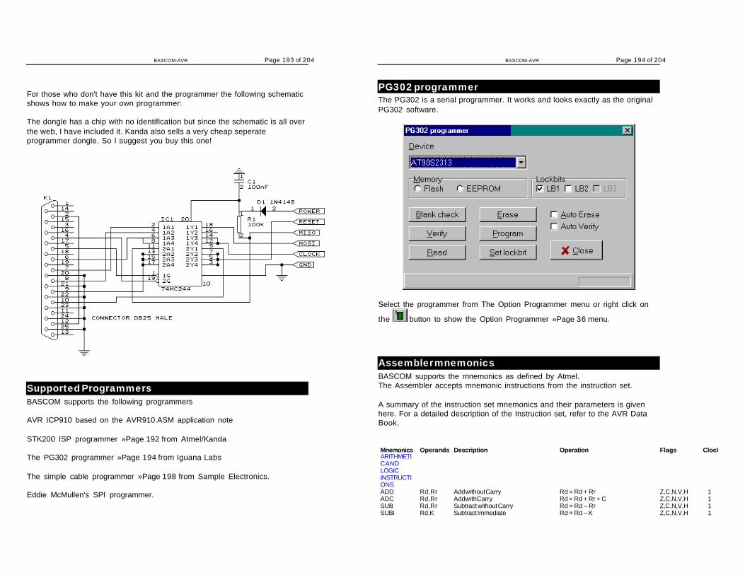
BASCOM-AVR Page 193 of 204
For those who don't have this kit and the programmer the following schematicshows how to make your own programmer:
The dongle has a chip with no identification but since the schematic is all overthe web, I have included it. Kanda also sells a very cheap seperateprogrammer dongle. So I suggest you buy this one!
Supported ProgrammersBASCOM supports the following programmers
AVR ICP910 based on the AVR910.ASM application note
STK200 ISP programmer »Page 192 from Atmel/Kanda
The PG302 programmer »Page 194 from Iguana Labs
The simple cable programmer »Page 198 from Sample Electronics.
Eddie McMullen's SPI programmer.
BASCOM-AVR Page 194 of 204
PG302 programmerThe PG302 is a serial programmer. It works and looks exactly as the originalPG302 software.
Select the programmer from The Option Programmer menu or right click on
the button to show the Option Programmer »Page 36 menu.
Assembler mnemonicsBASCOM supports the mnemonics as defined by Atmel.The Assembler accepts mnemonic instructions from the instruction set.
A summary of the instruction set mnemonics and their parameters is givenhere. For a detailed description of the Instruction set, refer to the AVR DataBook.
Mnemonics Operands Description Operation Flags ClockARITHMETIC ANDLOGICINSTRUCTIONSADD Rd, Rr Add without Carry Rd = Rd + Rr Z,C,N,V,H 1ADC Rd, Rr Add with Carry Rd = Rd + Rr + C Z,C,N,V,H 1SUB Rd, Rr Subtract without Carry Rd = Rd – Rr Z,C,N,V,H 1SUBI Rd, K Subtract Immediate Rd = Rd – K Z,C,N,V,H 1
BASCOM-AVR Page 195 of 204
SBC Rd, Rr Subtract with Carry Rd = Rd - Rr - C Z,C,N,V,H 1SBCI Rd, K Subtract Immediate with Carry Rd = Rd - K - C Z,C,N,V,H 1AND Rd, Rr Logical AND Rd = Rd · Rr Z,N,V 1ANDI Rd, K Logical AND with Immediate Rd = Rd · K Z,N,V 1OR Rd, Rr Logical OR Rd = Rd v Rr Z,N,V 1ORI Rd, K Logical OR with Immediate Rd = Rd v K Z,N,V 1EOR Rd, Rr Exclusive OR Rd = Rd Å Rr Z,N,V 1COM Rd Ones Complement Rd = $FF - Rd Z,C,N,V 1NEG Rd Twos Complement Rd = $00 - Rd Z,C,N,V,H 1SBR Rd,K Set Bit(s) in Register Rd = Rd v K Z,N,V 1CBR Rd,K Clear Bit(s) in Register Rd = Rd · ($FFh - K) Z,N,V 1INC Rd Increment Rd = Rd + 1 Z,N,V 1DEC Rd Decrement Rd = Rd - 1 Z,N,V 1TST Rd Test for Zero or Minus Rd = Rd · Rd Z,N,V 1CLR Rd Clear Register Rd = Rd Å Rd Z,N,V 1SER Rd Set Register Rd = $FF None 1ADIW Rdl, K Add Immediate to Word Rdh:Rdl = Rdh:Rdl + K None 1SBIW Rdl, K Subtract Immediate from Word Rdh:Rdl = Rdh:Rdl - K None 1MUL Rd,Rr Multiply Unsigned R1, R0 = Rd * Rr C 2 *BRANCHINSTRUCTIONSRJMP k Relative Jump PC = PC + k + 1 None 2IJMP Indirect Jump to (Z) PC = Z None 2JMP k Jump PC = k None 3RCALL k Relative Call Subroutine PC = PC + k + 1 None 3ICALL Indirect Call to (Z) PC = Z None 3CALL k Call Subroutine PC = k None 4RET Subroutine Return PC = STACK None 4RETI Interrupt Return PC = STACK I 4CPSE Rd,Rr Compare, Skip if Equal if (Rd = Rr) PC = PC + 2 or 3 None 1 / 2CP Rd,Rr Compare Rd - Rr Z,C,N,V,H, 1CPC Rd,Rr Compare with Carry Rd - Rr - C Z,C,N,V,H 1CPI Rd,K Compare with Immediate Rd - K Z,C,N,V,H 1SBRC Rr, b Skip if Bit in Register Cleared If (Rr(b)=0) PC = PC + 2 or 3 None 1 / 2SBRS Rr, b Skip if Bit in Register Set If (Rr(b)=1) PC = PC + 2 or 3 None 1 / 2SBIC P, b Skip if Bit in I/O Register Cleared If(I/O(P,b)=0) PC = PC + 2 or 3 None 2 / 3SBIS P, b Skip if Bit in I/O Register Set If(I/O(P,b)=1) PC = PC + 2 or 3 None 2 / 3BRBS s, k Branch if Status Flag Set if (SREG(s) = 1) then PC=PC+k + 1 None 1 / 2BRBC s, k Branch if Status Flag Cleared if (SREG(s) = 0) then PC=PC+k + 1 None 1 / 2BREQ k Branch if Equal if (Z = 1) then PC = PC + k + 1 None 1 / 2BRNE k Branch if Not Equal if (Z = 0) then PC = PC + k + 1 None 1 / 2BRCS k Branch if Carry Set if (C = 1) then PC = PC + k + 1 None 1 / 2BRCC k Branch if Carry Cleared if (C = 0) then PC = PC + k + 1 None 1 / 2BRSH k Branch if Same or Higher if (C = 0) then PC = PC + k + 1 None 1 / 2BRLO k Branch if Lower if (C = 1) then PC = PC + k + 1 None 1 / 2BRMI k Branch if Minus if (N = 1) then PC = PC + k + 1 None 1 / 2BRPL k Branch if Plus if (N = 0) then PC = PC + k + 1 None 1 / 2BRGE k Branch if Greater or Equal, Signed if (N V= 0) then PC = PC+ k + 1 None 1 / 2BRLT k Branch if Less Than, Signed if (N V= 1) then PC = PC + k + 1 None 1 / 2BRHS k Branch if Half Carry Flag Set if (H = 1) then PC = PC + k + 1 None 1 / 2BRHC k Branch if Half Carry Flag Cleared if (H = 0) then PC = PC + k + 1 None 1 / 2BRTS k Branch if T Flag Set if (T = 1) then PC = PC + k + 1 None 1 / 2BRTC k Branch if T Flag Cleared if (T = 0) then PC = PC + k + 1 None 1 / 2BRVS k Branch if Overflow Flag is Set if (V = 1) then PC = PC + k + 1 None 1 / 2BRVC k Branch if Overflow Flag is Cleared if (V = 0) then PC = PC + k + 1 None 1 / 2BRIE k Branch if Interrupt Enabled if ( I = 1) then PC = PC + k + 1 None 1 / 2BRID k Branch if Interrupt Disabled if ( I = 0) then PC = PC + k + 1 None 1 / 2DATATRANSFERINSTRUCTIONS
BASCOM-AVR Page 196 of 204
MOV Rd, Rr Copy Register Rd = Rr None 1LDI Rd, K Load Immediate Rd = K None 1LDS Rd, k Load Direct Rd = (k) None 3LD Rd, X Load Indirect Rd = (X) None 2LD Rd, X+ Load Indirect and Post-Increment Rd = (X), X = X + 1 None 2LD Rd, -X Load Indirect and Pre-Decrement X = X - 1, Rd =(X) None 2LD Rd, Y Load Indirect Rd = (Y) None 2LD Rd, Y+ Load Indirect and Post-Increment Rd = (Y), Y = Y + 1 None 2LD Rd, -Y Load Indirect and Pre-Decrement Y = Y - 1, Rd = (Y) None 2LDD Rd,Y+q Load Indirect with Displacement Rd = (Y + q) None 2LD Rd, Z Load Indirect Rd = (Z) None 2LD Rd, Z+ Load Indirect and Post-Increment Rd = (Z), Z = Z+1 None 2LD Rd, -Z Load Indirect and Pre-Decrement Z = Z - 1, Rd = (Z) None 2LDD Rd, Z+q Load Indirect with Displacement Rd = (Z + q) None 2STS k, Rr Store Direct (k) = Rr None 3ST X, Rr Store Indirect (X) = Rr None 2ST X+, Rr Store Indirect and Post-Increment (X) = Rr, X = X + 1 None 2ST -X, Rr Store Indirect and Pre-Decrement X = X - 1, (X) = Rr None 2ST Y, Rr Store Indirect (Y) = Rr None 2ST Y+, Rr Store Indirect and Post-Increment (Y) = Rr, Y = Y + 1 None 2ST -Y, Rr Store Indirect and Pre-Decrement Y = Y - 1, (Y) = Rr None 2STD Y+q,Rr Store Indirect with Displacement (Y + q) = Rr None 2ST Z, Rr Store Indirect (Z) = Rr None 2ST Z+, Rr Store Indirect and Post-Increment (Z) = Rr, Z = Z + 1 None 2ST -Z, Rr Store Indirect and Pre-Decrement Z = Z - 1, (Z) = Rr None 2STD Z+q,Rr Store Indirect with Displacement (Z + q) = Rr None 2LPM Load Program Memory R0 =(Z) None 3IN Rd, P In Port Rd = P None 1OUT P, Rr Out Port P = Rr None 1PUSH Rr Push Register on Stack STACK = Rr None 2POP Rd Pop Register from Stack Rd = STACK None 2BIT ANDBIT-TESTINSTRUCTIONSLSL Rd Logical Shift Left Rd(n+1) =Rd(n),Rd(0)= 0,C=Rd(7) Z,C,N,V,H 1LSR Rd Logical Shift Right Rd(n) = Rd(n+1), Rd(7) =0,
C=Rd(0)Z,C,N,V 1
ROL Rd Rotate Left Through Carry Rd(0) =C, Rd(n+1) =Rd(n),C=Rd(7) Z,C,N,V,H 1ROR Rd Rotate Right Through Carry Rd(7) =C,Rd(n) =Rd(n+1),C¬Rd(0) Z,C,N,V 1ASR Rd Arithmetic Shift Right Rd(n) = Rd(n+1), n=0..6 Z,C,N,V 1SWAP Rd Swap Nibbles Rd(3..0) « Rd(7..4) None 1BSET s Flag Set SREG(s) = 1 SREG(s) 1BCLR s Flag Clear SREG(s) = 0 SREG(s) 1SBI P, b Set Bit in I/O Register I/O(P, b) = 1 None 2CBI P, b Clear Bit in I/O Register I/O(P, b) = 0 None 2BST Rr, b Bit Store from Register to T T = Rr(b) T 1BLD Rd, b Bit load from T to Register Rd(b) = T None 1SEC Set Carry C = 1 C 1CLC Clear Carry C = 0 C 1SEN Set Negative Flag N = 1 N 1CLN Clear Negative Flag N = 0 N 1SEZ Set Zero Flag Z = 1 Z 1CLZ Clear Zero Flag Z = 0 Z 1SEI Global Interrupt Enable I = 1 I 1CLI Global Interrupt Disable I = 0 I 1SES Set Signed Test Flag S = 1 S 1CLS Clear Signed Test Flag S = 0 S 1SEV Set Twos Complement Overflow V = 1 V 1CLV Clear Twos Complement Overflow V = 0 V 1SET Set T in SREG T = 1 T 1CLT Clear T in SREG T = 0 T 1

BASCOM-AVR Page 197 of 204
SHE Set Half Carry Flag in SREG H = 1 H 1CLH Clear Half Carry Flag in SREG H = 0 H 1NOP No Operation None 1SLEEP Sleep None 1WDR Watchdog Reset None 1
* ) Not available in base-line microcontrollers
The Assembler is not case sensitive.
The operands have the following forms:
Rd: R0-R31 or R16-R31 (depending on instruction)Rr: R0-R31b: Constant (0-7)s: Constant (0-7)P: Constant (0-31/63)K: Constant (0-255)k: Constant, value range depending on instruction.q: Constant (0-63)Rdl: R24, R26, R28, R30. For ADIW and SBIW instructions
Mixing ASM and BASICBASCOM allows you to mix BASIC with assembly.This can be very usefull in some situations when you need full control of thegenerated code.
Almost all assembly mnemonics are recognized by the compiler. Theexceptions are : SUB, SWAP and OUT. These are BASIC reserved wordsand have priority over the ASM mnemonics. To use these mnemonicsprecede them with the ! - sign.For example :
Dim a As Byte At &H60 'A is stored at location &H60Ldi R27 , $00 'Load R27 with MSB of addressLdi R26 , $60 'Load R26 with LSB of addressLd R1, X 'load memory location $60 into R1!SWAP R1 'swap nibbles
As you can see the SWAP mnemonic is preceded by a ! sign.
Another option is to use the assembler block directives:$ASM
Ldi R27 , $00 'Load R27 with MSB of addressLdi R26 , $60 'Load R26 with LSB of addressLd R1, X 'load memory location $60 into R1SWAP R1 'swap nibbles
$END ASM
A special assembler helper function is provided to load the address in to the
BASCOM-AVR Page 198 of 204
register X or Z. Y can not be used because it is used as the stack pointer.
Dim A As Byte 'reserve spaceLOADADR a, X 'load addres of variable named A into registerpairX
This has the same effect as :Ldi R26 , $60 'for example !Ldi R27, $00 'for example !
Some registers are used by BASCOMR4 and R5 are used to point to the stack frameR6 is used to store some bit variables:
R6 bit 0 = flag for int/word conversionR6 bit 1 = temp bit space used for swapping bitsR6 bit 2 = error bit (ERR variable)R6 bit 3 = show/noshow flag when using INPUT statement
R8 and R9 are used as a datapointer for the READ statement.
All other registers are used depending on the used statements.
To Load the address of a variable you must enclose them in brackets.Dim B As BitLds R16, {B} 'will replace {B} with the address of variable B
To refer to the bitnumber you must precede the variable name by BIT.Sbrs R16 , BIT.B 'notice the point!Since this was the first dimensioned bit the bitnumber is 7. Bits are stored inbytes and the first dimensioned bit goes in the LS bit.
Sample Electronics cable programmer
The simple cable programmer was submitted by Sample Electronics.They produce professional programmers too. This simple programmer youcan make yourself within a 10 minutes.
What you need is a DB25 centronics male connector, a flatcable and aconnector that can be connected to the target MCU board.
The connections to make are as following:
DB25 pin Target MCU pin(AT90S8535) DT1042, D0 MOSI, pin 6 J5, pin 44, D2 RESET, pin 9 J5, pin 85, D3 CLOCK, pin 8 J5, pin 6

BASCOM-AVR Page 199 of 204
11, BUSY MISO, pin 7 J5, pin 518-25,GND GROUND J5, pin 1
The MCU pin numbers are shown for an 8535!
Note that 18-25 means pins 18,19,20,21,22,23,24 and 25You can use a small resistor of 100 ohm in series with the D0, D2 and D3 linein order not to short circuit your LPT port in the event the MCU pins are high.But it was tested without these resistors and my PC still works :-)
Tip : when testing programmers etc. on the LPT it is best to buy a I/O card foryour PC that has a LPT port. This way you dont destroy your LPT port that ison the motherboard in the event you make a mistake!
SPIMOVEActionSends and receives value or a variable to the SPI-bus.
Syntaxvar = SPIMOVE( byte )
Remarksvar The variable that is assigned with the received byte from the SPI-
bus.byte The variable or constant whose content must be send to the SPI-
bus.
See alsoSPIIN »Page 178 , SPIINIT »Page 179 , CONFIG SPI »Page 101
ExampleCONFIG SPI = SOFT, DIN = P1.0, DOUT = P1.1, CS=P1.2, CLK = P1.3INITSPIDim a(10) as Byte , X As ByteSPIOUT a(1) , 5 'send 5 bytesSPIOUT X , 1 'send 1 byteA(1) = SpiMove(5) ' move 5 to SPI and store resultl in a(1)End
BASCOM-AVR Page 200 of 204
INSTRActionReturns the position of a substring in a string.
Syntaxvar = INSTR( start , string , substr )var = INSTR( string , substr )
RemarksVar Numeric variable that will be assigned with the position of the
substring in the string. Returns 0 when the substring is notfound.
Start An optional numeric parameter that can be assigned with thefirst position where must be searched in the string. By default(when not used) the whole string is searched starting fromposition 1.
String The string to search.Substr The search string.
No constant can be used for string it must be a string.Only substr can be either a string or a constant.
See also
ExampleDim S As String * 10 , Z as String * 5Dim bP as Bytes = "This is a test"Z = "is"bP = Instr(s,z) : Print bP 'should print 3bP = Instr(4,s,z) : Print bP 'should print 6End

BASCOM-AVR Page 201 of 204
Index
—$—
$ASM, 64$BAUD, 64$CRYSTAL, 65$DATA, 65$DEFAULT, 66$EEPROM, 67$EXTERNAL, 68$INCLUDE, 69$LCD, 69$LCDPUTCTRL, 70$LCDPUTDATA, 71$LCDRS, 72$LIB, 73$REGFILE, 75$SERIALINPUT, 75$SERIALINPUT2LCD, 77$SERIALOUTPUT, 78$XRAMSIZE, 78$XRAMSTART, 79
—1—
1WREAD, 811WRESET, 801WWRITE, 82
—A—
A word of thank, 13ABS, 84Additional Hardware, 44ALIAS, 83ASC, 85Assembler mnemonics, 194Attaching an LCD Display, 53AVR Internal Hardware, 45AVR Internal Hardware Port B, 50AVR Internal Hardware Port D, 52AVR Internal Hardware TIMER1, 49AVR Internal Hardware Watchdog timer, 50AVR Internal Registers, 46
—B—
BASCOM Editor Keys, 39BAUD, 85BCD, 86BITWAIT, 87BYVAL, 88
—C—
CALL, 88CASE, 173Changes compared to BASCOM-8051, 191CHR, 90CLOCKDIVISION, 91CLOSE, 92CLS, 91CONFIG, 93CONFIG 1WIRE, 94CONFIG DEBOUNCE, 94CONFIG I2CDELAY, 95CONFIG INTx, 96CONFIG KBD, 96CONFIG LCD, 97CONFIG LCDBUS, 97CONFIG LCDMODE, 98CONFIG LCDPIN, 99CONFIG PORT, 107CONFIG SCL, 100CONFIG SDA, 99CONFIG SPI, 101CONFIG TIMER0, 101CONFIG TIMER1, 103CONFIG WAITSUART, 106CONFIG WATCHDOG, 106CONST, 122Constants, 40COUNTER0 and COUNTER1, 109CPEEK, 110CRYSTAL, 111CURSOR, 112
—D—
DATA, 112DEBOUNCE, 114DECLARE FUNCTION, 116DECLARE SUB, 118DECR, 116DEFBIT, 119DEFINT, 119DEFLCDCHAR, 119DEFLNG, 119DEFSNG, 119DEFWORD, 119DEFxxx, 119DELAY, 120Developing Order, 40DIM, 120DISABLE, 123DISPLAY, 125DO, 125DOWNTO, 128
BASCOM-AVR Page 202 of 204
—E—
Edit Copy, 19Edit Cut, 19Edit Find, 20Edit Find Next, 20Edit Goto, 20Edit Goto Bookmark, 21Edit Indent Block, 21Edit Paste, 20Edit Redo, 19Edit Replace, 20Edit Toggle Bookmark, 20Edit Undo, 19Edit Unindent Block, 21ELSE, 126, 142ENABLE, 126END, 127END IF, 142END SELECT, 173ERAM, 40Error Codes, 42EXIT, 128
—F—
File Close, 18File Exit, 19File New, 17File Open, 17File Print, 19File Print Preview, 18File Save, 18File Save As, 18FOR, 128FOR-NEXT, 128FOURTHLINE, 129FUSING, 130
—G—
GETAD, 130GETKBD, 131GETRC0, 132GETRC5, 133GOSUB, 135GOTO, 136
—H—
Help About, 38Help Credits, 39Help Index, 38Help on Help, 38HEX, 137HEXVAL, 137HIGH, 138
HOME, 138
—I—
I2CRBYTE, 140I2CRECEIVE, 139I2CSEND, 139I2CSTART, 140I2CSTOP, 140I2CWBYTE, 140I2START,I2CSTOP, I2CRBYTE, I2CWBYTE,
140IDLE, 141IF, 142IF-THEN-ELSE-END IF, 142INCR, 143Index, 1INKEY, 143INP, 144INPUT, 146INPUTBIN, 144INPUTHEX, 145Installation, 6INSTR, 200ISP programmer, 192
—L—
Language Fundamentals, 56LCD, 147LEFT, 150LEN, 150LOAD, 151LOADADR, 191LOCAL, 152LOCATE, 154LOOKUP, 154LOOKUPSTR, 155LOOP, 125LOW, 156LOWERLINE, 156LTRIM, 151
—M—
MAKEBCD, 157MAKEDEC, 158MAKEINT, 157Memory usage, 40MID, 158Mixing ASM and BASIC, 197
—N—
NEXT, 128
BASCOM-AVR Page 203 of 204
—O—
ON INTERRUPT, 159ON VALUE, 160OPEN, 161Options Communication, 32Options Compiler, 27, 30Options Compiler 1WIRE, 30Options Compiler Chip, 27Options Compiler Communication, 29Options Compiler I2C, 30Options Compiler LCD, 31Options Compiler Output, 28Options Compiler SPI, 30Options Environment, 33Options Monitor, 36Options Printer, 37Options Programmer, 36Options Simulator, 35OUT, 162
—P—
PEEK, 163PG302 programmer, 194POKE, 163POPALL, 164Power Up, 55POWERDOWN, 164POWERSAVE, 164PRINT, 165PRINTBIN, 166Program Compile, 21Program Send to Chip, 23Program Show Result, 22Program Simulate, 23Program Syntax Check, 22PUSHALL, 166
—R—
READ, 167READEEPROM, 168REM, 168Resellers, 9Reserved Words, 56RESET, 169RESTORE, 170RETURN, 170RIGHT, 171ROTATE, 172RTRIM, 171Running BASCOM-AVR, 17
—S—
Sample Electronics cable programmer, 198
SELECT, 173SELECT-CASE-END SELECT, 173SET, 173SETUP, 6SHIFT, 174SHIFTCURSOR, 175SHIFTIN, 175SHIFTLCD, 177SHIFTOUT, 176SOUND, 177SPACE, 178SPIIN, 178SPIINIT, 179SPIMOVE, 199SPIOUT, 180START, 180STEP, 128STOP, 181STR, 182STRING, 183SUB, 184Supported Programmers, 193SWAP, 184
—T—
THEN, 142THIRDLINE, 184TIMER0, 48Tools LCD Designer, 26Tools Terminal Emulator, 25TRIM, 185
—U—
UPPERLINE, 186Using the 1 WIRE protocol, 55Using the I2C protocol, 54Using the SPI protocol, 55
—V—
VAL, 186VARPTR, 187
—W—
WAIT, 187WAITKEY, 188WAITMS, 188WAITUS, 189WEND, 189WHILE, 189WHILE-WEND, 189Window Arrange Icons, 37Window Minimize All, 37
BASCOM-AVR Page 204 of 204
Window Tile, 37Windows Cascade, 37WRITEEEPROM, 190
—X—
XRAM, 40