Tooling the Future www.ceratizit.com Technical Manual BAR PEELING CERATIZIT is a high-technology engineering group specialised in cutting tools and hard material solutions.

Welcome message from author
This document is posted to help you gain knowledge. Please leave a comment to let me know what you think about it! Share it to your friends and learn new things together.
Transcript
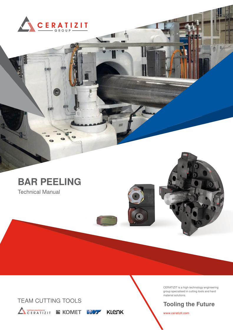
Tooling the Futurewww.ceratizit.com
Technical ManualBAR PEELING
CERATIZIT is a high-technology engineering group specialised in cutting tools and hard material solutions.

2 cuttingtools.ceratizit.com
As our customer, you will benefit from one of the largest ranges on the market, an efficient sales operation and our leading expertise worldwide!
Every sector has its own specific requirements. Tools and materials are expected to offer maximum cutting performance, wear resistance, precision and quality – from large- scale production to the manufacture of single parts. This applies to the machining of aluminium alloys, cast materials and high-alloy steel as well as super alloys and titanium. As such, almost every sector of industry is affected – from the automotive and heavy duty machining sectors to aerospace and energy technology.
As the leading supplier of solutions for numerous industry-specific applications, we draw upon our wide-ranging expertise to offer you first-class advice and support. Whatever you need, we will work with you to find a successful, innovative solution to optimise your production process.
Industry-specific applications and bespoke solutions
Industry Solutions

3
Team Cutting Tools from the CERATIZIT Group is your gateway to leading international experts in machining solutions.We are masters of the carbide production process, from the powder to the finished cutting tool. Not only does this allow us to develop special-purpose tools for customer-specific applications, it also meanswe can draw upon a full range of sector-specific standard tools, which are kept in stock and are available immediately.We are experts at developing solutions, including the ability to analyse and optimise existing processes. And there is one thing that will never change – direct contact with our customers – thanks to streamlined structures and personal contacts.
▲ Uniquely extensive expertise in the field of machining
▲ One of the most extensive ranges on the market – from standard and semi-standard tools to special-purpose tools.
▲ Best-in-class R&D, sales and customer service
▲ Leading expertise in future technologies such as digitalisation and innovative production processes
▲ Many years of in-depth experience in various industry segments
▲ All under one roof the global CERATIZIT Group
Team Cutting Tools from the CERATIZIT GroupThe full-service provider in the machining sector
33 production facilities
> 9.000 employees
> 1.000 patents
4 cuttingtools.ceratizit.com
Technical manualBar peeling
Content
Bar peeling
For the bar peeling application range we offer machining solutions that guarantee high process security, optimum surface quality and maximum machining rates.
Use our user manual to find out more about the particular challenges and options for bar peeling. Find out more about the specific process and our cutting material solutions which cover the entire range of requirements. Experience gained in bar peeling with CERATIZIT tools speaks for itself. Our practical examples will inspire you
Our solutions for the entire process
Technical informationBar peeling → page 9Our solutions for the entire application range → pages 10–11The bar peeling process → pages 12–13Comparison tables for materials → pages 14–17Cutting materials → pages 18–23Dragonskin → pages 24–25Application examples → pages 26–31Influencing factors and selection of the correct indexable insert → page 32
Support chamfers → pages 33–35Peeling inserts – product range → pages 36–37Solutions for super alloys and titanium → pages 38–39Hexagonal roughing inserts → pages 40–41Peeling inserts for roughing → pages 42–43Peeling inserts for roughing and finishing → pages 44–45Peeling inserts for finishing → pages 46–47Hexagonal roughing inserts HNMJ 131050, HNMH/J 221550 and HNMH/J 281850 → pages 48–49
Tool holders and cartridges → pages 50–51Different clamping methods → pages 52–53Use of carbide shims → page 54Precise setting of the tool holders → page 55Surface quality → page 56Productivity and efficiency → page 57Machining examples → page 58Bar peeling formulae → page 59Troubleshooting guide for turning → page 60Troubleshooting guide for bar peeling → page 61Causes and types of wear → pages 62–64
5cuttingtools.ceratizit.com
Technical manualBar peeling
Content
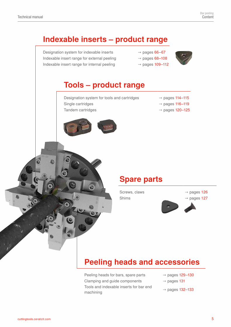
Indexable inserts – product rangeDesignation system for indexable inserts → pages 66–67Indexable insert range for external peeling → pages 68–108Indexable insert range for internal peeling → pages 109–112
Tools – product rangeDesignation system for tools and cartridges → pages 114–115Single cartridges → pages 116–119Tandem cartridges → pages 120–125
Spare partsScrews, claws → pages 126Shims → pages 127
Peeling heads and accessoriesPeeling heads for bars, spare parts → pages 129–130Clamping and guide components → pages 131Tools and indexable inserts for bar end machining → pages 132–133

6 cuttingtools.ceratizit.com
Technical manualBar peeling
Our service
Your expert local partner
An application engineer is always available by phone to answer your application-specific questions. Even if they are not on-site with you, our experts are always ready to answer your questions.
State-of-the-art with technical trainingOur engineers are provided with constant training to keep them up to speed on all technical matters. You can also use our service to train your employees on-site.
Customised tool solutions
We adapt standard tools and develop special tools or complete tool concepts together with you.
Our service – your competitive advantage
Do you want to be one of the players setting the pace on the international market? With Team Cutting Tools from CERATIZIT as your expert partner, you can. In addition to the latest technological standards, innovative materials and coatings, as well as unique special tools for bar peeling, you can benefit from our highly attractive, comprehensive range of services. Our trend-setting offers explicitly target manufacturers of bright steel and are individually tailored to each customer's objectives – a unique offer that gives you a decisive competitive advantage. See for yourself with our services that take your processes to a completely new level and assist you significantly in addressing your challenges.
Take advantage of our customer-specific services that truly make the difference
7cuttingtools.ceratizit.com
Technical manualBar peeling
Our service
Environmentally friendly, sustainable and cost-effectiveCertified recycling of high quality carbide.
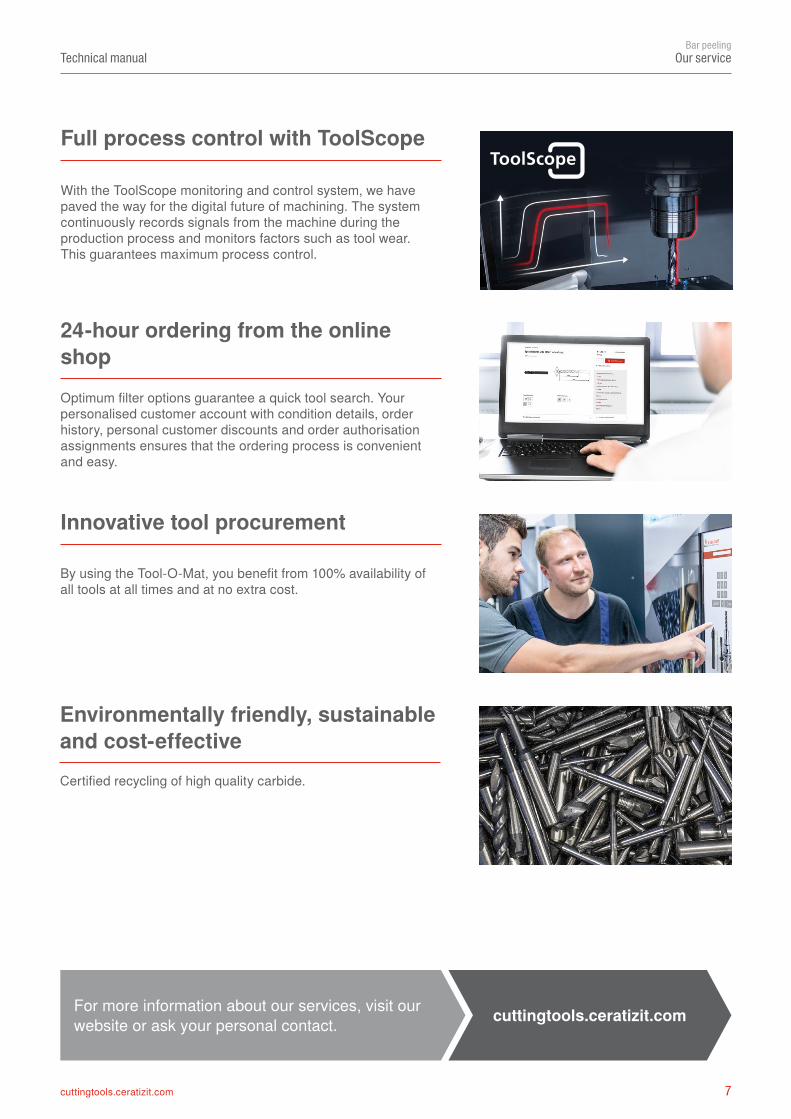
Full process control with ToolScope
With the ToolScope monitoring and control system, we have paved the way for the digital future of machining. The system continuously records signals from the machine during the production process and monitors factors such as tool wear. This guarantees maximum process control.
Innovative tool procurement
By using the Tool-O-Mat, you benefit from 100% availability of all tools at all times and at no extra cost.
24-hour ordering from the online shop Optimum filter options guarantee a quick tool search. Your personalised customer account with condition details, order history, personal customer discounts and order authorisation assignments ensures that the ordering process is convenient and easy.
For more information about our services, visit our website or ask your personal contact. cuttingtools.ceratizit.com
8 cuttingtools.ceratizit.com
Technical manualBar peeling
Always the best quality
CERATIZIT is a quality leader that unites all the process knowledge and extensive manufacturing expertise of the CERATIZIT Group.
▲ Highly qualified, trained experts in a wide range of areas. ▲ We control each individual production step. ▲ Our modern fleet of machinery is constantly being expanded and improved. ▲ Optimised production processes reduce process costs and ensure that our products are of the highest quality and environmentally friendly.
▲ Independently tested and certified products.
Always the best quality
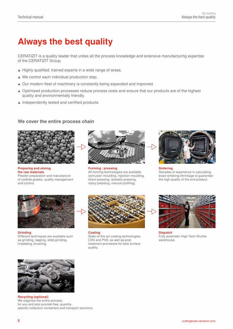
We cover the entire process chain
Preparing and mixing the raw materials Powder preparation and manufacture of carbide grades, quality management and control.
Forming / pressing All forming technologies are available (extrusion moulding, injection moulding, direct pressing, isostatic pressing, rotary pressing, manual profiling).
Sintering Decades of experience in calculating exact sintering shrinkage to guarantee the high quality of the end product.
Grinding Different techniques are available such as grinding, lapping, slide grinding, irradiating, brushing.
Coating State-of-the-art coating technologies, CVD and PVD, as well as post-treatment processes for best surface quality.
Dispatch Fully automatic High-Tech-Shuttle warehouse.
Recycling (optional)We organise the entire process for you and also provide free, quantity- specific collection containers and transport solutions.
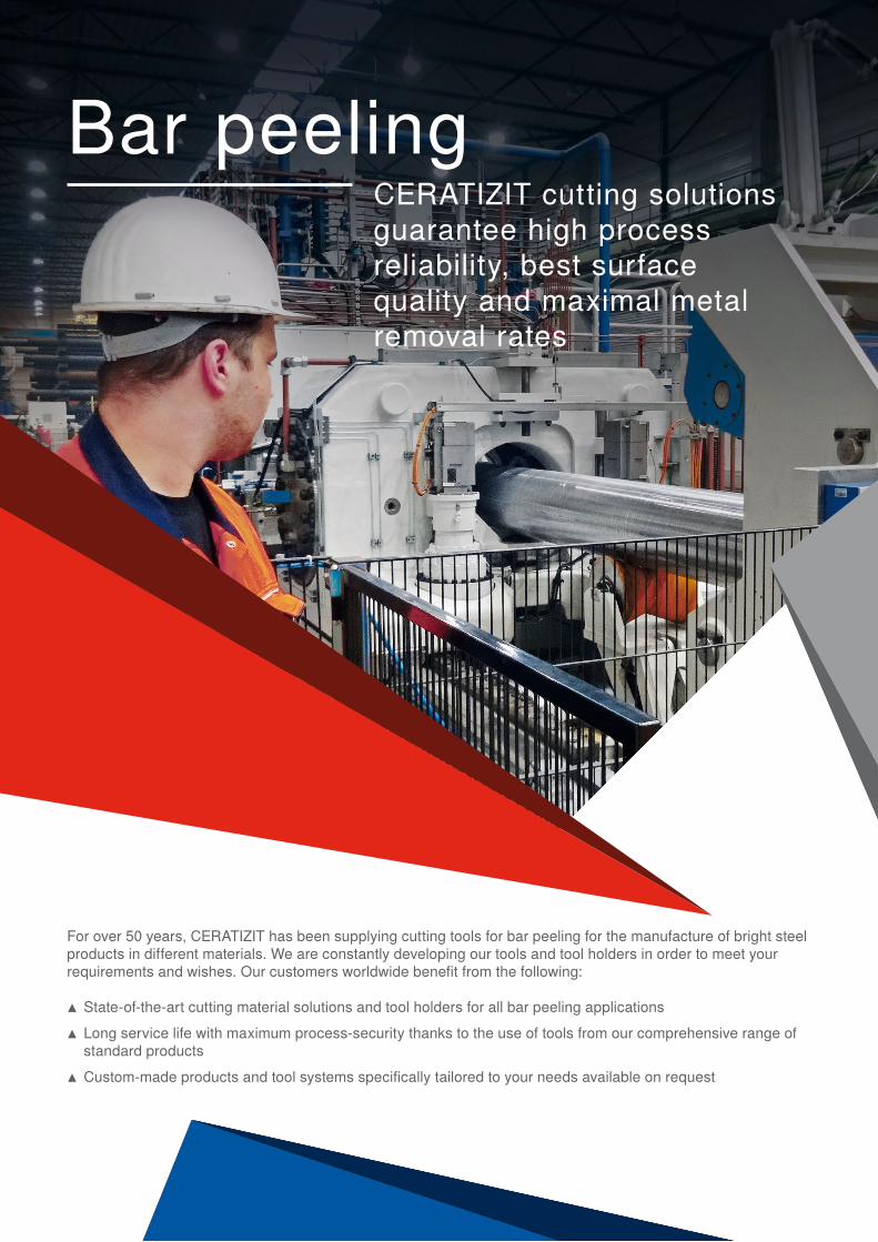
Bar peelingCERATIZIT cutting solutionsguarantee high process reliability, best surface quality and maximal metal removal rates
For over 50 years, CERATIZIT has been supplying cutting tools for bar peeling for the manufacture of bright steel products in different materials. We are constantly developing our tools and tool holders in order to meet your requirements and wishes. Our customers worldwide benefit from the following:
▲ State-of-the-art cutting material solutions and tool holders for all bar peeling applications ▲ Long service life with maximum process-security thanks to the use of tools from our comprehensive range of standard products
▲ Custom-made products and tool systems specifically tailored to your needs available on request
10 cuttingtools.ceratizit.com
Technical manualBar peeling
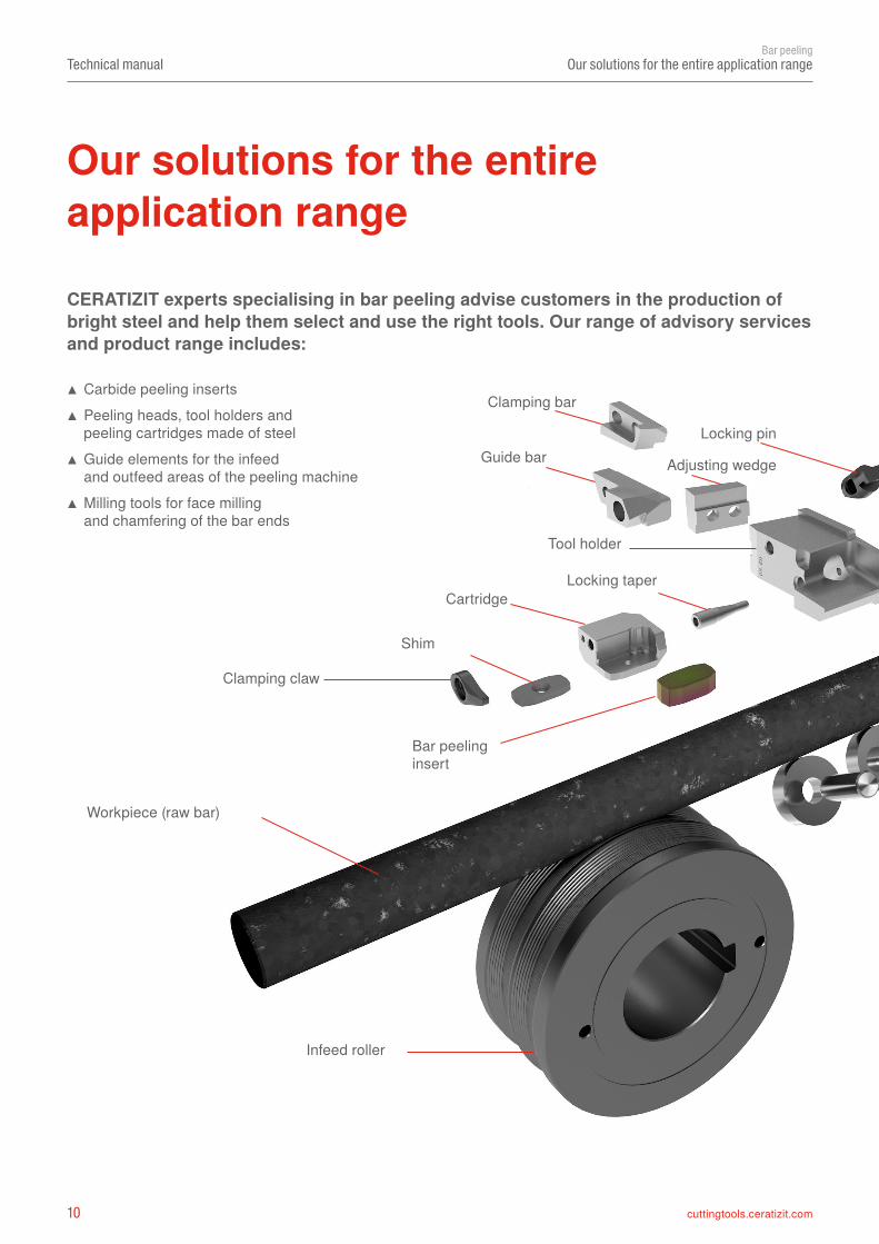
Our solutions for the entire application range
Cartridge
Bar peeling insert
Workpiece (raw bar)
CERATIZIT experts specialising in bar peeling advise customers in the production of bright steel and help them select and use the right tools. Our range of advisory services and product range includes:
▲ Carbide peeling inserts ▲ Peeling heads, tool holders and peeling cartridges made of steel
▲ Guide elements for the infeed and outfeed areas of the peeling machine
▲ Milling tools for face milling and chamfering of the bar ends
Our solutions for the entire application range
Tool holder
Clamping claw
Shim
Clamping bar
Locking pinGuide bar
Locking taper
Adjusting wedge
Infeed roller
11cuttingtools.ceratizit.com
Technical manualBar peeling
Our solutions for the entire application range
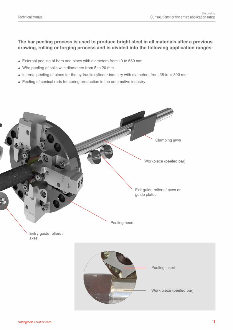
Peeling insert
Work piece (peeled bar)
Entry guide rollers / axes
Exit guide rollers / axes or guide plates
Workpiece (peeled bar)
Peeling head
The bar peeling process is used to produce bright steel in all materials after a previous drawing, rolling or forging process and is divided into the following application ranges:
▲ External peeling of bars and pipes with diameters from 10 to 650 mm ▲ Wire peeling of coils with diameters from 5 to 20 mm ▲ Internal peeling of pipes for the hydraulic cylinder industry with diameters from 35 to is 300 mm ▲ Peeling of conical rods for spring production in the automotive industry
Clamping jaws
Locking pin
12 cuttingtools.ceratizit.com
M
MM
M
Technical manualBar peeling
Bar peeling – the process
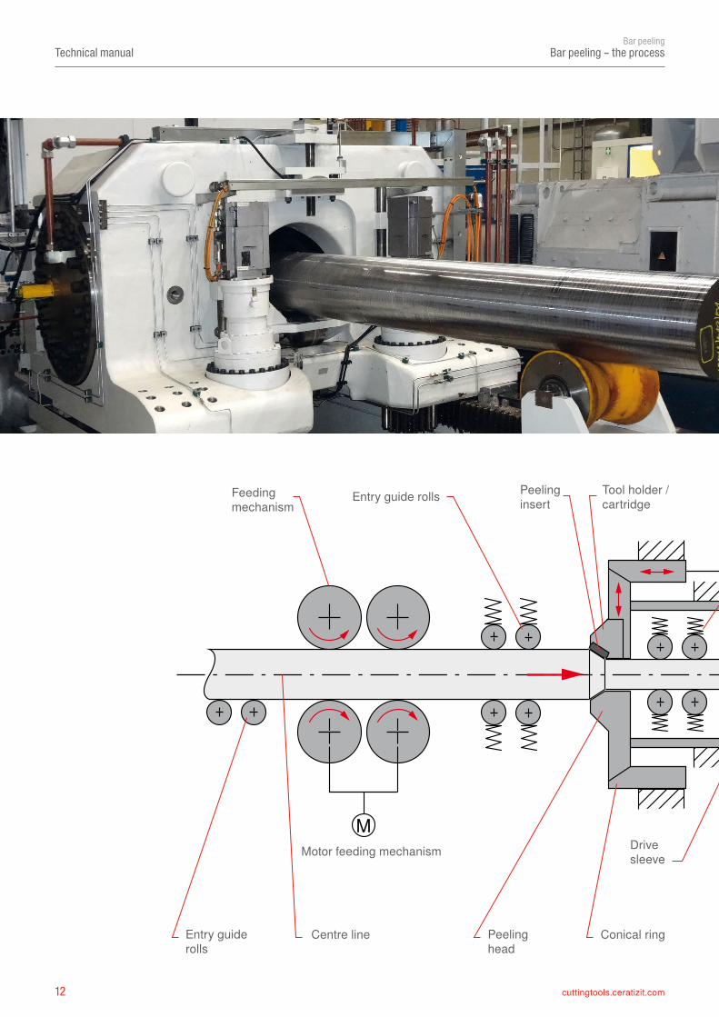
Feedingmechanism
Entry guide rolls
Entry guiderolls
Centre line Peelinghead
Conical ring
Peelinginsert
Tool holder / cartridge
Motor feeding mechanism Drivesleeve
13cuttingtools.ceratizit.com
M
MM
M
Technical manualBar peeling
Bar peeling – the process
Bar peeling gives bars and tubes in various materials (carbon) steel, spring steel, stainless steel, nickel-basedalloy, titanium, aluminium) the requisite surface quality and dimensional and form accuracy. In the peeling process work pieces with diameters from 6 to 650 mm (in many cases rough forged, but also rolled or drawn) are machined to produce a bright smooth surface while eliminating ruptures caused during the forging and rolling process.
This heavy machining process is seen as very productive and efficient, but at the same time particularly challenging for the tools and machines. Due to the considerably reduced throughput times compared to the conventional turning process, and the excellent result the bright steel products show in terms of surface quality and dimensional accuracy, costs and outlay are reduced in the final machining of these semi-finished products.
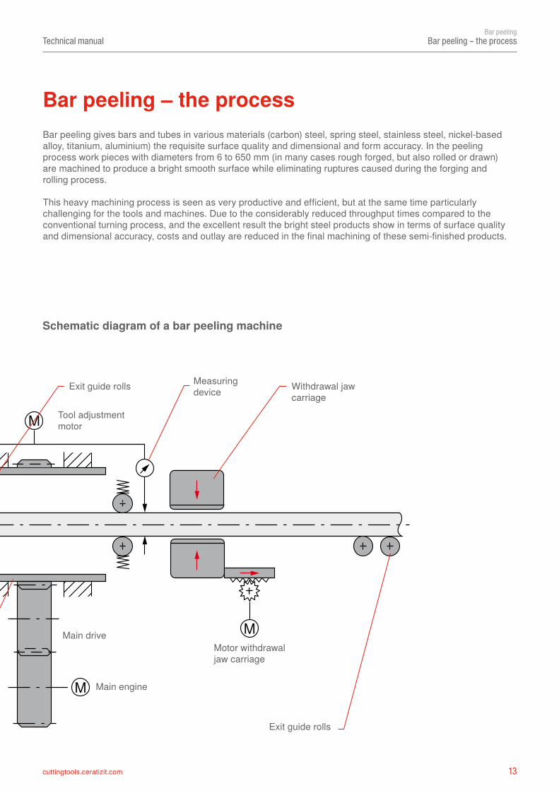
Schematic diagram of a bar peeling machine
Bar peeling – the process
Exit guide rolls Measuringdevice Withdrawal jaw
carriage
Conical ring Exit guide rolls
Tool holder / cartridge
Main engine
Tool adjustmentmotor
Motor withdrawal jaw carriage
Main drive
14 cuttingtools.ceratizit.com
Technical manualBar peeling
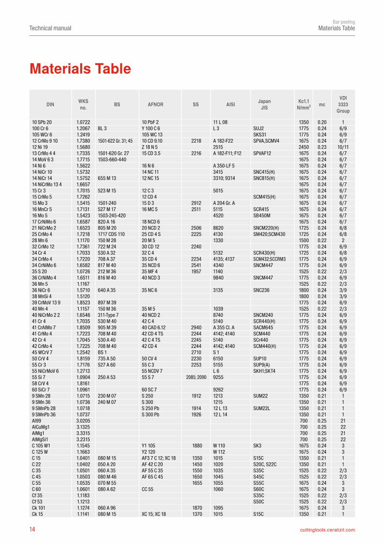
Materials Table
Materials Table
DIN WKS no. BS AFNOR SS AISI Japan
JISKc1.1
N/mm2 mcVDI
3323 Group
10 SPb 20 1.0722 10 PbF 2 11 L 08 1350 0.20 1100 Cr 6 1.2067 BL 3 Y 100 C 6 L 3 SUJ2 1775 0.24 6/9105 WCr 6 1.2419 105 WC 13 SKS31 1775 0.24 6/912 CrMo 9 10 1.7380 1501-622 Gr. 31; 45 10 CD 9.10 2218 A 182-F22 SPVA,SCMV4 1675 0.24 6/712 Ni 19 1.5680 Z 18 N 5 2515 2450 0.23 10/1113 CrMo 4 4 1.7335 1501-620 Gr. 27 15 CD 3.5 2216 A 182-F11; F12 SPVAF12 1675 0.24 6/714 MoV 6 3 1.7715 1503-660-440 1675 0.24 6/714 Ni 6 1.5622 16 N 6 A 350-LF 5 1675 0.24 6/714 NiCr 10 1.5732 14 NC 11 3415 SNC415(H) 1675 0.24 6/714 NiCr 14 1.5752 655 M 13 12 NC 15 3310; 9314 SNC815(H) 1675 0.24 6/714 NiCrMo 13 4 1.6657 1675 0.24 6/715 Cr 3 1.7015 523 M 15 12 C 3 5015 1675 0.24 6/715 CrMo 5 1.7262 12 CD 4 SCM415(H) 1675 0.24 6/715 Mo 3 1.5415 1501-240 15 D 3 2912 A 204 Gr. A 1675 0.24 6/716 MnCr 5 1.7131 527 M 17 16 MC 5 2511 5115 SCR415 1675 0.24 6/716 Mo 5 1.5423 1503-245-420 4520 SB450M 1675 0.24 6/717 CrNiMo 6 1.6587 820 A 16 18 NCD 6 1675 0.24 6/721 NiCrMo 2 1.6523 805 M 20 20 NCD 2 2506 8620 SNCM220(H) 1725 0.24 6/825 CrMo 4 1.7218 1717 CDS 110 25 CD 4 S 2225 4130 SM420;SCM430 1725 0.24 6/828 Mn 6 1.1170 150 M 28 20 M 5 1330 1500 0.22 232 CrMo 12 1.7361 722 M 24 30 CD 12 2240 1775 0.24 6/934 Cr 4 1.7033 530 A 32 32 C 4 5132 SCR430(H) 1725 0.24 6/834 CrMo 4 1.7220 708 A 37 35 CD 4 2234 4135; 4137 SCM432;SCCRM3 1775 0.24 6/934 CrNiMo 6 1.6582 817 M 40 35 NCD 6 2541 4340 SNCM447 1775 0.24 6/935 S 20 1.0726 212 M 36 35 MF 4 1957 1140 1525 0.22 2/336 CrNiMo 4 1.6511 816 M 40 40 NCD 3 9840 SNCM447 1775 0.24 6/936 Mn 5 1.1167 1525 0.22 2/336 NiCr 6 1.5710 640 A 35 35 NC 6 3135 SNC236 1800 0.24 3/938 MnSi 4 1.5120 1800 0.24 3/939 CrMoV 13 9 1.8523 897 M 39 1775 0.24 6/940 Mn 4 1.1157 150 M 36 35 M 5 1039 1525 0.22 2/340 NiCrMo 2 2 1.6546 311-Type 7 40 NCD 2 8740 SNCM240 1775 0.24 6/941 Cr 4 1.7035 530 M 40 42 C 4 5140 SCR440(H) 1775 0.24 6/941 CrAlMo 7 1.8509 905 M 39 40 CAD 6.12 2940 A 355 Cl. A SACM645 1775 0.24 6/941 CrMo 4 1.7223 708 M 40 42 CD 4 TS 2244 4142; 4140 SCM440 1775 0.24 6/942 Cr 4 1.7045 530 A 40 42 C 4 TS 2245 5140 SCr440 1775 0.24 6/942 CrMo 4 1.7225 708 M 40 42 CD 4 2244 4142; 4140 SCM440(H) 1775 0.24 6/945 WCrV 7 1.2542 BS 1 2710 S 1 1775 0.24 6/950 CrV 4 1.8159 735 A 50 50 CV 4 2230 6150 SUP10 1775 0.24 6/955 Cr 3 1.7176 527 A 60 55 C 3 2253 5155 SUP9(A) 1775 0.24 6/955 NiCrMoV 6 1.2713 55 NCDV 7 L 6 SKH1;SKT4 1775 0.24 6/955 Si 7 1.0904 250 A 53 55 S 7 2085; 2090 9255 1775 0.24 6/958 CrV 4 1.8161 1775 0.24 6/960 SiCr 7 1.0961 60 SC 7 9262 1775 0.24 6/99 SMn 28 1.0715 230 M 07 S 250 1912 1213 SUM22 1350 0.21 19 SMn 36 1.0736 240 M 07 S 300 1215 1350 0.21 19 SMnPb 28 1.0718 S 250 Pb 1914 12 L 13 SUM22L 1350 0.21 19 SMnPb 36 1.0737 S 300 Pb 1926 12 L 14 1350 0.21 1Al99 3.0205 700 0.25 21AlCuMg1 3.1325 700 0.25 22AlMg1 3.3315 700 0.25 21AlMgSi1 3.2315 700 0.25 22C 105 W1 1.1545 Y1 105 1880 W 110 SK3 1675 0.24 3C 125 W 1.1663 Y2 120 W 112 1675 0.24 3C 15 1.0401 080 M 15 AF3 7 C 12; XC 18 1350 1015 S15C 1350 0.21 1C 22 1.0402 050 A 20 AF 42 C 20 1450 1020 S20C, S22C 1350 0.21 1C 35 1.0501 060 A 35 AF 55 C 35 1550 1035 S35C 1525 0.22 2/3C 45 1.0503 080 M 46 AF 65 C 45 1650 1045 S45C 1525 0.22 2/3C 55 1.0535 070 M 55 1655 1055 S55C 1675 0.24 3C 60 1.0601 080 A 62 CC 55 1060 S60C 1675 0.24 3Cf 35 1.1183 S35C 1525 0.22 2/3Cf 53 1.1213 S50C 1525 0.22 2/3Ck 101 1.1274 060 A 96 1870 1095 1675 0.24 3Ck 15 1.1141 080 M 15 XC 15; XC 18 1370 1015 S15C 1350 0.21 1
15cuttingtools.ceratizit.com
Technical manualBar peeling
Materials Table
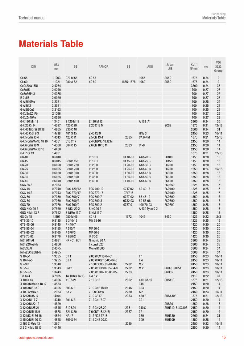
Materials Table
DIN Wks no. BS AFNOR SS AISI Japan
JISKc1.1
N/mm2 mcVDI
3323 Group
Ck 55 1.1203 070 M 55 XC 55 1055 S55C 1675 0.24 3Ck 60 1.1221 080 A 62 XC 60 1665; 1678 1060 S58C 1675 0.24 3CoCr20W15Ni 2.4764 3300 0.24 35CuZn15 2.0240 700 0.27 27CuZn36Pb3 2.0375 700 0.27 26E-Cu57 2.0060 700 0.27 28G-AlSi10Mg 3.2381 700 0.25 24G-AlSi12 3.2581 700 0.25 23G-AlSi9Cu3 3.2163 700 0.25 23G-CuSn5ZnPb 2.1096 700 0.27 26G-CuZn40Fe 2.0590 700 0.27 28G-X 120 Mn 12 1.3401 Z 120 M 12 Z 120 M 12 A 128 (A) 3300 0.24 35G-X 20 Cr 14 1.4027 420 C 29 Z 20 C 13 M SCS2 1875 0.21 12/13G-X 40 NiCrSi 38 18 1.4865 330 C 40 2600 0.24 31G-X 45 CrSi 9 3 1.4718 401 S 45 Z 45 CS 9 HNV 3 2450 0.23 10/11G-X 5 CrNi 13 4 1.4313 425 C 11 Z 5 CN 13.4 2385 CA 6-NM 1875 0.21 12/13G-X 5 CrNiMoNb 18 10 1.4581 318 C 17 Z 4 CNDNb 18.12 M 2150 0.20 14G-X 6 CrNi 18 9 1.4308 304 C 15 Z 6 CN 18.10 M 2333 CF-8 2150 0.20 14G-X 6 CrNiMo 18 10 1.4408 2150 0.20 14G-X 7 Cr 13 1.4001 1875 0.21 12/13GG-10 0.6010 Ft 10 D 01 10-00 A48-20 B FC100 1150 0.20 15GG-15 0.6015 Grade 150 Ft 15 D 01 15-00 A48-25 B FC150 1150 0.20 15GG-20 0.6020 Grade 220 Ft 20 D 01 20-00 A48-30 B FC200 1150 0.20 15GG-25 0.6025 Grade 260 Ft 25 D 01 25-00 A48-40 B FC250 1250 0.24 15/16GG-30 0.6030 Grade 300 Ft 30 D 01 30-00 A48-45 B FC300 1350 0.28 16GG-35 0.6035 Grade 350 Ft 35 D 01 35-00 A48-50 B FC350 1350 0.28 16GG-40 0.6040 Grade 400 Ft 40 D 01 40-00 A48-60 B FC400 1350 0.28 16GGG-35.3 0.7033 FCD350 1225 0.25 17GGG-40 0.7040 SNG 420/12 FGS 400-12 0717-02 60-40-18 FCD400 1225 0.25 17GGG-40.3 0.7043 SNG 370/17 FGS 370-17 0717-15 FCD400 1225 0.25 17GGG-50 0.7050 SNG 500/7 FGS 500-7 0727-02 65-45-12 FCD500 1350 0.28 18GGG-60 0.7060 SNG 600/3 FGS 600-3 0732-03 80-55-06 FCD600 1350 0.28 18GGG-70 0.7070 SNG 700/2 FGS 700-2 0737-01 100-70-03 FCD700 1350 0.28 18GGG-NiCr 20 2 0.7660 S-NiCr 20 2 S-NC 20 2 A 439 Type D-2 1350 0.28 18GGG-NiMn 13 7 0.7652 S-NiMn 13 7 S-NM 13 7 1350 0.28 18GS-Ck 45 1.1191 080 M 46 XC 42 1672 1045 S45C 1525 0.22 2/3GTS-35-10 0.8135 B 340/12 MN 35-10 1225 0.25 19GTS-45-06 0.8145 P 440/7 1420 0.30 20GTS-55-04 0.8155 P 510/4 MP 50-5 1420 0.30 20GTS-65-02 0.8165 P 570/3 MP 60-3 1420 0.30 20GTS-70-02 0.8170 P 690/2 IP 70-2 1420 0.30 20NiCr20TiAl 2.4631 HR 401; 601 Nimonic 80 A 3300 0.24 33NiCr22Mo9Nb 2.4856 Inconel 625 3300 0.24 33NiCu30Al 2.4375 Monel K 500 3300 0.24 34NiFe25Cr20NbTi 2.4955 3300 0.24 34S 18-0-1 1.3355 BT 1 Z 80 WCV 18-04-01 T 1 2450 0.23 10/11S 18-1-2-5 1.3255 BT 4 Z 80 WKCV 18-05-04-0 T 4 2450 0.23 10/11S 2-9-2 1.3348 Z 100 DCWV 09-04-02- 2782 M 7 2450 0.23 10/11S 6-5-2 1.3343 BM 2 Z 85 WDCV 06-05-04-0 2722 M 2 SKH9; SKH51 2450 0.23 10/11S 6-5-2-5 1.3243 Z 85 WDKCV 06-05-05- 2723 SKH55 2450 0.23 10/11TiAl6V4 3.7165 TA 10 bis TA 13 T-A 6 V 2110 0.22 37X 10 Cr 13 1.4006 410 S 21 Z 12 C 13 2302 410; CA-15 SUS410 1875 0.21 12/13X 10 CrNiMoNb 18 12 1.4583 318 2150 0.20 14X 10 CrNiS 18 9 1.4305 303 S 21 Z 10 CNF 18.09 2346 303 2150 0.20 14X 100 CrMoV 5 1 1.2363 BA 2 Z 100 CDV 5 2260 A 2 2450 0.23 10/11X 12 CrMoS 17 1.4104 Z 10 CF 17 2383 430 F SUS430F 1875 0.21 12/13X 12 CrNi 17 7 1.4310 301 S 21 Z 12 CN 17.07 301 2150 0.20 14X 12 CrNi 22 12 1.4829 SUS301 1350 0.28 16X 12 CrNi 25 21 1.4845 310 S24 Z 12 CN 25.20 2361 310 S SUH310; SUS310S 2150 0.20 14X 12 CrNiTi 18 9 1.4878 321 S 20 Z 6 CNT 18.12 (B) 2337 321 2150 0.20 14X 12 NiCrSi 36 16 1.4864 NA 17 Z 12 NCS 37.18 330 SUH330 2600 0.24 31X 15 CrNiSi 20 12 1.4828 309 S 24 Z 15 CNS 20.12 309 SUH309 1350 0.28 16X 165 CrMoV 12 1.2601 2310 2450 0.23 10/11X 2 CrNiMo 18 13 1.4440 2150 0.20 14
16 cuttingtools.ceratizit.com
Technical manualBar peeling
Materials Table / Hardness values
The figures given are approximate according to DIN EN ISO18265 (02-2004)
DIN Mat. no. BS AFNOR SS AISI Japan
JISKc1.1
N/mm2 mcVDI
3323 Group
X 2 CrNiMoN 17 13 3 1.4429 316 S 62 Z 2 CND 17.13 Az 2375 316 LN SUS316LN 2150 0.20 14X 2 CrNiN 18 10 1.4311 304 S 62 Z 2 CN 18 .10 2371 304 LN SUS304LN 2150 0.20 14X 20 CrNi 17 2 1.4057 431 S 29 Z 15 CN 16.02 2321 431 SUS431 1875 0.21 12/13X 210 Cr 12 1.2080 BD 3 Z 200 C 12 D 3 2450 0.23 10/11X 210 CrW 12 1.2436 2312 2450 0.23 10/11X 30 WCrV 9 3 1.2581 BH 21 Z 30 WCV 9 H 21 SKD5 2450 0.23 10/11X 40 CrMoV 5 1 1.2344 BH 13 Z 40 CDV 5 2242 H 13 SKD61 2450 0.23 10/11X 46 Cr 13 1.4034 420 S 45 Z 40 C 14 1875 0.21 12/13X 5 CrNi 18 9 1.4301 304 S 15 Z 6 CN 18.09 2332; 2333 304; 304 H SUS304 2150 0.20 14X 5 CrNiMo 17 13 3 1.4436 316 S 16 Z 6 CND 17.12 2343 316 SUS316 2150 0.20 14X 5 CrNiMo 18 10 1.4401 316 S 16 Z 6 CND 17.11 2347 316 SUS316 2150 0.20 14X 53 CrMnNiN 21 9 1.4871 349 S 54 Z 52 CMN 21.09 EV 8 1875 0.21 12/13X 6 Cr 13 1.4000 403 S 17 Z 6 C 13 2301 403 SUS403 1875 0.21 12/13X 6 Cr 17 1.4016 430 S 15 Z 8 C 17 2320 430 SUS430 1875 0.21 12/13X 6 CrMo 17 1.4113 434 S 17 Z 8 CD 17.01 2325 434 SUS434 1875 0.21 12/13X 6 CrNiMoTi 17 12 2 1.4571 320 S 31 Z 6 CNT 17.12 2350 316 Ti 2150 0.20 14X 6 CrNiNb 18 10 1.4550 347 S 17 Z 6 CNNb 18.10 2338 347 2150 0.20 14X 6 CrNiTi 18 10 1.4541 321 S 12 Z 6 CNT 18.10 2337 321 2150 0.20 14X2 CrNi 18-8 1.4317 2150 0.20 14
TensilestrengthN/mm2
Vickers HV
Brinell HB
Rockwell HRC
Shore C
TensilestrengthN/mm2
Vickers HV
Brinell HB
Rockwell HRC
Shore C
305 95 90 800 250 238 22.2 31320 100 95 820 255 242 23.1 32335 105 100 835 260 247 24 33350 110 105 850 265 252 24.8370 115 109 865 270 257 25.6385 120 114 880 275 261 26.4 34400 125 119 900 280 268 27.1415 130 124 915 285 271 27.8 35430 135 128 930 290 276 28.5450 140 133 950 295 280 29.2 36465 145 138 965 300 285 29.8 37480 150 143 995 310 295 31 38495 155 147 1030 320 304 32.2 39510 160 152 1060 330 314 33.3 40530 165 157 1095 340 323 34.3 41545 170 162 1125 350 333 35.5 42560 175 166 1155 360 342 36.6 43575 180 171 1190 370 352 37.7 44595 185 176 1220 380 361 38.8 45610 190 181 1255 390 371 39.8 46625 195 185 1290 400 380 40.8 47640 200 190 1320 410 390 41.8 48660 205 195 13 1350 420 399 42.7675 210 199 14 1385 430 409 43.6 49690 215 204 15 1420 440 418 44.5705 220 209 15 28 1455 450 428 45.3 51720 225 214 16 1485 460 437 46.1 52740 230 219 17 29 1520 470 447 46.9 53755 235 223 18 1555 480 465 47.7 54770 240 228 20.3 30 1595 490 466 48.4785 245 233 21.3 1630 500 475 49.1 57
Materials Table
Hardness values
17cuttingtools.ceratizit.com
Technical manualBar peeling
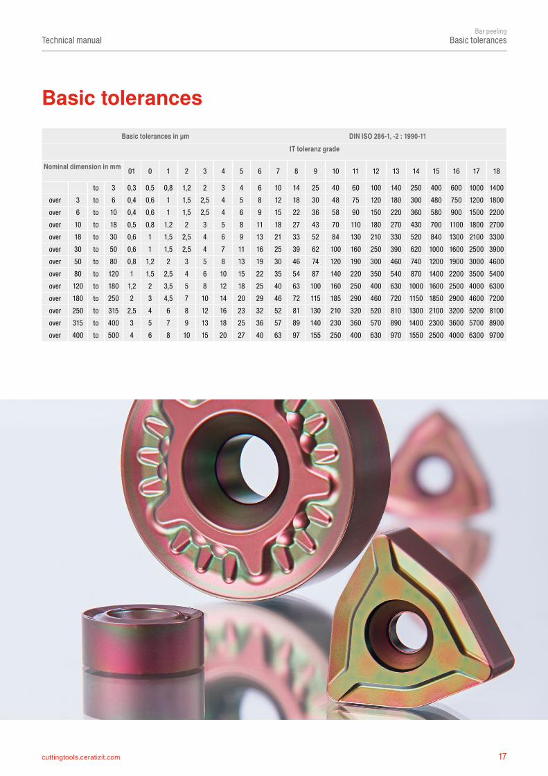
Basic tolerances
Basic tolerances in µm DIN ISO 286-1, -2 : 1990-11IT toleranz grade
Nominal dimension in mm 01 0 1 2 3 4 5 6 7 8 9 10 11 12 13 14 15 16 17 18
to 3 0,3 0,5 0,8 1,2 2 3 4 6 10 14 25 40 60 100 140 250 400 600 1000 1400over 3 to 6 0,4 0,6 1 1,5 2,5 4 5 8 12 18 30 48 75 120 180 300 480 750 1200 1800over 6 to 10 0,4 0,6 1 1,5 2,5 4 6 9 15 22 36 58 90 150 220 360 580 900 1500 2200over 10 to 18 0,5 0,8 1,2 2 3 5 8 11 18 27 43 70 110 180 270 430 700 1100 1800 2700over 18 to 30 0,6 1 1,5 2,5 4 6 9 13 21 33 52 84 130 210 330 520 840 1300 2100 3300over 30 to 50 0,6 1 1,5 2,5 4 7 11 16 25 39 62 100 160 250 390 620 1000 1600 2500 3900over 50 to 80 0,8 1,2 2 3 5 8 13 19 30 46 74 120 190 300 460 740 1200 1900 3000 4600over 80 to 120 1 1,5 2,5 4 6 10 15 22 35 54 87 140 220 350 540 870 1400 2200 3500 5400over 120 to 180 1,2 2 3,5 5 8 12 18 25 40 63 100 160 250 400 630 1000 1600 2500 4000 6300over 180 to 250 2 3 4,5 7 10 14 20 29 46 72 115 185 290 460 720 1150 1850 2900 4600 7200over 250 to 315 2,5 4 6 8 12 16 23 32 52 81 130 210 320 520 810 1300 2100 3200 5200 8100over 315 to 400 3 5 7 9 13 18 25 36 57 89 140 230 360 570 890 1400 2300 3600 5700 8900over 400 to 500 4 6 8 10 15 20 27 40 63 97 155 250 400 630 970 1550 2500 4000 6300 9700
Basic tolerances
18 cuttingtools.ceratizit.com
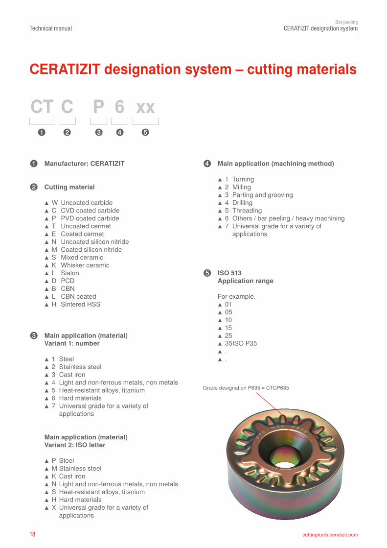
CT C P 6 xx➍ ➎➊ ➋ ➌
➊
➋
➍
➎
➌
Technical manualBar peeling
CERATIZIT designation system
Grade designation P635 = CTCP635
Manufacturer: CERATIZIT
Cutting material
▲ W Uncoated carbide ▲ C CVD coated carbide ▲ P PVD coated carbide ▲ T Uncoated cermet ▲ E Coated cermet ▲ N Uncoated silicon nitride ▲ M Coated silicon nitride ▲ S Mixed ceramic ▲ K Whisker ceramic ▲ I Sialon ▲ D PCD ▲ B CBN ▲ L CBN coated ▲ H Sintered HSS
Main application (material)Variant 1: number
▲ 1 Steel ▲ 2 Stainless steel ▲ 3 Cast iron ▲ 4 Light and non-ferrous metals, non metals ▲ 5 Heat-resistant alloys, titanium ▲ 6 Hard materials ▲ 7 Universal grade for a variety of applications
Main application (machining method)
▲ 1 Turning ▲ 2 Milling ▲ 3 Parting and grooving ▲ 4 Drilling ▲ 5 Threading ▲ 6 Others / bar peeling / heavy machining ▲ 7 Universal grade for a variety of applications
ISO 513 Application range
For example. ▲ 01 ▲ 05 ▲ 10 ▲ 15 ▲ 25 ▲ 35 ISO P35 ▲ . ▲ .
Main application (material)Variant 2: ISO letter
▲ P Steel ▲ M Stainless steel ▲ K Cast iron ▲ N Light and non-ferrous metals, non metals ▲ S Heat-resistant alloys, titanium ▲ H Hard materials ▲ X Universal grade for a variety of applications
CERATIZIT designation system – cutting materials
19cuttingtools.ceratizit.com
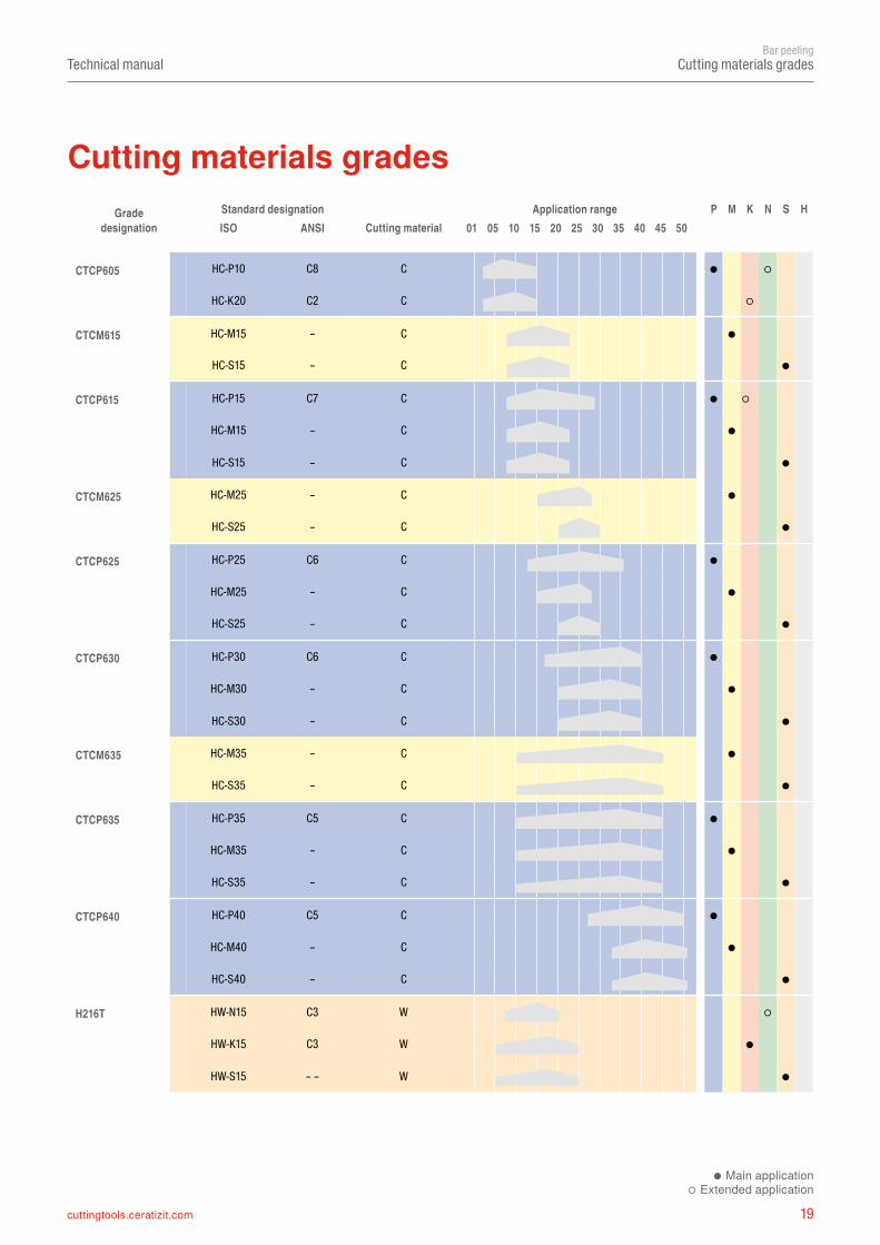
CTCP605 HC-P10 C8 C ● ○
HC-K20 C2 C ○
CTCM615 HC-M15 – C ●
HC-S15 – C ●
CTCP615 HC-P15 C7 C ● ○
HC-M15 – C ●
HC-S15 – C ●
CTCM625 HC-M25 – C ●
HC-S25 – C ●
CTCP625 HC-P25 C6 C ●
HC-M25 – C ●
HC-S25 – C ●
CTCP630 HC-P30 C6 C ●
HC-M30 – C ●
HC-S30 – C ●
CTCM635 HC-M35 – C ●
HC-S35 – C ●
CTCP635 HC-P35 C5 C ●
HC-M35 – C ●
HC-S35 – C ●
CTCP640 HC-P40 C5 C ●
HC-M40 – C ●
HC-S40 – C ●
H216T HW-N15 C3 W ○
HW-K15 C3 W ●
HW-S15 – – W ●
Technical manualBar peeling
Cutting materials grades
Cutting materials gradesGrade
designationStandard designation
Cutting materialApplication range P M K N S H
ISO ANSI 01 05 10 15 20 25 30 35 40 45 50
● Main application○ Extended application
20 cuttingtools.ceratizit.com
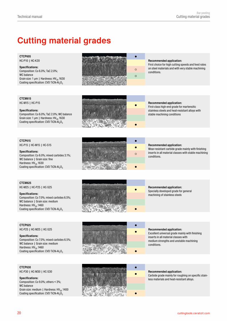
●
●
●
●
●
○
●
●
●
●
○
○
●
●
●
●
●
Technical manualBar peeling
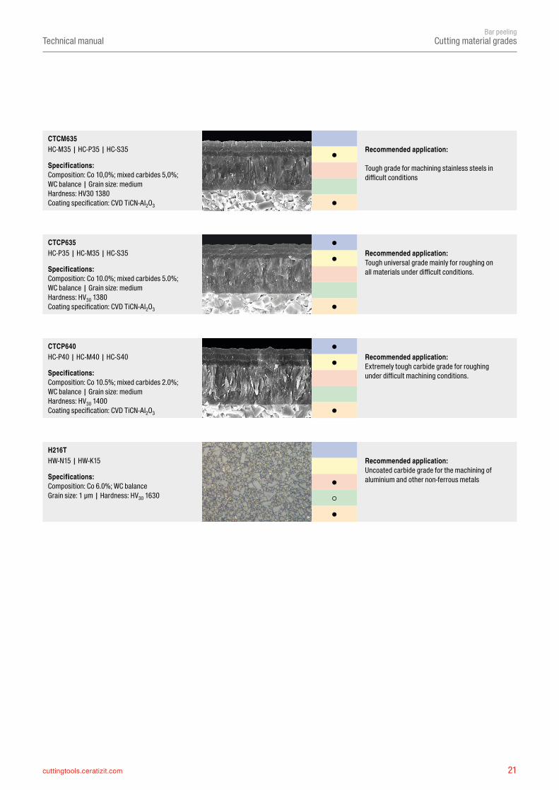
CTCP625HC-P25 | HC-M25 | HC-S25 Recommended application:
Excellent universal grade mainly with finishing inserts in all material classes withmedium strengths and unstable machining conditions.
Specifications:Composition: Co 7.0%; mixed carbides 6.5%; WC balance | Grain size: mediumHardness: HV30 1460 Coating specification: CVD TiCN-Al2O3
CTCP615HC-P15 | HC-M15 | HC-S15 Recommended application:
Wear-resistant carbide grade mainly with finishing inserts in all material classes with stable machining conditions.
Specifications:Composition: Co 6.0%; mixed carbides 3.1%; WC balance | Grain size: fineHardness: HV30 1630 Coating specification: CVD TiCN-Al2O3
CTCP605HC-P10 | HC-K20 Recommended application:
First choice for high cutting speeds and feed rates on steel materials and with very stable machining conditions.
Specifications:Composition: Co 6.0%; TaC 2.0%; WC balance Grain size: 1 μm | Hardness: HV30 1630 Coating specification: CVD TiCN-Al2O3
Recommended application: First-class high-end grade for martensitic stainless steels and heat-resistant alloys with stable machining conditions
Recommended application: Specially developed grade for general machining of stainless steels
Cutting material grades
Cutting material grades
CTCM615HC-M15 | HC-P15
Specifications:Composition: Co 6.0%; TaC 2.0%; WC balance Grain size: 1 μm | Hardness: HV30 1630 Coating specification: CVD TiCN-Al2O3
CTCM625HC-M25 | HC-P25 | HC-S25
Specifications:Composition: Co 7.0%; mixed carbides 6.5%; WC balance | Grain size: mediumHardness: HV30 1460 Coating specification: CVD TiCN-Al2O3
CTCP630HC-P30 | HC-M30 | HC-S30 Recommended application:
Carbide grade mainly for roughing on specific stain-less materials and heat-resistant alloys.Specifications:
Composition: Co 9.0%; others < 3%; WC balance Grain size: medium | Hardness: HV30 1400 Coating specification: CVD TiCN-Al2O3
21cuttingtools.ceratizit.com
●
○
●
●
●
●
●
●
●
●
●
Technical manualBar peeling
H216THW-N15 | HW-K15 Recommended application:
Uncoated carbide grade for the machining of aluminium and other non-ferrous metalsSpecifications:
Composition: Co 6.0%; WC balance Grain size: 1 μm | Hardness: HV30 1630
CTCP640HC-P40 | HC-M40 | HC-S40 Recommended application:
Extremely tough carbide grade for roughing under difficult machining conditions.Specifications:
Composition: Co 10.5%; mixed carbides 2.0%; WC balance | Grain size: mediumHardness: HV30 1400 Coating specification: CVD TiCN-Al2O3
CTCP635HC-P35 | HC-M35 | HC-S35 Recommended application:
Tough universal grade mainly for roughing on all materials under difficult conditions.Specifications:
Composition: Co 10.0%; mixed carbides 5.0%; WC balance | Grain size: mediumHardness: HV30 1380 Coating specification: CVD TiCN-Al2O3
Recommended application:
Tough grade for machining stainless steels in difficult conditions
Cutting material grades
CTCM635HC-M35 | HC-P35 | HC-S35
Specifications:Composition: Co 10,0%; mixed carbides 5,0%; WC balance | Grain size: medium Hardness: HV30 1380Coating specification: CVD TiCN-Al2O3
22 cuttingtools.ceratizit.com
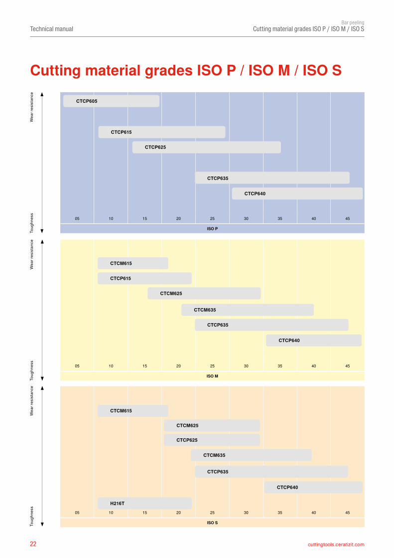
05 10 15 20 25 30 35 40 45
ISO M
05 10 15 20 25 30 35 40 45
ISO S
05 10 15 20 25 30 35 40 45
ISO P
CTCM615
CTCP615
CTCM625
CTCM635
CTCP635
CTCP640
CTCP625
CTCM635
CTCP635
H216T
CTCP640
CTCP605
CTCP615
CTCP625
CTCP635
CTCP640
CTCM615
CTCM625
Technical manualBar peeling
Cutting material grades ISO P / ISO M / ISO SW
ear r
esis
tanc
eTo
ughn
ess
Wea
r res
ista
nce
Toug
hnes
sW
ear r
esis
tanc
eTo
ughn
ess
Cutting material grades ISO P / ISO M / ISO S
23cuttingtools.ceratizit.com
Technical manualBar peeling
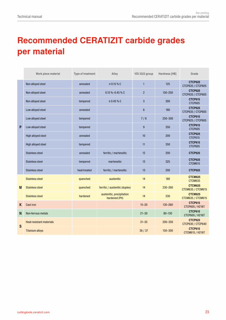
Recommended CERATIZIT carbide grades per material
Recommended CERATIZIT carbide grades per material
Work piece material Type of treatment Alloy VDI 3323 group Hardness [HB] Grade
P
Non alloyed steel annealed ≤ 0.15 % C 1 125 CTCP625CTCP635 / CTCP605
Non alloyed steel annealed 0.15 %–0.45 % C 2 150–250 CTCP625CTCP635 / CTCP605
Non alloyed steel tempered ≥ 0.45 % C 3 300 CTCP615CTCP605
Low alloyed steel annealed 6 180 CTCP625CTCP635 / CTCP605
Low alloyed steel tempered 7 / 8 250–300 CTCP615CTCP625 / CTCP605
Low alloyed steel tempered 9 350 CTCP615CTCP605
High alloyed steel annealed 10 200 CTCP625CTCP615
High alloyed steel tempered 11 350 CTCP615CTCP605
Stainless steel annealed ferritic / martensitic 12 200 CTCP625
Stainless steel tempered martensitic 13 325 CTCP625CTCM615
Stainless steel heat-treated ferritic / martensitic 13 200 CTCP625
M
Stainless steel quenched austenitic 14 180 CTCM625CTCM635
Stainless steel quenched ferritic / austenitic (duplex) 14 230–260 CTCM625CTCM635 / CTCM615
Stainless steel hardened austenitic, precipitation hardened (PH) 14 330 CTCM625
CTCM635 / CTCM615
K Cast iron 15–20 130–260 CTCP615CTCP605 / H216T
N Non-ferrous metals 21–30 80–130 CTCP615CTCP605 / H216T
SHeat-resistant materials 31–35 200–350 CTCP625
CTCP630 / CTCP640
Titanium alloys 36 / 37 150–300 CTCP615CTCM615 / H216T
cuttingtools.ceratizit.com
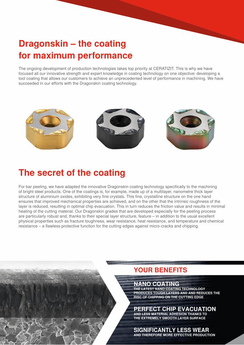
The ongoing development of production technologies takes top priority at CERATIZIT. This is why we have focused all our innovative strength and expert knowledge in coating technology on one objective: developing a tool coating that allows our customers to achieve an unprecedented level of performance in machining. We have succeeded in our efforts with the Dragonskin coating technology.
Dragonskin – the coating for maximum performance
The secret of the coatingFor bar peeling, we have adapted the innovative Dragonskin coating technology specifically to the machining of bright steel products. One of the coatings is, for example, made up of a multilayer, nanometre thick layer structure of aluminium oxides, exhibiting very fine crystals. This fine, crystalline structure on the one hand ensures that improved mechanical properties are achieved, and on the other that the intrinsic roughness of the layer is reduced, resulting in optimal chip evacuation. This in turn reduces the friction value and results in minimal heating of the cutting material. Our Dragonskin grades that are developed especially for the peeling process are particularly robust and, thanks to their special layer structure, feature – in addition to the usual excellent physical properties such as fracture toughness, wear resistance, heat resistance, and temperature and chemical resistance – a flawless protective function for the cutting edges against micro-cracks and chipping.
YOUR BENEFITS
NANO COATINGTHE LATEST NANO COATING TECHNOLOGY PRODUCES TOUGH LAYERS AND AND REDUCES THE RISC OF CHIPPING ON THE CUTTING EDGE
PERFECT CHIP EVACUATIONAND LESS MATERIAL ADHESION THANKS TO THE EXTREMELY SMOOTH LAYER SURFACE
SIGNIFICANTLY LESS WEARAND THEREFORE MORE EFFECTIVE PRODUCTION
cuttingtools.ceratizit.com
by CERATIZIT
YOUR BENEFITS
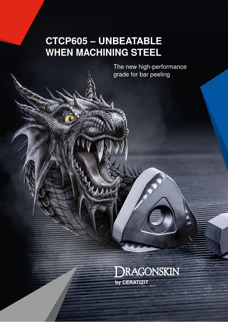
CTCP605 – UNBEATABLE WHEN MACHINING STEEL
The new high-performance grade for bar peeling
26 cuttingtools.ceratizit.com
0 20 40 60 80 100 120 140 160
Technical manualBar peeling
Application examples
Tool life
NNUX 201020S50-M43CTCP625
Tandem cartridge TCA14-RN50NN20
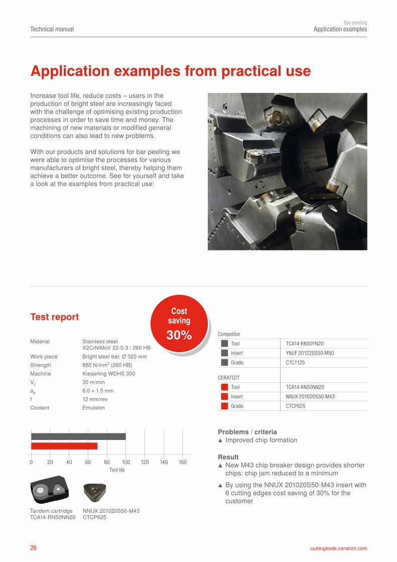
Material Stainless steel X2CrNiMoV 22-5-3 / 260 HB
Work piece Bright steel bar, Ø 320 mmStrength 880 N/mm2 (260 HB)Machine Kieserling WDHS 300Vc 30 m/minap 6.0 + 1.5 mmf 12 mm/revCoolant Emulsion
CompetitorTool TCA14-RN50YN20Insert YNUF 201220S50-M50Grade CTC1125
CERATIZITTool TCA14-RN50NN20Insert NNUX 201020S50-M43Grade CTCP625
Cost saving
30%Test report
Problems / criteria ▲ Improved chip formation
Result ▲ New M43 chip breaker design provides shorter chips: chip jam reduced to a minimum
▲ By using the NNUX 201020S50-M43 insert with 6 cutting edges cost saving of 30% for the customer
Increase tool life, reduce costs – users in the production of bright steel are increasingly faced with the challenge of optimising existing production processes in order to save time and money. The machining of new materials or modified general conditions can also lead to new problems.
With our products and solutions for bar peeling we were able to optimise the processes for various manufacturers of bright steel, thereby helping them achieve a better outcome. See for yourself and take a look at the examples from practical use:
Application examples from practical use
27cuttingtools.ceratizit.com
0 50 100 150 200 250 300 350 400 450
Technical manualBar peeling
Application examples
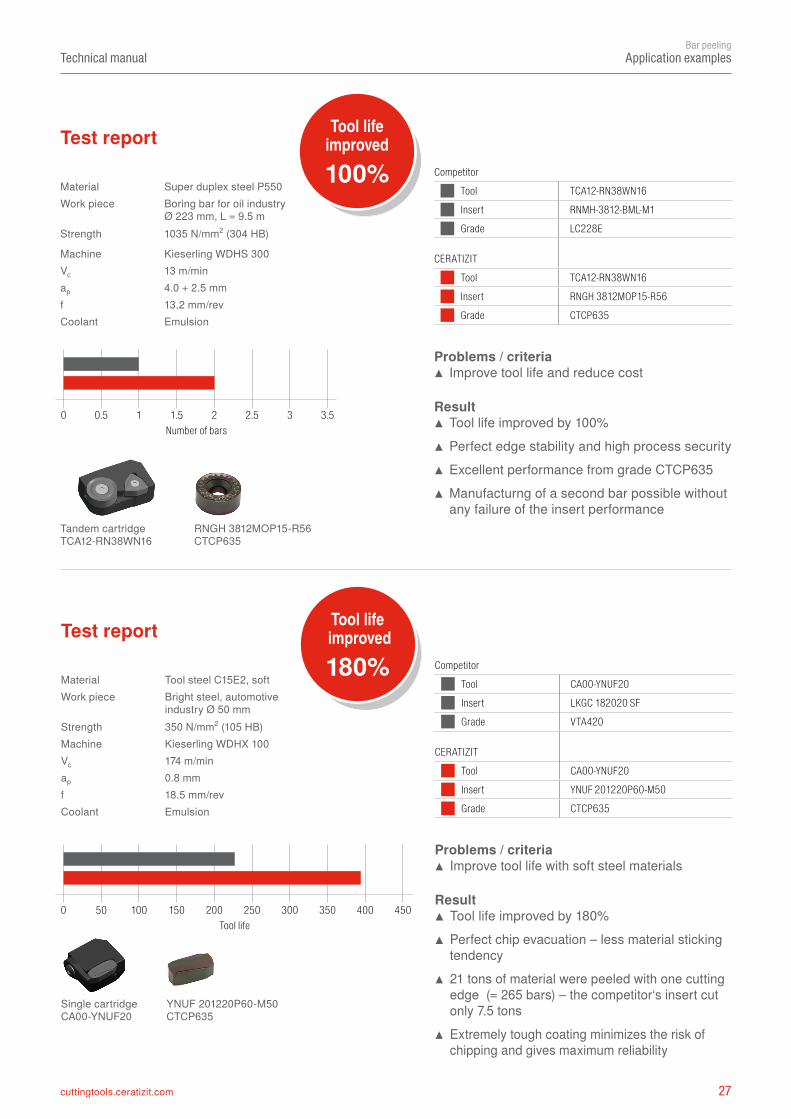
Material Super duplex steel P550Work piece Boring bar for oil industry
Ø 223 mm, L = 9.5 mStrength 1035 N/mm2 (304 HB)
Machine Kieserling WDHS 300Vc 13 m/minap 4.0 + 2.5 mmf 13.2 mm/revCoolant Emulsion
CompetitorTool TCA12-RN38WN16Insert RNMH-3812-BML-M1Grade LC228E
CERATIZITTool TCA12-RN38WN16Insert RNGH 3812MOP15-R56Grade CTCP635
Number of bars
Tool life improved
100%Test report
Problems / criteria ▲ Improve tool life and reduce cost
Result ▲ Tool life improved by 100% ▲ Perfect edge stability and high process security ▲ Excellent performance from grade CTCP635 ▲ Manufacturng of a second bar possible without any failure of the insert performance
RNGH 3812MOP15-R56CTCP635
Tandem cartridge TCA12-RN38WN16
CompetitorTool CA00-YNUF20Insert LKGC 182020 SFGrade VTA420
CERATIZITTool CA00-YNUF20Insert YNUF 201220P60-M50Grade CTCP635
Material Tool steel C15E2, softWork piece Bright steel, automotive
industry Ø 50 mmStrength 350 N/mm2 (105 HB)Machine Kieserling WDHX 100Vc 174 m/minap 0.8 mmf 18.5 mm/revCoolant Emulsion
Tool life improved
180%Test report
Problems / criteria ▲ Improve tool life with soft steel materials
Result ▲ Tool life improved by 180% ▲ Perfect chip evacuation – less material sticking tendency
▲ 21 tons of material were peeled with one cutting edge (= 265 bars) – the competitor‘s insert cut only 7.5 tons
▲ Extremely tough coating minimizes the risk of chipping and gives maximum reliability
Tool life
YNUF 201220P60-M50CTCP635
Single cartridge CA00-YNUF20
0 0.5 1 1.5 2 2.5 3 3.5
28 cuttingtools.ceratizit.com
0 20 40 60 80 100 120 140 160 180
0 2 4 6 8 10 12 14 16 18
Technical manualBar peeling
Application examples
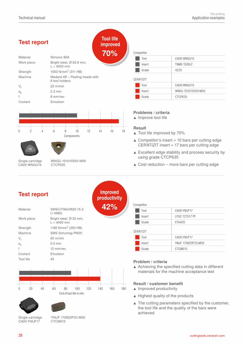
Material X6NiCrTiMoVB25-15-2 (1.4980)
Work piece Bright steel, Ø 20 mm, L = 4000 mm
Strength 1180 N/mm2 (350 HB)Machine SMS Schumag PM35Vc 65 m/minap 0.5 mmf 12 mm/rev.Coolant Emulsion
45
Test report
YNUF 170820P33-M50CTCM615
Single cartridgeCA00-YNUF17
CompetitorTool CA00-YNUF17Insert LPUC 121517 PFGrade VTA420
CERATIZITTool CA00-YNUF17Insert YNUF 170820P33-M50Grade CTCM615
CompetitorTool CA00-WNGU15Insert TNMX 1509-2Grade 4225
CERATIZITTool CA00-WNGU15Insert WNGU 151015S50-M50Grade CTCP635
Material Nimonic 80AWork piece Bright steel, Ø 62.8 mm,
L = 4000 mmStrength 1050 N/mm2 (311 HB)Machine Medard 4R – Peeling heads with
6 tool holdersVc 22 m/minap 2.3 mmf 8 mm/rev.Coolant Emulsion
Tool life improved
70%Test report
Problems / criteria ▲ Improve tool life
Result ▲ Tool life improved by 70% ▲ Competitor‘s insert = 10 bars per cutting edge CERATIZIT insert = 17 bars per cutting edge
▲ Excellent edge stability and process security by using grade CTCP635
▲ Cost reduction – more bars per cutting edge
Components
WNGU 151015S50-M50CTCP635
Single cartridge CA00-WNGU15
Problem / criteria ▲ Achieving the specified cutting data in different materials for the machine acceptance test
Result / customer benefit ▲ Improved productivity ▲ Highest quality of the products ▲ The cutting parameters specified by the customer, the tool life and the quality of the bars were achieved
End of tool life in min.
Improved productivity
42%
Tool life
29cuttingtools.ceratizit.com
0 20 40 60 80 100 120 140 160 180
0 20 40 60 80 100 120 140 160
Technical manualBar peeling
Application examples
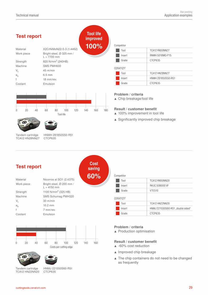
Material X2CrNiMoN22-5-3 (1.4462) Work piece Bright steel, Ø 325 mm /
L = 7700 mmStrength 820 N/mm2 (240HB)Machine SMS PMH600 Vc 45 m/minap 6.5 mmf 18 mm/rev.Coolant Emulsion
Test report
HNMH 281850S50-R51CTCP635
Tandem cartridge TCA12 HN28NN27
Material Nicorros al SO1 (2.4375)Work piece Bright steel, Ø 200 mm /
L = 4150 mmStrength 1100 N/mm2 (325 HB)Machine SMS Schumag PMH320Vc 30 m/minap 10.2 mmf 7 mm/rev.Coolant Emulsion
Test report
HNMJ 221550S60-R51 CTCP635
Tandem cartridge TCA12 HN22NN20
CompetitorTool TCA12 RN50NN27Insert RNMH 5018MO-P15 Grade CTCP635
CERATIZITTool TCA12 HN28NN27Insert HNMH 281850S50-R51Grade CTCP635
CompetitorTool TCA12 RN50NN20Insert RKUC 508000 VF Grade VTE510
CERATIZITTool TCA12 HN22NN20Insert HNMJ 221550S60-R51 „double sided“ Grade CTCP635
Tool lifeimproved
100%
Problem / criteria ▲ Chip breakage/tool life
Result / customer benefit ▲ 100% improvement in tool life ▲ Significantly improved chip breakage
Tool life
Cost saving
60%
Costs per cutting edge
Problem / criteria ▲ Production optimisation
Result / customer benefit ▲ -60% cost reduction ▲ Improved chip breakage ▲ The chip containers do not need to be changed as frequently
30 cuttingtools.ceratizit.com
0 20 40 60 80 100 120 140 160
0 50 100 150 200 250 300 350 400 450
Technical manualBar peeling
Application examples
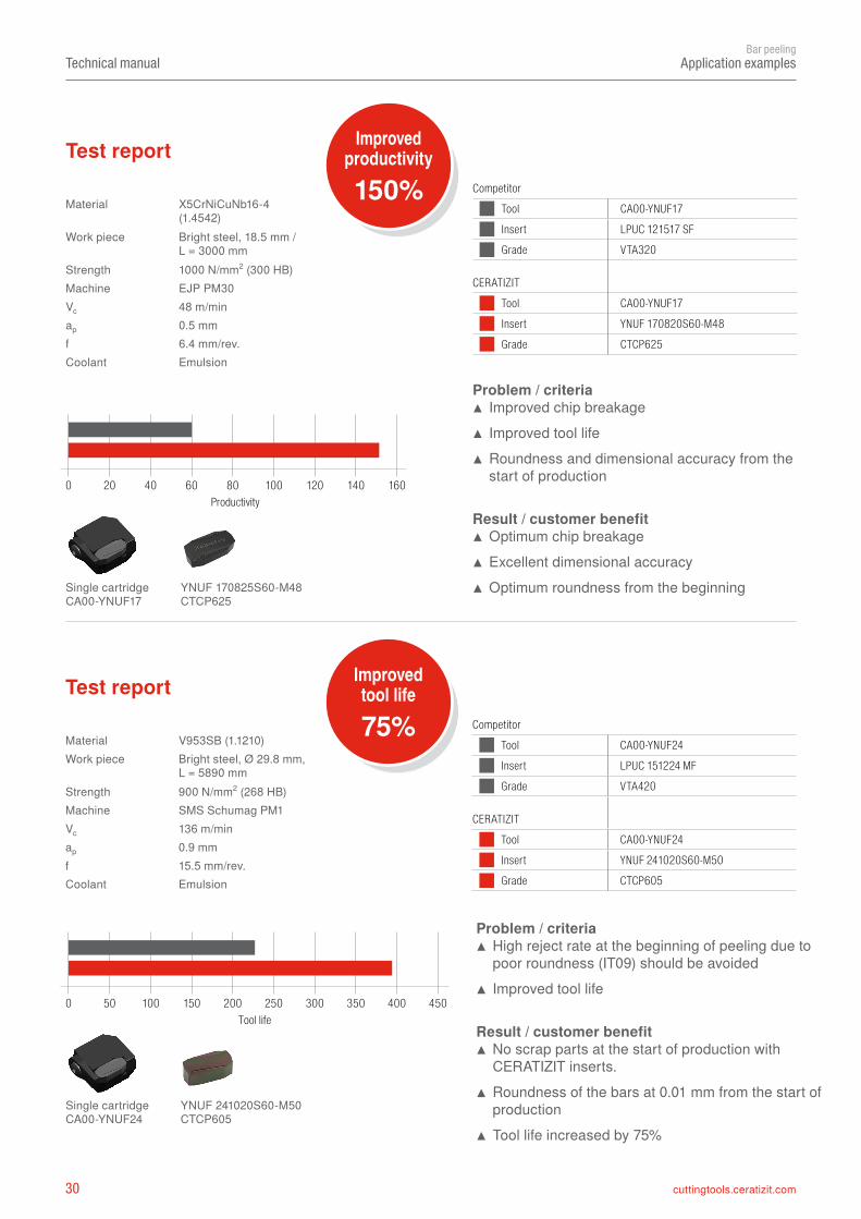
Material X5CrNiCuNb16-4 (1.4542)
Work piece Bright steel, 18.5 mm / L = 3000 mm
Strength 1000 N/mm2 (300 HB)Machine EJP PM30 Vc 48 m/minap 0.5 mmf 6.4 mm/rev. Coolant Emulsion
Test report
YNUF 170825S60-M48 CTCP625
Single cartridgeCA00-YNUF17
CompetitorTool CA00-YNUF17Insert LPUC 121517 SF Grade VTA320
CERATIZITTool CA00-YNUF17Insert YNUF 170820S60-M48 Grade CTCP625
Material V953SB (1.1210)Work piece Bright steel, Ø 29.8 mm,
L = 5890 mmStrength 900 N/mm2 (268 HB)Machine SMS Schumag PM1Vc 136 m/minap 0.9 mmf 15.5 mm/rev.Coolant Emulsion
Test report
YNUF 241020S60-M50CTCP605
Single cartridge CA00-YNUF24
CompetitorTool CA00-YNUF24Insert LPUC 151224 MFGrade VTA420
CERATIZITTool CA00-YNUF24Insert YNUF 241020S60-M50Grade CTCP605
Improved productivity
150%
Problem / criteria ▲ Improved chip breakage ▲ Improved tool life ▲ Roundness and dimensional accuracy from the start of production
Result / customer benefit ▲ Optimum chip breakage ▲ Excellent dimensional accuracy ▲ Optimum roundness from the beginning
Productivity
Improved tool life
75%
Problem / criteria ▲ High reject rate at the beginning of peeling due to poor roundness (IT09) should be avoided
▲ Improved tool life
Result / customer benefit ▲ No scrap parts at the start of production with CERATIZIT inserts.
▲ Roundness of the bars at 0.01 mm from the start of production
▲ Tool life increased by 75%
Tool life
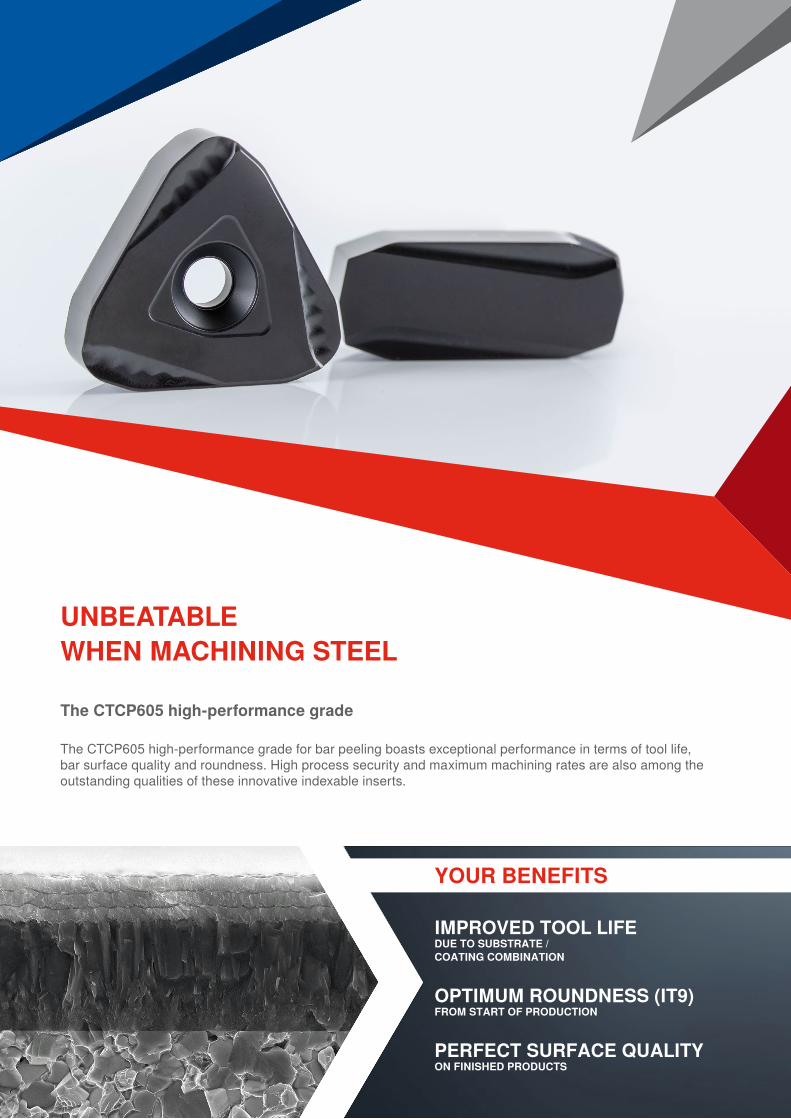
Bar peeling
The CTCP605 high-performance grade for bar peeling boasts exceptional performance in terms of tool life, bar surface quality and roundness. High process security and maximum machining rates are also among the outstanding qualities of these innovative indexable inserts.
UNBEATABLE WHEN MACHINING STEEL
The CTCP605 high-performance grade
YOUR BENEFITS
IMPROVED TOOL LIFEDUE TO SUBSTRATE / COATING COMBINATION
OPTIMUM ROUNDNESS (IT9)FROM START OF PRODUCTION
PERFECT SURFACE QUALITYON FINISHED PRODUCTS
32 cuttingtools.ceratizit.com
Technical manualBar peeling
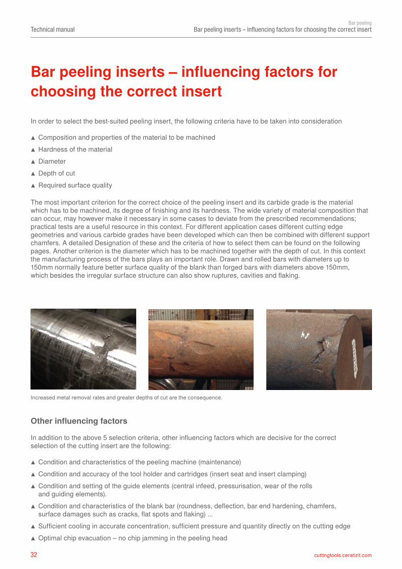
Bar peeling inserts – influencing factors for choosing the correct insert
In order to select the best-suited peeling insert, the following criteria have to be taken into consideration
▲ Composition and properties of the material to be machined ▲ Hardness of the material ▲ Diameter ▲ Depth of cut ▲ Required surface quality
The most important criterion for the correct choice of the peeling insert and its carbide grade is the material which has to be machined, its degree of finishing and its hardness. The wide variety of material composition that can occur, may however make it necessary in some cases to deviate from the prescribed recommendations; practical tests are a useful resource in this context. For different application cases different cutting edge geometries and various carbide grades have been developed which can then be combined with different support chamfers. A detailed Designation of these and the criteria of how to select them can be found on the following pages. Another criterion is the diameter which has to be machined together with the depth of cut. In this context the manufacturing process of the bars plays an important role. Drawn and rolled bars with diameters up to 150mm normally feature better surface quality of the blank than forged bars with diameters above 150mm, which besides the irregular surface structure can also show ruptures, cavities and flaking.
In addition to the above 5 selection criteria, other influencing factors which are decisive for the correct selection of the cutting insert are the following:
▲ Condition and characteristics of the peeling machine (maintenance) ▲ Condition and accuracy of the tool holder and cartridges (insert seat and insert clamping) ▲ Condition and setting of the guide elements (central infeed, pressurisation, wear of the rolls and guiding elements).
▲ Condition and characteristics of the blank bar (roundness, deflection, bar end hardening, chamfers, surface damages such as cracks, flat spots and flaking) ...
▲ Sufficient cooling in accurate concentration, sufficient pressure and quantity directly on the cutting edge ▲ Optimal chip evacuation – no chip jamming in the peeling head
Other influencing factors
Bar peeling inserts – influencing factors for choosing the correct insert
Increased metal removal rates and greater depths of cut are the consequence.

33cuttingtools.ceratizit.com
5°
Technical manualBar peeling
Bar peeling inserts – influencing factors for choosing the correct insert
Peeling inserts – different angles on the peeling insert
Support chamfer angle
Inclination angle of the insert in the cartridge mainly 5°
Secondary cutting edge Main cutting edge
Clearance angle on the support chamfer plus 1°
Clearance angle on the support chamfer +/– 0°
Clearance angle on the support chamfer minus 1°5°
ang
le o
f inc
linat
ion
5° support chamfer angle
Soft cutting conditions„Positive insert“
Support chamfer type S42(Support chamfer angle 4°)
Support chamfer type S50(Support chamfer angle 5°)
Support chamfer type S60(Support chamfer angle 6°)
Neutral conditions„Insert has a form lock with the bar“
Stabile conditions„Negative insert“
Cartridge
Tool holder
Angle of inclination
Insert
Shim
Cutting edgehone
Support chamfer angle
Angle of inclination
Negative chamfer
angle
Rake angle
Appr
oach
ang
le
34 cuttingtools.ceratizit.com
Technical manualBar peeling
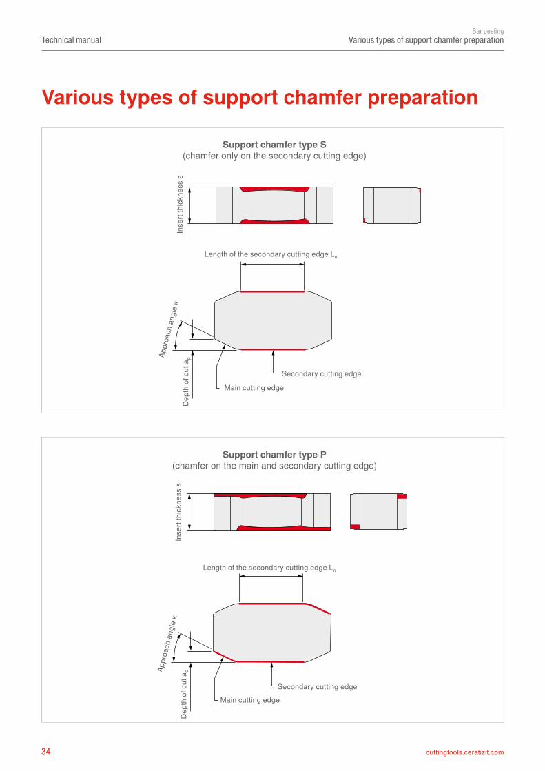
Various types of support chamfer preparation
Dep
th o
f cut
apAp
proa
ch a
ngle
ĸ
Support chamfer type P(chamfer on the main and secondary cutting edge)
Various types of support chamfer preparation
Inse
rt th
ickn
ess
s
Secondary cutting edge
Main cutting edge
Dep
th o
f cut
apAp
proa
ch a
ngle
ĸ
Support chamfer type S(chamfer only on the secondary cutting edge)
Length of the secondary cutting edge Ln
Length of the secondary cutting edge Ln
Secondary cutting edgeMain cutting edge
Inse
rt th
ickn
ess
s
35cuttingtools.ceratizit.com
500 600 700 800 900 1000 1100 1200 1300 1400
140 170 200 240 270 300 325 350 380 415
P60
S60
S50
P40
S42
P30
P50
S30
Technical manualBar peeling
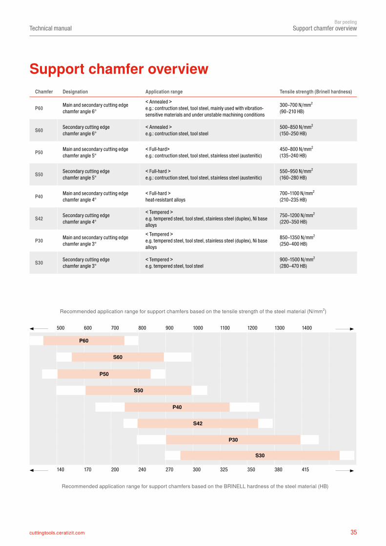
Support chamfer overview
Support chamfer overviewChamfer Designation Application range Tensile strength (Brinell hardness)
P60 Main and secondary cutting edgechamfer angle 6°
< Annealed >e.g.: contruction steel, tool steel, mainly used with vibration-sensitive materials and under unstable machining conditions
300–700 N/mm2
(90–210 HB)
S60 Secondary cutting edgechamfer angle 6°
< Annealed >e.g.: contruction steel, tool steel
500–850 N/mm2
(150–250 HB)
P50 Main and secondary cutting edgechamfer angle 5°
< Full-hard>e.g.: contruction steel, tool steel, stainless steel (austenitic)
450–800 N/mm2
(135–240 HB)
S50 Secondary cutting edgechamfer angle 5°
< Full-hard >e.g.: contruction steel, tool steel, stainless steel (austenitic)
550–950 N/mm2
(160–280 HB)
P40 Main and secondary cutting edgechamfer angle 4°
< Full-hard >heat-resistant alloys
700–1100 N/mm2
(210–235 HB)
S42 Secondary cutting edgechamfer angle 4°
< Tempered >e.g. tempered steel, tool steel, stainless steel (duplex), Ni base alloys
750–1200 N/mm2
(220–350 HB)
P30 Main and secondary cutting edgechamfer angle 3°
< Tempered >e.g. tempered steel, tool steel, stainless steel (duplex), Ni base alloys
850–1350 N/mm2
(250–400 HB)
S30 Secondary cutting edgechamfer angle 3°
< Tempered >e.g. tempered steel, tool steel
900–1500 N/mm2
(280–470 HB)
Recommended application range for support chamfers based on the tensile strength of the steel material (N/mm2)
Recommended application range for support chamfers based on the BRINELL hardness of the steel material (HB)
36 cuttingtools.ceratizit.com
Technical manualBar peeling
CERATIZIT peeling insert range
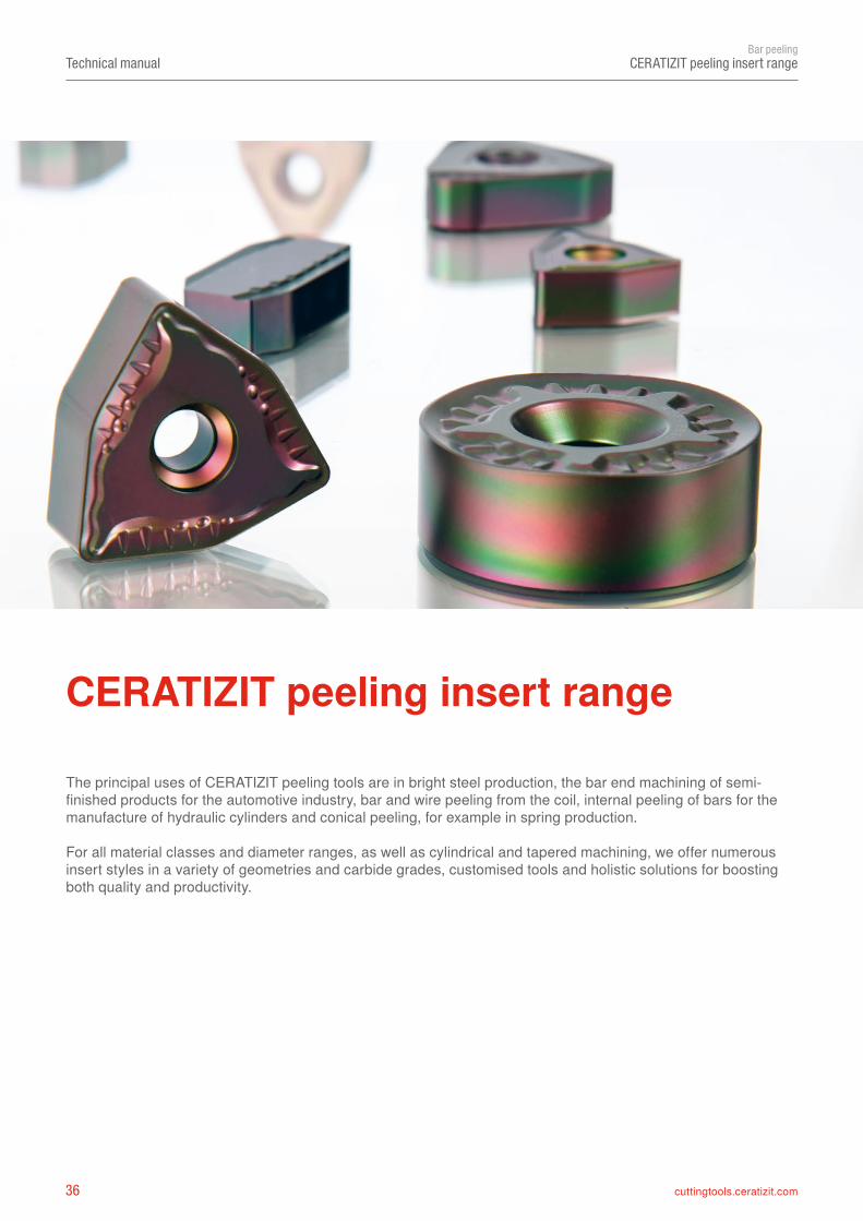
The principal uses of CERATIZIT peeling tools are in bright steel production, the bar end machining of semi-finished products for the automotive industry, bar and wire peeling from the coil, internal peeling of bars for the manufacture of hydraulic cylinders and conical peeling, for example in spring production.
For all material classes and diameter ranges, as well as cylindrical and tapered machining, we offer numerous insert styles in a variety of geometries and carbide grades, customised tools and holistic solutions for boosting both quality and productivity.
CERATIZIT peeling insert range
37cuttingtools.ceratizit.com
Technical manualBar peeling
CERATIZIT peeling insert range
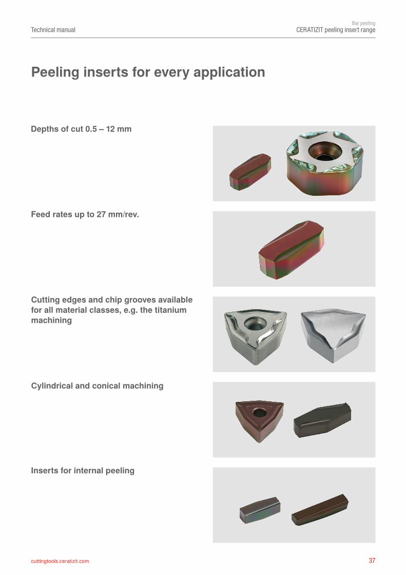
Depths of cut 0.5 – 12 mm
Cutting edges and chip grooves available for all material classes, e.g. the titanium machining
Feed rates up to 27 mm/rev.
Cylindrical and conical machining
Inserts for internal peeling
Peeling inserts for every application
38 cuttingtools.ceratizit.com
➝
➝
➝
➝
➝
Technical manualBar peeling
Solutions for super alloys and titanium
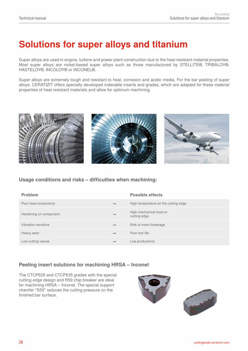
Super alloys are used in engine, turbine and power plant construction due to the heat-resistant material properties. Most super alloys are nickel-based super alloys such as those manufactured by STELLITE®, TRIBALOY®, HASTELOY®, INCOLOY® or INCONEL®.
Super alloys are extremely tough and resistant to heat, corrosion and acidic media. For the bar peeling of super alloys, CERATIZIT offers specially developed indexable inserts and grades, which are adapted for these material properties of heat-resistant materials and allow for optimum machining.
Usage conditions and risks – difficulties when machining:
Peeling insert solutions for machining HRSA – Inconel
The CTCP625 and CTCP635 grades with the special cutting edge design and R59 chip breaker are ideal for machining HRSA – Inconel. The special support chamfer "S55" reduces the cutting pressure on the finished bar surface.
Problem Possible effects
Poor heat conductivity ➝ High temperature on the cutting edge
Hardening on component ➝ High mechanical load on cutting edge
Vibration-sensitive ➝ Risk of insert breakage
Heavy wear ➝ Poor tool life
Low cutting values ➝ Low productivity
Solutions for super alloys and titanium
39cuttingtools.ceratizit.com
Technical manualBar peeling
Solutions for super alloys and titanium
WNEU 161325P50-R51
WNMF 96-P50
WNGU 151015
NNUX 150820
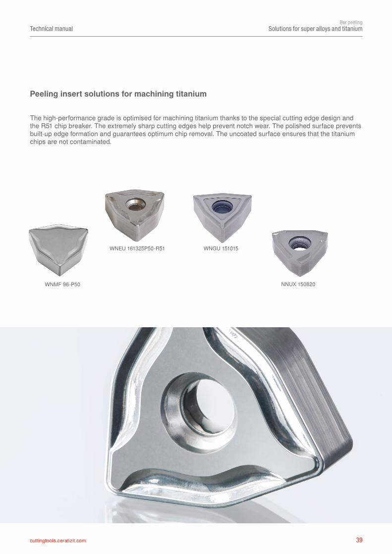
The high-performance grade is optimised for machining titanium thanks to the special cutting edge design and the R51 chip breaker. The extremely sharp cutting edges help prevent notch wear. The polished surface prevents built-up edge formation and guarantees optimum chip removal. The uncoated surface ensures that the titanium chips are not contaminated.
Peeling insert solutions for machining titanium
40 cuttingtools.ceratizit.com
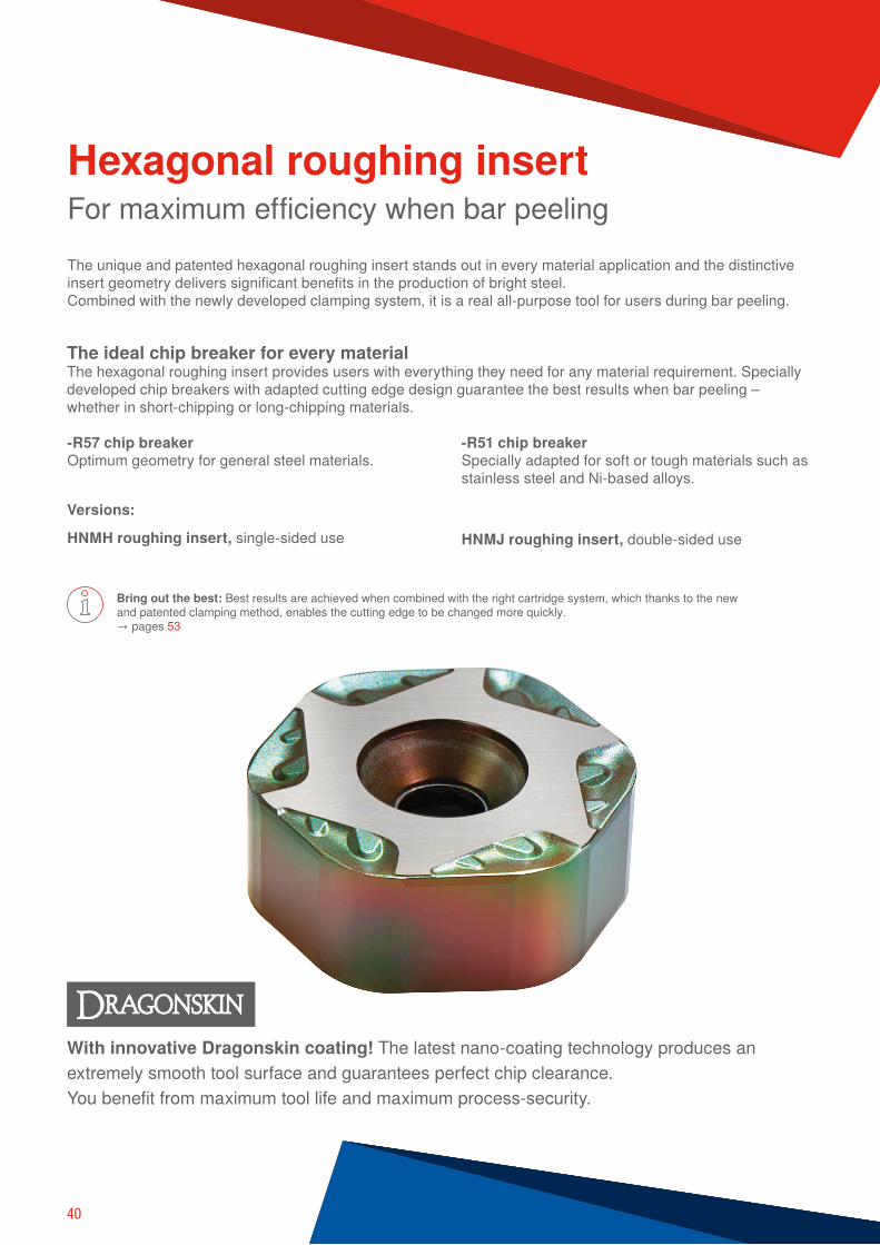
With innovative Dragonskin coating! The latest nano-coating technology produces an extremely smooth tool surface and guarantees perfect chip clearance. You benefit from maximum tool life and maximum process-security.
The unique and patented hexagonal roughing insert stands out in every material application and the distinctive insert geometry delivers significant benefits in the production of bright steel. Combined with the newly developed clamping system, it is a real all-purpose tool for users during bar peeling.
Bring out the best: Best results are achieved when combined with the right cartridge system, which thanks to the new and patented clamping method, enables the cutting edge to be changed more quickly. → pages 53
For maximum efficiency when bar peeling
Versions:
HNMH roughing insert, single-sided use HNMJ roughing insert, double-sided use
Hexagonal roughing insert
-R57 chip breakerOptimum geometry for general steel materials.
-R51 chip breakerSpecially adapted for soft or tough materials such as stainless steel and Ni-based alloys.
The ideal chip breaker for every material The hexagonal roughing insert provides users with everything they need for any material requirement. Specially developed chip breakers with adapted cutting edge design guarantee the best results when bar peeling – whether in short-chipping or long-chipping materials.
41
➊
➋
➌
➍
➎
➏
A++A+ABCDEFG
D =
50
50°
Rt
Rt
▲
▲
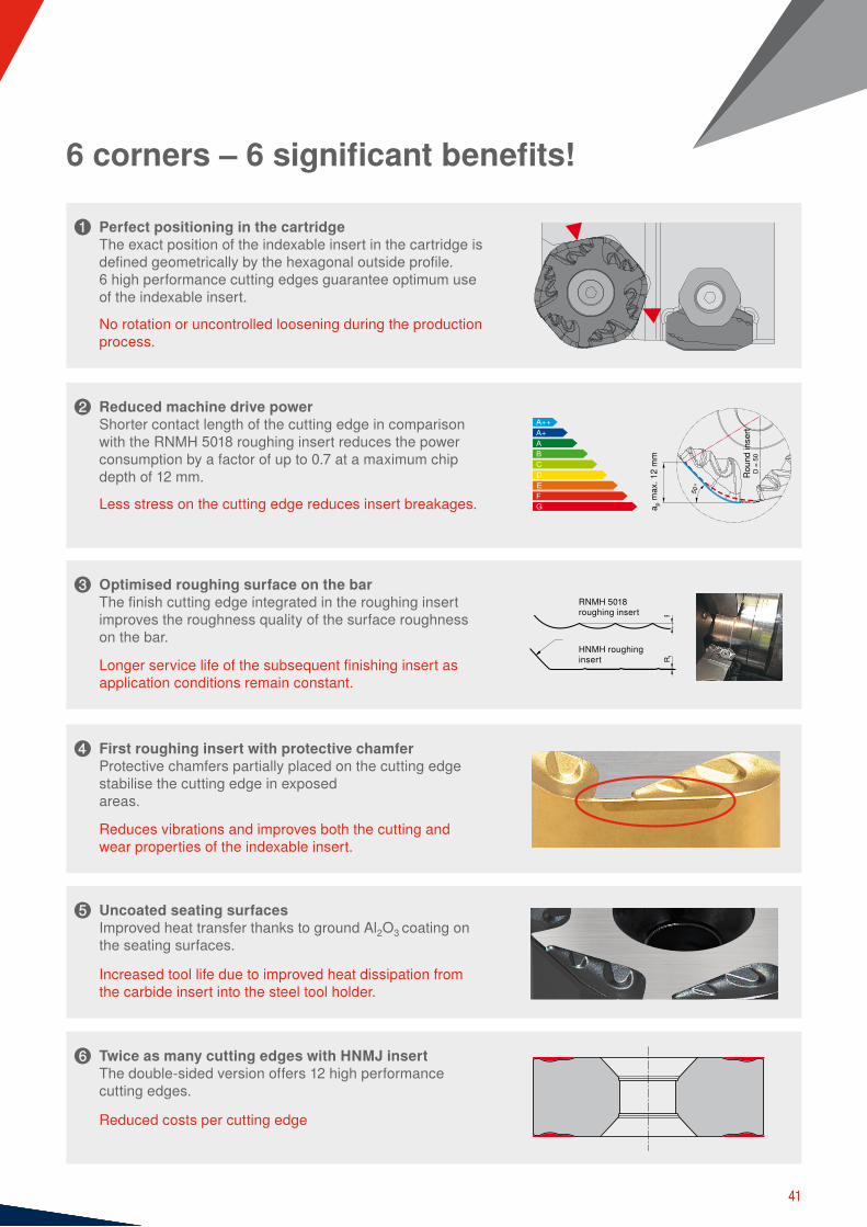
6 corners – 6 significant benefits!
Perfect positioning in the cartridgeThe exact position of the indexable insert in the cartridge is defined geometrically by the hexagonal outside profile. 6 high performance cutting edges guarantee optimum use of the indexable insert.
No rotation or uncontrolled loosening during the production process.
Reduced machine drive powerShorter contact length of the cutting edge in comparison with the RNMH 5018 roughing insert reduces the power consumption by a factor of up to 0.7 at a maximum chip depth of 12 mm.
Less stress on the cutting edge reduces insert breakages.
Optimised roughing surface on the barThe finish cutting edge integrated in the roughing insert improves the roughness quality of the surface roughness on the bar.
Longer service life of the subsequent finishing insert as application conditions remain constant.
First roughing insert with protective chamferProtective chamfers partially placed on the cutting edge stabilise the cutting edge in exposed areas.
Reduces vibrations and improves both the cutting and wear properties of the indexable insert.
Uncoated seating surfacesImproved heat transfer thanks to ground Al2O3 coating on the seating surfaces.
Increased tool life due to improved heat dissipation from the carbide insert into the steel tool holder.
Twice as many cutting edges with HNMJ insertThe double-sided version offers 12 high performance cutting edges.
Reduced costs per cutting edge
Roun
d in
sert
a p m
ax. 1
2 m
m
RNMH 5018 roughing insert
HNMH roughing insert
42 cuttingtools.ceratizit.com
HNMH 2215..-R51 HNMJ 2215..-R51 HNMH 2215..-R57 HNMJ 2215..-R57
HNMH 2818..-R51 HNMJ 2818..-R51 HNMH 2818..-R57 HNMJ 2818..-R57
HNMJ 1310..-R51 HNMJ 1310..-R57
RNMH 2008..-R50 RNMH 2008..-R56
RNMH 2810..-R50 RNMH 2810..-R56
RNGH 3812..-R50 RNGH 3812..-R55 RNGH 3812..-R56 RNGX 3812..-R56
RNMX 5018..-R50 RNMH 5018..-R55 RNMH 5018..-R56
Technical manualBar peeling
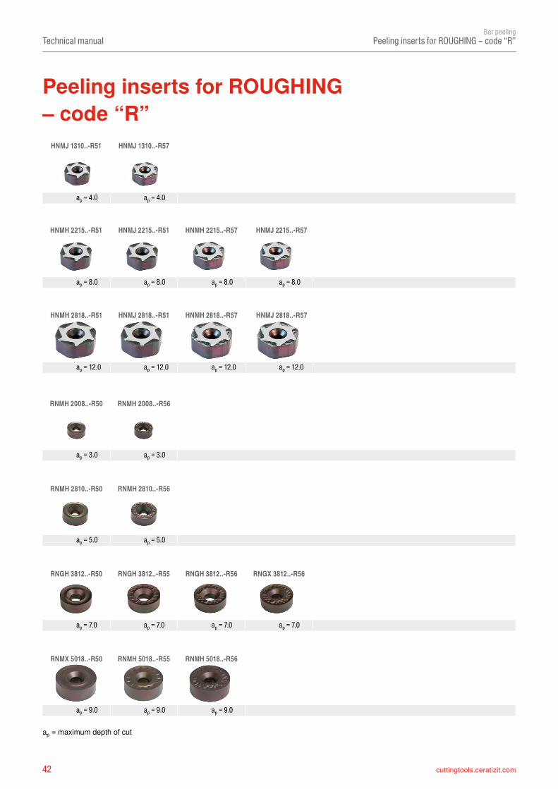
Peeling inserts for ROUGHING – code “R”
Peeling inserts for ROUGHING– code “R”
ap = maximum depth of cut
ap = 8.0 ap = 8.0 ap = 8.0 ap = 8.0
ap = 12.0 ap = 12.0 ap = 12.0 ap = 12.0
ap = 4.0 ap = 4.0
ap = 3.0 ap = 3.0
ap = 5.0 ap = 5.0
ap = 7.0 ap = 7.0 ap = 7.0 ap = 7.0
ap = 9.0 ap = 9.0 ap = 9.0
43cuttingtools.ceratizit.com
HNMJ 131050 S60–R51 S60–R57
HNMH/J 221550 S60–R51 S60–R57
HNMH/J 281850 S60–R51 S60–R57
RNMH 200800 E00 E00 P15
RNMH 281000 E00 E00 P15
RNGH 381200 P15 P15 E00 P15
RNGX 381200 E00 P15
RNMH 5018MO E00 E00 P15
RNMX 5018MO E00
Technical manualBar peeling
Chip groove code – roughing inserts – code “R”
Chip groove code – ROUGHING inserts– code “R”
Roughing insert code “R” neutral negative neutral negative neutral negativeChip groove code R51 R50 R55 R55 R56 R57
Page 68
Page 68, 69
Page 68, 69
Page 84
Page 84
Page 85
Page 86
Page 87
Page 87
44 cuttingtools.ceratizit.com
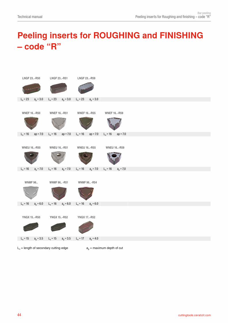
LNGF 23..-R50 LNGF 23..-R51 LNGF 23..-R59
WNEF 16..-R50 WNEF 16..-R51 WNEF 16..-R55 WNEF 16..-R59
WNEU 16..-R50 WNEU 16..-R51 WNEU 16..-R55 WNEU 16..-R59
WNMF 96.. WNMF 96.. -R51 WNMF 96.. -R54
YNGX 15..-R50 YNGX 15..-R52 YNGX 17..-R52
Technical manualBar peeling
Ln = 23 ap = 3.0 Ln = 23 ap = 3.0 Ln = 23 ap = 3.0
Ln = 16 ap = 7.0 Ln = 16 ap = 7.0 Ln = 16 ap = 7.0 Ln = 16 ap = 7.0
Ln = 16 ap = 7.0 Ln = 16 ap = 7.0 Ln = 16 ap = 7.0 Ln = 16 ap = 7,0
Ln = 16 ap = 6.0 Ln = 16 ap = 6.0 Ln = 16 ap = 6.0
Ln = 15 ap = 3.5 Ln = 15 ap = 3.5 Ln = 17 ap = 4.0
Peeling inserts for Roughing and finishing – code “R”
Peeling inserts for ROUGHING and FINISHING – code “R”
Ln = length of secondary cutting edge ap = maximum depth of cut
45cuttingtools.ceratizit.com
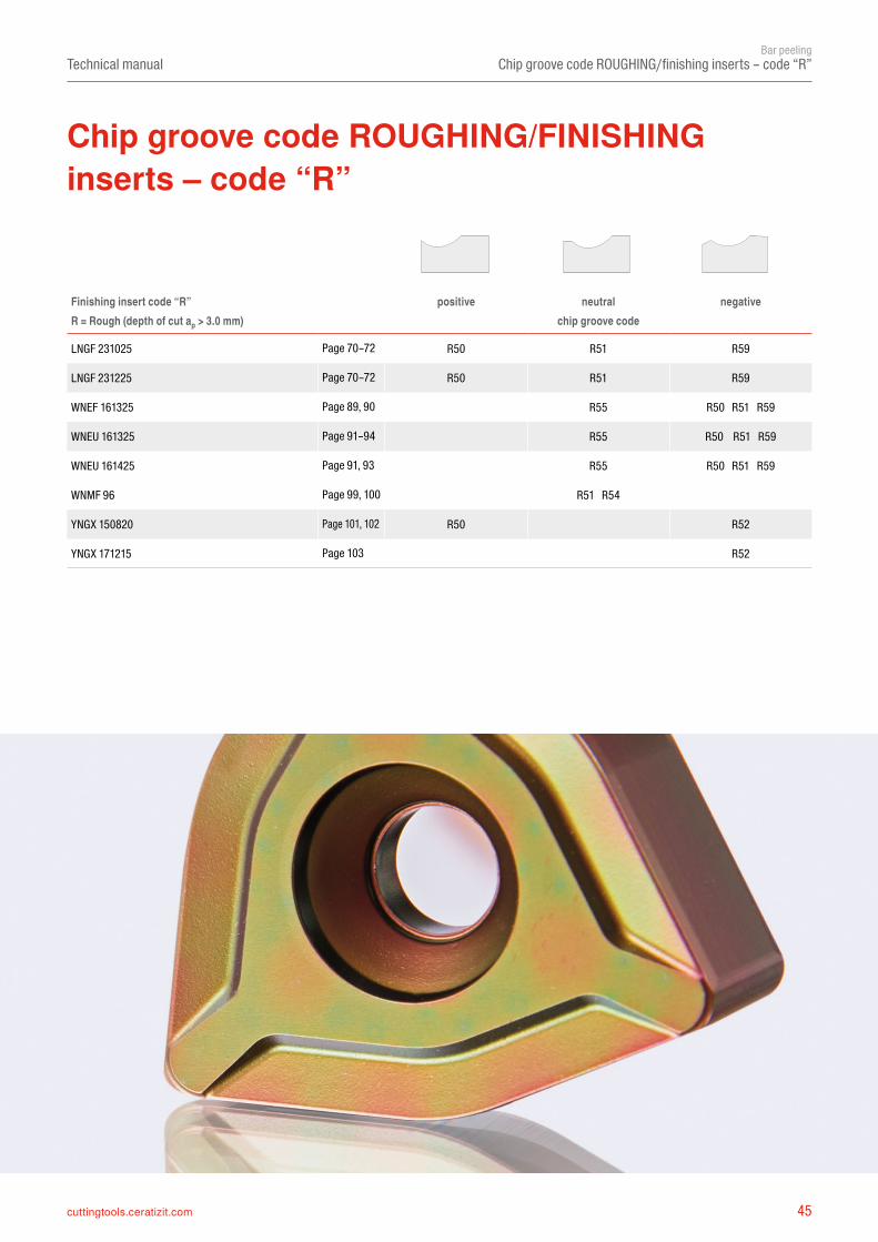
LNGF 231025 R50 R51 R59
LNGF 231225 R50 R51 R59
WNEF 161325 R55 R50 R51 R59
WNEU 161325 R55 R50 R51 R59
WNEU 161425 R55 R50 R51 R59
WNMF 96 R51 R54
YNGX 150820 R50 R52
YNGX 171215 R52
Technical manualBar peeling
Chip groove code ROUGHING/finishing inserts – code “R”
Finishing insert code “R” positive neutral negativeR = Rough (depth of cut ap > 3.0 mm) chip groove code
Page 70–72
Page 70–72
Page 89, 90
Page 91–94
Page 91, 93
Page 99, 100
Page 101, 102
Page 103
Chip groove code ROUGHING/FINISHING inserts – code “R”
46 cuttingtools.ceratizit.com
YNUX 10..-M50 YNGX 15..-M50
YNUF 17..-M48 YNUF 2009..-M48 YNUF 2012..-M48
YNUF 17..-M50 YNUF 2009..-M50 YNUF 2012..-M50 YNUF 24..-M50 YNUF 27..-M50
YNUR 27..-M40
TNGT 22..-F46
NNUX 12..-M40 NNUX 15..-M43 NNUX 15..-M46
NNUX 20..-M40 NNUX 20..-M41 NNUX 20..-M43 NNUX 20..-M46 NNXX 20..-M40 NNUX 27..-M43
WNGU 10..-M46 WNGU 15..-M50 WNGU 15..-M52
WNMF 11..-M43 WNMF 11..-M41
Technical manualBar peeling
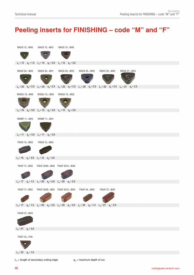
Peeling inserts for FINISHING – code “M” and “F”
Ln = length of secondary cutting edge ap = maximum depth of cut
Peeling inserts for FINISHING – code “M” and “F”
Ln = 12 ap = 1.5 Ln = 15 ap = 2.0 Ln = 15 ap = 2,0
Ln = 20 ap = 2.5 Ln = 20 ap = 2.5 Ln = 20 ap = 2.5 Ln = 20 ap = 2.5 Ln = 20 ap = 2.5 Ln = 27 ap = 2.5
Ln = 10 ap = 3.0 Ln = 15 ap = 3.0 Ln = 15 ap = 3.0
Ln = 11 ap = 3.0 Ln = 11 ap = 3.0
Ln = 22 ap = 1.0
Ln = 10 ap = 2.0 Ln = 15 ap = 3.0
Ln = 17 ap = 1.5 Ln = 20 ap = 2.0 Ln = 20 ap = 2.0
Ln = 17 ap = 1.5 Ln = 20 ap = 2.0 Ln = 20 ap = 2.0 Ln = 24 ap = 1.2 Ln = 27 ap = 2.0
Ln = 27 ap = 3.0
47cuttingtools.ceratizit.com
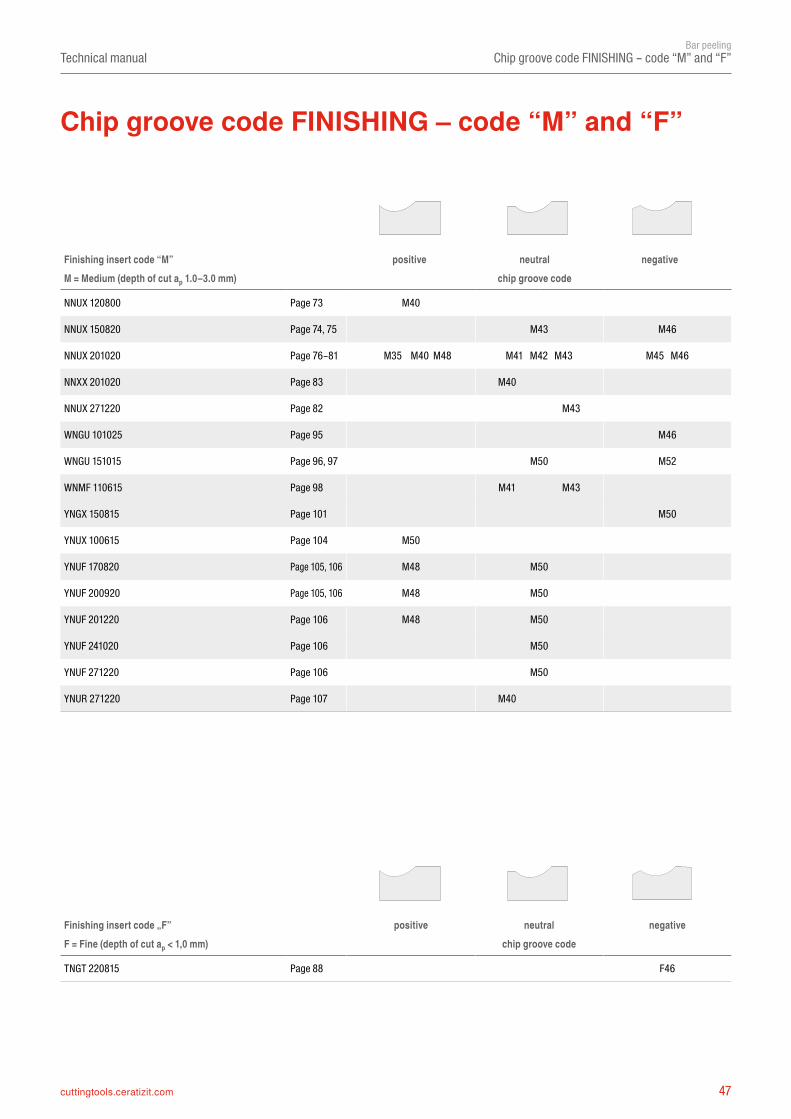
NNUX 120800 M40
NNUX 150820 M43 M46
NNUX 201020 M35 M40 M48 M41 M42 M43 M45 M46
NNXX 201020 M40
NNUX 271220 M43
WNGU 101025 M46
WNGU 151015 M50 M52
WNMF 110615 M41 M43
YNGX 150815 M50
YNUX 100615 M50
YNUF 170820 M48 M50
YNUF 200920 M48 M50
YNUF 201220 M48 M50
YNUF 241020 M50
YNUF 271220 M50
YNUR 271220 M40
TNGT 220815 F46
Technical manualBar peeling
Chip groove code FINISHING – code “M” and “F”
Chip groove code FINISHING – code “M” and “F”
Finishing insert code “M” positive neutral negativeM = Medium (depth of cut ap 1.0–3.0 mm) chip groove code
Page 73
Page 74, 75
Page 76–81
Page 83
Page 82
Page 95
Page 96, 97
Page 98
Page 101
Page 104
Page 105, 106
Page 105, 106
Page 106
Page 106
Page 106
Page 107
Finishing insert code „F” positive neutral negativeF = Fine (depth of cut ap < 1,0 mm) chip groove code
Page 88
48 cuttingtools.ceratizit.com
Technical manualBar peeling
Hexagonal roughing insert
Workpiece / material Type of treatment Alloy VDI 3323 group Hardness [HB] Chip breakerRecommendation
P
Unalloyed steel Annealed ≤ 0.15% C 1 125
Unalloyed steel Annealed 0.15%–0.45% C 2 150-250
Unalloyed steel Tempered ≥ 0.45% C 3 300
Low-alloy steel Annealed 6 180 R57
Low-alloy steel Tempered 7 / 8 250-300
Low-alloy steel Tempered 9 350
High-alloy steel Annealed 10 200
High-alloy steel Tempered 11 350
Stainless steel Annealed Ferritic / martensitic 12 200
Stainless steel Tempered Martensitic 13 325 R51+R57
Stainless steel Heat-treated Ferritic / martensitic 13 200R57
M
Stainless steel Quenched Austenitic 14 180
Stainless steel Quenched Ferritic / austenitic (Duplex) 14 230-260R51
Stainless steel Age-hardened Austenitic precipitation hardened (PH) 14 330
K Cast iron 15-20 130-260 Not yet peeled
N Non-ferrous metals 21-30 80-130 R51
SHeat-resistant alloys 31-35 200-350 R51
Titanium alloys 36 / 37 150-300 Not yet peeled
Hexagonal roughing insert HNMJ 131050, HNMH/J 221550 and HNMH/J 281850
50 cuttingtools.ceratizit.com
Technical manualBar peeling
Tool holders and cartridges
Examples of machine-specific tool holders:
Farmer Norton
Kieserling Daisho
Calow
MAIR ResearchBültmann / SMS Schumag
Tool holders and cartridges
Hetran-B
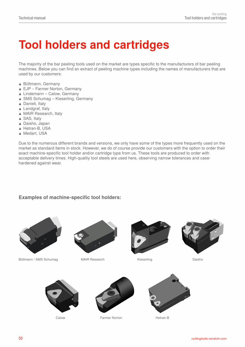
The majority of the bar peeling tools used on the market are types specific to the manufacturers of bar peeling machines. Below you can find an extract of peeling machine types including the names of manufacturers that are used by our customers:
▲ Bültmann, Germany ▲ EJP – Farmer Norton, Germany ▲ Lindemann – Calow, Germany ▲ SMS Schumag – Kieserling, Germany ▲ Danieli, Italy ▲ Landgraf, Italy ▲ MAIR Research, Italy ▲ SAS, Italy ▲ Daisho, Japan ▲ Hetran-B, USA ▲ Medart, USA
Due to the numerous different brands and versions, we only have some of the types more frequently used on the market as standard items in stock. However, we do of course provide our customers with the option to order their exact machine-specific tool holder and/or cartridge type from us. These tools are produced to order withacceptable delivery times. High-quality tool steels are used here, observing narrow tolerances and case-hardened against wear.
51cuttingtools.ceratizit.com
Technical manualBar peeling
Tool holders and cartridges
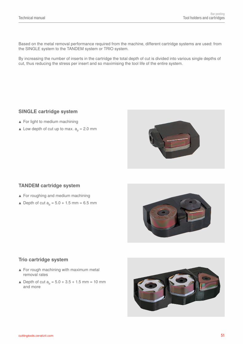
SINGLE cartridge system
▲ For light to medium machining ▲ Low depth of cut up to max. ap = 2.0 mm
TANDEM cartridge system
▲ For roughing and medium machining ▲ Depth of cut ap = 5.0 + 1.5 mm = 6.5 mm
Trio cartridge system
▲ For rough machining with maximum metal removal rates
▲ Depth of cut ap = 5.0 + 3.5 + 1.5 mm = 10 mm and more
Based on the metal removal performance required from the machine, different cartridge systems are used: from the SINGLE system to the TANDEM system or TRIO system.
By increasing the number of inserts in the cartridge the total depth of cut is divided into various single depths of cut, thus reducing the stress per insert and so maximising the tool life of the entire system.
52 cuttingtools.ceratizit.com
Technical manualBar peeling
Different insert clamping methods
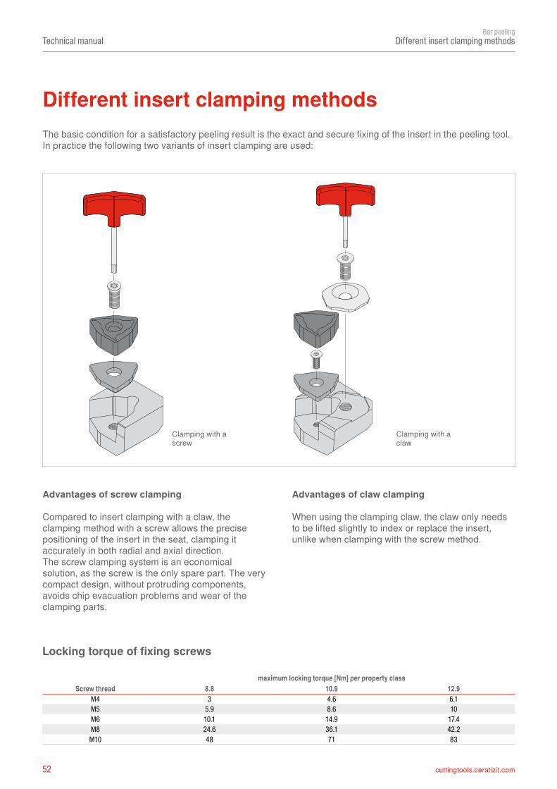
The basic condition for a satisfactory peeling result is the exact and secure fixing of the insert in the peeling tool. In practice the following two variants of insert clamping are used:
Different insert clamping methods
Clamping with a screw
Clamping with a claw
Advantages of screw clamping
Compared to insert clamping with a claw, the clamping method with a screw allows the precise positioning of the insert in the seat, clamping it accurately in both radial and axial direction.The screw clamping system is an economical solution, as the screw is the only spare part. The very compact design, without protruding components, avoids chip evacuation problems and wear of the clamping parts.
Advantages of claw clamping
When using the clamping claw, the claw only needs to be lifted slightly to index or replace the insert, unlike when clamping with the screw method.
maximum locking torque [Nm] per property classScrew thread 8.8 10.9 12.9
M4 3 4.6 6.1M5 5.9 8.6 10M6 10.1 14.9 17.4M8 24.6 36.1 42.2
M10 48 71 83
Locking torque of fixing screws
53cuttingtools.ceratizit.com
1
3
4
5
2
Technical manualBar peeling
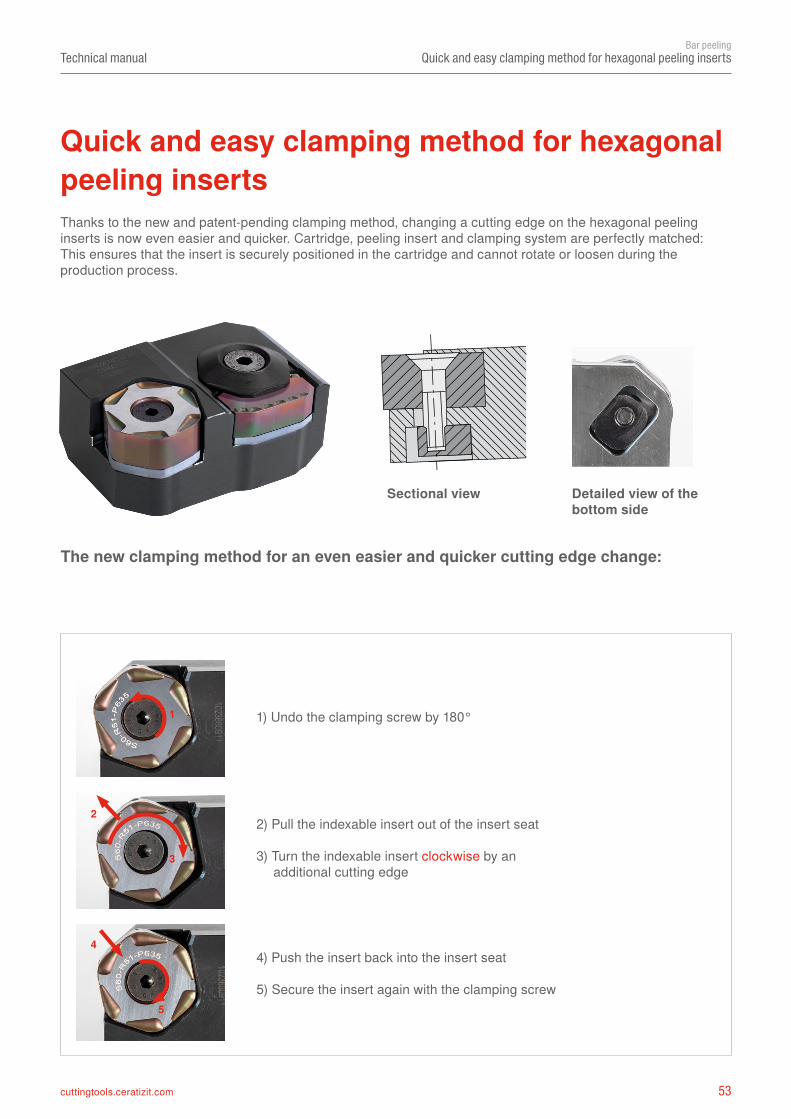
Quick and easy clamping method for hexagonal peeling inserts
Quick and easy clamping method for hexagonal peeling inserts
1) Undo the clamping screw by 180°
2) Pull the indexable insert out of the insert seat
3) Turn the indexable insert clockwise by an additional cutting edge
4) Push the insert back into the insert seat
5) Secure the insert again with the clamping screw
Sectional view Detailed view of the bottom side
Thanks to the new and patent-pending clamping method, changing a cutting edge on the hexagonal peeling inserts is now even easier and quicker. Cartridge, peeling insert and clamping system are perfectly matched: This ensures that the insert is securely positioned in the cartridge and cannot rotate or loosen during the production process.
The new clamping method for an even easier and quicker cutting edge change:
54 cuttingtools.ceratizit.com
Technical manualBar peeling
Peeling tools – use of carbide shims
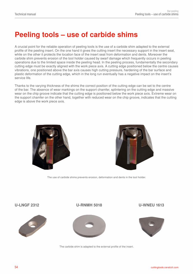
The use of carbide shims prevents erosion, deformation and dents in the tool holder.
The carbide shim is adapted to the external profile of the insert.
A crucial point for the reliable operation of peeling tools is the use of a carbide shim adapted to the external profile of the peeling insert. On the one hand it gives the cutting insert the necessary support in the insert seat, while on the other it protects the location face of the insert seat from deformation and dents. Moreover the carbide shim prevents erosion of the tool holder caused by swarf damage which frequently occurs in peeling operations due to the limited space inside the peeling head. In the peeling process, fundamentally the secondary cutting edge must be exactly aligned with the work piece axis. A cutting edge positioned below the centre causes vibrations, one positioned above the bar axis causes high cutting pressure, hardening of the bar surface and plastic deformation of the cutting edge, which in the long run eventually has a negative impact on the insert’s service life.
Thanks to the varying thickness of the shims the correct position of the cutting edge can be set to the centre of the bar. The absence of wear markings on the support chamfer, splintering on the cutting edge and massive wear on the chip groove indicate that the cutting edge is positioned below the work piece axis. Extreme wear on the support chamfer on the other hand, together with reduced wear on the chip groove, indicates that the cutting edge is above the work piece axis.
Peeling tools – use of carbide shims
U-LNGF 2312 U-RNMH 5018 U-WNEU 1613
55cuttingtools.ceratizit.com
Technical manualBar peeling
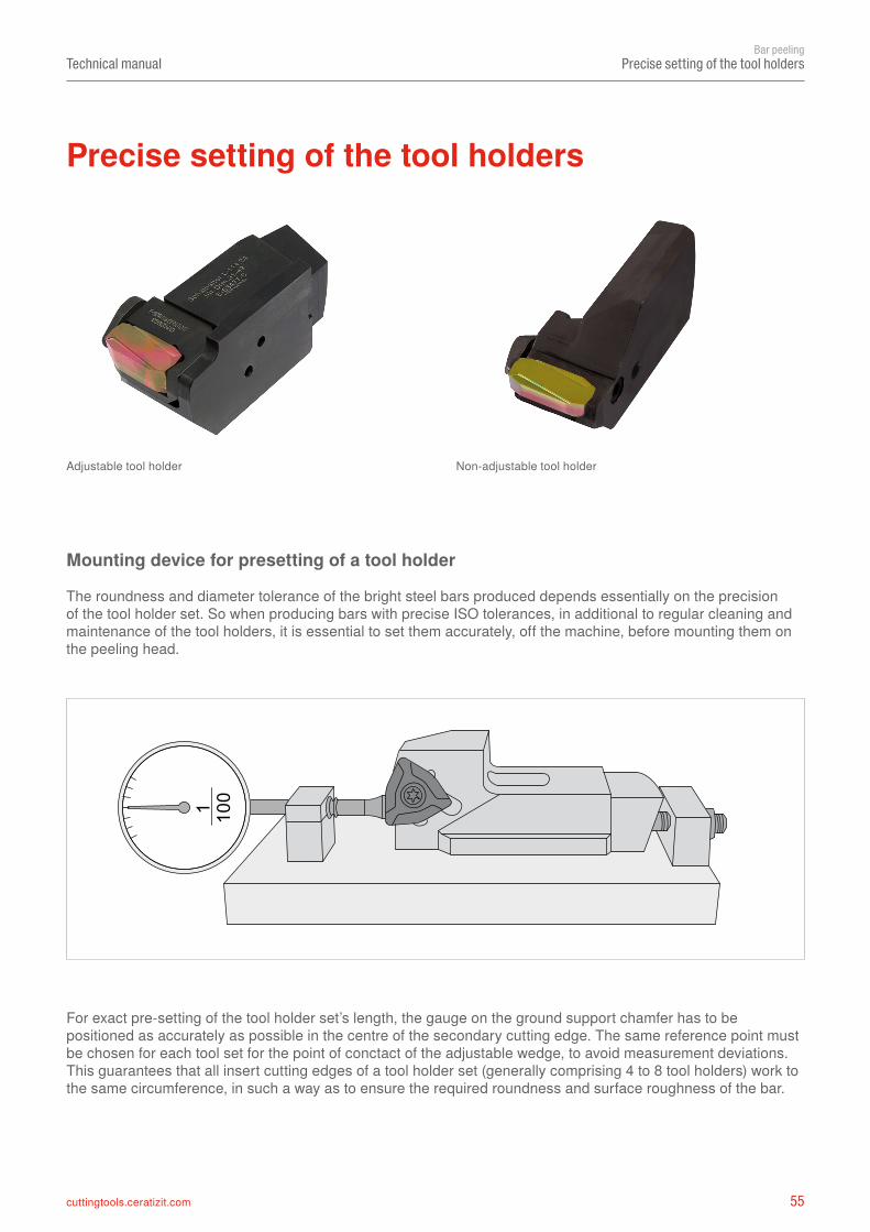
Precise setting of the tool holders
Precise setting of the tool holders
The roundness and diameter tolerance of the bright steel bars produced depends essentially on the precision of the tool holder set. So when producing bars with precise ISO tolerances, in additional to regular cleaning and maintenance of the tool holders, it is essential to set them accurately, off the machine, before mounting them on the peeling head.
Mounting device for presetting of a tool holder
For exact pre-setting of the tool holder set’s length, the gauge on the ground support chamfer has to be positioned as accurately as possible in the centre of the secondary cutting edge. The same reference point must be chosen for each tool set for the point of conctact of the adjustable wedge, to avoid measurement deviations.This guarantees that all insert cutting edges of a tool holder set (generally comprising 4 to 8 tool holders) work to the same circumference, in such a way as to ensure the required roundness and surface roughness of the bar.
Adjustable tool holder Non-adjustable tool holder
56 cuttingtools.ceratizit.com
N 1 N 2 N 3 N 4 N 5 N 6 N 7 N 8 N 9 N 10 N 11 N 12
Technical manualBar peeling
Surface quality
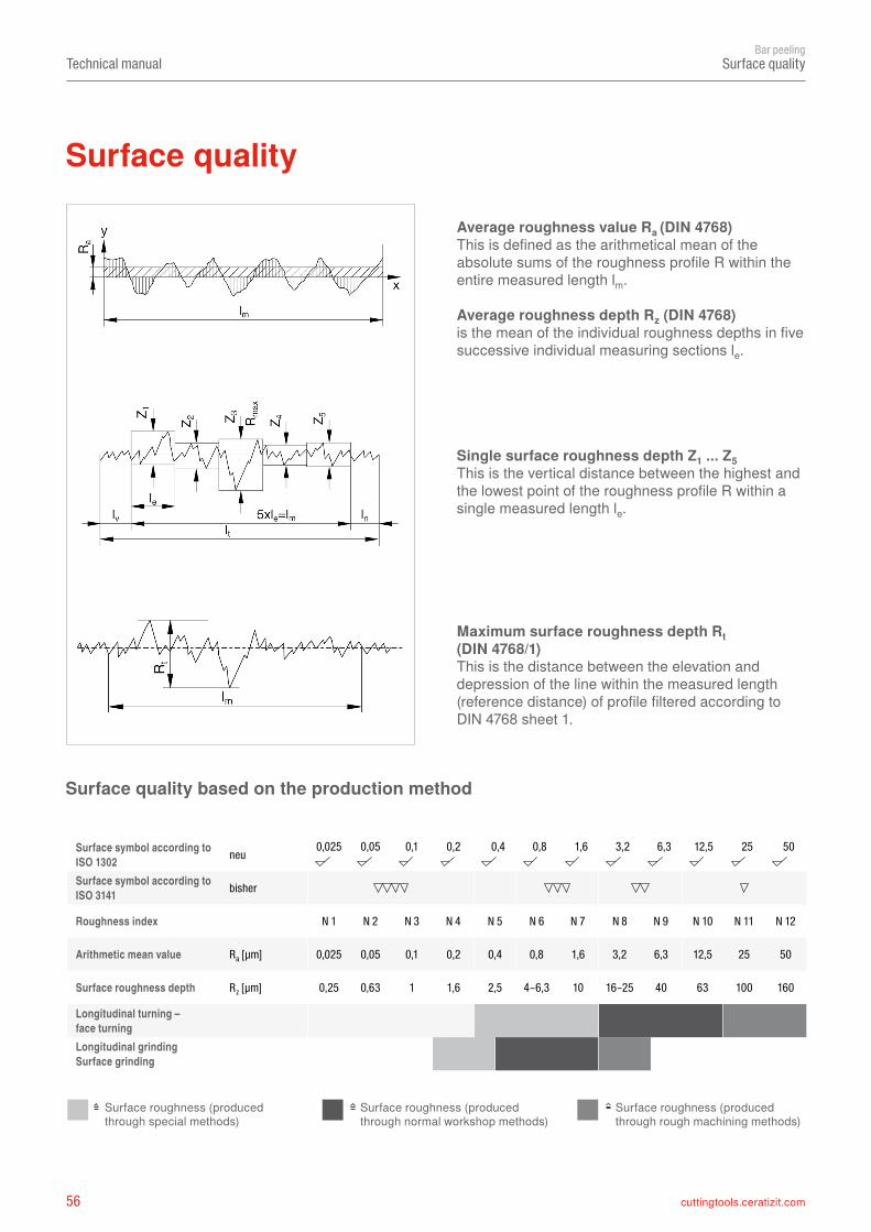
Average roughness value Ra (DIN 4768)This is defined as the arithmetical mean of the absolute sums of the roughness profile R within the entire measured length lm.
Average roughness depth Rz (DIN 4768)is the mean of the individual roughness depths in five successive individual measuring sections le.
Single surface roughness depth Z1 ... Z5This is the vertical distance between the highest and the lowest point of the roughness profile R within a single measured length le.
Maximum surface roughness depth Rt (DIN 4768/1)This is the distance between the elevation and depression of the line within the measured length (reference distance) of profile filtered according to DIN 4768 sheet 1.
Surface quality based on the production method
Surface roughness (produced through normal workshop methods)
Surface roughness (produced through rough machining methods)
Surface roughness (produced through special methods)
Surface quality
Surface symbol according to ISO 1302 neu 0,025 0,05 0,1 0,2 0,4 0,8 1,6 3,2 6,3 12,5 25 50
Surface symbol according to ISO 3141 bisher
Roughness index
Arithmetic mean value Ra [µm] 0,025 0,05 0,1 0,2 0,4 0,8 1,6 3,2 6,3 12,5 25 50
Surface roughness depth Rz [µm] 0,25 0,63 1 1,6 2,5 4–6,3 10 16–25 40 63 100 160
Longitudinal turning – face turningLongitudinal grinding Surface grinding
57cuttingtools.ceratizit.com
P =(vc • ap • f • Kc1.1)
60000
0.29
• 0.4
f[kW]
Technical manualBar peeling
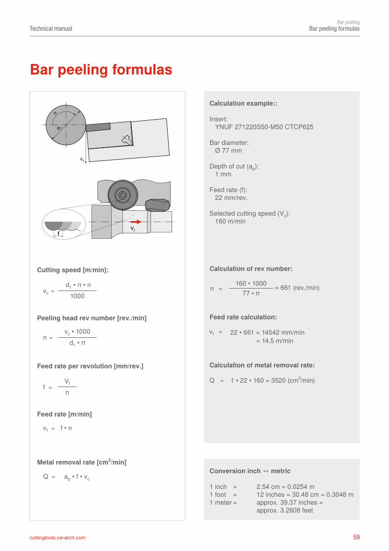
Productivity and efficiency
Along with high process reliability and high metal removal rates, the need for perfect bar surfaces and form accuracy are the most important criteria for our bar peeling customers.An important prerequisite for the above requirements is the choice of the peeling machine. Different machining methods and combinations of cutting inserts in SINGLE, TANDEM or TRIO cartridge systems entail varying levels of power consumption on the part of the peeling machine. The formula below serves for an approximate calculation of the necessary power consumption P [kW], on the basis of which the number of the usable cutting edges or inserts can then be determined:
Productivity and efficiency
Formula for the calculation of power consumption
vc = cutting speed [m/min]ap = depth of cut [mm]f = feed rate per cartridge [mm/rev.]Kc1.1 = specific cutting force [N/mm2]
The major influencing factors in terms of productivity are the feed rate and the depth of cut. These, however, are limited by the possibilities and the state of repair of the peeling ´machine and its peeling tools, as well as by the condition of the raw material, all of which inevitably generate vibrations. In the last resort, the reduction of vibrations during the peeling process is the winning formula for productivity and product quality. The preparation of the support chamfer, based on the quality and hardness of the material which is to be machined, contributes additional stability to the peeling process. The nominal value of the support chamfer angle determines whether the finishing insert, which is aligned parallel to the axis, forms a clearance angle between the bar and the support chamfer. If it does so, these are described as positive inserts. The inserts are described as neutral when they have a form lock with the bar, while negative inserts exert massive pressure on the bars. Depending on their nature, different materials need the properties of the cutting insert to be adapted accordingly.
The support chamfer angle and the length of the secondary cutting edge in the last resort influence the surface quality of the bars, and also, importantly, the choice of the correct insert for the respective depth of cut ap. Chip grooves which are specifically adapted to the material’s properties break the chips produced during the peeling process to an acceptable length. In this context the depth of cut is a significant factor. As described in previous sections, in bar peeling there are different inserts for roughing, for medium machining and for finish machining. The designations of the CERATIZIT chip grooves already indicate the application range in terms of depth of cut ap. Chip groove designations with the letter R (Rough) should be used for depths of cut larger than 3.0 mm. Chip grooves with the letter M (Medium) should be used for depths of cut between 1.0 and 3.0 mm, and those with the letter F (Fine) for depths of cut less than 1.0 mm – these are in all cases suitable for finishing operations. Based on this selection the best possible cutting conditions can be obtained, the cutting forces are optimally distributed and tool life will be ideally prolonged. When using TANDEM cartridge systems, the major part of the material should be removed by the roughing insert: the depth of cut of the finishing insert – depending on its type – should be between 0.5 and 1.8 mm.
It has to be taken into account that the approximately calculated drive output applies only to one cartridge system. If the peeling machine is equipped with a peeling head comprising 4 cartridges / tool slides, the power consumption resulting from the formula has to be multiplied by a factor of 4. Regarding the depth of cut (ap), it has to be taken into account that in case of a TANDEM or TRIO system the individual radial depths of cut of all roughing and finishing inserts are cumulated.
Feed rate and depth of cut
58 cuttingtools.ceratizit.com
h m
κ
ap
f
h m
ap
fd
hm ≈ f • sin (ĸ) hm ≈ f • apd
Technical manualBar peeling
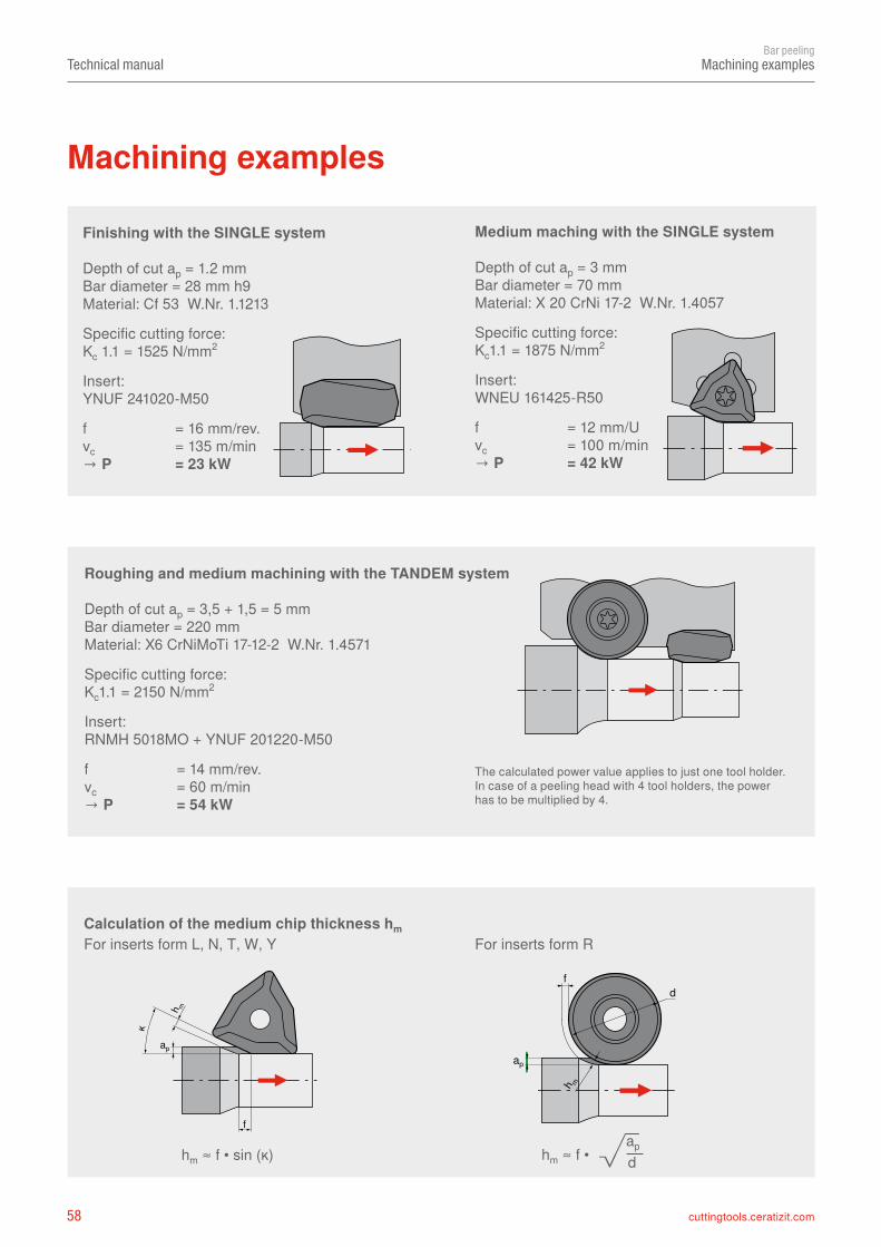
Machining examples
Finishing with the SINGLE system
Depth of cut ap = 1.2 mmBar diameter = 28 mm h9Material: Cf 53 W.Nr. 1.1213
Specific cutting force:Kc 1.1 = 1525 N/mm2
Insert:YNUF 241020-M50
f = 16 mm/rev.vc = 135 m/min→ P = 23 kW
Machining examples
Roughing and medium machining with the TANDEM system
Depth of cut ap = 3,5 + 1,5 = 5 mmBar diameter = 220 mmMaterial: X6 CrNiMoTi 17-12-2 W.Nr. 1.4571
Specific cutting force:Kc1.1 = 2150 N/mm2
Insert:RNMH 5018MO + YNUF 201220-M50
f = 14 mm/rev.vc = 60 m/min→ P = 54 kW
Medium maching with the SINGLE system
Depth of cut ap = 3 mmBar diameter = 70 mmMaterial: X 20 CrNi 17-2 W.Nr. 1.4057
Specific cutting force:Kc1.1 = 1875 N/mm2
Insert:WNEU 161425-R50
f = 12 mm/Uvc = 100 m/min→ P = 42 kW
The calculated power value applies to just one tool holder. In case of a peeling head with 4 tool holders, the power has to be multiplied by 4.
Calculation of the medium chip thickness hmFor inserts form L, N, T, W, Y For inserts form R
59cuttingtools.ceratizit.com
vc = d1 • π • n
1000
n =vc • 1000
d1 • π
f =Vf
n
Q = ap • f • vc
vf = f • n
vff
vc
n
d 1
n =160 • 1000
77 • π
Q = 1 • 22 • 160 = 3520 (cm3/min)
Technical manualBar peeling
Bar peeling formulas
Calculation example::
Insert: YNUF 271220S50-M50 CTCP625
Bar diameter: Ø 77 mm
Depth of cut (ap): 1 mm
Feed rate (f): 22 mm/rev.
Selected cutting speed (Vc): 160 m/min
Cutting speed [m/min]:
Peeling head rev number [rev./min]
Feed rate per revolution [mm/rev.]
Feed rate [m/min]
Metal removal rate [cm3/min]
Calculation of rev number:
Feed rate calculation:
Calculation of metal removal rate:
Conversion inch ↔ metric
1 inch = 2.54 cm = 0.0254 m1 foot = 12 inches = 30.48 cm = 0.3048 m1 meter = approx. 39.37 inches = approx. 3.2808 feet
= 661 (rev./min)
Bar peeling formulas
vf = 22 • 661 = 14542 mm/min = 14.5 m/min
60 cuttingtools.ceratizit.com
≈
≈ ≈ ≈ ≈ ≈≈ ≈ ≈ ≈ ≈≈ ≈
≈ ≈ ≈ ≈ ≈ ≈◾ ◾ ◾ ◾ ◾ ◾
≈◾◽
Technical manualBar peeling
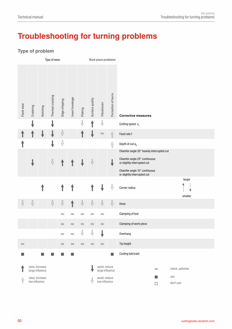
Troubleshooting for turning problems
Troubleshooting for turning problemsType of problem
Corrective measures
Type of wear Work piece problems
Flan
k wea
r
Crat
erin
g
Notc
hing
Ther
mal
crac
king
Edge
chip
ping
Inse
rt br
eaka
ge
Flak
ing
Surfa
ce q
ualit
y
Vibr
atio
nen
Form
atio
n of b
urrs
Cutting speed vc
Feed rate f
Depth of cut ap
Chamfer angle 35° heavily interrupted cut
Chamfer angle 25° continuous or slightly interrupted cut
Chamfer angle 15° continuous or slightly interrupted cut
Corner radius
larger
smaller
Hone
Clamping of tool
Clamping of work piece
Overhang
Tip height
Cooling lubricant
raise, increase, large influence
avoid, reduce large influence check, optimise
raise, increase low influence
avoid, reduce low influence
use
don’t use
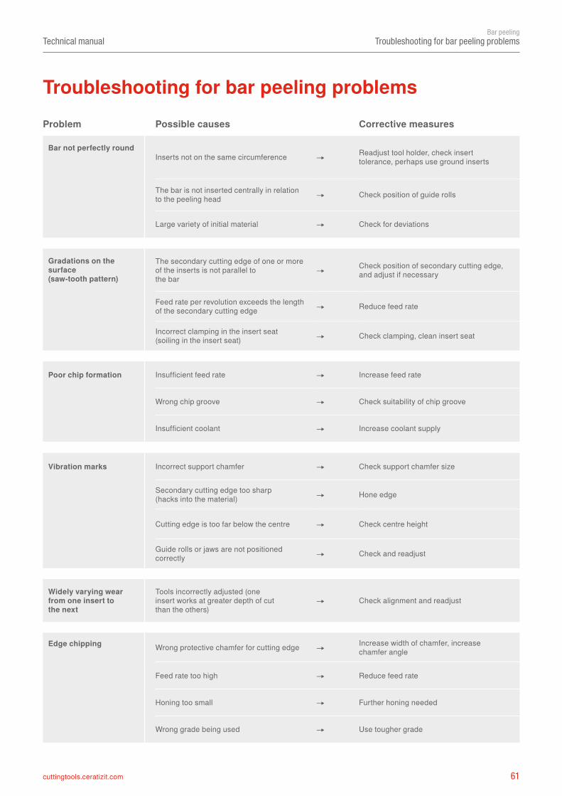
61cuttingtools.ceratizit.com
Technical manualBar peeling
Troubleshooting for bar peeling problems
Troubleshooting for bar peeling problemsProblem Possible causes Corrective measures
Bar not perfectly roundInserts not on the same circumference ➝ Readjust tool holder, check insert
tolerance, perhaps use ground inserts
The bar is not inserted centrally in relation to the peeling head ➝ Check position of guide rolls
Large variety of initial material ➝ Check for deviations
Gradations on the surface (saw-tooth pattern)
The secondary cutting edge of one or more of the inserts is not parallel to the bar
➝ Check position of secondary cutting edge, and adjust if necessary
Feed rate per revolution exceeds the length of the secondary cutting edge ➝ Reduce feed rate
Incorrect clamping in the insert seat (soiling in the insert seat) ➝ Check clamping, clean insert seat
Poor chip formation Insufficient feed rate ➝ Increase feed rate
Wrong chip groove ➝ Check suitability of chip groove
Insufficient coolant ➝ Increase coolant supply
Vibration marks Incorrect support chamfer ➝ Check support chamfer size
Secondary cutting edge too sharp (hacks into the material) ➝ Hone edge
Cutting edge is too far below the centre ➝ Check centre height
Guide rolls or jaws are not positioned correctly ➝ Check and readjust
Edge chipping Wrong protective chamfer for cutting edge ➝ Increase width of chamfer, increase chamfer angle
Feed rate too high ➝ Reduce feed rate
Honing too small ➝ Further honing needed
Wrong grade being used ➝ Use tougher grade
Widely varying wear from one insert to the next
Tools incorrectly adjusted (one insert works at greater depth of cut than the others)
➝ Check alignment and readjust
62 cuttingtools.ceratizit.com
a
bcd
Technical manualBar peeling
Causes of wear
With increasing cutting temperature the thermally caused wear types of oxidation and diffusion prevail.
Cutting temperature and wear depend decisively upon the machining conditions.
Benefits of hard material coatings
Depositing hard material layers on carbide tools positively influences wear characteristics.
▲ Friction ▲ Temperature changes ▲ Oxidation ▲ Diffusion
Wear is caused through simultaneous mechanical and thermal stress of the cutting edge. The most common causes are:
▲ Mechanical abrasion ▲ Damage due to built-up edge (BUE) ▲ Oxidation processes ▲ Diffusion
Causes of wear
a = diffusionb = mechanical abrasionc = oxidationd = built-up edge (BUE)
Cutting speed Feed rate Depth of cut
Wea
r
Cutting temperature
Wea
r
Increase of ap; f; vc
63cuttingtools.ceratizit.com
Technical manualBar peeling
Causes of wear
Causes of wearFlank wear Cause Remedy
Cutting speed too high ➝ Reduce cutting speed
Carbide grade with insufficient wear resistance ➝ Select more wear-resistant carbide grade
Incorrect feed rate ➝ Adapt feed rate to cutting speed and cutting depth (increase feed rate)
Edge chipping Cause Remedy
Grade with too high wear resistance ➝ Use tougher grade
Vibration ➝ Use negative cutting edge geometry with chip groove
Feed rate too high or excessive cutting depth ➝
Interrupted cut ➝
Swarf damage ➝
Built-up edge Cause Remedy
Cutting speed too low ➝ Increase cutting speed
Rake angle too small ➝ Increase rake angle
Wrong cutting material ➝ Apply TiN coating
Lack of cooling / lubrication ➝ Use emulsion with higher concentration
Thermal cracking Cause Remedy
Varying temperature of cutting edge, thermal shock ➝ Use grade that is resistant to thermal
cracking
Incorrect cooling ➝ Apply cooling lubricant abundantly or use dry milling
High tensile materials ➝
Cutting speed too high ➝
Abrasion on flank, normal wear after a certain machining time.
Through excessive mechanical stress at the cutting edge fracture andchipping can occur.
Small cracks at 90° to cutting edge.
Built-up edge occurs when the chip is not evacuated properly dueto insufficient cutting temperature.
➝ Adapt cutting values
➝ Use tougher grade or more stable geometry
➝ Use different chip breaker
➝
➝
➝ Select suitable cutting parameters
➝ Reduce cutting speed
64 cuttingtools.ceratizit.com
Technical manualBar peeling
Causes of wear
Plastic deformation Cause Remedy
Too high machining temperature, resulting in softening of substrate ➝ Reduce cutting speed
Damaged coatings ➝ Choose carbide grade with higher wear resistance
Chip groove too narrow ➝
Notching Cause Remedy
Cold work hardening materials (e.g. super alloys) ➝ Decrease cutting speed
Cast and forging skin ➝
Formation of burrs ➝ Change working orientation of the milling cutter
Insert breakage Cause Remedy
Excessive stress of the carbide grade ➝
Lack of stability ➝ Use protective edge chamfer
Corner angle too small ➝ Increase edge hone
Excessive notching ➝
Sudden changes of cutting forces ➝
Cratering Cause Remedy
Cutting speed and / or feed rate too high ➝ Reduce cutting speed and / or feed rate
Rake angle too shallow ➝
Grade with low wear resistance ➝
Insufficient coolant supply ➝ Increase coolant quantity and / or pressure, optimise coolant supply
Causes of wear
High machining temperature and simultaneous mechanical stresscan lead to plastic deformation.
Notch at the maximum cutting depth.
Excessive stress of the insert causes breakage.
The hot chip which is being evacuated causes cratering at the rake face of the cutting edge.
➝
➝
➝ Use different geometry
➝ Use tougher cutting material or adapt cutting parameter
➝
➝
➝ Use more stable geometry and adapt cutting parameter
➝ Reduce feed rate
➝ Use different geometry
➝ Use more wear-resistant grade
➝
➝ Use smaller setting angle
InsertsFirst-class cutting gradescombined with advancedchip breakers create a headstart on performance
Based on the different application cases, CERATIZIT offers an extensive range of bar peeling inserts in different geometries and carbide grades for the machining of all classes of material, with the goal of increasing both the productivity and efficiency of the manufacturing processes as well as the quality of the resulting products.
See for yourself!
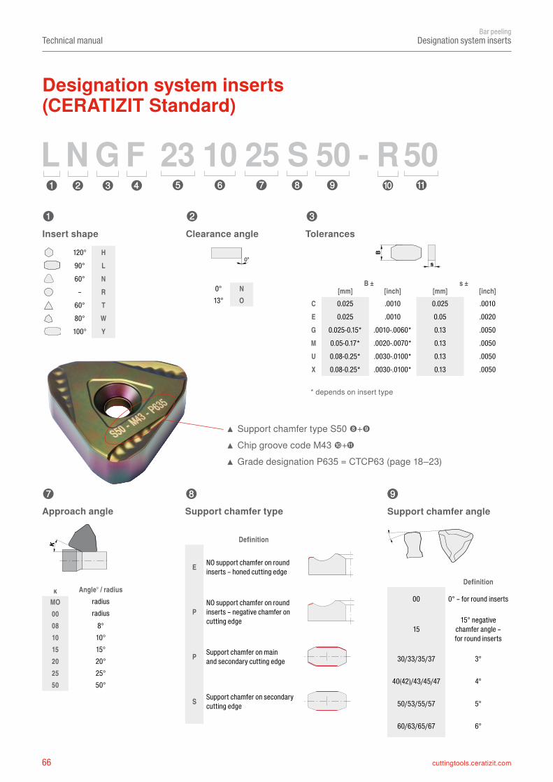
66 cuttingtools.ceratizit.com
➍ ➎➊ ➋ ➌ ➏ ➐ ➑ ➒ ➓
➊ ➋ ➌
➐ ➑ ➒
00
15
30/33/35/37 3°
40(42)/43/45/47 4°
50/53/55/57 5°
60/63/65/67 6°
120° H90° L60° N
– R60° T80° W
100° Y
0° N13° O
B ± s ±[mm] [inch] [mm] [inch]
CEGMUX
ĸMO0008 8°10 10°15 15°20 20°25 25°50 50°
E
P
P
S
L N G F 23 10 25 S 50 - R50
0°
B d
s
κTechnical manual
Bar peelingDesignation system inserts
0.025 .0010 0.025 .00100.025 .0010 0.05 .0020
0.025-0.15* .0010-.0060* 0.13 .00500.05-0.17* .0020-.0070* 0.13 .00500.08-0.25* .0030-.0100* 0.13 .00500.08-0.25* .0030-.0100* 0.13 .0050
Angle° / radiusradiusradius
Definition
0° – for round inserts
15° negativechamfer angle –for round inserts
Definition
NO support chamfer on round inserts – honed cutting edge
NO support chamfer on round inserts – negative chamfer on cutting edge
Support chamfer on mainand secondary cutting edge
Support chamfer on secondary cutting edge
Support chamfer angle
▲ Support chamfer type S50 ➑+➒ ▲ Chip groove code M43 ➓+ ▲ Grade designation P635 = CTCP63 (page 18–23)
Insert shape Clearance angle Tolerances
Approach angle Support chamfer type
* depends on insert type
Designation system inserts (CERATIZIT Standard)
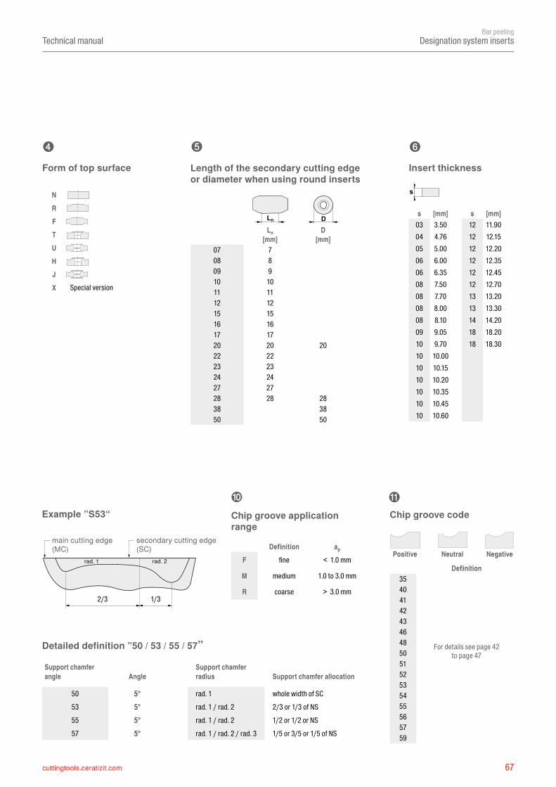
67cuttingtools.ceratizit.com
➍ ➏
➓
NRFTUHJX
Ln D[mm] [mm]
07 708 809 910 1011 1112 1215 1516 1617 1720 20 2022 2223 2324 2427 2728 28 2838 3850 50
ap
F
M
R35404142434648505152535455565759
s
s s03 1204 1205 1206 1206 1208 1208 1308 1308 1409 1810 18101010101010
2/3 1/3
➎
d
Ln D
Technical manualBar peeling
Designation system inserts
[mm] [mm]3.50 11.904.76 12.155.00 12.206.00 12.356.35 12.457.50 12.707.70 13.208.00 13.308.10 14.209.05 18.209.70 18.30
10.0010.1510.2010.3510.4510.60
Definition
For details see page 42to page 47
Form of top surface Length of the secondary cutting edgeor diameter when using round inserts
Chip groove applicationrange
Chip groove code
Insert thickness
Detailed definition ”50 / 53 / 55 / 57”
Example ”S53“
secondary cutting edge (SC)
main cutting edge (MC) Definition
fine < 1.0 mm
medium 1.0 to 3.0 mm
coarse > 3.0 mm
Special version
Positive Neutral Negativerad. 1 rad. 2
Support chamfer angle Angle
Support chamfer radius Support chamfer allocation
50 5° rad. 1 whole width of SC53 5° rad. 1 / rad. 2 2/3 or 1/3 of NS55 5° rad. 1 / rad. 2 1/2 or 1/2 or NS57 5° rad. 1 / rad. 2 / rad. 3 1/5 or 3/5 or 1/5 of NS
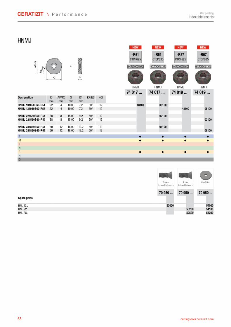
68 cuttingtools.ceratizit.com
NEW NEW NEW NEW
IC S
D1APM
X
KRIN
S
-R51CTCP625
-R51CTCP635
-R57CTCP625
-R57CTCP635
HNMJ HNMJ HNMJ HNMJ74 017 ... 74 017 ... 74 019 ... 74 019 ...
IC APMX S D1 KRINS NOI mm mm mm mm
HNMJ 131050S60-R51 22 4 50° 12 7401748100 7401708100HNMJ 131050S60-R57 22 4 50° 12 7401948100 7401908100 HNMJ 221550S60-R51 38 8 50° 12 7401702100HNMJ 221550S60-R57 38 8 50° 12 7401902100 HNMJ 281850S60-R51 50 12 50° 12 7401706100HNMJ 281850S60-R57 50 12 50° 12 7401906100
P ● ● ● ●M ● ● ● ●K N S ● ● ● ●H O
70 950 ... 70 950 ... 70 950 ...
HN.. 13.. 7095053000 7095054000HN.. 22.. 7095053200 7095054100HN.. 28.. 7095052500 7095054200
Bar peelingIndexable Inserts
HNMJ
Designation
10.00 7.210.00 7.2
15.00 9.215.00 9.2
18.00 12.218.00 12.2
Screw Indexable inserts
Screw Indexable inserts
HM-Shim
Spare parts
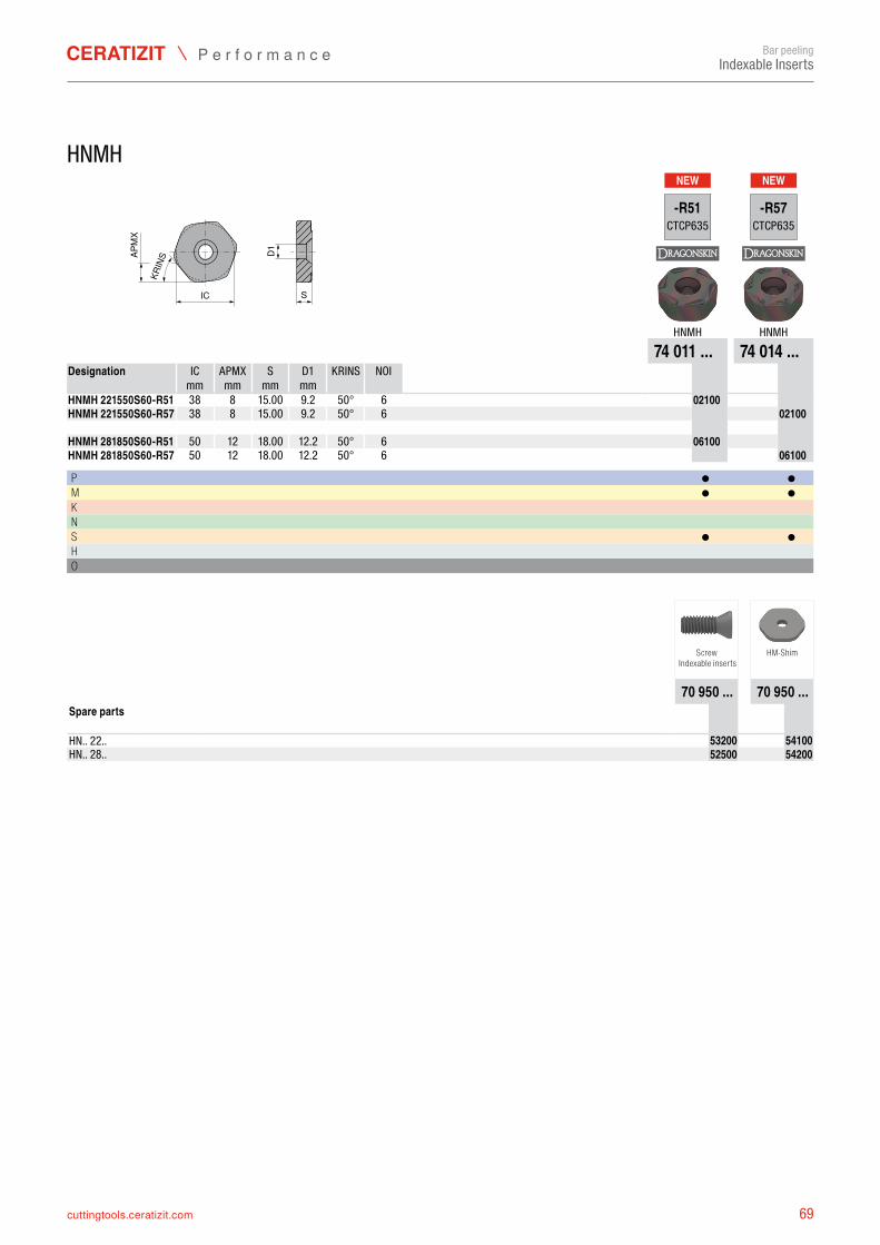
69cuttingtools.ceratizit.com
NEW NEW
IC S
D1APM
X
KRIN
S
-R51CTCP635
-R57CTCP635
HNMH HNMH74 011 ... 74 014 ...
IC APMX S D1 KRINS NOI mm mm mm mm
HNMH 221550S60-R51 38 8 50° 6 7401102100HNMH 221550S60-R57 38 8 50° 6 7401402100 HNMH 281850S60-R51 50 12 50° 6 7401106100HNMH 281850S60-R57 50 12 50° 6 7401406100
P ● ●M ● ●K N S ● ●H O
70 950 ... 70 950 ...
HN.. 22.. 7095053200 7095054100HN.. 28.. 7095052500 7095054200
Bar peelingIndexable Inserts
HNMH
Designation
15.00 9.215.00 9.2
18.00 12.218.00 12.2
Screw Indexable inserts
HM-Shim
Spare parts
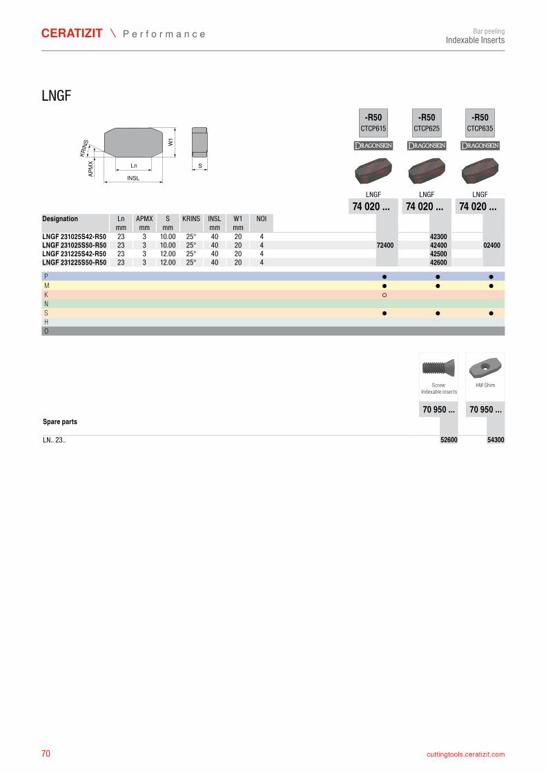
70 cuttingtools.ceratizit.com
KRIN
S
lNSLW
1S
APM
X Ln
-R50CTCP615
-R50CTCP625
-R50CTCP635
LNGF LNGF LNGF74 020 ... 74 020 ... 74 020 ...
Ln APMX S KRINS INSL W1 NOI mm mm mm mm mm
LNGF 231025S42-R50 23 3 25° 40 20 4 7402042300LNGF 231025S50-R50 23 3 25° 40 20 4 7402072400 7402042400 7402002400LNGF 231225S42-R50 23 3 25° 40 20 4 7402042500LNGF 231225S50-R50 23 3 25° 40 20 4 7402042600
P ● ● ●M ● ● ●K ○ N S ● ● ●H O
70 950 ... 70 950 ...
LN.. 23.. 7095052600 7095054300
Bar peelingIndexable Inserts
LNGF
Designation
10.0010.0012.0012.00
Screw Indexable inserts
HM-Shim
Spare parts
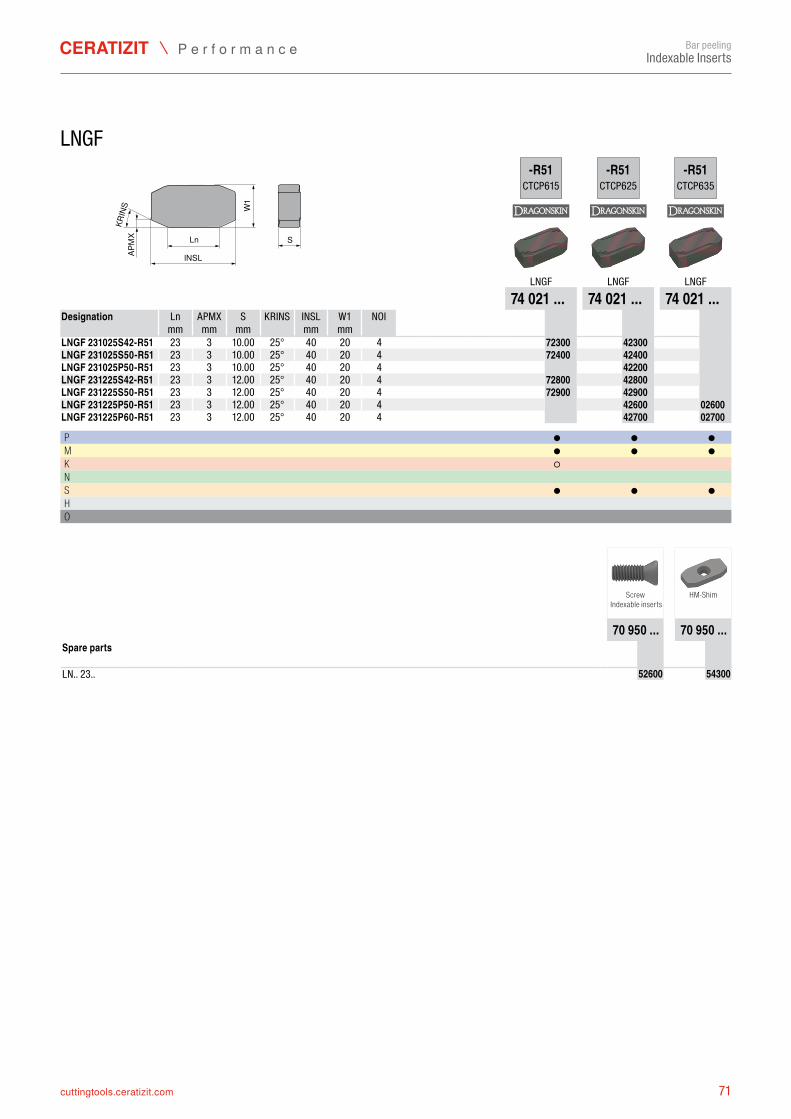
71cuttingtools.ceratizit.com
KRIN
S
lNSLW
1S
APM
X Ln
-R51CTCP615
-R51CTCP625
-R51CTCP635
LNGF LNGF LNGF74 021 ... 74 021 ... 74 021 ...
Ln APMX S KRINS INSL W1 NOI mm mm mm mm mm
LNGF 231025S42-R51 23 3 25° 40 20 4 7402172300 7402142300LNGF 231025S50-R51 23 3 25° 40 20 4 7402172400 7402142400LNGF 231025P50-R51 23 3 25° 40 20 4 7402142200LNGF 231225S42-R51 23 3 25° 40 20 4 7402172800 7402142800LNGF 231225S50-R51 23 3 25° 40 20 4 7402172900 7402142900LNGF 231225P50-R51 23 3 25° 40 20 4 7402142600 7402102600LNGF 231225P60-R51 23 3 25° 40 20 4 7402142700 7402102700
P ● ● ●M ● ● ●K ○ N S ● ● ●H O
70 950 ... 70 950 ...
LN.. 23.. 7095052600 7095054300
Bar peelingIndexable Inserts
LNGF
Designation
10.0010.0010.0012.0012.0012.0012.00
Screw Indexable inserts
HM-Shim
Spare parts
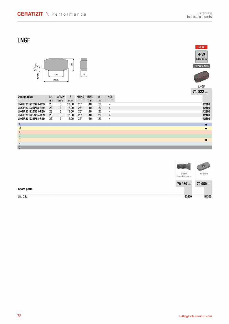
72 cuttingtools.ceratizit.com
LNGFNEW
KRIN
S
lNSL
W1
S
APM
X Ln
-R59CTCP625
LNGF74 022 ...
Ln APMX S KRINS INSL W1 NOI mm mm mm mm mm
LNGF 231225S43-R59 23 3 25° 40 20 4 7402242300LNGF 231225P43-R59 23 3 25° 40 20 4 7402242400LNGF 231225S53-R59 23 3 25° 40 20 4 7402242500LNGF 231225S55-R59 23 3 25° 40 20 4 7402242100LNGF 231225P53-R59 23 3 25° 40 20 4 7402242600
P ●M ●K N S ●H O
70 950 ... 70 950 ...
LN.. 23.. 7095052600 7095054300
Bar peelingIndexable Inserts
ScrewIndexable inserts
HM-Shim
Spare parts
LNGF
Designation
12.00 12.00 12.00 12.00 12.00
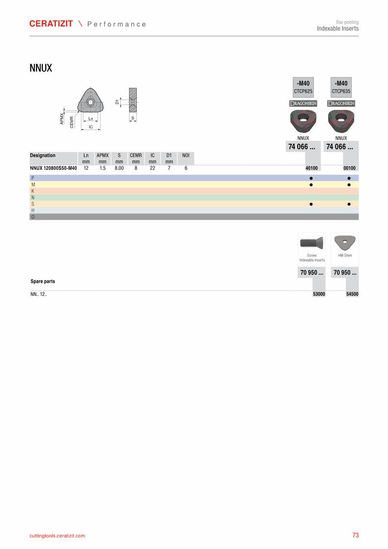
73cuttingtools.ceratizit.com
NNUX
D1S
CEM
R
APM
X
Ln
IC
-M40CTCP625
-M40CTCP635
NNUX NNUX74 066 ... 74 066 ...
Ln APMX S CEMR IC D1 NOI mm mm mm mm mm mm
NNUX 120800S50-M40 12 8 22 7 6 7406640100 7406600100
P ● ●M ● ●K N S ● ●H O
70 950 ... 70 950 ...
NN.. 12.. 7095053000 7095054500
Bar peelingIndexable Inserts
NNUX
Designation
1.5 8.00
Screw
Indexable insertsHM-Shim
Spare parts

74 cuttingtools.ceratizit.com
NNUXNEW
D1
S
KRIN
S
APM
X
Ln
IC
-M43CTCP605
-M43CTCP615
-M43CTCP625
NNUX NNUX NNUX74 064 ... 74 064 ... 74 064 ...
Ln APMX S KRINS IC D1 NOI mm mm mm mm mm
NNUX 150820P30-M43 15 2 20° 22 7 6 7406442101 7406472100NNUX 150820S42-M43 15 2 20° 22 7 6 7406442301 7406442300 7406472300NNUX 150820S50-M43 15 2 20° 22 7 6 7406442401 7406442400 7406472400NNUX 150820S60-M43 15 2 20° 22 7 6 7406442501 7406472500 7406442500NNUX 150820P60-M43 15 2 20° 22 7 6 7406442201 7406442200
P ● ● ●M ● ●K ○ ○ N ○ S ● ●H O
70 950 ... 70 950 ...
NN.. 15.. 7095053000 7095054600
Bar peelingIndexable Inserts
NNUX
Designation
8.008.008.008.008.00
Screw Indexable inserts
HM-Shim
Spare parts
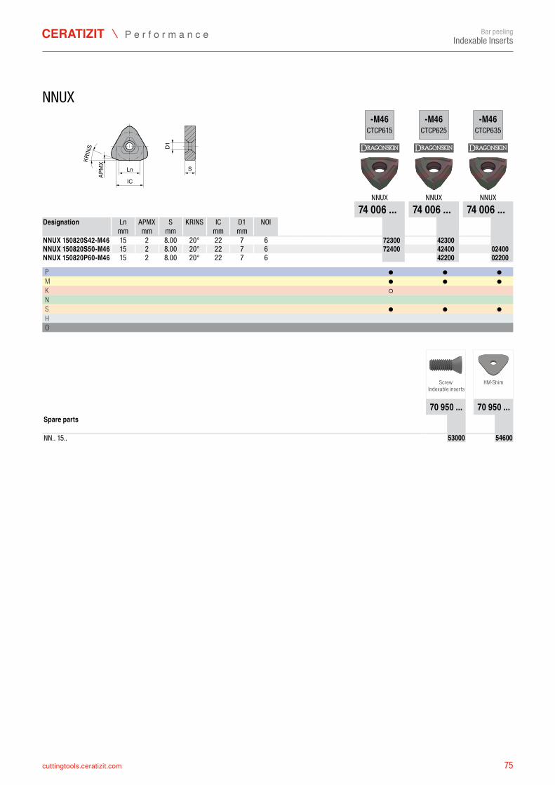
75cuttingtools.ceratizit.com
D1S
KRIN
S
APM
X
Ln
IC
-M46CTCP615
-M46CTCP625
-M46CTCP635
NNUX NNUX NNUX74 006 ... 74 006 ... 74 006 ...
Ln APMX S KRINS IC D1 NOI mm mm mm mm mm
NNUX 150820S42-M46 15 2 20° 22 7 6 7400672300 7400642300NNUX 150820S50-M46 15 2 20° 22 7 6 7400672400 7400642400 7400602400NNUX 150820P60-M46 15 2 20° 22 7 6 7400642200 7400602200
P ● ● ●M ● ● ●K ○ N S ● ● ●H O
70 950 ... 70 950 ...
NN.. 15.. 7095053000 7095054600
Bar peelingIndexable Inserts
NNUX
Designation
8.008.008.00
Screw Indexable inserts
HM-Shim
Spare parts
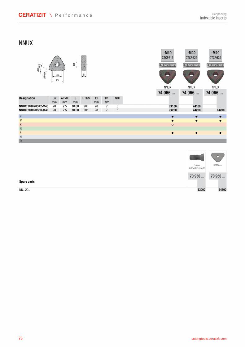
76 cuttingtools.ceratizit.com
D1S
KRIN
S
APM
X
Ln
IC
-M40CTCP615
-M40CTCP625
-M40CTCP635
NNUX NNUX NNUX74 066 ... 74 066 ... 74 066 ...
Ln APMX S KRINS IC D1 NOI mm mm mm mm mm
NNUX 201020S42-M40 20 20° 28 7 6 7406674100 7406644100NNUX 201020S50-M40 20 20° 28 7 6 7406674200 7406644200 7406604200
P ● ● ●M ● ● ●K ○ N S ● ● ●H O
70 950 ... 70 950 ...
NN.. 20.. 7095053000 7095054700
Bar peelingIndexable Inserts
NNUX
Designation
2.5 10.002.5 10.00
Screw Indexable inserts
HM-Shim
Spare parts
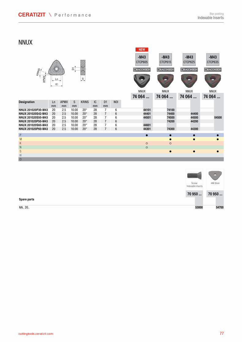
77cuttingtools.ceratizit.com
NEW
D1
S
KRIN
S
APM
X
Ln
IC
-M43CTCP605
-M43CTCP615
-M43CTCP625
-M43CTCP635
NNUX NNUX NNUX NNUX74 064 ... 74 064 ... 74 064 ... 74 064 ...
Ln APMX S KRINS IC D1 NOI mm mm mm mm mm
NNUX 201020P30-M43 20 20° 28 7 6 7406444101 7406474100NNUX 201020S42-M43 20 20° 28 7 6 7406444401 7406474400 7406444400NNUX 201020S50-M43 20 20° 28 7 6 7406444501 7406474500 7406444500 7406404500NNUX 201020P50-M43 20 20° 28 7 6 7406474200 7406444200NNUX 201020S60-M43 20 20° 28 7 6 7406444601NNUX 201020P60-M43 20 20° 28 7 6 7406444301 7406474300 7406444300
P ● ● ● ●M ● ● ●K ○ ○ N ○ S ● ● ●H O
70 950 ... 70 950 ...
NN.. 20.. 7095053000 7095054700
Bar peelingIndexable Inserts
NNUX
Designation
2.5 10.002.5 10.002.5 10.002.5 10.002.5 10.002.5 10.00
Screw Indexable inserts
HM-Shim
Spare parts
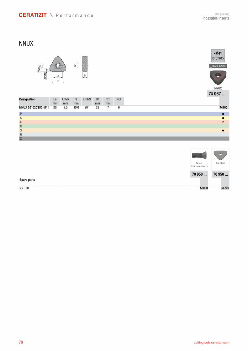
78 cuttingtools.ceratizit.com
D1S
KRIN
S
APM
X
Ln
IC
-M41CTCP615
NNUX74 067 ...
Ln APMX S KRINS IC D1 NOI mm mm mm mm mm
NNUX 201020S50-M41 20 20° 28 7 6 7406774100
P ●M ●K ○N S ●H O
70 950 ... 70 950 ...
NN.. 20.. 7095053000 7095054700
Bar peelingIndexable Inserts
NNUX
Designation
2.5 10.0
Screw Indexable inserts
HM-Shim
Spare parts
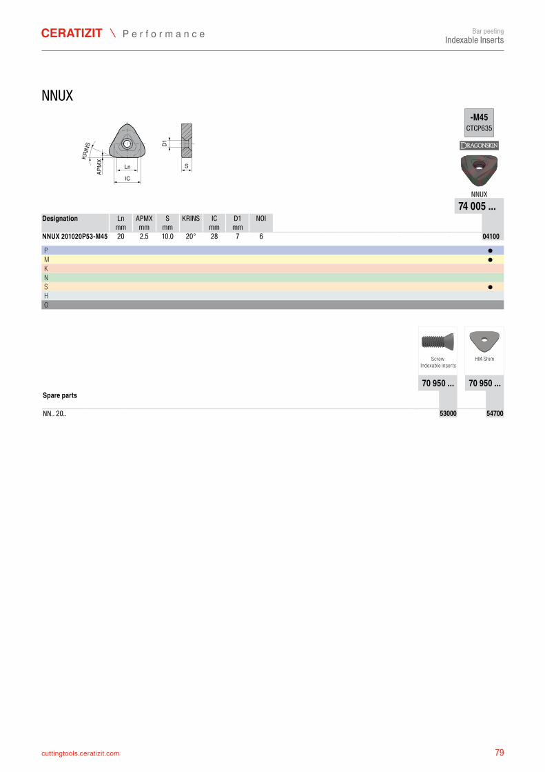
79cuttingtools.ceratizit.com
D1S
KRIN
S
APM
X
Ln
IC
-M45CTCP635
NNUX74 005 ...
Ln APMX S KRINS IC D1 NOI mm mm mm mm mm
NNUX 201020P53-M45 20 20° 28 7 6 7400504100
P ●M ●K N S ●H O
70 950 ... 70 950 ...
NN.. 20.. 7095053000 7095054700
Bar peelingIndexable Inserts
NNUX
Designation
2.5 10.0
Screw Indexable inserts
HM-Shim
Spare parts
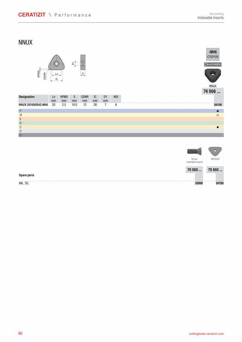
80 cuttingtools.ceratizit.com
D1S
CEM
R
APM
X
Ln
IC
-M46CTCP125
NNUX74 006 ...
Ln APMX S CEMR IC D1 NOI mm mm mm mm mm mm
NNUX 201000S42-M46 20 12 28 7 6 7400664100
P ●M ○K N S ●H O
70 950 ... 70 950 ...
NN.. 20.. 7095053000 7095054700
Bar peelingIndexable Inserts
NNUX
Designation
2.5 10.0
Screw Indexable inserts
HM-Shim
Spare parts
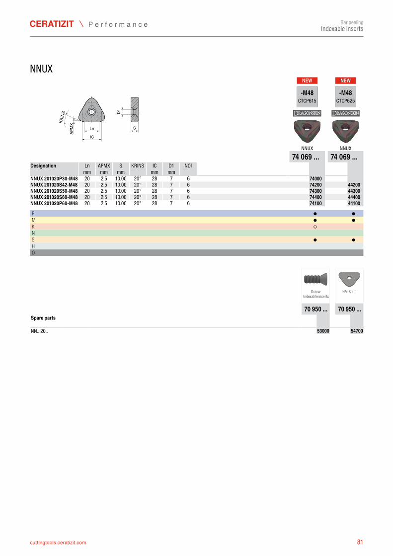
81cuttingtools.ceratizit.com
NEW NEW
D1
S
KRIN
S
APM
X
Ln
IC
-M48CTCP615
-M48CTCP625
NNUX NNUX74 069 ... 74 069 ...
Ln APMX S KRINS IC D1 NOI mm mm mm mm mm
NNUX 201020P30-M48 20 20° 28 7 6 7406974000NNUX 201020S42-M48 20 20° 28 7 6 7406974200 7406944200NNUX 201020S50-M48 20 20° 28 7 6 7406974300 7406944300NNUX 201020S60-M48 20 20° 28 7 6 7406974400 7406944400NNUX 201020P60-M48 20 20° 28 7 6 7406974100 7406944100
P ● ●M ● ●K ○ N S ● ●H O
70 950 ... 70 950 ...
NN.. 20.. 7095053000 7095054700
Bar peelingIndexable Inserts
NNUX
Designation
2.5 10.002.5 10.002.5 10.002.5 10.002.5 10.00
Screw Indexable inserts
HM-Shim
Spare parts
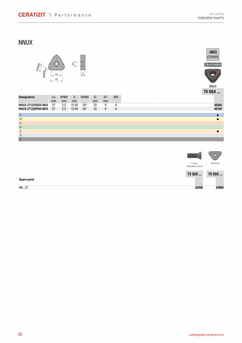
82 cuttingtools.ceratizit.com
D1S
KRIN
S
APM
X
Ln
IC
-M43CTCP625
NNUX74 064 ...
Ln APMX S KRINS IC D1 NOI mm mm mm mm mm
NNUX 271220S50-M43 27 20° 32 9 6 7406446200NNUX 271220P60-M43 27 20° 32 9 6 7406446100
P ●M ●K N S ●H O
70 950 ... 70 950 ...
NN.. 27.. 7095052200 7095054800
Bar peelingIndexable Inserts
NNUX
Designation
2.5 12.00 2.5 12.00
Screw Indexable inserts
HM-Shim
Spare parts
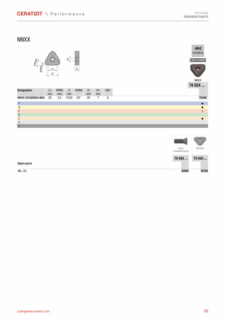
83cuttingtools.ceratizit.com
D1S
KRIN
S
APM
X
Ln
IC
-M40CTCP615
NNXX74 024 ...
Ln APMX S KRINS IC D1 NOI mm mm mm mm mm
NNXX 201020S50-M40 20 20° 28 7 6 7402472100
P ●M ●K ○N S ●H O
70 950 ... 70 950 ...
NN.. 20.. 7095053000 7095054700
Bar peelingIndexable Inserts
NNXX
Designation
2.5 10.00
Screw Indexable inserts
HM-Shim
Spare parts
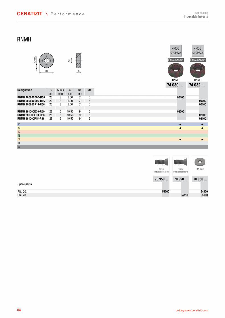
84 cuttingtools.ceratizit.com
ICD1
S
APM
X
-R50CTCP635
-R56CTCP635
RNMH RNMH74 030 ... 74 032 ...
IC APMX S D1 NOI mm mm mm mm
RNMH 200800E00-R50 20 3 7 5 7403000100RNMH 200800E00-R56 20 3 7 5 7403200000RNMH 200800P15-R56 20 3 7 5 7403200100 RNMH 281000E00-R50 28 5 9 5 7403002200RNMH 281000E00-R56 28 5 9 5 7403202000RNMH 281000P15-R56 28 5 9 5 7403202100
P ● ●M ● ●K N S ● ●H O
70 950 ... 70 950 ... 70 950 ...
RN.. 20.. 7095053000 7095054900RN.. 28.. 7095052200 7095055000
Bar peelingIndexable Inserts
RNMH
Designation
8.008.008.00
10.5010.5010.50
Screw Indexable inserts
Screw Indexable inserts
HM-Shim
Spare parts
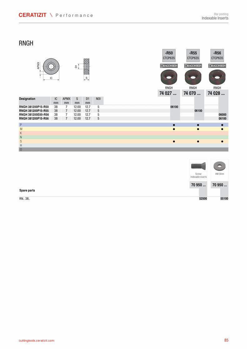
85cuttingtools.ceratizit.com
ICD1
S
APM
X
-R50CTCP635
-R55CTCP635
-R56CTCP635
RNGH RNGH RNGH74 027 ... 74 070 ... 74 028 ...
IC APMX S D1 NOI mm mm mm mm
RNGH 381200P15-R50 38 7 5 7402706100RNGH 381200P15-R55 38 7 5 7407006100RNGH 381200E00-R56 38 7 5 7402806000RNGH 381200P15-R56 38 7 5 7402806100
P ● ● ●M ● ● ●K N S ● ● ●H O
70 950 ... 70 950 ...
RN.. 38.. 7095052500 7095055100
Bar peelingIndexable Inserts
RNGH
Designation
12.00 12.712.00 12.712.00 12.712.00 12.7
Screw Indexable inserts
HM-Shim
Spare parts
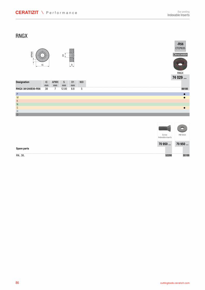
86 cuttingtools.ceratizit.com
ICD1
S
APM
X
-R56CTCP635
RNGX74 029 ...
IC APMX S D1 NOI mm mm mm mm
RNGX 381200E00-R56 38 7 5 7402906100
P ●M ●K N S ●H O
70 950 ... 70 950 ...
RN.. 38.. 7095052200 7095055100
Bar peelingIndexable Inserts
RNGX
Designation
12.00 8.8
Screw Indexable inserts
HM-Shim
Spare parts
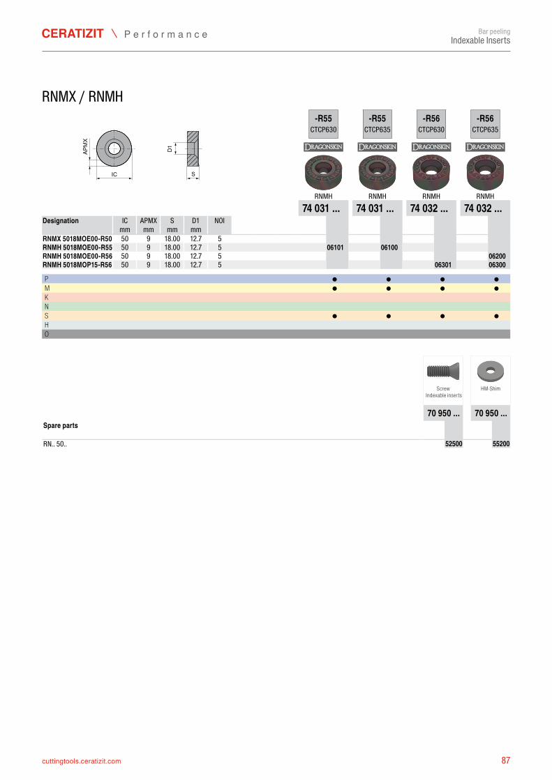
87cuttingtools.ceratizit.com
ICD1
S
APM
X
-R55CTCP630
-R55CTCP635
-R56CTCP630
-R56CTCP635
RNMH RNMH RNMH RNMH74 031 ... 74 031 ... 74 032 ... 74 032 ...
IC APMX S D1 NOI mm mm mm mm
RNMX 5018MOE00-R50 50 9 5RNMH 5018MOE00-R55 50 9 5 7403106101 7403106100RNMH 5018MOE00-R56 50 9 5 7403206200RNMH 5018MOP15-R56 50 9 5 7403206301 7403206300
P ● ● ● ●M ● ● ● ●K N S ● ● ● ●H O
70 950 ... 70 950 ...
RN.. 50.. 7095052500 7095055200
Bar peelingIndexable Inserts
RNMX / RNMH
Designation
18.00 12.718.00 12.718.00 12.718.00 12.7
Screw Indexable inserts
HM-Shim
Spare parts
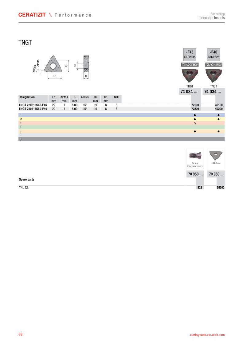
88 cuttingtools.ceratizit.com
KRIN
S
SD1IC
Ln
APM
X
-F46CTCP615
-F46CTCP625
TNGT TNGT74 034 ... 74 034 ...
Ln APMX S KRINS IC D1 NOI mm mm mm mm mm
TNGT 220815S42-F46 22 1 15° 19 8 3 7403472100 7403442100TNGT 220815S50-F46 22 1 15° 19 8 3 7403472200 7403442200
P ● ●M ● ●K ○ N S ● ●H O
70 950 ... 70 950 ...
TN.. 22.. 70950822 7095055300
Bar peelingIndexable Inserts
TNGT
Designation
8.008.00
Screw Indexable inserts
HM-Shim
Spare parts
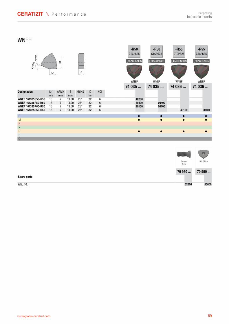
89cuttingtools.ceratizit.com
Ln S
IC
KRIN
SAP
MX
-R50CTCP625
-R50CTCP635
-R55CTCP625
-R55CTCP635
WNEF WNEF WNEF WNEF74 035 ... 74 035 ... 74 036 ... 74 036 ...
Ln APMX S KRINS IC NOI mm mm mm mm
WNEF 161325S50-R50 16 7 25° 32 6 7403540200WNEF 161325P50-R50 16 7 25° 32 6 7403540400 7403500400WNEF 161325P60-R50 16 7 25° 32 6 7403540100 7403500100WNEF 161325S50-R55 16 7 25° 32 6 7403640100 7403600100
P ● ● ● ●M ● ● ● ●K N S ● ● ● ●H O
70 950 ... 70 950 ...
WN.. 16.. 7095052600 7095055600
Bar peelingIndexable Inserts
WNEF
Designation
13.0013.0013.0013.00
ScrewShim
HM-Shim
Spare parts
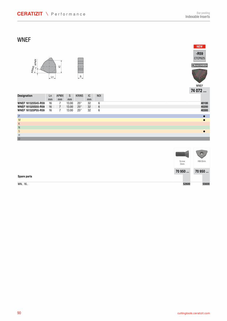
90 cuttingtools.ceratizit.com
NEW
Ln S
IC
KRIN
SAP
MX
-R59CTCP625
WNEF74 072 ...
Ln APMX S KRINS IC NOI mm mm mm mm
WNEF 161325S45-R59 16 7 25° 32 6 7407240100WNEF 161325S55-R59 16 7 25° 32 6 7407240200WNEF 161325P55-R59 16 7 25° 32 6 7407240300
P ●M ●K N S ●H O
70 950 ... 70 950 ...
WN.. 16.. 7095052600 7095055600
Bar peelingIndexable Inserts
WNEF
Designation
13.0013.0013.00
ScrewShim
HM-Shim
Spare parts
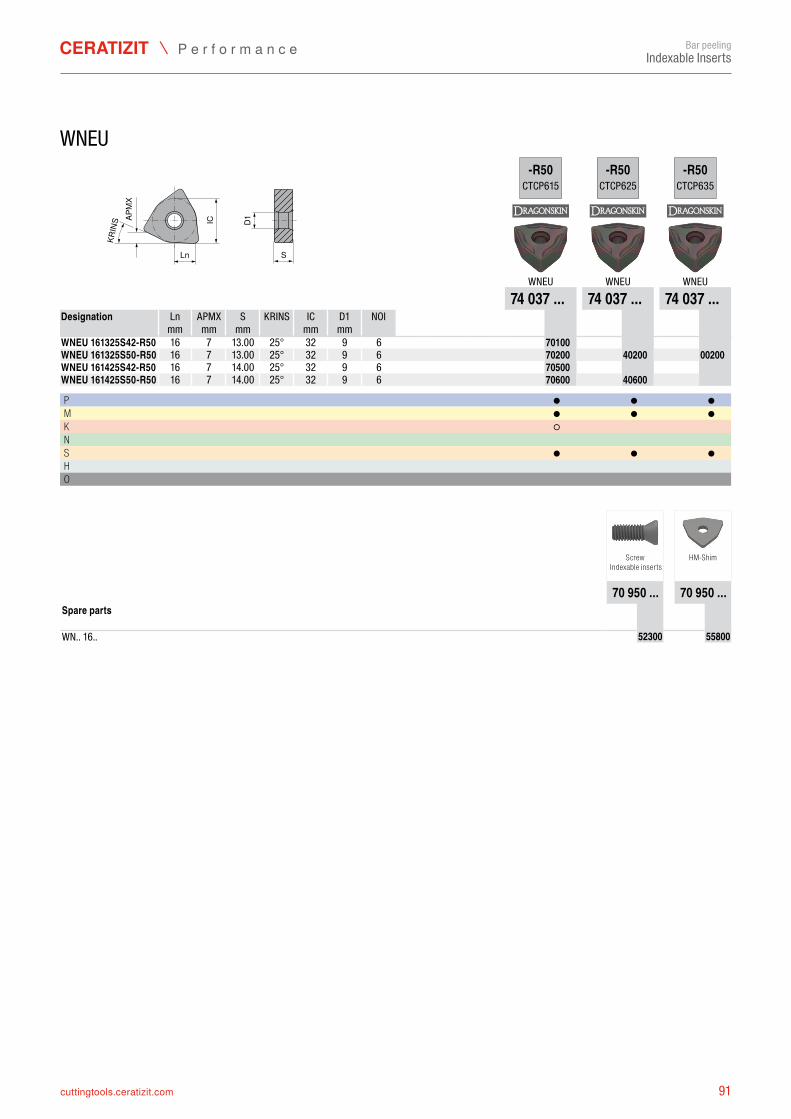
91cuttingtools.ceratizit.com
KRIN
S
S
IC
LnD1AP
MX
-R50CTCP615
-R50CTCP625
-R50CTCP635
WNEU WNEU WNEU74 037 ... 74 037 ... 74 037 ...
Ln APMX S KRINS IC D1 NOI mm mm mm mm mm
WNEU 161325S42-R50 16 7 25° 32 9 6 7403770100WNEU 161325S50-R50 16 7 25° 32 9 6 7403770200 7403740200 7403700200WNEU 161425S42-R50 16 7 25° 32 9 6 7403770500WNEU 161425S50-R50 16 7 25° 32 9 6 7403770600 7403740600
P ● ● ●M ● ● ●K ○ N S ● ● ●H O
70 950 ... 70 950 ...
WN.. 16.. 7095052300 7095055800
Bar peelingIndexable Inserts
WNEU
Designation
13.0013.0014.0014.00
Screw Indexable inserts
HM-Shim
Spare parts
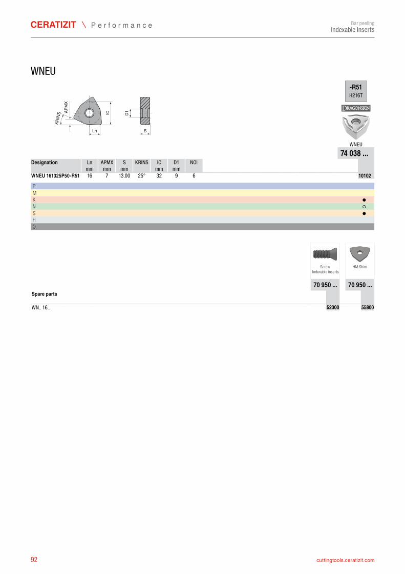
92 cuttingtools.ceratizit.com
KRIN
S
S
IC
LnD1AP
MX
-R51H216T
WNEU74 038 ...
Ln APMX S KRINS IC D1 NOI mm mm mm mm mm
WNEU 161325P50-R51 16 7 25° 32 9 6 7403810102
P M K ●N ○S ●H O
70 950 ... 70 950 ...
WN.. 16.. 7095052300 7095055800
Bar peelingIndexable Inserts
WNEU
Designation
13.00
Screw Indexable inserts
HM-Shim
Spare parts
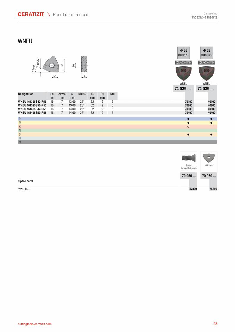
93cuttingtools.ceratizit.com
KRIN
S
S
IC
LnD1AP
MX
-R55CTCP615
-R55CTCP625
WNEU WNEU74 039 ... 74 039 ...
Ln APMX S KRINS IC D1 NOI mm mm mm mm mm
WNEU 161325S42-R55 16 7 25° 32 9 6 7403970100 7403940100WNEU 161325S50-R55 16 7 25° 32 9 6 7403970200 7403940200WNEU 161425S42-R55 16 7 25° 32 9 6 7403970300 7403940300WNEU 161425S50-R55 16 7 25° 32 9 6 7403970400 7403940400
P ● ●M ● ●K ○ N S ● ●H O
70 950 ... 70 950 ...
WN.. 16.. 7095052300 7095055800
Bar peelingIndexable Inserts
WNEU
Designation
13.0013.0014.0014.00
Screw Indexable inserts
HM-Shim
Spare parts
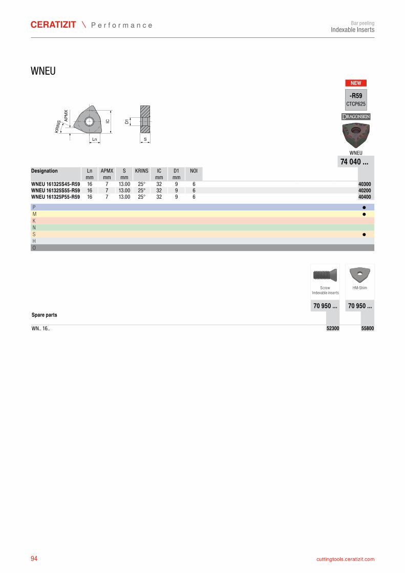
94 cuttingtools.ceratizit.com
NEW
KRIN
S
S
IC
Ln
D1APM
X
-R59CTCP625
WNEU74 040 ...
Ln APMX S KRINS IC D1 NOI mm mm mm mm mm
WNEU 161325S45-R59 16 7 25° 32 9 6 7404040300WNEU 161325S55-R59 16 7 25° 32 9 6 7404040200WNEU 161325P55-R59 16 7 25° 32 9 6 7404040400
P ●M ●K N S ●H O
70 950 ... 70 950 ...
WN.. 16.. 7095052300 7095055800
Bar peelingIndexable Inserts
WNEU
Designation
13.0013.0013.00
Screw Indexable inserts
HM-Shim
Spare parts
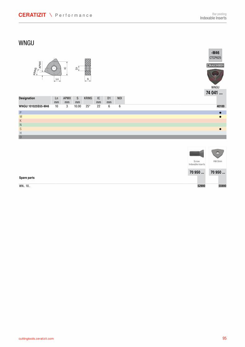
95cuttingtools.ceratizit.com
KRIN
S
S
IC
LnD1AP
MX
-M46CTCP625
WNGU74 041 ...
Ln APMX S KRINS IC D1 NOI mm mm mm mm mm
WNGU 101025S55-M46 10 3 25° 22 6 6 7404140100
P ●M ●K N S ●H O
70 950 ... 70 950 ...
WN.. 10.. 7095052900 7095055900
Bar peelingIndexable Inserts
WNGU
Designation
10.00
Screw Indexable inserts
HM-Shim
Spare parts
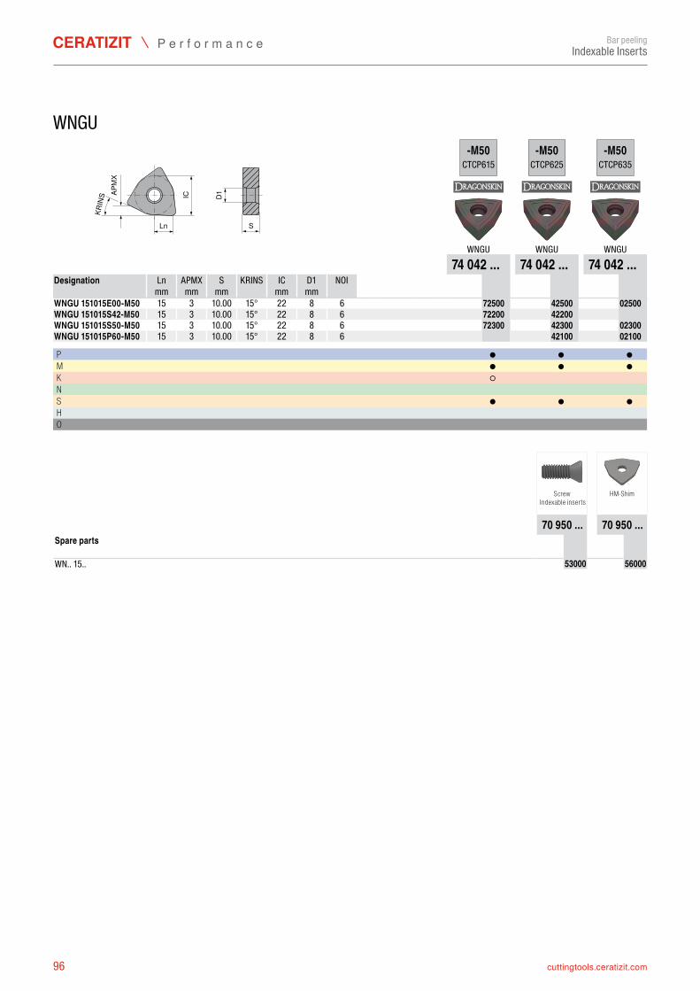
96 cuttingtools.ceratizit.com
KRIN
S
S
IC
LnD1AP
MX
-M50CTCP615
-M50CTCP625
-M50CTCP635
WNGU WNGU WNGU74 042 ... 74 042 ... 74 042 ...
Ln APMX S KRINS IC D1 NOI mm mm mm mm mm
WNGU 151015E00-M50 15 3 15° 22 8 6 7404272500 7404242500 7404202500WNGU 151015S42-M50 15 3 15° 22 8 6 7404272200 7404242200WNGU 151015S50-M50 15 3 15° 22 8 6 7404272300 7404242300 7404202300WNGU 151015P60-M50 15 3 15° 22 8 6 7404242100 7404202100
P ● ● ●M ● ● ●K ○ N S ● ● ●H O
70 950 ... 70 950 ...
WN.. 15.. 7095053000 7095056000
Bar peelingIndexable Inserts
WNGU
Designation
10.0010.0010.0010.00
Screw Indexable inserts
HM-Shim
Spare parts
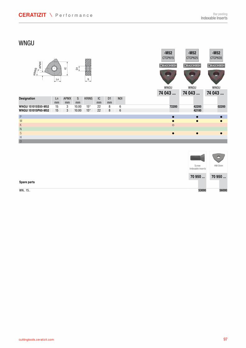
97cuttingtools.ceratizit.com
KRIN
S
S
IC
LnD1AP
MX
-M52CTCP615
-M52CTCP625
-M52CTCP635
WNGU WNGU WNGU74 043 ... 74 043 ... 74 043 ...
Ln APMX S KRINS IC D1 NOI mm mm mm mm mm
WNGU 151015S50-M52 15 3 15° 22 8 6 7404372200 7404342200 7404302200WNGU 151015P60-M52 15 3 15° 22 8 6 7404342100
P ● ● ●M ● ● ●K ○ N S ● ● ●H O
70 950 ... 70 950 ...
WN.. 15.. 7095053000 7095056000
Bar peelingIndexable Inserts
WNGU
Designation
10.0010.00
Screw Indexable inserts
HM-Shim
Spare parts
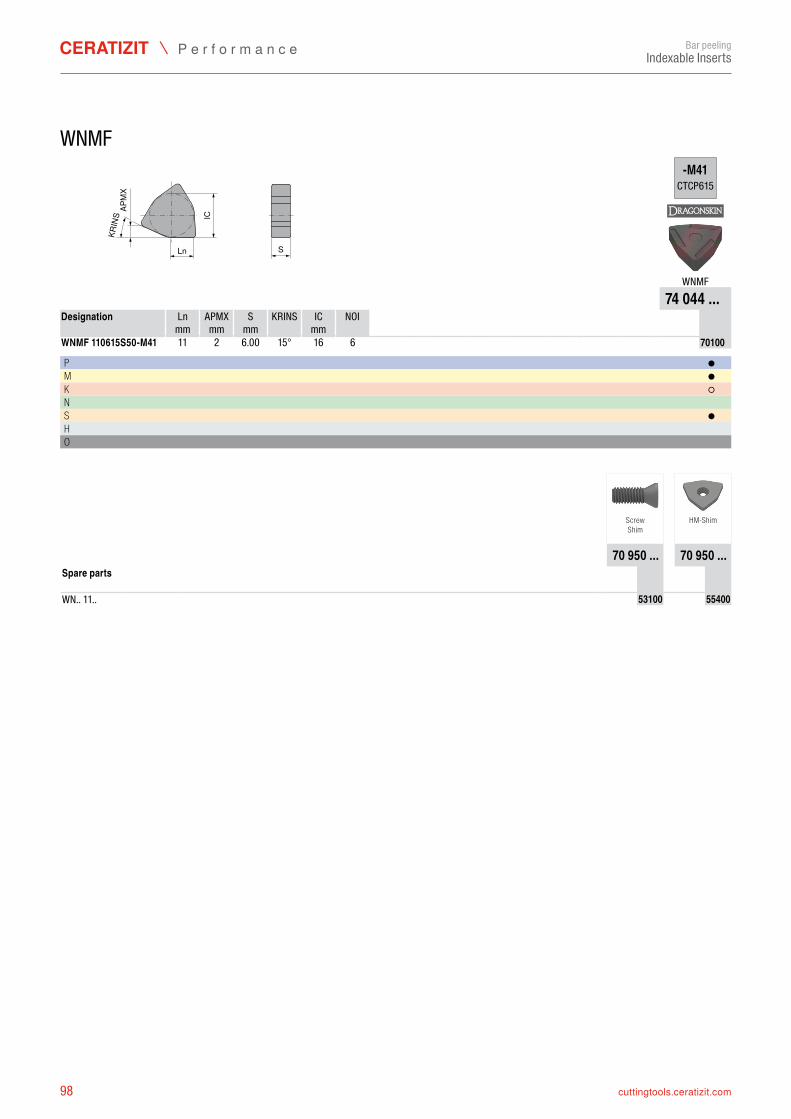
98 cuttingtools.ceratizit.com
Ln S
IC
KRIN
SAP
MX
-M41CTCP615
WNMF74 044 ...
Ln APMX S KRINS IC NOI mm mm mm mm
WNMF 110615S50-M41 11 2 15° 16 6 7404470100
P ●M ●K ○N S ●H O
70 950 ... 70 950 ...
WN.. 11.. 7095053100 7095055400
Bar peelingIndexable Inserts
WNMF
Designation
6.00
ScrewShim
HM-Shim
Spare parts
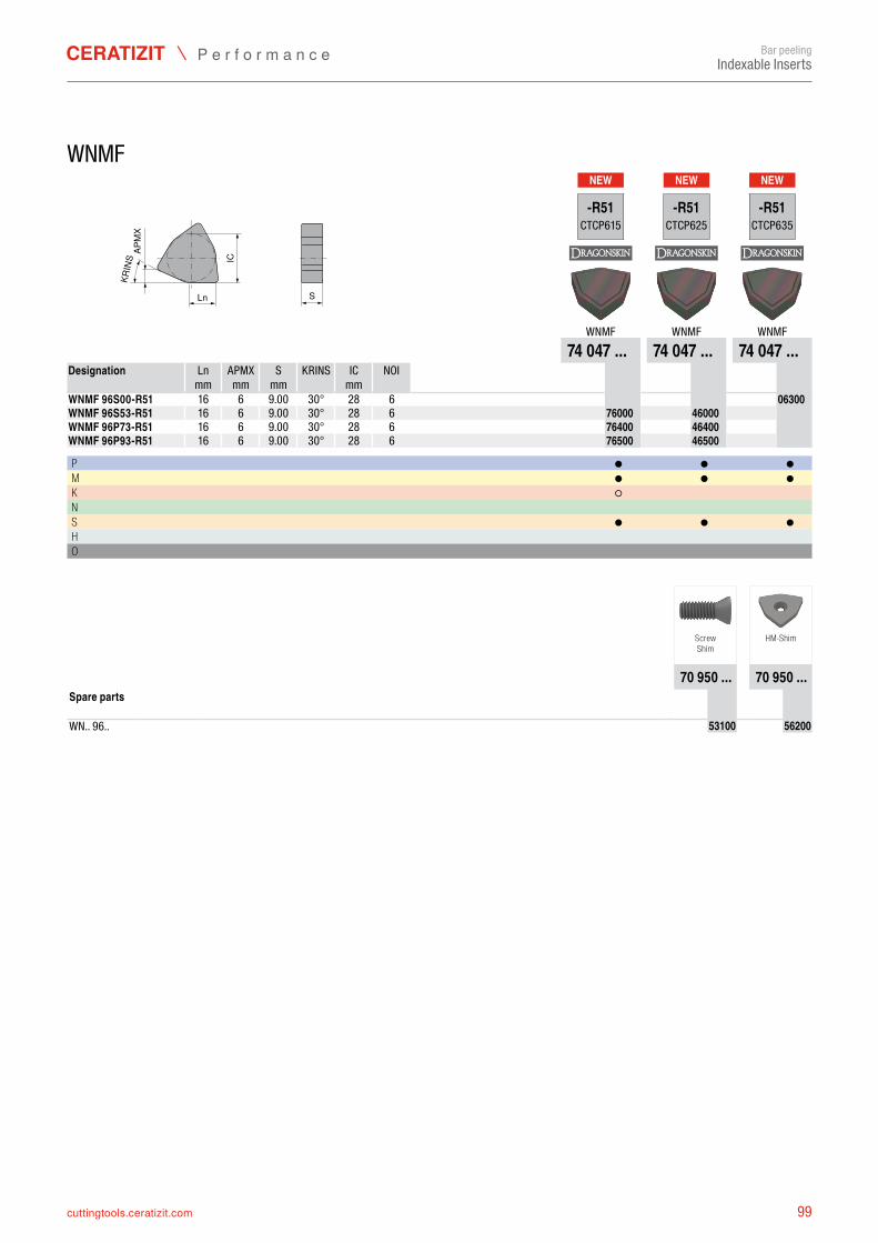
99cuttingtools.ceratizit.com
NEW NEW NEW
Ln S
IC
KRIN
SAP
MX
-R51CTCP615
-R51CTCP625
-R51CTCP635
WNMF WNMF WNMF74 047 ... 74 047 ... 74 047 ...
Ln APMX S KRINS IC NOI mm mm mm mm
WNMF 96S00-R51 16 6 30° 28 6 7404706300WNMF 96S53-R51 16 6 30° 28 6 7404776000 7404746000WNMF 96P73-R51 16 6 30° 28 6 7404776400 7404746400WNMF 96P93-R51 16 6 30° 28 6 7404776500 7404746500
P ● ● ●M ● ● ●K ○ N S ● ● ●H O
70 950 ... 70 950 ...
WN.. 96.. 7095053100 7095056200
Bar peelingIndexable Inserts
WNMF
Designation
9.009.009.009.00
ScrewShim
HM-Shim
Spare parts
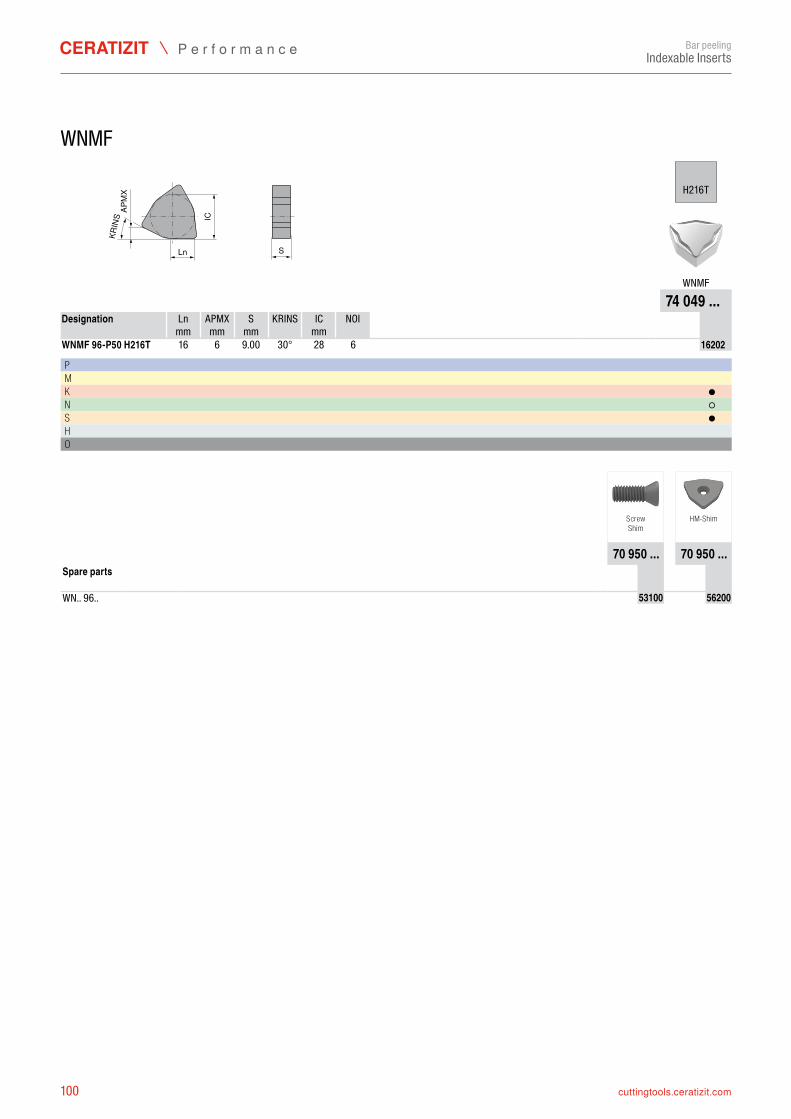
100 cuttingtools.ceratizit.com
Ln S
IC
KRIN
SAP
MX
H216T
WNMF
74 049 ...Ln APMX S KRINS IC NOI
mm mm mm mmWNMF 96-P50 H216T 16 6 30° 28 6 7404916202
P M K ●N ○S ●H O
70 950 ... 70 950 ...
WN.. 96.. 7095053100 7095056200
Bar peelingIndexable Inserts
WNMF
Designation
9.00
ScrewShim
HM-Shim
Spare parts
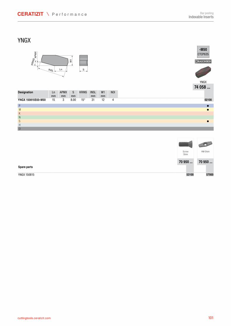
101cuttingtools.ceratizit.com
KRIN
S
lNSL SW
1Ln
APM
X
-M50CTCP635
YNGX74 058 ...
Ln APMX S KRINS INSL W1 NOI mm mm mm mm mm
YNGX 150815S50-M50 15 3 15° 31 12 4 7405802100
P ●M ●K N S ●H O
70 950 ... 70 950 ...
YNGX 150815 7095053100 7095057000
Bar peelingIndexable Inserts
YNGX
Designation
8.00
ScrewShim
HM-Shim
Spare parts
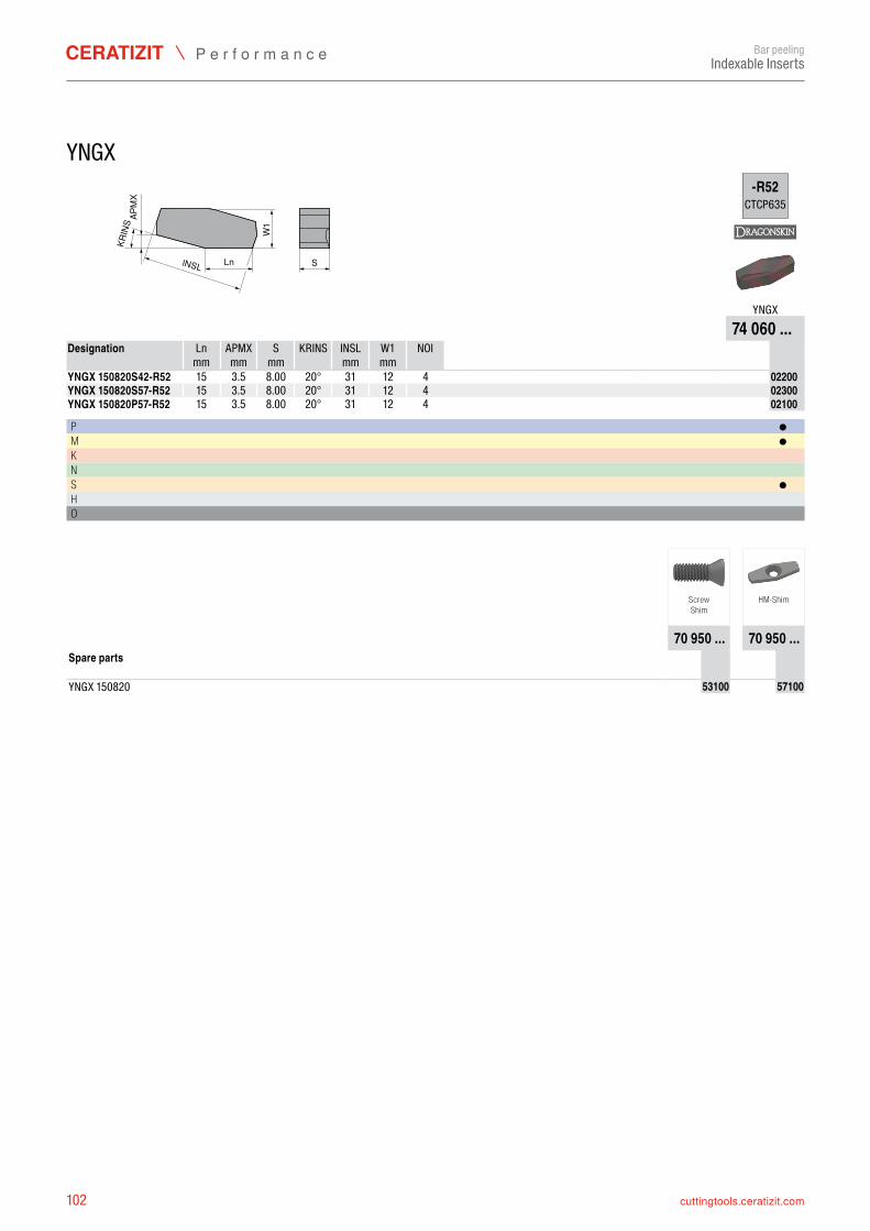
102 cuttingtools.ceratizit.com
KRIN
S
lNSL SW
1Ln
APM
X
-R52CTCP635
YNGX74 060 ...
Ln APMX S KRINS INSL W1 NOI mm mm mm mm mm
YNGX 150820S42-R52 15 20° 31 12 4 7406002200YNGX 150820S57-R52 15 20° 31 12 4 7406002300YNGX 150820P57-R52 15 20° 31 12 4 7406002100
P ●M ●K N S ●H O
70 950 ... 70 950 ...
YNGX 150820 7095053100 7095057100
Bar peelingIndexable Inserts
YNGX
Designation
3.5 8.003.5 8.003.5 8.00
ScrewShim
HM-Shim
Spare parts
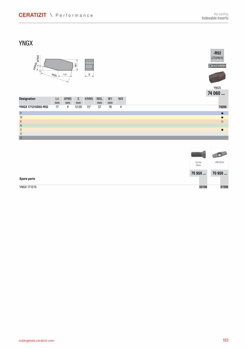
103cuttingtools.ceratizit.com
KRIN
S
lNSL SW
1Ln
APM
X
-R52CTCP615
YNGX74 060 ...
Ln APMX S KRINS INSL W1 NOI mm mm mm mm mm
YNGX 171215S55-R52 17 4 15° 37 18 4 7406074200
P ●M ●K ○N S ●H O
70 950 ... 70 950 ...
YNGX 171215 7095053100 7095057200
Bar peelingIndexable Inserts
YNGX
Designation
12.00
ScrewShim
HM-Shim
Spare parts
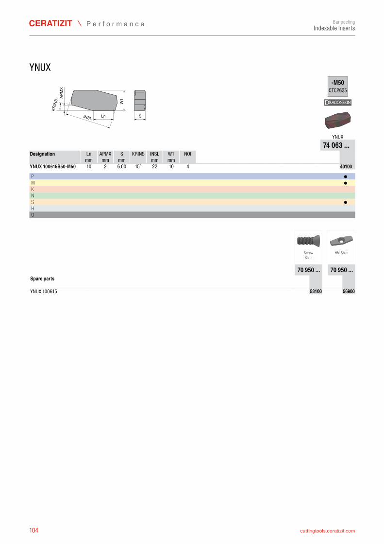
104 cuttingtools.ceratizit.com
SW
1lNSL
KRIN
S
Ln
APM
X
-M50CTCP625
YNUX74 063 ...
Ln APMX S KRINS INSL W1 NOI mm mm mm mm mm
YNUX 100615S50-M50 10 2 15° 22 10 4 7406340100
P ●M ●K N S ●H O
70 950 ... 70 950 ...
YNUX 100615 7095053100 7095056900
Bar peelingIndexable Inserts
YNUX
Designation
6.00
ScrewShim
HM-Shim
Spare parts
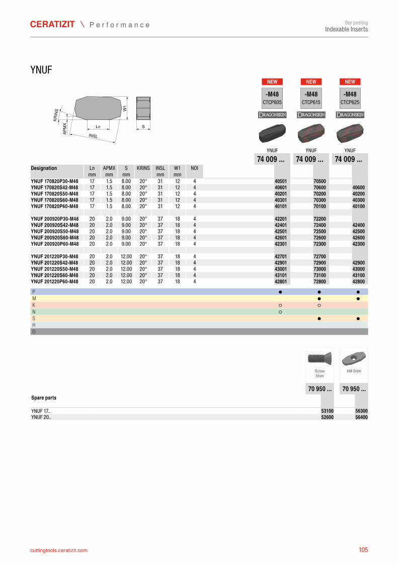
105cuttingtools.ceratizit.com
NEW NEW NEW
Ln SW
1
INSL
KRIN
S
APM
X
-M48CTCP605
-M48CTCP615
-M48CTCP625
YNUF YNUF YNUF74 009 ... 74 009 ... 74 009 ...
Ln APMX S KRINS INSL W1 NOI mm mm mm mm mm
YNUF 170820P30-M48 17 20° 31 12 4 7400940501 7400970500YNUF 170820S42-M48 17 20° 31 12 4 7400940601 7400970600 7400940600YNUF 170820S50-M48 17 20° 31 12 4 7400940201 7400970200 7400940200YNUF 170820S60-M48 17 20° 31 12 4 7400940301 7400970300 7400940300YNUF 170820P60-M48 17 20° 31 12 4 7400940101 7400970100 7400940100 YNUF 200920P30-M48 20 20° 37 18 4 7400942201 7400972200YNUF 200920S42-M48 20 20° 37 18 4 7400942401 7400972400 7400942400YNUF 200920S50-M48 20 20° 37 18 4 7400942501 7400972500 7400942500YNUF 200920S60-M48 20 20° 37 18 4 7400942601 7400972600 7400942600YNUF 200920P60-M48 20 20° 37 18 4 7400942301 7400972300 7400942300 YNUF 201220P30-M48 20 20° 37 18 4 7400942701 7400972700YNUF 201220S42-M48 20 20° 37 18 4 7400942901 7400972900 7400942900YNUF 201220S50-M48 20 20° 37 18 4 7400943001 7400973000 7400943000YNUF 201220S60-M48 20 20° 37 18 4 7400943101 7400973100 7400943100YNUF 201220P60-M48 20 20° 37 18 4 7400942801 7400972800 7400942800
P ● ● ●M ● ●K ○ ○ N ○ S ● ●H O
70 950 ... 70 950 ...
YNUF 17.. 7095053100 7095056300YNUF 20.. 7095052600 7095056400
Bar peelingIndexable Inserts
YNUF
Designation
1.5 8.001.5 8.001.5 8.001.5 8.001.5 8.00
2.0 9.002.0 9.002.0 9.002.0 9.002.0 9.00
2.0 12.002.0 12.002.0 12.002.0 12.002.0 12.00
ScrewShim
HM-Shim
Spare parts
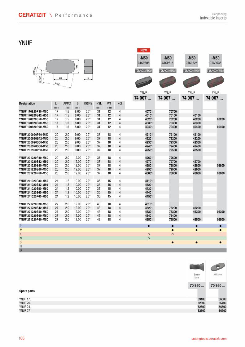
106 cuttingtools.ceratizit.com
NEW
Ln SW
1
INSL
KRIN
S
APM
X
-M50CTCP605
-M50CTCP615
-M50CTCP625
-M50CTCP635
YNUF YNUF YNUF YNUF74 007 ... 74 007 ... 74 007 ... 74 007 ...
Ln APMX S KRINS INSL W1 NOI mm mm mm mm mm
YNUF 170820P30-M50 17 20° 31 12 4 7400740701 7400770700YNUF 170820S42-M50 17 20° 31 12 4 7400740101 7400770100 7400740100YNUF 170820S50-M50 17 20° 31 12 4 7400740201 7400770200 7400740200 7400700200YNUF 170820S60-M50 17 20° 31 12 4 7400740301 7400770300 7400740300YNUF 170820P60-M50 17 20° 31 12 4 7400740401 7400770400 7400740400 7400700400 YNUF 200920P30-M50 20 20° 37 18 4 7400742101 7400772100 7400742100YNUF 200920S42-M50 20 20° 37 18 4 7400742201 7400772200 7400742200YNUF 200920S50-M50 20 20° 37 18 4 7400742301 7400772300 7400742300YNUF 200920S60-M50 20 20° 37 18 4 7400742401 7400772400 7400742400YNUF 200920P60-M50 20 20° 37 18 4 7400742501 7400772500 7400742500 YNUF 201220P30-M50 20 20° 37 18 4 7400742601 7400772600YNUF 201220S42-M50 20 20° 37 18 4 7400742701 7400772700 7400742700YNUF 201220S50-M50 20 20° 37 18 4 7400742801 7400772800 7400742800 7400702800YNUF 201220S60-M50 20 20° 37 18 4 7400742901 7400772900 7400742900YNUF 201220P60-M50 20 20° 37 18 4 7400743001 7400773000 7400743000 7400703000 YNUF 241020P30-M50 24 20° 35 15 4 7400744101YNUF 241020S42-M50 24 20° 35 15 4 7400744201YNUF 241020S50-M50 24 20° 35 15 4 7400744301YNUF 241020S60-M50 24 20° 35 15 4 7400744401YNUF 241020P60-M50 24 20° 35 15 4 7400744501 YNUF 271220P30-M50 27 20° 43 18 4 7400746101YNUF 271220S42-M50 27 20° 43 18 4 7400746201 7400776200 7400746200YNUF 271220S50-M50 27 20° 43 18 4 7400746301 7400776300 7400746300 7400706300YNUF 271220S60-M50 27 20° 43 18 4 7400746401 7400776400YNUF 271220P60-M50 27 20° 43 18 4 7400746501 7400776500 7400746500 7400706500
P ● ● ● ●M ● ● ●K ○ ○ N ○ S ● ● ●H O
70 950 ... 70 950 ...
YNUF 17.. 7095053100 7095056300YNUF 20.. 7095052600 7095056400YNUF 24.. 7095052600 7095056600YNUF 27.. 7095052600 7095056700
Bar peelingIndexable Inserts
YNUF
Designation
1.5 8.001.5 8.001.5 8.001.5 8.001.5 8.00
2.0 9.002.0 9.002.0 9.002.0 9.002.0 9.00
2.0 12.002.0 12.002.0 12.002.0 12.002.0 12.00
1.2 10.001.2 10.001.2 10.001.2 10.001.2 10.00
2.0 12.002.0 12.002.0 12.002.0 12.002.0 12.00
ScrewShim
HM-Shim
Spare parts
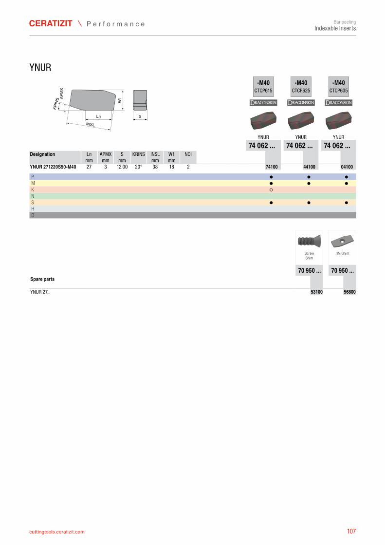
107cuttingtools.ceratizit.com
W1
lNSL
KRIN
S
SLn
APM
X
-M40CTCP615
-M40CTCP625
-M40CTCP635
YNUR YNUR YNUR74 062 ... 74 062 ... 74 062 ...
Ln APMX S KRINS INSL W1 NOI mm mm mm mm mm
YNUR 271220S50-M40 27 3 20° 38 18 2 7406274100 7406244100 7406204100
P ● ● ●M ● ● ●K ○ N S ● ● ●H O
70 950 ... 70 950 ...
YNUR 27.. 7095053100 7095056800
Bar peelingIndexable Inserts
YNUR
Designation
12.00
ScrewShim
HM-Shim
Spare parts
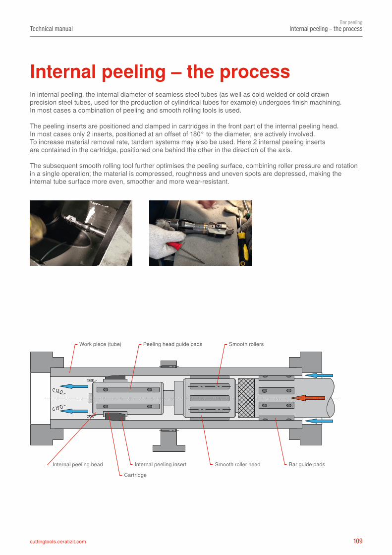
109cuttingtools.ceratizit.com
Technical manualBar peeling
Internal peeling – the process
Internal peeling – the processIn internal peeling, the internal diameter of seamless steel tubes (as well as cold welded or cold drawn precision steel tubes, used for the production of cylindrical tubes for example) undergoes finish machining.In most cases a combination of peeling and smooth rolling tools is used.
The peeling inserts are positioned and clamped in cartridges in the front part of the internal peeling head. In most cases only 2 inserts, positioned at an offset of 180° to the diameter, are actively involved.To increase material removal rate, tandem systems may also be used. Here 2 internal peeling inserts are contained in the cartridge, positioned one behind the other in the direction of the axis.
The subsequent smooth rolling tool further optimises the peeling surface, combining roller pressure and rotation in a single operation; the material is compressed, roughness and uneven spots are depressed, making the internal tube surface more even, smoother and more wear-resistant.
Internal peeling insert
Cartridge
Peeling head guide padsWork piece (tube)
Internal peeling head
Smooth rollers
Smooth roller head Bar guide pads
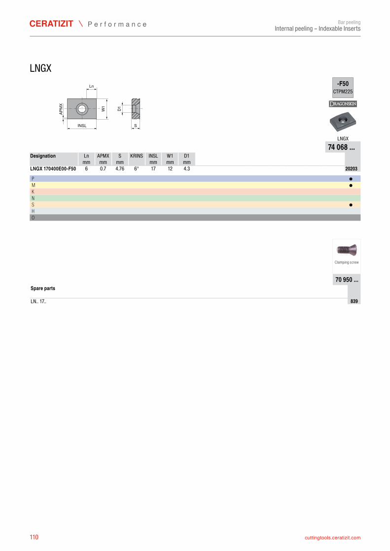
110 cuttingtools.ceratizit.com
SlNSL
W1
D1
Ln
APM
X
-F50CTPM225
LNGX74 068 ...
Ln APMX S KRINS INSL W1 D1 mm mm mm mm mm mm
LNGX 170400E00-F50 6 6° 17 12 7406820203
P ●M ●K N S ●H O
70 950 ...
LN.. 17.. 70950839
Bar peelingInternal peeling – Indexable Inserts
LNGX
Designation
0.7 4.76 4.3
Clamping screw
Spare parts
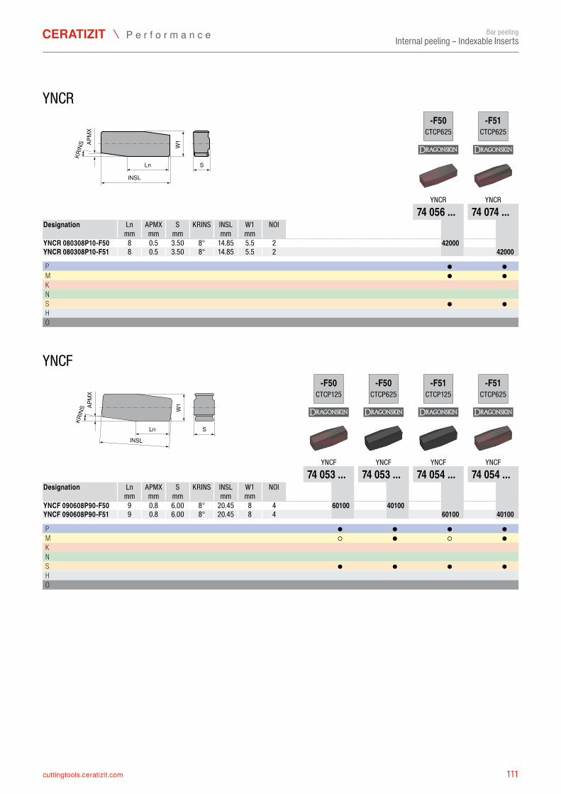
111cuttingtools.ceratizit.com
KRIN
S W1
S
lNSL
Ln
APM
X
-F50CTCP625
-F51CTCP625
YNCR YNCR74 056 ... 74 074 ...
Ln APMX S KRINS INSL W1 NOI mm mm mm mm mm
YNCR 080308P10-F50 8 2 7405642000YNCR 080308P10-F51 8 2 7407442000
P ● ●M ● ●K N S ● ●H O
KRIN
S
lNSL
S
W1
Ln
APM
X
-F50CTCP125
-F50CTCP625
-F51CTCP125
-F51CTCP625
YNCF YNCF YNCF YNCF74 053 ... 74 053 ... 74 054 ... 74 054 ...
Ln APMX S KRINS INSL W1 NOI mm mm mm mm mm
YNCF 090608P90-F50 9 8 4 7405360100 7405340100YNCF 090608P90-F51 9 8 4 7405460100 7405440100
P ● ● ● ●M ○ ● ○ ●K N S ● ● ● ●H O
Bar peelingInternal peeling – Indexable Inserts
YNCR
Designation
0.5 3.50 8° 14.85 5.50.5 3.50 8° 14.85 5.5
YNCF
Designation
0.8 6.00 8° 20.450.8 6.00 8° 20.45
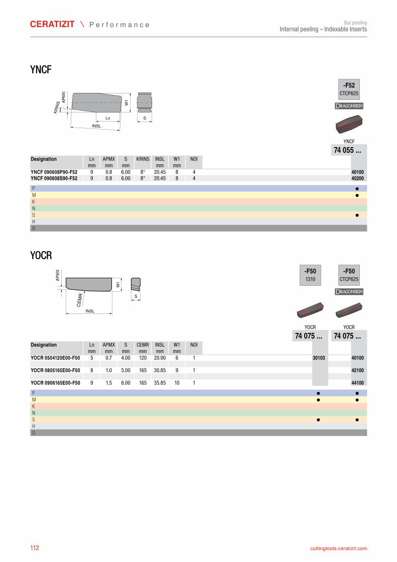
112 cuttingtools.ceratizit.com
YNCFKR
INS
lNSL
S
W1
Ln
APM
X
-F52CTCP625
YNCF74 055 ...
Ln APMX S KRINS INSL W1 NOI mm mm mm mm mm
YNCF 090608P90-F52 9 8 4 7405540100YNCF 090608S90-F52 9 8 4 7405540200
P ●M ●K N S ●H O
YOCR
S
W1
lNSL
CEM
R
APM
X -F501310
-F50CTCP625
YOCR YOCR74 075 ... 74 075 ...
Ln APMX S CEMR INSL W1 NOI mm mm mm mm mm mm
YOCR 0504120E00-F50 5 6 1 7407530103 7407540100 YOCR 0805165E00-F50 8 9 1 7407542100 YOCR 0906165E00-F50 9 10 1 7407544100
P ● ●M ● ●K N S ● ●H O
Bar peelingInternal peeling – Indexable Inserts
YNCF
Designation
0.8 6.00 8° 20.450.8 6.00 8° 20.45
YOCR
Designation
0.7 4.00 120 20.90
1.0 5.00 165 30.85
1.5 6.00 165 35.85
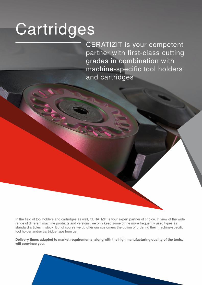
CartridgesCERATIZIT is your competent partner with first-class cutting grades in combination with machine-specific tool holders and cartridges
In the field of tool holders and cartridges as well, CERATIZIT is your expert partner of choice. In view of the wide range of different machine products and versions, we only keep some of the more frequently used types as standard articles in stock. But of course we do offer our customers the option of ordering their machine-specific tool holder and/or cartridge type from us.
Delivery times adapted to market requirements, along with the high manufacturing quality of the tools, will convince you.
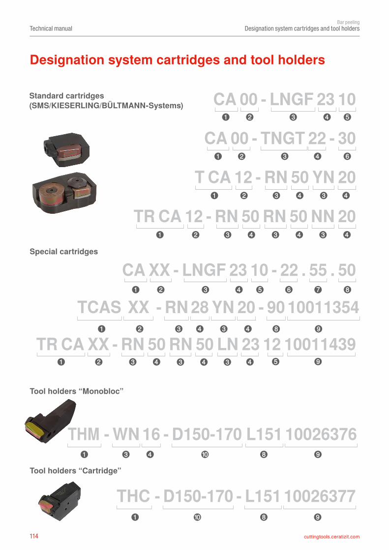
114 cuttingtools.ceratizit.com
CA 00 - LNGF 23 10
TR CA 12 - RN 50 RN 50 NN 20
CA XX - LNGF 23 10 - 22 . 55 . 50
TR CA XX - RN 50 RN 50 LN 23 12 10011439
CA 00 - TNGT 22 - 30
T CA 12 - RN 50 YN 20
THM - WN 16 - D150-170 L151 10026376
THC - D150-170 - L151 10026377
TCAS XX - RN 28 YN 20 - 90 10011354
➍ ➎➊ ➋ ➌
➍➊ ➋ ➌ ➏
➍➊ ➋ ➌ ➌ ➍
➊ ➋ ➌ ➍ ➌ ➍ ➌ ➍
➊ ➋ ➌ ➍ ➎ ➏ ➐ ➑
➊ ➋ ➌ ➍ ➌ ➍ ➑ ➒
➊ ➋ ➌ ➍ ➌ ➍ ➌ ➍ ➎ ➒
➊ ➌ ➍ ➑ ➒
➒➑➊
➓
➓
Technical manualBar peeling
Designation system cartridges and tool holders
Special cartridges
Standard cartridges(SMS/KIESERLING/BÜLTMANN-Systems)
Designation system cartridges and tool holders
Tool holders “Monobloc”
Tool holders “Cartridge”
115cuttingtools.ceratizit.com
➓
CA
TCA
TRCA
TRCAS
THM
THC
00121415XX
LNGFNNUXTNGTWNEFWNEUWNGUYNUFWNHNLNNNRNTNYN
0708091011121516172022232427283850
091012
22
55 50
D150–170
10011345
➊ ➋
➌ ➍ ➎
➏
➐ ➑ ➒
Technical manualBar peeling
Designation system cartridges and tool holders
Cartridges /Tool holders Cartridge definition
Insert seat definition Insert size Insert thicknesses
Cartridge height
Cartridge depth Cartridge length Drawing number
Diameter range tool holder
SINGLE cartridge(1 insert seat)
TANDEM cartridge (2 insert seats)
TRIO cartridge (3 insert seats)
Tool holderMONOBLOC
Tool holderCARTRIGDE
CERATIZIT standard cartridges– for Bültmann and Kieserling
peeling machines– the figures define different
clamping methodsCERATIZIT special cartridges
Insert designation
One part of the insert designation
By analogy with the insert designation system
Definition of different insert thicknesses depending on the insert type
Cartridge height in mmetc.
Cartridge depth in mmetc.
Cartridge length in mmetc.
Ø 150 to 170 mm
CERATIZIT drawing numberetc.
QUICK CLAMPING system
Tools upon request All peeling cartridges except the CA00 standard cartridge are produced upon request.
If you are interested in CERATIZIT peeling cartridges, please send us your enquiry.
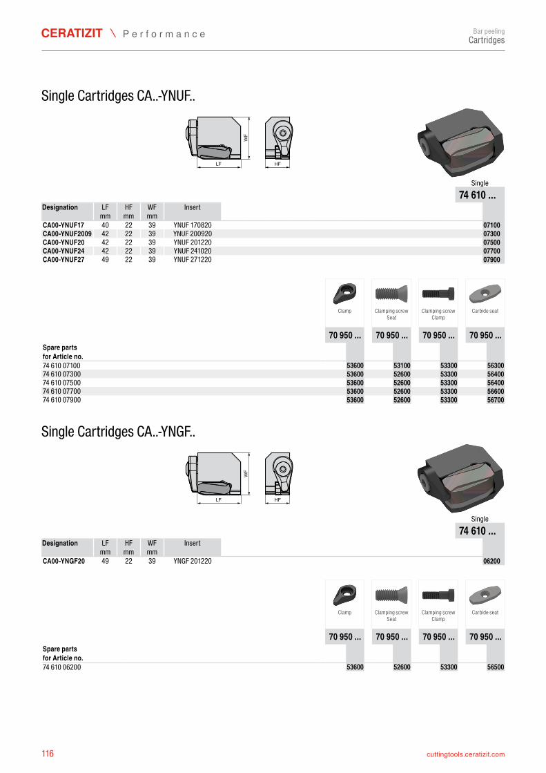
116 cuttingtools.ceratizit.com
LF HF
WF
74 610 ...LF HF WF
mm mm mmCA00-YNUF17 40 22 39 YNUF 170820 7461007100CA00-YNUF2009 42 22 39 YNUF 200920 7461007300CA00-YNUF20 42 22 39 YNUF 201220 7461007500CA00-YNUF24 42 22 39 YNUF 241020 7461007700CA00-YNUF27 49 22 39 YNUF 271220 7461007900
70 950 ... 70 950 ... 70 950 ... 70 950 ...
74 610 07100 7095053600 7095053100 7095053300 709505630074 610 07300 7095053600 7095052600 7095053300 709505640074 610 07500 7095053600 7095052600 7095053300 709505640074 610 07700 7095053600 7095052600 7095053300 709505660074 610 07900 7095053600 7095052600 7095053300 7095056700
LF HF
WF
74 610 ...LF HF WF
mm mm mmCA00-YNGF20 49 22 39 YNGF 201220 7461006200
70 950 ... 70 950 ... 70 950 ... 70 950 ...
74 610 06200 7095053600 7095052600 7095053300 7095056500
Bar peeling
Single Cartridges CA..-YNUF..
Single
Designation Insert
Clamp Clamping screwSeat
Clamping screwClamp
Carbide seat
Spare parts for Article no.
Single Cartridges CA..-YNGF..
Single
Designation Insert
Clamp Clamping screwSeat
Clamping screwClamp
Carbide seat
Spare parts for Article no.
Cartridges
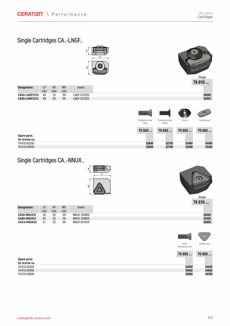
117cuttingtools.ceratizit.com
LF
WF
HF
74 610 ...LF HF WF
mm mm mmCA00-LNGF2310 49 22 39 LNGF 231025 7461000200CA00-LNGF2312 49 22 39 LNGF 231225 7461000400
70 950 ... 70 950 ... 70 950 ... 70 950 ...
74 610 00200 7095052600 7095052700 7095053400 709505440074 610 00400 7095052600 7095052700 7095053400 7095054300
LF
WF
HF
74 610 ...LF HF WF
mm mm mmCA00-NNUX12 42 22 39 NNUX 120800 7461002200CA00-NNUX15 42 22 39 NNUX 150820 7461002400CAXX-NNUX20 51 25 46 NNUX 201020 7461002600
70 950 ... 70 950 ...
74 610 02200 7095053000 709505450074 610 02400 7095053000 709505460074 610 02600 7095053000 7095054700
Bar peeling
Single Cartridges CA..-LNGF..
Single
Designation Insert
Clamping screwSeat
Clamping screwClamp
Clamp Carbide seat
Spare parts for Article no.
Single Cartridges CA..-NNUX..
Single
Designation Insert
InsertClamping screw
Carbide seat
Spare parts for Article no.
Cartridges
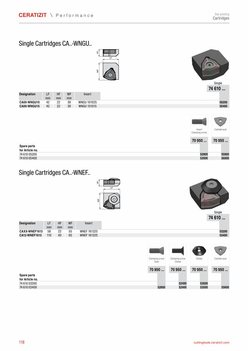
118 cuttingtools.ceratizit.com
LF
WF
HF
74 610 ...LF HF WF
mm mm mmCA00-WNGU10 42 22 39 WNGU 101025 7461005200CA00-WNGU15 42 22 39 WNGU 151015 7461005400
70 950 ... 70 950 ...
74 610 05200 7095052900 709505590074 610 05400 7095053000 7095056000
LF
WF
HF
74 610 ...LF HF WF
mm mm mmCAXX-WNEF1613 58 22 55 WNEF 161325 7461003200CA12-WNEF1613 110 40 65 WNEF 161325 7461003400
70 950 ... 70 950 ... 70 950 ... 70 950 ...
74 610 03200 7095052400 709505350074 610 03400 7095052600 7095052400 7095053500 7095055600
Bar peeling
Single Cartridges CA..-WNGU..
Single
Designation Insert
InsertClamping screw
Carbide seat
Spare parts for Article no.
Single Cartridges CA..-WNEF..
Single
Designation Insert
Clamping screwSeat
Clamping screwClamp
Clamp Carbide seat
Spare parts for Article no.
Cartridges
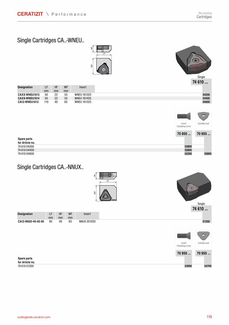
119cuttingtools.ceratizit.com
LF
WF
HF
74 610 ...LF HF WF
mm mm mmCAXX-WNEU1613 50 22 55 WNEU 161325 7461004200CAXX-WNEU1614 50 22 55 WNEU 161425 7461004400CA12-WNEU1613 110 40 65 WNEU 161325 7461004600
70 950 ... 70 950 ...
74 610 04200 709505280074 610 04400 709505280074 610 04600 7095052300 7095055800
LF
WF
HF
74 610 ...LF HF WF
mm mm mmCA12-NN20-40-65-90 90 40 65 NNUX 201020 7461001200
70 950 ... 70 950 ...
74 610 01200 7095053000 7095054700
Bar peeling
Single Cartridges CA..-WNEU..
Single
Designation Insert
InsertClamping screw
Carbide seat
Spare parts for Article no.
Single Cartridges CA..-NNUX..
Single
Designation Insert
InsertClamping screw
Carbide seat
Spare partsfor Article no.
Cartridges
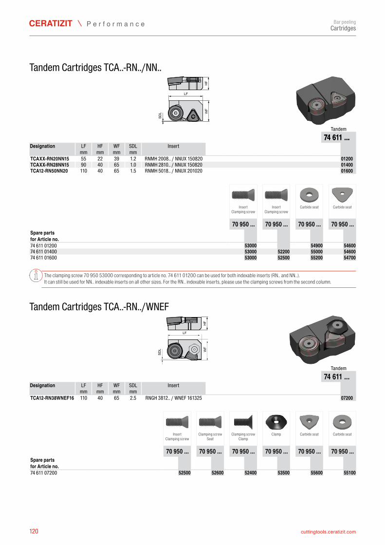
120 cuttingtools.ceratizit.com
WF
LF
HF
SDL
74 611 ...LF HF WF SDL
mm mm mm mmTCAXX-RN20NN15 55 22 39 RNMH 2008.. / NNUX 150820 7461101200TCAXX-RN28NN15 90 40 65 RNMH 2810.. / NNUX 150820 7461101400TCA12-RN50NN20 110 40 65 RNMH 5018.. / NNUX 201020 7461101600
70 950 ... 70 950 ... 70 950 ... 70 950 ...
74 611 01200 7095053000 7095054900 709505460074 611 01400 7095053000 7095052200 7095055000 709505460074 611 01600 7095053000 7095052500 7095055200 7095054700
HF
WF
LF
SDL
74 611 ...LF HF WF SDL
mm mm mm mmTCA12-RN38WNEF16 110 40 65 RNGH 3812.. / WNEF 161325 7461107200
70 950 ... 70 950 ... 70 950 ... 70 950 ... 70 950 ... 70 950 ...
74 611 07200 7095052500 7095052600 7095052400 7095053500 7095055600 7095055100
Bar peeling
Tandem Cartridges TCA..-RN../NN..
Tandem74 611 ...
Designation Insert
1.21.01.5
InsertClamping screw
InsertClamping screw
Carbide seat Carbide seat
Spare parts for Article no.
The clamping screw 70 950 53000 corresponding to article no. 74 611 01200 can be used for both indexable inserts (RN.. and NN..).It can still be used for NN.. indexable inserts on all other sizes. For the RN.. indexable inserts, please use the clamping screws from the second column.
Tandem Cartridges TCA..-RN../WNEF
Tandem
Designation Insert
2.5
InsertClamping screw
Clamping screwSeat
Clamping screwClamp
Clamp Carbide seat Carbide seat
Spare parts for Article no.
Cartridges
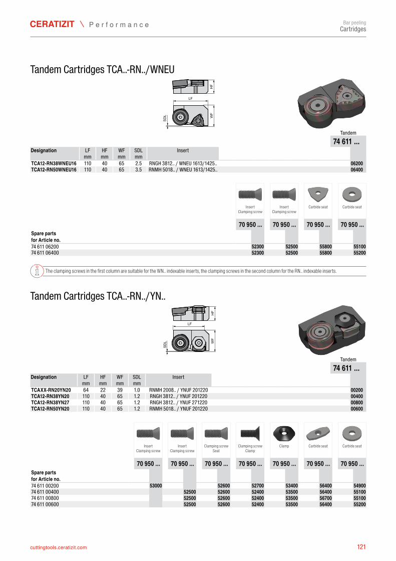
121cuttingtools.ceratizit.com
WF
LF
HF
SDL
74 611 ...LF HF WF SDL
mm mm mm mmTCA12-RN38WNEU16 110 40 65 RNGH 3812.. / WNEU 1613/1425.. 7461106200TCA12-RN50WNEU16 110 40 65 RNMH 5018.. / WNEU 1613/1425.. 7461106400
70 950 ... 70 950 ... 70 950 ... 70 950 ...
74 611 06200 7095052300 7095052500 7095055800 709505510074 611 06400 7095052300 7095052500 7095055800 7095055200
WF
LF
HF
SDL
74 611 ...LF HF WF SDL
mm mm mm mmTCAXX-RN20YN20 64 22 39 RNMH 2008.. / YNUF 201220 7461100200TCA12-RN38YN20 110 40 65 RNGH 3812.. / YNUF 201220 7461100400TCA12-RN38YN27 110 40 65 RNGH 3812.. / YNUF 271220 7461100800TCA12-RN50YN20 110 40 65 RNMH 5018.. / YNUF 201220 7461100600
70 950 ... 70 950 ... 70 950 ... 70 950 ... 70 950 ... 70 950 ... 70 950 ...
74 611 00200 7095053000 7095052600 7095052700 7095053400 7095056400 709505490074 611 00400 7095052500 7095052600 7095052400 7095053500 7095056400 709505510074 611 00800 7095052500 7095052600 7095052400 7095053500 7095056700 709505510074 611 00600 7095052500 7095052600 7095052400 7095053500 7095056400 7095055200
Bar peeling
Tandem Cartridges TCA..-RN../WNEU
Tandem
Designation Insert
2.5 3.5
InsertClamping screw
InsertClamping screw
Carbide seat Carbide seat
Spare parts for Article no.
The clamping screws in the first column are suitable for the WN.. indexable inserts, the clamping screws in the second column for the RN.. indexable inserts.
Tandem Cartridges TCA..-RN../YN..
Tandem
Designation Insert
1.01.21.21.2
InsertClamping screw
InsertClamping screw
Clamping screwSeat
Clamping screwClamp
Clamp Carbide seat Carbide seat
Spare parts for Article no.
Cartridges
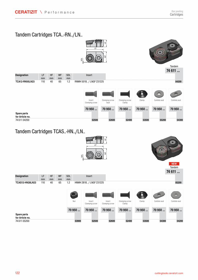
122 cuttingtools.ceratizit.com
WF
LF
HF
SDL
74 611 ...LF HF WF SDL
mm mm mm mmTCA12-RN50LN23 110 40 65 RNMH 5018.. / LNGF 231225 7461104200
70 950 ... 70 950 ... 70 950 ... 70 950 ... 70 950 ... 70 950 ...
74 611 04200 7095052500 7095052600 7095052400 7095053500 7095055200 7095054300
WF
LF
HF
SDL
NEW
74 611 ...LF HF WF SDL
mm mm mm mmTCAS12-HN28LN23 110 40 65 HNMH 2818.. / LNGF 231225 7461105200
70 950 ... 70 950 ... 70 950 ... 70 950 ... 70 950 ... 70 950 ... 70 950 ...
74 611 05200 7095053900 7095052500 7095052600 7095052400 7095053500 7095054300 7095054200
Bar peeling
Tandem Cartridges TCA..-RN../LN..
Tandem
Designation Insert
1.2
InsertClamping screw
Clamping screwSeat
Clamping screwClamp
Clamp Carbide seat Carbide seat
Spare parts for Article no.
Tandem Cartridges TCAS..-HN../LN..
Tandem
Designation Insert
1.2
Nut InsertClamping screw
InsertClamping screw
Clamping screwClamp
Clamp Carbide seat Carbide seat
Spare parts for Article no.
Cartridges
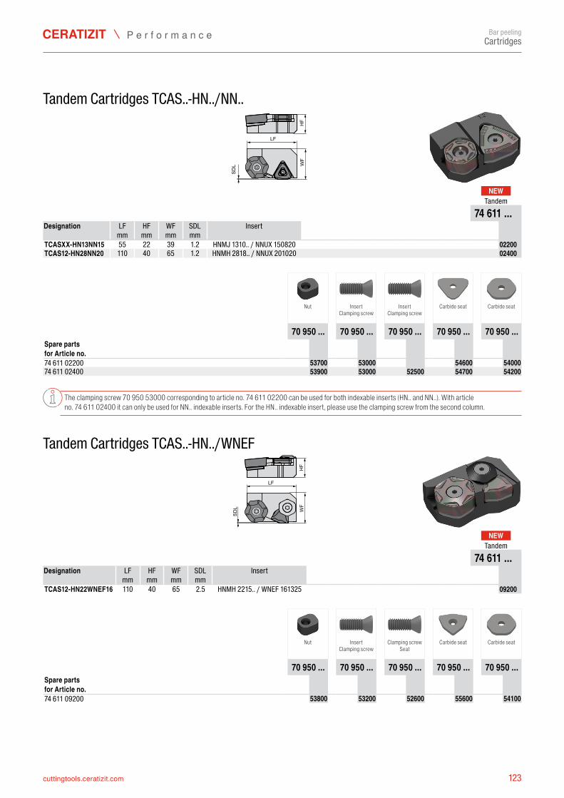
123cuttingtools.ceratizit.com
WF
LF
HF
SDL
NEW
74 611 ...LF HF WF SDL
mm mm mm mmTCASXX-HN13NN15 55 22 39 HNMJ 1310.. / NNUX 150820 7461102200TCAS12-HN28NN20 110 40 65 HNMH 2818.. / NNUX 201020 7461102400
70 950 ... 70 950 ... 70 950 ... 70 950 ... 70 950 ...
74 611 02200 7095053700 7095053000 7095054600 709505400074 611 02400 7095053900 7095053000 7095052500 7095054700 7095054200
WF
LF
HF
SDL
NEW
74 611 ...LF HF WF SDL
mm mm mm mmTCAS12-HN22WNEF16 110 40 65 HNMH 2215.. / WNEF 161325 7461109200
70 950 ... 70 950 ... 70 950 ... 70 950 ... 70 950 ...
74 611 09200 7095053800 7095053200 7095052600 7095055600 7095054100
Bar peeling
Tandem Cartridges TCAS..-HN../NN..
Tandem
Designation Insert
1.2 1.2
Nut InsertClamping screw
InsertClamping screw
Carbide seat Carbide seat
Spare parts for Article no.
The clamping screw 70 950 53000 corresponding to article no. 74 611 02200 can be used for both indexable inserts (HN.. and NN..). With article no. 74 611 02400 it can only be used for NN.. indexable inserts. For the HN.. indexable insert, please use the clamping screw from the second column.
Tandem Cartridges TCAS..-HN../WNEF
Tandem
Designation Insert
2.5
Nut InsertClamping screw
Clamping screwSeat
Carbide seat Carbide seat
Spare parts for Article no.
Cartridges
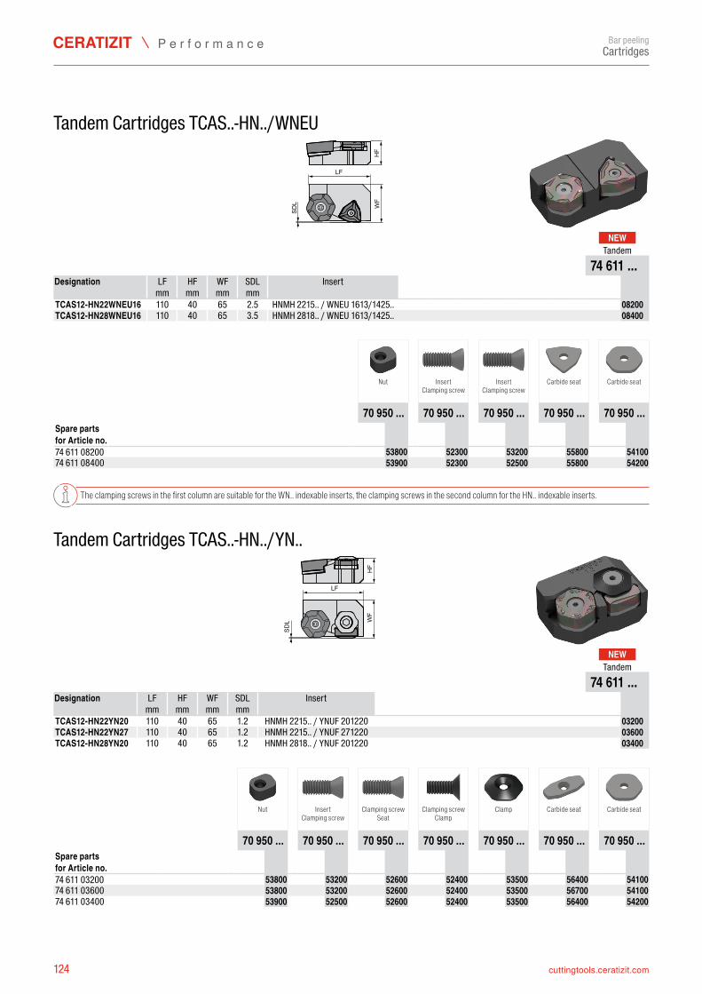
124 cuttingtools.ceratizit.com
WF
LF
HF
SDL
NEW
74 611 ...LF HF WF SDL
mm mm mm mmTCAS12-HN22WNEU16 110 40 65 HNMH 2215.. / WNEU 1613/1425.. 7461108200TCAS12-HN28WNEU16 110 40 65 HNMH 2818.. / WNEU 1613/1425.. 7461108400
70 950 ... 70 950 ... 70 950 ... 70 950 ... 70 950 ...
74 611 08200 7095053800 7095052300 7095053200 7095055800 709505410074 611 08400 7095053900 7095052300 7095052500 7095055800 7095054200
WF
LF
HF
SDL
NEW
74 611 ...LF HF WF SDL
mm mm mm mmTCAS12-HN22YN20 110 40 65 HNMH 2215.. / YNUF 201220 7461103200TCAS12-HN22YN27 110 40 65 HNMH 2215.. / YNUF 271220 7461103600TCAS12-HN28YN20 110 40 65 HNMH 2818.. / YNUF 201220 7461103400
70 950 ... 70 950 ... 70 950 ... 70 950 ... 70 950 ... 70 950 ... 70 950 ...
74 611 03200 7095053800 7095053200 7095052600 7095052400 7095053500 7095056400 709505410074 611 03600 7095053800 7095053200 7095052600 7095052400 7095053500 7095056700 709505410074 611 03400 7095053900 7095052500 7095052600 7095052400 7095053500 7095056400 7095054200
Bar peeling
Tandem Cartridges TCAS..-HN../WNEU
Tandem
Designation Insert
2.53.5
Nut InsertClamping screw
InsertClamping screw
Carbide seat Carbide seat
Spare parts for Article no.
The clamping screws in the first column are suitable for the WN.. indexable inserts, the clamping screws in the second column for the HN.. indexable inserts.
Tandem Cartridges TCAS..-HN../YN..
Tandem
Designation Insert
1.21.21.2
Nut InsertClamping screw
Clamping screwSeat
Clamping screwClamp
Clamp Carbide seat Carbide seat
Spare parts for Article no.
Cartridges
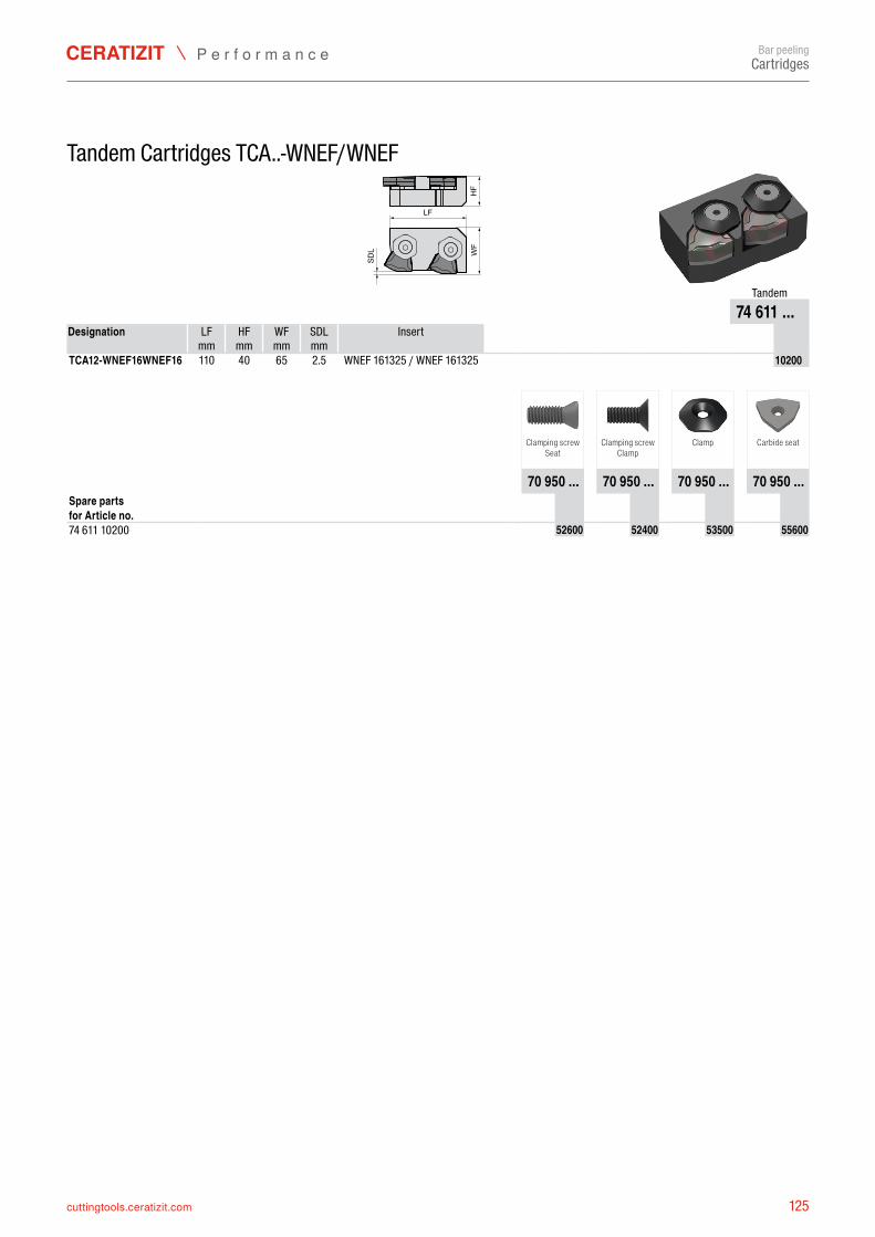
125cuttingtools.ceratizit.com
HF
WF
LF
SDL
74 611 ...LF HF WF SDL
mm mm mm mmTCA12-WNEF16WNEF16 110 40 65 WNEF 161325 / WNEF 161325 7461110200
70 950 ... 70 950 ... 70 950 ... 70 950 ...
74 611 10200 7095052600 7095052400 7095053500 7095055600
Bar peeling
Tandem Cartridges TCA..-WNEF/WNEF
Tandem
Designation Insert
2.5
Clamping screwSeat
Clamping screwClamp
Clamp Carbide seat
Spare parts for Article no.
Cartridges
126 cuttingtools.ceratizit.com
Bar peelingSpare parts
Spare partsScrews
Claws
Material-No. Type, Designation
11378194 KLF-D27
11268345 KLF-D38
11329186 SPP-33
Material-No. Type, Designation Length [mm] Size of thread Wrench size
1342301 M8X30 DIN 7991 12.9 30 M8 SW5
6210871 C/26381 DIN7991 M8X25 10.9 25 M8 SW5
11181940 10006286/M8.0X30 SW5 30 M8 SW5
11227329 M6X16-25IP/10003048 16 M6 T25IP
11363595 M10X20 DIN 7991 10.9 20 M10 SW6
11363596 M10X35 DIN 7991 10.9 35 M10 SW6
11365730 M5X8 DIN 7991 10.9 8 M5 SW3
11377574 M6X12 SW4 DIN7991 10.9 6 M6 SW4
11417617 10006285/M8.0X20 SW5 20 M8 SW5
11450042 10006887/M3.5x8,6/15IP 8.6 M3.5 T15IP
11801691 M5X20 DIN 7991 10.9 20 M5 SW3
12535687 S-M6X18/T20 12.9 50060196 18 M6 T20
12535753 S-M4X8 ISO 10642 10.9 8 M4 SW2.5
14546695 S-M8X35 ISO 10642 10.9 35 M8 SW5
11880977 M8X16 DIN 6912 10.9 16 M8 SW6
127cuttingtools.ceratizit.com
Bar peelingSpare parts
Shims
Material-No. Type, Designation Strength s [mm]
HNMH
/J.. 12090033 U-HNMH2818 5.0
12144314 U-HNMH2215 5.0
14567503 U-HNMJ1310 3.0
LNGF
.. 11364020 U-LNGF2310 6.0
11364027 U-LNGF2312 4.0
NNUX
..
11364028 U-NNUX2010 3.0
11910314 U-NNUX2712 5.0
12124545 U-NNUX1508 3.0
12556277 U-NNUX1208 3.0
RNGH
../RN
MH.. 11356071 U-RNGH3812 5.0
11363153 U-RNMH5018 5.0
12429188 U-RNMH2810 3.0
12556291 U-RNMH2008 3.0
TNGT
..
12556298 U-TNGT220815 3.0
WNE
F../W
NEU.
./WNG
U../W
NMF..
11354688 U-WNMF1510 3.0
11357792 U-WNEU16-06 6.0
11414040 U-WNMF1106 3.0
11451724 U-WNEU16-05 5.0
11458166 U-WNEF1613 5.0
12292429 U-WNGU1510 3.0
12574005 U-WNGU1510-05 5.0
12556308 U-WNGU1010 3.0
12556314 U-WNMF96 4.75
YNGF
../YN
GX../
YNUF
../YN
UR../
YNUX
..
11262407 U-YNUF2012 5.0
11262435 U-YNUF2712 5.0
11262436 U-YNUF1708 5.0
11356624 U-YNUX1006 3.0
11369058 U-YNUR2712 3.0
12148501 U-YNUF2410 5.0
12556318 U-YNGF2012 5.0
12556319 U-YNGX150815 3.0
12556320 U-YNGX150820 3.0
12556322 U-YNGX1712 3.0
Peeling heads and accessories
The use of innovative cutting materials and optimized tools provides a vital advantage
In addition to inserts, CERATIZIT also offers all the spare parts which are needed for bar peeling. All peeling heads and the associated spare parts are produced upon request.
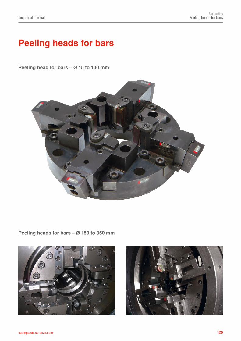
129cuttingtools.ceratizit.com
Technical manualBar peeling
Peeling heads for bars
Peeling head for bars – Ø 15 to 100 mm
Peeling heads for bars – Ø 150 to 350 mm
Peeling heads for bars
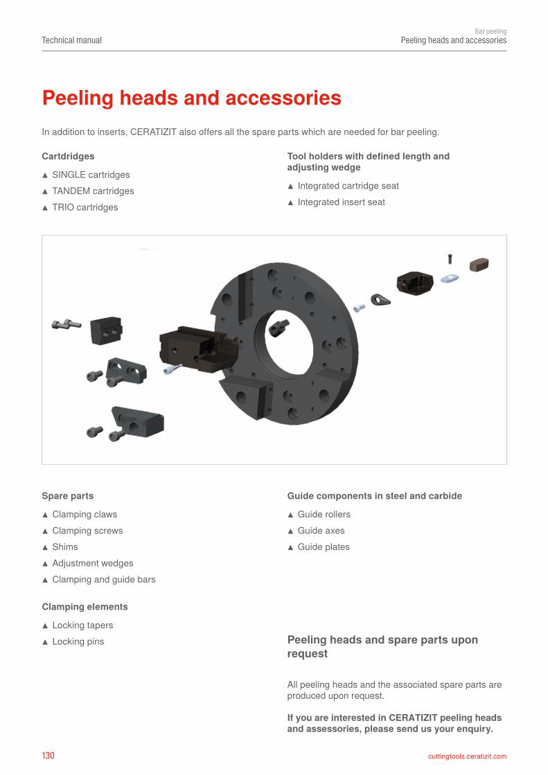
130 cuttingtools.ceratizit.com
Technical manualBar peeling
Peeling heads and accessories
In addition to inserts, CERATIZIT also offers all the spare parts which are needed for bar peeling.
Peeling heads and accessories
Tool holders with defined length and adjusting wedge
▲ Integrated cartridge seat ▲ Integrated insert seat
Cartdridges
▲ SINGLE cartridges ▲ TANDEM cartridges ▲ TRIO cartridges
Spare parts
▲ Clamping claws ▲ Clamping screws ▲ Shims ▲ Adjustment wedges ▲ Clamping and guide bars
Clamping elements
▲ Locking tapers ▲ Locking pins
Guide components in steel and carbide
▲ Guide rollers ▲ Guide axes ▲ Guide plates
Peeling heads and spare parts upon request
All peeling heads and the associated spare parts are produced upon request.
If you are interested in CERATIZIT peeling heads and assessories, please send us your enquiry.
131cuttingtools.ceratizit.com
Technical manualBar peeling
Peeling heads and accessories
Clamping components
Guide components
Locking pins Adjusting wedges Locking tapers
Clamping and guide bars
Guide components Roll holders
Clamping and guide components upon request
All clamping and guide components and the associated spare parts are produced upon request.
If you are interested in CERATIZIT clamping and guide components, please send us your enquiry.
132 cuttingtools.ceratizit.com
Technical manualBar peeling
Tools and inserts for bar end machining and chamfering
Tools and inserts for bar end machining and chamfering
Tool: Face milling cutter with chamfer insert
Indexable insert:
RPHX 1605M8
SNKU 150510SN-M50
Tool: Face and chamfer head
Indexable insert:
LNUX 400614EN
SNMG 190612FN
Tool: Face milling cutter with chamfer insert
Indexable insert:
OAKU 060508SR-M50
SDHT 1204AESN
133cuttingtools.ceratizit.com
Technical manualBar peeling
Tools and inserts for bar end machining and chamfering
Tool: Face milling cutter with chamfer insert
Indexable insert:
OAKU 060508SR-M50
SDHT 1204AESN
Tool: Face milling cutter with chamfer insert
Indexable insert:
OAKU 060508SR-M50
TCMT 220408EN-M55
Milling tools upon request
This page shows different examples of milling tools that we produce upon request according to the wishes and requirements of our customers.
If you are interested in CERATIZIT face milling cutters and chamfer heads, please send us your enquiry.


UNITED. EXPERIENCED. METAL CUTTING.
The product brand CERATIZIT stands for high-quality indexable insert tools. The products are characterized by their high quality and contain the DNA of many years of experience in the development and production of carbide tools.
SPECIALIST FOR INDEXABLE INSERT TOOLS FOR TURNING, MILLING AND GROOVING
WNT is synonymous with product diversity: solid carbide and HSS rotating tools, tool holders and efficient workholding solutions are all part of this brand.
EXPERTS FOR ROTATING TOOLS, TOOL HOLDERS AND CLAMPING SOLUTIONS
Solid carbide drills specially developed for the aerospace industry bear the product name KLENK. The highly specialised products are specifically designed for machining lightweight materials.
CUTTING TOOLS FOR THE AEROSPACE INDUSTRY
High-precision drilling, reaming, countersinking and boring is a matter of expertise: efficient tooling solutions for drilling and mechatronic tools are therefore part of the KOMET brand name.
THE QUALITY LABEL FOR EFFICIENT BORE PRODUCTION
09/2
021 –
94 2
21 3
4021
Related Documents