EZ-SCREEN TYPE 4 14 or 30 mm TYPE 4 LOW PROFILE 14 or 25 mm TYPE 2 30 mm GRIDS & POINTS PICO-GUARD 473 Photoelectrics Sensors Fiber Optic Sensors Special Purpose Sensors Measurement & Inspection Sensors Vision Wireless Lighting & Indicators Safety Light Screens Safety Laser Scanners Fiber Optic Safety Systems Safety Controllers & Modules Safety Two-Hand Control Modules Safety Interlock Switches Emergency Stop & Stop Control More information online at bannerengineering.com EZ-SCREEN ® Type 4 Point-of-Operation • Available in 14 mm resolution for finger, hand and ankle detection or 30 mm resolution for hand and ankle detection • Operates in ranges from 0.1 to 6 m (14 mm models) and 0.1 to 18 m (30 mm models) • Offers fixed or 2-beam reduced resolution (floating blanking) to ignore tooling or constant inflow of materials • Displays operating status, configuration error codes, and blocked beams • User-configurable trip or latch outputs, Scan Code 1 or 2 and Aux output • Exceeds OSHA/ANSI Control Reliability requirements, certified to cULus NIPF, and CE certified to Type 4, Cat 4 PLe, and SIL 3 • Provides external device monitoring (EDM) • Resists impact, twisting and abusive environments with a durable aluminum housing and metal endcaps • Available with standard yellow, clear anodized aluminum housing or nickel-plated ESD-safe housing for protection against electrostatic discharges (other color options available) • Offers optional cascading to create up to a four sensor system that issues a single stop command • Offers optional lens shields and enclosures for added durability Interface multiple devices with the SC22-3 Safety Controller. See page 526 ONLINE AUTOCAD, STEP, IGES & PDF EZ-SCREEN Systems 45.2 mm L 36.0 mm Some of the Available Finishes Yellow Painted Aluminum Nickel-Plated ESD Clear Anodized Aluminum ACCESSORIES page 480 Courtesy of Steven Engineering, Inc.-230 Ryan Way, South San Francisco, CA 94080-6370-Main Office: (650) 588-9200-Outside Local Area: (800) 258-9200-www.stevenengineering.com

Welcome message from author
This document is posted to help you gain knowledge. Please leave a comment to let me know what you think about it! Share it to your friends and learn new things together.
Transcript
EZ-SCREEN
TYPE 414 or 30 mm
TYPE 4LOW PROFILE14 or 25 mm
TYPE 230 mm
GRIDS & POINTS
PICO-GUARD
473
PhotoelectricsSensors
Fiber OpticSensors
Special PurposeSensors
Measurement & Inspection Sensors
Vision
Wireless
Lighting &Indicators
Safety Light Screens
Safety Laser Scanners
Fiber OpticSafety Systems
Safety Controllers & Modules
Safety Two-Hand Control Modules
Safety Interlock Switches
Emergency Stop & Stop Control
More information online at bannerengineering.com
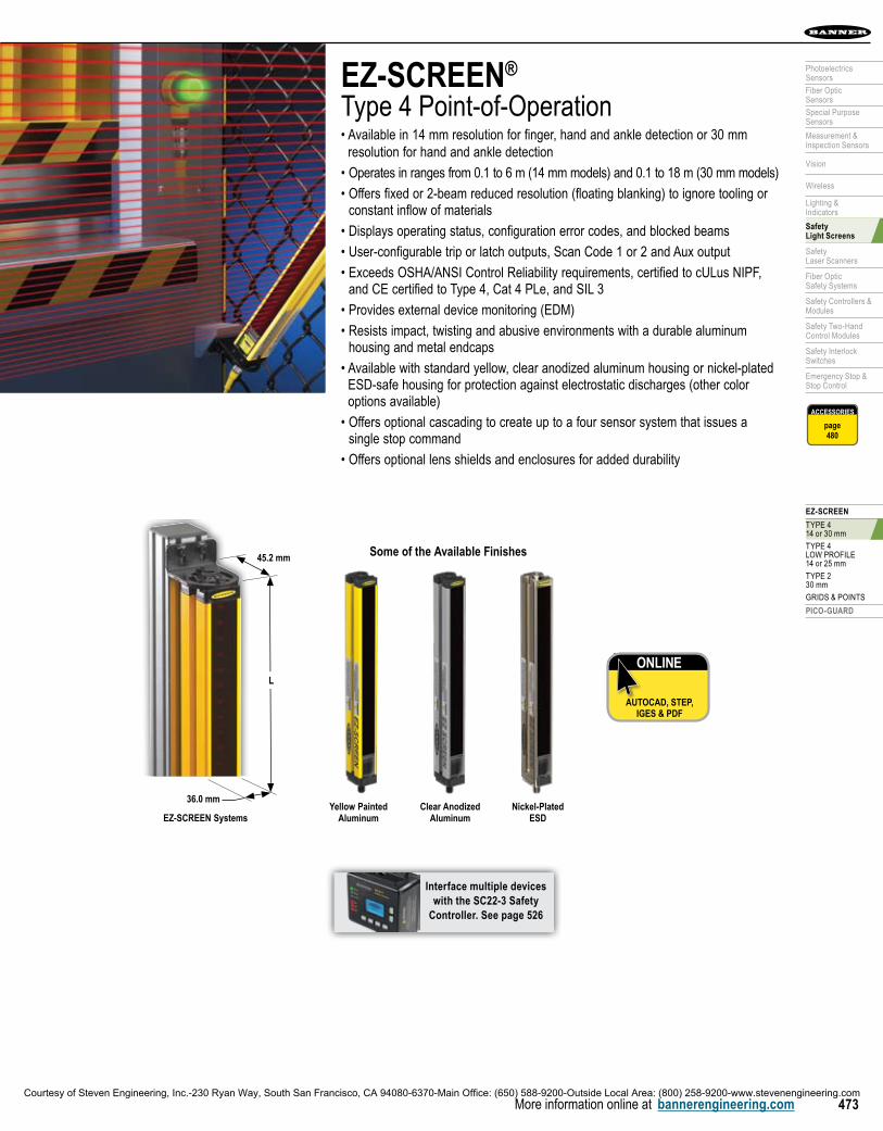
EZ-SCREEN®
Type 4 Point-of-Operation• Available in 14 mm resolution for finger, hand and ankle detection or 30 mm
resolution for hand and ankle detection
• Operates in ranges from 0.1 to 6 m (14 mm models) and 0.1 to 18 m (30 mm models)
• Offers fixed or 2-beam reduced resolution (floating blanking) to ignore tooling or constant inflow of materials
• Displays operating status, configuration error codes, and blocked beams
• User-configurable trip or latch outputs, Scan Code 1 or 2 and Aux output
• Exceeds OSHA/ANSI Control Reliability requirements, certified to cULus NIPF, and CE certified to Type 4, Cat 4 PLe, and SIL 3
• Provides external device monitoring (EDM)
• Resists impact, twisting and abusive environments with a durable aluminum housing and metal endcaps
• Available with standard yellow, clear anodized aluminum housing or nickel-plated ESD-safe housing for protection against electrostatic discharges (other color options available)
• Offers optional cascading to create up to a four sensor system that issues a single stop command
• Offers optional lens shields and enclosures for added durability
Interface multiple devices with the SC22-3 Safety
Controller. See page 526
ONLINE
AUTOCAD, STEP, IGES & PDF
EZ-SCREEN Systems
45.2 mm
L
36.0 mm
Some of the Available Finishes
Yellow Painted Aluminum
Nickel-Plated ESD
Clear Anodized Aluminum
ACCESSORIES
page480
Courtesy of Steven Engineering, Inc.-230 Ryan Way, South San Francisco, CA 94080-6370-Main Office: (650) 588-9200-Outside Local Area: (800) 258-9200-www.stevenengineering.com

MAC
HIN
E SA
FETY
EZ-SCREEN® (TYPE 4 & TYPE 2) PICO-GUARD FIBER OPTIC (TYPE 4)
474 More information online at bannerengineering.com
ACCESSORIES
page480
EZ-SCREEN® Systems, 14 mm Resolution–0.1 to 6 m Range, 24V dcDefined
AreaM12/Euro
ConnectionHousing
Length (L)Response
Time# of
Beams OutputModels*
Emitter Receiver Pair†
150 mm8-pin QD
262 mm 11 ms 20
2 PNP OSSD
(Trip/Latch selectable)
SLSE14-150Q8 SLSR14-150Q8 SLSP14-150Q88
8-pin Pigtail QD SLSE14-150P8 SLSR14-150P8 SLSP14-150P88
300 mm8-pin QD
372 mm 15 ms 40SLSE14-300Q8 SLSR14-300Q8 SLSP14-300Q88
8-pin Pigtail QD SLSE14-300P8 SLSR14-300P8 SLSP14-300P88
450 mm8-pin QD
522 mm 19 ms 60SLSE14-450Q8 SLSR14-450Q8 SLSP14-450Q88
8-pin Pigtail QD SLSE14-450P8 SLSR14-450P8 SLSP14-450P88
600 mm8-pin QD
671 mm 23 ms 80SLSE14-600Q8 SLSR14-600Q8 SLSP14-600Q88
8-pin Pigtail QD SLSE14-600P8 SLSR14-600P8 SLSP14-600P88
750 mm8-pin QD
821 mm 27 ms 100SLSE14-750Q8 SLSR14-750Q8 SLSP14-750Q88
8-pin Pigtail QD SLSE14-750P8 SLSR14-750P8 SLSP14-750P88
900 mm8-pin QD
971 mm 32 ms 120SLSE14-900Q8 SLSR14-900Q8 SLSP14-900Q88
8-pin Pigtail QD SLSE14-900P8 SLSR14-900P8 SLSP14-900P88
1050 mm8-pin QD
1120 mm 36 ms 140SLSE14-1050Q8 SLSR14-1050Q8 SLSP14-1050Q88
8-pin Pigtail QD SLSE14-1050P8 SLSR14-1050P8 SLSP14-1050P88
1200 mm8-pin QD
1270 mm 40 ms 160SLSE14-1200Q8 SLSR14-1200Q8 SLSP14-1200Q88
8-pin Pigtail QD SLSE14-1200P8 SLSR14-1200P8 SLSP14-1200P88
1350 mm8-pin QD
1420 mm 43 ms 180SLSE14-1350Q8 SLSR14-1350Q8 SLSP14-1350Q88
8-pin Pigtail QD SLSE14-1350P8 SLSR14-1350P8 SLSP14-1350P88
1500 mm8-pin QD
1569 mm 48 ms 200SLSE14-1500Q8 SLSR14-1500Q8 SLSP14-1500Q88
8-pin Pigtail QD SLSE14-1500P8 SLSR14-1500P8 SLSP14-1500P88
1650 mm8-pin QD
1719 mm 52 ms 220SLSE14-1650Q8 SLSR14-1650Q8 SLSP14-1650Q88
8-pin Pigtail QD SLSE14-1650P8 SLSR14-1650P8 SLSP14-1650P88
1800 mm8-pin QD
1869 mm 56 ms 240SLSE14-1800Q8 SLSR14-1800Q8 SLSP14-1800Q88
8-pin Pigtail QD SLSE14-1800P8 SLSR14-1800P8 SLSP14-1800P88
EZ-SCREEN® Systems, 30 mm Resolution–0.1 to 18 m Range, 24V dcDefined
AreaM12/Euro
ConnectionHousing
Length (L)Response
Time# of
Beams OutputModels*
Emitter Receiver Pair†
150 mm8-pin QD
262 mm 9 ms 10
2 PNP OSSD
(Trip/Latch selectable)
SLSE30-150Q8 SLSR30-150Q8 SLSP30-150Q88
8-pin Pigtail QD SLSE30-150P8 SLSR30-150P8 SLSP30-150P88
300 mm8-pin QD
372 mm 11 ms 20SLSE30-300Q8 SLSR30-300Q8 SLSP30-300Q88
8-pin Pigtail QD SLSE30-300P8 SLSR30-300P8 SLSP30-300P88
450 mm8-pin QD
522 mm 13 ms 30SLSE30-450Q8 SLSR30-450Q8 SLSP30-450Q88
8-pin Pigtail QD SLSE30-450P8 SLSR30-450P8 SLSP30-450P88
600 mm8-pin QD
671 mm 15 ms 40SLSE30-600Q8 SLSR30-600Q8 SLSP30-600Q88
8-pin Pigtail QD SLSE30-600P8 SLSR30-600P8 SLSP30-600P88
750 mm8-pin QD
821 mm 17 ms 50SLSE30-750Q8 SLSR30-750Q8 SLSP30-750Q88
8-pin Pigtail QD SLSE30-750P8 SLSR30-750P8 SLSP30-750P88
900 mm8-pin QD
971 mm 19 ms 60SLSE30-900Q8 SLSR30-900Q8 SLSP30-900Q88
8-pin Pigtail QD SLSE30-900P8 SLSR30-900P8 SLSP30-900P88
Moreon next page
QD models: A model with a QD requires a mating cordset (see page 480).
For an emitter with TEST function, replace Q8 with Q5 on emitter model numbers (example, SLSE14-150Q5) and Q88 with Q85 on pair model numbers (example, SLSP14-150Q85). For a 300 mm M12/Euro pigtail QD, replace Q with P in model numbers (example, SLSP14-150P88).
For a 5-pin 300 mm M12/Euro pigtail QD with No EDM or TEST functions, replace Q8 with P5NT on emitter or receiver (example, SLSE14-150P5NT) and Q88 with P55NT on pair model numbers (example, SLSP14-150P55NT). For a 4-pin 300 mm M12/Euro pigtail QD with no EDM or TEST functions (GND/PE via mounting), replace Q8 with P4NT or Q88 with P44NT (example, SLSP14-150P44NT).
* ESD-safe models: Add N to the model number, prior to the QD option designation (example, SLSE14-150NQ8). ESD-safe models are not available with the pigtail QD option.
Optional housing finishes: Prior to the QD designation in the model number, add A for a clear (brushed) anodized aluminum finish, black endcaps (example, SLSE14-150AQ8); S for a nickel-plated (silver) finish, black endcaps (example, SLSE14-150SQ8), B for a black painted finish, black endcaps (example, SLSE14-150BQ8), W for a white painted finish, black endcaps (example, SLSE14-150WQ8) or SO for a safety orange painted finish, black endcaps (example, SLSE14-150SOQ8).† A pair includes an emitter and receiver (example, SLSP14-150Q88). Emitters (example, SLSE14-150Q8) and receivers (example, SLSR14-150Q8) are also sold separately.
Courtesy of Steven Engineering, Inc.-230 Ryan Way, South San Francisco, CA 94080-6370-Main Office: (650) 588-9200-Outside Local Area: (800) 258-9200-www.stevenengineering.com
EZ-SCREEN
TYPE 414 or 30 mm
TYPE 4LOW PROFILE14 or 25 mm
TYPE 230 mm
GRIDS & POINTS
PICO-GUARD
475
PhotoelectricsSensors
Fiber OpticSensors
Special PurposeSensors
Measurement & Inspection Sensors
Vision
Wireless
Lighting &Indicators
Safety Light Screens
Safety Laser Scanners
Fiber OpticSafety Systems
Safety Controllers & Modules
Safety Two-Hand Control Modules
Safety Interlock Switches
Emergency Stop & Stop Control
More information online at bannerengineering.com
ACCESSORIES
page480
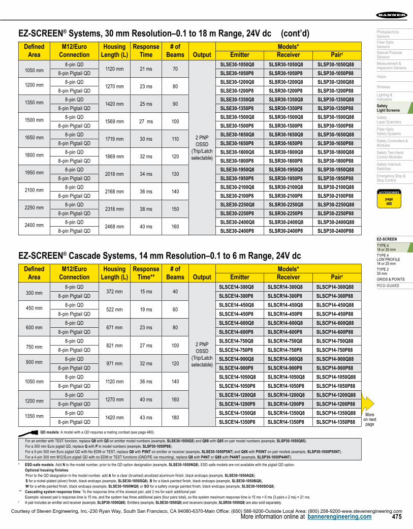
EZ-SCREEN® Systems, 30 mm Resolution–0.1 to 18 m Range, 24V dcDefined
AreaM12/Euro
ConnectionHousing
Length (L)Response
Time# of
Beams OutputModels*
Emitter Receiver Pair†
1050 mm8-pin QD
1120 mm 21 ms 70
2 PNP OSSD
(Trip/Latch selectable)
SLSE30-1050Q8 SLSR30-1050Q8 SLSP30-1050Q88
8-pin Pigtail QD SLSE30-1050P8 SLSR30-1050P8 SLSP30-1050P88
1200 mm 8-pin QD1270 mm 23 ms 80
SLSE30-1200Q8 SLSR30-1200Q8 SLSP30-1200Q88
8-pin Pigtail QD SLSE30-1200P8 SLSR30-1200P8 SLSP30-1200P88
1350 mm 8-pin QD1420 mm 25 ms 90
SLSE30-1350Q8 SLSR30-1350Q8 SLSP30-1350Q88
8-pin Pigtail QD SLSE30-1350P8 SLSR30-1350P8 SLSP30-1350P88
1500 mm 8-pin QD1569 mm 27 ms 100
SLSE30-1500Q8 SLSR30-1500Q8 SLSP30-1500Q88
8-pin Pigtail QD SLSE30-1500P8 SLSR30-1500P8 SLSP30-1500P88
1650 mm 8-pin QD1719 mm 30 ms 110
SLSE30-1650Q8 SLSR30-1650Q8 SLSP30-1650Q88
8-pin Pigtail QD SLSE30-1650P8 SLSR30-1650P8 SLSP30-1650P88
1800 mm 8-pin QD1869 mm 32 ms 120
SLSE30-1800Q8 SLSR30-1800Q8 SLSP30-1800Q88
8-pin Pigtail QD SLSE30-1800P8 SLSR30-1800P8 SLSP30-1800P88
1950 mm 8-pin QD2018 mm 34 ms 130
SLSE30-1950Q8 SLSR30-1950Q8 SLSP30-1950Q88
8-pin Pigtail QD SLSE30-1950P8 SLSR30-1950P8 SLSP30-1950P88
2100 mm 8-pin QD2168 mm 36 ms 140
SLSE30-2100Q8 SLSR30-2100Q8 SLSP30-2100Q88
8-pin Pigtail QD SLSE30-2100P8 SLSR30-2100P8 SLSP30-2100P88
2250 mm 8-pin QD2318 mm 38 ms 150
SLSE30-2250Q8 SLSR30-2250Q8 SLSP30-2250Q88
8-pin Pigtail QD SLSE30-2250P8 SLSR30-2250P8 SLSP30-2250P88
2400 mm 8-pin QD2468 mm 40 ms 160
SLSE30-2400Q8 SLSR30-2400Q8 SLSP30-2400Q88
8-pin Pigtail QD SLSE30-2400P8 SLSR30-2400P8 SLSP30-2400P88
(cont’d)
EZ-SCREEN® Cascade Systems, 14 mm Resolution–0.1 to 6 m Range, 24V dcDefined
AreaM12/Euro
ConnectionHousing
Length (L)Response
Time**# of
Beams OutputModels*
Emitter Receiver Pair†
300 mm8-pin QD
372 mm 15 ms 40
2 PNP OSSD
(Trip/Latch selectable)
SLSCE14-300Q8 SLSCR14-300Q8 SLSCP14-300Q88
8-pin Pigtail QD SLSCE14-300P8 SLSCR14-300P8 SLSCP14-300P88
450 mm8-pin QD
522 mm 19 ms 60SLSCE14-450Q8 SLSCR14-450Q8 SLSCP14-450Q88
8-pin Pigtail QD SLSCE14-450P8 SLSCR14-450P8 SLSCP14-450P88
600 mm8-pin QD
671 mm 23 ms 80SLSCE14-600Q8 SLSCR14-600Q8 SLSCP14-600Q88
8-pin Pigtail QD SLSCE14-600P8 SLSCR14-600P8 SLSCP14-600P88
750 mm8-pin QD
821 mm 27 ms 100SLSCE14-750Q8 SLSCR14-750Q8 SLSCP14-750Q88
8-pin Pigtail QD SLSCE14-750P8 SLSCR14-750P8 SLSCP14-750P88
900 mm8-pin QD
971 mm 32 ms 120SLSCE14-900Q8 SLSCR14-900Q8 SLSCP14-900Q88
8-pin Pigtail QD SLSCE14-900P8 SLSCR14-900P8 SLSCP14-900P88
1050 mm8-pin QD
1120 mm 36 ms 140SLSCE14-1050Q8 SLSCR14-1050Q8 SLSCP14-1050Q88
8-pin Pigtail QD SLSCE14-1050P8 SLSCR14-1050P8 SLSCP14-1050P88
1200 mm8-pin QD
1270 mm 40 ms 160SLSCE14-1200Q8 SLSCR14-1200Q8 SLSCP14-1200Q88
8-pin Pigtail QD SLSCE14-1200P8 SLSCR14-1200P8 SLSCP14-1200P88
1350 mm8-pin QD
1420 mm 43 ms 180SLSCE14-1350Q8 SLSCR14-1350Q8 SLSCP14-1350Q88
8-pin Pigtail QD SLSCE14-1350P8 SLSCR14-1350P8 SLSCP14-1350P88More
on next page
QD models: A model with a QD requires a mating cordset (see page 480).
For an emitter with TEST function, replace Q8 with Q5 on emitter model numbers (example, SLSE30-1050Q5) and Q88 with Q85 on pair model numbers (example, SLSP30-1050Q85). For a 300 mm Euro pigtail QD, replace Q with P in model numbers (example, SLSP30-1050P88). For a 5-pin 300 mm Euro pigtail QD with No EDM or TEST, replace Q8 with P5NT on emitter or receiver (example, SLSE30-1050P5NT) and Q88 with P55NT on pair models (example, SLSP30-1050P55NT). For a 4-pin 300 mm M12/Euro pigtail QD with no EDM or TEST functions (GND/PE via mounting), replace Q8 with P4NT or Q88 with P44NT (example, SLSP30-1050P44NT).
* ESD-safe models: Add N to the model number, prior to the QD option designation (example, SLSE30-1050NQ8). ESD-safe models are not available with the pigtail QD option. Optional housing finishes:
Prior to the QD designation in the model number, add A for a clear (brushed) anodized aluminum finish, black endcaps (example, SLSE30-1050AQ8); S for a nickel-plated (silver) finish, black endcaps (example, SLSE30-1050SQ8), B for a black painted finish, black endcaps (example, SLSE30-1050BQ8), W for a white painted finish, black endcaps (example, SLSE30-1050WQ8) or SO for a safety orange painted finish, black endcaps (example, SLSE30-1050SOQ8).
** Cascading system response time: To the response time of the slowest pair, add 2 ms for each additional pair. Example: slowest pair’s response time is 15 ms, and the system has three additional pairs (four pairs total), so the system maximum response time is 15 ms + 6 ms (3 pairs x 2 ms) = 21 ms.† A pair includes an emitter and receiver (example, SLSP30-1050Q88). Emitters (example, SLSE30-1050Q8) and receivers (example, SLSR30-1050Q8) are also sold separately.
Courtesy of Steven Engineering, Inc.-230 Ryan Way, South San Francisco, CA 94080-6370-Main Office: (650) 588-9200-Outside Local Area: (800) 258-9200-www.stevenengineering.com
MAC
HIN
E SA
FETY
EZ-SCREEN® (TYPE 4 & TYPE 2) PICO-GUARD FIBER OPTIC (TYPE 4)
476 More information online at bannerengineering.com
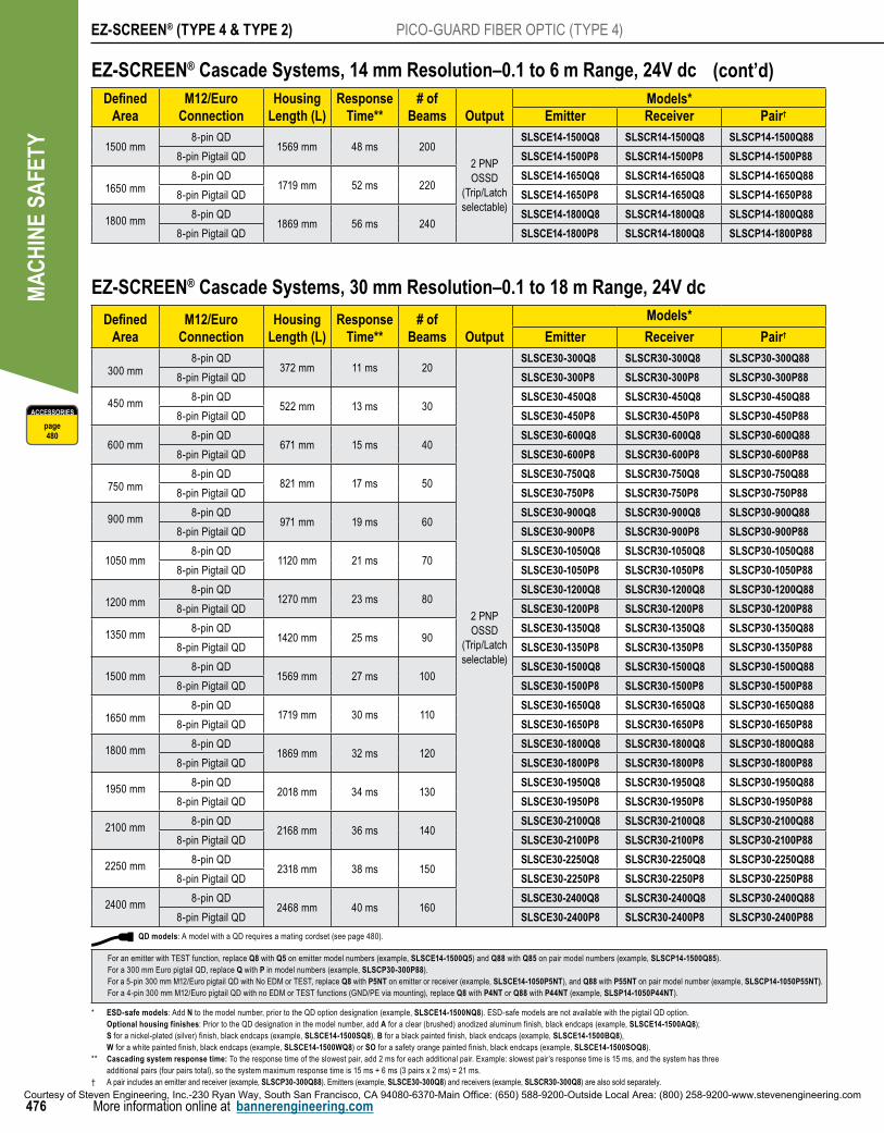
EZ-SCREEN® Cascade Systems, 30 mm Resolution–0.1 to 18 m Range, 24V dc
Defined Area
M12/Euro Connection
Housing Length (L)
Response Time**
# ofBeams Output
Models*
Emitter Receiver Pair†
300 mm8-pin QD
372 mm 11 ms 20
2 PNP OSSD
(Trip/Latch selectable)
SLSCE30-300Q8 SLSCR30-300Q8 SLSCP30-300Q88
8-pin Pigtail QD SLSCE30-300P8 SLSCR30-300P8 SLSCP30-300P88
450 mm8-pin QD
522 mm 13 ms 30SLSCE30-450Q8 SLSCR30-450Q8 SLSCP30-450Q88
8-pin Pigtail QD SLSCE30-450P8 SLSCR30-450P8 SLSCP30-450P88
600 mm8-pin QD
671 mm 15 ms 40SLSCE30-600Q8 SLSCR30-600Q8 SLSCP30-600Q88
8-pin Pigtail QD SLSCE30-600P8 SLSCR30-600P8 SLSCP30-600P88
750 mm8-pin QD
821 mm 17 ms 50SLSCE30-750Q8 SLSCR30-750Q8 SLSCP30-750Q88
8-pin Pigtail QD SLSCE30-750P8 SLSCR30-750P8 SLSCP30-750P88
900 mm8-pin QD
971 mm 19 ms 60SLSCE30-900Q8 SLSCR30-900Q8 SLSCP30-900Q88
8-pin Pigtail QD SLSCE30-900P8 SLSCR30-900P8 SLSCP30-900P88
1050 mm8-pin QD
1120 mm 21 ms 70SLSCE30-1050Q8 SLSCR30-1050Q8 SLSCP30-1050Q88
8-pin Pigtail QD SLSCE30-1050P8 SLSCR30-1050P8 SLSCP30-1050P88
1200 mm8-pin QD
1270 mm 23 ms 80SLSCE30-1200Q8 SLSCR30-1200Q8 SLSCP30-1200Q88
8-pin Pigtail QD SLSCE30-1200P8 SLSCR30-1200P8 SLSCP30-1200P88
1350 mm8-pin QD
1420 mm 25 ms 90SLSCE30-1350Q8 SLSCR30-1350Q8 SLSCP30-1350Q88
8-pin Pigtail QD SLSCE30-1350P8 SLSCR30-1350P8 SLSCP30-1350P88
1500 mm8-pin QD
1569 mm 27 ms 100SLSCE30-1500Q8 SLSCR30-1500Q8 SLSCP30-1500Q88
8-pin Pigtail QD SLSCE30-1500P8 SLSCR30-1500P8 SLSCP30-1500P88
1650 mm8-pin QD
1719 mm 30 ms 110SLSCE30-1650Q8 SLSCR30-1650Q8 SLSCP30-1650Q88
8-pin Pigtail QD SLSCE30-1650P8 SLSCR30-1650P8 SLSCP30-1650P88
1800 mm8-pin QD
1869 mm 32 ms 120SLSCE30-1800Q8 SLSCR30-1800Q8 SLSCP30-1800Q88
8-pin Pigtail QD SLSCE30-1800P8 SLSCR30-1800P8 SLSCP30-1800P88
1950 mm8-pin QD
2018 mm 34 ms 130SLSCE30-1950Q8 SLSCR30-1950Q8 SLSCP30-1950Q88
8-pin Pigtail QD SLSCE30-1950P8 SLSCR30-1950P8 SLSCP30-1950P88
2100 mm8-pin QD
2168 mm 36 ms 140SLSCE30-2100Q8 SLSCR30-2100Q8 SLSCP30-2100Q88
8-pin Pigtail QD SLSCE30-2100P8 SLSCR30-2100P8 SLSCP30-2100P88
2250 mm8-pin QD
2318 mm 38 ms 150SLSCE30-2250Q8 SLSCR30-2250Q8 SLSCP30-2250Q88
8-pin Pigtail QD SLSCE30-2250P8 SLSCR30-2250P8 SLSCP30-2250P88
2400 mm8-pin QD
2468 mm 40 ms 160SLSCE30-2400Q8 SLSCR30-2400Q8 SLSCP30-2400Q88
8-pin Pigtail QD SLSCE30-2400P8 SLSCR30-2400P8 SLSCP30-2400P88
EZ-SCREEN® Cascade Systems, 14 mm Resolution–0.1 to 6 m Range, 24V dcDefined
AreaM12/Euro
ConnectionHousing
Length (L)Response
Time**# of
Beams OutputModels*
Emitter Receiver Pair†
1500 mm8-pin QD
1569 mm 48 ms 200
2 PNP OSSD
(Trip/Latch selectable)
SLSCE14-1500Q8 SLSCR14-1500Q8 SLSCP14-1500Q88
8-pin Pigtail QD SLSCE14-1500P8 SLSCR14-1500P8 SLSCP14-1500P88
1650 mm8-pin QD
1719 mm 52 ms 220SLSCE14-1650Q8 SLSCR14-1650Q8 SLSCP14-1650Q88
8-pin Pigtail QD SLSCE14-1650P8 SLSCR14-1650Q8 SLSCP14-1650P88
1800 mm8-pin QD
1869 mm 56 ms 240SLSCE14-1800Q8 SLSCR14-1800Q8 SLSCP14-1800Q88
8-pin Pigtail QD SLSCE14-1800P8 SLSCR14-1800Q8 SLSCP14-1800P88
(cont’d)
ACCESSORIES
page480
QD models: A model with a QD requires a mating cordset (see page 480).
For an emitter with TEST function, replace Q8 with Q5 on emitter model numbers (example, SLSCE14-1500Q5) and Q88 with Q85 on pair model numbers (example, SLSCP14-1500Q85). For a 300 mm Euro pigtail QD, replace Q with P in model numbers (example, SLSCP30-300P88). For a 5-pin 300 mm M12/Euro pigtail QD with No EDM or TEST, replace Q8 with P5NT on emitter or receiver (example, SLSCE14-1050P5NT), and Q88 with P55NT on pair model number (example, SLSCP14-1050P55NT). For a 4-pin 300 mm M12/Euro pigtail QD with no EDM or TEST functions (GND/PE via mounting), replace Q8 with P4NT or Q88 with P44NT (example, SLSP14-1050P44NT).
* ESD-safe models: Add N to the model number, prior to the QD option designation (example, SLSCE14-1500NQ8). ESD-safe models are not available with the pigtail QD option. Optional housing finishes: Prior to the QD designation in the model number, add A for a clear (brushed) anodized aluminum finish, black endcaps (example, SLSCE14-1500AQ8); S for a nickel-plated (silver) finish, black endcaps (example, SLSCE14-1500SQ8), B for a black painted finish, black endcaps (example, SLSCE14-1500BQ8), W for a white painted finish, black endcaps (example, SLSCE14-1500WQ8) or SO for a safety orange painted finish, black endcaps (example, SLSCE14-1500SOQ8).** Cascading system response time: To the response time of the slowest pair, add 2 ms for each additional pair. Example: slowest pair’s response time is 15 ms, and the system has three
additional pairs (four pairs total), so the system maximum response time is 15 ms + 6 ms (3 pairs x 2 ms) = 21 ms.† A pair includes an emitter and receiver (example, SLSCP30-300Q88). Emitters (example, SLSCE30-300Q8) and receivers (example, SLSCR30-300Q8) are also sold separately.
Courtesy of Steven Engineering, Inc.-230 Ryan Way, South San Francisco, CA 94080-6370-Main Office: (650) 588-9200-Outside Local Area: (800) 258-9200-www.stevenengineering.com
EZ-SCREEN
TYPE 414 or 30 mm
TYPE 4LOW PROFILE14 or 25 mm
TYPE 230 mm
GRIDS & POINTS
PICO-GUARD
477
PhotoelectricsSensors
Fiber OpticSensors
Special PurposeSensors
Measurement & Inspection Sensors
Vision
Wireless
Lighting &Indicators
Safety Light Screens
Safety Laser Scanners
Fiber OpticSafety Systems
Safety Controllers & Modules
Safety Two-Hand Control Modules
Safety Interlock Switches
Emergency Stop & Stop Control
More information online at bannerengineering.com
ACCESSORIES
page480
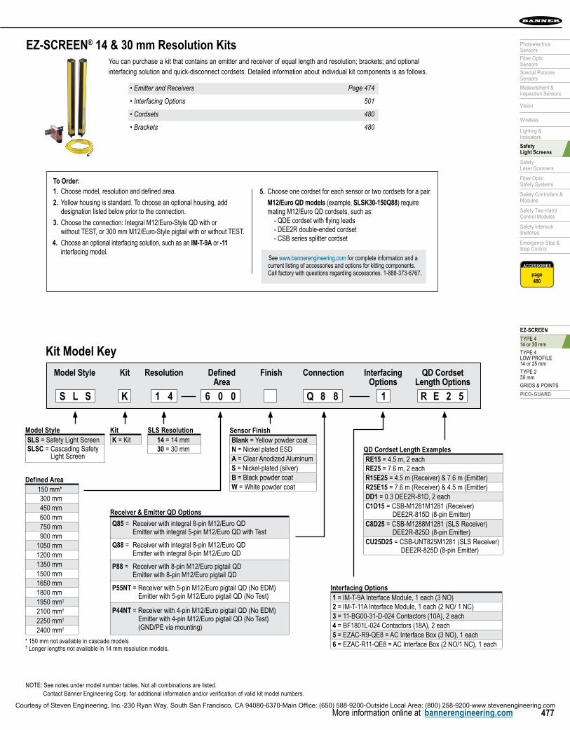
You can purchase a kit that contains an emitter and receiver of equal length and resolution; brackets; and optional interfacing solution and quick-disconnect cordsets. Detailed information about individual kit components is as follows.
•EmitterandReceivers Page474
•InterfacingOptions 501
•Cordsets 480
•Brackets 480
EZ-SCREEN® 14 & 30 mm Resolution Kits
To Order:1. Choose model, resolution and defined area.
2. Yellow housing is standard. To choose an optional housing, add designation listed below prior to the connection.
3. Choose the connection: Integral M12/Euro-Style QD with or without TEST, or 300 mm M12/Euro-Style pigtail with or without TEST.
4. Choose an optional interfacing solution, such as an IM-T-9A or -11 interfacing model.
5. Choose one cordset for each sensor or two cordsets for a pair.
M12/Euro QD models (example, SLSK30-150Q88) require mating M12/Euro QD cordsets, such as: - QDE cordset with flying leads - DEE2R double-ended cordset - CSB series splitter cordset
See www.bannerengineering.com for complete information and a current listing of accessories and options for kitting components. Call factory with questions regarding accessories. 1-888-373-6767.
NOTE: See notes under model number tables. Not all combinations are listed. Contact Banner Engineering Corp. for additional information and/or verification of valid kit model numbers.
Model StyleSLS = Safety Light ScreenSLSC = Cascading Safety
Light Screen
1 4S L S K 1 R E 2 5
KitK = Kit
Defined Area150 mm*300 mm450 mm600 mm750 mm900 mm
1050 mm1200 mm1350 mm1500 mm1650 mm1800 mm1950 mm†
2100 mm†
2250 mm†
2400 mm†
Receiver & Emitter QD Options
Q85 = Receiver with integral 8-pin M12/Euro QD Emitter with integral 5-pin M12/Euro QD with Test
Q88 = Receiver with integral 8-pin M12/Euro QD Emitter with integral 8-pin M12/Euro QD
P88 = Receiver with 8-pin M12/Euro pigtail QD Emitter with 8-pin M12/Euro pigtail QD
P55NT = Receiver with 5-pin M12/Euro pigtail QD (No EDM) Emitter with 5-pin M12/Euro pigtail QD (No Test)
P44NT = Receiver with 4-pin M12/Euro pigtail QD (No EDM) Emitter with 4-pin M12/Euro pigtail QD (No Test) (GND/PE via mounting)
6 0 0 Q 8 8
Interfacing Options1 = IM-T-9A Interface Module, 1 each (3 NO)2 = IM-T-11A Interface Module, 1 each (2 NO/ 1 NC)3 = 11-BG00-31-D-024 Contactors (10A), 2 each4 = BF1801L-024 Contactors (18A), 2 each5 = EZAC-R9-QE8 = AC Interface Box (3 NO), 1 each6 = EZAC-R11-QE8 = AC Interface Box (2 NO/1 NC), 1 each
QD Cordset Length ExamplesRE15 = 4.5 m, 2 eachRE25 = 7.6 m, 2 eachR15E25 = 4.5 m (Receiver) & 7.6 m (Emitter)R25E15 = 7.6 m (Receiver) & 4.5 m (Emitter)DD1 = 0.3 DEE2R-81D, 2 eachC1D15 = CSB-M1281M1281 (Receiver) DEE2R-815D (8-pin Emitter)C8D25 = CSB-M1288M1281 (SLS Receiver) DEE2R-825D (8-pin Emitter)CU25D25 = CSB-UNT825M1281 (SLS Receiver) DEE2R-825D (8-pin Emitter)
Kit Model Key
Model Style Kit Resolution Defined Finish Connection Interfacing QD Cordset Area Options Length Options
* 150 mm not available in cascade models† Longer lengths not available in 14 mm resolution models.
SLS Resolution14 = 14 mm30 = 30 mm
Sensor FinishBlank = Yellow powder coatN = Nickel plated ESDA = Clear Anodized AluminumS = Nickel-plated (silver)B = Black powder coatW = White powder coat
Courtesy of Steven Engineering, Inc.-230 Ryan Way, South San Francisco, CA 94080-6370-Main Office: (650) 588-9200-Outside Local Area: (800) 258-9200-www.stevenengineering.com

MAC
HIN
E SA
FETY
EZ-SCREEN® (TYPE 4 & TYPE 2) PICO-GUARD FIBER OPTIC (TYPE 4)
478 More information online at bannerengineering.com
EZ-SCREEN® 14 & 30 mm Resolution SpecificationsSupply Voltage at the Device 24V dc ±15% (use a SELV-rated supply according to EN IEC60950)
(The external voltage supply must be capable of buffering brief mains interruptions of 20 ms, as specified in EN/IEC 60204-1.)
Residual Ripple ± 10% maximum
Supply Current Emitter: 100 mA max.Receiver: 275 mA max., exclusive of OSSD1 and OSSD2 loads (up to an additional 0.5A each) and AUX output load (up to 75 mA)
Response Time 9 to 56 milliseconds (see model number tables)Cascade Safety Stop Interface (CSSI): 40 milliseconds max.
Remote Test Input (Optional – available only on model SLSE..-..Q5 emitters)
Test Mode is activated either by applying a low signal (less than 3V dc) to emitter TEST #1 terminal for a minimum of 50 milliseconds, or by opening a switch connected between TEST #1 and TEST #2 for a minimum of 50 milliseconds. Beam scanning stops to simulate a blocked condition. A high signal at TEST #1 deactivates Test Mode. High signal: 10 to 30V dc Low signal: 0 to 3V dc Input current: 35 mA inrush, 10 mA max.
Wavelength of Emitter Elements Infrared LEDs, 950 nm at peak emission
Recovery Time–Blocked to clear (OSSDs turn ON; varies with total number of sensing beams and whether Sync beam is blocked)
Beam 1 (Sync Beam) All Other Beams
14 mm Models 109 to 800 ms 33 to 220 ms
30 mm Models 81 to 495 ms 25 to 152 ms
EDM Input +24V dc signals from external device contacts can be monitored (one-channel, two-channel or no monitoring) via EDM1 and EDM2 terminals in the receiver. High signal: 10 to 30V dc at 30 mA typical Low signal: 0 to 3V dc
Reset Input The Reset input must be high for 0.25 to 2 seconds and then low to reset the receiver.High signal: 10 to 30V dc at 30 mA typical Low signal: 0 to 3V dc Closed switch time: 0.25 to 2 sec
Safety Outputs (OSSDs) Two redundant solid-state 24V dc, 0.5 A max. sourcing OSSD (Output Signal Switching Device) safety outputs. (Use optional interface modules for ac or larger dc loads.)Capable of the Banner “Safety Handshake”. ON-State voltage: ≥ Vin-1.5V dc OFF-State voltage: 1.2V dc max. (0-1.2V dc) Max. load capacitance: 1.0 µF Max. load inductance: 10 H Leakage current: 0.50 mA maximum Cable resistance: 10 Ω maximum OSSD test pulse width: 100 to 300 microseconds OSSD test pulse period: 10 to 27 milliseconds (varies with number of beams) Switching current: 0-0.5 A
Auxiliary (Aux.) Output Switching Capacity
Current-sourcing (PNP) solid-state output, 24V dc at 75mA max that follow the safety outputs (lockout function optional)
Controls and Adjustments Emitter:Scan Code selection: 2-position switch (code 1 or 2). Factory default position is code 1.Receiver:Scan Code selection: 2-position switch (code 1 or 2). Factory default position is code 1.Trip/Latch Output selection: Redundant switches. Factory default position is T (Trip).EDM/MPCE monitor selection: 2-position switch selects between 1- or 2-channel monitoring.Factory default position is 2.Reduced Resolution (2-beam Floating Blanking): Redundant switches. Factory default is OFF.
Short Circuit Protection All inputs and outputs are protected from short circuits to +24V dc or dc common.
Electrical Safety Class (IEC 61140)
III
Operating Range 14 mm models: 0.1 m to 6 m30 mm models: 0.1 m to 18 mRange decreases with use of mirrors and/or lens shields: Lens shields – approximately 10% less range per shield. Glass-surface mirrors – approximately 8% less range per mirror. See Accessory section for more information on a specific mirror, page 726.
Ambient Light Immunity > 10,000 lux at 5° angle of incidence
Strobe Light Immunity Totally immune to one Federal Signal Corp. “Fireball” model FB2PST strobe
Effective Aperture Angle (EAA) Meets Type 4 requirements per IEC 61496-2, ± 2.5° @ 3 m
Enclosure Materials: Extruded aluminum housing with yellow polyester powder (optional black or white or nickel-plated silver finish) and well-sealed, rugged die-cast zinc end caps, acrylic lens cover, copolyester access cover. Endcaps on silver models are also nickel-plated.
Rating: IP65More
on next page
Courtesy of Steven Engineering, Inc.-230 Ryan Way, South San Francisco, CA 94080-6370-Main Office: (650) 588-9200-Outside Local Area: (800) 258-9200-www.stevenengineering.com

EZ-SCREEN
TYPE 414 or 30 mm
TYPE 4LOW PROFILE14 or 25 mm
TYPE 230 mm
GRIDS & POINTS
PICO-GUARD
479
PhotoelectricsSensors
Fiber OpticSensors
Special PurposeSensors
Measurement & Inspection Sensors
Vision
Wireless
Lighting &Indicators
Safety Light Screens
Safety Laser Scanners
Fiber OpticSafety Systems
Safety Controllers & Modules
Safety Two-Hand Control Modules
Safety Interlock Switches
Emergency Stop & Stop Control
More information online at bannerengineering.com
EZ-SCREEN® 14 & 30 mm Resolution SpecificationsOperating Conditions Temperature: 0° to +55° C Relative humidity: 95% (non-condensing)
Status Indicators Emitter:One Bi-color (Red/Green) Status Indicator – indicates operating mode, Lockout or power OFF condition7-segment Diagnostic Indicator (1 digit) – indicates proper operation, scan code or error code
Receiver:Yellow Reset Indicator – indicates whether system is ready for operation or requires a resetBi-Color (Red/Green) Status Indicator – indicates general system and output statusBi-Color (Red/Green) Zone Status Indicators – indicates condition (clear or blocked beam) of a defined group of beams7-Segment Diagnostic Indicator (3-digit) – indicates proper operation, scan code or error code, total number of blocked beams
Mounting Hardware Emitter and receiver each are supplied with a pair of swivel end-mounting brackets. Models longer than 900 mm also include a swivel center-mount bracket. Mounting brackets are 8-gauge cold-rolled steel, black zinc finish.
Shock and Vibration EZ-SCREEN components have passed vibration and shock tests according to IEC 61496-1. This includes vibration (10 cycles) of 10-55 Hz at 0.35 mm single amplitude (0.70 mm peak-to-peak) and shock of 10 g for 16 milliseconds (6,000 cycles).
Design Standards Designed to comply with Type 4 per IEC 61496; Category 4 PLe per EN ISO 13849-1; SIL 3 per IEC 61508, SIL CL 3 per IEC 62061; Type 4 per UL 61496-1/-2
Certifications
Wiring Diagrams WD001, WD003, WD004, WD005, WD006, WD007, WD013, WD014, WD015, WD016, WD017, WD018, WD019 (pp. 776-786)
(cont’d)
Courtesy of Steven Engineering, Inc.-230 Ryan Way, South San Francisco, CA 94080-6370-Main Office: (650) 588-9200-Outside Local Area: (800) 258-9200-www.stevenengineering.com

MAC
HIN
E SA
FETY
EZ-SCREEN® (TYPE 4 & TYPE 2) PICO-GUARD FIBER OPTIC (TYPE 4)
480 More information online at bannerengineering.com
Euro QDSee page 690
Length 8-Pin 5-Pin4.57 m QDE-815D QDE-515D
7.62 m QDE-825D QDE-525D
15.3 m QDE-850D QDE-550D
22.9 m QDE-875D QDE-575D
30.5 m QDE-8100D QDE-5100D
Euro QD SplitterSee page 693
Length 8-Pin0 m CSB-M1280M1280
0.30 m CSB-M1281M1281
2.50 m CSB-M1288M1281
4.60 m CSB-M12815M1281
7.60 m CSB-M12825M1281
7.60 m CSB-UNT825M1281
Euro QD–Double-EndedSee page 691
Length 8-Pin* 5-Pin0.31 m DEE2R-81D DEE2R-51D
0.91 m DEE2R-83D DEE2R-53D
2.44 m DEE2R-88D DEE2R-58D
4.57 m DEE2R-815D DEE2R-515D
7.62 m DEE2R-825D DEE2R-525D
15.2 m DEE2R-850D DEE2R-550D
22.9 m DEE2R-875D DEE2R-575D
30.5 m DEE2R-8100D DEE2R-5100D
Brackets14 & 30 mm 14 & 30 mm Cascade
EZA-MBK-12* EZA-MBK-11* EZA-MBK-20 EZA-MBK-21
pg. 629 pg. 629
Cordsets
Replacement Parts
Model Description
EZA-ADE-1 Copolyester access cover with label for 14 or 30 mm resolution emitters
EZA-ADE-2 Copolyester access cover with inverted label for 14 or 30 mm resolution emitters
EZA-ADR-1 Copolyester access cover with label for 14 or 30 mm resolution receiver
EZA-ADR-2 Copolyester access cover with inverted label for 14 or 30 mm resolution receiver
EZA-MBK-12 Center bracket kit (includes 1 bracket and hardware to mount to MSA Series stands) for 14 or 30 mm resolution EZ-SCREEN
EZA-MBK-11 Standard bracket kit with hardware (includes 2 end brackets and hardware to mount to MSA Series stands) for 14 or 30 mm resolution EZ-SCREEN
EZA-TP-1 Access cover security plate (includes 2 screws, wrench) for 14 or 30 mm resolution EZ-SCREEN
EZA-RR-1 External normally open reset switch with 8-pin/M12 Euro-style QD
MGA-K-1 Replacement key for switch MGA-KS0-1
MGA-KS0-1 Panel-mount keyed normally open reset switch
SMA-MBK-1 SSM Series Mirror Bracket Kit
STP-13 14 mm test piece (14 mm resolution systems)
STP-14 30 mm test piece (14 mm resolution systems with 2-beam Reduced Resolution and for 30 mm resolution systems)
STP-15 60 mm test piece (30 mm resolution systems with 2-beam Reduced Resolution)
Note: See Installation manual p/n 112852 for complete list of replacement parts and accessories.
pg. 629 pg. 630
Additional brackets and information available.See page 620.
* Standard brackets included with emitter/receiver.
ENCLOSURES
PAGE 728
STANDS
PAGE 722
MIRRORS
PAGE 726
INTERFACE
PAGE 501
PAGE 732
LENS SHIELDS
Additional cordsets and information available.See page 679.
NOTE: See page 501 for interfacing solutions.Additional accessories are listed on page 619. * For connection to safety BUS gateway/node a “smart” self-monitored
safety module, safety controller or safety PLC see page 691.
Courtesy of Steven Engineering, Inc.-230 Ryan Way, South San Francisco, CA 94080-6370-Main Office: (650) 588-9200-Outside Local Area: (800) 258-9200-www.stevenengineering.com

More information online at bannerengineering.com776
REF
EREN
CE
More information online at bannerengineering.com776
HOOKUPS WIRING DIAGRAMS REFERENCE CHARTS GLOSSARY INTERNATIONAL REPS
WD001EZ-SCREEN ® System (Type 4)
Emitter 8-Pin Euro-Style (Standard Emitter)
+24V dc 0V dc
Bn (#1)
Gn/Ye (#7)
Bu (#6)
Bk (#5)Wh (#4)
Vi (#8)Or (#3)Or/Bk (#2)
Emitter (standard)
n.c.*
n.c.*
n.c.*
n.c.*
n.c.*
*NOTE: Pins 2, 3, 4, 5, and 8 are not connected, or are paralleled to same color wire from the 8-pin receiver cable (see Section 3.7 and Figure 3-16).
8-pin maleEuro-style†
Models EZ-SCREEN 14 & 30 mm •models with 8-pin M12/Euro QD
EZ-SCREEN Grid & Point •models with 8-pin M12/Euro QD
Wiring diagrams are for information only. See appropriate
manuals for all specific warnings, cautions and information for use.
!
Emitter 5-Pin Euro-Style (Emitter with Test)
Models+24V dc 0V dc
or
Bn (Pin #1)
Gn/Ye (#5)
Bu (#3)
Bk (#4)
Wh (#2) Jumper open to test
Emitter (with TEST)
5-pin maleEuro-style†
†See Table 2.2 for further cable information
EZ-SCREEN 14 & 30 mm •models with 5-pin M12/Euro QD
EZ-SCREEN Grid & Point •models with 5-pin M12/Euro QD
Wiring diagrams are for information only. See appropriate
manuals for all specific warnings, cautions and information for use.
!† See Euro-style connectors on page 682 for female mating cordset.
Page 469
WD002EZ-SCREEN ® LP System (Type 4)
Emitter 8-Pin Euro-Style (Reset Hookup)
+24V dc 0V dc
8-pin maleEuro-styleface view
Bn (Pin #1)
Gn/Ye (#7)
Bu (#6)
Bk (#5)
Wh (#4)
Vi (#8)
Or (#3)
Or/Bk (#2)
Close to reset
n.c.*
n.c.*
n.c.*
n.c.*
*NOTE: Pins 2, 3, 4 and 5 either are not connected, or are paralleled to same color wire from the 8-pin receiver cable.
*NOTE: Pins 2, 3, 4 and 5 either are not connected (n.c), or are paralleled to same color wire from the 8-pin receiver cable.
Models EZ-SCREEN LP 14 & 25 mm •models with 8-pin M12/Euro QD Wiring diagrams are
for information only. See appropriate
manuals for all specific warnings, cautions and information for use.
!
Emitter 8-Pin Euro-Style (Test Hookup)
Models +24V dc 0V dc
8-pin maleEuro-styleface view
Bn (Pin #1)
Gn/Ye (#7)
Bu (#6)
Bk (#5)
Wh (#4)
Vi (#8)
Or (#3)
Or/Bk (#2)
Open to test
n.c.*
n.c.*
n.c.*
n.c.*
*NOTE: Pins 2, 3, 4 and 5 either are not connected, or are paralleled to same color wire from the 8-pin receiver cable.
*NOTE: Pins 2, 3, 4 and 5 either are not connected (n.c), or are paralleled to same color wire from the 8-pin receiver cable.
EZ-SCREEN LP 14 & 25 mm •models with 8-pin M12/Euro QD
Wiring diagrams are for information only. See appropriate
manuals for all specific warnings, cautions and information for use.
!† See Euro-style connectors on page 682 for female mating cordset.
Page 481
Moreon next page
Courtesy of Steven Engineering, Inc.-230 Ryan Way, South San Francisco, CA 94080-6370-Main Office: (650) 588-9200-Outside Local Area: (800) 258-9200-www.stevenengineering.com

777777More information online at bannerengineering.com
Accessories
Reference
Hookups
Wiring Diagrams
Glossary
International Reps
WD003 EZ-SCREEN ® System (Type 4)
Receiver with 2 Solid-State OSSDs, 2 FSDs and 2-Channel EDM
+24V dc 0V dc
8-pin maleEuro-style† Bn (Pin #1)
Gn/Ye (#7)
Bu (#6)
Bk (#5)
Wh (#4)
Vi (#8)
Or (#3)
Or/Bk (#2)
+24V dc
Ground
0V dc
OSSD1
OSSD2
Reset
EDM1
EDM2
FSD2
FSD1
Single-ChannelSafety Stop
Circuit
Dual-ChannelSafety Stop
Circuit
NOTE: Do not exceed OSSD maximum load capacitance specification.
†See Table 2.2 for further QDE-8..D cable information.
*
Models EZ-SCREEN 14 & 30 mm •models with 8-pin M12/Euro QD
EZ-SCREEN LP 14 & 25 mm •models with 8-pin M12/Euro QD
EZ-SCREEN Grid & Point •models with 8-pin M12/Euro QD
Wiring diagrams are for information only. See appropriate
manuals for all specific warnings, cautions and information for use.
!* Trip (auto reset) not connected.† See Euro-style connectors on page 682 for female mating cordset.
Page 469
WD004 EZ-SCREEN ® System (Type 4)
Receiver with 2 Solid-State OSSDs and 2-Channel EDM of SC22-3
+24V dc 0V dc
Receiver8-pin male Euro-style†
Bn (Pin #1)
Gn/Ye (#7)
Bu (#6)
Bk (#5)
Wh (#4)
Vi (#8)
Or (#3)
Or/Bk (#2)Jumper
+24V dc
Ground
0V dc
OSSD1
OSSD2
Reset*
EDM1
EDM2
*Trip (auto reset) – Not connected
†See Euro-style connections onpage xxx for female mating cordsets.
S1
A1 A1 A2 A2
S2 S3
SC22-3Safety Controller
NOTE: EZ-SCREEN receiver DIP switches are configured for “Trip” (T) output and 2-channel EDM (E2). If the Auxiliary output is to be used, configure the EZ-SCREEN receiver for 1-channel EDM (E1) and connect pin #3 (Or) to +24V dc.
Models EZ-SCREEN 14 & 30 mm •models with 8-pin M12/Euro QD
EZ-SCREEN LP 14 & 25 mm •models with 8-pin M12/Euro QD
EZ-SCREEN Grid & Point •models with 8-pin M12/Euro QD
Wiring diagrams are for information only. See appropriate
manuals for all specific warnings, cautions and information for use.
!* Trip (auto reset) not connected.† See Euro-style connectors on page 682 for female mating cordset.
Page 469
Moreon next page
Courtesy of Steven Engineering, Inc.-230 Ryan Way, South San Francisco, CA 94080-6370-Main Office: (650) 588-9200-Outside Local Area: (800) 258-9200-www.stevenengineering.com

More information online at bannerengineering.com778
REF
EREN
CE
More information online at bannerengineering.com778
HOOKUPS WIRING DIAGRAMS REFERENCE CHARTS GLOSSARY INTERNATIONAL REPS
WD005 EZ-SCREEN ® System (Type 4)
1-Channel EDM of IM-T-9A Interface Module
+24V dc
+
0V dc
S1
S2
Y4
Y2
14
24
34
S3
S4
Y3
Y1
13
23
33
K2 K1
MachineControl
Feedback (optional)
MPCE2
MPCE1
Receiver8-pin male Euro-styleface view†
IM-T-9A***
Aux. out
Bn (Pin #1)
Gn/Ye (#7)
Bu (#6)
Bk (#5)
Wh (#4)
Vi (#8)
Or (#3)
Or/Bk (#2)
*
*
Reset**
Models EZ-SCREEN 14 & 30 mm •models with 8-pin M12/Euro QD EZ-SCREEN LP 14 & 25 mm •models with 8-pin M12/Euro QD EZ-SCREEN Grid & Point •models with 8-pin M12/Euro QD
IM-T-9ATerminal Locations
13
S1 S2 Y1
23 33 Y2
Y3 S3 S4
Y4 14 24 34
IM-T-9A
Wiring diagrams are for information only. See appropriate
manuals for all specific warnings, cautions and information for use.
!* Arc Suppressors. See manual for specific warnings.
** Trip (auto reset) not connected.† See Euro-style connectors on page 685 for female mating cordset.
Page 469
WD006EZ-SCREEN ® System (Type 4)
2-Channel EDM of IM-T-9A Interface Module
* Arc Suppressors. See manual for specific warnings.
** Trip (auto reset) not connected.† See Euro-style connectors on page 685 for female mating cordset.
+24V dc 0V dc
S1
S2
Y4
Y2
14
24
34
S3
S4
Y3
Y1
13
23
33
K2 K1
MachineControl
Feedback (optional)
MPCE2
MPCE1
8-pin male Euro-style†
IM-T-9A
Bn (Pin #1)
Gn/Ye (#7)
Bu (#6)
Bk (#5)
Wh (#4)
Vi (#8)
Or (#3)
Or/Bk (#2)
*
*
Reset **
Models EZ-SCREEN 14 & 30 mm •models with 8-pin M12/Euro QD EZ-SCREEN LP 14 & 25 mm •models with 8-pin M12/Euro QD EZ-SCREEN Grid & Point •models with 8-pin M12/Euro QD
IM-T-9ATerminal Locations
13
S1 S2 Y1
23 33 Y2
Y3 S3 S4
Y4 14 24 34
IM-T-9A
Wiring diagrams are for information only. See appropriate
manuals for all specific warnings, cautions and information for use.
!
Page 469
Moreon next page
Courtesy of Steven Engineering, Inc.-230 Ryan Way, South San Francisco, CA 94080-6370-Main Office: (650) 588-9200-Outside Local Area: (800) 258-9200-www.stevenengineering.com

779779More information online at bannerengineering.com
Accessories
Reference
Hookups
Wiring Diagrams
Glossary
International Reps
WD007EZ-SCREEN ® System (Type 4)
Hookup of E-Stop Button to the last Receiver in a Cascade
bn
wh
bu
bk
E-stop 1 E-stop 2 E-stop N
22 awg
QDE2R4-8..D Cable Pinout*
Pin #1 Brown (Ch 1a) Pin #2 Black (Ch 1b) Pin #3 Blue (Ch 2b)Pin #4 Pin #5Pin #6Pin #7 n.c.Pin #8 White (Ch 2a)
n.c.n.c.n.c.
*Standard M12/Euro-style cables (8-pin male QD) can also be used, although pin number/wire color must be verified.
EZ-SCREEN 14 & 30 mm model shown
Models EZ-SCREEN 14 & 30 mm models• EZ-SCREEN LP 14 & 25 mm models•
EZ-SCREEN LP 14 & 25 mm Models EZ-SCREEN 14 & 30 mm Models
RDLP6G-4..DCordset Pinout*
Combination DELPEF-8..D/QDE2R4-8..DCordset Pinout**
Brown—Ch 1a Pin #1 – Brown (Ch 1a) Pin #5 – Blue (ch 2b)
White—Ch 2a Pin #2 – n.c. Pin #6 – n.c.
Blue—Ch 2b Pin #3 – n.c. Pin #7 – n.c.
Black—Ch 1b Pin #4 – Black (Ch 1b) Pin #8 – White (Ch 2a)
* Other cordset options may also be used, see above for more information.** Standard M12/Euro-style cordsets (8-pin male QD) can also be used,
although pin number/wire color must be verified.
QDE2R4-8..D Cordset Pinout*
Pin #1 – Brown (Ch 1a) Pin #5 – n.c
Pin #2 – Black (Ch 1b) Pin #6 – n.c.
Pin #3 – Blue (Ch 2b) Pin #7 – n.c.
Pin #4 – n.c. Pin #8 – White (Ch 2a)
* Standard M12/Euro-style cordsets (8-pin male QD) can also be used, although pin number/wire color must be verified. Wiring diagrams are
for information only. See appropriate
manuals for all specific warnings, cautions and information for use.
!
Page 469
WD008EZ-SCREEN ® System (Type 2)
Emitter
+24V dc 0V dc
Bn (#1)
Gn/Ye (#7)
Bu (#6)
Bk (#5)
Wh (#4)
Vi (#8)
Or (#3)
Or/Bk (#2)
n.c.*
n.c.*
n.c.*
n.c.*
n.c.*
*NOTE: Pins 2, 3, 4, 5, and 8 are not connected, or are paralleled to same color wire from the receiver cable (see Section 3.2.4 and Figures 3-17 and 3-18).
8-pin maleEuro-style†
* NOTE: Pins 2, 3, 4, 5 and 8 are not connected, or are paralleled to same color wire from the receiver cable.
ModelsEZ-SCREEN Type 2 30 mm models•
Wiring diagrams are for information only. See appropriate
manuals for all specific warnings, cautions and information for use.
!
Page 469
† See Euro-style connectors on page 685 for female mating cordset.More
on next page
Courtesy of Steven Engineering, Inc.-230 Ryan Way, South San Francisco, CA 94080-6370-Main Office: (650) 588-9200-Outside Local Area: (800) 258-9200-www.stevenengineering.com

More information online at bannerengineering.com780
REF
EREN
CE
More information online at bannerengineering.com780
HOOKUPS WIRING DIAGRAMS REFERENCE CHARTS GLOSSARY INTERNATIONAL REPS
WD009EZ-SCREEN ® System (Type 2)
Receiver with 2 Solid-State OSSDs, 2 FSDs and Power Monitoring
+24V dc 0V dc
Receiver8-pin male Euro-style† Bn (Pin #1)
Gn/Ye (#7)
Bu (#6)
Bk (#5)
Wh (#4)
Vi (#8)
Or (#3)
Or/Bk (#2)
+24V dc
Ground
0V dc
OSSD1
OSSD2
Reset/Test
Manual Testor Reset
(Latch or Lockout)
AutomaticTest
FSDMonitoring
Circuit
n.c.
n.c.
FSD2
FSD1
Single-ChannelSafety Stop
Circuit
Dual-ChannelSafety Stop
Circuit
NOTE: Do not exceed OSSD maximum load capacitance specification.
†See Section 2.2 for further QDE-8..D cable information.
NOTE: Pins 2 and 3 are not connected, or are paralleled to same color wire from the emitter cable and properly terminated
Models EZ-SCREEN Type 2 30 mm models•
Wiring diagrams are for information only. See appropriate
manuals for all specific warnings, cautions and information for use.
!
Page 469
† See Euro-style connectors on page 685 for female mating cordset.
WD010 EZ-SCREEN ® System (Type 2)
Power Monitoring of IM-T-9A Interface Module
+24V dc
L1/+V dc
L2/-V dc
0V dc
S1
S2
Y4
Y2
14
24
34
S3
S4
Y3
Y1
13
23
33
K2 K1
MachineControl
MPCE2
MPCE1
IM-T-9A
Bn (Pin #1) +24V dc
0V dc
OSSD 1
OSSD 2
MPCE Monitoring
Reset/Test
n.c.
N.C.
n.c.
GroundGn/Ye (#7)
Bu (#6)
Bk (#5)
Wh (#4)
Vi (#8)
Or (#3)
Or/Bk (#2)
*
*
8-pin male Euro-style†
Models EZ-SCREEN Type 2 30 mm models•
IM-T-9ATerminal Locations
13
S1 S2 Y1
23 33 Y2
Y3 S3 S4
Y4 14 24 34
IM-T-9A
Wiring diagrams are for information only. See appropriate
manuals for all specific warnings, cautions and information for use.
!
Page 469
NOTE: Pins 2 and 3 are not connected, or are paralleled to same color wire from the emitter cable and properly terminated.
* Arc Suppressors. See manual for specific warnings.
† See Euro-style connectors on page 685 for female mating cordset.More
on next page
Courtesy of Steven Engineering, Inc.-230 Ryan Way, South San Francisco, CA 94080-6370-Main Office: (650) 588-9200-Outside Local Area: (800) 258-9200-www.stevenengineering.com
781781More information online at bannerengineering.com
Accessories
Reference
Hookups
Wiring Diagrams
Glossary
International Reps
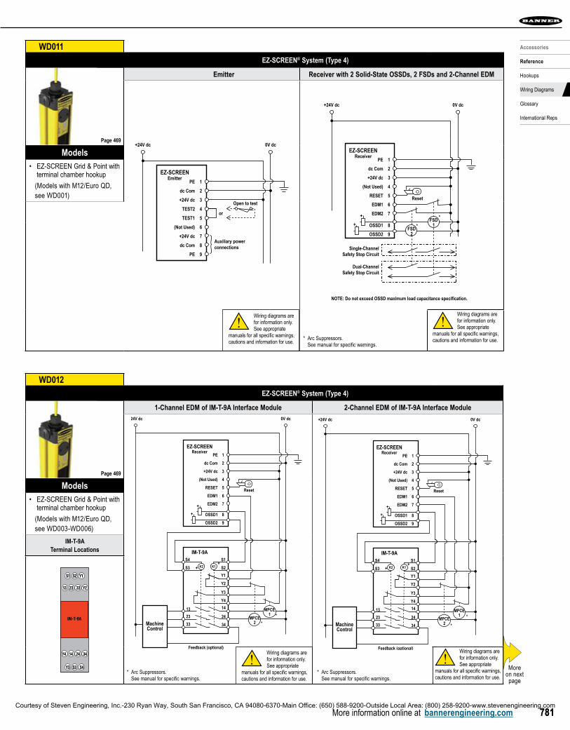
WD011 EZ-SCREEN ® System (Type 4)
Emitter Receiver with 2 Solid-State OSSDs, 2 FSDs and 2-Channel EDM
PE 1
dc Com 2
+24V dc
+24V dc 0V dc
3
TEST2 4or
TEST1 5
(Not Used) 6
+24V dc 7
dc Com 8
PE 9
EZ-SCREENEmitter
Auxiliary power connections
Open to test
1) TEST input must be jumpered if not used. Typically a Normally Open switch held closed. See Section 3.7.4 for information on TEST input and hookup.
Dual-ChannelSafety Stop Circuit
Single-ChannelSafety Stop Circuit
* Installation of transient suppressors across the coils of FSD1 and FSD2 is recommended. NOTE: Do not exceed OSSD maximum load capacitance specification.
*
*
+24V dc 0V dc
Reset
PE 1
dc Com 2
+24V dc 3
(Not Used) 4
RESET 5
EDM1 6
EDM2 7
OSSD1 8
OSSD2 9
EZ-SCREENReceiver
FSD1
FSD2
+
+
Models EZ-SCREEN Grid & Point with •terminal chamber hookup
(Models with M12/Euro QD, see WD001)
Wiring diagrams are for information only. See appropriate
manuals for all specific warnings, cautions and information for use.
!
Page 469
WD012 EZ-SCREEN ® System (Type 4)
1-Channel EDM of IM-T-9A Interface Module 2-Channel EDM of IM-T-9A Interface Module
Models EZ-SCREEN Grid & Point with •terminal chamber hookup
(Models with M12/Euro QD, see WD003-WD006)
IM-T-9ATerminal Locations
13
S1 S2 Y1
23 33 Y2
Y3 S3 S4
Y4 14 24 34
IM-T-9A
Wiring diagrams are for information only. See appropriate
manuals for all specific warnings, cautions and information for use.
!
Page 469
* Arc Suppressors. See manual for specific warnings.
* Arc Suppressors. See manual for specific warnings.
* Arc Suppressors. See manual for specific warnings.
Wiring diagrams are for information only. See appropriate manuals for all specific warnings, cautions and information for use.
!
Wiring diagrams are for information only. See appropriate manuals for all specific warnings, cautions and information for use.
!
+24V dc 0V dc
Reset
PE 1
dc Com 2
+24V dc 3
(Not Used) 4
RESET 5
EDM1 6
EDM2 7
OSSD1 8
OSSD2 9
S1
S2
Y1
Y2
Y3
Y4
14
24
34
13
23
33
S4
S3
EZ-SCREENReceiver
IM-T-9A
+
+
K2 K1
MPCE2
Feedback (optional)
MPCE1
MachineControl
* Installation of transient suppressors across the coils of MPCE1 and MPCE2 is recommended (see Warning).
++
*
*
1) See Section 3.5 for more information on Reset input and hookup.
2) See Section 3.7.3 for information on EDM input and hookup.
Moreon next page
Courtesy of Steven Engineering, Inc.-230 Ryan Way, South San Francisco, CA 94080-6370-Main Office: (650) 588-9200-Outside Local Area: (800) 258-9200-www.stevenengineering.com

More information online at bannerengineering.com782
REF
EREN
CE
More information online at bannerengineering.com782
HOOKUPS WIRING DIAGRAMS REFERENCE CHARTS GLOSSARY INTERNATIONAL REPS
WD013 EZ-SCREEN ® AC Interface Box
EZAC-R9-QE8 – Hard-Wired with 3 NO and EDM
2-ch. 1-ch.
X1
X2
X3
X4
13
14
23
24
33
34
1
2
3
4
5
6
7
8
1
2
3
4
5
1
2
3
2-ch. 1-ch.
EDM
P4
P1
P5
P3
P2
EZAC-R9-QE8100 - 230V ac
NL
Monitoring Contacts
K1 K2
MachineControl
2-ch. 1-ch.
2-ch. 1-ch.
No EDM
1-Channel EDM Hookup
2-Channel EDM Hookup
Monitoring Contacts
(Line) P5
(Neutral) P5
(Gnd) P5
13
23
X1
(EDM1)
(EDM2)
(EDM1)
(EDM2)
(EDM1)
(EDM2)
33
14
3
2
1
24
34
MPCE1
MPCE1
MPCE1
*
MPCE2
MPCE2
MPCE2
*
X2
X3
X4
X1
X2
X3
X4
X1
X2
X3
X4
Models EZAC-R9-QE8•
Connections(Hand Wired)
1/2 NPT threadsfor outputs
1/2 NPT threadsfor AC inputs
8-pin female Euro-style QD
to emitter/receiver
Wiring diagrams are for information only. See appropriate
manuals for all specific warnings, cautions and information for use.
!* Arc Suppressors. See manual for specific warnings.
Page 736
Moreon next page
Courtesy of Steven Engineering, Inc.-230 Ryan Way, South San Francisco, CA 94080-6370-Main Office: (650) 588-9200-Outside Local Area: (800) 258-9200-www.stevenengineering.com

783783More information online at bannerengineering.com
Accessories
Reference
Hookups
Wiring Diagrams
Glossary
International Reps
WD014 EZ-SCREEN ® AC Interface Box
EZAC-R11-QE8 – Hard-Wired with 2 NO, 1 NC and EDM
Models EZAC-R11-QE8•
Connections(Hand Wired)
1/2 NPT threadsfor outputs
1/2 NPT threadsfor AC inputs
8-pin female Euro-style QD
to emitter/receiver
Wiring diagrams are for information only. See appropriate
manuals for all specific warnings, cautions and information for use.
!
Page 736
* Arc Suppressors. See manual for specific warnings.
Moreon next page
Courtesy of Steven Engineering, Inc.-230 Ryan Way, South San Francisco, CA 94080-6370-Main Office: (650) 588-9200-Outside Local Area: (800) 258-9200-www.stevenengineering.com

More information online at bannerengineering.com784
REF
EREN
CE
More information online at bannerengineering.com784
HOOKUPS WIRING DIAGRAMS REFERENCE CHARTS GLOSSARY INTERNATIONAL REPS
WD015 EZ-SCREEN ® System (Type 4)
EZAC-R15A-QE8-Q583-Mini-Style QD with 1 NO, 1 SPDT and 1-Channel EDM
EZAC-R15A-QE8-QS83
(Neutral) P5
N
N
L
L(Line) P5
(Gnd) P5
K1 K2
MPCE1 MPCE2
Monitoring Contacts
Gn/Ye
Bk
N.O.
N.O.
EDM
+24V dc (switched)
N.O. (to load)
N.O. (to load)
N.C. Aux (see Warning)Lamp
Bn
Wh
Vi
Bu
Or/Bk
Or
Gn/Ye
Bn
Bu
(EDM1)
(EDM2)
X1
X2
X3
X4
5
7
3
8
4
1
2
6
3
3
11
2
2
MachineControl
100 - 230V ac
MPCE1
*
MPCE2
*
13
23
31
14
24
32
3-Pin Mini-Style Power ConnectorMale Face View
Mating Cordset: QDS-3..C
Pin Color Function
1 Green/Yellow Gnd/PE
2 Brown Line
3 Blue Neutral
Green/Yellowwire
Brownwire
Bluewire
8-Pin Mini-Style Output ConnectorMale Face View
Mating Cordset: QDS-8..C
Pin Color Function
1 Brown N.O.
2 Orange/Black +24V dc (EDM)
3 Orange EDM
4 White N.O. (to load)
5 Black N.O. (to load)
6 Blue Common
7 Green/Yellow Gnd/PE
8 Violet N.C. Aux.
Brown
Violet
Orange
Blue
White
BlackOrange/Black
Green/Yellow
ModelsEZAC-R15A-QE8-QS83•
Connections(8-Pin Mini)
3-pin male Mini-style
for AC inputs
8-pin female Euro-style QD
to emitter/receiver
8-pin male Mini-style
for outputs
Wiring diagrams are for information only. See appropriate
manuals for all specific warnings, cautions and information for use.
!
Page 736
† Arc Suppressors. See manual for specific warnings.
WD016 EZ-SCREEN ® AC Interface Box
EZAC-R8N-QE8-QS53 – Mini-Style QD with 1 NO, 1 NC and Power Monitoring
EZAC-R8N-QE8-QS53
(Neutral) P5
N
N
L
L(Line) P5
(Gnd) P5
K1 K2
MachineControl
MonitoringContacts
Gn/Ye
Wh
Bk
Bu
Bn
Gn/Ye
Bn
Bu
N.O. (1a)
N.C. (2a)
N.C. (2b)
N.O. (1b)
13
23
31
14
24
32
MPCE1
*
MPCE2
MPCE2MPCE1
*
5
3
3
3
1
11
2
2
2
4
100 - 230V ac
(EDM1)
(EDM2)
X1
X2
X3
X4
5-Pin Mini-Style Output ConnectorMale Face View
Mating Cordset: QDS-5..C
Pin Color Function
1 Black N.O. (1a)
2 Blue N.C. (2a)
3 Green/Yellow Gnd/PE
4 Brown N.C. (2b)
5 White N.O. (1b)
Black White
BrownBlue
Green/Yellow
3-Pin Mini-Style Power ConnectorMale Face View
Mating Cordset: QDS-3..C
Pin Color Function
1 Green/Yellow Gnd/PE
2 Brown Line
3 Blue Neutral
Green/Yellowwire
Brownwire
Bluewire
ModelsEZAC-R8N-QE8-QS53•
Connections(5-Pin Mini)
3-pin male Mini-style
for AC inputs
8-pin female Euro-style QD
to emitter/receiver
5-pin male Mini-style
for outputs
Wiring diagrams are for information only. See appropriate
manuals for all specific warnings, cautions and information for use.
!
Page 736
† Arc Suppressors. See manual for specific warnings.
Moreon next page
Courtesy of Steven Engineering, Inc.-230 Ryan Way, South San Francisco, CA 94080-6370-Main Office: (650) 588-9200-Outside Local Area: (800) 258-9200-www.stevenengineering.com
785785More information online at bannerengineering.com
Accessories
Reference
Hookups
Wiring Diagrams
Glossary
International Reps
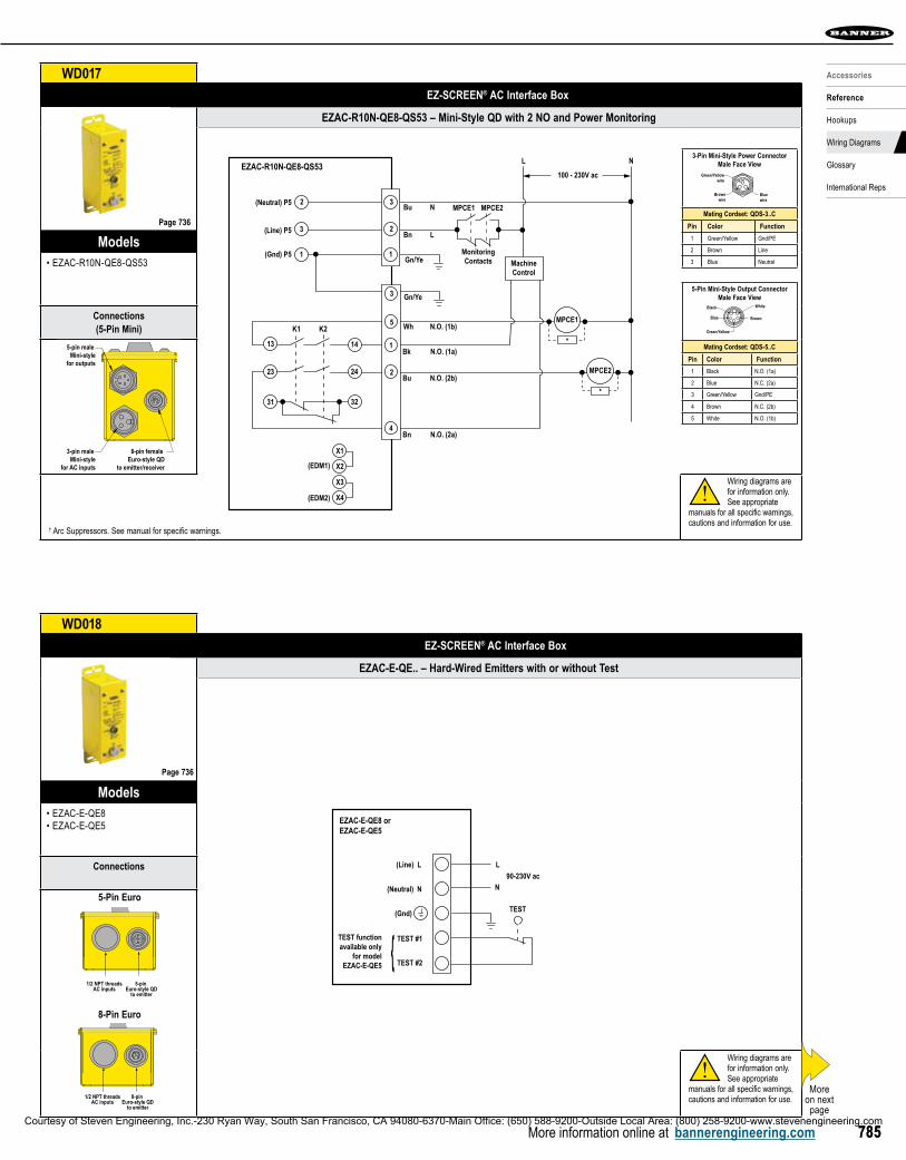
WD017 EZ-SCREEN ® AC Interface Box
EZAC-R10N-QE8-QS53 – Mini-Style QD with 2 NO and Power Monitoring
EZAC-R10N-QE8-QS53
(Neutral) P5
N
N
L
L(Line) P5
(Gnd) P5
(EDM1)
K1 K2
(EDM2)
MachineControl
Gn/Ye
Wh
N.O. (1a)
N.O. (2a)
N.O. (2b)
N.O. (1b)
Bk
Bu
Bn
Gn/Ye
Bn
Bu3
3
11
2
2
13
23
31
14
24
32
5
3
1
2
4
MPCE1
*
MPCE2
*
100 - 230V ac
X1
X2
X3
X4
MonitoringContacts
MPCE2MPCE1
5-Pin Mini-Style Output ConnectorMale Face View
Mating Cordset: QDS-5..C
Pin Color Function
1 Black N.O. (1a)
2 Blue N.C. (2a)
3 Green/Yellow Gnd/PE
4 Brown N.C. (2b)
5 White N.O. (1b)
Black White
BrownBlue
Green/Yellow
3-Pin Mini-Style Power ConnectorMale Face View
Mating Cordset: QDS-3..C
Pin Color Function
1 Green/Yellow Gnd/PE
2 Brown Line
3 Blue Neutral
Green/Yellowwire
Brownwire
Bluewire
ModelsEZAC-R10N-QE8-QS53•
Connections(5-Pin Mini)
3-pin male Mini-style
for AC inputs
8-pin female Euro-style QD
to emitter/receiver
5-pin male Mini-style
for outputs
Wiring diagrams are for information only. See appropriate
manuals for all specific warnings, cautions and information for use.
!
Page 736
† Arc Suppressors. See manual for specific warnings.
WD018 EZ-SCREEN ® AC Interface Box
EZAC-E-QE.. – Hard-Wired Emitters with or without Test
(Neutral) N
(Line) L L
N
TEST
90-230V ac
TEST #1
TEST #2{TEST functionavailable only
for modelEZAC-E-QE5
Terminal strip on box inside cover; see Figure 3
(Gnd)
EZAC-E-QE8 orEZAC-E-QE5
ModelsEZAC-E-QE8•EZAC-E-QE5•
Connections
8-pin Euro-style QD
to emitter
1/2 NPT threadsAC inputs
5-pin Euro-style QD
to emitter
1/2 NPT threadsAC inputs
5-Pin Euro
8-Pin Euro
Wiring diagrams are for information only. See appropriate
manuals for all specific warnings, cautions and information for use.
!
Page 736
Moreon next page
Courtesy of Steven Engineering, Inc.-230 Ryan Way, South San Francisco, CA 94080-6370-Main Office: (650) 588-9200-Outside Local Area: (800) 258-9200-www.stevenengineering.com

More information online at bannerengineering.com786
REF
EREN
CE
More information online at bannerengineering.com786
HOOKUPS WIRING DIAGRAMS REFERENCE CHARTS GLOSSARY INTERNATIONAL REPS
WD019 EZ-SCREEN ® AC Interface Box
EZAC-E-QE8-QS3 – Mini-Style QD Emitter EZAC-E-QE5-QS5 – Mini-Style QD Emitter with Test
(Neutral) N
(Line) L
(Gnd)
EZAC-E-QE8-QS3
L
N90-230V ac
Brown
Blue
Green/Yellow1
2
3
3-Pin Mini-Style Power ConnectorMale Face View
Mating Cordset: QDS-3..C
Pin Color Function
1 Green/Yellow Gnd/PE
2 Brown Line
3 Blue Neutral
Green/Yellowwire
Brownwire
Bluewire
5-Pin Mini-Style Output ConnectorMale Face View
Mating Cordset: QDS-5..C
Pin Color Function
1 Black N.O. (1a)
2 Blue N.C. (2a)
3 Green/Yellow Gnd/PE
4 Brown N.C. (2b)
5 White N.O. (1b)
Black White
BrownBlue
Green/Yellow
(Neutral) N
(Line) L L
N
TEST
90-230V ac
TEST #1
TEST #2
(Gnd)
EZAC-E-QE5-QS5
Brown
Blue
Green/Yellow
Black
White
4
2
3
1
5
ModelsEZAC-E-QE8-QS3•EZAC-E-QE5-QS5•
Connections
(3-Pin Mini)
8-pin Euro-style QD
to emitter
3-pin maleMini-styleAC inputs
(5-Pin Mini)
5-pin Euro-style QD
to emitter
5-pin maleMini-styleAC inputs
Wiring diagrams are for information only. See appropriate
manuals for all specific warnings, cautions and information for use.
!
WD020 AG4 Laser Scanner
AG4 to FSD1 & FSD2
ModelsAG4•
Wiring diagrams are for information only. See appropriate
manuals for all specific warnings, cautions and information for use.
!
Page 398
Page 736
+24V dc
AG4
0V dc
0V dc
+
FSD2
FSD1
Single-ChannelSafety Stop
Circuit
Dual-ChannelSafety Stop
Circuit
NOTE: Do not exceed OSSD maximum load capacitance specification.
Restart(Reset)
+24V dc
FP1*
Alarm 1(Auxiliary 1) **
FP2*
FP3*
FP4*
OSSD1
OSSD2
Fuse1.6A
X1
* Figure shows Field Pair #1 selected.See manual for further information on Field Pair Switchover
** See manual for further information on the non-safety Alarm/Auxiliary outputs.
Warning: Monitoring FSDs FSDs must be monitored for proper operation. 1-channel EDM can only be used when the AG4-4E is configured for manual reset. See manual for more information.
1
2
3
4
5
6
7
8
9
10
11
12
13
14
15Alarm 2(Auxiliary 2) **
Wht/Blk
Black
White
Shield
Orange
Brown
Violet
Blue
Wiring diagrams are for information only. See appropriate manuals for all specific warnings, cautions and information for use.
!
Warning: Monitoring FSDsFSD’s must be monitored for proper operation. 1-channel EDM can only be used when the scanner is configured for manual reset. See manual for more information. More
on next page
Courtesy of Steven Engineering, Inc.-230 Ryan Way, South San Francisco, CA 94080-6370-Main Office: (650) 588-9200-Outside Local Area: (800) 258-9200-www.stevenengineering.com
Related Documents