RRDP-II-SSN-02-04 i ISO 9001, ISO 14001 & OHSAS 18001 Certified BANGLADESH RURAL ELECTRIFICATION BOARD (BREB) TENDER DOCUMENT FOR THE SUPPLY, INSTALLATION, TESTING & COMMISSIONING OF 33/11KV SUB-STATIONS (10MVA EACH) UNDER RURAL ELECTRIFICATION EXPANSION RAJSHAHI-RANGPUR DIVISION PROGRAM-II TENDER PACKAGE NO: RRDP-II-SSN-02 SUB-PACKAGE NO: RRDP-II-SSN-02-04 ISSUED TO: M/S…………………………………………………………………… ON BEHALF OF THE OFFICE OF Project Director, REE-RRDP-II Training Academy Building (6 th Floor) Bangladesh Rural Electrification Board SEAL & SIGNATURE

Welcome message from author
This document is posted to help you gain knowledge. Please leave a comment to let me know what you think about it! Share it to your friends and learn new things together.
Transcript
RRDP-II-SSN-02-04 i
ISO 9001, ISO 14001 &OHSAS 18001 Certified
BANGLADESH RURAL ELECTRIFICATION BOARD (BREB)
TENDER DOCUMENTFOR THE
SUPPLY, INSTALLATION, TESTING & COMMISSIONING OF 33/11KVSUB-STATIONS (10MVA EACH)
UNDERRURAL ELECTRIFICATION EXPANSION RAJSHAHI-RANGPUR DIVISION
PROGRAM-II
TENDER PACKAGE NO: RRDP-II-SSN-02SUB-PACKAGE NO: RRDP-II-SSN-02-04
ISSUED TO: M/S……………………………………………………………………
ON BEHALF OF THE OFFICE OFProject Director, REE-RRDP-IITraining Academy Building (6th Floor)Bangladesh Rural Electrification Board
SEAL & SIGNATURE
RRDP-II-SSN-02-04 ii
RRDP-II-SSN-02-04 iii
ISO 9001, ISO 14001 &OHSAS 18001 Certified
BANGLADESH RURAL ELECTRIFICATION BOARD (BREB)
TENDER DOCUMENTFOR THE
SUPPLY, INSTALLATION, TESTING & COMMISSIONING OF 33/11KVSUB-STATIONS (10MVA EACH)
UNDERRURAL ELECTRIFICATION EXPANSION RAJSHAHI-RANGPUR DIVISION
PROGRAM-II
VOLUME 1 OF 2
SECTION: 1- Instruction To Tenderers (ITT)SECTION: 2- Tender Data Sheet (TDS)SECTION: 3- General Conditions of Contract (GCC)SECTION: 4- PCC, Labour LawsSECTION: 5- Tender and Contract FormsSECTION: 6- Bill of Quantity
RRDP-II-SSN-02-04 iv
ISO 9001, ISO 14001 &OHSAS 18001 Certified
BANGLADESH RURAL ELECTRIFICATION BOARD (BREB)
TENDER DOCUMENTFOR THE
SUPPLY, INSTALLATION, TESTING & COMMISSIONING OF 33/11KVSUB-STATIONS (10MVA EACH)
UNDERRURAL ELECTRIFICATION EXPANSION RAJSHAHI-RANGPUR DIVISION
PROGRAM-II
I N D E X TO V O L U M E S
Volume 1 of 2 Section : 1 Instruction to Tenders (ITT) Section : 2 Tender Data Sheet (TDS) Section : 3 General Conditions of Contract (GCC) Section : 4
Part I Particular Conditions of Contract (PCC)Part II Labour Laws
Section : 5 Tenders and Contract FormsForm PW3-1 : Tender Submission LetterForm PW3-2 : Tenderer InformationForm PW3-3 : JV Partner Information.Form PW3-4 : Sub-contractor InformationForm PW3-5 : Personnel InformationForm PW3-6 : Bank Guarantee for Tender SecurityForm PW3-8 : Notification of AwardForm PW3-9 : Contract AgreementForm PW3-10 : Bank Guarantee for Performance Security
RRDP-II-SSN-02-04 v
Section : 6 Bill of Quantity
Volume 2 of 2SECTION :7 - GENERAL SPECIFICATIONScope of Work
Section : 8 - PARTICULAR SPECIFICATION
Section : 9 - DRAWINGs
RRDP-II-SSN-02-04 vi
Table of ContentsVOLUME 1 OF 2 .................................................................................................................iii
Section 1.Instructions to Tenderers...................................................................1A. General............................................................................................................. 1
1. Scope of Tender .............................................................................................................. 12. Interpretation ................................................................................................................... 13. Source of Funds .............................................................................................................. 14. Corrupt, Fraudulent, Collusive, Coercive (or Obstructive in case of Development Partner)Practices ...................................................................................................................... 25. Eligible Tenderers............................................................................................................ 46. Eligible Materials, Equipment and Associated Services ................................................. 57. Site Visit........................................................................................................................... 5
B. Tender Document ........................................................................................... 58. Tender Document: General ............................................................................................. 59. Clarification of Tender Document .................................................................................... 510. Pre-Tender Meeting....................................................................................................... 611. Addendum to Tender Document ................................................................................... 6
C. Qualification Criteria.............................................................................................. 712. General Criteria ............................................................................................................. 713. Litigation History ............................................................................................................ 714. Experience Criteria ........................................................................................................ 715. Financial Criteria............................................................................................................ 816. Personnel Capacity ....................................................................................................... 817. Equipment Capacity ...................................................................................................... 818. Joint Venture (JV).......................................................................................................... 819. Subcontractor(s) ............................................................................................................ 9
D. Tender Preparation......................................................................................... 920. Only one Tender............................................................................................................ 921. Cost of Tendering .......................................................................................................... 922. Issuance and Sale of Tender Document .....................................................................1023. Language of Tender ....................................................................................................1024. Contents of Tender......................................................................................................1025. Tender Submission Letter and Bill of Quantities ......................................................... 1126. Alternatives .................................................................................................................. 1127. Tender Prices, Discounts and Price Adjustment ......................................................... 1128. Tender Currency.......................................................................................................... 1229. Documents Establishing Eligibility of the Tenderer ..................................................... 1230. Documents Establishing the Eligibility and Conformity of Materials, Equipment and
Services..................................................................................................................... 1331. Documents Establishing Technical Proposal .............................................................. 1332. Documents Establishing the Tenderer’s Qualification................................................. 1333. Validity Period of Tender ............................................................................................. 1434. Extension of Tender Validity and Tender Security .................................................. 1435. Tender Security ........................................................................................................... 1436. Form of Tender Security.............................................................................................. 1537. Authenticity of Tender Security ................................................................................... 1538. Return of Tender Security ........................................................................................... 1539. Forfeiture of Tender Security....................................................................................... 1540. Format and Signing of Tender..................................................................................... 16
E. Tender Submission ...................................................................................... 1641. Sealing, Marking and Submission of Tender............................................................... 1642. Deadline for Submission of Tender ............................................................................. 1743. Late Tender ................................................................................................................. 1744. Modification, Substitution or Withdrawal of Tender ..................................................... 1745. Tender Modification .....................................................................................................1746. Tender Substitution .....................................................................................................17
RRDP-II-SSN-02-04 vii
47. Tender Withdrawal ......................................................................................................18F. Tender Opening and Evaluation ................................................................. 18
48. Tender Opening........................................................................................................... 1849. Evaluation of Tenders..................................................................................................1950. Evaluation Process......................................................................................................1951. Preliminary Examination.............................................................................................. 2152. Technical Responsiveness and Technical Evaluation ................................................ 2153. Clarification on Tender ................................................................................................ 2254. Restrictions on Disclosure of Information....................................................................2355. Correction of Arithmetical Errors ................................................................................. 2356. Financial Evaluation ....................................................................................................2357. Price Comparison ........................................................................................................ 2458. Negotiations................................................................................................................. 2559. Post-qualification ......................................................................................................... 2560. Procuring Entity’s Right to Accept any or to Reject Any or All Tenders ...................... 2661. Rejection of All Tenders .............................................................................................. 2662. Informing Reasons for Rejection ................................................................................. 26
G. Contract Award ............................................................................................. 2663. Award Criteria .............................................................................................................. 2664. Notification of Award....................................................................................................2765. Performance Security ..................................................................................................2766.Form and Time Limit for Furnishing of Performance Security....................................2867.Validity of Performance Security .................................................................................. 2868. Authenticity of Performance Security .......................................................................... 2869. Contract Signing ....................................................................................................... 2870. Publication of Notification of Award of Contract .......................................................... 2871. Debriefing of Tenderers............................................................................................... 2872. Adjudicator................................................................................................................... 2973. Right to Complain ........................................................................................................ 29
Section 2. Tender Data Sheet.........................................................................30A. General........................................................................................................... 30B. Tender Document ......................................................................................... 30C. Qualification Criteria .................................................................................... 31D. Tender Preparation....................................................................................... 33E. Tender Submission ...................................................................................... 35F. Tender Opening and Evaluation ................................................................. 36G. Contract Award ............................................................................................. 36
Section 3. General Conditions of Contract ...................................................37A. General........................................................................................................... 37
1. Definitions................................................................................................................ 372. Interpretation ........................................................................................................... 403. Communications & Notices......................................................................................... 414. Governing Law ........................................................................................................ 415. Governing Language............................................................................................... 416. Documents Forming the Contract and Priority of Documents ............................ 417. Scope of Works ....................................................................................................... 418. Assignment .............................................................................................................. 419. Eligibility .................................................................................................................. 4210. Gratuities / Agency fees.......................................................................................... 4211. Confidential Details ................................................................................................. 4212. Joint Venture (JV).................................................................................................... 4213. Possession of the Site ............................................................................................ 4314. Access to the Site.................................................................................................... 4315. Procuring Entity’s Responsibilities ....................................................................... 4316. Approval of the Contractor’s Temporary Works .................................................. 4317. Contractor’s Responsibilities................................................................................. 43
RRDP-II-SSN-02-04 viii
18. Taxes and Duties ..................................................................................................... 4319. Contractor’s Personnel........................................................................................... 4320. Subcontracting ........................................................................................................ 4421. Other Contractors.................................................................................................... 4422. Project Manager’s Decisions.................................................................................. 4423. Delegation ................................................................................................................ 4424. Instructions.............................................................................................................. 4425. Queries About the Contract Conditions ................................................................ 4426. Safety, Security and Protection of the Environment ............................................ 4427. Working Hours......................................................................................................... 4528. Welfare of Labourers............................................................................................... 4529. Child Labour ............................................................................................................ 4530. Discoveries .............................................................................................................. 4531. Procuring Entity’s and Contractor’s Risks ........................................................... 4532. Procuring Entity’s Risks ......................................................................................... 4533. Contractor’s Risks................................................................................................... 4634. Copyright ................................................................................................................. 4635. Limitation of Liability .............................................................................................. 4636. Insurance ................................................................................................................. 4637. Management and Progress Meetings .................................................................... 47
B. Time Control .................................................................................................. 4939. Commencement of Works ........................................................................................... 4940. Completion of Works .............................................................................................. 4941. Program of Works ................................................................................................... 4942. Pro Rata Progress ................................................................................................... 5043. Early Warning .......................................................................................................... 5044. Extension of Intended Completion Date................................................................ 5045. Delays Caused by Authorities ................................................................................ 5146. Acceleration............................................................................................................. 5147. Delays Ordered by the Project Manager................................................................ 5148. Suspension of Work................................................................................................ 5149. Consequences of Suspension ............................................................................... 52
C. Quality Control .............................................................................................. 5250. Execution of Works ................................................................................................. 5251. Examination of Works before covering up............................................................ 5252. Identifying Defects .................................................................................................. 5253. Testing...................................................................................................................... 5254. Rejection of Works .................................................................................................. 5255. Remedial Work ........................................................................................................ 5356. Correction of Defects .............................................................................................. 5357. Uncorrected Defects ............................................................................................... 53
D. Cost Control .................................................................................................. 5358. Contract Price.......................................................................................................... 5359. Bill of Quantities ...................................................................................................... 5360. Changes in the Quantities and Unit Rate .............................................................. 5461. Issue Variation or Extra Work Order...................................................................... 5462. Costing of Variations or Extra Orders ................................................................... 5563. Cash Flow Forecasts............................................................................................... 5564. Payment Certificates ............................................................................................... 5565. Payments to the Contractor ................................................................................... 5666. Delayed Payment..................................................................................................... 5667. Compensation Events............................................................................................. 5668. Adjustments for Changes in Legislation ............................................................... 5769. Price Adjustment ..................................................................................................... 5770. Retention Money...................................................................................................... 5871. Liquidated Damages ............................................................................................... 5872. Bonus ....................................................................................................................... 5873. Advance Payment.................................................................................................... 5974. Performance Security ............................................................................................. 5975. Provisional Sums .................................................................................................... 6076. Day works ................................................................................................................ 6077. Cost of Repairs to Loss or Damages..................................................................... 6078. Completion............................................................................................................... 6079. Taking Over.............................................................................................................. 6080. Amendment to Contract.......................................................................................... 60
RRDP-II-SSN-02-04 ix
81. Final Account........................................................................................................... 6182. As-built Drawings and Manuals ............................................................................. 6183. Force Majeure .......................................................................................................... 6184. Notice of Force Majeure.......................................................................................... 6185. Consequences of Force Majeure ........................................................................... 6286. Release from Performance ..................................................................................... 6287. Termination.............................................................................................................. 6288. Payment upon Termination .................................................................................... 6489. Property.................................................................................................................... 6590. Frustration ............................................................................................................... 6591. Contractor’s Claims ................................................................................................ 6592. Settlement of Disputes............................................................................................ 66
Section 4. Particular Conditions of Contract................................................67SECTION 4: PART -II -( LABOUR LAWS ) ...................................................................... 72
Section 5. Tender and Contract Forms.............................................................72Tender Submission Letter (Form PW3-1)............................................................................. 74Tenderer Information (Form PW3-2)................................................................................... 77JV Partner Information (Form PW3-3)................................................................................ 80Personnel Information (Form PW3-5).................................................................................. 85Letter of Commitment for Bank’s Undertaking for Line of Credit (Form PW3-7)................. 87Notification of Award (Form PW3-8) ................................................................................... 88Contract Agreement (Form PW3-9) ..................................................................................... 89Bank Guarantee for Performance Security (Form PW3-10).................................................. 90
Section 6. Bill of Quantities ..............................................................................91VOLUME 2 OF 2 ............................................................................................................... 95
Section 7. General Specifications......................................................................96Section 7. General Specifications....................................................................103Section 9. Drawings .......................................................................................391
RRDP-II-SSN-02-04 1
Section 1.Instructions to Tenderers
A. General1. Scope of Tender 1.1 The Procuring Entity, as indicated in the Tender Data Sheet
(TDS) issues this Tender Document for the procurement of Worksand physical services incidental thereto as specified in the TDSand as detailed in Section 6: Bill of Quantities. The name of theTender and the number and identification of its constituent lot(s)are stated in the TDS.
1.2 The successful Tenderer shall be required to execute the Worksand physical services as specified in the General Conditions ofContract
2. Interpretation 2.1 Throughout this Tender Document:(a) the term “in writing” means communication written by hand or
machine duly signed and includes properly authenticatedmessages by facsimile or electronic mail;
(b) if the context so requires, singular means plural and vice versa;(c) “day” means calendar days unless otherwise specified as working
days;(d) “Person” means and includes an individual, body of individuals,
sole proprietorship, partnership, company, association orcooperative society that wishes to participate in Procurementproceedings;
(e) “Tenderer” meansa Person who submits a Tender;(f) “Tender Document” means the Document provided by a
Procuring Entity to a Tenderer as a basis for preparation of theTender; and
(g) “Tender” depending on the context, means a Tender submitted bya Tenderer for execution of Works and physical services to aProcuring Entity in response to an Invitation for Tender.
3. Source of Funds 3.1 The Procuring Entity has been allocated public funds asindicated in the TDS and intends to apply a portion of the fundsto eligible payments under the Contract for which this TenderDocument is issued.
3.2 For the purpose of this provision, “public funds” means anymonetary resources appropriated to the Procuring Entity underGovernment budget, or loan, grants and credits placed at thedisposal of the Procuring Entity through the Government by thedevelopment partners or foreign states or organisations.
3.3 Payments by the development partner, if so indicated in theTDS, will be made only at the request of the Government andupon approval by the development partner or foreign state orOrganisation in accordance with the applicable Loan / Credit /Grant Agreement, and will be subject in all respects to theterms and conditions of that Agreement.
RRDP-II-SSN-02-04 2
4. Corrupt, Fraudulent,Collusive, Coercive(or Obstructive incase ofDevelopmentPartner) Practices4.1 The Government and the Development Partner, if
applicablerequires that the Procuring Entity as well as theTenderers and Contracts (including , sub-contractors,agents, personnel, consultants, and service providers)shallobserve the highest standard of ethics duringimplementation of procurement proceedings and theexecution of Contracts under public funds.
4.2 For the purposes of ITT Sub Clause 4.3, the terms set forthbelow as follows:(a) “corrupt practice” means offering, giving or
promising to give, receiving, or soliciting eitherdirectly or indirectly, to any officer or employee of theProcuring Entity or other public or private authority orindividual, a gratuity in any form; employment or anyother thing or service of value as an inducement withrespect to an actor decision or method followed by theProcuring Entity in connection with a Procurementproceeding or Contract execution;
(b) “fraudulent practice” means the misrepresentation oromission of facts in order to influence a decision to betaken in a Procurement proceeding or Contractexecution;
(c) “collusive practice” means a scheme or arrangementbetween two (2) or more Persons, with or without theknowledge of the Procuring Entity, that is designed toarbitrarily reduce the number of Tenders submitted orfix Tender prices at artificial, non-competitive levels,thereby denying the Procuring Entity the benefits ofcompetitive price arising from genuine and opencompetition;
(d) “coercive practice” means harming or threatening toharm, directly or indirectly, Persons or their propertyto influence a decision to be taken in theProcurement proceeding or the execution of aContract, and this will include creating obstructions inthe normal submission process used for Tenders.
(e) “Obstructive practice” (applicable in case ofDevelopment Partner) means deliberatelydestroying, falsifying, altering or concealing ofevidence material to the investigation or making falsestatements to investigators in order to materiallyimpede an investigation into allegations of a corrupt,fraudulent, coercive or collusive practice; and /orthreatening, harassing or intimidating any party toprevent it from disclosing its knowledge of mattersrelevant to the investigation or from pursuing theinvestigation.
4.3 Should any corrupt, fraudulent, collusive, coercive (orobstructive in case of Development Partner) practice of anykind is determined by the Procuring Entity or theDevelopment Partner, if applicable, this will be dealt inaccordance with the provisions of the Public ProcurementAct and Rules and Guidelines of the Development Partnersas stated in the ITT sub-clause 3.3.In case of obstructivepractice, this will be dealt in accordance with DevelopmentPartners Guidelines.
RRDP-II-SSN-02-04 3
4.4 If corrupt, fraudulent, collusive, coercive (or obstructive incase of Development Partner) practices of any kind isdetermined by the Procuring Entity against any Tendereror Contracts (including sub-contractors, agents, personnel,consultants, and service providers) in competing for, or inexecuting, a contract under public fund:(a) Procuring Entity and/or the Development Partner
shall exclude the concerned Tenderer from furtherparticipation in the concerned procurementproceedings;
(b) Procuring Entity and/or the Development Partnershall reject any recommendation for award that hadbeen proposed for that concerned Tenderer;
(c) Procuring Entity and/or the Development Partnershall declare, at its discretion, the concerned Tendererto be ineligible to participate in further Procurementproceedings, either indefinitely or for a specific period oftime;
(d) Development Partner shall sanction the concernedTenderer or individual, at any time, in accordancewith prevailing Development Partner’ sanctionsprocedures, including by publicly declaring suchTenderer or individual ineligible, either indefinitely orfor a stated period of time: (i) to be awarded aDevelopment Partner-financed contract; and (ii) to bea nominated sub-contractor, consultant,manufacturer or Contractor, or service provider of anotherwise eligible firm being awarded a DevelopmentPartner-financed contract; and
(e) Development Partner shall cancel the portion of theloan allocated to a contract if it determines at anytime that representatives of the Procuring Entity or ofa beneficiary of the loan engaged in corrupt,fraudulent, collusive, coercive or obstructivepractices during the procurement or the execution ofthat Development Partner financed contract, withoutthe Procuring Entity having taken timely andappropriate action satisfactory to the DevelopmentPartner to remedy the situation.
4.5 Tenderer shall be aware of the provisions on corruption,fraudulence, collusion, coercion (and obstruction, in case ofDevelopment Partner) of the Public Procurement Act,2006, the Public Procurement Rules, 2008 and others asstated in GCC Clause 38.
4.6 In further pursuance of this policy, Tenderers, Contractorsand their sub-contractors, agents, personnel, consultants,service providers shall permit the Government and theDevelopment Partner to inspect any accounts and recordsand other documents relating to the Tender submission andcontract performance, and to have them audited by auditorsappointed by the Government and/or the DevelopmentPartner during the procurement or the execution of that
RRDP-II-SSN-02-04 4
Development Partner financed contract.5. Eligible Tenderers 5.1 This Invitation for Tenders is open to all potential
Tenderers from all countries, except for any specified inthe TDS.
5.2 Tenderers shall have the legal capacity to enter into theContract under the Applicable law.
5.3 Tenderers shall be enrolled in the relevant professional ortrade organisations registered in Bangladesh.
5.4 Tenderers may be a physical or juridical individual orbody of individuals, or company, association or anycombination of them in the form of a Joint Venture(JV)invited to take part in public procurement or seeking to beso invited or submitting a Tender in response to anInvitation for Tenders.
5.5 Tenderers shall have fulfilled its obligations to pay taxesand social security contributions under the provisions oflaws and regulations of the country of its origin.
5.6 Tenderers should not be associated, or have beenassociated in the past, directly or indirectly, with aconsultant or any of its affiliates which have beenengaged by the Procuring Entity to provide consultingservices for the preparation of the design, specifications,and other documents to be used for the procurement ofthe works to be performed under this Invitation forTenders.
5.7 Tenderers in its own name or its other names or also inthe case of its Persons in different names shall not beunder a declaration of ineligibility for corrupt, fraudulent,collusive or coercive practices as stated under ITT SubClause 4.4 (or obstructive practice, in case ofDevelopment Partner) in relation to the DevelopmentPartner’s Guidelines in projects financed by DevelopmentPartner.
5.8 Tenderers are not restrained or barred from participatingin Public Procurement on grounds of poor performance inthe past under any Contract.
5.9 Tenderers shall not be insolvent, be in receivership, bebankrupt, be in the process of bankruptcy, be nottemporarily barred from undertaking business and it shallnot be the subject of legal proceedings for any of theforegoing.
5.10 Government-owned enterprise in Bangladesh may alsoparticipate in the Tender if it is legally and financiallyautonomous, it operates under commercial law, and it isnot a dependent agency of the Procuring Entity.
5.11 Tenderers shall provide such evidence of their continuedeligibility satisfactory to the Procuring Entity, as theProcuring Entity will reasonably request.
5.12 These above requirements for eligibility will extend, asapplicable, to each JV partner and Subcontractorproposed by the Tenderers.
RRDP-II-SSN-02-04 5
5.13 Tenderers shall have the up-to-date valid license(s),issued by the corresponding competent authority, asspecified in the TDS.
6. Eligible Materials,Equipment and
Associated Services
6.1 All materials, equipment and associated services to besupplied under the Contract are from eligible sources,unless their origin is from a country specified in the TDS.
6.2 For the purposes of this Clause, “origin” means the placewhere the Materials and Equipments are mined, grown,cultivated, produced or manufactured or processed, orthrough manufacturing, processing, or assembling, anothercommercially recognized new product results that differssubstantially in its basic characteristics from its componentsor the place from which the associated services aresupplied.
6.3 The origin of materials and equipment and associatedservices is distinct from the nationality of the Tenderer.
7. Site Visit 7.1 Tenderers are advised to visit and examine the Site ofWorks and its surroundings and obtain for itself on its ownresponsibility all information that may be necessary forpreparing the Tender and entering into a contract forconstruction of the Works. The costs of visiting the Siteshall be at Tenderer’s own expense.
B. Tender Document8. Tender Document:
General8.1 The Sections comprising the Tender Document are listed
below, and should be read in conjunction with anyAddendum issued under ITT Clause 11.
Section 1 Instructions to Tenderers (ITT) Section 2 Tender Data Sheet (TDS) Section 3 General Conditions of Contract (GCC) Section 4 Particular Conditions of Contract (PCC) Section 5 Tender and Contract Forms Section 6 Bill of Quantities (BOQ) Section 7 General Specifications Section 8 Particular Specifications Section 9 Drawings
8.2 The Procuring Entity is not responsible for the completenessof the Tender Document and their addenda, if these were notpurchased directly from the Procuring Entity, or through itsagent as specified in the TDS.
8.3 Tenderers are expected to examine all instructions, forms,terms, and specifications in the Tender Document as wellas in addendum to Tender, if any.
9. Clarification of Tender 9.1 A prospective Tenderer requiring any clarification of theTender Document shall contact the Procuring Entity in
RRDP-II-SSN-02-04 6
Document writing at the Procuring Entity’s address and within timeas specified in the TDS.
9.2 The Procuring Entity is not obliged to answer anyclarification request received after that date as statedunder ITT Sub Clause 9.1.
9.3 The Procuring Entity shall respond in writing within five (5)working days of receipt of any such request forclarification received under ITT Sub Clause 9.1.
9.4 The Procuring Entity shall forward copies of its response toall those who have purchased the Tender Document,including a description of the enquiry but without identifyingits source.
9.5 Should the Procuring Entity deem it necessary to revise theTender Document as a result of a clarification, it will do sofollowing the procedure under ITT Clause 11.
10. Pre-Tender Meeting 10.1 To clarify issues and to answer questions on any matterarising in the Tender Document, the Procuring Entity may, ifstated in the TDS, hold a pre-Tender Meeting at the place,date and time as specified in the TDS. All potentialTenderers are encouraged and invited to attend themeeting, if it is held.
10.2 Tenderers are requested to submit any questions in writingso as to reach the Procuring Entity not later than one dayprior to the date of the meeting.
10.3 Minutes of the pre-Tender meeting, including the text of thequestions raised and the responses given, together with anyresponses prepared after the meeting, will be transmittedwithin five (5) working days after holding the meeting to allthose who purchased the Tender document and to eventhose who did not attend the meeting. Any revision to theTender Document listed in ITT Sub Clause 8.1 that maybecome necessary as a result of the pre-Tender meetingwill be made by the Procuring Entity exclusively through theissue of an Addendum pursuant to ITT Sub Clause 11 andnot through the minutes of the pre-Tender meeting.
10.4 Non-attendance at the Pre-Tender meeting will not be acause for disqualification of a Tenderer.
11. Addendum to TenderDocument
11.1 At any time prior to the deadline for submission of Tenders,the Procuring Entity, on its own initiative or in response toan inquiry in writing from a Tenderer, having purchased theTender Document, or as a result of a pre-Tender meetingmay revise the Tender Document by issuing an Addendum.
11.2 The Addendum issued under ITT Sub Clause 11.1 shallbecome an integral part of the Tender Document and shallhave a date and an issue number and must be circulated byfax, mail or e-mail, to Tenderers who have purchased theTender Documents, within five (5) working days of issuanceof such Addendum, to enable Tenderers to take appropriateaction
RRDP-II-SSN-02-04 7
11.3 The Procuring Entity shall also ensure posting of therelevant addenda with the reference number and date ontheir websites including notice boards, where the ProcuringEntity had originally posted the IFTs.
11.4 To give a prospective Tenderer reasonable time in which totake an addendum into account in preparing its Tender, theProcuring Entity may, at its discretion, extend the deadlinefor the submission of Tenders, pursuant to ITT Sub Clause42.2.
11.5 If an addendum is issued when time remaining is less thanone-third of the time allowed for the preparation ofTenders, the Procuring Entity at its discretion shall extendthe deadline by an appropriate number of days for thesubmission of Tenders, depending upon the nature of theProcurement requirement and the addendum. In any case,the minimum time for such extension shall not be less thanthree (3) working days.
C. Qualification Criteria
12. General Criteria 12.1 Tender Tenderers shall possess the necessaryprofessional and technical qualifications and competence,financial resources, equipment and other physicalfacilities, managerial capability, specific experience,reputation, and the personnel, to perform the contract,which entails setting pass/fail criteria, which if not met bythe Tenderers, will result in consideration of its Tender asnon-responsive.
12.2 In addition to meeting the eligibility criteria, as stated inITT Clause 5, Tenderers must satisfy the other criteriastated in ITT Clauses 13 to 18 inclusive
12.3 To qualify for multiple number of contracts/lots in apackage made up of this and other individualcontracts/lots for which Tenders are invited in theInvitation for Tenders, the Tenderers shall demonstratehaving resources sufficient to meet the aggregate of thequalifying criteria for the individual contracts. Therequirement of general experience as stated under ITTSub Clause 14.1(a) and specific experience, unlessotherwise of different nature, as stated under ITT SubClause 15.1(b) shall not be separately applicable for eachindividual lot.
13. Litigation History 13.1 Litigation history shall comply with the requirement asstated under ITT Sub Clause15.1(c).
14. Experience Criteria 14.1 Tenderers shall have the following minimum level ofconstruction experience to qualify for the performance ofthe Works under the Contract:(a) a minimum number of years of general experience
in the construction of works as Prime Contractor or
RRDP-II-SSN-02-04 8
Subcontractor or Management Contractor asspecified in the TDS; and
(b) specific experience as a Prime Contractor orSubcontractor or Management Contractor inconstruction works of a nature, complexity andmethods/construction technology similar to theproposed Works, in at least a number ofcontract(s)and, each with a minimum value over theperiod,as specified in the TDS.
15. Financial Criteria 15.1 Tenderers shall have the following minimum level offinancial capacity to qualify for the performance of theWorks under the Contract.(a) the average annual construction turnover as
specified in the TDS during the period specified inthe TDS;
(b) availability of minimum liquid assets i.e workingcapital or credit facilities from any scheduled Bankof Bangladesh, net of other contractualcommitments, of the amount as specified in theTDS;
(c) satisfactory resolution of all claims under litigationcases and shall not have serious negative impact onthe financial capacity of the Tenderers. All pendinglitigation shall be treated as resolved against theTenderers; and
(d) The Minimum Tender Capacity as specified in theTDS.
16. Personnel Capacity 16.1 Tenderers shall have the following minimum level ofpersonnel capacity to qualify for the performance of theWorks under the Contract consisting of a ConstructionProject Manager, Engineers, and other key staff withqualifications and experience as specified in the TDS.
17. Equipment Capacity 17.1 Tenderers shall own suitable equipment and otherphysical facilities or have proven access throughcontractual arrangement to hire or lease such equipmentor facilities for the desired period, where necessary orhave assured access through lease, hire, or other suchmethod, of the essential equipment, in full working order,as specified in the TDS.
18. Joint Venture (JV) 18.1 Tenderers may participate in the procurement proceedingsforming a Joint Venture(JV) by an agreement, executedcase by case on a non judicial stamp of value as specified inthe TDS or alternately with the intent to enter into such anagreement supported by a Letter of Intent along with theproposed agreement duly signed by all legally authorisedpartners of the intended JV and authenticated by a NotaryPublic, with the declaration that the partners will execute theJV agreement in the event the Tenderer is successful.
18.2 The figures for each of the partners of a JV shall be addedtogether to determine the Tenderer’s compliance with the
RRDP-II-SSN-02-04 9
minimum qualifying criteria; however, for a JV under ITTSub Clause 18.1, with number of partners as specified in theTDS to qualify, Leading partner and other partners mustmeet the criteria as specified in the TDS. Failure to complywith these requirements will result in non-responsiveness ofthe JV Tender.
18.3 Each partner of the JV shall be jointly and severally liable forthe execution of the Contract, all liabilities and ethical andlegal obligations in accordance with the Contract terms.
18.4 JV shall nominate the Leading Partner asRPRESENTATIVE being entrusted with the Contractadministration and management at Site who shall have theauthority to conduct all business for and on behalf of anyand all the partners of the JV during the Tendering processand, in the event the JV is awarded the Contract, duringcontract execution including the receipt of payments for andon behalf of the JV.
19. Subcontractor(s) 19.1 Tenderers may intend to subcontract an activity or part ofthe Works, in which case such elements and the proposedSubcontractor shall be clearly identified.
19.2 The Procuring Entity may require Tenderers to provide moreinformation about their subcontracting arrangements. If anySubcontractor is found ineligible or unsuitable to carry outthe subcontracted tasks, the Procuring Entity may requestthe Tenderers to propose an acceptable substitute.
19.3 A Subcontractor may participate in more than one Tender,but only in that capacity.
19.4 The Procuring Entity may also select in advance NominatedSubcontractor(s) to execute certain specific components ofthe Works and if so, those will be specified in the TDS.
19.5 The successful Tenderer shall under no circumstancesassign the Works or any part of it to a Subcontractor.
D. Tender Preparation20. Only one Tender 20.1 Tenderers shall submit only one (1) Tender for each lot,
either individually or as a JV. Tenderer who submits orparticipates in more than one (1) Tender in one (1) lot ofa package or in one (1) package with one (1) lot will causeall the Tenders of that particular Tenderer to be rejected.
21. Cost of Tendering 21.1 Tenderers shall bear all costs associated with thepreparation and submission of its Tender, and theProcuring Entity shall not be responsible or liable for thosecosts, regardless of the conduct or outcome of the
RRDP-II-SSN-02-04 10
Tendering process.22. Issuance and Sale of
Tender Document22.1 The Procuring Entity shall make Tender Documents
available immediately to the potential Tenderers,requesting and willing to purchase at the correspondingprice by the date the advertisement has been published inthe newspaper.
22.2 There shall not be any pre-conditions whatsoever, for saleof Tender Documents and the sale of such Documentshall be permitted up to the day prior to the day ofdeadline for the submission of Tender.
23. Language of Tender 23.1 Tenders shall be written in the English language.Correspondences and documents relating to the Tendermay be written in English or Bangla. Supportingdocuments and printed literature furnished by theTenderers that are part of the Tender may be in anotherlanguage, provided they are accompanied by an accuratetranslation of the relevant passages in the English orBangla language, in which case, for purposes ofinterpretation of the Tender, such translation shall govern.
23.2 Tenderers shall bear all costs of translation to thegoverning language and all risks of the accuracy of suchtranslation.
24. Contents of Tender 24.1 The Tender prepared by the Tenderers will comprise thefollowing:
(a) the Tender Submission Letter(Form PW3-1), asstated under ITT Sub Clause 25.1;
(b) the Tenderer Information as stated under ITTClauses 5,29 and 32 (Form PW3-2);
(c) the priced BOQ for each lot in accordance with ITTClauses 25,27and 28;
(d) the Tender Security as stated under ITT Clauses 35,36 and 37.
(e) the alternatives, if permissible, as stated under ITTClause 26;
(f) the written confirmation authorizing the signatory ofthe Tender to commit the Tenderer, as stated underITT Sub Clause 40.3;
(g) the Valid Trade license ;
(h) documentary evidence of Tax Identification Number(TIN) and Value Added Tax (VAT) as a proof of taxationobligations as stated under ITT Sub Clause 5.5;
(i) the Technical Proposal describing work plan &method, personnel, equipment and schedules asstated under ITT Clause 31;
(j) documentary evidence as stated under ITT Clause29 and 32 establishing the Tenderer’s eligibility andthe minimum qualifications of the Tenderers
RRDP-II-SSN-02-04 11
required to be met for due performance of theWorks and physical services under the Contract;
(k) document establishing legal and financial autonomyand compliance with commercial law, as statedunder ITT Sub Clause5.10 in case of governmentowned entity;
(l) documentary evidence for past performanceevaluation and rating matrix as stated under ITTSub Clause 50.2; and
(m) any other document as specified in the TDS.25. Tender Submission
Letter and Bill ofQuantities
25.1 Tenderers shall submit the Tender Submission Letter(Form PW3-1), which shall be completed without anyalterations to its format, filling in all blank spaces with theinformation requested, failing which the Tender may berejected as being incomplete.
25.2 Tenderers shall submit the priced BOQ using the form(s)furnished in Section 6: Bill of Quantities.
25.3 If in preparing its Tender, the Tenderer has made errors inthe unit rate or the total price, and wishes to correct sucherrors prior to submission of its Tender, it may do so, butshall ensure that each correction is initialled by theauthorised person of the Tenderer.
26. Alternatives 26.1 Unless otherwise specified in the TDS, alternativetechnical solutions shall not be considered.
26.2 When specified in ITT clause 26.1, Tenderers arepermitted to submit alternative technical solutions forspecified parts of the Works, and such parts will beidentified in the TDS.
26.3 Only the technical alternatives, if any, of the lowestevaluated Tenderer conforming to the basic technicalrequirements will be considered by the Procuring Entity.
27. Tender Prices, Discountsand Price Adjustment
27.1 The prices and discounts quoted by the Tenderers in theTender Submission Letter (Form PW3-1) and in the BOQshall conform to the requirements specified below.
27.2 Tenderers shall fill in unit rates for all items of the Worksboth in figures and in words as described in the BOQ,excluding any discount offered.
27.3 The items quantified in the BOQ for which no unit rateshave been quoted by the Tenderer will not be paid for, bythe Procuring Entity when executed and shall be deemedcovered by the amounts of other rates in the BOQ and, itshall not be a reason to change the Tender price.
27.4 The price to be quoted in the Tender Submission Letter,as stated under ITT Sub Clause 25.1, shall be the totalprice of the Tender, excluding any discounts offered.
RRDP-II-SSN-02-04 12
27.5 Tenderers shall quote any unconditional discounts in theTender Submission Letter as stated under ITT Sub Clause25.1.
27.6 Tenderers wishing to offer any unconditional discount toany package or lot as applicable shall mention discount inpercentage (%) in the Tender Submission Letter. Discountshall be equally applicable on all the items of BOQ andshall be applied after arithmetic correction of the tender.
27.7 All applicable taxes, custom duties, VAT and other leviespayable by the Contractor under the Contract, or for anyother causes, as of the date twenty-eight (28) days prior tothe deadline for submission of Tenders, shall be includedin the unit rates and the total Tender price submitted bythe Tenderers.
27.8 Unless otherwise specified in the TDS and provided in thethe Contract, the price of a Contract shall be fixed in whichcase the unit rates may not be modified in response tochanges in economic or commercial conditions.
27.9 If so stated under ITT Sub Clause 27.9, Tenders are beinginvited with a provision for price adjustments. The unitrates quoted by the Tenderers are subject to adjustmentduring the performance of the Contract in accordance withthe provisions of General Condition of Contract (GCC)Clause 69 and, in such case the Procuring Entity shallprovide the indexes and weightings or coefficients inAppendix to the Tender (Table 1.1 and Table 1.2) forthe price adjustment formulae as specified in the ParticularConditions of Contract (PCC).
28. Tender Currency 28.1 Tenderers shall quote all prices in the Tender SubmissionLetter and in the BOQ in Bangladesh Taka (BDT)currency.
29. Documents EstablishingEligibility of the
Tenderer
29.1 Tenderers, if applying as a sole Tenderer, shall submitdocumentary evidence to establish its eligibility as statedunder ITT Clause 5 and, in particular, it shall:(a) complete the eligibility declarations in the Tender
Submission Letter (Form PW3-1);(b) complete the Tenderer Information (Form PW3-2);(c) complete Subcontractor Information (Form PW3-4),
if it intends to engage any Subcontractor(s).
29.2 Tenderers, if applying as a partner of an existing orintended JV shall submit documentary evidence toestablish its eligibility as stated under ITT Clause 5 and, inparticular, in addition to as stated underITT Sub Clause29.1, it shall:(a) provide for each JV partner, completed JV Partner
Information (Form PW3-3);(b) provide the JV agreement or Letter of Intent along
with the proposed agreement of the intended JV asstated under ITT Sub Clause 18.1
RRDP-II-SSN-02-04 13
30. Documents Establishingthe Eligibility and
Conformity ofMaterials, Equipment
and Services
30.1 Tenderers shall submit documentary evidence toestablish the origin of all Materials, Equipment andservices to be supplied under the Contract as statedunder ITT Clause 6.
30.2 To establish the conformity of the Materials, Equipmentand services to be supplied under the Contract, theTenderers shall furnish, as part of its Tender, thedocumentary evidence (which may be in the form ofliterature, specifications and brochures, drawings or data)that these conform to the technical specifications andstandards specified in Section 7, General Specificationsand Section 8, Particular Specifications.
31. Documents EstablishingTechnical Proposal
31.1 Tenderers shall furnish a Technical Proposal including astatement of work methods, equipment, personnel,schedule and any other information as stipulated in TDS,in sufficient detail to demonstrate the adequacy of theTenderer’s proposal to meet the work requirements andthe completion time.
32. Documents Establishingthe Tenderer’sQualification
32.1 Tenderers shall complete and submit the TendererInformation (Form PW3-2/PW3-3) and shall includedocumentary evidence, as applicable to satisfy thefollowing:
(a) general experience, oftheentity(s) participating in theTender, in construction works as stated under ITTSub Clause 14.1(a), substantiated by the year ofregistration/constitution/licensing in its country oforigin;
(b) specific experience, of the entity(s) participating in theTender, in construction works under public sector ofsimilar nature and size as stated under ITT SubClause 14.1(b), substantiated by CompletionCertificate (s) issued by the relevant ProcuringEntity(s);
(c) average annual construction turnover i.e totalcertified payments received for contracts in progressor completed under public sector for a period asstated under ITT Sub Clause 15.1(a), substantiatedby Statement(s) of Receipts, from any scheduledBank of Bangladesh, issued not earlier than twenty-eight (28) days prior to the day of the originaldeadline for submission of Tenders;
(d) adequacy of minimum liquid assets i.e workingcapital substantiated by Audit Reports mentioned in(i) below or credit line(s) substantiated by anyscheduled Bank of Bangladesh in the format asspecified (Form PW3-7), without alteration, issuednot earlier than twenty-eight (28) days prior to the dayof the original deadline for submission of Tenders forthis Contract as stated under ITT Sub Clause15.1(b);
(e) information regarding claims under litigation,
RRDP-II-SSN-02-04 14
current or during the last years as specified in theTDS, in which the Tenderer is involved, the partiesconcerned, and value of claim as stated under ITTSub Clause 15.1(c), substantiated by statement(s) ofthe entity(s) participating in the Tender in its letter-head pad;
(f) technical and administrative personnel along withtheir qualification and experience proposed for theContract as stated under ITT Clause 16;
(g) major items of construction equipment proposed tocarry out the Contract as stated under ITT Clause17, substantiated by statement(s) of the entity(s)participating in the Tender in its letter-head paddeclaring source of its availability;
(h) authority(s), to seek references from the Tenderer’sBankers or any other sources, of the entity(s)participating in the Tender in its letter-head pad;
(i) reports on the financial standing of the Tenderer,such as profit and loss statements and auditedbalance sheet for the past years as specified in theTDS, of the entity(s) participating in the Tender,substantiated by Audit Reports.
33. Validity Period of Tender 33.1 Tenders shall remain valid for the period as specified inthe TDS after the date of Tender submission deadline. ATender valid for a period shorter than that specified will beconsidered, non- responsive.
34. Extension of TenderValidity and Tender
Security
34.1 In exceptional circumstances, prior to the expiration of theTender Validity period, the Procuring Entity may solicit allthe Tenderers’ consent to an extension of the period ofvalidity of their Tenders; provided that those Tenderershave passed the preliminary examination as stated underITT Sub Clause 51.3.
34.2 The request for extension of Tender Validity period shallstate the new date of the validity of the Tender.
34.2 The request and the responses shall be made in writing.Validity of the Tender Security provided under ITT Clause35 shall also be suitably extended for twenty-eight (28)days beyond the new date for the expiry of the TenderValidity. If a Tenderer does not respond or refuses therequest it shall not forfeit its Tender Security, but its Tendershall no longer be considered in the evaluationproceedings. A Tenderer agreeing to the request will notbe required or permitted to modify its Tender.
35. Tender Security 35.1 Tenderers shall furnish as part of its Tender, in favour ofthe Procuring Entity or as otherwise directed on account ofthe Tenderer, a Tender Security in original form (not copy)and in the amount, as specified in the TDS.
35.2 If the Tender is a Joint Venture, the Tenderer shall furnishas part of its Tender, in favour of the Procuring Entity or asotherwise directed on account of the title of the existing or
RRDP-II-SSN-02-04 15
intended JV or any of the partners of that JV or in thenames of all future partners as named in the Letter ofIntent of the JV, a Tender Security in original form and inthe amount as stated under ITT Sub Clause 35.1.
35.3 In case of substitution of the Tender as stated under ITTClause 46 a new Tender Security shall be required in thesubstituted Tender.
36. Form of Tender Security 36.1 The Tender Security shall:(a) at the Tenderer’s option, be either;
i. in the form of a Bank Draft or Pay Order, orii. in the form of an irrevocable unconditional Bank
Guarantee issued by any scheduled Bank ofBangladesh, in the format (Form PW3-6),without any alteration, furnished in Section 5:Tender and Contract Forms;
(b) be payable promptly upon written demand by theProcuring Entity in the case of the conditions asstated under ITT Sub Clause 39.1 being invoked;and
(c) remain valid for at least twenty-eight (28) daysbeyond the expiry date of the Tender Validity inorder to make a claim in due course against aTenderer in the circumstances as stated under ITTSub Clause 39.1.
37. Authenticity of TenderSecurity
37.1 The authenticity of the Tender Security submitted by aTenderer may be examined and verified by the ProcuringEntity at its discretion in writing from the Bank issuing thesecurity.
37.2 If a Tender Security is found to be not authentic, theProcuring Entity may proceed to take measures againstthat Tenderer as stated under ITT Sub Clause 4.4.
37.3 A Tender not accompanied by a valid Tender Security willbe considered non-responsive.
38. Return of TenderSecurity
38.1 No Tender Security shall be returned to the Tenderersbefore contract signing.
38.2 Unsuccessful Tenderer’s Tender Security will bedischarged or returned as soon as possible but withintwenty-eight (28) days after the expiry of the TenderValidity period as stated under ITT Sub Clauses 33.1.
38.3 The Tender Security of the successful Tenderer will bedischarged upon the Tenderer’s furnishing of theperformance security and signing of the ContractAgreement.
39. Forfeiture of TenderSecurity
39.1 The Tender Security may be forfeited, if a Tenderer:(a) withdraws its Tender after opening of Tenders but
within the validity of the Tender as stated under ITTClause 33 and 34; or
(b) refuses to accept a Notification of Award as stated
RRDP-II-SSN-02-04 16
under ITT Sub Clause 64.3; or(c) fails to furnish Performance Security as stated
under ITT Sub Clause 65.1 and 65.2; or(d) refuses to sign the Contract as stated under ITT
Sub Clause 70.2; or(e) does not accept the correction of the Tender price
following the correction of the arithmetic errors asstated under ITT Clause 55.
40. Format and Signing ofTender
40.1 Tenderers shall prepare one (1) original of the documentscomprising the Tender as described in ITT Clause 24 andclearly mark it “ORIGINAL” In addition, the Tenderersshall prepare the number of copies of the Tender, asspecified in the TDS and clearly mark each of them“COPY.” In the event of any discrepancy between theoriginal and the copies, the ORIGINAL shall prevail.
40.2 Alternatives, if permitted as stated under ITT Clause 26,shall be clearly marked “Alternative”.
40.3 The original and each copy of the Tender shall be typed orwritten in indelible ink and shall be signed by the Personduly authorized to sign on behalf of the Tenderer. ThisTender specific authorization shall be attached to theTender Submission Letter (Form PW3-1). The name andposition held by each Person(s) signing the authorizationmust be typed or printed below the signature. All pages ofthe original and of each copy of the Tender, except for un-amended printed literature, shall be numbered sequentiallyand signed by the person signing the Tender.
40.4 Any interlineations, erasures, or overwriting will be validonly if they are signed or initialled by the Person(s) signingthe Tender.
E. Tender Submission41. Sealing, Marking and
Submission of Tender41.1 Tenderers shall enclose the original in one (1) envelope
and all the copies of the Tender, including the alternatives,if permitted under ITT Clause 26, in another envelope,duly marking the envelopes as “ORIGINAL (O)”“ALTERNATIVE (A)” (if permitted) and “COPY.” Thesesealed envelopes will then be enclosed and sealed in one(1) single outer envelope.
41.2 The inner and outer envelopes shall:(a) be addressed to the Procuring Entity at the address
as stated under ITT Sub Clause 42.1;(b) bear the name of the Tender and the Tender Number
as stated under ITT Sub Clause 1.1;(c) bear the name and address of the Tenderer;(d) bear a statement “DO NOT OPEN BEFORE -----------
-----------” the time and date for Tender opening as
RRDP-II-SSN-02-04 17
stated under ITT Sub Clause 48.1;(e) bear any additional identification marks as specified
in the TDS.41.3 Tenderers are solely and entirely responsible for pre-
disclosure of Tender information if the envelope(s) are notproperly sealed and marked.
41.4 Tenders shall be delivered by hand or by mail, includingcourier services at the address(s) as stated under ITTSub Clause 42.1.
41.5 The Procuring Entity will, on request, provide the Tendererwith acknowledgement of receipt showing the date andtime when it’s Tender was received.
42. Deadline for Submissionof Tender
42.1 Tenders shall be delivered to the Procuring Entity at theaddress specified in the TDS and not later than the dateand time specified in the TDS.
42.2 The Procuring Entity may, at its discretion, extend thedeadline for submission of Tender as stated under ITTSub Clause 42.1, in which case all rights and obligations ofthe Procuring Entity and Tenderers previously subject tothe deadline will thereafter be subject to the new deadlineas extended.
42.3 If submission of Tenders is allowed in more than onelocation, the date and time, for submission of Tenders forboth the primary and the secondary place(s), shall be the“same and not different” as specified in the TDS.
42.4 The Procuring Entity shall ensure that the Tendersreceived at the secondary place(s) are hand-delivered atthe primary place as stated under ITT Sub Clause 42.1,within THREE (3) HOURS after the deadline forsubmission of Tenders at the secondary place (s), in caseof MULTIPLE DROPPING as stated under ITT SubClause 42.3, as specified in the TDS.
43. Late Tender 43.1 Any Tender received by the Procuring Entity after thedeadline for submission of Tenders as stated under ITTSub Clause 42.1shall be declared LATE and returnedunopened to the Tenderer.
44. Modification,Substitution or
Withdrawal of Tender
44.1 Tenderers may modify, substitute or withdraw its Tenderafter it has been submitted by sending a written notice dulysigned by the authorized signatory and properly sealed,and shall include a copy of the authorization ; provided thatsuch written notice including the affidavit is received by theProcuring Entity prior to the deadline for submission ofTenders as stated under ITT Clause 42.
45. Tender Modification 45.1 Tenderers shall not be allowed to retrieve its originalTender, but shall be allowed to submit correspondingmodification to its original Tender marked as“MODIFICATION (M)”.
46. Tender Substitution 46.1 Tenderers shall not be allowed to retrieve its originalTender, but shall be allowed to submit another Tender
RRDP-II-SSN-02-04 18
marked as “SUBSTITUTION (S)”.47. Tender Withdrawal 47.1 Tenderers shall be allowed to withdraw its Tender by a
Letter of Withdrawal marked as “WITHDRAWAL(W)”.
F. Tender Opening and Evaluation48. Tender Opening 48.1 Tenders shall be opened immediately after the deadline
for submission of Tenders at the primary place asspecified in the TDS but not later than ONE HOUR afterexpiry of the submission deadline at the same primaryplace unless otherwise stated under ITT Sub Clause 48.2.
48.2 If submission of Tenders is allowed in more than onelocation as stated under ITT Sub Clause 42.3 and 42.4,Tenders shall be opened, immediately after receipt ofTenders from all the secondary place(s), at the primaryplace at the date and time as stated under ITT Sub Clause48.1.
48.3 Persons not associated with the Tender may not beallowed to attend the public opening of Tenders.
48.4 Tenderers’ representatives shall be duly authorised by theTenderer. Tenderers or their authorised representativeswill be allowed to attend and witness the opening ofTenders, and will sign a register evidencing theirattendance.
48.5 The authenticity of withdrawal or substitution of, ormodifications to original Tender, if any made by aTenderer in specified manner, shall be examined andverified by the Tender Opening Committee (TOC) basedon documents submitted as stated under ITT Sub Clause44.1.
48.6 Ensuring that only the correct (M), (S), (A), (O) envelopesare opened, details of each Tender will be dealt with asfollows:(a) the Chairperson of the TOC will read aloud each
Tender and record in the Tender Opening Sheet(TOS):
(i) the name and address of the Tenderer;(ii) state if it is a withdrawn, modified, substituted
or original Tender;(iii) the Tender price;(iv) the official cost estimate;(v) any discounts;(vi) any alternatives;(vii) the presence or absence of any requisite
RRDP-II-SSN-02-04 19
Tender Security; and(viii) such other details as the Procuring Entity, at
its discretion, may consider appropriate(b) only discounts and alternatives read aloud at the
Tender opening will be considered in evaluation.(c) all pages of the original version of the Tender,
except for un-amended printed literature, will beinitialled by members of the TOC.
48.7 Upon completion of Tender opening, all members of theTOC and the Tenderers or Tenderer’s duly authorisedrepresentatives attending the Tender opening shall sign byname, address, designation, the TOS, copies of whichshall be issued to the Head of the Procuring Entity or anofficer authorised by him or her and also to the membersof the TOC and any authorised Consultants and, to theTenderers immediately.
48.8 The omission of a Tenderer’s signature on the record shallnot invalidate the contents and effect of the record underITT Sub Clause 48.6.
48.9 No Tender will be rejected at the Tender opening stageexcept the LATE Tenders as stated in the ITT Clause 43.
49. Evaluation of Tenders 49.1 Tenders shall be examined and evaluated only on thebasis of the criteria specified in the Tender Document.
49.2 Tender Evaluation Committee (TEC) shall examine,evaluate and compare Tenders that are responsive to therequirements of Tender Documents in order to identify thesuccessful Tenderer.
49.3 Tenderers having quoted the tender price more than10 (Ten) percent above or below the official costestimate, the tender will be rejected.
50. Evaluation Process 50.1 TEC may consider a Tender as responsive in theEvaluation, only if it is submitted in compliance with themandatory requirements set out in the Tender Document.The evaluation process should begin immediately afterTender opening following four steps:(a) Preliminary examination(b) Technical examination and responsiveness(c) Financial evaluation and price comparison(d) Post-qualification of the Tender.
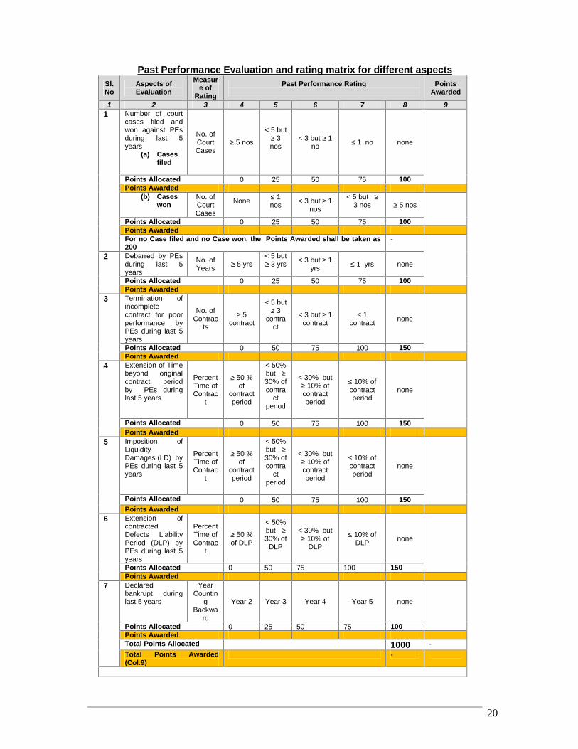
50.2 In case of tie for the evaluated price, the tenderer shall beselected based on the “Past Performance Evaluation andrating matrix for different aspects” to be used inassessing the Tenderer’s quality as stated below:
RRDP-II-SSN-02-04 20
Past Performance Evaluation and rating matrix for different aspectsSl.No
Aspects ofEvaluation
Measure of
RatingPast Performance Rating Points
Awarded
1 2 3 4 5 6 7 8 91 Number of court
cases filed andwon against PEsduring last 5years
(a) Casesfiled
No. ofCourtCases
≥ 5 nos
< 5 but≥ 3nos
< 3 but ≥ 1no ≤ 1 no none
Points Allocated 0 25 50 75 100Points Awarded
(b) Caseswon
No. ofCourtCases
None ≤ 1nos < 3 but ≥ 1
nos
< 5 but ≥3 nos ≥ 5 nos
Points Allocated 0 25 50 75 100Points AwardedFor no Case filed and no Case won, the Points Awarded shall be taken as200
-
2 Debarred by PEsduring last 5years
No. ofYears ≥ 5 yrs
< 5 but≥ 3 yrs < 3 but ≥ 1
yrs ≤ 1 yrs none
Points Allocated 0 25 50 75 100Points Awarded
3 Termination ofincompletecontract for poorperformance byPEs during last 5years
No. ofContrac
ts
≥ 5contract
< 5 but≥ 3
contract
< 3 but ≥ 1contract
≤ 1contract none
Points Allocated 0 50 75 100 150Points Awarded
4 Extension of Timebeyond originalcontract periodby PEs duringlast 5 years
PercentTime ofContrac
t
≥ 50 %of
contractperiod
< 50%but ≥30% ofcontra
ctperiod
< 30% but≥ 10% ofcontractperiod
≤ 10% ofcontractperiod
none
Points Allocated 0 50 75 100 150Points Awarded
5 Imposition ofLiquidityDamages (LD) byPEs during last 5years
PercentTime ofContrac
t
≥ 50 %of
contractperiod
< 50%but ≥30% ofcontra
ctperiod
< 30% but≥ 10% ofcontractperiod
≤ 10% ofcontractperiod
none
Points Allocated 0 50 75 100 150Points Awarded
6 Extension ofcontractedDefects LiabilityPeriod (DLP) byPEs during last 5years
PercentTime ofContrac
t
≥ 50 %of DLP
< 50%but ≥30% of
DLP
< 30% but≥ 10% of
DLP
≤ 10% ofDLP none
Points Allocated 0 50 75 100 150Points Awarded
7 Declaredbankrupt duringlast 5 years
YearCountin
gBackwa
rd
Year 2 Year 3 Year 4 Year 5 none
Points Allocated 0 25 50 75 100Points AwardedTotal Points Allocated 1000 -Total Points Awarded(Col.9)
-
RRDP-II-SSN-02-04 21
In case of multiple EQUALs in their Past Performance, total Turnover of last five (5) yearsshall determine the ranking.
51. Preliminary Examination 51.2 TEC shall examine the Tenders to confirm that alldocumentation as stated under ITT Clause 24 has beenprovided, to determine the completeness of eachdocument submitted.
51.3 TEC shall confirm that the following documents andinformation have been provided in the Tender. If any ofthese documents or information is missing, the Tendershall be considered rejected.(a) Tender Submission Letter;(b) Priced Bill of Quantities;(c) Written confirmation authorizing the signatory of the
Tender to commit the Tenderer; and(d) Valid Tender Security.
52. Technical Responsivenessand Technical
Evaluation
52.1 TEC’S determination of a Tender’s responsiveness is tobe based on the contents of the Tender itself withoutrecourse to extrinsic evidence.
52.2 A responsive Tender is one that conforms in all respects tothe requirements of the Tender Document without materialdeviation, reservation, or omission. A material deviation,reservation, or omission is one that:(a) affects in any substantial way the scope, quality,
or performance of the Works and physicalservices specified in the Contract; or
(b) limits in any substantial way, or is inconsistentwith the Tender Documents, the Procuring Entity’srights or the Tenderer’s obligations under theContract; or
(c) if rectified would unfairly affect the competitiveposition of other Tenderers presenting responsiveTenders.
During the evaluation of Tenders, the following definitionsshall apply:
“Deviation” is a departure from the requirements specified in theTender Document;“Reservation” is the setting of limiting conditions or withholding fromcomplete acceptance of the requirements specified in the TenderDocument; and“Omission” is the failure to submit part or all of the information ordocumentation required in the Tender Document.
52.3 If a Tender is not responsive to the mandatoryrequirements set out in the Tender Document, shall notsubsequently be made responsive by the Tenderer bycorrection of the material deviation, reservation, oromission.
RRDP-II-SSN-02-04 22
52.4 There shall be no requirement as to the minimum numberof responsive Tenders.
52.5 There shall be no automatic exclusion of Tenders whichare above or below the official estimate except ITT sub-Clause 49.3.
52.6 TEC shall evaluate the aspects of the Tender submittedas stated under ITT Clauses 29, 30,31 and 32 and, toconfirm that all requirements specified in Section 7:General Specifications and Section 8: ParticularSpecifications of the Tender Document have been metwithout any material deviation, reservation or omission.
52.7 Provided that a Tender is responsive, TEC may requestthat the Tenderer submit the necessary information ordocumentation, within a reasonable period of time, torectify nonmaterial nonconformities or omissions in theTender related to documentation requirements. Suchomission shall not be related to any aspect of the rates ofthe Tender reflected in the Priced BOQ or any mandatorycriteria. Failure of the Tenderer to comply with the requestmay result in the consideration of its Tender as non-responsive.
52.8 TEC may regard a Tender as responsive even if itcontains;(a) minor or insignificant deviations which do not
meaningfully alter or depart from the technicalspecifications, characteristics and commercial termsand, conditions or other mandatory requirements setout in the Tender Document; or
(b) errors or oversights, that if corrected, would not alterthe key aspects of the Tender.
53. Clarification on Tender 53.1 TEC may ask Tenderers for clarification of their Tenders,including breakdowns of unit rates, in order to facilitate theexamination and evaluation of Tenders. The request forclarification by the TEC and the response from theTenderer shall be in writing, and Tender clarificationswhich may lead to a change in the substance of theTender or in any of the key elements of the Tenderasstated under ITT Sub Clause 52.2, will neither be soughtnor be permitted.
53.2 Changes in the Tender price shall also not be sought orpermitted, except to confirm the correction of arithmeticalerrors discovered by the TEC in the evaluation of theTenders, as stated under ITT Sub Clause 55.1.
53.3 Any request for clarifications by the TEC shall not bedirected towards making an apparently non-responsiveTender responsive and reciprocally the response fromthe concerned Tenderer shall not be articulated towardsany addition, alteration or modification to its Tender.
53.4 If a Tenderer does not provide clarifications of its
RRDP-II-SSN-02-04 23
Tender by the date and time, its Tender shall not beconsidered in the evaluation
54. Restrictions on Disclosureof Information
54.1 Following the opening of Tenders until issuance ofNotification of Award no Tenderer shall, unlessrequested to provide clarification to its Tender or unlessnecessary for submission of a complaint, communicatewith the concerned Procuring Entity
54.2 Tenderers shall not seek to influence in anyway, theexamination and evaluation of the Tenders
54.3 Any effort by a Tenderer to influence the ProcuringEntity in its decision concerning the evaluation ofTenders, Contract awards may result in the non-responsiveness of its Tender as well as further action inaccordance with Section 64 (5) of the PublicProcurement Act, 2006.
54.4 All clarification requests shall remind Tenderers of theneed for confidentiality and that any breach ofconfidentiality on the part of the Tenderer may result intheir Tender being non-responsive.
55. Correction ofArithmetical Errors
55.1 Provided that the Tender is responsive, the TEC shallcorrect arithmetical errors on the following basis:
(a) if there is a discrepancy between the unit priceand the line item total price that is obtained bymultiplying the unit price and quantity, the unitprice will prevail and the line item total price shallbe corrected, unless in the opinion of the TECthere is an obvious misplacement of the decimalpoint in the unit price, in which case the total priceas quoted will govern and the unit price will becorrected; and
(b) if there is an error in a total corresponding to theaddition or subtraction of subtotals, the subtotalsshall prevail and the total shall be corrected; and
(c) if there is a discrepancy between words andfigures, the amount in words shall prevail, unlessthe amount expressed in words is related to anarithmetic error, in which case the amount infigures shall prevail subject to (a) and (b) above.
55.2 TEC shall correct the arithmetic errors and shall promptlynotify the concerned Tenderer(s).If the Tenderer does notaccept the correction of arithmetic errors, its Tender shallbe rejected.
56. Financial Evaluation 56.1 TEC will evaluate each Tender that has been determined,up to this stage of the evaluation, to be responsive to therequirements set out in the Tender Document.
56.2 To evaluate a Tender, the TEC will consider the following:(a) the Tender price, excluding Provisional Sums and
the provision, if any, for contingencies in thepriced BOQ, but including Day work items ;
RRDP-II-SSN-02-04 24
(b) adjustments for correction of arithmetical errors,asstated under ITT Sub Clause 55.1;
(c) adjustments in order to take into consideration theunconditional discounts as stated under ITT SubClause 27.5 and 27.6, if any..
56.3 Variations, deviations, alternatives and other factors whichare in excess of the requirements of the Tender Documentor otherwise result in unsolicited benefits for the ProcuringEntity will not be taken into account in Tender evaluation.
56.4 The estimated effect of any price adjustment provisionsunder GCC Clause 71, applied over the period ofexecution of the Contract, will not be taken into account inTender evaluation.
56.5 If so indicated in the ITT Sub Clause 1.1 the ProcuringEntity may award one or multiple lots to one Tendererfollowing the methodology specified in ITT Sub Clause56.6.
56.6 To determine the lowest-evaluated lot/package the TECwill take into account:(a) the lowest-evaluated Tender for each lot;(b) the resources sufficient to meet the qualifying
criteria for the individual lot or aggregate of thequalifying criteria for the multiple lots;
(c) the price reduction on account of discount perlot/package as offered by the Tenderer in itsTender; and
(d) the Contract-award sequence that provides theoptimum economic combination on the basis ofleast overall cost of the total Contract packagetaking into account any limitations due toconstraints in Works or execution capacitydetermined in accordance with the tender capacityas stated in ITT Sub Clause 15.1 (d) and post-qualification criteria as stated under ITT Clause 59.
56.7 TEC may recommend to increase the amount of thePerformance Security above the amounts as stated underITT Sub Clause 65.1 but not exceeding twenty-five (25)percent of the Contract Price, if in the opinion of TEC, it isfound that the Tender is significantly below the updatedofficial estimated cost or unbalanced as a result of frontloading.
57. Price Comparison 57.1 TEC shall compare all responsive Tenders to determine thelowest-evaluated Tender, as stated under ITT Clause 56.
57.2 In the extremely unlikely event that there is a tie for thelowest evaluated price, the Tenderer with the superior pastperformance as stated in ITT sub-clause 50.2 shall beselected.
57.3 In the event that there is a tie for the lowest price and noneof the Tenderers has the record of past performance withthe Procuring Entity as stated under ITT Sub Clause 57.2,
RRDP-II-SSN-02-04 25
then the Tenderer shall be selected, subject to firmconfirmation through the Post-qualification process, afterconsideration as to whether the Tenderer hasdemonstrated in its Tender superior past performance withthe other Procuring Entities or a more efficient workprogramme and work methodology.
57.4 The successful Tenderer as stated under ITT Sub Clause57.1, 57.2 and 57.3 shall not be selected through lotteryunder any circumstances.
58. Negotiations 58.1 No negotiations shall be held during the Tenderevaluation or award, with the lowest or any otherTenderer.
58.2 The Procuring Entity through the TEC may, however,negotiate with the lowest evaluated Tenderer with theobjective to reduce the Contract Price by reducing thescope of works or a reallocation of risks andresponsibilities, only when it is found that the lowestevaluated Tender is significantly higher than the officialestimated cost; the reasons for such higher price beingduly investigated.
58.3 If the Procuring Entity decides to negotiate for reducingthe scope of the requirements under ITT Sub Clause58.2, it will be required to guarantee that the lowestTenderer remains the lowest Tenderer even after thescope of work has been revised and shall further beensured that the objective of the Procurement will not beseriously affected through this reduction.
58.4 In the event that the Procuring Entity decides becauseof a high Tender price to reduce the scope of therequirements to meet the available budget, the Tendereris not obliged to accept the award and shall not bepenalised in any way for un-accepting the proposedaward.
59. Post-qualification 59.1 The determination on Post-qualification shall be basedupon an examination of the documentary evidence of theTenderer’s qualifications submitted by the Tenderer,pursuant to ITT Clause 32, clarifications as stated underITT Clause 53 and the qualification criteria indicated in ITTClauses 12 to 17. Factors not included therein shall not beused in the evaluation of the Tenderer’s qualification.
59.2 An affirmative determination shall be a prerequisite foraward of the Contract to the Tenderer. A negativedetermination shall result in non-responsiveness of theTenderer’s Tender, in which event the Procuring Entityshall proceed to the next lowest evaluated Tender to makea similar determination of that Tenderer’s capabilities toperform the Contract satisfactorily, if awarded.
59.3 TEC may verify information contained in the Tender byvisiting the premises of the Tenderer as a part of the postqualification process, if practical and appropriate.
RRDP-II-SSN-02-04 26
60. Procuring Entity’s Rightto Accept any or toReject Any or AllTenders
60.1 The Procuring Entity reserves the right to accept any Tenderor to reject any or all the Tenders any time prior to contract awardand , to annul the Procurement proceedings with prior approval ofthe Head of the Procuring Entity, any time prior to the deadline forsubmission of Tenders following specified procedures, withoutthereby incurring any liability to Tenderers, or any obligations toinform the Tenderers of the grounds for the Procuring Entity’saction.
61. Rejection of All Tenders 61.1 The Procuring Entity may, in the circumstances asstated under ITT Sub Clause61.2 reject all Tendersfollowing recommendations from the TEC only after theapproval of such recommendations by the Head of theProcuring Entity.
61.2 All Tenders can be rejected, if -(a) the price of the lowest evaluated Tender exceeds
the official estimated cost, provided the estimate isrealistic, subject to ITT Sub Clause 58.2 ; or
(b) there is evidence of lack of effective competition;such as non-participation by a number of potentialTenderers; or
(c) the Tenderers are unable to propose completionof the contract within the stipulated time in itsTender, though the stipulated time is reasonableand realistic; or
(d) all Tenders are non-responsive; or(e) evidence of professional misconduct, affecting
seriously the Procurement process, is establishedpursuant to Rule 127 of the Public ProcurementRules, 2008
61.3 61.3 Notwithstanding anything contained in ITT Sub-Clause 61.2 Tenders may not be rejected if the lowestevaluated price is in conformity with the market price.
62. Informing Reasons forRejection
62.1 Notice of the rejection will be given promptly within seven(7) working days of decision taken by the Procuring Entityto all Tenderers and, the Procuring Entity will, upon receiptof a written request, communicate to any Tenderer thereason(s) for its rejection but is not required to justify thosereason(s).
G. Contract Award
63. Award Criteria 63.1 The Procuring Entity shall award the Contract to theTenderer whose Tender is responsive to all therequirements of the Tender Document and that hasbeen determined to be the lowest evaluated Tender,provided further that the Tenderer is determined to bePost-qualified in accordance with ITT Clouse 59.
63.2 Tenderer will not be required, as a condition for award,to undertake responsibilities not stipulated in the TenderDocuments, to change its price, or otherwise to modify
RRDP-II-SSN-02-04 27
its Tender.64. Notification of Award 64.1 Prior to the expiry of the Tender Validity period and
within one (1) week of receipt of the approval of theaward by the Approving Authority, the Procuring Entityshall issue the Notification of Award (NOA) to thesuccessful Tenderer.
64.2 The NOA, attaching the contract as per the sample(Form PW3-8) to be signed, shall state :
(a) the acceptance of the Tender by the ProcuringEntity;
(b) the price at which the contract is awarded;
(c) the amount of the Performance Security and itsformat;
(d) the date and time within which the PerformanceSecurity shall be furnished; and
(e) the date and time within which the Contract shallbe signed.
64.3 The NOA shall be accepted by the successful Tendererwithin seven (7) working days from the date of itsissuance.
64.4 Until a formal contract is signed, the NOA will constitutea Contract, which shall become binding upon thefurnishing of a Performance Security and the signing ofthe Contract by both parties.
65. Performance Security 65.1 Performance Security shall be provided by thesuccessful Tenderer in BDT currency, of the amountas specified in the TDS.
65.2 The Procuring Entity shall increase the amount of thePerformance Security on the recommendation of TECabove the amounts as stated under ITT Sub Clause56.7.
65.3 The proceeds of the Performance Security shall bepayable to the Procuring Entity unconditionally uponfirst written demand as compensation for Contractor’sfailure to complete its obligations under the Contract.
65.4 In the event a Government owned enterprise as statedunder ITT Sub Clause 5.10 is the successful Tenderer,Performance Security, as stated under ITT Sub Clause65.1, shall not be required and, in lieu, there shall beRetention Money as specified in the TDS.
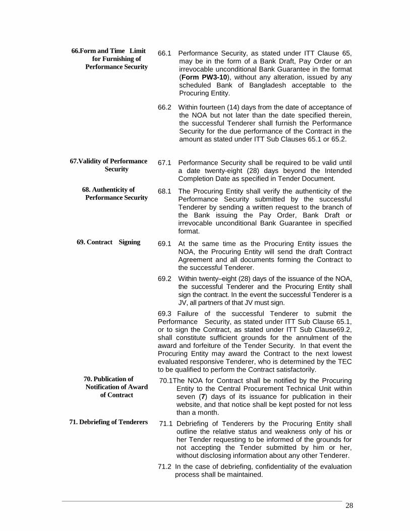
RRDP-II-SSN-02-04 28
66.Form and Time Limitfor Furnishing of
Performance Security
66.1 Performance Security, as stated under ITT Clause 65,may be in the form of a Bank Draft, Pay Order or anirrevocable unconditional Bank Guarantee in the format(Form PW3-10), without any alteration, issued by anyscheduled Bank of Bangladesh acceptable to theProcuring Entity.
66.2 Within fourteen (14) days from the date of acceptance ofthe NOA but not later than the date specified therein,the successful Tenderer shall furnish the PerformanceSecurity for the due performance of the Contract in theamount as stated under ITT Sub Clauses 65.1 or 65.2.
67.Validity of PerformanceSecurity
67.1 Performance Security shall be required to be valid untila date twenty-eight (28) days beyond the IntendedCompletion Date as specified in Tender Document.
68. Authenticity ofPerformance Security
68.1 The Procuring Entity shall verify the authenticity of thePerformance Security submitted by the successfulTenderer by sending a written request to the branch ofthe Bank issuing the Pay Order, Bank Draft orirrevocable unconditional Bank Guarantee in specifiedformat.
69. Contract Signing 69.1 At the same time as the Procuring Entity issues theNOA, the Procuring Entity will send the draft ContractAgreement and all documents forming the Contract tothe successful Tenderer.
69.2 Within twenty–eight (28) days of the issuance of the NOA,the successful Tenderer and the Procuring Entity shallsign the contract. In the event the successful Tenderer is aJV, all partners of that JV must sign.
69.3 Failure of the successful Tenderer to submit thePerformance Security, as stated under ITT Sub Clause 65.1,or to sign the Contract, as stated under ITT Sub Clause69.2,shall constitute sufficient grounds for the annulment of theaward and forfeiture of the Tender Security. In that event theProcuring Entity may award the Contract to the next lowestevaluated responsive Tenderer, who is determined by the TECto be qualified to perform the Contract satisfactorily.
70. Publication ofNotification of Award
of Contract
70.1The NOA for Contract shall be notified by the ProcuringEntity to the Central Procurement Technical Unit withinseven (7) days of its issuance for publication in theirwebsite, and that notice shall be kept posted for not lessthan a month.
71. Debriefing of Tenderers 71.1 Debriefing of Tenderers by the Procuring Entity shalloutline the relative status and weakness only of his orher Tender requesting to be informed of the grounds fornot accepting the Tender submitted by him or her,without disclosing information about any other Tenderer.
71.2 In the case of debriefing, confidentiality of the evaluationprocess shall be maintained.

RRDP-II-SSN-02-04 29
72. Adjudicator 72.1 The Procuring Entity proposes the person named in theTDS to be appointed as Adjudicator under the Contract,at an hourly fee and for those reimbursable expenses asspecified in the TDS.
73. Right to Complain 73.1 Tenderer has the right to complain in accordance withthe Public Procurement Act 2006 and the PublicProcurement Rules, 2008.
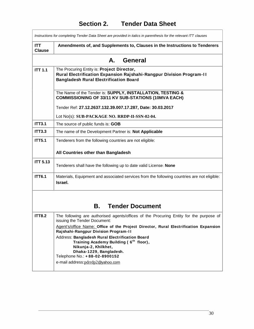
RRDP-II-SSN-02-04 30
Section 2. Tender Data Sheet
Instructions for completing Tender Data Sheet are provided in italics in parenthesis for the relevant ITT clauses
ITTClause
Amendments of, and Supplements to, Clauses in the Instructions to Tenderers
A. GeneralITT 1.1 The Procuring Entity is: Project Director,
Rural Electrification Expansion Rajshahi-Rangpur Division Program-IIBangladesh Rural Electrification Board
The Name of the Tender is: SUPPLY, INSTALLATION, TESTING &COMMISSIONING OF 33/11 KV SUB-STATIONS (10MVA EACH)
Tender Ref: 27.12.2637.132.39.007.17.287, Date: 30.03.2017
Lot No(s): SUB-PACKAGE NO. RRDP-II-SSN-02-04.
ITT3.1 The source of public funds is: GOBITT3.3 The name of the Development Partner is: Not Applicable
ITT5.1 Tenderers from the following countries are not eligible:
All Countries other than Bangladesh
ITT 5.13Tenderers shall have the following up to date valid License: None
ITT6.1 Materials, Equipment and associated services from the following countries are not eligible:Israel.
B. Tender DocumentITT8.2 The following are authorised agents/offices of the Procuring Entity for the purpose of
issuing the Tender Document:Agent’s/office Name: Office of the Project Director, Rural Electrification ExpansionRajshahi-Rangpur Division Program-IIAddress: Bangladesh Rural Electrification Board
Training Academy Building ( 6th floor),Nikunja-2, Khilkhet,Dhaka-1229, Bangladesh.
Telephone No.: +88-02-8900152e-mail address:[email protected]

RRDP-II-SSN-02-04 31
ITT9.1 For clarification of Tender Document purposes only, the Procuring Entity’s address is:Attention: Project Director, Rural Electrification Expansion Rajshahi-RangpurDivision Program-IIAddress: Bangladesh Rural Electrification Board
Training Academy Building (6th floor),Nikunja-2, KhilkhetDhaka-1229, Bangladesh.Telephone: +88-02-8900152.
Fax No.:
e-mail address:[email protected]
and contact the Procuring Entity within 05.04.2017
ITT10.1 A Pre- Tender meeting shall be held at
Address: Office of the Project Director,
Rural Electrification Expansion Rajshahi-Rangpur Division Program-II
Bangladesh Rural Electrification BoardTraining Academy Building (6th floor),Nikunja-2, KhilkhetDhaka-1229, Bangladesh.
Time & Date: 11.00 A.M (BST) &16.04.2017
A site visit conducted by the Employer will not be organized.Tenderers are advised to conduct site visit at their own responsibility. The Employermay arrange necessary permissions if requested by the Tenderers.
The costs and expenses associated with attending the pre-Tender meeting and/or sitevisit shall be borne by the Potential Tenderers.
C. Qualification CriteriaITT14.1(a)
The minimum number of general experience of the tenderer in the constructionworks/supply of goods and related service as Prime Contractor or Sub-Contractor or aManagement contractor shall be 5 (five) years.
[ years counting backward from the date of publication of IFT in the newspaper]
ITT14.1(b)
i) Specific experience:- In the case of single entity the minimum specific experience as aPrime Contractor or Subcontractor or Management Contractor in construction works atleast 1(one) contract(s) of Indoor Type 33KV Switching Station or 132/33KV Sub Stationor 33/11 KV Indoor Sub-station successfully completed within the last 05 (five) years,each with a value of at least as following:
Lot No. Amount in TakaRRDP-II-SSN-02-04 7,00,00,000.00
ii) Joint venture, Consortium or Association (JVCA) may be made by 1(one) supplycontractor and 01(one) construction contractor. In that case, the leading partner musthave successfully completed at least 01 (one) contract of Indoor Type 33KV SwitchingStation or 132/33KV Sub Station or 33/11 KV Indoor Sub-station within the last 5(five)years each with a value of at least as following:
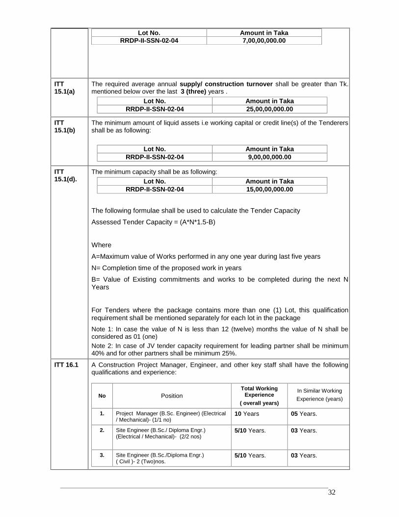
RRDP-II-SSN-02-04 32
Lot No. Amount in TakaRRDP-II-SSN-02-04 7,00,00,000.00
ITT15.1(a)
The required average annual supply/ construction turnover shall be greater than Tk.mentioned below over the last 3 (three) years .
Lot No. Amount in TakaRRDP-II-SSN-02-04 25,00,00,000.00
ITT15.1(b)
The minimum amount of liquid assets i.e working capital or credit line(s) of the Tenderersshall be as following:
Lot No. Amount in TakaRRDP-II-SSN-02-04 9,00,00,000.00
ITT15.1(d).
The minimum capacity shall be as following:Lot No. Amount in Taka
RRDP-II-SSN-02-04 15,00,00,000.00
The following formulae shall be used to calculate the Tender Capacity
Assessed Tender Capacity = (A*N*1.5-B)
Where
A=Maximum value of Works performed in any one year during last five years
N= Completion time of the proposed work in years
B= Value of Existing commitments and works to be completed during the next NYears
For Tenders where the package contains more than one (1) Lot, this qualificationrequirement shall be mentioned separately for each lot in the packageNote 1: In case the value of N is less than 12 (twelve) months the value of N shall beconsidered as 01 (one)Note 2: In case of JV tender capacity requirement for leading partner shall be minimum40% and for other partners shall be minimum 25%.
ITT 16.1 A Construction Project Manager, Engineer, and other key staff shall have the followingqualifications and experience:
No PositionTotal Working
Experience( overall years)
In Similar WorkingExperience (years)
1. Project Manager (B.Sc. Engineer) (Electrical/ Mechanical)- (1/1 no)
10 Years 05 Years.
2. Site Engineer (B.Sc./ Diploma Engr.)(Electrical / Mechanical)- (2/2 nos)
5/10 Years. 03 Years.
3. Site Engineer (B.Sc./Diploma Engr.)( Civil )- 2 (Two)nos.
5/10 Years. 03 Years.
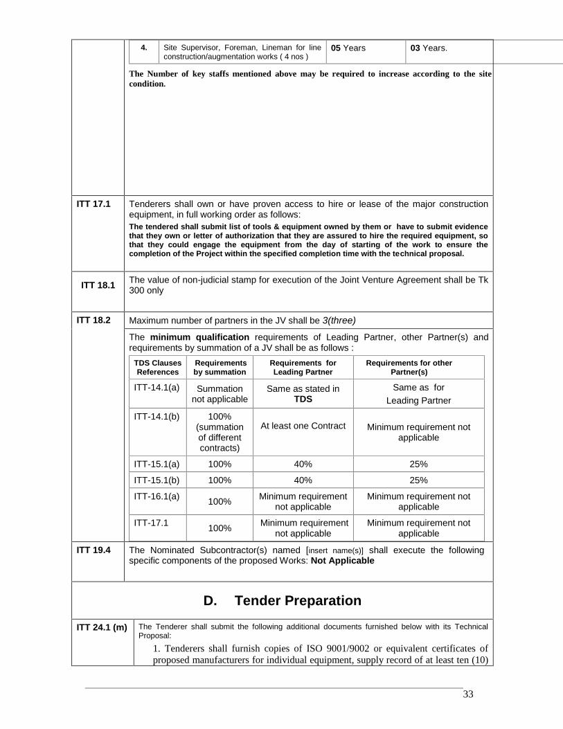
RRDP-II-SSN-02-04 33
4. Site Supervisor, Foreman, Lineman for lineconstruction/augmentation works ( 4 nos )
05 Years 03 Years.
The Number of key staffs mentioned above may be required to increase according to the sitecondition.
ITT 17.1 Tenderers shall own or have proven access to hire or lease of the major constructionequipment, in full working order as follows:The tendered shall submit list of tools & equipment owned by them or have to submit evidencethat they own or letter of authorization that they are assured to hire the required equipment, sothat they could engage the equipment from the day of starting of the work to ensure thecompletion of the Project within the specified completion time with the technical proposal.
ITT 18.1 The value of non-judicial stamp for execution of the Joint Venture Agreement shall be Tk300 only
ITT 18.2 Maximum number of partners in the JV shall be 3(three)
The minimum qualification requirements of Leading Partner, other Partner(s) andrequirements by summation of a JV shall be as follows :
TDS ClausesReferences
Requirementsby summation
Requirements forLeading Partner
Requirements for otherPartner(s)
ITT-14.1(a) Summationnot applicable
Same as stated inTDS
Same as forLeading Partner
ITT-14.1(b) 100%(summationof differentcontracts)
At least one Contract Minimum requirement notapplicable
ITT-15.1(a) 100% 40% 25%
ITT-15.1(b) 100% 40% 25%
ITT-16.1(a) 100% Minimum requirementnot applicable
Minimum requirement notapplicable
ITT-17.1 100% Minimum requirementnot applicable
Minimum requirement notapplicable
ITT 19.4 The Nominated Subcontractor(s) named [insert name(s)] shall execute the followingspecific components of the proposed Works: Not Applicable
D. Tender Preparation
ITT 24.1 (m) The Tenderer shall submit the following additional documents furnished below with its TechnicalProposal:
1. Tenderers shall furnish copies of ISO 9001/9002 or equivalent certificates ofproposed manufacturers for individual equipment, supply record of at least ten (10)
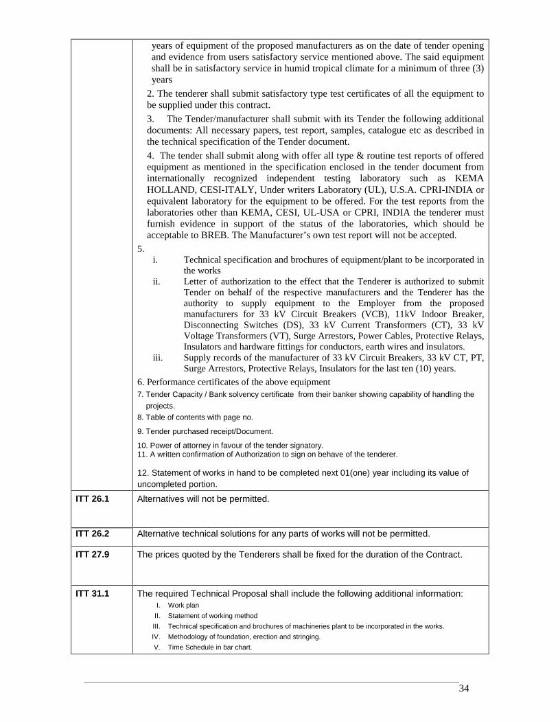
RRDP-II-SSN-02-04 34
years of equipment of the proposed manufacturers as on the date of tender openingand evidence from users satisfactory service mentioned above. The said equipmentshall be in satisfactory service in humid tropical climate for a minimum of three (3)years
2. The tenderer shall submit satisfactory type test certificates of all the equipment tobe supplied under this contract.
3. The Tender/manufacturer shall submit with its Tender the following additionaldocuments: All necessary papers, test report, samples, catalogue etc as described inthe technical specification of the Tender document.
4. The tender shall submit along with offer all type & routine test reports of offeredequipment as mentioned in the specification enclosed in the tender document frominternationally recognized independent testing laboratory such as KEMAHOLLAND, CESI-ITALY, Under writers Laboratory (UL), U.S.A. CPRI-INDIA orequivalent laboratory for the equipment to be offered. For the test reports from thelaboratories other than KEMA, CESI, UL-USA or CPRI, INDIA the tenderer mustfurnish evidence in support of the status of the laboratories, which should beacceptable to BREB. The Manufacturer’s own test report will not be accepted.
5.i. Technical specification and brochures of equipment/plant to be incorporated in
the worksii. Letter of authorization to the effect that the Tenderer is authorized to submit
Tender on behalf of the respective manufacturers and the Tenderer has theauthority to supply equipment to the Employer from the proposedmanufacturers for 33 kV Circuit Breakers (VCB), 11kV Indoor Breaker,Disconnecting Switches (DS), 33 kV Current Transformers (CT), 33 kVVoltage Transformers (VT), Surge Arrestors, Power Cables, Protective Relays,Insulators and hardware fittings for conductors, earth wires and insulators.
iii. Supply records of the manufacturer of 33 kV Circuit Breakers, 33 kV CT, PT,Surge Arrestors, Protective Relays, Insulators for the last ten (10) years.
6. Performance certificates of the above equipment7. Tender Capacity / Bank solvency certificate from their banker showing capability of handling the
projects.8. Table of contents with page no.
9. Tender purchased receipt/Document.
10. Power of attorney in favour of the tender signatory.11. A written confirmation of Authorization to sign on behave of the tenderer.
12. Statement of works in hand to be completed next 01(one) year including its value ofuncompleted portion.
ITT 26.1 Alternatives will not be permitted.
ITT 26.2 Alternative technical solutions for any parts of works will not be permitted.
ITT 27.9 The prices quoted by the Tenderers shall be fixed for the duration of the Contract.
ITT 31.1 The required Technical Proposal shall include the following additional information:I. Work plan
II. Statement of working methodIII. Technical specification and brochures of machineries plant to be incorporated in the works.IV. Methodology of foundation, erection and stringing.V. Time Schedule in bar chart.
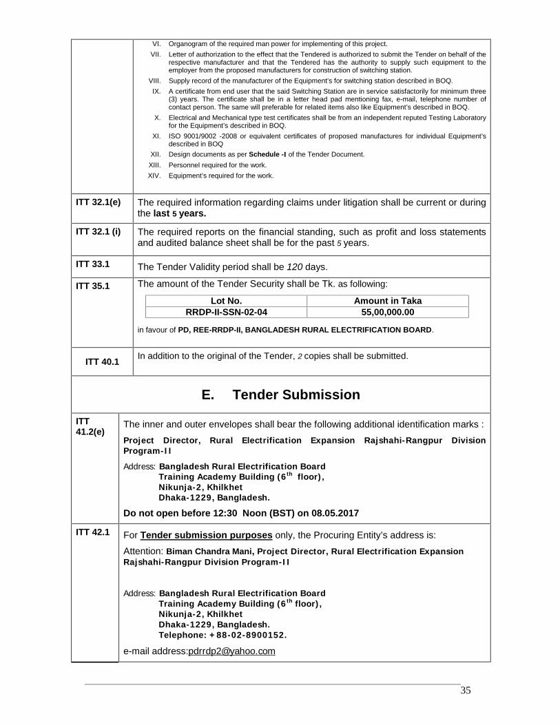
RRDP-II-SSN-02-04 35
VI. Organogram of the required man power for implementing of this project.VII. Letter of authorization to the effect that the Tendered is authorized to submit the Tender on behalf of the
respective manufacturer and that the Tendered has the authority to supply such equipment to theemployer from the proposed manufacturers for construction of switching station.
VIII. Supply record of the manufacturer of the Equipment’s for switching station described in BOQ.IX. A certificate from end user that the said Switching Station are in service satisfactorily for minimum three
(3) years. The certificate shall be in a letter head pad mentioning fax, e-mail, telephone number ofcontact person. The same will preferable for related items also like Equipment’s described in BOQ.
X. Electrical and Mechanical type test certificates shall be from an independent reputed Testing Laboratoryfor the Equipment’s described in BOQ.
XI. ISO 9001/9002 -2008 or equivalent certificates of proposed manufactures for individual Equipment’sdescribed in BOQ
XII. Design documents as per Schedule -I of the Tender Document.XIII. Personnel required for the work.XIV. Equipment’s required for the work.
ITT 32.1(e) The required information regarding claims under litigation shall be current or duringthe last 5 years.
ITT 32.1 (i) The required reports on the financial standing, such as profit and loss statementsand audited balance sheet shall be for the past 5 years.
ITT 33.1 The Tender Validity period shall be 120 days.
ITT 35.1 The amount of the Tender Security shall be Tk. as following:
Lot No. Amount in TakaRRDP-II-SSN-02-04 55,00,000.00
in favour of PD, REE-RRDP-II, BANGLADESH RURAL ELECTRIFICATION BOARD.
ITT 40.1 In addition to the original of the Tender, 2 copies shall be submitted.
E. Tender Submission
ITT41.2(e)
The inner and outer envelopes shall bear the following additional identification marks :
Project Director, Rural Electrification Expansion Rajshahi-Rangpur DivisionProgram-II
Address: Bangladesh Rural Electrification BoardTraining Academy Building (6th floor),Nikunja-2, KhilkhetDhaka-1229, Bangladesh.
Do not open before 12:30 Noon (BST) on 08.05.2017
ITT 42.1 For Tender submission purposes only, the Procuring Entity’s address is:
Attention: Biman Chandra Mani, Project Director, Rural Electrification ExpansionRajshahi-Rangpur Division Program-II
Address: Bangladesh Rural Electrification BoardTraining Academy Building (6th floor),Nikunja-2, KhilkhetDhaka-1229, Bangladesh.Telephone: +88-02-8900152.
e-mail address:[email protected]
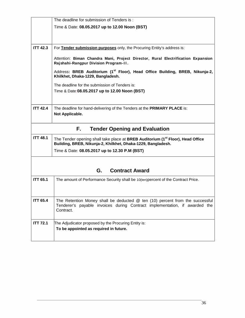
RRDP-II-SSN-02-04 36
The deadline for submission of Tenders is :
Time & Date: 08.05.2017 up to 12.00 Noon (BST)
ITT 42.3 For Tender submission purposes only, the Procuring Entity’s address is:
Attention: Biman Chandra Mani, Project Director, Rural Electrification ExpansionRajshahi-Rangpur Division Program-II.
Address: BREB Auditorium (1st Floor), Head Office Building, BREB, Nikunja-2,Khilkhet, Dhaka-1229, Bangladesh.
The deadline for the submission of Tenders is:Time & Date:08.05.2017 up to 12.00 Noon (BST)
ITT 42.4 The deadline for hand-delivering of the Tenders at the PRIMARY PLACE is:Not Applicable.
F. Tender Opening and EvaluationITT 48.1 The Tender opening shall take place at BREB Auditorium (1st Floor), Head Office
Building, BREB, Nikunja-2, Khilkhet, Dhaka-1229, Bangladesh.
Time & Date: 08.05.2017 up to 12.30 P.M (BST)
G. Contract AwardITT 65.1 The amount of Performance Security shall be 10(ten)percent of the Contract Price.
ITT 65.4 The Retention Money shall be deducted @ ten (10) percent from the successfulTenderer’s payable invoices during Contract implementation, if awarded theContract.
ITT 72.1 The Adjudicator proposed by the Procuring Entity is:To be appointed as required in future.
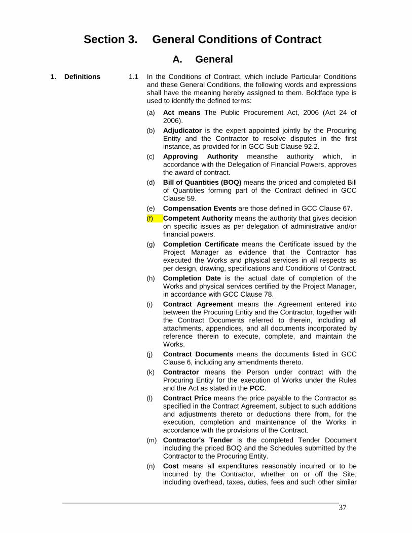
RRDP-II-SSN-02-04 37
Section 3. General Conditions of ContractA. General
1. Definitions 1.1 In the Conditions of Contract, which include Particular Conditionsand these General Conditions, the following words and expressionsshall have the meaning hereby assigned to them. Boldface type isused to identify the defined terms:
(a) Act means The Public Procurement Act, 2006 (Act 24 of2006).
(b) Adjudicator is the expert appointed jointly by the ProcuringEntity and the Contractor to resolve disputes in the firstinstance, as provided for in GCC Sub Clause 92.2.
(c) Approving Authority meansthe authority which, inaccordance with the Delegation of Financial Powers, approvesthe award of contract.
(d) Bill of Quantities (BOQ) means the priced and completed Billof Quantities forming part of the Contract defined in GCCClause 59.
(e) Compensation Events are those defined in GCC Clause 67.(f) Competent Authority means the authority that gives decision
on specific issues as per delegation of administrative and/orfinancial powers.
(g) Completion Certificate means the Certificate issued by theProject Manager as evidence that the Contractor hasexecuted the Works and physical services in all respects asper design, drawing, specifications and Conditions of Contract.
(h) Completion Date is the actual date of completion of theWorks and physical services certified by the Project Manager,in accordance with GCC Clause 78.
(i) Contract Agreement means the Agreement entered intobetween the Procuring Entity and the Contractor, together withthe Contract Documents referred to therein, including allattachments, appendices, and all documents incorporated byreference therein to execute, complete, and maintain theWorks.
(j) Contract Documents means the documents listed in GCCClause 6, including any amendments thereto.
(k) Contractor means the Person under contract with theProcuring Entity for the execution of Works under the Rulesand the Act as stated in the PCC.
(l) Contract Price means the price payable to the Contractor asspecified in the Contract Agreement, subject to such additionsand adjustments thereto or deductions there from, for theexecution, completion and maintenance of the Works inaccordance with the provisions of the Contract.
(m) Contractor’s Tender is the completed Tender Documentincluding the priced BOQ and the Schedules submitted by theContractor to the Procuring Entity.
(n) Cost means all expenditures reasonably incurred or to beincurred by the Contractor, whether on or off the Site,including overhead, taxes, duties, fees and such other similar
RRDP-II-SSN-02-04 38
levies including corresponding incidental charges andpremiums for banking and insurances, as applicable.
(o) Day means calendar day unless otherwise specified asworking days.
(p) Day works means work carried out following the instructionsof the Procuring Entity or the authorised Project Manager andis paid for on the basis of time spent by the Contractor’sworkers and equipment at the rates specified in theSchedules, in addition to payments for associated Materialsand Plant.
(q) Defect is any part of the Works not completed in accordancewith the Contract.
(r) Defects Correction Certificate is the certificate issued by theProject Manager upon correction of defects by the Contractor.
(s) Drawings include calculations and other information providedin Section 9 or as approved by the Project Manager for theexecution and completion of the Contract.
(t) Equipment is the Contractor’s apparatus, machinery, vehiclesand other things required for the execution and completion ofthe Works and remedying any defects excluding TemporaryWorks and the Procuring Entity’s Equipment (if any ), Plant,Materials and any other things to form or forming part of thePermanent Works.
(u) Force Majeure means an event or situation beyond thecontrol of the Contractor that is not foreseeable, isunavoidable, and its origins not due to negligence or lack ofcare on the part of the Contractor; such events may include,but not be limited to, acts of the Government in its sovereigncapacity, wars or revolutions, fires, floods, epidemics,quarantine restrictions, and freight embargoes or more asincluded in GCC Clause 83;
(v) GCC means the General Conditions of Contract.(w) Government means the Government of the People’s Republic
of Bangladesh.(x) Goods mean the Contractor’s Equipment, Materials, Plant and
Temporary Works, or any of them as appropriate.(y) "Head of the Procuring Entity" means the Secretary of a
Ministry or a Division, the Head of a Government Departmentor Directorate; or the Chief Executive, or as applicable,Divisional Commissioner, Deputy Commissioner, Zilla Judge;or by whatever designation called, of a local Governmentagency, an autonomous or semi-autonomous body or acorporation, or a corporate body established under theCompanies Act;
(z) Intended Completion Date is the date calculated from theCommencement Date as specified in the PCC, on which it isintended that the Contractor shall complete the Works andphysical services as specified in the Contract and may berevised only by the Project Manager by issuing an extensionof time or an acceleration order.
(aa) Materials means things of all kinds other than Plant intendedto form or forming part of the Permanent Works, including thesupply-only materials, if any, to be supplied by the Contractorunder the Contract.
RRDP-II-SSN-02-04 39
(bb) Month means calendar month.(cc) Original Contract Price is the Contract Price stated in the
Procuring Entity’s Notification of Award (Form PW3-7) andfurther clearly determined in the PCC.
(dd) Permanent works means the permanent works to beexecuted by the Contractor under the Contract.
(ee) PCC means the Particular Conditions of Contract.(ff) Plant means the apparatus, machinery and other equipment
intended to form or forming part of the Permanent Works,including vehicles purchased for the Procuring Entity andrelating to the construction of the Works and physical services.
(gg) Procuring Entity means a Procuring Entity havingadministrative and financial powers to undertake procurementof Works and physical services using public funds and is asnamed in the PCC who employs the Contractor to carry outthe Works.
(hh) Project Manager is the person named in the PCC or anyother competent person appointed by the Procuring Entity andnotified to the Contractor who is responsible for supervisingthe execution and completion of the Works and physicalservices and administering the Contract.
(ii) Provisional Sums means amounts of money specified by theProcuring Entity in the BOQ which shall be used, at itsdiscretion for meeting other essential expenditures under theContract pursuant to GCC Sub Clause 75.
(jj) Retention Money means the accumulated retention moneyswhich the Procuring Entity retains under GCC Clause 70.
(kk) Schedules means the document(s) entitled schedules,completed by the Contractor and submitted with the TenderSubmission Letter, as included in the Contract. Suchdocument may include the data, lists and schedules of ratesand/or prices.
(ll) Site means the places where the Permanent Works are to beexecuted including storage and working areas and to whichPlant and Materials are to be delivered, and any other placesas may be specified in the PCC as forming part of the Site.
(mm)Site Investigation Reports are those that were included inthe Tender Document and are factual and interpretativereports about the surface and subsurface conditions at theSite.
(nn) Specification means the Specification of the Works includedin the Contract and any modifications or additions to thespecifications made or approved by the Project Manager inaccordance with the Contract.
(oo) Start Date is the date defined in the PCC and it is the lastdate when the Contractor shall commence execution of theWorks under the Contract.
(pp) Subcontractor means a person or corporate body, who has acontract with the Contractor to carry out a part of the work inthe Contract, which includes work on the Site.
(qq) Temporary Works means all temporary works of every kindother than Contractor’s Equipment required on the Site for theexecution and completion of the Permanent Works and
RRDP-II-SSN-02-04 40
remedying of any defects.(rr) Variation means any change to the Works directly procured
from the original Contractor to cover increases or decreases inquantities, including the introduction of new work items (non-Tendered items) that are either due to change of plans, designor alignment to suit actual field conditions, within the generalscope and physical boundaries of the contract.
(ss) Works means all works associated with the construction,reconstruction, site preparation, demolition, repair,maintenance or renovation of railways, roads, highways, or abuilding, an infrastructure or structure or an installation or anyconstruction work relating to excavation, installation ofequipment and materials, decoration, as well as physicalservices ancillary to works as detailed in the PCC, if the valueof those services does not exceed that of the Worksthemselves.Writing means communication written by hand or machineduly signed and includes properly authenticated messages byfacsimile or electronic mail.
2. Interpretation 2.1 In interpreting the GCC, singular also means plural, male alsomeans female or neuter, and the other way around. Headings inthe GCC shall not be deemed part thereof or be taken intoconsideration in the interpretation or construance of the Contract.Words have their normal meaning under the language of theContract unless specifically defined.
2.2 Entire AgreementThe Contract constitutes the entire agreement between theProcuring Entity and the Contractor and supersedes allcommunications, negotiations and agreements (whether written orverbal) of parties with respect thereto made prior to the date ofContract Agreement; except those stated under GCC Sub Clause6.1(j).
2.3 Non waiver(a) Subject to GCC Sub Clause 2.3(b), no relaxation,
forbearance, delay, or indulgence by either party in enforcingany of the terms and conditions of the Contract or the grantingof time by either party to the other shall prejudice, affect, orrestrict the rights of that party under the Contract, neither shallany waiver by either party of any breach of Contract operateas waiver of any subsequent or continuing breach of Contract.
(b) Any waiver of a party’s rights, powers, or remedies under theContract must be in writing, dated, and signed by anauthorized representative of the party granting such waiver,and must specify the right and the extent to which it is beingwaived.
2.4 SeverabilityIf any provision or condition of the Contract is prohibited orrendered invalid or unenforceable, such prohibition, invalidity orunenforceability shall not affect the validity or enforceability of anyother provisions and conditions of the Contract.
2.5 Sectional completion
RRDP-II-SSN-02-04 41
If sectional completion is specified in the PCC, references in theGCC to the Works, the Completion Date, and the IntendedCompletion Date apply to any section of the Works (other thanreferences to the Completion Date and Intended Completion Datefor the whole of the Works).
3. Communications& Notices
3.1 Communications between Parties (notice, request or consentrequired or permitted to be given or made by one party to the other)pursuant to the Contract shall be in writing to the addressesspecified in the PCC.
3.2 A notice shall be effective when delivered or on the notice’seffective date, whichever is later.
3.3 A Party may change its address for notice hereunder by giving theother Party notice of such change to the address.
4. Governing Law 4.1 The Contract shall be governed by and interpreted in accordancewith the laws of the People’s Republic of Bangladesh.
5. GoverningLanguage
5.1 The Contract shall be written in English. All correspondences anddocuments relating to the Contract may be written in English orBangla. Supporting documents and printed literature that are part ofthe Contract may be in another language, provided they areaccompanied by an accurate translation of the relevant passages inEnglish, in which case, for purposes of interpretation of theContract, such translation shall govern.
5.2 The Contractor shall bear all costs of translation to the governinglanguage and all risks of the accuracy of such translation.
6. DocumentsForming theContract andPriority ofDocuments
6.1 The following documents forming the Contract shall be interpretedin the following order of priority:(a) the signed Contract Agreement (Form PW3-9);(b) the Notification of Award (PW3-8);(c) the completed Tender and the Appendix to the Tender;(d) the Particular Conditions of Contract;(e) the General Conditions of Contract;(f) the Technical Specifications;(g) the General Specifications;(h) the Drawings;(i) the priced BOQ and the Schedules; and(j) any other document listed in the PCC forming part of the
Contract.
7. Scope of Works 7.1 The Works to be executed, completed and maintained shall be asspecified in the BOQ, the General and Particular Specifications andDrawings.
7.2 Unless otherwise stipulated in the Contract, the Works shall include allsuch items not specifically mentioned in the Contract but that can bereasonably inferred from the Contract as being required for completionof the Works as if such items were expressly mentioned in theContract.
8. Assignment 8.1 Neither the Contractor nor the Procuring Entity shall assign, in
RRDP-II-SSN-02-04 42
whole or in part, its obligations under the Contract.
9. Eligibility 9.1 The Contractor and its Subcontractor(s) shall have the nationality ofa country other than that specified in the PCC.
9.2 All materials, equipment, plant, and supplies used by the Contractorin both permanent and temporary works and services suppliedunder the Contract shall have their origin in the countries exceptany specified in the PCC.
10. Gratuities /Agency fees
10.1 No fees, gratuities, rebates, gifts, commissions or other payments,other than those shown in the Tender or in the Contract, have beengiven or received in connection with the procurement process or inthe Contract execution.
11. ConfidentialDetails
11.1 The Contractor’s and the Procuring Entity’s personnel shall discloseall such confidential and other information as may be reasonablyrequired in order to verify the Contractor’s compliance with theContract and allow its proper implementation.
11.2 Each of them shall treat the details of the Contract as private andconfidential, except to the extent necessary to carry out theirrespective obligations under the Contract or to comply withapplicable Laws. Each of them shall not publish or disclose anyparticulars of the Works prepared by the other Party without theprevious agreement of the other Party. However, the Contractorshall be permitted to disclose any publicly available information, orinformation otherwise required to establish his qualifications tocompete for other projects.
12. Joint Venture(JV)
12.1 If the Contractor is a JV ,
(a) each partner of the JV shall be jointly and severally liable forall liabilities and ethical or legal obligations to the ProcuringEntity for performance of the Contract;
(b) the JV partners shall nominate the Leading Partner asREPRESENTATIVE being entrusted with the Contractadministration and management at Site who shall have theauthority to conduct all business including the receipt ofpayments for and on behalf of all partners of the JV;
(c) If there is a dispute that results in legal action being taken incourt then action will be taken against all partners of the JV, ifthey are available and, if only one partner is available, thenthat partner alone shall answer on behalf of all partners and, ifthe complaint lodged is proven, the penalty shall be applicableon that partner alone as whatever penalty all the partnerswould have received; provided that if the other partners of theJV subsequently become available before the legal action hasbeen completed, the Procuring Entity shall have the right totake action against those other partners of that JV as well.
(d) the composition or constitution and legal status of the JV shallnot be altered without the prior approval of the ProcuringEntity;
(e) alteration of partners, except the Leading partner, shall onlybe allowed if any of them is found to be incompetent or hasany serious difficulties which may impact the overallimplementation of the Works, whereby the incoming partnershall require to posses qualifications higher than that of the
RRDP-II-SSN-02-04 43
outgoing partner;(f) "if any of the partners of JV has been debarred from
participating in any procurement activity due to corrupt,fraudulent, collusive or coercive practices and while in case,the Leading partner is found incompetent or has beendebarred due to the same reasons stated herein the Contractshall be terminated pursuant to GCC Sub Clause 87.1(b)."
13. Possession ofthe Site
13.1 The Procuring Entity shall give possession of the Site or part(s) ofthe Site, to the Contractor on the date(s) stated in the PCC. Ifpossession of a part of the Site is not given by the date stated in thePCC, the Procuring Entity will be deemed to have delayed the startof the relevant activities, and this will be a Compensation Event asstated under GCC Sub Clause 67.1(a).
14. Access to theSite
14.1 The Contractor shall allow the Project Manager and any personauthorised by the Project Manager access to the Site and to anyplace where work in connection with the Contract is being carriedout or is intended to be carried out.
15. ProcuringEntity’sResponsibilities
15.1 The Procuring Entity shall pay the Contractor, in consideration ofthe satisfactory progress of execution and completion of the Worksand physical services, and the remedying of defects therein, theContract Price or such other sum as may become payable underthe provisions of the Contract at the times and in the mannerprescribed by the Contract Agreement.
15.2 The Procuring Entity shall make its best effort to guide and assistthe Contractor in obtaining, if required, any permit, licence, andapprovals from local public authorities for the purpose of executionof the Works and physical services under the Contract.
16. Approval of theContractor’sTemporaryWorks
16.1 The Contractor shall submit Specifications and Drawings showingthe proposed Temporary Works to the Project Manager, who is toapprove them, if they comply with the Specifications andDrawings.
16.2 The Contractor shall be responsible for design of TemporaryWorks.
16.3 The Project Manager’s approval shall not alter the Contractor’sresponsibility for design of the Temporary Works.
16.4 The Contractor shall obtain approval of third parties to the designof the Temporary Works, where required.
17. Contractor’sResponsibilities
17.1 The Contractor shall execute and complete the Works and remedyany defects therein in conformity in all respects with the provisionsof the Contract Agreement.
18. Taxes and Duties 18.1 The Contractor shall be entirely responsible for all applicabletaxes, custom duties, VAT, and other levies imposed or incurredinside and outside Bangladesh.
19. Contractor’sPersonnel
19.1 The Contractor shall employ the key personnel named in theSchedule of Key Personnel, as referred to in the PCC, to carry outthe functions stated in the Schedule or other personnel approvedby the Project Manager.
19.2 The Project Manager will approve any proposed replacement of
RRDP-II-SSN-02-04 44
key personnel only if their relevant qualifications and abilities areequal to or higher than those of the personnel named in theSchedule.
19.3 If the Project Manager asks the Contractor to remove a particularperson who is a member of the Contractor’s staff or work forcefrom the Site, he or she shall state the reasons, and the Contractorshall ensure that the person leaves the Site within three (3) daysand has no further connection with the work in the Contract.
20. Subcontracting 20.1 Subcontracting the whole of the Works by the Contractor shall notbe permissible. The Contractor shall be responsible for the acts ordefaults of any Subcontractor, his or her agents or employees, asif they were the acts or defaults of the Contractor.
20.2 The prior consent, in writing, of the Project Manager shall howeverbe obtained for other proposed Subcontractor(s).
20.3 Nominated Subcontractor named in the Contract shall be entitledto execute the specific components of the Works stated in thePCC.
20.4 Subcontractors shall comply with the provisions of GCC Clause 38.
21. OtherContractors
21.1 The Contractor shall cooperate and share the Site with otherContractors, public authorities, utilities, the Project Manager andthe Procuring Entity between the dates given in the Schedule ofother Contractors. The Contractor shall also provide facilities andservices for them as described in the Schedule. The ProcuringEntity may modify the Schedule of other Contractors, and shallnotify the Contractor of any such modification.
22. ProjectManager’sDecisions
22.1 Except where otherwise specifically stated in the PCC, the ProjectManager will decide Contractual matters between the ProcuringEntity and the Contractor in its role as representative of theProcuring Entity.
23. Delegation 23.1 The Project Manager may delegate any of his duties andresponsibilities to his representative except to the Adjudicator,after notifying the Contractor, and may cancel any delegation,without retroactivity, after notifying the Contractor.
23.2 Any communications to the Contractor in accordance with suchdelegation shall have the same effect as if it was given by theProject Manager.
24. Instructions 24.1 The Contractor shall carry out all instructions of the ProjectManager that comply with the applicable law.
25. Queries Aboutthe ContractConditions
25.1 The Project Manager, on behalf of the Procuring Entity, will clarifyqueries on the Conditions of Contract.
26. Safety, Securityand Protection ofthe Environment
26.1 The Contractor shall throughout the execution and completion ofthe Works and the remedying of any defects therein:
(a) take all reasonable steps to safeguard the health and safetyof all workers working on the Site and other persons entitledto be on it, and to keep the Site in an orderly state;
(b) provide and maintain at the Contractor’s own cost all lights,guards, fencing, warning signs and watching for the
RRDP-II-SSN-02-04 45
protection of the Works or for the safety on-site; and(c) take all reasonable steps to protect the environment on and
off the Site and to avoid damage or nuisance to persons orto property of the public or others resulting from pollution,noise or other causes arising as a consequence of theContractors methods of operation.
27. Working Hours 27.1 The Contractor shall not perform any work on the Site on theweekly holidays, or during the night or outside the normal workinghours, or on any religious or public holiday, without the priorwritten approval of the Project Manager.
28. Welfare ofLabourers
28.1 The Contractor shall comply with all the relevant labour Lawsapplicable to the Contractor’s personnel relating to theiremployment, health, safety, welfare, immigration and shall allowthem all their legal rights.
28.2 The Contractor, in particular, shall provide proper accommodationto his or her labourers and arrange proper water supply,conservancy and sanitation arrangements at the site for allnecessary hygienic requirements and for the prevention ofepidemics in accordance with relevant regulations, rules andorders of the government.
28.3 The Contractor, further in particular, shall pay reasonable wagesto his or her labourers, and pay them in time. In the event ofdelay in payment the Procuring Entity may effect payments to thelabourers and recover the cost from the Contractor.
29. Child Labour 29.1 The Contractor shall not employ any child to perform any workthat is economically exploitative, or is likely to be hazardous to, orto interfere with, the child's education, or to be harmful to thechild's health or physical, mental, spiritual, moral, or socialdevelopment in compliance with the applicable labor laws andother relevant treaties ratified by the government.
30. Discoveries 30.1 Anything of historical or other interest or of significant valueunexpectedly discovered on the Site shall be the property of theProcuring Entity. The Contractor shall notify the Project Managerof such discoveries and carry out the Project Manager’sinstructions for dealing with them.
31. ProcuringEntity’s andContractor’sRisks
31.1 The Procuring Entity carries the risks that the Contract states areProcuring Entity’s risks and the Contractor carries the risks thatthe Contract states are Contractor’s risks.
32. ProcuringEntity’s Risks
32.1 From the Start Date until the Defects Correction Certificate hasbeen issued, the following are Procuring Entity’s risks:(a) the risk of personal injury, death, or loss of or damage to
property (excluding the Works, Plant, Materials, andEquipment), which are due toi. use or occupation of the Site by the Works or for the
purpose of the Works, which is the unavoidable resultof the Works or
ii. negligence, breach of statutory duty, or interferencewith any legal right by the Procuring Entity or by anyperson employed by or Contracted to him except the
RRDP-II-SSN-02-04 46
Contractor.(b) the risk of damage to the Works, Plant, Materials, and
Equipment to the extent that it is due to a fault of theProcuring Entity or in the Procuring Entity’s design, or dueto war or radioactive contamination directly affecting thecountry where the Works are to be executed.
32.2 From the Completion Date until the Defects CorrectionCertificate has been issued, the risk of loss of or damage to theWorks, Plant, and Materials is Procuring Entity’s risk, except lossor damage due to:(a) a Defect which existed on the Completion Date;(b) an event occurring before the Completion Date, which was
not itself Procuring Entity’s risk; or(c) the activities of the Contractor on the Site after the
Completion Date.
33. Contractor’sRisks
33.1 From the Start Date until the Defects Correction Certificate hasbeen issued the risks of personal injury, death, and loss of ordamage to property including without limitation, the Works,Plant, Materials, and Equipment, which are not ProcuringEntity’s risks are Contractor’s risks.
34. Copyright 34.1 The copyright in all drawings, documents, and other materialscontaining data and information furnished to the Procuring Entityby the Contractor herein shall remain vested in the Contractor,or, if they are furnished to the Procuring Entity directly or throughthe Contractor by any third party, including Suppliers ofmaterials, the copyright in such materials shall remain vested insuch third party.
34.2 The Contractor shall not, except for the purposes of performingthe obligations under the Contract, without the written permissionof the Procuring Entity disclose or make use of any specification,plan, design and drawing, pattern, sample or informationfurnished by or on behalf of the Procuring Entity.
35. Limitation ofLiability
35.1 Except in cases of criminal negligence or wilful misconduct:(a) the Contractor shall not be liable to the Procuring Entity,
whether in Contract, tort, or otherwise, for any indirect orconsequential loss or damage, loss of use, loss ofproduction, or loss of profits or interest costs, provided thatthis exclusion shall not apply to any obligation of theContractor to pay liquidated damages to the ProcuringEntity; and
(b) the aggregate liability of the Contractor to the ProcuringEntity, whether under the Contract, in tort or otherwise,shall not exceed the total Contract Price, provided that thislimitation shall not apply to the cost of repairing orreplacing defective Works, or to any obligation of theContractor to indemnify the Procuring Entity with respectto patent infringement.
36. Insurance 36.1 The Contractor shall provide, in the joint names of the ProcuringEntity and the Contractor, insurance cover from the Start Date tothe end of the Defects Liability Period, in the amounts specified in
RRDP-II-SSN-02-04 47
the PCC for the following events which are due to theContractor’s risks:(a) loss of or damage to the Works, Plant, and Materials;(b) loss of or damage to Equipment;(c) loss of or damage to property (except the Works, Plant,
Materials, and Equipment) in connection with theContract; and
(d) personal injury or death.
36.2 The Contractor shall deliver policies and certificates of insuranceto the Project Manager, for the Project Manager’s approval,before the Start Date. All such insurances shall provide forcompensation to be payable in the types and proportionsrequired to rectify the loss or damage incurred.
36.3 If the Contractor does not provide any of the policies andcertificates required, the Procuring Entity may effect theinsurance which the Contractor should have provided andrecover the premiums the Procuring Entity has paid frompayments otherwise due to the Contractor or, if no payment isdue, the payment of the premiums shall be a debt due.
36.4 Alterations to the terms of insurance shall not be made withoutthe approval of the Project Manager.
36.5 Both parties shall comply with conditions of the insurancepolicies.
37. Management andProgressMeetings
37.1 Either the Project Manager or the Contractor may require theother to attend a management and progress meeting. Thebusiness of such meeting shall be to review the progress andplans for remaining work and to deal with matters raised inaccordance with the early warning procedure.
37.2 The Project Manager shall record the business of the meetingsand provide copies of the record to those attending the meetingand to the Procuring Entity. The responsibility of the parties foractions to be taken shall be decided by the Project Managereither at the management and progress meeting or after themeeting, and stated in writing to all concerned.
38. Corrupt,Fraudulent,Collusive,Coercive( andObstructive incase ofDevelopmentPartner)Practices
38.1 The Government and the Development Partner requires that theProcuring Entity as well as the Contractor (including sub-contractors, agents, personnel, consultants and serviceproviders), shall observe the highest standard of ethics duringthe implementation of procurement proceedings and theexecution of contracts under public funds.
38.2 The Contractor (including sub-contractors, agents, personnel,consultants and service providers) shall permit the Governmentand/or the Development Partner to inspect the Contractor’saccounts and records and other documents relating to thesubmission of Tender and contract performance, and to havethem audited by auditors appointed by the Government and/orthe Development Partner, if so required.
RRDP-II-SSN-02-04 48
38.3 For the purposes of GCC Sub Clause 38.4, the terms set forthbelow as follows:(a) “corrupt practice” means offering, giving or promising to
give, receiving, or soliciting either directly or indirectly, toany officer or employee of a Procuring Entity or other publicor private authority or individual, a gratuity in any form;employment or any other thing or service of value as aninducement with respect to an act or decision or methodfollowed by a Procuring Entity in connection with aProcurement proceeding or Contract execution;
(b) “fraudulent practice” means the misrepresentation or omissionof facts in order to influence a decision to be taken in aProcurement proceeding or Contract execution;
(c) “collusive practice” means a scheme or arrangement betweentwo (2) or more Persons, with or without the knowledge of theProcuring Entity, that is designed to arbitrarily reduce thenumber of Tenders submitted or fix Tender prices at artificial,non-competitive levels, thereby denying a Procuring Entitythe benefits of competitive price arising from genuine andopen competition;
(d) “coercive practice” means harming or threatening to harm,directly or indirectly, Persons or their property to influence adecision to be taken in the Procurement proceeding or theexecution of the Contract, and this will include creatingobstructions in the normal submission process used forTenders; or
(e) “Obstructive practice” (applicable in case of DevelopmentPartner) means deliberately destroying, falsifying, alteringor concealing of evidence material to the investigation ormaking false statements to investigators in order tomaterially impede an investigation into allegations of acorrupt, fraudulent, coercive or collusive practice; and /orthreatening, harassing or intimidating any party to prevent itfrom disclosing its knowledge of matters relevant to theinvestigation or from pursuing the investigation.
38.4 Should any corrupt, fraudulent, collusive, coercive practice ( orobstructive practice in case of Development Partner ) of anykind, in competing for or in executing the Contract, is determinedby the Procuring Entity, then the Procuring Entity may, upongiving 28 days’ notice to the Contractor, terminate theContractor’s employment under the Contract and the provisionsof Clause 87 shall apply as if such expulsion had been madeunder sub-clause 87.1 (Termination for Default).
RRDP-II-SSN-02-04 49
38.5 If corrupt, fraudulent, collusive or coercive (or obstructive in caseof Development Partners) practices of any kind determined bythe Procuring Entity or the Development Partner against theContractor alleged to have carried out such practices, theProcuring Entity and/or the Development Partner shall:(a) exclude the Contractor from further participation in the
particular Procurement proceeding; or(b) declare, at its discretion, the Contractor to be ineligible to
participate in further Procurement proceedings, eitherindefinitely or for a specific period of time; or
(c) PE can debar the Contractor for a period of 1 (one) to 2(two) years for the procurement of all procuring entities dueto fundamental breach of contract.
38.6 The Contractor shall be aware of the provisions on corruption,fraudulence, collusion and coercion in Section 64 of the PublicProcurement Act, 2006 and Rule 127 of the Public ProcurementRules, 2008 and in case of Development Partner financedcontract, the Procurement Guidelines of the DevelopmentPartner.
B. Time Control
39. Commencement ofWorks
39.1 Except otherwise specified in the PCC , the CommencementDate shall be the date at which the following precedentconditions have all been fulfilled and the Project Manager’sinstruction recording the agreement of both Parties on suchfulfilment and instructing to commence the Works is received bythe Contractor:(a) signing of the Contract Agreement by both parties upon
approval of the by relevant authorities;(b) possession of the Site given to the Contractor as required
for the commencement of the Works; and(c) receipt by the Contractor of the Advance Payment under
GCC Clause 73 provided that the corresponding BankGuarantee has been delivered by the Contractor, if any.
39.2 The Contractor shall commence the execution of the Works assoon as is reasonably practicable by the Start Date as specifiedin the GCC Sub Clause 1.1(oo) after the Commencement Date,and shall then proceed with the Works with due expedition andwithout delay.
40. Completion ofWorks
40.1 The Contractor shall carry out the Works in accordance with theProgramme of Works submitted by the Contractor and asupdated with the approval of the Project Manager as statedunder GCC Clause 41 to complete them in all respects by theIntended Completion Date, as specified in the PCC.
41. Program ofWorks
41.1 Within the time stated in the PCC, the Contractor shall submit tothe Project Manager for approval a Programme of Worksshowing the general methods, arrangements, order, and timingfor all the activities in the Works. The programme may be in theform of an Implementation Schedule prepared in any software orother form acceptable to the Project Manager.
RRDP-II-SSN-02-04 50
41.2 The Contractor shall submit to the Project Manager for approvalof an updated Programme at intervals no longer than the periodstated in the PCC. An update of the Programme shall be aProgramme showing the actual progress achieved on eachactivity and the effect of the progress achieved on the timing ofthe remaining work, including any changes to the sequence ofthe activities.
41.3 If the Contractor does not submit an updated Programme ofWorks at the intervals as stated under GCC Sub Clause 41.2,the Project Manager may withhold an amount as stated in thePCC from the next payment certificate and continue to withholdthis amount until the next due payment after the date on whichthe overdue Programme of Works has been submitted.
41.4 The Project Manager’s approval of the Programme of Worksshall not alter the Contractor’s obligations. The Contractor mayrevise the Programme and submit it to the Project Manager againat any time for approval. A revised Programme shall show theeffect of Variations and Compensation Events.
42. Pro RataProgress
42.1 The Contractor shall maintain Pro Rata progress of the Works.Progress to be achieved shall be pursuant to GCC Clause 41and shall be determined in terms of the value of the works done.
43. Early Warning 43.1 If at any time during performance of the Contract, the Contractoror its Subcontractors should encounter events, circumstances,conditions that may adversely affect the quality of the work,increase the original Contract Price or delay the execution of theWorks, the Contractor shall promptly notify the Project Managerin writing of the delay, its likely duration, and its cause. As soonas practicable after receipt of the Contractor’s notice, the ProjectManager shall evaluate the situation, and the Contractor shallcooperate with the Project Manager in making and consideringproposals for how the effect of such an event or circumstancecan be avoided or reduced.
43.2 The Project Manager may require the Contractor to provide anestimate of the expected effect of the future event orcircumstance on the original Contract Price and CompletionDate. The Contractor shall provide the estimate and the ProjectManager shall further proceed as soon as reasonably possible.
44. Extension ofIntendedCompletion Date
44.1 The Contractor shall be entitled to an extension of the IntendedCompletion Date, if and to the extent that completion of theWorks or any part thereof is or will be delayed byCompensation Events or a Variation or Extra Work Order.
44.2 If the Contractor considers itself to be entitled to an extension ofthe execution period as stated under GCC Sub Clause 44.1, theContractor shall give notice, not later than twenty-eight (28) daysafter the Contractor became aware or should have becomeaware of the event or circumstance, to the Project Manager.
44.3 The Project Manager shall decide whether and by how much toextend the Intended Completion Date within twenty-one (21) daysof the Contractor asking the Project Manager for a decision uponthe effect of a Compensation Event or Variation and submitting fullsupporting information. If the Contractor has failed to give earlywarning of a delay or has failed to cooperate in dealing with adelay, the delay by this failure shall not be considered in
RRDP-II-SSN-02-04 51
assessing the extension of Intended Completion Date.
44.4 The Project Manager may extend the Intended Completion Dateby twenty (20) percent of the original Contract time as statedunder GCC Sub Clause 44.1, if a Compensation Event occurs orVariation Order or extra work Order issued. which does notmake it possible to complete the execution of works withoutincurring additional cost.
44.5 In the case an extension of the Intended Completion Daterequired under GCC Sub Clause 44.3 is or will be more thantwenty (20) percent of the original Contract time, approval of theHead of the Procuring Entity or an officer authorized by him orher for the same shall be required to be obtained.
44.6 Except in case of Force Majeure, as provided under GCC Clause83, a delay by the Contractor in the execution Works shall renderthe Contractor liable to the imposition of Liquidated Damagespursuant to GCC Clause 71, unless an extension of the IntendedCompletion Date is agreed upon, pursuant to GCC Clause 44.3.
45. Delays Causedby Authorities
45.1 If the following conditions apply, namely:(a) the Contractor has diligently followed the procedures laid
down by the relevant legally constituted public authorities,(b) these public authorities delay or disrupt the Contractor’s
work, and(c) the delay or disruption was unforeseeable;then this delay or disruption will be considered as a cause ofdelay under GCC Sub Clause 44.1.
45.2 The Project Manager shall notify the Contractor accordinglykeeping the Procuring Entity posted.
46. Acceleration 46.1 When the Procuring Entity wants the Contractor to finish theWorks before the Intended Completion Date, the ProjectManager will obtain priced proposals for achieving the necessaryacceleration from the Contractor. If the Procuring Entity acceptsthese proposals, the Intended Completion Date will be advancedaccordingly and confirmed by both the Procuring Entity and theContractor.
46.2 If the Procuring Entity accepts the Contractor’s priced proposalsfor acceleration, they will be incorporated in the Contract Priceand treated as a Variation under GCC Clause 61.
47. Delays Orderedby the ProjectManager
47.1 The Project Manager may instruct the Contractor to delay thestart or progress of any activity within the Works.
48. Suspension ofWork
48.1 The Project Manager may at any time instruct the Contractor tosuspend progress of part or all of the Works. During suchsuspension, the Contractor shall protect, store and secure suchpart or the Works against any deterioration, loss or damage.
RRDP-II-SSN-02-04 52
49. Consequences ofSuspension
49.1 If the Contractor suffers delay and/or incurs Cost from complyingwith the Project Manager’s instructions under GCC Clause 48and/or from resuming the work, the Contractor shall give noticeto the Project Manager and shall be entitled subject to GCCClause 91 to:(a) an extension of time for any such delay, if Completion is or
will be delayed and(b) payment of any such cost, which shall be included in the
Contract Price.
49.2 After receiving this notice, the Project Manager shall proceed toagree or determine these matters.
49.3 The Contractor shall not be entitled to any extension of time for,or to any payment of the cost incurred in, making good theconsequences of the Contractor’s faulty design, workmanship ormaterials, or of the Contractor’s failure to protect, store or securein accordance with GCC Clause 48.
C. Quality Control50. Execution of
Works50.1 The Contractor shall construct, install and carry out the Works and
physical services in accordance with the Specifications andDrawings as scheduled in GCC Clause6.
51. Examination ofWorks beforecovering up
51.1 All works under the Contract shall at all times be open toexamination, inspection, measurements, testing and supervisionof the Project Manager, and the Contractor shall ensure presenceof its representatives at such actions provided proper advancenotice is given by the Project Manager.
51.2 No part of the Works shall be covered up or put out of sightwithout the approval of the Project Manager. The Contractor shallgive notice in writing to the Project Manager whenever any suchpart of the Works is ready for examination and, the ProjectManager shall attend to such examination without unreasonabledelay.
52. IdentifyingDefects
52.1 The Project Manager shall check the works executed by theContractor and notify the Contractor of any Defects found. Suchchecking shall not relieve the Contractor from his or herobligations. The Project Manager may also instruct theContractor to search for a Defect and to uncover and test anywork that the Project Manager considers may have a Defect.
53. Testing 53.1 If the Project Manager instructs the Contractor to carry out a testnot specified in the Specification to check whether any work has aDefect and the test shows that it does, the Contractor shall payfor the test and any samples. If there is no Defect, the test shallbe a Compensation Event pursuant to GCC Sub Clause 67.
54. Rejection ofWorks
54.1 If, as a result of an examination, inspection, measurement ortesting, of Works it is found to be defective or otherwise not inaccordance with the Contract, the Project Manager may rejectthe Works by giving notice to the Contractor, with reasons. TheContractor shall then promptly make good the defect and ensurethat the rejected Works subsequently complies with the Contract.
RRDP-II-SSN-02-04 53
55. Remedial Work 55.1 Notwithstanding any test or certification, the Project Managermay instruct the Contractor to:
(a) remove from the Site and replace any Plant or Materialswhich is not in accordance with the Contract,
(b) remove and re-execute any other work which is not inaccordance with the Contract, and
(c) execute any work which is urgently required for the safetyof the Works, whether because of an accident,unforeseeable event or otherwise.
55.2 The Contractor shall comply with the instruction issued underGCC Sub Clause 55.1 within a reasonable time, which shall bespecified in the instruction, or immediately if urgency is specifiedunder GCC Sub Clause 55.1(c).
55.3 If the Contractor fails to comply with the instruction issued underGCC Sub Clause 55.2, the Procuring Entity shall be entitled toemploy and pay other persons to carry out the work. Except to theextent that the Contractor would have been entitled to paymentfor the work, the Contractor shall be liable to pay all such costsarising from this failure.
56. Correction ofDefects
56.1 The Project Manager shall give notice to the Contractor, with acopy to the Procuring Entity and others concerned, of any Defectsbefore the end of the Defects Liability Period, which begins atCompletion Date, and is defined in the PCC. The Defects LiabilityPeriod shall be extended for as long as Defects remain to becorrected.
56.2 Every time notice of a Defect is given, the Contractor shall correctthe notified Defect within the length of time specified by theProject Manager’s notice.
57. UncorrectedDefects
57.1 If the Contractor has not corrected a Defect within the timespecified in the Project Manager’s notice, the Project Managershall assess the cost of having the Defect corrected by it, and theContractor shall remain liable to pay the expenditures incurred onaccount of correction of such Defect.
D. Cost Control
58. Contract Price 58.1 The Contract Price shall be as specified in the ContractAgreement subject to any additions and adjustments thereto, ordeductions there from, as may be made pursuant to Contract.
59. Bill of Quantities 59.1 The Bill of Quantities (BOQ) shall contain priced items for theconstruction, installation, testing, and commissioning work to bedone by the Contractor.
59.2 The BOQ is used to calculate the Contract Price. The Contractoris paid for the quantity of the work done at the rate in the BOQ foreach item.
59.3 Items of works quantified in the BOQ for which no rates havebeen quoted shall be deemed covered by the amounts at rates of
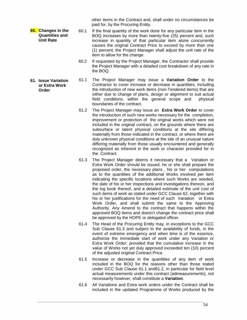
RRDP-II-SSN-02-04 54
other items in the Contract and, shall under no circumstances bepaid for, by the Procuring Entity.
60. Changes in theQuantities andUnit Rate
60.1 If the final quantity of the work done for any particular item in theBOQ increases by more than twenty-five (25) percent and, suchincrease in quantity of that particular item alone concurrentlycauses the original Contract Price to exceed by more than one(1) percent, the Project Manager shall adjust the unit rate of theitem to allow for the change.
60.2 If requested by the Project Manager, the Contractor shall providethe Project Manager with a detailed cost breakdown of any rate inthe BOQ.
61. Issue Variationor Extra WorkOrder
61.1 The Project Manager may issue a Variation Order to theContractor to cover increase or decrease in quantities, includingthe introduction of new work items (non-Tendered items) that areeither due to change of plans, design or alignment to suit actualfield conditions, within the general scope and physicalboundaries of the contract.
61.2 The Project Manager may issue an Extra Work Order to coverthe introduction of such new works necessary for the completion,improvement or protection of the original works which were notincluded in the original contract, on the grounds where there aresubsurface or latent physical conditions at the site differingmaterially from those indicated in the contract, or where there areduly unknown physical conditions at the site of an unusual naturediffering materially from those usually encountered and generallyrecognized as inherent in the work or character provided for inthe Contract.
61.3 The Project Manager deems it necessary that a Variation orExtra Work Order should be issued, he or she shall prepare theproposed order, the necessary plans , his or her computationsas to the quantities of the additional Works involved per itemindicating the specific locations where such Works are needed,the date of his or her inspections and investigations thereon, andthe log book thereof, and a detailed estimate of the unit cost ofsuch items of work as stated under GCC Clause 62, together withhis or her justifications for the need of such Variation or ExtraWork Order, and shall submit the same to the ApprovingAuthority. Any Amend to the contract that happens within theapproved BOQ items and doesn’t change the contract price shallbe approved by the HOPE or delegated officer.
61.4 The Head of the Procuring Entity may, in exceptions to the GCCSub Clause 61.3 and subject to the availability of funds, in theevent of extreme emergency and when time is of the essence,authorize the immediate start of work under any Variation orExtra Work Order; provided that the cumulative increase in thevalue of Works not yet duly approved exceeded ten (10) percentof the adjusted original Contract Price.
61.5 Increase or decrease in the quantities of any item of workincluded in the BOQ for the reasons other than those statedunder GCC Sub Clause 61.1 and61.2, in particular for field levelactual measurements under this contract (admeasurements), notnecessarily however, shall constitute a Variation.
61.6 All Variations and Extra work orders under the Contract shall beincluded in the updated Programme of Works produced by the
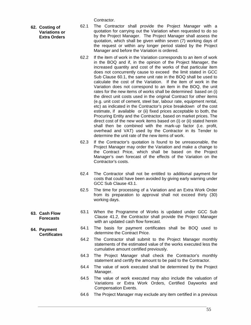
RRDP-II-SSN-02-04 55
Contractor.
62. Costing ofVariations orExtra Orders
62.1 The Contractor shall provide the Project Manager with aquotation for carrying out the Variation when requested to do soby the Project Manager. The Project Manager shall assess thequotation, which shall be given within seven (7) working days ofthe request or within any longer period stated by the ProjectManager and before the Variation is ordered.
62.2 If the item of work in the Variation corresponds to an item of workin the BOQ and if, in the opinion of the Project Manager, theincreased quantity and cost of the works of that particular itemdoes not concurrently cause to exceed the limit stated in GCCSub Clause 60.1, the same unit rate in the BOQ shall be used tocalculate the cost of the Variation. If the item of work in theVariation does not correspond to an item in the BOQ, the unitrates for the new items of works shall be determined based on (i)the direct unit costs used in the original Contract for other items(e.g. unit cost of cement, steel bar, labour rate, equipment rental,etc) as indicated in the Contractor’s price breakdown of the costestimate, if available or (ii) fixed prices acceptable to both, theProcuring Entity and the Contractor, based on market prices. Thedirect cost of the new work items based on (i) or (ii) stated hereinshall then be combined with the mark-up factor (i.e. profit,overhead and VAT) used by the Contractor in its Tender todetermine the unit rate of the new items of work.
62.3 If the Contractor’s quotation is found to be unreasonable, theProject Manager may order the Variation and make a change tothe Contract Price, which shall be based on the ProjectManager’s own forecast of the effects of the Variation on theContractor’s costs.
62.4 The Contractor shall not be entitled to additional payment forcosts that could have been avoided by giving early warning underGCC Sub Clause 43.1.
62.5 The time for processing of a Variation and an Extra Work Orderfrom its preparation to approval shall not exceed thirty (30)working days.
63. Cash FlowForecasts
63.1 When the Programme of Works is updated under GCC SubClause 41.2, the Contractor shall provide the Project Managerwith an updated cash flow forecast.
64. PaymentCertificates
64.1 The basis for payment certificates shall be BOQ used todetermine the Contract Price.
64.2 The Contractor shall submit to the Project Manager monthlystatements of the estimated value of the works executed less thecumulative amount certified previously.
64.3 The Project Manager shall check the Contractor’s monthlystatement and certify the amount to be paid to the Contractor.
64.4 The value of work executed shall be determined by the ProjectManager.
64.5 The value of work executed may also include the valuation ofVariations or Extra Work Orders, Certified Dayworks andCompensation Events.
64.6 The Project Manager may exclude any item certified in a previous
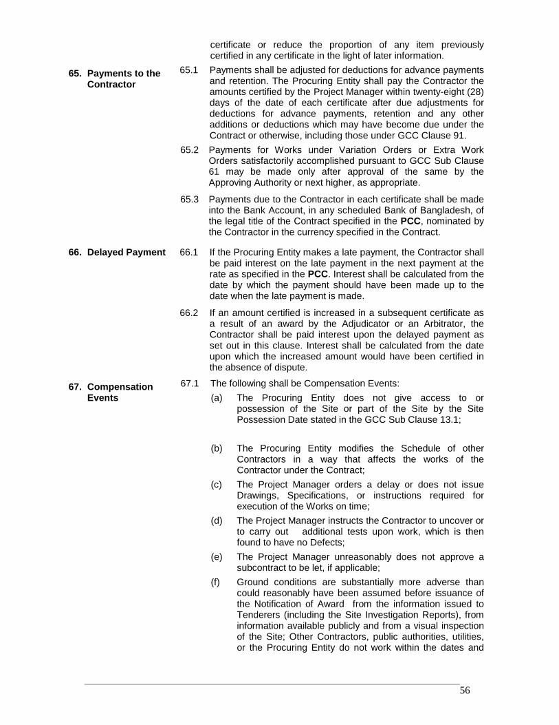
RRDP-II-SSN-02-04 56
certificate or reduce the proportion of any item previouslycertified in any certificate in the light of later information.
65. Payments to theContractor
65.1 Payments shall be adjusted for deductions for advance paymentsand retention. The Procuring Entity shall pay the Contractor theamounts certified by the Project Manager within twenty-eight (28)days of the date of each certificate after due adjustments fordeductions for advance payments, retention and any otheradditions or deductions which may have become due under theContract or otherwise, including those under GCC Clause 91.
65.2 Payments for Works under Variation Orders or Extra WorkOrders satisfactorily accomplished pursuant to GCC Sub Clause61 may be made only after approval of the same by theApproving Authority or next higher, as appropriate.
65.3 Payments due to the Contractor in each certificate shall be madeinto the Bank Account, in any scheduled Bank of Bangladesh, ofthe legal title of the Contract specified in the PCC, nominated bythe Contractor in the currency specified in the Contract.
66. Delayed Payment 66.1 If the Procuring Entity makes a late payment, the Contractor shallbe paid interest on the late payment in the next payment at therate as specified in the PCC. Interest shall be calculated from thedate by which the payment should have been made up to thedate when the late payment is made.
66.2 If an amount certified is increased in a subsequent certificate asa result of an award by the Adjudicator or an Arbitrator, theContractor shall be paid interest upon the delayed payment asset out in this clause. Interest shall be calculated from the dateupon which the increased amount would have been certified inthe absence of dispute.
67. CompensationEvents
67.1 The following shall be Compensation Events:(a) The Procuring Entity does not give access to or
possession of the Site or part of the Site by the SitePossession Date stated in the GCC Sub Clause 13.1;
(b) The Procuring Entity modifies the Schedule of otherContractors in a way that affects the works of theContractor under the Contract;
(c) The Project Manager orders a delay or does not issueDrawings, Specifications, or instructions required forexecution of the Works on time;
(d) The Project Manager instructs the Contractor to uncover orto carry out additional tests upon work, which is thenfound to have no Defects;
(e) The Project Manager unreasonably does not approve asubcontract to be let, if applicable;
(f) Ground conditions are substantially more adverse thancould reasonably have been assumed before issuance ofthe Notification of Award from the information issued toTenderers (including the Site Investigation Reports), frominformation available publicly and from a visual inspectionof the Site; Other Contractors, public authorities, utilities,or the Procuring Entity do not work within the dates and
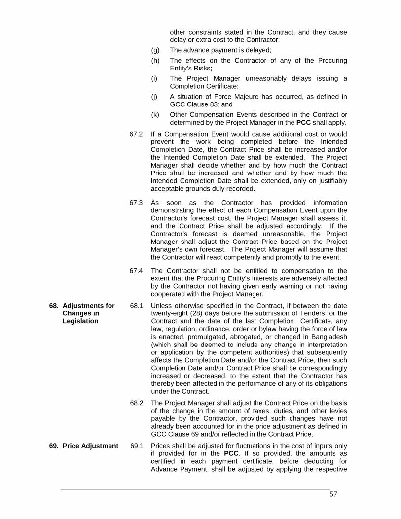
RRDP-II-SSN-02-04 57
other constraints stated in the Contract, and they causedelay or extra cost to the Contractor;
(g) The advance payment is delayed;(h) The effects on the Contractor of any of the Procuring
Entity’s Risks;(i) The Project Manager unreasonably delays issuing a
Completion Certificate;(j) A situation of Force Majeure has occurred, as defined in
GCC Clause 83; and(k) Other Compensation Events described in the Contract or
determined by the Project Manager in the PCC shall apply.
67.2 If a Compensation Event would cause additional cost or wouldprevent the work being completed before the IntendedCompletion Date, the Contract Price shall be increased and/orthe Intended Completion Date shall be extended. The ProjectManager shall decide whether and by how much the ContractPrice shall be increased and whether and by how much theIntended Completion Date shall be extended, only on justifiablyacceptable grounds duly recorded.
67.3 As soon as the Contractor has provided informationdemonstrating the effect of each Compensation Event upon theContractor’s forecast cost, the Project Manager shall assess it,and the Contract Price shall be adjusted accordingly. If theContractor’s forecast is deemed unreasonable, the ProjectManager shall adjust the Contract Price based on the ProjectManager’s own forecast. The Project Manager will assume thatthe Contractor will react competently and promptly to the event.
67.4 The Contractor shall not be entitled to compensation to theextent that the Procuring Entity’s interests are adversely affectedby the Contractor not having given early warning or not havingcooperated with the Project Manager.
68. Adjustments forChanges inLegislation
68.1 Unless otherwise specified in the Contract, if between the datetwenty-eight (28) days before the submission of Tenders for theContract and the date of the last Completion Certificate, anylaw, regulation, ordinance, order or bylaw having the force of lawis enacted, promulgated, abrogated, or changed in Bangladesh(which shall be deemed to include any change in interpretationor application by the competent authorities) that subsequentlyaffects the Completion Date and/or the Contract Price, then suchCompletion Date and/or Contract Price shall be correspondinglyincreased or decreased, to the extent that the Contractor hasthereby been affected in the performance of any of its obligationsunder the Contract.
68.2 The Project Manager shall adjust the Contract Price on the basisof the change in the amount of taxes, duties, and other leviespayable by the Contractor, provided such changes have notalready been accounted for in the price adjustment as defined inGCC Clause 69 and/or reflected in the Contract Price.
69. Price Adjustment 69.1 Prices shall be adjusted for fluctuations in the cost of inputs onlyif provided for in the PCC. If so provided, the amounts ascertified in each payment certificate, before deducting forAdvance Payment, shall be adjusted by applying the respective
RRDP-II-SSN-02-04 58
price adjustment factor to the payment amount. The formulaeindicated below applies:
P= A + B (Im/Io)where:
P is the adjustment factor
A and B are Coefficients specified in the PCC, representingthe nonadjustable and adjustable portions, respectively, ofthe Contract; and
Im is the Index during the month the work has beenexecuted and
Io is the Index prevailing twenty-eight (28) days prior to thedeadline for submission of Tender.
The Indexes to be used is as published by the BangladeshBureau of Statistics (BBS) on a monthly basis. In case notavailable, then other countries or authorities of the sourcesmentioned in Appendix to the Tender may be used.
70. Retention Money 70.1 The Procuring Entity may retain from each progressive paymentdue to the Contractor at the percentage specified in the PCCuntil completion of the whole of the Works under the Contract.
70.2 On completion of the whole of the Works, the first half of the totalamount retained under GCC Sub Clause 70.1 shall be returnedto the Contractor and the remaining second half after the DefectsLiability Period has passed and the Project Manager hascertified in the form of Defects Corrections Certificate..
70.3 On completion of the whole of the Works, the Contractor maysubstitute an irrevocable unconditional Bank Guarantee from anyscheduled Bank of Bangladesh, in the format as specified (FormPW3-12), without any alteration, acceptable to the ProcuringEntity for the second half of the retention money as stated underGCC Sub Clause 70.2.
71. LiquidatedDamages
71.1 Except as provided under GCC Sub Clause 83, if the Contractorfails to complete the Works and physical services within theIntended Completion Date or extended Intended CompletionDate, the Procuring Entity shall, as Liquidated Damages, deductfrom the Contract Price, a sum at the percent-rate per day ofdelay as specified in the PCC, of the contract value of theuncompleted works or part thereof completed after the IntendedCompletion Date or extended Intended Completion Date, asapplicable. The total amount of Liquidated Damages or DelayDamages shall not exceed the amount specified in the PCC. TheProcuring Entity may deduct Liquidated Damages frompayments due to the Contractor. Payment of Liquidateddamages shall not affect the Contractor’s liabilities.
71.2 If the Intended Completion Date is extended after LiquidatedDamages have been paid, the Project Manager shall correct anyoverpayment of liquidated damages by the Contractor byadjusting the next payment certificate.
72. Bonus 72.1 The Contractor shall be paid a Bonus calculated at the percent-rate per day if stated in the PCC for each day (less any days forwhich the Contractor is paid for acceleration) that the Completionof the whole of the Works is earlier than the Intended Completion
RRDP-II-SSN-02-04 59
Date. The Project Manager shall require certifying that theWorks are complete, although they may not have fallen due tobeing complete as per approved updated Programme of Works.
73. AdvancePayment
73.1 The Procuring Entity shall make advance payment, if sospecified in the PCC, to the Contractor in the amounts and bythe dates specified in the PCC against an irrevocableunconditional Bank Guarantee issued by any scheduled Bank ofBangladesh in the format as specified (Form PW3-11), withoutalteration, and acceptable to the Procuring Entity of an amountequal to the advance payment. The Guarantee shall remaineffective until the advance payment has been amortized, but theamount of the Guarantee shall be progressively reduced by theamounts amortized by the Contractor. Interest will not becharged on the advance payment.
73.2 The Contractor shall use the advance payment only to pay forEquipment, Plant, Materials, and mobilization expenses requiredspecifically for execution of the Contract. The Contractor shalldemonstrate that advance payment has been used for suchspecific purposes by supplying copies of invoices or otherdocuments to the Project Manager.
73.3 The advance payment shall be amortized by deducting atproportionate rate from payments otherwise due to theContractor, following the schedule of completed percentages ofthe Works as specified in the PCC. No account shall be taken ofthe advance payment or its amortization in assessing valuationsof work done, Variations, price adjustments, CompensationEvents, Bonuses, or Liquidated Damages.
73.4 If the amortization of advance payment has not been completedby twenty-eight (28) days prior to the expiry date of theGuarantee stated under GCC Sub Clause 73.1, the Contractorshall correspondingly extend the validity of the Guarantee for aperiod so long the advance payment is fully amortized. The BankGuarantee for advance payment shall be released when thesame has been fully amortized.
74. PerformanceSecurity
74.1 The Procuring Entity shall notify the Contractor of any claimmade against the Bank issuing the Performance Security.
74.2 The Procuring Entity may claim against the security if any of thefollowing events occurs for fourteen (14) days or more.(a) The Contractor is in breach of the Contract and the
Procuring Entity has duly notified him or her ; and(b) The Contractor has not paid an amount due to the
Procuring Entity and the Procuring Entity has dulynotified him or her.
74.3 In the event as stated under GCC Sub Clause 74.2, theContractor is liable to pay compensation under the Contractamounting to the full value of the security or more, the ProcuringEntity may call the full amount of the security.
74.4 The Performance Security furnished at the time of signing of theContract Agreement shall be substituted, after the issuance ofcertificate of Completion of works by the Project Manager, by anew Security covering fifty (50) percent amount of thePerformance Security to cover the Defects Liability Period.
RRDP-II-SSN-02-04 60
74.5 If there is no reason to call the security, the security shall bedischarged by the Procuring Entity and returned to theContractor after the Defects Liability period has passed and theProject Manager has certified in the form of Defects CorrectionsCertificates and the Procuring Entity shall not make any claimunder the security, except for amounts to which the ProcuringEntity is entitled under this Contract. In the event this Contract issignificantly below the updated official estimated cost orunbalanced as a result of front loading, the Procuring Entity shallcall the full amount of the security in the circumstances statedunder GCC Sub Clause 74.3.
75. ProvisionalSums
75.1 Provisional Sums shall only be used in whole or in part, inaccordance with the Project Manager’s instructions.
75.2 Plants, Materials or Services to be purchased by the Contractorunder the provisions of GCC Sub Clause 75.1 from NominatedSubcontractor(s) or for meeting the other expenditures underthe Contract, and for which there shall be included in theContract price, the actual amounts paid or due to be paid by theContractor, and a sum for profit, overhead and VAT, asapplicable, calculated as a percentage of these actual amountsby applying the relevant percentage rate as specified in thePCC.
76. Day works 76.1 If applicable, the Day works rates in the Contractor’s Tendershall be used for small additional amounts of work only whenthe Project Manager has given written instructions in advancefor additional work to be paid for in that way.
76.2 All works to be paid for as Day works shall be recorded by theContractor on forms approved by the Project Manager. Eachcompleted form shall be certified and signed by the ProjectManager within seven (7) days of the works being done.
76.3 The Contractor shall be paid for Day works subject to obtainingsigned Day works forms.
77. Cost of Repairsto Loss orDamages
77.1 Loss or damage to the Works or Materials to be incorporated inthe Works between the Start Date and the end of the DefectsLiability Period shall be remedied by the Contractor at theContractor’s own cost, if the loss or damage arises from theContractor’s acts or omissions.
E. Completion of the Contract78. Completion 78.1 The Contractor shall apply by notice to the Project Manager for
issuing a Completion Certificate of the Works, and the ProjectManager shall do so upon deciding that the work is completed.
79. Taking Over 79.1 The Procuring Entity shall take over the Site and the Workswithin seven (7) days of the Project Manager’s issuing acertificate of Completion.
80. Amendment toContract
80.1 The amendment to Contract shall generally include extension oftime to the Intended Completion Date, increase or decrease inoriginal Contract Price and any other changes acceptable underthe conditions of the Contract.
RRDP-II-SSN-02-04 61
80.2 The Procuring Entity shall amend the Contract, incorporatingthe changes approved, in accordance with the Delegation ofFinancial Power or Sub-delegation thereof and, introduced tothe original terms and conditions of the Contract
81. Final Account 81.1 The Contractor shall submit with a detailed account of the totalamount that the Contractor considers payable under theContract to the Project Manager before the end of the DefectsLiability Period.
81.2 The Project Manager shall certify the Final Payment within fiftysix (56) days of receiving the Contractor’s account if thepayable amount claimed by the Contractor is correct and thecorresponding works are completed.
81.3 If it is not, the Project Manager shall issue within fifty six (56)days a Defects Liability Schedule that states the scope of thecorrections or additions that are necessary.
81.4 If the Final Account of Works submitted under GCC SubClause 81.1 is unsatisfactory even after it has beenresubmitted, the Project Manager shall decide on the amountpayable to the Contractor and issue a payment certificate.
82. As-builtDrawings andManuals
82.1 If “As Built” Drawings and/or operating and maintenancemanuals are required, the Contractor shall supply them by thedates stated in the PCC.
82.2 If the Contractor does not supply the Drawings and/or Manualsby the dates specified in GCC Sub Clause 82.1, or they do notreceive the Project Manager’s approval, the Project Managershall withhold a nominal amount specified in the PCC frompayments due to the Contractor.
83. Force Majeure 83.1 Force Majeure may include, but is not limited to, exceptionalevents or circumstances of the kind stated below;(a) war, hostilities (whether war be declared or not),
invasion, act of foreign enemies;(b) rebellion, terrorism, sabotage by persons other than the
Contractor’s personnel, revolution, insurrection, militaryor usurped power, or civil war ;
(c) riot, commotion, disorder, strike or lockout by personsother than the Contractor’s personnel ;
(d) munitions of war, explosive materials, ionising radiationor contamination by radio-activity, except as may beattributable to the Contractor’s use of such munitions,explosives, radiation or radio-activity ; and
(e) natural catastrophes such as fires, floods, epidemics,quarantine restrictions, freight embargoes, cyclone,hurricane, typhoon, tsunami, storm surge, earthquake,hill slides, landslides, and volcanic activities.
83.2 The Head of Procuring Entity decides the existence of a ForceMajeure that will be the basis of the issuance of order forsuspension of Works as stated under GCC Sub Clause 48.1.
84. Notice of Force 84.1 If a Party is or will be prevented from performing its substantialobligations under the Contract by Force Majeure, then it shall
RRDP-II-SSN-02-04 62
Majeure give notice, within fourteen (14) days after the party becameaware, to the other Party of the event or circumstancesconstituting the Force Majeure and shall specify the obligations,the performance of which is or will be prevented.
84.2 Notwithstanding any other provision of this Clause, ForceMajeure shall not apply to obligations of either Party to makepayments to the other Party under the Contract.
85. Consequences ofForce Majeure
85.1 The Contractor shall not be liable for forfeiture of its security,liquidated damages, or termination for default if and to theextent that it’s delay in performance or other failure to performits obligations under the Contract is the result of an event ofForce Majeure.
85.2 If the Contractor is prevented from performing its substantialobligations under the Contract by Force Majeure of whichnotice has been given under GCC Sub Clause 84, and suffersdelay and/or incurs cost by reason of such Force Majeure, theContractor shall be entitled subject to GCC Sub Clause 91 to:(a) an extension of time for any such delay, if completion is or
will be delayed, under GCC Clause 44, and(b) if the event or circumstance is of the kind described sub-
paragraphs (a) to (e) of GCC Sub Clause 83.1 occurs inthe country, payment of any such cost, including the costsof rectifying or replacing the Works and physical servicesdamaged or destructed by Force Majeure, to the extentthey are not indemnified through the insurance policyreferred to in GCC Clause 36.
85.3 After receiving notice under GCC Sub Clause 84.1, the ProjectManager shall proceed to determine these matters under theprovisions of the Contract.
86. Release fromPerformance
86.1 Notwithstanding any other provision of this Clause, if any eventor circumstance outside the control of the parties (including, butnot limited to, Force Majeure) arises which makes it impossibleor unlawful for either or both Parties to fulfil its or theircontractual obligations or which, under the law governing theContract, entitles the Parties to be released from furtherperformance of the Contract, then upon notice by either Party tothe other party of such event or circumstance:(a) the Parties shall be discharged from further performance,
without prejudice to the rights of either Party in respect ofany previous breach of the Contract, and
(b) the sum payable by the Procuring Entity to the Contractorshall be the same as would have been payable underGCC Sub Clause 88.3 if the Contract had been terminatedunder GCC Sub Clause 87.3.
F. Termination and Settlement of Disputes
87. Termination 87.1 Termination for Default(a) The Procuring Entity or the Contractor, without prejudice
to any other remedy for breach of Contract, by giving
RRDP-II-SSN-02-04 63
twenty-eight (28) days written notice of default to theother party, may terminate the Contract in whole or in partif the other party causes a fundamental breach ofContract. Fundamental breaches of the Contract shallinclude, but shall not be limited to, the following:(i) the Contractor stops work for twenty-eight (28) days
when no stoppage of work is shown on the currentProgramme and the stoppage has not beenauthorized by the Project Manager;
(ii) the Project Manager instructs the Contractor todelay the progress of the Works, and the instructionis not withdrawn within eighty four ( 84) days;
(iii) the Project Manager gives Notice that failure tocorrect a particular Defect is a fundamental breachof Contract and the Contractor fails to correct itwithin a reasonable period of time determined bythe Project Manager;
(iv) the Contractor does not maintain a Security, whichis required;
(v) the Contractor has delayed the completion of theWorks by the number of days for which themaximum amount of Liquidated Damages can bepaid, as specified in GCC Sub Clause 71;
(vi) the Contractor has subcontracted the whole of theWorks or has assigned the Contract without therequired agreement and without the approval of theProject Manager;
(vii) the Contractor, in the judgment of the ProcuringEntity has engaged in corrupt or fraudulentpractices, as defined in GCC Sub Clause 38, incompeting for or in executing the Contract.
(viii) A payment certified by the Project Manager is notpaid by the Procuring Entity to the Contractor withineighty-four (84) days of the date of the ProjectManager’s certificate.
87.2 Termination for InsolvencyThe Procuring Entity and the Contractor may at any timeterminate the Contract by giving twenty-eight (28) days writtennotice to the other party if either of the party becomesbankrupt or otherwise insolvent. In such event, terminationwill be without compensation to any party, provided that suchtermination will not prejudice or affect any right of action orremedy that has accrued or will accrue thereafter to the otherparty.
87.3 Termination for Convenience(a) The Procuring Entity, by giving twenty-eight (28) days
written notice sent to the Contractor, may terminate theContract, in whole or in part, at any time for itsconvenience. The notice of termination shall specify thattermination is for the Procuring Entity’s convenience, theextent to which performance of the Contractor under theContract is terminated, and the date upon which such
RRDP-II-SSN-02-04 64
termination becomes effective.(b) The Procuring Entity shall not terminate the contract
under GCC Sub Clause 87.3 (a) in order to execute theWorks itself or to arrange for the Works to be executedby another contractor or to avoid a termination of theContract by the Contractor as stated under GCC SubClause 87.1(a).
87.4 In the event the Procuring Entity terminates the Contract in wholeor in part, the Procuring Entity shall accept the portion of theWorks that are complete and ready for handing over after theContractor’s receipt of notice of termination of the Contract. Forthe remaining portion of the Works, the Procuring Entity may elect:(a) to have any portion completed by the Contractor at the
Contract terms and prices; and /or(b) to cancel the remainder and pay to the Contractor an
agreed amount for partially completed Works and formaterials and parts previously procured by theContractor, or
(c) except in the case of termination for convenience asstated under GCC Sub Clause 87.3, engage anotherContractor to complete the Works, and in that case theContractor shall be liable to the Procuring Entity for anycost that may be incurred in excess of the sum thatwould have been paid to the Contractor, if the workwould have been executed and completed by him or her.
87.5 If the Contract is terminated, the Contractor shall stop workimmediately, make the Site safe and secure, and leave the Siteas soon as is reasonably possible.
87.6 The expiration of the Intended Completion Date under GCCClause 44 and, the initiation of settlement of disputes likeamicable or adjudication and arbitration under GCC Clause 92shall not be deemed a termination of the Contract under GCCClause 87.
88. Payment uponTermination
88.1 If the Contract is terminated because of a fundamental breachof Contract under GCC Sub Clause 87.1 by the Contractor,the Project Manager shall issue a certificate for the value ofthe Works done and Plant and Materials ordered lessadvance payments received up to the date of the issue of thecertificate and further less the amount from percentage toapply to the contract value of the works not completed, asindicated in the PCC. If the total amount due to the ProcuringEntity exceeds any payment due to the Contractor, thedifference shall be a debt payable to the Procuring Entity.
88.2 If the Contract is terminated for the Procuring Entity’sconvenience or because of a fundamental breach of Contractby the Procuring Entity, the Project Manager shall issue apayment certificate for the value of the work done, Materialsordered, the reasonable cost of removal of Equipment,repatriation of the Contractor’s foreign personnel employedsolely on the Works and recruited specifically for the Works,and the Contractor’s costs of protecting and securing the
RRDP-II-SSN-02-04 65
Works, and less advance payments received up to the date ofthe certificate.
88.3 If the Contract is terminated for reasons of Force Majeure, theProject Manager shall determine the value of the work doneand issue a Payment Certificate which shall include:
(a) the amounts payable for any work carried out for whichunit rates or prices are stated in the Contract;
(b) the cost of Plant and Materials ordered for the Workswhich have been delivered to the Contractor, or of whichthe Contractor is liable to accept delivery: this Plant andMaterials shall become the property of (and be at the riskof) the Procuring Entity when paid for by the ProcuringEntity, and the Contractor shall place the same at theProcuring Entity’s disposal;
(c) other costs or liabilities which in the circumstances werereasonably and necessarily incurred by the Contractor inthe expectation of completing the Works;
(d) the cost of removal of Temporary Works andContractor’s Equipment from the Site; and
(e) the cost of repatriation of the Contractor’s staff andlabour employed wholly in connection with the Works atthe date of termination.
89. Property 89.1 All Materials on the Site, Plant, Equipment, Temporary Works,and Works shall be deemed to be the property of theProcuring Entity if the Contract is terminated because of theContractor’s default stated under GCC Sub Clause 87.1.
90. Frustration 90.1 If the Contract is frustrated by the occurrence of a situation ofForce Majeure as defined in GCC Sub Clause 83, the ProjectManager shall certify that the Contract has been frustrated.The Contractor shall make the Site safe and stop work asquickly as possible after receiving this certificate and shall bepaid for all works carried out before receiving it and for anywork carried out afterwards to which a commitment wasmade.
G. Claims, Disputes and Arbitration
91. Contractor’sClaims
91.1 If the Contractor considers himself to be entitled to anyextension of the Completion Time and/or any additionalpayment, under any Clause of these Conditions or otherwise inconnection with the Contract, the Contractor shall give notice tothe Procuring Entity, describing the event or circumstancegiving rise to the claim. The notice shall be given as soon aspracticable, and not later than twenty-eight (28) days after theContractor became aware, or should have become aware, ofthe event or circumstance.
91.2 If the Contractor fails to give notice of a claim within suchperiod of twenty-eight (28) days, the Intended Completion Dateshall not be extended, the Contractor shall not be entitled toadditional payment, and the Procuring Entity shall bedischarged from all liability in connection with the claim.
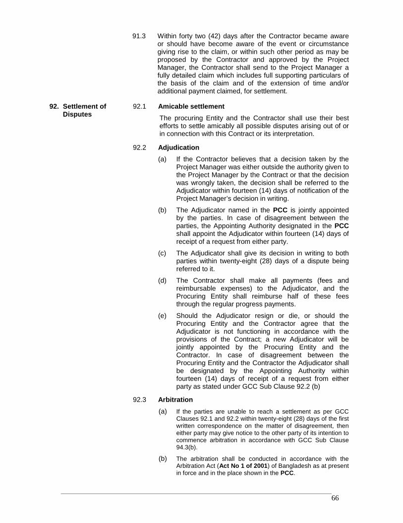
RRDP-II-SSN-02-04 66
91.3 Within forty two (42) days after the Contractor became awareor should have become aware of the event or circumstancegiving rise to the claim, or within such other period as may beproposed by the Contractor and approved by the ProjectManager, the Contractor shall send to the Project Manager afully detailed claim which includes full supporting particulars ofthe basis of the claim and of the extension of time and/oradditional payment claimed, for settlement.
92. Settlement ofDisputes
92.1 Amicable settlementThe procuring Entity and the Contractor shall use their bestefforts to settle amicably all possible disputes arising out of orin connection with this Contract or its interpretation.
92.2 Adjudication(a) If the Contractor believes that a decision taken by the
Project Manager was either outside the authority given tothe Project Manager by the Contract or that the decisionwas wrongly taken, the decision shall be referred to theAdjudicator within fourteen (14) days of notification of theProject Manager’s decision in writing.
(b) The Adjudicator named in the PCC is jointly appointedby the parties. In case of disagreement between theparties, the Appointing Authority designated in the PCCshall appoint the Adjudicator within fourteen (14) days ofreceipt of a request from either party.
(c) The Adjudicator shall give its decision in writing to bothparties within twenty-eight (28) days of a dispute beingreferred to it.
(d) The Contractor shall make all payments (fees andreimbursable expenses) to the Adjudicator, and theProcuring Entity shall reimburse half of these feesthrough the regular progress payments.
(e) Should the Adjudicator resign or die, or should theProcuring Entity and the Contractor agree that theAdjudicator is not functioning in accordance with theprovisions of the Contract; a new Adjudicator will bejointly appointed by the Procuring Entity and theContractor. In case of disagreement between theProcuring Entity and the Contractor the Adjudicator shallbe designated by the Appointing Authority withinfourteen (14) days of receipt of a request from eitherparty as stated under GCC Sub Clause 92.2 (b)
92.3 Arbitration(a) If the parties are unable to reach a settlement as per GCC
Clauses 92.1 and 92.2 within twenty-eight (28) days of the firstwritten correspondence on the matter of disagreement, theneither party may give notice to the other party of its intention tocommence arbitration in accordance with GCC Sub Clause94.3(b).
(b) The arbitration shall be conducted in accordance with theArbitration Act (Act No 1 of 2001) of Bangladesh as at presentin force and in the place shown in the PCC.
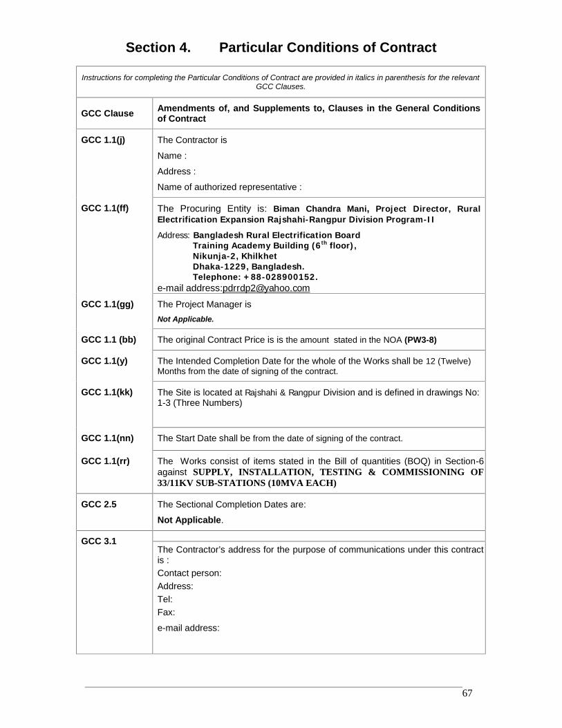
RRDP-II-SSN-02-04 67
Section 4. Particular Conditions of Contract
Instructions for completing the Particular Conditions of Contract are provided in italics in parenthesis for the relevantGCC Clauses.
GCC Clause Amendments of, and Supplements to, Clauses in the General Conditionsof Contract
GCC 1.1(j) The Contractor is
Name :
Address :
Name of authorized representative :
GCC 1.1(ff) The Procuring Entity is: Biman Chandra Mani, Project Director, RuralElectrification Expansion Rajshahi-Rangpur Division Program-II
Address: Bangladesh Rural Electrification BoardTraining Academy Building (6th floor),Nikunja-2, KhilkhetDhaka-1229, Bangladesh.Telephone: +88-028900152.
e-mail address:[email protected]
GCC 1.1(gg) The Project Manager isNot Applicable.
GCC 1.1 (bb) The original Contract Price is is the amount stated in the NOA (PW3-8)
GCC 1.1(y) The Intended Completion Date for the whole of the Works shall be 12 (Twelve)Months from the date of signing of the contract.
GCC 1.1(kk) The Site is located at Rajshahi & Rangpur Division and is defined in drawings No:1-3 (Three Numbers)
GCC 1.1(nn) The Start Date shall be from the date of signing of the contract.
GCC 1.1(rr) The Works consist of items stated in the Bill of quantities (BOQ) in Section-6against SUPPLY, INSTALLATION, TESTING & COMMISSIONING OF33/11KV SUB-STATIONS (10MVA EACH)
GCC 2.5 The Sectional Completion Dates are:
Not Applicable.
GCC 3.1The Contractor’s address for the purpose of communications under this contractis :Contact person:Address:Tel:Fax:
e-mail address:
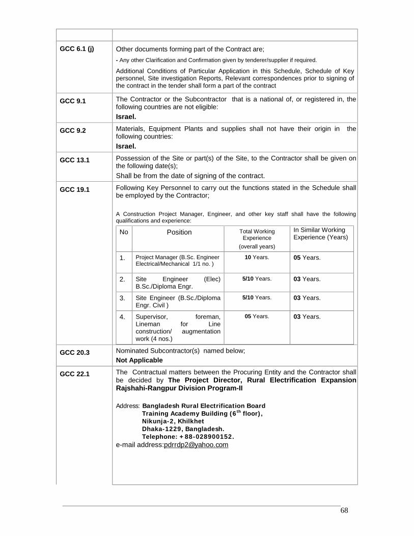
RRDP-II-SSN-02-04 68
GCC 6.1 (j) Other documents forming part of the Contract are;- Any other Clarification and Confirmation given by tenderer/supplier if required.
Additional Conditions of Particular Application in this Schedule, Schedule of Keypersonnel, Site investigation Reports, Relevant correspondences prior to signing ofthe contract in the tender shall form a part of the contract
GCC 9.1 The Contractor or the Subcontractor that is a national of, or registered in, thefollowing countries are not eligible:Israel.
GCC 9.2 Materials, Equipment Plants and supplies shall not have their origin in thefollowing countries:Israel.
GCC 13.1 Possession of the Site or part(s) of the Site, to the Contractor shall be given onthe following date(s);Shall be from the date of signing of the contract.
GCC 19.1 Following Key Personnel to carry out the functions stated in the Schedule shallbe employed by the Contractor;
A Construction Project Manager, Engineer, and other key staff shall have the followingqualifications and experience:
No Position Total WorkingExperience
(overall years)
In Similar WorkingExperience (Years)
1. Project Manager (B.Sc. EngineerElectrical/Mechanical 1/1 no. )
10 Years. 05 Years.
2. Site Engineer (Elec)B.Sc./Diploma Engr.
5/10 Years. 03 Years.
3. Site Engineer (B.Sc./DiplomaEngr. Civil )
5/10 Years. 03 Years.
4. Supervisor, foreman,Lineman for Lineconstruction/ augmentationwork (4 nos.)
05 Years. 03 Years.
GCC 20.3 Nominated Subcontractor(s) named below;Not Applicable
GCC 22.1 The Contractual matters between the Procuring Entity and the Contractor shallbe decided by The Project Director, Rural Electrification ExpansionRajshahi-Rangpur Division Program-II
Address: Bangladesh Rural Electrification BoardTraining Academy Building (6th floor),Nikunja-2, KhilkhetDhaka-1229, Bangladesh.Telephone: +88-028900152.
e-mail address:[email protected]
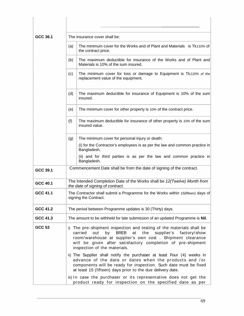
RRDP-II-SSN-02-04 69
GCC 36.1 The insurance cover shall be:
(a) The minimum cover for the Works and of Plant and Materials is Tk110% ofthe contract price.
(b) The maximum deductible for insurance of the Works and of Plant andMaterials is 10% of the sum insured.
(c) The minimum cover for loss or damage to Equipment is Tk110% of thereplacement value of the equipment.
(d) The maximum deductible for insurance of Equipment is 10% of the suminsured.
(e) The minimum cover for other property is 10% of the contract price.
(f) The maximum deductible for insurance of other property is 10% of the suminsured value.
(g) The minimum cover for personal injury or death:
(i) for the Contractor’s employees is as per the law and common practice inBangladesh.
(ii) and for third parties is as per the law and common practice inBangladesh.
GCC 39.1 Commencement Date shall be from the date of signing of the contract.
GCC 40.1 The Intended Completion Date of the Works shall be 12(Twelve) Month fromthe date of signing of contract.
GCC 41.1 The Contractor shall submit a Programme for the Works within 15(fifteen) days ofsigning the Contract.
GCC 41.2 The period between Programme updates is 30 (Thirty) days.
GCC 41.3 The amount to be withheld for late submission of an updated Programme is Nil.
GCC 53 i) The pre–shipment inspection and testing of the materials shall becarried out by BREB at the supplier's factory/showroom/warehouse at supplier’s own cost . Shipment clearancewill be given after satisfactory completion of pre-shipmentinspection of the materials.
ii) The Supplier shall notify the purchaser at least Four (4) weeks inadvance of the date or dates when the products and /orcomponents will be ready for inspection. Such date must be fixedat least 15 (fifteen) days prior to the due delivery date.
iii) In case the purchaser or its representative does not get theproduct ready for inspection on the specif ied date as per
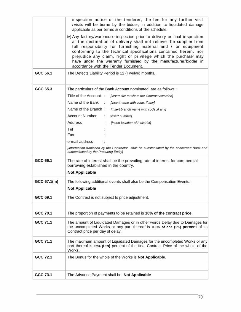
RRDP-II-SSN-02-04 70
inspection notice of the tenderer, the fee for any further visit/visits will be borne by the bidder, in addition to liquidated damageapplicable as per terms & conditions of the schedule.
iv) Any factory/warehouse inspection prior to delivery or final inspectionat the destination of delivery shall not relieve the supplier fromfull responsibility for furnishing material and / or equipmentconforming to the technical specifications contained herein, norprejudice any claim, right or privilege which the purchaser mayhave under the warranty furnished by the manufacturer/bidder inaccordance with the Tender Document.
GCC 56.1 The Defects Liability Period is 12 (Twelve) months.
GCC 65.3 The particulars of the Bank Account nominated are as follows :
Title of the Account : [insert title to whom the Contract awarded]
Name of the Bank : [insert name with code, if any]
Name of the Branch : [insert branch name with code ,if any]
Account Number : [insert number]
Address : [insert location with district]
Tel :Fax :
e-mail address :[information furnished by the Contractor shall be substantiated by the concerned Bank andauthenticated by the Procuring Entity]
GCC 66.1 The rate of interest shall be the prevailing rate of interest for commercialborrowing established in the country.
Not Applicable
GCC 67.1(m) The following additional events shall also be the Compensation Events:
Not Applicable
GCC 69.1 The Contract is not subject to price adjustment.
GCC 70.1 The proportion of payments to be retained is 10% of the contract price.
GCC 71.1 The amount of Liquidated Damages or in other words Delay due to Damages forthe uncompleted Works or any part thereof is 0.075 of one (1%) percent of itsContract price per day of delay.
GCC 71.1 The maximum amount of Liquidated Damages for the uncompleted Works or anypart thereof is 10% (ten) percent of the final Contract Price of the whole of theWorks.
GCC 72.1 The Bonus for the whole of the Works is Not Applicable.
GCC 73.1 The Advance Payment shall be: Not Applicable
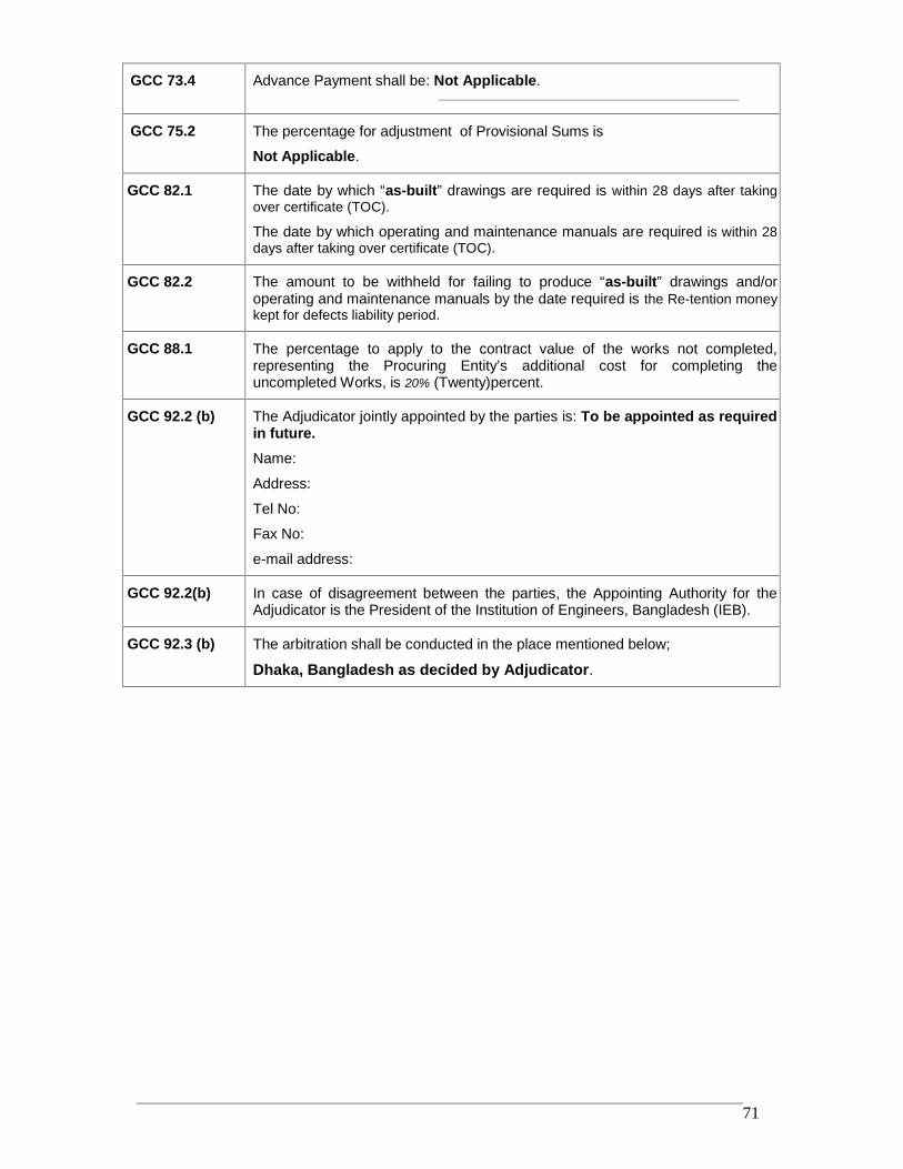
RRDP-II-SSN-02-04 71
GCC 73.4 Advance Payment shall be: Not Applicable.
GCC 75.2 The percentage for adjustment of Provisional Sums is
Not Applicable.
GCC 82.1 The date by which “as-built” drawings are required is within 28 days after takingover certificate (TOC).
The date by which operating and maintenance manuals are required is within 28days after taking over certificate (TOC).
GCC 82.2 The amount to be withheld for failing to produce “as-built” drawings and/oroperating and maintenance manuals by the date required is the Re-tention moneykept for defects liability period.
GCC 88.1 The percentage to apply to the contract value of the works not completed,representing the Procuring Entity’s additional cost for completing theuncompleted Works, is 20% (Twenty)percent.
GCC 92.2 (b) The Adjudicator jointly appointed by the parties is: To be appointed as requiredin future.Name:
Address:
Tel No:
Fax No:
e-mail address:
GCC 92.2(b) In case of disagreement between the parties, the Appointing Authority for theAdjudicator is the President of the Institution of Engineers, Bangladesh (IEB).
GCC 92.3 (b) The arbitration shall be conducted in the place mentioned below;
Dhaka, Bangladesh as decided by Adjudicator.
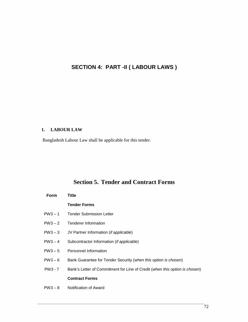
RRDP-II-SSN-02-04 72
SECTION 4: PART -II ( LABOUR LAWS )
1. LABOUR LAW
Bangladesh Labour Law shall be applicable for this tender.
Section 5. Tender and Contract Forms
Form Title
Tender Forms
PW3 – 1 Tender Submission Letter
PW3 – 2 Tenderer Information
PW3 – 3 JV Partner Information (if applicable)
PW3 – 4 Subcontractor Information (if applicable)
PW3 – 5 Personnel Information
PW3 – 6 Bank Guarantee for Tender Security (when this option is chosen)
PW3 - 7 Bank’s Letter of Commitment for Line of Credit (when this option is chosen)
Contract Forms
PW3 – 8 Notification of Award
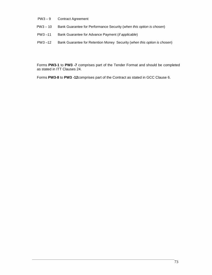
RRDP-II-SSN-02-04 73
PW3 – 9 Contract Agreement
PW3 – 10 Bank Guarantee for Performance Security (when this option is chosen)
PW3 –11 Bank Guarantee for Advance Payment (if applicable)
PW3 –12 Bank Guarantee for Retention Money Security (when this option is chosen)
Forms PW3-1 to PW3 -7 comprises part of the Tender Format and should be completedas stated in ITT Clauses 24.
Forms PW3-8 to PW3 -12comprises part of the Contract as stated in GCC Clause 6.
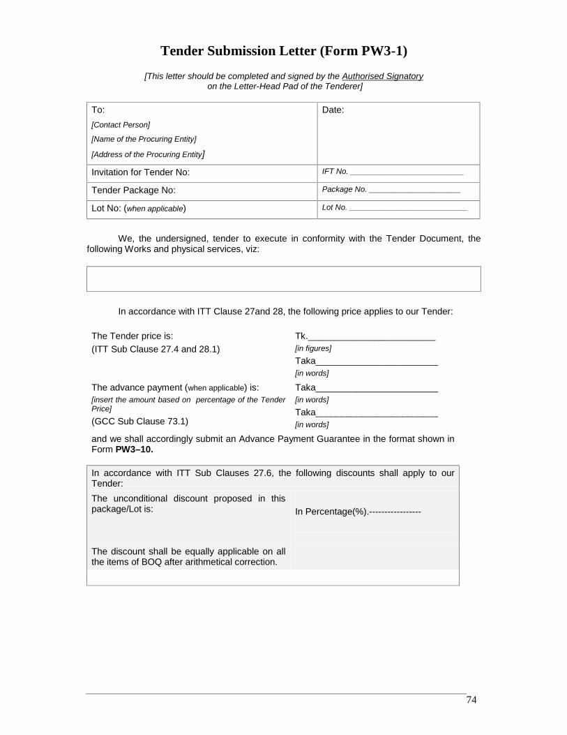
RRDP-II-SSN-02-04 74
Tender Submission Letter (Form PW3-1)
[This letter should be completed and signed by the Authorised Signatoryon the Letter-Head Pad of the Tenderer]
To:[Contact Person]
[Name of the Procuring Entity]
[Address of the Procuring Entity]
Date:
Invitation for Tender No: IFT No. __________________________
Tender Package No: Package No. _____________________
Lot No: (when applicable) Lot No. ___________________________
We, the undersigned, tender to execute in conformity with the Tender Document, thefollowing Works and physical services, viz:
In accordance with ITT Clause 27and 28, the following price applies to our Tender:
The Tender price is:(ITT Sub Clause 27.4 and 28.1)
Tk._________________________[in figures]Taka________________________[in words]
The advance payment (when applicable) is:[insert the amount based on percentage of the TenderPrice]
(GCC Sub Clause 73.1)
Taka________________________[in words]Taka________________________[in words]
and we shall accordingly submit an Advance Payment Guarantee in the format shown inForm PW3–10.
In accordance with ITT Sub Clauses 27.6, the following discounts shall apply to ourTender:The unconditional discount proposed in thispackage/Lot is: In Percentage(%).-----------------
The discount shall be equally applicable on allthe items of BOQ after arithmetical correction.
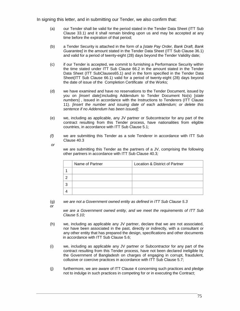
RRDP-II-SSN-02-04 75
In signing this letter, and in submitting our Tender, we also confirm that:
(a) our Tender shall be valid for the period stated in the Tender Data Sheet (ITT SubClause 33.1) and it shall remain binding upon us and may be accepted at anytime before the expiration of that period;
(b) a Tender Security is attached in the form of a [state Pay Order, Bank Draft, BankGuarantee] in the amount stated in the Tender Data Sheet (ITT Sub Clause 36.1)and valid for a period of twenty-eight (28) days beyond the Tender Validity date;
(c) if our Tender is accepted, we commit to furnishing a Performance Security withinthe time stated under ITT Sub Clause 66.2 in the amount stated in the TenderData Sheet (ITT SubClauses65.1) and in the form specified in the Tender DataSheet(ITT Sub Clause 66.1) valid for a period of twenty-eight (28) days beyondthe date of issue of the Completion Certificate of the Works;
(d) we have examined and have no reservations to the Tender Document, issued byyou on [insert date];including Addendum to Tender Document No(s) [statenumbers] , issued in accordance with the Instructions to Tenderers (ITT Clause11). [insert the number and issuing date of each addendum; or delete thissentence if no Addendum has been issued];
(e) we, including as applicable, any JV partner or Subcontractor for any part of thecontract resulting from this Tender process, have nationalities from eligiblecountries, in accordance with ITT Sub Clause 5.1;
(f) we are submitting this Tender as a sole Tenderer in accordance with ITT SubClause 40.3
orwe are submitting this Tender as the partners of a JV, comprising the followingother partners in accordance with ITT Sub Clause 40.3;
Name of Partner Location & District of Partner
1
2
3
4
(g) we are not a Government owned entity as defined in ITT Sub Clause 5.3or
we are a Government owned entity, and we meet the requirements of ITT SubClause 5.10;
(h) we, including as applicable any JV partner, declare that we are not associated,nor have been associated in the past, directly or indirectly, with a consultant orany other entity that has prepared the design, specifications and other documentsin accordance with ITT Sub Clause 5.6;
(i) we, including as applicable any JV partner or Subcontractor for any part of thecontract resulting from this Tender process, have not been declared ineligible bythe Government of Bangladesh on charges of engaging in corrupt, fraudulent,collusive or coercive practices in accordance with ITT Sub Clause 5.7;
(j) furthermore, we are aware of ITT Clause 4 concerning such practices and pledgenot to indulge in such practices in competing for or in executing the Contract;
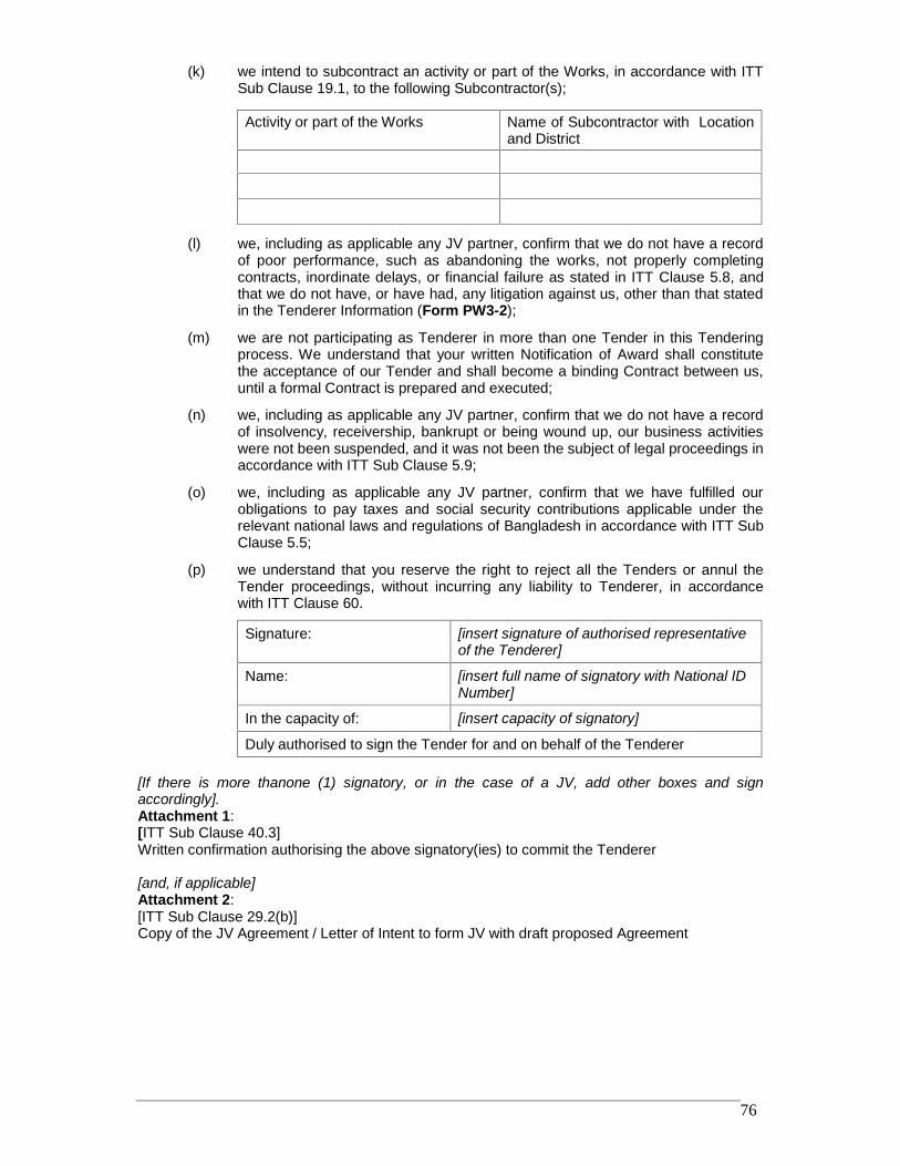
RRDP-II-SSN-02-04 76
(k) we intend to subcontract an activity or part of the Works, in accordance with ITTSub Clause 19.1, to the following Subcontractor(s);
Activity or part of the Works Name of Subcontractor with Locationand District
(l) we, including as applicable any JV partner, confirm that we do not have a recordof poor performance, such as abandoning the works, not properly completingcontracts, inordinate delays, or financial failure as stated in ITT Clause 5.8, andthat we do not have, or have had, any litigation against us, other than that statedin the Tenderer Information (Form PW3-2);
(m) we are not participating as Tenderer in more than one Tender in this Tenderingprocess. We understand that your written Notification of Award shall constitutethe acceptance of our Tender and shall become a binding Contract between us,until a formal Contract is prepared and executed;
(n) we, including as applicable any JV partner, confirm that we do not have a recordof insolvency, receivership, bankrupt or being wound up, our business activitieswere not been suspended, and it was not been the subject of legal proceedings inaccordance with ITT Sub Clause 5.9;
(o) we, including as applicable any JV partner, confirm that we have fulfilled ourobligations to pay taxes and social security contributions applicable under therelevant national laws and regulations of Bangladesh in accordance with ITT SubClause 5.5;
(p) we understand that you reserve the right to reject all the Tenders or annul theTender proceedings, without incurring any liability to Tenderer, in accordancewith ITT Clause 60.
Signature: [insert signature of authorised representativeof the Tenderer]
Name: [insert full name of signatory with National IDNumber]
In the capacity of: [insert capacity of signatory]
Duly authorised to sign the Tender for and on behalf of the Tenderer
[If there is more thanone (1) signatory, or in the case of a JV, add other boxes and signaccordingly].Attachment 1:[ITT Sub Clause 40.3]Written confirmation authorising the above signatory(ies) to commit the Tenderer
[and, if applicable]Attachment 2:[ITT Sub Clause 29.2(b)]Copy of the JV Agreement / Letter of Intent to form JV with draft proposed Agreement
RRDP-II-SSN-02-04 77
Tenderer Information (Form PW3-2)
[This Form should be completed only by the Tenderer, preferably on its Letter-Head Pad]
Invitation for Tender No: IFT No]
Tender Package No: [ Package No]
Lot No (when applicable) [Lot No)]
1. Eligibility Information of the Tenderer [ITT –Clauses 5& 29]
1.1 Nationality of individual or countryof registration
1.2 Tenderer’s legal title
1.3 Tenderer’s registered address
1.4 Tenderer’s legal status [complete the relevant box]
Proprietorship
Partnership
Limited Liability Concern
Government-owned Enterprise
Others[please describe, if applicable]
1.5 Tenderer’s year of registration
1.6 Tenderer’s authorised representative details
Name
National ID number
Address
Telephone / Fax numbers
e-mail address
1.7 Litigation [ITT Cause 13]
A. No pending litigation [if no pending litigation put Tick Mark in Box]
B. Pending litigation
Year Matter in dispute Value ofPending Claim
Value ofPending
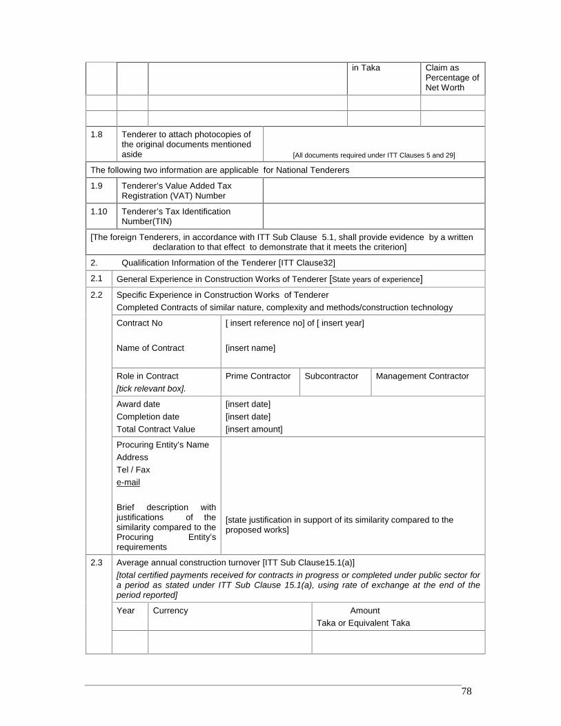
RRDP-II-SSN-02-04 78
in Taka Claim asPercentage ofNet Worth
1.8 Tenderer to attach photocopies ofthe original documents mentionedaside [All documents required under ITT Clauses 5 and 29]
The following two information are applicable for National Tenderers
1.9 Tenderer’s Value Added TaxRegistration (VAT) Number
1.10 Tenderer’s Tax IdentificationNumber(TIN)
[The foreign Tenderers, in accordance with ITT Sub Clause 5.1, shall provide evidence by a writtendeclaration to that effect to demonstrate that it meets the criterion]
2. Qualification Information of the Tenderer [ITT Clause32]
2.1 General Experience in Construction Works of Tenderer [State years of experience]2.2 Specific Experience in Construction Works of Tenderer
Completed Contracts of similar nature, complexity and methods/construction technology
Contract No
Name of Contract
[ insert reference no] of [ insert year]
[insert name]
Role in Contract[tick relevant box].
Prime Contractor Subcontractor Management Contractor
Award dateCompletion dateTotal Contract Value
[insert date][insert date][insert amount]
Procuring Entity’s NameAddressTel / Faxe-mail
Brief description withjustifications of thesimilarity compared to theProcuring Entity’srequirements
[state justification in support of its similarity compared to theproposed works]
2.3 Average annual construction turnover [ITT Sub Clause15.1(a)][total certified payments received for contracts in progress or completed under public sector fora period as stated under ITT Sub Clause 15.1(a), using rate of exchange at the end of theperiod reported]
Year Currency AmountTaka or Equivalent Taka
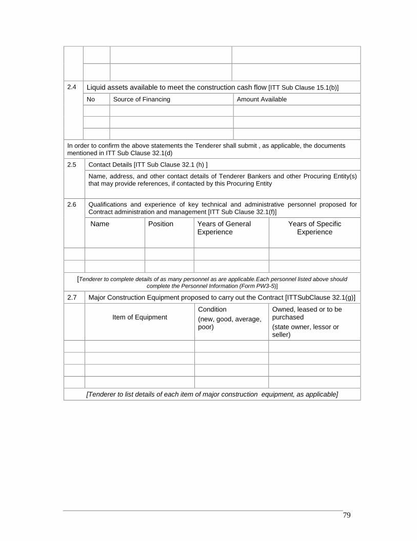
RRDP-II-SSN-02-04 79
2.4 Liquid assets available to meet the construction cash flow [ITT Sub Clause 15.1(b)]
No Source of Financing Amount Available
In order to confirm the above statements the Tenderer shall submit , as applicable, the documentsmentioned in ITT Sub Clause 32.1(d)
2.5 Contact Details [ITT Sub Clause 32.1 (h) ]
Name, address, and other contact details of Tenderer Bankers and other Procuring Entity(s)that may provide references, if contacted by this Procuring Entity
2.6 Qualifications and experience of key technical and administrative personnel proposed forContract administration and management [ITT Sub Clause 32.1(f)]
Name Position Years of GeneralExperience
Years of SpecificExperience
[Tenderer to complete details of as many personnel as are applicable.Each personnel listed above shouldcomplete the Personnel Information (Form PW3-5)]
2.7 Major Construction Equipment proposed to carry out the Contract [ITTSubClause 32.1(g)]
Item of EquipmentCondition(new, good, average,poor)
Owned, leased or to bepurchased(state owner, lessor orseller)
[Tenderer to list details of each item of major construction equipment, as applicable]
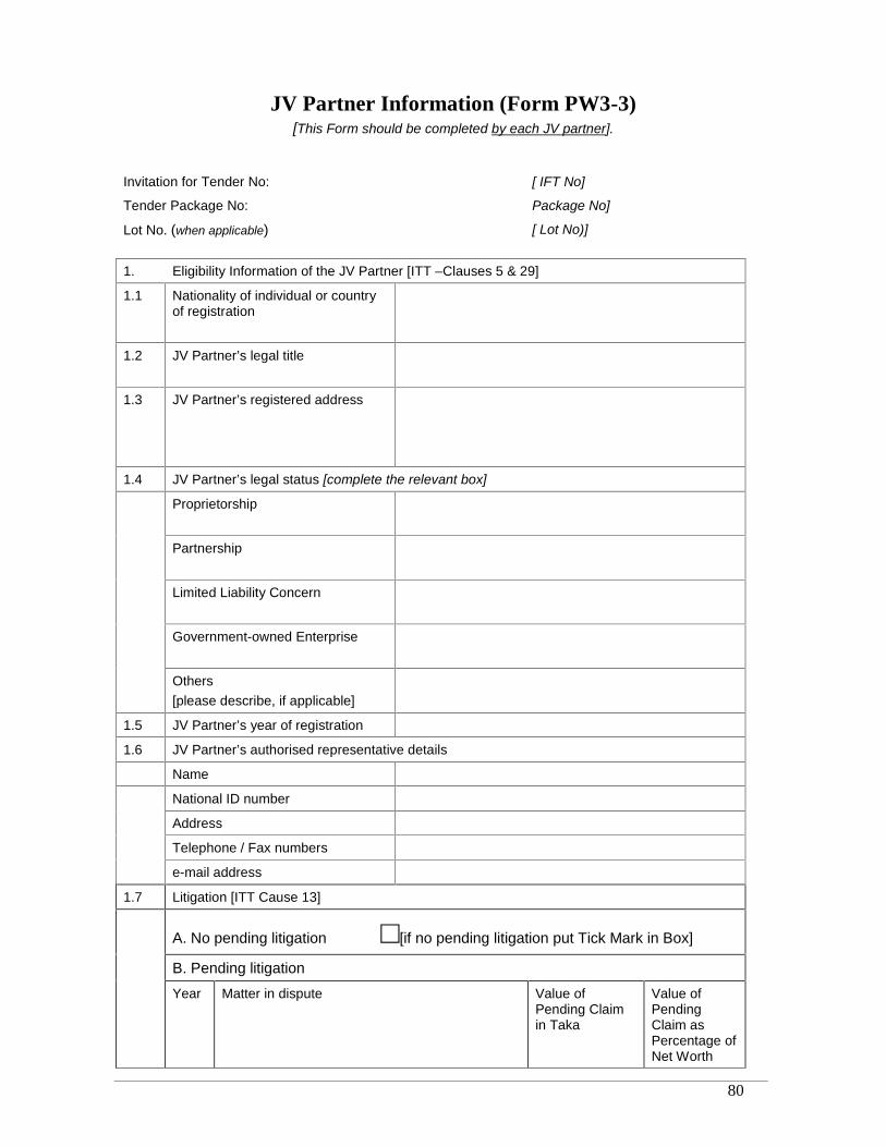
RRDP-II-SSN-02-04 80
JV Partner Information (Form PW3-3)[This Form should be completed by each JV partner].
Invitation for Tender No: [ IFT No]
Tender Package No: Package No]
Lot No. (when applicable) [ Lot No)]
1. Eligibility Information of the JV Partner [ITT –Clauses 5 & 29]
1.1 Nationality of individual or countryof registration
1.2 JV Partner’s legal title
1.3 JV Partner’s registered address
1.4 JV Partner’s legal status [complete the relevant box]
Proprietorship
Partnership
Limited Liability Concern
Government-owned Enterprise
Others[please describe, if applicable]
1.5 JV Partner’s year of registration
1.6 JV Partner’s authorised representative details
Name
National ID number
Address
Telephone / Fax numbers
e-mail address
1.7 Litigation [ITT Cause 13]
A. No pending litigation [if no pending litigation put Tick Mark in Box]
B. Pending litigation
Year Matter in dispute Value ofPending Claimin Taka
Value ofPendingClaim asPercentage ofNet Worth
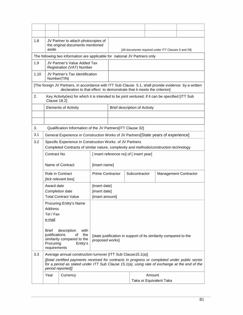
RRDP-II-SSN-02-04 81
1.8 JV Partner to attach photocopies ofthe original documents mentionedaside [All documents required under ITT Clauses 5 and 29]
The following two information are applicable for national JV Partners only
1.9 JV Partner’s Value Added TaxRegistration (VAT) Number
1.10 JV Partner’s Tax IdentificationNumber(TIN)
[The foreign JV Partners, in accordance with ITT Sub Clause 5.1, shall provide evidence by a writtendeclaration to that effect to demonstrate that it meets the criterion]
2. Key Activity(ies) for which it is intended to be joint ventured, if it can be specified [ITT SubClause 18.2]
Elements of Activity Brief description of Activity
3. Qualification Information of the JV Partners[ITT Clause 32]
3.1 General Experience in Construction Works of JV Partners[State years of experience]3.2 Specific Experience in Construction Works of JV Partners
Completed Contracts of similar nature, complexity and methods/construction technology
Contract No
Name of Contract
[ insert reference no] of [ insert year]
[insert name]
Role in Contract[tick relevant box].
Prime Contractor Subcontractor Management Contractor
Award dateCompletion dateTotal Contract Value
[insert date][insert date][insert amount]
Procuring Entity’s NameAddressTel / Faxe-mail
Brief description withjustifications of thesimilarity compared to theProcuring Entity’srequirements
[state justification in support of its similarity compared to theproposed works]
3.3 Average annual construction turnover [ITT Sub Clause15.1(a)][[total certified payments received for contracts in progress or completed under public sectorfor a period as stated under ITT Sub Clause 15.1(a), using rate of exchange at the end of theperiod reported]]
Year Currency AmountTaka or Equivalent Taka
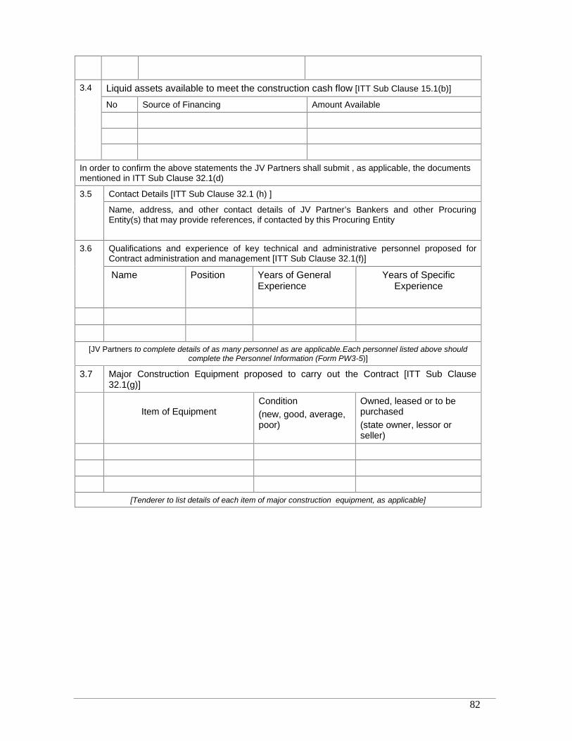
RRDP-II-SSN-02-04 82
3.4 Liquid assets available to meet the construction cash flow [ITT Sub Clause 15.1(b)]
No Source of Financing Amount Available
In order to confirm the above statements the JV Partners shall submit , as applicable, the documentsmentioned in ITT Sub Clause 32.1(d)
3.5 Contact Details [ITT Sub Clause 32.1 (h) ]
Name, address, and other contact details of JV Partner’s Bankers and other ProcuringEntity(s) that may provide references, if contacted by this Procuring Entity
3.6 Qualifications and experience of key technical and administrative personnel proposed forContract administration and management [ITT Sub Clause 32.1(f)]
Name Position Years of GeneralExperience
Years of SpecificExperience
[JV Partners to complete details of as many personnel as are applicable.Each personnel listed above shouldcomplete the Personnel Information (Form PW3-5)]
3.7 Major Construction Equipment proposed to carry out the Contract [ITT Sub Clause32.1(g)]
Item of EquipmentCondition(new, good, average,poor)
Owned, leased or to bepurchased(state owner, lessor orseller)
[Tenderer to list details of each item of major construction equipment, as applicable]
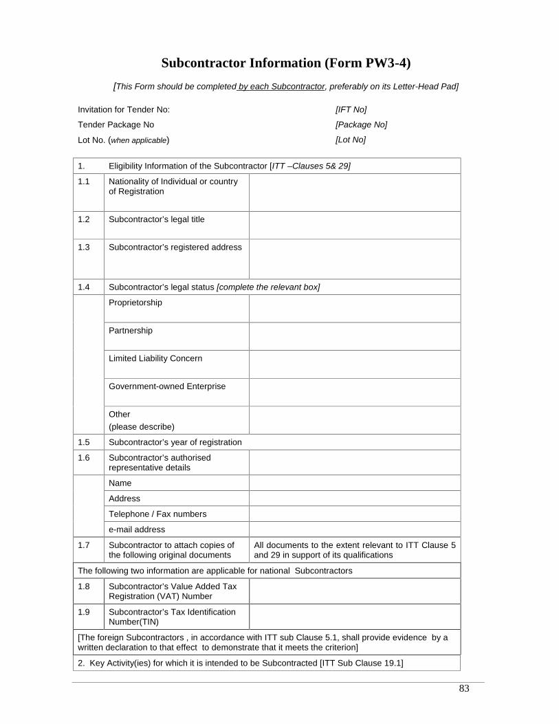
RRDP-II-SSN-02-04 83
Subcontractor Information (Form PW3-4)
[This Form should be completed by each Subcontractor, preferably on its Letter-Head Pad]
Invitation for Tender No: [IFT No]
Tender Package No [Package No]
Lot No. (when applicable) [Lot No]
1. Eligibility Information of the Subcontractor [ITT –Clauses 5& 29]
1.1 Nationality of Individual or countryof Registration
1.2 Subcontractor’s legal title
1.3 Subcontractor’s registered address
1.4 Subcontractor’s legal status [complete the relevant box]
Proprietorship
Partnership
Limited Liability Concern
Government-owned Enterprise
Other(please describe)
1.5 Subcontractor’s year of registration
1.6 Subcontractor’s authorisedrepresentative details
Name
Address
Telephone / Fax numbers
e-mail address
1.7 Subcontractor to attach copies ofthe following original documents
All documents to the extent relevant to ITT Clause 5and 29 in support of its qualifications
The following two information are applicable for national Subcontractors
1.8 Subcontractor’s Value Added TaxRegistration (VAT) Number
1.9 Subcontractor’s Tax IdentificationNumber(TIN)
[The foreign Subcontractors , in accordance with ITT sub Clause 5.1, shall provide evidence by awritten declaration to that effect to demonstrate that it meets the criterion]
2. Key Activity(ies) for which it is intended to be Subcontracted [ITT Sub Clause 19.1]
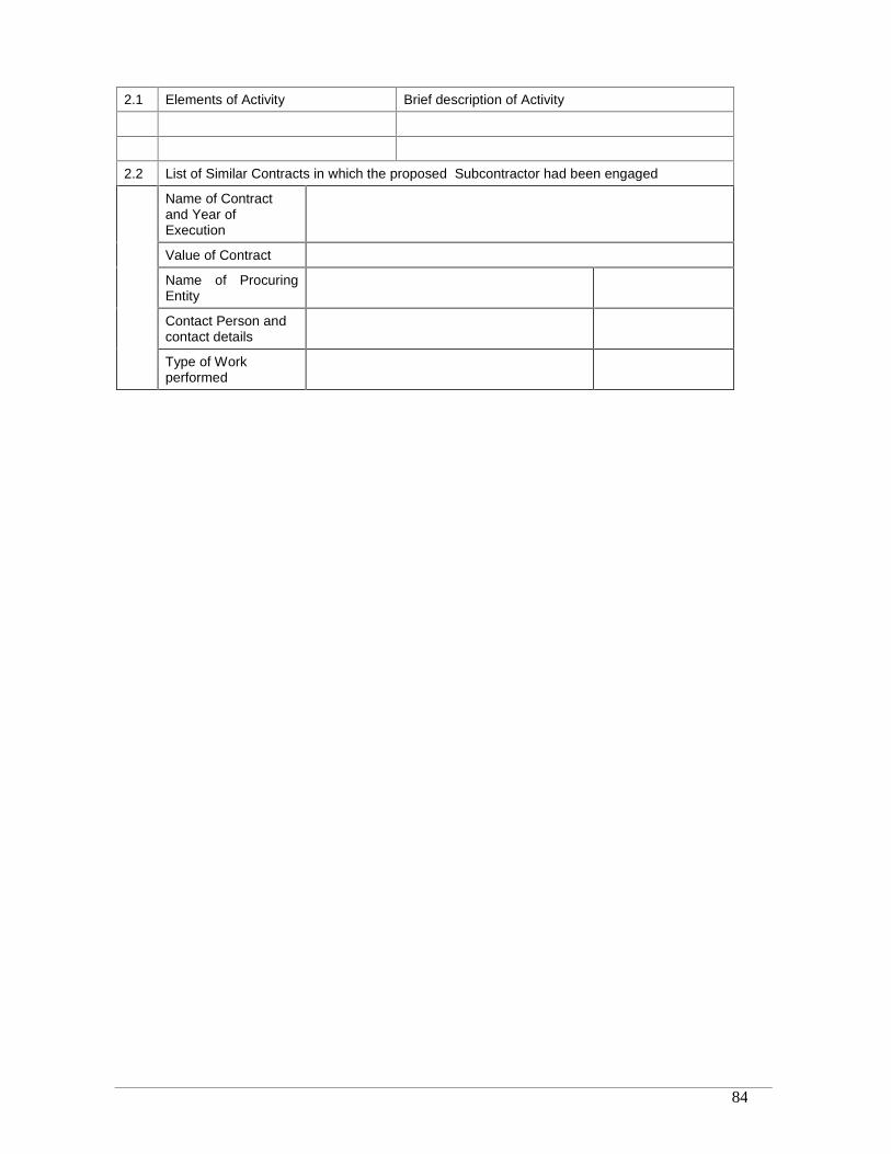
RRDP-II-SSN-02-04 84
2.1 Elements of Activity Brief description of Activity
2.2 List of Similar Contracts in which the proposed Subcontractor had been engaged
Name of Contractand Year ofExecution
Value of Contract
Name of ProcuringEntity
Contact Person andcontact details
Type of Workperformed
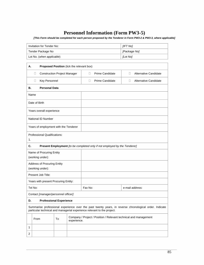
RRDP-II-SSN-02-04 85
Personnel Information (Form PW3-5)[This Form should be completed for each person proposed by the Tenderer in Form PW3-2 & PW3-3, where applicable]
Invitation for Tender No: [IFT No]
Tender Package No [Package No]
Lot No. (when applicable) [Lot No]
A. Proposed Position (tick the relevant box)
Construction Project Manager Prime Candidate Alternative Candidate
Key Personnel Prime Candidate Alternative Candidate
B. Personal Data
Name
Date of Birth
Years overall experience
National ID Number
Years of employment with the Tenderer
Professional Qualifications:
1.
C. Present Employment [to be completed only if not employed by the Tenderer]
Name of Procuring Entity
(working under):
Address of Procuring Entity
(working under):
Present Job Title:
Years with present Procuring Entity:
Tel No: Fax No: e-mail address:
Contact [manager/personnel officer]:
D. Professional Experience
Summarise professional experience over the past twenty years, in reverse chronological order. Indicateparticular technical and managerial experience relevant to the project.
From To Company / Project / Position / Relevant technical and managementexperience.
1
2
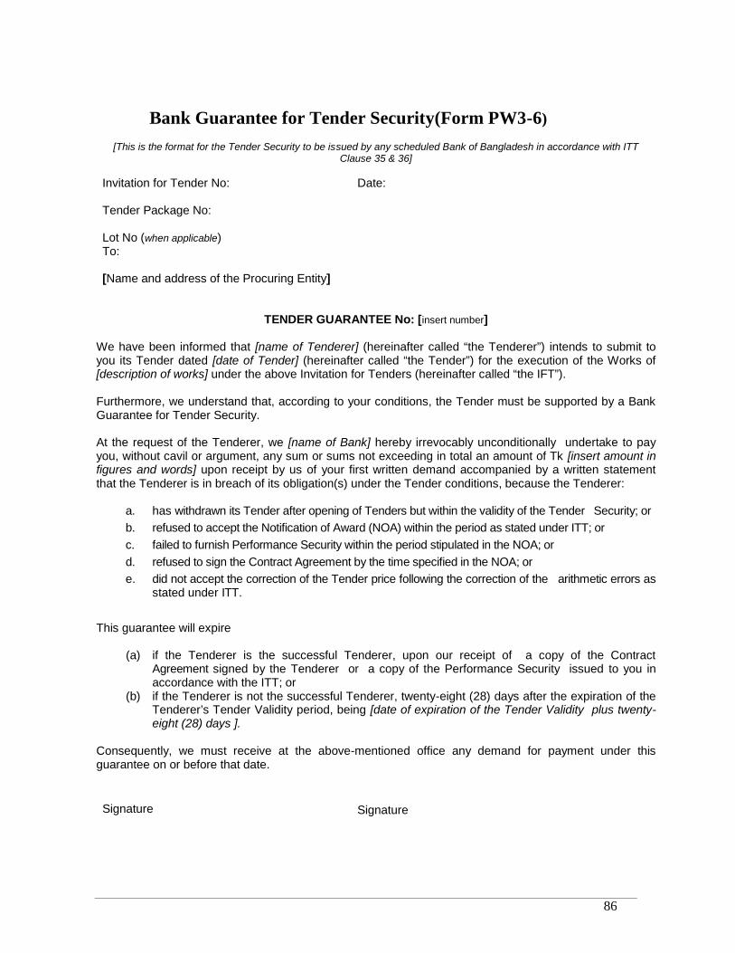
RRDP-II-SSN-02-04 86
Bank Guarantee for Tender Security(Form PW3-6)
[This is the format for the Tender Security to be issued by any scheduled Bank of Bangladesh in accordance with ITTClause 35 & 36]
Invitation for Tender No: Date:
Tender Package No:
Lot No (when applicable)To:
[Name and address of the Procuring Entity]
TENDER GUARANTEE No: [insert number]
We have been informed that [name of Tenderer] (hereinafter called “the Tenderer”) intends to submit toyou its Tender dated [date of Tender] (hereinafter called “the Tender”) for the execution of the Works of[description of works] under the above Invitation for Tenders (hereinafter called “the IFT”).
Furthermore, we understand that, according to your conditions, the Tender must be supported by a BankGuarantee for Tender Security.
At the request of the Tenderer, we [name of Bank] hereby irrevocably unconditionally undertake to payyou, without cavil or argument, any sum or sums not exceeding in total an amount of Tk [insert amount infigures and words] upon receipt by us of your first written demand accompanied by a written statementthat the Tenderer is in breach of its obligation(s) under the Tender conditions, because the Tenderer:
a. has withdrawn its Tender after opening of Tenders but within the validity of the Tender Security; orb. refused to accept the Notification of Award (NOA) within the period as stated under ITT; orc. failed to furnish Performance Security within the period stipulated in the NOA; ord. refused to sign the Contract Agreement by the time specified in the NOA; ore. did not accept the correction of the Tender price following the correction of the arithmetic errors as
stated under ITT.
This guarantee will expire
(a) if the Tenderer is the successful Tenderer, upon our receipt of a copy of the ContractAgreement signed by the Tenderer or a copy of the Performance Security issued to you inaccordance with the ITT; or
(b) if the Tenderer is not the successful Tenderer, twenty-eight (28) days after the expiration of theTenderer’s Tender Validity period, being [date of expiration of the Tender Validity plus twenty-eight (28) days ].
Consequently, we must receive at the above-mentioned office any demand for payment under thisguarantee on or before that date.
Signature Signature
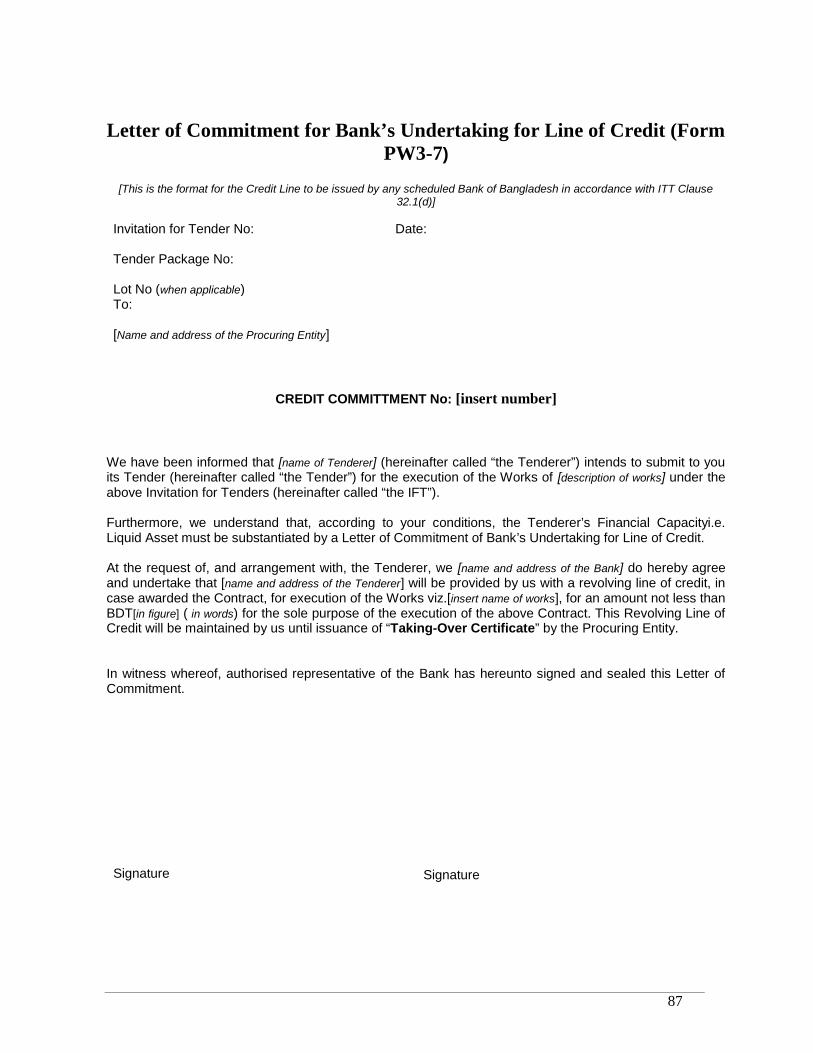
RRDP-II-SSN-02-04 87
Letter of Commitment for Bank’s Undertaking for Line of Credit (FormPW3-7)
[This is the format for the Credit Line to be issued by any scheduled Bank of Bangladesh in accordance with ITT Clause32.1(d)]
Invitation for Tender No: Date:
Tender Package No:
Lot No (when applicable)To:
[Name and address of the Procuring Entity]
CREDIT COMMITTMENT No: [insert number]
We have been informed that [name of Tenderer] (hereinafter called “the Tenderer”) intends to submit to youits Tender (hereinafter called “the Tender”) for the execution of the Works of [description of works] under theabove Invitation for Tenders (hereinafter called “the IFT”).
Furthermore, we understand that, according to your conditions, the Tenderer’s Financial Capacityi.e.Liquid Asset must be substantiated by a Letter of Commitment of Bank’s Undertaking for Line of Credit.
At the request of, and arrangement with, the Tenderer, we [name and address of the Bank] do hereby agreeand undertake that [name and address of the Tenderer] will be provided by us with a revolving line of credit, incase awarded the Contract, for execution of the Works viz.[insert name of works], for an amount not less thanBDT[in figure] ( in words) for the sole purpose of the execution of the above Contract. This Revolving Line ofCredit will be maintained by us until issuance of “Taking-Over Certificate” by the Procuring Entity.
In witness whereof, authorised representative of the Bank has hereunto signed and sealed this Letter ofCommitment.
Signature Signature

RRDP-II-SSN-02-04 88
Notification of Award (Form PW3-8)
Contract No: Date:To:
[Name of Contractor]
This is to notify you that your Tender dated [insert date] for the execution of the Works for [name ofproject/Contract] for the Contract Price of Tk[state amount in figures and in words], as corrected andmodified in accordance with the Instructions to Tenderers, has been approved by [name ofProcuring Entity].
You are thus requested to take following actions:
i. accept in writing the Notification of Award within seven (7) working days of itsissuance in accordance with ITT Clause 64
ii. furnish a Performance Security in the form as specified and in the amount of Tk[stateamount in figures and words] ,within fourteen (14)days of acceptance of thisNotification of Award but not later than (specify date), in accordance with ITT Clause65 & 66.
iii. sign the Contract within twenty-eight (28)days of issuance of this Notification ofAward but not later than (specify date), in accordance with ITT Clause 70.
You may proceed with the execution of the Works only upon completion of the above tasks. You mayalso please note that this Notification of Award shall constitute the formation of this Contract whichshall become binding upon you.
We attach the draft Contract and all other documents for your perusal and signature.
Signed
Duly authorised to sign for and on behalf of[name of Procuring Entity]
Date:

RRDP-II-SSN-02-04 89
Contract Agreement (Form PW3-9)
THIS AGREEMENT made the [day] day of [month][year] between [name and address of Procuring Entity](hereinafter called “the Procuring Entity”) of the one part and [name and address of Contractor](hereinafter called “the Contractor”) of the other part:
WHEREAS the Procuring Entity invited Tenders for certain works, viz, [brief description of works] and hasaccepted a Tender by the Contractor for the execution of those works in the sum of Taka [Contract Price infigures and in words] (hereinafter called “the Contract Price”).
NOW THIS AGREEMENT WITNESSETH AS FOLLOWS:1. In this Agreement words and expressions shall have the same meanings as are respectively
assigned to them in the General Conditions of Contract hereafter referred to.
2. The documents forming the Contract shall be interpreted in the following order of priority:
(a) the signed Contract Agreement(b) the Notification of Award(c) the completed Tender and the Appendix to the Tender(d) the Particular Conditions of Contract(e) the General Conditions of Contract(f) the Technical Specifications(g) the General Specifications(h) the Drawings(i) the priced BOQ and the Schedules(j) any other document listed in the PCC forming part of the Contract.
3. In consideration of the payments to be made by the Procuring Entity to the Contractor ashereinafter mentioned, the Contractor hereby covenants with the Procuring Entity to execute andcomplete the works and to remedy any defects therein in conformity in all respects with theprovisions of the Contract.
4. The Procuring Entity hereby covenants to pay the Contractor in consideration of the execution andcompletion of the works and the remedying of defects therein, the Contract Price or such othersum as may become payable under the provisions of the Contract at the times and in the mannerprescribed by the Contract.
IN WITNESS whereof the parties hereto have caused this Agreement to be executed in accordance withthe laws of Bangladesh on the day, month and year first written above.
For the Procuring Entity For the Contractor
Signature
Name
National ID No.Title
In the presence of Name
Address
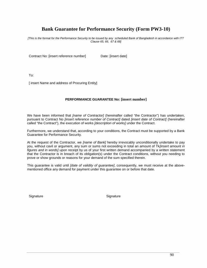
RRDP-II-SSN-02-04 90
Bank Guarantee for Performance Security (Form PW3-10)
[This is the format for the Performance Security to be issued by any scheduled Bank of Bangladesh in accordance with ITTClause 65, 66, 67 & 68]
Contract No: [insert reference number] Date: [insert date]
To:
[ insert Name and address of Procuring Entity]
PERFORMANCE GUARANTEE No: [insert number]
We have been informed that [name of Contractor] (hereinafter called “the Contractor”) has undertaken,pursuant to Contract No [insert reference number of Contract] dated [insert date of Contract] (hereinaftercalled “the Contract”), the execution of works [description of works] under the Contract.
Furthermore, we understand that, according to your conditions, the Contract must be supported by a BankGuarantee for Performance Security.
At the request of the Contractor, we [name of Bank] hereby irrevocably unconditionally undertake to payyou, without cavil or argument, any sum or sums not exceeding in total an amount of Tk[insert amount infigures and in words] upon receipt by us of your first written demand accompanied by a written statementthat the Contractor is in breach of its obligation(s) under the Contract conditions, without you needing toprove or show grounds or reasons for your demand of the sum specified therein.
This guarantee is valid until [date of validity of guarantee], consequently, we must receive at the above-mentioned office any demand for payment under this guarantee on or before that date.
Signature Signature
RRDP-II-SSN-02-04 91
Section 6. Bill of Quantities
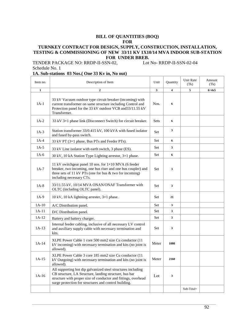
RRDP-II-SSN-02-04 92
BILL OF QUANTITIES (BOQ)FOR
TURNKEY CONTRACT FOR DESIGN, SUPPLY, CONSTRUCTION, INSTALLATION,TESTING & COMMISSIONING OF NEW 33/11 KV 1X10/14 MVA INDOOR SUB-STATION
FOR UNDER BREB.TENDER PACKAGE NO: RRDP-II-SSN-02, Lot No- RRDP-II-SSN-02-04Schedule No. 11A. Sub-stations 03 Nos.( One 33 Kv in, No out)
Item no. Description of Item Unit QuantityUnit Rate
(Tk)Amount
(Tk)
1 2 3 4 5 6=4x5
1A-133 kV Vacuum outdoor type circuit breaker (incoming) withcurrent transformer on same structure including Control andProtection panel for the 33 kV outdoor VCB and33/11.55 kVTransformer.
Nos. 6
1A-2 33 kV 3×1 phase link (Disconnect Switch) for circuit breaker. Sets 6
1A-3 Station transformer 33/0.415 kV, 100 kVA with fused isolatorand fused by-pass switch.
Set 3
1A-4 33 kV PT (3×1 phase, Bus PTs and Feeder PTs). Set 6
1A-5 33 kV Line isolator with earth switch, 3 phase (ES). Set 3
1A-6 30 kV, 10 kA Station Type Lighting arrestor, 3×1 phase. Set 6
1A-711 kV switchgear panel 10 nos. for 1×10 MVA (6 feederbreaker, two incoming, one bus riser and one bus coupler) andthree sets of 11 kV PTs (one for bus & two for incoming)including necessary CTs.
Set 3
1A-8 33/11.55 kV, 10/14 MVA ONAN/ONAF Transformer withOLTC (including OLTC panel).
Set 3
1A-9 10 kV, 10 kA lightning arrester, 3×1 phase. Set 21
1A-10 A/C Distribution panel. Set 3
1A-11 D/C Distribution panel. Set 3
1A-12 Battery and battery charger. Set 3
1A-13Internal feeder cabling, inclusive of all necessary LV controland auxiliary supply cable with necessary termination andkits.
Set 3
1A-14XLPE Power Cable 1 core 500 mm2 size Cu conductor (11kV incoming) with necessary termination and kits (no joint isallowed).
Meter 1080
1A-15XLPE Power Cable 3 core 185 mm2 size Cu conductor (11kV Outgoing) with necessary termination and kits (no joint isallowed).
Meter 2160
1A-16
All supporting hot dip galvanized steel structures includingCB structure, LA Structure, landing structure, bus barstructure with proper size of conductor and fittings, overheadsurge protection for structures and control building.
Lot 3
Sub-Total=
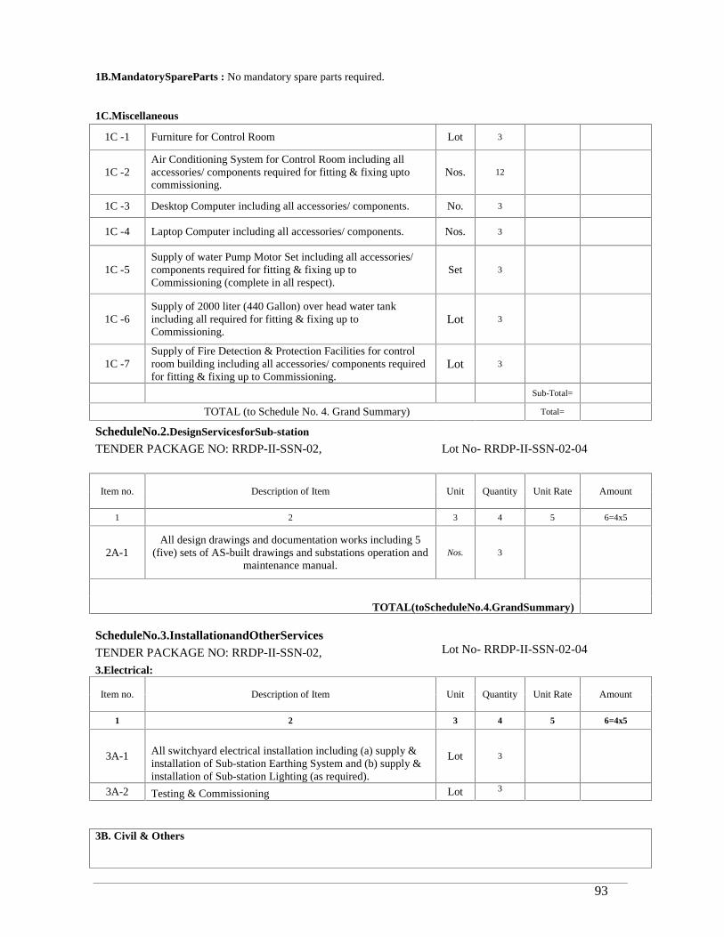
RRDP-II-SSN-02-04 93
1B.MandatorySpareParts : No mandatory spare parts required.
1C.Miscellaneous
1C -1 Furniture for Control Room Lot 3
1C -2Air Conditioning System for Control Room including allaccessories/ components required for fitting & fixing uptocommissioning.
Nos. 12
1C -3 Desktop Computer including all accessories/ components. No. 3
1C -4 Laptop Computer including all accessories/ components. Nos. 3
1C -5Supply of water Pump Motor Set including all accessories/components required for fitting & fixing up toCommissioning (complete in all respect).
Set 3
1C -6Supply of 2000 liter (440 Gallon) over head water tankincluding all required for fitting & fixing up toCommissioning.
Lot 3
1C -7Supply of Fire Detection & Protection Facilities for controlroom building including all accessories/ components requiredfor fitting & fixing up to Commissioning.
Lot 3
Sub-Total=
TOTAL (to Schedule No. 4. Grand Summary) Total=
ScheduleNo.2.DesignServicesforSub-station
TENDER PACKAGE NO: RRDP-II-SSN-02, Lot No- RRDP-II-SSN-02-04
Item no. Description of Item Unit Quantity Unit Rate Amount
1 2 3 4 5 6=4x5
2A-1All design drawings and documentation works including 5
(five) sets of AS-built drawings and substations operation andmaintenance manual.
Nos. 3
TOTAL(toScheduleNo.4.GrandSummary)
ScheduleNo.3.InstallationandOtherServicesTENDER PACKAGE NO: RRDP-II-SSN-02, Lot No- RRDP-II-SSN-02-04
3.Electrical:
Item no. Description of Item Unit Quantity Unit Rate Amount
1 2 3 4 5 6=4x5
3A-1 All switchyard electrical installation including (a) supply &installation of Sub-station Earthing System and (b) supply &installation of Sub-station Lighting (as required).
Lot 3
3A-2 Testing & Commissioning Lot 3
3B. Civil & Others
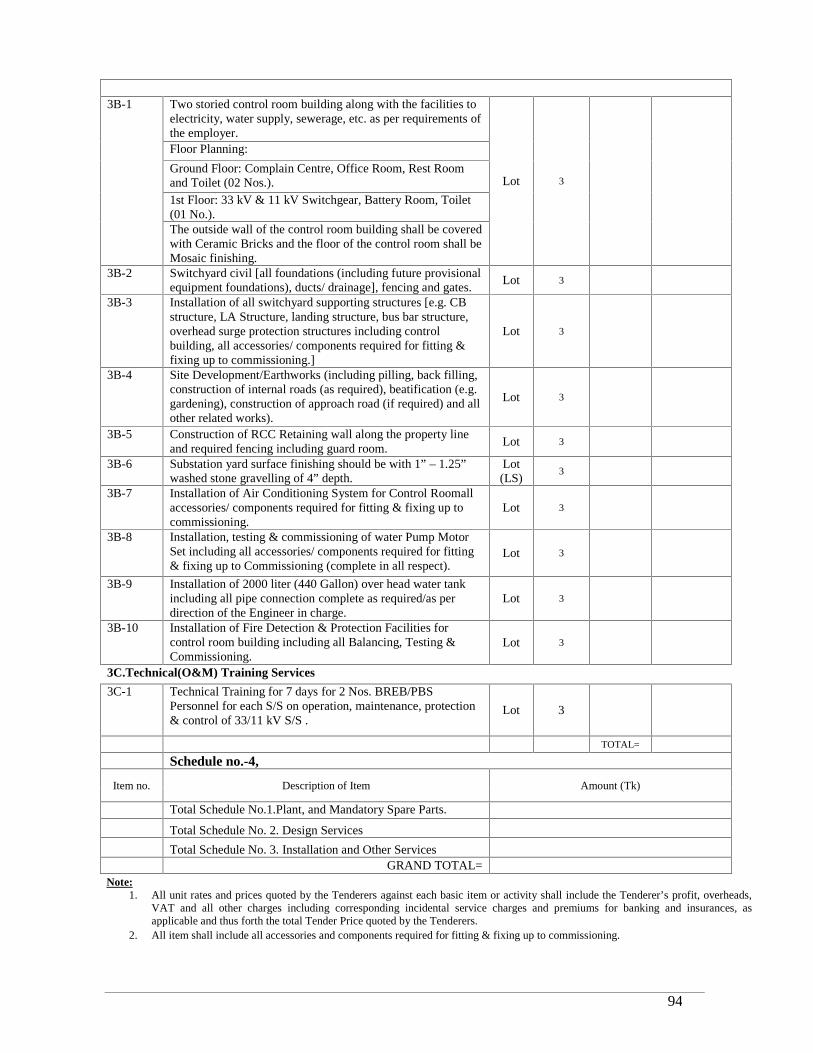
RRDP-II-SSN-02-04 94
3B-1 Two storied control room building along with the facilities toelectricity, water supply, sewerage, etc. as per requirements ofthe employer.
Lot 3
Floor Planning:
Ground Floor: Complain Centre, Office Room, Rest Roomand Toilet (02 Nos.).1st Floor: 33 kV & 11 kV Switchgear, Battery Room, Toilet(01 No.).The outside wall of the control room building shall be coveredwith Ceramic Bricks and the floor of the control room shall beMosaic finishing.
3B-2 Switchyard civil [all foundations (including future provisionalequipment foundations), ducts/ drainage], fencing and gates.
Lot 3
3B-3 Installation of all switchyard supporting structures [e.g. CBstructure, LA Structure, landing structure, bus bar structure,overhead surge protection structures including controlbuilding, all accessories/ components required for fitting &fixing up to commissioning.]
Lot 3
3B-4 Site Development/Earthworks (including pilling, back filling,construction of internal roads (as required), beatification (e.g.gardening), construction of approach road (if required) and allother related works).
Lot 3
3B-5 Construction of RCC Retaining wall along the property lineand required fencing including guard room.
Lot 3
3B-6 Substation yard surface finishing should be with 1” – 1.25”washed stone gravelling of 4” depth.
Lot(LS)
3
3B-7 Installation of Air Conditioning System for Control Roomallaccessories/ components required for fitting & fixing up tocommissioning.
Lot 3
3B-8 Installation, testing & commissioning of water Pump MotorSet including all accessories/ components required for fitting& fixing up to Commissioning (complete in all respect).
Lot 3
3B-9 Installation of 2000 liter (440 Gallon) over head water tankincluding all pipe connection complete as required/as perdirection of the Engineer in charge.
Lot 3
3B-10 Installation of Fire Detection & Protection Facilities forcontrol room building including all Balancing, Testing &Commissioning.
Lot 3
3C.Technical(O&M) Training Services
3C-1 Technical Training for 7 days for 2 Nos. BREB/PBSPersonnel for each S/S on operation, maintenance, protection& control of 33/11 kV S/S .
Lot 3
TOTAL=
Schedule no.-4,
Item no. Description of Item Amount (Tk)
Total Schedule No.1.Plant, and Mandatory Spare Parts.
Total Schedule No. 2. Design Services
Total Schedule No. 3. Installation and Other ServicesGRAND TOTAL=
Note:1. All unit rates and prices quoted by the Tenderers against each basic item or activity shall include the Tenderer’s profit, overheads,
VAT and all other charges including corresponding incidental service charges and premiums for banking and insurances, asapplicable and thus forth the total Tender Price quoted by the Tenderers.
2. All item shall include all accessories and components required for fitting & fixing up to commissioning.
RRDP-II-SSN-02-04 95
ISO 9001:2008 Certified &OHSAS 18001 Certified.
BANGLADESH RURAL ELECTRIFICATION BOARD (BREB)
TENDER DOCUMENTFOR THE
SUPPLY, INSTALLATION, TESTING & COMMISSIONING OF 33/11KV SUB-STATIONS (10MVA EACH)
UNDERRURAL ELECTRIFICATION EXPANSION RAJSHAHI-RANGPURPROGRAM-II
VOLUME 2 OF 2
SECTION :7 - GENERAL SPECIFICATION
Scope of Work
Section : 8 - PARTICULAR SPECIFICATION
Section : 9 - DRAWINGs

RRDP-II-SSN-02-04 96
Section 7. General Specifications
RRDP-II-SSN-02-04 97
1.0 Overview
The works in this bidding document covers the supply, construction, installation andcommissioning of 33/11 kV Substations at various locations in Chittagong and Sylhet divisionsof Bangladesh, under the jurisdiction of the BREB/PBS, on a design, supply, and installationbasis. A list of the sites is given in Table 01 below and site plans are provided in “Drawings”section of this document.
The scope of work includes design, manufacture, quality assurance, inspection & testing, packingfor export, insurance & shipment to site, civil works, complete construction & installation jointing,terminating, bonding, earthing, painting, setting to work, site testing & commissioning all theequipment necessary for operation of the sub-station.
The detail requirements are listed in the technical particulars and guaranteed schedules in thetechnical specification. The Contractor shall remedy all defects during the defect notification periodof the equipment as per the contract.
The scope also includes imparting technical training for BREB/PBS Personnel on operation,maintenance, protection & control of 33/11 kV sub-stations.
The Contractor shall be responsible for providing equipment, which shall meet in all respects theperformance specifications and will have satisfactory durability for the prevailing site conditions.The Contractor is responsible for ensuring that all and any items of work (materials and labor)required for the safe efficient and satisfactory completion and functioning of the works inaccordance with the specification, are included in the bid price whether they be individuallydescribed in the specification or not.
The site plans are included in the drawings and the locations are identified by pegs in the ground.Each bidder shall visit each site during the bidding period. Contact details of the relevantBERB/PBS representatives are given in Attachment 1. At least 10days’ notice will be required.
The Bidders shall inspect each new site to identify the location, orientation, actual space available,extent of earth works involved, construction of control building and its ancillary facilities and sub-soil investigation and soil testing reports available (which will be supplied from PMUoffice)including recommendations, to determine the actual scope of work. Modifications to the lay-out provided in the drawing, may be necessary based on the Contractor’s detailed design and theactual available size of the land at the site.
The detailed design arrangement of the equipment shall be the responsibility of the Contractorsubject to the approval of the concern committee of BREB with the recommendation of ProjectManager. The Contractor shall submit all drawings, manuals, designs and calculations for reviewprior to commencing manufacturing and/or installation works. Typical existing BERB designs areincluded in Drawings section of this document, for information only.
Transportation requirements, storage, suitable construction tools, necessary equipment and allrequired materials for installation and connections as well as testing and commissioning areincluded in the scope of work.
RRDP-II-SSN-02-04 98
1.1 New 33/11 kV Substations – Electrical
There are Single categories of 10/14 MVA substations to be constructed. In all the substations,there should be 02 Nos. of Transformer Pads/ Foundations. These foundations shall be madeconsidering the load bearing capacity of 20/28 MVA transformers along with a fire wall betweenthe two units to facilitate up-gradation at a later date by adding another transformer. Furtherprovision shall be made for inclusion of a future bus coupler isolator with circuit breaker betweenthe two feeders as well as space for additional 33 kV feeders at the two ends of the bus bar system.
The key requirements for the new substations are presented hereunder; any other works requiredbut not included below but required to complete the substation and put it into operation is to betreated as forming a part of this contract.
1.1.1 The new 10/14 MVA substation shall have the following features:
The 10/14MVA design shall take into consideration future expansion of the installation withthe addition of a second 10/14MVA transformer. A fire wall and transformer foundationshall be erected to cater for this at the same time as the first transformer is installed. The 33kV equipments will be out door and the 11 kV equipments will be indoor. The number of 33kV feeders will be as per the substation type. The 11 kV switchgear panels will consist of6 outgoing feeder panels (space shall be left for 6 more feeder panels for future use),two transformer incoming panels and a bus section VCB and riser panels (to utilize asplit-bus arrangement at a later date). The main equipment at the substation will consist of:
10/14 MVA (ONAN/ONAF), three phase 33/11.55 kV transformers with OLTC having+6% to -18% tapping range and 1.5% tap step;
33 kV isolator and earth switch, 1250 A for each feeder bay; 33 kV isolator, 1250 A for each feeder bay and transformer bay; 33 kV lightning arresters (30 kV, 10 kA); 33 kV 1250 A vacuum circuit breaker for each feeder bay and transformer bay; 11 kV Indoor switchgear and panels with 2000 A vacuum circuit breakers
for transformer and bus section panels and 630 A vacuum circuit breakers for 6outgoing feeders ;
100 kVA, 33/0.415 kV three phase transformer with fused isolator and bypass switchfor local station supply;
11 kV cables from transformer to 11 kV bus-bar, 2 Nos. single core 500 mm2 Cu XLPECable per phase (allow 2 × 60 m per phase);
11 kV cables to feeders, 3 × 185 mm2 Cu XLPE Cable (allow 120 m per feeder for 6feeders);
11kV lightning arresters; Space to be left (suitably covered with metal plates) for additional six (6) 11 kV panels
– two on either side of the 11kV panel; 33 kV and 11 kV CT’s and PT’s for metering, indication and protection;
RRDP-II-SSN-02-04 99
33 kV panel with OLTC control, CB protection and control, and transformer protection 33 kV and 11 kV panels with mimic diagram embedded operating switches; Laminated substation Single line diagrams(A0 size) on durable paper- 5 copies; Station supply AC panel; DC panel; Control building, outdoor yard lighting, and all indoor and outdoor electrical facilities Battery and charger, battery panel; All relevant civil works, foundations, earth grid and structural works as detailed in this
specification and shown on the drawings. In particular, a suitable fire wall shall beinstalled between the two transformer bays;
The main earth grid including bonding of bays and all steel work / gantries shall beinstalled for the final configuration;
The foundations for future second transformer (only) in the future second bay shall alsobe installed at this time;
The quantities of each item will be as indicated in the bill of quantities and the drawings.
The conceptual single line diagrams, plans and elevations are provided in Section 4 -Drawings

RRDP-II-SSN-02-04 100
1.1.2 Terminal Points
Incoming 33kV Line
The landing span from the 33kV incoming line to the equipment is the responsibility of theline contractor and therefore the droppers from the landing pole to the substation equipmentgantry shall be provided by the line contractor. If the substation equipment gantry is notready at the time of the installation of the 33kV line this line span shall be left coiled forlater connection by the substation contractor as directed by the Project Manager.
Cables within sub-station
Power and Multi-core cabling between equipment within the substation i.e. 11 kV, LVAC,DC, etc. shall be provided and installed by the contractor as required under this Contract.
11kV Outgoing Cables
The supply of cable boxes on the switchgear complete with cable lugs shall be providedunder this Contract. The outgoing feeders from the 11kV switchgear to the overhead takeoff point including terminations and line surge diverters shall be provided under thiscontract. The termination of the cable on the pole including surge arresters shall be carriedout by the Contractor.
1.1.3 New 33/11 kV 10 and 20 MVA Substations – Civil works
The Contractor shall be responsible for the construction of the control building and its
facilities, boundary wall/ fence, fire wall and earthworks associated with each new
substation. This shall include but not be limited to the following:
Site topographical surveys and sub-soil investigations report including recommendation Testing of water and materials used in construction works Earthworks, and landscaping as per approved drawings Any required piling work. Preliminary soil test reports will be provided by the
Employer, However final soil test reports and designs will be contractor’s responsibility Temporary and permanent access roads to the substation from public roads, and
service roads inside the Substations.
A single two storied control room building (approx. 2 × 140 sq. meters) having 2 storied
foundations along with the facilities to electricity, water supply, sewerage, etc. as per
requirements of the employer.
Floor Planning:
(i) Ground Floor: Customer Service Centre, Office Room, Rest Room and Toilet
(02 Nos.).
(ii) First Floor: 33 kV & 11 kV Switchgear, Battery Room, Toilet (01 No.).
The outside wall of the control room building shall be covered with Ceramic
Bricks and the floor of the control room shall be Mosaic finishing.
33/11 kV transformer foundations (with one additional foundation to cater for future
second transformer in single transformer substation). All the foundations should be
RRDP-II-SSN-02-04 101
constructed considering load baring capacity of 20/28 MVA sub-stations, oil
containment bund walls and fire wall.
Cable trenches, ducts and sump pits. Perimeter boundary fence/wall and matching main and personnel gates. Guard room Structure and foundations for line landing gantries, plant and equipment. Roads and footpaths as per design and site requirements. Waste water and surface water drainage systems and septic tank and soakwell Building Services; ventilation, plumbing works, water supply, small power and lighting,
telephones, fire detection, etc.
Outdoor lighting
Water tank as per specific site requirements.
Any required temporary works.
Master plan/site layout plan as per respective site condition.
Architectural plan, section, all side elevation and also 3-D perspective.
Structural design as per present code of practices in Bangladesh (BNBC), drawings andall documents necessary for, completion and maintenance of the works. Preparation ofAs-built documentation.
Tube well and water pump to feed water tank. All required lighting systems. All required fire extinguishers. Any other works required but not included in the above to complete the substation and
put it into operation.
1.2 Substation Types
1.2.1 Schedule of Substations and Types
The following Table 01 lists the names of each 33/11 kV substation to be constructed, thetype of substation to be constructed and the supply arrangements from the relevant GridSS/other sources.
Substations are either supplied direct from a new grid substation feeder bay, via a tee-offfrom an existing feeder from a grid substation, or via a 33 kV switching station.
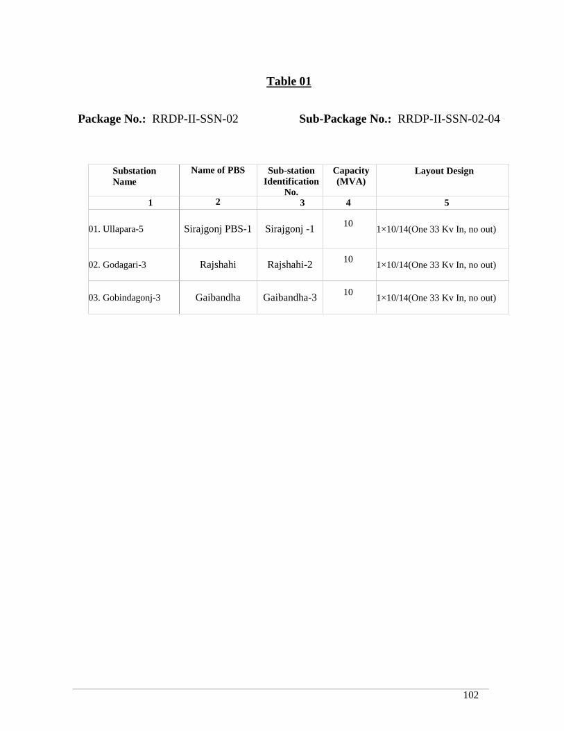
RRDP-II-SSN-02-04 102
Table 01
Package No.: RRDP-II-SSN-02 Sub-Package No.: RRDP-II-SSN-02-04
SubstationName
Name of PBS Sub-stationIdentification
No.
Capacity(MVA)
Layout Design
1 2 3 4 5
01. Ullapara-5 Sirajgonj PBS-1 Sirajgonj -1 101×10/14(One 33 Kv In, no out)
02. Godagari-3
(Baliatoir)
Rajshahi Rajshahi-2 101×10/14(One 33 Kv In, no out)
03. Gobindagonj-3 Gaibandha Gaibandha-3 101×10/14(One 33 Kv In, no out)

RRDP-II-SSN-02-04 103
Section 7. General Specifications
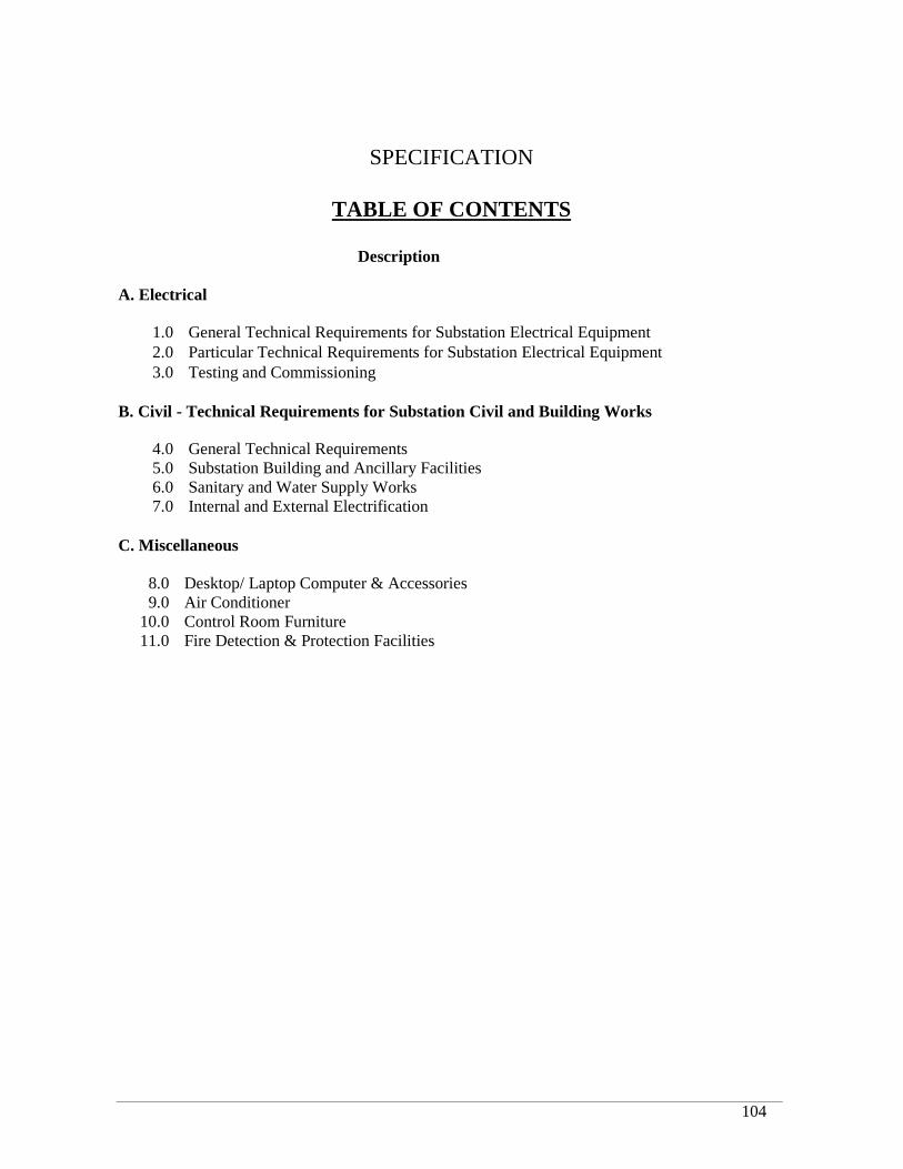
RRDP-II-SSN-02-04 104
SPECIFICATION
TABLE OF CONTENTS
Description
A. Electrical
1.0 General Technical Requirements for Substation Electrical Equipment2.0 Particular Technical Requirements for Substation Electrical Equipment3.0 Testing and Commissioning
B. Civil - Technical Requirements for Substation Civil and Building Works
4.0 General Technical Requirements5.0 Substation Building and Ancillary Facilities6.0 Sanitary and Water Supply Works7.0 Internal and External Electrification
C. Miscellaneous
8.0 Desktop/ Laptop Computer & Accessories9.0 Air Conditioner
10.0 Control Room Furniture11.0 Fire Detection & Protection Facilities
RRDP-II-SSN-02-04 105
A. ELECTRICAL
1.0 GENERAL TECHNICAL REQUIREMENTSFOR SUBSTATION ELECTRICAL EQUIPMENT
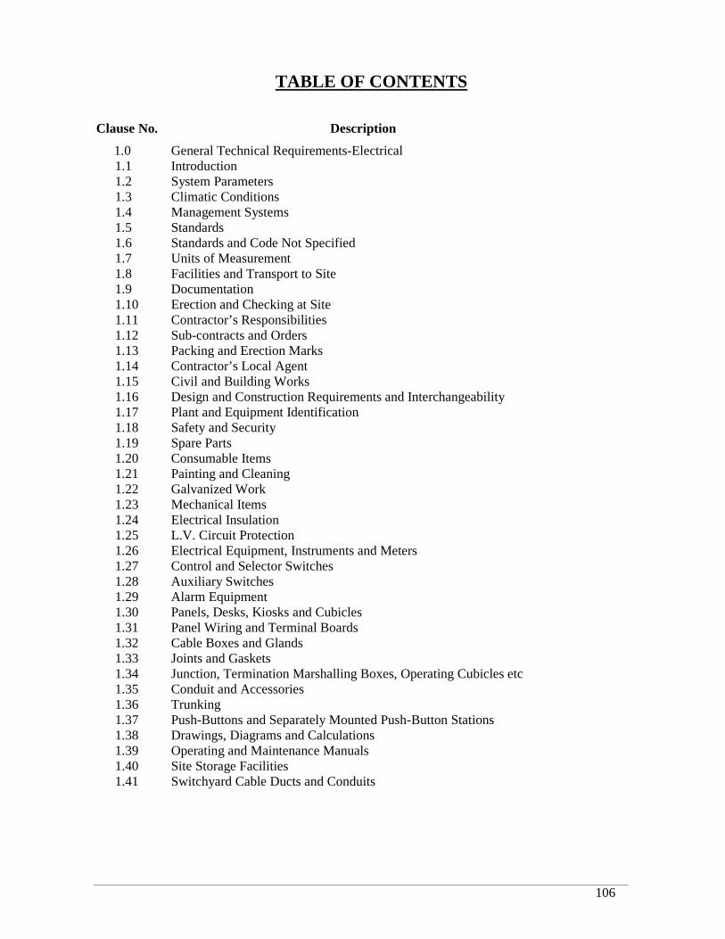
RRDP-II-SSN-02-04 106
TABLE OF CONTENTS
Clause No.
1.01.11.21.31.41.51.61.71.81.91.101.111.121.131.141.151.161.171.181.191.201.211.221.231.241.251.261.271.281.291.301.311.321.331.341.351.361.371.381.391.401.41
Description
General Technical Requirements-Electrical 144Introduction 144System Parameters 144Climatic Conditions 146Management Systems 147Standards 148Standards and Code Not Specified 148Units of Measurement 148Facilities and Transport to Site 149Documentation 149Erection and Checking at Site 149Contractor’s Responsibilities 150Sub-contracts and Orders 151Packing and Erection Marks 152Contractor’s Local Agent 152Civil and Building Works 153Design and Construction Requirements and Interchangeability 153Plant and Equipment Identification 154Safety and Security 155Spare Parts 156Consumable Items 156Painting and Cleaning 156Galvanized Work 158Mechanical Items 159Electrical Insulation 160L.V. Circuit Protection 161Electrical Equipment, Instruments and Meters 162Control and Selector Switches 163Auxiliary Switches 164Alarm Equipment 164Panels, Desks, Kiosks and Cubicles 165Panel Wiring and Terminal Boards 168Cable Boxes and Glands 170Joints and Gaskets 172Junction, Termination Marshalling Boxes, Operating Cubicles etc 172Conduit and Accessories 173Trunking 173Push-Buttons and Separately Mounted Push-Button Stations 173Drawings, Diagrams and Calculations 174Operating and Maintenance Manuals 175Site Storage Facilities 176Switchyard Cable Ducts and Conduits 177
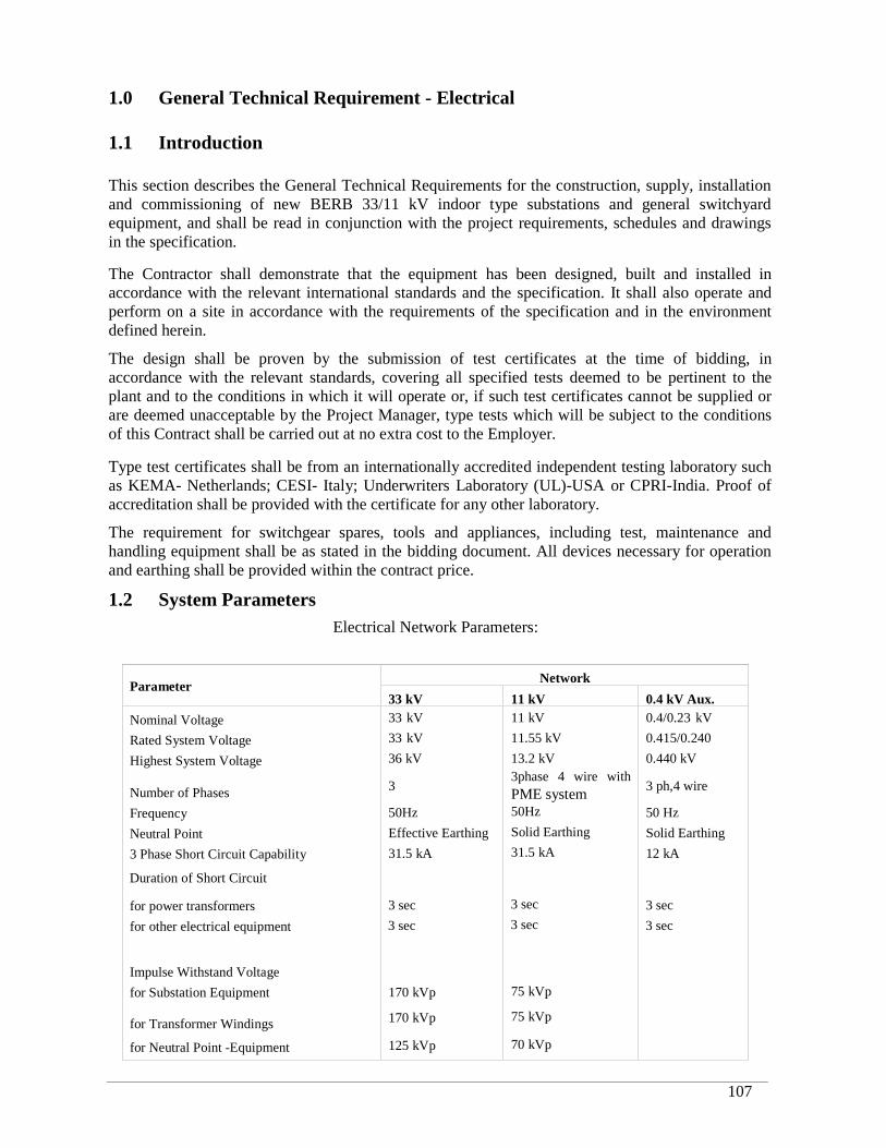
RRDP-II-SSN-02-04 107
1.0 General Technical Requirement - Electrical
1.1 Introduction
This section describes the General Technical Requirements for the construction, supply, installationand commissioning of new BERB 33/11 kV indoor type substations and general switchyardequipment, and shall be read in conjunction with the project requirements, schedules and drawingsin the specification.
The Contractor shall demonstrate that the equipment has been designed, built and installed inaccordance with the relevant international standards and the specification. It shall also operate andperform on a site in accordance with the requirements of the specification and in the environmentdefined herein.
The design shall be proven by the submission of test certificates at the time of bidding, inaccordance with the relevant standards, covering all specified tests deemed to be pertinent to theplant and to the conditions in which it will operate or, if such test certificates cannot be supplied orare deemed unacceptable by the Project Manager, type tests which will be subject to the conditionsof this Contract shall be carried out at no extra cost to the Employer.
Type test certificates shall be from an internationally accredited independent testing laboratory suchas KEMA- Netherlands; CESI- Italy; Underwriters Laboratory (UL)-USA or CPRI-India. Proof ofaccreditation shall be provided with the certificate for any other laboratory.
The requirement for switchgear spares, tools and appliances, including test, maintenance andhandling equipment shall be as stated in the bidding document. All devices necessary for operationand earthing shall be provided within the contract price.
1.2 System ParametersElectrical Network Parameters:
ParameterNetwork
33 kV 11 kV 0.4 kV Aux.
Nominal Voltage
Rated System Voltage
Highest System Voltage
Number of Phases
Frequency
Neutral Point
3 Phase Short Circuit Capability
Duration of Short Circuit
for power transformers
for other electrical equipment
Impulse Withstand Voltage
for Substation Equipment
for Transformer Windings
for Neutral Point -Equipment
33 kV
33 kV
36 kV
3
50Hz
Effective Earthing
31.5 kA
3 sec
3 sec
170 kVp
170 kVp
125 kVp
11 kV
11.55 kV
13.2 kV3phase 4 wire withPME system50Hz
Solid Earthing
31.5 kA
3 sec
3 sec
75 kVp
75 kVp
70 kVp
0.4/0.23 kV
0.415/0.240
0.440 kV
3 ph,4 wire
50 Hz
Solid Earthing
12 kA
3 sec
3 sec
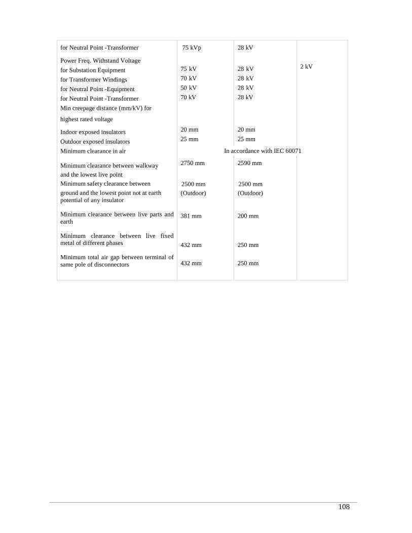
RRDP-II-SSN-02-04 108
for Neutral Point -Transformer
Power Freq. Withstand Voltage
for Substation Equipment
for Transformer Windings
for Neutral Point -Equipment
for Neutral Point -Transformer
Min creepage distance (mm/kV) for
highest rated voltage
Indoor exposed insulators
Outdoor exposed insulators
Minimum clearance in air
Minimum clearance between walkway
and the lowest live point
Minimum safety clearance between
ground and the lowest point not at earthpotential of any insulator
Minimum clearance between live parts andearth
Minimum clearance between live fixedmetal of different phases
Minimum total air gap between terminal ofsame pole of disconnectors
75 kVp
75 kV
70 kV
50 kV
70 kV
20 mm
25 mm
28 kV
28 kV
28 kV
28 kV
28 kV
20 mm
25 mm
2 kV
In accordance with IEC 60071
2750 mm
2500 mm
(Outdoor)
381 mm
432 mm
432 mm
2590 mm
2500 mm
(Outdoor)
200 mm
250 mm
250 mm
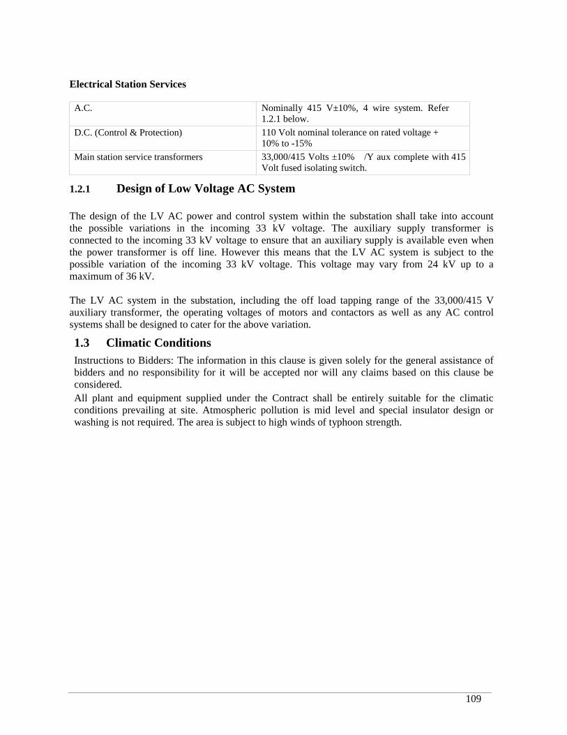
RRDP-II-SSN-02-04 109
Electrical Station Services
A.C. Nominally 415 V±10%, 4 wire system. Refer1.2.1 below.
D.C. (Control & Protection) 110 Volt nominal tolerance on rated voltage +10% to -15%
Main station service transformers 33,000/415 Volts ±10% /Y aux complete with 415Volt fused isolating switch.
1.2.1 Design of Low Voltage AC System
The design of the LV AC power and control system within the substation shall take into accountthe possible variations in the incoming 33 kV voltage. The auxiliary supply transformer isconnected to the incoming 33 kV voltage to ensure that an auxiliary supply is available even whenthe power transformer is off line. However this means that the LV AC system is subject to thepossible variation of the incoming 33 kV voltage. This voltage may vary from 24 kV up to amaximum of 36 kV.
The LV AC system in the substation, including the off load tapping range of the 33,000/415 Vauxiliary transformer, the operating voltages of motors and contactors as well as any AC controlsystems shall be designed to cater for the above variation.
1.3 Climatic ConditionsInstructions to Bidders: The information in this clause is given solely for the general assistance ofbidders and no responsibility for it will be accepted nor will any claims based on this clause beconsidered.All plant and equipment supplied under the Contract shall be entirely suitable for the climaticconditions prevailing at site. Atmospheric pollution is mid level and special insulator design orwashing is not required. The area is subject to high winds of typhoon strength.
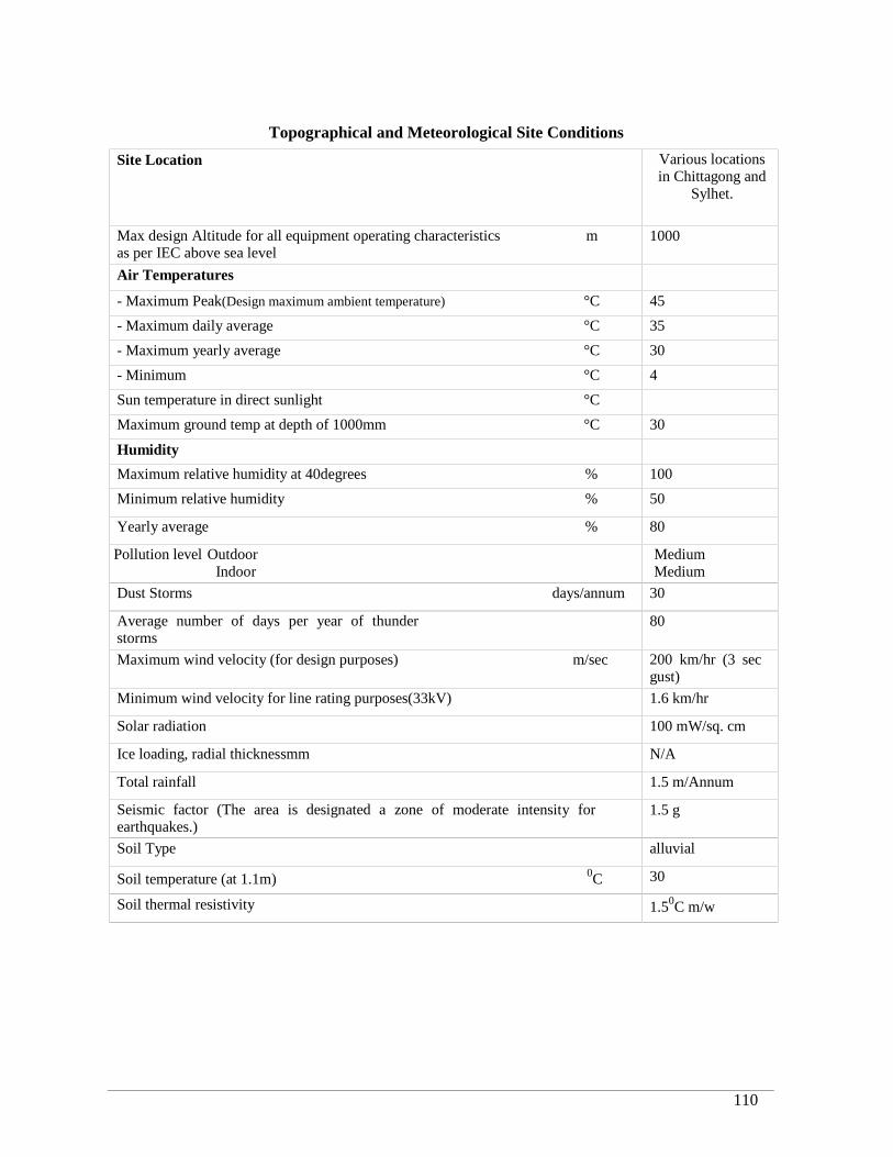
RRDP-II-SSN-02-04 110
Topographical and Meteorological Site Conditions
Site Location Various locationsin Chittagong and
Sylhet.
Max design Altitude for all equipment operating characteristics mas per IEC above sea level
1000
Air Temperatures
- Maximum Peak(Design maximum ambient temperature) °C 45
- Maximum daily average °C 35
- Maximum yearly average °C 30
- Minimum °C 4
Sun temperature in direct sunlight °C
Maximum ground temp at depth of 1000mm °C 30
Humidity
Maximum relative humidity at 40degrees % 100
Minimum relative humidity % 50
Yearly average % 80
Pollution level OutdoorIndoor
MediumMedium
Dust Storms days/annum 30
Average number of days per year of thunderstorms
80
Maximum wind velocity (for design purposes) m/sec 200 km/hr (3 secgust)
Minimum wind velocity for line rating purposes(33kV) 1.6 km/hr
Solar radiation 100 mW/sq. cm
Ice loading, radial thicknessmm N/A
Total rainfall 1.5 m/Annum
Seismic factor (The area is designated a zone of moderate intensity forearthquakes.)
1.5 g
Soil Type alluvial
Soil temperature (at 1.1m) 0C 30
Soil thermal resistivity 1.50C m/w
RRDP-II-SSN-02-04 111
1.4 Management Systems
1.4.1 General
The Contractor shall carry out the Works in accordance with sound quality and environmentalmanagement principles, and in particular shall have management systems which conform to therequirements of the ISO 9000 family of standards for Quality Management and the ISO 14000family of standards for Environmental Management.
These quality management requirements shall apply to all activities including design, procurement,manufacturing, inspection, testing, packing, shipping, storage, site erection and commissioning.
The Contractor, major sub-contractors and suppliers shall have Quality Systems certified ascomplying with the requirements of ISO 9001 applicable to sales, design, construction andcommissioning of high- and medium-voltage substations. If minor sub-contractors and suppliers donot have such systems then the Contractor’s Quality System shall be deemed to apply.
It is preferred that the Bidder be certified as complying with ISO 14001 but this is not a qualifyingrequirement.
Documents submitted by the Bidder, including those provided by sub-contractors, will not beaccepted unless they include evidence that they have been verified by the Bidder.
1.4.2 Quality Documentation and Audit
The Contractor shall submit a copy of its Quality Manual and relevant quality procedures, in theEnglish language, within one (1) month of the Effective Date of the Contract. Quality Manualsfrom sub-contractor and suppliers shall be submitted within two (2) weeks of the Contractormaking a commitment to them.
The Contractor shall clearly identify all quality records that will be used for the Contract.The Employer may undertake an inspection or quality audit of the Contractor’s or sub-contractor’sfacilities at any time. Full quality records of procurement and manufacture shall be made availableat the start of factory inspection and testing of equipment. Full quality records to the completion ofinstallation shall be made available before the start of site testing.
1.4.3 Quality Plan
The Contractor shall ensure that its quality procedures address all requirements of the Specification.The Contractor shall ensure that the quality procedures of sub-contractor, manufacturers andsuppliers address all requirements of the Specification, and that the Contractor’s quality proceduresprovide verification of this.
The Contractor shall prepare an overall Quality Plan for the Works, and shall provide detailedquality plans for all major sub-contractors and suppliers. Quality plans shall include:
Organisation chart with identification and details of key personnel;
Inspection and Test Plans on which hold points and recommended inspections by theEmployer are clearly shown.
Quality Plans shall be subject to the approval of the Employer. An initial Quality Plan shall besubmitted with one (1) month of the Effective Date of the Contract. A revised Quality Plan which
RRDP-II-SSN-02-04 112
includes full details of all Inspection and Test Plans shall be submitted within two (2) months of theEffective Date of the Contract.
Not less than two (2) months prior to mobilization to Site, the Contractor shall submit the QualityPlan revised to include a complete list of all site personnel detailing names, positions andresponsibilities complete with an organization chart. The Contractor shall provide for approval fulldetails, including curriculum vitae, of all engineering, technical and other key staff to be employedat site. Personnel shall not mobilize to Site prior to approval being given.
1.4.4 Measuring and Testing Equipment
All measuring and testing equipment shall have current calibration certification. Use of measuringand test equipment which is demonstrated to be calibrated against equipment which has suchcertification may be accepted.
1.4.5 Inspection and Test Records
The Contractor shall compile the reports of all factory and site tests into a volume of the Operationand Maintenance Manuals.
1.4.6 Equipment Identification and Preservation
The Contractor shall establish and maintain a system for the identification, preservation,segregation and handling of all equipment from receipt through manufacturing, dispatch, storageand installation to prevent abuse, misuse, damage, or deterioration by corrosion through exposureto air or moisture.
1.5 Standards
In the technical specification references have been made to various clauses of IEC; BS; ISO andASTM and ANSI standards. Where any standard referred to in this specification has beensuperseded by a new standard the reference shall be deemed to be to such superseding standards.Notwithstanding the standard numbers mentioned in the technical specification the bidders aredirected to apply the latest published editions of these standards.
Deviations from the specified standards referred to above shall be given in a Schedule of ProposedStandards and shall have to be accepted by the Employer before contract placement.
1.6 Standards and Code Not Specified
Where not specified, the IEC Standard and the Bangladesh National Building Code (BNBC) shallbe applicable.
1.7 Units of Measurement
In all correspondence, in all technical schedules, on all drawings and for all instrument scales, S.I.units of measurement are to be employed. Angular measurement shall be in degrees with 90degrees forming a right angle.
RRDP-II-SSN-02-04 113
1.8 Facilities and Transport to Site
Chittagong & Mongla sea ports and Benapole land port are the principal port of entry for material toBangladesh. The contractor shall provide his own storage facilities, security, insurance etc.
The Contractor is responsible for performing all unloading, inland transportation and obtaining allapprovals and consents etc. necessary for the movement of plant and Contractor’s equipment fromthe port to the site.
All necessary access roads, jetties or off-loading points etc. required for the transport of the plantetc. to site will be the Contractors responsibility.
Where heavy loads are to be moved the Contractor shall be responsible for performing surveys ofthe routes to ensure that all portions have adequate load-bearing capacity.
A comprehensive method statement shall be submitted to the Project Manager detailing theproposed transport route(s) and requirements. Plans indicating all bridges, ducts, culverts, railwaycrossings, overhead lines, water mains etc. their load bearing capacity or clearances as appropriateshall be given together with proposed means of achieving the transportation requirements. Anyreinforcement, strengthening, modifications or temporary works required to obtain the necessarycapacity shall be the responsibility of the Contractor. The cost of the above is to be included in theBid price.
No plant is to be consigned to Bangladesh by airfreight without the prior written approval of theEmployer.
1.9 Documentation
1.9.1 Documentation
In order for the Employer to obtain the necessary import permits and satisfy the requirements of thecustoms authorities the following documentation is required.
Within 60 days of the effective date of Contract, the Contractor shall submit a detailed schedule ofplant that is to be provided under the Contract indicating the type of equipment and the name of themanufacturer. Six copies of the schedule are to be submitted to the Project Manager and theEmployer.
1.10 Erection and Checking at Site
As each part of the works is erected, the Contractor shall seek the Employer’s approval that theworks have been constructed in accordance with the specification and approved drawings.
For purposes of progress payments for site work a monthly and cumulative system of jointmeasurement of work done for each section of work shall be set up by the Contractor in a mannerapproved by the Employer.
Any works constructed prior to the issue of drawings approved by the Employer for the particularworks may not be included in the percentage completion figures.
RRDP-II-SSN-02-04 114
The Contractor is to provide such protection and watchmen as may be considered necessary tosafeguard his materials and stores. The Employer will not accept responsibility for any loss ordamage, which may occur during the execution of the Contract.
The carrying out of all the work included in the Contract shall be supervised by a sufficient numberof qualified representatives of the Contractor, and full facilities and assistance shall be provided tothe Employer to check the works. The Contractor shall obtain from the Employer details of theworks that he proposes to inspect, but such inspection shall in no way exonerate the Contractorfrom any of his obligations. The Contractor, if required by the Employer, shall open for inspectionbefore erection any equipment, which has been delivered to the site partly assembled.
On completion of the works the site shall be left clean and tidy to the satisfaction of the Employer.Any damage done to buildings, structures, plant or property belonging to the Employer shall bemade good at the Contractor's expense.
The Contractor shall ensure the correctness of electrical and mechanical connections to allequipment supplied under the contract before such equipment is commissioned.
During erection and commissioning the Contractor shall provide all temporary scaffolding, ladders,platforms with toe boards and hand-rails essential for proper access of workmen and inspectors,cover or rail off dangerous opening or holes in floors, and afford adequate protection againstmaterials falling from a higher level on a person below.
The maximum personal safety must be afforded to personnel either directly engaged on thisContract or who in the normal course of their occupations find it necessary to utilize temporaryworks erected by the Contractor or to frequent the working area.
In each and every case involving a connection between the plant supplied under this Contract andany other existing plant which may or may not be in service, the Contractor must make suitablearrangements as regards the time and manner in which the connection is made subject to theapproval of Employer’s Representative who is in charge of the existing plant. Where cases ariseinvolving the operation of the plant or work on plant in operation or whenever required by theEmployer’s Representative, the Contractor must obtain a written “Permit to Work” signed by aperson duly authorized by the Employer.
1.11 Contractor’s Responsibilities
1.11.1 Planning of Works
Within 30 days after the effective date of Contract, the Contractor shall prepare, in an agreed form,a detailed manufacture, delivery and erection program chart for the complete Contract works, andshall submit the chart to the Employer for approval.The manufacture, delivery and erection program chart shall indicate for each major item of theContract the various phases of work from the commencement of the Contract to its completion,e.g., design, ordering of materials, manufacture, delivery, installation and commissioning. Theprogram shall include a fully comprehensive drawings production program which shall demonstratethe Contractors intended issue dates for approval.
These presentations shall be in bar chart and precedence critical path analysis format.
The program shall indicate percentage completion points of the various phases which can form thebasis of progress reporting.

RRDP-II-SSN-02-04 115
A cash-flow forecast of the estimated monthly invoice values shall be included in the program. Thisforecast shall take into account the terms of payment and indicate down-payments, release ofretention’s, etc. Figures may be rounded to the nearest thousands of the appropriate currency.
The Contractor shall indicate in the program the number, grade and discipline of supervisory andmanagerial site staff proposed throughout the site construction periods. If specialist erection andcommissioning staff are to be employed by the Contractor details of the number, discipline andduration of visit of these staff are to be indicated in the program. The provision of this informationwill not form any contractual limit on the number of staff to be provided by the Contractor toensure the timely completion of the Contract. Should any incident occur which, in the opinion ofthe Contractor will result in an over-run of any section of the Works this shall be indicated in theprogram and brought to the Employer’s attention.
If, at any time during the execution of the Contract, it is found necessary to modify the approvedmanufacture, delivery and erection program chart, the Contractor shall inform the Employer andsubmit a modified chart for his approval. The submission, and subsequent approval, of a modifiedmanufacture, delivery and erection program chart shall not necessarily obviate or diminish theContractor’s responsibilities and liabilities under the Contract. The chart shall be updated atmonthly intervals and submitted to the Employer no later than the middle of each calendar month.
1.11.2 Progress Reports and Meetings
At monthly intervals after approval of the plant manufacture, delivery and erection program chart,the Contractor shall submit to the Employer updated bar chart programs and precedence criticalpath analysis networks in triplicate in an approved format indicating the stage reached in thedesign, ordering of material, manufacture, delivery and erection of all components of plant. Inaddition the Contractor will compile and submit “S-curves” based upon the approved programindicating programmed and actual percentage completion of the various stages of drawingapproval, manufacture, shipping, civil works and erection for each section of the works plus theoverall Contract.
An updated cash-flow forecast indicating previously forecast and actual, involving levels togetherwith revised future requirements shall be submitted quarterly. A graphical display in the form of an“S-curve” of the actual vs. planned payment certification (on & offshore) shall be provided by theContractor in triplicate on a quarterly basis to supplement the basic cash flow information.
If, during execution of the Contract, the Employer considers the progress position of any section ofthe work to be unsatisfactory, or for any other reason relating to the Contract, he will be at libertyto call meetings, either in his head office or at site. If required by the Employer, a responsiblerepresentative from the Contractor is to attend at the Contractor’s expense such meetings withsufficient authority to issue instructions or effect an alteration in the works to the satisfaction of theEmployer.Access to the Contractor’s and Sub-contractor’s works is to be granted to the Employersrepresentative at all reasonable times for the purpose of ascertaining progress.
1.12 Sub-contracts and OrdersAs soon as practicable after entering into the Contract the Contractor may, having obtained theProject Manager’s consent, enter into the sub-contracts he considers necessary, for the satisfactorycompletion of the Contract works. Three un-priced copies of the Contractor’s sub-orders shall besupplied to the Project Manager.
RRDP-II-SSN-02-04 116
One copy of any drawings where the sub-order shall refer shall also be submitted. Each sub-orderand drawing shall contain the following reference and an instruction that the plant is subject toinspection and tests to be witnessed by the Project Manager or his agent with sufficient authority toissue instructions, or effect an alternation in the works to the satisfaction of the Project Manager.Approval by the Project Manager of Contractor’s sub-orders shall not relieve the Contractor of hisresponsibilities in meeting this specification. It is the Contractor’s responsibility to ensure that afull specification based on the relevant information in the Contract is passed to the sub-contractor.
The Contractor will be responsible for progressing the Sub-contractor’s works including visits tothe works to ensure the work as to programme, specification, quality and drawings and to witnessall necessary routine, sample and type tests. The cost of this Contract control is deemed to beincluded in the Contract sum.
1.13 Packing and Erection Marks
Each item is to be export packed and properly protected for shipment, transport and storage in theport area and for transport to and storage on site.
All Plant provided under this Contract shall have the packing marked in the following manner.
A green band shall be painted all around each package. The band shall be 8” wide or ¼ of thelength of the packing whichever is the less. Each package should have the following informationprinted on it in bold letters:-
(a) Port of Loading(b) Name of Consignee(c) Purchase Order Number(d) Brief description of Stores(e) Number of Package(f) Gross, tare and net weight(g) Measurements(h) Contractors Name(i) Contract Title(j) Contract Number(k) Port of Landing
All members comprising multi-part assembles, e.g. steel frameworks, are to be marked withdistinguishing numbers and/or letters corresponding to those of the approved drawings or materialslists.
Colour banding to and approved code is to be employed to identify members of similar shape ortype but of differing strengths or grades.
Cases containing delicate items such as relays and instruments should carry a separate marking:
Sensitive equipment packages shall be opened in the presence of a representative of the Employer.
1.14 Contractor’s Local Agent
Instruction to Bidder: The Bidder shall state in his bid the name and address in Bangladesh of hislocal Agent, if any.

RRDP-II-SSN-02-04 117
1.15 Civil and Building Works
Where items of mechanical plant are mounted on foundations, which are part of the civilengineering works, the Contractor shall carry out suitable leveling and adjustment of the plant onthe foundations, before the plant is secured in position. The Contractor shall check the alignment,leveling or positioning of the mechanical plant in question, before and after grooving. TheContractor shall make records of the alignment, leveling or positional measurement and shallmaintain such records until his activities at site are concluded. The building steel work shall bedesigned to carry the loads/forces imposed by pipe work, cables and associated fittings which alsoform part of the works, and all necessary supports and fixing shall be shown on the relevantdrawings.
Such supports and fixings may be secured to the steel work by bolting welding or clamping.No other supports or fixings shall be subsequently attached to the steel work nor may any otherdrilling, cutting or welding be carried out without the prior permission of the Project Manager.
1.16 Design and Construction Requirements and Interchangeability
1.16.1 General Requirements
The Works shall be designed to operate safely, reliably and efficiently in accordance with thedesign and operating requirements stated in this specification.
No departure from the specification shall be made subsequent to the Contract without the writtenapproval of the Employer with the recommendation of the Project Manager.
The design shall conform to the best current engineering practice. Each of the several parts of theplant shall be of the maker’s standard design, provided that this design is in general accordancewith the specification.The design, dimensions and materials of all parts shall be such that they will not suffer damage as aresult of stresses under the most severe service conditions. The materials used in the construction ofthe plant shall be of the highest quality and selected particularly to meet the duties required ofthem. The plant shall be designed and constructed to minimize correction. Workmanship andgeneral finish shall be of the highest class throughout.
All plant items and corresponding parts forming similar duties shall be interchangeable in order tominimize the stock of spare parts.
All equipment shall be designed to minimize the risk of fire and damage which may be caused inthe event of fire.
1.16.2 Specific Requirements
The choice of plant and design of the installation is to meet the following criteria.Sub-station layouts are to utilize the minimum of land area.All equipment is to facilitate the installation of all circuits indicated as “future” with the minimum ofdisruption. All cabling schemes, D.C. and A.C. equipment etc. shall be designed toaccommodate all such future circuits, loads, etc.The plant and installation shall be designed for a minimum service life of 25 years.
RRDP-II-SSN-02-04 118
All plant is to have a minimum of 2 years satisfactory and proven service record of high durabilityand reliability in a similar environment. Documentary evidence in support of the choice of any itemof plant shall be provided by the Contractor if requested by the Project Manager.
Each sub-station is to be designed such that the failure or removal of any one item of plant formaintenance or repair shall not impair the operational integrity of the sub-station.
The design and layout of the sub-stations shall ensure the safety of personnel concerned with theoperation and maintenance of the plant.
1.17 Plant and Equipment Identification
1.17.1 Identification on Drawings
The Contractor shall prepare comprehensive plant or equipment identification schedules. Theschedules shall include the respective flow sheet or drawing/diagram identification numbers.
1.17.2 Labels and Nameplates
The Contractor shall supply and install all labels, ratings, instruction and warning plates necessaryfor the identification and safe operation of the works.
Nameplates of labels shall be non-hygroscopic material with engraved lettering of a contrastingcolor or, alternatively in the case of indoor circuit-breakers, starters, etc. of plastic material withsuitably colored lettering engraved thereon.
All the above labels and plates shall be securely fixed to items of plant and equipment withstainless steel rivets, plated self tapping screws or other approved means. The use of adhesives willnot be permitted.
The language of labels, plates and notices shall comply with the requirements of the Contract.
Individual plant items and all relevant areas within the contract works where a danger to personnelexists shall be provided with plentiful, prominent and clear warning notices.
These warning notices shall draw attention to the danger or risk with words which attract attentionand summarize the type of risk or danger. The notices shall also carry a large symbol whichgraphically depicts the type of risk.All equipment within panels and desks shall be individually identified. The identification shallcorrespond to that used in schematic and wiring diagrams.
Each circuit breaker panel, electrical control panel, relay panel etc., shall have circuit designationlabel mounted on the front and rear. Corridor type panels shall additionally have circuit designationlabels within the panels.
All equipment and apparatus mounted there on shall be clearly labeled in an approved manner. Thefunction of each relay, control switch, indicating lamp, MCB, link etc. shall be separately labeled.
The Contractor shall be responsible for the relocation, or replacement of all labels on existing plant,which became inaccurate as a consequence of the contract works.
RRDP-II-SSN-02-04 119
1.18 Safety and Security
1.18.1 Interlocks
A complete system of interlocks and safety devices shall be provided so that the followingrequirements and any other condition necessary for the safe and continuous operation of the plantare provided:
Safety of personnel engaged on operational and maintenance work on the plant.
Correct sequence of operation of the plant during starting up and shutting down periods.
Safety of the plant when operating under normal or emergency conditions.
Interlocks shall be preventive, as distinct from corrective in operation.
Where plant supplied under this Contract forms the whole or a part of a system for which one ofmore interlocking schemes are required, the Contractor shall be responsible for all interlockingschemes for the Project Manager’s approval. General descriptions of interlocking requirements aregiven in the specifications but the Contractor shall include for any other interlocks he considersnecessary.
1.18.2 Locks, Padlocks, and Key Cabinets
The Contractor shall provide padlocks, locks, chains or other locking devices for the locking of allequipment cubicles, electrical isolating switches, selector switches, valves, etc. to the approval ofthe Project Manager.
All locking devices and chains shall be manufactured from corrosion resistant material. Allmechanisms shall be provided with a cover to minimize entry of water or dust.
Locks shall conform to a master keying feature system to be agreed with the Project Manager forgroups of equipment.
All locks shall have individual high integrity locks and shall be provided with (two) keys.
Each key shall be provided with a label as specified.
The Contractor will supply and fit key cabinets equipped with labeled hooks, each identified withits appropriate key. Every cabinet shall be provided with a nameplate identifying the cabinet withits respective item or items of plant. Sufficient cabinets will be provided to store all keys suppliedunder this Contract and cater for future extensions.
The Contractor shall provide comprehensive lock and key schedules to readily permit identificationwith equipment and doors. Such schedules are not required for loose padlocks.
Where modifications are performed to existing sites the Contractor shall provide a system identicalto that existing.
RRDP-II-SSN-02-04 120
1.19 Spare Parts
1.19.1 Commissioning Spares
In addition to the spare parts being provided for the Employer, the Contractor is responsible forensuring that he has access to a stock of commissioning spares. Spares provided for the Employerare not to be utilized as commissioning spares, without written approval, in which case theContractor shall immediately replace the contract spare at his own expense.
All commissioning spares are considered as Contractors equipment.
1.20 Consumable Items
1.20.1 Chemicals and other Consumable
The Contract includes for the provision of all chemicals, resins, and other consumables required fortesting, commissioning and setting to work of each section of the works.Unless otherwise stated, the Contractor shall provide all such chemicals and other consumablesrequired for the efficient operation and maintenance of the plant at full load 24 hours per day for aperiod of 12 months for each section of the works from the date of the final certificate.
The Contractor shall prepare a list of these consumables giving quantities necessary for eachsection of the works and the recommended suppliers.
1.21 Painting and Cleaning
Immediately following the award of a contract, the Contractor shall submit the names of theproposed paint supplier and applicator together with a quality assurance program for approval. Allpaints for a contract shall be provided by one manufacturer and preferably shall be manufactured inone country to ensure compatibility
The painting of the plant shall be carried out in accordance with the appropriate schedule. The workis generally covered by the schedules but where particular items are not referred to specifically,they shall be treated in a manner similar to other comparable items as agreed with the ProjectManager.
The schedule indicate standards of surface preparation and painting which is intended to give aminimum service life of 10 years in a coastal industrial environment, with need for minor remedialwork only during the intervening period.
Steel sections and plate shall be free from surface flaws and laminations prior to blast cleaning andshall not be in worse condition than Pictorial Standard B, Swedish Standard SIS 05 5900.
The Project Manager is prepared to consider alternative paint schemes to meet the requirements offabrication using modern automated materials handling systems, provided they offer the samestandards of surface protection and service life as those intended by the schedules.
All paints shall be applied by brush or spray in accordance with the schedule, except for primingcoats for steel floors, galleries and stairways where dipping is permitted.Where paint is to be applied by spray, the applicator shall demonstrate that the spray techniqueemployed does not produce paint films containing vacuoles.
RRDP-II-SSN-02-04 121
Where paint coatings are proposed for the protection of surfaces of equipment exposed to corrosiveconditions, such as plant items exposed to brines or sea water immersion in liquid, or wet gases, thecoatings shall be formulated to the suitably corrosion resistant and shall be high voltage sparktested at works and/or at site prior to commissioning. The test procedure shall be based on the useof a high voltage direct current. The voltage used shall be 75% of the breakdown voltage of thecoating. This breakdown voltage shall first be separately determined using test plates coated withthe specified coating formulation and thickness. The coating on the test plate shall also be micro-sectioned by the applicator to show that it is free from vacuoles and other defects likely toinvalidate the test procedure.
If the defects revealed by the above test procedure do not exceed one per 5 m2 of coating surface,the coating need not be re-tested after the defects have been repaired. If the defects exceed one per5 m2 of coating surface, the repairs shall be resettled after any curing is completed, and thisprocedure shall be repeated until the defects are less than one per 5 m2 of coating surface. Afterrepair of these defects, the equipment can be placed in service without further testing.
All coating proposed for the internal protection of domestic water storage tanks and desalinationplants shall be certified by an approved independent Authority as suitable for use in potable waterinstallations and shall meet the non-painting requirements of BS 3416.
All plain shed and bright parts shall be coated with grease, oil or other approved rust preventivebefore dispatch and during erection and this coating shall be cleaned off and the parts polishedbefore being handed over.Where lapped or butted joints form part of an assembly which is assembled or part assembled priorto final painting, the jointed surfaces shall be cleaned free from all scales, loose rust, dirt and greaseand given one brush applied coat of zinc phosphate primer before assembly.
Paint shall not be applied to surfaces which are superficially or structurally damp and condensationmust be absent before the application of each coat.
Painting shall not be carried out under adverse weather conditions, such as low temperature (below40C) or above 90% relative humidity or during rain or fog, or when the surfaces are less than 30Cabove dew point, except to the approval of the Project Manager or his duly appointedrepresentative.
Priming coats of paint should not be applied until the surfaces have been inspected and preparatorywork has been approved by the Project Manager or his duly appointed representative.No consecutive coats of paint, except in the case of white, should be of the same shade. Thinnersshall not be used except with the written agreement of the Project Manager.
On sheltered or unventilated horizontal surfaces on which dew may linger more protection isneeded and to achieve this additional top coat of paint shall be applied.
The schedules differentiate between ‘Treatment at Maker’s Works’ and ‘Treatment at Site afterCompletion of Erection’ but the locations at which different stages of the treatments are carried outmay be modified always providing that each change is specifically agreed to by the ProjectManager and the painting is finished at site to the Project Manager’s satisfaction.
All paint film thickness quoted are minimum and refer to the dry film condition. All thickness shallbe determined by the correct use of approved commercial paint film thickness measuring meters.
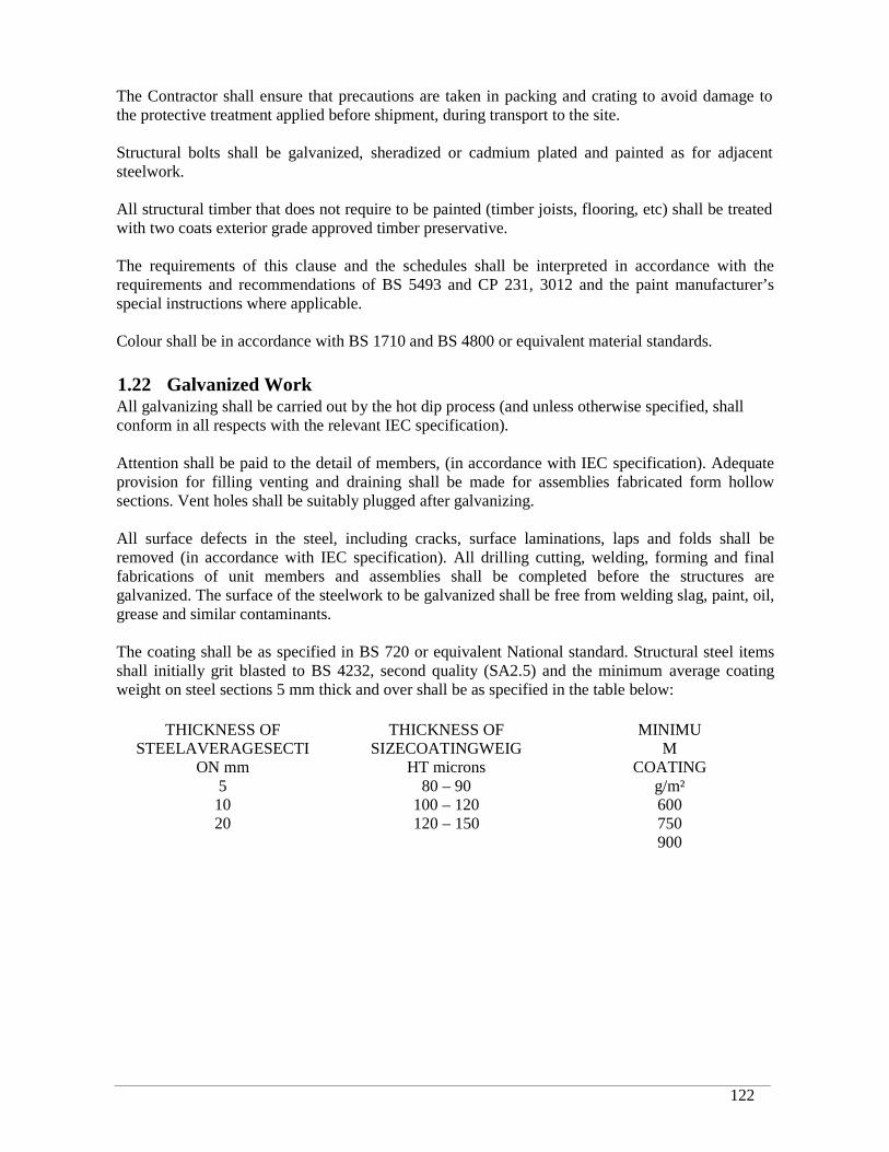
RRDP-II-SSN-02-04 122
The Contractor shall ensure that precautions are taken in packing and crating to avoid damage tothe protective treatment applied before shipment, during transport to the site.
Structural bolts shall be galvanized, sheradized or cadmium plated and painted as for adjacentsteelwork.
All structural timber that does not require to be painted (timber joists, flooring, etc) shall be treatedwith two coats exterior grade approved timber preservative.
The requirements of this clause and the schedules shall be interpreted in accordance with therequirements and recommendations of BS 5493 and CP 231, 3012 and the paint manufacturer’sspecial instructions where applicable.
Colour shall be in accordance with BS 1710 and BS 4800 or equivalent material standards.
1.22 Galvanized WorkAll galvanizing shall be carried out by the hot dip process (and unless otherwise specified, shallconform in all respects with the relevant IEC specification).
Attention shall be paid to the detail of members, (in accordance with IEC specification). Adequateprovision for filling venting and draining shall be made for assemblies fabricated form hollowsections. Vent holes shall be suitably plugged after galvanizing.
All surface defects in the steel, including cracks, surface laminations, laps and folds shall beremoved (in accordance with IEC specification). All drilling cutting, welding, forming and finalfabrications of unit members and assemblies shall be completed before the structures aregalvanized. The surface of the steelwork to be galvanized shall be free from welding slag, paint, oil,grease and similar contaminants.
The coating shall be as specified in BS 720 or equivalent National standard. Structural steel itemsshall initially grit blasted to BS 4232, second quality (SA2.5) and the minimum average coatingweight on steel sections 5 mm thick and over shall be as specified in the table below:
THICKNESS OFSTEELAVERAGESECTI
ON mm5
1020
THICKNESS OFSIZECOATINGWEIG
HT microns80 – 90
100 – 120120 – 150
MINIMUM
COATINGg/m²600750900
RRDP-II-SSN-02-04 123
With intermediate values on a pro rata basis.On removal from the galvanizing bath the resultant coating shall be smooth, continuous, free fromgross surface imperfections such as bare stops, lumps, blisters and inclusions of flux, ash or dross.Galvanized contact surfaces to be jointed by high strength friction grip bolts shall be roughenedbefore assembly so that the required slip factor (defined in BS 3294. Part BS 4606 part 1 and I) is
achieved, care shall be taken to ensure that the roughening is confined to the area of the fayingsurface.
Bolts, nuts and washers, including general grade high strength friction grip bolts (referred to in BS3139 and BS 4395 part 1) shall be hot dip galvanized and subsequently centrifuged (according toBS 729). Nuts shall be tapped up to 0.4 mm oversize after galvanizing and the threads oiled topermit the nuts to be finger turned on the bolt for the full depth of the nut. No lubricant, applied tothe projecting threads of a galvanized high strength friction grip bolt after the bolt has been insertedthrough the steelwork shall be allowed to come into contact with the faying surfaces.
During off-loading and erection, nylon slings shall be used. Galvanized work which is to be storedin works on site shall be stacked so as to provided adequate ventilation to all surfaces to avoid wetstorage staining (with rust).
Small areas of the galvanized coating damaged in any way shall be brought to the attention of theProject Manager who shall authorize repair by:
Cleaning the area of any weld slug and though wire brushing to give a clean surface.
The application of two coats of zinc rich paint or the application of low melting point zincalloyrepair rod or power to the damage area, which is heated to 300°C.
After fixing, bolt heads, washes and nuts shall receive two coats zinc rich paint.
1.23 Mechanical Items
All screw threads shall be of the ISO metric form and the diameters and pitch of thread for all boltsstuds and nuts shall conform to the ISO Standards as stated in BS 3692 or BS 4190 or equivalentNational Standard.
It is recognized that in a number of applications such as instrument, machine components and pipe,other thread forms may be used.
1.23.1 Pipe Work
All piping shall be designed, manufactured and tested in accordance with BritishStandards or equivalent Nationals Standards approved by the Project Manager. Inparticular, pipework should meet the requirements of the following standards or theirequivalents. Dimensions shall comply with Table 1 of BS 1600. The minimum wallthickness of carbon steel pipes excluding any allowance for corrosion shall be as shown inBritish Standards:
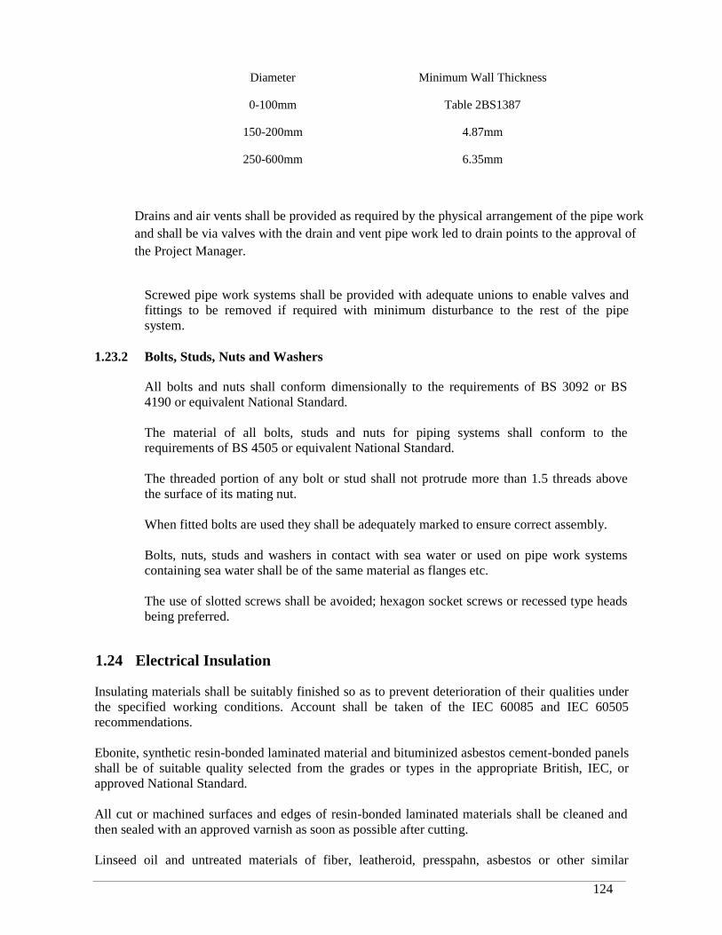
RRDP-II-SSN-02-04 124
Diameter Minimum Wall Thickness
0-100mm Table 2BS1387
150-200mm 4.87mm
250-600mm 6.35mm
Drains and air vents shall be provided as required by the physical arrangement of the pipe workand shall be via valves with the drain and vent pipe work led to drain points to the approval ofthe Project Manager.
Screwed pipe work systems shall be provided with adequate unions to enable valves andfittings to be removed if required with minimum disturbance to the rest of the pipesystem.
1.23.2 Bolts, Studs, Nuts and Washers
All bolts and nuts shall conform dimensionally to the requirements of BS 3092 or BS4190 or equivalent National Standard.
The material of all bolts, studs and nuts for piping systems shall conform to therequirements of BS 4505 or equivalent National Standard.
The threaded portion of any bolt or stud shall not protrude more than 1.5 threads abovethe surface of its mating nut.
When fitted bolts are used they shall be adequately marked to ensure correct assembly.
Bolts, nuts, studs and washers in contact with sea water or used on pipe work systemscontaining sea water shall be of the same material as flanges etc.
The use of slotted screws shall be avoided; hexagon socket screws or recessed type headsbeing preferred.
1.24 Electrical Insulation
Insulating materials shall be suitably finished so as to prevent deterioration of their qualities underthe specified working conditions. Account shall be taken of the IEC 60085 and IEC 60505recommendations.
Ebonite, synthetic resin-bonded laminated material and bituminized asbestos cement-bonded panelsshall be of suitable quality selected from the grades or types in the appropriate British, IEC, orapproved National Standard.
All cut or machined surfaces and edges of resin-bonded laminated materials shall be cleaned andthen sealed with an approved varnish as soon as possible after cutting.
Linseed oil and untreated materials of fiber, leatheroid, presspahn, asbestos or other similar
RRDP-II-SSN-02-04 125
hygroscope types of materials shall not be used for insulation purposes. Untreated leatheroid andpresspahn may be used for mechanical protection of winding insulation.
Wherever practicable, instrument, apparatus and machine coil windings, including wire woundresistors, with the exception of those immersed in oil or compound, shall be thoroughly dried in avacuum or by other approved means and shall then be insulating varnish. Varnish with a linseed oilbase shall not be used.
No material of a hygroscope nature shall be used for covering coils. Where inter-leaving betweenwindings in coils is necessary, only the best manila paper, thoroughly dried, which permitspenetration by the insulating varnish or wax, shall be used.
1.25 L.V. Circuit Protection
Fuses are not to be used for protection of circuits below 1000V phase-to-phase, (Low Voltage).All low voltage and dc circuit protection is to be provided by moulded case, or miniature circuitbreakers.
Link carriers and bases shall be of an approved manufacture and of such form and material so as toprotect persons from shock and burns in normal service and maintenance. Links and fixed contactsshall be shielded to prevent inadvertent contact with live metal whilst the link is being inserted orwithdrawn.
The labeling of carriers and bases shall comply with IEC 60269 Identification labels fixed topanels, boards and desks for MCBs and links shall describe their duty, voltage and rating.
1.25.1 Miniature Circuit Breakers
All miniature circuit breakers (MCBs) shall comply with IEC 60157 and be fitted withover-current releases of both the thermal and instantaneous type. All MCBs supplied onthis contract shall be to short circuit category P2 of IEC 60157.
Single, two or three pole breakers may be used where appropriate and a trip of one poleshall cause a complete trip of all associated poles. In addition the rating given of MCBssupplied shall be confirmed as that appropriate to the enclosure provided.
The Contractor shall ensure satisfactory time and current grading with other associatedminiature circuit breakers or MCCBs.
1.25.2 Distribution Boards and Isolators
Distribution boards shall be provided throughout the plant for local distribution oflighting, small power and air conditioning supplies. The lighting and small power circuitsmay use a common distribution board.
Distribution boards shall be of 1 kV A.C., 1.2 kV D.C. rating and conform to IEC 60439.All distribution boards shall be of the weatherproof enclosure type and shall be arrangedso that the door or cover can be locked in the closed position.
All triple pole and neutral boards shall provide satisfactory cable entry for all cableswhich could be required for the number of circuit facilities provided and shall have the
RRDP-II-SSN-02-04 126
neutral bar drilled for the full number single phase ways.
Each distribution board supplied from a remote location shall have a load breaking/faultmaking incoming isolating switch mounted adjacent to or as part of the distribution board.Each distribution board shall have removable top and bottom (undrilled) gland plates.
Each circuit in every distribution board shall be numbered and identified by means of aschedule attached to the interior of the door or cover of the board. The schedule shall belegible and durable to the Project Manager’s approval.
Twenty-five percent spare ways shall be provided for future use.
1.26 Electrical Equipment, Instruments and Meters
All instruments and meters shall be fitted with glasses of low reflectivity and shall not cause pointerdeflection due to electro-static charging through friction.
All indicating instruments shall be of the flush mounted pattern with dust and moisture proof casescomplying with BS. 2011, Classification 00/50/04, and shall comply with BS. 89 or IEC 60051.
Unless otherwise specified, all indicating instruments shall have 95mm square cases to DINstandard or equivalent circular cases.
Instrument dials in general shall be white with black markings and should preferably be reversiblewhere double scale instruments are specified.
Scales shall be of such material that no peeling or discoloration will take place with age underhumid tropical conditions.
The movements of all instruments shall be of the dead beat type.
Instruments shall be provided with a readily accessible zero adjustments.The mounting height of the centre of all indicating instruments shall not exceed 2000mm.
A.C. ammeters for transformer, feeder or inter connector circuits, and D.C ammeter for all loadcircuits except motors, shall have linear scales commencing at zero.
A.C and D.C ammeters for motor circuits shall have scales commencing at zero and with acompressed overload portion for reading of the associated minor starting current.
D.C. ammeters for the main battery circuit of D.C systems shall have scales with positive andnegative ranges, labeled charge and discharge respectively.
Voltmeters for feeders and transformer circuits shall have expanded scales to display the nominalservice voltage ± 20%.
Wattmeter for feeders shall have linear positive and negative reading scales to be approved.
Varmeters for all circuits shall have linear positive and negative reading scales to be approved.
Integrating metering shall be provided where indicated on the specification drawings. These metersshall be of the withdrawable flush mounted type and comply with the relevant parts of IEC 60521
RRDP-II-SSN-02-04 127
and BS 5685, Class 1.0 accuracy and BS 37, Part 9. The meters shall include cyclometer dial typeregisters.
Approved test terminal blocks of the three-phase type shall be provided for connecting in circuitwith each meter a portable testing meter.
If applicable, recording instruments shall be of an approved type, and unless otherwise specified,shall have two chart speeds of 25 mm and 50 mm per hour available for selection by means otherthan changing connections. They shall be complete with sufficient charts and inks for two years’working.
All instruments, meters, recorders and apparatus shall be capable of carrying their full load currentswithout undue heating. They shall not be damaged by the passage of fault currents within the ratingof the associated switchgear through the primaries of their corresponding instrument transformers.
All instruments, motors and apparatus shall be back connected and the metal cases shall be earthed.
All voltage circuits to instruments shall be protected by a fuse in each unearthed phase of the circuitplaced as close as practicable to the main connection.
All power-factor indicators in 3-phase circuits shall have the star point of their current coils broughtout to a separate terminal which shall be connected to the star point of the instrument currenttransformer secondary windings.
All instruments and meters associated with multi-ratio CT’s shall be provided with sets of scalesetc. appropriate to each CT ratio. It shall be possible to replace the scales of instruments withoutdismantling the instruments or interfering with any tropicalization finish.
The Contractor shall provide electrical instrument and meter schedules to include, manufacturer,type, designation, current and voltage rating, accuracy class and circuit designation.
All equipment shall be colored “NEMA Standard Grey 70” unless otherwise specified by theProject Manager.
1.27 Control and Selector Switches
Control switches shall be of the three-position type with a spring return action to a central position(and without a locking feature).
Circuit breakers shall have control switches which shall be labeled open/N/close or (O/N/I andarranged to operate clockwise when closing the circuit breakers and anti-clockwise when openingthem, and shall be of the pistol grip type.
Control switches of the discrepancy type shall be provided where specified. Such discrepancycontrol switches shall be arranged in the lines of the mimic diagram on the switchgear panels. Suchswitches shall include lamps and be of the manually operated pattern, spring loaded such that it isnecessary to push and twist the switch past its indicating position for operation. The lamp shall beincorporated in the switch base and shall flash whenever the position of the circuit breaker is atvariance with the position indicated by the control switch. Hand dressing of the control switch tothe correct position shall cause the lamp to extinguish.
Selector switches shall be of the two or more position type as required, and have a stay-put action
RRDP-II-SSN-02-04 128
to remain in any selected position which shall be lockable (separate padlocks each with duplicatekeys should be provided). Each position of the selector switches shall be suitably labeled to signifytheir function. The switch handle shall be of the pistol grip type to the approval of the ProjectManager.
It shall not be possible at any time to operate any switchgear equipment from more than onelocation simultaneously, and suitable lockable selector switches shall be provided to meet thisrequirement.
The contacts of all control and selector switches shall be shrouded to minimize the ingress of dustand accidental contact, and shall be amply rated for voltage and current for the circuits in whichthey are used.
1.28 Auxiliary Switches
Auxiliary switches shall be to approval and contacts shall have a positive wiping action whenclosing.
All auxiliary switches, whether in service or not in the first instance, shall be wired up to a terminalboard and shall be arranged in the same sequence on similar equipment.
Auxiliary switches mechanically operated by the circuit breakers, contactors, isolators, etc. shall beto approval and contacts mounted in accessible positions clear of the operating mechanism of thecircuit breaker, contactor, isolator, etc., and they shall be adequately protected against accidentalelectrical shock.
Auxiliary switches shall be provided to interrupt the supply of current to the trip coil of each circuitbreaker and contactor immediately the breaker or contactor has opened. These auxiliary switchesshall make before the main contacts, during a closing operation.
A minimum of four spare auxiliary switches, two normally open, two normally closed shall beprovided for each circuit breaker, and contactors and also for isolators.
1.29 Alarm Equipment
Where an alarm system is specified, it shall consist of an initiating device, a display unit and pushbuttons mounted on the front of the appropriate control panel, together with a continuously ratedaudible warning device flasher unit and relays. The relays shall wherever possible, be mountedinside the same panel; where the number of alarms to be displayed makes this impracticable, aseparate alarm relay cubicle or cubicles will be considered as an alternative.
Where it is necessary to differentiate between the urgency of alarms then various approved alarmtone devices shall be provided in this Contract. In addition and where specified an alarm beacon tothe approval of the Project Manager shall be provided.The display unit shall consist of a rectangular frame or bezel enclosing the required number ofindividual facias, each of which shall be preferably approximately 32mm x 25mm in size. Eachfacia shall be in the form of a window inscribed with the specified legend, describing the faultcondition to be indicated. Lamps shall not illuminate adjacent windows.
At least 3 spare ways shall be provided on each display unit. All unused ways in a display unit shallbe fully equipped and the alarm system designed to enable these ways to be utilized at a future date.

RRDP-II-SSN-02-04 129
Alarm relays shall be of a type to the approval of the Project Manager, arranged to plug into fixedbases, either singly or in groups and have positive means of retaining them securely in the serviceposition, the bases being mounted on racks or frames which shall be hinged to allow them to beswung clear of the sides of the panel or cubicle in which they are installed in order to provide readyaccess.
The type of wiring used for internal connections between alarm facias and their relays and betweenrelays and terminal blocks, shall generally comply with these requirements with the followingexceptions:-
(i) Single-strand wire, not less than 0.85 mm in diameter may be used.
Soldered terminations will be acceptable
External connections for alarm circuits will in general be run in multi-core cables having a largercore size than that referred to above. This will necessitate special terminal blocks, if solderedterminations are used, in which case the internal and external terminations of each pair shall bejoined by a removable link. Samples of the type of wire and terminal block to be used for alarmconnections shall be submitted for the Project Manager’s approval.
The operation of the alarm system shall be as follows:-
When an external alarm indicating contact closes the audible warning shall sound continuously andthe appropriate facia shall be illuminated by a flashing light at a frequency which allows theinscription to be easily road.
An ‘Accept’ push-button shall be provided on or near the display unit, which when pressed, shallsilence the audible signal and cause the facia to remain illuminated steadily.
The alarm circuit shall be designed to retain the indication after the re-opening of the initiatingcontact, requiring a separate ‘Reset’ push button to be pressed before the alarm is cancelled.
A ‘Test’ push button shall be fitted close to the ‘Accept’ and ‘Reset’ buttons, to illuminate all thefacias on the associated display unit for as long as the ‘Test’ button is held depressed.
The operation of the ‘Accept’ button shall not preclude the receipt of further indications givingmore audible alarm and visual indications as the result of the operation of other sets of alarmcontacts.
Relays shall not be continuously energized when the alarm system is at rest.
For all alarm indication initiating device a spare set of voltage-free contacts shall be provided (thismay be by the use of auxiliary relays) and connected by cable to a suitable, approved marshallingcubicle. These spare contacts will provide for the transmission of the alarm indication signals to theremote Grid Control Centre.
The Contractor shall be responsible for providing all the alarms required for the safe and efficientoperation of the plant. General descriptions of alarms requirements are given in the specificationand the Contractor shall include any other alarms that are necessary due to the type of equipmentand design of the plant to the Project Manager’s approval.
1.30 Panels, Desks, Kiosks and Cubicles
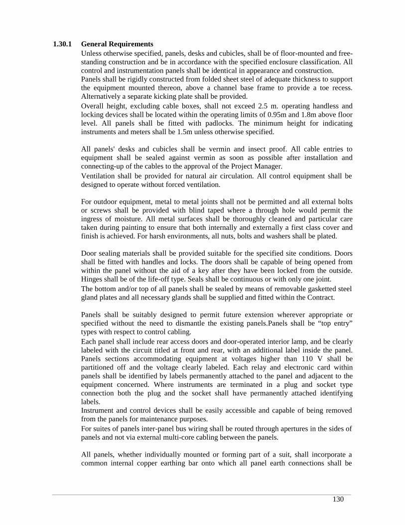
RRDP-II-SSN-02-04 130
1.30.1 General RequirementsUnless otherwise specified, panels, desks and cubicles, shall be of floor-mounted and free-standing construction and be in accordance with the specified enclosure classification. Allcontrol and instrumentation panels shall be identical in appearance and construction.Panels shall be rigidly constructed from folded sheet steel of adequate thickness to supportthe equipment mounted thereon, above a channel base frame to provide a toe recess.Alternatively a separate kicking plate shall be provided.Overall height, excluding cable boxes, shall not exceed 2.5 m. operating handless andlocking devices shall be located within the operating limits of 0.95m and 1.8m above floorlevel. All panels shall be fitted with padlocks. The minimum height for indicatinginstruments and meters shall be 1.5m unless otherwise specified.
All panels' desks and cubicles shall be vermin and insect proof. All cable entries toequipment shall be sealed against vermin as soon as possible after installation andconnecting-up of the cables to the approval of the Project Manager.Ventilation shall be provided for natural air circulation. All control equipment shall bedesigned to operate without forced ventilation.
For outdoor equipment, metal to metal joints shall not be permitted and all external boltsor screws shall be provided with blind taped where a through hole would permit theingress of moisture. All metal surfaces shall be thoroughly cleaned and particular caretaken during painting to ensure that both internally and externally a first class cover andfinish is achieved. For harsh environments, all nuts, bolts and washers shall be plated.
Door sealing materials shall be provided suitable for the specified site conditions. Doorsshall be fitted with handles and locks. The doors shall be capable of being opened fromwithin the panel without the aid of a key after they have been locked from the outside.Hinges shall be of the life-off type. Seals shall be continuous or with only one joint.The bottom and/or top of all panels shall be sealed by means of removable gasketted steelgland plates and all necessary glands shall be supplied and fitted within the Contract.
Panels shall be suitably designed to permit future extension wherever appropriate orspecified without the need to dismantle the existing panels.Panels shall be “top entry”types with respect to control cabling.Each panel shall include rear access doors and door-operated interior lamp, and be clearlylabeled with the circuit titled at front and rear, with an additional label inside the panel.Panels sections accommodating equipment at voltages higher than 110 V shall bepartitioned off and the voltage clearly labeled. Each relay and electronic card withinpanels shall be identified by labels permanently attached to the panel and adjacent to theequipment concerned. Where instruments are terminated in a plug and socket typeconnection both the plug and the socket shall have permanently attached identifyinglabels.Instrument and control devices shall be easily accessible and capable of being removedfrom the panels for maintenance purposes.For suites of panels inter-panel bus wiring shall be routed through apertures in the sides ofpanels and not via external multi-core cabling between the panels.
All panels, whether individually mounted or forming part of a suit, shall incorporate acommon internal copper earthing bar onto which all panel earth connections shall be
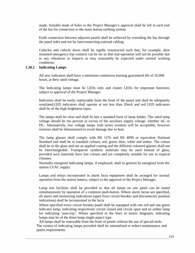
131
made. Suitable studs of holes to the Project Manager’s approval shall be left at each endof the bar for connection to the main station earthing system.
Earth connection between adjacent panels shall be achieved by extending the bar throughthe panel sides and not by interconnecting external cabling.
Cubicles and cubicle doors shall be rigidly constructed such that, for example, doormounted emergency trip contacts can be set so that mal-operation will not be possible dueto any vibrations or impacts as may reasonably be expected under normal workingconditions.
1.30.2 Indicating Lamps
All new indicators shall have a minimum continuous burning guaranteed life of 10,000hours, at their rated voltage.
The Indicating lamps must be LEDs only and cluster LEDs for important functionssubject to approval of the Project Manager.
Indicators shall be easily replaceable from the front of the panel and shall be adequatelyventilated.LED indicators shall operate at not less than 20mA and red LED indicatorsshall be of the high brightness types.
The lamps shall be clear and shall fit into a standard form of lamp holder. The rated lampvoltage should be ten percent in excess of the auxiliary supply voltage, whether AC orDC. Alternatively, low voltage lamps with series resistors will be acceptable, howeverresistors shall be dimensioned to avoid damage due to heat.
The lamp glasses shall comply with BS 1376 and BS 4099 or equivalent NationalStandard and shall be in standard colours, red, green, blue, white and amber. The colourshall be in the glass and not an applied coating and the different coloured glasses shall notbe interchangeable. Transparent synthetic materials may be used instead of glass,provided such materials have fast colours and are completely suitable for use in tropicalclimates.Normally energized indicating lamps, if employed, shall in general be energized from thestation LVAC supply.
Lamps and relays incorporated in alarm facia equipment shall be arranged for normaloperation from the station battery, subject to the approval of the Project Manager.
Lamp test facilities shall be provided so that all lamps on one panel can be testedsimultaneously by operation of a common push-button. Where alarm facias are specified,all alarm and monitoring indications (apart from circuit-breaker and disconnector positionindications) shall be incorporated in the faciaWhere specified every circuit breaker panel shall be equipped with one red and one greenindicator lamp, indicating respectively circuit closed and circuit open and an amber lampfor indicating ‘auto-trip’. Where specified in the lines of mimic diagrams, indicatinglamps may be of the three-lamp single-aspect type.All lamps shall be renewable from the front of panels without the use of special tools.
The variety of indicating lamps provided shall be rationalized to reduce maintenance andspares requirements.
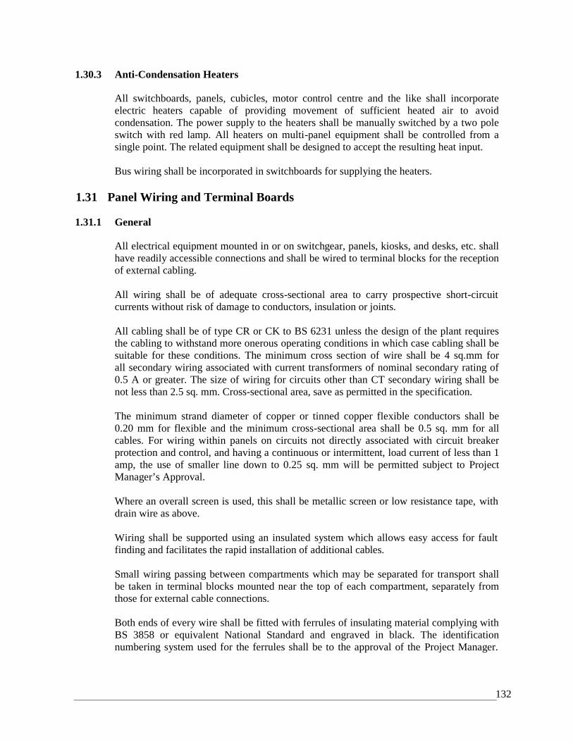
132
1.30.3 Anti-Condensation Heaters
All switchboards, panels, cubicles, motor control centre and the like shall incorporateelectric heaters capable of providing movement of sufficient heated air to avoidcondensation. The power supply to the heaters shall be manually switched by a two poleswitch with red lamp. All heaters on multi-panel equipment shall be controlled from asingle point. The related equipment shall be designed to accept the resulting heat input.
Bus wiring shall be incorporated in switchboards for supplying the heaters.
1.31 Panel Wiring and Terminal Boards
1.31.1 General
All electrical equipment mounted in or on switchgear, panels, kiosks, and desks, etc. shallhave readily accessible connections and shall be wired to terminal blocks for the receptionof external cabling.
All wiring shall be of adequate cross-sectional area to carry prospective short-circuitcurrents without risk of damage to conductors, insulation or joints.
All cabling shall be of type CR or CK to BS 6231 unless the design of the plant requiresthe cabling to withstand more onerous operating conditions in which case cabling shall besuitable for these conditions. The minimum cross section of wire shall be 4 sq.mm forall secondary wiring associated with current transformers of nominal secondary rating of0.5 A or greater. The size of wiring for circuits other than CT secondary wiring shall benot less than 2.5 sq. mm. Cross-sectional area, save as permitted in the specification.
The minimum strand diameter of copper or tinned copper flexible conductors shall be0.20 mm for flexible and the minimum cross-sectional area shall be 0.5 sq. mm for allcables. For wiring within panels on circuits not directly associated with circuit breakerprotection and control, and having a continuous or intermittent, load current of less than 1amp, the use of smaller line down to 0.25 sq. mm will be permitted subject to ProjectManager’s Approval.
Where an overall screen is used, this shall be metallic screen or low resistance tape, withdrain wire as above.
Wiring shall be supported using an insulated system which allows easy access for faultfinding and facilitates the rapid installation of additional cables.
Small wiring passing between compartments which may be separated for transport shallbe taken in terminal blocks mounted near the top of each compartment, separately fromthose for external cable connections.
Both ends of every wire shall be fitted with ferrules of insulating material complying withBS 3858 or equivalent National Standard and engraved in black. The identificationnumbering system used for the ferrules shall be to the approval of the Project Manager.
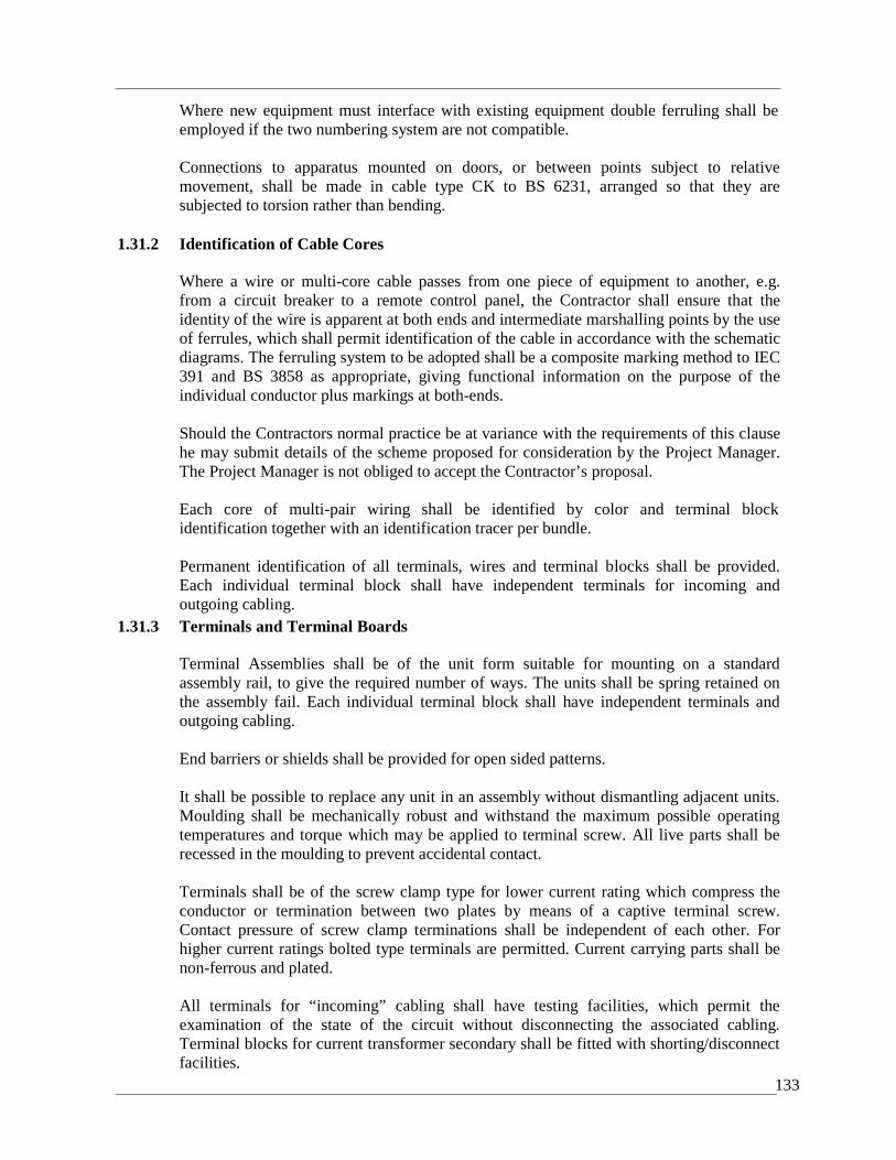
133
Where new equipment must interface with existing equipment double ferruling shall beemployed if the two numbering system are not compatible.
Connections to apparatus mounted on doors, or between points subject to relativemovement, shall be made in cable type CK to BS 6231, arranged so that they aresubjected to torsion rather than bending.
1.31.2 Identification of Cable Cores
Where a wire or multi-core cable passes from one piece of equipment to another, e.g.from a circuit breaker to a remote control panel, the Contractor shall ensure that theidentity of the wire is apparent at both ends and intermediate marshalling points by the useof ferrules, which shall permit identification of the cable in accordance with the schematicdiagrams. The ferruling system to be adopted shall be a composite marking method to IEC391 and BS 3858 as appropriate, giving functional information on the purpose of theindividual conductor plus markings at both-ends.
Should the Contractors normal practice be at variance with the requirements of this clausehe may submit details of the scheme proposed for consideration by the Project Manager.The Project Manager is not obliged to accept the Contractor’s proposal.
Each core of multi-pair wiring shall be identified by color and terminal blockidentification together with an identification tracer per bundle.
Permanent identification of all terminals, wires and terminal blocks shall be provided.Each individual terminal block shall have independent terminals for incoming andoutgoing cabling.
1.31.3 Terminals and Terminal Boards
Terminal Assemblies shall be of the unit form suitable for mounting on a standardassembly rail, to give the required number of ways. The units shall be spring retained onthe assembly fail. Each individual terminal block shall have independent terminals andoutgoing cabling.
End barriers or shields shall be provided for open sided patterns.
It shall be possible to replace any unit in an assembly without dismantling adjacent units.Moulding shall be mechanically robust and withstand the maximum possible operatingtemperatures and torque which may be applied to terminal screw. All live parts shall berecessed in the moulding to prevent accidental contact.
Terminals shall be of the screw clamp type for lower current rating which compress theconductor or termination between two plates by means of a captive terminal screw.Contact pressure of screw clamp terminations shall be independent of each other. Forhigher current ratings bolted type terminals are permitted. Current carrying parts shall benon-ferrous and plated.
All terminals for “incoming” cabling shall have testing facilities, which permit theexamination of the state of the circuit without disconnecting the associated cabling.Terminal blocks for current transformer secondary shall be fitted with shorting/disconnectfacilities.

134
Terminal blocks for voltage transformers secondaries shall be isolatable.
Terminal blocks in telemetry marshalling cubicles shall be isolatable. The means ofisolation shall be fixed and give visual identification of the status of the terminal.
Not more than 1 wire shall be connected to each terminal and cross-connection facilitiesshall be provided where numerous cores are to connected together.
Each terminal block, and every individual terminal shall be identified. The terminalidentification number shall be included on associated schematic and wiring diagrams.
The mounting rail may only be used to provide an earth connection, when firmly bondedto the earth bar and to be approved by the Project Manager.
The Contractor shall submit samples of the terminal blocks/mounting rail assembliestogether with details of his proposed cabling/termination system to the Project Managerfor approval.Adjacent terminals to which wires of different voltage, polarity or phase are connectedshall be separated by a protruding insulating barrier; this requirement also applies toterminals carrying wires of the same voltage but originating from different sources.
Wires shall be grounded on the terminal boards according to their functions. Terminalblocks for connections exceeding 110V shall be fitted with insulting covers.
Terminal blocks shall be mounted not less than 150 mm from the gland plates, and spacednot less than 100 mm apart, on the side of the enclosure.
Sufficient terminals shall be provided to permit all cores on multicore cables to beterminated. Terminals for spare cores shall be numbered and be located at such position aswill provide the maximum length of spare core. At least 10% spare terminals shall beprovided in all cases.
The tails of multi-core cables shall be bound and routed so that each tail may be tracedwithout difficulty to its associated cable. All spare cores shall be made off to terminals.
When two lengths of screened cable are to be connected at a terminal block (i.e. junctionbox) a separate terminal shall be provided to maintain screen continuity.
Should the terminal block manufacturer recommend that specific types of terminal toolsare used (eg parallel sided screw/drivers) the Contractor shall provide three sets of these ateach sub-station site. In addition the Contractor shall provide 8 numbers, test leads ofminimum 1500 mm length which can be inserted into the test terminals of the terminalblocks, at each sub-station. The test leads shall be capable of being ‘jumpered’ togetherfor multi-instrument use.
The use of pre-formed factory tested cable connections to field mounted marshallingboxes shall be to the Project Manager’s approval.
1.32 Cable Boxes and GlandsElectrical equipment supplied under this contract shall be fitted with all necessary cable boxes andglands which shall be complete with all required fittings. Boxes shall be of adequate proportions to
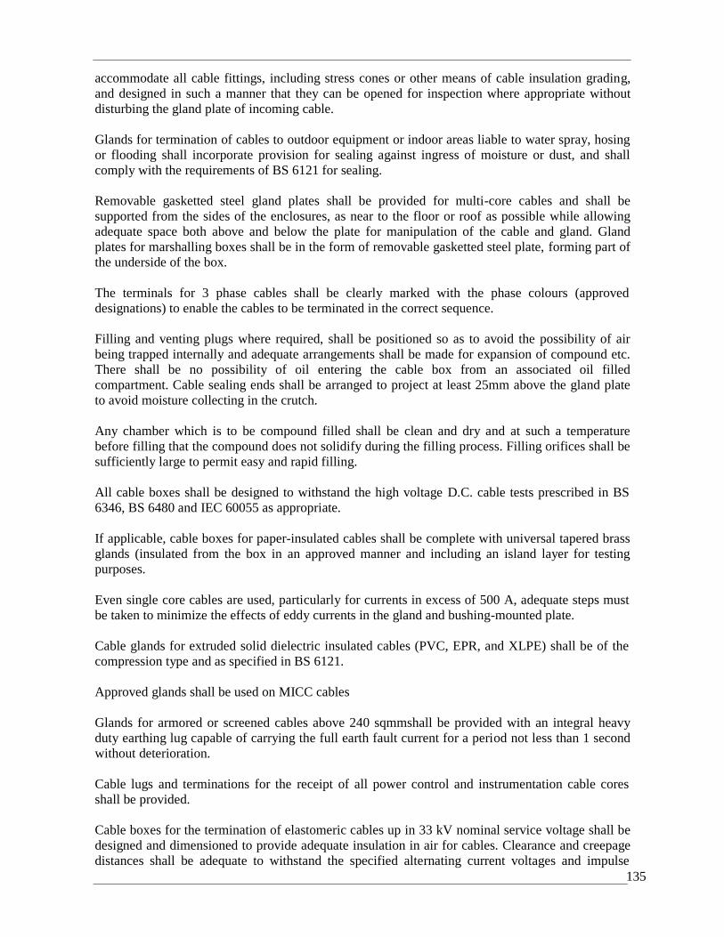
135
accommodate all cable fittings, including stress cones or other means of cable insulation grading,and designed in such a manner that they can be opened for inspection where appropriate withoutdisturbing the gland plate of incoming cable.
Glands for termination of cables to outdoor equipment or indoor areas liable to water spray, hosingor flooding shall incorporate provision for sealing against ingress of moisture or dust, and shallcomply with the requirements of BS 6121 for sealing.
Removable gasketted steel gland plates shall be provided for multi-core cables and shall besupported from the sides of the enclosures, as near to the floor or roof as possible while allowingadequate space both above and below the plate for manipulation of the cable and gland. Glandplates for marshalling boxes shall be in the form of removable gasketted steel plate, forming part ofthe underside of the box.
The terminals for 3 phase cables shall be clearly marked with the phase colours (approveddesignations) to enable the cables to be terminated in the correct sequence.
Filling and venting plugs where required, shall be positioned so as to avoid the possibility of airbeing trapped internally and adequate arrangements shall be made for expansion of compound etc.There shall be no possibility of oil entering the cable box from an associated oil filledcompartment. Cable sealing ends shall be arranged to project at least 25mm above the gland plateto avoid moisture collecting in the crutch.
Any chamber which is to be compound filled shall be clean and dry and at such a temperaturebefore filling that the compound does not solidify during the filling process. Filling orifices shall besufficiently large to permit easy and rapid filling.
All cable boxes shall be designed to withstand the high voltage D.C. cable tests prescribed in BS6346, BS 6480 and IEC 60055 as appropriate.
If applicable, cable boxes for paper-insulated cables shall be complete with universal tapered brassglands (insulated from the box in an approved manner and including an island layer for testingpurposes.
Even single core cables are used, particularly for currents in excess of 500 A, adequate steps mustbe taken to minimize the effects of eddy currents in the gland and bushing-mounted plate.
Cable glands for extruded solid dielectric insulated cables (PVC, EPR, and XLPE) shall be of thecompression type and as specified in BS 6121.
Approved glands shall be used on MICC cables
Glands for armored or screened cables above 240 sqmmshall be provided with an integral heavyduty earthing lug capable of carrying the full earth fault current for a period not less than 1 secondwithout deterioration.
Cable lugs and terminations for the receipt of all power control and instrumentation cable coresshall be provided.
Cable boxes for the termination of elastomeric cables up in 33 kV nominal service voltage shall bedesigned and dimensioned to provide adequate insulation in air for cables. Clearance and creepagedistances shall be adequate to withstand the specified alternating current voltages and impulse

136
voltages for service under the prevailing site conditions. The performance is to be met without theuse of insulating ‘boots’ shrouds orany other material fitted over or between the cable terminationsapart from permanently fitted barriers forming part of the switchgear or cable box.
Means shall be provided for preventing accumulation of dirt, dust, moisture, vermin or insects suchas to maintain the anticipated life of the equipment. The Contractor shall ascertain the means bywhich elastomeric cables are to be terminated and shall provide such information or instructions asnecessary to any other contractor or sub-contract or to ensure compliance with this clause.
The cable crutch within a cable box or equipment panel shall be protected by the use of a heat-shrink plastic ‘udder’ places over the conductors and crutch.
1.33 Joints and Gaskets
All joint faces are to be flat and parallel to the approval of the Project Manager and arrangedto prevent the ingress of water or leakage of oil with a minimum of gasket surface exposed tothe action of oil or air.
Oil-resisting synthetic rubber gaskets are not permissible, unless the degree of compression isaccurately controlled. For gaskets of cork or similar, oil resisting synthetic rubber may be used as abonding medium. No joints are allow in gaskets.
1.34 Junction, Termination Marshalling Boxes, Operating Cubicles etc
All junctions, termination and marshalling boxes shall be of substantial sheet steel construction,having enclosure classification in accordance with the specification and fitted with external fixinglugs and finished in accordance with this Specification for cleaning, painting and finishing.
The boxes shall allow ample room for wiring, with particular regard to the deployment of wiresfrom the point of entry.
Outdoor boxes shall have internal anti-condensation heaters and stay bars fitted to doors. Indoorboxes shall be designed such that any condensed water cannot affect the insulation of the terminalboards or cables. No cables shall be terminated into the top of outdoor boxes unless specificallyapproved by the Project Manager.
Each box shall be complete with suitably inscribed identification labels.
Any outdoor boxes, cubicles etc containing instruments or meters shall have glazing suitable topermit the visual examination of these.
Covers shall be arranged for padlocking and padlocks with keys shall be supplied. Cast iron boxesshall have bolted lids requiring the use of special keys or spanners for removal.
All boxes shall be provided with adequate earthing bars and terminals.
Notwithstanding information supplied by the Project Manager, the Contractor shall, as each box iscompleted or at intervals as requested by the Project Manager, supply to the Project Managercopies of accurate termination or destination charts showing the as-fitted arrangement of cables andcores in each box. The Contractor shall, following the Project Manager’s approval, fit one plasticlaminated copy of the appropriate chart to the interior of each box.
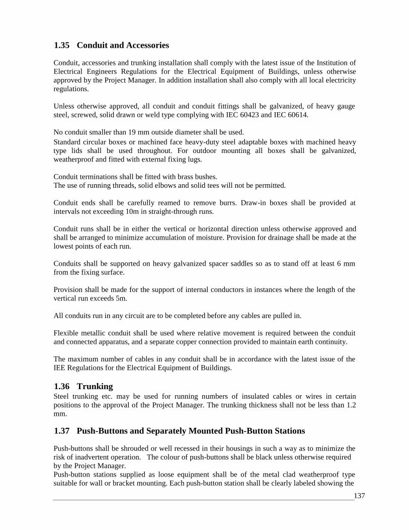
137
1.35 Conduit and Accessories
Conduit, accessories and trunking installation shall comply with the latest issue of the Institution ofElectrical Engineers Regulations for the Electrical Equipment of Buildings, unless otherwiseapproved by the Project Manager. In addition installation shall also comply with all local electricityregulations.
Unless otherwise approved, all conduit and conduit fittings shall be galvanized, of heavy gaugesteel, screwed, solid drawn or weld type complying with IEC 60423 and IEC 60614.
No conduit smaller than 19 mm outside diameter shall be used.Standard circular boxes or machined face heavy-duty steel adaptable boxes with machined heavytype lids shall be used throughout. For outdoor mounting all boxes shall be galvanized,weatherproof and fitted with external fixing lugs.
Conduit terminations shall be fitted with brass bushes.The use of running threads, solid elbows and solid tees will not be permitted.
Conduit ends shall be carefully reamed to remove burrs. Draw-in boxes shall be provided atintervals not exceeding 10m in straight-through runs.
Conduit runs shall be in either the vertical or horizontal direction unless otherwise approved andshall be arranged to minimize accumulation of moisture. Provision for drainage shall be made at thelowest points of each run.
Conduits shall be supported on heavy galvanized spacer saddles so as to stand off at least 6 mmfrom the fixing surface.
Provision shall be made for the support of internal conductors in instances where the length of thevertical run exceeds 5m.
All conduits run in any circuit are to be completed before any cables are pulled in.
Flexible metallic conduit shall be used where relative movement is required between the conduitand connected apparatus, and a separate copper connection provided to maintain earth continuity.
The maximum number of cables in any conduit shall be in accordance with the latest issue of theIEE Regulations for the Electrical Equipment of Buildings.
1.36 TrunkingSteel trunking etc. may be used for running numbers of insulated cables or wires in certainpositions to the approval of the Project Manager. The trunking thickness shall not be less than 1.2mm.
1.37 Push-Buttons and Separately Mounted Push-Button Stations
Push-buttons shall be shrouded or well recessed in their housings in such a way as to minimize therisk of inadvertent operation. The colour of push-buttons shall be black unless otherwise requiredby the Project Manager.Push-button stations supplied as loose equipment shall be of the metal clad weatherproof typesuitable for wall or bracket mounting. Each push-button station shall be clearly labeled showing the
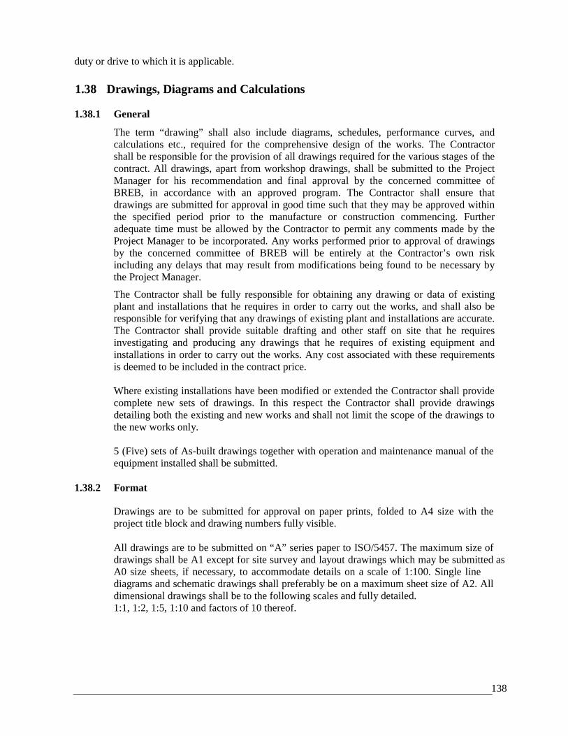
138
duty or drive to which it is applicable.
1.38 Drawings, Diagrams and Calculations
1.38.1 General
The term “drawing” shall also include diagrams, schedules, performance curves, andcalculations etc., required for the comprehensive design of the works. The Contractorshall be responsible for the provision of all drawings required for the various stages of thecontract. All drawings, apart from workshop drawings, shall be submitted to the ProjectManager for his recommendation and final approval by the concerned committee ofBREB, in accordance with an approved program. The Contractor shall ensure thatdrawings are submitted for approval in good time such that they may be approved withinthe specified period prior to the manufacture or construction commencing. Furtheradequate time must be allowed by the Contractor to permit any comments made by theProject Manager to be incorporated. Any works performed prior to approval of drawingsby the concerned committee of BREB will be entirely at the Contractor’s own riskincluding any delays that may result from modifications being found to be necessary bythe Project Manager.
The Contractor shall be fully responsible for obtaining any drawing or data of existingplant and installations that he requires in order to carry out the works, and shall also beresponsible for verifying that any drawings of existing plant and installations are accurate.The Contractor shall provide suitable drafting and other staff on site that he requiresinvestigating and producing any drawings that he requires of existing equipment andinstallations in order to carry out the works. Any cost associated with these requirementsis deemed to be included in the contract price.
Where existing installations have been modified or extended the Contractor shall providecomplete new sets of drawings. In this respect the Contractor shall provide drawingsdetailing both the existing and new works and shall not limit the scope of the drawings tothe new works only.
5 (Five) sets of As-built drawings together with operation and maintenance manual of theequipment installed shall be submitted.
1.38.2 Format
Drawings are to be submitted for approval on paper prints, folded to A4 size with theproject title block and drawing numbers fully visible.
All drawings are to be submitted on “A” series paper to ISO/5457. The maximum size ofdrawings shall be A1 except for site survey and layout drawings which may be submitted asA0 size sheets, if necessary, to accommodate details on a scale of 1:100. Single linediagrams and schematic drawings shall preferably be on a maximum sheet size of A2. Alldimensional drawings shall be to the following scales and fully detailed.1:1, 1:2, 1:5, 1:10 and factors of 10 thereof.
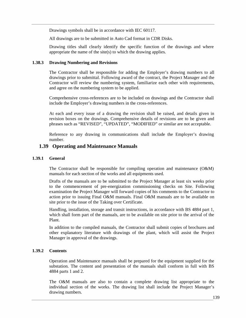
139
Drawings symbols shall be in accordance with IEC 60117.
All drawings are to be submitted in Auto Cad format in CDR Disks.
Drawing titles shall clearly identify the specific function of the drawings and whereappropriate the name of the site(s) to which the drawing applies.
1.38.3 Drawing Numbering and Revisions
The Contractor shall be responsible for adding the Employer’s drawing numbers to alldrawings prior to submittal. Following award of the contract, the Project Manager and theContractor will review the numbering system, familiarize each other with requirements,and agree on the numbering system to be applied.
Comprehensive cross-references are to be included on drawings and the Contractor shallinclude the Employer’s drawing numbers in the cross-references.
At each and every issue of a drawing the revision shall be raised, and details given inrevision boxes on the drawings. Comprehensive details of revisions are to be given andphrases such as “REVISED”, “UPDATED”, “MODIFIED” or similar are not acceptable.
Reference to any drawing in communications shall include the Employer’s drawingnumber.
1.39 Operating and Maintenance Manuals2.
1.39.1 General
The Contractor shall be responsible for compiling operation and maintenance (O&M)manuals for each section of the works and all equipments used.
Drafts of the manuals are to be submitted to the Project Manager at least six weeks priorto the commencement of pre-energization commissioning checks on Site. Followingexamination the Project Manager will forward copies of his comments to the Contractor toaction prior to issuing Final O&M manuals. Final O&M manuals are to be available onsite prior to the issue of the Taking over Certificate.
Handling, installation, storage and transit instructions, in accordance with BS 4884 part 1,which shall form part of the manuals, are to be available on site prior to the arrival of thePlant.
In addition to the compiled manuals, the Contractor shall submit copies of brochures andother explanatory literature with drawings of the plant, which will assist the ProjectManager in approval of the drawings.
1.39.2 Contents
Operation and Maintenance manuals shall be prepared for the equipment supplied for thesubstation. The content and presentation of the manuals shall conform in full with BS4884 parts 1 and 2.
The O&M manuals are also to contain a complete drawing list appropriate to theindividual section of the works. The drawing list shall include the Project Manager’sdrawing numbers.
140
Maintenance instructions for all plant shall cover preventive and corrective maintenanceprocedures. For electronic or solid state control, protection equipment etc. details shall beprovided to enable individual circuit cards to be checked for correct operation and faultsto be traced, and repaired.
The Contractor shall provide proformas of the required maintenance record sheets for allplant, which shall include cross-reference to the appropriate section of the O&M manualswhich detail how to perform the tasks required. Any other record sheets suitable for themonitoring of the plant shall also be designed and provided.
1.39.3 Binders, Presentation
The information will be provided on A4 pages, with diagrams on throw-clear pages whererequired to enable the text and diagrams to be refereed to simultaneously.
The front cover and spine of the manuals shall give the following information:
Project TitleEmployer’s nameContract numberIdentification of the Section of the WorksVolume number and total number of volumes applicable(e.g. volume 3 of 5 volumes)Contractor’s company logo and name
The above shall also be provided on a flysheet inside the front cover of each volume.Draft O&M manuals may be presented in unprinted covers.
Four copies of draft O&M manuals are to be provided to the Project Manager; followingapproval 8 copies are to be provided to the Project Manager or his site Representative foreach section of the works.
1.40 Site Storage Facilities
The Contractor shall provide lockable cabinets in each of the individual substations, which are tocontain the following:
(a) One set of paper prints of the complete record of drawings for the section of the work.These shall be arranged in a logical sequence in accordance with the drawing list containedin the O&M manuals. Record drawings are to be grouped into labeled pockets or binders tominimize disturbance in locating specific drawings. As-built drawings are to be stored inthese locations prior to the issue of record drawings.
(b) Two complete sets of O&M manuals(c) Volumes of factory and site test reports/certificates(d) Copies of maintenance log sheets, record sheets etc.(e) Space for stationery and operators’ log booksThese cabinets shall match other furnishings being provided in the substation and the location assuch items is to be included in the design of the substation layout.
141
1.41 Switchyard Cable Ducts and Conduits
A system of UPVC conduits (equipment to duct) and pre-cast concrete ducts shall be used for controland LV cabling between switchyard equipment and the control building. Entry to the control/protection panels in the building shall be via the top of the panels and a suitable sealing arrangement.
HV cabling between the transformers and switchgear panels shall be installed in concrete ducts in theswitchyard and within the building. HV Cabling between the control building and the feedertermination poles shall be direct buried outside the building.
142
8. ELECTRICAL
8.0 PARTICULAR TECHNICAL REQUIREMENTSFOR SUBSTATION ELECTRICAL EQUIPMENT
143
TABLE OF CONTENTS
Description Page NoIntroduction 180Power Transformers 181Technical Requirement and Guarantee Schedule(a) OLTC Type 20/28 MVA 33/11.55 K, 50 Hz Power Transformers 219(b) OLTC Type 33/11.55 kV 10/14MVA Power Transformers 222(c) 33 kV Surge Arrester, Station Class 224(d) 11 kV Surge Arrester, Station Class 225(e) 33/0.415 kV, 3 Phase 100 kVA Station Transformer 22633 kV Outdoor Vacuum Circuit Breaker 227Technical Requirement and Guarantee Schedule(f) 33 kV Outdoor Type Vacuum Circuit Breaker (VCB) 241(g) 33 kV Control and Energy Metering Panel 243(h) Indication meter 245(i) 33 kV Current Transformer (CT) 246(j) 33 kV Voltage Transformer 24711 kV Indoor Vacuum Circuit Breaker 248Technical Requirement and Guarantee Schedule(k) 11 kV Switchgear and Control Equipment 25836 kV Underground Power Cable 26415 kV Underground Power Cable 271500 mm² 11 KV XLPE Cable 278Technical Requirement and Guarantee Schedule(l) 11KV, 1-Core x 500 Sq. mm U/G XLPE Copper Cable 283(m)Joining kits for 11 kV XLPE, 1-Core, 500 mm2 Copper Cable 285Conductors and Connections 287Disconnectors and Earthing Switches 288Insulators 291Technical Requirement and Guarantee Schedule(n) 33 kV Isolator/ Earth Switch 293(o) 11 kV Isolator 294(p) 33 kV Double Break Switched Fuse 295Substation Earthing Systems 296Substation Battery and Battery Charger 300Overhead Earthing Screen 303Section VI. Employers Requirements 180
1.1 INTRODUCTION
This section describes the Particular Technical Requirements for the 33 kV outdoor switchgear, the11kV indoor switchgear, the main 33/11.55kV OLTC Transformers and all associated substationequipment, and shall be read in conjunction with the General Technical Requirements, Schedulesand Drawings in the specification. The latest edition of the relevant IEC, British or Americanstandard shall apply. Standards from other countries may be considered by the Project Manager ifequivalent to or better than the above relevant standards.
144
PUBLICATION 916A-2014BANGLADESH RURAL ELECTRIFICATION BOARD (BREB)
PEOPLE’S REPUBLIC OF BANGLADESHSTANDARD FOR SUB-STATION
OLTC TYPE THREE PHASE POWER TRANSFORMERS:10 MVA & 20 MVA
PART-1: GENERAL
1. SCOPE
The transformers shall be suitable for continuous operation on a three-phase 50 Hz high voltagetransmission system as specified herein. .
The transformers shall be of the three phase oil immersed type and designed with particularattention to the suppression of harmonic especially the third and fifth harmonics and to minimizethe detrimental effects resulting there from. All transformers shall be suitable for outdoorinstallation on concrete bases and shall be designed to operate satisfactorily in parallel with eachother. The transformer shall conform in all respects to highest standards of engineering, design,workmanship, this specification and the latest revisions of relevant standards at the time of delivery.
The cooling for the transformers shall be ONAN/ONAF as specified.
2. REFERENCES
2.1 British Standards
BS 61 Specification for threads for light gauge copper tubes and fittingsBS 3600 Specification for dimensions and masses per unit length of welded and
seamless steel pipes and tubes for pressure purposesBS 4504 Circular flanges for pipes, valves and fittings (PN designated)BS 6121 Mechanical cable glandsBS 6346 Specification tor PVC insulated cables for electricity supplyBS 6435 Specification for unfilled enclosures for the dry termination of HV cables
for transformers and reactorsBS 7354 Code of practice for design of HV open terminal stationsBS 7613 Specification tor hot rolled quenched and tempered wieldable plates
2.2 BS European Standards
BS EN 10029 Specification for tolerances on dimensions, shape and mass for hot rolledsteel plates 3mm thick and above.
2.3 IEC Standards
IEC 60076IEC 60137IEC 60186IEC 60214IEC 60228
Power transformersInsulated bushings for ac voltages above l000 VVoltage transformersOn load tap changersConductors of insulated cables
145
Section VI. Employers Requirements 182
IEC 60233
IEC 60296
IEC 60354
IEC 60422
IEC 60529IEC 60551
Tests on hollow insulators for use in electrical equipmentSpecification for unused mineral insulating oils tor transformers andswitchgearLoading guide for oil immersed power transformersSupervision and maintenance guide for mineral insulating oils in electricalequipmentDegrees of protection provided by enclosuresDetermination of transformer and reactor sound levels
3. CLIMATE DATAMain climate data that must be taken into account for the goods will be the followings:
ClimateMaximum TemperatureMinimum TemperatureAverage daily TemperatureAverage isokeraunic levelRelative humidityAverage annual rain fallMaximum wind velocityAltitude
: Tropical, intense sunshine, heave rain: 450 C: 030 C: 300 C: 80 days/ year: 50-100%: 3454 mm: 200 km/hour: 300 meters above Sea level
Atmospherically, Mechanical and Chemical impurities: Moderately polluted
The information is given solely as a guide for Bid and no responsibility for its, Accuracy will beaccepted nor will any claim based on the above be entertained.Transformer supplied under this Contract will be installed in tropical locations that can beconsidered hostile to its proper operation. Particular problems that shall receive specialconsideration relate to operation in a humid environment and presence of insects and vermin.4. SYSTEM CONDITIONSThe equipment shall be suitable for installation in supply systems of the following characteristics:
Frequency 50 HzNominal system voltages 33 kV
11 kV400/230V
Maximum system voltages: 33 kV System 36 kV11 kV System 13.2 kVLV System 440V
Minimum LV voltage 360 VNominal short circuit levels 33 Kv System 31.5 kA
11 Kv System 31.5 kAInsulation levels:1.2/50 ms impulse withstand (positive andnegative polarity)
33 kV System 170kV11 kV System 75 kV
Power frequency one minute withstand(wet and dry)
33 kV System 70 kV11 kV System 28 kVLV System 3 kV
Neutral earthing arrangements 33 kV System solidly earthed11 kV System solidly earthedLV System solidly earthed
146
5. INSPECTION AND TESTING
During pre-delivery/ pre-shipment inspection; BREB’s inspection team will witness the followingtest of not less than 10% of total quantity ready for delivery on random sampling basis (sampleselected by the inspection team) during factory test in manufacturer’s factory premises:
1. Measurement of turn ration test;2. Vector group test (check of phase displacement)3. Measurement of winding resistance;4. Measurement of no load loss & no-load current;5. Measurement of impedance voltage & load loss;6. Dielectric withstands test;7. Transformer oil test;8. Temperature rise test.9. Impulse test.
Besides BREB’s inspection team will perform some physical test of at least 10 (ten) % transformerof on random sampling basis during factory test:
1. Transformer tank sheet thickness (top bottom & side);2. Hot dip galvanization test as per standard BS-729 of all bolts & nuts connected with
transformer tank, conservator, radiator etc;3. Dimension of bolted type bimetallic connector for H.T. and L.T. bushing;4. Dimension of tanks;5. Checking of creep age distance of HT/LT bushings.6. Others visible parts as per approval drawing.
As and when the Employer is satisfied that any materials/equipment shall have passed the relevanttests, the Employer/ Project Manager shall notify the Contractor in writing to that effect.
Should any inspected/tested goods fail to conform to the specification, the Employer shall have theright to reject any of the items or complete batch if necessary. In that case the Contractor shallreplace the goods or make them good without any cost to the Employer. The inspection and testingshall be carried out again and all costs thereof shall be borne by the Contractor.
Nothing in this clause shall in any way release the Contractor from any warranty or otherobligations under the Contract.
5.1 Type Tests:
Instructions to the Bidders: The following shall be regarded as type tests. The Bidder shall submitall Type test reports from internationally recognized independent testing laboratory along with his/her bid.
5.1.1 Type Tests (for Transformer):
(a) Test of temperature rise (for both ONAN and ONAF).(b) Short circuit test.
147
(c) Dielectric test: (Induced over voltage test, Lightning Impulse voltage withstand test,Power frequency voltage withstand test)
Temperature Rise, Short Circuit and Dielectric test (Induced over voltage test, LightningImpulse voltage withstand test, Power frequency voltage withstand test) on one Transformerof each type and size (i.e. same KVA, KV, AMPS, Frequency, Impedance, Weight of theCore, Oil etc. with tolerance ±5%) of Transformer. These all type tests shall be done onsame Transformer.
5.1.2 HT Bushing type test:
Dry or wet power-frequency voltage withstand test; Dry lightning impulse voltage withstand test; Temperature rise test ; Verification of thermal short-time current withstand; Cantilever load withstand test; Verification of dimensions.
5.2 Special Tests:
a) Noise level measurement, in accordance with IEC Publication 551 using a precision sound levelmeter conforming to IEC Publication 651. In addition the test shall be repeated with narrowband filters for the harmonic frequencies from 100Hz. up to 350 Hz.
b) Magnetic balance test.c) Dissolve gas test (for transformer oil).d) Harmonics measurement test.e) Measurement of zero phase sequence impedance.
5.3 Routine Tests
The following shall be regarded as routine tests and shall be carried out on each transformer.
(a) Measurement of winding resistance at principal tap and two extreme taps.(b) Voltage-ratio measurement and check of vector group.(c) Measurement of the impedance voltage at principal tap and two extreme taps.(d) Measurement of the load loss.(e) Measurement of no-load loss and no-load current, including measurement of harmonics.(f) Applied voltage test to all auxiliary circuits.(g) Tests on on-load tap-changer (fully assembled on transformer).(h) Induced over-voltage withstand test. The voltage applied shall be the relevant power
frequency voltage specified in the clause on Insulation Levels.(i) Separate source voltage withstand test. The applied voltage shall be the relevant power
frequency voltage specified in the clause on Insulation Levels.(j) Polarization index test (1 minute and 10 minute). Index shall be not less than 1.3.(i) Dielectric withstands test;(j) Transformer oil test;(k) Lightning Impulse Voltage with Withstand test (minimum 2 nos. of each type of transformer
per lot)(l) Temperature rise test (minimum 2 nos. of each type of transformer per lot)
148
5.3.1 Routine Test Sequence
The sequence of tests shall be:
(a) Winding resistance measurement, voltage ratio measurement and vector group check(b) Separate source voltage withstand test, induced over-voltage withstand test, impulse
test.(c) Impedance voltage and loss measurements.(d) Tap changer test.(e) Tests on auxiliary circuits.(f) Temperature rise test.
The following tests on site will be carried out after plant is fully assembled:
(a) Ratio and vector group checks.(b) Insulation resistance (HV-LV, HV-E, LV-E).(c) Oil tests.(d) Other necessary pre-commissioning tests.
The Contractor will be held responsible for any discrepancy or defect discovered duringthese tests and shall rectify immediately on receipt of notification at no cost to theEmployer. The Contractor may at his own discretion witness site testing of transformers.
6. PACKING AND SHIPPING
6.1 PackingThe equipment and any supporting structures are to be transported adequately sealed against wateringress. All accessories and spares shall be packed and securely clamped against movement inrobust, wooden, non returnable packing cases to ensure safe transit in rough terrain, cross countryroad conditions and in heavy rains from the manufacturer's works to the work sites.
individual serial number;employer’s name; contract number; destination; a colour coded marking to indicate destination;contractor’s name; name and address of contractor; description and numbers of contents; manufacturer’s name country of origin; case measurements; gross and net weights in kilograms; and all necessary slinging and stacking instructions.
Each crate or container shall be marked clearly on the outside of the case to show TOP andBOTTOM positions with appropriate signs to indicate where the mass is bearing and the correctpositions for slings. All component parts which are separately transported shall have permanentidentification marks to facilitate correct matching and assembly at site. Welded parts shall bemarked before welding. Six copies of each packing list shall be sent to the Employer prior todispatching the equipment.
149
6.2 Shipping
The Contractor shall be responsible for the shipping of all plant and equipment supplied fromabroad to the ports of entry and for the transport of all goods to the various specified destinationsincluding customs clearance, off loading, warehousing and insurance.
The Contractor shall inform himself fully as to all relevant transport facilities and requirements andloading gauges and ensure that the equipment as packed for transport shall conform to theselimitations. The Contractor shall also be responsible for verifying the access facilities specified.
The Contractor shall be responsible for the transportation of all loads associated with the contractworks and shall take all reasonable steps to prevent any highways or bridges from being damagedby his traffic and shall select routes, choose and use vehicles and restrict and distribute loads so thatthe risk of damage shall be avoided. The Contractor shall immediately report to the Employer anyclaims made against the Contractor arising out of alleged damage to a highway or bridge.
All transport accessories, such as riding lugs, jacking pads or blanking off plates shall become theproperty of the Employer. All items of equipment shall be securely clamped against movement toensure safe transit from the manufacturer's facilities to the specified destinations.
The Contractor shall advise the storage requirements for any plant and equipment that may bedelivered to the Employer’s stores. The Contractor shall be required to accept responsibility for theadvice given in so far as these arrangements may have a bearing on the behavior of the equipmentin subsequent service.
6.3 Hazardous substances
The Contractor shall submit safety data sheets for all hazardous substances used with theequipment. The Contractor shall give an assurance that there are no other substances classified ashazardous in the equipment supplied. No oil shall be supplied or used at any stage of manufactureor test without a certificate acceptable to the Employer that it has a PCB content zero. TheContractor shall accept responsibility for the disposal of such hazardous substances, should any befound.
The Contractor shall also be responsible for any injuries resulting from hazardous substances due tonon compliance with these requirements.
7. SUBMITTALS
7.1 Submittals required with the bid
The following shall be required with each copy of the bid:
completed technical data schedule; descriptive literature giving full technical details with calculation of heat dissipation,
radiator arrangement, no-load loss, full load loss, short circuit withstand capability, withconsidering flux density and current density of equipment offered for both ONAN andONAF;
150
outline dimension drawing for each major component, general arrangement drawingshowing component layout and general schematic diagrams;
type test certificates, where available, and sample routine test reports; detailed reference list of customers already using equipment offered during the last 5
years with particular emphasis on units of similar design and rating; details of manufacturer's quality assurance standards and program and ISO 9000 series
or equivalent national certification; deviations from this specification. Only deviations approved in writing before award of
contract shall be accepted; list of recommended spare parts and consumable items for five years of operation with
prices and spare parts catalogue with price list for future requirements.
7.2 Submittals required after contract award
7.2.1. Program
Five copies of the program for production and testing.
7.2.2. Technical Particulars
Within 30 days of contract award five bound folders with records of the technicalparticulars relating to the equipment. Each folder shall contain the following information:
general description of the equipment and all components, including brochures; technical data schedule, with approved revisions; calculations to substantiate choice of electrical, structural, mechanical component
size/ratings; detailed dimension drawing for all components, general arrangement drawing showing
detailed component layout and detailed schematic and wiring drawings for allcomponents;
detailed loading drawing to enable the Employer to design and construct foundations forthe transformer;
statement drawing attention to all exposed points in the equipment at whichcopper/aluminum or aluminum alloy parts are in contact with or in close proximity toother metals and stating clearly what protection is employed to prevent corrosion at eachpoint;
detailed installation and commissioning instructions; at the final hold point forEmployer approval prior to delivery of the equipment the following shall be submitted;
inspection and test reports carried out in the manufacturer's works; operation and maintenance instructions as well as trouble shooting char
7.2.3. Operation and Maintenance instructionsThe copy of installation and commissioning instructions and of the operation andmaintenance instructions and troubleshooting charts shall be supplied with eachtransformer. The Contractor/ Supplier should provide detail drawing including specifiedloss, ratio, impedance, tap position against primary voltage etc.
7.3 Drawings
Within 30 days of Contract commencement the Contractor shall submit, to the Project Manager forrecommendation and approval by the concern committee of the Employer, a schedule of thedrawings to be produced detailing which are to be submitted for “Approval” and which are to be
151
submitted “For Information Only”. The schedule shall also provide a program of drawingsubmission, for approval by the concern committee of the Employer that ensures that all drawingsand calculations are submitted within the period specified above. All detail drawings submitted forapproval shall be to scale not less than 1:20. All important dimensions shall be given and thematerial of which each part is to be constructed shall be indicated on the drawings. All documentsand drawings shall be submitted in accordance with the provisions of this specification and shallbecome the property of the Employer. All drawings and calculations, submitted to the Employer,shall be on international standard size paper, either A0, A1, A2, A3 or A4. All such drawings andcalculations shall be provided with a Contract title block, which shall include the name of theEmployer and Consultants and shall be assigned a unique project drawing number; the Contracttitle block and project numbering system shall be agreed with the Employer. Script sizes andthickness of scripts and lines be selected so that if reduced by two stages the alphanumericcharacters and lines are still perfectly legible so as to facilitate microfilming. For presentation ofdesign drawings and circuit documents IEC Publication 617 or equivalent standards for graphicalsymbols are to be followed.
8. SHIPMENT AND DRYING OUT
8.1 Shipment
Each transformer, when prepared for shipment, shall be fitted with a shock indicator or recorderwhich shall remain in situ until the transformer is delivered to Site. In the event that thetransformer is found to have been subjected to excessive shock in transit, such examination as isnecessary shall be made in the presence of the Project Manager.
Where practicable, transformers shall be shipped with oil filling to cover core and windings but,when shipped under pressure of gas, shall be fitted for the duration of delivery to Site and for suchtime there after as is necessary, with a gauge and gas cylinder adequate to maintain internalpressure above atmospheric.
All earthing transformers shall be shipped full of oil.
8.2 Drying Out
All transformers shall be dried out by an approved method at the manufacturer's works and soarranged that they might be put into service without further drying out on Site.
Clear instructions shall be included in the Maintenance Instructions regarding any specialprecautionary measures (e.g. strutting of tap changer barriers or tank cover) which must be takenbefore the specified vacuum treatment can be carried out. Any special equipment necessary toenable the transformer to withstand the treatment shall be provided with each transformer.
9. APPROVAL PROCEDUREThe Contractor shall submit all drawings, documents and type test reports for approval in sufficienttime to permit modifications to be made if such are deemed necessary and resubmit them forapproval without delaying the initial deliveries or completion of the Contract work. TheEmployer’s representative shall endeavor to return them within a period of four weeks from
the date of receipt. Three copies of all drawings shall be submitted for approval and three copiesfor any subsequent revision. The Employer reserves the right to request any furtheradditional information that may be considered necessary in order to fully review thedrawings. If the Employer is satisfied with the drawing, one copy will be turned to the
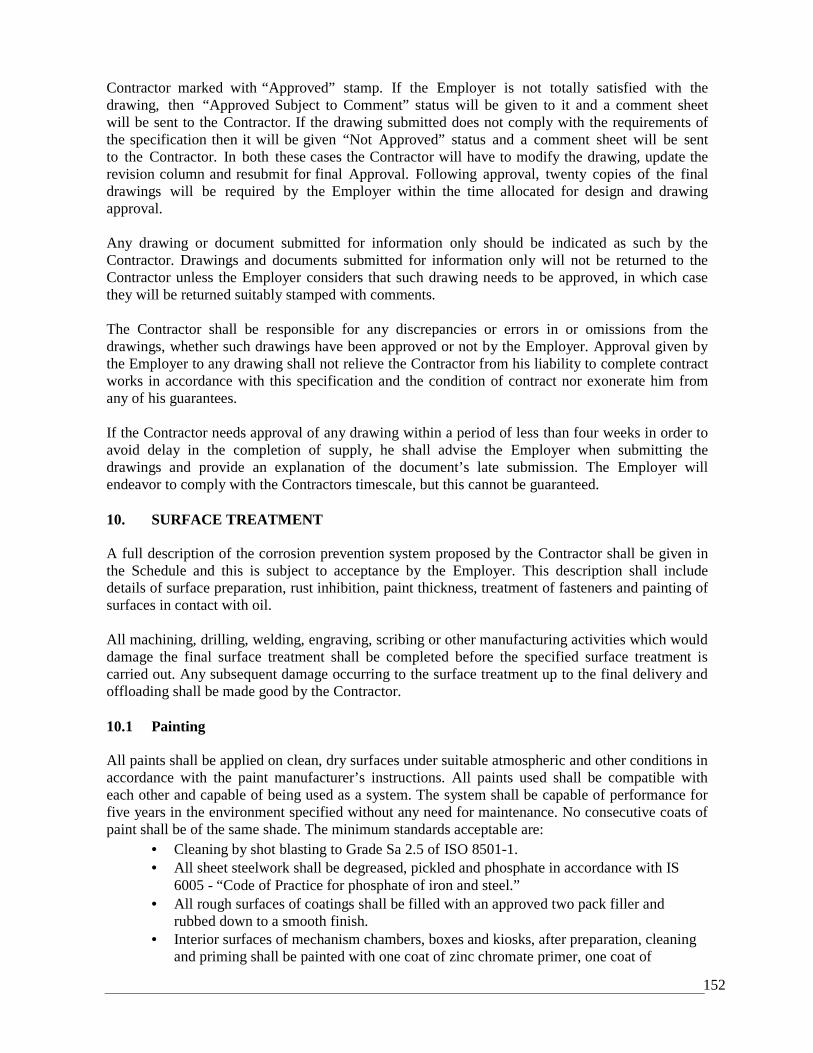
152
Contractor marked with “Approved” stamp. If the Employer is not totally satisfied with thedrawing, then “Approved Subject to Comment” status will be given to it and a comment sheetwill be sent to the Contractor. If the drawing submitted does not comply with the requirements ofthe specification then it will be given “Not Approved” status and a comment sheet will be sentto the Contractor. In both these cases the Contractor will have to modify the drawing, update therevision column and resubmit for final Approval. Following approval, twenty copies of the finaldrawings will be required by the Employer within the time allocated for design and drawingapproval.
Any drawing or document submitted for information only should be indicated as such by theContractor. Drawings and documents submitted for information only will not be returned to theContractor unless the Employer considers that such drawing needs to be approved, in which casethey will be returned suitably stamped with comments.
The Contractor shall be responsible for any discrepancies or errors in or omissions from thedrawings, whether such drawings have been approved or not by the Employer. Approval given bythe Employer to any drawing shall not relieve the Contractor from his liability to complete contractworks in accordance with this specification and the condition of contract nor exonerate him fromany of his guarantees.
If the Contractor needs approval of any drawing within a period of less than four weeks in order toavoid delay in the completion of supply, he shall advise the Employer when submitting thedrawings and provide an explanation of the document’s late submission. The Employer willendeavor to comply with the Contractors timescale, but this cannot be guaranteed.
10. SURFACE TREATMENT
A full description of the corrosion prevention system proposed by the Contractor shall be given inthe Schedule and this is subject to acceptance by the Employer. This description shall includedetails of surface preparation, rust inhibition, paint thickness, treatment of fasteners and painting ofsurfaces in contact with oil.
All machining, drilling, welding, engraving, scribing or other manufacturing activities which woulddamage the final surface treatment shall be completed before the specified surface treatment iscarried out. Any subsequent damage occurring to the surface treatment up to the final delivery andoffloading shall be made good by the Contractor.
10.1 Painting
All paints shall be applied on clean, dry surfaces under suitable atmospheric and other conditions inaccordance with the paint manufacturer’s instructions. All paints used shall be compatible witheach other and capable of being used as a system. The system shall be capable of performance forfive years in the environment specified without any need for maintenance. No consecutive coats ofpaint shall be of the same shade. The minimum standards acceptable are:
Cleaning by shot blasting to Grade Sa 2.5 of ISO 8501-1. All sheet steelwork shall be degreased, pickled and phosphate in accordance with IS
6005 - “Code of Practice for phosphate of iron and steel.” All rough surfaces of coatings shall be filled with an approved two pack filler and
rubbed down to a smooth finish. Interior surfaces of mechanism chambers, boxes and kiosks, after preparation, cleaning
and priming shall be painted with one coat of zinc chromate primer, one coat of
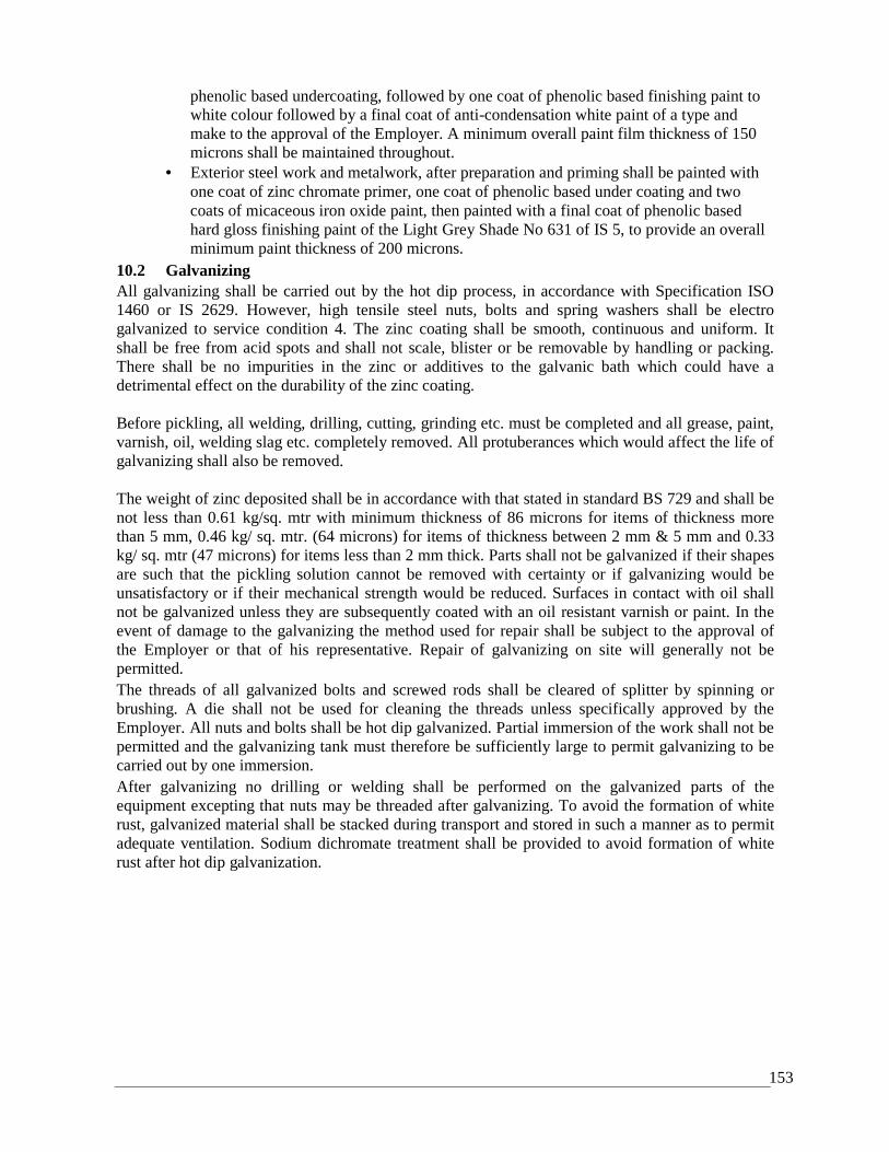
153
phenolic based undercoating, followed by one coat of phenolic based finishing paint towhite colour followed by a final coat of anti-condensation white paint of a type andmake to the approval of the Employer. A minimum overall paint film thickness of 150microns shall be maintained throughout.
Exterior steel work and metalwork, after preparation and priming shall be painted withone coat of zinc chromate primer, one coat of phenolic based under coating and twocoats of micaceous iron oxide paint, then painted with a final coat of phenolic basedhard gloss finishing paint of the Light Grey Shade No 631 of IS 5, to provide an overallminimum paint thickness of 200 microns.
10.2 GalvanizingAll galvanizing shall be carried out by the hot dip process, in accordance with Specification ISO1460 or IS 2629. However, high tensile steel nuts, bolts and spring washers shall be electrogalvanized to service condition 4. The zinc coating shall be smooth, continuous and uniform. Itshall be free from acid spots and shall not scale, blister or be removable by handling or packing.There shall be no impurities in the zinc or additives to the galvanic bath which could have adetrimental effect on the durability of the zinc coating.
Before pickling, all welding, drilling, cutting, grinding etc. must be completed and all grease, paint,varnish, oil, welding slag etc. completely removed. All protuberances which would affect the life ofgalvanizing shall also be removed.
The weight of zinc deposited shall be in accordance with that stated in standard BS 729 and shall benot less than 0.61 kg/sq. mtr with minimum thickness of 86 microns for items of thickness morethan 5 mm, 0.46 kg/ sq. mtr. (64 microns) for items of thickness between 2 mm & 5 mm and 0.33kg/ sq. mtr (47 microns) for items less than 2 mm thick. Parts shall not be galvanized if their shapesare such that the pickling solution cannot be removed with certainty or if galvanizing would beunsatisfactory or if their mechanical strength would be reduced. Surfaces in contact with oil shallnot be galvanized unless they are subsequently coated with an oil resistant varnish or paint. In theevent of damage to the galvanizing the method used for repair shall be subject to the approval ofthe Employer or that of his representative. Repair of galvanizing on site will generally not bepermitted.The threads of all galvanized bolts and screwed rods shall be cleared of splitter by spinning orbrushing. A die shall not be used for cleaning the threads unless specifically approved by theEmployer. All nuts and bolts shall be hot dip galvanized. Partial immersion of the work shall not bepermitted and the galvanizing tank must therefore be sufficiently large to permit galvanizing to becarried out by one immersion.After galvanizing no drilling or welding shall be performed on the galvanized parts of theequipment excepting that nuts may be threaded after galvanizing. To avoid the formation of whiterust, galvanized material shall be stacked during transport and stored in such a manner as to permitadequate ventilation. Sodium dichromate treatment shall be provided to avoid formation of whiterust after hot dip galvanization.
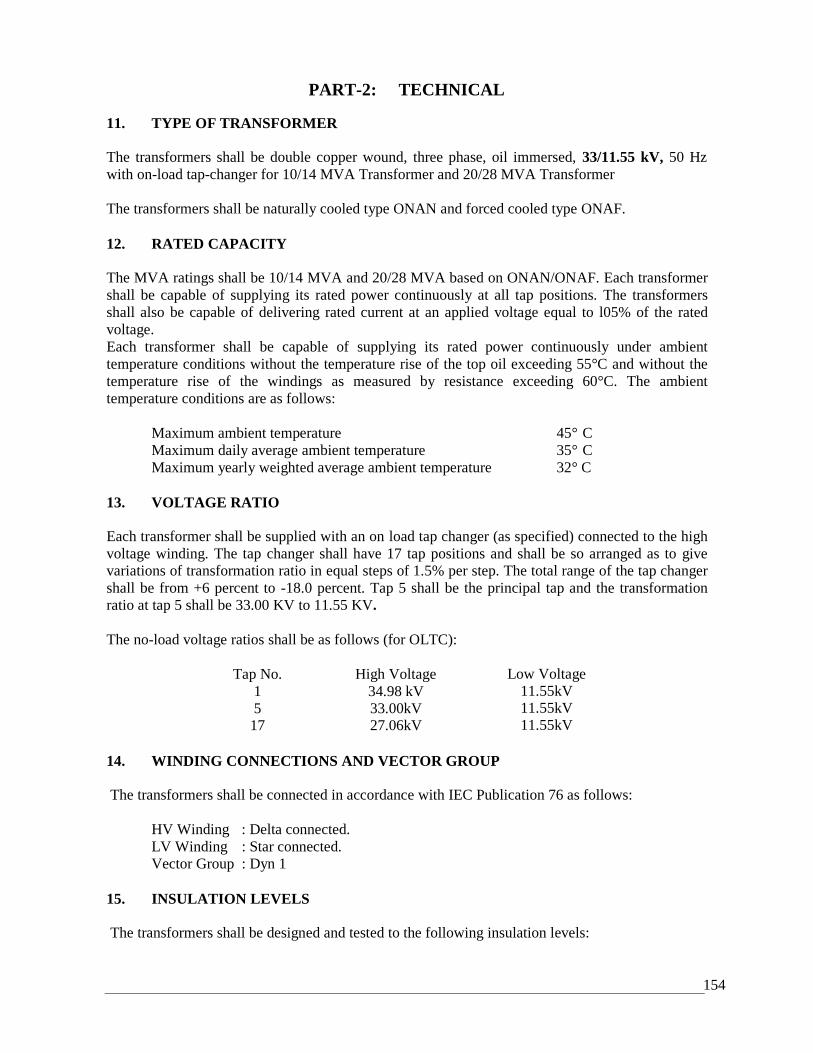
154
PART-2: TECHNICAL
11. TYPE OF TRANSFORMER
The transformers shall be double copper wound, three phase, oil immersed, 33/11.55 kV, 50 Hzwith on-load tap-changer for 10/14 MVA Transformer and 20/28 MVA Transformer
The transformers shall be naturally cooled type ONAN and forced cooled type ONAF.
12. RATED CAPACITY
The MVA ratings shall be 10/14 MVA and 20/28 MVA based on ONAN/ONAF. Each transformershall be capable of supplying its rated power continuously at all tap positions. The transformersshall also be capable of delivering rated current at an applied voltage equal to l05% of the ratedvoltage.Each transformer shall be capable of supplying its rated power continuously under ambienttemperature conditions without the temperature rise of the top oil exceeding 55°C and without thetemperature rise of the windings as measured by resistance exceeding 60°C. The ambienttemperature conditions are as follows:
Maximum ambient temperature 45° CMaximum daily average ambient temperature 35° CMaximum yearly weighted average ambient temperature 32° C
13. VOLTAGE RATIO
Each transformer shall be supplied with an on load tap changer (as specified) connected to the highvoltage winding. The tap changer shall have 17 tap positions and shall be so arranged as to givevariations of transformation ratio in equal steps of 1.5% per step. The total range of the tap changershall be from +6 percent to -18.0 percent. Tap 5 shall be the principal tap and the transformationratio at tap 5 shall be 33.00 KV to 11.55 KV.
The no-load voltage ratios shall be as follows (for OLTC):
Tap No. High Voltage1 34.98 kV5 33.00kV
17 27.06kV
Low Voltage11.55kV11.55kV11.55kV
14. WINDING CONNECTIONS AND VECTOR GROUP
The transformers shall be connected in accordance with IEC Publication 76 as follows:
HV Winding : Delta connected.LV Winding : Star connected.Vector Group : Dyn 1
15. INSULATION LEVELS
The transformers shall be designed and tested to the following insulation levels:
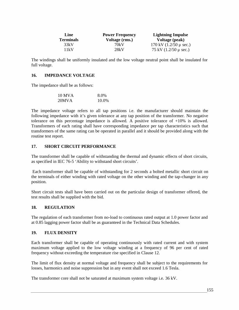
155
LineTerminals
33kV11kV
Power FrequencyVoltage (rms.)
70kV28kV
Lightning ImpulseVoltage (peak)
170 kV (1.2/50 μ sec.)75 kV (1.2/50 μ sec.)
The windings shall be uniformly insulated and the low voltage neutral point shall be insulated forfull voltage.
16. IMPEDANCE VOLTAGE
The impedance shall be as follows:
10 MVA 8.0%20MVA 10.0%
The impedance voltage refers to all tap positions i.e. the manufacturer should maintain thefollowing impedance with it’s given tolerance at any tap position of the transformer. No negativetolerance on this percentage impedance is allowed. A positive tolerance of +10% is allowed.Transformers of each rating shall have corresponding impedance per tap characteristics such thattransformers of the same rating can be operated in parallel and it should be provided along with theroutine test report.
17. SHORT CIRCUIT PERFORMANCE
The transformer shall be capable of withstanding the thermal and dynamic effects of short circuits,as specified in IEC 76-5 ‘Ability to withstand short circuits’.
Each transformer shall be capable of withstanding for 2 seconds a bolted metallic short circuit onthe terminals of either winding with rated voltage on the other winding and the tap-changer in anyposition.
Short circuit tests shall have been carried out on the particular design of transformer offered, thetest results shall be supplied with the bid.
18. REGULATION
The regulation of each transformer from no-load to continuous rated output at 1.0 power factor andat 0.85 lagging power factor shall be as guaranteed in the Technical Data Schedules.
19. FLUX DENSITY
Each transformer shall be capable of operating continuously with rated current and with systemmaximum voltage applied to the low voltage winding at a frequency of 96 per cent of ratedfrequency without exceeding the temperature rise specified in Clause 12.
The limit of flux density at normal voltage and frequency shall be subject to the requirements forlosses, harmonics and noise suppression but in any event shall not exceed 1.6 Tesla.
The transformer core shall not be saturated at maximum system voltage i.e. 36 kV.
156
20. HARMONIC CURRENTS
The transformers shall be designed with particular attention to the suppression of harmonicvoltages, especially the 3rd, 5th and 7th harmonics, so as to eliminate wave form distortion and thepossibility of high frequency disturbances, induction effect or of circulating current between neutralpoints at different transformer stations.
21. PARTIAL DISCHARGE
Each transformer shall be partial discharge free up to 120% of rated voltage as the voltage isreduced from 150% of rated voltage i.e. there shall be no significant rise above background level.
22. VOLTAGE CONTROL
22.1 General
Transformers shall be provided with tap changers for varying the effective transformation ratio.Control schemes shall utilize 110V ac centre tap earthed voltage derived from the LV 3-Phase, 4-Wire system. Phase failure relays shall be provided to ensure a secure supply. Winding taps ascalled for in the Technical Requirements and Guarantee Schedule shall be provided on the highvoltage winding.
All terminals shall be clearly and permanently marked with numbers corresponding to the cablesconnected thereto.
Tap positions shall be numbered consecutively, ranging from one upwards. The tap positions shallbe numbered so that by raising the tap position the LV voltage is increased
22.2 On-Load Tap Changers
22.2.1 General
On-load tap changers are according as per IEC 60214 and be from MaschinenfabrikReinhausen(MR) Germany or ABB Sweden and should be of the vacuum switchingtype in order to comply with existing equipment standards, including operationalexperience, spare parts, interchangeability, system reliability etc.. The On-Load TapChangers shall be Oil type.
Current making and breaking switches associated with the tap selectors or otherwisewhere combined with tap selectors shall be contained in a tank in which the head of oil ismaintained by means completely independent of that on the transformer itself. Details ofmaintaining oil separation, oil levels, and detection of oil surges and provision of alarmand trip contacts shall be dependent on the design of tap-changer and be to the approval ofthe Project Manager.
22.2.2 Mechanisms
The tap change mechanism shall be designed such that when a tap change has beeninitiated, it will be completed independently of the operation of the control relays andswitches. If a failure of the auxiliary supply during tap change or any other contingencywould result in that movement not being completed an approved means shall be providedto safeguard the transformer and its auxiliary equipment.
157
Limit switches shall be provided to prevent over-running of the tap changing mechanism.These shall be directly connected in the operating motor circuit. In addition, mechanicalstops shall be fitted to prevent over-running of the mechanism under any conditions. Foron-load tap change equipment these stops shall withstand the full torque of the drivingmechanism without damage to the tap change equipment.
Thermal devices or other approved means shall be provided to protect the motor andcontrol circuit.
A permanently legible lubrication chart shall be provided and fitted inside the tap changemechanism chamber.
22.2.3 Local and Remote Control
Equipment for local manual and electrical operation shall be provided in an indoor cubiclecomplying with Section-2. A thermostat controlled anti-condensation heater is to beprovided in the cubicle. Electrical remote control equipment shall also be supplied asspecified.
The following operating conditions are to apply to the on-load tap changer controls:-
a) It must not be possible to operate the electric drive when the manual operating gear isin use.
b) It must not be possible for two electric control points to be in operation at the sametime.
c) Operation from the local or remote control switch shall cause one tap movement only,unless the control switch is returned to the off position between successive operations.
d) It must not be possible for any transformer operating in parallel with one or moretransformers in a group to be more than one tap out of step with the other transformersin the group.
e) All electrical control switches and local manual operating gear shall be clearly labeledin an approved manner to indicate the direction of tap changing, i.e. raise and lowertap number.
f) Emergency stop push-button at local and remote control positions.
22.2.4 Indication
Apparatus of an approved type shall be provided on each transformer:
a) To give indication mechanically at the transformer and electrically at the remotecontrol point of the number of the tapping in use.
b) To give electrical indication, separate from that specified above, of tap position.c) To give indication at the remote control point that a tap change is in progress; this
indication to continue until the tap change is completed.d) To give indication at the remote control point when the transformers operating in
parallel are operation out of step.e) To indicate at the tap change mechanism the number of operations completed by the
equipment.
158
22.4 On Load Tap Changer (OLTC)
On Load Tap Changer (OLTC) shall be from ‘MR’ Germany or ABB Sweden which issuitable for control of transformers in parallel.
In addition to the methods of control included in this specification, the following methodsshall also be provided. This is for future addition of a similar transformer and associatedparallel operation.a) Automatic Independent – It shall be possible to select automatic independent control
for each transformer irrespective of the method of control selected for any other ofthe associated transformers.
b) Automatic parallel – It shall be possible to select any transformer for master orfollower control. It must not be possible to operate any tap changer by remote orlocal electrical manual control while the equipment is switched for automaticoperation.
22.4.1 Voltage Regulating Relays
Automatic voltage control shall be initiated by a voltage regulating relay of an approvedtype and suitable for flush mounting. The relay shall operate from the nominal referencevoltage stated in the Schedule of Requirements derived from a circuit mounted LVvoltage transformer having Class 1.0 accuracy to IEC 60186 and the relay voltagereference balance point shall be adjustable.
The relay bandwidth shall preferably be adjustable to any value between 1.5 times and 2.5times the transformer tap step percentage, the nominal setting being twice the transformertap step percentage.
The relay shall be insensitive to frequency variation between the limits of 47 Hz and 51Hz. The relay shall be complete with a time delay element adjustable between 10 and 120seconds. The relay shall also incorporate an under voltage blocking facility which rendersthe control inoperative if the reference voltage falls below 80 percent of the nominal valuewith automatic restoration of control when the reference voltage rises to 85 percent ofnominal value.
On each transformer the voltage transformer supply to the voltage regulating relay shallbe monitored for partial or complete failure. The specified indicating lamp and alarm willbe inoperative when the circuit- breaker controlling the lower voltage side of thetransformer is open and also that when the tap changer is on control other than automaticcontrol.
23. COOLING AND TEMPERATURE CONTROL
The banks of cooling radiators shall be detachable from the tank for transport and maintenance.Shut-off valves shall be provided on the tanks of the transformers for this purpose. An air-vent anddraining plug shall be provided on each radiator bank. All external surfaces of the radiators shall behot dip galvanized as specified in Sub-clause 13.2, Part 1 of this document. Temperature controlequipment shall be housed in a local control box mounted on the side of the transformer. A 150mmdiameter dial thermometer shall be provided to indicate the temperature of the top oil in thetransformer. This thermometer shall be fitted in such a way that it can easily be read from groundlevel through a window in the door of the control box. The thermometer shall be fitted with two
159
adjustable contacts, one connected to give an alarm and one to trip associated circuit breakers. Itshall also be fitted with a maximum temperature pointer which shall be re-settable by hand.
A similar dial thermometer shall be provided in the control box to indicate winding temperature.This thermometer shall have two sets of adjustable contacts one connected to give an alarm and theother to trip associated circuit breakers and a maximum temperature pointer which shall be re-settable by hand. The minimum range of these contacts shall be 50 C to 100 C for alarm and 60 Cto 120 C for trip. The temperature control box shall be weatherproofed to IP55 of IEC 529 or IS2147 equivalent.
23.1 Cooling Plant
23.1.1 General
Radiators and coolers shall be hot-dip galvanized, designed so that all painted surfacescan be thoroughly cleaned and easily painted in situ with brush or spray gun. The designshall also avoid pockets in which water can collect and shall be capable of withstandingthe pressure tests specified in the schedule of requirements for the transformer main tank.
The clearance between any oil or other pipe work and live parts shall be not less than theminimum clearances stated in the Employer’s Requirements.
23.1.2 Radiators connected directly to Tank
Where built-on radiators are used, each radiator shall be connected to the main tankthrough flanged valves. Plugs shall be fitted at the top of each radiator for air release andat the bottom for draining.
A valve shall be provided on the tank at each point of connection to the tank.
23.1.3 Cooler Banks
Each cooler bank shall be provided with:-
A) A valve at each point of connection to the tank.B) A valve at each point of connection of radiatorsC) Loose blanking plates for blanking off the main oil connections.D) A 50mm filter valve at the top of each cooler bank.E) A 50mm drain valve at the lowest point of each interconnecting oil pipe.F) A thermometer pocket, fitted with captive screw cap in the inlet and in the outlet oil pipes.G) Air release and drain plugs on each radiator.
The omission of any, or the provision of alternative, arrangements to the aboverequirements will not be accepted unless approved in writing by the Project Manager beforemanufacture.
23.1.4 Forced CoolingThe type of forced cooling shall be as stated in the Schedule of Requirements.Forced cooling equipment of transformers of similar rating and design shall becompletely interchangeable, one with the other, without modification on Site.
160
23.1.5 Oil Pipes and Flanges
All oil piping necessary for the connecting of each transformer to its conservator, coolerbanks etc. shall be supplied and erected under this Contract.
The oil piping shall be of approved material with machined flanged joints. Copper pipework is to comply with BS 61.
Dimensions of steel pipes shall be in accordance with BS 3600 and the drilling of all pipeflanges shall with BS 4504.
An approved expansion piece shall be provided in each oil pipe connection between thetransformer and each oil cooler bank.
All necessary pipe supports, foundation bolts and other attachments are to be provided.
It shall be possible to drain any section of pipe work independently of the rest and drainvalves or plugs shall be provided as necessary to meet this requirement.
23.1.6 Air Blowers
Air blowers for forced air-cooling shall be of approved make and design and be suitable forcontinuous operation out-of-doors. They shall also be capable of withstanding the stressesimposed when brought up to speed by the direct application of full line voltage to themotor.
To reduce noise to the practical minimum, motors shall be mounted independently from thecoolers, alternatively, an approved form of anti-vibration mounting shall be provided.
It shall be possible to remove the blower, complete with motor, without disturbing ordismantling the cooler structure framework.
Blades shall be of material subject to approval.
Blower casings shall be made or galvanized steel of thickness not less than 2.6 mm (14S.W.G.) and shall be suitably stiffened by angles or tees.
Galvanized wire guards with mesh not exceeding 12.5mm shall be provided to preventaccidental contact with the blades. Guards shall also be provided over all moving parts.Guards shall be designed such that blades and other moving parts cannot be touched by testfingers to IEC 529.
23.1.7 Cooler Control
Where forced cooling using multiple small single-phase motors is employed, the motors ineach cooling bank shall be grouped so as to form a balanced three-phase load.
Each motor or group of motors shall be provided with a three-pole electrically operatedContractor and with control gear of approved design for starting and stopping manually.
161
Where forced cooling is used on transformers, provision shall be included under thiscontract for automatic starting and stopping from contacts on the winding temperatureindicating devices as specified. The control equipment shall be provided with a short timedelay device to prevent the starting of more than one motor, or group of motors in the caseof multiple cooling, at a time.
Where motors are operated in groups, the group protection shall be arranged so that it willoperate satisfactorily in the event of a fault occurring in a single motor.
The control arrangements are to be designed to prevent the starting of motors totaling morethan15 KW simultaneously, either manually or automatically. Phase failure relays are to beprovided in the main cooler supply circuit.
All contacts and other parts which may require periodic renewal, adjustment or inspectionshall be readily accessible.
All wiring for the control gear accommodated in the marshalling kiosk, together with allnecessary cable boxes and terminations and all wiring between the marshalling kiosk andthe motors, shall be included in the contract .Each box shall have a hinged gasketed doorlockable by padlock. Solar gain can give rise to high temperature in a local control box.Adequate ventilation shall be provided to ensure that all equipment contained therein shalloperate satisfactorily under these conditions.
A terminal block with 10% spare terminals shall be provided in each temperature controlbox.
24. TANK AND ACCESSORIES
24.1 General
The transformer tank shall be skid mounted type. The transformer tank shall be designed so that thecomplete transformer with oil and excluding conservator and radiators can be lifted and transportedwithout permanent deformation or oil leakage. The tank and cover including the stiffeners shall bedesigned in such a manner as to leave no external pockets in which water can lodge, or internalpockets where gas/air can collect. All fittings shall be designed so as to prevent entry of air orleakage of oil from the tank. All pipes, shall be externally welded to the tank wall. The tank andcover shall be of structural quality, weld-able high tensile steel with a minimum thickness of 3mm.All welding shall be stress relieved. The requirement of post weld heat treatment of tank/ stressrelieving shall be based on recommendation of BS-5500.
The tank lid shall not be welded shut, but shall be secured by bolts and provided with suitable oil-tight gasket. The tank is to withstand vacuum up to 500mm of mercury for 5 MVA, 10 MVA and20 MVA transformers and any pressure of oil developed during operation conditions includingshort circuits.
24.2 Surface Treatment
The transformer tank and accessories shall be adequately protected against corrosion. The inside ofthe tank shall be painted with an approved oil resisting varnish. The outside of the tank shall bepainted as specified in Sub-clause 13.1, Part 1 of this document.
162
Conservator Tank:
A conservator tank shall be provided of adequate capacity between lowest and highest visible levelsto meet expansion of oil from 0 C to 100 C. A suitable oil level gauge shall be located on the tankso that it can be easily read from ground level. The gauge shall be graduated for temperatures of 0C, +45 C and +90 C.
Each gauge shall be provided with contacts for separate low oil level alarm and trip signals. Theconservator shall be fitted with a filling hole with cap and drain valve. It shall be inclined towardsthe drain valve. The pipe connecting the conservator to the main tank shall project 20mm above thebottom of the conservator for collection of impurities.
24.3 Breather
The conservator tank shall be fitted with a breather in which silica gel is the dehydrating agent fromany country of Europe, USA or Japan. The breather shall be a molded type transparent case ofadequate size and so designed that:
• the passage of air through the silica gel does not give rise to any excess pressure rise;• silica gel crystal of not less than 5mm. size is used;• the silica gel is sealed from the external atmosphere by means of an oil seal;• the moisture absorption indicated by a change in color of the crystals can be easily observed
from a distance;• the breather mounting height facilitates maintenance from ground level without switching out
the transformer.
24.4 Explosion Vent or Pressure Relief Device
An explosion vent or pressure relief device shall be provided to release any severe build-up ofpressure within the tank. The vent shall be designed such that in the event of an explosion, rain,sand or any other foreign bodies are prevented from getting into the tank. The vent shall bepositioned so as to direct the explosion safely into the oil pit.
24.5 Oil Sampling Devices
Oil sampling devices shall be fitted to the main tank. They shall be located suitably for easy accessespecially during maintenance, one near the bottom of the tank and one near the top.
24.6 Oil Filtration
Two 50mm bore filter valves shall be fitted to the tank, one on the top and the other diagonallyopposite on the bottom.
24.7 Lifting Lugs/Eyes
Lifting lugs shall be provided for supporting the weight of the transformer including core andwindings and fittings and with the tank filled with oil.
163
24.8 Jacking Pads
Four jacking pads shall be provided near the corners of the tank of each transformer andapproximately 400mm above the lowest part of the tank. These pads shall be designed to take thecomplete weight of the transformer filled with oil.
24.9 Hauling Eyes
Hauling eyes shall be provided on all sides of the transformer.
24.10 Earthing Terminals
Earthing terminals shall be provided on the transformer close to each of the four corners of the tankto facilitate easy earthing of the transformer on site.
24.11 Oil Valves
In addition to the valves already mentioned, a drain valve shall be provided near the bottom of thetank. All oil valves shall be provided with means for securing them in the open or closed position.
25. TERMINAL BUSHING AND CONNECTIONS
25.1 General
Transformers are to be provided with outdoor type bushing insulators and cable box on the LVside. HV and LV bushings shall be from Europe, USA or Japan origin.
All bushings shall comply with IEC 60137 and the minimum creepage distance for outdoorbushings shall not be less than 25mm per kV of rated voltage between phases. Outdoor bushinginsulators shall be provided with adjustable arcing horns and for rated voltages of 36 kV and lowerthese shall be of the duplex gap type.
Bushings shall be of sealed construction suitable for service under the very humid conditions at siteand, addition, for the very rapid cooling of equipment exposed to direct sunlight when this isfollowed by sudden heavy rainstorms.
Typical sections of bushing insulators showing the internal construction, method of securing the topcap and methods of sealing shall be included in the Bid.
Completely immersed bushings and lower voltage outdoor immersed bushings may be of other typeof construction, subject to the approval of the Project Manager but bushings of resin bonded paperconstruction are not permitted. The 33 kV bushings shall be porcelain (solid or condenser type). Onall condenser bushings a tapping shall be brought out to a separate terminal for testing purposes onSite.
Special precautions shall be taken to exclude moisture from any paper insulation duringmanufacture, assembly, transport and erection. Terminal arrangement of LV cable box position &neutral bushing position shall be as per approved drawings.
164
25.2 Porcelain
Hollow porcelain shall meet the test requirements of IEC 60233 and shall be sound, free fromdefects and thoroughly vitrified. Designs based on jointed porcelains will not be acceptable. Theglaze must not be depended upon for insulation. The glaze shall be smooth, hard, of a uniformshade of brown and shall cover completely all exposed parts of the insulator. Outdoor insulatorsand fittings shall be unaffected by atmospheric conditions producing weathering, acids, alkalis, dustand rapid changes in temperature that may be experienced under working conditions.
The porcelain must not engage directly with hard metal and, where necessary, gaskets shall beinterposed between the porcelain and the fittings. All porcelain clamping surfaces in contact withgaskets shall be accurately ground and free from glaze.
All fixing material used shall be of suitable quality and properly applied and must not enter intochemical action with the metal parts or cause fracture by expansion in service. Cement thicknessare to as small and even as possible and proper care is to be taken to center and locate theindividual parts correctly during cementing.All porcelain insulators shall be designed to facilitate cleaning.
25.3 Marking
Each porcelain insulator shall have marked upon it the manufacturer’s name or identification markand year of manufacture. These marks shall be clearly legible after assemble of fittings and shall beimprinted before firing, not impressed.
When a batch of insulators bearing a certain identification mark has been rejected, no furtherinsulators bearing this mark shall be submitted and the Contractor shall satisfy the Project Managerthat adequate steps will be taken to mark or segregate the insulators constituting the rejected batchin such a way that there can be no possibility of the insulators being re-submitted for the test orsupplied for the use of the Employer.
Each complete bushing shall be marked with the manufacturer’s name or identification mark, yearof manufacture, serial number, electrical and mechanical characteristics in accordance with IEC60137.25.4 Mounting of BushingsBushing insulators shall be mounted on the tank in a manner such that the external connections canbe taken away clear of all obstacles. Neutral bushings shall be mounted in a position from whichconnection can be taken to a neutral current transformer mounted on a bracket secured to thetransformer tank. The current transformer will be supplied by the switchgear manufacturer butprovision shall be made on the tank for mounting to theProject Manager’s requirements.
The clearances from phase to earth must not be less than those stated in the TechnicalRequirements and Guarantee Schedule.
A flexible pull-through lead suitably suited to the end of the winding copper shall be provided forthe bushings and is to be continuous to the connector which is housed in the helmet of the bushings.When bushings with an under-oil end of a re-entrant type are used the associated flexible pull-through lead is to be fitted with suitably designed gas bubble deflector. The bushing flanges mustnot be of re-entrant shape which may trap air.
Clamps and fittings made of steel or malleable iron shall be galvanized and all bolt threads are to begreased before erection.
165
25.5 Tests
Routine, sample and type tests of Bushing shall be carried out in accordance with the specifiedstandards. Type tests shall also be carried out unless approved type test evidence is submitted.These tests shall include temperature cycle and porosity tests.
The following standards shall apply:- IEC 60233(BS 4963) for hollow porcelains. IEC 60137 for bushings. IEC 60148 and 60273 (BS 3297) for high voltage post insulators. IEC 60383 and 60305 (BS 137 Part 1 and Part 2) for cap and pin string insulators.
26. CORE AND WINDINGS26.1 GeneralThe winding shall be of high-conductivity electrolytic copper and transposed winding conductorsshall be employed where applicable. Maximum current density for HV and LV windings shouldnot exceed 2.5 A/mm2.
The Windings shall have uniform insulation as defined in IEC 76. All neutral points shall begrounded.
The windings shall be located in a manner which will ensure that they remain electro- magneticallybalanced and that their magnetic centers remain coincident under all conditions of operation.
The windings shall also be thoroughly dried and shrunk by the application of axial pressure forsuch length of time as will ensure that further shrinkage will not occur in service.
The windings and leads of all transformers shall be braced to withstand the shocks which mayoccur through rough handling and vibration during transport, switching and other transient serviceconditions including external short circuit26.2 Core
The core shall be constructed from high grade, non-ageing, cold rolled grain oriented silicon steellaminations. The core and winding shall be capable of withstanding shocks during transport,installation and service. Provision shall be made to prevent movement of the core and windingsrelative to the tank during these conditions and also during short circuits.
The design shall avoid the presence of pockets which would prevent the complete emptying of thetank through the drain valve.
26.3 WindingsThe winding conductor shall be of electrolytic copper, free from burs and splinter. Paper shall beused for conductor insulation. The insulation shall be free from insulating compounds which areiliable to soften, ooze out, shrink or collapse. It shall be non catalytic and chemically inert intransformer oil during normal service.
The stacks of windings are to receive adequate shrinkage treatment.The windings and connections are to be braced to withstand shocks during transport, switching,short circuit or other transient conditions. The manufacturer must provide the thermal damagecurve or thermal damage description of the transformer winding or the transformer as per relevantIEC standard.
166
The winding shall be of electrolytic copper, free from burs and splinter. Paper shall be used forconductor insulation.
27. INTERNAL EARTHING
27.1 General
All metal parts of the transformer, with the exception of the individual core laminations, core boltsand associated individual clamping plates, shall be maintained fixed potential.
27.2 Earthing of Core clamping Structure
The top main core clamping structure shall be connected to the tank body by a copper strap. Thebottom main core clamping structure shall be earthed by one or more of the following methods:
a) by connection through vertical tie rods to the top structure;b) by direct metal-to-metal contact with the tank base maintained by the weight of the core and
windings;c) by connection to the top structure on the same side of the core as the main earth connection
to the tank.
27.3 Earthing of Magnetic Circuits
The magnetic circuit shall be earthed to the clamping structure at one point only through aremovable link placed in an accessible position just beneath an inspection opening in the tankcover and which, by disconnection, will enable the insulation between the core and clampingplates, etc., to be tested at voltages up to 2 kV. The link shall have no detachable components andthe connection to the link shall be on the same side of the core as the main earth connection. Theserequirements are compulsory.
All insulating barriers within magnetic circuits shall be bridged by means of aluminum or tinnedcopper strips, so inserted as to maintain electrical continuity.
27.4 Earthing of Coil Clamping Rings
Where coil clamping rings are of metal at earth potential, each ring shall be connected to theadjacent core clamping structure on the same side of the transformer as the main earth connection.27.5 Size of Earthing connections
Main earthing connections shall have a cross-sectional area of not less than 80 sq.mm butconnections inserted between laminations may have cross-sectional areas reduced to 20 sq. mmwhen in close thermal contact with the core.
28. TANKS AND ANCILLARY EQUIPMENT
28.1 Transformer Tanks
Each transformer shall be enclosed in a suitably stiffened weld-able high tensile steel tank suchthat the transformer can be lifted and transported without permanent deformation or oil leakage.The construction shall employ weld-able structural high tensile steel of an approved grade to BS
167
7613 and BS EN10029. The final coat colour of Transformers shall be to Munsell notation N5Y-7/l.
Lifting lugs shall be provided, suitable for the weight of the transformer, including core andwindings, fittings, and with the tank filled with oil. Each tank shall be provided with at least fourjacking lugs, and where required, with lugs suitably positioned for transport on a beam transporter.Haulage lugs should also be provided to enable a cable to be used safely for haulage in anydirection.
The transformer tank shall be capable of withstanding vacuum up to 500 mm of mercury withoutdefection exceeding the value stated in the Schedule of Requirements.
Where the design of the tank is such that the bottom plates will be in direct contact with the surfaceof the foundations. The base of each tank shall be so designed that it is possible to move thecomplete transformer unit in any direction without injury when using rollers, plates, or rails
All joints, other than those which may have to be broken, shall be welded.
The tank and cover shall be designed in such a manner as to leave no external pockets in whichwater can lodge, no internal pockets in which oil can remain when draining the tank or in which aircan be trapped when filling the tank, and to provide easy access to all external surfaces forpainting. Where cooling tubes are used, each tube shall be of heavy gauge steel welded into thetank sides, top and bottom.
Each tank cover shall be of adequate strength, must not distort when lifted and shall be providedwith suitable f1anges having sufficient and properly spaced bolts. Inspection openings shall beprovided to give access to the internal connections of bushings, winding connections and earthinglinks. Each opening shall be correctly located and must be of ample size for the purpose for whichit is intended. All inspection covers shall be provided with lifting handles.
It must be possible to remove any bushing without removing the tank cover.
Pockets shall be provided for a stem type them1ometer and for the bulbs of temperature indicatorswhere specified. These pockets shall be located in the position of maximum oil temperature and itmust be possible to remove any bulb without lowering the oil level in the tank. Captive screwedcaps shall be provided to prevent the ingress of water to the thermometer pockets when they arenot in use. Where called for in the Technical Requirements and Guarantee Schedule,accommodation shall be provided for outdoor weatherproof neutral current transformers.
168
A ladder shall be provided on one side of the tank as a means for inspection and access to the topof the transformer. The lower section of the ladder shall be equipped with a barrier complete withprovision for locking with a padlock.
28.2 Conservator Tanks, Breathers and Air Dryers
Each transformer shall be provided with an overhead conservator tank formed of substantial steelplates and arranged above the highest point of the oil circulating system. Connections into themain tank shall be at the highest point to prevent the trapping of air or gas under the main tankcover. A steel ladder shall be fixed between conservator top and the transformer top cover.
The capacity of each conservator tank shall be adequate for the expansion and contraction of oil inthe whole system under the specified operating conditions. Conservator tanks shall also beprovided with a cleaning door, filling cap, drain valve with captive cap and an oil level indicatorwith minimum and maximum levels indicated. The normal level at an oil temperature of 25°Cshallbe indicated and the minimum and maximum levels shall also be correlated with oil temperaturemarkings. The temperature markings shall preferably be integral with the level indicating device.The Oil level indicator shall be from MR. Germany or equivalent European class.
The location of the conservator tank shall be so arranged that it does not obstruct the passage ofhigh voltage conductors immediately above the transformer.
The pipe work between the conservator and the transformer tank shall comply with the standardrequirements and a valve shall be provided at the conservator to cut-off the oil supply to the tank.
Each conservator shall be fitted with an air cell which shall be connected to a silica gel breather ofa type which permits the silica gel content to be removed for drying. Due to the climatic conditionsat site, this breather shall be larger than would be fitted for use in a temperate climate. Allbreathers shall be mounted at a height of approximately 1400 mm above ground level. The silicagel container shall be fully transparent.
28.3 Valves
Each transformer shall be fitted with the following valves as a minimum requirement:
28.3.1 Main Tank
a) One 50mm bore filter valve located near to the top of the tank.
b) One 50 mm bore filter valve located near to the bottom of the tank and diagonallyopposite to the filter valve required against(A).Where design permits, this valve may becombined with item (C).
c) One 50mm drain valve with such arrangements as may be necessary inside the tank toensure that the tank can be completely drained of oil as far as practicable. This valveshall also be provided with an approved oil sampling device.
d) One valve between the main tank and gas actuated relay, complete with bypass facilityto facilitate removal of relay and maintain oil flow.
169
28.3.2 Conservator
a) One valve between the conservator and gas actuated relay for the main tank and whereappropriate, for the tap change diverter switch tank complete with by pass forBuchholzrelay to facilitate maintenance of the relay.
b) One drain valve for oil conservator tank so arranged that the tank can be completelydrained of all oil.
28.3.3 Radiators and Cooler Banksa) Valves at each point of connection to the tank.
The two valves 28.3.1 (d) and 28.3.2 (a) arrangement across the gas actuated relay are to beconnected with an oil pipe work bypass facility to facilitate removal of the relay, due tofailure etc, and still maintain the oil flow system between the conservator and main tank.Blank flanges, plates or captive screw caps shall be fitted to all valves and pipe ends notnormally connected in service.
The omission of any, or the provision of alternative arrangements to the aboverequirements, will not be accepted unless approved in writing by the Project Managerbefore manufacture.
28.4 Joints and Gaskets
All joint faces shall be arranged to prevent the ingress of water or leakage of oil with a minimumof gasket surface exposed to the action of oil or air.
Oil resisting synthetic rubber gaskets are not permissible except where the synthetic rubber is usedas a bonding medium for cork, or where metal inse1ts are provided to limit compression.
Gaskets shall have sufficient thickness consistent with the provision of a good seal and full detailsof all gasket sealing arrangements shall be shown on the Plant drawings.All gaskets shall be closed design (without open ends) and shall be one piece only. Exteriorgaskets shall be weatherproof and shall not be affected by strong sunlight. Care shall be taken tosecure uniformly distributed mechanical strength over the gaskets and retains throughout the totallength. No gaskets shall be used in which the material of the gasket is mounted on a textilebacking. Gaskets of neoprene or any kind of impregnated/ bonded core or cork only which caneasily damage by over pressing is not acceptable. Use of hemp as gasket material is also notacceptable.
28.5 Pressure Relief deviceAn approved pressure relief device of sufficient size for the rapid release of over pressure that maybe generated in the tank, and designed to operate at a static pressure lower than the hydraulic testpressure, shall be provided. It shall be of the spring operated valve type and shall be provided withone set of normally open signaling contacts which will be used for trip alarm purposes. Thepressure relief device shall be from 'MR' or equivalent European made.
The relief device is to be mounted on the tank cover and is to be provided with a skirt to projectat least 25 mm in to the tank to prevent gas accumulation. Discharge of oil shall be directed awayfrom the transformer top cover and clear of any operating position.
170
28.6 Earthing Terminals
Two substantial steel flag type terminals having two 14mm diameter holes on 55mmcenters shall be located one on either side and near to the bottom of the transformer tofacilitate connection to the local earthing system.
28.7 Rating, Diagram and Valve Plates
The following plates, or an approved combined plate, shall be fixed to each transformertank at an average height of 1500 mm above the ground level:
a) A rating plate bearing the data specified in IEC 76 Part 1. This plate shall also includethe short-circuit current rating and time-factor for each winding.
b) A Diagram plate showing in an approved manner the internal connections and thevoltage vector relationship of the several windings, in accordance with IEC 76 Part1with the transformer voltage ratio for each tap and, in addition a plan view of thetransformer giving the correct physical relationship of the terminals.
c) A plate showing the location and function of all valves and air release cocks or plugs.This plate shall also if necessary warn operators to refer to the Maintenance Instructionsbefore applying vacuum.
Plates are to be of stainless steel or other approved material capable of withstanding therigorous of continuous outdoor service at site.
29. STATION AUXILIARY TRANSFORMER:
The Contractor shall supply Station Auxiliary transformer with 10 MVA & 20 MVA OLTCTransformer.Auxiliary transformers shall be hermetically sealed two-winding, conservator type, three-phase, oilimmersed, ONAN, with Off Load Tap Changing, suitable for outdoor use.
The station auxiliary transformers shall be 33/0.415 kV and have a maximum continuous rating of100 kVA, shall be capable of supplying the maximum continuous rating for all tap positions andmaintaining rated voltage on the low voltage winding, under the maximum ambient temperatureconditions, without the temperature rise of the top oil exceeding 50°C or the temperature rise of thewindings as measured by resistance exceeding 55°C.
Transformers shall be in accordance with the relevant IEC standard and this specification. Refer tothe Schedule of Technical Particulars and Guarantees for other relevant requirements.
Off-load tap-changing shall be carried out by means of an external hand-operated tapping switchmounted on the side of the tank. All phases of the tapping switch must be operated by one handwheel.
The tapping switch shall have a spring-loaded captive bolt or other approved means on the movingpart which positively locates the switch correctly at each tapping position. This bolt must be
171
lockable at each tapping position and shall be provided with a suitable padlock and keys. Movingthe switch from one tapping position to another shall require that the bolt be withdrawn by handfrom its locating socket on the transformer tank against the spring pressure.
Tap-position numbers corresponding to the tapping switch bolt-locating sockets shall be cast orengraved in a metal indication plate fixed to the tank and a keyed metal pointer on the tappingswitch operating handle shall show clearly at which tapping number the transformer is operating.
All tap-position indicators shall be marked with one integer for each tap position, beginning atnumber 1. Adjacent taps shall be numbered consecutively in such a manner that when moving a tapto a new tapping position which has a higher number, the no-load output voltage of the untappedwinding increases.
29.1 Technical RequirementsTransformers shall be provided with the following fittings: Off-load tap changer. Oil filler plug and drain valve. Thermometer. Pressure release device. Four lifting lugs. Air insulated terminals for 33kV and 0.4 kV connections using adequately sized
conductor. Galvanised tank, conservator and radiators.
30. CABLE TERMINATIONS AND GLANDS30.1 Cable BoxesThe transformers may have cable boxes with all necessary fittings and attachments as per approvalof Drawings (submitted by the bidder) by the proper authority of BREB. Cable boxes shall be ofadequate proportions and designed in accordance with BS 6435 in such the manner that they can beopened for inspection without disturbing the gland plate or incoming cable(s).Cable boxes shall bedesigned for ease of access for jointing and connecting the cable. They shall be constructed tominimize the danger of fragmentation; cast iron boxes shall not be used. The cable box shall be ofsuch a design as to prevent ingress of moisture. Where blind tapped holes have to be provided,studs shall be used and not bolts or set screws.
All gaskets, unless otherwise approved, shall be in one continuous piece without joints. Gasketsshall not be compressed before use. Provision shall be made for earthing the body of each cablebox. Removable blank gland plates and suitable type and size of cable glands shall be supplied andfitted for termination of the cables.Dehydrating breather and draining holes protected by 1 mm aperture mesh shall be incorporated atthe base of the box to avoid moisture condensation within cable box and ensure drainage ofcondensation respectively. Cable boxes shall be provided with suitable means for clamping thearmor wires of the cables.
Gland plates for single core cable shall be made from non-ferrous metal. The Contractor shallguarantee (test certificate shall be supplied to prove) that the air clearances and the creep age pathon the bushing connecting to the associated switchgear or transformers shall be such that thecompleted installation shall withstand in air the impulse and power frequency voltages appropriateto the plant.The cable box clearances would meet the requirements for BS 6435 for partially insulated cableboxes. An earthing terminal shall be provided in each sealing end chamber to which theconnections from the transformer winding can be earthed during cable testing. Cable boxes shall be
172
provided on 33kV/11kV sides suitable for air insulations terminations of XLPE Copper Conductorcables of minimum sizes as mentioned below:
31. TEMPERATURE AND ALARM DEVICES
31.1 Temperature Indicating Devices and Alarms
The transformers shall be provided with approved devices of Kilhstrom for indicating the top oiltemperature and hottest spot winding temperatures. The devices shall have a dial type indicatorand, in addition, a pointer to register the highest temperature reached. Each winding temperaturedevice shall have four separate contacts fitted, two of which shall be used to control the two groupsof cooling plant motors (i.e. AF1 and AF2), one to give an alarm and one to trip the associatedcircuit breakers. The Temperature indicating device shall be from MR Germany or equivalentEuropean class.
To simulate indication of the hottest spot temperature of the winding the device shall comprise acurrent transformer associated with one phase only and a heating device designed to operatecontinuously at 130 percent of transformer CMR current and for30 minutes at 150 percent of CMRcurrent, associated with a sensing bulb installed in an oil tight pocket in the transformer top oil.
The winding temperature indicators (WTI) shall be housed in the marshalling cubicle. The trippingcontacts of the winding temperature indicators shall be adjustable to close between 80°Cand 150°Cand to re-open when the temperature has fallen by not more than 10°C.
The alarm contacts and the contacts used to control the cooling plant motors on the above devicesshall be adjustable to close between 50° C and 100° C and to re-open when the temperature hasfallen by a desired amount between 10° C and l5° C.
All contacts shall be adjustable to a scale and must be accessible on removal of the relay cover.Alarm and trip circuit contacts shall be suitable for making or breaking 150 VA between the limitsor 30 volts and 250 volts AC or DC and of making 500 VA between the limits of 110 and250VDC. Cooler motor control contacts shall be suitable for operating the cooler Contractors direct or,if necessary, through an interposing relay.The temperature indicators in the marshalling kiosk shall be so designed that it is possible to movethe pointers by hand for the purpose of checking the operation of the contacts and associatedequipment. The working parts of the instrument shall be made visible by the provision of cut-awaydials and glass-fronted covers and all setting and error adjustment devices shall be easilyaccessible.
Connections shall be brought from the device to terminal boards placed inside the marshallingcubicle.Terminals, links and a 63mm moving iron ammeter shall be provided in the marshalling kiosk foreach WTI for:a) Checking the output of the current transformer.b) Testing the current transformer and thermal image characteristics.c) Disconnecting the bulb heaters from the current transformer secondary circuit to enable the
instrument to be used as an oil temperature indicator. Links shall be provided as shown onthe drawing enclosed with the offer.
173
31.2 Gas and Oil-Actuated Relays (Buchholz Relays)
Each transformer shall be fitted with gas and oil-actuated relay equipment having alarm contactswhich close on collection of gas or low oil level, and tripping contacts which close following oilsurge conditions. The Relay shall be from MR, Germany or equivalent European class.
Each gas and oil-actuated relay shall be provided with a test cock to take a flexible pipe connectionfor checking the operation of the relay by inserting air in the relay. The floats of the Buchholz shallbe solid body. Each relay shall be fitted with UV protective covered glass window for indication ofgas volume.
To allow gas to be collected at ground level, a small bore pipe shall be connected to the gas releasecock of the gas and oil-actuated relay and brought down to appoint approximately1400 mm aboveground level, where it shall be terminated by a cock which shall have provision for locking toprevent unauthorized operation.
The design of the relay mounting arrangements, the associated pipe work and the cooling plantshall be such that multi operation of the relay will not take place under normal service conditions,including starting or stopping of oil circulating pumps, whether by manual or automatic controlunder all operating temperatures.
The pipe work shall be so arranged that all gas arising from the transformer will pass into the gasand oil-actuated relay. The oil circuit through the relay must not form a delivery path in parallelwith any circulating oil pipe, nor is it to be fed into or connected through the pressure relief vent.Sharp bends in the pipe work shall be avoided.
When a transformer is provided with two conservators, the gas and oil-actuated relays shall bearranged as follows:
a) If the two conservators are connected to the transformer by a common oil pipe, one relayshall be installed in the common pipe.
b) If the two conservators are piped separately to the transformer, two relays shall be installed,one in each pipe connection.
The clearance between oil pipe work and live metal shall be not less than the minimum clearancesstated in the schedule of requirement.
32. TRANSFORMER OILInsulating oil shall comply with the requirements of IEC 60296. Insulating oil shall be provided bythe Contractor for all oil-filled apparatus and 10% excess shall be provided for topping up purposesin sealed drums. The Contractor shall satisfy himself that suitable oil treatment facilities areavailable at Site for his use. If the Contractor is unable to obtain written assurances to this effect heshall provide such oil treatment facilities as required to meet the specification, at no additional cost.
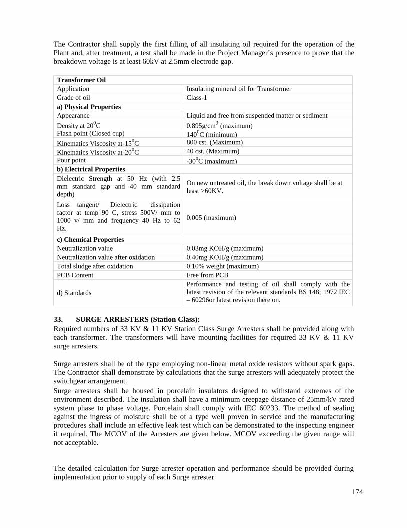
174
The Contractor shall supply the first filling of all insulating oil required for the operation of thePlant and, after treatment, a test shall be made in the Project Manager’s presence to prove that thebreakdown voltage is at least 60kV at 2.5mm electrode gap.
Transformer OilApplication Insulating mineral oil for TransformerGrade of oil Class-1a) Physical PropertiesAppearance Liquid and free from suspended matter or sediment
Density at 200C 0.895g/cm3 (maximum)Flash point (Closed cup) 1400C (minimum)Kinematics Viscosity at-150C 800 cst. (Maximum)
Kinematics Viscosity at-200C 40 cst. (Maximum)Pour point -300C (maximum)b) Electrical PropertiesDielectric Strength at 50 Hz (with 2.5mm standard gap and 40 mm standarddepth)
On new untreated oil, the break down voltage shall be atleast >60KV.
Loss tangent/ Dielectric dissipationfactor at temp 90 C, stress 500V/ mm to1000 v/ mm and frequency 40 Hz to 62Hz.
0.005 (maximum)
c) Chemical PropertiesNeutralization value 0.03mg KOH/g (maximum)Neutralization value after oxidation 0.40mg KOH/g (maximum)Total sludge after oxidation 0.10% weight (maximum)PCB Content Free from PCB
d) StandardsPerformance and testing of oil shall comply with thelatest revision of the relevant standards BS 148; 1972 IEC– 60296or latest revision there on.
33. SURGE ARRESTERS (Station Class):Required numbers of 33 KV & 11 KV Station Class Surge Arresters shall be provided along witheach transformer. The transformers will have mounting facilities for required 33 KV & 11 KVsurge arresters.
Surge arresters shall be of the type employing non-linear metal oxide resistors without spark gaps.The Contractor shall demonstrate by calculations that the surge arresters will adequately protect theswitchgear arrangement.Surge arresters shall be housed in porcelain insulators designed to withstand extremes of theenvironment described. The insulation shall have a minimum creepage distance of 25mm/kV ratedsystem phase to phase voltage. Porcelain shall comply with IEC 60233. The method of sealingagainst the ingress of moisture shall be of a type well proven in service and the manufacturingprocedures shall include an effective leak test which can be demonstrated to the inspecting engineerif required. The MCOV of the Arresters are given below. MCOV exceeding the given range willnot acceptable.
The detailed calculation for Surge arrester operation and performance should be provided duringimplementation prior to supply of each Surge arrester
175
Arrester according to Voltage class MCOV range (KV)
10 KV 7.65 kV – 9.56 kV30 KV 22 kV– 27.5 kV
Good electrical contact shall be maintained between resistor blocks taking account of any thermalexpansion and contraction of the block or mechanical shock during transport and erection, byinstalling a well proven clamping system.
Metal oxide arresters installed outdoors shall be able to dissipate, when new, twice the energygenerated in the resistor blocks when energized at their maximum continuous operating voltageimmediately having been subjected to the discharge duties specified in IEC 60099-4 and assumingthat the porcelain housing and the surrounding air is at least 5 degree centigrade higher than themaximum ambient air temperature specified.
All surge arresters shall be fitted with a pressure relief diaphragm which shall prevent explosiveshattering of the porcelain housing in the event of an arrester failure and the arrester shall have beentested according to the high and low current tests specified in IEC 60099-1. Arresters shall besupplied complete for installation in an outdoor switchyard, including insulating bases and surgecounters, one per phase, and, if applicable, grading rings. The material used for terminals shall becompatible with that of the conductors to which they are to be connected.Each arrester shall be identified by a rating plate in accordance with the requirements of IEC60099-4. In addition an identification mark shall be permanently inscribed on each separatelyhoused unit of a multi-unit arrester so that units can be replaced in the correct position in the eventof them being dismantled.
Each surge arrester should have surge counter. The Surge counters shall have an internal assemblywhich is matched to the line discharge capability of the arrester and shall include a leakage currentmeter with a bi-linear scale for ease of reading. Auxiliary contacts are to be provided to signalremote indication of counter operation. The manufacturer should declare the maximum countnumber/ life of each surge arrester.
Surge arrester shall have suitable earth terminal to connect surge counter with insulated cable.
33.1 TestsRoutine tests and type tests shall be carried out to the specified standards. Bidder shall submit typeand routine tests reports of surge arresters along with bid proposal.
The following routine tests shall be carried out on all arrester units in accordance with clause 8.1 ofIEC 60099-4.
Measurement of reference voltage Residual voltage testPartial discharge testHousing leakage test Current distribution test for multi-column arreste
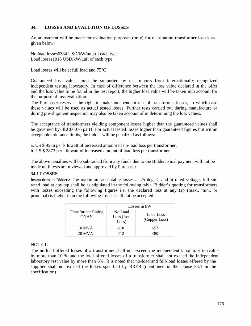
176
34. LOSSES AND EVALUTION OF LOSSES
An adjustment will be made for evaluation purposes (only) for distribution transformer losses asgiven below:
No load losses6384 USD/kW/unit of each typeLoad losses1915 USD/kW/unit of each type
Load losses will be at full load and 75C
Guaranteed loss values must be supported by test reports from internationally recognizedindependent testing laboratory. In case of difference between the loss value declared in the offerand the loss value to be found in the test report, the higher loss value will be taken into account forthe purpose of loss evaluation.The Purchaser reserves the right to make independent test of transformer losses, in which casethese values will be used as actual tested losses. Further tests carried out during manufacture orduring pre-shipment inspection may also be taken account of in determining the loss values.
The acceptance of transformers yielding component losses higher than the guaranteed values shallbe governed by- IEC60076 part1. For actual tested losses higher than guaranteed figures but withinacceptable tolerance limits, the bidder will be penalized as follows:
a. US $ 9576 per kilowatt of increased amount of no-load loss per transformer.b. US $ 2873 per kilowatt of increased amount of load loss per transformer.
The above penalties will be subtracted from any funds due to the Bidder. Final payment will not bemade until tests are reviewed and approved by Purchaser.
34.1 LOSSESInstructions to Bidders: The maximum acceptable losses at 75 deg. C and at rated voltage, full siterated load at any tap shall be as stipulated in the following table. Bidder’s quoting for transformerswith losses exceeding the following figures i.e. the declared loss at any tap (max., min., orprincipal) is higher than the following losses shall not be accepted.
Transformer RatingONAN
Losses in kWNo Load
Loss (IronLoss)
Load Loss(Copper Loss)
10 MVA ≤10 ≤5720 MVA ≤12 ≤80
NOTE 1:The no-load offered losses of a transformer shall not exceed the independent laboratory testvalueby more than 10 % and the total offered losses of a transformer shall not exceed the independentlaboratory test value by more than 6%. It is noted that no-load and full-load losses offered by thesupplier shall not exceed the losses specified by BREB (mentioned in the clause 34.1 in thespecification).
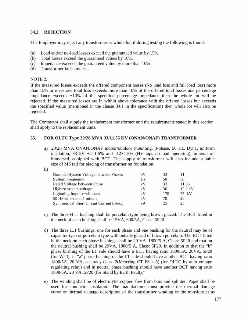
177
34.2 REJECTION
The Employer may reject any transformer or whole lot, if during testing the following is found:
(a) Load and/or no-load losses exceed the guaranteed value by 15%.(b) Total losses exceed the guaranteed values by 10%.(c) Impedance exceeds the guaranteed value by more than 10%.(d) Transformer fails any test.
NOTE 2:If the measured losses exceeds the offered component losses (No load loss and full load loss) morethan 15% or measured total loss exceeds more than 10% of the offered total losses and percentageimpedance exceeds +10% of the specified percentage impedance then the whole lot will berejected. If the measured losses are in within above tolerance with the offered losses but exceedsthe specified value (mentioned in the clause 34.1 in the specification) then whole lot will also berejected.
The Contractor shall supply the replacement transformer and the requirements stated in this sectionshall apply to the replacement units.
35. FOR OLTC Type 20/28 MVA 33/11.55 KV (ONAN/ONAF) TRANSFORMER
a) 20/28 MVA ONAN/ONAF indoor/outdoor mounting, 3-phase, 50 Hz, Dyn1, uniforminsulation, 33 kV +4×1.5% and -12×1.5% (HV taps on-load operating), mineral oilimmersed, equipped with BCT. The supply of transformer will also include suitablesize of MS rail for placing of transformer on foundation.
b)Nominal System Voltage between Phases kV 33 11System Frequency Hz 50 50Rated Voltage between Phase kV 33 11.55Highest system voltage kV 36 12.2 kVLightning Impulse withstand kV 170 75 kV50 Hz withstand, 1 minute kV 70 28Symmetrical Short Circuit Current (3sec.) kA 25 25
c) The three H.T. bushing shall be porcelain type being brown glazed. The BCT fitted inthe neck of each bushing shall be 15VA, 600/5A, Class: 5P20
d) The three L.T bushings, one for each phase and one bushing for the neutral may be ofcapacitor type or porcelain type with outside glazed of brown porcelain. The BCT fittedin the neck on each phase bushings shall be 20 VA. 1800/5 A, Class: 5P20 and that onthe neutral bushing shall be 20VA, 1800/5 A, Class: 5P20. In addition to that the ''b"phase bushing of the LT side should have a BCT having ratio 1800/5A, 20VA, 5P20(for WTI), in "a'' phase bushing of the LT side should have another BCT having ratio1800/5A. 20 VA, accuracy class .2(Metering CT FS < 5) (for OLTC by auto voltageregulating relay) and in neutral phase bushing should have another BCT having ratio1800/5A, 20 VA, 5P20 (for Stand by Earth Fault)."
e) The winding shall be of electrolytic copper, free from burs and splinter. Paper shall beused for conductor insulation. The manufacturer must provide the thermal damagecurve or thermal damage description of the transformer winding or the transformer as
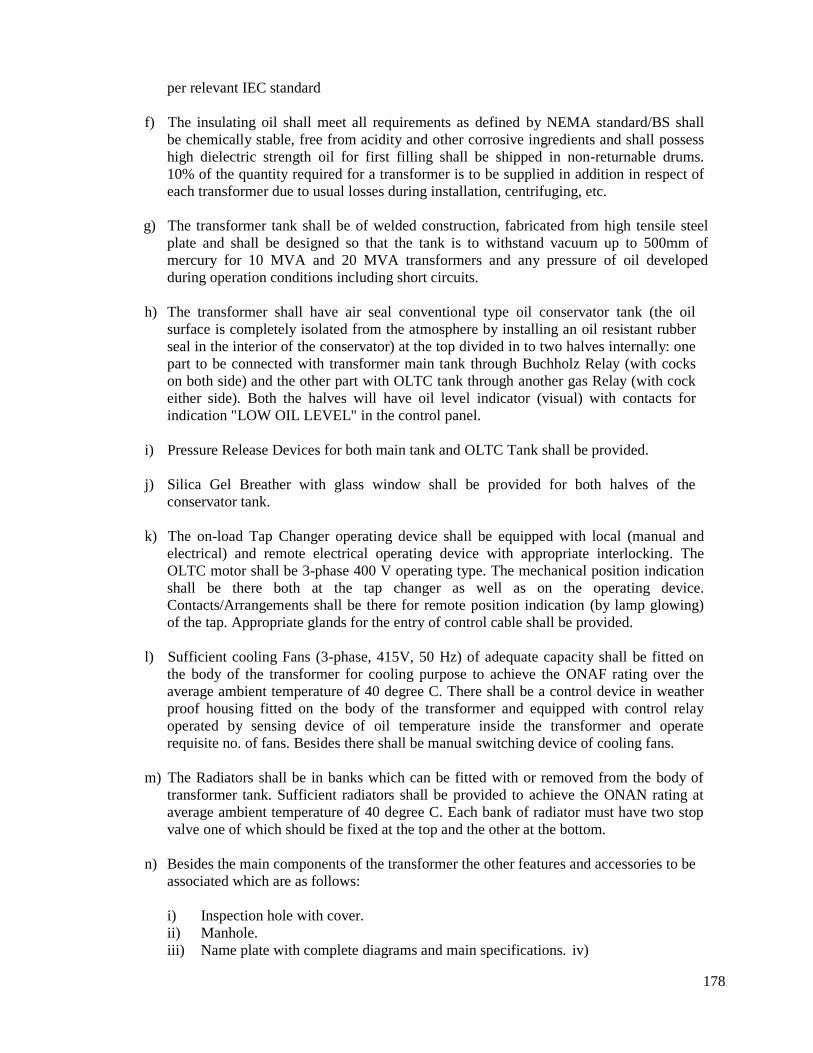
178
per relevant IEC standard
f) The insulating oil shall meet all requirements as defined by NEMA standard/BS shallbe chemically stable, free from acidity and other corrosive ingredients and shall possesshigh dielectric strength oil for first filling shall be shipped in non-returnable drums.10% of the quantity required for a transformer is to be supplied in addition in respect ofeach transformer due to usual losses during installation, centrifuging, etc.
g) The transformer tank shall be of welded construction, fabricated from high tensile steelplate and shall be designed so that the tank is to withstand vacuum up to 500mm ofmercury for 10 MVA and 20 MVA transformers and any pressure of oil developedduring operation conditions including short circuits.
h) The transformer shall have air seal conventional type oil conservator tank (the oilsurface is completely isolated from the atmosphere by installing an oil resistant rubberseal in the interior of the conservator) at the top divided in to two halves internally: onepart to be connected with transformer main tank through Buchholz Relay (with cockson both side) and the other part with OLTC tank through another gas Relay (with cockeither side). Both the halves will have oil level indicator (visual) with contacts forindication "LOW OIL LEVEL" in the control panel.
i) Pressure Release Devices for both main tank and OLTC Tank shall be provided.
j) Silica Gel Breather with glass window shall be provided for both halves of theconservator tank.
k) The on-load Tap Changer operating device shall be equipped with local (manual andelectrical) and remote electrical operating device with appropriate interlocking. TheOLTC motor shall be 3-phase 400 V operating type. The mechanical position indicationshall be there both at the tap changer as well as on the operating device.Contacts/Arrangements shall be there for remote position indication (by lamp glowing)of the tap. Appropriate glands for the entry of control cable shall be provided.
l) Sufficient cooling Fans (3-phase, 415V, 50 Hz) of adequate capacity shall be fitted onthe body of the transformer for cooling purpose to achieve the ONAF rating over theaverage ambient temperature of 40 degree C. There shall be a control device in weatherproof housing fitted on the body of the transformer and equipped with control relayoperated by sensing device of oil temperature inside the transformer and operaterequisite no. of fans. Besides there shall be manual switching device of cooling fans.
m) The Radiators shall be in banks which can be fitted with or removed from the body oftransformer tank. Sufficient radiators shall be provided to achieve the ONAN rating ataverage ambient temperature of 40 degree C. Each bank of radiator must have two stopvalve one of which should be fixed at the top and the other at the bottom.
n) Besides the main components of the transformer the other features and accessories to beassociated which are as follows:
i) Inspection hole with cover.ii) Manhole.iii) Name plate with complete diagrams and main specifications. iv)
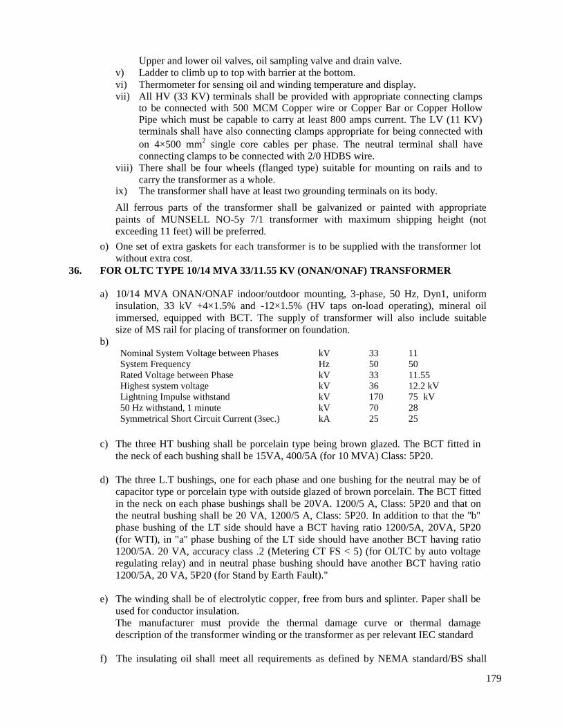
179
Upper and lower oil valves, oil sampling valve and drain valve.v) Ladder to climb up to top with barrier at the bottom.vi) Thermometer for sensing oil and winding temperature and display.vii) All HV (33 KV) terminals shall be provided with appropriate connecting clamps
to be connected with 500 MCM Copper wire or Copper Bar or Copper HollowPipe which must be capable to carry at least 800 amps current. The LV (11 KV)terminals shall have also connecting clamps appropriate for being connected withon 4×500 mm2 single core cables per phase. The neutral terminal shall haveconnecting clamps to be connected with 2/0 HDBS wire.
viii) There shall be four wheels (flanged type) suitable for mounting on rails and tocarry the transformer as a whole.
ix) The transformer shall have at least two grounding terminals on its body.
All ferrous parts of the transformer shall be galvanized or painted with appropriatepaints of MUNSELL NO-5y 7/1 transformer with maximum shipping height (notexceeding 11 feet) will be preferred.
o) One set of extra gaskets for each transformer is to be supplied with the transformer lotwithout extra cost.
36. FOR OLTC TYPE 10/14 MVA 33/11.55 KV (ONAN/ONAF) TRANSFORMER
a) 10/14 MVA ONAN/ONAF indoor/outdoor mounting, 3-phase, 50 Hz, Dyn1, uniforminsulation, 33 kV +4×1.5% and -12×1.5% (HV taps on-load operating), mineral oilimmersed, equipped with BCT. The supply of transformer will also include suitablesize of MS rail for placing of transformer on foundation.
b)Nominal System Voltage between Phases kV 33 11System Frequency Hz 50 50Rated Voltage between Phase kV 33 11.55Highest system voltage kV 36 12.2 kVLightning Impulse withstand kV 170 75 kV50 Hz withstand, 1 minute kV 70 28Symmetrical Short Circuit Current (3sec.) kA 25 25
c) The three HT bushing shall be porcelain type being brown glazed. The BCT fitted inthe neck of each bushing shall be 15VA, 400/5A (for 10 MVA) Class: 5P20.
d) The three L.T bushings, one for each phase and one bushing for the neutral may be ofcapacitor type or porcelain type with outside glazed of brown porcelain. The BCT fittedin the neck on each phase bushings shall be 20VA. 1200/5 A, Class: 5P20 and that onthe neutral bushing shall be 20 VA, 1200/5 A, Class: 5P20. In addition to that the ''b"phase bushing of the LT side should have a BCT having ratio 1200/5A, 20VA, 5P20(for WTI), in "a'' phase bushing of the LT side should have another BCT having ratio1200/5A. 20 VA, accuracy class .2 (Metering CT FS < 5) (for OLTC by auto voltageregulating relay) and in neutral phase bushing should have another BCT having ratio1200/5A, 20 VA, 5P20 (for Stand by Earth Fault)."
e) The winding shall be of electrolytic copper, free from burs and splinter. Paper shall beused for conductor insulation.The manufacturer must provide the thermal damage curve or thermal damagedescription of the transformer winding or the transformer as per relevant IEC standard
f) The insulating oil shall meet all requirements as defined by NEMA standard/BS shall
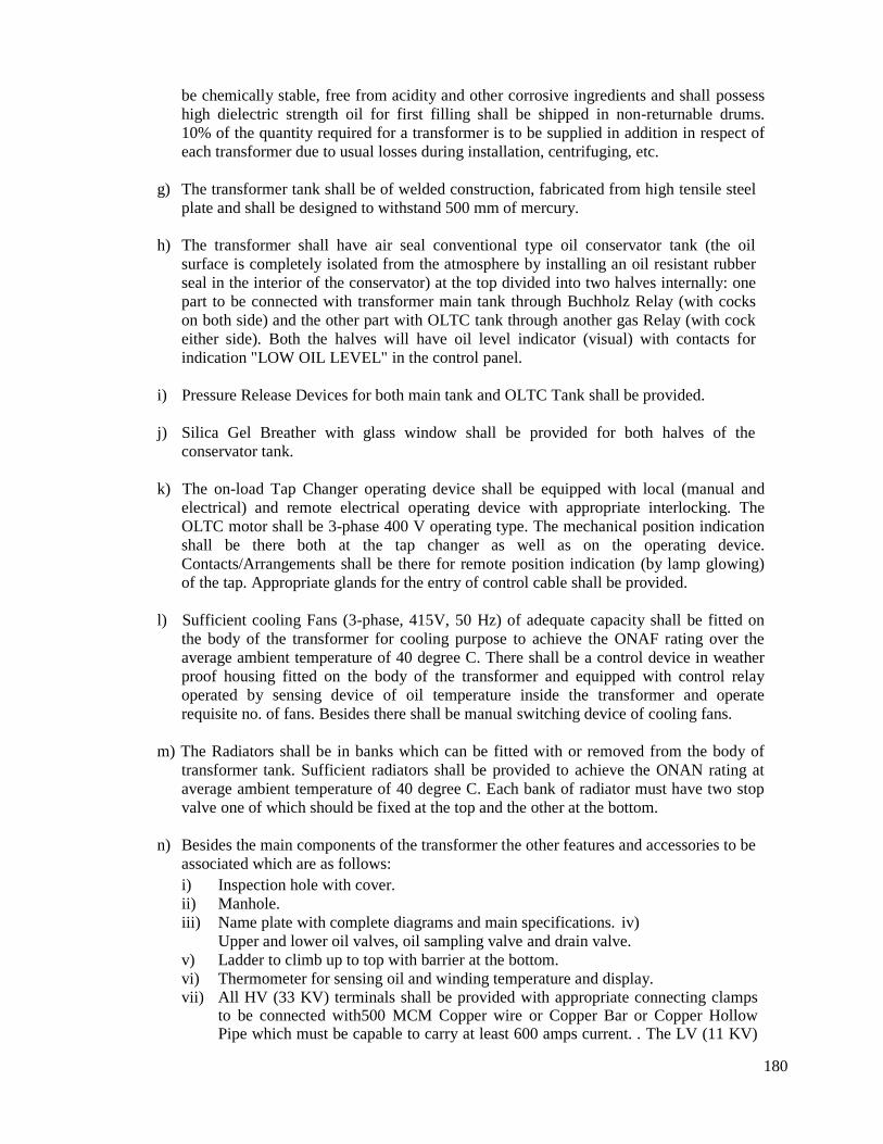
180
be chemically stable, free from acidity and other corrosive ingredients and shall possesshigh dielectric strength oil for first filling shall be shipped in non-returnable drums.10% of the quantity required for a transformer is to be supplied in addition in respect ofeach transformer due to usual losses during installation, centrifuging, etc.
g) The transformer tank shall be of welded construction, fabricated from high tensile steelplate and shall be designed to withstand 500 mm of mercury.
h) The transformer shall have air seal conventional type oil conservator tank (the oilsurface is completely isolated from the atmosphere by installing an oil resistant rubberseal in the interior of the conservator) at the top divided into two halves internally: onepart to be connected with transformer main tank through Buchholz Relay (with cockson both side) and the other part with OLTC tank through another gas Relay (with cockeither side). Both the halves will have oil level indicator (visual) with contacts forindication "LOW OIL LEVEL" in the control panel.
i) Pressure Release Devices for both main tank and OLTC Tank shall be provided.
j) Silica Gel Breather with glass window shall be provided for both halves of theconservator tank.
k) The on-load Tap Changer operating device shall be equipped with local (manual andelectrical) and remote electrical operating device with appropriate interlocking. TheOLTC motor shall be 3-phase 400 V operating type. The mechanical position indicationshall be there both at the tap changer as well as on the operating device.Contacts/Arrangements shall be there for remote position indication (by lamp glowing)of the tap. Appropriate glands for the entry of control cable shall be provided.
l) Sufficient cooling Fans (3-phase, 415V, 50 Hz) of adequate capacity shall be fitted onthe body of the transformer for cooling purpose to achieve the ONAF rating over theaverage ambient temperature of 40 degree C. There shall be a control device in weatherproof housing fitted on the body of the transformer and equipped with control relayoperated by sensing device of oil temperature inside the transformer and operaterequisite no. of fans. Besides there shall be manual switching device of cooling fans.
m) The Radiators shall be in banks which can be fitted with or removed from the body oftransformer tank. Sufficient radiators shall be provided to achieve the ONAN rating ataverage ambient temperature of 40 degree C. Each bank of radiator must have two stopvalve one of which should be fixed at the top and the other at the bottom.
n) Besides the main components of the transformer the other features and accessories to beassociated which are as follows:i) Inspection hole with cover.ii) Manhole.iii) Name plate with complete diagrams and main specifications. iv)
Upper and lower oil valves, oil sampling valve and drain valve.v) Ladder to climb up to top with barrier at the bottom.vi) Thermometer for sensing oil and winding temperature and display.vii) All HV (33 KV) terminals shall be provided with appropriate connecting clamps
to be connected with500 MCM Copper wire or Copper Bar or Copper HollowPipe which must be capable to carry at least 600 amps current. . The LV (11 KV)
181
terminals shall have also connecting clamps appropriate for being connected withon 2×500 mm2 single core cables per phase. The neutral terminal shall haveconnecting clamps to be connected with 2/0 HDBS wire.
viii) There shall be four wheels (flanged type) suitable for mounting on rails and tocarry the transformer as a whole.
ix) The transformer shall have at least two grounding terminals on its body.
All ferrous parts of the transformer shall be galvanized or painted with appropriatepaints of MUNSELL NO-5y 7/1 transformer with maximum shipping height (notexceeding 11 feet) will be preferred.
37. WARRANTYThe Contractor shall warrant that the transformers furnished have conformed to thisspecification. The warranty shall state that if, within three (3) years from the date transformersare delivered , a transformer is found to have defects in workmanship or material or fails inservice , the Contractor shall repair or replace such defective parts (and other parts damaged asa result) within 15 days with free of charge .
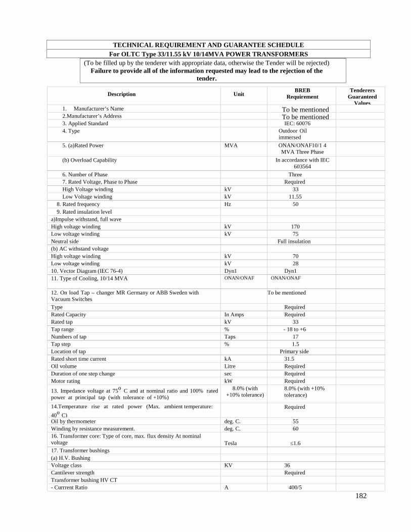
182
TECHNICAL REQUIREMENT AND GUARANTEE SCHEDULEFor OLTC Type 33/11.55 kV 10/14MVA POWER TRANSFORMERS
(To be filled up by the tenderer with appropriate data, otherwise the Tender will be rejected)Failure to provide all of the information requested may lead to the rejection of the
tender.
Description UnitBREB
RequirementTenderers
GuaranteedValues
1. Manufacturer’s Name To be mentioned2.Manufacturer’s Address To be mentioned3. Applied Standard IEC: 600764. Type Outdoor Oil
immersed
5. (a)Rated Power MVA ONAN/ONAF10/1 4MVA Three Phase
(b) Overload Capability In accordance with IEC603564
6. Number of Phase Three7. Rated Voltage, Phase to Phase RequiredHigh Voltage winding kV 33Low Voltage winding kV 11.55
8. Rated frequency Hz 509. Rated insulation level
a)Impulse withstand, full waveHigh voltage winding kV 170Low voltage winding kV 75Neutral side Full insulation(b) AC withstand voltageHigh voltage winding kV 70Low voltage winding kV 2810. Vector Diagram (IEC 76-4) Dyn1 Dyn111. Type of Cooling, 10/14 MVA ONAN/ONAF ONAN/ONAF
12. On load Tap – changer MR Germany or ABB Sweden withVacuum Switches
To be mentioned
Type RequiredRated Capacity In Amps RequiredRated tap kV 33Tap range % - 18 to +6Numbers of tap Taps 17Tap step % 1.5Location of tap Primary sideRated short time current kA 31.5Oil volume Litre RequiredDuration of one step change sec RequiredMotor rating kW Required
13. Impedance voltage at 75o C and at nominal ratio and 100% ratedpower at principal tap (with tolerance of +10%)
8.0% (with+10% tolerance)
8.0% (with +10%tolerance)
14.Temperature rise at rated power (Max. ambient temperature:
40o C)
Required
Oil by thermometer deg. C. 55Winding by resistance measurement. deg. C. 6016. Transformer core: Type of core, max. flux density At nominalvoltage Tesla ≤1.617. Transformer bushings(a) H.V. BushingVoltage class KV 36Cantilever strength RequiredTransformer bushing HV CT- Currrent Ratio A 400/5
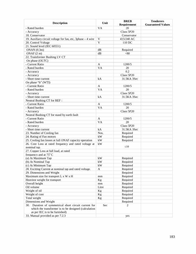
183
Description UnitBREB
RequirementTenderers
Guaranteed Values- Rated burden VA 20- Accuracy Class 5P2018. Conservator Conservator19. Auxiliary circuit voltage for fan, etc, 3phase – 4 wire V 415/240 AC20. Control Voltage V 110 DC21. Sound level (IEC 60551)ONAN (0.3m) dB RequiredONAF (2 m) dB <80
22. Transformer Bushing LV CTOn phase (OLTC)
- Current Ratio A 1200/5- Rated burden VA 20- Accuracy 0.2- Accuracy Class 5P20- Short time current kA 31.5KA 3SecOn phase “b” (WTI)- Current Ratio A 1200/5- Rated burden VA 20- Accuracy Class 5P20- Short time current kA 31.5KA 3SecNeutral Bushing CT for REF :- Current Ratio A 1200/5- Rated burden VA 20- Accuracy Class 5P20Neutral Bushing CT for stand by earth fault- Current Ratio A 1200/5- Rated burden VA 20- Accuracy Class 5P20- Short time current kA 31.5KA 3Sec23. Number of Cooling fan Nos. Required24. Rating of Fan motors kW Required25. Cooling fan losses at full ONAF capacity operation kW Required26. Core Loss at rated frequency and rated voltage atnominal tap.
kW≤10
27. Copper Loss at full load, at ratedfrequency and at 75o C(a) At Maximum Tap kW Required(b) At Nominal Tap kW Required(c) At Minimum Tap kW Required28. Exciting Current at nominal tap and rated voltage. A Required29. Dimensions and Weight RequiredMaximum size for transport L x W x H mm RequiredHeaviest weight for transport Kg RequiredOverall height mm RequiredOil volume Litre RequiredWeight of oil Kg RequiredWeight of core Kg RequiredTotal weight Kg RequiredDimensions and Weight Required30. Duration of symmetrical short circuit current for
which the transformer is to be designed (calculationas per IEC is to be furnished)
Sec 2
33. Manual provided as per 7.2.3 yes
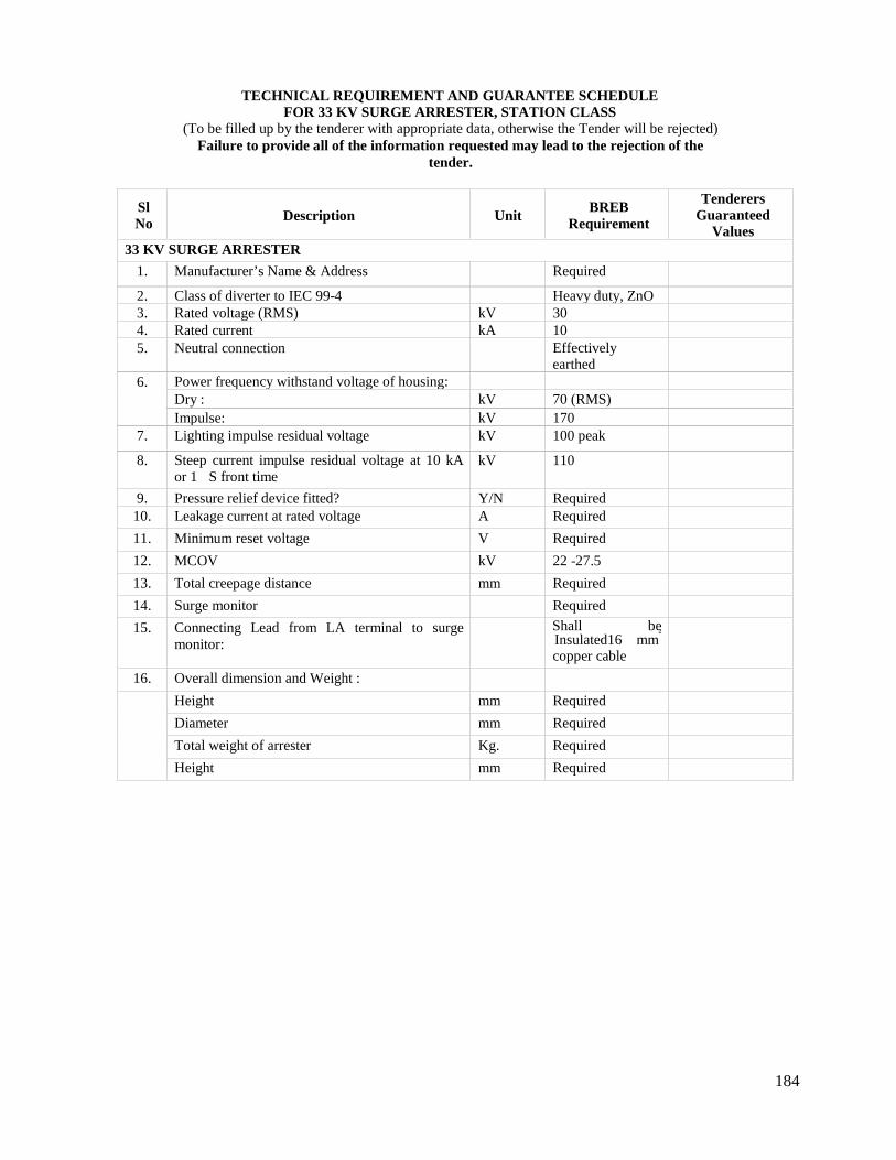
184
TECHNICAL REQUIREMENT AND GUARANTEE SCHEDULEFOR 33 KV SURGE ARRESTER, STATION CLASS
(To be filled up by the tenderer with appropriate data, otherwise the Tender will be rejected)Failure to provide all of the information requested may lead to the rejection of the
tender.
SlNo Description Unit
BREBRequirement
TenderersGuaranteed
Values33 KV SURGE ARRESTER
1. Manufacturer’s Name & Address Required
2. Class of diverter to IEC 99-4 Heavy duty, ZnO3. Rated voltage (RMS) kV 304. Rated current kA 105. Neutral connection Effectively
earthed6. Power frequency withstand voltage of housing:
Dry : kV 70 (RMS)Impulse: kV 170
7. Lighting impulse residual voltage kV 100 peak
8. Steep current impulse residual voltage at 10 kAor 1 S front time
kV 110
9. Pressure relief device fitted? Y/N Required10. Leakage current at rated voltage A Required
11. Minimum reset voltage V Required
12. MCOV kV 22 -27.5
13. Total creepage distance mm Required
14. Surge monitor Required
15. Connecting Lead from LA terminal to surgemonitor:
Shall beInsulated16 mm
2
copper cable
16. Overall dimension and Weight :
Height mm Required
Diameter mm Required
Total weight of arrester Kg. Required
Height mm Required
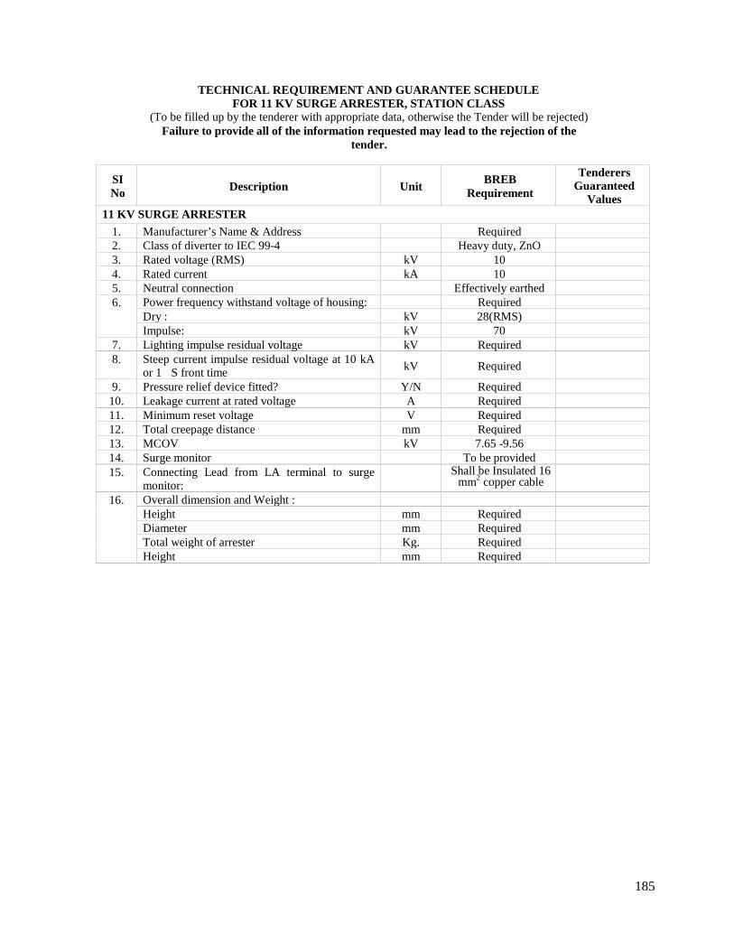
185
TECHNICAL REQUIREMENT AND GUARANTEE SCHEDULEFOR 11 KV SURGE ARRESTER, STATION CLASS
(To be filled up by the tenderer with appropriate data, otherwise the Tender will be rejected)Failure to provide all of the information requested may lead to the rejection of the
tender.
SINo Description Unit
BREBRequirement
TenderersGuaranteed
Values11 KV SURGE ARRESTER
1. Manufacturer’s Name & Address Required2. Class of diverter to IEC 99-4 Heavy duty, ZnO3. Rated voltage (RMS) kV 104. Rated current kA 105. Neutral connection Effectively earthed6. Power frequency withstand voltage of housing: Required
Dry : kV 28(RMS)Impulse: kV 70
7. Lighting impulse residual voltage kV Required8. Steep current impulse residual voltage at 10 kA
or 1 S front time kV Required
9. Pressure relief device fitted? Y/N Required10. Leakage current at rated voltage A Required11. Minimum reset voltage V Required12. Total creepage distance mm Required13. MCOV kV 7.65 -9.5614. Surge monitor To be provided15. Connecting Lead from LA terminal to surge
monitor:Shall be Insulated 16
mm2 copper cable
16. Overall dimension and Weight :Height mm RequiredDiameter mm RequiredTotal weight of arrester Kg. RequiredHeight mm Required
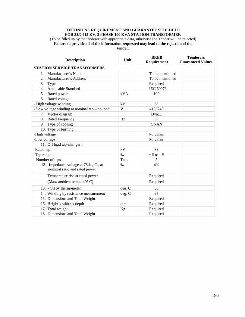
186
TECHNICAL REQUIREMENT AND GUARANTEE SCHEDULEFOR 33/0.415 KV, 3 PHASE 100 KVA STATION TRANSFORMER
(To be filled up by the tenderer with appropriate data, otherwise the Tender will be rejected)Failure to provide all of the information requested may lead to the rejection of the
tender.
Description UnitBREB
RequirementTenderers
Guaranteed Values
STATION SERVICE TRANSFORMERS1. Manufacturer’s Name To be mentioned2. Manufacturer’s Address To be mentioned3. Type Required4. Applicable Standard IEC 600765. Rated power kVA 1006. Rated voltage :
- High voltage winding kV 33- Low voltage winding at nominal tap – no load V 415/ 240
7. Vector diagram Dyn118. Rated Frequency Hz 509. Type of cooling ONAN10. Type of bushing :
-High voltage Porcelain-Low voltage Porcelain
11. Off load tap-changer :-Rated tap kV 33-Tap range % + 5 to – 5- Number of taps Taps 5
12. Impedance voltage at 75deg C., atnominal ratio and rated power
% 4%
Temperature rise at rated power Required
(Max. ambient temp.: 40° C) Required
13. - Oil by thermometer deg. C 6014. Winding by resistance measurement deg. C 6515. Dimensions and Total Weight Required16. Height x width x depth mm Required17. Total weight Kg Required18. Dimensions and Total Weight Required
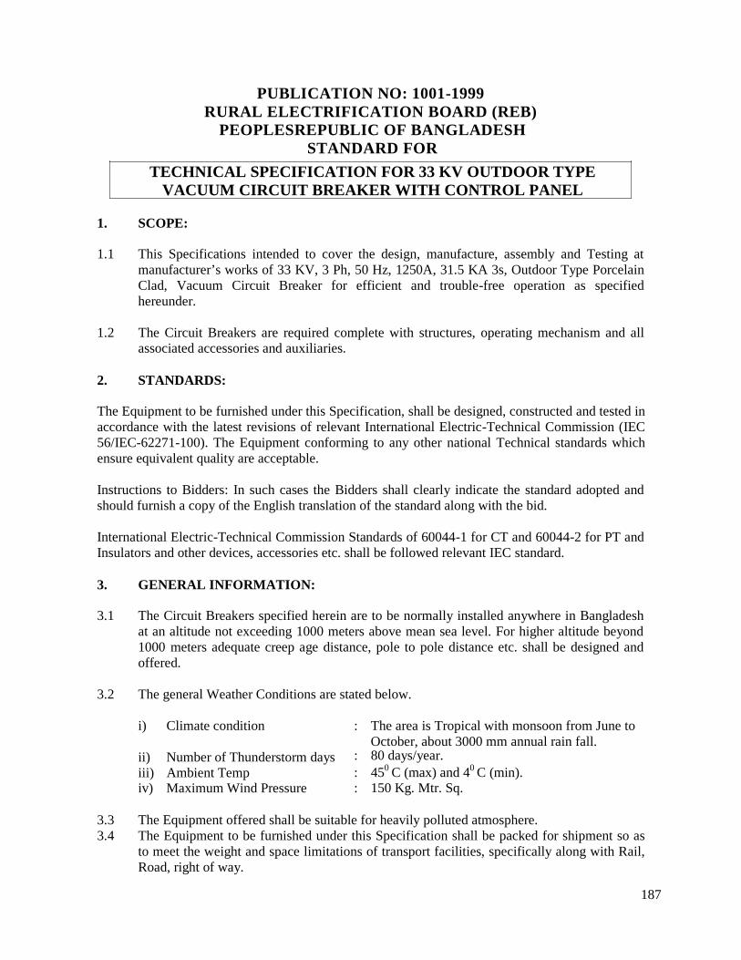
187
PUBLICATION NO: 1001-1999RURAL ELECTRIFICATION BOARD (REB)
PEOPLESREPUBLIC OF BANGLADESHSTANDARD FOR
TECHNICAL SPECIFICATION FOR 33 KV OUTDOOR TYPEVACUUM CIRCUIT BREAKER WITH CONTROL PANEL
1. SCOPE:
1.1 This Specifications intended to cover the design, manufacture, assembly and Testing atmanufacturer’s works of 33 KV, 3 Ph, 50 Hz, 1250A, 31.5 KA 3s, Outdoor Type PorcelainClad, Vacuum Circuit Breaker for efficient and trouble-free operation as specifiedhereunder.
1.2 The Circuit Breakers are required complete with structures, operating mechanism and allassociated accessories and auxiliaries.
2. STANDARDS:
The Equipment to be furnished under this Specification, shall be designed, constructed and tested inaccordance with the latest revisions of relevant International Electric-Technical Commission (IEC56/IEC-62271-100). The Equipment conforming to any other national Technical standards whichensure equivalent quality are acceptable.
Instructions to Bidders: In such cases the Bidders shall clearly indicate the standard adopted andshould furnish a copy of the English translation of the standard along with the bid.
International Electric-Technical Commission Standards of 60044-1 for CT and 60044-2 for PT andInsulators and other devices, accessories etc. shall be followed relevant IEC standard.
3. GENERAL INFORMATION:
3.1 The Circuit Breakers specified herein are to be normally installed anywhere in Bangladeshat an altitude not exceeding 1000 meters above mean sea level. For higher altitude beyond1000 meters adequate creep age distance, pole to pole distance etc. shall be designed andoffered.
3.2 The general Weather Conditions are stated below.
i) Climate condition
ii) Number of Thunderstorm daysiii) Ambient Tempiv) Maximum Wind Pressure
: The area is Tropical with monsoon from June toOctober, about 3000 mm annual rain fall.
: 80 days/year.: 450 C (max) and 40 C (min).: 150 Kg. Mtr. Sq.
3.3 The Equipment offered shall be suitable for heavily polluted atmosphere.3.4 The Equipment to be furnished under this Specification shall be packed for shipment so as
to meet the weight and space limitations of transport facilities, specifically along with Rail,Road, right of way.
188
3.5 The Equipment covered by this Specification shall be complete in all respects. Any materialor accessory which may not have been specifically mentioned, but is essential or necessaryfor satisfactory and trouble free operation and maintenance of the Equipment shall befurnished without any extra charge to the Employer.
3.6 The Equipment shall be supplied with all accessories listed in this Specification with suchmodifications and alternations as to safeguard the Technical requirements.
4. DESIGN CRITERIA:
4.1 The Equipment will be used in effectively neutral grounded System with fault level of 31.5KA at highest system voltage of 36 KV.
4.2 Continuous current rating shall be 1250 Amp. Maximum temperature attained by any partof the Equipment at specified rating should not exceed the permissible limit as stipulate inthe relevant standards. Equipment shall be designed taking 500C as maximum ambienttemperature.
4.3 The circuit breakers and their components shall be capable of withstanding the mechanicalforces and thermal stresses of the short circuit current of the system without any damage ordeterioration of material.
4.4 The circuit breakers shall have motor wound spring charged trip free mechanism with anti-pumping feature, and shunt trip. In addition, facility for manual charging of spring shall beprovided.
4.5 Each breaker shall be provided with manual close & open facility, mechanical ON-OFFindication, an operation counter and mechanism charge/discharge indicator.
4.6 For motor wound mechanism, spring charging shall take place automatically after eachbreaker closing operation. One open-close-open operation of the circuit breaker shall bepossible after failure of power supply to the motor. A visual mechanical indicating devicewill also be provided to show the position of the spring.
4.7 All controls shall be suitable for 80%, to 110% for closing & 70% to 110% for tripping of110V D.C. The A.C. supply shall be available 415/230 Volt, 50 Hz.
4.8 The operating duty of the Breaker will be 0-0.3 sec-CO-3 min-CO.
4.9 There shall be no radio interference when the Equipment is operated up to maximumservice voltage.
4.10 The minimum safe clearance of all live parts of the Equipment shall be as per relevantstandards. Clearances of 33 KV Low Level pipe bus of switchyard are:
a) Phase to Phaseb) Pipe bus to ground level of supporting structure
: 1200 mm and: 4000 mm
4.11 All electrical and mechanical interlocks which are necessary for safe and satisfactoryoperation of the Breaker shall be furnished. The interlocking device shall be of provenquality.
189
4.12 The condition of Breaker and its contacts shall be intact even under conditions of phaseopposition that may arise due to faulty synchronization or otherwise. Bidders shouldconfirm in this regards.
4.13 The Breaker shall be capable of smooth and rapid interruption of current under allconditions, completely suppressing the undesirable phenomenon even under the most severeand persistent rated short circuit conditions. There will be no abnormal voltage risesubsequent to the switching ON/OFF a capacitor bank within the rated capacity.
4.14 The total make and break time (in m sec/cycle) for the breaker throughout the range of theiroperating duty shall be indicated and guaranteed.
4.15 The breaker shall be suitable for interrupting low inductive currents without generation ofabnormal over voltage.
4.16 The breaker shall be capable of interrupting rated breaking current with recovery voltageequal to maximum line Service Voltage and at all inductive power factor of the Circuitequal to or exceeding 0.15.
4.17 The Circuit Breaker shall be capable to withstand power frequency over Voltage 70 KV for1 min.
4.18 Instructions to Bidders: The Bidder may indicate in his offer the methods adopted forlimiting over voltage.
4.19 The Circuit Breaker with its hot dip galvanized steel structure shall be suitable for mountingon concrete foundation. The height of the supporting structure will be such that it will beable to maintain clearance as indicated in clause 4.10 above.
4.20 The detail of steel structure, foundation design and erection drawing shall be given. InGA/Structure drawing please indicate the location of CB point of application of dynamicload and its amplitude, dead load etc.
4.21 Special tools & tackles required for erection and dismantling and fitting of the Breaker andits accessories, if required shall be offered indicating the prices etc.
5. CONSTRUCTION:
Each vacuum Circuit breaker shall comprise of three identical poles linked together electrically andmechanically for synchronous operation.
Vacuum Interrupter
The vacuum interrupter, consisting of fixed contact and moving contact, shall be interchangeableamong the same type interrupter. Short circuit capacity of vacuum bottle should be 31.5 KA anddesign life should be 100 nos. Operation at rated short circuit level. The operation of the interrupterwill be 30000 nos. at rated current.
i) Instructions to Bidders: Constructional features of the vacuum chamber along with itsfunctional arrangements are to be shown in a drawing submitted along with bid documents.
190
ii) The gap between contacts of the Circuit Breaker inside interrupter should be capable ofwithstanding 1.3 time voltage to neutral at one atmospheric pressure at normal ambientcondition within Breaker in the event of vacuum pressure drop due to leakage.
iii) Vacuum Bottle shall be of Siemens/ABB or/ALSTOM and of reputed indigenous make.Offered bottle shall be identical with Type tested one. Brochures/leaflet on technical data sheetfor vacuum bottle shall be enclosed with technical bid.
Control Panel and Protective Relays
i) Protective relays must be provided by the Contractor with the breaker. The relays must benumerical relays (from ABB, Sweden or Siemens, Germany or GE, USA) for over current,earth fault protection and differential of 33 kV feeder. There must be one master trip relay forinter tripping.
ii) All the relays should be 61850 protocol type for automation network of the 33/11.55 kV Sub-station.
iii) Plug setting range will be from 5% to 2500% and time setting range from 2.5% to 1000%.iv) All indicating instruments shall be switch board type connected suitable for flush mounting and
provided with dust and vermin proof cases for tropical use and finished in suitable color. Allinstrument have practical lab. means of adjustment of accuracy. The limit error of voltmeter andammeter shall be permissible for 0.2 instrument
v) There must have minimum 3 nos. Ammeter, 3 nos.voltmeter,1nos KW meter,1nos KVARmeter, 1nos Pf meter, 1 nos. frequency meter 1 no. ammeter selector switch, 1 no. voltmeterselector switch, Test terminal block, ON/OFF/Auto Trip/Spring Charge etc. indication lamps ofdifferent colors. All indication meters will be Digital.
6.1 MAIN CONTACTS:
a) In vacuum interrupter the contact configuration, contact area, contact pressure will besufficient for carrying rated current and short time rates current, without any abnormalphenomena.
b) Complete details of main contacts shall be furnished. The material of contacts andcoating of the contacts shall be suitable for vacuum Breaker technology. Evaporation ofmetal during arcing and deposition of the same in the inner surface of vacuuminterrupter should be restricted by adopting suitable material. Bidder shall furnish thejustification of using the materials for contacts.
c) Complete details of main contacts and arc quenching device, if any with sectionaldrawings shall be furnished at the time of offer. Measures taken to free the contactsfrom vibration during closing shall be clearly explained in the drawing, support by testsresults.
d) The contact erosion should be limited up to 3 mm for useful life and indication tomonitor the progress of contact erosion has to be provided.
6.2 The vacuum pressure within interrupter shall be adequate to interrupt the fault current.Precaution shall be taken so that there will be no flush over on outside of the vacuuminterrupter inside the porcelain insulator.
6.3 Design of the vacuum bottle and its insulator encasing should be suitable for outdoor use,taking care of required creepage distance considering possibility of moisture condensation if
191
any, in the annular space between the vacuum bottle and insulator enclosure. Type test withidentical bottle type with similar encasing arrangement shall be done and accordinglyReport shall be submitted along with bid document.
6.4 Vacuum bottle with its insulator encasing chamber shall be hermetically sealed. Freepassage of air in the chamber with or without provision of circulation of hot air is notaccepted.
6.5 Tripping/Closing Coil burden of Equipment should not be more than 200 watts at 110 VD.C. The value will not be relaxed, specially for tripping coil.
6.5 OPERATING MECHANISM:
a) The operating mechanism shall be suitable for rapid closing and tripping. The openingand closing energy shall be obtained from spring charge mechanism. The springcharging may be done by either motor operation with facility for manual charging whenrequired or by other suitable trouble free mechanism. Local arrangement for operatingbreakers both electrically and mechanically shall be provided in addition to remoteoperation.
b) The mechanism shall have anti-pumping circuitry and will be trip free electrically andmechanically. The anti-pumping arrangement shall be initiated through normally „NO‟type, direct auxiliary contact of circuit breaker and shall be of self hold type. Plug-intype relay/Contactor for Anti-pumping Relay will not be acceptable.
c) Spring operated mechanism will be complete with opening spring, closing spring, limitswitch and all necessary accessories to make the mechanism a complete operating unit.
d) Contactor used for anti-pumping relay shall be of reputed make.
e) There shall be mechanical ON/OFF indicator spring charge and operation counter foreach Breaker and also provision for remote indication.
f) The operating mechanism box shall be fixed at a working height from ground level.View glass shall be provided on hinged door at the front side.
g) Spring charging LS shall have sufficient no. of spare contact.
6.6 COMMON CONTROL CUBICLE:
a) A free standing outdoor type weather proof, dust and vermin proof cubicle shall beprovided to house the operating mechanism and all other accessories except those whichmust be located in the pole box.
b) The cubicle shall be of 3.00 mm thick sheet steel and shall have hinged doors at frontand hinged/bolted door or cover at rear for access to the mechanism. Doors should be ofproper design for smooth opening and closing with pad locking arrangement.
c) A removable gland plate of 3 mm thickness shall be provided at the bottom of thecubicles for the Employer’s Cable entry. Glands of sizes suitable for entry of 1 no. 12core, 2 nos. 8 core and 2 nos. 4 core Cables for Control etc.
192
d) Terminal blocks for AC & DC shall be kept separate. Terminals shall be suitable for atleast 2X 2.5 sq.mm copper leads. All wiring shall be of 1100 V grade PVC.
e) Thermostat controlled heaters shall be provided to prevent condensation within cubicle.Cubicle illumination Lamp with switch and a 230 V., 15A, 3 pin sockets with a ControlSwitch shall be provided.
f) All controls, alarms, indications and interlocking devices furnished with breaker shall bewired up to the terminal Black in the common control cubicle. Not more than two wiresshall be connected to one terminal.
g) All wires shall be identified at both ends with ferrule marking in accordance withapproved wiring diagram.
h) Terminal blocks shall have compression type multi-way terminals with bonding screwsand washers. At least 15% spare terminal shall be provided.
i) Scheme diagram on a durable sticker shall be fixed on inside door of Control Cubicle.
j) Degree of protection of control cubicle shall be IP-55.
7. INSULATORS:
a) Porcelain supports, interrupter housing of adequate mechanical and dielectric strength withsuitable creep age distance shall have to be used. All Support/Interrupter Housing ofidentical ratings shall be interchangeable. Each Interrupter-Housing shall be provided withterminal stud/pad.
b) The porcelain used in interrupter housing shall be made from wet process and shall behomogeneous, free from laminations, caustics and other flaws which may impair itsmechanical or dielectric strength and shall be glossy, tough and impervious to moisture.
c) The porcelain supports, interrupter –housing insulation shall be coordinated with that ofCircuit Breaker. The puncture strength of the bushings shall be greater than the dryflashover value.
d) When operating at rated voltage, there shall not be any electrical discharge between liveterminal and earth. No Radio disturbance shall be caused by the support insulators whenoperating up to the maximum System Voltage. It shall also be free from corona.
e) All iron parts shall be hot dip galvanized. The nuts, bolts, washers etc. shall also be hotdip galvanized steel or stainless steel.
f) Each Circuit Breaker shall be provided with Bi-metallic terminal stud/pad suitable forconnection of pipe bus/ACSR Conductor.
8. AUXILIARY CONTACTS:
a) Breaker shall be provided with 9 NO & 9 NC spare auxiliary contacts in addition to theauxiliary contacts required for Breaker’s own operational requirements. These auxiliarycontacts shall preferably be convertible type.
193
b) These contacts shall have continuous current rating of at least 10A. The breakingcapacity shall be adequate for the circuits controlled, or at least 12A at 110 V DC with acircuit time constant of minimum 20 ms.
c) All these contacts shall be wired up to terminal block in the control cubicle. Auxiliarycontacts which are to be installed on the frame of Circuit Breaker shall be suitablyprotected against accidental arcing from main circuit. Insulating materials of contactsshall be ceramics or other non-tracking materials.
9. GROUNDING:
Circuit Breaker shall be provided with two grounding pads with 2 nos. tapped holes for M10 boltsand spring washers for connection of the Employer’s grounding conductor (50x6 mm G.I. strips).
10. PAINTING:
External surfaces shall be given a coat of high quality red oxide or other suitable primer and shallbe finished with two coats of synthetic enamel paints. Such painting should be able to withstandtropical climate as stipulated in Sl.No.3 of this Specification.
11. EQUIPMENT FOUNDATION AND STEEL STRUCTURE:
a) The Circuit breaker etc. shall be furnished complete with base frame, anchor/foundationbolts and hardware. Details structure assembly drawing, mentioning part no. of eachmember and also indicating cross sectional area of member used with supportingcalculations. The point of C.B. dynamic load and its amplitude, dead load etc. shall bementioned.
b) Similar grounding pad as mentioned against Sl.No.8 are also to be provided.
c) If the Centre line of Control Cubicle is more than 1.50m above ground plate, onesuitable platform with checker plate shall be fixed at a suitable height of support structurewith ladder step arrangement, to access the control cubicle for Local operation &maintenance purpose.
12. CURRENT TRANSFORMER:Current transformers, three per circuit breaker, shall be of outdoor, single phase, electromagneticinduction, oil immerged, suitable for operation in hot and humid atmospheric conditions describedin service condition. They shall be mounted on the bracket. The CT tank should be Hot Dipgalvanized as per relevant IEC to prevent corrosion of all exposed metal parts.12.1 Core
High grade non-ageing cold rolled grain oriented (CRGO M4 or better grade) silicon steelof low hysteresis loss and permeability shall be used for the core so as to ensure specifiedaccuracy at both normal and over currents. The flux density shall be limited to ensure thatthere is no saturation during normal service.
194
The instrument security factor of the core shall be low enough so as not to cause damage to theinstruments in the event of maximum short circuit current.
12.2 Winding
The secondary windings shall be made of electrolytic copper with suitable insulation. Theconductor shall be of adequate cross-section so as to limit the temperature rise even duringshort circuit conditions. The insulation of windings and connections shall be free fromcomposition liable to soften coze, shrink or collapse during service.
Polarity shall be indelibly marked on each current transformer and at the lead andtermination at associated terminal blocks. CTs with multi ratio winding shall be clearlytabulated to show the connections required for different ration. Similar numbers shall bemarked on terminal block arrangement and wiring diagram.
The continuous current rating of the primary winding shall be one hundred and twentypercent of the normal rated current. Secondary windings of current transformers shall beused for metering, instrumentation and protection and shall be rated for continuous currentof one hundred and fifty percent of normal rated current of primary winding.
12.3 Construction
The current transformer enclosures shall be made of high quality steel and shall be not dipgalvanized and shall be able to withstand and stresses occurring during transportation andthe terminal and mechanical stresses resulting from maximum short circuit current inservice. The primary winding and terminals shall be in a tank and supported by a hollowporcelain insulator. The secondary connection shall be conducted through the hollowinsulator and terminated in a terminal box mounted on the base plate.
12.4 Insulation level
The current transformers shall be designed to withstand impulse test voltages and powerfrequency test voltage as specification.
13. POTENTIAL TRANSFORMER
The voltage transformer to be supplied under this specification shall be of outdoor, single phasedead tank double wound, oil immersed type for operation in hot and humid atmospheric conditionsdescribed in this document. To prevent corrosion of the exposed surfaces, the tank should be notdip galvanized. They shall have separate HV and LV windings and shall be suitable for use as busVTs in 33 KV.
13.1 Duty requirement
33KV Voltage transformer for all the indicating instruments, measuring meters andprotection on the 33 KV side.
13.2 Porcelain Insulator
External parts of the voltage transformers which are under continuous electrical stress shallbe of hollow porcelain insulators. The creepage and flashover distance of the insulators
195
shall be dimensioned and the type and profile designed and shall be suitable for the worstenvironmental conditions for heavily polluted atmosphere and shall be not less than 25mmper KV of highest phase to phase system voltage with protected creepage distance minimum50 percent of the total. Internal surfaces of hollow insulators shall also be glazed.
The insulators shall be withstand in high mechanical, tensile and breaking strength. Allporcelain used on the voltage transformers shall have the following properties high strength,homogeneity, uniform glaze, free from cavities and other flaws and a high quality uniformfinish porcelain components shall withstand the maximum expected static and dynamicloads to which the voltage transformers may be subjected during their service life. Theinsulation of the hollow porcelain insulators shall be coordinated with that of the voltagetransformers to ensure that any flash over occurs only externally.
13.3 Core
High grade non-ageing cold rolled grain oriented silicone steel of low hysteresis loss andpermeability shall be used for core so as to ensure accuracy at both normal and or overVoltage. The flux density shall be limited to 1.6 Tesla at normal voltage and frequency.There shall be no saturation at any stage during operation.
The instrument security factor of the core shall be low enough so as to cause damage to theinstruments in the event of maximum short circuit current or over voltage.
13.4 Windings
The primary and secondary windings shall be electrolytic copper of high purity andconductivity and covered with double paper insulation. The conductor shall be of adequatecross-section so as to limit the temperature rise even during maximum over voltages.
The insulation of windings and connections shall be free from composition liable to soften,ooze, shrink or collapse during service. The secondary windings of the voltage transformersshall be suitable for continuous over voltage corresponding to the maximum system voltageat the primary winding. The winding supports shall be suitable reinforced to withstandnormal handling and the thermal and dynamic stresses during operation without damage.The voltage transformer secondary circuits will be taken out to form the star point andearthed at one point outside the voltage transformers.
Both primary and secondary winding terminals shall be clearly and indelible marked toshow polarity. The connections required for different secondary windings in case of multi-winding voltage transformers shall be clearly indicated in terminal blocks and the wiringdiagrams.
13.5 Secondary Terminal Box
A dust vermin and weather proof terminal box shall be provided at the lower end of eachvoltage transformer for terminating the secondary windings. The box shall have a boltedremovable cover plate complete with gaskets. The terminal box shall have cable gland plateand cable glads with shrouds suitable for entry of 4 core 2.5mm2 PVC insulated controlcables. The terminal box enclosure shall have protection of class IP 55.
196
13.6 Circuit diagram
A durable copy of the circuit wiring diagram shall be affixed to the inner side of theterminal box cover. Labels shall be provided inside the cover to describe the functions ofvarious items of equipments.
13.7 Earthing Termination
Two earthing terminals complete with necessary hardware shall be provided on eachvoltage transformer for connecting to earth continuity conductors of the Employer. Theyshall be of electroplated brass and of adequate size to carry the earth fault current.
The earthing terminals shall be identified by means of appropriate symbol marked in alegible and indelible manner adjacent to the terminals.
14. DRAWING, MANUALS AND TYPE TEST CERTIFICATES:
The following drawings and manuals shall be furnished for information purpose with each copy ofthe bid.
14.1 General Arrangement Drawings indicating all dimensions,
14.2 Technical leaflets/manuals on each piece of Equipment explaining the function of variousparts, principle of operation and special features. Technical leaflets/manuals for offered typeof vacuum bottle etc.
14.3 Type Test Certificates as per IEC carried out on Similar Circuit Breaker fromreputed/recognized laboratory shall be furnished with the bid.
14.4 Supplier also have to provide test reports of relays.
15. CONTRACT DRAWING AND CATALOGUE:
After placement of order, six (6) copies of various drawings data and manuals as mentioned belowshall be submitted to the Project Manager/Employer.
15.1 Dimensional General Arrangement drawing showing all dimensions and disposition offittings and space requirement and mounting arrangements.
15.2 Sectional views of contact assembly, operating mechanism and are extinguishing chamber.
15.3 Transport/shipping dimensions with weights.
15.4 Foundation and anchor details including dead-load and impact load with direction and also
point of application.
15.5 Assembly drawing for erection at site with part numbers and schedule of materials.
15.6 Electrical schematic and wiring diagram with explanatory notes, if any.
15.7 Schematic diagram for spring charged operating mechanism schematic layout drawings.
197
15.8 Name plate drawing and any other relevant drawing and data necessary for erection,
operation and maintenance.
15.9 Outline drawings of bushings, terminals and terminal connectors.
15.10 i) After approval, the Contractor shall submit Ten (10) sets of approval drawings andmanuals to the Project Manager/Employer. Instruction manuals and data sheets for eachrating of Equipment shall be submitted. The manuals shall clearly indicate the installationmethods, checkups and tests to be carried out for testing the Equipment and maintenanceprocedure.
ii) In all drawings, manuals etc., reference no. of purchase order no. shall be indicated.
iii) Two sets complete in all respects with required bindings should be sent directly to theProject Manager/ Employer.
16. TEST REPORTS AND INSPECTION:
The test reports are to be submitted along with the bid and Inspections shall be carried out duringPre Shipment and Post Landing Inspection.16.1 Type testThe Bidder shall submit along with the bid, detailed as well as complete test reports of all tests(including Type Test) as stipulated in relevant IEC with Complete identification, date and serialno., carried out in a Government recognized Test House or Laboratory/ CPRI/ NABL accreditedlab/ on Circuit Breakers of identical design.
For Breaker:a) Short time withstand and peak withstand current testb) Lightning impulse voltage withstand testc) Temperature rise Testd) Mechanical Endurance Teste) Measurement of the resistance of the main circuitf) Short circuit current making and breaking testsg) Tightness tests.
For CT:
a) Lightning impulse voltage(Chopped impulse and full impulse);b) Power frequency wet withstand voltage;c) Temperature rise;d) Short circuit withstand capability test;e) Current error and phase displacementf) Switching impulse.
For PT:a) Lightning impulse voltage test;b) High voltage power frequency wet withstand voltage;c) Temperature rise test;d) Short circuit withstand capability test;e) Switching impulse;f) Determinations of error;
198
16.2 Routine test
For Breaker:
a) Dielectric test on main, auxiliary and control circuitb) Measurement of the resistance of the main circuitc) Tightness testd) Mechanical operation testse) Design and visual checksFor CT:
a) Verification of terminal marking and polarity;b) Power frequency dry withstand test on both windings;c) Power frequency dry withstand test between sections;d) Over voltage inter-turn test;e) Turn ratio;f) Instrument security factor test;g) Determinations of error;h) Secondary winding resistance and Accuracy test ;i) Current error and phase displacement;j) Knee point voltage and magnetizing current test ;k) Insulation Resistance Test;For PT:
a) Verification of terminal marking and polarity;b) Power frequency dry withstand tests on both winding;c) Power frequency withstand tests between sections;d) Determination of limits of voltage errors and phase displacement;e) Partial discharge measurement;f) Insulating Resistance measurement;
16.3 Special tests
For CT:
a) Multiple chopped impulse test on primary winding;b) Measurement of capacitance and dielectric dissipation test.c) Mechanical tests.For PT:
a) Chopped impulse test on primary winding;b) Measurement of capacitance and dielectric dissipation test.c) Mechanical tests.d) Transmitted over-voltage measurement.
17. SPECIFIC LIMIT OF AUXILIARY SUPPLY VOLTAGE:
a) The auxiliary supply voltage shall be 80% to 110% of the rated 110 V in supply forclosing coil and the same shall be 70% to 110% for tripping coil.
b) The operating voltage for motor operated spring charged mechanism shall be 415VA.C., 3 phase, 50 Hz or 230V. 1-phase, 50 Hz. The motor shall operate at a voltage
199
variation of 85% to 110% of the supply voltage.
18. NAME PLATE:
i. Rated voltage/Maximum voltageii. Rated insulation leveliii. Type /Model No./Sl. No./Year of manufacture.iv. Rated currentv. Rated frequency.vi. Rated short Circuit Breaking Current.vii. Rated transient recovery voltage for terminal fault.viii. Rated short circuit making current.ix. Rated operating sequence.x. Rated short time current.xi. Rated line charging/breaking currentxii. Rated Cable charging current.xiii. Rated single capacitor bank charging/breaking current.xiv. Rated small inductive breaking current.xv. Rated Supply Voltage of auxiliary circuits.xvi. Applicable standard.
19. RECOMMENDED SPARES:
Instructions to Bidders: The Bidder shall quote item-wise price of recommended spares for 5 (five)years normal operation. The Employer will decide the actual quality of spare to be procured on thebasis of the List.20. ACCESSORIES:
Each Breaker shall be furnished complete with fittings and accessories as listed below (The list isillustrative & not exhaustive).
i. Clamp-type terminal connectors for ACSR Conductor
ii. Base frame and foundation/anchor bolts.
iii. Operating mechanism, trip and close coils.
iv. Set of valves required for gas filling.
v. Auxiliary Contacts and Relays/Contacts.
vi. Local/Remote selector Switch and Close/Trip Control Switch.
vii. Manual close and trip devices.
viii. Mechanical ON/OFF indicators.
ix. Operation counters.
x. Weatherproof Control cubicle and operating mechanism boxes, with locking
arrangement.
xi. Set of Switch-Fuse/MCB/MCCB units for A.C. & D.C. Supply.
200
xii. Space heaters with thermostat and switch. Two units will be provided with the
option to operate separately.
xiii. Cubicle illumination Lamp with Switch.
xiv. Terminal blocks and internal wiring.
xv. Necessary all Main Control cables & Auxiliary Control cables.
xvi. G.I. conduits and accessories for connection between Central Control Cubicle andoperating mechanism boxes where applicable.
xvii. Other standard accessories which are not specified, but are necessary for efficientand trouble free operation shall be supplied.
21. TEST AT FACTORY AND TEST CERTIFICATES
21.1 All Acceptance tests shall be carried out at manufacturer’s works in presence of theEmployer’s and Contractor’s representatives. In addition to above, all routine tests are alsoto be carried on the breakers as per relevant IEC. The entire cost of acceptance and routinetest that to be carried out as per relevant IEC’ shall be treated as included in the quoted priceof breakers. The Contractor shall give at least 21(twenty one) days advance noticeintimating the actual date of inspection and details of all tests that are to be carried out fromthe date when the tests will be carried out.
21.2 Routine tests on all breakers, CTs and PTs shall be carried out as per IEC-62271-100, IEC60044-1, IEC 60044-2 and test reports shall be submitted along offer.
22. WARRANTY
The Contractor shall warrant that the VCB furnished have conformed to this specification. Thewarranty shall state that if, within three (3) years from the date of delivery in case of EXWcontracts & from the date of arrival at the designated port of entry in case of CIP Contracts, a VCBis found to have defects in workmanship or material (or fails in service due to such defects) theContractor shall repair or replace such defective parts (and other parts damaged as a result) within15 days, free of charge.
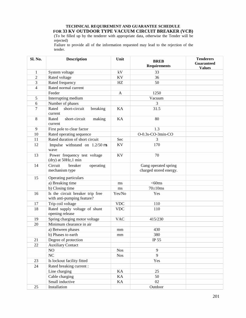
201
TECHNICAL REQUIREMENT AND GUARANTEE SCHEDULEFOR 33 KV OUTDOOR TYPE VACUUM CIRCUIT BREAKER (VCB)(To be filled up by the tenderer with appropriate data, otherwise the Tender will berejected)Failure to provide all of the information requested may lead to the rejection of thetender.
Sl. No. Description Unit BREBRequirements
TenderersGuaranteed
Values1 System voltage kV 332 Rated voltage KV 363 Rated frequency HZ 504 Rated normal current
Feeder A 12505 Interrupting medium Vacuum6 Number of phases 37 Rated short-circuit breaking
currentKA 31.5
8 Rated short-circuit makingcurrent
KA 80
9 First pole to clear factor 1.310 Rated operating sequence O-0.3s-CO-3min-CO11 Rated duration of short circuit Sec 312 Impulse withstand on 1.2/50 s
waveKV 170
13 Power frequency test voltage(dry) at 50Hz,1 min
KV 70
14 Circuit breaker operatingmechanism type
Gang operated springcharged stored energy.
15 Operating particularsa) Breaking time ms <60msb) Closing time ms 70±10ms
16 Is the circuit breaker trip freewith anti-pumping feature?
Yes/No Yes
17 Trip coil voltage VDC 11018 Rated supply voltage of shunt
opening releaseVDC 110
19 Spring charging motor voltage VAC 415/23020 Minimum clearance in air
a) Between phases mm 430b) Phases to earth mm 380
21 Degree of protection IP 5522 Auxiliary Contact
NO Nos 9NC Nos 9
23 Is lockout facility fitted Yes24 Rated breaking current :
Line charging KA 25Cable charging KA 50Small inductive KA 02
25 Installation Outdoor
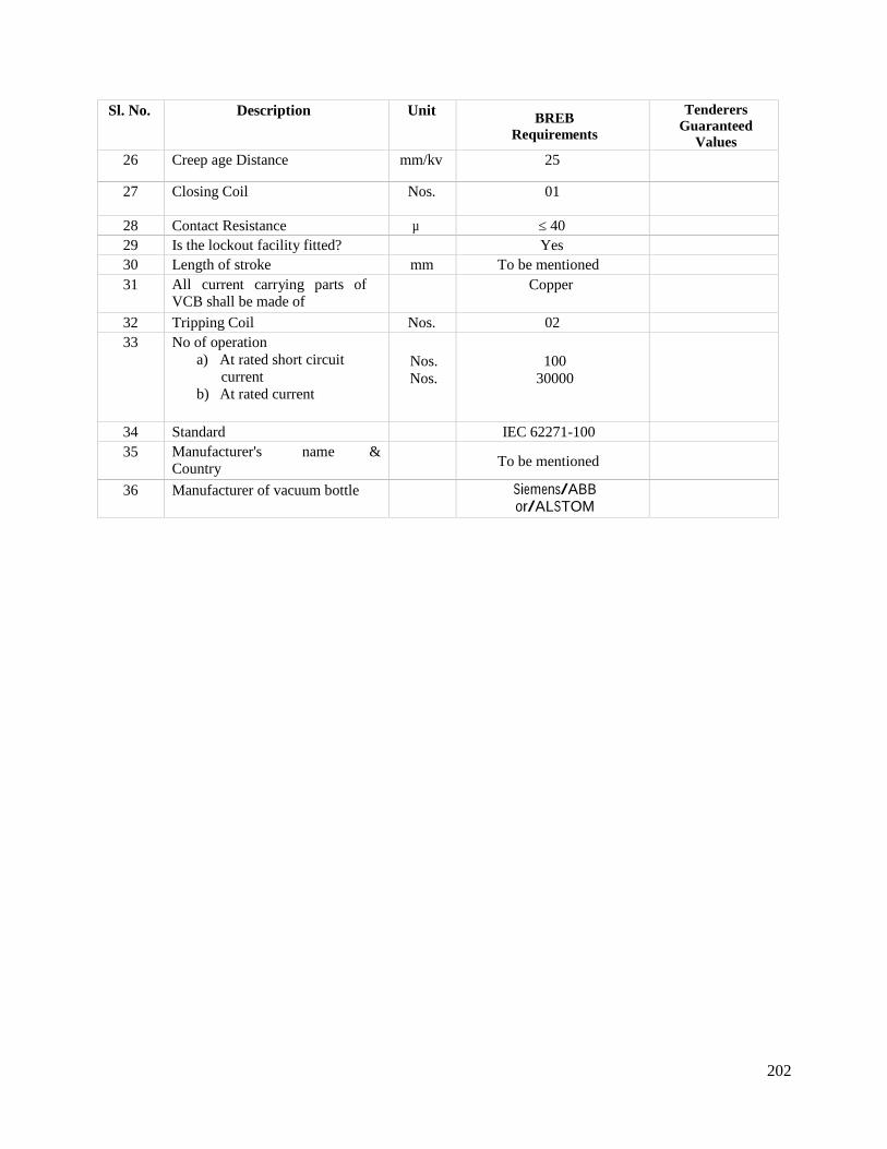
202
Sl. No. Description Unit BREBRequirements
TenderersGuaranteed
Values26 Creep age Distance mm/kv 25
27 Closing Coil Nos. 01
28 Contact Resistance µ ≤ 4029 Is the lockout facility fitted? Yes30 Length of stroke mm To be mentioned31 All current carrying parts of
VCB shall be made ofCopper
32 Tripping Coil Nos. 0233 No of operation
a) At rated short circuitcurrent
b) At rated current
Nos.Nos.
10030000
34 Standard IEC 62271-10035 Manufacturer's name &
Country To be mentioned
36 Manufacturer of vacuum bottle Siemens/ABBor/ALSTOM
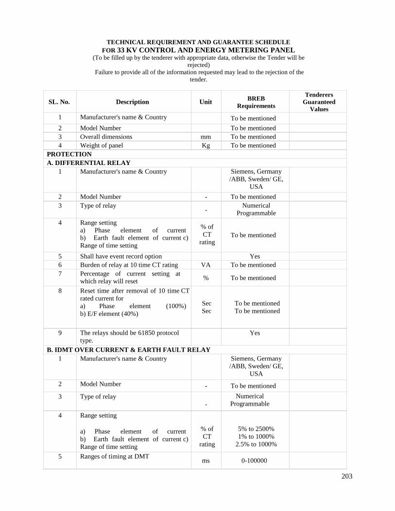
203
TECHNICAL REQUIREMENT AND GUARANTEE SCHEDULEFOR 33 KV CONTROL AND ENERGY METERING PANEL
(To be filled up by the tenderer with appropriate data, otherwise the Tender will berejected)
Failure to provide all of the information requested may lead to the rejection of thetender.
SL. No. Description Unit BREBRequirements
TenderersGuaranteed
Values1 Manufacturer's name & Country To be mentioned
2 Model Number To be mentioned3 Overall dimensions mm To be mentioned4 Weight of panel Kg To be mentioned
PROTECTIONA. DIFFERENTIAL RELAY
1 Manufacturer's name & Country Siemens, Germany/ABB, Sweden/ GE,
USA
2 Model Number - To be mentioned3 Type of relay
-Numerical
Programmable
4 Range settinga) Phase element of currentb) Earth fault element of current c)Range of time setting
% ofCT
ratingTo be mentioned
5 Shall have event record option Yes6 Burden of relay at 10 time CT rating VA To be mentioned7 Percentage of current setting at
which relay will reset % To be mentioned
8 Reset time after removal of 10 time CTrated current fora) Phase element (100%)b) E/F element (40%)
SecSec
To be mentionedTo be mentioned
9 The relays should be 61850 protocoltype.
Yes
B. IDMT OVER CURRENT & EARTH FAULT RELAY1 Manufacturer's name & Country Siemens, Germany
/ABB, Sweden/ GE,USA
2 Model Number - To be mentioned
3 Type of relay-
NumericalProgrammable
4 Range setting
a) Phase element of currentb) Earth fault element of current c)Range of time setting
% ofCT
rating
5% to 2500%1% to 1000%
2.5% to 1000%
5 Ranges of timing at DMTms 0-100000
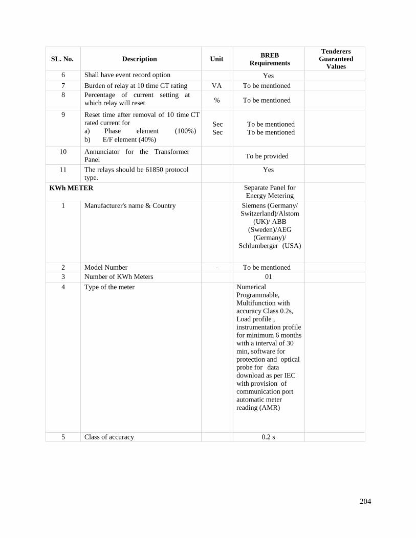
204
SL. No. Description Unit BREBRequirements
TenderersGuaranteed
Values6 Shall have event record option Yes
7 Burden of relay at 10 time CT rating VA To be mentioned8 Percentage of current setting at
which relay will reset % To be mentioned
9 Reset time after removal of 10 time CTrated current fora) Phase element (100%)b) E/F element (40%)
SecSec
To be mentionedTo be mentioned
10 Annunciator for the TransformerPanel To be provided
11 The relays should be 61850 protocoltype.
Yes
KWh METER Separate Panel forEnergy Metering
1 Manufacturer's name & Country Siemens (Germany/Switzerland)/Alstom
(UK)/ ABB(Sweden)/AEG
(Germany)/Schlumberger (USA)
2 Model Number - To be mentioned3 Number of KWh Meters 01
4 Type of the meter NumericalProgrammable,Multifunction withaccuracy Class 0.2s,Load profile ,instrumentation profilefor minimum 6 monthswith a interval of 30min, software forprotection and opticalprobe for datadownload as per IECwith provision ofcommunication portautomatic meterreading (AMR)
5 Class of accuracy 0.2 s
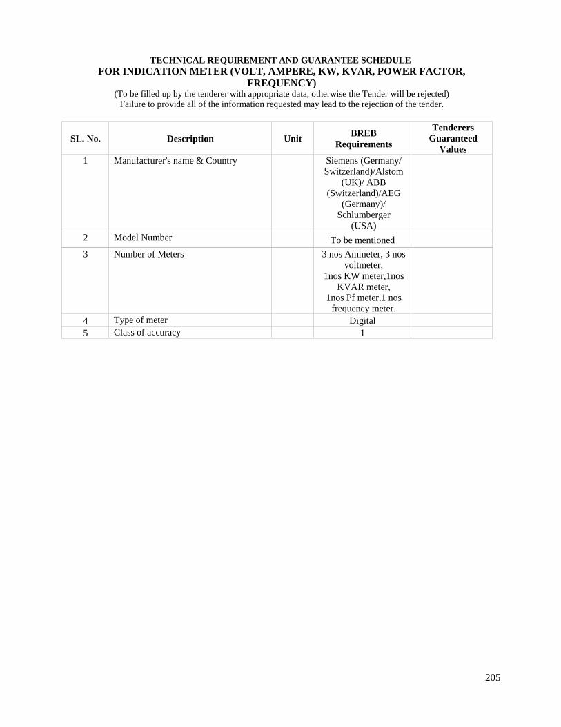
205
TECHNICAL REQUIREMENT AND GUARANTEE SCHEDULEFOR INDICATION METER (VOLT, AMPERE, KW, KVAR, POWER FACTOR,
FREQUENCY)(To be filled up by the tenderer with appropriate data, otherwise the Tender will be rejected)
Failure to provide all of the information requested may lead to the rejection of the tender.
SL. No. Description Unit BREBRequirements
TenderersGuaranteed
Values1 Manufacturer's name & Country Siemens (Germany/
Switzerland)/Alstom(UK)/ ABB
(Switzerland)/AEG(Germany)/
Schlumberger(USA)
2 Model Number To be mentioned
3 Number of Meters 3 nos Ammeter, 3 nosvoltmeter,
1nos KW meter,1nosKVAR meter,
1nos Pf meter,1 nosfrequency meter.
4 Type of meter Digital5 Class of accuracy 1
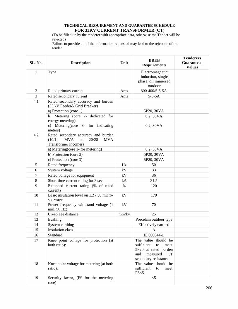
206
TECHNICAL REQUIREMENT AND GUARANTEE SCHEDULEFOR 33KV CURRENT TRANSFORMER (CT)
(To be filled up by the tenderer with appropriate data, otherwise the Tender will berejected)Failure to provide all of the information requested may lead to the rejection of thetender.
SL. No. Description Unit BREBRequirements
TenderersGuaranteed
Values1 Type Electromagnetic
induction, singlephase, oil immersed
outdoor2 Rated primary current Ams 800-400/5-5-5A3 Rated secondary current Ams 5-5-5A
4.1 Rated secondary accuracy and burden(33 kV Feeder& Grid Breaker)a) Protection (core 1) 5P20, 30VAb) Metering (core 2- dedicated forenergy metering)
0.2, 30VA
c) Metering(core 3- for indicatingmeters)
0.2, 30VA
4.2 Rated secondary accuracy and burden(10/14 MVA or 20/28 MVATransformer Incomer)a) Metering(core 1- for metering) 0.2, 30VAb) Protection (core 2) 5P20, 30VAc) Protection (core 3) 5P20, 30VA
5 Rated frequency Hz 506 System voltage kV 337 Rated voltage for equipment kV 368 Short time current rating for 3 sec. kA 31.59 Extended current rating (% of rated
current)% 120
10 Basic insulation level on 1.2 / 50 micro-sec wave
kV 170
11 Power frequency withstand voltage (1min, 50 Hz)
kV 70
12 Creep age distance mm/kv 2513 Bushing Porcelain outdoor type14 System earthing Effectively earthed15 Insulation class A16 Standard IEC60044-117 Knee point voltage for protection (at
both ratio):The value should besufficient to meet5P20 at rated burdenand measured CTsecondary resistance.
18 Knee point voltage for metering (at bothratio):
The value should besufficient to meetFS<5
19 Security factor, (FS for the meteringcore)
<5
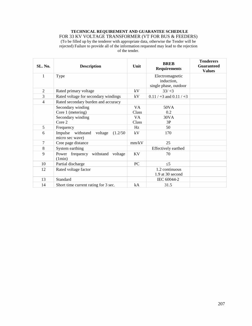
207
TECHNICAL REQUIREMENT AND GUARANTEE SCHEDULEFOR 33 KV VOLTAGE TRANSFORMER (VT FOR BUS & FEEDERS)(To be filled up by the tenderer with appropriate data, otherwise the Tender will be
rejected) Failure to provide all of the information requested may lead to the rejectionof the tender.
SL. No. Description Unit BREBRequirements
TenderersGuaranteed
Values1 Type Electromagnetic
induction,single phase, outdoor
2 Rated primary voltage kV 33/ 33 Rated voltage for secondary windings kV 0.11 / 3 and 0.11 / 34 Rated secondary burden and accuracy
Secondary windingCore 1 (metering)
VAClass
50VA0.2
Secondary windingCore 2
VAClass
30VA3P
5 Frequency Hz 506 Impulse withstand voltage (1.2/50
micro sec wave)kV 170
7 Cree page distance mm/kV 258 System earthing Effectively earthed9 Power frequency withstand voltage
(1min)KV 70
10 Partial discharge PC ≤512 Rated voltage factor 1.2 continuous
1.9 at 30 second13 Standard IEC 60044-214 Short time current rating for 3 sec. kA 31.5
208
PUBLICATION NO: 1002-1999BANGLADESH RURAL ELECTRIFICATION BOARD (BREB)
TECHNICAL SPECIFICATION FOR 11 KV INDOOR TYPEVACUUM CIRCUIT BREAKER/SWITCHGEAR
1. 11 KV Indoor Switchgear
1.1 General
The 11 kV switchgear shall consist of a single bus-bar, metal clad, indoor type, floormounted, single tier integrated unit, incorporating enclosures for the circuit breaker units,bus-bars, current transformers and auxiliary wiring.
Each 11 kV CB shall be provided with a combined relay & control panel forming anintegral part of the circuit breaker equipment. All in door 11 kV feeders/ bus CTs and busPTs shall be dry/ cast resin type.
The panels shall be equipped with the necessary protection control devices, indicatinginstruments and alarming devices, MCBs, etc. All the relays should be 61850 protocol typefor automation network of the 33/11.55 kV Sub-station.
The switchgear shall be of robust construction designed for maximum reliability of servicein the tropical climate specified.
Cable boxes shall be supplied complete with glands and terminal lugs.
1.2 Clearances
Maximum insulator lengths and clearances in air shall be not less than those specified for 11kV switchgear having 75 KVp Basic Impulse Level.
1.3 Current Ratings
All parts of the switchgear, including current transformers, shall be capable of withstanding,without thermal of mechanical damage, the instantaneous peak and the three second shorttime current corresponding to the rated making and breaking capacity of the circuitbreakers.
All normal current specified are the minimum continuous values required under the serviceconditions appertaining to Bangladesh.
1.4 Circuit Breaker making and Breaking capacities
Each circuit breaker shall be capable of making and breaking short circuit faults inaccordance with the requirements of IEC 56 - Circuit Breaker, at 3 phase symmetricalcircuit ratings at 11 kV service voltages as stated in the schedules.
209
1.5 Circuit Breakers
1.5.1 Type
The 11 kV circuit breakers shall be vacuum type in accordance with IEC 56 as appropriate.
All types shall incorporate horizontal isolation facilities and be mounted on horizontaldraw-out type.
1.5.2 Interchangeability of Circuit Breakers
Circuit breaker of the same type and current rating shall be interchangeable, bothelectrically and mechanically, but it must be impossible to interchange equipment ofdifferent current ratings.
1.5.3 Circuit Breaker Operation Mechanism
Circuit breaker closing mechanisms shall be 230-volt a.c motor wound preferably springoperated type such that the closing speed is independent of the operator.
11kV switchgear tripping shall be effected by means of 02 nos. of 110 volt dc shunt tripcoil.
Each equipment shall be provided with a visual, mechanized, indicating device, which shallbe positively driven in both directions to show whether the circuit breaker is “Open” or“Closed”. It shall be operative when the circuit breaker is in the “Service” and “Test”locations. Lamp indication in place of a mechanical indicator will not be accepted.Operation counters shall be provided on each mechanism.
Means shall be provided for coupling the secondary circuits on the fixed portion to those onthe movable portion when the circuit breaker is isolated in order to permit closing, trippingand interlock circuits to be checked for operation test purposes.
Means shall be provided for local manual mechanical tripping of circuit breakers, preferablyby push buttons, shrouded to prevent inadvertent operation.
Locking facilities shall be provided so that with the circuit breaker in any location it can beprevented from being closed when it is open and from being mechanical tripped when it isclosed. This requirement shall be met by the fitting of a single padlock and shall not entailthe fitting of any loose components prior to the insertion of the padlock.
It shall not be possible, without the use of tools, to gain access to the tripping toggle or anypart of the mechanism which would permit defeat of the locking of the mechanical trippingfeature.It shall not be possible to render the electrical tripping feature inoperative by anymechanical locking device.1.5.4 Circuit Breaker Isolating FeaturesIrrespective of the operating type of unit the following shall apply.Each circuit breaker shall be connected to the bus bars and feeder circuit through plug andsocket type isolating devices. The devices shall be of the “Off Load Type” but shall besuitable for operation whilst the bus bars and/or feeder circuits are alive.
210
Isolating devices shall be interlocked with their respective circuit breakers to prevent theirmaking or breaking load, but arrangements whereby attempted isolation of a closed circuitbreaker trips the circuit breaker are not permitted.
The main circuit isolating devices and also all secondary circuit isolating contacts shall beof the self-aligning type, mounted in accessible positions to permit maintenance.
The number of auxiliary circuit isolating switches shall be sufficient to meet the facilities.
1.5.5 InterlocksAll mechanical interlocks shall be of the preventive type and shall be arranged to preventmal operation as close as possible to the point at which mechanical force is applied, in orderto prevent defeat of the interlocks by distortion of linkages Electrical interlocks shall alsofunction so as to prevent the closing of the circuit breaker.
Clearly labeled mechanical interlocks shall be provided which are designed to prevent:
a) A closed circuit breaker from being withdrawn or inserted into the isolating contacts.b) Tripping by attempted isolation.c) The closing of a circuit breaker except when correctly located in Service or Test
positions.d) A circuit breaker from being plugged into the isolation contacts if the tank is not in
positione) A circuit breaker being closed in the service position when the secondary circuits
between the fixed and moving portions are not completed.
In addition electrical interlocks may be utilized to ensure safe operation of the plant; i.e. on11 kV transformer incoming circuits the circuit earth position shall not be operative unlessthe 33 kV circuit is de-energized and isolated etc.
1.5.6 Safety Shutter Devices
A set metal shutters shall be provided to cover each 3 phase group of stationary isolatingcontacts.
The shutters shall open automatically by a positive drive initiated by the movement of thecircuit breaker. The closing operation shall also be automatic by positive driveWhen padlocked closed, the shutters shall completely shroud the stationary contacts and itshall not be possible to force the shutters or part of the shutters to gain access to thestationary contacts.To facilitate testing, means other than locking shall be provided for securing the shutters inthe open position. However, such means shall be automatically cancelled when theautomatic operation of the shutters restored upon reconnection of the circuit breaker.
Bus-bar shutters shall be painted signal red, colour 537 in BS 381 C, and shall be clearlyand indelibly labeled “BUSBARS” in large white letter in English. The Contractor mayoffer works which comply with different standards or codes only if, and when requested bythe Project Manager Circuit shutters shall be painted yellow, colour 355 in BS 381 C, butshall not be lettered, except that on incoming feeders the circuit shutters shall be clearly andindelibly labeled “DANGER LIVE CABLES” in large red letters.
211
Voltage transformer spout shutters shall be painted yellow, colour 355 in BS 381 C.Durable phase colour identification shall be provided in a prominent position. Provision oraccess shall be made for lubricating the mechanical linkages.
All shutters shall be effectively earthed
Shutters shall not operate towards the fixed isolating contacts.
1.5.7 Bus-bars and Connections
The equipment shall be of single bus-bar type. Bus-bars and connection shall comply withapplicable clauses of IEC 298 and shall be fully insulated.
The equipment shall be of single bus-bar type. The bus-bar assemblies shall be of a typewhich shall not rely only on air for insulation purpose.
Any earthed screen applied to the exterior of the insulation shall be securely earthed in eachbus-bar compartments.
The insulation of the bus-bars and their connections shall be capable of withstanding,without damage, the thermal and mechanical effect of a through fault current equivalent tothe short-time rating of the switchgear.
Access to bus-bars and the connections directly thereto shall be gained only by the removalof covers secured by bolts or screws. Such covers shall be marked clearly and indelibly“BUSBARS”
Bus-bars shall extensible at both ends; such extension shall entail the minimum possibledisturbance to the bus-bar chambers. Compound filled bus-bar chambers are not acceptable.
1.5.8 Earthing of Metal Parts of SwitchgearAll metal parts, other than those forming part of an electrical circuit, shall be connected to ahard-drawn, high conductivity, copper earth conductor on each unit, of adequate sectionalarea.
The frame of draw-out circuit breakers shall be connected to the earth bar through asubstantial plug type contact and the plug shall be long enough to allow the bus-bar andfeeder shutters to close before breaking contact.
Interlocking (both mechanical & electrical) must be provided to avoid accidental earthingcircuit breaker in “service position”.1.5.9 Earthing of InsulationsEarthing of the switchgear and ancillary panels and auxiliary equipment shall be carried outin accordance with IEEE Standard 80 & 142 where applicable.
1.5.10 InsulatorsPorcelain insulators shall be best quality electrical porcelain. The clamping surfaces of allporcelain insulators shall be accurately ground and shall be free of glaze.Insulators of moulded or resin bonded material shall have a durable, non-hygroscopicsurface finish having a high anti-tracking index.
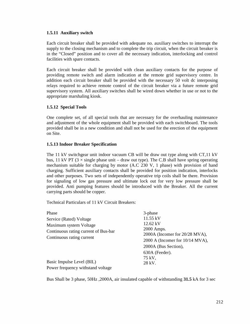
212
1.5.11 Auxiliary switch
Each circuit breaker shall be provided with adequate no. auxiliary switches to interrupt thesupply to the closing mechanism and to complete the trip circuit, when the circuit breaker isin the “Closed” position and to cover all the necessary indication, interlocking and controlfacilities with spare contacts.
Each circuit breaker shall be provided with clean auxiliary contacts for the purpose ofproviding remote switch and alarm indication at the remote grid supervisory centre. Inaddition each circuit breaker shall be provided with the necessary 50 volt dc interposingrelays required to achieve remote control of the circuit breaker via a future remote gridsupervisory system. All auxiliary switches shall be wired down whether in use or not to theappropriate marshaling kiosk.
1.5.12 Special Tools
One complete set, of all special tools that are necessary for the overhauling maintenanceand adjustment of the whole equipment shall be provided with each switchboard. The toolsprovided shall be in a new condition and shall not be used for the erection of the equipmenton Site.
1.5.13 Indoor Breaker Specification
The 11 kV switchgear unit indoor vacuum CB will be draw out type along with CT,11 kVbus, 11 kV PT (3 × single phase unit – draw out type). The C.B shall have spring operatingmechanism suitable for charging by motor (A.C 230 V, 1 phase) with provision of handcharging. Sufficient auxiliary contacts shall be provided for position indication, interlocksand other purposes. Two sets of independently operative trip coils shall be there. Provisionfor signaling of low gas pressure and ultimate lock out for very low pressure shall beprovided. Anti pumping features should be introduced with the Breaker. All the currentcarrying parts should be copper.
Technical Particulars of 11 kV Circuit Breakers:
PhaseService (Rated) VoltageMaximum system VoltageContinuous rating current of Bus-barContinuous rating current
Basic Impulse Level (BIL)Power frequency withstand voltage
3-phase11.55 kV12.62 kV2000 Amps.2000A (Incomer for 20/28 MVA),2000 A (Incomer for 10/14 MVA),2000A (Bus Section),630A (Feeder).75 kV,28 kV.
Bus Shall be 3 phase, 50Hz ,2000A, air insulated capable of withstanding 31.5 kA for 3 sec

213
Vacuum Interrupter
The vacuum interrupter, consisting of fixed contact and moving contact, shall beinterchangeable among the same type interrupter. Short circuit capacity of vacuum bottleshould be 31.5 KA and design life should be 100 nos. Operation at rated short circuit level.The operation of the interrupter will be 30000 nos. at rated current.
Vacuum Bottle shall be from Siemens/ABB or/ALSTOM and of reputed indigenous make.Offered bottle shall be identical with Type tested one. Brochures/leaflet on technical datasheet for vacuum bottle shall be enclosed with technical bid.
1.5.14 Current Transformers (CTs).
The current transformer rated current ratio shall match the connected load circuit andsecondary circuit requirements.
Current transformers shall be capable of withstanding without damage the full load, peakand rated short time currents of their associated equipment.
Where space within a current transformer chamber permits dedicated current transformersshall be used for protection, instrumentation and metering. All the indoor 11 kV CTs shallbe dry/ cast resin type.
Current transformers used for energizing indicating instruments and metering shall be ofClass 0.2 accuracy in accordance with IEC 185Current transformers for protective andprotective/indication purposes shall be designed to suit the particular requirements of theassociated protection, which in general shall be in accordance with the recommendationsgiven in BS 3938 or approved equivalent.
Class 5p current transformers shall be used for inverse time over-current and/or earth faultprotection. The rated accuracy limit current shall be equivalent to the maximumsymmetrical three phase fault current or earth fault current of the protected circuit orequivalent to the switchgear breaking capacity unless otherwise approved by the ProjectManager.
The current transformers shall be capable of meeting the 5p error classification at ratedaccuracy limit current over the full range of relay settings, unless otherwise approved by theProject Manager.
Current transformers used for indication/metering purposes shall be designed to saturate at avalue of primary current sufficiently low to protect the secondary circuit from damage at allpossible values of primary fault current up to the associated primary short time thermalrating.
Current transformers for combined purposes (e.g. protection relays and indicating meters)shall have a dual Class 5p/Class 0.2 performance, and the secondary circuit shall have anapproved means (saturating reactor or saturating interposing C.T.) of protecting the metersand reducing their burden under system fault conditions.The rated volt-amp output of each current transformer shall not be less than 110% of theconnected burden as installed in service, the burden of cable connections being taken intoaccount.
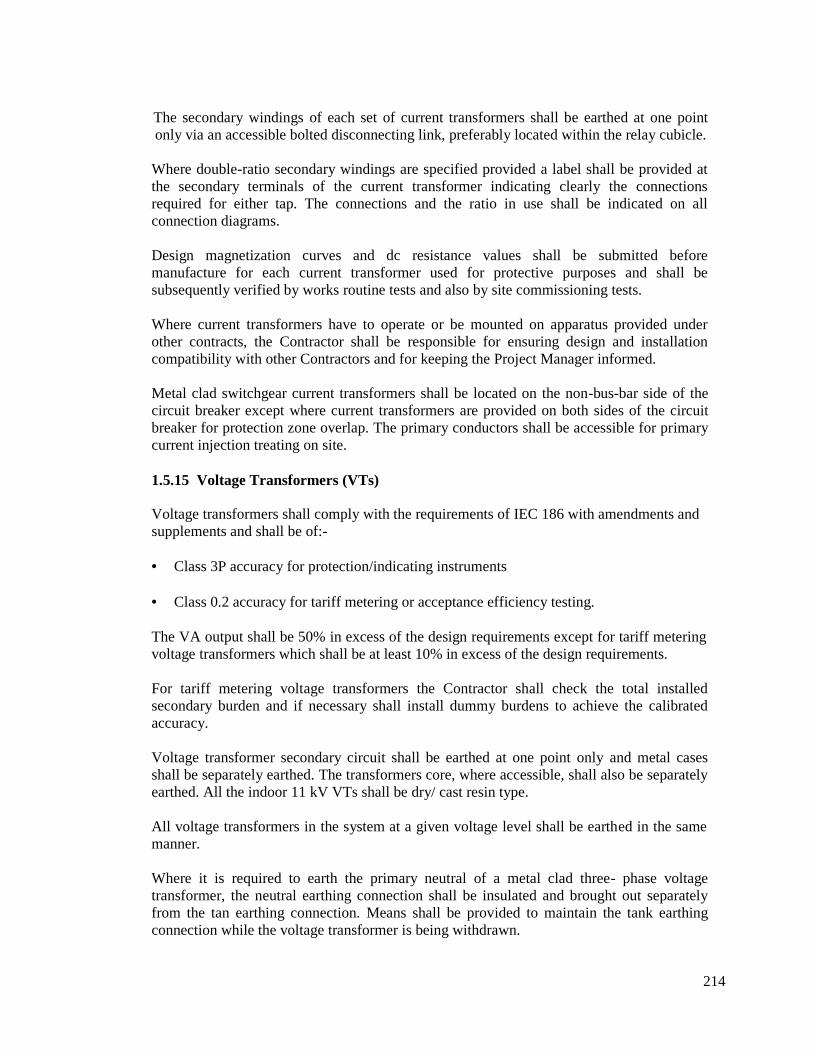
214
The secondary windings of each set of current transformers shall be earthed at one pointonly via an accessible bolted disconnecting link, preferably located within the relay cubicle.
Where double-ratio secondary windings are specified provided a label shall be provided atthe secondary terminals of the current transformer indicating clearly the connectionsrequired for either tap. The connections and the ratio in use shall be indicated on allconnection diagrams.
Design magnetization curves and dc resistance values shall be submitted beforemanufacture for each current transformer used for protective purposes and shall besubsequently verified by works routine tests and also by site commissioning tests.
Where current transformers have to operate or be mounted on apparatus provided underother contracts, the Contractor shall be responsible for ensuring design and installationcompatibility with other Contractors and for keeping the Project Manager informed.
Metal clad switchgear current transformers shall be located on the non-bus-bar side of thecircuit breaker except where current transformers are provided on both sides of the circuitbreaker for protection zone overlap. The primary conductors shall be accessible for primarycurrent injection treating on site.
1.5.15 Voltage Transformers (VTs)
Voltage transformers shall comply with the requirements of IEC 186 with amendments andsupplements and shall be of:-
Class 3P accuracy for protection/indicating instruments
Class 0.2 accuracy for tariff metering or acceptance efficiency testing.
The VA output shall be 50% in excess of the design requirements except for tariff meteringvoltage transformers which shall be at least 10% in excess of the design requirements.
For tariff metering voltage transformers the Contractor shall check the total installedsecondary burden and if necessary shall install dummy burdens to achieve the calibratedaccuracy.
Voltage transformer secondary circuit shall be earthed at one point only and metal casesshall be separately earthed. The transformers core, where accessible, shall also be separatelyearthed. All the indoor 11 kV VTs shall be dry/ cast resin type.
All voltage transformers in the system at a given voltage level shall be earthed in the samemanner.
Where it is required to earth the primary neutral of a metal clad three- phase voltagetransformer, the neutral earthing connection shall be insulated and brought out separatelyfrom the tan earthing connection. Means shall be provided to maintain the tank earthingconnection while the voltage transformer is being withdrawn.
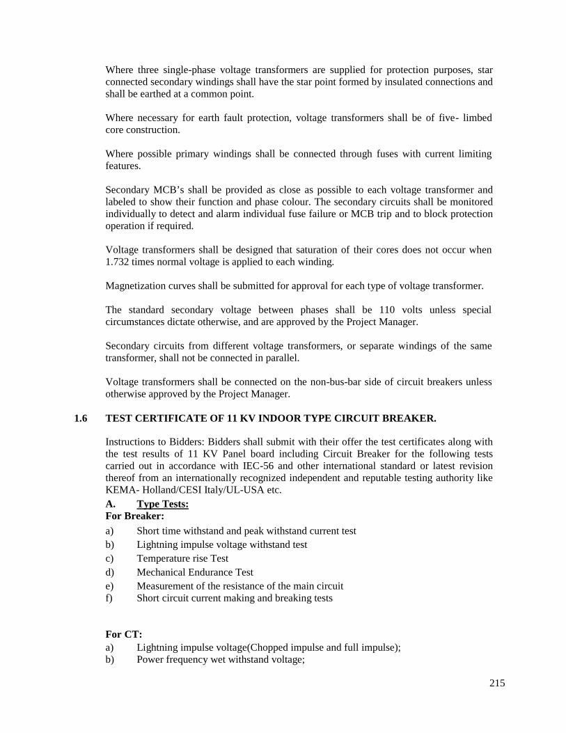
215
Where three single-phase voltage transformers are supplied for protection purposes, starconnected secondary windings shall have the star point formed by insulated connections andshall be earthed at a common point.
Where necessary for earth fault protection, voltage transformers shall be of five- limbedcore construction.
Where possible primary windings shall be connected through fuses with current limitingfeatures.
Secondary MCB’s shall be provided as close as possible to each voltage transformer andlabeled to show their function and phase colour. The secondary circuits shall be monitoredindividually to detect and alarm individual fuse failure or MCB trip and to block protectionoperation if required.
Voltage transformers shall be designed that saturation of their cores does not occur when1.732 times normal voltage is applied to each winding.
Magnetization curves shall be submitted for approval for each type of voltage transformer.
The standard secondary voltage between phases shall be 110 volts unless specialcircumstances dictate otherwise, and are approved by the Project Manager.
Secondary circuits from different voltage transformers, or separate windings of the sametransformer, shall not be connected in parallel.
Voltage transformers shall be connected on the non-bus-bar side of circuit breakers unlessotherwise approved by the Project Manager.
1.6 TEST CERTIFICATE OF 11 KV INDOOR TYPE CIRCUIT BREAKER.
Instructions to Bidders: Bidders shall submit with their offer the test certificates along withthe test results of 11 KV Panel board including Circuit Breaker for the following testscarried out in accordance with IEC-56 and other international standard or latest revisionthereof from an internationally recognized independent and reputable testing authority likeKEMA- Holland/CESI Italy/UL-USA etc.A. Type Tests:For Breaker:a) Short time withstand and peak withstand current testb) Lightning impulse voltage withstand testc) Temperature rise Testd) Mechanical Endurance Teste) Measurement of the resistance of the main circuitf) Short circuit current making and breaking tests
For CT:a) Lightning impulse voltage(Chopped impulse and full impulse);b) Power frequency wet withstand voltage;
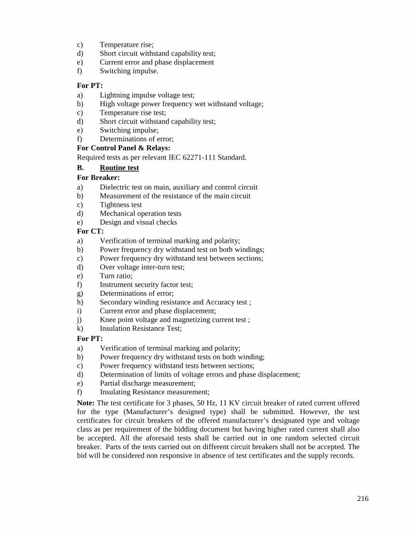
216
c) Temperature rise;d) Short circuit withstand capability test;e) Current error and phase displacementf) Switching impulse.
For PT:a) Lightning impulse voltage test;b) High voltage power frequency wet withstand voltage;c) Temperature rise test;d) Short circuit withstand capability test;e) Switching impulse;f) Determinations of error;For Control Panel & Relays:Required tests as per relevant IEC 62271-111 Standard.B. Routine testFor Breaker:a) Dielectric test on main, auxiliary and control circuitb) Measurement of the resistance of the main circuitc) Tightness testd) Mechanical operation testse) Design and visual checksFor CT:a) Verification of terminal marking and polarity;b) Power frequency dry withstand test on both windings;c) Power frequency dry withstand test between sections;d) Over voltage inter-turn test;e) Turn ratio;f) Instrument security factor test;g) Determinations of error;h) Secondary winding resistance and Accuracy test ;i) Current error and phase displacement;j) Knee point voltage and magnetizing current test ;k) Insulation Resistance Test;For PT:a) Verification of terminal marking and polarity;b) Power frequency dry withstand tests on both winding;c) Power frequency withstand tests between sections;d) Determination of limits of voltage errors and phase displacement;e) Partial discharge measurement;f) Insulating Resistance measurement;
Note: The test certificate for 3 phases, 50 Hz, 11 KV circuit breaker of rated current offeredfor the type (Manufacturer’s designed type) shall be submitted. However, the testcertificates for circuit breakers of the offered manufacturer’s designated type and voltageclass as per requirement of the bidding document but having higher rated current shall alsobe accepted. All the aforesaid tests shall be carried out in one random selected circuitbreaker. Parts of the tests carried out on different circuit breakers shall not be accepted. Thebid will be considered non responsive in absence of test certificates and the supply records.
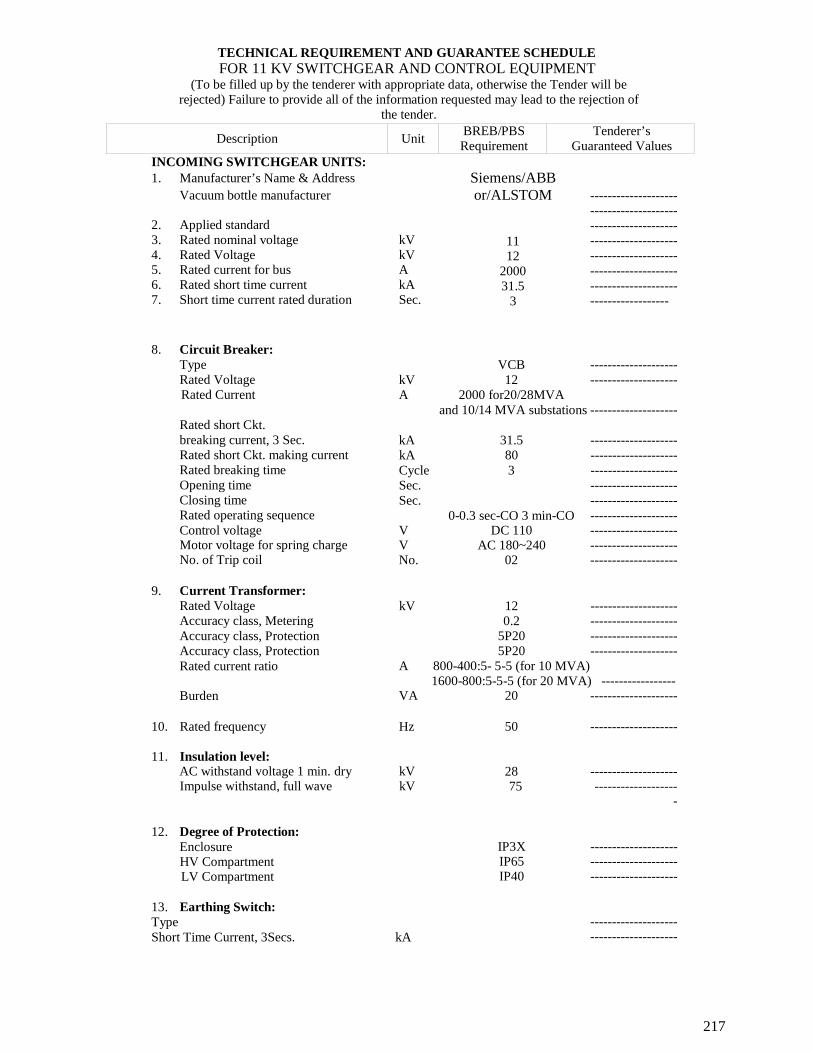
217
TECHNICAL REQUIREMENT AND GUARANTEE SCHEDULEFOR 11 KV SWITCHGEAR AND CONTROL EQUIPMENT
(To be filled up by the tenderer with appropriate data, otherwise the Tender will berejected) Failure to provide all of the information requested may lead to the rejection of
the tender.
Description UnitBREB/PBSRequirement
Tenderer’sGuaranteed Values
INCOMING SWITCHGEAR UNITS:1. Manufacturer’s Name & Address
Vacuum bottle manufacturer
2. Applied standard3. Rated nominal voltage kV4. Rated Voltage kV5. Rated current for bus A6. Rated short time current kA7. Short time current rated duration Sec.
Siemens/ABBor/ALSTOM
1112
200031.5
3
--------------------------------------------------------------------------------------------------------------------------------------------------------------
8. Circuit Breaker:TypeRated VoltageRated Current
Rated short Ckt.breaking current, 3 Sec.Rated short Ckt. making currentRated breaking timeOpening timeClosing timeRated operating sequenceControl voltageMotor voltage for spring chargeNo. of Trip coil
VCB --------------------kV 12 --------------------A 2000 for20/28MVA
and 10/14 MVA substations --------------------
kA 31.5 --------------------kA 80 --------------------Cycle 3 --------------------Sec. --------------------Sec. --------------------
0-0.3 sec-CO 3 min-CO --------------------V DC 110 --------------------V AC 180~240 --------------------No. 02 --------------------
9. Current Transformer:Rated VoltageAccuracy class, MeteringAccuracy class, ProtectionAccuracy class, ProtectionRated current ratio
Burden
kV 12 --------------------0.2 --------------------
5P20 --------------------5P20 --------------------
A 800-400:5- 5-5 (for 10 MVA)1600-800:5-5-5 (for 20 MVA) -----------------
VA 20 --------------------
10. Rated frequency Hz
11. Insulation level:AC withstand voltage 1 min. dry kVImpulse withstand, full wave kV
50 --------------------
28 --------------------75 -------------------
-
12. Degree of Protection:EnclosureHV CompartmentLV Compartment
IP3X --------------------IP65 --------------------IP40 --------------------
13. Earthing Switch:TypeShort Time Current, 3Secs. kA
----------------------------------------
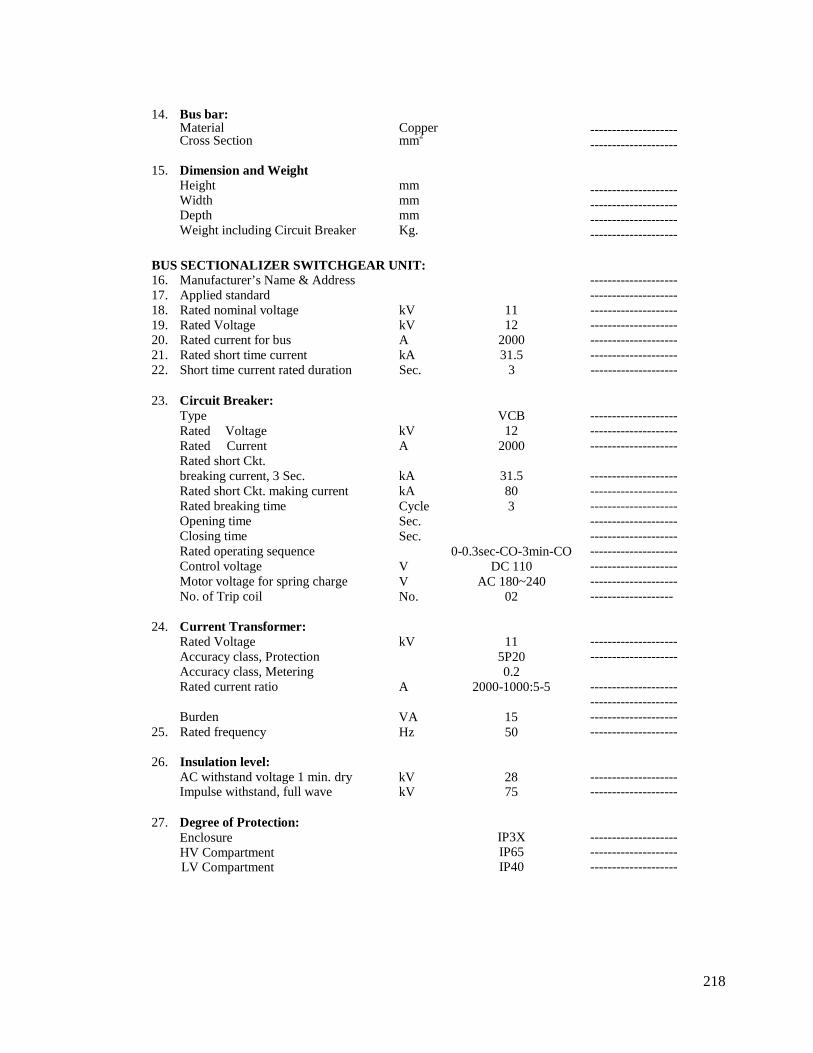
218
14. Bus bar:Material CopperCross Section mm2
15. Dimension and WeightHeight mmWidth mmDepth mmWeight including Circuit Breaker Kg.
----------------------------------------
--------------------------------------------------------------------------------
BUS SECTIONALIZER SWITCHGEAR UNIT:16. Manufacturer’s Name & Address17. Applied standard18. Rated nominal voltage kV19. Rated Voltage kV20. Rated current for bus A21. Rated short time current kA22. Short time current rated duration Sec.
----------------------------------------
11 --------------------12 --------------------
2000 --------------------31.5 --------------------
3 --------------------
23. Circuit Breaker:TypeRated VoltageRated CurrentRated short Ckt.breaking current, 3 Sec.Rated short Ckt. making currentRated breaking timeOpening timeClosing timeRated operating sequenceControl voltageMotor voltage for spring chargeNo. of Trip coil
24. Current Transformer:Rated VoltageAccuracy class, ProtectionAccuracy class, MeteringRated current ratio
Burden25. Rated frequency
26. Insulation level:AC withstand voltage 1 min. dryImpulse withstand, full wave
VCBkV 12A 2000
kA 31.5kA 80Cycle 3Sec.Sec.
0-0.3sec-CO-3min-COV DC 110V AC 180~240No. 02
kV 115P200.2
A 2000-1000:5-5
VA 15Hz 50
kV 28kV 75
------------------------------------------------------------
-----------------------------------------------------------------------------------------------------------------------------------------------------------------------------------
----------------------------------------
--------------------------------------------------------------------------------
----------------------------------------
27. Degree of Protection:EnclosureHV CompartmentLV Compartment
IP3X --------------------IP65 --------------------IP40 --------------------
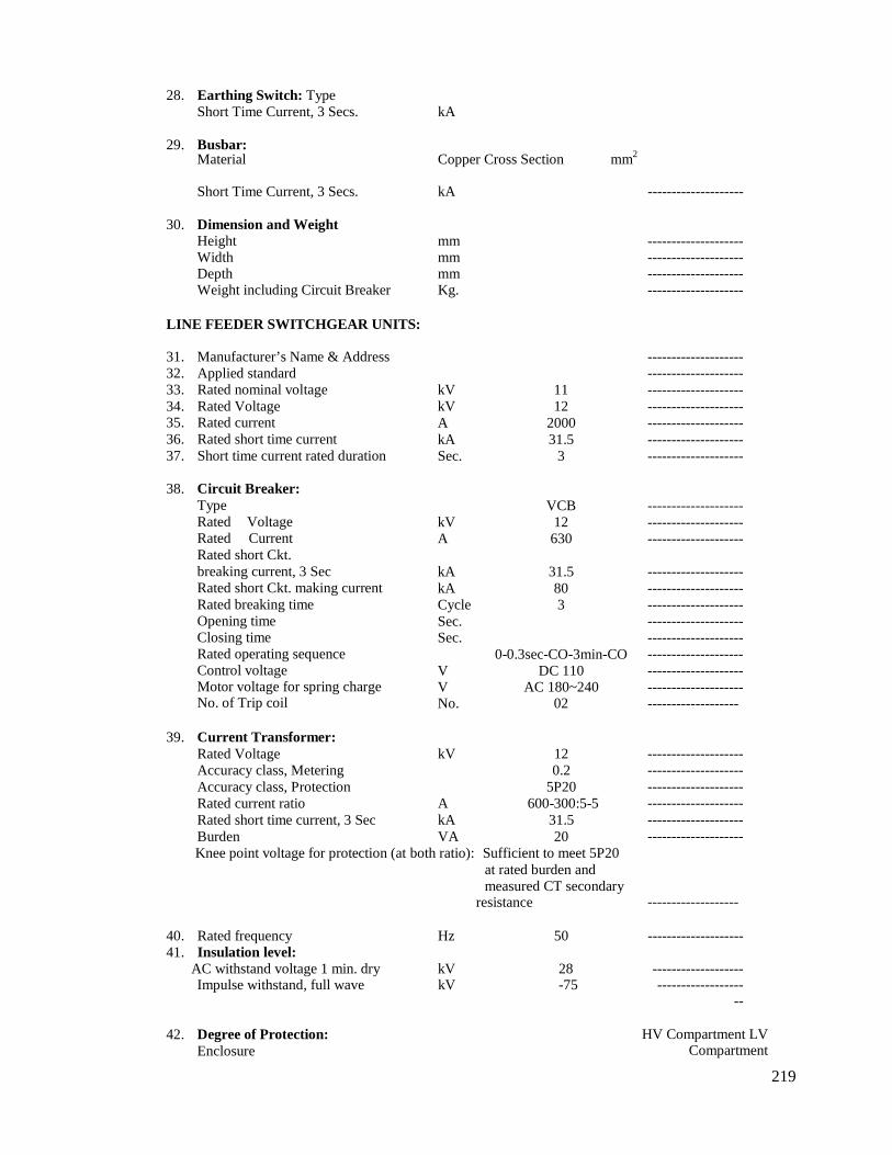
219
28. Earthing Switch: TypeShort Time Current, 3 Secs. kA
29. Busbar:Material Copper Cross Section mm2
Short Time Current, 3 Secs. kA --------------------
30. Dimension and WeightHeight mmWidth mmDepth mmWeight including Circuit Breaker Kg.
--------------------------------------------------------------------------------
LINE FEEDER SWITCHGEAR UNITS:
31. Manufacturer’s Name & Address32. Applied standard33. Rated nominal voltage34. Rated Voltage35. Rated current36. Rated short time current37. Short time current rated duration
38. Circuit Breaker:TypeRated VoltageRated CurrentRated short Ckt.breaking current, 3 SecRated short Ckt. making currentRated breaking timeOpening timeClosing timeRated operating sequenceControl voltageMotor voltage for spring chargeNo. of Trip coil
kV 11kV 12A 2000kA 31.5Sec. 3
VCBkV 12A 630
kA 31.5kA 80Cycle 3Sec.Sec.
0-0.3sec-CO-3min-COV DC 110V AC 180~240No. 02
--------------------------------------------------------------------------------------------------------------------------------------------
------------------------------------------------------------
-----------------------------------------------------------------------------------------------------------------------------------------------------------------------------------
39. Current Transformer:Rated Voltage kV 12Accuracy class, Metering 0.2Accuracy class, Protection 5P20Rated current ratio A 600-300:5-5Rated short time current, 3 Sec kA 31.5Burden VA 20Knee point voltage for protection (at both ratio): Sufficient to meet 5P20
at rated burden andmeasured CT secondary
resistance
------------------------------------------------------------------------------------------------------------------------
-------------------
40. Rated frequency Hz 50 --------------------41. Insulation level:
AC withstand voltage 1 min. dry kVImpulse withstand, full wave kV
28 --------------------75 ------------------
--
42. Degree of Protection:Enclosure
HV Compartment LVCompartment

220
IP3X --------------------IP65 --------------------IP40 --------------------
43. Earthing Switch:TypeShort Time Current, 3 Secs. kA
----------------------------------------
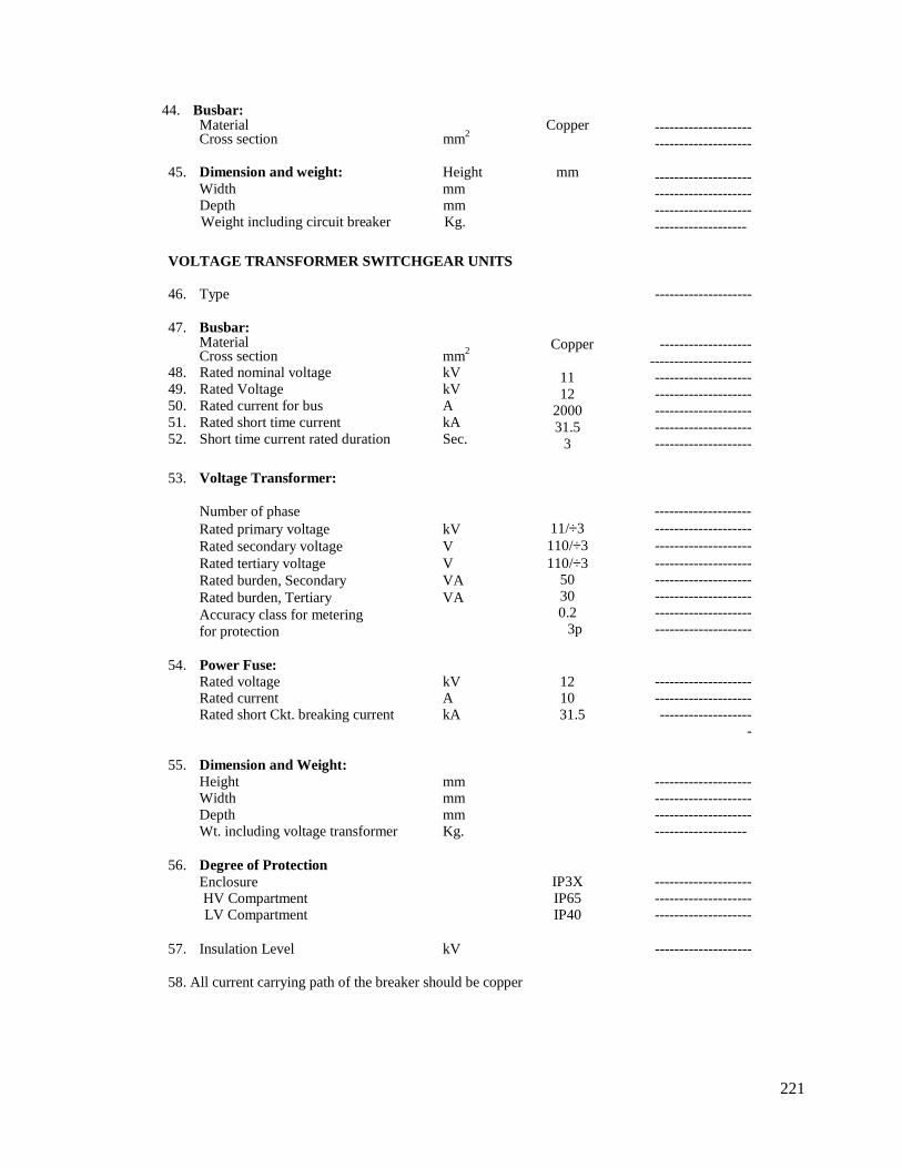
221
44. Busbar:Material CopperCross section mm2
45. Dimension and weight: Height mmWidth mmDepth mmWeight including circuit breaker Kg.
----------------------------------------
-------------------------------------------------------------------------------
VOLTAGE TRANSFORMER SWITCHGEAR UNITS
46. Type --------------------
47. Busbar:MaterialCross section mm2
48. Rated nominal voltage kV49. Rated Voltage kV50. Rated current for bus A51. Rated short time current kA52. Short time current rated duration Sec.
Copper ----------------------------------------
11 --------------------12 --------------------
2000 --------------------31.5 --------------------
3 --------------------
53. Voltage Transformer:
Number of phaseRated primary voltage kVRated secondary voltage VRated tertiary voltage VRated burden, Secondary VARated burden, Tertiary VAAccuracy class for meteringfor protection
--------------------11/3 --------------------110/3 --------------------110/3 --------------------
50 --------------------30 --------------------0.2 --------------------
3p --------------------
54. Power Fuse:Rated voltage kVRated current ARated short Ckt. breaking current kA
12 --------------------10 --------------------31.5 -------------------
-
55. Dimension and Weight:Height mmWidth mmDepth mmWt. including voltage transformer Kg.
-------------------------------------------------------------------------------
56. Degree of ProtectionEnclosureHV CompartmentLV Compartment
IP3X --------------------IP65 --------------------IP40 --------------------
57. Insulation Level kV --------------------
58. All current carrying path of the breaker should be copper
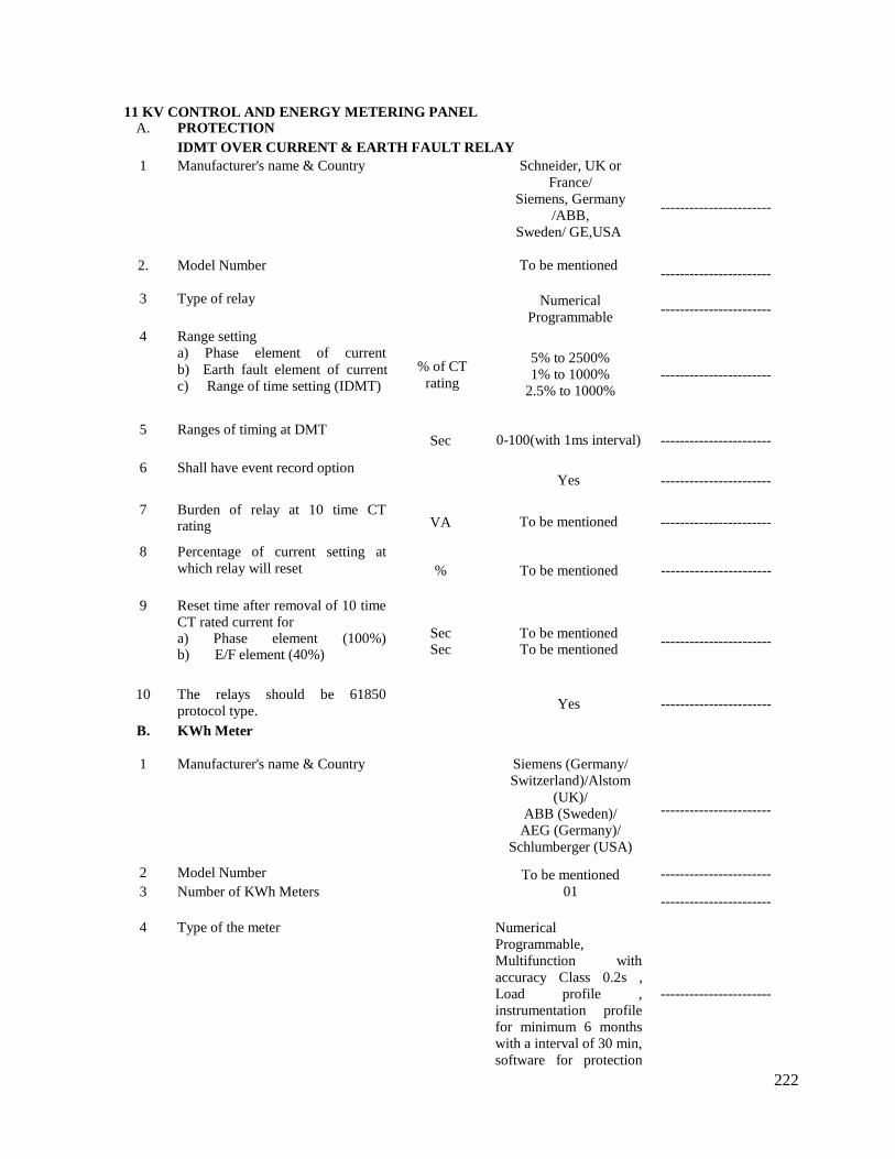
222
11 KV CONTROL AND ENERGY METERING PANELA. PROTECTION
IDMT OVER CURRENT & EARTH FAULT RELAY1 Manufacturer's name & Country
2. Model Number
3 Type of relay
4 Range settinga) Phase element of currentb) Earth fault element of currentc) Range of time setting (IDMT)
5 Ranges of timing at DMT
6 Shall have event record option
7 Burden of relay at 10 time CTrating
% of CTrating
Sec
VA
Schneider, UK orFrance/
Siemens, Germany/ABB,
Sweden/ GE,USA
To be mentioned
NumericalProgrammable
5% to 2500%1% to 1000%
2.5% to 1000%
0-100(with 1ms interval)
Yes
To be mentioned
-----------------------
-----------------------
-----------------------
-----------------------
-----------------------
-----------------------
-----------------------
8 Percentage of current setting atwhich relay will reset % To be mentioned -----------------------
9 Reset time after removal of 10 timeCT rated current fora) Phase element (100%)b) E/F element (40%)
Sec To be mentionedSec To be mentioned
-----------------------
10 The relays should be 61850protocol type.
B. KWh Meter
Yes -----------------------
1 Manufacturer's name & Country
2 Model Number3 Number of KWh Meters
4 Type of the meter
Siemens (Germany/Switzerland)/Alstom
(UK)/ABB (Sweden)/
AEG (Germany)/Schlumberger (USA)
To be mentioned01
NumericalProgrammable,Multifunction withaccuracy Class 0.2s ,Load profile ,instrumentation profilefor minimum 6 monthswith a interval of 30 min,software for protection
-----------------------
-----------------------
-----------------------
-----------------------
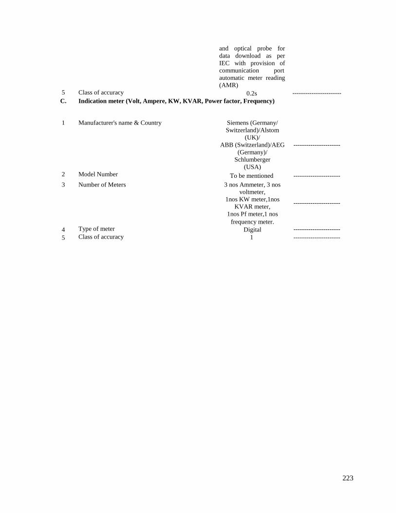
223
and optical probe fordata download as perIEC with provision ofcommunication portautomatic meter reading(AMR)
5 Class of accuracy 0.2s -----------------------C. Indication meter (Volt, Ampere, KW, KVAR, Power factor, Frequency)
1 Manufacturer's name & Country
2 Model Number
3 Number of Meters
4 Type of meter
5 Class of accuracy
Siemens (Germany/Switzerland)/Alstom
(UK)/ABB (Switzerland)/AEG
(Germany)/Schlumberger
(USA)To be mentioned
3 nos Ammeter, 3 nosvoltmeter,
1nos KW meter,1nosKVAR meter,
1nos Pf meter,1 nosfrequency meter.
Digital1
----------------------
----------------------
----------------------
--------------------------------------------
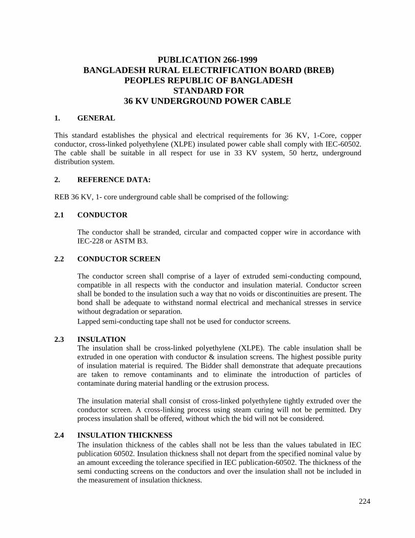
224
PUBLICATION 266-1999BANGLADESH RURAL ELECTRIFICATION BOARD (BREB)
PEOPLES REPUBLIC OF BANGLADESHSTANDARD FOR
36 KV UNDERGROUND POWER CABLE
1. GENERAL
This standard establishes the physical and electrical requirements for 36 KV, 1-Core, copperconductor, cross-linked polyethylene (XLPE) insulated power cable shall comply with IEC-60502.The cable shall be suitable in all respect for use in 33 KV system, 50 hertz, undergrounddistribution system.
2. REFERENCE DATA:
REB 36 KV, 1- core underground cable shall be comprised of the following:
2.1 CONDUCTOR
The conductor shall be stranded, circular and compacted copper wire in accordance withIEC-228 or ASTM B3.
2.2 CONDUCTOR SCREEN
The conductor screen shall comprise of a layer of extruded semi-conducting compound,compatible in all respects with the conductor and insulation material. Conductor screenshall be bonded to the insulation such a way that no voids or discontinuities are present. Thebond shall be adequate to withstand normal electrical and mechanical stresses in servicewithout degradation or separation.Lapped semi-conducting tape shall not be used for conductor screens.
2.3 INSULATIONThe insulation shall be cross-linked polyethylene (XLPE). The cable insulation shall beextruded in one operation with conductor & insulation screens. The highest possible purityof insulation material is required. The Bidder shall demonstrate that adequate precautionsare taken to remove contaminants and to eliminate the introduction of particles ofcontaminate during material handling or the extrusion process.
The insulation material shall consist of cross-linked polyethylene tightly extruded over theconductor screen. A cross-linking process using steam curing will not be permitted. Dryprocess insulation shall be offered, without which the bid will not be considered.
2.4 INSULATION THICKNESSThe insulation thickness of the cables shall not be less than the values tabulated in IECpublication 60502. Insulation thickness shall not depart from the specified nominal value byan amount exceeding the tolerance specified in IEC publication-60502. The thickness of thesemi conducting screens on the conductors and over the insulation shall not be included inthe measurement of insulation thickness.
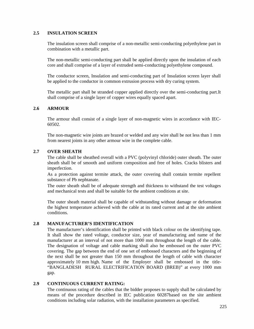
225
2.5 INSULATION SCREEN
The insulation screen shall comprise of a non-metallic semi-conducting polyethylene part incombination with a metallic part.
The non-metallic semi-conducting part shall be applied directly upon the insulation of eachcore and shall comprise of a layer of extruded semi-conducting polyethylene compound.
The conductor screen, Insulation and semi-conducting part of Insulation screen layer shallbe applied to the conductor in common extrusion process with dry curing system.
The metallic part shall be stranded copper applied directly over the semi-conducting part.Itshall comprise of a single layer of copper wires equally spaced apart.
2.6 ARMOUR
The armour shall consist of a single layer of non-magnetic wires in accordance with IEC-60502.
The non-magnetic wire joints are brazed or welded and any wire shall be not less than 1 mmfrom nearest joints in any other armour wire in the complete cable.
2.7 OVER SHEATHThe cable shall be sheathed overall with a PVC (polyvinyl chloride) outer sheath. The outersheath shall be of smooth and uniform composition and free of holes. Cracks blisters andimperfection.As a protection against termite attack, the outer covering shall contain termite repellentsubstance of Pb nephtanate.The outer sheath shall be of adequate strength and thickness to withstand the test voltagesand mechanical tests and shall be suitable for the ambient conditions at site.
The outer sheath material shall be capable of withstanding without damage or deformationthe highest temperature achieved with the cable at its rated current and at the site ambientconditions.
2.8 MANUFACTURER’S IDENTIFICATIONThe manufacturer’s identification shall be printed with black colour on the identifying tape.It shall show the rated voltage, conductor size, year of manufacturing and name of themanufacturer at an interval of not more than 1000 mm throughout the length of the cable.The designation of voltage and cable marking shall also be embossed on the outer PVCcovering. The gap between the end of one set of embossed characters and the beginning ofthe next shall be not greater than 150 mm throughout the length of cable with characterapproximately 10 mm high. Name of the Employer shall be embossed in the title-“BANGLADESH RURAL ELECTRIFICATION BOARD (BREB)” at every 1000 mmgap.
2.9 CONTINUOUS CURRENT RATING:The continuous rating of the cables that the bidder proposes to supply shall be calculated bymeans of the procedure described in IEC publication 60287based on the site ambientconditions including solar radiation, with the installation parameters as specified.
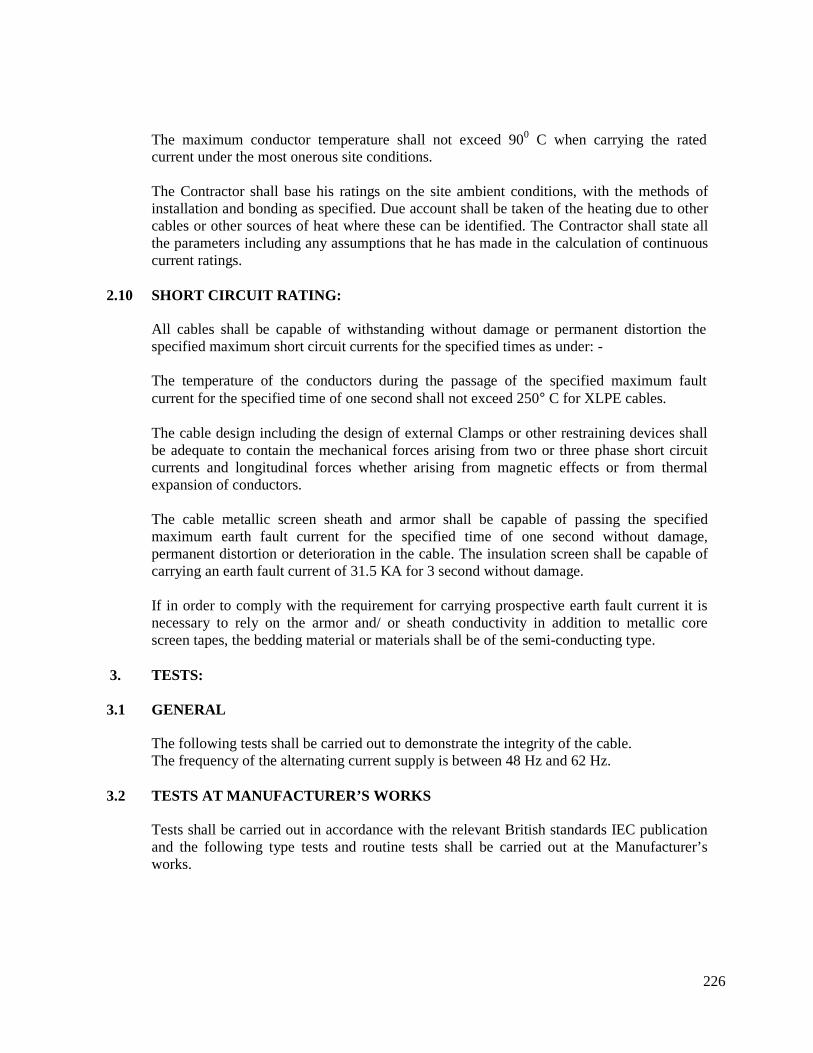
226
The maximum conductor temperature shall not exceed 900 C when carrying the ratedcurrent under the most onerous site conditions.
The Contractor shall base his ratings on the site ambient conditions, with the methods ofinstallation and bonding as specified. Due account shall be taken of the heating due to othercables or other sources of heat where these can be identified. The Contractor shall state allthe parameters including any assumptions that he has made in the calculation of continuouscurrent ratings.
2.10 SHORT CIRCUIT RATING:
All cables shall be capable of withstanding without damage or permanent distortion thespecified maximum short circuit currents for the specified times as under: -
The temperature of the conductors during the passage of the specified maximum faultcurrent for the specified time of one second shall not exceed 250C for XLPE cables.
The cable design including the design of external Clamps or other restraining devices shallbe adequate to contain the mechanical forces arising from two or three phase short circuitcurrents and longitudinal forces whether arising from magnetic effects or from thermalexpansion of conductors.
The cable metallic screen sheath and armor shall be capable of passing the specifiedmaximum earth fault current for the specified time of one second without damage,permanent distortion or deterioration in the cable. The insulation screen shall be capable ofcarrying an earth fault current of 31.5 KA for 3 second without damage.
If in order to comply with the requirement for carrying prospective earth fault current it isnecessary to rely on the armor and/ or sheath conductivity in addition to metallic corescreen tapes, the bedding material or materials shall be of the semi-conducting type.
3. TESTS:
3.1 GENERAL
The following tests shall be carried out to demonstrate the integrity of the cable.The frequency of the alternating current supply is between 48 Hz and 62 Hz.
3.2 TESTS AT MANUFACTURER’S WORKS
Tests shall be carried out in accordance with the relevant British standards IEC publicationand the following type tests and routine tests shall be carried out at the Manufacturer’sworks.
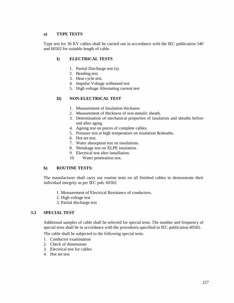
227
a) TYPE TESTS
Type test for 36 KV cables shall be carried out in accordance with the IEC publication 540and 60502 for suitable length of cable.
I) ELECTRICAL TESTS
1. Partial Discharge test (s).2. Bending test.3. Heat cycle test.4. Impulse Voltage withstand test5. High voltage Alternating current test
II) NON-ELECTRICAL TEST
1. Measurement of Insulation thickness2. Measurement of thickness of non-metalic sheath.3. Determination of mechanical properties of insulation and sheaths before
and after aging.4. Ageing test on pieces of complete cables.5. Pressure test at high temperature on insulation &sheaths.6. Hot set test.7. Water absorption test on insulations.8. Shrinkage test on XLPE insulation.9. Electrical test after installation.10. Water penetration test.
b) ROUTINE TESTS:
The manufacturer shall carry out routine tests on all finished cables to demonstrate theirindividual integrity as per IEC pub. 60502
1. Measurement of Electrical Resistance of conductors.2. High voltage test3. Partial discharge test
3.3 SPECIAL TEST
Additional samples of cable shall be selected for special tests. The number and frequency ofspecial tests shall be in accordance with the procedures specified in IEC publication 60502.
The cable shall be subjected to the following special tests.1. Conductor examination2. Check of dimensions3. Electrical test for cables4. Hot set test
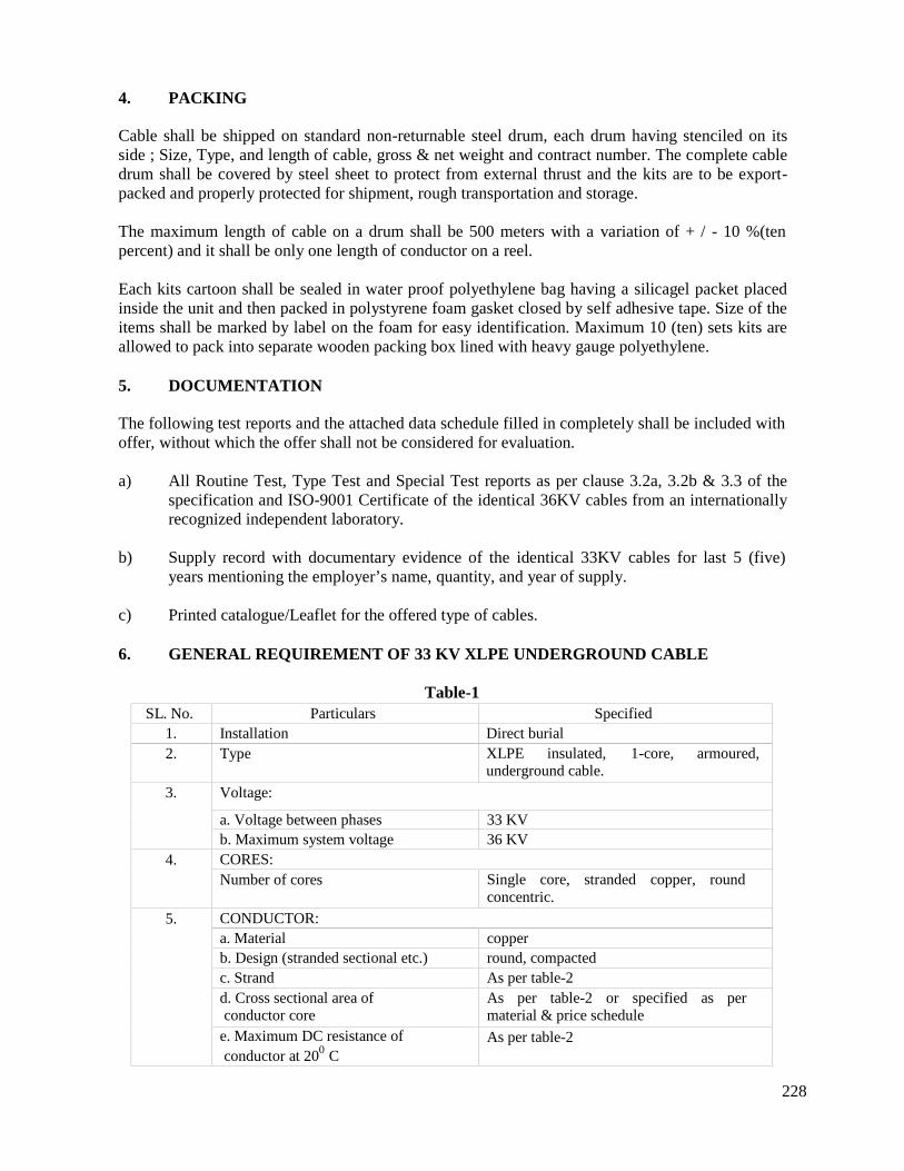
228
4. PACKING
Cable shall be shipped on standard non-returnable steel drum, each drum having stenciled on itsside ; Size, Type, and length of cable, gross & net weight and contract number. The complete cabledrum shall be covered by steel sheet to protect from external thrust and the kits are to be export-packed and properly protected for shipment, rough transportation and storage.
The maximum length of cable on a drum shall be 500 meters with a variation of + / - 10 %(tenpercent) and it shall be only one length of conductor on a reel.
Each kits cartoon shall be sealed in water proof polyethylene bag having a silicagel packet placedinside the unit and then packed in polystyrene foam gasket closed by self adhesive tape. Size of theitems shall be marked by label on the foam for easy identification. Maximum 10 (ten) sets kits areallowed to pack into separate wooden packing box lined with heavy gauge polyethylene.
5. DOCUMENTATION
The following test reports and the attached data schedule filled in completely shall be included withoffer, without which the offer shall not be considered for evaluation.
a) All Routine Test, Type Test and Special Test reports as per clause 3.2a, 3.2b & 3.3 of thespecification and ISO-9001 Certificate of the identical 36KV cables from an internationallyrecognized independent laboratory.
b) Supply record with documentary evidence of the identical 33KV cables for last 5 (five)years mentioning the employer’s name, quantity, and year of supply.
c) Printed catalogue/Leaflet for the offered type of cables.
6. GENERAL REQUIREMENT OF 33 KV XLPE UNDERGROUND CABLE
Table-1SL. No. Particulars Specified
1. Installation Direct burial2. Type XLPE insulated, 1-core, armoured,
underground cable.
3. Voltage:
a. Voltage between phases 33 KVb. Maximum system voltage 36 KV
4. CORES:Number of cores Single core, stranded copper, round
concentric.
5. CONDUCTOR:a. Material copperb. Design (stranded sectional etc.) round, compactedc. Strand As per table-2d. Cross sectional area ofconductor core
As per table-2 or specified as permaterial & price schedule
e. Maximum DC resistance ofconductor at 200 C
As per table-2
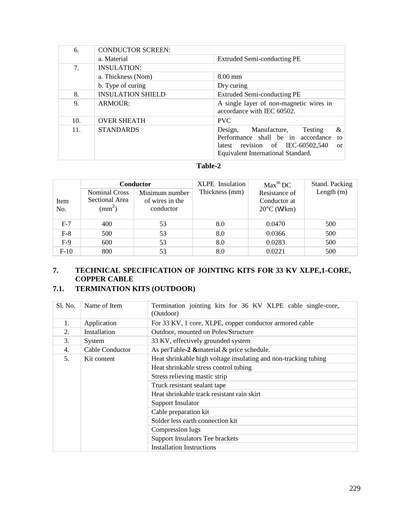
229
6. CONDUCTOR SCREEN:a. Material Extruded Semi-conducting PE
7. INSULATION:a. Thickness (Nom) 8.00 mmb. Type of curing Dry curing
8. INSULATION SHIELD Extruded Semi-conducting PE9. ARMOUR: A single layer of non-magnetic wires in
accordance with IEC 60502.
10. OVER SHEATH PVC11. STANDARDS Design, Manufacture, Testing &
Performance shall be in accordance tolatest revision of IEC-60502,540 orEquivalent International Standard.
Table-2
ItemNo.
Conductor XLPE InsulationThickness (mm)
Maxm DCResistance ofConductor at20C (/km)
Stand. PackingLength (m)Nominal Cross
Sectional Area(mm2)
Minimum numberof wires in the
conductor
F-7 400 53 8.0 0.0470 500F-8 500 53 8.0 0.0366 500F-9 600 53 8.0 0.0283 500
F-10 800 53 8.0 0.0221 500
7. TECHNICAL SPECIFICATION OF JOINTING KITS FOR 33 KV XLPE,1-CORE,COPPER CABLE
7.1. TERMINATION KITS (OUTDOOR)
Sl. No. Name of Item Termination jointing kits for 36 KV XLPE cable single-core,(Outdoor)
1. Application For 33 KV, 1 core, XLPE, copper conductor armored cable2. Installation Outdoor, mounted on Poles/Structure3. System 33 KV, effectively grounded system4. Cable Conductor As perTable-2 &material & price schedule.5. Kit content Heat shrinkable high voltage insulating and non-tracking tubing
Heat shrinkable stress control tubingStress relieving mastic stripTruck resistant sealant tapeHeat shrinkable track resistant rain skirtSupport InsulatorCable preparation kitSolder less earth connection kitCompression lugsSupport Insulators Tee bracketsInstallation Instructions
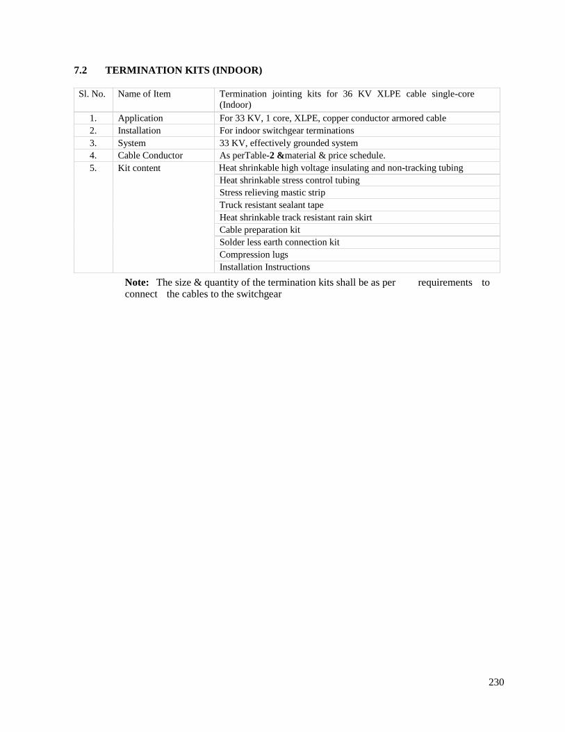
230
7.2 TERMINATION KITS (INDOOR)
Sl. No. Name of Item Termination jointing kits for 36 KV XLPE cable single-core(Indoor)
1. Application For 33 KV, 1 core, XLPE, copper conductor armored cable2. Installation For indoor switchgear terminations3. System 33 KV, effectively grounded system4. Cable Conductor As perTable-2 &material & price schedule.5. Kit content Heat shrinkable high voltage insulating and non-tracking tubing
Heat shrinkable stress control tubingStress relieving mastic stripTruck resistant sealant tapeHeat shrinkable track resistant rain skirtCable preparation kitSolder less earth connection kitCompression lugsInstallation Instructions
Note: The size & quantity of the termination kits shall be as per requirements toconnect the cables to the switchgear
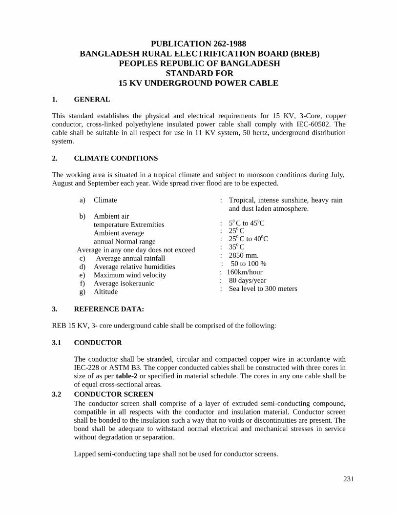
231
PUBLICATION 262-1988BANGLADESH RURAL ELECTRIFICATION BOARD (BREB)
PEOPLES REPUBLIC OF BANGLADESHSTANDARD FOR
15 KV UNDERGROUND POWER CABLE
1. GENERAL
This standard establishes the physical and electrical requirements for 15 KV, 3-Core, copperconductor, cross-linked polyethylene insulated power cable shall comply with IEC-60502. Thecable shall be suitable in all respect for use in 11 KV system, 50 hertz, underground distributionsystem.
2. CLIMATE CONDITIONS
The working area is situated in a tropical climate and subject to monsoon conditions during July,August and September each year. Wide spread river flood are to be expected.
a) Climate
b) Ambient airtemperature ExtremitiesAmbient averageannual Normal range
Average in any one day does not exceedc) Average annual rainfalld) Average relative humiditiese) Maximum wind velocityf) Average isokeraunicg) Altitude
: Tropical, intense sunshine, heavy rainand dust laden atmosphere.
: 50 C to 450C: 250 C: 250 C to 400C: 350 C: 2850 mm.: 50 to 100 %
: 160km/hour: 80 days/year: Sea level to 300 meters
3. REFERENCE DATA:
REB 15 KV, 3- core underground cable shall be comprised of the following:
3.1 CONDUCTOR
The conductor shall be stranded, circular and compacted copper wire in accordance withIEC-228 or ASTM B3. The copper conducted cables shall be constructed with three cores insize of as per table-2 or specified in material schedule. The cores in any one cable shall beof equal cross-sectional areas.
3.2 CONDUCTOR SCREENThe conductor screen shall comprise of a layer of extruded semi-conducting compound,compatible in all respects with the conductor and insulation material. Conductor screenshall be bonded to the insulation such a way that no voids or discontinuities are present. Thebond shall be adequate to withstand normal electrical and mechanical stresses in servicewithout degradation or separation.
Lapped semi-conducting tape shall not be used for conductor screens.
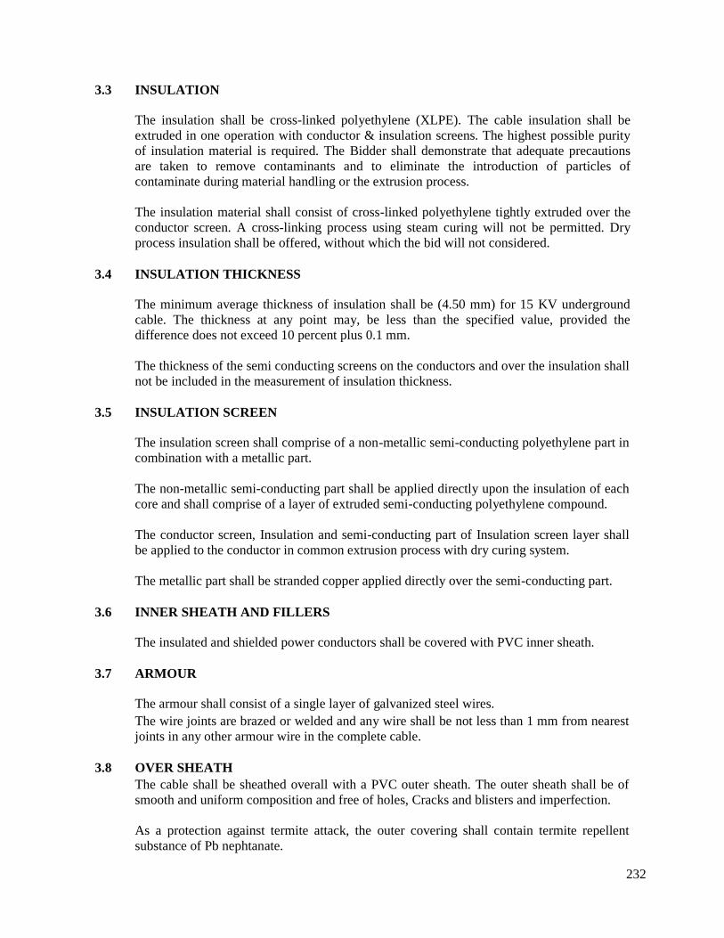
232
3.3 INSULATION
The insulation shall be cross-linked polyethylene (XLPE). The cable insulation shall beextruded in one operation with conductor & insulation screens. The highest possible purityof insulation material is required. The Bidder shall demonstrate that adequate precautionsare taken to remove contaminants and to eliminate the introduction of particles ofcontaminate during material handling or the extrusion process.
The insulation material shall consist of cross-linked polyethylene tightly extruded over theconductor screen. A cross-linking process using steam curing will not be permitted. Dryprocess insulation shall be offered, without which the bid will not considered.
3.4 INSULATION THICKNESS
The minimum average thickness of insulation shall be (4.50 mm) for 15 KV undergroundcable. The thickness at any point may, be less than the specified value, provided thedifference does not exceed 10 percent plus 0.1 mm.
The thickness of the semi conducting screens on the conductors and over the insulation shallnot be included in the measurement of insulation thickness.
3.5 INSULATION SCREEN
The insulation screen shall comprise of a non-metallic semi-conducting polyethylene part incombination with a metallic part.
The non-metallic semi-conducting part shall be applied directly upon the insulation of eachcore and shall comprise of a layer of extruded semi-conducting polyethylene compound.
The conductor screen, Insulation and semi-conducting part of Insulation screen layer shallbe applied to the conductor in common extrusion process with dry curing system.
The metallic part shall be stranded copper applied directly over the semi-conducting part.
3.6 INNER SHEATH AND FILLERS
The insulated and shielded power conductors shall be covered with PVC inner sheath.
3.7 ARMOUR
The armour shall consist of a single layer of galvanized steel wires.The wire joints are brazed or welded and any wire shall be not less than 1 mm from nearestjoints in any other armour wire in the complete cable.
3.8 OVER SHEATHThe cable shall be sheathed overall with a PVC outer sheath. The outer sheath shall be ofsmooth and uniform composition and free of holes, Cracks and blisters and imperfection.
As a protection against termite attack, the outer covering shall contain termite repellentsubstance of Pb nephtanate.
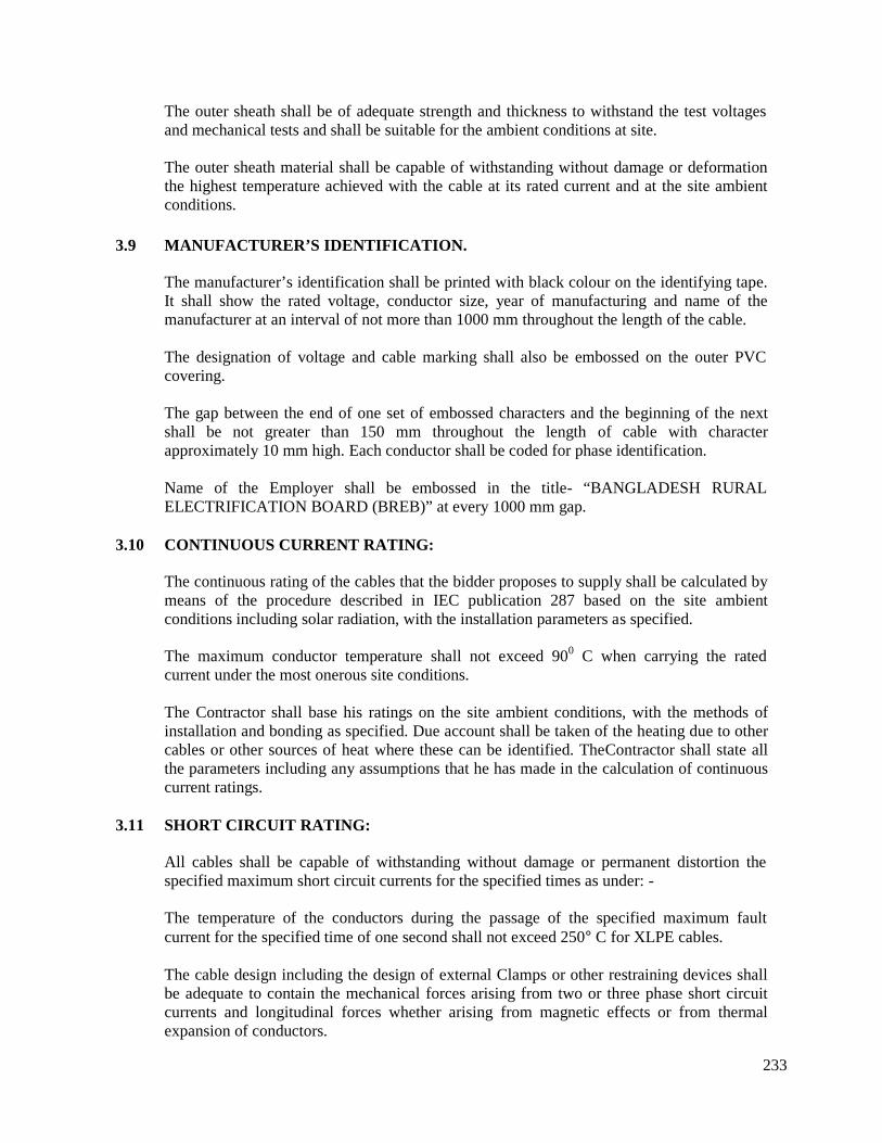
233
The outer sheath shall be of adequate strength and thickness to withstand the test voltagesand mechanical tests and shall be suitable for the ambient conditions at site.
The outer sheath material shall be capable of withstanding without damage or deformationthe highest temperature achieved with the cable at its rated current and at the site ambientconditions.
3.9 MANUFACTURER’S IDENTIFICATION.
The manufacturer’s identification shall be printed with black colour on the identifying tape.It shall show the rated voltage, conductor size, year of manufacturing and name of themanufacturer at an interval of not more than 1000 mm throughout the length of the cable.
The designation of voltage and cable marking shall also be embossed on the outer PVCcovering.
The gap between the end of one set of embossed characters and the beginning of the nextshall be not greater than 150 mm throughout the length of cable with characterapproximately 10 mm high. Each conductor shall be coded for phase identification.
Name of the Employer shall be embossed in the title- “BANGLADESH RURALELECTRIFICATION BOARD (BREB)” at every 1000 mm gap.
3.10 CONTINUOUS CURRENT RATING:
The continuous rating of the cables that the bidder proposes to supply shall be calculated bymeans of the procedure described in IEC publication 287 based on the site ambientconditions including solar radiation, with the installation parameters as specified.
The maximum conductor temperature shall not exceed 900 C when carrying the ratedcurrent under the most onerous site conditions.
The Contractor shall base his ratings on the site ambient conditions, with the methods ofinstallation and bonding as specified. Due account shall be taken of the heating due to othercables or other sources of heat where these can be identified. TheContractor shall state allthe parameters including any assumptions that he has made in the calculation of continuouscurrent ratings.
3.11 SHORT CIRCUIT RATING:
All cables shall be capable of withstanding without damage or permanent distortion thespecified maximum short circuit currents for the specified times as under: -
The temperature of the conductors during the passage of the specified maximum faultcurrent for the specified time of one second shall not exceed 250C for XLPE cables.
The cable design including the design of external Clamps or other restraining devices shallbe adequate to contain the mechanical forces arising from two or three phase short circuitcurrents and longitudinal forces whether arising from magnetic effects or from thermalexpansion of conductors.
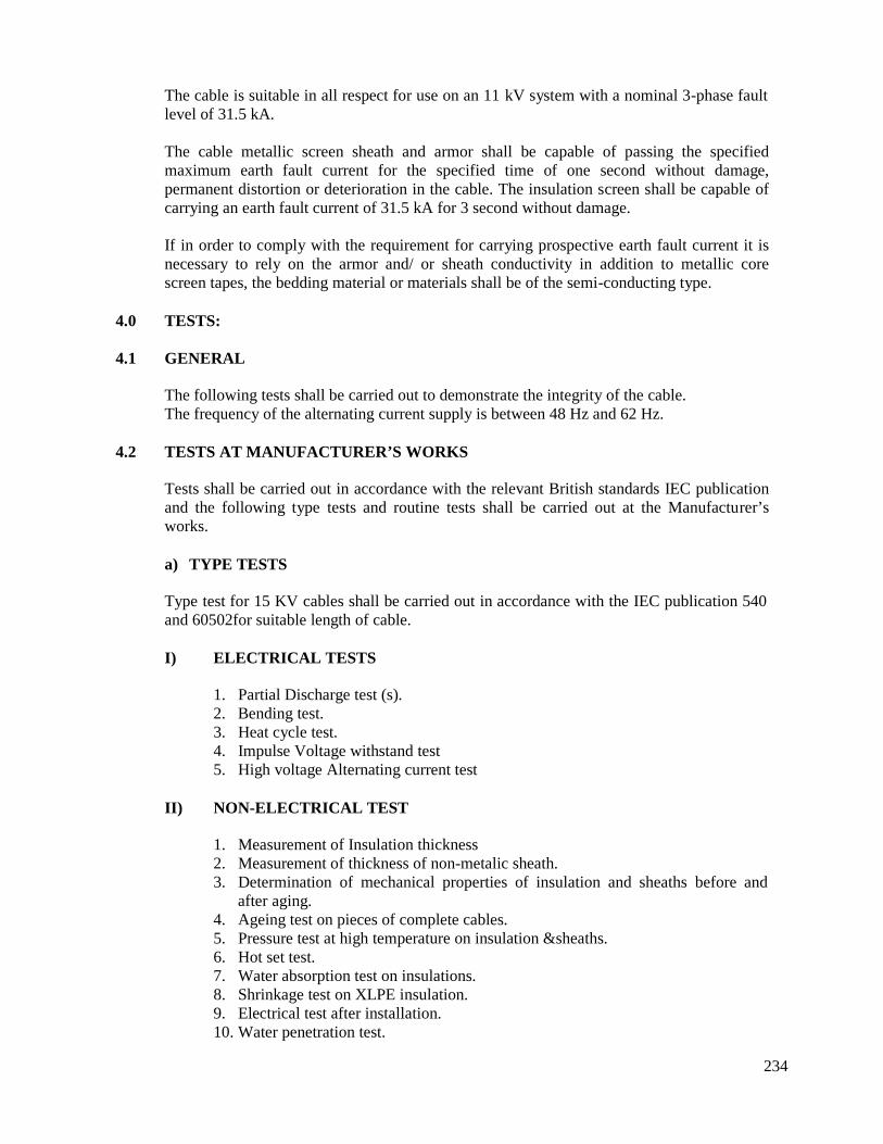
234
The cable is suitable in all respect for use on an 11 kV system with a nominal 3-phase faultlevel of 31.5 kA.
The cable metallic screen sheath and armor shall be capable of passing the specifiedmaximum earth fault current for the specified time of one second without damage,permanent distortion or deterioration in the cable. The insulation screen shall be capable ofcarrying an earth fault current of 31.5 kA for 3 second without damage.
If in order to comply with the requirement for carrying prospective earth fault current it isnecessary to rely on the armor and/ or sheath conductivity in addition to metallic corescreen tapes, the bedding material or materials shall be of the semi-conducting type.
4.0 TESTS:
4.1 GENERAL
The following tests shall be carried out to demonstrate the integrity of the cable.The frequency of the alternating current supply is between 48 Hz and 62 Hz.
4.2 TESTS AT MANUFACTURER’S WORKS
Tests shall be carried out in accordance with the relevant British standards IEC publicationand the following type tests and routine tests shall be carried out at the Manufacturer’sworks.
a) TYPE TESTS
Type test for 15 KV cables shall be carried out in accordance with the IEC publication 540and 60502for suitable length of cable.
I) ELECTRICAL TESTS
1. Partial Discharge test (s).2. Bending test.3. Heat cycle test.4. Impulse Voltage withstand test5. High voltage Alternating current test
II) NON-ELECTRICAL TEST
1. Measurement of Insulation thickness2. Measurement of thickness of non-metalic sheath.3. Determination of mechanical properties of insulation and sheaths before and
after aging.4. Ageing test on pieces of complete cables.5. Pressure test at high temperature on insulation &sheaths.6. Hot set test.7. Water absorption test on insulations.8. Shrinkage test on XLPE insulation.9. Electrical test after installation.10. Water penetration test.
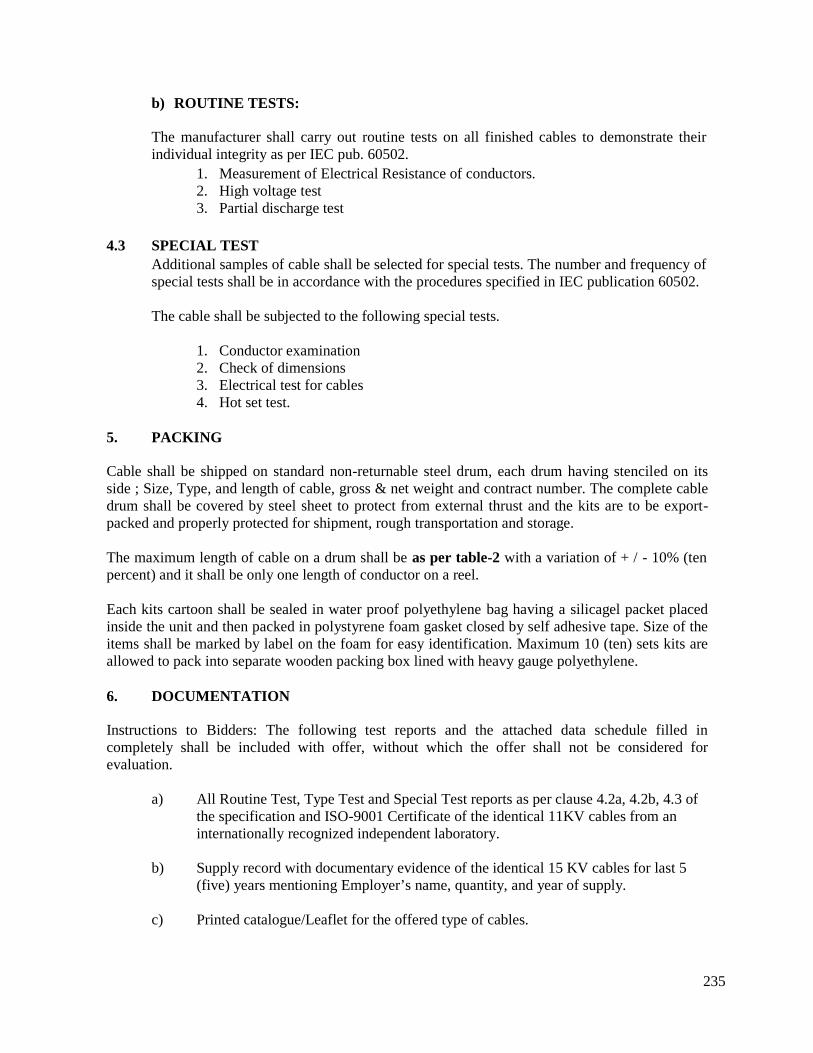
235
b) ROUTINE TESTS:
The manufacturer shall carry out routine tests on all finished cables to demonstrate theirindividual integrity as per IEC pub. 60502.
1. Measurement of Electrical Resistance of conductors.2. High voltage test3. Partial discharge test
4.3 SPECIAL TESTAdditional samples of cable shall be selected for special tests. The number and frequency ofspecial tests shall be in accordance with the procedures specified in IEC publication 60502.
The cable shall be subjected to the following special tests.
1. Conductor examination2. Check of dimensions3. Electrical test for cables4. Hot set test.
5. PACKING
Cable shall be shipped on standard non-returnable steel drum, each drum having stenciled on itsside ; Size, Type, and length of cable, gross & net weight and contract number. The complete cabledrum shall be covered by steel sheet to protect from external thrust and the kits are to be export-packed and properly protected for shipment, rough transportation and storage.
The maximum length of cable on a drum shall be as per table-2 with a variation of + / - 10% (tenpercent) and it shall be only one length of conductor on a reel.
Each kits cartoon shall be sealed in water proof polyethylene bag having a silicagel packet placedinside the unit and then packed in polystyrene foam gasket closed by self adhesive tape. Size of theitems shall be marked by label on the foam for easy identification. Maximum 10 (ten) sets kits areallowed to pack into separate wooden packing box lined with heavy gauge polyethylene.
6. DOCUMENTATION
Instructions to Bidders: The following test reports and the attached data schedule filled incompletely shall be included with offer, without which the offer shall not be considered forevaluation.
a) All Routine Test, Type Test and Special Test reports as per clause 4.2a, 4.2b, 4.3 ofthe specification and ISO-9001 Certificate of the identical 11KV cables from aninternationally recognized independent laboratory.
b) Supply record with documentary evidence of the identical 15 KV cables for last 5(five) years mentioning Employer’s name, quantity, and year of supply.
c) Printed catalogue/Leaflet for the offered type of cables.
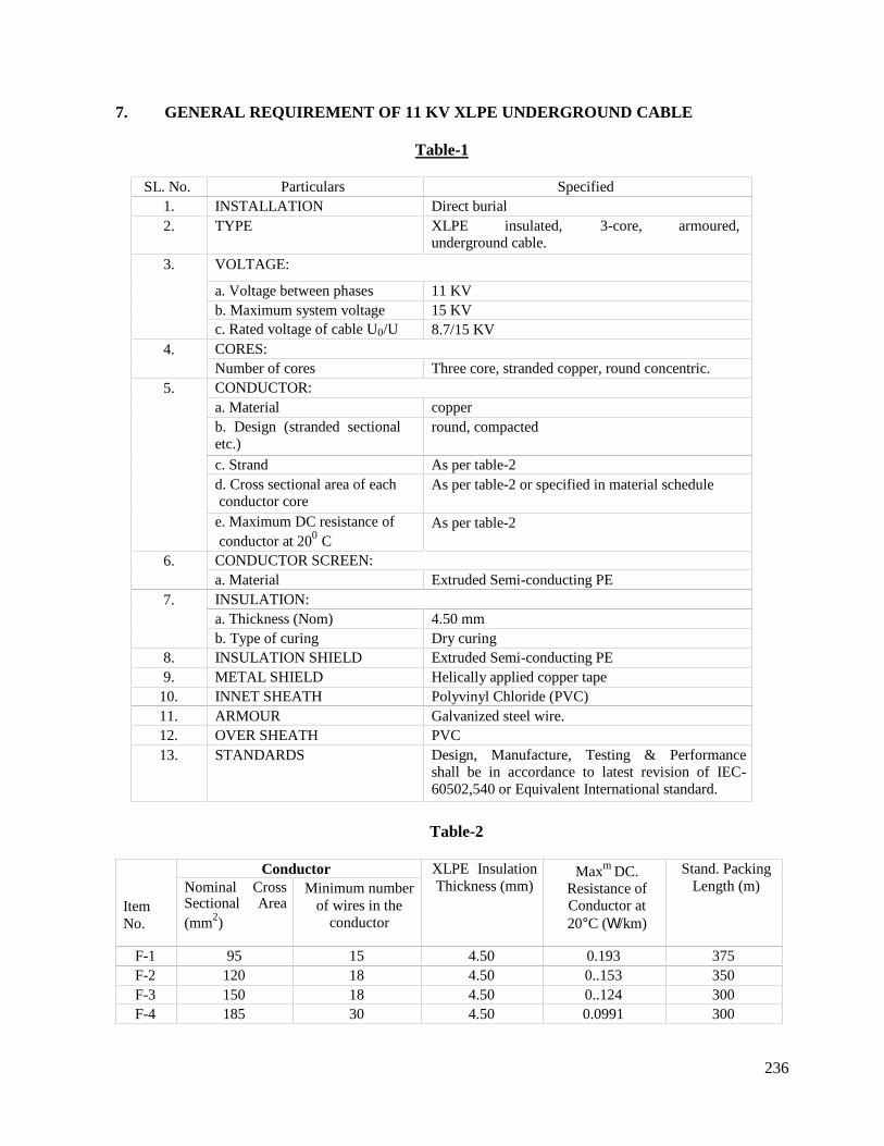
236
7. GENERAL REQUIREMENT OF 11 KV XLPE UNDERGROUND CABLE
Table-1
SL. No. Particulars Specified1. INSTALLATION Direct burial2. TYPE XLPE insulated, 3-core, armoured,
underground cable.
3. VOLTAGE:
a. Voltage between phases 11 KVb. Maximum system voltage 15 KVc. Rated voltage of cable U0/U 8.7/15 KV
4. CORES:Number of cores Three core, stranded copper, round concentric.
5. CONDUCTOR:a. Material copperb. Design (stranded sectionaletc.)
round, compacted
c. Strand As per table-2d. Cross sectional area of eachconductor core
As per table-2 or specified in material schedule
e. Maximum DC resistance ofconductor at 200 C
As per table-2
6. CONDUCTOR SCREEN:a. Material Extruded Semi-conducting PE
7. INSULATION:a. Thickness (Nom) 4.50 mmb. Type of curing Dry curing
8. INSULATION SHIELD Extruded Semi-conducting PE9. METAL SHIELD Helically applied copper tape
10. INNET SHEATH Polyvinyl Chloride (PVC)11. ARMOUR Galvanized steel wire.12. OVER SHEATH PVC13. STANDARDS Design, Manufacture, Testing & Performance
shall be in accordance to latest revision of IEC-60502,540 or Equivalent International standard.
Table-2
ItemNo.
Conductor XLPE InsulationThickness (mm)
Maxm DC.Resistance ofConductor at20C (/km)
Stand. PackingLength (m)Nominal Cross
Sectional Area(mm2)
Minimum numberof wires in the
conductor
F-1 95 15 4.50 0.193 375F-2 120 18 4.50 0..153 350F-3 150 18 4.50 0..124 300F-4 185 30 4.50 0.0991 300
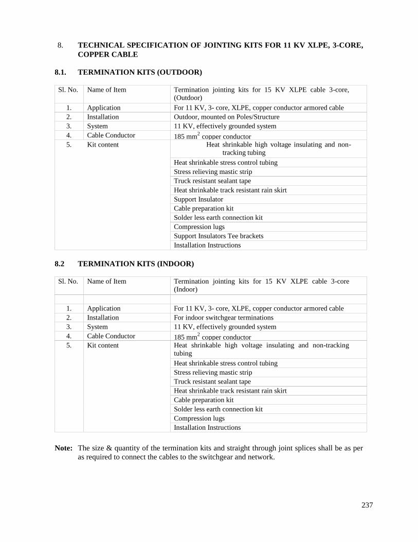
237
8. TECHNICAL SPECIFICATION OF JOINTING KITS FOR 11 KV XLPE, 3-CORE,COPPER CABLE
8.1. TERMINATION KITS (OUTDOOR)
Sl. No. Name of Item Termination jointing kits for 15 KV XLPE cable 3-core,(Outdoor)
1. Application For 11 KV, 3- core, XLPE, copper conductor armored cable2. Installation Outdoor, mounted on Poles/Structure3. System 11 KV, effectively grounded system4. Cable Conductor 185 mm2 copper conductor5. Kit content Heat shrinkable high voltage insulating and non-
tracking tubing
Heat shrinkable stress control tubingStress relieving mastic stripTruck resistant sealant tapeHeat shrinkable track resistant rain skirtSupport InsulatorCable preparation kitSolder less earth connection kitCompression lugsSupport Insulators Tee bracketsInstallation Instructions
8.2 TERMINATION KITS (INDOOR)
Sl. No. Name of Item Termination jointing kits for 15 KV XLPE cable 3-core(Indoor)
1. Application For 11 KV, 3- core, XLPE, copper conductor armored cable2. Installation For indoor switchgear terminations3. System 11 KV, effectively grounded system4. Cable Conductor 185 mm2 copper conductor5. Kit content Heat shrinkable high voltage insulating and non-tracking
tubingHeat shrinkable stress control tubingStress relieving mastic stripTruck resistant sealant tapeHeat shrinkable track resistant rain skirtCable preparation kitSolder less earth connection kitCompression lugsInstallation Instructions
Note: The size & quantity of the termination kits and straight through joint splices shall be as peras required to connect the cables to the switchgear and network.
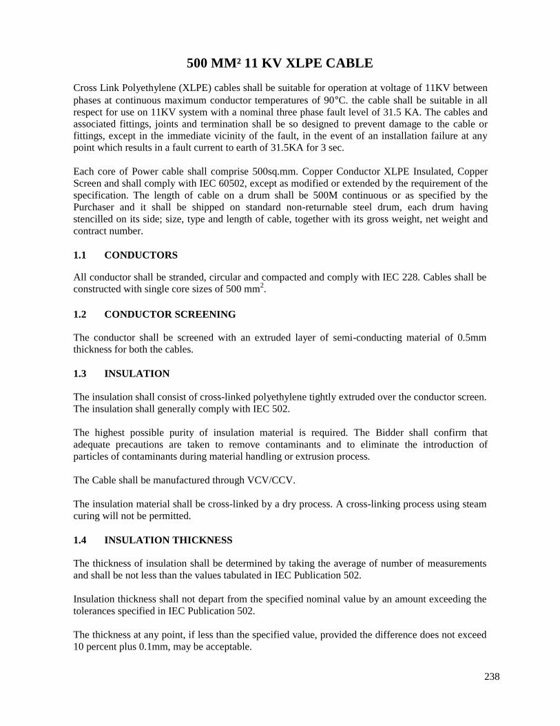
238
500 MM² 11 KV XLPE CABLE
Cross Link Polyethylene (XLPE) cables shall be suitable for operation at voltage of 11KV betweenphases at continuous maximum conductor temperatures of 90C. the cable shall be suitable in allrespect for use on 11KV system with a nominal three phase fault level of 31.5 KA. The cables andassociated fittings, joints and termination shall be so designed to prevent damage to the cable orfittings, except in the immediate vicinity of the fault, in the event of an installation failure at anypoint which results in a fault current to earth of 31.5KA for 3 sec.
Each core of Power cable shall comprise 500sq.mm. Copper Conductor XLPE Insulated, CopperScreen and shall comply with IEC 60502, except as modified or extended by the requirement of thespecification. The length of cable on a drum shall be 500M continuous or as specified by thePurchaser and it shall be shipped on standard non-returnable steel drum, each drum havingstencilled on its side; size, type and length of cable, together with its gross weight, net weight andcontract number.
1.1 CONDUCTORS
All conductor shall be stranded, circular and compacted and comply with IEC 228. Cables shall beconstructed with single core sizes of 500 mm2.
1.2 CONDUCTOR SCREENING
The conductor shall be screened with an extruded layer of semi-conducting material of 0.5mmthickness for both the cables.
1.3 INSULATION
The insulation shall consist of cross-linked polyethylene tightly extruded over the conductor screen.The insulation shall generally comply with IEC 502.
The highest possible purity of insulation material is required. The Bidder shall confirm thatadequate precautions are taken to remove contaminants and to eliminate the introduction ofparticles of contaminants during material handling or extrusion process.
The Cable shall be manufactured through VCV/CCV.
The insulation material shall be cross-linked by a dry process. A cross-linking process using steamcuring will not be permitted.
1.4 INSULATION THICKNESS
The thickness of insulation shall be determined by taking the average of number of measurementsand shall be not less than the values tabulated in IEC Publication 502.
Insulation thickness shall not depart from the specified nominal value by an amount exceeding thetolerances specified in IEC Publication 502.
The thickness at any point, if less than the specified value, provided the difference does not exceed10 percent plus 0.1mm, may be acceptable.
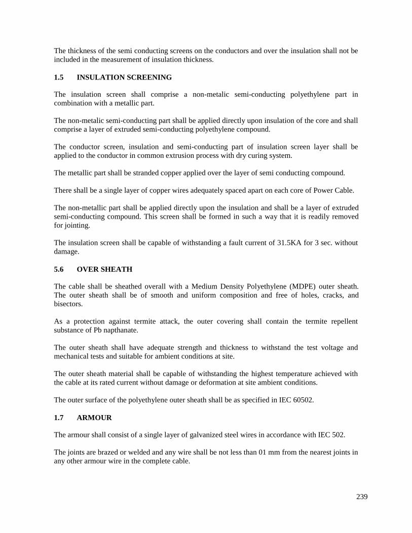
239
The thickness of the semi conducting screens on the conductors and over the insulation shall not beincluded in the measurement of insulation thickness.
1.5 INSULATION SCREENING
The insulation screen shall comprise a non-metalic semi-conducting polyethylene part incombination with a metallic part.
The non-metalic semi-conducting part shall be applied directly upon insulation of the core and shallcomprise a layer of extruded semi-conducting polyethylene compound.
The conductor screen, insulation and semi-conducting part of insulation screen layer shall beapplied to the conductor in common extrusion process with dry curing system.
The metallic part shall be stranded copper applied over the layer of semi conducting compound.
There shall be a single layer of copper wires adequately spaced apart on each core of Power Cable.
The non-metallic part shall be applied directly upon the insulation and shall be a layer of extrudedsemi-conducting compound. This screen shall be formed in such a way that it is readily removedfor jointing.
The insulation screen shall be capable of withstanding a fault current of 31.5KA for 3 sec. withoutdamage.
5.6 OVER SHEATH
The cable shall be sheathed overall with a Medium Density Polyethylene (MDPE) outer sheath.The outer sheath shall be of smooth and uniform composition and free of holes, cracks, andbisectors.
As a protection against termite attack, the outer covering shall contain the termite repellentsubstance of Pb napthanate.
The outer sheath shall have adequate strength and thickness to withstand the test voltage andmechanical tests and suitable for ambient conditions at site.
The outer sheath material shall be capable of withstanding the highest temperature achieved withthe cable at its rated current without damage or deformation at site ambient conditions.
The outer surface of the polyethylene outer sheath shall be as specified in IEC 60502.
1.7 ARMOUR
The armour shall consist of a single layer of galvanized steel wires in accordance with IEC 502.
The joints are brazed or welded and any wire shall be not less than 01 mm from the nearest joints inany other armour wire in the complete cable.
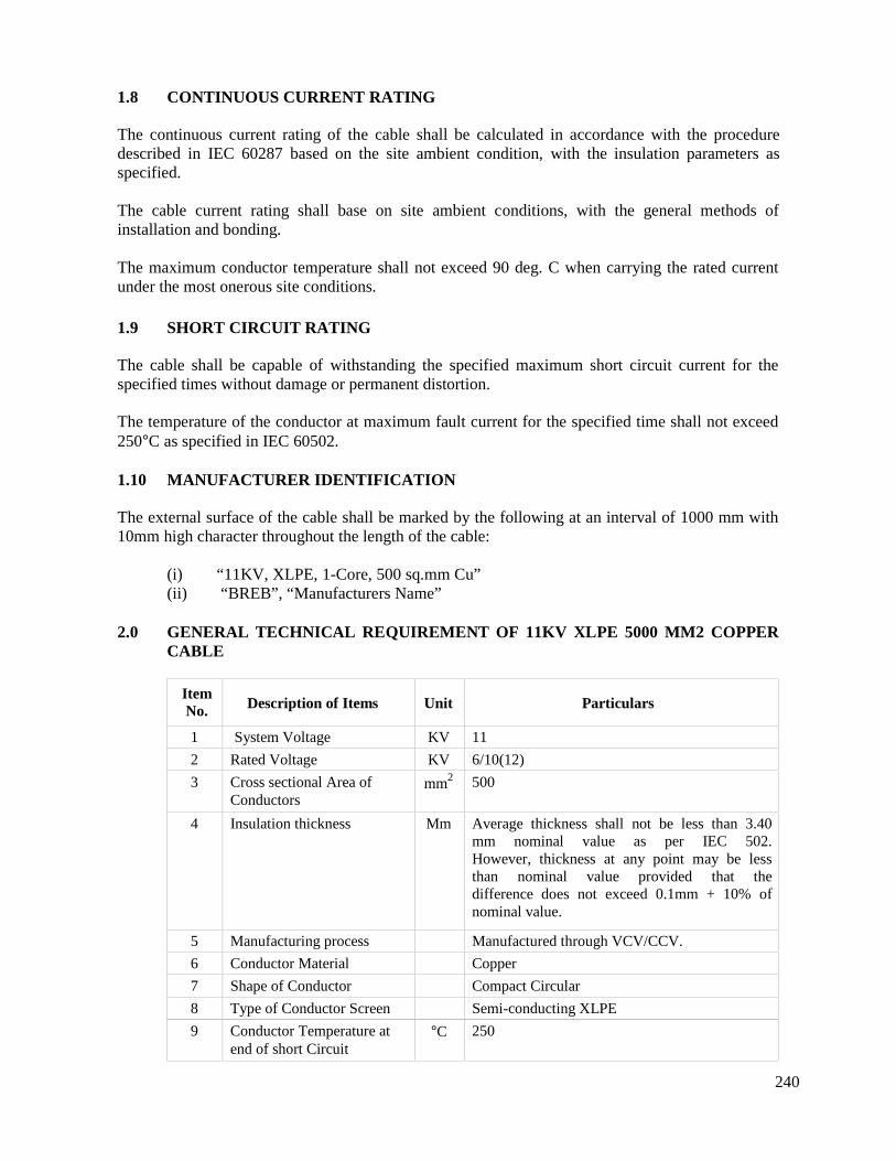
240
1.8 CONTINUOUS CURRENT RATING
The continuous current rating of the cable shall be calculated in accordance with the proceduredescribed in IEC 60287 based on the site ambient condition, with the insulation parameters asspecified.
The cable current rating shall base on site ambient conditions, with the general methods ofinstallation and bonding.
The maximum conductor temperature shall not exceed 90 deg. C when carrying the rated currentunder the most onerous site conditions.
1.9 SHORT CIRCUIT RATING
The cable shall be capable of withstanding the specified maximum short circuit current for thespecified times without damage or permanent distortion.
The temperature of the conductor at maximum fault current for the specified time shall not exceed250C as specified in IEC 60502.
1.10 MANUFACTURER IDENTIFICATION
The external surface of the cable shall be marked by the following at an interval of 1000 mm with10mm high character throughout the length of the cable:
(i) “11KV, XLPE, 1-Core, 500 sq.mm Cu”(ii) “BREB”, “Manufacturers Name”
2.0 GENERAL TECHNICAL REQUIREMENT OF 11KV XLPE 5000 MM2 COPPERCABLE
ItemNo. Description of Items Unit Particulars
1 System Voltage KV 11
2 Rated Voltage KV 6/10(12)
3 Cross sectional Area ofConductors
mm2 500
4 Insulation thickness Mm Average thickness shall not be less than 3.40mm nominal value as per IEC 502.However, thickness at any point may be lessthan nominal value provided that thedifference does not exceed 0.1mm + 10% ofnominal value.
5 Manufacturing process Manufactured through VCV/CCV.
6 Conductor Material Copper
7 Shape of Conductor Compact Circular
8 Type of Conductor Screen Semi-conducting XLPE
9 Conductor Temperature atend of short Circuit
C 250
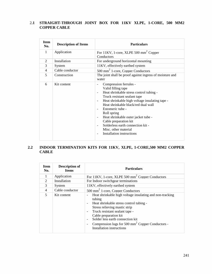
241
2.1 STRAIGHT-THROUGH JOINT BOX FOR 11KV XLPE, 1-CORE, 500 MM2COPPER CABLE
ItemNo. Description of Items Particulars
1 Application For 11KV, 1-core, XLPE 500 mm2 CopperConductors
2 Installation For underground horizontal mounting3 System 11KV, effectively earthed system4 Cable conductor 500 mm2 1-core, Copper Conductors5 Construction The joint shall be proof against ingress of moisture and
water
6 Kit content - Compression ferrules -Valid filling tape
- Heat shrinkable stress control tubing -Truck resistant sealant tape
- Heat shrinkable high voltage insulating tape -Heat shrinkable black/red dual wall
- Estomeric tube -Roll spring
- Heat shrinkable outer jacket tube -Cable preparation kit
- Solderless earth connection kit -Misc. other material
- Installation instructions
2.2 INDOOR TERMINATION KITS FOR 11KV, XLPE, 1-CORE,500 MM2 COPPERCABLE
ItemNo.
Description ofItems Particulars
1 Application For 11KV, 1-core, XLPE 500 mm2 Copper Conductors2 Installation For Indoor switchgear terminations3 System 11KV, effectively earthed system4 Cable conductor 500 mm2 1-core, Copper Conductors5 Kit content - Heat shrinkable high voltage insulating and non-tracking
tubing- Heat shrinkable stress control tubing -
Stress relieving mastic strip- Truck resistant sealant tape -
Cable preparation kit- Solder less earth connection kit- Compression lugs for 500 mm2 Copper Conductors -
Installation instructions
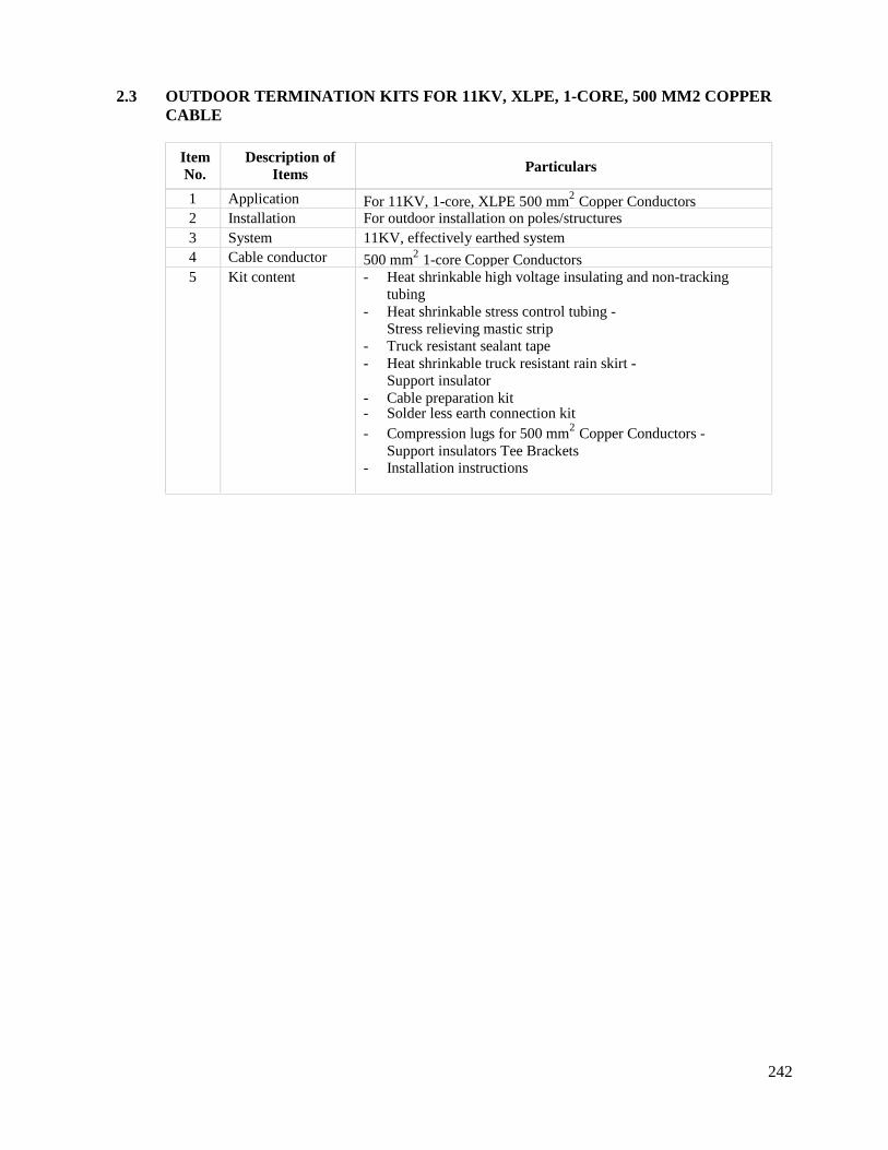
242
2.3 OUTDOOR TERMINATION KITS FOR 11KV, XLPE, 1-CORE, 500 MM2 COPPERCABLE
ItemNo.
Description ofItems Particulars
1 Application For 11KV, 1-core, XLPE 500 mm2 Copper Conductors2 Installation For outdoor installation on poles/structures3 System 11KV, effectively earthed system4 Cable conductor 500 mm2 1-core Copper Conductors5 Kit content - Heat shrinkable high voltage insulating and non-tracking
tubing- Heat shrinkable stress control tubing -
Stress relieving mastic strip- Truck resistant sealant tape- Heat shrinkable truck resistant rain skirt -
Support insulator- Cable preparation kit- Solder less earth connection kit- Compression lugs for 500 mm2 Copper Conductors -
Support insulators Tee Brackets- Installation instructions
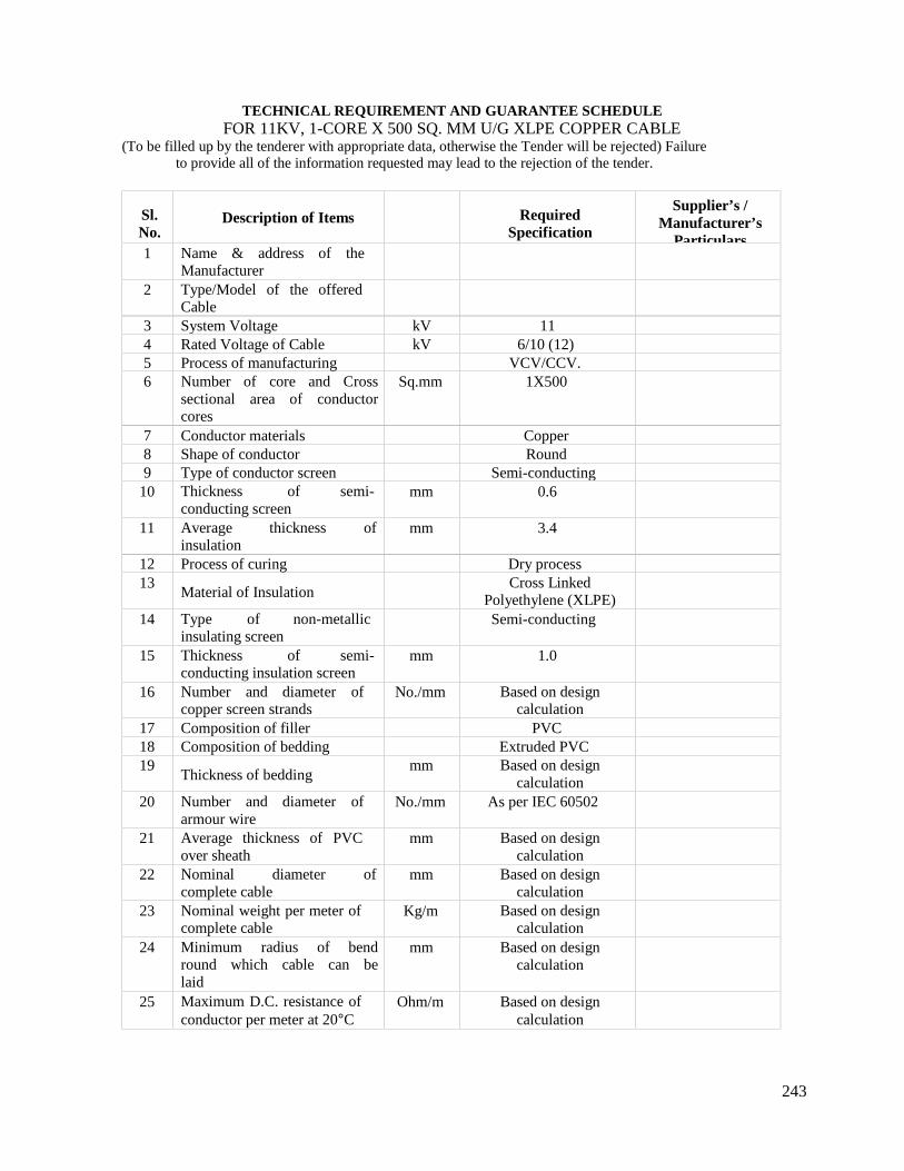
243
TECHNICAL REQUIREMENT AND GUARANTEE SCHEDULEFOR 11KV, 1-CORE X 500 SQ. MM U/G XLPE COPPER CABLE
(To be filled up by the tenderer with appropriate data, otherwise the Tender will be rejected) Failureto provide all of the information requested may lead to the rejection of the tender.
Sl.No.
Description of Items RequiredSpecification
Supplier’s /Manufacturer’s
Particulars1 Name & address of the
Manufacturer2 Type/Model of the offered
Cable3 System Voltage kV 114 Rated Voltage of Cable kV 6/10 (12)5 Process of manufacturing VCV/CCV.6 Number of core and Cross
sectional area of conductorcores
Sq.mm 1X500
7 Conductor materials Copper8 Shape of conductor Round9 Type of conductor screen Semi-conducting
10 Thickness of semi-conducting screen
mm 0.6
11 Average thickness ofinsulation
mm 3.4
12 Process of curing Dry process13
Material of InsulationCross Linked
Polyethylene (XLPE)14 Type of non-metallic
insulating screenSemi-conducting
15 Thickness of semi-conducting insulation screen
mm 1.0
16 Number and diameter ofcopper screen strands
No./mm Based on designcalculation
17 Composition of filler PVC18 Composition of bedding Extruded PVC19
Thickness of beddingmm Based on design
calculation20 Number and diameter of
armour wireNo./mm As per IEC 60502
21 Average thickness of PVCover sheath
mm Based on designcalculation
22 Nominal diameter ofcomplete cable
mm Based on designcalculation
23 Nominal weight per meter ofcomplete cable
Kg/m Based on designcalculation
24 Minimum radius of bendround which cable can belaid
mm Based on designcalculation
25 Maximum D.C. resistance ofconductor per meter at 20C
Ohm/m Based on designcalculation
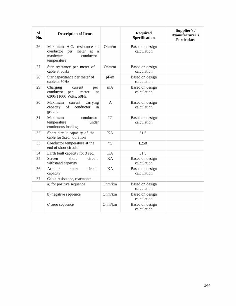
244
Sl.No.
Description of Items RequiredSpecification
Supplier’s /Manufacturer’s
Particulars
26 Maximum A.C. resistance ofconductor per meter at amaximum conductortemperature
Ohm/m Based on designcalculation
27 Star reactance per meter ofcable at 50Hz
Ohm/m Based on designcalculation
28 Star capacitance per meter ofcable at 50Hz
pF/m Based on designcalculation
29 Charging current perconductor per meter at6300/11000 Volts, 50Hz
mA Based on designcalculation
30 Maximum current carryingcapacity of conductor inground
A Based on designcalculation
31 Maximum conductortemperature undercontinuous loading
C Based on designcalculation
32 Short circuit capacity of thecable for 3sec. duration
KA 31.5
33 Conductor temperature at theend of short circuit
C 250
34 Earth fault capacity for 3 sec. KA 31.535 Screen short circuit
withstand capacityKA Based on design
calculation
36 Armour short circuitcapacity
KA Based on designcalculation
37 Cable resistance, reactance:a) for positive sequence Ohm/km Based on design
calculation
b) negative sequence Ohm/km Based on designcalculation
c) zero sequence Ohm/km Based on designcalculation
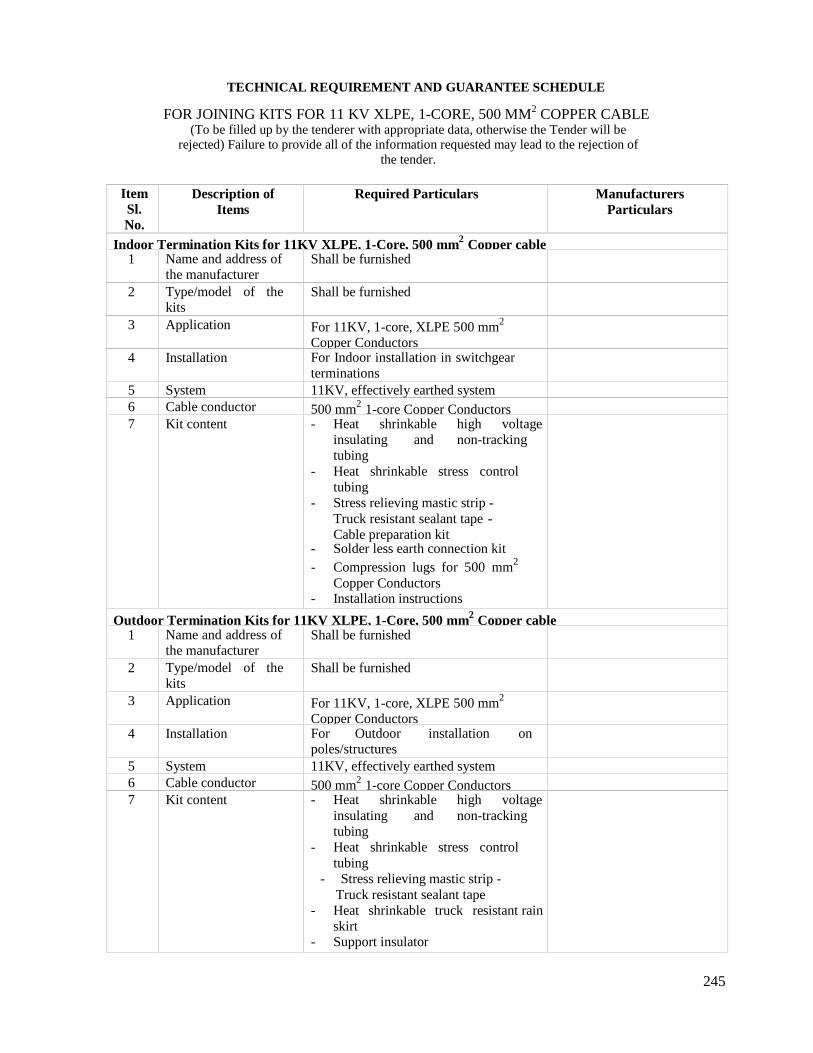
245
TECHNICAL REQUIREMENT AND GUARANTEE SCHEDULE
FOR JOINING KITS FOR 11 KV XLPE, 1-CORE, 500 MM2 COPPER CABLE(To be filled up by the tenderer with appropriate data, otherwise the Tender will be
rejected) Failure to provide all of the information requested may lead to the rejection ofthe tender.
ItemSl.No.
Description ofItems
Required Particulars ManufacturersParticulars
Indoor Termination Kits for 11KV XLPE, 1-Core, 500 mm2 Copper cable1 Name and address of
the manufacturerShall be furnished
2 Type/model of thekits
Shall be furnished
3 Application For 11KV, 1-core, XLPE 500 mm2
Copper Conductors4 Installation For Indoor installation in switchgear
terminations5 System 11KV, effectively earthed system6 Cable conductor 500 mm2 1-core Copper Conductors7 Kit content - Heat shrinkable high voltage
insulating and non-trackingtubing
- Heat shrinkable stress controltubing
- Stress relieving mastic strip -Truck resistant sealant tape -Cable preparation kit
- Solder less earth connection kit- Compression lugs for 500 mm2
Copper Conductors- Installation instructions
Outdoor Termination Kits for 11KV XLPE, 1-Core, 500 mm2 Copper cable1 Name and address of
the manufacturerShall be furnished
2 Type/model of thekits
Shall be furnished
3 Application For 11KV, 1-core, XLPE 500 mm2
Copper Conductors4 Installation For Outdoor installation on
poles/structures5 System 11KV, effectively earthed system6 Cable conductor 500 mm2 1-core Copper Conductors7 Kit content - Heat shrinkable high voltage
insulating and non-trackingtubing
- Heat shrinkable stress controltubing
- Stress relieving mastic strip -Truck resistant sealant tape
- Heat shrinkable truck resistant rainskirt
- Support insulator
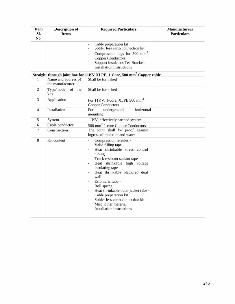
246
ItemSl.No.
Description ofItems
Required Particulars ManufacturersParticulars
- Cable preparation kit- Solder less earth connection kit- Compression lugs for 500 mm2
Copper Conductors- Support insulators Tee Brackets -
Installation instructions
Straight-through joint box for 11KV XLPE, 1-Core, 500 mm2 Copper cable1 Name and address of
the manufacturerShall be furnished
2 Type/model of thekits
Shall be furnished
3 Application For 11KV, 1-core, XLPE 500 mm2
Copper Conductors4 Installation For underground horizontal
mounting
5 System 11KV, effectively earthed system6 Cable conductor 500 mm2 1-core Copper Conductors7 Construction The joint shall be proof against
ingress of moisture and water
8 Kit content - Compression ferrules -Valid filling tape
- Heat shrinkable stress controltubing
- Truck resistant sealant tape- Heat shrinkable high voltage
insulating tape- Heat shrinkable black/red dual
wall- Estomeric tube -
Roll spring- Heat shrinkable outer jacket tube -
Cable preparation kit- Solder less earth connection kit -
Misc. other material- Installation instructions
247
CONDUCTORS AND CONNECTIONS
Overhead conductors carried by the switchyard structures shall be erected with such sags andtensions that when the conductors are subjected to load combinations, the factor of safety will notbe less than 3.5.
Materials used for connections shall be stressed to not more than forty percent of their elastic limit.Provision shall be made for expansion and contraction with variation in conductor temperature andbus bars shall be arranged so they may be readily extended in length with a minimum ofdisturbance to existing equipment. The design of joints and connections shall be such as to permitready dismantling.
Connectors shall be of an approved type. Connections dependent upon site welding techniques willnot be permitted.
All bus connections and joints for aluminum conductor where applicable shall be of crimp andbolted palm types in accordance with the design parameters and the general technical requirementsof this specification and the relevant standards.
Suspension and tension conductor clamps shall be of approved types and shall be as light aspossible. Suspension and tension clamps shall be designed to avoid any possibility of deforming thestranded conductor and separating the individual strands.
Tension conductor clamps shall not permit slipping of, or damage to, or failure of the completeconductor or any part thereof at a load less than 95 percent of the ultimate strength of the conductoras stated in the schedule of particulars and guarantees.
All clamps and fittings and their components shall be electro-chemically compatible with theconductor material and those made of steel or malleable iron shall be hot dip galvanized. All boltsand nuts shall be locked in an approved manner.
Unless otherwise approved, connections shall be so arranged and supported that under nocircumstances, including short circuit conditions, can the clearances between live metal and earth ofearthed metal work or between other conductors be less than the specified distances.
Where dissimilar metals are in contact, approved means shall be provided to prevent electro-chemical action and corrosion. Unless otherwise approved, joints and surfaces of copper or copperalloy fittings shall be tinned.
Cleaning down and preparation of contact surfaces of connectors and clamps shall be to theapproval of the Project Manager.

248
DISCONNECTORS AND EARTHING SWITCHES
1. GENERAL
Disconnecting and earthing devices shall be in accordance with IEC 60129 and IEC 60265 (Part 2).Transformer disconnectors in transformer circuits without circuit breakers on the High Voltage sideshall be in accordance with IEC 60265 and shall be capable of breaking the transformermagnetizing current. All shall be complete with supporting steel work and installed to permitmaintenance of any section of the substation plant when the remainder is alive and shall be solocate that the minimum safety clearances stated in BS 7354 are always maintained.
In outdoor substations, disconnectors shall preferably be of the single throw double air break,centre rotating post type or the double rotating post type with single air break and shall be to theapproval of the Project Manager. Pantograph designs, or other alternatives, if applicable will beconsidered.
Disconnectors shall comply with the requirement of BS 5253 in respect of lighting impulse voltagetests. The contact resistance should be ≤ 30µ Ω
Circuit isolating switches shall be rated not less than specified. Bus section/coupler isolatingswitches shall be rated not less than the associated bus bars.
Isolating switches shall generally be designed of live operations and will not require switchingcurrent other than the charging current of open bus bars and connections or load currents shuntedby parallel circuits. Main contacts shall be of the high pressures line type and arcing contacts, ifprovided, shall be to the Project Manager approval.
Service conditions require that isolating switches shall remain alive and in continuous service forperiods of up to 2 (Two) years in the climatic conditions specified and without operation ormaintenance. The contacts shall carry their rated load and short circuit currents without overheatingor welding and at the end of the two year period the maximum torque required at the operatinghandle to open a 3-phase disconnector shall not exceed 340 Nm.
All feeder disconnectors and high level disconnectors where specified shall be fitted with approvedthree phase line earthing devices, mechanically coupled or interlocked with the main isolator, sothat the earthing device and main isolator cannot be closed at the same time.
The earthing switch, when in the closed position, shall be capable of carrying the rated short timecurrent for three seconds without the contacts burning or welding.
Isolating devices shall be interlocked with circuit breakers and as necessary to prevent thepossibility of making or breaking load current. Except where electrical interlocking is providedeach mechanism box shall accommodate the relevant Castell type key interlocks.
Disconnector operation mechanisms shall be robust construction, carefully fitted to ensure freeaction and action and shall be unaffected by the climatic conditions at site. Mechanisms shall be assimple as possible and comprise a minimum of bearing and wearing parts. Approved greaselubricating devices shall be fitted to all principal bearing which are not of the self lubrication type.The mechanisms shall be housed in a weatherproof enclosure complete with auxiliary switches,terminal blocks and cable gland plates. All steel and malleable iron parts, including the supportingsteelwork shall be hot dip galvanized.
249
2. 33 KV ISOLATOR, EARTH SWITCH AND FUSE SWITCH
(a) 33 KV Isolator, Off Load Type (Outdoor)The 33 KV Isolator, shall be a gang operated type, horizontal mounted and horizontal break, 3-phase, outdoor mounted, manual operating type along with the following feature:
(a) Auxiliary contact operative through the operating mechanism of the isolator blade (6normally ON and 6 normally OFF contacts).
(b) Terminal connecting clamp suitable for being connected with AAAC/ ACSR conductor.(c) Earth pad for safety of the operating person. The operating lever shall be provided with
locking device. Necessary grounding points shall be provided with connector suitable forbeing connected with 100 mm2 stranded Cu wire.
(d) Gland for multi core control cable.(e) 33 KV structure beam, complete operating mechanism for easy manual operation from
the ground and grounding points with connection clamps for connecting with str. Cu wire.(f) All ferrous parts to be hot dip galvanized as per BS 729.(g) All electrical auxiliaries to be housed in a fully weather proof housing.
All other features as stated in the table of guaranteed data schedule should be applicable also.(b) 33 KV Isolator with Earth Switch of the Line Side (Outdoor)Same as in specification of 33 KV isolator but with the added feature of earthing blade with willalso hand operable from the switchyard by another handle and the operation of this earth blade withbe mechanically interlocked with that of the main blade. The earth blade will be of same currentrating as the main blades and shall be earthed through a 100 mm sq. (cu) earthing conductor.Necessary aux. contracts for position indication and to provide electrical inter locking should bethere.
(c) 33KV Fuse Switch with Holder and Fuse (Outdoor) for By-passing VCB and CT
The 33 KV Fuse Switch, shall be 3 pole double-break gang operated type, outdoor verticalmounted, manual operating type which shall have a removable fuse in series. The switch shall besuitable for mounting on a pole (wooden, concrete or metal). A suitable structure shall beconstructed by the Contractor with proper phase & ground clearances.
The circuit breaker/by-pass switch combination shall be designed in such a way that the circuitbreaker primary circuits can be isolated by bolted links or switchable single phase links or similardisconnect devices to enable maintenance of the CB with the by-pass switch closed supplying thesubstation, without encroaching on any safety clearances.
The purpose of the fused bypass switch is to enable the substation to be supplied while the circuitbreaker/current transformer combination is being maintained or replaced. The Contractor shalldesign and install 2 sets of disconnect links in the circuit breaker/current transformer branch of thecircuit so that the complete breaker/current transformer can be safely maintained with the bypassswitch closed and providing 33 KV supply to the power transformer.3. 11 KV ISOLATOR
The 11KV Isolator, shall be of gang operated type, horizontal mounted and horizontal break, 3phase, outdoor mounded, manual operated type.

250
INSULATORS
1. DESIGN
For open terminal type insulator, transformer terminal bushings and cable sealing ends theminimum specified creepage distance measured from the insulator metal cap to the base over theinsulation cells shall not be less than 25mm per KV of rated voltage between phases.
All types of insulator shall satisfactorily withstand the specified climatic and service conditions.The strength of insulators as given by the electro-mechanical test load shall be such that the factorof safety, when supporting their maximum working loads, shall be not less than 2.5.
Designs shall be such that stresses due to expansion and contraction in any part of the insulatorsand fittings do not lead to development of defects.
All insulators shall be manufactured in one piece. Jointing of solid or hollow porcelains in notpermitted except by use of metal fittings.
Damaged insulators may not be repaired without the written consent of the Project Manager.
Arcing horns are not required on post type and string insulators.
All insulators shall be porcelain construction type in accordance with IEC 60305. Post insulatorsshall comply with IEC 60273. Porcelain shall be sound, free from defects and thoroughly vitrifiedand the glaze shall not be depended upon for insulation.
The minimum specific creepage distances of outdoor insulators shall be as stated in the schedule ofrequirements. The shed shape, spacing and inclination shall be such as to with stand moderatepollution and the extremely heavy rainfall encountered at Site.
Glaze shall be smooth, hard of a uniform shade of brown and shall completely cover all exposedparts of the insulators. Outdoor insulator fittings shall remain unaffected by atmospheric conditionsproducing weathering, acids alkalis, dust and rapid changes in temperature that may be experiencedunder working conditions.
Porcelain insulators shall be secured in an approved manner, preferably by means of bolts or metalclamping plates with suitable packing material interposed.
Porcelain shall not engage directly with hard metal and where necessary, approved water and oilresistant yielding material shall be interposed between the porcelain and fittings. All porcelainclamping surfaces shall be approved quality applied in an approved manner and shall not bechemically active with the metal parts or cause fracture by expansion in service. Where cement isused as a fixing medium, the cement thickness shall be as small and as even as possible and careshall be taken to correctly centre and locate the individual parts during cementing.
Suspension and tension insulators shall comprise porcelain units with ball and socket fittings. Eachtension insulator shall consist of a string of insulator units and the ball socket joints of the units andof the associated fittings shall be in accordance with IEC 60305 (BS 137 Part 2) and IEC 60383(BS Part 1).Retaining pins or locking devices for cap and pin insulators shall be in accordance with BS 137.
251
Unless otherwise approved, the individual units of both the suspension and tension insulators setsshall be identical and interchangeable.
2. IDENTIFICATION
Each insulator shall have marked on it the manufacture’s name or trademark, the year ofmanufacture and the insulator reference. Tension and suspension insulators shall also be markedwith the guaranteed electro-mechanical strength. Marks shall be visible after assembly of fittingsand shall be imprinted and not impressed. For porcelain insulators, the marks shall be imprintedbefore firing and shall be clearly legible after firing and glazing.
When a batch of insulators has been rejected, no further insulators from this batch shall besubmitted and the Contractor shall take adequate steps to mark or segregate the insulatorsconstituting the rejected batch in such a way there is no possibility of the insulators beingsubsequently resubmitted for tests or supplied for the Employer’s use.
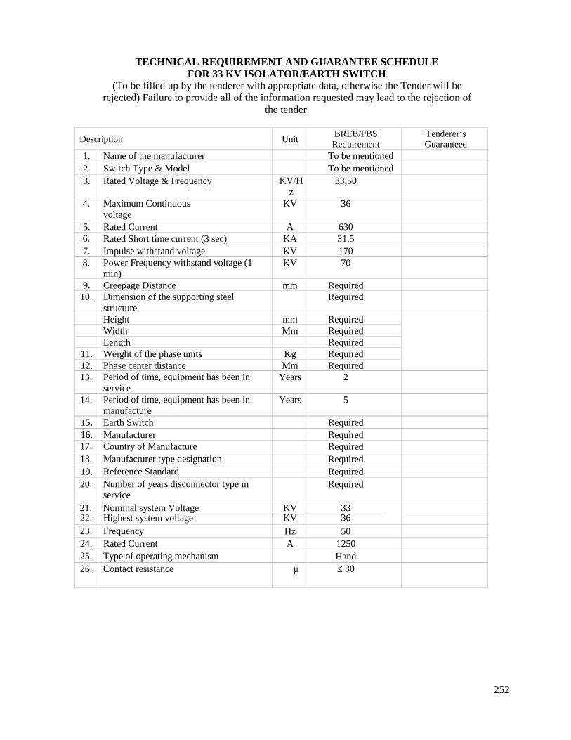
252
TECHNICAL REQUIREMENT AND GUARANTEE SCHEDULEFOR 33 KV ISOLATOR/EARTH SWITCH
(To be filled up by the tenderer with appropriate data, otherwise the Tender will berejected) Failure to provide all of the information requested may lead to the rejection of
the tender.
Description UnitBREB/PBSRequirement
Tenderer’sGuaranteed
Values1. Name of the manufacturer To be mentioned2. Switch Type & Model To be mentioned3. Rated Voltage & Frequency KV/H
z33,50
4. Maximum Continuousvoltage
KV 36
5. Rated Current A 6306. Rated Short time current (3 sec) KA 31.57. Impulse withstand voltage KV 1708. Power Frequency withstand voltage (1
min)KV 70
9. Creepage Distance mm Required10. Dimension of the supporting steel
structureRequired
Height mm RequiredWidth Mm RequiredLength Required
11. Weight of the phase units Kg Required12. Phase center distance Mm Required13. Period of time, equipment has been in
serviceYears 2
14. Period of time, equipment has been inmanufacture
Years 5
15. Earth Switch Required16. Manufacturer Required17. Country of Manufacture Required18. Manufacturer type designation Required19. Reference Standard Required20. Number of years disconnector type in
serviceRequired
21.22.
Nominal system VoltageHighest system voltage
KVKV
3336
23. Frequency Hz 5024. Rated Current A 125025. Type of operating mechanism Hand26. Contact resistance μ ≤ 30
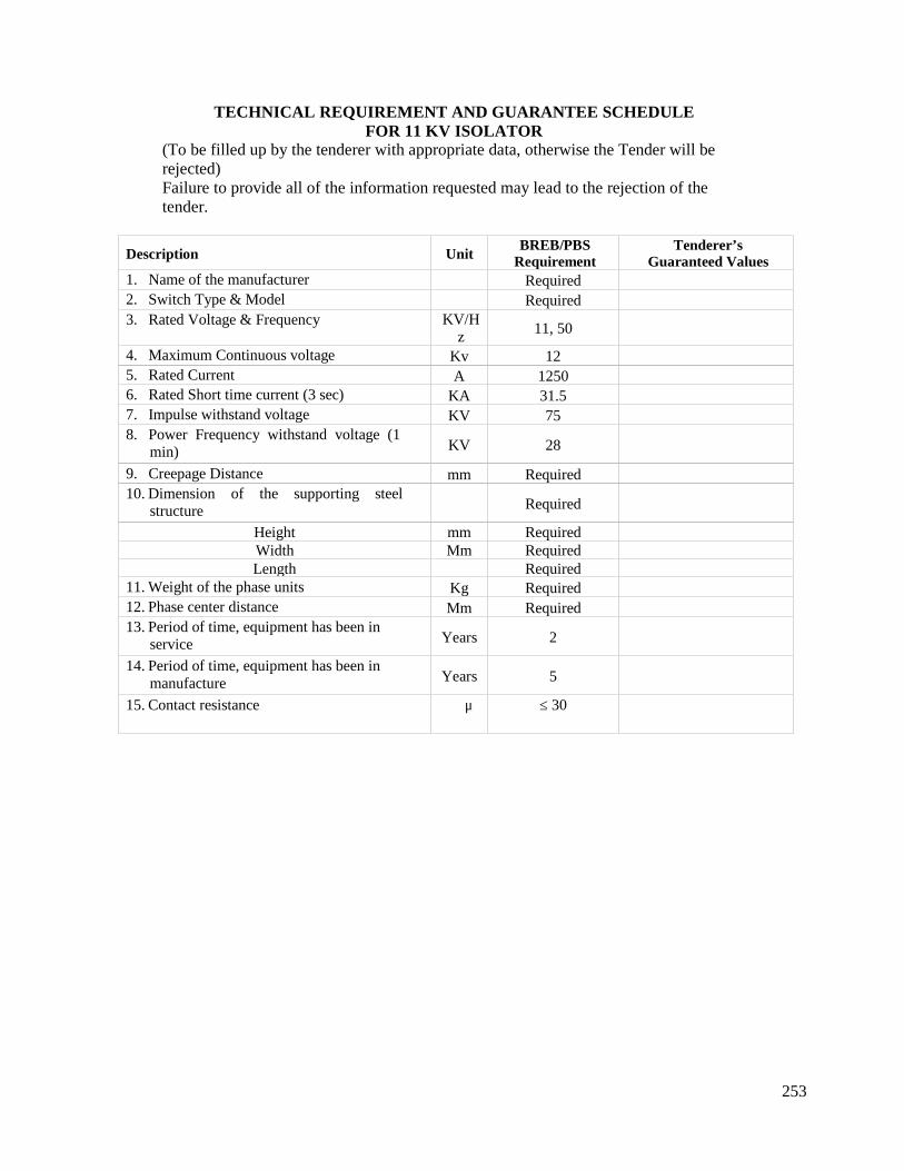
253
TECHNICAL REQUIREMENT AND GUARANTEE SCHEDULEFOR 11 KV ISOLATOR
(To be filled up by the tenderer with appropriate data, otherwise the Tender will berejected)Failure to provide all of the information requested may lead to the rejection of thetender.
Description UnitBREB/PBS
RequirementTenderer’s
Guaranteed Values1. Name of the manufacturer Required2. Switch Type & Model Required3. Rated Voltage & Frequency KV/H
z 11, 50
4. Maximum Continuous voltage Kv 125. Rated Current A 12506. Rated Short time current (3 sec) KA 31.57. Impulse withstand voltage KV 758. Power Frequency withstand voltage (1
min) KV 28
9. Creepage Distance mm Required10. Dimension of the supporting steel
structure Required
Height mm RequiredWidth Mm RequiredLength Required
11. Weight of the phase units Kg Required12. Phase center distance Mm Required13. Period of time, equipment has been in
service Years 2
14. Period of time, equipment has been inmanufacture Years 5
15. Contact resistance μ ≤ 30
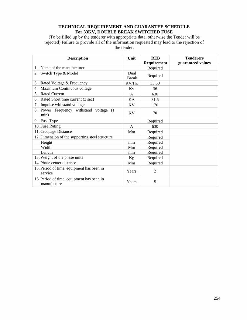
254
TECHNICAL REQUIREMENT AND GUARANTEE SCHEDULEFor 33KV, DOUBLE BREAK SWITCHED FUSE
(To be filled up by the tenderer with appropriate data, otherwise the Tender will berejected) Failure to provide all of the information requested may lead to the rejection of
the tender.
Description Unit REBRequirement
Tenderersguaranteed values
1. Name of the manufacturer Required2. Switch Type & Model Dual
Break Required
3. Rated Voltage & Frequency KV/Hz 33,504. Maximum Continuous voltage Kv 365. Rated Current A 6306. Rated Short time current (3 sec) KA 31.57. Impulse withstand voltage KV 1708. Power Frequency withstand voltage (1
min) KV 70
9. Fuse Type Required10. Fuse Rating A 63011. Creepage Distance Mm Required12. Dimension of the supporting steel structure Required
Height mm RequiredWidth Mm RequiredLength mm Required
13. Weight of the phase units Kg Required14. Phase center distance Mm Required15. Period of time, equipment has been in
service Years 2
16. Period of time, equipment has been inmanufacture Years 5
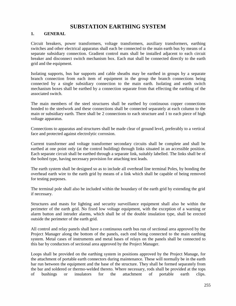
255
SUBSTATION EARTHING SYSTEM1. GENERAL
Circuit breakers, power transformers, voltage transformers, auxiliary transformers, earthingswitches and other electrical apparatus shall each be connected to the main earth bus by means of aseparate subsidiary connection. Gradient control mats shall be installed adjacent to each circuitbreaker and disconnect switch mechanism box. Each mat shall be connected directly to the earthgrid and the equipment.
Isolating supports, bus bar supports and cable sheaths may be earthed in groups by a separatebranch connection from each item of equipment in the group the branch connections beingconnected by a single subsidiary connection to the main earth. Isolating and earth switchmechanism boxes shall be earthed by a connection separate from that effecting the earthing of theassociated switch.
The main members of the steel structures shall be earthed by continuous copper connectionsbonded to the steelwork and these connections shall be connected separately at each column to themain or subsidiary earth. There shall be 2 connections to each structure and 1 to each piece of highvoltage apparatus.
Connections to apparatus and structures shall be made clear of ground level, preferably to a verticalface and protected against electrolytic corrosion.
Current transformer and voltage transformer secondary circuits shall be complete and shall beearthed at one point only (at the control building) through links situated in an accessible position.Each separate circuit shall be earthed through a separate link, suitably labelled. The links shall be ofthe bolted type, having necessary provision for attaching test leads.
The earth system shall be designed so as to include all overhead line terminal Poles, by bonding theoverhead earth wire to the earth grid by means of a link which shall be capable of being removedfor testing purposes.
The terminal pole shall also be included within the boundary of the earth grid by extending the gridif necessary.
Structures and masts for lighting and security surveillance equipment shall also be within theperimeter of the earth grid. No fixed low voltage equipment, with the exception of a warning oralarm button and intruder alarms, which shall be of the double insulation type, shall be erectedoutside the perimeter of the earth grid.
All control and relay panels shall have a continuous earth bus run of sectional area approved by theProject Manager along the bottom of the panels, each end being connected to the main earthingsystem. Metal cases of instruments and metal bases of relays on the panels shall be connected tothis bar by conductors of sectional area approved by the Project Manager.
Loops shall be provided on the earthing system in positions approved by the Project Manage, forthe attachment of portable earth connectors during maintenance. These will normally be in the earthbar run between the equipment and the base of the structure. They shall be formed separately fromthe bar and soldered or thermo-welded thereto. Where necessary, rods shall be provided at the topsof bushings or insulators for the attachment of portable earth clips.

256
Earthing for any high frequency coupling equipment , if applicable, and surge diverters shall be viaa copper rod driven directly into the ground at a position immediately adjacent to the equipmentbeing earthed in addition to the normal earth connection.
2. EARTHING SYSTEM DESIGN
The earthing system shall be designed to meet the requirements of this specification and shall be inaccordance with "The Guide for Safety in Alternating Current Substation Grounding" as publishedby the Institute of Electrical and Electronic Engineers Incorporated, Publication IEEE 80 and 142.The Contractor shall present calculations to show the earthing system meets these requirements andcan be shown to be safe in terms of touch, step and transferred potentials. The earth resistanceshould be kept below or equal to 0.2 Ω.
Electrical measurements of the subsoil at various depths, up to 20 metres shall be made at the siteof the substation in order to determine the layered effects of the ground from which the effectiveground resistivity and hence the expected resistance of the proposed earth grid system may bepredicted.
Soil composition may be highly corrosive and special consideration shall be given to this problem.The earth grid shall be effectively protected against corrosion. Cathodic protection, if considered,may adversely affect other equipment and shall be subject to approval by the Project Manager.
In actual design, the earthing system shall take the form of a combination of grids of buriedconductors and earth rods driven vertically into the ground. Within the grid, conductors shall belaid in parallel lines at reasonably uniform spacing. They shall be located along rows of structuresor equipment to facilitate the making of earth connections, where practical.
The main earth and each subsidiary earth shall have a sectional area, as required for 31.5 kA for 3sec, in any case not less than 120 mm2 in any part of its length. Each branch connection shall have asectional area of not less than 70 mm2.
Connections to the grid of all non-current carrying metallic parts, which might become energisedby chance, such as metal structures, building earth, equipment, earth rods, water pipes, etc. shall notbe less than 70 mm2 and shall be of adequate size, current-carrying capacity and mechanicalruggedness.The spacing between conductors forming the mesh system shall be such as to limit the gridpotential rise to a value that limits the touch voltage to a value not greater than the maximumtolerable touch potential assuming a fault clearance time equal to that of the main protectionequipment being provided.
Each group of earth electrodes shall be connected to the main earth grid through connectionshaving a sectional area of not less than 120 mm2 which shall be protected from corrosion.The grid shall be subdivided into a number of sections, interconnected with test links. These linksshall be accessible from above-ground.
Areas of the grid, where high concentrations of fault currents can appear, as at neutral earthingconnections, shall have reinforced conductor sizes where necessary, to handle adequately thehighest fault current and its duration.
In case the equipment is widely spaced in the station, individual local grids may be established atthe various equipment locations and the local grids shall be interconnected and connected to the
257
overall earth grid. Interconnecting conductors shall not be less than the size of the conductor formain grid.
Metal parts of all equipment, other than those forming part of an electrical circuit shall beconnected directly to the main earth system via a single conductor. The arrangement of the meshearth system shall be such as to minimise the length of these single connections.Earth bars installed directly into the ground should normally be laid bare and the trench back-filledwith fine topsoil. Where the soil is of a corrosive nature, precautions must be taken to protect theearth bar.
All trenches shall be backfilled in compacted 100 mm layers. All stones and other sharp objectsshall be removed from the backfill by a suitable sieve.
Copper to copper joints on strip conductor shall be brazed, using zinc-free brazing material with amelting point of not less than 600°C, or by approved exothermic welding. All exposed joints shallbe at a minimum height of 150 mm above floor or ground level. Earth conductor joints that arerequired to be broken for testing or maintenance shall have mating surfaces tinned.
After installation of the earth system the Contractor shall measure the resistance of the substation.The method used shall preferably be the "fall of potential" method, requiring the availability of alocal low voltage supply but other methods using an earth resistance megger will be acceptable inthe event of a local supply being unavailable.
In the case of surge (lightning) arrestors a local earth connection shall be made by drivingelectrodes into the earth near the arrestors and the lightning arrester earth conductor shall beconnected to both the rod and to the common earthing grid of the station. The connection fromarrester to earth shall be as short and as straight as possible. The conductor shall not be less than120 mm2.
The measured earth resistance shall not exceed 0.5 ohm. A value higher than 0.5 ohm shall besubject to the approval of the Project Manager. The resistance shall be measured with alltransmission line earth wires connected to the earthing grid.
In the event of the substation resistance obtained with the foregoing installation being of amagnitude unacceptable to the Project Manager, then where practicable, the ground area enclosedby the earth system shall be increased by installing directly in the ground an additional copperconductor in the form of a ring around the site, or by additional conductors within the site.Alternatively earth conductors can be directly buried radially outside the substation perimeterfence. The use of earth plates as current carrying electrodes is not acceptable. Any additionalconductors shall be as directed by the Project Manager.
From the point of view of the possible damage to apparatus, the earthing system shall be such as tolimit voltage appearing between the substation equipment and the main body of earth, so thatinsulation breakdown or burning does not occur on apparatus. For the same reason, voltage risebetween earthed points in the substation shall be kept to a minimum. In addition, the effectivenessof any surge protection devices shall be fully realized by providing an adequate earth path. In thiscase, the earthing system shall not only be of low resistance, but of as low reactance as practicable.
258
3. STEP AND TOUCH VOLTAGE
The earthing systems shall be so designed as to keep the "step" and "touch" potentials withinacceptable limits, thereby ensuring safety to the personnel. The aim shall be to ensure that undereither normal or abnormal conditions no dangerous voltages can appear on the equipment oraccessories to which a person has legitimate access.
The step and touch potential voltages obtained inside the site and at selected locations around thefence/gate shall also be measured by a suitable method acceptable to the Project Manager.Appropriate measures shall be taken to rectify the causes of any deviations from allowable values.
4. FENCE AND PERIMETER EARTHING
The fence surrounding the substation shall be earthed to its own earth grid and the fence earth gridshall be connected to the main station earth grid at frequent intervals as approved by the ProjectManager.
A continuous conductor shall be laid outside the periphery of the substation site at a distance of1.0 metre from the boundary fence and at a depth of 0.6 metres below the surface. This shall bewelded to earth rods installed at adequate intervals and at points adjacent to each corner andimmediately below any overhead line entering or leaving the site. The location of the meshconductors shall be such as to enable all items of equipment to be connected to the earth system viathe shortest possible route. All corner fence posts and posts adjacent to earth rods shall beeffectively connected to the earth conductor.
Gateposts forming part of the substation fence shall be bonded together with below groundconnections and the gates themselves shall be electrically bonded to the posts.
The alternative approach of independently earthing the fence and placing it outside the earth gridarea shall only be adopted if the above mentioned procedures prove insufficient or impracticable.The Contractor shall provide calculations to show that this approach produces safe touch voltagesat the fence and shall ensure that the fence is isolated from all other buried metalwork.
5. TESTS
All relevant type and routine tests shall be carried out.
Complete charge and discharge tests on each of the combined batteries and chargers shall beconducted and results recorded so as to permit verification of the ampere-hour capacity of thebattery. During these tests the Project Manager shall select at random reference cells and thevoltage curves thereof shall be checked when the battery is discharged over three and ten hourperiods. The alarm levels and the automatic voltage control feature of the charger shall bedemonstrated over the specified load range.
259
SUBSTATION BATTERY AND BATTERY CHARGER
The following battery size is the minimum expected and is provided as a guide only. TheContractor shall provide the detailed calculations of the loads and the expected loadings and thesizing of the battery for approval before implementation. The number of cells required in thebattery shall be determined by the Contractor in accordance with the design of the DCrequirements.
A. BATTERY
i Application : Supply for remote control, operation, indication,
ii Installationiii Type/Modeliv Operating Voltagev Continuous dischargevi Capacity (at the 5 hr rate)vii No. of cellviii Discharging voltageix Charging voltage (normal)x Charging voltage (max)xi Type of containerxii Mountingxiii Constructionxiv Standard
protective and regulation apparatus, emergency lightetc.: Indoor (self supporting unit).: Nickel Cadmium Alkaline: 110 V, DC: 20 A during 5 hour: 100 A hour: 90: 1.3 - 1.5 volt per cell: 1.45 - 1.55 volt per cell: 1.65 volts per cell: Transparent plastic: Cabinet: Closed top: All equipment and materials shall bedesigned, manufactured and tested in accordance withthe latest editions of applicable IEC standard unlessotherwise specified in the specification. Otherinternationally acceptable standards will also beconsidered provided that relevant values are at leastsimilar to those under IEC standards.
260
Features and Accessories:The battery shall be Nickel Cadmium Alkaline type, negative plates shall have life equal to orgreater than positive plates.
The battery shall have built in protection against active materials shedding and grid corrosion andshall be assembled in heat-resistant, shock-absorbing containers. The containers and covers shall beconnected together to form a leak proof bond against seepage of electrolyte.
The cell terminal posts of the inter-cell and end cell connectors shall have adequate current carryingcapacity and shall be of lead alloy or lead alloy reinforced with copper inserter. The container shallbe filled with sufficient quantity of Alkaline complying with internationally acceptable standards toensure that the surface of Alkali is leveled with the level mark.
Cells shall be equipped with necessary bolts and alkali resisting units, shall be furnished with allthe bolts.Plates shall be hung suspended without touching the bottom of the containers. Containers shallprovide sufficient sediment space so that the plates in the cell, as well as to avoid cleaning of cellsduring the expected life of the battery.110% of the required electrolyte meeting the manufacturer’s specification shall be supplied at thecorrect filling specific gravity with each battery. The electrolyte shall be packaged in 15 gallons orless plastic coated steel drum or in plastic containers. After discharging off the specified ratedcapacity, the battery shall have the voltage including the internal resistance drip of all inter cell andinter rack connectors not to drop below 1.10 VPC.
The battery rack shall be a few step structural steel and shall be printed with 2 coats of acidresistant Grey paint. Inter rack connector terminal lugs shall be provided with each rack.Battery shall be shipped dry with concentrated electrolyte in separate containers.
The following accessories shall be supplied with each battery set:
Two lead plated lugs for No. 4/0 AWG copper cable.Two portable hydrometer syringe.One set of socket wrenches to fit nuts.Polyethylene bottle with extendable tube for topping up the battery.Special voltmeters to measure cell voltage.One gallon of anti-corrosive paint.
The following spare parts shall be supplied with each battery set:
One positive plateOne negative plateOne spare container and cover.One vent plugOne gallon electrolyte.
The battery shall be tropicalized.
All other features as stated in the table of guaranteed data schedule shall be applicable also.
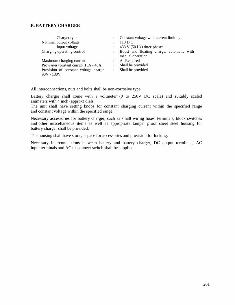
261
B. BATTERY CHARGER
All interconnections, nuts and bolts shall be non-corrosive type.
Battery charger shall come with a voltmeter (0 to 250V DC scale) and suitably scaledammeters with 4 inch (approx) dials.The unit shall have setting knobs for constant charging current within the specified rangeand constant voltage within the specified range.
Necessary accessories for battery charger, such as small wiring fuses, terminals, block switchesand other miscellaneous items as well as appropriate tamper proof sheet steel housing forbattery charger shall be provided.
The housing shall have storage space for accessories and provision for locking.
Necessary interconnections between battery and battery charger, DC output terminals, ACinput terminals and AC disconnect switch shall be supplied.
Charger type : Constant voltage with current limitingNominal output voltage : 110 D.C
Input voltage : 433 V (50 Hz) three phases.Charging operating control : Boost and floating charge, automatic with
manual operationMaximum charging current : As RequiredProvision constant current 15A - 40A : Shall be providedProvision of constant voltage charge90V - 130V
: Shall be provided

262
OVERHEAD EARTHING SCREEN
Earthed screens shall be provided at all substations to protect the substation equipment from directlightning strikes. The screens shall be of aluminum clad steel wires of not less than 50 sq. mm totalsection, and connected to provide low impedance paths to earth.
In accordance with international standards, the ‘Rolling Sphere’ method shall be used to determinethe required protection. The layout of the earth wires shall be such that equipment to be protectedgenerally lies within areas bounded by two or more conductors.
The earth screens shall be suitable for extension to protect the substation equipment to be installedin future stages of development.
Connections to the main underground earth grid shall be made of suitably rated copper strap at eachsupport unless the galvanized steel support structure has sufficient area and current carryingcapacity. Earth wires shall be held in clamps with free pin type joints between clamps and supports.
Connections shall be provided for the terminations of the earth wires of the overhead lines,including bimetal connectors where necessary.
The design of all structures shall comply with the requirements of the standards and specificationswith consider the layout of the 33/11 kV sub-station. In particular the design shall ensure that in theevent of the breakage of one earth wire, the Factor of Safety is not less than 1.5.
263
A. ELECTRICAL
3.0 TESTING AND COMMISSIONING
264
TABLE OF CONTENTS
Clause No.
3.03.13.23.33.43.53.63.73.83.93.103.113.123.133.143.153.163.173.183.193.203.213.223.233.24
Description Page No
Testing and Commissioning 306Motors 306Relays 306Instrument Transformers 307Electrical Instruments and Meters 307AC Switchboards/ Contacts/L.V Equipment 307PVC Cable 307Metal Clad Switchgear 307Disconnectors and Earth Switches 307Bushings and Insulators 308Current and Voltage Transformers 308Structures of Electrical Equipment 308Surge Arresters 308Batteries and Battery Chargers 308Control Panels 309Metal Clad Switchgear Busbars 309Instruments 309Power Transformers 309Station service Transformer 311Prior to Shipment 312Inspection and Testing During Site Erection and Commissioning 312Commissioning Tests 313Commissioning of Electrical Equipment 315Plant Performance 321Manufacturer’s Standard Tests 322
265
3.0 Testing and Commissioning
The Contractor shall include comprehensive Inspection and Test Plans in its Quality Plan. Factorytesting shall include all type tests and routine tests set out in the relevant IEC standards and in theParticular Technical Requirements.
If satisfactory type tests have been carried out on identical equipment the Contractor shall submitcopies of the test certificates to the Employer. The Employer may waive the requirement for any ofthe type tests if it approves these test certificates.
The Employer will witness all factory inspections and testing. The Contractor shall notify theEmployer of its intention to conduct factory inspection and testing for each lot of equipment at leastone month in advance, and shall not perform such testing unless the Employer witnesses the test ora waiver has been provided by the Employer.
The notification shall include full details of the equipment, manufacturers and proposed tests,including:
Contract identificationFull details of equipment to be testedManufacturer's name, address and contact informationContractor or manufacturer's staff responsible for the testing
Location and date of testsSchedule of tests to be performed and standard to be appliedList of relevant drawings and documents
In the following sections, various relevant standards and tests are listed. These are not intended tobe exhaustive. If other standards and/or tests are relevant, they shall also apply.
3.1 Motors
One motor of each type and rating shall be type tested and all motors shall be routine tested inaccordance with the tests specified in IEC 60034, NEMA MG 1, IEEE 112, 114, 115 and 85.
3.2 Relays
3.2.1 Type Tests
Type test results shall be submitted for approval for each type and rating of relay.
Type tests may be waived at the Project Manager’s discretion if adequate type tests have alreadybeen performed and copies of the type test reports are supplied.
3.2.2 Routine Tests
All relays and associated equipment shall be routine tested as required by the standards to prove thequality and accuracy. Routine tests shall be in accordance with relevant IEC recommendations andBS 142.
All relays shall be subjected to the appropriate routine tests as listed below, the individual testsbeing as detailed in IEC 60255 or as otherwise agreed with theProject Manager.

266
Accuracy of calibrated pick-up and drop-off levels over the effective range of settings Insulation tests Accuracy of timing elements Correct operation of flag (or other) indicators Mechanical requirements, integrity/safety of draw-out units, check of contact pressure and
alignment.
3.3 Instrument Transformers
All required tests shall be carried out as per relevant IEC standards.
3.4 Electrical Instruments and Meters
One instrument and meter of each type and rating shall be subjected to the test as specified in IEC60051.
3.5 AC Switchboards/ Contacts/L.V Equipment
Routine tests shall include general inspection and electrical operation tests.
3.6 PVC Cable
Each size and rating of PVC cable shall be subjected to type tests as specified in BS 6346. Routinetests are detailed in this document.
3.7 Metal Clad Switchgear
One circuit breaker, disconnector, earthing device and other switchgear equipment of each ratingand type shall be subjected to the type tests laid down in IEC 60056, ANSI C37, IEC 62271-100and other relevant IEC standards. In cases where documentary evidence is produced that a circuitbreaker of exactly similar design has been type tested by an approved and independent testingstation, the type test requirement may be waived.
The circuit breakers of each type shall be either fully assembled at the manufacturer’s works andsubjected to operation tests and power frequency tests or, where not assembled at works, separatepower frequency voltage tests shall be performed on all major insulation components.
Routine tests in accordance with IEC 60056, IEC 62271-100 or ANSI C37 shall be carried out onall circuit breakers. These shall include operation tests, millivolt drop tests and power frequencyvoltage tests. Routine tests in accordance with the relevant IEC standards, including operation testsand power frequency voltage tests, shall be carried out on all switchgear.
3.8 Disconnectors and Earth Switches
Tests shall be carried out as required according to the following standards:
Type and routine tests to IEC 60129 (BS 5253). Type and routine tests to IEC 60265 for switch disconnection. Routine high voltage and mechanical test of insulators. Sample and type tests of insulators
267
3.9 Bushings and Insulators
Routine, sample and type tests shall be carried out in accordance with the specified standards. Typetests shall also be carried out unless approved type test evidence is submitted. These tests shallinclude temperature cycle and porosity tests.
The following standards shall apply:-
IEC 60233 (BS 4963) for hollow porcelains. IEC 60137 for bushings. IEC 60148 and 60273 (BS 3297) for high voltage post insulators. IEC 60383 and 60305 (BS 137 Part 1 and Part 2) for cap and pin string insulators.
3.10 Current and Voltage Transformers
Type and routine tests shall be carried out according to IEC 60185 (BS 3938), IEC 60186 (BS3941), IEC 60044-1 and IEC 60044-2.
3.11 Structures of Electrical Equipment
Sample tests on the assembly and galvanizing of the structures shall be carried out. A mechanicaltype test with the structure loaded with working load multiplied by the appropriate factor of safetyshall be carried out.
3.12 Surge Arresters
Routine tests and type tests shall be carried out to the specified standards.
The following routine tests shall be carried out on all arrester units in accordance with clause 8.1 ofIEC 60099-4.
Measurement of reference voltage Residual voltage testPartial discharge testHousing leakage test Current distribution test for multi-column arrester
3.13 Batteries and Battery Chargers
All relevant type and routine tests shall be carried out.
Complete charge and discharge tests on each of the combined batteries and chargers shall beconducted and results recorded so as to permit verification of the ampere-hour capacity of thebattery. During these tests the Project Manager shall select at random reference cells and thevoltage curves thereof shall be checked when the battery is discharged over three and ten hourperiods. The alarm levels and the automatic voltage control feature of the charger shall bedemonstrated over the specified load range.
268
3.14 Control Panels
Routine operation tests and insulation resistance tests shall be carried out.
3.15 Metal Clad Switchgear Busbars
Routine tests including millivolt drop tests shall be carried out in accordance with the specifiedstandard. Type tests shall also be carried out on each busbar design unless approved type testevidence is submitted.
3.16 Instruments
Calibration tests shall be carried out on all important pressure gauges and other instruments asrequired by the relevant standards. Site tests shall also be carried out to prove compliance.
3.17 Power Transformers
Testing shall include all routine electrical, mechanical and hydraulic tests in accordance with therelevant IEC or British Standard, except where departures there from and modifications thereto areembodied in this specification. For plant not covered by any IEC or British Standard or specificallymentioned in this specification, such tests as are relevant shall be agreed with the Project Manager.
Should the plant, or any portion thereof, fail under test to give the required performance, furthertests which are considered necessary by the Project Manager shall be carried out by the Contractorand the whole costs of the repeated tests borne by the Contractor. This also applies to tests carriedout at the Sub- contractors’ works.
After satisfactory completion of the witnessed tests at the works, the Plant shall be submitted forthe Project Manager’s approval during dismantling preparatory to shipment. No item of Plant is tobe despatched to site until the Project Manager has given his approval in writing.
Routine Tests
All transformers shall be subject to the routine tests and routine test sequence (mentioned inSection VI Part 2 Electrical Transformer Specification (Clause 5)) in accordance with IEC 60076and the requirements of this Specification.
The test shall be in accordance with IEC 60076, Part 2, and shall be carried out on one transformerof each size and type. Temperature-rise tests shall be conducted on the tapping corresponding to themaximum losses.
All relevant type tests shall be carried out or documentary evidence of tests on similar designspresented.
Temperature Rise Test:
This shall be carried out in accordance with IEC 60076 Part 2.
Noise Level Tests:
A noise level test according to IEC 60075 shall be carried out on one transformer of each typespecified under items 1 and 2 in accordance with IEC 60551.
269
Special Tests
As mentioned in Section VI Part 2 Electrical Transformer Specification (Clause 5).
3.17.1 Voltage Control Equipment
The following tests shall be carried out:
Routine Tests
Each finished tap changer shall be subjected to the routine tests specified in IEC 60214.
Type Tests
Type tests shall be carried out entirely in accordance with IEC 60214 except that evidence of theservice duty type test shall be in excess of 100,000 operations.
3.17.2 Magnetic Circuit
The following tests shall be carried out:
Routine Tests
Each core completely assembled shall be tested for one minute at 2,000V AC between core bolts,side plates, structural steelwork and core at the core and coil stage. After the transformer is tankedand completely assembled, a further test shall be applied between the core and the earthedstructural steelwork to prove that the core is earthed through the removable link, at one point only.
3.17.3 Outdoor Bushing Assemblies with Porcelain Insulators
The following tests shall be carried out:Hollow insulators tested in accordance with IEC 60233.
Complete bushings tested in accordance with IEC 60137.
All relevant type and routine tests shall be carried out.
3.17.4 Tanks
The following tests shall be carried out:
Routine Tests shall include:
Oil Leakage:
All tanks, conservators and oil filled compartments, which are subjected in service or duringmaintenance to oil pressure, shall withstand without leakage a hydraulic pressure test equal to 69kN/m2 or the normal pressure plus 34 N/m2 whichever is the greater, for 24 hours during whichtime no leakage or oil ingress into normally oil free spaces shall occur.

270
Type Tests:
Unless type test certificates can be produced for tests carried out on similar equipment, thefollowing tests shall be included for tanks and conservators.
i) Vacuum Test:
The equipment shall withstand a full vacuum when empty of oil. The permanent deflection ofplates or stiffeners on removal of vacuum shall not exceed the following values:
Length of Plate
Less than 1300 mm1300 to 2500 mmGreater than 2500 mm
Permanent deflection
3.17 mm9.5 mm12.7 mm
3.17.5 Cooling Plant
The following tests shall be carried out:
Routine Tests Cooler: Pressure test to be as specified above. Motors and control Gear: as required by the standard
3.17.6 Gas and Oil – Actuated Relays
The following tests shall be carried out:
Routine Tests:
Oil Leakage, when subject to an internal oil pressure of 207kN/m2 for fifteen minutes. Gas Collection Oil Surge Performance test under service conditions Voltage:2kV for one minute between electrical circuits and casing.
3.17.7 Galvanizing
Routine Tests shall be carried out to the requirements of BS 443 or BS 729 whichever is applicable
3.18 Station Service Transformer
The following tests shall be carried out:
Routine Tests
Measurement of Winding Resistance Ratio, polarity and phase relationships Measurement of impedance voltage

271
Measurement of loss Short duration power frequency voltage-withstand test Induced over voltage withstand test Insulation resistance of each winding
Type Tests
All relevant type tests including a temperature rise test shall be carried out.
Unless acceptable type test certificates cab be submitted in respect of a transformer similar indesign to that specified, a temperature rise test shall be carried out and the costs shall be included inthe contract Price. This test shall take into account temperature rise due to both the specified earthfault current and continuous operation at CMR of the auxiliary winding.
3.19 Prior to Shipment
After the satisfactory completion of all tests at the factory, the plant shall be submitted for theProject Manager’s approval during dismantling preparatory to shipping. No item of plant shall bedespatched to site until the Project Manager has given approval in writing.
3.20 Inspection and Testing During Site Erection and Commissioning
3.20.1 General
The Contractor shall be responsible for the inspection and testing during site erection, to ensurecorrect erection and compliance with the specification. Tests carried out during testing andcommissioning shall includes those tests listed in this section but shall not be limited to them.
During the course of erection, the Contractor shall provide access as required by the ProjectManager for inspecting the progress of the works and checking its accuracy to any extent that maybe required.
The Contractor shall provide, at its own cost, all labor, materials, stores, and apparatus as may berequired and as may be reasonable demanded to carry out all tests during erection, whether or notthe tests are specifically referred to in this specification. All power supplies (including 50Hz AC)shall be provided by the Contractor.
A full site test program shall be submitted for approval. This shall include a brief description of alltests and testing procedures and shall be provided before tests commence and the method of testing,unless otherwise specified, shall be agreed with the Project Manager.
The Contractor shall provide experienced test personnel and testing shall be carried out duringnormal working hours as far as is practicable. Tests which involve existing apparatus and outagesmay be carried out outside normal working hours. The Contractor shall give sufficient notice toallow for the necessary outage arrangements to be made in conformity with the testing program.
The Contractor shall record the results of the tests clearly, on an approved form and with clearreference to the equipment and items to which they refer, so that the record can be used as the basisfor maintenance test during the working life of the equipment. The required number of site testresult records shall be provided by the Contractor to the Project Manager as soon as possible aftercompletion of the tests.
272
No tests as agreed under the program of tests shall be waived except upon the instruction oragreement of the Project Manager in writing.
The Contractor’s test equipment shall be of satisfactory quality and condition and, where necessary,shall be appropriately calibrated by an approved authority at the Contractor’s expense. Details ofthe test equipment and instruments used shall be noted in the test sheets in cases where theinstrument or equipment characteristics can have a bearing on the test results.
The testing requirements detailed under this specification may be subject to some variation uponthe instruction or agreement of the Project Manager where necessitated by change conditions at siteof by differing design, manufacture, or construction techniques.
The Contractor shall be responsible for the safe and efficient setting to work of the whole of theplant and equipment. The methods adopted shall be in accordance with any safety and permitregulations in force by the Employer on the site.
3.20.2 Mechanical Equipment
The extent of testing during erection shall include, but not be limited to, the following.
Checking the accuracy and alignment of plant erected. The accuracy shall comply with therelevant standards, the specification or the plant manufacturer’s requirements as may beapplicable or where no requirements exist, to a standard to be agreed between the ProjectManager and the Contractor.
Checking the alignment of rotating equipment to the manufacturer’s requirements. Non-destructive testing of site welds as required by the relevant standard and as detailed in
this specification.
3.21 Commissioning Tests
At least two months before commencing the commissioning of any plant or equipment, theContractor shall submit for approval fully comprehensive schedules of pre-commissioning checksas applicable to each item of the plant and equipment provided. These schedules shall then be usedduring pre-commissioning as a guide to the methods to be followed and to record the actualactivities carried out with the appropriate date, together with details of all work yet to becompleted, variations and modifications to design conditions.
In addition the Contractor is to submit with the schedules to the Project Manager proforma testsheets (to be used by the Contractor during testing and commissioning) for all tests he proposes tocarry out and those required by the Project Manager.
Each activity on the schedules, when completed to the satisfaction of the Project Manager, shall besigned and dated by the Contractor. The schedules shall be countersigned by the Project Manageras necessary. If during the performance of the pre-commissioning checks the Project Managerconsiders that additional tests are necessary to prove the system or plant the Contractor shallperform such additional tests to the Project Manager’s satisfaction.
Each activity on the commissioning procedure schedules when completed to the satisfaction of theProject Manager, shall be signed and dated by the Contractor and shall be countersigned by theProject Manager as necessary.
273
The commissioning procedures shall ensure that the commissioning of any section of the Worksdoes not interrupt the normal commercial operation of any previously commissioned section(s).
At least 14 days prior to commencing commissioning checks, the Contractor is to agree with theProject Manager, the method and sequence of performing the commissioning tests. Followingagreement the Contractor shall submit a detailed program indicating the testing sequence to permitadvance notice to be given to the Employer in order that the Employer’s representatives may alsowitness testing.
For the purposes of this Contract, the provisions of this section will apply to plant supplied fromnominated sub-contractors.
3.21.1 Contractor’s Site Supervisory Staff
During the commissioning and subsequent testing of any item of plant the Contractor shall providethe services of any special supervisory staff necessary for the purpose of ensuring propercommissioning and the satisfactory completion of all tests. The cost of any such specializedservices is deemed to be part of the bid price for erection of plant.
3.21.2 Commissioning of Modified Circuits
Where the scope of works has included the diversion, relocation or variation of any existing circuitthe Contractor is deemed to have included for all pre-commissioning checks on existing equipment.Where this work includes overhead line or cable circuits the Contractor is responsible for carryingout full pre-commissioning and on-load checks at the remote end of the circuit including theinjection testing and re-setting of relays if required.
All and any such work associated with the re-commissioning of existing equipment is deemed to beincluded in the contract price.
3.21.3 Test Equipment
The Contractor is responsible for providing all equipment, power, etc. necessary to carry out alltests on site. Following award of contract, at the appropriate time, the successful Contractor shallsubmit a detailed schedule of the test equipment etc., he intends to provide for carrying out thisportion of the works. Should the Project Manager require additional or alternative test equipment tobe provided to enable full site testing to be performed in accordance with the requirements of thespecification, the Contractor shall supply such equipment at no extra cost.
3.21.4 Owner Participation
The Contractor shall plan for Employer staff participation either continuously or on a regularlyrecurring basis in the commissioning work with the primary intent of:
a) Staff becoming familiar with the operating and maintenance aspects of the new equipment.b) Staff maintaining a continuing assessment of the precautions required in, or possible
consequences of, initial energization of equipment.
These two objectives must be allowed for in the preparation of schedules.
274
3.22 Commissioning of Electrical Equipment
3.22.1 General
A general check of all the main switchgear and ancillary equipment shall be made and shall includea cheek of the completeness, correctness and condition of earth connections, labeling, arcing ringand horn gaps, clearances, painted surfaces, cables, wiring, pipe work, valves, blanking plates andall other auxiliary and ancillary items. Checks shall be made for oil and gas leaks and that theinsulators are clean and free from external damage. A check shall be made that loose items whichare to be handed over to the employer e.g. blanking plates, tools, spares, are in order and arecorrectly stored.
The following general tests are to be carried out on electrical equipment after erection at site:-
Routine high voltage tests to the appropriate IEC standard. Where no relevant standard exists, testsshall be agreed with the Project Manager.
Insulation resistance tests on all electrical equipment. Continuity and conductivity resistance tests. Test operation of alarm and tripping, devices to local and remote. Rotational tests on all motors. Polarity tests on CTs and VTs. Oil tests. Grounding system and electrode tests. Ratio, vector grouping and magnetizing current tests on each transformer. Calibration of winding and oil temperature devices. Vector group and phasing tests on VT circuits. Magnetization current/voltage tests, knee voltage, accuracy and winding resistance tests on
all current transformers. Primary and secondary injection tests on relays, protection devices and equipment.
3.22.2 TransformersThe site tests, full details of which are to be submitted by the Contractor after the Contract has beenplaced, shall include those tests described in outline below.
(a) Insulation resistance of core and windings.(b) Dielectric strength of oil samples.(c) Ratio and no-load current at low voltage (e.g. 400 V) on all tappings.(d) Vector notation check.(e) Calibration check of temperature instruments, including secondary current injection and
proving contact settings.(f) Air injection tests of gas/oil-actuated relays.(g) Setting check of oil-level and oil-flow devices.(h) Complete functional tests of cooling equipment and tap-change equipment, including
manual/automatic sequences, indications, alarms and interlocks, measurement of motorcurrents, adoption of suitable motor protection settings and proof of protection for stalled orsingle-phasing conditions.
(i) Operational tests of breathers.(j) Insulation resistance of all secondary circuits.(k) Carry out “footprint” tests to confirm that no damage to the windings has taken place during
transit and installation.
275
(l) Final checks before energizing:-
Venting, position and locking of valves, earthing of star-point(s) and of tank, state ofbreathers and of pressure-relief devices, oil levels, absence of oil leakage, operation of kioskheaters, tap-change counter readings, resetting of maximum temperature indicators, finalproving of alarms and trips.
(m) Dissolved Gas Analysis of transformer oil after final processing(n) Tests when energized:
On-load tap-changer operation throughout range (subject to not exceeding 1.1 pu volts on anywindings).Maintenance of 1.1 pu volts on untapped windings for 15 minutes (but not exceeding thisvalue on tapped winding).
(o) Tests on load:Temperature instrument readingsMeasurement of WTI CT secondary currentsRepeat Dissolved Gas Analysis of transformer oil after energisation tests completed
(p) Oil:Samples of oil from each consignment shall be tested in accordance with IEC 60296 beforedispatch.
Subject to the agreement of the Project Manager a test certificate, confirming that the oil fromwhich the consignment was drawn has been tested in accordance with IEC 60296, may be accepted.Before commissioning any transformer, the electric strength of its oil shall be check-tested andresults approved by the Project Manager.
3.22.3 Circuit-Breakers
Circuit-breakers shall be given a visual inspection.
In the case of gas type circuit-breakers testing will be required on the gas system to prove the gaspressure, quantity, dryness and dielectric strength.
Contact resistance tests shall be carried out. In the case of multi-interrupter circuit-breakersresistance tests will be required at each interrupter or pair of interrupters as well as through theseries of interrupters on each pole.
Local air components associated with pneumatic operation, including air compressors, shall betested and air loss measurements and pressure and alarm settings checked. Tests shall be made alsoon mechanical and hydraulic operation systems.
3.22.4 Disconnectors and Earth Switches
Manual operation of disconnectors and earth switches shall be subject to operational tests toconfirm contact pressures, contact resistances, simultaneous operation of all phases and the ease ofoperation.
276
Motorised operation of disconnectors and earth switches shall be tested to prove the motoroperation, including local and remote operation, and timing tests shall also be carried out. Motorprotection shall be tested.
Checks shall be made on interlocks, local and remote indications and operation of auxiliarycontacts.
Earth switches shall be tested to confirm the opening and closing sequences and checks shall bemade on interlocks, indications and manual locking devices.
3.22.5 Busbars and Connections
Flexible busbars and connections shall be tested to ensure that the correct tensions, sags andclearances will be maintained over the range of environmental conditions and loads without stressto other equipment. If dynamometers are used to check the sags and tensions, they shall be checkedboth before and after use.
Rigid busbars and connections shall be tested to ensure that the busbars will not cause overloadingof the supporting insulators under load conditions and under the range of climatic variationsapplicable to the site and that expansion and contraction of the equipment is fully accommodatedby flexible connections.
Conductivity tests shall be carried out on all connections and joints which are made on site, withoutexception.
3.22.6 Earthing System
Tests shall be made on the effectiveness of the bonding and earthing which will includeconductivity tests on selected joints, on the main earthing system, and at the connections toequipment and structures. Checks shall also be made on precautions taken to avoid corrosion attackon the earthing system.
Test probes at approximately 300 and 600 meters separation will normally be required toeffectively test the earthing system. The use of transmission line conductors may be arranged tosimplify test testing procedures.
The earth resistance shall be measured during the installation and on completion as follows:-
of each earth rod after driving of the earth grid after completion and back-filling of the trenches of each group of earth rods or earth point after completion of the connection from the test
link terminal. Of the completed installation without any connections outside the substation
The tests shall be carried out by a method and with equipment approved by theProject Manager. Alltests are to be witnessed and the equipment and method used recorded with the test results.
The Contractor may also be called upon to provide assistance in the measurement of earthresistance after earth connections to the system have been completed.
277
3.22.7 Control Relays and metering Panels, Instruments and Protective Devices
(a) Wiring
After complete erection and cabling, all circuits shall be subjected to the high voltage test specifiedin the relevant IEC or approved standard.
The insulation resistance of all circuits shall be measured before and after any high voltage tests.
For AC secondary injection tests a substantially sinusoidal test supply shall be used.
The operation and resetting level (current and/or voltage) and timing of all relays shall be measuredover an agreed range of settings for all relays.
Other relays shall be fully tested in accordance with the manufacturer’s recommendations.
All DC elements of protection relays shall be tested for operation at 70% rated voltage.
All d/c supplies shall be checked for severity of current inrush when energized by switching on orinserting fuses or links.
(b) Mechanical Inspection
All panel equipment is to be examined to ensure that it is in proper working condition and correctlyadjusted, correctly labeled and that cases, covers, glass and gaskets are in good order and properlyfitting.
(c) General
Sufficient tests shall be performed on the relays and protection schemes to:
Establish that the equipment has not suffered damage during transit.Establish that the correct equipment has been supplied and installed. Confirm that the various items of equipment have been correctly interconnected. Confirm performance of schemes designed on the bases of calculation e.g. differential
protection. To provide a set of figures for comparison with future maintenance values allowing the
condition of the equipment to be determined.
(d) Secondary Injection
Secondary injection shall be carried out on all AC relays, using voltage and current of sinusoidalwave form and rated power frequency to confirm satisfactory operation and range adjustment.
The polar characteristic of all distance protections shall be recorded at a minimum of 30 degreeintervals.
For circulating current protection employing high impedance voltage operated relays, the points ofinjection for relay voltage setting tests shall be across the relay and stabilizing resistance.
278
The fault setting for the type of protection is to be established by secondary injection, where it isimpracticable to ascertain this value by primary injection. Injection is to be made across theappropriate relay bus wires with all associated relays, setting resistors, and CT’s connected.
(e) Primary Injection
All current operated relays shall be tested by injection of primary current to record the actual relaysetting and as a final proof of the integrity of all secondary connections.
The stability of all differential schemes shall be checked by injection of primary current.
Primary current injection tests are to be carried out by the Contractor and the methods employed fora particular installation are to be agreed with theProject Manager.
Tests are to be carried out as follows:
Local primary injection to establish the ratio and polarity of current transformers as a group,care being taken to prove the identity of current transformers of similar ratio.
Overall primary injection to prove correct interconnection between current transformergroups and associated relays.
Fault setting tests, where possible, to establish the value of current necessary to produceoperation of the relays.
(f) DC Operations
Tests are to be carried out to prove the correctness of all DC polarities, the operating levels of DCrelays and the correct functioning of DC relay schemes, selection and control switching, indicationsand alarms. The correct functioning of all isolation links and fuses shall also be checked.
(g) Tests on Load
Tests on load shall also be done to demonstrate stability and operation of protection relays asrequired by theProject Manager.
All tripping, control, alarm and interlocking circuits shall be functionally tested to provesatisfactory and full proof operation and/or resetting. The functional and safety aspects of allshorting and/ or isolation links, fuses and switches devices shall be proved.
The total burdens connected to all voltage transformer circuits shall be measured and recorded.
The total capacitance of all wiring and apparatus connected to the negative pole of each maintripping battery shall be measured and recorded; the value shall not exceed 10 microfarad.
The continuous current drain of all trip circuit supervision relays shall be measured and shall not begreater than half the minimum current required for tripping. The supervision current shall bemeasured with the circuit-breaker (or other device) both open and closed.
Batteries and Chargers
Tests shall be carried out on the batteries and chargers to confirm the charger ratings andadjustment, the battery and charger alarm systems and battery capacity.
279
The open-circuit cell voltages of the batteries when fully charged shall be recorded.
The insulation to earth of the complete DC installation shall be tested.
Power Cables
Each completed circuit shall be tested for continuity and insulation resistance.
Current Transformers
A magnetization curve shall be obtained for each current transformer in order to:-
Detect damage in transit or installation Prove that the correct cores have been wired out to the relevant terminals For high impedance relay schemes, to confirm that correct relay settings have been
calculated. The DC resistance of each current transformer secondary winding shall be measured and
also the transformers and connection leads, each item being recorded separately. The insulation resistance of all secondary circuits shall be measured at 1000 volt and
recorded.
Primary current injection tests shall be conducted on all current transformers using adequateprimary current to prove correct ratio, polarity and, for differential protection schemes, to prove thecorrect relative polarities of all current transformers of each scheme.
Voltage Transformers
The transformer ratio and polarity shall be checked using a primary voltage high enough to give aclearly measurable secondary voltage or by using rated primary voltage and comparison with analready proven voltage transformer. The phasing and phase rotation shall be checked. For threephase voltage transformers a test shall be conducted to show that energizing each primary windingproduces an output from only the correct phase secondary winding. The residual voltage of anyopen delta or broken delta winding shall be measured with rated primary voltage applied.
Control and Instrumentation Equipment
The following general tests shall be performed on control and instrumentation equipment at site:
Insulation resistance testing of all circuits. Functional tests for all tripping, control, alarm and interlocking circuits.
The testing of all equipment in accordance with the manufacturer’s instructions or as advised by theProject Manager.
Transformers and Ancillary Equipment
The following tests shall be performed.
Insulation resistance tests on bushings. Insulation resistance test at 500V between core and core clamping structure. Voltage withstand tests on insulation oil to BS 148.

280
Ratio test. Phase relationship Magnetization characteristics of current transformers of winding temperature devices. Calibration of winding temperature devices. Tap Selector and Diverter Switch alignment. Calibration of automatic voltage control equipment. Proving tests as necessary on control schemes. Measurement of winding resistance on all taps and phases.
3.22.8 Inspection Plan and Procedures
3.22.9 Measuring and Testing Equipments
At prescribed intervals, or prior to each use, all measuring and testing equipment used in inspectionshall be calibrated and adjusted against certified equipment having a known valid relationship tonationally recognized standards. Where no national standards exist, the basis employed forcalibration shall be approved by the Project Manager.
The manufacturer shall prepare a calibration schedule showing equipment type, identificationnumber, location, frequency of checks, method of checking and action to take when results areunsatisfactory.
Each piece of equipment shall be labeled with its identification and current calibration status.
Calibration records for each piece of equipment shall be maintained at least for life of that piece ofequipment and shall be available for examination by the Project Manager.
3.22.10 Re-inspection Following Non-Conformance
If a non-conformance report is issued as specified in this clause and the clause below, theContractor shall reimburse the Project Manager for all costs incurred by its staff (including timecosts, travel, accommodation etc.) for both attending discussions on remedial matters and any re-inspection that the incurred by its staff may deem to be necessary.
3.23 Plant Performance
3.23.1 Guarantees
Bidders shall state and guarantee the technical particulars listed in the Schedules of TechnicalParticulars and Guarantees. These guarantees and particulars shall be binding and shall not bedeviated from without the written permission of the Project Manager.The tolerances permitted in the IEC or other standard shall apply unless otherwise stated.
3.23.2 Rejection
If the guarantees are not met and/or if any items fails to comply with the requirements of thisSpecification in any respect whatsoever at any stage of manufacture, test, erection or during themaintenance period, the Project Manager may reject the item, or defective component thereof,whichever he considers necessary, and after adjustment or modification as directed by the ProjectManager, the Contractor shall submit the item for further inspection and/or test. The repairprocedure shall be to the Project Manager’s approval. In the event of a defect on any item being of

281
such a nature that the requirements of this Specification cannot be fulfilled by adjustment ormodification, such item shall be replaced by the Contractor, at his own expense to the entiresatisfaction of the Project Manager. Any item of plant repaired to an approved procedure shall notbe accepted as a part of the Works as a permanent solution or replacement unless the Contractorguarantees in writing that the repaired plant or component shall have the same service life andefficiency as the component originally manufactured.
3.24 Manufacturer’s Standard Tests
3.24.1 General
Where no specific test is specified then the various items of plant, materials and equipment shall betested in accordance with the appropriate IEC standard. Where no appropriate standard is available,tests shall be carried out in accordance with the maker’s standard practice, subject to the priorapproval of the Project Manager. In all cases, works tests shall include electrical mechanical andhydraulic tests in addition to any tests called for by the Project Manager to ensure that the plantbeing supplied fulfills the requirements of the Specification.If considered necessary by the Project Manager any multi-part assemblies shall be fully erected inthe Works prior to packing and dispatch to Site.
All tests to be performed during manufacture, fabrication and inspection shall be agreed with theProject Manager prior to commencement of the work. The inspection schedule included in theSchedules of Miscellany shall be used for this purpose. The Contractor shall prepare the details ofthe schedule and submit these to the Project Manager for approval.It must be ensured that adequate relevant information on the design, code/standard employed, themanufacture/fabrication/assembly procedure and the attendant quality control steps proposed aremade available to the Project Manager. The Project Manager will mark in the appropriate spaceshis intention to attend or waive the invited tests, or inspections.
A minimum of 14 days notice in writing, of the readiness of plant for test or inspection shall beprovided to the Project Manager by the Contractor in accordance with the following:
The Contractor shall submit to the Project Manager sequentially numbered applications forinspection which shall contain the following information.
Contract number Contract title Contractors Name Inspection application number Manufacturers name, address, telephone and telex numbers, plus name of manufacturers
staff responsible for the testing and manufacturer’s works order number. Location of tests Date of tests
Description in full of Plant offered for inspection (Contractors order references alone areinsufficient and unacceptable)
Section of the Works for which Plant is allocated.
Schedule of tests to be performed and standard to be applied. List of the Employer’s approved drawing numbers appropriate to the Plant offered
Sub-order number

282
The subject items should remain available for the Project Manager inspection and test up to aminimum of 10 days beyond the agreed date of witnessing the test.
Every facility in respect of access, drawings, instruments, and manpower shall be provided by theContractor and his Sub-contractor to enable the Project Manager or his designated representative tocarry out the necessary inspection and testing of the plant.
No equipment shall be packed, prepared for shipment, or dismantled for the purpose of packing forshipment, unless it has been satisfactorily inspected, and approved for shipment, or alternativelyinspection has been waived. The Contractor shall request permission to dispatch in writing.
Functional electrical, mechanical and hydraulic tests shall be carried out on the completed plantafter assembly in the works. The extent of these tests and method of recording the results shall besubmitted to, and agreed by, the Project Manager in sufficient time to enable the tests to besatisfactorily witnessed, or if necessary for any changes required to the proposed programme oftests to be agreed.
All instruments and apparatus used in the performance of the tests shall be to the approval of theProject Manager, and, if required by the Project Manager, shall be calibrated to an agreed standardat the National Physical Laboratories or equivalent centre and approved by the Project Manager.
The cost of carrying out such calibrations shall be borne by the Contractor in all cases.
The Project Manager reserves the right to visit the Contractor’s works at any reasonable timeduring manufacture of the items of plant and to familiarize him with the progress made and thequality of the work to date.
3.24.2 Test Certificates
Within 30 days of the completion of any test, four sets of all principal test records, test certificatesand correction and performance curves for the plant and its component parts shall be supplied to theProject Manager.
These test records, certificates and performance curves shall be supplied for all tests, whether or notthey have been witnessed by the Project Manager or his Representative. The information given onsuch test certificates and curves shall be sufficient to identify the material or equipment to whichthe certificate refers and should also bear the contract reference title. It shall be possible to identifythe item of plant to which a specific test certificate refers, including those of sub-components andthe specific site for which the item is allocated.
Contractors order numbers or drawing reference numbers are not sufficient for this purpose withouta description of the plant involved.
Test certificate shall provide full details of the measurements of their tolerances, and actual testvalues obtained. Certificates simply stating phrases such as ‘Passed’ or ‘Tested in accordance with’are not acceptable.
When all equipment has been tested, the test certificates from all works and site tests shall becompiled by the Contractor into volumes and bound in an approved form, complete with index andincluded in the appropriate operation and maintenance manuals.
283
B. CIVIL
4.0 TECHNICAL REQUIREMENTSFOR SUBSTATION CIVIL AND BUILDING WORKS
284
TABLE OF CONTENTS
ClauseNo.
Description
4.1 Introduction4.2 Design and Construction Standards4.3 Units of Measurement4.4 New 33/11 kV 10MVA or 20MVA Sub
Stations4.5 Site Analysis and Topographical Survey4.6 Subsoil Investigations4.7 Laboratory Testing4.8 Bulk Earthworks4.9 Building Foundations4.10 Civil Work4.11 Design and Construction Requirements
and Interchangeability4.11.1 General Requirements4.11.2 Specific Requirements4.12 Plant and Equipment Identification4.12.1 Identification on Drawings4.12.2 Labels and Nameplates4.13 Safety and Security4.13.1 Interlocks4.13.2 Locks, Padlocks, and Key Cabinets4.14 Commissioning Spares4.15 Consumable Items4.15.1 Chemicals and other Consumable4.16 Painting and Cleaning4.17 Galvanized Work4.18 Steel Pipe Work4.19 Bolts, Studs, Nuts and Washers4.20 Architectural and Structural Requirements
of Buildings4.20.1 Architectural Planning and Design4.20.2 Structural Design4.21 Utility Services4.22 Fire Detection and Protection Facilities4.23 Grid Substation Sending End Bays for
New Substations4.24 Preparation of the Site4.25 Temporary Buildings on Site4.26 Access to the Site4.27 Site Drainage4.28 Site Maintenance during Construction

285
4.1 Introduction
This contract is being tendered as a turnkey contract, in which the selected contractor will beresponsible for carrying out all civil works designs, including preparing working drawings andspecifying materials to be used in all temporary and permanent works. This section describes theGeneral Technical Requirements for all civil works, which include earthworks, the construction offoundations, structures, architectural features and all associated works required for REB 33/11 KVIndoor Rural Type Substations, fitting out structures, buildings and associated works, and erecting,installing and commissioning of all Substation plant. This section shall be read in conjunction withthe Project Requirements, Schedules and Drawings.
The Contractor shall appoint a team of qualified and experienced engineers and other specialists toundertake the detailed design of all civil and associated works, and shall submit all completeddesigns, drawings and supporting calculations to the Project Manager for approval before site workcommences.
286
4.2 Design and Construction Standards
The design and construction shall conform to the latest edition of the relevant codes of practice andstandards listed below and in individual clauses in this document relating to specific materials orpractice. Any proposed substitution for the listed standards by an equivalent standard shall besubject to approval by the Employer.AASHTO American Association of State Highway and Transportation codes for site
access road designACI 318-89 Building Code Requirements for Reinforced ConcreteASTM American Society for Testing and MaterialsBNBC (Bangladesh National Building Code) with requirements for building worksBS 12 Portland CementBS EN 124 Gully and Manhole Tops for Vehicular and Pedestrian AreasBS 812 Testing AggregatesBS 882 Aggregates from Natural Sources for ConcreteBS 1387 Specification for Screwed and Socketed Steel TubesBS EN ISO 1461 Hot Dip Galvanized Coatings on Fabricated Iron and Steel ArticlesBS 1881 Testing ConcreteBS EN 1992-1-1 Design of Concrete Structures (includes foundations)BS EN 1997-1 Geotechnical DesignBS 2853 Design and Testing of Overhead Runway BeamsBS 3148 Methods of Testing for Water for Making ConcreteBS 3921 Clay bricksBS 4449 Steel Bars for the Reinforcement of ConcreteBS 5262 External RenderingsBS 5395 Stairs, Ladders and WalkwaysBS 5572 Sanitary Pipe WorksBS 5628 Code of Practice for use of MasonryBS 5930 Code of Practice for Site InvestigationsBS 6031 Code of Practice for EarthworksBS 6367 Code of Practice for Drainage of Roofs and Paved AreasBS 6399: Part1 Code of Practice for Dead and Imposed LoadsBS 6399: Part 2 Code of Practice for Wind LoadsBS 6465 Sanitary InstallationsBS 6651 Code of Practice for Protection of Structures against LightningBS 6700 Design, Installation, Testing and Maintenance of Services Supplying Water for
Domestic UseBS 8004 Code of Practice for FoundationsBS 8005 SewerageBS 8100 Lattice Towers and MastsBS 8102 Code of Practice for Protection of Structures Against WaterBS 8110 Structural Use of ConcreteBS 8206-2 Lighting for BuildingsBS 8215 Code of Practice for Design and Installation of Damp-proof Courses in MasonryBS 8290 Suspended CeilingsBS 8301 Code of Practice for Building Drainage
4.3 Units of Measurement
All designs and measurements in this Contract shall be provided in the International System of Units
287
(SI) in accordance with the provisions of ISO 31 and ISO 1000.
4.4 New 33/11 kV 10 MVA or 20 MVA Sub Stations
Two storied buildings will be designed and constructed to establish a 33/11.55 kV, 10 MVA or 20MVA Substations, with associated work including control room, complaint room, service road,fencing work, landscaping and beautification work and other related works.
The Contactor shall be responsible for the design and construction of the Substation and associatedwork, which will include the following:
Topographical survey as part of site analysis
Subsoil investigation, sampling and laboratory testing
Master plan including services road, landscaping (beautification work) as per respectivesite condition
Conceptual alternative studies of site plans shall be undertaken for individual sites, studyand architectural planning of individual units. The site plan shall consider the building andother facilities/utilities like circulation roads, parking, utility networks, landscaping andboundaries.
Foundation works
Architectural plan, section, all side elevation including 3-D perspective of the building.
Structural design as per present code of practices in Bangladesh (BNBC), detail drawingsfor construction works.
All required temporary works.
Earth works requirements as per site condition.
Time schedule/work programme, BOQ including rates and all other document,Maintenance and Operation Manual as required for the process.
288
4.5 Site Analysis and Topographical Survey
The proposed substation sites are located in Rajshahi, Rangpur, Khulna and Barisal divisions ofBangladesh. They are mainly in low lying areas and predominantly paddy land. The Contractorshall carry out atopographical survey of all substation sites prior to design work commencing, usingthe most modern survey equipment available in the country. The Contractor shall first establish abenchmark on or immediately adjacent to each site on a permanent structure, and establish its levelrelative to the nearest PWD benchmark. Detailed digital plans of each site shall be prepared usingAutoCAD at a scale agreed by the Project Manager showing all existing physical features and otherinformation as listed below and, to the extent necessary, the survey shall extend beyond the siteboundaries to capture adjacent information:
(a) contours at intervals agreed by the Project Manager, extending into the immediatesurroundings of the site;
(b) boundary line of the site;(c) above ground physical features such as roads, including the nearest National or other main
road, tracks, structures, utilities and plantations;(d) the location of below ground utilities including piped water supply, gas, drainage,
sewerage and tube wells;(e) the highest flood level (HFL) at the site and its surrounding areas, related to the
benchmark;(f) the nearest points at which connections could be made to existing water, electricity and
gas supplies, if available
4.6 Subsoil Investigations
Any previous soil test reports, if available, for each sub-station site will be provided by theEmployer. However, the Contractor shall be fully responsible for all foundation design and mustconduct his own subsoil investigations at every site, the main purpose of which is to determine,within practical limits, the stratification, ground water table and engineering properties of the soilsunderlying the sites of the proposed buildings. The principal properties of interest shall be thestrength, bearing capacity and settlement characteristics of the underlying soils. Efficient, safe,economical design and construction can be achieved only through adequate evaluation of soilconditions of the proposed construction.
The Contractor may appoint a sub-contractor (if required) to carry out the site investigations but allwork and all lab work shall be witnessed by one of his own staff who shall countersign all recordeddata.The record of all boring shall include but not limited to the following information:
(a) Size of the casing (if used)
(b) Number of blows per 300mm required to drive the sampling spoon and data should berecorded every 1.5 m intervals.
(c) The elevation of the ground surface referred to an established datum
(d) Location and depth of boring and its relation to the proposed construction
(e) Elevation at which samples are taken
(f) Elevation of the boundaries of soil strata
(g) Description of soil strata encountered and any particular unusual or special condition suchas loss of water in the earth and rock strata, boulders, cavities and obstructions, use of
289
special type of samplers, traps etc.
(h) The level of ground water together with a description of how and when ground water levelwas observed
A minimum of five boreholes or augurs shall be drilled at each Substation site and if the resultsvary across the site, the Project Manager shall determine whether and how many additionalboreholes shall be drilled.
4.7 Laboratory Testing
The following soil tests shall be performed in a laboratory approved by the Project Manager forevaluation of soil parameters:
(a) Grain size analysis
(b) Specific gravity
(c) Unit weight (wet & dry)
(d) Natural moisture content
(e) Unconfined compression strength
(f) Direct shear
(g) Consolidation test
The Contractor’s Soil Investigation Reports for each site shall propose full details of foundationsand loading thereon and shall provide estimates of total settlements and differential settlements ofthe underlying soil deposits and substantiate the recommendations regarding type of foundation.The site investigations and analysis of the data in the Reports shall contain but not be limited to thefollowing:
(a) Location of ground water level
(b) Bearing capacity of the soil
(c) Comparison of alternative types and/or depths of foundation
(d) Data on soil parameters and properties
(e) Settlement predictions
(f) Risks if any to property adjacent to the site.
(g) End bearing value and skin friction for pile design
4.8 Bulk Earthworks
The existing level of all sites are below the HFL, in some cases by up to 5 m, and filling is requiredto raise the site level above HFL. The raised ground level of all sites shall be either 600 mm abovethe HFL or equal to the level of the nearest main road to the site, whichever is the higher, and alsodetermined such that water shall not drain from the approach road or main road to the site. It is theContractor’s responsibility to determine the fill height required from the topographical survey datain accordance with the above criteria.
Slope protection works shall also be designed and carried out. This protection should be mainly bythe construction of reinforced concrete retaining walls, pre-cast concrete piles or seasoned woodenpiles, which shall be dependent on the height of filling required as well as existing sub-soil. The
290
Contractor may select and design the type of retaining wall considering the Soil InvestigationReports and the following:
(a) RCC retaining wall shall be selected where the filling height is above 3.0 m. Thefoundation of the wall shall be dependent on the sub soil report.
(b) Pre-cast pile shall be considered where the filling height between 2.0 m to 3.0 m. Thespacing of the pile shall depend on the filling height and size of pile. A rectangular RCCpre-cast slab of size 1.0 m × 0.5 m shall be used and is to be fixed with the pile by properbolting to retain the soil.
(c) Seasoned wooden pile shall be considered where the filling height is below 2.0 m. Ametal sheet with proper treatment shall be fixed with the pile by proper bolting to retainthe soil. The spacing of the pile depends on the filling height and diameter of pile
The fill materials shall be deposited and spread in successive uniform horizontal layers of about150rnrn thick and compacted by use of mechanical 1.5 ton “Vibro” compactor or other approveddevices to a 98% standard dry density in road and pavement sub-base and 95% standard drydensity for other areas. In filling /back filling against a newly constructed structure precaution mustbe taken so that the structure is well matured to take the thrust of filling and when filling against awall, the filling shall be carried out from both sides simultaneously.
Tests shall be carried out at a recognized laboratory to ascertain the nature of the fill material andthe degree of compaction obtained for the filled material for which samples shall be taken andtransported to the recognized laboratory by the Contractor at his cost and as directed by theProjectManager.
4.9 Building Foundations
The type of foundations required will be selected and designed by the Contractor based on theresults of the subsoil investigation and testing program at each new Substation site. Thefoundations may be either shallow (spread footings or mat) foundations or deep (pile) foundationsaccording to subsoil conditions. The Contractor shall submit his foundation design with fullsupporting calculation for the approval of the Project Manager. Design shall be according to BSEN 1992-1-1 and BS EN 1997-1. If deep piles are required, the submission shall include fulldetails of the type of pile (bored or driven) and the proposed construction sequence.4.10 Civil Work
Each Substation shall be designed with a two storied control room building (with a foundationsuitable for three stories) with an approximate floor area of 140 sq. m. per story.
Ground Floor (Ceiling Height 3 m): Complaint Centre, Office Room, Rest Room andToilet (02 Nos.).
First Floor (Ceiling Height 3 – 3.7 m): 33 kV & 11 kV Switchgear, Control Room,Battery Room, Toilet (01 No.).
Stair with two flights (run width = 25 cm, riser height = 15 cm and railing with SS/MSangle).
Great beam height of control room building to be 60 cm above finished ground level.
The outside wall of the control room building shall be covered with Ceramic Bricks andthe floor of the control room shall be Mosaic finishing.
291
One no. opening with shutter (20 cm wide and full first floor height) at the outer wall ofthe first floor of the control room building at a suitable position as per instruction of theProject Manager (for materials to be carried on the first floor or carried out from the firstfloor).
Oil Containment bund walls – for oil drain out one tank to be provided along/beside thetransformer pad.
Cable Trench, Duct and Sump Pits: Cable Trench depth should be provided above floodlevel of that area i.e. we should be able to avoid water logging in the cable trench.
RCC Retaining wall along the property line and matching main and personnel gates: RCCRetaining wall to be constructed along the property line of Substation area includingmatching main and personal gates. Structure and foundations for line landing gantries,plant and equipment. All foundations (including future provisional equipmentfoundations), ducts/ drainage, fencing and gates.
33/11 kV Transformer Foundation: Solid power transformer foundation may beconsidered in that case rail provision to be provided above x-former pad.
FGL of substation yard should be 60 cm above the highest flood level.
Substation yard surface finishing should be with 25 – 30 mm washed stone gravelling of7-10 cm depth.
Construction of internal roads (as required).
Substation yard surface finishing should be with 1” – 1.25” washed stone gravelling of 4”depth.
Supply and installation of Air Conditioning System for Control Room including all otheraccessories/ components required for fitting & fixing up to commissioning.
Supply and installation of submersible water pump motor set for safe drinking waterincluding borehole drilling, pipes and all other accessories/ components required forfitting & fixing up to commissioning.
All necessary furniture for the Control Room.
Supply and installation of security lights.
Material test results used in construction works.4.11 Design and Construction Requirements and Interchangeability4.11.1 General RequirementsThe Works shall be designed to operate safely, reliably and efficiently in accordance with thedesign and operating requirements stated in this Specification. No violation from the Specificationshall be made subsequent to the Contract without the written approval of the Project Manager.
Each of the several parts of the Plant to be provided shall be of the manufacturer’s standard design,provided that this design shall be in accordance with an international code of practice and generallyin accordance with this Specification.
The design, dimensions and materials of all parts shall be such that they shall not suffer damage asa result of stresses under the most severe service conditions. The materials used in the constructionof the Plant shall be of the highest quality and selected particularly to meet the duties required ofthem. The plant shall be designed and constructed to minimize correction. Workmanship andgeneral finish shall be of the highest class throughout.
292
All plant items and corresponding parts performing similar duties shall be interchangeable in orderto minimize the stock of spare parts.
All equipment shall be designed to minimize the risk of fire and damage which may be caused inthe event of fire.
4.11.2 Specific Requirements
The choice of plant and design of the installation is to meet the following criteria:
(a) Sub-station layouts are to utilize the minimum of land area in the existing Substation.
(b) All equipment is to facilitate the installation of all circuits indicated as “future” with theminimum of disruption. All cabling schemes, D.C. and A.C. equipment etc. shall bedesigned to accommodate all such future circuits and loads.
(c) The plant and installation shall be designed for a minimum service life of 25 years.
(d) All plant is to have a minimum of 2 years satisfactory and proven service record of highdurability and reliability in a similar environment. Documentary evidence in support of thechoice of any item of plant shall be provided by the Contractor if requested by the ProjectManager.
Each sub-station is to be designed such that the failure or removal of any one item of plant formaintenance or repair shall not damage or hamper the operational integrity of the sub-station. Thedesign and layout of the sub-stations shall ensure the safety of personnel concerned with the operationand maintenance of the plant.
4.12 Plant and Equipment Identification
4.12.1 Identification on Drawings
The Contractor shall prepare comprehensive plant and equipment Identification Schedules. Each itemin the Schedules shall include the drawing number of the related flow sheet, diagram or drawingshowing that item.4.12.2 Labels and Nameplates
The Contractor shall supply and install labels, nameplates, ratings, instructions and warning plates,necessary for the identification and safe operation of plant and equipment at Substations.
Nameplates and labels shall be non-hygroscopic material with engraved lettering of a contrastingcolour or, alternatively in the case of indoor circuit-breakers and starters, of plastic material withsuitably coloured lettering engraved thereon.
All nameplates and labels shall be securely fixed to items of plant and equipment with stainless steelrivets, plated self-tapping screws or other approved means. The use of adhesives shall not bepermitted.
Individual plant items and all relevant areas within the contract works where a danger to personnelexists shall be provided with plentiful, prominent and clear warning notices. These warning noticesshall draw attention to the danger or risk with words which attract attention and summarize the typeof risk or danger. The notices shall also carry a large symbol which graphically depicts the type ofrisk.
293
All equipment within panels and desks shall be individually identified. The identification shallcorrespond to that used in schematic and wiring diagrams.
Each circuit breaker panel, electrical control panel, relay panel etc., shall have circuit designationlabel mounted on the front and rear. Corridor type panels shall additionally have circuit designationlabels within the panels.
All equipment and apparatus mounted there on shall be clearly labeled in an approved manner. Thefunction of each relay, control switch, indicating lamp, MCB, link etc. shall be separately labeled.
The Contractor shall be responsible for the relocation, or replacement of all labels on existing plant,which becomes inaccurate as a consequence of the contract works.
The language of labels, plates and notices shall comply with the requirements of the Contract.
4.13 Safety and Security
4.13.1 Interlocks
A complete system of interlocks and safety devices shall be provided so that the followingrequirements and any other condition necessary for the safe and continuous operation of the plant areprovided:
(a) Safety of personnel engaged on operational and maintenance work on the plant.
(b) Correct sequence of operation of the plant during starting up and shutting downperiods.
(c) Safety of the plant when operating under normal or emergency conditions.
(d) Interlocks shall be preventive, as distinct from corrective in operation.
Where plant supplied under this Contract forms the whole or a part of a system for which one ofmore interlocking schemes are required, the Contractor shall be responsible for designing allinterlocking schemes and presenting them for the Project Manager’s approval. General descriptionsof interlocking requirements are given in the Specifications but the Contractor shall include for anyother interlocks he considers necessary.
4.13.2 Locks, Padlocks, and Key Cabinets
The Contractor shall provide padlocks, locks, chains or other locking devices for the locking of allequipment cubicles, electrical isolating switches, selector switches, valves, etc. to the approval ofthe Project Manager.
All locking devices and chains shall be manufactured from corrosion resistant material. Allmechanisms shall be provided with a cover to minimize entry of water or dust.
Locks shall conform to a master keying feature system to be agreed with the Project Manager forgroups of equipment. All locks shall have individual high integrity locks and shall be provided withthree (3) keys. Each key shall be provided with a label as specified
294
The Contractor shall supply and fit key cabinets equipped with labeled hooks, each Identified withits appropriate key. Every cabinet shall be provided with a nameplate identifying the cabinet withits respective item or items of plant. Sufficient cabinets shall be provided to store all keys suppliedunder this Contract and cater for future extensions.
The Contractor shall provide comprehensive lock and key schedules to readily permit identificationwith equipment and doors. Such schedules are not required for loose padlocks.
Where modifications are performed to existing sites the Contractor shall provide a system identicalto that existing.
4.14 Commissioning Spares
In addition to the spare parts being provided to the Employer, the Contractor is responsible forensuring that he has access to a stock of commissioning spares. Spares provided to the Employerare not to be utilized as commissioning spares without written approval of the Project Manager, inwhich case the Contractor shall immediately replace the contract spares at his own expense.
All commissioning spares are considered as Contractors equipment.
4.15 Consumable Items
4.15.1 Chemicals and other Consumable
The Contract includes for the provision of all chemicals, resins, and other consumables required fortesting, commissioning and setting to work of each section of the works.
Unless otherwise stated, the Contractor shall provide all such chemicals and other consumablesrequired for the efficient operation and maintenance of the plant at full load 24 hours per day for aperiod of 12 months for each section of the works from the date of the final certificate.
The Contractor shall prepare a list of these consumables giving quantities necessary for eachsection of the works and the recommended suppliers.
4.16 Painting and Cleaning
Immediately following signing of the contract, the Contractor shall submit the names of theproposed paint supplier and applicator together with a quality assurance program for approval. Allpaints for a contract shall be provided by one manufacturer and preferably shall be manufactured inone country to ensure compatibility.
Painting of the plant shall be carried out in accordance with the appropriate schedule. The work isgenerally covered by the schedules but where particular items are not referred to specifically, theyshall be treated in a manner similar to other comparable items as agreed with the Project Manager.
The schedules indicate standards of surface preparation and painting which is intended to give aminimum service life of 10 years in a coastal industrial environment, with need for minor remedialwork only during that period.
Steel sections and plate shall be free from surface flaws and laminations prior to blast cleaning andshall not be in worse condition than Pictorial Standard B, Swedish Standard SIS 05 5900.

295
The Project Manager will consider alternative paint schemes to meet the requirements offabrication using modern automated materials handling systems, provided they offer the samestandards of surface protection and service life as those intended by the schedules.
All paints shall be applied by brush or spray in accordance with the schedule, except for primingcoats for steel floors, galleries and stairways where dipping is permitted.
Where paint is to be applied by spray, the applicator shall demonstrate that the spray techniqueemployed does not produce paint films containing vacuoles.
Where paint coatings are proposed for the protection of surfaces of equipment exposed to corrosiveconditions, such as plant items exposed to brines or sea water immersion in liquid, or wet gases, thecoatings shall be formulated to the suitably corrosion resistant and shall be high voltage sparktested at works and/or at site prior to commissioning. The test procedure shall be based on the useof a high voltage direct current. The voltage used shall be 75% of the breakdown voltage of thecoating. This breakdown voltage shall first be separately determined using test plates coated withthe specified coating formulation and thickness. The coating on the test plate shall also be micro-sectioned by the applicator to show that it is free from vacuoles and other defects likely toinvalidate the test procedure.
If the defects revealed by the above test procedure do not exceed one per 5 m2 of coating surface,the coating need not be re-tested after the defects have been repaired. If the defects exceed one per5 m2 of coating surface, the repairs shall be resettled after any curing is completed, and thisprocedure shall be repeated until the defects are less than one per 5 m2 of coating surface. Afterrepair of these defects, the equipment can be placed in service without further testing.
All coating proposed for the internal protection of domestic water storage tanks and shall becertified by an approved independent Authority as suitable for use in potable water installations andshall meet the non-painting requirements of BS 3416.
All planished and bright parts shall be coated with grease, oil or other approved rust preventivebefore dispatch and during erection and this coating shall be cleaned off and the parts polishedbefore being handed over.
Where lapped or butted joints form part of an assembly which is assembled or part assembled priorto final painting, the jointed surfaces shall be cleaned free from all scales, loose rust, dirt and greaseand given one brush applied coat of zinc phosphate primer before assembly.
Paint shall not be applied to surfaces which are superficially or structurally damp and condensationmust be absent before the application of each coat.
Painting shall not be carried out under adverse weather conditions, such as low temperature (below40° C) or above 90% relative humidity or during rain or fog, or when the surfaces are less than 30°C above dew point, except to the approval of the Project Manager or his duly appointedrepresentative.
Priming coats of paint should not be applied until the surfaces have been inspected and preparatorywork has been approved by the Project Manager or his duly appointed representative.
No consecutive coats of paint, except in the case of white, should be of the same shade. Thinnersshall not be used except with the written agreement of the Project Manager.

296
On sheltered or unventilated horizontal surfaces on which dew may linger more protection isneeded and to achieve this additional top coat of paint shall be applied.
The schedules differentiate between ‘Treatment at Maker’s Works’ and ‘Treatment at Site afterCompletion of Erection’ but the locations at which different stages of the treatments are carried outmay be modified always providing that each change is specifically agreed to by the ProjectManager and the painting is finished at site to the Project Manager’s satisfaction.
All paint film thickness quoted are minimum and refer to the dry film condition. All thickness shallbe determined by the correct use of approved commercial paint film thickness measuring meters.
The Contractor shall ensure that precautions are taken in packing and crating to avoid damage tothe protective treatment applied before shipment, during transport to the site.
Structural bolts shall be galvanized, sherardized or cadmium plated and painted as for adjacentsteelwork.
All structural timber that does not require to be painted (timber joists, flooring, etc.) shall be treatedwith two coats exterior grade approved timber preservative.
The requirements of this clause and the schedules shall be interpreted in accordance with therequirements and recommendations of BS 5493 and CP 231, 3012 and the paint manufacturer’sspecial instructions where applicable.
Colour shall be in accordance with BS 1710 and BS 4800 or equivalent national standards.
4.17 Galvanized Work
All galvanizing shall be carried out by the hot dip process and unless otherwise specified, shallconform in all respects with IEC’s.
Attention shall be paid to the detail of members, (in accordance with IEC’s). Adequate provisionfor filling venting and draining shall be made for assemblies fabricated form hollow sections. Ventholes shall be suitably plugged after galvanizing.
All surface defects in the steel, including cracks, surface laminations, laps and folds shall beremoved (in accordance with IEC’s). All drilling cutting, welding, forming and final fabrications ofunit members and assemblies shall be completed before the structures are galvanized. The surfaceof the steelwork to be galvanized shall be free from welding slag, paint, oil, grease and similarcontaminants.
The coating shall be as specified in BS EN ISO 1461or equivalent National standard. Structuralsteel items shall initially grit blasted to BS 4232, second quality (SA2.5). The minimum averagecoating weight on steel sections 5 mm thick and over shall be as specified in BS EN ISO 1461.
Bolts, nuts and washers, including general grade high strength friction grip bolts (referred to in BS3139 and BS 4395 part 1) shall be hot dip galvanized and subsequently centrifuged (according toBS 729). Nuts shall be tapped up to 0.4 mm oversize after galvanizing and the threads oiled topermit the nuts to be finger turned on the bolt for the full depth of the nut. No lubricant, applied tothe projecting threads of a galvanized high strength friction grip bolt after the bolt has been insertedthrough the steelwork shall be allowed to come into contact with the faying surfaces.

297
During off-loading and erection, nylon slings shall be used. Galvanized work which is to be storedin works on site shall be stacked so as to provided adequate ventilation to all surfaces to avoid wetstorage staining (with rust).
Small areas of the galvanized coating damaged in any way shall be brought to the attention of theProject Manager who shall authorize repair by cleaning the area of any weld slug and though wirebrushing to give a clean surface, and application of two coats of zinc rich paint or the application oflow melting point zinc alloy repair rod or power to the damage area, which is heated to 3000C.
After fixing, bolt heads, washes and nuts shall receive two coats zinc rich paint.
4.18 Steel Pipe Work
All steel piping shall be designed, manufactured and tested in accordance with British Standards orequivalent Nationals Standards approved by the Project Manager. In particular, the minimum wallthickness of steel pipe work shall comply with Table 2 of BS 1387.
Drains and air vents shall be provided as required by the physical arrangement of the pipe work andshall be via valves with the drain and vent pipe work led to drain points to the approval of theProject Manager.
Screwed pipe work systems shall be provided with adequate unions to enable valves and fittings tobe removed if required with minimum disturbance to the rest of the pipe system.
4.19 Bolts, Studs, Nuts and Washers
All bolts and nuts shall conform dimensionally to the requirements of BS 3092 or BS 4190 orequivalent National Standard.
The Material of all bolts, studs and nuts for piping systems shall conform to the requirements of BS4505 or equivalent National Standard.
The threaded portion of any bolt or stud shall not protrude more than 1.5 threads above the surfaceof its mating nut.
When fitted bolts are used they shall be adequately marked to ensure correct assembly.
Bolts, nuts, studs and washers in contact with sea water or used on pipe work systems containingsea water shall be of the same material as flanges etc.
The use of slotted screws shall be avoided; hexagon socket screws or recessed type heads shall beused.
4.20 Architectural and Structural Requirements of Buildings
4.20.1 Architectural Planning and Design
All new buildings and extension to existing buildings shall be designed to be architecturallypleasing in appearances to the satisfaction of the Employer and to withstand the tropical climatewith minimal maintenance.
298
Architectural plan and elevations of all sides of buildings shall be agreed with the Project Managerbefore other details are finalized. All external walls shall be 230 mm first class brick work plus a 50mm thick layer of Mirpur ceramics facing bricks or similar approved for 10 MVA new sub-stationbuilding as required by the architectural drawing. The internal walls shall be 105 mm thick firstclass brick work with plastered and painting of an approved color. For the 5 MVA substationsbuilding internal walls shall plastered with paint finishing.
Bath room floors, walls and stairs shall be tiled. A fixed ladder of galvanized steel shall beprovided up to the roof considering the future provision. Window frames shall be aluminum withMS grill. Doors shall be wooden and water proofed. A rolling shutter door with a ramp shall beprovided for 10 MVA Substation buildings.
The main entrance to all buildings shall be shaded, either by a projection of the roof over theentrance verandah or by a separate roof at a lower level. This area of roof shall also be limeterraced and drained by rainwater pipes.
The service facilities like electricity, water supply and sanitary works, sewerage, gas connection (ifpossible) etc. shall be provided as per requirements. Best quality fitting and fixture made inBangladesh shall be provided in bathroom in kitchen room. Electrical fittings and fixtures shall bebest quality and wiring provided in Substation buildings shall be internal. Samples shall be shownto and approved by the Project Manager.
4.20.2 Structural Design
Structural design of Substation buildings shall be according to the Bangladesh National BuildingCode (BNBC). Loads for reinforce concrete design shall be calculated as the sum of dead loads,live loads and environmental loads (wind and seismic) as explained in the BNBC. UltimateStrength Design (USD) method (BNBC Chapter 6) shall be adopted for design of all reinforceconcrete structural elements.
The roof shall be a cast in situ concrete slab designed for 2.5 kN/m2 live load. The ground floorslab shall be cast as per cable trench layout which shall be considered as slab on grade (RBC floor).
4.21 Utility Services
Utilities shall be designed and installed comprising:
(a) Plumbing system including wastewater and surface water drainage system developmentincluding septic tank, soak well, and surface or buried drain.
(b) Water supply and sanitary work.
(c) Electrical works includes internal wiring, fitting, fixing all necessary items, internallighting, street lighting, necessary earthing.
(d) Telephone if needed.
4.22 Fire Detection and Protection Facilities
The Contractor shall design, manufacture, deliver to the Site, install, test and commission thefirefighting system to protect each Substation, all plant associated equipment and outdoor yard. Inparticular, the following shall be included:
299
(a) Fire Detection and Alarm system: fire detection shall be by means of smoke detectors andultra violet flame detectors with a backup system utilizing rate-of-rise temperaturedetectors, along with an alarm system.
(b) Balancing, testing and commissioning of fire detection and alarm system for 16 zone.
(c) Dry chemical powder and carbon dioxide type fire extinguishers.
(d) Five wall mounted sand buckets outside the control room building at suitable placelocations
A reinforced concrete fire wall is required between two transformers in future provision for 10MVA substations. The wall size shall depend on the transformer size. The Contractor shall prepareproposed designs for approval of the Project Manager.
4.23 Grid Substation Sending End Bays for New Substations
Some of the new Substations shall have direct connections from grid substations. Bays and busbarmust be available for facilitating this connection. Where existing bay and busbar space is notavailable, new bays shall have to be designed and constructed and the existing busbar extended.
The Contractor shall be responsible for designing and constructing the grid substation foundationfor 33KV circuit breaker, CT, gantry extension to construct new feeder bays and bays extensionincluding earth grid where required including installing bay equipment and associated works. Thedesign and drawings shall be submitted for the Project Manager’s approval before any workcommences at site.
4.24 Preparation of the Site
Boundary pillars of standard designs shall be fixed on the ground to define the boundary of the site.
Refuse or superfluous earthon the site shall be removed before construction begins. Shrubs andstumps of treesshall be uprooted and removed off site. Any valuable material derived from theclearing of the site should be stored and disposed of according to the BNBC.
No tree shall be cut down or pruned unless prior approval is given by the Project Manager. Asurvey report must be submitted and sanctions obtained before the trees are disposed of. If whiteants are found to exist in the trees, their nests shall be located and dug up and the queen ant bedestroyed. Holes left after uprooting of the trees shall be backfilled with sand or earth, care beingtaken that the fill, on compaction, achieves the density of the surrounding soil.
The Contractor’s Engineer himself shall set out all important levels for permanent works using thesite benchmark established during the topographical survey. Areas for storage and stacking ofmaterials should be set out and pegged, similarly the position of temporary buildings, the accessroad and site roads.
The Contractor shall not fell any tree outside the site boundary without the express writtenpermission of the land possessor, even if such tree is an obstacle to execution of the work.
4.25 Temporary Buildings on Site
Locations of temporary offices, guard sheds, work sheds and accommodation on each site shall beselected such that they do not clash with the location of permanent work and do not interfere with
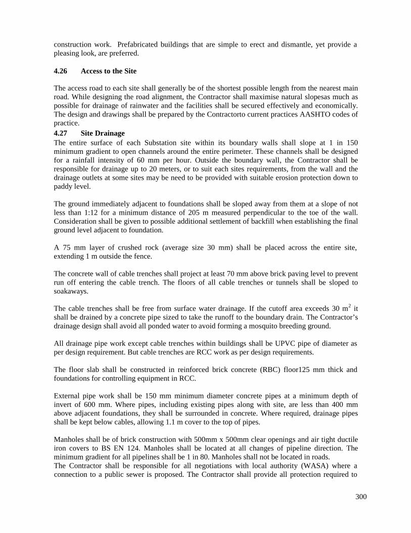
300
construction work. Prefabricated buildings that are simple to erect and dismantle, yet provide apleasing look, are preferred.
4.26 Access to the Site
The access road to each site shall generally be of the shortest possible length from the nearest mainroad. While designing the road alignment, the Contractor shall maximise natural slopesas much aspossible for drainage of rainwater and the facilities shall be secured effectively and economically.The design and drawings shall be prepared by the Contractorto current practices AASHTO codes ofpractice.4.27 Site DrainageThe entire surface of each Substation site within its boundary walls shall slope at 1 in 150minimum gradient to open channels around the entire perimeter. These channels shall be designedfor a rainfall intensity of 60 mm per hour. Outside the boundary wall, the Contractor shall beresponsible for drainage up to 20 meters, or to suit each sites requirements, from the wall and thedrainage outlets at some sites may be need to be provided with suitable erosion protection down topaddy level.
The ground immediately adjacent to foundations shall be sloped away from them at a slope of notless than 1:12 for a minimum distance of 205 m measured perpendicular to the toe of the wall.Consideration shall be given to possible additional settlement of backfill when establishing the finalground level adjacent to foundation.
A 75 mm layer of crushed rock (average size 30 mm) shall be placed across the entire site,extending 1 m outside the fence.
The concrete wall of cable trenches shall project at least 70 mm above brick paving level to preventrun off entering the cable trench. The floors of all cable trenches or tunnels shall be sloped tosoakaways.
The cable trenches shall be free from surface water drainage. If the cutoff area exceeds 30 m2 itshall be drained by a concrete pipe sized to take the runoff to the boundary drain. The Contractor’sdrainage design shall avoid all ponded water to avoid forming a mosquito breeding ground.
All drainage pipe work except cable trenches within buildings shall be UPVC pipe of diameter asper design requirement. But cable trenches are RCC work as per design requirements.
The floor slab shall be constructed in reinforced brick concrete (RBC) floor125 mm thick andfoundations for controlling equipment in RCC.
External pipe work shall be 150 mm minimum diameter concrete pipes at a minimum depth ofinvert of 600 mm. Where pipes, including existing pipes along with site, are less than 400 mmabove adjacent foundations, they shall be surrounded in concrete. Where required, drainage pipesshall be kept below cables, allowing 1.1 m cover to the top of pipes.
Manholes shall be of brick construction with 500mm x 500mm clear openings and air tight ductileiron covers to BS EN 124. Manholes shall be located at all changes of pipeline direction. Theminimum gradient for all pipelines shall be 1 in 80. Manholes shall not be located in roads.The Contractor shall be responsible for all negotiations with local authority (WASA) where aconnection to a public sewer is proposed. The Contractor shall provide all protection required to
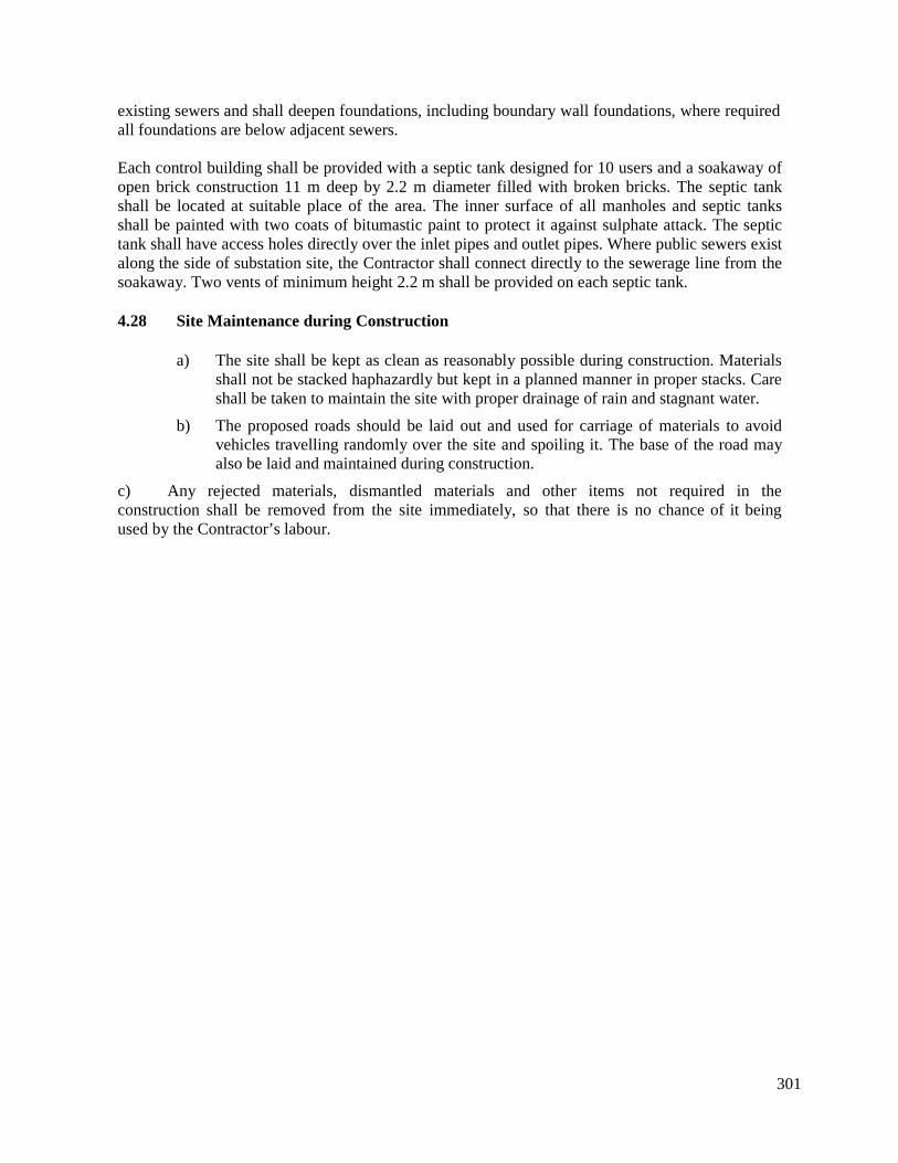
301
existing sewers and shall deepen foundations, including boundary wall foundations, where requiredall foundations are below adjacent sewers.
Each control building shall be provided with a septic tank designed for 10 users and a soakaway ofopen brick construction 11 m deep by 2.2 m diameter filled with broken bricks. The septic tankshall be located at suitable place of the area. The inner surface of all manholes and septic tanksshall be painted with two coats of bitumastic paint to protect it against sulphate attack. The septictank shall have access holes directly over the inlet pipes and outlet pipes. Where public sewers existalong the side of substation site, the Contractor shall connect directly to the sewerage line from thesoakaway. Two vents of minimum height 2.2 m shall be provided on each septic tank.
4.28 Site Maintenance during Construction
a) The site shall be kept as clean as reasonably possible during construction. Materialsshall not be stacked haphazardly but kept in a planned manner in proper stacks. Careshall be taken to maintain the site with proper drainage of rain and stagnant water.
b) The proposed roads should be laid out and used for carriage of materials to avoidvehicles travelling randomly over the site and spoiling it. The base of the road mayalso be laid and maintained during construction.
c) Any rejected materials, dismantled materials and other items not required in theconstruction shall be removed from the site immediately, so that there is no chance of it beingused by the Contractor’s labour.
302
B. CIVIL
5.0 SUBSTATION BUILDINGS AND ANCILLARY FACILITIES
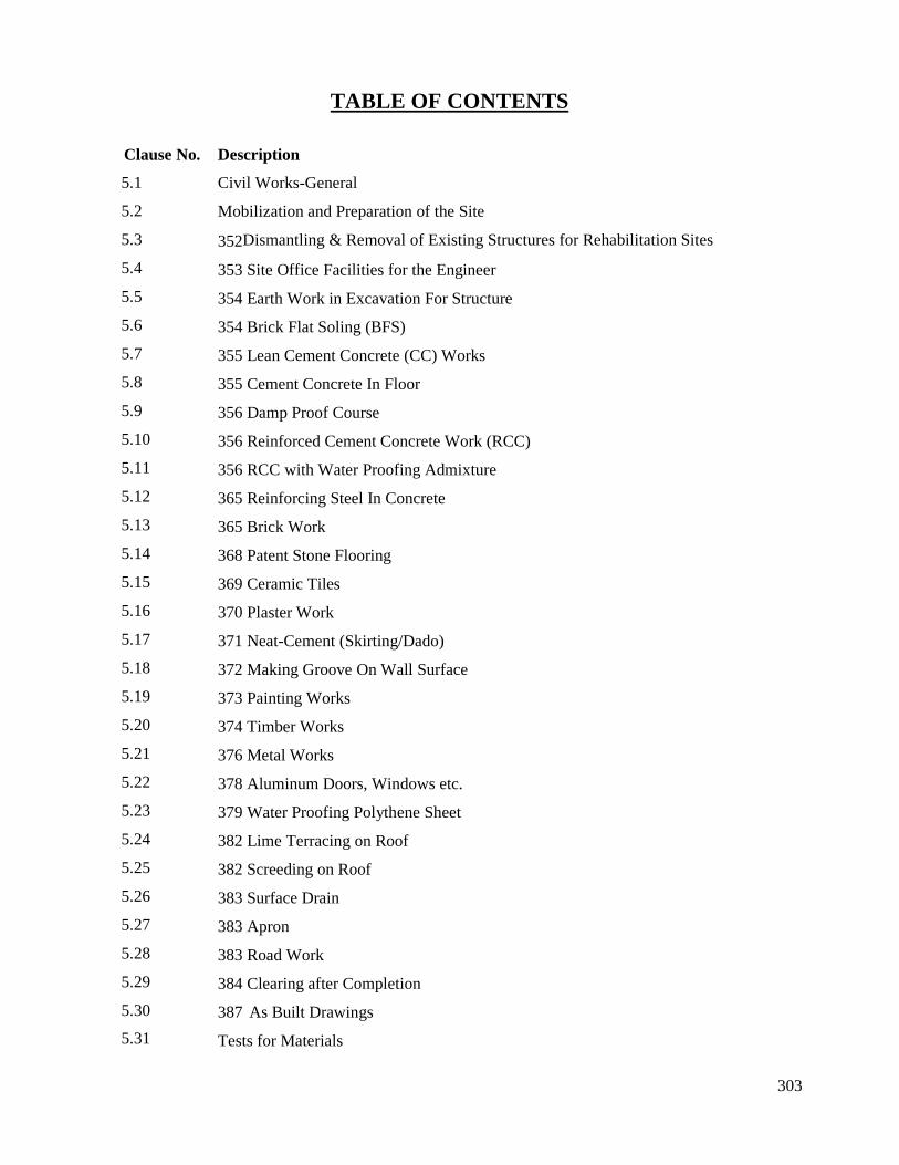
303
TABLE OF CONTENTS
Clause No.
5.1
5.2
5.3
5.4
5.5
5.6
5.7
5.8
5.9
5.10
5.11
5.12
5.13
5.14
5.15
5.16
5.17
5.18
5.19
5.20
5.21
5.22
5.23
5.24
5.25
5.26
5.27
5.28
5.29
5.30
5.31
Description
Civil Works-General
Mobilization and Preparation of the Site
352Dismantling & Removal of Existing Structures for Rehabilitation Sites
353 Site Office Facilities for the Engineer
354 Earth Work in Excavation For Structure
354 Brick Flat Soling (BFS)
355 Lean Cement Concrete (CC) Works
355 Cement Concrete In Floor
356 Damp Proof Course
356 Reinforced Cement Concrete Work (RCC)
356 RCC with Water Proofing Admixture
365 Reinforcing Steel In Concrete
365 Brick Work
368 Patent Stone Flooring
369 Ceramic Tiles
370 Plaster Work
371 Neat-Cement (Skirting/Dado)
372 Making Groove On Wall Surface
373 Painting Works
374 Timber Works
376 Metal Works
378 Aluminum Doors, Windows etc.
379 Water Proofing Polythene Sheet
382 Lime Terracing on Roof
382 Screeding on Roof
383 Surface Drain
383 Apron
383 Road Work
384 Clearing after Completion
387 As Built Drawings
Tests for Materials
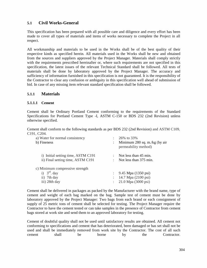
304
5.1 Civil Works-General
This specification has been prepared with all possible care and diligence and every effort has beenmade to cover all types of materials and items of works necessary to complete the Project in allrespect.
All workmanship and materials to be used in the Works shall be of the best quality of theirrespective kinds as specified herein. All materials used in the Works shall be new and obtainedfrom the sources and suppliers approved by the Project Manager. Materials shall comply strictlywith the requirements prescribed hereinafter or, where such requirements are not specified in thisspecification, the latest issues of the relevant Technical Standard shall be followed. All tests ofmaterials shall be done by laboratory approved by the Project Manager. The accuracy andsufficiency of information furnished in this specification is not guaranteed. It is the responsibility ofthe Contractor to clear any confusion or ambiguity in this specification well ahead of submission ofbid. In case of any missing item relevant standard specification shall be followed.
5.1.1
5.1.1.1
Materials
Cement
Cement shall be Ordinary Portland Cement conforming to the requirements of the StandardSpecifications for Portland Cement Type -I, ASTM C-150 or BDS 232 (2nd Revision) unlessotherwise specified.
Cement shall conform to the following standards as per BDS 232 (2nd Revision) and ASTM C109,C191, C204.
a) Water for normal consistency : 26% to 33%b) Fineness : Minimum 280 sq. m./kg (by air
permeability method)
i) Initial setting time, ASTM C191ii) Final setting time, ASTM C191
c) Minimum compressive strengthi) 3rd. dayii) 7th dayiii) 28th day
: Not less than 45 min.: Not less than 375 min.
: 9.45 Mpa (1350 psi): 14.7 Mpa (2100 psi): 21.0 Mpa (3000 psi)
Cement shall be delivered in packages as packed by the Manufacturer with the brand name, type ofcement and weight of each bag marked on the bag. Sample test of cement must be done bylaboratory approved by the Project Manager: Two bags from each brand or each consignment ofsupply of 25 metric tons of cement shall be selected for testing. The Project Manager require theContractor to have the cement tested or can take samples in the presence of Contractor from cementbags stored at work site and send them to an approved laboratory for testing.
Cement of doubtful quality shall not be used until satisfactory results are obtained. All cement notconforming to specifications and cement that has deteriorated, been damaged or has set shall not beused and shall be immediately removed from work site by the Contractor. The cost of all suchcement shall be borne by the Contractor.
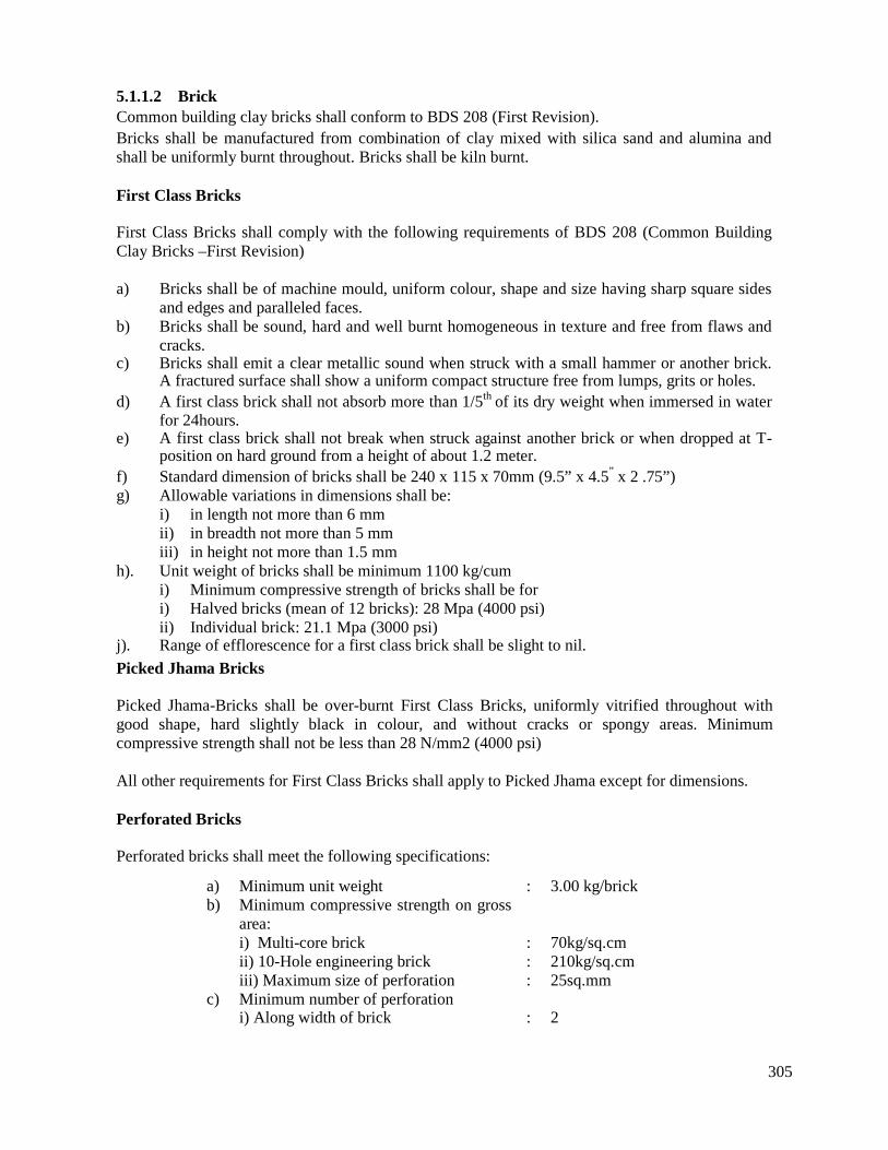
305
5.1.1.2 BrickCommon building clay bricks shall conform to BDS 208 (First Revision).Bricks shall be manufactured from combination of clay mixed with silica sand and alumina andshall be uniformly burnt throughout. Bricks shall be kiln burnt.
First Class Bricks
First Class Bricks shall comply with the following requirements of BDS 208 (Common BuildingClay Bricks –First Revision)
a) Bricks shall be of machine mould, uniform colour, shape and size having sharp square sidesand edges and paralleled faces.
b) Bricks shall be sound, hard and well burnt homogeneous in texture and free from flaws andcracks.
c) Bricks shall emit a clear metallic sound when struck with a small hammer or another brick.A fractured surface shall show a uniform compact structure free from lumps, grits or holes.
d) A first class brick shall not absorb more than 1/5th of its dry weight when immersed in waterfor 24hours.
e) A first class brick shall not break when struck against another brick or when dropped at T-position on hard ground from a height of about 1.2 meter.
f) Standard dimension of bricks shall be 240 x 115 x 70mm (9.5” x 4.5” x 2 .75”)g) Allowable variations in dimensions shall be:
i) in length not more than 6 mmii) in breadth not more than 5 mmiii) in height not more than 1.5 mm
h). Unit weight of bricks shall be minimum 1100 kg/cumi) Minimum compressive strength of bricks shall be fori) Halved bricks (mean of 12 bricks): 28 Mpa (4000 psi)ii) Individual brick: 21.1 Mpa (3000 psi)
j). Range of efflorescence for a first class brick shall be slight to nil.
Picked Jhama Bricks
Picked Jhama-Bricks shall be over-burnt First Class Bricks, uniformly vitrified throughout withgood shape, hard slightly black in colour, and without cracks or spongy areas. Minimumcompressive strength shall not be less than 28 N/mm2 (4000 psi)
All other requirements for First Class Bricks shall apply to Picked Jhama except for dimensions.
Perforated Bricks
Perforated bricks shall meet the following specifications:
a) Minimum unit weight :b) Minimum compressive strength on gross
area:i) Multi-core brick :ii) 10-Hole engineering brick :iii) Maximum size of perforation :
c) Minimum number of perforationi) Along width of brick :
3.00 kg/brick
70kg/sq.cm210kg/sq.cm25sq.mm
2
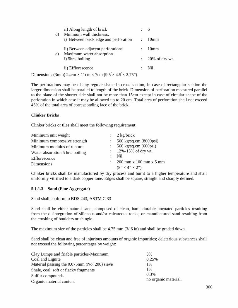
306
ii) Along length of brickd) Minimum wall thickness:
i) Between brick edge and perforation
ii) Between adjacent perforationse) Maximum water absorption
i) 5hrs, boiling
: 6
: 10mm
: 10mm
: 20% of dry wt.
ii) Efflorescence : Nil
Dimensions (3mm) 24cm × 11cm × 7cm (9.5”× 4.5”× 2.75”)
The perforations may be of any regular shape in cross section, In case of rectangular section thelarger dimension shall be parallel to length of the brick. Dimension of perforation measured parallelto the plane of the shorter side shall not be more than 15cm except in case of circular shape of theperforation in which case it may be allowed up to 20 cm. Total area of perforation shall not exceed45% of the total area of corresponding face of the brick.
Clinker Bricks
Clinker bricks or tiles shall meet the following requirement:
Minimum unit weightMinimum compressive strengthMinimum modulus of ruptureWater absorption 5 hrs. boilingEfflorescenceDimensions
: 2 kg/brick: 560 kg/sq.cm (8000psi): 560 kg/sq.cm (600psi): 12%-15% of dry wt.: Nil: 200 mm x 100 mm x 5 mm
(8” × 4” × 2”)Clinker bricks shall be manufactured by dry process and burnt to a higher temperature and shalluniformly vitrified to a dark copper tone. Edges shall be square, straight and sharply defined.
5.1.1.3 Sand (Fine Aggregate)
Sand shall conform to BDS 243, ASTM C 33
Sand shall be either natural sand, composed of clean, hard, durable uncoated particles resultingfrom the disintegration of siliceous and/or calcareous rocks; or manufactured sand resulting fromthe crushing of boulders or shingle.
The maximum size of the particles shall be 4.75 mm (3/l6 in) and shall be graded down.
Sand shall be clean and free of injurious amounts of organic impurities; deleterious substances shallnot exceed the following percentages by weight:
Clay Lumps and friable particles-MaximumCoal and LigniteMaterial passing the 0.075mm (No. 200) sieveShale, coal, soft or flacky fragmentsSulfur compoundsOrganic material content
3%0.25%1%1%0.3%no organic material.
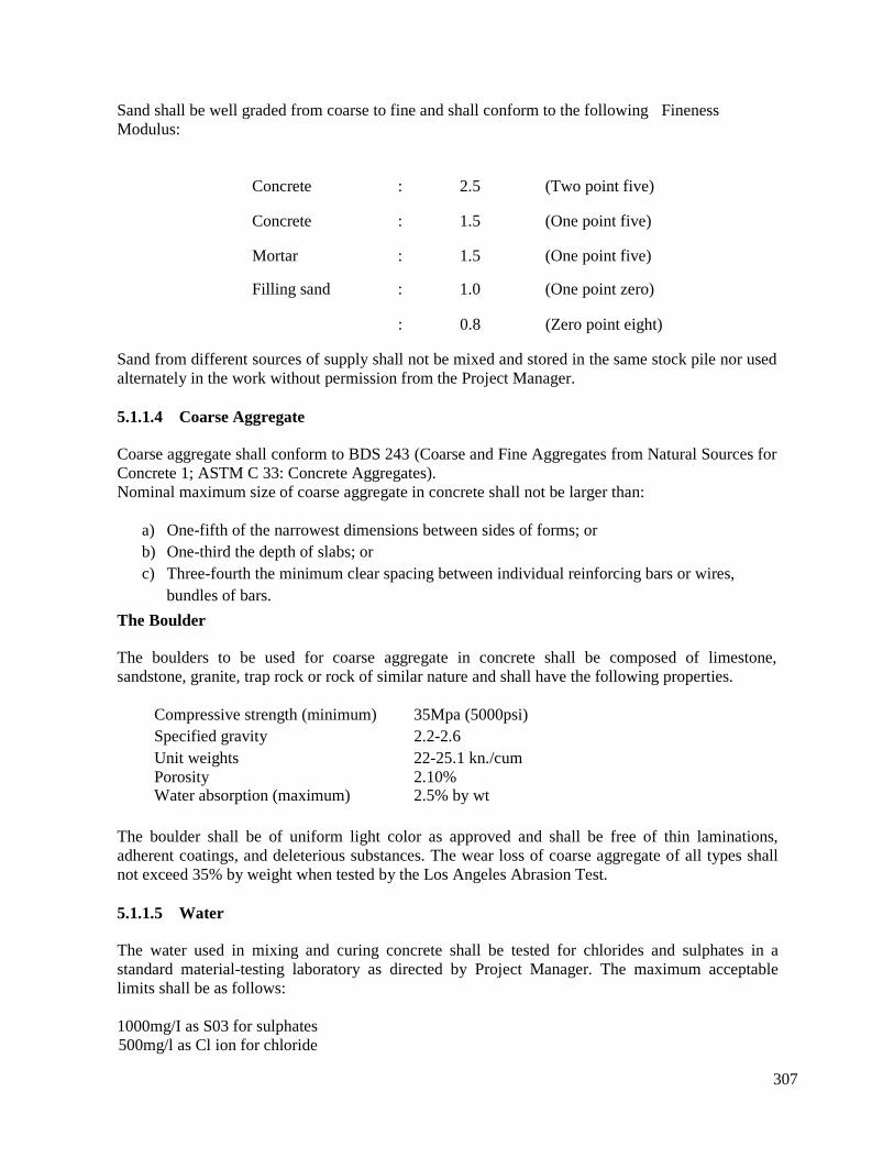
307
Sand shall be well graded from coarse to fine and shall conform to the following FinenessModulus:
Concrete
Concrete
Mortar
Filling sand
: 2.5 (Two point five)
: 1.5 (One point five)
: 1.5 (One point five)
: 1.0 (One point zero)
: 0.8 (Zero point eight)
Sand from different sources of supply shall not be mixed and stored in the same stock pile nor usedalternately in the work without permission from the Project Manager.
5.1.1.4 Coarse Aggregate
Coarse aggregate shall conform to BDS 243 (Coarse and Fine Aggregates from Natural Sources forConcrete 1; ASTM C 33: Concrete Aggregates).Nominal maximum size of coarse aggregate in concrete shall not be larger than:
a) One-fifth of the narrowest dimensions between sides of forms; orb) One-third the depth of slabs; orc) Three-fourth the minimum clear spacing between individual reinforcing bars or wires,
bundles of bars.
The Boulder
The boulders to be used for coarse aggregate in concrete shall be composed of limestone,sandstone, granite, trap rock or rock of similar nature and shall have the following properties.
Compressive strength (minimum)Specified gravityUnit weightsPorosityWater absorption (maximum)
35Mpa (5000psi)2.2-2.622-25.1 kn./cum2.10%2.5% by wt
The boulder shall be of uniform light color as approved and shall be free of thin laminations,adherent coatings, and deleterious substances. The wear loss of coarse aggregate of all types shallnot exceed 35% by weight when tested by the Los Angeles Abrasion Test.
5.1.1.5 Water
The water used in mixing and curing concrete shall be tested for chlorides and sulphates in astandard material-testing laboratory as directed by Project Manager. The maximum acceptablelimits shall be as follows:
1000mg/I as S03 for sulphates500mg/l as Cl ion for chloride
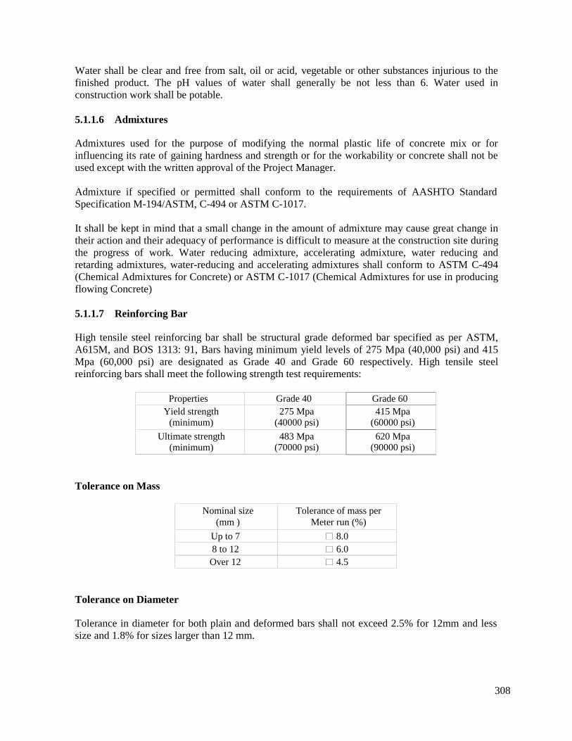
308
Water shall be clear and free from salt, oil or acid, vegetable or other substances injurious to thefinished product. The pH values of water shall generally be not less than 6. Water used inconstruction work shall be potable.
5.1.1.6 Admixtures
Admixtures used for the purpose of modifying the normal plastic life of concrete mix or forinfluencing its rate of gaining hardness and strength or for the workability or concrete shall not beused except with the written approval of the Project Manager.
Admixture if specified or permitted shall conform to the requirements of AASHTO StandardSpecification M-194/ASTM, C-494 or ASTM C-1017.
It shall be kept in mind that a small change in the amount of admixture may cause great change intheir action and their adequacy of performance is difficult to measure at the construction site duringthe progress of work. Water reducing admixture, accelerating admixture, water reducing andretarding admixtures, water-reducing and accelerating admixtures shall conform to ASTM C-494(Chemical Admixtures for Concrete) or ASTM C-1017 (Chemical Admixtures for use in producingflowing Concrete)
5.1.1.7 Reinforcing Bar
High tensile steel reinforcing bar shall be structural grade deformed bar specified as per ASTM,A615M, and BOS 1313: 91, Bars having minimum yield levels of 275 Mpa (40,000 psi) and 415Mpa (60,000 psi) are designated as Grade 40 and Grade 60 respectively. High tensile steelreinforcing bars shall meet the following strength test requirements:
Properties Grade 40 Grade 60Yield strength
(minimum)275 Mpa
(40000 psi)415 Mpa
(60000 psi)
Ultimate strength(minimum)
483 Mpa(70000 psi)
620 Mpa(90000 psi)
Tolerance on Mass
Nominal size(mm )
Tolerance of mass perMeter run (%)
Up to 7 8.08 to 12 6.0
Over 12 4.5
Tolerance on Diameter
Tolerance in diameter for both plain and deformed bars shall not exceed 2.5% for 12mm and lesssize and 1.8% for sizes larger than 12 mm.
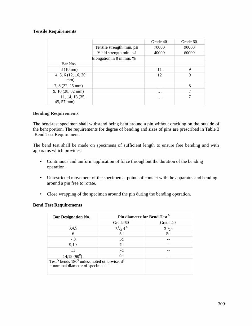
309
Tensile Requirements
Grade 40 Grade 60Tensile strength, min. psi 70000 90000
Yield strength min. psi 40000 60000Elongation in 8 in min. %
Bar Nos.3 (10mm) 11 9
4 ,5, 6 (12, 16, 20mm)
12 9
7, 8 (22, 25 mm) … 89, 10 (28, 32 mm) … 7
11, 14, 18 (35,45, 57 mm)
… 7
Bending Requirements
The bend-test specimen shall withstand being bent around a pin without cracking on the outside ofthe bent portion. The requirements for degree of bending and sizes of pins are prescribed in Table 3-Bend Test Requirement.
The bend test shall be made on specimens of sufficient length to ensure free bending and withapparatus which provides.
Continuous and uniform application of force throughout the duration of the bendingoperation.
Unrestricted movement of the specimen at points of contact with the apparatus and bendingaround a pin free to rotate.
Close wrapping of the specimen around the pin during the bending operation.
Bend Test Requirements
Bar Designation No. Pin diameter for Bend TestA
Grade 60 Grade 403,4,5 31/2 d b 31/2d
6 5d 5d7,8 5d --
9,10 7d --11 7d --
14,18 (900) 9d --TestA bends 1800 unless noted otherwise. db
= nominal diameter of specimen
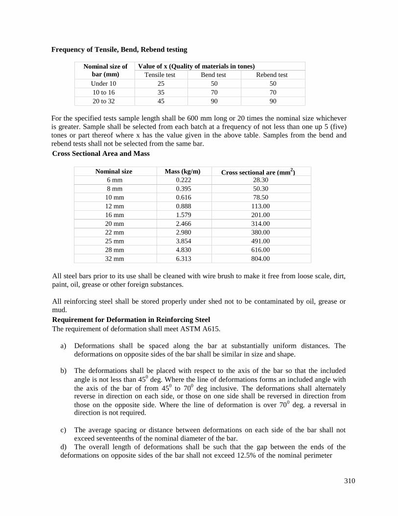
310
Frequency of Tensile, Bend, Rebend testing
Nominal size ofbar (mm)
Value of x (Quality of materials in tones)Tensile test Bend test Rebend test
Under 10 25 50 5010 to 16 35 70 7020 to 32 45 90 90
For the specified tests sample length shall be 600 mm long or 20 times the nominal size whicheveris greater. Sample shall be selected from each batch at a frequency of not less than one up 5 (five)tones or part thereof where x has the value given in the above table. Samples from the bend andrebend tests shall not be selected from the same bar.Cross Sectional Area and Mass
Nominal size Mass (kg/m) Cross sectional are (mm2)6 mm 0.222 28.308 mm 0.395 50.30
10 mm 0.616 78.5012 mm 0.888 113.0016 mm 1.579 201.0020 mm 2.466 314.0022 mm 2.980 380.0025 mm 3.854 491.0028 mm 4.830 616.0032 mm 6.313 804.00
All steel bars prior to its use shall be cleaned with wire brush to make it free from loose scale, dirt,paint, oil, grease or other foreign substances.
All reinforcing steel shall be stored properly under shed not to be contaminated by oil, grease ormud.Requirement for Deformation in Reinforcing SteelThe requirement of deformation shall meet ASTM A615.
a) Deformations shall be spaced along the bar at substantially uniform distances. Thedeformations on opposite sides of the bar shall be similar in size and shape.
b) The deformations shall be placed with respect to the axis of the bar so that the includedangle is not less than 450 deg. Where the line of deformations forms an included angle withthe axis of the bar of from 450 to 700 deg inclusive. The deformations shall alternatelyreverse in direction on each side, or those on one side shall be reversed in direction fromthose on the opposite side. Where the line of deformation is over 700 deg. a reversal indirection is not required.
c) The average spacing or distance between deformations on each side of the bar shall notexceed seventeenths of the nominal diameter of the bar.
d) The overall length of deformations shall be such that the gap between the ends of thedeformations on opposite sides of the bar shall not exceed 12.5% of the nominal perimeter
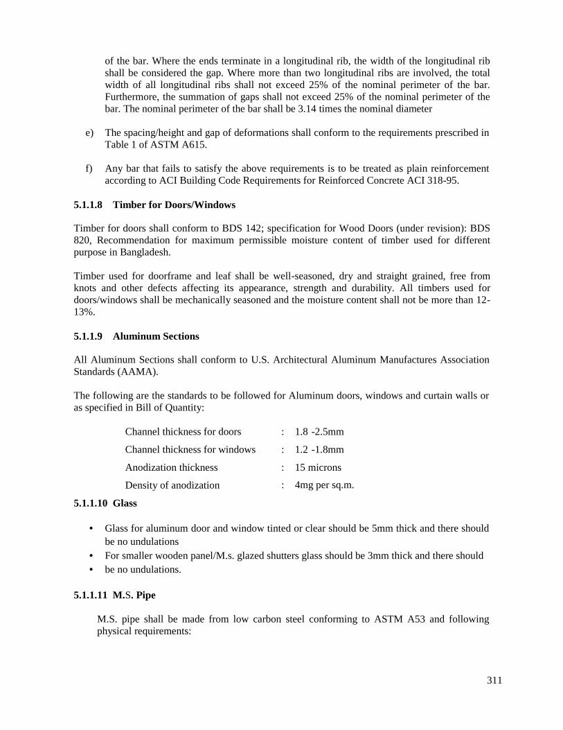
311
of the bar. Where the ends terminate in a longitudinal rib, the width of the longitudinal ribshall be considered the gap. Where more than two longitudinal ribs are involved, the totalwidth of all longitudinal ribs shall not exceed 25% of the nominal perimeter of the bar.Furthermore, the summation of gaps shall not exceed 25% of the nominal perimeter of thebar. The nominal perimeter of the bar shall be 3.14 times the nominal diameter
e) The spacing/height and gap of deformations shall conform to the requirements prescribed inTable 1 of ASTM A615.
f) Any bar that fails to satisfy the above requirements is to be treated as plain reinforcementaccording to ACI Building Code Requirements for Reinforced Concrete ACI 318-95.
5.1.1.8 Timber for Doors/Windows
Timber for doors shall conform to BDS 142; specification for Wood Doors (under revision): BDS820, Recommendation for maximum permissible moisture content of timber used for differentpurpose in Bangladesh.
Timber used for doorframe and leaf shall be well-seasoned, dry and straight grained, free fromknots and other defects affecting its appearance, strength and durability. All timbers used fordoors/windows shall be mechanically seasoned and the moisture content shall not be more than 12-13%.
5.1.1.9 Aluminum Sections
All Aluminum Sections shall conform to U.S. Architectural Aluminum Manufactures AssociationStandards (AAMA).
The following are the standards to be followed for Aluminum doors, windows and curtain walls oras specified in Bill of Quantity:
Channel thickness for doors
Channel thickness for windows
Anodization thickness
Density of anodization
5.1.1.10 Glass
: 1.8 -2.5mm
: 1.2 -1.8mm
: 15 microns
: 4mg per sq.m.
Glass for aluminum door and window tinted or clear should be 5mm thick and there shouldbe no undulations
For smaller wooden panel/M.s. glazed shutters glass should be 3mm thick and there should be no undulations.
5.1.1.11 M.S. Pipe
M.S. pipe shall be made from low carbon steel conforming to ASTM A53 and followingphysical requirements:
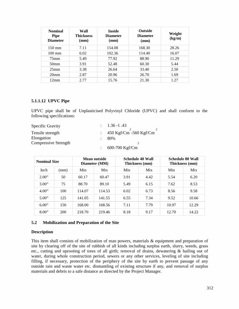
312
NominalPipe
Diameter
WallThickness
(mm)
InsideDiameter
(mm)
OutsideDiameter
(mm)
Weight(kg/m)
150 mm 7.11 154.08 168.30 28.26100 mm 6.02 102.36 114.40 16.0775mm 5.49 77.92 88.90 11.2950mm 3.91 52.48 60.30 5.4425mm 3.38 26.64 33.40 2.5020mm 2.87 20.96 26.70 1.6912mm 2.77 15.76 21.30 1.27
5.1.1.12 UPVC Pipe
UPVC pipe shall be of Unplasticised Polyvinyl Chloride (UPVC) and shall conform to thefollowing specifications:
Specific Gravity
Tensile strengthElongationCompressive Strength
: 1.36 -1 .43
: 450 Kgf/Cm2-560 Kgf/Cm
2
: 80%2
: 600-700 Kgf/Cm
Nominal SizeMean outside
Diameter (MM)Schedule 40 WallThickness (mm)
Schedule 80 WallThickness (mm)
Inch (mm) Min Mix Min Mix Min Mix
2.00” 50 60.17 60.47 3.91 4.42 5.54 6.20
3.00” 75 88.70 89.10 5.49 6.15 7.62 8.53
4.00” 100 114.07 114.53 6.02 6.73 8.56 9.58
5.00” 125 141.05 141.55 6.55 7.34 9.52 10.66
6.00” 150 168.00 168.56 7.11 7.79 10.97 12.29
8.00” 200 218.70 219.46 8.18 9.17 12.70 14.22
5.2 Mobilization and Preparation of the Site
Description
This item shall consists of mobilization of man powers, materials & equipment and preparation ofsite by clearing off of the site of rubbish of all kinds including surplus earth, slurry, weeds, grassetc., cutting and uprooting of trees of all girth; removal of drains, dewatering & bailing out ofwater, during whole construction period, sewers or any other services, leveling of site includingfilling, if necessary, protection of the periphery of the site by earth to prevent passage of anyoutside rain and waste water etc. dismantling of existing structure if any, and removal of surplusmaterials and debris to a safe distance as directed by the Project Manager.

313
Construction Requirement:
Before setting out the new work and commencing foundation work the site must be cleared off ofall those described above. On clearance of site it should be roughly leveled as required.
The trees shall be cut and their roots totally up-rooted as directed by the Project Manager No treeshould be cut unless it is absolutely unavoidable. All serviceable materials obtained from theclearing shall be property of the competent authority as determined by the Project Manager.Salvaged material may be handed over by the Contractor to the local authority on instruction fromthe Employer.
5.3 Dismantling & Removal of Existing Structures for Rehabilitation Sites
Description
This item shall consists of the removal/ dismantling and satisfactory cleaning, stacking, storing ordisposal, inside or outside the site of such portions of existing structures as provided in the Plans,Schedule of Quantities and Specifications or ordered by the Project Manager. This includes allitems such as breaking and removal of khoa debris, concrete, R.C.C, brick work, plaster and otheritems as mentioned in schedule of quantity or as directed by the Project Manager.
Construction Requirement
Before commencement of removal/ dismantling work, the structure or parts thereof shall beproperly earmarked and necessary arrangement for stabilization of the adjoining structures shall beensured by means of adequate shoring, shuttering, propping and strutting. The dismantling workshall not commence until the arrangement of safety of the adjoining structure has been insured bythe Contractor, inspected and approved by the Project Manager. The Contractor shall be solelyresponsible for any damage to the portion of structure which' were not intended to be dismantledand make good the damages, if any, at his own cost. The Contractor shall comply with all safetyregulations and shall furnish, erect and maintain suitable barricades and warning signs and takesuch other measures as necessary to prevent personal injury or property damage. All thesebarricades, warning signs shall comply with the by-laws, regulations and provisions of BNBC andshall be to the satisfaction of Employer, and Local Authorities concerned.
This item of work also includes cleaning and sorting out of the salvaged materials in a usablecondition, transporting and storing neatly for use/disposal as directed by the Project Manager. Theitems of dismantling works of different structures in foundation also include all excavation, bailingout water by pumping, drainage, bracing, shoring, etc. as found necessary and their subsequentremoval and satisfactory disposal of all materials obtained from such excavations and backfilling tothe level of original ground where required. The Contractor shall keep adequate records of alldimensional measurements of the structures and all other information relating to them as revealedand obtained during their work and have such measurements and information duly endorsed by theProject Manager at site. The work shall not start unless full measurement is recorded by the ProjectManager. In some special cases, however, the recording may be done after dismantling.
The salvaged materials before or after dismantling shall be immediately measured and recorded inpresence of the Project Manager and shall be in the custody of the Contractor until instructed to bedisposed of by the Project Manager. Any loss of any dismantled material shall be recovered fromthe Contractor's bill at the recovery rate.
314
5.4 Site office Facilities for the Project Manager and his Staff
Description
The Contractor shall provide and maintain temporary site office facilities during the constructionperiod for the Employer and Consultant.
5.5 Earth Work in Excavation for Structure
Description
The item shall consist of setting out true lines to all foundations for structures, performing theexcavations to the required levels and grades in any kind of soil encountered, removing the spoilsand backfilling of original ground line as provided in these specification or as directed by theProject Manager.
Construction Requirements
The Contractor shall comply with all safety regulations and shall furnish, erect and maintainsuitable barricades and warning signs and take such other measures as necessary to preventpersonal injury or property damage.
5.5.1 Earth Filling
Description
The item shall consist of filling any place or area, to make up levels, according to theseSpecifications and Plans with specified earth materials.
Construction RequirementsSilty Sand or other approved materials, free from large lumps, organic or other extraneousmaterials, shall be used for fill. Materials from excavation on the sites may be used as ordinary fillif it is approved.
The fill materials shall be deposited and spread in successive uniform horizontal layers of about150 mm thick and compacted by use of mechanical 1.5 ton “Vibro” compactor or other approveddevices to a 98% standard dry density in road and pavement sub-base and 95% standard dry densityfor other area.
Tests shall have to be carried out at recognized laboratory to ascertain the nature of the fill materialand the degree of compaction obtained for the filled material for which samples have to be takenand transported by the Contractor at his expense and as directed by the Project Manager.
5.5.2 Sand Filling
Description
The item shall consist of filling any place or area, to make up levels, according to theseSpecifications and Plans with specified and approved materials.
315
Construction Requirements:
Silty Sand or other approved materials, free from large lumps, organic or other extraneousmaterials, shall be used for filling Materials from excavation on the sites may be used as ordinaryfill if it is approved.
MaterialsFineness modulus not less than 1.0 shall be clean and free from organic and other deleteriousmaterials
The fill materials shall be deposited and spread in successive uniform horizontal layers of about150rnrn thick and compacted by use of mechanical 1.5 ton “Vibro” compactor or other approveddevices to a 98% standard dry density in road and pavement sub-base and 95% standard dry densityfor other area. In filling /back filling against a newly constructed structure precaution must be takenso that the structure is well matured to take the thrust of filling and while filling that against a wall,the filling is done from both sides simultaneously.
Tests shall have to be carried out at recognized laboratory to ascertain the nature of the fill materialand the degree of compaction obtained for the filled material for which samples have to be takenand transported to the recognized laboratory by the Contractor at his expense and as directed by theProject Manager.
5.6 Brick Flat Soling (BFS)
Description
The item shall consist of supplying and laying bricks on top of the earth or sand bed to form a sub-base.
Construction Requirements
Bricks shall comply with requirements of First Class bricks. The binding sand shall have aminimum Fineness Modulus of 1.0 and shall be clean, and free of any organic matters.
Bricks shall be laid flat in surface to surface contact with adjoining bricks and their joints shall befilled with sand. The sand shall be brushed in until the joints are filled. Flushing in of sand withwater shall not be done unless permitted. Bricks shall not be laid on the floor or foundation beduntil the floor or foundation bed is inspected and approved by the Project Manager.
In case of Multi-layer Soling, care shall be taken to stagger or "break" all joints in placingsubsequent courses of soling. No brick shall be laid on loose earth or earth filling which are notcompacted to the desired degree.
5.7 Lean Cement Concrete (CC) WorksThe specification shall be the same as for RCC works excepting that:
(i) No reinforcement shall be used;
(ii) Proportion shall be as noted in Schedule of Items;
(iii) 12 mm downgraded chips of Jhama bricks /Boulder shall be used as coarse aggregate as
specified in Schedule of items;
316
(iv) The curing shall be done for 7 days minimum;
(v) Compaction of concrete may be done by wooden or steel tempers or rammers in lieu of
vibrators.
In order to improve bond with masonry/concrete work coming above it, if required, the surfaceshall be roughened before it reaches initial set, by scouring with the help of a pointed tool.
5.8 Cement Concrete in Floor
DescriptionThe work covered by this item shall consist of constructing in floor or elsewhere, 75mm or 38mmthick cement concrete with 1:3:6 mix of cement, sand of FM 1.2 and 12mm downgraded bricks orstone chips as specified in schedule of items.
Construction Requirements
Construction shall be carried out as per requirements of drawing.
5.9 Damp Proof Course
Description
The work covered by this item shall consist of constructing, on top of foundation walls orelsewhere 75mm/ 38 mm thick artificial stone with a 1:1.5:3 mix of cement, sand of FM 2.5 and 12mm downgraded crushed stone chips and finishing with a coat of bitumen as per instruction of theProject Manager.
Construction Requirements
Damp-proof course shall extend the full width of the plinth walls unless otherwise required by theplans and shall be laid only after the levels of the plinth have been checked.
5.10 Reinforced Cement Concrete Work (RCC)
Description
This item shall consist of manufacturing concrete as provided in these Specifications andconstruction where required, and of the form, dimensions and design shown on the plans.
Construction RequirementsConcrete shall consist of a mixture of Portland cement, fine and course aggregate and water. Theproportions in which the various ingredients shall be used in the concrete mix for various work,shall be designed in accordance with the specified strength and suitable workability.
Material shall conform to the requirements specified below and in the relevant sections MaterialSpecifications.Construction shall be according to these specifications. Contractor shall follow the followingstandards of American Society of Testing Materials along with the Building Code Requirements forReinforced Concrete ACI 318-89 for Specification not covered in these Specifications. In case ofdifferences between specifications contained in this book and those of ASTM or ACI, thespecifications specified in this book shall stand.

317
Cement
"Specification for Ordinary Portland Cement" (Type-I)"Specification for Concrete Aggregates""Standard Method of Making and curing concrete Test Specimen inthe field""Standard Method of Test for compressive strength of cylindricalconcrete Specimens""Standard Method of Sampling Fresh Concrete""Standard method of Making & Curing concrete Test Specimens inthe laboratory""Standard method of obtaining and Testing Drilled Cores and Sawedbeams of Concrete""Standard Specifications of Chemical admixtures in concrete"Cement shall be Portland Cement Type-I, ASTM
- ASTM C150 or BS12- ASTM C 33- ASTM C31-89
- ASTM C39-86
- ASTM C172-90- ASTM CI92-90
- ASTM C42-90
- ASTM C494- ASTM C150
Portland cement to be normally used shall conform to ASTM specification C-150 type-l or BS-12.It shall be free from any hardened lumps and any foreign material other than the manufacturingingredients. Cement shall have a minimum 90% of particles by weight passing the 75 micron sieve.Cement shall have an initial setting time in excess of 30 minutes and final setting time not longerthan 7 hours. The Project Manager reserves the right to reject any cement that fails to achievespecified concrete strength as per proportion of materials laid down in the schedule of items.
Only approved brand, grade or kind of cement shall be used in a given structure above the groundlevel specially, for fare face finished concrete, tiles works etc. except upon the written permissionof the Project Manager of other used.
The Contractor shall be responsible for the proper storage of the cement at the job site. Cementshall be stored in an air tight waterproof shaded area having damp proof floor, waterproof walls andleak proof roof. The cement stacks shall be placed at a minimum distance of 300 mm from thewalls. The damp proof floor shall be constructed by raising it minimum 300 mm above the ground.If the cement is damaged and becomes lumpy due to defective storage, it shall be removed from thejob site within 24 hours of receipt of instructions from the Project Manager.
Cement may be measured by weight of in a standard bag to weigh 1 cwt or 112 pounds/50kghaving a volume of 0.0354 cum or 1.25 cft. The Contractor shall maintain the record of deliveriesof cement to the site and its use in the work.
Fine Aggregate (Sand)
Fine Aggregate shall consist of well-graded clean natural sand, free from injurious amount oforganic impurities and deleterious substances and shall have a fineness modulus of not less than2.50. Fine aggregate shall be well graded from coarse to fine and when tested by means oflaboratory sieves shall conform to the following requirements:
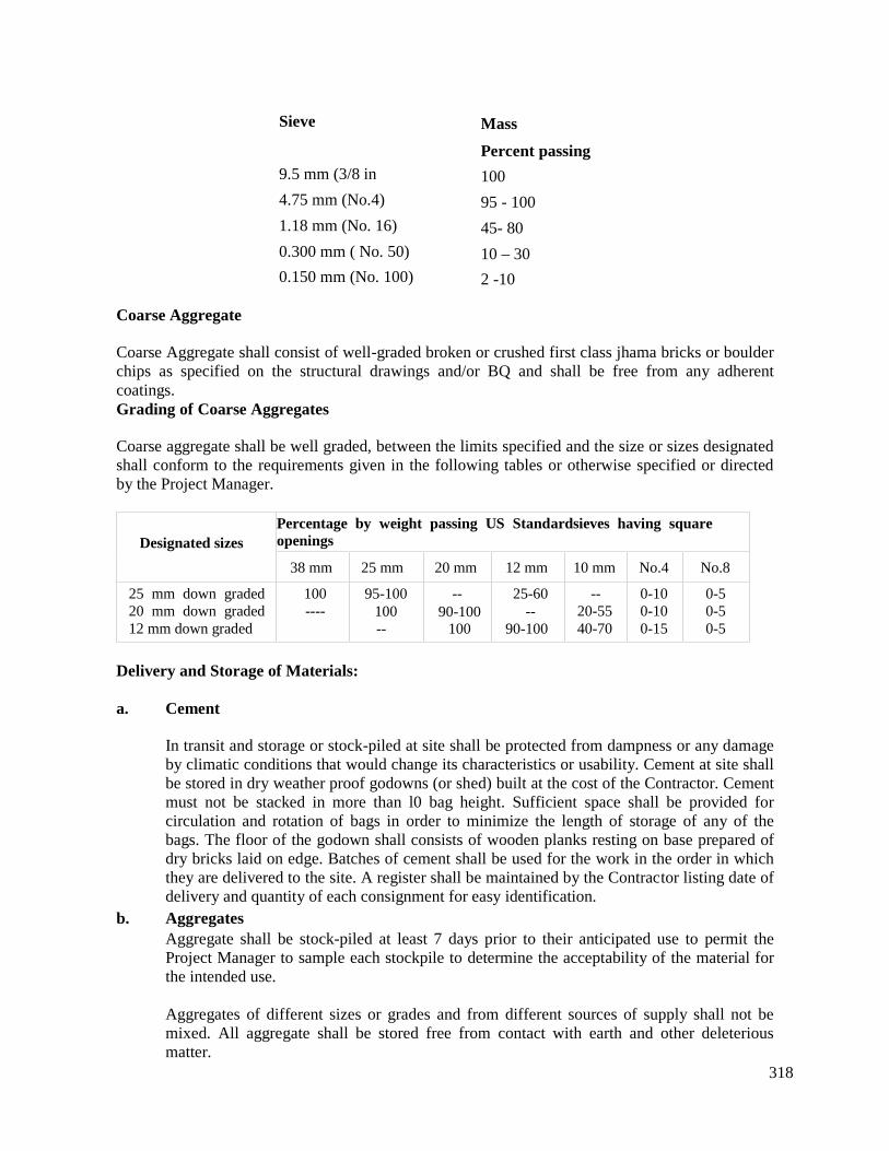
318
Sieve
9.5 mm (3/8 in
4.75 mm (No.4)
1.18 mm (No. 16)
0.300 mm ( No. 50)
0.150 mm (No. 100)
Mass
Percent passing
100
95 - 100
45- 80
10 – 30
2 -10
Coarse Aggregate
Coarse Aggregate shall consist of well-graded broken or crushed first class jhama bricks or boulderchips as specified on the structural drawings and/or BQ and shall be free from any adherentcoatings.Grading of Coarse Aggregates
Coarse aggregate shall be well graded, between the limits specified and the size or sizes designatedshall conform to the requirements given in the following tables or otherwise specified or directedby the Project Manager.
Designated sizesPercentage by weight passing US Standardsieves having squareopenings
38 mm 25 mm 20 mm 12 mm 10 mm No.4 No.8
25 mm down graded20 mm down graded12 mm down graded
100----
95-100100--
--90-100
100
25-60--
90-100
--20-5540-70
0-100-100-15
0-50-50-5
Delivery and Storage of Materials:
a. Cement
In transit and storage or stock-piled at site shall be protected from dampness or any damageby climatic conditions that would change its characteristics or usability. Cement at site shallbe stored in dry weather proof godowns (or shed) built at the cost of the Contractor. Cementmust not be stacked in more than l0 bag height. Sufficient space shall be provided forcirculation and rotation of bags in order to minimize the length of storage of any of thebags. The floor of the godown shall consists of wooden planks resting on base prepared ofdry bricks laid on edge. Batches of cement shall be used for the work in the order in whichthey are delivered to the site. A register shall be maintained by the Contractor listing date ofdelivery and quantity of each consignment for easy identification.
b. AggregatesAggregate shall be stock-piled at least 7 days prior to their anticipated use to permit theProject Manager to sample each stockpile to determine the acceptability of the material forthe intended use.
Aggregates of different sizes or grades and from different sources of supply shall not bemixed. All aggregate shall be stored free from contact with earth and other deleteriousmatter.
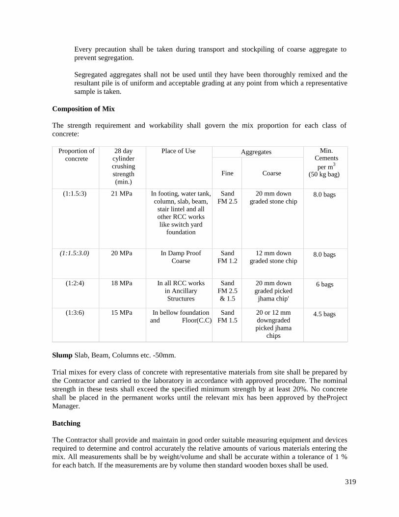
319
Every precaution shall be taken during transport and stockpiling of coarse aggregate toprevent segregation.
Segregated aggregates shall not be used until they have been thoroughly remixed and theresultant pile is of uniform and acceptable grading at any point from which a representativesample is taken.
Composition of Mix
The strength requirement and workability shall govern the mix proportion for each class ofconcrete:
Proportion ofconcrete
28 daycylindercrushingstrength(min.)
Place of Use Aggregates Min.Cementsper m3
(50 kg bag)Fine Coarse
(1:1.5:3) 21 MPa In footing, water tank,column, slab, beam,
stair lintel and allother RCC workslike switch yard
foundation
SandFM 2.5
20 mm downgraded stone chip
8.0 bags
(1:1.5:3.0) 20 MPa In Damp ProofCoarse
SandFM 1.2
12 mm downgraded stone chip
8.0 bags
(1:2:4) 18 MPa In all RCC worksin AncillaryStructures
SandFM 2.5& 1.5
20 mm downgraded picked
jhama chip'
6 bags
(1:3:6) 15 MPa In bellow foundationand Floor(C.C)
SandFM 1.5
20 or 12 mmdowngradedpicked jhama
chips
4.5 bags
Slump Slab, Beam, Columns etc. -50mm.
Trial mixes for every class of concrete with representative materials from site shall be prepared bythe Contractor and carried to the laboratory in accordance with approved procedure. The nominalstrength in these tests shall exceed the specified minimum strength by at least 20%. No concreteshall be placed in the permanent works until the relevant mix has been approved by theProjectManager.
Batching
The Contractor shall provide and maintain in good order suitable measuring equipment and devicesrequired to determine and control accurately the relative amounts of various materials entering themix. All measurements shall be by weight/volume and shall be accurate within a tolerance of 1 %for each batch. If the measurements are by volume then standard wooden boxes shall be used.
320
a. Cement
Unless an integral number of bags, as packed by the manufacturer is used, the Cement shall beweighed. A bag of cement weighing 50 kg net shall be considered as 0.035 m3
b. Aggregates
Different types and sizes of aggregates shall be batched separately by weight/volume.
c. Water
The amount of mixing water shall be weighed/measured, allowance being made for the quantity ofthe free water contained in the aggregates. Water cement ratio shall be decided for every class ofconcrete and according to the place of use. The water/Cement ratio shall not exceed 45% by weightfor all type of concrete.
Sufficient acceptable materials shall be available at the batching site to ensure continuousplacement necessary for structures. The moisture content of the accepted aggregate shall remainconsistent to the extent that the resultant successive batches of concrete do not vary in consistencyby more than 6 mm of slump. If the moisture content in the aggregate varies by more than theabove tolerance, corrective measures shall be taken to bring the moisture to a constant and uniformquantity before any more concrete is placed.
Coarse aggregate shall be saturated with water at least 12 hours before use to prevent absorption ofthe mixing water.
MIXING OF CONCRETE
a) Machine Mixing:
Concrete shall be mixed in concrete mixer of approved type and appropriate capacity.Each batch shall be thoroughly mixed for a period of not less than 2 minute after all materialsincluding the water are in the drum and during this period the drum shall be in the mixing positionand revolve at uniform rate of not less than 14 or more than 20 revolutions per minute. The cementand sand shall be thoroughly mixed in dry condition.
The batch shall be so charged into the mixer drum that some water shall enter in advance of thecement and aggregate. The entire content shall be removed from the drum before the succeedingbatch is placed.
Concrete shall be mixed in quantities required for immediate use. Concrete shall not be used whichhas developed initial set or which is not in place within thirty (30) minutes after the water has beenadded. Re-tempering of partially hardened concrete by remixing with or without additionalmaterials or water, or by other means shall not be permitted. The inside of the mixing drum shall bekept free of hardened concrete at all times.
Mixers which have been out of use for more than 30 minutes shall be thoroughly cleaned beforeany fresh concrete is mixed. Unless otherwise agreed by the Project Manager, the first batch ofconcrete through the mixer shall contain only two thirds of the normal quantity of coarse aggregate.Mixing plant shall be thoroughly cleaned before changing from one type of cement to another.
321
b) Hand Mixing:
Hand mixing shall not be permitted except for unimportant structural members and only at thediscretion of the Project Manager. When hand mixing is permitted it shall be taken to ensure thatthe mixing is continued until the mass is uniform in colour and consistency. If hand mixing ispermitted by the Project Manager, the Contractor shall use l0% extra cement for hand mixing forwhich no extra payment will be made.
Consistency of Concrete
The consistency of concrete shall be determined following evaluation of the placement conditionsfor each individual section of the work but in no case the slump shall exceed 62mm unlessotherwise decided. Mix proportions and consistency shall produce a dense, well compactedconcrete with a minimum tendency to segregate under placing conditions, free from sand streaks,honeycomb, air-pockets, exposed reinforcing steel and other forms of structural weakness orunsatisfactory appearance.
Transport and Placing
Concrete shall be so transported from the mixer and placed in the form that contamination,segregation or loss of the constituent materials does not occur. Before placing the concrete, all formwork, space and the reinforcement contained in it shall be thoroughly cleaned .of all extraneousmatter. Care shall be taken to fill every part of the forms, to work the coarse aggregate back fromthe face so that sufficient mortar shall be flushed from the mass to form a smooth surface, and toforce the concrete under and around reinforcing bars without displacing them.
The concrete shall be deposited in the forms in horizontal layers to a depth not exceeding 300 mmand each layer shall be properly vibrated before laying the next one.
The concrete shall not be dropped freely from a height exceeding 1.0 meter nor shall it be depositedin large quantities at any point. In columns of structures special tremie pipe may be used for dropmore than 1.8 meters. Dragging of concrete inside the forms or distribution by vibrators or allowingit to flow by gravity to the ends of the forms shall not be permitted.
In sections where it is extremely difficult, to place concrete containing the larger sizes of the coarseaggregate, a modified mix, as approved by the Project Manager, may be used to ensure againsthoneycomb and separation of the coarse aggregate from the mortar. Concrete shall be depositedand compacted in its final position within 30 minutes of its discharge from the mixer and shall notbe subjected to vibration between 2 and 24 hours after compaction. When in situ concrete has beenin place for 4 hours no further concrete shall be placed against it for a further 20 hours.
Compaction
Concrete, during and immediately after placing, shall be thoroughly compacted by mechanicalvibration. The vibration shall be internal unless otherwise authorized by the Project Manager.
Vibration shall be of a type and design approved by the Project Manager. It shall be capable oftransmitting vibration to the concrete at frequencies of not less than 4,500 impulses per minute.
The intensity of vibration shall be such as to visibly affect a mass of concrete of one inch slumpover a radius of at least 450 mm.

322
The Contractor shall provide a sufficient number of vibrators to properly compact each batchimmediately after it is placed in the forms. He also provided sufficient number of nozzles ofdifferent diameter to execute the work smoothly.
Vibration shall be applied at the point of deposit and in the area of freshly deposited concrete.
Vibration shall not be applied directly or through the reinforcement to sections or layers of concretewhich have hardened to the degree that the concrete ceases to lie plastic under vibration. It shall notbe used to make concrete flow in the forms over distances so great as to cause segregation.Vibrators shall not be used to transport concrete in the forms.
Concrete pouring schedules and construction joint sequences of different stages shall have to beapproved well in advance by the Project Manager.
Construction and Expansion Joints
Expansion joints shall be constructed at the locations and to the dimensions shown on the plans.Position and detail of construction joints, not shown on the plans, shall be planned in advance andapproved by the Project Manager. Placement of concrete shall be in a continuous operationbetween consecutive joints.
Where sections of the work are carried out in lifts, the line of the proposed joint on all exposedsurfaces shall be made truly straight by tacking a temporary horizontal straight edge on the insideof the form with its lower edge on the line of the joint and then placing concrete 12 mm higher thanthis edge to allow for settlement. In case of water reservoir PVC water stopper shall be used in allconstruction joints with 250 mm overlapping at the water stopper joints.
In resuming the work, the old concrete surface shall be thoroughly cleaned of laitance and all loosematerial by stiff wire brush, roughened, if deemed necessary, and washed with clean water.
The surface then shall be coated with very thick cement slurry before fresh concrete is placed.
Water Reservoir/Tank
Admixture of Sika Plastocrete Super (Conforms to both IS 2645 and IS 9103) 0.2% by weight ofcement or similar product of approved quality at manufacturer recommendation for heavy dutywater tank are to be used in bases and walls of R.C.C. reservoirs/tank.
Special Casting process for Columns and R.C.C. Wall
Minimum of construction joints shall be allowed in beams, slab and column of the structures. Noconstruction joint in columns from below floor to bottom of beam shall be allowed, column mustbe cast in a lift, to avoid any construction joint below lintel level. Special shuttering with opening atmiddle height shall be used for the facility of casting. The opening shall be closed after casting ofconcrete up to that level without disturbing the green concrete. The Contractor shall prepareshuttering details ahead of actual work and shop drawings are to be approved by the ProjectManager. In any case the safety and stability of form work shall be the Contractor's responsibility.No construction joint shall be allowed between beam, web & roof slab of building. For wall &water reservoir no concrete shall be placed from a height of more than 1.0m and the shuttering ofthe wall shall not be more than 1.25m in height.

323
Control Tests for Concretea. Sampling:
The number, frequency and location of batches to be sampled shall be decided by the ProjectManager. The method of sampling shall be according to ASTM C172.
b. Slump
This determination shall be made at the commencement of concreting, on the occasion of eachchange in mix proportions, and thereafter when requested by the Project Manager. The testingshall be in accordance with ASTM C- 143, current issue.
c. Compressive Strength
Test cylinders 150 mm in diameter and 300 mm high shall be made at the site of the work insets of three (3) from each thirty (30) cubic meter of each class of concrete or fraction thereof oras directed by the Project Manager.
Casting and curing the concrete cylinders shall be in accordance with ASTM C-31, currentissue. Testing of cylinders shall be done in accordance with ASTM C- 39, current issue; onecylinder at 7 days and 2 at 28-days. Cylinder at 7 days test shall not be less than 70% of thespecified (design) strength.
If the Project Manager allows cubes to be tested instead of cylinders, the cube strength shall beat least 25.0 percent higher than the cylinder strength specified.
The Contractor shall arrange to transport the cylinders/cubes to the approved laboratory andarrange to have the test results forwarded (in duplicate) directly from the laboratory to theProject Manager or his appropriate site representative. The Contractor shall bear all expenses inconnection with the preparation of test cylinders /cubes, i.e. provision of moulds, cost ofconcrete, labor and transportation charges to the approved laboratory, laboratory testing chargesetc.
Formwork
Formwork may consist of steel sheets of minimum thickness of 14 BG or wooden planks of hardwood of approved variety having a minimum thickness of 45 mm with necessary battens, struts,stringers, beams, ties, etc. In case of wooden planks the same shall be new and shall not be usedmore than three times in contact with concrete.
All formworks, especially for fair face concreting, must be 12 BG steel sheet and should be dented,rust free by using of sanding disk etc. before every lift of casting.
All formwork shall be of sound materials constructed water-tight, true to line as per drawing and ofsuch rigidity to prevent bulging or movement during the placement and curing of the concrete.Form work for bases and walls of water reservoir shall have chamfer of appropriate dimension asper drawing and direction. After hardening the concrete shall conform to the shape, dimensions andsurface finish described in the Contract. The forms shall be simple in construction, easy forerection, maintenance and removal
Form lining shall be in largest practicable panel to minimize joints. Under usual conditions the

324
following minimum periods between concreting and the removal of formwork shall be observed:
Vertical sides
Soffits from under span of 6 meter or less
Soffits from under span of over 6 meters
: 72 hours
: 18 days
: Min. 21 days and as directed by ProjectManager.
Concrete exposed by the removal of formwork shall be left untouched pending inspection by theProject Manager. Cement mortar separators or block of appropriate sizes are to be used in allcovering as per drawing or directed by Project Manager.
The drip course shall be constructed at the edge of roof slab etc. by means of an approved battenincluded in the form work before casting or after casting as desired by the Project Manager.
Surface Finish and Remedial Treatment of Surfaces
Unless otherwise provided on the plans, all reasonably true and even surfaces, which are of uniformcolour and texture, and free from stone pockets, honeycomb, depressions or projections, shall beconsidered as acceptable surfaces.
Immediately after the removal of forms, all cavities produced by form ties and all other holes,broken corners or edges and other defects except air bubble holes, shall be cleaned and after havingbeen kept saturated with water for a period of not less than two hours shall be completely filled,rammed and made good with a mortar of the same proportions as used in the concrete beingfinished.
The holes shall be completely filled by use of a pressure gun or hand rammed method as directedby Project Manager's representative.
Any remedial treatment to surfaces shall be agreed with the Project Manager following inspectionimmediately after removing the formwork and shall be carried out without delay. Any concrete, thesurface of which has been treated before being inspected by the Project Manager, shall be liable torejection.
Curing and Protection
Concrete shall be protected against harmful effects of weather for a period of not less than seven (7)days immediately following the placing of concrete.
All concrete surface shall be covered with two thicknesses of wet burlap which have been spotstitched, or wet jute felt or gunny bags as soon after placing of concrete as it can be done withoutmarking the surface and kept thoroughly wet by continuous sprinkling of water for a period of notless than 21 days after the concrete has taken its final set.
In lieu of continuous sprinkling, plastic sheeting or plastic coated burlap may be used to preventmoisture loss. The concrete RCC shall be pre-moistened and the plastic sheeting shall be heldsecurely in place so that positive moisture seal is provided to retain the curing moisture during the21 days curing period. Form of perforated sheeting shall De without delay repaired or replaced withacceptable material.
325
TRAINED SUPERVISOR
It is essential that the Contractor's supervisor who is in charge of the construction of all concretework whether reinforced or not, shall be skilled in this class of work and shall superintendpersonally the whole construction and pay special attention to :
a) The quality, testing, proportioning and mixing of the materials and particularly control of watercement ratio
b) Laying of materials in place and thorough consolidation of the concrete to ensure solidity andfreedom from voids.
c) Position of reinforcements.
5.11 RCC with Water Proofing Admixture
Description
This item shall be done as described in item 2.12 except that for water proofing admixture of SikaPlastocrete Supper (IS: 2645, and IS 9103) in proportion of 0.2% by weight of cement' or "SUPERBARBARA 05" of MBI International AG, NITTOPROOF of FOSROK or equivalent, made inUK/Switzerland/Singapore/Saudi Arabia in proportion recommended by the manufacturer is to beused in the concrete of the basement mat & wall, underground water reservoir and where necessary.
Construction Requirement
This approved admixture shall be put to the concrete mixture machine along with the cement. Otherprocedures are same as in item 2.10 including formwork etc.
5.12 Reinforcing Steel in Concrete
Description
This item shall consist of furnishing and placing in concrete reinforcing steel (Deformed bar) ofquality type size and quantity designated, all as required by these Specifications and as shown onthe applicable structural drawings.
Construction Requirements
Reinforcing steel shall be deformed bars of 60 graded as specified on the structural drawings andshall meet the following requirements:
1. Quality of reinforcement steel, its properties including strength, elongation, bending,splicing, hooking, covering and all related events shall be in accordance with therequirements of ACI 318-89.
2. De-formed bars, when used shall meet the requirements of BS: 4461 or ASTM: A615 ofhigh strength of 60 - grade.
It should be noted that steel made from scrap iron shall not be accepted for any type of work. Allreinforcement bars shall be clean and free from loose scale, dirt, paint oil, grease or other foreignsubstance. Bars should be placed in position as drawing/design requirement and be cleaned with astiff wire brash if required.
326
Bending of Reinforcement
All reinforcement bars shall be bent cold to pertinent dimensions using bending appliances andmethod approved by the Project Manager. All bars of slab and beam shall invariably have standardhooks at the end. All standard hooks shall meet the following requirements:
a. A semicircular turn plus an extension of at least four bar diameters but not less than 62mm at the free end of the bar.
b. A 90 degree turn plus an extension of at least 12 bar diameters at the free end of the bar.
c. For stirrup and tie anchorage only either a 90 degree or a 135 degree turn plus anextension of at least six bar diameters but not less than 62 mm at the free end of the bar.
The radii of bend measured on the inside of the bar for standard hooks shall not be less than thevalues given below:
Bar size10 mm, 12 mm, 16 mm20 mm, 22 mm, 25 mm
Minimum radii2.5 bar dia.3 bar dia.
Bends for stirrups and ties shall have radii on the inside of the bar not less than one bar diameter.
Placing of Reinforcement
Reinforcement shall be placed, supported and maintained in the position shown in the Drawing andshall be checked and approved by the Project Manager before placement of concrete begins. Unlessotherwise permitted by the Project Manager, all intersecting bars shall be tied together with doublelayer of22G black iron wire and the ends of wire shall be turned into the main body of the concrete.Clear cover must be maintained to the side of reinforcement as shown on the drawing by usingconcrete blocks or separators.
Splicing of Reinforcement
No splices shall be made in the reinforcement where not shown in the drawing. Wherever it isnecessary to splice reinforcement at points other than those shown on the plans, Drawings showingthe location of each splice shall be submitted to and approved by theProject Manager before thereinforcing steel is placed.
a. Splices in reinforcement in which critical design stress is tensile
Splices at points of maximum tensile stress shall be avoided where possible, such spliceswhere used shall be lapped or otherwise fully developed. In any case 'the splice shalltransfer the entire computed stress from bar to bar without exceeding three fourths of thepermissible bond values for the concrete. The length of lap shall be 40 bar diameterexcluding hook. However length of splices to be used for different bars shall be accordingto drawing or according to the direction of Project Manager.
b. Splices in reinforcement in which critical design stress is compressiveWhere lapped splices are used it shall be minimum of 35 bar diameters excluding hook.Where longitudinal bars are offset at a splice the slope of the inclined portion of the bar
327
with the axis of the column shall not exceed 1 in 6 and the portions of the bar above andbelow the offset shall be parallel to the axis of the column. Adequate horizontal support atthe offset shall be secured by additional stirrups, ties, etc. Offset bars shall be bent beforethey are placed in the forms.
Supports
Pre-cast concrete blocks or metal supports of adequate strength, of proper dimension and insufficient number shall be used for supporting the bars in position. Blocks shall be of a shapeacceptable to the Project Manager and designed so that they shall not overturn when concrete isstored. They shall be made of concrete with 10 mm maximum aggregate size from same materialsand of the same mix proportions as that of the concrete in which they are to be used. They shall becast and properly cured for at least seven days before use and shall have wire or other device cast inthe block for the purpose of attaching them securely to the reinforcement. Where directed chairsmade with 12mm bars shall be provided for keeping the negative reinforcement in place duringconcreting. These chairs when used shall provide proper cover as required and the numbers shall beas decided by the Project Manager.
Welding of Reinforcement
Reinforcement in structures shall not be welded except where permitted. All welding proceduresshall be subject to the prior approval of the Project Managers in writing. In pile reinforcementwelding may be necessary and shall be done in accordance to the drawing and with the approval ofthe Project Manager. Welding for connecting the damaged portion of the reinforcement shall beallowed on both sides of the Re-bar and shall be 50 mm of welding length on both sides and onends.
If welded connections are made on intermediate grade reinforcing steel, to hold bars in position,low hydrogen electrodes shall be used.
Concrete protection for Reinforcement
Unless otherwise shown on the plans, the covering of reinforcement for different types of membersshall be as follows:
Column, Footing/Mat & Pile Cap All
sides, below FGL 75 mm
Column:
All sides, above FGL 50 mm
Grade Beam:
All faces 60 mm
Other beams in Structures:
Side, Top and Bottom 50 mm
328
Slab, lintle and staircase:
Bottom
Top
25 mm
20 mm
Protective Coating
All exposed reinforcing steel at construction joints shall be protected with a brush coat of neatcement, mixed to a consistency of thick paint, within one week after the placing of the initialconcrete, unless it is definitely known that the steel shall be embedded within 60 days. This coatingshall be entirely removed, by lightly tapping with a hammer or other tool, more than one weekprevious to the placing of the final pour. The Contractor shall notify the Project Manager or hisauthorized representative when the steel has been placed in position for pouring concrete and noconcrete shall be placed until the Project Manager has inspected the steel and given his approval inwriting.
5.13 Brick Work
5.13.1 250mm BRICK WORK AND ABOVEDescriptionThis item shall consist of constructing brick masonry work in 1:5 cement mortar in such thicknessand at such heights as required by the plans.
Construction Requirement
All materials shall meet the requirement of the relevant sections of Material Specifications.
a. Bricks shall be 1st class well burnt bricks of uniform colour, shape, size with sharp cornersbricks unless otherwise specified.
b. Cement shall be Portland cement Type-I ASTM C- 150 or BS - 12c. Sand shall be clean well graded natural sand having a minimum FM of 1.5.d. Water shall be same as required for concrete.
Mortar
Mortar of brickwork unless otherwise required shall consists of 1 part of cement and 5 parts ofsand.
Cement and sand shall be mixed dry in the specified proportions until the colour of the mixture isuniform. Water shall then be added sparingly, only the minimum necessary being used to produce aworkable mixture of normal consistency, The water cement ratio in no case shall exceed 0.50 byweight, or as directed by the Project Manager.The mixing shall be done on a clean hard platform with watertight joints to avoid leakage. Themixture should be covered with polythene sheet or other means so that dust or other foreignmaterials cannot be deposited. At the close of each day's work, the mixing trough and the pans shallbe thoroughly cleaned and washed.
Mortar shall be mixed in quantities required for immediate use within 30 minutes of mixing.
329
Mortar, which has taken its initial set, shall, on no account be used on the work, nor shall it beremixed with or without additional materials or re tempered by other means.
Workmanship
No bricks shall be used until they have been thoroughly soaked in clear water for at least eighthours. Soaking shall be discontinued one hour before use. Care shall be taken that the bricks areclean and free from lime or dirt of any kind. If necessary, bricks shall be scrubbed clean.
Brickwork shall be built in plumb and shall be carried up regularly throughout the entire length ofthe structure. Unless otherwise specified, bricks shall be laid in English Bond unless otherwisespecified each brick being set with mortar in bed and vertical joints. All bricks shall be wholeexcept where necessary for closers and where expressly authorized. All horizontal joints shall beparallel and level. Vertical joints in alternate courses shall come directly over one another. Jointthickness should be uniform and shall be 6 mm for pointing brick work and shall in no case exceed10 mm for other brick works. Exposed joints shall be raked and flush-pointed unless otherwisespecified and the face of the work shall be kept clean as work proceeds. The height of day's workshall be limited to 1.25 meter unless otherwise permitted. In exposed situations the day's work shallbe protected against harmful effect of weather during and for a period immediately followingconstruction until the mortar has sufficiently hardened. All brickwork shall be thoroughly cured fora period of at least 7 days. Fixture in masonry such as anchors, clamps, brackets, pipes, etc. shall bebuilt-in during construction at no additional cost to the Contract.
5.13.2 125 mm THICK BRICK WORK
The work covered by this item shall consists in constructing 125 mm thick wall with 1st classbricks in 1:4 cement mortar at any heights as required by the plans.
Construction Requirement and Materials
Materials and method of construction shall be as stated in item 2.13.1 except that the mortar shallconsist of 1 part of cement and 4 parts of sand.
5.14 Patent Stone Flooring
Description
The item shall consist of constructing 25 mm /38mm thick concrete with 12 mm downgradedpicked “Jhama” brick chips, sand and cement in specified panels of floor slab and elsewhere inaccordance with these Specifications, Use approximately 25 kg of cement per 10 m2for neat cementfinish and finish with steel trowel up to the satisfaction of Project Manager or as directed.
Construction RequirementsMaterials and construction shall be in accordance with the requirements of item 2.10. The flooringshall be laid preferably not later than 24 hours after the floor slab is poured. When flooring is to belaid on an older concrete slab, the base surface shall be thoroughly cleaned of all loose materials bystiff wire brush, roughened if seemed necessary and washed and soaked with clean water. Surpluswater shall be removed and a dense cement grouting is applied to the surface before flooring isplaced.
The floor shall be divided into panels of specified sizes, which shall not be more than 16 sq. m. by
330
means of wooden 'battens. The top of the battens shall be at the level of the finished "surface.
The mixture shall be spread evenly between the battens in alternate panels and shall be uniformlyconsolidated and leveled by a strike-off. When the moisture has disappeared from the surface, thesurface shall be steel trowelled under firm pressure to produce a dense uniform smooth surface freefrom trowel marks.
The dividing battens shall be removed carefully after 16 hrs and the remaining panels shall becompleted in the aforesaid manner. Joints would be marked with thin ropes to allow cracks, if any,to form along straight line and providing neat appearance.
The work shall be cured and protected from weather for at least 10 days immediately following thelaying.
5.15 Ceramic Tiles
5.15.1 Glazed Ceramic Tiles
Description
The work covered under this item shall consist of supplying and fixing glazed ceramic tiles onwalls and where necessary on a 1:3 cement mortar in accordance with the applicable plans,schedules and these specifications.
Construction Requirements
Glazed ceramic tiles unless otherwise specified, shall be standard Grade 200mm x 300mm x 6mmand 250mm x 400mm x 6mm white interior wall tiles free from war page, blemishes anddimensional defects and conforming to the standards of Federal specification SS-T-308b.
Mortar for installation shall consist of 1 part cement to 3 parts sand (FM 1.5).
Grout for tile joints shall be made of white cement coloured as and where specified with inertpigments.
Preparation of wall surface and application of mortar bed shall comply with the provisions of item2.16.1 &2.16.2. If the surface needs leveling a scratch coat of plaster shall be applied, leveled andscratched for key and allowed to dry for 12 hours before installing tiles. The setting mortar shall beapplied evenly and a neat-cement paste to a thickness of about 1.5mm shall be trawled to the backof tile and the tile set on firmly tapped into place to ensure full contact. The joints shall be inspecified pattern and shall not exceed 1.5 mm in width.
The mortar bed shall be minimum 6mm thick and shall be cut through horizontally and verticallyevery 400 mm to 600 mm. The tiles shall be soaked in water for at least 6 hours before setting.Installation shall be controlled by strings, pegs, spacers, levels or other suitable methods to ensurecorrect layout and uniform leveled joints. The joints shall be grouted, cleaned and damp-cured forat least 3 days.5.15.2 Non Slip Tiles Work
The Non slip tile shall be smooth, water proof, dust pressed with square edges (Bangladeshi) andsize of the tiles shall be between 200mm x 300mm or 250mm x 250mm or 300 mm x 300 mm. No
331
border edging or rounding pieces shall be used. Length of each size of floor/wall shall be filled bythe tiles completely. The cut sizes if used at the ends shall be equal in size and as closed to full sizeas possible by making either the edge or the centre of tile to coincide with the vertical centre line offloor/wall. The waI1/floor on which the tile shall be applied shall be kept moistened for 2 hours.The bedding mortar in 1:2 using medium sand (FM 1.5) shall be applied. The joints in tiles shall beminimum 5 mm wide, kept clean for pointing and to be filled flush with pointing material withwhite or coloured cement mortar unless otherwise specified. Measurement shall be given for theactual area covered by the tiles. No measurement of the under bed shall be given.
5.16 Plaster Work
5.16.1 Plaster on Brick Masonry
Description
This item shall consist of providing 12 mm to 20 mm thick (1:4)/ (1:6) on walls, and wherenecessary in accordance with these Specifications & direction ofProject Manager.
Construction Requirements
Materials shall meet requirements specified below and in the relevant section of MaterialSpecifications.
a. Cement shall be Ordinary Portland cement Type-I ASTM C- 150 or BS-12
b. Sand shall be clean well-grade natural sand having a fineness modulus of 1.50. Sand shallbe washed if necessary.
c. Water shall be potable and clean and contain no salt or organic materials.
d. Admixture shall be mixed with the cement mortar of approved quantity where item in BOQis specifically mentioned.
Cement and sand shall be mixed dry in the specified proportion until the mixture is uniform incolour. Only enough water shall be added to provide plasticity. Mortar shall be mixed only inquantities for immediate use. Mortar which has taken initial set shall not be used on the work withor without addition of fresh material.
Before application of plaster, the joints in brick walls shall be adequately raked out wherenecessary and smooth concrete surfaces shall be roughened to provide key. The surfaces shall bescrubbed clean of loose materials and soaked with water and kept damped for 24 hours in case ofbrick masonry.Plaster which consists of two coats, under and finish, when applied over brick masonry, the "underand finish coats shall be applied with an interval to permit the undercoat to set. Water proofingadmixture of specified quantity shall be mixed with cement mortar as per manufacturer’sinstruction.
Plaster shall be kept moist by watering and protected from weather for at least 10 days immediatelyfollowing completion.
If any cracks appear in the plaster or any part sounds hollow when tapped or is found to be soft or

332
otherwise defective after the plaster has dried, it shall be considered as defect and the defect shallbe made good by cutting out and re-plastering at the Contractor's own cost.
5.16.2 Plaster on R.C.C Surfaces
Description
This item shall consist of providing 6 mm to 12 mm thick 1: 4 cement-sand plasters on all RCCmembers in accordance with this Specification.
Construction Requirement
Plaster shall consist of 1 part cement and 4 parts sand and have thickness of 6 mm and shall beapplied in a single coat, where plaster on concrete surface is required 12 mm thick, it shall consistof two coats, under and finish. The under coat shall consist of a grout application and shall haveminimum thickness of 6 mm and shall be leveled with straight edge and scratched for key. Thefinish coat shall be trowelled over with care and leveled with straight edge to obtain a flat smoothsurface. The under and finish coats shall be applied with an interval to permit the under coat to set.All edges and corners unless otherwise shown on the plans, shall be rounded or chamfered asdirected by the Project Manager. All moldings shall be neat, clean and true to template.
5.16.3 Plaster with Water Proofing Admixtures
Description
This item consists of providing 20 mm thick 1:4 cement mortar plaster with water proofingadmixture of "Sika Plastorate Super" 0.2% by weight of cement or any other admixture ofinternationally reputed manufacturer in the proportion recommended by them shall be used as permanufacturer’s instruction. This plaster shall be used on RCC surface or Brick wall or as directedby Project Manager.
Construction Requirement: Plaster shall consist of 1 part of Portland cement and 4 parts of sandwith recommended quantity of approved water proofing admixture. However the whole procedureof this works shall be subject to the approval of the Project Manager.
5.17 Neat-Cement (Skirting/Dado)
DescriptionThis item shall consist of providing 12mm thick neat cement with black/red oxide finished (1:2)cement- sand Skirting/Dado on a (1:4) cement-sand mortar plaster of 12 mm thick underbid onwalls or where necessary in accordance with these specifications.
Construction RequirementsMaterials shall meet requirement as stated in item in 2.16.1
Wall plaster, if any, shall be removed along the floor to the required height and the surface shall bethoroughly scrubbed and wetted before applying the underbid. The second undercoat shall have anominal thickness of 6 mm and the total built-up thickness shall be same as that of the plaster onthe wall. A 3 mm deep and 3 mm wide groove shall be formed where skirting/Dado meets wallplaster.
333
The skirting/Dado shall be installed flush with the finished wall surface. The intersection with thefloor shall be a right angle and the top of the skirting/Dado shall be straight and sharp.
The underbid shall be laid as uniformly as possible and allowed to become firm before scratchingfor key and subsequently allowed to become thoroughly dry before applying the second undercoat.A neat cement paste 3 mm thick shall be spread evenly over the second coat and shall be steeltrowelled under firm pressure to produce a dense uniform smooth surface free from trowel marks.
The work shall be cured and protected from weather for at least 10 days immediately following theinstallation.
5.18 Making Groove on Wall Surface
Description
The work covered by this item shall consists of making groove of 38 mm wide & 25 mm deep andto be provided on all types of wall surface as per drawing and direction ofthe Project Manager. Thefaces of the groove must be straight and well finished.
Construction Requirement
Before making groove wall shall be chiseled to attain the required depth of the groove. Care shallbe taken for chiseling. In case of any damage the Contractor shall make good to the damage at hisown cost.
5.18.1 Making Groove in RCC Casting (On Railings, Drop Walls & RCC Walls)
Description
Fair faced concrete of drop wall, railing and RCC wall shall have 20mm deep grooves as shown.All horizontal grooves shall be 40mm wide in the front and 30mm wide at the back and all verticalgrooves shall be 25mm wide in the front and 20mm wide at the back.
Continuous horizontal grooves shall run between the parapet and the slab and also between the slaband the drop wall. Vertical grooves shall be 2.20m apart, positioned along the column axes andadditionally two numbers in each bay except when otherwise shown. For R.C.C works in lift wallsand staircase walls, the grooves shall be positioned as shown in the drawing. This is to be done byusing approved hard wood plank made plain as per sizes to be fixed on the shuttering before castingof fair faced concrete. This wedge shaped timber shall be used for one time only and shall have tobe changed/ replaced at the time of changing of plywood during shuttering work of fair facedconcrete. This timber must be straight and free from any defect. REEBOL release agent or anyother approved type is to used before every casting.5.19 Painting Works
5.19.1 Distempering
Description
The item shall consist of applying 2 coat of distemper of approved color over a coat at priming onplastered wall or ceiling surfaces where necessary in accordance with this specification.
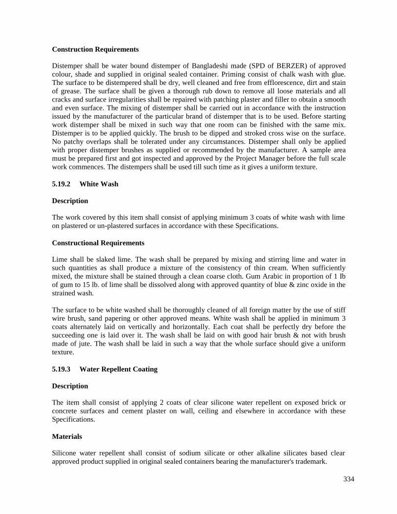
334
Construction Requirements
Distemper shall be water bound distemper of Bangladeshi made (SPD of BERZER) of approvedcolour, shade and supplied in original sealed container. Priming consist of chalk wash with glue.The surface to be distempered shall be dry, well cleaned and free from efflorescence, dirt and stainof grease. The surface shall be given a thorough rub down to remove all loose materials and allcracks and surface irregularities shall be repaired with patching plaster and filler to obtain a smoothand even surface. The mixing of distemper shall be carried out in accordance with the instructionissued by the manufacturer of the particular brand of distemper that is to be used. Before startingwork distemper shall be mixed in such way that one room can be finished with the same mix.Distemper is to be applied quickly. The brush to be dipped and stroked cross wise on the surface.No patchy overlaps shall be tolerated under any circumstances. Distemper shall only be appliedwith proper distemper brushes as supplied or recommended by the manufacturer. A sample areamust be prepared first and got inspected and approved by the Project Manager before the full scalework commences. The distempers shall be used till such time as it gives a uniform texture.
5.19.2 White Wash
Description
The work covered by this item shall consist of applying minimum 3 coats of white wash with limeon plastered or un-plastered surfaces in accordance with these Specifications.
Constructional Requirements
Lime shall be slaked lime. The wash shall be prepared by mixing and stirring lime and water insuch quantities as shall produce a mixture of the consistency of thin cream. When sufficientlymixed, the mixture shall be stained through a clean coarse cloth. Gum Arabic in proportion of 1 Ibof gum to 15 lb. of lime shall be dissolved along with approved quantity of blue & zinc oxide in thestrained wash.
The surface to be white washed shall be thoroughly cleaned of all foreign matter by the use of stiffwire brush, sand papering or other approved means. White wash shall be applied in minimum 3coats alternately laid on vertically and horizontally. Each coat shall be perfectly dry before thesucceeding one is laid over it. The wash shall be laid on with good hair brush & not with brushmade of jute. The wash shall be laid in such a way that the whole surface should give a uniformtexture.
5.19.3 Water Repellent Coating
Description
The item shall consist of applying 2 coats of clear silicone water repellent on exposed brick orconcrete surfaces and cement plaster on wall, ceiling and elsewhere in accordance with theseSpecifications.
Materials
Silicone water repellent shall consist of sodium silicate or other alkaline silicates based clearapproved product supplied in original sealed containers bearing the manufacturer's trademark.

335
Application Method
The application of water repellent coat shall strictly comply with the manufacturer’sinstructions.The application shall preferably be carried out after a period of dry weather and before applications;the surface shall be thoroughly clean and dry. A heavy coat shall be applied evenly direct from thecontainer by flooding the surface with a wide brush so that at least 6mm penetration is achieved.
A second coat, applied as above, shall follow after 24 hours subjected dry & clean weather.
5.19.4 Enamel Paint
Description
The work covered under this item shall consist of applying 2 (two) coat of synthetic enamel paintof approved colour over a coat of priming on plaster wall or ceiling surface where necessary inaccordance with these specification.
Construction Requirement
The plaster surface shall be painted with two coats or more of synthetic enamel ready mixed paintof best quality and approved color. Before application the surface shall be given a through rubdown to remove all loose materials and all cracks and surface irregularities shall be repaired withpatching plaster and filler to obtain a smooth and even surface. The paint shall be applied onappropriate primer after the surface has been finished with filler/putty, etc.
Before applying the paint on plastered surface the surfaces must be thoroughly smooth and cleanedfrom grease dirt and other foreign materials by a use of stiff wire brush, sand papering or otherapproved means. Painting shall not be carried out in damp weather. No patchy overlap shall betolerated under any circumstances.
The enamel paint should Robialac (Berger) or equivalent and must be approved by the ProjectManager.
Manufacturer’s instructions for application for paint must be followed. The colour of the paintshould be according to the direction of the Project Manager.
A sample area must be prepared first and got inspected and approved by theProject Manager beforethe full scale work commences
5.19.5 French Polishing to Wooden Surface
Description
The work covered by this item shall consist of providing French polishing work to wooden surfaceas per direction of the Project Manager.
Construction Requirement
French polishing to door frame and shutters three coats over a coat of priming including cleaningfinishing and polishing with sand paper etc. all complete in all floor.

336
5.19.6 Plastic Paint
Description
The work covered under this item shall consist of applying 2 (two) coat of plastic paint of approvedcolor over a coat of priming on plastered wall or ceiling surface where necessary in accordancewith these specifications. The painted surface shall be easily washable by soft soap and water.
Materials
The plastic paint should be Robialac (Berger) or equivalent and must be approved by the ProjectManager. The priming consists of appropriate type as specified for the paint by the manufacturer,and shall be applied accordingly.
Application Method
The surface to be plastic painted shall be dry, well cleaned and free from efflorescence dirt andstain of grease. The surface shall be given a through rub down to remove all loose materials and allcracks and surface irregularities shall be repaired with patching plaster and filler to obtain a smoothand even surface. The mixing of plastic paint shall be carried out in accordance with the instructionissued by the manufacturer of the particular brand of plastic paint that is to be used. Before startingwork plastic paint shall be mixed in such way that one room can be finished with same mix. Plasticpaint is to be applied with proper brushes as supplied or recommended by the manufacturer. Asample area must be prepared first and get inspected and approved by the Project Manager beforethe full scale work commences, The paint work shall not be considered as complete till a surface ofperfect uniformity in color, shade and texture is achieved.
5.20 Timber Works
Descriptions
The item shall consist of supplying and fixing timber for doors, windows fitted with hardware andfinished in accordance with the applicable plans, schedules and these Specifications.
Construction Requirements for Timber Doors
Timber for shutters, trims and frames shall be Silkorai/Teak/Chapalish. Grounds, studs andblocking shall be in sound Jam or other approved wood. All timber shall be free from sap, shakes,large or loose knots and defects affecting the appearance, strength and durability of constructionand shall be well seasoned, dried to moisture content of 6% by weight and treated with non-swelling, non-staining water repellent paintable wood preservative.
Glue shall be waterproof approved product consisting of synthetic resin (phenolic, amino plastic orpolyvinyl acetate) emulsion adhesives for wood or any other approved materials conforming BS-1204.
Knotting shall consist of a uniform dispersion of 25% flake shellac in 75% methylated spirit orother approved natural or synthetic resin in a suitable solvent and conform to BS-I336.
Stopping shall be made from white or red lead and sufficient linseed oil to produce a stiff paste andconform to BS-544.
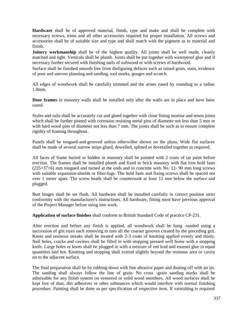
337
Hardware shall be of approved material, finish, type and make and shall be complete withnecessary screws, trims and all other accessories required for proper installation. All screws andaccessories shall be of suitable size and type and shall match with the pigment as to material andfinish.Joinery workmanship shall be of the highest quality. All joints shall be well made, cleanlymatched and tight. Verticals shall be plumb. Joints shall be put together with waterproof glue and ifnecessary further secured with finishing nails of softwood or with screws of hardwood.Surface shall be finished smooth free from disfiguring defaces such as raised grain, stain, evidenceof poor and uneven planning and sanding, tool marks, gouges and scratch.
All edges of woodwork shall be carefully trimmed and the arises eased by rounding to a radius1.0mm.
Door frames in masonry walls shall be installed only after the walls are in place and have beencured.
Styles and rails shall be accurately cut and glued together with close fitting mortise and tenon jointswhich shall be further pinned with corrosion resisting metal pins of diameter not less than 5 mm orwith hard wood pins of diameter not less than 7 mm. The joints shall be such as to ensure completerigidity of framing throughout.
Panels shall be tongued-and-grooved unless otherwi8se shown on the plans, Wide flat surfacesshall be made of several narrow strips glued, dowelled, splined or dovetailed together as required.
All faces of frame buried or hidden in masonry shall be painted with 2 coats of tar paint beforeerection. The frames shall be installed plumb and fixed to brick masonry with flat iron hold fasts(225×37×6) mm tongued and turned at the ends and to concrete with No. 12- 90 mm long screwswith suitable expansion-shields or fiber-lugs. The hold fasts and fixing screws shall be spaced notover 1 meter apart. The screw heads shall be countersunk at least 12 mm below the surface andplugged.
Butt hinges shall be set flush. All hardware shall be installed carefully in correct position strictconformity with the manufacturer's instructions. All hardware, fitting must have previous approvalof the Project Manager before using into work.
Application of surface finishes shall conform to British Standard Code of practice CP-231.
After erection and before any finish is applied, all woodwork shall be hang -sanded using asuccession of grit sizes each removing in turn all the coarser grooves created by the preceding grit.Knots and resinous streaks shall be treated with 2-3 coats of knotting applied evenly and thinly.Nail holes, cracks and cavities shall be filled in with stopping pressed well home with a stoppingknife. Large holes or knots shall be plugged in with a mixture of red lead and enamel glue in equalquantities laid hot. Knotting and stopping shall extend slightly beyond the resinous area or cavityon to the adjacent surface.
The final preparation shall be by rubbing down with fine abrasive paper and dusting off with air jet.The sanding shall always follow the line of grain. No cross -grain sanding marks shall beadmissible for any finish system on veneered or solid wood members. All wood surfaces shall bekept free of dust, dirt adhesives or other substances which would interfere with normal finishingprocedure. Painting shall be done as per specification of respective item. If varnishing is required
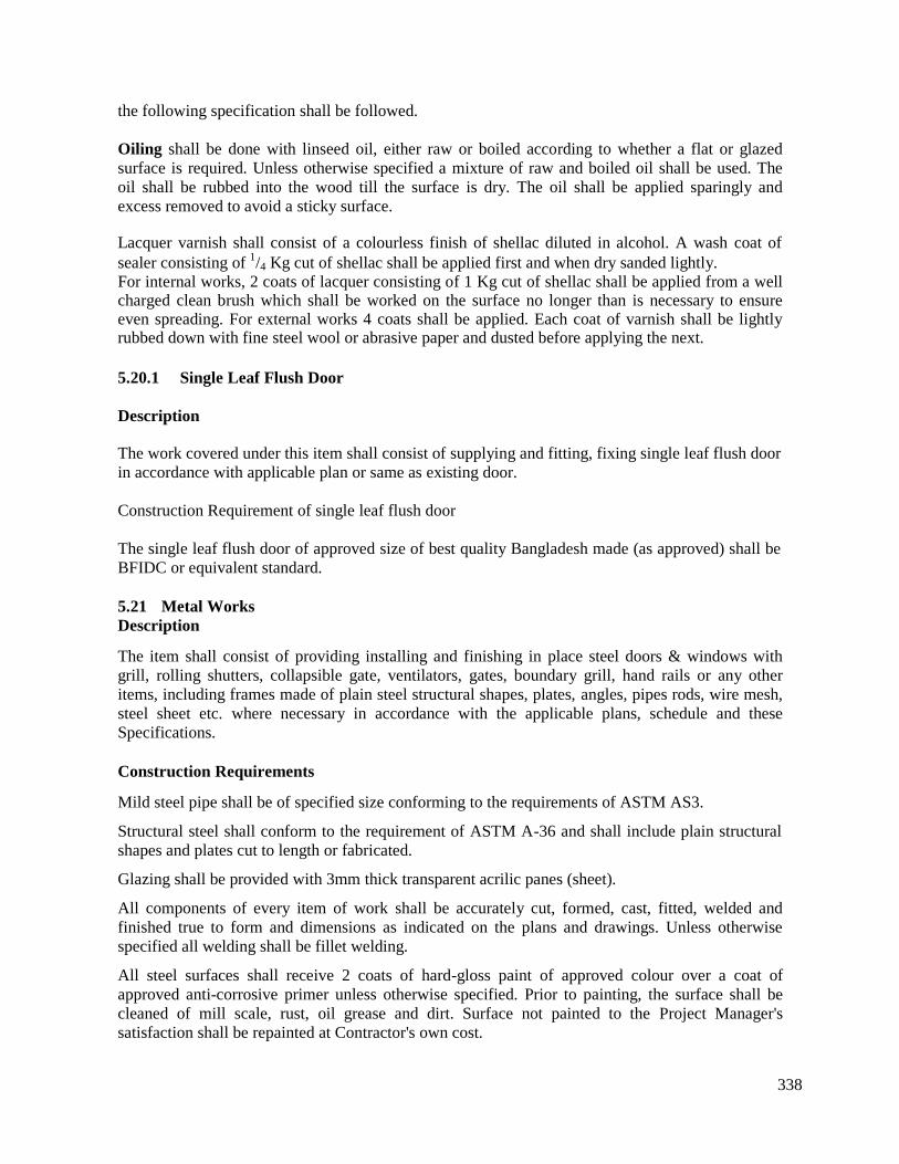
338
the following specification shall be followed.
Oiling shall be done with linseed oil, either raw or boiled according to whether a flat or glazedsurface is required. Unless otherwise specified a mixture of raw and boiled oil shall be used. Theoil shall be rubbed into the wood till the surface is dry. The oil shall be applied sparingly andexcess removed to avoid a sticky surface.
Lacquer varnish shall consist of a colourless finish of shellac diluted in alcohol. A wash coat ofsealer consisting of 1/4 Kg cut of shellac shall be applied first and when dry sanded lightly.For internal works, 2 coats of lacquer consisting of 1 Kg cut of shellac shall be applied from a wellcharged clean brush which shall be worked on the surface no longer than is necessary to ensureeven spreading. For external works 4 coats shall be applied. Each coat of varnish shall be lightlyrubbed down with fine steel wool or abrasive paper and dusted before applying the next.
5.20.1 Single Leaf Flush Door
Description
The work covered under this item shall consist of supplying and fitting, fixing single leaf flush doorin accordance with applicable plan or same as existing door.
Construction Requirement of single leaf flush door
The single leaf flush door of approved size of best quality Bangladesh made (as approved) shall beBFIDC or equivalent standard.
5.21 Metal WorksDescription
The item shall consist of providing installing and finishing in place steel doors & windows withgrill, rolling shutters, collapsible gate, ventilators, gates, boundary grill, hand rails or any otheritems, including frames made of plain steel structural shapes, plates, angles, pipes rods, wire mesh,steel sheet etc. where necessary in accordance with the applicable plans, schedule and theseSpecifications.
Construction Requirements
Mild steel pipe shall be of specified size conforming to the requirements of ASTM AS3.
Structural steel shall conform to the requirement of ASTM A-36 and shall include plain structuralshapes and plates cut to length or fabricated.
Glazing shall be provided with 3mm thick transparent acrilic panes (sheet).
All components of every item of work shall be accurately cut, formed, cast, fitted, welded andfinished true to form and dimensions as indicated on the plans and drawings. Unless otherwisespecified all welding shall be fillet welding.
All steel surfaces shall receive 2 coats of hard-gloss paint of approved colour over a coat ofapproved anti-corrosive primer unless otherwise specified. Prior to painting, the surface shall becleaned of mill scale, rust, oil grease and dirt. Surface not painted to the Project Manager'ssatisfaction shall be repainted at Contractor's own cost.
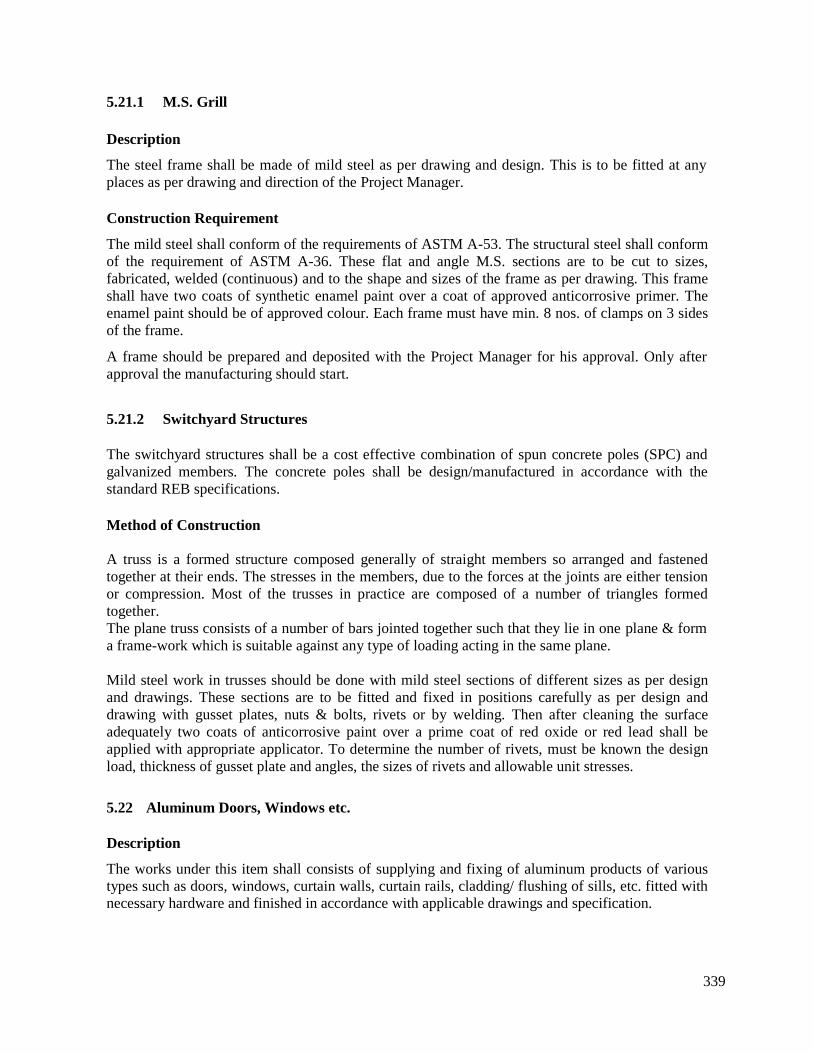
339
5.21.1 M.S. Grill
Description
The steel frame shall be made of mild steel as per drawing and design. This is to be fitted at anyplaces as per drawing and direction of the Project Manager.
Construction Requirement
The mild steel shall conform of the requirements of ASTM A-53. The structural steel shall conformof the requirement of ASTM A-36. These flat and angle M.S. sections are to be cut to sizes,fabricated, welded (continuous) and to the shape and sizes of the frame as per drawing. This frameshall have two coats of synthetic enamel paint over a coat of approved anticorrosive primer. Theenamel paint should be of approved colour. Each frame must have min. 8 nos. of clamps on 3 sidesof the frame.
A frame should be prepared and deposited with the Project Manager for his approval. Only afterapproval the manufacturing should start.
5.21.2 Switchyard Structures
The switchyard structures shall be a cost effective combination of spun concrete poles (SPC) andgalvanized members. The concrete poles shall be design/manufactured in accordance with thestandard REB specifications.
Method of Construction
A truss is a formed structure composed generally of straight members so arranged and fastenedtogether at their ends. The stresses in the members, due to the forces at the joints are either tensionor compression. Most of the trusses in practice are composed of a number of triangles formedtogether.The plane truss consists of a number of bars jointed together such that they lie in one plane & forma frame-work which is suitable against any type of loading acting in the same plane.
Mild steel work in trusses should be done with mild steel sections of different sizes as per designand drawings. These sections are to be fitted and fixed in positions carefully as per design anddrawing with gusset plates, nuts & bolts, rivets or by welding. Then after cleaning the surfaceadequately two coats of anticorrosive paint over a prime coat of red oxide or red lead shall beapplied with appropriate applicator. To determine the number of rivets, must be known the designload, thickness of gusset plate and angles, the sizes of rivets and allowable unit stresses.
5.22 Aluminum Doors, Windows etc.
Description
The works under this item shall consists of supplying and fixing of aluminum products of varioustypes such as doors, windows, curtain walls, curtain rails, cladding/ flushing of sills, etc. fitted withnecessary hardware and finished in accordance with applicable drawings and specification.
340
Construction Requirements
a) Materials and Products
Doors, windows, curtain walls etc. shall be of approved standard conforming to the U.S.Architectural Aluminum Manufacturers Association (AAMA) or BT A specifications. The framesand sash members shall be of extruded shape made of 6063 T5 high quality aluminum alloy havinga minimum section thickness of 2mm unless otherwise shown on the drawings or indicated in theschedule of items and shall conform to AAMA or BT A standard.
b) Fasteners, Hardware and anchors
Fasteners, hardware and anchors shall be of aluminum or non-magnetic, non-corrosive materialcompatible with aluminum, All windows shall be provided with non-jamming latches of rockertype designed to be locked from inside. Window locks shall be flush type as manufactured by theAdams Rite Manufacturing Company of Gleudale, California or approved equivalent. The doorsshall be provided with cylindrical locks and suitable built-in non jumping latches and bolts.
Security locks shall be pin type mortise lock, 6 or 7 pins and adaptable to Master, Grand master andGreat Grand Master keys. Sliding windows and doors shall be fitted with adjustable sealed bearingsheaves of durable hydrated nylon or approved equivalent. Closers Push/pull and kick plates shallhave to match with the frames. Any other hard wares to be incorporated in the work shall alsomatch with the frame. Assembly and installation screws shall be of stainless steel. Doors,Windows, curtain walls etc. shall be installed with teflon injected expanding bolts, Sills shallcontain adequate provisions for drainage. Head, sills and jamb members shall be of one piececonstruction. Aluminum to aluminum contact between hardware parts or moving members shall notbe permitted. Such contacts shall be properly insulated.
c) Glass Pane
Glass shall be 6mm thick tinted dark bronze float glass panes (Japan, Bangladesh or Equivalent).Or as per drawing, schedule of item and direction of the Project Manager.
d) Glazing Beads
Glazing beads shall be aluminum shape-in interchangeable type.
e) Glazing Strips
Glazing strips or channels shall be of formed neoprene of acceptable quality.
f) Weather Stripping
Weather stripping shall be of neoprene or silicon treated woven wood or approved equal.
g) Joints
Joints shall be mechanically done square (telescopic) joints. No mitred Joints shall be accepted. Noforced fitting shall be accepted. All units shall be fabricated at the factory to accurate dimensions.
It shall be rigid and designed to permit complete weather stripping. In principle, the parts should beput together by self-tapping screw
341
h) Surface Finish
All exposed surfaces of aluminum members shall be factory finish and of substantially uniformappearance conforming to "Architectural" standard.
All exposed surfaces shall be given a natural Anodic Oxide hardcore coating of 15 micron inthickness and a density of 25mg. per square inch and a uniform color tone conforming to the U.S.Aluminum Association or equivalent standard. The color spectrum shall be natural silver/approvedshade of bronze or all exposed surfaces of the Aluminum frames shall be electrostatically paintedwith VV resistance hard resin powder with minimum coating thickness of 40 micron of approvedcolor shade. Finish of hardware shall match closely with the door/window/curtain wall finish.
i) Accessories
Accessories necessary for proper fixing and preparation such as anchors, clips, fins, sub-frames,metal sills, mullion, covers, casing, other trim, cleaning anchors, glazing beads, weathering andglazing strips, hardware and mechanical operators shall be supplied ready to set in place with thedoor, window, curtain wall units.
Steel or wood sub frames shall be painted with Zinc-chromatic primer in case of steel and' withwood preservative in case of wood. Steel anchor shall be properly insulated from aluminum frame.
j) Sealant
Sealant shall be one part elastic compound of "Architectural" grade caulk and shall be in matchingcolor or as approved by the Project Manager.
k) Shop Drawings
The Contractor shall prepare detailed design of all work involved in line with the Consultantsdesign and prepare Shop Drawings for the total work and submit to the Project Manager forapproval before factory fabrication. All exterior doors, windows and curtain walls shall be designedto withstand a wind pressure of 30Ib/sft.
l) Installation
All units shall be assembled at site under proper conditions, erected, fixed and glazed in place instrict conformity with manufacturer's instruction. All cut-out operations for hardware preparationshall be made accurately and reinforced as required.
All doors, windows, curtain walls etc. shall be set plumb, square, level and in exact alignment withsurrounding works and shall be securely anchored ready for operation. All joints between themasonry openings and frames hall be caulked and sealed after installation of the frames. Allinstallation works shall be done and finished in such a way as to ensure a free and smoothoperation.
Abrasion or other injury to finished surfaces shall be carefully avoided. Cleaning should beaccomplished with plain water or a petroleum type cleaning agent or with the manufacturer'srecommended cleaning reagent. No corrosive reagent shall be used.
342
5.23 Water Proofing Polythene Sheet
Description
The work covered under this item shall consist of supplying and laying in place polythene sheetsover brick flat soling in floor of buildings and where needed in accordance with the applicablePlans, Schedules and Specification.
Construction Requirement
The sheets shall be laid within the building covering the entire inside floor area. Before laying thesheets the brick surface shall be cleaned with a duster to give the surface a free of extraneousparticles. The sheets shall be free of damage, tear or other imperfection and shall be laid such thatthere is a minimum of 225 mm overlap between, adjacent strips. The second layer shall be laid overthe first in the same direction but with a stagger of half the strip width.
5.24 Lime Terracing on Roof
Description
The item shall consist of constructing a layer of lime concrete 2:2:7 on roof slabs in accordancewith these Specifications.
Construction Requirements
Lime concrete shall consist of a mixture of 2 parts lime to 2 parts surki and 7 parts brick chips.
Lime shall be unslaked lime and shall be mixed by weight. Lime weight shall be measured atUnslaked Condition and one cubic meter of lime terracing work requires 4.60 mounds (172.16 kg)of lime. Slaked lime shall be screened through 3.35 mm sieves and the residue shall be rejected.The lime stone should be brought to site and slaked in the ground of the working place.
Surki shall be made from 1st class (well-burnt but not vitrified) bricks crushed or ground to passthrough a 2 mm sq mesh.
Brick chips (khoa) shall consist of 18 mm down-graded angular fragments of broken or crushed 1stclass bricks.The mixing shall be done on a clean platform but not on roof. Lime and surki in the specifiedquantities shall first be mixed dry till the mixture is of uniform colour. Then the mixture shall bescreened. Specified quantity of previously wetted khoa shall be added .and the whole turned overonce without adding water and twice by gradually adding small quantities of water for tempering.The mix shall then be allowed to age for at least 7 days. During this period the mixture shall beturned by spading twice a day and further lime water added if needed to prevent drying up. Careshould be taken to keep it under cover to protect against rain. The mixture shall then be laid evenlyon the roof slab to proper slope and in thickness 30% more than that shown on the plans andthoroughly beaten for 7 days with wooden mallets to the finished thickness and proper slope.Before beating a lime slurry shall be laid on the top and allowed to soak well. The lime watermixed with molasses shall be continually sprinkled on the concrete to keep it wet while beingbeaten. Beating should not be stopped until the metallic sound is obtained. The mortar which comesto the surface during the beating is to be rendered smooth and finished off with lime rubbing. Theterracing shall be kept wet after completion for a period of not less than one week. The soundness
343
of the lime terrace roof should be tested by cutting a small portion of the materials 75 mm squareand 50 mm deep in few representative areas and filling the holes with water and observing for halfan hour. If the water level does not go down in any of the' holes the compaction of the L.C. shall beconsidered to have been adequate. If not, the L.C. shall have to be done again.
5.25 Screeding on Roof
Description
Average 50mm thick screeding with concrete on top of roof slab with cement, sand (FM 2.5) &12mm downgraded stone chips. Concrete is to be laid in slope as per drawing and direction of theProject Manager.
5.26 Surface Drain
Description
The item shall consist of 300 mm or 450 mm deep drains in accordance with these specifications.
Construction Requirement
Bricks, cement, sand and all other materials shall conform to the requirement of respectivematerials specified in the relevant sections of materials specifications.
The surface drain shall be constructed in true line and level as per drawing and direction of theProject Manager.
300 mm deep drains shall have 300 mm clear width with 125 mm thick brick wall (1:6) on 75 mmthick cement concrete (1:3:6) base over single layer brick flat soling. The exposed surface shallhave 12 mm thick cement plaster (1:3) with neat cement finishing and curing at least for 7 daysmust be done.
5.27 ApronDescriptionThe item shall consist of construction 50 mm thick cement concrete over a layer of Brick flat solingaround the structure in accordance to this specification.
Construction Requirements:Cement Concrete (1:2:4) with neat cement finishing.
Brick flat soling by first class bricks unless otherwise specified.
Sand shall be clean well graded natural sand having F.M of 2.0 for concrete.
Water shall be same as required for concrete.
The area specified for construction of apron shall be thoroughly cleaned, leveled &' compacted toproper slope & level. Brick flat soling shall be laid over compacted earth according to specificationno. 2.6, then cement concrete (1:2:4) as per specification no. 2.7shall be placed over BFS withmaintaining proper level & slope towards drain, Simultaneously neat cement finish shall be appliedon top surface curing for a period of at least 7 days as prescribed in item no. 2.7complete as perdrawing & direction to the Project Manager.
344
5.28 Road Work
The proposed substation sites are located in different parts of Bangladesh. These are the low lyingarea mostly are paddy land. The proposed substation sites may be connected by a road which shallbe constructed during construction period.
The Construction work of roads shall be carried out in accordance with the Drawing. The designand drawing shall be as per AASHTO specification. However, demolition and restoration of thepublic roads (including private roads) shall be carried out according to the specifications designatedthe official in charge of road management not withstanding the provisions described in thespecifications and the Drawing.
5.28.1 Road Work Inside The Premises
Sub–grade
a) Any excavation and banking work required for sub-grade construction shall be carried outin accordance with the respective provisions in General Provision of earth work.
b) The material required for banking and displacement shall be so placed that the finishedthickness of one layer after compaction shall become 20 cm or less.
c) The sub-grade surface shall be finished by proof- rolling in order to obtain the contactpressure sufficient to permit smooth traffic of vehicles of 8 tons or over should anydefects be detected as a result of proof-rolling, such detective sub-grade surface shall befinished again to the satisfaction of the Project Manager.
d) The finished sub-grade surface shall be within + 5 cm of the design elevation.
Sub base Course
(a) The materials to be used for sub base course shall be in accordance with the specificationdescribed in the Drawing. The Contractor shall submit a report concerning the quality ofmaterials and the methods of sampling to theProject Manager for approval.
(b) The finished surface of sub base course shall be within –10 mm and+5mm of the designelevation.
Surface Course (Asphalt pavement) – Approach/Access Roads
(a) Prior to commencing pavement, the sides of concrete side walk, manhole, etc. shall becleaned, and molten asphalt, etc. shall be coated over the sides.
(b) The surface to be seal-coated and prime- coated shall be finished into even level, and afterperfecting removing any bloc, dust and other foreign matters, such surface shall be curedand dried.
(c) The mixtures shall be spread uniformly, rolled and finished into the specified thickness.Then, the finished surface shall be measured in parallel to the center line of the load byusing a 3 m straight line ruler. In this case, the depth of any concave sections shall notexceed 5 mm.
(d) The Contractor shall submit a report on the materials to be used for pavement of surfacecourse and method thereof to the Project Manager for approval.
345
Inspection
The Contractor shall invite inspection by the Project Manager during the course and aftercompletion of sub base course and surface course works.
5.28.2 Public Road (Including Private Road)
(1) Demolition of Pavement
Demolition of Pavement for public roads including private roads shall be carried outso carefully as not to cause any hazardous effect upon the surrounding portions ofcement, concrete or pavement.
(2) Road Keeping and Restoration
(3) The road keeping shall be of a construction applicable to the prevailing siteconditions and so provided as not to cause any danger or trouble against traffic.
(4) The Contractor shall submit the drawings for road keeping to the Project Managerfor approval.
(5) The Contractor shall constantly patrol any spots of road keeping and exert hisutmost efforts perform maintenance and repair of such roads in order to eliminateany trouble against smooth traffic.
(6) The Contractor shall carry out maintenance and repair of any pertinent roads socarefully as not to cause any trouble against smooth traffic until the said roads havebeen restored and taken over to the official in charge of road management.
5.28.3 Herring Bone Bond Brick Pavement
Description
This work shall consist of a base composed of bricks, laid on edge in a herring bone pattern, placedon a prepared single layer brick flat soling in accordance with these specifications and to the lines,grades, levels, dimensions and cross section shown in the drawings and as required by the ProjectManager.
Materials
The materials shall consist of first class bricks.
Construction Methods
The bricks shall be laid either flat or on edge with the shortest side vertical , in a single layer in aherring bone pattern to the lines, grades, levels, dimensions and cross section shown on thedrawings and as required by the Project Manager. The edges/lines of the layer shall be made withcut bricks to produce a line which is compatible with brick soling. The joints shall be filled withsand brushed in and the completed layer shall be sprinkle liberally with water
346
5.28.4 RCC Pavement – Internal Roads.
Description
The item shall consist of constructing R. c.c. road with 250mm thick guid wall of height 0.30 meterand 150mm thick R.C.C. work over one layer first class brick flat soling and reinforcement 10mmdia M.S. rod @ 175mm c/c in both direction.
Reinforcement
In pavement shall be placed and secured as shown on the plans in accordance with the requirementsof item 2.12.
Construction and expansion joints
Shall be constructed exactly in accordance with the details shown on plans and with bestworkmanship and as per direction of the Project Manager.
Extreme care shall be exercised in placing, compacting and finishing concrete at the joints toprevent displacement of the joints and to avoid the formation of honeycombs and voids. Theconcrete along the joints shall be thoroughly consolidated by the use of vibrators.
As soon as the concrete is sufficiently hardened, the edges of the pavement, the longitudinal joints,the construction, and expansion joints shall be carefully executed as per drawing and direction andfinished with an edging tool so that the radius shown on the plans is obtained.
Curing and protection
Shall start as soon as newly-laid pavement is sufficiently, hardened and shall be continued for aperiod of at least 7 days as prescribed in item no. 2.10
After hardening of concrete the joints shall be cleaned and filled with sand bituminous masticto thesatisfaction of theProject Manager.
5.28.5 Laying of Curb Stone(Concrete Block)
Description
The work covered by this item shall consist of providing and laying curb stone in sidewalks,driveways, road islands, garden paths, parking areas, etc. as per manufacturer specification,drawings and direction of the Project Manager.
Materials
Materials shall meet requirements specified below and in accordance with the specifications.
Curb stone shall be with concrete class C18.The mortar for joining shall be 1:2 cement mortar.
Installation Requirements

347
Preparation of bed, laying and joining shall be as per manufacturer specification.
348
5.29 Clearing after Completion
The Contractor shall thoroughly clean all work upon completion. Clean off an strains, marks, spots,and disfigurements from all works, touch up as required, clean all windows panes, remove allrubbish and debris from building and site and leave premises clean and tidy and fit for occupationin all respects and to the entire satisfaction of the Project Manager.
5.30 AS Built Drawings
The Contractor shall prepare as-built drawings for entire project after completion of Construction,installation and all tests, and obtain approval from Owner/Consultant, and shall submit 3 (three) setof such as-built drawing to the Owner for keeping record. Minimum one computer soft-copy shallbe accompanied with the as-built drawings.
5.31 Tests for Materials
The following tests for the construction materials shall be performed.
5.31.1 Sand
At least two samples shall be tested for each consignment but not exceeding 275 cum.
a) FM
b) Percentage of clay lump
c) Mica content
d) Organic Impurities
e) Material fiber than # 200
5.31.2 Brick
At least 6 bricks to be tested for each consignment not exceeding 50,000 no. of brick.
a) Unit weightb) Compressive strengthc) Water absorptiond) Dimensionse) Efflorescence, if necessary
5.31.3 Reinforcement
Each set of sample shall consist of 3 (three) representation standard places of Deformed bar foreach size for each consignment or as directed and shall be tested for the following properties:
a) Yield or 0.2% Proof strength testb) Ultimate tensile strength testc) Elongationd) Bend test

349
e) Cross section area
350
f). Unit Weight/meter
5.31.4 Stone Chips
At least two samples shall be tested for each consignment but not exceeding 600 cum.
a) Gradationb) Unit weightc) Specific Gravityd) Los Angeles Abrasion Test.
5.31.5 Cement
At least 3 samples of cement shall be tested for each consignment but not exceeding 100 tons.
a) Finenessb) Setting timesb) Compressive strength for 3rd, 7th and 28th day
5.31.6 Concrete
For all concrete work at least 3 (three) sets of 3 (three) samples cylinder/cubes and for each dayscasting or for each 15 cum of concrete shall be preserved and tested to for 7 days and 28 dayscrushing strength.
5.31.7 Water
Sulphate and Chloride content shall be tested for construction works of each site.
5.31.8 Where Tests to be Done
All tests shall be performed in the BRTC of BUET or any other laboratory approved by theProjectManager.
5.31.9 Cost of Tests
The cost of making any test shall be borne by the Contractor if such test is clearly intended by orprovided for in the specifications or Bill of quantities and is required to ascertain whether thedesign of and / or quality of any finished or partially finished work is appropriate for the purposeswhich it was intended to fulfill and conforms to specifications.
5.31.10 Building Furniture
The required building furniture is listed on the drawings. The final specification of the suppliedfurniture shall be to the approval of the Project Manager.
351
B. CIVIL
6.0 BUILDING, SANITARY AND ANCILLARY FACILITIES
352
TABLE OF CONTENTS
Clause No.
6.1
6.2
6.3
6.4
6.5
6.6
6.7
6.8
6.9
6.10
6.11
6.12
Description Page No
Plumbing Fixtures 391
Wash Basins 391
Kitchen Sink 392
Soap Tray 392
Toilet Paper Holder 392
Glass Shelf 393
Towel Rails 393
Mirrors 393
Shower Rose 393
CP Grating 394
CP Bib Cock 394
CP Stop Cock 394
6.13 G.I. Water Pipes and Fire Stand Pipes 394
6.14 PVC Sewer Pipes and Fittings 396
6.15 UPVC Soil and Waste Pipes and Fittings 396
6.16 RCC Pipes 397
6.17 Inspection Chambers with R.C.C. Cover 398
6.18 Water Tank 399
6.19 Water Pump 399
353
6.1 Plumbing Fixtures
6.1.1 Water Closets
Description
The work shall covered by this item shall consist of furnishing and installing white-glazed vitreouschina water closest (WC) long pan/commode/Combi closet in accordance with these specifications.
Construction Requirements
Water closet (commode/Combi closet shall be "S" or "P" type with low down cistern of vitreousChina and shall be standard product of Bangladesh Insulator and Sanitary ware Factory (BISF)Ltd/International- standard complete with seat and cover shall be made of formal dehyde moldingcompound of VICTORY brand/ equivalent of approved quality. Size of commode shall be as perrequirements of schedule of item.
Long Pan Shall be squat type as per BISF/ International -standard with integrated foot rests andshall be as specified in schedule of item.
Low down Cistern for commode/Combi closet/long pan shall be BISF/ International standardquality cistern of size 550mm x 260mm x 375mm and capacity 12.00 liters.
Cistern For long pan shall be overhead 13 liters type (MAANCO/ BISF/ International Standard orapproved equivalent) complete with float valve, fittings and fixtures as per requirements ofschedule of item.
Angle stop shall be as per drawing and instruction.
Pans shall be fixed to the floor with 1:2 cement mortar in case of squat type and with 4 nos. CPround headed screws in case of pedestal type.
Cistern shall be secured to the wall by 2 nos. #14 CP round headed screws and supported on centrebracket fixed to the wall with 2 nos. #14 CP countersunk screws. Cistern shall be connected towater supply with 12 mm plastic connecting pipe and CP angle stop.
6.2 Wash Basins
Description
The work shall covered by this item shall consist of furnishing and installing white-glazed vitreouschina wash basin on wall and supported by concealed wall hangers and fitted with chrome-plated30 mm waste, bottle trap and waste pipe, 12 mm angle stop and pillar faucet, chain, stay, rubberplug and 12 mm plastic supply connector pipe in accordance with these specifications.
Construction Requirement
Wash basin shall be of BISF-standard colour and size as specified in schedule of items.
Pillar faucets and angles stops shall be 12mm bore chrome plated brass and be of best quality (kingsize) Bangladesh made prior approved.
354
Traps (Syphone : dismantle type) shall be 30mm bore Chrome plated copper alloy having at least75mm water seal and shall be priority approved best quality Bangladesh made.
Waste pipe shall be of 30mm. PYC pipe best quality available for sewer grade.
Basins shall be supported on 2 concealed wall hangers. The basin in the executive/Master toiletroom shall be provided with pedestal: 652mm x 204mm x 204mrn size BISF standard coloured.
Hangers shall be screwed to hardwood plugs built in the wall using 3 nos14 countersunk screws foreach hanger. Hangers shall be painted with 2 coats of oil paint, over a coat of red lead primer orshall be galvanized.
Taps, valves and traps shall be connected with water supply installation by means of standardunions, coupling nuts and fittings.
6.3 Kitchen Sink
Description
The work covered by this item shall consist of furnishing and installing Kitchen sink and tray onbracket in accordance with these specifications.
Construction Requirements
Kitchen sink and tray shall be Stainless Steel as per requirements of schedule of items. Theconstruction requirement shall be similar to Wash Basin.
6.4 Soap Tray
Description
This item covers the supply and installation of soap tray as per following requirement.
Requirements
The soap tray shall be C. P. cast iron of standard size best quality Bangladesh made (as approved)and should be fixed in wall by drilling & fixing by screws etc. all complete. The dimension shall be150mm x ll0mm x 40mm.
6.5 Toilet Paper Holder
Description
The work covered by this item shall consist of furnishing and installing Toilet paper holder inaccordance with these specifications.
Construction Requirements
Toilet paper holder shall be of approved quality as specified in schedule of item. The holder shallbe fixed with chrome plated brass screws to plugs built in the wall.
355
6.6 Glass Shelf
Description
This item shall cover supply and installation of glass shelf 5mm as per schedule of item fm: basins& toilets as per following requirements.
Requirements
The glass shelf shall be best quality local made (Priority approved) with C. P. or stainless steelsupports & guide rails and should be fitted in the wall with screws etc. complete.
6.7 Towel Rails
Description
The work covered by this item shall consist of supply of towel rails and installation of the same asper following requirements.
Requirements
The towel rails shall be chromium plated heavy type 20mm dia 600mm long with C. P. flangedholder, counter sunk screws. The rail should be fixed in walls by drilling holes in wall, fixingscrews through rowel plugto the satisfaction of theProject Manager.
6.8 Mirrors
Description
The work covered by this item shall consist of furnishing and installing plate glass mirrorsJapan/Belgium of approximate dimensions 450 mm x 350 mm and of 5 mm thickness over lavatorybasins according to these specifications.
Construction requirements
Edges of mirror shall be clean cut and round smooth. Mirror shall not be installed in direct contactwith the wall. The separation shall be effected by 6 mm thick rubber or cork spacers. Fixing shallbe by means of chrome-plated holders and screws to hardwood plugs built in the wall. Care shall betaken to place the mirror symmetrical to the axis of the basin and with sides vertical and horizontal.
6.9 Shower Rose
Description
The item shall consist of furnishing and installing chrome plated brass shower rose in accordancewith these specifications.
Construction Requirements
The shower rose shall be of nominal 100 mm diameter best quality Bangladesh made priorapproved and shall be connected to the water supply installation by screwing giving a leak-proof

356
joint.
357
6.10 CP Grating
Description
The work covered by this item shall consist of furnishing and installing chrome-plate gratings inaccordance with these specifications.
Construction Requirements
CP grating shall be 125mm dia. heavy type and approved quality and shall be installed in directcontract with the floor.
6.11 CP Bib Cock
Description
The item shall consist of furnishing and installing chrome-plated brass bib taps in accordance withthese Specifications.
Construction Requirements
Bib taps shall be of 12mm bore heavy type with at least 75 mm projection and shall be best qualityBangladesh made (Nazma, Sharif or equivalent) prior approved Draw-off taps and stop valves forwater services!
Taps shall be connected with the water supply installation by means of standard unions, couplingnuts and fittings.
6.12 CP Stop Cock
Description
The work covered by this item shall consist of furnishing and installing chrome-plate stop cocks inaccordance with these specifications.
Construction Requirements
The stop cock shall be 12mm dia heavy duty chrome-plated concealed and shall be approvedquality Bangladesh made (Nazma, Sharif or equivalent).
Stop cock shall be connected with the water supply installation by means of standard unions,coupling nuts and fittings,
6.13 G.I. Water Pipes and Fire Stand Pipes
Description
The work covered by this item shall consist of supplying and installing galvanized steel water pipeson wall surface or in wall, underground through stack (duct) and where necessary in accordancewith these specifications.
358
Constructional Requirements
GI pipes shall be galvanized steel welded tubes of screwed and socketed type, Class A and shall beequivalent to as specified in BS-1387.
Stop valvesShall be of brass and equivalent of the screw down pattern conforming to as specified in BS-1953.
Draining
Staps shall be screw-down pattern conforming to BS-2879.
Ball valve
Shall be of brass and conform to BS- 1212.
Float for ball valve
Shall be of copper with solder joints and conform to the requirements of Class A, BS-1968.
All fittings shall be standard GI products and shall conform to BS-534.
The piping work shall be carried out in accordance with British Standard Code of Practice CP-310Water Supply!
Pipes shall be jointed with preferably with raplon tape according to manufacturer’s instructions.However, strands of find jute may be used with the approval of the Project Manager.
A gate valve along with a float valve shall be provided with a socket union where the service pipefrom main is connected to the underground reservoir.
Stop valve shall be provided on the supply pipe to individual buildings in an accessible positioninside the building as near as practicable to the point of entry of the pipe to each building so that thesupply may be readily shut off for repairs. A draining tap shall be provided just above the stopvalve to enable the service piping in the building to be emptied of water when stop valve is shut.Stop valve shall also be provided at the outlet from roof storage tank and on every branch pipe ofthe feed pipe as near as possible to the point at which the pipe leaves so as to minimize interruptionof supply during repairs.
Where the service pipe is less than 50 mm bore, all the stop valves shall be of the screw down type.Other stop valves shall be of the gate type.
Pipe in structures shall be installed during construction. No hole or chasing in wall or floor shall beallowed without prior approval. Pipes shall be supported by steel clips placed at an interval ofapproximately 1 meter. All clips and brackets shall be fixed with rawal plugs into the masonry.
The fire stand pipe shall be 4" dia G.I. unless otherwise specified. Each floor shall be equipped withfire hose, made of rubber lined cotton 63mm diameter. Rubber covered or unlined linen may beprovided with the approval of the Project Manager. A closet in which hose is stored should beventilated and installed at least 1300mm above the finished floor. The hose is to the equipped with25 to 33mm nozzle.
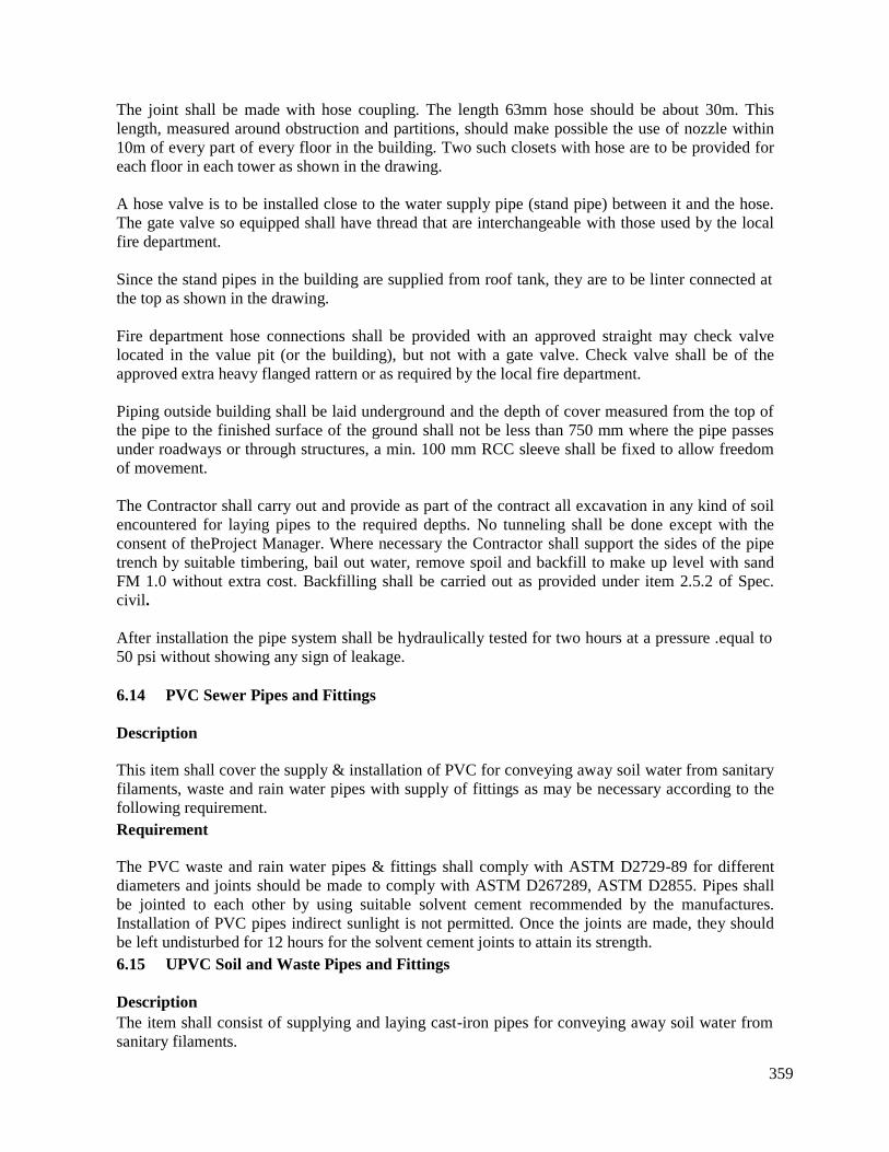
359
The joint shall be made with hose coupling. The length 63mm hose should be about 30m. Thislength, measured around obstruction and partitions, should make possible the use of nozzle within10m of every part of every floor in the building. Two such closets with hose are to be provided foreach floor in each tower as shown in the drawing.
A hose valve is to be installed close to the water supply pipe (stand pipe) between it and the hose.The gate valve so equipped shall have thread that are interchangeable with those used by the localfire department.
Since the stand pipes in the building are supplied from roof tank, they are to be linter connected atthe top as shown in the drawing.
Fire department hose connections shall be provided with an approved straight may check valvelocated in the value pit (or the building), but not with a gate valve. Check valve shall be of theapproved extra heavy flanged rattern or as required by the local fire department.
Piping outside building shall be laid underground and the depth of cover measured from the top ofthe pipe to the finished surface of the ground shall not be less than 750 mm where the pipe passesunder roadways or through structures, a min. 100 mm RCC sleeve shall be fixed to allow freedomof movement.
The Contractor shall carry out and provide as part of the contract all excavation in any kind of soilencountered for laying pipes to the required depths. No tunneling shall be done except with theconsent of theProject Manager. Where necessary the Contractor shall support the sides of the pipetrench by suitable timbering, bail out water, remove spoil and backfill to make up level with sandFM 1.0 without extra cost. Backfilling shall be carried out as provided under item 2.5.2 of Spec.civil.
After installation the pipe system shall be hydraulically tested for two hours at a pressure .equal to50 psi without showing any sign of leakage.
6.14 PVC Sewer Pipes and Fittings
Description
This item shall cover the supply & installation of PVC for conveying away soil water from sanitaryfilaments, waste and rain water pipes with supply of fittings as may be necessary according to thefollowing requirement.Requirement
The PVC waste and rain water pipes & fittings shall comply with ASTM D2729-89 for differentdiameters and joints should be made to comply with ASTM D267289, ASTM D2855. Pipes shallbe jointed to each other by using suitable solvent cement recommended by the manufactures.Installation of PVC pipes indirect sunlight is not permitted. Once the joints are made, they shouldbe left undisturbed for 12 hours for the solvent cement joints to attain its strength.6.15 UPVC Soil and Waste Pipes and Fittings
DescriptionThe item shall consist of supplying and laying cast-iron pipes for conveying away soil water fromsanitary filaments.
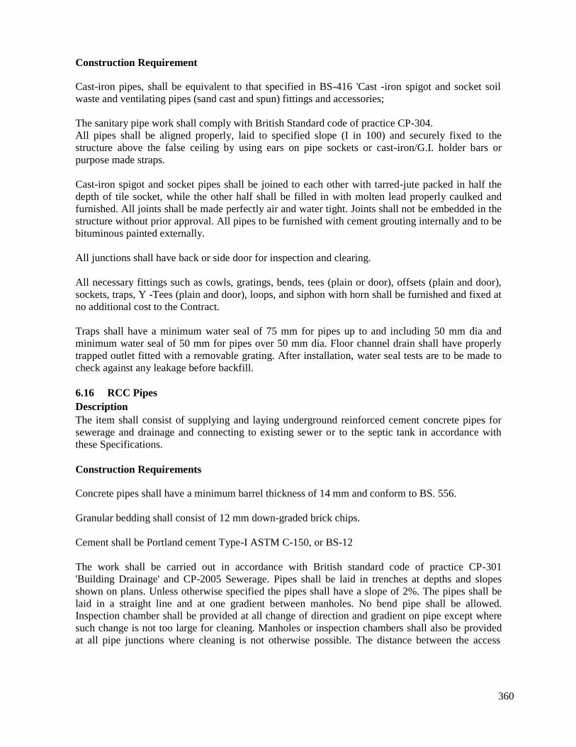
360
Construction Requirement
Cast-iron pipes, shall be equivalent to that specified in BS-416 'Cast -iron spigot and socket soilwaste and ventilating pipes (sand cast and spun) fittings and accessories;
The sanitary pipe work shall comply with British Standard code of practice CP-304.All pipes shall be aligned properly, laid to specified slope (I in 100) and securely fixed to thestructure above the false ceiling by using ears on pipe sockets or cast-iron/G.I. holder bars orpurpose made straps.
Cast-iron spigot and socket pipes shall be joined to each other with tarred-jute packed in half thedepth of tile socket, while the other half shall be filled in with molten lead properly caulked andfurnished. All joints shall be made perfectly air and water tight. Joints shall not be embedded in thestructure without prior approval. All pipes to be furnished with cement grouting internally and to bebituminous painted externally.
All junctions shall have back or side door for inspection and clearing.
All necessary fittings such as cowls, gratings, bends, tees (plain or door), offsets (plain and door),sockets, traps, Y -Tees (plain and door), loops, and siphon with horn shall be furnished and fixed atno additional cost to the Contract.
Traps shall have a minimum water seal of 75 mm for pipes up to and including 50 mm dia andminimum water seal of 50 mm for pipes over 50 mm dia. Floor channel drain shall have properlytrapped outlet fitted with a removable grating. After installation, water seal tests are to be made tocheck against any leakage before backfill.
6.16 RCC PipesDescriptionThe item shall consist of supplying and laying underground reinforced cement concrete pipes forsewerage and drainage and connecting to existing sewer or to the septic tank in accordance withthese Specifications.
Construction Requirements
Concrete pipes shall have a minimum barrel thickness of 14 mm and conform to BS. 556.
Granular bedding shall consist of 12 mm down-graded brick chips.
Cement shall be Portland cement Type-I ASTM C-150, or BS-12
The work shall be carried out in accordance with British standard code of practice CP-301'Building Drainage' and CP-2005 Sewerage. Pipes shall be laid in trenches at depths and slopesshown on plans. Unless otherwise specified the pipes shall have a slope of 2%. The pipes shall belaid in a straight line and at one gradient between manholes. No bend pipe shall be allowed.Inspection chamber shall be provided at all change of direction and gradient on pipe except wheresuch change is not too large for cleaning. Manholes or inspection chambers shall also be providedat all pipe junctions where cleaning is not otherwise possible. The distance between the access
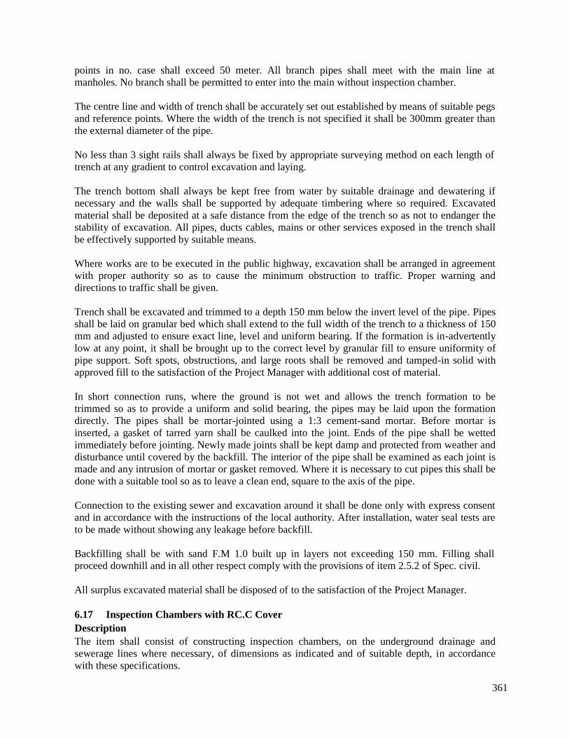
361
points in no. case shall exceed 50 meter. All branch pipes shall meet with the main line atmanholes. No branch shall be permitted to enter into the main without inspection chamber.
The centre line and width of trench shall be accurately set out established by means of suitable pegsand reference points. Where the width of the trench is not specified it shall be 300mm greater thanthe external diameter of the pipe.
No less than 3 sight rails shall always be fixed by appropriate surveying method on each length oftrench at any gradient to control excavation and laying.
The trench bottom shall always be kept free from water by suitable drainage and dewatering ifnecessary and the walls shall be supported by adequate timbering where so required. Excavatedmaterial shall be deposited at a safe distance from the edge of the trench so as not to endanger thestability of excavation. All pipes, ducts cables, mains or other services exposed in the trench shallbe effectively supported by suitable means.
Where works are to be executed in the public highway, excavation shall be arranged in agreementwith proper authority so as to cause the minimum obstruction to traffic. Proper warning anddirections to traffic shall be given.
Trench shall be excavated and trimmed to a depth 150 mm below the invert level of the pipe. Pipesshall be laid on granular bed which shall extend to the full width of the trench to a thickness of 150mm and adjusted to ensure exact line, level and uniform bearing. If the formation is in-advertentlylow at any point, it shall be brought up to the correct level by granular fill to ensure uniformity ofpipe support. Soft spots, obstructions, and large roots shall be removed and tamped-in solid withapproved fill to the satisfaction of the Project Manager with additional cost of material.
In short connection runs, where the ground is not wet and allows the trench formation to betrimmed so as to provide a uniform and solid bearing, the pipes may be laid upon the formationdirectly. The pipes shall be mortar-jointed using a 1:3 cement-sand mortar. Before mortar isinserted, a gasket of tarred yarn shall be caulked into the joint. Ends of the pipe shall be wettedimmediately before jointing. Newly made joints shall be kept damp and protected from weather anddisturbance until covered by the backfill. The interior of the pipe shall be examined as each joint ismade and any intrusion of mortar or gasket removed. Where it is necessary to cut pipes this shall bedone with a suitable tool so as to leave a clean end, square to the axis of the pipe.
Connection to the existing sewer and excavation around it shall be done only with express consentand in accordance with the instructions of the local authority. After installation, water seal tests areto be made without showing any leakage before backfill.
Backfilling shall be with sand F.M 1.0 built up in layers not exceeding 150 mm. Filling shallproceed downhill and in all other respect comply with the provisions of item 2.5.2 of Spec. civil.
All surplus excavated material shall be disposed of to the satisfaction of the Project Manager.
6.17 Inspection Chambers with RC.C CoverDescriptionThe item shall consist of constructing inspection chambers, on the underground drainage andsewerage lines where necessary, of dimensions as indicated and of suitable depth, in accordancewith these specifications.
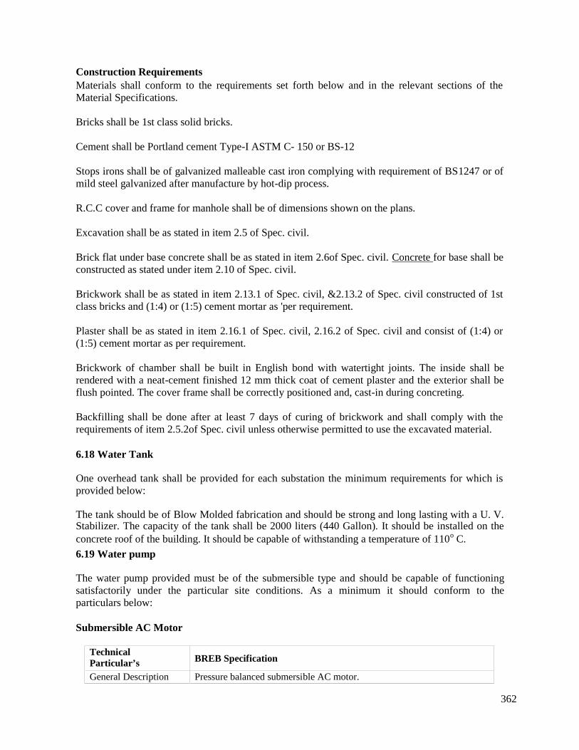
362
Construction RequirementsMaterials shall conform to the requirements set forth below and in the relevant sections of theMaterial Specifications.
Bricks shall be 1st class solid bricks.
Cement shall be Portland cement Type-I ASTM C- 150 or BS-12
Stops irons shall be of galvanized malleable cast iron complying with requirement of BS1247 or ofmild steel galvanized after manufacture by hot-dip process.
R.C.C cover and frame for manhole shall be of dimensions shown on the plans.
Excavation shall be as stated in item 2.5 of Spec. civil.
Brick flat under base concrete shall be as stated in item 2.6of Spec. civil. Concrete for base shall beconstructed as stated under item 2.10 of Spec. civil.
Brickwork shall be as stated in item 2.13.1 of Spec. civil, &2.13.2 of Spec. civil constructed of 1stclass bricks and (1:4) or (1:5) cement mortar as 'per requirement.
Plaster shall be as stated in item 2.16.1 of Spec. civil, 2.16.2 of Spec. civil and consist of (1:4) or(1:5) cement mortar as per requirement.
Brickwork of chamber shall be built in English bond with watertight joints. The inside shall berendered with a neat-cement finished 12 mm thick coat of cement plaster and the exterior shall beflush pointed. The cover frame shall be correctly positioned and, cast-in during concreting.
Backfilling shall be done after at least 7 days of curing of brickwork and shall comply with therequirements of item 2.5.2of Spec. civil unless otherwise permitted to use the excavated material.
6.18 Water Tank
One overhead tank shall be provided for each substation the minimum requirements for which isprovided below:
The tank should be of Blow Molded fabrication and should be strong and long lasting with a U. V.Stabilizer. The capacity of the tank shall be 2000 liters (440 Gallon). It should be installed on theconcrete roof of the building. It should be capable of withstanding a temperature of 110o C.
6.19 Water pump
The water pump provided must be of the submersible type and should be capable of functioningsatisfactorily under the particular site conditions. As a minimum it should conform to theparticulars below:
Submersible AC Motor
TechnicalParticular’s BREB Specification
General Description Pressure balanced submersible AC motor.
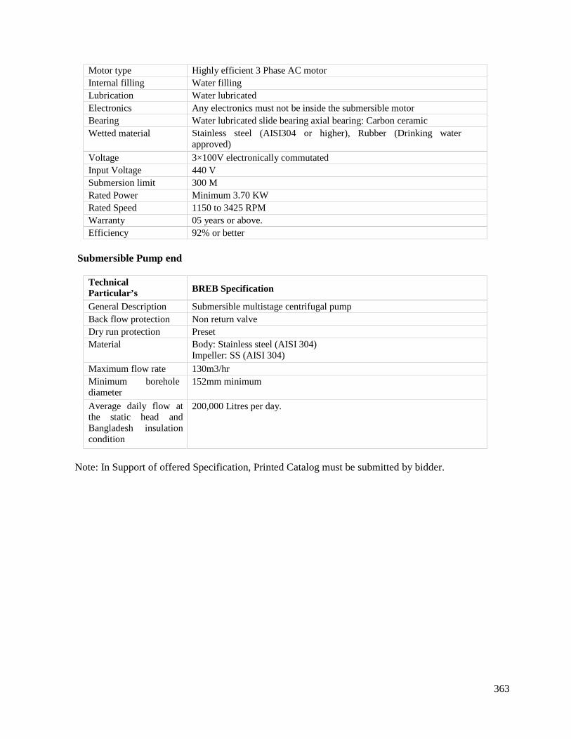
363
Motor type Highly efficient 3 Phase AC motorInternal filling Water fillingLubrication Water lubricatedElectronics Any electronics must not be inside the submersible motorBearing Water lubricated slide bearing axial bearing: Carbon ceramicWetted material Stainless steel (AISI304 or higher), Rubber (Drinking water
approved)Voltage 3×100V electronically commutatedInput Voltage 440 VSubmersion limit 300 MRated Power Minimum 3.70 KWRated Speed 1150 to 3425 RPMWarranty 05 years or above.Efficiency 92% or better
Submersible Pump end
TechnicalParticular’s BREB Specification
General Description Submersible multistage centrifugal pumpBack flow protection Non return valveDry run protection PresetMaterial Body: Stainless steel (AISI 304)
Impeller: SS (AISI 304)Maximum flow rate 130m3/hrMinimum boreholediameter
152mm minimum
Average daily flow atthe static head andBangladesh insulationcondition
200,000 Litres per day.
Note: In Support of offered Specification, Printed Catalog must be submitted by bidder.
364
B. CIVIL
7.0 INTERNAL AND EXTERNAL ELECTRIFICATION
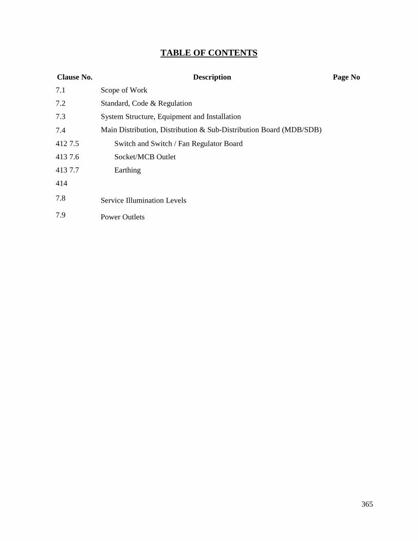
365
TABLE OF CONTENTS
Clause No. Description Page No
7.1 Scope of Work 403
7.2 Standard, Code & Regulation 403
7.3 System Structure, Equipment and Installation 404
7.4 Main Distribution, Distribution & Sub-Distribution Board (MDB/SDB)
412 7.5 Switch and Switch / Fan Regulator Board
413 7.6 Socket/MCB Outlet
413 7.7 Earthing
414
7.8 Service Illumination Levels 415
7.9 Power Outlets 416
366
7.1 Scope of Work
The electrical installation for each site comprises electrical wiring of light, fan, small power,ventilation power, water pump and all other utilities power supply in the substation building,switchyard, guard room and parking area. There shall be two types of power supply 4I5 V, 240 V50 Hz i.e. 3-phase 4-wire and single-phase 2 wire.
The Contractor shall have to submit shop drawings on the basis of Consultants drawing for theproject for each and every item of work. The Contractor shall submit at least one month prior tostart of the particular part or parts of their work to the Project Manager for approval. Similarity thebrand, country of origin, design and /sample of all equipment, material, fitting etc. as applicableand which are required for the building, either local or imported item shall have to be approved bythe Project Manager. Before taking the item at site or before placing order (for imported items) forprocurement, manufacturing etc. or shall be carried out without having such approval.
The bidder shall specify brand name, country of origin, model number etc. of all equipment andmaterial and also attach original catalogue with the bid.
Scheduled quantity may vary as per site requirement. Quantity of some items have been shown asunity. These are only for fixing rate, in case these items are required to be executed, to avoid NT(Non Tendered Item).
7.2 Standard, Code & Regulation
The installation in general shall be carried out in conformity with the Electricity Rules of the Govt.of Bangladesh, Bangladesh National Building Code [BNBC] and the 16th edition of the Regulationfor Electrical Equipment of Buildings of the Institute of Electrical Engineers (U.K), hereinafterreferred as I.E.E. wiring Regulations, and the British Standard Code of practice for the relevantworks. Any special requirement of the Electrical Inspector, Govt. of Bangladesh or the PowerDevelopment Board, Dhaka Electric Supply Authority, Dhaka Electric Supply Company, or theTelegraph and Telephone Board, or any other Legal Authority shall also be complied withno extracost to the Employer.
The following standards, in addition shall be followed for design, manufacture, installation, testingand commissioning of wiring and the communication system of this project:
Bangladesh National Building Code BNBC
International Electro technical Commission IEC
Institute of Electrical and Electronics Engineers IEEE
National Electrical Manufacturers Association. NEMA
German International Standard VDE
International Standard Organization ISO
Japan International Standard JIS
British Standard BS
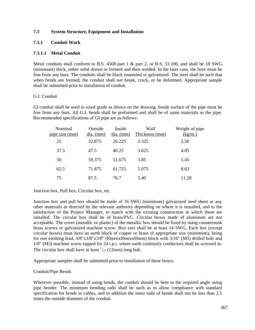
367
7.3
7.3.1
7.3.1.1
System Structure, Equipment and Installation
Conduit Work
Metal Conduit
Metal conduits shall conform to B.S. 4568 part 1 & part 2, or B.S. 31:100, and shall be 18 SWG(minimum) thick, either solid drawn or formed and then welded. In the later case, the bore must befree from any burs. The conduits shall be black enameled or galvanized. The steel shall be such thatwhen bends are formed, the conduit shall not break, crack, or be deformed. Appropriate sampleshall be submitted prior to installation of conduit.
G.I. Conduit
GI conduit shall be used in sized grade as shown on the drawing. Inside surface of the pipe must befree from any burs. All G.I. bends shall be preformed and shall be of same materials as the pipe.Recommended specifications of GI pipe are as follows:
Nominalpipe size (mm)
25
37.5
50
62.5
75
Outsidedia. (mm)
32.875
47.5
59.375
71.875
87.5
Insidedia. (mm)
26.225
40.25
51.675
61.725
76.7
WallThickness (mm)
3.325
3.625
3.85
5.075
5.40
Weight of pipe(kg/m.)
2.50
4.05
5.45
8.63
11.28
Junction box, Pull box, Circular box, etc.
Junction box and pull box should be made of 16 SWG (minimum) galvanized steel sheet or anyother materials as directed by the relevant authority depending on where it is installed, and to thesatisfaction of the Project Manager, to match with the existing construction in which these areinstalled. The circular box shall be of brass/PVC. Circular boxes made of aluminum are notacceptable. The cover (metallic or plastic) of the metallic box should be fixed by using countersunkbrass screws or galvanized machine screw. Box ears shall be at least 14 SWG, Each box (exceptcircular boxes) must have an earth block of copper or brass of appropriate size (minimum), beingfor one earthing lead, 3/8"x3/8"x3/8" (l0mrnxl0mrnxl0mm) block with 3/16" (M5) drilled hole and1/8" (M3) machine screw tapped for 24 t.p.i. where earth continuity conductors shall be screwed in.The circular box shall have at least 1/2” (12mm) long hub.
Appropriate samples shall be submitted prior to installation of these boxes.
Conduit/Pipe Bends
Wherever possible, instead of using bends, the conduit should be bent to the required angle usingpipe bender. The minimum bending radii shall be such as to allow compliance with standardspecification for bends in cables, and in addition the inner radii of bends shall not be less than 2.5times the outside diameter of the conduit.
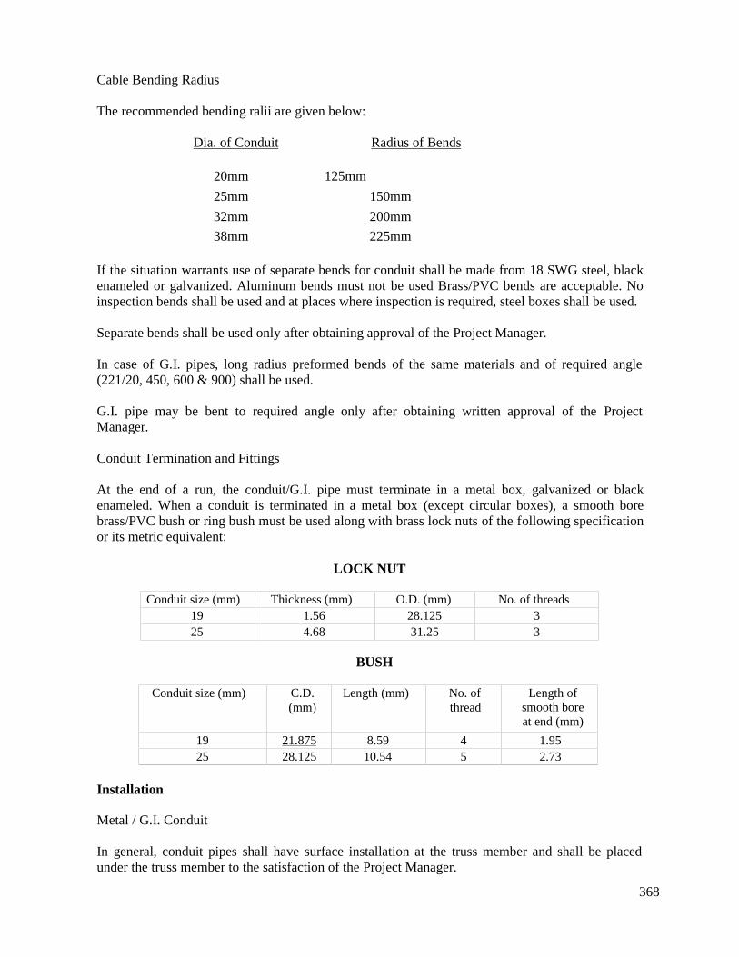
368
Cable Bending Radius
The recommended bending ralii are given below:
Dia. of Conduit
20mm
25mm
32mm
38mm
Radius of Bends
125mm
150mm
200mm
225mm
If the situation warrants use of separate bends for conduit shall be made from 18 SWG steel, blackenameled or galvanized. Aluminum bends must not be used Brass/PVC bends are acceptable. Noinspection bends shall be used and at places where inspection is required, steel boxes shall be used.
Separate bends shall be used only after obtaining approval of the Project Manager.
In case of G.I. pipes, long radius preformed bends of the same materials and of required angle(221/20, 450, 600 & 900) shall be used.
G.I. pipe may be bent to required angle only after obtaining written approval of the ProjectManager.
Conduit Termination and Fittings
At the end of a run, the conduit/G.I. pipe must terminate in a metal box, galvanized or blackenameled. When a conduit is terminated in a metal box (except circular boxes), a smooth borebrass/PVC bush or ring bush must be used along with brass lock nuts of the following specificationor its metric equivalent:
LOCK NUT
Conduit size (mm) Thickness (mm) O.D. (mm) No. of threads19 1.56 28.125 325 4.68 31.25 3
BUSH
Conduit size (mm) C.D.(mm)
Length (mm) No. ofthread
Length ofsmooth boreat end (mm)
19 21.875 8.59 4 1.9525 28.125 10.54 5 2.73
Installation
Metal / G.I. Conduit
In general, conduit pipes shall have surface installation at the truss member and shall be placedunder the truss member to the satisfaction of the Project Manager.
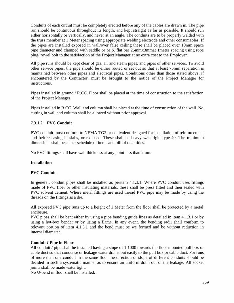
369
Conduits of each circuit must be completely erected before any of the cables are drawn in. The piperun should be continuous throughout its length, and kept straight as far as possible. It should runeither horizontally or vertically, and never at an angle. The conduits are to be properly welded withthe truss member at 1 Meter spacing using appropriate welding electrode and other consumables. Ifthe pipes are installed exposed in wall/over false ceiling these shall be placed over 10mm spacepipe diameter and clamped with saddle or M.S. flat bar 25mmx3mmat 1meter spacing using ropeplug/ rowel bolt to the satisfaction of the Project Manager at no extra cost to the Employer.
All pipe runs should be kept clear of gas, air and steam pipes, and pipes of other services. To avoidother service pipes, the pipe should be either routed or set out so that at least 75mm separation ismaintained between other pipes and electrical pipes. Conditions other than those stated above, ifencountered by the Contractor, must be brought to the notice of the Project Manager forinstructions.
Pipes installed in ground / R.CC. Floor shall be placed at the time of construction to the satisfactionof the Project Manager.
Pipes installed in R.CC. Wall and column shall be placed at the time of construction of the wall. Nocutting in wall and column shall be allowed without prior approval.
7.3.1.2 PVC Conduit
PVC conduit must conform to NEMA TG2 or equivalent designed for installation of reinforcementand before casing in slabs, or exposed. These shall be heavy wall rigid type-40. The minimumdimensions shall be as per schedule of items and bill of quantities.
No PVC fittings shall have wall thickness at any point less than 2mm.
Installation
PVC Conduit
In general, conduit pipes shall be installed as peritem 4.1.3.1. Where PVC conduit uses fittingsmade of PVC fiber or other insulating materials, these shall be press fitted and then sealed withPVC solvent cement. Where metal fittings are used thread PVC pipe may be made by using thethreads on the fittings as a die.
All exposed PVC pipe runs up to a height of 2 Meter from the floor shall be protected by a metalenclosure.PVC pipes shall be bent either by using a pipe bending guide lines as detailed in item 4.1.3.1 or byusing a hot-box bender or by using a flame. In any event, the bending radii shall conform torelevant portion of item 4.1.3.1 and the bend must be we formed and be without reduction ininternal diameter.
Conduit I Pipe in FloorAll conduit / pipe shall be installed having a slope of 1:1000 towards the floor mounted pull box orcable duct so that condense or leakage water drains out easily to the pull box or cable duct. For runsof more than one conduit in the same floor the direction of slope of different conduits should bedecided in such a systematic manner as to ensure an uniform drain out of the leakage. All socketjoints shall be made water tight.No U-bend in floor shall be installed.
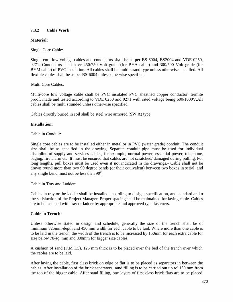
370
7.3.2 Cable Work
Material:
Single Core Cable:
Single core low voltage cables and conductors shall be as per BS-6004, BS2004 and VDE 0250,0271. Conductors shall have 450/750 Volt grade (for BYA cable) and 300/500 Volt grade (forBYM cable) of PVC insulation. All cables shall be multi strand type unless otherwise specified. Allflexible cables shall be as per BS-6004 unless otherwise specified.
Multi Core Cables:
Multi-core low voltage cable shall be PVC insulated PVC sheathed copper conductor, termiteproof, made and tested according to VDE 0250 and 0271 with rated voltage being 600/1000V.AlIcables shall be multi stranded unless otherwise specified.
Cables directly buried in soil shall be steel wire armored (SW A) type.
Installation:
Cable in Conduit:
Single core cables are to be installed either in metal or in PVC (water grade) conduit. The conduitsize shall be as specified in the drawing. Separate conduit pipe must be used for individualdiscipline of supply and services cables, for example, normal power, essential power, telephone,paging, fire alarm etc. It must be ensured that cables are not scratched/ damaged during pulling. Forlong lengths, pull boxes must be used even if not indicated in the drawings.- Cable shall not bedrawn round more than two 90 degree bends (or their equivalent) between two boxes in serial, andany single bend must not be less than 900.
Cable in Tray and Ladder:
Cables in tray or the ladder shall be installed according to design, specification, and standard andtothe satisfaction of the Project Manager. Proper spacing shall be maintained for laying cable. Cablesare to be fastened with tray or ladder by appropriate and approved type fasteners.
Cable in Trench:
Unless otherwise stated in design and schedule, generally the size of the trench shall be ofminimum 825mm-depth and 450 mm width for each cable to be laid. Where more than one cable isto be laid in the trench, the width of the trench is to be increased by 150mm for each extra cable forsize below 70-sq. mm and 300mm for bigger size cables.
A cushion of sand (F.M 1.5), 125 mm thick is to be placed over the bed of the trench over whichthe cables are to be laid.
After laying the cable, first class brick on edge or flat is to be placed as separators in between thecables. After installation of the brick separators, sand filling is to be carried out up to' 150 mm fromthe top of the bigger cable. After sand filling, one layers of first class brick flats are to be placed
371
along the length and breadth of the trench as a protection against injury. The rest of the trench shallbe filled with earth, watered and rammed at 150mm layers. Then red plastic sheet of 0.5mm thickshall be placed throughout the trench as an indications that power cable(s) has been laid down.After cables are laid the original ground conditions shall be restored. But if brick pavement, drain,concrete road, or bituminous carpeted road are cut across or damaged, they shall be remedied andrestored to the original specification.
The cable route shall be as direct as possible and shall receive the Project Manager's approvalbefore excavation.
Cables shall always be laid out or laid into the ground through GI pipe of suitable size as decidedby the Consultant. No extra cost shall be paid for such pipes. The exposed end of the pipes shall besealed using PVC or wooden plugs.
Cable marker of approved type shall be provided in the cable trench 300mm below GL level, alongthe length of laid cable.
GI cable marker shall be installed at every turning point of the trench.
After the cable is laid, it shall be tested by the Contractor in presence of the Project Manager. If thetest is unsatisfactory, the cost of all repairs and replacement shall be borne by the Contractor.
All surplus earth shall be removed by the Contractor at their own cost to the indicated places.
Any damage done to any other services by the Contractor for cable laying operations shall be madegood by the Contractor, at their own cost.
All chasing and passages necessary for laying of cable indoor or outdoor shall be carried out by theContractor and the same shall be made good to the satisfaction of the Consultant by the Contractorwithout any extra charge to the relevant Authority.
When trenches are left open overnight, and where the road shall be cut, the Contractor shall exhibita suitable danger signal such as banners, red flags and red lamps at his own cost. Temporaryarrangement by placing wooden sleepers/steel sheet etc. across the road cutting for vehicular trafficare also to be made by the Contractor at no extra cost. The Contractor shall be wholly responsiblefor any accident, which may occur due to the negligence of the Contractor.
All excavations shall be filled up in layers with powdered earth and suitably watered and rammedin such a manner that after completion of the work there is no land subsidence. The road top shallbe re-constructed to match the existing road pavement.
No trench shall be dug until all cables meant for laying have been procured and brought at sitestore. Cost of any watering or shuttering and shoring of trench required to be done shall be borneby the Contractor.
Road Crossing:
At road crossings, the cable shall be protected from damages by passing the cable through metal orconcrete conduit and protecting that conduit with appropriate road construction.
372
Cable Termination and Joint:
There shall be no twisted joint in the entire wiring system. Cables from 2.5 sq. mm and above sizesshall be terminated through cable lugs and with spring washer, nut etc. Cable gland shall beprovided for cable termination at the entrance of boxes, panels, chambers etc. For armoured cables,earth tags shall be provided with cable gland, for connection with system earth or Earth ContinuityConductor (ECC).
Cable Bending Radius
Refer item 4.1.3.1
Connection to Switches:
The Switches or Isolators shall be provided at phase conductor only.
Cable Colour:
All cables used must have colour as stated below:
Two wire single phase A.C. system:
Red, Yellow or Blue for phase.Black for neutral.Green or Green-Yellow for Earth.
Three or four wire three phase A.C. system:
Red for first phase.Yellow for second phase.Blue for third phase.Black for neutral.Green or Green-Yellow for earth
Two wire D.C. system:
Red for positive or switch wire.Black for negative.
For two wire final sub circuits.
Whether A.C. or D.C. supplying lighting or power circuits, the neutral or 'middle' wire shall alwaysbe black and the phase or outer wire (no matter which phase it is connected to) shall always be red.For lighting, the red wire shall always feed the switch, and the red wire shall always be used fromthe switch to the light.
Cable Identification:
All cables, all feeders or circuits in all distribution boards shall be provided with permanent andapproved type of identification.
373
7.3.3
7.3.3.1
Earth Continuity Conductor (ECC)
Earth Continuity Conductor
Material
All ECC shall be insulated copper (BYA cable) as indicated in the schedule of items and bill ofquantities. ECC shall be of white/green/green-yellow colored.
Installation
The earth continuity conductor and earthing lead shall run in accordance with the drawings anddirection, and all metal fittings shall be earthed with continuity conductors. All the earth continuityconductors from various circuits, sockets, etc. shall be connected to the earthing block locatedwithin the MDB/SDB. Size of earth continuity conductors shall be as stated in the drawings. Theearth continuity conductor shall be drawn along with the cables as per drawing and to thesatisfaction of Project Manager and no joint shall be allowed from earthing block to the respectiveearth point. Light and fan points, except where indicated otherwise shall not be earthed.
7.3.3.2 Light Fitting
Material:
The light fitting shall be manufactured as per design, specification and schedule of items and BOQand shall comply with the relevant requirements of standards, including BS 4533.
The chokes, if applicable, shall comply with the requirements of BS 2818, and shall haveappropriate power factor correction capacitor (250V, 3.5 μF for 20W and 40W tubes), theimproved P.F shall not be less than 0.90. In no case power consumption by the choke shall be morethan 16W for magnify ballast.
The starters shall be 2 W-I amp type and shall have built-in radio interference suppressor capacitor.
All incandescent light fittings, except where specifically stated otherwise, shall have un switchedbrass holders, lamp caps, complying with BS 52.
Type of lamp and detail technical data of various categories of lamps shown in design and scheduleshall be followed. Appropriate sample of light fitting with choke starter and any relevant controlgear shall be submitted for approval, prior to installation.
The bidder must submit detailed technical specification supported by catalogue for all light fittings,lamps, and accessories. The country of origin or manufacturer’s country, brand name, modelnumber etc. details are also to be furnished with the bid.
Any special feature, or equipment or control gear, such as photocell switch, time switch, powersupply support battery, frame for installation of lamp and fixture, remote control wiring andequipment, relay etc required for any lamp, shall be inclusive of the respective light fitting item. Noextra charge claimed for any of such feature or support. The entire work shall be carried out as perdesign, standard, schedule of works and to the satisfaction of the Project Manager.
374
Installation:
The light fittings shall be installed in accordance with the applicable lighting layout drawings, andto the satisfaction of Project Manager.
All pendant fittings shall be supported from brass ceiling base plate with at least 100mm screw-hub.
The location of outlets shown in the design shall be considered as approximate and it shall be theresponsibility of the Contractor, before installation of outlet boxes, to study all related drawings andobtain precise information from the architectural drawing and schedule. Outlets incorrectly locatedand lights improperly installed, or any mal-function of any lamp shall be properly relocated orreplaced by the Contractor at the Contractor's expense.
7.3.4 Lamp Post
Material:
The G.I. pipe for lamp post shall be hot dip galvanized. The thickness of the pipe shall be as below:
Normal pipe size (mm)253038506375100150
Wall thickness (mm)2.652.652.902.93.253.253.654.85
Installation
Fabrication, installation, testing and commissioning shall be done as per drawing, schedule and tothe satisfaction of the Project Manager.
7.3.5 Ceiling Fan
Material:
Ceiling fans shall be of capacitor type, AC 240V single phase, 50Hz, complete with suspension rodof required length, canopy and shall be constructed in accordance with applicable B.S. Theminimum air velocity for 1400mm fan at horizontal distance of 600mm from the fan center andvertical distance of 1950mm shall be 47meter minute. Appropriate sample of fan shall be submittedprior to installation for approval.
Installation:
The fans shall normally be installed at a height of 2550 mm from the floor and in accordance withthe applicable fan layout drawings and to the satisfaction of Project Manager. Circular box withceiling rose for fan outlet shall be at the center of the clamps.

375
Fan incorrectly located or any mal-function of any fan shall be rectified or replaced by theContractor at their own expense.
7.4 Main Distribution Board& Sub-Distribution Board (MDB/SDB)Material
The MDB/SDB shall be as per design, specification mentioned in the schedule items and bill ofquantities. Panels shall be designed for operation on a 240/415V, 50Hz, 3 phase, 4 wire system.The panels and bus bars shall have clearly marked identification.
The panels shall have printed directory on frames and on/inside of door. The door is to be providedwith flush lock handle. All doors are to be keyed alike. All hinges shall be concealed. All bus barshall be isolated by proper voltage rating insulators from board body, & front side of bus bar musthave protective paints. Provision for cable entry to the DB shall be from top, bottom and sides.
The MCB/MCCB’s shall be quick-make, quick-break type, and shall have inverse time limitcharacteristics with instantaneous magnetic trip elements functioning on overload, earth fault andshort circuit. All circuit breakers shall be 'trip free'. Ratings and frame sizes of breakers shall be inaccordance with design and schedule. Each breaker shall be capable of carrying rated full loadcurrent continuously without exceeding temperature rise specified in the applicable IEC standard.Circuit- breaker insulation shall be coordinated with the DB structure and shall be designed for useon 600-volt system. The MCB must comply with BS 3871 part I category M3 (5 A-60 A). Ratedvoltage 240/415V, A.C.50Hz, minimum interrupting capacity 6000 amp as per B.S. and capable ofproviding overload and short circuit protection, through thermal and magnetic trip actionsrespectively. Temperature rating, of CB shall be 400 C, preferably tropicalised (moisture funguscorrosion treated), with contacts of silver alloy. The MCCB must comply with BS 3871; part 2.MCCB above 25 A TP shall be adjustable type.
The MCCB's shall have the minimum symmetrical interrupting capacity as per B.S. and IEC, at415V A.C. if not indicated otherwise:MCB up to 63A TP or SP shall have 6 KA rating. SDC (Switch Disconnector) up to 125 A TP is 3KA, up to 250 A TP is 4.3 KA.
The continuous current rating of individual MCB/MCCB's may be varied within + 15% at the timeof installation without any additional cost implication.Installation:
The Board shall be installed in accordance with applicable layout drawing. Minimum height tobottom of the Board from the floor level shall be 600 mm and maximum height of any circuitbreaker/switch shall be 1800 mm from the same level or as specified in the drawing. The minimumdepth of MDB, DB or SDB etc. shall be in accordance with schedule of items and bill of quantity.
The location of MDB/SDB shown on design shall be considered as approximate and it shall beresponsibility of the Contractor before installation of MDB/SDB to study all pertinent drawings andobtain precise information from the architectural drawings. MDB/SDB incorrectly located or anymalfunction of any equipment, instrument in any board shall be properly relocated or replaced bythe Contractor at the Contractor's expense.Number of outgoing circuits in different panel boards may be varied by ±5% at the time ofinstallation.
376
7.5 Switch and Switch / Fan Regulator Board
Material:
Switch board and fan regulator board shall be as per design, specification and schedule and shallhave gang switches MK England and fan regulators. The switches shall be vertical, single pole (1-way/2-way) 5A A.C., white or approved color, to BS 3676, complying with the test requirementsfor inductive, fluorescent or resistive loads as specified, and satisfy the test requirements offluorescent lamp circuits, up to the ratings of these switches, as set out in BS 3676 amendment 3.The switches must have minimum clearance of 3mm between the contacts, and a similar distance.All contacts shall be faced with pure silver/silver-cadmium oxide alloy. The switch operatingmember shall make the speed of 'make and break' independent of the speed at which the switch isoperated. Sample shall be submitted for approval prior to installation of switches.
Each board shall have copper earthing block/blocks of suitable size with necessary connectingarrangement.
Installation:
The switch board and fan regulator board shall be installed on wall at a height of 1.5 meter, if notspecified otherwise, from the floor and at locations shown in applicable layout drawings. The fanregulators shall be installed inside the box with regulator knobs projected over the covering, if notspecified otherwise. The phase wire shall be connected to the switches and the neutral wire shall bekept solid in all switch connections. The ECC shall be connected to the earth point inside the switchboards. Approved size steel boxes shall be installed at the time of construction of the wall to avoidchisell in wall.
The location of board shown on design shall be considered as approximate and it shall beresponsibility of the Contractor, before installation switch board/regulator board boxes, to study allpertinent drawings and obtain precise information from the architectural drawings and approvedshop drawings of other trades. Switch boards/regulator boards incorrectly located shall be properlyrelocated at the Contractor's expenses.
7.6 Socket/MCB Outlet
MaterialSocket outlets shall be white in color, and conforming to B.S.546: (3 pins) and B.S. 372: part 1 (2pins). All switched sockets shall have pure silver/silver-cadmium oxide alloy contacts in whichcontact pressure shall be permanently, maintained by subsidiary helical compression spring. Theseshall be supplied with countersunk cadmium plated fixing screws and mounted in 18 SWG (1.5mm) hammer painted sheet steel box having brass earth point as per drawing and direction. Allswitch and socket outlets shall be international standard type and shall be of same manufacturer.The country of origin of switches and sockets shall be USA, UK, Germany, French or Japan.
The Controlled sockets of MCB/MCCB, if applicable, shall be un switched and the box shall haveearth point.
The lift indicator outlets shall be made of 16 SWG sheet steel, [stainless steel]
377
Installation:The Socket/MCB/MCCB shall be installed on wall with lower end of the face plate at a height of225mm (Skirting level) from the floor, if not specified otherwise, and locations shown in applicabledesign.
The fixing of the outlets boxes shall be by means of flat head cadmium plated screws. The flat headof the screw shall be sunk in the plates so as to finish flush with the surface of the cover. Themounting height of the outlet shall be as shown in the drawing. The earth wire shall be connected toearth point of the box to the 3rd pole of the 3-pin socket.
7.7 Earthing
Material:
Earthing Electrode:
a. Pipe Electrode
This would be 40mm dia. G.I. pipe with two 3mm dia. holes across the diameter at every 1200mmat the pipe.
b. Plate Electrode
This earth electrode shall be cold rolled double copper plate 600mmx 600mmx3mm havingprovision for connecting the earthing lead.
Earthing Lead:
Earthing lead shall consist of copper conductor as per specification given in 23. All terminal lugsshall be of copper and nut bolts of brass.
Earth Inspection Pit
The size of earth inspection pit shall be constructed as per drawings. The Pit cover shall beconstructed by RCC slab with l0mm dia. MS rod. & having two holding hook of 20mm dia. MSrod. The designed drawing shall be submitted for the Project Manager’s approval.
Installation:
Earth electrode:
a. Pipe Electrode:
The pipe earth electrode shall be buried below ground level, as per design and schedule by tube-well sinking method. The terminal connected to the earth electrode shall use a brass clamp. Aftermaking the connection, the clamp shall be covered with bitumen poured hot and covered with jutecloth.
b. Plate Electrode:
The plate earth electrode shall be buried below ground level as per schedule and installed in an
378
upright position, completely surrounded by a bed of at least 300mm of charcoal and packed hard.Distance between any two-earth electrodes shall be at least 8 meter.
Earthing Lead:
The earthing lead from the earth electrode shall be connected to the earth block in MBDB etc. Adouble run of specified copper conductor (preferably tinned) shall be brought out of earth electrodethrough GI pipe and connected to the earth block. All earthing leads shall follow the shortest andmost direct route to earth electrode arid sharp bends shall be avoided. The earthing lead shall bemade mechanically strong and electrically continuous and of minimum resistance. There shall beno joint in earthing lead conductor, between terminals.
Earth Inspection Pit
The earth inspection pit shall be constructed as per design, schedule and to the satisfaction of theProject Manager. The slab shall have level surface and the pit shall have well formed regular sides.Water curing for the slab and the pit shall be done for a minimum of 7 days.
Earth Loop Resistance test:
The maximum earth loop resistance from any point in the installation, including earthing lead to theearth electrode shall not exceed the resistance specified in the relevant standard of earth test. TheContractor must ensure that the leads are efficiently bonded to all metal works of the building otherthan the current carrying parts. It shall be the responsibility of the Contractor to provide earth tester,all equipment and supports, required for testing and test the installation in presence of theConsultant or authorized representative of the Authority & submit the earth test report to therelevant Authority for approval.7.8 Service Illumination Levels
The lighting system shall be designed in accordance with the relevant standards to achieve thefollowing levels of luminance.
Building Lighting
The following minimum luminance levels shall be provided.Toilets 100 luxControl / switchgear room 300 luxBattery room 200 luxCustomer Serrviceroom 300 luxStores room 200 lux
The illumination levels at control of instrument panels shall be measured in a vertical plane at thepanel location.Emergency LightingAn emergency lighting system shall be installed to provide the following.
Control / relay Room 50 luxCustomer Serrviceroom 50 luxWorkshop 50 lux
379
An emergency exit light shall be mounted above each exit/entrance.
Switchyard Lighting
The following minimum service illumination levels shall be provided;
General switchyard lighting 20 luxAt control panels and marshaling boxes 50 lux
7.9 Power Outlets
Power Outlets shall be installed in accordance with the relevant standards and according to thefollowing tables. The actual location shall be determined during the detailed design stagewith theapproval of theProject Manager.
Table 1 Switchyard (New and Rehabilitated Substations)
Amp Nos.1 ø 30 6 General Area3 ø 100 2 Transformer Area
Table 2 Building for New 10 MVA Substations
Amp Nos.1 ø 10
3066
3 ø 50 1
Table 3 Building for New 5 MVA Substations and Augmented Substations
Amp Nos.1 ø 10
3034
3 ø 50 1
380
C. MISCELLANEOUS
8.0 DESKTOP/LAPTOP COMPUTERS & ACCESSORIES

381
TECHNICAL REQUIREMENT AND GUARANTEE SCHEDULEFor Desktop/Laptop Computers & Accessories
(To be filled up by the tenderer with appropriate data, otherwise the Tender will berejected) Failure to provide all of the information requested may lead to the rejection of
the tender.
Technical Particular’s BREB Specification Guaranteed Specification
Desktop Computer (Brand)
Brand Internationally Reputed Brand
Model To be Mentioned by bidder
Country of Origin To be Mentioned by bidder
Processor Intel core i5 4th Generation or Higher
Speed 3.10 GHZ or Higher
Cache 6 MB or Higher
Chipset Intel Express Chipset or Higher
RAM4GB High-Speed DDR-3 RAM,Expandable up to 8 GB
HDDMin. 500 GB, SATA, 7200 RPM(Min) or Higher
LAN Card Integrated-10/100/1000
Expansion Slots1 PCI (Conventional), 1 PCIeX1,1PCIe X 16, 4 SATA Connector
PortsUSB Port Minimum-6 (2 Front USB2.0 ports & 4 Rear USB 2.0), 1 VGADisplay connector, RJ-45 etc.
Graphics (AGP) Built-in
Audio (Sound Card) Built-in
SpeakersBuilt-in High Definition audio codecor external Speaker
DVD-RW Drive 16XDVD Writer or Higher
Monitor 18.5” LED Color, Same Brand
Key-Board USB enhanced, Same Brand
Mouse USB Optical Mouse, Same Brand
CasingTower, Drive Bay: 3X3.5” &2X5.25”
OS SupportWindows7/WindowsXP/WindowsVista
SoftwareWindows7/XP/Vista, Office & OtherSoftware as per site Requirements.
Accessories
Dust Cover, Driver DVD (Copy) &Manual & Heavy duty Power supplystrip (Multiple pin plugs supported),All necessary power and dataconnection cable.
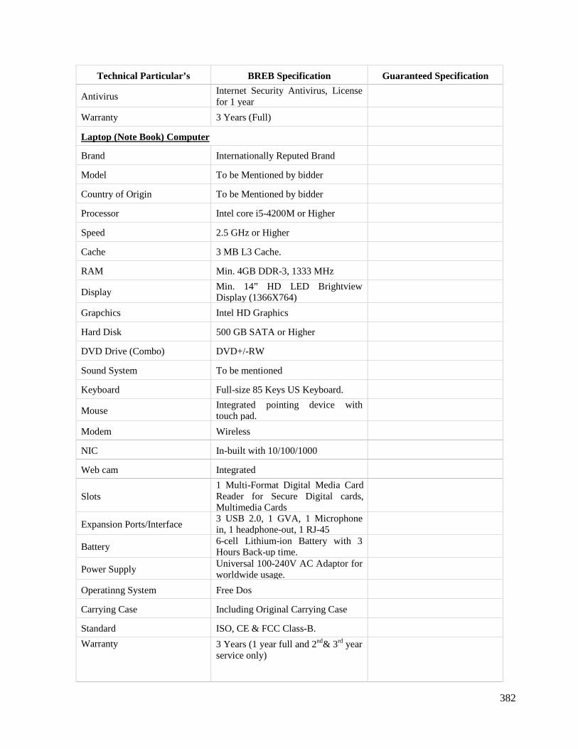
382
Technical Particular’s BREB Specification Guaranteed Specification
AntivirusInternet Security Antivirus, Licensefor 1 year
Warranty 3 Years (Full)
Laptop (Note Book) Computer
Brand Internationally Reputed Brand
Model To be Mentioned by bidder
Country of Origin To be Mentioned by bidder
Processor Intel core i5-4200M or Higher
Speed 2.5 GHz or Higher
Cache 3 MB L3 Cache.
RAM Min. 4GB DDR-3, 1333 MHz
DisplayMin. 14” HD LED BrightviewDisplay (1366X764)
Grapchics Intel HD Graphics
Hard Disk 500 GB SATA or Higher
DVD Drive (Combo) DVD+/-RW
Sound System To be mentioned
Keyboard Full-size 85 Keys US Keyboard.
MouseIntegrated pointing device withtouch pad.
Modem Wireless
NIC In-built with 10/100/1000
Web cam Integrated
Slots1 Multi-Format Digital Media CardReader for Secure Digital cards,Multimedia Cards
Expansion Ports/Interface3 USB 2.0, 1 GVA, 1 Microphonein, 1 headphone-out, 1 RJ-45
Battery6-cell Lithium-ion Battery with 3Hours Back-up time.
Power SupplyUniversal 100-240V AC Adaptor forworldwide usage.
Operatinng System Free Dos
Carrying Case Including Original Carrying Case
Standard ISO, CE & FCC Class-B.
Warranty 3 Years (1 year full and 2nd& 3rd yearservice only)
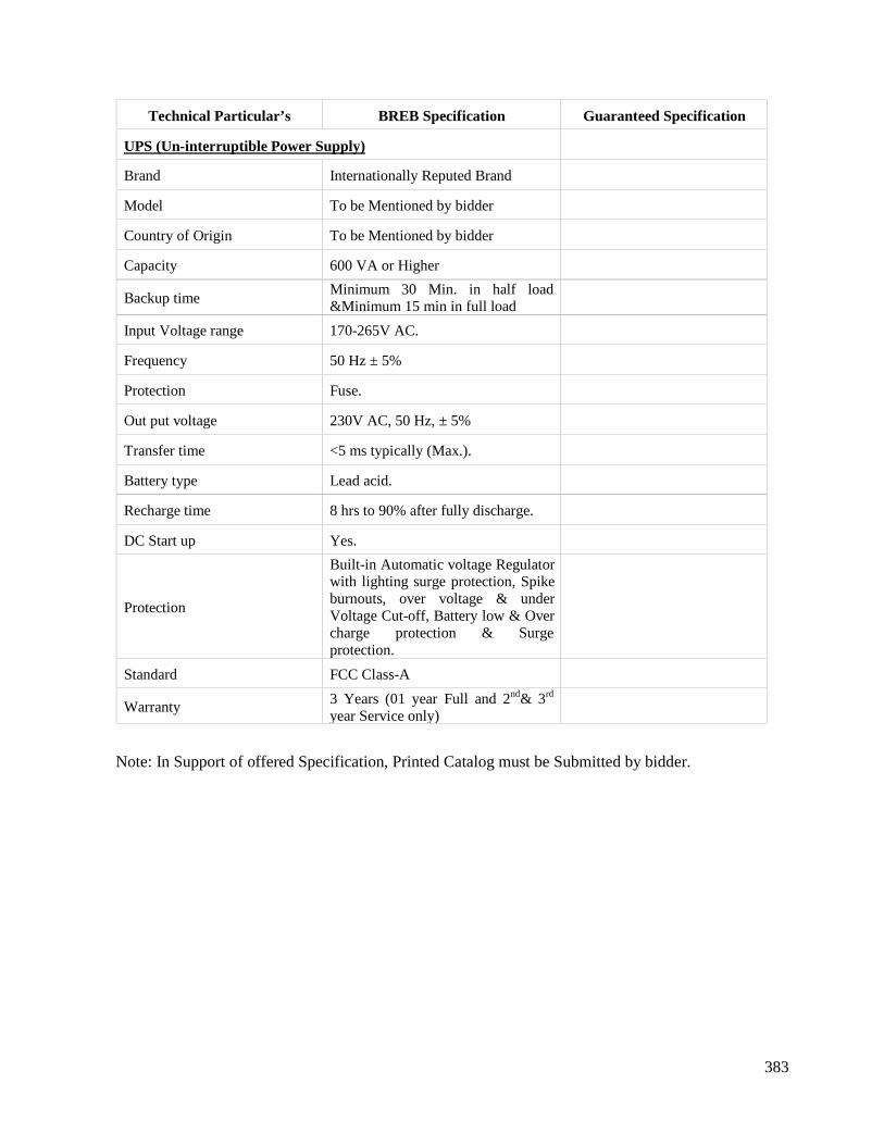
383
Technical Particular’s BREB Specification Guaranteed Specification
UPS (Un-interruptible Power Supply)
Brand Internationally Reputed Brand
Model To be Mentioned by bidder
Country of Origin To be Mentioned by bidder
Capacity 600 VA or Higher
Backup timeMinimum 30 Min. in half load&Minimum 15 min in full load
Input Voltage range 170-265V AC.
Frequency 50 Hz ± 5%
Protection Fuse.
Out put voltage 230V AC, 50 Hz, ± 5%
Transfer time <5 ms typically (Max.).
Battery type Lead acid.
Recharge time 8 hrs to 90% after fully discharge.
DC Start up Yes.
Protection
Built-in Automatic voltage Regulatorwith lighting surge protection, Spikeburnouts, over voltage & underVoltage Cut-off, Battery low & Overcharge protection & Surgeprotection.
Standard FCC Class-A
Warranty 3 Years (01 year Full and 2nd& 3rd
year Service only)
Note: In Support of offered Specification, Printed Catalog must be Submitted by bidder.
384
C. MISCELLANEOUS
9.0 AIR CONDITIONER
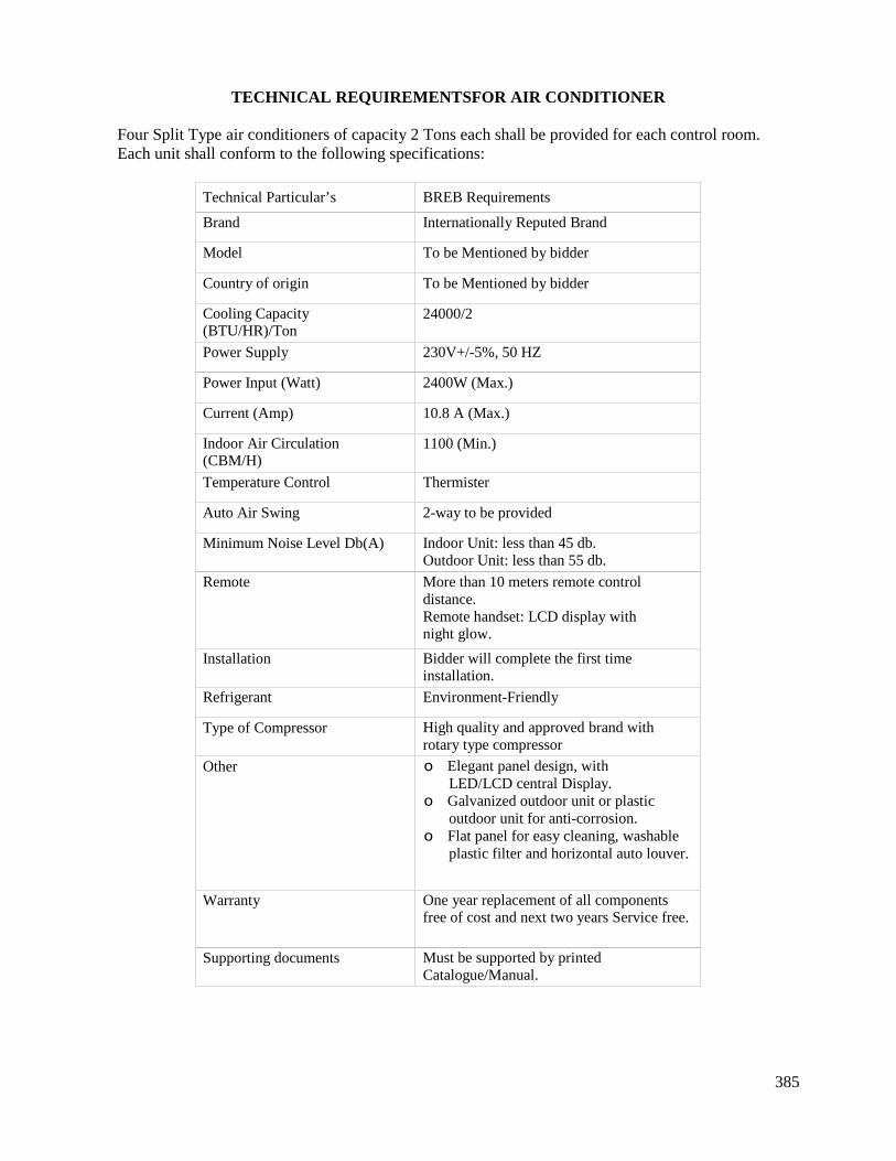
385
TECHNICAL REQUIREMENTSFOR AIR CONDITIONER
Four Split Type air conditioners of capacity 2 Tons each shall be provided for each control room.Each unit shall conform to the following specifications:
Technical Particular’s BREB Requirements
Brand Internationally Reputed Brand
Model To be Mentioned by bidder
Country of origin To be Mentioned by bidder
Cooling Capacity(BTU/HR)/Ton
24000/2
Power Supply 230V+/-5%, 50 HZ
Power Input (Watt) 2400W (Max.)
Current (Amp) 10.8 A (Max.)
Indoor Air Circulation(CBM/H)
1100 (Min.)
Temperature Control Thermister
Auto Air Swing 2-way to be provided
Minimum Noise Level Db(A) Indoor Unit: less than 45 db.Outdoor Unit: less than 55 db.
Remote More than 10 meters remote controldistance.Remote handset: LCD display withnight glow.
Installation Bidder will complete the first timeinstallation.
Refrigerant Environment-Friendly
Type of Compressor High quality and approved brand withrotary type compressor
Other o Elegant panel design, withLED/LCD central Display.
o Galvanized outdoor unit or plasticoutdoor unit for anti-corrosion.
o Flat panel for easy cleaning, washableplastic filter and horizontal auto louver.
Warranty One year replacement of all componentsfree of cost and next two years Service free.
Supporting documents Must be supported by printedCatalogue/Manual.

386
C. MISCELLANEOUS
10.0 CONTROL ROOM FURNITURE
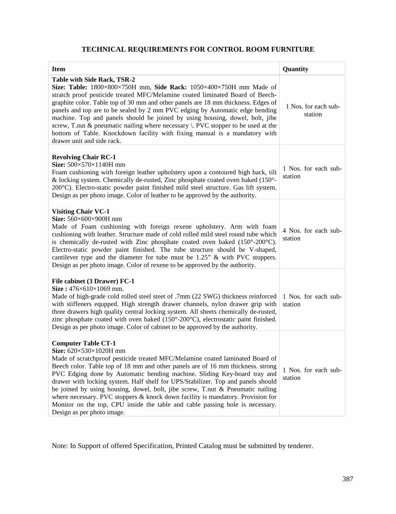
387
TECHNICAL REQUIREMENTS FOR CONTROL ROOM FURNITURE
Item Quantity
Table with Side Rack, TSR-2Size: Table: 1800×800×750H mm, Side Rack: 1050×400×750H mm Made ofstratch proof pesticide treated MFC/Melamine coated liminated Board of Beech-graphite color. Table top of 30 mm and other panels are 18 mm thickness. Edges ofpanels and top are to be sealed by 2 mm PVC edging by Automatic edge bendingmachine. Top and panels should be joined by using housing, dowel, bolt, jibescrew, T.nut & pneumatic nailing where necessary \. PVC stopper to be used at thebottom of Table. Knockdown facility with fixing manual is a mandatory withdrawer unit and side rack.
1 Nos. for each sub-station
Revolving Chair RC-1Size: 500×570×1140H mmFoam cushioning with foreign leather upholstery upon a contoured high back, tilt& locking system. Chemically de-rusted, Zinc phosphate coated oven baked (150°-200°C). Electro-static powder paint finished mild steel structure. Gas lift system.Design as per photo image. Color of leather to be approved by the authority.
1 Nos. for each sub-station
Visiting Chair VC-1Size: 560×600×900H mmMade of Foam cushioning with foreign rexene upholstery. Arm with foamcushioning with leather. Structure made of cold rolled mild steel round tube whichis chemically de-rusted with Zinc phosphate coated oven baked (150°-200°C).Electro-static powder paint finished. The tube structure should be V-shaped,cantilever type and the diameter for tube must be 1.25” & with PVC stoppers.Design as per photo image. Color of rexene to be approved by the authority.
4 Nos. for each sub-station
File cabinet (3 Drawer) FC-1Size : 476×610×1069 mm.Made of high-grade cold rolled steel steet of .7mm (22 SWG) thickness reinforcedwith stiffeners equpped. High strength drawer channels, nylon drawer grip withthree drawers high quality central locking system. All sheets chemically de-rusted,zinc phosphate coated with oven baked (150°-200°C), electrostatic paint finished.Design as per photo image. Color of cabinet to be approved by the authority.
1 Nos. for each sub-station
Computer Table CT-1Size: 620×530×1020H mmMade of scratchproof pesticide treated MFC/Melamine coated laminated Board ofBeech color. Table top of 18 mm and other panels are of 16 mm thickness. strongPVC Edging done by Automatic bending machine. Sliding Key-board tray anddrawer with locking system. Half shelf for UPS/Stabilizer. Top and panels shouldbe joined by using housing, dowel, bolt, jibe screw, T.nut & Pneumatic nailingwhere necessary. PVC stoppers & knock down facility is mandatory. Provision forMonitor on the top, CPU inside the table and cable passing hole is necessary.Design as per photo image.
1 Nos. for each sub-station
Note: In Support of offered Specification, Printed Catalog must be submitted by tenderer.
388
C. MISCELLANEOUS
11.0 FIRE DETECTION & PROTECTION FACILITIES

389
FIRE DETECTION & PROTECTION FACILITIES
11.1 Design Requirements
All fire protection installations shall comply with the requirements of the codes of practice of theNational Fire Protection Association, Boston, Massachusetts, U.S.A. as appropriate for therespective systems, subject to the approval of the Project Manager. The Codes and practice of theJapanese Fire Protection may also be considered.11.2 Fire Detection and Alarm system
Fire detection shall be by means of smoke detectors/heat detectors with a backup system utilizingrate-of-rise temperature detectors along with alarm system. The system and its components mustconform to the applicable appropriate standards. The use of these detectors shall be subject tospecific approval by the Project Manager as regards their type and location.
(a) Fire Alarm Panel: 16 Zone Capacity:
Supply and Installation of 16 Zone Conventional Fire alarm control panel with powersupply unit, batteries and other accessories. The panel shall be complete with zoneindicating LED, Fault Indication and optional telephone Jack etc. The pane shall be input220V AC and output 24V DC. Panel shall be confirmed UL Listed or EN54.
Country of Origin: Japan / Italy / UK / USA or equivalent approved by the Project Manager.
(b) Fire Alarm Bell:
Supply and installation of Conventional type Fire Alarm Bell of 150mm dia, red color, shallbe UL / ULC / CSFM / FM / MEA / BFP / EN54 approved. Power supply shall be 24VDC.Sound level shall be not less than 92 dBA @ 3meter.Color of the Bell shall be red.
Country of Origin: Japan / Italy / UK / USA or equivalent approved by the Project Manager.
(c) Optical / Photoelectric Smoke Detector:
Supply and installation of Smoke Detector complete with base. Shall be UL / ULC / CSFM/ FM / MEA / BFP / EN54 approved. Integrated alarm LED. Remote LED connection.Power supply shall be 24VDC.
Country of Origin: Japan / Italy / UK / USA or equivalent approved by the Project Manager.
(d) Heat Detector:Supply and installation of Heat Detector complete with base. Shall be UL / ULC / CSFM /FM / MEA / BFP / EN54 approved. Integrated alarm LED. Remote LED connection. Powersupply shall be 24VDC.
Country of Origin: Japan / Italy / UK / USA or equivalent approved by the Project Manager.
11.3 Fire Extinguisher
(a) Dry Chemical Powder Type:
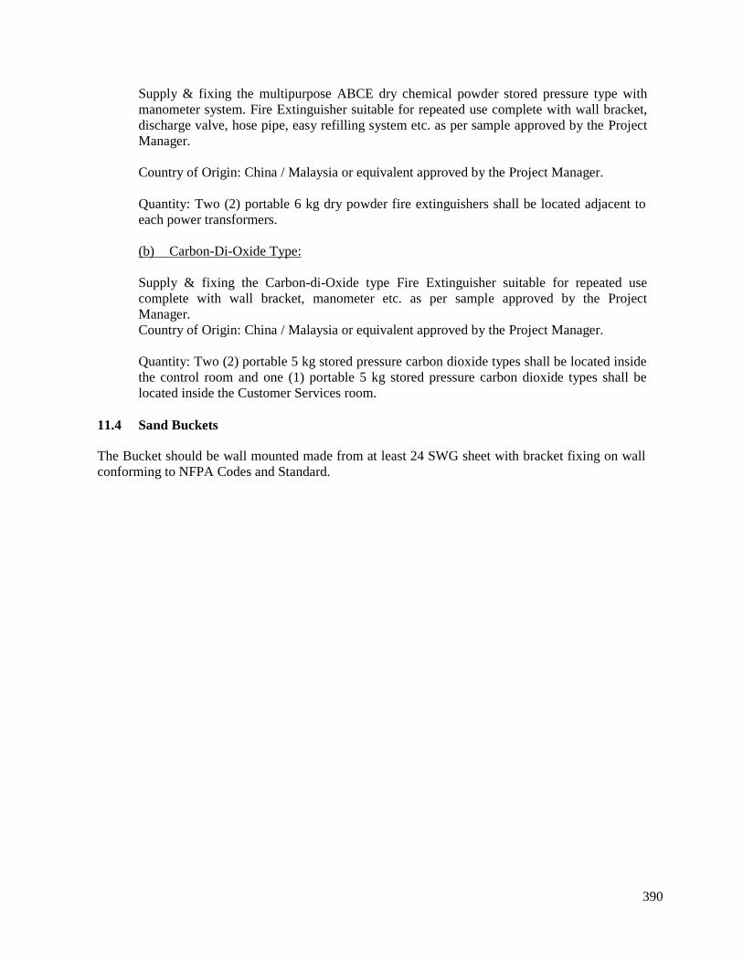
390
Supply & fixing the multipurpose ABCE dry chemical powder stored pressure type withmanometer system. Fire Extinguisher suitable for repeated use complete with wall bracket,discharge valve, hose pipe, easy refilling system etc. as per sample approved by the ProjectManager.
Country of Origin: China / Malaysia or equivalent approved by the Project Manager.
Quantity: Two (2) portable 6 kg dry powder fire extinguishers shall be located adjacent toeach power transformers.
(b) Carbon-Di-Oxide Type:
Supply & fixing the Carbon-di-Oxide type Fire Extinguisher suitable for repeated usecomplete with wall bracket, manometer etc. as per sample approved by the ProjectManager.Country of Origin: China / Malaysia or equivalent approved by the Project Manager.
Quantity: Two (2) portable 5 kg stored pressure carbon dioxide types shall be located insidethe control room and one (1) portable 5 kg stored pressure carbon dioxide types shall belocated inside the Customer Services room.
11.4 Sand Buckets
The Bucket should be wall mounted made from at least 24 SWG sheet with bracket fixing on wallconforming to NFPA Codes and Standard.

391
Section 9. Drawings

392
LAYOUT OF S/S LAND
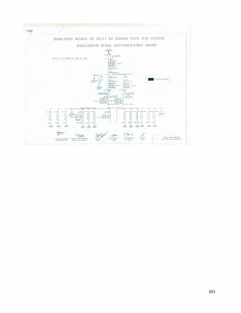
393
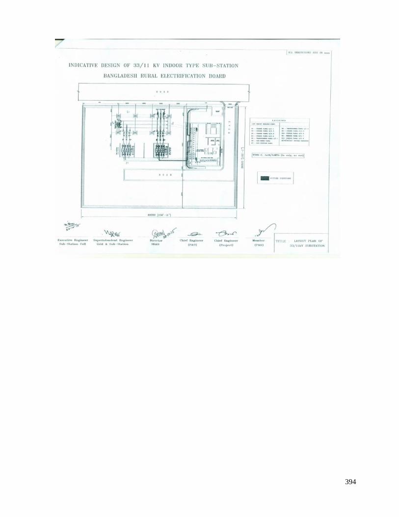
394

395
INDICATIVE CIVIL DRAWINGS
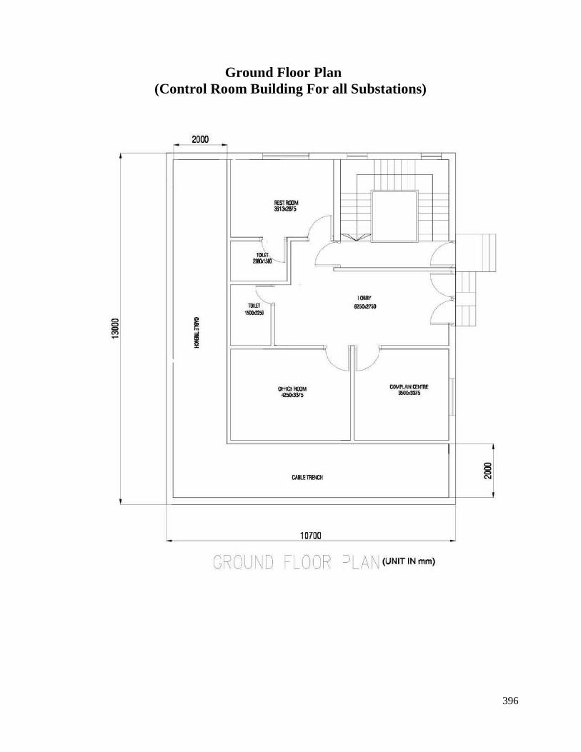
396
Ground Floor Plan(Control Room Building For all Substations)
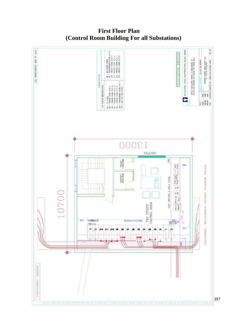
397
First Floor Plan(Control Room Building For all Substations)
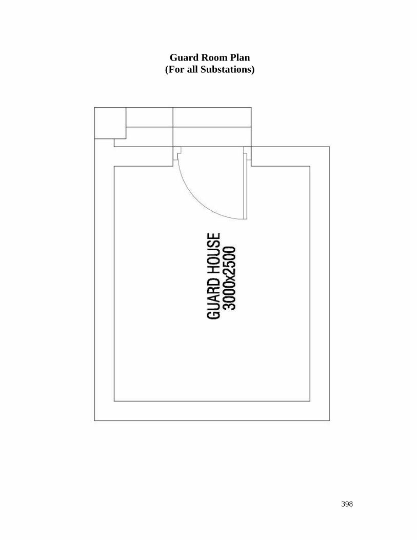
398
Guard Room Plan(For all Substations)
Related Documents