Bandwidth Optimization for Satellite Digital Broadcasting S. Cioni 1 , C. Ernst 2 and A. Ginesi 3 European Space Agency/ESTEC – Noordwijk, The Netherlands and G. Colavolpe 4 CNIT/University of Parma – Italy The 2 nd -generation satellite digital video broadcasting (DVB-S2) system is at present under review with the aim of improving its spectral efficiency. In this paper, we have addressed the problem to optimize the user bandwidth taking into account a realistic satellite broadcasting channel. Two different receiver architectures have been evaluated in order to maximize the system spectral efficiency. Finally, some considerations on the OMUX dissipated power have been reported. Nomenclature α = Shaping pulse roll-off AWGN = Additive white Gaussian noise f T = Transponder bandwidth (or frequency spacing among adjacent channels) FTN = Faster-than-Nyquist ICI = Inter-channel interference IMUX = Input multiplexer ISI = Inter-symbol interference LMS = Least mean square MMSE = Minimum mean square error N u = Number of transmitting users OMUX = Output multiplexer SE = Spectral efficiency P sat = On-board saturation power R s = Symbol rate T s = Symbol interval TF = Time-frequency 1 Communication System Engineer, TEC-ETC, [email protected] . 2 Microwave Engineer, TIA-TTP, [email protected] . 3 Head of Communications and TT&C Section, TEC-ETC, [email protected] . 4 Associate Professor, SPADiCLab, [email protected] .

Welcome message from author
This document is posted to help you gain knowledge. Please leave a comment to let me know what you think about it! Share it to your friends and learn new things together.
Transcript

Bandwidth Optimization for Satellite Digital Broadcasting
S. Cioni 1, C. Ernst 2 and A. Ginesi3 European Space Agency/ESTEC – Noordwijk, The Netherlands
and
G. Colavolpe4 CNIT/University of Parma – Italy
The 2nd-generation satellite digital video broadcasting (DVB-S2) system is at present under review with the aim of improving its spectral efficiency. In this paper, we have addressed the problem to optimize the user bandwidth taking into account a realistic satellite broadcasting channel. Two different receiver architectures have been evaluated in order to maximize the system spectral efficiency. Finally, some considerations on the OMUX dissipated power have been reported.
Nomenclature α = Shaping pulse roll-off AWGN = Additive white Gaussian noise fT = Transponder bandwidth (or frequency spacing among adjacent channels) FTN = Faster-than-Nyquist ICI = Inter-channel interference IMUX = Input multiplexer ISI = Inter-symbol interference LMS = Least mean square MMSE = Minimum mean square error Nu = Number of transmitting users OMUX = Output multiplexer SE = Spectral efficiency Psat = On-board saturation power Rs = Symbol rate Ts = Symbol interval TF = Time-frequency
1 Communication System Engineer, TEC-ETC, [email protected] .
2 Microwave Engineer, TIA-TTP, [email protected] .
3 Head of Communications and TT&C Section, TEC-ETC, [email protected] .
4 Associate Professor, SPADiCLab, [email protected] .

TWTA = Traveling wave tube amplifier W = Signal bandwidth
I. Introduction he 2nd-generation satellite digital video broadcasting (DVB-S2) [1] system is at
present under review with the aim of improving its spectral efficiency. To this purpose, time-frequency (TF) packing [2, 3, 4] is one of the techniques under consideration. This technique relies on both time packing of adjacent symbols, thus introducing controlled inter-symbol interference (ISI), as well as reducing the carrier spacing of the adjacent channels when applicable, thus introducing also inter-channel interference (ICI). Since time and frequency spacings are optimized, spectral efficiency (SE) is used as figure of merit in contrast to faster-than-Nyquist (FTN) techniques [5] for example where the minimum distance, and thus the bit-error rate (BER) is used as figure of merit.
Works on TF have considered a low-complexity memoryless receiver [2] but also more complex suboptimal detection algorithms [3] for the case of linear channels. The scenario of a realistic nonlinear satellite transponder is considered in [4].
Whereas the adoption of frequency packing implies a change of the frequency separation between two adjacent transponders, time packing only requires a modification of the baud rate for a fixed shaping pulse. Guided by the same idea, as an alternative (or in addition to) TF packing, an optimization of the signal bandwidth W and the roll-off of the employed shaping pulse can be performed. Whereas this optimization is implicitly performed in TF packing on the additive white Gaussian noise (AWGN) channel, in the sense that we can obtain the same ICI by fixing the frequency spacing fT and increasing W or by fixing W and decreasing fT, this is not the case for realistic satellite channel, since the bandwidth of IMUX and OMUX filters on board are kept fixed. Hence, an increased value of W also increases the ISI as in the case of time packing.
In this paper, we consider the improvement in terms of SE, η, that can be obtained by optimizing the bandwidth W of the used shaping pulse, still within pulses with root raised cosine spectra. Hence, it is well-known that the bandwidth is related to the user baud rate Rs by the equation W=(1+ α) Rs, where α is the shaping pulse roll-off.
Finally, the paper addresses the impact on the dissipated power of the OMUX. Since the signal bandwidth W may exceed the specified usable bandwidth for which the OMUX is typically designed for, it is important to check the consequences to the OMUX from the thermal behaviour point of view.
II. Channel Model Hereafter, we consider the forward link of a transparent satellite broadcasting system,
where Nu carriers use the same DVB-S2 waveform [1], the same symbol rate, and access the channel according to a frequency division multiplexing scheme. Assuming the case of Nu = 3, the transmitted uplink signal can be expressed as
𝑥(𝑡) = � �𝑎𝑘(𝑙)𝑝(𝑡 − 𝑘𝑇𝑠)𝑒𝑗2𝜋𝑙𝑓𝑇𝑡
𝑘
1
𝑙=−1
(1)
where 𝑎𝑘(𝑙) is the symbol transmitted by user l during the k-th symbol interval, fT is the
frequency spacing among adjacent channels, and p(t) is the shaping pulse.
T
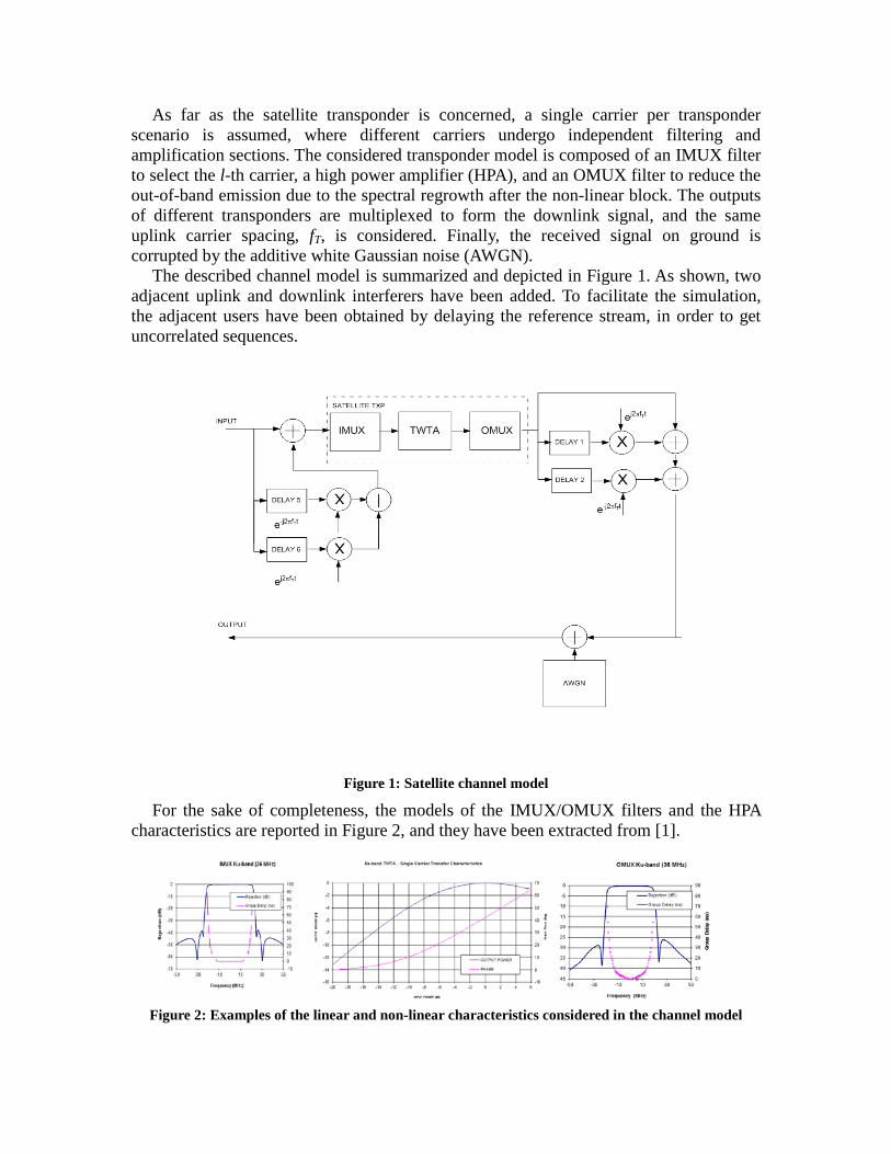
As far as the satellite transponder is concerned, a single carrier per transponder scenario is assumed, where different carriers undergo independent filtering and amplification sections. The considered transponder model is composed of an IMUX filter to select the l-th carrier, a high power amplifier (HPA), and an OMUX filter to reduce the out-of-band emission due to the spectral regrowth after the non-linear block. The outputs of different transponders are multiplexed to form the downlink signal, and the same uplink carrier spacing, fT, is considered. Finally, the received signal on ground is corrupted by the additive white Gaussian noise (AWGN).
The described channel model is summarized and depicted in Figure 1. As shown, two adjacent uplink and downlink interferers have been added. To facilitate the simulation, the adjacent users have been obtained by delaying the reference stream, in order to get uncorrelated sequences.
Figure 1: Satellite channel model
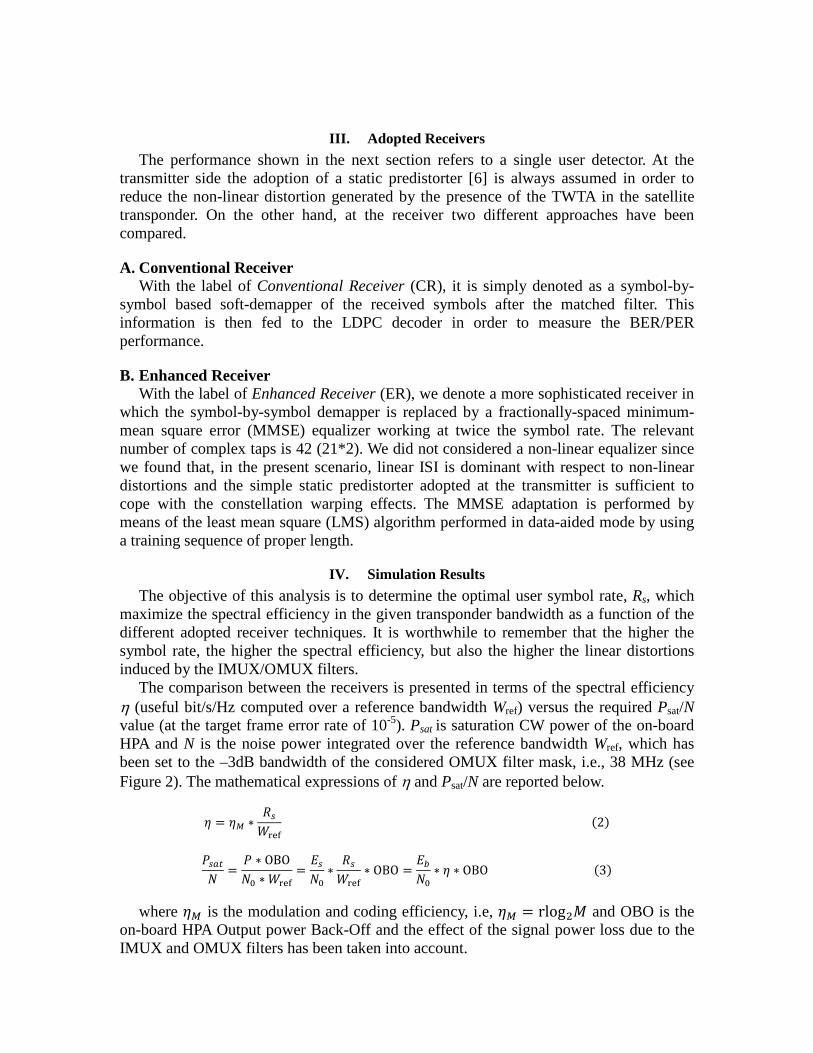
For the sake of completeness, the models of the IMUX/OMUX filters and the HPA characteristics are reported in Figure 2, and they have been extracted from [1].
Figure 2: Examples of the linear and non-linear characteristics considered in the channel model
III. Adopted Receivers The performance shown in the next section refers to a single user detector. At the
transmitter side the adoption of a static predistorter [6] is always assumed in order to reduce the non-linear distortion generated by the presence of the TWTA in the satellite transponder. On the other hand, at the receiver two different approaches have been compared.
A. Conventional Receiver With the label of Conventional Receiver (CR), it is simply denoted as a symbol-by-
symbol based soft-demapper of the received symbols after the matched filter. This information is then fed to the LDPC decoder in order to measure the BER/PER performance.
B. Enhanced Receiver With the label of Enhanced Receiver (ER), we denote a more sophisticated receiver in
which the symbol-by-symbol demapper is replaced by a fractionally-spaced minimum-mean square error (MMSE) equalizer working at twice the symbol rate. The relevant number of complex taps is 42 (21*2). We did not considered a non-linear equalizer since we found that, in the present scenario, linear ISI is dominant with respect to non-linear distortions and the simple static predistorter adopted at the transmitter is sufficient to cope with the constellation warping effects. The MMSE adaptation is performed by means of the least mean square (LMS) algorithm performed in data-aided mode by using a training sequence of proper length.
IV. Simulation Results The objective of this analysis is to determine the optimal user symbol rate, Rs, which
maximize the spectral efficiency in the given transponder bandwidth as a function of the different adopted receiver techniques. It is worthwhile to remember that the higher the symbol rate, the higher the spectral efficiency, but also the higher the linear distortions induced by the IMUX/OMUX filters.
The comparison between the receivers is presented in terms of the spectral efficiency η (useful bit/s/Hz computed over a reference bandwidth Wref) versus the required Psat/N value (at the target frame error rate of 10-5). Psat is saturation CW power of the on-board HPA and N is the noise power integrated over the reference bandwidth Wref, which has been set to the –3dB bandwidth of the considered OMUX filter mask, i.e., 38 MHz (see Figure 2). The mathematical expressions of η and Psat/N are reported below.
𝜂 = 𝜂𝑀 ∗𝑅𝑠𝑊ref
(2)
𝑃𝑠𝑠𝑡𝑁
=𝑃 ∗ OBO𝑁0 ∗𝑊ref
=𝐸𝑠𝑁0
∗𝑅𝑠𝑊ref
∗ OBO =𝐸𝑏𝑁0
∗ 𝜂 ∗ OBO (3) where 𝜂𝑀 is the modulation and coding efficiency, i.e, 𝜂𝑀 = rlog2𝑀 and OBO is the
on-board HPA Output power Back-Off and the effect of the signal power loss due to the IMUX and OMUX filters has been taken into account.
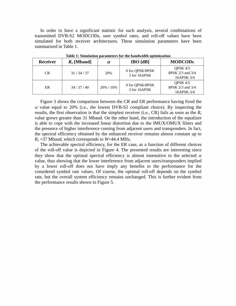
In order to have a significant statistic for such analysis, several combinations of transmitted DVB-S2 MODCODs, user symbol rates, and roll-off values have been simulated for both receiver architectures. These simulation parameters have been summarized in Table 1.
Table 1: Simulation parameters for the bandwidth optimization
Receiver Rs [Mbaud] α IBO [dB] MODCODs
CR 31 / 34 / 37 20% 0 for QPSK/8PSK 3 for 16APSK
QPSK 4/5 8PSK 2/3 and 3/4
16APSK 3/4
ER 34 / 37 / 40 20% / 10% 0 for QPSK/8PSK 3 for 16APSK
QPSK 4/5 8PSK 2/3 and 3/4
16APSK 3/4 Figure 3 shows the comparison between the CR and ER performance having fixed the
α value equal to 20% (i.e., the lowest DVB-S2 compliant choice). By inspecting the results, the first observation is that the simplest receiver (i.e., CR) fails as soon as the Rs value grows greater than 31 Mbaud. On the other hand, the introduction of the equalizer is able to cope with the increased linear distortion due to the IMUX/OMUX filters and the presence of higher interference coming from adjacent users and transponders. In fact, the spectral efficiency obtained by the enhanced receiver remains almost constant up to Rs =37 Mbaud, which corresponds to W=44.4 MHz.
The achievable spectral efficiency, for the ER case, as a function of different choices of the roll-off value is depicted in Figure 4. The presented results are interesting since they show that the optimal spectral efficiency is almost insensitive to the selected α value, thus showing that the lower interference from adjacent users/transponders implied by a lower roll-off does not have imply any benefits to the performance for the considered symbol rate values. Of course, the optimal roll-off depends on the symbol rate, but the overall system efficiency remains unchanged. This is further evident from the performance results shown in Figure 5.
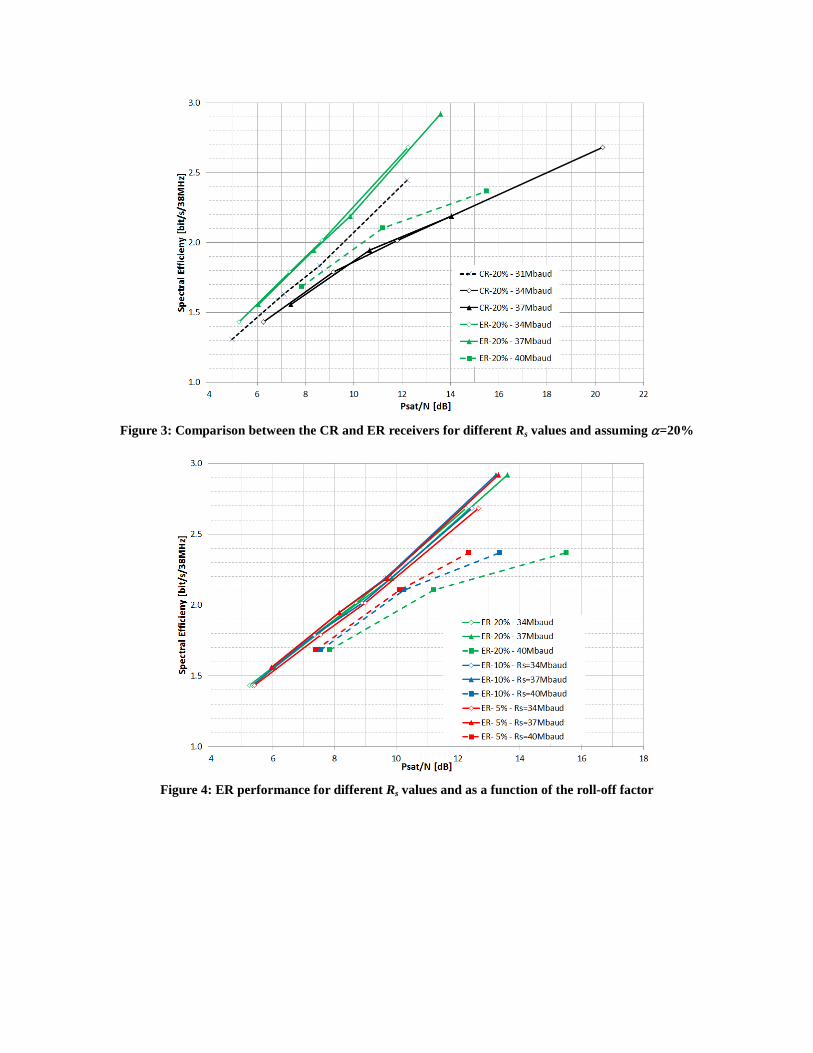
Figure 3: Comparison between the CR and ER receivers for different Rs values and assuming α=20%
Figure 4: ER performance for different Rs values and as a function of the roll-off factor

Figure 5: Spectral efficiency vs. symbol rate as a function of Psat/N
Figure 5 reports the achievable spectral efficiency as a function of the selected symbol
rate and for different choices on the receiver techniques, the roll-off values and the transmitted power. From these simulation results it is clear that without the exploitation of an equalizer, the symbol-rate offering the best capacity is around 31 Mbaud. On the contrary, an additional capacity gain of about 8% to 10% is achievable by using the ER architecture, and by increasing the transmitted Rs up to 34-37 Mbaud. Based on these channel model definitions, the potential system capacity is quite independent of the α value, and remains almost flat over the symbol rate range 33 to 38 Mbaud. It is only important to notice that choosing α = 20%, the best performance is achieved with Rs = 34-35 Mbaud, whereas small improvements on η may be obtained by choosing α = 10% and Rs = 36 Mbaud. The last case could be also preferable since it guarantees that the signal occupied bandwidth W is limited to a value lower than 40 MHz. This aspect is further analyzed from a different perspective in the next section.
V. Investigation on the Dissipated Power Enlarging the signal bandwidth on board of the spacecraft will impact all equipments
designed for narrowband operations. The major concern is the behaviour of the OMUX channel filters when a larger signal bandwidth is used. In particular, the thermal power dissipation is critical and has been assessed for typical flight hardware. In Table 1, the OMUX dissipated power of a typical 36 MHz channelization is computed and normalized with respect to the reference bandwidth Wref = 33MHz (i.e., Rs = 27.5 Mbaud and α = 20%). Thermal dissipation for an edge channel (Channel 1) and a centre channel (Channel 2) is given.

Table 2: OMUX Channel Filter Dissipated Power Results Signal Bandwidth and Symbol
Rate Channel 1
Dissipated Power Channel 2
Dissipated Power
W = 33 MHz Rs = 27.5 Mbaud 100.0% 100.0% W = 36 MHz Rs = 30 Mbaud 102.4% 103.4% W = 40 MHz Rs = 36 Mbaud 112.9% 121.6%
Comparing the dissipated power in the two channels for an occupied bandwidth of up
to 40 MHz an increased power dissipation of up to about 20% is observed. This is a significant increase of overall dissipated power. Fortunately, the OMUX technology is very mature and robust and it is anticipated that for standard input power ranges no new technology has to be developed. However, modifications and re-qualification of the equipment thermal design may be needed as well as re-qualification of processes and materials if temperatures in the equipment fall outside of the existing process and material qualification temperatures range.
VI. Conclusion In this paper, the user bandwidth optimization is performed under realistic
assumptions on the satellite channel model. At the receiver side, two different demodulation techniques have been compared. The presented results show slightly independence from the choice of the roll-off value. The achievable gain in spectral efficiency is of about 8% to 10% by optimizing the user bandwidth and by choosing a proper equalizer. Finally, the impact of the increased user bandwidth in terms of OMUX dissipated power has been evaluated and it is not affecting too much the current technology.
References [1] ETSI EN 302 307, “DVB; Second generation framing structure, channel coding and modulation systems for
Broadcasting, Interactive Services, New Gathering and other broadband satellite applications”, 2006 [2] A. Barbieri, D. Fertonani, and G. Colavolpe, “Time-frequency packing for linear modulations: spectral efficiency
and practical detection schemes,” IEEE Trans. Commun., vol. 57, pp. 2951–2959, Oct. 2009. [3] A. Modenini, G. Colavolpe, and N. Alagha, “How to significantly improve the spectral efficiency of linear
modulations through time-frequency packing and advanced processing,” in Proc. IEEE Intern. Conf. on Communications (ICC), Jun. 2012, pp. 3299–3304.
[4] A. Piemontese, A. Modenini, G. Colavolpe, and N. Alagha, “Improving the spectral efficiency of nonlinear satellite systems through time-frequency packing and advanced processing,” to be published on IEEE Trans. on Commun., and available on http://arxiv.org/abs/1301.4184.
[5] J.E. Mazo, “Faster-than-Nyquist Signaling”, Journal of Bell System Tech., vol. 54, pp. 1450-1462, Oct. 1975. [6] E. Casini, R. De Gaudenzi, A. Ginesi, “DVB-S2 modem algorithms design and performance over typical satellite
channels”, International Journal of Satellite Communications and Networking, vol. 22, pp. 281-318, May 2004.
Related Documents