6- 1 Preferred Architecture for Cisco Webex Hybrid Services February 11, 2019 CHAPTER 6 Bandwidth Management Revised: February 11, 2019 This chapter describes the bandwidth management strategy for the Preferred Architecture (PA) for Cisco Webex Hybrid Services. Overview Bandwidth management architecture and deployment for the Cisco Collaboration on-premises solution is covered in depth in the latest version of the Preferred Architecture for Cisco Collaboration Enterprise On-Premises Deployments, available at https://www.cisco.com/go/pa. This chapter covers the additional bandwidth management considerations for implementing Cisco Webex Hybrid Services in an existing deployment of the Enterprise Preferred Architecture for Collaboration. Therefore, before continuing with this chapter, it is a requirement for you to read and understand the concepts and deployment recommendations in the Bandwidth Management chapter of the Preferred Architecture for Cisco Collaboration Enterprise On-Premises Deployments. The first part of this chapter provides an architectural overview and introduces some fundamental design concepts at a high level. A more detailed discussion of the architecture and design considerations for Cisco Webex Hybrid Services is then articulated in order to situate the hybrid products and components within the bandwidth management strategy and policies covered in the Preferred Architecture for Cisco Collaboration Enterprise On-Premises Deployments. The second part of this chapter covers deployment procedures, again focusing only on the hybrid components within an on-premises Cisco Collaboration solution. The Architecture section discusses how the hybrid endpoints, clients, products, and components fit within the identification and classification, queuing and scheduling, provisioning and admission control architecture, using the hypothetical customer topology presented in the examples throughout this document. The Deployment section of this chapter describes the deployment procedures at a high level. The deployment examples in that section help explain the implementation of certain design decisions more clearly than an abstract discussion of concepts can. The order of the topics in the Deployment section follows the recommended order of configuration.

Welcome message from author
This document is posted to help you gain knowledge. Please leave a comment to let me know what you think about it! Share it to your friends and learn new things together.
Transcript

February 11, 2019
C H A P T E R 6
Bandwidth ManagementRevised: February 11, 2019
This chapter describes the bandwidth management strategy for the Preferred Architecture (PA) for Cisco Webex Hybrid Services.
OverviewBandwidth management architecture and deployment for the Cisco Collaboration on-premises solution is covered in depth in the latest version of the Preferred Architecture for Cisco Collaboration Enterprise On-Premises Deployments, available at https://www.cisco.com/go/pa. This chapter covers the additional bandwidth management considerations for implementing Cisco Webex Hybrid Services in an existing deployment of the Enterprise Preferred Architecture for Collaboration. Therefore, before continuing with this chapter, it is a requirement for you to read and understand the concepts and deployment recommendations in the Bandwidth Management chapter of the Preferred Architecture for Cisco Collaboration Enterprise On-Premises Deployments.
The first part of this chapter provides an architectural overview and introduces some fundamental design concepts at a high level. A more detailed discussion of the architecture and design considerations for Cisco Webex Hybrid Services is then articulated in order to situate the hybrid products and components within the bandwidth management strategy and policies covered in the Preferred Architecture for Cisco Collaboration Enterprise On-Premises Deployments.
The second part of this chapter covers deployment procedures, again focusing only on the hybrid components within an on-premises Cisco Collaboration solution. The Architecture section discusses how the hybrid endpoints, clients, products, and components fit within the identification and classification, queuing and scheduling, provisioning and admission control architecture, using the hypothetical customer topology presented in the examples throughout this document. The Deployment section of this chapter describes the deployment procedures at a high level. The deployment examples in that section help explain the implementation of certain design decisions more clearly than an abstract discussion of concepts can. The order of the topics in the Deployment section follows the recommended order of configuration.
6-1Preferred Architecture for Cisco Webex Hybrid Services

Chapter 6 Bandwidth ManagementOverview
Core ComponentsCisco Webex Hybrid Services architecture contains these key components:
• Cisco Unified Communications Manager
• Cisco Webex Teams applications and endpoints
• Cisco Expressway
• Cisco Webex
• Cisco Webex Video Mesh Node
• Network infrastructure:
– Cisco routers
– Cisco switches
Figure 6-1 illustrates the design approach to Quality of Service (QoS) used in the Cisco PA for Enterprise Collaboration. This approach consists of the following phases:
• Classification and Marking — Refers to concepts of trust and techniques for identifying media and call signaling for endpoints and applications. It also includes the process of mapping the identified traffic to the correct DSCP markings to provide the media and signaling with the correct per-hop behavior end-to-end across the network.
• Queuing and Scheduling — Consists of general WAN queuing and scheduling, the various types of queues, and recommendations for ensuring that collaboration media and signaling are correctly queued on egress to the WAN.
• Provisioning and Admission Control — Refers to provisioning the bandwidth in the network and determining the maximum bit rate that groups of endpoints will utilize. This is also where call admission control can be implemented in areas of the network where it is required. Admission control applies only to the on-premises solution.
• Monitoring, Troubleshooting, and Optimization — Ensures the proper operation and management of voice and video across the network. Cisco Prime Collaboration offers a suite of tools to perform these functions. Monitoring, troubleshooting, and optimization are not covered in the Preferred Architectures but are part of the overall approach.
6-2Preferred Architecture for Cisco Webex Hybrid Services
February 11, 2019

Chapter 6 Bandwidth ManagementOverview
Figure 6-1 Architecture for Bandwidth Management
Recommended DeploymentModify the existing on-premises QoS switch and WAN policies to include Webex Hybrid Services identification, classification, and marking. As mentioned, it is assumed that the QoS policies in place are those articulated in the Bandwidth Management chapter of the Preferred Architecture for Cisco Collaboration Enterprise On-Premises Deployments, available at https://www.cisco.com/go/pa.
• Identify and classify media and SIP signaling traffic from the Webex Teams applications and the Webex Video Mesh Nodes.
• Media and signaling marking recommendations:
1. Mark all audio with Expedited Forwarding class EF (includes all audio of voice-only calls as well as audio for all types of video calls).
2. Mark all Webex Teams application video with an Assured Forwarding class of AF42 for an opportunistic video class of service or with AF41 for a prioritized video class of service. The marking of AF41 or AF42 will depend on the choice of whether or not to deploy opportunistic video during the on-premises deployment phase.
3. Mark all call signaling with CS3. (All call signaling in HTTPS traffic will be marked based on the enterprise's current policy of traffic marking for HTTP/HTTPS.)
• Configure QoS on all media originating and terminating applications such as the Video Mesh Nodes.
• Update the WAN edge ingress re-marking policy.
• Update the WAN edge egress queuing and scheduling policy if applicable.
NetworkManagement
EF
AF41
CS3
1
WAN
3132
89
Classification Marking Queuing and Scheduling
Provisioning and Admission
Control
Monitoring, Troubleshooting, and Optimization
6-3Preferred Architecture for Cisco Webex Hybrid Services
February 11, 2019

Chapter 6 Bandwidth ManagementArchitecture
Key BenefitsThis deployment of bandwidth management provides the following benefits:
• Provides prescriptive recommendations to simplify deployment with a simplified QoS architecture that integrates with the Enterprise PA for Collaboration
• Makes more efficient use of network resources
• Supports mobile and multi-media collaboration devices
• Takes into account unmanaged network segments (Internet)
• Is "future-proof" because it facilitates introduction of new services, features, and endpoints
ArchitectureIn this Preferred Architecture, usage of the Internet and cloud-based services such as Webex Teams is an important aspect of the solution, which means that some of the collaboration infrastructure is located outside of the managed enterprise network and located in the cloud. The enterprise office connectivity options also range from remote sites and mobile users connected over managed leased lines directly connected to MPLS or other technologies, to connectivity over the Internet through technologies such as Dynamic Multipoint VPN (DMVPN), for example. With Webex Teams an office can be anywhere there is sufficient Internet connectivity.
Figure 6-2 illustrates the convergence of a traditional on-premises collaboration solution in a managed (capable of QoS) network with cloud services and sites located over an unmanaged (not capable of QoS) network such as the Internet. On-premises remote sites are connected over this managed network, where administrators can prioritize collaboration media and signaling with QoS, while other remote sites and branches connect into the enterprise over the Internet, where collaboration media and signaling cannot be prioritized or are prioritized only outbound from the site. Many different types of mobile users and teleworkers also connect over the Internet into the on-premises solution. So the incorporation of the Internet as a source for connecting the enterprise with remote sites, home and mobile users, as well as other businesses and consumers, has an important impact on bandwidth management and user experience.
6-4Preferred Architecture for Cisco Webex Hybrid Services
February 11, 2019

Chapter 6 Bandwidth ManagementArchitecture
Figure 6-2 Managed and Unmanaged Networks
This section presents a strategy for leveraging smart media techniques in Cisco video endpoints, building an end-to-end QoS architecture, and using the latest design and deployment recommendations and best practices for managing bandwidth to achieve the best user experience possible based on the network resources available and the various types of networks that collaboration media traverse.
Media AssureWhen deploying video pervasively across an organization, administrators will inevitably encounter insufficient bandwidth to handle the load of video required during the busy hour in some bottleneck areas of the Wide Area Network (WAN). In light of this, it is important to prioritize video correctly to ensure that audio is not affected by any video packet loss that may occur and to ensure that certain types of video can leverage video rate adaptation to manage the amount of bandwidth used during times of congestion. The media resilience and rate adaptation techniques allow for an optimized video experience in the face of congestion and packet loss over managed and unmanaged networks, but that is not all. These techniques, when used as a strategy coupled with QoS, enable an organization to deploy video pervasively while at the same time maximizing video quality. They allow endpoints to reduce their bit rate and thus their bandwidth utilization during periods of congestion and packet loss. In addition, during more idle times of the day outside of the busy hour, endpoints are able to increase their bit rate and thus utilize more of the available bandwidth.
Every Cisco video endpoint employs a number of media techniques to avoid network congestion, recover from packet loss, and optimize network resources. These techniques, termed Media Assure, have been broadly implemented across Cisco Collaboration endpoints and clients, including Webex Teams and Cisco's conferencing infrastructure.
Call Control
Remote Sites
CentralSite
On-premisesUC Services
MPLSVPNPLSPN
ManagedWAN
DMVPN
Home/Mobile Users
QoS-capable
3132
90
Video Mesh Node
Internet
Sites
DMVPN
HHoomeme//MMobile Users
Videoh Mesh Node
Internet
WebexCisco
6-5Preferred Architecture for Cisco Webex Hybrid Services
February 11, 2019

Chapter 6 Bandwidth ManagementArchitecture
Rate Adaptation
Rate adaptation or dynamic bit rate adjustments, part and parcel of Media Assure, adapt the call rate to the variable bandwidth available, down-speeding or up-speeding the video bit rate based on the packet loss condition. An endpoint will reduce bit rate when it receives messages from the receiver indicating there is packet loss; and once the packet loss has decreased, up-speeding of the bit rate may also occur.
The Self-Regulating Video Network
The self-regulating video network, prioritized audio, and opportunistic video are all QoS concepts as well as a QoS strategy. A self-regulating video network consists of leveraging the smart media and rate adaptation techniques of Media Assure discussed previously, along with proper provisioning and QoS to allow the video endpoints to maximize their video resolution during times when video bandwidth is not fully utilized in the network and to rate adapt or throttle down their bit rate to accommodate more video flows during the busy hour of the day.
Prioritized audio for both audio-only and audio of video calls ensures that all audio is prioritized in the network and is thus not impacted by any loss that can occur in the video queues. Prioritizing voice from all types of collaboration media ensures that even during times of extreme congestion when video is experiencing packet loss and adjusting to that loss, the audio streams are not experiencing packet loss and are allowing the users to carry on an uninterrupted audio experience.
In addition, opportunistic video allows for a group of video endpoints to be strategically marked with a lower class of video, thus allowing them to use available bandwidth when the opportunity arises. This enables endpoints to achieve optimal video resolution during times when the network is less congested and more bandwidth is available. Conversely, endpoints are able to down-speed their video more aggressively than the higher prioritized class of video during times of congestion when the network is in its busiest hour.
This concept of opportunistic video, coupled with prioritized audio, maintains an acceptable video experience while simultaneously ensuring that voice media for these opportunistic video calls is not compromised. This of course applies to the managed network, since an unmanaged network such as the Internet is not QoS enabled and thus provides no guarantees with regard to packet loss. Nevertheless, the media resiliency and rate adaptation mechanisms also attempt to ensure that media over unmanaged networks has the best possible quality in the face of packet loss, delay, and jitter.
Opportunistic video is an optional deployment choice that adds value to a self-regulating video network with prioritized audio; however, it is not mandatory for a self-regulating video network to function.
QoS Architecture for CollaborationQuality of Service (QoS) ensures reliable, high-quality voice and video by reducing delay, packet loss, and jitter for media endpoints and applications. QoS provides a foundational network infrastructure technology, which is required to support the transparent convergence of voice, video, and data networks. With the increasing amount of interactive applications (particularly voice, video, and immersive applications), real-time services are often required from the network. Because these resources are finite, they must be managed efficiently and effectively. If the number of flows contending for such priority resources were not limited, then as those resources become oversubscribed, the quality of all real-time traffic flows would degrade, eventually to the point of futility. Media Assure and QoS ensure that real-time applications and their related media do not oversubscribe the network and the bandwidth provisioned for those applications. These smart media techniques coupled with QoS are a powerful set
6-6Preferred Architecture for Cisco Webex Hybrid Services
February 11, 2019

Chapter 6 Bandwidth ManagementArchitecture
of tools used to protect real-time media from non-real-time network traffic and to protect the network from over-subscription and the potential loss of quality of experience for end users of voice and video applications.
Webex Teams Signaling and Media Path OverviewIt is important to understand the path taken by interactive audio and video streams generated by one-to-one calls and multipoint meetings in a Webex Hybrid Services deployment, so that you can apply the QoS tools in the relevant parts of the network and can provision bandwidth correctly.
Figure 6-3 depicts the network paths taken by Webex Teams signaling and media traffic in a typical hybrid deployment where mobile users are connected directly to the Internet and thus the Webex Teams application and on-premises endpoints connect to the Webex Hybrid Services for connectivity to Webex Meetings and/or the Webex Teams application via the Cisco Expressway Edge deployment.
Figure 6-3 Signaling and Media Path for On-Premises Endpoints and Webex Teams Applications
As shown in Figure 6-3, audio/video traffic always flows between Webex Teams endpoints and Webex, whether it belongs to a point-to-point call, a multipoint meeting, or a wireless screen sharing session. Depending on the enterprise network topology, this media traffic might have to traverse the WAN before reaching the enterprise's Internet edge; for example, if the endpoints are located at a remote site that does not have direct Internet access (as seen in the Remote Site in Figure 6-3).
A unique aspect of Webex Hybrid Services is that it allows enterprise customers to deploy Webex Video Mesh Nodes on their corporate network to optimize media flows. Figure 6-4 shows a Webex Teams deployment with a Video Mesh Node located in the main site.
Internet
Cisco WebexTeams
Applications
Cisco Webex RoomCisco Webex Board
Endpoints
InternetEdge
Signaling/Media
Edge Deployment
Cisco Unified CM (call control)
Expressway-C Expressway-E
Campus
Remote Site(No direct Internet access)
MPLS WAN
WANEdge
MediaSignaling to Unified CM
3132
91
WebexCisco
6-7Preferred Architecture for Cisco Webex Hybrid Services
February 11, 2019

Chapter 6 Bandwidth ManagementArchitecture
Figure 6-4 Webex Video Mesh Node Forms a Cascade Link to Webex
When a Video Mesh Node is present, Webex Teams endpoints and applications located inside the corporate network automatically detect it and send their audio/video streams to it. If any participants to a multipoint meeting are located on the Internet (for example, the mobile user in Figure 6-4), they will send their audio/video flows to Webex and a "cascade" link will automatically be set up between Webex and the Video Mesh Node, so that all meeting participants can have the same experience. For more information on the Video Mesh Node, see the chapter on Cisco Webex Video Mesh.
The exception to this is for on-premises endpoints connecting to meetings hosted by Webex. It is possible to configure a SIP trunk to an on-premises Video Mesh Node for Webex Meetings so that on-premises SIP endpoints can then connect to a Webex meeting by leveraging the on-premises Video Mesh Node. In this case the media and signaling from the Video Mesh Node for the on-premises endpoints will follow the same path and use the same destination ports as for the Webex Teams clients and endpoints. (Source ports for Unified CM endpoints are configured in the Unified CM SIP profiles.) See the Cisco Webex Video Mesh chapter for more information on integrating the Video Mesh Node for on-premises endpoints to connect to Webex Meetings.
Cloud Services
MPLS WAN
Internet
Video MeshNode
Webex Teams ClientsWebex RoomWebex Board
Endpoints
Audio/Video
Campus
“cascade” link
Remote Site(no direct Internet access)
Cisco Unified CM(call control)
InternetEdge
Media
Signaling to Unified CM Cascade link media/signaling
Ia
3132
92
oud Servrr ices
WebexCisco
6-8Preferred Architecture for Cisco Webex Hybrid Services
February 11, 2019

Chapter 6 Bandwidth ManagementArchitecture
Classification and MarkingWhen you deploy Webex Teams on an enterprise network across multiple sites, you must classify real-time media flows correctly (that is, identify them as audio, video, or other application traffic) and mark them as close as possible to the media source or whenever they enter the enterprise network domain.
Webex Teams endpoints, applications, and the Video Mesh Node always attempt to set DSCP for the traffic they originate, as indicated in Table 6-1. The table also shows the corresponding 802.11 User Priority (UP) values used when the connection is to an enterprise wireless network.
The DSCP values for media traffic are aligned with the RFC 4594 recommendations and with Cisco's design guidance for on-premises Collaboration deployments. (For more details, refer to the latest version of the Preferred Architecture for Cisco Collaboration Enterprise On-Premises Deployments, available at https://www.cisco.com/go/pa.)
While it is possible to configure your network to pass through the DSCP values natively set by the endpoints, we recommend classifying traffic at the campus access layer in order to simplify ingress policy configuration. It is also worth noting that DSCP values are not preserved over the Internet, so network-based classification is necessary for media flows that originate from the cloud and are directed to endpoints on the enterprise network.
The ability of the network to identify Webex Teams media flows relies on a consistent usage of specific UDP port ranges for each media type, which essentially provide identifiable traffic "signatures." These traffic signatures can then be used to create access control lists (ACLs) to reclassify the flows in the network according to the implemented QoS policy. The traffic signatures are also leveraged by Cisco's Next Generation Network-Based Application Recognition (NBAR2) libraries and EasyQoS for easy creation of QoS policies.
As described earlier, Webex Teams endpoints and applications always send media to and receive media from a media node, which can be located either in Webex or on-premises. With media services located in Webex, all media streams from/to endpoints and clients are multiplexed over the same UDP port (5004). However, Webex Teams endpoints and applications use a different UDP port for each media stream they send and receive, with audio streams and video streams using distinct ranges as depicted in Figure 6-5.
Table 6-1 DSCP Values Used by Webex Teams Endpoints, Applications, and Video Mesh Nodes
Traffic TypeDSCP (PHB; decimal value)
802.11 User Priority (UP) Notes
Audio EF; 46 6 Includes audio streams of voice-only calls, audio streams of video calls, and related RTCP packets
Prioritized video AF41; 34 5 Includes video streams (main video and presentations or content) and related RTCP packets
Opportunistic video AF42; 36 5 Includes video streams (main video and presentations or content) and related RTCP packets
Other traffic Best Effort; 0 0 Includes messaging, file transfer, configuration, call and meeting setup
6-9Preferred Architecture for Cisco Webex Hybrid Services
February 11, 2019

Chapter 6 Bandwidth ManagementArchitecture
Figure 6-5 Dynamic Port Ranges for Webex Teams Endpoints and Applications
When a Video Mesh Node is deployed, the Webex Teams endpoints and applications use local ports from the same ranges to communicate with it, but media streams are terminated on different port ranges at the Video Mesh Node. A "cascade link" may also need to be created between the Video Mesh Node and the cloud if the meeting has external participants.
The Video Mesh Node requires larger port ranges than endpoints and applications, given the number of media streams that may be terminated by a single node. However, the IP addresses of Video Mesh Nodes are well known to the enterprise network administrator, so specific access control lists can be used to reclassify the traffic pertaining to these nodes if necessary. Figure 6-6 depicts the port usage for media flows between Webex Teams endpoints and applications, Video Mesh Node, and Webex Cloud media services.
Figure 6-6 Port Ranges for Webex Video Mesh Nodes
Cisco Webex TeamsEndpoints and Applications
TCP
UDP52000-52099
UDP52100-52299
TCP443
TCP/UDP5004
Enterprise Network Internet
3132
93
WebexCisco
Cisco Webex TeamsEndpoints and Clients
TCP
Enterprise Network Internet
Video MeshNode
TCP TCP443,444
TCP/UDP5004
UDP52000-52099
UDP52100-52299
UDP52500-62999
UDP63000-65500
TCP
(SIP
)50
60,5
061
UD
P52
500-
6299
9
UD
P63
000-
6550
0
SIP Endpoints
TCP443
TCP/UDP5004,5006
Video MeshNode
TCP5000,5001
TCP
UDP52500-62999
UDP63000-65500
UDP5004,5006
Source ports configure on Unified CM
3132
94
44
WebexCisco
6-10Preferred Architecture for Cisco Webex Hybrid Services
February 11, 2019

Chapter 6 Bandwidth ManagementArchitecture
In summary, Table 6-2 shows all the traffic signatures for Webex Teams media flows and the corresponding recommended DSCP settings. In this table, flows are listed in the egress direction, which is from the endpoints toward the cloud, but the same port ranges apply to the flows in the ingress direction, which is from the cloud toward the endpoints. You can simply swap source and destination IP addresses and ports to obtain the traffic signatures for the ingress direction.
With the traffic signatures listed in Table 6-2, you can classify Webex Teams real-time media using a common access control list (ACL) as close as possible to the network edge – that is, at the campus access layer and at the Internet edge.
If your deployment includes Video Mesh Nodes, you can also classify the audio and video traffic related to the cascade link between the Video Mesh Nodes and the Webex cloud media services, based on the UDP ports shown in Table 6-2 and the individual IP addresses of the Video Mesh Nodes.
All media traffic for calls to/from on-premises endpoints registered with Cisco Unified CM to/from Webex Teams meetings, endpoints, or applications is routed through the Expressway pair that is used for interconnecting the on-premises endpoints with the Webex Teams applications and meetings. The media and signaling DSCP values for the streams from the on-premises endpoints are set by Unified CM. This is covered in detail in the latest version of the Preferred Architecture for Cisco Collaboration Enterprise On-Premises Deployments, available at https://www.cisco.com/go/pa.
Table 6-2 Traffic Signatures for Webex Teams Real-Time Media (Symmetric1)
1. Symmetric in this case means that the same ports are used in the reverse direction where the source port becomes the destination port, and the destination port becomes the source port, for the return media path. For example, if the media source port from a Webex Teams application is 52004 and the destination port to the cloud is 5004, then the media return path from the cloud will have a source port of 5004 and a destination port to the Webex Teams application of 52004. Figure 6-6 illustrates the media paths and port ranges.
Source IP Address Destination IP Address Source UDP PortsDestination UDP Ports
Recommended DSCP2
2. These values are the recommended values for DSCP marking based on UDP port ranges and not necessarily the “native marking” of the flows.
Media Type3
3. As elsewhere in this document, Audio in this table refers to audio streams of voice-only calls, audio streams of video calls, and related RTCP packets; while Video refers to video streams (main video and presentation or content sharing) and related RTCP packets.
Webex Teams application or endpoint
Webex cloud media services 52000 to 52099 5004 EF Audio
Webex Teams application or endpoint
Webex cloud media services 52100 to 52299 5004 AF41 or AF42 Video
Webex Teams application or endpoint
Video Mesh Node 52000 to 52099 5004 or 5006 EF Audio
Webex Teams application or endpoint
Video Mesh Node 52100 to 52299 5004 or 5006 AF41 or AF42 Video
Video Mesh Node Webex cloud media services 52500 to 62999 5004 EF Audio
Video Mesh Node Webex cloud media services 63000 to 65500 5004 AF41 or AF42 Video
Video Mesh Node Video Mesh Node 52500 to 62999 5004 and 5006 EF Audio
Video Mesh Node Video Mesh Node 63000 to 65500 5004 and 5006 AF41 or AF42 Video
Unified CM SIP endpoints
Video Mesh Node Unified CM SIP Profile
52500 to 62999 EF Audio
Unified CM SIP endpoints
Video Mesh Node Unified CM SIP Profile
63000 to 65500 AF41 or AF42 Video
6-11Preferred Architecture for Cisco Webex Hybrid Services
February 11, 2019

Chapter 6 Bandwidth ManagementArchitecture
Media and signaling DSCP values for the streams from Webex cloud media services to the on-premises endpoints are set by Expressway-C on ingress into the enterprise. The media and signaling are marked with the same DSCP settings as all other incoming Expressway media and signaling. Therefore, if the deployed Expressway edge equipment has been installed and configured as part of the Preferred Architecture for Cisco Collaboration Enterprise On-Premises Deployments, then nothing more is required on Cisco Expressway.
For deployments where the Video Mesh Node sits in the DMZ, there is a Video Mesh Node configuration setting in the Webex Control Hub that allows the administrator to optimize the port ranges used by the Video Mesh Node. This Quality of Service setting, when disabled (enabled by default), changes the source ports that are used for audio, video, and content sharing from the Video Mesh Node to the range of 34000 to 34999. The impact of this, however, is that the Video Mesh Node will natively mark all audio, video, and content sharing to a single DSCP of AF41; and due to the fact that the source ports are the same for all media regardless of destination, it is not possible to differentiate the audio from video or content sharing based on port range with this setting disabled.
If your deployment requires the Video Mesh Node to be deployed in the DMZ, this setting may be helpful to reduce the firewall port openings. For more information on this setting and the impacts, refer to the Deployment Guide for Cisco Webex Video Mesh, available at
https://www.cisco.com/c/en/us/support/unified-communications/spark/products-installation-guides-list.html
Note For Microsoft Windows Operating System: Webex Teams for Windows currently use ephemeral UDP source ports for audio and video streams, and thus currently it is not possible to mark QoS based on UDP source ports to differentiate audio and video.
Queuing and SchedulingOnce real-time media traffic has been correctly identified and classified with DSCP, it can be assigned to the appropriate queues in the network devices it traverses. Because WAN and Internet links are the most common bandwidth bottleneck points in an enterprise deployment, this section shows an example based on the Low-Latency Queuing (LLQ) features found in Cisco IOS routers, but the same considerations can be applied to other parts of the network such as the campus or data center.
In alignment with existing recommendations for on-premises Cisco Collaboration deployments, the WAN queuing and scheduling model adopted here is based on two separate queues for interactive media traffic, and the queue assignment is based on DSCP settings:
• A Priority Queue for all audio traffic marked with DSCP EF
• A Class-Based Weighted Fair Queue for all video traffic marked with DSCP AF41 for a prioritized class of video, or AF42 if an opportunistic class of video is configured
Figure 6-7 illustrates how media streams from Webex Teams endpoints and applications are assigned to queues in a Cisco IOS router.
6-12Preferred Architecture for Cisco Webex Hybrid Services
February 11, 2019

Chapter 6 Bandwidth ManagementArchitecture
Figure 6-7 Assigning Webex Teams Audio and Video Traffic to Queues
In Figure 6-7 the audio streams of voice-only calls and video calls are marked as EF and placed into a Priority Queue (PQ). Priority queues are generally associated with a policer that limits how much bandwidth can be allocated to the queue, in order to avoid starving other traffic types.
Video streams (main video and content or presentation sharing) are marked as AF41 or AF42 and placed into a Class-Based Weighted Fair Queue (CBWFQ) with Weighted Random Early Detect (WRED). AF42 marking is used if opportunistic video has been deployed and Webex Teams endpoints are used as the opportunistic video endpoints. These queues guarantee that the matching traffic will receive at least the configured bandwidth, but they can also take advantage of any unused bandwidth from other queues. WRED is a congestion avoidance mechanism that was originally developed for TCP applications, but it can also be effective with UDP applications that support loss-based dynamic rate adaptation, such as Cisco Collaboration endpoints that implement Media Assure. In a nutshell, when the queue length reaches a certain threshold, WRED preemptively starts to drop an increasing percentage of packets in the queue, thus triggering the loss-sensing rate adaptation algorithm before the tail of the queue is reached.
For more information about these features, refer to the latest version of the Preferred Architecture for Cisco Collaboration Enterprise On-Premises Deployments, available at https://www.cisco.com/go/pa.
PQ
other queues
AF41 or AF42
VideoVidVV ed oCBWFQ
BW
Assigned to LLQ C
lassesAF41 or AF42
Cisco Webex Teams Applications
EF
WR
ED
AF41 or AF42
Cisco Webex RoomCisco Webex Board
AF41 or AF42
Cisco Webex Teams Audio-only Endpoints
EF
EF
Audio traffic (DSCP EF) mapped to priority queue
Video traffic (DSCP AF42 or AF41) mapped to a class-based weighted fair queue with DSCP-based WRED
3132
95
6-13Preferred Architecture for Cisco Webex Hybrid Services
February 11, 2019

Chapter 6 Bandwidth ManagementDeployment
DeploymentThe QoS and bandwidth management strategy for Webex Teams is based on the following three aspects, illustrated in Figure 6-8:
• Leverage the Media Assure tools to reduce the impact of packet loss (through media resilience techniques) and to minimize network congestion (through dynamic video bit-rate adaptation). These tools are valuable both on the public Internet and within the enterprise network.
• Consolidate mechanisms to identify real-time audio and video streams for Webex Teams in the enterprise network, and apply QoS classification and scheduling tools. This ensures that Webex Teams media gets the appropriate level of service when traversing the corporate internal network.
• Combine Media Assure and QoS classification and scheduling tools to simplify network provisioning and optimize bandwidth utilization on the enterprise network. This is achieved by integrating bandwidth provisioning best practices with the flexibility to allow a variable number of video streams to compete for the same bandwidth over the WAN or the Internet edge, knowing that during the busy hour the video streams will reduce their bit rate to avoid network congestion.
Figure 6-8 QoS and Bandwidth Management Tools
The remainder of this section provides deployment best practices to implement this strategy on an enterprise network.
Based on the identifiable media streams originated by Webex Teams endpoints and applications, common network QoS tools can be used to create traffic classes and to re-mark packets according to those classes. These QoS mechanisms can be applied in different parts of the network, such as the campus access layer (which is closest to the endpoint), the distribution or core layer, the WAN edge, and the Internet edge. Regardless of where classification and re-marking occurs, we recommend using DSCP to ensure end-to-end per-hop behaviors.
The recommendation is to classify and re-mark at the access layer, then trust through the distribution and core of the network, and finally re-classify and re-mark at the WAN or Internet edge if and when needed. For smaller networks such as branch offices where no Layer 3 switching components are deployed, QoS marking can be applied at the WAN edge router.
Figure 6-9 outlines the places in the network relevant to a Webex Teams deployment.
Media Assure QoS Tools
...
?
P1
LTRF1
P2P3
P4
P5
......
P1
LTRF1
P2 P4...Encoder Decoder
P5
ACK LTRF1OOS (P4)
R2R2...
LTRFRepair-P
...
Encoder Decoder
01110100011000011001
0001100
11100101011011010010
1010010
10010001000011001011
1011110
...
RFRepap ir-P
.........
R1 FEC
FECR1
R2
Design & Deployment
AF4x
WAN
Link
AF4x
EF
AF4x
AF4x
EFEF
AF4x
WWAANN
LLiinnkk
AF4x
EF
AF4x
AF4x
EFEF
3132
96
6-14Preferred Architecture for Cisco Webex Hybrid Services
February 11, 2019
Chapter 6 Bandwidth ManagementDeployment
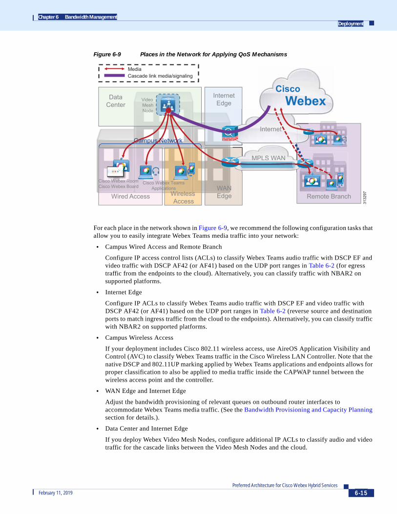
Figure 6-9 Places in the Network for Applying QoS Mechanisms
For each place in the network shown in Figure 6-9, we recommend the following configuration tasks that allow you to easily integrate Webex Teams media traffic into your network:
• Campus Wired Access and Remote Branch
Configure IP access control lists (ACLs) to classify Webex Teams audio traffic with DSCP EF and video traffic with DSCP AF42 (or AF41) based on the UDP port ranges in Table 6-2 (for egress traffic from the endpoints to the cloud). Alternatively, you can classify traffic with NBAR2 on supported platforms.
• Internet Edge
Configure IP ACLs to classify Webex Teams audio traffic with DSCP EF and video traffic with DSCP AF42 (or AF41) based on the UDP port ranges in Table 6-2 (reverse source and destination ports to match ingress traffic from the cloud to the endpoints). Alternatively, you can classify traffic with NBAR2 on supported platforms.
• Campus Wireless Access
If your deployment includes Cisco 802.11 wireless access, use AireOS Application Visibility and Control (AVC) to classify Webex Teams traffic in the Cisco Wireless LAN Controller. Note that the native DSCP and 802.11UP marking applied by Webex Teams applications and endpoints allows for proper classification to also be applied to media traffic inside the CAPWAP tunnel between the wireless access point and the controller.
• WAN Edge and Internet Edge
Adjust the bandwidth provisioning of relevant queues on outbound router interfaces to accommodate Webex Teams media traffic. (See the Bandwidth Provisioning and Capacity Planning section for details.).
• Data Center and Internet Edge
If you deploy Webex Video Mesh Nodes, configure additional IP ACLs to classify audio and video traffic for the cascade links between the Video Mesh Nodes and the cloud.
Wired Access Remote Branch
MPLS WAN
Internet
Video MeshNode
Cisco Webex TeamsApplications
Cisco Webex RoomCisco Webex Board WAN
Edge
InternetEdge
Wireless Access
DataCenter
Campus Network
W b R
MediaCascade link media/signaling
3132
97
WebexCisco
6-15Preferred Architecture for Cisco Webex Hybrid Services
February 11, 2019

Chapter 6 Bandwidth ManagementDeployment
• Remote Branch
Consider providing direct Internet access to remote branch offices so that Webex Teams endpoints can connect directly to the cloud infrastructure. For design and configuration details, refer to the IWAN Direct Internet Access Design Guide, available at
https://www.cisco.com/c/dam/en/us/td/docs/solutions/CVD/Dec2016/CVD-IWAN-DIADesignGuide-Dec16.pdf?dtid=osscdc000283
• Remote Branch
If deploying Direct Internet Access at a branch site, you can use policy-based routing using the UDP port ranges in Table 6-2 to route media traffic from Webex Teams endpoints and applications directly to the cloud.
• All places in the network
You can use the EasyQoS application in the APIC-EM SDN controller to simplify QoS policy configuration throughout your deployment. (More information about EasyQoS and APIC-EM is available on Cisco.com.)
Bandwidth Provisioning and Capacity PlanningWhile all Webex devices and applications use Media Assure to adapt their bit rate dynamically depending on network conditions and available bandwidth, it is important to know how much bandwidth is typically used by a call, so that WAN and Internet links can be provisioned to accommodate busy hour traffic without compromising the user experience. Table 6-3 lists audio and video bandwidth requirements for various types of Webex endpoints.
The bandwidth requirements in Table 6-3 take into account typical usage that includes Layer 3 overhead and multiple video streams for presentation sharing and local layout composition.
It can also be helpful to know what video resolution can be expected for a given bit rate of an individual video stream, as shown in Table 6-4.
Table 6-3 Bandwidth Requirements for Webex Endpoints (Including Layer-3 Overhead)
Webex Endpoint Audio BandwidthVideo Bandwidth (Typical)
Video Bandwidth (Maximum1)
1. Maximum here refers to the sustained bandwidth usage with the highest possible video resolution. Due to the bursty nature of compressed video traffic, bandwidth usage can occasionally exceed these values for very short periods of time.
Webex Teams applications 80 kbps 1 to 2 Mbps 3 Mbps
Webex DX Series, SX10 80 kbps 1 to 2 Mbps 3 Mbps
MX Series, SX20, SX80, Webex Room Kit, Webex Board 80 kbps 2 to 4 Mbps 10 Mbps
Table 6-4 Video Resolutions and Bit Rate Ranges for Webex Teams Devices and Applications
Video Bit RateWebex Room Devices: Video Resolution
Webex Teams Applications: Video Resolution
Less than 128 kbps 176x144 180x90
128 kbps to 256 kbps 512x288 320x180
256 kbps to 320 kbps 512x288 480x270
6-16Preferred Architecture for Cisco Webex Hybrid Services
February 11, 2019

Chapter 6 Bandwidth ManagementDeployment
Taking into account the values shown in Table 6-3 and Table 6-4, you can plan the WAN and Internet bandwidth capacities based on the number of endpoints and/or users per site and the typical call volumes in the busy hour. No single formula will work for every deployment, but it can be useful to look at the following Provisioning Example to understand the steps involved in the capacity planning process.
Provisioning Example
Figure 6-10 shows an example of a multi-site Webex Teams deployment with three types of sites: the central site, a large branch office, and a small branch office. The number of users and endpoints at each site is also shown in the figure.
Figure 6-10 Bandwidth Provisioning Example for a Multi-Site Webex Teams Deployment
320 kbps to 512 kbps 768x448 640x360
512 kbps to 900 kbps 1024x576 960x540
900 kbps to 1.8 Mbps 1280x720 1280x720
More than 1.8 Mbps 1920x1080 1920x1080
Table 6-4 Video Resolutions and Bit Rate Ranges for Webex Teams Devices and Applications
Video Bit RateWebex Room Devices: Video Resolution
Webex Teams Applications: Video Resolution
WebexCisco
Small BranchInternet
Cisco Webex TeamsApplications
VideoEndpoints
Audio/Video
Central SiteLarge Branch
500 users:500 Webex Teams applications and Webex devices20 Small video endpoints10 Large video endpoints
50 users:50 Webex Teams applications4 Small video endpoints1 Large video endpoint
12 users:12 Webex Teams applications2 Small video endpoints
3132
98
6-17Preferred Architecture for Cisco Webex Hybrid Services
February 11, 2019

Chapter 6 Bandwidth ManagementDeployment
To keep things simple, we made a generalization in this example: Webex DX Series and SX10 endpoints are considered "small" video endpoints, while all other video room systems, as well as the Webex Board, are considered "large" video endpoints.
A capacity planning exercise also requires some assumptions to be made with respect to busy-hour call attempts, call and meeting patterns, video endpoint utilization ratios, and average bandwidth per call. We assume the following average bandwidth values per call throughout this example:
• Voice call (or audio stream of a video call): 80 kbps
• Video streams of small video endpoints: 1.2 Mbps at 720p resolution
• Video streams of large video endpoint: 2.5 Mbps at 1080p resolution
• Video streams of Webex Teams application: 2 Mbps at 720p resolution, 1 Mbps at 540p resolution, and 500 kbps at 270p resolution
It is important to understand that these are ideal values based on desired call quality levels for each endpoint type. However, because the dynamic rate adaptation in Media Assure is based on observed instantaneous network congestion, it currently is not possible to enforce different bandwidth allocations for given groups of endpoints. Depending on relative call start time and resulting network congestion, it is therefore possible that several calls sharing the same bottleneck will adapt to different video bit rates, regardless of endpoint type.
Also note that, although there is obviously no traffic prioritization on the Internet, it is always beneficial to configure queuing on the egress interface of the Internet edge router and to match the total bandwidth allocated for classes to the bandwidth provided by the Internet service provider. This ensures that the real-time media traffic from the endpoints toward the cloud is guaranteed a share of the Internet access link even when competing with other applications. Throughout this example we assume a consistent distribution of bandwidth across classes that allocates 10% of the link bandwidth to the audio/voice queue and 55% of the link bandwidth to the interactive video queue.
The other assumptions are called out explicitly as we analyze the Internet bandwidth allocation at each site (central site, large branch, and small branch) and the bandwidth provisioned for each traffic class based on the number of users and endpoints.
First we look at the central site: In this example it is provisioned with a 100 Mbps connection to the Internet, which results in 10 Mbps allocated to the voice queue and 55 Mbps allocated to the video queue (see Figure 6-11).
Figure 6-11 Central Site Bandwidth Allocation Example
500 users:
500 Cisco Webex Teams applications and Webex devices20 Small video endpoints 10 Large video endpoints
voice10%
VideoViVV deo55 M bps
VoiceVoVV ice10 Mbps
DefaultDefaff ult31 M bps
WAN WAWW NAALink
100 100Mbps
video55%
3132
99
6-18Preferred Architecture for Cisco Webex Hybrid Services
February 11, 2019

Chapter 6 Bandwidth ManagementDeployment
Based on the number of users and endpoints located at the central site, we made these additional assumptions about busy-hour calls and video endpoint utilization ratios:
• At most 25% of the users are involved in a call (voice or video) at the same time.
• At most 25% of the small video endpoints are involved in a call at the same time.
• At most 75% of the large video endpoints are involved in a call at the same time.
As a consequence, these are the numbers and types of calls that can be supported at the central site in this example:
• Voice queue: 10 Mbps; Supports 125 calls (80 kbps per call)
• Video queue: 55 Mbps
– Small video endpoints: 1.2 Mbps 20 calls 0.25 utilization ratio = 6 Mbps
– Large video endpoints: 2.5 Mbps 10 calls 0.75 utilization ratio = 19 Mbps
– Webex Teams application video: 55 - (16+9) = 30 Mbps; Supports 15 calls at 720p, 30 calls at 540p, or 60 calls at 270p
Next we look at the large branch site, which is provisioned with a 34 Mbps connection to the Internet, resulting in 3.4 Mbps allocated to the voice queue and 18.7 Mbps allocated to the video queue (see Figure 6-12).
Figure 6-12 Large Branch Site Bandwidth Allocation Example
Based on the number of users and endpoints located at the large branch site, we made these additional assumptions about busy-hour calls and video endpoint utilization ratios:
• At most 80% of the users are involved in a call (voice or video) at the same time.
• All video endpoints (small and large) can be involved in a call at the same time.
As a consequence, these are the numbers and types of calls that can be supported at the large branch site in this example:
• Voice queue: 3.4 Mbps; Supports 42 calls (80 kbps per call)
• Video queue: 18.7 Mbps
– Small video endpoints: 1.2 Mbps 4 calls = 4.8 Mbps
– Large video endpoint: 2.5 Mbps
– Webex Teams application video: 18.7 - (4.8+2.5) = 11.4 Mbps; Supports 5 calls at 720p, 11 calls at 540p, or 22 calls at 270p
voice10%
VideoVidVV edd o18.7 Mbps
VoiceVoVV ice3.4 Mbps
DefaultDefaff ult10.5 Mbps
WAN WANLink
34 34Mbps
video55%
50 users:50 Cisco Webex Teams applications4 small video endpoints 1 large video endpoint
3133
00
6-19Preferred Architecture for Cisco Webex Hybrid Services
February 11, 2019

Chapter 6 Bandwidth ManagementDeployment
Next we consider the small branch site, which is provisioned with a 10 Mbps connection to the Internet, resulting in 1 Mbps allocated to the voice queue and 5.5 Mbps allocated to the video queue (see Figure 6-13).
Figure 6-13 Small Branch Site Bandwidth Allocation Example
Based on the number of users and endpoints located at the small branch site, we made these additional assumptions about busy-hour calls and video endpoint utilization ratios:
• All the users may be involved in a call (voice or video) at the same time.
• All video endpoints can be involved in a call at the same time.
As a consequence, these are the numbers and types of calls that can be supported at the small branch site in this example:
• Voice queue: 1 Mbps; Supports 12 calls (80 kbps per call)
• Video queue: 5.5 Mbps
– Small video endpoints: 1.2 Mbps 2 calls = 2.4 Mbps
– Webex Teams application video: 5.5 - 2.4 = 3.1 Mbps; Supports 1 to 2 calls at 720p, 3 calls at 540p, or 6 calls at 270p
VideoVidVV ed o5.5 Mbps
VoiceVoiVV ce1 Mbps
DefaultD3.1
aultDefaff11 Mbps
WAN WANLink
10 10Mbps
12 users:12 Cisco Webex Teams applications2 small video endpoints
voice10%
video55%
3133
01
6-20Preferred Architecture for Cisco Webex Hybrid Services
February 11, 2019

Chapter 6 Bandwidth ManagementDeployment
Provisioning Best Practices
In summary, the following best practices described in this section can prove helpful when provisioning bandwidth for you Webex Teams deployment:
• Prioritize audio and video traffic on all outgoing router interfaces to the Internet and to the corporate WAN.
• Provision WAN and Internet links for the busy hour – that is, for the highest simultaneous usage during the day – in order to optimize the user experience.
• Consider the typical per-call bandwidth requirements shown in Table 6-3, and apply utilization ratios depending on user behavior and your business goals. As a general rule, personal endpoints and clients have a lower utilization ratio than conference room systems, but this can vary depending on the nature of the user and the industry.
• On an appropriately sized Internet or WAN link, you can start with this general rule for relative bandwidth allocation:
– 10% for voice traffic
– 55% for video traffic
– At least 30% for default traffic
• When provisioning queues and WAN or Internet links, continuously monitor bandwidth utilization and endpoint usage, and adjust the overall capacity and bandwidth allocations as needed.
Enterprise QoS Policy Access, WAN and Internet Edge Policy
Ingress Classification Policy
The following example represents an ingress policy definition that classifies audio traffic to and from Webex Teams applications and endpoints as EF, and video traffic to and from Webex Teams applications and endpoints as AF42. Replace AF42 (DSCP 36) with AF41 (DSCP 34) if you are marking Webex Teams video as Prioritized Video. This policy can be applied anywhere in the network, ideally close to the edge of the network, such as the campus access layer and the WAN or Internet edge, and it aligns with the QoS policy of the Preferred Architecture for Cisco Collaboration Enterprise On-Premises Deployments. This policy assumes all traffic goes to the cloud and no Video Mesh Nodes are deployed. Refer to the Video Mesh Node section for a configuration example with a Video Mesh Node.
! This section configures the ACLs to match the UDP port ranges for audio and video,! both for ingress (endpoint-to-cloud) and egress (cloud-to-endpoint) trafficip access-list extended QOS_WEBEX_AUDIOpermit udp any range 52000 52099 any eq 5004permit udp any eq 5004 any range 52000 52099ip access-list extended QOS_WEBEX_VIDEOpermit udp any range 52100 52299 any eq 5004permit udp any eq 5004 any range 52100 52299! This section configures the classes that match on the ACLs above.class-map match-any VOICEmatch access-group name QOS_WEBEX_AUDIOclass-map match-any OPPORTUNISTIC_VIDEOmatch access-group name QOS_WEBEX_VIDEO! This section configures the policy-map matching the classes configured! above and sets DSCP for voice and video on ingress on this switch/router.! Note that the class-default sets everything that does not match the! above to a DSCP of 0 (BE).policy-map INGRESS_MARKING
6-21Preferred Architecture for Cisco Webex Hybrid Services
February 11, 2019

Chapter 6 Bandwidth ManagementDeployment
class VOICEset dscp efclass PRIORITIZED_VIDEOset dscp af41class OPPORTUNISTIC_VIDEOset dscp af42class class-defaultset dscp 0! This section applies the policy-map to the interface.Switch (config-if)# service-policy input INGRESS-MARKING
Note In the QoS policy for the Preferred Architecture for Cisco Collaboration Enterprise On-Premises Deployments, the class map for opportunistic video for Jabber endpoints was called JABBER_VIDEO. In the above example it has been renamed to OPPORTUNISTIC_VIDEO.
An alternative option for Cisco Catalyst 3650 and 3850 switches running Cisco IOS XE 16.3+ is to use NBAR2 to identify Webex Teams traffic. In this case IP ACLs are not required, and the class-maps simplify to:
class-map match-any VOICE match protocol cisco-spark-audioclass-map match-any OPPORTUNISTIC_VIDEO match protocol cisco-spark-video
Video Mesh Node
The following example presents an additional ingress policy definition (based on a Cisco IOS switch) that classifies traffic originated by a Webex Video Mesh Node as well as cascade traffic from the cloud to that Video Mesh Node. These access lists can be combined with those shown in the previous section.
! This section configures the ACLs to match the UDP port ranges for audio and video! for the cascade link between a Video Mesh Node (HMN) with IP address 10.10.10.10! and the cloudip access-list extended QOS_WEBEX_VMN_AUDIOpermit udp 10.10.10.10 range 52500 62999 any eq 5004 5006permit udp any eq 5004 5006 10.10.10.10 range 52500 62999ip access-list extended QOS_WEBEX_VMN_VIDEOpermit udp 10.10.10.10 range 63000 65500 any eq 5004 5006permit udp any eq 5004 5006 10.10.10.10 range 63000 65500! This section configures the classes that match on the ACLs above as well as! the ACL's shown in section above "Ingress Classification Policy"class-map match-any VOICEmatch access-group name QOS_WEBEX_AUDIOmatch access-group name QOS_WEBEX_VMN_AUDIOclass-map match-any OPOORTUNISTIC_VIDEOmatch access-group name QOS_WEBEX_VIDEOmatch access-group name QOS_WEBEX_VMN_VIDEO
Wireless Configuration
The following AireOS WLC software configuration creates an AVC profile to mark Webex Teams audio and video traffic to EF and AF41 respectively, and it applies this policy to a specific WLAN (WLAN 10 in this example).
! This section creates the AVC Profile(Cisco WLC) > config avc profile AVC-STATIC-PROFILE create
6-22Preferred Architecture for Cisco Webex Hybrid Services
February 11, 2019

Chapter 6 Bandwidth ManagementDeployment
! This section configures AVC to mark Webex Teams voice applications/sub-components to EF ! (DSCP 46)(Cisco WLC) > config avc profile AVC-PROFILE rule add application cisco-spark-audio mark 46
! This section configures AVC to mark Webex Teams video to AF42 (DSCP 36)(Cisco WLC) > config avc profile AVC-PROFILE rule add application cisco-spark-video mark 36
! This section applies the Platinum QoS Profile to the WLAN (Cisco WLC) > config wlan qos 10 platinum
! This section enables AVC Visibility on WLAN 10 (Cisco WLC) > config wlan avc 10 visibility enable
! This section applies the AVC Profile to WLAN ID 10 (Cisco WLC) > config wlan avc 10 profile AVC-PROFILE enable
Special Considerations for Cisco Webex Teams for Microsoft WindowsThe Webex Teams application requires functionality enablement expected to release in early 2019. This new functionality will bind itself to the source port ranges and will use those port ranges as listed in Table 6-2. Prior to this new release, the source ports used by the Webex Teams application are dynamic and cannot be used to classify audio and video traffic, so it is not possible to provide Quality of Service (QoS) to Cisco Webex Teams for Windows clients until the new release is available. Following the guidelines for the port ranges will allow the enterprise to deploy the correct ACLs to match the traffic correctly and will also apply to Cisco Webex Teams for Windows when the new release becomes available.
In order to allocate source ports from the specific ranges shown in Table 6-2, the Webex Teams application must make a request to the underlying operating system when it is first installed on a device. This results in the following behavior, which requires particular attention on devices running Microsoft Windows:
Because of a limitation in the Microsoft Windows APIs, whenever an application requests a specific source port from the operating system, it also gains permission to listen for unsolicited incoming traffic on that port. The Webex Teams application does not need these privileges because it receives packets only on a given port after transmitting from it, but it has no way of communicating this to the operating system.
Therefore, in Microsoft Windows system configurations where Microsoft Windows Firewall is enabled, a security alert might be displayed to the end user when Webex Teams is first installed, informing them that Windows Firewall has blocked some features of the application and prompting them to allow access (which requires administrator privileges) or to cancel.
It is important to note that, regardless of the action chosen by the end user for this alert, the Webex Teams application will operate correctly using the ports shown in Table 6-2, and no other alert will be displayed after the initial installation.
This issue applies only to Microsoft Windows and it does not affect the Webex Teams application on other platforms such as MacOS, Apple iOS, or Android.
6-23Preferred Architecture for Cisco Webex Hybrid Services
February 11, 2019

Chapter 6 Bandwidth ManagementDeployment
6-24Preferred Architecture for Cisco Webex Hybrid Services
February 11, 2019
Related Documents