1 Bull. Pol. Acad. Sci. Tech. Sci. BULLETIN OF THE POLISH ACADEMY OF SCIENCES TECHNICAL SCIENCES DOI: 10.24425/bpasts.2021.137509 THIS IS AN EARLY ACCESS ARTICLE. This article has been accepted for publication in a future issue of this journal, but has not been fully edited. Content may change prior to final publication. SPECIAL SECTION Enhanced power and bandwidth in PZEH with magnetic tipmass Ashutosh Anand 1 * , Srikanta Pal 1 , Sudip Kundu 2 1 Department of Electronics and Communication Engineering, Birla Institute of Technology Mesra, Ranchi, India. 2 Department of Electronics and Communication Engineering and Center for Nanomaterials, National Institute of Technology Rourkela, India ABSTRACT: In this paper, the performance and frequency bandwidth of the piezoelectric energy harvester (PZEH) is improved by introducing two permanent magnets, which is attached to the proof mass of a dual beam structure. Both magnets are in the vicinity of each other and attached in such as a way to proof mass of a dual-beam, so that they create a magnetic field around each other. The generated magnetic field develops a repulsive force between the magnets, which improves not only electrical output but also enhances the bandwidth of harvester. The simple rectangular cantilever structure with and without magnetic tip mass has the frequency bandwidth of 4 Hz and 4.5 Hz respectively. The proposed structure generates a peak voltage of 20 V at a frequency of 114.51 Hz at an excitation acceleration of 1g (g=9.8 m/s 2 ). The peak output power of a proposed structure is 12.2 µW. The operational frequency range of a proposed dual-beam cantilever with magnetic tip mass of 30 mT is from 102.51 Hz to 120.51 Hz i.e., 18 Hz. The operational frequency range of a dual-beam cantilever without magnetic tip mass is from 104.18 Hz to 118.18 Hz i.e., 14 Hz. There is an improvement of 22.22 % in the frequency bandwidth of proposed dual-beam cantilever with magnetic tip mass of 30 mT than the dual-beam without magnetic tip mass. Key words: Vibration, Piezoelectric Energy harvester, Magnetic Tip mass, Bandwidth, Stress. 1. INTRODUCTION The advancement in the field of VLSI and ever-increasing interest in the Internet of Things (IoT) leads to rapid advancement in the development of the miniaturized low power electronic devices. There are several barriers in the global implementation of IoT, such as the dependency on the conventional battery for the power supply. These batteries have a limited life-span. Thus, energy harvesting from the ambient energy source became an active research area. The energy harvesting from the vibration of the ambient nature is the most promising way to power these miniaturized low power electronic devices like wireless sensors nodes, biomedical devices, military equipment’s etc. The vibration energy harvester (EH) converts vibration energy into the useable electric energy. Vibration energy can be converted into electrical energy using electrostatic [1][2], electromagnetic [3][4] and piezoelectric (PZ) mechanism [5-13]. The piezoelectric transducer is the most favored, as it has high energy density, easy integration in CMOS technology, high durability and it does not need any external voltage source [10]. There are many EH designs such as cantilever [5,6], clamped- clamped beams [13], diaphragms [13], cymbal type structure [13], shell and stack type structures [13]. The cantilever structure is the most used structures as it has a higher average strain energy. The rectangular type cantilever structure is most easy to fabricate and implement. Apart from energy harvesting, the piezoelectric materials have been used in several different applications such as buckling [14], stability [14,15], vibration or loading capacity control [16], tactile sensing [17], etc. The piezoelectric energy harvester (PZEH) has the ability to generate maximum output voltage and power at the resonant frequency. Even the slight change in an ambient frequency can drastically reduce the efficiency of a PZEH. Numerous researches are going on to eliminate this limitation. One of such method is the use of non-linearity in the EH design [18][19]. One of the methods to introduce non-linearity is the use of magnetic tip mass as a proof mass in the magnetic environment [19]. The relative alignment, position and arrangement of the magnet can introduce non-linearity in the system. There are several configurations to improve the efficiency and operating bandwidth of PZEH. The permanent magnet has been used in the EH system to achieve monostable [20][21], bi-stable [22-24] or tri-stable state [25-28] and hence able to increase the operating frequency range. Challa et al. [19] designed EH of size 34 mm and tune the resonant frequency with the magnetic force by changing the relative position of the magnets. Zhou et al. [29] tries to achieve a penta-stable state by adjusting the position and orientation of permanent magnet and hence improve the efficiency. Tan et al. [30] tries to device a method to calculate magnetic force in the vibration and energy harvesting efficiency of the piezoelectric energy harvester. Zhu et al. [31] designed (13 x 5) mm 2 cantilever beam for the electromagnetic micro- generator. The resonant frequency of the cantilever has been tuned with the help of attractive force of axially aligned permanent magnet. Wei-jiun et al. [32] designed a 98 mm dual cantilever to enhance the bandwidth of the EH with permanent magnet on a dual cantilever. D. Guo et al. [33] also designed 12 cm long array of cantilevers to enhance the frequency bandwidth with the magnetic tip mass and increase the performance of EH. This paper tries to use the concept of multi-beam structure along with the use of magnetic field intensity in EH system to achieve the bandwidth improvement. This paper introduces dual magnets in a dual cantilever system. One magnet is attached to the proof-mass of the inner beam and the other magnet is attached to the outer beam. Both magnets are attached in the vicinity of each other to create the magnetic field intensity and interact with each other. This orientation helps in the improvement of the frequency bandwidth of the EH. 2. ELECTRICAL ANALYSIS OF PIEZOELECTRIC CANTILEVER A simplified cantilever plate structure consist of piezoelectric plate on the top of a substrate layer is considered, to develop the analytical model as shown in Fig. 1. The thickness of the substrate layer is tS and that of the piezoelectric layer is tP. The effect of electrode is neglected in the analytical model due to its small thickness. In a PZ material, the external force on the PZ layer generates electric field and vice versa. When the PZ cantilever operates in 31 mode, which means that stress generates in the lateral direction (X direction or 3 direction) and an electric field in Bandwidth and Power Enhancement in the MEMS Based Piezoelectric Energy Harvester using Magnetic Tip Mass * e-mail: [email protected]

Welcome message from author
This document is posted to help you gain knowledge. Please leave a comment to let me know what you think about it! Share it to your friends and learn new things together.
Transcript

1Bull. Pol. Acad. Sci. Tech. Sci.
BULLETIN OF THE POLISH ACADEMY OF SCIENCES TECHNICAL SCIENCESDOI: 10.24425/bpasts.2021.137509
THIS IS AN EARLY ACCESS ARTICLE.This article has been accepted for publication in a future issue of this journal,
but has not been fully edited. Content may change prior to final publication.
SPECIAL SECTION
Enhanced power and bandwidth in PZEH with magnetic tipmass
Ashutosh Anand1 *, Srikanta Pal1, Sudip Kundu2 1 Department of Electronics and Communication Engineering, Birla Institute of Technology Mesra, Ranchi, India.
2 Department of Electronics and Communication Engineering and Center for Nanomaterials, National Institute of Technology Rourkela, India
ABSTRACT: In this paper, the performance and frequency bandwidth of the piezoelectric energy harvester (PZEH) is improved by introducing two permanent magnets, which is attached to the proof mass of a dual beam structure. Both magnets are in the vicinity of each other and attached in such as a way to proof mass of a dual-beam, so that they create a magnetic field around each other. The generated magnetic field develops a repulsive force between the magnets, which improves not only electrical output but also enhances the bandwidth of harvester. The simple rectangular cantilever structure with and without magnetic tip mass has the frequency bandwidth of 4 Hz and 4.5 Hz respectively. The proposed structure generates a peak voltage of 20 V at a frequency of 114.51 Hz at an excitation acceleration of 1g (g=9.8 m/s2). The peak output power of a proposed structure is 12.2 µW. The operational frequency range of a proposed dual-beam cantilever with magnetic tip mass of 30 mT is from 102.51 Hz to 120.51 Hz i.e., 18 Hz. The operational frequency range of a dual-beam cantilever without magnetic tip mass is from 104.18 Hz to 118.18 Hz i.e., 14 Hz. There is an improvement of 22.22 % in the frequency bandwidth of proposed dual-beam cantilever with magnetic tip mass of 30 mT than the dual-beam without magnetic tip mass. Key words: Vibration, Piezoelectric Energy harvester, Magnetic Tip mass, Bandwidth, Stress.
1. INTRODUCTION The advancement in the field of VLSI and ever-increasing interest in the Internet of Things (IoT) leads to rapid advancement in the development of the miniaturized low power electronic devices. There are several barriers in the global implementation of IoT, such as the dependency on the conventional battery for the power supply. These batteries have a limited life-span. Thus, energy harvesting from the ambient energy source became an active research area. The energy harvesting from the vibration of the ambient nature is the most promising way to power these miniaturized low power electronic devices like wireless sensors nodes, biomedical devices, military equipment’s etc. The vibration energy harvester (EH) converts vibration energy into the useable electric energy. Vibration energy can be converted into electrical energy using electrostatic [1][2], electromagnetic [3][4] and piezoelectric (PZ) mechanism [5-13]. The piezoelectric transducer is the most favored, as it has high energy density, easy integration in CMOS technology, high durability and it does not need any external voltage source [10]. There are many EH designs such as cantilever [5,6], clamped-clamped beams [13], diaphragms [13], cymbal type structure [13], shell and stack type structures [13]. The cantilever structure is the most used structures as it has a higher average strain energy. The rectangular type cantilever structure is most easy to fabricate and implement. Apart from energy harvesting, the piezoelectric materials have been used in several different applications such as buckling [14], stability [14,15], vibration or loading capacity control [16], tactile sensing [17], etc. The piezoelectric energy harvester (PZEH) has the ability to generate maximum output voltage and power at the resonant frequency. Even the slight change in an ambient frequency can drastically reduce the efficiency of a PZEH. Numerous researches are going on to eliminate this limitation. One of such method is the use of non-linearity in the EH design [18][19]. One of the methods to introduce non-linearity is the use of magnetic tip mass as a proof mass in the magnetic environment [19]. The relative alignment, position and arrangement of the magnet can introduce non-linearity in the system. There are several configurations to improve the efficiency and operating bandwidth of PZEH. The permanent magnet has been used in the
EH system to achieve monostable [20][21], bi-stable [22-24] or tri-stable state [25-28] and hence able to increase the operating frequency range. Challa et al. [19] designed EH of size 34 mm and tune the resonant frequency with the magnetic force by changing the relative position of the magnets. Zhou et al. [29] tries to achieve a penta-stable state by adjusting the position and orientation of permanent magnet and hence improve the efficiency. Tan et al. [30] tries to device a method to calculate magnetic force in the vibration and energy harvesting efficiency of the piezoelectric energy harvester. Zhu et al. [31] designed (13 x 5) mm2 cantilever beam for the electromagnetic micro-generator. The resonant frequency of the cantilever has been tuned with the help of attractive force of axially aligned permanent magnet. Wei-jiun et al. [32] designed a 98 mm dual cantilever to enhance the bandwidth of the EH with permanent magnet on a dual cantilever. D. Guo et al. [33] also designed 12 cm long array of cantilevers to enhance the frequency bandwidth with the magnetic tip mass and increase the performance of EH. This paper tries to use the concept of multi-beam structure along with the use of magnetic field intensity in EH system to achieve the bandwidth improvement. This paper introduces dual magnets in a dual cantilever system. One magnet is attached to the proof-mass of the inner beam and the other magnet is attached to the outer beam. Both magnets are attached in the vicinity of each other to create the magnetic field intensity and interact with each other. This orientation helps in the improvement of the frequency bandwidth of the EH.
2. ELECTRICAL ANALYSIS OF PIEZOELECTRIC
CANTILEVER A simplified cantilever plate structure consist of piezoelectric plate on the top of a substrate layer is considered, to develop the analytical model as shown in Fig. 1. The thickness of the substrate layer is tS and that of the piezoelectric layer is tP. The effect of electrode is neglected in the analytical model due to its small thickness. In a PZ material, the external force on the PZ layer generates electric field and vice versa. When the PZ cantilever operates in 31 mode, which means that stress generates in the lateral direction (X direction or 3 direction) and an electric field in
Bandwidth and Power Enhancement in the MEMS Based Piezoelectric Energy Harvester using Magnetic Tip Mass
* e-mail: [email protected]
2
A. Anand, S. Pal, and S. Kundu
Bull. Pol. Acad. Sci. Tech. Sci. Bull. Pol. Acad. Sci. Tech. Sci.
This article has been accepted for publication in a future issue of this journal, but has not been fully edited. Content may change prior to final publication. This article has been accepted for publication in a future issue of this journal, but has not been fully edited. Content may change prior to final publication.
transverse direction (Z direction or 1 direction). So, the equations (1a) and (1b) show the PZ property and inverse PZ property [5-6].
= . + . (1a)
= . + . (1b)
Where is mechanical strain generated in the PZ material and is the electric displacement in the PZ materials under given mechanical stress T1 and electric field E3.
is strain under zero or constant electric field,
is the permittivity of the material under zero or constant stress and is the PZ coefficient. The substrate layer is the normal linear elastic material, so the stress applied (Ts) in the substrate layer is directly proportional to the resultant strain (Ss) as
= (2) But, in case of the PZ material, applied stress (Tp) not only induces strain (Sp) but also generates an electric filed (E). When the rectangular cantilever structure vibrates in the vertical direction, stress acts in the x, y and xy plane. So, the applied stress, strain and electric field in the PZ layer is related as in equations (3) (a, b, c) [5-6].
Fig. 1. Simplified version of the basic cantilever
=
+
− (3a)
=
+
− (3b)
= − ( + ) (3c)
Where υ is the poison ratio, G is the shear modulus and Yp is the Young’s Modulus of the PZ layer. When the cantilever plate is subject to an external stress, it deflects from the mean position or neutral axis. This induces the bending strain in the layer away from the neutral axis. The equations 4 (a, b, c) shows the bending strain in the cantilever plates [5-6].
= −( − ) (,,)
(4a)
= −( − ) (,,)
(4b)
= −2( − ) (,,)
(4c)
Where ZN is the neutral plane and ( − ) = is the distance from the neutral surface to the material point of interest, (, , ) is the transverse displacement of the cantilever structure. Putting the value of strain from equation (4 (a, b, c)) into equation (3 (a, b, c)) [5-6], we have.
=
−(,,)
+
−(,,)
−
(5a)
=
−(,,)
+
−(,,)
−
(5b)
= −2(,,)
− ( + ) (5c)
The value of stress from equations (5 (a, b, c)) is substituted in equation (1b) to obtained the electric displacement in x, y and xy plane. The equation (6) shows the electric displacement due to stress in the x plane [5-6].
=
−(,,)
+
−(,,)
−
+ ℇ (6)
The charge generated in the piezoelectric plate is given by equation (7) [5-6],
() = ∫ ∫
−(,,)
+
−(,,)
+ ℇ −
= ∫ ∫
−(,,)
+ −(,,)
+
ℇ ()
(7)
Where (ℇ − )= ℇ
, = ()
, is a thickness of PZ
layer, V(t) is the voltage generated in PZ layer.
Thus, total current generated in this plate is () = ()
.
If R is the internal resistance of PZ plate, so according to the ohm’s law the voltage generated in PZ plate is given by (t)= () × , [5-6].
() = − ∫ ∫
(,,)
+
(,,)
−
ℇ
()
(8)
Similarly, the voltage generated in a PZ layer due to the stress in y and xy plane can be evaluated as [5-6].
() = − ∫ ∫
(,,)
+
(,,)
−
ℇ
()
(9)
() = − ∫ ∫ ( + ) (,,)
−
(ℇ
ℇ )
()
(10)
The total voltage generated across the PZ layer of the cantilever as in equation (11) [5-6].
() = () + () + () (11) So, from the above discussion (equations (7), (8), (9), (10) and (11)), it can be concluded that the electric voltage develop across the PZ layer depends on the stress distribution on the cantilever beam. So, when the all the other design parameter is same then the cantilever structure with a higher stress distribution gives higher voltage than the others. The introduction of the magnetic field in the PZ cantilever system with the help of the magnetic

3
Bandwidth and Power Enhancement in the MEMS Based Piezoelectric Energy Harvester using Magnetic Tip Mass
Bull. Pol. Acad. Sci. Tech. Sci. Bull. Pol. Acad. Sci. Tech. Sci.
This article has been accepted for publication in a future issue of this journal, but has not been fully edited. Content may change prior to final publication. This article has been accepted for publication in a future issue of this journal, but has not been fully edited. Content may change prior to final publication.
tip mass will increase the stress districtution and hence improve the performance of the PZEH.
3. MECHANICAL MODELLING OF PZEH WITH
MAGNET TIP MASS The PZEH with permanent magnet attached to the proof mass which is axially aligned with the fixed magnet. Kirchhoff plate theory with additional magnetic force is used to model the system [5,6]. The nonlinear restoring force is produced by the magnetic force in the PZEH. The mechanical deviation of cantilever plate in perpendicular direction can be expressed as equation (12a or 12b) [5][6][34].
(,,)
+ 2(,,)
+(,,)
+ (,,)
=
(, , ) (12a)
or, ∇(, , ) + (,,)
= (, , ) (12b)
Where, ∇ is the biharmonic operator and is given in equation (13), (, , ) is the vertical displacement of the plate, is the density, is the flexural rigidity which is given in equation (14). f(x,y,t)m is the magnetic force between the magnets in the system at the any deflection (, , ), is given by equation (15) [5][6][34].
∇= ∇∇=
+ 2
+
(13)
=
() (14)
(, , ) = −
((,,)) (15)
Where m1 and m2 are the magnetic dipole which is given as
=
, = 1,2. µ0 (= 4π × 10−7 H/m) is the permeability of
the air and two magnets are D distance apart and is the volume of the magnets. There will be the repulsive force when both magnets are of same magnetic polarization and attractive in nature when the magnets are of opposite magnetic polarization. When there is no magnetic force acting in the cantilever system then the (, , ) is taken as zero in equation (12). This is the case of free vibration of a cantilever plate [5][6][34] as
∇(, , ) + (,,)
= 0 (16)
The length and width of the rectangular plate is L and b, so the boundary limit along the length varies from x = 0 to L and along the width is y = 0 to b. When the external magnetic force
(f(x,y,t)) will be considered then the solution of displacement of the rectangular cantilever i.e., equation (12) will be considered as [5][6][34].
∇(, , ) + (,,)
= −
((,,)) (17)
According to the vertical displacement of the plate we have, (, , ) = ∑ ∑ (, )()
(18)
Where, (, ) = sin
sin
; , = 1,2.. (19)
The normalization condition that the normal nodes will satisfy is given as [5][6][34],
∫ ∫
= 1 (20)
Which yields =
. By using normalization
condition in equation (20) and substituting it into equation (12), we obtained the equation of the governing the generalized coordinates () as [5][6][34],
()
+ () = (); , = 1,2 … (21)
Where () is the generalized force and the natural
frequency is given by [5][6][34],
() = ∫ ∫ (, )(, , )
(22)
=
+
; , = 1,2 … (23)
The solution of equation (21) can be expressed as (24) [5][6][34],
() = (0) cos +
()
sin +
∫ () sin ( − )
(24)
The final solution of the rectangular plate vibration under external force is given by equation (25) [5][6][34].
(, , ) = ∑ ∑ (0) sin
sin
cos[]
+
∑ ∑()
sin
sin
sin[] +
∑ ∑
sin
sin
∫ ()
sin[( − )]
(25) Thus, it can be observed that the deflection of the end mass
of the vibrating dual beam cantilever structure depends on the magnetic force (from equations (22), (24) and (25)). Hence the magnetic effect influences the vibration of the cantilever structure.
Fig. 2. Single rectangular cantilever beam with magnetic tip mass
4. DESIGN OF THE CANTILEVER STRUCTURE 4.1. Design of the single beam structure The rectangular cantilever structure is designed with silicon as the substrate and zinc oxide as the PZ layer. The proof mass is at the tip of the free end of the cantilever consists of Si and permanent magnet (PM1), which helps to reduce the resonant frequency [5] as shown in Fig. 2. Another fixed magnet (PM2) is placed axially in the vicinity of the first magnet to create repulsive magnetic force [4]. The permanent magnet can act as a spring which produces non-linearity in the system. Table 1 and Table 2 complies all the dimension and properties of the materials used in designing of the cantilever plate. The magnetic
4
A. Anand, S. Pal, and S. Kundu
Bull. Pol. Acad. Sci. Tech. Sci. Bull. Pol. Acad. Sci. Tech. Sci.
This article has been accepted for publication in a future issue of this journal, but has not been fully edited. Content may change prior to final publication. This article has been accepted for publication in a future issue of this journal, but has not been fully edited. Content may change prior to final publication.
field intensity of the magnets used in the design of the simple rectangular structure is 5 mT. Both the magnets are 500 µm apart. The COMSOL Multiphysics 5.3a is used to design the cantilever structure. The structure is meshed as the normal meshing techniques. The solid mechanics and electrostatics physics are used to obtained the mechanical and electrical characterization of the designed cantilever structure. The resonant frequency of the simple single rectangular cantilever structure is 95.5 Hz and that of the simple single rectangular cantilever with magnetic tip mass structure is 95 Hz, which is in agreement with the above discussion.
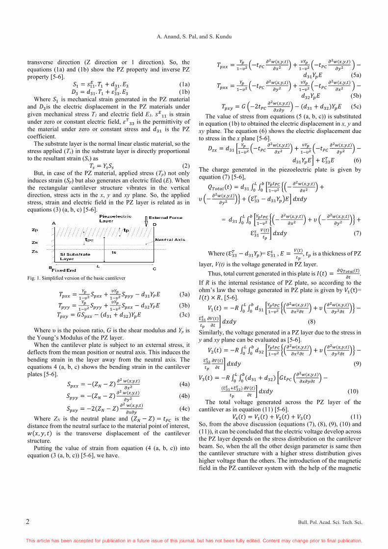
Before moving to the design of the dual beam structure, we first try to verify the effect of the magnetic field intensity on the stress distribution. For that, we have taken the designed simple rectangular cantilever of dimensions as shown in Fig. 2 and in table 1. The stationary study is employed on the designed cantilever structure to verify the effect of magnetic field intensity on the stress distribution. First stationary study is employed with fixed load of 1g (=9.8m/s2) only, then gradually the magnetic field intensity is introduced in the system to study its effect. The Fig. 3 shows the stress distribution along the arc length of the cantilever structure. It can be observed from the Fig. 3 that the stress distribution increases with the increase in the magnetic field intensity which is in agreement with the above discussed mathematical analysis.
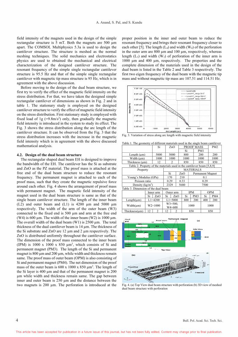
4.2. Design of the dual beam structure The rectangular shaped dual beam EH is designed to improve the bandwidth of the EH. The cantilever has the Si as substrate and ZnO as the PZ material. The proof mass is attached at the free end of the dual beam structure to reduce the resonant frequency. The permanent magnet is attached to each of the proof mass, such that they create the magnetic repulsive force around each other. Fig. 4 shows the arrangement of proof mass with permanent magnet. The magnetic field intensity of the magnet used in the dual beam structure is same as that of the single beam cantilever structure. The length of the inner beam (L2) and outer beam and (L1) is 4200 µm and 5000 µm respectively. The width of the arm of the outer beam (W3) connected to the fixed end is 500 µm and arm at the free end (W4) is 600 µm. The width of the inner beam (W2) is 1000 µm. The overall width of the dual beam (W1) is 2500 µm. The total thickness of the dual cantilever beam is 14 µm. The thickness of the Si substrate and ZnO are 12 µm and 2 µm respectively. The ZnO is distributed uniformly throughout the cantilever surface. The dimension of the proof mass connected to the inner beam (IPM) is 1000 x 1000 x 850 µm3, which consists of Si and permanent magnet (PM3). The length of the Si and permanent magnet is 800 µm and 200 µm, while width and thickness remain same. The proof mass of outer beam (OPM) is also consisting of Si and permanent magnet (PM4). The net dimension of the proof mass of the outer beam is 600 x 1000 x 850 µm3. The length of the Si layer is 400 µm and that of the permanent magnet is 200 µm while width and thickness remain same. The gap between inner and outer beam is 250 µm and the distance between the two magnets is 200 µm. The perforation is introduced at the
proper position in the inner and outer beam to reduce the resonant frequency and brings their resonant frequency closer to each other [5]. The length (L4) and width (W4) of the perforation in the outer arm are 800 µm and 100 µm, respectively, whereas length (L3) and width (W3) of perforation of the inner arm is 1000 µm and 400 µm, respectively. The properties and the complete dimension of the materials used in the design of the dual beam is listed in the Table 2 and Table 3 respectively. The first two eigen frequency of the dual beam with the magnetic tip mass and without magnetic tip mass are 107.51 and 114.51 Hz.
Fig. 3. Variation of stress along arc length with magnetic field intensity
Table 1. The geometry of different materials used in the single beam cantilever
Si ZnO PROOF MASS PM2 Si PM1
Length (µm) 5000 5000 800 200 200 Width (µm) 1000 1000 1000 1000 1000
Thickness (µm) 12 2 850 850 850 Table 2. Property of the materials used in the cantilever beam [5,8,9]
Property MATERIALS Si ZnO Permanent Magnet
Young’s Modulus (GPa) 170 210 0.1 Poisson ratio 0.29 0.33 0.29
Density (kg/m3) 2329 5680 7500 Table 3. Dimension of the dual beam
Inner arm Outer arm IPM OPM Si ZnO Si ZnO Si PM3 Si PM4
Length(µm) L1=4200 L1=5000 800 200 400 200
Width(µm) W2=1000 W3=500, W4=600
1000 1000
Thickness(µm) 12 2 12 2 850 850
Fig. 4. (a) Top View dual beam structure with perforation (b) 3D view of meshed dual beam structure with perforation
5
Bandwidth and Power Enhancement in the MEMS Based Piezoelectric Energy Harvester using Magnetic Tip Mass
Bull. Pol. Acad. Sci. Tech. Sci. Bull. Pol. Acad. Sci. Tech. Sci.
This article has been accepted for publication in a future issue of this journal, but has not been fully edited. Content may change prior to final publication. This article has been accepted for publication in a future issue of this journal, but has not been fully edited. Content may change prior to final publication.
5. MECHANICAL OUTPUT OF THE STRUCTURE The electrical output of the PZEH depends on the average
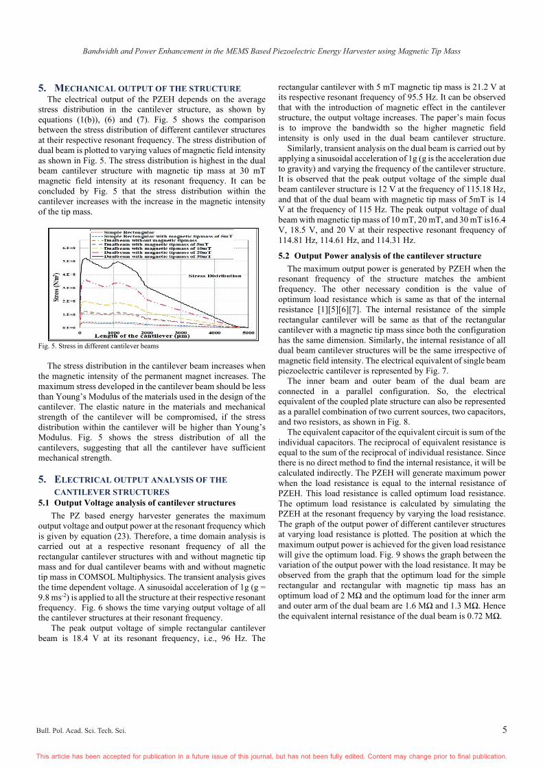
stress distribution in the cantilever structure, as shown by equations (1(b)), (6) and (7). Fig. 5 shows the comparison between the stress distribution of different cantilever structures at their respective resonant frequency. The stress distribution of dual beam is plotted to varying values of magnetic field intensity as shown in Fig. 5. The stress distribution is highest in the dual beam cantilever structure with magnetic tip mass at 30 mT magnetic field intensity at its resonant frequency. It can be concluded by Fig. 5 that the stress distribution within the cantilever increases with the increase in the magnetic intensity of the tip mass.
Fig. 5. Stress in different cantilever beams
The stress distribution in the cantilever beam increases when the magnetic intensity of the permanent magnet increases. The maximum stress developed in the cantilever beam should be less than Young’s Modulus of the materials used in the design of the cantilever. The elastic nature in the materials and mechanical strength of the cantilever will be compromised, if the stress distribution within the cantilever will be higher than Young’s Modulus. Fig. 5 shows the stress distribution of all the cantilevers, suggesting that all the cantilever have sufficient mechanical strength.
5. ELECTRICAL OUTPUT ANALYSIS OF THE
CANTILEVER STRUCTURES 5.1 Output Voltage analysis of cantilever structures
The PZ based energy harvester generates the maximum output voltage and output power at the resonant frequency which is given by equation (23). Therefore, a time domain analysis is carried out at a respective resonant frequency of all the rectangular cantilever structures with and without magnetic tip mass and for dual cantilever beams with and without magnetic tip mass in COMSOL Multiphysics. The transient analysis gives the time dependent voltage. A sinusoidal acceleration of 1g (g = 9.8 ms-2) is applied to all the structure at their respective resonant frequency. Fig. 6 shows the time varying output voltage of all the cantilever structures at their resonant frequency.
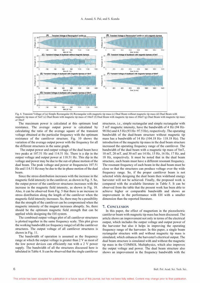
The peak output voltage of simple rectangular cantilever beam is 18.4 V at its resonant frequency, i.e., 96 Hz. The
rectangular cantilever with 5 mT magnetic tip mass is 21.2 V at its respective resonant frequency of 95.5 Hz. It can be observed that with the introduction of magnetic effect in the cantilever structure, the output voltage increases. The paper’s main focus is to improve the bandwidth so the higher magnetic field intensity is only used in the dual beam cantilever structure. Similarly, transient analysis on the dual beam is carried out by applying a sinusoidal acceleration of 1g (g is the acceleration due to gravity) and varying the frequency of the cantilever structure. It is observed that the peak output voltage of the simple dual beam cantilever structure is 12 V at the frequency of 115.18 Hz, and that of the dual beam with magnetic tip mass of 5mT is 14 V at the frequency of 115 Hz. The peak output voltage of dual beam with magnetic tip mass of 10 mT, 20 mT, and 30 mT is16.4 V, 18.5 V, and 20 V at their respective resonant frequency of 114.81 Hz, 114.61 Hz, and 114.31 Hz.
5.2 Output Power analysis of the cantilever structure
The maximum output power is generated by PZEH when the resonant frequency of the structure matches the ambient frequency. The other necessary condition is the value of optimum load resistance which is same as that of the internal resistance [1][5][6][7]. The internal resistance of the simple rectangular cantilever will be same as that of the rectangular cantilever with a magnetic tip mass since both the configuration has the same dimension. Similarly, the internal resistance of all dual beam cantilever structures will be the same irrespective of magnetic field intensity. The electrical equivalent of single beam piezoelectric cantilever is represented by Fig. 7.
The inner beam and outer beam of the dual beam are connected in a parallel configuration. So, the electrical equivalent of the coupled plate structure can also be represented as a parallel combination of two current sources, two capacitors, and two resistors, as shown in Fig. 8.
The equivalent capacitor of the equivalent circuit is sum of the individual capacitors. The reciprocal of equivalent resistance is equal to the sum of the reciprocal of individual resistance. Since there is no direct method to find the internal resistance, it will be calculated indirectly. The PZEH will generate maximum power when the load resistance is equal to the internal resistance of PZEH. This load resistance is called optimum load resistance. The optimum load resistance is calculated by simulating the PZEH at the resonant frequency by varying the load resistance. The graph of the output power of different cantilever structures at varying load resistance is plotted. The position at which the maximum output power is achieved for the given load resistance will give the optimum load. Fig. 9 shows the graph between the variation of the output power with the load resistance. It may be observed from the graph that the optimum load for the simple rectangular and rectangular with magnetic tip mass has an optimum load of 2 MΩ and the optimum load for the inner arm and outer arm of the dual beam are 1.6 MΩ and 1.3 MΩ. Hence the equivalent internal resistance of the dual beam is 0.72 MΩ.
6
A. Anand, S. Pal, and S. Kundu
Bull. Pol. Acad. Sci. Tech. Sci. Bull. Pol. Acad. Sci. Tech. Sci.
This article has been accepted for publication in a future issue of this journal, but has not been fully edited. Content may change prior to final publication. This article has been accepted for publication in a future issue of this journal, but has not been fully edited. Content may change prior to final publication.
Fig. 6. Transient Voltage of (a) Simple Rectangular (b) Rectangular with magnetic tip mass (c) Dual Beam without magnetic tip mass (d) Dual Beam with magnetic tip mass of 5mT (e) Dual Beam with magnetic tip mass of 10mT (f) Dual Beam with magnetic tip mass of 20mT (g) Dual Beam with magnetic tip mass of 30mT
The maximum power is calculated at this optimum load resistance. The average output power is calculated by calculating the ratio of the average square of the transient voltage obtained at the particular frequency with the optimum resistance of the cantilever structure. Fig. 10 shows the variation of the average output power with the frequency for all the different structures in the same graph.
The output power and output voltage of the dual beam have two peaks at 107.51 Hz and 114.51 Hz. There is a dip in the output voltage and output power at 110.51 Hz. This dip in the voltage and power may be due to the out-of-phase motion of the dual beam. The peak voltage and power at frequencies 107.51 Hz and 114.51 Hz may be due to the in-phase motion of the dual beam.
Since the stress distribution increases with the increase in the magnetic field intensity in the cantilever, as shown in Fig. 5. So, the output power of the cantilever structures increases with the increase in the magnetic field intensity, as shown in Fig. 10. Also, it can be observed from Fig. 5 that there is an increase in stress distribution along the length of the cantilever when the magnetic field intensity increases. So, there may be a possibility that the strength of the cantilever can be compromised when the magnetic intensity of the magnet increases abruptly. So, there should be the optimum magnetic field strength that can be applied while designing the EH system.
The combined output voltage plot of all cantilever structures is plotted together in the same frequency scale. This plot gives the working bandwidth (or frequency range) of all the cantilever structures. The output voltage of all cantilever structures is shown in Fig. 11.
The bandwidth of operation is assumed as the frequency range at which the output voltage is greater than 2 V as most of the low power devices can efficiently run with a 2 V power supply. The bandwidth of all the structures discussed here is tabulated in Table 4. It can be observed that the single cantilever
structures, i.e., simple rectangular and simple rectangular with 5 mT magnetic intensity, have the bandwidth of 4 Hz (94 Hz- 98 Hz) and 4.5 Hz (93 Hz- 97.5 Hz), respectively. The operating bandwidth of the dual-beam structure without magnetic tip mass has a bandwidth of 14 Hz (104.18 Hz- 118.18 Hz). The introduction of the magnetic tip mass in the dual beam structure increased the operating frequency range of the cantilever. The bandwidth of the dual beam with a magnetic tip mass of 5mT, 10 mT, 20 mT, and 30 mT are 14 Hz, 15 Hz, 16 Hz, 17 Hz, and 18 Hz, respectively. It must be noted that in the dual beam structure, each beam must have a different resonant frequency. The resonant frequency of each beam in the dual beam must be close so that the structures can produce voltage over the wide frequency range. So, if the proper cantilever beam is not selected while designing the dual beam then wideband energy harvester will not be achieved. Finally, the proposed work is compared with the available literature in Table 5. It can be observed from the table that the present work has been able to achieve higher or comparable bandwidth and shows an improvement in the performance with EH with a smaller dimension than the reported literature.
7. CONCLUSION
In this paper, the effect of magnetism in the piezoelectric cantilever beam with magnetic tip mass has been discussed. The article shows an improvement not only in terms of the electrical output, which includes the output voltage and output power of the harvester but also it helps in improving the operating frequency range of the harvester. In this paper, a single beam rectangular structure with and without magnetic tip mass is simulated, which enhances the harvester's electrical output. The dual beam structure is simulated with and without the magnetic tip mass in the COMSOL Multiphysics, which also improves the output voltage and power. The dual beam structure also shows an improvement in the frequency bandwidth with the

7
Bandwidth and Power Enhancement in the MEMS Based Piezoelectric Energy Harvester using Magnetic Tip Mass
Bull. Pol. Acad. Sci. Tech. Sci. Bull. Pol. Acad. Sci. Tech. Sci.
This article has been accepted for publication in a future issue of this journal, but has not been fully edited. Content may change prior to final publication. This article has been accepted for publication in a future issue of this journal, but has not been fully edited. Content may change prior to final publication.
introduction of the magnetic field intensity. The increase in the magnetic field intensity improves the output voltage and power of the dual beam structures. There is a significant improvement in the frequency bandwidth of the dual beam structures compared to the single beam rectangular structures. The operational frequency bandwidth of the dual beam cantilever with a magnetic tip mass of 30 mT is 18 Hz as compared to the simple rectangular cantilever with or without the magnetic tip mass, which has the operational frequency bandwidth of 4.5 Hz and 4 Hz. The operating frequency range of the proposed dual beam cantilever with magnetic tip mass is from 102.51 Hz to 120.51 Hz. The proposed dual beam's output power and output voltage with a magnetic tip mass of 30 mT is 12.2 µW and 20 V, respectively.
Fig. 7. Electrical equivalent model of a PZ Cantilever Plate
Fig. 8. Electrical equivalent circuit model for coupled dual beam structure
Fig. 9. Variation of Output Power with Load Resistance
Fig. 10. Variation of output power with Frequency for all cantilever structures
Table 4. Bandwidth of all the structure
Structures Bandwidth Peak
Voltage (V)
Average Power (µW)
Simple Rectangular Cantilever
4 Hz (94-98 Hz)
18.4 12.614
Rectangular Cantilever with magnetic tip mass
of 5mT
4.5 Hz (93-97.5 Hz)
21.2 13.52
Dual beam without magnetic tip mass
14 Hz (104.18-
118.18 Hz) 12 12.42
Dual beam with magnetic tip mass of
5mT
15 Hz (103.51-
118.51 Hz) 14 15.12
Dual beam with magnetic tip mass of 10
mT
16 Hz (103.51-
119.51 Hz) 16.4 19.58
Dual beam with magnetic tip mass of 20
mT
17 Hz (103.51-
120.51 Hz) 18.5
21.4
Dual beam with magnetic tip mass of 30
mT
18 Hz (102.51-
120.51 Hz) 20 25.5
Fig. 11. Variation of output voltage with Frequency for all cantilever structures
Table 5. Comparison of the proposed work with the existing literature Ref (year) Dimension Bandwidth Electrical output [19] Challa et.al. (2008)
Beam- 34x20x0.6 mm3
10 Hz (22 -32 Hz)
Power - 240–280 μW
[31] Zhu et.al (2010)
Beam- 13x5x0.12 mm3
30.4 Hz (67.6 - 98 Hz)
Power - 61.6–156.6 µW
[32] W. Su et.al. (2014)
Length 98 mm, width 20 mm, thickness 0.531 mm
3.8 Hz (10 - 13.8 Hz)
Power – 1.8 mW
[33] Guo et.al. (2016)
Beam 1- 120x20x2 mm3 Beam 2- 120x20x1 mm3
14 Hz (28-42 Hz)
Beam 1- Voltage – 24.84 V, power 81.97 mW/g2; Beam 2 Voltage - 18.36V, Power -44.78 mW/g2
This work 5x2.5x0.014 mm3 18 Hz (102.51-120.51 Hz).
Voltage – 20 V, Power 12.20 µW
This article uses the concept of a multi-beam structure using the magnetic field strength in the EH system to improve the bandwidth. The use of an efficient electrode design can further enhance the efficiency of EH. Another way to change the
8
A. Anand, S. Pal, and S. Kundu
Bull. Pol. Acad. Sci. Tech. Sci. Bull. Pol. Acad. Sci. Tech. Sci.
This article has been accepted for publication in a future issue of this journal, but has not been fully edited. Content may change prior to final publication. This article has been accepted for publication in a future issue of this journal, but has not been fully edited. Content may change prior to final publication.
orientation and position of a permanent magnet to enhance the bandwidth further.
REFERENCES 1. Glynne-Jones, P., Tudor, M. J., Beeby, S. P., & White, N. M., “An
electromagnetic, vibration-powered generator for intelligent sensor systems,” Sensors Actuators, A Phys., vol. 110, no. 1–3, pp. 344–349, 2004. https://doi.org/10.1016/j.sna.2003.09.045
2. Mitcheson, P. D., Miao, P., Stark, B. H., Yeatman, E. M., Holmes, A. S., & Green, T. C., “MEMS electrostatic micropower generator for low frequency operation,” Sensors Actuators, A Phys., vol. 115, no. 2–3, pp. 523–529, 2004. DOI: 10.1016/j.sna.2004.04.026
3. Mitcheson, P. D., Yeatman, E. M., Rao, G. K., Holmes, A. S., & Green, T. C., “Energy harvesting from human and machine motion for wireless electronic devices,” Proc. IEEE, vol. 96, no. 9, pp. 1457–1486, 2008. DOI: 10.1109/JPROC.2008.927494
4. Ostrowski, M., Błachowski, B., Bocheński, M., Piernikarski, D., Filipek, P., & Janicki, W., “Design of nonlinear electromagnetic energy harvester equipped with mechanical amplifier and spring bumpers,” Bull. Pol. Ac.: Tech. vol. 68, no. 6, pp. 1373-1383, 2020. DOI: 10.24425/bpasts.2020.135384
5. Anand, A., Pal, S., & Kundu, S., “Multi-perforated Energy-Efficient Piezoelectric Energy Harvester Using Improved Stress Distribution,” IETE J. Res., pp-1-16, 2021, DOI:10.1080/03772063.2021.1913071
6. Anand A, Naval S, Sinha PK, Das NK, Kundu S., “Effects of coupling in piezoelectric multi-beam structure,” Microsystem Technologies. Vol-26, no-4, pp- 1235-1252 2020. DOI: 10.1007/s00542-019-04653-3
7. Anand A, Kundu S., “Improvement of Output Power in Piezoelectric Energy Harvester under Magnetic Influence,” Proceedings of 3rd International Conference on 2019 Devices for Integrated Circuit, DevIC 2019 IEEE, pp. 382-385. 2019. DOI: 10.1109/DEVIC.2019.8783607
8. Anand A, Kundu S., “Design of a spiral-shaped piezoelectric energy harvester for powering pacemakers,” Nanomaterials and Energy, vol-8, no-2, pp-139-150, 2019, https://doi.org/10.1680/jnaen.19.00016
9. Anand, A., & Kundu, S., “Design of Mems Based Piezoelectric Energy Harvester for Pacemaker,” Proceedings of 3rd International Conference on Devices for Integrated Circuit, DevIC, IEEE, 2019, pp 465–469. https://doi.org/10.1109/DEVIC.2019.8783311
10. Roundy, S., Wright, P. K., & Rabaey, J., “A study of low level vibrations as a power source for wireless sensor nodes,” Comput. Commun., vol. 26, no. 11, pp. 1131–1144, 2003. DOI: 10.1016/S0140-3664(02)00248-7
11. Naval, S., Sinha, P. K., Das, N. K., Anand, A., & Kundu, S., “Wideband piezoelectric energy harvester design using parallel connection of multiple beams,” International Journal of Nanoparticles, vol-12,no-3, pp 206–223, 2020, https://doi.org/10.1504/IJNP.2020.109545
12. Naval, S., Sinha, P. K., Das, N. K., Anand, A., & Kundu, S., “Bandwidth Increment of Piezoelectric Energy Harvester using Multi-beam Structure,” Proceedings of 3rd International Conference on 2019 Devices for Integrated Circuit, DevIC 2019, IEEE, pp 370–373. https://doi.org/10.1109/DEVIC.2019.8783724
13. Kim, H. S., Kim, J. H., & Kim, J., “A review of piezoelectric energy harvesting based on vibration,” Int. J. Precis. Eng. Manuf., vol. 12, no. 6, pp. 1129–1141, 2011. DOI: 10.1007/s12541-011-0151-3
14. Sokół K.,“Passive control of instability regions by means of piezoceramic elements,” Lat. Am. j. solids struct, vol-18, no-1, DOI: 10.1590/1679-78256015.
15. Irschik H., “A review on static and dynamic shape control of structures by piezoelectric actuation,” Engineering Structures, vol-24, no-1, pp-5-11, 2002, DOI: 10.1016/S0141-0296(01)00081-5.
16. Peng J, Zhang G, Xiang M, Sun H, Wang X, Xie X.,“Vibration control for the nonlinear resonant response of a piezoelectric elastic beam via time-delayed feedback,” Smart Materials and Structures, vol-28, no-9,pp-095010, 2019, DOI: 0000-0003-0104-522X.
17. Hu H, Han Y, Song A, Chen S, Wang C, Wang Z., “A finger-shaped tactile sensor for fabric surfaces evaluation by 2-dimensional active sliding touch,” Sensors, vol-14, no-3, pp-4899-4913, 2014, DOI: 10.3390/s140304899.
18. Daqaq, M. F., Masana, R., Erturk, A., & Dane Quinn, D., “On the role of nonlinearities in vibratory energy harvesting: a critical review and discussion,” Appl. Mech. Rev. vol-66 no-4, 2014 pp- 040801. DOI: 10.1115/1.4026278
19. Challa, V. R., Prasad, M. G., Shi, Y., & Fisher, F. T., “A vibration energy harvesting device with bidirectional resonance frequency tunability,”
Smart Materials and Structures, vol. 17, no-1, pp. 015035, 2008. DOI: 10.1088/0964-1726/17/01/015035
20. Barton, D. A., Burrow, S. G., & Clare, L. R., “Energy harvesting from vibrations with a nonlinear oscillator,” J Vib Acoust; vol-132, no-02, 2010. DOI: 10.1115/1.4000809
21. Stanton, S. C., McGehee, C. C., & Mann, B. P., “Reversible hysteresis for broadband magnetopiezoelastic energy harvesting,” Appl Phys Lett, vol-95, no-17, pp174103, 2009. DOI: 10.1063/1.3253710
22. Erturk A, Inman D. J., “Broadband piezoelectric power generation on high-energy orbits of the bistable Duffing oscillator with electromechanical coupling,” J Sound Vib, vol- 330, no-10, pp- 2339-2353, 2011, DOI: 10.1016/j.jsv.2010.11.018
23. Zhou S, Cao J, Erturk A, Lin J., “Enhanced broadband piezoelectric energy harvesting using rotatable magnets,” Appl Phys Lett, vol-102, no-17, pp-173901, 2013. DOI: 10.1063/1.4803445
24. Zhou S, Cao J, Wang W, Liu S, Lin J., “Modeling and experimental verification of doubly nonlinear magnet-coupled piezoelectric energy harvesting from ambient vibration,” Smart Mater Struct, vol-24, no-5,pp-055008, 2015. DOI: 10.1088/0964-1726/24/5/055008
25. Zhou S, Cao J, Inman DJ, Lin J, Liu S, Wang Z., “Broadband tristable energy harvester: modeling and experiment verification,” Appl Energy; vol-133, pp-33-39, 2014, DOI: 10.1016/j.apenergy.2014.07.077
26. Haitao, L., Weiyang, Q., Chunbo, L., Wangzheng, D., & Zhiyong, Z., “Dynamics and coherence resonance of tri- stable energy harvesting system,” Smart Mater Struct, vol-25,no-1, pp-015001, 2015., DOI: 10.1088/0964-1726/25/1/015001
27. Cao JY, Zhou SX, Wang W, Lin J., “Influence of potential well depth on nonlinear tristable energy harvesting”. Appl Phys Lett, vol-106, no-7, pp-173903, 2015, DOI: 10.1063/1.4919532.
28. Kim P, Seok J., “A multi-stable energy harvester: dynamic modeling and bifurcation analysis,” J Sound Vib, vol-333, no-21, pp-5525-5547, 2014. DOI: 10.1016/j.jsv.2014.05.054
29. Zhou Z, Qin W, Yang Y, Zhu P., “Improving efficiency of energy harvesting by a novel penta-stable configuration,” Sensors and Actuators, A: Physical, vol-265, pp-297–305, 2017. DOI: 10.1016/j.sna.2017.08.039
30. Tan D, Leng YG, Gao YJ., “Magnetic force of piezoelectric cantilever energy harvesters with external magnetic field,” European Physical Journal: Special Topics, vol-224, no-14, pp-2839–2853, 2015, DOI: 10.1140/epjst/e2015-02592-6
31. Zhu, D., Roberts, S., Tudor, M. J., & Beeby, S. P., “Design and experimental characterization of a tunable vibration-based electromagnetic micro-generator,” Sensors and Actuators, A: Physical, vol-158, no-2, pp-284–293, 2010. DOI: 10.1016/j.sna.2010.01.002
32. Su, W. J., Zu, J., & Zhu, Y., “Design and development of a broadband magnet-induced dual-cantilever piezoelectric energy harvester,” J Intell Mater Syst Struct, vol. 25, no. 4, pp. 430–442, 2014. DOI: 10.1177/1045389X13498315
33. Guo, D., Zhang, X. F., Li, H. Y., & Li, H., “Piezoelectric Energy Harvester Array with Magnetic Tip Mass,”, In ASME International Mechanical Engineering Congress and Exposition, American Society of Mechanical Engineers. 2015, vol- 57403, pp. V04BT04A045, 2015. DOI: 10.1115/IMECE2015-51044
34. Rao, S.S., “Vibration of continuous systems” John Wiley & Sons, Ltd, 2019. DOI: 10.1002/9781119424284
Related Documents