Balancing Procedure CBAV 1. Waterside Commissioning 1) Fully purge the complete hydronic system of air prior to commissioning. 2) Carefully inspect the system for leaks, paying particular attention to the connections. 3) Carefully inspect flexible hose, if applicable, for leaks. 4) Use system balancing valves to adjust water flow rate to specified values. Note. The chilled beam is not provided with any water flow control or measuring devices, therefore the pipe work system should be fitted with sufficient balancing aids to enable adjustment of the flow rate. 2a. Airside Commissioning — Preparation Check that the ductwork between main supply air ducts and chilled beams is airtight. Connections and fittings should be sealed to SMACNA class B standard up to 2 in. w.g. Ductwork pressure testing is recommended to identify leaks before the chilled beams are balanced. Final duct connections should be straight immediately upstream of the chilled beam units. Ductwork should have at least THREE duct diameters length of straight duct before the first system bends. Twisted or kinked flexible duct final connections or bends immediately upstream of the beam will result in incorrect pressure port readings on the beam. 2b. Airside Commissioning — Airflow Measuring & Balancing Procedure Note. Do not attempt to read the total discharge airflow rate using a hood or any other device that adds downstream pressure to the beam as it will reduce the amount of induction and give false readings. The total air flow (primary + induced) cannot be measured! The pitot-traverse method must not be used to measure the airflow in the small primary air ducts serving the chilled beam, this will result in inaccurate readings, the only accurate method is to measure the static pressure in the primary air plenum as described in the next section. The primary air flow rate is determined by measuring the static pressure in the primary air chamber and referring to the calibration chart label provided on each beam or the charts shown at the end of this document. Alternatively use the static pressures listed on the Titus chilled beam schedule provided in the submittal drawing set.

Welcome message from author
This document is posted to help you gain knowledge. Please leave a comment to let me know what you think about it! Share it to your friends and learn new things together.
Transcript
Balancing Procedure
CBAV
1. Waterside Commissioning
1) Fully purge the complete hydronic system of air prior to commissioning.
2) Carefully inspect the system for leaks, paying particular attention to the connections.
3) Carefully inspect flexible hose, if applicable, for leaks.
4) Use system balancing valves to adjust water flow rate to specified values.
Note.
The chilled beam is not provided with any water flow control or measuring devices, therefore the pipe work
system should be fitted with sufficient balancing aids to enable adjustment of the flow rate.
2a. Airside Commissioning — Preparation
Check that the ductwork between main supply air ducts and chilled beams is airtight. Connections and
fittings should be sealed to SMACNA class B standard up to 2 in. w.g. Ductwork pressure testing is
recommended to identify leaks before the chilled beams are balanced.
Final duct connections should be straight immediately upstream of the chilled beam units. Ductwork should
have at least THREE duct diameters length of straight duct before the first system bends. Twisted or kinked
flexible duct final connections or bends immediately upstream of the beam will result in incorrect pressure
port readings on the beam.
2b. Airside Commissioning — Airflow Measuring & Balancing Procedure
Note.
Do not attempt to read the total discharge airflow rate using a hood or any other device that adds downstream
pressure to the beam as it will reduce the amount of induction and give false readings. The total air flow
(primary + induced) cannot be measured!
The pitot-traverse method must not be used to measure the airflow in the small primary air ducts serving the
chilled beam, this will result in inaccurate readings, the only accurate method is to measure the static pressure in
the primary air plenum as described in the next section.
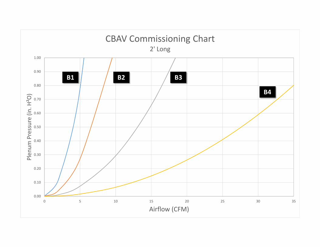
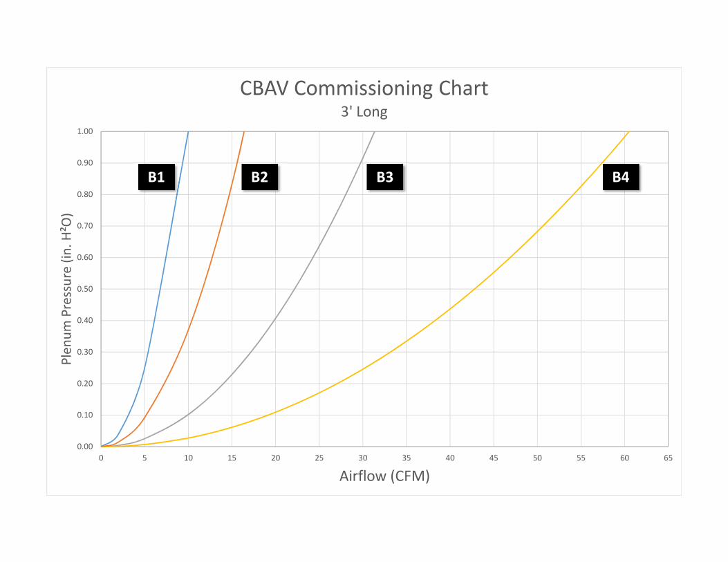
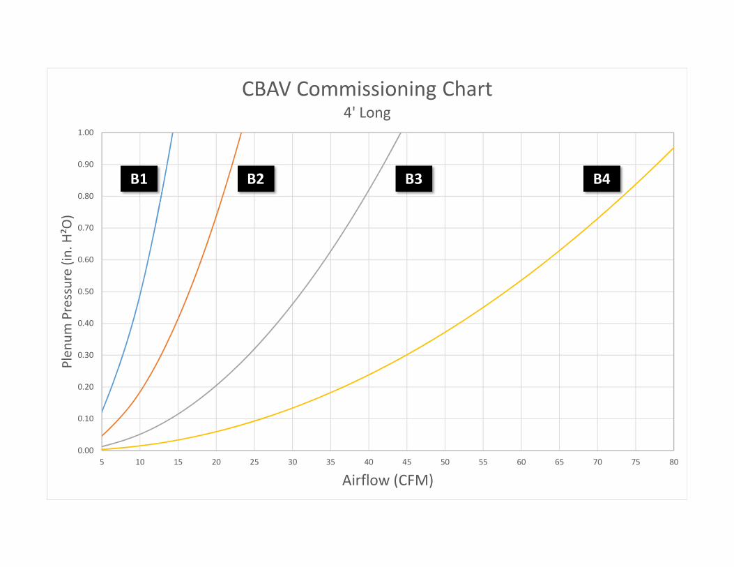
The primary air flow rate is determined by measuring the static pressure in the primary air chamber and
referring to the calibration chart label provided on each beam or the charts shown at the end of this
document. Alternatively use the static pressures listed on the Titus chilled beam schedule provided in the
submittal drawing set.
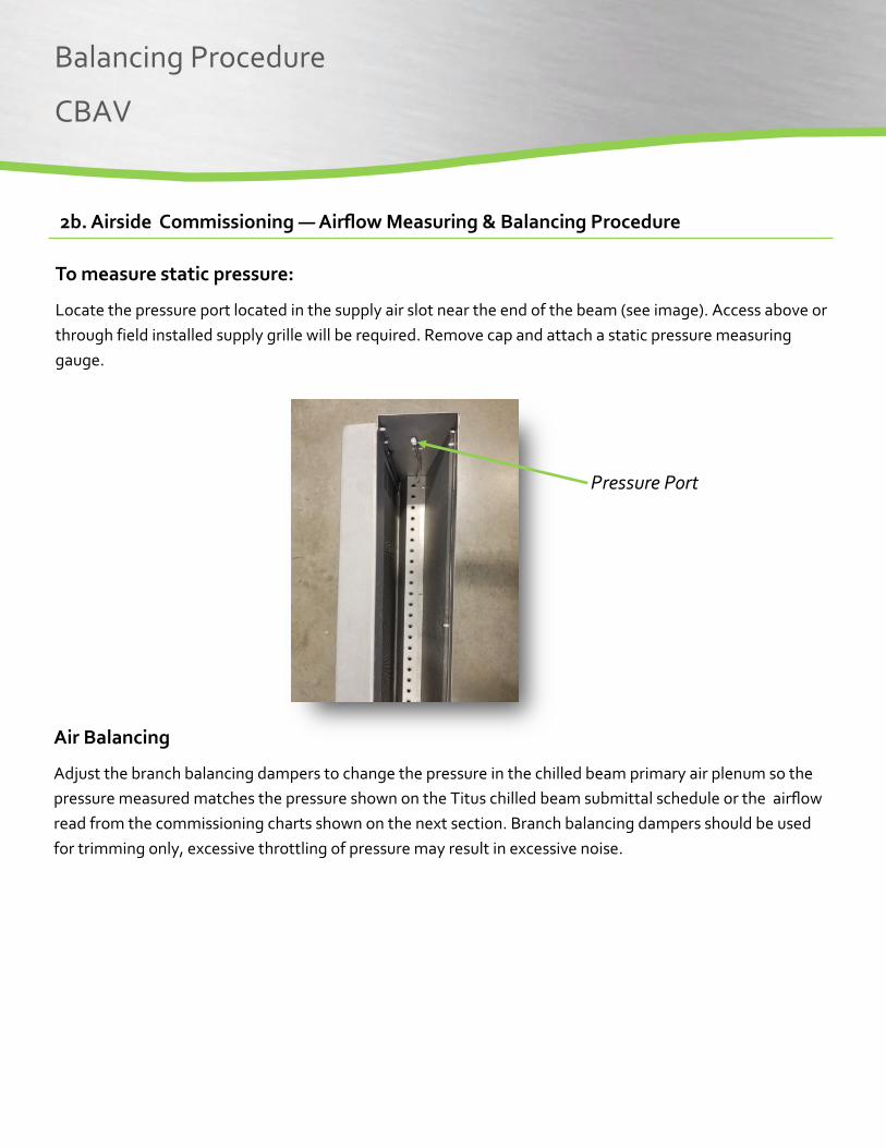
To measure static pressure:
Locate the pressure port located in the supply air slot near the end of the beam (see image). Access above or through field installed supply grille will be required. Remove cap and attach a static pressure measuring
gauge.
Pressure Port
Balancing Procedure
CBAV
2b. Airside Commissioning — Airflow Measuring & Balancing Procedure
Air Balancing
Adjust the branch balancing dampers to change the pressure in the chilled beam primary air plenum so the
pressure measured matches the pressure shown on the Titus chilled beam submittal schedule or the airflow
read from the commissioning charts shown on the next section. Branch balancing dampers should be used
for trimming only, excessive throttling of pressure may result in excessive noise.

3. Airside Commissioning Charts
Balancing Procedure
CBAV
0.00
0.10
0.20
0.30
0.40
0.50
0.60
0.70
0.80
0.90
1.00
0 5 10 15 20 25 30 35
Plen
um Pressure (in
. H²O)
Airflow (CFM)
CBAV Commissioning Chart2' Long
B3
B4
B2B1
0.00
0.10
0.20
0.30
0.40
0.50
0.60
0.70
0.80
0.90
1.00
0 5 10 15 20 25 30 35 40 45 50 55 60 65
Plen
um Pressure (in
. H²O)
Airflow (CFM)
CBAV Commissioning Chart3' Long
B3 B4B2B1
0.00
0.10
0.20
0.30
0.40
0.50
0.60
0.70
0.80
0.90
1.00
5 10 15 20 25 30 35 40 45 50 55 60 65 70 75 80
Plen
um Pressure (in
. H²O)
Airflow (CFM)
CBAV Commissioning Chart4' Long
B2 B3 B4B1
0.00
0.10
0.20
0.30
0.40
0.50
0.60
0.70
0.80
0.90
1.00
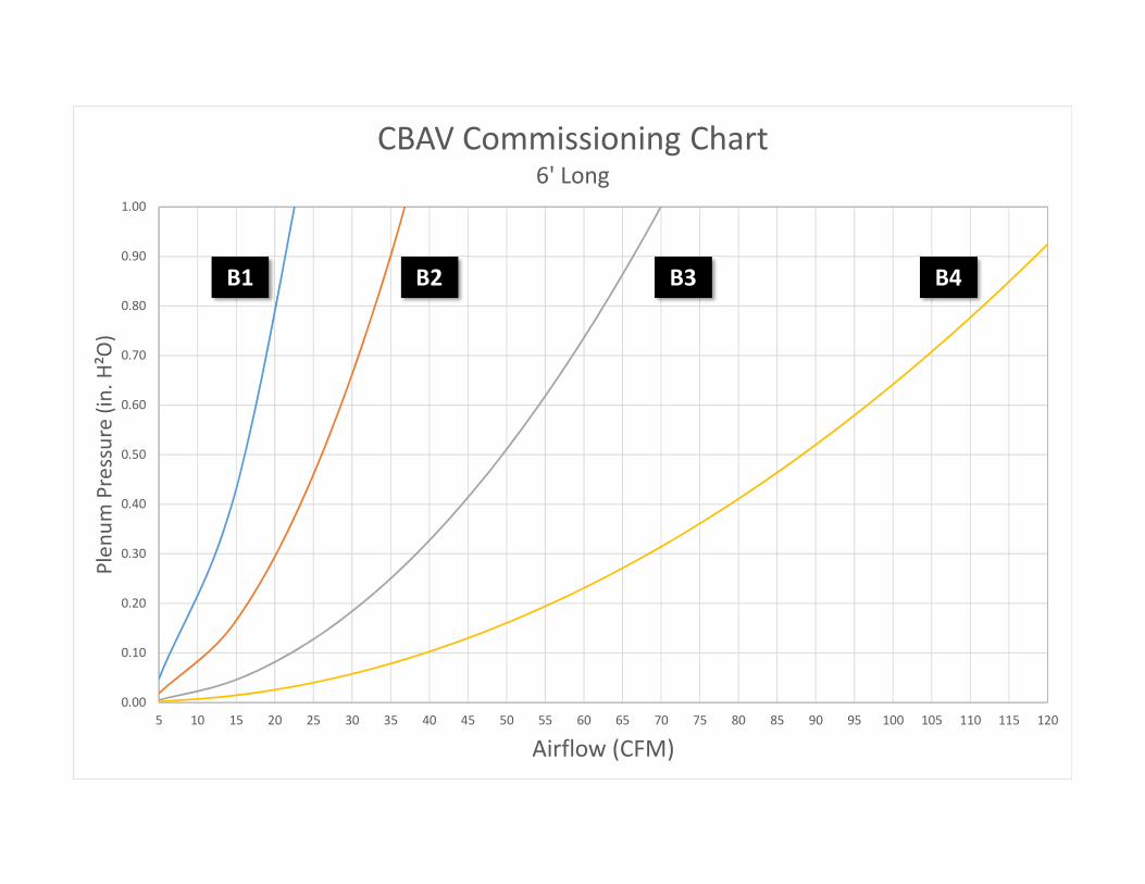
5 10 15 20 25 30 35 40 45 50 55 60 65 70 75 80 85 90 95 100 105 110 115 120
Plen
um Pressure (in
. H²O)
Airflow (CFM)
CBAV Commissioning Chart6' Long
B1 B2 B3 B4
0.00
0.10
0.20
0.30
0.40
0.50
0.60
0.70
0.80
0.90
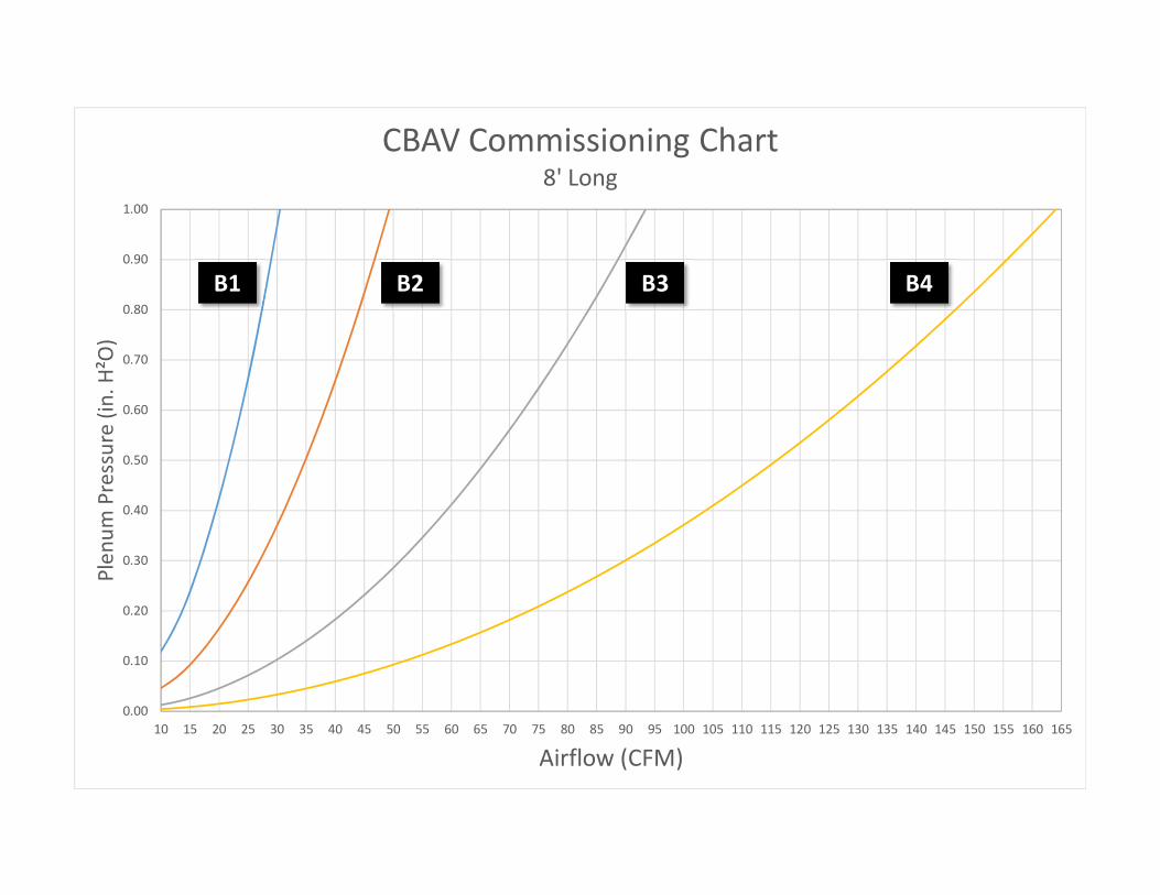
1.00
10 15 20 25 30 35 40 45 50 55 60 65 70 75 80 85 90 95 100 105 110 115 120 125 130 135 140 145 150 155 160 165
Plen
um Pressure (in
. H²O)
Airflow (CFM)
CBAV Commissioning Chart8' Long
B1 B2 B3 B4
Related Documents


![Strategies to Increase Res HVAC Efficiency [FINAL] · Strategies to Increase Residential HVAC Efficiency in the Northeast Final Report May 2006 Prepared by: Elizabeth Titus, Project](https://static.cupdf.com/doc/110x72/5fff06016a8b337871567225/strategies-to-increase-res-hvac-efficiency-final-strategies-to-increase-residential.jpg)
