ChemPlant Technology s.r.o. Tel.: +420 474 527 221 V Zahradkach 656/31 400 01 Ústí nad Labem E-mail: [email protected] Balancing and Data Reconciliation of a coal fired boiler Author: Frantisek Madron Ústí nad Labem August 2013 Report CPT-321-13 Date of issue: 23.8.2013 This report has 29 pages.

Welcome message from author
This document is posted to help you gain knowledge. Please leave a comment to let me know what you think about it! Share it to your friends and learn new things together.
Transcript

ChemPlant Technology s.r.o. Tel.: +420 474 527 221 V Zahradkach 656/31 400 01 Ústí nad Labem E-mail: [email protected]
Balancing and Data Reconciliation
of a coal fired boiler
Author: Frantisek Madron
Ústí nad Labem August 2013
Report CPT-321-13 Date of issue: 23.8.2013
This report has 29 pages.

i
This report is the internal report of ChemPlant Technology, s.r.o. It is not allowed to pass this report to any third party without a written permission
of ChemPlant Technology, s.r.o.

i
Index
SUMMARY 1
1. INTRODUCTION 2
2. A PULVERIZED COAL FIRED BOILER 3
2.1. System description 3
2.2. Targets of monitoring 3
2.3. Method of solution 5
2.4. The balancing flowsheet 6
2.5. Modeling in RECON 8 2.5.1 Basic considerations 8 2.5.2 Modeling the combustion chamber 12 2.5.3 Modeling the flue gas path 13 2.5.4 Modeling the water and the steam path 15 2.5.5 User defined equations 15
3. RESULTS OF DATA RECONCILIATION 17
LITERATURE 20
APPENDIX 1: RECON’S OUTPUT FILE 21

1
Summary 1. The present report describes the modeling and data reconciliation of a pulverized
coal fired boiler.
2. The model is based on a detailed mass, component and energy balance of main process units (air preheater, firebox, steam superheaters, economizer and steam coolers). The combustion chamber is modeled as a reaction invariant chemical reactor. The balancing model was complemented by user defined equations defining KPIs.
3. The following KPIs were calculated:
Efficiency of the boiler
Estimation of the coal consumption which is not measured
Fouling of heat transfer areas of all heat exchangers (steam superheaters, economizer, air preheater) in the form of HTC (Heat Transfer Coefficients)
Detailed mass and heat balance of the system including heat duties of all heat transfers
Information about leaks and the economizer bypass
4. The following results of calculation were discussed:
Precision of boiler’s efficiency determination and possible improvement in this direction (key measured variables influencing the precision)
Precision of other KPI’s
Possibilities and limitations of gross errors detection.

2
1. Introduction Coal fired power stations are the most common plants which convert coal into electric energy and large power stations provide the majority of the world's electricity. Boilers which generate steam are complex systems which require adequate monitoring, control and maintenance.
This report describes modeling and data reconciliation of coal fired boilers in the program RECON. There are several challenging features which must not be neglected during this activity, for example
The on-line measurement of the coal input is frequently not accurate enough for a direct determination of boiler’s efficiency
The quality of the coal is often not constant (the content of water, ash and other qualitative variables are variable or several kinds of coal can be blended)
There can be significant leaks in a boiler causing a not required entry of air in a boiler
Mass and energy balance of boilers requires mastering several unit operations, from chemical reactions in the combustion chamber to balancing high pressure steam, sometime in the supercritical state
High temperatures (especially in the flue gas path) causing problems in temperature measurement due to the radiation)
Different systems of units occurring in one task (generally the mass balance complemented by volume measurement of air and composition of flue gases in moles measured on the dry basis).
Further will be modeled a typical medium size coal fired boiler with air preheat and steam superheaters. As there are two fuels (coal and a fuel gas), the solution can be also a prototype for gas fueled boilers (in general, gas fueled boilers are simpler than coal fired boilers, as concerns their modeling). Sometimes we can meet boilers with a steam reheat, but this is not a significant problem in modeling.
3
2. A pulverized coal fired boiler
2.1. System description
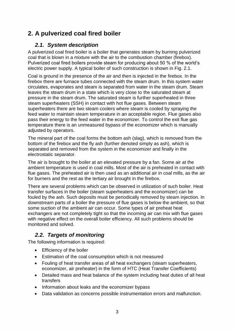
A pulverized coal fired boiler is a boiler that generates steam by burning pulverized coal that is blown in a mixture with the air to the combustion chamber (firebox). Pulverized coal fired boilers provide steam for producing about 50 % of the world’s electric power supply. A typical boiler of such construction is shown in Fig. 2.1.
Coal is ground in the presence of the air and then is injected in the firebox. In the firebox there are furnace tubes connected with the steam drum. In this system water circulates, evaporates and steam is separated from water in the steam drum. Steam leaves the steam drum in a state which is very close to the saturated steam at pressure in the steam drum. The saturated steam is further superheated in three steam superheaters (SSH) in contact with hot flue gases. Between steam superheaters there are two steam coolers where steam is cooled by spraying the feed water to maintain steam temperature in an acceptable region. Flue gases also pass their energy to the feed water in the economizer. To control the exit flue gas temperature there is an unmeasured bypass of the economizer which is manually adjusted by operators.
The mineral part of the coal forms the bottom ash (slag), which is removed from the bottom of the firebox and the fly ash (further denoted simply as ash), which is separated and removed from the system in the economizer and finally in the electrostatic separator.
The air is brought to the boiler at an elevated pressure by a fan. Some air at the ambient temperature is used in coal mills. Most of the air is preheated in contact with flue gases. The preheated air is then used as an additional air in coal mills, as the air for burners and the rest as the tertiary air brought in the firebox.
There are several problems which can be observed in utilization of such boiler. Heat transfer surfaces in the boiler (steam superheaters and the economizer) can be fouled by the ash. Such deposits must be periodically removed by steam injection. In downstream parts of a boiler the pressure of flue gases is below the ambient, so that some suction of the ambient air can occur. Some types of air preheat heat exchangers are not completely tight so that the incoming air can mix with flue gases with negative effect on the overall boiler efficiency. All such problems should be monitored and solved.
2.2. Targets of monitoring
The following information is required:
Efficiency of the boiler
Estimation of the coal consumption which is not measured
Fouling of heat transfer areas of all heat exchangers (steam superheaters, economizer, air preheater) in the form of HTC (Heat Transfer Coefficients)
Detailed mass and heat balance of the system including heat duties of all heat transfers
Information about leaks and the economizer bypass
Data validation as concerns possible instrumentation errors and malfunction.
4
Fig. 2.1: A pulverized coal-fired boiler
Coal-air mix
Superheated steam
Steam cooling
Steam drum
SSH3 SSH2 SSH1
Fu
rnac
e t
ub
es
Economizer
Hot air
Blowdown
Coal
Coal
pulverizer
Fuel gas Ash
Ambient air
Air preheater
Feedwater
Flue Gas
ES
Slag
Fan
Ash

5
2.3. Method of solution
There exits the international standard [1] which deals with acceptance test of boilers (new boilers or boilers after revamps). This document will be used as a basis in creating the model.
The most important is the determination of the boiler efficiency. There are 2 methods described in [1] which will be here a little bit simplified:
1. In the direct method the efficiency is defined as a ratio of the useful heat transferred to the water and steam in the boiler to the total energy brought to the system (mainly the low heating value of the fuel).
(2-1)
where D boiler efficiency determined by the direct method
Etot total energy brought in the boiler
Eu useful energy transferred to the feed water and steam
2. In the indirect method the efficiency is determined as
(2-2)
where I boiler efficiency determined by the indirect method
Eloss sum of all losses
Obviously
(2-3)
The advantage of the indirect method is that it does not require the knowledge of the feed of the fuel (which is frequently difficult to measure on-line). Moreover, the result of the indirect method is in most cases more precise than in the direct method.
Further we will use the indirect method. In our model the following assumptions will be accepted:
1. The useful heat transferred to the feed water and to the steam are heat fluxes in the
boiler (transformation of the feed water into a saturated steam)
3 steam superheaters
economizer

6
2. The losses consist mostly of the apparent heat of the following streams:
Slag
2 ash streams
flue gas leaving the electrostatic separator
heat loss from the whole boiler by convention and radiation. This loss is calculated as a constant from [1], Eq.(8.3-42), depending on the maximum design heat power of the boiler.
There were the following simplification done: the loss by incomplete combustion was neglected. The content of CO in flue gas is negligible from the balancing point of view (less than 100 ppm by volume). The information about the incompletely combusted flammable part of the coal presented in the ash was not available. Also the heat of the incoming air was not included in the efficiency calculation.
The indirect method of the efficiency determination requires the information about the apparent heat loss of streams leaving the boiler (slag, ash and flue gases). To calculate heat loss in these streams, the hypothetical coolers must be implemented in the balancing model (see Section 2.5). In these coolers all streams are cooled to the reference temperature. The reference temperature 25 oC was selected in this case.
The Blowdown requires some discussion. The Blowdown in our case is recycled via a feed water treatment plant, so that its energy is not lost. In the opposite case its energy should be added to other loss streams.
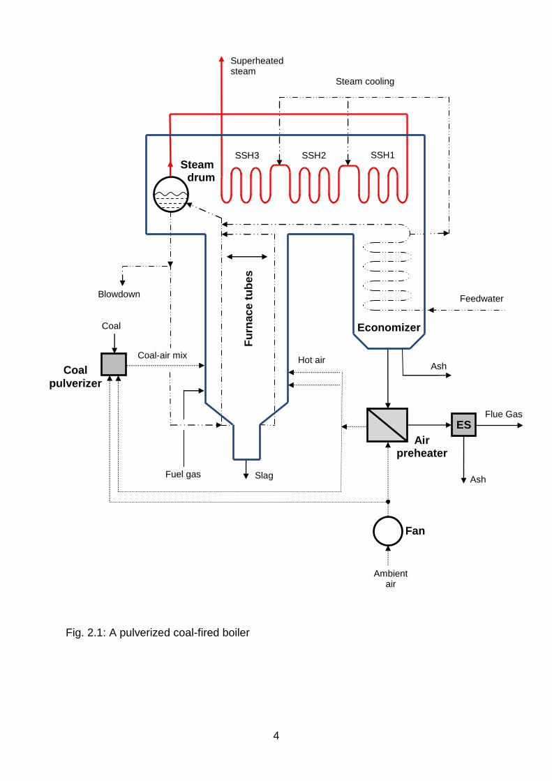
2.4. The balancing flowsheet
Before creating a complex flowsheet in RECON it is good to draw a simple flowsheet which can be used during the model building in RECON. Such a sketch is shown in Fig. 2.2.
The furnace part of the system is separated into 3 balancing nodes:
Combustion chamber where the pulverized coal, fuel gas and air are mixed and burned. Leaving gases and ash create a mixture which leaves this node. There is no heat flux from this node and the calculated temperature in this node is the so-called theoretical flame temperature.
Flame is the hypothetical node which serves for a heat transfer from the firebox to the water part of the boiler and from this node is also withdrawn the heat loss stream by convention and radiation.
The Boiler node represents tubes in the firebox and the drum. It is supposed that steam leaving this node is saturated steam at the pressure in the drum. In reality this steam is wet.
It should be noted that this part of the model is idealized. In practice there is probably no theoretical flame temperature inside the firebox due to a continuous heat transfer to other parts of the boiler. Also the steam leaving the drum is not saturated. But all this has no significant effect on final results (boiler efficiency , etc.).
Flue gases and ash are then in a less or more countercurrent contact with steam in 3 steam superheaters and later with the feed water in the economizer. The economizer can be bypassed on the flue gas side to control the exit flue gas temperature. There are also 2 steam coolers on the steam path where the steam is cooled by spraying a part of the feed water in the steam.
7
Fig. 2.2: A pulverized coal-fired boiler – a balancing flowsheet
Co
mb
us
tio
n
Ch
am
be
r
Bo
ile
r
ES
F
T
T
T
P
T F Feed water
ECO SSH3 SSH2 SSH1
F
T
F
T T
T
T F
Qloss
T T T T
F T
Air
preheater
Ash cooling
T
Qloss
Ash
Flue gas
cooling Qloss
Flue gas exit
Air in
Ash
cooling
F
F
F
F
Qloss
Coal Fuel gas
Slag
cooling
Qloss
Steam
Superheated steam
Flame
Feed water
Blowdown
P
O2
O2
T
%
P

8
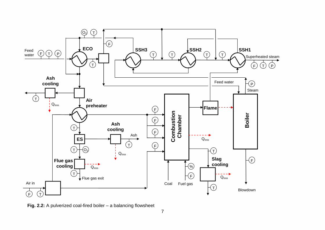
The slag and the ash are removed from the system from the firebox and in the economizer and the electrostatic separator. On these places are installed hypothetical coolers which will be later needed for calculating heat losses. A similar hypothetical cooler is placed at the end of the flue gas path to calculate the flue gas heat loss.
There is a lot of instrumentation shown on the flowsheet. This is important for observability and redundancy of the model. Let’s discuss some important observations:
Important is the fact that the coal input is not measured so that the indirect method of the efficiency determination must be used.
There is the complete temperature measurement on the steam path. This makes possible to calculate the enthalpy balance around all superheaters, economizer and also around steam coolers.
The balance around steam coolers makes possible to calculate the amount of the feed water entering steam coolers. As the overall amount of the feed water to steam coolers is directly measured, there is one degree of redundancy.
There exist some thermometers in the flue gas path in the boiler but due to high temperatures they are unreliable due to radiation. The first thermometer which can be trusted is at the flue gas inlet to the economizer.
There are 2 analyzers of oxygen, the first at the inlet to the economizer and the second at the outlet of the electrostatic separator.
There is redundancy on the air path where all flows are measured
2.5. Modeling in RECON
2.5.1 Basic considerations
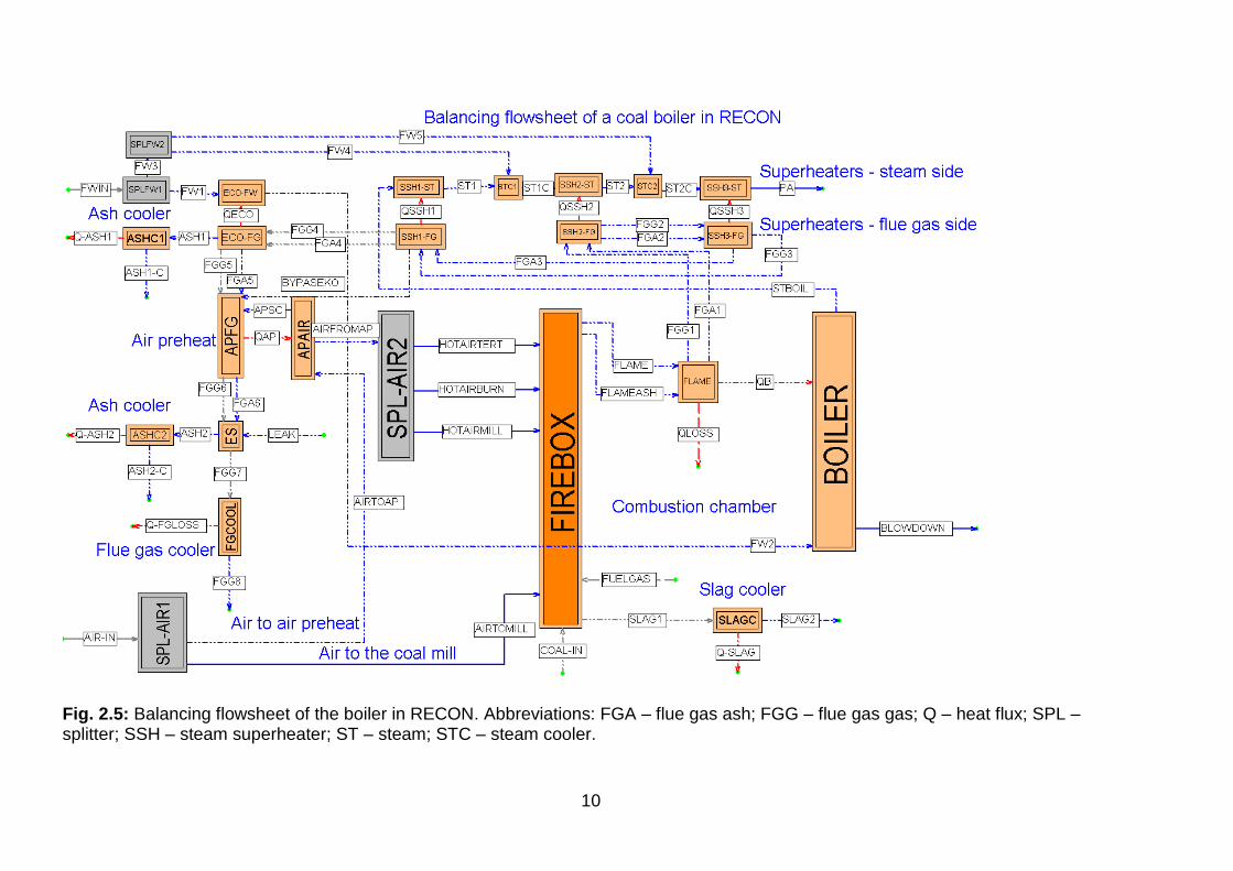
The boiler flowsheet in RECON is shown in Fig. 2.5. The system of units is shown in Fig. 2.3.
Fig. 2.3: Definition of physical units

9
As the most of measured flow variables is in tons per hour, the mass balance was selected as a basis of calculation. The system of pressure measurement MPag requires definition of the atmospheric pressure which is 0.101325 MPa. The energy unit is GJ and the power unit is GJ/HR. The more common power unit in the Power industry - MW - must be re-calculated if it is used.
The list of 11 components occurring in our problem is shown on the next panel.
Fig. 2.4: Configuration of components
The enthalpy calculations require thermodynamic properties of components and every component must be therefore linked with the corresponding item in the RECON’s database of physical properties (column “Database of …”). This database contains more than 400 pure components and users can also define new pure components and also empirical components like coal. The composition and other properties of empirical components can be defined by the RECON’s administrator only in the Administration – Physical properties data. The example of an average soft coal properties is shown in the next panel:
10
Fig. 2.5: Balancing flowsheet of the boiler in RECON. Abbreviations: FGA – flue gas ash; FGG – flue gas gas; Q – heat flux; SPL – splitter; SSH – steam superheater; ST – steam; STC – steam cooler.

11
Fig. 2.5: Definition of composition of the flammable part of a soft coal
It is supposed that a coal is composed of 3 components: water, ash and the flammable part which is marked in the database as “Soft coal aver”. It is supposed that the flammable part consists of carbon, hydrogen, nitrogen, oxygen and sulphur. While pure components are usually characterized by their heats of formation, in the case of coal the Low Heating Value (heat of combustion when water in flue gases is in vapor state) is more common (LHV can be calculated from the heat of formation and vice versa). The coal composition can be either some average or can be imported on-line from some data source. Of other components we mention Ash, the fictive element representing the mineral part of the coal (atomic weight 100).
A special discussion requires the component water (H2O). There are two places in the model where water behaves in a different way. In the pure water path (feed water, boiler proper and steam) thermodynamic properties of water are modeled according to the IAPWS IF-97 method [2]. A different situation is in the air – coal and the flue gas path. Water enters the firebox mostly in the form of a coal moisture and partially also as an air humidity and water is also created during combustion from hydrogen presented in the flammable part of coal. Application of the IAPWS method is not possible in this case as water is here in complex mixtures. The proper way of modeling is to view water as two components – liquid water (presented in the coal) and gaseous water (presented in the incoming air and also in flue gases). The enthalpy of the water vapor in flue gases is calculated from the model of ideal gas as the temperature on the flue gas path is high and pressure is low [3].
In the flowsheet we will frequently use so-called dependent streams. This means that the composition of a dependent stream is the same as the composition of the so-called master stream. This hold for all air streams and also for most of flue gas streams. This makes the model configuration less tedious and resulting models are simpler. In the following parts of this chapter a reader should refer to the RECON flowsheet in Fig. 2.5.

12
2.5.2 Modeling the combustion chamber
Further we will look at the combustion chamber including heat transfer to the boiler proper (nodes FIREBOX, FLAME and BOILER). The reaction part of the combustion chamber (node FIREBOX) is modeled as a so-called Reaction invariant chemical reactor. The configuration panel of the firebox is shown in the next figure.
Fig. 2.6: The configuration of the firebox
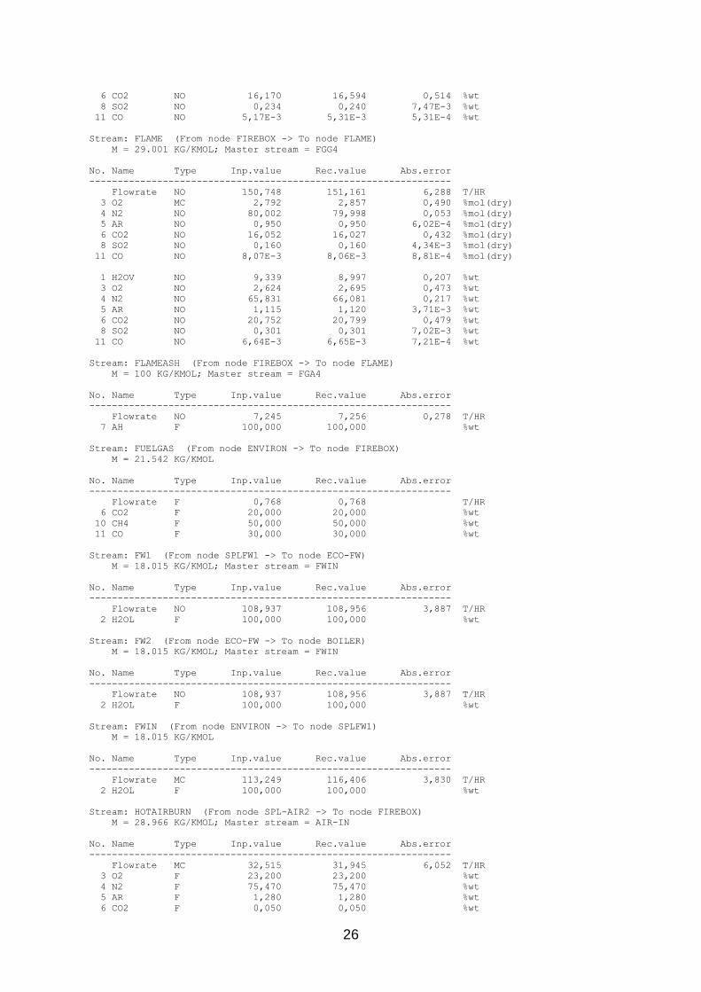
There are 4 streams of air entering the FIREBOX (AIRTOMILL, HOTAIRBURN, HOTAIRMILL and HOTAIRTERT). The fuel streams are COAL-IN and FUELGAS). Outputs are SLAG1 and FLAME (representing gaseous part of flue gases) and FLAMEASH representing the flying ash. The separation of flue gases into two streams is inevitable as it is not possible to incorporate solid ash into the gaseous part which is treated as an ideal gas. This fact will be seen in the whole flue gas path till the electrostatic separator where the flying ash is separated definitely.
The functions for calculating enthalpies for air, ash and coal are simple polynoms as functions of temperature. The IG(T) function calculates enthalpy of gases available in the RECON’s database of physical properties.
The invariant balance option (the checkbox in the panel) means that there are needed no reactions in the model. The balance is reconciled on the basis of conservation of chemical element in the FIREBOX node. The heat of combustion is calculated from heats of combustion of streams connected with the firebox. In this process also the evaporation of coal moisture is respected.
The temperature TFLAME represents the theoretical flame temperature calculated from the energy balance of the firebox. It is the main result of this calculation (even though there exists no such real temperature in the boiler). The next balancing node belonging to the firebox area is the FLAME node. Its purpose is to represent a heat exchange between the flame and water in tubes of the boiler proper.

13
Fig. 2.6: The configuration of the FLAME node
The temperature TFLUEGAS represents the temperature of the flue gas leaving the firebox. This is calculated from the flame temperature and the heat transferred to the boiler proper. There is also a small heat loss calculated according to the standard [1]. The temperature at the exit of the firebox is important for monitoring the firebox function and can indicate improper function of the firebox caused for example by fouling of the firebox by slag.
Fig. 2.7: The configuration of the BOILER node
The boiler proper (steam generator) energy balance is modeled with the aid of the IAPWS IF-97 enthalpy model. It is supposed that the enthalpy of the feed water is defined by its temperature and the pressure (heat function H2OL(T,P). The output streams (BLOWDOWN and STBOIL) are water and steam saturated at the boiler pressure.
2.5.3 Modeling the flue gas path
As was mentioned previously, the gas path consists of two parallel steams – gas and ash. There are 3 steam superheaters, 2 steam coolers, 1 economizer, 1 air preheater and 1 electrostatic separator on this path. It should be noted that on the flue gas path there are used no temperature measurements between the firebox and the economizer. All temperatures are unmeasured and are calculated from the enthalpy balance of the steam path. Example of configuration of a steam superheater is shown in the Fig. 2.8.
14
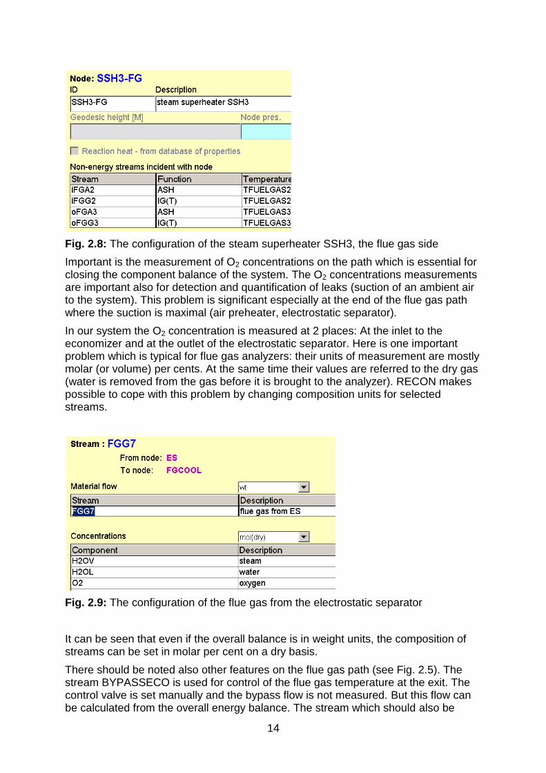
Fig. 2.8: The configuration of the steam superheater SSH3, the flue gas side
Important is the measurement of O2 concentrations on the path which is essential for closing the component balance of the system. The O2 concentrations measurements are important also for detection and quantification of leaks (suction of an ambient air to the system). This problem is significant especially at the end of the flue gas path where the suction is maximal (air preheater, electrostatic separator).
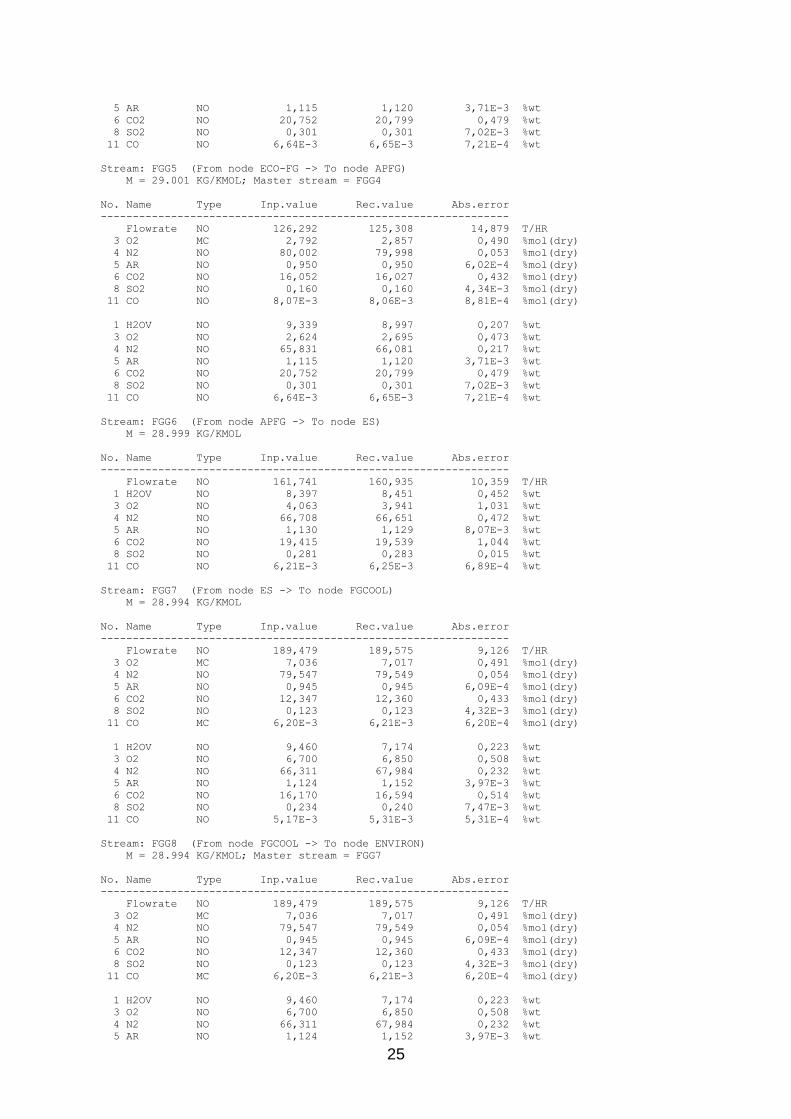
In our system the O2 concentration is measured at 2 places: At the inlet to the economizer and at the outlet of the electrostatic separator. Here is one important problem which is typical for flue gas analyzers: their units of measurement are mostly molar (or volume) per cents. At the same time their values are referred to the dry gas (water is removed from the gas before it is brought to the analyzer). RECON makes possible to cope with this problem by changing composition units for selected streams.
Fig. 2.9: The configuration of the flue gas from the electrostatic separator
It can be seen that even if the overall balance is in weight units, the composition of streams can be set in molar per cent on a dry basis.
There should be noted also other features on the flue gas path (see Fig. 2.5). The stream BYPASSECO is used for control of the flue gas temperature at the exit. The control valve is set manually and the bypass flow is not measured. But this flow can be calculated from the overall energy balance. The stream which should also be

15
monitored is the air shortcut from the air side to the flue gas side of the air preheater (stream APSC). The flow of this shortcut can be calculated from the heat and component balance.
2.5.4 Modeling the water and the steam path
This part of our model is very standard based on the IAPWS IF-97 model. The only component present here is H2O. As an example can serve the steam side of the first steam cooler STC1.
Fig. 2.9: The configuration of the steam cooler
The mass and energy balance on the water and steam path is important as it fixes the flue gas balance where are no flowmeters and some thermometers are not reliable.
2.5.5 User defined equations
There are two kinds of user defined equation. The equations used in data pre-processing pre-calculate some variables to get acceptable inputs. In this model there is just one equation of this kind. The blowdown measurement is not reliable and so the blowdown is pre-calculated as 0.6 % of the feed water flow. This is acceptable as the blowdown flow is controlled by a small orifice and is stable.
The other user defined equations complete the model formed by RECON automatically on the basis of the flowsheet configured. The following auxiliary variables were calculated:
Distribution of ash among slag in the firebox and the fly ash separated in the
economizer and the electrostatic separator. This distribution is fixed on the
basis of previous experience
Mean temperature difference in heat exchangers. The character of the flow in
heat exchangers is not completely known. The mean temperature difference
was calculated as the arithmetic average of temperature differences at both
ends of a heat exchanger. In all cases the countercurrent flow was supposed
Heat Transfer Coefficients (HTC) were calculated from the heat flux, mean
temperature difference and the heat transfer area

16
Temperature in the boiler as the saturated steam temperature belonging to the
pressure at the exit of the boiler
There is a shortcut of air in the air preheater (Ljungstrom exchanger). To set
up the model, the mean temperature of this shortcut is needed. Here is
supposed that this temperature is the arithmetic average of air temperature in
the inlet and the outlet streams of the air preheater.

17
3. Results of data reconciliation Complete results of calculation are in the Appendix 1 (RECON’s output file). It is supposed that the reader is familiar with basics of Data Reconciliation in the extent of report [4]. Here are some excerpts of main results:
The iterative calculation required 4 iterations. The calculation lasted 2 second on a standard desktop PC. The main global characteristics are G L O B A L D A T A
Number of nodes 24
Number of heat nodes 20
Number of streams 58
Number of energy streams 11
Number of components 11
Number of heat functions 4
Number of temperatures 21
Number of pressures 4
Number of auxiliaries 13
Number of react.nodes 1
Number of measured variables 27
Number of adjusted variables 27
Number of non-measured variables 99
Number of observed variables 99
Number of non-observed variables 0
Number of free variables 0
Number of equations (incl. UDE) 133
Number of independent equations 104
Number of user-defined equations (UDE) 17
Degree of redundancy 5
Mean residue of equations 1,6478E-07
Qmin 2,7978E+00
Qcrit 1,1100E+01
Status (Qmin/Qcrit) 0,252058
The Status of data quality (see the last row) is well below the critical value 1, so that no gross error was detected. The degree of redundancy is 5. RECON generated 29 dependent equations which is quite high number. This is caused by not unified system of units in this task (mass and molar concentrations, concentrations based on dry gas composition). Anyway, the existence of dependent equations has no effect on the final result as the dependent equations are eliminated during the solution.
Probably the most important KPI result is the efficiency of the boiler. The main result is:
BOILER EFFICIENCY = 90.99 ± 0.27 %
The relative maximum error is about 0.3 % of the boiler efficiency value. This is typical for the indirect method of the efficiency determination. The confidence interval contains both random and systematic errors so that in practice (with stable systematic errors) substantially smaller changes in the efficiency can be monitored and detected.
We can ask question, which variables are influencing the precision the boiler efficiency. The next table presents shares of important variables on variance the boiler efficiency.

18
REPORT ABOUT PROPAGATION OF ERRORS
==================================
Type Variable
-------------
V EFFICIENCY
THE VARIANCE OF GIVEN VARIABLE IS CAUSED MAINLY BY:
Type Variable Share
-----------------------------------
MF AIR-IN 4 %
T 01X01T023 3 %
T 01X01T025 3 %
T 01X01TIA131 25 %
V [C<FGG7:O2>] 59 %
Sum 93 %
The Share informs how much the individual primary variables influence the Efficiency’s variance. The other variables influence the efficiency by less than 2 %. It is clear that there are 2 variables which together represent 84 % of the Efficiency’s variance:
Temperature 01X01TIA131 (flue gas exit from the electrostatic separator)
C<FGG7:O2> (oxygen concentration at the exit of the electrostatic separator)
These variables represent the bottleneck of Efficiency’s precision. These instruments should be therefore carefully maintained.
Some other calculated KPIs are in the next table:
Name Type Inp.value Rec.value Abs.error
------------------------------------------------------------------
HTCECO NO 67,128 65,656 8,208
HTCSSH1 NO 85,622 86,543 8,328
HTCSSH2 NO 30,710 30,975 3,987
HTCSSH3 NO 48,779 50,207 9,082
Q-LOSS NO 28,835 28,715 1,310
Q-USEFULL NO 289,893 290,142 10,351
The heat transfer coefficients (HTC) are estimated with tolerance about ± 10 – 20 % (column Abs.error.)
Heat fluxes are in the next table:
E N E R G Y S T R E A M S
Name Type Inp.value Rec.value Abs.error
------------------------------------------------------------------
Q-ASH1 NO 0,125 0,125 5,98E-3 GJ/HR
Q-ASH2 NO 0,741 0,738 0,033 GJ/HR
Q-FGLOSS NO 24,534 24,416 1,264 GJ/HR
Q-SLAG NO 0,555 0,556 0,021 GJ/HR
QAP NO 41,477 41,656 2,902 GJ/HR
QB NO 167,994 168,465 6,421 GJ/HR
QECO NO 23,320 22,623 3,515 GJ/HR
QLOSS F 2,880 2,880 GJ/HR
QSSH1 NO 42,038 41,912 2,953 GJ/HR
QSSH2 NO 28,654 28,785 3,884 GJ/HR
QSSH3 NO 27,888 28,356 4,829 GJ/HR

19
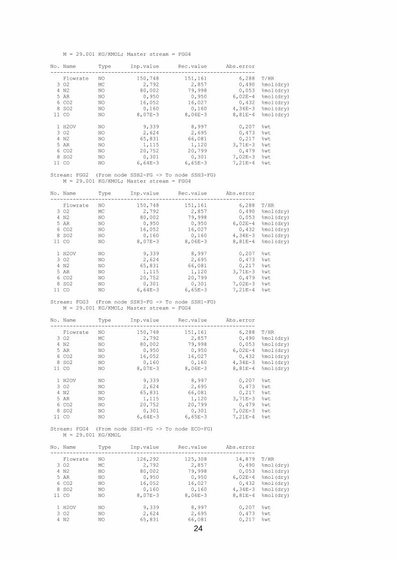
Typical output table of stream parameters is
Stream: FGG4 (From node SSH1-FG -> To node ECO-FG)
M = 29.001 KG/KMOL
No. Name Type Inp.value Rec.value Abs.error
----------------------------------------------------------------
Flowrate NO 126,292 125,308 14,879 T/HR
3 O2 MC 2,792 2,857 0,490 %mol(dry)
4 N2 NO 80,002 79,998 0,053 %mol(dry)
5 AR NO 0,950 0,950 6,02E-4 %mol(dry)
6 CO2 NO 16,052 16,027 0,432 %mol(dry)
8 SO2 NO 0,160 0,160 4,34E-3 %mol(dry)
11 CO NO 8,07E-3 8,06E-3 8,81E-4 %mol(dry)
1 H2OV NO 9,339 8,997 0,207 %wt
3 O2 NO 2,624 2,695 0,473 %wt
4 N2 NO 65,831 66,081 0,217 %wt
5 AR NO 1,115 1,120 3,71E-3 %wt
6 CO2 NO 20,752 20,799 0,479 %wt
8 SO2 NO 0,301 0,301 7,02E-3 %wt
11 CO NO 6,64E-3 6,65E-3 7,21E-4 %wt
This stream is the flue gas (gas without ash) going from the superheater SSH1 to the economizer. At this place is the measurement if the O2 concentration which is measured in molar per cents based on the dry gas. Both systems of units are available for this stream.
Another question is the “How well are results protected against gross measurement errors?”. This depends on redundancy of measurements. The best measure of redundancy is the adjustability redundant variables. Adjustabilities greater than 0.1 are shown in the next table (for variables with adjustabilities lesser than 0.1 gross errors will probably remain undetected). The column Threshold value shows how large must a gross error be to be detected with probability 90 %. For example, the error of the feed water (variable MF FWIN) must be at least 15.992 T/HR to be detected with probability 90 %.
R E D U N D A N T M E A S U R E M E N T S
Type Variable Adjustability Threshold value Unit Description
-----------------------------------------------------------------------------
MF AIR-IN 0,645620 62,426 T/HR Air input
MF FWIN 0,323534 15,922 T/HR Feed water input
MF HOTAIRTERT 0,387152 36,809 T/HR Tertiary air input
MF PA 0,353783 16,084 T/HR Steam export
T 01X01T023 0,427280 48,245 C Steam from spray 1
T 01X01T025 0,401387 57,184 C Steam from spray 2
T 01X01TIA131 0,119248 12,831 C Flue gas from ES
Legend: MF – mass flow; T – temperature.

20
Literature [1] EN 12952-15:2003: Water-tube boilers and auxiliary installations – Part 15:
Acceptance tests.
[2] IAPWS Industrial Formulation 1997 for the Thermodynamic Properties of Water and Steam. International Association for the Properties of Water and Steam. 2007
[3] API: API Data Book. 7th edition. API 2005
[4] Process data validation in practice. Applications from chemical, oil, mineral and power industries. Report CPT 229-07. Usti nad Labem 2007

21
Appendix 1: RECON’s output file RECON 11.1.2-Pro [CHemPlant]
Task: COAL_BOILLER (detailed coal boiler balance)
Balance: [21.01.2011 08:00; 21.01.2011 09:00)
I T E R A T I O N S
Iter Qeq Qx Qy Qmin
-----------------------------------------------------------------
START 3,4606E+04
1 8,7922E+01 4,8248E-01 2,3182E+03 2,6510E+00
2 5,6261E+00 1,8147E-01 1,1041E+03 2,7978E+00
3 9,9636E-05 2,3733E-04 1,4098E+00 2,7978E+00
4 1,6478E-07 1,2936E-07 1,4179E-03 2,7978E+00
Legend:
Qeq mean residual of equations
Qx mean increment of measured variables in iteration
Qy mean increment of non-measured variables in iteration
Qmin least-square function
G L O B A L D A T A
Number of nodes 24
Number of heat nodes 20
Number of streams 58
Number of energy streams 11
Number of components 11
Number of heat functions 4
Number of temperatures 21
Number of pressures 4
Number of auxiliaries 13
Number of react. nodes 1
Number of measured variables 27
Number of adjusted variables 27
Number of non-measured variables 99
Number of observed variables 99
Number of non-observed variables 0
Number of free variables 0
Number of equations (incl. UDE) 133
Number of independent equations 104
Number of user-defined equations (UDE) 17
Degree of redundancy 5
Mean residue of equations 1,6478E-07
Qmin 2,7978E+00
Qcrit 1,1100E+01
Status (Qmin/Qcrit) 0,252058
S T R E A M S
Stream: AIR-IN (From node ENVIRON -> To node SPL-AIR1)
M = 28.966 KG/KMOL
No. Name Type Inp.value Rec.value Abs.error
----------------------------------------------------------------
Flowrate MC 140,945 141,985 9,990 T/HR
3 O2 F 23,200 23,200 %wt
4 N2 F 75,470 75,470 %wt
5 AR F 1,280 1,280 %wt
6 CO2 F 0,050 0,050 %wt
Stream: AIRFROMAP (From node APAIR -> To node SPL-AIR2)
M = 28.966 KG/KMOL; Master stream = AIR-IN
No. Name Type Inp.value Rec.value Abs.error
----------------------------------------------------------------
Flowrate NO 129,884 130,273 5,731 T/HR
3 O2 F 23,200 23,200 %wt
4 N2 F 75,470 75,470 %wt

22
5 AR F 1,280 1,280 %wt
6 CO2 F 0,050 0,050 %wt
Stream: AIRTOAP (From node SPL-AIR1 -> To node APAIR)
M = 28.966 KG/KMOL; Master stream = AIR-IN
No. Name Type Inp.value Rec.value Abs.error
----------------------------------------------------------------
Flowrate NO 140,876 140,047 9,996 T/HR
3 O2 F 23,200 23,200 %wt
4 N2 F 75,470 75,470 %wt
5 AR F 1,280 1,280 %wt
6 CO2 F 0,050 0,050 %wt
Stream: AIRTOMILL (From node SPL-AIR1 -> To node FIREBOX)
M = 28.966 KG/KMOL; Master stream = AIR-IN
No. Name Type Inp.value Rec.value Abs.error
----------------------------------------------------------------
Flowrate MC 1,943 1,937 0,389 T/HR
3 O2 F 23,200 23,200 %wt
4 N2 F 75,470 75,470 %wt
5 AR F 1,280 1,280 %wt
6 CO2 F 0,050 0,050 %wt
Stream: APSC (From node APAIR -> To node APFG)
M = 28.966 KG/KMOL; Master stream = AIR-IN
No. Name Type Inp.value Rec.value Abs.error
----------------------------------------------------------------
Flowrate NO 10,992 9,774 9,307 T/HR
3 O2 F 23,200 23,200 %wt
4 N2 F 75,470 75,470 %wt
5 AR F 1,280 1,280 %wt
6 CO2 F 0,050 0,050 %wt
Stream: ASH1 (From node ECO-FG -> To node ASHC1)
M = 100 KG/KMOL; Master stream = FGA4
No. Name Type Inp.value Rec.value Abs.error
----------------------------------------------------------------
Flowrate NO 0,403 0,403 0,015 T/HR
7 AH F 100,000 100,000 %wt
Stream: ASH1-C (From node ASHC1 -> To node ENVIRON)
M = 100 KG/KMOL; Master stream = FGA4
No. Name Type Inp.value Rec.value Abs.error
----------------------------------------------------------------
Flowrate NO 0,403 0,403 0,015 T/HR
7 AH F 100,000 100,000 %wt
Stream: ASH2 (From node ES -> To node ASHC2)
M = 100 KG/KMOL; Master stream = FGA4
No. Name Type Inp.value Rec.value Abs.error
----------------------------------------------------------------
Flowrate NO 6,843 6,853 0,262 T/HR
7 AH F 100,000 100,000 %wt
Stream: ASH2-C (From node ASHC2 -> To node ENVIRON)
M = 100 KG/KMOL; Master stream = FGA4
No. Name Type Inp.value Rec.value Abs.error
----------------------------------------------------------------
Flowrate NO 6,843 6,853 0,262 T/HR
7 AH F 100,000 100,000 %wt
Stream: BLOWDOWN (From node BOILER -> To node ENVIRON)
M = 18.015 KG/KMOL; Master stream = FWIN
No. Name Type Inp.value Rec.value Abs.error
----------------------------------------------------------------
Flowrate MC 0,711 0,711 0,036 T/HR
2 H2OL F 100,000 100,000 %wt
Stream: BYPASSECO (From node SSH1-FG -> To node APFG)
M = 29.001 KG/KMOL; Master stream = FGG4

23
No. Name Type Inp.value Rec.value Abs.error
----------------------------------------------------------------
Flowrate NO 24,457 25,853 14,103 T/HR
3 O2 MC 2,792 2,857 0,490 %mol(dry)
4 N2 NO 80,002 79,998 0,053 %mol(dry)
5 AR NO 0,950 0,950 6,02E-4 %mol(dry)
6 CO2 NO 16,052 16,027 0,432 %mol(dry)
8 SO2 NO 0,160 0,160 4,34E-3 %mol(dry)
11 CO NO 8,07E-3 8,06E-3 8,81E-4 %mol(dry)
1 H2OV NO 9,339 8,997 0,207 %wt
3 O2 NO 2,624 2,695 0,473 %wt
4 N2 NO 65,831 66,081 0,217 %wt
5 AR NO 1,115 1,120 3,71E-3 %wt
6 CO2 NO 20,752 20,799 0,479 %wt
8 SO2 NO 0,301 0,301 7,02E-3 %wt
11 CO NO 6,64E-3 6,65E-3 7,21E-4 %wt
Stream: COAL-IN (From node ENVIRON -> To node FIREBOX)
M = 46.384 KG/KMOL
No. Name Type Inp.value Rec.value Abs.error
----------------------------------------------------------------
Flowrate NO 26,206 26,244 1,005 T/HR
2 H2OL F 25,400 25,400 %wt
7 AH F 30,720 30,720 %wt
9 COAL F 43,880 43,880 %wt
Stream: FGA1 (From node FLAME -> To node SSH2-FG)
M = 100 KG/KMOL; Master stream = FGA4
No. Name Type Inp.value Rec.value Abs.error
----------------------------------------------------------------
Flowrate NO 7,245 7,256 0,278 T/HR
7 AH F 100,000 100,000 %wt
Stream: FGA2 (From node SSH2-FG -> To node SSH3-FG)
M = 100 KG/KMOL; Master stream = FGA4
No. Name Type Inp.value Rec.value Abs.error
----------------------------------------------------------------
Flowrate NO 7,245 7,256 0,278 T/HR
7 AH F 100,000 100,000 %wt
Stream: FGA3 (From node SSH3-FG -> To node SSH1-FG)
M = 100 KG/KMOL; Master stream = FGA4
No. Name Type Inp.value Rec.value Abs.error
----------------------------------------------------------------
Flowrate NO 7,245 7,256 0,278 T/HR
7 AH F 100,000 100,000 %wt
Stream: FGA4 (From node SSH1-FG -> To node ECO-FG)
M = 100 KG/KMOL
No. Name Type Inp.value Rec.value Abs.error
----------------------------------------------------------------
Flowrate NO 7,245 7,256 0,278 T/HR
7 AH F 100,000 100,000 %wt
Stream: FGA5 (From node ECO-FG -> To node APFG)
M = 100 KG/KMOL; Master stream = FGA4
No. Name Type Inp.value Rec.value Abs.error
----------------------------------------------------------------
Flowrate NO 6,843 6,853 0,262 T/HR
7 AH F 100,000 100,000 %wt
Stream: FGA6 (From node APFG -> To node ES)
M = 100 KG/KMOL; Master stream = FGA4
No. Name Type Inp.value Rec.value Abs.error
----------------------------------------------------------------
Flowrate NO 6,843 6,853 0,262 T/HR
7 AH F 100,000 100,000 %wt
Stream: FGG1 (From node FLAME -> To node SSH2-FG)
24
M = 29.001 KG/KMOL; Master stream = FGG4
No. Name Type Inp.value Rec.value Abs.error
----------------------------------------------------------------
Flowrate NO 150,748 151,161 6,288 T/HR
3 O2 MC 2,792 2,857 0,490 %mol(dry)
4 N2 NO 80,002 79,998 0,053 %mol(dry)
5 AR NO 0,950 0,950 6,02E-4 %mol(dry)
6 CO2 NO 16,052 16,027 0,432 %mol(dry)
8 SO2 NO 0,160 0,160 4,34E-3 %mol(dry)
11 CO NO 8,07E-3 8,06E-3 8,81E-4 %mol(dry)
1 H2OV NO 9,339 8,997 0,207 %wt
3 O2 NO 2,624 2,695 0,473 %wt
4 N2 NO 65,831 66,081 0,217 %wt
5 AR NO 1,115 1,120 3,71E-3 %wt
6 CO2 NO 20,752 20,799 0,479 %wt
8 SO2 NO 0,301 0,301 7,02E-3 %wt
11 CO NO 6,64E-3 6,65E-3 7,21E-4 %wt
Stream: FGG2 (From node SSH2-FG -> To node SSH3-FG)
M = 29.001 KG/KMOL; Master stream = FGG4
No. Name Type Inp.value Rec.value Abs.error
----------------------------------------------------------------
Flowrate NO 150,748 151,161 6,288 T/HR
3 O2 MC 2,792 2,857 0,490 %mol(dry)
4 N2 NO 80,002 79,998 0,053 %mol(dry)
5 AR NO 0,950 0,950 6,02E-4 %mol(dry)
6 CO2 NO 16,052 16,027 0,432 %mol(dry)
8 SO2 NO 0,160 0,160 4,34E-3 %mol(dry)
11 CO NO 8,07E-3 8,06E-3 8,81E-4 %mol(dry)
1 H2OV NO 9,339 8,997 0,207 %wt
3 O2 NO 2,624 2,695 0,473 %wt
4 N2 NO 65,831 66,081 0,217 %wt
5 AR NO 1,115 1,120 3,71E-3 %wt
6 CO2 NO 20,752 20,799 0,479 %wt
8 SO2 NO 0,301 0,301 7,02E-3 %wt
11 CO NO 6,64E-3 6,65E-3 7,21E-4 %wt
Stream: FGG3 (From node SSH3-FG -> To node SSH1-FG)
M = 29.001 KG/KMOL; Master stream = FGG4
No. Name Type Inp.value Rec.value Abs.error
----------------------------------------------------------------
Flowrate NO 150,748 151,161 6,288 T/HR
3 O2 MC 2,792 2,857 0,490 %mol(dry)
4 N2 NO 80,002 79,998 0,053 %mol(dry)
5 AR NO 0,950 0,950 6,02E-4 %mol(dry)
6 CO2 NO 16,052 16,027 0,432 %mol(dry)
8 SO2 NO 0,160 0,160 4,34E-3 %mol(dry)
11 CO NO 8,07E-3 8,06E-3 8,81E-4 %mol(dry)
1 H2OV NO 9,339 8,997 0,207 %wt
3 O2 NO 2,624 2,695 0,473 %wt
4 N2 NO 65,831 66,081 0,217 %wt
5 AR NO 1,115 1,120 3,71E-3 %wt
6 CO2 NO 20,752 20,799 0,479 %wt
8 SO2 NO 0,301 0,301 7,02E-3 %wt
11 CO NO 6,64E-3 6,65E-3 7,21E-4 %wt
Stream: FGG4 (From node SSH1-FG -> To node ECO-FG)
M = 29.001 KG/KMOL
No. Name Type Inp.value Rec.value Abs.error
----------------------------------------------------------------
Flowrate NO 126,292 125,308 14,879 T/HR
3 O2 MC 2,792 2,857 0,490 %mol(dry)
4 N2 NO 80,002 79,998 0,053 %mol(dry)
5 AR NO 0,950 0,950 6,02E-4 %mol(dry)
6 CO2 NO 16,052 16,027 0,432 %mol(dry)
8 SO2 NO 0,160 0,160 4,34E-3 %mol(dry)
11 CO NO 8,07E-3 8,06E-3 8,81E-4 %mol(dry)
1 H2OV NO 9,339 8,997 0,207 %wt
3 O2 NO 2,624 2,695 0,473 %wt
4 N2 NO 65,831 66,081 0,217 %wt
25
5 AR NO 1,115 1,120 3,71E-3 %wt
6 CO2 NO 20,752 20,799 0,479 %wt
8 SO2 NO 0,301 0,301 7,02E-3 %wt
11 CO NO 6,64E-3 6,65E-3 7,21E-4 %wt
Stream: FGG5 (From node ECO-FG -> To node APFG)
M = 29.001 KG/KMOL; Master stream = FGG4
No. Name Type Inp.value Rec.value Abs.error
----------------------------------------------------------------
Flowrate NO 126,292 125,308 14,879 T/HR
3 O2 MC 2,792 2,857 0,490 %mol(dry)
4 N2 NO 80,002 79,998 0,053 %mol(dry)
5 AR NO 0,950 0,950 6,02E-4 %mol(dry)
6 CO2 NO 16,052 16,027 0,432 %mol(dry)
8 SO2 NO 0,160 0,160 4,34E-3 %mol(dry)
11 CO NO 8,07E-3 8,06E-3 8,81E-4 %mol(dry)
1 H2OV NO 9,339 8,997 0,207 %wt
3 O2 NO 2,624 2,695 0,473 %wt
4 N2 NO 65,831 66,081 0,217 %wt
5 AR NO 1,115 1,120 3,71E-3 %wt
6 CO2 NO 20,752 20,799 0,479 %wt
8 SO2 NO 0,301 0,301 7,02E-3 %wt
11 CO NO 6,64E-3 6,65E-3 7,21E-4 %wt
Stream: FGG6 (From node APFG -> To node ES)
M = 28.999 KG/KMOL
No. Name Type Inp.value Rec.value Abs.error
----------------------------------------------------------------
Flowrate NO 161,741 160,935 10,359 T/HR
1 H2OV NO 8,397 8,451 0,452 %wt
3 O2 NO 4,063 3,941 1,031 %wt
4 N2 NO 66,708 66,651 0,472 %wt
5 AR NO 1,130 1,129 8,07E-3 %wt
6 CO2 NO 19,415 19,539 1,044 %wt
8 SO2 NO 0,281 0,283 0,015 %wt
11 CO NO 6,21E-3 6,25E-3 6,89E-4 %wt
Stream: FGG7 (From node ES -> To node FGCOOL)
M = 28.994 KG/KMOL
No. Name Type Inp.value Rec.value Abs.error
----------------------------------------------------------------
Flowrate NO 189,479 189,575 9,126 T/HR
3 O2 MC 7,036 7,017 0,491 %mol(dry)
4 N2 NO 79,547 79,549 0,054 %mol(dry)
5 AR NO 0,945 0,945 6,09E-4 %mol(dry)
6 CO2 NO 12,347 12,360 0,433 %mol(dry)
8 SO2 NO 0,123 0,123 4,32E-3 %mol(dry)
11 CO MC 6,20E-3 6,21E-3 6,20E-4 %mol(dry)
1 H2OV NO 9,460 7,174 0,223 %wt
3 O2 NO 6,700 6,850 0,508 %wt
4 N2 NO 66,311 67,984 0,232 %wt
5 AR NO 1,124 1,152 3,97E-3 %wt
6 CO2 NO 16,170 16,594 0,514 %wt
8 SO2 NO 0,234 0,240 7,47E-3 %wt
11 CO NO 5,17E-3 5,31E-3 5,31E-4 %wt
Stream: FGG8 (From node FGCOOL -> To node ENVIRON)
M = 28.994 KG/KMOL; Master stream = FGG7
No. Name Type Inp.value Rec.value Abs.error
----------------------------------------------------------------
Flowrate NO 189,479 189,575 9,126 T/HR
3 O2 MC 7,036 7,017 0,491 %mol(dry)
4 N2 NO 79,547 79,549 0,054 %mol(dry)
5 AR NO 0,945 0,945 6,09E-4 %mol(dry)
6 CO2 NO 12,347 12,360 0,433 %mol(dry)
8 SO2 NO 0,123 0,123 4,32E-3 %mol(dry)
11 CO MC 6,20E-3 6,21E-3 6,20E-4 %mol(dry)
1 H2OV NO 9,460 7,174 0,223 %wt
3 O2 NO 6,700 6,850 0,508 %wt
4 N2 NO 66,311 67,984 0,232 %wt
5 AR NO 1,124 1,152 3,97E-3 %wt
26
6 CO2 NO 16,170 16,594 0,514 %wt
8 SO2 NO 0,234 0,240 7,47E-3 %wt
11 CO NO 5,17E-3 5,31E-3 5,31E-4 %wt
Stream: FLAME (From node FIREBOX -> To node FLAME)
M = 29.001 KG/KMOL; Master stream = FGG4
No. Name Type Inp.value Rec.value Abs.error
----------------------------------------------------------------
Flowrate NO 150,748 151,161 6,288 T/HR
3 O2 MC 2,792 2,857 0,490 %mol(dry)
4 N2 NO 80,002 79,998 0,053 %mol(dry)
5 AR NO 0,950 0,950 6,02E-4 %mol(dry)
6 CO2 NO 16,052 16,027 0,432 %mol(dry)
8 SO2 NO 0,160 0,160 4,34E-3 %mol(dry)
11 CO NO 8,07E-3 8,06E-3 8,81E-4 %mol(dry)
1 H2OV NO 9,339 8,997 0,207 %wt
3 O2 NO 2,624 2,695 0,473 %wt
4 N2 NO 65,831 66,081 0,217 %wt
5 AR NO 1,115 1,120 3,71E-3 %wt
6 CO2 NO 20,752 20,799 0,479 %wt
8 SO2 NO 0,301 0,301 7,02E-3 %wt
11 CO NO 6,64E-3 6,65E-3 7,21E-4 %wt
Stream: FLAMEASH (From node FIREBOX -> To node FLAME)
M = 100 KG/KMOL; Master stream = FGA4
No. Name Type Inp.value Rec.value Abs.error
----------------------------------------------------------------
Flowrate NO 7,245 7,256 0,278 T/HR
7 AH F 100,000 100,000 %wt
Stream: FUELGAS (From node ENVIRON -> To node FIREBOX)
M = 21.542 KG/KMOL
No. Name Type Inp.value Rec.value Abs.error
----------------------------------------------------------------
Flowrate F 0,768 0,768 T/HR
6 CO2 F 20,000 20,000 %wt
10 CH4 F 50,000 50,000 %wt
11 CO F 30,000 30,000 %wt
Stream: FW1 (From node SPLFW1 -> To node ECO-FW)
M = 18.015 KG/KMOL; Master stream = FWIN
No. Name Type Inp.value Rec.value Abs.error
----------------------------------------------------------------
Flowrate NO 108,937 108,956 3,887 T/HR
2 H2OL F 100,000 100,000 %wt
Stream: FW2 (From node ECO-FW -> To node BOILER)
M = 18.015 KG/KMOL; Master stream = FWIN
No. Name Type Inp.value Rec.value Abs.error
----------------------------------------------------------------
Flowrate NO 108,937 108,956 3,887 T/HR
2 H2OL F 100,000 100,000 %wt
Stream: FWIN (From node ENVIRON -> To node SPLFW1)
M = 18.015 KG/KMOL
No. Name Type Inp.value Rec.value Abs.error
----------------------------------------------------------------
Flowrate MC 113,249 116,406 3,830 T/HR
2 H2OL F 100,000 100,000 %wt
Stream: HOTAIRBURN (From node SPL-AIR2 -> To node FIREBOX)
M = 28.966 KG/KMOL; Master stream = AIR-IN
No. Name Type Inp.value Rec.value Abs.error
----------------------------------------------------------------
Flowrate MC 32,515 31,945 6,052 T/HR
3 O2 F 23,200 23,200 %wt
4 N2 F 75,470 75,470 %wt
5 AR F 1,280 1,280 %wt
6 CO2 F 0,050 0,050 %wt

27
Stream: HOTAIRMILL (From node SPL-AIR2 -> To node FIREBOX)
M = 28.966 KG/KMOL; Master stream = AIR-IN
No. Name Type Inp.value Rec.value Abs.error
----------------------------------------------------------------
Flowrate MC 31,285 30,758 5,857 T/HR
3 O2 F 23,200 23,200 %wt
4 N2 F 75,470 75,470 %wt
5 AR F 1,280 1,280 %wt
6 CO2 F 0,050 0,050 %wt
Stream: HOTAIRTERT (From node SPL-AIR2 -> To node FIREBOX)
M = 28.966 KG/KMOL; Master stream = AIR-IN
No. Name Type Inp.value Rec.value Abs.error
----------------------------------------------------------------
Flowrate MC 70,230 67,571 8,608 T/HR
3 O2 F 23,200 23,200 %wt
4 N2 F 75,470 75,470 %wt
5 AR F 1,280 1,280 %wt
6 CO2 F 0,050 0,050 %wt
Stream: LEAK (From node ENVIRON -> To node ES)
M = 28.966 KG/KMOL; Master stream = AIR-IN
No. Name Type Inp.value Rec.value Abs.error
----------------------------------------------------------------
Flowrate NO 27,739 28,640 7,471 T/HR
3 O2 F 23,200 23,200 %wt
4 N2 F 75,470 75,470 %wt
5 AR F 1,280 1,280 %wt
6 CO2 F 0,050 0,050 %wt
Stream: PA (From node SSH3-ST -> To node ENVIRON)
M = 18.015 KG/KMOL; Master stream = FWIN
No. Name Type Inp.value Rec.value Abs.error
----------------------------------------------------------------
Flowrate MC 118,550 115,694 3,830 T/HR
2 H2OL F 100,000 100,000 %wt
Stream: SLAG1 (From node FIREBOX -> To node SLAGC)
M = 100 KG/KMOL
No. Name Type Inp.value Rec.value Abs.error
----------------------------------------------------------------
Flowrate NO 0,805 0,806 0,031 T/HR
7 AH F 100,000 100,000 %wt
Stream: SLAG2 (From node SLAGC -> To node ENVIRON)
M = 100 KG/KMOL; Master stream = SLAG1
No. Name Type Inp.value Rec.value Abs.error
----------------------------------------------------------------
Flowrate NO 0,805 0,806 0,031 T/HR
7 AH F 100,000 100,000 %wt
Stream: SPRAY (From node SPLFW1 -> To node SPLFW2)
M = 18.015 KG/KMOL; Master stream = FWIN
No. Name Type Inp.value Rec.value Abs.error
----------------------------------------------------------------
Flowrate MC 7,398 7,450 0,730 T/HR
2 H2OL F 100,000 100,000 %wt
Stream: SPRAY1 (From node SPLFW2 -> To node STC1)
M = 18.015 KG/KMOL; Master stream = FWIN
No. Name Type Inp.value Rec.value Abs.error
----------------------------------------------------------------
Flowrate NO 3,693 3,687 2,054 T/HR
2 H2OL F 100,000 100,000 %wt
Stream: SPRAY2 (From node SPLFW2 -> To node STC2)
M = 18.015 KG/KMOL; Master stream = FWIN
No. Name Type Inp.value Rec.value Abs.error
----------------------------------------------------------------

28
Flowrate NO 3,711 3,763 2,023 T/HR
2 H2OL F 100,000 100,000 %wt
Stream: ST1 (From node SSH1-ST -> To node STC1)
M = 18.015 KG/KMOL; Master stream = FWIN
No. Name Type Inp.value Rec.value Abs.error
----------------------------------------------------------------
Flowrate NO 108,226 108,244 3,887 T/HR
2 H2OL F 100,000 100,000 %wt
Stream: ST1C (From node STC1 -> To node SSH2-ST)
M = 18.015 KG/KMOL; Master stream = FWIN
No. Name Type Inp.value Rec.value Abs.error
----------------------------------------------------------------
Flowrate NO 111,919 111,932 4,090 T/HR
2 H2OL F 100,000 100,000 %wt
Stream: ST2 (From node SSH2-ST -> To node STC2)
M = 18.015 KG/KMOL; Master stream = FWIN
No. Name Type Inp.value Rec.value Abs.error
----------------------------------------------------------------
Flowrate NO 111,919 111,932 4,090 T/HR
2 H2OL F 100,000 100,000 %wt
Stream: ST2C (From node STC2 -> To node SSH3-ST)
M = 18.015 KG/KMOL; Master stream = FWIN
No. Name Type Inp.value Rec.value Abs.error
----------------------------------------------------------------
Flowrate NO 115,630 115,694 3,830 T/HR
2 H2OL F 100,000 100,000 %wt
Stream: STBOIL (From node BOILER -> To node SSH1-ST)
M = 18.015 KG/KMOL; Master stream = FWIN
No. Name Type Inp.value Rec.value Abs.error
----------------------------------------------------------------
Flowrate NO 108,226 108,244 3,887 T/HR
2 H2OL F 100,000 100,000 %wt
E N E R G Y S T R E A M S
Name Type Inp.value Rec.value Abs.error
------------------------------------------------------------------
Q-ASH1 NO 0,125 0,125 5,98E-3 GJ/HR
Q-ASH2 NO 0,741 0,738 0,033 GJ/HR
Q-FGLOSS NO 24,534 24,416 1,264 GJ/HR
Q-SLAG NO 0,555 0,556 0,021 GJ/HR
QAP NO 41,477 41,656 2,902 GJ/HR
QB NO 167,994 168,465 6,421 GJ/HR
QECO NO 23,320 22,623 3,515 GJ/HR
QLOSS F 2,880 2,880 GJ/HR
QSSH1 NO 42,038 41,912 2,953 GJ/HR
QSSH2 NO 28,654 28,785 3,884 GJ/HR
QSSH3 NO 27,888 28,356 4,829 GJ/HR
T E M P E R A T U R E S
Name Type Inp.value Rec.value Abs.error
------------------------------------------------------------------
01X01T006 MC 223,831 224,290 4,404 C
01X01T007 MC 268,725 267,906 4,967 C
01X01T022 MC 405,370 404,849 7,692 C
01X01T023 MC 381,968 382,340 10,938 C
01X01T024 MC 471,252 471,201 9,024 C
01X01T025 MC 442,403 442,770 13,241 C
01X01T037 MC 535,948 537,401 10,395 C
01X01TIA113-114 MC 165,243 165,264 4,886 C
01X01TIA131 MC 146,718 146,057 2,584 C
AIREXAP MC 340,234 340,054 10,000 C
AMBIENTAIR MC 37,500 37,899 9,935 C
PA-BOILER NO 309,964 309,964 0,218 C
T25 F 25,000 25,000 C

29
TFLAME NO 1816,792 1814,990 28,565 C
TFLUEGAS1 NO 1014,542 1012,500 21,683 C
TFLUEGAS2 NO 875,951 873,589 19,151 C
TFLUEGAS3 NO 738,509 734,126 22,482 C
TFLUEGAS4 NO 522,224 518,792 19,967 C
TFLUEGASEXECO MC 373,183 373,047 9,996 C
TSLAG F 800,000 800,000 C
TZKRAT NO 190,069 188,976 7,048 C
P R E S S U R E S
Name Type Inp.value Rec.value Abs.error
------------------------------------------------------------------
01X01P004 MC 10,176 10,176 0,031 MPAG
01X01P017 MC 9,759 9,759 0,029 MPAG
01X01P031 MC 9,400 9,400 0,028 MPAG
ATM F 1,60E-18 1,60E-18 MPAG
W E T N E S S E S
Name Type Inp.value Rec.value Abs.error
------------------------------------------------------------------
steam F 0,00E+0 0,00E+0 %
water F 100,000 100,000 %
A U X I L I A R I E S
Name Type Inp.value Rec.value Abs.error
------------------------------------------------------------------
DTAP NO 23,005 23,058 6,561
DTECO NO 201,459 199,822 11,138
DTSSH1 NO 272,758 269,052 19,576
DTSSH2 NO 518,358 516,274 20,366
DTSSH3 NO 317,629 313,772 18,959
EFFICIENCY NO 90,953 90,994 0,275
HTCAP NO 500,813 501,835 149,177
HTCECO NO 67,128 65,656 8,208
HTCSSH1 NO 85,622 86,543 8,328
HTCSSH2 NO 30,710 30,975 3,987
HTCSSH3 NO 48,779 50,207 9,082
Q-LOSS NO 28,835 28,715 1,310
Q-USEFULL NO 289,893 290,142 10,351
End of results
Calculations lasted 00:00:2.1
Report created 21.08.2013 11:35:40
Related Documents