Bainite - from nano to macro Symposium on science and application of Bainite 1/2 June 2017 Dorint Hotel, Wiesbaden, Germany Proceedings Honoring Professor Sir Harshad K. D. H. Bhadeshia

Welcome message from author
This document is posted to help you gain knowledge. Please leave a comment to let me know what you think about it! Share it to your friends and learn new things together.
Transcript
Bainite - from nano to macroSymposium on science and
application of Bainite1/2 June 2017
Dorint Hotel, Wiesbaden, Germany
Proceedings
Honoring Professor Sir Harshad K. D. H. Bhadeshia
Reproduced with the permission of AWT and Prof. Dr.-Ing. Hans-Werner Zoch

Bainite – from nano to macro, Wiesbaden (Germany), 1/2 June 2017
Copyright © 2017 Arbeitsgemeinschaft Wärmebehandlung und Werkstofftechnik e. V. All rights reserved. No part of the contents of this publication may be reproduced or transmitted in any form by any means without the written permission of the publisher. Arbeitsgemeinschaft Wärmebehandlung und Werkstofftechnik e. V. Paul-Feller-Str. 1 28199 Bremen Germany www.awt-online.org image sources: bulk nanostructured steel (coloured micrograph) Source: Garcia-Mateo, Caballero, Bhadeshia; Dorint Hotels & Resorts; Harshad K. D. H. Bhadeshia; Wiesbaden Marketing GmbH.

Bainite – from nano to macro, Wiesbaden (Germany), 1/2 June 2017
International Committee
H. Altena (Austria) S. Denis (France) I. Felde (Hungary)
B. Haase (Germany) S. Hock (UK)
P. Jacquot (France) Ch. Keul (Germany)
B. Kuntzmann (Switzerland) V. Leskovśek (Slovenia)
K. Löser (Germany) S. Mackenzie (USA)
D. Petta (Italy) H.-W. Raedt (Germany) R. Schneider (Austria) B. Smoljan (Croatia)
P. Stolař (Czech Republic) G. Totten (USA)
E. Troell (Sweden) B. Vandewiele (Belgium) H.-J. Wieland (Germany)
Bainite – from nano to macro, Wiesbaden (Germany), 1/2 June 2017
Sponsors of Bainite – from nano to macro
Bainite – from nano to macro, Wiesbaden (Germany), 1/2 June 2017
Foreword Bainite – from nano to macro
Symposium on science and application of bainite honoring
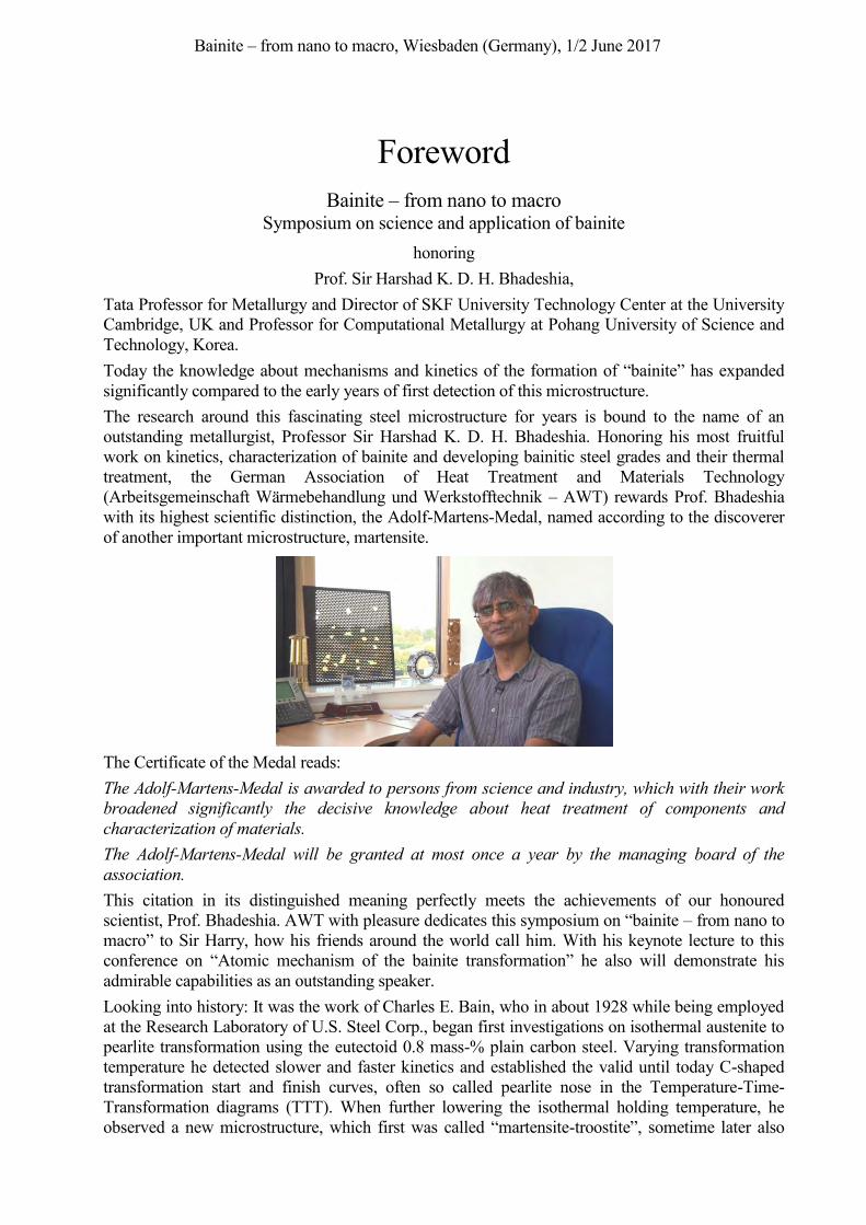
Prof. Sir Harshad K. D. H. Bhadeshia, Tata Professor for Metallurgy and Director of SKF University Technology Center at the University Cambridge, UK and Professor for Computational Metallurgy at Pohang University of Science and Technology, Korea. Today the knowledge about mechanisms and kinetics of the formation of “bainite” has expanded significantly compared to the early years of first detection of this microstructure. The research around this fascinating steel microstructure for years is bound to the name of an outstanding metallurgist, Professor Sir Harshad K. D. H. Bhadeshia. Honoring his most fruitful work on kinetics, characterization of bainite and developing bainitic steel grades and their thermal treatment, the German Association of Heat Treatment and Materials Technology (Arbeitsgemeinschaft Wärmebehandlung und Werkstofftechnik – AWT) rewards Prof. Bhadeshia with its highest scientific distinction, the Adolf-Martens-Medal, named according to the discoverer of another important microstructure, martensite.
The Certificate of the Medal reads: The Adolf-Martens-Medal is awarded to persons from science and industry, which with their work broadened significantly the decisive knowledge about heat treatment of components and characterization of materials. The Adolf-Martens-Medal will be granted at most once a year by the managing board of the association. This citation in its distinguished meaning perfectly meets the achievements of our honoured scientist, Prof. Bhadeshia. AWT with pleasure dedicates this symposium on “bainite – from nano to macro” to Sir Harry, how his friends around the world call him. With his keynote lecture to this conference on “Atomic mechanism of the bainite transformation” he also will demonstrate his admirable capabilities as an outstanding speaker. Looking into history: It was the work of Charles E. Bain, who in about 1928 while being employed at the Research Laboratory of U.S. Steel Corp., began first investigations on isothermal austenite to pearlite transformation using the eutectoid 0.8 mass-% plain carbon steel. Varying transformation temperature he detected slower and faster kinetics and established the valid until today C-shaped transformation start and finish curves, often so called pearlite nose in the Temperature-Time-Transformation diagrams (TTT). When further lowering the isothermal holding temperature, he observed a new microstructure, which first was called “martensite-troostite”, sometime later also
Bainite – from nano to macro, Wiesbaden (Germany), 1/2 June 2017 detected by Wever and Lange and named “Zwischenstufe”. Bain and his young metallurgist co-worker, E. S. Davenport published about this new microstructure in 1929, which was later named “bainite”, honoring the fundamental research of Charles E. Bain. Even at that time already the favorable strength-ductility-relationship of bainitic steels was reported, which today finds various application in severe industrial applications. Especially the rolling bearing industry introduced this new heat treatment process into production as to prevent hardening cracking of large cross section rings. Further the generation of favorable compressive residual stresses within the surface regions of isothermal treated parts in the lower bainite range up to now is very useful in applications, where surface stresses cause a component to fail. In the bearing business bainitic components even compete with casehardened designs sometimes. Bringing the basic knowledge of bainitic microstructure development to industrial processes another name has to be mentioned, Prof. Otto Schaaber. Having been the first director of IHT – Institute of heat treatment technology, Bremen (now IWT – Institute of Materials Technology), among others he developed the “Schaaber-Dilatometer”, which allowed to study in-situ the microstructure evolution from austenite to bainite. Although research on bainite has a history of almost 90 years, still some observations are not fully clarified up to now. And the development is just going on, as Prof. Bhadeshia and some of his co-workers will report during this symposium as the nanostructured bainite. Recent developments deal with steel grades which allow a continuous transformation into bainite during cooling down from forging temperature to ambient temperature. The so-called “bainitic forging steels” also will be addressed by several speakers from the fundamentals to industrial application. The longest tradition in isothermal transformation to bainite without doubt has the bearing industry as contributions of the leading bearing manufacturers will demonstrate, including research results of multi-step bainitic treatments which lead to significant reductions in process time. Transferring the transformation mechanisms to casehardening opens up new possibilities to adjust case-core-properties by the so called carbo-austempering procedure. The very time-consuming isothermal treatment, which can take up to 10 hours or more, require a reliable process technology which also will be presented. An interesting process variant, the dry bainitizing without salt baths was developed some years ago, too. All processes lacked the necessary online information, how the microstructure evolution occurs. The development of the so-called bainite-sensor “switches on the light” and allows to in-situ monitor the formation of bainite fractions, the remaining retained austenite portions and – very important – the precise finish of the process. In-situ observation by eddy current sensors or within an X-ray diffractometer offers great chances to better understand and control the processes. The complex transformation and its many influencing parameters finally calls for a suitable simulation, which also will be addressed. Not precisely a bainitic transformation as described before but also an isothermal transformation from austenite to the so-called ausferrite is the process that leads to austempered ductile iron (ADI), with very promising properties but ambitious in process control. Also this heat treated cast iron will be presented and the beneficial properties and narrow process windows described. The comprehensive presentation on all aspects of isothermal or continuous transformation of austenite to bainite and related materials shall provide state-of-the-art knowledge and recent developments for all participants of this symposium. We wish to thank all participants for their appearance and fruitful discussions. We further explicitly would like to thank all speakers, authors and co-authors for their excellent contributions to this symposium. Our gratitude also goes to the members of the international committee for their support. Finally we gratefully acknowledge the excellent organizational assistance of Mrs. S. Müller, Mrs. H. Dietz and Mrs. Y. Lübben.
Dr.-Ing. Michael Lohrmann Prof. Dr.-Ing. Hans-Werner Zoch Chairmen of the Symposium on Science and Application of Bainite
Wiesbaden, Juni 1st, 2017
Bainite – from nano to macro, Wiesbaden (Germany), 1/2 June 2017 VI
Contents Session 1: Fundamentals and new findings on bainite mechanisms
Atomic mechanism of the bainite transformation 2 H. K. D. H. Bhadeshia, University of Cambridge, Materials Science and Metallurgy, U. K.
New Insights into carbon distribution in bainitic ferrite 12 Rosalia Rementeria, Carlos Garcia-Mateo, Francisca G. Caballero, Spanish National Center for Metallurgical Research (CENIM-CSIC), Madrid, Spain
Session 2: Steels and steel developments for bainitizing and their characterization
Microalloyed Engineering Steels with Improved Performance 22 Wolfgang Bleck1, Margarita Bambach2, Vera Wirths3, Andreas Stieben1, 1Steel Institute, RWTH Aachen University, Aachen, Germany, 2Chair of Materials and Physical Metallurgy, Brandenburg University of Technology Cottbus-Senftenberg, Germany, 3BGH Edelstahl Siegen GmbH, Siegen, Germany
Bainite and superbainite in long products and forged applications 32 Thomas Sourmail, Asco Industries CREAS, Hagondange, France
Taming the bainite for use in bright bar applications 43 Hans Roelofs1, Mirkka Ingrid Lembke2, 1Swiss Steel AG, Emmenbrücke, Switzerland, 2Steeltec AG, Emmenbrücke, Switzerland
Development and Application of high Strength Bainitic Forging Steel 52 Oliver Rösch, Georgsmarienhütte GmbH, Georgsmarienhütte, Germany
Low Distortion Bainitic Steel for Automotive Applications 57 Till Schneiders1, Frank van Soest2, Drago Duh2, Hans-Günter Krull2, 1Deutsche Edelstahlwerke, Witten, Germany, 2Deutsche Edelstahlwerke, Krefeld, Germany
Session 3: Heat treatment processes and properties of bainitic components
Bainitic Bearings for Demanding Applications 66 Werner Trojahn1, Markus Dinkel2, 1Schaeffler AG, Schweinfurt, Germany, 2 Schaeffler AG, Herzogenaurach, Germany
Development of a two-step bainitizing procedure to enhance fatigue strength economically 75 Brigitte Clausen1, Juan Dong1, Klaus Burkart1, Hans-Werner Zoch1,2, 1 Stiftung Institut für Werkstofftechnik, Bremen, Germany, 2MAPEX Center for Materials and Processes, University of Bremen, Germany
CarboBain: case hardening by carbo-austempering – a systematic evaluation of transformation kinetics, microstructure and residual stresses 88 Matthias Steinbacher1, Hans-Werner Zoch1,2, 1Stiftung Institut für Werkstofftechnik Bremen, Germany, 2MAPEX Center for Materials and Processes, University of Bremen, Germany
Bainite – from nano to macro, Wiesbaden (Germany), 1/2 June 2017 VII
Session 4: Process equipment and control
Process Technology and Plant Design for Austempering 100 Herwig Altena1, Klaus Buchner2, 1Aichelin Holding GmbH, Mödling, Austria,, 2Aichelin GesmbH, Mödling, Austria
Batch furnace line with integrated salt quench for austempering 108 Herbert Hans, Ipsen International GmbH, Kleve, Germany
Dry bainitizing – a clean approach to achieve bainitic microstructures 114 Volker Heuer, Klaus Loeser, ALD Vacuum Technologies GmbH, Hanau, Germany
Dry austempering: A new technology for future automotive requirements 123 Eric Dabrock1, László Hagymási2, Frank Sarfert3, Hagen Kuckert3, Eberhard Kerscher4, 1Robert Bosch GmbH, Stuttgart, Germany, 2Robert Bosch GmbH, Stuttgart, Germany, 3Robert Bosch GmbH, Renningen, Germany, 4Materials Testing, University of Kaiserslautern, Kaiserslautern, Germany
New bainite sensor technology allows for a detailed view on material transformation 133 Heinrich Klümper-Westkamp1, Jochen Vetterlein2, Hans-Werner Zoch1, Wilfried Reimche3, Oliver
Bruchwald3, Hans Jürgen Maier3, 1Stiftung Institut für Werkstofftechnik, Bremen, Germany, 2Flowserve Hamburg GmbH, Hamburg, Germany, 3Leibniz Universität Hannover, Garbsen, Germany
Inline application of bainite sensor technology for characterizing phase transformation during cooling 141 Wilfried Reimche1, Oliver Bruchwald1, Sebastian Barton1, Hans Jürgen Maier1, Heinrich Klümper-Westkamp2, Hans-Werner Zoch2, 1Leibniz Universität Hannover, Garbsen, Germany, 2Stiftung Institut für Werkstofftechnik, Bremen, Germany
In-situ Investigation of Bainite Formation with fast X-Ray Diffraction (iXRD) 151 Andreas Kopp, Timo Bernthaler, Dieter Schmid, Gaby Ketzer-Raichle, Gerhard Schneider, Materials Research Institute, Aalen University, Aalen, Germany
Session 5: Fundamentals and simulation of bainite transformation
Bainitic transformation analysis in carbon and nitrogen enriched low alloyed steels: kinetics and microstructures 162 Julien Teixeira1,2, Simon D. Catteau1,2,3, Hugo P. Van Landeghem1,2, Jacky Dulcy1, Moukrane Dehmas1,2, Abdelkrim Redjaïmia1,2, Sabine Denis1,2, Marc Courteaux3, 1Institut Jean Lamour – UMR 7198 CNRS – Université de Lorraine, Nancy CEDEX, France, 2Labex DAMAS “Design of Alloy Metals for Low-mass Structures”, Université de Lorraine, France, 3PSA Peugeot-Citroën, Centre Technique de Belchamp, Voujeaucourt, France
Modeling of bainitic transformations under high stresses 172 Martin Hunkel, Diego Said Schicchi, Stiftung Institut für Werkstofftechnik, Bremen, Germany
Session 6: Ausferritizing of cast iron (Austempered ductile iron – ADI)
Virtual optimization of process and material properties for ADI 183 Erik Hepp, Corinna Thomser, MAGMA Gießereitechnologie GmbH, Aachen, Germany
Is ADI with Bainite Optimized? 192 Arron Rimmer1, Eike Wüller2, 1ADI Treatments Ltd., West Bromwich, U.K., 2SIEMENS AG, Voerde, Germany
Bainite – from nano to macro, Wiesbaden (Germany), 1/2 June 2017 1
1. Fundamentals and new findings on bainite mechanisms
Bainite – from nano to macro, Wiesbaden (Germany), 1/2 June 2017 2
Atomic mechanism of the bainite transformation H. K. D. H. Bhadeshia
University of Cambridge, Materials Science and Metallurgy, U. K., [email protected]
Abstract I have on previous occasions shown how we can be surprised and delighted by new discoveries in steels, which at the same time may be useful. However, my focus in this lecture is purely on some basic science so that a well-founded understanding of mechanisms can lead to ever greater advances. The composite structure that is known colloquially as bainite is arguably the most interesting of all of the essential microstructures that occur in steels, where the manner in which atoms move is seminal to the design of steels. Therefore, I take the liberty to indulge myself and talk only of theory on this occasion.
Keywords Atomic mechanism, bainite, shape deformation, local equilibrium, thermodynamic, dissipations
1 Introduction
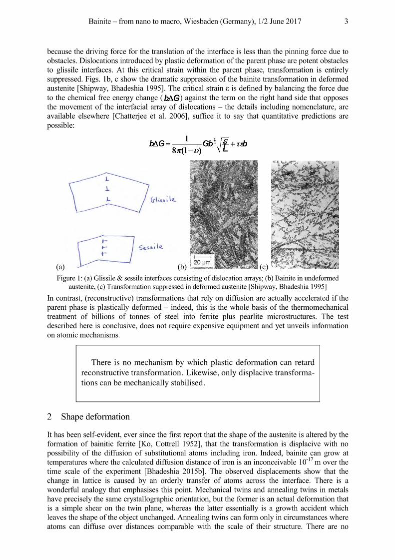
Bainite is not a phase, rather, it can be an aggregate of phases consisting predominantly of platelets of ferrite but with a sprinkling of minority phases such as carbides or residual austenite [Davenport 1930, Bhadeshia 2015b]. It is lovely structure that has advantages including the fact that it can be generated uniformly in huge components such as steam turbines [Colbeck, Rait 1952], or can be used microscopically as a surface treatment to enhance tribological properties [Zhang et al. 2008]. The structure is amenable to careful control – for example, its scale can be regulated from hundreds of micrometres to tens of nanometres [Bhadeshia, Honeycombe 2017]. Such variations are reflected in properties, emphasising the versatility of the structure. There are cases where the structure has such a high energy absorbing capacity that the Charpy toughness cannot in fact be measured because the energy absorbed is off the upper limit of the scale at sub-zero temperatures [Zhu et al. 2016]. A number of the industrial advances that have been made in recent years have relied on the theoretical understanding of the bainite transformation. The theory therefore is not simply fodder for academic debate. Any completely satisfactory theory of a phase transformation must explain in quantitative detail the known set of observations. It should also be able to venture into previously unknown domains so that experiments can be done to verify its ability to generalise. Some of its predictions may lead to previously unknown consequences, which is when it becomes thrilling. But first, it is important to set aside any discussion about whether or not there is the diffusion of atoms during the transformation. In the next few paragraphs I describe a disarmingly simple way to distinguish changes in crystal structure that are accomplished by the homogeneous deformation of the lattice, as opposed to those that occur by a higgledy-piggledy movement of atoms. All that is required is to monitor the transformation of austenite that has been deformed beyond a critical plastic strain . Fig. 1 illustrates two kinds of interfaces consisting of dislocation arrays between the parent and product crystals. The glissile interface is able to translate without diffusion because the Burgers vectors of the interfacial dislocations lie outside of the plane of the boundary. The corresponding dislocations in the sessile interface would need to climb for the boundary to move, with diffusion occurring over a distance comparable to the scale of the transformation product [Bhadeshia 1985]. A distinguishing characteristic of these two kinds of interfaces is that obstacles (defects) in the path of a glissile interface hinder its motion. A point is reached where it cannot advance
Bainite – from nano to macro, Wiesbaden (Germany), 1/2 June 2017 3
because the driving force for the translation of the interface is less than the pinning force due to obstacles. Dislocations introduced by plastic deformation of the parent phase are potent obstacles to glissile interfaces. At this critical strain within the parent phase, transformation is entirely suppressed. Figs. 1b, c show the dramatic suppression of the bainite transformation in deformed austenite [Shipway, Bhadeshia 1995]. he c itical st ai is e i e b bala ci the o ce ue to the chemical free energy change ( ) against the term on the right hand side that opposes the movement of the interfacial array of dislocations – the details including nomenclature, are available elsewhere [Chatterjee et al. 2006], suffice it to say that quantitative predictions are possible:
(a) (b) (c) Figure 1: (a) Glissile & sessile interfaces consisting of dislocation arrays; (b) Bainite in undeformed
austenite, (c) Transformation suppressed in deformed austenite [Shipway, Bhadeshia 1995] In contrast, (reconstructive) transformations that rely on diffusion are actually accelerated if the parent phase is plastically deformed – indeed, this is the whole basis of the thermomechanical treatment of billions of tonnes of steel into ferrite plus pearlite microstructures. The test described here is conclusive, does not require expensive equipment and yet unveils information on atomic mechanisms.
2 Shape deformation
It has been self-evident, ever since the first report that the shape of the austenite is altered by the formation of bainitic ferrite [Ko, Cottrell 1952], that the transformation is displacive with no possibility of the diffusion of substitutional atoms including iron. Indeed, bainite can grow at temperatures where the calculated diffusion distance of iron is an inconceivable 10-17 m over the time scale of the experiment [Bhadeshia 2015b]. The observed displacements show that the change in lattice is caused by an orderly transfer of atoms across the interface. There is a wonderful analogy that emphasises this point. Mechanical twins and annealing twins in metals have precisely the same crystallographic orientation, but the former is an actual deformation that is a simple shear on the twin plane, whereas the latter essentially is a growth accident which leaves the shape of the object unchanged. Annealing twins can form only in circumstances where atoms can diffuse over distances comparable with the scale of their structure. There are no
Bainite – from nano to macro, Wiesbaden (Germany), 1/2 June 2017 4
restrictions in principle to the lowest temperature at which mechanical twins can be induced by applying an appropriate stimulus.
Item Structure change? Volume change? Shape deformation? Annealing twin None None None Mechanical twin None None Shea st ai ( )
Bainite fcc to bcc or bct Yes Shear (~0.26), dilatation (~0.02) Martensite fcc to bcc or bct Yes Shear (~0.26), dilatation (~0.03)
Table 1: Distinguishing characteristics of twins and transformations. fcc, bcc and bct represent the face-centred cubic, body-centred cubic and body-centred tetragonal structures of iron
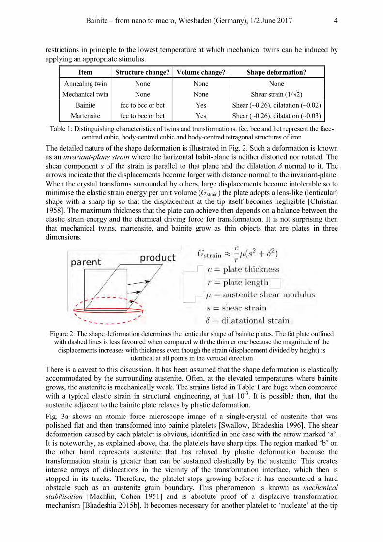
The detailed nature of the shape deformation is illustrated in Fig. 2. Such a deformation is known as an invariant-plane strain where the horizontal habit-plane is neither distorted nor rotated. The shear component s of the strain is parallel to that plane and the dilatation δ normal to it. The arrows indicate that the displacements become larger with distance normal to the invariant-plane. When the crystal transforms surrounded by others, large displacements become intolerable so to minimise the elastic strain energy per unit volume (Gstrain) the plate adopts a lens-like (lenticular) shape with a sharp tip so that the displacement at the tip itself becomes negligible [Christian 1958]. The maximum thickness that the plate can achieve then depends on a balance between the elastic strain energy and the chemical driving force for transformation. It is not surprising then that mechanical twins, martensite, and bainite grow as thin objects that are plates in three dimensions.
Figure 2: The shape deformation determines the lenticular shape of bainite plates. The fat plate outlined
with dashed lines is less favoured when compared with the thinner one because the magnitude of the displacements increases with thickness even though the strain (displacement divided by height) is
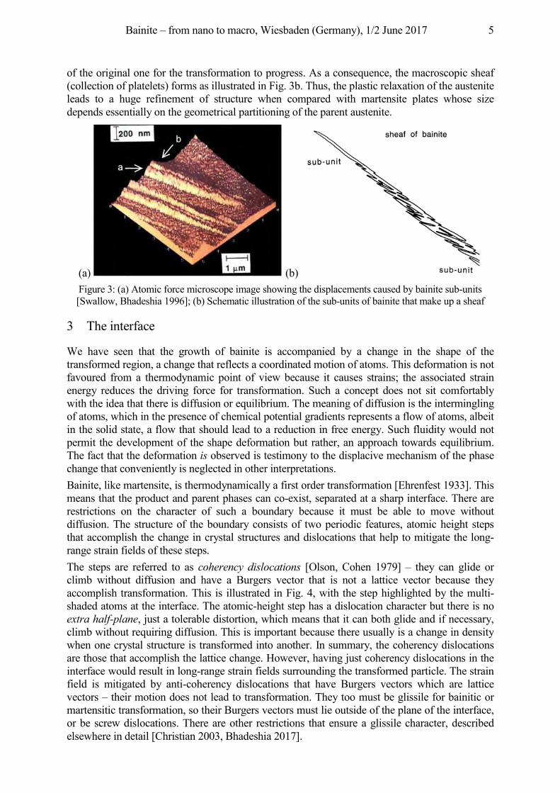
identical at all points in the vertical direction There is a caveat to this discussion. It has been assumed that the shape deformation is elastically accommodated by the surrounding austenite. Often, at the elevated temperatures where bainite grows, the austenite is mechanically weak. The strains listed in Table 1 are huge when compared with a typical elastic strain in structural engineering, at just 10-3. It is possible then, that the austenite adjacent to the bainite plate relaxes by plastic deformation. Fig. 3a shows an atomic force microscope image of a single-crystal of austenite that was polished flat and then transformed into bainite platelets [Swallow, Bhadeshia 1996]. The shear deformation caused by each platelet is obvious, identified in one case with the arrow marked ‘a’. It is noteworthy, as explained above, that the platelets have sharp tips. The region marked ‘b’ on the other hand represents austenite that has relaxed by plastic deformation because the transformation strain is greater than can be sustained elastically by the austenite. This creates intense arrays of dislocations in the vicinity of the transformation interface, which then is stopped in its tracks. Therefore, the platelet stops growing before it has encountered a hard obstacle such as an austenite grain boundary. This phenomenon is known as mechanical stabilisation [Machlin, Cohen 1951] and is absolute proof of a displacive transformation mechanism [Bhadeshia 2015b]. It becomes necessary for another platelet to ‘nucleate’ at the tip
Bainite – from nano to macro, Wiesbaden (Germany), 1/2 June 2017 5
of the original one for the transformation to progress. As a consequence, the macroscopic sheaf (collection of platelets) forms as illustrated in Fig. 3b. Thus, the plastic relaxation of the austenite leads to a huge refinement of structure when compared with martensite plates whose size depends essentially on the geometrical partitioning of the parent austenite.
(a) (b) Figure 3: (a) Atomic force microscope image showing the displacements caused by bainite sub-units [Swallow, Bhadeshia 1996]; (b) Schematic illustration of the sub-units of bainite that make up a sheaf
3 The interface
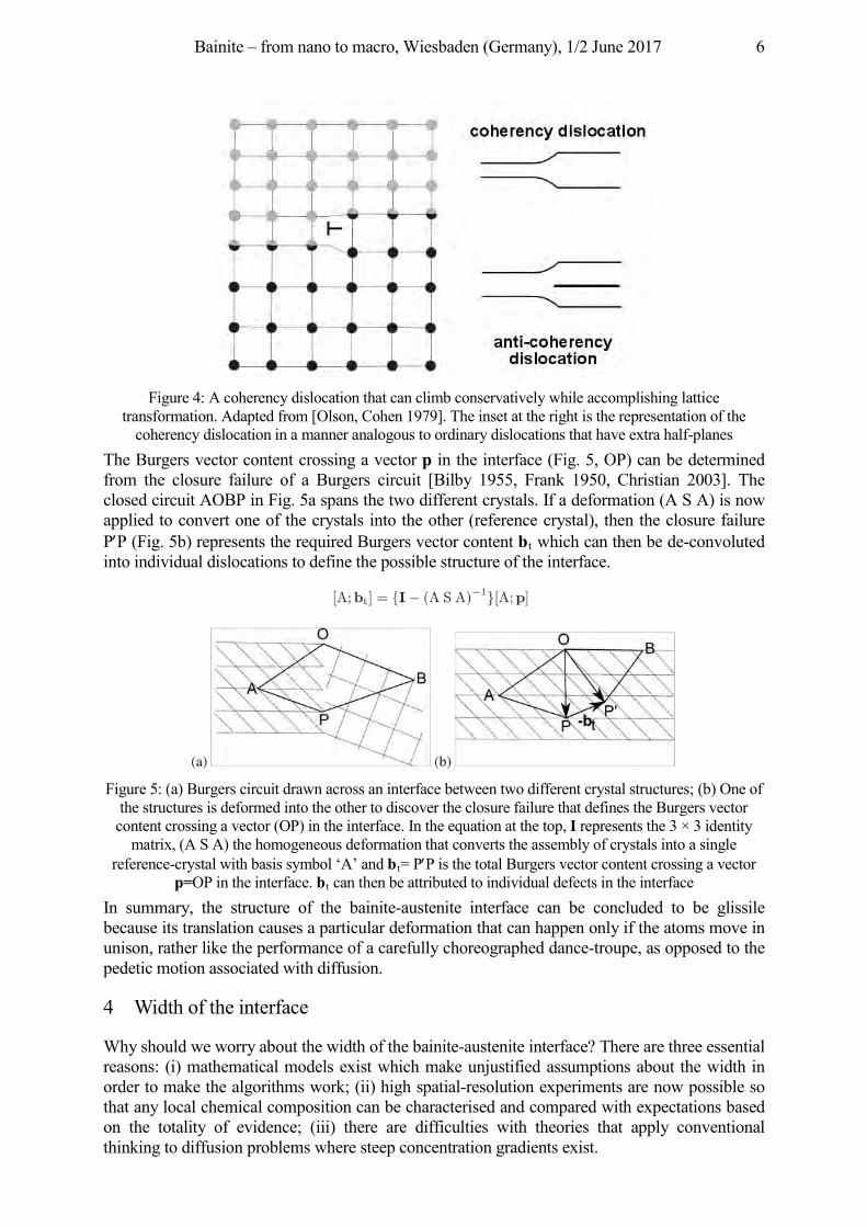
We have seen that the growth of bainite is accompanied by a change in the shape of the transformed region, a change that reflects a coordinated motion of atoms. This deformation is not favoured from a thermodynamic point of view because it causes strains; the associated strain energy reduces the driving force for transformation. Such a concept does not sit comfortably with the idea that there is diffusion or equilibrium. The meaning of diffusion is the intermingling of atoms, which in the presence of chemical potential gradients represents a flow of atoms, albeit in the solid state, a flow that should lead to a reduction in free energy. Such fluidity would not permit the development of the shape deformation but rather, an approach towards equilibrium. The fact that the deformation is observed is testimony to the displacive mechanism of the phase change that conveniently is neglected in other interpretations. Bainite, like martensite, is thermodynamically a first order transformation [Ehrenfest 1933]. This means that the product and parent phases can co-exist, separated at a sharp interface. There are restrictions on the character of such a boundary because it must be able to move without diffusion. The structure of the boundary consists of two periodic features, atomic height steps that accomplish the change in crystal structures and dislocations that help to mitigate the long-range strain fields of these steps. The steps are referred to as coherency dislocations [Olson, Cohen 1979] – they can glide or climb without diffusion and have a Burgers vector that is not a lattice vector because they accomplish transformation. This is illustrated in Fig. 4, with the step highlighted by the multi-shaded atoms at the interface. The atomic-height step has a dislocation character but there is no extra half-plane, just a tolerable distortion, which means that it can both glide and if necessary, climb without requiring diffusion. This is important because there usually is a change in density when one crystal structure is transformed into another. In summary, the coherency dislocations are those that accomplish the lattice change. However, having just coherency dislocations in the interface would result in long-range strain fields surrounding the transformed particle. The strain field is mitigated by anti-coherency dislocations that have Burgers vectors which are lattice vectors – their motion does not lead to transformation. They too must be glissile for bainitic or martensitic transformation, so their Burgers vectors must lie outside of the plane of the interface, or be screw dislocations. There are other restrictions that ensure a glissile character, described elsewhere in detail [Christian 2003, Bhadeshia 2017].
Bainite – from nano to macro, Wiesbaden (Germany), 1/2 June 2017 6
Figure 4: A coherency dislocation that can climb conservatively while accomplishing lattice
transformation. Adapted from [Olson, Cohen 1979]. The inset at the right is the representation of the coherency dislocation in a manner analogous to ordinary dislocations that have extra half-planes
The Burgers vector content crossing a vector p in the interface (Fig. 5, OP) can be determined from the closure failure of a Burgers circuit [Bilby 1955, Frank 1950, Christian 2003]. The closed circuit AOBP in Fig. 5a spans the two different crystals. If a deformation (A S A) is now applied to convert one of the crystals into the other (reference crystal), then the closure failure P′P (Fig. 5b) represents the required Burgers vector content bt which can then be de-convoluted into individual dislocations to define the possible structure of the interface.
Figure 5: (a) Burgers circuit drawn across an interface between two different crystal structures; (b) One of
the structures is deformed into the other to discover the closure failure that defines the Burgers vector content crossing a vector (OP) in the interface. In the equation at the top, I represents the 3 × 3 identity
matrix, (A S A) the homogeneous deformation that converts the assembly of crystals into a single reference-crystal with basis symbol ‘A’ and bt= P′P is the total Burgers vector content crossing a vector
p=OP in the interface. bt can then be attributed to individual defects in the interface In summary, the structure of the bainite-austenite interface can be concluded to be glissile because its translation causes a particular deformation that can happen only if the atoms move in unison, rather like the performance of a carefully choreographed dance-troupe, as opposed to the pedetic motion associated with diffusion.
4 Width of the interface
Why should we worry about the width of the bainite-austenite interface? There are three essential reasons: (i) mathematical models exist which make unjustified assumptions about the width in order to make the algorithms work; (ii) high spatial-resolution experiments are now possible so that any local chemical composition can be characterised and compared with expectations based on the totality of evidence; (iii) there are difficulties with theories that apply conventional thinking to diffusion problems where steep concentration gradients exist.
Bainite – from nano to macro, Wiesbaden (Germany), 1/2 June 2017 7
The first issue is particularly prevalent in phase field models of bainite where the parent, product and interface are all represented in terms of an order parameter; the interface is therefore diffuse [Song et al. 2011, Ramazani et al. 2013, Arif, Qin 2013, Arif, Qin 2014]. Both the definition of how the free energy density varies across the boundary, and the assumption of particular systematic gradients within the diffuse interface are arbitrary. High resolution transmission electron microscopy has shown that the bainite-austenite interface is in reality sharp, less than 1 nm in thickness [Kajiwara 1999, Kajiwara 2003, Ogawa:2006]. The treatment of the strain energy due to the shape deformation is either absent [Song et al. 2011], [Ramazani et al. 2013] or has been implemented incorrectly with shear occurring in all directions within the habit plane [Arif, Qin 2013, Arif, Qin 2014]. When the shape deformation is neglected, the plate shape is generated by an arbitrary anisotropy of interfacial energy; this procedure amounts to image generation rather than a physical representation. I think it is reasonable to conclude that no new knowledge has emerged from the application of phase field methods to bainite [Bhadeshia 2015b]. The second issue marked (ii) concerns the availability of instruments, in particular of the field ion microscope/atom probe, and of course, high-resolution transmission electron microscopy. The latter gives a direct observation of interfacial width whereas the former has difficulties in the precise location of the interface due to effects described elsewhere [Bhadeshia 2015a]. Two conclusions can nevertheless be reached from the vast number of experiments that have been conducted using the atom-probe. The first is that there is absolutely no partitioning of substitutional solutes during the growth of bainite; this immediately invalidates any notions that the transformation to bainite could be occurring by a negligible partitioning local equilibrium mechanism (NPLE) [Coates 1972, Coates 1973] in which growth occurs with very little redistribution of solutes but with local equilibrium maintained at the interface where a concentration spike occurs in the parent phase. The magnitude of this spike would ensure that the che ical pote tials o the ele e ts a e i e tical i the a . Bainite forms at low temperatures so the width of these spikes has long been recognised as being unphysical [Coates 1972, Coates 1973], often reaching dimensions far less than the size of atoms. Software such as DICTRA© [Borgenstam et al. 2000] allow these calculations to be conducted routinely, but it is not appreciated that there is a cost involved in the development of sharp concentration profiles [Bhadeshia 2016]. The free energy per atom ( ) of a heterogeneous solid solution is given by [Hilliard 1970]:
where the first term on the right represents the corresponding free energy per atom of a homogeneous solution of the average concentration, and the second term depends on the magnitude of the gradient in concentration and opposes the formation of steep gradients,
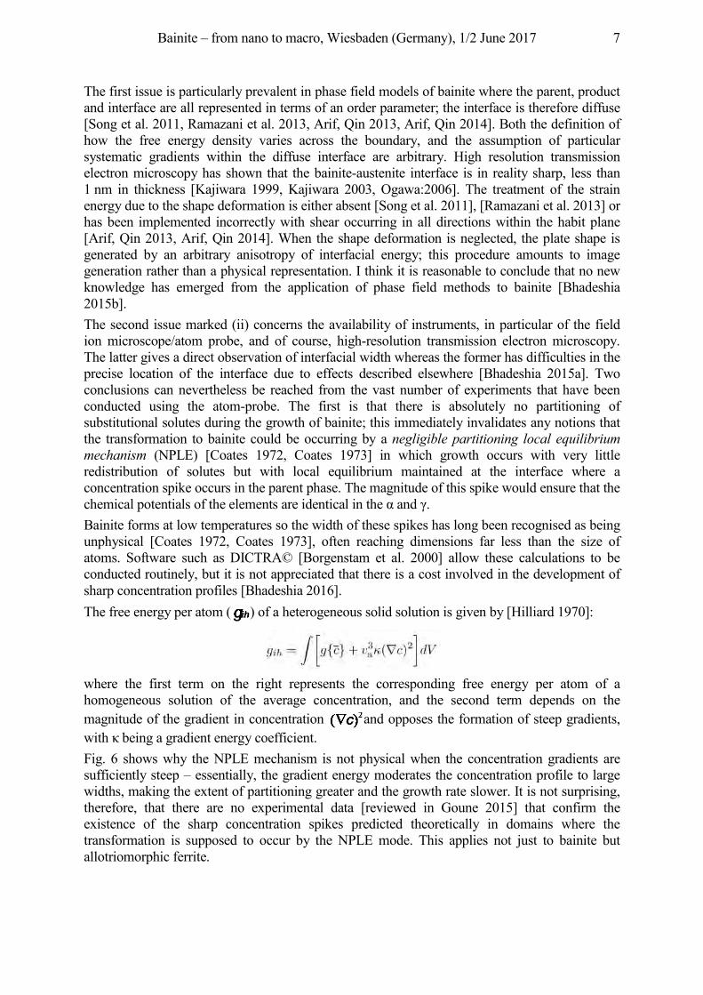
ith bei a a ie t e e coe icie t. Fig. 6 shows why the NPLE mechanism is not physical when the concentration gradients are sufficiently steep – essentially, the gradient energy moderates the concentration profile to large widths, making the extent of partitioning greater and the growth rate slower. It is not surprising, therefore, that there are no experimental data [reviewed in Goune 2015] that confirm the existence of the sharp concentration spikes predicted theoretically in domains where the transformation is supposed to occur by the NPLE mode. This applies not just to bainite but allotriomorphic ferrite.
Bainite – from nano to macro, Wiesbaden (Germany), 1/2 June 2017 8
Figure 6: Estimate of the penalty on free energy due to the gradient of concentration in the austenite ahead of the i te ace ha eshia . The diffusion distance refers to the width of the concentration spike
at the interface It is noted that given the atom probe data, and the fact that steep gradients of concentration are costly in terms of free energy, any explanation of kinetics based on substitutional solute gradients existing within or without the interface are not real [Bhadeshia 1983]. All models that rely on dissipations due to such diffusion are also invalidated [Bhadeshia 2015b].
5 Carbon
The fact that bainite grows without any diffusion, not even that of carbon, has been reviewed [Bhadeshia 2015b], so will not be discussed here. The salient points are as follows:
• The growth rate when measured at sufficient resolution is orders of magnitude faster than expected on the basis of paraequilibrium, carbon diffusion-controlled lengthening of platelets [Bhadeshia 1984].
• In circumstances where the austenite retains its carbon, the reaction stops when the chemical composition is such that diffusionless growth is thermodynamically impossible [Bhadeshia, Edmonds 1980].
• The carbides that precipitate inside bainitic ferrite follow exactly the same orientation relationships and metastable precipitation sequences as during the tempering of martensite [Bhadeshia 2015b].
• Large concentrations of carbon have been observed in solid solution within the bainitic ferrite, far greater than permitted by equilibrium between cubic ferrite and austenite [Caballero et al. 2011, Caballero et al. 2012, Caballero et al. 2014].
• When excess carbon in retained in solution, the ferrite lattice has been shown to be body-centred tetragonal [Smith et al. 2013].
6 Summary
The accumulated evidence proves that bainite is nothing but martensite that may be tempered immediately after transformation. There are differences because the driving force available for bainite is smaller than for martensite. So although the nucleation mechanism for bainite, like martensite, involves the dissociation of dislocations, unlike martensite, it is required that carbon partitions during those early stages of genesis. The nucleus then evolves into diffusionless growth [Bhadeshia 2015b]. Secondly, the combination of the low driving force and weakness of the austenite at the temperatures where bainite typically forms, induces mechanical stabilisation that leads to a dramatic refinement of the structure. As a result, the platelets of bainite can be much finer than those of martensite.
Bainite – from nano to macro, Wiesbaden (Germany), 1/2 June 2017 9
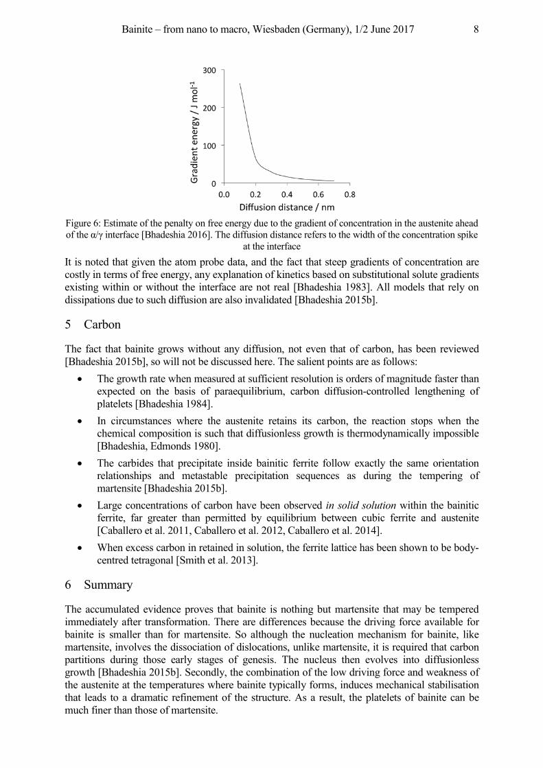
It is important not to consider the bainite transformation in isolation. Table 2 outlines the characteristics of all of the major transformation products in steel, and forms the basis of many mathematical models which are based on physical principles, and which permit the calculation of overall microstructure as a function of chemical composition and processing.
able e t a s o atio cha acte istics i steels. a te site lo e bai ite lb uppe bai ite ub
acicula e ite a i a staette e ite allot io o phic e ite i io o phic e ite i pea lite P substitutional solutes X. Consistency of a comment with the transformation is indicated by =,
i co siste c b . bullet i e ti ies cases he e the co e t is o l so eti es co sistent with the t a s o atio . he te pa e t i plies the ai o hich the p o uct phase grows. Adapted from
[Bhadeshia, Christian 1990]
Acknowledgement I am especially grateful to all who have been so generous in selflessly organising this event, in particular, Professor Hans-Werner Zoch, Dr Michael Lohrmann and the staff of the AWT.
References Arif, T. T.; Qin, R., 2014. A phase- el o el o the o atio o a te site a bai ite. va ce Materials
Research 922, pp. 31–36. Arif, T. T.; Qin, R. S., 2013. A phase- el o el o bai itic t a s o atio . Co putatio al Materials Science 77,
pp. 230–235. Bhadeshia, H. K. D. H., 1983. Considerations of solute drag in relation to transformations in steels. Journal of
Material Science 18, pp. 1473–1481. Bhadeshia, H. K. D. H., 1984. Solute-drag, kinetics and the mechanism of the bainite transformation. In: Marder, A.
R., Goldstein, J. I. (Eds.), Phase Transformations in Ferrous Alloys. TMS-AIME, Ohio, USA, pp. 335–340.
Bainite – from nano to macro, Wiesbaden (Germany), 1/2 June 2017 10
ha eshia . . . . . i usional formation of ferrite in iron and its alloys. Progress in Materials Science 29, pp. 321–386.
Bhadeshia, H. K. D. H., 2015a. Anomalies in carbon concentration determinations from nanostructured bainite. Materials Science and Technology 31, pp. 758–763.
Bhadeshia, H. K. D. H., 2015b. Bainite in steels: theory and practice, 3rd Edition. Maney Publishing, Leeds, U. K. ha eshia . . . . . So e i culties i the theo o i usio -controlled growth in substitutionally
alloyed steels. Current Opinion in Solid State and Materials Science 20, pp. 396–400. Bhadeshia, H. K. D. H., 2017. Geometry of Crystals, Polycrystals, and Phase Transformations. CRC press, ISBN
9781138070783, Florida, USA. Bhadeshia, H. K. D. H.; Christian, J. W., 1990. The bainite transformation in steels. Metallurgical & Materials
Transactions A 21A, pp. 767–797. Bhadeshia, H. K. D. H.; Edmonds, D. V., 1980. The mechanism of bainite formation in steels. Acta Metallurgica
28, pp. 1265–1273. Bhadeshia, H. K. D. H.; Honeycombe, R. W. K., 2017. Steels: Microstructure and Properties, 4th Edition. Elsevier. Bilby, B. A., 1955. Types of dislocation source. In: Bristol Conference Report on Defects in Crystalline Solids. The
Physical Society, London, U. K., pp. 124–133. Borgenstam, A.; Engstron, A., Hoglund, L., Agren, J., 2000. DICTRA, a tool for simulation of i usio al
transformations in alloys. Journal of Phase Equilibria 21, pp. 269–280. Caballero, F. G.; Miller, M.; Yen, H. W.; Jimenez, J. A.; Mateo, C. G.; Rivas, L. M.; Yang, J. R., 2014. Carbon
supersaturation and tetragonal bainitic ferrite in nanocrystalline bainitic steels, TMS2014, 143rd Annual Meeting and Exhibition, San Diego, USA.
Caballero, F. G.; Miller, M. K.; Garcia-Mateo, C., 2011. Atom probe tomography analysis of precipitation during tempering of a nanostructured bainitic steel. Metallurgical & Materials Transactions A 42, pp. 3660–3668.
Caballero, F. G.; Miller, M. K.; Garcia-Mateo, C.; Co i e . . e e pe i e tal evi e ceo the i usio less transformation nature of bainite. Journal of Alloys and Compounds 577, pp. S626–S630.
Chatterjee, S.; Wang, H. S.; Yang, J. R.; Bhadeshia, H. K. D. H., 2006. Mechanical stabilisation of austenite. Materials Science and Technology 22, pp. 641–644.
Christian, J. W., 1958. Accommodation strains in martensite formation, the use of the dilatation parameter. Acta Metallurgica 6, pp. 377–379.
Coates . . . i usio co t olle p ecipitate o th i te a s ste s . etallu ical Transactions 3, pp. 1203–1212.
Coates, D. E., 1973. Precipitate growth kinetics for Fe-C-X alloys. Metallurgical Transactions 4, pp. 395–396. Colbeck, E. W.; Rait, J. R., 1952. Creep-resisting ferritic steels. Tech. Rep. Special report 43, Iron and Steel
Institute, London, U. K. Davenport, E. S.; Bain, E. C., 1930. Transformation of austenite at constant subcritical temperatures. Trans. Am.
Inst. Min. Metall. Engng. 90, pp. 117–154. Ehrenfest, P., 1933. Phasenumwandlungen im ueblichen und erweiterten sinn, classi ziert nach dem
entsprechenden sigularitaeten des thermodynamischen potentiales. Verhandelingen der Koninklijke Akademie van Wetenschappen (Amsterdam) 36, pp. 153–157.
Frank, F. C., 1950. Report of the pittsburgh symposium. In: Symposium on the Plastic Deformation of Crystalline Soli s. ce o Naval Research, Pittsburgh, USA, p. 150.
Hilliard, J. E., 1970. Spinodal decomposition. In: Zackay, V. F., Aaronson, H. I. (Eds.), Phase Transformations. ASM International, Metals Park, Ohio, USA, pp. 497–560.
Hulme-Smith, C. N.; Lonardelli, I.; Dippel, A. C.; Bhadeshia, H. K. D. H., 2013. Experimental evidence for non-cubic bainitic ferrite. Scripta Materialia 69, pp. 409–412.
Ko, T.; Cottrell, S. A., 1952. The formation of bainite. Journal of the Iron and Steel Institute 172, pp. 307–313. Machlin, E. S.; Cohen, M., 1951. Burst phenomenon in the martensitic transformation. Trans. Metall. Soc. AIME
191, pp. 746–754. Olson, G. B.; Cohen, M., 1979. Interphase boundary dislocations and the concept of coherency. Acta Metallurgica
27, pp. 1907–1918. Ramazani, A.; Li, Y.; Mukherjee, K.; Prahl, U.; Bleck, W. A.; Abdurakhmanov, M. S.; Reisgen, U., 2013.
Microstructure evolution simulation in hot rolled DP600 steel during gas metal arc welding. Computational Materials Science 68, pp. 107–116.

Bainite – from nano to macro, Wiesbaden (Germany), 1/2 June 2017 11
Shipway, P. H.; Bhadeshia, H. K. D. H., 1995. Mechanical stabilisation of bainite. Materials Science and Technology 11, pp. 1116–1128.
Song, W.; Prahl, U.; Bleck, W.; ukhe ee . . Phase el si ulatio s o bai itic phase transformations in 100Cr6. In: Materials fabrication, properties, charaterisation and modelling. J. Wiley & Sons, New Jersey, USA, pp. 417–425.
Swallow, E.; Bhadeshia, H. K. D. H., 1996. High resolution observations of displacements caused by bainitic transformation. Materials Science and Technology 12, pp. 121–125.
Zhang, F. C.; Wang, T. S.; Zhang, P.; Zhang, C. L.; Lv, B.; Zhang, M.; Zhang, Y. Z., 2008. A novel method for the development of a low-temperature bainitic microstructure in the surface layer of low-carbon steel. Scripta Materialia 59, pp. 294–296.
Zhu, Z.; Han, J.; Li, H.; Lu, C., 2016. High temperature processed high Nb X80 steel with excellent heat-a ecte zone toughness. Materials Letters 163, pp. 171–174.
Bainite – from nano to macro, Wiesbaden (Germany), 1/2 June 2017 12
New Insights into carbon distribution in bainitic ferrite
Rosalia Rementeria, Carlos Garcia-Mateo, Francisca G. Caballero
Spanish National Center for Metallurgical Research (CENIM-CSIC), Avda Gregorio del Amo 8, E-28040 Madrid, Spain, [email protected]
Abstract A number of studies on bainite transformation at low temperature have revealed that bainitic ferrite formed super-saturated in carbon. The most sensible explanation to this is the increased solubility of a tetragonal ferrite lattice, by virtue of synchrotron radiation and X-ray diffraction results, as well as ab-initio calculations. The question is if this increased tetragonality in bainitic ferrite is the result of a disordered distribution of carbon atoms in ferrite or the result of local carbon clustering (ordering) in association with a locally increased tetragonality. This development of carbon-enriched and carbon-depleted zones that leads gradually to the formation of a modulated structure was reported in the early stages of decomposition of martensite. In the present work, new experimental and theoretical results on the distribution of carbon in bainitic ferrite will be shown trying to shed new light on the nature of bainite transformation.
Keywords Bainite transformation, carbon distribution, clustering
1 Bainite mechanisms and carbon supersaturation in ferrite
Nowadays, there is no doubt that bainite grows via a displacive mechanism [Hillert 2002] i.e., as lath-shaped transformation products exhibiting an invariant plane strain surface relief effect. But, the discussion on the diffusion or diffusionless nature of bainite is still alive. The diffusional hypothesis states that bainitic ferrite growth is controlled by carbon diffusion and is not distinctly different in character from Widmanstätten ferrite, with carbide precipitation at the austenite/ferrite boundaries. The diffusionless hypothesis states that bainitic ferrite grows without any diffusion of carbon, and carbon supersaturation is subsequently relieved by partitioning to austenite, and/or through carbide precipitation. Ideally, the criterion for differentiating the two bainite transformation mechanisms is to determine whether the newly-formed bainitic ferrite has the para-equilibrium (PE) carbon content or if it retains the carbon content of the parent austenite. However, current experimental techniques are not capable of detecting the fully carbon supersaturation of bainitic ferrite since the time taken for any carbon to diffuse into austenite can be extremely short. Despite carbon diffusion into the neighbouring austenite takes place straightaway, early experimental evidence of carbon supersaturation in bainitic ferrite, obtained using field ion atom probe microscope [Bhadeshia 1982], lattice imaging [Self 1981] and convergent beam Kikuchi line diffraction in transmission electron microscopy (TEM) [Zhang 1998], proved that carbon does not reach the para-equilibrium level in the bainitic ferrite regardless of the availability of sufficient time for partitioning. In most cases, this was attributed to the trapping of carbon at dislocations related to the accommodation of transformation strain. Taking advantage of the extremely slow bainite reaction rates at low temperature (200 ºC) in high-carbon high-silicon bainitic steels, and the modern analysis techniques such as atom probe tomography (APT) that offers extensive capabilities for chemical composition measurements at sub-nanometre scale, the presence of a level of carbon above that expected from PE with austenite was confirmed in dislocation-free bainitic ferrite [Caballero 2010]. Moreover, examination of APT experimental data from steels treated between 200 and 525 ºC did not show
Bainite – from nano to macro, Wiesbaden (Germany), 1/2 June 2017 13
any abrupt change of the carbon content in bainitic ferrite that could indicate a difference in the bainite growth mechanism between high and low temperatures [Caballero 2012]. What was also remarkable is that there was no essential difference in the observed results between steels that transform to bainite with and without the interference of cementite precipitation. These observations and following experimental results using synchrotron radiation [Hulme-Smith 2013], XRD [Garcia-Mateo 2015], and in-situ neutron diffraction [Timokhina 2016], lend strong support for the opinion that the bainitic ferrite in high-silicon steels grows supersaturated with carbon independently of the transformation temperature and the overall reaction rate. As the transformation temperature is increased, carbon diffusion is enhanced, providing an opportunity for the decarburization of the supersaturated ferrite sooner after the growth event. The excess carbon may then partition into the residual austenite, migrate to lattice defects in the vicinity of a bainitic ferrite/austenite interface or precipitate within ferrite in the form of carbides. Therefore, the observed carbon content in solid solution in bainitic ferrite seems to be stable regardless of the competition between the rate at which carbon is partitioned from super-saturated ferrite into austenite and the rate at which carbides can precipitate from ferrite.
2 Possible explanations for carbon supersaturation in ferrite
The interesting question is what factors have caused the abnormally high carbon solubility in bainitic ferrite. One reasonable explanation for carbon supersaturation in bainitic ferrite is that the unit cell is non-cubic. The diffusionless transformation of the austenite retaining a significant amount of carbon necessarily leads to a body-centered tetragonal (bct) lattice, especially in the very beginning of the transformation. Computational simulations support that a shift in the ratio of the c/a lattice parameters, caused by the presence of carbon, changes the equilibrium between austenite and ferrite [Jang 2013]. This is also indicated by ab-initio studies of the individual phases [Jiang 2003]. Besides the high degree of experimental difficulty, there is a number of attempts to provide evidences on the tetragonality of low temperature bainitic ferrite, based on in-situ synchrotron radiation [Hulme-Smith 2013, Datta et al. 2014], XRD measurements and High-Resolution Transmission Electron Microscopy (HR-TEM) [Garcia-Mateo et al. 2015]. However, in the case of TEM analyses, the observed degree of tetragonality is close to the instrument detection errors (~1 % at best). Moreover, the bct lattice formed during the early stages of transformation may undergo changes during subsequent isothermal holding or during cooling to room temperature due to inevitable autotempering. This makes it particularly challenging to confirm or disprove the issue using currently available techniques. On the other hand, when mobile enough, vacancies contribute to the transport of substitutional atoms during bainitic transformation and are as well utilized by interstitial solute atoms to flatten their pile-up in the parent phase near the advancing boundary [van der Zwaag 2002]. Specific interstitial lattice sites near linear defects in bainitic ferrite provide lower-energy sites for carbon than the regular interstitial lattice positions because of the stress field around these defects. Meanwhile, the ease in formation of the vacancy-carbon complexes by the motion of carbon and vacancy under irradiation, deformation, or quenching has been proven theoretically and e pe i e tall i the e C s ste [Paxton 2013, Seydel 1994]. Although the formation of carbon-vacancy complexes in pure iron is favourable, the presence of substitutional atoms may alter this situation. Modern low-temperature bainitic steels have a non-negligible amount of silicon and manganese in the composition (1.5 at.% Si at a minimum to avoid massive carbide precipitation; and about 1.5 at.% Mn to ensure enough hardenability to avoid the formation of proeutectoid phases during cooling). In general, ab-initio results indicate a repulsive interaction of carbon with substitutional silicon in bcc ferrite [Simonovic 2010] but the e cess solutio e thalp o e C a e Si-strongly depends on the interatomic distance. The activation energy (or energy barrier) for a carbon atom to diffuse from one octahedral to another octahedral position through the tetrahedral interstitial in
Bainite – from nano to macro, Wiesbaden (Germany), 1/2 June 2017 14
a pure iron system, was determined to be = 0.87 eV, which agrees well with experimental results [Wert 1950]. The energy barriers are modified by the presence of silicon, leading to the effect that the carbon diffusivity is significantly reduced with increasing the silicon concentration [Liu 2014]. a itio the p ese ce o a vaca c i the bcc e lattice a silico -vacancy-carbon co ple ca be o e the eb e uci the ca bo i usivit i bcc e [Liu 2014]. Both facts are prone to the influence of lattice strain, due to a tetragonal distortion or due to the presence of other defects, such as dislocations. In contrast, it is well known that due to their high binding energy, manganese and carbon atoms form dipoles in both the fcc and bcc lattices of iron alloys and that the dipoles formed in austenite at high temperature are quenched in [Abe 1984]. It was suggested [Shim 2001] that silicon may increase the interaction between manganese and carbon atoms. In addition, it was shown [Massardier 2004] that the solubility limit of carbon increases with manganese content at temperatures below 550 ºC. It was also reported that Mn–C binding energy in austenite increases with increasing manganese content and that the presence of Mn–C dipoles reduces the diffusion rate of carbon [Medvedeva 2014]. itio all he a vaca t site is i t o uce i bcc e the binding energy of the Mn-vacancy pair is exceptionally large, and serves as a stronger trap site to carbon [Liu 2014]. Thus, it has been recently suggested [Pereloma 2015] that the presence of Mn–C dipoles in the ferrite lattice could also be a contributing factor to the observed carbon supersaturation. However, more experimental and theoretical work is required to provide explanation for the carbon supersaturation in bainitic ferrite. In the present work, careful in-situ transformation experiments and TEM analyses were performed to provide the answer on the exact lattice parameters of bainitic ferrite during bainite reaction at low temperature in a high-carbon high-silicon steel. In addition, a detailed ab-initio study of the interaction between an interstitial carbon ato i both bcc a cc Fe, with and without substitutional silicon and an iron vacancy, was performed considering different tetragonal states along the Bain path.
3 New experimental evidences on lattice parameter and ferrite structure in bainite
In-situ and ex-situ X-ray experiments were performed at the European Synchrotron Radiation Facility (ESRF) in Grenoble (France) on the ID15B beamline. Measurements were performed in a high-carbon high-silicon bainitic steel (Table 1) by high-energy X-ray synchrotron diffraction using a monochromatic 90 keV beam. Samples were austenitized at 900 ºC for 5 min and isothermally transformed at 220 and 250 ºC for 16 and 15 h, respectively, after quenching to these temperatures. Rietveld analyses of the synchrotron radiation patterns were performed using
P S . so t a e ove the a e o step ti es o min. during the first 5 h of transformation and step times of 1 h for the rest of the transformation, up to the total transformation time. The refinement protocol includes the background, zero displacement, scale factors, peak breadth, unit cell parameter, and texture parameters. Line-broadening effects due to the crystallite size and lattice strain were analyzed with the double-Voigt approach, in which both the crystallite size and strain comprise Lorentzian and Gaussian component convolution [Balzar 1993].
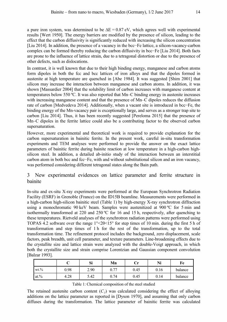
C Si Mn Cr Ni Fe wt.% 0.98 2.90 0.77 0.45 0.16 balance at.% 4.28 5.42 0.74 0.45 0.14 balance
Table 1: Chemical composition of the steel studied
The retained austenite carbon content (C ) was calculated considering the effect of alloying additions on the lattice parameter as reported in [Dyson 1970], and assuming that only carbon diffuses during the transformation. The lattice parameter of bainitic ferrite was calculated
Bainite – from nano to macro, Wiesbaden (Germany), 1/2 June 2017 15
assuming that this phase has a bct structure. Accordingly, the carbon content in bainitic ferrite (C ) was calculated as function of the tetragonal lattice parameters, c and a o bct e ite ( ) according to Cohen’s relation [Cohen 1962].
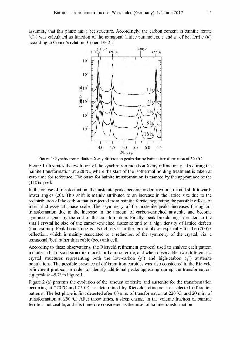
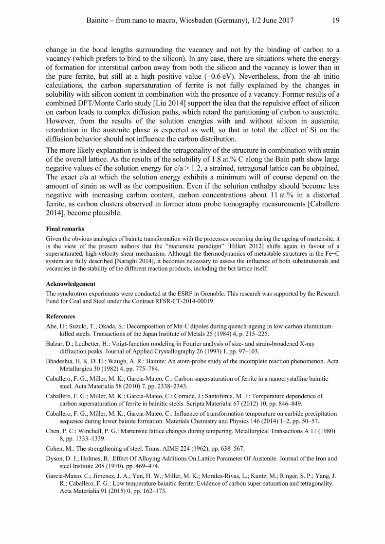
Figure 1: Synchrotron radiation X-ray diffraction peaks during bainite transformation at 220 ºC
Figure 1 illustrates the evolution of the synchrotron radiation X-ray diffraction peaks during the bainite transformation at 220 ºC, where the start of the isothermal holding treatment is taken at zero time for reference. The onset for bainite transformation is marked by the appearance of the ( ) peak. In the course of transformation, the austenite peaks become wider, asymmetric and shift towards lo e a les ( ). his shi t is ai l att ibute to a i c ease i the lattice size ue to the redistribution of the carbon that is rejected from bainitic ferrite, neglecting the possible effects of internal stresses at phase scale. The asymmetry of the austenite peaks increases throughout transformation due to the increase in the amount of carbon-enriched austenite and become symmetric again by the end of the transformation. Finally, peak broadening is related to the small crystallite size of the carbon-enriched austenite and to a high density of lattice defects ( ic ost ai ). Peak b oa e i is also obse ve i the e itic phase especiall o the ( ) reflection, which is mainly associated to a reduction of the symmetry of the crystal, viz. a tetragonal (bct) rather than cubic (bcc) unit cell. According to these observations, the Rietveld refinement protocol used to analyze each pattern includes a bct crystal structure model for bainitic ferrite, and when observable, two different fcc crystal structures representing both the low-ca bo ( ) and high-ca bo ( +) austenite populations. The possible presence of different iron-carbides was also considered in the Rietveld refinement protocol in order to identify additional peaks appearing during the transformation, e.g. peak at ~5.2º in Figure 1. Figure 2 (a) presents the evolution of the amount of ferrite and austenite for the transformation occurring at 220 ºC and 250 ºC as determined by Rietveld refinement of selected diffraction patterns. The bct phase is first detected after 60 min. of transformation at 220 ºC, and 20 min. of transformation at 250 ºC. After those times, a steep change in the volume fraction of bainitic ferrite is noticeable, and it is therefore considered as the onset of bainite transformation.
Bainite – from nano to macro, Wiesbaden (Germany), 1/2 June 2017 16
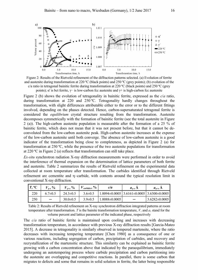
Figure 2: Results of the Rietveld refinement of the diffraction patterns selected. (a) Evolution of ferrite
and austenite during transformation at 220 ºC (black points) and 250 ºC (grey points); (b) evolution of the c/a ratio in tetragonal bainitic ferrite during transformation at 220 ºC (black points) and 250 ºC (grey
poi ts) is bct e ite is lo -ca bo cc auste ite a is hi h-carbon fcc austenite Figure 2 (b) shows the evolution of tetragonality in bainitic ferrite, expressed as the c/a ratio, during transformation at 220 and 250 ºC. Tetragonality hardly changes throughout the transformation, with slight differences attributable either to the error or to the different fittings involved, depending on the phases detected. Hence, carbon-supersaturated tetragonal ferrite is considered the equilibrium crystal structure resulting from the transformation. Austenite decomposes symmetrically with the formation of bainitic ferrite (see the total austenite in Figure 2 (a)). The high-carbon austenite population is measurable after the formation of a 25 % of bainitic ferrite, which does not mean that it was not present before, but that it cannot be de-convoluted from the low-carbon austenite peak. High-carbon austenite increases at the expense of the low-carbon austenite until both converge. The absence of low-carbon austenite is a good indicator of the transformation being close to completeness, as depicted in Figure 2 (a) for transformation at 250 ºC, while the presence of the two austenite populations for transformation at 220 ºC in Figure 2 (a) reflects that transformation can still take place. Ex-situ synchrotron radiation X-ray diffraction measurements were performed in order to avoid the interference of thermal expansion on the determination of lattice parameters of both ferrite and austenite. Table 2 summarizes the results of Rietveld refinement on the experimental data collected at room temperature after transformation. The carbides identified through Rietveld refinement are cementite and –carbide, with contents around the typical resolution limit in conventional X-ray diffraction.
T, ºC V -, % V +, % Vcarbides, % c/a a -, Å a +, Å 220 6.7±0.5 24.3±0.5 3.6±0.5 1.0094±0.0005 3.6161±0.0005 3.6300±0.0005 250 30.0±0.5 3.9±0.5 1.0088±0.0005 3.6282±0.0005
Table 2: Results of Rietveld refinement on X-ray synchrotron diffraction integrated patterns at room temperature after transformation. T is the bainite transformation temperature, Vi and ai stand for the
volume percent and lattice parameter of the indicated phase, respectively The c/a ratio of bainitic ferrite is maintained upon cooling and increases with decreasing transformation temperature, in accordance with previous X-ray diffraction results [Garcia-Mateo 2015]. A decrease in tetragonality is similarly observed in tempered martensite, where the ratio decreases with increasing tempering temperature [Chen 1980] as a consequence of one or various reactions, including segregation of carbon, precipitation of carbides, and recovery and recrystallization of the martensitic structure. This similarity can be explained as bainitic ferrite growing with a carbon concentration above that indicated by the paraequilibrium, immediately undergoing an autotempering process where carbide precipitation and carbon partitioning into the austenite are overlapping and competitive reactions. In parallel, there is some carbon that migrates to defects and some that remains in solid solution in ferrite, the latter being responsible
Bainite – from nano to macro, Wiesbaden (Germany), 1/2 June 2017 17
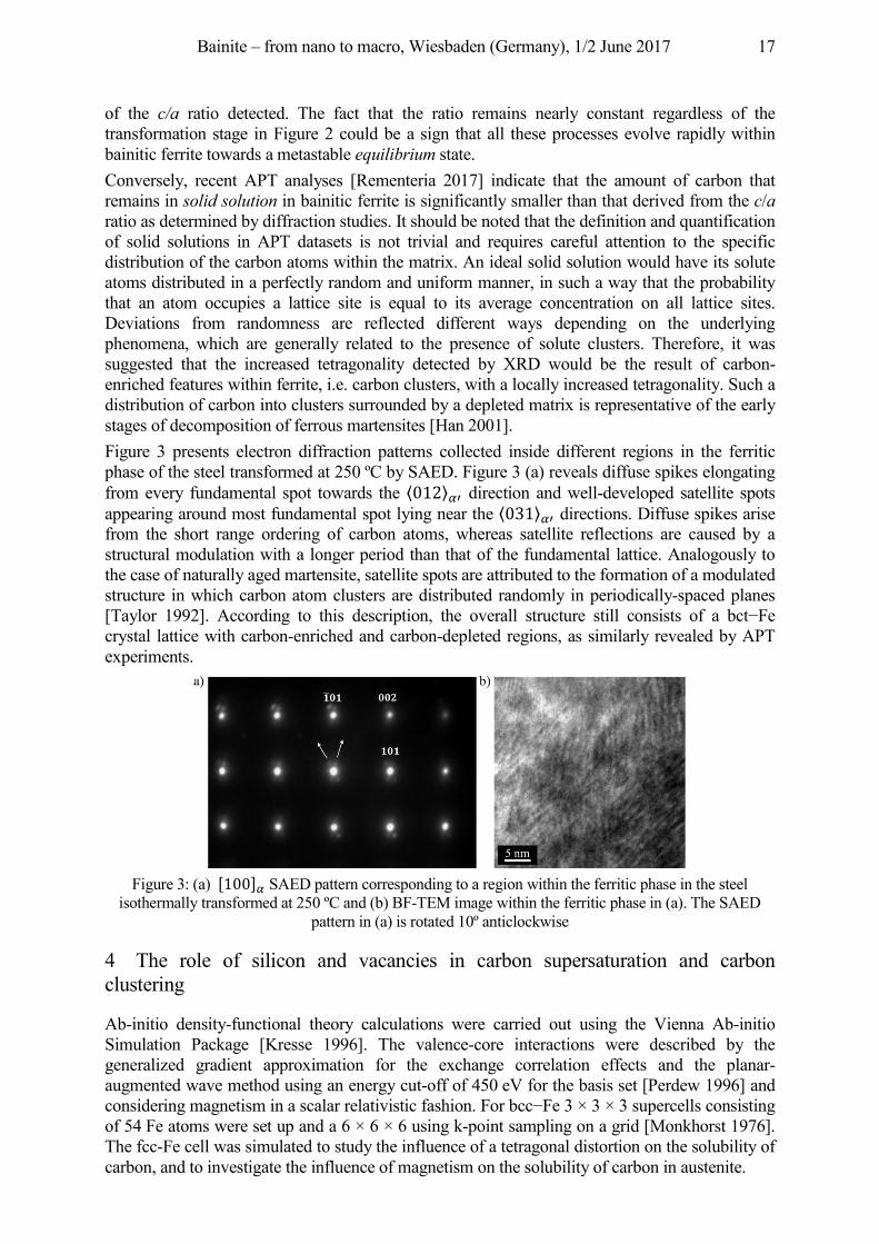
of the c/a ratio detected. The fact that the ratio remains nearly constant regardless of the transformation stage in Figure 2 could be a sign that all these processes evolve rapidly within bainitic ferrite towards a metastable equilibrium state. Conversely, recent APT analyses [Rementeria 2017] indicate that the amount of carbon that remains in solid solution in bainitic ferrite is significantly smaller than that derived from the c/a ratio as determined by diffraction studies. It should be noted that the definition and quantification of solid solutions in APT datasets is not trivial and requires careful attention to the specific distribution of the carbon atoms within the matrix. An ideal solid solution would have its solute atoms distributed in a perfectly random and uniform manner, in such a way that the probability that an atom occupies a lattice site is equal to its average concentration on all lattice sites. Deviations from randomness are reflected different ways depending on the underlying phenomena, which are generally related to the presence of solute clusters. Therefore, it was suggested that the increased tetragonality detected by XRD would be the result of carbon-enriched features within ferrite, i.e. carbon clusters, with a locally increased tetragonality. Such a distribution of carbon into clusters surrounded by a depleted matrix is representative of the early stages of decomposition of ferrous martensites [Han 2001]. Figure 3 presents electron diffraction patterns collected inside different regions in the ferritic phase of the steel transformed at 250 ºC by SAED. Figure 3 (a) reveals diffuse spikes elongating from every fundamental spot towards the ⟨�012⟩�𝛼′ direction and well-developed satellite spots appearing around most fundamental spot lying near the ⟨�031⟩�𝛼′ directions. Diffuse spikes arise from the short range ordering of carbon atoms, whereas satellite reflections are caused by a structural modulation with a longer period than that of the fundamental lattice. Analogously to the case of naturally aged martensite, satellite spots are attributed to the formation of a modulated structure in which carbon atom clusters are distributed randomly in periodically-spaced planes [Taylor 1992]. cco i to this esc iptio the ove all st uctu e still co sists o a bct e crystal lattice with carbon-enriched and carbon-depleted regions, as similarly revealed by APT experiments.
Figure 3: (a) [100]𝛼 SAED pattern corresponding to a region within the ferritic phase in the steel
isothermally transformed at 250 ºC and (b) BF-TEM image within the ferritic phase in (a). The SAED pattern in (a) is rotated 10º anticlockwise
4 The role of silicon and vacancies in carbon supersaturation and carbon clustering
Ab-initio density-functional theory calculations were carried out using the Vienna Ab-initio Simulation Package [Kresse 1996]. The valence-core interactions were described by the generalized gradient approximation for the exchange correlation effects and the planar-augmented wave method using an energy cut-off of 450 eV for the basis set [Perdew 1996] and considering magnetism in a scalar relativistic fashion. o bcc e × 3 × 3 supercells consisting of 54 Fe atoms were set up and a 6 × 6 × 6 using k-point sampling on a grid [Monkhorst 1976]. The fcc-Fe cell was simulated to study the influence of a tetragonal distortion on the solubility of carbon, and to investigate the influence of magnetism on the solubility of carbon in austenite.
Bainite – from nano to macro, Wiesbaden (Germany), 1/2 June 2017 18
Subsequently, the interatomic positions were added to the supercell with one interstitial carbon atom in an octahedral site and relaxed volume. The same calculation procedure was conducted for a system containing one substitutional silicon atom (in fcc and bcc) and a vacancy considering different carbon positions. In this system, the most favourable position for the vacancy turned out to be a nearest-neighbour site to the silicon. This spatial arrangement was used for the calculations with interstitial carbon. To investigate the influence of structure, strain, and composition on the solubility of carbon in an Fe Si C alloy, two strategies were followed. In a first step, ferrite and austenite were considered separately, with the main goal of investigating the influence of interatomic distance and magnetism on the solution enthalpy. The solution energies for an interstitial carbon atom in the different structures as a function of the Si C distance were determined. In general, both ferrite and austenite structures showed the same trend. The solution enthalpy or energy of formation of carbon in an octahedral site is significantly enhanced in the vicinity of silicon compared to the reference value for carbon in pure iron. With increasing distance from the silicon atom, the solution enthalpy approaches this reference value. The presence of a vacancy partially compensates the increase in energy due to the silicon. In the austenite phase, the solution enthalpy depends in general on the magnetic state. For a better understanding of the effect of vacancies, the length of the carbon bonds with nearest neighbour atoms close to silicon were investigated taking Fe54C as a reference. This analysis showed that the vacancy is increasing the solubility of carbon in the Fe Si C system by altering the bond lengths in its surrounding rather than by providing a bonding site for carbon.
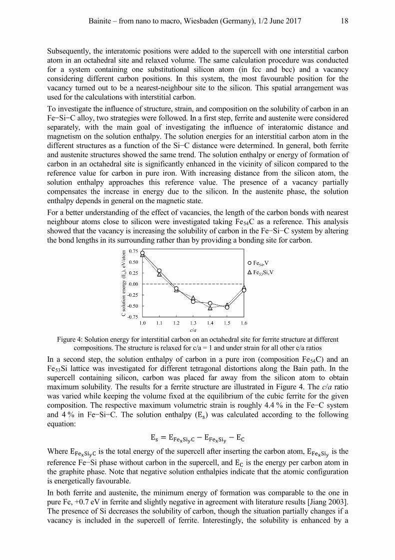
Figure 4: Solution energy for interstitial carbon on an octahedral site for ferrite structure at different
compositions. The structure is relaxed for c/a = 1 and under strain for all other c/a ratios In a second step, the solution enthalpy of carbon in a pure iron (composition Fe54C) and an Fe53Si lattice was investigated for different tetragonal distortions along the Bain path. In the supercell containing silicon, carbon was placed far away from the silicon atom to obtain maximum solubility. The results for a ferrite structure are illustrated in Figure 4. The c/a ratio was varied while keeping the volume fixed at the equilibrium of the cubic ferrite for the given composition. The respective maximum volumetric strain is roughly 4.4 % in the Fe C system and 4 % in Fe Si C. The solution enthalpy (Es) was calculated according to the following equation:
Es = EFexSiyC − EFexSiy − EC
Where EFexSiyC is the total energy of the supercell after inserting the carbon atom, EFexSiy is the e e e ce e Si phase ithout ca bo i the supe cell a EC is the energy per carbon atom in
the graphite phase. Note that negative solution enthalpies indicate that the atomic configuration is energetically favourable. In both ferrite and austenite, the minimum energy of formation was comparable to the one in pure Fe, +0.7 eV in ferrite and slightly negative in agreement with literature results [Jiang 2003]. The presence of Si decreases the solubility of carbon, though the situation partially changes if a vacancy is included in the supercell of ferrite. Interestingly, the solubility is enhanced by a
Bainite – from nano to macro, Wiesbaden (Germany), 1/2 June 2017 19
change in the bond lengths surrounding the vacancy and not by the binding of carbon to a vacancy (which prefers to bind to the silicon). In any case, there are situations where the energy of formation for interstitial carbon away from both the silicon and the vacancy is lower than in the pure ferrite, but still at a high positive value (+0.6 eV). Nevertheless, from the ab initio calculations, the carbon supersaturation of ferrite is not fully explained by the changes in solubility with silicon content in combination with the presence of a vacancy. Former results of a combined DFT/Monte Carlo study [Liu 2014] support the idea that the repulsive effect of silicon on carbon leads to complex diffusion paths, which retard the partitioning of carbon to austenite. However, from the results of the solution energies with and without silicon in austenite, retardation in the austenite phase is expected as well, so that in total the effect of Si on the diffusion behavior should not influence the carbon distribution. The more likely explanation is indeed the tetragonality of the structure in combination with strain of the overall lattice. As the results of the solubility of 1.8 at.% C along the Bain path show large negative values of the solution energy for c/a > 1.2, a strained, tetragonal lattice can be obtained. The exact c/a at which the solution energy exhibits a minimum will of course depend on the amount of strain as well as the composition. Even if the solution enthalpy should become less negative with increasing carbon content, carbon concentrations about 11 at.% in a distorted ferrite, as carbon clusters observed in former atom probe tomography measurements [Caballero 2014], become plausible.
Final remarks Given the obvious analogies of bainite transformation with the processes occurring during the ageing of martensite, it is the view of the present authors that the “martensite paradigm” [Hillert 2012] shifts again in favour of a supersaturated, high-velocity shear mechanism. Although the thermodyna ics o etastable st uctu es i the e C system are fully described [Naraghi 2014], it becomes necessary to assess the influence of both substitutionals and vacancies in the stability of the different reaction products, including the bct lattice itself.
Acknowledgement The synchrotron experiments were conducted at the ESRF in Grenoble. This research was supported by the Research Fund for Coal and Steel under the Contract RFSR-CT-2014-00019.
References Abe, H.; Suzuki, T.; Okada, S.: Decomposition of Mn-C dipoles during quench-ageing in low-carbon aluminium-
killed steels. Transactions of the Japan Institute of Metals 25 (1984) 4, p. 215–225. Balzar, D.; Ledbetter, H.: Voigt-function modeling in Fourier analysis of size- and strain-broadened X-ray
diffraction peaks. Journal of Applied Crystallography 26 (1993) 1, pp. 97–103. Bhadeshia, H. K. D. H.; Waugh, A. R.: Bainite: An atom-probe study of the incomplete reaction phenomenon. Acta
Metallurgica 30 (1982) 4, pp. 775–784. Caballero, F. G.; Miller, M. K.; Garcia-Mateo, C.: Carbon supersaturation of ferrite in a nanocrystalline bainitic
steel. Acta Materialia 58 (2010) 7, pp. 2338–2343. Caballero, F. G.; Miller, M. K.; Garcia-Mateo, C.; Cornide, J.; Santofimia, M. J.: Temperature dependence of
carbon supersaturation of ferrite in bainitic steels. Scripta Materialia 67 (2012) 10, pp. 846–849. Caballero, F. G.; Miller, M. K.; Garcia-Mateo, C.: Influence of transformation temperature on carbide precipitation
sequence during lower bainite formation. Materials Chemistry and Physics 146 (2014) 1–2, pp. 50–57. Chen, P. C.; Winchell, P. G.: Martensite lattice changes during tempering. Metallurgical Transactions A 11 (1980)
8, pp. 1333–1339. Cohen, M.: The strengthening of steel. Trans. AIME 224 (1962), pp. 638–567. Dyson, D. J.; Holmes, B.: Effect Of Alloying Additions On Lattice Parameter Of Austenite. Journal of the Iron and
steel Institute 208 (1970), pp. 469–474. Garcia-Mateo, C.; Jimenez, J. A.; Yen, H. W.; Miller, M. K.; Morales-Rivas, L.; Kuntz, M.; Ringer, S. P.; Yang, J.
R.; Caballero, F. G.: Low temperature bainitic ferrite: Evidence of carbon super-saturation and tetragonality. Acta Materialia 91 (2015) 0, pp. 162–173.
Bainite – from nano to macro, Wiesbaden (Germany), 1/2 June 2017 20
Han, K.; Van Genderen, M. J.; Böttger, A.; Zandbergen, H. W.; Mittemeijer, E. J.: Initial stages of Fe-C martensite decomposition. Philosophical Magazine A: Physics of Condensed Matter, Structure, Defects and Mechanical Properties 81 (2001) 3, pp. 741–757.
Hillert, M.; Borgenstam, A.: Centennial of the Diffusionless Paradigm of Bainite. Metallurgical and Materials Transactions A: Physical Metallurgy and Materials Science 43 (2012) 12, pp. 4487–4495.
Hulme-Smith, C. N.; Lonardelli, I.; Dippel, A. C.; Bhadeshia, H. K. D. H.: Experimental evidence for non-cubic bainitic ferrite. Scripta Materialia 69 (2013) 5, pp. 409–412.
Jang, J. H.; Bhadeshia, H. K. D. H.; Suh, D.-W.: Solubility of carbon in tetragonal ferrite in equilibrium with austenite. Scripta Materialia 68, (2013) 3–4, pp. 195–198.
Jiang, D. E.; Carter, E. A.: Carbon dissolution and diffusion in ferrite and austenite from first principles. Physical Review B 67 (2003) 21, p. 214103.
Kresse, G.; Furthmüller, J.: Efficiency of ab-initio total energy calculations for metals and semiconductors using a plane-wave basis set. Computational Materials Science 6, (1996) 1, pp. 15–50.
Liu, P.; Xing, W.; Cheng, X.; Li, D.; Li, Y.; Chen, X.-Q.: Effects of dilute substitutional solutes on interstitial ca bo i -Fe: Interactions and associated carbon diffusion from first-principles calculations. Physical Review B 90 (2014) 2, p. 024103.
Massardier, V.; Lavaire, N.; Soler, M.; Merlin, J.: Comparison of the evaluation of the carbon content in solid solution in extra-mild steels by thermoelectric power and by internal friction. Scripta Materialia 50 (2004) 12, pp. 1435–1439.
Medvedeva, N. I.; Park, M. S.; Van Aken, D. C.; Medvedeva, J. E.: First-principles study of Mn, Al and C distribution and their effect on stacking fault energies in fcc Fe. Journal of Alloys and Compounds 582 (2014), pp. 475–482.
Monkhorst, H. J.; Pack, J. D.: Special points for Brillouin-zone integrations. Physical Review B 13 (1976) 12, p. 5188.
Naraghi, R.; Selleby, M.; Ågren, J.: Thermodynamics of stable and metastable structures in Fe–C system. Calphad 46 (2014), pp. 148–158.
Paxton, A. T.; Elsässer, C.: Analysis of a carbon dimer bound to a vacancy in iron using density functional theory and a tight binding model. Physical Review B 87 (2013) 22, p. 224110.
Perdew, J. P.; Burke, K.; Ernzerhof, M.: Generalized gradient approximation made simple. Physical Review Letters 77 (1996) 18, p. 3865.
Rementeria, R.; Poplawsky, J. D.; Aranda, M. M.; Guo, W.; Jimenez, J. A.; Garcia-Mateo, C.; Caballero, F. G.: Carbon concentration measurements by atom probe tomography in the ferritic phase of high-silicon steels. Acta Materialia 125 (2017), pp. 359–368.
Self, P. G.; Bhadeshia, H.K.D.H.; Stobbs, W. M.: Lattice spacings from lattice fringes. Ultramicroscopy 6 (1981) 1, pp. 29–40.
Seydel, O.; Frohberg, G.; Wever, H.: Quenching-in of vacancies i pu e -iron. physica status solidi (a) 144 (1994) 1, pp. 69–79.
Shim, J. H.; Byun, J. S.; Cho, Y. W.; Young-Joo, O. H.; Shim, J. D.; Lee, D. N.: Effects of Si and Al on acicular ferrite formation in C-Mn steel. Metallurgical and Materials Transactions A: Physical Metallurgy and Materials Science 32 (2001) 1, p. 75–82.
Simonovic, D.; Ande, C. K.; Duff, A. I.; Syahputra, F.; Sluiter, M. H. F.: Diffusion of carbon in bcc Fe in the presence of Si. Physical Review B 81 (2010) 5, p. 054116.
Taylor, K. A.; Cohen, M.: Aging of ferrous martensites. Progress in Materials Science 36 (1992), pp. 151–272. Timokhina, I. B.; Liss, K. D.; Raabe, D.; Rakha, K.; Beladi, H.; Xiong, X. Y.; Hodgson, P. D.: Growth of bainitic
ferrite and carbon partitioning during the early stages of bainite transformation in a 2 mass% silicon steel studied by in situ neutron diffraction, TEM and APT. Journal of Applied Crystallography 49 (2016) 2, pp. 399–414.
van der Zwaag, S.; Wang, J.: A discussion on the atomic mechanism of the bainitic reaction in TRIP steels. Scripta Materialia 47 (2002) 3, pp. 169–173.
Wert, C. A.: Diffusion Coefficient of C i -Iron. Physical Review 79 (1950) 4, p. 601. Zhang, M. X.; Kelly, P. M.: Determination of carbon content in bainitic ferrite and carbon distribution in austenite
by using CBKLDP. Materials Characterization 40 (1998) 3, pp. 159–168.
Bainite – from nano to macro, Wiesbaden (Germany), 1/2 June 2017 21
2. Steels and steel developments for bainitizing and their characterization
Bainite – from nano to macro, Wiesbaden (Germany), 1/2 June 2017 22
Microalloyed Engineering Steels with Improved Performance
Wolfgang Bleck1, Margarita Bambach2, Vera Wirths3, Andreas Stieben1 1Steel Institute, RWTH Aachen University, Intzestraße 1, 52072 Aachen, Germany,
[email protected] 2Chair of Materials and Physical Metallurgy, Brandenburg University of Technology Cottbus-
Senftenberg, Konrad-Wachsmann-Allee 17, 03046 Cottbus, Germany 3BGH Edelstahl Siegen GmbH, Industriestraße 9, 57076 Siegen, Germany
Abstract Microalloying elements are added to a wide range of steels for improving microstructure, properties, processing or general performance. A survey is given on the various reasons for microalloying of engineering steels. In case hardening steels microalloying improves toughness and fatigue properties mainly due to a smaller and more homogeneous prior austenite grain size. In forging steels, microalloying controls the phase transformation during cooling after forging enabling shorter process routes. Furthermore, microallying contributes to the microstructural refinement improving the balance of fatigue, cyclic behavior and strength. Recently, microalloying supports the interface engineering in air hardening medium Mn steels and prevents embrittlement by Mn segregation.
Keywords Microalloying, forging steels, case-hardening steels
1 Rationale for microalloying engineering steels
Engineering steels are used in wrought and heat-treated conditions for components for automotive, aerospace, power generation, machine building and many other engineering applications. Components made from engineering steels often require critical levels of elasticity, strength, toughness, fatigue or wear resistance, machinability and formability. Prominent examples are gears, crankshafts and connecting rods, bearing suspensions and fasteners. These steels are supplied as long or to a smaller part as flat products and in general require forging, machining and various heat treatments to achieve their final properties. Engineering steels typically contain C contents above 0.18 % and Mn contents up to 2.5 %. Other alloying elements that are commonly used are Mo and Cr. The alloying focuses on adjusting the microstructure after heat treatment that often includes austenitization, quenching and tempering and by this controlling the balance of different mechanical properties. Case hardening steels, Quench+Tempered steels (Q+T), Quench+Partitioning steels (Q+P), Precipitation Hardening Ferritic-Pearlitic steels (PHFP), air-hardening steels, bearing steels can be distinguished for these applications. New requirements for these steels are
• to reduce the environmental impact by shorter and more efficient processing, • to reduce the processing costs by eliminating heat treatments, • to improve the competitiveness with respect to alternative materials by improving the
balance of strength and toughness, • to increase the (cyclic) strength to meet higher component efficiency, • to increase the component life time by damage tolerant microstructures, • to reduce the alloying costs and/or to reduce the volatility of the alloy surcharge.
Bainite – from nano to macro, Wiesbaden (Germany), 1/2 June 2017 23
Therefore, new steels concepts have been developed using microalloying elements and their specific properties. Microalloying elements are added
• for controlling the austenite grain size during hot processing, • for controlling the phase transformation kinetics, • for precipitation strengthening, • for improving the weldability by lower CE factors, • for the substitution of resource or price critical alloying elements, • for improved machinability and tool life by microstructure control.
Emphasis is laid on well-defined microstructures with increased homogeneity, with a mixture of nanostructured constituents and with adjusted local chemical composition. The new steels have to be processed along the traditional process chains for engineering steels including a sequence of different heat treatments. These include austenitization treatments at temperatures as low as possible for minimizing energy consumption as well as distortion during quenching. The precipitation stage of the microalloying elements therefore has to be monitored over the whole process chain including continuous casting, soaking prior to forging, spheroidize annealing, hardening and stress relief annealing; thus a thorough understanding of the dissolution, precipitation and coarsening behavior of the microalloying elements is requested for safe processing.
2 Specifics of microalloying in steels with higher C contents
Traditionally the main task of microalloying in steels is grain refinement, by this contributing to strength and toughness increase, and precipitation hardening. The particular impacts of the microalloying elements Ti, Nb, V and to some extent Al have to be distinguished; these elements exert their specific influence mainly by precipitation and only to a small degree in solid solution. Thus, the solubility of these elements during industrial austenitization treatments has to be taken into account. Medium C steels are often processed with a higher N content than low C flat rolled products and by this, the formation of relatively large TiN precipitates in segregated areas cannot be safely avoided because of its very small solubility. These large TiN as well as other primary precipitates during solidification are considered detrimental and risky especially for fatigue- and toughness-relevant applications. Thus, usually upper limits for the alloying level of microalloying elements have to be considered. For a Cr + Mo containing steel with 900 ppm Nb a C content above 0.6 % would lead to primary precipitation even under equilibrium conditions, Figure 1. When local enrichment during solidification is considered, even smaller Nb contents may result in primary carbide precipitation when the interdendritic segregation is regarded. Phase Field calculations using the program code MICRESS result in local enrichments up to 40 times of the initial Nb content and even higher C segregation depending on the cooling conditions, Figure 2. Prior to forging high soaking temperatures are required for the complete dissolution of the carbides and carbonitrides of Nb that have formed during the cooling of the cast slab. It is obvious that with a forging steel of 0.5 % C and 0.06 % Nb the Niobium compounds will be incompletely dissolved during reheating, which typically takes place at max. 1250 °C. Much higher Nb contents can be applied in steels with lower carbon levels, e.g. in HSLA steels with 0.05 %C. Furthermore, it can be concluded that in forging steels in equilibrium conditions nearly all precipitation will occur in the austenite range while in conventional HSLA steels a significant amount of precipitation is available in the ferrite range that is below 900 °C.
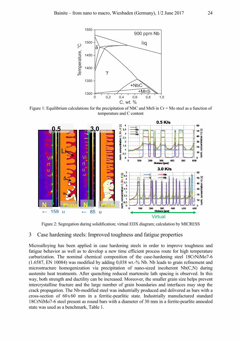
Bainite – from nano to macro, Wiesbaden (Germany), 1/2 June 2017 24
Figure 1: Equilibrium calculations for the precipitation of NbC and MnS in Cr + Mo steel as a function of
temperature and C content
Figure 2: Segregation during solidification; virtual EDX diagram; calculation by MICRESS
3 Case hardening steels: Improved toughness and fatigue properties
Microalloying has been applied in case hardening steels in order to improve toughness and fatigue behavior as well as to develop a new time efficient process route for high temperature carburization. The nominal chemical composition of the case-hardening steel 18CrNiMo7-6 (1.6587, EN 10084) was modified by adding 0,038 wt.-% Nb. Nb leads to grain refinement and microstructure homogenization via precipitation of nano-sized incoherent Nb(C,N) during austenite heat treatments. After quenching reduced martensite lath spacing is observed. In this way, both strength and ductility can be increased. Moreover, the smaller grain size helps prevent intercrystalline fracture and the large number of grain boundaries and interfaces may stop the crack propagation. The Nb-modified steel was industrially produced and delivered as bars with a cross-section of 60 x 60 mm in a ferritic-pearlitic state. Industrially manufactured standard 18CrNiMo7-6 steel present as round bars with a diameter of 30 mm in a ferrite-pearlite annealed state was used as a benchmark, Table 1.
← 150
← 159 μ
N
Phase
γ
δ
Li
← 85 μ
N
Phase
0,5
3,0
Virtual
Virtual
Virtual
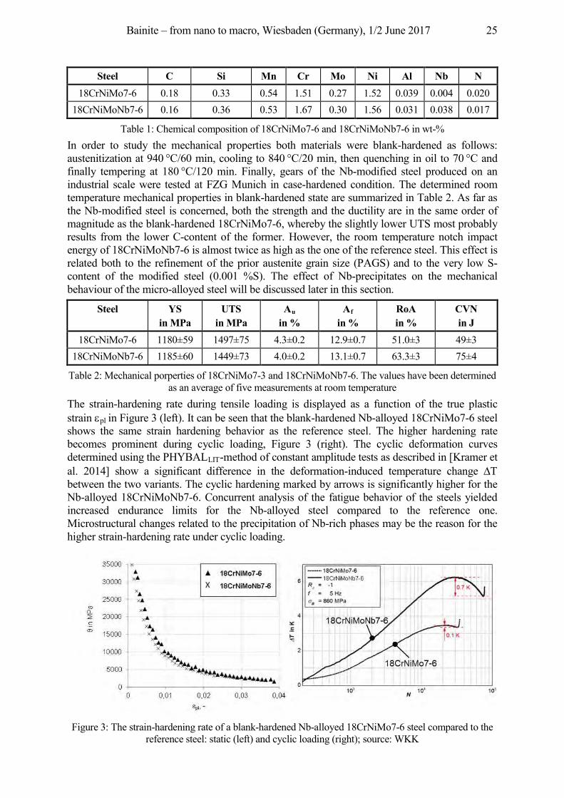
Bainite – from nano to macro, Wiesbaden (Germany), 1/2 June 2017 25
Steel C Si Mn Cr Mo Ni Al Nb N 18CrNiMo7-6 0.18 0.33 0.54 1.51 0.27 1.52 0.039 0.004 0.020
18CrNiMoNb7-6 0.16 0.36 0.53 1.67 0.30 1.56 0.031 0.038 0.017
Table 1: Chemical composition of 18CrNiMo7-6 and 18CrNiMoNb7-6 in wt-% In order to study the mechanical properties both materials were blank-hardened as follows: austenitization at 940 °C/60 min, cooling to 840 °C/20 min, then quenching in oil to 70 °C and finally tempering at 180 °C/120 min. Finally, gears of the Nb-modified steel produced on an industrial scale were tested at FZG Munich in case-hardened condition. The determined room temperature mechanical properties in blank-hardened state are summarized in Table 2. As far as the Nb-modified steel is concerned, both the strength and the ductility are in the same order of magnitude as the blank-hardened 18CrNiMo7-6, whereby the slightly lower UTS most probably results from the lower C-content of the former. However, the room temperature notch impact energy of 18CrNiMoNb7-6 is almost twice as high as the one of the reference steel. This effect is related both to the refinement of the prior austenite grain size (PAGS) and to the very low S-content of the modified steel (0.001 %S). The effect of Nb-precipitates on the mechanical behaviour of the micro-alloyed steel will be discussed later in this section.
Steel YS in MPa
UTS in MPa
Au
in % Af
in % RoA in %
CVN in J
18CrNiMo7-6 1180±59 1497±75 4.3±0.2 12.9±0.7 51.0±3 49±3 18CrNiMoNb7-6 1185±60 1449±73 4.0±0.2 13.1±0.7 63.3±3 75±4
Table 2: Mechanical porperties of 18CrNiMo7-3 and 18CrNiMoNb7-6. The values have been determined as an average of five measurements at room temperature
The strain-hardening rate during tensile loading is displayed as a function of the true plastic strain pl in Figure 3 (left). It can be seen that the blank-hardened Nb-alloyed 18CrNiMo7-6 steel shows the same strain hardening behavior as the reference steel. The higher hardening rate becomes prominent during cyclic loading, Figure 3 (right). The cyclic deformation curves determined using the PHYBALLIT-method of constant amplitude tests as described in [Kramer et al. 2014] show a significant difference in the deformation-induced temperature change between the two variants. The cyclic hardening marked by arrows is significantly higher for the Nb-alloyed 18CrNiMoNb7-6. Concurrent analysis of the fatigue behavior of the steels yielded increased endurance limits for the Nb-alloyed steel compared to the reference one. Microstructural changes related to the precipitation of Nb-rich phases may be the reason for the higher strain-hardening rate under cyclic loading.
Figure 3: The strain-hardening rate of a blank-hardened Nb-alloyed 18CrNiMo7-6 steel compared to the
reference steel: static (left) and cyclic loading (right); source: WKK
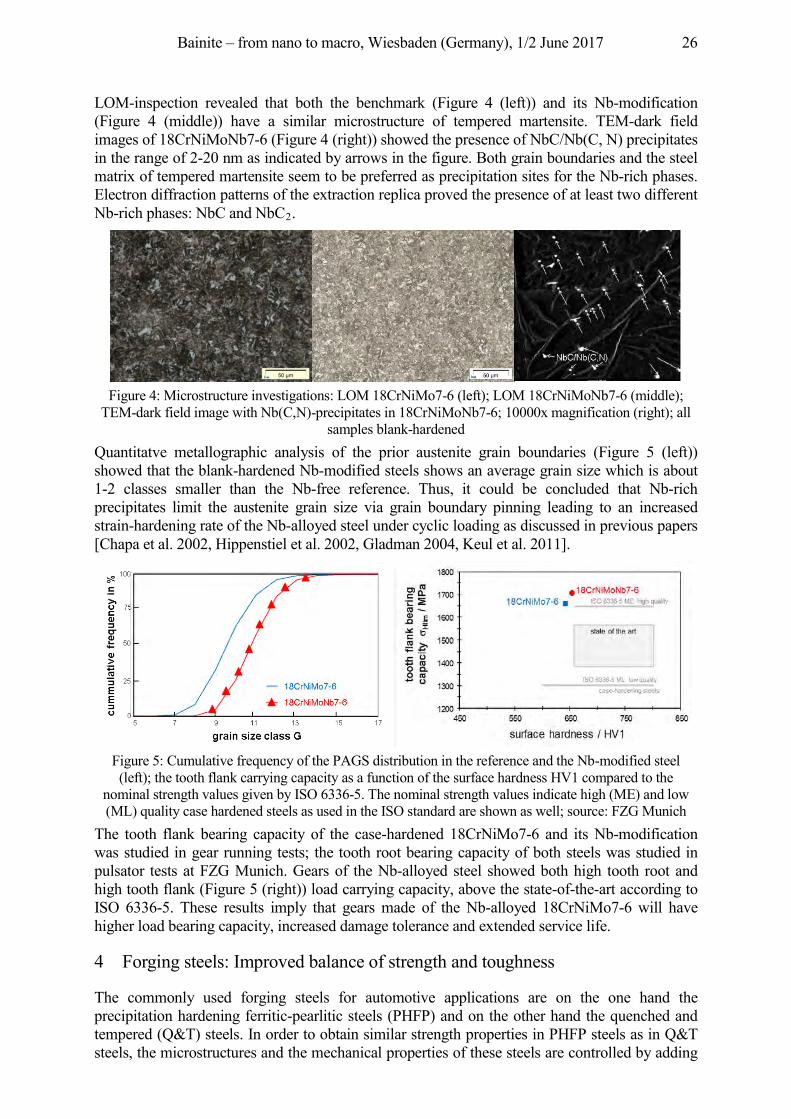
Bainite – from nano to macro, Wiesbaden (Germany), 1/2 June 2017 26
LOM-inspection revealed that both the benchmark (Figure 4 (left)) and its Nb-modification (Figure 4 (middle)) have a similar microstructure of tempered martensite. TEM-dark field images of 18CrNiMoNb7-6 (Figure 4 (right)) showed the presence of NbC/Nb(C, N) precipitates in the range of 2-20 nm as indicated by arrows in the figure. Both grain boundaries and the steel matrix of tempered martensite seem to be preferred as precipitation sites for the Nb-rich phases. Electron diffraction patterns of the extraction replica proved the presence of at least two different Nb-rich phases: NbC and NbC2.
Figure 4: Microstructure investigations: LOM 18CrNiMo7-6 (left); LOM 18CrNiMoNb7-6 (middle);
TEM-dark field image with Nb(C,N)-precipitates in 18CrNiMoNb7-6; 10000x magnification (right); all samples blank-hardened
Quantitatve metallographic analysis of the prior austenite grain boundaries (Figure 5 (left)) showed that the blank-hardened Nb-modified steels shows an average grain size which is about 1-2 classes smaller than the Nb-free reference. Thus, it could be concluded that Nb-rich precipitates limit the austenite grain size via grain boundary pinning leading to an increased strain-hardening rate of the Nb-alloyed steel under cyclic loading as discussed in previous papers [Chapa et al. 2002, Hippenstiel et al. 2002, Gladman 2004, Keul et al. 2011].
Figure 5: Cumulative frequency of the PAGS distribution in the reference and the Nb-modified steel (left); the tooth flank carrying capacity as a function of the surface hardness HV1 compared to the
nominal strength values given by ISO 6336-5. The nominal strength values indicate high (ME) and low (ML) quality case hardened steels as used in the ISO standard are shown as well; source: FZG Munich
The tooth flank bearing capacity of the case-hardened 18CrNiMo7-6 and its Nb-modification was studied in gear running tests; the tooth root bearing capacity of both steels was studied in pulsator tests at FZG Munich. Gears of the Nb-alloyed steel showed both high tooth root and high tooth flank (Figure 5 (right)) load carrying capacity, above the state-of-the-art according to ISO 6336-5. These results imply that gears made of the Nb-alloyed 18CrNiMo7-6 will have higher load bearing capacity, increased damage tolerance and extended service life.
4 Forging steels: Improved balance of strength and toughness
The commonly used forging steels for automotive applications are on the one hand the precipitation hardening ferritic-pearlitic steels (PHFP) and on the other hand the quenched and tempered (Q&T) steels. In order to obtain similar strength properties in PHFP steels as in Q&T steels, the microstructures and the mechanical properties of these steels are controlled by adding
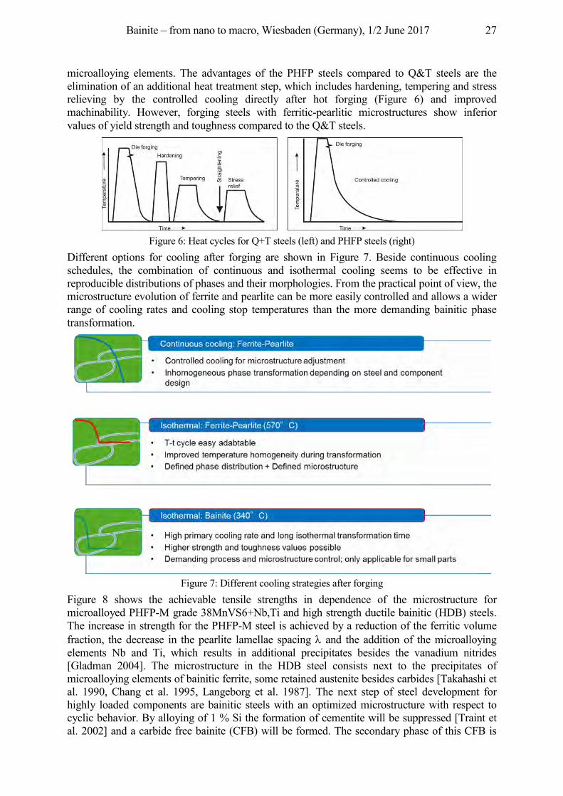
Bainite – from nano to macro, Wiesbaden (Germany), 1/2 June 2017 27
microalloying elements. The advantages of the PHFP steels compared to Q&T steels are the elimination of an additional heat treatment step, which includes hardening, tempering and stress relieving by the controlled cooling directly after hot forging (Figure 6) and improved machinability. However, forging steels with ferritic-pearlitic microstructures show inferior values of yield strength and toughness compared to the Q&T steels.
Figure 6: Heat cycles for Q+T steels (left) and PHFP steels (right)
Different options for cooling after forging are shown in Figure 7. Beside continuous cooling schedules, the combination of continuous and isothermal cooling seems to be effective in reproducible distributions of phases and their morphologies. From the practical point of view, the microstructure evolution of ferrite and pearlite can be more easily controlled and allows a wider range of cooling rates and cooling stop temperatures than the more demanding bainitic phase transformation.
Figure 7: Different cooling strategies after forging
Figure 8 shows the achievable tensile strengths in dependence of the microstructure for microalloyed PHFP-M grade 38MnVS6+Nb,Ti and high strength ductile bainitic (HDB) steels. The increase in strength for the PHFP-M steel is achieved by a reduction of the ferritic volume fraction, the decrease in the pearlite lamellae spacing and the addition of the microalloying elements Nb and Ti, which results in additional precipitates besides the vanadium nitrides [Gladman 2004]. The microstructure in the HDB steel consists next to the precipitates of microalloying elements of bainitic ferrite, some retained austenite besides carbides [Takahashi et al. 1990, Chang et al. 1995, Langeborg et al. 1987]. The next step of steel development for highly loaded components are bainitic steels with an optimized microstructure with respect to cyclic behavior. By alloying of 1 % Si the formation of cementite will be suppressed [Traint et al. 2002] and a carbide free bainite (CFB) will be formed. The secondary phase of this CFB is
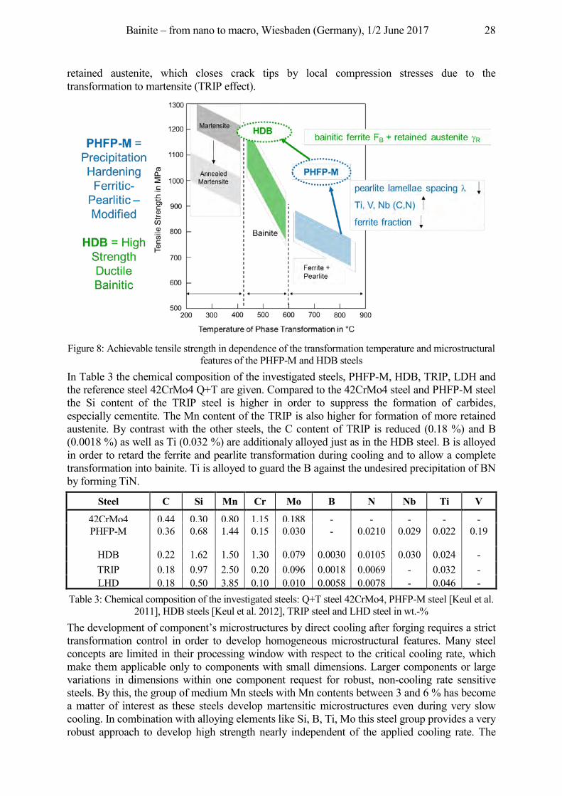
Bainite – from nano to macro, Wiesbaden (Germany), 1/2 June 2017 28
retained austenite, which closes crack tips by local compression stresses due to the transformation to martensite (TRIP effect).
Figure 8: Achievable tensile strength in dependence of the transformation temperature and microstructural
features of the PHFP-M and HDB steels In Table 3 the chemical composition of the investigated steels, PHFP-M, HDB, TRIP, LDH and the reference steel 42CrMo4 Q+T are given. Compared to the 42CrMo4 steel and PHFP-M steel the Si content of the TRIP steel is higher in order to suppress the formation of carbides, especially cementite. The Mn content of the TRIP is also higher for formation of more retained austenite. By contrast with the other steels, the C content of TRIP is reduced (0.18 %) and B (0.0018 %) as well as Ti (0.032 %) are additionaly alloyed just as in the HDB steel. B is alloyed in order to retard the ferrite and pearlite transformation during cooling and to allow a complete transformation into bainite. Ti is alloyed to guard the B against the undesired precipitation of BN by forming TiN.
Steel C Si Mn Cr Mo B N Nb Ti V
42CrMo4 0.44 0.30 0.80 1.15 0.188 - - - - - PHFP-M 0.36 0.68 1.44 0.15 0.030 - 0.0210 0.029 0.022 0.19
HDB 0.22 1.62 1.50 1.30 0.079 0.0030 0.0105 0.030 0.024 - TRIP
0.18 0.97 2.50 0.20 0.096 0.0018 0.0069 - 0.032 -
LHD 0.18 0.50 3.85 0.10 0.010 0.0058 0.0078 - 0.046 - Table 3: Chemical composition of the investigated steels: Q+T steel 42CrMo4, PHFP-M steel [Keul et al.
2011], HDB steels [Keul et al. 2012], TRIP steel and LHD steel in wt.-% The development of component’s microstructures by direct cooling after forging requires a strict transformation control in order to develop homogeneous microstructural features. Many steel concepts are limited in their processing window with respect to the critical cooling rate, which make them applicable only to components with small dimensions. Larger components or large variations in dimensions within one component request for robust, non-cooling rate sensitive steels. By this, the group of medium Mn steels with Mn contents between 3 and 6 % has become a matter of interest as these steels develop martensitic microstructures even during very slow cooling. In combination with alloying elements like Si, B, Ti, Mo this steel group provides a very robust approach to develop high strength nearly independent of the applied cooling rate. The
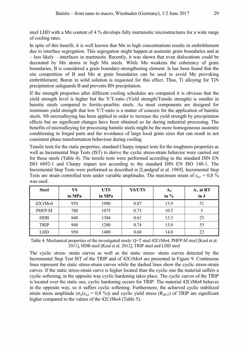
Bainite – from nano to macro, Wiesbaden (Germany), 1/2 June 2017 29
steel LHD with a Mn content of 4 % develops fully martensitic microstructures for a wide range of cooling rates. In spite of this benefit, it is well known that Mn in high concentrations results in embrittlement due to interface segregation. This segregation might happen at austenite grain boundaries and at – less likely – interfaces in martensite. Recently, it was shown that even dislocations could be decorated by Mn atoms in high Mn steels. While Mn weakens the coherency of grain boundaries, B is considered a grain boundary-strengthening element. Is has been found that the site competition of B and Mn at grain boundaries can be used to avoid Mn provoking embrittlement; Boron in solid solution is requested for this effect. Thus, Ti alloying for TiN precipitation safeguards B and prevents BN precipitation. If the strength properties after different cooling schedules are compared it is obvious that the yield strength level is higher but the Y/T-ratio (Yield strength/Tensile strength) is smaller in bainitic steels compared to ferritic-pearlitic steels. As most components are designed for minimum yield strength that low Y/T-ratio is a matter of concern for the application of bainitic steels. Nb microalloying has been applied in order to increase the yield strength by precipitation effects but no significant changes have been obtained so far during industrial processing. The benefits of microalloying for processing bainitic steels might be the more homogeneous austenite conditioning in forged parts and the avoidance of large local grain sizes that can result in not consistent phase transformation behaviour during cooling. Tensile tests for the static properties, standard Charpy impact tests for the toughness properties as well as Incremental Step Tests (IST) to derive the cyclic stress-strain behavior were carried out for these steels (Table 4). The tensile tests were performed according to the standard DIN EN ISO 6892-1 and Charpy impact test according to the standard DIN EN ISO 148-1. The Incremental Step Tests were performed as described in [Landgraf et al. 1969]. Incremental Step
ests a e st ai co t olle tests u e va iable a plitu es. he a i u st ai o a,t = 0,8 % was used.
Steel YS in MPa
UTS in MPa
YS/UTS A5 in %
Av at RT in J
42CrMo4 954 1090 0.87 13.9 51 PHFP-M 780 1075 0.73 10.5 5
HDB 848 1384 0.61 13.3 23 TRIP 948 1280 0.74 15.0 53 LHD 950 1400 0.68 14.0 22
Table 4: Mechanical properties of the investigated steels: Q+T steel 42CrMo4, PHFP-M steel [Keul et al. 2011], HDB steel [Keul et al. 2012], TRIP steel and LHD steel
The cyclic stress- strain curves as well as the static stress- strain curves detected by the Incremental Step Test IST of the TRIP and of 42CrMo4 are presented in Figure 9. Continuous lines represent the static stress-strain curves while the dashed lines show the cyclic stress-strain curves. If the static stress-strain curve is higher located than the cyclic one the material suffers a cyclic softening, in the opposite way cyclic hardening takes place. The cyclic curves of the TRIP is located over the static one, cyclic hardening occurs for TRIP. The material 42CrMo4 behaves in the opposite way, so it suffers cyclic softening. Furthermore, the achieved cyclic stabilized st ai st ess a plitu e ( a( a,t = 0,8 %)) and cyclic yield stress (Rp0.2) of TRIP are significant higher compared to the values of the 42CrMo4 (Table 5).
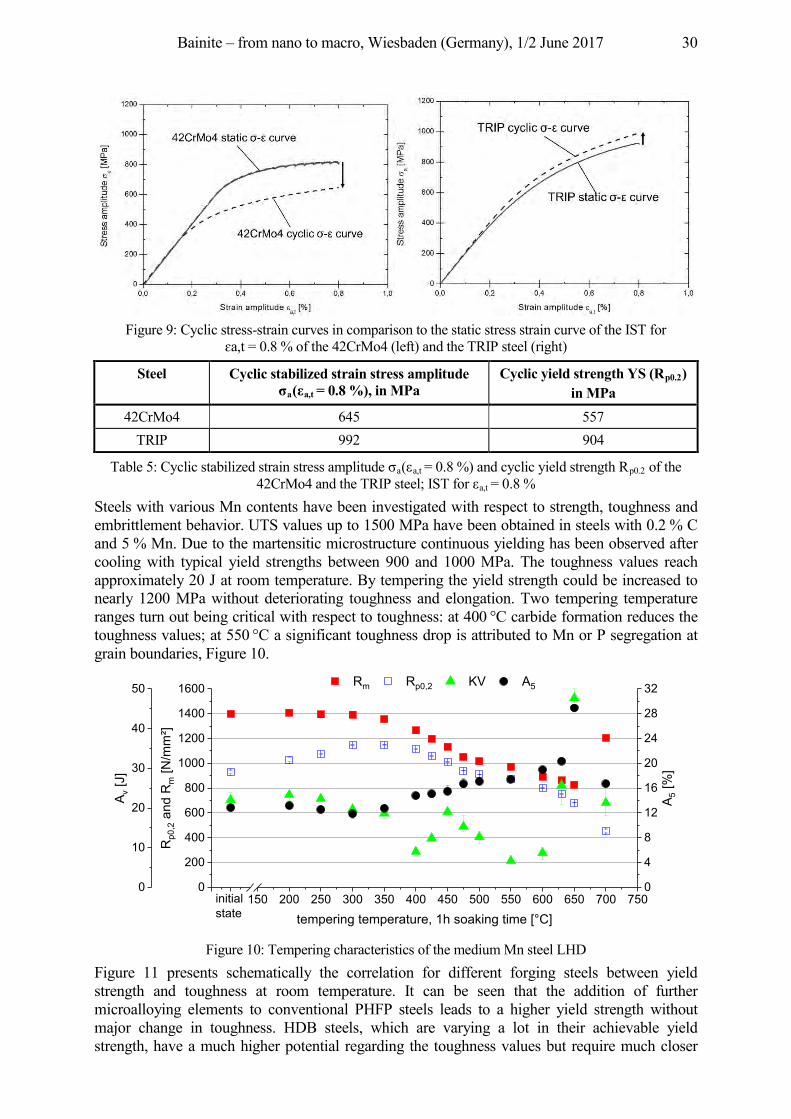
Bainite – from nano to macro, Wiesbaden (Germany), 1/2 June 2017 30
Figure 9: Cyclic stress-strain curves in comparison to the static stress strain curve of the IST for
a t = 0.8 % of the 42CrMo4 (left) and the TRIP steel (right)
Steel Cyclic stabilized strain stress amplitude σa(εa,t = 0.8 %), in MPa
Cyclic yield strength YS (Rp0.2) in MPa
42CrMo4 645 557 TRIP 992 904
Table 5: Cyclic stabilized strain stress amplitude a( a,t = 0.8 %) and cyclic yield strength Rp0.2 of the 42CrMo4 and the TRIP steel; IST for a,t = 0.8 %
Steels with various Mn contents have been investigated with respect to strength, toughness and embrittlement behavior. UTS values up to 1500 MPa have been obtained in steels with 0.2 % C and 5 % Mn. Due to the martensitic microstructure continuous yielding has been observed after cooling with typical yield strengths between 900 and 1000 MPa. The toughness values reach approximately 20 J at room temperature. By tempering the yield strength could be increased to nearly 1200 MPa without deteriorating toughness and elongation. Two tempering temperature ranges turn out being critical with respect to toughness: at 400 °C carbide formation reduces the toughness values; at 550 °C a significant toughness drop is attributed to Mn or P segregation at grain boundaries, Figure 10.
Figure 10: Tempering characteristics of the medium Mn steel LHD
Figure 11 presents schematically the correlation for different forging steels between yield strength and toughness at room temperature. It can be seen that the addition of further microalloying elements to conventional PHFP steels leads to a higher yield strength without major change in toughness. HDB steels, which are varying a lot in their achievable yield strength, have a much higher potential regarding the toughness values but require much closer
0 20 150 200 250 300 350 400 450 500 550 600 650 700 7500
200
400
600
800
1000
1200
1400
1600
Rp0
,2 a
nd R
m [N
/mm²]
tempering temperature, 1h soaking time [°C]
Rm Rp0,2 KV A5
initialstate
0
10
20
30
40
50
A v [J
]
0
4
8
12
16
20
24
28
32
A 5 [%
]
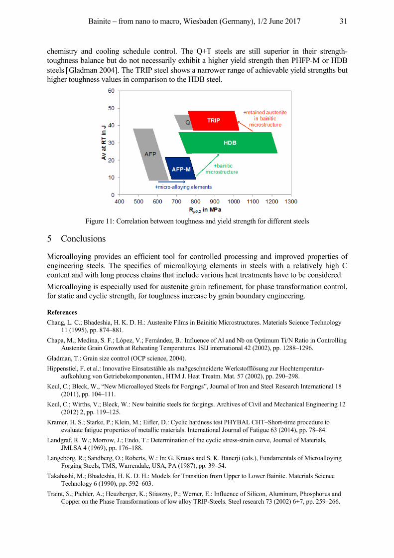
Bainite – from nano to macro, Wiesbaden (Germany), 1/2 June 2017 31
chemistry and cooling schedule control. The Q+T steels are still superior in their strength-toughness balance but do not necessarily exhibit a higher yield strength then PHFP-M or HDB steels Gladman 2004 . The TRIP steel shows a narrower range of achievable yield strengths but higher toughness values in comparison to the HDB steel.
Figure 11: Correlation between toughness and yield strength for different steels
5 Conclusions
Microalloying provides an efficient tool for controlled processing and improved properties of engineering steels. The specifics of microalloying elements in steels with a relatively high C content and with long process chains that include various heat treatments have to be considered. Microalloying is especially used for austenite grain refinement, for phase transformation control, for static and cyclic strength, for toughness increase by grain boundary engineering.
References Chang, L. C.; Bhadeshia, H. K. D. H.: Austenite Films in Bainitic Microstructures. Materials Science Technology
11 (1995), pp. 874–881. Chapa, M.; Medina, S. F.; López, V.; Fernández, B.: Influence of Al and Nb on Optimum Ti/N Ratio in Controlling
Austenite Grain Growth at Reheating Temperatures. ISIJ international 42 (2002), pp. 1288–1296. Gladman, T.: Grain size control (OCP science, 2004). Hippenstiel, F. et al.: Innovative Einsatzstähle als maßgeschneiderte Werkstofflösung zur Hochtemperatur-
aufkohlung von Getriebekomponenten., HTM J. Heat Treatm. Mat. 57 (2002), pp. 290–298. Keul, C.; Bleck, W., “New Microalloyed Steels for Forgings”, Journal of Iron and Steel Research International 18
(2011), pp. 104–111. Keul, C.; Wirths, V.; Bleck, W.: New bainitic steels for forgings. Archives of Civil and Mechanical Engineering 12
(2012) 2, pp. 119–125. Kramer, H. S.; Starke, P.; Klein, M.; Eifler, D.: Cyclic hardness test PHYBAL CHT–Short-time procedure to
evaluate fatigue properties of metallic materials. International Journal of Fatigue 63 (2014), pp. 78–84. Landgraf, R. W.; Morrow, J.; Endo, T.: Determination of the cyclic stress-strain curve, Journal of Materials,
JMLSA 4 (1969), pp. 176–188. Langeborg, R.; Sandberg, O.; Roberts, W.: In: G. Krauss and S. K. Banerji (eds.), Fundamentals of Microalloying
Forging Steels, TMS, Warrendale, USA, PA (1987), pp. 39–54. Takahashi, M.; Bhadeshia, H. K. D. H.: Models for Transition from Upper to Lower Bainite. Materials Science
Technology 6 (1990), pp. 592–603. Traint, S.; Pichler, A.; Heuzberger, K.; Stiaszny, P.; Werner, E.: Influence of Silicon, Aluminum, Phosphorus and
Copper on the Phase Transformations of low alloy TRIP-Steels. Steel research 73 (2002) 6+7, pp. 259–266.
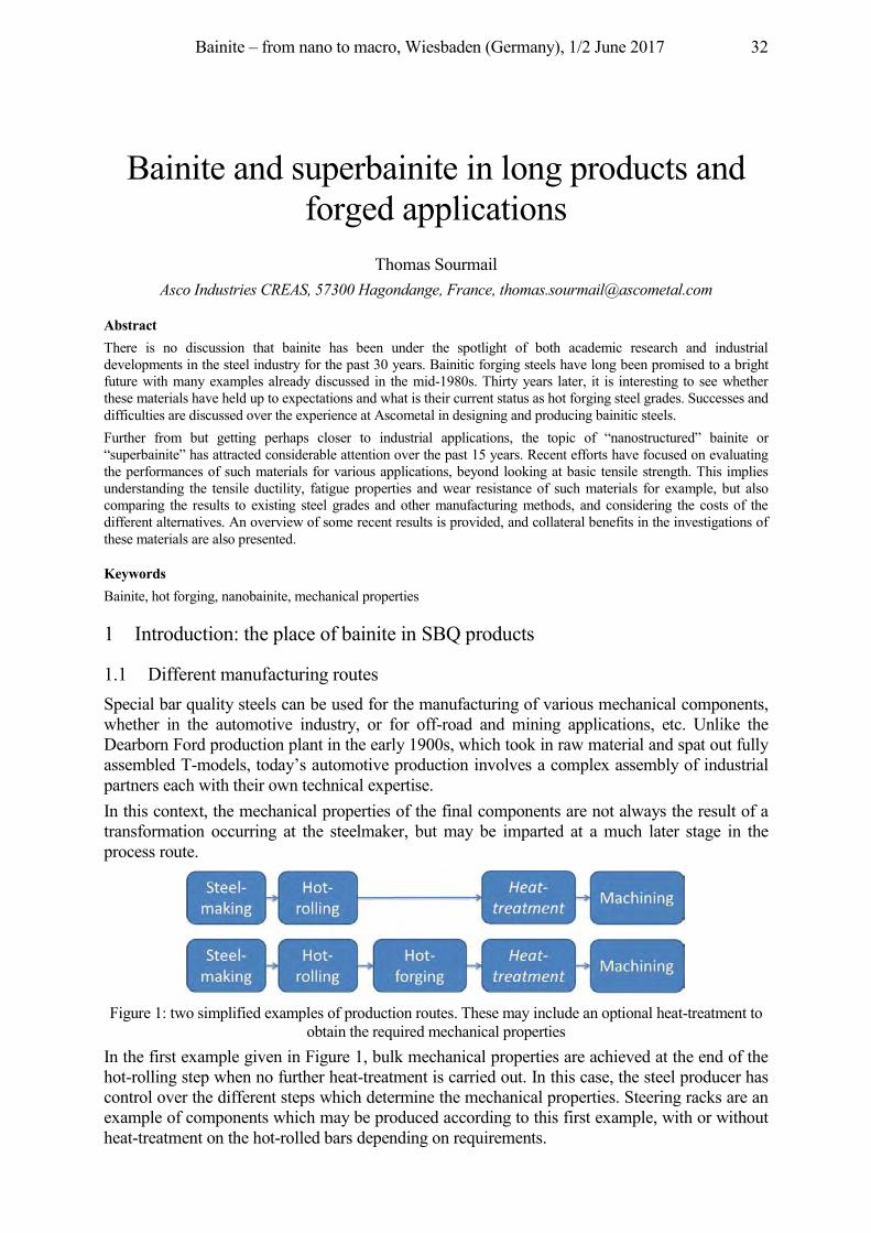
Bainite – from nano to macro, Wiesbaden (Germany), 1/2 June 2017 32
Bainite and superbainite in long products and forged applications
Thomas Sourmail Asco Industries CREAS, 57300 Hagondange, France, [email protected]
Abstract There is no discussion that bainite has been under the spotlight of both academic research and industrial developments in the steel industry for the past 30 years. Bainitic forging steels have long been promised to a bright future with many examples already discussed in the mid-1980s. Thirty years later, it is interesting to see whether these materials have held up to expectations and what is their current status as hot forging steel grades. Successes and difficulties are discussed over the experience at Ascometal in designing and producing bainitic steels. Further from but getting perhaps closer to industrial applications, the topic of “nanostructured” bainite or “superbainite” has attracted considerable attention over the past 15 years. Recent efforts have focused on evaluating the performances of such materials for various applications, beyond looking at basic tensile strength. This implies understanding the tensile ductility, fatigue properties and wear resistance of such materials for example, but also comparing the results to existing steel grades and other manufacturing methods, and considering the costs of the different alternatives. An overview of some recent results is provided, and collateral benefits in the investigations of these materials are also presented.
Keywords Bainite, hot forging, nanobainite, mechanical properties
1 Introduction: the place of bainite in SBQ products
1.1 Different manufacturing routes Special bar quality steels can be used for the manufacturing of various mechanical components, whether in the automotive industry, or for off-road and mining applications, etc. Unlike the Dearborn Ford production plant in the early 1900s, which took in raw material and spat out fully assembled T-models, today’s automotive production involves a complex assembly of industrial partners each with their own technical expertise. In this context, the mechanical properties of the final components are not always the result of a transformation occurring at the steelmaker, but may be imparted at a much later stage in the process route.
Figure 1: two simplified examples of production routes. These may include an optional heat-treatment to
obtain the required mechanical properties In the first example given in Figure 1, bulk mechanical properties are achieved at the end of the hot-rolling step when no further heat-treatment is carried out. In this case, the steel producer has control over the different steps which determine the mechanical properties. Steering racks are an example of components which may be produced according to this first example, with or without heat-treatment on the hot-rolled bars depending on requirements.
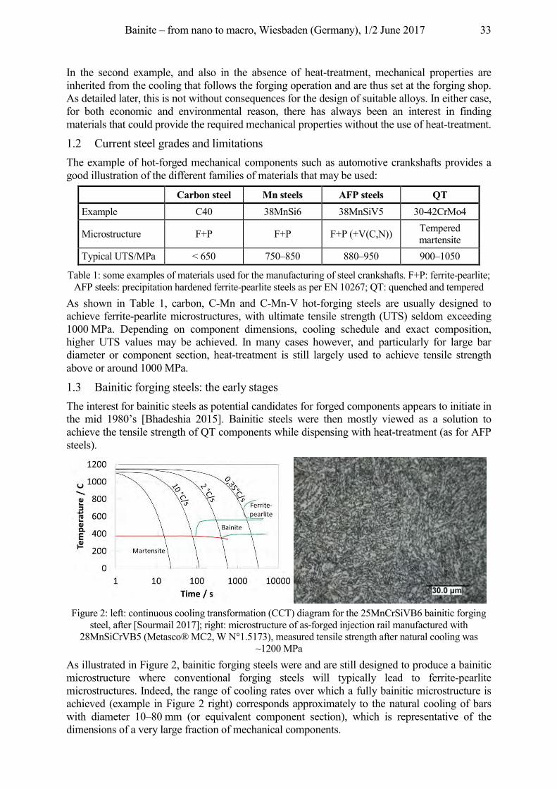
Bainite – from nano to macro, Wiesbaden (Germany), 1/2 June 2017 33
In the second example, and also in the absence of heat-treatment, mechanical properties are inherited from the cooling that follows the forging operation and are thus set at the forging shop. As detailed later, this is not without consequences for the design of suitable alloys. In either case, for both economic and environmental reason, there has always been an interest in finding materials that could provide the required mechanical properties without the use of heat-treatment.
1.2 Current steel grades and limitations The example of hot-forged mechanical components such as automotive crankshafts provides a good illustration of the different families of materials that may be used:
Carbon steel Mn steels AFP steels QT Example C40 38MnSi6 38MnSiV5 30-42CrMo4
Microstructure F+P F+P F+P (+V(C,N)) Tempered martensite
Typical UTS/MPa < 650 750–850 880–950 900–1050
Table 1: some examples of materials used for the manufacturing of steel crankshafts. F+P: ferrite-pearlite; AFP steels: precipitation hardened ferrite-pearlite steels as per EN 10267; QT: quenched and tempered
As shown in Table 1, carbon, C-Mn and C-Mn-V hot-forging steels are usually designed to achieve ferrite-pearlite microstructures, with ultimate tensile strength (UTS) seldom exceeding 1000 MPa. Depending on component dimensions, cooling schedule and exact composition, higher UTS values may be achieved. In many cases however, and particularly for large bar diameter or component section, heat-treatment is still largely used to achieve tensile strength above or around 1000 MPa.
1.3 Bainitic forging steels: the early stages The interest for bainitic steels as potential candidates for forged components appears to initiate in the mid 1980’s [Bhadeshia 2015]. Bainitic steels were then mostly viewed as a solution to achieve the tensile strength of QT components while dispensing with heat-treatment (as for AFP steels).
Figure 2: left: continuous cooling transformation (CCT) diagram for the 25MnCrSiVB6 bainitic forging
steel, after [Sourmail 2017]; right: microstructure of as-forged injection rail manufactured with 28MnSiCrVB5 (Metasco® MC2, W N°1.5173), measured tensile strength after natural cooling was
~1200 MPa As illustrated in Figure 2, bainitic forging steels were and are still designed to produce a bainitic microstructure where conventional forging steels will typically lead to ferrite-pearlite microstructures. Indeed, the range of cooling rates over which a fully bainitic microstructure is achieved (example in Figure 2 right) corresponds approximately to the natural cooling of bars with diameter 10–80 mm (or equivalent component section), which is representative of the dimensions of a very large fraction of mechanical components.
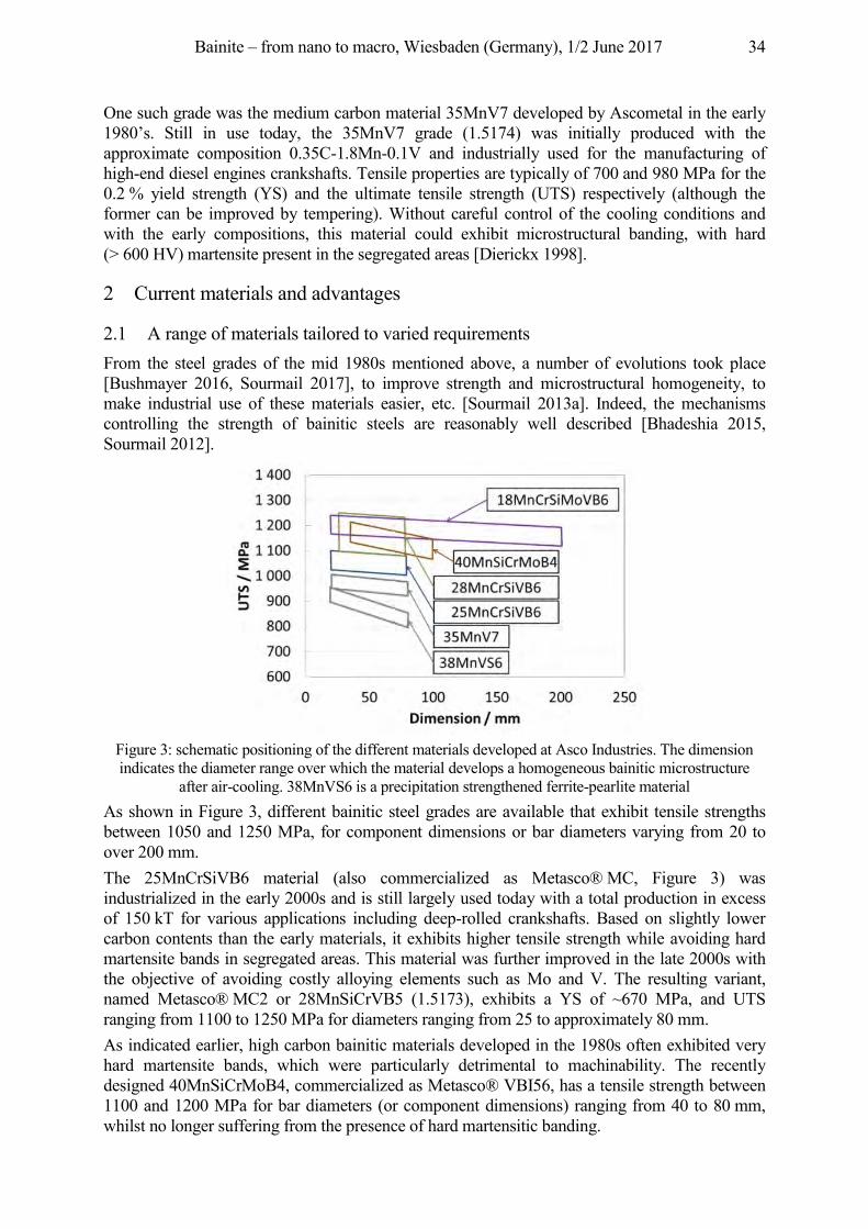
Bainite – from nano to macro, Wiesbaden (Germany), 1/2 June 2017 34
One such grade was the medium carbon material 35MnV7 developed by Ascometal in the early 1980’s. Still in use today, the 35MnV7 grade (1.5174) was initially produced with the approximate composition 0.35C-1.8Mn-0.1V and industrially used for the manufacturing of high-end diesel engines crankshafts. Tensile properties are typically of 700 and 980 MPa for the 0.2 % yield strength (YS) and the ultimate tensile strength (UTS) respectively (although the former can be improved by tempering). Without careful control of the cooling conditions and with the early compositions, this material could exhibit microstructural banding, with hard (> 600 HV) martensite present in the segregated areas [Dierickx 1998].
2 Current materials and advantages
2.1 A range of materials tailored to varied requirements From the steel grades of the mid 1980s mentioned above, a number of evolutions took place [Bushmayer 2016, Sourmail 2017], to improve strength and microstructural homogeneity, to make industrial use of these materials easier, etc. [Sourmail 2013a]. Indeed, the mechanisms controlling the strength of bainitic steels are reasonably well described [Bhadeshia 2015, Sourmail 2012].
Figure 3: schematic positioning of the different materials developed at Asco Industries. The dimension indicates the diameter range over which the material develops a homogeneous bainitic microstructure
after air-cooling. 38MnVS6 is a precipitation strengthened ferrite-pearlite material As shown in Figure 3, different bainitic steel grades are available that exhibit tensile strengths between 1050 and 1250 MPa, for component dimensions or bar diameters varying from 20 to over 200 mm. The 25MnCrSiVB6 material (also commercialized as Metasco® MC, Figure 3) was industrialized in the early 2000s and is still largely used today with a total production in excess of 150 kT for various applications including deep-rolled crankshafts. Based on slightly lower carbon contents than the early materials, it exhibits higher tensile strength while avoiding hard martensite bands in segregated areas. This material was further improved in the late 2000s with the objective of avoiding costly alloying elements such as Mo and V. The resulting variant, named Metasco® MC2 or 28MnSiCrVB5 (1.5173), exhibits a YS of ~670 MPa, and UTS ranging from 1100 to 1250 MPa for diameters ranging from 25 to approximately 80 mm. As indicated earlier, high carbon bainitic materials developed in the 1980s often exhibited very hard martensite bands, which were particularly detrimental to machinability. The recently designed 40MnSiCrMoB4, commercialized as Metasco® VBI56, has a tensile strength between 1100 and 1200 MPa for bar diameters (or component dimensions) ranging from 40 to 80 mm, whilst no longer suffering from the presence of hard martensitic banding.
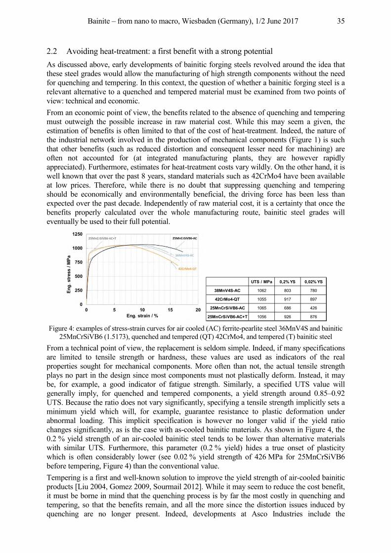
Bainite – from nano to macro, Wiesbaden (Germany), 1/2 June 2017 35
2.2 Avoiding heat-treatment: a first benefit with a strong potential As discussed above, early developments of bainitic forging steels revolved around the idea that these steel grades would allow the manufacturing of high strength components without the need for quenching and tempering. In this context, the question of whether a bainitic forging steel is a relevant alternative to a quenched and tempered material must be examined from two points of view: technical and economic. From an economic point of view, the benefits related to the absence of quenching and tempering must outweigh the possible increase in raw material cost. While this may seem a given, the estimation of benefits is often limited to that of the cost of heat-treatment. Indeed, the nature of the industrial network involved in the production of mechanical components (Figure 1) is such that other benefits (such as reduced distortion and consequent lesser need for machining) are often not accounted for (at integrated manufacturing plants, they are however rapidly appreciated). Furthermore, estimates for heat-treatment costs vary wildly. On the other hand, it is well known that over the past 8 years, standard materials such as 42CrMo4 have been available at low prices. Therefore, while there is no doubt that suppressing quenching and tempering should be economically and environmentally beneficial, the driving force has been less than expected over the past decade. Independently of raw material cost, it is a certainty that once the benefits properly calculated over the whole manufacturing route, bainitic steel grades will eventually be used to their full potential.
Figure 4: examples of stress-strain curves for air cooled (AC) ferrite-pearlite steel 36MnV4S and bainitic
25MnCrSiVB6 (1.5173), quenched and tempered (QT) 42CrMo4, and tempered (T) bainitic steel From a technical point of view, the replacement is seldom simple. Indeed, if many specifications are limited to tensile strength or hardness, these values are used as indicators of the real properties sought for mechanical components. More often than not, the actual tensile strength plays no part in the design since most components must not plastically deform. Instead, it may be, for example, a good indicator of fatigue strength. Similarly, a specified UTS value will generally imply, for quenched and tempered components, a yield strength around 0.85–0.92 UTS. Because the ratio does not vary significantly, specifying a tensile strength implicitly sets a minimum yield which will, for example, guarantee resistance to plastic deformation under abnormal loading. This implicit specification is however no longer valid if the yield ratio changes significantly, as is the case with as-cooled bainitic materials. As shown in Figure 4, the 0.2 % yield strength of an air-cooled bainitic steel tends to be lower than alternative materials with similar UTS. Furthermore, this parameter (0.2 % yield) hides a true onset of plasticity which is often considerably lower (see 0.02 % yield strength of 426 MPa for 25MnCrSiVB6 before tempering, Figure 4) than the conventional value. Tempering is a first and well-known solution to improve the yield strength of air-cooled bainitic products [Liu 2004, Gomez 2009, Sourmail 2012]. While it may seem to reduce the cost benefit, it must be borne in mind that the quenching process is by far the most costly in quenching and tempering, so that the benefits remain, and all the more since the distortion issues induced by quenching are no longer present. Indeed, developments at Asco Industries include the
UTS / MPa 0,2% YS 0,02% YS
38MnV4S-AC 1062 803 780
42CrMo4-QT 1055 917 897
25MnCrSiVB6-AC 1065 686 426
25MnCrSiVB6-AC+T 1056 926 876
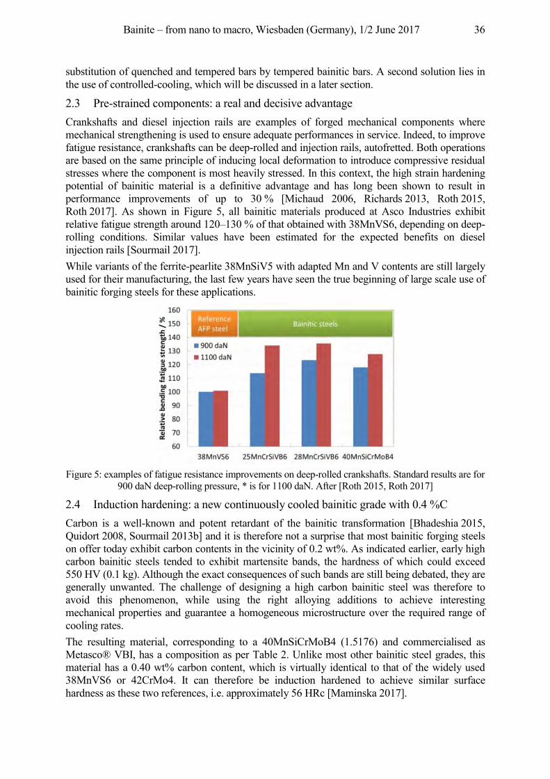
Bainite – from nano to macro, Wiesbaden (Germany), 1/2 June 2017 36
substitution of quenched and tempered bars by tempered bainitic bars. A second solution lies in the use of controlled-cooling, which will be discussed in a later section.
2.3 Pre-strained components: a real and decisive advantage Crankshafts and diesel injection rails are examples of forged mechanical components where mechanical strengthening is used to ensure adequate performances in service. Indeed, to improve fatigue resistance, crankshafts can be deep-rolled and injection rails, autofretted. Both operations are based on the same principle of inducing local deformation to introduce compressive residual stresses where the component is most heavily stressed. In this context, the high strain hardening potential of bainitic material is a definitive advantage and has long been shown to result in performance improvements of up to 30 % [Michaud 2006, Richards 2013, Roth 2015, Roth 2017]. As shown in Figure 5, all bainitic materials produced at Asco Industries exhibit relative fatigue strength around 120–130 % of that obtained with 38MnVS6, depending on deep-rolling conditions. Similar values have been estimated for the expected benefits on diesel injection rails [Sourmail 2017]. While variants of the ferrite-pearlite 38MnSiV5 with adapted Mn and V contents are still largely used for their manufacturing, the last few years have seen the true beginning of large scale use of bainitic forging steels for these applications.
Figure 5: examples of fatigue resistance improvements on deep-rolled crankshafts. Standard results are for
900 daN deep-rolling pressure, * is for 1100 daN. After [Roth 2015, Roth 2017]
2.4 Induction hardening: a new continuously cooled bainitic grade with 0.4 %C Carbon is a well-known and potent retardant of the bainitic transformation [Bhadeshia 2015, Quidort 2008, Sourmail 2013b] and it is therefore not a surprise that most bainitic forging steels on offer today exhibit carbon contents in the vicinity of 0.2 wt%. As indicated earlier, early high carbon bainitic steels tended to exhibit martensite bands, the hardness of which could exceed 550 HV (0.1 kg). Although the exact consequences of such bands are still being debated, they are generally unwanted. The challenge of designing a high carbon bainitic steel was therefore to avoid this phenomenon, while using the right alloying additions to achieve interesting mechanical properties and guarantee a homogeneous microstructure over the required range of cooling rates. The resulting material, corresponding to a 40MnSiCrMoB4 (1.5176) and commercialised as Metasco® VBI, has a composition as per Table 2. Unlike most other bainitic steel grades, this material has a 0.40 wt% carbon content, which is virtually identical to that of the widely used 38MnVS6 or 42CrMo4. It can therefore be induction hardened to achieve similar surface hardness as these two references, i.e. approximately 56 HRc [Maminska 2017].
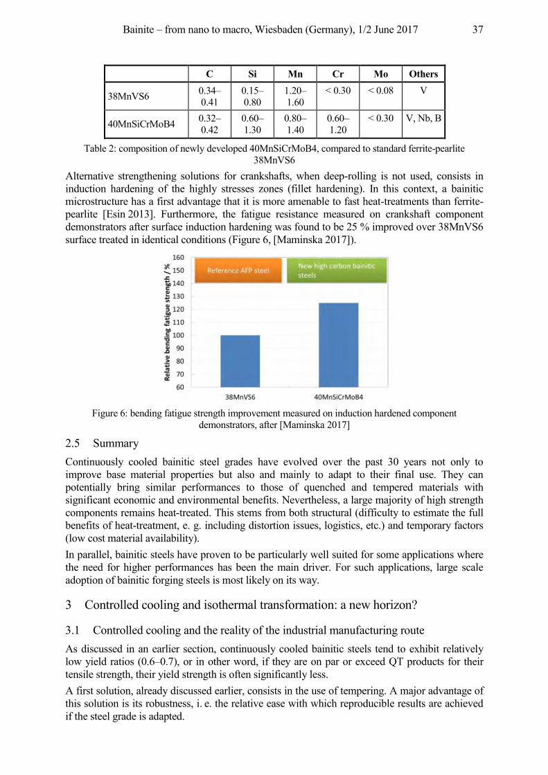
Bainite – from nano to macro, Wiesbaden (Germany), 1/2 June 2017 37
C Si Mn Cr Mo Others
38MnVS6 0.34–0.41
0.15–0.80
1.20–1.60
< 0.30 < 0.08 V
40MnSiCrMoB4 0.32–0.42
0.60–1.30
0.80–1.40
0.60–1.20
< 0.30 V, Nb, B
Table 2: composition of newly developed 40MnSiCrMoB4, compared to standard ferrite-pearlite 38MnVS6
Alternative strengthening solutions for crankshafts, when deep-rolling is not used, consists in induction hardening of the highly stresses zones (fillet hardening). In this context, a bainitic microstructure has a first advantage that it is more amenable to fast heat-treatments than ferrite-pearlite [Esin 2013]. Furthermore, the fatigue resistance measured on crankshaft component demonstrators after surface induction hardening was found to be 25 % improved over 38MnVS6 surface treated in identical conditions (Figure 6, [Maminska 2017]).
Figure 6: bending fatigue strength improvement measured on induction hardened component
demonstrators, after [Maminska 2017]
2.5 Summary Continuously cooled bainitic steel grades have evolved over the past 30 years not only to improve base material properties but also and mainly to adapt to their final use. They can potentially bring similar performances to those of quenched and tempered materials with significant economic and environmental benefits. Nevertheless, a large majority of high strength components remains heat-treated. This stems from both structural (difficulty to estimate the full benefits of heat-treatment, e. g. including distortion issues, logistics, etc.) and temporary factors (low cost material availability). In parallel, bainitic steels have proven to be particularly well suited for some applications where the need for higher performances has been the main driver. For such applications, large scale adoption of bainitic forging steels is most likely on its way.
3 Controlled cooling and isothermal transformation: a new horizon?
3.1 Controlled cooling and the reality of the industrial manufacturing route As discussed in an earlier section, continuously cooled bainitic steels tend to exhibit relatively low yield ratios (0.6–0.7), or in other word, if they are on par or exceed QT products for their tensile strength, their yield strength is often significantly less. A first solution, already discussed earlier, consists in the use of tempering. A major advantage of this solution is its robustness, i. e. the relative ease with which reproducible results are achieved if the steel grade is adapted.
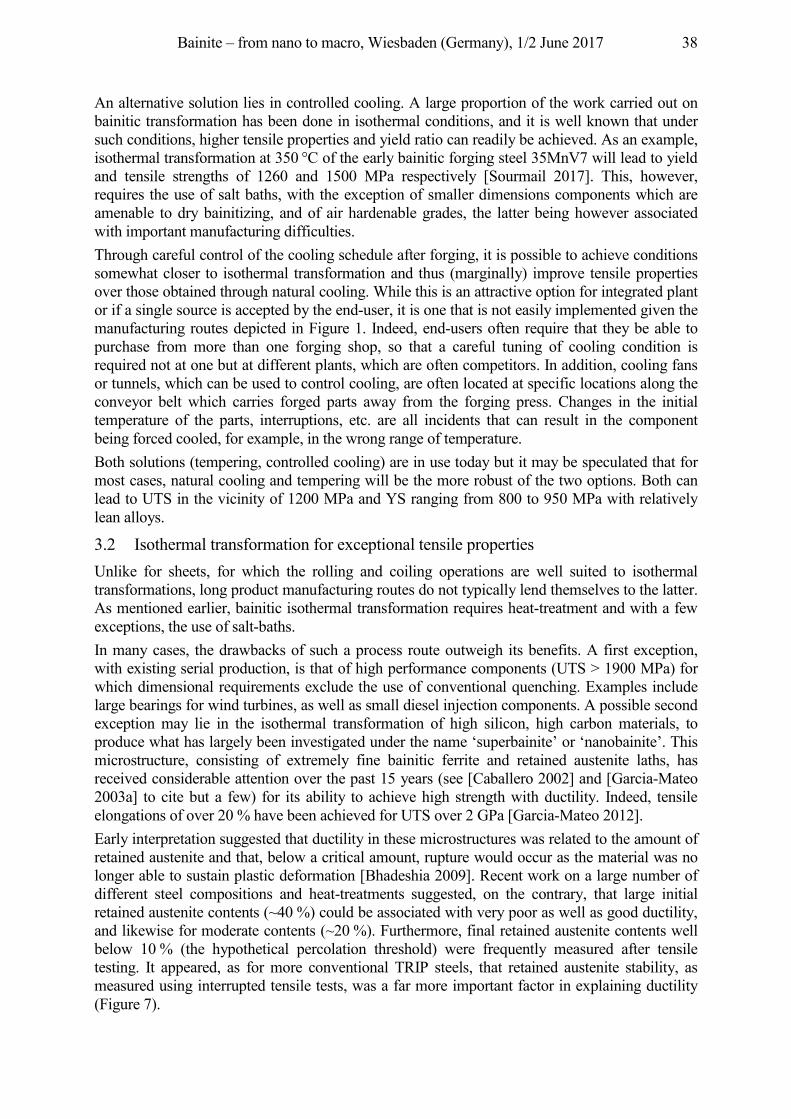
Bainite – from nano to macro, Wiesbaden (Germany), 1/2 June 2017 38
An alternative solution lies in controlled cooling. A large proportion of the work carried out on bainitic transformation has been done in isothermal conditions, and it is well known that under such conditions, higher tensile properties and yield ratio can readily be achieved. As an example, isothermal transformation at 350 °C of the early bainitic forging steel 35MnV7 will lead to yield and tensile strengths of 1260 and 1500 MPa respectively [Sourmail 2017]. This, however, requires the use of salt baths, with the exception of smaller dimensions components which are amenable to dry bainitizing, and of air hardenable grades, the latter being however associated with important manufacturing difficulties. Through careful control of the cooling schedule after forging, it is possible to achieve conditions somewhat closer to isothermal transformation and thus (marginally) improve tensile properties over those obtained through natural cooling. While this is an attractive option for integrated plant or if a single source is accepted by the end-user, it is one that is not easily implemented given the manufacturing routes depicted in Figure 1. Indeed, end-users often require that they be able to purchase from more than one forging shop, so that a careful tuning of cooling condition is required not at one but at different plants, which are often competitors. In addition, cooling fans or tunnels, which can be used to control cooling, are often located at specific locations along the conveyor belt which carries forged parts away from the forging press. Changes in the initial temperature of the parts, interruptions, etc. are all incidents that can result in the component being forced cooled, for example, in the wrong range of temperature. Both solutions (tempering, controlled cooling) are in use today but it may be speculated that for most cases, natural cooling and tempering will be the more robust of the two options. Both can lead to UTS in the vicinity of 1200 MPa and YS ranging from 800 to 950 MPa with relatively lean alloys.
3.2 Isothermal transformation for exceptional tensile properties Unlike for sheets, for which the rolling and coiling operations are well suited to isothermal transformations, long product manufacturing routes do not typically lend themselves to the latter. As mentioned earlier, bainitic isothermal transformation requires heat-treatment and with a few exceptions, the use of salt-baths. In many cases, the drawbacks of such a process route outweigh its benefits. A first exception, with existing serial production, is that of high performance components (UTS > 1900 MPa) for which dimensional requirements exclude the use of conventional quenching. Examples include large bearings for wind turbines, as well as small diesel injection components. A possible second exception may lie in the isothermal transformation of high silicon, high carbon materials, to produce what has largely been investigated under the name ‘superbainite’ or ‘nanobainite’. This microstructure, consisting of extremely fine bainitic ferrite and retained austenite laths, has received considerable attention over the past 15 years (see [Caballero 2002] and [Garcia-Mateo 2003a] to cite but a few) for its ability to achieve high strength with ductility. Indeed, tensile elongations of over 20 % have been achieved for UTS over 2 GPa [Garcia-Mateo 2012]. Early interpretation suggested that ductility in these microstructures was related to the amount of retained austenite and that, below a critical amount, rupture would occur as the material was no longer able to sustain plastic deformation [Bhadeshia 2009]. Recent work on a large number of different steel compositions and heat-treatments suggested, on the contrary, that large initial retained austenite contents (~40 %) could be associated with very poor as well as good ductility, and likewise for moderate contents (~20 %). Furthermore, final retained austenite contents well below 10 % (the hypothetical percolation threshold) were frequently measured after tensile testing. It appeared, as for more conventional TRIP steels, that retained austenite stability, as measured using interrupted tensile tests, was a far more important factor in explaining ductility (Figure 7).
Bainite – from nano to macro, Wiesbaden (Germany), 1/2 June 2017 39
Figure 7: left: percolation theory to explain the tensile rupture in nanobainitic materials, after [Bhadeshia
2009] and right: influence of retained austenite stability as measured through the coefficient k in the specified equation, where p is in % [Morales-Rivas 2016, Sourmail 2017]. Values for k were very similar to those reported for conventional TRIP steels [Gui 2017], ie in the range 0.05–0.12 when tensile rupture
was ductile. All materials investigated had UTS in the vicinity of 2 GPa Beyond exceptional tensile properties, one major drawback remained the duration required for the isothermal transformation to achieve steady-state. This particular topic has attracted significant attention, and attempts to improve reaction kinetics include modification of the composition [Garcia-Mateo 2003b, Sourmail 2013b, Sourmail 2013e] and heat-treatment schedule [Vetters 2003, Vetters 2006]. Early ‘nanobainite’ would nevertheless require 48 hours or many days of isothermal holding to achieve their properties.
3.3 What benefits for which application? To accelerate transformation, attempts were carried out to tailor the alloy composition following the three simple principles [Sourmail 2013c, Garcia-Mateo 2014]:
• silicon content must be sufficient to stabilise retained austenite • the alloying content must be sufficient to depress the martensite temperature below the
required isothermal transformation temperature, • and to avoid reconstructive transformation during cooling, or bainite formation during
cooling before reaching the desired transformation temperature (typically, cooling in salt bath).
With these principles, it was possible to design materials which transformed in ~20 h at 250 °C, temperature at which they exhibited a tensile strength in excess of 2 GPa and good ductility. As for continuously cooled bainitic materials however, tensile properties or even hardness are often just an indicator of the real design property (e.g. fatigue, wear, etc.), and one must be careful when applying established correlations to different microstructures. Perhaps the first application of ‘superbainite’ was for defines purposes, based on the remarkable ballistic impact properties of this microstructure [MoD 2013]. More recently, the wear and fatigue performances of nanostructured bainite were investigated to evaluate the potential of these microstructures for different applications where high hardness or UTS are usually specified. Notched fatigue performance was evaluated for a variety of load ratios, with different materials transformed isothermally at 220 or 250 °C, to achieve UTS in excess of 2 GPa, and shown to be potentially 10–20 % better than 100Cr6 isothermally transformed to a UTS of 2.35 GPa [Sourmail 2013c, Sourmail 2016]. As for most high hardness materials however, cleanliness was shown to be paramount in determining the fatigue performance. Through careful analysis, and accounting for the stress concentration resulting from the unavoidable presence of a few non-metallic inclusions, it was possible to identify bainite packet size as a critical microstructural element controlling crack propagation rate [Rementiera 2015, Mueller 2016].
Bainite – from nano to macro, Wiesbaden (Germany), 1/2 June 2017 40
Wear performances were perhaps far more promising with considerable improvements [Sourmail 2013c, Leiro 2013, Das Bakshi 2014] reported in specific conditions. Indeed, for a 1C-2.5Si based material with UTS 2.2 GPa, the specific wear rate in dry rolling/sliding conditions was found to be 25 times less than that of 100Cr6 isothermally transformed to a UTS of 2.35 GPa [Sourmail 2013c, Leiro 2013]. This was associated with surface hardness in excess of 1200 HV, where 100Cr6 remained below 1000 HV; in turn, this phenomenon was shown to correlate with the partial destabilisation of retained austenite into very hard martensite.
3.4 Perspectives In contrast with an intense academic research activity, nanostructured bainite are still very far from mass production for at least two reasons. First, the heat-treatment to obtain these microstructures remains complex. Indeed, this production commonly requires the use of salt-baths and temperature control is critical. Such installations are however found far less frequently than conventional quenching and tempering furnaces. Furthermore, existing lines are often designed to handle treatments of 2 to 3 hours but not of 20–40 hours. Second, the benefits remain to be clearly established. In particular, for components designed with fatigue as the main damage mechanism, it is not clear whether nanostructured bainite will bring a sufficiently large advantage to justify a change from existing solutions. When wear is the main damage mechanism, there is no doubt that these microstructures have exceptional potential. As wear is a system and not an intrinsic property, further work is nevertheless required to confirm whether these results can be transferred to actual applications. In any case, and independently of commercial developments, nanostructured bainite can be considered as the horizon, the upper limit which can be achieved with a mixture of bainitic ferrite and retained austenite. Their study has shed light on the nature of the bainite reaction and without doubt, will help with the improvement of somewhat lower strength materials.
4 General conclusions and perspectives
Continuously cooled bainitic steels for hot-rolled bars or forged components have been a topic of growing interest over the past ten years. They can substitute quenched and tempered materials with economic and environmental benefits, but can also be used on specific applications where they bring remarkable performance improvements. If today, standard materials such as 38MnVS6 (air cooled) and 42CrMo4 (quenched and tempered) still represent a very large majority of steels used for forging mechanical components, there is little doubt that a different situation will prevail in ten years. In fact, the imminent release of the first standard for bainitic forging and hot-rolled steels is a good indication that the industry has finally adopted these materials. Much further ahead, nanostructured bainitic steels continue to generate significant interest for their promising performances. In particular, their excellent potential for the manufacturing of wear resistant components and already demonstrated value for armour plates [MoD 2011] suggests that they will sooner or later find larger scale industrial applications beyond a few specific applications.
Acknowledgement This work has been partly funded by the Research Fund for Coal and Steel (contracts NANOBAIN and MECBAIN). The author wishes to acknowledge all his colleagues and co-authors, who were too numerous to include in the title and have hopefully all been cited. Finally, as a personal note for this symposium honouring Pr Bhadeshia, I would like to thank him for six most excellent years at Cambridge and for transmitting some of his passion for steel metallurgy.
References Bhadeshia, H. K. D. H., 2015. Bainite in steels: theory and practice, 3rd Edition. Maney Publishing, Leeds, U. K. Bushmayer, B., 2016. Critical Assessment 22, Bainitic forging steels. Mater. Sci. Technol., 32, pp. 517–22.
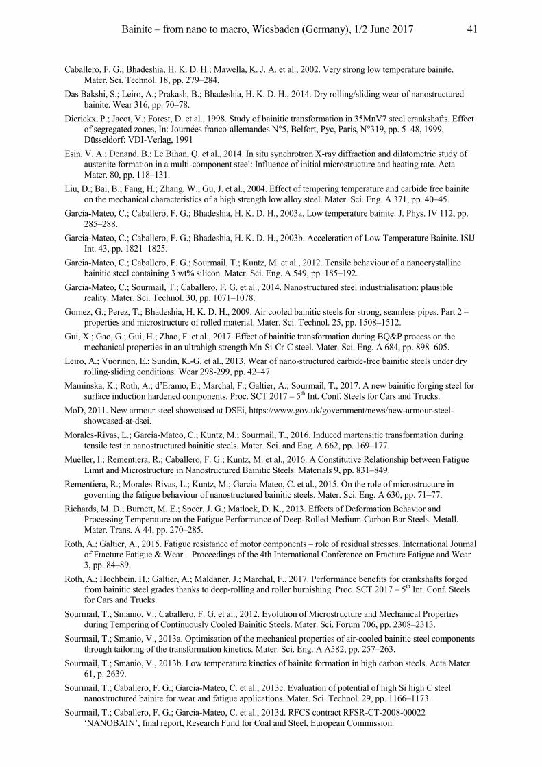
Bainite – from nano to macro, Wiesbaden (Germany), 1/2 June 2017 41
Caballero, F. G.; Bhadeshia, H. K. D. H.; Mawella, K. J. A. et al., 2002. Very strong low temperature bainite. Mater. Sci. Technol. 18, pp. 279–284.
Das Bakshi, S.; Leiro, A.; Prakash, B.; Bhadeshia, H. K. D. H., 2014. Dry rolling/sliding wear of nanostructured bainite. Wear 316, pp. 70–78.
Dierickx, P.; Jacot, V.; Forest, D. et al., 1998. Study of bainitic transformation in 35MnV7 steel crankshafts. Effect of segregated zones, In: Journées franco-allemandes N°5, Belfort, Pyc, Paris, N°319, pp. 5–48, 1999, Düsseldorf: VDI-Verlag, 1991
Esin, V. A.; Denand, B.; Le Bihan, Q. et al., 2014. In situ synchrotron X-ray diffraction and dilatometric study of austenite formation in a multi-component steel: Influence of initial microstructure and heating rate. Acta Mater. 80, pp. 118–131.
Liu, D.; Bai, B.; Fang, H.; Zhang, W.; Gu, J. et al., 2004. Effect of tempering temperature and carbide free bainite on the mechanical characteristics of a high strength low alloy steel. Mater. Sci. Eng. A 371, pp. 40–45.
Garcia-Mateo, C.; Caballero, F. G.; Bhadeshia, H. K. D. H., 2003a. Low temperature bainite. J. Phys. IV 112, pp. 285–288.
a cia ateo, C.; Caballero, F. G.; Bhadeshia, H. K. D. H., 2003b. Acceleration of Low Temperature Bainite. ISIJ Int. 43, pp. 1821–1825.
Garcia-Mateo, C.; Caballero, F. G.; Sourmail, T.; Kuntz, M. et al., 2012. Tensile behaviour of a nanocrystalline bainitic steel containing 3 wt% silicon. Mater. Sci. Eng. A 549, pp. 185–192.
Garcia-Mateo, C.; Sourmail, T.; Caballero, F. G. et al., 2014. Nanostructured steel industrialisation: plausible reality. Mater. Sci. Technol. 30, pp. 1071–1078.
Gomez, G.; Perez, T.; Bhadeshia, H. K. D. H., 2009. Air cooled bainitic steels for strong, seamless pipes. Part 2 – properties and microstructure of rolled material. Mater. Sci. Technol. 25, pp. 1508–1512.
Gui, X.; Gao, G.; Gui, H.; Zhao, F. et al., 2017. Effect of bainitic transformation during BQ&P process on the mechanical properties in an ultrahigh strength Mn-Si-Cr-C steel. Mater. Sci. Eng. A 684, pp. 898–605.
Leiro, A.; Vuorinen, E.; Sundin, K.-G. et al., 2013. Wear of nano-structured carbide-free bainitic steels under dry rolling-sliding conditions. Wear 298-299, pp. 42–47.
Maminska, K.; Roth, A.; d’Eramo, E.; Marchal, F.; Galtier, A.; Sourmail, T., 2017. A new bainitic forging steel for surface induction hardened components. Proc. SCT 2017 – 5th Int. Conf. Steels for Cars and Trucks.
MoD, 2011. New armour steel showcased at DSEi, https://www.gov.uk/government/news/new-armour-steel-showcased-at-dsei.
Morales-Rivas, L.; Garcia-Mateo, C.; Kuntz, M.; Sourmail, T., 2016. Induced martensitic transformation during tensile test in nanostructured bainitic steels. Mater. Sci. and Eng. A 662, pp. 169–177.
Mueller, I.; Rementiera, R.; Caballero, F. G.; Kuntz, M. et al., 2016. A Constitutive Relationship between Fatigue Limit and Microstructure in Nanostructured Bainitic Steels. Materials 9, pp. 831–849.
Rementiera, R.; Morales-Rivas, L.; Kuntz, M.; Garcia-Mateo, C. et al., 2015. On the role of microstructure in governing the fatigue behaviour of nanostructured bainitic steels. Mater. Sci. Eng. A 630, pp. 71–77.
Richards, M. D.; Burnett, M. E.; Speer, J. G.; Matlock, D. K., 2013. Effects of Deformation Behavior and Processing Temperature on the Fatigue Performance of Deep-Rolled Medium-Carbon Bar Steels. Metall. Mater. Trans. A 44, pp. 270–285.
Roth, A.; Galtier, A., 2015. Fatigue resistance of motor components – role of residual stresses. International Journal of Fracture Fatigue & Wear – Proceedings of the 4th International Conference on Fracture Fatigue and Wear 3, pp. 84–89.
Roth, A.; Hochbein, H.; Galtier, A.; Maldaner, J.; Marchal, F., 2017. Performance benefits for crankshafts forged from bainitic steel grades thanks to deep-rolling and roller burnishing. Proc. SCT 2017 – 5th Int. Conf. Steels for Cars and Trucks.
Sourmail, T.; Smanio, V.; Caballero, F. G. et al., 2012. Evolution of Microstructure and Mechanical Properties during Tempering of Continuously Cooled Bainitic Steels. Mater. Sci. Forum 706, pp. 2308–2313.
Sourmail, T.; Smanio, V., 2013a. Optimisation of the mechanical properties of air-cooled bainitic steel components through tailoring of the transformation kinetics. Mater. Sci. Eng. A A582, pp. 257–263.
Sourmail, T.; Smanio, V., 2013b. Low temperature kinetics of bainite formation in high carbon steels. Acta Mater. 61, p. 2639.
Sourmail, T.; Caballero, F. G.; Garcia-Mateo, C. et al., 2013c. Evaluation of potential of high Si high C steel nanostructured bainite for wear and fatigue applications. Mater. Sci. Technol. 29, pp. 1166–1173.
Sourmail, T.; Caballero, F. G.; Garcia-Mateo, C. et al., 2013d. RFCS contract RFSR-CT-2008-00022 ‘NANOBAIN’, final report, Research Fund for Coal and Steel, European Commission.

Bainite – from nano to macro, Wiesbaden (Germany), 1/2 June 2017 42
Sourmail, T.; Smanio, V., 2013e. Influence of Co on Bainite Formation Kinetics in 1 %C Steels. Metal. Mater. Trans. A 44, pp. 1975–1978.
Sourmail, T. et al., 2016. Understanding the basic mechanisms to optimize and predict in service properties of nanobainitic steels (MECBAIN). Res. Fund Coal Steel, in press.
Sourmail, T., 2017. 30 years of bainitic forging steels. Int. Conf. NEMU 2017, 15–17.05.2017, Stuttgart. Quidort, D.; Bréchet ,Y., 2002. The role of carbon on the kinetics of bainite transformation in steels. Scripta Mater.
47, pp. 51. Vetters, H.; Dong, J.; Zoch, H.-W., 2009. Effect of residual austenite on properties of tool steel following shortened
treatments in lower bainitic phase. International Heat Treatment and Surface Engineering 3, pp. 130–135. Vetters, H.; Dong, J.; Bomas, H.; Hoffman, F.; Zoch, H.-W., 2006. Microstructure and fatigue strength of the roller-
bearing steel 100Cr6 (SAE 52100) after two-step bainitisation and combined bainitic–martensitic heat treatment. Inter. J. Mater. Res. 97, pp. 1432–1440.
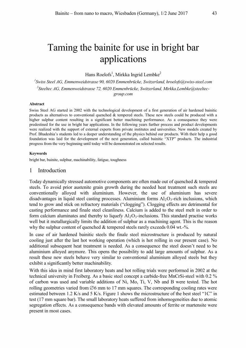
Bainite – from nano to macro, Wiesbaden (Germany), 1/2 June 2017 43
Taming the bainite for use in bright bar applications
Hans Roelofs1, Mirkka Ingrid Lembke2 1Swiss Steel AG, Emmenweidstrasse 90, 6020 Emmenbrücke, Switzerland, [email protected]
2Steeltec AG, Emmenweidstrasse 72, 6020 Emmenbrücke, Switzerland, [email protected]
Abstract Swiss Steel AG started in 2002 with the technological development of a first generation of air hardened bainitic products as alternatives to conventional quenched & tempered steels. These new steels could be produced with a higher sulphur content resulting in a significant better machining performance. As a consequence they were predestined for the use in bright bar applications. In the following years further process and product developments were realized with the support of external experts from private institutes and universities. New models created by Prof. Bhadeshia’s students led to a deeper understanding of the physics behind our products. With their help a good foundation was laid for the development of the next generation, called bainitic “XTP” products. The industrial progress from the very beginning until today will be demonstrated on selected results.
Keywords bright bar, bainite, sulphur, machinability, fatigue, toughness
1 Introduction
Today dynamically stressed automotive components are often made out of quenched & tempered steels. To avoid prior austenite grain growth during the needed heat treatment such steels are conventionally alloyed with aluminium. However, the use of aluminium has severe disadvantages in liquid steel casting processes. Aluminium forms Al2O3-rich inclusions, which tend to grow and stick on refractory materials (“clogging”). Clogging effects are detrimental for casting performance and finale steel cleanliness. Calcium is added to the steel melt in order to form calcium aluminates and thereby to liquefy Al2O3-inclusions. This standard practise works well but it metallurgically limits the addition of sulphur as a machining agent. This is the reason why the sulphur content of quenched & tempered steels rarely exceeds 0.04 wt.-%. In case of air hardened bainitic steels the finale steel microstructure is produced by natural cooling just after the last hot working operation (which is hot rolling in our present case). No additional subsequent heat treatment is needed. As a consequence the steel doesn’t need to be aluminium alloyed anymore. This opens the possibility to add large amounts of sulphur. As a result these new steels behave very similar to conventional aluminium alloyed steels but they exhibit a significantly better machinability. With this idea in mind first laboratory heats and hot rolling trials were performed in 2002 at the technical university in Freiberg. As a basic steel concept a carbide-free MnCrSi-steel with 0.2 % of carbon was used and variable additions of Ni, Mo, Ti, V, Nb and B were tested. The hot rolling geometries varied from 6 mm to 17 mm squares. The corresponding cooling rates were estimated between 1.2 K/s and 5 K/s. Figure 1 shows the microstructure of the best steel “1C” in test (17 mm square bar). The small laboratory heats suffered from inhomogeneities due to atomic segregation effects. As a consequence bands with elevated amounts of ferrite or martensite were present in most cases.
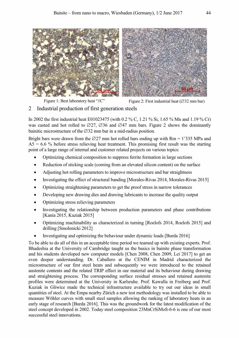
Bainite – from nano to macro, Wiesbaden (Germany), 1/2 June 2017 44
Figure 1: Best laboratory heat “1C” Figure 2: First industrial heat ( 32 mm bar)
2 Industrial production of first generation steels
In 2002 the first industrial heat E01023475 (with 0.2 % C, 1.21 % Si, 1.65 % Mn and 1.19 % Cr) was casted and hot rolled to 27, 36 and 47 mm bars. Figure 2 shows the dominantly bainitic microstructure of the 32 mm bar in a mid-radius position. Bright bars were drawn from the 27 mm hot rolled bars ending up with Rm = 1’335 MPa and A5 = 6.6 % before stress relieving heat treatment. This promising first result was the starting point of a large range of internal and customer related projects on various topics:
• Optimizing chemical composition to suppress ferrite formation in large sections • Reduction of sticking scale (coming from an elevated silicon content) on the surface • Adjusting hot rolling parameters to improve microstructure and bar straightness • Investigating the effect of structural banding [Morales-Rivas 2014, Morales-Rivas 2015] • Optimizing straightening parameters to get the proof stress in narrow tolerances • Developing new drawing dies and drawing lubricants to increase the quality output • Optimizing stress relieving parameters • Investigating the relationship between production parameters and phase contributions
[Kania 2015, Kuziak 2015] • Optimizing machinability as characterized in turning [Roelofs 2014, Roelofs 2015] and
drilling [Smolenicki 2012] • Investigating and optimizing the behaviour under dynamic loads [Burda 2016]
To be able to do all of this in an acceptable time period we teamed up with existing experts. Prof. Bhadeshia at the University of Cambridge taught us the basics in bainite phase transformation and his students developed new computer models [Chen 2008, Chen 2009, Lei 2017] to get an even deeper understanding. Dr. Caballero at the CENIM in Madrid characterized the microstructure of our first steel heats and subsequently we were introduced to the retained austenite contents and the related TRIP effect in our material and its behaviour during drawing and straightening process. The corresponding surface residual stresses and retained austenite profiles were determined at the University in Karlsruhe. Prof. Kawalla in Freiberg and Prof. Kuziak in Gliwice made the technical infrastructure available to try out our ideas in small quantities of steel. At the Empa nearby Zürich a new test methodology was installed to be able to measure Wöhler curves with small steel samples allowing the ranking of laboratory heats in an early stage of research [Burda 2016]. This was the groundwork for the latest modification of the steel concept developed in 2002. Today steel composition 23MnCrSiMoS-6-6 is one of our most successful steel innovations.
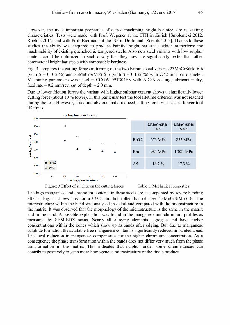
Bainite – from nano to macro, Wiesbaden (Germany), 1/2 June 2017 45
23MnCrSiMo-6-6
23MnCrSiMoS-6-6
Rp0.2 673 MPa 852 MPa
Rm 983 MPa 1’021 MPa
A5 18.7 % 17.3 %
However, the most important properties of a free machining bright bar steel are its cutting characteristics. Tests were made with Prof. Wegener at the ETH in Zürich [Smolenicki 2012, Roelofs 2014] and with Prof. Biermann at the ISF in Dortmund [Roelofs 2015]. Thanks to these studies the ability was acquired to produce bainitic bright bar steels which outperform the machinability of existing quenched & tempered steels. Also new steel variants with low sulphur content could be optimized in such a way that they now are significantly better than other commercial bright bar steels with comparable hardness. Fig. 3 compares the cutting forces in turning of the two bainitic steel variants 23MnCrSiMo-6-6 (with S = 0.015 %) and 23MnCrSiMoS-6-6 (with S = 0.135 %) with 42 mm bar diameter. Machining parameters were: tool = CCGW 09T304FN with AlCrN coating; lubricant = dry; feed rate = 0.2 mm/rev; cut of depth = 2.0 mm. Due to lower friction forces the variant with higher sulphur content shows a significantly lower cutting force (about 10 % lower). In this particular test the tool lifetime criterion was not reached during the test. However, it is quite obvious that a reduced cutting force will lead to longer tool lifetimes.
Figure: 3 Effect of sulphur on the cutting forces Table 1: Mechanical properties
The high manganese and chromium contents in these steels are accompanied by severe banding effects. Fig. 4 shows this for a 32 mm hot rolled bar of steel 23MnCrSiMo-6-6. The microstructure within the band was analysed in detail and compared with the microstructure in the matrix. It was observed that the morphology of the microstructure is the same in the matrix and in the band. A possible explanation was found in the manganese and chromium profiles as measured by SEM-EDX scans. Nearly all alloying elements segregate and have higher concentrations within the zones which show up as bands after edging. But due to manganese sulphide formation the available free manganese content is significantly reduced in banded areas. The local reduction in manganese compensates for the higher chromium concentration. As a consequence the phase transformation within the bands does not differ very much from the phase transformation in the matrix. This indicates that sulphur under some circumstances can contribute positively to get a more homogenous microstructure of the finale product.
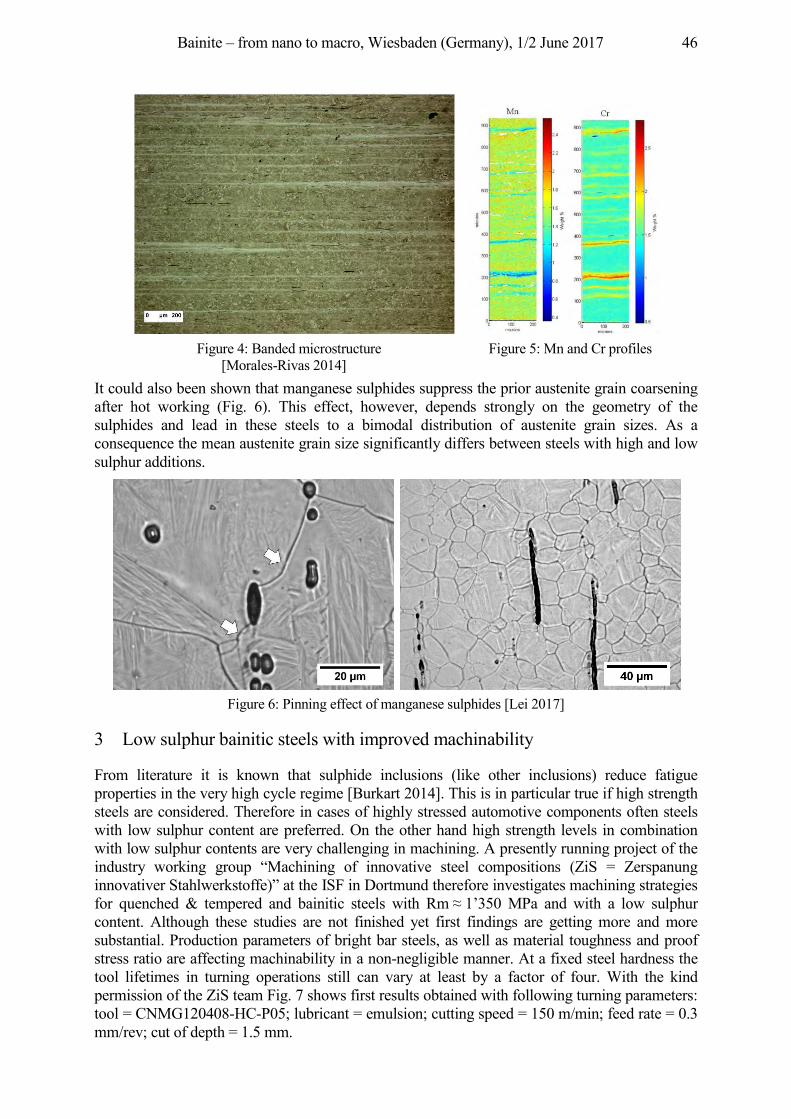
Bainite – from nano to macro, Wiesbaden (Germany), 1/2 June 2017 46
Figure 4: Banded microstructure
[Morales-Rivas 2014] Figure 5: Mn and Cr profiles
It could also been shown that manganese sulphides suppress the prior austenite grain coarsening after hot working (Fig. 6). This effect, however, depends strongly on the geometry of the sulphides and lead in these steels to a bimodal distribution of austenite grain sizes. As a consequence the mean austenite grain size significantly differs between steels with high and low sulphur additions.
Figure 6: Pinning effect of manganese sulphides [Lei 2017]
3 Low sulphur bainitic steels with improved machinability
From literature it is known that sulphide inclusions (like other inclusions) reduce fatigue properties in the very high cycle regime [Burkart 2014]. This is in particular true if high strength steels are considered. Therefore in cases of highly stressed automotive components often steels with low sulphur content are preferred. On the other hand high strength levels in combination with low sulphur contents are very challenging in machining. A presently running project of the industry working group “Machining of innovative steel compositions (ZiS = Zerspanung innovativer Stahlwerkstoffe)” at the ISF in Dortmund therefore investigates machining strategies for quenched & tempered and bainitic steels with Rm 1’350 MPa and with a low sulphur content. Although these studies are not finished yet first findings are getting more and more substantial. Production parameters of bright bar steels, as well as material toughness and proof stress ratio are affecting machinability in a non-negligible manner. At a fixed steel hardness the tool lifetimes in turning operations still can vary at least by a factor of four. With the kind permission of the ZiS team Fig. 7 shows first results obtained with following turning parameters: tool = CNMG120408-HC-P05; lubricant = emulsion; cutting speed = 150 m/min; feed rate = 0.3 mm/rev; cut of depth = 1.5 mm.
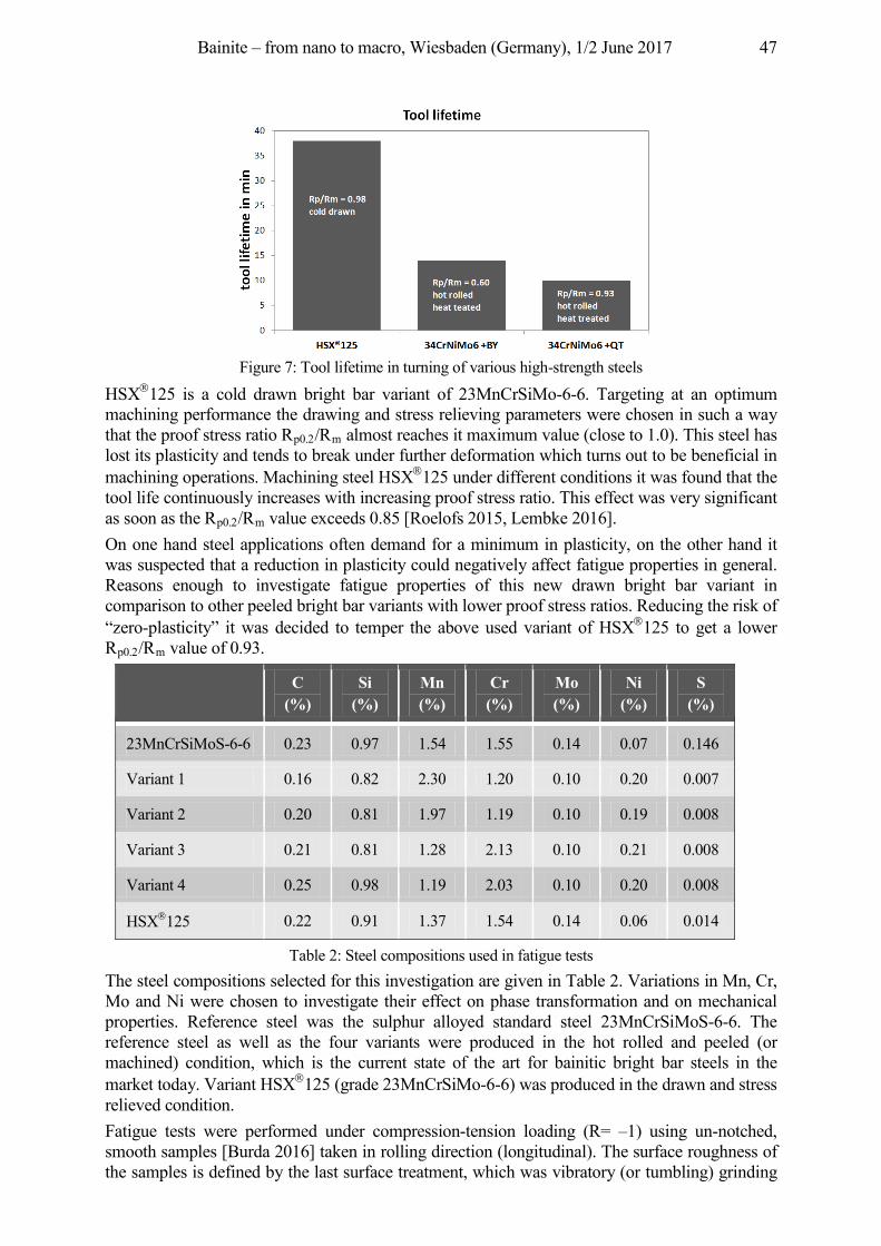
Bainite – from nano to macro, Wiesbaden (Germany), 1/2 June 2017 47
Figure 7: Tool lifetime in turning of various high-strength steels
HSX 125 is a cold drawn bright bar variant of 23MnCrSiMo-6-6. Targeting at an optimum machining performance the drawing and stress relieving parameters were chosen in such a way that the proof stress ratio Rp0.2/Rm almost reaches it maximum value (close to 1.0). This steel has lost its plasticity and tends to break under further deformation which turns out to be beneficial in machining operations. Machining steel HSX 125 under different conditions it was found that the tool life continuously increases with increasing proof stress ratio. This effect was very significant as soon as the Rp0.2/Rm value exceeds 0.85 [Roelofs 2015, Lembke 2016]. On one hand steel applications often demand for a minimum in plasticity, on the other hand it was suspected that a reduction in plasticity could negatively affect fatigue properties in general. Reasons enough to investigate fatigue properties of this new drawn bright bar variant in comparison to other peeled bright bar variants with lower proof stress ratios. Reducing the risk of “zero-plasticity” it was decided to temper the above used variant of HSX 125 to get a lower Rp0.2/Rm value of 0.93.
C
(%) Si
(%) Mn (%)
Cr (%)
Mo (%)
Ni (%)
S (%)
23MnCrSiMoS-6-6 0.23 0.97 1.54 1.55 0.14 0.07 0.146
Variant 1 0.16 0.82 2.30 1.20 0.10 0.20 0.007
Variant 2 0.20 0.81 1.97 1.19 0.10 0.19 0.008
Variant 3 0.21 0.81 1.28 2.13 0.10 0.21 0.008
Variant 4 0.25 0.98 1.19 2.03 0.10 0.20 0.008
HSX 125 0.22 0.91 1.37 1.54 0.14 0.06 0.014
Table 2: Steel compositions used in fatigue tests The steel compositions selected for this investigation are given in Table 2. Variations in Mn, Cr, Mo and Ni were chosen to investigate their effect on phase transformation and on mechanical properties. Reference steel was the sulphur alloyed standard steel 23MnCrSiMoS-6-6. The reference steel as well as the four variants were produced in the hot rolled and peeled (or machined) condition, which is the current state of the art for bainitic bright bar steels in the market today. Variant HSX 125 (grade 23MnCrSiMo-6-6) was produced in the drawn and stress relieved condition. Fatigue tests were performed under compression-tension loading (R= –1) using un-notched, smooth samples [Burda 2016] taken in rolling direction (longitudinal). The surface roughness of the samples is defined by the last surface treatment, which was vibratory (or tumbling) grinding
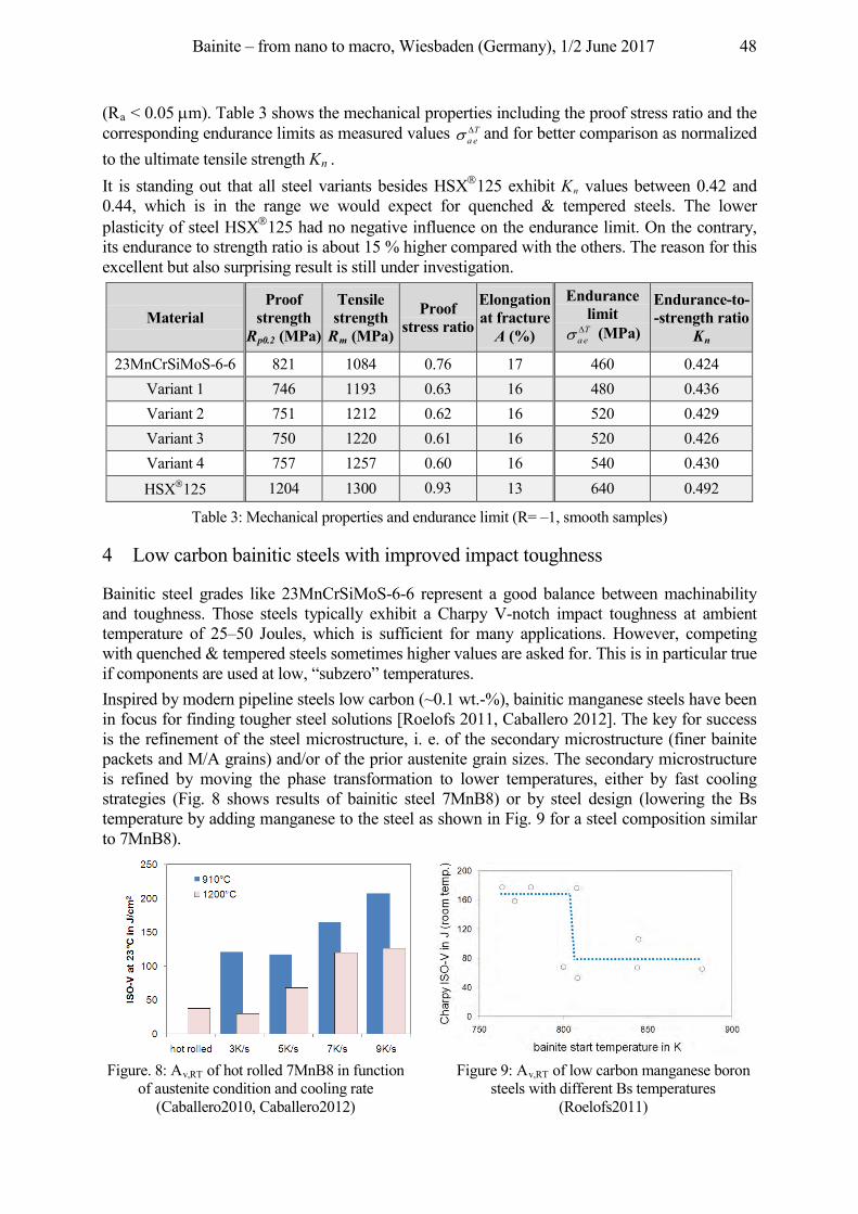
Bainite – from nano to macro, Wiesbaden (Germany), 1/2 June 2017 48
(Ra < 0.05 m). Table 3 shows the mechanical properties including the proof stress ratio and the corresponding endurance limits as measured values T
ea and for better comparison as normalized to the ultimate tensile strength Kn . It is standing out that all steel variants besides HSX 125 exhibit Kn values between 0.42 and 0.44, which is in the range we would expect for quenched & tempered steels. The lower plasticity of steel HSX 125 had no negative influence on the endurance limit. On the contrary, its endurance to strength ratio is about 15 % higher compared with the others. The reason for this excellent but also surprising result is still under investigation.
Material Proof
strength Rp0.2 (MPa)
Tensile strength Rm (MPa)
Proof stress ratio
Elongation at fracture A (%)
Endurance limit
Tea (MPa)
Endurance-to- -strength ratio
Kn
23MnCrSiMoS-6-6 821 1084 0.76 17 460 0.424 Variant 1 746 1193 0.63 16 480 0.436 Variant 2 751 1212 0.62 16 520 0.429 Variant 3 750 1220 0.61 16 520 0.426 Variant 4 757 1257 0.60 16 540 0.430 HSX 125 1204 1300 0.93 13 640 0.492
Table 3: Mechanical properties and endurance limit (R= –1, smooth samples)
4 Low carbon bainitic steels with improved impact toughness
Bainitic steel grades like 23MnCrSiMoS-6-6 represent a good balance between machinability and toughness. Those steels typically exhibit a Charpy V-notch impact toughness at ambient temperature of 25–50 Joules, which is sufficient for many applications. However, competing with quenched & tempered steels sometimes higher values are asked for. This is in particular true if components are used at low, “subzero” temperatures. Inspired by modern pipeline steels low carbon (~0.1 wt.-%), bainitic manganese steels have been in focus for finding tougher steel solutions [Roelofs 2011, Caballero 2012]. The key for success is the refinement of the steel microstructure, i. e. of the secondary microstructure (finer bainite packets and M/A grains) and/or of the prior austenite grain sizes. The secondary microstructure is refined by moving the phase transformation to lower temperatures, either by fast cooling strategies (Fig. 8 shows results of bainitic steel 7MnB8) or by steel design (lowering the Bs temperature by adding manganese to the steel as shown in Fig. 9 for a steel composition similar to 7MnB8).
Figure. 8: Av,RT of hot rolled 7MnB8 in function
of austenite condition and cooling rate (Caballero2010, Caballero2012)
Figure 9: Av,RT of low carbon manganese boron steels with different Bs temperatures
(Roelofs2011)
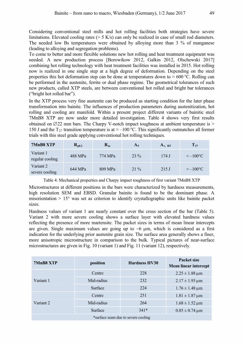
Bainite – from nano to macro, Wiesbaden (Germany), 1/2 June 2017 49
Considering conventional steel mills and hot rolling facilities both strategies have severe limitations. Elevated cooling rates (> 5 K/s) can only be realized in case of small rod diameters. The needed low Bs temperatures were obtained by alloying more than 3 % of manganese (leading to alloying and segregation problems). To come to better and more flexible solutions new hot rolling and heat treatment equipment was needed. A new production process [Borowikow 2012, Galkin 2012, Olschewski 2017] combining hot rolling technology with heat treatment facilities was installed in 2015. Hot rolling now is realized in one single step at a high degree of deformation. Depending on the steel p ope ties this hot e o atio step ca be o e at te pe atu es o to 600 °C. Rolling can be performed in the austenite, ferrite or dual phase regime. The geometrical tolerances of such new products, called XTP steels, are between conventional hot rolled and bright bar tolerances (“bright hot rolled bar”). In the XTP process very fine austenite can be produced as starting condition for the later phase transformation into bainite. The influences of production parameters during austenitization, hot rolling and cooling are manifold. Within a present project different variants of bainitic steel 7MnB8 XTP are now under more detailed investigation. Table 4 shows very first results obtained on 22 mm bars. The Charpy V-notch impact toughness at ambient temperature is > 150 J and the T27 t a sitio te pe atu e is at –100 °C. This significantly outmatches all former trials with this steel grade applying conventional hot rolling techniques.
7MnB8 XTP Rp0.2 Rm A5 Av, RT T27
Variant 1 regular cooling
488 MPa 774 MPa 23 % 174 J –100°C
Variant 2 severe cooling
644 MPa 809 MPa 21 % 215 J –100°C
Table 4: Mechanical properties and Charpy impact toughness of first variant 7MnB8 XTP Microstructures at different positions in the bars were characterized by hardness measurements, high resolution SEM and EBSD. Granular bainite is found to be the dominant phase. A misorientation > 15° was set as criterion to identify crystallographic units like bainite packet sizes. Hardness values of variant 1 are nearly constant over the cross section of the bar (Table 5). Variant 2 with more severe cooling shows a surface layer with elevated hardness values reflecting the presence of more martensite. The packet sizes in terms of mean linear intercepts are given. Single maximum values are going up to ~6 m, which is considered as a first indication for the underlying prior austenite grain size. The surface area generally shows a finer, more anisotropic microstructure in comparison to the bulk. Typical pictures of near-surface microstructures are given in Fig. 10 (variant 1) and Fig. 11 (variant 12), respectively.
7MnB8 XTP position Hardness HV30 Packet size
Mean linear intercept
Variant 1
Centre 228 2.25 ± 1.88 m Mid-radius 232 2.17 ± 1.93 m
Surface 224 1.76 ± 1.48 m
Variant 2
Centre 251 1.81 ± 1.87 m Mid-radius 264 1.68 ± 1.52 m
Surface 341* 0.85 ± 0.74 m *surface seam due to severe cooling
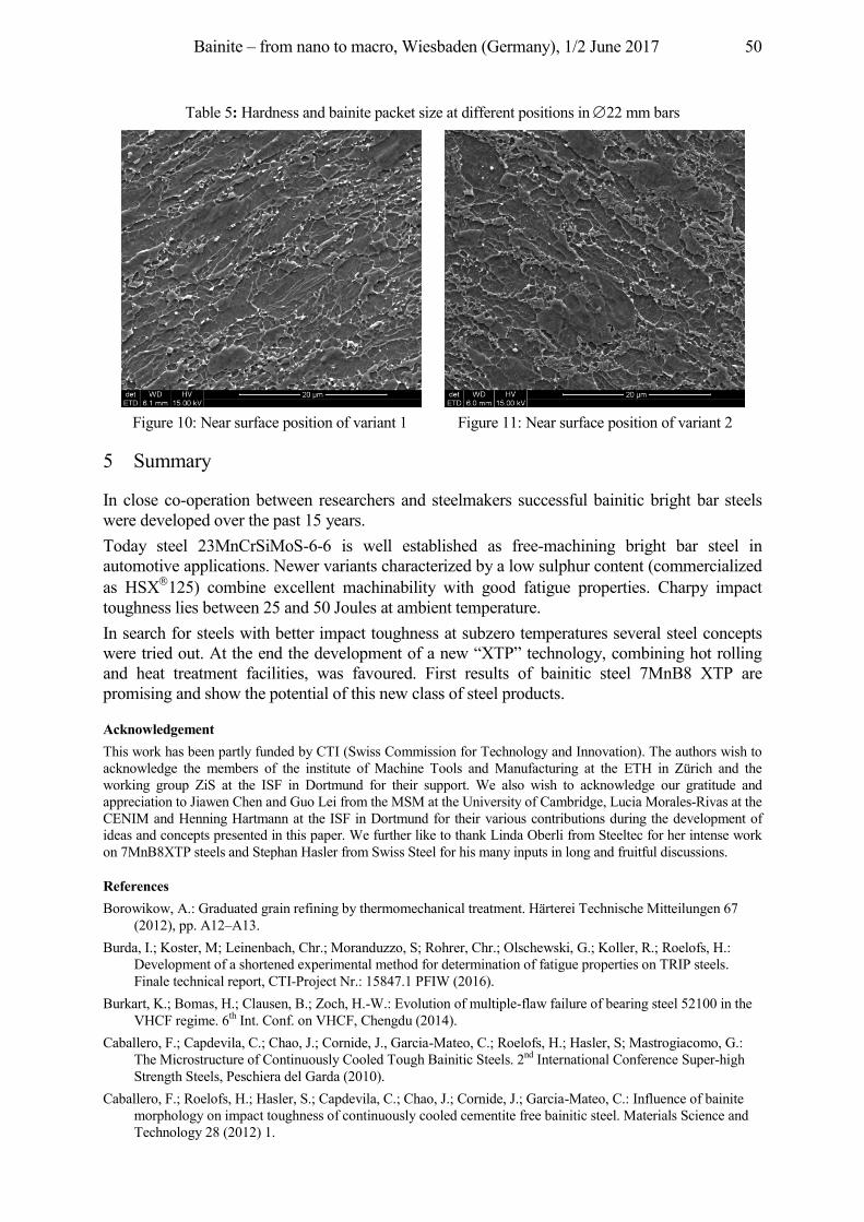
Bainite – from nano to macro, Wiesbaden (Germany), 1/2 June 2017 50
Table 5: Hardness and bainite packet size at different positions in 22 mm bars
Figure 10: Near surface position of variant 1 Figure 11: Near surface position of variant 2
5 Summary
In close co-operation between researchers and steelmakers successful bainitic bright bar steels were developed over the past 15 years. Today steel 23MnCrSiMoS-6-6 is well established as free-machining bright bar steel in automotive applications. Newer variants characterized by a low sulphur content (commercialized as HSX 125) combine excellent machinability with good fatigue properties. Charpy impact toughness lies between 25 and 50 Joules at ambient temperature. In search for steels with better impact toughness at subzero temperatures several steel concepts were tried out. At the end the development of a new “XTP” technology, combining hot rolling and heat treatment facilities, was favoured. First results of bainitic steel 7MnB8 XTP are promising and show the potential of this new class of steel products.
Acknowledgement This work has been partly funded by CTI (Swiss Commission for Technology and Innovation). The authors wish to acknowledge the members of the institute of Machine Tools and Manufacturing at the ETH in Zürich and the working group ZiS at the ISF in Dortmund for their support. We also wish to acknowledge our gratitude and appreciation to Jiawen Chen and Guo Lei from the MSM at the University of Cambridge, Lucia Morales-Rivas at the CENIM and Henning Hartmann at the ISF in Dortmund for their various contributions during the development of ideas and concepts presented in this paper. We further like to thank Linda Oberli from Steeltec for her intense work on 7MnB8XTP steels and Stephan Hasler from Swiss Steel for his many inputs in long and fruitful discussions.
References Borowikow, A.: Graduated grain refining by thermomechanical treatment. Härterei Technische Mitteilungen 67
(2012), pp. A12–A13. Burda, I.; Koster, M; Leinenbach, Chr.; Moranduzzo, S; Rohrer, Chr.; Olschewski, G.; Koller, R.; Roelofs, H.:
Development of a shortened experimental method for determination of fatigue properties on TRIP steels. Finale technical report, CTI-Project Nr.: 15847.1 PFIW (2016).
Burkart, K.; Bomas, H.; Clausen, B.; Zoch, H.-W.: Evolution of multiple-flaw failure of bearing steel 52100 in the VHCF regime. 6th Int. Conf. on VHCF, Chengdu (2014).
Caballero, F.; Capdevila, C.; Chao, J.; Cornide, J., Garcia-Mateo, C.; Roelofs, H.; Hasler, S; Mastrogiacomo, G.: The Microstructure of Continuously Cooled Tough Bainitic Steels. 2nd International Conference Super-high Strength Steels, Peschiera del Garda (2010).
Caballero, F.; Roelofs, H.; Hasler, S.; Capdevila, C.; Chao, J.; Cornide, J.; Garcia-Mateo, C.: Influence of bainite morphology on impact toughness of continuously cooled cementite free bainitic steel. Materials Science and Technology 28 (2012) 1.
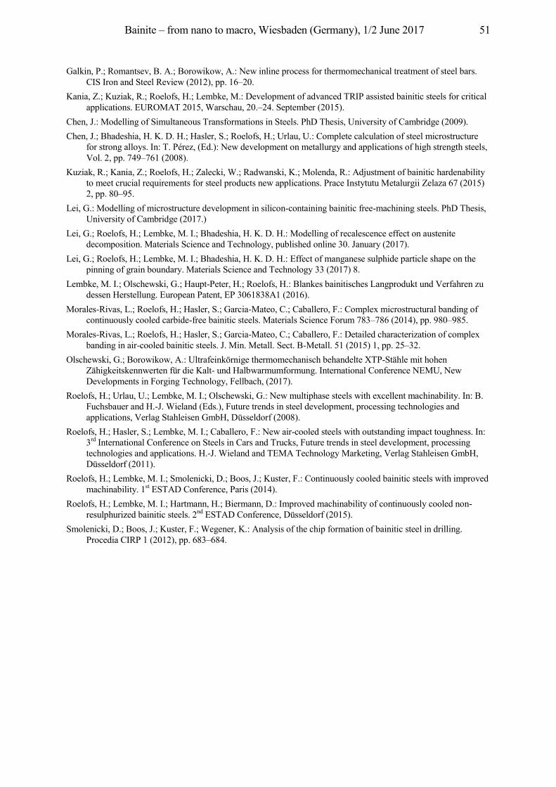
Bainite – from nano to macro, Wiesbaden (Germany), 1/2 June 2017 51
Galkin, P.; Romantsev, B. A.; Borowikow, A.: New inline process for thermomechanical treatment of steel bars. CIS Iron and Steel Review (2012), pp. 16–20.
Kania, Z.; Kuziak, R.; Roelofs, H.; Lembke, M.: Development of advanced TRIP assisted bainitic steels for critical applications. EUROMAT 2015, Warschau, 20.–24. September (2015).
Chen, J.: Modelling of Simultaneous Transformations in Steels. PhD Thesis, University of Cambridge (2009). Chen, J.; Bhadeshia, H. K. D. H.; Hasler, S.; Roelofs, H.; Urlau, U.: Complete calculation of steel microstructure
for strong alloys. In: T. Pérez, (Ed.): New development on metallurgy and applications of high strength steels, Vol. 2, pp. 749–761 (2008).
Kuziak, R.; Kania, Z.; Roelofs, H.; Zalecki, W.; Radwanski, K.; Molenda, R.: Adjustment of bainitic hardenability to meet crucial requirements for steel products new applications. Prace Instytutu Metalurgii Zelaza 67 (2015) 2, pp. 80–95.
Lei, G.: Modelling of microstructure development in silicon-containing bainitic free-machining steels. PhD Thesis, University of Cambridge (2017.)
Lei, G.; Roelofs, H.; Lembke, M. I.; Bhadeshia, H. K. D. H.: Modelling of recalescence effect on austenite decomposition. Materials Science and Technology, published online 30. January (2017).
Lei, G.; Roelofs, H.; Lembke, M. I.; Bhadeshia, H. K. D. H.: Effect of manganese sulphide particle shape on the pinning of grain boundary. Materials Science and Technology 33 (2017) 8.
Lembke, M. I.; Olschewski, G.; Haupt-Peter, H.; Roelofs, H.: Blankes bainitisches Langprodukt und Verfahren zu dessen Herstellung. European Patent, EP 3061838A1 (2016).
Morales-Rivas, L.; Roelofs, H.; Hasler, S.; Garcia-Mateo, C.; Caballero, F.: Complex microstructural banding of continuously cooled carbide-free bainitic steels. Materials Science Forum 783–786 (2014), pp. 980–985.
Morales-Rivas, L.; Roelofs, H.; Hasler, S.; Garcia-Mateo, C.; Caballero, F.: Detailed characterization of complex banding in air-cooled bainitic steels. J. Min. Metall. Sect. B-Metall. 51 (2015) 1, pp. 25–32.
Olschewski, G.; Borowikow, A.: Ultrafeinkörnige thermomechanisch behandelte XTP-Stähle mit hohen Zähigkeitskennwerten für die Kalt- und Halbwarmumformung. International Conference NEMU, New Developments in Forging Technology, Fellbach, (2017).
Roelofs, H.; Urlau, U.; Lembke, M. I.; Olschewski, G.: New multiphase steels with excellent machinability. In: B. Fuchsbauer and H.-J. Wieland (Eds.), Future trends in steel development, processing technologies and applications, Verlag Stahleisen GmbH, Düsseldorf (2008).
Roelofs, H.; Hasler, S.; Lembke, M. I.; Caballero, F.: New air-cooled steels with outstanding impact toughness. In: 3rd International Conference on Steels in Cars and Trucks, Future trends in steel development, processing technologies and applications. H.-J. Wieland and TEMA Technology Marketing, Verlag Stahleisen GmbH, Düsseldorf (2011).
Roelofs, H.; Lembke, M. I.; Smolenicki, D.; Boos, J.; Kuster, F.: Continuously cooled bainitic steels with improved machinability. 1st ESTAD Conference, Paris (2014).
Roelofs, H.; Lembke, M. I.; Hartmann, H.; Biermann, D.: Improved machinability of continuously cooled non-resulphurized bainitic steels. 2nd ESTAD Conference, Düsseldorf (2015).
Smolenicki, D.; Boos, J.; Kuster, F.; Wegener, K.: Analysis of the chip formation of bainitic steel in drilling. Procedia CIRP 1 (2012), pp. 683–684.
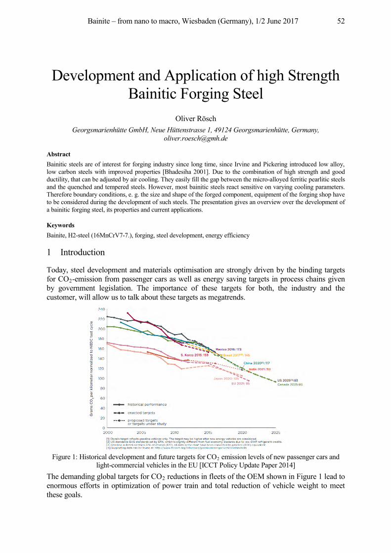
Bainite – from nano to macro, Wiesbaden (Germany), 1/2 June 2017 52
Development and Application of high Strength Bainitic Forging Steel
Oliver Rösch Georgsmarienhütte GmbH, Neue Hüttenstrasse 1, 49124 Georgsmarienhütte, Germany,
Abstract Bainitic steels are of interest for forging industry since long time, since Irvine and Pickering introduced low alloy, low carbon steels with improved properties [Bhadesiha 2001]. Due to the combination of high strength and good ductility, that can be adjusted by air cooling. They easily fill the gap between the micro-alloyed ferritic pearlitic steels and the quenched and tempered steels. However, most bainitic steels react sensitive on varying cooling parameters. Therefore boundary conditions, e. g. the size and shape of the forged component, equipment of the forging shop have to be considered during the development of such steels. The presentation gives an overview over the development of a bainitic forging steel, its properties and current applications.
Keywords Bainite, H2-steel (16MnCrV7-7.), forging, steel development, energy efficiency
1 Introduction
Today, steel development and materials optimisation are strongly driven by the binding targets for CO2-emission from passenger cars as well as energy saving targets in process chains given by government legislation. The importance of these targets for both, the industry and the customer, will allow us to talk about these targets as megatrends.
Figure 1: Historical development and future targets for CO2 emission levels of new passenger cars and
light-commercial vehicles in the EU [ICCT Policy Update Paper 2014] The demanding global targets for CO2 reductions in fleets of the OEM shown in Figure 1 lead to enormous efforts in optimization of power train and total reduction of vehicle weight to meet these goals.
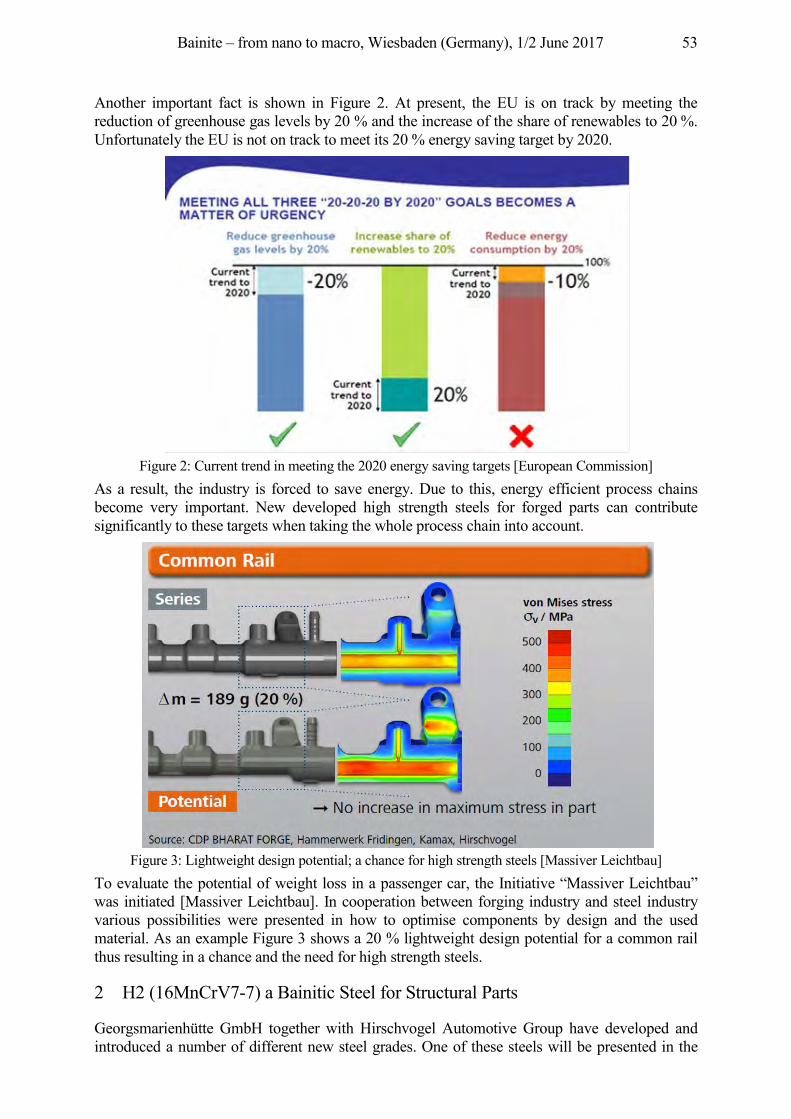
Bainite – from nano to macro, Wiesbaden (Germany), 1/2 June 2017 53
Another important fact is shown in Figure 2. At present, the EU is on track by meeting the reduction of greenhouse gas levels by 20 % and the increase of the share of renewables to 20 %. Unfortunately the EU is not on track to meet its 20 % energy saving target by 2020.
Figure 2: Current trend in meeting the 2020 energy saving targets [European Commission]
As a result, the industry is forced to save energy. Due to this, energy efficient process chains become very important. New developed high strength steels for forged parts can contribute significantly to these targets when taking the whole process chain into account.
Figure 3: Lightweight design potential; a chance for high strength steels [Massiver Leichtbau]
To evaluate the potential of weight loss in a passenger car, the Initiative “Massiver Leichtbau” was initiated [Massiver Leichtbau]. In cooperation between forging industry and steel industry various possibilities were presented in how to optimise components by design and the used material. As an example Figure 3 shows a 20 % lightweight design potential for a common rail thus resulting in a chance and the need for high strength steels.
2 H2 (16MnCrV7-7) a Bainitic Steel for Structural Parts
Georgsmarienhütte GmbH together with Hirschvogel Automotive Group have developed and introduced a number of different new steel grades. One of these steels will be presented in the
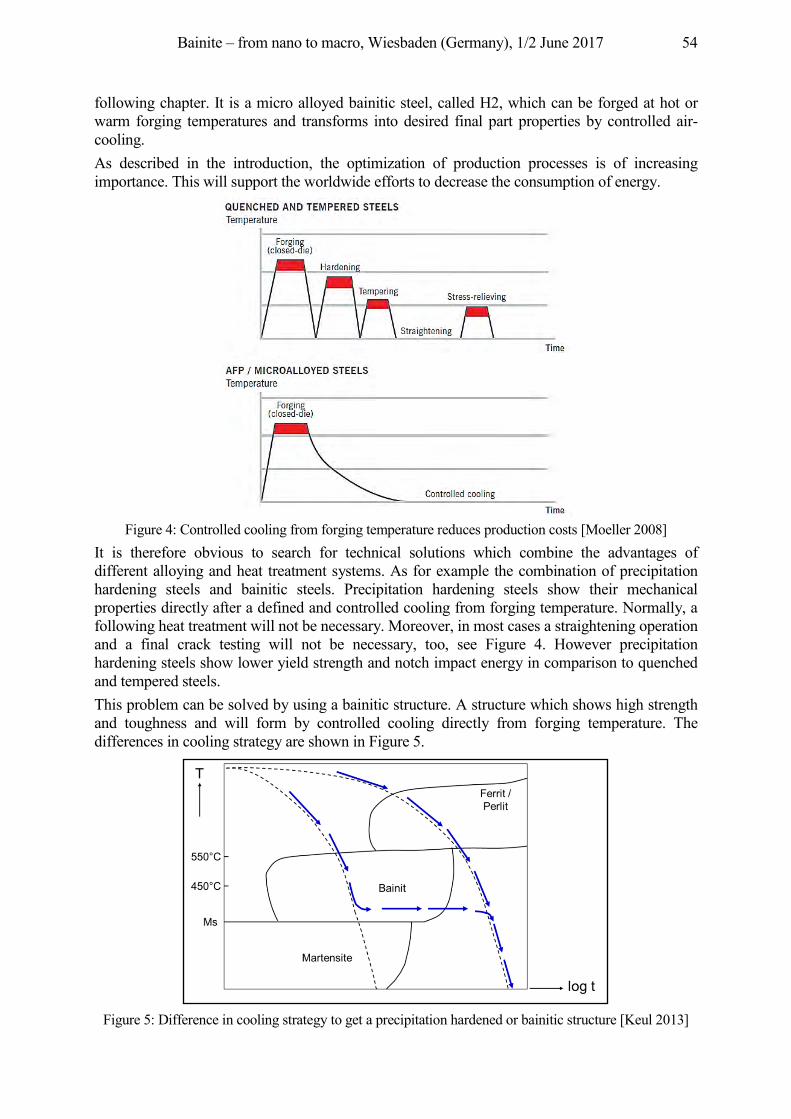
Bainite – from nano to macro, Wiesbaden (Germany), 1/2 June 2017 54
following chapter. It is a micro alloyed bainitic steel, called H2, which can be forged at hot or warm forging temperatures and transforms into desired final part properties by controlled air-cooling. As described in the introduction, the optimization of production processes is of increasing importance. This will support the worldwide efforts to decrease the consumption of energy.
Figure 4: Controlled cooling from forging temperature reduces production costs [Moeller 2008]
It is therefore obvious to search for technical solutions which combine the advantages of different alloying and heat treatment systems. As for example the combination of precipitation hardening steels and bainitic steels. Precipitation hardening steels show their mechanical properties directly after a defined and controlled cooling from forging temperature. Normally, a following heat treatment will not be necessary. Moreover, in most cases a straightening operation and a final crack testing will not be necessary, too, see Figure 4. However precipitation hardening steels show lower yield strength and notch impact energy in comparison to quenched and tempered steels. This problem can be solved by using a bainitic structure. A structure which shows high strength and toughness and will form by controlled cooling directly from forging temperature. The differences in cooling strategy are shown in Figure 5.
Figure 5: Difference in cooling strategy to get a precipitation hardened or bainitic structure [Keul 2013]
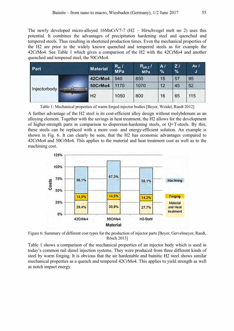
Bainite – from nano to macro, Wiesbaden (Germany), 1/2 June 2017 55
The newly developed micro-alloyed 16MnCrV7-7 (H2 – Hirschvogel melt no 2) uses this potential. It combines the advantages of precipitation hardening steel and quenched and tempered steels. Thus resulting in shortened production times. Even the mechanical properties of the H2 are prior to the widely known quenched and tempered steels as for example the 42CrMo4. See Table 1 which gives a comparison of the H2 with the 42CrMo4 and another quenched and tempered steel, the 50CrMo4.
Table 1: Mechanical properties of warm forged injector bodies [Beyer, Weidel, Raedt 2012]
A further advantage of the H2 steel is its cost-efficient alloy design without molybdenum as an alloying element. Together with the savings in heat treatment, the H2 allows for the development of higher-strength parts in comparison to dispersion-hardening steels, or Q+T-steels. By this, these steels can be replaced with a more cost- and energy-efficient solution. An example is shown in Fig. 6. It can clearly be seen, that the H2 has economic advantages compared to 42CrMo4 and 50CrMo4. This applies to the material and heat treatment cost as well as to the machining cost.
Figure 6: Summary of different cost types for the production of injector parts [Beyer, Gervelmeyer, Raedt,
Rösch 2013] Table 1 shows a comparison of the mechanical properties of an injector body which is used in today’s common rail diesel injection systems. They were produced from three different kinds of steel by warm forging. It is obvious that the air hardenable and bainitic H2 steel shows similar mechanical properties as a quench and tempered 42CrMo4. This applies to yield strength as well as notch impact energy.
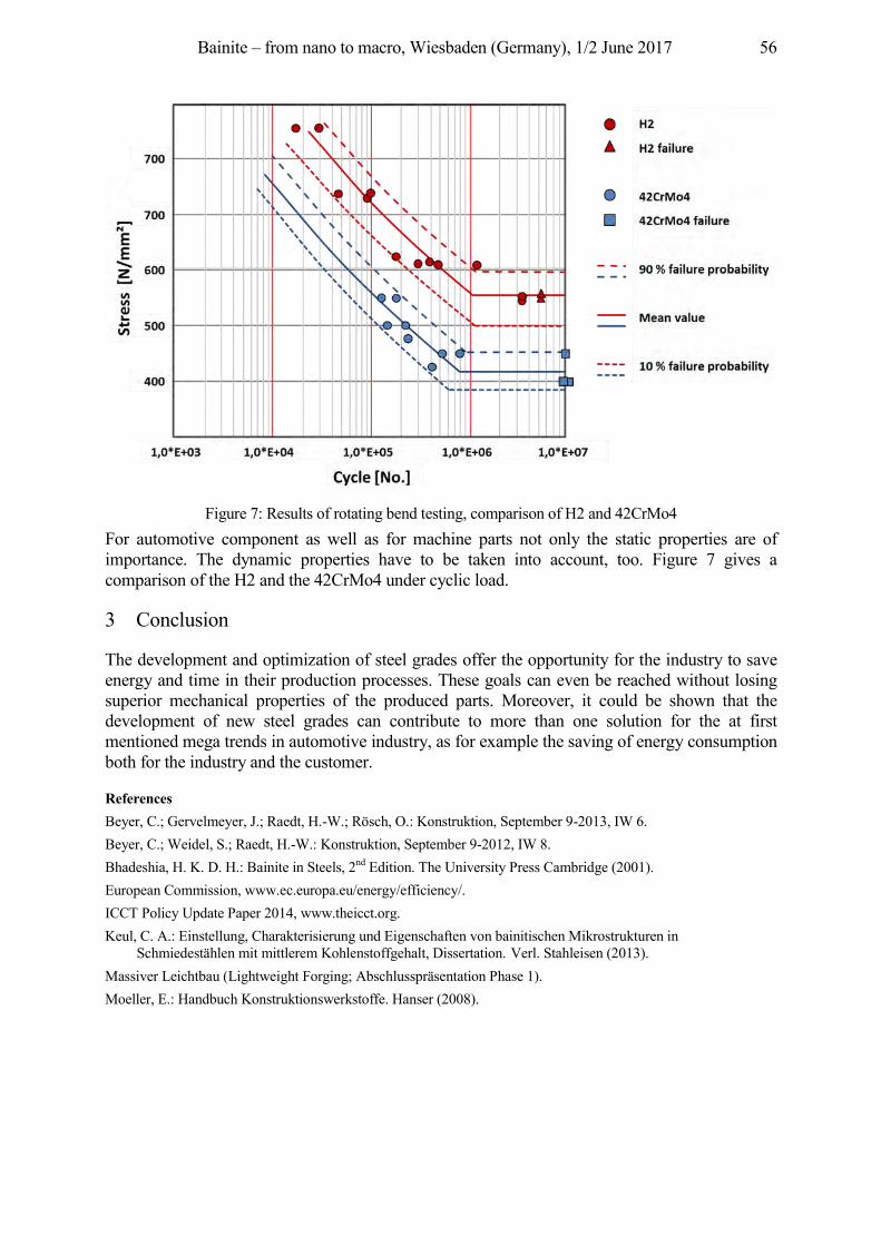
Bainite – from nano to macro, Wiesbaden (Germany), 1/2 June 2017 56
Figure 7: Results of rotating bend testing, comparison of H2 and 42CrMo4
For automotive component as well as for machine parts not only the static properties are of importance. The dynamic properties have to be taken into account, too. Figure 7 gives a comparison of the H2 and the 42CrMo4 under cyclic load.
3 Conclusion
The development and optimization of steel grades offer the opportunity for the industry to save energy and time in their production processes. These goals can even be reached without losing superior mechanical properties of the produced parts. Moreover, it could be shown that the development of new steel grades can contribute to more than one solution for the at first mentioned mega trends in automotive industry, as for example the saving of energy consumption both for the industry and the customer.
References Beyer, C.; Gervelmeyer, J.; Raedt, H.-W.; Rösch, O.: Konstruktion, September 9-2013, IW 6. Beyer, C.; Weidel, S.; Raedt, H.-W.: Konstruktion, September 9-2012, IW 8. Bhadeshia, H. K. D. H.: Bainite in Steels, 2nd Edition. The University Press Cambridge (2001). European Commission, www.ec.europa.eu/energy/efficiency/. ICCT Policy Update Paper 2014, www.theicct.org. Keul, C. A.: Einstellung, Charakterisierung und Eigenschaften von bainitischen Mikrostrukturen in
Schmiedestählen mit mittlerem Kohlenstoffgehalt, Dissertation. Verl. Stahleisen (2013). Massiver Leichtbau (Lightweight Forging; Abschlusspräsentation Phase 1). Moeller, E.: Handbuch Konstruktionswerkstoffe. Hanser (2008).
Bainite – from nano to macro, Wiesbaden (Germany), 1/2 June 2017 57
Low Distortion Bainitic Steel for Automotive Applications
Till Schneiders1, Frank van Soest2, Drago Duh2, Hans-Günter Krull2 1Deutsche Edelstahlwerke, Auestraße 4, 58452 Witten, Germany, [email protected]
2Deutsche Edelstahlwerke, Oberschlesienstr. 16, 47807 Krefeld, Germany, {frank.vansoest, drago.duh, hans-guenter.krull}@dew-stahl.com
Abstract The increasing demand for light weight construction in the automotive industry is leading to high strength steel solutions. Components with varying dimensions and inhomogeneous microstructure show large amounts of distortion. This is taken into account by designing the rough formed component with oversized material which has to be removed by costly machining operations after the final heat treatment. The process chain should not be sensitive to small changes in the chemical analysis or variances in the thermal treatment from heating to the final cooling. It is shown in this paper that a small addition of molybdenum is able to solve a lot of problems in such a process chain at the price of higher alloying cost. The range of possible sizes with complete bainitic structure could be extended up to a diameter of 120 mm. The machinability is improved by an additional precipitation hardening step to reach the final mechanical properties. The high heat resistance is given up to a temperature above 600 °C.
Keywords Distortion, Molybdenum, Precipitation hardening, CCT-Diagram, Fatigue
1 Development objectives
The rising ecological requirements of reduced fuel consumption lead to a demand for high strength steels for light weight construction beside a better design of the components, q. v. [Raedt, Wilke, Ernst 2015]. Steels with a bainitic microstructure after hot forming and continuous cooling have the potential to play a bigger role in the future. The main advantages of bainitic steels are the short process chain without complicated heat treatment and the high tensile strength. The drawbacks of this type of grades are the narrow range of cooling rates, the limited size of component dimensions and the challenge to machine parts with high tensile strength. The aim of this new developed grade Bainidur 1300 is to extend the process windows especially for the cooling after forging, to make the process as robust as possible and to avoid the machining at high hardness after the final heat treatment.
2 Empirical rules for the development of bainitic steels
For the practical use of the material some minimum mechanical properties must be reached and the costs of alloying elements have to be taken into account. For homogeneous mechanical properties showing a small spread of hardness values there is a need of a homogeneous structure like bainite without a large amount of other phases like martensite or ferrite. Targeting at a robust process to produce steel showing an almost complete bainitic structure the range of cooling rates in the continuous cooling transformation (CCT) diagram without crossing the areas of martensite or ferrite/perlite formation should be as large as possible. For the design of bainitic steels some rules of thumb should be considered (values given in mass-%):
• 0.10 % < carbon < 0.35 %: Lower carbon content promotes the formation of bainite but decreases strength.
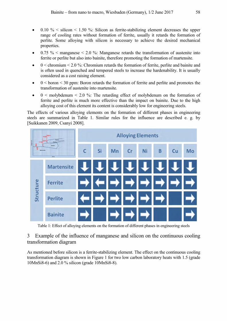
Bainite – from nano to macro, Wiesbaden (Germany), 1/2 June 2017 58
• 0.10 % < silicon < 1.50 %: Silicon as ferrite-stabilizing element decreases the upper range of cooling rates without formation of ferrite, usually it retards the formation of perlite. Some alloying with silicon is necessary to achieve the desired mechanical properties.
• 0.75 % < manganese < 2.0 %: Manganese retards the transformation of austenite into ferrite or perlite but also into bainite, therefore promoting the formation of martensite.
• 0 < chromium < 2.0 %: Chromium retards the formation of ferrite, perlite and bainite and is often used in quenched and tempered steels to increase the hardenability. It is usually considered as a cost raising element.
• 0 < boron < 30 ppm: Boron retards the formation of ferrite and perlite and promotes the transformation of austenite into martensite.
• 0 < molybdenum < 2.0 %: The retarding effect of molybdenum on the formation of ferrite and perlite is much more effective than the impact on bainite. Due to the high alloying cost of this element its content is considerably low for engineering steels.
The effects of various alloying elements on the formation of different phases in engineering steels are summarized in Table 1. Similar rules for the influence are described e. g. by [Suikkanen 2009, Csanyi 2008].
Table 1: Effect of alloying elements on the formation of different phases in engineering steels
3 Example of the influence of manganese and silicon on the continuous cooling transformation diagram
As mentioned before silicon is a ferrite-stabilizing element. The effect on the continuous cooling transformation diagram is shown in Figure 1 for two low carbon laboratory heats with 1.5 (grade 10MnSi8-6) and 2.0 % silicon (grade 10MnSi8-8).
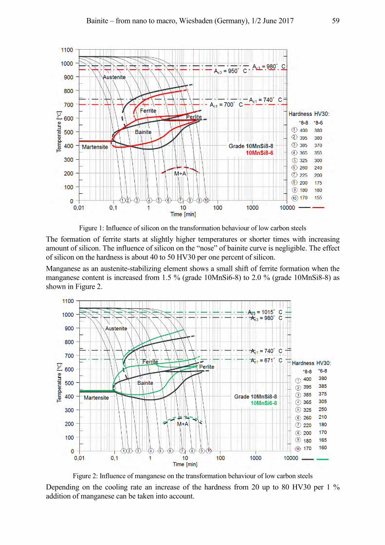
Bainite – from nano to macro, Wiesbaden (Germany), 1/2 June 2017 59
Figure 1: Influence of silicon on the transformation behaviour of low carbon steels
The formation of ferrite starts at slightly higher temperatures or shorter times with increasing amount of silicon. The influence of silicon on the “nose” of bainite curve is negligible. The effect of silicon on the hardness is about 40 to 50 HV30 per one percent of silicon. Manganese as an austenite-stabilizing element shows a small shift of ferrite formation when the manganese content is increased from 1.5 % (grade 10MnSi6-8) to 2.0 % (grade 10MnSi8-8) as shown in Figure 2.
Figure 2: Influence of manganese on the transformation behaviour of low carbon steels
Depending on the cooling rate an increase of the hardness from 20 up to 80 HV30 per 1 % addition of manganese can be taken into account.
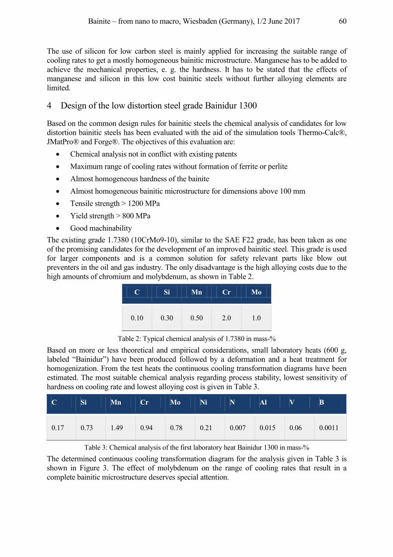
Bainite – from nano to macro, Wiesbaden (Germany), 1/2 June 2017 60
The use of silicon for low carbon steel is mainly applied for increasing the suitable range of cooling rates to get a mostly homogeneous bainitic microstructure. Manganese has to be added to achieve the mechanical properties, e. g. the hardness. It has to be stated that the effects of manganese and silicon in this low cost bainitic steels without further alloying elements are limited.
4 Design of the low distortion steel grade Bainidur 1300
Based on the common design rules for bainitic steels the chemical analysis of candidates for low distortion bainitic steels has been evaluated with the aid of the simulation tools Thermo-Calc®, JMatPro® and Forge®. The objectives of this evaluation are:
• Chemical analysis not in conflict with existing patents • Maximum range of cooling rates without formation of ferrite or perlite • Almost homogeneous hardness of the bainite • Almost homogeneous bainitic microstructure for dimensions above 100 mm • Tensile strength > 1200 MPa • Yield strength > 800 MPa • Good machinability
The existing grade 1.7380 (10CrMo9-10), similar to the SAE F22 grade, has been taken as one of the promising candidates for the development of an improved bainitic steel. This grade is used for larger components and is a common solution for safety relevant parts like blow out preventers in the oil and gas industry. The only disadvantage is the high alloying costs due to the high amounts of chromium and molybdenum, as shown in Table 2.
C Si Mn Cr Mo
0.10 0.30 0.50 2.0 1.0
Table 2: Typical chemical analysis of 1.7380 in mass-% Based on more or less theoretical and empirical considerations, small laboratory heats (600 g, labeled “Bainidur”) have been produced followed by a deformation and a heat treatment for homogenization. From the test heats the continuous cooling transformation diagrams have been estimated. The most suitable chemical analysis regarding process stability, lowest sensitivity of hardness on cooling rate and lowest alloying cost is given in Table 3.
C Si Mn Cr Mo Ni N Al V B
0.17 0.73 1.49 0.94 0.78 0.21 0.007 0.015 0.06 0.0011
Table 3: Chemical analysis of the first laboratory heat Bainidur 1300 in mass-% The determined continuous cooling transformation diagram for the analysis given in Table 3 is shown in Figure 3. The effect of molybdenum on the range of cooling rates that result in a complete bainitic microstructure deserves special attention.
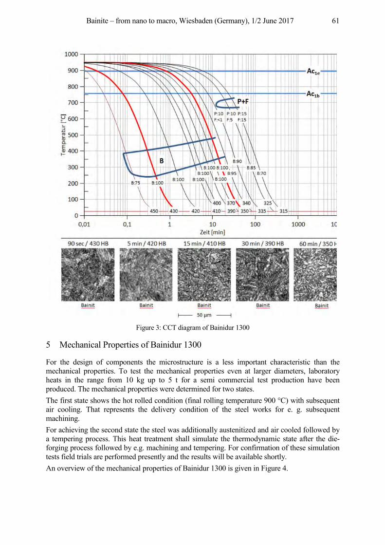
Bainite – from nano to macro, Wiesbaden (Germany), 1/2 June 2017 61
Figure 3: CCT diagram of Bainidur 1300
5 Mechanical Properties of Bainidur 1300
For the design of components the microstructure is a less important characteristic than the mechanical properties. To test the mechanical properties even at larger diameters, laboratory heats in the range from 10 kg up to 5 t for a semi commercial test production have been produced. The mechanical properties were determined for two states. The first state shows the hot rolled condition (final rolling temperature 900 °C) with subsequent air cooling. That represents the delivery condition of the steel works for e. g. subsequent machining. For achieving the second state the steel was additionally austenitized and air cooled followed by a tempering process. This heat treatment shall simulate the thermodynamic state after the die-forging process followed by e.g. machining and tempering. For confirmation of these simulation tests field trials are performed presently and the results will be available shortly. An overview of the mechanical properties of Bainidur 1300 is given in Figure 4.
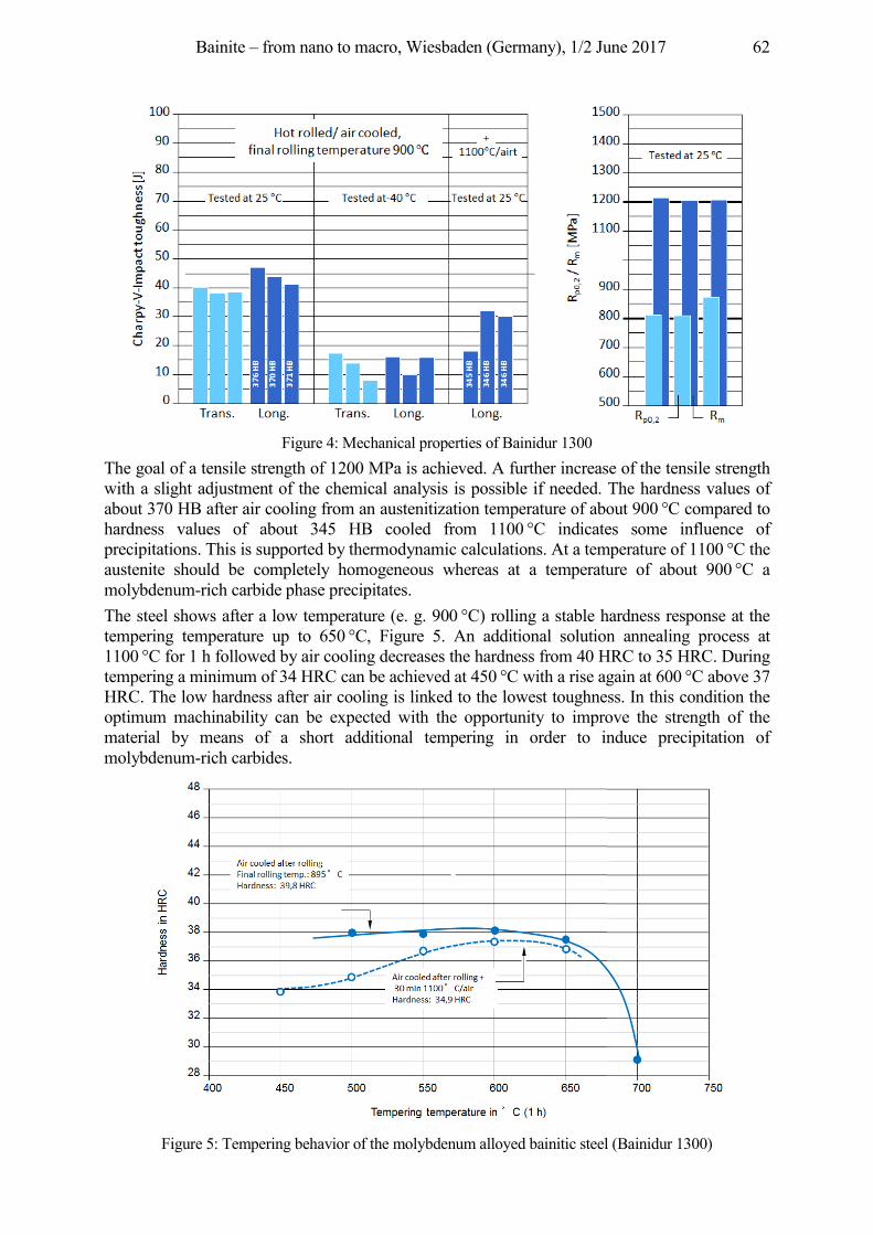
Bainite – from nano to macro, Wiesbaden (Germany), 1/2 June 2017 62
Figure 4: Mechanical properties of Bainidur 1300
The goal of a tensile strength of 1200 MPa is achieved. A further increase of the tensile strength with a slight adjustment of the chemical analysis is possible if needed. The hardness values of about 370 HB after air cooling from an austenitization temperature of about 900 °C compared to hardness values of about 345 HB cooled from 1100 °C indicates some influence of precipitations. This is supported by thermodynamic calculations. At a temperature of 1100 °C the austenite should be completely homogeneous whereas at a temperature of about 900 °C a molybdenum-rich carbide phase precipitates. The steel shows after a low temperature (e. g. 900 °C) rolling a stable hardness response at the tempering temperature up to 650 °C, Figure 5. An additional solution annealing process at 1100 °C for 1 h followed by air cooling decreases the hardness from 40 HRC to 35 HRC. During tempering a minimum of 34 HRC can be achieved at 450 °C with a rise again at 600 °C above 37 HRC. The low hardness after air cooling is linked to the lowest toughness. In this condition the optimum machinability can be expected with the opportunity to improve the strength of the material by means of a short additional tempering in order to induce precipitation of molybdenum-rich carbides.
Figure 5: Tempering behavior of the molybdenum alloyed bainitic steel (Bainidur 1300)
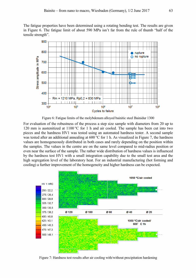
Bainite – from nano to macro, Wiesbaden (Germany), 1/2 June 2017 63
The fatigue properties have been determined using a rotating bending test. The results are given in Figure 6. The fatigue limit of about 590 MPa isn’t far from the rule of thumb “half of the tensile strength”.
Figure 6: Fatigue limits of the molybdenum alloyed bainitic steel Bainidur 1300
For evaluation of the robustness of the process a step size sample with diameters from 20 up to 120 mm is austenitized at 1100 °C for 1 h and air cooled. The sample has been cut into two pieces and the hardness HV1 was tested using an automated hardness tester. A second sample was tested after an additional annealing at 600 °C for 1 h. As visualized in Figure 7, the hardness values are homogeneously distributed in both cases and rarely depending on the position within the samples. The values in the centre are on the same level compared to mid-radius position or even near the surface of the sample. The rather wide distribution of hardness values is influenced by the hardness test HV1 with a small integration capability due to the small test area and the high segregation level of the laboratory heat. For an industrial manufacturing (hot forming and cooling) a further improvement of the homogeneity and higher hardness can be expected.
Figure 7: Hardness test results after air cooling with/without precipitation hardening
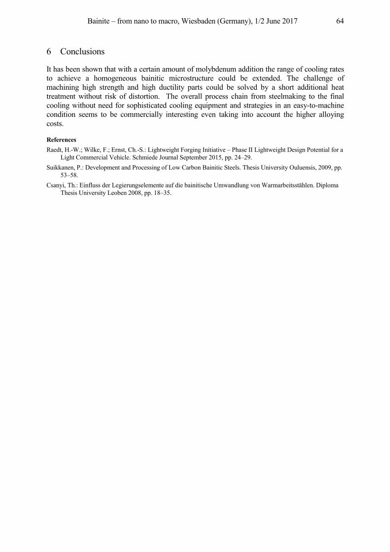
Bainite – from nano to macro, Wiesbaden (Germany), 1/2 June 2017 64
6 Conclusions
It has been shown that with a certain amount of molybdenum addition the range of cooling rates to achieve a homogeneous bainitic microstructure could be extended. The challenge of machining high strength and high ductility parts could be solved by a short additional heat treatment without risk of distortion. The overall process chain from steelmaking to the final cooling without need for sophisticated cooling equipment and strategies in an easy-to-machine condition seems to be commercially interesting even taking into account the higher alloying costs.
References Raedt, H.-W.; Wilke, F.; Ernst, Ch.-S.: Lightweight Forging Initiative – Phase II Lightweight Design Potential for a
Light Commercial Vehicle. Schmiede Journal September 2015, pp. 24–29. Suikkanen, P.: Development and Processing of Low Carbon Bainitic Steels. Thesis University Ouluensis, 2009, pp.
53–58. Csanyi, Th.: Einfluss der Legierungselemente auf die bainitische Umwandlung von Warmarbeitsstählen. Diploma
Thesis University Leoben 2008, pp. 18–35.

Bainite – from nano to macro, Wiesbaden (Germany), 1/2 June 2017 65
3. Heat treatment processes and properties of bainitic components
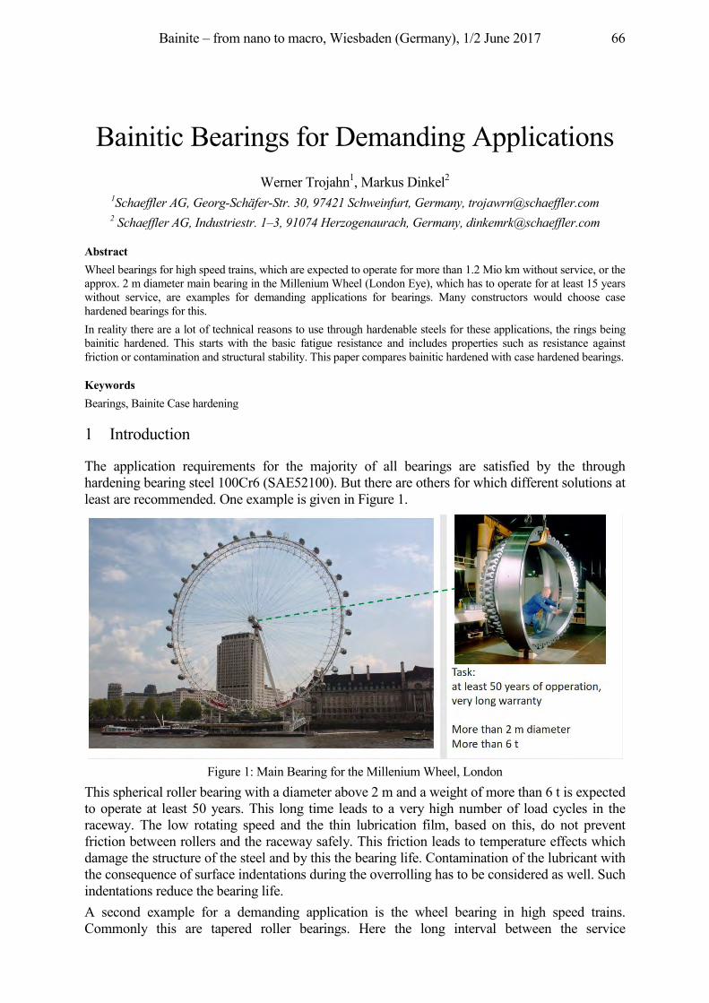
Bainite – from nano to macro, Wiesbaden (Germany), 1/2 June 2017 66
Bainitic Bearings for Demanding Applications Werner Trojahn1, Markus Dinkel2
1Schaeffler AG, Georg-Schäfer-Str. 30, 97421 Schweinfurt, Germany, [email protected] 2 Schaeffler AG, Industriestr. 1–3, 91074 Herzogenaurach, Germany, [email protected]
Abstract Wheel bearings for high speed trains, which are expected to operate for more than 1.2 Mio km without service, or the approx. 2 m diameter main bearing in the Millenium Wheel (London Eye), which has to operate for at least 15 years without service, are examples for demanding applications for bearings. Many constructors would choose case hardened bearings for this. In reality there are a lot of technical reasons to use through hardenable steels for these applications, the rings being bainitic hardened. This starts with the basic fatigue resistance and includes properties such as resistance against friction or contamination and structural stability. This paper compares bainitic hardened with case hardened bearings.
Keywords Bearings, Bainite Case hardening
1 Introduction
The application requirements for the majority of all bearings are satisfied by the through hardening bearing steel 100Cr6 (SAE52100). But there are others for which different solutions at least are recommended. One example is given in Figure 1.
Figure 1: Main Bearing for the Millenium Wheel, London
This spherical roller bearing with a diameter above 2 m and a weight of more than 6 t is expected to operate at least 50 years. This long time leads to a very high number of load cycles in the raceway. The low rotating speed and the thin lubrication film, based on this, do not prevent friction between rollers and the raceway safely. This friction leads to temperature effects which damage the structure of the steel and by this the bearing life. Contamination of the lubricant with the consequence of surface indentations during the overrolling has to be considered as well. Such indentations reduce the bearing life. A second example for a demanding application is the wheel bearing in high speed trains. Commonly this are tapered roller bearings. Here the long interval between the service
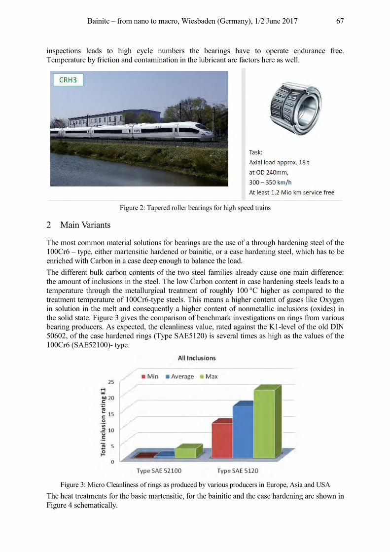
Bainite – from nano to macro, Wiesbaden (Germany), 1/2 June 2017 67
inspections leads to high cycle numbers the bearings have to operate endurance free. Temperature by friction and contamination in the lubricant are factors here as well.
Figure 2: Tapered roller bearings for high speed trains
2 Main Variants
The most common material solutions for bearings are the use of a through hardening steel of the 100Cr6 – type, either martensitic hardened or bainitic, or a case hardening steel, which has to be enriched with Carbon in a case deep enough to balance the load. The different bulk carbon contents of the two steel families already cause one main difference: the amount of inclusions in the steel. The low Carbon content in case hardening steels leads to a temperature through the metallurgical treatment of roughly 100 °C higher as compared to the treatment temperature of 100Cr6-type steels. This means a higher content of gases like Oxygen in solution in the melt and consequently a higher content of nonmetallic inclusions (oxides) in the solid state. Figure 3 gives the comparison of benchmark investigations on rings from various bearing producers. As expected, the cleanliness value, rated against the K1-level of the old DIN 50602, of the case hardened rings (Type SAE5120) is several times as high as the values of the 100Cr6 (SAE52100)- type.
Figure 3: Micro Cleanliness of rings as produced by various producers in Europe, Asia and USA
The heat treatments for the basic martensitic, for the bainitic and the case hardening are shown in Figure 4 schematically.
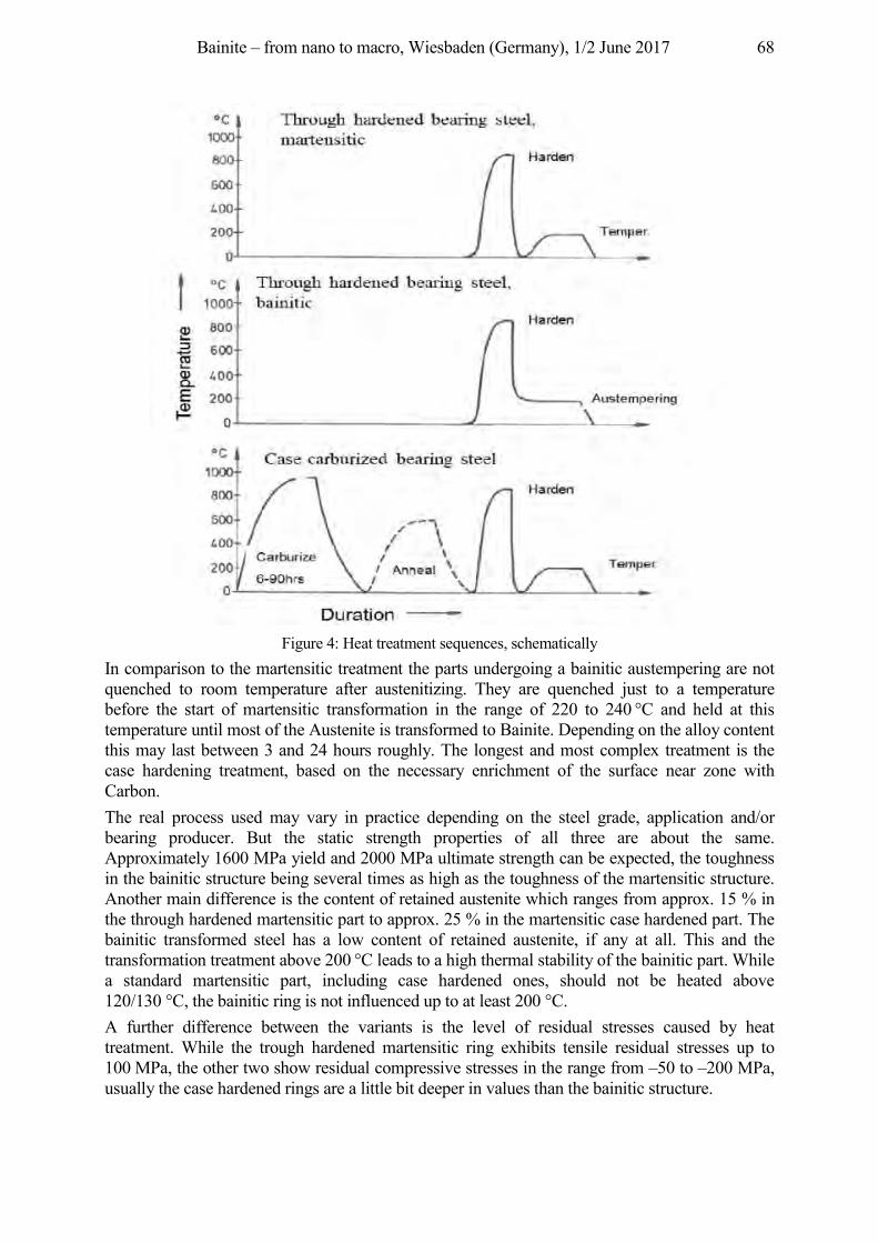
Bainite – from nano to macro, Wiesbaden (Germany), 1/2 June 2017 68
Figure 4: Heat treatment sequences, schematically
In comparison to the martensitic treatment the parts undergoing a bainitic austempering are not quenched to room temperature after austenitizing. They are quenched just to a temperature before the start of martensitic transformation in the range of 220 to 240 °C and held at this temperature until most of the Austenite is transformed to Bainite. Depending on the alloy content this may last between 3 and 24 hours roughly. The longest and most complex treatment is the case hardening treatment, based on the necessary enrichment of the surface near zone with Carbon. The real process used may vary in practice depending on the steel grade, application and/or bearing producer. But the static strength properties of all three are about the same. Approximately 1600 MPa yield and 2000 MPa ultimate strength can be expected, the toughness in the bainitic structure being several times as high as the toughness of the martensitic structure. Another main difference is the content of retained austenite which ranges from approx. 15 % in the through hardened martensitic part to approx. 25 % in the martensitic case hardened part. The bainitic transformed steel has a low content of retained austenite, if any at all. This and the transformation treatment above 200 °C leads to a high thermal stability of the bainitic part. While a standard martensitic part, including case hardened ones, should not be heated above 120/130 °C, the bainitic ring is not influenced up to at least 200 °C. A further difference between the variants is the level of residual stresses caused by heat treatment. While the trough hardened martensitic ring exhibits tensile residual stresses up to 100 MPa, the other two show residual compressive stresses in the range from –50 to –200 MPa, usually the case hardened rings are a little bit deeper in values than the bainitic structure.
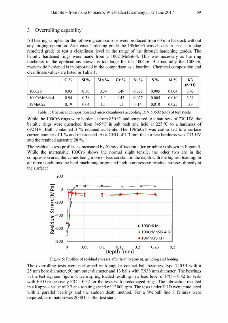
Bainite – from nano to macro, Wiesbaden (Germany), 1/2 June 2017 69
3 Overrolling capability
All bearing samples for the following comparisons were produced from 60 mm barstock without any forging operation. As a case hardening grade the 19MnCr5 was chosen in an electro-slag remelted grade to test a cleanliness level in the range of the through hardening grades. The bainitic hardened rings were made from a 100CrMnSi6-4. This was necessary as the ring thickness in the applications shown is too large for the 100Cr6. But naturally the 100Cr6, martensitic hardened is incorporated in the comparison as a baseline. Chemical composition and cleanliness values are listed in Table 1.
C % Si % Mn % Cr % Ni % S % Al % K3 (S+O)
100Cr6 0.93 0.30 0.34 1.49 0.025 0.005 0.004 3.43 100CrMnSi6-4 0.94 0.58 1.1 1.43 0.027 0.005 0.010 3.31 19MnCr5 0.19 0.04 1.1 1.1 0.14 0.010 0.025 0.3
Table 1: Chemical composition and microcleanliness according DIN 50602 (old) of test steels While the 100Cr6 rings were hardened from 850 °C and tempered to a hardness of 730 HV, the bainitic rings were quenched from 845 °C in salt bath and held at 225 °C to a hardness of 692 HV. Both contained 3 % retained austenite. The 19MnCr5 was carburized to a surface carbon content of 1 % and rehardened. At a CHD of 1.3 mm the surface hardness was 733 HV and the retained austenite 28 %. The residual stress profiles as measured by X-ray diffraction after grinding is shown in Figure 5. While the martensitic 100Cr6 shows the normal slight tensile, the other two are in the compression area, the values being more or less constant in the depth with the highest loading. In all three conditions the hard machining originated high compressive residual stresses directly at the surface:
Figure 5: Profiles of residual stresses after heat treatment, grinding and honing
The overrolling tests were performed with angular contact ball bearings, type 7205B with a 25 mm bore diameter, 50 mm outer diameter and 13 balls with 7.938 mm diameter. The bearings in the test rig, see Figure 6, were spring loaded resulting in a load level of P/C = 0.42 for tests with EHD respectively P/C = 0.32 for the tests with predamaged rings. The lubrication resulted in a Kappa – value of 2.7 at a rotating speed of 12 000 rpm. The tests under EHD were conducted with 2 parallel bearings and the sudden death method. For a Weibull line 7 failures were required, termination was 2000 hrs after test start.
-800
-600
-400
-200
0
200
0 0,05 0,1 0,15 0,2 0,25 0,3
Resid
ual S
tres
s [M
Pa]
Depth [mm]
100Cr6 M100CrMnSi6-4 B19MnCr5 CH
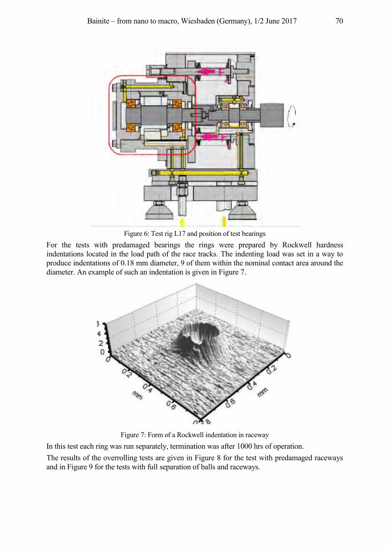
Bainite – from nano to macro, Wiesbaden (Germany), 1/2 June 2017 70
Figure 6: Test rig L17 and position of test bearings
For the tests with predamaged bearings the rings were prepared by Rockwell hardness indentations located in the load path of the race tracks. The indenting load was set in a way to produce indentations of 0.18 mm diameter, 9 of them within the nominal contact area around the diameter. An example of such an indentation is given in Figure 7.
Figure 7: Form of a Rockwell indentation in raceway
In this test each ring was run separately, termination was after 1000 hrs of operation. The results of the overrolling tests are given in Figure 8 for the test with predamaged raceways and in Figure 9 for the tests with full separation of balls and raceways.
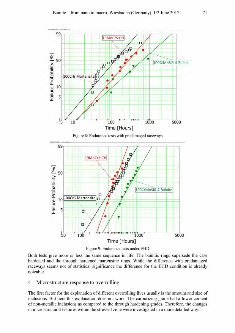
Bainite – from nano to macro, Wiesbaden (Germany), 1/2 June 2017 71
Figure 8: Endurance tests with predamaged raceways
Figure 9: Endurance tests under EHD
Both tests give more or less the same sequence in life. The bainitic rings supersede the case hardened and the through hardened martensitic rings. While the difference with predamaged raceways seems not of statistical significance the difference for the EHD condition is already noteable.
4 Microstructure response to overrolling
The first factor for the explanation of different overrolling lives usually is the amount and size of inclusions. But here this explanation does not work. The carburizing grade had a lower content of non-metallic inclusions as compared to the through hardening grades. Therefore, the changes in microstructural features within the stressed zone were investigated in a more detailed way.
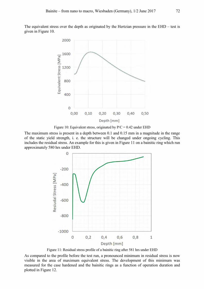
Bainite – from nano to macro, Wiesbaden (Germany), 1/2 June 2017 72
The equivalent stress over the depth as originated by the Hertzian pressure in the EHD – test is given in Figure 10.
Figure 10: Equivalent stress, originated by P/C = 0.42 under EHD
The maximum stress is present in a depth between 0.1 and 0.15 mm in a magnitude in the range of the static yield strength, i. e. the structure will be changed under ongoing cycling. This includes the residual stress. An example for this is given in Figure 11 on a bainitic ring which run approximately 580 hrs under EHD.
Figure 11: Residual stress profile of a bainitic ring after 581 hrs under EHD
As compared to the profile before the test run, a pronounced minimum in residual stress is now visible in the area of maximum equivalent stress. The development of this minimum was measured for the case hardened and the bainitic rings as a function of operation duration and plotted in Figure 12.
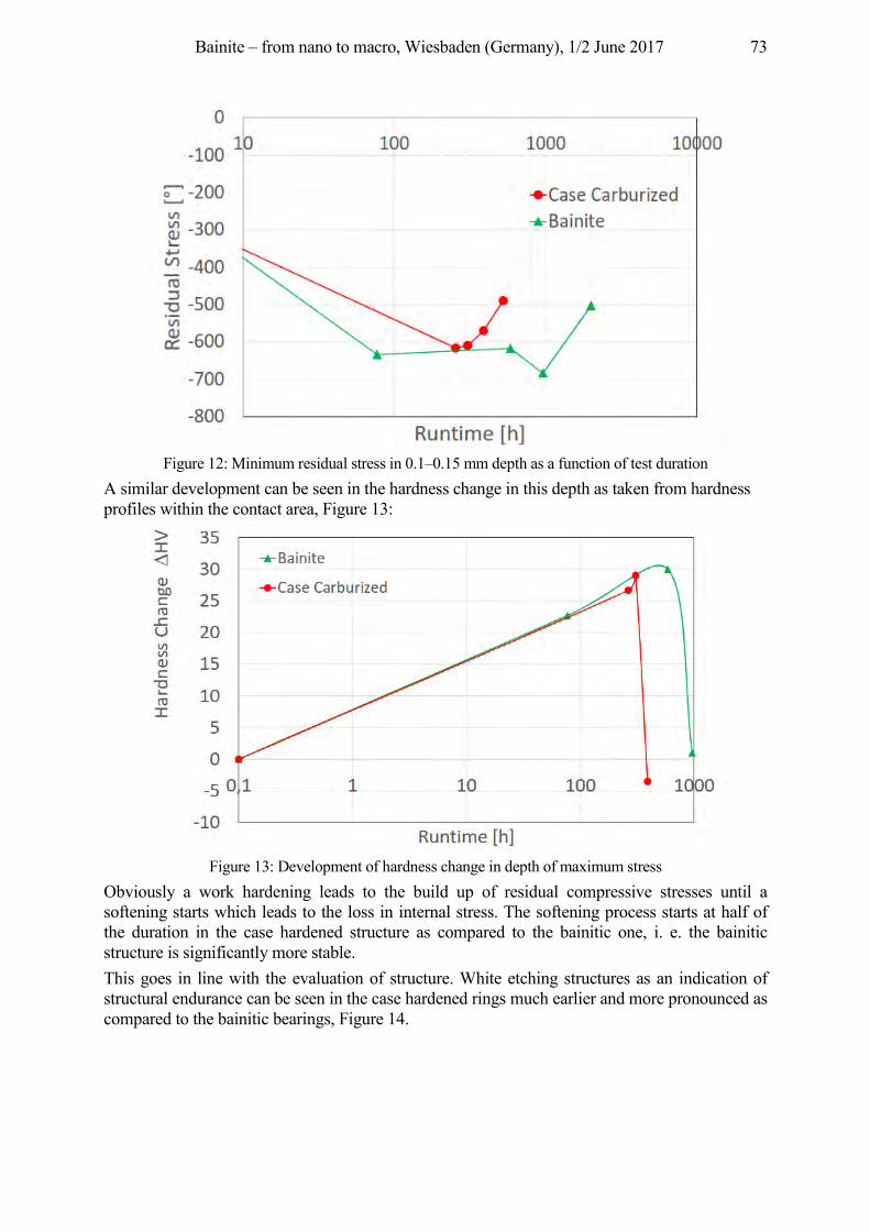
Bainite – from nano to macro, Wiesbaden (Germany), 1/2 June 2017 73
Figure 12: Minimum residual stress in 0.1–0.15 mm depth as a function of test duration
A similar development can be seen in the hardness change in this depth as taken from hardness profiles within the contact area, Figure 13:
Figure 13: Development of hardness change in depth of maximum stress
Obviously a work hardening leads to the build up of residual compressive stresses until a softening starts which leads to the loss in internal stress. The softening process starts at half of the duration in the case hardened structure as compared to the bainitic one, i. e. the bainitic structure is significantly more stable. This goes in line with the evaluation of structure. White etching structures as an indication of structural endurance can be seen in the case hardened rings much earlier and more pronounced as compared to the bainitic bearings, Figure 14.
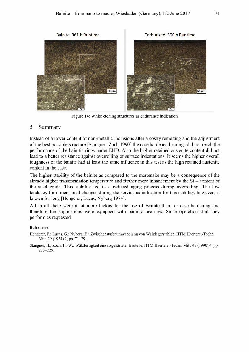
Bainite – from nano to macro, Wiesbaden (Germany), 1/2 June 2017 74
Figure 14: White etching structures as endurance indication
5 Summary
Instead of a lower content of non-metallic inclusions after a costly remelting and the adjustment of the best possible structure [Stangner, Zoch 1990] the case hardened bearings did not reach the performance of the bainitic rings under EHD. Also the higher retained austenite content did not lead to a better resistance against overrolling of surface indentations. It seems the higher overall toughness of the bainite had at least the same influence in this test as the high retained austenite content in the case. The higher stability of the bainite as compared to the martensite may be a consequence of the already higher transformation temperature and further more inhancement by the Si – content of the steel grade. This stability led to a reduced aging process during overrolling. The low tendency for dimensional changes during the service as indication for this stability, however, is known for long [Hengerer, Lucas, Nyberg 1974]. All in all there were a lot more factors for the use of Bainite than for case hardening and therefore the applications were equipped with bainitic bearings. Since operation start they perform as requested.
References Hengerer, F.; Lucas, G.; Nyberg, B.: Zwischenstufenumwandlung von Wälzlagerstählen. HTM Haerterei-Techn.
Mitt. 29 (1974) 2, pp. 71–79. Stangner, H.; Zoch, H.-W.: Wälzfestigkeit einsatzgehärteter Bauteile, HTM Haerterei-Techn. Mitt. 45 (1990) 4, pp.
223–229.
Bainite – from nano to macro, Wiesbaden (Germany), 1/2 June 2017 75
Development of a two-step bainitizing procedure to enhance fatigue strength
economically Brigitte Clausen1, Juan Dong1, Klaus Burkart1, Hans-Werner Zoch1,2
1Stiftung Institut für Werkstofftechnik, Badgasteiner Str. 3, 28359 Bremen, Germany {clausen, dong, burkart, zoch}@iwt-bremen.de
2MAPEX Center for Materials and Processes, University of Bremen, Germany, [email protected]
Abstract Quenching in order to obtain martensite is the mostly applied process for standard rolling bearing elements. Isothermal treatment in the lower bainitic range is used as an alternative method to generate favourable compressive residual stresses in the surface region of components, e. g. in spherical roller bearings. The duration of the bainitic treatment, however, is much longer than that of a martensitic treatment, because more or less a complete transformation of austenite to bainite is usually requested. This causes higher energy consumption and longer production time. Therefore it is desirable to perform a bainitic treatment with shortened process duration. In the present work possible procedures for shortening the bainitic treatment of the bearing steel AISI 52100 were primarily investigated by dilatometric experiments. Some selected processes were carried out in salt bath. The resulting bainitic microstructures were observed by light optical microscope (LOM), transmission electron microscope (TEM) and field emission scanning electron microscope (FESEM) and compared with martensitic ones. The cyclic fatigue strengths of the steel after different shortened bainitic treatments were examined in a first step using rotating bending fatigue (RBF) tests. The most promising processes were applied on German bearing steels 100Cr6 (AISI 52100) and 100CrMn6-4 (AISI 52100 with 1.1 % Mn) and compared in rolling contact fatigue (RCF)-tests with martensitic references. Since the focus in this particular investigation was on the resistance of raceways against debris denting, the inner rings were artificially pre-damaged. The results show that the fatigue resistance, while ensuring the requested minimum hardness of 58 HRC, were comparable respectively enhanced through the shortened treatments, particularly by means of a two-step bainitic treatment. The process duration was shortened about 75 % compared to the conventional time.
Keywords lower bainite, dilatometry, fatigue strength, bainitic microstructure, AISI 52100, bearing steel, RBF, RCF
1 Introduction
High fatigue strength and dimensional stability are the most important requirements of precision machine components. In the case of rolling element bearings made from the steel AISI 52100, martensitic hardening followed by tempering at low temperature is often applied as the final heat treatment method. Yet the kinetic of microstructural transformation generates unfavorable tensile residual stresses at the surface of martensitic through-hardened rolling bearings. Retained austenite furthermore can decompose during application and cause dimensional change [Slycke, Fajers, Volkmuth 2002]. The well-known isothermal treatment in the lower bainitic range allows us to obtain suitable mechanical properties of machine components and favorable compressive residual stresses at the surface. Additionally the dimensional change of machine components during operation caused by the transformation of retained austenite can be greatly reduced [Hengerer, Lucas, Nyberg 1974]. A main disadvantage of the isothermal bainitic treatment in salt baths however is the long duration of the treatment, which exceeds that of martensitic hardening by hours. This will result in higher costs. Therefore it would be desirable to shorten the transformation duration in the lower bainitic range while maintaining the beneficial properties. It has already been reported that a short pre-
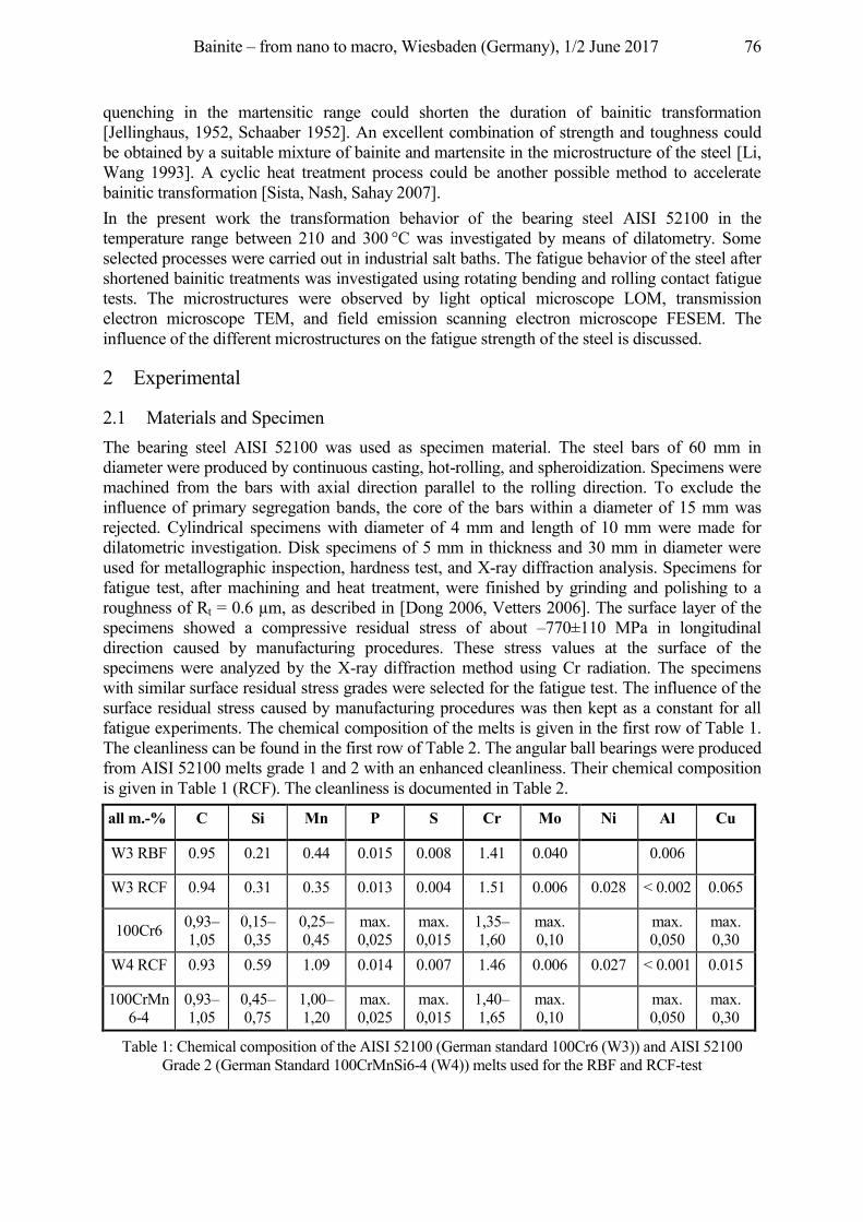
Bainite – from nano to macro, Wiesbaden (Germany), 1/2 June 2017 76
quenching in the martensitic range could shorten the duration of bainitic transformation [Jellinghaus, 1952, Schaaber 1952]. An excellent combination of strength and toughness could be obtained by a suitable mixture of bainite and martensite in the microstructure of the steel [Li, Wang 1993]. A cyclic heat treatment process could be another possible method to accelerate bainitic transformation [Sista, Nash, Sahay 2007]. In the present work the transformation behavior of the bearing steel AISI 52100 in the temperature range between 210 and 300 °C was investigated by means of dilatometry. Some selected processes were carried out in industrial salt baths. The fatigue behavior of the steel after shortened bainitic treatments was investigated using rotating bending and rolling contact fatigue tests. The microstructures were observed by light optical microscope LOM, transmission electron microscope TEM, and field emission scanning electron microscope FESEM. The influence of the different microstructures on the fatigue strength of the steel is discussed.
2 Experimental
2.1 Materials and Specimen The bearing steel AISI 52100 was used as specimen material. The steel bars of 60 mm in diameter were produced by continuous casting, hot-rolling, and spheroidization. Specimens were machined from the bars with axial direction parallel to the rolling direction. To exclude the influence of primary segregation bands, the core of the bars within a diameter of 15 mm was rejected. Cylindrical specimens with diameter of 4 mm and length of 10 mm were made for dilatometric investigation. Disk specimens of 5 mm in thickness and 30 mm in diameter were used for metallographic inspection, hardness test, and X-ray diffraction analysis. Specimens for fatigue test, after machining and heat treatment, were finished by grinding and polishing to a roughness of Rt = 0.6 µm, as described in [Dong 2006, Vetters 2006]. The surface layer of the specimens showed a compressive residual stress of about –770±110 MPa in longitudinal direction caused by manufacturing procedures. These stress values at the surface of the specimens were analyzed by the X-ray diffraction method using Cr radiation. The specimens with similar surface residual stress grades were selected for the fatigue test. The influence of the surface residual stress caused by manufacturing procedures was then kept as a constant for all fatigue experiments. The chemical composition of the melts is given in the first row of Table 1. The cleanliness can be found in the first row of Table 2. The angular ball bearings were produced from AISI 52100 melts grade 1 and 2 with an enhanced cleanliness. Their chemical composition is given in Table 1 (RCF). The cleanliness is documented in Table 2.
all m.-% C Si Mn P S Cr Mo Ni Al Cu
W3 RBF 0.95 0.21 0.44 0.015 0.008 1.41 0.040 0.006
W3 RCF 0.94 0.31 0.35 0.013 0.004 1.51 0.006 0.028 < 0.002 0.065
100Cr6 0,93–1,05
0,15–0,35
0,25–0,45
max. 0,025
max. 0,015
1,35–1,60
max. 0,10
max. 0,050
max. 0,30
W4 RCF 0.93 0.59 1.09 0.014 0.007 1.46 0.006 0.027 < 0.001 0.015
100CrMn6-4
0,93–1,05
0,45–0,75
1,00–1,20
max. 0,025
max. 0,015
1,40–1,65
max. 0,10
max. 0,050
max. 0,30
Table 1: Chemical composition of the AISI 52100 (German standard 100Cr6 (W3)) and AISI 52100 Grade 2 (German Standard 100CrMnSi6-4 (W4)) melts used for the RBF and RCF-test
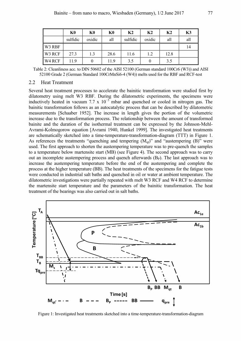
Bainite – from nano to macro, Wiesbaden (Germany), 1/2 June 2017 77
K0 K0 K0 K2 K2 K2 K3 sulfidic oxidic all sulfidic oxidic all all W3 RBF 14 W3 RCF 27.3 1.3 28.6 11.6 1.2 12.8 W4 RCF 11.9 0 11.9 3.5 0 3.5
Table 2: Cleanliness acc. to DIN 50602 of the AISI 52100 (German standard 100Cr6 (W3)) and AISI 52100 Grade 2 (German Standard 100CrMnSi6-4 (W4)) melts used for the RBF and RCF-test
2.2 Heat Treatment Several heat treatment processes to accelerate the bainitic transformation were studied first by dilatometry using melt W3 RBF. During the dilatometric experiments, the specimens were inductively heated in vacuum 7.7 x 10⁻³ mbar and quenched or cooled in nitrogen gas. The bainitic transformation follows as an autocatalytic process that can be described by dilatometric measurements [Schaaber 1952]. The increase in length gives the portion of the volumetric increase due to the transformation process. The relationship between the amount of transformed bainite and the duration of the isothermal treatment can be expressed by the Johnson-Mehl-Avrami-Kolmogorow equation [Avrami 1940, Hunkel 1999]. The investigated heat treatments are schematically sketched into a time-temperature-transformation-diagram (TTT) in Figure 1. As references the treatments “quenching and tempering (Mqt)” and “austempering (B)” were used. The first approach to shorten the austempering temperature was to pre-quench the samples to a temperature below martensite start (MB) (see Figure 4). The second approach was to carry out an incomplete austempering process and quench afterwards (BP). The last approach was to increase the austempering temperature before the end of the austempering and complete the process at the higher temperature (BB). The heat treatments of the specimens for the fatigue tests were conducted in industrial salt baths and quenched in oil or water at ambient temperature. The dilatometric investigations were partially repeated with melt W3 RCF and W4 RCF to determine the martensite start temperature and the parameters of the bainitic transformation. The heat treatment of the bearings was also carried out in salt baths.
Figure 1: Investigated heat treatments sketched into a time-temperature-transformation-diagram
Tem
pera
ture
[°C
]
Time [s]
B
P
Ms
TA
TBBTBTqpre
BP BB Mqt B
Mqt B BP BB qpre
Ac1e
Ac1b
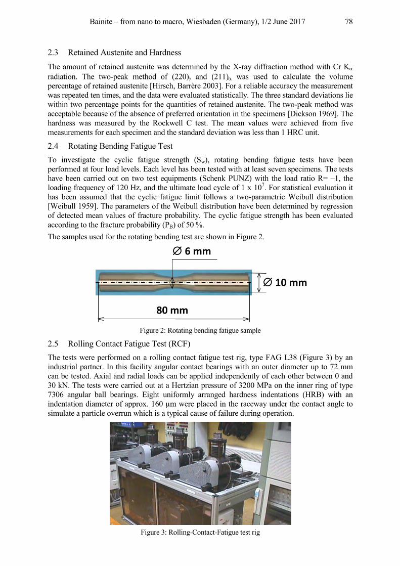
Bainite – from nano to macro, Wiesbaden (Germany), 1/2 June 2017 78
2.3 Retained Austenite and Hardness The amount of retained austenite was determined by the X-ray diffraction method with Cr KD radiation. The two-peak method of (220)J and (211)D was used to calculate the volume percentage of retained austenite [Hirsch, Barrère 2003]. For a reliable accuracy the measurement was repeated ten times, and the data were evaluated statistically. The three standard deviations lie within two percentage points for the quantities of retained austenite. The two-peak method was acceptable because of the absence of preferred orientation in the specimens [Dickson 1969]. The hardness was measured by the Rockwell C test. The mean values were achieved from five measurements for each specimen and the standard deviation was less than 1 HRC unit.
2.4 Rotating Bending Fatigue Test To investigate the cyclic fatigue strength (Sw), rotating bending fatigue tests have been performed at four load levels. Each level has been tested with at least seven specimens. The tests have been carried out on two test equipments (Schenk PUNZ) with the load ratio R= –1, the loading frequency of 120 Hz, and the ultimate load cycle of 1 x 10⁷. For statistical evaluation it has been assumed that the cyclic fatigue limit follows a two-parametric Weibull distribution [Weibull 1959]. The parameters of the Weibull distribution have been determined by regression of detected mean values of fracture probability. The cyclic fatigue strength has been evaluated according to the fracture probability (PB) of 50 %. The samples used for the rotating bending test are shown in Figure 2.
Figure 2: Rotating bending fatigue sample
2.5 Rolling Contact Fatigue Test (RCF) The tests were performed on a rolling contact fatigue test rig, type FAG L38 (Figure 3) by an industrial partner. In this facility angular contact bearings with an outer diameter up to 72 mm can be tested. Axial and radial loads can be applied independently of each other between 0 and 30 kN. The tests were carried out at a Hertzian pressure of 3200 MPa on the inner ring of type 7306 angular ball bearings. Eight uniformly arranged hardness indentations (HRB) with an indentation diameter of approx. 160 µm were placed in the raceway under the contact angle to simulate a particle overrun which is a typical cause of failure during operation.
Figure 3: Rolling-Contact-Fatigue test rig
� 6 mm
80 mm
� 10 mm
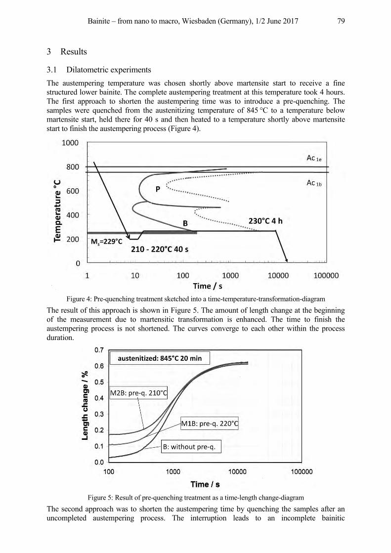
Bainite – from nano to macro, Wiesbaden (Germany), 1/2 June 2017 79
3 Results
3.1 Dilatometric experiments The austempering temperature was chosen shortly above martensite start to receive a fine structured lower bainite. The complete austempering treatment at this temperature took 4 hours. The first approach to shorten the austempering time was to introduce a pre-quenching. The samples were quenched from the austenitizing temperature of 845 °C to a temperature below martensite start, held there for 40 s and then heated to a temperature shortly above martensite start to finish the austempering process (Figure 4).
Figure 4: Pre-quenching treatment sketched into a time-temperature-transformation-diagram
The result of this approach is shown in Figure 5. The amount of length change at the beginning of the measurement due to martensitic transformation is enhanced. The time to finish the austempering process is not shortened. The curves converge to each other within the process duration.
Figure 5: Result of pre-quenching treatment as a time-length change-diagram
The second approach was to shorten the austempering time by quenching the samples after an uncompleted austempering process. The interruption leads to an incomplete bainitic
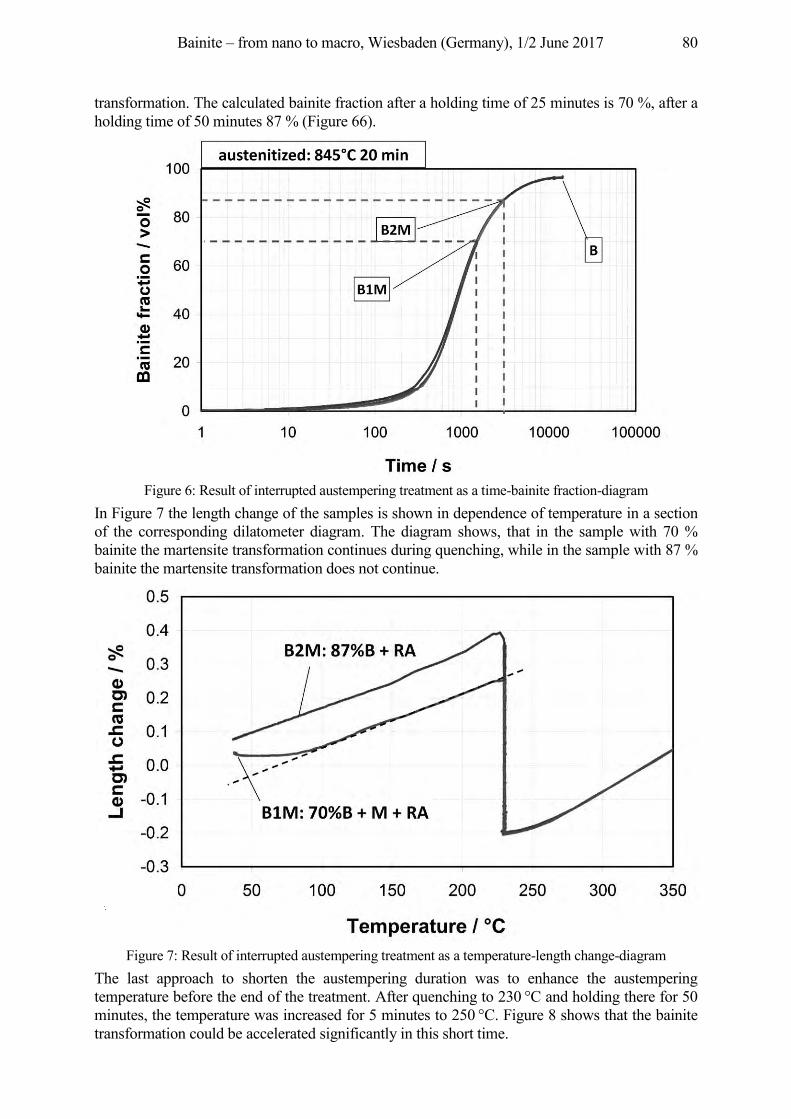
Bainite – from nano to macro, Wiesbaden (Germany), 1/2 June 2017 80
transformation. The calculated bainite fraction after a holding time of 25 minutes is 70 %, after a holding time of 50 minutes 87 % (Figure 66).
Figure 6: Result of interrupted austempering treatment as a time-bainite fraction-diagram
In Figure 7 the length change of the samples is shown in dependence of temperature in a section of the corresponding dilatometer diagram. The diagram shows, that in the sample with 70 % bainite the martensite transformation continues during quenching, while in the sample with 87 % bainite the martensite transformation does not continue.
Figure 7: Result of interrupted austempering treatment as a temperature-length change-diagram
The last approach to shorten the austempering duration was to enhance the austempering temperature before the end of the treatment. After quenching to 230 °C and holding there for 50 minutes, the temperature was increased for 5 minutes to 250 °C. Figure 8 shows that the bainite transformation could be accelerated significantly in this short time.
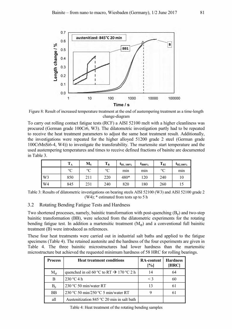
Bainite – from nano to macro, Wiesbaden (Germany), 1/2 June 2017 81
Figure 8: Result of increased temperature treatment at the end of austempering treatment as a time-length
change-diagram To carry out rolling contact fatigue tests (RCF) a AISI 52100 melt with a higher cleanliness was procured (German grade 100Cr6, W3). The dilatometric investigation partly had to be repeated to receive the heat treatment parameters to adjust the same heat treatment result. Additionally, the investigations were repeated for the higher alloyed 51200 grade 2 steel (German grade 100CrMnSi6-4, W4)) to investigate the transferability. The martensite start temperature and the used austempering temperatures and times to receive defined fractions of bainite are documented in Table 3.
TA MS TB tB1, 100% tB80% TB2 tB2,100% °C °C °C min min °C min W3 850 211 220 480* 120 240 10 W4 845 231 240 820 180 260 15
Table 3: Results of dilatometric investigations on bearing steels AISI 52100 (W3) and AISI 52100 grade 2 (W4); * estimated from tests up to 5 h
3.2 Rotating Bending Fatigue Tests and Hardness Two shortened processes, namely, bainitic transformation with post-quenching (Bp) and two-step bainitic transformation (BB), were selected from the dilatometric experiments for the rotating bending fatigue test. In addition a martensitic treatment (Mqt) and a conventional full bainitic treatment (B) were introduced as references. These four heat treatments were carried out in industrial salt baths and applied to the fatigue specimens (Table 4). The retained austenite and the hardness of the four experiments are given in Table 4. The three bainitic microstructures had lower hardness than the martensitic microstructure but achieved the requested minimum hardness of 58 HRC for rolling bearings.
Process Heat treatment conditions RA-content [%]
Hardness [HRC]
Mqt quenched in oil 60 °C to RT Æ 170 °C 2 h 14 64 B 230 °C 4 h < 3 60 Bp 230 °C 50 min/water RT 13 61 BB 230 °C 50 min/250 °C 5 min/water RT 9 61 all Austenitization 845 °C 20 min in salt bath
Table 4: Heat treatment of the rotating bending samples
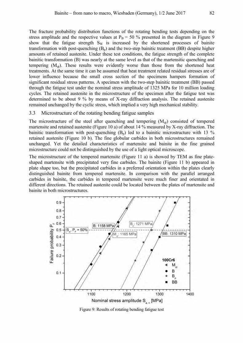
Bainite – from nano to macro, Wiesbaden (Germany), 1/2 June 2017 82
The fracture probability distribution functions of the rotating bending tests depending on the stress amplitude and the respective values at PB = 50 % presented in the diagram in Figure 9 show that the fatigue strength SW is increased by the shortened processes of bainite transformation with post-quenching (Bp) and the two-step bainitic treatment (BB) despite higher amounts of retained austenite. Under these test conditions, the fatigue strength of the complete bainitic transformation (B) was nearly at the same level as that of the martensitic quenching and tempering (Mqt). These results were evidently worse than those from the shortened heat treatments. At the same time it can be assumed that heat treatment related residual stresses are of lower influence because the small cross section of the specimens hampers formation of significant residual stress patterns. A specimen with the two-step bainitic treatment (BB) passed through the fatigue test under the nominal stress amplitude of 1325 MPa for 10 million loading cycles. The retained austenite in the microstructure of the specimen after the fatigue test was determined to be about 9 % by means of X-ray diffraction analysis. The retained austenite remained unchanged by the cyclic stress, which implied a very high mechanical stability.
3.3 Microstructure of the rotating bending fatigue samples The microstructure of the steel after quenching and tempering (Mqt) consisted of tempered martensite and retained austenite (Figure 10 a) of about 14 % measured by X-ray diffraction. The bainitic transformation with post-quenching (Bp) led to a bainitic microstructure with 13 % retained austenite (Figure 10 b). The fine globular carbides in both microstructures remained unchanged. Yet the detailed characteristics of martensite and bainite in the fine grained microstructure could not be distinguished by the use of a light optical microscope. The microstructure of the tempered martensite (Figure 11 a) is showed by TEM as fine plate-shaped martensite with precipitated very fine carbides. The bainite (Figure 11 b) appeared in plate shape too, but the precipitated carbides in a preferred orientation within the plates clearly distinguished bainite from tempered martensite. In comparison with the parallel arranged carbides in bainite, the carbides in tempered martensite were much finer and orientated in different directions. The retained austenite could be located between the plates of martensite and bainite in both microstructures.
Figure 9: Results of rotating bending fatigue test
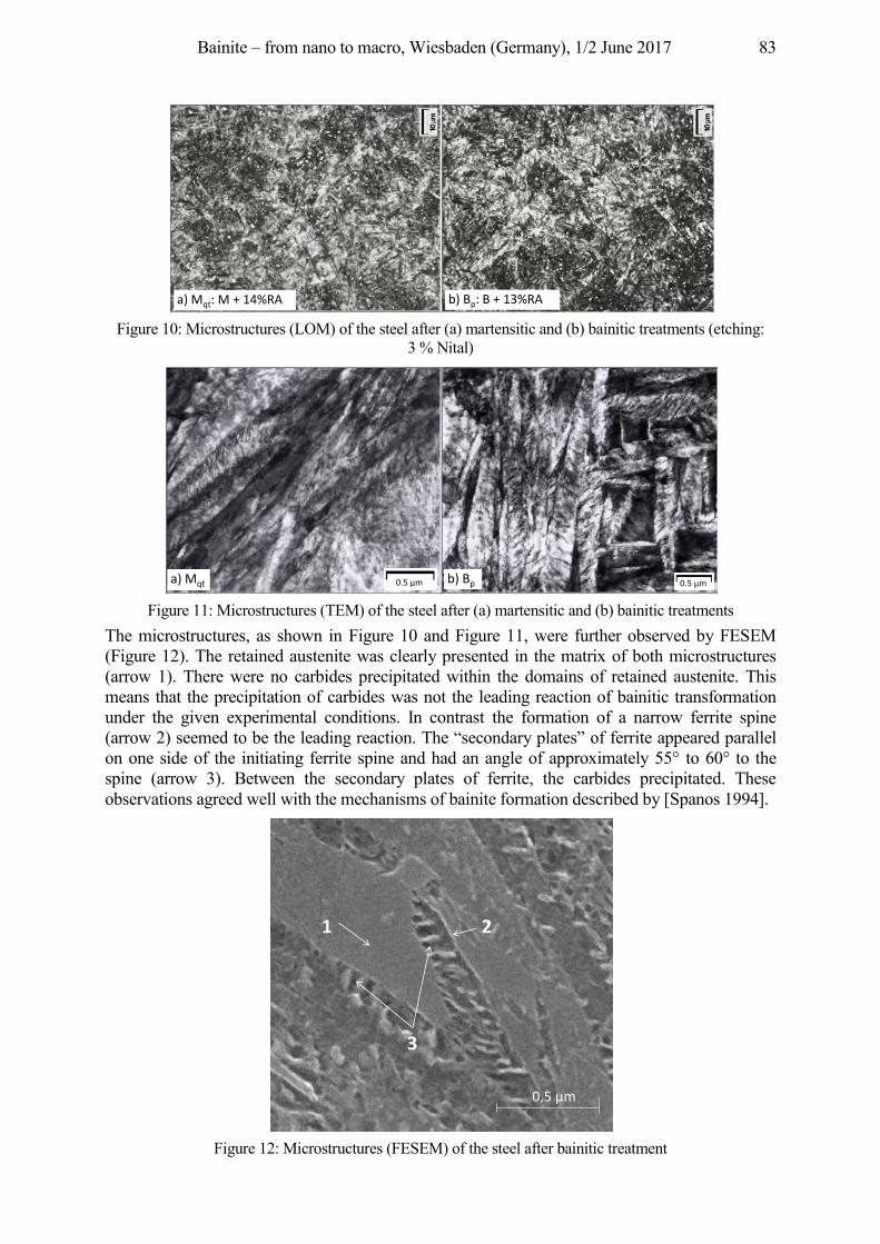
Bainite – from nano to macro, Wiesbaden (Germany), 1/2 June 2017 83
Figure 10: Microstructures (LOM) of the steel after (a) martensitic and (b) bainitic treatments (etching:
3 % Nital)
Figure 11: Microstructures (TEM) of the steel after (a) martensitic and (b) bainitic treatments
The microstructures, as shown in Figure 10 and Figure 11, were further observed by FESEM (Figure 12). The retained austenite was clearly presented in the matrix of both microstructures (arrow 1). There were no carbides precipitated within the domains of retained austenite. This means that the precipitation of carbides was not the leading reaction of bainitic transformation under the given experimental conditions. In contrast the formation of a narrow ferrite spine (arrow 2) seemed to be the leading reaction. The “secondary plates” of ferrite appeared parallel on one side of the initiating ferrite spine and had an angle of approximately 55° to 60° to the spine (arrow 3). Between the secondary plates of ferrite, the carbides precipitated. These observations agreed well with the mechanisms of bainite formation described by [Spanos 1994].
Figure 12: Microstructures (FESEM) of the steel after bainitic treatment
a) Mqt: M + 14%RA b) Bp: B + 13%RA
0.5 µma) Mqt 0.5 µmb) Bp
a) Mqt b) Bp
1
a) martensitic quenching and tempering845°C 20 min / 170°C 2 h
1 2
3
0,5 µm
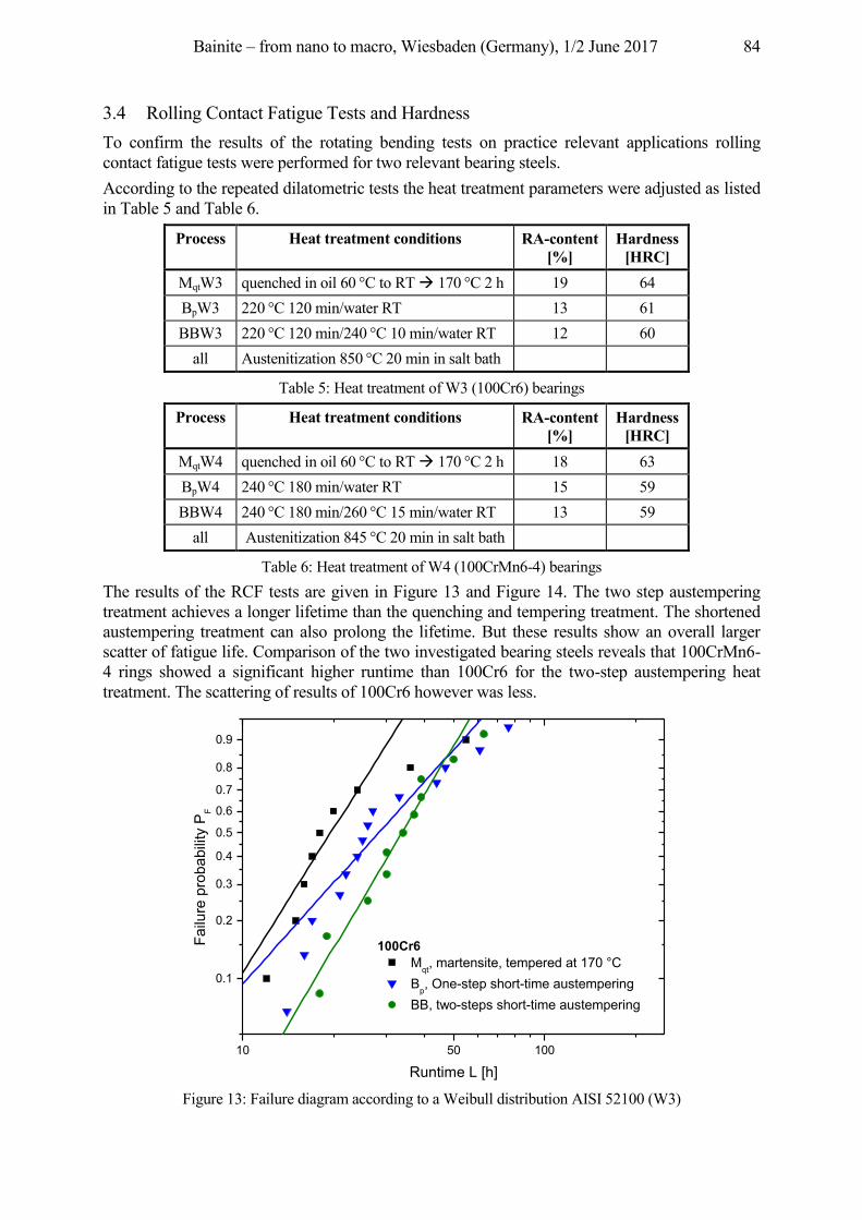
Bainite – from nano to macro, Wiesbaden (Germany), 1/2 June 2017 84
3.4 Rolling Contact Fatigue Tests and Hardness To confirm the results of the rotating bending tests on practice relevant applications rolling contact fatigue tests were performed for two relevant bearing steels. According to the repeated dilatometric tests the heat treatment parameters were adjusted as listed in Table 5 and Table 6.
Process Heat treatment conditions RA-content [%]
Hardness [HRC]
MqtW3 quenched in oil 60 °C to RT Æ 170 °C 2 h 19 64 BpW3 220 °C 120 min/water RT 13 61 BBW3 220 °C 120 min/240 °C 10 min/water RT 12 60
all Austenitization 850 °C 20 min in salt bath
Table 5: Heat treatment of W3 (100Cr6) bearings
Process Heat treatment conditions RA-content [%]
Hardness [HRC]
MqtW4 quenched in oil 60 °C to RT Æ 170 °C 2 h 18 63 BpW4 240 °C 180 min/water RT 15 59 BBW4 240 °C 180 min/260 °C 15 min/water RT 13 59
all Austenitization 845 °C 20 min in salt bath
Table 6: Heat treatment of W4 (100CrMn6-4) bearings The results of the RCF tests are given in Figure 13 and Figure 14. The two step austempering treatment achieves a longer lifetime than the quenching and tempering treatment. The shortened austempering treatment can also prolong the lifetime. But these results show an overall larger scatter of fatigue life. Comparison of the two investigated bearing steels reveals that 100CrMn6-4 rings showed a significant higher runtime than 100Cr6 for the two-step austempering heat treatment. The scattering of results of 100Cr6 however was less.
10 10050
0.1
0.2
0.3
0.4
0.5
0.6
0.7
0.8
0.9
100Cr6 Mqt, martensite, tempered at 170 °C Bp, One-step short-time austempering BB, two-steps short-time austempering
Failu
re p
roba
bilit
y P
F
Runtime L [h] Figure 13: Failure diagram according to a Weibull distribution AISI 52100 (W3)
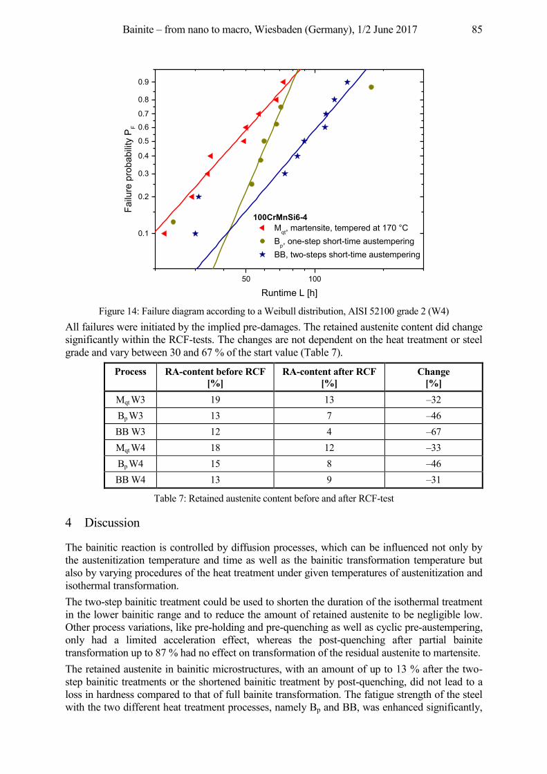
Bainite – from nano to macro, Wiesbaden (Germany), 1/2 June 2017 85
10050
0.1
0.2
0.3
0.4
0.5
0.6
0.7
0.8
0.9
100CrMnSi6-4 Mqt, martensite, tempered at 170 °C Bp, one-step short-time austempering BB, two-steps short-time austempering
Failu
re p
roba
bilit
y P
F
Runtime L [h] Figure 14: Failure diagram according to a Weibull distribution, AISI 52100 grade 2 (W4)
All failures were initiated by the implied pre-damages. The retained austenite content did change significantly within the RCF-tests. The changes are not dependent on the heat treatment or steel grade and vary between 30 and 67 % of the start value (Table 7).
Process RA-content before RCF [%]
RA-content after RCF [%]
Change [%]
Mqt W3 19 13 –32 Bp W3 13 7 –46 BB W3 12 4 –67 Mqt W4 18 12 –33 Bp W4 15 8 –46 BB W4 13 9 –31
Table 7: Retained austenite content before and after RCF-test
4 Discussion
The bainitic reaction is controlled by diffusion processes, which can be influenced not only by the austenitization temperature and time as well as the bainitic transformation temperature but also by varying procedures of the heat treatment under given temperatures of austenitization and isothermal transformation. The two-step bainitic treatment could be used to shorten the duration of the isothermal treatment in the lower bainitic range and to reduce the amount of retained austenite to be negligible low. Other process variations, like pre-holding and pre-quenching as well as cyclic pre-austempering, only had a limited acceleration effect, whereas the post-quenching after partial bainite transformation up to 87 % had no effect on transformation of the residual austenite to martensite. The retained austenite in bainitic microstructures, with an amount of up to 13 % after the two-step bainitic treatments or the shortened bainitic treatment by post-quenching, did not lead to a loss in hardness compared to that of full bainite transformation. The fatigue strength of the steel with the two different heat treatment processes, namely Bp and BB, was enhanced significantly,
Bainite – from nano to macro, Wiesbaden (Germany), 1/2 June 2017 86
despite of the enhanced retained austenite content. The two-step process achieved the best fatigue result in rotating bending fatigue tests. In order to understand the results of the fatigue tests the martensitic and bainitic microstructures were observed by microscopy as described above. There are essential differences between martensitic and bainitic microstructures considering their formation conditions. Martensite formation is a thermal and takes place without diffusion. The carbon distribution in the microstructure is homogeneous apart from carbides already present at austenitization temperature. The bainite formation is a thermal diffusion controlled process. Fine carbides are formed within the ferritic matrix. The carbon distribution is inhomogeneous. The stabilization of retained austenite in martensitic structures is led back on compression stresses, while in bainitic structures it is mainly implied by carbon enrichment. Therefore the retained austenite in bainitic microstructure was assumed to be more stable than the retained austenite in martensitic microstructure. The fraction change of retained austenite content during tempering was described by [Lucas, Nützel 1966]. Within the research project [Burkart, Clausen, Bomas 2013] it could be confirmed with tempering experiments at 120 °C that all variants follow the law of Lucas and Nützel (1) with the same exponent 0.9.
With RAG = retained austenite content RAG0 = retained austenite content before tempering t = time = Temperature n = exponent The RCF-tests showed the same results concerning the enhanced fatigue strength of the shortened austempering treatments in comparison to the quenched and tempered variant. However, the retained austenite content measurements before and after the RCF test did not confirm the hypothesis of more stable retained austenite contents. The retained austenite content decreased during rolling contact in similar ways. Additional fatigue crack propagation measurements in torsion fatigue samples [Burkart, Clausen, Bomas 2013] could not confirm the hypothesis of a deceleration of crack growths. All variants behaved in a similar way. The experimental work demonstrates that the bainitic transformation with post-quenching and the two-step bainitic treatment (Bp and BB) could lead to a significant shortening of the heat treatment duration. If the duration of the conventional full bainitic transformation (B) was normalized to 100 %, the corresponding duration of the two short-term bainitic treatments could be reduced to about 25 %, which allows remarkable cost savings in production.
5 Conclusion and Outlook
From the experimental work it was demonstrated that the short time bainitic transformation with post-quenching and the two-step bainitic treatment (Bp and BB) could shorten the heat treatment duration significantly maintaining the required hardness for bearings. The duration of the austempering treatment could be reduced to about 25 % of that of a full bainitic transformation. Additionally, the fatigue strength of the steel was enhanced significantly through the shortened treatments, particularly by means of a two-step bainitic treatment. The retained austenite with an amount up to 13 % within the bainitic microstructure did not impair the fatigue strength. It could be attributed to the fine dispersion of the retained austenite within the microstructure. The retained austenite in bainitic microstructure could be distinguished from that in martensitic microstructure. The results could be confirmed for roller bearings.
Bainite – from nano to macro, Wiesbaden (Germany), 1/2 June 2017 87
Acknowledgement This work has been partly funded by the German Bundesministerium für Wirtschaft und Technologie BMWi via the Arbeitsgemeinschaft industrieller Forschungsvereinigungen “Otto von Guericke” e.V. grant No. AiF 13712N and 15946 AiF, which is gratefully acknowledged. We also wish to acknowledge our gratitude and appreciation to all industrial partners within the AWT Fachausschuss 21 “Gefüge und Mechanische Eigenschaften” and “FVA AK Werkstoffe” for their contribution during the development of various ideas and concepts presented in this paper. Especially we would like to thank our partners Deutsche Edelstahlwerke GmbH and Schaeffler KG for their contribution.
References Avrami, M.: Kinetics of phase change. II. Transformation-time relations for random distribution of nuclei. J. Chem.
Phys. 8 (1940), pp. 212–224. Burkart, K.; Clausen, B.; Bomas, H.: Einfluss des Restaustenits und seiner Eigenschaften auf das Verhalten von
Wälzlagerstählen bei Partikelüberrollung. FVA-Vorhaben Nr. 595 I, FVA-Forschungsheft Nr. 1094 (2013). Dickson, M. J.: The significance of texture parameters in phase analysis by x-ray diffraction. J. Appl. Crystallogr. 2
(1969), pp. 176–180. Dong, J.; Vetters, H.; Hoffmann, F.; Bomas, H.; Hirsch, T.; Kohlmann, R.; Zoch, H.-W.: Gefüge und mechanische
Eigenschaften von Wälzlagerstählen nach verkürzten Wärmebehandlungen in der unteren Bainitstufe. HTM Haerterei-Tech. Mitt. 61 (2006) 3, pp. 128–135.
Hengerer, F.; Lucas, G.; Nyberg, B.: Zwischenstufenumwandlung von Wälzlagerstählen. HTM Haerterei-Tech. Mitt. 29 (1974) 2, pp. 71–79.
Hirsch, T.; Barrère, V.: Überrollungsbedingte Wekstoffstrukturänderungen bei der Hochtemperaturbeanspruchung von Walzlagerm. HTM Haerterei-Tech. Mitt. 58 (2003) 6, pp. 295–303.
Hunkel, M.; Lübben, Th.; Hoffmann, F.; Mayr, P.: Modellierung der bainitischen und perlitischen Umwandlung bei Stählen. HTM Haerterei-Tech. Mitt. 54 (1999) 6, pp. 365–372.
Jellinghaus, W.: Arch. Eisenhuettenwes. 23 (1952) 11/12, pp. 459–470. Li, C.; Wang, J. L.: Effect on pre-quenching on martensitic-bainitic microstructure and mechanical properties of
GCr15 bearing steel. J. Mater. Sci. 28 (1993), pp. 2112–2118. Lucas, G.; Nützel, H.: Untersuchungen über die Umwandlung des Restaustenits in niedrig legierten Stählen mit
rund 1 % C. Archiv f. d. Eisenhüttenwesen 12 (1966), pp. 981–987. Schaaber, O.: Factors influencing the isothermal transformation of austenite in the intermediate range (bainite
range), part I and II. Wire, Prost & Meiner-Verlag, Coburg, Germany, 1952, pp. 127–137. Sista, V.; Nash, P.; Sahay, S. S: Accelerated bainitic transformation during cyclic austempering. J. Mater. Sci. 42
(2007) 11, pp. 9112–9115. Slycke, J.; Fajers, C.;Volkmuth, J.: Berechnung der Maßstabilität von Wälzlagerbauteilen. HTM Härterei-Tech.
Mitt. 57 (2002) 3, pp. 156–163. Spanos, G.: The fine structure and formation mechanism of lower bainite. Metall. Mater. Trans. A 25, (1994), pp.
1967–1980. Vetters, H.; Dong, J.; Bomas, H.; Hoffmann, F.; Zoch, H.-W.: Microstructure and fatigue strength of the rolling-
bearing steel 100Cr6 _SAE 52100_ after two-step bainitisation and combined bainitic-martensitic heat treatment: Int. J. Mater. Res. 97 (2006) 10, pp. 1432–1440.
Weibull, W.: Zur Abhängigkeit der Festigkeit von der Probengröße. Ing.-Arch. 28 (1959), pp. 360–362.
Bainite – from nano to macro, Wiesbaden (Germany), 1/2 June 2017 88
CarboBain: case hardening by carbo-austempering – a systematic evaluation of transformation kinetics, microstructure and
residual stresses Matthias Steinbacher1, Hans-Werner Zoch1,2
1Stiftung Institut für Werkstofftechnik, Badgasteiner Str. 3, 28359 Bremen, Germany, {steinbacher, zoch}@iwt-bremen.de
2MAPEX Center for Materials and Processes, University of Bremen, Germany, [email protected]
Abstract The beneficial strength properties of bainitic microstructures are perceived since several years. The transformation kinetic and different morphology of bainite were analyzed scientifically in depth and with increasing understanding the application of bainite is focus now. But still, bainitic microstructures are mainly utilized with chemically homogeneous steels. An application of bainitic transformed carburized samples is rather rare up to now. Therefore highly stressed geared components today typically are carburized and martensitic hardened. The microstructure in the case is generally composed of martensite with finely dispersed retained austenite and/or carbides. For gear wheel application during the past 50 years research was focused on topics like microstructure optimization within the bounds of martensite with no more than 25 % of retained austenite. For gears only very limited information on heat treatments with bainitic transformation of the case is available. In the USA few suppliers are propagating carbo-austempering heat treatment for case hardening applications. In the literature a combination of carburization and austempering is discussed with only scarce data on material and microstructure performance. To close the gap a systematic approach was made in a public funded project, analyzing transformation kinetics, microstructure properties and mechanical performance of two typical case hardening steels in carburized state being bainitic transformed. The heat treatment method using case hardening by carburization and adjacent austempering, the transformation behaviour, microstructure development and mechanical properties will be discussed.
Keywords Case hardening, carbo-austempering, isothermal transformation, bainite, gear wheels
1 Introduction
Case hardening typically includes a carburization of low carbon and low alloy steels in an oxygen bearing atmosphere at ambient pressure using carbon monoxide for carbon transfer or a pulsed hydrocarbon atmosphere (typically acetylene) at reduced pressure of less than 20 mbar for carbon transfer. After the designated carbon profile is set up during carburization, parts are typically quenched in a fluid or gaseous atmosphere at excess pressure to maintain a nearly complete martensitic transformation with fine disperse and metastable retained austenite. Adjacent to quenching, typically a tempering at moderate temperatures below 210 °C is applied to reduce martensite brittleness and increase stability of retained austenite or to diminish retained austenite. The isothermal bainitic transformation (austempering) is known for many QT steel grades and cold working steels like bearing steels respectively and deemed to provide high hardness with better ductility than martensitic microstructures combined with a superior residual stress profile. The combination of a carburization with a subsequent isothermal transformation into lower bainite has been used for few applications but not analyzed systematically, yet. Due to a patent by Caterpillar the process was protected from universal use until the end of 2007 and only little
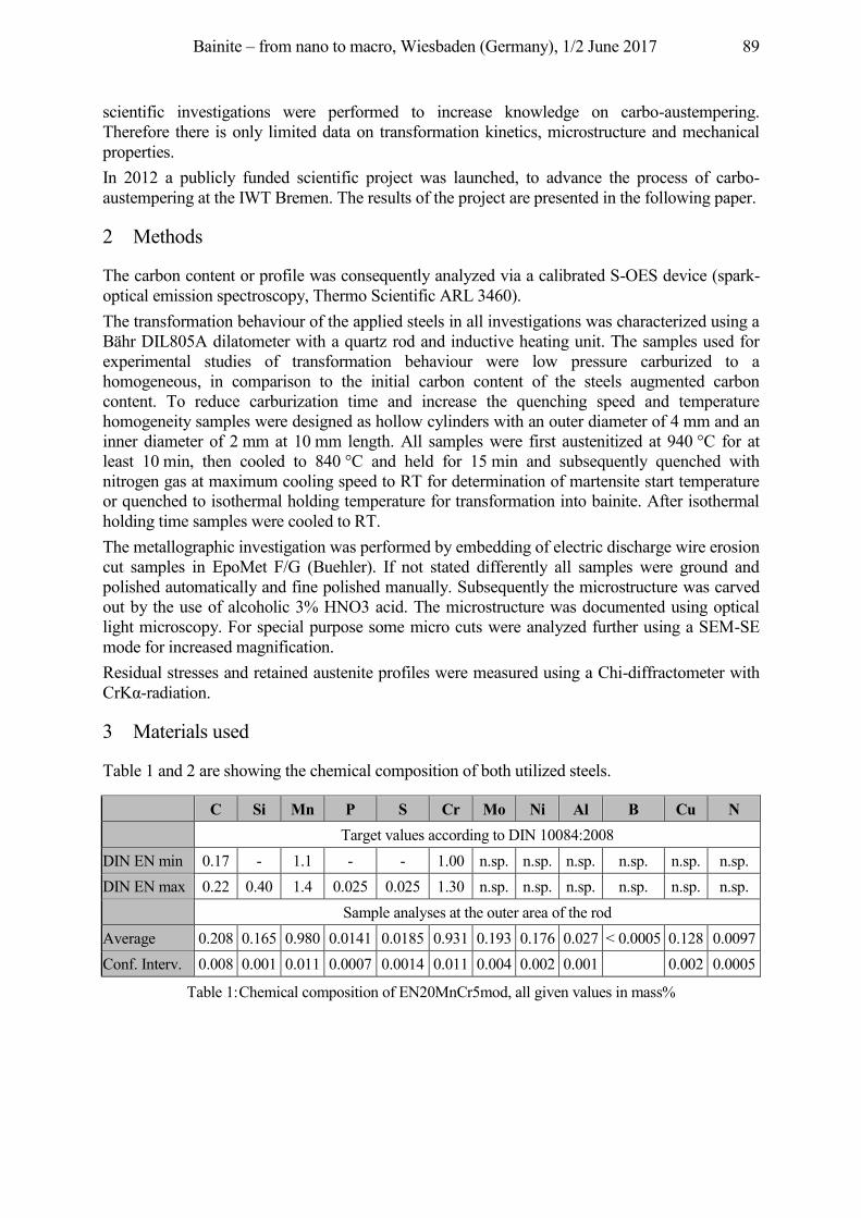
Bainite – from nano to macro, Wiesbaden (Germany), 1/2 June 2017 89
scientific investigations were performed to increase knowledge on carbo-austempering. Therefore there is only limited data on transformation kinetics, microstructure and mechanical properties. In 2012 a publicly funded scientific project was launched, to advance the process of carbo-austempering at the IWT Bremen. The results of the project are presented in the following paper.
2 Methods
The carbon content or profile was consequently analyzed via a calibrated S-OES device (spark-optical emission spectroscopy, Thermo Scientific ARL 3460). The transformation behaviour of the applied steels in all investigations was characterized using a Bähr DIL805A dilatometer with a quartz rod and inductive heating unit. The samples used for experimental studies of transformation behaviour were low pressure carburized to a homogeneous, in comparison to the initial carbon content of the steels augmented carbon content. To reduce carburization time and increase the quenching speed and temperature homogeneity samples were designed as hollow cylinders with an outer diameter of 4 mm and an inner diameter of 2 mm at 10 mm length. All samples were first austenitized at 940 °C for at least 10 min, then cooled to 840 °C and held for 15 min and subsequently quenched with nitrogen gas at maximum cooling speed to RT for determination of martensite start temperature or quenched to isothermal holding temperature for transformation into bainite. After isothermal holding time samples were cooled to RT. The metallographic investigation was performed by embedding of electric discharge wire erosion cut samples in EpoMet F/G (Buehler). If not stated differently all samples were ground and polished automatically and fine polished manually. Subsequently the microstructure was carved out by the use of alcoholic 3% HNO3 acid. The microstructure was documented using optical light microscopy. For special purpose some micro cuts were analyzed further using a SEM-SE mode for increased magnification. Residual stresses and retained austenite profiles were measured using a Chi-diffractometer with CrKα-radiation.
3 Materials used
Table 1 and 2 are showing the chemical composition of both utilized steels.
C Si Mn P S Cr Mo Ni Al B Cu N
Target values according to DIN 10084:2008
DIN EN min 0.17 - 1.1 - - 1.00 n.sp. n.sp. n.sp. n.sp. n.sp. n.sp. DIN EN max 0.22 0.40 1.4 0.025 0.025 1.30 n.sp. n.sp. n.sp. n.sp. n.sp. n.sp.
Sample analyses at the outer area of the rod
Average 0.208 0.165 0.980 0.0141 0.0185 0.931 0.193 0.176 0.027 < 0.0005 0.128 0.0097 Conf. Interv. 0.008 0.001 0.011 0.0007 0.0014 0.011 0.004 0.002 0.001
0.002 0.0005
Table 1: Chemical composition of EN20MnCr5mod, all given values in mass%
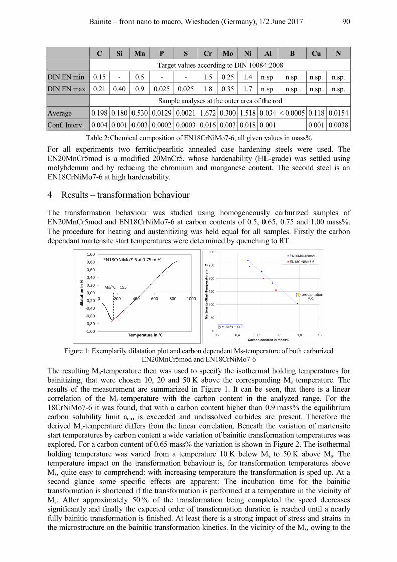
Bainite – from nano to macro, Wiesbaden (Germany), 1/2 June 2017 90
C Si Mn P S Cr Mo Ni Al B Cu N
Target values according to DIN 10084:2008
DIN EN min 0.15 - 0.5 - - 1.5 0.25 1.4 n.sp. n.sp. n.sp. n.sp. DIN EN max 0.21 0.40 0.9 0.025 0.025 1.8 0.35 1.7 n.sp. n.sp. n.sp. n.sp.
Sample analyses at the outer area of the rod
Average 0.198 0.180 0.530 0.0129 0.0021 1.672 0.300 1.518 0.034 < 0.0005 0.118 0.0154 Conf. Interv. 0.004 0.001 0.003 0.0002 0.0003 0.016 0.003 0.018 0.001
0.001 0.0038
Table 2: Chemical composition of EN18CrNiMo7-6, all given values in mass% For all experiments two ferritic/pearlitic annealed case hardening steels were used. The EN20MnCr5mod is a modified 20MnCr5, whose hardenability (HL-grade) was settled using molybdenum and by reducing the chromium and manganese content. The second steel is an EN18CrNiMo7-6 at high hardenability.
4 Results – transformation behaviour
The transformation behaviour was studied using homogeneously carburized samples of EN20MnCr5mod and EN18CrNiMo7-6 at carbon contents of 0.5, 0.65, 0.75 and 1.00 mass%. The procedure for heating and austenitizing was held equal for all samples. Firstly the carbon dependant martensite start temperatures were determined by quenching to RT.
Figure 1: Exemplarily dilatation plot and carbon dependent Ms-temperature of both carburized
EN20MnCr5mod and EN18CrNiMo7-6 The resulting Ms-temperature then was used to specify the isothermal holding temperatures for bainitizing, that were chosen 10, 20 and 50 K above the corresponding Ms temperature. The results of the measurement are summarized in Figure 1. It can be seen, that there is a linear correlation of the Ms-temperature with the carbon content in the analyzed range. For the 18CrNiMo7-6 it was found, that with a carbon content higher than 0.9 mass% the equilibrium carbon solubility limit acm is exceeded and undissolved carbides are present. Therefore the derived Ms-temperature differs from the linear correlation. Beneath the variation of martensite start temperatures by carbon content a wide variation of bainitic transformation temperatures was explored. For a carbon content of 0.65 mass% the variation is shown in Figure 2. The isothermal holding temperature was varied from a temperature 10 K below Ms to 50 K above Ms. The temperature impact on the transformation behaviour is, for transformation temperatures above Ms, quite easy to comprehend: with increasing temperature the transformation is sped up. At a second glance some specific effects are apparent: The incubation time for the bainitic transformation is shortened if the transformation is performed at a temperature in the vicinity of Ms. After approximately 50 % of the transformation being completed the speed decreases significantly and finally the expected order of transformation duration is reached until a nearly fully bainitic transformation is finished. At least there is a strong impact of stress and strains in the microstructure on the bainitic transformation kinetics. In the vicinity of the Ms, owing to the
Ms/°C = 155
-1,00
-0,80
-0,60
-0,40
-0,20
0,00
0,20
0,40
0,60
0,80
1,00
0 200 400 600 800 1000
dila
tatio
n in
%
Temperature in °C
EN18CrNiMo7-6 at 0.75 m.%
y = -346x + 4420
50
100
150
200
250
300
0,2 0,4 0,6 0,8 1,0 1,2
Mar
tens
ite-S
tart-
Tem
pera
ture
in C
Carbon content in mass%
EN20MnCr5mod
EN18CrNiMo7-6
( ) precipitationMxCy
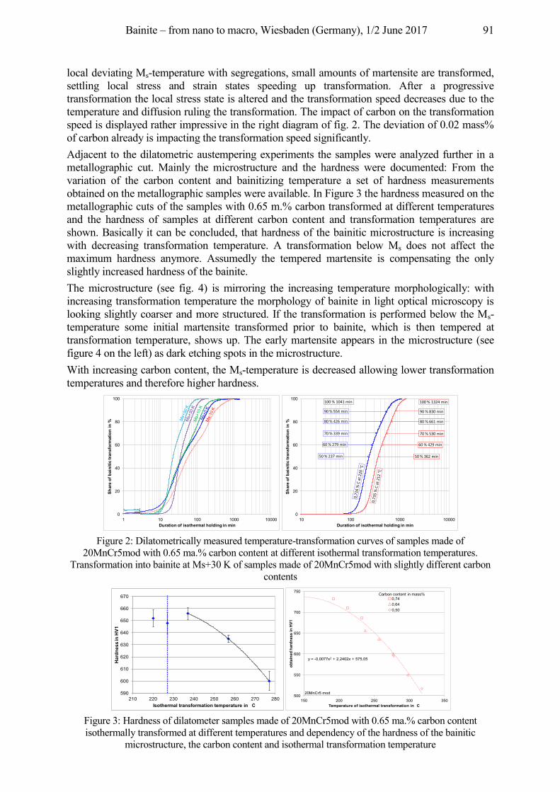
Bainite – from nano to macro, Wiesbaden (Germany), 1/2 June 2017 91
local deviating Ms-temperature with segregations, small amounts of martensite are transformed, settling local stress and strain states speeding up transformation. After a progressive transformation the local stress state is altered and the transformation speed decreases due to the temperature and diffusion ruling the transformation. The impact of carbon on the transformation speed is displayed rather impressive in the right diagram of fig. 2. The deviation of 0.02 mass% of carbon already is impacting the transformation speed significantly. Adjacent to the dilatometric austempering experiments the samples were analyzed further in a metallographic cut. Mainly the microstructure and the hardness were documented: From the variation of the carbon content and bainitizing temperature a set of hardness measurements obtained on the metallographic samples were available. In Figure 3 the hardness measured on the metallographic cuts of the samples with 0.65 m.% carbon transformed at different temperatures and the hardness of samples at different carbon content and transformation temperatures are shown. Basically it can be concluded, that hardness of the bainitic microstructure is increasing with decreasing transformation temperature. A transformation below Ms does not affect the maximum hardness anymore. Assumedly the tempered martensite is compensating the only slightly increased hardness of the bainite. The microstructure (see fig. 4) is mirroring the increasing temperature morphologically: with increasing transformation temperature the morphology of bainite in light optical microscopy is looking slightly coarser and more structured. If the transformation is performed below the Ms-temperature some initial martensite transformed prior to bainite, which is then tempered at transformation temperature, shows up. The early martensite appears in the microstructure (see figure 4 on the left) as dark etching spots in the microstructure. With increasing carbon content, the Ms-temperature is decreased allowing lower transformation temperatures and therefore higher hardness.
Figure 2: Dilatometrically measured temperature-transformation curves of samples made of
20MnCr5mod with 0.65 ma.% carbon content at different isothermal transformation temperatures. Transformation into bainite at Ms+30 K of samples made of 20MnCr5mod with slightly different carbon
contents
Figure 3: Hardness of dilatometer samples made of 20MnCr5mod with 0.65 ma.% carbon content isothermally transformed at different temperatures and dependency of the hardness of the bainitic
microstructure, the carbon content and isothermal transformation temperature
0
20
40
60
80
100
1 10 100 1000 10000
Shar
e of
bai
nitic
tran
sfor
mat
ion
in %
Duration of isothermal holding in min
0
20
40
60
80
100
10 100 1000 10000
Shar
e of
bai
nitic
tran
sfor
mat
ion
in %
Duration of isothermal holding in min
60 % 429 min
70 % 530 min
90 % 830 min
100 % 1324 min
50 % 362 min
80 % 661 min
60 % 429 min
70 % 530 min
90 % 830 min
50 % 362 min
80 % 661 min
60 % 279 min
70 % 339 min
90 % 554 min
100 % 1041 min
50 % 237 min
80 % 426 min
590
600
610
620
630
640
650
660
670
210 220 230 240 250 260 270 280
Har
dnes
s in
HV1
Isothermal transformation temperature in C
y = -0,0077x2 + 2,2402x + 575,05
500
550
600
650
700
750
150 200 250 300 350
obta
ined
har
dnes
s in
HV1
Temperature of isothermal transformation in C
0,740,640,50
Carbon content in mass%
20MnCr5 mod
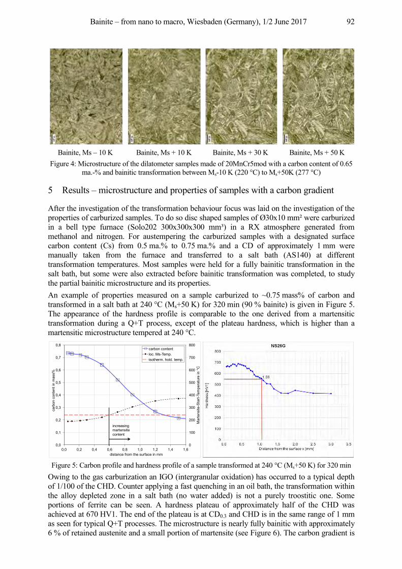
Bainite – from nano to macro, Wiesbaden (Germany), 1/2 June 2017 92
Bainite, Ms – 10 K Bainite, Ms + 10 K Bainite, Ms + 30 K Bainite, Ms + 50 K
Figure 4: Microstructure of the dilatometer samples made of 20MnCr5mod with a carbon content of 0.65 ma.-% and bainitic transformation between Ms-10 K (220 °C) to Ms+50K (277 °C)
5 Results – microstructure and properties of samples with a carbon gradient
After the investigation of the transformation behaviour focus was laid on the investigation of the properties of carburized samples. To do so disc shaped samples of Ø30x10 mm² were carburized in a bell type furnace (Solo202 300x300x300 mm³) in a RX atmosphere generated from methanol and nitrogen. For austempering the carburized samples with a designated surface carbon content (Cs) from 0.5 ma.% to 0.75 ma.% and a CD of approximately 1 mm were manually taken from the furnace and transferred to a salt bath (AS140) at different transformation temperatures. Most samples were held for a fully bainitic transformation in the salt bath, but some were also extracted before bainitic transformation was completed, to study the partial bainitic microstructure and its properties. An example of properties measured on a sample carburized to ~0.75 mass% of carbon and transformed in a salt bath at 240 °C (Ms+50 K) for 320 min (90 % bainite) is given in Figure 5. The appearance of the hardness profile is comparable to the one derived from a martensitic transformation during a Q+T process, except of the plateau hardness, which is higher than a martensitic microstructure tempered at 240 °C.
Figure 5: Carbon profile and hardness profile of a sample transformed at 240 °C (Ms+50 K) for 320 min
Owing to the gas carburization an IGO (intergranular oxidation) has occurred to a typical depth of 1/100 of the CHD. Counter applying a fast quenching in an oil bath, the transformation within the alloy depleted zone in a salt bath (no water added) is not a purely troostitic one. Some portions of ferrite can be seen. A hardness plateau of approximately half of the CHD was achieved at 670 HV1. The end of the plateau is at CD0.3 and CHD is in the same range of 1 mm as seen for typical Q+T processes. The microstructure is nearly fully bainitic with approximately 6 % of retained austenite and a small portion of martensite (see Figure 6). The carbon gradient is
0
100
200
300
400
500
600
700
800
0,0
0,1
0,2
0,3
0,4
0,5
0,6
0,7
0,8
0,0 0,2 0,4 0,6 0,8 1,0 1,2 1,4 1,6
Mar
tens
ite-S
tart-
Tem
pera
ture
in °
C
carb
on c
onte
nt in
mas
s%
distance from the surface in mm
carbon contentloc. Ms-Temp.isotherm. hold. temp.
increasing martensite content
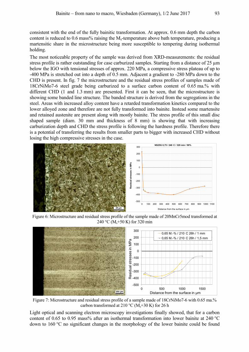
Bainite – from nano to macro, Wiesbaden (Germany), 1/2 June 2017 93
consistent with the end of the fully bainitic transformation. At approx. 0.6 mm depth the carbon content is reduced to 0.6 mass% raising the Ms-temperature above bath temperature, producing a martensitic share in the microstructure being more susceptible to tempering during isothermal holding. The most noticeable property of the sample was derived from XRD-measurements: the residual stress profile is rather outstanding for case carburized samples. Starting from a distance of 25 µm below the IGO with tensional stresses of approx. 220 MPa, a compressive stress plateau of up to -400 MPa is stretched out into a depth of 0.5 mm. Adjacent a gradient to -280 MPa down to the CHD is present. In fig. 7 the microstructure and the residual stress profiles of samples made of 18CrNiMo7-6 steel grade being carburized to a surface carbon content of 0.65 ma.% with different CHD (1 and 1.3 mm) are presented. First it can be seen, that the microstructure is showing some banded line structure. The banded structure is derived from the segregations in the steel. Areas with increased alloy content have a retarded transformation kinetics compared to the lower alloyed zone and therefore are not fully transformed into bainite. Instead some martensite and retained austenite are present along with mostly bainite. The stress profile of this small disc shaped sample (diam. 30 mm and thickness of 8 mm) is showing that with increasing carburization depth and CHD the stress profile is following the hardness profile. Therefore there is a potential of transferring the results from smaller parts to bigger with increased CHD without losing the high compressive stresses in the case.
Figure 6: Microstructure and residual stress profile of the sample made of 20MnCr5mod transformed at
240 °C (Ms+50 K) for 320 min
Figure 7: Microstructure and residual stress profile of a sample made of 18CrNiMo7-6 with 0.65 ma.%
carbon transformed at 210 °C (Ms+30 K) for 26 h Light optical and scanning electron microscopy investigations finally showed, that for a carbon content of 0.65 to 0.95 mass% after an isothermal transformation into lower bainite at 240 °C down to 160 °C no significant changes in the morphology of the lower bainite could be found
-500
-400
-300
-200
-100
0
100
200
300
0 100 200 300 400 500 600 700 800 900 1000 1100
Resi
dual
stre
sses
in M
Pa
Distance from the surface in µm
NS25G 0,75 / 240 C / 320 min / 90%
-500
-400
-300
-200
-100
0
100
200
300
0 500 1000 1500
Eige
nspa
nnun
g in
Mpa
Abstand von der Oberfläche in µm
0,65 M.-% / 210 C 26h / 1 mm0,65 M.-% / 210 C 26h / 1,5 mm
Distance from the surface in µm
Res
idua
l stre
sses
in M
Pa
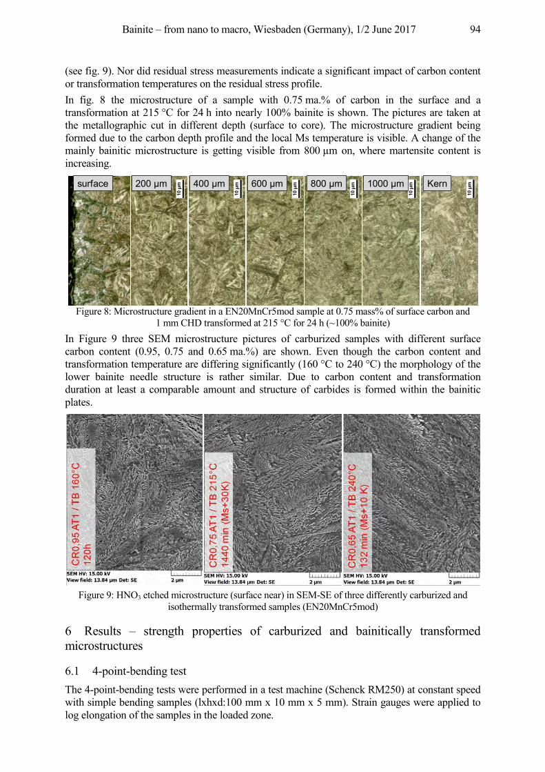
Bainite – from nano to macro, Wiesbaden (Germany), 1/2 June 2017 94
(see fig. 9). Nor did residual stress measurements indicate a significant impact of carbon content or transformation temperatures on the residual stress profile. In fig. 8 the microstructure of a sample with 0.75 ma.% of carbon in the surface and a transformation at 215 °C for 24 h into nearly 100% bainite is shown. The pictures are taken at the metallographic cut in different depth (surface to core). The microstructure gradient being formed due to the carbon depth profile and the local Ms temperature is visible. A change of the mainly bainitic microstructure is getting visible from 800 µm on, where martensite content is increasing.
Figure 8: Microstructure gradient in a EN20MnCr5mod sample at 0.75 mass% of surface carbon and
1 mm CHD transformed at 215 °C for 24 h (~100% bainite) In Figure 9 three SEM microstructure pictures of carburized samples with different surface carbon content (0.95, 0.75 and 0.65 ma.%) are shown. Even though the carbon content and transformation temperature are differing significantly (160 °C to 240 °C) the morphology of the lower bainite needle structure is rather similar. Due to carbon content and transformation duration at least a comparable amount and structure of carbides is formed within the bainitic plates.
Figure 9: HNO3 etched microstructure (surface near) in SEM-SE of three differently carburized and
isothermally transformed samples (EN20MnCr5mod)
6 Results – strength properties of carburized and bainitically transformed microstructures
6.1 4-point-bending test The 4-point-bending tests were performed in a test machine (Schenck RM250) at constant speed with simple bending samples (lxhxd:100 mm x 10 mm x 5 mm). Strain gauges were applied to log elongation of the samples in the loaded zone.
surface 200 µm 400 µm 600 µm 800 µm 1000 µm Kern
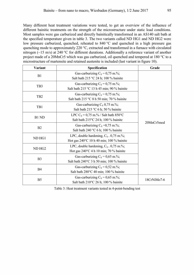
Bainite – from nano to macro, Wiesbaden (Germany), 1/2 June 2017 95
Many different heat treatment variations were tested, to get an overview of the influence of different bainitic treatments on the strength of the microstructure under static load conditions. Most samples were gas carburized and directly bainitically transformed in an AS140 salt bath at the specified temperature given in table 3. The two variants called ND HG1 and ND HG2 were low pressure carburized, quenched, reheated to 840 °C and quenched in a high pressure gas quenching mode to approximately 220 °C, extracted and transformed in a furnace with circulated nitrogen (~15 m/s) at 240 °C for different durations. Additionally a reference variant of another project made of a 20MnCr5 which was gas carburized, oil quenched and tempered at 180 °C to a microstructure of martensite and retained austenite is included (last variant in figure 10).
Variant Specification Grade
B1 Gas-carburizing CS = 0,75 m.%;
Salt bath 215 °C 24 h; 100 % bainite
20MnCr5mod
TB3 Gas-carburizing CS = 0,75 m.%;
Salt bath 215 °C 13 h 45 min; 90 % bainite
TB2 Gas-carburizing CS = 0,75 m.%;
Salt bath 215 °C 8 h 50 min; 70 % bainite
TB1 Gas-carburizing CS 0,75 m.%;
Salt bath 215 °C 6 h; 50 % bainite
B1 ND LPC CS = 0,75 m.% / Salt bath 850°C Salt bath 215°C 24 h; 100 % bainite
B2 Gas-carburizing CS =0,75 m.%;
Salt bath 240 °C 6 h; 100 % bainite
ND HG1 LPC, double hardening, CS = 0,75 m.%;
Hot gas 240°C 10 h 40 min; 100 % bainite
ND HG2 LPC, double hardening, CS = 0,75 m.%; Hot gas 240°C 4 h 10 min; 70 % bainite
B3 Gas-carburizing CS = 0,65 m.%;
Salt bath 240°C 3 h 50 min; 100 % bainite
B4 Gas-carburizing CS = 0,52 m.%;
Salt bath 280°C 40 min; 100 % bainite
B5 Gas-carburizing CS = 0,65 m.%;
Salt bath 210°C 26 h; 100 % bainite 18CrNiMo7-6
Table 3: Heat treatment variants tested in 4-point-bending test
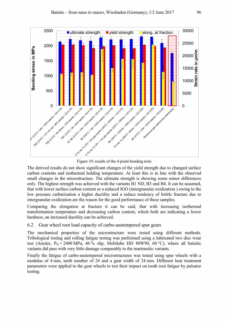
Bainite – from nano to macro, Wiesbaden (Germany), 1/2 June 2017 96
Figure 10: results of the 4-point-bending tests
The derived results do not show significant changes of the yield strength due to changed surface carbon contents and isothermal holding temperature. At least this is in line with the observed small changes in the microstructure. The ultimate strength is showing some minor differences only. The highest strength was achieved with the variants B1 ND, B3 und B4. It can be assumed, that with lower surface carbon content or a reduced IGO (intergranular oxidization ) owing to the low pressure carburization a higher ductility and a reduce tendency of brittle fracture due to intergranular oxidization are the reason for the good performance of these samples. Comparing the elongation at fracture it can be said, that with increasing isothermal transformation temperature and decreasing carbon content, which both are indicating a lower hardness, an increased ductility can be achieved.
6.2 Gear wheel root load capacity of carbo-austempered spur gears The mechanical properties of the microstructure were tested using different methods. Tribological testing and rolling fatigue testing was performed using a lubricated two disc wear test (Amsler, PH = 2400 MPa, 46 % slip, Mobilube HD 80W90, 60 °C), where all bainitic variants did pass with very little damage comparably to the martensitic variants. Finally the fatigue of carbo-austempered microstructures was tested using spur wheels with a modulus of 4 mm, teeth number of 24 and a gear width of 24 mm. Different heat treatment parameters were applied to the gear wheels to test their impact on tooth root fatigue by pulsator testing.
0
5000
10000
15000
20000
25000
30000
0
500
1000
1500
2000
2500
Stra
in ra
te in
µm
/m
Bend
ing
stre
ss in
MPa
ultimate strength yield strength elong. at fraction
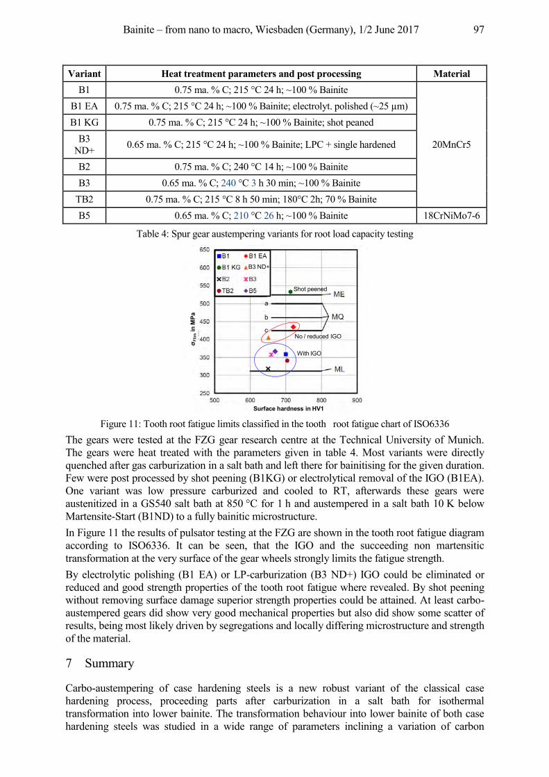
Bainite – from nano to macro, Wiesbaden (Germany), 1/2 June 2017 97
Variant Heat treatment parameters and post processing Material B1 0.75 ma. % C; 215 °C 24 h; ~100 % Bainite
20MnCr5
B1 EA 0.75 ma. % C; 215 °C 24 h; ~100 % Bainite; electrolyt. polished (~25 µm) B1 KG 0.75 ma. % C; 215 °C 24 h; ~100 % Bainite; shot peaned
B3 ND+ 0.65 ma. % C; 215 °C 24 h; ~100 % Bainite; LPC + single hardened
B2 0.75 ma. % C; 240 °C 14 h; ~100 % Bainite B3 0.65 ma. % C; 240 °C 3 h 30 min; ~100 % Bainite
TB2 0.75 ma. % C; 215 °C 8 h 50 min; 180°C 2h; 70 % Bainite B5 0.65 ma. % C; 210 °C 26 h; ~100 % Bainite 18CrNiMo7-6
Table 4: Spur gear austempering variants for root load capacity testing
Figure 11: Tooth root fatigue limits classified in the tooth root fatigue chart of ISO6336
The gears were tested at the FZG gear research centre at the Technical University of Munich. The gears were heat treated with the parameters given in table 4. Most variants were directly quenched after gas carburization in a salt bath and left there for bainitising for the given duration. Few were post processed by shot peening (B1KG) or electrolytical removal of the IGO (B1EA). One variant was low pressure carburized and cooled to RT, afterwards these gears were austenitized in a GS540 salt bath at 850 °C for 1 h and austempered in a salt bath 10 K below Martensite-Start (B1ND) to a fully bainitic microstructure. In Figure 11 the results of pulsator testing at the FZG are shown in the tooth root fatigue diagram according to ISO6336. It can be seen, that the IGO and the succeeding non martensitic transformation at the very surface of the gear wheels strongly limits the fatigue strength. By electrolytic polishing (B1 EA) or LP-carburization (B3 ND+) IGO could be eliminated or reduced and good strength properties of the tooth root fatigue where revealed. By shot peening without removing surface damage superior strength properties could be attained. At least carbo-austempered gears did show very good mechanical properties but also did show some scatter of results, being most likely driven by segregations and locally differing microstructure and strength of the material.
7 Summary
Carbo-austempering of case hardening steels is a new robust variant of the classical case hardening process, proceeding parts after carburization in a salt bath for isothermal transformation into lower bainite. The transformation behaviour into lower bainite of both case hardening steels was studied in a wide range of parameters inclining a variation of carbon
Surface hardness in HV1
σ Flim
in M
Pa
B3 ND+
With IGO
No / reduced IGO
Shot peened
Bainite – from nano to macro, Wiesbaden (Germany), 1/2 June 2017 98
content from 0.5 to 1.0 mass %. For gear wheel application typically a minimum hardness of 650 HV1 is required. Additionally the duration of transformation should be less than 24 hours for practical reasons. Therefore the range of parameters could be narrowed to a carbon content of min. 0.65 mass% and a transformation temperature of / and less than 240 °C to meet the requirements. A carbon content of 0.75 mass% and a transformation at 215 °C was setting the limit for duration for the EN20MnCr5 mod. The investigation of carbon profiles produced by gas carburization and analysis of the microstructure did not reveal strong deviations of the morphology of the investigated lower bainite range. From the heat treatment a superior residual stress profile could be attained. The mechanical properties did not show strong impact of the isothermal holding temperature nor of the surface carbon content. But internal oxidation revealed to diminish fatigue strength of spur wheels. The static strength (4-P-bending) of carbo-austempered specimens exceeded the typical case hardening specimens and tribological performance was equal for bainitic and martensitic samples. The tooth root fatigue limit of carbo-austempered gears showed good results, being competitive with those of case hardening steels with martensitic microstructure. Nonetheless the bainitic microstructure is bearing the potential of improved temperature stability.
Acknowledgment The IGF Project 17661 N of the research association Arbeitsgemeinschaft Wärmebehandlung und Werkstofftechnik e. V. (AWT) was funded by the German Federal Ministry of Economic Affairs and Energy (BMWi) via the AiF within the Industrial Collective Research Program (IGF), based on a resolution of the German Parliament.

Bainite – from nano to macro, Wiesbaden (Germany), 1/2 June 2017 99
4. Process equipment and control
Bainite – from nano to macro, Wiesbaden (Germany), 1/2 June 2017 100
Process Technology and Plant Design for Austempering
Herwig Altena1, Klaus Buchner2
1Aichelin Holding GmbH, Fabriksgasse 3, 2340 Mödling, Austria [email protected]
2Aichelin GesmbH, Fabriksgasse 3, 2340 Mödling, Austria [email protected]
Abstract Austempering or Bainite hardening is a commonly used process especially in the bearing industry. In the last years an increased interest in austempering processes for different applications can be found. The first part of the presentation deals with the metallurgical requirements, the process technologies and the materials which can be used for an austempering process. Furthermore the advantages, but also the restrictions of the process are pointed out. Depending on the requirements, batch type furnaces or continuous plants can be used. The furnace design with regard to salt bath quenching and the most important factors influencing the parts‘ quality are explained. In the second part some practical applications of bainite hardening, the processes and the required furnace technologies are shown with regard to the specific heat treatment demands of the austempering products.
Keywords Austempering, Bainite, Salt bath, Bearings, 100Cr6, Furnace design
1 Introduction
Traditionally bainite hardening was always combined with salt bath technology. About 25 years ago, when the old salt bath technology lost its’ importance because of dirt, safety and ecological reasons, the interest in bainite hardening was decreasing, too. Time has changed, modern salt bath installations are completely capsuled and safe. The composition of salts was adapted to fulfil the ecological requirements and a compete recycling of the used salts is carried out. This might be the reason that austempering processes start to gain increased interest, besides of the mainly used applications in the bearing industry. Furthermore a lot of research is done to analyse the advantages of the process for different materials and applications. Subsequent the principles of the austempering process, suitable materials and applications will be pointed out.
2 Metallurgical fundamentals
2.1 Heat treatment process and structure of the materials The structure of bainite can vary in a wide range, depending on the temperature of the salt bath. Fig. 1 shows a TTT-diagram of SAE 52100 (= 100Cr6), the typical bearing steel. Depending on the temperature, two different structures can be achieved: the “upper” and the “lower” bainite (Fig. 1). At upper temperature of the transformation range, it resembles pearlite. Initial nuclei are ferrite which is coherent with the austenite matrix. Cementite then precipitates from the carbon-enriched layer of austenite, allowing further growth of the ferrite. The carbides tend to lie parallel to the long axis of the bainite needle to form the typical open feathery structure of upper bainite [Spur, Stöferle 1987; Boyer 1984].
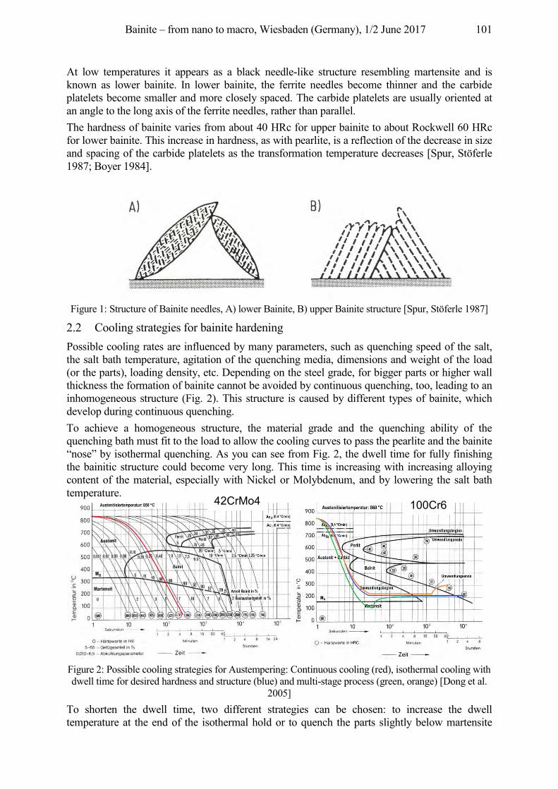
Bainite – from nano to macro, Wiesbaden (Germany), 1/2 June 2017 101
At low temperatures it appears as a black needle-like structure resembling martensite and is known as lower bainite. In lower bainite, the ferrite needles become thinner and the carbide platelets become smaller and more closely spaced. The carbide platelets are usually oriented at an angle to the long axis of the ferrite needles, rather than parallel. The hardness of bainite varies from about 40 HRc for upper bainite to about Rockwell 60 HRc for lower bainite. This increase in hardness, as with pearlite, is a reflection of the decrease in size and spacing of the carbide platelets as the transformation temperature decreases [Spur, Stöferle 1987; Boyer 1984].
Figure 1: Structure of Bainite needles, A) lower Bainite, B) upper Bainite structure [Spur, Stöferle 1987]
2.2 Cooling strategies for bainite hardening Possible cooling rates are influenced by many parameters, such as quenching speed of the salt, the salt bath temperature, agitation of the quenching media, dimensions and weight of the load (or the parts), loading density, etc. Depending on the steel grade, for bigger parts or higher wall thickness the formation of bainite cannot be avoided by continuous quenching, too, leading to an inhomogeneous structure (Fig. 2). This structure is caused by different types of bainite, which develop during continuous quenching. To achieve a homogeneous structure, the material grade and the quenching ability of the quenching bath must fit to the load to allow the cooling curves to pass the pearlite and the bainite “nose” by isothermal quenching. As you can see from Fig. 2, the dwell time for fully finishing the bainitic structure could become very long. This time is increasing with increasing alloying content of the material, especially with Nickel or Molybdenum, and by lowering the salt bath temperature.
Figure 2: Possible cooling strategies for Austempering: Continuous cooling (red), isothermal cooling with dwell time for desired hardness and structure (blue) and multi-stage process (green, orange) [Dong et al.
2005] To shorten the dwell time, two different strategies can be chosen: to increase the dwell temperature at the end of the isothermal hold or to quench the parts slightly below martensite
42CrMo4 100Cr6
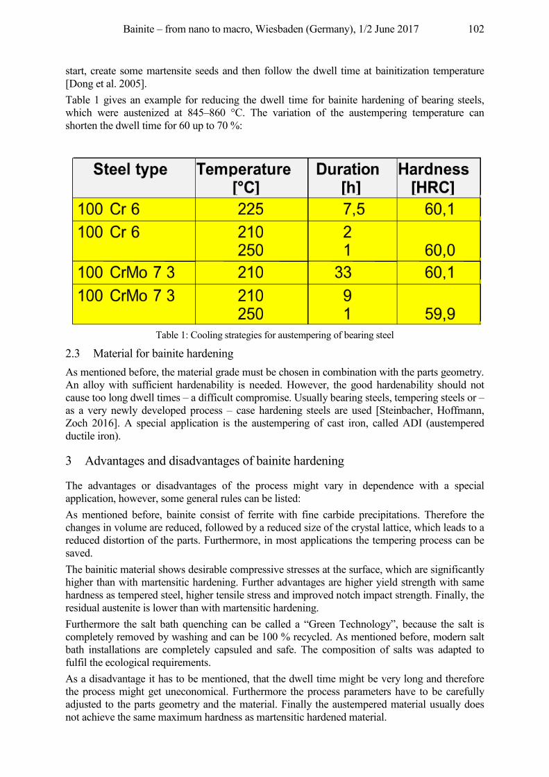
Bainite – from nano to macro, Wiesbaden (Germany), 1/2 June 2017 102
start, create some martensite seeds and then follow the dwell time at bainitization temperature [Dong et al. 2005]. Table 1 gives an example for reducing the dwell time for bainite hardening of bearing steels, which were austenized at 845–860 °C. The variation of the austempering temperature can shorten the dwell time for 60 up to 70 %:
Table 1: Cooling strategies for austempering of bearing steel
2.3 Material for bainite hardening As mentioned before, the material grade must be chosen in combination with the parts geometry. An alloy with sufficient hardenability is needed. However, the good hardenability should not cause too long dwell times – a difficult compromise. Usually bearing steels, tempering steels or – as a very newly developed process – case hardening steels are used [Steinbacher, Hoffmann, Zoch 2016]. A special application is the austempering of cast iron, called ADI (austempered ductile iron).
3 Advantages and disadvantages of bainite hardening
The advantages or disadvantages of the process might vary in dependence with a special application, however, some general rules can be listed: As mentioned before, bainite consist of ferrite with fine carbide precipitations. Therefore the changes in volume are reduced, followed by a reduced size of the crystal lattice, which leads to a reduced distortion of the parts. Furthermore, in most applications the tempering process can be saved. The bainitic material shows desirable compressive stresses at the surface, which are significantly higher than with martensitic hardening. Further advantages are higher yield strength with same hardness as tempered steel, higher tensile stress and improved notch impact strength. Finally, the residual austenite is lower than with martensitic hardening. Furthermore the salt bath quenching can be called a “Green Technology”, because the salt is completely removed by washing and can be 100 % recycled. As mentioned before, modern salt bath installations are completely capsuled and safe. The composition of salts was adapted to fulfil the ecological requirements. As a disadvantage it has to be mentioned, that the dwell time might be very long and therefore the process might get uneconomical. Furthermore the process parameters have to be carefully adjusted to the parts geometry and the material. Finally the austempered material usually does not achieve the same maximum hardness as martensitic hardened material.
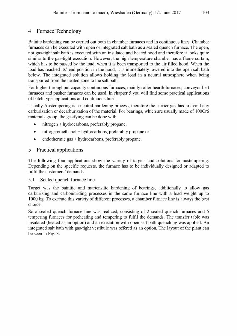
Bainite – from nano to macro, Wiesbaden (Germany), 1/2 June 2017 103
4 Furnace Technology
Bainite hardening can be carried out both in chamber furnaces and in continuous lines. Chamber furnaces can be executed with open or integrated salt bath as a sealed quench furnace. The open, not gas-tight salt bath is executed with an insulated and heated hood and therefore it looks quite similar to the gas-tight execution. However, the high temperature chamber has a flame curtain, which has to be passed by the load, when it is been transported to the air filled hood. When the load has reached its’ end position in the hood, it is immediately lowered into the open salt bath below. The integrated solution allows holding the load in a neutral atmosphere when being transported from the heated zone to the salt bath. For higher throughput capacity continuous furnaces, mainly roller hearth furnaces, conveyor belt furnaces and pusher furnaces can be used. In chapter 5 you will find some practical applications of batch type applications and continuous lines. Usually Austempering is a neutral hardening process, therefore the carrier gas has to avoid any carburization or decarburization of the material. For bearings, which are usually made of 100Cr6 materials group, the gasifying can be done with
• nitrogen + hydrocarbons, preferably propane, • nitrogen/methanol + hydrocarbons, preferably propane or • endothermic gas + hydrocarbons, preferably propane.
5 Practical applications
The following four applications show the variety of targets and solutions for austempering. Depending on the specific requests, the furnace has to be individually designed or adapted to fulfil the customers’ demands.
5.1 Sealed quench furnace line Target was the bainitic and martensitic hardening of bearings, additionally to allow gas carburizing and carbonitriding processes in the same furnace line with a load weight up to 1000 kg. To execute this variety of different processes, a chamber furnace line is always the best choice. So a sealed quench furnace line was realized, consisting of 2 sealed quench furnaces and 5 tempering furnaces for preheating and tempering to fulfil the demands. The transfer table was insulated (heated as an option) and an execution with open salt bath quenching was applied. An integrated salt bath with gas-tight vestibule was offered as an option. The layout of the plant can be seen in Fig. 3.
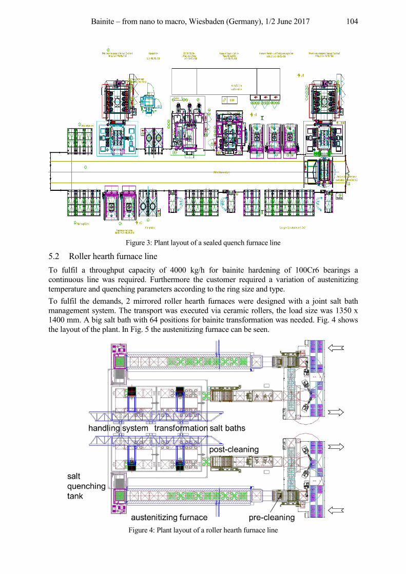
Bainite – from nano to macro, Wiesbaden (Germany), 1/2 June 2017 104
Figure 3: Plant layout of a sealed quench furnace line
5.2 Roller hearth furnace line To fulfil a throughput capacity of 4000 kg/h for bainite hardening of 100Cr6 bearings a continuous line was required. Furthermore the customer required a variation of austenitizing temperature and quenching parameters according to the ring size and type. To fulfil the demands, 2 mirrored roller hearth furnaces were designed with a joint salt bath management system. The transport was executed via ceramic rollers, the load size was 1350 x 1400 mm. A big salt bath with 64 positions for bainite transformation was needed. Fig. 4 shows the layout of the plant. In Fig. 5 the austenitizing furnace can be seen.
Figure 4: Plant layout of a roller hearth furnace line
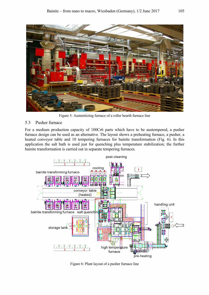
Bainite – from nano to macro, Wiesbaden (Germany), 1/2 June 2017 105
Figure 5: Austenitizing furnace of a roller hearth furnace line
5.3 Pusher furnace For a medium production capacity of 100Cr6 parts which have to be austempered, a pusher furnace design can be used as an alternative. The layout shows a preheating furnace, a pusher, a heated conveyor table and 10 tempering furnaces for bainite transformation (Fig. 6). In this application the salt bath is used just for quenching plus temperature stabilization; the further bainite transformation is carried out in separate tempering furnaces.
Figure 6: Plant layout of a pusher furnace line
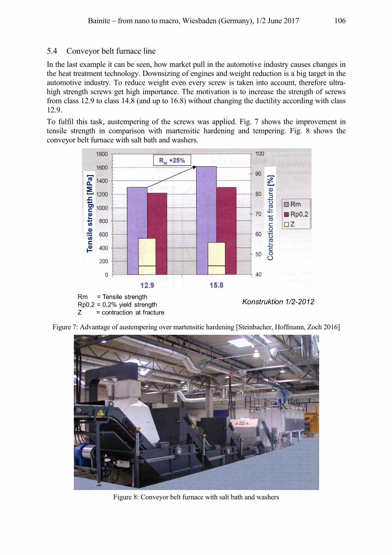
Bainite – from nano to macro, Wiesbaden (Germany), 1/2 June 2017 106
5.4 Conveyor belt furnace line In the last example it can be seen, how market pull in the automotive industry causes changes in the heat treatment technology. Downsizing of engines and weight reduction is a big target in the automotive industry. To reduce weight even every screw is taken into account, therefore ultra-high strength screws get high importance. The motivation is to increase the strength of screws from class 12.9 to class 14.8 (and up to 16.8) without changing the ductility according with class 12.9. To fulfil this task, austempering of the screws was applied. Fig. 7 shows the improvement in tensile strength in comparison with martensitic hardening and tempering. Fig. 8 shows the conveyor belt furnace with salt bath and washers.
Figure 7: Advantage of austempering over martensitic hardening [Steinbacher, Hoffmann, Zoch 2016]
Figure 8: Conveyor belt furnace with salt bath and washers
Bainite – from nano to macro, Wiesbaden (Germany), 1/2 June 2017 107
6 Conclusion
In the last years an increased interest in austempering processes for different applications can be found. Besides the applications in the bearing industry, where salt bath quenching is state of the art, more and more applications can be found, where austempering generates advantages in comparison with martensitic hardening and tempering. Austempering allows higher yield strength with same hardness as tempered steel, higher tensile stresses and leads to desirable compressive stresses at the surface. However, it is necessary to carefully select the material grade according with the wall thickness or weight of the parts and the desired yield strength. Furthermore the cooling strategies have to be optimized to minimize the dwell time in the salt bath. In the second part of the paper some practical applications and furnace designs for austempering were shown. These examples give a good insight in the variety of different parts, applications and furnace designs, which can be used for austempering.
References Boyer, H. E.: Practical Heat Treating, American Society of Metals (1984) Dong, J. et al: Härten von Wälzlagerstählen durch verkürzte Wärmebehandlung in der unteren Bainitstufe. HTM Z.
Werkst. Wärmebeh. Fertigung 60 (2005) 2, S. 77–85 Spur, G.; Stöferle, Th. (Hrgb): Handbuch der Fertigungstechnik 4/2, Wärmebehandeln, Carl Hanser Verlag (1987),
S. 781–783 Steinbacher, M.; Hoffmann, F.; Zoch, H.-W.: Randschichtgefüge aufgekohlter und bainitisch umgewandelter
Bauteile und deren Festigkeitseigenschaften – Teil 1: Untersuchungen des Umwandlungsverhaltens. HTM J. Heat Treatm. Mat. 71 (2016) 5, S. 197–211
Zeitschrift Konstruktion 1/2-2012
Bainite – from nano to macro, Wiesbaden (Germany), 1/2 June 2017 108
Batch furnace line with integrated salt quench for austempering
Herbert Hans Ipsen International GmbH, Flutstrasse 78, 47533 Kleve, Germany, [email protected]
Abstract In particular thin-walled machine components require a rapid and oxidation-free transfer into the salt quench bath for an optimized austempering heat treatment result. This requirement is fulfilled with the development of a batch furnace with an integrated salt quench bath. The construction details of the furnace installation, the requirements and some of the achieved results are subject of this paper.
Keywords Bainite, Austempering, Batch furnace, Salt Quench
1 Introduction
Did you ever wonder why bainite has become so popular all of a sudden? It is because modern engines place enormous demands on their nozzle holders. For this purpose steel parts are used that have to meet the highest requirements. Extraordinary precision in controlling the furnace is required for large scale heat treatment involving the bainite transformation of modern injection nozzles bodies. The Ipsen batch furnace line has been developed as a solution for this complex process which includes heat treatment under protective atmosphere and integrated salt quench. Basic requirement:
• small batch size: approx. (W x L x H) 600 x 900 x 450 mm • average gross load 250 kg (max. 350 kg) • austempering of steel grade DIN 1.3505 (100Cr6) • protective atmospheres: Endogas, Nitrogen/Methanol etc. • transport to salt quench in protective atmosphere • quenching in salt at 220 °C • followed by a transformation duration of about 4–6 hours
2 Technical Specification
The specification for the batch furnace line with integrated salt quench was defined as follows: Product spectrum:
• material: 100Cr6 • part dimension: Ø 15–50 mm • part weight: up to 400 g
Heat Treatment:
• temperature range: 800–1.000 °C • heat treatment processes: carbonitriding, neutral and case hardening
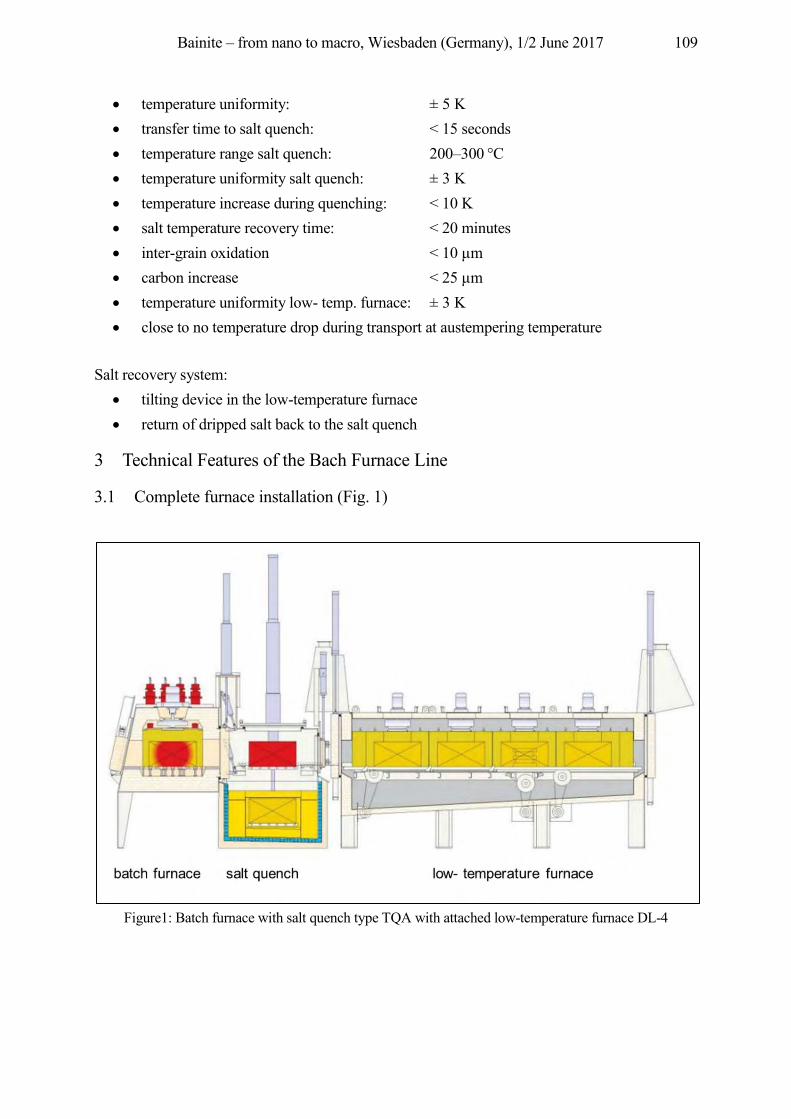
Bainite – from nano to macro, Wiesbaden (Germany), 1/2 June 2017 109
• temperature uniformity: ± 5 K • transfer time to salt quench: < 15 seconds • temperature range salt quench: 200–300 °C • temperature uniformity salt quench: ± 3 K • temperature increase during quenching: < 10 K • salt temperature recovery time: < 20 minutes • inter-grain oxidation < 10 µm • carbon increase < 25 µm • temperature uniformity low- temp. furnace: ± 3 K • close to no temperature drop during transport at austempering temperature
Salt recovery system:
• tilting device in the low-temperature furnace • return of dripped salt back to the salt quench
3 Technical Features of the Bach Furnace Line
3.1 Complete furnace installation (Fig. 1)
Figure1: Batch furnace with salt quench type TQA with attached low-temperature furnace DL-4
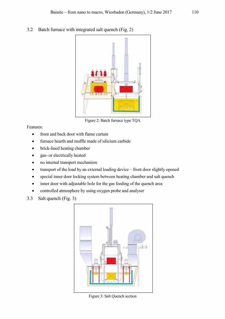
Bainite – from nano to macro, Wiesbaden (Germany), 1/2 June 2017 110
3.2 Batch furnace with integrated salt quench (Fig. 2)
Figure 2: Batch furnace type TQA
Features: • front and back door with flame curtain • furnace hearth and muffle made of silicium carbide • brick-lined heating chamber • gas- or electrically heated • no internal transport mechanism • transport of the load by an external loading device – front door slightly opened • special inner door locking system between heating chamber and salt quench • inner door with adjustable hole for the gas feeding of the quench area • controlled atmosphere by using oxygen probe and analyser
3.3 Salt quench (Fig. 3)
Figure 3: Salt Quench section
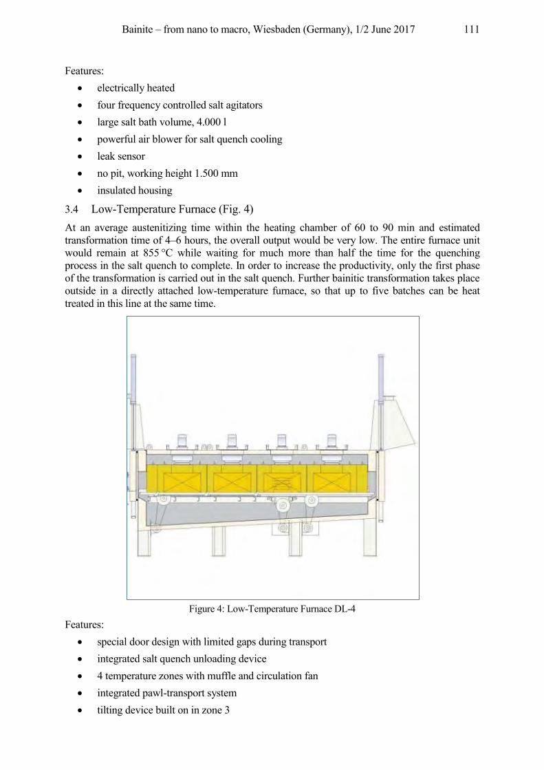
Bainite – from nano to macro, Wiesbaden (Germany), 1/2 June 2017 111
Features: • electrically heated • four frequency controlled salt agitators • large salt bath volume, 4.000 l • powerful air blower for salt quench cooling • leak sensor • no pit, working height 1.500 mm • insulated housing
3.4 Low-Temperature Furnace (Fig. 4) At an average austenitizing time within the heating chamber of 60 to 90 min and estimated transformation time of 4–6 hours, the overall output would be very low. The entire furnace unit would remain at 855 °C while waiting for much more than half the time for the quenching process in the salt quench to complete. In order to increase the productivity, only the first phase of the transformation is carried out in the salt quench. Further bainitic transformation takes place outside in a directly attached low-temperature furnace, so that up to five batches can be heat treated in this line at the same time.
Figure 4: Low-Temperature Furnace DL-4
Features: • special door design with limited gaps during transport • integrated salt quench unloading device • 4 temperature zones with muffle and circulation fan • integrated pawl-transport system • tilting device built on in zone 3
Bainite – from nano to macro, Wiesbaden (Germany), 1/2 June 2017 112
• sloping furnace floor to encourage return of liquid salt • salt refill tank with filling funnel, electrically heated • unloading zone 4 by an external unloader
Design benefits:
• SiC muffle strong and uniform atmosphere circulation • flat hearth extended lifetime of grids and baskets • “push” transport no special base grid needed • air/salt cooling system high cooling speed • directly attached low-temperature furnace minimized temperature drop • salt recovery system less salt consumption
4 Testing and acceptance results
Aerodynamic flow measurements were taken above the furnace hearth in an empty furnace before the unit was commissioned. After the final adjustments in all batch area, speeds of 5–8 m/s were measured, which corresponds to the maximum difference high/low of 3 m/s.
4.1 Overview of the measuring results for the batch furnace with integrated salt quench:
• circulation speed 5–8m/s • heating-up time (855 °C, 320 kg) 80 min • temperature uniformity HC (855 °C, empty furnace) 3 K • temperature uniformity Q (220 °C, empty salt quench) 1,0 K • temperature rise in the salt bath (350 kg, 855/220 °C) 8 K • salt temperature recovery time (350 kg, 855/220 °C) 17 min • inter-grain oxidation (Endogas) 3 µm • carbon increase layer 10 µm
4.2 Overview of the temperature uniformity results for the low-temperature furnace: Set point: 220 °C
• Temperature uniformity zone 1 (empty furnace) 2,5 K • Temperature uniformity zone 2 (empty furnace) 2,9 K • Temperature uniformity zone 3 (empty furnace) 2,3 K • Temperature uniformity zone 4 (empty furnace) 5 K
Set point: 260 °C • Temperature uniformity zone 1 (empty furnace) • Temperature uniformity zone 2 (empty furnace) • Temperature uniformity zone 3 (empty furnace) • Temperature uniformity zone 4 (empty furnace)
The temperature drop during door opening times was in the range of 1–2 K.
Bainite – from nano to macro, Wiesbaden (Germany), 1/2 June 2017 113
5 Conclusion
Inspection and acceptance procedures has shown, that this installation meets all demands on the technical requirements for austempering 100Cr6. In the near future Ipsen will also focus on the batch furnaces with integrated salt quench for batch sizes up to 1.500 kg and a salt bath temperature up to 450 °C.
References Herbert, H.: Bainitic hardening of common-rail injectors for modern diesel engines. Heat Processing 2-2012. Handel, H.; Briem, K.; Edenhofer, B.: Kammeröfen mit integrierter Salzbadabschreckung für das bainitische
Härten (Chamber furnaces with integrated salt bath quenching for bainite hardening). Gaswärme International 48 (1999) 4/5.
Common-Rail-Systeme von Bosch (Common rail systems by Bosch) Diesel injection systems soon with an injection pressure of up to 2500 bar.
Improved solenoid valve and piezo injectors, Bosch Product Information Bulletin 7473, 2011. Mit Bosch-Technik CO-Emissionen senken (Reducing CO emissions with Bosch technology), CO2 targets can
only be achieved using efficient combustion. Bosch Product Information Bulletin 7477, 2011.
Bainite – from nano to macro, Wiesbaden (Germany), 1/2 June 2017 114
Dry bainitizing – a clean approach to achieve bainitic microstructures
Volker Heuer, Klaus Loeser ALD Vacuum Technologies GmbH, Otto-von-Guericke Platz 1, 63457 Hanau, Germany,
{Dr.Volker.Heuer, Dr.Klaus.Loeser}@ald-vt.de
Abstract The currently applied technology for bainitizing of steels is using a salt-bath as quenching medium. This technology is however often problematic since the salt can be environmental hazardous, parts need to be washed after quenching and an integration into the manufacturing-line is often difficult. Therefore a Dry Bainitizing process (DryBainTM) was developed. By using this new quenching process, the parts are quenched with a high pressure gas-stream. To avoid the formation of perlite the components are being quenched rapidly. This is being ensured by a high heat transfer coefficient, which is achieved by applying high gas-velocities and high gas-pressures. Furthermore it must be ensured that no volume-fraction of the components falls below bainitizing temperature so that no martensite formation takes place. An industrial furnace-equpiment for the DryBainTM-process and an example for practical application are introduced in this paper.
Keywords Bainite, Dry Bainitizing, Austempering, Gas Quenching, 100Cr6
1 Introduction
Bainitized steel-components offer high toughness and high residual compressive stresses combined with high hardness-values. Bainitizing is often being called austempering as well. In most cases the aim of the bainitizing process is to provide a fully bainitic microstructure through the whole volume of the parts after heat treatment. For reaching this objective, the temperature of the quenching medium is kept constantly above martensite-start temperature (MS) during quenching. The so called ‘lower bainite’ is achieved if the temperature of the part is kept constantly just above MS. Parts with bainitic microstructure have a somewhat lower hardness compared to parts with martensitic structure. But the hardness of lower bainite is in many cases only about 1.2 HRC below the hardness of martensite. The toughness of bainite is much higher compared to martensite. The formation of bainite and the properties of bainitic microstructures are described in detail by [Bhadeshia 2001]. Further developments in the field of short-time bainitizing are described by [Dong 2006]. Typical steel grades for the bainitizing-process are 100Cr6, 36CrNiMo4, 37MnSi5 and others. Typical industrial applications for bainitizing are bolts, axles, shafts, spur racks, precision parts for injection systems and parts for the bearing industry. The diameters of bainitized components usually range from 6 mm to 85 mm. Currently applied technology is using a salt-bath as quenching medium. The salt-bath is kept at bainitizing temperature which is usually between MS and 500 °C depending on the steel grade. After being quenched down to bainitizing temperature the parts are kept long enough in the salt bath until they are transformed to a fully bainitic microstructure. The use of a salt-bath is however often problematic since:
the salt can be toxic or environmental hazardous,
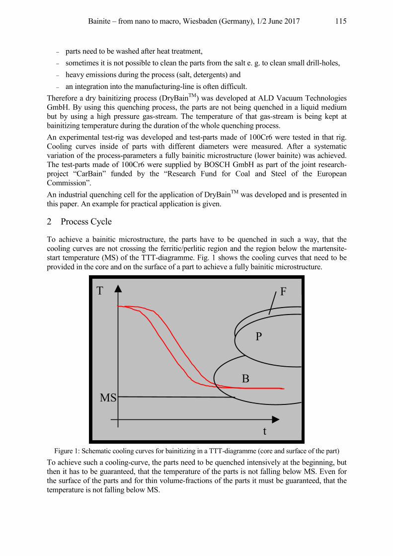
Bainite – from nano to macro, Wiesbaden (Germany), 1/2 June 2017 115
parts need to be washed after heat treatment, sometimes it is not possible to clean the parts from the salt e. g. to clean small drill-holes, heavy emissions during the process (salt, detergents) and an integration into the manufacturing-line is often difficult.
Therefore a dry bainitizing process (DryBainTM) was developed at ALD Vacuum Technologies GmbH. By using this quenching process, the parts are not being quenched in a liquid medium but by using a high pressure gas-stream. The temperature of that gas-stream is being kept at bainitizing temperature during the duration of the whole quenching process. An experimental test-rig was developed and test-parts made of 100Cr6 were tested in that rig. Cooling curves inside of parts with different diameters were measured. After a systematic variation of the process-parameters a fully bainitic microstructure (lower bainite) was achieved. The test-parts made of 100Cr6 were supplied by BOSCH GmbH as part of the joint research-project “CarBain” funded by the “Research Fund for Coal and Steel of the European Commission”. An industrial quenching cell for the application of DryBainTM was developed and is presented in this paper. An example for practical application is given.
2 Process Cycle
To achieve a bainitic microstructure, the parts have to be quenched in such a way, that the cooling curves are not crossing the ferritic/perlitic region and the region below the martensite-start temperature (MS) of the TTT-diagramme. Fig. 1 shows the cooling curves that need to be provided in the core and on the surface of a part to achieve a fully bainitic microstructure.
T
t
B
P
F
MS
Figure 1: Schematic cooling curves for bainitizing in a TTT-diagramme (core and surface of the part)
To achieve such a cooling-curve, the parts need to be quenched intensively at the beginning, but then it has to be guaranteed, that the temperature of the parts is not falling below MS. Even for the surface of the parts and for thin volume-fractions of the parts it must be guaranteed, that the temperature is not falling below MS.
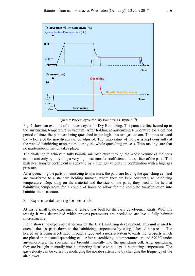
Bainite – from nano to macro, Wiesbaden (Germany), 1/2 June 2017 116
Figure 2: Process cycle for Dry Bainitizing (DryBainTM)
Fig. 2 shows an example of a process cycle for Dry Bainitizing. The parts are first heated up to the austenizing temperature in vacuum. After holding at austenizing temperature for a defined period of time, the parts are being quenched in the high pressure gas-stream. The pressure and the velocity of the gas-stream can be adjusted. The temperature of the gas is kept constantly at the wanted bainitizing temperature during the whole quenching process. Thus making sure that no martensite-formation takes place. The challenge to achieve a fully bainitic microstructure through the whole volume of the parts can be met only by providing a very high heat transfer coefficient at the surface of the parts. This high heat transfer coefficient is achieved by a high gas velocity in combination with a high gas pressure. After quenching the parts to bainitizing temperature, the parts are leaving the quenching cell and are transferred to a standard holding furnace, where they are kept constantly at bainitizing temperature. Depending on the material and the size of the parts, they need to be held at bainitizing temperature for a couple of hours to allow for the complete transformation into bainitic microstructure.
3 Experimental test-rig for pre-trials
At first a small scale experimental test-rig was built for the early development-trials. With this test-rig it was determined which process-parameters are needed to achieve a fully bainitic microstructure. Fig. 3 shows the experimental test-rig for the Dry Bainitizing development. This unit is used to quench the test-parts down to the bainitizing temperature by using a heated air-stream. The heated air is being accelerated through a tube and a nozzle-system towards the test-parts which are placed in the small quenching cell. After austenitizing at temperatures around 890 °C under air-atmosphere, the specimen are brought manually into the quenching cell. After quenching, they are brought manually into a tempering furnace to be kept at bainitizing temperature. The gas-velocity can be varied by modifying the nozzle-system and by changing the frequency of the air-blower.
Time
Quenching
110-1
10-3
10-5
10
890
20
Pressure (bar)
Quench-Gas-Temperature (°C)
Time
Temperature of the component (°C)
260
Bainitic transformation
Austenizing
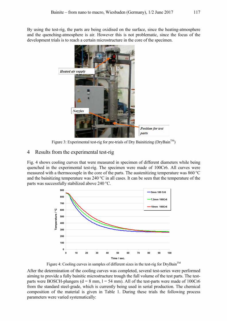
Bainite – from nano to macro, Wiesbaden (Germany), 1/2 June 2017 117
By using the test-rig, the parts are being oxidised on the surface, since the heating-atmosphere and the quenching-atmosphere is air. However this is not problematic, since the focus of the development trials is to reach a certain microstructure in the core of the specimen.
Figure 3: Experimental test-rig for pre-trials of Dry Bainitizing (DryBainTM)
4 Results from the experimental test-rig
Fig. 4 shows cooling curves that were measured in specimen of different diameters while being quenched in the experimental test-rig. The specimen were made of 100Cr6. All curves were measured with a thermocouple in the core of the parts. The austenitizing temperature was 860 °C and the bainitizing temperature was 240 °C in all cases. It can be seen that the temperature of the parts was successfully stabilized above 240 °C.
Figure 4: Cooling curves in samples of different sizes in the test-rig for DryBainTM
After the determination of the cooling curves was completed, several test-series were performed aiming to provide a fully bainitic microstructure trough the full volume of the test parts. The test-parts were BOSCH-plungers (d = 8 mm, l = 54 mm). All of the test-parts were made of 100Cr6 from the standard steel-grade, which is currently being used in serial production. The chemical composition of the material is given in Table 1. During these trials the following process parameters were varied systematically:
0
100
200
300
400
500
600
700
800
900
0 10 20 30 40 50 60 70 80 90 100
Time / sec.
Tem
pera
ture
/ °C
5mm 100 Cr6
7,5mm 100Cr6
10mm 100Cr6
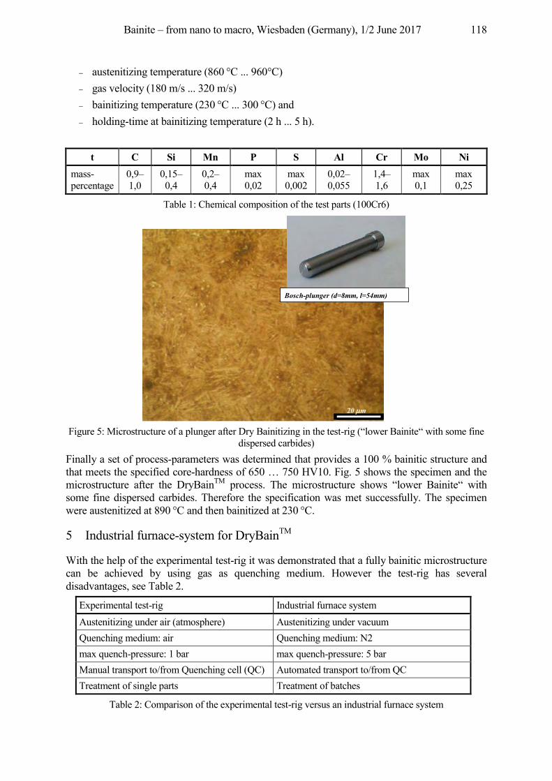
Bainite – from nano to macro, Wiesbaden (Germany), 1/2 June 2017 118
austenitizing temperature (860 °C ... 960°C) gas velocity (180 m/s ... 320 m/s) bainitizing temperature (230 °C ... 300 °C) and holding-time at bainitizing temperature (2 h ... 5 h).
t C Si Mn P S Al Cr Mo Ni mass-percentage
0,9–1,0
0,15–0,4
0,2–0,4
max 0,02
max 0,002
0,02–0,055
1,4–1,6
max 0,1
max 0,25
Table 1: Chemical composition of the test parts (100Cr6)
Figure 5: Microstructure of a plunger after Dry Bainitizing in the test-rig (“lower Bainite“ with some fine
dispersed carbides) Finally a set of process-parameters was determined that provides a 100 % bainitic structure and that meets the specified core-hardness of 650 … 750 HV10. Fig. 5 shows the specimen and the microstructure after the DryBainTM process. The microstructure shows “lower Bainite“ with some fine dispersed carbides. Therefore the specification was met successfully. The specimen were austenitized at 890 °C and then bainitized at 230 °C.
5 Industrial furnace-system for DryBainTM
With the help of the experimental test-rig it was demonstrated that a fully bainitic microstructure can be achieved by using gas as quenching medium. However the test-rig has several disadvantages, see Table 2.
Experimental test-rig Industrial furnace system
Austenitizing under air (atmosphere) Austenitizing under vacuum Quenching medium: air Quenching medium: N2 max quench-pressure: 1 bar max quench-pressure: 5 bar Manual transport to/from Quenching cell (QC) Automated transport to/from QC Treatment of single parts Treatment of batches
Table 2: Comparison of the experimental test-rig versus an industrial furnace system
Bosch-plunger (d=8mm, l=54mm)
20 m
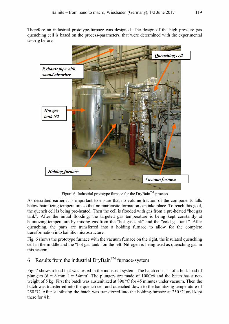
Bainite – from nano to macro, Wiesbaden (Germany), 1/2 June 2017 119
Therefore an industrial prototype-furnace was designed. The design of the high pressure gas quenching cell is based on the process-parameters, that were determined with the experimental test-rig before.
Figure 6: Industrial prototype furnace for the DryBainTM-process
As described earlier it is important to ensure that no volume-fraction of the components falls below bainitizing temperature so that no martensite formation can take place. To reach this goal, the quench cell is being pre-heated. Then the cell is flooded with gas from a pre-heated “hot gas tank”. After the initial flooding, the targeted gas temperature is being kept constantly at bainitizing-temperature by mixing gas from the “hot gas tank” and the "cold gas tank”. After quenching, the parts are transferred into a holding furnace to allow for the complete transformation into bainitic microstructure. Fig. 6 shows the prototype furnace with the vacuum furnace on the right, the insulated quenching cell in the middle and the “hot gas-tank” on the left. Nitrogen is being used as quenching gas in this system.
6 Results from the industrial DryBainTM furnace-system
Fig. 7 shows a load that was tested in the industrial system. The batch consists of a bulk load of plungers (d = 8 mm, l = 54mm). The plungers are made of 100Cr6 and the batch has a net-weight of 5 kg. First the batch was austenitized at 890 °C for 45 minutes under vacuum. Then the batch was transferred into the quench cell and quenched down to the bainitizing temperature of 250 °C. After stabilizing the batch was transferred into the holding-furnace at 250 °C and kept there for 4 h.
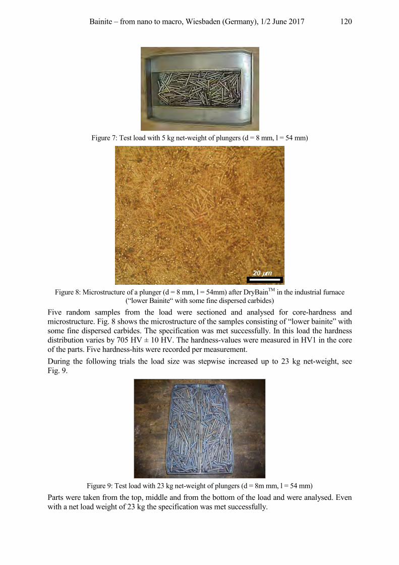
Bainite – from nano to macro, Wiesbaden (Germany), 1/2 June 2017 120
Figure 7: Test load with 5 kg net-weight of plungers (d = 8 mm, l = 54 mm)
Figure 8: Microstructure of a plunger (d = 8 mm, l = 54mm) after DryBainTM in the industrial furnace
(“lower Bainite“ with some fine dispersed carbides) Five random samples from the load were sectioned and analysed for core-hardness and microstructure. Fig. 8 shows the microstructure of the samples consisting of “lower bainite” with some fine dispersed carbides. The specification was met successfully. In this load the hardness distribution varies by 705 HV ± 10 HV. The hardness-values were measured in HV1 in the core of the parts. Five hardness-hits were recorded per measurement. During the following trials the load size was stepwise increased up to 23 kg net-weight, see Fig. 9.
Figure 9: Test load with 23 kg net-weight of plungers (d = 8m mm, l = 54 mm)
Parts were taken from the top, middle and from the bottom of the load and were analysed. Even with a net load weight of 23 kg the specification was met successfully.
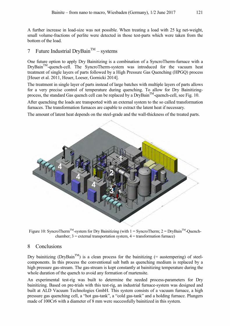
Bainite – from nano to macro, Wiesbaden (Germany), 1/2 June 2017 121
A further increase in load-size was not possible. When treating a load with 25 kg net-weight, small volume-fractions of perlite were detected in those test-parts which were taken from the bottom of the load.
7 Future Industrial DryBainTM – systems
One future option to apply Dry Bainitizing is a combination of a SyncroTherm-furnace with a DryBainTM-quench-cell. The SyncroTherm-system was introduced for the vacuum heat treatment of single layers of parts followed by a High Pressure Gas Quenching (HPGQ) process [Heuer et al. 2011, Heuer, Loeser, Gornicki 2014]. The treatment in single layer of parts instead of large batches with multiple layers of parts allows for a very precise control of temperature during quenching. To allow for Dry Bainitizing-process, the standard Gas quench cell can be replaced by a DryBainTM-quench-cell, see Fig. 10. After quenching the loads are transported with an external system to the so called transformation furnaces. The transformation furnaces are capable to extract the latent heat if necessary. The amount of latent heat depends on the steel-grade and the wall-thickness of the treated parts.
Figure 10: SyncroThermTM-system for Dry Bainitizing (with 1 = SyncroTherm; 2 = DryBainTM-Quench-
chamber; 3 = external transportation system, 4 = transformation furnace)
8 Conclusions
Dry bainitizing (DryBainTM) is a clean process for the bainitizing (= austempering) of steel-components. In this process the conventional salt bath as quenching medium is replaced by a high pressure gas-stream. The gas-stream is kept constantly at bainitizing temperature during the whole duration of the quench to avoid any formation of martensite. An experimental test-rig was built to determine the needed process-parameters for Dry bainitizing. Based on pre-trials with this test-rig, an industrial furnace-system was designed and built at ALD Vacuum Technologies GmbH. This system consists of a vacuum furnace, a high pressure gas quenching cell, a “hot gas-tank”, a “cold gas-tank” and a holding furnace. Plungers made of 100Cr6 with a diameter of 8 mm were successfully bainitized in this system.
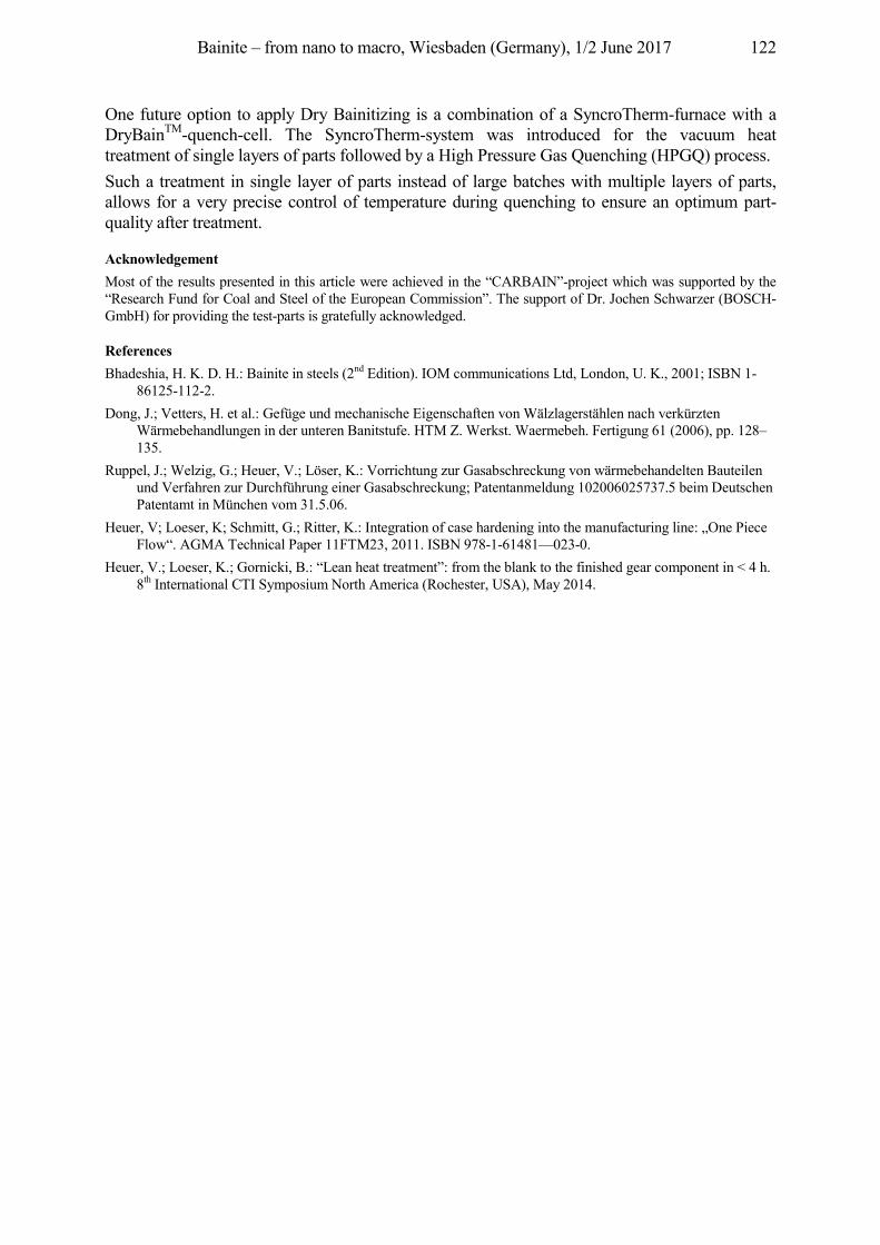
Bainite – from nano to macro, Wiesbaden (Germany), 1/2 June 2017 122
One future option to apply Dry Bainitizing is a combination of a SyncroTherm-furnace with a DryBainTM-quench-cell. The SyncroTherm-system was introduced for the vacuum heat treatment of single layers of parts followed by a High Pressure Gas Quenching (HPGQ) process. Such a treatment in single layer of parts instead of large batches with multiple layers of parts, allows for a very precise control of temperature during quenching to ensure an optimum part-quality after treatment.
Acknowledgement Most of the results presented in this article were achieved in the “CARBAIN”-project which was supported by the “Research Fund for Coal and Steel of the European Commission”. The support of Dr. Jochen Schwarzer (BOSCH-GmbH) for providing the test-parts is gratefully acknowledged.
References Bhadeshia, H. K. D. H.: Bainite in steels (2nd Edition). IOM communications Ltd, London, U. K., 2001; ISBN 1-
86125-112-2. Dong, J.; Vetters, H. et al.: Gefüge und mechanische Eigenschaften von Wälzlagerstählen nach verkürzten
Wärmebehandlungen in der unteren Banitstufe. HTM Z. Werkst. Waermebeh. Fertigung 61 (2006), pp. 128–135.
Ruppel, J.; Welzig, G.; Heuer, V.; Löser, K.: Vorrichtung zur Gasabschreckung von wärmebehandelten Bauteilen und Verfahren zur Durchführung einer Gasabschreckung; Patentanmeldung 102006025737.5 beim Deutschen Patentamt in München vom 31.5.06.
Heuer, V; Loeser, K; Schmitt, G.; Ritter, K.: Integration of case hardening into the manufacturing line: „One Piece Flow“. AGMA Technical Paper 11FTM23, 2011. ISBN 978-1-61481—023-0.
Heuer, V.; Loeser, K.; Gornicki, B.: “Lean heat treatment”: from the blank to the finished gear component in < 4 h. 8th International CTI Symposium North America (Rochester, USA), May 2014.
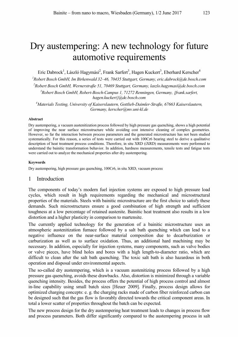
Bainite – from nano to macro, Wiesbaden (Germany), 1/2 June 2017 123
Dry austempering: A new technology for future automotive requirements
Eric Dabrock1, László Hagymási2, Frank Sarfert3, Hagen Kuckert3, Eberhard Kerscher4 1Robert Bosch GmbH, Im Birkenwald 32–46, 70435 Stuttgart, Germany, [email protected] 2Robert Bosch GmbH, Wernerstraße 51, 70469 Stuttgart, Germany, [email protected]
3Robert Bosch GmbH, Robert-Bosch-Campus 1, 71272 Renningen, Germany, {frank.sarfert, hagen.kuckert}@de.bosch.com
4Materials Testing, University of Kaiserslautern, Gottlieb-Daimler-Straße, 67663 Kaiserslautern, Germany, [email protected]
Abstract Dry austempering, a vacuum austenitization process followed by high pressure gas quenching, shows a high potential of improving the near surface microstructure while avoiding cost intensive cleaning of complex geometries. However, so far the interaction between process parameters and the generated microstructure has not been studied systematically. For this reason, a series of tests were carried out with 100Cr6 bearing steel to derive a qualitative description of heat treatment process conditions. Therefore, in situ XRD (iXRD) measurements were performed to understand the bainitic transformation behavior. In addition, hardness measurements, tensile tests and fatigue tests were carried out to analyze the mechanical properties after dry austempering.
Keywords Dry austempering, high pressure gas quenching, 100Cr6, in situ XRD, vacuum process
1 Introduction
The components of today’s modern fuel injection systems are exposed to high pressure load cycles, which result in high requirements regarding the mechanical and microstructural properties of the materials. Steels with bainitic microstructure are the first choice to satisfy these demands. Such microstructures ensure a good combination of high strength and sufficient toughness at a low percentage of retained austenite. Bainitic heat treatment also results in a low distortion and a higher plasticity in comparison to martensite. The currently applied technology for the generation of a bainitic microstructure uses an atmospheric austenitization furnace followed by a salt bath quenching which can lead to a negative influence on the near-surface material composition due to decarburization or carburization as well as to surface oxidation. Thus, an additional hard machining may be necessary. In addition, especially for injection systems, many components, such as valve bodies or valve pieces, have blind holes and bores with a high length-to-diameter ratio, which are difficult to clean after the salt bath quenching. The toxic salt bath is also hazardous in both operation and disposal under environmental aspects. The so-called dry austempering, which is a vacuum austenitizing process followed by a high pressure gas quenching, avoids these drawbacks. Also, distortion is minimized through a variable quenching intensity. Besides, the process offers the potential of high process control and almost in-line capability using small batch sizes [Heuer 2009]. Finally, process design allows for optimized charging concepts: e. g. the charging racks made of carbon fiber reinforced carbon can be designed such that the gas flow is favorably directed towards the critical component areas. In total a lower scatter of properties throughout the batch can be expected. The new process design for the dry austempering heat treatment leads to changes in process flow and process parameters. Both differ significantly compared to the austempering process in salt
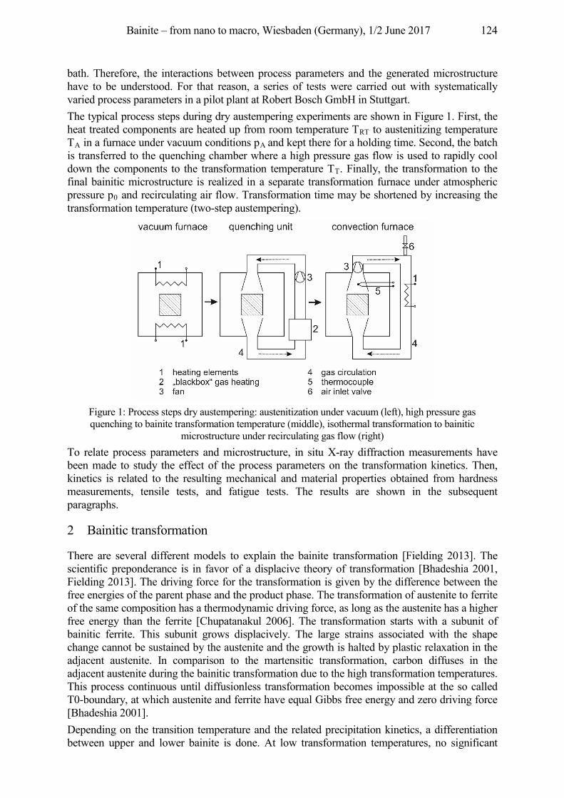
Bainite – from nano to macro, Wiesbaden (Germany), 1/2 June 2017 124
bath. Therefore, the interactions between process parameters and the generated microstructure have to be understood. For that reason, a series of tests were carried out with systematically varied process parameters in a pilot plant at Robert Bosch GmbH in Stuttgart. The typical process steps during dry austempering experiments are shown in Figure 1. First, the heat treated components are heated up from room temperature TRT to austenitizing temperature TA in a furnace under vacuum conditions pA and kept there for a holding time. Second, the batch is transferred to the quenching chamber where a high pressure gas flow is used to rapidly cool down the components to the transformation temperature TT. Finally, the transformation to the final bainitic microstructure is realized in a separate transformation furnace under atmospheric pressure p0 and recirculating air flow. Transformation time may be shortened by increasing the transformation temperature (two-step austempering).
Figure 1: Process steps dry austempering: austenitization under vacuum (left), high pressure gas quenching to bainite transformation temperature (middle), isothermal transformation to bainitic
microstructure under recirculating gas flow (right) To relate process parameters and microstructure, in situ X-ray diffraction measurements have been made to study the effect of the process parameters on the transformation kinetics. Then, kinetics is related to the resulting mechanical and material properties obtained from hardness measurements, tensile tests, and fatigue tests. The results are shown in the subsequent paragraphs.
2 Bainitic transformation
There are several different models to explain the bainite transformation [Fielding 2013]. The scientific preponderance is in favor of a displacive theory of transformation [Bhadeshia 2001, Fielding 2013]. The driving force for the transformation is given by the difference between the free energies of the parent phase and the product phase. The transformation of austenite to ferrite of the same composition has a thermodynamic driving force, as long as the austenite has a higher free energy than the ferrite [Chupatanakul 2006]. The transformation starts with a subunit of bainitic ferrite. This subunit grows displacively. The large strains associated with the shape change cannot be sustained by the austenite and the growth is halted by plastic relaxation in the adjacent austenite. In comparison to the martensitic transformation, carbon diffuses in the adjacent austenite during the bainitic transformation due to the high transformation temperatures. This process continuous until diffusionless transformation becomes impossible at the so called T0-boundary, at which austenite and ferrite have equal Gibbs free energy and zero driving force [Bhadeshia 2001]. Depending on the transition temperature and the related precipitation kinetics, a differentiation between upper and lower bainite is done. At low transformation temperatures, no significant
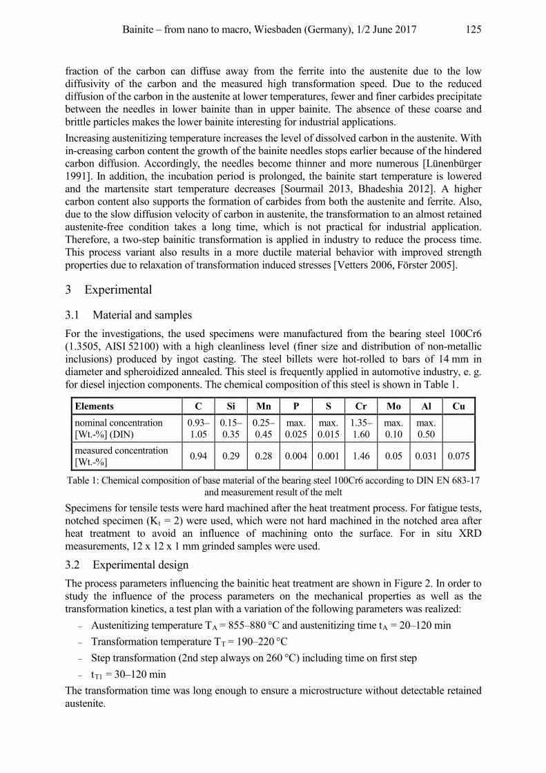
Bainite – from nano to macro, Wiesbaden (Germany), 1/2 June 2017 125
fraction of the carbon can diffuse away from the ferrite into the austenite due to the low diffusivity of the carbon and the measured high transformation speed. Due to the reduced diffusion of the carbon in the austenite at lower temperatures, fewer and finer carbides precipitate between the needles in lower bainite than in upper bainite. The absence of these coarse and brittle particles makes the lower bainite interesting for industrial applications. Increasing austenitizing temperature increases the level of dissolved carbon in the austenite. With in-creasing carbon content the growth of the bainite needles stops earlier because of the hindered carbon diffusion. Accordingly, the needles become thinner and more numerous [Lünenbürger 1991]. In addition, the incubation period is prolonged, the bainite start temperature is lowered and the martensite start temperature decreases [Sourmail 2013, Bhadeshia 2012]. A higher carbon content also supports the formation of carbides from both the austenite and ferrite. Also, due to the slow diffusion velocity of carbon in austenite, the transformation to an almost retained austenite-free condition takes a long time, which is not practical for industrial application. Therefore, a two-step bainitic transformation is applied in industry to reduce the process time. This process variant also results in a more ductile material behavior with improved strength properties due to relaxation of transformation induced stresses [Vetters 2006, Förster 2005].
3 Experimental
3.1 Material and samples For the investigations, the used specimens were manufactured from the bearing steel 100Cr6 (1.3505, AISI 52100) with a high cleanliness level (finer size and distribution of non-metallic inclusions) produced by ingot casting. The steel billets were hot-rolled to bars of 14 mm in diameter and spheroidized annealed. This steel is frequently applied in automotive industry, e. g. for diesel injection components. The chemical composition of this steel is shown in Table 1.
Table 1: Chemical composition of base material of the bearing steel 100Cr6 according to DIN EN 683-17 and measurement result of the melt
Specimens for tensile tests were hard machined after the heat treatment process. For fatigue tests, notched specimen (Kt = 2) were used, which were not hard machined in the notched area after heat treatment to avoid an influence of machining onto the surface. For in situ XRD measurements, 12 x 12 x 1 mm grinded samples were used.
3.2 Experimental design The process parameters influencing the bainitic heat treatment are shown in Figure 2. In order to study the influence of the process parameters on the mechanical properties as well as the transformation kinetics, a test plan with a variation of the following parameters was realized:
Austenitizing temperature TA = 855–880 °C and austenitizing time tA = 20–120 min Transformation temperature TT = 190–220 °C Step transformation (2nd step always on 260 °C) including time on first step tT1 = 30–120 min
The transformation time was long enough to ensure a microstructure without detectable retained austenite.
Elements C Si Mn P S Cr Mo Al Cu nominal concentration [Wt.-%] (DIN)
0.93–1.05
0.15–0.35
0.25–0.45
max. 0.025
max. 0.015
1.35–1.60
max. 0.10
max. 0.50
measured concentration [Wt.-%] 0.94 0.29 0.28 0.004 0.001 1.46 0.05 0.031 0.075
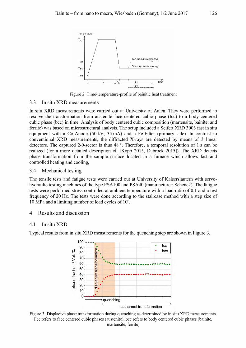
Bainite – from nano to macro, Wiesbaden (Germany), 1/2 June 2017 126
Figure 2: Time-temperature-profile of bainitic heat treatment
3.3 In situ XRD measurements In situ XRD measurements were carried out at University of Aalen. They were performed to resolve the transformation from austenite face centered cubic phase (fcc) to a body centered cubic phase (bcc) in time. Analysis of body centered cubic composition (martensite, bainite, and ferrite) was based on microstructural analysis. The setup included a Seifert XRD 3003 fast in situ equipment with a Co-Anode (50 kV, 35 mA) and a Fe-Filter (primary side). In contrast to conventional XRD measurements, the diffracted X-rays are detected by means of 3 linear detectors. The captured 2- -sector is thus 48 °. Therefore, a temporal resolution of 1 s can be realized (for a more detailed description cf. [Kopp 2015, Dabrock 2015]). The XRD detects phase transformation from the sample surface located in a furnace which allows fast and controlled heating and cooling,
3.4 Mechanical testing The tensile tests and fatigue tests were carried out at University of Kaiserslautern with servo-hydraulic testing machines of the type PSA100 and PSA40 (manufacturer: Schenck). The fatigue tests were performed stress-controlled at ambient temperature with a load ratio of 0.1 and a test frequency of 20 Hz. The tests were done according to the staircase method with a step size of 10 MPa and a limiting number of load cycles of 106.
4 Results and discussion
4.1 In situ XRD Typical results from in situ XRD measurements for the quenching step are shown in Figure 3.
Figure 3: Displacive phase transformation during quenching as determined by in situ XRD measurements.
Fcc refers to face centered cubic phases (austenite), bcc refers to body centered cubic phases (bainite, martensite, ferrite)
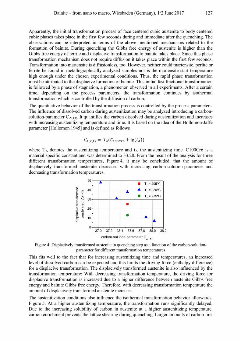
Bainite – from nano to macro, Wiesbaden (Germany), 1/2 June 2017 127
Apparently, the initial transformation process of face centered cubic austenite to body centered cubic phases takes place in the first few seconds during and immediate after the quenching. The observations can be interpreted in terms of the above mentioned mechanisms related to the formation of bainite. During quenching the Gibbs free energy of austenite is higher than the Gibbs free energy of ferrite and displacive transformation to bainite takes place. Since this phase transformation mechanism does not require diffusion it takes place within the first few seconds. Transformation into martensite is diffusionless, too. However, neither could martensite, perlite or ferrite be found in metallographically analyzed samples nor is the martensite start temperature high enough under the chosen experimental conditions. Thus, the rapid phase transformation must be attributed to the displacive formation of bainite. This initial fast fractional transformation is followed by a phase of stagnation, a phenomenon observed in all experiments. After a certain time, depending on the process parameters, the transformation continues by isothermal transformation which is controlled by the diffusion of carbon. The quantitative behavior of the transformation process is controlled by the process parameters. The influence of dissolved carbon during austenitization may be analyzed introducing a carbon-solution-parameter CA(T,t). It quantifies the carbon dissolved during austenitization and increases with increasing austenitizing temperature and time. It is based on the idea of the Hollomon-Jaffe parameter [Hollomon 1945] and is defined as follows
( , ) = ( + lg( ))
where TA denotes the austenitizing temperature and tA the austenitizing time. C100Cr6 is a material specific constant and was determined to 33.28. From the result of the analysis for three different transformation temperatures, Figure 4, it may be concluded, that the amount of displacively transformed austenite decreases with increasing carbon-solution-parameter and decreasing transformation temperatures.
Figure 4: Displacively transformed austenite in quenching step as a function of the carbon-solution-
parameter for different transformation temperatures This fits well to the fact that for increasing austenitizing time and temperatures, an increased level of dissolved carbon can be expected and this limits the driving force (enthalpy difference) for a displacive transformation. The displacively transformed austenite is also influenced by the transformation temperature: With decreasing transformation temperature, the driving force for displacive transformation is increased due to a higher difference between austenite Gibbs free energy and bainite Gibbs free energy. Therefore, with decreasing transformation temperature the amount of displacively transformed austenite increases. The austenitization conditions also influence the isothermal transformation behavior afterwards, Figure 5. At a higher austenitizing temperature, the transformation runs significantly delayed: Due to the increasing solubility of carbon in austenite at a higher austenitizing temperature, carbon enrichment prevents the lattice shearing during quenching. Larger amounts of carbon first
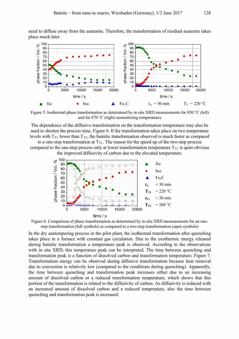
Bainite – from nano to macro, Wiesbaden (Germany), 1/2 June 2017 128
need to diffuse away from the austenite. Therefore, the transformation of residual austenite takes place much later.
Figure 5: Isothermal phase transformation as determined by in situ XRD measurements for 850 °C (left) and for 870 °C (right) austenitizing temperatures
The dependence of the diffusive transformation on the transformation temperature may also be used to shorten the process time, Figure 6. If the transformation takes place on two temperature levels with TT1 lower than TT2, the bainitic transformation observed is much faster as compared
to a one-step transformation at TT1. The reason for the speed-up of the two-step process compared to the one-step process only at lower transformation temperature TT1 is quite obvious
the improved diffusivity of carbon due to the elevated temperature.
Figure 6: Comparison of phase transformation as determined by in situ XRD measurements for an one-step transformation (full symbols) as compared to a two-step transformation (open symbols)
In the dry austempering process in the pilot plant, the isothermal transformation after quenching takes place in a furnace with constant gas circulation. Due to the exothermic energy released during bainitic transformation a temperature peak is observed. According to the observations with in situ XRD, this temperature peak can be interpreted. The time between quenching and transformation peak is a function of dissolved carbon and transformation temperature, Figure 7. Transformation energy can be observed during diffusive transformation because heat removal due to convection is relatively low (compared to the conditions during quenching). Apparently, the time between quenching and transformation peak increases either due to an increasing amount of dissolved carbon or a reduced transformation temperature, which shows that this portion of the transformation is related to the diffusivity of carbon. As diffusivity is reduced with an increased amount of dissolved carbon and a reduced temperature, also the time between quenching and transformation peak is increased.
fcc bcc Fe3C tA = 30 min TT = 220 °C
fcc bcc Fe3C
tA = 30 min TT1 = 220 °C tT1 = 30 min TT2 = 260 °C
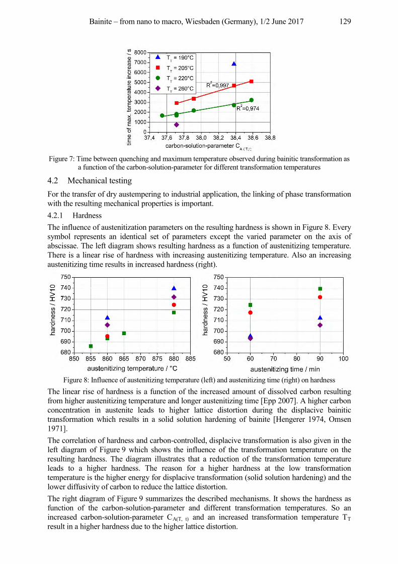
Bainite – from nano to macro, Wiesbaden (Germany), 1/2 June 2017 129
Figure 7: Time between quenching and maximum temperature observed during bainitic transformation as
a function of the carbon-solution-parameter for different transformation temperatures
4.2 Mechanical testing For the transfer of dry austempering to industrial application, the linking of phase transformation with the resulting mechanical properties is important. 4.2.1 Hardness The influence of austenitization parameters on the resulting hardness is shown in Figure 8. Every symbol represents an identical set of parameters except the varied parameter on the axis of abscissae. The left diagram shows resulting hardness as a function of austenitizing temperature. There is a linear rise of hardness with increasing austenitizing temperature. Also an increasing austenitizing time results in increased hardness (right).
Figure 8: Influence of austenitizing temperature (left) and austenitizing time (right) on hardness
The linear rise of hardness is a function of the increased amount of dissolved carbon resulting from higher austenitizing temperature and longer austenitizing time [Epp 2007]. A higher carbon concentration in austenite leads to higher lattice distortion during the displacive bainitic transformation which results in a solid solution hardening of bainite [Hengerer 1974, Omsen 1971]. The correlation of hardness and carbon-controlled, displacive transformation is also given in the left diagram of Figure 9 which shows the influence of the transformation temperature on the resulting hardness. The diagram illustrates that a reduction of the transformation temperature leads to a higher hardness. The reason for a higher hardness at the low transformation temperature is the higher energy for displacive transformation (solid solution hardening) and the lower diffusivity of carbon to reduce the lattice distortion. The right diagram of Figure 9 summarizes the described mechanisms. It shows the hardness as function of the carbon-solution-parameter and different transformation temperatures. So an increased carbon-solution-parameter CA(T, t) and an increased transformation temperature TT result in a higher hardness due to the higher lattice distortion.
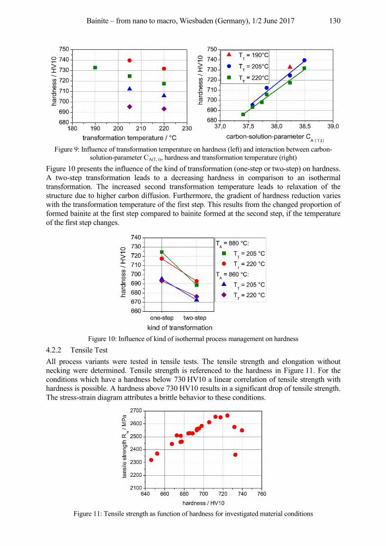
Bainite – from nano to macro, Wiesbaden (Germany), 1/2 June 2017 130
Figure 9: Influence of transformation temperature on hardness (left) and interaction between carbon-
solution-parameter CA(T, t), hardness and transformation temperature (right) Figure 10 presents the influence of the kind of transformation (one-step or two-step) on hardness. A two-step transformation leads to a decreasing hardness in comparison to an isothermal transformation. The increased second transformation temperature leads to relaxation of the structure due to higher carbon diffusion. Furthermore, the gradient of hardness reduction varies with the transformation temperature of the first step. This results from the changed proportion of formed bainite at the first step compared to bainite formed at the second step, if the temperature of the first step changes.
Figure 10: Influence of kind of isothermal process management on hardness
4.2.2 Tensile Test All process variants were tested in tensile tests. The tensile strength and elongation without necking were determined. Tensile strength is referenced to the hardness in Figure 11. For the conditions which have a hardness below 730 HV10 a linear correlation of tensile strength with hardness is possible. A hardness above 730 HV10 results in a significant drop of tensile strength. The stress-strain diagram attributes a brittle behavior to these conditions.
Figure 11: Tensile strength as function of hardness for investigated material conditions
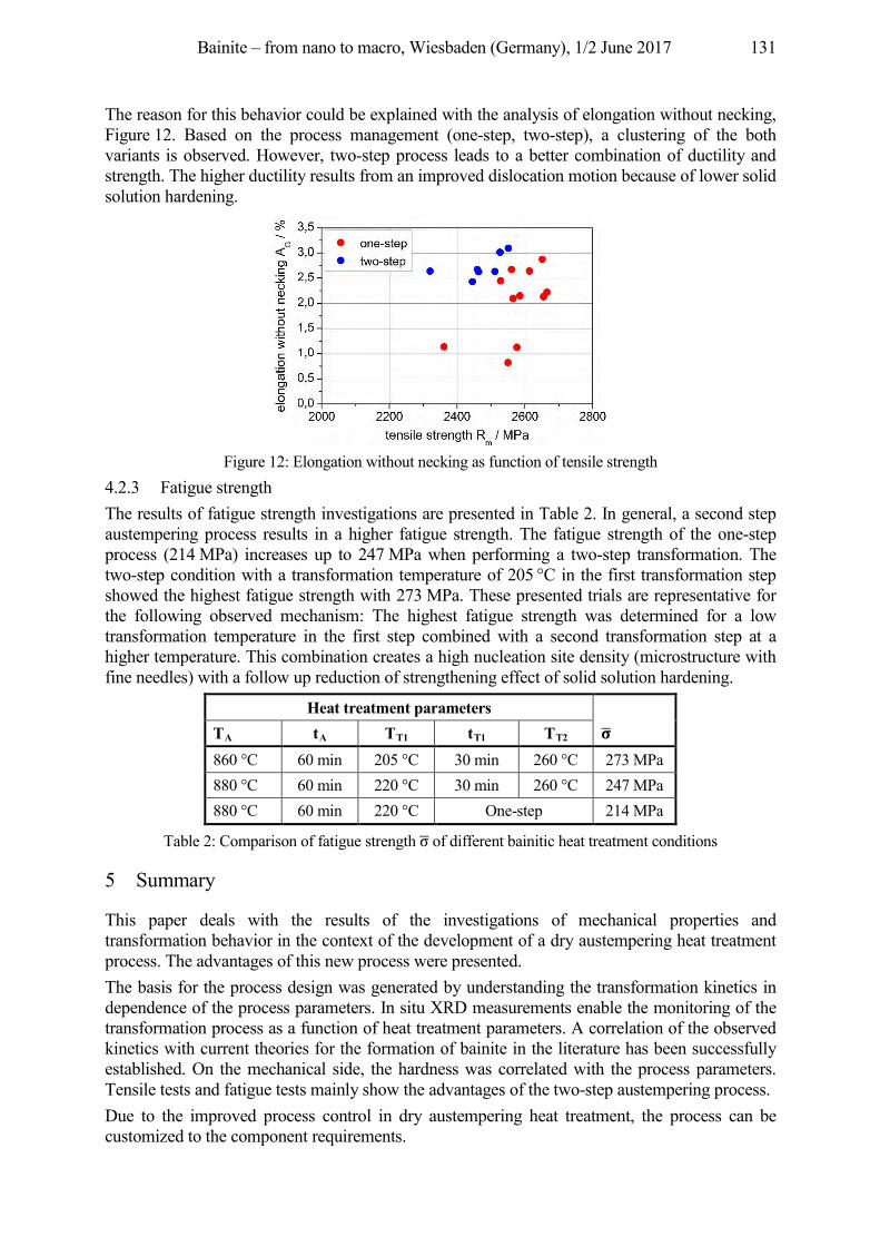
Bainite – from nano to macro, Wiesbaden (Germany), 1/2 June 2017 131
The reason for this behavior could be explained with the analysis of elongation without necking, Figure 12. Based on the process management (one-step, two-step), a clustering of the both variants is observed. However, two-step process leads to a better combination of ductility and strength. The higher ductility results from an improved dislocation motion because of lower solid solution hardening.
Figure 12: Elongation without necking as function of tensile strength
4.2.3 Fatigue strength The results of fatigue strength investigations are presented in Table 2. In general, a second step austempering process results in a higher fatigue strength. The fatigue strength of the one-step process (214 MPa) increases up to 247 MPa when performing a two-step transformation. The two-step condition with a transformation temperature of 205 °C in the first transformation step showed the highest fatigue strength with 273 MPa. These presented trials are representative for the following observed mechanism: The highest fatigue strength was determined for a low transformation temperature in the first step combined with a second transformation step at a higher temperature. This combination creates a high nucleation site density (microstructure with fine needles) with a follow up reduction of strengthening effect of solid solution hardening.
Heat treatment parameters TA tA TT1 tT1 TT2
860 °C 60 min 205 °C 30 min 260 °C 273 MPa 880 °C 60 min 220 °C 30 min 260 °C 247 MPa 880 °C 60 min 220 °C One-step 214 MPa
Table 2: Comparison of fatigue strength of different bainitic heat treatment conditions
5 Summary
This paper deals with the results of the investigations of mechanical properties and transformation behavior in the context of the development of a dry austempering heat treatment process. The advantages of this new process were presented. The basis for the process design was generated by understanding the transformation kinetics in dependence of the process parameters. In situ XRD measurements enable the monitoring of the transformation process as a function of heat treatment parameters. A correlation of the observed kinetics with current theories for the formation of bainite in the literature has been successfully established. On the mechanical side, the hardness was correlated with the process parameters. Tensile tests and fatigue tests mainly show the advantages of the two-step austempering process. Due to the improved process control in dry austempering heat treatment, the process can be customized to the component requirements.
Bainite – from nano to macro, Wiesbaden (Germany), 1/2 June 2017 132
References Bhadeshia, H. K. D. H.: in steels (2nd Edition). IOM communications Ltd, London, U. K., 2001; ISBN 1-86125-
112-2 Bhadeshia, H. K. D. H.: Steels for bearings. Progress in Materials Science 57( 2012) 2, pp. 268–435. Chupatanakul, S.; Nash, P.: Dilatometric measurement of carbon enrichment in austenite during bainite
transformation. Journal of Materials Science 41 (2006) 15, pp. 4965–4969. Dabrock, E.; Hagymási, L.; Krug, T.; Sarfert, F.; Kerscher, E.: Dry austempering heat treatment process:
interactions between process parameters, transformation kinetics, and mechanical properties. La Metallurgia Italiana 107 (2015) 10, pp. 49–56.
Epp, J.; Surm, H.; Kessler, O.; Hirsch, Th.: In situ X-ray phase analysis and computer simulation of carbide dissolution of ball bearing steel at different austenitizing temperatures. Acta Materialia 55 (2007) 17, pp. 5959–5967.
Fielding, L. C. D.: The bainite Controversy. Materials Science and Technology 29 (2013) 4, pp. 383–399. Förster, L.; Michalski, M.; Becht, A.; Englert, K.-O.; Czeringer, M.: Verfahren zum Bainitisieren von Stahlteilen.
EP1248862 B1, 2005. Hengerer, F.; Lucas, G.; Nyberg, B.: Zwischenstufenumwandlung von Wälzlagerstählen. HTM Haerterei-Techn.
Mitt. 29 (1974) 2, pp. 71–79. Heuer, V.; Löser, K.; Ruppel, J.: Dry bainitizing – a new process for bainitic microstructures. HTM J. Heat Treatm.
Mat. 64 (2009) 1, pp. 28–33. Hollomon, J. H.; Jaffe, L. D.: Time-Temperature Relations in Tempering Steel. Transactions of the American
Institute of Mining and Metallurgical Engineers, Vol 162, 1945, pp. 223–249. Kopp, A.; Bernthaler, T.; Ketzer-Raichle, G.; Schneider, G.: Investigation of phase transformations in steel using
fast in-situ x-ray diffraction (iXRD). European Conference on Heat treatment 2015 & 22nd IFHTSE Congress, Venice, 2015.
Lünenbürger, A.: Zum Umwandlungs- und Verformungsverhalten bainitisch-austenitischer Siliziumstähle. University of Karlsruhe, 1991.
Omsen: Relationships between structure, hardness, and toughness of untempered and tempered 0.7 C bainits. The Journal of the Iron and Steel Institute 209 (1971) 2, pp. 131–137.
Sourmail, Th.; Smanio, V.: Low temperature kinetics of bainite formation in high carbon steels. Acta Materialia 61 (2013) 7, pp. 2639–2648.
Vetters; H. Dong, J.; Bomas, H.; Hoffmann, F.; Zoch, H.-W.: Microstructure and fatigue strength of the roller-bearing steel 100Cr6 (SAE 52100) after two-step bainitisation and combined bainitic-martensitic heat treatment. International Journal of Materials Research 97 (2006) 10, pp. 1432–1440.
Bainite – from nano to macro, Wiesbaden (Germany), 1/2 June 2017 133
New bainite sensor technology allows for a detailed view on material transformation
Heinrich Klümper-Westkamp1, Jochen Vetterlein2, Hans-Werner Zoch1, Wilfried Reimche3, Oliver Bruchwald3, Hans Jürgen Maier3
1Stiftung Institut für Werkstofftechnik, Badgasteiner Str. 3, 28359 Bremen, Germany, {hkw, zoch}@iwt-bremen.de
2Flowserve Hamburg GmbH, Friedrich-Ebert-Damm 105, 22047 Hamburg, Germany, [email protected]
3Leibniz Universität Hannover, Lise-Meitner-Straße 1,30823 Garbsen, Germany, {reimche, bruchwald, maier}@iw.uni-hannover.de
Abstract Bainite sensor technology is a non-destructive measurement system for the application to monitor bainite transformation. The measurement is based upon eddy current harmonic analysis. Electrical and magnetic properties are measured, analyzed and correlated to the relevant material properties. The measured electromagnetical properties are influenced not only by lattice structure and grain boundaries but also by subgrains, interstitial content, dislocations, residual stress and precipitations. This technology is a powerful tool to look inside the steel material even during transformation. It is important to understand, interpret and correlate the measured signals to these structural material aspects. The principle function of the bainite sensor technology will be illustrated and basic functions exemplarily shown for ball bearing steel and austempered ductile iron (ADI). The main measured property is the fraction of retained austenite within the microstructure. Further information from harmonic analyses delivers more details to a complete picture and understanding of transformation. So sensor controlled bainite hardening will make the process more reproducible, well directed and more economical.
Keywords eddy current, non-destructive testing, ball bearing steels, ADI, bainite transformation, bainite sensor
1 Introduction
Bainite hardening or so-called austempering is a heat treatment process applied to steel and cast iron products to improve mechanical properties in combination with lower distortion, higher toughness, better residual stress pattern and higher crack propagation resistance [Bhadeshia 2001, Aaronson, Spanos, Reynolds 2002]. It is increasingly used to produce components with high strength and hardness as an alternative to the martensite hardening [Hengerer, Lucas, Nyberg 1974, Zoch 1992, Fang et al. 2002, Hillert 2002, Vetters, Bullerdiek 2002, Ölund, Larsson, Lund 1999, Vetters 2002]. Typical components are ball bearings [Ölund, Larsson, Lund 1999], rail steels [Sawley, Kristan 2003], stamped, bended and formed steel sheets [Kaiser 2001] and many ADI components, which see the similar process of ausferritizing [Elliot 1997]. The bainite transformation is a time consuming process. The time dependence of the transformation is controlled by the microstructure of the material, the chemical composition, and the temperature and time of austenitizing and the transformation temperature range. It is difficult to predict the development and the end of the process [Schwendemann 1983, Hunkel et al. 1999, Quidort, Brechet 2002, Maier, Ahrens 2002]. So when precise components have to be produced without or very low retained austenite, very long treatment times are necessary. A high safety factor for the transformation time must be included. This fact reduces the economy of the process. Furthermore, it is difficult and complex to get the optimised process cycle when special transformation cycles are required as for the patented two-temperature step process [Ölund, Larsson, Lund 1999]. To overcome this difficulty, a measurement system was developed, which
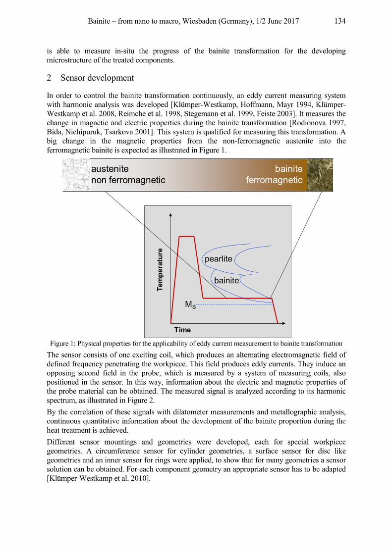
Bainite – from nano to macro, Wiesbaden (Germany), 1/2 June 2017 134
is able to measure in-situ the progress of the bainite transformation for the developing microstructure of the treated components.
2 Sensor development
In order to control the bainite transformation continuously, an eddy current measuring system with harmonic analysis was developed [Klümper-Westkamp, Hoffmann, Mayr 1994, Klümper-Westkamp et al. 2008, Reimche et al. 1998, Stegemann et al. 1999, Feiste 2003]. It measures the change in magnetic and electric properties during the bainite transformation [Rodionova 1997, Bida, Nichipuruk, Tsarkova 2001]. This system is qualified for measuring this transformation. A big change in the magnetic properties from the non-ferromagnetic austenite into the ferromagnetic bainite is expected as illustrated in Figure 1.
Figure 1: Physical properties for the applicability of eddy current measurement to bainite transformation
The sensor consists of one exciting coil, which produces an alternating electromagnetic field of defined frequency penetrating the workpiece. This field produces eddy currents. They induce an opposing second field in the probe, which is measured by a system of measuring coils, also positioned in the sensor. In this way, information about the electric and magnetic properties of the probe material can be obtained. The measured signal is analyzed according to its harmonic spectrum, as illustrated in Figure 2. By the correlation of these signals with dilatometer measurements and metallographic analysis, continuous quantitative information about the development of the bainite proportion during the heat treatment is achieved. Different sensor mountings and geometries were developed, each for special workpiece geometries. A circumference sensor for cylinder geometries, a surface sensor for disc like geometries and an inner sensor for rings were applied, to show that for many geometries a sensor solution can be obtained. For each component geometry an appropriate sensor has to be adapted [Klümper-Westkamp et al. 2010].
Tem
pera
ture
Time
MS
bainite
pearlite
austenitenon ferromagnetic
bainiteferromagnetic
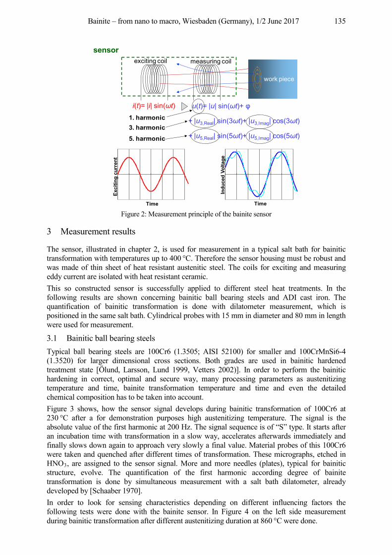
Bainite – from nano to macro, Wiesbaden (Germany), 1/2 June 2017 135
Figure 2: Measurement principle of the bainite sensor
3 Measurement results
The sensor, illustrated in chapter 2, is used for measurement in a typical salt bath for bainitic transformation with temperatures up to 400 °C. Therefore the sensor housing must be robust and was made of thin sheet of heat resistant austenitic steel. The coils for exciting and measuring eddy current are isolated with heat resistant ceramic. This so constructed sensor is successfully applied to different steel heat treatments. In the following results are shown concerning bainitic ball bearing steels and ADI cast iron. The quantification of bainitic transformation is done with dilatometer measurement, which is positioned in the same salt bath. Cylindrical probes with 15 mm in diameter and 80 mm in length were used for measurement.
3.1 Bainitic ball bearing steels Typical ball bearing steels are 100Cr6 (1.3505; AISI 52100) for smaller and 100CrMnSi6-4 (1.3520) for larger dimensional cross sections. Both grades are used in bainitic hardened treatment state [Ölund, Larsson, Lund 1999, Vetters 2002)]. In order to perform the bainitic hardening in correct, optimal and secure way, many processing parameters as austenitizing temperature and time, bainite transformation temperature and time and even the detailed chemical composition has to be taken into account. Figure 3 shows, how the sensor signal develops during bainitic transformation of 100Cr6 at 230 °C after a for demonstration purposes high austenitizing temperature. The signal is the absolute value of the first harmonic at 200 Hz. The signal sequence is of “S” type. It starts after an incubation time with transformation in a slow way, accelerates afterwards immediately and finally slows down again to approach very slowly a final value. Material probes of this 100Cr6 were taken and quenched after different times of transformation. These micrographs, etched in HNO3, are assigned to the sensor signal. More and more needles (plates), typical for bainitic structure, evolve. The quantification of the first harmonic according degree of bainite transformation is done by simultaneous measurement with a salt bath dilatometer, already developed by [Schaaber 1970]. In order to look for sensing characteristics depending on different influencing factors the following tests were done with the bainite sensor. In Figure 4 on the left side measurement during bainitic transformation after different austenitizing duration at 860 °C were done.
i(t)= |i| sin(ωt) u(t)= |u| sin(ωt)+ 1. harmonic3. harmonic
5. harmonic
+ |u3,Real| sin(3ωt)+ |u3,Imag| cos(3ωt)
+ |u5,Real| sin(5ωt)+ |u5,Imag| cos(5ωt)
Time
Exci
ting
curr
ent
Time
Indu
ced
Volta
ge
exciting coil
work piece
measuring coil
sensor
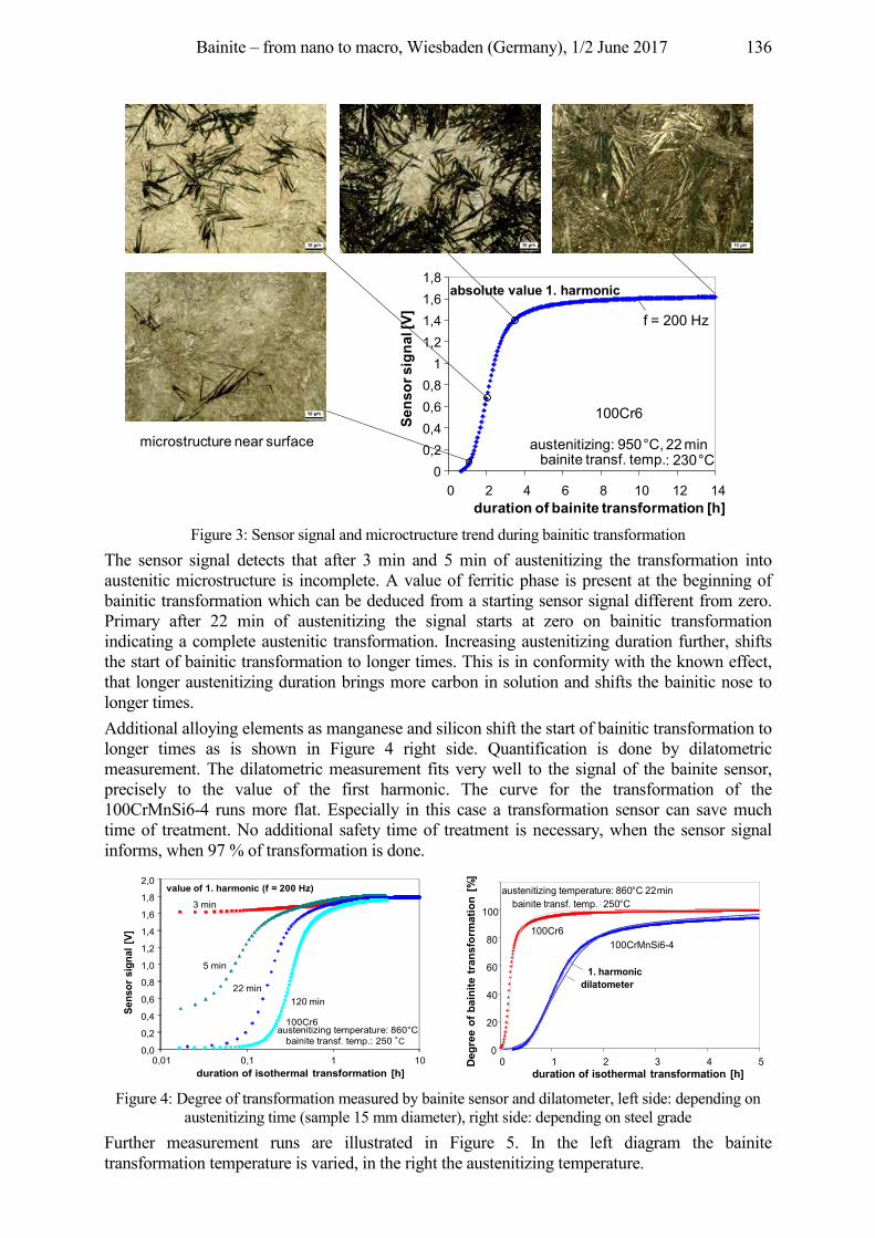
Bainite – from nano to macro, Wiesbaden (Germany), 1/2 June 2017 136
Figure 3: Sensor signal and microctructure trend during bainitic transformation
The sensor signal detects that after 3 min and 5 min of austenitizing the transformation into austenitic microstructure is incomplete. A value of ferritic phase is present at the beginning of bainitic transformation which can be deduced from a starting sensor signal different from zero. Primary after 22 min of austenitizing the signal starts at zero on bainitic transformation indicating a complete austenitic transformation. Increasing austenitizing duration further, shifts the start of bainitic transformation to longer times. This is in conformity with the known effect, that longer austenitizing duration brings more carbon in solution and shifts the bainitic nose to longer times. Additional alloying elements as manganese and silicon shift the start of bainitic transformation to longer times as is shown in Figure 4 right side. Quantification is done by dilatometric measurement. The dilatometric measurement fits very well to the signal of the bainite sensor, precisely to the value of the first harmonic. The curve for the transformation of the 100CrMnSi6-4 runs more flat. Especially in this case a transformation sensor can save much time of treatment. No additional safety time of treatment is necessary, when the sensor signal informs, when 97 % of transformation is done.
Figure 4: Degree of transformation measured by bainite sensor and dilatometer, left side: depending on
austenitizing time (sample 15 mm diameter), right side: depending on steel grade Further measurement runs are illustrated in Figure 5. In the left diagram the bainite transformation temperature is varied, in the right the austenitizing temperature.
microstructure near surface
f = 200 Hz
00,20,40,60,8
11,21,41,61,8
0 2 4 6 8 10 12 14duration of bainite transformation [h]
Sens
or s
igna
l [V]
100Cr6
austenitizing: 950 °C, 22 minbainite transf. temp.: 230 °C
absolute value 1. harmonic
f = 200 Hz
0,0
0,2
0,4
0,6
0,8
1,0
1,2
1,4
1,6
1,8
2,0
0,01 0,1 1 10duration of isothermal transformation [h]
3 min
5 min
22 min120 min
100Cr6austenitizing temperature: 860°C
bainite transf. temp.: 250 °C
value of 1. harmonic (f = 200 Hz)
Sens
or s
igna
l[V]
0
20
40
60
80
100
0 1 2 3 4 5
austenitizing temperature: 860 °C 22 minbainite transf. temp. : 250 °C
100CrMnSi6-4100Cr6
1. harmonicdilatometer
duration of isothermal transformation [h]
Deg
ree
of b
aini
tetr
ansf
orm
atio
n [%
]
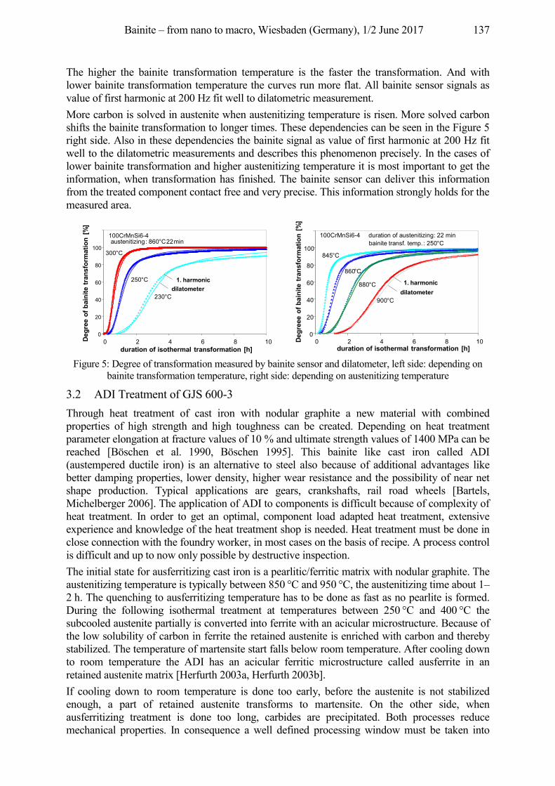
Bainite – from nano to macro, Wiesbaden (Germany), 1/2 June 2017 137
The higher the bainite transformation temperature is the faster the transformation. And with lower bainite transformation temperature the curves run more flat. All bainite sensor signals as value of first harmonic at 200 Hz fit well to dilatometric measurement. More carbon is solved in austenite when austenitizing temperature is risen. More solved carbon shifts the bainite transformation to longer times. These dependencies can be seen in the Figure 5 right side. Also in these dependencies the bainite signal as value of first harmonic at 200 Hz fit well to the dilatometric measurements and describes this phenomenon precisely. In the cases of lower bainite transformation and higher austenitizing temperature it is most important to get the information, when transformation has finished. The bainite sensor can deliver this information from the treated component contact free and very precise. This information strongly holds for the measured area.
Figure 5: Degree of transformation measured by bainite sensor and dilatometer, left side: depending on
bainite transformation temperature, right side: depending on austenitizing temperature
3.2 ADI Treatment of GJS 600-3 Through heat treatment of cast iron with nodular graphite a new material with combined properties of high strength and high toughness can be created. Depending on heat treatment parameter elongation at fracture values of 10 % and ultimate strength values of 1400 MPa can be reached [Böschen et al. 1990, Böschen 1995]. This bainite like cast iron called ADI (austempered ductile iron) is an alternative to steel also because of additional advantages like better damping properties, lower density, higher wear resistance and the possibility of near net shape production. Typical applications are gears, crankshafts, rail road wheels [Bartels, Michelberger 2006]. The application of ADI to components is difficult because of complexity of heat treatment. In order to get an optimal, component load adapted heat treatment, extensive experience and knowledge of the heat treatment shop is needed. Heat treatment must be done in close connection with the foundry worker, in most cases on the basis of recipe. A process control is difficult and up to now only possible by destructive inspection. The initial state for ausferritizing cast iron is a pearlitic/ferritic matrix with nodular graphite. The austenitizing temperature is typically between 850 °C and 950 °C, the austenitizing time about 1–2 h. The quenching to ausferritizing temperature has to be done as fast as no pearlite is formed. During the following isothermal treatment at temperatures between 250 °C and 400 °C the subcooled austenite partially is converted into ferrite with an acicular microstructure. Because of the low solubility of carbon in ferrite the retained austenite is enriched with carbon and thereby stabilized. The temperature of martensite start falls below room temperature. After cooling down to room temperature the ADI has an acicular ferritic microstructure called ausferrite in an retained austenite matrix [Herfurth 2003a, Herfurth 2003b]. If cooling down to room temperature is done too early, before the austenite is not stabilized enough, a part of retained austenite transforms to martensite. On the other side, when ausferritizing treatment is done too long, carbides are precipitated. Both processes reduce mechanical properties. In consequence a well defined processing window must be taken into
0
20
40
60
80
100
0 2 4 6 8 10duration of isothermal transformation [h]
Degr
ee o
f bai
nite
tran
sfor
mat
ion
[%]
100CrMnSi6-4austenitizing: 860 °C 22 min
230 °C
250 °C
300 °C
1. harmonicdilatometer
0
20
40
60
80
100
0 2 4 6 8 10
100CrMnSi6-4 duration of austenitizing: 22 minbainite transf. temp. : 250 °C
900 °C
880 °C
860 °C
845 °C
1. harmonicdilatometer
duration of isothermal transformation [h]
Degr
eee
of b
aini
tetr
ansf
orm
atio
n [%
]
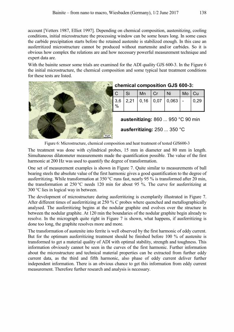
Bainite – from nano to macro, Wiesbaden (Germany), 1/2 June 2017 138
account [Vetters 1987, Elliot 1997]. Depending on chemical composition, austenitizing, cooling conditions, initial microstructure the processing window can be some hours long. In some cases the carbide precipitation starts before the retained austenite is stabilized enough. In this case an ausferritized microstructure cannot be produced without martensite and/or carbides. So it is obvious how complex the relations are and how necessary powerful measurement technique and expert data are. With the bainite sensor some trials are examined for the ADI quality GJS 600-3. In the Figure 6 the initial microstructure, the chemical composition and some typical heat treatment conditions for these tests are listed.
Figure 6: Microstructure, chemical composition and heat treatment of tested GJS600-3
The treatment was done with cylindrical probes, 15 mm in diameter and 80 mm in length. Simultaneous dilatometer measurements made the quantification possible. The value of the first harmonic at 200 Hz was used to quantify the degree of transformation. One set of measurement examples is shown in Figure 7. Quite similar to measurements of ball bearing steels the absolute value of the first harmonic gives a good quantification to the degree of ausferritizing. While transformation at 350 °C runs fast, nearly 95 % is transformed after 20 min, the transformation at 250 °C needs 120 min for about 95 %. The curve for ausferritizing at 300 °C lies in logical way in between. The development of microstructure during ausferritizing is exemplarily illustrated in Figure 7. After different times of ausferritizing at 250 % C probes where quenched and metallographically analysed. The ausferritizing begins at the nodular graphite end evolves over the structure in between the nodular graphite. At 120 min the boundaries of the nodular graphite begin already to resolve. In the micrograph quite right in Figure 7 is shown, what happens, if ausferritizing is done too long, the graphite resolves more and more. The transformation of austenite into ferrite is well observed by the first harmonic of eddy current. But for the optimum ausferritizing treatment should be finished before 100 % of austenite is transformed to get a material quality of ADI with optimal stability, strength and toughness. This information obviously cannot be seen in the curves of the first harmonic. Further information about the microstructure and technical material properties can be extracted from further eddy current data, as the third and fifth harmonic, also phase of eddy current deliver further independent information. There is an obvious chance to get this information from eddy current measurement. Therefore further research and analysis is necessary.
C Si Mn Cr Ni Mo Cu3,6%
2,21 0,16 0,07 0,063 - 0,29
austenitizing: 860 ... 950 °C 90 min
ausferritizing: 250 ... 350 °C
chemical composition GJS 600-3:
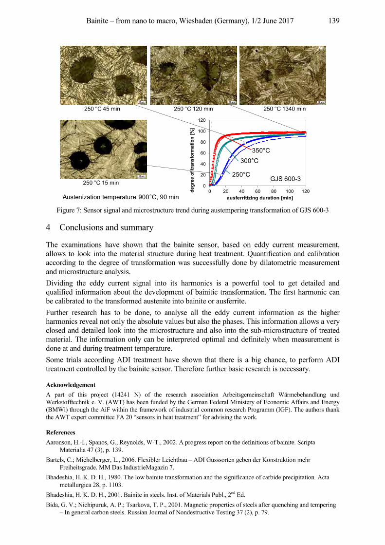
Bainite – from nano to macro, Wiesbaden (Germany), 1/2 June 2017 139
Figure 7: Sensor signal and microstructure trend during austempering transformation of GJS 600-3
4 Conclusions and summary
The examinations have shown that the bainite sensor, based on eddy current measurement, allows to look into the material structure during heat treatment. Quantification and calibration according to the degree of transformation was successfully done by dilatometric measurement and microstructure analysis. Dividing the eddy current signal into its harmonics is a powerful tool to get detailed and qualified information about the development of bainitic transformation. The first harmonic can be calibrated to the transformed austenite into bainite or ausferrite. Further research has to be done, to analyse all the eddy current information as the higher harmonics reveal not only the absolute values but also the phases. This information allows a very closed and detailed look into the microstructure and also into the sub-microstructure of treated material. The information only can be interpreted optimal and definitely when measurement is done at and during treatment temperature. Some trials according ADI treatment have shown that there is a big chance, to perform ADI treatment controlled by the bainite sensor. Therefore further basic research is necessary.
Acknowledgement A part of this project (14241 N) of the research association Arbeitsgemeinschaft Wärmebehandlung und Werkstofftechnik e. V. (AWT) has been funded by the German Federal Ministery of Economic Affairs and Energy (BMWi) through the AiF within the framework of industrial common research Programm (IGF). The authors thank the AWT expert committee FA 20 “sensors in heat treatment” for advising the work.
References Aaronson, H.-I., Spanos, G., Reynolds, W-T., 2002. A progress report on the definitions of bainite. Scripta
Materialia 47 (3), p. 139. Bartels, C.; Michelberger, L., 2006. Flexibler Leichtbau – ADI Gusssorten geben der Konstruktion mehr
Freiheitsgrade. MM Das IndustrieMagazin 7. Bhadeshia, H. K. D. H., 1980. The low bainite transformation and the significance of carbide precipitation. Acta
metallurgica 28, p. 1103. Bhadeshia, H. K. D. H., 2001. Bainite in steels. Inst. of Materials Publ., 2nd Ed. Bida, G. V.; Nichipuruk, A. P.; Tsarkova, T. P., 2001. Magnetic properties of steels after quenching and tempering
– In general carbon steels. Russian Journal of Nondestructive Testing 37 (2), p. 79.
0
20
40
60
80
100
120
0 20 40 60 80 100 120degr
ee o
f tra
nsfo
rmat
ion
[%]
ausferritizing duration [min]
GJS 600-3Austenitisierung: 900 °C 90 min
250 °C 45 min 250 °C 120 min 250 °C 1340 min
250 °C 15 min
300°C350°C
250°C
Austenization temperature 900°C, 90 min
GJS 600-3
Bainite – from nano to macro, Wiesbaden (Germany), 1/2 June 2017 140
Böschen, R., 1995. Schwingfestigkeitsverhalten von randschichtgehärtetem bainitisch-austenitischen Gußeisen mit Kugelgraphit. Dissertation IWT Bremen, Fortschritt Berichte VDI Reihe 18 Nr. 168.
Böschen, R.; Bomas, H.; Vetters, H.; Mayr, P., 1990. Einfluß des Restaustenits auf die Schwingfestigkeit von bainitischem Gußeisen mit Kugelgraphit. Konstruieren + Giessen 15, pp. 34–39; ISSN-0341-6615.
Elliot, R., 1997. The role of in promoting Austempered ductile iron. Heat treatment of metals 3, p. 55–59. Fang, H.-S..; Yang, J.-B.; Yang, Z.-G.; Bai, B.-Z., 2002. The mechanism of bainite transformation in steels. Scripta
Materialia, 47 (3), p. 157. Feiste, K. L., 2003. Entwicklung der Harmonischen-Analyse von Wirbelstromsignalen zur Charakterisierung
mechanischer Kugelgraphitgusseigenschaften. Fortschritt Berichte VDI, Reihe 8, Nr. 1006, Diss. Uni. Hannover, ISBN 3-18-500608-9.
Hengerer, F.; Lucas, G.; Nyberg, B., 1974. Zwischenstufenumwandlung von Wälzlagerstählen. HTM Härterei-Techn. Mitt. 29, p. 71.
Herfurth, K., 2003a. Austenitisch-ferritisches Gußeisen mit Kugelgraphit. Teil 1 Ausferritisierung. Giesserei-Praxis 3, p. 99.
Herfurth, K., 2003b: Austenitisch-ferritisches Gußeisen mit Kugelgraphit. Teil 2 Unvollständige isothermische Austenitumwandlung. Giesserei-Praxis 4, p. 137.
Hillert, M., 2002. Paradigm shift for bainite. Scripta Materialia, 47 (3), p. 175. Hunkel, M.; Lübben, Th.; Hoffmann, F.; Mayr, P., 1999. Modellierung der bainitischen und perlitischen
Umwandlung bei Stählen. HTM Härterei-Techn. Mitt. 54, p. 365. Kaiser, P., 2001. Bainitisch vergütetes Kaltband für Stanz-, Biege- und Formteile. EFB-Tagungsband, Band T21
(2001), Seite 4.1–4.9, Prozessoptimierung in der Blechverarbeitung, EFB-Kolloquium, Fellbach b. Stuttgart, D, 13.–14. März.
Klümper-Westkamp, H.; Hoffmann, F.; Mayr, P., 1994. Neue werkstoffkundliche Qualitätssicherungsperspektiven durch in-situ Anlaßsensoren. FVA Forschungsreport.
Klümper-Westkamp, H.; Vetterlein, J.; Lütjens, J.; Zoch, H.-W.; Reimche, W.; Bach, Fr.-W., 2008. Bainite Sensor – A new tool for process and quality control of the bainite transformation. HTM Z. Werkst. Waermebeh. Fertigung 63 (3), pp. 174–180.
Klümper-Westkamp, H.; Zoch, H.-W.; Reimche, W.; Zwoch, S.; Bach, Fr.-W., 2010. Wirtschaftlich Bainitisieren mit neuem Wirbelstrom-Messsystem. Gaswärme International 59 (6), p. 472.
Maier, H-J.; Ahrens, U., 2002. Isothermal bainitic transformation in low alloy steels: factors limiting prediction of the resulting material’s properties. Zeitschrift für Metallkunde 93 (7), p. 712.
Ölund, P.; Larsson, S.; Lund, T., 1999. Properties of bainite hardened SAE52100 steel. Heat Treating Proceedings of the 18th conference of ASM. 12–15. Oct. 1998, Rosemont, USA, p. 305.
Quidort, D.; Brechet, Y., 2002. The role of carbon on the kinetics of bainite transformation in steels. Scripta Materialia 47 (3), p. 151.
Reimche, W.; Stegemann, D.; Feiste, K. L.; Reichert, C.; Heutling, B., 1998. Non Linear Harmonic Analysis for the Determination of Steel Properties. 7th Annual Research Symposium of the ASNT, Mai.
Rodionova, S. S. et al., 1997. Interconnection between magnetic and mechanical properties and the structural state of steel for isothermal quenching. Russian Journal of Nondestructive Testing 33 (8), p. 521.
Sawley, K.; Kristan, J., 2003. Development of bainitic rail steels with potential resistance to rolling contact fatigue. Fatigue and Fracture of Engineering Materials and Structures 10, p. 1019.
Schaaber, O., 1970. Kinetik des isothermen Zerfalls von übersättigten Mischkristallen, Deutung der komplexen Kurven. HTM Härterei-Techn. Mitt. 25 (3), pp. 177–185.
Schwendemann, H., 1983. Die therm. Restaustenitstabilisierung bei den Stählen 100Cr6 und X210Cr12. Diss. Karlsruhe.
Stegemann, D.; Reimche, W.; Feiste, K. L.; Reichert, CH.; Marques, P., 1999. Determination of Hardness and Hardness Penetration Depth of Metal Components by Non Linear Harmonics Analysis. 9th Int. Symp. on Nondestructive Characterization of Materials in Sydney, Aus., 28.6–.2.7.
Vetters, H.; Bullerdiek, K., 2002. Umwandlungsgefüge des Wälzlagerstahls 100 Cr 6. Sonderbände der Praktischen Metallographie 33, p. 41.
Vetters, H., 2002. Wälzelemente aus 100Cr6, bainitisch umwandeln oder martensitisch härten. HTM Z. Werkst. Waermebeh. Fertigung 57 (6), p. 403.
Vetters, H. et al., 1987. Bainitisches Gusseisen mit Kugelgraphit. Abschlußbericht BMFT FV:03-S-428-1. Zoch, H.-W., 1992. Wärmebehandlungsverfahren in der Wälzlagerfertigung. Härterei-Techn. Mitt. 47, p. 223.
Bainite – from nano to macro, Wiesbaden (Germany), 1/2 June 2017 141
Inline application of bainite sensor technology for characterizing phase transformation during
cooling Wilfried Reimche1, Oliver Bruchwald1, Sebastian Barton1, Hans Jürgen Maier1, Heinrich
Klümper-Westkamp2, Hans-Werner Zoch2 1Leibniz Universität Hannover, Lise-Meitner-Straße 1,30823 Garbsen, Germany, {reimche, bruchwald,
barton, maier}@iw.uni-hannover.de
2Stiftung Institut für Werkstofftechnik, Badgasteiner Str. 3, 28359 Bremen, Germany, {hkw,zoch}@iwt-bremen.de
Abstract The current efforts to reduce CO2-emissions increasingly require the usage of new high strength steel grades and high performance lightweight components in cars as well as resource-efficient and eco-friendly production processes. Modern bainitic steels with high strength and ductility can obtain their desired microstructure and properties directly upon cooling from the forging heat. Therefore, no additional heat treatment is necessary and the forging process chain can be significantly shortened compared to Q&T steels. However, many process parameters influence the microstructure evolution during the cooling from the forging heat; hence reliable prediction of the resulting microstructure is challenging. For that reason, safety margins in the shortened process workflow are currently still necessary in order to ensure high component quality. A new measuring system - developed to detect and to monitor the real material transformation and microstructure formation in steel components in situ during the cooling from the austenitic state in an air or water-air sprayfield will be presented. The reliable detection of the transformation onset, degree and end as well as the characterization and quantification of the microstructure components online during the cooling process allows for realizing an individual and controlled cooling as well as an online quality assurance and documentation of the microstructure evolution, e. g. in Industry 4.0 applications.
Keywords bainite transformation, process monitoring, bainite sensor, eddy current, harmonic analysis, non-destructive testing
1 Introduction
Due to many advantages [Williams, Fatemi 2007, Doege, Behrens 2010] high performance steel components, especially for applications in car manufacturing, are usually forged parts. In order to shorten the forging process chain and to realize a resource- and energy-efficient production, bainitic steels that can obtain their desired microstructure and mechanical properties during the cooling from the forging heat without any further heat treatment are increasingly used. Unfortunately, many process parameters (e. g. the austenitising temperature or the components chemical composition) significantly influence the transformation behaviour, and thus, predictions about the microstructure’s evolution using CCT-diagrams or simulation results are often inaccurate. Therefore, safety margins in the process design and an additional quality assurance are often necessary.
2 Measuring system
Within the project "EcoForge” [Bucquet et al. 2014] a new measuring system was developed to detect and to monitor the real material transformation and microstructure evolution in steel components in situ during the cooling from the austenite region [Bruchwald, Frackowiak, Reimche et al. 2015, Bruchwald, Frackowiak, Bucquet et al. 2015, Bruchwald 2017]. The
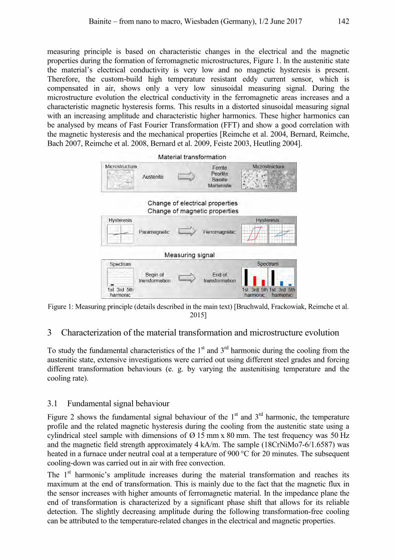
Bainite – from nano to macro, Wiesbaden (Germany), 1/2 June 2017 142
measuring principle is based on characteristic changes in the electrical and the magnetic properties during the formation of ferromagnetic microstructures, Figure 1. In the austenitic state the material’s electrical conductivity is very low and no magnetic hysteresis is present. Therefore, the custom-build high temperature resistant eddy current sensor, which is compensated in air, shows only a very low sinusoidal measuring signal. During the microstructure evolution the electrical conductivity in the ferromagnetic areas increases and a characteristic magnetic hysteresis forms. This results in a distorted sinusoidal measuring signal with an increasing amplitude and characteristic higher harmonics. These higher harmonics can be analysed by means of Fast Fourier Transformation (FFT) and show a good correlation with the magnetic hysteresis and the mechanical properties [Reimche et al. 2004, Bernard, Reimche, Bach 2007, Reimche et al. 2008, Bernard et al. 2009, Feiste 2003, Heutling 2004].
Figure 1: Measuring principle (details described in the main text) [Bruchwald, Frackowiak, Reimche et al.
2015]
3 Characterization of the material transformation and microstructure evolution
To study the fundamental characteristics of the 1st and 3rd harmonic during the cooling from the austenitic state, extensive investigations were carried out using different steel grades and forcing different transformation behaviours (e. g. by varying the austenitising temperature and the cooling rate).
3.1 Fundamental signal behaviour Figure 2 shows the fundamental signal behaviour of the 1st and 3rd harmonic, the temperature profile and the related magnetic hysteresis during the cooling from the austenitic state using a cylindrical steel sample with dimensions of Ø 15 mm x 80 mm. The test frequency was 50 Hz and the magnetic field strength approximately 4 kA/m. The sample (18CrNiMo7-6/1.6587) was heated in a furnace under neutral coal at a temperature of 900 °C for 20 minutes. The subsequent cooling-down was carried out in air with free convection. The 1st harmonic’s amplitude increases during the material transformation and reaches its maximum at the end of transformation. This is mainly due to the fact that the magnetic flux in the sensor increases with higher amounts of ferromagnetic material. In the impedance plane the end of transformation is characterized by a significant phase shift that allows for its reliable detection. The slightly decreasing amplitude during the following transformation-free cooling can be attributed to the temperature-related changes in the electrical and magnetic properties.
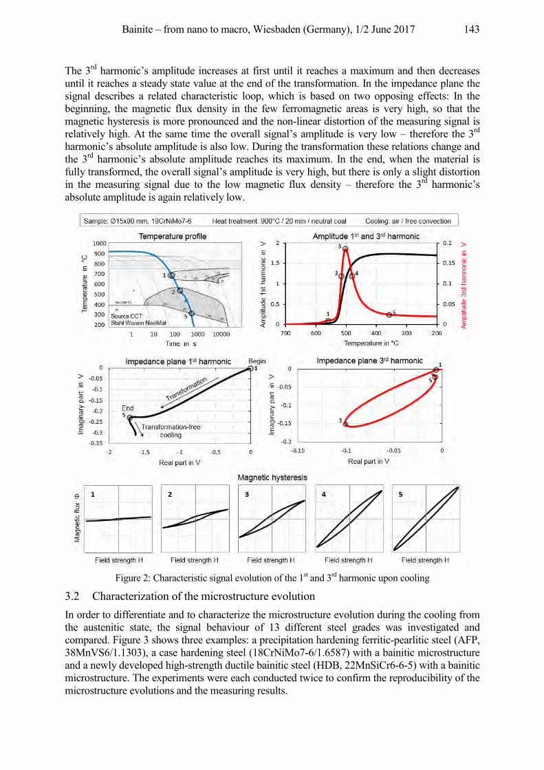
Bainite – from nano to macro, Wiesbaden (Germany), 1/2 June 2017 143
The 3rd harmonic’s amplitude increases at first until it reaches a maximum and then decreases until it reaches a steady state value at the end of the transformation. In the impedance plane the signal describes a related characteristic loop, which is based on two opposing effects: In the beginning, the magnetic flux density in the few ferromagnetic areas is very high, so that the magnetic hysteresis is more pronounced and the non-linear distortion of the measuring signal is relatively high. At the same time the overall signal’s amplitude is very low – therefore the 3rd harmonic’s absolute amplitude is also low. During the transformation these relations change and the 3rd harmonic’s absolute amplitude reaches its maximum. In the end, when the material is fully transformed, the overall signal’s amplitude is very high, but there is only a slight distortion in the measuring signal due to the low magnetic flux density – therefore the 3rd harmonic’s absolute amplitude is again relatively low.
Figure 2: Characteristic signal evolution of the 1st and 3rd harmonic upon cooling
3.2 Characterization of the microstructure evolution In order to differentiate and to characterize the microstructure evolution during the cooling from the austenitic state, the signal behaviour of 13 different steel grades was investigated and compared. Figure 3 shows three examples: a precipitation hardening ferritic-pearlitic steel (AFP, 38MnVS6/1.1303), a case hardening steel (18CrNiMo7-6/1.6587) with a bainitic microstructure and a newly developed high-strength ductile bainitic steel (HDB, 22MnSiCr6-6-5) with a bainitic microstructure. The experiments were each conducted twice to confirm the reproducibility of the microstructure evolutions and the measuring results.
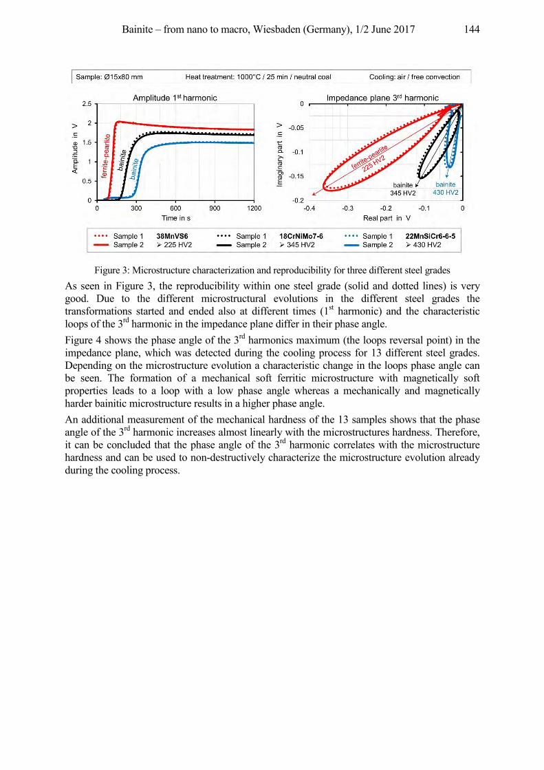
Bainite – from nano to macro, Wiesbaden (Germany), 1/2 June 2017 144
Figure 3: Microstructure characterization and reproducibility for three different steel grades
As seen in Figure 3, the reproducibility within one steel grade (solid and dotted lines) is very good. Due to the different microstructural evolutions in the different steel grades the transformations started and ended also at different times (1st harmonic) and the characteristic loops of the 3rd harmonic in the impedance plane differ in their phase angle. Figure 4 shows the phase angle of the 3rd harmonics maximum (the loops reversal point) in the impedance plane, which was detected during the cooling process for 13 different steel grades. Depending on the microstructure evolution a characteristic change in the loops phase angle can be seen. The formation of a mechanical soft ferritic microstructure with magnetically soft properties leads to a loop with a low phase angle whereas a mechanically and magnetically harder bainitic microstructure results in a higher phase angle. An additional measurement of the mechanical hardness of the 13 samples shows that the phase angle of the 3rd harmonic increases almost linearly with the microstructures hardness. Therefore, it can be concluded that the phase angle of the 3rd harmonic correlates with the microstructure hardness and can be used to non-destructively characterize the microstructure evolution already during the cooling process.
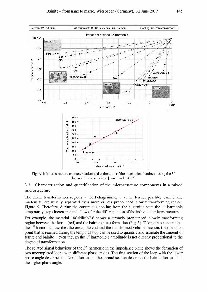
Bainite – from nano to macro, Wiesbaden (Germany), 1/2 June 2017 145
Figure 4: Microstructure characterization and estimation of the mechanical hardness using the 3rd
harmonic’s phase angle [Bruchwald 2017]
3.3 Characterization and quantification of the microstructure components in a mixed microstructure The main transformation regions a CCT-diagramme, i. e. in ferrite, pearlite, bainite and martensite, are usually separated by a more or less pronounced, slowly transforming region, Figure 5. Therefore, during the continuous cooling from the austenitic state the 1st harmonic temporarily stops increasing and allows for the differentiation of the individual microstructures. For example, the material 18CrNiMo7-6 shows a strongly pronounced, slowly transforming region between the ferrite (red) and the bainite (blue) formation (Fig. 5). Taking into account that the 1st harmonic describes the onset, the end and the transformed volume fraction, the operation point that is reached during the temporal stop can be used to quantify and estimate the amount of ferrite and bainite – even though the 1st harmonic’s amplitude is not directly proportional to the degree of transformation. The related signal behaviour of the 3rd harmonic in the impedance plane shows the formation of two uncompleted loops with different phase angles. The first section of the loop with the lower phase angle describes the ferrite formation, the second section describes the bainite formation at the higher phase angle.
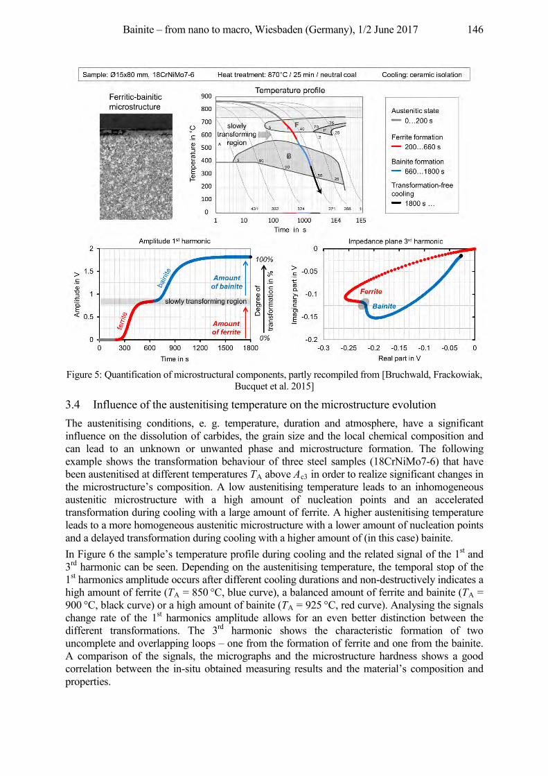
Bainite – from nano to macro, Wiesbaden (Germany), 1/2 June 2017 146
Figure 5: Quantification of microstructural components, partly recompiled from [Bruchwald, Frackowiak,
Bucquet et al. 2015]
3.4 Influence of the austenitising temperature on the microstructure evolution The austenitising conditions, e. g. temperature, duration and atmosphere, have a significant influence on the dissolution of carbides, the grain size and the local chemical composition and can lead to an unknown or unwanted phase and microstructure formation. The following example shows the transformation behaviour of three steel samples (18CrNiMo7-6) that have been austenitised at different temperatures TA above Ac3 in order to realize significant changes in the microstructure’s composition. A low austenitising temperature leads to an inhomogeneous austenitic microstructure with a high amount of nucleation points and an accelerated transformation during cooling with a large amount of ferrite. A higher austenitising temperature leads to a more homogeneous austenitic microstructure with a lower amount of nucleation points and a delayed transformation during cooling with a higher amount of (in this case) bainite. In Figure 6 the sample’s temperature profile during cooling and the related signal of the 1st and 3rd harmonic can be seen. Depending on the austenitising temperature, the temporal stop of the 1st harmonics amplitude occurs after different cooling durations and non-destructively indicates a high amount of ferrite (TA = 850 °C, blue curve), a balanced amount of ferrite and bainite (TA = 900 °C, black curve) or a high amount of bainite (TA = 925 °C, red curve). Analysing the signals change rate of the 1st harmonics amplitude allows for an even better distinction between the different transformations. The 3rd harmonic shows the characteristic formation of two uncomplete and overlapping loops – one from the formation of ferrite and one from the bainite. A comparison of the signals, the micrographs and the microstructure hardness shows a good correlation between the in-situ obtained measuring results and the material’s composition and properties.
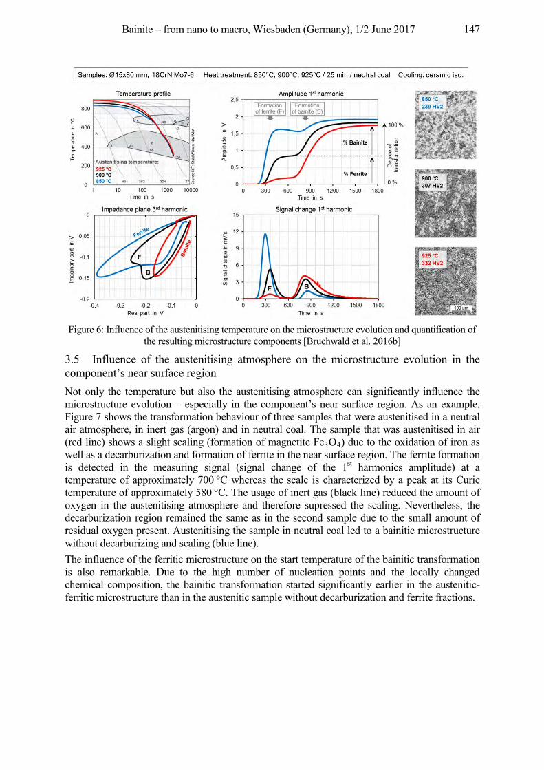
Bainite – from nano to macro, Wiesbaden (Germany), 1/2 June 2017 147
Figure 6: Influence of the austenitising temperature on the microstructure evolution and quantification of
the resulting microstructure components [Bruchwald et al. 2016b]
3.5 Influence of the austenitising atmosphere on the microstructure evolution in the component’s near surface region Not only the temperature but also the austenitising atmosphere can significantly influence the microstructure evolution – especially in the component’s near surface region. As an example, Figure 7 shows the transformation behaviour of three samples that were austenitised in a neutral air atmosphere, in inert gas (argon) and in neutral coal. The sample that was austenitised in air (red line) shows a slight scaling (formation of magnetite Fe3O4) due to the oxidation of iron as well as a decarburization and formation of ferrite in the near surface region. The ferrite formation is detected in the measuring signal (signal change of the 1st harmonics amplitude) at a temperature of approximately 700 °C whereas the scale is characterized by a peak at its Curie temperature of approximately 580 °C. The usage of inert gas (black line) reduced the amount of oxygen in the austenitising atmosphere and therefore supressed the scaling. Nevertheless, the decarburization region remained the same as in the second sample due to the small amount of residual oxygen present. Austenitising the sample in neutral coal led to a bainitic microstructure without decarburizing and scaling (blue line). The influence of the ferritic microstructure on the start temperature of the bainitic transformation is also remarkable. Due to the high number of nucleation points and the locally changed chemical composition, the bainitic transformation started significantly earlier in the austenitic-ferritic microstructure than in the austenitic sample without decarburization and ferrite fractions.
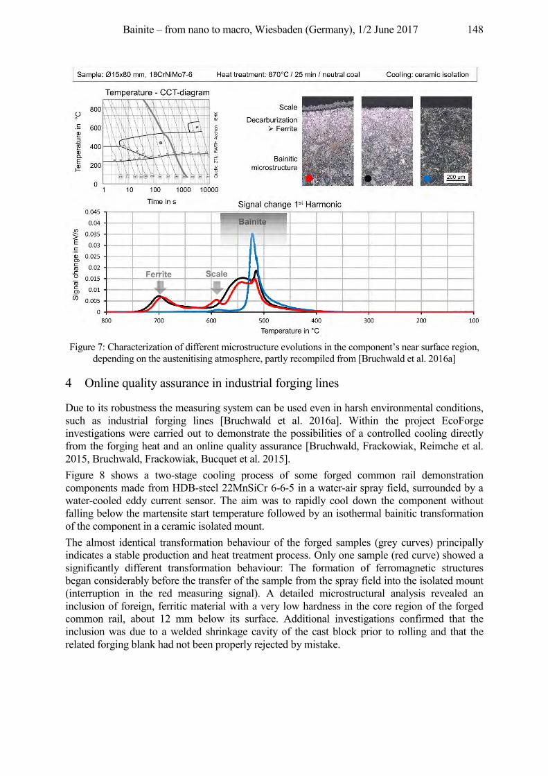
Bainite – from nano to macro, Wiesbaden (Germany), 1/2 June 2017 148
Figure 7: Characterization of different microstructure evolutions in the component’s near surface region,
depending on the austenitising atmosphere, partly recompiled from [Bruchwald et al. 2016a]
4 Online quality assurance in industrial forging lines
Due to its robustness the measuring system can be used even in harsh environmental conditions, such as industrial forging lines [Bruchwald et al. 2016a]. Within the project EcoForge investigations were carried out to demonstrate the possibilities of a controlled cooling directly from the forging heat and an online quality assurance [Bruchwald, Frackowiak, Reimche et al. 2015, Bruchwald, Frackowiak, Bucquet et al. 2015]. Figure 8 shows a two-stage cooling process of some forged common rail demonstration components made from HDB-steel 22MnSiCr 6-6-5 in a water-air spray field, surrounded by a water-cooled eddy current sensor. The aim was to rapidly cool down the component without falling below the martensite start temperature followed by an isothermal bainitic transformation of the component in a ceramic isolated mount. The almost identical transformation behaviour of the forged samples (grey curves) principally indicates a stable production and heat treatment process. Only one sample (red curve) showed a significantly different transformation behaviour: The formation of ferromagnetic structures began considerably before the transfer of the sample from the spray field into the isolated mount (interruption in the red measuring signal). A detailed microstructural analysis revealed an inclusion of foreign, ferritic material with a very low hardness in the core region of the forged common rail, about 12 mm below its surface. Additional investigations confirmed that the inclusion was due to a welded shrinkage cavity of the cast block prior to rolling and that the related forging blank had not been properly rejected by mistake.
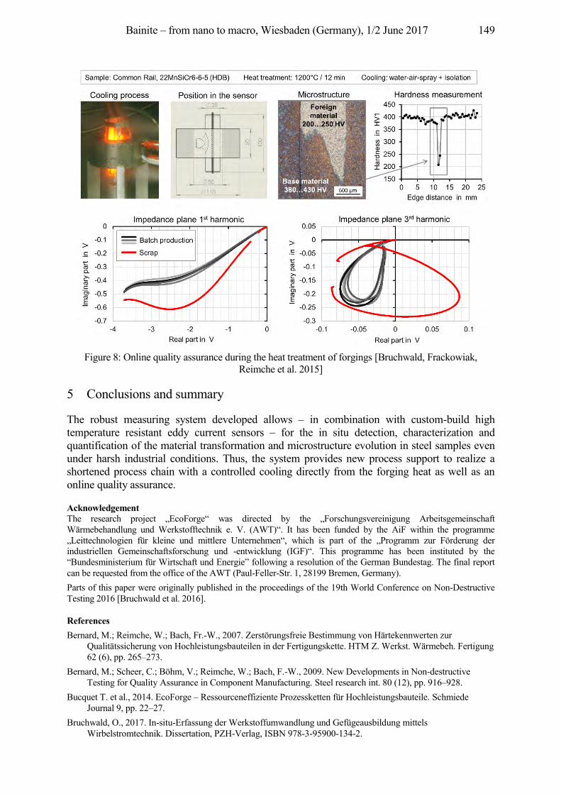
Bainite – from nano to macro, Wiesbaden (Germany), 1/2 June 2017 149
Figure 8: Online quality assurance during the heat treatment of forgings [Bruchwald, Frackowiak,
Reimche et al. 2015]
5 Conclusions and summary
The robust measuring system developed allows – in combination with custom-build high temperature resistant eddy current sensors – for the in situ detection, characterization and quantification of the material transformation and microstructure evolution in steel samples even under harsh industrial conditions. Thus, the system provides new process support to realize a shortened process chain with a controlled cooling directly from the forging heat as well as an online quality assurance.
Acknowledgement The research project „EcoForge“ was directed by the „Forschungsvereinigung Arbeitsgemeinschaft Wärmebehandlung und Werkstofftechnik e. V. (AWT)“. It has been funded by the AiF within the programme „Leittechnologien für kleine und mittlere Unternehmen“, which is part of the „Programm zur Förderung der industriellen Gemeinschaftsforschung und -entwicklung (IGF)“. This programme has been instituted by the “Bundesministerium für Wirtschaft und Energie” following a resolution of the German Bundestag. The final report can be requested from the office of the AWT (Paul-Feller-Str. 1, 28199 Bremen, Germany). Parts of this paper were originally published in the proceedings of the 19th World Conference on Non-Destructive Testing 2016 [Bruchwald et al. 2016].
References Bernard, M.; Reimche, W.; Bach, Fr.-W., 2007. Zerstörungsfreie Bestimmung von Härtekennwerten zur
Qualitätssicherung von Hochleistungsbauteilen in der Fertigungskette. HTM Z. Werkst. Wärmebeh. Fertigung 62 (6), pp. 265–273.
Bernard, M.; Scheer, C.; Böhm, V.; Reimche, W.; Bach, F.-W., 2009. New Developments in Non-destructive Testing for Quality Assurance in Component Manufacturing. Steel research int. 80 (12), pp. 916–928.
Bucquet T. et al., 2014. EcoForge – Ressourceneffiziente Prozessketten für Hochleistungsbauteile. Schmiede Journal 9, pp. 22–27.
Bruchwald, O., 2017. In-situ-Erfassung der Werkstoffumwandlung und Gefügeausbildung mittels Wirbelstromtechnik. Dissertation, PZH-Verlag, ISBN 978-3-95900-134-2.
Bainite – from nano to macro, Wiesbaden (Germany), 1/2 June 2017 150
Bruchwald, O.; Frackowiak, W.; Bucquet, T.; Huskic, A.; Reimche, W.; Maier, H. J., 2015. In-situ-Erfassung der Werkstoffumwandlung und Gefügeausbildung von Schmiedebauteilen im Abkühlpfad. HTM J. Heat Treatm. Mat. 70 (3), pp. 150–161. DOI: 10.3139/105.110259
Bruchwald, O.; Frackowiak, W.; Reimche, W.; Maier, H. J., 2015. Non-destructive in situ monitoring of the microstructural development in high performance steel components during heat treatment. La Metallurgia Italiana 11/12, pp. 29–37.
uch al . cko iak W.; Reimche, W.; Maier, H. J., 2016a. Sensor-controlled bainitic transformation and microstructure formation of forgings during the cooling process. Mat.-wiss. u. Werkstofftech 47 (8), pp. 780–788. DOI: 10.1002/mawe.201600612
Bruchwald, O.; Frackowiak, W.; Reimche, W.; Maier, H. J., 2016b. In-Situ Monitoring of the Microstructure Evolution. Proc. European Conference on Heat Treatment, Prague, Czech Republic.
Bruchwald, O.; Frackowiak, W.; Zwoch, S.; Reimche, W.; Maier, H. J., 2016. In-Situ Monitoring of the Microstructure Evolution Using Eddy Current Technology, Proc. 19th World Conference on Non-Destructive Testing WCNDT, München, Germany.
Doege, B. A. B. E.; Behrens, B. A., 2010. Handbuch Umformtechnik, Springer Verlag. Feiste, K. L., 2003. Entwicklung der Harmonischen-Analyse von Wirbelstromsignalen zur Charakterisierung
mechanischer Kugelgraphitgusseigenschaften. Dissertation, VDI-Verlag, ISBN: 3-18-500608-9. Heutling, B., 2004. Zerstörungsfreie Online-Materialcharakterisierung von Stahlfeinblechen mittels Harmonischen
Analyse von Wirbelstromsignalen. Dissertation, PZH-Verlag, ISBN: 3-93-688862-0. Reimche, W.; Heutling, B.; Bach, Fr.-W.; Kroos, J.; Schulz, S., 2004. Online-Materialcharakterisierung und
Überwachung relevanter Bandeigenschaften von feuerverzinktem Stahlfeinblech im Produktionsfluss mit einem Harmonischen-Messsystem. Proc. DACH-Jahrestagung, Salzburg, Österreich.
Reimche, W.; Zwoch, S.; Böhm, V.; Bach, Fr.-W.; Vetterlein, J.; Klümper-Westkamp, H.; Zoch, H.-W., 2008. Entwicklung einer prozessfähigen Prüftechnik zum sensorkontrollierten Bainitisieren in der Wärmebehandlung. Proc. DGZfP-Jahrestagung, St. Gallen, Schweiz.
Williams, J.; Fatemi, A., 2007. Fatigue performance of forged steel and ductile cast iron crankshafts. SAE Technical paper, 2007-01-1001.
Bainite – from nano to macro, Wiesbaden (Germany), 1/2 June 2017 151
In-situ Investigation of Bainite Formation with fast X-Ray Diffraction (iXRD)
Andreas Kopp, Timo Bernthaler, Dieter Schmid, Gaby Ketzer-Raichle, Gerhard Schneider Materials Research Institute, Aalen University, Beethovenstraße 1, 73430 Aalen, Germany,
{andreas.kopp, timo.bernthaler, gaby.ketzer-raichle, gerhard.schneider}@hs-aalen.de
Abstract Using specific equipment for high temperature fast in-situ X-ray diffraction (iXRD) enables the collection of diffraction patterns over a range of 48 degrees in 2-theta within one second. In combination with a high-temperature furnace, modifications in the crystallographic structure under a thermal treatment like phase transformations in steel can be observed nearly in real-time. We demonstrate the usefulness of fast high temperature iXRD using the ball bearing steel (100Cr6), which is of high industrial importance for many applications. The specimens were austenitized at 860 °C. Various isothermal annealings were carried out to develop a bainitic steel structure. The transformation was interrupted by further cooling at different stages. The specimens were further investigated with SEM and light microscopy using different etching techniques to correlate the microstructure with the diffraction patterns. We will show that iXRD can help to optimize heat treatments, validate time transformation diagrams and increase the understanding of phase transformations in steels.
Keywords in-situ X-ray diffraction, XRD, phase transformation, steel, isothermal formation
1 Introduction
Steel is the most commonly used construction material. Different modifications of steel like pearlite, bainite and martensite can be achieved by variations in composition and by variations in heat treatments. The modifications of steel only differ in the arrangement and size of the ferrite cell, and for bainite and pearlite in the morphology of cementite. These modifications are directly connected with the technical properties like hardness and ductility. To adjust the microstructure of steel to specific applications it is necessary to understand the transformation processes during heat treatment cycles. A common way to investigate phase transformations is the use of quenching dilatometry. Phase transformations cause length changes of the specimen. These length changes can be used to calculate the fraction of the transformed material. These experiments give no further information of the crystal structure and can only measure bulk effects. To get more detailed information about the microstructure, diffraction experiments are very common. Fast transformation processes require fast recording times of the diffraction data. These times can be achieved with synchrotron radiation. Recording times in a range of some milli seconds are used and the solidification process during welding processes [Elmer, Wong, Ressler 2000, Terasaki, Komizo 2012] or phase transformations [Stone et al. 2008] can be observed. Experiments with conventional x-ray radiation normally only reach scan times down to 3 s [Rocha, Hirsch 2005]. This time is not suitable for many applications and rather suitable for applications that require a long time like the dissolution of carbides for example [Epp, Hirsch, Curfs 2012]. With the use of three linear detectors (Figure 1) the scanning time at the diffractometer at Aalen University can be reduced to one second which is one of the fastest scanning times with conventional x-ray radiation achieved so far. Many experiments that normally require synchrotron radiation can now be investigated with much less effort on a laboratory scale diffractometer. This opens the door for a wide range of applications and investigations which couldn’t be carried out so far because of the limited access to synchrotron radiation sources and the high costs of these devices. In-situ x-ray diffraction may contribute to a
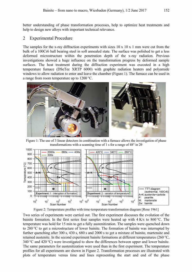
Bainite – from nano to macro, Wiesbaden (Germany), 1/2 June 2017 152
better understanding of phase transformation processes, help to optimize heat treatments and help to design new alloys with important technical relevance.
2 Experimental Procedure
The samples for the x-ray diffraction experiments with sizes 10 x 10 x 1 mm were cut from the bulk of a 100Cr6 ball bearing steel in soft annealed state. The surface was polished to get a less deformed microstructure within the penetration depth of the x-ray radiation. Previous investigations showed a huge influence on the transformation progress by deformed sample surfaces. The heat treatment during the diffraction experiment was executed in a high temperature furnace (DSeTec XRTP 6000) with graphite radiation heaters and polyamide windows to allow radiation to enter and leave the chamber (Figure 1). The furnace can be used in a range from room temperature up to 1200 °C.
Figure 1: The use of 3 linear detectors in combination with a furnace allows the investigation of phase
transformations with a scanning time of 1 s for a range of 48° in 2θ
Figure 2: Temperature profiles with time-temperature-transformation diagram [Rose 1961]
Two series of experiments were carried out. The first experiment discusses the evolution of the bainite formation. In the first series four samples were heated up with 4 K/s to 860 °C. The temperature was hold for 15 min to get a fully austenitization. The samples were quenched down to 280 °C to get a microstructure of lower bainite. The formation of bainite was interrupted by further quenching after 300 s, 430 s, 680 s and 2000 s to get a mixture of bainite, martensite and retained austenite. In the second experiment bainite formations at different temperatures (260 °C, 340 °C and 420 °C) were investigated to show the differences between upper and lower bainite. The same parameters for austenitization were used than in the first experiment. The temperature profiles for all experiments are shown in Figure 2. Transformation processes are illustrated with plots of temperature versus time and lines representing the start and end of the phase
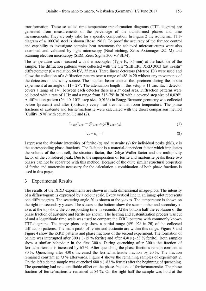
Bainite – from nano to macro, Wiesbaden (Germany), 1/2 June 2017 153
transformation. These so called time-temperature-transformation diagrams (TTT-diagram) are generated from measurements of the percentage of the transformed phases and time measurements. They are only valid for a specific composition. In Figure 2 the isothermal TTT-diagram of a 100Cr6 steel is shown [Rose 1961]. To proof the accuracy of the furnace control and capability to investigate complex heat treatments the achieved microstructures were also examined and validated by light microscopy (Nital etching, Zeiss Axiomager .Z2 M) and scanning electron microscopy (SEM, Zeiss Sigma 300 VP SEM). The temperature was measured with thermocouples (Type K, 0,5 mm) at the backside of the sample. The diffraction patterns were collected with the GE “SEIFERT XRD 3003 fast in-situ” diffractometer (Co radiation 50 kV, 35 mA). Three linear detectors (Meteor 1D) were used and allow the collection of a diffraction pattern over a range of 48° in 2θ without any movements of the detectors or the x-ray source. The incident beam entered the specimen during the in-situ experiment at an angle of Ω = 28°. The attenuation length in this setup is 11 µm. Each detector covers a range of 14°, between each detector there is a 3° dead area. Diffraction patterns were collected with a rate of 1 Hz and a range from 31°–79° in 2θ with a covered step size of 0,026°. A diffraction pattern (2θ: 40–105°, step size: 0,013°) in Bragg-Brentano geometry was collected before (prescan) and after (postscan) every heat treatment at room temperature. The phase fractions of austenite and ferrite/martensite were calculated with the direct comparison method [Cullity 1978] with equation (1) and (2).
Iγ,hkl/Iα,hkl = (Rγ,hkl*cγ)/(Rα,hkl*cα) (1)
cγ + cα = 1 (2)
I represent the absolute intensities of ferrite (α) and austenite (γ) for individual peaks (hkl), c is the corresponding phase fractions. The R-factor is a material-dependent factor which implicates the volume of the unit cell, the structure factor, the Debye-Waller factor and the multiplicity factor of the considered peak. Due to the superposition of ferrite and martensite peaks those two phases can not be separated with this method. Because of the quite similar structural properties of ferrite and martensite necessary for the calculation a combination of both phase fractions is used in this paper.
3 Experimental Results
The results of the iXRD experiments are shown in multi dimensional image-plots. The intensity of a diffractogram is expressed by a colour scale. Every vertical line in an image-plot represents one diffractogram. The scattering angle 2θ is shown at the y-axes. The temperature is shown on the right on secondary y-axes. The x-axes at the bottom show the scan number and secondary x-axes at the top show the corresponding time in seconds. At the bottom half the evolution of the phase fraction of austenite and ferrite are shown. The heating and austenitization process was cut of and a logarithmic time scale was used to compare the iXRD patterns with commonly known TTT-diagrams. The image plots only show a partial range (49°–92° in 2θ) of the collected diffraction patterns. The main peaks of ferrite and austenite are within this range. Figure 3 and Figure 4 show the iXRD patterns and phase fractions of the second experiment. The formation of bainite was interrupted after 300 s (~15 % ferrite) and after 430 s (~53 % ferrite). Both samples show a similar behaviour in the first 300 s. During quenching after 300 s the fraction of ferrite/martensite is increased by 65 %. After quenching the phase fractions remain constant at 80 %. Quenching after 430 s increased the ferrite/martensite fraction by 20 %. The fraction remained constant at 73 % afterwards. Figure 4 shows the remaining samples of experiment 2. On the left side the sample was quenched 680 s (~83 % ferrite) after the beginning of quenching. The quenching had no quantifiable effect on the phase fractions of ferrite/martensite. The phase fraction of ferrite/martensite remained at 84 %. On the right half the sample was hold at the
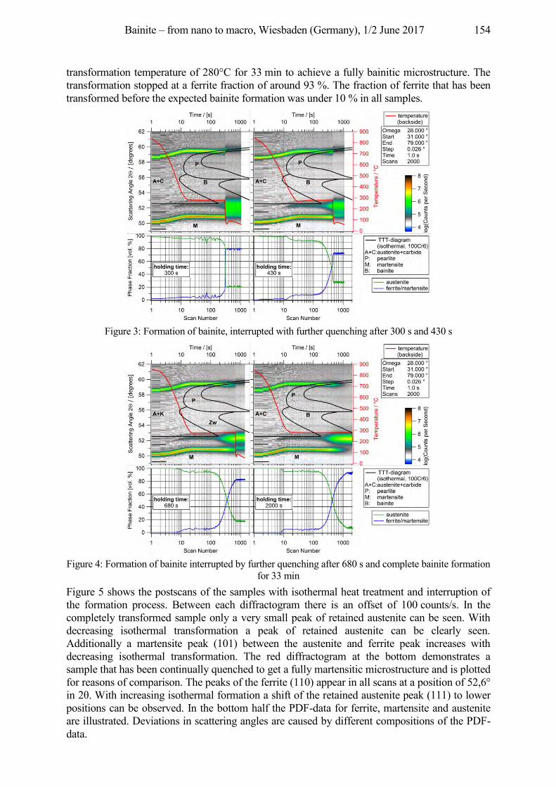
Bainite – from nano to macro, Wiesbaden (Germany), 1/2 June 2017 154
transformation temperature of 280°C for 33 min to achieve a fully bainitic microstructure. The transformation stopped at a ferrite fraction of around 93 %. The fraction of ferrite that has been transformed before the expected bainite formation was under 10 % in all samples.
Figure 3: Formation of bainite, interrupted with further quenching after 300 s and 430 s
Figure 4: Formation of bainite interrupted by further quenching after 680 s and complete bainite formation
for 33 min Figure 5 shows the postscans of the samples with isothermal heat treatment and interruption of the formation process. Between each diffractogram there is an offset of 100 counts/s. In the completely transformed sample only a very small peak of retained austenite can be seen. With decreasing isothermal transformation a peak of retained austenite can be clearly seen. Additionally a martensite peak (101) between the austenite and ferrite peak increases with decreasing isothermal transformation. The red diffractogram at the bottom demonstrates a sample that has been continually quenched to get a fully martensitic microstructure and is plotted for reasons of comparison. The peaks of the ferrite (110) appear in all scans at a position of 52,6° in 2θ. With increasing isothermal formation a shift of the retained austenite peak (111) to lower positions can be observed. In the bottom half the PDF-data for ferrite, martensite and austenite are illustrated. Deviations in scattering angles are caused by different compositions of the PDF-data.
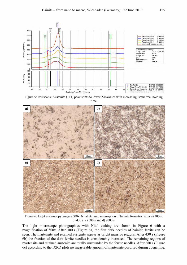
Bainite – from nano to macro, Wiesbaden (Germany), 1/2 June 2017 155
Figure 5: Postscans: Austenite (111) peak shifts to lower 2-θ-values with increasing isothermal holding
time
Figure 6: Light microscopy images 500x, Nital etching, interruption of bainite formation after a) 300 s,
b) 430 s, c) 680 s and d) 2000 s The light microscope photographies with Nital etching are shown in Figure 6 with a magnification of 500x. After 300 s (Figure 6a) the first dark needles of bainitic ferrite can be seen. The martensite and retained austenite appear as bright massive regions. After 430 s (Figure 6b) the fraction of the dark ferrite needles is considerably increased. The remaining regions of martensite and retained austenite are totally surrounded by the ferrite needles. After 680 s (Figure 6c) according to the iXRD plots no measurable amount of martensite occurred during quenching.
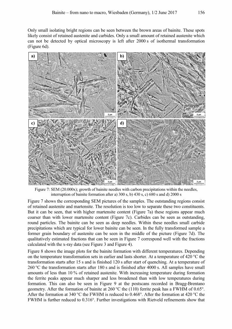
Bainite – from nano to macro, Wiesbaden (Germany), 1/2 June 2017 156
Only small isolating bright regions can be seen between the brown areas of bainite. These spots likely consist of retained austenite and carbides. Only a small amount of retained austenite which can not be detected by optical microscopy is left after 2000 s of isothermal transformation (Figure 6d).
Figure 7: SEM (20.000x); growth of bainite needles with carbon precipitations within the needles,
interruption of bainite formation after a) 300 s, b) 430 s, c) 680 s and d) 2000 s Figure 7 shows the corresponding SEM pictures of the samples. The outstanding regions consist of retained austenite and martensite. The resolution is too low to separate these two constituents. But it can be seen, that with higher martensite content (Figure 7a) these regions appear much coarser than with lower martensite content (Figure 7c). Carbides can be seen as outstanding, round particles. The bainite can be seen as deep needles. Within these needles small carbide precipitations which are typical for lower bainite can be seen. In the fully transformed sample a former grain boundary of austenite can be seen in the middle of the picture (Figure 7d). The qualitatively estimated fractions that can be seen in Figure 7 correspond well with the fractions calculated with the x-ray data (see Figure 3 and Figure 4). Figure 8 shows the image plots for the bainite formation with different temperatures. Depending on the temperature transformation sets in earlier and lasts shorter. At a temperature of 420 °C the transformation starts after 15 s and is finished 120 s after start of quenching. At a temperature of 260 °C the transformation starts after 180 s and is finished after 4000 s. All samples have small amounts of less than 10 % of retained austenite. With increasing temperature during formation the ferrite peaks appear much sharper and less broadened than with low temperatures during formation. This can also be seen in Figure 9 at the postscans recorded in Bragg-Brentano geometry. After the formation of bainite at 260 °C the (110) ferrite peak has a FWHM of 0.65°. After the formation at 340 °C the FWHM is reduced to 0.468°. After the formation at 420 °C the FWHM is further reduced to 0.316°. Further investigations with Rietveld refinements show that
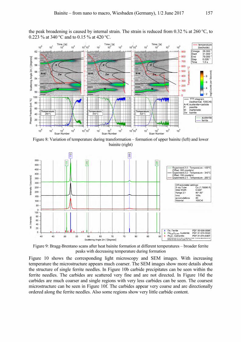
Bainite – from nano to macro, Wiesbaden (Germany), 1/2 June 2017 157
the peak broadening is caused by internal strain. The strain is reduced from 0.32 % at 260 °C, to 0.223 % at 340 °C and to 0.15 % at 420 °C.
Figure 8: Variation of temperature during transformation – formation of upper bainite (left) and lower
bainite (right)
Figure 9: Bragg-Brentano scans after heat bainite formation at different temperatures – broader ferrite
peaks with decreasing temperature during formation Figure 10 shows the corresponding light microscopy and SEM images. With increasing temperature the microstructure appears much coarser. The SEM images show more details about the structure of single ferrite needles. In Figure 10b carbide precipitates can be seen within the ferrite needles. The carbides are scattered very fine and are not directed. In Figure 10d the carbides are much coarser and single regions with very less carbides can be seen. The coarsest microstructure can be seen in Figure 10f. The carbides appear very coarse and are directionally ordered along the ferrite needles. Also some regions show very little carbide content.
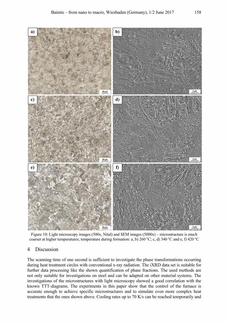
Bainite – from nano to macro, Wiesbaden (Germany), 1/2 June 2017 158
Figure 10: Light microscopy images (500x, Nital) and SEM images (5000x) – microstructure is much
coarser at higher temperatures; temperature during formation: a, b) 260 °C; c, d) 340 °C and e, f) 420 °C
4 Discussion
The scanning time of one second is sufficient to investigate the phase transformations occurring during heat treatment circles with conventional x-ray radiation. The iXRD data set is suitable for further data processing like the shown quantification of phase fractions. The used methods are not only suitable for investigations on steel and can be adapted on other material systems. The investigations of the microstructures with light microscopy showed a good correlation with the known TTT-diagrams. The experiments in this paper show that the control of the furnace is accurate enough to achieve specific microstructures and to simulate even more complex heat treatments that the ones shown above. Cooling rates up to 70 K/s can be reached temporarily and
Bainite – from nano to macro, Wiesbaden (Germany), 1/2 June 2017 159
temperature can be held constant for several hours. The following topics have to be considered for a right interpretation of the results. The temperature was measured with thermocouples at the back of the specimen. This way the thermocouple is covered by the sample and the specimen holder (graphite). The information of the diffraction patterns origin from an 11 µm thick layer on the surface of the sample. The measurement of the temperature at the surface was not possible. The measurement was influenced by the stream of nitrogen gas used to cool the sample and delivered values much lower than that on the backside. As soon as the stream of gas vanished the temperature at the two positions levelled up. Especially in the first 20 s after quenching when great temperature gradients in the sample can occur the measurement of the temperature is rather inaccurate. After this period during the isothermal holding time the measurement delivers much more reliable values. The evolution of the bainite microstructure could be shown with the interruption of the transformation process. The achieved microstructures were correlated with microscope investigations and have shown good accordance. The calculated phase fractions so far correspond quite well with the observed microstructures. Rietveld refinements were done on the postscans. The phase fractions determined by the refinements correspond well with the phase fractions calculated with the iXRD data. In the calculation of the phase fractions as well as in the Rietveld refinements the fractions of ferrite and martensite can hardly be separated due to overlapping of the main peaks. To get more reliable values only a combination of the fractions of ferrite and martensite is considered. The separation between martensite and lower bainite in the pictures of the SEM can be rather difficult because the needles appear quite similar. But the needles shown in Figure 7 do not show the typical arrangement of martensite where the new generation of martensite appears in an angle of 60° to the former generations. In the light optical and scanning electron microscope investigations the separation between retained austenite and martensite wasn’t possible. The regions of martensite and austenite appear much coarser with an increasing martensite content after the interruption after 300 s (see Figure 7a). The observed peak shift of austenite (111) to lower angles with increasing isothermal transformation of bainite can be explained with the rejection of carbon from the bainitic ferrite which leads to an increased carbon content in the retained austenite. There are several methods to calculate the carbon content from the lattice parameter [Chang 1998, Hummelshøj, Christiansen, Somers 2010, Stone et al. 2008]. There is a linear correlation between the lattice parameter and the carbon content. The different methods only differ in the gradient of the carbon content. An increase of the carbon content in the austenite by 0,7 wt.% was calculated from the peakshift shown in the postscans (Figure 5). It has to be mentioned that other effects responsible for peakshift were not considered. So a lower increase of the carbon content seems more plausible. This can also explain why the quenching after 680 s leads to no further ferrite/martensite formation. Due to the increased carbon content the formation of martensite requires temperatures below room temperature that can not be achieved with the current quenching concept. Although upper and lower bainite do not show different diffraction patterns the influence on the FWHM is clearly visible. The FWHM of the ferrite (110) peak is twice as big for the lower bainite than for the upper bainite. Due to the higher temperatures diffusion rates are much higher and cause less internal strain in the atom lattice.
References Chang, L. C.: Carbon content of austenite in austempered ductile iron. Scripta Materialia 39 (1998) 1. Cullity, B.: Elements of X-ray diffraction. 2. Ed. Massachusetts, Addison Wesley, 1978. Elmer, J. W.;Wong, J.; Ressler, T.: In-situ observations of phase transformations during solidification and cooling
of austenitic stainless steel welds using time-resolved x-ray diffraction. Scripta Materialia 43 (2000) 8, pp. 751–757.
Epp, J.; Hirsch, T.; Curfs, C.: In situ X-Ray Diffraction Analysis of Carbon Partitioning During Quenching of Low Carbon Steel. Metallurgical and Materials Transactions A 43 (2012) 7, pp. 2210–2217.

Bainite – from nano to macro, Wiesbaden (Germany), 1/2 June 2017 160
Hummelshøj, T. S.; Christiansen, T. L.; Somers, M. A. J.: Lattice expansion of carbon-stabilized expanded austenite. Scripta Materialia 63 (2010) 7, pp. 761–763.
Rocha, A. da S.; Hirsch, T.: Fast in situ X-ray diffraction phase and stress analysis during complete heat treatment cycles of steel. Materials Science and Engineering: A 395 (2005) 1–2, pp. 195–207.
Rose, A.: Atlas zur Wärmebehandlung der Stähle. Düsseldorf: Verl. Stahleisen, 1961. Stone, H.; Peet, M.; Bhadeshia, H. K. D. H.; Withers, P.; Babu, S.; Specht, E.: Synchrotron X-ray studies of
austenite and bainitic ferrite. Proceedings of the Royal Society of London A: Mathematical, Physical and Engineering Sciences, Vol. 464, No. 2092, pp. 1009–1027, 2008.
Terasaki, H.; Komizo, Y.: Time-resolved X-ray diffraction studies of phase evolution including liquid phase and grain structure during solidification process in stainless steel welds. Materials Letters 74 (2012), pp. 187–190.

Bainite – from nano to macro, Wiesbaden (Germany), 1/2 June 2017 161
5. Fundamentals and simulation of bainite transformation
Bainite – from nano to macro, Wiesbaden (Germany), 1/2 June 2017 162
Bainitic transformation analysis in carbon and nitrogen enriched low alloyed steels: kinetics
and microstructures Julien Teixeira1,2, Simon D. Catteau1,2,3, Hugo P. Van Landeghem1,2, Jacky Dulcy1, Moukrane
Dehmas1,2, Abdelkrim Redjaïmia1,2, Sabine Denis1,2, Marc Courteaux3
1Institut Jean Lamour – UMR 7198 CNRS – Université de Lorraine, Parc de Saurupt, F-54011 Nancy CEDEX, France, [email protected]
2Labex DAMAS “Design of Alloy Metals for Low-mass Structures”, Université de Lorraine, France 3PSA Peugeot-Citroën, Centre Technique de Belchamp, F-25420 Voujeaucourt, France
Abstract The effect on the bainitic transformation of carburizing (0.6 %mC), nitriding (0.12 %mC–0.25 %mN) and carbonitriding (0.7 %mC–0.25 %mN) of a 23MnCrMo5 low-alloyed steel in the austenitic field was examined by in situ high-energy synchrotron X-ray diffraction (HEXRD) and transmission electron microscopy. The enrichment in nitrogen induces strong acceleration of the bainitic transformation kinetics in carbonitrided steel compared to carburized steel, despite the -stabilizing character of nitrogen. This is attributed to the nucleation of ferrite on CrN nitrides, which precipitated during the enrichment, either at grain boundaries or intragranularly. AlN, VN and MnSiN2 nitrides were observed as well, with much smaller number density. They formed frequently aggregates with the CrN nitrides. The bainitic microstructure is much finer than in initial or carburized steel. It shares some common features with intragranularly nucleated bainite, i. e. acicular ferrite. From HEXRD, the chronology of the phase formation (ferrite and precipitates) during bainitic transformation as well as cell parameter evolutions are analyzed.
Keywords Carbonitriding, Phase transformation kinetics, Low-alloyed steel, TEM, High energy synchrotron X-ray diffraction
1 Introduction
The influence of carbon content on austenite decomposition in steels was largely described in literature (e. g. [Constant, Henry, Charbonnier 1992]). Conversely, nitrogen effects on the austenite decomposition were less examined. Most studies dealt with the model Fe-N system (e. g. [Jiang 2008, Nakada 2013]). In this case, product phases are ferrite and ’-Fe4N. Regarding the Fe-C-N system, some studies considered the tempering of martensite (e. g. [Böttger 1996, Cheng 1992]). Very few studies were conducted on multicomponent alloys. For instance, [Simon et al. 1974] examined a 30CrMo4 steel enriched in carbon and nitrogen. Unexpectedly, the continuous cooling kinetics was faster for increased nitrogen amounts despite the -stabilizing character of nitrogen. This observation was ascribed to the formation of carbonitrides during the carbonitriding treatment. The aim of this study will be to analyse the decomposition of carbon and nitrogen enriched austenites of a low-alloyed 23MnCrMo5 steel in isothermal conditions. Concentration levels in the range 0.1–0.6 wt.%C and 0.25 wt.%N will be considered. In this paper, we will focus on the bainitic transformation, which will be examined by using in situ high-energy synchrotron X-ray diffraction (HEXRD), scanning and transmission electron microscopies (SEM, TEM). HEXRD has already been used to study the bainitic transformation but almost exclusively in silicon-alloyed steels leading to carbide free bainite [Hell 2011, Babu 2005, Stone 2008, Chen 2009]. Except in [Dutta 2014], bainitic transformation accompanied by formation of precipitates was not considered so far. In the present study, HEXRD will be used in combination with TEM to
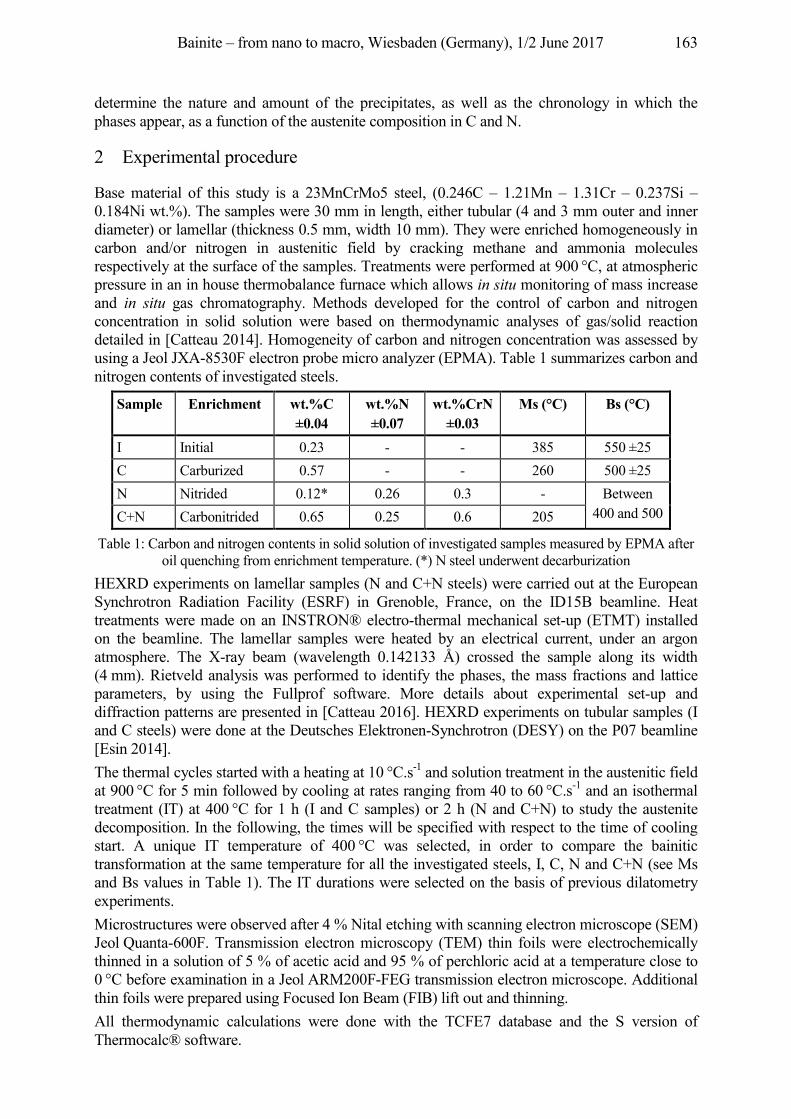
Bainite – from nano to macro, Wiesbaden (Germany), 1/2 June 2017 163
determine the nature and amount of the precipitates, as well as the chronology in which the phases appear, as a function of the austenite composition in C and N.
2 Experimental procedure
Base material of this study is a 23MnCrMo5 steel, (0.246C – 1.21Mn – 1.31Cr – 0.237Si – 0.184Ni wt.%). The samples were 30 mm in length, either tubular (4 and 3 mm outer and inner diameter) or lamellar (thickness 0.5 mm, width 10 mm). They were enriched homogeneously in carbon and/or nitrogen in austenitic field by cracking methane and ammonia molecules respectively at the surface of the samples. Treatments were performed at 900 °C, at atmospheric pressure in an in house thermobalance furnace which allows in situ monitoring of mass increase and in situ gas chromatography. Methods developed for the control of carbon and nitrogen concentration in solid solution were based on thermodynamic analyses of gas/solid reaction detailed in [Catteau 2014]. Homogeneity of carbon and nitrogen concentration was assessed by using a Jeol JXA-8530F electron probe micro analyzer (EPMA). Table 1 summarizes carbon and nitrogen contents of investigated steels.
Sample Enrichment wt.%C ±0.04
wt.%N ±0.07
wt.%CrN ±0.03
Ms (°C) Bs (°C)
I Initial 0.23 - - 385 550 ±25 C Carburized 0.57 - - 260 500 ±25 N Nitrided 0.12* 0.26 0.3 - Between
400 and 500 C+N Carbonitrided 0.65 0.25 0.6 205
Table 1: Carbon and nitrogen contents in solid solution of investigated samples measured by EPMA after oil quenching from enrichment temperature. (*) N steel underwent decarburization
HEXRD experiments on lamellar samples (N and C+N steels) were carried out at the European Synchrotron Radiation Facility (ESRF) in Grenoble, France, on the ID15B beamline. Heat treatments were made on an INSTRON® electro-thermal mechanical set-up (ETMT) installed on the beamline. The lamellar samples were heated by an electrical current, under an argon atmosphere. The X-ray beam (wavelength 0.142133 Å) crossed the sample along its width (4 mm). Rietveld analysis was performed to identify the phases, the mass fractions and lattice parameters, by using the Fullprof software. More details about experimental set-up and diffraction patterns are presented in [Catteau 2016]. HEXRD experiments on tubular samples (I and C steels) were done at the Deutsches Elektronen-Synchrotron (DESY) on the P07 beamline [Esin 2014]. The thermal cycles started with a heating at 10 °C.s-1 and solution treatment in the austenitic field at 900 °C for 5 min followed by cooling at rates ranging from 40 to 60 °C.s-1 and an isothermal treatment (IT) at 400 °C for 1 h (I and C samples) or 2 h (N and C+N) to study the austenite decomposition. In the following, the times will be specified with respect to the time of cooling start. A unique IT temperature of 400 °C was selected, in order to compare the bainitic transformation at the same temperature for all the investigated steels, I, C, N and C+N (see Ms and Bs values in Table 1). The IT durations were selected on the basis of previous dilatometry experiments. Microstructures were observed after 4 % Nital etching with scanning electron microscope (SEM) Jeol Quanta-600F. Transmission electron microscopy (TEM) thin foils were electrochemically thinned in a solution of 5 % of acetic acid and 95 % of perchloric acid at a temperature close to 0 °C before examination in a Jeol ARM200F-FEG transmission electron microscope. Additional thin foils were prepared using Focused Ion Beam (FIB) lift out and thinning. All thermodynamic calculations were done with the TCFE7 database and the S version of Thermocalc® software.
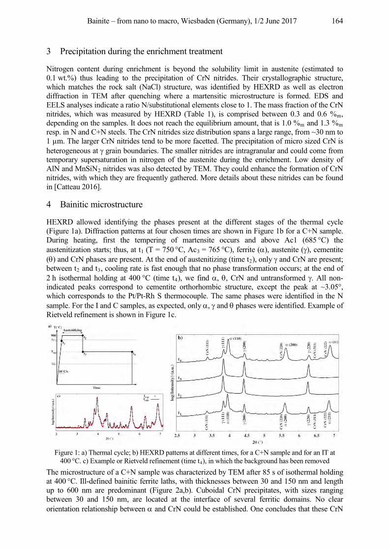
Bainite – from nano to macro, Wiesbaden (Germany), 1/2 June 2017 164
3 Precipitation during the enrichment treatment
Nitrogen content during enrichment is beyond the solubility limit in austenite (estimated to 0.1 wt.%) thus leading to the precipitation of CrN nitrides. Their crystallographic structure, which matches the rock salt (NaCl) structure, was identified by HEXRD as well as electron diffraction in TEM after quenching where a martensitic microstructure is formed. EDS and EELS analyses indicate a ratio N/substitutional elements close to 1. The mass fraction of the CrN nitrides, which was measured by HEXRD (Table 1), is comprised between 0.3 and 0.6 %m, depending on the samples. It does not reach the equilibrium amount, that is 1.0 %m and 1.3 %m resp. in N and C+N steels. The CrN nitrides size distribution spans a large range, from ~30 nm to 1 µm. The larger CrN nitrides tend to be more facetted. The precipitation of micro sized CrN is heterogeneous at grain boundaries. The smaller nitrides are intragranular and could come from temporary supersaturation in nitrogen of the austenite during the enrichment. Low density of AlN and MnSiN2 nitrides was also detected by TEM. They could enhance the formation of CrN nitrides, with which they are frequently gathered. More details about these nitrides can be found in [Catteau 2016].
4 Bainitic microstructure
HEXRD allowed identifying the phases present at the different stages of the thermal cycle (Figure 1a). Diffraction patterns at four chosen times are shown in Figure 1b for a C+N sample. During heating, first the tempering of martensite occurs and above Ac1 (685 °C) the austenitization starts; thus, at t1 (T = 750 °C, Ac3 = 765 °C), ferrite ( ), austenite ( ), cementite ( ) and CrN phases are present. At the end of austenitizing (time t2), only and CrN are present; between t2 and t3, cooling rate is fast enough that no phase transformation occurs; at the end of 2 h isothermal holding at 400 °C (time t4), we find , , CrN and untransformed . All non-indicated peaks correspond to cementite orthorhombic structure, except the peak at ~3.05°, which corresponds to the Pt/Pt-Rh S thermocouple. The same phases were identified in the N sample. For the I and C samples, as expected, only , and phases were identified. Example of Rietveld refinement is shown in Figure 1c.
Figure 1: a) Thermal cycle; b) HEXRD patterns at different times, for a C+N sample and for an IT at
400 °C. c) Example or Rietveld refinement (time t4), in which the background has been removed The microstructure of a C+N sample was characterized by TEM after 85 s of isothermal holding at 400 °C. Ill-defined bainitic ferrite laths, with thicknesses between 30 and 150 nm and length up to 600 nm are predominant (Figure 2a,b). Cuboidal CrN precipitates, with sizes ranging between 30 and 150 nm, are located at the interface of several ferritic domains. No clear orientation relationship between and CrN could be established. One concludes that these CrN
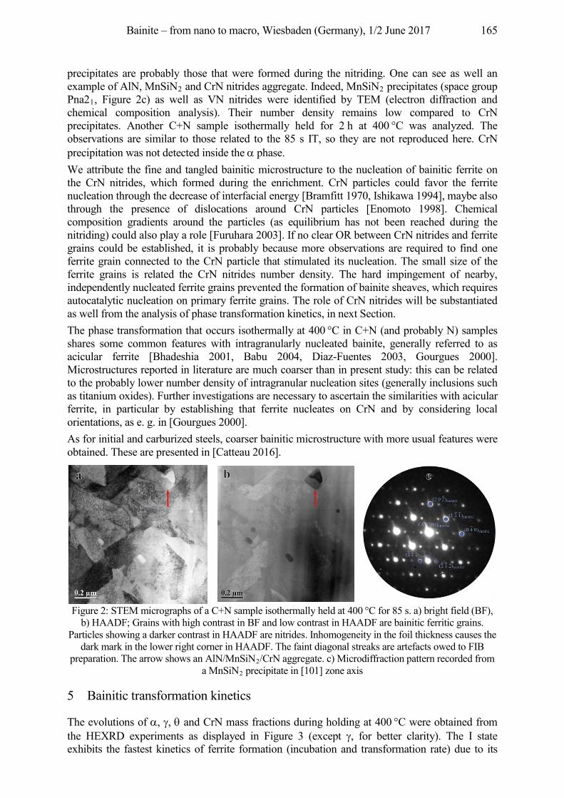
Bainite – from nano to macro, Wiesbaden (Germany), 1/2 June 2017 165
precipitates are probably those that were formed during the nitriding. One can see as well an example of AlN, MnSiN2 and CrN nitrides aggregate. Indeed, MnSiN2 precipitates (space group Pna21, Figure 2c) as well as VN nitrides were identified by TEM (electron diffraction and chemical composition analysis). Their number density remains low compared to CrN precipitates. Another C+N sample isothermally held for 2 h at 400 °C was analyzed. The observations are similar to those related to the 85 s IT, so they are not reproduced here. CrN precipitation was not detected inside the phase. We attribute the fine and tangled bainitic microstructure to the nucleation of bainitic ferrite on the CrN nitrides, which formed during the enrichment. CrN particles could favor the ferrite nucleation through the decrease of interfacial energy [Bramfitt 1970, Ishikawa 1994], maybe also through the presence of dislocations around CrN particles [Enomoto 1998]. Chemical composition gradients around the particles (as equilibrium has not been reached during the nitriding) could also play a role [Furuhara 2003]. If no clear OR between CrN nitrides and ferrite grains could be established, it is probably because more observations are required to find one ferrite grain connected to the CrN particle that stimulated its nucleation. The small size of the ferrite grains is related the CrN nitrides number density. The hard impingement of nearby, independently nucleated ferrite grains prevented the formation of bainite sheaves, which requires autocatalytic nucleation on primary ferrite grains. The role of CrN nitrides will be substantiated as well from the analysis of phase transformation kinetics, in next Section. The phase transformation that occurs isothermally at 400 °C in C+N (and probably N) samples shares some common features with intragranularly nucleated bainite, generally referred to as acicular ferrite [Bhadeshia 2001, Babu 2004, Diaz-Fuentes 2003, Gourgues 2000]. Microstructures reported in literature are much coarser than in present study: this can be related to the probably lower number density of intragranular nucleation sites (generally inclusions such as titanium oxides). Further investigations are necessary to ascertain the similarities with acicular ferrite, in particular by establishing that ferrite nucleates on CrN and by considering local orientations, as e. g. in [Gourgues 2000]. As for initial and carburized steels, coarser bainitic microstructure with more usual features were obtained. These are presented in [Catteau 2016].
Figure 2: STEM micrographs of a C+N sample isothermally held at 400 °C for 85 s. a) bright field (BF),
b) HAADF; Grains with high contrast in BF and low contrast in HAADF are bainitic ferritic grains. Particles showing a darker contrast in HAADF are nitrides. Inhomogeneity in the foil thickness causes the
dark mark in the lower right corner in HAADF. The faint diagonal streaks are artefacts owed to FIB preparation. The arrow shows an AlN/MnSiN2/CrN aggregate. c) Microdiffraction pattern recorded from
a MnSiN2 precipitate in [101] zone axis
5 Bainitic transformation kinetics
The evolutions of , , and CrN mass fractions during holding at 400 °C were obtained from the HEXRD experiments as displayed in Figure 3 (except , for better clarity). The I state exhibits the fastest kinetics of ferrite formation (incubation and transformation rate) due to its
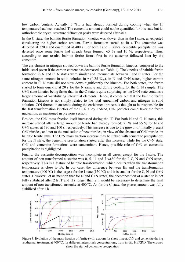
Bainite – from nano to macro, Wiesbaden (Germany), 1/2 June 2017 166
low carbon content. Actually, 5 %m had already formed during cooling when the IT temperature had been reached. The cementite amount could not be quantified for this state but its orthorhombic crystal structure diffraction peaks were detected after 40 s. In the C state, the bainitic ferrite formation kinetics was slower than in the I state, as expected considering the higher carbon amount. Ferrite formation started at 40 s. The cementite was detected at 220 s and quantified at 400 s. For both I and C states, cementite precipitation was detected once some ferrite had already been formed: 65 % and 10 %, respectively. Thus, according to our results, bainitic ferrite forms first in the austenite followed later by the cementite. The enrichment in nitrogen slowed down the bainitic ferrite formation kinetics, compared to the initial steel (even if the carbon content has decreased, see Table 1). The kinetics of bainitic ferrite formation in N and C+N states were similar and intermediate between I and C states. For the same nitrogen amount in solid solution in (0.25 %m), in N and C+N states, higher carbon content in C+N state did not slow down significantly the kinetics. For both states, the ferrite started to form quickly: at 20 s for the N sample and during cooling for the C+N sample. The C+N state kinetics being faster than in the C state is quite surprising, as the C+N state contains a larger amount of -stabilizing interstitial elements. Hence, it comes out that the bainitic ferrite formation kinetics is not simply related to the total amount of carbon and nitrogen in solid solution. CrN formed in austenite during the enrichment process is thought to be responsible for the fast transformation kinetics of the C+N alloy. Indeed, CrN particles could favor the ferrite nucleation, as mentioned in previous section. Besides, the CrN mass fraction itself increased during the IT. For both N and C+N states, this increase started after a large amount of ferrite had already formed: 71 % and 55 % for N and C+N states, at 190 and 160 s, respectively. This increase is due to the growth of initially present CrN nitrides, and not to the nucleation of new nitrides, in view of the absence of CrN nitrides in bainitic ferrite laths. The CrN mass fraction increase may be linked with cementite precipitation: for the N state, the cementite precipitation started after this increase, while for the C+N state, CrN and cementite formations were concomitant. Hence, possible role of CrN on cementite precipitation is highlighted. Finally, the austenite decomposition was incomplete in all cases, except for the I state. The amount of non-transformed austenite was 0, 5, 11 and 7 wt.% for the I, C, N and C+N states, respectively. This is a feature of bainitic transformation, which occurs when the transformation temperature is close to Bs. In our case, the difference between Bs and the transformation temperature (400 °C) is the largest for the I state (150 °C) and it is smaller for the C, N and C+N states. However, let us mention that for N and C+N states, the decomposition of austenite is not fully stabilized after 2 h IT and ITs longer than 2 h would be necessary to determine the final amount of non-transformed austenite at 400 °C. As for the C state, the phases amount was fully stabilized after 1 h.
Figure 3. Evolution of the mass fraction of ferrite (with a zoom for short times), CrN and cementite during isothermal treatment at 400 °C, for different interstitials concentrations, from in-situ HEXRD. The crosses
show the start of cementite precipitation
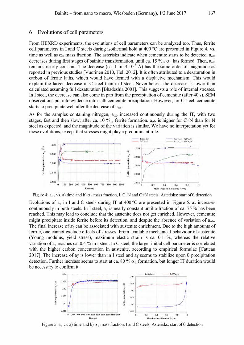
Bainite – from nano to macro, Wiesbaden (Germany), 1/2 June 2017 167
6 Evolutions of cell parameters
From HEXRD experiments, the evolutions of cell parameters can be analyzed too. Thus, ferrite cell parameters in I and C steels during isothermal hold at 400 °C are presented in Figure 4, vs. time as well as b mass fraction. The asterisks indicate when cementite starts to be detected. a b decreases during first stages of bainitic transformation, until ca. 15 %m b has formed. Then, a b remains nearly constant. The decrease (ca. 1 m–3 10-3 Å) has the same order of magnitude as reported in previous studies [Vuorinen 2010, Hell 2012]. It is often attributed to a desaturation in carbon of ferrite laths, which would have formed with a displacive mechanism. This would explain the larger decrease in C steel than in I steel. Nevertheless, the decrease is lower than calculated assuming full desaturation [Bhadeshia 2001]. This suggests a role of internal stresses. In I steel, the decrease can also come in part from the precipitation of cementite (after 40 s). SEM observations put into evidence intra-lath cementite precipitation. However, for C steel, cementite starts to precipitate well after the decrease of a b. As for the samples containing nitrogen, a b increased continuously during the IT, with two stages, fast and then slow, after ca. 10 %m ferrite formation. a b is higher for C+N than for N steel as expected, and the magnitude of the variation is similar. We have no interpretation yet for these evolutions, except that stresses might play a predominant role.
Figure 4: a b vs. a) time and b) b mass fraction, I, C, N and C+N steels. Asterisks: start of detection
Evolutions of a in I and C steels during IT at 400 °C are presented in Figure 5. a increases continuously in both steels. In I steel, a is nearly constant until a fraction of ca. 75 % has been reached. This may lead to conclude that the austenite does not get enriched. However, cementite might precipitate inside ferrite before its detection, and despite the absence of variation of a b. The final increase of a can be associated with austenite enrichment. Due to the high amounts of ferrite, one cannot exclude effects of stresses. From available mechanical behaviour of austenite (Young modulus, yield stress), maximum elastic strain is ca. 0.1 %, whereas the relative variation of a reaches ca. 0.4 % in I steel. In C steel, the larger initial cell parameter is correlated with the higher carbon concentration in austenite, according to empirical formulae [Catteau 2017]. The increase of a is lower than in I steel and a seems to stabilize upon precipitation detection. Further increase seems to start at ca. 80 % b formation, but longer IT duration would be necessary to confirm it.
Figure 5: a vs. a) time and b) b mass fraction, I and C steels. Asterisks: start of detection
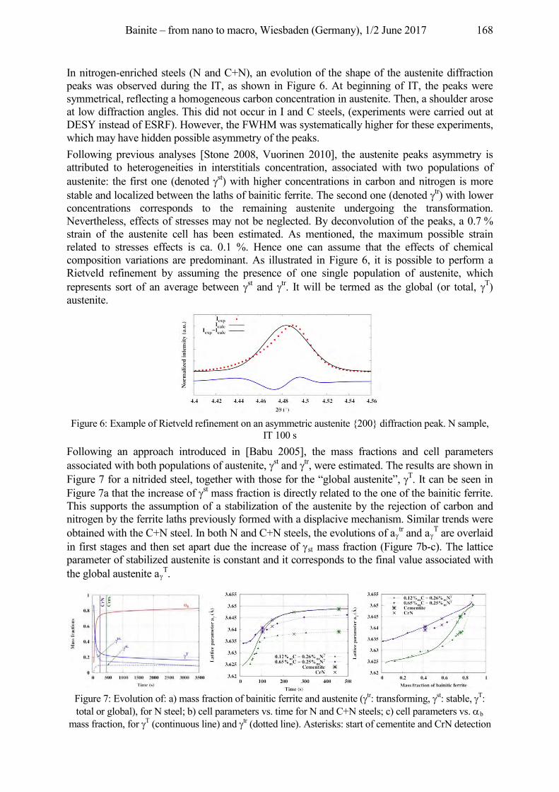
Bainite – from nano to macro, Wiesbaden (Germany), 1/2 June 2017 168
In nitrogen-enriched steels (N and C+N), an evolution of the shape of the austenite diffraction peaks was observed during the IT, as shown in Figure 6. At beginning of IT, the peaks were symmetrical, reflecting a homogeneous carbon concentration in austenite. Then, a shoulder arose at low diffraction angles. This did not occur in I and C steels, (experiments were carried out at DESY instead of ESRF). However, the FWHM was systematically higher for these experiments, which may have hidden possible asymmetry of the peaks. Following previous analyses [Stone 2008, Vuorinen 2010], the austenite peaks asymmetry is attributed to heterogeneities in interstitials concentration, associated with two populations of austenite: the first one (denoted st) with higher concentrations in carbon and nitrogen is more stable and localized between the laths of bainitic ferrite. The second one (denoted tr) with lower concentrations corresponds to the remaining austenite undergoing the transformation. Nevertheless, effects of stresses may not be neglected. By deconvolution of the peaks, a 0.7 % strain of the austenite cell has been estimated. As mentioned, the maximum possible strain related to stresses effects is ca. 0.1 %. Hence one can assume that the effects of chemical composition variations are predominant. As illustrated in Figure 6, it is possible to perform a Rietveld refinement by assuming the presence of one single population of austenite, which represents sort of an average between st and tr. It will be termed as the global (or total, T) austenite.
Figure 6: Example of Rietveld refinement on an asymmetric austenite {200} diffraction peak. N sample,
IT 100 s Following an approach introduced in [Babu 2005], the mass fractions and cell parameters associated with both populations of austenite, st and tr, were estimated. The results are shown in Figure 7 for a nitrided steel, together with those for the “global austenite”, T. It can be seen in Figure 7a that the increase of st mass fraction is directly related to the one of the bainitic ferrite. This supports the assumption of a stabilization of the austenite by the rejection of carbon and nitrogen by the ferrite laths previously formed with a displacive mechanism. Similar trends were obtained with the C+N steel. In both N and C+N steels, the evolutions of a tr and a T are overlaid in first stages and then set apart due the increase of st mass fraction (Figure 7b-c). The lattice parameter of stabilized austenite is constant and it corresponds to the final value associated with the global austenite a T.
Figure 7: Evolution of: a) mass fraction of bainitic ferrite and austenite ( tr: transforming, st: stable, T: total or global), for N steel; b) cell parameters vs. time for N and C+N steels; c) cell parameters vs. b
mass fraction, for T (continuous line) and tr (dotted line). Asterisks: start of cementite and CrN detection
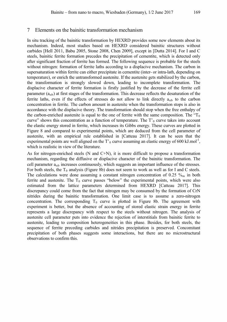
Bainite – from nano to macro, Wiesbaden (Germany), 1/2 June 2017 169
7 Elements on the bainitic transformation mechanism
In situ tracking of the bainitic transformation by HEXRD provides some new elements about its mechanism. Indeed, most studies based on HEXRD considered bainitic structures without carbides [Hell 2011, Babu 2005, Stone 2008, Chen 2009], except in [Dutta 2014]. For I and C steels, bainitic ferrite formation precedes the precipitation of cementite, which is detected only after significant fraction of ferrite has formed. The following sequence is probable for the steels without nitrogen: formation of ferrite laths according to a displacive mechanism. The carbon in supersaturation within ferrite can either precipitate in cementite (inter- or intra-lath, depending on temperature), or enrich the untransformed austenite. If the austenite gets stabilized by the carbon, the transformation is strongly slowed down, leading to incomplete transformation. The displacive character of ferrite formation is firstly justified by the decrease of the ferrite cell parameter (a b) at first stages of the transformation. This decrease reflects the desaturation of the ferrite laths, even if the effects of stresses do not allow to link directly a b to the carbon concentration in ferrite. The carbon amount in austenite when the transformation stops is also in accordance with the displacive theory. The transformation should stop when the free enthalpy of the carbon-enriched austenite is equal to the one of ferrite with the same composition. The “T0 curve” shows this concentration as a function of temperature. The T’0 curve takes into account the elastic energy stored in ferrite, which increases its Gibbs energy. These curves are plotted in Figure 8 and compared to experimental points, which are deduced from the cell parameter of austenite, with an empirical rule established in [Catteau 2017]. It can be seen that the experimental points are well aligned on the T’0 curve assuming an elastic energy of 600 kJ.mol-1, which is realistic in view of the literature. As for nitrogen-enriched steels (N and C+N), it is more difficult to propose a transformation mechanism, regarding the diffusive or displacive character of the bainitic transformation. The cell parameter a b increases continuously, which suggests an important influence of the stresses. For both steels, the T0 analysis (Figure 8b) does not seem to work as well as for I and C steels. The calculations were done assuming a constant nitrogen concentration of 0.25 %m in both ferrite and austenite. The T0 curve passes “below” the experimental points, which were also estimated from the lattice parameters determined from HEXRD [Catteau 2017]. This discrepancy could come from the fact that nitrogen may be consumed by the formation of CrN nitrides during the bainitic transformation. One limit case is to assume a zero-nitrogen concentration. The corresponding T0 curve is plotted in Figure 8b. The agreement with experiment is better, but the absence of accounting of stored elastic strain energy in ferrite represents a large discrepancy with respect to the steels without nitrogen. The analysis of austenite cell parameter puts into evidence the rejection of interstitials from bainitic ferrite to austenite, leading to composition heterogeneities in this phase. Besides, for both steels, the sequence of ferrite preceding carbides and nitrides precipitation is preserved. Concomitant precipitation of both phases suggests some interactions, but there are no microstructural observations to confirm this.
Bainite – from nano to macro, Wiesbaden (Germany), 1/2 June 2017 170
Figure 8: Comparison between carbon concentrations within austenite at the end of bainitic transformation
with T0 and T’0 concepts, considering an elastic strain energy of 600 J.mol-1 stored in ferrite. a) I and C steels; b) N and C+N steels
8 Conclusion
Effects of carbon and nitrogen on bainitic transformation have been studied in a low alloyed steel, by HEXRD and TEM. Experimental study of isothermal transformation kinetics was realized on specimens homogeneously enriched (in carbon and/or nitrogen) in the austenitic field. Classical slowing down effect on kinetics was observed by increasing the carbon content in parent austenite. In presence of nitrogen, kinetics cannot be directly linked to the interstitials content in austenite. Kinetics is intermediate between initial and carbon enriched steels and a finer microstructure is observed. This phenomenon is attributed to the stimulation of ferrite nucleation by the presence of CrN in parent austenite, which precipitated during enrichment. In presence of nitrogen, the bainitic microstructure consists of submicronic, ill-defined and tangled laths, which is attributed as well to the nucleation on CrN nitrides. In situ HEXRD allowed to analyse the evolutions of the different phases: ferrite, austenite, cementite and CrN. To our knowledge, similar studies were carried out almost only on carbide-free bainite and steels without nitrogen. The chronology of the phases formation could be established, as well as the evolutions of the cell parameters. For initial and carburized steels, the results are in agreement with the assumption of a displacive mechanism. In presence of nitrogen, analysis of austenite cell parameters and peaks profiles showed clearly the rejection of interstitials from ferrite into austenite, leading to composition heterogeneities, without making possible to propose firm hypotheses on the phase transformation mechanism.
Acknowledgement This work was supported by PSA and by the French State through the program "Investment in the future" operated by the National Research Agency (ANR) and referenced by ANR-11-LABX- 0008-01 (LabEx DAMAS).
References Babu, S. S.: The mechanism of acicular ferrite in weld deposits. Curr. Opin. Solid State Mater. Sci. 8 (2004), pp.
267–278. Babu, S. S; Specht, E. D.; David, S. A.; Karapetrova, E.; Zschack, P.; Peet, M; Bhadeshia, H. K. D. H.: In-situ
observations of lattice parameter fluctuations in Austenite and transformation to Bainite. Met. Mat. Trans. A 36A (2005) 12, pp. 3281–3289.
Bhadeshia, H. K. D. H.; David, S. A.; Vitek, J. M.; Reed, R. W.: Stress Induced Transformation to Bainite in Pressure Vessel Steel. Materials Science and Technology 7 (1991), pp. 686–698.
Bhadeshia, H. K. D. H.: Bainite in Steels Transformations, Microstructure and Properties, 2. Ed., IOM Communications Ltd, 2001.
Böttger, A.; van Genderen, M. J.; Sijbrandij, S. J.; Mittemeijer, E. J.; Smith, D. W.: Atom probe and X-ray diffraction analysis of the composition and structure of precipitates formed on tempering of ternary iron-carbon-nitrogen martensites. ISIJ Int. 36 (1996) 7, pp. 764–767.
Bramfitt, B.: The effect of carbide and nitride additions on the heterogeneous nucleation of liquid iron. Metall. Trans. 1 (1970), pp. 1987–1995.
Bainite – from nano to macro, Wiesbaden (Germany), 1/2 June 2017 171
Catteau, S. D.: Effets du carbone et de l’azote sur les cinétiques de décomposition de l’austénite dans un acier faiblement allié – Etude expérimentale et Modélisation, PhD. Thesis manuscript, 2017, (in preparation).
Catteau, S. D.; Denis, S.; Teixeira, J.; Dulcy, J.; Dehmas, M.; Redjaïmia, A.; Courteaux, M.: Proc. 21st IFHTSE Congress, AWT, Bremen, Germany. H.-W. Zoch, R. Schneider, Th. Lübben (Eds.), 2014, pp. 153–161.
Catteau, S. D.; Van Landeghem, H. P.; Teixeira, J.; Dulcy, J.; Dehmas, M.; Denis, S.; Redjaïmia, A.; Courteaux, M.: Carbon and nitrogen effects on microstructure and kinetics associated with bainitic transformation in a low-alloyed steel. J. Alloys and Compounds 658 (2016), pp. 832–838.
Cheng, L.; Böttger, A.; Mittemeijer, E. J.: Tempering of iron-carbon-nitrogen martensites. Metall. Mat. Trans. A 23 (1992), pp. 1129–1145.
Chen, X.; Vuorinen, E.: In-situ high temperature X-ray studies of austempering transformation in high silicon cast steel. ISIJ Int. 49 (2009) 8, pp. 1220–1224.
Constant, A.; Henry, G.; Charbonnier, J-C.: Principes de Base des Traitements Thermiques, Thermomecaniques et Thermochimiques des Aciers. PYC Edition, 1992.
Diaz-Fuentes, M.; Iza-Mendia, A.; Gutierrez, I.: Analysis of different acicular ferrite microstructures in low-carbon steels by electron backscattered diffraction. Study of their toughness behaviour. Metall. Trans. A 34 (2003), pp. 2505–2516.
Dutta, R. K.; Huizenga, R. M.; Amirthlingam, M.; King, A.; Gao, H.; Hermans, M. J. M.; Sietsma, J.; Richardson, I. M: In-situ synchrotron diffraction studies on transformation strain development in a high strength quenched and tempered structural steel. – Part I. Bainitic transformation. Metall. Mat. Trans. A 45 (2014), pp. 218–229.
Enomoto, M.: Nucleation of phase transformations at intragranular inclusions in steel. Metals Mater. Korea 4 (1998) 2, pp. 115–123.
Esin, V. A.; Denand, B.; Le Bihan, Q.; Dehmas, M.; Teixeira, J.; Geandier, G.; Denis, S.; Sourmail, T.; Aeby-Gautier, E.: In situ synchrotron X-ray diffraction and dilatometric study of austenite formation in a multi-component steel: Influence of initial microstructure and heating rate. Acta Mat. 80 (2014), pp. 118–131.
Furuhara, T.; Yamaguchi, J.; Sugita, N.; Miyamoto, G.; Maki, T.: Nucleation of proeutectoid ferrite on complex precipitates in austenite. ISIJ Int. 43 (2003) 10, pp. 1630–1639.
Gourgues, A.-F.; Flower, H. M.; Lindley, T. C.: Electron backscattering diffraction study of acicular ferrite, bainite, and martensite steel microstructures. Mater. Sci. Technol. 16 (2000), pp. 26–40.
Hell, J.-C.: Aciers Bainitiques Sans Carbure : Caractérisations Microstructurale Multi-Echelle et In-Situ de la Transformation Austénite-Bainite et Relations entre Microstructure et Comportement Mécanique. PhD. Thesis manuscript, Université Paul Verlaine-Metz, 2012.
Hell, J.-C.; Dehmas, M.; Allain, S.; Prado, J. M.; Hazotte, A.; Chateau, J.-P.: Microstructure-properties relationships in carbide-free bainitic steels. ISIJ Int. 51 (2011) 10, pp. 1724–1732.
Ishikawa, F.; Takahashi, T.; Ochi, T.: Intragranular ferrite nucleation in medium-carbon vanadium steels. Metall. Mat. Trans. A 25 (1994) 5, pp. 929–936.
Jiang, Z.; Li, X.; Gu, J.; Hu, M.; Zhu, Z.: Isothermal decomposition behavior of the high nitrogen concentration -Fe[N] prepared from pure iron. Appl. Surf. Sci. 254 (2008), pp. 7361–7364.
Nakada, N.; Fukuzawa, N.; Tsuchiyama, T.; Takaki, S.; Koyano, T.; Iwamoto, T.; Omori, Y.: Isothermal transformation in Fe-N hypereutectoid alloy. ISIJ Int. 53 (2013) 1, pp. 139–144.
Simon, A.; Lorenzo, A.; Beck, G.; Meynet, G.: Influence de la teneur en azote sur les transformations de l'austénite carbonitrurée de l'acier 30CD4, Mémoires Sci. Rev. Mét., Vol 71, No 12, 1974, pp. 823–831.
Stone, H. J; Peet, M. J.; Bhadeshia, H. K. D. H.; Withers, P. J.; Babu, S. S.; Specht, E. D.: Synchrotron X-ray studies of austenite and bainitic ferrite. Proc. R. Soc. A 464 (2008), pp. 1009–1027.
Vuorinen, E.; Chen, X.: In Situ High Temperature X-Ray Studies on Bainitic Transformation of Austempered Silicon Alloyed Steels. Materials Science Forum 638-642 (2010), pp. 3086–3092.
Bainite – from nano to macro, Wiesbaden (Germany), 1/2 June 2017 172
Modeling of bainitic transformations under high stresses Martin Hunkel, Diego Said Schicchi
Stiftung Institut für Werkstofftechnik, Badgasteiner Str. 3, 28359 Bremen, Germany, {hunkel, schicchi}@iwt-bremen.de
Abstract The use of press-hardened components in the automotive industry has considerably grown during the last decades. The intrinsic nature of this process causes transformations to occur under the influence of high stresses and pre-deformed austenite. A variant of this forming process, the so-called partial press hardening, employs locally heated tools in order to produce bainitic microstructure, obtaining zones within the formed parts with higher ductility. Pre-strain states of austenite and applied stresses influence the kinetics of the bainitic transformation, mainly causing its acceleration. Furthermore, the transformation plasticity effect has great influence in this process. Linear models of this effect have been successfully used to predict the behavior in presence of low stresses; however, for forming processes involving severe conditions, these tend to fail. A strong nonlinearity of the transformation plasticity strain is observed for applied stresses above the austenite yield strength. These aspects are investigated in this work through thermo-mechanical tests in sheet specimens of a manganese-boron steel (22MnB5), widely utilized in the industry.
Keywords Bainite, Nonlinear Transformation Plasticity, High Stresses, 22MnB5
1 Introduction
Partial press-hardening is an important technology for the production of safety related components within the automotive industry. Parts are hot formed in heated tools (in the temperature range of 350–550 °C) and afterwards cooled down inside the tool still with applied load. Complex shapes can be achieved in parts made of ultrahigh strength steel which, depending on the cooling conditions determined by the forming tools, may contain martensitic and bainitic microstructures throughout the components. Due to the intrinsic nature of this process, loads and deformations will affect the original austenitic microstructure and consequently the bainitic and martensitic transformation kinetics [Said Schicchi, Hunkel 2016]. Therefore, the strong coupling between mechanical loading, internal stresses, internal strains, chemical composition and phase transformation kinetics needs to be deeply studied in order to be able of understanding this phenomenon and developing close to reality models with simulation purposes. Regarding the bainitic microstructure, relevant contributions have been made by Bhadeshia and co-workers during the last decades dealing with formation mechanism and kinetics [Bhadeshia, Edmonds 1979, Bhadeshia 1982, Rees, Bhadeshia 1992a, Rees, Bhadeshia 1992b, Bhadeshia 1999, Matsuda, Bhadeshia 2004]. In this work, the focus is made on the austenite-to-bainite transformation kinetics of the 22MnB5 steel grade, in the range of 450–550 °C, under the influence of external applied stresses. Especial attention is made on the effect of high stresses (larger than the austenite yield strength) concerning the transformation plasticity strain. After this short introduction, Section 2 summarizes the performed tests and material properties; Section 3 presents the proposed numerical approach for the study of the aforementioned phenomena; Section 4 introduces experimental and numerical results, and conclusive remarks are presented in Section 5.
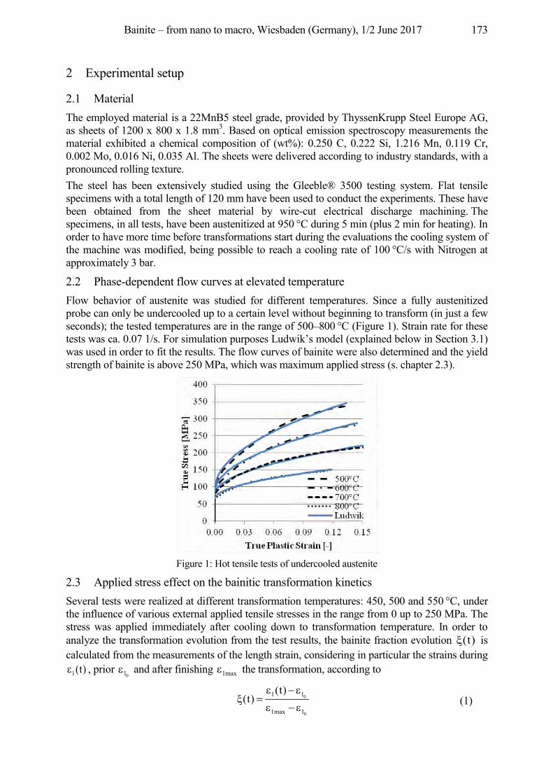
Bainite – from nano to macro, Wiesbaden (Germany), 1/2 June 2017 173
2 Experimental setup
2.1 Material The employed material is a 22MnB5 steel grade, provided by ThyssenKrupp Steel Europe AG, as sheets of 1200 x 800 x 1.8 mm3. Based on optical emission spectroscopy measurements the material exhibited a chemical composition of (wt%): 0.250 C, 0.222 Si, 1.216 Mn, 0.119 Cr, 0.002 Mo, 0.016 Ni, 0.035 Al. The sheets were delivered according to industry standards, with a pronounced rolling texture. The steel has been extensively studied using the Gleeble® 3500 testing system. Flat tensile specimens with a total length of 120 mm have been used to conduct the experiments. These have been obtained from the sheet material by wire-cut electrical discharge machining. The specimens, in all tests, have been austenitized at 950 °C during 5 min (plus 2 min for heating). In order to have more time before transformations start during the evaluations the cooling system of the machine was modified, being possible to reach a cooling rate of 100 °C/s with Nitrogen at approximately 3 bar.
2.2 Phase-dependent flow curves at elevated temperature Flow behavior of austenite was studied for different temperatures. Since a fully austenitized probe can only be undercooled up to a certain level without beginning to transform (in just a few seconds); the tested temperatures are in the range of 500–800 °C (Figure 1). Strain rate for these tests was ca. 0.07 1/s. For simulation purposes Ludwik’s model (explained below in Section 3.1) was used in order to fit the results. The flow curves of bainite were also determined and the yield strength of bainite is above 250 MPa, which was maximum applied stress (s. chapter 2.3).
Figure 1: Hot tensile tests of undercooled austenite
2.3 Applied stress effect on the bainitic transformation kinetics Several tests were realized at different transformation temperatures: 450, 500 and 550 °C, under the influence of various external applied tensile stresses in the range from 0 up to 250 MPa. The stress was applied immediately after cooling down to transformation temperature. In order to analyze the transformation evolution from the test results, the bainite fraction evolution )t( is calculated from the measurements of the length strain, considering in particular the strains during
)t(l , prior 0l and after finishing maxl the transformation, according to
0
0
lmaxl
ll )t()t( (1)
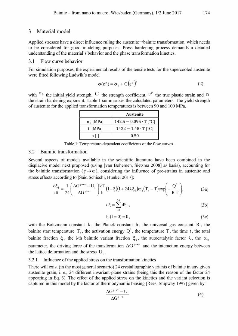
Bainite – from nano to macro, Wiesbaden (Germany), 1/2 June 2017 174
3 Material model
Applied stresses have a direct influence ruling the austenite�bainite transformation, which needs to be considered for good modeling purposes. Press hardening process demands a detailed understanding of the material’s behavior and the phase transformation kinetics.
3.1 Flow curve behavior For simulation purposes, the experimental results of the tensile tests for the supercooled austenite were fitted following Ludwik’s model np
0p C)( (2)
with 0 the initial yield strength, C the strength coefficient, p
the true plastic strain and n the strain hardening exponent. Table 1 summarizes the calculated parameters. The yield strength of austenite for the applied transformation temperatures is between 90 and 100 MPa.
Austenite [MPa] 142.5− 0.095 T [°C]
C [MPa] 1422− 1.48 T [°C] n [-] 0.50
Table 1: Temperature-dependent coefficients of the flow curves.
3.2 Bainitic transformation Several aspects of models available in the scientific literature have been combined in the displacive model next proposed (using [van Bohemen, Sietsma 2008] as basis), accounting for the bainitic transformation ( ), considering the influence of pre-strains in austenite and stress effects according to [Said Schicchi, Hunkel 2017]:
TRQexpTT2411
hTk
GUG
241
dtd *
hbiii , (3a)
24
1iidd , (3b)
0)0t(i , (3c) with the Boltzmann constant k , the Planck constant h , the universal gas constant R , the bainite start temperature hT , the activation energy *Q , the temperature T , the time t , the total bainite fraction , the i-th bainitic variant fraction i , the autocatalytic factor , the b parameter, the driving force of the transformation G and the interaction energy between the lattice deformation and the stress iU .
3.2.1 Influence of the applied stress on the transformation kinetics There will exist (in the most general scenario) 24 crystallographic variants of bainite in any given austenite grain, i. e., 24 different invariant-plane strains (being this the reason of the factor 24 appearing in Eq. 3). The effect of the applied stress on the kinetics and the variant selection is captured in this model by the factor of thermodynamic biasing [Rees, Shipway 1997] given by:
GUG i (4)
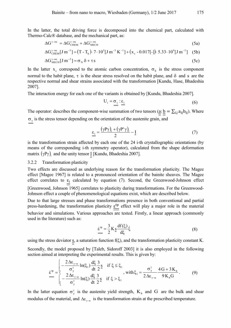
Bainite – from nano to macro, Wiesbaden (Germany), 1/2 June 2017 175
In the latter, the total driving force is decomposed into the chemical part, calculated with Thermo-Calc® database, and the mechanical part, as:
MECHCHEM GGG (5a) ]mJ[105.33 0.017[-] - x ]KmJ[107T -T ]mJ[G 39
c135
h3
CHEM (5b) s ]mJ[G N
3MECH (5c)
In the latter cx correspond to the atomic carbon concentration, S is the stress component normal to the habit plane, is the shear stress resolved on the habit plane, and and s are the respective normal and shear strains associated with the transformation [Kundu, Hase, Bhadeshia 2007]. The interaction energy for each one of the variants is obtained by [Kundu, Bhadeshia 2007].
ii :U (6)
The operator: describes the component-wise summation of two tensors (a: b = ai bii, ). Where is the stress tensor depending on the orientation of the austenite grain, and
I
2'PP ii
i (7)
is the transformation strain affected by each one of the 24 i-th crystallographic orientations (by means of the corresponding i-th symmetry operator), calculated from the shape deformation matrix iP and the unity tensor I [Kundu, Bhadeshia 2007].
3.2.2 Transformation plasticity Two effects are discussed as underlying reason for the transformation plasticity. The Magee effect [Magee 1967] is related to a pronounced orientation of the bainite sheaves. The Magee effect correlates to i calculated by equation (7). Second, the Greenwood-Johnson effect
[Greenwood, Johnson 1965] correlates to plasticity during transformations. For the Greenwood-Johnson effect a couple of phenomenological equations exist, which are described below. Due to that large stresses and phase transformations presence in both conventional and partial press-hardening, the transformation plasticity effect will play a major role in the material behavior and simulations. Various approaches are tested. Firstly, a linear approach (commonly used in the literature) such as: ��
d)(dfsK
23tp (8)
using the stress deviator s, a saturation function f( ), and the transformation plasticity constant K.
Secondly, the model proposed by [Taleb, Sidoroff 2003] it is also employed in the following section aimed at interpreting the experimental results. This is given by:
ly
llytp
ifs23
dtd)ln(
2
ifs23
dtd)ln(
2
� , withGK9K3G4
2 b
byl . (9)
In the latter equation y is the austenite yield strength, bK and G are the bulk and shear modulus of the material, and is the transformation strain at the prescribed temperature.
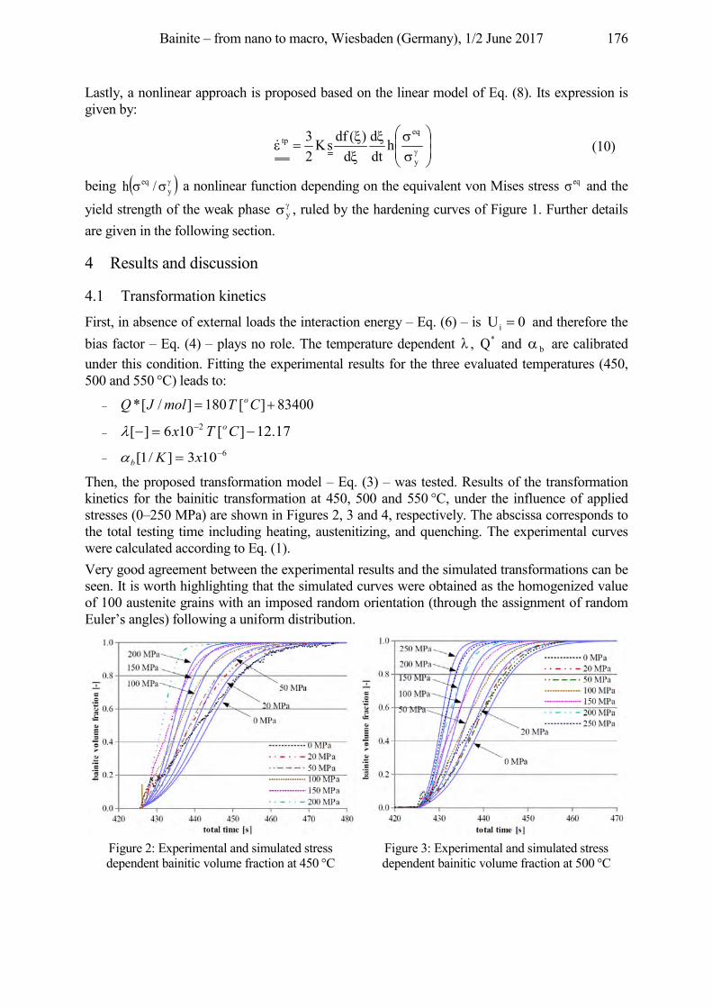
Bainite – from nano to macro, Wiesbaden (Germany), 1/2 June 2017 176
Lastly, a nonlinear approach is proposed based on the linear model of Eq. (8). Its expression is given by:
y
eqtp h
dtd
d)(dfsK
23
� (10)
being yeq /h a nonlinear function depending on the equivalent von Mises stress eq and the
yield strength of the weak phase y , ruled by the hardening curves of Figure 1. Further details are given in the following section.
4 Results and discussion
4.1 Transformation kinetics
First, in absence of external loads the interaction energy – Eq. (6) – is 0Ui and therefore the bias factor – Eq. (4) – plays no role. The temperature dependent , *Q and b are calibrated under this condition. Fitting the experimental results for the three evaluated temperatures (450, 500 and 550 °C) leads to:
83400][180]/[* CTmolJQ o
17.12][106][ 2 CTx o
6103]/1[ xKb
Then, the proposed transformation model – Eq. (3) – was tested. Results of the transformation kinetics for the bainitic transformation at 450, 500 and 550 °C, under the influence of applied stresses (0–250 MPa) are shown in Figures 2, 3 and 4, respectively. The abscissa corresponds to the total testing time including heating, austenitizing, and quenching. The experimental curves were calculated according to Eq. (1). Very good agreement between the experimental results and the simulated transformations can be seen. It is worth highlighting that the simulated curves were obtained as the homogenized value of 100 austenite grains with an imposed random orientation (through the assignment of random Euler’s angles) following a uniform distribution.
Figure 2: Experimental and simulated stress dependent bainitic volume fraction at 450 °C
Figure 3: Experimental and simulated stress dependent bainitic volume fraction at 500 °C
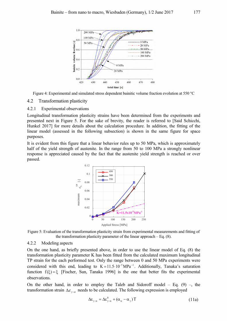
Bainite – from nano to macro, Wiesbaden (Germany), 1/2 June 2017 177
Figure 4: Experimental and simulated stress dependent bainitic volume fraction evolution at 550 °C
4.2 Transformation plasticity 4.2.1 Experimental observations Longitudinal transformation plasticity strains have been determined from the experiments and presented next in Figure 5. For the sake of brevity, the reader is referred to [Said Schicchi, Hunkel 2017] for more details about the calculation procedure. In addition, the fitting of the linear model (assessed in the following subsection) is shown in the same figure for space purposes. It is evident from this figure that a linear behavior rules up to 50 MPa, which is approximately half of the yield strength of austenite. In the range from 50 to 100 MPa a strongly nonlinear response is appreciated caused by the fact that the austenite yield strength is reached or over passed.
Figure 5: Evaluation of the transformation plasticity strain from experimental measurements and fitting of
the transformation plasticity parameter of the linear approach – Eq. (8). 4.2.2 Modeling aspects On the one hand, as briefly presented above, in order to use the linear model of Eq. (8) the transformation plasticity parameter K has been fitted from the calculated maximum longitudinal TP strain for the each performed test. Only the range between 0 and 50 MPa experiments were considered with this end, leading to 15 MPa105.11K . Additionally, Tanaka’s saturation function )(f [Fischer, Sun, Tanaka 1996] is the one that better fits the experimental observations. On the other hand, in order to employ the Taleb and Sidoroff model – Eq. (9) –, the transformation strain needs to be calculated. The following expression is employed
T)(0 (11a)
0 50 100 150 200 250
Applied Stress [MPa]
0
0.02
0.04
0.06
0.08
0.1
0.12
max
imum
LTP
[-]
450500550
K=11.5x10⁻⁵MPa-1
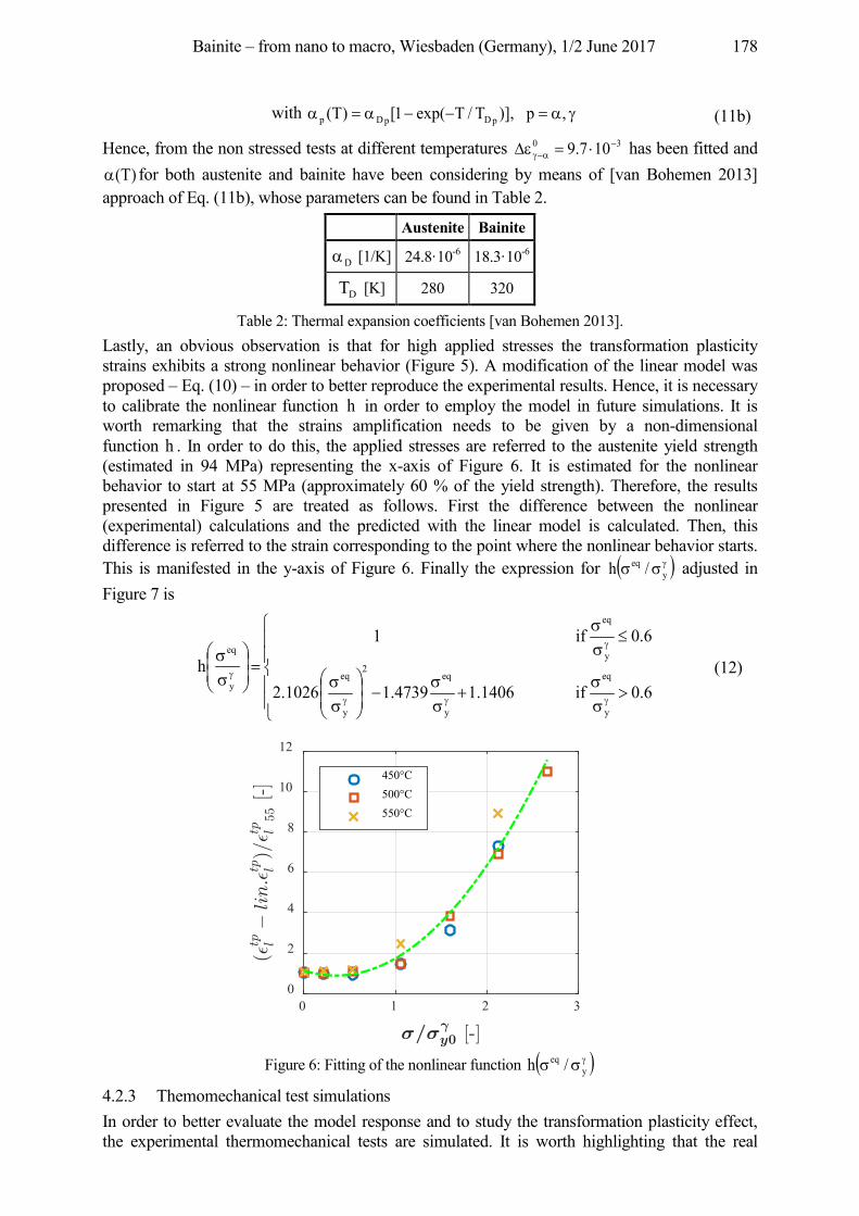
Bainite – from nano to macro, Wiesbaden (Germany), 1/2 June 2017 178
with ,p)],T/Texp(1[)T( pDpDp (11b)
Hence, from the non stressed tests at different temperatures 30 107.9 has been fitted and )T( for both austenite and bainite have been considering by means of [van Bohemen 2013]
approach of Eq. (11b), whose parameters can be found in Table 2.
Austenite Bainite
D [1/K] 24.8·10-6 18.3·10-6
DT [K] 280 320
Table 2: Thermal expansion coefficients [van Bohemen 2013]. Lastly, an obvious observation is that for high applied stresses the transformation plasticity strains exhibits a strong nonlinear behavior (Figure 5). A modification of the linear model was proposed – Eq. (10) – in order to better reproduce the experimental results. Hence, it is necessary to calibrate the nonlinear function h in order to employ the model in future simulations. It is worth remarking that the strains amplification needs to be given by a non-dimensional function h . In order to do this, the applied stresses are referred to the austenite yield strength (estimated in 94 MPa) representing the x-axis of Figure 6. It is estimated for the nonlinear behavior to start at 55 MPa (approximately 60 % of the yield strength). Therefore, the results presented in Figure 5 are treated as follows. First the difference between the nonlinear (experimental) calculations and the predicted with the linear model is calculated. Then, this difference is referred to the strain corresponding to the point where the nonlinear behavior starts. This is manifested in the y-axis of Figure 6. Finally the expression for y
eq /h adjusted in Figure 7 is
6.0if1.14064739.11026.2
6.0if1
h
y
eq
y
eq2
y
eq
y
eq
y
eq
(12)
Figure 6: Fitting of the nonlinear function y
eq /h
4.2.3 Themomechanical test simulations In order to better evaluate the model response and to study the transformation plasticity effect, the experimental thermomechanical tests are simulated. It is worth highlighting that the real
0 1 2 30
2
4
6
8
10
12
450°C500°C550°C
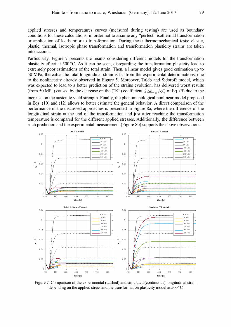
Bainite – from nano to macro, Wiesbaden (Germany), 1/2 June 2017 179
applied stresses and temperatures curves (measured during testing) are used as boundary conditions for these calculations, in order not to assume any “perfect” isothermal transformation or application of loads prior to transformation. During these thermomechanical tests: elastic, plastic, thermal, isotropic phase transformation and transformation plasticity strains are taken into account. Particularly, Figure 7 presents the results considering different models for the transformation plasticity effect at 500 °C. As it can be seen, disregarding the transformation plasticity lead to extremely poor estimations of the total strain. Then, a linear model gives good estimation up to 50 MPa, thereafter the total longitudinal strain is far from the experimental determinations, due to the nonlinearity already observed in Figure 5. Moreover, Taleb and Sidoroff model, which was expected to lead to a better prediction of the strains evolution, has delivered worst results (from 50 MPa) caused by the decrease on the (“K”) coefficient y/2 of Eq. (9) due to the increase on the austenite yield strength. Finally, the phenomenological nonlinear model proposed in Eqs. (10) and (12) allows to better estimate the general behavior. A direct comparison of the performance of the discussed approaches is presented in Figure 8a, where the difference of the longitudinal strain at the end of the transformation and just after reaching the transformation temperature is compared for the different applied stresses. Additionally, the difference between each prediction and the experimental measurement (Figure 8b) supports the above observations.
Figure 7: Comparison of the experimental (dashed) and simulated (continuous) longitudinal strain
depending on the applied stress and the transformation plasticity model at 500 °C
420 440 460 480 500 520 540
time [s]
0
0.02
0.04
0.06
0.08
0.1
0.12
L [-
]
No TP model
0 MPa20 MPa50 MPa100 MPa150 MPa200 MPa250 MPa
420 440 460 480 500 520 540
time [s]
0
0.02
0.04
0.06
0.08
0.1
0.12
L [-
]
Linear TP model
0 MPa20 MPa50 MPa100 MPa150 MPa200 MPa250 MPa
420 440 460 480 500 520 540
time [s]
0
0.02
0.04
0.06
0.08
0.1
0.12
L [-
]
Taleb & Sidoroff model
0 MPa20 MPa50 MPa100 MPa150 MPa200 MPa250 MPa
420 440 460 480 500 520 540
time [s]
0
0.02
0.04
0.06
0.08
0.1
0.12
L [-
]
Nonlinear TP model
0 MPa20 MPa50 MPa100 MPa150 MPa200 MPa250 MPa
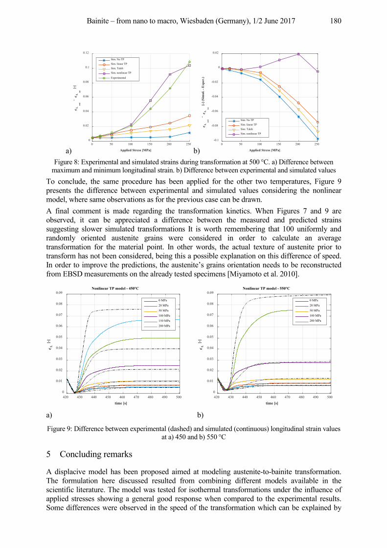
Bainite – from nano to macro, Wiesbaden (Germany), 1/2 June 2017 180
a) b) Figure 8: Experimental and simulated strains during transformation at 500 °C. a) Difference between
maximum and minimum longitudinal strain. b) Difference between experimental and simulated values To conclude, the same procedure has been applied for the other two temperatures, Figure 9 presents the difference between experimental and simulated values considering the nonlinear model, where same observations as for the previous case can be drawn. A final comment is made regarding the transformation kinetics. When Figures 7 and 9 are observed, it can be appreciated a difference between the measured and predicted strains suggesting slower simulated transformations It is worth remembering that 100 uniformly and randomly oriented austenite grains were considered in order to calculate an average transformation for the material point. In other words, the actual texture of austenite prior to transform has not been considered, being this a possible explanation on this difference of speed. In order to improve the predictions, the austenite’s grains orientation needs to be reconstructed from EBSD measurements on the already tested specimens [Miyamoto et al. 2010].
a) b)
Figure 9: Difference between experimental (dashed) and simulated (continuous) longitudinal strain values at a) 450 and b) 550 °C
5 Concluding remarks
A displacive model has been proposed aimed at modeling austenite-to-bainite transformation. The formulation here discussed resulted from combining different models available in the scientific literature. The model was tested for isothermal transformations under the influence of applied stresses showing a general good response when compared to the experimental results. Some differences were observed in the speed of the transformation which can be explained by
0 50 100 150 200 250
Applied Stress [MPa]
0
0.02
0.04
0.06
0.08
0.1
0.12
Len
d
- L
ini
[-]
Sim. No TPSim. linear TPSim. TalebSim. nonlinear TP
Experimental
0 50 100 150 200 250
Applied Stress [MPa]
-0.1
-0.08
-0.06
-0.04
-0.02
0
0.02
Len
d
- L
ini
[-] (
Sim
ul. -
Exp
er.)
Sim. No TPSim. linear TPSim. TalebSim. nonlinear TP
420 430 440 450 460 470 480 490 500
time [s]
0
0.01
0.02
0.03
0.04
0.05
0.06
0.07
0.08
0.09
L [-
]
Nonlinear TP model - 450°C
0 MPa20 MPa50 MPa100 MPa150 MPa200 MPa
420 430 440 450 460 470 480 490 500
time [s]
0
0.01
0.02
0.03
0.04
0.05
0.06
0.07
0.08
0.09
L [-
]
Nonlinear TP model - 550°C
0 MPa20 MPa50 MPa100 MPa200 MPa
Bainite – from nano to macro, Wiesbaden (Germany), 1/2 June 2017 181
texture effects not considered in this article. Ongoing work is done in this regard in a model capable of reconstructing austenite’s grains orientations based on EBSD results. It is expected for the incorporation of austenite’s real texture to improve the performance of the approach. Regarding the transformation plasticity strains, its importance for this kind of forming processes involving large stresses has been shown. Strong deficiencies were found in the predictions of theoretical models available in the literature when these are employed beyond the linear range. A phenomenological approach has been proposed seeking to skip this issue; however a lot of work is still needed in order to have a clear or at least better understanding of this effect.
Acknowledgement This work has been supported by the “Deutsche Forschungsgemeinschaft” under the priority program SPP 1713 “Strong coupling of thermo-chemical and thermo-mechanical states in applied materials”, project PressBain “Modeling bainitic transformations during press-hardening”.
References Bhadeshia, H. K. D. H., Edmonds, D., 1979. The bainite transformation in a silicon steel. Metallurgical
Transactions A 10 (7), pp. 895–907. Bhadeshia, H. K. D. H., 1982. Bainite: Overall transformation kinetics. Journal de Physique Colloques 43 (C4), pp.
443–448. Bhadeshia, H. K. D. H., 1999. The bainite transformation: unresolved issues. Materials Science and Engineering: A
273–275, pp. 58–66. Fischer, F.; Sun, Q.; Tanaka, K., 1996. Transformation-Induced Plasticity (TRIP). Appl. Mech. Rev. 49, pp. 317–
364. Greenwood, G.W.; Johnson, R. H., 1965. The deformation of metals under small stresses during phase
transformations. Proc. R. Soc. A283, pp. 403–422. Kundu, S.; Bhadeshia, H. K. D. H., 2007. Crystallographic texture and intervening transformations. Scripta
Materialia 57, pp. 869–872. Kundu, S.; Hase, K.; Bhadeshia, H. K. D. H., 2007. Crystallographic texture of stress-affected bainite.
In Proceedings of the Royal Society of London A 463 (2085), pp. 2309–2328. Magee, C. L., 1967. Transformation kinetics, microplasticity and aging of martensite in iron 21 Ni. Dissertation
Carnegie Melton University, Pittsburg (Pennsylvania). Matsuda, H.; Bhadeshia, H. K. D. H., 2004. Kinetics of the bainite transformation. Proceedings of the Royal
Society of London A: Mathematical, Physical and Engineering Sciences 460 (2046), pp. 1707–1722. Miyamoto, G.; Iwata, N.; Takayama, N.; Furuhara, T., 2010. Mapping the parent austenite orientation reconstructed
from the orientation of martensite by ebsd and its application to ausformed martensite. Acta Materialia 58 (19), pp. 6393–6403.
Rees, G.; Bhadeshia, H. K. D. H., 1992a. Bainite transformation kinetics Part 1 Modified model. Materials Science and Technology 8, pp. 985–993.
Rees, G.; Bhadeshia, H. K. D. H., 1992b. Bainite transformation kinetics Part 2 Non-uniform distribution of carbon. Materials Science and Technology 8, pp. 994–1003.
Rees, G.; Shipway, P. H., 1997. Modelling transformation plasticity during the growth of bainite under stress. Materials Science and Engineering A 223, pp. 168–178.
Said Schicchi, D.; Hunkel, M., 2016. Transformation plasticity and kinetic during bainite transformation on a 22MnB5 steel grade. Mat.-wiss. u. Werkstofftech, 47, pp. 771–779.
Said Schicchi, D.; Hunkel, M., 2017. Effect of pre-strain and high stresses on the bainite transformation of manganese-boron steel 22MnB. Materials Science and Engineering A, Submitted.
Taleb, L.; Sidoroff, F., 2003. A micromechanical modeling of the Greenwood-Johnson mechanism in transformation induced plasticity. International Journal of Plasticity, 19 (10), pp. 1821–1842.
van Bohemen, S. M. C.; Sietsma, J., 2008. Modeling of isothermal bainite formation based on the nucleation kinetics. Int. J. Mat. Res. 99, pp. 739–747.
van Bohemen, S. M. C., 2013. The nonlinear lattice expansion of iron alloys in the range 100–1600 K. Scripta Materialia 69 (4), pp. 315–318.
Bainite – from nano to macro, Wiesbaden (Germany), 1/2 June 2017 182
6. Ausferritizing of cast iron (Austempered ductile iron – ADI)
Bainite – from nano to macro, Wiesbaden (Germany), 1/2 June 2017 183
Virtual optimization of process and material properties for ADI
Erik Hepp, Corinna Thomser MAGMA Gießereitechnologie GmbH, Kackertstraße 11, 52072 Aachen, Germany, {c.thomser,
e.hepp}@magmasoft.de
Abstract Austempered Ductile Iron (ADI) materials show a good combination of mechanical properties, with high tensile strength levels (800–1600 MPa) and an elongation at fracture of up to 10 %. For that reason ADI is a very attractive material group for applications under cyclic loads. However, the material properties are very sensitive to the applied process conditions during heat treatment. In order to optimize the microstructure in an industrial heat treatment process for ADI castings virtually, several aspects concerning microstructure formation as well as industrial heat treatment process conditions have to be considered in simulation. Coupling process simulation with virtual Design of Experiments offers a new methodology to assess and optimize heat treatment processes.
Keywords ADI, Numerical Simulation, Austenitization, Quenching, Ausferritization, Radiation, Ray Tracing, Heat Exchange, Robust Designs, Virtual Optimization
1 Introduction
ADI is isothermally tempered ductile iron. It is characterized by a very good combination of strength, elongation and high fatigue strength. The microstructure of ADI shows needles of carbide free ferrite and carbon-enriched austenite stabilized without carbides, Figure 1. The retained austenite should be relatively stable (1.8–2.2 % C) and should not change to martensite. ADI irons obtain their excellent properties in terms of hardness, strength and toughness substantially through a heat treatment process similar to steels. A disadvantage of steels is their high density and the associated weight of conventional designs. In addition, a robust production of steel castings requires special measures due to their feeding demands during solidification and their sensitivity to form cracks during processing. In high carbon cast irons, the material density compared to steels is lower by about 10–15 %. In the case of ADI materials, this advantage can be used and coupled with their excellent strength and toughness properties. As the base material for ADI, alloyed ductile iron shows excellent (self-) feeding performance during solidification and a low susceptibility to form cracks or tears. By exploiting the full potential of ADI in terms of its mechanical properties for component design, together with its low density, means that weight reductions of 10 % or more are possible. Even compared to lightweight aluminum materials, ADI can prove to have significant weight advantages for a given component. In addition to the static mechanical properties such as the tensile strength, the lightweight potential for the ADI material group is particularly evident when considering their properties under cyclic loading. In comparison to conventional ductile iron materials, ADI can sustain a multitude of load cycles. Especially in light of stochastic operating stresses, significant advantages for cast iron with an ausferritic microstructure arise compared to wrought materials. Due to the combination of these advantages for ADI materials, wider perspectives for cast iron castings become evident. Nonetheless, the level of application for ADI materials today is still very low, due to their high process sensitivity and the related costs for establishing and maintaining a relatively small process window during heat treatment. Numerical simulation and optimization can be used here to give answers upfront and help to define stable processes.
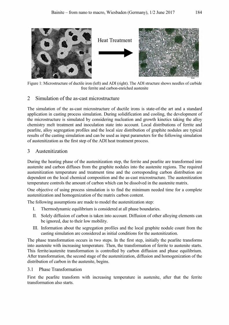
Bainite – from nano to macro, Wiesbaden (Germany), 1/2 June 2017 184
Figure 1: Microstructure of ductile iron (left) and ADI (right). The ADI structure shows needles of carbide
free ferrite and carbon-enriched austenite
2 Simulation of the as-cast microstructure
The simulation of the as-cast microstructure of ductile irons is state-of-the art and a standard application in casting process simulation. During solidification and cooling, the development of the microstructure is simulated by considering nucleation and growth kinetics taking the alloy chemistry melt treatment and inoculation state into account. Local distributions of ferrite and pearlite, alloy segregation profiles and the local size distribution of graphite nodules are typical results of the casting simulation and can be used as input parameters for the following simulation of austenitization as the first step of the ADI heat treatment process.
3 Austenitization
During the heating phase of the austenitization step, the ferrite and pearlite are transformed into austenite and carbon diffuses from the graphite nodules into the austenite regions. The required austenitization temperature and treatment time and the corresponding carbon distribution are dependent on the local chemical composition and the as-cast microstructure. The austenitization temperature controls the amount of carbon which can be dissolved in the austenite matrix. One objective of using process simulation is to find the minimum needed time for a complete austenitization and homogenization of the matrix carbon content. The following assumptions are made to model the austenitization step:
I. Thermodynamic equilibrium is considered at all phase boundaries. II. Solely diffusion of carbon is taken into account. Diffusion of other alloying elements can
be ignored, due to their low mobility. III. Information about the segregation profiles and the local graphite nodule count from the
casting simulation are considered as initial conditions for the austenitization. The phase transformation occurs in two steps. In the first step, initially the pearlite transforms into austenite with increasing temperature. Then, the transformation of ferrite to austenite starts. This ferrite/austenite transformation is controlled by carbon diffusion and phase equilibrium. After transformation, the second stage of the austenitization, diffusion and homogenization of the distribution of carbon in the austenite, begins.
3.1 Phase Transformation First the pearlite transform with increasing temperature in austenite, after that the ferrite transformation also starts.
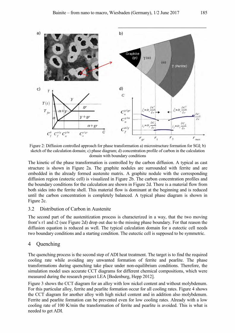
Bainite – from nano to macro, Wiesbaden (Germany), 1/2 June 2017 185
Figure 2: Diffusion controlled approach for phase transformation a) microstructure formation for SGI; b) sketch of the calculation domain; c) phase diagram; d) concentration profile of carbon in the calculation
domain with boundary conditions The kinetic of the phase transformation is controlled by the carbon diffusion. A typical as cast structure is shown in Figure 2a. The graphite nodules are surrounded with ferrite and are embedded in the already formed austenite matrix. A graphite nodule with the corresponding diffusion region (eutectic cell) is visualized in Figure 2b. The carbon concentration profiles and the boundary conditions for the calculation are shown in Figure 2d. There is a material flow from both sides into the ferrite shell. This material flow is dominant at the beginning and is reduced until the carbon concentration is completely balanced. A typical phase diagram is shown in Figure 2c.
3.2 Distribution of Carbon in Austenite The second part of the austenitization process is characterized in a way, that the two moving front’s r1 and r2 (see Figure 2d) drop out due to the missing phase boundary. For that reason the diffusion equation is reduced as well. The typical calculation domain for a eutectic cell needs two boundary conditions and a starting condition. The eutectic cell is supposed to be symmetric.
4 Quenching
The quenching process is the second step of ADI heat treatment. The target is to find the required cooling rate while avoiding any unwanted formation of ferrite and pearlite. The phase transformations during quenching take place under non-equilibrium conditions. Therefore, the simulation model uses accurate CCT diagrams for different chemical compositions, which were measured during the research project LEA [Bodenburg, Hepp 2012]. Figure 3 shows the CCT diagram for an alloy with low nickel content and without molybdenum. For this particular alloy, ferrite and pearlite formation occur for all cooling rates. Figure 4 shows the CCT diagram for another alloy with high nickel content and in addition also molybdenum. Ferrite and pearlite formation can be prevented even for low cooling rates. Already with a low cooling rate of 100 K/min the transformation of ferrite and pearlite is avoided. This is what is needed to get ADI.
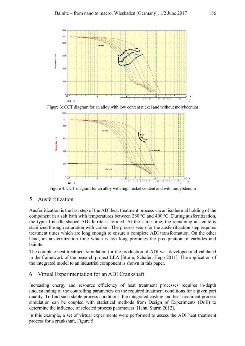
Bainite – from nano to macro, Wiesbaden (Germany), 1/2 June 2017 186
Figure 3: CCT diagram for an alloy with low content nickel and without molybdenum
Figure 4: CCT diagram for an alloy with high nickel content and with molybdenum
5 Ausferritization
Ausferritization is the last step of the ADI heat treatment process via an isothermal holding of the component in a salt bath with temperatures between 280 °C and 400 °C. During ausferritization, the typical needle-shaped ADI ferrite is formed. At the same time, the remaining austenite is stabilized through saturation with carbon. The process setup for the ausferritization step requires treatment times which are long enough to ensure a complete ADI transformation. On the other hand, an ausferritization time which is too long promotes the precipitation of carbides and bainite. The complete heat treatment simulation for the production of ADI was developed and validated in the framework of the research project LEA [Sturm, Schäfer, Hepp 2011]. The application of the integrated model to an industrial component is shown in this paper.
6 Virtual Experimentation for an ADI Crankshaft
Increasing energy and resource efficiency of heat treatment processes requires in-depth understanding of the controlling parameters on the required treatment conditions for a given part quality. To find such stable process conditions, the integrated casting and heat treatment process simulation can be coupled with statistical methods from Design of Experiments (DoE) to determine the influence of selected process parameters [Hahn, Sturm 2012]. In this example, a set of virtual experiments were performed to assess the ADI heat treatment process for a crankshaft, Figure 5.
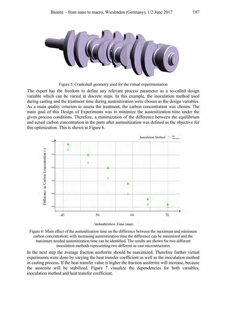
Bainite – from nano to macro, Wiesbaden (Germany), 1/2 June 2017 187
Figure 5: Crankshaft geometry used for the virtual experimentation
The expert has the freedom to define any relevant process parameter as a so-called design variable which can be varied in discrete steps. In this example, the inoculation method used during casting and the treatment time during austenitization were chosen as the design variables. As a main quality criterion to assess the treatment, the carbon concentration was chosen. The main goal of this Design of Experiments was to minimize the austenitization time under the given process conditions. Therefore, a minimization of the difference between the equilibrium and actual carbon concentration in the parts after austenitization was defined as the objective for this optimization. This is shown in Figure 6.
Figure 6: Main effect of the austenitization time on the difference between the maximum and minimum
carbon concentration; with increasing austenitization time the difference can be minimized and the maximum needed austenitization time can be identified. The results are shown for two different
inoculation methods representing two different as cast microstructures In the next step the average fraction ausferrite should be maximized. Therefore further virtual experiments were done by varying the heat transfer coefficient as well as the inoculation method in casting process. If the heat transfer value is higher the fraction ausferrite will increase, because the austenite will be stabilized. Figure 7 visualize the dependencies for both variables, inoculation method and heat transfer coefficient.
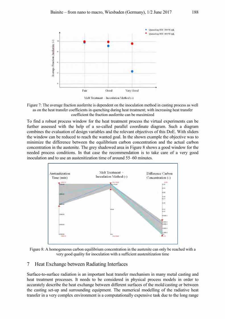
Bainite – from nano to macro, Wiesbaden (Germany), 1/2 June 2017 188
Figure 7: The average fraction ausferrite is dependent on the inoculation method in casting process as well
as on the heat transfer coefficients in quenching during heat treatment; with increasing heat transfer coefficient the fraction ausferrite can be maximized
To find a robust process window for the heat treatment process the virtual experiments can be further assessed with the help of a so-called parallel coordinate diagram. Such a diagram combines the evaluation of design variables and the relevant objectives of this DoE. With sliders the window can be reduced to reach the wanted goal. In the shown example the objective was to minimize the difference between the equilibrium carbon concentration and the actual carbon concentration in the austenite. The grey shadowed area in Figure 8 shows a good window for the needed process conditions. In that case the recommendation is to take care of a very good inoculation and to use an austenitization time of around 55–60 minutes.
Figure 8: A homogeneous carbon equilibrium concentration in the austenite can only be reached with a
very good quality for inoculation with a sufficient austenitization time
7 Heat Exchange between Radiating Interfaces
Surface-to-surface radiation is an important heat transfer mechanism in many metal casting and heat treatment processes. It needs to be considered in physical process models in order to accurately describe the heat exchange between different surfaces of the mold/casting or between the casting set-up and surrounding equipment. The numerical modelling of the radiative heat transfer in a very complex environment is a computationally expensive task due to the long range
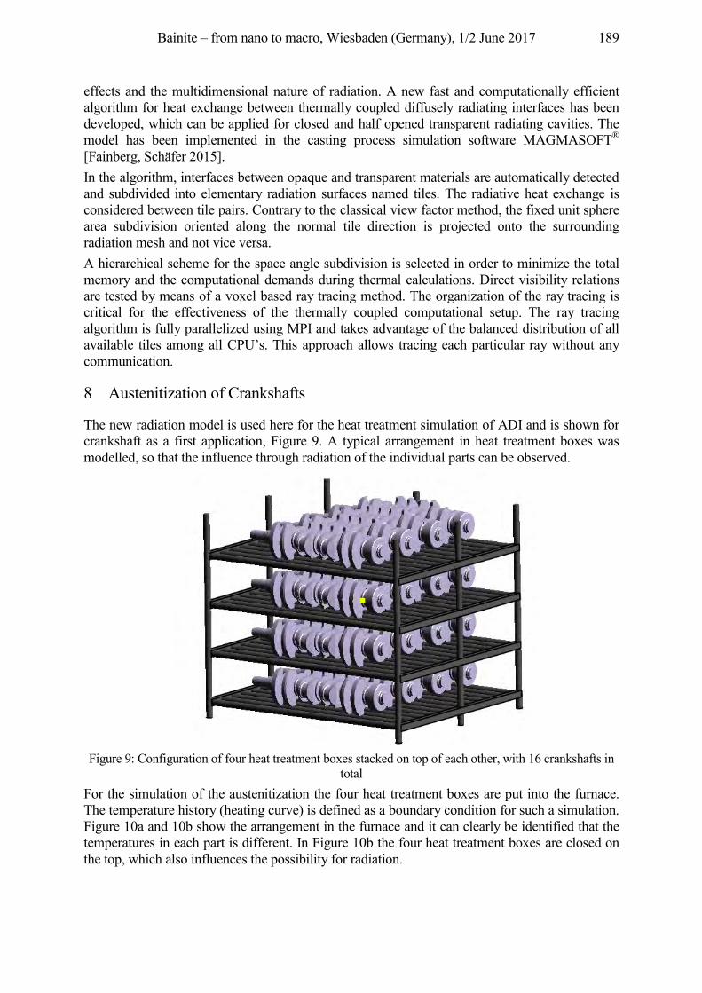
Bainite – from nano to macro, Wiesbaden (Germany), 1/2 June 2017 189
effects and the multidimensional nature of radiation. A new fast and computationally efficient algorithm for heat exchange between thermally coupled diffusely radiating interfaces has been developed, which can be applied for closed and half opened transparent radiating cavities. The model has been implemented in the casting process simulation software MAGMASOFT® [Fainberg, Schäfer 2015]. In the algorithm, interfaces between opaque and transparent materials are automatically detected and subdivided into elementary radiation surfaces named tiles. The radiative heat exchange is considered between tile pairs. Contrary to the classical view factor method, the fixed unit sphere area subdivision oriented along the normal tile direction is projected onto the surrounding radiation mesh and not vice versa. A hierarchical scheme for the space angle subdivision is selected in order to minimize the total memory and the computational demands during thermal calculations. Direct visibility relations are tested by means of a voxel based ray tracing method. The organization of the ray tracing is critical for the effectiveness of the thermally coupled computational setup. The ray tracing algorithm is fully parallelized using MPI and takes advantage of the balanced distribution of all available tiles among all CPU’s. This approach allows tracing each particular ray without any communication.
8 Austenitization of Crankshafts
The new radiation model is used here for the heat treatment simulation of ADI and is shown for crankshaft as a first application, Figure 9. A typical arrangement in heat treatment boxes was modelled, so that the influence through radiation of the individual parts can be observed.
Figure 9: Configuration of four heat treatment boxes stacked on top of each other, with 16 crankshafts in
total For the simulation of the austenitization the four heat treatment boxes are put into the furnace. The temperature history (heating curve) is defined as a boundary condition for such a simulation. Figure 10a and 10b show the arrangement in the furnace and it can clearly be identified that the temperatures in each part is different. In Figure 10b the four heat treatment boxes are closed on the top, which also influences the possibility for radiation.
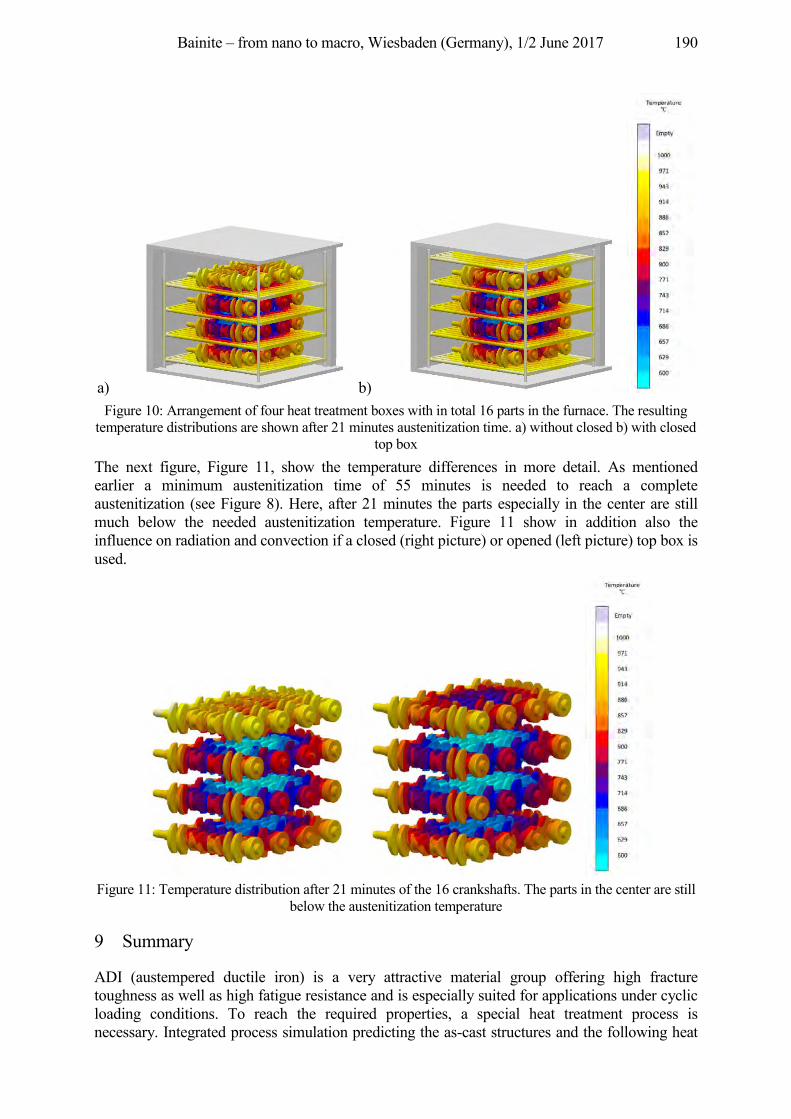
Bainite – from nano to macro, Wiesbaden (Germany), 1/2 June 2017 190
a) b) Figure 10: Arrangement of four heat treatment boxes with in total 16 parts in the furnace. The resulting
temperature distributions are shown after 21 minutes austenitization time. a) without closed b) with closed top box
The next figure, Figure 11, show the temperature differences in more detail. As mentioned earlier a minimum austenitization time of 55 minutes is needed to reach a complete austenitization (see Figure 8). Here, after 21 minutes the parts especially in the center are still much below the needed austenitization temperature. Figure 11 show in addition also the influence on radiation and convection if a closed (right picture) or opened (left picture) top box is used.
Figure 11: Temperature distribution after 21 minutes of the 16 crankshafts. The parts in the center are still
below the austenitization temperature
9 Summary
ADI (austempered ductile iron) is a very attractive material group offering high fracture toughness as well as high fatigue resistance and is especially suited for applications under cyclic loading conditions. To reach the required properties, a special heat treatment process is necessary. Integrated process simulation predicting the as-cast structures and the following heat
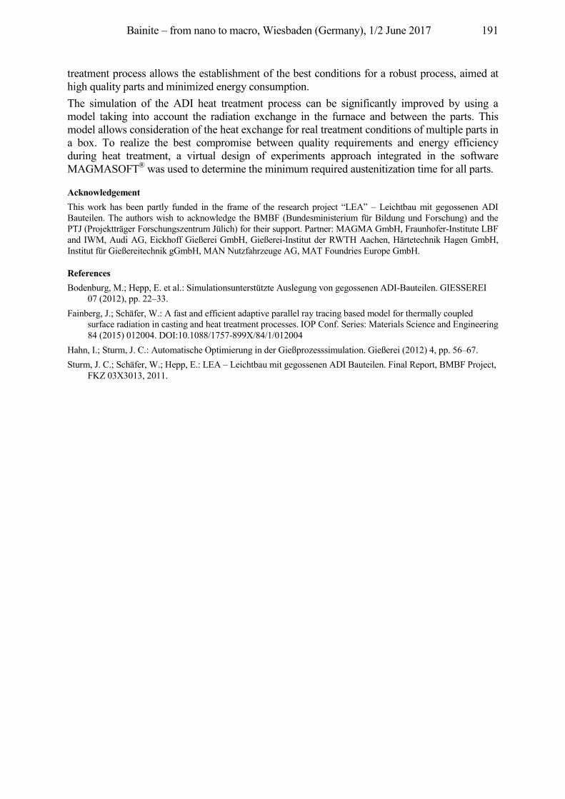
Bainite – from nano to macro, Wiesbaden (Germany), 1/2 June 2017 191
treatment process allows the establishment of the best conditions for a robust process, aimed at high quality parts and minimized energy consumption. The simulation of the ADI heat treatment process can be significantly improved by using a model taking into account the radiation exchange in the furnace and between the parts. This model allows consideration of the heat exchange for real treatment conditions of multiple parts in a box. To realize the best compromise between quality requirements and energy efficiency during heat treatment, a virtual design of experiments approach integrated in the software MAGMASOFT® was used to determine the minimum required austenitization time for all parts.
Acknowledgement This work has been partly funded in the frame of the research project “LEA” – Leichtbau mit gegossenen ADI Bauteilen. The authors wish to acknowledge the BMBF (Bundesministerium für Bildung und Forschung) and the PTJ (Projektträger Forschungszentrum Jülich) for their support. Partner: MAGMA GmbH, Fraunhofer-Institute LBF and IWM, Audi AG, Eickhoff Gießerei GmbH, Gießerei-Institut der RWTH Aachen, Härtetechnik Hagen GmbH, Institut für Gießereitechnik gGmbH, MAN Nutzfahrzeuge AG, MAT Foundries Europe GmbH.
References Bodenburg, M.; Hepp, E. et al.: Simulationsunterstützte Auslegung von gegossenen ADI-Bauteilen. GIESSEREI
07 (2012), pp. 22–33. Fainberg, J.; Schäfer, W.: A fast and efficient adaptive parallel ray tracing based model for thermally coupled
surface radiation in casting and heat treatment processes. IOP Conf. Series: Materials Science and Engineering 84 (2015) 012004. DOI:10.1088/1757-899X/84/1/012004
Hahn, I.; Sturm, J. C.: Automatische Optimierung in der Gießprozesssimulation. Gießerei (2012) 4, pp. 56–67. Sturm, J. C.; Schäfer, W.; Hepp, E.: LEA – Leichtbau mit gegossenen ADI Bauteilen. Final Report, BMBF Project,
FKZ 03X3013, 2011.
Bainite – from nano to macro, Wiesbaden (Germany), 1/2 June 2017 192
Is ADI with Bainite Optimized? Arron Rimmer1, Eike Wüller2
1ADI Treatments Ltd., Doranda Way, West Bromwich, U.K., [email protected] 2SIEMENS AG, Am Industriepark 2, 46562 Voerde, Germany, [email protected]
Abstract In industrial gearboxes ADI (austempered-ductile-iron) can be used for substituting gears made of steel with a simultaneous weight reduction and an improvement in damping capacity. For the application of ADI in gearboxes it is very important to know the behaviour of ADI and have an understanding of its production process. ADI is a heat treated ductile iron casting. It is characterized by high tensile strength combined with ductility. This makes ADI a competitor to forged, cast or fabricated steel. To achieve these properties it is very important to adjust the chemical composition and heat-treatment considering the wall thickness of the casting. Non synchronized processes will lead to the occurrence of a microstructure which has a big impact on the properties and usability of the parts. Therefore a high grade of automatization, process and quality control is necessary.
Keywords ADI, Gearbox, Bainite, Ausferrite, Austenite, Martensite, Perlite, Ductile Iron, Heat Treatment
1 Application of ADI in gearboxes
ADI is well known as a high grade ductile iron material with a good wear resistance. In comparison, the mechanical properties of ADI to the standard gear toothed material 34CrNiMo6 has the same range with exception of elongation (see also Table 1).
34CrNiMo6 ADI
Rm [MPa] 800–1400 800–1400 Re [MPa] 600–1000 500–1100 A [%] 9–13 1–10 k 7,8 7,1
Table 1: Comparison of 34CrNiMo6 versus ADI grades This is the technical reason why this material is interesting for use in gearboxes as a tooth material. Additionally there are some other facts why the substitution of 34CrNiMo6 by ADI could be reasonable. By substituting there is a potential weight reduction of approximately 9 % because of the different density of this two materials. Because of the usage of high amount of alloying elements used in steel the base material price is much higher than for ADI. A further benefit is the production of ADI. ADI is a casting material based on ductile iron and complex structures are possible. This could be used to combine classic casting and toothed parts in a gearbox to one component. Combined parts reduce the machining and assembly time and also the amount of parts. This will also have an impact of the cost.
2 Processing of ADI
For producing ADI the base-material is ductile iron with some alloying elements for stabilizing the process. The microstructure before heat-treatment is a typically a pearlitic/ferritic microstructure. The schematic process is shown in Figure 1. Before starting the heat-treatment and change of microstructure a pre-heating is performed in a separate furnace and because as the temperature is < 600 C no special atmosphere is necessary. After pre-heating the parts move to the main furnace
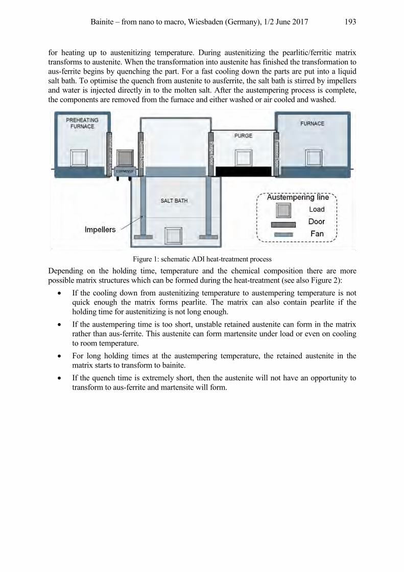
Bainite – from nano to macro, Wiesbaden (Germany), 1/2 June 2017 193
for heating up to austenitizing temperature. During austenitizing the pearlitic/ferritic matrix transforms to austenite. When the transformation into austenite has finished the transformation to aus-ferrite begins by quenching the part. For a fast cooling down the parts are put into a liquid salt bath. To optimise the quench from austenite to ausferrite, the salt bath is stirred by impellers and water is injected directly in to the molten salt. After the austempering process is complete, the components are removed from the furnace and either washed or air cooled and washed.
Figure 1: schematic ADI heat-treatment process
Depending on the holding time, temperature and the chemical composition there are more possible matrix structures which can be formed during the heat-treatment (see also Figure 2):
• If the cooling down from austenitizing temperature to austempering temperature is not quick enough the matrix forms pearlite. The matrix can also contain pearlite if the holding time for austenitizing is not long enough.
• If the austempering time is too short, unstable retained austenite can form in the matrix rather than aus-ferrite. This austenite can form martensite under load or even on cooling to room temperature.
• For long holding times at the austempering temperature, the retained austenite in the matrix starts to transform to bainite.
• If the quench time is extremely short, then the austenite will not have an opportunity to transform to aus-ferrite and martensite will form.
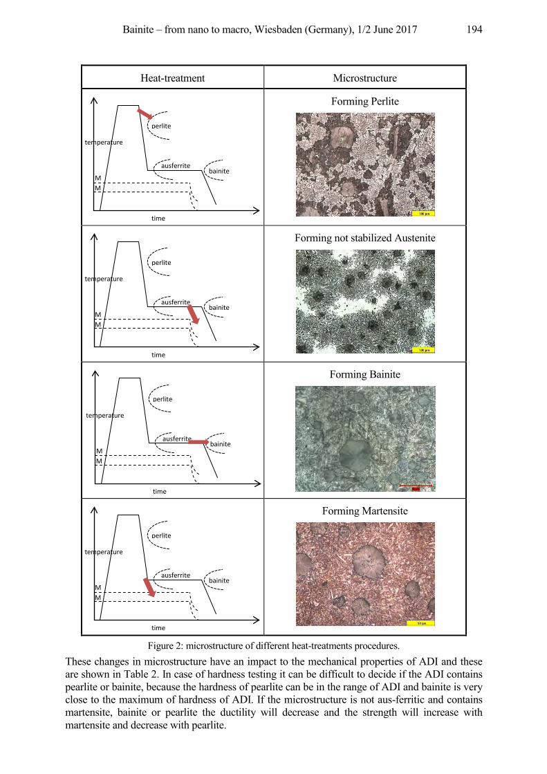
Bainite – from nano to macro, Wiesbaden (Germany), 1/2 June 2017 194
Heat-treatment Microstructure
Forming Perlite
Forming not stabilized Austenite
Forming Bainite
Forming Martensite
Figure 2: microstructure of different heat-treatments procedures. These changes in microstructure have an impact to the mechanical properties of ADI and these are shown in Table 2. In case of hardness testing it can be difficult to decide if the ADI contains pearlite or bainite, because the hardness of pearlite can be in the range of ADI and bainite is very close to the maximum of hardness of ADI. If the microstructure is not aus-ferritic and contains martensite, bainite or pearlite the ductility will decrease and the strength will increase with martensite and decrease with pearlite.
M
ausferrite bainite
MF
perlite
time
temperature
MS
ausferrite bainite
MF
perlite
time
temperature
MS
ausferrite bainite
M
perlite
time
temperature
M
ausferrite bainite
MF
perlite
time
temperature
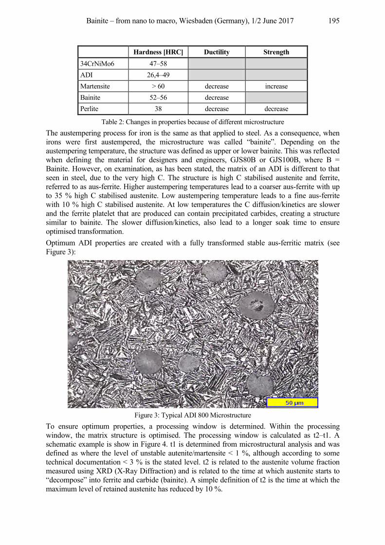
Bainite – from nano to macro, Wiesbaden (Germany), 1/2 June 2017 195
Hardness [HRC] Ductility Strength 34CrNiMo6 47–58 ADI 26,4–49 Martensite > 60 decrease increase Bainite 52–56 decrease Perlite 38 decrease decrease
Table 2: Changes in properties because of different microstructure The austempering process for iron is the same as that applied to steel. As a consequence, when irons were first austempered, the microstructure was called “bainite”. Depending on the austempering temperature, the structure was defined as upper or lower bainite. This was reflected when defining the material for designers and engineers, GJS80B or GJS100B, where B = Bainite. However, on examination, as has been stated, the matrix of an ADI is different to that seen in steel, due to the very high C. The structure is high C stabilised austenite and ferrite, referred to as aus-ferrite. Higher austempering temperatures lead to a coarser aus-ferrite with up to 35 % high C stabilised austenite. Low austempering temperature leads to a fine aus-ferrite with 10 % high C stabilised austenite. At low temperatures the C diffusion/kinetics are slower and the ferrite platelet that are produced can contain precipitated carbides, creating a structure similar to bainite. The slower diffusion/kinetics, also lead to a longer soak time to ensure optimised transformation. Optimum ADI properties are created with a fully transformed stable aus-ferritic matrix (see Figure 3):
Figure 3: Typical ADI 800 Microstructure
To ensure optimum properties, a processing window is determined. Within the processing window, the matrix structure is optimised. The processing window is calculated as t2–t1. A schematic example is show in Figure 4. t1 is determined from microstructural analysis and was defined as where the level of unstable autenite/martensite < 1 %, although according to some technical documentation < 3 % is the stated level. t2 is related to the austenite volume fraction measured using XRD (X-Ray Diffraction) and is related to the time at which austenite starts to “decompose” into ferrite and carbide (bainite). A simple definition of t2 is the time at which the maximum level of retained austenite has reduced by 10 %.
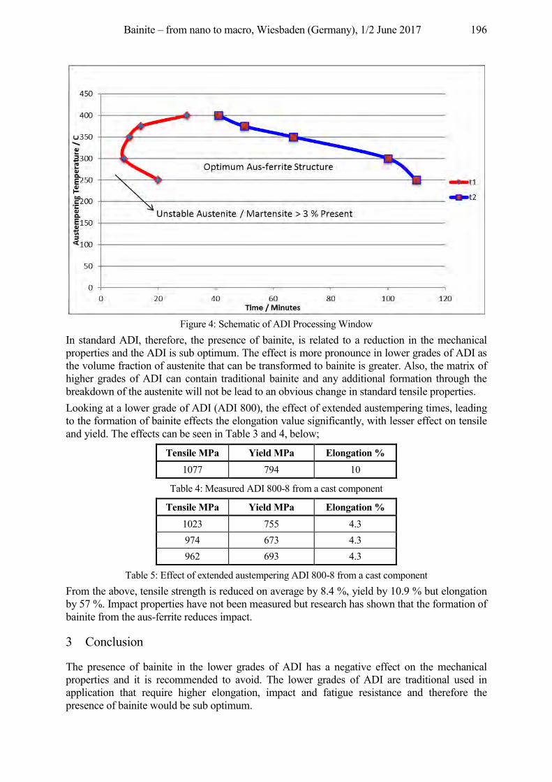
Bainite – from nano to macro, Wiesbaden (Germany), 1/2 June 2017 196
Figure 4: Schematic of ADI Processing Window
In standard ADI, therefore, the presence of bainite, is related to a reduction in the mechanical properties and the ADI is sub optimum. The effect is more pronounce in lower grades of ADI as the volume fraction of austenite that can be transformed to bainite is greater. Also, the matrix of higher grades of ADI can contain traditional bainite and any additional formation through the breakdown of the austenite will not be lead to an obvious change in standard tensile properties. Looking at a lower grade of ADI (ADI 800), the effect of extended austempering times, leading to the formation of bainite effects the elongation value significantly, with lesser effect on tensile and yield. The effects can be seen in Table 3 and 4, below;
Tensile MPa Yield MPa Elongation % 1077 794 10
Table 4: Measured ADI 800-8 from a cast component
Tensile MPa Yield MPa Elongation % 1023 755 4.3 974 673 4.3 962 693 4.3
Table 5: Effect of extended austempering ADI 800-8 from a cast component From the above, tensile strength is reduced on average by 8.4 %, yield by 10.9 % but elongation by 57 %. Impact properties have not been measured but research has shown that the formation of bainite from the aus-ferrite reduces impact.
3 Conclusion
The presence of bainite in the lower grades of ADI has a negative effect on the mechanical properties and it is recommended to avoid. The lower grades of ADI are traditional used in application that require higher elongation, impact and fatigue resistance and therefore the presence of bainite would be sub optimum.

Bainite – from nano to macro, Wiesbaden (Germany), 1/2 June 2017 197
References DIN EN 1564: Founding – Ausferritic spheroidal graphite cast irons. ISO 683-2: Heat-treatable steels, alloy steels and free-cutting steels – Part 2: Alloy steels for quenching and
tempering. Spittel, M.; Spittel, T.: SpringerMaterials. Steel symbol/number: GS–34CrNiMo6/1.6582. In: Warlimont, H. (Ed.),
Metal Forming Data – Ferrous Alloys – deformation behaviour. Springer-Verlag Berlin Heidelberg, 2009. Keough, J. R.; Hayrynen, K. L.; Pioszak, G. L.: Designing with Austempered Ductile Iron (ADI). AFS Proceedings
2010, pp. 10–129. Rimmer, A. L.: Mechanical: Microstructure Relationships of a Cu-Mo Alloyed Ductile Iron. M.Sc Thesis 1991. Bayati, H.; Rimmer, A. L.; Ellliott, R: The austempering kinetics and processing window in an austempered, low
managanse compacted graphite cast iron. Cast Metals 7 (1994) 1, pp. 11–24. Eric, O. et al.: Determination of Processing Window for ADI materials alloyed with copper. MJoM 16 (2010) 2, pp.
91–102.
Bainite – from nano to macro, Wiesbaden (Germany), 1/2 June 2017 198
Index
Altena, H. 100
Bambach, M. 22 Barton, S. 141 Bernthaler, T. 151 Bhadeshia, H. K. D. H. 2 Bleck, W. 22 Bruchwald, O. 133, 141 Buchner, K. 100 Burkart, K. 75
Caballero, F. G. 12 Catteau, S. D. 162 Clausen, B. 75 Courteaux, M. 162
Dabrock, E. 123 Dehmas, M. 162 Denis, S. 162 Dinkel, M. 66 Dong, J. 75 Duh, D. 57 Dulcy, J. 162
Garcia-Mateo, C. 12
Hagymási, L. 123 Hans, H. 108 Hepp, E. 183 Heuer, V. 114 Hunkel, M. 172
Kerscher, E. 123 Ketzer-Raichle, G. 151 Klümper-Westkamp, H. 133, 141 Kopp, A. 151
Krull, H.-G. 57 Kuckert, H. 123
Lembke, M. I. 43 Loeser, K. 114
Maier, H. J. 133, 141
Redjaïmia, A. 162 Reimche, W. 133, 141 Rementeria, R. 12 Rimmer, A. 192 Roelofs, H. 43 Rösch, O. 52
Sarfert, F. 123 Schicchi, D. S. 172 Schmid, D. 151 Schneider, G. 151 Schneiders, T. 57 Sourmail, Th. 32 Steinbacher, M. 88 Stieben, A. 22
Teixeira, J. 162 Thomser, C. 183 Trojahn, W. 66
van Landeghem, H. P. 162 van Soest, F. 57 Vetterlein, J. 133
Wirths, V. 22 Wüller, E. 192
Zoch, H.-W. 75, 88, 133, 141
Related Documents