BACTRON ANAEROBIC CHAMBERS OPERATION MANUAL MODELS: I, II & IV Blanc-Labo SA Centre du Bief - Chemin des Mouettes 1 CH-1027 Lonay [email protected] www.blanc-labo.com T : +41 21 804.18.50 F : +41 21 804 18 59

Welcome message from author
This document is posted to help you gain knowledge. Please leave a comment to let me know what you think about it! Share it to your friends and learn new things together.
Transcript
BACTRON ANAEROBIC CHAMBERS
OPERATION MANUAL
MODELS: I, II & IV
Blanc-Labo SA Centre du Bief - Chemin des Mouettes 1
CH-1027 Lonay [email protected] www.blanc-labo.com
T : +41 21 804.18.50 F : +41 21 804 18 59
______________________________________________________________________________
Bactron Operations Manual 2
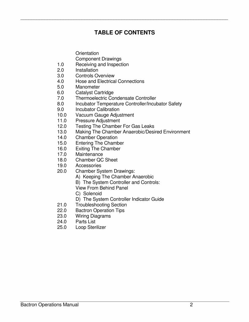
TABLE OF CONTENTS
Orientation Component Drawings 1.0 Receiving and Inspection 2.0 Installation 3.0 Controls Overview 4.0 Hose and Electrical Connections 5.0 Manometer 6.0 Catalyst Cartridge 7.0 Thermoelectric Condensate Controller 8.0 Incubator Temperature Controller/Incubator Safety 9.0 Incubator Calibration 10.0 Vacuum Gauge Adjustment 11.0 Pressure Adjustment 12.0 Testing The Chamber For Gas Leaks 13.0 Making The Chamber Anaerobic/Desired Environment 14.0 Chamber Operation 15.0 Entering The Chamber 16.0 Exiting The Chamber 17.0 Maintenance 18.0 Chamber QC Sheet 19.0 Accessories 20.0 Chamber System Drawings: A) Keeping The Chamber Anaerobic B) The System Controller and Controls: View From Behind Panel C) Solenoid D) The System Controller Indicator Guide 21.0 Troubleshooting Section 22.0 Bactron Operation Tips 23.0 Wiring Diagrams 24.0 Parts List 25.0 Loop Sterilizer
______________________________________________________________________________
Bactron Operations Manual 3
IMPORTANT: READ THIS INSTRUCTION MANUAL IMMEDIATELY.
Your satisfaction and safety require a complete understanding of this unit, including its proper function and operational characteristics. Be sure operators are given adequate training before attempting to put the unit in service. NOTE: This equipment must be used only for its intended application; any alterations or modifications will void your warranty.
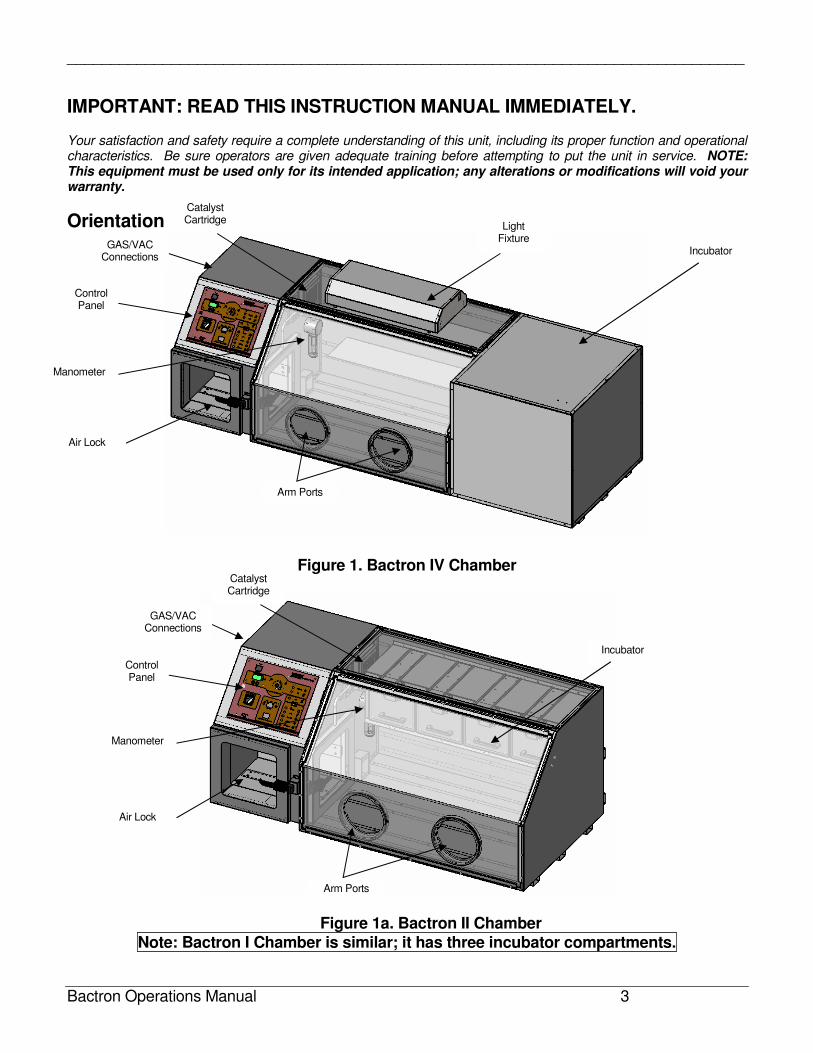
Orientation
Figure 1. Bactron IV Chamber
Figure 1a. Bactron II Chamber Note: Bactron I Chamber is similar; it has three incubator compartments.
Catalyst Cartridge
GAS/VAC Connections
Manometer
Control Panel
Air Lock
Arm Ports
Incubator
Catalyst Cartridge
GAS/VAC Connections
Control Panel
Manometer
Incubator
Light Fixture
Air Lock
Arm Ports
______________________________________________________________________________
Bactron Operations Manual 4
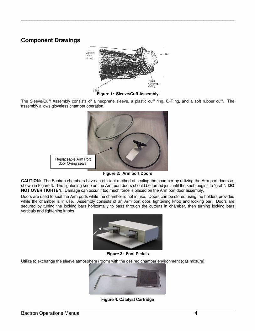
Component Drawings
Figure 1: Sleeve/Cuff Assembly
The Sleeve/Cuff Assembly consists of a neoprene sleeve, a plastic cuff ring, O-Ring, and a soft rubber cuff. The assembly allows gloveless chamber operation.
Figure 2: Arm port Doors
CAUTION: The Bactron chambers have an efficient method of sealing the chamber by utilizing the Arm port doors as shown in Figure 3. The tightening knob on the Arm port doors should be turned just until the knob begins to “grab”. DO NOT OVER TIGHTEN. Damage can occur if too much force is placed on the Arm port door assembly.
Doors are used to seal the Arm ports while the chamber is not in use. Doors can be stored using the holders provided while the chamber is in use. Assembly consists of an Arm port door, tightening knob and locking bar. Doors are secured by tuning the locking bars horizontally to pass through the cutouts in chamber, then turning locking bars verticals and tightening knobs.
Figure 3: Foot Pedals
Utilize to exchange the sleeve atmosphere (room) with the desired chamber environment (gas mixture).
Figure 4. Catalyst Cartridge
Replaceable Arm Port door O-ring seals.
______________________________________________________________________________
Bactron Operations Manual 5
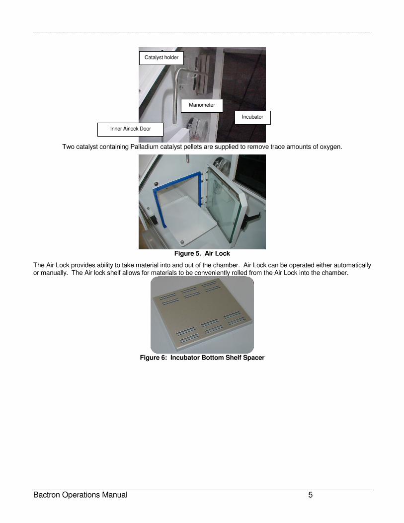
Two catalyst containing Palladium catalyst pellets are supplied to remove trace amounts of oxygen.
Figure 5. Air Lock
The Air Lock provides ability to take material into and out of the chamber. Air Lock can be operated either automatically or manually. The Air lock shelf allows for materials to be conveniently rolled from the Air Lock into the chamber.
Figure 6: Incubator Bottom Shelf Spacer
Inner Airlock Door
Manometer
Incubator
Catalyst holder
______________________________________________________________________________
Bactron Operations Manual 6
1.0 RECEIVING AND INSPECTION
1.1 The carrier, when accepting shipment, also accepts responsibility for safe delivery and is liable for loss or damage claims. On delivery, you must inspect for visible exterior damage. Note and describe on the freight bill any damage found and enter your claim on the form the carrier supplies.
1.2 Inspect for concealed loss or damage on the unit itself, both interior and exterior. If any, the carrier will arrange for official inspection to substantiate your claim. Save the shipping crate until you are sure the unit has been delivered in good condition.
1.3 If for any reason you must return the unit, contact your sales representative for authorization and supply nameplate data.
2.0 INSTALLATION
2.1 Local city, county, or other ordinances may govern the use of this equipment. If you have any questions about local requirements, please contact the appropriate local agency.
2.2 Under normal circumstances these units are intended for use indoors, at room temperatures between
5° and 40°C, at no greater than 80% relative Humidity (at 25°C) and with a supply voltage that does not vary by more than 10%. These ovens should not be operated at an altitude exceeding 2000 meters. Installation category is CAT-II.
2.3 Pollution Degree 2. Customer service should be contacted for operating conditions outside of these limits. Installation may be performed by the end user. It is unnecessary for this unit to be installed by a technician.
2.4 Location: When selecting a site for the unit, consider conditions which may affect performance, such as heat from steam radiators, ovens, autoclaves, etc. Avoid direct sun, fast-moving air currents, heating/cooling ducts, and high traffic areas. To ensure air circulation around the unit, allow a minimum of 2” between chamber rear and sides and any walls, partitions, or obstructions to free airflow.
2.5 Power Source: The power source must match the voltage, cycle, phase and amperage requirements listed on the data plate. Plug the cord into a grounded outlet. VOLTAGE OF THE OUTLET SHOULD NOT VARY MORE THAN 10% FROM THE DATA PLATE RATING. A separate circuit is recommended to precluded loss of product due to overloading or circuit failure. Note that the electrical supply to the unit must conform to all national and local electrical codes.
2.6 Gas Source: Install the gas regulator(s) on the tank(s) of gas. Chain the gas tanks(s) to a secure position on the wall. Set the regulator(s) to 10 psi.
2.7 If you are using an anaerobic gas mixture (AMG), we recommend 5% (H2), 5% Carbon Dioxide (CO2),
and 90% Nitrogen(N2).
2.8 If you are using a two gas anaerobic application, we recommend one tank of AMG gas and the second
tank of 100% Nitrogen (N2).
Figure 7. Warning Label
2.9 Cleaning: The Bactron unit was cleaned at the factory, however, a general cleaning is recommended. Use BENZALKONIUM CHLORIDE to clean your chamber. See list of cleaning products.
______________________________________________________________________________
Bactron Operations Manual 7
3.0 CONTROLS OVERVIEW
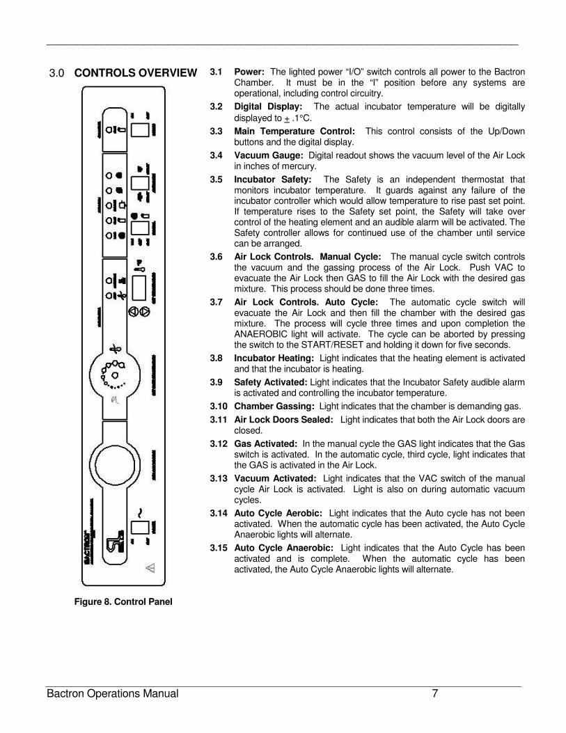
Figure 8. Control Panel
3.1 Power: The lighted power “I/O” switch controls all power to the Bactron Chamber. It must be in the “I” position before any systems are operational, including control circuitry.
3.2 Digital Display: The actual incubator temperature will be digitally
displayed to + .1°C.
3.3 Main Temperature Control: This control consists of the Up/Down buttons and the digital display.
3.4 Vacuum Gauge: Digital readout shows the vacuum level of the Air Lock in inches of mercury.
3.5 Incubator Safety: The Safety is an independent thermostat that monitors incubator temperature. It guards against any failure of the incubator controller which would allow temperature to rise past set point. If temperature rises to the Safety set point, the Safety will take over control of the heating element and an audible alarm will be activated. The Safety controller allows for continued use of the chamber until service can be arranged.
3.6 Air Lock Controls. Manual Cycle: The manual cycle switch controls the vacuum and the gassing process of the Air Lock. Push VAC to evacuate the Air Lock then GAS to fill the Air Lock with the desired gas mixture. This process should be done three times.
3.7 Air Lock Controls. Auto Cycle: The automatic cycle switch will evacuate the Air Lock and then fill the chamber with the desired gas mixture. The process will cycle three times and upon completion the ANAEROBIC light will activate. The cycle can be aborted by pressing the switch to the START/RESET and holding it down for five seconds.
3.8 Incubator Heating: Light indicates that the heating element is activated and that the incubator is heating.
3.9 Safety Activated: Light indicates that the Incubator Safety audible alarm is activated and controlling the incubator temperature.
3.10 Chamber Gassing: Light indicates that the chamber is demanding gas.
3.11 Air Lock Doors Sealed: Light indicates that both the Air Lock doors are closed.
3.12 Gas Activated: In the manual cycle the GAS light indicates that the Gas switch is activated. In the automatic cycle, third cycle, light indicates that the GAS is activated in the Air Lock.
3.13 Vacuum Activated: Light indicates that the VAC switch of the manual cycle Air Lock is activated. Light is also on during automatic vacuum cycles.
3.14 Auto Cycle Aerobic: Light indicates that the Auto cycle has not been activated. When the automatic cycle has been activated, the Auto Cycle Anaerobic lights will alternate.
3.15 Auto Cycle Anaerobic: Light indicates that the Auto Cycle has been activated and is complete. When the automatic cycle has been activated, the Auto Cycle Anaerobic lights will alternate.
______________________________________________________________________________
Bactron Operations Manual 8
4.0 HOSE AND ELECTRICAL CONNECTIONS
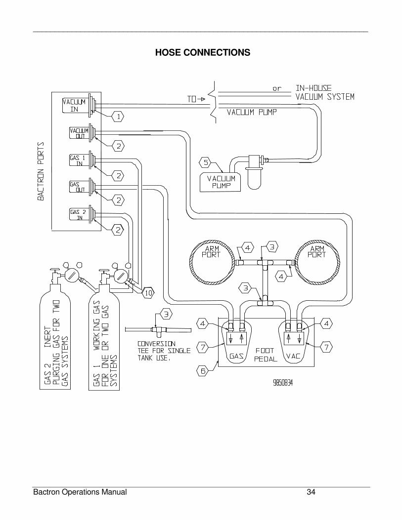
4.1 Hose ports for the gas and vacuum supplies and foot pedal controls are provided on the upper left side of the control module section. Bactrons have five access ports. (older models have four access ports.) See Diagrams Section for more details.
4.2 Install the hose from the gas regulator of the working gas, for example AMG, (GAS 1) tank to the port marked “GAS 1” on the chamber module.
4.3 Install the hose from the gas regulator of the purging gas, for example Nitrogen, (GAS 2) tank to the port marked “GAS 2” on the chamber module.
NOTE: If using only one gas supply, install the “T” tube/fitting assembly (provided in the accessory pack) between the “GAS 1 IN” port and the “GAS 2 IN” port on the control module. Then attach the hose from GAS 1 tank regulator, as in 4.2, to the unused brass “T” tube end. Failure to follow this procedure will render the purging cycles of a single gas system inoperative.
4.4 Connect the 3/8” hose from the vacuum pump or a 3/8” hose from a suitable in-house vacuum system, to the port marked VAC IN. In-house vacuum systems must be capable of evacuating to a minimum of 25 inches of mercury.
4.5 Plug the vacuum pump power cord into the outlet receptacle at the top left of the control module. This outlet is marked “5 AMPS” (installations using in-house vacuum supplies will not follow this step).
NOTE: CONNECTING HOSES. Hose connections are intended to be simple. Insert the hose into the appropriate connector until the hose stops. Pull back slightly to ensure hose will stay in place. Reinsert if hose pulls out.
4.6 Connect the center “T” section from the foot pedal assembly to the tube fittings located on the inner sides of the arm port access openings on the front of the chamber.
4.7 Connect the tube from the GAS side of the foot pedal assembly to port marked GAS OUT on the control module section.
4.8 Connect the tube from the VAC side of foot pedal assembly to the port marked VAC OUT on the control module section.
4.9 Plug power cord from Chamber into a suitable outlet. Refer to the Installation Section of this manual for additional information. Turn the power switch ON to verify power to the system.
4.10 When the main power switch is turned on, the vacuum pump should come on for a few seconds and then go off. If the pump does not come on, or comes on and will not go off, consult the Troubleshooting Guide for adjustment.
4.11 When the power switch to the Chamber is turned on, you should see Power ON, CHAMBER GASSING, AIR LOCK DOORS SEALED and AUTO CYCLE AEROBIC lights illuminate, along with readout of the incubator temperature. If any of these appear not to work, consult the Troubleshooting Guide.
______________________________________________________________________________
Bactron Operations Manual 9
5.0 MANOMETER
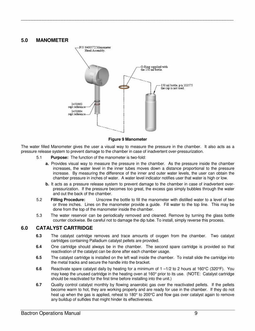
Figure 9 Manometer
The water filled Manometer gives the user a visual way to measure the pressure in the chamber. It also acts as a pressure release system to prevent damage to the chamber in case of inadvertent over-pressurization.
5.1 Purpose: The function of the manometer is two-fold:
a. Provides visual way to measure the pressure in the chamber. As the pressure inside the chamber increases, the water level in the inner tubes moves down a distance proportional to the pressure increase. By measuring the difference of the inner and outer water levels, the user can obtain the chamber pressure in inches of water. A water level indicator notifies user that water is high or low.
b. It acts as a pressure release system to prevent damage to the chamber in case of inadvertent over-pressurization. If the pressure becomes too great, the excess gas simply bubbles through the water and out the back of the chamber.
5.2 Filling Procedure: Unscrew the bottle to fill the manometer with distilled water to a level of two or three inches. Lines on the manometer provide a guide. Fill water to the top line. This may be done from the top of the manometer inside the chamber.
5.3 The water reservoir can be periodically removed and cleaned. Remove by turning the glass bottle counter clockwise. Be careful not to damage the dip tube. To install, simply reverse this process.
6.0 CATALYST CARTRIDGE
6.3 The catalyst cartridge removes and trace amounts of oxygen from the chamber. Two catalyst cartridges containing Palladium catalyst pellets are provided.
6.4 One cartridge should always be in the chamber. The second spare cartridge is provided so that reactivation of the catalyst can be done after each chamber usage.
6.5 The catalyst cartridge is installed on the left wall inside the chamber. To install slide the cartridge into the metal tracks and secure the handle into the bracket.
6.6 Reactivate spare catalyst daily by heating for a minimum of 1 –1/2 to 2 hours at 160°C (320°F). You
may keep the unused cartridge in the heating oven at 160° prior to its use. (NOTE: Catalyst cartridge should be reactivated for the first time before installing into the unit.)
6.7 Quality control catalyst monthly by flowing anaerobic gas over the reactivated pellets. If the pellets become warm to hot, they are working properly and are ready for use in the chamber. If they do not
heat up when the gas is applied, reheat to 180° to 200°C and flow gas over catalyst again to remove any buildup of sulfides that might hinder its effectiveness.
______________________________________________________________________________
Bactron Operations Manual 10
6.8 The entire catalyst cartridge can be placed in the heating oven for reactivating. However, if necessary, the handle on the cartridge can be removed.
6.9 A catalyst cartridge can also be placed inside the Air Lock to remove any trace amounts of oxygen.
7.0 THERMOELECTRIC CONDENSATE CONTROLER
7.1 The thermoelectric condensate controller collects excess humidity and eliminates chamber condensation. Moisture is funneled into a tube for collection inside your chamber.
7.2 The thermoelectric condensate controller is located on the left side of the chamber interior behind the catalyst cartridge. A plastic tube drains excess moisture into the working chamber, on the back left side.
7.3 Place a container, e.g., glass flask or beaker, under the tube for collection. Empty the container DAILY.
7.4 Desiccants are not recommended in the chamber. Desiccants are drying agents that can pull moisture from your samples.
8.0 INCUBATOR TEMPERATURE CONTROLLER/INCUBATOR SAFETY
Under certain circumstances, samples placed directly on the bottom shelf may become too hot and dry out. Shelf spacers are provided to minimize this condition. Place spacers on the bottom shelf. Note the slots go to the front and back.
8.1 Setting Incubator Controller: The INCUBATOR TEMPERATURE controller regulates the incubator temperature by use of Up/Down buttons. To enter set point mode on the control, press either the Up or Down button one time. The digital display will start to blink, going from bright to dim. While blinking, the Digital Display is showing the set point. To change the set point, use the Up and Down buttons. If the buttons are not pressed for five (5) seconds, the display will stop blinking and will read the temperature of the unit. Note that the INCUBATOR SAFETY should be turned to its maximum position, (clockwise) until the unit has stabilized at desired set point temperature. Allow the incubator at least 24 hours to stabilize. Then re-calibrate the digital display to your reference thermometer, follow
the calibration instructions. This incubator was calibrated at the factory at 37°C.
8.2 Setting Incubator Safety: First, set the control to the desired incubator temperature and set the INCUBATOR SAFETY to its maximum position. Allow 24 hours for stabilization before proceeding.
If, after 24 hours the temperature is not at desired level, adjust the INCUBATOR TEMPERATURE up or down until the precise desired temperature is achieved. (See Section 9 for calibration procedures)
8.3 When stabilization at the desired temperature has been achieved, turn the INCUBATOR SAFETY control knob counter-clockwise until the INCUBATOR SAFETY ACTIVATED light comes on and audible alarm is activated. Next, carefully turn the INCUBATOR SAFETY knob clockwise until the light is just off. The Safety is now set; the INCUBATOR SAFETY ACTIVATED light should remain OFF during normal operation.
NOTE: An accurate thermometer should be used inside the incubator as a reference when setting and calibrating the incubator temperature.
8.4 It is a good idea to mark the INCUBATOR SAFETY label with the desired setting or position as a backup in case the knob is moved accidentally. If the SAFETY ACTIVATED light is on and audio alarm is activated at any time, check the INCUBATOR TEMPERATURE controller setting to be sure that it is not set above the INCUBATOR SAFETY setting.
9.0 INCUBATOR CALIBRATION
9.1 Compare the reading of the digital temperature display to an accurate reference thermometer. If there is a difference, put the display into calibrate mode by pressing both the Up and the Down buttons at the same time and holding them in for about five (5) seconds or until the two outside decimal points start to flash on and off.
When the decimal points are flashing, the display can be calibrated to match the reference thermometer by pressing the Up or Down button until the display reads correctly.
______________________________________________________________________________
Bactron Operations Manual 11
10.0 VACUUM ADJUSTMENT
10.2 The vacuum gauge for the Automatic Air Lock Cycle is factory calibrated. It is recommended that customers note the setting of the vacuum gauge during Auto Air Lock Cycle to ensure that the setting is correct. Evacuation and the vacuum pump capabilities can affect the calibration.
10.3 The Air Lock Auto Cycle settings are preset at the factory to 18 in. HG. (46 cm. Hg.) High and 4 in. Hg. (10 cm. Hg.) Low.
10.4 Setting Digital Vacuum Gauge:
Press the MODE and Up Arrow simultaneously and the display will illuminate three (3) letters with the far right letter flashing. The flashing letter can be changed by pressing the DOWN Arrow. By pressing the UP arrow, the display will select the next digit (letter) in the display and it will start flashing. It also can be changed by pressing the DOWN Arrow. It is the same for the third digit (letter) also. The letter setting should be set to read IHd in the display. After the letters are set, push the MODE Button to return to NORM operations.
Vacuum calibration procedure: Low Limit
A) Activate the Auto Air Lock Cycle and note the low level reached by the vacuum gauge. If the vacuum is not at the desired Low setting of 4, adjust the Low vacuum switch located in the same area as the high vacuum switch noted above.
B) Repeat the procedure noted above under High vacuum to adjust the low Vacuum setting except adjust for the lower value of 4.
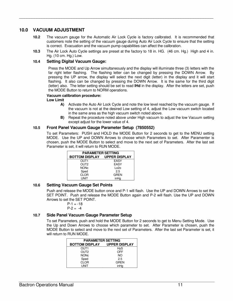
10.5 Front Panel Vacuum Gauge Parameter Setup (7850552)
To set Parameters: PUSH and HOLD the MODE Button for 2 seconds to get to the MENU setting MODE. Use the UP and DOWN Arrows to choose which Parameters to set. After Paramenter is chosen, push the MODE Button to select and move to the next set of Parameters. After the last set Parameter is set, it will return to RUN MODE.
PARAMETER SETTING BOTTOM DISPLAY UPPER DISPLAY
OUT1 EASY OUT2 EASY NONc Lo2o Sped 2.5 CLOR GREN UNIT inHg
10.6 Setting Vacuum Gauge Set Points
Push and release the MODE button once and P-1 will flash. Use the UP and DOWN Arrows to set the SET POINT. Push and release the MODE Button again and P-2 will flash. Use the UP and DOWN Arrows to set the SET POINT.
P-1 = -18 P-2 = -4
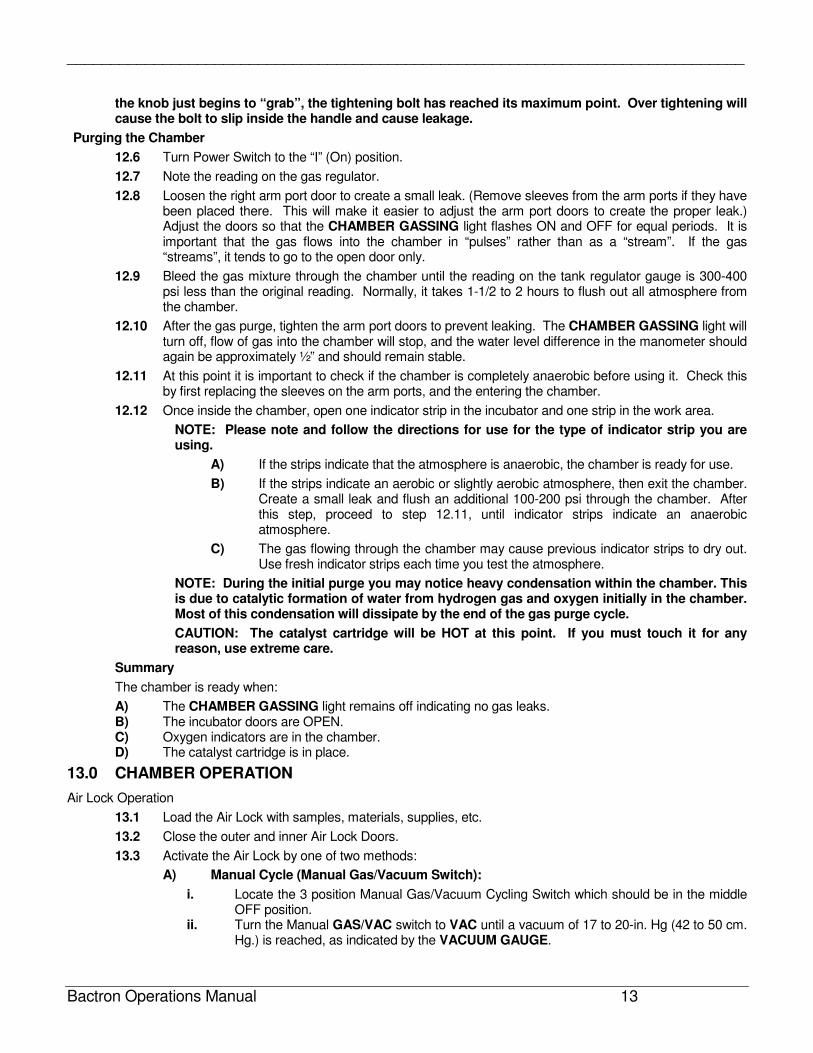
10.7 Side Panel Vacuum Gauge Parameter Setup
To set Parameters, push and hold the MODE Button for 2 seconds to get to Menu Setting Mode. Use the Up and Down Arrows to choose which parameter to set. After Parameter is chosen, push the MODE Button to select and move to the next set of Parameters. After the last set Parameter is set, it will return to RUN MODE.
PARAMETER SETTING BOTTOM DISPLAY UPPER DISPLAY
OUT1 HyS OUT2 OFF NONc NO Sped 2.5 CLOR GREN UNIT inHg

______________________________________________________________________________
Bactron Operations Manual 12
10.8 Setting Vacuum Gauge Set Points
Push and release the MODE button once and LO-1 will flash. Use the UP and DOWN Arrows to set the SET POINT. Push and release the MODE Button again and HI-1 will flash. Use the UP and DOWN Arrows to set the SET POINT.
LO-1 = -20.3 HI-1 = -19.3
11.0 TESTING THE CHAMBER FOR GAS LEAKS
11.1 Each chamber is individually tested at the factory before shipping. The following procedure, however, should still be followed to detect any possible damage due to shipping.
11.2 Make sure the catalyst is removed from the chamber during initial leak testing.
11.3 Check to ensure Manometer is filled.
11.4 Close the outer and inner air Lock doors.
11.5 Secure the Arm port doors. Turn the locking bars horizontally to pass through the cutouts in the chamber, then turn bars so they are vertical, tighten knobs. Do not over tighten.
11.6 Open the gas tank valve all the way on and set the gas regulator to 10 psi.
11.7 Turn the power switch on. As before, with the power switch on, you should see the POWER SWITCH, INCUBATOR TEMPERATURE display, CHAMBER GASSING, AIR LOCK DOORS SEALED, and AUTO CYCLE AEROBIC light illuminate.
11.8 The CHAMBER GASSING light will turn OFF when the water level in the manometer reaches a level of approximately ½” of water. The AIR LOCK DOORS SEALED light will turn ON when the inner and outer Transfer Module doors are both closed. If this light is not ON, either the doors are not closed properly or one or both of the door sensors are improperly adjusted.
11.9 If there are no leaks in the system, the CHAMBER GASSING light will remain OFF, and the water level in the manometer will remain stable at approximately ½” water. Normally, a “leak-tight” chamber will go from 15 to 30 minutes without the CHAMBER GASSING light coming on again.
11.10 If the system has a gas leak, the CHAMBER GASSING light will flash ON and OFF. Flashing every 10-30 seconds indicates a very large leak, whereas flashing every 10 minutes or so indicates a small leak. This is accompanied by a “clicking” sound (originating from the chamber gas solenoid). In this case, check the following:
A) Arm port doors for adequate seal of O-rings. B) Air Lock outer/inner door gaskets for adequate contact with doors.
11.11 If the system still has a leak, refer to:
A) Chamber Maintenance: Leak Detection B) Trouble Shooting: Excessive Gas Consumption
12.0 MAKING THE CHAMBER ANAEROBIC/DESIRED ENVIROMENT
Prior to Purging The Chamber
12.1 Turn Power switch to the “O” (Off) position.
12.2 Place about six (6) oxygen indicators inside the system. Place one unopened indicator in the incubator, and place one unopened indicator in the work area. The others can be stored in the work area for future use.
12.3 Place catalyst in the chamber. For more information about the correct placement of the catalyst, see Section 6.0. Catalyst Cartridge.
12.4 Open the incubator doors before leaving the chamber. This allows the incubator to become anaerobic also.
12.5 Put arm port doors in place.
NOTE: The Bactron chambers have an efficient method for sealing the chamber by utilizing the Arm port doors as shown in Figure 3. The tightening knob on the Arm port doors should be snug, DO NOT OVER TIGHTEN. Damage can occur if too much force is placed on the Arm port door assembly. When
______________________________________________________________________________
Bactron Operations Manual 13
the knob just begins to “grab”, the tightening bolt has reached its maximum point. Over tightening will cause the bolt to slip inside the handle and cause leakage.
Purging the Chamber
12.6 Turn Power Switch to the “I” (On) position.
12.7 Note the reading on the gas regulator.
12.8 Loosen the right arm port door to create a small leak. (Remove sleeves from the arm ports if they have been placed there. This will make it easier to adjust the arm port doors to create the proper leak.) Adjust the doors so that the CHAMBER GASSING light flashes ON and OFF for equal periods. It is important that the gas flows into the chamber in “pulses” rather than as a “stream”. If the gas “streams”, it tends to go to the open door only.
12.9 Bleed the gas mixture through the chamber until the reading on the tank regulator gauge is 300-400 psi less than the original reading. Normally, it takes 1-1/2 to 2 hours to flush out all atmosphere from the chamber.
12.10 After the gas purge, tighten the arm port doors to prevent leaking. The CHAMBER GASSING light will turn off, flow of gas into the chamber will stop, and the water level difference in the manometer should again be approximately ½” and should remain stable.
12.11 At this point it is important to check if the chamber is completely anaerobic before using it. Check this by first replacing the sleeves on the arm ports, and the entering the chamber.
12.12 Once inside the chamber, open one indicator strip in the incubator and one strip in the work area.
NOTE: Please note and follow the directions for use for the type of indicator strip you are using.
A) If the strips indicate that the atmosphere is anaerobic, the chamber is ready for use.
B) If the strips indicate an aerobic or slightly aerobic atmosphere, then exit the chamber. Create a small leak and flush an additional 100-200 psi through the chamber. After this step, proceed to step 12.11, until indicator strips indicate an anaerobic atmosphere.
C) The gas flowing through the chamber may cause previous indicator strips to dry out. Use fresh indicator strips each time you test the atmosphere.
NOTE: During the initial purge you may notice heavy condensation within the chamber. This is due to catalytic formation of water from hydrogen gas and oxygen initially in the chamber. Most of this condensation will dissipate by the end of the gas purge cycle.
CAUTION: The catalyst cartridge will be HOT at this point. If you must touch it for any reason, use extreme care.
Summary
The chamber is ready when:
A) The CHAMBER GASSING light remains off indicating no gas leaks. B) The incubator doors are OPEN. C) Oxygen indicators are in the chamber. D) The catalyst cartridge is in place.
13.0 CHAMBER OPERATION
Air Lock Operation
13.1 Load the Air Lock with samples, materials, supplies, etc.
13.2 Close the outer and inner Air Lock Doors.
13.3 Activate the Air Lock by one of two methods:
A) Manual Cycle (Manual Gas/Vacuum Switch):
i. Locate the 3 position Manual Gas/Vacuum Cycling Switch which should be in the middle OFF position.
ii. Turn the Manual GAS/VAC switch to VAC until a vacuum of 17 to 20-in. Hg (42 to 50 cm. Hg.) is reached, as indicated by the VACUUM GAUGE.
______________________________________________________________________________
Bactron Operations Manual 14
iii. Flip the GAS/VAC switch to GAS to refill the Air Lock with the gas mixture until the AIR LOCK VACUUM GAUGE reads approximately 4 in. Hg. (10 cm. Hg.) on the first two cycles. On the third and last cycle leave the gas on until the gauge reaches zero to ensure that there is no vacuum still present in the Air Lock, and then return the switch to the middle or OFF position.
iv. It is essential to perform the cycle at least three times. Once this is done, you may enter the chamber through the arm ports, using the procedure specified in the next section, and take your materials into the chamber through the Inner Air Lock door.
NOTE: When cycling the Air Lock manually, the AUTO CYCLE ANAEROBIC light on the control panel will not illuminate when the cycle is completed, as it does at the end of the automatic cycle.
B) Automatic Cycle:
i. Make sure both Air Lock doors are closed. The automatic cycle will not start otherwise. ii. Press the “AUTO CYCLE START/RESET” button to initiate the cycle. The AUTO
CYCLE AEROBIC/AUTO CYCLE ANAEROBIC lights will alternately flash on and off, indicating the cycle is in progress. When the cycle is complete, the system will stop automatically with the AUTO CYCLE ANAEROBIC light on.
iii. If the cycle does not follow the sequences in the previous section on manual operation (e.g.: cycle won’t start, cycle does not go through three (3) times, cycle out within specified limits, door won’t open upon completion, etc.), consult the Troubleshooting Guide for adjustments. NOTE: Do not hold Auto Cycle Start Switch down. Simply press the button and let go to activate.
iv. If you want to abort the cycle, press and hold the “AUTO CYCLE START/RESET” switch for 5 seconds. The vacuum gauge will go to 0 and stop. Then the AUTO CYCLE AEROBIC/AUTO CYCLE ANAEROBIC light will stop flashing.
14.0 ENTERING THE CHAMBER
14.2 The rubber cuffs of the sleeve should be secured around your arm as opposed to clothing. Remove watches, bracelets, etc., as they may damage the cuffs.
14.3 Insert your hands and forearms into the sleeves. The cuffs must be firmly secured around your bare forearms. Keep your hands four to six (4-6) inches away from the arm port doors.
14.4 Depress the VAC foot pedal (this procedure evacuated both sleeves), and continue depressing until the sleeves have collapsed completely and firmly around your forearms.
14.5 Flush the sleeves with the gas mixture by depressing the GAS foot pedal. Do not overfill the sleeves. Stop when you feel a small separation of space between your hands and the sleeves.
14.6 Repeat steps 14.3 – 14.4 three more times to ensure that the sleeves are completely anaerobic/desired atmosphere before entering the chamber.
NOTE: ALWAYS enter the chamber with both arms simultaneously.
14.7 Loosen the arm port door knobs a few turns and rotate the locking bars to a horizontal position. The arm port doors can now be pushed forward into the chamber interior and can be secured on the arm port door holders.
NOTE: Arm movements that are too forceful may cause the sleeves to dislodge from the arm ports.
15.0 EXITING THE CHAMBER
15.2 Before leaving the chamber the incubator doors and the inner Air Lock door must be closed.
15.3 Depress the GAS foot pedal to allow the sleeves to fill with gas. This procedure keeps the sleeves from collapsing as you move outward, making it easier to reposition the doors.
15.4 Hold the locking bars in a horizontal position, and close the doors. Rotate the locking bars to a vertical position, and gently tighten both arm port door knobs, just until they “grab”.
15.5 Before removing arms from the sleeves:
A) Check to be sure that arm port doors are securely sealed by slowly pushing both arms forward (this action generates a pressure within the sleeves).
______________________________________________________________________________
Bactron Operations Manual 15
B) If the Manometer bubbles when the arms are pushed forward, this indicates that the doors are improperly sealed. Loosen the arm port door knobs again and remove the doors. Check the O-rings for any particulate matter on the sealing areas and repeat Step A. If Manometer remains stable, the doors are sealed properly.
15.6 When the arm port doors are properly sealed, slowly and carefully withdraw both arms from the sleeves.
16.0 MAINTENANCE
DAILY/ROUTINELY:
16.1 Before using any cleaning or decontamination method except those recommended by the manufacturer, users should check with the manufacturer that the proposed method will not damage the equipment.
16.2 Exchange chamber catalyst cartridge with reactivated one.
16.3 Remove and empty condensate collection container.
16.4 Change oxygen indicators.
16.5 Disinfect the chamber interior. Do not use alcohol based cleaning products on the Plexiglas.
16.6 Check the cuffs on the sleeve system. If the cuffs have holes or any tears, replace.
16.7 Check incubator temperature.
16.8 Record gas tank reading.
16.9 Change/Rejuvenate Anatox. Anatox absorbs volatile fatty acids and hydrogen sulfide in the chamber. Recommended use is 250 grams placed in a beaker in the chamber. Anatox-1000 grams (packaged in 250 gram packages)
Instructions: A. Empty two (2) 250 gram packages into two (2) separate 500 ml Pyrex beakers. B. Day one – place one beaker in the chamber (new Anatox can be placed directly into the
chamber). C. Day two – remove beaker in the chamber and replace with the second beaker of Anatox (also
new).
D. Day three – reactivate the first beaker of Anatox by heating at 160°C for 2 hours. Then replace the beaker in the chamber with this reactivated beaker.
E. Day four – six months – continue switching the reactivated beakers daily until six months is complete, then discard the old Anatox and repeat the procedure again.
______________________________________________________________________________
Bactron Operations Manual 16
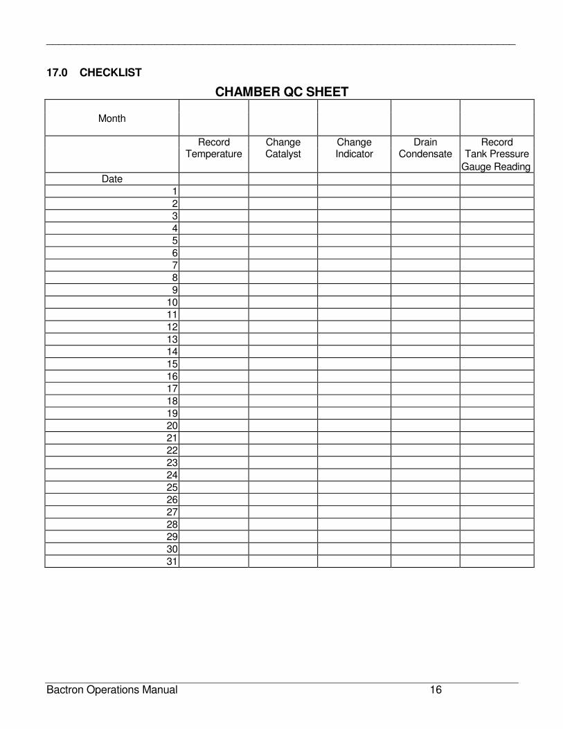
17.0 CHECKLIST
CHAMBER QC SHEET
Month
Record Change Change Drain Record Temperature Catalyst Indicator Condensate Tank Pressure
Gauge Reading
Date
1
2
3
4
5
6
7
8
9
10
11
12
13
14
15
16
17
18
19
20
21
22
23
24
25
26
27
28
29
30
31
______________________________________________________________________________
Bactron Operations Manual 17
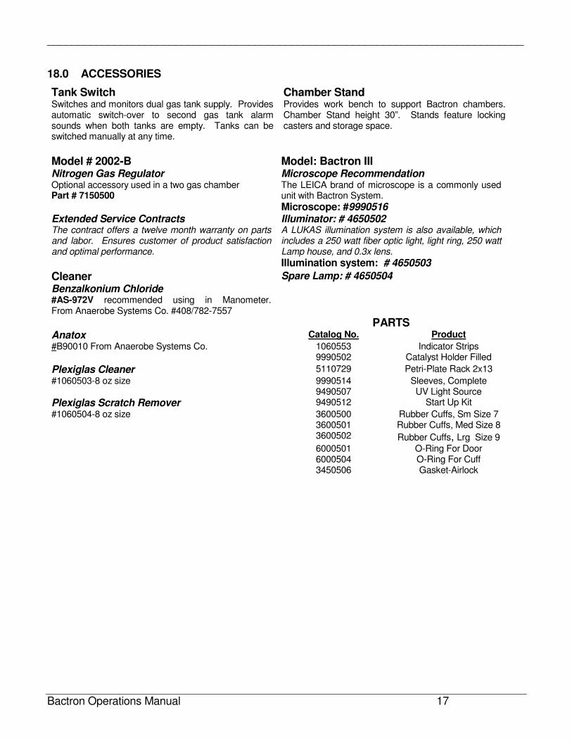
18.0 ACCESSORIES
Tank Switch Chamber Stand Switches and monitors dual gas tank supply. Provides automatic switch-over to second gas tank alarm sounds when both tanks are empty. Tanks can be switched manually at any time.
Provides work bench to support Bactron chambers. Chamber Stand height 30”. Stands feature locking casters and storage space.
Model # 2002-B Model: Bactron III Nitrogen Gas Regulator Microscope Recommendation Optional accessory used in a two gas chamber Part # 7150500
The LEICA brand of microscope is a commonly used unit with Bactron System.
Microscope: #9990516 Extended Service Contracts Illuminator: # 4650502 The contract offers a twelve month warranty on parts and labor. Ensures customer of product satisfaction and optimal performance.
A LUKAS illumination system is also available, which includes a 250 watt fiber optic light, light ring, 250 watt Lamp house, and 0.3x lens.
Illumination system: # 4650503
Cleaner Spare Lamp: # 4650504
Benzalkonium Chloride #AS-972V recommended using in Manometer. From Anaerobe Systems Co. #408/782-7557
PARTS Anatox Catalog No. Product
#B90010 From Anaerobe Systems Co. 1060553 Indicator Strips 9990502 Catalyst Holder Filled
Plexiglas Cleaner 5110729 Petri-Plate Rack 2x13 #1060503-8 oz size 9990514 Sleeves, Complete 9490507 UV Light Source Plexiglas Scratch Remover 9490512 Start Up Kit #1060504-8 oz size 3600500 Rubber Cuffs, Sm Size 7 3600501 Rubber Cuffs, Med Size 8 3600502 Rubber Cuffs, Lrg Size 9 6000501 O-Ring For Door 6000504 O-Ring For Cuff 3450506 Gasket-Airlock
______________________________________________________________________________
Bactron Operations Manual 18
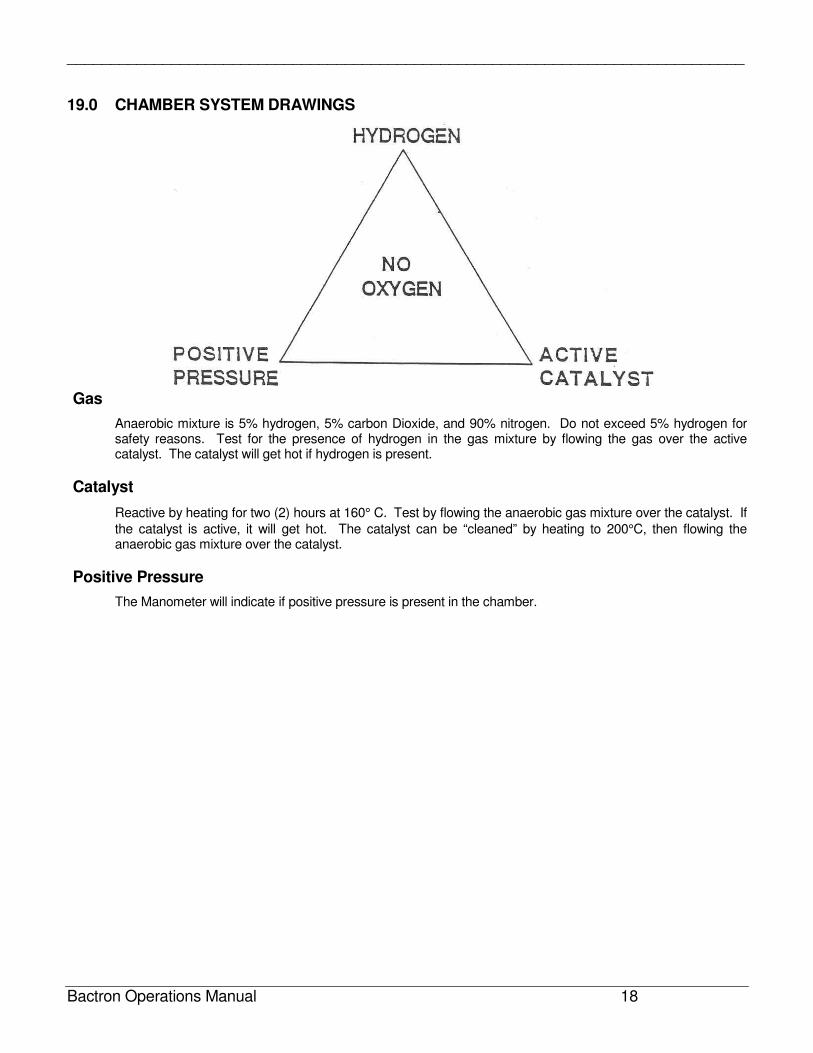
19.0 CHAMBER SYSTEM DRAWINGS
Gas
Anaerobic mixture is 5% hydrogen, 5% carbon Dioxide, and 90% nitrogen. Do not exceed 5% hydrogen for safety reasons. Test for the presence of hydrogen in the gas mixture by flowing the gas over the active catalyst. The catalyst will get hot if hydrogen is present.
Catalyst
Reactive by heating for two (2) hours at 160° C. Test by flowing the anaerobic gas mixture over the catalyst. If
the catalyst is active, it will get hot. The catalyst can be “cleaned” by heating to 200°C, then flowing the anaerobic gas mixture over the catalyst.
Positive Pressure
The Manometer will indicate if positive pressure is present in the chamber.
______________________________________________________________________________
Bactron Operations Manual 19
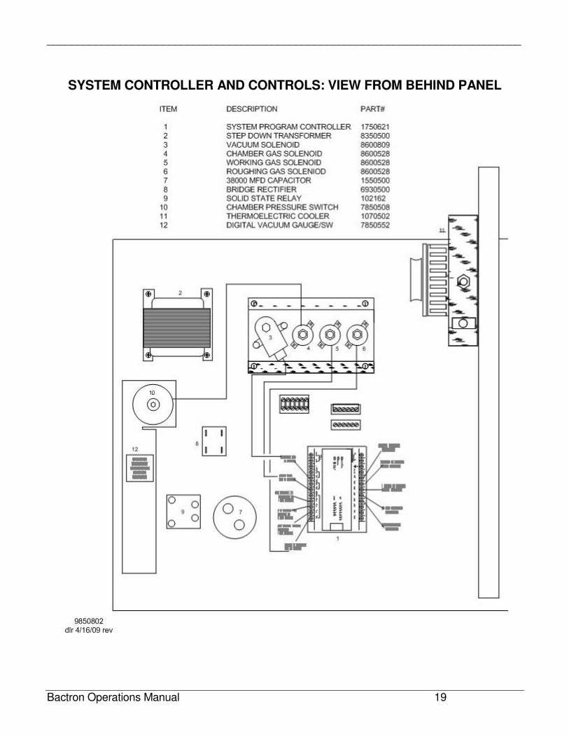
SYSTEM CONTROLLER AND CONTROLS: VIEW FROM BEHIND PANEL
______________________________________________________________________________
Bactron Operations Manual 20
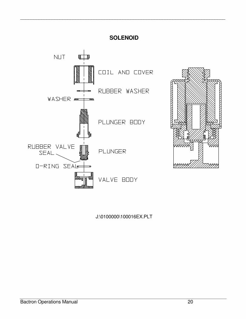
SOLENOID
J:\0100000\100016EX.PLT
______________________________________________________________________________
Bactron Operations Manual 21
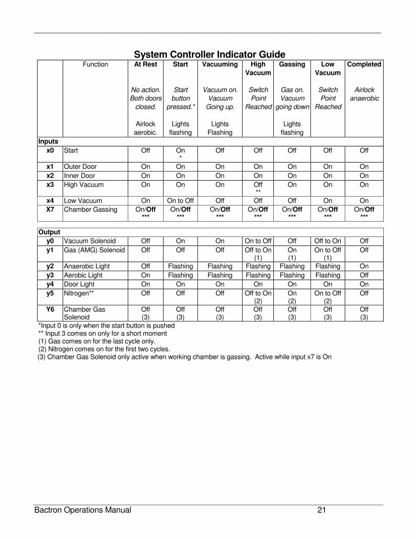
System Controller Indicator Guide Function At Rest Start Vacuuming High Gassing Low Completed
Vacuum Vacuum
No action. Start Vacuum on. Switch Gas on. Switch Airlock
Both doors button Vacuum Point Vacuum Point anaerobic
closed. pressed.* Going up. Reached going down Reached
Airlock Lights Lights Lights
aerobic. flashing Flashing flashing
Inputs
x0 Start Off On *
Off Off Off Off Off
x1 Outer Door On On On On On On On
x2 Inner Door On On On On On On On
x3 High Vacuum On On On Off **
On On On
x4 Low Vacuum On On to Off Off Off Off On On
X7 Chamber Gassing On/Off ***
On/Off ***
On/Off ***
On/Off ***
On/Off ***
On/Off ***
On/Off ***
Output
y0 Vacuum Solenoid Off On On On to Off Off Off to On Off
y1 Gas (AMG) Solenoid Off Off Off Off to On (1)
On (1)
On to Off (1)
Off
y2 Anaerobic Light Off Flashing Flashing Flashing Flashing Flashing On
y3 Aerobic Light On Flashing Flashing Flashing Flashing Flashing Off
y4 Door Light On On On On On On On
y5 Nitrogen** Off Off Off Off to On (2)
On (2)
On to Off (2)
Off
Y6 Chamber Gas Solenoid
Off (3)
Off (3)
Off (3)
Off (3)
Off (3)
Off (3)
Off (3)
*Input 0 is only when the start button is pushed ** Input 3 comes on only for a short moment (1) Gas comes on for the last cycle only. (2) Nitrogen comes on for the first two cycles. (3) Chamber Gas Solenoid only active when working chamber is gassing. Active while input x7 is On
______________________________________________________________________________
Bactron Operations Manual 22
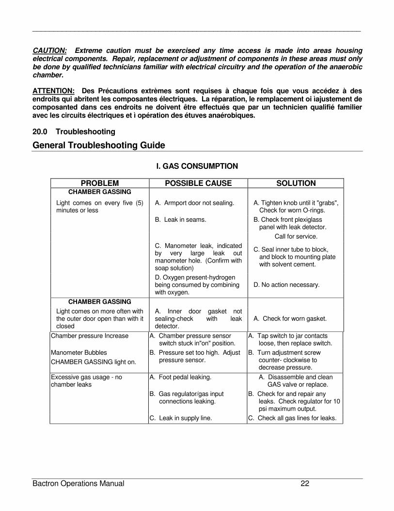
CAUTION: Extreme caution must be exercised any time access is made into areas housing electrical components. Repair, replacement or adjustment of components in these areas must only be done by qualified technicians familiar with electrical circuitry and the operation of the anaerobic chamber.
ATTENTION: Des Précautions extrèmes sont requises à chaque fois que vous accédez à des endroits qui abritent les composantes électriques. La réparation, le remplacement oi ìajustement de composanted dans ces endroits ne doivent être effectués que par un technicien qualifié familier avec les circuits électriques et ì opération des étuves anaérobiques.
20.0 Troubleshooting
General Troubleshooting Guide
I. GAS CONSUMPTION
PROBLEM POSSIBLE CAUSE SOLUTION CHAMBER GASSING
Light comes on every five (5) minutes or less
A. Armport door not sealing. A. Tighten knob until it "grabs", Check for worn O-rings.
B. Leak in seams. B. Check front plexiglass panel with leak detector.
Call for service.
C. Manometer leak, indicated by very large leak out manometer hole. (Confirm with soap solution)
C. Seal inner tube to block, and block to mounting plate with solvent cement.
D. Oxygen present-hydrogen being consumed by combining with oxygen.
D. No action necessary.
CHAMBER GASSING
Light comes on more often with the outer door open than with it closed
A. Inner door gasket not sealing-check with leak detector.
A. Check for worn gasket.
Chamber pressure Increase A. Chamber pressure sensor switch stuck in"on" position.
A. Tap switch to jar contacts loose, then replace switch.
Manometer Bubbles
CHAMBER GASSING light on.
B. Pressure set too high. Adjust pressure sensor.
B. Turn adjustment screw counter- clockwise to decrease pressure.
Excessive gas usage - no chamber leaks
A. Foot pedal leaking. A. Disassemble and clean GAS valve or replace.
B. Gas regulator/gas input connections leaking.
B. Check for and repair any leaks. Check regulator for 10 psi maximum output.
C. Leak in supply line. C. Check all gas lines for leaks.
______________________________________________________________________________
Bactron Operations Manual 23
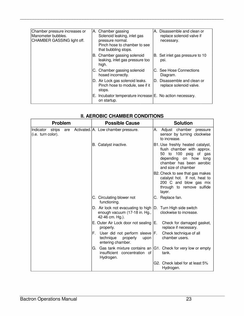
Chamber pressure increases or Manometer bubbles. CHAMBER GASSING light off.
A. Chamber gassing Solenoid leaking, inlet gas pressure normal. Pinch hose to chamber to see that bubbling stops.
A. Disassemble and clean or replace solenoid valve if necessary.
B. Chamber gassing solenoid leaking, inlet gas pressure too high.
B. Set inlet gas pressure to 10 psi.
C. Chamber gassing solenoid hosed incorrectly.
C. See Hose Connections Diagram.
D. Air Lock gas solenoid leaks. Pinch hose to module, see if it stops.
D. Disassemble and clean or replace solenoid valve.
E. Incubator temperature increase on startup.
E. No action necessary.
II. AEROBIC CHAMBER CONDITIONS
Problem Possible Cause Solution
Indicator strips are Activated. (i.e. turn color).
A. Low chamber pressure. A. Adjust chamber pressure sensor by turning clockwise to increase.
B. Catalyst inactive. B1. Use freshly heated catalyst, flush chamber with approx. 50 to 100 psig of gas depending on how long chamber has been aerobic and size of chamber
B2. Check to see that gas makes catalyst hot. If not, heat to 200 C and blow gas mix through to remove sulfide layer.
C. Circulating blower not functioning.
C. Replace fan.
D. Air lock not evacuating to high enough vacuum (17-18 in. Hg., 42-46 cm. Hg.).
D. Turn High side switch clockwise to increase.
E. Outer Air Lock door not sealing properly.
E. Check for damaged gasket, replace if necessary.
F. User did not perform sleeve technique properly upon entering chamber.
F. Check technique of all chamber users.
G. Gas tank mixture contains an insufficient concentration of Hydrogen.
G1. Check for very low or empty tank.
G2. Check label for at least 5% Hydrogen.
______________________________________________________________________________
Bactron Operations Manual 24
General Troubleshooting Guide Continued
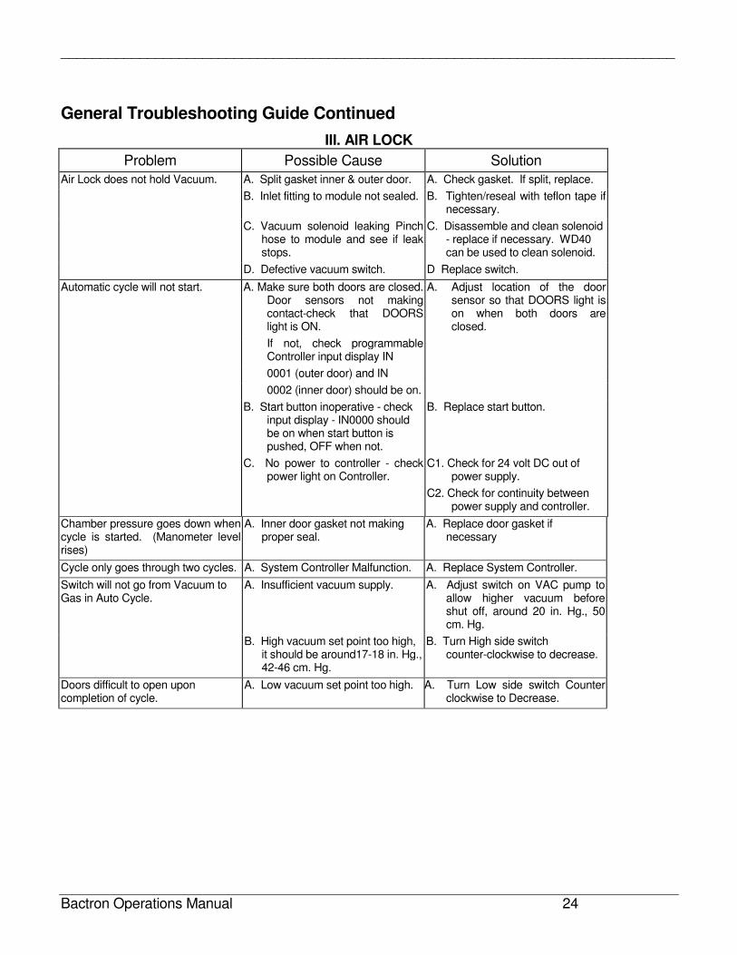
III. AIR LOCK
Problem Possible Cause Solution
Air Lock does not hold Vacuum. A. Split gasket inner & outer door. A. Check gasket. If split, replace.
B. Inlet fitting to module not sealed. B. Tighten/reseal with teflon tape if necessary.
C. Vacuum solenoid leaking Pinch hose to module and see if leak stops.
C. Disassemble and clean solenoid - replace if necessary. WD40 can be used to clean solenoid.
D. Defective vacuum switch. D Replace switch.
Automatic cycle will not start. A. Make sure both doors are closed. Door sensors not making contact-check that DOORS light is ON.
A. Adjust location of the door sensor so that DOORS light is on when both doors are closed.
If not, check programmable Controller input display IN
0001 (outer door) and IN
0002 (inner door) should be on.
B. Start button inoperative - check input display - IN0000 should be on when start button is pushed, OFF when not.
B. Replace start button.
C. No power to controller - check power light on Controller.
C1. Check for 24 volt DC out of power supply.
C2. Check for continuity between power supply and controller.
Chamber pressure goes down when cycle is started. (Manometer level rises)
A. Inner door gasket not making proper seal.
A. Replace door gasket if necessary
Cycle only goes through two cycles. A. System Controller Malfunction. A. Replace System Controller.
Switch will not go from Vacuum to Gas in Auto Cycle.
A. Insufficient vacuum supply. A. Adjust switch on VAC pump to allow higher vacuum before shut off, around 20 in. Hg., 50 cm. Hg.
B. High vacuum set point too high, it should be around17-18 in. Hg., 42-46 cm. Hg.
B. Turn High side switch counter-clockwise to decrease.
Doors difficult to open upon completion of cycle.
A. Low vacuum set point too high. A. Turn Low side switch Counter clockwise to Decrease.
______________________________________________________________________________
Bactron Operations Manual 25
General Troubleshooting Guide Continued
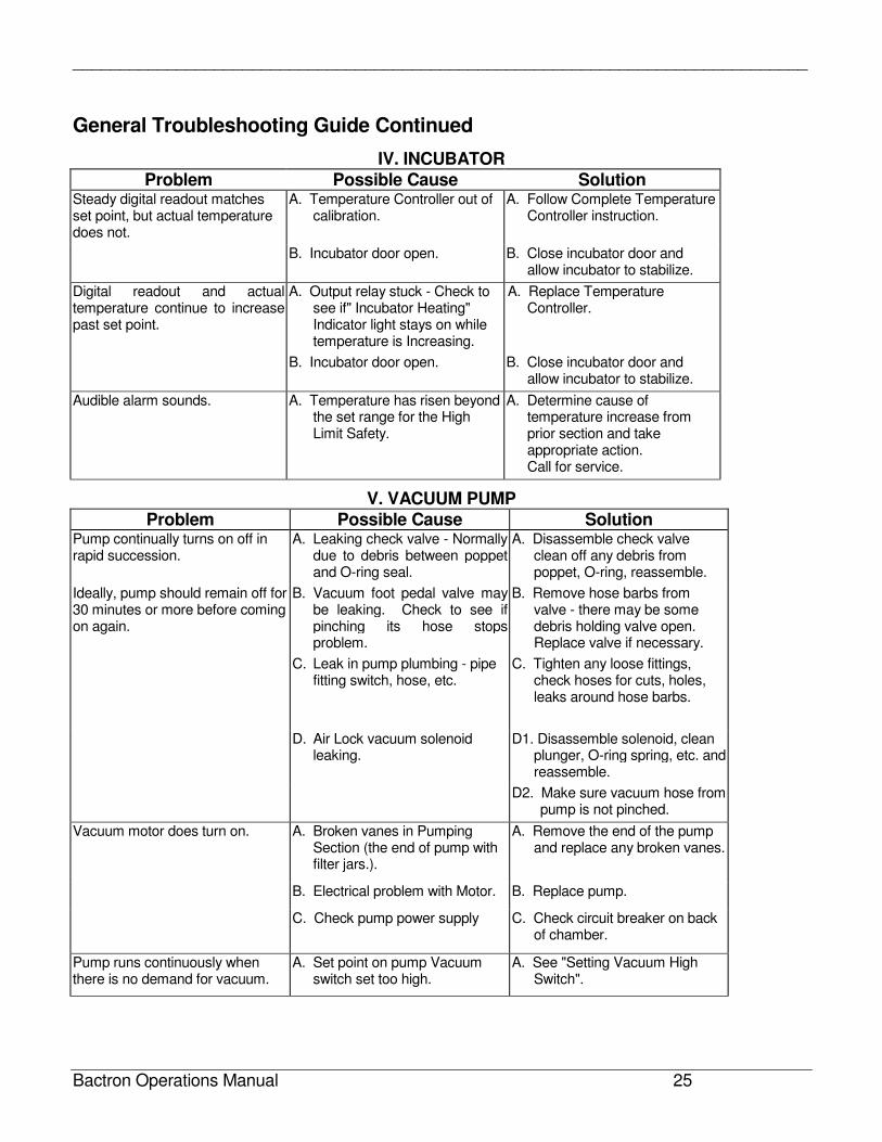
IV. INCUBATOR
Problem Possible Cause Solution Steady digital readout matches set point, but actual temperature does not.
A. Temperature Controller out of calibration.
A. Follow Complete Temperature Controller instruction.
B. Incubator door open. B. Close incubator door and allow incubator to stabilize.
Digital readout and actual temperature continue to increase past set point.
A. Output relay stuck - Check to see if" Incubator Heating" Indicator light stays on while temperature is Increasing.
A. Replace Temperature Controller.
B. Incubator door open. B. Close incubator door and allow incubator to stabilize.
Audible alarm sounds. A. Temperature has risen beyond the set range for the High Limit Safety.
A. Determine cause of temperature increase from prior section and take appropriate action. Call for service.
V. VACUUM PUMP
Problem Possible Cause Solution Pump continually turns on off in rapid succession.
A. Leaking check valve - Normally due to debris between poppet and O-ring seal.
A. Disassemble check valve clean off any debris from poppet, O-ring, reassemble.
Ideally, pump should remain off for 30 minutes or more before coming on again.
B. Vacuum foot pedal valve may be leaking. Check to see if pinching its hose stops problem.
B. Remove hose barbs from valve - there may be some debris holding valve open. Replace valve if necessary.
C. Leak in pump plumbing - pipe fitting switch, hose, etc.
C. Tighten any loose fittings, check hoses for cuts, holes, leaks around hose barbs.
D. Air Lock vacuum solenoid leaking.
D1. Disassemble solenoid, clean plunger, O-ring spring, etc. and reassemble.
D2. Make sure vacuum hose from pump is not pinched.
Vacuum motor does turn on. A. Broken vanes in Pumping Section (the end of pump with filter jars.).
A. Remove the end of the pump and replace any broken vanes.
B. Electrical problem with Motor. B. Replace pump.
C. Check pump power supply C. Check circuit breaker on back of chamber.
Pump runs continuously when there is no demand for vacuum.
A. Set point on pump Vacuum switch set too high.
A. See "Setting Vacuum High Switch".
______________________________________________________________________________
Bactron Operations Manual 26
General Troubleshooting Guide Continued
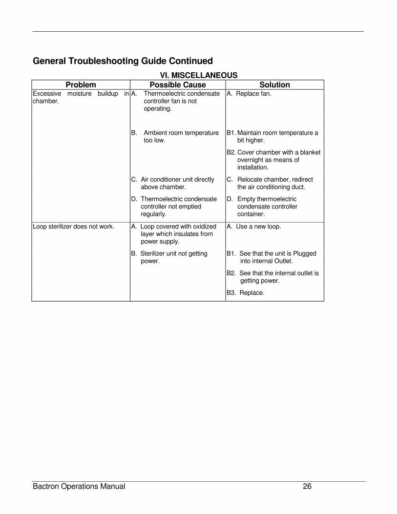
VI. MISCELLANEOUS Problem Possible Cause Solution
Excessive moisture buildup in chamber.
A. Thermoelectric condensate controller fan is not operating.
A. Replace fan.
B. Ambient room temperature too low.
B1. Maintain room temperature a bit higher.
B2. Cover chamber with a blanket overnight as means of installation.
C. Air conditioner unit directly above chamber.
C. Relocate chamber, redirect the air conditioning duct.
D. Thermoelectric condensate controller not emptied regularly.
D. Empty thermoelectric condensate controller container.
Loop sterilizer does not work. A. Loop covered with oxidized layer which insulates from power supply.
A. Use a new loop.
B. Sterilizer unit not getting power.
B1. See that the unit is Plugged into internal Outlet.
B2. See that the internal outlet is getting power.
B3. Replace.
______________________________________________________________________________
Bactron Operations Manual 27
21.0 BACTRON OPERATION TIPS
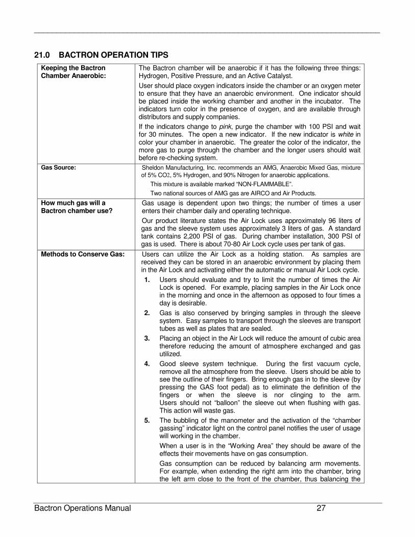
Keeping the Bactron Chamber Anaerobic:
The Bactron chamber will be anaerobic if it has the following three things: Hydrogen, Positive Pressure, and an Active Catalyst.
User should place oxygen indicators inside the chamber or an oxygen meter to ensure that they have an anaerobic environment. One indicator should be placed inside the working chamber and another in the incubator. The indicators turn color in the presence of oxygen, and are available through distributors and supply companies.
If the indicators change to pink, purge the chamber with 100 PSI and wait for 30 minutes. The open a new indicator. If the new indicator is white in color your chamber in anaerobic. The greater the color of the indicator, the more gas to purge through the chamber and the longer users should wait before re-checking system.
Gas Source: Sheldon Manufacturing, Inc. recommends an AMG, Anaerobic Mixed Gas, mixture
of 5% CO2, 5% Hydrogen, and 90% Nitrogen for anaerobic applications.
This mixture is available marked “NON-FLAMMABLE”.
Two national sources of AMG gas are AIRCO and Air Products.
How much gas will a Bactron chamber use?
Gas usage is dependent upon two things; the number of times a user enters their chamber daily and operating technique.
Our product literature states the Air Lock uses approximately 96 liters of gas and the sleeve system uses approximately 3 liters of gas. A standard tank contains 2,200 PSI of gas. During chamber installation, 300 PSI of gas is used. There is about 70-80 Air Lock cycle uses per tank of gas.
Methods to Conserve Gas: Users can utilize the Air Lock as a holding station. As samples are received they can be stored in an anaerobic environment by placing them in the Air Lock and activating either the automatic or manual Air Lock cycle.
1. Users should evaluate and try to limit the number of times the Air Lock is opened. For example, placing samples in the Air Lock once in the morning and once in the afternoon as opposed to four times a day is desirable.
2. Gas is also conserved by bringing samples in through the sleeve system. Easy samples to transport through the sleeves are transport tubes as well as plates that are sealed.
3. Placing an object in the Air Lock will reduce the amount of cubic area therefore reducing the amount of atmosphere exchanged and gas utilized.
4. Good sleeve system technique. During the first vacuum cycle, remove all the atmosphere from the sleeve. Users should be able to see the outline of their fingers. Bring enough gas in to the sleeve (by pressing the GAS foot pedal) as to eliminate the definition of the fingers or when the sleeve is nor clinging to the arm. Users should not “balloon” the sleeve out when flushing with gas. This action will waste gas.
5. The bubbling of the manometer and the activation of the “chamber gassing” indicator light on the control panel notifies the user of usage will working in the chamber.
When a user is in the “Working Area” they should be aware of the effects their movements have on gas consumption.
Gas consumption can be reduced by balancing arm movements. For example, when extending the right arm into the chamber, bring the left arm close to the front of the chamber, thus balancing the
______________________________________________________________________________
Bactron Operations Manual 28
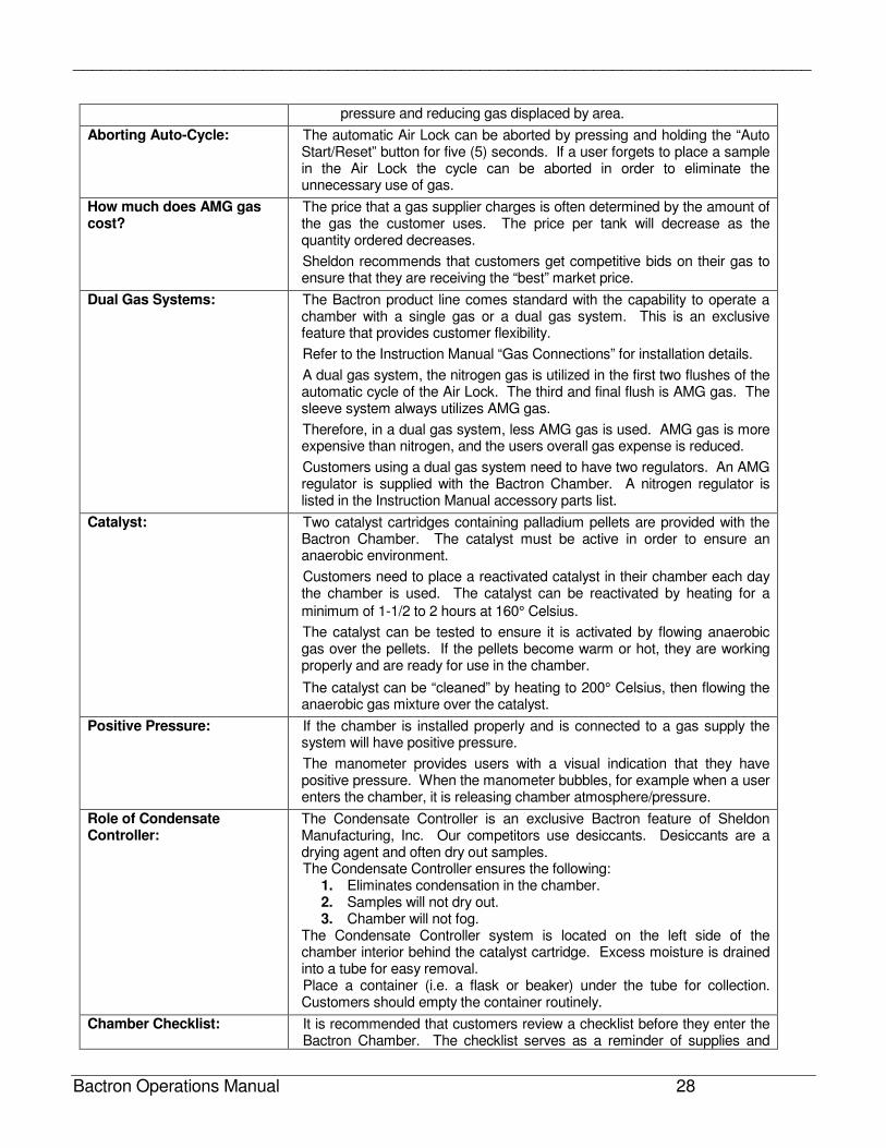
pressure and reducing gas displaced by area.
Aborting Auto-Cycle: The automatic Air Lock can be aborted by pressing and holding the “Auto Start/Reset” button for five (5) seconds. If a user forgets to place a sample in the Air Lock the cycle can be aborted in order to eliminate the unnecessary use of gas.
How much does AMG gas cost?
The price that a gas supplier charges is often determined by the amount of the gas the customer uses. The price per tank will decrease as the quantity ordered decreases.
Sheldon recommends that customers get competitive bids on their gas to ensure that they are receiving the “best” market price.
Dual Gas Systems: The Bactron product line comes standard with the capability to operate a chamber with a single gas or a dual gas system. This is an exclusive feature that provides customer flexibility.
Refer to the Instruction Manual “Gas Connections” for installation details.
A dual gas system, the nitrogen gas is utilized in the first two flushes of the automatic cycle of the Air Lock. The third and final flush is AMG gas. The sleeve system always utilizes AMG gas.
Therefore, in a dual gas system, less AMG gas is used. AMG gas is more expensive than nitrogen, and the users overall gas expense is reduced.
Customers using a dual gas system need to have two regulators. An AMG regulator is supplied with the Bactron Chamber. A nitrogen regulator is listed in the Instruction Manual accessory parts list.
Catalyst: Two catalyst cartridges containing palladium pellets are provided with the Bactron Chamber. The catalyst must be active in order to ensure an anaerobic environment.
Customers need to place a reactivated catalyst in their chamber each day the chamber is used. The catalyst can be reactivated by heating for a
minimum of 1-1/2 to 2 hours at 160° Celsius.
The catalyst can be tested to ensure it is activated by flowing anaerobic gas over the pellets. If the pellets become warm or hot, they are working properly and are ready for use in the chamber.
The catalyst can be “cleaned” by heating to 200° Celsius, then flowing the anaerobic gas mixture over the catalyst.
Positive Pressure: If the chamber is installed properly and is connected to a gas supply the system will have positive pressure.
The manometer provides users with a visual indication that they have positive pressure. When the manometer bubbles, for example when a user enters the chamber, it is releasing chamber atmosphere/pressure.
Role of Condensate Controller:
The Condensate Controller is an exclusive Bactron feature of Sheldon Manufacturing, Inc. Our competitors use desiccants. Desiccants are a drying agent and often dry out samples. The Condensate Controller ensures the following:
1. Eliminates condensation in the chamber. 2. Samples will not dry out. 3. Chamber will not fog.
The Condensate Controller system is located on the left side of the chamber interior behind the catalyst cartridge. Excess moisture is drained into a tube for easy removal. Place a container (i.e. a flask or beaker) under the tube for collection. Customers should empty the container routinely.
Chamber Checklist: It is recommended that customers review a checklist before they enter the Bactron Chamber. The checklist serves as a reminder of supplies and
______________________________________________________________________________
Bactron Operations Manual 29
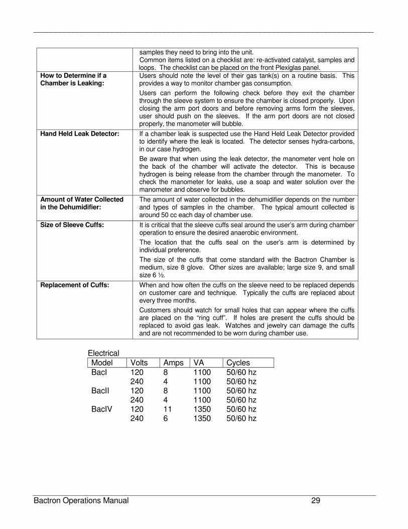
samples they need to bring into the unit. Common items listed on a checklist are: re-activated catalyst, samples and loops. The checklist can be placed on the front Plexiglas panel.
How to Determine if a Chamber is Leaking:
Users should note the level of their gas tank(s) on a routine basis. This provides a way to monitor chamber gas consumption.
Users can perform the following check before they exit the chamber through the sleeve system to ensure the chamber is closed properly. Upon closing the arm port doors and before removing arms form the sleeves, user should push on the sleeves. If the arm port doors are not closed properly, the manometer will bubble.
Hand Held Leak Detector: If a chamber leak is suspected use the Hand Held Leak Detector provided to identify where the leak is located. The detector senses hydra-carbons, in our case hydrogen.
Be aware that when using the leak detector, the manometer vent hole on the back of the chamber will activate the detector. This is because hydrogen is being release from the chamber through the manometer. To check the manometer for leaks, use a soap and water solution over the manometer and observe for bubbles.
Amount of Water Collected in the Dehumidifier:
The amount of water collected in the dehumidifier depends on the number and types of samples in the chamber. The typical amount collected is around 50 cc each day of chamber use.
Size of Sleeve Cuffs: It is critical that the sleeve cuffs seal around the user’s arm during chamber operation to ensure the desired anaerobic environment.
The location that the cuffs seal on the user’s arm is determined by individual preference.
The size of the cuffs that come standard with the Bactron Chamber is medium, size 8 glove. Other sizes are available; large size 9, and small size 6 ½.
Replacement of Cuffs: When and how often the cuffs on the sleeve need to be replaced depends on customer care and technique. Typically the cuffs are replaced about every three months.
Customers should watch for small holes that can appear where the cuffs are placed on the “ring cuff”. If holes are present the cuffs should be replaced to avoid gas leak. Watches and jewelry can damage the cuffs and are not recommended to be worn during chamber use.
Electrical Model Volts Amps VA Cycles BacI 120 8 1100 50/60 hz 240 4 1100 50/60 hz BacII 120 8 1100 50/60 hz 240 4 1100 50/60 hz BacIV 120 11 1350 50/60 hz 240 6 1350 50/60 hz
______________________________________________________________________________
Bactron Operations Manual 30
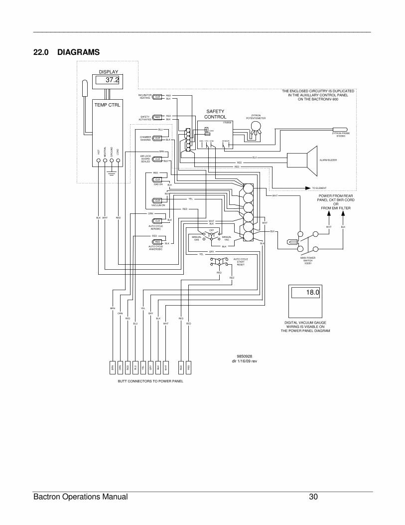
22.0 DIAGRAMS
TEMP CTRL
DISPLAY
37.2
INCUBATOR
HEATING
SAFETY
ACTIVATED
CHAMBER
GASSING
RED
BLK
BLK
RED
SAFETY
CONTROL
AIR LOCK
DOORS
SEALED
GAS ON
VACUUM ON
AUTO CYCLE
AEROBIC
AUTO CYCLE
ANAEROBIC
AUTO CYCLE
START
RESET
MANUAL
GAS
MANUAL
VAC
OFF
BLK
BLK
BLK
WHT
WHT RED
BLK
RED
ORN
BLK
YELGRY
BLK
BLK
WHT
WHT
WHT BLK
RED
YEL
BLK
BLK
RED
RED
RED
BLK
BLK
BLK
BRN
BLU
ZYTRON PROBE
8100500
ZYTRON
POTENTIOMETER
ALARM BUZZER
1750500
LOAD
230V 115V COM SENSOR
MAIN POWER
SWITCH
103351
POWER FROM REARPANEL CKT BKR CORD
ORFROM EMI FILTER
TO ELEMENT
BR
N
OR
N
RE
D
BLU
YE
L
GR
Y
BL
K
WH
T
RE
D
RE
D
RED
RED
GRY
BLK
WHT
YEL
BLU
ORN
RED
BRN
RED
RED
RED
CLR
CLR
CLR
CLR
CLR
CLR
RED
18.0
DIGITAL VACUUM GAUGEWIRING IS VISABLE ON
THE POWER PANEL DIAGRAM
THE ENCLOSED CIRCUITRY IS DUPLICATEDIN THE AUXILLARY CONTROL PANEL
ON THE BACTRONIV-900H
OT
NE
UT
RA
L
GR
OU
ND
LO
AD
9850928
dlr 1/16/09 rev
BUTT CONNECTORS TO POWER PANEL
______________________________________________________________________________
Bactron Operations Manual 31
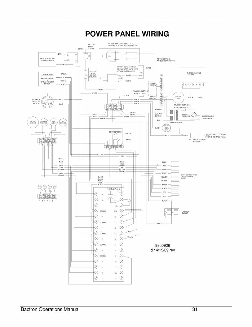
POWER PANEL WIRING
CHAMBER
FAN
INC FAN
BAC-IV
SERIES
ONLY
VACUUM
SOLENOID
N2
SOLENOID
GAS
SOLENOID
CHAMBER
SOLENOID
MOV MOV MOV MOV
COMM 4
COMM 3
Y7
Y6
1 2 3 4 5 6
654321
NO NC
C
TO THE CONTROL
PANEL ON/OFF SWITCH
15A
15A
POWER CORD AND MAIN
BREAKER FOR UNITS WITH
ATTACHED CORDSETS
FILTERED AND FUSED INLET FOR
UNITS WITH DETACHABLE CORDSETS
VACUUMPUMP
CIRCUITBREAKER
VACUUM
PUMP
OUTLET
X7
X6
X5
X4
X3
X2
X1
X0
S/S
N
L
Y3
Y2
COMM 2
Y1
COMM 1
Y0
COMM 0
0
24
CAPACITOR FOR230 VOLT ONLY
BUTT CONNECTORSTO THE CONTROLPANEL
INCUBATOR ELEMENTASSEMBLY
TRANSFORMER
TRANSFORMER SEC
FUSE 6.3A TYPE "T"
RED TO SAFETY CONTROL
ON THE CONTROL PANEL
BRIDGERECTIFIER ELECTROLYTIC
CONDENSER
1 2 3 4 5 6 7 8
THERMOELECTRIC COOLER
230VACHOOKUP
120VACHOOKUP
TB5
CHAMBEROUTLET
Y4 X10
Y5 X11
X12
X13
CONTROL PANEL
VACUUM GAUGE
&
CYCLE HIGH/LOW
SWITCH
VACUUM HIGH LIMIT
DISPLAY/SWITCH
BLUE
WHITE
BLACK
BROWN
+
-
BRN
BLU
DOOR SENSORSOUTER
INNER
BLACK
WHITE
WHITEWHITE
BLACK
BLACK
WHITE
WHITE
BLACK
BLACK
WHITE
BLACK
YELLOW
RED
BLUE
REDORANGE
GRAY
YELLOWBROWN
BLUE
RED
ORANGE
GRAY
YELLOW
BROWN
WHITE
BLACK
RED
RED
BLACK
BLUE
WHITE
RED
GRAYYELLOW
GRAY
YELLOWBLACK
BLACKWHITE
RED
BLACK
BLACK
BLACK
WHITE
WHITE
BLUE
CHAMBER
PRESSURE
SWITCH
YELLOW
RED
WHITE
WHITE
BLACK
WHITE
BLACK
BLACK
BLK
BLK/BLU
BLK/WHT
BLK/PUR
BLACK RED
TRANSFORMER PRI
FUSE 1A TYPE "T"
9850926
dlr 4/15/09 rev
______________________________________________________________________________
Bactron Operations Manual 32
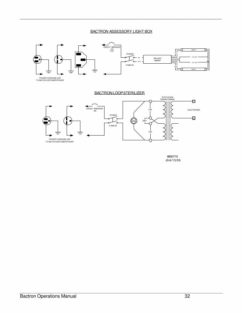
115V
115V
230V
CIRCUIT BREAKER15A
POWER
ELECTRODES
STEP-DOWNTRANSFORMER
POWER CORD AND CAP
TO MATCH CUSTOMER POWER
BACTRON LOOP STERILIZER
CIRCUIT BREAKER15A
1100505
POWER
POWER CORD AND CAPTO MATCH CUSTOMER POWER
BACTRON ASSESSORY LIGHT BOX
BALLAST4660507
4650537
4650537
YELLOW
YELLOW
RED
BLUE
BLK
WHT
9850715dlr 4/15/09
X1000124
X1000124
______________________________________________________________________________
Bactron Operations Manual 33
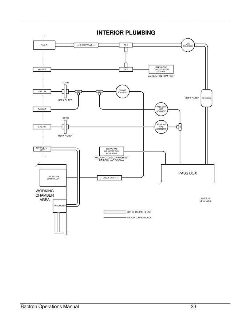
INTERIOR PLUMBING
VAC IN
VAC OUT
GAS 1 IN
GAS OUT
GAS 2 IN
TEE
TEE>> CHECK VALVE >>VAC
SOLENOID
TEECH GAS
SOLENOID
PASS BOXGAS
SOLENOID
WORKINGGAS
SOLENOID
TEE
TE
E
DIGITAL VACGAUGE/SWITCH
20 IN.HG.
PASS BOX
MANOMETERVENT
MANOMETER
CONDENSATECONTROLLER
<< CHECK VALVE <<
DIGITAL VACGAUGE/SWITCH
4 & 18 IN.HG.
X1000330
WORKING
CHAMBER
AREA
100199
100199
HEPA FILTER
HEPA FILTER
HEPA FILTER
VACUUM HIGH LIMIT SET
VACUUM CYCLE LOW/HIGH SET
AIR LOCK VAC DISPLAY
9850933
dlr 4/14/09
3/8" ID TUBING CLEAR
1/4" OD TUBING BLACK
______________________________________________________________________________
Bactron Operations Manual 34
HOSE CONNECTIONS
______________________________________________________________________________
Bactron Operations Manual 35
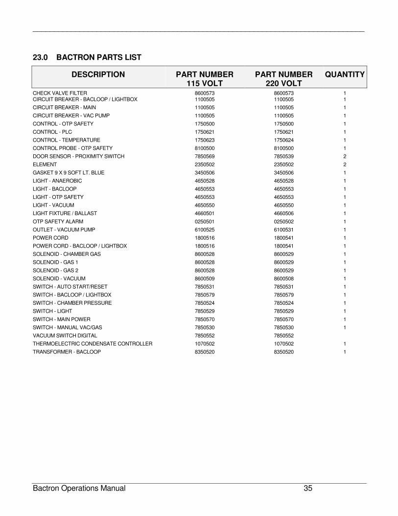
23.0 BACTRON PARTS LIST
DESCRIPTION PART NUMBER 115 VOLT
PART NUMBER 220 VOLT
QUANTITY
CHECK VALVE FILTER 8600573 8600573 1 CIRCUIT BREAKER - BACLOOP / LIGHTBOX 1100505 1100505 1
CIRCUIT BREAKER - MAIN 1100505 1100505 1
CIRCUIT BREAKER - VAC PUMP 1100505 1100505 1
CONTROL - OTP SAFETY 1750500 1750500 1
CONTROL - PLC 1750621 1750621 1
CONTROL - TEMPERATURE 1750623 1750624 1
CONTROL PROBE - OTP SAFETY 8100500 8100500 1
DOOR SENSOR - PROXIMITY SWITCH 7850569 7850539 2
ELEMENT 2350502 2350502 2
GASKET 9 X 9 SOFT LT. BLUE 3450506 3450506 1
LIGHT - ANAEROBIC 4650528 4650528 1
LIGHT - BACLOOP 4650553 4650553 1
LIGHT - OTP SAFETY 4650553 4650553 1
LIGHT - VACUUM 4650550 4650550 1
LIGHT FIXTURE / BALLAST 4660501 4660506 1
OTP SAFETY ALARM 0250501 0250502 1
OUTLET - VACUUM PUMP 6100525 6100531 1
POWER CORD 1800516 1800541 1
POWER CORD - BACLOOP / LIGHTBOX 1800516 1800541 1
SOLENOID - CHAMBER GAS 8600528 8600529 1
SOLENOID - GAS 1 8600528 8600529 1
SOLENOID - GAS 2 8600528 8600529 1
SOLENOID - VACUUM 8600509 8600508 1
SWITCH - AUTO START/RESET 7850531 7850531 1
SWITCH - BACLOOP / LIGHTBOX 7850579 7850579 1
SWITCH - CHAMBER PRESSURE 7850524 7850524 1
SWITCH - LIGHT 7850529 7850529 1
SWITCH - MAIN POWER 7850570 7850570 1
SWITCH - MANUAL VAC/GAS 7850530 7850530 1
VACUUM SWITCH DIGITAL 7850552 7850552
THERMOELECTRIC CONDENSATE CONTROLLER 1070502 1070502 1
TRANSFORMER - BACLOOP 8350520 8350520 1
______________________________________________________________________________
Bactron Operations Manual 36
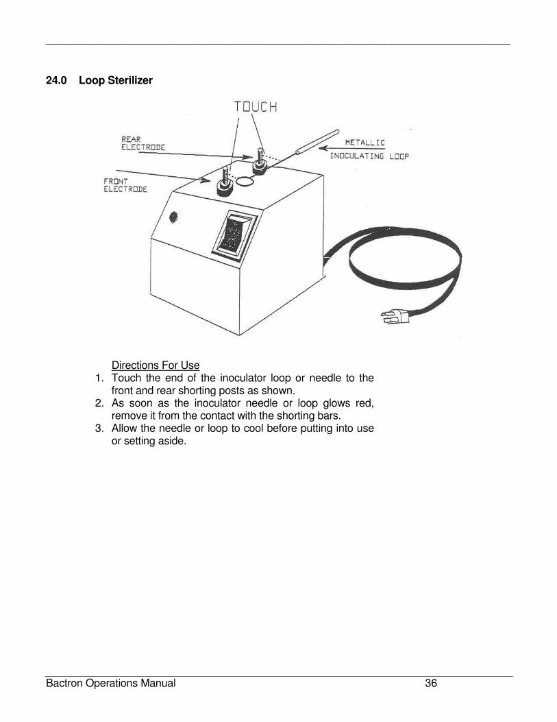
24.0 Loop Sterilizer
Directions For Use 1. Touch the end of the inoculator loop or needle to the
front and rear shorting posts as shown. 2. As soon as the inoculator needle or loop glows red,
remove it from the contact with the shorting bars. 3. Allow the needle or loop to cool before putting into use
or setting aside.
Related Documents