BACnet ® Link Technical Guide www.orioncontrols.com Revision- 02B - August 2005

Welcome message from author
This document is posted to help you gain knowledge. Please leave a comment to let me know what you think about it! Share it to your friends and learn new things together.
Transcript
BACnet® LinkTechnical Guide
www.orioncontrols.com
Revision- 02B - August 2005
Table Of Contents
WattMaster Controls Inc.8500 NW River Park Drive · Parkville , MO 64152Toll Free Phone: 866-918-1100PH: (816) 505-1100 · FAX: (816) 505-1101 · E-mail: [email protected] our web site at www.orioncontrols.comForm: OR-BACNET-TGD-02B Copyright 2005 WattMaster Controls, Inc.AAON® is a registered trademark of AAON, Inc., Tulsa, OK.BACnet® is a registered trademark of ASHRAE Inc., Atlanta, GA.WattMaster Controls, Inc. assumes no responsibility for errors, or omissions.This document is subject to change without notice.
General Information ........................................................................................................................................ 3Data Sharing ............................................................................................................................................................................... 3Scheduling .................................................................................................................................................................................. 3Hardware Specifications ............................................................................................................................................................. 3
Connection and Wiring Information ................................................................................................................ 4Troubleshooting Information .......................................................................................................................... 5
General Information .................................................................................................................................................................... 5Using LED’s To Verify Operation ................................................................................................................................................ 5
Programming- General Information ................................................................................................................ 6BACnet® Link Overview ............................................................................................................................................................. 6BACnet® Link Device Object ...................................................................................................................................................... 6WattBacObjectTypes .................................................................................................................................................................. 6Local Address (MAC address) .................................................................................................................................................... 6BACnet® Services Supported ................................................................................................................................................... 6MS/TP LAN Baud Rate ............................................................................................................................................................... 6
Programming - Standard Objects ................................................................................................................... 7General Information .................................................................................................................................................................... 7Parameters ................................................................................................................................................................................. 7Instance Number Base ............................................................................................................................................................... 7MUA II Instance Number Base ................................................................................................................................................... 7MUA II BACnet® Property Identifier ........................................................................................................................................... 8VAV/CAV Instance Number Base ............................................................................................................................................... 9VAV/CAV BACnet® Property Identifier ....................................................................................................................................... 9CW/HW Instance Number Base ............................................................................................................................................... 10CW/HW BACnet® Property Identifier ........................................................................................................................................ 11Parameter Instance Numbers ................................................................................................................................................... 12
Programming - Proprietary Objects .............................................................................................................. 13BACnet® Link Overview ........................................................................................................................................................... 13MUA II Object ............................................................................................................................................................................ 13MUA II Property Identifier ......................................................................................................................................................... 14VAV/CAV Object ....................................................................................................................................................................... 15VAV/CAV Property Identifier ..................................................................................................................................................... 16CW/HW Object ......................................................................................................................................................................... 17CW/HW Property Identifier ....................................................................................................................................................... 18Proprietary Object Instance Numbers....................................................................................................................................... 19
Appendix 1 ..................................................................................................................................................... 20BACnet® Link Protocol Implementation Conformance Statement ........................................................................................... 20

BACnet® Link Interface 3
Technical Guide
4.0
0”
4.5
0"
0.2
5”
0.25”7.00"
7.50"
JP
1
R1
ADDR.
2 1
C4
U1
EE
PR
OMNET-
WORK
LOOP R4
U6
T
SHLD
R
C1
0
X2
C9
DR
IVE
R
C12U7
JP4
TE
RM
.
R1
5
R11
R1
0R
18 RN2
LE
D1
LE
D2
LE
D3
LE
D4
NE
TC
OM
M
LO
OP
CO
MM
U9
RN
1 C7
U2
C2
C3
R3
YS101928
0.20 Dia.
Mounting Hole
Typ. 4 PL.Mounting
Backplate
Network (MSTP)
Communications
Wiring Terminal
Local Loop
Communications
Wiring Terminal
Local Loop
Communications
Driver Chip
24 VAC Power
Terminals
Network
Communications
LED
Local Loop
Communications
LED
Power
LED
Network
Driver Chip
EPROM Chip
Pin 1 Indicator
Address Switch
RAM Chip
Pin 1 Indicator
TRANSLATOR BOARD
REV 0
U3EPROM
C8
Q1
PW
R
R20
D2
R17
R1
6
R1
3 C1
4 R14
JP3
WDOG U1
0
C11
JP2
RAMU5
U4
SERIAL #
C1
R5
L1 R6
R7R
12
D1
C16
C17
R1
9
U11R2
1
D3
R23
C19
R2
2
+24VAC
GND
TB3
C13
R8
R9
U8
DR
IVE
R
T (-)
SHLD
R (+)
C6 LOOP
LOCAL
C5
X1
VCC VBAT
R2
The OE367-22 BACnet® Link provides bi-directional translation ofdata and information between BACnet® devices and Orion VAV/CAV,CW/HW and MUA II unit controllers.
Up to 16 total, Orion VAV/CAV, CH/HW, MUA II or any combinationof these controllers may be connected to each BACnet® Link. Up to 4BACnet® Links can be used on a Orion Controls system allowing fora maximum of 64 total controllers to be used.
Data SharingThe BACnet® Link interface provides the following data sharing capa-bilities:
• Provides values from points on the Orion side of thegateway to BACnet® devices as if the values wereoriginating from BACnet® objects.
• Allows BACnet® devices to modify point values on theOrion controller side of the BACnet® Link by usingstandard BACnet® write services
Scheduling
• Ability to allow BACnet® devices to send Schedule eventsto the Orion controller side of the gateway by usingstandard BACnet® services
Hardware SpecificationsTable 1 below contains the hardware specifications for the BACnet®
Link interface.
Technical Data
BACnet Loop RS-485, Auto Detect HostMatching - 9600, 19200, 38400,76800 Baud Rates
Controller L oop RS-485, 9600 Baud
Protocol (BACnet Loop) MS/TP Lan
Protocol(W attM aster Loop)
HSI Open P rotocolToken Passing
Pow er Input Voltage 24 VAC
Pow er Consumption 10 VA M aximum
Operating Temp 10°F to 149°F
Operating Humidity 90% RH Non-Condensing
W eight 8 oz
Table 1: BACnet® Link Interface Technical Data
General Information
Figure 1: BACnet® Link Board Components and Dimensions

Technical Guide
BACnet® Link Interface4
Connection and Wiring Information
Modular Service Tool
ModeSelection
ENTER
CLEARESC
PREV NEXT
DOWN
UP
654
DEC
7
0
8
1 32
9
MINUS-
STATUS
SETPOINTS
SCHEDULES
CONFIGURATION
ALARMS
ON
OVERRIDES
BALANCE - TEST
To Next VAV/CAV or MUA II
Controller On Loop
Up To 16 Controllers
Can Be Interconnected
All Programming Of Unit Controllers
Must Be Done With The Modular Service Tool
Line Voltage
BACnet Link Interface
BACnet MS/TP
LAN Connection
To BACnet
Network
24 VAC
(10 VA)
Line Voltage
VAV/CAV or MUA II Unit Controller
24 VAC
(8 VA)
Line Voltage
VAV/CAV or MUA II Unit Controller
24 VAC
(8 VA)
Line Voltage
VAV/CAV or MUA II Unit Controller
24 VAC
(8 VA)
Line Voltage
VAV/CAV or MUA II Unit Controller
24 VAC
(8 VA)
Line Voltage
VAV/CAV or MUA II Unit Controller
24 VAC
(8 VA)
Line Voltage
VAV/CAV or MUA II Unit Controller
24 VAC
(8 VA)
SHLD
T
R
Typical Terminal Blocks. All
Wiring To Be T To T, SHLD
(G) To SHLD (G) & R To R
Figure 2: BACnet® Link Interface Wiring
Figure 3: BACnet® Link Interface Address Switch Setting
BACnet® Link Interface
Technical Guide
5
General InformationThe BACnet® Link is designed to only work with the following Orioncontrollers.
VAV/CAV Controller (SS1003, SS1012, Y200235, Y200301)
MUA II Controller (SS1004, Y200231, Y200306, Y200405)
CW/HW Controller (Y200311)
To determine what controller you have you must look at the label lo-cated on the controller E-prom. If the controller label does not matchany of the SS or Y numbers listed above, your controller will not workwith the BACnet® Link.
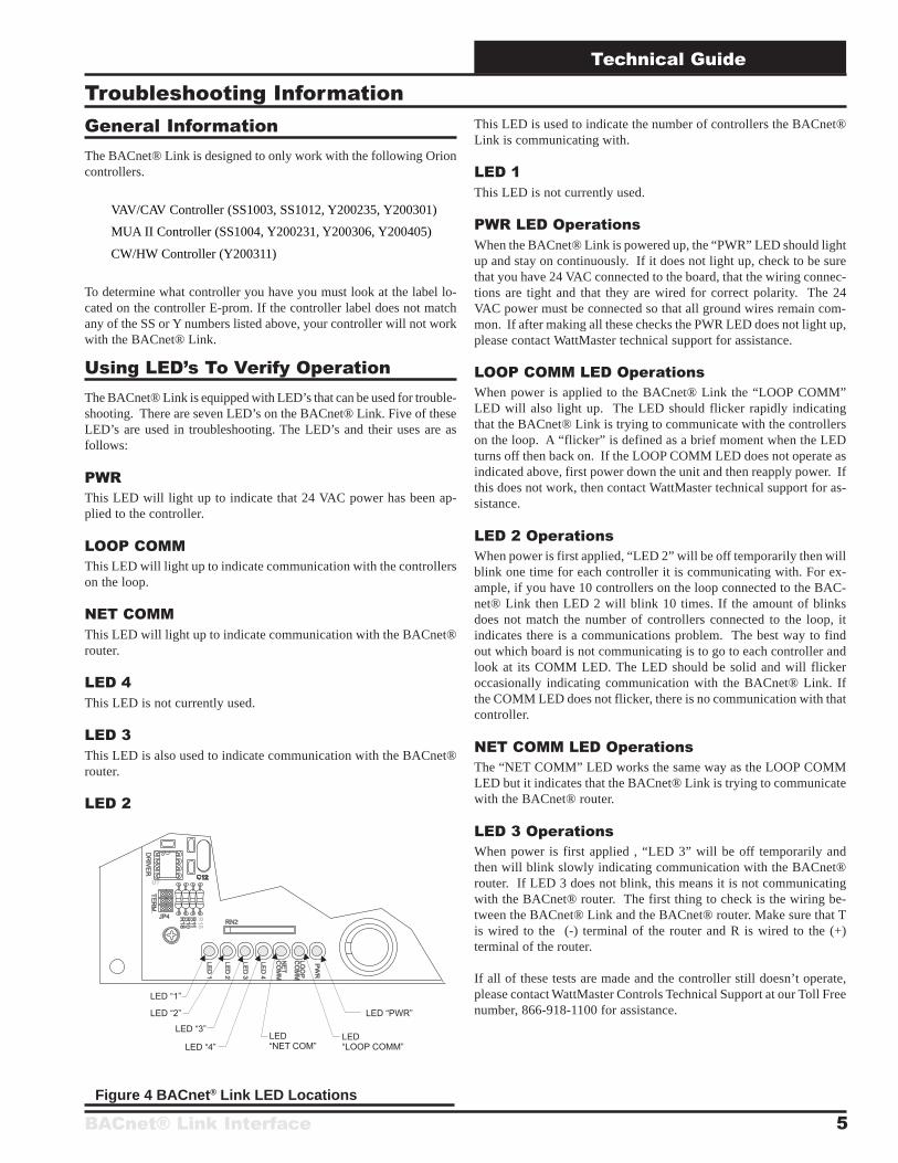
Using LED’s To Verify OperationThe BACnet® Link is equipped with LED’s that can be used for trouble-shooting. There are seven LED’s on the BACnet® Link. Five of theseLED’s are used in troubleshooting. The LED’s and their uses are asfollows:
PWRThis LED will light up to indicate that 24 VAC power has been ap-plied to the controller.
LOOP COMMThis LED will light up to indicate communication with the controllerson the loop.
NET COMMThis LED will light up to indicate communication with the BACnet®router.
LED 4This LED is not currently used.
LED 3This LED is also used to indicate communication with the BACnet®router.
LED 2
This LED is used to indicate the number of controllers the BACnet®Link is communicating with.
LED 1This LED is not currently used.
PWR LED OperationsWhen the BACnet® Link is powered up, the “PWR” LED should lightup and stay on continuously. If it does not light up, check to be surethat you have 24 VAC connected to the board, that the wiring connec-tions are tight and that they are wired for correct polarity. The 24VAC power must be connected so that all ground wires remain com-mon. If after making all these checks the PWR LED does not light up,please contact WattMaster technical support for assistance.
LOOP COMM LED OperationsWhen power is applied to the BACnet® Link the “LOOP COMM”LED will also light up. The LED should flicker rapidly indicatingthat the BACnet® Link is trying to communicate with the controllerson the loop. A “flicker” is defined as a brief moment when the LEDturns off then back on. If the LOOP COMM LED does not operate asindicated above, first power down the unit and then reapply power. Ifthis does not work, then contact WattMaster technical support for as-sistance.
LED 2 OperationsWhen power is first applied, “LED 2” will be off temporarily then willblink one time for each controller it is communicating with. For ex-ample, if you have 10 controllers on the loop connected to the BAC-net® Link then LED 2 will blink 10 times. If the amount of blinksdoes not match the number of controllers connected to the loop, itindicates there is a communications problem. The best way to findout which board is not communicating is to go to each controller andlook at its COMM LED. The LED should be solid and will flickeroccasionally indicating communication with the BACnet® Link. Ifthe COMM LED does not flicker, there is no communication with thatcontroller.
NET COMM LED OperationsThe “NET COMM” LED works the same way as the LOOP COMMLED but it indicates that the BACnet® Link is trying to communicatewith the BACnet® router.
LED 3 OperationsWhen power is first applied , “LED 3” will be off temporarily andthen will blink slowly indicating communication with the BACnet®router. If LED 3 does not blink, this means it is not communicatingwith the BACnet® router. The first thing to check is the wiring be-tween the BACnet® Link and the BACnet® router. Make sure that Tis wired to the (-) terminal of the router and R is wired to the (+)terminal of the router.
If all of these tests are made and the controller still doesn’t operate,please contact WattMaster Controls Technical Support at our Toll Freenumber, 866-918-1100 for assistance.
Troubleshooting Information
Figure 4 BACnet® Link LED Locations
Technical Guide
BACnet® Link Interface6
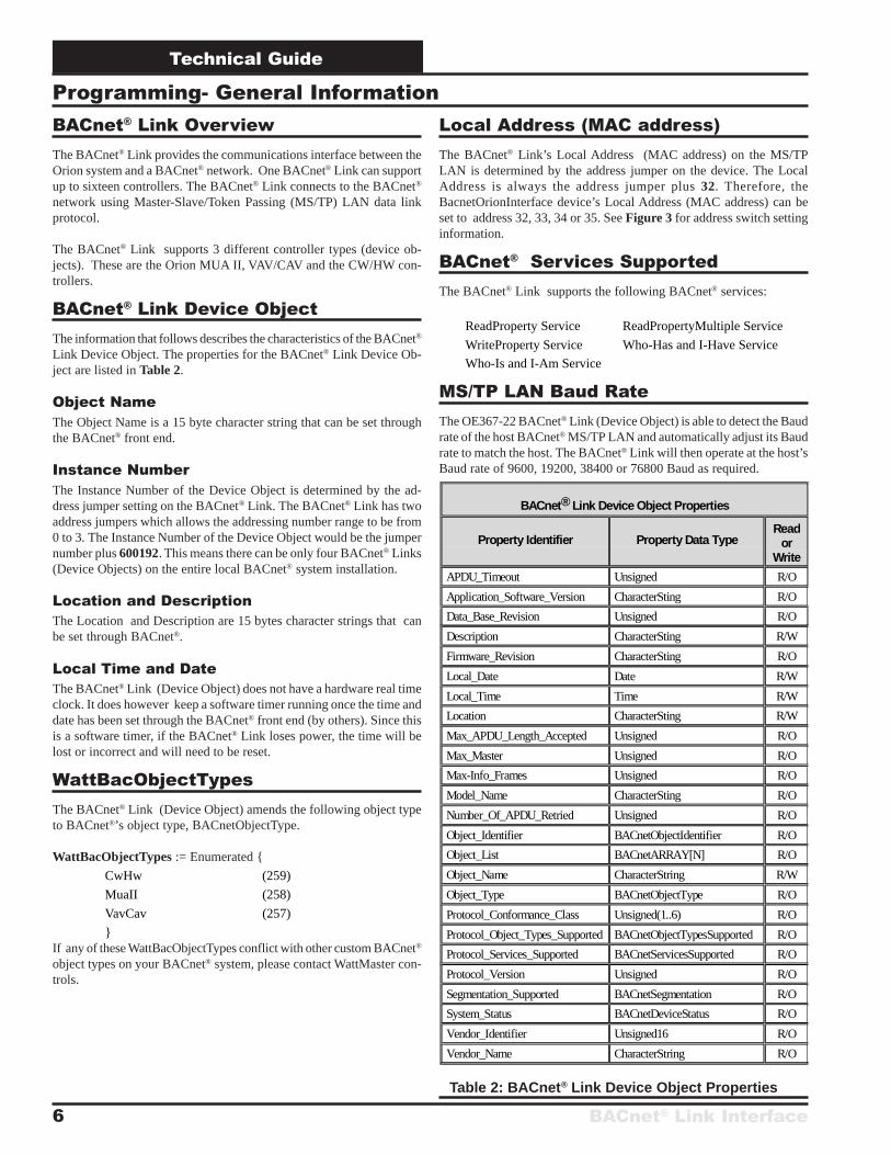
BACnet® Link OverviewThe BACnet® Link provides the communications interface between theOrion system and a BACnet® network. One BACnet® Link can supportup to sixteen controllers. The BACnet® Link connects to the BACnet®
network using Master-Slave/Token Passing (MS/TP) LAN data linkprotocol.
The BACnet® Link supports 3 different controller types (device ob-jects). These are the Orion MUA II, VAV/CAV and the CW/HW con-trollers.
BACnet® Link Device ObjectThe information that follows describes the characteristics of the BACnet®
Link Device Object. The properties for the BACnet® Link Device Ob-ject are listed in Table 2.
Object NameThe Object Name is a 15 byte character string that can be set throughthe BACnet® front end.
Instance NumberThe Instance Number of the Device Object is determined by the ad-dress jumper setting on the BACnet® Link. The BACnet® Link has twoaddress jumpers which allows the addressing number range to be from0 to 3. The Instance Number of the Device Object would be the jumpernumber plus 600192. This means there can be only four BACnet® Links(Device Objects) on the entire local BACnet® system installation.
Location and DescriptionThe Location and Description are 15 bytes character strings that canbe set through BACnet®.
Local Time and DateThe BACnet® Link (Device Object) does not have a hardware real timeclock. It does however keep a software timer running once the time anddate has been set through the BACnet® front end (by others). Since thisis a software timer, if the BACnet® Link loses power, the time will belost or incorrect and will need to be reset.
WattBacObjectTypesThe BACnet® Link (Device Object) amends the following object typeto BACnet®’s object type, BACnetObjectType.
WattBacObjectTypes := Enumerated {
CwHw (259)
MuaII (258)
VavCav (257)
}If any of these WattBacObjectTypes conflict with other custom BACnet®
object types on your BACnet® system, please contact WattMaster con-trols.
Programming- General InformationLocal Address (MAC address)The BACnet® Link’s Local Address (MAC address) on the MS/TPLAN is determined by the address jumper on the device. The LocalAddress is always the address jumper plus 32. Therefore, theBacnetOrionInterface device’s Local Address (MAC address) can beset to address 32, 33, 34 or 35. See Figure 3 for address switch settinginformation.
BACnet® Services SupportedThe BACnet® Link supports the following BACnet® services:
ReadProperty Service ReadPropertyMultiple Service
WriteProperty Service Who-Has and I-Have Service
Who-Is and I-Am Service
MS/TP LAN Baud RateThe OE367-22 BACnet® Link (Device Object) is able to detect the Baudrate of the host BACnet® MS/TP LAN and automatically adjust its Baudrate to match the host. The BACnet® Link will then operate at the host’sBaud rate of 9600, 19200, 38400 or 76800 Baud as required.
Table 2: BACnet® Link Device Object Properties
BACnet® Link Device Object Properties
Property Identifier Property Data TypeRead
orWrite
APDU_Timeout Unsigned R/O
Application_Software_Version CharacterSting R/O
Data_Base_Revision Unsigned R/O
Description CharacterSting R/W
Firmware_Revision CharacterSting R/O
Local_Date Date R/W
Local_Time Time R/W
Location CharacterSting R/W
Max_APDU_Length_Accepted Unsigned R/O
Max_Master Unsigned R/O
Max-Info_Frames Unsigned R/O
Model_Name CharacterSting R/O
Number_Of_APDU_Retried Unsigned R/O
Object_Identifier BACnetObjectIdentifier R/O
Object_List BACnetARRAY[N] R/O
Object_Name CharacterString R/W
Object_Type BACnetObjectType R/O
Protocol_Conformance_Class Unsigned(1..6) R/O
Protocol_Object_Types_Supported BACnetObjectTypesSupported R/O
Protocol_Services_Supported BACnetServicesSupported R/O
Protocol_Version Unsigned R/O
Segmentation_Supported BACnetSegmentation R/O
System_Status BACnetDeviceStatus R/O
Vendor_Identifier Unsigned16 R/O
Vendor_Name CharacterString R/O
BACnet® Link Interface
Technical Guide
7
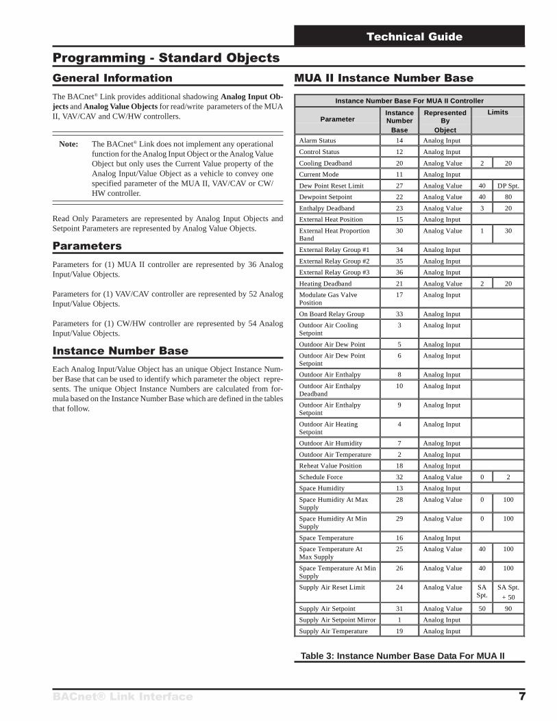
Programming - Standard ObjectsGeneral InformationThe BACnet® Link provides additional shadowing Analog Input Ob-jects and Analog Value Objects for read/write parameters of the MUAII, VAV/CAV and CW/HW controllers.
Note: The BACnet® Link does not implement any operationalfunction for the Analog Input Object or the Analog ValueObject but only uses the Current Value property of theAnalog Input/Value Object as a vehicle to convey onespecified parameter of the MUA II, VAV/CAV or CW/HW controller.
Read Only Parameters are represented by Analog Input Objects andSetpoint Parameters are represented by Analog Value Objects.
ParametersParameters for (1) MUA II controller are represented by 36 AnalogInput/Value Objects.
Parameters for (1) VAV/CAV controller are represented by 52 AnalogInput/Value Objects.
Parameters for (1) CW/HW controller are represented by 54 AnalogInput/Value Objects.
Instance Number BaseEach Analog Input/Value Object has an unique Object Instance Num-ber Base that can be used to identify which parameter the object repre-sents. The unique Object Instance Numbers are calculated from for-mula based on the Instance Number Base which are defined in the tablesthat follow.
MUA II Instance Number Base
Instance Number Base For MUA II Controller
ParameterInstanceNumber
Base
RepresentedBy
Object
Limits
Alarm Status 14 Analog Input
Control Status 12 Analog Input
Cooling Deadband 20 Analog Value 2 20
Current Mode 11 Analog Input
Dew Point Reset Limit 27 Analog Value 40 DP Spt.
Dewpoint Setpoint 22 Analog Value 40 80
Enthalpy Deadband 23 Analog Value 3 20
External Heat Position 15 Analog Input
External Heat ProportionBand
30 Analog Value 1 30
External Relay Group #1 34 Analog Input
External Relay Group #2 35 Analog Input
External Relay Group #3 36 Analog Input
Heating Deadband 21 Analog Value 2 20
Modulate Gas ValvePosition
17 Analog Input
On Board Relay Group 33 Analog Input
Outdoor Air CoolingSetpoint
3 Analog Input
Outdoor Air Dew Point 5 Analog Input
Outdoor Air Dew PointSetpoint
6 Analog Input
Outdoor Air Enthalpy 8 Analog Input
Outdoor Air EnthalpyDeadband
10 Analog Input
Outdoor Air EnthalpySetpoint
9 Analog Input
Outdoor Air HeatingSetpoint
4 Analog Input
Outdoor Air Humidity 7 Analog Input
Outdoor Air Temperature 2 Analog Input
Reheat Value Position 18 Analog Input
Schedule Force 32 Analog Value 0 2
Space Humidity 13 Analog Input
Space Humidity At MaxSupply
28 Analog Value 0 100
Space Humidity At MinSupply
29 Analog Value 0 100
Space Temperature 16 Analog Input
Space Temperature AtMax Supply
25 Analog Value 40 100
Space Temperature At MinSupply
26 Analog Value 40 100
Supply Air Reset Limit 24 Analog Value SASpt.
SA Spt.
+ 50
Supply Air Setpoint 31 Analog Value 50 90
Supply Air Setpoint Mirror 1 Analog Input
Supply Air Temperature 19 Analog Input
Table 3: Instance Number Base Data For MUA II
Technical Guide
BACnet® Link Interface8
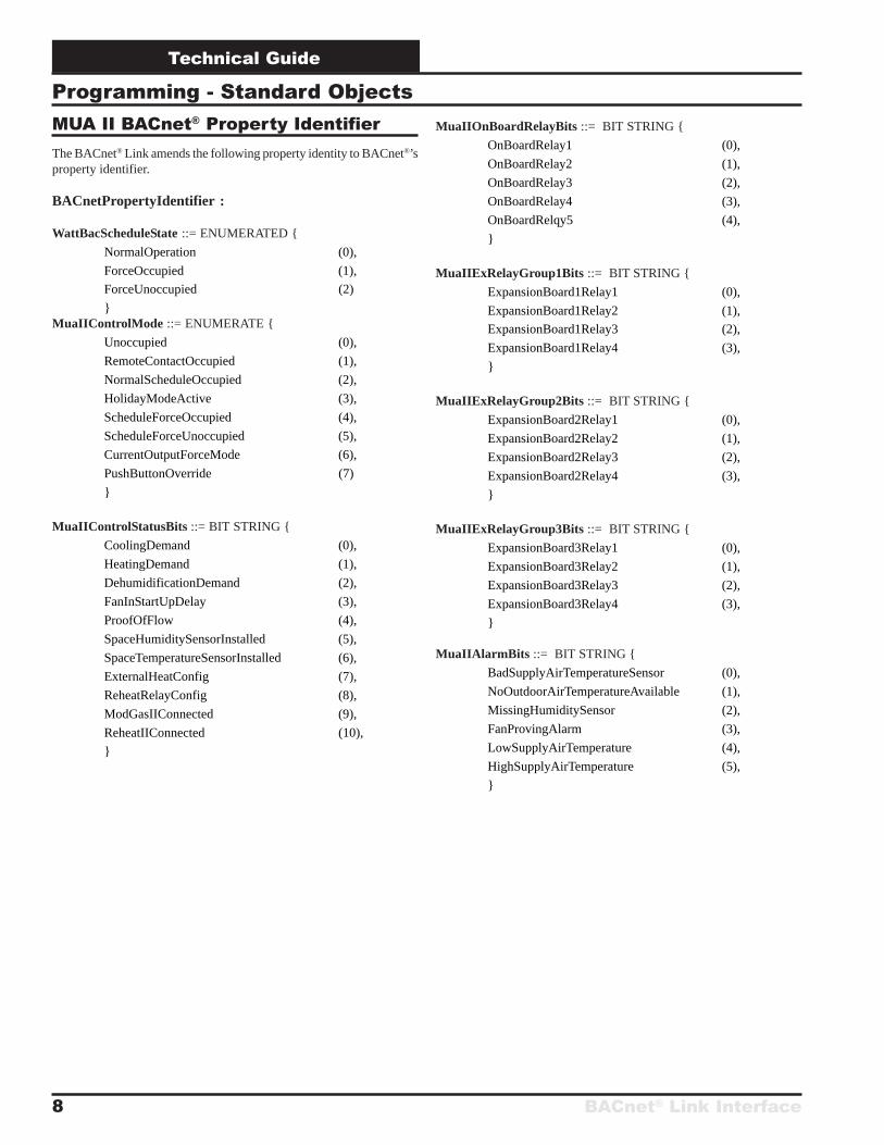
MUA II BACnet® Property IdentifierThe BACnet® Link amends the following property identity to BACnet®’sproperty identifier.
BACnetPropertyIdentifier :
WattBacScheduleState ::= ENUMERATED {
NormalOperation (0),
ForceOccupied (1),
ForceUnoccupied (2)
}MuaIIControlMode ::= ENUMERATE {
Unoccupied (0),
RemoteContactOccupied (1),
NormalScheduleOccupied (2),
HolidayModeActive (3),
ScheduleForceOccupied (4),
ScheduleForceUnoccupied (5),
CurrentOutputForceMode (6),
PushButtonOverride (7)
}
MuaIIControlStatusBits ::= BIT STRING {
CoolingDemand (0),
HeatingDemand (1),
DehumidificationDemand (2),
FanInStartUpDelay (3),
ProofOfFlow (4),
SpaceHumiditySensorInstalled (5),
SpaceTemperatureSensorInstalled (6),
ExternalHeatConfig (7),
ReheatRelayConfig (8),
ModGasIIConnected (9),
ReheatIIConnected (10),
}
MuaIIOnBoardRelayBits ::= BIT STRING {
OnBoardRelay1 (0),
OnBoardRelay2 (1),
OnBoardRelay3 (2),
OnBoardRelay4 (3),
OnBoardRelqy5 (4),
}
MuaIIExRelayGroup1Bits ::= BIT STRING {
ExpansionBoard1Relay1 (0),
ExpansionBoard1Relay2 (1),
ExpansionBoard1Relay3 (2),
ExpansionBoard1Relay4 (3),
}
MuaIIExRelayGroup2Bits ::= BIT STRING {
ExpansionBoard2Relay1 (0),
ExpansionBoard2Relay2 (1),
ExpansionBoard2Relay3 (2),
ExpansionBoard2Relay4 (3),
}
MuaIIExRelayGroup3Bits ::= BIT STRING {
ExpansionBoard3Relay1 (0),
ExpansionBoard3Relay2 (1),
ExpansionBoard3Relay3 (2),
ExpansionBoard3Relay4 (3),
}
MuaIIAlarmBits ::= BIT STRING {
BadSupplyAirTemperatureSensor (0),
NoOutdoorAirTemperatureAvailable (1),
MissingHumiditySensor (2),
FanProvingAlarm (3),
LowSupplyAirTemperature (4),
HighSupplyAirTemperature (5),
}
Programming - Standard Objects
BACnet® Link Interface
Technical Guide
9
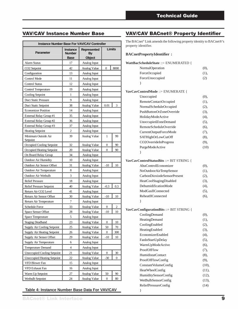
VAV/CAV Instance Number Base VAV/CAV BACnet® Property IdentifierThe BACnet® Link amends the following property identity to BACnet®’sproperty identifier.
BACnetPropertyIdentifier :
WattBacScheduleState ::= ENUMERATED {
NormalOperation (0),
ForceOccupied (1),
ForceUnoccupied (2)
}
VavCavControlMode ::= ENUMERATE {
Unoccupied (0),
RemoteContactOccupied (1),
NormalScheduleOccupied (2),
PushButtonOrZoneOverride (3),
HolidayModeActive (4),
UnoccupiedZoneDemand (5),
RemoteScheduleOverride (6),
CurrentOutputForceMode (7),
SATHighOrLowCutOff (8),
CO2OverrideInProgress (9),
PurgeModeActive (10)
}
VavCavControlStatusBits ::= BIT STRING {
AhuControlEconomizer (0),
NoOutdoorAirTempSensor (1),
CarbonDioxiodeSensorPresent (2),
HeatCoolStagingDisabled (3),
DehumidificationMode (4),
ModGasIIConnected (5),
ReheatIIConnected (6),
}
VavCavConfigurationBits ::= BIT STRING {
CoolingDemand (0),
HeatingDemand (1),
CoolingEnabled (2),
HeatingEnabled (3),
EconomizerEnabled (4),
FanInStartUpDelay (5),
WarmUpModeActive (6),
ProofOfFlow (7),
HumidistatContact (8),
ProofOfFlowConfig (9),
ConstantVolumeConfig (10),
HeatWheelConfig (11),
HumiditySensorConfig (12),
WetBulbSensorConfig (13),
ReliefPressureConfig (14)
}
Instance Number Base For VAV/CAV Controller
ParameterInstanceNumber
Base
RepresentedBy
Object
Limits
Alarm Status 17 Analog Input
CO2 Setpoint 42 Analog Value 0 8000
Configuration 13 Analog Input
Control Mode 11 Analog Input
Control Status 12 Analog Input
Control Temperature 19 Analog Input
Cooling Setpoint 1 Analog Input
Duct Static Pressure 9 Analog Input
Duct Static Setpoint 38 Analog Value 0.01 3
Economizer Position 14 Analog Input
External Relay Group #1 35 Analog Input
External Relay Group #2 36 Analog Input
External Relay Group #3 37 Analog Input
Heating Setpoint 2 Analog Input
Minimum Outside AirSetpoint
39 Analog Value 1 99
Occupied Cooling Setpoint 32 Analog Value 0 90
Occupied Heating Setpoint 20 Analog Value 0 90
On Board Relay Group 34 Analog Input
Outdoor Air Humidity 10 Analog Input
Outdoor Air Sensor Offset 31 Analog Value -10 10
Outdoor Air Temperature 8 Analog Input
Outdoor Air Wetbulb 3 Analog Input
Relief Pressure 18 Analog Input
Relief Pressure Setpoint 40 Analog Value -0.3 0.3
Return Air CO2 Level 41 Analog Input
Return Air Sensor Offset 30 Analog Value -10 10
Return Air Temperature 7 Analog Input
Schedule Force 33 Analog Value 0 2
Space Sensor Offset 28 Analog Value -10 10
Space Temperature 5 Analog Input
Staging Deadband 23 Analog Value 0 10
Supply Air Cooling Setpoint 25 Analog Value 50 70
Supply Air Heating Setpoint 26 Analog Value 0 300
Supply Air Sensor Offset 29 Analog Value -10 10
Supply Air Temperature 6 Analog Input
Temperature Demand 4 Analog Input
Unoccupied Cooling Setpoint 21 Analog Value 0 30
Unoccupied Heating Setpoint 22 Analog Value -30 0
VFD Blower Fan 15 Analog Input
VFD Exhaust Fan 16 Analog Input
Warm Up Setpoint 27 Analog Value 50 90
Wetbulb Setpoint 24 Analog Value 0 80
Table 4: Instance Number Base Data For VAV/CAV
Technical Guide
BACnet® Link Interface10
Programming - Standard Objects
VavCavOnBoardRelayBits ::= BIT STRING {
OnBoardRelay1 (0),
OnBoardRelay2 (1),
OnBoardRelay3 (2),
OnBoardRelay4 (3),
OnBoardRelqy5 (4),
}
VavCavExRelayGroup1Bits ::= BIT STRING {
ExpansionBoard1Relay1 (0),
ExpansionBoard1Relay2 (1),
ExpansionBoard1Relay3 (2),
ExpansionBoard1Relay4 (3),
ExpansionBoard2Relay1 (4),
ExpansionBoard2Relay2 (5),
ExpansionBoard2Relay3 (6),
ExpansionBoard2Relay4 (7),
}
VavCavExRelayGroup2Bits ::= BIT STRING {
ExpansionBoard3Relay1 (0),
ExpansionBoard3Relay2 (1),
ExpansionBoard3Relay3 (2),
ExpansionBoard3Relay4 (3),
}
VavCavExRelayGroup3Bits ::= BIT STRING {
ExpansionBoard4Relay1 (0),
ExpansionBoard4Relay2 (1),
ExpansionBoard4Relay3 (2),
ExpansionBoard4Relay4 (3),
}
VavCavAlarmBits ::= BIT STRING {
BadSpaceTempSensor (0),
FanProvingAlarm (1),
MechanicalCoolingAlarm (2),
MechanicalHeatingAlarm (3),
DirtyFilterDetected (4),
HighSpaceTempAlarm (5),
LowSpaceTempAlarm (6),
}
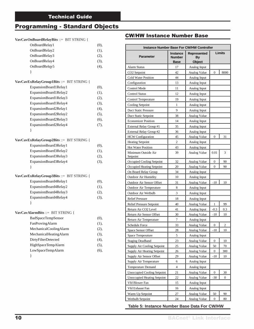
CW/HW Instance Number Base
Instance Number Base For CW/HW Controller
ParameterInstanceNumber
Base
RepresentedBy
Object
Limits
Alarm Status 17 Analog Input
CO2 Setpoint 42 Analog Value 0 8000
Cold Water Position 44 Analog Input
Configuration 13 Analog Input
Control Mode 11 Analog Input
Control Status 12 Analog Input
Control Temperature 19 Analog Input
Cooling Setpoint 1 Analog Input
Duct Static Pressure 9 Analog Input
Duct Static Setpoint 38 Analog Value
Economizer Position 14 Analog Input
External Relay Group #1 35 Analog Input
External Relay Group #2 36 Analog Input
HCW Configuration 45 Analog Value 0 31
Heating Setpoint 2 Analog Input
Hot Water Position 43 Analog Input
Minimum Outside AirSetpoint
39 Analog Value 0.01 3
Occupied Cooling Setpoint 32 Analog Value 0 90
Occupied Heating Setpoint 20 Analog Value 0 90
On Board Relay Group 34 Analog Input
Outdoor Air Humidity 10 Analog Input
Outdoor Air Sensor Offset 31 Analog Value -10 10
Outdoor Air Temperature 8 Analog Input
Outdoor Air Wetbulb 3 Analog Input
Relief Pressure 18 Analog Input
Relief Pressure Setpoint 40 Analog Value 1 99
Return Air CO2 Level 41 Analog Input -0.3 0.3
Return Air Sensor Offset 30 Analog Value -10 10
Return Air Temperature 7 Analog Input
Schedule Force 33 Analog Value 0 2
Space Sensor Offset 28 Analog Value -10 10
Space Temperature 5 Analog Input
Staging Deadband 23 Analog Value 0 10
Supply Air Cooling Setpoint 25 Analog Value 50 70
Supply Air Heating Setpoint 26 Analog Value 0 300
Supply Air Sensor Offset 29 Analog Value -10 10
Supply Air Temperature 6 Analog Input
Temperature Demand 4 Analog Input
Unoccupied Cooling Setpoint 21 Analog Value 0 30
Unoccupied Heating Setpoint 22 Analog Value -30 0
Vfd Blower Fan 15 Analog Input
Vfd Exhaust Fan 16 Analog Input
Warm Up Setpoint 27 Analog Value 50 90
Wetbulb Setpoint 24 Analog Value 0 80
Table 5: Instance Number Base Data For CW/HW
BACnet® Link Interface
Technical Guide
11
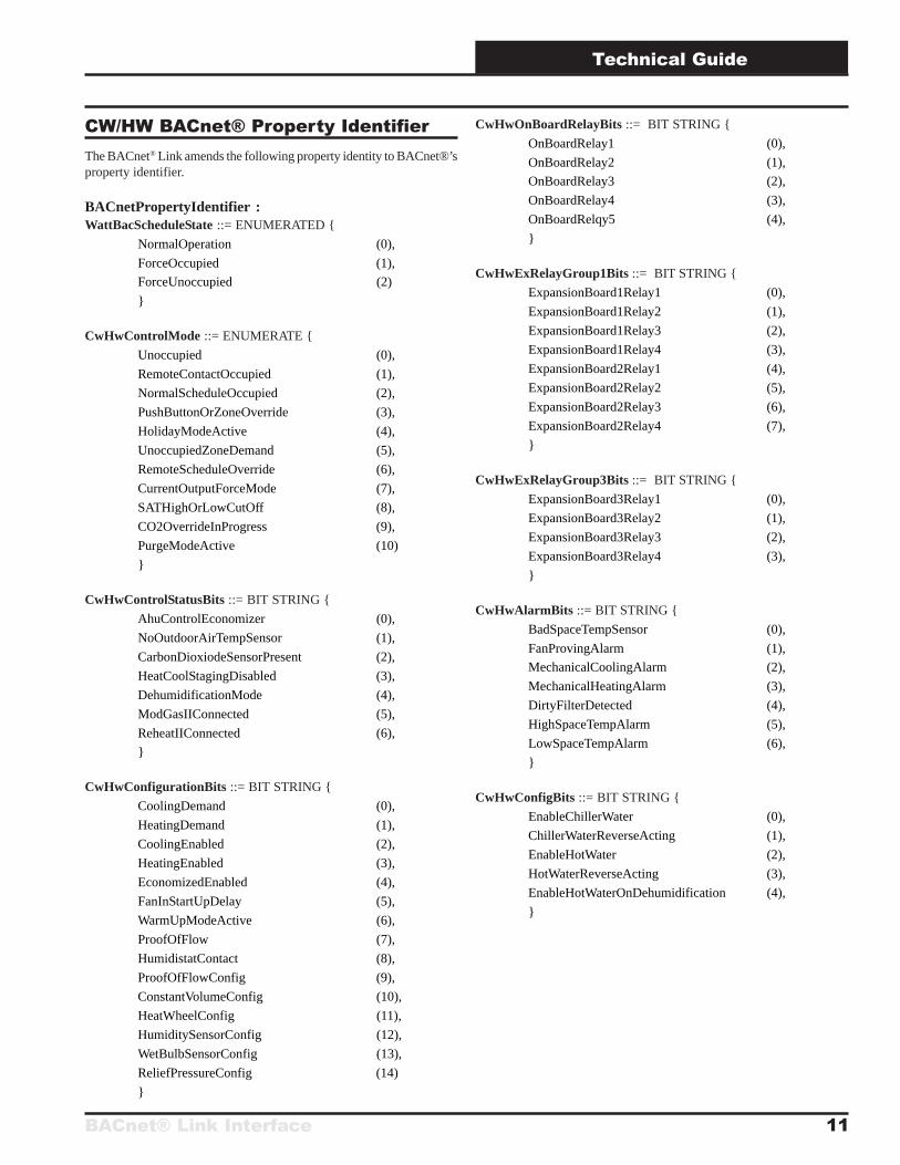
CW/HW BACnet® Property IdentifierThe BACnet® Link amends the following property identity to BACnet®’sproperty identifier.
BACnetPropertyIdentifier :WattBacScheduleState ::= ENUMERATED {
NormalOperation (0),
ForceOccupied (1),
ForceUnoccupied (2)
}
CwHwControlMode ::= ENUMERATE {
Unoccupied (0),
RemoteContactOccupied (1),
NormalScheduleOccupied (2),
PushButtonOrZoneOverride (3),
HolidayModeActive (4),
UnoccupiedZoneDemand (5),
RemoteScheduleOverride (6),
CurrentOutputForceMode (7),
SATHighOrLowCutOff (8),
CO2OverrideInProgress (9),
PurgeModeActive (10)
}
CwHwControlStatusBits ::= BIT STRING {
AhuControlEconomizer (0),
NoOutdoorAirTempSensor (1),
CarbonDioxiodeSensorPresent (2),
HeatCoolStagingDisabled (3),
DehumidificationMode (4),
ModGasIIConnected (5),
ReheatIIConnected (6),
}
CwHwConfigurationBits ::= BIT STRING {
CoolingDemand (0),
HeatingDemand (1),
CoolingEnabled (2),
HeatingEnabled (3),
EconomizedEnabled (4),
FanInStartUpDelay (5),
WarmUpModeActive (6),
ProofOfFlow (7),
HumidistatContact (8),
ProofOfFlowConfig (9),
ConstantVolumeConfig (10),
HeatWheelConfig (11),
HumiditySensorConfig (12),
WetBulbSensorConfig (13),
ReliefPressureConfig (14)
}
CwHwOnBoardRelayBits ::= BIT STRING {
OnBoardRelay1 (0),
OnBoardRelay2 (1),
OnBoardRelay3 (2),
OnBoardRelay4 (3),
OnBoardRelqy5 (4),
}
CwHwExRelayGroup1Bits ::= BIT STRING {
ExpansionBoard1Relay1 (0),
ExpansionBoard1Relay2 (1),
ExpansionBoard1Relay3 (2),
ExpansionBoard1Relay4 (3),
ExpansionBoard2Relay1 (4),
ExpansionBoard2Relay2 (5),
ExpansionBoard2Relay3 (6),
ExpansionBoard2Relay4 (7),
}
CwHwExRelayGroup3Bits ::= BIT STRING {
ExpansionBoard3Relay1 (0),
ExpansionBoard3Relay2 (1),
ExpansionBoard3Relay3 (2),
ExpansionBoard3Relay4 (3),
}
CwHwAlarmBits ::= BIT STRING {
BadSpaceTempSensor (0),
FanProvingAlarm (1),
MechanicalCoolingAlarm (2),
MechanicalHeatingAlarm (3),
DirtyFilterDetected (4),
HighSpaceTempAlarm (5),
LowSpaceTempAlarm (6),
}
CwHwConfigBits ::= BIT STRING {
EnableChillerWater (0),
ChillerWaterReverseActing (1),
EnableHotWater (2),
HotWaterReverseActing (3),
EnableHotWaterOnDehumidification (4),
}
Technical Guide
BACnet® Link Interface12
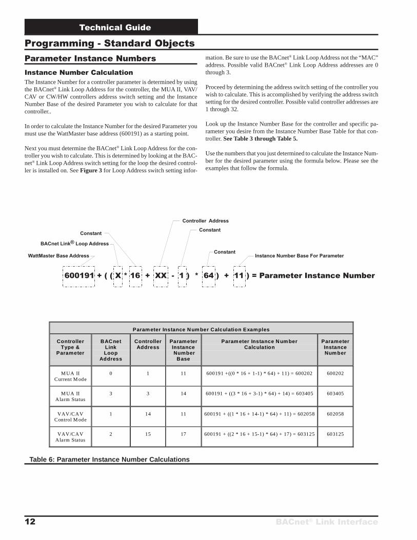
Programming - Standard ObjectsParameter Instance NumbersInstance Number CalculationThe Instance Number for a controller parameter is determined by usingthe BACnet® Link Loop Address for the controller, the MUA II, VAV/CAV or CW/HW controllers address switch setting and the InstanceNumber Base of the desired Parameter you wish to calculate for thatcontroller..
In order to calculate the Instance Number for the desired Parameter youmust use the WattMaster base address (600191) as a starting point.
Next you must determine the BACnet® Link Loop Address for the con-troller you wish to calculate. This is determined by looking at the BAC-net® Link Loop Address switch setting for the loop the desired control-ler is installed on. See Figure 3 for Loop Address switch setting infor-
mation. Be sure to use the BACnet® Link Loop Address not the “MAC”address. Possible valid BACnet® Link Loop Address addresses are 0through 3.
Proceed by determining the address switch setting of the controller youwish to calculate. This is accomplished by verifying the address switchsetting for the desired controller. Possible valid controller addresses are1 through 32.
Look up the Instance Number Base for the controller and specific pa-rameter you desire from the Instance Number Base Table for that con-troller. See Table 3 through Table 5.
Use the numbers that you just determined to calculate the Instance Num-ber for the desired parameter using the formula below. Please see theexamples that follow the formula.
Table 6: Parameter Instance Number Calculations
Param eter Instance N um ber Calculation Examples
ControllerType &
Parameter
BACnetLinkLoop
Address
ControllerAddress
ParameterInstance Number
Base
Param eter Instance N um berCalculation
ParameterInstanceNum ber
M UA IICurrent M ode
0 1 11 600191 +((0 * 16 + 1-1) * 64) + 11) = 600202 600202
M UA IIAlarm Status
3 3 14 600191 + ((3 * 16 + 3-1) * 64) + 14) = 603405 603405
VAV/CAVControl M ode
1 14 11 600191 + ((1 * 16 + 14-1) * 64) + 11) = 602058 602058
VAV/CAVAlarm Status
2 15 17 600191 + ((2 * 16 + 15-1) * 64) + 17) = 603125 603125
BACnet® Link Interface
Technical Guide
13
Programming - Proprietary ObjectsBACnet® Link OverviewThe BACnet® Link provides the communications interface between theOrion system and a BACnet® network. One BACnet® Link can supportup to sixteen controllers. The BACnet® Link connects to the BACnet®
network using Master-Slave/Token Passing (MS/TP) LAN data linkprotocol. Complete information regarding the BACnet® Link deviceobject can be found on pages 3 through 5 of this manual.
The BACnet® Link supports 3 different controller types (objects). Theseare the Orion MUA II, VAV/CAV and the CW/HW controllers. Thesections that follow describe the properties for each controller (deviceobject).
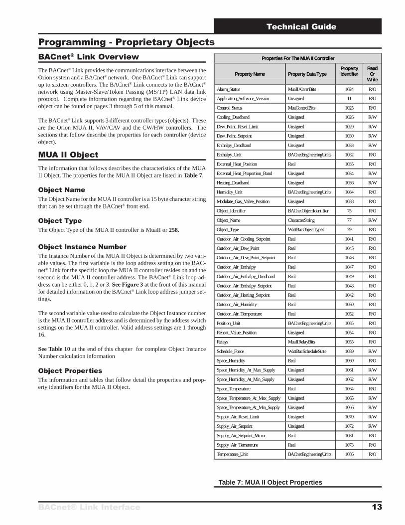
MUA II ObjectThe information that follows describes the characteristics of the MUAII Object. The properties for the MUA II Object are listed in Table 7.
Object NameThe Object Name for the MUA II controller is a 15 byte character stringthat can be set through the BACnet® front end.
Object TypeThe Object Type of the MUA II controller is MuaII or 258.
Object Instance NumberThe Instance Number of the MUA II Object is determined by two vari-able values. The first variable is the loop address setting on the BAC-net® Link for the specific loop the MUA II controller resides on and thesecond is the MUA II controller address. The BACnet® Link loop ad-dress can be either 0, 1, 2 or 3. See Figure 3 at the front of this manualfor detailed information on the BACnet® Link loop address jumper set-tings.
The second variable value used to calculate the Object Instance numberis the MUA II controller address and is determined by the address switchsettings on the MUA II controller. Valid address settings are 1 through16.
See Table 10 at the end of this chapter for complete Object InstanceNumber calculation information
Object PropertiesThe information and tables that follow detail the properties and prop-erty identifiers for the MUA II Object.
Properties For The MUA II Controller
Property Name Property Data TypePropertyIdentifier
ReadOr
Write
Alarm_Status MuaIIAlarmBits 1024 R/O
Application_Software_Version Unsigned 11 R/O
Control_Status MuaControlBits 1025 R/O
Cooling_Deadband Unsigned 1026 R/W
Dew_Point_Reset_Limit Unsigned 1029 R/W
Dew_Point_Setpoint Unsigned 1030 R/W
Enthalpy_Deadband Unsigned 1033 R/W
Enthalpy_Unit BACnetEngineeringUnits 1082 R/O
External_Heat_Position Real 1035 R/O
External_Heat_Proportion_Band Unsigned 1034 R/W
Heating_Deadband Unsigned 1036 R/W
Humidity_Unit BACnetEngineeringUnits 1084 R/O
Modulate_Gas_Valve_Position Unsigned 1038 R/O
Object_Identifier BACnetObjectIdentifier 75 R/O
Object_Name CharacterString 77 R/W
Object_Type WattBacObjectTypes 79 R/O
Outdoor_Air_Cooling_Setpoint Real 1041 R/O
Outdoor_Air_Dew_Point Real 1045 R/O
Outdoor_Air_Dew_Point_Setpoint Real 1046 R/O
Outdoor_Air_Enthalpy Real 1047 R/O
Outdoor_Air_Enthalpy_Deadband Real 1049 R/O
Outdoor_Air_Enthalpy_Setpoint Real 1048 R/O
Outdoor_Air_Heating_Setpoint Real 1042 R/O
Outdoor_Air_Humidity Real 1050 R/O
Outdoor_Air_Temperature Real 1052 R/O
Position_Unit BACnetEngineeringUnits 1085 R/O
Reheat_Value_Position Unsigned 1054 R/O
Relays MuaIIRelayBits 1055 R/O
Schedule_Force WattBacScheduleState 1059 R/W
Space_Humidity Real 1060 R/O
Space_Humidity_At_Max_Supply Unsigned 1061 R/W
Space_Humidity_At_Min_Supply Unsigned 1062 R/W
Space_Temperature Real 1064 R/O
Space_Temperature_At_Max_Supply Unsigned 1065 R/W
Space_Temperature_At_Min_Supply Unsigned 1066 R/W
Supply_Air_Reset_Limit Unsigned 1070 R/W
Supply_Air_Setpoint Unsigned 1072 R/W
Supply_Air_Setpoint_Mirror Real 1081 R/O
Supply_Air_Temerature Real 1073 R/O
Temperature_Unit BACnetEngineeringUnits 1086 R/O
Table 7: MUA II Object Properties
Technical Guide
BACnet® Link Interface14
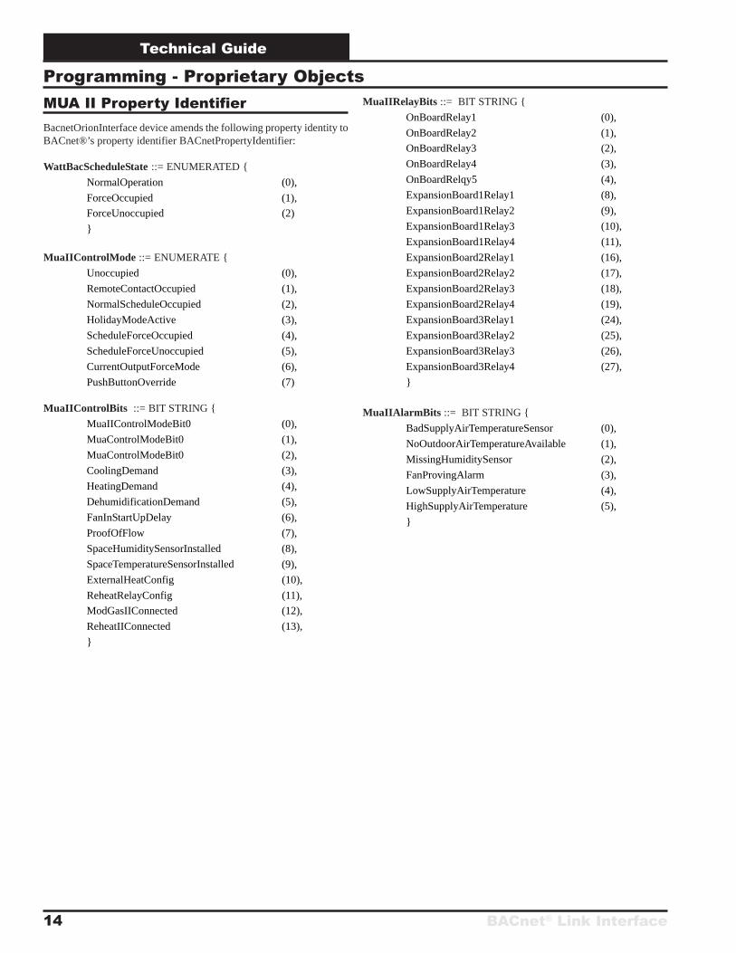
Programming - Proprietary ObjectsMUA II Property IdentifierBacnetOrionInterface device amends the following property identity toBACnet®’s property identifier BACnetPropertyIdentifier:
WattBacScheduleState ::= ENUMERATED {
NormalOperation (0),
ForceOccupied (1),
ForceUnoccupied (2)
}
MuaIIControlMode ::= ENUMERATE {
Unoccupied (0),
RemoteContactOccupied (1),
NormalScheduleOccupied (2),
HolidayModeActive (3),
ScheduleForceOccupied (4),
ScheduleForceUnoccupied (5),
CurrentOutputForceMode (6),
PushButtonOverride (7)
MuaIIControlBits ::= BIT STRING {
MuaIIControlModeBit0 (0),
MuaControlModeBit0 (1),
MuaControlModeBit0 (2),
CoolingDemand (3),
HeatingDemand (4),
DehumidificationDemand (5),
FanInStartUpDelay (6),
ProofOfFlow (7),
SpaceHumiditySensorInstalled (8),
SpaceTemperatureSensorInstalled (9),
ExternalHeatConfig (10),
ReheatRelayConfig (11),
ModGasIIConnected (12),
ReheatIIConnected (13),
}
MuaIIRelayBits ::= BIT STRING {
OnBoardRelay1 (0),
OnBoardRelay2 (1),
OnBoardRelay3 (2),
OnBoardRelay4 (3),
OnBoardRelqy5 (4),
ExpansionBoard1Relay1 (8),
ExpansionBoard1Relay2 (9),
ExpansionBoard1Relay3 (10),
ExpansionBoard1Relay4 (11),
ExpansionBoard2Relay1 (16),
ExpansionBoard2Relay2 (17),
ExpansionBoard2Relay3 (18),
ExpansionBoard2Relay4 (19),
ExpansionBoard3Relay1 (24),
ExpansionBoard3Relay2 (25),
ExpansionBoard3Relay3 (26),
ExpansionBoard3Relay4 (27),
}
MuaIIAlarmBits ::= BIT STRING {
BadSupplyAirTemperatureSensor (0),
NoOutdoorAirTemperatureAvailable (1),
MissingHumiditySensor (2),
FanProvingAlarm (3),
LowSupplyAirTemperature (4),
HighSupplyAirTemperature (5),
}
BACnet® Link Interface
Technical Guide
15
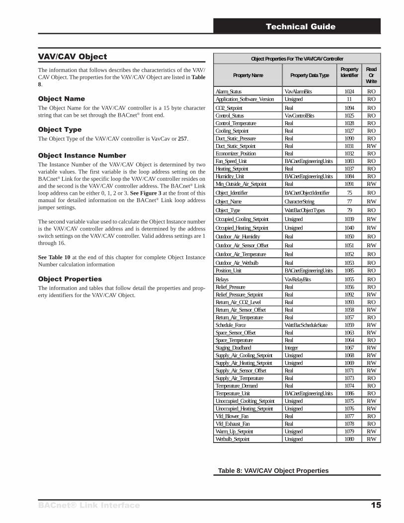
Object Properties For The VAV/CAV Controller
Property Name Property Data TypePropertyIdentifier
ReadOr
Write
Alarm_Status VavAlarmBits 1024 R/OApplication_Software_Version Unsigned 11 R/O
CO2_Setpoint Real 1094 R/OControl_Status VavControlBits 1025 R/OControl_Temperature Real 1028 R/OCooling_Setpoint Real 1027 R/ODuct_Static_Pressure Real 1090 R/ODuct_Static_Setpoint Real 1031 R/WEconomizer_Position Real 1032 R/OFan_Speed_Unit BACnetEngineeringUnits 1083 R/OHeating_Setpoint Real 1037 R/OHumidity_Unit BACnetEngineeringUnits 1084 R/OMin_Outside_Air_Setpoint Real 1091 R/W
Object_Identifier BACnetObjectIdentifier 75 R/O
Object_Name CharacterString 77 R/W
Object_Type WattBacObjectTypes 79 R/O
Occupied_Cooling_Setpoint Unsigned 1039 R/W
Occupied_Heating_Setpoint Unsigned 1040 R/W
Outdoor_Air_Humidity Real 1050 R/O
Outdoor_Air_Sensor_Offset Real 1051 R/W
Outdoor_Air_Temperature Real 1052 R/O
Outdoor_Air_Wetbulb Real 1053 R/OPosition_Unit BACnetEngineeringUnits 1085 R/O
Relays VavRelayBits 1055 R/ORelief_Pressure Real 1056 R/ORelief_Pressure_Setpoint Real 1092 R/WReturn_Air_CO2_Level Real 1093 R/OReturn_Air_Sensor_Offset Real 1058 R/WReturn_Air_Temperature Real 1057 R/OSchedule_Force WattBacScheduleState 1059 R/WSpace_Sensor_Offset Real 1063 R/WSpace_Temperature Real 1064 R/OStaging_Deadband Integer 1067 R/WSupply_Air_Cooling_Setpoint Unsigned 1068 R/WSupply_Air_Heating_Setpoint Unsigned 1069 R/WSupply_Air_Sensor_Offset Real 1071 R/WSupply_Air_Temperature Real 1073 R/OTemperature_Demand Real 1074 R/OTemperature_Unit BACnetEngineeringUnits 1086 R/OUnoccupied_Coolting_Setpoint Unsigned 1075 R/WUnoccupied_Heating_Setpoint Unsigned 1076 R/WVfd_Blower_Fan Real 1077 R/OVfd_Exhaust_Fan Real 1078 R/OWarm_Up_Setpoint Unsigned 1079 R/WWetbulb_Setpoint Unsigned 1080 R/W
Table 8: VAV/CAV Object Properties
VAV/CAV ObjectThe information that follows describes the characteristics of the VAV/CAV Object. The properties for the VAV/CAV Object are listed in Table8.
Object NameThe Object Name for the VAV/CAV controller is a 15 byte characterstring that can be set through the BACnet® front end.
Object TypeThe Object Type of the VAV/CAV controller is VavCav or 257.
Object Instance NumberThe Instance Number of the VAV/CAV Object is determined by twovariable values. The first variable is the loop address setting on theBACnet® Link for the specific loop the VAV/CAV controller resides onand the second is the VAV/CAV controller address. The BACnet® Linkloop address can be either 0, 1, 2 or 3. See Figure 3 at the front of thismanual for detailed information on the BACnet® Link loop addressjumper settings.
The second variable value used to calculate the Object Instance numberis the VAV/CAV controller address and is determined by the addressswitch settings on the VAV/CAV controller. Valid address settings are 1through 16.
See Table 10 at the end of this chapter for complete Object InstanceNumber calculation information
Object PropertiesThe information and tables that follow detail the properties and prop-erty identifiers for the VAV/CAV Object.
Technical Guide
BACnet® Link Interface16
VavCavRelayBits ::= BIT STRING {
OnBoardRelay1 (0),
OnBoardRelay2 (1),
OnBoardRelay3 (2),
OnBoardRelay4 (3),
OnBoardRelqy5 (4),
ExpansionBoard1Relay1 (8),
ExpansionBoard1Relay2 (9),
ExpansionBoard1Relay3 (10),
ExpansionBoard1Relay4 (11),
ExpansionBoard2Relay1 (12),
ExpansionBoard2Relay2 (13),
ExpansionBoard2Relay3 (14),
ExpansionBoard2Relay4 (15),
ExpansionBoard3Relay1 (16),
ExpansionBoard3Relay2 (17),
ExpansionBoard3Relay3 (18),
ExpansionBoard3Relay4 (19),
ExpansionBoard4Relay1 (24),
ExpansionBoard4Relay2 (25),
ExpansionBoard4Relay3 (26),
ExpansionBoard4Relay4 (27),
}
VavCavAlarmBits::= BIT STRING {
BadSpaceTempSensor (0),
FanProvingAlarm (1),
MechanicalCoolingAlarm (2),
MechanicalHeatingAlarm (3),
DirtyFilterDetected (4),
HighSpaceTempAlarm (5),
LowSpaceTempAlarm (6),
}
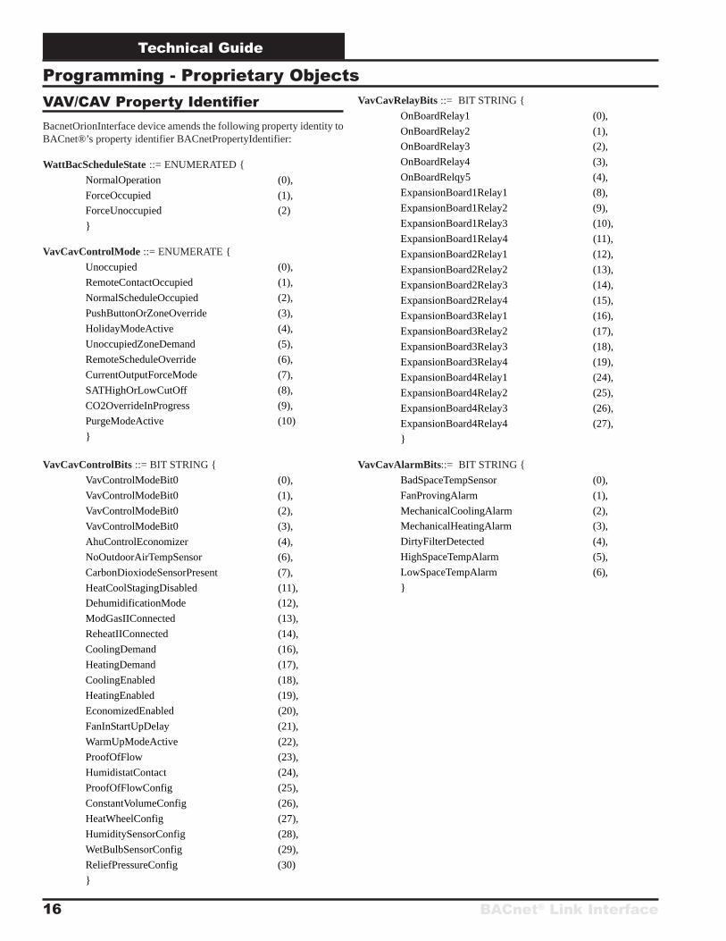
Programming - Proprietary ObjectsVAV/CAV Property IdentifierBacnetOrionInterface device amends the following property identity toBACnet®’s property identifier BACnetPropertyIdentifier:
WattBacScheduleState ::= ENUMERATED {
NormalOperation (0),
ForceOccupied (1),
ForceUnoccupied (2)
}
VavCavControlMode ::= ENUMERATE {
Unoccupied (0),
RemoteContactOccupied (1),
NormalScheduleOccupied (2),
PushButtonOrZoneOverride (3),
HolidayModeActive (4),
UnoccupiedZoneDemand (5),
RemoteScheduleOverride (6),
CurrentOutputForceMode (7),
SATHighOrLowCutOff (8),
CO2OverrideInProgress (9),
PurgeModeActive (10)
}
VavCavControlBits ::= BIT STRING {
VavControlModeBit0 (0),
VavControlModeBit0 (1),
VavControlModeBit0 (2),
VavControlModeBit0 (3),
AhuControlEconomizer (4),
NoOutdoorAirTempSensor (6),
CarbonDioxiodeSensorPresent (7),
HeatCoolStagingDisabled (11),
DehumidificationMode (12),
ModGasIIConnected (13),
ReheatIIConnected (14),
CoolingDemand (16),
HeatingDemand (17),
CoolingEnabled (18),
HeatingEnabled (19),
EconomizedEnabled (20),
FanInStartUpDelay (21),
WarmUpModeActive (22),
ProofOfFlow (23),
HumidistatContact (24),
ProofOfFlowConfig (25),
ConstantVolumeConfig (26),
HeatWheelConfig (27),
HumiditySensorConfig (28),
WetBulbSensorConfig (29),
ReliefPressureConfig (30)
}

BACnet® Link Interface
Technical Guide
17
CW/HW ObjectThe information that follows describes the characteristics of the CW/HW Object. Properties for the CW/HW Object are listed in Table 9.
Object NameThe Object Name for the CW/HW controller is a 15 byte characterstring that can be set through the BACnet® front end.
Object TypeThe Object Type of the CW/HW controller is CwHw or 259.
Object Instance NumberThe Instance Number of the CW/HW Object is determined by two vari-able values. The first variable is the loop address setting on the BAC-net® Link for the specific loop the CW/HW controller resides on andthe second is the CW/HW controller address. The BACnet® Link loopaddress can be either 0, 1, 2 or 3. See Figure 3 at the front of thismanual for detailed information on the BACnet® Link loop addressjumper settings.
The second variable value used to calculate the Object Instance numberis the CW/HW controller address and is determined by the address switchsettings on the CW/HW controller. Valid address settings are 1 through16.
See Table 10 at the end of this chapter for complete Object InstanceNumber calculation information
Object PropertiesThe information and tables that follow detail the properties and prop-erty identifiers for the CW/HW Object.
Object Properties For The CW/HW Controller
Property Name Property Data TypePropertyIdentifier
ReadOr
Write
Alarm_Status CwHwAlarmBits 1024 R/OApplilcation_Software_Version Unsigned 11 R/OCO2_Setpoint Real 1094 R/OCold_Water_Position Real 1088 R/OControl_Status CwHwControlBits 1025 R/OControl_Temperature Real 1028 R/OCooling_Setpoint Real 1027 R/ODuct_Static_Pressure Real 1031 R/ODuct_Static_Setpoint Real 1090 R/WEconomizer_Position Real 1032 R/OFan_Speed_Unit BACnetEngineeringUnits 1083 R/OHcw_Configuration HcwConfigBits 1089 R./WHeating_Setpoint Real 1037 R/OHot_Water_Position Real 1087 R/OHumidity_Unit BACnetEngineeringUnits 1084 R/OMin_Outside_Air_Setpoint Real 1091 R/WObject_Identifier BACnetObjectIdentifier 75 R/OObject_Name CharacterString 77 R/WObject_Type WattBacObjectTypes 79 R/OOccupied_Cooling_Setpoint Unsigned 1039 R/WOccupied_Heating_Setpoint Unsigned 1040 R/WOutdoor_Air_Humidity Real 1050 R/OOutdoor_Air_Sensor_Offset Real 1051 R/WOutdoor_Air_Temperature Real 1052 R/OOutdoor_Air_Wetbulb Real 1053 R/OPosition_Unit BACnetEngineeringUnits 1085 R/ORelays CwHwRelayBits 1055 R/ORelief_Pressure Real 1056 R/ORelief_Pressure_Setpoint Real 1092 R/WReturn_Air_CO2_Level Real 1093 R/OReturn_Air_Sensor_Offset Real 1058 R/WReturn_Air_Temperature Real 1057 R/OSchedule_Force WattBacScheduleState 1059 R/WSpace_Sensor_Offset Real 1063 R/WSpace_Temperature Real 1064 R/OStaging_Deadband Integer 1067 R/WSupply_Air_Cooling_Setpoint Unsigned 1068 R/WSupply_Air_Heating_Setpoint Unsigned 1069 R/WSupply_Air_Sensor_Offset Real 1071 R/WSupply_Air_Temperature Real 1073 R/OTemperature_Demand Real 1074 R/OTemperature_Unit BACnetEngineeringUnits 1086 R/OUnoccupied_Coolting_Setpoint Unsigned 1075 R/WUnoccupied_Heating_Setpoint Unsigned 1076 R/WVfd_Blower_Fan Real 1077 R/OVfd_Exhaust_Fan Real 1078 R/OWarm_Up_Setpoint Unsigned 1079 R/WWetbulb_Setpoint Unsigned 1080 R/W
Table 9: CW/HW Object Properties
Technical Guide
BACnet® Link Interface18
CwHwRelayBits := BIT STRING {
OnBoardRelay1 (0),
OnBoardRelay2 (1),
OnBoardRelay3 (2),
OnBoardRelay4 (3),
OnBoardRelqy5 (4),
ExpansionBoard1Relay1 (8),
ExpansionBoard1Relay2 (9),
ExpansionBoard1Relay3 (10),
ExpansionBoard1Relay4 (11),
ExpansionBoard2Relay1 (12),
ExpansionBoard2Relay2 (13),
ExpansionBoard2Relay3 (14),
ExpansionBoard2Relay4 (15),
ExpansionBoard3Relay1 (16),
ExpansionBoard3Relay2 (17),
ExpansionBoard3Relay3 (18),
ExpansionBoard3Relay4 (19),
ExpansionBoard4Relay1 (24),
ExpansionBoard4Relay2 (25),
ExpansionBoard4Relay3 (26),
ExpansionBoard4Relay4 (27),
}
CwHwAlarmBits ::= BIT STRING {
BadSpaceTempSensor (0),
FanProvingAlarm (1),
MechanicalCoolingAlarm (2),
MechanicalHeatingAlarm (3),
DirtyFilterDetected (4),
HighSpaceTempAlarm (5),
LowSpaceTempAlarm (6),
}
CwHwConfigBits ::= BIT STRING {
EnableChillerWater (0),
ChillerWaterReverseActing (1),
EnableHotWater (2),
HotWaterReverseActing (3),
EnableHotWaterOnDehumidification (4),
}
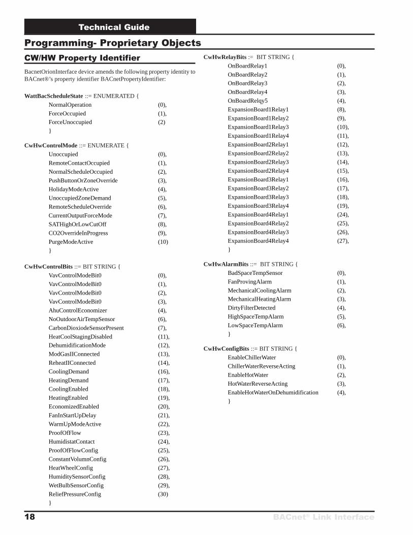
Programming- Proprietary ObjectsCW/HW Property IdentifierBacnetOrionInterface device amends the following property identity toBACnet®’s property identifier BACnetPropertyIdentifier:
WattBacScheduleState ::= ENUMERATED {
NormalOperation (0),
ForceOccupied (1),
ForceUnoccupied (2)
}
CwHwControlMode ::= ENUMERATE {
Unoccupied (0),
RemoteContactOccupied (1),
NormalScheduleOccupied (2),
PushButtonOrZoneOverride (3),
HolidayModeActive (4),
UnoccupiedZoneDemand (5),
RemoteScheduleOverride (6),
CurrentOutputForceMode (7),
SATHighOrLowCutOff (8),
CO2OverrideInProgress (9),
PurgeModeActive (10)
}
CwHwControlBits ::= BIT STRING {
VavControlModeBit0 (0),
VavControlModeBit0 (1),
VavControlModeBit0 (2),
VavControlModeBit0 (3),
AhuControlEconomizer (4),
NoOutdoorAirTempSensor (6),
CarbonDioxiodeSensorPresent (7),
HeatCoolStagingDisabled (11),
DehumidificationMode (12),
ModGasIIConnected (13),
ReheatIIConnected (14),
CoolingDemand (16),
HeatingDemand (17),
CoolingEnabled (18),
HeatingEnabled (19),
EconomizedEnabled (20),
FanInStartUpDelay (21),
WarmUpModeActive (22),
ProofOfFlow (23),
HumidistatContact (24),
ProofOfFlowConfig (25),
ConstantVolumnConfig (26),
HeatWheelConfig (27),
HumiditySensorConfig (28),
WetBulbSensorConfig (29),
ReliefPressureConfig (30)
}
BACnet® Link Interface
Technical Guide
19
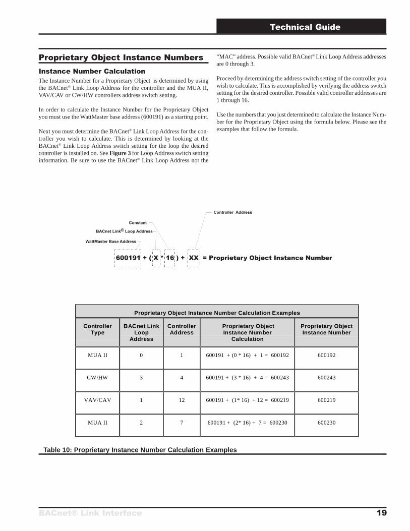
Table 10: Proprietary Instance Number Calculation Examples
Proprietary Object Instance NumbersInstance Number CalculationThe Instance Number for a Proprietary Object is determined by usingthe BACnet® Link Loop Address for the controller and the MUA II,VAV/CAV or CW/HW controllers address switch setting.
In order to calculate the Instance Number for the Proprietary Objectyou must use the WattMaster base address (600191) as a starting point.
Next you must determine the BACnet® Link Loop Address for the con-troller you wish to calculate. This is determined by looking at theBACnet® Link Loop Address switch setting for the loop the desiredcontroller is installed on. See Figure 3 for Loop Address switch settinginformation. Be sure to use the BACnet® Link Loop Address not the
“MAC” address. Possible valid BACnet® Link Loop Address addressesare 0 through 3.
Proceed by determining the address switch setting of the controller youwish to calculate. This is accomplished by verifying the address switchsetting for the desired controller. Possible valid controller addresses are1 through 16.
Use the numbers that you just determined to calculate the Instance Num-ber for the Proprietary Object using the formula below. Please see theexamples that follow the formula.
Proprietary Object Instance Number Calculation Examples
ControllerType
BACnet LinkLoop
Address
ControllerAddress
Proprietary ObjectInstance Number
Calculation
Proprietary ObjectInstance Number
MUA II 0 1 600191 + (0 * 16) + 1 = 600192 600192
CW/HW 3 4 600191 + (3 * 16) + 4 = 600243 600243
VAV/CAV 1 12 600191 + (1* 16) + 12 = 600219 600219
MUA II 2 7 600191 + (2* 16) + 7 = 600230 600230
Technical Guide
BACnet® Link Interface20
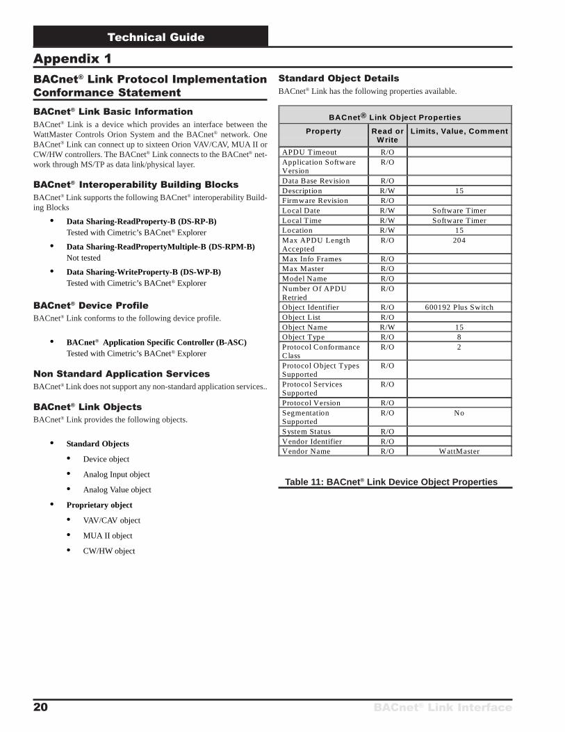
BACnet® Link Protocol ImplementationConformance StatementBACnet® Link Basic InformationBACnet® Link is a device which provides an interface between theWattMaster Controls Orion System and the BACnet® network. OneBACnet® Link can connect up to sixteen Orion VAV/CAV, MUA II orCW/HW controllers. The BACnet® Link connects to the BACnet® net-work through MS/TP as data link/physical layer.
BACnet® Interoperability Building BlocksBACnet® Link supports the following BACnet® interoperability Build-ing Blocks
• Data Sharing-ReadProperty-B (DS-RP-B)Tested with Cimetric’s BACnet® Explorer
• Data Sharing-ReadPropertyMultiple-B (DS-RPM-B)Not tested
• Data Sharing-WriteProperty-B (DS-WP-B)Tested with Cimetric’s BACnet® Explorer
BACnet® Device ProfileBACnet® Link conforms to the following device profile.
• BACnet® Application Specific Controller (B-ASC)Tested with Cimetric’s BACnet® Explorer
Non Standard Application ServicesBACnet® Link does not support any non-standard application services..
BACnet® Link ObjectsBACnet® Link provides the following objects.
• Standard Objects
• Device object
• Analog Input object
• Analog Value object
• Proprietary object
• VAV/CAV object
• MUA II object
• CW/HW object
Standard Object DetailsBACnet® Link has the following properties available.
Appendix 1
BACnet® Link Object Properties
Property Read orWrite
Limits, Value, Comment
APDU Timeout R/OApplication SoftwareVersion
R/O
Data Base Revision R/ODescription R/W 15Firmware Revision R/OLocal Date R/W Software TimerLocal T ime R/W Software TimerLocation R/W 15Max APDU LengthAccepted
R/O 204
Max Info Frames R/OMax Master R/OModel Name R/ONumber Of APDURetried
R/O
Object Identifier R/O 600192 Plus SwitchObject List R/OObject Name R/W 15Object Type R/O 8Protocol ConformanceClass
R/O 2
Protocol Object TypesSupported
R/O
Protocol ServicesSupported
R/O
Protocol Version R/OSegmentationSupported
R/O No
System Status R/OVendor Identifier R/OVendor Name R/O WattMaster
Table 11: BACnet® Link Device Object Properties
BACnet® Link Interface
Technical Guide
21
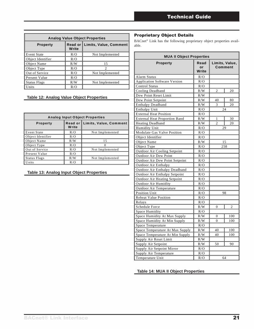
Analog Value Object Properties
Property Read orWrite
Limits, Value, Comment
Event State R/O Not ImplementedObject Identifier R/OObject Name R/W 15Object Type R/O 2Out of Service R/O Not ImplementedPresent Value R/OStatus Flags R/W Not ImplementedUnits R/O
Table 12: Analog Value Object Properties
Proprietary Object DetailsBACnet® Link has the following proprietary object properties avail-able.
Analog Input O bject Properties
Property Read orW rite
Lim its, Value, Comm ent
Event State R/O N ot ImplementedObject Identifier R/OObject Name R/W 15Object Type R/O 0Out of Service R/O N ot ImplementedPresent Value R/OStatus Flags R/W N ot ImplementedUnits R/O
MUA II Object Properties
Property Reador
Write
Limits, Value,Comment
Alarm Status R/OApplication Software Version R/OControl Status R/OCooling Deadband R/W 2 20Dew Point Reset Limit R/WDew Point Setpoint R/W 40 80Enthalpy Deadband R/W 3 20Enthalpy Unit R/O 24External Heat Position R/OExternal Heat Proportion Band R/W 1 30Heating Deadband R/W 2 20Humidity Unit R/O 29Modulate Gas Valve Position R/OObject Identifier R/OObject Name R/W 15Object Type R/O 258Outdoor Air Cooling Setpoint R/OOutdoor Air Dew Point R/OOutdoor Air Dew Point Setpoint R/OOutdoor Air Enthalpy R/OOutdoor Air Enthalpy Deadband R/OOutdoor Air Enthalpy Setpoint R/OOutdoor Air Heating Setpoint R/OOutdoor Air Humidity R/OOutdoor Air Temperature R/OPosition Unit R/O 98Reheat Value Position R/ORelays R/OSchedule Force R/W 0 2Space Humidity R/OSpace Humidity At Max Supply R/W 0 100Space Humidity At Min Supply R/W 0 100Space Temperature R/OSpace Temperature At Max Supply R/W 40 100Space Temperature At Min Supply R/W 40 100Supply Air Reset Limit R/WSupply Air Setpoint R/W 50 90Supply Air Setpoint Mirror R/OSupply Air Temperature R/OTemperature Unit R/O 64
Table 13: Analog Input Object Properties
Table 14: MUA II Object Properties
Technical Guide
BACnet® Link Interface22
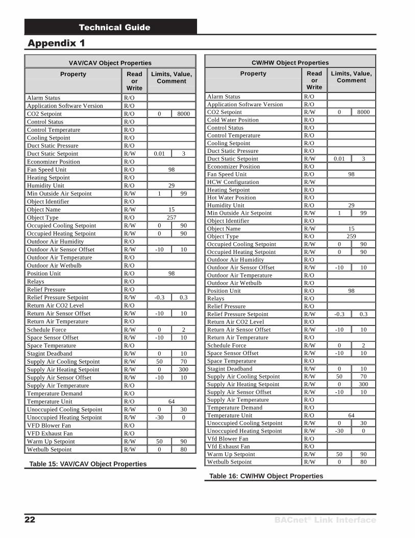
Appendix 1
VAV/CAV Object Properties
Property Reador
Write
Limits, Value,Comment
Alarm Status R/OApplication Software Version R/OCO2 Setpoint R/O 0 8000Control Status R/OControl Temperature R/OCooling Setpoint R/ODuct Static Pressure R/ODuct Static Setpoint R/W 0.01 3Economizer Position R/OFan Speed Unit R/O 98Heating Setpoint R/OHumidity Unit R/O 29Min Outside Air Setpoint R/W 1 99Object Identifier R/OObject Name R/W 15Object Type R/O 257Occupied Cooling Setpoint R/W 0 90Occupied Heating Setpoint R/W 0 90Outdoor Air Humidity R/OOutdoor Air Sensor Offset R/W -10 10Outdoor Air Temperature R/OOutdoor Air Wetbulb R/OPosition Unit R/O 98Relays R/ORelief Pressure R/ORelief Pressure Setpoint R/W -0.3 0.3Return Air CO2 Level R/OReturn Air Sensor Offset R/W -10 10Return Air Temperature R/OSchedule Force R/W 0 2Space Sensor Offset R/W -10 10Space Temperature R/OStagint Deadband R/W 0 10Supply Air Cooling Setpoint R/W 50 70Supply Air Heating Setpoint R/W 0 300Supply Air Sensor Offset R/W -10 10Supply Air Temperature R/OTemperature Demand R/OTemperature Unit R/O 64Unoccupied Cooling Setpoint R/W 0 30Unoccupied Heating Setpoint R/W -30 0VFD Blower Fan R/OVFD Exhaust Fan R/OWarm Up Setpoint R/W 50 90Wetbulb Setpoint R/W 0 80
CW/HW Object Properties
Property Reador
Write
Limits, Value,Comment
Alarm Status R/OApplication Software Version R/OCO2 Setpoint R/W 0 8000Cold Water Position R/OControl Status R/OControl Temperature R/OCooling Setpoint R/ODuct Static Pressure R/ODuct Static Setpoint R/W 0.01 3Economizer Position R/OFan Speed Unit R/O 98HCW Configuration R/WHeating Setpoint R/OHot Water Position R/OHumidity Unit R/O 29Min Outside Air Setpoint R/W 1 99Object Identifier R/OObject Name R/W 15Object Type R/O 259Occupied Cooling Setpoint R/W 0 90Occupied Heating Setpoint R/W 0 90Outdoor Air Humidity R/OOutdoor Air Sensor Offset R/W -10 10Outdoor Air Temperature R/OOutdoor Air Wetbulb R/OPosition Unit R/O 98Relays R/ORelief Pressure R/ORelief Pressure Setpoint R/W -0.3 0.3Return Air CO2 Level R/OReturn Air Sensor Offset R/W -10 10Return Air Temperature R/OSchedule Force R/W 0 2Space Sensor Offset R/W -10 10Space Temperature R/OStagint Deadband R/W 0 10Supply Air Cooling Setpoint R/W 50 70Supply Air Heating Setpoint R/W 0 300Supply Air Sensor Offset R/W -10 10Supply Air Temperature R/OTemperature Demand R/OTemperature Unit R/O 64Unoccupied Cooling Setpoint R/W 0 30Unoccupied Heating Setpoint R/W -30 0Vfd Blower Fan R/OVfd Exhaust Fan R/OWarm Up Setpoint R/W 50 90Wetbulb Setpoint R/W 0 80Table 15: VAV/CAV Object Properties
Table 16: CW/HW Object Properties
BACnet® Link Interface
Technical Guide
23
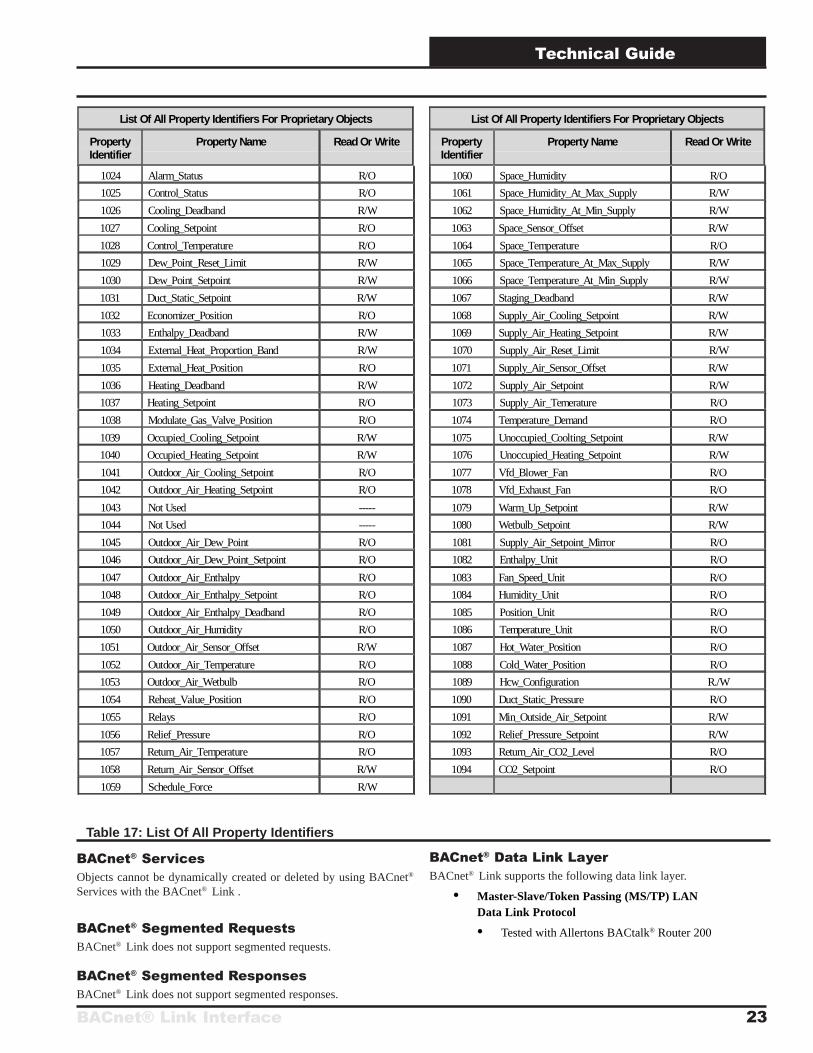
BACnet® ServicesObjects cannot be dynamically created or deleted by using BACnet®
Services with the BACnet® Link .
BACnet® Segmented RequestsBACnet® Link does not support segmented requests.
BACnet® Segmented ResponsesBACnet® Link does not support segmented responses.
List Of All Property Identifiers For Proprietary Objects
PropertyIdentifier
Property Name Read Or Write
1024 Alarm_Status R/O
1025 Control_Status R/O
1026 Cooling_Deadband R/W
1027 Cooling_Setpoint R/O
1028 Control_Temperature R/O
1029 Dew_Point_Reset_Limit R/W
1030 Dew_Point_Setpoint R/W
1031 Duct_Static_Setpoint R/W
1032 Economizer_Position R/O
1033 Enthalpy_Deadband R/W
1034 External_Heat_Proportion_Band R/W
1035 External_Heat_Position R/O
1036 Heating_Deadband R/W
1037 Heating_Setpoint R/O
1038 Modulate_Gas_Valve_Position R/O
1039 Occupied_Cooling_Setpoint R/W
1040 Occupied_Heating_Setpoint R/W
1041 Outdoor_Air_Cooling_Setpoint R/O
1042 Outdoor_Air_Heating_Setpoint R/O
1043 Not Used -----
1044 Not Used -----
1045 Outdoor_Air_Dew_Point R/O
1046 Outdoor_Air_Dew_Point_Setpoint R/O
1047 Outdoor_Air_Enthalpy R/O
1048 Outdoor_Air_Enthalpy_Setpoint R/O
1049 Outdoor_Air_Enthalpy_Deadband R/O
1050 Outdoor_Air_Humidity R/O
1051 Outdoor_Air_Sensor_Offset R/W
1052 Outdoor_Air_Temperature R/O
1053 Outdoor_Air_Wetbulb R/O
1054 Reheat_Value_Position R/O
1055 Relays R/O
1056 Relief_Pressure R/O
1057 Return_Air_Temperature R/O
1058 Return_Air_Sensor_Offset R/W
1059 Schedule_Force R/W
Table 17: List Of All Property Identifiers
List Of All Property Identifiers For Proprietary Objects
PropertyIdentifier
Property Name Read Or Write
1060 Space_Humidity R/O
1061 Space_Humidity_At_Max_Supply R/W
1062 Space_Humidity_At_Min_Supply R/W
1063 Space_Sensor_Offset R/W
1064 Space_Temperature R/O
1065 Space_Temperature_At_Max_Supply R/W
1066 Space_Temperature_At_Min_Supply R/W
1067 Staging_Deadband R/W
1068 Supply_Air_Cooling_Setpoint R/W
1069 Supply_Air_Heating_Setpoint R/W
1070 Supply_Air_Reset_Limit R/W
1071 Supply_Air_Sensor_Offset R/W
1072 Supply_Air_Setpoint R/W
1073 Supply_Air_Temerature R/O
1074 Temperature_Demand R/O
1075 Unoccupied_Coolting_Setpoint R/W
1076 Unoccupied_Heating_Setpoint R/W
1077 Vfd_Blower_Fan R/O
1078 Vfd_Exhaust_Fan R/O
1079 Warm_Up_Setpoint R/W
1080 Wetbulb_Setpoint R/W
1081 Supply_Air_Setpoint_Mirror R/O
1082 Enthalpy_Unit R/O
1083 Fan_Speed_Unit R/O
1084 Humidity_Unit R/O
1085 Position_Unit R/O
1086 Temperature_Unit R/O
1087 Hot_Water_Position R/O
1088 Cold_Water_Position R/O
1089 Hcw_Configuration R./W
1090 Duct_Static_Pressure R/O
1091 Min_Outside_Air_Setpoint R/W
1092 Relief_Pressure_Setpoint R/W
1093 Return_Air_CO2_Level R/O
1094 CO2_Setpoint R/O
BACnet® Data Link LayerBACnet® Link supports the following data link layer.
• Master-Slave/Token Passing (MS/TP) LANData Link Protocol
• Tested with Allertons BACtalk® Router 200

Form: OR-BACNET-TGD-02B Printed in the USA August 2005All rights reserved Copyright 2005
WattMaster Controls Inc. • 8500 NW River Park Drive • Parkville, Mo. • 64152
Phone (816) 505-1100 www.orioncontrols.com Fax (816) 505-1101
Related Documents