© 2007 Eaton Corporation. All rights reserved. Backup Power Applications/Considerations Backup Power Types Automatic Transfer Switch Basics Backup Power Automatic Transfer NIPSCO Energy Symposium symposium Presenters McGill Power - Jeremy Irmeger Eaton - Barry Graves

Welcome message from author
This document is posted to help you gain knowledge. Please leave a comment to let me know what you think about it! Share it to your friends and learn new things together.
Transcript

© 2007 Eaton Corporation. All rights reserved.
Backup Power Applications/Considerations
Backup Power Types
Automatic Transfer Switch Basics
Backup Power Automatic Transfer
NIPSCO Energy Symposium symposium
Presenters McGill Power - Jeremy Irmeger
Eaton - Barry Graves
Objective & Agenda
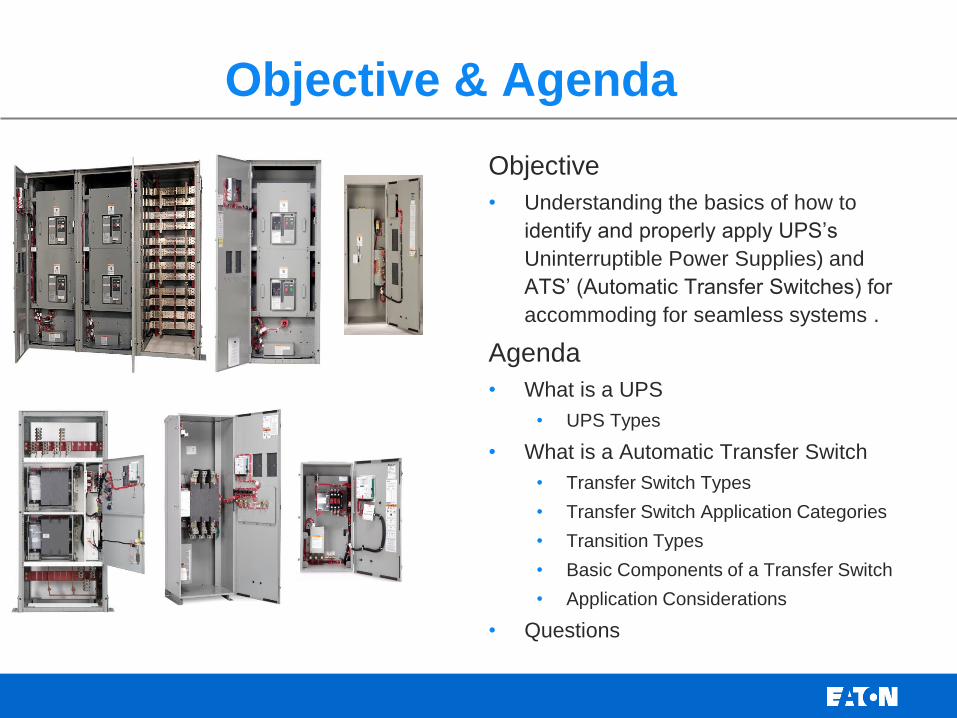
Objective
• Understanding the basics of how to
identify and properly apply UPS’s
Uninterruptible Power Supplies) and
ATS’ (Automatic Transfer Switches) for
accommoding for seamless systems .
Agenda
• What is a UPS
• UPS Types
• What is a Automatic Transfer Switch
• Transfer Switch Types
• Transfer Switch Application Categories
• Transition Types
• Basic Components of a Transfer Switch
• Application Considerations
• Questions
Bypass Isolation Magnum Front Access

Interruption Sag Swell
Undervoltage Line Noise
Switching Transients Frequency Variation Harmonic Distortion
Overvoltage
The 9 Common Power Problems

3 (+1) Basic Types of UPS
(
Standby
• “Off Line”
Line
Interactive
On Line
• “Double
Conversion”
Powerware Series 3 The Series 3 (Stand-By) UPS delivers
power protection from 3 of the most
common power problems that threaten
your equipment and data
Powerware Series 5 The Series 5 (Line-Interactive) UPS
delivers power protection from 5 of the
most common power problems that
threaten your equipment and data
Powerware Series 9 The Series 9 (On-Line) UPS delivers
power protection from all 9 of the most
common power problems that
threaten your equipment and data
Interruption
Sag
Swell
Under-
voltage
Over-
voltage
Switching
transients
Frequency
variation
Harmonic
distortion
Line
noise
Normal Operation
Power Failure Event
Buck/Boost
Ferroresonant
• “+1”
Powerware Series Ferro The Series Ferro UPS delivers
galvanic isolated power protection from
8 of the most common power problems
that threaten equipment and data
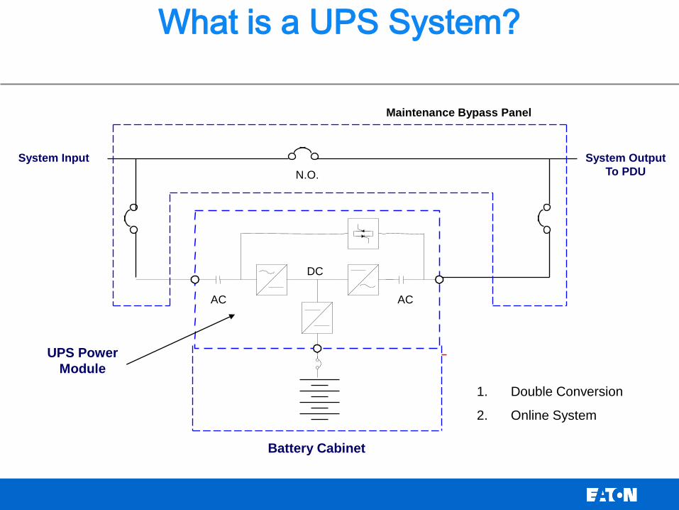
System Input
UPS Power
Module
Battery Cabinet
What is a UPS System?
System Output
To PDU N.O.
AC AC
DC
Maintenance Bypass Panel
1. Double Conversion
2. Online System

How Much Downtime is Acceptable?
Power Availability Equivalent Power Disruptions (yr)
99.9%
99.99%
99.999%
99.9999999%
8.8 hours
0.88 hours
5.3 minutes
< 3 seconds
ISPs,
e-Business,
Communications,
Electronics mfg.
N+ Redundancy
Food Processing
Server Operating Systems
Generators and Some UPS
Hospitals, Airports
Generator Only
Residential Homes
Typical Grid Power
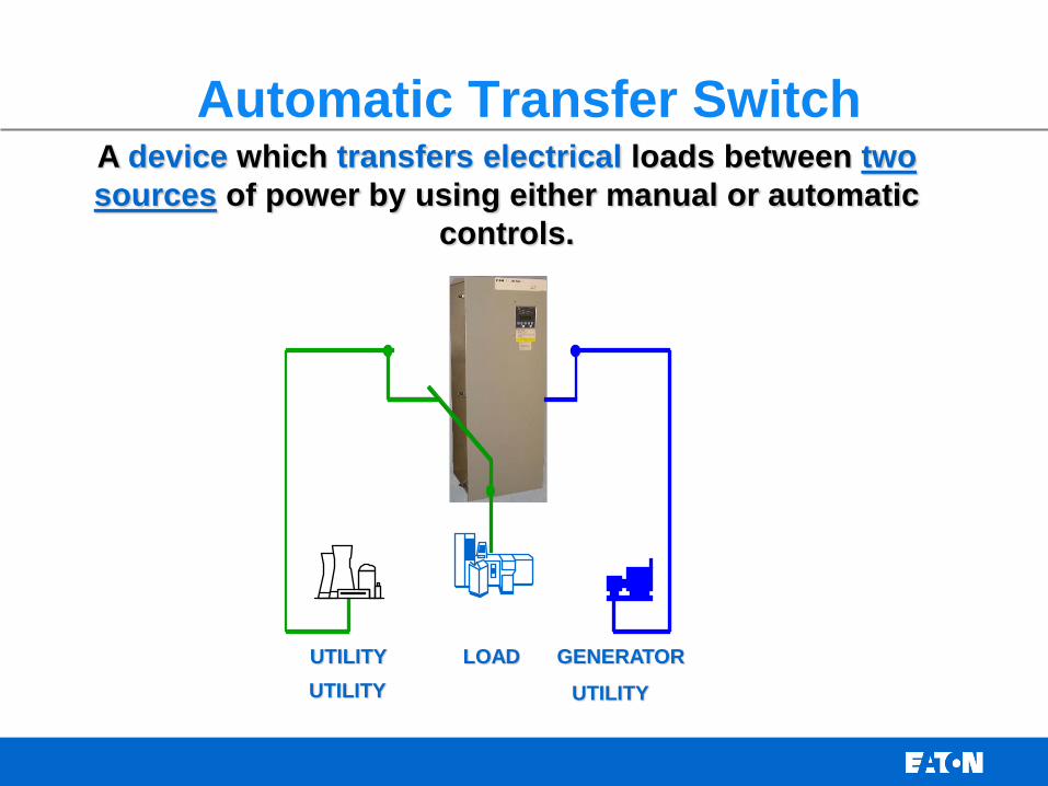
Automatic Transfer Switch
UTILITY LOAD GENERATOR
A device which transfers electrical loads between two
sources of power by using either manual or automatic
controls.
UTILITY UTILITY

Bypass Isolation Transfer Switch
• An automatic transfer switch with an additional bypass isolation switch
• Provides ability to perform maintenance of the main transfer switch power device, without interruption of power to the load
• Applied in high reliability applications:
• Provides emergency power to life safety and other critical loads

Transfer Switch Types
• There are only two ways to transfer power:
• Automatic
• If loads are very critical, an automatic transfer switch would
probably be used insure the fastest possible transfer.
• Non-Automatic (manual, or electrically operated)
• If loads are not quite as critical, but still cannot go for any
extended period of time without power, a Non-Automatic or manual transfer switch could be used.
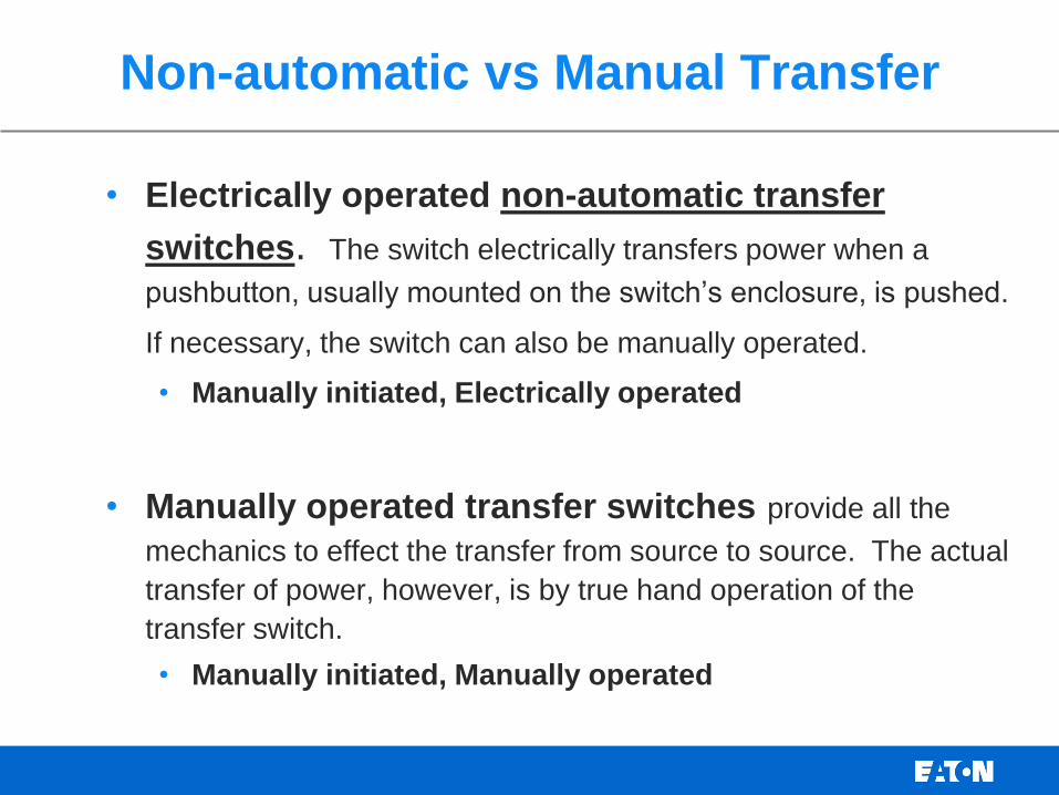
Non-automatic vs Manual Transfer
• Electrically operated non-automatic transfer
switches. The switch electrically transfers power when a
pushbutton, usually mounted on the switch’s enclosure, is pushed.
If necessary, the switch can also be manually operated.
• Manually initiated, Electrically operated
• Manually operated transfer switches provide all the
mechanics to effect the transfer from source to source. The actual
transfer of power, however, is by true hand operation of the
transfer switch.
• Manually initiated, Manually operated

National Electric Code
Application
Category
NFPA 70
• NFPA 70 - National Electric
Code
• Article 700 - Emergency
Systems
• Article 701 - Legally
Required Standby Systems
• Article 702 - Optional
Standby Systems
• Article 708 - COPS
• Article 517 - Health Care
Facilities
• NFPA 99 - Health Care Facilities
• NFPA 110 - Emergency &
Standby Systems
• NFPA 20 - Fire Pumps
• NFPA 70E – Workplace Safety
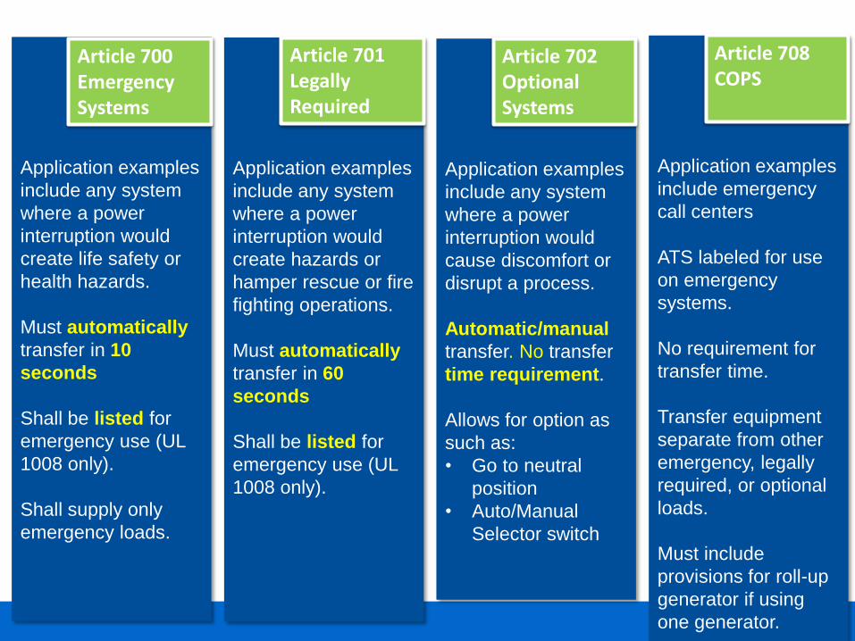
Application examples
include emergency
call centers
ATS labeled for use
on emergency
systems.
No requirement for
transfer time.
Transfer equipment
separate from other
emergency, legally
required, or optional
loads.
Must include
provisions for roll-up
generator if using
one generator.
Article 708 COPS
Application examples
include any system
where a power
interruption would
create life safety or
health hazards.
Must automatically
transfer in 10
seconds
Shall be listed for
emergency use (UL
1008 only).
Shall supply only
emergency loads.
Article 700 Emergency Systems
Application examples
include any system
where a power
interruption would
create hazards or
hamper rescue or fire
fighting operations.
Must automatically
transfer in 60
seconds
Shall be listed for
emergency use (UL
1008 only).
Article 701 Legally Required
Application examples
include any system
where a power
interruption would
cause discomfort or
disrupt a process.
Automatic/manual
transfer. No transfer
time requirement.
Allows for option as
such as:
• Go to neutral
position
• Auto/Manual
Selector switch
Article 702 Optional Systems
© 2007 Eaton Corporation. All rights reserved.
Transfer Switch Transition Types

Open Transition
• Also called a “break-before-make” switch. One set of contacts opens
before the other set closes
• There is a definite break in power as the load is taken off one source
and connected to another.
• This is the most common and least expensive
Normal
Emergency
Loads
TS N
TS E

Delayed Transition
• Break Both Sides – Delayed Transition
• One set of contacts opens before the other
• The other set of contacts delays in closing
• Load is disconnected from power during all transfers
Normal
Emergency
Loads
TS N
TS E
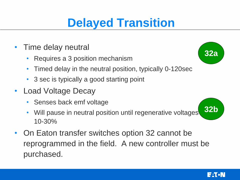
Delayed Transition
• Time delay neutral
• Requires a 3 position mechanism
• Timed delay in the neutral position, typically 0-120sec
• 3 sec is typically a good starting point
• Load Voltage Decay
• Senses back emf voltage
• Will pause in neutral position until regenerative voltages are at
10-30%
• On Eaton transfer switches option 32 cannot be
reprogrammed in the field. A new controller must be
purchased.
32a
32b

100 m/secs
overlap-time
Normal
Emergency
Loads
TS N
TS E
Closed Transition
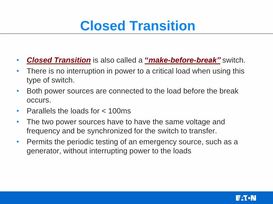
Closed Transition
• Closed Transition is also called a “make-before-break” switch.
• There is no interruption in power to a critical load when using this
type of switch.
• Both power sources are connected to the load before the break
occurs.
• Parallels the loads for < 100ms
• The two power sources have to have the same voltage and
frequency and be synchronized for the switch to transfer.
• Permits the periodic testing of an emergency source, such as a
generator, without interrupting power to the loads
Consideration for selecting Transition Types
• When transferring two live sources, abnormal motor inrush current
can occur leading to possible damage of motor windings, insulation,
couplings and in some cases, the load itself.
• Inrush currents are caused by the motor’s residual voltage being out
of phase with the voltage source to which it’s being transferred.
• Methods of control are:
• Open Inphase transfer
• Motor load disconnect control circuit
• Delayed transition - Time Delay Neutral, Load Voltage Decay
• Closed transition – less than 100 ms paralleling of sources

Open In-phase Transfer
• Feature that allows a live transfer between two sources only when
the phase difference between the two is near to zero.
• This feature prevents in-rush currents from exceeding normal starting
currents in the case where motor loads are being transferred
• How it works:
• Monitor samples the relative phase angle between the two sources being
transferred
• When the two sources are within the desired phase angle different and
are approaching zero phase angle difference, the inphase monitor
signals the transfer switch to operate.
• The operating time of the transfer switch is key in utilizing an inphase
monitor (must transfer in less than ten cycles)
• In-phase monitor and VFD’s do not work well together, use TDN.
In-phase doesn’t give the VFD’s time to reset.
32f

Motor Load Disconnect Control Circuit
• Selected motor loads are de-energized
during transfer operation
• Controller signals contact to open
approx. 3 seconds prior to transfer,
thus de-energizing selected loads.
• Loads are turned onto the generator
after a designated time delay.
• Loads can be turned on at one time or
sequentially so as to not block load the
generator.
• Motor load disconnect works well
when the generator is sized at the min.
45
© 2007 Eaton Corporation. All rights reserved.
Automatic Transfer Switches - Main Components

Transfer Switch Main Components
An automatic transfer switch (ATS) is made up of several main
components
Controller –
• Continually monitors the condition of the power sources
• Initiates start command to backup generator,
• Initiates transfer and retransfer to good power source
Power switching device
• Power device rated to transfer the load to/from the power sources
Control Power Transformer panel
• Supplies operational power to the switching device/controller
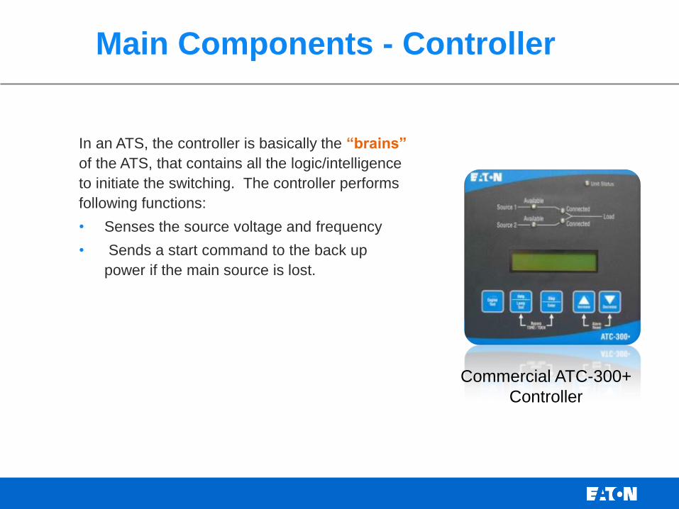
Main Components - Controller
In an ATS, the controller is basically the “brains”
of the ATS, that contains all the logic/intelligence
to initiate the switching. The controller performs
following functions:
• Senses the source voltage and frequency
• Sends a start command to the back up
power if the main source is lost.
Commercial ATC-300+
Controller
Main Components – Switching Device
The switching device is the main power device that transfers the load
from one power source to another. The switching device includes the
main power device and the transfer mechanism. The ATS controller
tells the switching device when to make the transfer/retransfer to a
good source
Two basic types of switching devices:
• Contactor
• Specifically designed contactors to perform load transfer between
to AC sources. Transfer switches do not use motor starting/lighting
type contactors.
• Molded Case/Power Case Switch
• A molded case or power case circuit breaker without and /or with a
trip unit. Used when a circuit requires a compact, high capacity
disconnect device.

Main Components – Contactor Switching Device
Contactor based
• The contactor switching device includes the main power assembly and
the operating mechanism.
• The power assembly is composed of the individual power poles.
• The operating mechanism includes the solenoid and the mechanical
interlock.
Power Assembly
Operating Mechanism
3 Pole Contactor
Moving
Contact Source 1
Bus
Source 2
Bus
Load Bus
Single Power Pole
Main Components – Molded Case or Power Case Circuit Breaker Switching Device
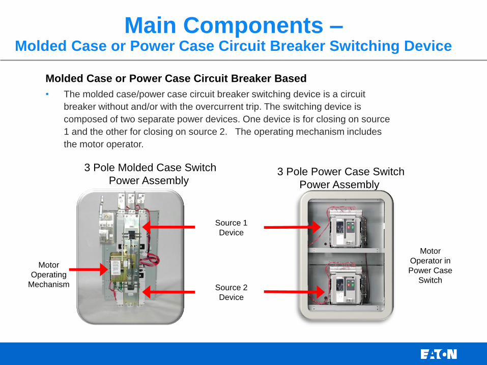
Molded Case or Power Case Circuit Breaker Based
• The molded case/power case circuit breaker switching device is a circuit
breaker without and/or with the overcurrent trip. The switching device is
composed of two separate power devices. One device is for closing on source
1 and the other for closing on source 2. The operating mechanism includes
the motor operator.
Motor
Operating
Mechanism
3 Pole Molded Case Switch
Power Assembly 3 Pole Power Case Switch
Power Assembly
Source 1
Device
Source 2
Device
Motor
Operator in
Power Case
Switch
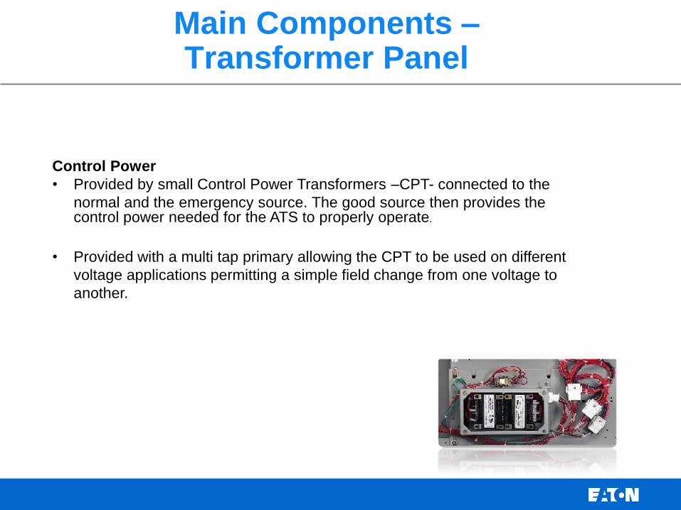
Main Components – Transformer Panel
Control Power
• Provided by small Control Power Transformers –CPT- connected to the
normal and the emergency source. The good source then provides the control power needed for the ATS to properly operate.
• Provided with a multi tap primary allowing the CPT to be used on different
voltage applications permitting a simple field change from one voltage to
another.

Basic Information for ATS Selection
When selecting a Transfer Switch, review the following:
– Types of load to be transferred
– Transition type
– Open In phase, Delayed, Closed Transition
– Application Type
– Life Safety, Emergency, Optional
– Switch Ratings
– Voltage rating, Phase, # poles
– Continuous Current rating/amps
– Overload and fault current withstand ratings
– Configuration Type
– Service Entrance
– Bypass Isolation
UPS and ATS Basics
Questions?
Related Documents


