Background Report: Evacuation of High-rise Buildings with Lifts and Stairs Version: 1.1 Status: Final Date: 1 July 2012 Authors: J. Wijnia (Peutz) J. Wit (Deerns) R. Noordermeer Commissioned by NEN and the Convenant Hoogbouw steering group, with support from Liftinstituut – Nederlands Instituut voor Lifttechniek.

Welcome message from author
This document is posted to help you gain knowledge. Please leave a comment to let me know what you think about it! Share it to your friends and learn new things together.
Transcript
Background Report: Evacuation of High-rise Buildings with Lifts and Stairs
Version: 1.1
Status: Final
Date: 1 July 2012
Authors: J. Wijnia (Peutz)
J. Wit (Deerns)
R. Noordermeer
Commissioned by NEN and the Convenant Hoogbouw steering group,
with support from Liftinstituut – Nederlands Instituut voor Lifttechniek.

Cover page 2
Evacuation of High-rise Buildings with Lifts and Stairs
1
Contents
1 Introduction ..................................................................................................................................... 2
2 Normative references ................................................................................................................... 23
3 Terms and definitions ................................................................................................................... 24
4 Symbols and abbreviations ......................................................................................................... 24
5 Limit values .................................................................................................................................... 32
6 Evacuation ..................................................................................................................................... 35
7 Scenarios ....................................................................................................................................... 38
8 New stairs model ........................................................................................................................... 45
9 The lift model ................................................................................................................................. 50
10 Example analyses with the models ............................................................................................. 74
11 General requirements ................................................................................................................... 82
12 Conclusions ................................................................................................................................... 94
13 Recommendations ........................................................................................................................ 95
Annex A: Case studies ................................................................................................................................... 96
Annex B: Explanatory notes on NEN-EN 81-72 and NEN-EN 81-73 ........................................................ 171
Annex C: Example of building zones (low-rise, mid-rise, and high-rise) and lift groups ..................... 172
Annex D: Examples of lift simulations as basis for lift model (determination of lift groups) .............. 173
Bibliography .................................................................................................................................................. 174

Background Report
2
1 Introduction
1.1 Background
This report describes the results of a study of the backgrounds and options for evacuation from high-rise buildings in the Netherlands. It discusses the use of stairs, lifts, and combinations of the two. This study was performed in 2009-2010 by Peutz BV and Deerns Raadgevende Ingenieurs BV on behalf of NEN in the context of Convenant Hoogbouw (Covenant on High-Rise Buildings). A major factor that has given rise to this covenant is the increase in the number and height of high-rise building projects in the Netherlands.
This report is not a Dutch Technical Agreement (NTA), but forms a potential step towards the future development of an NTA for evacuation of high-rise buildings with lifts and stairs. Particular attention is given to lifts in this report because this is the area about which least is known in the context of evacuation. With regard to evacuation via stairs, the assumptions made in this report are based broadly on the methods commonly used in the Netherlands.
1.2 Structure of this document
This report is structured as follows:
1) Chapter 1 is an introduction to the definition, the objective, and the requirements of the study human behaviour during evacuation is also discussed.
2) Chapter 2 contains the normative references.
3) Chapter 3 contains an explanation of the terms and definitions used.
4) Chapter 4 contains an explanation of the symbols and abbreviations used.
5) Chapter 5 discusses the necessary criteria for clearance, such as limit values for clearance times and refuge times.
6) Chapter 6 explains the current stairs model in accordance with the Bouwbesluit [Dutch Building Decree] and the SBR Code of Practice Brandveiligheid in hoge gebouwen [Fire Safety in High-rise Buildings].
7) Chapter 7 presents the scenarios that can be used for evacuating high-rise buildings.
8) Chapter 8 describes how the widely used stairs model has been modified for this report, including its validation.
9) Chapter 9 presents a lift model for evacuation from high-rise buildings, including its validation.
10) Chapter 10 describes example analyses with the combined lift and stairs model.
11) Chapter 11 sets out the requirements for the safe application of each scenario.
12) Chapter 12 draws conclusions on evacuation with lifts and the model.
13) Chapter 13 makes recommendations for further study.
Annex A describes three cases illustrating the application of the model.

Evacuation of High-rise Buildings with Lifts and Stairs
3
1.3 General
In recent years, there has been a clear increase in research into the use of lifts for evacuation of high-rise buildings worldwide. The WTC disaster in New York in 2001 played a major role in this: on the one hand, it underlined how vulnerable people in high-rise buildings can be, while on the other hand, it made clear that increasing numbers of people in high-rise buildings need help to be able to leave the building via the stairs.
1.3.1 NIST recommendations post-WTC in New York
NIST (the National Institute of Standards and Technology) carried out extensive research into the effectiveness of the evacuation of the WTC twin towers in 2001. NIST makes the following important recommendations concerning evacuation, which can also be applied in the Dutch context.
a) Recommendation 16: More public education and information must be provided to improve building occupants’ preparedness for evacuation.
b) Recommendation 17a: Timely and full evacuation must be specifically included in every building design.
c) Recommendation 17b: The design of stairs should be adequate to accommodate counterflow due to access by emergency services.
d) Recommendation 18: Egress systems should be designed for maximum remoteness and integrity, as well as consistent layouts and signage.
e) Recommendation 19: Building owners should be compelled to provide more information, more evacuation drills, and more enforcement.
f) Recommendation 20: The full range of potential evacuation technologies should be evaluated for future use, including lifts, exterior escape devices, and stairwell descent devices.
g) Recommendation 21: The design should ensure the functional integrity of fire-fighting lifts for the purpose of repressing the fire and evacuating mobility-impaired building occupants.
1.3.2 Motivating reasons within the Dutch context
Partly due to the above, a strong desire has arisen within the Covenant to explore the use of lifts for evacuation of high-rise buildings in more detail. The most important reasons for this in the Dutch context are as follows:
a) The number of high-rise building projects in the Netherlands is increasing, as is their height.
b) Besides making buildings accessible to all users, they should also be easy for all users to escape from.
c) There is an increase in attention to and awareness of risks during evacuation from high-rise buildings as a result of previous disasters (such as the WTC in New York, the fire at Prinsenhof in The Hague, the fire in the CCTV tower in Beijing, the fire at Rabobank in Utrecht, the fire at the Faculty of Architecture at Delft University of Technology, the fireworks disaster in Enschede, and the café fire in Volendam).
d) A significant proportion of the building population will be mobility-impaired and therefore unable to evacuate via stairs without help, such as those who have heart problems or are disabled, visually impaired, obese, pregnant, elderly, or injured. The proportion of building occupants unable to evacuate without help is rising as the mobility of mobility-impaired people, obesity and demographic ageing increase.
e) The assumption that all healthy, able-bodied occupants of a high-rise building above 100-150 m in height can evacuate by themselves via the stairs within 30-60 minutes is not correct: a significant proportion of the occupants will not be physically able to do so (see Section 1.10) or will encounter delays caused by congestion on the stairs.

Background Report
4
f) The current Building Decree provides no concrete guidelines for buildings of more than 70 m in height, but equivalence must be demonstrated. Above 70 m, however, there is a disproportionate increase in the number of mobility-impaired occupants, so equivalence with the Building Decree is not possible without lifts. Descending stairs over a distance of 100-250 m is simply not possible for a significant part of the population. These people cannot descend without lifts and are therefore left behind.
g) Above 70 m, the fire service will still be focusing primarily on fighting the fire and not on rescuing mobility-impaired occupants. In taller buildings in particular, assisting people during an evacuation takes relatively more time; this is at the expense of repression by the fire service, so it is becoming increasingly important for the building population to be able to evacuate themselves.
h) The question needs answering who is responsible for evacuating the last 2-20% of the population (the taller the building, the higher the percentage).
i) High-rise buildings are generally built in densely populated urban areas where there is a greater chance of emergencies caused by external factors (emergencies in adjacent buildings, terrorist attacks, proximity of public transport hubs, proximity of airports).
1.3.3 Questions to be answered
In addition, the following questions need to be asked when assessing current evacuation models via stairs and the potential for evacuating with the lifts:
a) Are evacuation times via the stairs in high-rise buildings still reliable?
b) Is evacuation of buildings more than 70 m in height feasible within a realistic evacuation time without using the lifts, particularly for mobility-impaired occupants?
c) How can evacuation times with lifts be estimated?
d) Can simultaneous evacuation via the stairs and with lifts reduce the necessary evacuation time in high-rise buildings?
e) Is it possible to evacuate safely with lifts from a technical and fire safety point of view?

Evacuation of High-rise Buildings with Lifts and Stairs
5
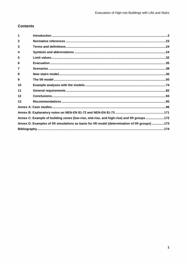
Figure 1.1 – Wheelchair users cannot evacuate from high-rise buildings without using lifts
1.3.4 Opportunities and challenges
The use of lifts for evacuation offers the following advantages:
It is possible to evacuate mobility-impaired occupants with lifts, making evacuation of the entire population in an emergency in a high-rise building feasible.
In an evacuation, people tend to choose a route they are familiar with, so it is logical for them to use lifts because they are used to using them (as opposed to escape stairs).
The physical effort of leaving the building is dramatically reduced.
Congestion in the stairwells is reduced.
The simultaneous capacity of stairwells and lifts can be exploited.
The redundancy of evacuation resources increases because a wider range of resources becomes available.
Clearance times are reduced.
The investment in providing evacuation lifts is less than the investment needed for more and/or wider stairwells.
Furthermore, the following challenges must be taken into account:
People are not yet used to using lifts for evacuation.
The safety of people waiting in the lift lobbies must be guaranteed.
Different evacuation strategies may arise for different buildings.
Background Report
6
Evacuation with lifts requires different compartmentation and design of fire- and smoke-free areas.
The functional integrity of lifts must be guaranteed.
Human behaviour must be taken into consideration.
1.4 Experience gained in the use of lifts for evacuation
1.4.1 General
In this section, we provide some general background information on experience gained in the use of lifts for evacuation in various parts of the world. The text is intended to be purely informative.
1.4.2 Experience and guidelines worldwide
Lifts are increasingly being used for evacuation all over the world. The traditional approach using stairs only is being departed from more and more, with a more holistic approach being adopted that takes all aspects of the building design and use into account, including the safety of the building occupants. Lifts play a crucial role in this approach: the advantages of using lifts are so patently obvious that various buildings have already been fitted with evacuation lifts despite the fact that there are as yet no standards in place for them.
The current trend in the event of a fire alarm is to send the fire-fighting lifts to the fire service access level to await the arrival of the fire service. The other evacuation lifts are used to clear the floor on which the fire alarm was raised, along with the two floors above and below it. Once these floors have been cleared, the evacuation lifts are sent to the evacuation floor to await further instructions from the fire service. If the fire service commander decides that full evacuation is necessary or that an additional zone in the building needs to be evacuated, the evacuation lifts are activated to evacuate the building or zone in a top-down process. A floor is considered evacuated when no further lift calls are placed. If calls are placed subsequently, a lift is sent back up to the corresponding floor.
The number of towers worldwide that are evacuated with lifts is still limited (see also Subsection 1.4.3). In most cases, therefore, these are one-off incidents and they are not based on any standards or codes. Structural, fire safety, installation, lift engineering and organisational aspects are generally organised on the basis of a best estimate in line with the situation. Sometimes BS (British Standard) 5588-8:1999 is applied; this refers to evacuation with lifts as a possibility, but only gives rough indications as to functional integrity requirements. This standard was replaced in 2008 by BS 9999:2008. The new standard makes recommendations for the design of evacuation lifts, including the surrounding area (lobbies, stairwells etc.). It discusses accompanied fractional evacuation only.
In a few cases, previous versions of ISO/TR 25743:2010 may have been used, but this standard only describes the decision tree and communication between the Building Management System (BMS) and the lift control system. The European standard for fire-fighting lifts, EN 81-72, has also sometimes been used as a reference, along with EN 81-73 on the behaviour of lifts in the event of fire, to prevent doors from opening on the floor containing the seat of the fire. See Annex B for a brief explanation of the content of these two standards.
US guidelines for evacuating with lifts have only recently become available with the publication of NFPA 5000:2009. This prescribes evacuation with lifts for special technical functions with a small population and a non-public function (observation platforms, radio masts, control towers etc.), and for certain other functions in particular circumstances. However, this has not yet been used in completed high-rise buildings. The starting points have been used in broad terms as a reference for the requirements described in Chapter 11 of this report.
Finally, CEN (the European Committee for Standardization) is also engaged in the preparation of EN 81-76: ‘Evacuation of disabled persons using lifts’. This standard is not yet available, but it will concentrate purely on the requirements for accompanied, fractional evacuation of mobility-impaired persons.
Evacuation of High-rise Buildings with Lifts and Stairs
7
In all the above-mentioned guidelines, only requirements for the design and surroundings of evacuation lifts are given, such as the emergency power supply, additional signalling, communication, and fire resistance. Evacuation scenarios, evacuation routines for the lift control, and expected evacuation times with lifts are not discussed. The specific problems surrounding evacuation of high-rise buildings are also not addressed.
1.4.3 Examples of evacuation with lifts worldwide
A list of buildings in which evacuation takes place with lifts can be found in Table 1.1. This list may not be exhaustive.
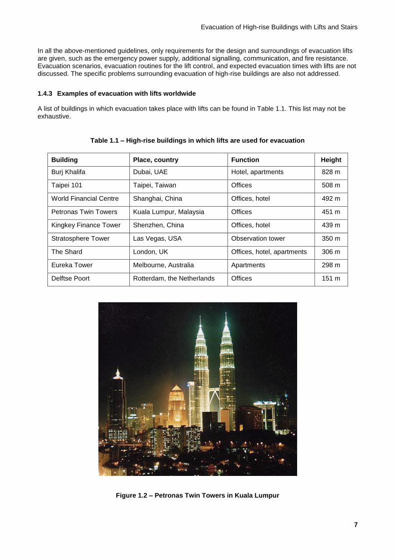
Table 1.1 – High-rise buildings in which lifts are used for evacuation
Building Place, country Function Height
Burj Khalifa Dubai, UAE Hotel, apartments 828 m
Taipei 101 Taipei, Taiwan Offices 508 m
World Financial Centre Shanghai, China Offices, hotel 492 m
Petronas Twin Towers Kuala Lumpur, Malaysia Offices 451 m
Kingkey Finance Tower Shenzhen, China Offices, hotel 439 m
Stratosphere Tower Las Vegas, USA Observation tower 350 m
The Shard London, UK Offices, hotel, apartments 306 m
Eureka Tower Melbourne, Australia Apartments 298 m
Delftse Poort Rotterdam, the Netherlands Offices 151 m
Figure 1.2 – Petronas Twin Towers in Kuala Lumpur
Background Report
8
Below, we describe the evacuation methods used in two prominent buildings from Table 1.1 and the use of lifts in evacuation.
Petronas Twin Towers (see Figure 1.2) The Petronas Twin Towers in Kuala Lumpur are two interconnected office towers. They have a control centre with an in-house safety department which is manned 24/7. The staff of this department provide first response (first aid, initial fire-fighting) until the fire service arrives. Mobility-impaired people are evacuated by department staff via the service lifts. Any casualties are evacuated via the fire-fighting lifts. There are two service lifts and two fire-fighting lifts in both towers.
The towers are functionally separated into two building zones: the low zone (floors 8-37) and the high zone (floors 41-86). The low zone is served by a low-rise lift group (floors 8-23) and a high-rise lift group (floors 24-37). The high zone is served by a low-rise lift group (floors 41-61), a mid-rise lift group (floors 62-75), and a high-rise lift group (floors 76-86). The low zone is served by passenger lifts directly from the ground floor. To get from/to the high zone, occupants must take shuttle lifts between the ground floor and the sky lobbies on floors 41 and 42. Every tower has five double-deck shuttle lifts. On the sky lobby floors, the two towers are interconnected by a skybridge.
Workers in the low zone evacuate via the stairs. Workers in the high zone descend via the stairs to floor 41 (low-rise zone) or 42 (mid-rise and high-rise zone), where they assemble and are evacuated with the shuttle lifts.
Before the 9/11 attacks on the WTC in New York, the strategy was to evacuate workers from one tower by having them transfer to the other tower on floors 41 and 42, from where they could be evacuated safely with that tower’s shuttle lifts. This was changed after 9/11: in situations where both towers need to be cleared or the connecting bridge is unusable, each tower can now be evacuated separately and simultaneously using its own shuttle lifts. A bomb threat in 2001 highlighted the risk involved in the original approach: workers from both towers met on the connecting bridge, creating a highly dangerous impasse. The evacuation ultimately took several hours. The new strategy proved much more effective when in October 2002 it was shown in an exercise that both towers could be evacuated in 32 minutes.
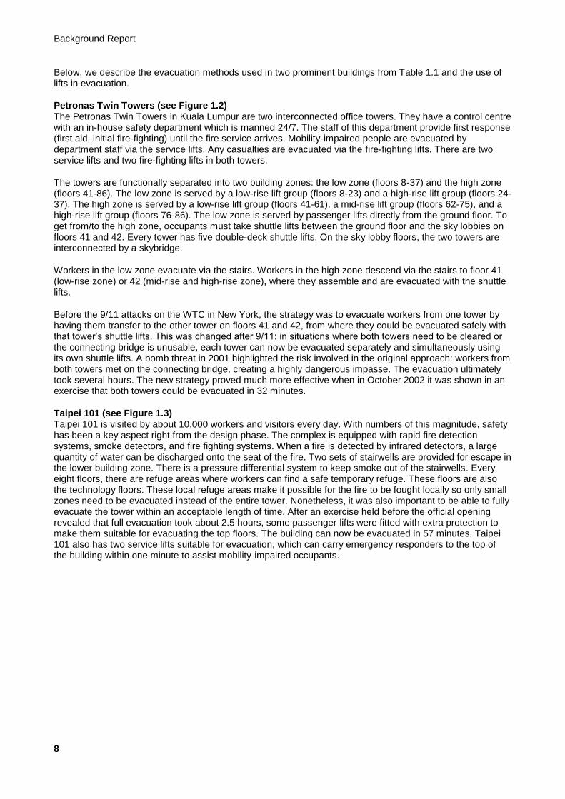
Taipei 101 (see Figure 1.3) Taipei 101 is visited by about 10,000 workers and visitors every day. With numbers of this magnitude, safety has been a key aspect right from the design phase. The complex is equipped with rapid fire detection systems, smoke detectors, and fire fighting systems. When a fire is detected by infrared detectors, a large quantity of water can be discharged onto the seat of the fire. Two sets of stairwells are provided for escape in the lower building zone. There is a pressure differential system to keep smoke out of the stairwells. Every eight floors, there are refuge areas where workers can find a safe temporary refuge. These floors are also the technology floors. These local refuge areas make it possible for the fire to be fought locally so only small zones need to be evacuated instead of the entire tower. Nonetheless, it was also important to be able to fully evacuate the tower within an acceptable length of time. After an exercise held before the official opening revealed that full evacuation took about 2.5 hours, some passenger lifts were fitted with extra protection to make them suitable for evacuating the top floors. The building can now be evacuated in 57 minutes. Taipei 101 also has two service lifts suitable for evacuation, which can carry emergency responders to the top of the building within one minute to assist mobility-impaired occupants.
Evacuation of High-rise Buildings with Lifts and Stairs
9
Figure 1.3 – Taipei 101 in Taiwan
These office towers have a total of 50 lifts, including 34 double-deck lifts. Public access to the observatory on the 89
th floor is provided via two public shuttle lifts.
NOTE: These shuttle lifts are officially recognised as the fastest lifts in the world by the publication Guinness World Records. The ascending lift speed with full cabins is 16.8 m/s (about 60 km/h). The descending speed is 10.0 m/s
(approx. 37 km/h). By way of comparison, the fastest lifts in the Netherlands operate at 6.0 m/s (Maastoren, Rotterdam; Delftse Poort, Rotterdam; Rembrandt Tower, Amsterdam; Hoftoren, The Hague; and WTC, Amsterdam).
The office tower (9th to 84
th floor) consists of three zones and is accessed as three independent segments of
about 110 m in height stacked on top of one another. Transport to and from the sky lobbies on the 35th and
59th floors is provided by ten fast double-decker shuttle lifts with a capacity of 4,080 kg (27 persons per car)
which convey passengers non-stop to the transfer floors. Each of the three subsegments is individually connected to local double-deck lifts with a capacity of 2,700 kg (18 persons per car): 4 low-rise and 4 high-rise lifts per segment.
In addition to the public shuttles to the observatory on the 89th floor and the double-deck lifts mentioned
above, Taipei 101 also has five exclusive (local) passenger lifts (for the Sky Restaurant and the Executive Club), three general goods and fire-fighting lifts, six separate lifts to the parking levels, 11 passenger lifts in the platform (commercial functions), and 50 escalators.
1.4.4 Experience gained from 9/11
Although evacuation with lifts was never envisaged for the WTC in New York, the lifts in WTC2 played an important role in the evacuations during the 9/11 attacks. After the first aircraft hit WTC1, many people left WTC2 as a precautionary measure using the lifts. The effect of this is shown in the egress flow profiles of both WTC towers (see Figure 1.4), from which the following interesting conclusions can be drawn for this study:
a) Immediately after the first aircraft hit WTC1, evacuation started in both towers. But the egress flow rate in WTC2 was about three times higher in the first 18 minutes. This can partly be explained by the fact that the lifts were used in this tower.

Background Report
10
b) Even after the second aircraft hit WTC2, the egress flow rate from this tower was still higher than from WTC1. This can also be explained by the fact that the lifts were used in this tower, which meant that capacity on the stairs was much lower during evacuation from this tower.
c) Although WTC2 remained standing for less time after the attack than WTC1, more people were rescued from it. This too can be partly attributed to the fact that the lifts in this tower were used and precautionary evacuation took place after the impact in WTC1.
d) In WTC2, 44% of the population above the point of impact was saved, while in WTC1 nobody above the impact managed to leave the tower. This is mainly due to the precautionary evacuation that got under way in WTC2 after the impact in WTC1.
The above all too clearly illustrates the added value of lifts for evacuation purposes.
Figure 1.4 – Egress flow profiles in WTC1 and WTC2 on 9/11
1.4.5 Dutch experience with evacuation with lifts
Evacuation with lifts has already taken place on a small scale in the Netherlands, namely in the Delftse Poort building in Rotterdam (151 m, completed in 1991). This building has a high level of safety facilities, far higher than the minimum requirement. Because the building was unusually high at the time it was designed, it was decided to aim for an excellent safety level. In addition to the compartmentation and sprinkler system, the building has a redundant emergency power supply and three escape stairwells (two in the low-rise building) with lobbies, fitted with a pressure differential system.
The in-house emergency response organisation has an agreement with the Rotterdam fire service regarding the use of one passenger/goods lift and a reserve (second) fire-fighting lift for evacuating mobility-impaired persons. The lift lobby in front of these lifts is between the two (30-minute) fire-resistant doors to the stairs, so the stairs are accessible from the lift lobby for at least 30 minutes. The lift lobby itself can also be isolated by a door offering an additional 60 minutes resistance against smoke and fire. The lift lobby is fitted with advanced fire and smoke detectors.
Finally, the fire service command centre can switch the normal lifts to evacuation mode remotely. Although this option is available from a technical point of view, the Rotterdam fire service and Delftse Poort’s in-house

Evacuation of High-rise Buildings with Lifts and Stairs
11
emergency response organisation have agreed not to use it, and that able-bodied evacuees should be evacuated using the stairs.
1.5 Objective
Based on the observations and questions described in Section 1.1, the following objective was formulated for the study of evacuation with lifts and stairs in high-rise buildings:
‘Development of a model for determining the optimal evacuation strategy for high-rise buildings, depending on the building function and height. This model must enable the evacuation time for each strategy to be estimated, and should allow stairs and lifts to be used simultaneously.’
To ensure that this model is usable and reliable, the following subsidiary objectives apply:
a) The common evacuation models for stairs in high-rise buildings should be tested and, if necessary, improved.
b) A lift model should be developed for evacuation with lifts.
c) The model should provide formulae for integrated evacuation with lifts and stairs, and it should be possible to determine the necessary evacuation times for each strategy.
d) The model should not only offer a solution for fires but also for other types of emergencies, such as external safety (bomb alerts, chemical leak, fires in the vicinity etc.) and extreme weather conditions (flooding, hurricane etc.). The assumption is that everybody in the building must be able to be evacuated; evacuation by zones or fractional evacuation is inadequate in light of the possible emergencies mentioned above. The evacuation method and evacuation capacity must therefore be designed for full evacuation.
e) For each strategy, the model must set out the necessary requirements regarding engineering, fire safety, installation technology, lift engineering, logistics, organisation, compliance, communication, and signalling.
The model should be a planning tool, not a forecasting tool: it should specify the best theoretical strategy for a building instead of predicting what is actually going to happen.
In addition to the model, general requirements to eliminate objections to evacuation with lifts will be specified. The following objections are listed on page 28 of the SBR Code of Practice:
a) The increased risk that waiting evacuees will be exposed to smoke and/or heat
b) Technical risks with regard to lift control, e.g. stopping on the floor with the fire
c) Lifts being overfilled
d) Malfunctioning lift electronics
e) Fire-fighting water leaking into the lift shaft
f) Users not trusting the use of lifts.

Background Report
12
1.6 Scope
This report applies to buildings between 70 and 250 m in height. The method presented in it was developed on the basis of buildings with one of the following functions:
a) Residential function
b) Office function
c) Hotel function
When applying the method to buildings with a different function, the differences between the function in question and the functions used in the development of this method should be borne in mind. At present, there do not seem to be any objections to using the method for any other functions.
This report and the evacuation methods described in it do not apply to the evacuation of buildings
a) Whose structural integrity can no longer be guaranteed on account of an explosion, attack, or earthquake
b) Whose structural integrity is no longer guaranteed on account of fire that is still out of control after 120 minutes (i.e. a building with no effective automatic fire-fighting facilities)
c) Whose height is outside the above range of 70 to 250 m 1
d) With a function other than an office, accommodation or residential function 2
e) In which passenger traffic is handled in double-decker or twin lifts
f) In which a fire occurs in the shafts, cars or machine rooms of evacuation lifts
1.7 Requirements and assumptions in the model
The following assumptions and requirements apply to the evacuation model presented in this report. These are partly based on the joint vision formulated by the participants of the Evacuation of High-Rise Buildings workshop at NEN on 12 February 2010. The assumptions and requirements are as follows:
a) Clearance of high-rise buildings is the responsibility of the building owner or operator, not of the fire service.
b) A maximum clearance time of 30 minutes must be aimed at, although 60 minutes is assumed as a maximum. It is assumed that the main supporting structure will be resistant to collapsing for at least 120 minutes. See also Subsection 5.1.1 and NTA 4614-3.
1 However, the approach and the model are suitable for low-rise buildings (< 70 m).
2 Other building functions for high-rise buildings include: assembly function (panorama deck) and healthcare. The assumption for
assembly functions is now that people in high-level assembly functions are collected first, unless this function has its own lifts (separate
function not mixed with the underlying building function). In healthcare buildings, it is usual to evacuate horizontally to another fire
compartment, so the building does not need to be cleared.
Evacuation of High-rise Buildings with Lifts and Stairs
13
c) The building must at least be fitted with an automatic sprinkler system certified in accordance with the applicable regulations. The associated risk of failure of the system as a combination of various components depends on the nature of the building and the function within which the system is used. In the event of a normal fire, the building will be partially cleared to begin with. Complete evacuation in the event of a fire is assumed not to apply to begin with, although it will apply to other types of emergencies (bomb alert, chemical leak, fire/smoke in immediate vicinity). A point to note in this regard is that the alarm system is geared towards partial evacuation. An accidental alarm throughout the whole building will result in undesirable situations. Full evacuation in the event of a fire may become necessary subsequently; this decision will be taken by the fire service on site. The level of facilities is geared towards the situation in the event of a fire; the evacuation time is determined for full evacuation, whereby the impact of a fire does not affect aspects such as the choice of which floor to evacuate first.
d) Any tie-in with NEN 6089 is specifically not being studied further. This is because this standard is not geared towards tall buildings and the associated delays. Both NEN 6089 and this report are intended solely for use within the area of application described in the documents. Furthermore, the standard also does not relate to the escape scenarios described in the SBR Code of Practice for high-rise buildings.
e) All lifts are available, or this report assumes that one emergency happens at a time.
f) High-rise buildings will always have two fire-fighting lifts: fewer than this is not permitted according to the SBR Code of Practice, and the workshop concluded that more are not necessary. The fire-fighting lifts form part of a central lift group (all lifts serving all floors) or a high-rise lift group (with additional stops in the bottom part of the building) or are separate passenger/goods lifts.
g) Fire-fighting lifts are available for evacuation until the fire service arrives on site. If both fire-fighting lifts are operational, the second (reserve) fire-fighting lift will remain operational for evacuation purposes after the arrival of the fire service.
h) All lifts are fitted with an emergency power evacuation circuit; fire and evacuation lifts have emergency power or a preferential power supply.
i) There is no evidence of panic. A description of how panic can be avoided can be found in Subsection 1.8.2.
j) The evacuation time that is calculated is the time needed for vertical transport, not including signalling time, reaction time etc. The assumption is that everyone will immediately walk to the stairs or lifts. The starting time of the results presented is the time at which everyone arrives at the vertical transport point on their own floor. See also Section 5.11 for definitions.
k) This report offers no solutions for terrorist attacks such as those on the WTC in New York in 2001.
l) The in-house emergency response organisation determines in-situ whether the building should be evacuated top-down or bottom-up with lifts, possibly in consultation with the fire service. See Section 1.9.
m) The design capacity of the lifts in the building is determined on the basis of NTA 4614-4-6, Verkeersafhandeling met liftinstallaties in hoogbouw [Traffic Handling with Lift Installations in High-rise Buildings].
n) In the event of failure of a fire safety facility such as the pressure differential system, a sprinkler pump, a fire-fighting lift, or an evacuation lift, precautionary evacuation will not take place. However, a risk assessment (RIE) must be drawn up for each situation before routine (preventative) maintenance is performed on these installations.
o) Even if a client/developer wants lower occupancy in the building than the design capacity, the lift plan must not be reduced to reflect this if this would impact on evacuation of the design capacity.
p) A building type can only be modified to another building type if the design capacity is reduced (from office to hotel or apartments, from hotel to apartments), and not vice versa.
Background Report
14
1.8 Human behaviour
1.8.1 Background
Efficient evacuation depends on people behaving predictably and calmly. In an emergency – especially a fire – however, panic can ensue and quickly spread. Luckily, the literature (e.g. Kobes, DSVP) shows that panic seldom occurs during an evacuation: people react remarkably calmly and rationally after the alarm has been raised. This is the result of common sense, naivety, underestimating the risk (‘it won’t happen to me’), or resignation. Furthermore, in practice people act with real solidarity and spontaneously help one another. Problems during evacuation therefore do not generally occur because of panic but for the following reasons:
a) People experience a delayed reaction to an alarm. See also Section 9.5.
b) A considerable proportion of the population do not react to an alarm. See also Section 9.5.
c) People form groups with colleagues, neighbours, or family members. This complicates and delays evacuation because slow people in the group determine the speed of the group, and because people on the stairs form a counterflow when they are looking for their friends or relatives.
d) In an evacuation, people are inclined to follow their regular route into the building in reverse. This is partly because many people in buildings are not accustomed to familiarising themselves with the escape routes and emergency exits. This can cause particular confusion and uncertainty in high-rise buildings because people have entered the building with the lifts and have always been told that they should not use the lifts in an evacuation.
In an evacuation from a high-rise building, it is therefore necessary to prevent panic and eliminate the above obstacles.
1.8.2 How to avoid panic
The likelihood of panic occurring during evacuation from a high-rise building is minimal, particularly if the following requirements are met.
a) The evacuees must be prepared to evacuate and accustomed to doing so. But preparedness for evacuation is low in the Netherlands and must be improved by providing information and staging regular evacuation drills in high-rise buildings, e.g. twice a year. Actual evacuation exercises are currently taking place too infrequently in high-rise buildings. See also Section 11.8.
b) The evacuees must be properly informed about the evacuation procedure to be followed (scenario) and the expected evacuation time. After all, it is important for people in a building to be able to make the right decisions when a building is being cleared. That is why it is essential to provide clear information about the incident and the action perspectives during the incident itself. This information must not only be available as a precautionary measure but should also be regularly repeated during the evacuation in the form of spoken messages. The use of pre-recorded texts for this should be avoided since this does not engender sufficient trust in a tailor-made evacuation procedure.
c) In an evacuation, people are inclined to follow those who take the lead. Suitably trained emergency response team members, security personnel, or caretakers must therefore be present to accompany the evacuation process on each floor (emergency response team members in offices, security personnel in hotels) and/or in each lift (security personnel in hotels, caretakers in apartment blocks). This creates clarity, speeds up an organised evacuation, and can even increase acceptance of possible waiting times at lifts.
d) The people being evacuated must not be confronted directly with smoke or fire.
e) Evacuation routes must never look or be blocked.
f) The refuge areas on regular floors and transition layers must have sufficient room to allow people to wait for the lift in a relaxed way. This can be achieved by assuming no more than 3-4 people per m
2.
Evacuation of High-rise Buildings with Lifts and Stairs
15
g) It must always be possible to evacuate via the stairs because there will always be people who are hesitant about using the lift or who think they will get down sooner if they use the stairs.
h) There must be sufficient lighting on all escape routes.
If the evacuation scenarios set out in this report are applied, it is assumed that the above requirements are met in full.
1.8.3 Preparedness to use a lift
Most people know that, in the event of an emergency and/or evacuation, they are not supposed to use the lifts. The perception is that lifts would not be safe enough, so people are afraid of becoming trapped in a lift that breaks down during the emergency. In practice, many passenger lifts (those that are not fire-fighting lifts) should be able to operate without any problems in most emergencies (flooding, chemical leaks, bomb alerts) and can play a role in an evacuation. But this is often not the case in a fire, as only fire-fighting lifts generally offer protection against smoke and fire and have a preferential power supply.
In many buildings, lifts are fitted with a fire alarm evacuation circuit. This stops the lifts accepting new floor calls in the event of a fire alarm, and causes ascending lifts to stop as quickly as possible and return to the park floor (usually the ground floor) without stopping. Once they arrive on the park floor, the doors open so that any passengers can alight; they are then taken out of service and left with the doors open. They are only taken back into service when the fire service cancels the fire alarm.
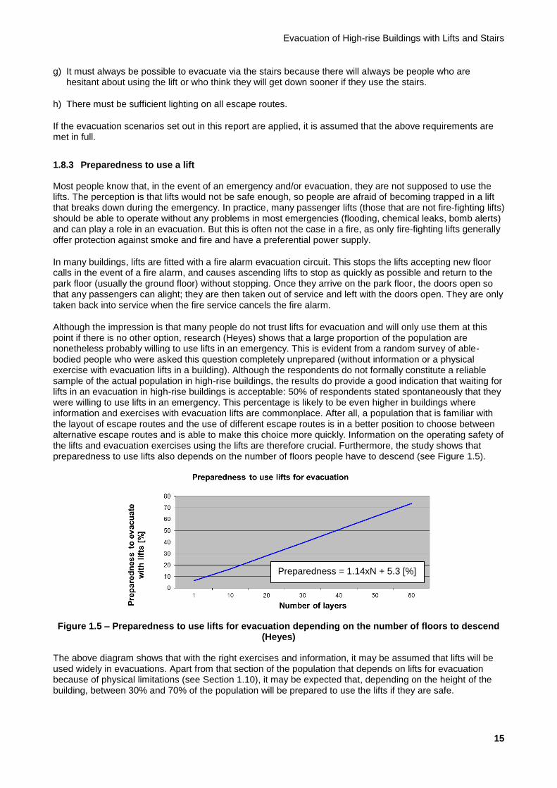
Although the impression is that many people do not trust lifts for evacuation and will only use them at this point if there is no other option, research (Heyes) shows that a large proportion of the population are nonetheless probably willing to use lifts in an emergency. This is evident from a random survey of able-bodied people who were asked this question completely unprepared (without information or a physical exercise with evacuation lifts in a building). Although the respondents do not formally constitute a reliable sample of the actual population in high-rise buildings, the results do provide a good indication that waiting for lifts in an evacuation in high-rise buildings is acceptable: 50% of respondents stated spontaneously that they were willing to use lifts in an emergency. This percentage is likely to be even higher in buildings where information and exercises with evacuation lifts are commonplace. After all, a population that is familiar with the layout of escape routes and the use of different escape routes is in a better position to choose between alternative escape routes and is able to make this choice more quickly. Information on the operating safety of the lifts and evacuation exercises using the lifts are therefore crucial. Furthermore, the study shows that preparedness to use lifts also depends on the number of floors people have to descend (see Figure 1.5).
Figure 1.5 – Preparedness to use lifts for evacuation depending on the number of floors to descend (Heyes)
The above diagram shows that with the right exercises and information, it may be assumed that lifts will be used widely in evacuations. Apart from that section of the population that depends on lifts for evacuation because of physical limitations (see Section 1.10), it may be expected that, depending on the height of the building, between 30% and 70% of the population will be prepared to use the lifts if they are safe.
Preparedness = 1.14xN + 5.3 [%]

Background Report
16
?
Figure 1.6 – How can we ensure that people can and will use the lift safely?
1.8.4 How long are people prepared to wait for a lift?
The fact that people are prepared to use a lift for evacuation if it is safe does not mean that they are prepared to wait for a lift indefinitely. Understandably, people will consider whether they are physically and mentally able to descend a large number of steps, estimate how much time they will need to do so, and use this information to weigh up how long they are prepared to wait for a lift.
Among other things, the time people are prepared to wait for a lift depends on the following:
How safe or threatened they feel in the lift lobby
What they know about the reliability and performance of the lifts
Whether they see any progress in clearance of the building
What information they receive about likely waiting times
Whether they are alone or with other people
Whether there is someone taking the lead or accompanying them and whether they trust them
How easy the stairs are to locate and reach
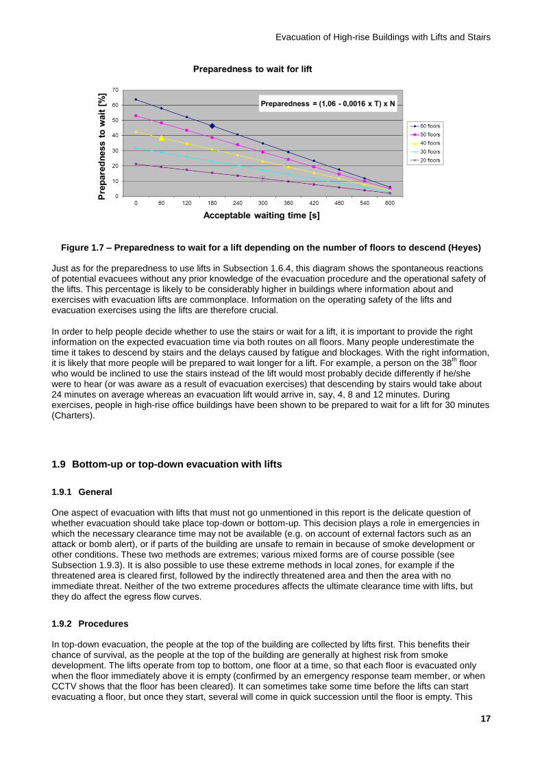
Preparedness to accept a waiting time for evacuation with lifts was also studied (Heyes). Preparedness to wait decreases with the expected waiting time and increases with the height or the number of stairs to descend. In Figure 1.7, this can be seen for a building of 20, 30, 40, 50 and 60 floors. The following examples can be derived from the diagram:
a) Approximately 46% of the population are prepared to wait longer than 180 seconds (3 minutes) on the 60th floor
b) Approximately 38% are prepared to wait longer than 60 seconds (1 minute) on the 40th floor
c) Approximately 13% are prepared to wait longer than 300 seconds (5 minutes) on the 20th floor
Evacuation of High-rise Buildings with Lifts and Stairs
17
Figure 1.7 – Preparedness to wait for a lift depending on the number of floors to descend (Heyes)
Just as for the preparedness to use lifts in Subsection 1.6.4, this diagram shows the spontaneous reactions of potential evacuees without any prior knowledge of the evacuation procedure and the operational safety of the lifts. This percentage is likely to be considerably higher in buildings where information about and exercises with evacuation lifts are commonplace. Information on the operating safety of the lifts and evacuation exercises using the lifts are therefore crucial.
In order to help people decide whether to use the stairs or wait for a lift, it is important to provide the right information on the expected evacuation time via both routes on all floors. Many people underestimate the time it takes to descend by stairs and the delays caused by fatigue and blockages. With the right information, it is likely that more people will be prepared to wait longer for a lift. For example, a person on the 38
th floor
who would be inclined to use the stairs instead of the lift would most probably decide differently if he/she were to hear (or was aware as a result of evacuation exercises) that descending by stairs would take about 24 minutes on average whereas an evacuation lift would arrive in, say, 4, 8 and 12 minutes. During exercises, people in high-rise office buildings have been shown to be prepared to wait for a lift for 30 minutes (Charters).
1.9 Bottom-up or top-down evacuation with lifts
1.9.1 General
One aspect of evacuation with lifts that must not go unmentioned in this report is the delicate question of whether evacuation should take place top-down or bottom-up. This decision plays a role in emergencies in which the necessary clearance time may not be available (e.g. on account of external factors such as an attack or bomb alert), or if parts of the building are unsafe to remain in because of smoke development or other conditions. These two methods are extremes; various mixed forms are of course possible (see Subsection 1.9.3). It is also possible to use these extreme methods in local zones, for example if the threatened area is cleared first, followed by the indirectly threatened area and then the area with no immediate threat. Neither of the two extreme procedures affects the ultimate clearance time with lifts, but they do affect the egress flow curves.
1.9.2 Procedures
In top-down evacuation, the people at the top of the building are collected by lifts first. This benefits their chance of survival, as the people at the top of the building are generally at highest risk from smoke development. The lifts operate from top to bottom, one floor at a time, so that each floor is evacuated only when the floor immediately above it is empty (confirmed by an emergency response team member, or when CCTV shows that the floor has been cleared). It can sometimes take some time before the lifts can start evacuating a floor, but once they start, several will come in quick succession until the floor is empty. This

Background Report
18
should prevent any arguments over the question of who may board first. But the disadvantage of top-down evacuation is that the egress flow rate on the starting level is initially low (see Figure 1.8) because of the long cycle times of the lifts; this disadvantages people waiting lower down if the building is collapsing. The average waiting time for lifts is also high.
With bottom-up evacuation with lifts, as many people as possible are rescued from the bottom up, so the highest possible egress flow rate is achieved because of the initially short lift cycle times. But when a building is collapsing, this evacuation strategy operates at the expense of the people at the top.
Figure 1.8 – Egress flow profiles of top-down versus bottom-up evacuation
Both approaches result in substantially different egress flow curves on the evacuation level (see Figure 1.8). The lift simulations carried out for this study (see Chapter 9) show that the difference in size of the evacuated population between the top-down and the bottom-up approach may well amount to around 15% at the halfway mark.
1.9.3 Mixed forms
Mixed forms and variations on the evacuation sequence are of course possible, such as the following.
a) Each lift is allocated a zone of several floors which are only evacuated individually by this lift. The advantage of this is that waiting times are distributed more-or-less evenly across the height of the building, but there will also be long intervals between the successive arrivals of a lift at a floor, which may result in agitation and pushing.
b) Half the lifts evacuate top-down and the other half bottom-up. This leads to the shortest waiting times at the bottom of the tower, average waiting times at the top of the tower, and the longest waiting times in the middle. It may take some time before the lifts start evacuating a floor, but once they start, several will come in quick succession until the floor is empty. This should avoid agitation around the question of who may board first.
c) The lifts evacuate the floors together in succession from top to bottom, with each lift serving one floor only, the next going to the next floor down, and so on. As soon as a lift reaches the lowest floor, the next lift starts again at the top floor. The advantage of this is that waiting times are distributed more-or-less evenly across the height of the building, but there will also be long intervals between the successive arrivals of a lift at a floor, which may result in agitation and pushing.

Evacuation of High-rise Buildings with Lifts and Stairs
19
1.9.4 Moral choice
The choice between top-down evacuation, bottom-up evacuation, or another mixed form therefore mainly depends on the anticipated remaining availability of the building, how safe it is to remain in it at different heights, and the population’s acceptance of waiting times. This complex, moral choice is up to the in-house emergency response organisation which has ultimate responsibility for the evacuation on behalf of the owner/operator. This decision should be made in consultation with the fire service once they arrive, however, since the fire service is able to best estimate the chances of survival depending on the height of the building. Until the fire service arrives, top-down should be the starting point, because the number of people who rely on lifts for evacuation increases with the height of the building. Depending on the nature of the emergency, however, bottom-up or a mixed form or variant determined in the design phase may also be desirable.
1.10 Physical limitations
1.10.1 Types of physical limitations
In Subsection 1.3.2 of this report, we have already seen that a considerable proportion of the population in high-rise buildings is not able to descend via the stairs unaided due to physical limitations. This group not only includes wheelchair users but comprises a much larger group of people who are mobility-impaired, such as the following:
a) Wheelchair users
b) People with joint pain, arthritis, or rheumatism
c) People with restricted mobility (prosthetic leg, walking stick, walker etc.)
d) People with heart and circulation problems
e) People with respiratory problems / asthma; smokers
f) People who need assistance as a result of taking medication
g) The injured, including those with injuries sustained during the evacuation
h) The visually-impaired
i) Obese people
j) Pregnant women
k) Elderly people
l) People in poor physical condition
1.10.2 Fractions
The group of people with a physical impairment forms a significant fraction of the total population in high-rise buildings. This is evident from a survey of survivors of 9/11, for example:
a) 70% were overweight, of which 5% were obese
b) 64% played no regular sports
c) 15% were smokers

Background Report
20
d) 24% had respiratory problems or arthritis
Even descending the stairs has been shown to be potentially hazardous: as many as 7% of the survivors of the WTC disaster stated that they had sustained orthopaedic injuries on the stairs, such as a sprained ankle or from tripping over shoes that had been left behind. Although it is debatable whether the average American is comparable with the average Dutch person in this respect, the above percentages indicate that a considerable fraction of the population may potentially suffer physical impairment while descending the stairs in a high-rise building, and will therefore be in need of assistance.
1.10.3 Indicative values
There is no specific data available on the fractions of people with physical impairments in the context of evacuation from high-rise buildings for the Netherlands. It may be assumed that 15-20% of the Dutch population are less able or unable to evacuate themselves in an emergency as a result of age and physical or psychological impairments, based on data from the Nationale Atlas Volksgezondheid [Dutch National Atlas of Public Health] and Statistics Netherlands (CBS). In order to test this assumption, delegates at the NEN Evacuation from High-Rise Buildings workshop on 12 February 2010 were asked how large they thought this fraction was for each usage function. The results can be found in Table 1.2. This table shows the lowest, highest and average estimate for each usage function by about 45 respondents.
Table 1.2 – Physical impairments preventing evacuees from using the stairs (estimated during workshop on 12 February 2010)
Type of impairment Usage function Minimum Maximum Average
Wheelchair users
Office function 0.5% 5% 2%
Residential function 0.5% 10% 4%
Hotel function 0.5% 10% 3%
Other impairments
Office function 0.1% 60% 10%
Residential function 1.0% 60% 16%
Hotel function 1.0% 60% 15%
Total
Office function 1.5% 61% 12%
Residential function 3.5% 67% 20%
Hotel function 1.5% 62% 18%
The values in the above table are purely indicative, as they are estimates from a random sample of interested parties in the area of fire safety and evacuation. This group cannot be guaranteed to have expertise in this specific field. A specific follow-up study of fractions of mobility-impaired people in high-rise buildings is therefore recommended in order to produce more substantiated figures. Until such time as better information is available from specific research or reliable data comes on-stream on a project basis, it is recommended to use the indicative percentages of mobility-impaired evacuees in the right-hand column of Table 1.2 (‘Average’) for evacuation with lifts. This fraction will be unable, or less able, to descend the stairs in high-rise buildings, and is therefore reliant on lifts.
1.11 Risk approach
The combined model for evacuation with lifts and stairs from high-rise buildings described in this report has a deterministic character when it comes to evacuation safety. In the context of the Covenant on High-rise
Evacuation of High-rise Buildings with Lifts and Stairs
21
Buildings and, in particular, the contribution of sub-working group 02, this has also always been the angle taken in the study presented here. An important aim of the study in this regard is to provide a method that can be used for buildings that are not covered entirely by the Building Decree and that can demonstrate that the level of safety achieved is equivalent to what is intended by the Building Decree. Although the use of Fire Safety Engineering (FSE) may play a role in this model, this is not yet necessarily the case now.
In order to be able to tie in with an integrated FSE approach for high-rise buildings in the future, it would also be desirable to offer a risk approach for evacuation safety in accordance with this model. An important aspect in a risk approach is to define the area under consideration. For a building, the impact of the failure of the evacuation options depends very much on the potential extent of a developing emergency. Fire safety measures implemented in the building in addition to measures to ensure safe evacuation are therefore of great importance for the actual safety of the building.
Following and/or adding this probabilistic risk approach would be outside the remit of this particular study. However, the model presented can play a role in, and is an initial step towards, a probabilistic FSE method including evacuation. We recommend developing the model further within the FSE method. This will enable a further step to be taken towards assessing fire safety in high-rise buildings within the contexts of potential scenarios and their associated effects. Furthermore, a risk approach would be more favourable towards innovation and would therefore have more value for the future. In terms of the escape options, further research should then be carried out into the risk of failure or the availability of the various components that play a role in escaping from a building, as well as their correlation with a developing emergency. Also important is to what extent the properties assigned to the escape routes are at risk of being exceeded or not achieved.
The following aspects and components come to mind:
Sprinkler system
Dry and wet risers
Pressure differential system
Evacuation system
Public address system
Stairwell (fire)
Stairwell (access failure)
Blocked escape route
Central group lift control, including evacuation control
Individual lift (during peak hours)
Individual lift (during off-peak hours)
Machine room (fire)
Lift shaft (fire)
Lift car (fire)
The dimensions of evacuation facilities are designed to prevent casualties during evacuation. Of course, no level of facilities is guaranteed to prevent casualties completely. There is a particularly realistic risk of injury to building users in areas of the building near the site of the emergency. The ratio between the speed at which the emergency – such as a fire – develops and the time needed to clear such an area is unfavourable.

Background Report
22
Outside an area where an actual emergency is taking place, the available escape time depends on the entirety of measures taken to isolate an emergency. These include measures near the emergency itself, such as an automatic sprinkler system, or measures that prevent the emergency from spreading further, such as smoke- and fire-resistant partitions.
In this report, we present research into the length of time a vertical escape route must remain usable. For now, the upper limit applied for the escape route is 60 minutes in combination with 120 minutes for the main supporting structure of the building. Together with the projected sprinkler system for the buildings under consideration here (Covenant on High-rise Buildings), the aim is to create a situation in which the escape route will in fact remain usable without restriction in most of the emergencies anticipated in the Netherlands.
In an actual risk analysis, it would be necessary to take a closer look at possible emergencies and the likelihood of their occurring, as well as the associated effects. In this context, it may be ascertained that in a number of emergencies the escape route does not remain available without restriction, so the escape time should be related to the expected availability of the escape route. In that case, the threat time for the vertical escape route and everything associated with it should be established. The combination of the threat time, the escape time, the risk of occurrence, and the potential impact of the emergency may then result in a certain risk, which may or may not be deemed acceptable. In such a system, this form of assessment will identify any additional measures that may be necessary.
For now, in the context of the lift model it is advisable to also determine the evacuation time with one less lift per lift group, with the premise that the maximum evacuation time of 60 minutes must not be exceeded in this case either.

Evacuation of High-rise Buildings with Lifts and Stairs
23
2 Normative references
The following documents, to which reference is made, are essential for the application of this report. Where references are dated, only the cited version applies. Where references are undated, the latest version of the document (including amendment sheets) referred to applies.
Bouwbesluit Building Decree
SBR Code of Practice Brandveiligheid in hoge gebouwen [Fire Safety in High-rise Buildings]
ISO/TR 25743:2006 Lifts (elevators) – Study of the use of lifts for evacuation during an emergency
NEN-EN 81-1 Safety rules for the construction and installation of lifts – Part 1: Electric lifts
NEN-EN 81-70 Safety rules for the construction and installations of lifts – Particular applications for passenger and good passenger lifts – Part 70: Accessibility to lifts for persons including persons with disability
NEN-EN 81-72 Safety rules for the construction and installation of lifts – Particular applications for passenger and goods passenger lifts – Part 72: Firefighters lifts
NEN-EN 81-73 Safety rules for the construction and installation of lifts – Particular applications for passenger and goods passenger lifts – Part 73: Behaviour of lifts in the event of fire
BS 9999:2008 Code of practice for fire safety in the design, management and use of buildings
NFPA 5000:2009 Building Construction and Safety Code
NPR-CEN/TS 81-76:2011 Safety rules for the construction and installation of lifts – Particular applications for passengers and goods passenger lifts – Part 76: Evacuation of disabled persons using lifts
NTA 4614-3 Covenant high-rise buildings – Part 3: Structural safety
NTA 4614-4 Covenant high-rise buildings – Part 4: Elevator installations
NTA 4614-5 Covenant high-rise buildings – Part 5: Facades and facade maintenance installations
NEN 6089 Determination of the collection capacity and the throughput capacity of circulation spaces

Background Report
24
3 Terms and definitions
The following definitions are used in this standard.
3.1 Able-bodied evacuee Person able to move via the stairs independently without assistance from others
3.2 Acceleration Change in speed per time unit, in m/s
2
3.3 Accompanied evacuation Evacuation in which the process is accompanied by assistance on the floors and/or in the lifts, for example by in-house emergency response team members (in offices) or an in-house security service (in hotels)
3.4 Building zone Vertical range of contiguous floors in a building
NOTE 1: In a building with one or more sky lobbies, the sky lobbies isolate the building zones from each other. In a building without sky lobbies, there is only one building zone. There is generally only one usage function in a building zone. If there is more than one usage function in a building zone, these are generally accessed by lifts separately, with the stopping range of the low-rise lift group, the high-rise lift group, and – if applicable – the mid-rise lift group corresponding to the floors of the usage functions.
NOTE 2: See Annex C.
3.5 Clearance time Time needed to clear a building or part of a building; in the event of a fire: time between a fire starting and the time the building is empty
3.6 Descent time per floor Time needed for the population of a floor to descend one floor via a stairwell
3.7 Destination time Time calculated from the placing of a call command, the waiting time, and the time a person spends in the lift car until the moment the passenger leaves the lift car at the destination
NOTE: Destination time is the sum of the waiting time and the journey time.
3.8 Detection time Time until a fire is discovered (by a person or automatically)
3.9 Disabled evacuee Person unable to move via the stairs independently or with assistance from others
3.10 Emergency power evacuation circuit
Circuit that keeps the lifts operating in emergency mode if main power is lost
NOTE: This circuit usually provides staggered restarting of the lifts, after which they return to the park floor with no intermediate stops, so that lift users do not remain trapped inside.
3.11 Escape capacity The capacity of a stairwell to accommodate escaping persons, expressed in persons per second per metre of stair width
3.12 Evacuation The organised, controlled vertical movement of persons in a building from a dangerous area to a safe exit
NOTE: Evacuation can take place from floor to floor and does not necessarily lead outside the building.
Evacuation of High-rise Buildings with Lifts and Stairs
25
3.13 Evacuation lift Passenger lift designed to evacuate persons in a safe manner
3.14 Evacuation lift service Handling of traffic with lifts whereby control of the lifts by the group control is designed to minimise evacuation time during evacuation with lifts
3.15 Evacuation method Method chosen to evacuate the building, with relation to the choice of lifts and stairs, the organisation, communication etc.
3.16 Evacuation scenario Form of combined evacuation with lifts and stairs using the determination method offered in this report
3.17 Evacuation time Time needed to descend the vertical distance from the evacuation layer to the exit of the vertical escape route
3.18 Evacuation zone Area being evacuated
NOTE: This area may be part of one floor or may cover several floors.
3.19 Exit time Time needed to cross the horizontal distance between the exit from the vertical escape route to the building exit
3.20 Fire- and smoke-free escape route Fire and smoke-free escape route that leads exclusively through circulation areas
3.21 Fire-fighting lift Passenger lift suitable for use by the fire service in accordance with NEN-EN 81-72
3.22 Fractional evacuation (with lifts) Evacuation in which the bulk of the building population leaves the building by the stairs but a fraction of mobility-impaired persons is evacuated with lifts
3.23 Full evacuation Evacuation in which the complete building population leaves the building
3.24 Group control (lift control) Connection between lift controls that optimises traffic handling by multiple lifts in a lift group by assigning traffic to individual lifts appropriately, so as to minimise average waiting times and/or destination times
3.25 High-rise lift group Local lift group within a building zone that serves the high-rise zone of a building zone from the ground floor or a sky lobby
NOTE 1: In a building with multiple building zones, there may be multiple high-rise lift groups.
NOTE 2: See Annex C.
3.26 High-rise zone Top part of a building zone that also incorporates a low-rise zone and possibly a mid-rise zone
NOTE 1: In a building with multiple building zones, there may be multiple high-rise zones.
NOTE 2: See Annex C.
Background Report
26
3.27 Hoisting height Vertical travel distance between the floor level of the park floor (excluding any parking or basement floors below) and the floor level of the highest floor served in normal service (excluding any technical or attic floors above)
3.28 Initial time Time a person takes to travel the horizontal distance between their current location and the vertical escape route
3.29 Length of the escape route Length of the escape route to be travelled by persons in stairwells
3.30 Lift capacity The carrying capacity of a lift or lift group, expressed in persons per time unit or as a percentage of the building population per time unit
NOTE: In this report, the lift capacity is expressed as HC5peak, the percentage of the building population that uses the lifts
in the busiest five minutes of the morning peak.
3.31 Lift car Part of the lift designed to accommodate and transport persons and/or goods
3.32 Lift car capacity Number of persons in the lift
NOTE: The standard for passenger lifts (NEN-EN 81-1) specifies that the maximum lift car capacity expressed in persons is equal to the load capacity divided by 75 kg.
3.33 Lift car capacity percentage Relationship between the actual lift car capacity and the maximum permitted lift car capacity in accordance with NEN-EN 81-1, expressed as a percentage
3.34 Lift lobby Waiting area for users in front of or between lifts
3.35 Lift simulation Capacity calculation in which the required lift configuration is based on an analysis of traffic handling with a modelled building, lift group, population, and traffic scenario
NOTE: In the simulation model, lifts handle traffic within a selected lift control based on pre-entered parameters. The data for this calculation method for determining the required lift configuration is obtained from a stochastic inflow profile of lift users in which, among other things, the actual waiting time and destination time of each call is registered along with the actual lift car capacity.
3.36 Low-rise lift group Local lift group within a building zone that serves the low-rise zone of a building zone from the ground floor or a sky lobby
NOTE 1: In a building with multiple building zones, there may be multiple low-rise lift groups.
NOTE 2: See Annex C.
3.37 Low-rise zone Lowest part of a building zone that also incorporates a high-rise zone and possibly a mid-rise zone
NOTE 1: In a building with multiple building zones, there may be multiple low-rise zones.
NOTE 2: See Annex C.
Evacuation of High-rise Buildings with Lifts and Stairs
27
3.38 Mid-rise lift group Local lift group within a building zone that serves the mid-rise zone of a building zone from the ground floor or a sky lobby
NOTE 1: In a building with multiple building zones, there may be multiple mid-rise lift groups.
NOTE 2: See Annex C.
3.39 Mid-rise zone Middle part of a building zone that also incorporates a low-rise and a high-rise zone
NOTE 1: In a building with multiple building zones, there may be multiple mid-rise zones.
NOTE 2: See Annex C.
3.40 Mobility-impaired evacuee Person able to move via the stairs with assistance from others
3.41 Nominal load Load for which the lift is designed, in kg
3.42 Nominal speed Speed of the lift car for which the lift is designed, in m/s
3.43 Park floor (main stopping place) Floor on which there is an entry level (entry, exit)
3.44 Passenger lift Permanently installed lifting device that serves certain stops and is fitted with a lift car the dimensions and composition of which identify it as being suitable for use by persons and which moves, entirely or partially, along vertical guides or guides at an angle of less than 15° from the vertical
3.45 Peak lift service Handling of traffic with lifts whereby control of the lifts by the group control is designed to minimise average waiting times or destination times during the representative peak traffic scenario
3.46 Phased evacuation Evacuation in which only a part of the building (zone) is cleared and the rest of the population remains present
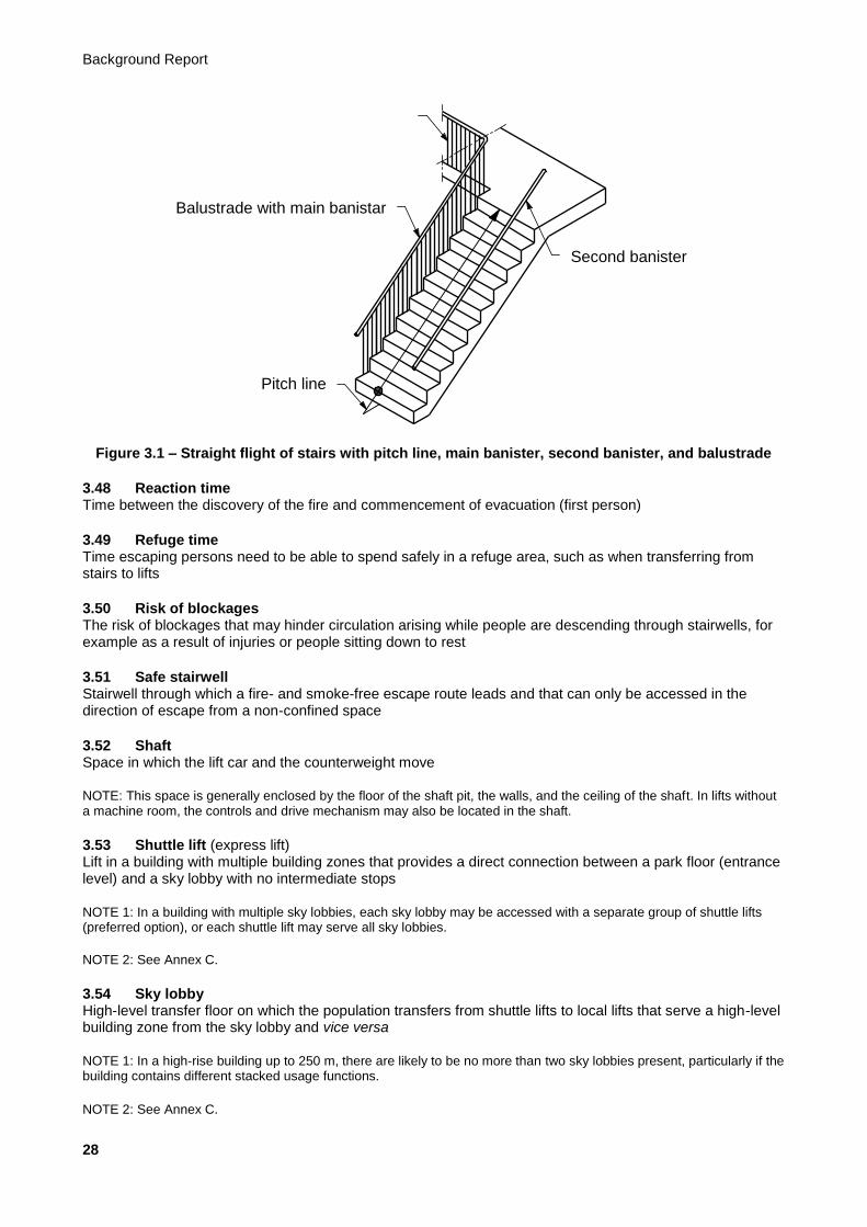
3.47 Pitch line Notional continuous line connecting the nosings of a flight of stairs
NOTE 1: See Figure 3.1.
NOTE 2: This definition is taken from the Building Decree.
NOTE 3: The pitch line is only needed to determine the position of the walking line.
Background Report
28
Figure 3.1 – Straight flight of stairs with pitch line, main banister, second banister, and balustrade
3.48 Reaction time Time between the discovery of the fire and commencement of evacuation (first person)
3.49 Refuge time Time escaping persons need to be able to spend safely in a refuge area, such as when transferring from stairs to lifts
3.50 Risk of blockages The risk of blockages that may hinder circulation arising while people are descending through stairwells, for example as a result of injuries or people sitting down to rest
3.51 Safe stairwell Stairwell through which a fire- and smoke-free escape route leads and that can only be accessed in the direction of escape from a non-confined space
3.52 Shaft Space in which the lift car and the counterweight move
NOTE: This space is generally enclosed by the floor of the shaft pit, the walls, and the ceiling of the shaft. In lifts without a machine room, the controls and drive mechanism may also be located in the shaft.
3.53 Shuttle lift (express lift) Lift in a building with multiple building zones that provides a direct connection between a park floor (entrance level) and a sky lobby with no intermediate stops
NOTE 1: In a building with multiple sky lobbies, each sky lobby may be accessed with a separate group of shuttle lifts (preferred option), or each shuttle lift may serve all sky lobbies.
NOTE 2: See Annex C.
3.54 Sky lobby High-level transfer floor on which the population transfers from shuttle lifts to local lifts that serve a high-level building zone from the sky lobby and vice versa
NOTE 1: In a high-rise building up to 250 m, there are likely to be no more than two sky lobbies present, particularly if the building contains different stacked usage functions.
NOTE 2: See Annex C.
Balustrade with main banistar
Pitch line
Second banister

Evacuation of High-rise Buildings with Lifts and Stairs
29
3.55 Smoke-free escape route Smoke-free route that starts at an entrance to a smoke compartment or a fire sub-compartment, leads exclusively via floors, stairs or access ramps, and ends at a safe place without the need to use a lift
3.56 Speed Change of position per time unit, in m/s
3.57 Stairwell Circulation area containing stairs
3.58 Transfer floor A high floor in the building where the population transfers from shuttle lifts to local lifts that serve a high-level building zone from the sky lobby and vice versa
3.59 Transition layer (transition layer) Floor on which evacuees can leave a stairwell to transfer to lifts or other stairwells (Scenario 3)
3.60 Transition time Time needed to move from the stairs to the lift
3.61 Waiting area Area where evacuees can wait to be collected by a lift
3.62 Waiting time Time calculated from the placing of a call command to the moment the lift can be boarded
3.63 Walking line Pitch line plus horizontal movement on the stairs
3.64 Zoning Subdivision of a building in a vertical direction into clusters of directly adjoining floors
Background Report
30
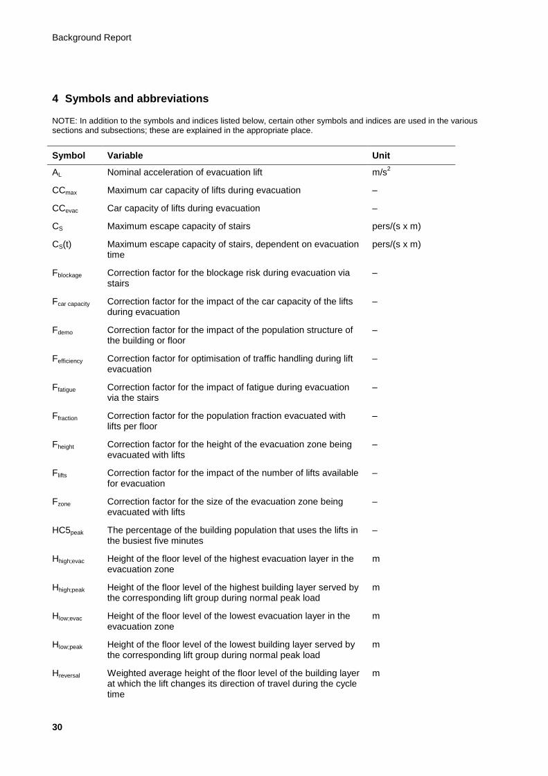
4 Symbols and abbreviations
NOTE: In addition to the symbols and indices listed below, certain other symbols and indices are used in the various sections and subsections; these are explained in the appropriate place.
Symbol Variable Unit
AL Nominal acceleration of evacuation lift m/s2
CCmax Maximum car capacity of lifts during evacuation –
CCevac Car capacity of lifts during evacuation –
CS Maximum escape capacity of stairs pers/(s x m)
CS(t) Maximum escape capacity of stairs, dependent on evacuation time
pers/(s x m)
Fblockage Correction factor for the blockage risk during evacuation via stairs
–
Fcar capacity Correction factor for the impact of the car capacity of the lifts during evacuation
–
Fdemo Correction factor for the impact of the population structure of the building or floor
–
Fefficiency Correction factor for optimisation of traffic handling during lift evacuation
–
Ffatigue Correction factor for the impact of fatigue during evacuation via the stairs
–
Ffraction Correction factor for the population fraction evacuated with lifts per floor
–
Fheight Correction factor for the height of the evacuation zone being evacuated with lifts
–
Flifts Correction factor for the impact of the number of lifts available for evacuation
–
Fzone Correction factor for the size of the evacuation zone being evacuated with lifts
–
HC5peak The percentage of the building population that uses the lifts in the busiest five minutes
–
Hhigh;evac Height of the floor level of the highest evacuation layer in the evacuation zone
m
Hhigh;peak Height of the floor level of the highest building layer served by the corresponding lift group during normal peak load
m
Hlow;evac Height of the floor level of the lowest evacuation layer in the evacuation zone
m
Hlow;peak Height of the floor level of the lowest building layer served by the corresponding lift group during normal peak load
m
Hreversal Weighted average height of the floor level of the building layer at which the lift changes its direction of travel during the cycle time
m
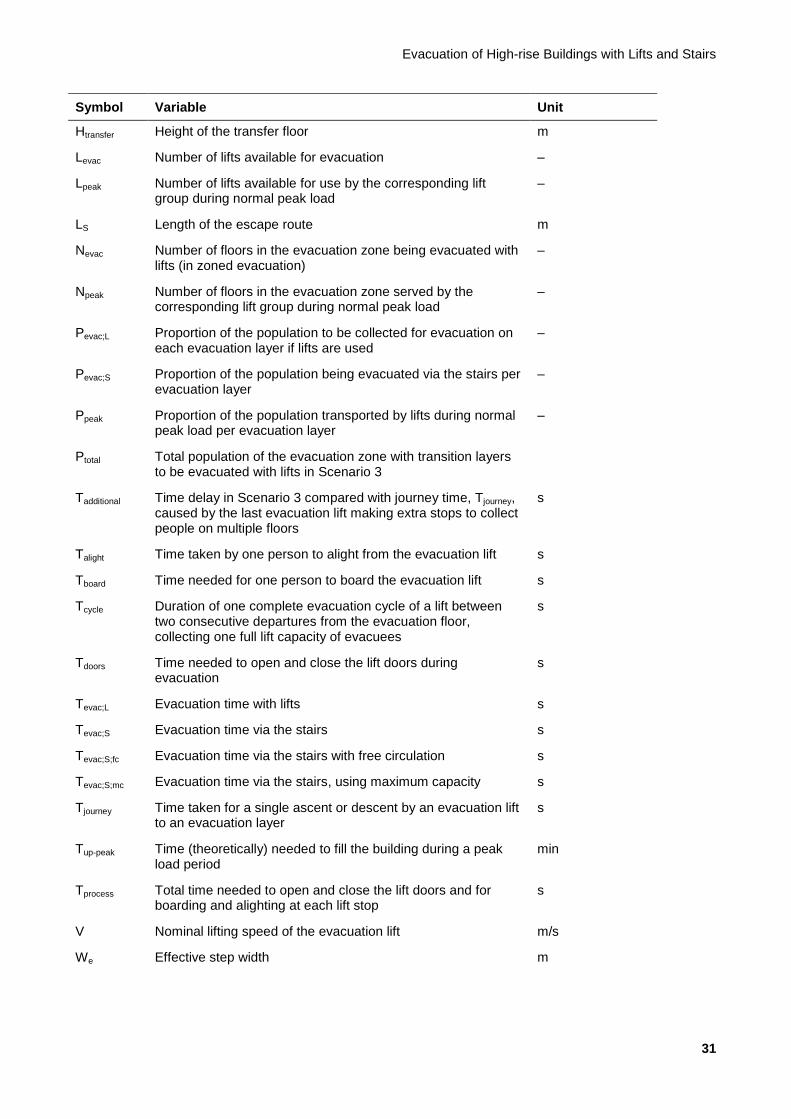
Evacuation of High-rise Buildings with Lifts and Stairs
31
Symbol Variable Unit
Htransfer Height of the transfer floor m
Levac Number of lifts available for evacuation –
Lpeak Number of lifts available for use by the corresponding lift group during normal peak load
–
LS Length of the escape route m
Nevac Number of floors in the evacuation zone being evacuated with lifts (in zoned evacuation)
–
Npeak Number of floors in the evacuation zone served by the corresponding lift group during normal peak load
–
Pevac;L Proportion of the population to be collected for evacuation on each evacuation layer if lifts are used
–
Pevac;S Proportion of the population being evacuated via the stairs per evacuation layer
–
Ppeak Proportion of the population transported by lifts during normal peak load per evacuation layer
–
Ptotal Total population of the evacuation zone with transition layers to be evacuated with lifts in Scenario 3
Tadditional Time delay in Scenario 3 compared with journey time, Tjourney, caused by the last evacuation lift making extra stops to collect people on multiple floors
s
Talight Time taken by one person to alight from the evacuation lift s
Tboard Time needed for one person to board the evacuation lift s
Tcycle Duration of one complete evacuation cycle of a lift between two consecutive departures from the evacuation floor, collecting one full lift capacity of evacuees
s
Tdoors Time needed to open and close the lift doors during evacuation
s
Tevac;L Evacuation time with lifts s
Tevac;S Evacuation time via the stairs s
Tevac;S;fc Evacuation time via the stairs with free circulation s
Tevac;S;mc Evacuation time via the stairs, using maximum capacity s
Tjourney Time taken for a single ascent or descent by an evacuation lift to an evacuation layer
s
Tup-peak Time (theoretically) needed to fill the building during a peak load period
min
Tprocess Total time needed to open and close the lift doors and for boarding and alighting at each lift stop
s
V Nominal lifting speed of the evacuation lift m/s
We Effective step width m

Background Report
32
5 Limit values
In this report, we provide various descriptions and models that can be used to determine the evacuation time of a building. In order to be able to use this determination as a design or testing tool, benchmark values must be available. In this chapter, we present the most important limit values that apply to the evacuation of high-rise buildings.
5.1 General limit values
General limit values are the limit values that apply to the building as a whole. The most important limit value is the maximum permitted clearance time. By analogy to the information contained in the SBR Code of Practice, a distinction can be made between different clearance concepts. Unlike the Code of Practice, however, we only distinguish between two concepts in this report: full clearance and zoned (partial) clearance (in the vicinity of a disaster only).
Limit values are always given on the basis of full clearance. If full clearance of the building is possible within the defined limit values, the same facilities and measures will also be able to clear part of the building within the defined limit values.
The assumption for the method of determination is therefore that the building will be able to be fully cleared within a set time and in line with associated requirements.
5.1.1 Clearance time
The total clearance time is set at a maximum of 60 minutes, the assumption being that the main supporting structure will be resistant to collapsing for at least 120 minutes.
Various aspects must be taken into account at this point. Firstly, if the clearance time is less than half the time the building can remain standing, it is assumed that there is a sufficiently large margin to have escape routes available at all times for clearing the building completely. Secondly, with the standard fire load (quantity of flammable materials) in buildings in the Netherlands, it is in fact assumed that a building that is resistant to collapsing for 120 minutes will not actually collapse.
The total clearance time is made up of a number of components which are illustrated below:
Figure 5.1 – Structure of clearance time
where:
Tresist MSS is the time the main supporting structure is resistant to collapsing [s]
Tclearance is the time between a fire starting and the moment the building is empty [s]
Tdet. is the time until a fire is detected (by a person or automatically) [s]
Treac. is the time between detecting the fire and starting to escape (first person) [s]
Tinit. is the time required to travel horizontal distances to the vertical escape routes (first person in lobby) [s]
T clearance
T det. T reac.
T E,vertical T init.
T exit
T resist MSS

Evacuation of High-rise Buildings with Lifts and Stairs
33
TE,vertical is the time needed to descend to the level of the exit (evacuation time) [s]
Texit is the time needed to travel horizontal distances from the vertical escape routes to the exit [s]
A determination method for TE,vertical is presented below. The method for determining the other components in a high-rise building is not significantly different from the method used for a low-rise building, although the requirements may be different.
5.1.2 Detection time
In the regulations, a duration of 15 minutes is assumed for detecting a fire and raising the alarm. Provided that this time interval is properly ensured, in a high-rise building it is sufficient to allow a gain to be made. This gain can deliver additional time for transportation within the building. To make optimum use of the clearance time, the detection time should be as short as possible. A shorter detection time also means that the fire service is alerted earlier and can therefore commence rescue and repression sooner.
In this context, it is stated that in high-rise buildings an installation should be used that shortens the detection time to 5 minutes. This ties in with the value applied in the SBR Code of Practice on fire safety in high-rise buildings.
5.1.3 Refuge times
The TE,vertical defined above also relates to the time needed to transfer between different stairwell segments. For this value, it is assumed that it is actually possible to leave one stairwell to move to another. It is also assumed that, after having descended part of the way via stairs, it is possible to descend part of the way by lift. In that case, a waiting time for the lift may be applicable.
Here it is stated that where people transfer from one stairwell to another, if applicable, no additional waiting time should be introduced because it is assumed that no flow compaction will take place: people will transfer to a stairwell that is at least the equivalent of the previous one. For transfers to lifts, a maximum refuge time of 15 minutes may be applied. This must be seen in conjunction with the fact that every individual user must also be able to choose to continue their escape via the stairs with no additional waiting time. That does not always necessarily lead to the quickest evacuation.
Important factors for providing refuge for this length of time are the facilities in the area where refuge is provided and the information the users are given there. Here it is stated that additional conditions apply to the design and the communication system quite apart from fire resistance, flammability, and smoke development. See Chapter 11 for further information.
5.2 Structural requirements
The escape routes themselves must also remain available for a sufficient length of time; see below. Important factors here are not only the clearance time but also the length of time the fire service uses the vertical transport for repressing the fire.
5.2.1 Design
Both the stairwells and the lifts (fire and evacuation lifts) must be equipped with a fireproof lobby. This not only protects the functionality of the vertical transport but also strengthens the weak link in terms of fire resistance that always arises at the location of vertical shafts in the building.
5.2.2 Resistance to fire penetration and spread
The stairwells and lift shafts in high-rise buildings must be isolated from fire compartments with 90 minutes of fire resistance. A similar solution is required if the lift shaft is combined with a stairwell.
Background Report
34
The lobbies must be isolated from fire compartments with 60 minutes of fire resistance. The stairwell cannot be a lift lobby.
Some waiting time is acceptable in lobbies that are isolated from the fire compartments on the floor, with 60 minutes of fire resistance. Since users who cannot evacuate via the stairs have to wait for the lift, this aspect must be paid sufficient attention.
5.2.3 Limiting the development of fire and smoke
The finishes of all stairwells, lift shafts and lobbies must meet the requirements for fire- and smoke-free escape routes in order to help limit the development of fire and smoke.
5.3 Other requirements
5.3.1 Fire-fighting lifts
Buildings such as those discussed here are always fitted with two fire-fighting lifts. The assumption here is not that two fire-fighting lifts will be used for repression but that this increases the likelihood of one fire-fighting lift remaining operational. If both fire-fighting lifts remain operational in an emergency, one of the two can be used throughout the entire evacuation.
5.3.2 Evacuation lifts
Lifts used for evacuation must be available for use during emergencies, including fire in the building. Resistance to fire penetration and spread as referred to in Subsection 5.2.2 is an important aspect of this. Please refer to Chapter 11 for additional measures to be taken, such as collection of fire-fighting water, control etc.

Evacuation of High-rise Buildings with Lifts and Stairs
35
6 Evacuation
6.1 Current situation
To make it completely clear, it is reiterated here that the situation described below for determining the evacuation time (in high-rise buildings) is the situation that currently applies in the Netherlands.
In the Dutch situation, evacuation is currently assumed to take place via stairs only. The walking speeds via stairs and stair capacities applied in this scenario relate to the evacuation of able-bodied (fit) people only. Delays caused by the evacuation of less fit people or the assisted evacuation of highly mobility-impaired evacuees (such as wheelchair users) are not taken into consideration. An assumption in this regard is that the total number of mobility-impaired users (for most building categories) will be manageable and that sufficient assistance will be present.
In the explanatory notes to the Regeling Bouwbesluit [Building Decree Regulation], a method is provided for determining the time required to descend via stairs in buildings covered by the Building Decree. The SBR Code of Practice provides a detailed description of the usage time of the stairs as part of the total evacuation time in high-rise buildings. A brief summary of both is given below. It should be noted that, in principle, only the determination method for the evacuation time via stairs is discussed below, since neither document refers to or acknowledges the lift as an escape route.
6.1.1 Buildings covered by the Building Decree
For buildings with a height for which the Building Decree describes performance requirements, the speed of evacuation via stairs is based on a person descending 1 floor in 1 minute. In relation to the requirements that 20 minutes may be allowed for stairwells with a lobby, this therefore amounts to a maximum building height of 70 m. In case of safety stairwells, a greater building height can be achieved with this method, but the fact remains that in terms of the area of application, this determination method in principle only relates to buildings up to 70 m in height.
6.1.2 High-rise buildings
The SBR Code of Practice describes the process of evacuating a high-rise building in considerable detail. It describes the use of lifts as a possible solution, although this is excluded for the time being due to the considerable lack of certainty.
In this method, the speed of travel via the stairs in an unimpeded state is assumed to be 0.8 m/s (a comparable value is also found in international literature: Fruin, 1971, and Barney, 2003). For the situation in which the maximum capacity of the stairs is used, circulation of 1.28 persons per metre of stair width per second is assumed. The descent time per floor is then calculated as a function of the stair width and the number of persons on the floor concerned. This is the speed with which it is possible to descend one floor according to the method described in the Code of Practice. If there are fewer people present on higher floors, a floor on which the stairs are full to capacity will form a bottleneck.
The evacuation time via the stairs is therefore the maximum of:
Tevac,S,fc = (N x lS) / vS (free circulation)
and
Tevac,S,mc = (N x Pevac,S) / (CS x We) (maximum capacity)
where:
Tevac,S,fc Evacuation time via stairs with free circulation [s]
Tevac,S,mc Evacuation time via stairs with maximum capacity [s]
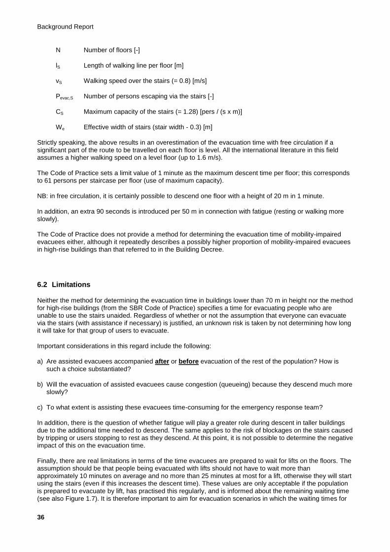
Background Report
36
N Number of floors [-]
lS Length of walking line per floor [m]
vS Walking speed over the stairs (= 0.8) [m/s]
Pevac,S Number of persons escaping via the stairs [-]
CS Maximum capacity of the stairs (= 1.28) [pers / (s x m)]
We Effective width of stairs (stair width - 0.3) [m]
Strictly speaking, the above results in an overestimation of the evacuation time with free circulation if a significant part of the route to be travelled on each floor is level. All the international literature in this field assumes a higher walking speed on a level floor (up to 1.6 m/s).
The Code of Practice sets a limit value of 1 minute as the maximum descent time per floor; this corresponds to 61 persons per staircase per floor (use of maximum capacity).
NB: in free circulation, it is certainly possible to descend one floor with a height of 20 m in 1 minute.
In addition, an extra 90 seconds is introduced per 50 m in connection with fatigue (resting or walking more slowly).
The Code of Practice does not provide a method for determining the evacuation time of mobility-impaired evacuees either, although it repeatedly describes a possibly higher proportion of mobility-impaired evacuees in high-rise buildings than that referred to in the Building Decree.
6.2 Limitations
Neither the method for determining the evacuation time in buildings lower than 70 m in height nor the method for high-rise buildings (from the SBR Code of Practice) specifies a time for evacuating people who are unable to use the stairs unaided. Regardless of whether or not the assumption that everyone can evacuate via the stairs (with assistance if necessary) is justified, an unknown risk is taken by not determining how long it will take for that group of users to evacuate.
Important considerations in this regard include the following:
a) Are assisted evacuees accompanied after or before evacuation of the rest of the population? How is such a choice substantiated?
b) Will the evacuation of assisted evacuees cause congestion (queueing) because they descend much more slowly?
c) To what extent is assisting these evacuees time-consuming for the emergency response team?
In addition, there is the question of whether fatigue will play a greater role during descent in taller buildings due to the additional time needed to descend. The same applies to the risk of blockages on the stairs caused by tripping or users stopping to rest as they descend. At this point, it is not possible to determine the negative impact of this on the evacuation time.
Finally, there are real limitations in terms of the time evacuees are prepared to wait for lifts on the floors. The assumption should be that people being evacuated with lifts should not have to wait more than approximately 10 minutes on average and no more than 25 minutes at most for a lift, otherwise they will start using the stairs (even if this increases the descent time). These values are only acceptable if the population is prepared to evacuate by lift, has practised this regularly, and is informed about the remaining waiting time (see also Figure 1.7). It is therefore important to aim for evacuation scenarios in which the waiting times for
Evacuation of High-rise Buildings with Lifts and Stairs
37
evacuation by lift remain acceptable as a result of a combination of lifts and stairs. The same applies to the waiting times in assembly areas if people are transferring from stairs to lifts in Scenario 3 (see Chapter 7).
6.3 Recommendations
The above immediately gives rise to an important recommendation: the impact of mobility-impaired evacuees on the evacuation time should be quantified. The time and effort this involves for the emergency response organisations should also be quantified. There must also at least be an option for quantifying the impact of the adverse effects, such as a reduction in speed as a result of fatigue and an increase in the risk of blockages.
An entirely separate recommendation is also to include the impact of the demographic composition of the population of a building in the determination of the evacuation time.
Furthermore, it is highly recommended that, at least in high-rise buildings, lifts are always included in the evacuation method. This means that the use of one or more lifts, specifically for assisted clearance, should be included in the design. A clearance time must then also be determined. Starting points will then need to be established for the number of persons requiring assistance to be included in the calculations and for the method of evacuation. In addition, the requirements the lift and the immediate vicinity need to meet in order to provide sufficient assurance that the lift will work must be specified very precisely.

Background Report
38
7 Scenarios
To elaborate upon the above recommendations, it is necessary to develop a model that enables us to assess the impact of evacuation assistance on the evacuation time. Such a model should also include the impact of the use of lifts in an evacuation. Various evacuation scenarios have been identified for this purpose; these are explained in Section 7.1.
7.1 Description of the scenarios
The various forms of evacuation for which a determination method should be provided for buildings higher than 70 m using the lift and stairs model presented in this report are given below. These forms are described in scenarios.
Table 7.1 – Scenarios for evacuation
Scenario Brief description More detailed description
Method of determining evacuation time
0 Stairs only Subsection 7.1.1 Section 8.2 / 8.3
1 Lifts only Subsection 7.1.2 Section 9.2 / 9.4
2 Fractional with lifts Subsection 7.1.3 Sections 8.2 / 8.3 and 9.2 / 9.4
3 Stairs/lifts with transition layers
Subsection 7.1.4 Sections 8.2 / 8.3 and 9.3 / 9.4
4 Free choice Subsection 7.1.5 Sections 8.2 / 8.3 and 9.2 / 9.4
The scenarios presented can be applied on a building-specific basis; combinations of various scenarios for stacked functions and zones can also be used.
7.1.1 Full evacuation – stairs only (Scenario 0)
This scenario is essentially the scenario used to date to assess the evacuation of buildings: ‘Do not use lift in case of fire’. However, Section 8.1 presents an amended determination method for the evacuation time using the stairs. This focuses more on the impact of mobility-impaired evacuees, including people who become mobility-impaired during the evacuation, with a view to obtaining a more complete picture of the use of stairs.
In light of the recommendations made above, this is not a scenario that can be used in a high-rise building, since the mobility-impaired fraction of the building population is not evacuated in this scenario. A major drawback of the methods used in the current situation (see Section 6.2), namely the impact of the mobility-impaired population on movement on the stairs, is eliminated in the other scenarios described below. This scenario is primarily included for the purpose of comparison with the other scenarios and to make it easier to validate the model for calculating usage times of the stairs. Such a validation has yet to be carried out; as an initial indication, a comparison was made with the egress flow profile observed during the evacuation of WTC1 and WTC2 in New York on 11 September 2001 (see Figure 8.3).

Evacuation of High-rise Buildings with Lifts and Stairs
39
7.1.2 Full evacuation – lifts only (Scenario 1)
In this scenario, the stairs are omitted entirely from the determination of the evacuation time. This is presented in more detail in Figure 7.1.
It is not advisable to omit stairs altogether, so this scenario can be regarded as intended primarily for determining a basic level for the evacuation time using lifts. When designing stairs in a building, it is unwise to ignore the positive impact of stairs on the evacuation time.
7.1.3 Full evacuation – fractional with lifts (Scenario 2)
This scenario describes the situation in which the bulk of the building population actually leaves the building in accordance with Scenario 0 (stairs only). Any mobility-impaired people are evacuated by lift, possibly with assistance. In offices and accommodation buildings, support for this should be provided by an in-house emergency response organisation. However, this requires a different form of organisation from the one currently found in buildings of this type. When users operate the lifts themselves, which is usually the case in residential buildings, they do not need to wait for assistance, but they must know how to respond. For the determination of the clearance time, the response time for the emergency response organisation is set to 0 s.
Figure 7.1 – Evacuation with lifts only
Figure 7.2 – Evacuation with transition layers
7.1.4 Full evacuation – stairs / transition layers / lifts as shuttles (Scenario 3)
In this scenario, the lifts serve a number of predetermined floors to which evacuation must take place via the stairs (see also Figure 7.2). In the situation shown in the figure, there are two transition layers to which
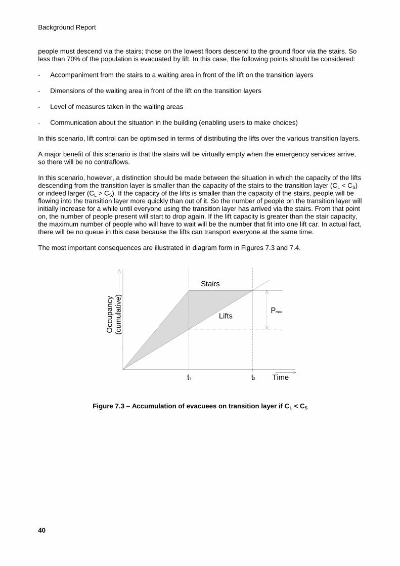
Background Report
40
people must descend via the stairs; those on the lowest floors descend to the ground floor via the stairs. So less than 70% of the population is evacuated by lift. In this case, the following points should be considered:
- Accompaniment from the stairs to a waiting area in front of the lift on the transition layers
- Dimensions of the waiting area in front of the lift on the transition layers
- Level of measures taken in the waiting areas
- Communication about the situation in the building (enabling users to make choices)
In this scenario, lift control can be optimised in terms of distributing the lifts over the various transition layers.
A major benefit of this scenario is that the stairs will be virtually empty when the emergency services arrive, so there will be no contraflows.
In this scenario, however, a distinction should be made between the situation in which the capacity of the lifts descending from the transition layer is smaller than the capacity of the stairs to the transition layer (CL < CS) or indeed larger (CL > CS). If the capacity of the lifts is smaller than the capacity of the stairs, people will be flowing into the transition layer more quickly than out of it. So the number of people on the transition layer will initially increase for a while until everyone using the transition layer has arrived via the stairs. From that point on, the number of people present will start to drop again. If the lift capacity is greater than the stair capacity, the maximum number of people who will have to wait will be the number that fit into one lift car. In actual fact, there will be no queue in this case because the lifts can transport everyone at the same time.
The most important consequences are illustrated in diagram form in Figures 7.3 and 7.4.
Figure 7.3 – Accumulation of evacuees on transition layer if CL < CS
Stairs
Lifts
Occu
pa
ncy
(cu
mu
lative)
Time

Evacuation of High-rise Buildings with Lifts and Stairs
41
Figure 7.4 – Circulation of evacuees if CL > CS
With regard to the clearance time in both cases, the main difference where CL < CS is that the evacuation time is determined by the evacuation time of the lifts (see also Figure 7.6). Where CL > CS, the evacuation time is primarily determined by the evacuation time of the stairs, after which one descent in the lift is still required. In addition, on account of the organisation needed for this scenario, the option has been added of allowing the emergency response organisation to get into position before the general alarm is given (the actual time necessary for this remains open; with the method used here, the response time can also be set to 0 seconds). The maximum potential response time given in Table 7.2 is 30 seconds. This is not sufficient for in-house emergency response team to be fully prepared, but it enables them to go into action before the flow of evacuees gets under way. Due consideration must be given to assigning a response time such as this. The response time plays no further role in the context of the determination method presented here.
The situation described above can also be applied to a tower with a special public function at the top, such as an assembly function, a restaurant, or a panorama deck. Within this function, sufficient refuge capacity and functionality must then be provided. Generally speaking, local stairs and lifts will always be present for this function. On the basis of the general requirements for refuge capacity (see Section 11.2), these should be based on a maximum of 3.5 persons per m
2. The necessary evacuation time with the separate shuttle lifts
usually present for such functions can be determined on the basis of the comparisons in Section 9.4.
7.1.5 Full evacuation – stairs and lifts, free choice (Scenario 4)
In this last scenario, both the stairs and the lifts are used for evacuation of every floor. Users are always free to choose to use the lift or the stairs. This is actually a differentiation of the scenario in which evacuation takes place fractionally with the lifts, the most important change being that there may not be any support from internal or external emergency response services, and that the fraction using the lift is not predefined. In addition, some users who are fully able to use the stairs as in the fractional scenario described above will also choose the lift. In this scenario, however, it is possible to inform people about the options available at any given time. On the basis of lift calls placed and an estimation of the congestion on the stairs (high lift use means little congestion), evacuation times can be presented to the population. The evacuees might also be influenced in this way.
In this scenario, it is important for the evacuees to have a clear view of both the lifts and the stairs, estimate the performance of both systems including waiting times, and then come to a well-considered decision. The likelihood that they are prepared to wait, or wait longer, for the lifts in this case increases when the consequences of a choice are visible. The evacuation lifts and the emergency stairwells should therefore adjoin the same waiting area.
Time
Stairs Lifts
Occu
pa
ncy
(cu
mu
lative)

Background Report
42
Figure 7.5A – Full evacuation with stairs and lifts, free choice
Figure 7.5B – The proportion of users opting to use the lifts is uncertain
It is assumed that the proportion of stairs use is related to the floor on which the user is located, the relative height of the hazard level and the emergency exit level. The grey areas in the figure represent the possible variation.The grey area in the figure shows the possible distribution.
Because of the uncertainty involved in the choice, plenty of leeway should be allowed in the framing of this model. This means that calculations based on this scenario without additional preconditions do not produce usable results. In principle, this scenario offers the possibility of achieving shorter evacuation times. But the variation in the number of potential additional preconditions is so great that they must be assessed for feasibility on a project-by-project basis. These preconditions should preferably be specified by the user of this design guideline.
To illustrate the possibilities, we look at a split of 50% of users being evacuated by lift and 50% of users via the stairs (indicated by the figure on the right). In actual fact, this is a specific form of Scenario 2 with unassisted clearance. In this case, a short time is determined for the use of both the lift and the stairs. This is elaborated upon in more detail in a model case.
Lifts Stairs Lifts Lifts
Stairs Stairs
Stairs
Lifts
Emergency
level
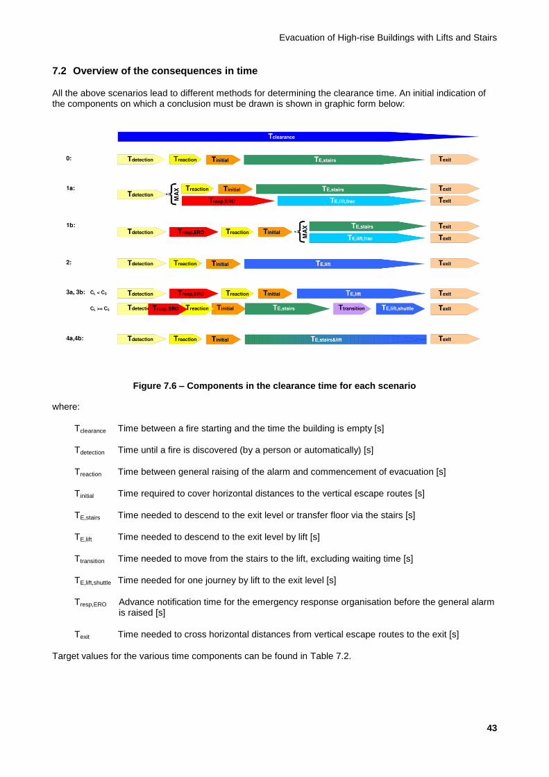
Evacuation of High-rise Buildings with Lifts and Stairs
43
7.2 Overview of the consequences in time
All the above scenarios lead to different methods for determining the clearance time. An initial indication of the components on which a conclusion must be drawn is shown in graphic form below:
Figure 7.6 – Components in the clearance time for each scenario
where:
Tclearance Time between a fire starting and the time the building is empty [s]
Tdetection Time until a fire is discovered (by a person or automatically) [s]
Treaction Time between general raising of the alarm and commencement of evacuation [s]
Tinitial Time required to cover horizontal distances to the vertical escape routes [s]
TE,stairs Time needed to descend to the exit level or transfer floor via the stairs [s]
TE,lift Time needed to descend to the exit level by lift [s]
Ttransition Time needed to move from the stairs to the lift, excluding waiting time [s]
TE,lift,shuttle Time needed for one journey by lift to the exit level [s]
Tresp,ERO Advance notification time for the emergency response organisation before the general alarm is raised [s]
Texit Time needed to cross horizontal distances from vertical escape routes to the exit [s]
Target values for the various time components can be found in Table 7.2.

Background Report
44
Table 7.2 – Target values for the various time aspects per function [sec]
Variable Residential building Accommodation building
Office building
Tdetection 3001 300 300
Treaction 6001 120
2 120
Tinitial Determined based on floor plan; walking speed in accordance with the SBR Code, depending on capacity of traffic routes, 0.37 to 1.6 m/s
TE,stairs
Determined in accordance with Chapters 8 and 9
TE,lift
Ttransition
TE,lift,shuttle
Tresp,ERO Assumed not present Max. 30 Max. 30
Texit Determined based on floor plan; walking speed in accordance with the SBR Code, depending on capacity of traffic routes, 0.37 to 1.6 m/s
NOTE 1: In accordance with the SBR Code of Practice, it is assumed that detection systems in communal circulation areas are linked to alarms and detection in the apartments. There is some uncertainty with regard to the operation of the components of such systems in the apartments. For this reason, there is a relatively high degree of uncertainty in relation to these figures.
NOTE 2: This value comes from the fire safety concept for accommodation buildings and special residential buildings (‘Brandbeveiligingsconcept logiesgebouwen en bijzondere woongebouwen’); the question is whether it always takes this length of time. When developing a concept for accommodation buildings, special attention should be paid to this in relation to the alarm system.
The study presented in this report only looked at the evacuation time, including any necessary transition time within the vertical transport.
All the variables that play a role in the total clearance time are presented in Table 7.2. See also the diagrams in Figures 5.1 and 7.6. The table also presents values that could potentially be used for some of the variables.
The time between the fire starting and its detection is determined by the design and nature of the detection components of the fire alarm system. Systems for high-rise buildings can be required to detect a fire within five minutes. From a technical point of view, an even shorter detection time could potentially be achieved, but the question is whether the time saved could actually lead to an immediate increase in the evacuation time.
The time between raising the alarm (end of detection time) and clearance actually getting under way is uncertain. Particular attention should be paid to the actual choice of reaction time in buildings in which people sleep. It may be that additional measures need to be taken to limit the reaction time in order to ensure effective clearance. It is important to hold regular exercises in office buildings, for example (see also Section 11.8).
The response time shown in the table also includes the time the in-house emergency response organisation gets as advance notification that a building clearance is imminent. It is proposed that a silent alarm of this kind should never be raised more than 30 seconds before the general alarm. It may also be that the general alarm is only raised for part of the building (partial or phased clearance). As far as residential buildings are concerned, based on current practice it is assumed that there is no emergency response organisation present, so no response time is applied.

Evacuation of High-rise Buildings with Lifts and Stairs
45
8 New stairs model
As discussed in Chapter 6, a number of factors are not included in the traditional method of determining evacuation time. In order to achieve a more realistic approach to the evacuation of high-rise buildings, therefore, a determination model for evacuation time via the stairs has been developed which includes these factors. Naturally, various assumptions apply in this case. In principle, it is assumed that the stairs in question will be the type commonly used as escape stairs. They have a limited width, but otherwise meet the standard or mandatory requirements. This is important since the method described below currently assumes that stair width has a linear impact on the capacity of the stairs.
8.1 General rule for determining evacuation time
The general rule for determining evacuation time via stairs is basically identical to the rule for the existing situation. The evacuation time via stairs in a building is the maximum of:
Tevac,S,fc [s] determined in accordance with Section 8.2
and
Tevac,S,mc [s] determined in accordance with Section 8.3
Fatigue, the risk of blockages, and demographics are now taken into account in the determination of the evacuation time. As yet, little has been found in the way of research results concerning the quantitative impact of these phenomena on evacuation time. Nonetheless, the option of including this impact is allowed for in the determination method.
8.1.1 Factor for fatigue
A factor for including fatigue has been added to the determination method in the model. This is a relative factor with a value between 0 and 1. Because fatigue is naturally related to the duration of the activity, this factor is, in general form:
Ffatigue = ƒ(t) [-]
In order to be able to use the stairs model both continuously and discretely, Ffatigue is provided as a function of the time in both forms. The continuous function is:
Ffatigue = 0.4 + (1 - 0.4) x (1 - T / 5,400)3
where T is the time in seconds, with a maximum value of 5,400 seconds.
The discrete function for Ffatigue is shown in Figure 8.1 below.
The functions for Ffatigue presented here are arbitrary for the time being. Because of the way in which this impact is included in the determination, however, every function can be entered for this impact. For the time being, this curve has been adapted for various widely used egress flow curves in order to make the assumption as reliable as possible. To be able to determine a properly substantiated function for this, further research in collaboration with exercise physiologists is required. This factor may also vary depending on the usage function.

Background Report
46
Ffatigue [-] 1.0
0.9
0.8
0.7
0.6
0.5
0.4
0.3
0.2
0.1
0 300 600 900 1200 1500 1800 2100 2400 2700 3000 3300 3600 3900 4200 4500 4800 5100 5400
Time [s]
Figure 8.1 – Factor used to take account of fatigue, in time intervals of 5 minutes
In addition, it is also important to bear in mind that the fatigue factor for Scenario 0 (stair use only) may be higher than in the other scenarios. This is because evacuees who are mobility-impaired and are therefore more vulnerable may be forced to use the stairs in this scenario, either with or without assistance. This can result in the person or their assisting companion becoming fatigued more quickly, which can cause delay. To account for this, it is possible to reduce the factor 0.4 in the above formula for Ffatigue to 0.3 or 0.2.
The factor used here becomes smaller as the fatigue increases. It therefore reduces with the passage of time, so it can be easily included in the formula.
8.1.2 Factor for risk of blockage
A factor for including the impact of blockages has also been added to the determination method in the model. This is also a relative factor with a value between 0 and 1. The risk of a blockage increases in line with the role played by fatigue. As mentioned above, fatigue is related to the duration of the activity, so this factor is also as follows, in general form:
Fblockage = ƒ(t) [-]
In order to be able to use the stairs model both continuously and discretely, Fblockage is provided as a function of the time in both forms. The continuous function is:
Fblockage = 0.4 + (1 - 0.4) x (1 - T / 5,400)2
where T is the time in seconds, with a maximum value of 5,400 seconds.
The discrete function for Fblockage is shown in Figure 8.2 below.
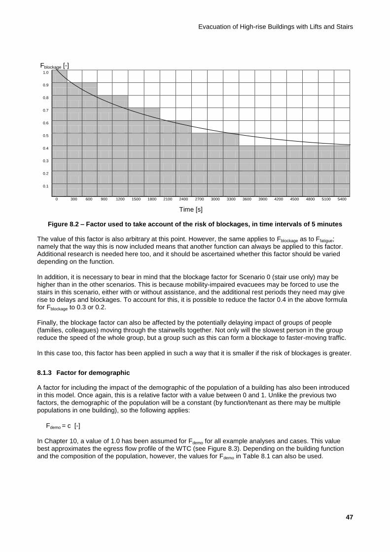
Evacuation of High-rise Buildings with Lifts and Stairs
47
Fblockage [-] 1.0
0.9
0.8
0.7
0.6
0.5
0.4
0.3
0.2
0.1
0 300 600 900 1200 1500 1800 2100 2400 2700 3000 3300 3600 3900 4200 4500 4800 5100 5400
Time [s]
Figure 8.2 – Factor used to take account of the risk of blockages, in time intervals of 5 minutes
The value of this factor is also arbitrary at this point. However, the same applies to Fblockage as to Ffatigue; namely that the way this is now included means that another function can always be applied to this factor. Additional research is needed here too, and it should be ascertained whether this factor should be varied depending on the function.
In addition, it is necessary to bear in mind that the blockage factor for Scenario 0 (stair use only) may be higher than in the other scenarios. This is because mobility-impaired evacuees may be forced to use the stairs in this scenario, either with or without assistance, and the additional rest periods they need may give rise to delays and blockages. To account for this, it is possible to reduce the factor 0.4 in the above formula for Fblockage to 0.3 or 0.2.
Finally, the blockage factor can also be affected by the potentially delaying impact of groups of people (families, colleagues) moving through the stairwells together. Not only will the slowest person in the group reduce the speed of the whole group, but a group such as this can form a blockage to faster-moving traffic.
In this case too, this factor has been applied in such a way that it is smaller if the risk of blockages is greater.
8.1.3 Factor for demographic
A factor for including the impact of the demographic of the population of a building has also been introduced in this model. Once again, this is a relative factor with a value between 0 and 1. Unlike the previous two factors, the demographic of the population will be a constant (by function/tenant as there may be multiple populations in one building), so the following applies:
Fdemo = c [-]
In Chapter 10, a value of 1.0 has been assumed for Fdemo for all example analyses and cases. This value best approximates the egress flow profile of the WTC (see Figure 8.3). Depending on the building function and the composition of the population, however, the values for Fdemo in Table 8.1 can also be used.

Background Report
48
Table 8.1 – Reference values for Fdemo [-]
Variable Residential building Accommodation building
Office building
Fdemo 0.8-1.0 0.8-1.0 0.9-1.0
NOTE: The above values have not yet been validated by means of practical research or in international literature. Because of the possible older age of all or part of the population in residential and accommodation buildings, a lower Fdemo could be applied here.
8.2 Determination of evacuation time via stairs with free circulation
The calculation of the evacuation time via stairs with free circulation has been modified as follows:
Tevac,S,fc = (N x lS) / vS(t)
where
vS(t) Walking speed over the stairs as function of time (= Ffatigue x Fdemo x vS) [m/s]
vS Walking speed over the stairs (= 0.8) [m/s]
This calculation does not take the factor for blockages into account. It is assumed that, when traffic is circulating freely, there is sufficient space remaining to adequately limit the impact of a blockage.
8.3 Determination of evacuation time via stairs when used to maximum capacity
Tevac,S,mc = (N x Pevac,S) / (CS(t) x We)
where
CS(t) Maximum capacity of the stairs as function of time (= Ffatigue x Fblockage x Fdemo x CS) [pers/(s x m)]
CS Maximum capacity of the stairs (= 1.28) [pers/(s x m)]
When the stairs are used to maximum capacity, the risk of blockages naturally plays a major role.
An important point for attention is the situation in which the occupancy level of lower floors in a building leads to the stairs being used to maximum capacity while upper floors still allow free circulation. The impact of the maximum use of the capacity of the stairs will then need to be specifically identified.
8.4 Validation of stairs model
At present, there is no validation of the stairs models available that can be used to evaluate this method. An initial comparison of the determination method used here with a practical situation has been made based on the established egress flow profiles of the WTC on 9/11 (Figure 1.4). This comparison tells us that the value applied for the capacity of the stairs together with the combination of the factors applied here shows similarities with the egress flow profile on 9/11. Much of the data on the clearance is unknown, including on ingress flows in the stairwells, the distribution of the start of evacuation, etc.
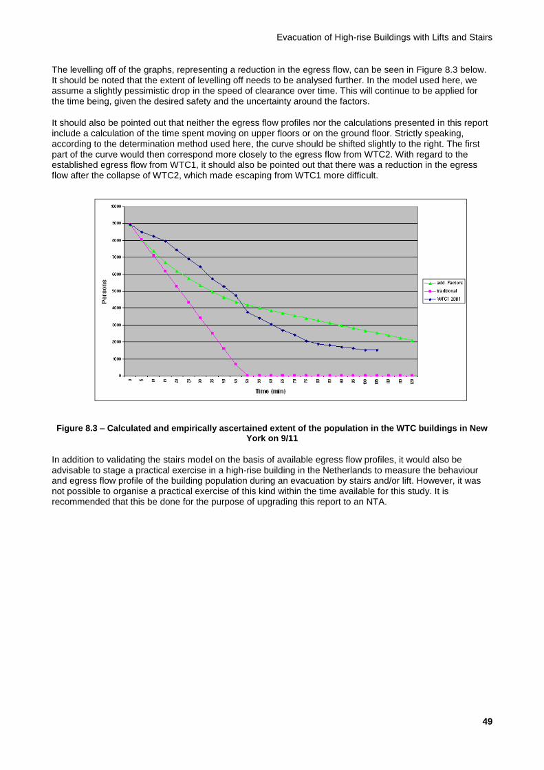
Evacuation of High-rise Buildings with Lifts and Stairs
49
The levelling off of the graphs, representing a reduction in the egress flow, can be seen in Figure 8.3 below. It should be noted that the extent of levelling off needs to be analysed further. In the model used here, we assume a slightly pessimistic drop in the speed of clearance over time. This will continue to be applied for the time being, given the desired safety and the uncertainty around the factors.
It should also be pointed out that neither the egress flow profiles nor the calculations presented in this report include a calculation of the time spent moving on upper floors or on the ground floor. Strictly speaking, according to the determination method used here, the curve should be shifted slightly to the right. The first part of the curve would then correspond more closely to the egress flow from WTC2. With regard to the established egress flow from WTC1, it should also be pointed out that there was a reduction in the egress flow after the collapse of WTC2, which made escaping from WTC1 more difficult.
Figure 8.3 – Calculated and empirically ascertained extent of the population in the WTC buildings in New York on 9/11
In addition to validating the stairs model on the basis of available egress flow profiles, it would also be advisable to stage a practical exercise in a high-rise building in the Netherlands to measure the behaviour and egress flow profile of the building population during an evacuation by stairs and/or lift. However, it was not possible to organise a practical exercise of this kind within the time available for this study. It is recommended that this be done for the purpose of upgrading this report to an NTA.

Background Report
50
9 The lift model
9.1 Background
The lift model developed for this report is partly based on the Emergency Evacuation: Elevator Systems Guideline published by the Council on Tall Buildings and Urban Habitat (CTBUH, 2004). In that document, it is stated that evacuation with lifts designed for an up-peak in normal service (e.g. in an office block) can handle the traffic more efficiently in evacuation mode. This increased transport capacity can be explained by the manner in which the traffic is handled: whereas ascending lifts in normal service stop repeatedly to allow people to alight, in evacuation mode they will generally only stop once or twice per cycle to allow evacuees to board. In addition, lifts ascending in normal service generally reach a reversal height that is far above the average floor level of the building zone served by the lifts because of the great spread in the number of destinations of people in the lift car. In evacuation mode, on the other hand, the average reversal height throughout the entire duration of the evacuation is roughly the same as the average floor level of the building zone served by the lifts.
The CTBUH approach is based on traffic handling in the up-peak, using the transport capacity HC5peak. This is the percentage of the building population that uses the lifts in the busiest five minutes. See also Chapter 6 of NTA 4614-4, Criteria voor verkeersafhandeling met liftinstallaties [Criteria for Traffic Handling with Lift Installations].
The time needed in theory to fill the building in the up-peak, Tup-peak, is equal to:
Tup-peak = 30,000 / HC5peak [s] (9.1)
In the CTBUH model, the theoretical evacuation time with lifts, Tevac,L,CTBUH, is obtained from the following formula:
Tevac,L,CTBUH = Tup-peak / 1.6 [s] (9.2)
By analogy to the CTBUH publication, this lift model uses the term Tup-peak, as this relates to the morning peak in office buildings with almost exclusively ascending (incoming) traffic. In the lift model, however, Tup-peak is also used for residential buildings and accommodation buildings, although the traffic in the morning peak in this case is principally descending (departing) and bi-directional (arriving and departing). The values to be used for HC5peak for all three building functions can be found in Chapter 6 of NTA 4614-4.
9.1.1 Assumptions for the lift model
The following assumptions were used in the lift model:
Boarding on upper floors can take slightly longer during evacuation than in normal circumstances, for example due to discussions around who should board first, attempting to fit an additional person into the lift, etc, and due to the potentially relatively high fraction of mobility-impaired evacuees. In drawing up the model, an average boarding time of 1.5 seconds per person was assumed, whereas the boarding time in normal operation according to Chapter 6 of NTA 4614-4 is between 1.0 and 1.3 seconds.
Whether a lift car is full enough to depart and whether a floor is empty is decided by the emergency response team member accompanying the evacuation. If the evacuees are not accompanied, fully automatic evacuation is assumed (see Section 9.6), and the decision as to whether to depart is taken by the lift control. A slight delay to allow for decision-making time is included in the lift model.
The lifting speed (or descent speed) and acceleration/deceleration are assumed to be the same during evacuation as during normal traffic.
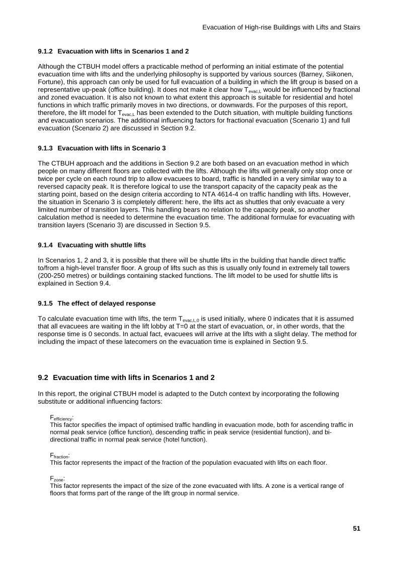
Evacuation of High-rise Buildings with Lifts and Stairs
51
9.1.2 Evacuation with lifts in Scenarios 1 and 2
Although the CTBUH model offers a practicable method of performing an initial estimate of the potential evacuation time with lifts and the underlying philosophy is supported by various sources (Barney, Siikonen, Fortune), this approach can only be used for full evacuation of a building in which the lift group is based on a representative up-peak (office building). It does not make it clear how Tevac,L would be influenced by fractional and zoned evacuation. It is also not known to what extent this approach is suitable for residential and hotel functions in which traffic primarily moves in two directions, or downwards. For the purposes of this report, therefore, the lift model for Tevac,L has been extended to the Dutch situation, with multiple building functions and evacuation scenarios. The additional influencing factors for fractional evacuation (Scenario 1) and full evacuation (Scenario 2) are discussed in Section 9.2.
9.1.3 Evacuation with lifts in Scenario 3
The CTBUH approach and the additions in Section 9.2 are both based on an evacuation method in which people on many different floors are collected with the lifts. Although the lifts will generally only stop once or twice per cycle on each round trip to allow evacuees to board, traffic is handled in a very similar way to a reversed capacity peak. It is therefore logical to use the transport capacity of the capacity peak as the starting point, based on the design criteria according to NTA 4614-4 on traffic handling with lifts. However, the situation in Scenario 3 is completely different: here, the lifts act as shuttles that only evacuate a very limited number of transition layers. This handling bears no relation to the capacity peak, so another calculation method is needed to determine the evacuation time. The additional formulae for evacuating with transition layers (Scenario 3) are discussed in Section 9.5.
9.1.4 Evacuating with shuttle lifts
In Scenarios 1, 2 and 3, it is possible that there will be shuttle lifts in the building that handle direct traffic to/from a high-level transfer floor. A group of lifts such as this is usually only found in extremely tall towers (200-250 metres) or buildings containing stacked functions. The lift model to be used for shuttle lifts is explained in Section 9.4.
9.1.5 The effect of delayed response
To calculate evacuation time with lifts, the term Tevac,L,0 is used initially, where 0 indicates that it is assumed that all evacuees are waiting in the lift lobby at T=0 at the start of evacuation, or, in other words, that the response time is 0 seconds. In actual fact, evacuees will arrive at the lifts with a slight delay. The method for including the impact of these latecomers on the evacuation time is explained in Section 9.5.
9.2 Evacuation time with lifts in Scenarios 1 and 2
In this report, the original CTBUH model is adapted to the Dutch context by incorporating the following substitute or additional influencing factors:
Fefficiency:
This factor specifies the impact of optimised traffic handling in evacuation mode, both for ascending traffic in normal peak service (office function), descending traffic in peak service (residential function), and bi-directional traffic in normal peak service (hotel function).
Ffraction: This factor represents the impact of the fraction of the population evacuated with lifts on each floor.
Fzone:
This factor represents the impact of the size of the zone evacuated with lifts. A zone is a vertical range of floors that forms part of the range of the lift group in normal service.

Background Report
52
Fheight:
This factor represents the impact of the height of the zone evacuated with lifts.
Fcar capacity:
This factor represents the impact of the capacity of the lift cars during evacuation.
Flifts:
This factor represents the impact of the number of lifts available for evacuation.
Using the above influencing factors, Formula 9.2 for Tevac,L can be adjusted to:
Tevac,L,0 = Tup-peak x (Ffraction x Fzone x Fheight) / (Fefficiency x Fcar capacity x Flifts) [s] (9.3)
To determine the effect of the above factors on the evacuation time with lifts, hundreds of lift simulations have been performed. First, the necessary lift configurations were determined in accordance with NTA 4614-4 on traffic handling by lift for various example office, residential and accommodation buildings with heights of 100, 150 and 250 m. A list of the example buildings studied and the simulations performed can be found in Annex D. These buildings were then evacuated with the calculated lifts, and the resulting evacuation time was registered. Finally, additional fractional and zoned evacuations were performed for various configurations. The simulation results were used to produce formulae for each of the six influencing factors mentioned above. These factors are described individually in Subsections 9.2.1-9.2.6.
9.2.1 Ffraction
The impact of the fraction to be evacuated per floor is as follows:
Ffraction = 0.1 + 0.9 x (Pevac / Ppeak) [-] (9.4)
In the above formula, Pevac stands for the population per floor to be collected in evacuation mode, and Ppeak represents the full population of the floor that is handled in normal peak service. An example can be seen in Figure 9.1, where Ffraction = 10%.
150 m 150 m
100%
(with lifts in
normal peak service)
90%
(evacueated
via stairs)
10%
(evacuated
with lifts)
Evacuation modeNormal mode
x 0,10
0 m 0 m
Figure 9.1 – Fractional evacuation of 10% of the population per floor
Evacuation of High-rise Buildings with Lifts and Stairs
53
Formula 9.4 is taken from Figure 9.2, in which the experimental simulation results for various fractional evacuations can be seen. The relationship between Ffraction and the fraction to be evacuated (Pevac/Ppeak) is more or less linear, but for small fractions, Ffraction converges to 0.1. This can largely be explained by the fact that, for small fractions, the number of lift stops per evacuation cycle of a single lift becomes dominant (e.g. 2-8 stops per cycle instead of 1-2 stops). This has a negative impact on the efficiency of the evacuation journey. There is also a relative increase in boarding and alighting times and car capacity per person, since evacuations of small fractions involve a relatively high number of wheelchair users and mobility-impaired persons.
Figure 9.2 – Simulation results for Ffraction
EXAMPLE 1: If only 15% of the population per floor is evacuated with lifts, with the remaining 85% evacuating via the stairs, the following applies:
Ffraction = 0.1 + 0.9 x 0.15 = 0.235
NOTE: In the case of hotels, the population to be evacuated may be larger than the population on which the calculation of the representative traffic handling of the lift group in normal service is based. This may be the case if, for example, the hotel staff evacuate simultaneously using the guest lifts, whereas the guest lifts are only designed to cope with the morning guest peak (check-out and breakfast time). The staff will have arrived at the hotel via other lifts or at other times. In this case, Ffraction > 1.0 is possible. For office and residential buildings too, situations are conceivable in which the present population that is to be evacuated by a lift group is larger than the design population on which the lifts were based by means of an analysis of the representative traffic peak in normal service. One such example may be the presence of guests in a meeting facility or a festivity in the building. In the above situations, application of F fraction > 1.0 is permitted in this model. For an example, see the cases described in Annex A.
9.2.2 Fzone
The impact of the number of floors in the zone being evacuated compared with the number of floors served by the lift group in question in normal peak service is as follows:
Fzone = Nevac / Npeak [-] (9.5)

Background Report
54
In Formula 9.5, Nevac stands for the number of floors evacuated with lifts on a zoned basis, and Npeak stands for the number of floors served in normal peak service. The effect of the relative height of these floors compared with the normal range is included by Fheight in Subsection 9.2.3.
EXAMPLE 2: If only the 22nd
to 25th
floors of a zone are evacuated with lifts which serve the 20th
to 34th
floors in normal peak service, the following applies:
Fzone = 4 / 15 = 0.267
9.2.3 Fheight
Apart from the number of floors served by lifts in zoned evacuation, the relative position of these floors in relation to the floors served by the lift group in question during normal peak service also plays a role. For example, it will take longer for the top quarter of a 40-floor building to be evacuated with lifts than the bottom quarter. This effect has been analysed with various lift simulations in which the impact of the relative position of the evacuation floors on the total evacuation time with lifts was registered. The factor Fheight obtained from this analysis is illustrated for a number of examples in Figure 9.5.
The formula for Fheight obtained from the simulation results is as follows:
Fheight = 0.7 + 0.3 x (Hhigh,evac + Hlow,evac - Hlow,peak) / Hhigh,peak [-] (9.6)
In Formula 9.6, Hhigh,evac represents the floor level of the highest evacuation layer, and Hlow,evac represents the floor level of the lowest evacuation layer. Hhigh,peak represents the floor level of the highest floor served by the lift group in question in normal peak service, while Hlow,peak represents the floor level of the lowest floor served in normal peak service.
If the average floor level of the evacuation zone is higher than the average floor level of the entire building zone in normal peak service, then Fheight is greater than 1. Similarly, Fheight is less than 1 if the average floor level of the evacuation zone is lower than the average floor level of the entire building zone in normal peak service. The distribution of Fheight around 1 depends on the relative difference between the two average floor levels and the relative height of the zone served in normal service compared with ground level (central group, high-rise, low-rise).
Figure 9.5 – Fheight: the influence of the height of the floors in the evacuation zone

Evacuation of High-rise Buildings with Lifts and Stairs
55
EXAMPLE 3: Let us suppose that the height of the upper floors in a tower is 3.6 m and that of the ground floor 5.0 m. In an evacuation, if only the 22
nd to 25
th floors of a zone are evacuated with lifts that serve the 20
th to 34
th floors in normal
peak service, the following applies:
Fheight = 0.7 + 0.3 x [(5.0 + 24 x 3.6) + (5.0 + 21 x 3.6) - (5.0 + 19 x 3.6)] / (5.0 + 33 x 3.6) = 0.7 + 0.3 x (91.4 + 80.6
- 73.4) / 123.8 = 0.7 + 0.3 x 0.796 = 0.939
9.2.4 Fefficiency
To determine Fefficiency for multiple building functions, various lift simulations have been performed. These have shown that this factor has a limited spread for each building function, depending among other things on the building height and group size. The spread found can be seen in Table 9.1. The table also shows the recommended value for use, namely the lower limit of the range found. The recommended value still contains a wide safety margin, but this should not be applied without good reason. See also Section 9.7 (Validation of lift model) and in particular Subsection 9.7.5.
Table 9.1 – Fefficiency by building function
Office function Residential function
Hotel function
Fefficiency, range found 1.6-1.9 2.4-2.8 1.9-2.2
Fefficiency, recommended design value 1.6 2.4 1.9
It is striking that Fefficiency appears to be significantly higher for residential and hotel functions than for office functions. However, this can be explained as follows.
a) NTA 4614-4 on traffic handling with lifts includes a significant percentage of traffic moving in the opposite direction and/or inter-floor traffic, which makes traffic handling in normal peak service less efficient. Because of the fact that evacuation traffic only moves downwards, even more efficiency gains can be made as a result of this.
b) The average car capacity in residential and accommodation buildings is often considerably lower than in office towers. The relative difference between this and the maximum car capacity according to NTA 4614-4 on traffic handling with lifts (see also Subsection 9.2.5) is therefore greater, as is the efficiency gain in evacuation mode.
c) In accommodation buildings, customer satisfaction is generally such a key criterion that hotels offer more than the necessary lift capacity.
d) Lift design in office functions is generally based on destination control, whereas this is often not the case in residential and hotel functions. As a result, the efficiency gain for office functions in terms of traffic handling during evacuation is smaller, since destination control by its very nature reduces the number of stops made during a cycle in normal ascending peak service. In addition, the average reversal height per cycle in normal peak service in residential and hotel towers can be higher than in office buildings with destination control.
e) In accordance with NTA 4614-4 on traffic handling with lifts, residential towers are calculated with a relatively low peak transport capacity of 5-6%. This results in an unfavourably distributed traffic offering in which only 1-2 people board per stop in normal peak service. As a result, the efficiency gain in evacuation mode is greater than in office towers.
9.2.5 Fcar capacity
It is generally accepted that car capacity during evacuation can and may be higher than in normal peak service. During evacuation, people are prepared to stand closer together; see Figure 9.6. Although 100% car

Background Report
56
capacity is unlikely, an increase of 10-20% of the car capacity is realistic. The impact of the increase in car capacity can be seen in Table 9.2.
Table 9.2 – Fcar capacity by building function
Office function Residential function
Hotel function
Fcar capacity 1.1 1.1 1.2
CCmax (maximum car capacity in peak service)
80% 80% 70%
NOTE: Fcar capacity relates to the maximum permitted car capacity in accordance with NTA 4614-4 on traffic handling with lifts. The combined values in Table 9.2 allow sufficient space for an emergency response team member or safety officer in the lift car in office and hotel functions.
Figure 9.6 – People are prepared to stand closer together when evacuating with lifts
9.2.6 Flifts
The impact of the number of lifts available for evacuation compared with the number of lifts available in the lift group in normal peak service is linear and is therefore as follows:
Flifts = Levac / Lpeak [-] (9.7)
In Formula 9.7, Levac represents the number of lifts available for evacuation, and Lpeak represents the number of lifts available in the lift group in normal peak service. The factor Flifts enables the evacuation time to be determined for situations in which:
a) Not all lifts in the group are designed as evacuation lifts
b) One or more lifts in the group are out of order or being maintained
c) One or more lifts in the group are designed as fire-fighting lifts and are used by the fire service for fire-fighting purposes
d) One or more lifts in the group are assigned to other zones or groups for evacuation purposes
e) One or more lifts in the group are assigned from other zones or groups for evacuation purposes
Evacuation of High-rise Buildings with Lifts and Stairs
57
9.3 Evacuation time with lifts for Scenario 3
9.3.1 General
In Scenario 3, the lifts operate almost as shuttles but collect a significant proportion of the population on a limited number of floors. Different formulae for the evacuation time with lifts therefore apply. The formulae below apply to evacuation with lifts from a maximum of 3 transition layers. These floors contain the subpopulations P1, P2 and P3 at heights H1, H2 and H3 respectively (in metres). The following applies:
Tevac,L,0 = Jlift,1 x Tcycle + Tadditional [s] (9.8)
The various terms in Formula 9.8 are explained in Subsections 9.3.2 to 9.3.4.
9.3.2 Calculation of Jlift,1
In this formula, Jlift,1 is the number of journeys made by one lift (the lift that is ready last). Tcycle represents the average cycle time of one evacuation cycle per lift, and Tadditional represents the additional time needed for up to two additional local stops during the last journey of the last lift. The following applies:
Jlift,1 = Jlift,total / Levac [journeys] (9.9)
In this formula, Jlift,total is the total number of journeys that need to be made by all lifts together to evacuate the entire population. Levac represents the number of lifts available for evacuation. Jlift,1 should be rounded up to a whole number of journeys.
For Jlift,total, the following applies:
Jlift,total = Ptotal / CCevac [journeys] (9.10)
where Ptotal is the total population to be evacuated, and CCevac is the car capacity of the lifts. Jlift,total should be rounded up to a whole number of journeys. The following applies:
Ptotal = P1 + P2 + P3 [persons] (9.11)
CCevac can be obtained from Table 9.2, depending on the building function, where:
CCevac = (LC / 75) x Fcar capacity x CCmax [persons] (9.12)
Here, LC is the nominal load capacity of the evacuation lifts in kilograms. CCevac should be rounded down to whole persons.
9.3.3 Calculation of Tcycle
The following applies:
Tcycle = 2 x Tjourney + Tprocess [s] (9.13)
where Tjourney is the time needed for a single up or down journey to or from a floor with evacuees. For T journey, the following applies:
Tjourney = (Hreversal / VL + VL / AL) [s] (9.14)
where Hreversal is the weighted average height of the reversal floor in the lift cycle, VL is the nominal lifting speed of the lift, and AL is the nominal acceleration of the lift. For Hreversal, the following applies:
Hreversal = (H1 x P1 + H2 x P2 + H3 x P3) / (P1 + P2 + P3) [m] (9.15)
Background Report
58
Tprocess is the total process time needed for the doors to open and close and passengers to board and alight per lift cycle. The following applies:
Tprocess = (2 x Tdoors + CCevac x Tboard + CCevac x Talight) [s] (9.16)
where Tdoors represents the total time needed for the lift doors to open and close at each stop, including any delays caused by repeated door closures. For evacuation purposes, Tdoors is set at 10 seconds. Tboard and Talight represent the boarding and alighting time per passenger respectively. For evacuation purposes, these are set at 1.5 and 1.0 seconds respectively.
9.3.4 Calculation of Tadditional
The term Tadditional represents the additional delay that occurs because the last lift involved in the evacuation may have to collect the last people from several floors. Tadditional is therefore made up of the time lost by making 1-2 additional stops and the associated additional door movements. There is no additional boarding and alighting time because this has been included for the entire population, as in Tprocess, regardless of where they are waiting for a lift. The following applies:
For three transition layers:
Tadditional = 2 x (VL / AL + Tdoors) [s] (9.17a)
For two transition layers:
Tadditional = 1 x (VL / AL + Tdoors) [s] (9.17b)
NB: With one transition layer, this effect does not apply and the formulae for shuttle lifts (see Section 9.4) can be used.
EXAMPLE 5: Let us suppose that an office building is evacuated on three floors using Scenario 3. There are 400 people on floor 16 (64 m), 500 people on floor 32 (128 m), and 350 people on floor 48 (196 m). The evacuation is performed with a group of six lifts, with a load capacity of 1,600 kg, a lifting speed of 6.0 m/s, and acceleration of 1.1 m/s
2. The
following then applies:
CCevac = (LC / 75) x Fcar capacity x CCmax = (1,600 / 75) x 1.1 x 80% = 18 people per car
Jlift,total = Ptotal / CCevac = (P1 + P2 + P3) / 18 = (400 + 500 + 350) / 18 = 70 journeys in total
Jlift,1 = Jlift,total / Levac = 70 / 6 = 12 journeys per lift
Tprocess = (2 x Tdoors + CCevac x Tboard + CCevac x Tboard) = (2 x 10 + 18 x 1.5 + 18 x 1.0 ) = 65.0 seconds
Hreversal = (H1 x P1 + H2 x P2 + H3 x P3) / (P1 + P2 + P3) = (64 x 400 + 128 x 500 + 196 x 350) / (400 + 500 + 350)
= 126.6 metres
Tjourney = (Hreversal / VL + VL / AL) = (126.6 / 6.0 + 6.0 / 1.1) = 26.6 seconds
Tcycle = 2 x Tjourney + Tprocess = 2 x 26.6 + 65.0 = 118.1 seconds
Tadditional = 2 x (VL / AL + Tdoors) = 2 x (6.0 / 1.1 + 10) = 30.9 seconds
Tevac,L,0 = Jlift,1 x Tcycle + Tadditional = 12 x 118.1 + 30.9 = 1,448 seconds
(24.2 min)
Evacuation of High-rise Buildings with Lifts and Stairs
59
9.4 Evacuation with shuttle lifts
9.4.1 General
In buildings with stacked functions and/or building zones, there may be shuttle lifts in the building that run directly to/from an upper transfer floor. See Case 3 in Annex A, for example. These lifts exclusively handle express traffic between two lift stops a great distance apart in both normal service and evacuation mode, so no efficiency gain can be achieved by optimising traffic handling. For this reason, the formulae in Sections 9.1 to 9.4 do not apply to shuttle lifts.
9.4.2 Calculation of Tevac,shuttle,0
A different set of formulae is used in the lift model for shuttle lifts, comparable to the adapted lift model for
Scenario 3:
Tevac,shuttle,0 = Jlift,1 x Tcycle [s] (9.18)
where
Jlift,1 = Jlift,total / Levac [journeys] (9.19)
In this formula, Jlift,total is the total number of journeys that need to be made by all shuttle lifts together to evacuate the entire population. Levac represents the number of shuttle lifts available for evacuation. Jlift,1 should be rounded up to a whole number of journeys.
For Jlift,total, the following applies:
Jlift,total = Ptotal / CCevac [journeys] (9.20)
Here, Ptotal is the total population to be evacuated from the transfer floor, and CCevac is the car capacity of the lifts. Jlift,total should be rounded up to a whole number of journeys. CCevac can be obtained from Table 9.2, depending on the building function, where:
CCevac = (LC / 75) x Fcar capacity x CCmax [persons] (9.21)
Here, LC is the nominal load capacity of the evacuation lifts in kilograms. CCevac should be rounded down to whole persons.
The following also applies:
Tcycle = 2 x Tjourney + Tprocess [s] (9.22)
where Tjourney is the time needed for a single up or down journey to or from the transfer floor. For Tjourney, the following applies:
Tjourney = (Htransfer / VL + VL / AL) [s] (9.23)
where Htransfer is the height of the transfer floor in metres, VL is the nominal lifting speed of the shuttle lift, and AL is the nominal acceleration of the shuttle lift. Tprocess is the total process time needed for the doors to open and close and passengers to board and alight per lift cycle. The following applies:
Tprocess = (2 x Tdoors + CCevac x Tboard + CCevac x Tboard) [s] (9.24)
where Tdoors represents the total time needed for the lift doors to open and close at each stop, including any delays caused by repeated door closures. For evacuation purposes, Tdoors is set at 10 seconds, and Tboard and Talight represent the boarding and alighting time per passenger respectively. For evacuation purposes, these are set at 1.2 and 1.5 seconds respectively.
Background Report
60
EXAMPLE 6: Let us suppose that an office building consists of two stacked building zones, the upper zone being accessed via shuttle lifts. These lifts handle the traffic from/to a transfer floor at 156 m, where people transfer from/to local lifts in the upper building zone. The population to be evacuated in the upper building zone consists of 800 people. Evacuation is performed with a group of three shuttle lifts, with a load capacity of 1,800 kg, a lifting speed of 8.0 m/s, and acceleration of 1.1 m/s
2. The following then applies:
CCevac = (LC / 75) x Fcar capacity x CCmax = (1,800 / 75) x 1.1 x 80% = 21 people per car
Jlift,total = Ptotal / CCevac = 800 / 21 = 39 journeys in total
Jlift,1 = Jlift,total / Levac = 39 / 3 = 13 journeys per lift
Tprocess = (2 x Tdoors + CCevac x Tboard + CCevac x Tboard) = (2 x 10 + 21 x 1.5 + 21 x 1.0 ) = 72.5 seconds
Tjourney = (Htransfer / VL + VL / AL) = (156 / 8.0 + 8.0 / 1.1) = 26.8 seconds
Tcycle = 2 x Tjourney + Tprocess = 2 x 26.8 + 72.5 = 126.1 seconds
Tevac,shuttle,0 = Jlift,1 x Tcycle = 13 x 126.1 = 1,639 seconds
(27.4 min)
9.4.3 Limited evacuation capacity of shuttle lifts
Since the method of traffic handling with shuttle lifts in evacuation mode is similar to that of normal service (but in the opposite direction), there is no efficiency gain to be achieved by optimising traffic handling. In other words, the filling time of a building with shuttle lifts will be virtually the same as the evacuation time. For this reason, the shuttle lifts will often prove to be the bottleneck during an evacuation. In addition, evacuees have to transfer from stairs or lifts to the shuttle lifts on the transfer floor, giving rise to two evacuation times in succession instead of evacuation taking place in parallel. For a calculation example, see Case 3 in Annex A.
It is therefore recommended that the evacuation capacity of shuttle lifts be seriously considered in the evaluation of buildings with stacked zones. It may often be necessary to reduce the evacuation time with the shuttle lifts by simultaneously using other available lifts, including, for example, the building’s goods lifts or one or more high-rise lifts from the building zone below.
9.5 The effect of delayed arrival
In this report, all formulae are based on the assumption that everyone is ready to evacuate via the lift and/or stairs at the beginning of the evacuation. In practice, however, people can take several minutes to react. This is because the population will react to an alarm signal with a delay: people will wait for a while, finish what they are doing, and/or collect up their valuables. Studies show that, for example, just 13% of people responded to the alarm signal within one minute during the evacuation at the WTC on 9/11. Of the population, 78% took between one and eight minutes to arrive at the lobby, and 9% took longer than eight minutes (Final Report on the Collapse of the World Trade Center Towers (2005)). It has also been shown that the response time in hotel functions can be very long (Kobes). Figure 9.7 below shows how the possible response and egress flow curve could theoretically look for the three usage functions under consideration.

Evacuation of High-rise Buildings with Lifts and Stairs
61
Figure 9.7 – Response time and egress flow profile
Another aspect of the response is illustrated in Figure 9.8: people who fail to react at all. Some of the population will refuse to leave their apartment/room or will not be woken up by the alarm. In many cases, this is caused by disbelief or underestimation of the risks; some people also believe that it is safer to remain in their room. Although this mainly occurs in residential and accommodation buildings, it cannot be ruled out in office buildings either that less than 100% of the population will respond to the call to evacuate the building. However, the emergency response team can play a major role in minimising the fraction that fails to respond at all.
The impact of the above delayed reactions on the lifts is that lifts may have to return to floors that had already been evacuated to pick up these latecomers. This impacts negatively on availability and therefore increases the minimum possible Tevac,L,0. Research (Siikonen) has shown that the delaying effect of latecomers is roughly the same in all cases, i.e. approximately 20%. Additional lift simulations performed specifically for this purpose confirm earlier research in this field.
To include the impact of delayed arrival on the evacuation time with lifts, Formula 9.3 can be extended as follows:
If Tlast Tevac,L,0: Tevac,L = Tevac,L,0 + 0.2 x Tlast [s] (9.25a)
If Tlast Tevac,L,0: Tevac,L = Tlast + 90 x (Hhigh,evac / Hhigh,peak) + 30 [s] (9.25b)
Here, Tlast is the response time needed by the last person to arrive at the lifts from the start of the evacuation. The additional time needed for a lift to collect one more person on an upper floor of the building after a virtually complete evacuation is added in Formula 9.25b. This time depends on the building height and the zone being evacuated and is a maximum of two minutes. Guide values for Tlast can be found in Table 9.3.
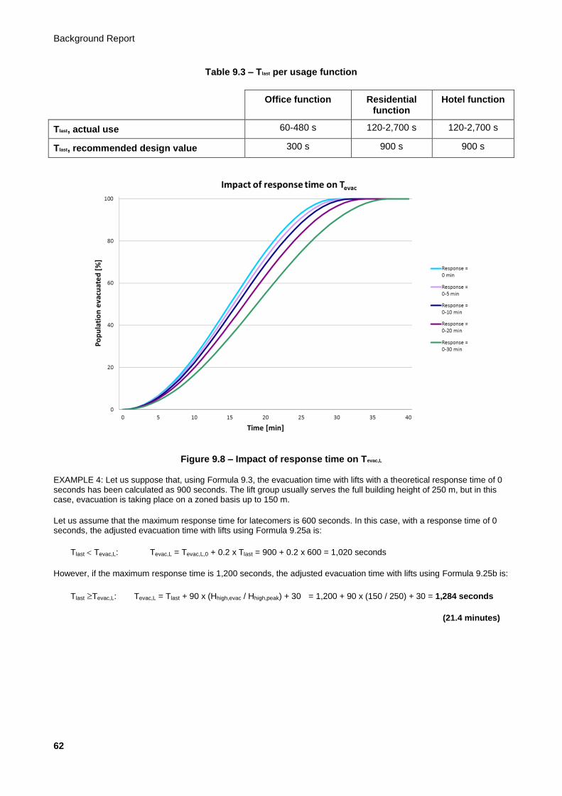
Background Report
62
Table 9.3 – Tlast per usage function
Office function Residential function
Hotel function
Tlast, actual use 60-480 s 120-2,700 s 120-2,700 s
Tlast, recommended design value 300 s 900 s 900 s
Figure 9.8 – Impact of response time on Tevac,L
EXAMPLE 4: Let us suppose that, using Formula 9.3, the evacuation time with lifts with a theoretical response time of 0 seconds has been calculated as 900 seconds. The lift group usually serves the full building height of 250 m, but in this case, evacuation is taking place on a zoned basis up to 150 m.
Let us assume that the maximum response time for latecomers is 600 seconds. In this case, with a response time of 0 seconds, the adjusted evacuation time with lifts using Formula 9.25a is:
Tlast Tevac,L: Tevac,L = Tevac,L,0 + 0.2 x Tlast = 900 + 0.2 x 600 = 1,020 seconds
However, if the maximum response time is 1,200 seconds, the adjusted evacuation time with lifts using Formula 9.25b is:
Tlast Tevac,L: Tevac,L = Tlast + 90 x (Hhigh,evac / Hhigh,peak) + 30 = 1,200 + 90 x (150 / 250) + 30 = 1,284 seconds
(21.4 minutes)
Evacuation of High-rise Buildings with Lifts and Stairs
63
9.6 The evacuation routine: accompanied, semi-automatic or fully-automatic evacuation with lifts?
9.6.1 General
In buildings with an emergency response organisation (office function) or in-house security service (hotel function), evacuation should be accompanied. This entails assistance being provided in the lift car and on the upper floors for evacuees wanting to use the lifts. The assisters will accompany the evacuation until the fire service arrives and possibly thereafter if required by the fire service. Accompanied evacuation has the following advantages:
a) The emergency response officer / security officer can assist mobility-impaired evacuees, prevent overloading of the lift car, and, if necessary, determine who should board first.
b) The emergency response officer / security officer can check upper floors to ensure that they are actually empty.
c) Accompanied evacuation is cheaper than fully automatic evacuation from a technical point of view because automatic evacuation control is not necessary.
There is generally no emergency response organisation present in residential buildings, and due to the transient nature of the population, not every resident will be familiar with the procedure for evacuating with lifts. However, regular evacuation exercises should be held in these buildings as well, and evacuation should preferably be accompanied. For this purpose, a permanently manned post could be set up which would be manned by a caretaker or security officer who can take charge in the event of an alarm until the fire service arrives. This person should ideally have an on-call emergency response team whom they can contact (residence or organised centrally via the housing corporation) so that assistance can be provided fast in the event of an evacuation. Evacuation can then take place fully automatically until this backup arrives. Once the fire service arrives, the fire service command post can switch to semi-automatic evacuation. Accompanied evacuation can commence when the on-call emergency response team members arrive.
When the various evacuation routines (accompanied, semi-automatic, and fully automatic evacuation) should be used is shown in Table 9.4.

Background Report
64
Table 9.4 – Application of evacuation routines by usage function
Evacuation routine
Usage function In case of fire: until the fire service arrives
In case of fire: after the fire service has arrived
In case of other emergency
Office function Accompanied (by emergency response organisation)
Accompanied (by emergency response organisation)
Accompanied (by emergency response organisation)
Hotel function Accompanied (by in-house security service)
Accompanied (by in-house security service)
Accompanied (by in-house security service)
Residential function (with post manned 24/7)
(PREFERRED)
Accompanied (by in-house security service); Fractional evacuation only (Scenario 2)
Accompanied (by in-house security service); Fractional evacuation only (Scenario 2)
Accompanied (by in-house security service); Fractional evacuation only (Scenario 2)
Residential function (no post manned 24/7)
(IN PRACTICE)
Fully automatic evacuation until on-call emergency response team arrives, then accompanied evacuation; Fractional evacuation only (Scenario 2)
Semi-automatic evacuation until on-call emergency response team arrives, then accompanied evacuation; Fractional evacuation only (Scenario 2)
Fully automatic evacuation until on-call emergency response team arrives, then accompanied evacuation; Fractional evacuation only (Scenario 2)
9.6.2 Accompanied evacuation
The assumption for accompanied evacuation is that the emergency response organisation (office function), in-house security service (hotel function) or on-call emergency response team (residential function) takes over control of the evacuation lifts from the lift car. For this purpose, there must be a switch (key switch, magnetic card reader, or button with code authorisation) in the car of the evacuation lift. When this switch is activated, the evacuation lift is removed from the lift group, all existing car commands are deleted, and no more floor calls are assigned to it. An emergency response team member in the car communicates with the central emergency response organisation where the person in charge assigns the lifts to the floors and determines the order of evacuation. It should be determined on a project basis whether the emergency response organisation should be permitted to use the means of communication at the fire service command centre (for example until the fire service arrives), or whether they should have their own means of communication (e.g. two-way radio, walkie-talkie, or mobile phone).
9.6.3 Semi-automatic evacuation
For semi-automatic evacuation, the assumption is that the evacuation lifts will be operated from the fire service command post. The person in charge determines the order of evacuation and assigns the lifts to the floors. No controls in the lift car or on the floors need to be used. When the semi-automatic evacuation circuit is activated at the command post, all existing car and floor calls are overridden, and the lifts are then available for evacuation only. The way in which the lifts are operated from the command room should be determined on a project basis: this can vary from full remote control to more or less fully automatic evacuation. With full remote control, every subsequent destination of an evacuation lift and the door closing time must be given from the command centre: the lifts will remain idle until they receive a command. With more or less fully automatic evacuation, only the next floor to be evacuated is specified from the command centre; the lifts will then automatically evacuate this floor together until it is empty. Lifts automatically evacuate top-down until they are given a different command from the command centre, and have a simple evacuation circuit alongside the lift control. For semi-automatic evacuation, CCTV monitoring of all floors and
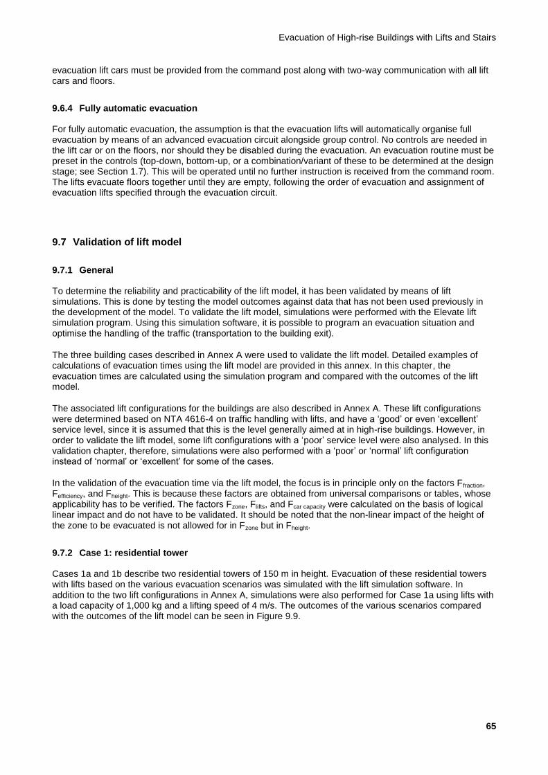
Evacuation of High-rise Buildings with Lifts and Stairs
65
evacuation lift cars must be provided from the command post along with two-way communication with all lift cars and floors.
9.6.4 Fully automatic evacuation
For fully automatic evacuation, the assumption is that the evacuation lifts will automatically organise full evacuation by means of an advanced evacuation circuit alongside group control. No controls are needed in the lift car or on the floors, nor should they be disabled during the evacuation. An evacuation routine must be preset in the controls (top-down, bottom-up, or a combination/variant of these to be determined at the design stage; see Section 1.7). This will be operated until no further instruction is received from the command room. The lifts evacuate floors together until they are empty, following the order of evacuation and assignment of evacuation lifts specified through the evacuation circuit.
9.7 Validation of lift model
9.7.1 General
To determine the reliability and practicability of the lift model, it has been validated by means of lift simulations. This is done by testing the model outcomes against data that has not been used previously in the development of the model. To validate the lift model, simulations were performed with the Elevate lift simulation program. Using this simulation software, it is possible to program an evacuation situation and optimise the handling of the traffic (transportation to the building exit).
The three building cases described in Annex A were used to validate the lift model. Detailed examples of calculations of evacuation times using the lift model are provided in this annex. In this chapter, the evacuation times are calculated using the simulation program and compared with the outcomes of the lift model.
The associated lift configurations for the buildings are also described in Annex A. These lift configurations were determined based on NTA 4616-4 on traffic handling with lifts, and have a ‘good’ or even ‘excellent’ service level, since it is assumed that this is the level generally aimed at in high-rise buildings. However, in order to validate the lift model, some lift configurations with a ‘poor’ service level were also analysed. In this validation chapter, therefore, simulations were also performed with a ‘poor’ or ‘normal’ lift configuration instead of ‘normal’ or ‘excellent’ for some of the cases.
In the validation of the evacuation time via the lift model, the focus is in principle only on the factors Ffraction, Fefficiency, and Fheight. This is because these factors are obtained from universal comparisons or tables, whose applicability has to be verified. The factors Fzone, Flifts, and Fcar capacity were calculated on the basis of logical linear impact and do not have to be validated. It should be noted that the non-linear impact of the height of the zone to be evacuated is not allowed for in Fzone but in Fheight.
9.7.2 Case 1: residential tower
Cases 1a and 1b describe two residential towers of 150 m in height. Evacuation of these residential towers with lifts based on the various evacuation scenarios was simulated with the lift simulation software. In addition to the two lift configurations in Annex A, simulations were also performed for Case 1a using lifts with a load capacity of 1,000 kg and a lifting speed of 4 m/s. The outcomes of the various scenarios compared with the outcomes of the lift model can be seen in Figure 9.9.

Background Report
66
Figure 9.9 – Simulation results for Case 1: residential building
This figure shows that the evacuation time calculation using the lift model is on the safe side for each scenario in these cases compared with the outcomes of the simulations. For Case 1a (normal), this margin is approximately +25% for each scenario. For Case 1a (poor), it is approximately +17%, with the exception of Scenario 2 with 10% evacuation, for which the margin is +25%. Scenario 1b produces a margin of approximately +15% for Scenarios 1 and 5, with +25% for Scenario 2.
For the validation of the evacuation time for this residential building via the lift model, only the factors Ffraction, Fefficiency, and Fcar capacity have an effect. The difference between Case 1a (normal) and Case 1a (poor) can be explained by the factor Fefficiency, which is greater in a building designed to a ‘normal’ level than one designed to a ‘poor’ level. The factor Fcar capacity does not affect the differences between the two cases since in both cases, only one more person fits into the lift car during an evacuation than during normal lift usage.
9.7.3 Case 2: office tower
9.7.3.1 General
Cases 2a and 2b describe two office towers of 180 m in height. Evacuation of these office towers with lifts based on the various evacuation scenarios was simulated with the lift simulation software. In addition to the two lift configurations in Annex A, simulations were also performed for the low-rise lifts in Case 2a using lifts with a load capacity of 1,275 kg and a lifting speed of 4.0 m/s. The outcomes of the various scenarios compared with the outcomes of the lift model can be seen in Figure 9.10.
Case 1: residential tower block
0 200 400 600 800
1000 1200 1400 1600 1800 2000 2200 2400 2600 2800 3000 3200 3400 3600
Full evacuation (Scenario 1)
Full evacuaton - 1 lift (Scenario 1)
Fractional evacuation (10%) (Scenario 2)
Fractional evacuation (20%) (Scenario 2)
Fractional evacuation (50%) (Scenario 4)
Scenario
Tevac, L
(s) Lift model, Case 1a Lift model. Case 1b Simulation, Case 1a (normal) Simulation, Case 1a (sparse) Simulation, Case 1b

Evacuation of High-rise Buildings with Lifts and Stairs
67
Figure 9.10 – Simulation results for Case 2: office tower
In Figure 9.10, it can also be seen that the simulation results for Case 2 provide a shorter evacuation time for
each scenario than the time calculated using the lift model. The simulation results in Scenarios 1 and 4 have
a margin of approximately +20% [Case 2a (good)] and +17% [Case 2a (poor) and Case 3b] compared with
the lift model. For Scenario 3, this is approximately +26% [Case 2a (good) and Case 2b] and 22% [Case 2a
(poor)].
For the validation of the evacuation time for this office building, just as with the residential building, only the factors Ffraction, Fefficiency, and Fcar capacity actually have an effect. The difference between Case 2a (normal) and Case 2a (poor) can also be explained in this case by the factor Fefficiency. The factor Fcar capacity does not affect the differences between the two cases since the lifts have the same load capacities in both cases.
9.7.3.2 Scenario 3
For Case 2, simulations were also performed on the basis of Scenario 3: evacuation with transition layers. In these simulations, it was assumed that there was the same number of transition layers as described in the examples in Annex A. The formulae described in Section 9.3 were used to calculate the evacuation times with the lift model. Figure 9.11 therefore serves as validation for these formulae.
Case 2: office tower block
0
200
400
600
800
1000
1200
1400
1600
1800
2000
Ful evacuation (Scenario 1)
Full evacuation - 1 lift (Scenario 1)
Fractional evacuation (6%)
(Scenario 2)
Fractional evacuation (12%)
(Scenario 2)
Fractional evacuation (50%)
(Scenario 4) Scenario
Tevac, L (s) Lift model, Case 2a Lift model, Case 2b Simulation, Case 2a low-rise (normal) Simulation, Case 2a low-rise (sparse) Simulation, Case 2a high-rise Simulation, Case 2b low-rise Simulation, Case 2b high-rise
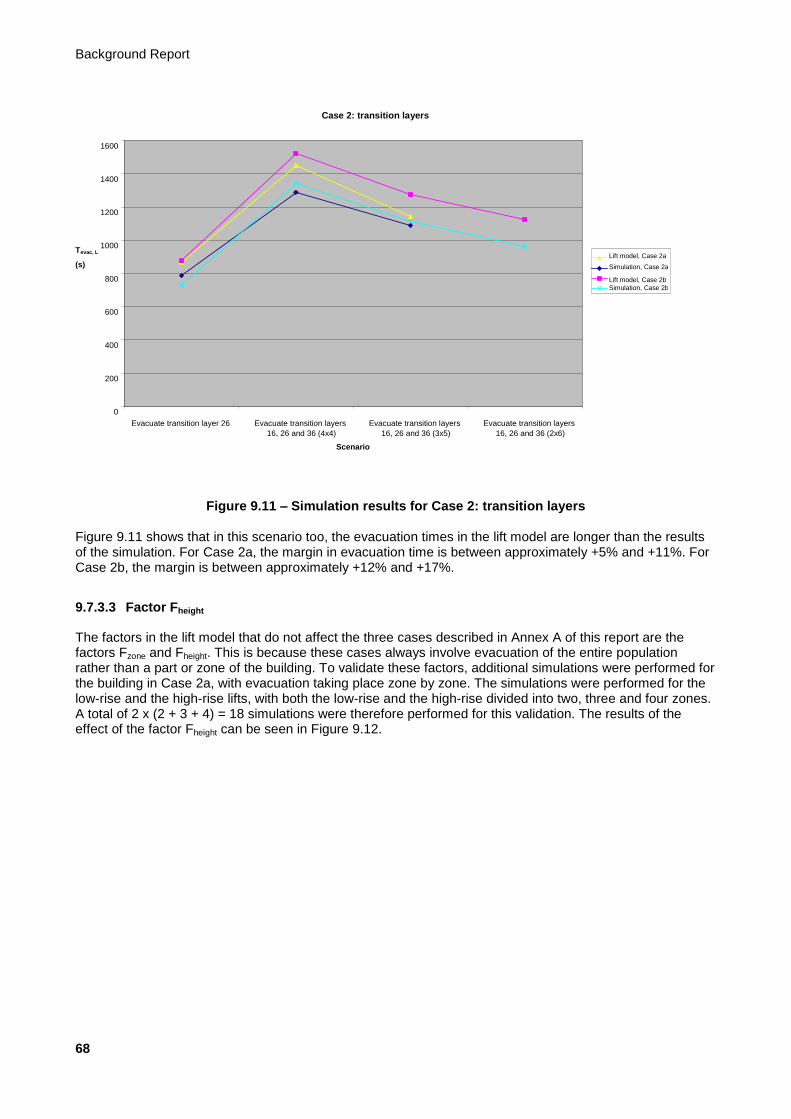
Background Report
68
Figure 9.11 – Simulation results for Case 2: transition layers
Figure 9.11 shows that in this scenario too, the evacuation times in the lift model are longer than the results of the simulation. For Case 2a, the margin in evacuation time is between approximately +5% and +11%. For Case 2b, the margin is between approximately +12% and +17%.
9.7.3.3 Factor Fheight
The factors in the lift model that do not affect the three cases described in Annex A of this report are the factors Fzone and Fheight. This is because these cases always involve evacuation of the entire population rather than a part or zone of the building. To validate these factors, additional simulations were performed for the building in Case 2a, with evacuation taking place zone by zone. The simulations were performed for the low-rise and the high-rise lifts, with both the low-rise and the high-rise divided into two, three and four zones. A total of 2 x (2 + 3 + 4) = 18 simulations were therefore performed for this validation. The results of the effect of the factor Fheight can be seen in Figure 9.12.
Case 2: transition layers
0
200
400
600
800
1000
1200
1400
1600
Evacuate transition layer 26 Evacuate transition layers 16, 26 and 36 (4x4)
Evacuate transition layers 16, 26 and 36 (3x5)
Evacuate transition layers 16, 26 and 36 (2x6)
Scenario
Tevac, L
(s) Lift model, Case 2a Simulation, Case 2a Lift model, Case 2b Simulation, Case 2b
Evacuation of High-rise Buildings with Lifts and Stairs
69
Figure 9.12 – Simulation results for Fheight
This figure shows that the results are relatively in line with the Fheight formula from Subsection 9.2.3. However, there are two clear outliers below the line of the formula. These are results of the simulation in which the high-rise group was divided into four zones and the simulation of the top two zones of the high-rise group resulted in a very short evacuation time. This arose because the lift cars in this situation could be precisely and optimally filled, leaving no half-full cars at the end of the simulation. This is an exact optimum situation that will not occur in practice, partly because the population will not usually fit precisely into a whole number of cars and because the population will in practice not be the same on each floor. If these two outliers are removed from the results, we are left with Figure 9.13.
Total Fheight
50%
60%
70%
80%
90%
100%
110%
120%
130%
140%
150%
0 0.2 0.4 0.6 0.8 1 1.2 1.4 1.6 1.8 2 Fheight
Tevac,L
(%)
Simulation, Case 2a Formula Fheight

Background Report
70
Figure 9.13 – Simulation results for Fheight (without outliers)
This diagram shows that the model for Fheight produces a good, average representation of the simulation results. The correlation is more or less linear, with the simulation results alternating above and below the model results.
9.7.4 Case 3: office tower and hotel
Cases 3a and 3b describe two combined office and hotel towers of 250 m in height. Evacuation of these two buildings with lifts based on the various evacuation scenarios was once again simulated with the lift simulation software. Evacuation of the offices and evacuation of the hotel were simulated separately, and both are discussed separately in this subsection. In addition to the lift configurations in Annex A, simulations were also performed for the high-rise lifts in the office part in Case 3b using lifts with a load capacity of 1,275 kg and a lifting speed of 8 m/s. For the lifts in the hotel part in Case 3a, simulations were also performed using lifts with a load capacity of 1,000 kg and a lifting speed of 2.5 m/s.
9.7.4.1 Office zone
The outcomes of the various evacuation scenarios for the office part compared with the outcomes in the lift model can be seen in Figure 9.14.
Total Fheight (without outliers)
50%
60%
70%
80%
90%
100%
110%
120%
130%
140%
150%
0 0.2 0.4 0.6 0.8 1 1.2 1.4 1.6 1.8 2 Fheight
Tevac,L
(%)
Simulation, Case 2a Formula Fheight

Evacuation of High-rise Buildings with Lifts and Stairs
71
Figure 9.14 – Simulation results for Case 3: office tower
In Case 3, almost all the simulation results produce a shorter evacuation time than the results calculated with the lift model. The only exception to this is Case 3b high-rise (poor). This lift configuration only just meets the ‘poor’ service level, with a waiting time of approximately 49 seconds in the morning peak. In Figure 9.14, we can see that the simulation results in this case are roughly the same as the results in the lift model, and that the simulation result from Scenario 1 in this case (-1 lift) actually produces a 2% longer evacuation time than the outcome of the model.
For the other results, the margin between the outcome of the lift model and the simulation results is approximately 11-17% in Scenario 1.
For Scenario 2, these margins have a greater spread, and the difference between the simulation results and the results of the lift model is approximately 2-31%.
For Scenario 4, the margin for both cases is 28% for low-rise and 18% for high-rise.
This case clearly shows the effect of Fefficiency. The range found for Fefficiency is described in Table 1 of Subsection 9.2.4. The recommendation is to choose the lowest value of the range for each building type. As can be seen in this case, in Case 3b (poor), this lowest value corresponds to a lift configuration with a ‘poor’ service level. For a higher service level, the margin for this factor is at least 10%.
9.7.4.2 Hotel zone
For the hotel part of the building, the impact of the presence of personnel in the hotel was also explored in the validation. The lift configuration in a hotel is generally designed to accommodate the population of hotel guests and not the number of staff. The simulations for full evacuation were therefore performed twice: with and without staff.
Simulations were also performed for evacuation of the hotel with shuttle lifts. These serve as validation for the lift model described in Section 9.4. The hotel staff were always included in the simulation of the shuttle lifts.
Case 3: office tower
0
200
400
600
800
1000
1200
1400
1600
1800
2000
Full evacuation (Scenario 1)
Full evacuation - 1 lift (Scenario 1)
Fractional evacuation (6%)
(Scenario 2)
Fractional evacuation (12%)
(Scenario 2)
Fractional evacuation (50%)
(Scenario 4) Scenario
Tevac, L (s) Lift model, Case 3a Lift model, Case 3b Simulation, Case 3a low-rise Simulation, Case 3a high-rise Simulation, Case 3b low-rise Simulation, Case 3b high-rise (normal) Simulation, Case 3b high-rise (sparse)
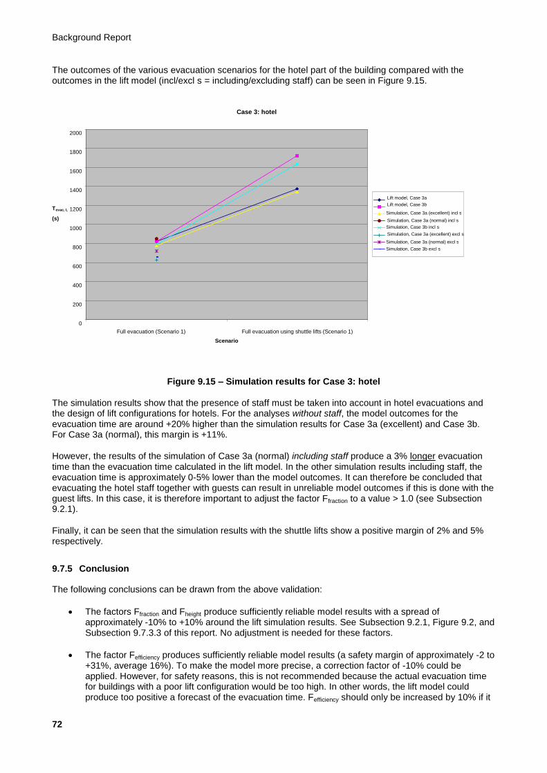
Background Report
72
The outcomes of the various evacuation scenarios for the hotel part of the building compared with the outcomes in the lift model (incl/excl s = including/excluding staff) can be seen in Figure 9.15.
Figure 9.15 – Simulation results for Case 3: hotel
The simulation results show that the presence of staff must be taken into account in hotel evacuations and the design of lift configurations for hotels. For the analyses without staff, the model outcomes for the evacuation time are around +20% higher than the simulation results for Case 3a (excellent) and Case 3b. For Case 3a (normal), this margin is +11%.
However, the results of the simulation of Case 3a (normal) including staff produce a 3% longer evacuation time than the evacuation time calculated in the lift model. In the other simulation results including staff, the evacuation time is approximately 0-5% lower than the model outcomes. It can therefore be concluded that evacuating the hotel staff together with guests can result in unreliable model outcomes if this is done with the guest lifts. In this case, it is therefore important to adjust the factor Ffraction to a value > 1.0 (see Subsection 9.2.1).
Finally, it can be seen that the simulation results with the shuttle lifts show a positive margin of 2% and 5% respectively.
9.7.5 Conclusion
The following conclusions can be drawn from the above validation:
The factors Ffraction and Fheight produce sufficiently reliable model results with a spread of approximately -10% to +10% around the lift simulation results. See Subsection 9.2.1, Figure 9.2, and Subsection 9.7.3.3 of this report. No adjustment is needed for these factors.
The factor Fefficiency produces sufficiently reliable model results (a safety margin of approximately -2 to +31%, average 16%). To make the model more precise, a correction factor of -10% could be applied. However, for safety reasons, this is not recommended because the actual evacuation time for buildings with a poor lift configuration would be too high. In other words, the lift model could produce too positive a forecast of the evacuation time. Fefficiency should only be increased by 10% if it
Case 3: hotel
0
200
400
600
800
1000
1200
1400
1600
1800
2000
Full evacuation (Scenario 1) Full evacuation using shuttle lifts (Scenario 1) Scenario
Tevac, L
(s)
Lift model, Case 3a Lift model, Case 3b Simulation, Case 3a (excellent) incl s Simulation, Case 3a (normal) incl s Simulation, Case 3b incl s Simulation, Case 3a (excellent) excl s Simulation, Case 3a (normal) excl s Simulation, Case 3b excl s
Evacuation of High-rise Buildings with Lifts and Stairs
73
can be ascertained with certainty that the lift configuration in the building guarantees ‘normal/good’ or ‘excellent’ traffic handling.
The separate formulae for the evacuation of shuttle lifts produce sufficiently reliable model results (a safety margin of approximately +2 to +5%, average 4%).
The separate formulae for the evacuation of transition layers produce sufficiently reliable model results (a safety margin of approximately +5 to +17%, average 11%). To make the model more precise, a correction factor of -5% could be applied, although this is not advised for safety reasons.
The factors Fzone, Fcar capacity, and Flifts do not need to be validated as they relate to logical, linear contexts.
Finally, in addition to validating the lift model on the basis of available egress flow profiles, it would also be advisable to stage a practical exercise in a high-rise building to measure the behaviour and egress flow profile of the building population during an evacuation by stairs and/or lift. However, it was not possible to organise a practical exercise of this kind within the time available for this study. It is recommended that this be done for the purpose of upgrading this report to an NTA.
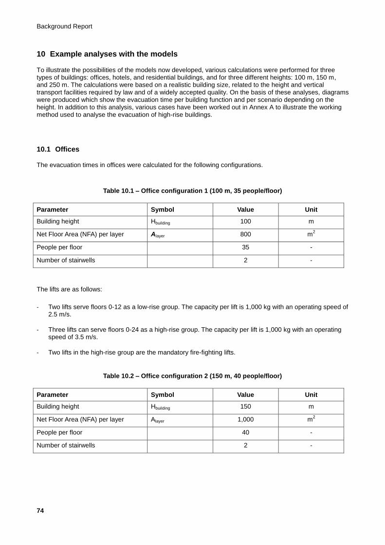
Background Report
74
10 Example analyses with the models
To illustrate the possibilities of the models now developed, various calculations were performed for three types of buildings: offices, hotels, and residential buildings, and for three different heights: 100 m, 150 m, and 250 m. The calculations were based on a realistic building size, related to the height and vertical transport facilities required by law and of a widely accepted quality. On the basis of these analyses, diagrams were produced which show the evacuation time per building function and per scenario depending on the height. In addition to this analysis, various cases have been worked out in Annex A to illustrate the working method used to analyse the evacuation of high-rise buildings.
10.1 Offices
The evacuation times in offices were calculated for the following configurations.
Table 10.1 – Office configuration 1 (100 m, 35 people/floor)
Parameter Symbol Value Unit
Building height Hbuilding 100 m
Net Floor Area (NFA) per layer Alayer 800 m2
People per floor 35 -
Number of stairwells 2 -
The lifts are as follows:
- Two lifts serve floors 0-12 as a low-rise group. The capacity per lift is 1,000 kg with an operating speed of 2.5 m/s.
- Three lifts can serve floors 0-24 as a high-rise group. The capacity per lift is 1,000 kg with an operating speed of 3.5 m/s.
- Two lifts in the high-rise group are the mandatory fire-fighting lifts.
Table 10.2 – Office configuration 2 (150 m, 40 people/floor)
Parameter Symbol Value Unit
Building height Hbuilding 150 m
Net Floor Area (NFA) per layer Alayer 1,000 m2
People per floor 40 -
Number of stairwells 2 -
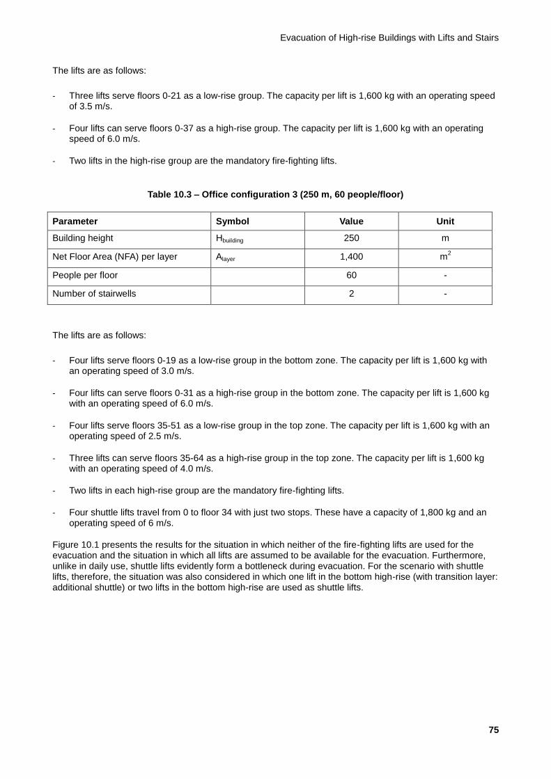
Evacuation of High-rise Buildings with Lifts and Stairs
75
The lifts are as follows:
- Three lifts serve floors 0-21 as a low-rise group. The capacity per lift is 1,600 kg with an operating speed of 3.5 m/s.
- Four lifts can serve floors 0-37 as a high-rise group. The capacity per lift is 1,600 kg with an operating speed of 6.0 m/s.
- Two lifts in the high-rise group are the mandatory fire-fighting lifts.
Table 10.3 – Office configuration 3 (250 m, 60 people/floor)
Parameter Symbol Value Unit
Building height Hbuilding 250 m
Net Floor Area (NFA) per layer Alayer 1,400 m2
People per floor 60 -
Number of stairwells 2 -
The lifts are as follows:
- Four lifts serve floors 0-19 as a low-rise group in the bottom zone. The capacity per lift is 1,600 kg with an operating speed of 3.0 m/s.
- Four lifts can serve floors 0-31 as a high-rise group in the bottom zone. The capacity per lift is 1,600 kg with an operating speed of 6.0 m/s.
- Four lifts serve floors 35-51 as a low-rise group in the top zone. The capacity per lift is 1,600 kg with an operating speed of 2.5 m/s.
- Three lifts can serve floors 35-64 as a high-rise group in the top zone. The capacity per lift is 1,600 kg with an operating speed of 4.0 m/s.
- Two lifts in each high-rise group are the mandatory fire-fighting lifts.
- Four shuttle lifts travel from 0 to floor 34 with just two stops. These have a capacity of 1,800 kg and an operating speed of 6 m/s.
Figure 10.1 presents the results for the situation in which neither of the fire-fighting lifts are used for the evacuation and the situation in which all lifts are assumed to be available for the evacuation. Furthermore, unlike in daily use, shuttle lifts evidently form a bottleneck during evacuation. For the scenario with shuttle lifts, therefore, the situation was also considered in which one lift in the bottom high-rise (with transition layer: additional shuttle) or two lifts in the bottom high-rise are used as shuttle lifts.
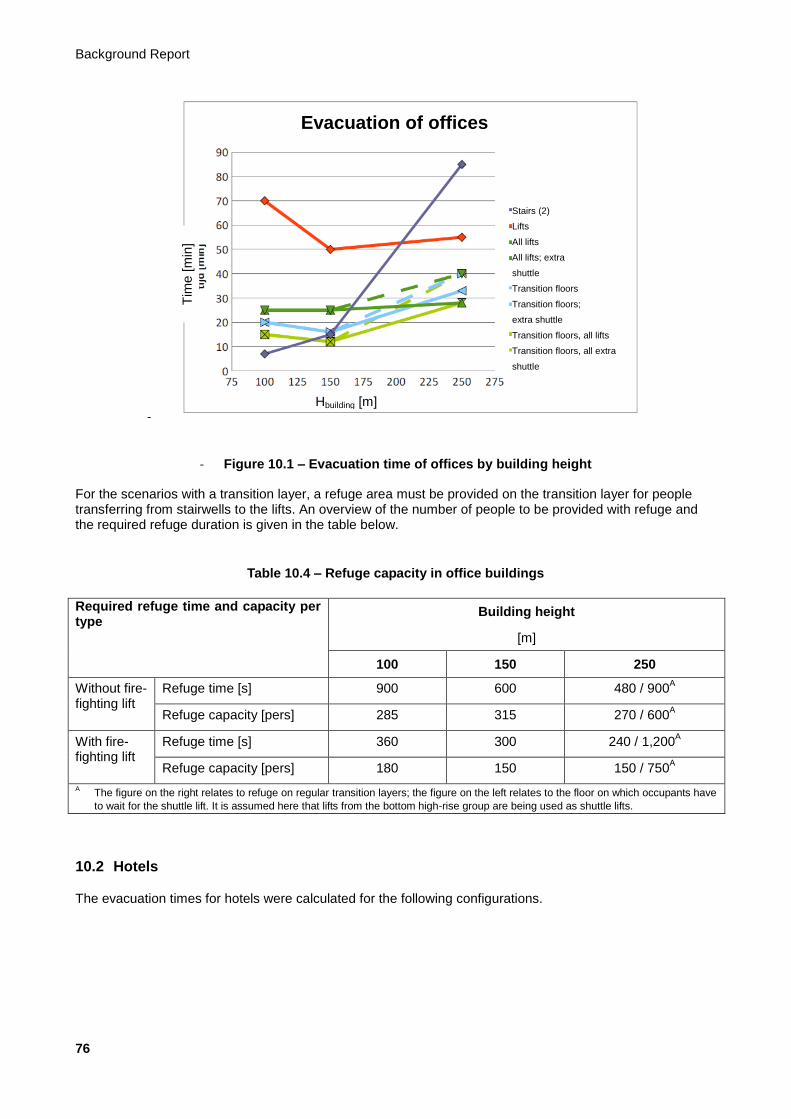
Background Report
76
-
- Figure 10.1 – Evacuation time of offices by building height
For the scenarios with a transition layer, a refuge area must be provided on the transition layer for people transferring from stairwells to the lifts. An overview of the number of people to be provided with refuge and the required refuge duration is given in the table below.
Table 10.4 – Refuge capacity in office buildings
Required refuge time and capacity per type
Building height
[m]
100 150 250
Without fire-fighting lift
Refuge time [s] 900 600 480 / 900A
Refuge capacity [pers] 285 315 270 / 600A
With fire-fighting lift
Refuge time [s] 360 300 240 / 1,200A
Refuge capacity [pers] 180 150 150 / 750A
A The figure on the right relates to refuge on regular transition layers; the figure on the left relates to the floor on which occupants have
to wait for the shuttle lift. It is assumed here that lifts from the bottom high-rise group are being used as shuttle lifts.
10.2 Hotels
The evacuation times for hotels were calculated for the following configurations.
Tim
e [
min
]
Hbuilding [m]
Stairs (2)
Lifts
All lifts
All lifts; extra
shuttle
Transition floors
Transition floors;
extra shuttle
Transition floors, all lifts
Transition floors, all extra
shuttle
Evacuation of offices

Evacuation of High-rise Buildings with Lifts and Stairs
77
Table 10.5 – Hotel configuration 1 (100 m, 20 people/floor)
Parameter Symbol Value Unit
Building height Hbuilding 100 m
Net Floor Area (NFA) per layer Alayer 800 m2
People per floor 20 -
Number of stairwells 2 -
The lifts are as follows:
- Four lifts serve floors 1-24. The capacity per lift is 1,275 kg with an operating speed of 3.5 m/s.
- The fire-fighting lifts are included in the service lifts separately from this group and play no role in this analysis.
Table 10.6 – Hotel configuration 2 (150 m, 24 people/floor)
Parameter Symbol Value Unit
Building height Hbuilding 150 m
Net Floor Area (NFA) per layer Alayer 1,000 m2
People per floor 24 -
Number of stairwells 2 -
The lifts are as follows:
- Four lifts serve floors 1-21 as a low-rise group. The capacity per lift is 1,275 kg with an operating speed of 3.0 m/s.
- Four lifts serve floors 22-39 as a high-rise group. The capacity per lift is 1,275 kg with an operating speed of 5.0 m/s.
- The fire-fighting lifts are included in the service lifts separately from this group and play no role in this analysis.
Table 10.7 – Hotel configuration 3 (250 m, 30 people/floor)
Parameter Symbol Value Unit
Building height Hbuilding 250 m
Net Floor Area (NFA) per layer Alayer 1,400 m2
People per floor 30 -
Number of stairwells 2 -

Background Report
78
The lifts are as follows:
- Four lifts serve floors 1-17 as a low-rise group in the bottom zone. The capacity per lift is 1,275 kg with an operating speed of 2.5 m/s.
- Four lifts serve floors 18-34 as a high-rise group in the bottom zone. The capacity per lift is 1,275 kg with an operating speed of 5.0 m/s.
- Three lifts serve floors 37-54 as a low-rise group in the top zone. The capacity per lift is 1,275 kg with an operating speed of 2.5 m/s.
- Three lifts serve floors 55-68 as a high-rise group in the top zone. The capacity per lift is 1,275 kg with an operating speed of 4.0 m/s.
- The fire-fighting lifts are included in the service lifts separately from this group and play no role in this analysis.
- There are two shuttle lifts from the ground floor to floor 37 with a capacity of 1,600 kg and an operating speed of 6.0 m/s.
In hotels too, unlike in daily use, shuttle lifts evidently form a bottleneck during evacuation (see Figure 10.2). In the shuttle lift scenario as well, the situation was considered in which two lifts in the bottom high-rise were used as shuttle lifts. In accordance with the guidelines in NTA 4614-4 on vertical transport, fire-fighting lifts in hotels are planned separately in the group designed as goods lifts.
-
- Figure 10.2 – Evacuation time of hotels by building height
For the scenarios with a transition layer, a refuge area must once again be provided on the transition layer for people transferring from stairwells to the lifts. An overview of the number of people to be provided with refuge and the required refuge duration is given in the table below.
Evacuation of hotels
Stairs (2)
All lifts
All lifts; extra
shuttle
Transition floors, all lifts
Transition floors, all extra
shuttle
Hbuilding [m]
Tim
e [
min
]

Evacuation of High-rise Buildings with Lifts and Stairs
79
Table 10.8 – Refuge capacity in hotels
Required refuge time and capacity per type
Building height
[m]
100 150 250
Without fire-fighting lift
A
Refuge time [s] - - -
Refuge capacity [pers] - - -
With fire-fighting lift
Refuge time [s] 600 420 420 / 600B
Refuge capacity [pers] 160 230 230 / 400B
A This type does not occur in hotels; the assumption is that fire-fighting lifts are part of the service lift group in this case.
B The figure on the right relates to refuge on regular transition layers; the figure on the left relates to the floor on which occupants have
to wait for the shuttle lift. It is assumed here that lifts from the bottom high-rise group are being used as shuttle lifts.
10.3 Residential buildings
Table 10.9 – Residential building configuration 1 (100 m, 20 people/floor)
Parameter Symbol Value Unit
Building height Hbuilding 100 m
Net Floor Area (NFA) per layer Alayer 800 m2
People per floor 20 -
Number of stairwells 2 -
The lifts are as follows:
- There is a central group of three lifts that serves all floors. These lifts have a capacity of 1,275 kg and an operating speed of 3.0 m/s.
- The two mandatory fire-fighting lifts are included in this group.
Table 10.10 – Residential building configuration 2 (150 m, 22 people/floor)
Parameter Symbol Value Unit
Building height Hbuilding 150 m
Net Floor Area (NFA) per layer Alayer 1,000 m2
People per floor 22 -
Number of stairwells 2 -
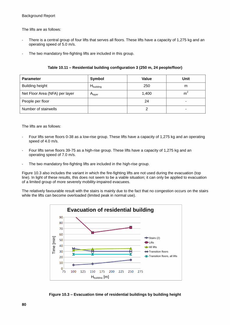
Background Report
80
The lifts are as follows:
- There is a central group of four lifts that serves all floors. These lifts have a capacity of 1,275 kg and an operating speed of 5.0 m/s.
- The two mandatory fire-fighting lifts are included in this group.
Table 10.11 – Residential building configuration 3 (250 m, 24 people/floor)
Parameter Symbol Value Unit
Building height Hbuilding 250 m
Net Floor Area (NFA) per layer Alayer 1,400 m2
People per floor 24 -
Number of stairwells 2 -
The lifts are as follows:
- Four lifts serve floors 0-38 as a low-rise group. These lifts have a capacity of 1,275 kg and an operating speed of 4.0 m/s.
- Four lifts serve floors 39-75 as a high-rise group. These lifts have a capacity of 1,275 kg and an operating speed of 7.0 m/s.
- The two mandatory fire-fighting lifts are included in the high-rise group.
Figure 10.3 also includes the variant in which the fire-fighting lifts are not used during the evacuation (top line). In light of these results, this does not seem to be a viable situation; it can only be applied to evacuation of a limited group of more severely mobility-impaired evacuees.
The relatively favourable result with the stairs is mainly due to the fact that no congestion occurs on the stairs while the lifts can become overloaded (limited peak in normal use).
Figure 10.3 – Evacuation time of residential buildings by building height
Tim
e [
min
]
Hbuilding [m]
Stairs (2)
Lifts
All lifts
Transition floors
Transition floors, all lifts
Evacuation of residential building
Evacuation of High-rise Buildings with Lifts and Stairs
81
For the scenarios with a transition layer, a refuge area must be provided on the transition layer for people transferring from stairwells to the lifts. An overview of the number of people to be provided with refuge and the required refuge duration is given in the table below.
Table 10.12 – Refuge capacity in residential buildings
Required refuge time and capacity per type
Building height
[m]
100 150 250
Without fire-fighting lift
Refuge time [s] 1,800 3,300 4,800
Refuge capacity [pers] 260 420 340
With fire-fighting lift
Refuge time [s] 480 900 1,200
Refuge capacity [pers] 175 300 290

Background Report
82
11 General requirements
11.1 General
The evacuation scenarios discussed above require the building components to have a particular functionality. It is also important to embed the evacuation in an organisational structure, particularly if a scenario is used in which evacuees have to wait somewhere for a certain length of time before they can proceed further. The aim in any case is to ensure that every person can always opt to proceed further without waiting. The general requirements described in this chapter relate to:
a) Creating safe areas where evacuees can wait for lifts; this includes waiting areas for mobility-impaired evacuees on every floor as well as assembly areas if a combination of stairs and lifts is used (Scenario 3)
b) Limiting the spread of smoke and heat to lift shafts and stairwells as well as their lobbies and refuge areas; this is particularly aimed at keeping vertical routes open for use by evacuees
b) Taking measures to prevent lifts from failing; this includes both measures to prevent smoke spreading to measurement and control equipment, as well as measures to make these components less susceptible to smoke and heat
c) Taking measures to keep stairwells usable
d) Providing sufficiently large refuge areas
e) Setting up an organisation that will ensure that the intended evacuation can actually be carried out
11.2 Structural aspects
Some of the above measures are structural. Some potential measures are described below, along with the key points to be taken into account. The functional requirement is important, particularly in relation to the length of time the components for evacuation must continue to function.
a) Refuge area per lobby on all floors (Scenarios 1, 2, 3) and per refuge level (Scenario 3) must be provided for. The widely used method in accordance with the explanatory notes to the Building Decree Regulation specifies a maximum of six persons per m² on stair landings, although it gives no number for other floors. NFPA 5000 assumes 3 ft² (0.28 m
2 per person). In this case, the starting point for the dimensions of the
lift lobbies is set at a maximum of 2 persons per m². For use as refuge space in accordance with Scenario 3, a maximum of 3.5 persons per m² should be assumed.
b) The emergency lighting levels in areas in the escape route with longer occupancy times should be considerably higher than normal emergency lighting: order of magnitude 50 lux.
c) All structural and interior design materials in refuge areas should be fire class B or Bfl.
d) Emergency services up traffic must be specifically considered in the design; emergency service traffic must not impede escape traffic. The fire-fighting lift must be able to be accessed on the fire service entry level. In connection with this, consideration should be given to the possibility of using it up to the floor on which the fire is located. In light of the other measures taken in the high-rise building, this is safe use.
e) No part of the evacuation route may be accessed solely with lifts.
Evacuation of High-rise Buildings with Lifts and Stairs
83
f) An important phenomenon that can result in undesired air movements and spreading of smoke is the stack effect caused by thermal convection. This must be effectively controlled, one potential structural measure being to provide a kind of lock chamber between the door in the lift shaft and outside. The effectiveness of such a lock chamber must be demonstrated for the design concerned. For measures to prevent a stack effect, see Subsection 8.6.2 of NTA 4614-4.
g) Evacuation lifts must be waterproof to withstand sprinkler and/or fire-fighting water from the floors. Nevertheless, the functional integrity of evacuation lifts must be additionally ensured by preventing excessive water ingress into the shafts. Necessary measures include providing a 20 mm sill in combination with a drain and possibly a drainage channel. Drainage must also be provided in the shaft.
h) Water must also be prevented from entering machine rooms of lift groups located below the seat of a fire by the method described above.
i) The mechanical strength of structural partitions between compartments and critical parts of the escape route must also be considered. These must be resistant to horizontal loads that may be a direct consequence of an emergency.
j) Both the stairwells and the lifts must be able to be reached from the lift lobbies and waiting areas on the transition layers without having to pass through the compartment on the floor concerned.
k) To ensure the functional integrity of evacuation lifts, the lift shafts and lift machine rooms must be isolated from compartments on the floors to at least resistance class EI 90 in compliance with NEN-EN 13501-2. Lift lobbies must be isolated from compartments on the floors to at least resistance class EI 60 in compliance with NEN-EN 13501-2, including the door, in compliance with NEN-EN 13501-2 (tested to NEN-EN 1634-3).
l) To ensure the usability of the stairwells, the fire-resistant partition constructions are subject to the same requirements as the functional integrity of the lifts.
m) Waiting areas must also be isolated from the floors themselves and from the stairwells with resistance class EI 60 in compliance with NEN-EN 13501-2, including the door, in compliance with NEN-EN 13501-2 (tested to NEN-EN 1634-3).
11.3 Fire safety aspects
a) The conditions (temperature, smoke, smoke density, moisture, pressure, CO level, CO2 level) in lift shafts, machine rooms, and all lift lobbies must be continuously monitored since these aspects determine the usability of evacuation lifts. If any of the maximum values are exceeded on a particular floor, the lifts must no longer serve that floor. However, that floor must still be accessible by the fire-fighting lift, using the controls in the lift car, provided the lift is still operational in the circumstances concerned. If any of the maximum values are exceeded in a machine room or lift shaft, the evacuation lift concerned must be parked at the exit level. The conditions must be continuously displayed in the fire service command centre.
b) If the temperature in the lift lobby rises above 65°C, fire-fighting lifts and evacuation lifts must be shut down (NEN-EN 81-72). This means that the temperature in high-rise buildings must always be monitored on each floor. This is another reason why the doors must be designed to EI 60 (see 11.2.k).
c) The materials used in the lift shafts of evacuation lifts must meet fire propagation class A1.
d) Detection, raising the alarm, and escape route signage must be optimised in order to limit clearance time. Combined with a high level of preparedness to evacuate, this can result in a further reduction in the time between raising the alarm and commencing evacuation. Preparedness to evacuate can be increased by staging sufficient exercises and with adequate reporting (see also Section 11.8).

Background Report
84
e) The safe, responsible use of evacuation lifts requires better agreements concerning smoke opacity in escape routes, lobbies, and shafts in relation to pressure differentials and the current regulations (see the Netherlands Code of Practice NPR 6095-2).
f) When designing the lobbies, a suitable location must be found for the dry riser.
11.4 Electrical aspects
a) All lifts must be provided with preferential power supply and/or emergency power supply with sufficient capacity for staggered use, in order to evacuate the persons present in all lifts to the exit level in the event of a power failure by means of an emergency evacuation circuit.
b) All fire and evacuation lifts must be provided with preferential power supply and/or independent emergency power supply close to the machine room with sufficient capacity for simultaneous peak use for at least 120 minutes. This must supply at least the following:
- The evacuation lifts
- The machine room
- The lift controls
- All means of communication and signalling
- Other systems involved in the evacuation chain with stairs and lifts
c) If the preferential power supply fails, all lifts must be able to evacuate to the exit level, e.g. with an independent battery pack. It must be shown that this will enable the lift to reach the nominal lifting speed and that there is sufficient capacity to perform the necessary evacuation journey. The capacity must be based on the available battery capacity at the end of its service life.
d) In evacuation mode, the evacuation lifts’ brake currents are released as heat in the machine room, or they must be able to be fed back into the grid (in emergency power mode in particular). The emergency power unit must be able to feed this energy back or absorb the heat.
e) All power and signalling cables for the lifts must be fire resistant for at least 60 minutes and must be installed in a structure that ensures functional integrity or fire resistance for at least 120 minutes.
f) In addition to a preferential power supply and/or emergency power supply, the functional integrity of the electrical installation infrastructure must also be ensured.
g) The lighting level along all escape routes and in all waiting areas must be adequate, i.e. at least 50 lux, even if the lighting is powered by an emergency power supply.
11.5 Mechanical aspects
a) The lift lobbies, lift shafts, and stairwells must be kept smoke- and fire-free for 60 minutes. An important phenomenon that can result in undesired air movements and spreading of smoke is thermal convection. A pressure differential system can help limit thermal convection: see NPR 6095-2. The spread of smoke through shafts depends on the building height, the outdoor temperature, the wind pressure, the area of loss via the doors, the area of loss to the open air, the pressure loss via other shafts, etc.

Evacuation of High-rise Buildings with Lifts and Stairs
85
b) In evacuation mode, the evacuation lifts’ brake currents are released as heat in the machine room, or they must be able to be fed back into the grid (in emergency power mode in particular). The heat released must therefore be extracted or cooled in the machine room.
11.6 Lift engineering aspects
11.6.1 Evacuation routine
a) Once the fire service arrives, the decision can be taken to complete accompanied evacuation or fully automatic evacuation unchanged, or to switch to semi-automatic evacuation.
b) It must be possible for the fire service command centre to interrupt the evacuation circuit or lift car operation (in case of accompanied evacuation) of all evacuation lifts at any time and operate uninterrupted evacuation to the exit level.
11.6.2 Design of evacuation lifts
a) Evacuation lifts must at least comply with NEN-EN 81-70. Accessibility for mobility-impaired people is essential.
b) Evacuation lifts must at least comply with NEN-EN 81-72. The functional integrity and fire safety of evacuation lifts must be at least equivalent to that of fire-fighting lifts.
c) Evacuation lifts must at least comply with NEN-EN 81-73. Automatic detection of conditions on the exit level must be provided so that the lift doors do not open in a high-risk area. Smoke and fire detectors must therefore be installed in every lift lobby. Automatic choice of an alternative exit level must be provided if there is a fire on the preferred exit level.
d) At least one evacuation lift must have the dimensions of a trolley stretcher lift or must have a car depth of 2,100 mm. However, a lift car with a depth of at least 2,300 mm should ideally be available.
e) Communication with the BMS must be ISO-25743 compliant.
f) The lifts must be suitable for operating in shafts with lobbies with heat, smoke, and water.
g) Evacuation lifts must be waterproof to withstand sprinkler and fire-fighting water from the floors. Nevertheless, the functional integrity of evacuation lifts must be additionally ensured by preventing excessive water ingress into the shafts. Necessary measures include a 20 mm high sill combined with a drain and possibly a drainage channel. Drainage must also be provided in the shaft.
h) Fire and smoke alarms must at least be provided in the following areas for evacuation lifts:
- In the lift lobby for every entrance to an evacuation lift
- In the machine room of every evacuation lift
- In the lift shaft of every evacuation lift
i) If smoke or fire is detected in the machine room or lift shaft of an evacuation lift, the lift in question must be taken out of operation. If the car is occupied, passengers must be allowed to alight on the next floor down.
j) There should be no sprinkler heads in the machine room and lift shaft of evacuation lifts, as the fire load in these areas is minimal, and fire safety of or to adjacent areas must be guaranteed with an EI 60 partition. If a fire is reported in the machine room and/or lift shaft, the car must stop at the next floor so that any passengers can alight. The lift is then taken out of operation.
Background Report
86
k) In evacuation mode, the pressure differential in the machine rooms of evacuation lifts must be increased to prevent a stack effect in the lift shafts. This will also help regulate the temperature range in these rooms to ensure functional integrity.
l) Evacuation lifts must be fitted with IP55 switching equipment.
m) Evacuation lifts must be identified as such with a pictogram (see example in Figure 1.6).
n) The car interiors of evacuation lifts must be made entirely of non-flammable materials.
11.6.3 Control and operation of evacuation lifts
a) For fully-automatic evacuation, group control of evacuation lifts must at least provide an evacuation module for automatic evacuation in top-down mode, bottom-up mode, and at least one other routine to be determined in accordance with Section 1.7.
b) For fully-automatic evacuation, fully evacuated floors must be identifiable as such in the fire service command centre.
c) Car control buttons and floor buttons must be disabled in evacuation mode. However, once a floor has been fully evacuated, the floor button must be re-activated to allow any latecomers or people who have left the stairwell to call an evacuation lift by placing a late call.
d) If latecomers or people who have left the stairwell place another call on a floor that has been fully evacuated, in fully-automatic evacuation one lift will be sent to the floor in question as soon as the main evacuation routine has been completed. As soon as a late call is placed, this must be identifiable as such in the fire service command centre. In this case, the floor will not be reported as fully evacuated until the late call has been completed. The fire service can then decide when to send an extra lift to this floor (for semi-automatic evacuation) or, in the case of accompanied evacuation, to notify the emergency response organisation, the security service, or the on-call emergency response service.
e) Control panels and signalling systems on floors with fire, smoke, heat, and/or water must not interrupt the operation of the corresponding lifts or generate unwanted calls.
f) If smoke or fire is detected in a lift lobby in front of an entrance to an evacuation lift, the floor in question must no longer be served in evacuation mode.
g) The assumption is that lifts will always descend to the exit level full but will never ascend full or half-full. So a half-full lift that departs downwards from a fully evacuated floor must allow extra people to board on a lower floor that has not yet been evacuated, but it does not have to ascend to pick these people up. Only calls in the direction of the exit level are accepted.
h) The evacuation routine ends when the alarm signal is cancelled (in case of half- and fully-automatic evacuation) or when the lift car switch for accompanied evacuation is deactivated.
11.6.4 Car capacity of evacuation lifts
a) Maximum car capacity (100%) should be realistic and feasible during evacuation. In accordance with Chapter 9, however, the lift model assumes capacity of 84% (accommodation buildings), 88% (office buildings), and 88% (residential buildings); in accommodation and office functions, this still allows space for an emergency response or security officer. To guarantee functional integrity and availability during the evacuation, however, overcapacity of up to 110% should be technically feasible without the lift breaking down. In evacuation mode, therefore, the maximum car capacity must be adapted so that 110% full lifts can depart safely. All safety components should be designed for 125% capacity.
b) The emergency response or security officer must be able to read the actual capacity of the car during evacuation by means of a percentage on a display. An overload indicator or acoustic signal is considered inadequate for this purpose.

Evacuation of High-rise Buildings with Lifts and Stairs
87
11.6.5 Lift doors of evacuation lifts
a) Standard lift doors may not work during an evacuation, for example on account of the pressure differential across the door, people pushing forward, or difficult closing of doors due to overloaded cars. Doors and drive mechanisms should be heavy-duty.
b) If there is a pressure differential between the lift shafts and the lift lobbies, the door package used must be resistant to this pressure so that the lift can continue to be used and operated safely.
c) The door sensor must be bypassed during evacuation (this is permitted), as long as the closing force remains limited.
d) To avoid the risk of malfunction, the number of door closures must not be maximised. The doors must force-close with an acoustic signal (with delay) after three closure attempts. An additional recessed handle in the car doors to enable them to be pushed in the right direction during closing should also be considered.
e) Shaft doors and car doors of evacuation lifts must be designed to be smoke-resistant and fire-retardant for 60 minutes. It must also be guaranteed that any deformation of the shaft door as a result of fire on a floor is so minimal that the lift in the shaft behind the shaft door remains operational.
f) There must be an automatic seal on the underside of evacuation lift car doors to prevent water ingress from floors.
g) Open shaft doors of evacuation lifts must close automatically if an alarm is triggered on the floor concerned.
h) Door deformation in relation to the temperature range should be limited so that functional integrity is guaranteed. Compliance with NEN-EN 81-58 is considered inadequate for this purpose.
i) If a pressure differential system is used: the pressure differential between spaces separated by automatic lift entrances (horizontally sliding doors) must not exceed 50 Pa because of the drive power required to close the lift doors. If forced door closing with heavy-duty door drive mechanisms on lift access doors is used, a pressure differential of 75 Pa may be applied.
11.6.6 Availability of evacuation lifts – maintenance and malfunctions
a) Maintenance must be scheduled specifically to ensure that no more than one evacuation lift is out of service at any one time for preventive or corrective maintenance or testing. A distributed maintenance programme must therefore be drawn up in consultation with the building safety coordinator.
b) For evacuation lifts, a suitable preventive maintenance programme should aim for at least 99.6% availability during peak hours (day-time in office buildings, evenings and night-time in accommodation and residential buildings, assuming that the maximum population is present), and at least 99.2% availability outside peak hours. The Mean Time To Repair (MTTR) must not exceed four hours. All components, including components that are not in stock locally and would not normally need to be replaced during the technical service life of the lifts, must be able to be replaced or exchanged within 72 hours.
c) If the group control of evacuation lifts is out of order, the evacuation lifts must continue to operate as single lifts.
d) If the evacuation control is out of order, the evacuation lifts must continue to operate as simplex lifts.
e) There is an increased risk of lift breakdowns during an evacuation, due for example to the simultaneous use of other lifts, so ventilation of electronic equipment and energy feed-in are critical. Just as for fire-fighting lifts, there must be separate detection systems for evacuation lifts in the machine rooms.
Background Report
88
f) The first fire-fighting lift must be available for evacuation purposes until the fire service arrives. The second fire-fighting lift must always be available for evacuation purposes. Because there may be a lift out of service at any time or a lift may break down during the evacuation, when determining Tevac, a situation in which one less evacuation lift is available must always be allowed for as a precautionary measure. In this case, a longer evacuation time is acceptable, but a clearance time of 60 minutes must not be exceeded.
11.6.7 Communication and signalling in relation to evacuation lifts
a) The primary aim of communication and signalling in relation to evacuation lifts is to inform the fire service, the emergency response organisation, and/or the security organisation about the status of the emergency and the evacuation lifts. It must also be clear at all times whether the evacuation is proceeding calmly and in an organised manner or whether stagnation or unrest is occurring anywhere.
b) The secondary aim of communication and signalling in relation to evacuation lifts is to avoid panic among users by offering timely, reliable, specific and up-to-date information on evacuation with lifts in general (procedure, availability) and on the waiting time in particular.
c) Two-way voice communication must be possible with each floor and each evacuation lift individually, with all floors simultaneously, and with all evacuation lifts simultaneously. A PA system that allows for the spoken word must be used for this purpose. In the lift car, this must take the form of a loudspeaker and microphone, not a telephone handset. Spoken text relating specifically to the emergency and the situation on the floors and/or in the lifts concerned should be given absolute priority over pre-recorded standard texts.
d) Two-way communication between the fire service command centre and each evacuation lift must be possible, regardless of the evacuation routine.
e) Two-way communication between the fire service command centre and each lift lobby from which people are being evacuated with lifts must be possible, regardless of the evacuation routine.
f) The fire service command centre must be able to monitor each evacuation lift via CCTV, regardless of the evacuation routine.
g) The fire service command centre must be able to monitor each lift lobby via CCTV, regardless of the evacuation routine.
h) The status of all evacuation lifts must be indicated in the fire service command centre. The following aspects must be indicated as a very minimum:
- Status (operational; out of order)
- Operating mode (normal service; accompanied evacuation; semi-automatic evacuation; fully-automatic evacuation; out of service)
- Car capacity (as percentage of normal load capacity)
- Door status (open; closed; malfunction)
- Direction of travel (up; down; neutral)
- Position (floor)
i) All means of communication and signalling must be connected to a preferential and/or emergency power supply.
j) The floor indicators of evacuation lifts on levels other than the park floor must be disabled in evacuation mode.
Evacuation of High-rise Buildings with Lifts and Stairs
89
k) During fully-automatic evacuation, those waiting in all lift lobbies must be informed automatically about the following by means of text displays and/or screens:
- The arrival time of the next lift
- The expected remaining waiting time (if the next lift has insufficient capacity to pick up the remaining persons waiting)
- The expected descent time via the stairs
- How long it is safe to remain on the floor
l) During accompanied and semi-automatic evacuation, the fire service, the emergency response organisation and/or the security service should inform those waiting in all lift lobbies about the following via two-way communication:
- The arrival time of the next lift
- The expected remaining waiting time (if the next lift has insufficient capacity to pick up the remaining persons waiting)
- The expected descent time via the stairs
- How long it is safe to remain on the floor
m) If a floor is not, or ceases to be, served in evacuation mode due to detection of smoke or fire, this must be clearly displayed on an indicator panel by the lifts, accompanied by an acoustic signal (spoken text).
n) If evacuation with a lift is not, or ceases to be, possible on account of maintenance or a malfunction, this must be clearly displayed on an indicator panel by the lifts.
o) If evacuation with lifts is not, or ceases to be, possible due to the lifts being non-operational, this must be clearly displayed on an indicator panel by the lifts, accompanied by an acoustic signal (spoken text).
p) If a floor is already fully evacuated, this must be clearly displayed on an indicator panel by the lifts, accompanied by an acoustic signal (spoken text). If latecomers or people who have left the stairwell press a lift button on a floor, one lift must be sent to the floor in question as soon as the main evacuation routine has been completed.
q) Evacuation lifts must be fitted with a status indicator in the form of pictograms and texts on all floors. These may show the following:
- A green illuminated text field with the message: ‘Lift available for evacuation’
- A red illuminated text field with the message: ‘Evacuation lift out of service; use the stairs’
- A red illuminated text field with the message: ‘This floor is not being evacuated with lifts; use the stairs’
- A red illuminated text field with the message: ‘Floor already evacuated; place new call’
- An illuminated text field with the message: ‘Lift in normal service’
r) Evacuation lifts must be fitted with a status indicator in the form of pictogram and texts in the lift car. These may show the following:
- A green illuminated text field with the message: ‘Lift available for evacuation’
- A red illuminated text field with the message: ‘Evacuation lift out of service; use the stairs’
Background Report
90
- An illuminated text field with the message: ‘Lift in normal service’
s) As soon as evacuation lifts are used for evacuation purposes, a message must be displayed on the lift car panel alerting passengers in the lift that all current lift calls will be cancelled and that the lift will now be used for evacuation purposes only.
t) Once the emergency response team member has activated the switch in the lift car during accompanied evacuation, no more than one destination can be selected at a time. The selected destination is visualised by means of a command feedback signal. During the uninterrupted journey to the destination, the destination can be changed; the original choice is then cancelled. On arrival at the destination, the doors will not open automatically but only when the door-open button on the lift panel is pressed. The doors will remain open for as long as this button is pressed. If the button is released before the doors are fully open, the doors must close automatically. As soon as the doors are fully open, they must remain open until a new destination is selected in the lift car.
u) During fully-automatic evacuation, the evacuation lifts must indicate whether a lift is departing from a floor with capacity remaining. This can be indicated to the evacuation control by the weighing device in each evacuation lift. In this case, the evacuation control can consider the floor evacuated, and the next floor can be evacuated. The notification to the evacuation control that a floor is empty can also be sent by the BMS in the form of automatic camera signalling and/or movement detection on the floors. Visual inspection by an emergency response team member, safety officer, or fire fighter (from the command centre) should always prevail over automatic reporting by the lift car weighing device, CCTV, or movement sensors.
v) To boost the efficiency of fully-automatic evacuation, it is advisable to produce an ongoing estimate of the number of persons waiting in each lift lobby using camera signalling (image analysis) or another form of detection. This not only enables the correct number of lifts to be allocated to the floors being evacuated, but can also provide those waiting with more reliable information on probable waiting times and the next lifts arriving.
11.6.8 Compliance and organisation of evacuation lifts
a) Evacuation lifts must be tested by a notified body at least once every 18 months in accordance with the regular testing periods. This test must not only focus on the safe operation of the lift, but must also include a check of all communication and signalling systems as well as the power supply.
b) Evacuation lifts must be tested by the fire service at least once every 18 months to ensure proper and safe operation, particularly with regard to the communication and signalling systems and the controls.
11.7 Communication and signalling
a) If an emergency situation is detected by the fire alarm system, the BMS, or by means of a manual alarm, an audible evacuation signal must activate. This signal must at least be audible, but should preferably be visible as well. A slow-whoop system is inadequate for this purpose if people are to be brought into motion as quickly as possible: spoken word communication via a PA system is required. Regular building users must also be given sufficient practice in evacuation so that they know what to do in the event of an alarm.
b) Clear arrangements must be made and enforced with regard to raising the alarm in the event of evacuation not involving a fire alarm. For example: how and by whom is the decision taken to evacuate the building in the event of a bomb alert; how and where is this made known to the alarm system.
c) Depending on the type of alarm, the following three types of evacuation can be performed with lifts:
- There is no building evacuation with lifts. the lifts only evacuate the persons present in the lift car to the exit level and are then taken out of service and left with their doors open (as per NEN-EN 81-73).
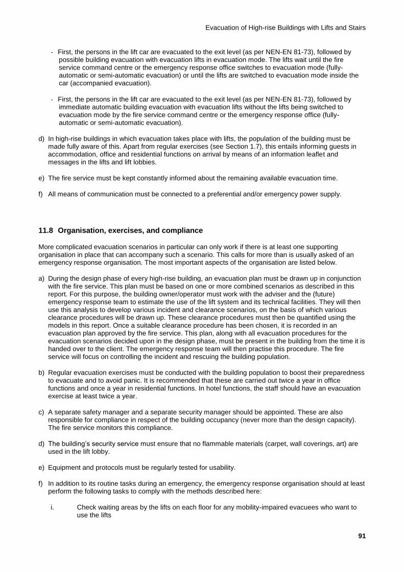
Evacuation of High-rise Buildings with Lifts and Stairs
91
- First, the persons in the lift car are evacuated to the exit level (as per NEN-EN 81-73), followed by possible building evacuation with evacuation lifts in evacuation mode. The lifts wait until the fire service command centre or the emergency response office switches to evacuation mode (fully-automatic or semi-automatic evacuation) or until the lifts are switched to evacuation mode inside the car (accompanied evacuation).
- First, the persons in the lift car are evacuated to the exit level (as per NEN-EN 81-73), followed by immediate automatic building evacuation with evacuation lifts without the lifts being switched to evacuation mode by the fire service command centre or the emergency response office (fully-automatic or semi-automatic evacuation).
d) In high-rise buildings in which evacuation takes place with lifts, the population of the building must be made fully aware of this. Apart from regular exercises (see Section 1.7), this entails informing guests in accommodation, office and residential functions on arrival by means of an information leaflet and messages in the lifts and lift lobbies.
e) The fire service must be kept constantly informed about the remaining available evacuation time.
f) All means of communication must be connected to a preferential and/or emergency power supply.
11.8 Organisation, exercises, and compliance
More complicated evacuation scenarios in particular can only work if there is at least one supporting organisation in place that can accompany such a scenario. This calls for more than is usually asked of an emergency response organisation. The most important aspects of the organisation are listed below.
a) During the design phase of every high-rise building, an evacuation plan must be drawn up in conjunction with the fire service. This plan must be based on one or more combined scenarios as described in this report. For this purpose, the building owner/operator must work with the adviser and the (future) emergency response team to estimate the use of the lift system and its technical facilities. They will then use this analysis to develop various incident and clearance scenarios, on the basis of which various clearance procedures will be drawn up. These clearance procedures must then be quantified using the models in this report. Once a suitable clearance procedure has been chosen, it is recorded in an evacuation plan approved by the fire service. This plan, along with all evacuation procedures for the evacuation scenarios decided upon in the design phase, must be present in the building from the time it is handed over to the client. The emergency response team will then practise this procedure. The fire service will focus on controlling the incident and rescuing the building population.
b) Regular evacuation exercises must be conducted with the building population to boost their preparedness to evacuate and to avoid panic. It is recommended that these are carried out twice a year in office functions and once a year in residential functions. In hotel functions, the staff should have an evacuation exercise at least twice a year.
c) A separate safety manager and a separate security manager should be appointed. These are also responsible for compliance in respect of the building occupancy (never more than the design capacity). The fire service monitors this compliance.
d) The building’s security service must ensure that no flammable materials (carpet, wall coverings, art) are used in the lift lobby.
e) Equipment and protocols must be regularly tested for usability.
f) In addition to its routine tasks during an emergency, the emergency response organisation should at least perform the following tasks to comply with the methods described here:
i. Check waiting areas by the lifts on each floor for any mobility-impaired evacuees who want to use the lifts

Background Report
92
ii. Accompany people transferring between stairs and lifts on transition layers
iii. Provide information on journey times; this can be supported by information screens etc.
11.9 Miscellaneous
11.9.1 Preventive evacuation
a) It is NOT necessary to fully or partially evacuate the building as a preventive measure in the event of a malfunction in the following systems:
- Pressure differential system
- Sprinkler system
- Fire alarm system
- Fire-fighting lift
- Evacuation lift
b) For planned maintenance on these systems, special events, and/or the absence of the emergency response officer(s) and/or the safety coordinator, a risk assessment must be drawn up.
11.9.2 Physical setting
Attention must also be paid to the following aspects in the immediate vicinity of the high-rise building to be evacuated:
a) Refuge facilities for evacuees on the evacuation level (usually, but not necessarily, ground level) must be provided.
b) The infrastructure around the building must be suitable for the facilities required by the emergency services and the evacuating population.
c) If the fire service uses a mobile command unit, sufficient space must be reserved for it.
11.9.3 Measures to ensure a safer escape
The following measures are recommended to improve escape safety:
- Lobby/escape doors should contain glass so that the smoke and fire conditions on the other side are visible (in accordance with the NFPA 5000 requirement).
- Fluorescent arrows or walk lines in the floor should be provided to mark evacuation routes in corridors, lift lobbies, and stairwells.
- Escape route markings must be designed to be visible in smoky conditions. In practice, this means that they should be positioned as low as possible.
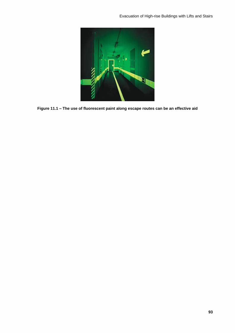
Evacuation of High-rise Buildings with Lifts and Stairs
93
Figure 11.1 – The use of fluorescent paint along escape routes can be an effective aid
Background Report
94
12 Conclusions
Lifts should always be used for evacuation from high-rise buildings in order to enable the building to be fully evacuated. After all, lifts are always necessary for evacuating mobility-impaired evacuees from high-rise buildings because accompanied evacuation of mobility-impaired evacuees via the stairs is unrealistic and undesirable.
Using lifts can considerably reduce the evacuation time. The advantages are greatest in buildings with a dense population (e.g. offices), very tall buildings, and buildings with a high proportion of mobility-impaired and/or elderly people (e.g. residential and accommodation buildings).
The use of lifts increases the redundancy of all means of evacuation, so there are always alternatives if any stairs or lifts cannot be used.
Evacuation with lifts almost always results in shorter evacuation times in office buildings of more than 150 m in height, but in office buildings with a high population per floor, this is even the case from 100 m. This is mainly because the use of lifts reduces congestion in the stairwells, thus improving throughput and preventing full flow.
Evacuation with lifts does not help reduce the evacuation time in residential and hotel functions. This is mainly because occupation is relatively low in these functions, so stairwells do not become congested quickly. As a result, the descent time via the stairs with free circulation from the top floor remains representative.
With office and hotel functions, evacuation via transition layers (Scenario 3) and free choice (Scenario 4) almost always results in the shortest possible evacuation times.
A well-considered evacuation plan for high-rise buildings is needed for each emergency/scenario.
Evacuation must be regularly practised with the population in order to improve their preparedness to evacuate and to familiarise them with the use of lifts for that purpose.
It is possible to avoid panic.
Evacuation of High-rise Buildings with Lifts and Stairs
95
13 Recommendations
13.1 General recommendations
In high-rise buildings, it is recommended that measures are always taken for fractional evacuation of mobility-impaired people with lifts.
In office functions, it is recommended to include the use of lifts for evacuation in the design of buildings of more than 100-150 m in height (depending on the occupation per floor) in order to keep the evacuation time at an acceptable level. Without the use of lifts to evacuate these buildings, so much congestion will occur on the stairs that the desired evacuation times will not be achieved.
For office and accommodation buildings, the presence of an emergency response organisation is required for evacuations with lifts. The presence of a permanently manned post or caretaker is recommended in tall residential buildings. Alternatively, on-call emergency response team members in the immediate vicinity can be mobilised. These people are needed to assist with fractional evacuation of mobility-impaired people.
13.2 Recommendations for follow-up study
The following follow-up research is recommended:
- Practical exercises in evacuation with stairs and lifts
- Upgrading of this report to an NTA
- Follow-up research on taller and wider buildings
- Follow-up research on the effect of double-decker lifts and twin lifts
- Separate consideration of assembly functions; the assumption is now that people in high-level assembly functions are collected first, unless this function has its own lifts (separate function)
- Development of a software tool to accompany this model, including graphics with egress flow profile and optimisation by scenario
- Specific follow-up research on fractions of mobility-impaired people in high-rise buildings by building function, in order to improve on Table 1.2 in a well-founded manner
- Specific follow-up research by, for example, an exercise physiologist into the factors influencing fatigue and blockages in stairwells (Ffatigue and Fblockage) which illustrate the drop in descent speed over time
Also, follow-up research on possible optimisation of the free choice evacuation scenario (Scenario 4) should be considered. The model should be expanded with the possible introduction of a fixed distribution of users between lifts and stairs (e.g. 30/70% or 60/40%) to find the lowest possible combined Tevac. The distribution should also be chosen in line with the height, e.g. from 20/80% at the bottom of the building to 70/30% at the top.
As part of a future FSE strategy, further research should be carried out on the chance of failure or the availability of the various components that play a role in the escape options, as well as their correlation with a developing emergency. Also important is to what extent the properties assigned to the escape routes are at risk of being exceeded or not achieved.
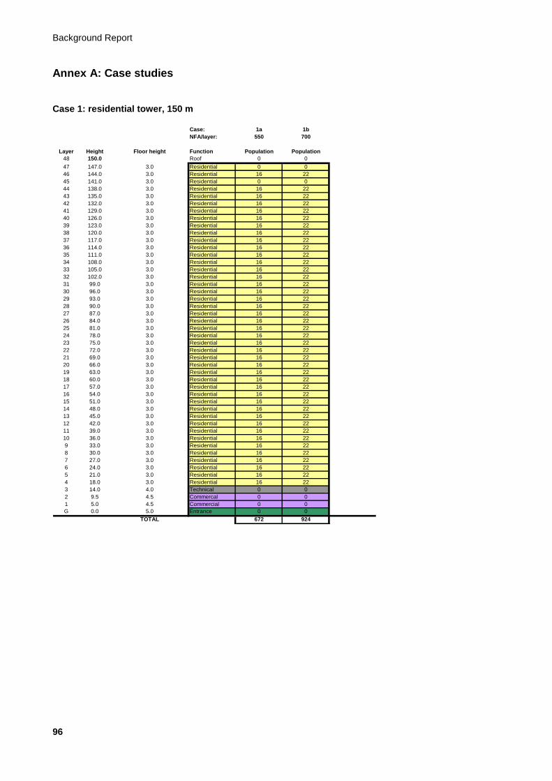
Background Report
96
Annex A: Case studies
Case 1: residential tower, 150 m
Case: 1a 1b
NFA/layer: 550 700
Layer Height Floor height Function Population Population
48 150.0 Roof 0 0
47 147.0 3.0 Residential 0 0
46 144.0 3.0 Residential 16 22
45 141.0 3.0 Residential 0 0
44 138.0 3.0 Residential 16 22
43 135.0 3.0 Residential 16 22
42 132.0 3.0 Residential 16 22
41 129.0 3.0 Residential 16 22
40 126.0 3.0 Residential 16 22
39 123.0 3.0 Residential 16 22
38 120.0 3.0 Residential 16 22
37 117.0 3.0 Residential 16 22
36 114.0 3.0 Residential 16 22
35 111.0 3.0 Residential 16 22
34 108.0 3.0 Residential 16 22
33 105.0 3.0 Residential 16 22
32 102.0 3.0 Residential 16 22
31 99.0 3.0 Residential 16 22
30 96.0 3.0 Residential 16 22
29 93.0 3.0 Residential 16 22
28 90.0 3.0 Residential 16 22
27 87.0 3.0 Residential 16 22
26 84.0 3.0 Residential 16 22
25 81.0 3.0 Residential 16 22
24 78.0 3.0 Residential 16 22
23 75.0 3.0 Residential 16 22
22 72.0 3.0 Residential 16 22
21 69.0 3.0 Residential 16 22
20 66.0 3.0 Residential 16 22
19 63.0 3.0 Residential 16 22
18 60.0 3.0 Residential 16 22
17 57.0 3.0 Residential 16 22
16 54.0 3.0 Residential 16 22
15 51.0 3.0 Residential 16 22
14 48.0 3.0 Residential 16 22
13 45.0 3.0 Residential 16 22
12 42.0 3.0 Residential 16 22
11 39.0 3.0 Residential 16 22
10 36.0 3.0 Residential 16 22
9 33.0 3.0 Residential 16 22
8 30.0 3.0 Residential 16 22
7 27.0 3.0 Residential 16 22
6 24.0 3.0 Residential 16 22
5 21.0 3.0 Residential 16 22
4 18.0 3.0 Residential 16 22
3 14.0 4.0 Technical 0 0
2 9.5 4.5 Commercal 0 0
1 5.0 4.5 Commercial 0 0
G 0.0 5.0 Entrance 0 0
TOTAL 672 924
Evacuation of High-rise Buildings with Lifts and Stairs
97
A.1 Case 1a: 672 persons
This residential building consists of an entrance level and 47 floors (44 residential layers, 2 commercial layers, and 1 technology layer). This case relates to the evacuation of the residential layers; the commercial layers are accessed with separate lifts. In addition, stair access in the plinth is separate from the stair access to the apartments. Two completely independent stairwells are provided for the residential part. The dimensions of the stairs are important. The assumption in the determination below is that they are designed in accordance with Table A (Column B) in Article 2.28 of the Building Decree, and that the landings comply with Article 2.29 of the Building Decree. The occupation of the residential layers is 16 persons per layer, with 16 persons per two layers on the top four layers. The lift configuration for the residential layers is determined based on NTA 4614-4 on vertical transport. The exact lift configuration for this building is shown below. The assumption is that the whole population will be evacuated.
Lifts
Case 1a
Floors Number Load capacity
[kg]
Lifting speed
[m/s]
G, 4-46 3 1,275 5.0
This building has a total of three lifts (excluding plinth and goods lifts). The evacuation scenarios for this residential building are described below, with an example worked out for each scenario. The examples show how the lift model can be used to determine the evacuation time for this building.
A.1.1 Scenario 0: stairs only
This is the basic scenario in which the clearance time is in fact determined more or less analogously to the methods used in the Netherlands up to 2010. The determination of the evacuation time for this building in accordance with the method described in Chapter 8 is given below.
An important starting point for determining the evacuation time is to identify the existing escape routes and the total length of the escape routes that form part of the vertical transport. In this case, these are the two stairs, which are also the determining factor for the speed in the stairwells.
The two stairs are 1.2 m wide and the length of the pitch line is 1.63 times the height difference. With the stair configuration assumed here (straight flight of stairs without landing), this results in:
lS = 1.63 x 3.0 + 0.425 x π = 6.23 m / floor lS;plinth = 1.63 x 18.0 + 3 x 0.425 x π = 33.35 m
For the people on the 49th floor, lS = 43 x 6.23 + 33.35 = 301.3 m.
Depending on any transfers between one stairwell and another, there may also be horizontal movement. This must be dealt with separately because the walking speed on a horizontal floor is different from the walking speed on stairs. Such a transfer is not necessarily long; it can be limited to a few metres, e.g. per segment of approx. 50 m in height. It is not included below, but allowance should be made for it where it actually occurs. By way of indication, note that including the factors for fatigue, a speed of 1.0 is somewhat pessimistic for these horizontal movements. For a building with two 50 m segments and therefore one transfer, this produces additional time of 1 x 5 m / 1.0 m/s = 5 seconds.
The easiest way to establish the evacuation time is by determining it both for free circulation and for use of the maximum stair capacity. The slower of the two is the situation that occurs. The calculation below has been performed in increments of 5 minutes using the discrete values for the factors; if it is established that everyone is outside within a period of 5 minutes, it can be ascertained what proportion of those 5 minutes is still necessary.
Background Report
98
A.1.1.1 Situation with free circulation
For the situation with free circulation, the vertical clearance time is determined entirely by the length of the walking line and the speed, contingent upon the time. The following formula therefore applies:
Tevac,S,fc = lS / vS(t)
Based on the discrete factors for fatigue and risk of blockage, the speed drops every 5 minutes. See Section 8.1 for the values of these factors.
In the first 5 minutes, the maximum distance travelled is lS = Tevac,S,fc x vS(t) = 300 x 0.8 = 240 m. So the users of the top floor will not be down after 5 minutes.
In the second 5 minutes, the maximum distance travelled is lS = Tevac,S,fc x vS(t) = 300 x (0.8 x 0.9 x 0.9) = 194 m. Counting the 240 metres from the first 5 minutes, this amounts to a total of 436 m. So the users of the top floor will be down after 10 minutes. Tevac,S,fc for the last 301.3 - 240 m becomes Tevac,S,fc = 61.3 / (0.8 x 0.9 x 0.9) = 95 seconds.
With free circulation, the time required to move down the stairwell is therefore 395 seconds (6:35 minutes).
A.1.1.2 Situation with maximum capacity
The occupancy of each floor in a residential building is usually low. Particularly in residential buildings with a population of this size (672 persons), total occupancy based on the average number of residents per apartment is certainly a realistic assumption of the representative situation. It should be borne in mind that many people will not be at home at any given time (averaged out over multiple apartments).
Below, we examine whether maximum capacity of the stairs is applicable in the situation in which all residents have to evacuate via the stairs. The following formula applies in this case:
Tevac,S,mc= (N x Pevac) / (CS(t) x We)
Based on the discrete factors for fatigue and risk of blockage, the capacity drops every 5 minutes in this case too. See Section 8.1 for the values of these factors.
For the maximum capacity of the stairs, the total number of persons per floor relying on the stairs is a major determinant of the descent time per floor. In the situation under consideration here, occupancy of the top four floors is half the standard occupancy. The speed of escape from these four floors will therefore differ from that of the other floors. Ultimately, the speed of the users of the top floors will become the same as the speed of users on the lower floors. The easiest way to determine the evacuation time in this case is in two stages.
A.1.1.2.1 Determination of time to top of plinth
In this step, we ascertain how quickly all floors on which people are still merging into the stairwells are cleared. The simplest way of ascertaining when the last person will arrive at the top of the plinth (one layer below the office part of the building) is to change the formula to:
N x Pevac = Tevac,S,mc x (CS(t) x We)
The total number of persons is 672 (40 x 16 + 2 x 16).
In the first 5 minutes, no more than the following number of persons will be evacuated over two staircases in accordance with Tevac,S,mc x CS(t) x We = 300 x 1.28 x 0.9 x 2 = 691 persons. According to this calculation, therefore, everyone is evacuated within 5 minutes, or more specifically after 672 / 691 x 300 = 292 seconds (4:52 minutes).
Evacuation of High-rise Buildings with Lifts and Stairs
99
A.1.1.2.2 Determination of time for descending through plinth
After the above time, the last remaining persons still have to descend through the plinth height. At this point in the calculation, people are in the stairwell at the level of the top plinth floor and still have to descend through three more of the four plinth floors. Fatigue and the risk of blockages also play a role in this case. The formula from Section 8.3 can be used unchanged for this part. Because we are calculating the time per building layer here, we use N = 1.
For the last three floors, a descent time as follows applies for up to 5 minutes:
Tevac,S,mc = Pevac / (CS(t) x We) per floor, or Tevac,S,mc = 16 / [(1.28 x 1 x 1) x 0.9 x 2] = 7 s
For the next 5 minutes, the following descent time applies per floor:
Tevac,S,mc = 16 / [(1.28 x 0.9 x 0.9) x 0.9 x 2] = 8.7 s
The descent time for the other three floors of the plinth is 1 x 7 + 2 x 8.7 = 24.4 seconds.
The total evacuation time based on maximum capacity on the stairs is therefore 292 + 25 = 317 seconds (5:17 minutes).
NB: In this case, the number of residents on the four plinth layers is equal to 0. Based on this, the walking speed of the population will temporarily increase at this point compared with the speed at full capacity assumed above (as the stairs are empty). But because it is not clear whether or not people will use the emergency stairs on the plinth floors, we assume that the stairs will be fully utilised in this case too. It is therefore advisable to calculate the additional time needed to descend to the ground floor.
A.1.1.3 Determination of total evacuation time for Scenario 0
The total evacuation time based on maximum capacity on the stairs (5:17 minutes) is faster than the evacuation time with free circulation (6:35 minutes). However, when people can circulate freely, they move at their own unhindered maximum speed. The shorter evacuation time at maximum capacity is therefore not physically possible: the calculation shows that maximum capacity is not reached and that people can move on the stairs unhindered.
In the residential building with a population of 16 people on the standard floors, the situation with free circulation is the determining factor, and the evacuation time via the stairs is in the order of 395 seconds (6:35 minutes).
A.1.2 Scenario 1: lifts only
This scenario describes the determination of the evacuation time if the use of stairs is completely excluded. To calculate the evacuation time using lifts for this scenario, the formulae described in Section 9.2 are used.
A.1.2.1 All lifts available for evacuation
To determine the total evacuation time if all lifts are available, the following applies:
Flifts = Levac / Lpeak = 3 / 3 = 1 (all lifts available)
Fcar capacity = 1.1 (residential function)
Fefficiency = 2.4 (residential function)
Fheight = 0.7 + 0.3 x (Hhigh,evac + Hlow,evac - Hlow,peak) / Hhigh,peak = 0.7 + 0.3 x (144 + 18 - 18) / 144 = 1 (full evacuation with lifts)
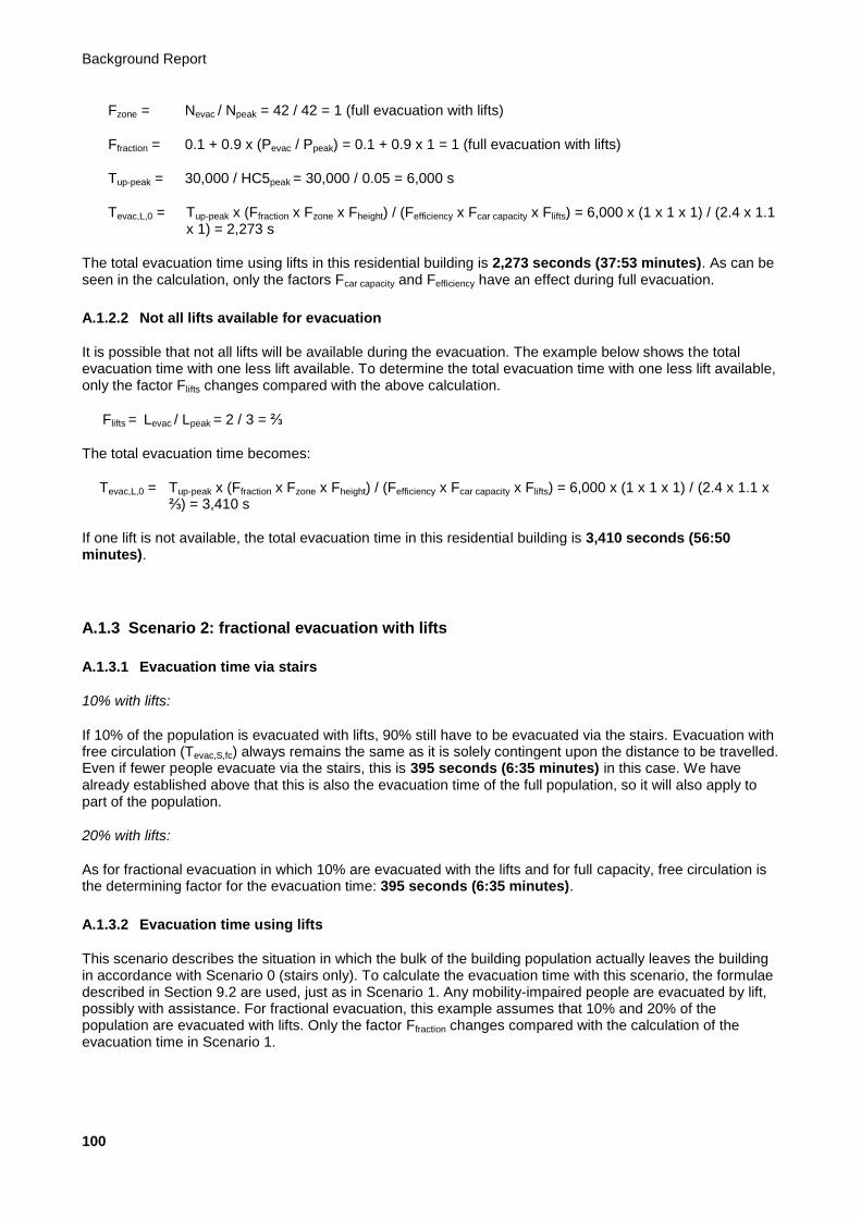
Background Report
100
Fzone = Nevac / Npeak = 42 / 42 = 1 (full evacuation with lifts)
Ffraction = 0.1 + 0.9 x (Pevac / Ppeak) = 0.1 + 0.9 x 1 = 1 (full evacuation with lifts)
Tup-peak = 30,000 / HC5peak = 30,000 / 0.05 = 6,000 s
Tevac,L,0 = Tup-peak x (Ffraction x Fzone x Fheight) / (Fefficiency x Fcar capacity x Flifts) = 6,000 x (1 x 1 x 1) / (2.4 x 1.1 x 1) = 2,273 s
The total evacuation time using lifts in this residential building is 2,273 seconds (37:53 minutes). As can be seen in the calculation, only the factors Fcar capacity and Fefficiency have an effect during full evacuation.
A.1.2.2 Not all lifts available for evacuation
It is possible that not all lifts will be available during the evacuation. The example below shows the total evacuation time with one less lift available. To determine the total evacuation time with one less lift available, only the factor Flifts changes compared with the above calculation.
Flifts = Levac / Lpeak = 2 / 3 = ⅔
The total evacuation time becomes:
Tevac,L,0 = Tup-peak x (Ffraction x Fzone x Fheight) / (Fefficiency x Fcar capacity x Flifts) = 6,000 x (1 x 1 x 1) / (2.4 x 1.1 x ⅔) = 3,410 s
If one lift is not available, the total evacuation time in this residential building is 3,410 seconds (56:50 minutes).
A.1.3 Scenario 2: fractional evacuation with lifts
A.1.3.1 Evacuation time via stairs
10% with lifts:
If 10% of the population is evacuated with lifts, 90% still have to be evacuated via the stairs. Evacuation with free circulation (Tevac,S,fc) always remains the same as it is solely contingent upon the distance to be travelled. Even if fewer people evacuate via the stairs, this is 395 seconds (6:35 minutes) in this case. We have already established above that this is also the evacuation time of the full population, so it will also apply to part of the population.
20% with lifts:
As for fractional evacuation in which 10% are evacuated with the lifts and for full capacity, free circulation is the determining factor for the evacuation time: 395 seconds (6:35 minutes).
A.1.3.2 Evacuation time using lifts
This scenario describes the situation in which the bulk of the building population actually leaves the building in accordance with Scenario 0 (stairs only). To calculate the evacuation time with this scenario, the formulae described in Section 9.2 are used, just as in Scenario 1. Any mobility-impaired people are evacuated by lift, possibly with assistance. For fractional evacuation, this example assumes that 10% and 20% of the population are evacuated with lifts. Only the factor Ffraction changes compared with the calculation of the evacuation time in Scenario 1.

Evacuation of High-rise Buildings with Lifts and Stairs
101
For 10% fractional evacuation, the factor Ffraction becomes:
Ffraction = 0.1 + 0.9 x (Pevac / Ppeak) = 0.1 + 0.9 x 0.1 = 0.19
The total evacuation time for 10% fractional evacuation becomes:
Tevac,L,0 = Tup-peak x (Ffraction x Fzone x Fheight) / (Fefficiency x Fcar capacity x Flifts) = 6,000 x (0.19 x 1 x 1) / (2.4 x 1.1 x 1) = 432 s
For 20% fractional evacuation, the factor Ffraction becomes:
Ffraction = 0.1 + 0.9 x (Pevac / Ppeak) = 0.1 + 0.9 x 0.2 = 0.28
The total evacuation time for 20% of this fraction becomes:
Tevac,L,0 = Tup-peak x (Ffraction x Fzone x Fheight) / (Fefficiency x Fcar capacity x Flifts) = 6,000 x (0.28 x 1 x 1) / (2.4 x 1.1 x 1) = 637 s
The total evacuation time using lifts in this residential building with 10% fractional evacuation is 432 seconds (7:12 minutes).
The total evacuation time using lifts in this residential building with 20% fractional evacuation is 637 seconds (10:37 minutes).
A.1.3.3 Combined evacuation time
Evacuation time via stairs, with both 10% and 20% fractional evacuation: 6:35 minutes.
Evacuation time using lifts, with 10% fractional evacuation: 7:12 minutes; with 20% fractional evacuation: 637 seconds.
In this scenario, the evacuation time using lifts is therefore the determining factor in the evacuation time for the building in this case. See Figure 7.6 for the procedure used.
A.1.4 Scenario 3: transition layers
In view of the level of organisation needed for evacuation with transition layers and the level of emergency response organisation usually found in residential buildings at present, this aspect has not been considered for residential buildings for now. In addition, evacuation by means of transition layers is not considered effective in view of the limited capacity of the stairwells.
A.1.5 Scenario 4: free choice
In this scenario, both the stairs and the lifts are used to evacuate every floor. Users are always free to choose to use the lift or the stairs. In this example, it is assumed that 50% of the population will use the stairs and 50% the lift.
A.1.5.1 Evacuation time via stairs
We have already seen in Subsection A.2.1.3 that the situation with free circulation is the determining factor. In this scenario, fewer people use the stairs so there is still free circulation. Here too, the time is 395 seconds (6:35 minutes).
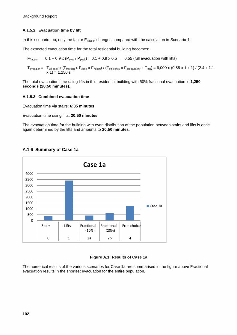
Background Report
102
A.1.5.2 Evacuation time by lift
In this scenario too, only the factor Ffraction changes compared with the calculation in Scenario 1.
The expected evacuation time for the total residential building becomes:
Ffraction = 0.1 + 0.9 x (Pevac / Ppeak) = 0.1 + 0.9 x 0.5 = 0.55 (full evacuation with lifts)
Tevac,L,0 = Tup-peak x (Ffraction x Fzone x Fheight) / (Fefficiency x Fcar capacity x Flifts) = 6,000 x (0.55 x 1 x 1) / (2.4 x 1.1 x 1) = 1,250 s
The total evacuation time using lifts in this residential building with 50% fractional evacuation is 1,250 seconds (20:50 minutes).
A.1.5.3 Combined evacuation time
Evacuation time via stairs: 6:35 minutes.
Evacuation time using lifts: 20:50 minutes.
The evacuation time for the building with even distribution of the population between stairs and lifts is once again determined by the lifts and amounts to 20:50 minutes.
A.1.6 Summary of Case 1a
Figure A.1: Results of Case 1a
The numerical results of the various scenarios for Case 1a are summarised in the figure above Fractional evacuation results in the shortest evacuation for the entire population.
0
500
1000
1500
2000
2500
3000
3500
4000
Stairs Lifts Fractional (10%)
Fractional (20%)
Free choice
0 1 2a 2b 4
Case 1a
Case 1a
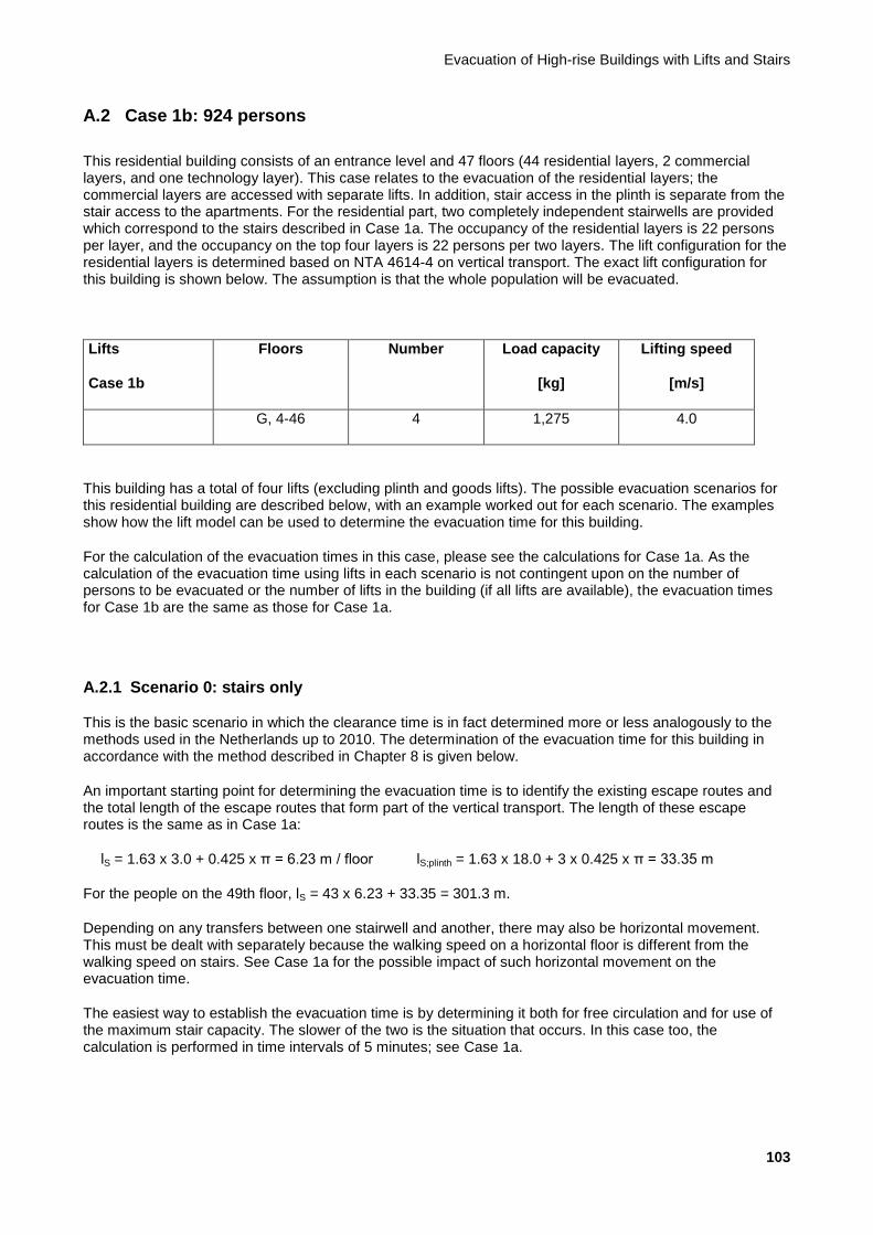
Evacuation of High-rise Buildings with Lifts and Stairs
103
A.2 Case 1b: 924 persons
This residential building consists of an entrance level and 47 floors (44 residential layers, 2 commercial layers, and one technology layer). This case relates to the evacuation of the residential layers; the commercial layers are accessed with separate lifts. In addition, stair access in the plinth is separate from the stair access to the apartments. For the residential part, two completely independent stairwells are provided which correspond to the stairs described in Case 1a. The occupancy of the residential layers is 22 persons per layer, and the occupancy on the top four layers is 22 persons per two layers. The lift configuration for the residential layers is determined based on NTA 4614-4 on vertical transport. The exact lift configuration for this building is shown below. The assumption is that the whole population will be evacuated.
Lifts
Case 1b
Floors Number Load capacity
[kg]
Lifting speed
[m/s]
G, 4-46 4 1,275 4.0
This building has a total of four lifts (excluding plinth and goods lifts). The possible evacuation scenarios for this residential building are described below, with an example worked out for each scenario. The examples show how the lift model can be used to determine the evacuation time for this building.
For the calculation of the evacuation times in this case, please see the calculations for Case 1a. As the calculation of the evacuation time using lifts in each scenario is not contingent upon on the number of persons to be evacuated or the number of lifts in the building (if all lifts are available), the evacuation times for Case 1b are the same as those for Case 1a.
A.2.1 Scenario 0: stairs only
This is the basic scenario in which the clearance time is in fact determined more or less analogously to the methods used in the Netherlands up to 2010. The determination of the evacuation time for this building in accordance with the method described in Chapter 8 is given below.
An important starting point for determining the evacuation time is to identify the existing escape routes and the total length of the escape routes that form part of the vertical transport. The length of these escape routes is the same as in Case 1a:
lS = 1.63 x 3.0 + 0.425 x π = 6.23 m / floor lS;plinth = 1.63 x 18.0 + 3 x 0.425 x π = 33.35 m
For the people on the 49th floor, lS = 43 x 6.23 + 33.35 = 301.3 m.
Depending on any transfers between one stairwell and another, there may also be horizontal movement. This must be dealt with separately because the walking speed on a horizontal floor is different from the walking speed on stairs. See Case 1a for the possible impact of such horizontal movement on the evacuation time.
The easiest way to establish the evacuation time is by determining it both for free circulation and for use of the maximum stair capacity. The slower of the two is the situation that occurs. In this case too, the calculation is performed in time intervals of 5 minutes; see Case 1a.

Background Report
104
A.2.1.1 Situation with free circulation
For the situation with free circulation, the vertical clearance time is determined entirely by the length of the walking line and the speed, contingent upon the time. The following formula therefore applies:
Tevac,S,fc = lS / vS(t)
The evacuation length (301.3 m) is the same as in Case 1a. With free circulation, the time required to move through the stairwell is therefore once again 395 seconds (6:35 minutes).
A.2.1.2 Situation with maximum capacity
The occupancy of each floor in a residential building is usually low. Particularly in residential buildings with a population of this size (924 persons), total occupancy in accordance with the average number of residents per apartment is certainly a realistic assumption of the representative situation.
Below, we examine whether maximum capacity of the stairs is applicable in the situation in which all residents have to evacuate via the stairs. The following formula applies in this case:
Tevac,S,mc= (N x Pevac)/(CS(t) x We)
Based on the discrete factors for fatigue and risk of blockage, the capacity drops every 5 minutes in this case too. See Section 8.1 for the values of these factors.
For the maximum capacity of the stairs, the total number of persons per floor relying on the stairs is a major determinant of the descent time per floor. The evacuation time is now calculated in two stages.
A.2.1.2.1 Determination of time to top of plinth
In this step, we ascertain how quickly all floors on which people are still merging into the stairwells are cleared. The simplest way of ascertaining when the last person will arrive at the top of the plinth (one layer below the office part of the building) is to change the formula to:
N x Pevac = Tevac,S,mc x (CS(t) x We)
The total number of persons is 924 (40 x 22 + 2 x 22).
In the first 5 minutes, no more than the following number of persons will be evacuated over two staircases in accordance with Tevac,S,mc x CS(t) x We = 300 x 1.28 x 0.9 x 2 = 691 persons. According to this calculation, therefore, not everyone is evacuated within 5 minutes.
In the second 5 minutes, no more than the following number of persons will be evacuated over two staircases in accordance with Tevac,S,mc x CS(t) x We = 300 x (1.28 x 0.9 x 0.9) x 0.9 x 2 = 559 persons. Counting the 691 persons from the first 5 minutes, this comes to a total of 1,250 persons. All users have therefore arrived at the top of the plinth after 10 minutes. The exact time taken for this is 300 + (924 - 691) / 559 x 300 = 425 seconds (7:05 minutes).
A.2.1.2.2 Determination of time for descending through plinth
After the above time, the last remaining persons still have to descend through the plinth height. Fatigue and the risk of blockages also play a role in this case. The formula from Section 8.3 can be used unchanged for this part. Because we are calculating the time per building layer here, we use n = 1. For the last three floors, a descent time of Tevac,S,mc = Pevac / (CS(t) x We) per floor can be adhered to for up to 10 minutes in accordance with Tevac,S,mc = 22 / [(1.28 x 0.9 x 0.9) x 0.9 x 2] = 11.9 seconds. An additional descent time of 3 x 11.9 = 35.7 seconds must therefore be added. The total evacuation time based on maximum capacity on the stairs is therefore 461 seconds (7:41 minutes).

Evacuation of High-rise Buildings with Lifts and Stairs
105
A.2.1.3 Determination of total evacuation time for Scenario 0
In the residential building with a population of 22 people on the standard floors, the situation using the maximum stair capacity is the determining factor, and the evacuation time via the stairs is in the order of 473 seconds (7:41 minutes).
A.2.2 Scenario 1: lifts only
A.2.2.1 All lifts available for evacuation
The total evacuation time using lifts in this residential building is 2,273 seconds (37:53 minutes). See the calculation for Scenario 1 in Case 1a.
A.2.2.2 Not all lifts available for evacuation
If one lift is not available, the total evacuation time in this residential building is different from Case 1a. The factor Flifts changes compared with the calculation in Case 1a:
Flifts = Levac / Lpeak = 3 / 4 = ¾
The total evacuation time becomes:
Tevac,L,0 = Tup-peak x (Ffraction x Fzone x Fheight) / (Fefficiency x Fcar capacity x Flifts) = 6,000 x (1 x 1 x 1) / (2.4 x 1.1 x ¾) = 3,031 s
If one lift is not available, the total evacuation time in this residential building is 3,031 seconds (50:31 minutes).
A.2.3 Scenario 2: fractional evacuation with lifts
This scenario describes the situation in which the bulk of the building population actually leaves the building in accordance with Scenario 0 (stairs only). For fractional evacuation, this example assumes that 10% and 20% of the population is evacuated with lifts.
A.2.3.1 Evacuation time via stairs
A.2.3.1.1 10% with lifts
If 10% of the population is evacuated with lifts, 90% still has to be evacuated via the stairs. In this case, that is 0.90 x 924 = 832 persons.
The evacuation with free circulation (Tevac,S,fc) is solely contingent on the distance to be travelled. Even if fewer people evacuate via the stairs, this is still 395 seconds (6:35 minutes) in this case.
For 832 persons, the evacuation time using maximum stair capacity must also be determined as follows.
A.2.3.1.1.1 Determination of time to top of plinth
In this step, we ascertain how quickly all floors on which people are still merging into the stairwells are cleared. The simplest way of ascertaining when the last person will arrive at the top of the plinth (one layer below the office part of the building) is to change the formula to:
N x Pevac = Tevac,S,mc x (CS(t) x We)
Background Report
106
The total number of persons is 832 [0.9 x (40 x 22 + 2 x 22)].
In the first 5 minutes, no more than the following number of persons will be evacuated over two staircases in accordance with Tevac,S,mc x CS(t) x We = 300 x 1.28 x 0.9 x 2 = 691 persons. According to this calculation, therefore, not everyone is evacuated within 5 minutes.
In the second 5 minutes, no more than the following number of persons will be evacuated over two staircases in accordance with Tevac,S,mc x CS(t) x We = 300 x (1.28 x 0.9 x 0.9) x 0.9 x 2 = 559 persons. Counting the 691 persons from the first 5 minutes, this comes to a total of 1,250 persons. All users have therefore arrived at the top of the plinth after 10 minutes. The exact time taken for this is 300 + (832 - 691) / 559 x 300 = 376 seconds (6:16 minutes).
A.2.3.1.1.2 Determination of time for descending through plinth
After the above time, the last remaining persons still have to descend through the plinth height. Fatigue and the risk of blockages also play a role in this case. The formula from Section 8.3 can be used unchanged for this part. Because we are calculating the time per building layer here, we use n = 1. For the last three floors, a descent time of Tevac,S,mc = Pevac /(CS(t) x We) per floor can be adhered to for up to 10 minutes in accordance with Tevac,S,mc = 22 / [(1.28 x 0.9 x 0.9) x 0.9 x 2] = 11.9 seconds. An additional descent time of 3 x 11.9 = 35.7 seconds must therefore be added. The total evacuation time based on maximum capacity on the stairs is therefore 412 seconds (6:52 minutes).
In the residential building with a population of 22 people on the standard floors, the situation in which the maximum stair capacity is used is also representative for evacuation of 10% of the population with lifts, and the evacuation time via the stairs is in the order of 412 seconds (6:52 minutes).
A.2.3.1.2 20% with lifts
As for fractional evacuation in which 10% are evacuated with the lifts and for full capacity, the evacuation time with free circulation is 395 seconds (6:35 minutes).
In this case, 0.80 x 924 = 740 persons have to be evacuated via the stairs. The time needed for this must be determined as follows.
A.2.3.1.2.1 Determination of time to top of plinth
In this step, we ascertain how quickly all floors on which people are still merging into the stairwells are cleared. The simplest way of ascertaining when the last person will arrive at the top of the plinth (one layer below the office part of the building) is to change the formula to:
N x Pevac = Tevac,S,mc x (CS(t) x We)
The total number of persons is 740 [0.80 x (40 x 22 + 2 x 22)].
In the first 5 minutes, no more than the following number of persons will be evacuated over two staircases in accordance with Tevac,S,mc x CS(t) x We = 300 x 1.28 x 0.9 x 2 = 691 persons. According to this calculation, therefore, not everyone is evacuated within 5 minutes.
In the second 5 minutes, no more than the following number of persons will be evacuated over two staircases in accordance with Tevac,S,mc x CS(t) x We = 300 x (1.28 x 0.9 x 0.9) x 0.9 x 2 = 559 persons. Counting the 691 persons from the first 5 minutes, this comes to a total of 1,250 persons. All users have therefore arrived at the top of the plinth after 10 minutes. The exact time taken for this is 300 + (740 - 691) / 559 x 300 = 327 seconds (5:27 minutes).
A.2.3.1.2.2 Determination of time for descending through plinth
After the above time, the last remaining persons still have to descend through the plinth height. Fatigue and the risk of blockages also play a role in this case. The formula from Section 8.3 can be used unchanged for this part. Because we are calculating the time per building layer here, we use n = 1. For the last three floors,
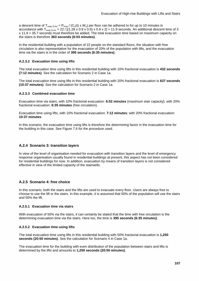
Evacuation of High-rise Buildings with Lifts and Stairs
107
a descent time of Tevac,S,mc = Pevac / (CS(t) x We) per floor can be adhered to for up to 10 minutes in accordance with Tevac,S,mc = 22 / [(1.28 x 0.9 x 0.9) x 0.9 x 2] = 11.9 seconds. An additional descent time of 3 x 11.9 = 35.7 seconds must therefore be added. The total evacuation time based on maximum capacity on the stairs is therefore 363 seconds (6:03 minutes).
In the residential building with a population of 22 people on the standard floors, the situation with free circulation is also representative for the evacuation of 20% of the population with lifts, and the evacuation time via the stairs is in the order of 395 seconds (6:35 minutes).
A.2.3.2 Evacuation time using lifts
The total evacuation time using lifts in this residential building with 10% fractional evacuation is 432 seconds (7:12 minutes). See the calculation for Scenario 2 in Case 1a.
The total evacuation time using lifts in this residential building with 20% fractional evacuation is 637 seconds (10:37 minutes). See the calculation for Scenario 2 in Case 1a.
A.2.3.3 Combined evacuation time
Evacuation time via stairs, with 10% fractional evacuation: 6:52 minutes (maximum stair capacity); with 20% fractional evacuation: 6:35 minutes (free circulation).
Evacuation time using lifts, with 10% fractional evacuation: 7:12 minutes; with 20% fractional evacuation: 10:37 minutes.
In this scenario, the evacuation time using lifts is therefore the determining factor in the evacuation time for the building in this case. See Figure 7.6 for the procedure used.
A.2.4 Scenario 3: transition layers
In view of the level of organisation needed for evacuation with transition layers and the level of emergency response organisation usually found in residential buildings at present, this aspect has not been considered for residential buildings for now. In addition, evacuation by means of transition layers is not considered effective in view of the limited capacity of the stairwells.
A.2.5 Scenario 4: free choice
In this scenario, both the stairs and the lifts are used to evacuate every floor. Users are always free to choose to use the lift or the stairs. In this example, it is assumed that 50% of the population will use the stairs and 50% the lift.
A.2.5.1 Evacuation time via stairs
With evacuation of 50% via the stairs, it can certainly be stated that the time with free circulation is the determining evacuation time via the stairs. Here too, the time is 395 seconds (6:35 minutes).
A.2.5.2 Evacuation time using lifts
The total evacuation time using lifts in this residential building with 50% fractional evacuation is 1,250 seconds (20:50 minutes). See the calculation for Scenario 4 in Case 1a.
The evacuation time for the building with even distribution of the population between stairs and lifts is determined by the lifts and amounts to 1,250 seconds (20:50 minutes).

Background Report
108
A.2.5.3 Combined evacuation time
Evacuation time via stairs: 6:35 minutes.
Evacuation time using lifts: 20:50 minutes.
A.2.6 Summary of Case 1b
Figure A.2: Results of Case 1b
The numerical results of the various scenarios for Case 1b are summarised in the figure above. Fractional evacuation results in the shortest evacuation for the entire population.
0
500
1000
1500
2000
2500
3000
3500
4000
Stairs Lifts Fractional (10%)
Fractional (20%)
Free choice
0 1 2a 2b 4
Case 1b
Case 1b
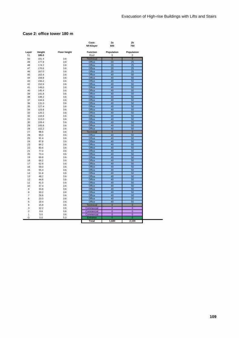
Evacuation of High-rise Buildings with Lifts and Stairs
109
Case 2: office tower 180 m
Case: 2a 2b
NFA/layer 600 750
Layer Height Floor height Function Population Population
51 185.0 Roof 0 0
50 181.4 3.6 Technical 0 0
49 177.8 3.6 Office 20 25
48 174.2 3.6 Office 20 25
47 170.6 3.6 Office 20 25
46 167.0 3.6 Office 20 25
45 163.4 3.6 Office 40 50
44 159.8 3.6 Office 40 50
43 156.2 3.6 Office 40 50
42 152.6 3.6 Office 40 50
41 149.0 3.6 Office 40 50
40 145.4 3.6 Office 40 50
39 141.8 3.6 Office 40 50
38 138.2 3.6 Office 40 50
37 134.6 3.6 Office 40 50
36 131.0 3.6 Office 40 50
35 127.4 3.6 Office 40 50
34 123.8 3.6 Office 40 50
33 120.2 3.6 Office 40 50
32 116.6 3.6 Office 40 50
31 113.0 3.6 Office 40 50
30 109.4 3.6 Office 40 50
29 105.8 3.6 Office 40 50
28 102.2 3.6 Office 40 50
27 98.6 3.6 Technical 0 0
26 95.0 3.6 Office 40 50
25 91.4 3.6 Office 40 50
24 87.8 3.6 Office 40 50
23 84.2 3.6 Office 40 50
22 80.6 3.6 Office 40 50
21 77.0 3.6 Office 40 50
20 73.4 3.6 Office 40 50
19 69.8 3.6 Office 40 50
18 66.2 3.6 Office 40 50
17 62.6 3.6 Office 40 50
16 59.0 3.6 Office 40 50
15 55.4 3.6 Office 40 50
14 51.8 3.6 Office 40 50
13 48.2 3.6 Office 40 50
12 44.6 3.6 Office 40 50
11 41.0 3.6 Office 40 50
10 37.4 3.6 Office 40 50
9 33.8 3.6 Office 40 50
8 30.2 3.6 Office 40 50
7 26.6 3.6 Office 40 50
6 23.0 3.6 Office 40 50
5 19.4 3.6 Office 40 50
4 15.8 3.6 Technical 0 0
3 12.2 3.6 Commercial 0 0
2 8.6 3.6 Commercial 0 0
1 5.0 3.6 Commercial 0 0
G 0.0 5.0 Entrance 0 0
Total 1,680 2,100
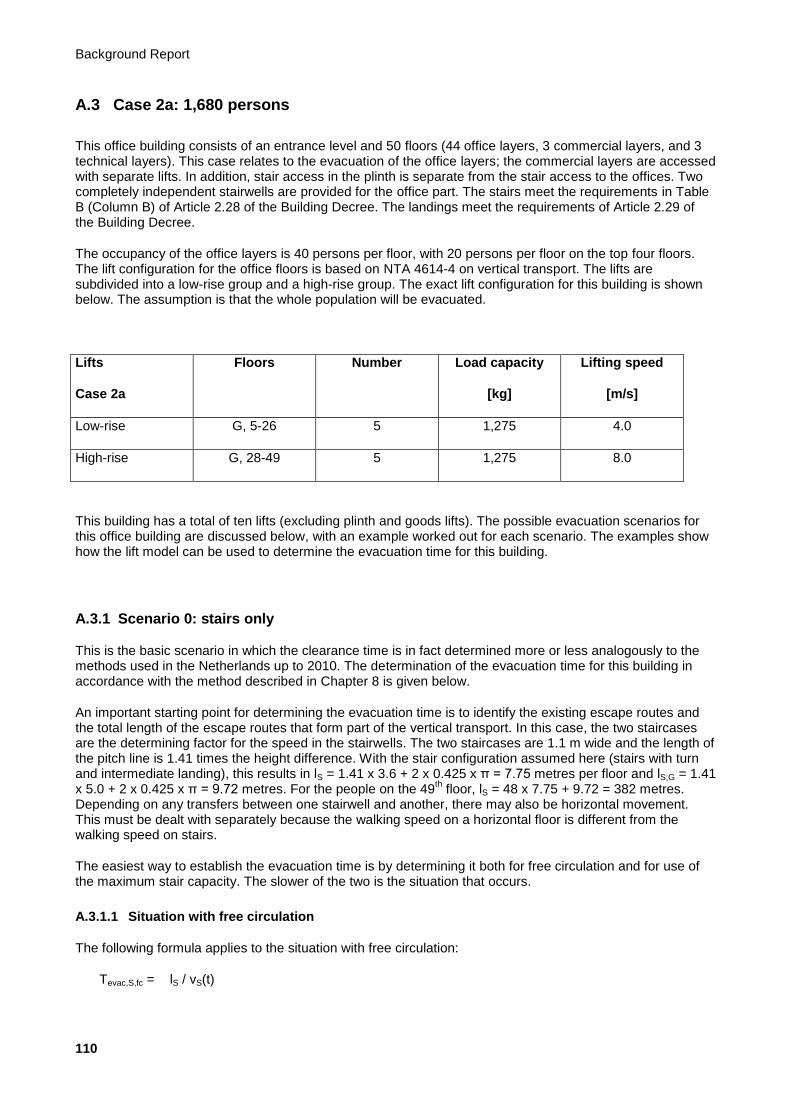
Background Report
110
A.3 Case 2a: 1,680 persons
This office building consists of an entrance level and 50 floors (44 office layers, 3 commercial layers, and 3 technical layers). This case relates to the evacuation of the office layers; the commercial layers are accessed with separate lifts. In addition, stair access in the plinth is separate from the stair access to the offices. Two completely independent stairwells are provided for the office part. The stairs meet the requirements in Table B (Column B) of Article 2.28 of the Building Decree. The landings meet the requirements of Article 2.29 of the Building Decree.
The occupancy of the office layers is 40 persons per floor, with 20 persons per floor on the top four floors. The lift configuration for the office floors is based on NTA 4614-4 on vertical transport. The lifts are subdivided into a low-rise group and a high-rise group. The exact lift configuration for this building is shown below. The assumption is that the whole population will be evacuated.
Lifts
Case 2a
Floors Number Load capacity
[kg]
Lifting speed
[m/s]
Low-rise G, 5-26 5 1,275 4.0
High-rise G, 28-49 5 1,275 8.0
This building has a total of ten lifts (excluding plinth and goods lifts). The possible evacuation scenarios for this office building are discussed below, with an example worked out for each scenario. The examples show how the lift model can be used to determine the evacuation time for this building.
A.3.1 Scenario 0: stairs only
This is the basic scenario in which the clearance time is in fact determined more or less analogously to the methods used in the Netherlands up to 2010. The determination of the evacuation time for this building in accordance with the method described in Chapter 8 is given below.
An important starting point for determining the evacuation time is to identify the existing escape routes and the total length of the escape routes that form part of the vertical transport. In this case, the two staircases are the determining factor for the speed in the stairwells. The two staircases are 1.1 m wide and the length of the pitch line is 1.41 times the height difference. With the stair configuration assumed here (stairs with turn and intermediate landing), this results in lS = 1.41 x 3.6 + 2 x 0.425 x π = 7.75 metres per floor and lS;G = 1.41 x 5.0 + 2 x 0.425 x π = 9.72 metres. For the people on the 49
th floor, lS = 48 x 7.75 + 9.72 = 382 metres.
Depending on any transfers between one stairwell and another, there may also be horizontal movement. This must be dealt with separately because the walking speed on a horizontal floor is different from the walking speed on stairs.
The easiest way to establish the evacuation time is by determining it both for free circulation and for use of the maximum stair capacity. The slower of the two is the situation that occurs.
A.3.1.1 Situation with free circulation
The following formula applies to the situation with free circulation:
Tevac,S,fc = lS / vS(t)
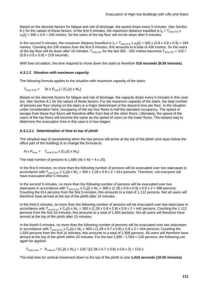
Evacuation of High-rise Buildings with Lifts and Stairs
111
Based on the discrete factors for fatigue and risk of blockage, the speed drops every 5 minutes. See Section 8.1 for the values of these factors. In the first 5 minutes, the maximum distance travelled is lS = Tevac,S,fc x vS(t) = 300 x 0.8 = 240 metres. So the users of the top floor will not be down after 5 minutes.
In the second 5 minutes, the maximum distance travelled is lS = Tevac,S,fc x vS(t) = 300 x (0.8 x 0.9 x 0.9) = 194 metres. Counting the 240 metres from the first 5 minutes, this amounts to a total of 436 metres. So the users of the top floor will be down after 10 minutes. Tevac,S,fc for the last 382 - 240 metres becomes Tevac,S,fc = 142 / (0.8 x 0.9 x 0.9) = 219 seconds.
With free circulation, the time required to move down the stairs is therefore 519 seconds (8:39 minutes).
A.3.1.2 Situation with maximum capacity
The following formula applies to the situation with maximum capacity of the stairs:
Tevac,S,mc = (N x Pevac) / (CS(t) x We)
Based on the discrete factors for fatigue and risk of blockage, the capacity drops every 5 minutes in this case too. See Section 8.1 for the values of these factors. For the maximum capacity of the stairs, the total number of persons per floor relying on the stairs is a major determinant of the descent time per floor. In the situation under consideration here, occupancy of the top four floors is half the standard occupancy. The speed of escape from these four floors will therefore differ from that of the other floors. Ultimately, the speed of the users of the top floors will become the same as the speed of users on the lower floors. The easiest way to determine the evacuation time in this case is in two stages.
A.3.1.2.1 Determination of time to top of plinth
The simplest way of ascertaining when the last person will arrive at the top of the plinth (one layer below the office part of the building) is to change the formula to:
N x Pevac = Tevac,S,mc x (CS(t) x We)
The total number of persons is 1,680 (40 x 40 + 4 x 20).
In the first 5 minutes, no more than the following number of persons will be evacuated over two staircases in accordance with Tevac,S,mc x CS(t) x We = 300 x 1.28 x 0.8 x 2 = 614 persons. Therefore, not everyone will have evacuated after 5 minutes.
In the second 5 minutes, no more than the following number of persons will be evacuated over two staircases in accordance with Tevac,S,mc x CS(t) x We = 300 x (1.28 x 0.9 x 0.9) x 0.8 x 2 = 498 persons. Counting the 614 persons from the first 5 minutes, this amounts to a total of 1,112 persons. Not all users will therefore have arrived at the top of the plinth after 10 minutes.
In the third 5 minutes, no more than the following number of persons will be evacuated over two staircases in accordance with Tevac,S,mc x CS(t) x We = 300 x (1.28 x 0.8 x 0.9) x 0.8 x 2 = 442 persons. Counting the 1,112 persons from the first 10 minutes, this amounts to a total of 1,554 persons. Not all users will therefore have arrived at the top of the plinth after 15 minutes.
In the fourth 5 minutes, no more than the following number of persons will be evacuated over two staircases in accordance with Tevac,S,mc x CS(t) x We = 300 x (1.28 x 0.7 x 0.8) x 0.8 x 2 = 344 persons. Counting the 1,554 persons from the first 15 minutes; this amounts to a total of 1,898 persons. All users will therefore have arrived at the top of the plinth within 20 minutes. For the last 1,680 - 1,554 = 126 persons, the following can again be applied:
Tevac,S,mc = Pevac,tot / (CS(t) x We) = 126 / [(1.28 x 0.7 x 0.8) x 0.8 x 2] = 110 s
The total time for vertical movement down to the top of the plinth is now 1,010 seconds (16:50 minutes).

Background Report
112
A.3.1.2.2 Determination of time through plinth
At this point in the calculation, people are in the stairwell at the level of the top plinth layer, so they still have to pass through four more of the five plinth layers. For the last four layers, a descent time of Tevac,S,mc = Pevac/(CS(t) x We) per floor can be adhered to for up to 20 minutes in accordance with Tevac,S,mc = 40 / [(1.28 x 0.7 x 0.8) x 0.8 x 2] = 35 seconds. An additional descent time of 4 x 35 = 140 seconds must therefore be added.
The total evacuation time based on maximum capacity on the stairs is therefore 1,150 seconds (19:10 minutes). This is also the evacuation time that must be applied.
NB: In this case, the number of people on the five plinth layers is equal to 0. Based on this, the walking speed of the population will temporarily increase at this point compared with the speed at full capacity assumed above (as the stairs are empty). But because it is not clear whether or not people will use the emergency stairs on the plinth layers, we assume that the stairs will be fully utilised in this case too. It is therefore advisable to calculate the additional time needed to descend to the ground floor.
A.3.2 Scenario 1: lifts only
This scenario describes the determination of the evacuation time if the use of stairs is completely excluded. To calculate the evacuation time using lifts for this scenario, the formulae described in Section 9.2 are used.
A.3.2.1 All lifts available for evacuation
The evacuation time of this office building with all lifts available is determined as follows:
For low-rise and high-rise:
Flifts = Levac / Lpeak = 4 / 4 = 1 (all lifts available)
Fcar capacity = 1.1 (office function)
Fefficiency = 1.6 (office function)
Fheight = 0.7 + 0.3 x (Hhigh,evac + Hlow,evac - Hlow,peak) / Hhigh,peak =
Low-rise: 0.7 + 0.3 x (95 + 19.4 - 19.4) / 95 = 1 (full evacuation with lifts)
High-rise: 0.7 + 0.3 x (177.8 + 102.2 - 102.2) / 177.8 = 1 (full evacuation with lifts)
Fzone = Nevac / Npeak = 22 / 22 = 1 (full evacuation with lifts)
Ffraction = 0.1 + 0.9 x (Pevac / Ppeak) = 0.1 + 0.9 x 1 = 1 (full evacuation with lifts)
For low-rise and high-rise:
Tup-peak = 30,000 / HC5peak = 30,000 / 0.12 = 2,500 s
Tevac,L,0 = Tup-peak x (Ffraction x Fzone x Fheight) / (Fefficiency x Fcar capacity x Flifts) = 2,500 x (1 x 1 x 1) / (1.6 x 1.1 x 1) = 1,421 s
The total evacuation time using lifts in this office building is 1,421 seconds (23:41 minutes). As can be seen in the calculation, only the factors Fcar capacity and Fefficiency have an effect during full evacuation, and the calculated evacuation time for low-rise and high-rise is the same.

Evacuation of High-rise Buildings with Lifts and Stairs
113
A.3.2.2 Not all lifts available for evacuation
It is possible that not all lifts will be available during the evacuation. The example below shows what the total evacuation time would be with one less lift available. To determine the total evacuation time with one less lift available, only the factor Flifts changes compared with the above calculation.
For low-rise and high-rise:
Flifts = Levac / Lpeak = 4 / 5= 4/5
The total evacuation time becomes:
Tevac,L,0 = Tup-peak x (Ffraction x Fzone x Fheight) / (Fefficiency x Fcar capacity x Flifts) = 2,500 x (1 x 1 x 1) / (1.6 x 1.1 x 4/5) = 1,776 s (29:36 min)
If one lift is not available, the total evacuation time in this office building is 1,776 seconds (29:36 minutes).3
A.3.3 Scenario 2: fractional evacuation with lifts
This scenario describes the situation in which the bulk of the building population actually leaves the building in accordance with Scenario 0 (stairs only). For fractional evacuation, this example assumes that 6% and 12% of the population is evacuated with lifts.
A.3.3.1 Evacuation time via stairs
6% with lifts:
If 6% of the population is evacuated with lifts, 94% has to be evacuated via the stairs. Tevac,S,fc always remains the same as it is solely contingent upon the distance to be travelled. Even if fewer people evacuate via the stairs, this takes 519 seconds in this case.
However, the number of people evacuated drops if the stairs are full to capacity. In this case, the number determined is 1,680 x 0.94 = 1,580 persons. In the calculation for Scenario 0, it can be seen that 1,554 persons will have arrived at the top of the plinth functions in 15 minutes. For the last 1,580 – 1,554 = 26 persons, the following can again be applied:
Tevac,S,mc = Pevac,tot / (CS(t) x We) = 26 / [(1.28 x 0.7 x 0.8) x 0.8 x 2] = 23 s
The total time for vertical movement down to the top of the plinth is now 923 seconds. The last part is travelled in 140 seconds (see Scenario 0), so the total Tevac,S,mc = 1,063 seconds (17:43 minutes).
12% with lifts:
Even if 12% of the population is evacuated with lifts, Tevac,S,fc = 519 seconds for this case.
However, the number of people evacuated drops if the stairs are full to capacity. In this case, the number determined is 1,680 x 0.88 = 1,478 persons. In the calculation for Scenario 0, it can be seen that 1,112 persons will have arrived at the top of the plinth functions in 10 minutes. For the last 1,478 - 1,112 = 366 persons, the following can again be applied:
3 This calculation of the evacuation time assumes that there will immediately be one less lift available. Another possibility is that there
will be one less lift available after 10 minutes after the arrival of the fire service, for example. The expected evacuation time can then
be calculated as follows: Tevac,L,0 = 1,421 seconds (23:41 minutes) with five lifts. After 10 minutes, (10 / 23.7) = 42.2% is evacuated.
821 seconds would be needed for the other 57.8% with five lifts. If one less lift is available, 57.8% x 1,776 = 1,027 seconds are
needed for the remaining evacuation. The total evacuation time is then 600 + 1,027 = 1,627 seconds (27:07 minutes).

Background Report
114
Tevac,S,mc = Pevac,tot / (CS(t) x We) = 366 / [(1.28 x 0.8 x 0.9) x 0.8 x 2] = 248 s
The total time for vertical movement down to the top of the plinth is now 848 seconds (14:08 minutes).
For the last four layers, a descent time of Tevac,S,mc = Pevac / (CS(t) x We) per floor can be adhered to for up to 15 minutes in accordance with Tevac,S,mc = 40 / [(1.28 x 0.8 x 0.9) x 0.8 x 2] = 27 seconds. An additional descent time of 1.93 x 27 + 2.07 x 35 = 125 seconds must therefore be added.
The last part is therefore travelled in 125 seconds, so the total Tevac,S,mc = 973 seconds (16:13 minutes).
A.3.3.2 Evacuation time using lifts
To calculate the evacuation time with this scenario, the formulae described in Section 9.2 are used, just as in Scenario 2. Any mobility-impaired people are evacuated by lift, possibly with assistance. For fractional evacuation, this example assumes that 6% and 12% of the population is evacuated with lifts. Only the factor Ffraction changes compared with the calculation of the evacuation time in Scenario 1.
For 6% fractional evacuation, the factor Ffraction becomes:
Ffraction = 0.1 + 0.9 x (Pevac / Ppeak) = 0.1 + 0.9 x 0.06 = 0.154
The total evacuation time for 6% fractional evacuation becomes:
Tevac,L,0 = Tup-peak x (Ffraction x Fzone x Fheight) / (Fefficiency x Fcar capacity x Flifts) = 2,500 x (0.154 x 1 x 1) / (1.6 x 1.1 x 1) = 219 s
For 12% fractional evacuation, the factor Ffraction becomes:
Ffraction = 0.1 + 0.9 x (Pevac / Ppeak) = 0.1 + 0.9 x 0.12 = 0.208
The total evacuation time for 12% of this fraction becomes:
Tevac,L,0 = Tup-peak x (Ffraction x Fzone x Fheight) / (Fefficiency x Fcar capacity x Flifts) = 2,500 x (0.208 x 1 x 1) / (1.6 x 1.1 x 1) = 296 s
The total evacuation time using lifts for this office building with 6% fractional evacuation is 219 seconds (3:39 minutes).
The total evacuation time using lifts for this office building with 12% fractional evacuation is 296 seconds (4:56 minutes).
These times apply to both the high-rise and low-rise lift groups and occur simultaneously.
A.3.3.3 Combined evacuation time
Evacuation time via stairs, with 6% fractional evacuation: 17:43 minutes; with 12% fractional evacuation: 16:13 minutes.
Evacuation time using lifts, with 6% fractional evacuation: 3:39 minutes; with 12% fractional evacuation: 4:56 minutes.
Conclusion: In this scenario, the evacuation time via the stairs determines the evacuation time for the building for this case. See Figure 7.6 for the procedure used.

Evacuation of High-rise Buildings with Lifts and Stairs
115
A.3.4 Scenario 3: lifts with transition layers
In this scenario, the lifts serve a number of predetermined floors to which evacuation must take place via the stairs. In the first example, we assume one transition layer on floor 26. A second example is also shown in which the transition layers are located on floors 16, 26, and 39. In this scenario, it is assumed that 88% of the population is able to reach the transition layers via the stairs and that the other 12% is mobility-impaired and will be evacuated through all floors. The evacuation time for this 12% has already been calculated in Scenario 2.
A.3.4.1 One transition layer: 26th
floor
A.3.4.1.1 Evacuation time via stairs
To assess the evacuation time via the stairs, two groups need to be assessed independently of each other. First, we need to ascertain the length of time needed by 88% of the users of floors 28 to 49 to reach floor 26 (floor 27 is a technology floor) via the stairs. We also need to ascertain how long the users of floors 5 to 25 will take to reach the ground floor. As shown below, the users of floor 26 are assumed to travel by lift, so they do not need to take the stairs at all.
A.3.4.1.1.1 High-rise by stairs to floor 26
In this case, lS is established to floor 26. In this part, only lS = 1.41 x 3.6 + 2 x 0.425 x π = 7.75 metre per floor plays a role. For the people on the 49
th floor, lS = (49 - 26) x 7.75 = 178 metres. Depending on any
transfers between one stairwell and another, there may also be horizontal movement. This must be dealt with separately because the walking speed on a horizontal floor is different from the walking speed on stairs.
The easiest way to establish the evacuation time is by determining it both for free circulation and for use of the maximum stair capacity. The slower of the two is the situation that occurs.
Situation with free circulation:
The following formula again applies to the situation with free circulation:
Tevac,S,fc = lS / vS(t)
From Scenario 0, we can see that more than 178 metres can be travelled in the first 5 minutes. Therefore, Tevac,S,fc = 178 / 0.8 = 223 seconds (3:43 minutes).
Situation with maximum stair capacity:
From this zone of the building, (18 x 40 + 4 x 20) x 88% = 704 persons need to be ‘conveyed’ to the appropriate transition layer via the stairs. By analogy to Scenario 0, we first determine how much time it takes for everyone to pass through floor 28 (therefore arriving at floor 27).
In the first 5 minutes, no more than the following number of persons will be evacuated over two staircases in accordance with Tevac,S,mc x CS(t) x We = 300 x 1.28 x 0.8 x 2 = 614 persons. Therefore, not everyone will have arrived at floor level on floor 28 after 5 minutes. For the last 704 - 614 = 90 persons, the following can again be applied:
Tevac,S,mc = Pevac,tot / (Cs(t) x We) = 90 / [(1.28 x 0.9 x 0.9) x 0.8 x 2] = 54 s
The total time for vertical movement down to floor level on floor 28 is now 354 seconds (5:54 minutes).

Background Report
116
For the last one level (from floor 27 to 26), a descent time of Tevac,S,mc = Pevac / (CS(t) x We) per floor can be adhered to for up to 10 minutes in accordance with Tevac,S,mc = 40 / [(1.28 x 0.9 x 0.9) x 0.8 x 2] = 24 seconds. An additional descent time of 1 x 24 = 24 seconds must therefore be added. The total descent time based on maximum capacity on the stairs is therefore 378 seconds (6:18 minutes).
A.3.4.1.1.2 Low-rise by stairs to the ground floor
In this case, first lS is established from floor 25 to the ground floor. For the people on the 25th floor, lS = 24 x
7.75 + 9.72 = 196 metres. Depending on any transfers between one stairwell and another, there may also be horizontal movement. This must be dealt with separately because the walking speed on a horizontal floor is different from the walking speed on stairs.
The easiest way to establish the evacuation time is by determining it both for free circulation and for use of the maximum stair capacity. The slower of the two is the situation that occurs.
Situation with free circulation:
The following formula again applies to the situation with free circulation:
Tevac,S,fc = lS / vS(t)
From Scenario 0, we can see that more than 196 metres can be travelled in the first 5 minutes. Therefore, Tevac,S,fc = 196 / 0.8 = 245 seconds (4:05 minutes).
Situation with maximum stair capacity:
From this zone of the building, (21 x 40) x 88% = 740 persons need to be ‘conveyed’ to the appropriate transition layer via the stairs. By analogy to Scenario 0, we first determine how much time it takes for everyone to arrive at the top of the plinth functions. In the first 5 minutes, no more than the following number of persons will be evacuated over two staircases in accordance with Tevac,S,mc x CS(t) x We = 300 x 1.28 x 0.8 x 2 = 614 persons. Therefore, not everyone will have arrived at the top of the plinth after 5 minutes.
For the last 740 - 614 = 126 persons, the following can again be applied:
Tevac,S,mc = Pevac,tot / (CS(t) x We) = 126 / [(1.28 x 0.9 x 0.9) x 0.8 x 2] = 76 s
The total time for vertical movement down to floor level on floor 5 is now 376 seconds (6:16 minutes).
For the last four floors, a descent time of Tevac,S,mc = Pevac / (CS(t) x We) per floor can be adhered to for up to 10 minutes in accordance with Tevac,S,mc = 40 / [(1.28 x 0.9 x 0.9) x 0.8 x 2] = 24 seconds. An additional descent time of 4 x 24 = 96 seconds must therefore be added. The total descent time based on maximum capacity on the stairs is therefore 472 seconds (7:52 minutes).
A.3.4.1.2 Evacuation time using lifts
To calculate the evacuation time with Scenario 3 with one transition layer, the formulae described in Section 9.4 are used. In this scenario with one transition layer, it is assumed that all eight lifts can be used to evacuate from this floor. The number of persons evacuated from this floor is 88% of the population of floors 26 to 49. The evacuation time of this office building with one transition layer (floor 26) is determined as follows:
CCevac = (LC / 75) x Fcar capacity x CCmax = (1,275 / 75) x 1.1 x 0.8 = 14 people per car
Jlift,total = Ptotal / CCevac = 0.88 x 840 / 14 = 53 journeys in total
Jlift,1 = Jlift,total / Levac = 53 / 10 = 6 journeys per lift
Tprocess = (2 x Tdoors + CCevac x Tboard + CCevac x Tboard) = (2 x 10 + 14 x 1.0 + 14 x 1.5) = 55 s

Evacuation of High-rise Buildings with Lifts and Stairs
117
Tjourney = (Htransfer / VL + VL / AL) = (95 / 6.0 + 6.0 / 1.1) = 21.3 s4
Tcycle = 2 x Tjourney + Tprocess = 2 x 21.3 + 55 = 97.6 s
Tevac,shuttle,0 = Jlift,1 x Tcycle = 6 x 97.6 = 586 s
The total evacuation time for the high-rise part of this office building with transition layer 26 and 12% fractional evacuation is 586 + 296 = 882 seconds (14:42 minutes).
A.3.4.1.3 Combined evacuation time
After 378 seconds, 704 + 36 = 740 people will have arrived at floor 26. In this case, evacuation with the lifts starts after 296 seconds. Thereafter, the time needed to remove everyone is 586 seconds. This means that in 378 seconds, (378 - 296) / 586 x 740 = 104 people will have been evacuated with lifts. There are therefore 740 - 104= 636 people still present on the floor at the same time. They can choose to continue via the stairs; however, because this scenario aims to transport everyone in the lift from this point, refuge must be arranged for these people. Assuming no more than 3.5 pers/m² (see also Section 11.2), this results in a physical area of approximately 182 m². This area must also meet the general requirements specified in Chapter 11.
Evacuation time via stairs for floors 49-26: 6:18 minutes; for floors 25-G: 7:52 minutes.
Evacuation time using lifts (floor 26): 14:42 minutes.
As can be seen in the diagram in Figure 7.6, the evacuation time is equal to Tevac,S,lift = 14:42 minutes.
A.3.4.2 Three transition layers: floors 16, 26, and 39 (four lifts for floors 16 and 26; four lifts for floor 39)
A.3.4.2.1 Evacuation time via stairs
To assess the evacuation time via the stairs, four groups must be assessed independently of each other. First, we need to ascertain the length of time needed by 88% of the users of floors 40 to 49 to reach floor 39 via the stairs. We also need to ascertain how long the users of floors 28 to 38 will take to reach floor 26, how long the users of floors 17 to 25 will take to reach floor 16, and, finally, how long the users of floors 5 to 15 will take to reach the ground floor. As shown below, the users of floors 16, 26, and 39 are assumed to travel by lift, so they do not need to take the stairs at all.
A.3.4.2.1.1 By stairs to floor 39
In this case, first lS is established to floor 39. In this part, only lS = 1.41 x 3.6 + 2 x 0.425 x π = 7.75 metre per floor plays a role. For the people on the 49
th floor, lS = (49 - 39) x 7.75 = 77.5 metres.
Situation with free circulation:
The following formula again applies to the situation with free circulation:
Tevac,S,fc = lS / vS(t)
From Scenario 0, we can see that more than 77.5 metres can be travelled in the first 5 minutes. Therefore, Tevac,S,fc = 77.5 / 0.8 = 97 seconds (1:37 minutes).
Situation with maximum stair capacity:
From this zone of the building, (6 x 40 + 4 x 20) x 88% = 282 persons need to be ‘conveyed’ to the appropriate transition layer via the stairs. These people can easily be ‘processed’ within 5 minutes. So the following can be applied:
4 This is based on the average speed of the eight lifts, all of which serve transition layer 26: (5 x 8.0 + 5 x 4.0) / 10 = 6.0 m/s.
Background Report
118
Tevac,S,mc = Pevac,tot / (CS(t) x We) = 282 / (1.28 x 0.8 x 2) = 138 s
The total time for vertical movement down to floor level on floor 39 is now 138 seconds (2:18 minutes).
A.3.4.2.1.2 By stairs to floor 26
In this case, lS is established to floor 26. In this part, only lS = 1.41 x 3.6 + 2 x 0.425 x π = 7.75 metre per floor plays a role. For the people on the 38
th floor, lS = (38 - 26) x 7.75 = 93 metres.
Situation with free circulation:
The following formula again applies to the situation with free circulation:
Tevac,S,fc = lS / vS(t)
From Scenario 0, we can see that more than 93 metres can be travelled in the first 5 minutes. Therefore, Tevac,S,fc = 93 / 0.8 = 116 seconds (1:56 minutes).
Situation with maximum stair capacity:
From this zone of the building, (11 x 40) x 88% = 388 persons need to be ‘conveyed’ to the appropriate transition layer via the stairs. These people can easily be ‘processed’ within 5 minutes. So the following can be applied:
Tevac,S,mc = Pevac,tot / (CS(t) x We) = 388 / (1.28 x 0.8 x 2) = 190 s
The total time for vertical movement down to floor level on floor 27 is now 190 seconds (3:10 minutes).
For the last floor, a descent time of Tevac,S,mc = Pevac / (CS(t) x We) per floor can be adhered to for up to 5 minutes in accordance with Tevac,S,mc = 40 / (1.28 x 0.8 x 2) = 20 seconds. An additional descent time of 1 x 20 = 20 seconds must therefore be added. The total descent time based on maximum capacity on the stairs is therefore 210 seconds (3:30 minutes).
A.3.4.2.1.3 By stairs to floor 16
In this case, first lS is established to floor 16. In this part, only lS = 1.41 x 3.6 + 2 x 0.425 x π = 7.75 metre per floor plays a role. For the people on the 25
th floor, lS = (25 - 16) x 7.75 = 70 metres.
Situation with free circulation:
The following formula again applies to the situation with free circulation:
Tevac,S,fc = lS / vS(t)
From Scenario 0, we can see that more than 70 metres can be travelled in the first 5 minutes. Therefore, Tevac,S,fc = 70 / 0.8 = 88 seconds (1:28 minutes).
Situation with maximum stair capacity:
From this zone of the building, (9 x 40) x 88% = 316 persons need to be ‘conveyed’ to the appropriate transition layer via the stairs. These people can easily be ‘processed’ within 5 minutes. So the following can be applied:
Tevac,S,mc = Pevac,tot / (CS(t) x We) = 316 / (1.28 x 0.8 x 2) = 155 s
The total time for vertical movement down to floor level on floor 16 is now 155 seconds (2:35 minutes).

Evacuation of High-rise Buildings with Lifts and Stairs
119
A.3.4.2.1.4 By stairs to the ground floor
In this case, first lS is established from floor 15 to the ground floor. For the people on the 15th floor, lS = 14 x
7.75 + 9.72 = 119 metres.
Situation with free circulation:
The following formula again applies to the situation with free circulation:
Tevac,S,fc = lS / vS(t)
From Scenario 0, we can see that more than 119 metres can be travelled in the first 5 minutes. Therefore, Tevac,S,fc = 119 / 0.8 = 149 seconds (2:29 minutes).
Situation with maximum stair capacity:
From this zone of the building, (11 x 40) x 88% = 388 persons need to be ‘conveyed’ to the ground floor via the stairs. These people can easily be ‘processed’ within 5 minutes. So the following can be applied:
Tevac,S,mc = Pevac,tot / (CS(t) x We) = 388 / (1.28 x 0.8 x 2) = 190 s
The total time for vertical movement down to floor level on floor 4 is now 190 seconds (3:10 minutes).
For the last four floors, a descent time of Tevac,S,mc = Pevac / (CS(t) x We) per floor can be adhered to for up to 5 minutes in accordance with Tevac,S,mc = 40 / (1.28 x 0.8 x 2) = 20 seconds. An additional descent time of 4 x 20 = 80 seconds must therefore be added. The total descent time based on maximum capacity on the stairs is therefore 270 seconds (4:30 minutes).
A.3.4.2.2 Evacuation time using lifts
To calculate the evacuation time for Scenario 3 with multiple transition layers, the formulae described in Section 9.3 are used. In this scenario, the four low-rise lifts are used to evacuate floors 16 and 26. The four high-rise lifts evacuate floor 39. 88% of all persons between floors 16 and 25 are evacuated from floor 16, 88% of persons between floors 26 and 38 are evacuated from floor 26, and 88% of persons between floors 39 and 49 are evacuated from floor 39. The 88% of the population below floor 16 uses the stairs. The other 12% is mobility-impaired and will be evacuated through all floors.
The evacuation time of this office building with transition layers 16 and 26 can be determined as follows:
CCevac = (LC / 75) x Fcar capacity x CCmax = (1,275 / 75) x 1.1 x 0.8 = 14 people per car
Jlift,total = Ptotal / CCevac = (P1 + P2 + P3) / 14 = (423 + 352 + 0) / 14 = 56 journeys in total
Jlift,1 = Jlift,total / Levac = 56 / 5 = 12 journeys per lift
Tprocess = (2 x Tdoors + CCevac x Tboard + CCevac x Tboard) = (2 x 10 + 14 x 1.0 + 14 x 1.5) = 55 s
Hreversal = (H1 x P1 + H2 x P2 + H3 x P3) / (P1 + P2 + P3) = (95 x 423 + 59 x 352 + 0 x 0) / (423 + 352 + 0) = 78.7 m
Tjourney = (Hreversal / VL + VL / AL) = (78.7 / 4.0 + 4.0 / 1.1) = 23.3 s
Tcycle = 2 x Tjourney + Tprocess = 2 x 23.3 + 55 = 101.6 s
Tadditional = 1 x (VL / AL + Tdoors) = 1 x (4.0 / 1.1 + 10) = 13.7 s
Tevac,L,0 = Jlift,1 x Tcycle + Tadditional = 12 x 101.6 + 13.7 = 1,233 s

Background Report
120
The evacuation time from floor 39 with the high-rise lifts can be calculated in the same manner. As there is one transition layer here, the factor Tadditional is not applied. The evacuation time for floor 39 becomes:
Tevac,L = 525 s (8:45 min)
The total evacuation time using lifts, including the 12% fractional evacuation for this building, is max(1,233;525) + 296 = 1,529 seconds (25:29 minutes). Here we have assumed that the high-rise lifts will be used for fractional evacuation of 12% of the population after having evacuated floor 39, so they will be finished after 525 + 296 = 821 seconds (13:41 minutes). As it cannot be guaranteed that the high-rise lifts will also have stops in the low-rise zone, they cannot routinely assist with fractional evacuation of the low-rise floors. Evacuation of the low-rise floor is therefore the determining factor. If the high-rise lifts are also provided with stops on the low-rise floors, the total evacuation time using lifts, including the 12% fractional evacuation for this building, is max(1,233;525+296+296) = max(1,233;1,117) = 1,233 seconds (20:33 minutes). The effect of the higher lifting speed of the high-rise lifts is disregarded here for the sake of convenience.
A.3.4.2.2.1 Alternative 1: three transition layers: floors 16, 26, and 39 (six lifts for floors 16 and 26; four lifts for floor 39)
The difference between the evacuation times of the low-rise and the high-rise floors in the above example from Subsection A.5.3.2 is almost 12 minutes. This is not optimal because the high-rise lifts are not used for 10 minutes in this scenario (unless stops on the low-rise floors are added), while the low-rise lifts are still evacuating. Because of this outcome, it can be decided to use one lift in the high-rise group to help evacuate floors 16 and 26. In this situation, five lifts are used to evacuate floors 16 and 26, and three lifts to evacuate floor 39.
Compared with the above calculation with four lifts for floors 16 and 26, the following factors change:
Jlift,1 = Jlift,total / Levac = 56 / 6 = 10 journeys per lift
Tjourney = (Hreversal / VL + VL / AL) = (78.6 / 4.7 + 4.7 / 1.1) = 21.1 s5
Tcycle = 2 x Tjourney + Tprocess = 2 x 21.1 + 55 = 97.2 s
Tadditional = 1 x (VL / AL + Tdoors) = 1 x (4.7 / 1.1 + 10) = 14.2 s
Tevac,L,0 = Jlift,1 x Tcycle + Tadditional = 10 x 97.2 + 14.2 = 987 s
These factors also change for the expected evacuation time for floor 39; the evacuation time for floor 39 is Tevac,L,0 = 630 seconds (10:30 minutes).
The difference between the two evacuation times has been reduced to almost 6 minutes by redistributing the lifts. The total evacuation time with the lifts for this building, including the 12% fractional evacuation from Scenario 2, is now: max(987;630) + 296 = 1,283 seconds (21:23 minutes).
A.3.4.2.2.2 Alternative 2: three transition layers: floors 16, 26, and 39 (seven lifts for floors 16 and 26; three lifts for floor 39)
The difference between the evacuation times of the low-rise and the high-rise floors in the above alternative from Subsection A.5.4.2.2.1 is still almost 6 minutes. It can be decided to use one more lift in the high-rise group to evacuate floors 16 and 26. In this situation, seven lifts are used to evacuate floors 16 and 26, and three lifts to evacuate floor 39.
The total evacuation time for floors 16 and 26 in this situation becomes Tevac,L,0 = 775 seconds (12:55 minutes).
The evacuation time for floor 39 becomes: Tevac,L,0 = 840 seconds (14:00 minutes).
5 This is based on the average speed of the six lifts, all of which serve transition layers 16 and 26: (5 x 4.0 + 1 x 8.0) / 6 = 4.7 m/s.

Evacuation of High-rise Buildings with Lifts and Stairs
121
The difference between the two evacuation times has been reduced to just over 1 minute by redistributing the lifts. The total evacuation time using lifts for this building, including the 12% fractional evacuation from Scenario 2, is now: max(775;840) + 296 = 1,136 seconds (18:56 minutes). This is even quicker than the outcome of the alternative in Subsection A.5.8.2 in which the high-rise lifts finish evacuating their zone much sooner and can then take over fractional evacuation of both the low-rise and the high-rise zone. However, in this alternative, it was necessary to provide all high-rise lifts with stops in the low-rise zone, whereas this is not necessary in the above example with seven lifts for the low-rise zone and three lifts for the high-rise zone.
A.3.4.3 Combined evacuation time
Users heading for transition layers via the stairs generally reach them before the fractional evacuation has been completed. The following physical refuge space must therefore be set aside for people on the various floors. The assumption here is once again 3.5 persons per m², as specified in Section 11.2:
Floor 39: 282 / 3.5 = 81 m²
Floor 26: 388 / 3.5 = 111 m²
Floor 16: 316 / 3.5 = 91 m²
Evacuation time via stairs for floors 49-39: 2:18 minutes; for floors 38-26: 3:30 minutes; for floors 25-16: 2:35 minutes; for floors 15-G: 4:30 minutes.
Evacuation time using lifts (combination; Alternative 2): 18:56 minutes.
As can be seen in the diagram in Figure 7.6, the evacuation time is equal to Tevac,S,L = 18:56 minutes.
A.3.5 Scenario 4: free choice
A.3.5.1 Evacuation time via stairs
For the people on the 49th floor, lS = 48 x 7.75 + 9.72 = 382 metres (see calculation for Scenario 0). Here too,
free circulation and maximum capacity are taken into consideration.
Situation with free circulation:
The following formula applies to the situation with free circulation:
Tevac,S,fc = lS / vS(t)
Based on the discrete factors for fatigue and risk of blockage, the speed drops every 5 minutes. See Section 8.1 for the values of these factors.
In the first 5 minutes, the maximum distance travelled is lS = Tevac,S,fc x vS(t) = 300 x 0.8 = 240 metres. So the users of the top floor will not be down after 5 minutes.
In the second 5 minutes, the maximum distance travelled is lS = Tevac,S,fc x vS(t) = 300 x (0.8 x 0.9 x 0.9) = 194 metres. Counting the 240 metres from the first 5 minutes, this amounts to a total of 436 metres. So the users of the top floor will be down after 10 minutes. Tevac,S,fc for the last 382 - 240 metres becomes Tevac,S,fc = 142 / (0.8 x 0.9 x 0.9) = 219 seconds.
With free circulation, the time required to move down the stairs is therefore 519 seconds (8:39 minutes).
Background Report
122
Situation with maximum capacity:
The following formula applies to the situation with maximum capacity of the stairs:
Tevac,S,mc = (N x Pevac) / (CS(t) x We)
The simplest way of ascertaining when the last person will arrive at the top of the plinth (one layer below the office part of the building) is to change the formula to:
N x Pevac = Tevac,S,mc x (CS(t) x We)
The total number of persons evacuated via the stairs is (40 x 40 + 4 x 20) x 50% = 840.
In the first 5 minutes, no more than the following number of persons will be evacuated over two staircases in accordance with Tevac,S,mc x CS(t) x We = 300 x 1.28 x 0.8 x 2 = 614 persons. Therefore, not everyone will have evacuated after 5 minutes.
All users will therefore have arrived at the top of the plinth within 10 minutes. For the last 840 - 614 = 226 persons, the following can be applied:
Tevac,S,mc = Pevac,tot / (CS(t) x We) = 226 / [(1.28 x 0.9 x 0.9) x 0.8 x 2] = 137 s
The total time for vertical movement to the top of the plinth is now 437 seconds (7:17 minutes).
For the last four floors, a descent time of Tevac,S,mc = Pevac / (CS(t) x We) per floor can be adhered to for up to 10 minutes in accordance with Tevac,S,mc = 20 / [(1.28 x 0.9 x 0.9) x 0.8 x 2] = 12 seconds. An additional descent time of 4 x 12 = 48 seconds must therefore be added. The total evacuation time based on maximum capacity on the stairs is therefore 485 seconds (8:05 minutes).
This capacity clearly allows for free circulation on the stairs, and an evacuation time of 519 seconds (8:39 minutes) must be applied.
A.3.5.2 Evacuation time using lifts
In this scenario, both the stairs and the lifts are used to evacuate every floor. Users are always free to choose to use the lift or the stairs. In this example, it is assumed that 50% of the population will use the stairs and 50% the lift. In this scenario, only the factor Ffraction changes compared with the calculation in Scenario 1.
The expected evacuation time using lifts for the total office building becomes:
For low-rise and high-rise:
Ffraction = 0.1 + 0.9 x (Pevac / Ppeak) = 0.1 + 0.9 x 0.5 = 0.55
Tevac,L,0 = Tup-peak x (Ffraction x Fzone x Fheight) / (Fefficiency x Fcar capacity x Flifts) = 2,500 x (0.55 x 1 x 1) / (1.6 x 1.1 x 1) = 781 s
The total evacuation time using lifts for this office building with 50% fractional evacuation is 781 seconds (13:01 minutes).
A.3.5.3 Combined evacuation time
Evacuation time via stairs(free circulation): 8:39 minutes.
Evacuation time using lifts: 13:02 minutes.
The evacuation time for the building with even distribution of the population between stairs and lifts is determined by the lifts and amounts to 13:02 minutes.

Evacuation of High-rise Buildings with Lifts and Stairs
123
A.3.6 Summary of Case 2A
Figure A.3: Results of Case 2a
The numerical results of the various scenarios for Case 2a are summarised in the figure above. Free choice results in the shortest evacuation for the entire population.
0
200
400
600
800
1000
1200
1400
1600
1800
2000
Stairs Lifts Fractional (6%)
Fractional (12%)
1 transition layer
3 transition layers
Free choice
0 1 2a 2b 3a 3b 4
Case 2a
Case 2a
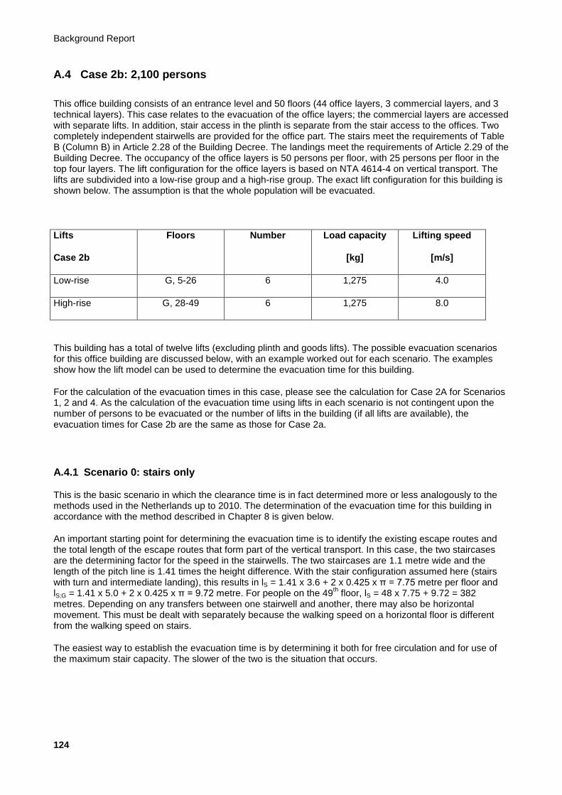
Background Report
124
A.4 Case 2b: 2,100 persons
This office building consists of an entrance level and 50 floors (44 office layers, 3 commercial layers, and 3 technical layers). This case relates to the evacuation of the office layers; the commercial layers are accessed with separate lifts. In addition, stair access in the plinth is separate from the stair access to the offices. Two completely independent stairwells are provided for the office part. The stairs meet the requirements of Table B (Column B) in Article 2.28 of the Building Decree. The landings meet the requirements of Article 2.29 of the Building Decree. The occupancy of the office layers is 50 persons per floor, with 25 persons per floor in the top four layers. The lift configuration for the office layers is based on NTA 4614-4 on vertical transport. The lifts are subdivided into a low-rise group and a high-rise group. The exact lift configuration for this building is shown below. The assumption is that the whole population will be evacuated.
Lifts
Case 2b
Floors Number Load capacity
[kg]
Lifting speed
[m/s]
Low-rise G, 5-26 6 1,275 4.0
High-rise G, 28-49 6 1,275 8.0
This building has a total of twelve lifts (excluding plinth and goods lifts). The possible evacuation scenarios for this office building are discussed below, with an example worked out for each scenario. The examples show how the lift model can be used to determine the evacuation time for this building.
For the calculation of the evacuation times in this case, please see the calculation for Case 2A for Scenarios 1, 2 and 4. As the calculation of the evacuation time using lifts in each scenario is not contingent upon the number of persons to be evacuated or the number of lifts in the building (if all lifts are available), the evacuation times for Case 2b are the same as those for Case 2a.
A.4.1 Scenario 0: stairs only
This is the basic scenario in which the clearance time is in fact determined more or less analogously to the methods used in the Netherlands up to 2010. The determination of the evacuation time for this building in accordance with the method described in Chapter 8 is given below.
An important starting point for determining the evacuation time is to identify the existing escape routes and the total length of the escape routes that form part of the vertical transport. In this case, the two staircases are the determining factor for the speed in the stairwells. The two staircases are 1.1 metre wide and the length of the pitch line is 1.41 times the height difference. With the stair configuration assumed here (stairs with turn and intermediate landing), this results in lS = 1.41 x 3.6 + 2 x 0.425 x π = 7.75 metre per floor and lS;G = 1.41 x 5.0 + 2 x 0.425 x π = 9.72 metre. For people on the 49
th floor, lS = 48 x 7.75 + 9.72 = 382
metres. Depending on any transfers between one stairwell and another, there may also be horizontal movement. This must be dealt with separately because the walking speed on a horizontal floor is different from the walking speed on stairs.
The easiest way to establish the evacuation time is by determining it both for free circulation and for use of the maximum stair capacity. The slower of the two is the situation that occurs.

Evacuation of High-rise Buildings with Lifts and Stairs
125
A.4.1.1 Situation with free circulation
The following formula applies to the situation with free circulation:
Tevac,S,fc = lS / vS(t)
Based on the discrete factors for fatigue and risk of blockage, the speed drops every 5 minutes. See Section 8.1 for the values of these factors.
In the first 5 minutes, the maximum distance travelled is lS = Tevac,S,fc x vS(t) = 300 x 0.8 = 240 metres. So not all users of the top floor will be down after 5 minutes.
In the second 5 minutes, the maximum distance travelled is lS = Tevac,S,fc x vS(t) = 300 x (0.8 x 0.9 x 0.9) = 194 metres. Counting the 240 metres from the first 5 minutes, this amounts to a total of 436 metres. So the users of the top floor will be down after 10 minutes. Tevac,S,fc for the last 382 - 240 metres becomes Tevac,S,fc = 142 / (0.8 x 0.9 x 0.9) = 219 seconds.
With free circulation, the time required to move down the stairs is therefore 519 seconds (8:39 minutes).
A.4.1.2 Situation with maximum capacity
The following formula applies to the situation with maximum capacity of the stairs:
Tevac,S,mc= (N x Pevac) / (CS(t) x We)
Based on the discrete factors for fatigue and risk of blockage, the capacity drops every 5 minutes in this case too. See Section 8.1 for the values of these factors.
For the maximum capacity of the stairs, the total number of persons per floor relying on the stairs is a major determinant of the descent time per floor. In the situation under consideration here, occupancy of the top four floors is half the standard occupancy. The speed of escape from these four floors will therefore differ from that of the other floors. Ultimately, the speed of the users of the top floors will become the same as the speed of users on the lower floors. The easiest way to determine the evacuation time in this case is in two stages.
A.4.1.2.1 Determination of time to top of plinth
The simplest way of ascertaining when the last person will arrive at the top of the plinth (one layer below the office part of the building) is to change the formula to:
N x Pevac = Tevac,S,mc x (CS(t) x We)
The total number of persons is 2,100 (40 x 40 + 4 x 20).
In the first 5 minutes, no more than the following number of persons will be evacuated over two staircases in accordance with Tevac,S,mc x CS(t) x We = 300 x 1.28 x 0.8 x 2 = 614 persons. Therefore, not everyone will have evacuated after 5 minutes.
In the second 5 minutes, no more than the following number of persons will be evacuated over two staircases in accordance with Tevac,S,mc x CS(t) x We = 300 x (1.28 x 0.9 x 0.9) x 0.8 x 2 = 498 persons. Counting the 614 persons from the first 5 minutes, this amounts to a total of 1,112 persons. Not all users will therefore have arrived at the top of the plinth after 10 minutes.
In the third 5 minutes, no more than the following number of persons will be evacuated over two staircases in accordance with Tevac,S,mc x CS(t) x We = 300 x (1.28 x 0.8 x 0.9) x 0.8 x 2 = 442 persons. Counting the 1,112 persons from the first 10 minutes, this amounts to a total of 1,554 persons. Not all users will therefore have arrived at the top of the plinth after 15 minutes.
In the fourth 5 minutes, no more than the following number of persons will be evacuated over two staircases in accordance with Tevac,S,mc x CS(t) x We = 300 x (1.28 x 0.7 x 0.8) x 0.8 x 2 = 344 persons. Counting the

Background Report
126
1,554 persons from the first 15 minutes, this amounts to a total of 1,898 persons. Not all users will therefore have arrived at the top of the plinth within 20 minutes.
In the fifth 5 minutes, no more than the following number of persons will be evacuated over two staircases in accordance with Tevac,S,mc x CS(t) x We = 300 x (1.28 x 0.7 x 0.8) x 0.8 x 2 = 344 persons. Counting the 1,898 persons from the first 20 minutes, this amounts to a total of 2,242 persons.
For the last 2,100 – 1,898 = 202 persons, the following can again be applied:
Tevac,S,mc = Pevac,tot / (CS(t) x We) = 202 / [(1.28 x 0.7 x 0.8) x 0.8 x 2] = 176 s
The total time for vertical movement down to the top of the plinth is now 1,376 seconds (22:56 minutes).
For the last four layers, a descent time of Tevac,S,mc = Pevac / (CS(t) x We) per floor can be adhered to for up to 25 minutes in accordance with Tevac,S,mc = 50 / [(1.28 x 0.7 x 0.8) x 0.8 x 2] = 44 seconds. Thereafter, the evacuation time per floor is Tevac,S,mc = 50 / [(1.28 x 0.6 x 0.7) x 0.8 x 2] = 58 seconds. An additional descent time of 2.82 x 44 + 1.18 x 58 = 193 seconds must therefore be added. The total evacuation time based on maximum capacity on the stairs is therefore 1,569 seconds (26:09 minutes). This is also the evacuation time that must be applied.
A.4.2 Scenario 1: lifts only
This scenario describes the determination of the evacuation time if the use of stairs is completely excluded. To calculate the evacuation time using lifts for this scenario, the formulae described in Section 9.2 are used.
A.4.2.1 All lifts available for evacuation
The total evacuation time using lifts in this office building is 1,421 seconds (23:41 minutes). See the calculation in Case 2a.
A.4.2.2 Not all lifts available for evacuation
It is possible that not all lifts will be available during the evacuation. The example below shows the total evacuation time with one less lift available. To determine the total evacuation time with one less lift available, only the factor Flifts changes compared with the scenario in which all lifts are available:
Flifts = Levac / Lpeak = 5 / 6 = 5/6
The total evacuation time becomes:
Tevac,L,0 = Tup-peak x (Ffraction x Fzone x Fheight) / (Fefficiency x Fcar capacity x Flifts) = 2,500 x (1 x 1 x 1) / (1.6 x 1.1 x 5/6) = 1,705 s
If one lift is not available, the total evacuation time in this office building is 1,705 seconds (28:25 minutes).
A.4.3 Scenario 2: fractional evacuation with lifts
This scenario describes the situation in which the bulk of the building population actually leaves the building in accordance with Scenario 0 (stairs only). For fractional evacuation, this example assumes that 6% and 12% of the population is evacuated with lifts.

Evacuation of High-rise Buildings with Lifts and Stairs
127
A.4.3.1 Evacuation time via stairs
6% with lifts:
If 6% of the population is evacuated with lifts, 94% has to be evacuated via the stairs. Tevac,S,fc always remains the same as it is solely contingent upon the distance to be travelled. Even if fewer people evacuate via the stairs, this is 219 seconds (8:39 minutes) in this case.
However, the number of people evacuated drops if the stairs are full to capacity. In this case, this is determined for 2,100 x 0.94 = 1,974 persons. In the calculation for Scenario 0, it can be seen that 1,898 persons will arrive at the top of the plinth functions in 20 minutes. For the last 1,974 - 1,898 = 76 persons, the following can again be applied:
Tevac,S,mc = Pevac,tot / (CS(t) x We) = 76 / [(1.28 x 0.7 x 0.8) x 0.8 x 2] = 66 s
The total time for vertical movement down to the top of the plinth is now 1,266 seconds (21:06 minutes).
For the last four floors, a descent time of Tevac,S,mc = Pevac / (CS(t) x We) per floor can be adhered to for up to 25 minutes in accordance with Tevac,S,mc = 50 / [(1.28 x 0.7 x 0.8) x 0.8 x 2] = 44 seconds. An additional descent time of 4 x 44 = 176 seconds must therefore be added. The total evacuation time based on maximum capacity on the stairs is therefore 1,442 seconds (24:02 minutes). This is also the evacuation time that must be applied.
12% with lifts:
Even if 12% of the population is evacuated with lifts, Tevac,S,fc = 219 seconds (8:39 minutes) for this case.
However, the number of people evacuated drops if the stairs are full to capacity. In this case, this is determined for 2,100 x 0.88 = 1,848 persons. In the calculation for Scenario 0, it can be seen that 1,554 persons will have arrived at the top of the plinth functions in 15 minutes. For the last 1,848 - 1,554 = 294 persons, the following can again be applied:
Tevac,S,mc = Pevac,tot / (CS(t) x We) = 294 / [(1.28 x 0.7 x 0.8) x 0.8 x 2] = 256 s
The total time for vertical movement down to the top of the plinth is now 1,156 seconds (19:16 minutes). As we can see above, 176 seconds need to be added for the last four floors, so the evacuation time becomes 1,332 seconds (22:12 minutes).
A.4.3.2 Evacuation time using lifts
The total evacuation time using lifts for this office building with 6% fractional evacuation is 219 seconds (3:39 minutes). See the calculation in Case 2a.
The total evacuation time using lifts for this office building with 12% fractional evacuation is 296 seconds (4:56 minutes). See the calculation in Case 2a.
A.4.3.3 Combined evacuation time
Evacuation time via stairs, with 6% fractional evacuation: 24:02 minutes; with 12% fractional evacuation: 22:12 minutes.
Evacuation time using lifts, with 6% fractional evacuation: 3:39 minutes; with 12% fractional evacuation: 4:56 minutes.
In this scenario, the evacuation time via the stairs determines the evacuation time for the building for this case. See Figure 7.6 for the procedure used.

Background Report
128
A.4.4 Scenario 3: lifts with transition layers
In this scenario, the lifts serve a number of predetermined floors to which evacuation must take place via the stairs. In the first example, we assume one transition layer on floor 26. A second example is also shown in which the transition layers are located on floors 16, 26, and 39. In this scenario, it is assumed that 88% of the population is able to reach the transition layers via the stairs, and that the other 12% is mobility-impaired and will be evacuated through all floors. The evacuation time for this 12% has already been calculated in Scenario 2. Since the number of lifts and the number of persons are determining factors in this scenario, the evacuation time in this scenario differs from the evacuation times in Scenario 3 for Case 2a.
A.4.4.1 One transition layer: 26th
floor
A.4.4.1.1 Evacuation time via stairs
To assess the evacuation time via the stairs, two groups need to be assessed independently of each other. First, we need to ascertain the length of time needed by 88% of the users of floors 28 to 49 to reach floor 26 via the stairs. We also need to ascertain how long the users of floors 5 to 25 will take to reach the ground floor. As shown below, the users of floor 26 are assumed to travel by lift, so they do not need to take the stairs at all.
A.4.4.1.1.1 High-rise via stairs to floor 26
In this case, lS is established to floor 26. In this part, only lS = 1.41 x 3.6 + 2 x 0.425 x π = 7.75 metres per floor plays a role. For the people on the 49
th floor, lS = (49 - 26) x 7.75 = 178 metres. Depending on any
transfers between one stairwell and another, there may also be horizontal movement. This must be dealt with separately because the walking speed on a horizontal floor is different from the walking speed on stairs.
The easiest way to establish the evacuation time is by determining it both for free circulation and for use of the maximum stair capacity. The slower of the two is the situation that occurs.
Situation with free circulation:
The following formula again applies to the situation with free circulation:
Tevac,S,fc = lS / vS(t)
From Scenario 0, we can see that more than 178 metres can be travelled in the first 5 minutes. Therefore, Tevac,S,fc = 178 / 0.8 = 223 seconds (3:43 minutes).
Situation with maximum stair capacity:
From this zone of the building, (18 x 50 + 4 x 25) x 88% = 880 persons need to be ‘conveyed’ to the appropriate transition layer via the stairs. By analogy to Scenario 0, we first determine how much time it takes for everyone to pass through floor 28 (therefore arriving at floor 27).
In the first 5 minutes, no more than the following number of persons will be evacuated over two staircases in accordance with Tevac,S,mc x CS(t) x We = 300 x 1.28 x 0.8 x 2 = 614 persons. Therefore, not everyone will have arrived at floor level on floor 27 after 5 minutes. For the last 880 - 614 = 266 persons, the following can again be applied:
Tevac,S,mc = Pevac,tot / (CS(t) x We) = 266 / [(1.28 x 0.9 x 0.9) x 0.8 x 2] = 160 s
The total time for vertical movement down to floor level on floor 28 is now 460 seconds (7:40 minutes).
For the last level (from 27 to 26), a descent time of Tevac,S,mc = Pevac / (CS(t) x We) per floor can be adhered to for up to 10 minutes in accordance with Tevac,S,mc = 50 / [(1.28 x 0.9 x 0.9) x 0.8 x 2] = 30 seconds. An
Evacuation of High-rise Buildings with Lifts and Stairs
129
additional descent time of 30 seconds must therefore be added. The total descent time based on maximum capacity on the stairs is therefore 490 seconds (8:10 minutes).
A.4.4.1.1.2 Low-rise by stairs to the ground floor
In this case, first lS is established from floor 25 to the ground floor. For the people on the 25th floor, lS = 24 x
7.75 + 9.72 = 196 metres. Depending on any transfers between one stairwell and another, there may also be horizontal movement. This must be dealt with separately because the walking speed on a horizontal floor is different from the walking speed on stairs.
The easiest way to establish the evacuation time is by determining it both for free circulation and for use of the maximum stair capacity. The slower of the two is the situation that occurs.
Situation with free circulation:
The following formula again applies to the situation with free circulation:
Tevac,S,fc = lS / vS(t)
From Scenario 0, we can see that more than 196 metres can be travelled in the first 5 minutes. Therefore, Tevac,S,fc = 196 / 0.8 = 245 seconds (4:05 minutes).
Situation with maximum stair capacity:
From this zone of the building, (21 x 50) x 88% = 924 persons need to be ‘conveyed’ to the appropriate transition layer via the stairs. By analogy to Scenario 0, we first determine how much time it takes for everyone to arrive at the top of the plinth functions. In the first 5 minutes, no more than the following number of persons will be evacuated over two staircases in accordance with Tevac,S,mc x CS(t) x We = 300 x 1.28 x 0.8 x 2 = 614 persons. Therefore, not everyone will have arrived at the top of the plinth after 5 minutes.
For the last 924 - 614 = 310 persons, the following can again be applied:
Tevac,S,mc = Pevac,tot / (CS(t) x We) = 310 / [(1.28 x 0.9 x 0.9) x 0.8 x 2] = 187 s
The total time for vertical movement down to floor level on floor 5 is now 487 seconds (8:07 minutes).
For the last four floors, a descent time of Tevac,S,mc = Pevac / (CS(t) x We) per floor can be adhered to for up to 10 minutes in accordance with Tevac,S,mc = 50 / [(1.28 x 0.9 x 0.9) x 0.8 x 2] = 30 seconds. Thereafter, the evacuation time per floor is Tevac,S,mc = 50 / [(1.28 x 0.8 x 0.9) x 0.8 x 2] = 34 seconds. An additional descent time of 3.77 x 30 + 0.23 x 34 = 121 seconds must therefore be added. The total descent time based on maximum capacity on the stairs is therefore 608 seconds (10:08 minutes).
A.4.4.1.2 Evacuation time using lifts
To calculate the evacuation time for Scenario 3 with one transition layer, the formulae described in Section 9.4 are used. In this scenario with one transition layer, it is assumed that all eight lifts can be used to evacuate from this floor. The number of persons evacuated from this floor is 88% of the population of floors 26 to 49. To calculate the evacuation time with one transition layer (floor 26), the following applies:
CCevac = (LC / 75) x Fcar capacity x CCmax = (1,275 / 75) x 1.1 x 0.8 = 14 persons per car
Jlift,total = Ptotal / CCevac = (1,050 x 0.88) / 14 = 924 / 14 = 66 journeys in total
Jlift,1 = Jlift,total / Levac = 66 / 12 = 6 journeys per lift
Tprocess = (2 x Tdoors + CCevac x Tboard + CCevac x Tboard) = (2 x 10 + 14 x 1.0 + 14 x 1.5 ) = 55 s
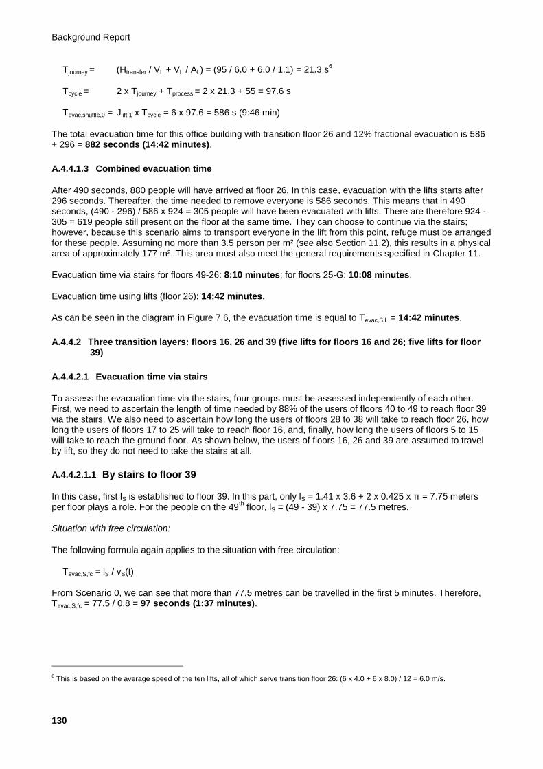
Background Report
130
Tjourney = (Htransfer / VL + VL / AL) = (95 / 6.0 + 6.0 / 1.1) = 21.3 s6
Tcycle = 2 x Tjourney + Tprocess = 2 x 21.3 + 55 = 97.6 s
Tevac,shuttle,0 = Jlift,1 x Tcycle = 6 x 97.6 = 586 s (9:46 min)
The total evacuation time for this office building with transition floor 26 and 12% fractional evacuation is 586 + 296 = 882 seconds (14:42 minutes).
A.4.4.1.3 Combined evacuation time
After 490 seconds, 880 people will have arrived at floor 26. In this case, evacuation with the lifts starts after 296 seconds. Thereafter, the time needed to remove everyone is 586 seconds. This means that in 490 seconds, (490 - 296) / 586 x 924 = 305 people will have been evacuated with lifts. There are therefore 924 - 305 = 619 people still present on the floor at the same time. They can choose to continue via the stairs; however, because this scenario aims to transport everyone in the lift from this point, refuge must be arranged for these people. Assuming no more than 3.5 person per m² (see also Section 11.2), this results in a physical area of approximately 177 m². This area must also meet the general requirements specified in Chapter 11.
Evacuation time via stairs for floors 49-26: 8:10 minutes; for floors 25-G: 10:08 minutes.
Evacuation time using lifts (floor 26): 14:42 minutes.
As can be seen in the diagram in Figure 7.6, the evacuation time is equal to Tevac,S,L = 14:42 minutes.
A.4.4.2 Three transition layers: floors 16, 26 and 39 (five lifts for floors 16 and 26; five lifts for floor 39)
A.4.4.2.1 Evacuation time via stairs
To assess the evacuation time via the stairs, four groups must be assessed independently of each other. First, we need to ascertain the length of time needed by 88% of the users of floors 40 to 49 to reach floor 39 via the stairs. We also need to ascertain how long the users of floors 28 to 38 will take to reach floor 26, how long the users of floors 17 to 25 will take to reach floor 16, and, finally, how long the users of floors 5 to 15 will take to reach the ground floor. As shown below, the users of floors 16, 26 and 39 are assumed to travel by lift, so they do not need to take the stairs at all.
A.4.4.2.1.1 By stairs to floor 39
In this case, first lS is established to floor 39. In this part, only lS = 1.41 x 3.6 + 2 x 0.425 x π = 7.75 meters per floor plays a role. For the people on the 49
th floor, lS = (49 - 39) x 7.75 = 77.5 metres.
Situation with free circulation:
The following formula again applies to the situation with free circulation:
Tevac,S,fc = lS / vS(t)
From Scenario 0, we can see that more than 77.5 metres can be travelled in the first 5 minutes. Therefore, Tevac,S,fc = 77.5 / 0.8 = 97 seconds (1:37 minutes).
6 This is based on the average speed of the ten lifts, all of which serve transition floor 26: (6 x 4.0 + 6 x 8.0) / 12 = 6.0 m/s.
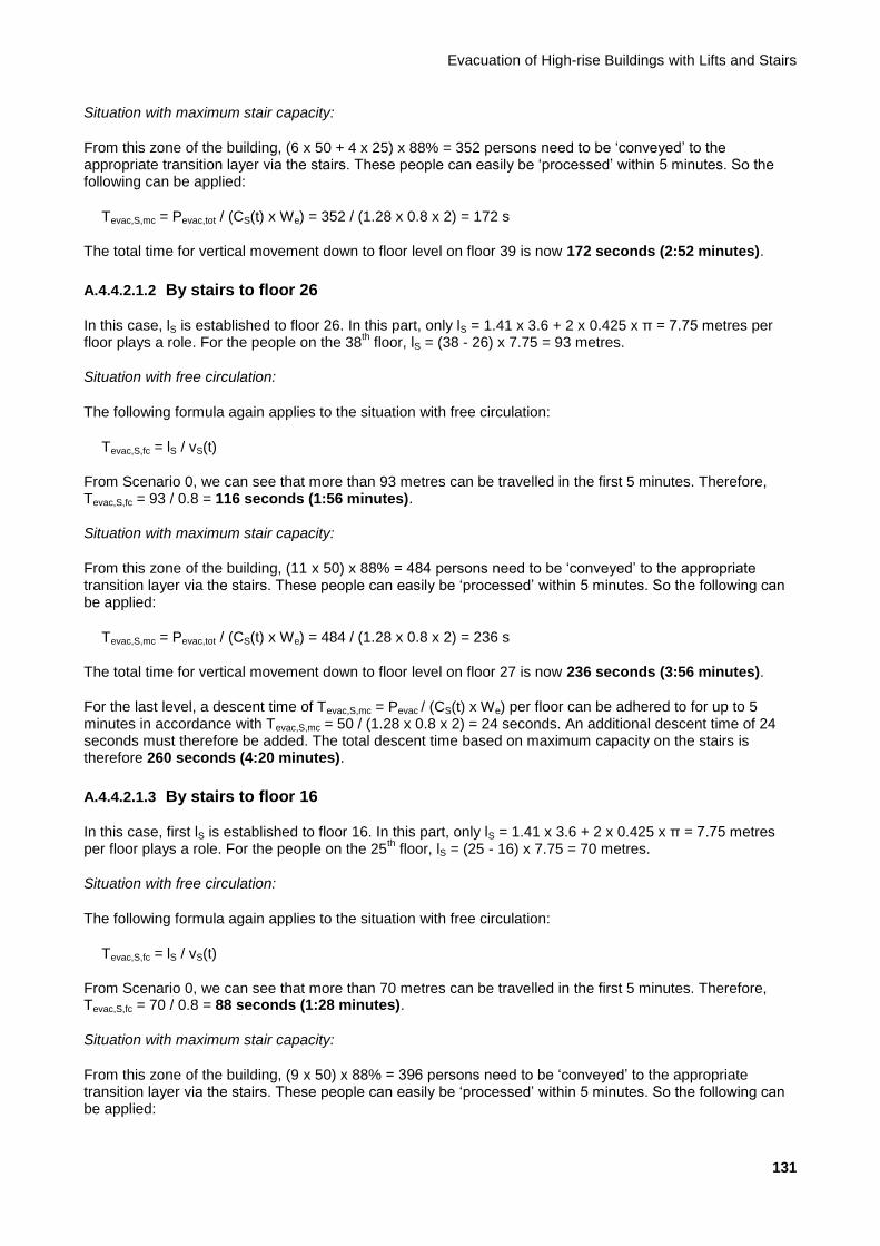
Evacuation of High-rise Buildings with Lifts and Stairs
131
Situation with maximum stair capacity:
From this zone of the building, (6 x 50 + 4 x 25) x 88% = 352 persons need to be ‘conveyed’ to the appropriate transition layer via the stairs. These people can easily be ‘processed’ within 5 minutes. So the following can be applied:
Tevac,S,mc = Pevac,tot / (CS(t) x We) = 352 / (1.28 x 0.8 x 2) = 172 s
The total time for vertical movement down to floor level on floor 39 is now 172 seconds (2:52 minutes).
A.4.4.2.1.2 By stairs to floor 26
In this case, lS is established to floor 26. In this part, only lS = 1.41 x 3.6 + 2 x 0.425 x π = 7.75 metres per floor plays a role. For the people on the 38
th floor, lS = (38 - 26) x 7.75 = 93 metres.
Situation with free circulation:
The following formula again applies to the situation with free circulation:
Tevac,S,fc = lS / vS(t)
From Scenario 0, we can see that more than 93 metres can be travelled in the first 5 minutes. Therefore, Tevac,S,fc = 93 / 0.8 = 116 seconds (1:56 minutes).
Situation with maximum stair capacity:
From this zone of the building, (11 x 50) x 88% = 484 persons need to be ‘conveyed’ to the appropriate transition layer via the stairs. These people can easily be ‘processed’ within 5 minutes. So the following can be applied:
Tevac,S,mc = Pevac,tot / (CS(t) x We) = 484 / (1.28 x 0.8 x 2) = 236 s
The total time for vertical movement down to floor level on floor 27 is now 236 seconds (3:56 minutes).
For the last level, a descent time of Tevac,S,mc = Pevac / (CS(t) x We) per floor can be adhered to for up to 5 minutes in accordance with Tevac,S,mc = 50 / (1.28 x 0.8 x 2) = 24 seconds. An additional descent time of 24 seconds must therefore be added. The total descent time based on maximum capacity on the stairs is therefore 260 seconds (4:20 minutes).
A.4.4.2.1.3 By stairs to floor 16
In this case, first lS is established to floor 16. In this part, only lS = 1.41 x 3.6 + 2 x 0.425 x π = 7.75 metres per floor plays a role. For the people on the 25
th floor, lS = (25 - 16) x 7.75 = 70 metres.
Situation with free circulation:
The following formula again applies to the situation with free circulation:
Tevac,S,fc = lS / vS(t)
From Scenario 0, we can see that more than 70 metres can be travelled in the first 5 minutes. Therefore, Tevac,S,fc = 70 / 0.8 = 88 seconds (1:28 minutes).
Situation with maximum stair capacity:
From this zone of the building, (9 x 50) x 88% = 396 persons need to be ‘conveyed’ to the appropriate transition layer via the stairs. These people can easily be ‘processed’ within 5 minutes. So the following can be applied:
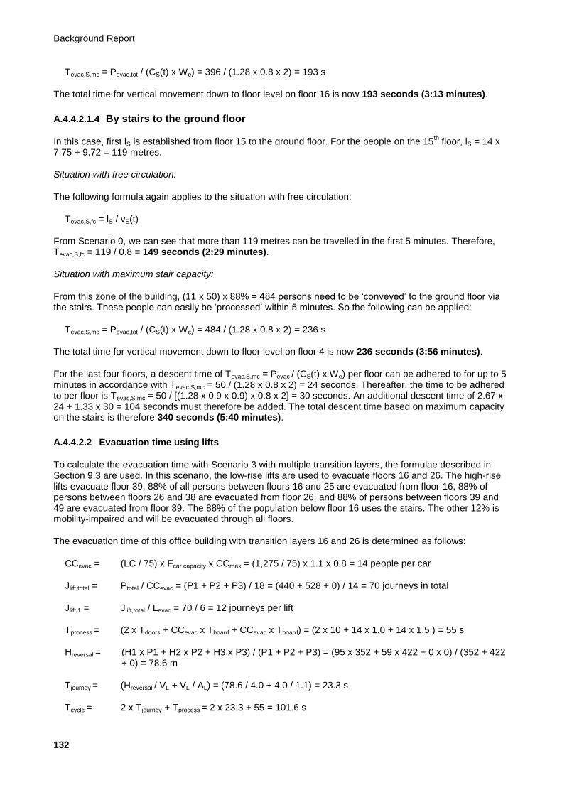
Background Report
132
Tevac,S,mc = Pevac,tot / (CS(t) x We) = 396 / (1.28 x 0.8 x 2) = 193 s
The total time for vertical movement down to floor level on floor 16 is now 193 seconds (3:13 minutes).
A.4.4.2.1.4 By stairs to the ground floor
In this case, first lS is established from floor 15 to the ground floor. For the people on the 15th floor, lS = 14 x
7.75 + 9.72 = 119 metres.
Situation with free circulation:
The following formula again applies to the situation with free circulation:
Tevac,S,fc = lS / vS(t)
From Scenario 0, we can see that more than 119 metres can be travelled in the first 5 minutes. Therefore, Tevac,S,fc = 119 / 0.8 = 149 seconds (2:29 minutes).
Situation with maximum stair capacity:
From this zone of the building, (11 x 50) x 88% = 484 persons need to be ‘conveyed’ to the ground floor via the stairs. These people can easily be ‘processed’ within 5 minutes. So the following can be applied:
Tevac,S,mc = Pevac,tot / (CS(t) x We) = 484 / (1.28 x 0.8 x 2) = 236 s
The total time for vertical movement down to floor level on floor 4 is now 236 seconds (3:56 minutes).
For the last four floors, a descent time of Tevac,S,mc = Pevac / (CS(t) x We) per floor can be adhered to for up to 5 minutes in accordance with Tevac,S,mc = 50 / (1.28 x 0.8 x 2) = 24 seconds. Thereafter, the time to be adhered to per floor is Tevac,S,mc = 50 / [(1.28 x 0.9 x 0.9) x 0.8 x 2] = 30 seconds. An additional descent time of 2.67 x 24 + 1.33 x 30 = 104 seconds must therefore be added. The total descent time based on maximum capacity on the stairs is therefore 340 seconds (5:40 minutes).
A.4.4.2.2 Evacuation time using lifts
To calculate the evacuation time with Scenario 3 with multiple transition layers, the formulae described in Section 9.3 are used. In this scenario, the low-rise lifts are used to evacuate floors 16 and 26. The high-rise lifts evacuate floor 39. 88% of all persons between floors 16 and 25 are evacuated from floor 16, 88% of persons between floors 26 and 38 are evacuated from floor 26, and 88% of persons between floors 39 and 49 are evacuated from floor 39. The 88% of the population below floor 16 uses the stairs. The other 12% is mobility-impaired and will be evacuated through all floors.
The evacuation time of this office building with transition layers 16 and 26 is determined as follows:
CCevac = (LC / 75) x Fcar capacity x CCmax = (1,275 / 75) x 1.1 x 0.8 = 14 people per car
Jlift,total = Ptotal / CCevac = (P1 + P2 + P3) / 18 = (440 + 528 + 0) / 14 = 70 journeys in total
Jlift,1 = Jlift,total / Levac = 70 / 6 = 12 journeys per lift
Tprocess = (2 x Tdoors + CCevac x Tboard + CCevac x Tboard) = (2 x 10 + 14 x 1.0 + 14 x 1.5 ) = 55 s
Hreversal = (H1 x P1 + H2 x P2 + H3 x P3) / (P1 + P2 + P3) = (95 x 352 + 59 x 422 + 0 x 0) / (352 + 422 + 0) = 78.6 m
Tjourney = (Hreversal / VL + VL / AL) = (78.6 / 4.0 + 4.0 / 1.1) = 23.3 s
Tcycle = 2 x Tjourney + Tprocess = 2 x 23.3 + 55 = 101.6 s

Evacuation of High-rise Buildings with Lifts and Stairs
133
Tadditional = 1 x (VL / AL + Tdoors) = 1 x (4.0 / 1.1 + 10) = 13.6 s
Tevac,L,0 = Jlift,1 x Tcycle + Tadditional = 12 x 101.6 + 13.6 = 1,233 s (20:33 min)
The evacuation time from floor 39 with the high-rise lifts can be calculated in the same manner. As there is one assembly floor here, the factor Tadditional does not apply. The evacuation time for floor 39 becomes:
Tevac,L,0 = 525 s (8:45 min)
The total evacuation time using lifts, including the 12% fractional evacuation for this building, is: max(1,233;525) + 296 = 1,529 seconds (25:29 minutes). Here, we have assumed that the high-rise lifts will be used for fractional evacuation of 12% of the population after having evacuated floor 39, so they will be finished after 525 + 296 = 821 seconds. As it cannot be guaranteed that the high-rise lifts will also have stops in the low-rise zone, they cannot routinely assist with fractional evacuation of the low-rise floors. Evacuation of the low-rise floor is therefore the determining factor. If the high-rise lifts are also provided with stops on the low-rise floors, the total evacuation time using lifts, including the 12% fractional evacuation for this building, is max(1,233;525+296+296) = max(1,233;1,117) = 1,233 seconds (20:33 minutes). The effect of the higher lifting speed of the high-rise lifts is disregarded here for the sake of convenience.
A.4.4.2.2.1 Alternative 1: three transition layers: floors 16, 26 and 39 (seven lifts for floors 16 and 26; five lifts for floor 39)
The difference between the evacuation times of the low-rise and the high-rise floors in the above example from Subsection A.4.4.2.2is almost 12 minutes. This is not optimal because the high-rise lifts are not used for 12 minutes in this scenario (unless stops on the low-rise floors are added), while the low-rise lifts are still evacuating. Because of this outcome, it can be decided to use one lift in the high-rise group to help evacuate floors 16 and 26. In this situation, seven lifts are used to evacuate floors 16 and 26, and five lifts to evacuate floor 39.
Compared with the above calculation with six lifts for floors 16 and 26, the following factors change:
Jlift,1 = Jlift,total / Levac = 70 / 7 = 10 journeys per lift
Tjourney = (Hreversal / VL + VL / AL) = (78.6 / 5.3 + 5.3 / 1.1) = 20.7 s7
Tcycle = 2 x Tjourney + Tprocess = 2 x 20.7 + 55 = 94.2 s
Tadditional = 1 x (VL / AL + Tdoors) = 1 x (5.3 / 1.1 + 10) = 14.8 s
Tevac,L,0 = Jlift,1 x Tcycle + Tadditional = 10 x 94.2 + 14.8 = 957 s (15:57 min)
These factors also change for the expected evacuation time for floor 39; the evacuation time for floor 39 is:
Tevac,L,0 = 630 s (10:30 min)
The difference between the two evacuation times has been reduced to 5.5 minutes by redistributing the lifts. The total evacuation time using lifts, including the 12% fractional evacuation from Scenario 2, is now: max(957;630) + 296 = 1,253 seconds (20:53 minutes).
A.4.4.2.2.2 Alternative 2: three transition layers: floors 16, 26 and 39 (eight lifts for floors 16 and 26; four lifts for floor 39)
The difference between the evacuation times of the low-rise and the high-rise floors is still relatively large (more than 5 minutes). It can be decided to use one more lift in the high-rise group to evacuate floors 16 and 26. In this situation, eight lifts are used to evacuate floors 16 and 26, and four lifts to evacuate floor 39.
7 This is based on the average speed of the seven lifts, all of which serve transition layers 16 and 26: (6 x 4.0 + 1 x 8.0) / 7 = 5.3 m/s.

Background Report
134
The total evacuation time for floors 16 and 26 in this situation becomes:
Tevac,L,0 = 852 s
The evacuation time for floor 39 becomes:
Tevac,L,0 = 840 s
The difference between the two evacuation times has been reduced to less than 1 minute by redistributing the lifts. The total evacuation time with the lifts for this building, including the 12% fractional evacuation from Scenario 2, is now: max(852;840) + 296 = 1,148 seconds (19:08 minutes). This is even quicker than the outcome of the alternative in Subsection A.4.4.2.2in which the high-rise lifts finish evacuating their zone much sooner and can then take over fractional evacuation of both the low-rise and the high-rise zone. However, in this alternative, it was necessary to provide all high-rise lifts with stops in the low-rise zone, whereas this is not necessary in the above example with eight lifts for the low-rise zone and four lifts for the high-rise zone.
A.4.4.3 Combined evacuation time
Users heading for transition layers via the stairs generally reach them before the fractional evacuation has been completed. The following physical refuge space must therefore be set aside for people on the various floors. The assumption here is once again 3.5 persons per m², as specified in Section 11.2:
Floor 39: 282 / 3.5 = 81 m²
Floor 26: 388 / 3.5 = 111 m²
Floor 16: 316 / 3.5 = 91 m²
Evacuation time via stairs for floors 49-39: 2:52 minutes; for floors 38-26: 4:20 minutes; for floors 25-16: 3:13 minutes; for floors 15-G: 5:40 minutes.
Evacuation time using lifts (combination; Alternative 2): 19:08 minutes.
As can be seen in the diagram in Figure 7.6, the evacuation time is equal to Tevac,S,L = 19:08 minutes.
A.4.5 Scenario 4: free choice
A.4.5.1 Evacuation time via stairs
For the people on the 49th floor, lS = 48 x 7.75 + 9.72 = 382 metres (see calculation for Scenario 0). Here too,
free circulation and maximum capacity are taken into consideration.
Situation with free circulation:
The following formula applies to the situation with free circulation:
Tevac,S,fc = lS / vS(t)
Based on the discrete factors for fatigue and risk of blockage, the speed drops every 5 minutes. See Section 8.1 for the values of these factors.
In the first 5 minutes, the maximum distance travelled is lS = Tevac,S,fc x vS(t) = 300 x 0.8 = 240 metres. So the users of the top floor will not be down after 5 minutes.
In the second 5 minutes, the maximum distance travelled is lS = Tevac,S,fc x vS(t) = 300 x (0.8 x 0.9 x 0.9) = 194 metres. Counting the 240 metres from the first 5 minutes, this amounts to a total of 436 metres. So the users

Evacuation of High-rise Buildings with Lifts and Stairs
135
of the top floor will be down after 10 minutes. Tevac,S,fc for the last 382 - 240 m becomes Tevac,S,fc = 142 / (0.8 x 0.9 x 0.9) = 219 seconds.
With free circulation, the time required to move down the stairs is therefore 519 seconds (8:39 minutes).
Situation with maximum capacity:
The following formula applies to the situation with maximum capacity of the stairs:
Tevac,S,mc= (N x Pevac) / (CS(t) x We)
The simplest way of ascertaining when the last person will arrive at the top of the plinth (one layer below the office part of the building) is to change the formula to:
N x Pevac = Tevac,S,mc x (CS(t) x We)
The total number of persons evacuated via the stairs is (40 x 50 + 4 x 25) x 50% = 1,050.
In the first 5 minutes, no more than the following number of persons will be evacuated over two staircases in accordance with Tevac,S,mc x CS(t) x We = 300 x 1.28 x 0.8 x 2 = 614 persons. Therefore, not everyone will have evacuated after 5 minutes.
All users will have arrived at the top of the plinth within 10 minutes. For the last 1,050 - 614 = 436 persons, the following can be applied:
Tevac,S,mc = Pevac,tot / (CS(t) x We) = 436 / [(1.28 x 0.9 x 0.9) x 0.8 x 2] = 263 s
The total time for vertical movement down to the top of the plinth is now 563 seconds (9:23 minutes).
For the last four floors, a descent time of Tevac,S,mc = Pevac / (CS(t) x We) per floor can be adhered to for up to 10 minutes in accordance with Tevac,S,mc = 25 / [(1.28 x 0.9 x 0.9) x 0.8 x 2] = 15 seconds. Thereafter, the evacuation time per floor is Tevac,S,mc = 25 / [(1.28 x 0.8 x 0.9) x 0.8 x 2] = 17 seconds. An additional descent time of 2.47 x 15 + 1.53 x 17 = 63 seconds must therefore be added. The total evacuation time based on maximum capacity on the stairs is therefore 626 seconds (10:26 minutes).
This capacity is obviously the equivalent of maximum capacity on the stairs, and an evacuation time of 626 seconds (10:26 minutes) must be adhered to in this case.
A.4.5.2 Evacuation time using lifts
The total evacuation time using lifts for this office building with 50% fractional evacuation is 782 seconds (13:02 minutes). See the calculation for Scenario 4 in Case 2a.
A.4.5.3 Combined evacuation time
Evacuation time via stairs: 10:26 minutes.
Evacuation time using lifts: 13:02 minutes.
The evacuation time for the building with even distribution of the population between stairs and lifts is determined by the lifts, and amounts to 13:02 minutes.

Background Report
136
A.4.6 Summary of Case 2b
Figure A.4: Results of Case 2b
The numerical results of the various scenarios for Case 2b are summarised in the figure above. Free choice
results in the shortest evacuation for the entire population.
0
200
400
600
800
1000
1200
1400
1600
1800
2000
Stairs Lifts Fractional (6%)
Fractional (12%)
1 transition layer
3 transition layers
Free choice
0 1 2a 2b 3a 3b 4
Case 2b
Case 2b
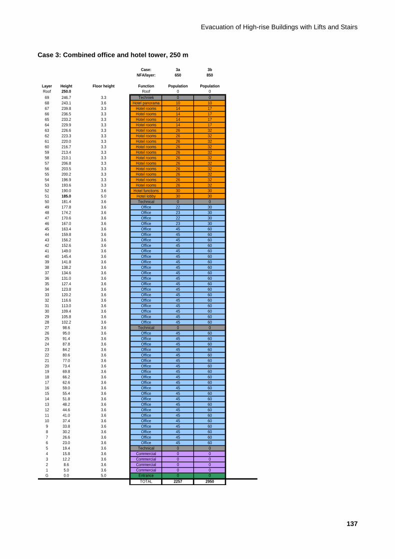
Evacuation of High-rise Buildings with Lifts and Stairs
137
Case 3: Combined office and hotel tower, 250 m
Case: 3a 3b
NFA/layer: 650 850
Layer Height Floor height Function Population Population
Roof 250.0 Roof 0 0
69 246.7 3.3 Techniek 0 0
68 243.1 3.6 Hotel panorama 10 10
67 239.8 3.3 Hotel rooms 14 17
66 236.5 3.3 Hotel rooms 14 17
65 233.2 3.3 Hotel rooms 14 17
64 229.9 3.3 Hotel rooms 14 17
63 226.6 3.3 Hotel rooms 26 32
62 223.3 3.3 Hotel rooms 26 32
61 220.0 3.3 Hotel rooms 26 32
60 216.7 3.3 Hotel rooms 26 32
59 213.4 3.3 Hotel rooms 26 32
58 210.1 3.3 Hotel rooms 26 32
57 206.8 3.3 Hotel rooms 26 32
56 203.5 3.3 Hotel rooms 26 32
55 200.2 3.3 Hotel rooms 26 32
54 196.9 3.3 Hotel rooms 26 32
53 193.6 3.3 Hotel rooms 26 32
52 190.0 3.6 Hotel functions 30 30
51 185.0 5.0 Hotel lobby 30 30
50 181.4 3.6 Technical 0 0
49 177.8 3.6 Office 22 30
48 174.2 3.6 Office 23 30
47 170.6 3.6 Office 22 30
46 167.0 3.6 Office 23 30
45 163.4 3.6 Office 45 60
44 159.8 3.6 Office 45 60
43 156.2 3.6 Office 45 60
42 152.6 3.6 Office 45 60
41 149.0 3.6 Office 45 60
40 145.4 3.6 Office 45 60
39 141.8 3.6 Office 45 60
38 138.2 3.6 Office 45 60
37 134.6 3.6 Office 45 60
36 131.0 3.6 Office 45 60
35 127.4 3.6 Office 45 60
34 123.8 3.6 Office 45 60
33 120.2 3.6 Office 45 60
32 116.6 3.6 Office 45 60
31 113.0 3.6 Office 45 60
30 109.4 3.6 Office 45 60
29 105.8 3.6 Office 45 60
28 102.2 3.6 Office 45 60
27 98.6 3.6 Technical 0 0
26 95.0 3.6 Office 45 60
25 91.4 3.6 Office 45 60
24 87.8 3.6 Office 45 60
23 84.2 3.6 Office 45 60
22 80.6 3.6 Office 45 60
21 77.0 3.6 Office 45 60
20 73.4 3.6 Office 45 60
19 69.8 3.6 Office 45 60
18 66.2 3.6 Office 45 60
17 62.6 3.6 Office 45 60
16 59.0 3.6 Office 45 60
15 55.4 3.6 Office 45 60
14 51.8 3.6 Office 45 60
13 48.2 3.6 Office 45 60
12 44.6 3.6 Office 45 60
11 41.0 3.6 Office 45 60
10 37.4 3.6 Office 45 60
9 33.8 3.6 Office 45 60
8 30.2 3.6 Office 45 60
7 26.6 3.6 Office 45 60
6 23.0 3.6 Office 45 60
5 19.4 3.6 Technical 0 0
4 15.8 3.6 Commercial 0 0
3 12.2 3.6 Commercial 0 0
2 8.6 3.6 Commercial 0 0
1 5.0 3.6 Commercial 0 0
G 0.0 5.0 Entrance 0 0
TOTAL 2257 2950
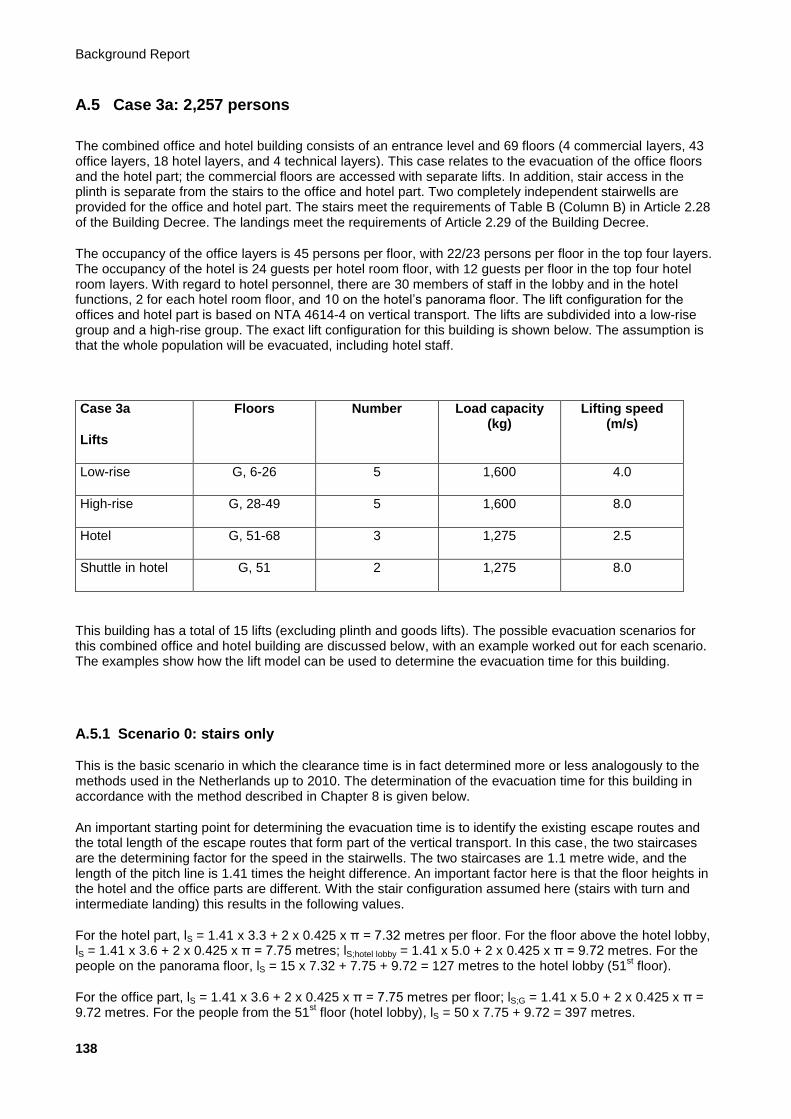
Background Report
138
A.5 Case 3a: 2,257 persons
The combined office and hotel building consists of an entrance level and 69 floors (4 commercial layers, 43 office layers, 18 hotel layers, and 4 technical layers). This case relates to the evacuation of the office floors and the hotel part; the commercial floors are accessed with separate lifts. In addition, stair access in the plinth is separate from the stairs to the office and hotel part. Two completely independent stairwells are provided for the office and hotel part. The stairs meet the requirements of Table B (Column B) in Article 2.28 of the Building Decree. The landings meet the requirements of Article 2.29 of the Building Decree.
The occupancy of the office layers is 45 persons per floor, with 22/23 persons per floor in the top four layers. The occupancy of the hotel is 24 guests per hotel room floor, with 12 guests per floor in the top four hotel room layers. With regard to hotel personnel, there are 30 members of staff in the lobby and in the hotel functions, 2 for each hotel room floor, and 10 on the hotel’s panorama floor. The lift configuration for the offices and hotel part is based on NTA 4614-4 on vertical transport. The lifts are subdivided into a low-rise group and a high-rise group. The exact lift configuration for this building is shown below. The assumption is that the whole population will be evacuated, including hotel staff.
Case 3a
Lifts
Floors Number Load capacity (kg)
Lifting speed (m/s)
Low-rise G, 6-26 5 1,600 4.0
High-rise G, 28-49 5 1,600 8.0
Hotel G, 51-68 3 1,275 2.5
Shuttle in hotel G, 51 2 1,275 8.0
This building has a total of 15 lifts (excluding plinth and goods lifts). The possible evacuation scenarios for this combined office and hotel building are discussed below, with an example worked out for each scenario. The examples show how the lift model can be used to determine the evacuation time for this building.
A.5.1 Scenario 0: stairs only
This is the basic scenario in which the clearance time is in fact determined more or less analogously to the methods used in the Netherlands up to 2010. The determination of the evacuation time for this building in accordance with the method described in Chapter 8 is given below.
An important starting point for determining the evacuation time is to identify the existing escape routes and the total length of the escape routes that form part of the vertical transport. In this case, the two staircases are the determining factor for the speed in the stairwells. The two staircases are 1.1 metre wide, and the length of the pitch line is 1.41 times the height difference. An important factor here is that the floor heights in the hotel and the office parts are different. With the stair configuration assumed here (stairs with turn and intermediate landing) this results in the following values.
For the hotel part, lS = 1.41 x 3.3 + 2 x 0.425 x π = 7.32 metres per floor. For the floor above the hotel lobby, lS = 1.41 x 3.6 + 2 x 0.425 x π = 7.75 metres; lS;hotel lobby = 1.41 x 5.0 + 2 x 0.425 x π = 9.72 metres. For the people on the panorama floor, lS = 15 x 7.32 + 7.75 + 9.72 = 127 metres to the hotel lobby (51
st floor).
For the office part, lS = 1.41 x 3.6 + 2 x 0.425 x π = 7.75 metres per floor; lS;G = 1.41 x 5.0 + 2 x 0.425 x π = 9.72 metres. For the people from the 51
st floor (hotel lobby), lS = 50 x 7.75 + 9.72 = 397 metres.
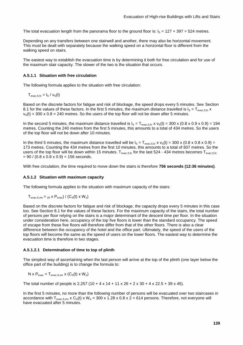
Evacuation of High-rise Buildings with Lifts and Stairs
139
The total evacuation length from the panorama floor to the ground floor is: lS = 127 + 397 = 524 metres.
Depending on any transfers between one stairwell and another, there may also be horizontal movement. This must be dealt with separately because the walking speed on a horizontal floor is different from the walking speed on stairs.
The easiest way to establish the evacuation time is by determining it both for free circulation and for use of the maximum stair capacity. The slower of the two is the situation that occurs.
A.5.1.1 Situation with free circulation
The following formula applies to the situation with free circulation:
Tevac,S,fc = lS / vS(t)
Based on the discrete factors for fatigue and risk of blockage, the speed drops every 5 minutes. See Section 8.1 for the values of these factors. In the first 5 minutes, the maximum distance travelled is lS = Tevac,S,fc x vS(t) = 300 x 0.8 = 240 metres. So the users of the top floor will not be down after 5 minutes.
In the second 5 minutes, the maximum distance travelled is lS = Tevac,S,fc x vS(t) = 300 x (0.8 x 0.9 x 0.9) = 194 metres. Counting the 240 metres from the first 5 minutes, this amounts to a total of 434 metres. So the users of the top floor will not be down after 10 minutes.
In the third 5 minutes, the maximum distance travelled will be lS = Tevac,S,fc x vS(t) = 300 x (0.8 x 0.8 x 0.9) = 173 metres. Counting the 434 metres from the first 10 minutes, this amounts to a total of 607 metres. So the users of the top floor will be down within 15 minutes. Tevac,S,fc for the last 524 - 434 metres becomes Tevac,S,fc = 90 / (0.8 x 0.8 x 0.9) = 156 seconds.
With free circulation, the time required to move down the stairs is therefore 756 seconds (12:36 minutes).
A.5.1.2 Situation with maximum capacity
The following formula applies to the situation with maximum capacity of the stairs:
Tevac,S,mc = (N x Pevac) / (CS(t) x We)
Based on the discrete factors for fatigue and risk of blockage, the capacity drops every 5 minutes in this case too. See Section 8.1 for the values of these factors. For the maximum capacity of the stairs, the total number of persons per floor relying on the stairs is a major determinant of the descent time per floor. In the situation under consideration here, occupancy of the top five floors is lower than the standard occupancy. The speed of escape from these five floors will therefore differ from that of the other floors. There is also a clear difference between the occupancy of the hotel and the office part. Ultimately, the speed of the users of the top floors will become the same as the speed of users on the lower floors. The easiest way to determine the evacuation time is therefore in two stages.
A.5.1.2.1 Determination of time to top of plinth
The simplest way of ascertaining when the last person will arrive at the top of the plinth (one layer below the office part of the building) is to change the formula to:
N x Pevac = Tevac,S,mc x (CS(t) x We)
The total number of people is 2,257 (10 + 4 x 14 + 11 x 26 + 2 x 30 + 4 x 22.5 + 39 x 45).
In the first 5 minutes, no more than the following number of persons will be evacuated over two staircases in accordance with Tevac,S,mc x CS(t) x We = 300 x 1.28 x 0.8 x 2 = 614 persons. Therefore, not everyone will have evacuated after 5 minutes.
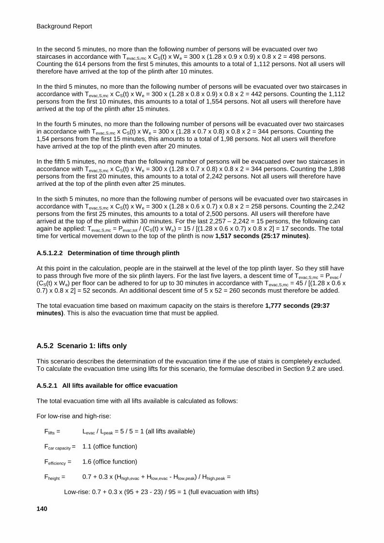
Background Report
140
In the second 5 minutes, no more than the following number of persons will be evacuated over two staircases in accordance with Tevac,S,mc x CS(t) x We = 300 x (1.28 x 0.9 x 0.9) x 0.8 x 2 = 498 persons. Counting the 614 persons from the first 5 minutes, this amounts to a total of 1,112 persons. Not all users will therefore have arrived at the top of the plinth after 10 minutes.
In the third 5 minutes, no more than the following number of persons will be evacuated over two staircases in accordance with Tevac,S,mc x CS(t) x We = 300 x (1.28 x 0.8 x 0.9) x 0.8 x 2 = 442 persons. Counting the 1,112 persons from the first 10 minutes, this amounts to a total of 1,554 persons. Not all users will therefore have arrived at the top of the plinth after 15 minutes.
In the fourth 5 minutes, no more than the following number of persons will be evacuated over two staircases in accordance with Tevac,S,mc x CS(t) x We = 300 x (1.28 x 0.7 x 0.8) x 0.8 x 2 = 344 persons. Counting the 1,54 persons from the first 15 minutes, this amounts to a total of 1,98 persons. Not all users will therefore have arrived at the top of the plinth even after 20 minutes.
In the fifth 5 minutes, no more than the following number of persons will be evacuated over two staircases in accordance with Tevac,S,mc x CS(t) x We = 300 x (1.28 x 0.7 x 0.8) x 0.8 x 2 = 344 persons. Counting the 1,898 persons from the first 20 minutes, this amounts to a total of 2,242 persons. Not all users will therefore have arrived at the top of the plinth even after 25 minutes.
In the sixth 5 minutes, no more than the following number of persons will be evacuated over two staircases in accordance with Tevac,S,mc x CS(t) x We = 300 x (1.28 x 0.6 x 0.7) x 0.8 x 2 = 258 persons. Counting the 2,242 persons from the first 25 minutes, this amounts to a total of 2,500 persons. All users will therefore have arrived at the top of the plinth within 30 minutes. For the last 2,257 – 2,242 = 15 persons, the following can again be applied: Tevac,S,mc = Pevac,tot / (CS(t) x We) = 15 / [(1.28 x 0.6 x 0.7) x 0.8 x 2] = 17 seconds. The total time for vertical movement down to the top of the plinth is now 1,517 seconds (25:17 minutes).
A.5.1.2.2 Determination of time through plinth
At this point in the calculation, people are in the stairwell at the level of the top plinth layer. So they still have to pass through five more of the six plinth layers. For the last five layers, a descent time of Tevac,S,mc = Pevac / (CS(t) x We) per floor can be adhered to for up to 30 minutes in accordance with Tevac,S,mc = 45 / [(1.28 x 0.6 x 0.7) x 0.8 x 2] = 52 seconds. An additional descent time of 5 x 52 = 260 seconds must therefore be added.
The total evacuation time based on maximum capacity on the stairs is therefore 1,777 seconds (29:37 minutes). This is also the evacuation time that must be applied.
A.5.2 Scenario 1: lifts only
This scenario describes the determination of the evacuation time if the use of stairs is completely excluded. To calculate the evacuation time using lifts for this scenario, the formulae described in Section 9.2 are used.
A.5.2.1 All lifts available for office evacuation
The total evacuation time with all lifts available is calculated as follows:
For low-rise and high-rise:
Flifts = Levac / Lpeak = 5 / 5 = 1 (all lifts available)
Fcar capacity = 1.1 (office function)
Fefficiency = 1.6 (office function)
Fheight = 0.7 + 0.3 x (Hhigh,evac + Hlow,evac - Hlow,peak) / Hhigh,peak =
Low-rise: 0.7 + 0.3 x (95 + 23 - 23) / 95 = 1 (full evacuation with lifts)
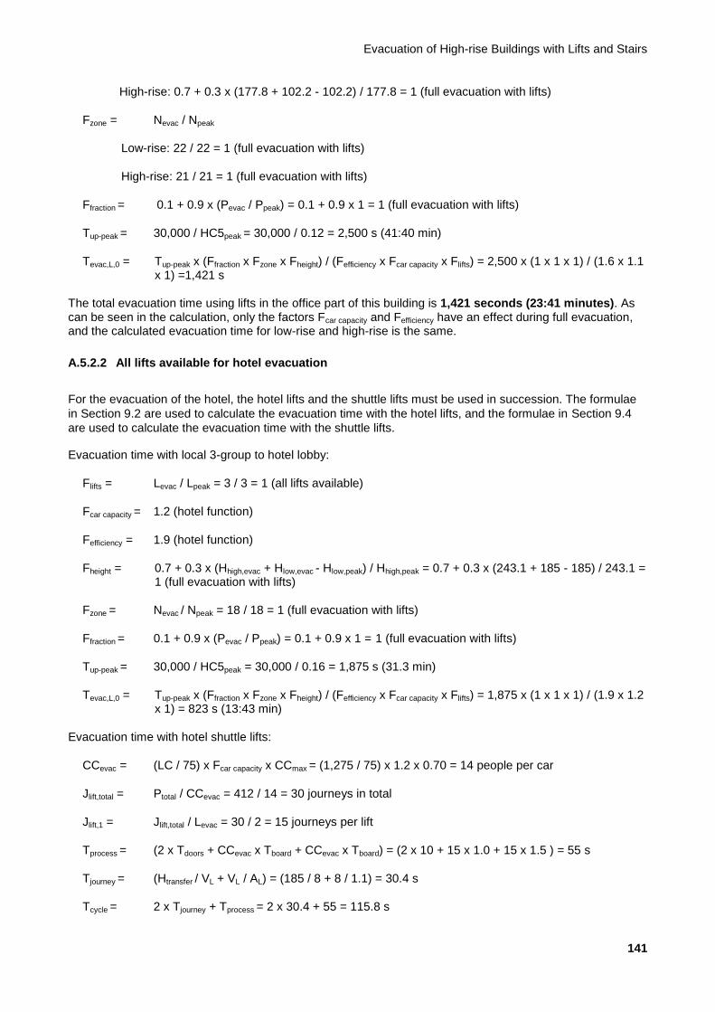
Evacuation of High-rise Buildings with Lifts and Stairs
141
High-rise: 0.7 + 0.3 x (177.8 + 102.2 - 102.2) / 177.8 = 1 (full evacuation with lifts)
Fzone = Nevac / Npeak
Low-rise: 22 / 22 = 1 (full evacuation with lifts)
High-rise: 21 / 21 = 1 (full evacuation with lifts)
Ffraction = 0.1 + 0.9 x (Pevac / Ppeak) = 0.1 + 0.9 x 1 = 1 (full evacuation with lifts)
Tup-peak = 30,000 / HC5peak = 30,000 / 0.12 = 2,500 s (41:40 min)
Tevac,L,0 = Tup-peak x (Ffraction x Fzone x Fheight) / (Fefficiency x Fcar capacity x Flifts) = 2,500 x (1 x 1 x 1) / (1.6 x 1.1 x 1) =1,421 s
The total evacuation time using lifts in the office part of this building is 1,421 seconds (23:41 minutes). As can be seen in the calculation, only the factors Fcar capacity and Fefficiency have an effect during full evacuation, and the calculated evacuation time for low-rise and high-rise is the same.
A.5.2.2 All lifts available for hotel evacuation
For the evacuation of the hotel, the hotel lifts and the shuttle lifts must be used in succession. The formulae
in Section 9.2 are used to calculate the evacuation time with the hotel lifts, and the formulae in Section 9.4
are used to calculate the evacuation time with the shuttle lifts.
Evacuation time with local 3-group to hotel lobby:
Flifts = Levac / Lpeak = 3 / 3 = 1 (all lifts available)
Fcar capacity = 1.2 (hotel function)
Fefficiency = 1.9 (hotel function)
Fheight = 0.7 + 0.3 x (Hhigh,evac + Hlow,evac - Hlow,peak) / Hhigh,peak = 0.7 + 0.3 x (243.1 + 185 - 185) / 243.1 = 1 (full evacuation with lifts)
Fzone = Nevac / Npeak = 18 / 18 = 1 (full evacuation with lifts)
Ffraction = 0.1 + 0.9 x (Pevac / Ppeak) = 0.1 + 0.9 x 1 = 1 (full evacuation with lifts)
Tup-peak = 30,000 / HC5peak = 30,000 / 0.16 = 1,875 s (31.3 min)
Tevac,L,0 = Tup-peak x (Ffraction x Fzone x Fheight) / (Fefficiency x Fcar capacity x Flifts) = 1,875 x (1 x 1 x 1) / (1.9 x 1.2 x 1) = 823 s (13:43 min)
Evacuation time with hotel shuttle lifts:
CCevac = (LC / 75) x Fcar capacity x CCmax = (1,275 / 75) x 1.2 x 0.70 = 14 people per car
Jlift,total = Ptotal / CCevac = 412 / 14 = 30 journeys in total
Jlift,1 = Jlift,total / Levac = 30 / 2 = 15 journeys per lift
Tprocess = (2 x Tdoors + CCevac x Tboard + CCevac x Tboard) = (2 x 10 + 15 x 1.0 + 15 x 1.5 ) = 55 s
Tjourney = (Htransfer / VL + VL / AL) = (185 / 8 + 8 / 1.1) = 30.4 s
Tcycle = 2 x Tjourney + Tprocess = 2 x 30.4 + 55 = 115.8 s
Background Report
142
Tevac,shuttle,0 = Jlift,1 x Tcycle = 15 x 115.8 = 3,474 s
As we can see from the above, the evacuation time with the shuttle lifts is the determining factor. Assuming that approximately 120 seconds would pass before the first evacuees exit the local hotel lifts (by analogy with Formula 9.25b), and that the transfer time to the shuttle lifts would be approximately 30 seconds, the total evacuation time using lifts for the hotel will be 120 + 30 + 1,737 = 1,887 seconds (31:27 minutes).
A.5.2.3 Not all lifts available for office evacuation
It is possible that not all lifts will be available during the evacuation. The example below shows the total evacuation time with one less lift available. To determine the total evacuation time with one less lift available, only the factor Flifts changes compared with the above calculation.
Flifts = Levac / Lpeak = 4 / 5 = 4/5
Tevac,L,0 = Tup-peak x (Ffraction x Fzone x Fheight) / (Fefficiency x Fcar capacity x Flifts) = 2,500 x (1 x 1 x 1) / (1.6 x 1.1 x 4/5) = 1,777 s
If one lift is not available, the total evacuation time in this office building is 1,777 seconds (29:37 minutes).
A.5.2.4 Not all lifts available for hotel evacuation
To determine the total evacuation time with one less lift available, only the factor Flifts changes compared with the above calculation for the hotel lifts.
Flifts = Levac / Lpeak = 2 / 3 = ⅔
Tevac,L,0 = Tup-peak x (Ffraction x Fzone x Fheight) / (Fefficiency x Fcar capacity x Flifts) = 1,875 x (1 x 1 x 1) / (1.9 x 1.2 x ⅔) = 1,234 s
If only one of the hotel shuttle lifts is available instead of two, the expected evacuation time is doubled:
Jlift,1 = Jlift,total / Levac = 30 / 1 = 30 journeys per lift
Tevac,shuttle,0 = Jlift,1 x Tcycle = 30 x 115.8 = 3,474 s
Assuming that approximately 120 seconds would pass before the first evacuees exit the local hotel lifts (by analogy with Formula 9.25b), and that the transfer time to the shuttle lifts would be approximately 30 seconds, the total evacuation time using lifts for the hotel will be 120 + 30 + 3,474 = 3,624 seconds (60:24 minutes).
A.5.3 Scenario 2: fractional evacuation with lifts
This scenario describes the situation in which the bulk of the building population actually leaves the building in accordance with Scenario 0 (stairs only). To calculate the evacuation time with this scenario, the formulae described in Section 9.2 are used, just as in Scenario 1. Any mobility-impaired people are evacuated by lift, possibly with assistance. For fractional evacuation, this example assumes that 6% and 12% of the population of the office building is evacuated with lifts. For the hotel, we assume that 18% of the population is evacuated with lifts. Only the factor Ffraction changes compared with the calculation of the evacuation time in Scenario 1. For the calculation of the evacuation time with the shuttle lifts, the number of persons to be evacuated changes.

Evacuation of High-rise Buildings with Lifts and Stairs
143
A.5.3.1 Fractional evacuation, office
A.5.3.1.1 Evacuation time via stairs
6% with lifts (18% in the hotel part):
NB: For fractional evacuation, the calculations for the hotel and office parts do not have to be performed separately. The calculation is the same as in Scenario 0, the difference being that not all of the population is evacuated via the stairs in this case.
If 6% of the population is evacuated with lifts, 94% has to be evacuated via the stairs. Tevac,S,fc always remains the same as it is solely contingent upon the distance to be travelled. Even if fewer people evacuate via the stairs, the evacuation time with free circulation is 756 seconds (12:36 minutes) for this case.
However, the number of people evacuated drops if the stairs are full to capacity. For the hotel part, 18% of the population takes the lift. With an original hotel population of 412 (10 + 4 x 14 + 11 x 26 + 2 x 30), the population to be evacuated now becomes 412 x 0.82 = 338 persons. The original office population is 1,845 (4 x 22.5 + 39 x 45). The total population to be evacuated via the stairs is therefore 338 + 1,845 x 0.94 = 2,072 persons.
In the calculation for Scenario 0, it can be seen that 1,898 persons will arrive at the top of the plinth functions in 20 minutes. For the last 2,072 - 1,898 = 174 persons, the following can again be applied:
Tevac,S,mc = Pevac,tot / (CS(t) x We) = 174 / [(1.28 x 0.7 x 0.8) x 0.8 x 2] = 152 s
The total time for vertical movement down to the top of the plinth is now 1,352 seconds (22:32 minutes).
For the last five layers, a descent time of Tevac,S,mc = Pevac / (CS(t) x We) per floor can be adhered to for up to 25 minutes in accordance with Tevac,S,mc = 45 / [(1.28 x 0.7 x 0.8) x 0.8 x 2] = 39 seconds. Thereafter, the evacuation time per floor is Tevac,S,mc = 45 / [(1.28 x 0.6 x 0.7) x 0.8 x 2] = 52 seconds. 1500 - 1,352 = 148 seconds. In 148 seconds, it is possible to descend 148 / 39 = 3.79 floors. An additional descent time of 3.79 x 39 + 1.21 x 52 = 211 seconds must therefore be added.
The total evacuation time based on maximum capacity on the stairs is therefore 1,352 + 211 = 1,563 seconds (26:03 minutes). This is also the evacuation time that must be applied.
12% with lifts (18% in the hotel part):
Even if 12% of the population is evacuated with lifts, Tevac,S,fc = 756 seconds (12:36 minutes) for this case.
However, the number of people evacuated drops if the stairs are full to capacity. For the hotel part, 18% of the population takes the lift. Of the original hotel population (412), 338 people take the stairs. The original office population is 1,845. The total population to be evacuated via the stairs is therefore 338 + 1,845 x 0.88 = 1,962 persons.
In the calculation for Scenario 0, it can be seen that 1,898 persons will arrive at the top of the plinth functions in 20 minutes. For the last 1,962 - 1,898 = 64 persons, the following can again be applied:
Tevac,S,mc = Pevac,tot / (CS(t) x We) = 64 / [(1.28 x 0.7 x 0.8) x 0.8 x 2] = 56 s
The total time for vertical movement down to the top of the plinth is now 1,256 seconds (20:56 minutes).
For the last five layers, a descent time of Tevac,S,mc = Pevac / (CS(t) x We) per floor can be adhered to for up to 25 minutes in accordance with Tevac,S,mc = 45 / [(1.28 x 0.7 x 0.8) x 0.8 x 2] = 39 seconds. Thereafter, the evacuation time per floor is Tevac,S,mc = 45 / [(1.28 x 0.6 x 0.7) x 0.8 x 2] = 52 seconds. 1500 - 1,256 = 244 seconds. In 244 seconds, it is possible to descend 244 / 39 = 6.2 floors. An additional descent time of 5 x 39 = 195 seconds must therefore be added.

Background Report
144
The total evacuation time based on maximum capacity on the stairs is therefore 1,256 + 195 = 1,451 seconds (24:11 minutes). This evacuation time is higher than the evacuation time with free circulation (12:33 minutes) and is therefore the determining factor.
A.5.3.1.2 Evacuation time using lifts
For 6% fractional evacuation, the factor Ffraction becomes:
Ffraction = 0.1 + 0.9 x (Pevac / Ppeak) = 0.1 + 0.9 x 0.06 = 0.154
The total evacuation time for 6% fractional evacuation becomes:
Tevac,L,0 = Tup-peak x (Ffraction x Fzone x Fheight) / (Fefficiency x Fcar capacity x Flifts) = 2,500 x (0.154 x 1 x 1) / (1.6 x 1.1 x 1) = 219 s
For 12% fractional evacuation, the factor Ffraction becomes:
Ffraction = 0.1 + 0.9 x (Pevac / Ppeak) = 0.1 + 0.9 x 0.12 = 0.208
The total evacuation time for 12% of this fraction becomes:
Tevac,L,0 = Tup-peak x (Ffraction x Fzone x Fheight) / (Fefficiency x Fcar capacity x Flifts) = 2,500 x (0.208 x 1 x 1) / (1.6 x 1.1 x 1) = 296 s
The total evacuation time using lifts for this office building with 6% fractional evacuation is 219 seconds (3:39 minutes).
The total evacuation time using lifts for this office building with 12% fractional evacuation is 296 seconds (4:56 minutes).
A.5.3.2 Fractional evacuation, hotel
A.5.3.2.1 Evacuation time using lifts
The evacuation time for the local hotel lifts is calculated as follows.
For 18% fractional evacuation, the factor Ffraction becomes:
Ffraction = 0.1 + 0.9 x (Pevac / Ppeak) = 0.1 + 0.9 x 0.18 = 0.262
The total evacuation time for 18% fractional evacuation of the local hotel lifts becomes:
Tevac,L,0 = Tup-peak x (Ffraction x Fzone x Fheight) / (Fefficiency x Fcar capacity x Flifts) = 1,875 x (0.262 x 1 x 1) / (1.9 x 1.2 x 1) = 215 s
The evacuation time for the shuttle lifts is calculated as follows:
Jlift,total = Ptotal / CCevac = (0.18 x 412) / 14 = 75 / 14 = 6 journeys in total
Jlift,1 = Jlift,total / Levac = 6 / 2 = 3 journeys per lift
Tevac,shuttle,0 = Jlift,1 x Tcycle = 3 x 115.8 = 348 s
Evacuation of High-rise Buildings with Lifts and Stairs
145
Assuming that approximately 120 seconds would pass before the first evacuees exit the local hotel lifts (by analogy with Formula 9.25b), and that the transfer time to the shuttle lifts would be approximately 30 seconds, the total evacuation time using lifts for the hotel will be 120 + 30 + 348 = 498 seconds (8:18 minutes).
A.5.3.3 Combined evacuation time
Evacuation time via stairs, with 6% fractional evacuation: 26:03 minutes; with 12% fractional evacuation: 24:11 minutes.
Evacuation time using lifts (office part), with 6% fractional evacuation: 3:39 minutes; with 12% fractional evacuation: 4:55 minutes.
Evacuation time using lifts (hotel part), with 18% fractional evacuation: 8:18 minutes.
In this scenario, the evacuation time via the stairs determines the evacuation time for the building for this case. See Figure 7.6 for the procedure used.
A.5.4 Scenario 3: lifts with transition layers
In this scenario, the office lifts serve a number of predetermined floors to which evacuation must take place via stairs. In the first example, we assume one transition layer on floor 26. A second example is also shown in which the transition layers are located on floors 16, 26 and 39. In this scenario, it is assumed that 88% of the population is able to reach the transition layers via the stairs, and that the other 12% is mobility-impaired and will be evacuated through all floors. The evacuation time for this 12% has already been calculated in Scenario 2.
This scenario does not apply to the hotel. Internal evacuation by means of transition layers is not considered likely in view of the limited height of the hotel zone. Evacuation takes place with the shuttle lifts from lobby level 51.
A.5.4.1 One transition layer: 26th
floor
A.5.4.1.1 Evacuation time via stairs
To assess the evacuation time via the stairs, two groups need to be assessed independently of each other. First, we need to ascertain the length of time needed by 88% of the users of floors 28 to 49 to reach floor 26 via the stairs. We also need to ascertain how long the users of floors 6 to 25 will take to reach the ground floor. As shown below, the users of floor 26 are assumed to travel by lift, so they do not need to take the stairs at all.
A.5.4.1.1.1 High-rise via stairs to floor 26
In this case, lS is established to floor 26. In this part, only lS = 1.41 x 3.6 + 2 x 0.425 x π = 7.75 metres per floor plays a role. For the people on the 49
th floor, lS = (49 - 26) x 7.75 = 178 metres. Depending on any
transfers between one stairwell and another, there may also be horizontal movement. This must be dealt with separately because the walking speed on a horizontal floor is different from the walking speed on stairs.
The easiest way to establish the evacuation time is by determining it both for free circulation and for use of the maximum stair capacity. The slower of the two is the situation that occurs.
Situation with free circulation:
The following formula again applies to the situation with free circulation:
Tevac,S,fc = lS / vS(t)
Background Report
146
From Scenario 0, we can see that more than 178 metres can be travelled in the first 5 minutes. Therefore, Tevac,S,fc = 178 / 0.8 = 223 seconds (3:43 minutes).
Situation with maximum stair capacity:
From this zone of the building, (18 x 45 + 4 x 22.5) x 88% = 792 persons need to be ‘conveyed’ to the appropriate transition layer via the stairs. By analogy to Scenario 0, we first determine how much time it takes for everyone to pass through floor 28 (therefore arriving at floor 27).
In the first 5 minutes, no more than the following number of persons will be evacuated over two staircases in accordance with Tevac,S,mc x CS(t) x We = 300 x 1.28 x 0.8 x 2 = 614 persons. Therefore, not everyone will have arrived at floor level on floor 28 after 5 minutes. For the last 792 - 614 = 178 persons, the following can again be applied:
Tevac,S,mc = Pevac,tot / (CS(t) x We) = 178 / [(1.28 x 0.9 x 0.9) x 0.8 x 2] = 107 s
The total time for vertical movement down to floor level on floor 27 is now 407 seconds (6:47 minutes).
For the last level (from 27 to 26), a descent time of Tevac,S,mc = Pevac / (CS(t) x We) per floor can be adhered to for up to 10 minutes in accordance with Tevac,S,mc = 45 / [(1.28 x 0.9 x 0.9) x 0.8 x 2] = 27 seconds. An additional descent time of 1 x 27 = 27 seconds must therefore be added. The total descent time based on maximum capacity on the stairs is therefore 434 seconds (7:14 minutes).
A.5.4.1.1.2 Low-rise by stairs to the ground floor
In this case, first lS is established from floor 25 to the ground floor. For the people on the 25th floor, lS = 24 x
7.75 + 9.72 = 196 metres. Depending on any transfers between one stairwell and another, there may also be horizontal movement. This must be dealt with separately because the walking speed on a horizontal floor is different from the walking speed on stairs.
The easiest way to establish the evacuation time is by determining it both for free circulation and for use of the maximum stair capacity. The slower of the two is the situation that occurs.
Situation with free circulation:
The following formula again applies to the situation with free circulation:
Tevac,S,fc = lS / vS(t)
From Scenario 0, we can see that more than 196 metres can be travelled in the first 5 minutes. Therefore, Tevac,S,fc = 196 / 0.8 = 245 seconds (4:05 minutes).
Situation with maximum stair capacity:
From this zone of the building, (20 x 45) x 88% = 792 persons need to be ‘conveyed’ to the appropriate transition layer via the stairs. By analogy to Scenario 0, we first determine how much time it takes for everyone to arrive at the top of the plinth functions. In the first 5 minutes, no more than the following number of persons will be evacuated over two staircases in accordance with Tevac,S,mc x CS(t) x We = 300 x 1.28 x 0.8 x 2 = 614 persons. Therefore, not everyone will have arrived at the top of the plinth after 5 minutes.
For the last 792 - 614 = 178 persons, the following can again be applied:
Tevac,S,mc = Pevac,tot / (CS(t) x We) = 178 / [(1.28 x 0.9 x 0.9) x 0.8 x 2] = 107 s
The total time for vertical movement down to plinth floor 5 is now 407 seconds (6:47 minutes).
For the last five layers, a descent time of Tevac,S,mc = Pevac / (CS(t) x We) per floor can be adhered to for up to 10 minutes in accordance with Tevac,S,mc = 45 / [(1.28 x 0.9 x 0.9) x 0.8 x 2] = 27 seconds. An additional

Evacuation of High-rise Buildings with Lifts and Stairs
147
descent time of 5 x 27 = 135 seconds must therefore be added. The total descent time based on maximum capacity on the stairs is therefore 542 seconds (9:02 minutes).
A.5.4.1.2 Evacuation time using lifts
To calculate the evacuation time with Scenario 3 with one transition layer, the formulae described in Section 9.4 are used. In this scenario with one transition layer, it is assumed that all ten lifts can be used to evacuate from this floor. The number of persons evacuated from this floor is 88% of the population of floors 26 to 49. To calculate the evacuation time with one transition layer (floor 26), the following applies:
CCevac = (LC / 75) x Fcar capacity x CCmax = (1,600 / 75) x 1.1 x 0.8 = 18 people per car
Jlift,total = Ptotal / CCevac = 832 / 18 = 47 journeys in total
Jlift,1 = Jlift,total / Levac = 47 / 10 = 5 journeys per lift
Tprocess = (2 x Tdoors + CCevac x Tboard + CCevac x Tboard) = (2 x 10 + 18 x 1.0 + 18 x 1.5 ) = 65 s
Tjourney = (Htransfer / VL + VL / AL) = (95 / 6.0 + 6.0 / 1.1) = 21.30 s8
Tcycle = 2 x Tjourney + Tprocess = 2 x 21.30 + 65 = 107.6 s
Tevac,shuttle,0 = Jlift,1 x Tcycle = 5 x 107.6 = 538 s
The total evacuation time for this office building with transition layer 26 and 12% fractional evacuation is 538 + 296 = 834 seconds (13:54 minutes).
A.5.4.1.3 Combined evacuation time
After 434 seconds, 792 people will have arrived at floor 26. In this case, evacuation with the lifts starts after 296 seconds. Thereafter, the time needed to remove everyone is 538 seconds. This means that in 434 seconds, (434 - 296) / 538 x (792 + 0.88 x 45) = 139 / 538 x 832 = 215 people will have been evacuated by lift. There are therefore 832 - 215 = 617 people still present on the floor at the same time. They can choose to continue via the stairs; however, because this scenario aims to transport everyone in the lift from this point, refuge must be arranged for these people. Assuming no more than 3.5 persons per m² (see also Section 11.2), this results in a physical area of approximately 177 m². This area must also meet the general requirements specified in Chapter 11.
Evacuation time via stairs for floors 49-26: 7:14 minutes; for floors 25-G: 9:02 minutes.
Evacuation time using lifts (floor 26): 13:54 minutes.
As can be seen in the diagram in Figure 7.6, the evacuation time is equal to Tevac,S,lift = 13:54 minutes.
A.5.4.2 Three transition layers: floors 16, 26 and 39 (five lifts for floors 16 and 26; five lifts for floor 39)
A.5.4.2.1 Evacuation time via stairs
To assess the evacuation time via the stairs, four groups must be assessed independently of each other. First, we need to ascertain the length of time needed by 88% of the users of floors 40 to 49 to reach floor 39 via the stairs. We also need to ascertain how long the users of floors 28 to 38 will take to reach floor 26, how long the users of floors 17 to 25 will take to reach floor 16, and, finally, how long the users of floors 6 to 15 will take to reach the ground floor. As shown below, the users of floors 16, 26 and 39 are assumed to travel by lift, so they do not need to take the stairs at all.
8 This is based on the average speed of the ten lifts, all of which serve transition layer 26: (5 x 4.0 + 5 x 8.0) / 6 = 6.0 m/s.
Background Report
148
A.5.4.2.1.1 By stairs to floor 39
In this case, first lS is established to floor 39. In this part, only lS = 1.41 x 3.6 + 2 x 0.425 x π = 7.75 metres per floor plays a role. For the people on the 49
th floor, lS = (49 - 39) x 7.75 = 77.5 metres.
Situation with free circulation:
The following formula again applies to the situation with free circulation:
Tevac,S,fc = lS / vS(t)
From Scenario 0, we can see that more than 77.5 metres can be travelled in the first 5 minutes. Therefore, Tevac,S,fc = 77.5 / 0.8 = 97 seconds (1:37 minutes).
Situation with maximum stair capacity:
From this zone of the building, (6 x 45 + 4 x 22.5) x 88% = 317 persons need to be ‘conveyed’ to the appropriate transition layer via the stairs. These people can easily be ‘processed’ within 5 minutes. So the following can be applied:
Tevac,S,mc = Pevac,tot / (CS(t) x We) = 317 / (1.28 x 0.8 x 2) = 155 s
The total time for vertical movement down to floor level on floor 39 is now 155 seconds (2:35 minutes).
A.5.4.2.1.2 By stairs to floor 26
In this case, lS is established to floor 26. In this part, only lS = 1.41 x 3.6 + 2 x 0.425 x π = 7.75 metres per floor plays a role. For the people on the 38
th floor, lS = (38 - 26) x 7.75 = 93 metres.
Situation with free circulation:
The following formula again applies to the situation with free circulation:
Tevac,S,fc = lS / vS(t)
From Scenario 0, we can see that more than 93 metres can be travelled in the first 5 minutes. Therefore, Tevac,S,fc = 93 / 0.8 = 116 seconds (1:56 minutes).
Situation with maximum stair capacity:
From this zone of the building, (11 x 45) x 88% = 436 persons need to be ‘conveyed’ to the appropriate transition layer via the stairs. These people can easily be ‘processed’ within 5 minutes. So the following can be applied:
Tevac,S,mc = Pevac,tot / (CS(t) x We) = 436 / (1.28 x 0.8 x 2) = 213 s
The total time for vertical movement down to floor level on floor 27 is now 213 seconds (3:33 minutes).
For the last floor, a descent time of Tevac,S,mc = Pevac / (CS(t) x We) per floor can be adhered to for up to 5 minutes in accordance with Tevac,S,mc = 45 / (1.28 x 0.8 x 2) = 22 seconds. An additional descent time of 22 seconds must therefore be added. The total descent time based on maximum capacity on the stairs is therefore 235 seconds (3:55 minutes).
A.5.4.2.1.3 By stairs to floor 16
In this case, first lS is established to floor 16. In this part, only lS = 1.41 x 3.6 + 2 x 0.425 x π = 7.75 metres per floor plays a role. For the people on the 25
th floor, lS = (25 - 16) x 7.75 = 70 metres.
Evacuation of High-rise Buildings with Lifts and Stairs
149
Situation with free circulation:
The following formula again applies to the situation with free circulation:
Tevac,S,fc = lS / vS(t)
From Scenario 0, we can see that more than 70 metres can be travelled in the first 5 minutes. Therefore, Tevac,S,fc = 70 / 0.8 = 88 seconds (1:28 minutes).
Situation with maximum stair capacity:
From this zone of the building, (9 x 45) x 88% = 356 persons need to be ‘conveyed’ to the appropriate transition layer via the stairs. These people can easily be ‘processed’ within 5 minutes. So the following can be applied:
Tevac,S,mc = Pevac,tot / (CS(t) x We) = 356 / (1.28 x 0.8 x 2) = 174 s
The total time for vertical movement down to floor level on floor 16 is now 174 seconds (2:54 minutes).
A.5.4.2.1.4 By stairs to the ground floor
In this case, first lS is established from floor 15 to the ground floor. For the people on the 15th floor, lS = 14 x
7.75 + 9.72 = 119 metres.
Situation with free circulation:
The following formula again applies to the situation with free circulation:
Tevac,S,fc = lS / vS(t)
From Scenario 0, we can see that more than 119 metres can be travelled in the first 5 minutes. Therefore, Tevac,S,fc = 119 / 0.8 = 149 seconds (2:29 minutes).
Situation with maximum stair capacity:
From this zone of the building, (10 x 45) x 88% = 396 persons need to be ‘conveyed’ to the ground floor via the stairs. These people can easily be ‘processed’ within 5 minutes. So the following can be applied:
Tevac,S,mc = Pevac,tot / (CS(t) x We) = 396 / (1.28 x 0.8 x 2) = 193 s
The total time for vertical movement down to floor level on floor 5 is now 193 seconds (3:13 minutes).
For the last 5 floors, a descent time of Tevac,S,mc = Pevac / (CS(t) x We) per floor can be adhered to for up to 5 minutes in accordance with Tevac,S,mc = 45 / (1.28 x 0.8 x 2) = 22 seconds. Thereafter, the time to be adhered to per floor is Tevac,S,mc = 45 / [(1.28 x 0.9 x 0.9) x 0.8 x 2] = 27 seconds. In 300 - 193 = 107 seconds, 107 / 22 = 4.86 floors can be descended. An additional descent time of 4.86 x 22 + 0.14 x 27 = 111 seconds must therefore be added. The total descent time based on maximum capacity on the stairs is therefore 304 seconds (5:04 minutes).
A.5.4.2.2 Evacuation time using lifts
To calculate the evacuation time with Scenario 3 with multiple transition layers, the formulae described in Section 9.3 are used. In this scenario, the low-rise lifts are used to evacuate floors 16 and 26. The high-rise lifts evacuate on floor 39. 88% of all persons between floors 16 and 25 are evacuated from floor 16, 88% of persons between floors 26 and 38 are evacuated from floor 26, and 88% of persons between floors 39 and 49 are evacuated from floor 39. The 88% of the population below floor 16 uses the stairs. The other 12% is mobility-impaired and will be evacuated through all floors.

Background Report
150
To calculate the evacuation time with transition floors 16 and 26, the following applies:
CCevac = (LC / 75) x Fcar capacity x CCmax = (1,600 / 75) x 1.1 x 0.8 = 18 people per car
Jlift,total = Ptotal / CCevac = (P1 + P2 + P3) / 18 = (476 + 396 + 0) / 18 = 49 journeys in total
Jlift,1 = Jlift,total / Levac = 49 / 5 = 10 journeys per lift
Tprocess = (2 x Tdoors + CCevac x Tboard + CCevac x Tboard) = (2 x 10 + 18 x 1.0 + 18 x 1.5) = 65 s
Hreversal = (H1 x P1 + H2 x P2 + H3 x P3) / (P1 + P2 + P3) = (95 x 476 + 59 x 376 + 0 x 0) / (476 + 396 + 0) = 78.7 m
Tjourney = (Hreversal / VL + VL / AL) = (78.7 / 4.0 + 4.0 / 1.1) = 23.3 s
Tcycle = 2 x Tjourney + Tprocess = 2 x 23.3 + 65 = 111.6 s
Tadditional = 1 x (VL / AL + Tdoors) = 1 x (4.0 / 1.1 + 10) = 13.7 s
Tevac,L,0 = Jlift,1 x Tcycle + Tadditional = 10 x 111.6 + 13.7 = 1,130 s
The evacuation time from floor 39 with the high-rise lifts can be calculated in the same manner. As there is one transition layer here, the factor Tadditional is not applied. The evacuation time for floor 39 becomes Tevac,L,0 = 460 seconds (7:40 minutes).
The total evacuation time using lifts, including the 12% fractional evacuation for this building, is max(1,130;460) + 296 = 1,426 seconds (23:46 minutes). Here, we have assumed that the high-rise lifts will be used for fractional evacuation of 12% of the population after having evacuated floor 39, so they will be finished after 460 + 296 = 756 seconds (12:36 minutes). As it cannot be guaranteed that the high-rise lifts will also have stops in the low-rise zone, they cannot routinely assist with fractional evacuation of the low-rise floors. Evacuation of the low-rise floor is therefore the determining factor. If the high-rise lifts also have stops on the low-rise floors, the total evacuation time using lifts, including the 12% fractional evacuation for this building, is max(1,130;460 + 296 + 296) = max(1,130;1,052) = 1,130 seconds (18:50 minutes). The effect of the higher lifting speed of the high-rise lifts is disregarded here for the sake of convenience.
A.5.4.2.2.1 Alternative 1: three transition layers: floors 16, 26 and 39 (six lifts for floors 16 and 26; four lifts for floor 39)
The difference between the evacuation times of the low-rise and the high-rise floors is more than 11 minutes. This is not optimal because the high-rise lifts are not used for 11 minutes in this scenario (unless stops on the low-rise floors are added), while the low-rise lifts are still evacuating. Because of this outcome, it can be decided to use one lift in the high-rise group to evacuate floors 16 and 26. In this situation, six lifts are used to evacuate floors 16 and 26, and four lifts to evacuate floor 39. Compared with the above calculation with five lifts for floors 16 and 26, the following factors change:
Jlift,1 = Jlift,total / Levac = 49 / 6 = 9 journeys per lift
Tjourney = (Hreversal / VL + VL / AL) = (78.7 / 4.7 + 4.7 / 1.1) = 21.1 s
Tcycle = 2 x Tjourney + Tprocess = 2 x 21.1 + 65 = 107.2 s
Tadditional = 1 x (VL / AL + Tdoors) = 1 x (4.7 /1.1 + 10) = 14.3 s
Tevac,L,0 = Jlift,1 x Tcycle + Tadditional = 9 x 107.2 + 14.3 Tevac,L,0 = Jlift,1 x Tcycle + Tadditional = 9 x 107.2 + 14.3 = 979 s
These factors also change for the expected evacuation time for floor 39; the evacuation time for floor 39 becomes Tevac,L,0 = 575 seconds (9:35 minutes).
Evacuation of High-rise Buildings with Lifts and Stairs
151
The difference between the two evacuation times has been reduced to almost 7 minutes in this manner. The total evacuation time with the lifts for this building, including the 12% fractional evacuation from Scenario 2, is now: max(979;575) + 296 = 1,275 seconds (21:15 minutes).
A.5.4.2.2.2 Alternative 2: three transition layers: floors 16, 26 and 39 (seven lifts for floors 16 and 26; three lifts for floor 39)
The difference between the evacuation times of the low-rise and the high-rise floors in the above alternative from Subsection A.7.4.2.2.1 is still almost 7 minutes. It can be decided to use one more lift in the high-rise group to evacuate floors 16 and 26. In this situation, seven lifts are used to evacuate floors 16 and 26, and three lifts to evacuate floor 39.
The total evacuation time for floors 16 and 26 in this situation becomes Tevac,L,0 = 750 seconds (12:30 minutes).
The evacuation time for floor 39 becomes Tevac,L,0 = 805 seconds (13:25 minutes).
The difference between the two evacuation times has been reduced to a little less than 1 minute by redistributing the lifts. The total evacuation time with the lifts for this building, including the 12% fractional evacuation from Scenario 2, is now max(750;805) + 296 = 1,101 seconds (18:21 minutes). This is even quicker than the outcome of the alternative in Subsection A.7.4.2.2 in which the high-rise lifts finish evacuating their zone much sooner and can then take over fractional evacuation of both the low-rise and the high-rise zone. However, in that alternative, it was necessary to provide all high-rise lifts with stops in the low-rise zone, whereas this is not necessary in the above example with seven lifts for the low-rise zone and three lifts for the high-rise zone.
A.5.4.3 Combined evacuation time
The necessary refuge capacities for floors 16, 26 and 39 are calculated as follows:
After 2:35 minutes, 317 people will have arrived at floor 39
After 3:55 minutes, 436 people will have arrived at floor 26
After 2:54 minutes, 356 people will have arrived at floor 16
In this case, evacuation with the lifts starts after 296 seconds (4:56 minutes). This means that the full population will have assembled on all transition layers before lift evacuation commences. Therefore, the full population of every zone must be able to be accommodated on these transition layers. Assuming no more than 3.5 persons per m² (see also Section 11.2), this results in the following physical areas:
Floor 39: population = 317 + 88% x 45 = 357 persons; area needed = 357 / 3.5 = 102 m²
Floor 26: population = 436 + 88% x 45 = 476 persons; area needed = 476 / 3.5 = 136 m²
Floor 16: population = 356 + 88% x 45 = 396 persons; area needed = 396 / 3.5 = 114 m²
Evacuation time via stairs for floors 49-39: 2:35 minutes; for floors 38-26: 3:55 minutes; for floors 25-16: 2:54 minutes; for floors 15-G: 5:04 minutes.
Evacuation time using lifts (combination; Alternative 2): 18:21 minutes.
As shown in the diagram in Figure 7.6, the evacuation time is equal to:
Lift alternative 1: Tevac,S,L = 21:05 min
Lift alternative 2: Tevac,S,L = 18:21 min
Background Report
152
A.5.5 Scenario 4: free choice
In this scenario, both the stairs and the lifts are used to evacuate every floor. Users are always free to choose to use the lift or the stairs. In this example, it is assumed that 50% of the population will use the stairs and 50% the lift. In this scenario too, only the factor Ffraction changes compared with the calculation in Scenario 1.
A.5.5.1 For the office building
A.5.5.1.1 Evacuation time via stairs
NB: The population of the entire building is taken into account for the evacuation time via the stairs (hotel and office part).
Here too, free circulation and maximum capacity are taken into consideration.
Situation with free circulation:
For the people on the 49th floor, lS = 48 x 7.75 + 9.72 = 382 metres (see calculation for Scenario 0). With free
circulation, the time required to move down the stairs is therefore 519 seconds (8:39 minutes).
For the people on the 51st floor (hotel lobby), lS = 50 x 7.75 + 9.72 = 397 metres. The total evacuation length
from the panorama floor to the ground floor is lS = 127 + 397 = 524 metres. With free circulation, the time required to move down the stairs is therefore 756 seconds (12:36 minutes).
Situation with maximum capacity:
The total number of persons is 2,257. Of these, the population to be evacuated is 50%, or 1,129 persons.
The following formula applies to the situation with maximum capacity of the stairs:
Tevac,S,mc = (N x Pevac) / (CS(t) x We)
In the first 5 minutes, no more than the following number of persons will be evacuated over two staircases in accordance with Tevac,S,mc x CS(t) x We = 300 x 1.28 x 0.8 x 2 = 614 persons. Therefore, not everyone will have evacuated after 5 minutes.
In the second 5 minutes, no more than the following number of persons will be evacuated over two staircases in accordance with Tevac,S,mc x CS(t) x We = 300 x (1.28 x 0.9 x 0.9) x 0.8 x 2 = 498 persons. Counting the 614 persons from the first 5 minutes, this amounts to a total of 1,112 persons. Not all users will therefore have arrived at the top of the plinth after 10 minutes.
All users will have arrived at the top of the plinth within 15 minutes. For the last 1,129 - 1,112 = 17 persons, the following can be applied:
Tevac,S,mc = Pevac,tot / (CS(t) x We) = 17 / [(1.28 x 0.8 x 0.9) x 0.8 x 2] = 12 s
The total time for vertical movement down to the top of the plinth is now 612 seconds (10:12 minutes).
For the last 5 floors, a descent time of Tevac,S,mc = Pevac / (CS(t) x We) per floor can be adhered to for up to 15 minutes in accordance with Tevac,S,mc = 23 / [(1.28 x 0.8 x 0.9) x 0.8 x 2] = 16 seconds. Thereafter, the evacuation time per floor is Tevac,S,mc = 23 / [(1.28 x 0.7 x 0.8) x 0.8 x 2] = 20 seconds. In 300 - 12 = 288 seconds, 288 / 16 = 18 floors can be descended (so five floors are easily descended within 15 minutes). An additional descent time of 5 x 16 = 80 seconds must therefore be added. The total evacuation time based on maximum capacity of the stairs is therefore 692 seconds (11:32 minutes).
This capacity clearly allows for free circulation on the stairs, and an evacuation time of 756 seconds (12:36 minutes) must be adhered to.

Evacuation of High-rise Buildings with Lifts and Stairs
153
A.5.5.1.2 Evacuation time using lifts
The expected evacuation time for the total office building becomes:
For low-rise and high-rise:
Ffraction = 0.1 + 0.9 x (Pevac / Ppeak) = 0.1 + 0.9 x 0.50 = 0.55
Tevac,L,0 = Tup-peak x (Ffraction x Fzone x Fheight) / (Fefficiency x Fcar capacity x Flifts) = 2,500 x (0.55 x 1 x 1) / (1.6 x 1.1 x 1) = 781 s
The total evacuation time using lifts for this office building with 50% fractional evacuation is 781 seconds (13:01 minutes).
A.5.5.2 For the hotel
A.5.5.2.1 Evacuation time with local lifts
The total evacuation time for 50% fractional evacuation becomes:
Tevac,L,0 = Tup-peak x (Ffraction x Fzone x Fheight) / (Fefficiency x Fcar capacity x Flifts) = 1,875 x (0.55 x 1 x 1) / (1.9 x 1.2 x 1) = 452 s
A.5.5.2.2 For the hotel shuttle lifts
The following applies:
Jlift,total = Ptotal / CCevac = 0.50 x 412 / 14 = 15 journeys in total
Jlift,1 = Jlift,total / Levac = 15 / 2 = 8 journeys per lift
Tevac,shuttle,0 = Jlift,1 x Tcycle = 8 x 115.8 = 927 s
Assuming that approximately 120 seconds would pass before the first evacuees exit the local hotel lifts (by analogy with Formula 9.25b) and that the transfer time to the shuttle lifts would be approximately 30 seconds, the total evacuation time using lifts for the hotel will be: 120 + 30 + 927 = 1,077 seconds (17:57 minutes).
A.5.5.3 Combined evacuation time
Evacuation time via stairs (free circulation): 12:36 minutes
Evacuation time using lifts (office part): 13:01 minutes
Evacuation time using lifts (hotel part): 17:57 minutes
The evacuation time for the building with even distribution of the population between stairs and lifts is determined by the (hotel) lifts and amounts to 17:57 minutes.
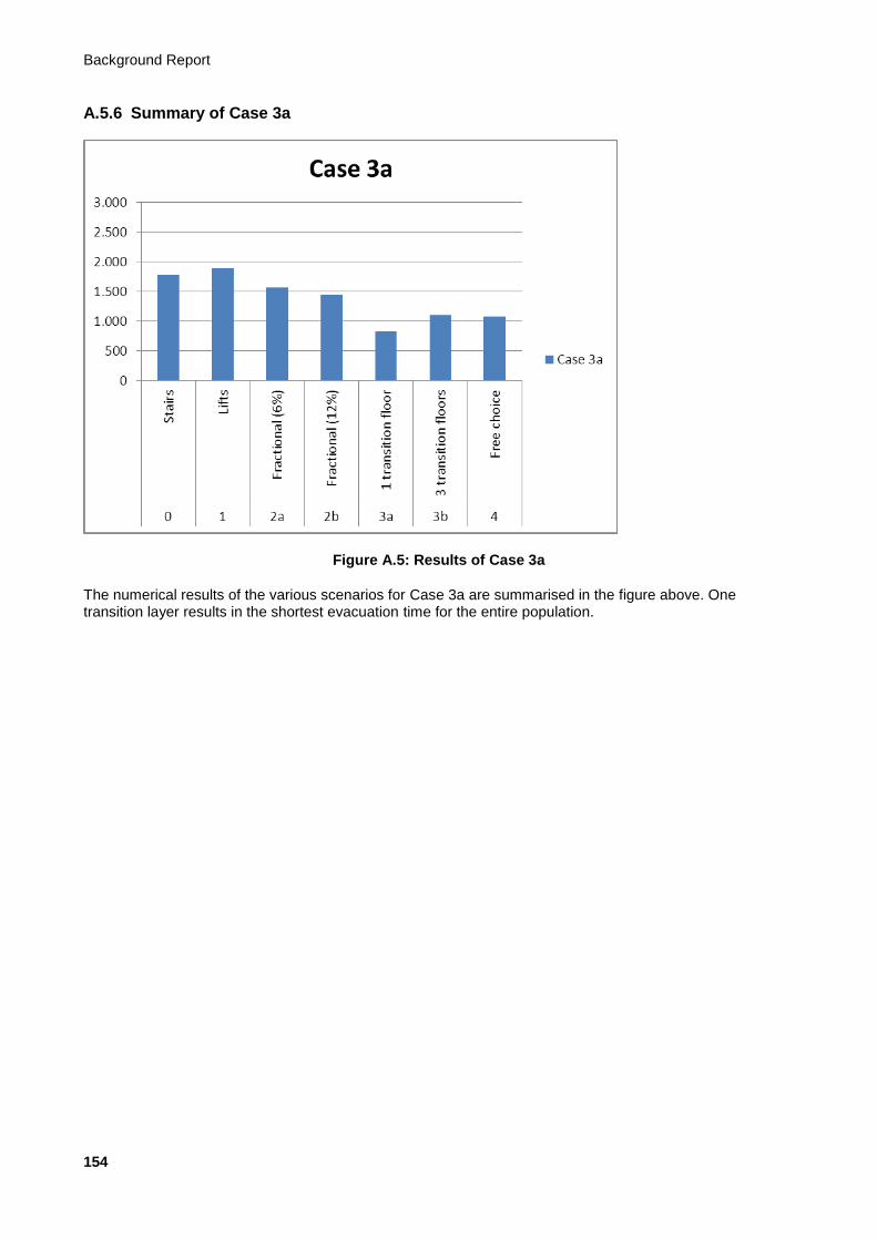
Background Report
154
A.5.6 Summary of Case 3a
Figure A.5: Results of Case 3a
The numerical results of the various scenarios for Case 3a are summarised in the figure above. One transition layer results in the shortest evacuation time for the entire population.
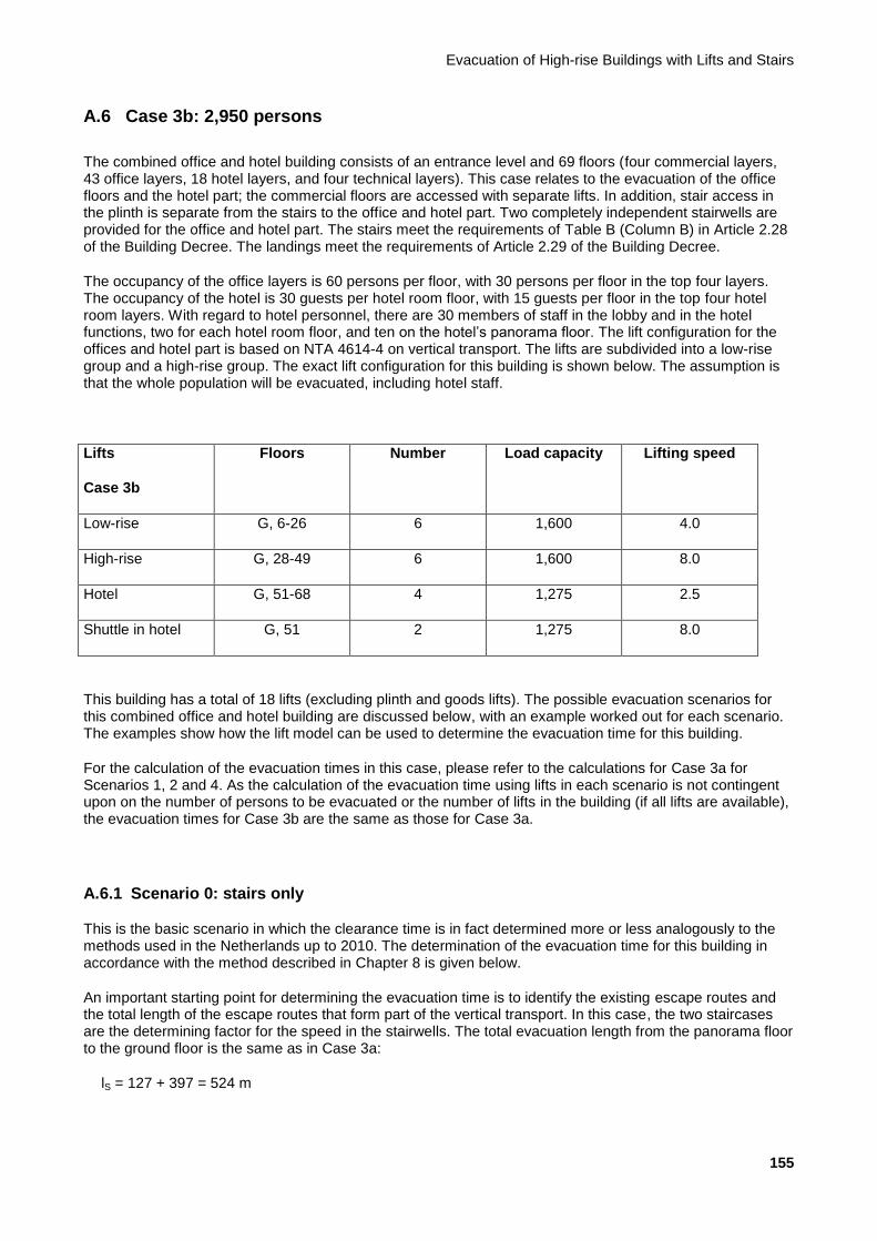
Evacuation of High-rise Buildings with Lifts and Stairs
155
A.6 Case 3b: 2,950 persons
The combined office and hotel building consists of an entrance level and 69 floors (four commercial layers, 43 office layers, 18 hotel layers, and four technical layers). This case relates to the evacuation of the office floors and the hotel part; the commercial floors are accessed with separate lifts. In addition, stair access in the plinth is separate from the stairs to the office and hotel part. Two completely independent stairwells are provided for the office and hotel part. The stairs meet the requirements of Table B (Column B) in Article 2.28 of the Building Decree. The landings meet the requirements of Article 2.29 of the Building Decree.
The occupancy of the office layers is 60 persons per floor, with 30 persons per floor in the top four layers. The occupancy of the hotel is 30 guests per hotel room floor, with 15 guests per floor in the top four hotel room layers. With regard to hotel personnel, there are 30 members of staff in the lobby and in the hotel functions, two for each hotel room floor, and ten on the hotel’s panorama floor. The lift configuration for the offices and hotel part is based on NTA 4614-4 on vertical transport. The lifts are subdivided into a low-rise group and a high-rise group. The exact lift configuration for this building is shown below. The assumption is that the whole population will be evacuated, including hotel staff.
Lifts
Case 3b
Floors Number Load capacity Lifting speed
Low-rise G, 6-26 6 1,600 4.0
High-rise G, 28-49 6 1,600 8.0
Hotel G, 51-68 4 1,275 2.5
Shuttle in hotel G, 51 2 1,275 8.0
This building has a total of 18 lifts (excluding plinth and goods lifts). The possible evacuation scenarios for this combined office and hotel building are discussed below, with an example worked out for each scenario. The examples show how the lift model can be used to determine the evacuation time for this building.
For the calculation of the evacuation times in this case, please refer to the calculations for Case 3a for Scenarios 1, 2 and 4. As the calculation of the evacuation time using lifts in each scenario is not contingent upon on the number of persons to be evacuated or the number of lifts in the building (if all lifts are available), the evacuation times for Case 3b are the same as those for Case 3a.
A.6.1 Scenario 0: stairs only
This is the basic scenario in which the clearance time is in fact determined more or less analogously to the methods used in the Netherlands up to 2010. The determination of the evacuation time for this building in accordance with the method described in Chapter 8 is given below.
An important starting point for determining the evacuation time is to identify the existing escape routes and the total length of the escape routes that form part of the vertical transport. In this case, the two staircases are the determining factor for the speed in the stairwells. The total evacuation length from the panorama floor to the ground floor is the same as in Case 3a:
lS = 127 + 397 = 524 m

Background Report
156
Depending on any transfers between one stairwell and another, there may also be horizontal movement. This must be dealt with separately because the walking speed on a horizontal floor is different from the walking speed on stairs.
The easiest way to establish the evacuation time is by determining it both for free circulation and for use of the maximum stair capacity. The slower of the two is the situation that occurs.
A.6.1.1 Situation with free circulation
The following formula applies to the situation with free circulation:
Tevac,S,fc = lS / vS(t)
With free circulation, the time required to move through the stairwell has already been calculated in Case 3a; it is therefore once again 756 seconds (12:36 minutes).
A.6.1.2 Situation with maximum capacity
The following formula applies to the situation with maximum capacity of the stairs:
Tevac,S,mc = (N x Pevac) / (CS(t) x We)
Based on the discrete factors for fatigue and risk of blockage, the capacity drops every 5 minutes in this case too. See Section 8.1 for the values of these factors. For the maximum capacity of the stairs, the total number of persons per floor relying on the stairs is a major determinant of the descent time per floor. In the situation under consideration here, occupancy of the top five layers is lower than the standard occupancy. The speed of escape from these five floors will therefore differ from that of the other floors. There is also a clear difference between the occupancy of the hotel and the office part. Ultimately, the speed of the users of the top floors will become the same as the speed of users on the lower floors. The easiest way to determine the evacuation time is therefore in two stages.
A.6.1.2.1 Determination of time to top of plinth
The simplest way of ascertaining when the last person will arrive at the top of the plinth (one layer below the office part of the building) is to change the formula to:
N x Pevac = Tevac,S,mc x (CS(t) x We)
The total number of people is 2,950 (10 + 4 x 17 + 11 x 32 + 2 x 30 + 4 x 30 + 39 x 60).
In the first 5 minutes, no more than the following number of persons will be evacuated over two staircases in accordance with Tevac,S,mc x CS(t) x We = 300 x 1.28 x 0.8 x 2 = 614 persons. Therefore, not everyone will have evacuated after 5 minutes.
In the second 5 minutes, no more than the following number of persons will be evacuated over two staircases in accordance with Tevac,S,mc x CS(t) x We = 300 x (1.28 x 0.9 x 0.9) x 0.8 x 2 = 498 persons. Counting the 614 persons from the first 5 minutes, this amounts to a total of 1,112 persons. Not all users will therefore have arrived at the top of the plinth after 10 minutes.
In the third 5 minutes, no more than the following number of persons will be evacuated over two staircases in accordance with Tevac,S,mc x CS(t) x We = 300 x (1.28 x 0.8 x 0.9) x 0.8 x 2 = 442 persons. Counting the 1,112 persons from the first 10 minutes, this amounts to a total of 1,554 persons. Not all users will therefore have arrived at the top of the plinth after 15 minutes.
In the fourth 5 minutes, no more than the following number of persons will be evacuated over two staircases in accordance with Tevac,S,mc x CS(t) x We = 300 x (1.28 x 0.7 x 0.8) x 0.8 x 2 = 344 persons. Counting the 1,554 persons from the first 15 minutes, this amounts to a total of 1,898 persons. Not all users will therefore have arrived at the top of the plinth even after 20 minutes.
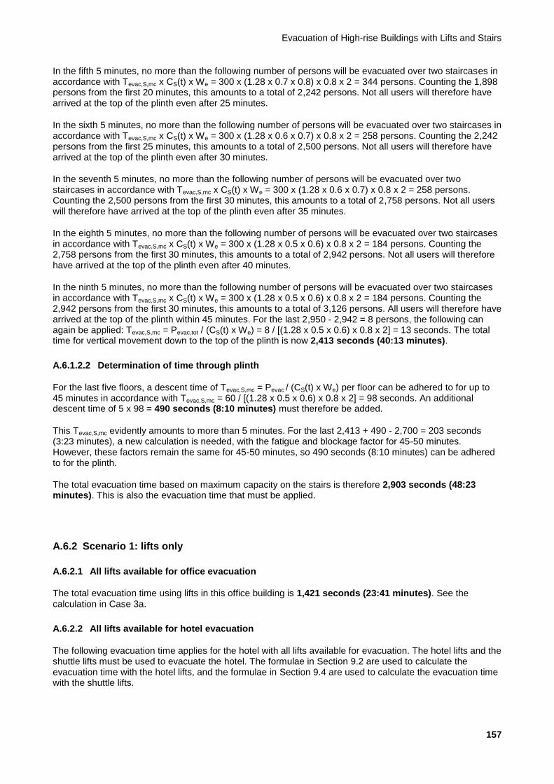
Evacuation of High-rise Buildings with Lifts and Stairs
157
In the fifth 5 minutes, no more than the following number of persons will be evacuated over two staircases in accordance with Tevac,S,mc x CS(t) x We = 300 x (1.28 x 0.7 x 0.8) x 0.8 x 2 = 344 persons. Counting the 1,898 persons from the first 20 minutes, this amounts to a total of 2,242 persons. Not all users will therefore have arrived at the top of the plinth even after 25 minutes.
In the sixth 5 minutes, no more than the following number of persons will be evacuated over two staircases in accordance with Tevac,S,mc x CS(t) x We = 300 x (1.28 x 0.6 x 0.7) x 0.8 x 2 = 258 persons. Counting the 2,242 persons from the first 25 minutes, this amounts to a total of 2,500 persons. Not all users will therefore have arrived at the top of the plinth even after 30 minutes.
In the seventh 5 minutes, no more than the following number of persons will be evacuated over two staircases in accordance with Tevac,S,mc x CS(t) x We = 300 x (1.28 x 0.6 x 0.7) x 0.8 x 2 = 258 persons. Counting the 2,500 persons from the first 30 minutes, this amounts to a total of 2,758 persons. Not all users will therefore have arrived at the top of the plinth even after 35 minutes.
In the eighth 5 minutes, no more than the following number of persons will be evacuated over two staircases in accordance with Tevac,S,mc x CS(t) x We = 300 x (1.28 x 0.5 x 0.6) x 0.8 x 2 = 184 persons. Counting the 2,758 persons from the first 30 minutes, this amounts to a total of 2,942 persons. Not all users will therefore have arrived at the top of the plinth even after 40 minutes.
In the ninth 5 minutes, no more than the following number of persons will be evacuated over two staircases in accordance with Tevac,S,mc x CS(t) x We = 300 x (1.28 x 0.5 x 0.6) x 0.8 x 2 = 184 persons. Counting the 2,942 persons from the first 30 minutes, this amounts to a total of 3,126 persons. All users will therefore have arrived at the top of the plinth within 45 minutes. For the last 2,950 - 2,942 = 8 persons, the following can again be applied: Tevac,S,mc = Pevac,tot / (CS(t) x We) = 8 / [(1.28 x 0.5 x 0.6) x 0.8 x 2] = 13 seconds. The total time for vertical movement down to the top of the plinth is now 2,413 seconds (40:13 minutes).
A.6.1.2.2 Determination of time through plinth
For the last five floors, a descent time of Tevac,S,mc = Pevac / (CS(t) x We) per floor can be adhered to for up to 45 minutes in accordance with Tevac,S,mc = 60 / [(1.28 x 0.5 x 0.6) x 0.8 x 2] = 98 seconds. An additional descent time of 5 x 98 = 490 seconds (8:10 minutes) must therefore be added.
This Tevac,S,mc evidently amounts to more than 5 minutes. For the last 2,413 + 490 - 2,700 = 203 seconds (3:23 minutes), a new calculation is needed, with the fatigue and blockage factor for 45-50 minutes. However, these factors remain the same for 45-50 minutes, so 490 seconds (8:10 minutes) can be adhered to for the plinth.
The total evacuation time based on maximum capacity on the stairs is therefore 2,903 seconds (48:23 minutes). This is also the evacuation time that must be applied.
A.6.2 Scenario 1: lifts only
A.6.2.1 All lifts available for office evacuation
The total evacuation time using lifts in this office building is 1,421 seconds (23:41 minutes). See the calculation in Case 3a.
A.6.2.2 All lifts available for hotel evacuation
The following evacuation time applies for the hotel with all lifts available for evacuation. The hotel lifts and the shuttle lifts must be used to evacuate the hotel. The formulae in Section 9.2 are used to calculate the evacuation time with the hotel lifts, and the formulae in Section 9.4 are used to calculate the evacuation time with the shuttle lifts.
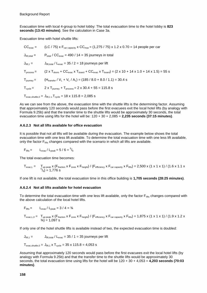
Background Report
158
Evacuation time with local 4-group to hotel lobby: The total evacuation time to the hotel lobby is 823 seconds (13:43 minutes). See the calculation in Case 3a.
Evacuation time with hotel shuttle lifts:
CCevac = (LC / 75) x Fcar capacity x CCmax = (1,275 / 75) x 1.2 x 0.70 = 14 people per car
Jlift,total = Ptotal / CCevac = 490 / 14 = 35 journeys in total
Jlift,1 = Jlift,total / Levac = 35 / 2 = 18 journeys per lift
Tprocess = (2 x Tdoors + CCevac x Tboard + CCevac x Tboard) = (2 x 10 + 14 x 1.0 + 14 x 1.5) = 55 s
Tjourney = (Htransfer / VL + VL / AL) = (185 / 8.0 + 8.0 / 1.1) = 30.4 s
Tcycle = 2 x Tjourney + Tprocess = 2 x 30.4 + 55 = 115.8 s
Tevac,shuttle,0 = Jlift,1 x Tcycle = 18 x 115.8 = 2,085 s
As we can see from the above, the evacuation time with the shuttle lifts is the determining factor. Assuming that approximately 120 seconds would pass before the first evacuees exit the local hotel lifts (by analogy with Formula 9.25b) and that the transfer time to the shuttle lifts would be approximately 30 seconds, the total evacuation time using lifts for the hotel will be: 120 + 30 + 2,085 = 2,235 seconds (37:15 minutes).
A.6.2.3 Not all lifts available for office evacuation
It is possible that not all lifts will be available during the evacuation. The example below shows the total evacuation time with one less lift available. To determine the total evacuation time with one less lift available, only the factor Flifts changes compared with the scenario in which all lifts are available.
Flifts = Levac / Lpeak = 5 / 6 = 5/6
The total evacuation time becomes:
Tevac,L = Tup-peak x (Ffraction x Fzone x Fheight) / (Fefficiency x Fcar capacity x Flifts) = 2,500 x (1 x 1 x 1) / (1.6 x 1.1 x 5/6) = 1,776 s
If one lift is not available, the total evacuation time in this office building is 1,705 seconds (28:25 minutes).
A.6.2.4 Not all lifts available for hotel evacuation
To determine the total evacuation time with one less lift available, only the factor Flifts changes compared with the above calculation of the local hotel lifts.
Flifts = Levac / Lpeak = 3 / 4 = ¾
Tevac,L,0 = Tup-peak x (Ffraction x Fzone x Fheight) / (Fefficiency x Fcar capacity x Flifts) = 1,875 x (1 x 1 x 1) / (1.9 x 1.2 x ¾) = 1,097 s
If only one of the hotel shuttle lifts is available instead of two, the expected evacuation time is doubled:
Jlift,1 = Jlift,total / Levac = 35 / 1 = 35 journeys per lift
Tevac,shuttle,0 = Jlift,1 x Tcycle = 35 x 115.8 = 4,053 s
Assuming that approximately 120 seconds would pass before the first evacuees exit the local hotel lifts (by analogy with Formula 9.25b) and that the transfer time to the shuttle lifts would be approximately 30 seconds, the total evacuation time using lifts for the hotel will be 120 + 30 + 4,053 = 4,203 seconds (70:03 minutes).

Evacuation of High-rise Buildings with Lifts and Stairs
159
A.6.3 Scenario 2: fractional evacuation with lifts
This scenario describes the situation in which the bulk of the building population actually leaves the building in accordance with Scenario 0 (stairs only). To calculate the evacuation time with this scenario, the formulae described in Section 9.2 are used, just as in Scenario 2. Any mobility-impaired people are evacuated by lift, possibly with assistance. For fractional evacuation, this example assumes that 6% and 12% of the population of the office building is evacuated with lifts. For the hotel, we assume that 18% of the population is evacuated with lifts. Only the factor Ffraction changes compared with the calculation of the evacuation time in Scenario 1. For the calculation of the evacuation time with the shuttle lifts, the number of persons to be evacuated changes.
A.6.3.1 Fractional evacuation, office
A.6.3.1.1 Evacuation time via stairs
6% with lifts (18% in the hotel part):
NB: For fractional evacuation, the calculations for the hotel and office parts do not have to be performed separately. The calculation is the same as in Scenario 0, the difference being that not all of the population is evacuated via the stairs in this case.
If 6% of the population is evacuated with lifts, 94% has to be evacuated via the stairs. Tevac,S,fc always remains the same as it is solely contingent upon the distance to be travelled. Even if fewer people evacuate via the stairs, the evacuation time with free circulation is 756 seconds (12:36 minutes) for this case.
However, the number of people evacuated drops if the stairs are full to capacity. For the hotel part, 18% of the population takes the lift. With an original hotel population of 490 (10 + 4 x 17 + 11 x 32 + 2 x 30). The population to be evacuated now becomes 490 x 0.82 = 402 persons. The original office population is 2,460 (4 x 30 + 39 x 60). The total population to be evacuated via the stairs is therefore 402 + 2,460 x 0.94 = 2,714 persons.
As we can see in the calculation for Scenario 0, 2,500 persons arrive at the top of the plinth functions in 30 minutes. For the last 2,714 - 2,500 = 214 persons, the following can again be applied:
Tevac,S,mc = Pevac,tot / (CS(t) x We) = 214 / [(1.28 x 0.6 x 0.7) x 0.8 x 2] = 249 s
The total time for vertical movement down to the top of the plinth is now 2,049 seconds (34:09 minutes).
For the last five layers, a descent time of Tevac,S,mc = Pevac / (CS(t) x We) per floor can be adhered to for up to 35 minutes in accordance with Tevac,S,mc = 60 / [(1.28 x 0.6 x 0.7) x 0.8 x 2] = 70 seconds. Thereafter (35-40 minutes), the evacuation time per floor is Tevac,S,mc = 60 / [(1.28 x 0.5 x 0.6) x 0.8 x 2] = 98 seconds. Thereafter (40-45 minutes), the evacuation time per floor is Tevac,S,mc = 60 / [(1.28 x 0.5 x 0.6) x 0.8 x 2] = 98 seconds. 2,100 - 2,049 = 51 seconds. In 51 seconds, it is possible to descend 51 / 70 = 0.73 floors. In the 35
th to 40
th minutes, it is possible to descend 300 / 98 = 3.06 floors. An additional descent time of 0.73 x 70 +
3.06 x 98 + 1.21 x 98 = 470 seconds must therefore be added.
The total evacuation time based on maximum capacity on the stairs is therefore 2,049 + 470 = 2,519 seconds (41:59 minutes). This is also the evacuation time that must be applied.
12% with lifts (18% in the hotel part):
Even if 12% of the population is evacuated with lifts, Tevac,S,fc = 756 seconds (12:36 minutes) for this case.
However, the number of people evacuated drops if the stairs are full to capacity. For the hotel part, 18% of the population takes the lift. Of the original hotel population (490), 402 people take the stairs. The original office population is 2,460. The total population to be evacuated via the stairs is therefore 402 + 2,460 x 0.88 = 2,567 persons.

Background Report
160
As we can see in the calculation for Scenario 0, 2,500 persons arrive at the top of the plinth functions in 30 minutes. For the last 2,567 - 2,500 = 67 persons, the following can again be applied:
Tevac,S,mc = Pevac,tot / (CS(t) x We) = 67 / [(1.28 x 0.6 x 0.7) x 0.8 x 2] = 78 s
The total time for vertical movement down to the top of the plinth is now 1,878 seconds (31:18 minutes).
For the last five layers, a descent time of Tevac,S,mc = Pevac / (CS(t) x We) per floor can be adhered to for
up to 35 minutes in accordance with Tevac,S,mc = 60 / [(1.28 x 0.6 x 0.7) x 0.8 x 2] = 70 seconds.
Thereafter (35-40 minutes), the evacuation time per floor is Tevac,S,mc = 60 / [(1.28 x 0.5 x 0.6) x 0.8 x
2] = 98 seconds. Thereafter (40-45 minutes), the evacuation time per floor is Tevac,S,mc = 60 / [(1.28 x
0.5 x 0.6) x 0.8 x 2] = 98 seconds. 2,100 - 1,878 = 222 seconds. In 222 seconds, it is possible to
descend 222 / 70 = 3.17 floors. An additional descent time of 3.17 x 70 + 1.71 x 98 = 390 seconds
must therefore be added. The total evacuation time based on maximum capacity on the stairs is
therefore 1,878 + 390 = 2,268 seconds (37:48 minutes). This evacuation time is higher than the
evacuation time with free circulation (12:33 minutes) and is therefore the determining factor.
The total evacuation time based on maximum capacity on the stairs is therefore 1,878 + 398 = 2,276 seconds (37:56 minutes). This evacuation time is higher than the evacuation time with free circulation (12:33 minutes) and is therefore the determining factor.
A.6.3.1.2 Evacuation time using lifts
The total evacuation time using lifts for this office building with 6% fractional evacuation is 219 seconds (3:39 minutes). See the calculation in Case 3a.
The total evacuation time using lifts for this office building with 12% fractional evacuation is 296 seconds (4:56 minutes). See the calculation in Case 3a.
A.6.3.2 Fractional evacuation, hotel
A.6.3.2.1 Evacuation time using lifts
The total evacuation time using lifts for the local hotel lifts with 18% fractional evacuation is 215 seconds (3:35 minutes). See the calculation in Case 3a.
The following applies for shuttle lifts:
Jlift,total = Ptotal / CCevac = (0.18 x 490) / 14 = 74 / 14 = 7 journeys in total
Jlift,1 = Jlift,total / Levac = 7 / 2 = 4 journeys per lift
Tprocess = (2 x Tdoors + CCevac x Tboard + CCevac x Tboard) = (2 x 10 + 14 x 1.0 + 14 x 1.5) = 55 s
Tjourney = (Htransfer / VL + VL / AL) = (185 / 8.0 + 8.0 / 1.1) = 30.4 s
Tcycle = 2 x Tjourney + Tprocess = 2 x 30.4 + 55 = 115.8 s
Tevac,shuttle,0 = Jlift,1 x Tcycle = 4 x 115.8 = 464 s
Assuming that approximately 120 seconds would pass before the first evacuees exit the local hotel lifts (by analogy with Formula 9.25b) and that the transfer time to the shuttle lifts would be approximately 30 seconds, the total evacuation time using lifts for the hotel will be: 120 + 30 + 464 seconds = 614 seconds (10:14 minutes).
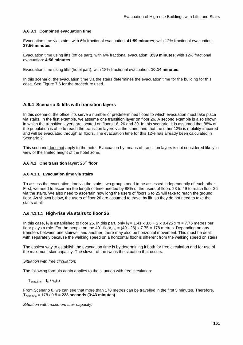
Evacuation of High-rise Buildings with Lifts and Stairs
161
A.6.3.3 Combined evacuation time
Evacuation time via stairs, with 6% fractional evacuation: 41:59 minutes; with 12% fractional evacuation: 37:56 minutes.
Evacuation time using lifts (office part), with 6% fractional evacuation: 3:39 minutes; with 12% fractional evacuation: 4:56 minutes.
Evacuation time using lifts (hotel part), with 18% fractional evacuation: 10:14 minutes.
In this scenario, the evacuation time via the stairs determines the evacuation time for the building for this case. See Figure 7.6 for the procedure used.
A.6.4 Scenario 3: lifts with transition layers
In this scenario, the office lifts serve a number of predetermined floors to which evacuation must take place via stairs. In the first example, we assume one transition layer on floor 26. A second example is also shown in which the transition layers are located on floors 16, 26 and 39. In this scenario, it is assumed that 88% of the population is able to reach the transition layers via the stairs, and that the other 12% is mobility-impaired and will be evacuated through all floors. The evacuation time for this 12% has already been calculated in Scenario 2.
This scenario does not apply to the hotel. Evacuation by means of transition layers is not considered likely in view of the limited height of the hotel zone.
A.6.4.1 One transition layer: 26th
floor
A.6.4.1.1 Evacuation time via stairs
To assess the evacuation time via the stairs, two groups need to be assessed independently of each other. First, we need to ascertain the length of time needed by 88% of the users of floors 28 to 49 to reach floor 26 via the stairs. We also need to ascertain how long the users of floors 6 to 25 will take to reach the ground floor. As shown below, the users of floor 26 are assumed to travel by lift, so they do not need to take the stairs at all.
A.6.4.1.1.1 High-rise via stairs to floor 26
In this case, lS is established to floor 26. In this part, only lS = 1.41 x 3.6 + 2 x 0.425 x π = 7.75 metres per floor plays a role. For the people on the 49
th floor, lS = (49 - 26) x 7.75 = 178 metres. Depending on any
transfers between one stairwell and another, there may also be horizontal movement. This must be dealt with separately because the walking speed on a horizontal floor is different from the walking speed on stairs.
The easiest way to establish the evacuation time is by determining it both for free circulation and for use of the maximum stair capacity. The slower of the two is the situation that occurs.
Situation with free circulation:
The following formula again applies to the situation with free circulation:
Tevac,S,fc = lS / vS(t)
From Scenario 0, we can see that more than 178 metres can be travelled in the first 5 minutes. Therefore, Tevac,S,fc = 178 / 0.8 = 223 seconds (3:43 minutes).
Situation with maximum stair capacity:
Background Report
162
From this zone of the building, (18 x 60 + 4 x 30) x 88% = 1,056 persons need to be ‘conveyed’ to the appropriate transition layer via the stairs. By analogy to Scenario 0, we first determine how much time it takes for everyone to pass through floor 28 (therefore arriving at floor 27).
In the first 5 minutes, no more than the following number of persons will be evacuated over two staircases in accordance with Tevac,S,mc x CS(t) x We = 300 x 1.28 x 0.8 x 2 = 614 persons. Therefore, not everyone will have arrived at floor level on floor 28 after 5 minutes.
For the last 1,056 - 614 = 442 persons, the following can again be applied:
Tevac,S,mc = Pevac,tot / (CS(t) x We) = 442 / [(1.28 x 0.9 x 0.9) x 0.8 x 2] = 266 s
The total time for vertical movement down to floor level on floor 28 is now 566 seconds (9:26 minutes).
For the last level (from 27 to 26), a descent time of Tevac,S,mc = Pevac / (CS(t) x We) per floor can be adhered to for up to 10 minutes in accordance with Tevac,S,mc = 60 / [(1.28 x 0.9 x 0.9) x 0.8 x 2] = 36 seconds. Thereafter, the evacuation time per floor is Tevac,S,mc = 60 / [(1.28 x 0.8 x 0.9) x 0.8 x 2] = 41 seconds. 600 - 566 = 34 seconds. In 34 seconds, it is possible to descend 34 / 36 = 0.94 floors. An additional descent time of 0.94 x 36 + 0.06 x 41 = 36 seconds must therefore be added. The total descent time based on maximum capacity on the stairs is therefore 602 seconds (10:02 minutes).
A.6.4.1.1.2 Low-rise by stairs to the ground floor
In this case, first lS is established from floor 25 to the ground floor. For the people on the 25th floor, lS = 24 x
7.75 + 9.72 = 196 metres. Depending on any transfers between one stairwell and another, there may also be horizontal movement. This must be dealt with separately because the walking speed on a horizontal floor is different from the walking speed on stairs.
The easiest way to establish the evacuation time is by determining it both for free circulation and for use of the maximum stair capacity. The slower of the two is the situation that occurs.
Situation with free circulation:
The following formula again applies to the situation with free circulation:
Tevac,S,fc = lS / vS(t)
From Scenario 0, we can see that more than 196 metres can be travelled in the first 5 minutes. Therefore, Tevac,S,fc = 196 / 0.8 = 245 seconds (4:05 minutes).
Situation with maximum stair capacity:
From this zone of the building, (20 x 60) x 88% = 1,056 persons need to be ‘conveyed’ to the appropriate transition layer via the stairs. By analogy to Scenario 0, we first determine how much time it takes for everyone to arrive at the top of the plinth functions. In the first 5 minutes, no more than the following number of persons will be evacuated over two staircases in accordance with Tevac,S,mc x CS(t) x We = 300 x 1.28 x 0.8 x 2 = 614 persons. Therefore, not everyone will have arrived at the top of the plinth after 5 minutes.
For the last 1,056 - 614 = 442 persons, the following can again be applied:
Tevac,S,mc = Pevac,tot / (CS(t) x We) = 442 / [(1.28 x 0.9 x 0.9) x 0.8 x 2] = 266 s
The total time for vertical movement down to the plinth floor is now 566 seconds (9:26 minutes).
For the last five floors, a descent time of Tevac,S,mc = Pevac / (CS(t) x We) per floor can be adhered to for up to 10 minutes in accordance with Tevac,S,mc = 60 / [(1.28 x 0.9 x 0.9) x 0.8 x 2] = 36 seconds. Thereafter, the evacuation time per floor is Tevac,S,mc = 60 / [(1.28 x 0.8 x 0.9) x 0.8 x 2] = 41 seconds. 600 - 566 = 34 seconds. In 34 seconds, it is possible to descend 34 / 36 = 0.94 floors. An additional descent time of 0.94 x
Evacuation of High-rise Buildings with Lifts and Stairs
163
36 + 4.06 x 41 = 200 seconds must therefore be added. The total descent time based on maximum capacity on the stairs is therefore 766 seconds (12:46 minutes).
A.6.4.1.2 Evacuation time using lifts
To calculate the evacuation time with Scenario 3 with one transition layer, the formulae described in Section 9.4 are used. In this scenario with one transition layer, it is assumed that all 10 lifts can be used to evacuate from this floor. The number of persons evacuated from this floor is 88% of the population of floors 26 to 49. To calculate the evacuation time with one transition layer (floor 26), the following applies:
CCevac = (LC / 75) x Fcar capacity x CCmax = (1,600/75) x 1.1 x 0.8 = 18 people per car
Jlift,total = Ptotal / CCevac = 1,109 / 18 = 62 journeys in total
Jlift,1 = Jlift,total / Levac = 62 / 12 = 6 journeys per lift
Tprocess = (2 x Tdoors + CCevac x Tboard + CCevac x Tboard) = (2 x 10 + 18 x 1.0 + 18 x 1.5 ) = 65 s
Tjourney = (Htransfer / VL + VL / AL) = (95 / 6.0 + 6.0 / 1.1) = 21.3 s
Tcycle = 2 x Tjourney + Tprocess = 2 x 21.3 + 65 = 107.6 s
Tevac,shuttle,0 = Jlift,1 x Tcycle = 6 x 107.6 = 646 s
The total evacuation time for this office building with transition layer 26 and 12% fractional evacuation is 646 + 296 = 942 seconds (15:42 minutes).
A.6.4.1.3 Combined evacuation time
After 602 seconds (10:02 minutes), 1,056 people will have arrived at floor 26. Evacuation with the lifts starts after 296 seconds (4:55 minutes) here. Thereafter, the time needed to remove everyone is 646 seconds (10:46 minutes). This means that in 10:02 minutes, (602 - 296) / 646 x (1,056 + 0.88 x 60) = 307 / 646 x 1,109 = 527 people are evacuated by lift. There are therefore 1,109 - 527 = 582 people still present on the floor at the same time. They can choose to continue via the stairs; however, because this scenario aims to transport everyone in the lift from this point, refuge must be arranged for these people. Assuming no more than 3.5 persons per m² (see also Section 11.2), this results in a physical area of approximately 167 m². This area must also meet the general requirements specified in Chapter 11.
Evacuation time via stairs for floors 49-26: 10:02 minutes; for floors 25-G: 12:46 minutes.
Evacuation time using lifts (floor 26): 15:42 minutes.
As can be seen in the diagram in Figure 7.6, the evacuation time is equal to Tevac,S,lift = 15:42 minutes.
A.6.4.2 Three transition layers: floors 16, 26 and 39 (six lifts for floors 16 and 26; six lifts for floor 39)
A.6.4.2.1 Evacuation time via stairs
To assess the evacuation time via the stairs, four groups must be assessed independently of each other. First, we need to ascertain the length of time needed by 88% of the users of floors 40 to 49 to reach floor 39 via the stairs. We also need to ascertain how long the users of floors 28 to 38 will take to reach floor 26, how long the users of floors 17 to 25 will take to reach floor 16, and, finally, how long the users of floors 6 to 15 will take to reach the ground floor. As shown below, the users of floors 16, 26 and 39 are assumed to travel by lift, so they do not need to take the stairs at all.
Background Report
164
A.6.4.2.1.1 By stairs to floor 39
In this case, first lS is established to floor 39. In this part, only lS = 1.41 x 3.6 + 2 x 0.425 x π = 7.75 metres per floor plays a role. For the people on the 49
th floor, lS = (49 - 39) x 7.75 = 77.5 metres.
Situation with free circulation:
The following formula again applies to the situation with free circulation:
Tevac,S,fc = lS / vS(t)
From Scenario 0, we can see that more than 77.5 metres can be travelled in the first 5 minutes. Therefore, Tevac,S,fc = 77.5 / 0.8 = 97 seconds (1:37 minutes).
Situation with maximum stair capacity:
From this zone of the building, (6 x 60 + 4 x 30) x 88% = 422 persons need to be ‘conveyed’ to the appropriate transition layer via the stairs. These people can easily be ‘processed’ within 5 minutes. So the following can be applied:
Tevac,S,mc = Pevac,tot / (CS(t) x We) = 422 / (1.28 x 0.8 x 2) = 206 s
The total time for vertical movement down to floor level on floor 39 is now 206 seconds (3:26 minutes).
A.6.4.2.1.2 By stairs to floor 26
In this case, lS is established to floor 26. In this part, only lS = 1.41 x 3.6 + 2 x 0.425 x π = 7.75 metres per floor plays a role. For the people on the 38
th floor, lS = (38 - 26) x 7.75 = 93 metres.
Situation with free circulation:
The following formula again applies to the situation with free circulation:
Tevac,S,fc = lS / vS(t)
From Scenario 0, we can see that more than 93 metres can be travelled in the first 5 minutes. Therefore, Tevac,S,fc = 93 / 0.8 = 116 seconds (1:56 minutes).
Situation with maximum stair capacity:
From this zone of the building, (11 x 60) x 88% = 581 persons need to be ‘conveyed’ to the appropriate transition layer via the stairs. These persons are ‘processed’ within 5 minutes. So the following can be applied:
Tevac,S,mc = Pevac,tot / (CS(t) x We) = 581 / (1.28 x 0.8 x 2) = 284 s
The total time for vertical movement down to floor level on floor 27 is now 284 seconds (4:44 minutes).
For the last floor, a descent time of Tevac,S,mc = Pevac / (CS(t) x We) per floor can be adhered to for up to 5 minutes in accordance with Tevac,S,mc = 60 / (1.28 x 0.8 x 2) = 29 seconds. Thereafter, the evacuation time per floor is Tevac,S,mc = 60 / [(1.28 x 0.9 x 0.9) x 0.8 x 2] = 36 seconds. 300 - 284 = 16 seconds. In 16 seconds, it is possible to descend 16 / 29 = 0.55 floors. An additional descent time of 0.55 x 29 + 0.45 x 36 = 32 seconds must therefore be added. The total descent time based on maximum capacity on the stairs is therefore 316 seconds (5:16 minutes).

Evacuation of High-rise Buildings with Lifts and Stairs
165
A.6.4.2.1.3 By stairs to floor 16
In this case, first lS is established to floor 16. In this part, only lS = 1.41 x 3.6 + 2 x 0.425 x π = 7.75 metres per floor plays a role. For the people on the 25
th floor, lS = (25 - 16) x 7.75 = 70 metres.
Situation with free circulation:
The following formula again applies to the situation with free circulation:
Tevac,S,fc = lS / vS(t)
From Scenario 0, we can see that more than 70 metres can be travelled in the first 5 minutes. Therefore, Tevac,S,fc = 70 / 0.8 = 88 seconds (1:28 minutes).
Situation with maximum stair capacity:
From this zone of the building, (9 x 60) x 88% = 475 persons need to be ‘conveyed’ to the appropriate transition layer via the stairs. These people can easily be ‘processed’ within 5 minutes. So the following can be applied:
Tevac,S,mc = Pevac,tot / (CS(t) x We) = 475 / (1.28 x 0.8 x 2) = 232 s
The total time for vertical movement down to floor level on floor 16 is now 232 seconds (3:52 minutes).
A.6.4.2.1.4 By stairs to the ground floor
In this case, first lS is established from floor 15 to the ground floor. For the people on the 15th floor, lS = 14 x
7.75 + 9.72 = 119 metres.
Situation with free circulation:
The following formula again applies to the situation with free circulation:
Tevac,S,fc = lS / vS(t)
From Scenario 0, we can see that more than 119 metres can be travelled in the first 5 minutes. Therefore, Tevac,S,fc = 119 / 0.8 = 149 seconds (2:29 minutes).
Situation with maximum stair capacity:
From this zone of the building, (10 x 60) x 88% = 528 persons need to be ‘conveyed’ to the ground floor via the stairs. These persons are ‘processed’ within 5 minutes. So the following can be applied:
Tevac,S,mc = Pevac,tot / (CS(t) x We) = 528 / (1.28 x 0.8 x 2) = 258 s
The total time for vertical movement down to floor level on floor 5 is now 258 seconds (4:18 minutes).
For the last five floors, a descent time of Tevac,S,mc = Pevac / (CS(t) x We) per floor can be adhered to for up to 5 minutes in accordance with Tevac,S,mc = 60 / (1.28 x 0.8 x 2) = 29 seconds. Thereafter, the time to be adhered to per floor is Tevac,S,mc = 60 / [(1.28 x 0.9 x 0.9) x 0.8 x 2) = 36 seconds. In 300 - 258 = 42 seconds, 42 / 29 = 1.45 floors can be descended. An additional descent time of 1.45 x 29 + 3.55 x 36 = 170 seconds must therefore be added. The total descent time based on maximum capacity on the stairs is therefore 428 seconds (7:08 minutes).
Background Report
166
A.6.4.2.2 Evacuation time using lifts
To calculate the evacuation time with Scenario 3 with multiple transition layers, the formulae described in Section 9.3 are used. In this scenario, the low-rise lifts are used to evacuate floors 16 and 26. The high-rise lifts evacuate on floor 39. 88% of all persons between floors 16 and 25 are evacuated from floor 16, 88% of persons between floors 26 and 38 are evacuated from floor 26, and 88% of persons between floors 39 and 49 are evacuated from floor 39. The 88% of the population below floor 16 uses the stairs. To calculate the evacuation time with transition layers 16 and 26, the following applies:
CCevac = (LC / 75) x Fcar capacity x CCmax = (1,600 / 75) x 1.1 x 0.8 = 18 people per car
Jlift,total = Ptotal / CCevac = (P1 + P2 + P3) / 18 = (634 + 528 + 0) / 18 = 65 journeys in total
Jlift,1 = Jlift,total / Levac = 65 / 6 = 11 journeys per lift
Tprocess = (2 x Tdoors + CCevac x Tboard + CCevac x Tboard) = (2 x 10 + 18 x 1.0 + 18 x 1.5 ) = 65 s
Hreversal = (H1 x P1 + H2 x P2 + H3 x P3) / (P1 + P2 + P3) = (95 x 634 + 59 x 528 + 0 x 0) / (720 + 600 + 0) = 78.6 m
Tjourney = (Hreversal / VL + VL / AL) = (78.6 / 4.0 + 4.0 / 1.1) = 23.3 s
Tcycle = 2 x Tjourney + Tprocess = 2 x 23.3 + 65 = 111.6 s
Tadditional = 1 x (VL / AL + Tdoors) = 1 x (4.0 / 1.1 + 10) = 13.6 s
Tevac,L,0 = Jlift,1 x Tcycle + Tadditional = 11 x 111.6 + 13.6 = 1,242 s
The evacuation time from floor 39 with the high-rise lifts can be calculated in the same manner. As there is one transition layer here, the factor Tadditional is not applied. The evacuation time for floor 39 becomes:
Tevac,L,0 = 575 s (9:35 min)
The total evacuation time using lifts, including the 12% fractional evacuation for this building, is max(1,242;575) + 296 = 1,538 seconds (25:38 minutes). Here, we have assumed that the high-rise lifts will be used for fractional evacuation of 12% of the population after having evacuated floor 39, so they will be finished after 575 + 296 = 871 seconds (14:31 minutes). If the high-rise lifts also have stops on the low-rise floors, the total evacuation time using lifts, including the 12% fractional evacuation for this building, is max(1,242;575 + 296 + 296) = max(1,242;1,167) = 1, 242 seconds (20:42 minutes). The effect of the higher lifting speed of the high-rise lifts is disregarded here for the sake of convenience.
A.6.4.3 Alternative 1: three transition layers: floors 16, 26 and 39 (seven lifts for floors 16 and 26; five lifts for floor 39)
A.6.4.3.1 Evacuation time via stairs
See Subsection A.6.4.2.1.
A.6.4.3.2 Evacuation time using lifts
However, the difference between the evacuation times of the low-rise and the high-rise floors is more than 11 minutes. With this outcome, one option is to use one lift in the high-rise group to evacuate floors 16 and 26. In this situation, seven lifts are used to evacuate floors 16 and 26, and five lifts to evacuate floor 39.
Compared with the above calculation with six lifts for floors 16 and 26, the following factors change:
Jlift,1 = Jlift,total / Levac = 65 / 7 = 10 journeys per lift
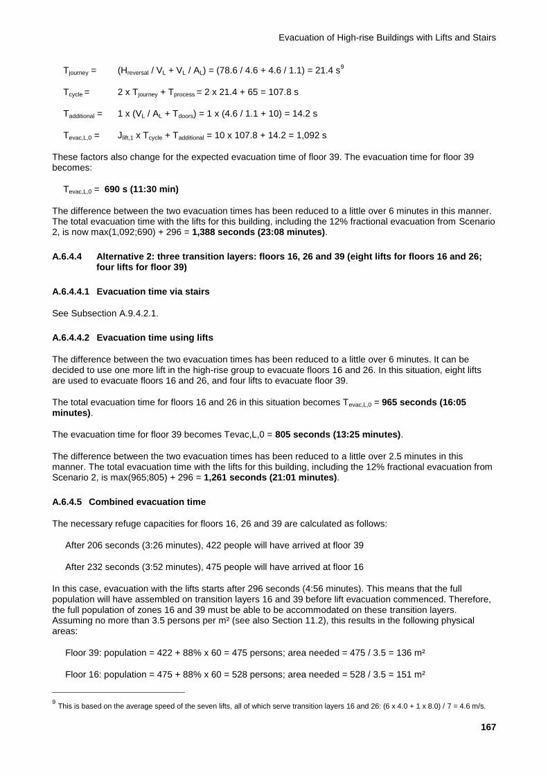
Evacuation of High-rise Buildings with Lifts and Stairs
167
Tjourney = (Hreversal / VL + VL / AL) = (78.6 / 4.6 + 4.6 / 1.1) = 21.4 s9
Tcycle = 2 x Tjourney + Tprocess = 2 x 21.4 + 65 = 107.8 s
Tadditional = 1 x (VL / AL + Tdoors) = 1 x (4.6 / 1.1 + 10) = 14.2 s
Tevac,L,0 = Jlift,1 x Tcycle + Tadditional = 10 x 107.8 + 14.2 = 1,092 s
These factors also change for the expected evacuation time of floor 39. The evacuation time for floor 39 becomes:
Tevac,L,0 = 690 s (11:30 min)
The difference between the two evacuation times has been reduced to a little over 6 minutes in this manner. The total evacuation time with the lifts for this building, including the 12% fractional evacuation from Scenario 2, is now max(1,092;690) + 296 = 1,388 seconds (23:08 minutes).
A.6.4.4 Alternative 2: three transition layers: floors 16, 26 and 39 (eight lifts for floors 16 and 26; four lifts for floor 39)
A.6.4.4.1 Evacuation time via stairs
See Subsection A.9.4.2.1.
A.6.4.4.2 Evacuation time using lifts
The difference between the two evacuation times has been reduced to a little over 6 minutes. It can be decided to use one more lift in the high-rise group to evacuate floors 16 and 26. In this situation, eight lifts are used to evacuate floors 16 and 26, and four lifts to evacuate floor 39.
The total evacuation time for floors 16 and 26 in this situation becomes Tevac,L,0 = 965 seconds (16:05 minutes).
The evacuation time for floor 39 becomes Tevac,L,0 = 805 seconds (13:25 minutes).
The difference between the two evacuation times has been reduced to a little over 2.5 minutes in this manner. The total evacuation time with the lifts for this building, including the 12% fractional evacuation from Scenario 2, is max(965;805) + 296 = 1,261 seconds (21:01 minutes).
A.6.4.5 Combined evacuation time
The necessary refuge capacities for floors 16, 26 and 39 are calculated as follows:
After 206 seconds (3:26 minutes), 422 people will have arrived at floor 39
After 232 seconds (3:52 minutes), 475 people will have arrived at floor 16
In this case, evacuation with the lifts starts after 296 seconds (4:56 minutes). This means that the full population will have assembled on transition layers 16 and 39 before lift evacuation commenced. Therefore, the full population of zones 16 and 39 must be able to be accommodated on these transition layers. Assuming no more than 3.5 persons per m² (see also Section 11.2), this results in the following physical areas:
Floor 39: population = 422 + 88% x 60 = 475 persons; area needed = 475 / 3.5 = 136 m²
Floor 16: population = 475 + 88% x 60 = 528 persons; area needed = 528 / 3.5 = 151 m²
9 This is based on the average speed of the seven lifts, all of which serve transition layers 16 and 26: (6 x 4.0 + 1 x 8.0) / 7 = 4.6 m/s.

Background Report
168
The following applies to floor 26: after 316 seconds (5:16 minutes), 581 people will have arrived at floor 26.
In this case, evacuation with the lifts starts after 296 seconds (4:56 minutes). Thereafter, the time needed to
remove everyone (in accordance with configuration 1) is 1,902 (18:12 minutes). This means that in 5:16
minutes, (316 - 296) / 1,092 x (581 + 0.88 x 60) = 20 / 1,092 x 634 = 12 people will have been evacuated by
lift. There are therefore 634 - 12 = 622 people still present on the floor at the same time. The area needed is
622 / 3.5 = 178 m².
Evacuation time via stairs for floors 49-39: 3:26 minutes; for floors 38-26: 5:16 minutes; for floors 25-16: 3:52 minutes; for floors 15-G: 7:08 minutes.
Evacuation time using lifts (combination; Alternative 2): 21:01 minutes.
As shown in the diagram in Figure 7.6, the evacuation time is equal to:
Lift alternative 1: Tevac,S,lift = 23:08 min
Lift alternative 2: Tevac,S,lift = 21:01 min
A.6.5 Scenario 4: free choice
In this scenario, both the stairs and the lifts are used to evacuate every floor. Users are always free to choose to use the lift or the stairs. In this example, it is assumed that 50% of the population will use the stairs and 50% the lift.
A.6.5.1 For the office lifts
A.6.5.1.1 Evacuation time via stairs
NB: The population of the entire building is taken into account for the evacuation time via the stairs (hotel and office part).
Here too, free circulation and maximum capacity are taken into consideration.
Situation with free circulation:
For the people on the 49th floor, lS = 48 x 7.75 + 9.72 = 382 metres (see calculation for Scenario 0). With free
circulation, the time required to move down the stairs is therefore 519 seconds (8:39 minutes).
For the people on the 51st floor (hotel lobby), lS = 50 x 7.75 + 9.72 = 397 metres. The total evacuation length
from the panorama floor to the ground floor is: lS = 127 + 397 = 524 metres. With free circulation, the time required to move down the stairs is therefore 756 seconds (12:36 minutes).
Situation with maximum capacity:
The total number of persons is 2,950. Of these, the population to be evacuated is 50% or 1,475 persons.
The following formula applies to the situation with maximum capacity of the stairs:
Tevac,S,mc= (N x Pevac) / (CS(t) x We)
In the first 5 minutes, no more than the following number of persons will be evacuated over two staircases in accordance with Tevac,S,mc x CS(t) x We = 300 x 1.28 x 0.8 x 2 = 614 persons. Therefore, not everyone will have evacuated after 5 minutes.
In the second 5 minutes, no more than the following number of persons will be evacuated over two staircases in accordance with Tevac,S,mc x CS(t) x We = 300 x (1.28 x 0.9 x 0.9) x 0.8 x 2 = 498 persons.
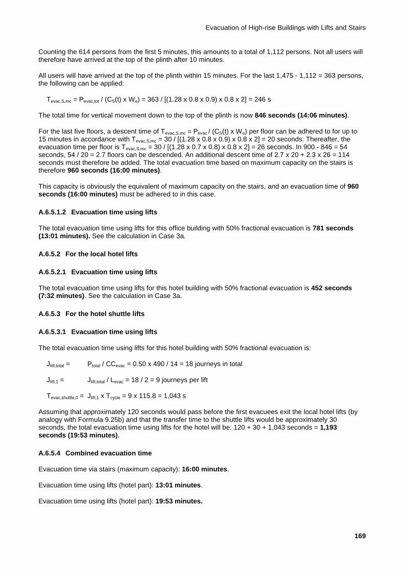
Evacuation of High-rise Buildings with Lifts and Stairs
169
Counting the 614 persons from the first 5 minutes, this amounts to a total of 1,112 persons. Not all users will therefore have arrived at the top of the plinth after 10 minutes.
All users will have arrived at the top of the plinth within 15 minutes. For the last 1,475 - 1,112 = 363 persons, the following can be applied:
Tevac,S,mc = Pevac,tot / (CS(t) x We) = 363 / [(1.28 x 0.8 x 0.9) x 0.8 x 2] = 246 s
The total time for vertical movement down to the top of the plinth is now 846 seconds (14:06 minutes).
For the last five floors, a descent time of Tevac,S,mc = Pevac / (CS(t) x We) per floor can be adhered to for up to 15 minutes in accordance with Tevac,S,mc = 30 / [(1.28 x 0.8 x 0.9) x 0.8 x 2] = 20 seconds. Thereafter, the evacuation time per floor is Tevac,S,mc = 30 / [(1.28 x 0.7 x 0.8) x 0.8 x 2] = 26 seconds. In 900 - 846 = 54 seconds, 54 / 20 = 2.7 floors can be descended. An additional descent time of 2.7 x 20 + 2.3 x 26 = 114 seconds must therefore be added. The total evacuation time based on maximum capacity on the stairs is therefore 960 seconds (16:00 minutes).
This capacity is obviously the equivalent of maximum capacity on the stairs, and an evacuation time of 960 seconds (16:00 minutes) must be adhered to in this case.
A.6.5.1.2 Evacuation time using lifts
The total evacuation time using lifts for this office building with 50% fractional evacuation is 781 seconds (13:01 minutes). See the calculation in Case 3a.
A.6.5.2 For the local hotel lifts
A.6.5.2.1 Evacuation time using lifts
The total evacuation time using lifts for this hotel building with 50% fractional evacuation is 452 seconds (7:32 minutes). See the calculation in Case 3a.
A.6.5.3 For the hotel shuttle lifts
A.6.5.3.1 Evacuation time using lifts
The total evacuation time using lifts for this hotel building with 50% fractional evacuation is:
Jlift,total = Ptotal / CCevac = 0.50 x 490 / 14 = 18 journeys in total
Jlift,1 = Jlift,total / Levac = 18 / 2 = 9 journeys per lift
Tevac,shuttle,0 = Jlift,1 x Tcycle = 9 x 115.8 = 1,043 s
Assuming that approximately 120 seconds would pass before the first evacuees exit the local hotel lifts (by analogy with Formula 9.25b) and that the transfer time to the shuttle lifts would be approximately 30 seconds, the total evacuation time using lifts for the hotel will be: 120 + 30 + 1,043 seconds = 1,193 seconds (19:53 minutes).
A.6.5.4 Combined evacuation time
Evacuation time via stairs (maximum capacity): 16:00 minutes.
Evacuation time using lifts (hotel part): 13:01 minutes.
Evacuation time using lifts (hotel part): 19:53 minutes.

Background Report
170
The evacuation time for the building with even distribution of the population between stairs and lifts is determined by the lifts and amounts to 19:53 minutes.
A.6.6 Summary of Case 3b
Figure A.6: Results of Case 3b
The numerical results of the various scenarios for Case 3b are summarised in the figure above. One transition layer results in the shortest evacuation time for the entire population.
0
500
1000
1500
2000
2500
3000
Stairs Lifts Fractional (6%)
Fractional (12%)
1 transition layer
3 transition layers
Free choice
0 1 2a 2b 3a 3b 4
Case 3b
Case 3b

Evacuation of High-rise Buildings with Lifts and Stairs
171
Annex B: Explanatory notes on NEN-EN 81-72 and NEN-EN 81-73
Current practice is to take lifts out of service before a hazardous situation occurs. All lifts are therefore fitted with a fire alarm evacuation control. This ensures that, in the event of a fire alarm, all lifts stop registering floor and lift car calls, all existing calls are cancelled, and lifts travel to a preprogrammed evacuation layer. Any passengers can then leave the car, and the lift will remain stationery with the doors open. The idea is for lifts to be sent to a safe area as soon as possible and be taken out of service there to prevent passengers from being exposed to the risk of entrapment, avoid lifts operating in smoke and fire, and give the emergency services visual confirmation that the lifts are empty.
The fire service can put fire-fighting lifts back into service from the evacuation layer by means of a fire brigade switch operated in the car. Other lifts will only be reactivated when the fire alarm is cancelled. In the single evacuation journey ordered by the fire alarm evacuation control, it must not be possible for lifts to stop on any floors on which there is a fire. This must be guaranteed in accordance with NEN-EN 81-73. This standard ensures that lifts do not stop on a floor on which a fire alarm has been raised, even if this is the preprogrammed evacuation layer and the fire alarm evacuation control is active. There must therefore be smoke and fire detectors in all lift lobbies and in the machine room.
In emergencies other than a fire, the lifts continue to operate normally.
NEN-EN 81-72 guarantees the safe use of fire-fighting lifts. This standard requires fire-fighting lifts to be provided with the following:
A fire-brigade switch and fire-service control
Stops on all floors with a residential, accommodation or work function
Smoke and fire-resistant lobbies
A lifting speed that enables the top stop to be reached in no more than 60 seconds
A preferential power supply
Lift shaft components resistant to fire-fighting water
High-temperature-resistant operating and signalling components on the various floors
Water drainage in the shaft pit
A car hatch
A ladder in the shaft and in the car
Communication equipment between the car, the machine room, and the fire service command centre
These facilities should enable the fire-fighting lifts to operate safely for at least as long as the collapse resistance of the main supporting structure.
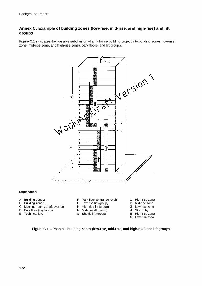
Background Report
172
Annex C: Example of building zones (low-rise, mid-rise, and high-rise) and lift groups
Figure C.1 illustrates the possible subdivision of a high-rise building project into building zones (low-rise zone, mid-rise zone, and high-rise zone), park floors, and lift groups.
Explanation
A Building zone 2 F Park floor (entrance level) 1 High-rise zone B Building zone 1 L Low-rise lift (group) 2 Mid-rise zone C Machine room / shaft overrun H High-rise lift (group) 3 Low-rise zone D Park floor (sky lobby) M Mid-rise lift (group) 4 Sky lobby E Technical layer S Shuttle lift (group) 5 High-rise zone 6 Low-rise zone
Figure C.1 – Possible building zones (low-rise, mid-rise, and high-rise) and lift groups
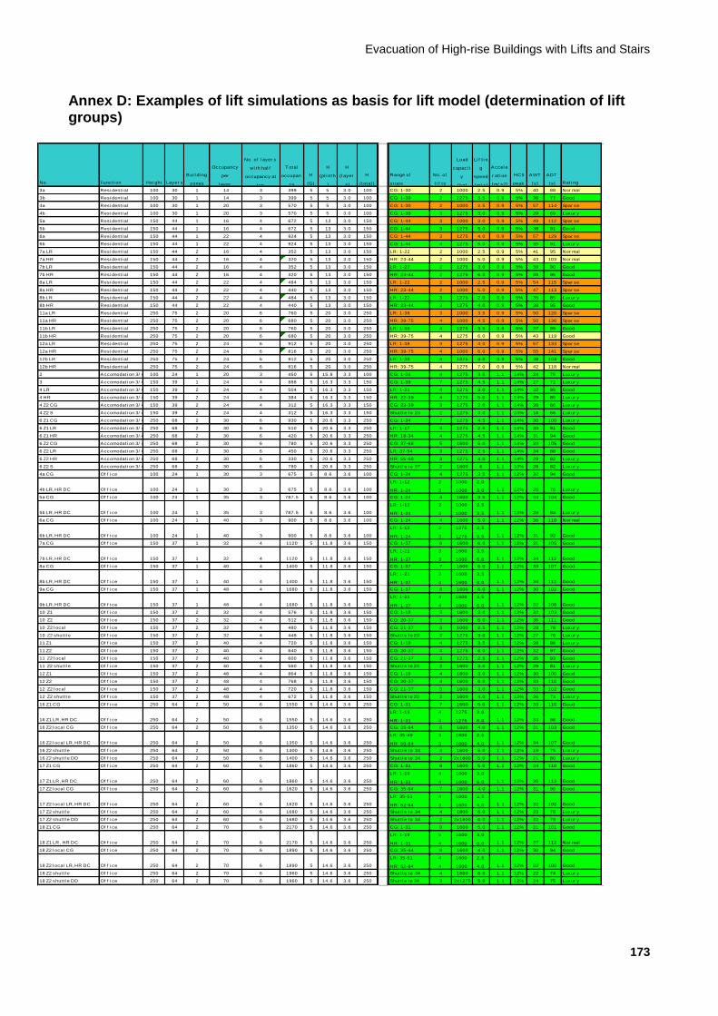
Evacuation of High-rise Buildings with Lifts and Stairs
173
Annex D: Examples of lift simulations as basis for lift model (determination of lift groups)
No. Funct i on Hei ght Layer s
Bui l di ng
zones
Occupancy
per
l ayer
No. of l ayer s
wi th hal f
occupancy at
top
T otal
occupan
cy
H
(G)
H
(pl i nth
)
H
(l ayer
s)
H
(total )
Range of
stops
No. of
l i f t s
Load
capaci t
y
[kg]
Li f t i n
g
speed
[m/ s]
Accel e
r at i on
[m/ s2]
HC5
peak
AWT
[s]
ADT
[s] Rat i ng
3a Resi dent i al 100 30 1 14 3 399 5 5 3.0 100 CG: 1-30 2 1000 2.5 0.9 5% 40 88 Nor mal
3b Resi dent i al 100 30 1 14 3 399 5 5 3.0 100 CG: 1-30 2 1275 3.5 0.9 5% 36 77 Good
4a Resi dent i al 100 30 1 20 3 570 5 5 3.0 100 CG: 1-30 2 1000 2.5 0.9 5% 57 114 Spar se
4b Resi dent i al 100 30 1 20 3 570 5 5 3.0 100 CG: 1-30 3 1275 3.0 0.9 5% 29 69 Luxur y
5a Resi dent i al 150 44 1 16 4 672 5 13 3.0 150 CG: 1-44 3 1000 3.0 0.9 5% 49 112 Spar se
5b Resi dent i al 150 44 1 16 4 672 5 13 3.0 150 CG: 1-44 3 1275 5.0 0.9 5% 38 91 Good
6a Resi dent i al 150 44 1 22 4 924 5 13 3.0 150 CG: 1-44 3 1275 4.0 0.9 5% 57 129 Spar se
6b Resi dent i al 150 44 1 22 4 924 5 13 3.0 150 CG: 1-44 4 1275 5.0 0.9 5% 35 91 Luxur y
7a LR Resi dent i al 150 44 2 16 4 352 5 13 3.0 150 LR: 1-22 2 1000 2.5 0.9 5% 41 95 Nor mal
7a HR Resi dent i al 150 44 2 16 4 320 5 13 3.0 150 HR: 23-44 2 1000 5.0 0.9 5% 43 103 Nor mal
7b LR Resi dent i al 150 44 2 16 4 352 5 13 3.0 150 LR: 1-22 2 1275 3.0 0.9 5% 38 90 Good
7b HR Resi dent i al 150 44 2 16 4 320 5 13 3.0 150 HR: 23-44 2 1275 6.0 0.9 5% 39 95 Good
8a LR Resi dent i al 150 44 2 22 4 484 5 13 3.0 150 LR: 1-22 2 1000 2.5 0.9 5% 54 115 Spar se
8a HR Resi dent i al 150 44 2 22 4 440 5 13 3.0 150 HR: 23-44 2 1000 5.0 0.9 5% 47 113 Spar se
8b LR Resi dent i al 150 44 2 22 4 484 5 13 3.0 150 LR: 1-22 3 1275 2.0 0.9 5% 35 85 Luxur y
8b HR Resi dent i al 150 44 2 22 4 440 5 13 3.0 150 HR: 23-44 3 1275 4.0 0.9 5% 38 95 Good
11a LR Resi dent i al 250 75 2 20 6 760 5 20 3.0 250 LR: 1-38 3 1000 3.5 0.9 5% 50 120 Spar se
11a HR Resi dent i al 250 75 2 20 6 680 5 20 3.0 250 HR: 39-75 4 1000 4.5 0.9 5% 50 136 Spar se
11b LR Resi dent i al 250 75 2 20 6 760 5 20 3.0 250 LR: 1-38 4 1275 3.5 0.9 5% 37 99 Good
11b HR Resi dent i al 250 75 2 20 6 680 5 20 3.0 250 HR: 39-75 4 1275 6.0 0.9 5% 43 119 Good
12a LR Resi dent i al 250 75 2 24 6 912 5 20 3.0 250 LR: 1-38 3 1275 4.0 0.9 5% 57 133 Spar se
12a HR Resi dent i al 250 75 2 24 6 816 5 20 3.0 250 HR: 39-75 4 1000 6.0 0.9 5% 55 141 Spar se
12b LR Resi dent i al 250 75 2 24 6 912 5 20 3.0 250 LR: 1-38 4 1275 4.0 0.9 5% 38 104 Good
12b HR Resi dent i al 250 75 2 24 6 816 5 20 3.0 250 HR: 39-75 4 1275 7.0 0.9 5% 42 118 Nor mal
2 Accomodat i on 3/ 4* 100 24 1 20 3 450 5 15.8 3.3 100 CG: 1-24 4 1275 3.5 1.1 14% 24 76 Luxur y
3 Accomodat i on 3/ 4* 150 39 1 24 4 888 5 16.3 3.3 150 CG: 1-39 7 1275 4.5 1.1 14% 27 72 Luxur y
4 LR Accomodat i on 3/ 4* 150 39 2 24 4 504 5 16.3 3.3 150 LR: 1-21 4 1275 3.0 1.1 14% 32 89 Good
4 HR Accomodat i on 3/ 4* 150 39 2 24 4 384 5 16.3 3.3 150 HR: 22-39 4 1275 5.0 1.1 14% 29 89 Luxur y
4 Z2 CG Accomodat i on 3/ 4* 150 39 2 24 4 312 5 16.3 3.3 150 CG: 23-39 3 1275 2.0 1.1 14% 26 66 Luxur y
4 Z2 S Accomodat i on 3/ 4* 150 39 2 24 4 312 5 16.3 3.3 150 Shut t l e to 23 2 1275 3.0 1.1 10% 18 66 Luxur y
6 Z1 CG Accomodat i on 3/ 4* 250 68 2 30 6 930 5 20.6 3.3 250 CG: 1-34 7 1275 4.5 1.1 14% 30 100 Luxur y
6 Z1 LR Accomodat i on 3/ 4* 250 68 2 30 6 510 5 20.6 3.3 250 LR: 1-17 4 1275 2.5 1.1 14% 30 91 Good
6 Z1 HR Accomodat i on 3/ 4* 250 68 2 30 6 420 5 20.6 3.3 250 HR: 18-34 4 1275 4.5 1.1 14% 31 94 Good
6 Z2 CG Accomodat i on 3/ 4* 250 68 2 30 6 780 5 20.6 3.3 250 CG: 37-68 5 1600 5.0 1.1 14% 33 105 Good
6 Z2 LR Accomodat i on 3/ 4* 250 68 2 30 6 450 5 20.6 3.3 250 LR: 37-54 3 1275 2.5 1.1 14% 34 88 Good
6 Z2 HR Accomodat i on 3/ 4* 250 68 2 30 6 330 5 20.6 3.3 250 HR: 55-68 3 1275 4.0 1.1 14% 29 82 Luxur y
6 Z2 S Accomodat i on 3/ 4* 250 68 2 30 6 780 5 20.6 3.3 250 Shut t l e to 37 2 1600 6 1.1 10% 28 82 Luxur y
4a CG Of f i ce 100 24 1 30 3 675 5 8.6 3.6 100 CG: 1-24 4 1275 3.5 1.1 12% 32 94 Good
4b LR,HR DC Of f i ce 100 24 1 30 3 675 5 8.6 3.6 100
LR: 1-12
HR: 1-24
2
3
1000
1000
2,0
3,0 1.1 12% 26 76 Luxur y
5a CG Of f i ce 100 24 1 35 3 787.5 5 8.6 3.6 100 CG: 1-24 4 1600 3.5 1.1 12% 34 104 Good
5b LR,HR DC Of f i ce 100 24 1 35 3 787.5 5 8.6 3.6 100
LR: 1-12
HR: 1-24
2
3
1000
1000
2,5
3,5 1.1 12% 28 83 Luxur y
6a CG Of f i ce 100 24 1 40 3 900 5 8.6 3.6 100 CG: 1-24 4 1600 5.0 1.1 12% 36 110 Nor mal
6b LR,HR DC Of f i ce 100 24 1 40 3 900 5 8.6 3.6 100
LR: 1-12
HR: 1-24
2
3
1275
1275
2,5
3,5 1.1 12% 31 92 Good
7a CG Of f i ce 150 37 1 32 4 1120 5 11.8 3.6 150 CG: 1-37 6 1600 6.0 1.1 12% 31 105 Good
7b LR,HR DC Of f i ce 150 37 1 32 4 1120 5 11.8 3.6 150
LR: 1-21
HR: 1-37
3
3
1600
1600
3,5
6,0 1.1 12% 34 112 Good
8a CG Of f i ce 150 37 1 40 4 1400 5 11.8 3.6 150 CG: 1-37 7 1600 6.0 1.1 12% 33 107 Good
8b LR,HR DC Of f i ce 150 37 1 40 4 1400 5 11.8 3.6 150
LR: 1-21
HR: 1-37
3
4
1600
1600
3,5
6,0 1.1 12% 34 112 Good
9a CG Of f i ce 150 37 1 48 4 1680 5 11.8 3.6 150 CG: 1-37 8 1600 6.0 1.1 12% 30 102 Good
9b LR,HR DC Of f i ce 150 37 1 48 4 1680 5 11.8 3.6 150
LR: 1-21
HR: 1-37
4
4
1600
1600
3,5
6,0 1.1 12% 32 108 Good
10 Z1 Of f i ce 150 37 2 32 4 576 5 11.8 3.6 150 CG: 1-18 3 1600 3.0 1.1 12% 32 103 Good
10 Z2 Of f i ce 150 37 2 32 4 512 5 11.8 3.6 150 CG: 20-37 3 1600 6.0 1.1 12% 35 111 Good
10 Z2 l ocal Of f i ce 150 37 2 32 4 480 5 11.8 3.6 150 CG: 21-37 3 1000 2.5 1.1 12% 28 76 Luxur y
10 Z2 shut t l e Of f i ce 150 37 2 32 4 448 5 11.8 3.6 150 Shut t l e to 20 2 1275 3.0 1.1 12% 27 76 Luxur y
11 Z1 Of f i ce 150 37 2 40 4 720 5 11.8 3.6 150 CG: 1-18 4 1275 3.5 1.1 12% 28 88 Luxur y
11 Z2 Of f i ce 150 37 2 40 4 640 5 11.8 3.6 150 CG: 20-37 4 1275 6.0 1.1 12% 32 97 Good
11 Z2 l ocal Of f i ce 150 37 2 40 4 600 5 11.8 3.6 150 CG: 21-37 3 1275 2.5 1.1 12% 35 93 Good
11 Z2 shut t l e Of f i ce 150 37 2 40 4 560 5 11.8 3.6 150 Shut t l e to 20 2 1600 3.0 1.1 12% 29 81 Luxur y
12 Z1 Of f i ce 150 37 2 48 4 864 5 11.8 3.6 150 CG: 1-18 4 1600 3.0 1.1 12% 30 100 Good
12 Z2 Of f i ce 150 37 2 48 4 768 5 11.8 3.6 150 CG: 20-37 4 1600 6.0 1.1 12% 33 110 Good
12 Z2 l ocal Of f i ce 150 37 2 48 4 720 5 11.8 3.6 150 CG: 21-37 3 1600 3.0 1.1 12% 33 102 Good
12 Z2 shut t l e Of f i ce 150 37 2 48 4 672 5 11.8 3.6 150 Shut t l e to 20 2 1600 4.0 1.1 12% 26 73 Luxur y
16 Z1 CG Of f i ce 250 64 2 50 6 1550 5 14.6 3.6 250 CG: 1-31 7 1600 5.0 1.1 12% 33 110 Good
16 Z1 LR,HR DC Of f i ce 250 64 2 50 6 1550 5 14.6 3.6 250
LR: 1-19
HR: 1-31
4
4
1275
1275
3,0
6,0 1.1 12% 33 98 Good
16 Z2 l ocal CG Of f i ce 250 64 2 50 6 1350 5 14.6 3.6 250 CG: 35-64 6 1600 4.0 1.1 12% 31 103 Good
16 Z2 l ocal LR,HR DC Of f i ce 250 64 2 50 6 1350 5 14.6 3.6 250
LR: 35-49
HR: 50-64
3
3
1600
1600
2,5
4,0 1.1 12% 34 107 Good
16 Z2 shut t l e Of f i ce 250 64 2 50 6 1400 5 14.6 3.6 250 Shut t l e to 34 4 1600 5.0 1.1 12% 19 75 Luxur y
16 Z2 shut t l e DD Of f i ce 250 64 2 50 6 1400 5 14.6 3.6 250 Shut t l e to 34 2 2x1600 5.0 1.1 12% 21 80 Luxur y
17 Z1 CG Of f i ce 250 64 2 60 6 1860 5 14.6 3.6 250 CG: 1-31 8 1600 5.0 1.1 12% 34 110 Good
17 Z1 LR,HR DC Of f i ce 250 64 2 60 6 1860 5 14.6 3.6 250
LR: 1-19
HR: 1-31
4
4
1600
1600
3,0
6,0 1.1 12% 36 113 Good
17 Z2 l ocal CG Of f i ce 250 64 2 60 6 1620 5 14.6 3.6 250 CG: 35-64 7 1600 4.0 1.1 12% 31 99 Good
17 Z2 l ocal LR,HR DC Of f i ce 250 64 2 60 6 1620 5 14.6 3.6 250
LR: 35-51
HR: 52-64
4
3
1600
1600
2,5
4,0 1.1 12% 32 102 Good
17 Z2 shut t l e Of f i ce 250 64 2 60 6 1680 5 14.6 3.6 250 Shut t l e to 34 4 1800 6.0 1.1 12% 23 78 Luxur y
17 Z2 shut t l e DD Of f i ce 250 64 2 60 6 1680 5 14.6 3.6 250 Shut t l e to 34 2 2x1800 6.0 1.1 12% 22 79 Luxur y
18 Z1 CG Of f i ce 250 64 2 70 6 2170 5 14.6 3.6 250 CG: 1-31 9 1600 5.0 1.1 12% 31 101 Good
18 Z1 LR, HR DC Of f i ce 250 64 2 70 6 2170 5 14.6 3.6 250
LR: 1-19
HR: 1-31
5
4
1600
1600
3,0
6,0 1.1 12% 37 112 Nor mal
18 Z2 l ocal CG Of f i ce 250 64 2 70 6 1890 5 14.6 3.6 250 CG: 35-64 8 1600 4.0 1.1 12% 30 94 Good
18 Z2 l ocal LR,HR DC Of f i ce 250 64 2 70 6 1890 5 14.6 3.6 250
LR: 35-51
HR: 52-64
4
4
1600
1600
2,5
4,0 1.1 12% 32 100 Good
18 Z2 shut t l e Of f i ce 250 64 2 70 6 1960 5 14.6 3.6 250 Shut t l e to 34 4 1800 6.0 1.1 12% 22 74 Luxur y
18 Z2 shut t l e DD Of f i ce 250 64 2 70 6 1960 5 14.6 3.6 250 Shut t l e to 34 3 2x1275 5.0 1.1 12% 24 75 Luxur y
Background Report
174
Bibliography
Aikman, A.J.M.: Elevator Operation during Fire Emergencies in High Buildings (1990)
Allen, T.: Early Evacuation Elevator Operation (2005)
Aloi, S. et al.: Evacuation & Life Safety Strategies for Super High-rise Buildings (2000)
Bärlund, K.: Elevator Monitoring and Management in Building Emergencies (2005)
Barney, G.: Behaviour of Lifts and Their Use for Evacuation (2003)
Barney, G.: More on Evacuation Using Elevators (2004)
Bialy, L. et al.: Potential Role of Elevators during Emergencies (2004)
Boer, L.: De onlogische logica van menselijk gedrag (2004)
Bukowski, R. W.: Protected Elevators for Egress and Access during Fires in Tall Buildings (2003)
Bukowski, R. W.: Protected Elevators and the Disabled (2005)
Bukowski, R. W.: Is There a Need to Enclose Elevator Lobbies in Tall Buildings (2005)
Bukowski, R. W.: Emergency Egress Strategies for Buildings (2007)
Bukowski, R. W.: Emergency Egress from Ultra Tall Buildings (2008)
Bukowski, R. W.: NIST Technical Note 1623: Emergency Egress from Buildings (2009)
Bukowski, R. W. et al.: Using Elevators in Fires (2010)
Caporale, R.S.: Use of Elevators in Fires and Other Emergencies (2004)
Chapman, E.F: Elevator Design for the 21st Century: Design criteria for elevators when used as the primary means of evacuation during fire emergencies (1991)
Charters, D.A.: Emergency Evacuation: Express elevator (2005)
Charters, D.A. et al.: The Effects of Using Passenger Lifts and Escalators for the Evacuation of Building Occupants in Fire and Other Emergencies in High-rise Buildings and Underground Complexes (2007)
Charters, D.A. et al.: BD 2466: Guidance on the Emergency Use of Lifts or Escalators for Evacuation and Fire and Rescue Service Operations (2009)
Cook, D.: Preplanning for Elevator Use during Major Fires & Following Seismic Events (2004)
CTBUH: Emergency Evacuation: Elevator Systems Guideline (2004)
Fortune, J.W.: New Thoughts on the Use of Elevators for Emergency Evacuations of High-rise Buildings (2002)
Fortune, J.W.: New Thoughts on Building Emergency Evacuations via Elevators after 9/11 (2007)
Fraser, B.: Using Elevators for Evacuation during Fire and Other Emergencies (2005)

Evacuation of High-rise Buildings with Lifts and Stairs
175
Fruin, J.J.: Pedestrian Planning and Design (1971)
Gale, J.: Evacuation of High-rise Buildings Using the Elevators (2001)
Greet, R.: A European Firefighter’s Perspective (2005)
Groner, N.: A Situation Awareness Requirements Analysis for the Use of Elevators during Fire Emergencies (2009)
Hakonen, H.: Evacuation Simulation of Tall Buildings (2003)
Hall, J.R.: High-rise Building Fires (2009)
Haven, J.: Rol nieuwe brandweerliften in evacuatieplan? (2007)
Heyes, E.: Lifts for Evacuation – Human behaviour considerations (2009)
Howkins, R.E. et al.: Evacuation by Elevator – The human formula (2003)
Howkins, R.E.: In the Event of Fire USE THE ELEVATORS (2000)
Hsiung, K.H. et al.: A Study on High-rise Building Fire Evacuation Strategies for Taipei 101 Financial Centre (2009)
Kinsey, M.J. et al.: Investigating the Use of Elevators for High-rise Building Evacuation through Computer Simulation (2009)
Klote, J.H.: Elevators as a Means of Fire Escape (1982)
Klote, J.H. et al.: NISTIR 4730: Routine for Analysis of the People Movement Time for Elevator Evacuation (1992)
Klote, J.H. et al.: NISTIR 4870: Feasibility and Design Considerations of Emergency Evacuation by Elevators (1992)
Klote, J.H.: Fire Protection Challenges of the Americans Disabilities Act: Elevator evacuation and refuge areas (1993)
Klote, J.H.: A Method for Calculation of Elevator Evacuation Time (1993)
Klote, J.H. et al.: NISTIR 4993: Workshop on Elevator Use during Fires (1993)
Klote, J.H. et al.: Fire Evacuation by Elevators (1993)
Klote, J.H. et al.: NISTIR 5445: Feasibility of Fire Evacuation by Elevators at FAA Control Towers (1994)
Klote, J.H. et al.: Emergency Elevator Evacuation Systems (1995)
Klote, J.H.: An Overview of Elevator Use for Emergency Evacuation (2003)
Klote, J.H.: Analysis of the Life Safety Consequences of Smoke Migration through Elevator Shafts (2004)
Kobes, M. et al.: Exit Choice, (Pre-)movement Time and (Pre-)evacuation Behaviour – Analysis of evacuation experiments in a hotel (2009)
Klunder, G. et al.: Menselijk gedrag bij vluchten uit gebouwen (2007)

Background Report
176
Koshak, J.: Elevator Evacuation in Emergency Situations (2005)
Kuligowski, E.: Elevators for Occupant Evacuation and Fire Department Access (2003)
Kuligowski, E.: Review of 28 Egress Models (2004)
Kuligowski, E. et al.: Design of Occupant Egress Systems for Tall Buildings (2004)
Kuligowski, E.: NIST Technical Note 1619: Modelling Human Behaviour during Building Fires (2008)
Lindenberg, K. van: Brandweer- en evacuatieliften (2008)
McClennan, H.A. et al.: Will Current High-rise Evacuation Systems Meet User Needs in 2010? (2008)
McWaters, I.: Proposals for the Use of Lifts to Evacuate People with Disabilities, in Fire Emergencies (in Australia) (2000)
NFPA: International Listing of Fatal High-rise Structure Fires 1911-2004 (2004)
NIST: Final Report on the Collapse of the World Trade Center Towers (2005)
Special Publication 1620: Cooperative Research on the Use of Elevators During Fire Emergencies (2009)
Noordermeer, R.: Usage of Lifts for the Evacuation of High-rise Projects (2010)
Pauls, J.: Elevators & Stairs for Evacuation: Comparisons and combinations (2005)
Peacock, R.D. et al.: NIST Special Publication 1620: Summary of NIST/GSA Cooperative Research on the Use of Elevators during Fire Emergencies (2009)
Peacock, R.D. et al.: NIST Technical Note 1624: Stairwell Evacuation from Buildings: What we know we don’t know (2009)
Proulx, G. et al.: Evacuation Procedures for Occupants with Disabilities in High-rise Buildings (1996)
Proulx, G.: Evacuation Planning for Occupants with Disability (2002)
Proulx, G. et al.: The Use of Elevators for Egress (2009)
Sekizawa, A. et al.: Is Use of Elevators in Evacuation Really Effective for General People (2004)
Siikonen, M.L. et al.: Efficient Evacuation Methods in Tall Buildings (2003)
Siikonen, M.L. et al.: Transportation Designs for Building Evacuation (2005)
Siikonen, M.L. et al.: Evacuation Mode for Total Building Evacuation (2006)
Siikonen, M.L.: Current Activities on Egress and Access in Europe (2006)
Smith, D.: Lifts for Evacuation during an Emergency (2006)
So, A. et al.: On the Development of Emergency Escape Lifts (2002)
Spyropoulos, N. et al.: Use of Lifts in an Emergency: The European experience (2008)
Evacuation of High-rise Buildings with Lifts and Stairs
177
Tubbs, J.: Selecting Appropriate Evacuation Strategies for Super Tall Buildings: Current challenges and needs (2009)
Turner, D.L.: Proactive Use of Elevators in Emergencies Other than Fires (2004)
Winslow, D.J.: Elevator Use in Fire Emergencies (2005)
Wit, J.: Evacuating Using Elevators - Enhancing the CTBUH approach for the Dutch high-rise covenant (2010)
Wong, R.: Using Lift as an Alternative Means of Egress for Evacuation (2009)
Related Documents