Instruction Manual 05/2005 Edition sinumerik SINUMERIK 802D sl Siemens Automation Parts

Welcome message from author
This document is posted to help you gain knowledge. Please leave a comment to let me know what you think about it! Share it to your friends and learn new things together.
Transcript
Instruction Manual 05/2005 Edition
sinumerik
SINUMERIK 802D slSiemens Automation Parts

Valid for
Control system Software versionSINUMERIK 802D sl 1
05/2005 Edition
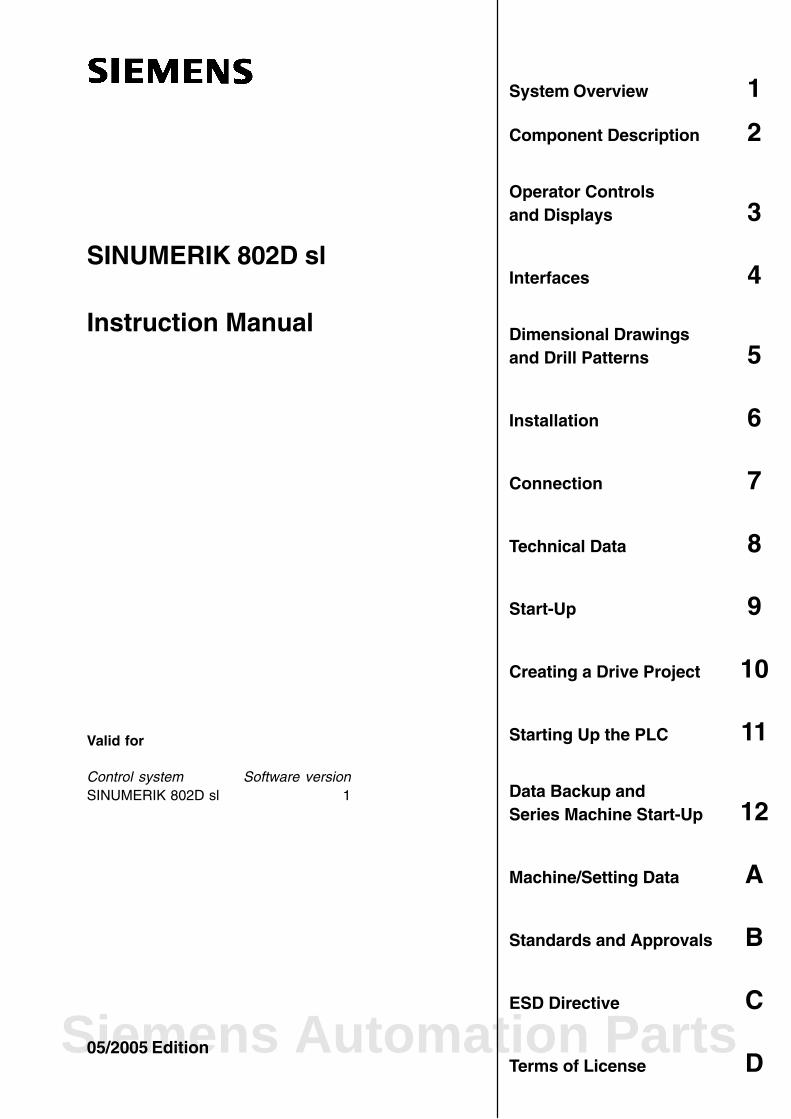
SINUMERIK 802D sl
Instruction Manual
System Overview 1
Component Description 2
Operator Controls and Displays 3
Interfaces 4
Dimensional Drawingsand Drill Patterns 5
Installation 6
Connection 7
Technical Data 8
Start-Up 9
Creating a Drive Project 10
Starting Up the PLC 11
Data Backup and Series Machine Start-Up 12
Machine/Setting Data A
Standards and Approvals B
ESD Directive C
Terms of License DSiemens Automation Parts
Siemens AGAutomation and DrivesPostfach 4848D–90437 NÜRNBERGGERMANY
Copyright () Siemens AG 2005.6FC5397–0CP10–1BA0
Siemens AG 2005Subject to change without prior notice.
Safety NotesThis Manual contains information which you should carefully observe to ensure your own personal safetyand the prevention of material damage. The notices are highlighted by a warning triangle and, depending onthe degree of hazard, represented as shown below:
!Danger
indicates that death or severe personal injury will result if proper precautions are not taken.
!Warning
indicates that death or severe personal injury may result if proper precautions are not taken.
!Caution
with a warning triangle indicates that minor personal injury can result if proper precautions are not taken.
Caution
without a safety alert symbol, indicates that property damage can result if proper precautions are not taken.
Attention
indicates that an undesirable event or state may arise if the relevant note is not observed.
If several hazards of different degrees occur, the hazard with the highest degree must always be givenpreference. If a warning note with a warning triangle warns of personal injury, the same warning note canalso contain a warning of material damage.
Qualified personnelStart-up and operation of the device/equipment/system in question must only be performed using thisdocumentation. Commissioning and operation of a device/system may only be performed by qualifiedpersonnel. Qualified personnel as referred to in the safety guidelines in this documentation are those whoare authorized to start up, ground and label units, systems and circuits in accordance with the relevant safetystandards.
Use as intendedPlease note the following:
!Warning
The equipment may only be used for single purpose applications explicitly described in the catalog and inthe technical description and it may only be used along with third-party devices and componentsrecommended by Siemens. It is assumed that this product be transported, stored and installed as intendedand maintained and operated with care to ensure that the product functions correctly and properly.
TrademarksAll designations with the trademark symbol are registered trademarks of Siemens AG. Other designationsin this documentation may be trademarks whose use by third parties for their own purposes may infringe therights of the owner.
Disclaimer of LiabilityWe have checked that the contents of this document correspond to the hardware and software described.Nonetheless, differences might exist and therefore we cannot guarantee that they are completely identical.The information given in this publication is reviewed at regular intervals and any corrections that might benecessary are made in the subsequent editions.

iiiSINUMERIK 802D sl Instruction Manual (BA), 05/2005 Edition6FC5 397-0CP10-1BA0
Preface
SINUMERIK Documentation
The SINUMERIK documentation is organized in 3 parts:
General Documentation
User Documentation
Manufacturer/Service Documentation
More detailed information about other publications concerning SINUMERIK 810D and 840Dand publications that apply to all SINUMERIK control systems (e.g., Universal Interface,Measuring Cycles, etc.) can be obtained from your local Siemens branch office.
A list of documents, updated on a monthly basis, is available on the Internet for the availablelanguages at:http://www.siemens.com/motioncontrolSelect “Support”/“Technical Documentation”/“Overview of Documents”.
The Internet version of the DOConCD (DOConWEB) is available at:http://www.automation.siemens.com/doconweb
Target readership of this documentation
This document is designed for machine tool manufacturers. This publication provides detai-led information that the user requires for operating the SINUMERIK 810D sl.
Standard version
This Instruction Manual describes the functionality of the standard scope. Extensions orchanges made by the machine manufacturer are documented by the machine manufacturer.
Other functions not described in this documentation might be executable in the control. Thisdoes not, however, represent an obligation to supply such functions with a new control orwhen servicing.
Hotline
If you have any questions, please contact the following hotline:A&D Technical SupportPhone: +49 (0) 180 / 5050 – 222Fax: +49 (0) 180 / 5050 – 223Internet: http://www.siemens.com/automation/support–request
If you have any comments, suggestions, or corrections regarding this documentation, pleasefax or e-mail them to:
Fax: +49 (0) 9131 / 98 – 63315E-mail: [email protected]
Fax form: See the reply form at the end of the brochure.
Siemens Automation Parts

Preface
ivSINUMERIK 802D sl Instruction Manual (BA), 05/2005 Edition
6FC5 397-0CP10-1BA0
Internet address
http://www.siemens.com/motioncontrol
Table of Contents
vSINUMERIK 802D sl Instruction Manual (BA), 05/2005 Edition6FC5 397-0CP10-1BA0
Table of Contents
1 System Overview 1-9. . . . . . . . . . . . . . . . . . . . . . . . . . . . . . . . . . . . . . . . . . . . . . . . . . . . . . . . . . . . .
2 Description 2-13. . . . . . . . . . . . . . . . . . . . . . . . . . . . . . . . . . . . . . . . . . . . . . . . . . . . . . . . . . . . . . . . . .
3 Operator Controls and Displays 3-17. . . . . . . . . . . . . . . . . . . . . . . . . . . . . . . . . . . . . . . . . . . . . . .
3.1 Operator controls 3-17. . . . . . . . . . . . . . . . . . . . . . . . . . . . . . . . . . . . . . . . . . . . . . . . . . . . . . . . . . . . .
3.2 Error and status displays 3-18. . . . . . . . . . . . . . . . . . . . . . . . . . . . . . . . . . . . . . . . . . . . . . . . . . . . . . .
4 Interfaces 4-19. . . . . . . . . . . . . . . . . . . . . . . . . . . . . . . . . . . . . . . . . . . . . . . . . . . . . . . . . . . . . . . . . . . .
4.1 CNC operator panel (PCU) interfaces 4-19. . . . . . . . . . . . . . . . . . . . . . . . . . . . . . . . . . . . . . . . . . . . 4.1.1 Compact flash card (CF card) slot 4-19. . . . . . . . . . . . . . . . . . . . . . . . . . . . . . . . . . . . . . . . . . . . . . . 4.1.2 Ethernet interface 4-20. . . . . . . . . . . . . . . . . . . . . . . . . . . . . . . . . . . . . . . . . . . . . . . . . . . . . . . . . . . . . 4.1.3 USB port (available soon) 4-20. . . . . . . . . . . . . . . . . . . . . . . . . . . . . . . . . . . . . . . . . . . . . . . . . . . . . . 4.1.4 RS232 COM interface 4-21. . . . . . . . . . . . . . . . . . . . . . . . . . . . . . . . . . . . . . . . . . . . . . . . . . . . . . . . . 4.1.5 PROFIBUS DP interface 4-22. . . . . . . . . . . . . . . . . . . . . . . . . . . . . . . . . . . . . . . . . . . . . . . . . . . . . . . 4.1.6 DRIVE CLiQ interface 4-23. . . . . . . . . . . . . . . . . . . . . . . . . . . . . . . . . . . . . . . . . . . . . . . . . . . . . . . . . 4.1.7 Handwheel connection 4-24. . . . . . . . . . . . . . . . . . . . . . . . . . . . . . . . . . . . . . . . . . . . . . . . . . . . . . . . . 4.1.8 Digital inputs/digital outputs 4-25. . . . . . . . . . . . . . . . . . . . . . . . . . . . . . . . . . . . . . . . . . . . . . . . . . . . .
4.2 MCPA module interfaces 4-28. . . . . . . . . . . . . . . . . . . . . . . . . . . . . . . . . . . . . . . . . . . . . . . . . . . . . . .
4.3 PP 72/48 I/O module interfaces 4-32. . . . . . . . . . . . . . . . . . . . . . . . . . . . . . . . . . . . . . . . . . . . . . . . .
5 Dimension Drawings 5-39. . . . . . . . . . . . . . . . . . . . . . . . . . . . . . . . . . . . . . . . . . . . . . . . . . . . . . . . . .
5.1 Dimension drawing and drilling pattern for the CNC operator panel (PCU) 5-40. . . . . . . . . . . . .
5.2 Dimension drawing and drilling pattern for the machine control panel (MCP) 5-42. . . . . . . . . . .
5.3 Dimension drawings and drilling patterns for the NC full keyboard 5-44. . . . . . . . . . . . . . . . . . . .
5.4 Dimension drawing for the PP72/48 I/O module 5-48. . . . . . . . . . . . . . . . . . . . . . . . . . . . . . . . . . . .
6 Installation 6-49. . . . . . . . . . . . . . . . . . . . . . . . . . . . . . . . . . . . . . . . . . . . . . . . . . . . . . . . . . . . . . . . . . .
7 Connecting 7-51. . . . . . . . . . . . . . . . . . . . . . . . . . . . . . . . . . . . . . . . . . . . . . . . . . . . . . . . . . . . . . . . . .
7.1 General rules for operation of a SINUMERIK 802D sl 7-52. . . . . . . . . . . . . . . . . . . . . . . . . . . . . . .
7.2 Rules regarding current consumption and power loss of a cubicle arrangement 7-53. . . . . . . .
7.3 Overall design of the SINUMERIK 802D sl 7-54. . . . . . . . . . . . . . . . . . . . . . . . . . . . . . . . . . . . . . . .
7.4 Connecting the protective conductor for the individual components 7-55. . . . . . . . . . . . . . . . . . .
7.5 Connection overview for the SINUMERIK 802D sl 7-56. . . . . . . . . . . . . . . . . . . . . . . . . . . . . . . . . .
7.6 Connecting the MCPA module 7-59. . . . . . . . . . . . . . . . . . . . . . . . . . . . . . . . . . . . . . . . . . . . . . . . . .
7.7 Connecting the analog spindle 7-60. . . . . . . . . . . . . . . . . . . . . . . . . . . . . . . . . . . . . . . . . . . . . . . . . .
7.8 Connecting the power supply 7-61. . . . . . . . . . . . . . . . . . . . . . . . . . . . . . . . . . . . . . . . . . . . . . . . . . .
7.9 Connecting the full keyboard to the CNC operator panel 7-63. . . . . . . . . . . . . . . . . . . . . . . . . . . .
7.10 Connecting the Ethernet interface 7-64. . . . . . . . . . . . . . . . . . . . . . . . . . . . . . . . . . . . . . . . . . . . . . .
7.11 Connecting the RS232 COM port 7-65. . . . . . . . . . . . . . . . . . . . . . . . . . . . . . . . . . . . . . . . . . . . . . . .
7.12 Connecting the PP72/48 I/O module and the drive 7-66. . . . . . . . . . . . . . . . . . . . . . . . . . . . . . . . .
7.13 Connecting the SINAMICS drive to the DRIVE-CLiQ interface 7-70. . . . . . . . . . . . . . . . . . . . . . .
7.14 Connecting the digital inputs/outputs to the PCU 7-71. . . . . . . . . . . . . . . . . . . . . . . . . . . . . . . . . . .
7.15 Connecting the digital inputs/digital outputs to the PP72/48 I/O module 7-72. . . . . . . . . . . . . . . .
7.16 Connecting the machine control panel to the PP72/48 I/O module 7-73. . . . . . . . . . . . . . . . . . . .
Siemens Automation Parts
Table of Contents
viSINUMERIK 802D sl Instruction Manual (BA), 05/2005 Edition
6FC5 397-0CP10-1BA0
7.17 Connecting shielded lines via the shield connection (PCU) 7-74. . . . . . . . . . . . . . . . . . . . . . . . . .
8 Technical Data 8-75. . . . . . . . . . . . . . . . . . . . . . . . . . . . . . . . . . . . . . . . . . . . . . . . . . . . . . . . . . . . . . .
9 Commissioning 9-79. . . . . . . . . . . . . . . . . . . . . . . . . . . . . . . . . . . . . . . . . . . . . . . . . . . . . . . . . . . . . .
9.1 General 9-79. . . . . . . . . . . . . . . . . . . . . . . . . . . . . . . . . . . . . . . . . . . . . . . . . . . . . . . . . . . . . . . . . . . . . . 9.1.1 Access levels 9-80. . . . . . . . . . . . . . . . . . . . . . . . . . . . . . . . . . . . . . . . . . . . . . . . . . . . . . . . . . . . . . . . . 9.1.2 Structure of machine data (MD) and setting data (SD) 9-81. . . . . . . . . . . . . . . . . . . . . . . . . . . . . . 9.1.3 RCS802D Commissioning and Diagnostic tool 9-82. . . . . . . . . . . . . . . . . . . . . . . . . . . . . . . . . . . .
9.2 Turning on and booting the control system 9-83. . . . . . . . . . . . . . . . . . . . . . . . . . . . . . . . . . . . . . . .
9.3 Language setting and file management 9-84. . . . . . . . . . . . . . . . . . . . . . . . . . . . . . . . . . . . . . . . . . 9.3.1 Creating a project 9-84. . . . . . . . . . . . . . . . . . . . . . . . . . . . . . . . . . . . . . . . . . . . . . . . . . . . . . . . . . . . . 9.3.2 Help, language and alarm files 9-85. . . . . . . . . . . . . . . . . . . . . . . . . . . . . . . . . . . . . . . . . . . . . . . . . . 9.3.3 Transmitting data to the 802D 9-85. . . . . . . . . . . . . . . . . . . . . . . . . . . . . . . . . . . . . . . . . . . . . . . . . . .
9.4 Setting the technology 9-88. . . . . . . . . . . . . . . . . . . . . . . . . . . . . . . . . . . . . . . . . . . . . . . . . . . . . . . . .
9.5 Entering the machine data 9-90. . . . . . . . . . . . . . . . . . . . . . . . . . . . . . . . . . . . . . . . . . . . . . . . . . . . . .
9.6 Setting the Profibus address 9-91. . . . . . . . . . . . . . . . . . . . . . . . . . . . . . . . . . . . . . . . . . . . . . . . . . . .
9.7 Starting Up the PLC 9-92. . . . . . . . . . . . . . . . . . . . . . . . . . . . . . . . . . . . . . . . . . . . . . . . . . . . . . . . . . .
9.8 Configuring SINAMICS S120 with 802D sl 9-93. . . . . . . . . . . . . . . . . . . . . . . . . . . . . . . . . . . . . . . . 9.8.1 Commissioning using predefined macros without the STARTER commissioning tool 9-93. . . . 9.8.2 Starting up motors without SMI 9-97. . . . . . . . . . . . . . . . . . . . . . . . . . . . . . . . . . . . . . . . . . . . . . . . . . 9.8.3 Faults and warnings when starting up the SINAMICS S120 drive 9-97. . . . . . . . . . . . . . . . . . . . . 9.8.4 Setpoint/actual-value assignment 9-98. . . . . . . . . . . . . . . . . . . . . . . . . . . . . . . . . . . . . . . . . . . . . . . . 9.8.5 Default settings of the axis machine data for feed axes 9-99. . . . . . . . . . . . . . . . . . . . . . . . . . . . . 9.8.6 Default settings of the axis machine data for the spindle 9-101. . . . . . . . . . . . . . . . . . . . . . . . . . . .
9.9 STARTER start-up tool 9-105. . . . . . . . . . . . . . . . . . . . . . . . . . . . . . . . . . . . . . . . . . . . . . . . . . . . . . . . . 9.9.1 Explanations regarding the STARTER user interface 9-105. . . . . . . . . . . . . . . . . . . . . . . . . . . . . . . 9.9.2 Operating philosophy of the STARTER commissioning tool for SINAMICS S120 9-106. . . . . . . .
9.10 Start-up sequence when working with STARTER 9-109. . . . . . . . . . . . . . . . . . . . . . . . . . . . . . . . . . 9.10.1 Creating a drive object OFFLINE 9-109. . . . . . . . . . . . . . . . . . . . . . . . . . . . . . . . . . . . . . . . . . . . . . . . 9.10.2 Operating the STARTER control panel (motor rotating) 9-110. . . . . . . . . . . . . . . . . . . . . . . . . . . . . 9.10.3 Creating a drive project ONLINE (recommended) 9-110. . . . . . . . . . . . . . . . . . . . . . . . . . . . . . . . . .
9.11 Diagnosis via STARTER 9-111. . . . . . . . . . . . . . . . . . . . . . . . . . . . . . . . . . . . . . . . . . . . . . . . . . . . . . . 9.11.1 Function generator 9-112. . . . . . . . . . . . . . . . . . . . . . . . . . . . . . . . . . . . . . . . . . . . . . . . . . . . . . . . . . . . 9.11.2 Trace function 9-115. . . . . . . . . . . . . . . . . . . . . . . . . . . . . . . . . . . . . . . . . . . . . . . . . . . . . . . . . . . . . . . . 9.11.3 Measuring function (SERVO) (available soon) 9-116. . . . . . . . . . . . . . . . . . . . . . . . . . . . . . . . . . . . . 9.11.4 Measuring sockets (available soon) 9-119. . . . . . . . . . . . . . . . . . . . . . . . . . . . . . . . . . . . . . . . . . . . . .
9.12 Completing the start-up 9-120. . . . . . . . . . . . . . . . . . . . . . . . . . . . . . . . . . . . . . . . . . . . . . . . . . . . . . . .
9.13 Service display of the axis drive behavior 9-121. . . . . . . . . . . . . . . . . . . . . . . . . . . . . . . . . . . . . . . . .
10 Creating a Drive Project 10-123. . . . . . . . . . . . . . . . . . . . . . . . . . . . . . . . . . . . . . . . . . . . . . . . . . . . . . .
10.1 Creating a drive project OFFLINE 10-123. . . . . . . . . . . . . . . . . . . . . . . . . . . . . . . . . . . . . . . . . . . . . . . 10.1.1 Creating a project 10-123. . . . . . . . . . . . . . . . . . . . . . . . . . . . . . . . . . . . . . . . . . . . . . . . . . . . . . . . . . . . . 10.1.2 Configuring a drive unit 10-131. . . . . . . . . . . . . . . . . . . . . . . . . . . . . . . . . . . . . . . . . . . . . . . . . . . . . . . .
10.2 Operating the control panel in STARTER (with the motor rotating) 10-140. . . . . . . . . . . . . . . . . . . . 10.2.1 Loading the project into the drive unit 10-140. . . . . . . . . . . . . . . . . . . . . . . . . . . . . . . . . . . . . . . . . . . . 10.2.2 Operating the control panel 10-143. . . . . . . . . . . . . . . . . . . . . . . . . . . . . . . . . . . . . . . . . . . . . . . . . . . . .
10.3 Creating a drive project ONLINE 10-150. . . . . . . . . . . . . . . . . . . . . . . . . . . . . . . . . . . . . . . . . . . . . . . . 10.3.1 Creating a project 10-150. . . . . . . . . . . . . . . . . . . . . . . . . . . . . . . . . . . . . . . . . . . . . . . . . . . . . . . . . . . . . 10.3.2 Acquiring the component topology and configuring the drive unit automatically 10-153. . . . . . . . . 10.3.3 Configuring and checking the topology of the drives 10-157. . . . . . . . . . . . . . . . . . . . . . . . . . . . . . . .
Table of Contents
viiSINUMERIK 802D sl Instruction Manual (BA), 05/2005 Edition6FC5 397-0CP10-1BA0
11 Starting Up the PLC 11-163. . . . . . . . . . . . . . . . . . . . . . . . . . . . . . . . . . . . . . . . . . . . . . . . . . . . . . . . . .
11.1 Commissioning the PLC 11-164. . . . . . . . . . . . . . . . . . . . . . . . . . . . . . . . . . . . . . . . . . . . . . . . . . . . . . .
11.2 Start-up modes of the PLC 11-164. . . . . . . . . . . . . . . . . . . . . . . . . . . . . . . . . . . . . . . . . . . . . . . . . . . . .
11.3 PLC alarms 11-166. . . . . . . . . . . . . . . . . . . . . . . . . . . . . . . . . . . . . . . . . . . . . . . . . . . . . . . . . . . . . . . . . . 11.3.1 General PLC alarms 11-167. . . . . . . . . . . . . . . . . . . . . . . . . . . . . . . . . . . . . . . . . . . . . . . . . . . . . . . . . . . 11.3.2 User alarms 11-167. . . . . . . . . . . . . . . . . . . . . . . . . . . . . . . . . . . . . . . . . . . . . . . . . . . . . . . . . . . . . . . . . .
11.4 PLC programming 11-170. . . . . . . . . . . . . . . . . . . . . . . . . . . . . . . . . . . . . . . . . . . . . . . . . . . . . . . . . . . . . 11.4.1 Command overview 11-171. . . . . . . . . . . . . . . . . . . . . . . . . . . . . . . . . . . . . . . . . . . . . . . . . . . . . . . . . . . 11.4.2 Explanation of the stack operations 11-174. . . . . . . . . . . . . . . . . . . . . . . . . . . . . . . . . . . . . . . . . . . . . . 11.4.3 Program organization 11-181. . . . . . . . . . . . . . . . . . . . . . . . . . . . . . . . . . . . . . . . . . . . . . . . . . . . . . . . . . 11.4.4 Data organization 11-181. . . . . . . . . . . . . . . . . . . . . . . . . . . . . . . . . . . . . . . . . . . . . . . . . . . . . . . . . . . . . 11.4.5 Interface to the control system 11-181. . . . . . . . . . . . . . . . . . . . . . . . . . . . . . . . . . . . . . . . . . . . . . . . . . 11.4.6 Testing and monitoring your program 11-182. . . . . . . . . . . . . . . . . . . . . . . . . . . . . . . . . . . . . . . . . . . . .
11.5 PLC applications Download/Upload/Copy/Compare 11-183. . . . . . . . . . . . . . . . . . . . . . . . . . . . . . . .
11.6 User interface 11-185. . . . . . . . . . . . . . . . . . . . . . . . . . . . . . . . . . . . . . . . . . . . . . . . . . . . . . . . . . . . . . . .
12 Data Backup and Series Machine Start-Up 12-187. . . . . . . . . . . . . . . . . . . . . . . . . . . . . . . . . . . . . .
12.1 Data backup 12-187. . . . . . . . . . . . . . . . . . . . . . . . . . . . . . . . . . . . . . . . . . . . . . . . . . . . . . . . . . . . . . . . . 12.1.1 Internal data backup 12-187. . . . . . . . . . . . . . . . . . . . . . . . . . . . . . . . . . . . . . . . . . . . . . . . . . . . . . . . . . . 12.1.2 External data backup 12-188. . . . . . . . . . . . . . . . . . . . . . . . . . . . . . . . . . . . . . . . . . . . . . . . . . . . . . . . . . 12.1.3 Data backup via V24 12-189. . . . . . . . . . . . . . . . . . . . . . . . . . . . . . . . . . . . . . . . . . . . . . . . . . . . . . . . . . 12.1.4 External data backup via CF Card 12-189. . . . . . . . . . . . . . . . . . . . . . . . . . . . . . . . . . . . . . . . . . . . . . .
12.2 Series machine start-up 12-190. . . . . . . . . . . . . . . . . . . . . . . . . . . . . . . . . . . . . . . . . . . . . . . . . . . . . . . .
12.3 Data backup in case of backlight failure 12-193. . . . . . . . . . . . . . . . . . . . . . . . . . . . . . . . . . . . . . . . . .
A Machine and Setting Data 802D A-195. . . . . . . . . . . . . . . . . . . . . . . . . . . . . . . . . . . . . . . . . .
A.1 List of machine data A-196. . . . . . . . . . . . . . . . . . . . . . . . . . . . . . . . . . . . . . . . . . . . . . . . . . . . . . . . . . . A.1.1 Display machine data A-196. . . . . . . . . . . . . . . . . . . . . . . . . . . . . . . . . . . . . . . . . . . . . . . . . . . . . . . . . . A.1.2 General machine data A-201. . . . . . . . . . . . . . . . . . . . . . . . . . . . . . . . . . . . . . . . . . . . . . . . . . . . . . . . . A.1.3 Channelspecific machine data A-206. . . . . . . . . . . . . . . . . . . . . . . . . . . . . . . . . . . . . . . . . . . . . . . . . . A.1.4 Axisspecific machine data A-214. . . . . . . . . . . . . . . . . . . . . . . . . . . . . . . . . . . . . . . . . . . . . . . . . . . . . .
A.2 Setting data A-226. . . . . . . . . . . . . . . . . . . . . . . . . . . . . . . . . . . . . . . . . . . . . . . . . . . . . . . . . . . . . . . . . .
A.3 SINAMICS parameters A-230. . . . . . . . . . . . . . . . . . . . . . . . . . . . . . . . . . . . . . . . . . . . . . . . . . . . . . . . .
B Standards and Approvals B-231. . . . . . . . . . . . . . . . . . . . . . . . . . . . . . . . . . . . . . . . . . . . . . .
B.1 Electromagnetic compatibility B-232. . . . . . . . . . . . . . . . . . . . . . . . . . . . . . . . . . . . . . . . . . . . . . . . . . .
B.2 Transport and storage conditions B-234. . . . . . . . . . . . . . . . . . . . . . . . . . . . . . . . . . . . . . . . . . . . . . . .
B.3 Mechanical and climatic ambient conditions for operation B-234. . . . . . . . . . . . . . . . . . . . . . . . . . .
B.4 Information on insulation tests, safety class, and degree of protection B-236. . . . . . . . . . . . . . . . .
B.5 Safety of electronic control systems B-237. . . . . . . . . . . . . . . . . . . . . . . . . . . . . . . . . . . . . . . . . . . . . .
C Directive for handling electrostatically sensitive devices (ESD) C-239. . . . . . . . . . . .
C.1 What does ESD mean? C-239. . . . . . . . . . . . . . . . . . . . . . . . . . . . . . . . . . . . . . . . . . . . . . . . . . . . . . . .
C.2 Electrostatic charging of persons C-240. . . . . . . . . . . . . . . . . . . . . . . . . . . . . . . . . . . . . . . . . . . . . . . .
C.3 Basic protective measures against discharge of static electricity C-241. . . . . . . . . . . . . . . . . . . . .
Siemens Automation Parts

Table of Contents
viiiSINUMERIK 802D sl Instruction Manual (BA), 05/2005 Edition
6FC5 397-0CP10-1BA0
D SINUMERIK 802D sl License Agreement D-243. . . . . . . . . . . . . . . . . . . . . . . . . . . . . . . . . .
D.1 General Terms and Conditions for the Use of Software for Sinumerik and Drive Technology D-243. . . . . . . . . . . . . . . . . . . . . . . . . . . . . . . . . . . . . . . . . . . . . . . . . . . . . . . . . . . . .
D.2 General Terms and Conditions for the Use of Software for Sinumerik and Drive Technology D-244. . . . . . . . . . . . . . . . . . . . . . . . . . . . . . . . . . . . . . . . . . . . . . . . . . . . . . . . . . . . .
D.2.1 Delivery of the Software to licensees and granting of rights of use in the Software D-244. . . . . . D.2.2 License type D-245. . . . . . . . . . . . . . . . . . . . . . . . . . . . . . . . . . . . . . . . . . . . . . . . . . . . . . . . . . . . . . . . . D.2.3 Software type D-246. . . . . . . . . . . . . . . . . . . . . . . . . . . . . . . . . . . . . . . . . . . . . . . . . . . . . . . . . . . . . . . . . D.2.4 Upgrade and PowerPack D-246. . . . . . . . . . . . . . . . . . . . . . . . . . . . . . . . . . . . . . . . . . . . . . . . . . . . . . . D.2.5 Further rights and duties of the Licensee D-247. . . . . . . . . . . . . . . . . . . . . . . . . . . . . . . . . . . . . . . . .
D.3 License Provisions for Free Software Components D-248. . . . . . . . . . . . . . . . . . . . . . . . . . . . . . . . .
D.4 Liability for Free Software D-248. . . . . . . . . . . . . . . . . . . . . . . . . . . . . . . . . . . . . . . . . . . . . . . . . . . . . .
D.5 see gpl.txt on the Toolbox CD under /licenses D-249. . . . . . . . . . . . . . . . . . . . . . . . . . . . . . . . . . . . .
D.6 see bsd.txt on the Toolbox CD under /licenses D-249. . . . . . . . . . . . . . . . . . . . . . . . . . . . . . . . . . . .
D.7 see zlip.txt on the Toolbox CD under /licenses D-249. . . . . . . . . . . . . . . . . . . . . . . . . . . . . . . . . . . . .
D.8 see lgpl.txt on the Toolbox CD under /licenses D-249. . . . . . . . . . . . . . . . . . . . . . . . . . . . . . . . . . . . .
E Abbreviations E-251. . . . . . . . . . . . . . . . . . . . . . . . . . . . . . . . . . . . . . . . . . . . . . . . . . . . . . . . . .
1-9SINUMERIK 802D sl Instruction Manual (BA), 05/2005 Edition6FC5 397-0CP10-1BA0
System Overview
Overview
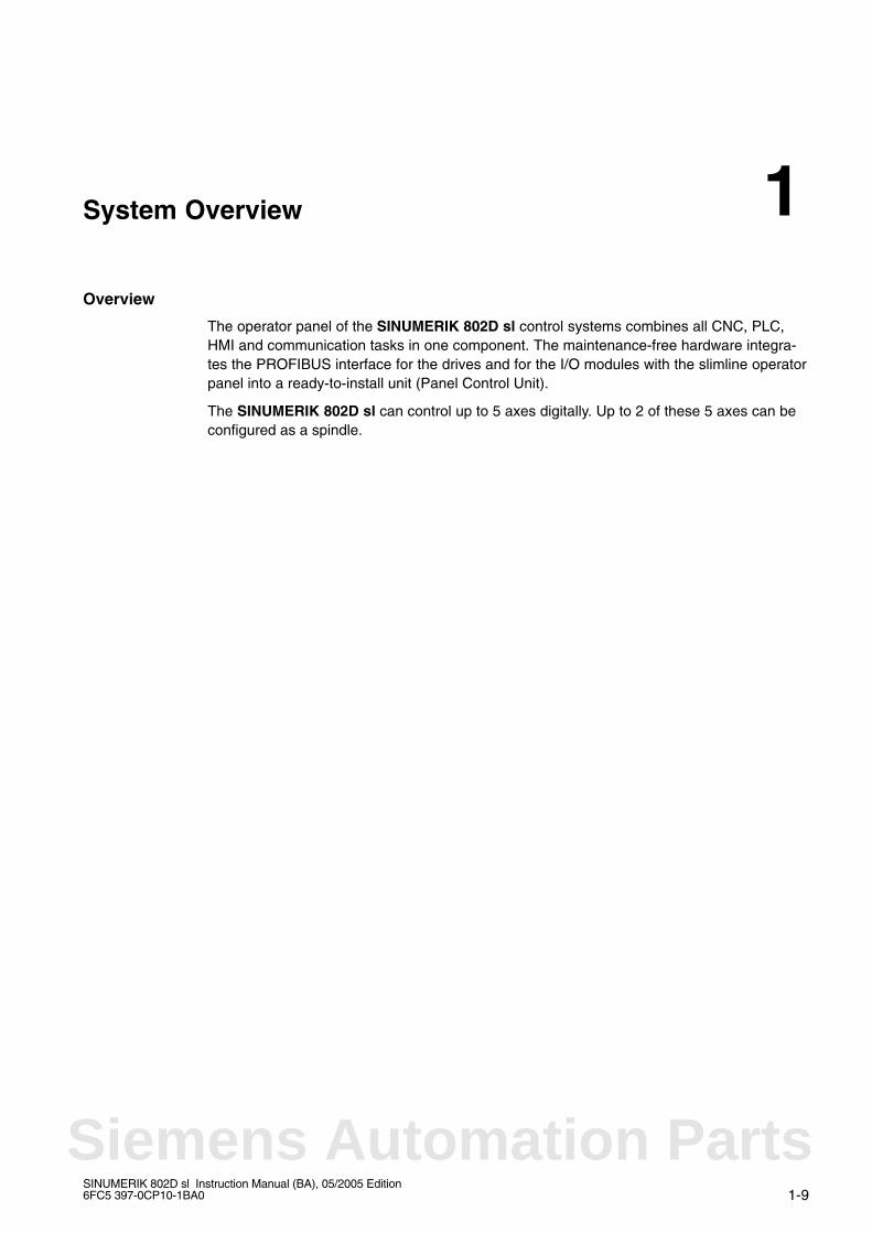
The operator panel of the SINUMERIK 802D sl control systems combines all CNC, PLC,HMI and communication tasks in one component. The maintenance-free hardware integra-tes the PROFIBUS interface for the drives and for the I/O modules with the slimline operatorpanel into a ready-to-install unit (Panel Control Unit).
The SINUMERIK 802D sl can control up to 5 axes digitally. Up to 2 of these 5 axes can beconfigured as a spindle.
1
Siemens Automation Parts
System Overview
1-10SINUMERIK 802D sl Instruction Manual (BA), 05/2005 Edition
6FC5 397-0CP10-1BA0
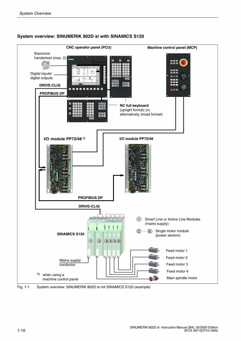
System overview: SINUMERIK 802D sl with SINAMICS S120
Digital inputs/digital outputs
CNC operator panel (PCU)
Feed motor 1
Feed motor 2
Feed motor 3
Feed motor 4
Electronic handwheel (max. 2)
Main spindle motor1) when using a
machine control panel
I/O module PP72/48 1)
PROFIBUS DP
PROFIBUS DP
DRIVE-CLiQ
DRIVE-CLiQ
NC full keyboard (upright format) (or, alternatively, broad format)
SINAMICS S120
Machine control panel (MCP)
1
2 6
Smart Line or Active Line Modules(mains supply)
Single motor module(power section)
...
Mains supplyconductor
654321
I/O module PP72/48
Fig. 1-1 System overview: SINUMERIK 802D sl mit SINAMICS S120 (example)
System Overview
1-11SINUMERIK 802D sl Instruction Manual (BA), 05/2005 Edition6FC5 397-0CP10-1BA0
Components
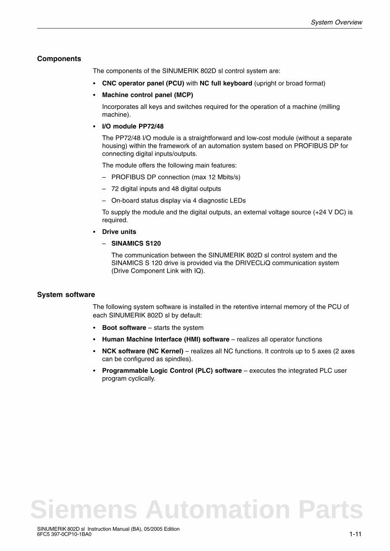
The components of the SINUMERIK 802D sl control system are:
CNC operator panel (PCU) with NC full keyboard (upright or broad format)
Machine control panel (MCP)
Incorporates all keys and switches required for the operation of a machine (millingmachine).
I/O module PP72/48
The PP72/48 I/O module is a straightforward and low-cost module (without a separatehousing) within the framework of an automation system based on PROFIBUS DP forconnecting digital inputs/outputs.
The module offers the following main features:
– PROFIBUS DP connection (max 12 Mbits/s)
– 72 digital inputs and 48 digital outputs
– On-board status display via 4 diagnostic LEDs
To supply the module and the digital outputs, an external voltage source (+24 V DC) isrequired.
Drive units
– SINAMICS S120
The communication between the SINUMERIK 802D sl control system and theSINAMICS S 120 drive is provided via the DRIVECLiQ communication system(Drive Component Link with IQ).
System software
The following system software is installed in the retentive internal memory of the PCU ofeach SINUMERIK 802D sl by default:
Boot software – starts the system
Human Machine Interface (HMI) software – realizes all operator functions
NCK software (NC Kernel) – realizes all NC functions. It controls up to 5 axes (2 axescan be configured as spindles).
Programmable Logic Control (PLC) software – executes the integrated PLC userprogram cyclically.
Siemens Automation Parts

System Overview
1-12SINUMERIK 802D sl Instruction Manual (BA), 05/2005 Edition
6FC5 397-0CP10-1BA0
Toolbox
A tool box is delivered on CD ROM together with the appropriate system software.
The toolbox contains software tools for configuring the control system. It must be installedon your PC/PG.
The following software can be found in the Toolbox:
Setup file for the technologies
Cycle packages for the technologies
Reloadable languages
Reloadable system blocks (SDB)
RCS802D Commissioning and Diagnostic tool
This program can be used to transfer texts, user data and programs from the PC to theCNC operator panel (PCU) and vice versa.
“PLC 802 Programming Tool” – tool for creating the PLC user program
PLC user library
“Starter” – parameterization and commissioning tool for the SINAMICS drive
Note
The table of contents and notes for setup can be found in the siemense.txt file.

2-13SINUMERIK 802D sl Instruction Manual (BA), 05/2005 Edition6FC5 397-0CP10-1BA0
Description 2
Siemens Automation Parts
Description
2-14SINUMERIK 802D sl Instruction Manual (BA), 05/2005 Edition
6FC5 397-0CP10-1BA0
View
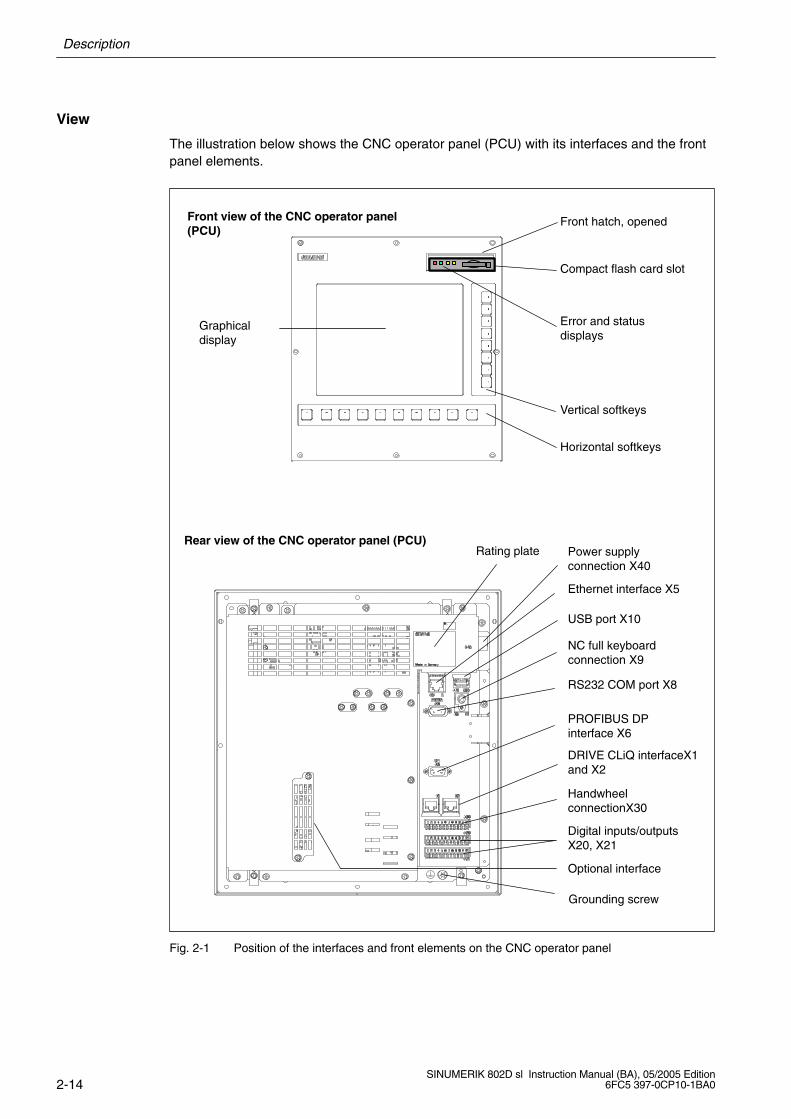
The illustration below shows the CNC operator panel (PCU) with its interfaces and the frontpanel elements.
Graphicaldisplay
Front view of the CNC operator panel(PCU)
Rear view of the CNC operator panel (PCU)
Horizontal softkeys
Vertical softkeys
Power supplyconnection X40
Ethernet interface X5
NC full keyboardconnection X9
PROFIBUS DPinterface X6
DRIVE CLiQ interfaceX1and X2
Digital inputs/outputsX20, X21
RS232 COM port X8
USB port X10
HandwheelconnectionX30
Compact flash card slot
Error and statusdisplays
Front hatch, opened
Optional interface
Grounding screw
Rating plate
Fig. 2-1 Position of the interfaces and front elements on the CNC operator panel
Description
2-15SINUMERIK 802D sl Instruction Manual (BA), 05/2005 Edition6FC5 397-0CP10-1BA0
CNC operator panel (PCU) interfaces
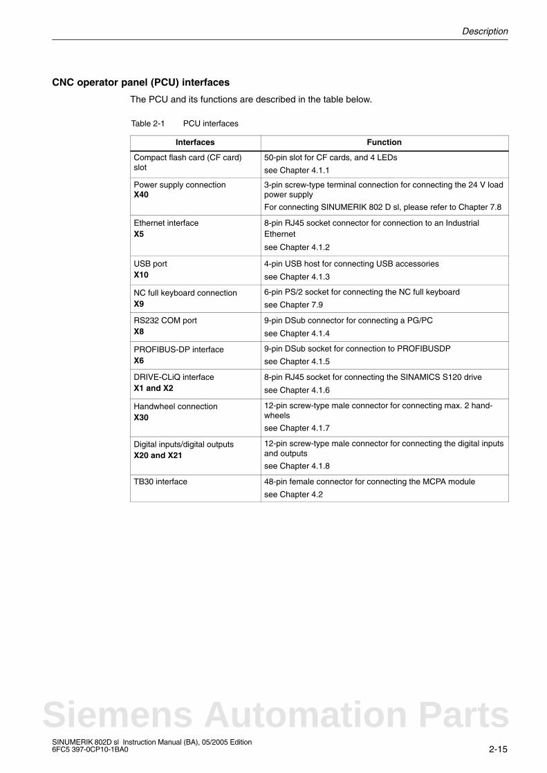
The PCU and its functions are described in the table below.
Table 2-1 PCU interfaces
Interfaces Function
Compact flash card (CF card)slot
50-pin slot for CF cards, and 4 LEDs
see Chapter 4.1.1
Power supply connectionX40
3-pin screw-type terminal connection for connecting the 24 V loadpower supply
For connecting SINUMERIK 802 D sl, please refer to Chapter 7.8
Ethernet interfaceX5
8-pin RJ45 socket connector for connection to an IndustrialEthernet
see Chapter 4.1.2
USB portX10
4-pin USB host for connecting USB accessories
see Chapter 4.1.3
NC full keyboard connectionX9
6-pin PS/2 socket for connecting the NC full keyboard
see Chapter 7.9
RS232 COM portX8
9-pin DSub connector for connecting a PG/PC
see Chapter 4.1.4
PROFIBUS-DP interfaceX6
9-pin DSub socket for connection to PROFIBUSDP
see Chapter 4.1.5
DRIVE-CLiQ interfaceX1 and X2
8-pin RJ45 socket for connecting the SINAMICS S120 drive
see Chapter 4.1.6
Handwheel connectionX30
12-pin screw-type male connector for connecting max. 2 hand-wheels
see Chapter 4.1.7
Digital inputs/digital outputsX20 and X21
12-pin screw-type male connector for connecting the digital inputsand outputs
see Chapter 4.1.8
TB30 interface 48-pin female connector for connecting the MCPA module
see Chapter 4.2
Siemens Automation Parts

Description
2-16SINUMERIK 802D sl Instruction Manual (BA), 05/2005 Edition
6FC5 397-0CP10-1BA0
Notes
3-17SINUMERIK 802D sl Instruction Manual (BA), 05/2005 Edition6FC5 397-0CP10-1BA0
Operator Controls and Displays
3.1 Operator controls
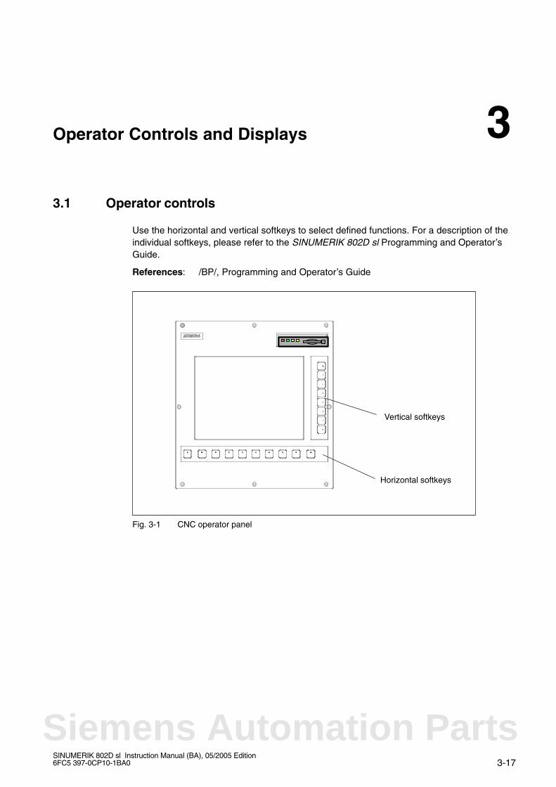
Use the horizontal and vertical softkeys to select defined functions. For a description of theindividual softkeys, please refer to the SINUMERIK 802D sl Programming and Operator’sGuide.
References: /BP/, Programming and Operator’s Guide
Horizontal softkeys
Vertical softkeys
Fig. 3-1 CNC operator panel
3
Siemens Automation Parts
3.2 Error and status displays
Operator Controls and Displays
3-18SINUMERIK 802D sl Instruction Manual (BA), 05/2005 Edition
6FC5 397-0CP10-1BA0
3.2 Error and status displays
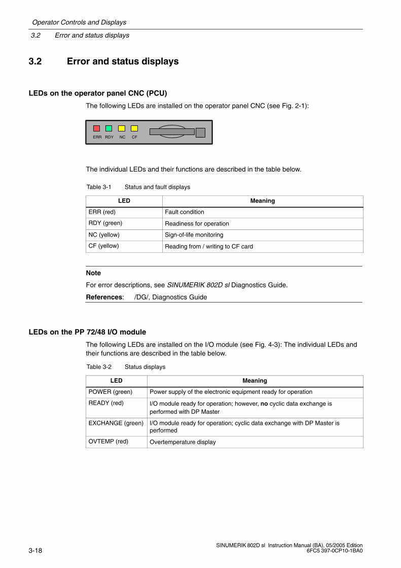
LEDs on the operator panel CNC (PCU)
The following LEDs are installed on the operator panel CNC (see Fig. 2-1):
ERR RDY NC DPERR RDY NC CF
The individual LEDs and their functions are described in the table below.
Table 3-1 Status and fault displays
LED Meaning
ERR (red) Fault condition
RDY (green) Readiness for operation
NC (yellow) Sign-of-life monitoring
CF (yellow) Reading from / writing to CF card
Note
For error descriptions, see SINUMERIK 802D sl Diagnostics Guide.
References: /DG/, Diagnostics Guide
LEDs on the PP 72/48 I/O module
The following LEDs are installed on the I/O module (see Fig. 4-3): The individual LEDs andtheir functions are described in the table below.
Table 3-2 Status displays
LED Meaning
POWER (green) Power supply of the electronic equipment ready for operation
READY (red) I/O module ready for operation; however, no cyclic data exchange isperformed with DP Master
EXCHANGE (green) I/O module ready for operation; cyclic data exchange with DP Master isperformed
OVTEMP (red) Overtemperature display

4-19SINUMERIK 802D sl Instruction Manual (BA), 05/2005 Edition6FC5 397-0CP10-1BA0
Interfaces
4.1 CNC operator panel (PCU) interfaces
4.1.1 Compact flash card (CF card) slot
Only type 1 compact flash cards can be used.
The compact flash card can be used, for example:
for start-up data
for NC programs
to carry out software updates
to store user data
to save parameters which have been set by the user.
4
Siemens Automation Parts
4.1 CNC operator panel (PCU) interfaces
Interfaces
4-20SINUMERIK 802D sl Instruction Manual (BA), 05/2005 Edition
6FC5 397-0CP10-1BA0
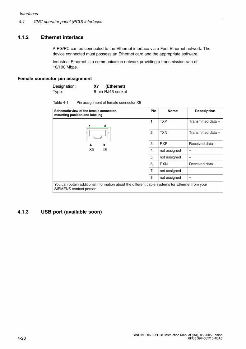
4.1.2 Ethernet interface
A PG/PC can be connected to the Ethernet interface via a Fast Ethernet network. Thedevice connected must possess an Ethernet card and the appropriate software.
Industrial Ethernet is a communication network providing a transmission rate of10/100 Mbps.
Female connector pin assignment
Designation: X7 (Ethernet)Type: 8-pin RJ45 socket
Table 4-1 Pin assignment of female connector X5
Schematic view of the female connector, mounting position and labeling
Pin Name Description
1 81 TXP Transmitted data +
2 TXN Transmitted data –
A B 3 RXP Received data +
X5 IEA B
4 not assigned –
5 not assigned –
6 RXN Received data –
7 not assigned –
8 not assigned –
You can obtain additional information about the different cable systems for Ethernet from your SIEMENS contact person.
4.1.3 USB port (available soon)

Interfaces
4.1 CNC operator panel (PCU) interfaces
4-21SINUMERIK 802D sl Instruction Manual (BA), 05/2005 Edition6FC5 397-0CP10-1BA0
4.1.4 RS232 COM interface
A PC/programming device (PG) for data exchange with the CNC operator panel can be con-nected to male connector X8.
Connector pin assignment
Designation: X8 (RS232)Type: 9-pin D-Sub plug terminal strip
Table 4-2 Pin assignment of connector X8
Schematic view of the femaleconnector, mounting position and labeling
Pin Name Description
X8RS232
1 DCD Received LineSignal DetectorCarrier Detector
Received signal level
1 2 RXD Received Data Received data
3 TXD Transmitted Data Transmitted data9 4 DTR Data Terminal
ReadyTerminal ready
5 M Ground Ground (GND)
6 DSR Data Set Ready Readiness foroperation
7 RTS Request To Send Transmission request
8 CTS Clear To Send Ready to send
9 notassigned
– –
Siemens Automation Parts
4.1 CNC operator panel (PCU) interfaces
Interfaces
4-22SINUMERIK 802D sl Instruction Manual (BA), 05/2005 Edition
6FC5 397-0CP10-1BA0
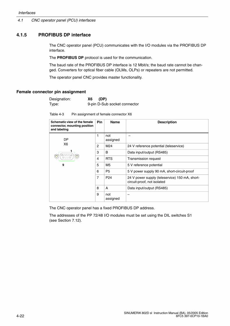
4.1.5 PROFIBUS DP interface
The CNC operator panel (PCU) communicates with the I/O modules via the PROFIBUS DPinterface.
The PROFIBUS DP protocol is used for the communication.
The baud rate of the PROFIBUS DP interface is 12 Mbit/s; the baud rate cannot be chan-ged. Converters for optical fiber cable (OLMs, OLPs) or repeaters are not permitted.
The operator panel CNC provides master functionality.
Female connector pin assignment
Designation: X6 (DP)Type: 9-pin D-Sub socket connector
Table 4-3 Pin assignment of female connector X6
Schematic view of the femaleconnector, mounting positionand labeling
Pin Name Description
X6DP
1 notassigned
–
X6 2 M24 24 V reference potential (teleservice)1 3 B Data input/output (RS485)
4 RTS Transmission request
9 5 M5 5 V reference potential
6 P5 5 V power supply 90 mA, short-circuit-proof
7 P24 24 V power supply (teleservice) 150 mA, short-circuit-proof, not isolated
8 A Data input/output (RS485)
9 notassigned
–
The CNC operator panel has a fixed PROFIBUS DP address.
The addresses of the PP 72/48 I/O modules must be set using the DIL switches S1(see Section 7.12).
Interfaces
4.1 CNC operator panel (PCU) interfaces
4-23SINUMERIK 802D sl Instruction Manual (BA), 05/2005 Edition6FC5 397-0CP10-1BA0
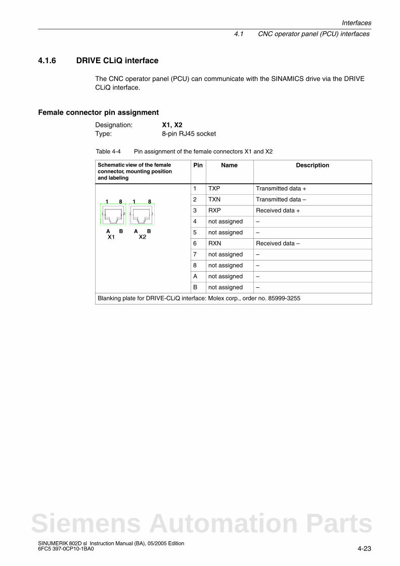
4.1.6 DRIVE CLiQ interface
The CNC operator panel (PCU) can communicate with the SINAMICS drive via the DRIVECLiQ interface.
Female connector pin assignment
Designation: X1, X2Type: 8-pin RJ45 socket
Table 4-4 Pin assignment of the female connectors X1 and X2
Schematic view of the femaleconnector, mounting positionand labeling
Pin Name Description
1 TXP Transmitted data +
81 8 1 2 TXN Transmitted data –81 8 1
3 RXP Received data +
4 not assigned –
X1 X2A AB B 5 not assigned –X1 X2
6 RXN Received data –
7 not assigned –
8 not assigned –
A not assigned –
B not assigned –
Blanking plate for DRIVE-CLiQ interface: Molex corp., order no. 85999-3255
Siemens Automation Parts
4.1 CNC operator panel (PCU) interfaces
Interfaces
4-24SINUMERIK 802D sl Instruction Manual (BA), 05/2005 Edition
6FC5 397-0CP10-1BA0
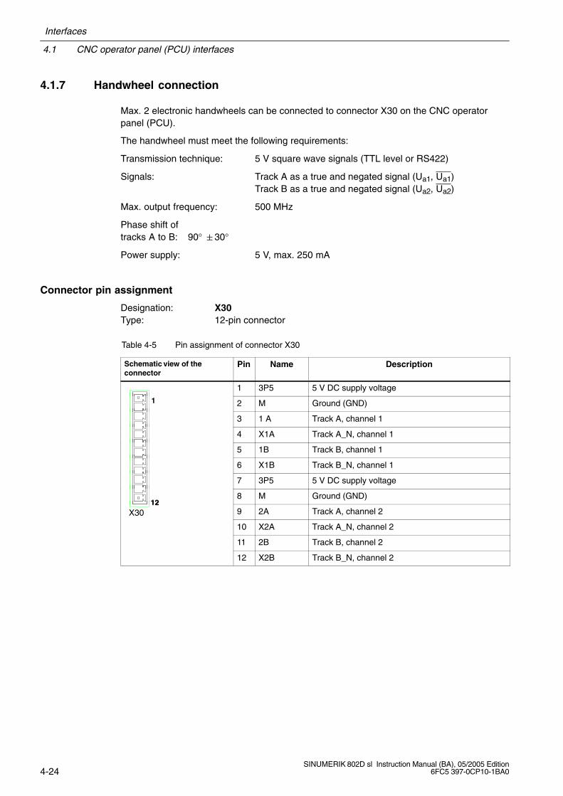
4.1.7 Handwheel connection
Max. 2 electronic handwheels can be connected to connector X30 on the CNC operatorpanel (PCU).
The handwheel must meet the following requirements:
Transmission technique: 5 V square wave signals (TTL level or RS422)
Signals: Track A as a true and negated signal (Ua1, Ua1)Track B as a true and negated signal (Ua2, Ua2)
Max. output frequency: 500 MHz
Phase shift oftracks A to B: 90° 30°
Power supply: 5 V, max. 250 mA
Connector pin assignment
Designation: X30Type: 12-pin connector
Table 4-5 Pin assignment of connector X30
Schematic view of theconnector
Pin Name Description
1 3P5 5 V DC supply voltage
1 2 M Ground (GND)
3 1 A Track A, channel 1
4 X1A Track A_N, channel 1
5 1B Track B, channel 1
6 X1B Track B_N, channel 1
7 3P5 5 V DC supply voltage
128 M Ground (GND)
X3012
9 2A Track A, channel 2
10 X2A Track A_N, channel 2
11 2B Track B, channel 2
12 X2B Track B_N, channel 2
Interfaces
4.1 CNC operator panel (PCU) interfaces
4-25SINUMERIK 802D sl Instruction Manual (BA), 05/2005 Edition6FC5 397-0CP10-1BA0
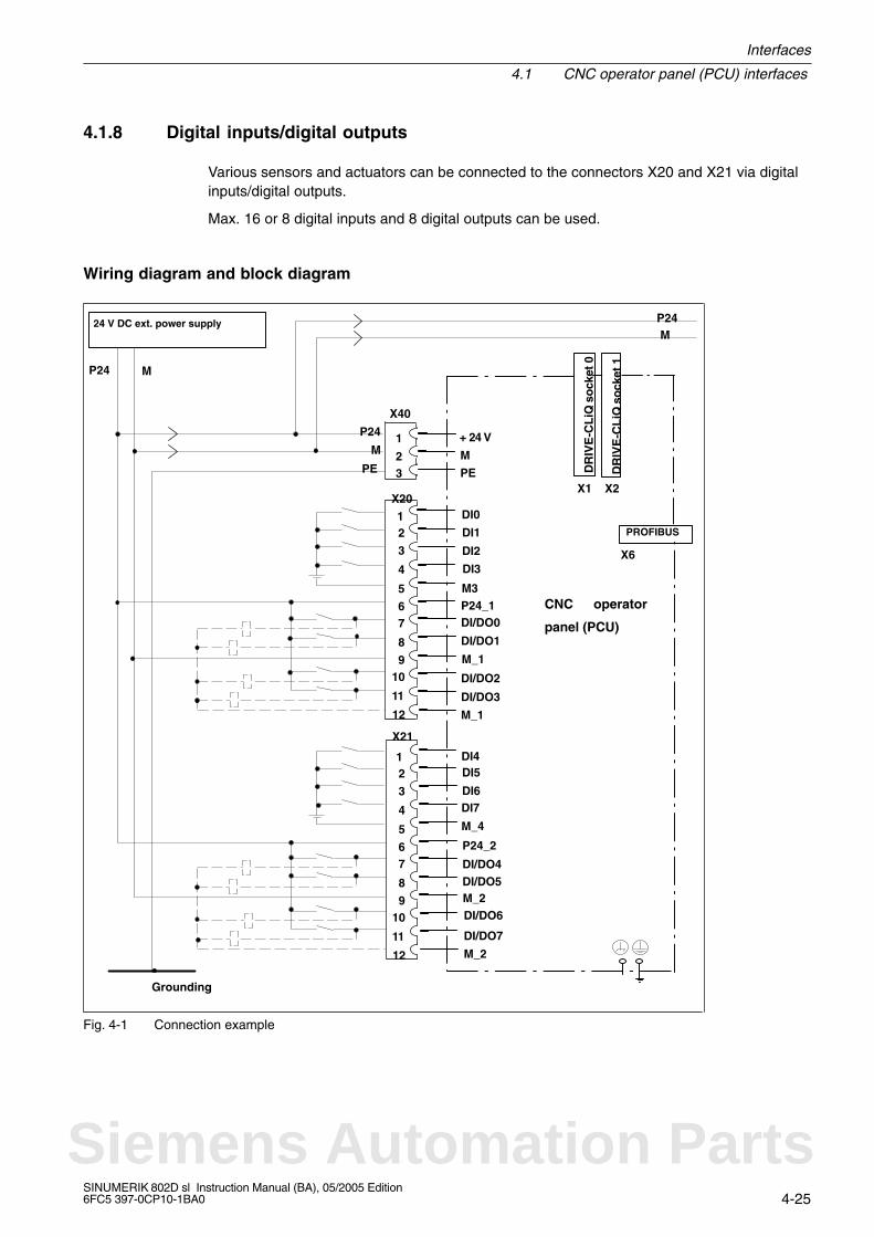
4.1.8 Digital inputs/digital outputs
Various sensors and actuators can be connected to the connectors X20 and X21 via digitalinputs/digital outputs.
Max. 16 or 8 digital inputs and 8 digital outputs can be used.
Wiring diagram and block diagram
PROFIBUS
DR
IVE
-CL
iQ s
ock
et 1
X1 X2
CNC operator
panel (PCU)
DR
IVE
-CL
iQ s
ock
et 0
X21
X20
24 V DC ext. power supply
X40
P24
M
PE PE
M
+ 24 V
MP24
DI1
DI0
DI3
DI2
P24_1M3
DI/DO1
DI/DO0
DI/DO2
M_1
M_1
DI/DO3
DI5DI4
DI7DI6
P24_2
M_4
DI/DO5DI/DO4
DI/DO6M_2
M_2
DI/DO7
1
12
P24 M
2
3
4
5
67
8
910
11
X6
1
12
2
3
4
5
67
8
910
11
Grounding
1
23
Fig. 4-1 Connection example
Siemens Automation Parts
4.1 CNC operator panel (PCU) interfaces
Interfaces
4-26SINUMERIK 802D sl Instruction Manual (BA), 05/2005 Edition
6FC5 397-0CP10-1BA0
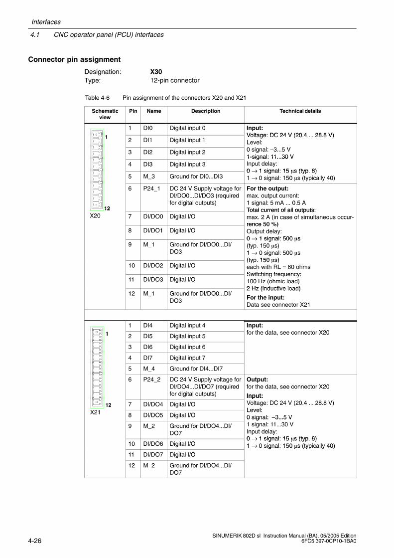
Connector pin assignment
Designation: X30Type: 12-pin connector
Table 4-6 Pin assignment of the connectors X20 and X21
Schematicview
Pin Name Description Technical details
1 DI0 Digital input 0 Input:Voltage: DC 24 V (20 4 28 8 V)1 2 DI1 Digital input 1Voltage: DC 24 V (20.4 ... 28.8 V)Level:
3 DI2 Digital input 2 0 signal: –3...5 V1-signal: 11...30 V
4 DI3 Digital input 31-signal: 11...30 VInput delay:0 → 1 signal: 15 s (typ 6)
5 M_3 Ground for DI0...DI30 → 1 signal: 15 s (typ. 6)1 → 0 signal: 150 s (typically 40)
12
6 P24_1 DC 24 V Supply voltage forDI/DO0...DI/DO3 (requiredfor digital outputs)
For the output:max. output current:1 signal: 5 mA ... 0.5 ATotal current of all outputs:
X2012
7 DI/DO0 Digital I/OTotal current of all outputs: max. 2 A (in case of simultaneous occur-rence 50 %)
8 DI/DO1 Digital I/Orence 50 %)Output delay:0 → 1 signal: 500 s
9 M_1 Ground for DI/DO0...DI/DO3
0 → 1 signal: 500 s(typ. 150 s)1 → 0 signal: 500 s(typ 150 s)
10 DI/DO2 Digital I/O(typ. 150 s)each with RL = 60 ohmsSwitching frequency:
11 DI/DO3 Digital I/OSwitching frequency:100 Hz (ohmic load)2 Hz (inductive load)
12 M_1 Ground for DI/DO0...DI/DO3
2 Hz (inductive load)
For the input:Data see connector X21
1 DI4 Digital input 4 Input:f th d t t X201 2 DI5 Digital input 5for the data, see connector X20
3 DI6 Digital input 6
4 DI7 Digital input 7
5 M_4 Ground for DI4...DI7
6 P24_2 DC 24 V Supply voltage forDI/DO4...DI/DO7 (requiredfor digital outputs)
Output:for the data, see connector X20
Input:
X2112 7 DI/DO4 Digital I/O
Input:Voltage: DC 24 V (20.4 ... 28.8 V)Level:X21 8 DI/DO5 Digital I/OLevel:0 signal: –3...5 V
9 M_2 Ground for DI/DO4...DI/DO7
0 signal: 3...5 V1 signal: 11...30 VInput delay:0 → 1 signal: 15 s (typ 6)
10 DI/DO6 Digital I/O0 → 1 signal: 15 s (typ. 6)1 → 0 signal: 150 s (typically 40)
11 DI/DO7 Digital I/O
1 → 0 signal: 150 s (typically 40)
12 M_2 Ground for DI/DO4...DI/DO7
Interfaces
4.1 CNC operator panel (PCU) interfaces
4-27SINUMERIK 802D sl Instruction Manual (BA), 05/2005 Edition6FC5 397-0CP10-1BA0
!Danger
The 24 V power supply is to be designed as functional extra-low voltage with protectiveseparation in accordance with EN60204-1, Section 6.4, PELV (with M ground).
Digital inputs (PCU)These fast inputs correspond to Standard IEC 1131-2/DIN EN 61131-2, characteristic curvetype 2 (24 V-P-switching). Switches or proximity encoders (2 or 3-wire encoders) can beconnected.
Digital outputs (PCU)These fast outputs (onboard) correspond to Standard IEC 1131-2/DIN EN 61131-2(24 V-P-switching).
Siemens Automation Parts
4.2 MCPA module interfaces
Interfaces
4-28SINUMERIK 802D sl Instruction Manual (BA), 05/2005 Edition
6FC5 397-0CP10-1BA0
4.2 MCPA module interfaces
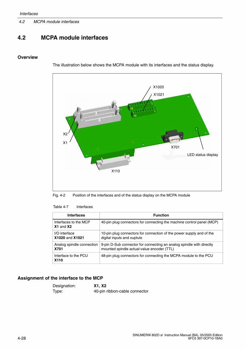
Overview
The illustration below shows the MCPA module with its interfaces and the status display.
X1020
X1021
X2
X1X701
X110
LED status display
1
1
10
10
Fig. 4-2 Position of the interfaces and of the status display on the MCPA module
Table 4-7 Interfaces
Interfaces Function
Interfaces to the MCPX1 and X2
40-pin plug connectors for connecting the machine control panel (MCP)
I/O interfaceX1020 and X1021
10-pin plug connectors for connection of the power supply and of thedigital inputs and ouptuts
Analog spindle connectionX701
9-pin D-Sub connector for connecting an analog spindle with directlymounted spindle actual-value encoder (TTL)
Interface to the PCUX110
48-pin plug connectors for connecting the MCPA module to the PCU
Assignment of the interface to the MCP
Designation: X1, X2Type: 40-pin ribbon-cable connector
Interfaces
4.2 MCPA module interfaces
4-29SINUMERIK 802D sl Instruction Manual (BA), 05/2005 Edition6FC5 397-0CP10-1BA0
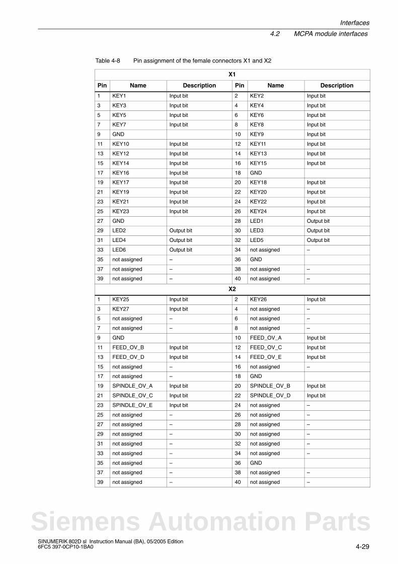
Table 4-8 Pin assignment of the female connectors X1 and X2
X1
Pin Name Description Pin Name Description
1 KEY1 Input bit 2 KEY2 Input bit
3 KEY3 Input bit 4 KEY4 Input bit
5 KEY5 Input bit 6 KEY6 Input bit
7 KEY7 Input bit 8 KEY8 Input bit
9 GND 10 KEY9 Input bit
11 KEY10 Input bit 12 KEY11 Input bit
13 KEY12 Input bit 14 KEY13 Input bit
15 KEY14 Input bit 16 KEY15 Input bit
17 KEY16 Input bit 18 GND
19 KEY17 Input bit 20 KEY18 Input bit
21 KEY19 Input bit 22 KEY20 Input bit
23 KEY21 Input bit 24 KEY22 Input bit
25 KEY23 Input bit 26 KEY24 Input bit
27 GND 28 LED1 Output bit
29 LED2 Output bit 30 LED3 Output bit
31 LED4 Output bit 32 LED5 Output bit
33 LED6 Output bit 34 not assigned –
35 not assigned – 36 GND
37 not assigned – 38 not assigned –
39 not assigned – 40 not assigned –
X2
1 KEY25 Input bit 2 KEY26 Input bit
3 KEY27 Input bit 4 not assigned –
5 not assigned – 6 not assigned –
7 not assigned – 8 not assigned –
9 GND 10 FEED_OV_A Input bit
11 FEED_OV_B Input bit 12 FEED_OV_C Input bit
13 FEED_OV_D Input bit 14 FEED_OV_E Input bit
15 not assigned – 16 not assigned –
17 not assigned – 18 GND
19 SPINDLE_OV_A Input bit 20 SPINDLE_OV_B Input bit
21 SPINDLE_OV_C Input bit 22 SPINDLE_OV_D Input bit
23 SPINDLE_OV_E Input bit 24 not assigned –
25 not assigned – 26 not assigned –
27 not assigned – 28 not assigned –
29 not assigned – 30 not assigned –
31 not assigned – 32 not assigned –
33 not assigned – 34 not assigned –
35 not assigned – 36 GND
37 not assigned – 38 not assigned –
39 not assigned – 40 not assigned –
Siemens Automation Parts
4.2 MCPA module interfaces
Interfaces
4-30SINUMERIK 802D sl Instruction Manual (BA), 05/2005 Edition
6FC5 397-0CP10-1BA0
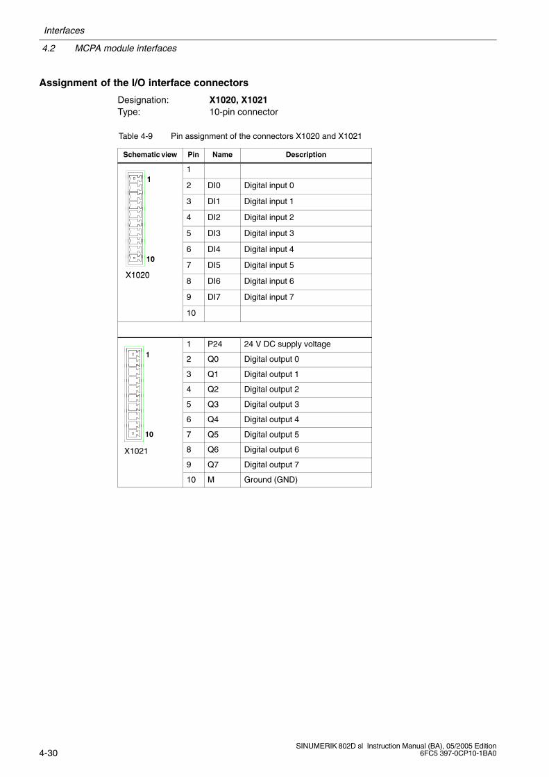
Assignment of the I/O interface connectors
Designation: X1020, X1021Type: 10-pin connector
Table 4-9 Pin assignment of the connectors X1020 and X1021
Schematic view Pin Name Description
11
12 DI0 Digital input 0
3 DI1 Digital input 1
4 DI2 Digital input 2
5 DI3 Digital input 3
106 DI4 Digital input 4
X1020
107 DI5 Digital input 5
X10208 DI6 Digital input 6
9 DI7 Digital input 7
10
11 P24 24 V DC supply voltage
1 2 Q0 Digital output 0
3 Q1 Digital output 1
4 Q2 Digital output 2
5 Q3 Digital output 3
6 Q4 Digital output 4
10 7 Q5 Digital output 5
X1021 8 Q6 Digital output 6
9 Q7 Digital output 7
10 M Ground (GND)
Interfaces
4.2 MCPA module interfaces
4-31SINUMERIK 802D sl Instruction Manual (BA), 05/2005 Edition6FC5 397-0CP10-1BA0
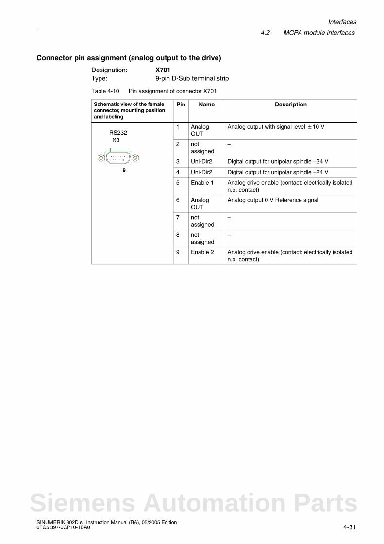
Connector pin assignment (analog output to the drive)
Designation: X701Type: 9-pin D-Sub terminal strip
Table 4-10 Pin assignment of connector X701
Schematic view of the femaleconnector, mounting positionand labeling
Pin Name Description
X8RS232
1 AnalogOUT
Analog output with signal level 10 V
X8
12 not
assigned–
3 Uni-Dir2 Digital output for unipolar spindle +24 V9 4 Uni-Dir2 Digital output for unipolar spindle +24 V
5 Enable 1 Analog drive enable (contact: electrically isolatedn.o. contact)
6 AnalogOUT
Analog output 0 V Reference signal
7 notassigned
–
8 notassigned
–
9 Enable 2 Analog drive enable (contact: electrically isolatedn.o. contact)
Siemens Automation Parts
4.3 PP 72/48 I/O module interfaces
Interfaces
4-32SINUMERIK 802D sl Instruction Manual (BA), 05/2005 Edition
6FC5 397-0CP10-1BA0
4.3 PP 72/48 I/O module interfaces
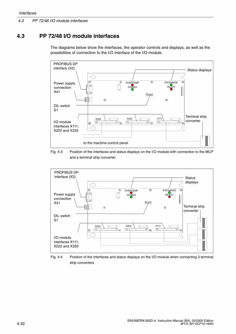
The diagrams below show the interfaces, the operator controls and displays, as well as thepossibilities of connection to the I/O interface of the I/O module.
X333 X222 X111
EXCHANGE
READY
OVERTEMP
POWER
I/O moduleinterfaces X111,X222 and X333
Status displays
Terminal stripconverter
to the machine control panel
PROFIBUS DPinterface (X2)
Power supplyconnectionX41
DIL switchS1
Fig. 4-3 Position of the interfaces and status displays on the I/O module with connection to the MCP
and a terminal strip converter
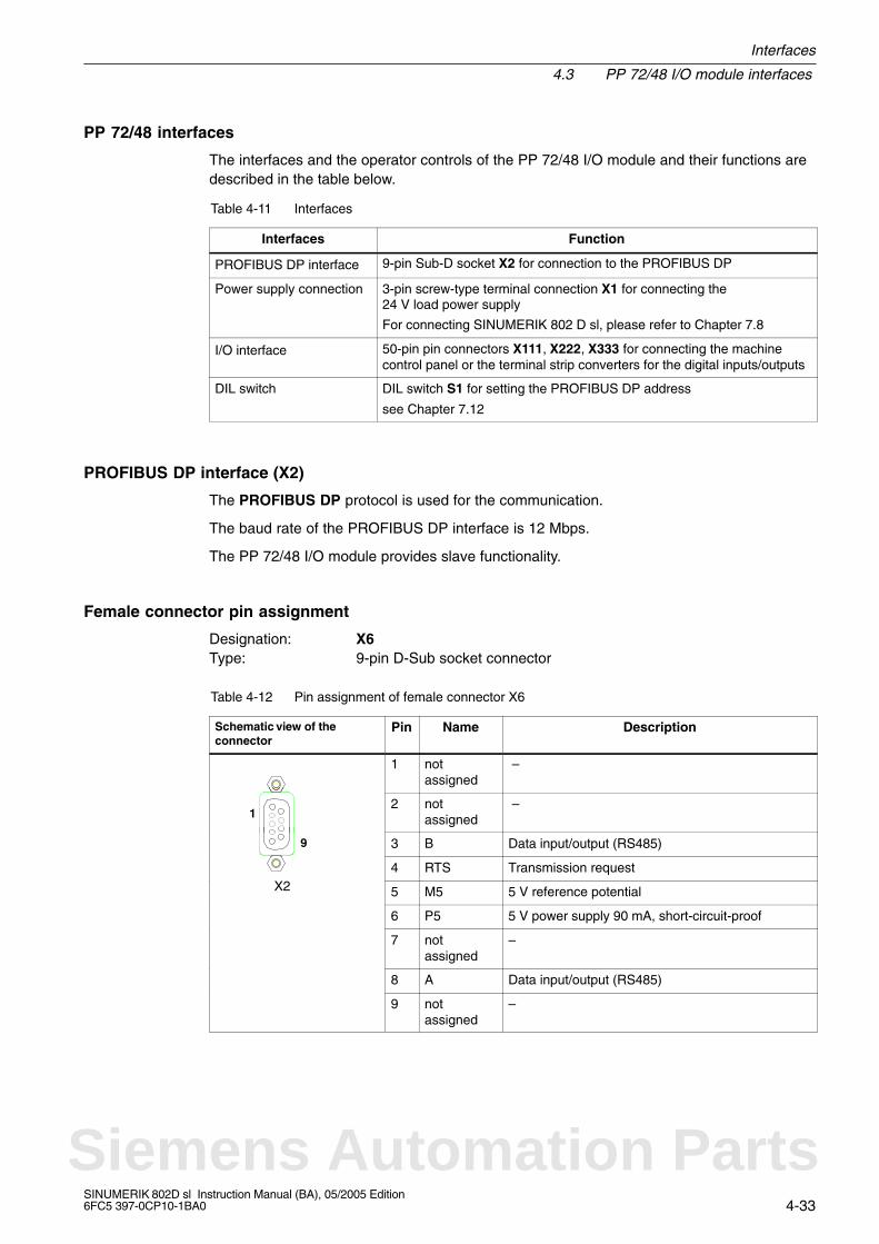
PROFIBUS DPinterface (X2)
Power supplyconnectionX41
I/O moduleinterfaces X111,X222 and X333
DIL switchS1
Statusdisplays
Terminal stripconverter
X333 X222 X111
EXCHANGE
READY
OVERTEMP
POWER
Fig. 4-4 Position of the interfaces and status displays on the I/O module when connecting 3 terminal
strip converters
Interfaces
4.3 PP 72/48 I/O module interfaces
4-33SINUMERIK 802D sl Instruction Manual (BA), 05/2005 Edition6FC5 397-0CP10-1BA0
PP 72/48 interfaces
The interfaces and the operator controls of the PP 72/48 I/O module and their functions aredescribed in the table below.
Table 4-11 Interfaces
Interfaces Function
PROFIBUS DP interface 9-pin Sub-D socket X2 for connection to the PROFIBUS DP
Power supply connection 3-pin screw-type terminal connection X1 for connecting the 24 V load power supply
For connecting SINUMERIK 802 D sl, please refer to Chapter 7.8
I/O interface 50-pin pin connectors X111, X222, X333 for connecting the machinecontrol panel or the terminal strip converters for the digital inputs/outputs
DIL switch DIL switch S1 for setting the PROFIBUS DP address
see Chapter 7.12
PROFIBUS DP interface (X2)
The PROFIBUS DP protocol is used for the communication.
The baud rate of the PROFIBUS DP interface is 12 Mbps.
The PP 72/48 I/O module provides slave functionality.
Female connector pin assignment
Designation: X6Type: 9-pin D-Sub socket connector
Table 4-12 Pin assignment of female connector X6
Schematic view of theconnector
Pin Name Description
1 notassigned
–
12 not
assigned –
9 3 B Data input/output (RS485)
4 RTS Transmission requestX2 5 M5 5 V reference potential
6 P5 5 V power supply 90 mA, short-circuit-proof
7 notassigned
–
8 A Data input/output (RS485)
9 notassigned
–
Siemens Automation Parts

4.3 PP 72/48 I/O module interfaces
Interfaces
4-34SINUMERIK 802D sl Instruction Manual (BA), 05/2005 Edition
6FC5 397-0CP10-1BA0
I/O interface
The following devices can be connected to the connectors X111, X222 and X333 (50-pin rib-bon-cable plug):
either one machine control panel (MCP) and one terminal strip converter for digital inputs/digital outputs (see Fig. 4-3)
or
three terminal strip converters for digital inputs/digital outputs (see Fig. 4-4)
The terminal strip converters are connected to the PP 72/48 I/O module via ribbon cable.The individual wiring can be performed at the terminal strips according to your particularapplication.
Connector pin assignment
Designation: X111, X222, X333Type: 50-pin ribbon-cable connector
Table 4-13 Pin assignment of the connectors X111, X222, X333
Pin Name Description Pin Name Description
1 M Ground (GND) 2 P24OUTINT DC 24 V, internal supplyvoltage for the inputs
3 DI m+0.0 Input bit 4 DI m+0.1 Input bit
5 DI m+0.2 Input bit 6 DI m+0.3 Input bit
7 DI m+0.4 Input bit 8 DI m+0.5 Input bit
9 DI m+0.6 Input bit 10 DI m+0.7 Input bit
11 DI m+1.0 Input bit 12 DI m+1.1 Input bit
13 DI m+1.2 Input bit 14 DI m+1.3 Input bit
15 DI m+1.4 Input bit 16 DI m+1.5 Input bit
17 DI m+1.6 Input bit 18 DI m+1.7 Input bit
19 DI m+2.0 Input bit 20 DI m+2.1 Input bit
21 DI m+2.2 Input bit 22 DI m+2.3 Input bit
23 DI m+2.4 Input bit 24 DI m+2.5 Input bit
25 DI m+2.6 Input bit 26 DI m+2.7 Input bit
27 notassigned
– 28 notassigned
–
29 notassigned
– 30 notassigned
–
31 DO n+0.0 Output bit 32 DO n+0.1 Output bit
33 DO n+0.2 Output bit 34 DO n+0.3 Output bit
35 DO n+0.4 Output bit 36 DO n+0.5 Output bit
37 DO n+0.6 Output bit 38 DO n+0.7 Output bit
39 DO n+1.0 Output bit 40 DO n+1.1 Output bit1) x = 1 for connector X111; x = 2 for connector X222; x = 3 for connector X333
m = 0 for connector X111; m = 3 for connector X222; m = 6 for connector X333n = 0 for connector X111; n = 2 for connector X222; n = 4 for connector X333

Interfaces
4.3 PP 72/48 I/O module interfaces
4-35SINUMERIK 802D sl Instruction Manual (BA), 05/2005 Edition6FC5 397-0CP10-1BA0
Table 4-13 Pin assignment of the connectors X111, X222, X333, continued
Pin DescriptionNamePinDescriptionName
41 DO n+1.2 Output bit 42 DO n+1.3 Output bit
43 DO n+1.4 Output bit 44 DO n+1.5 Output bit
45 DO n+1.6 Output bit 46 DO n+1.7 Output bit
47 DOCOMx1) DC 24 V Supply voltage for 48 DOCOMx1) DC 24 V Supply voltage for
49 DOCOMx1)
pp y gthe outputs 50 DOCOMx1)
pp y gthe outputs
1) x = 1 for connector X111; x = 2 for connector X222; x = 3 for connector X333m = 0 for connector X111; m = 3 for connector X222; m = 6 for connector X333n = 0 for connector X111; n = 2 for connector X222; n = 4 for connector X333
!Danger
The 24 V power supply is to be designed as functional extra-low voltage with protectiveseparation in accordance with EN60204-1, Section 6.4, PELV (with M ground).
Note
The connection cable between the voltage source and the load current supply connectorand the associated reference potential M should not exceed a maximum length of 10 m.
Siemens Automation Parts
4.3 PP 72/48 I/O module interfaces
Interfaces
4-36SINUMERIK 802D sl Instruction Manual (BA), 05/2005 Edition
6FC5 397-0CP10-1BA0
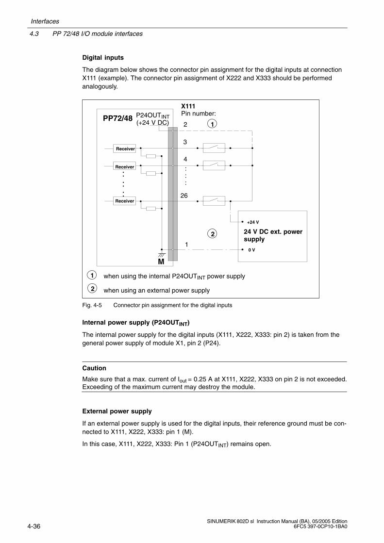
Digital inputs
The diagram below shows the connector pin assignment for the digital inputs at connectionX111 (example). The connector pin assignment of X222 and X333 should be performedanalogously.
PP72/48
X111Pin number:
2
26
4
3
:::
P24OUTINT(+24 V DC)
:::
M
1
24 V DC ext. powersupply
+24 V
0 V
1
Receiver
Receiver
Receiver
2
1
2
when using the internal P24OUTINT power supply
when using an external power supply
Fig. 4-5 Connector pin assignment for the digital inputs
Internal power supply (P24OUTINT)
The internal power supply for the digital inputs (X111, X222, X333: pin 2) is taken from thegeneral power supply of module X1, pin 2 (P24).
Caution
Make sure that a max. current of Iout = 0.25 A at X111, X222, X333 on pin 2 is not exceeded.Exceeding of the maximum current may destroy the module.
External power supply
If an external power supply is used for the digital inputs, their reference ground must be con-nected to X111, X222, X333: pin 1 (M).
In this case, X111, X222, X333: Pin 1 (P24OUTINT) remains open.
Interfaces
4.3 PP 72/48 I/O module interfaces
4-37SINUMERIK 802D sl Instruction Manual (BA), 05/2005 Edition6FC5 397-0CP10-1BA0
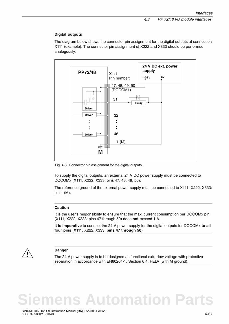
Digital outputs
The diagram below shows the connector pin assignment for the digital outputs at connectionX111 (example). The connector pin assignment of X222 and X333 should be performedanalogously.
Driver
Driver
Driver
::
PP72/48 X111Pin number:
47, 48, 49, 50(DOCOM1)
M
31
1 (M)
::
Relay
24 V DC ext. powersupply
+24 V 0V
32
46
Fig. 4-6 Connector pin assignment for the digital outputs
To supply the digital outputs, an external 24 V DC power supply must be connected toDOCOMx (X111, X222, X333: pins 47, 48, 49, 50).
The reference ground of the external power supply must be connected to X111, X222, X333:pin 1 (M).
Caution
It is the user’s responsibility to ensure that the max. current consumption per DOCOMx pin(X111, X222, X333: pins 47 through 50) does not exceed 1 A.
It is imperative to connect the 24 V power supply for the digital outputs for DOCOMx to allfour pins (X111, X222, X333: pins 47 through 50).
!Danger
The 24 V power supply is to be designed as functional extra-low voltage with protectiveseparation in accordance with EN60204-1, Section 6.4, PELV (with M ground).
Siemens Automation Parts
4.3 PP 72/48 I/O module interfaces
Interfaces
4-38SINUMERIK 802D sl Instruction Manual (BA), 05/2005 Edition
6FC5 397-0CP10-1BA0
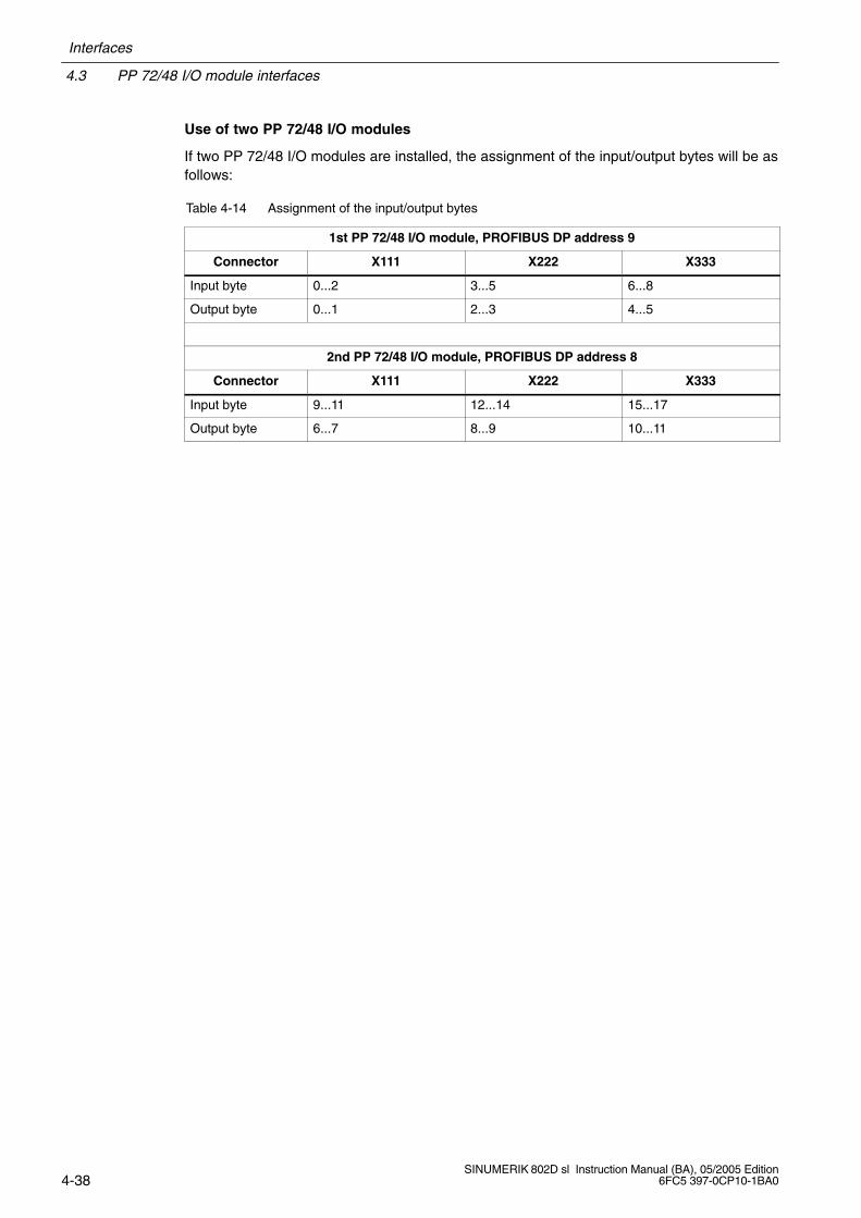
Use of two PP 72/48 I/O modules
If two PP 72/48 I/O modules are installed, the assignment of the input/output bytes will be asfollows:
Table 4-14 Assignment of the input/output bytes
1st PP 72/48 I/O module, PROFIBUS DP address 9
Connector X111 X222 X333
Input byte 0...2 3...5 6...8
Output byte 0...1 2...3 4...5
2nd PP 72/48 I/O module, PROFIBUS DP address 8
Connector X111 X222 X333
Input byte 9...11 12...14 15...17
Output byte 6...7 8...9 10...11

5-39SINUMERIK 802D sl Instruction Manual (BA), 05/2005 Edition6FC5 397-0CP10-1BA0
Dimension Drawings 5
Siemens Automation Parts
5.1 Dimension drawing and drilling pattern for the CNC operator panel (PCU)
Dimension Drawings
5-40SINUMERIK 802D sl Instruction Manual (BA), 05/2005 Edition
6FC5 397-0CP10-1BA0
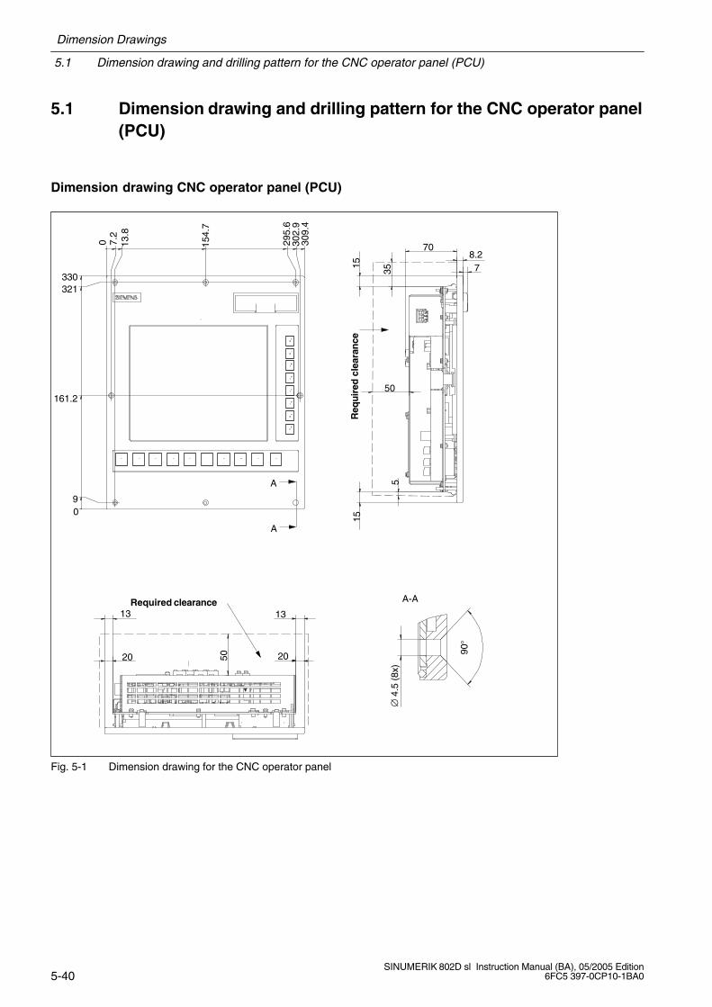
5.1 Dimension drawing and drilling pattern for the CNC operator panel(PCU)
Dimension drawing CNC operator panel (PCU)
Required clearance
Req
uir
ed c
lear
ance
708.27
50
330
1515
355
302.
929
5.6
7.2
13.8
0 309.
4
154.
7
161.2
90
321
90°
A
13
∅ 4
.5 (
8x)
A
5020
13
20
A-A
Fig. 5-1 Dimension drawing for the CNC operator panel

Dimension Drawings
5.1 Dimension drawing and drilling pattern for the CNC operator panel (PCU)
5-41SINUMERIK 802D sl Instruction Manual (BA), 05/2005 Edition6FC5 397-0CP10-1BA0
Drilling pattern for the CNC operator panel (PCU)
0
Z
281.
80.
15
295
0.15
140.
90.
1
281.
80.
15
5 1.6
285
0.3
23
3020.3
5
152
0.1
286.
60.
15
312
0.15
1)M
4 riv
et-d
own,
inse
rt n
ut o
r M
4 ex
trud
ed h
ole
(8x)
2)D
rill h
oles
for
fixin
g th
e po
sitio
n ∅
5.2
mm
(2x
)
Pan
el c
utou
t
Z M4
1)
2)2)
0.5
Fig. 5-2 Drilling pattern for the CNC operator panel
Siemens Automation Parts
5.2 Dimension drawing and drilling pattern for the machine control panel (MCP)
Dimension Drawings
5-42SINUMERIK 802D sl Instruction Manual (BA), 05/2005 Edition
6FC5 397-0CP10-1BA0
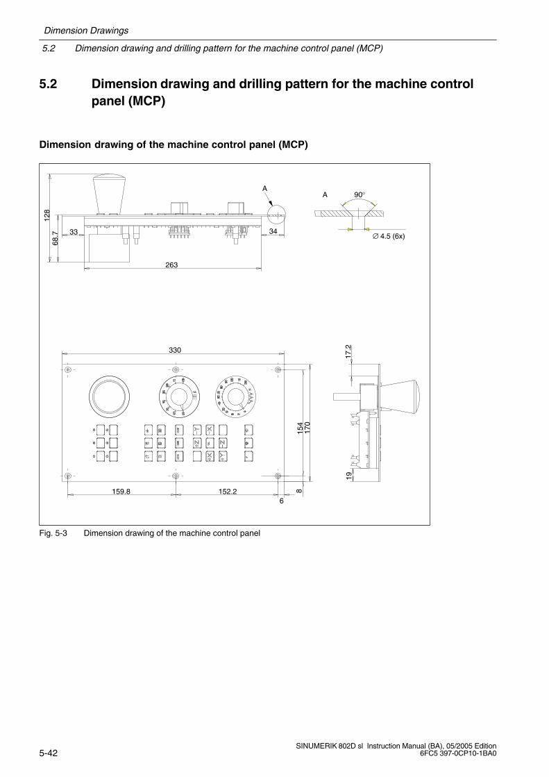
5.2 Dimension drawing and drilling pattern for the machine controlpanel (MCP)
Dimension drawing of the machine control panel (MCP)
6
128
68.7
170
19
3433
159.8
330
152.2
263
∅ 4.5 (6x)
154
17.2
8
90°AA
Fig. 5-3 Dimension drawing of the machine control panel
Dimension Drawings
5.2 Dimension drawing and drilling pattern for the machine control panel (MCP)
5-43SINUMERIK 802D sl Instruction Manual (BA), 05/2005 Edition6FC5 397-0CP10-1BA0
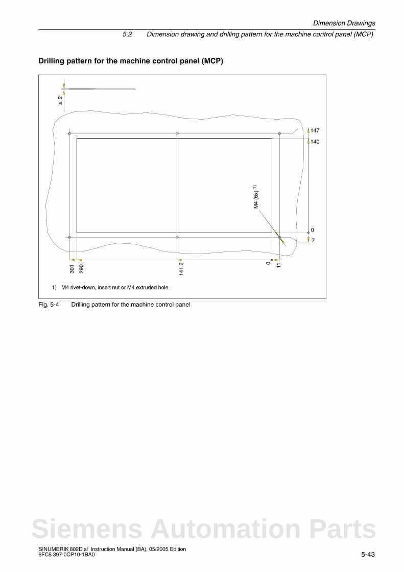
Drilling pattern for the machine control panel (MCP)
140
M4
(6x)
1)
290
147
301
141.
2 0
11
7
0
2
1) M4 rivet-down, insert nut or M4 extruded hole
Fig. 5-4 Drilling pattern for the machine control panel
Siemens Automation Parts
5.3 Dimension drawings and drilling patterns for the NC full keyboard
Dimension Drawings
5-44SINUMERIK 802D sl Instruction Manual (BA), 05/2005 Edition
6FC5 397-0CP10-1BA0
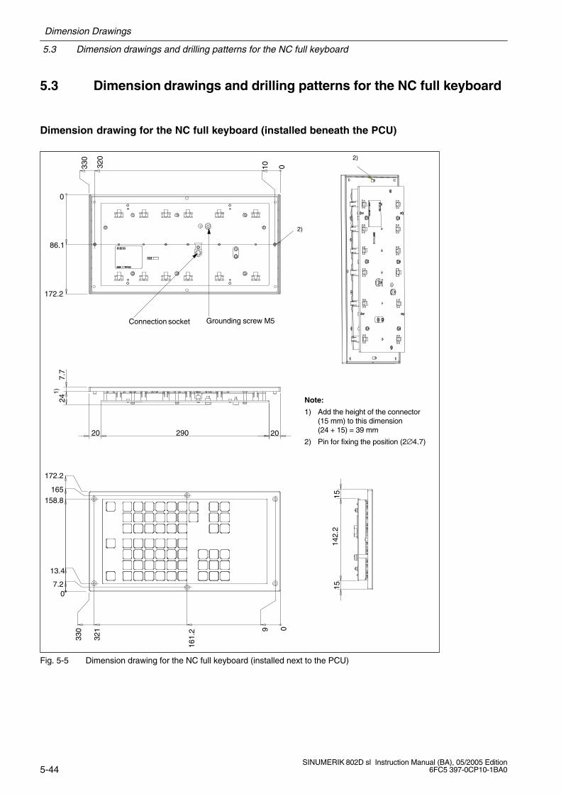
5.3 Dimension drawings and drilling patterns for the NC full keyboard
Dimension drawing for the NC full keyboard (installed beneath the PCU)
Connection socket
0
172.2
86.1
0
2)
320
001033
0
Grounding screw M5
290 2020
24
161.
2
7.7
157.2
165158.8
13.4
330
321 9
15
172.2
142.
2
Note:
1) Add the height of the connector(15 mm) to this dimension (24 + 15) = 39 mm
2) Pin for fixing the position (2∅4.7)
1)
2)
Fig. 5-5 Dimension drawing for the NC full keyboard (installed next to the PCU)

Dimension Drawings
5.3 Dimension drawings and drilling patterns for the NC full keyboard
5-45SINUMERIK 802D sl Instruction Manual (BA), 05/2005 Edition6FC5 397-0CP10-1BA0
Drilling pattern for the NC full keyboard (installed beneath the PCU)
1) M4 rivet-down, insert nut or extruded hole
2) Drill holes for fixing the position ∅ 5 mm (2x)
3) Please observe the cutting direction.
M4 (6x) 1)
146
151.9
0
Up 3)
73
145.7
0.3
143.
7
5 (2x) 2)
2+3
0.5
303.
5
302.
5
295
0 7.5
8.5
Fig. 5-6 Drilling pattern for the NC full keyboard (installed next to the PCU)
Siemens Automation Parts

5.3 Dimension drawings and drilling patterns for the NC full keyboard
Dimension Drawings
5-46SINUMERIK 802D sl Instruction Manual (BA), 05/2005 Edition
6FC5 397-0CP10-1BA0
Dimension drawing for the NC full keyboard (installed beneath the PCU)
0
309.4
302.2
0
7.2
154.7
145
0
87.5
24
2)
175
0
7.7
1)
2)
13.8
15
295.6
309.4
15
6
169
175
1527
9.4
15
Grounding screw M5
Connection socket
Note:
1) Add the height of the connector (15 mm) to this dimension (24 + 15) = 39 mm
2) Pin for fixing the position (2∅4.7)
Fig. 5-7 Dimension drawing for the NC full keyboard (installed beneath the PCU)
Dimension Drawings
5.3 Dimension drawings and drilling patterns for the NC full keyboard
5-47SINUMERIK 802D sl Instruction Manual (BA), 05/2005 Edition6FC5 397-0CP10-1BA0
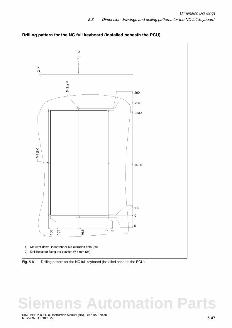
Drilling pattern for the NC full keyboard (installed beneath the PCU)
290
76.5
M4
(6x)
1)
153
158
0.5
5 (2
x) 2
)
2 +
3
142.5
285
283.4
1.6
0
5
50
1) M4 rivet-down, insert nut or M4 extruded hole (8x)
2) Drill holes for fixing the position ∅ 5 mm (2x)
Fig. 5-8 Drilling pattern for the NC full keyboard (installed beneath the PCU)
Siemens Automation Parts
5.4 Dimension drawing for the PP72/48 I/O module
Dimension Drawings
5-48SINUMERIK 802D sl Instruction Manual (BA), 05/2005 Edition
6FC5 397-0CP10-1BA0
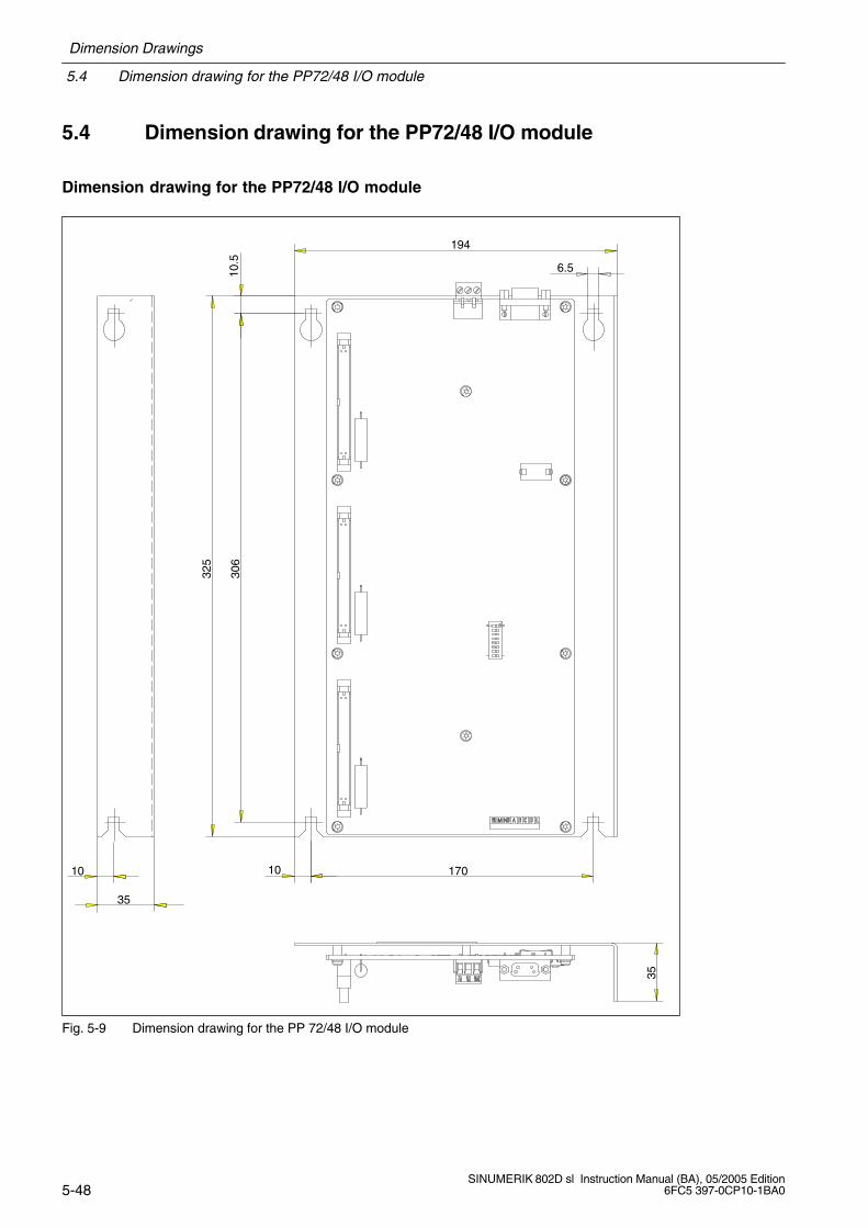
5.4 Dimension drawing for the PP72/48 I/O module
Dimension drawing for the PP72/48 I/O module32
5
10
194
6.5
306
10.5
10 170
35
35
Fig. 5-9 Dimension drawing for the PP 72/48 I/O module
6-49SINUMERIK 802D sl Instruction Manual (BA), 05/2005 Edition6FC5 397-0CP10-1BA0
Installation
Overview
To install SINUMERIK 802D sl, first secure the individual components on the site of installa-tion and then connect them with each other. When doing so, observe the Section “Configu-ring the electrical design” (see Chapter 7, “Connecting”).
Open-type equipment
The modules of SINUMERIK 802D sl are open-type equipment. This means that you areonly allowed to install SINUMERIK 802D sl in housings, cubicles or electrical service rooms.Access to these housings, cubicles or electrical service rooms must only be possible using akey or a tool and must be restricted to instructed or authorized personnel.
General procedure when installing SINUMERIK 802D sl
!Warning
Before installing or removing the components of the SINUMERIK 802D sl control system,make sure that the system is disconnected from the mains.
Note
When installing the control components, observe the dimensions given in Chapter 5. Thesedrilling patterns constitute the basis for preparing the mounting holes.
6
Siemens Automation Parts
Installation
6-50SINUMERIK 802D sl Instruction Manual (BA), 05/2005 Edition
6FC5 397-0CP10-1BA0
Mounting the CNC operator panel (PCU)
Install the CNC operator panel as shown on the relevant illustrations and diagrams 5-1and 5-2.
!Caution
If you do not have access from the rear during installation, you must connect the CNCoperator panel prior to its installation. When doing so, note that connector X40 (powersupplyconnection) and the lines connected to it protrude beyond the mounting edge.
When installing the CNC operator panel, do not pull off the connector; otherwise, thecables could be damaged!
Installing the machine control panel
Install the CNC operator panel as shown on the relevant illustrations and diagrams 5-3and 5-4.
Installing the CNC full keyboard
You can install the CNC full keyboard either next to the operator panel or beneath the CNCoperator panel. Observe the specifications in Figs. 5-5 through 5-8.
Installing the PP72/48 I/O module
This module must be installed according to EN 60204. For the dimension drawing of themodule, see Fig. 5-9.
Installing the SINAMICS S120 drive
For information regarding the SINAMICS S120 drive system (design, connection, planning,dimensioning, configuring, etc.), see:
References: /GH1/, /GH2/, Equipment Manuals
7-51SINUMERIK 802D sl Instruction Manual (BA), 05/2005 Edition6FC5 397-0CP10-1BA0
Connecting
General rules
The present chapter describes various general rules for electrical design. You must observethese rules to ensure trouble-free operation.
Safety rules
To ensure safe operation of your plant, realize the following measures and adapt them toyour particular conditions:
An EMERGENCY STOP strategy in accordance with generally accepted rules of currentengineering practice(e.g., European Standards EN 60204, EN 418, and the like).
additional measures for the limiting of limit positions of axes(e.g. hardware limit switches).
devices and measures for protection of motors and power electronics according to thedesign guidelines for SIMODRIVE or SINAMICS.
To identify hazard sources for the entire plant, we additionally recommend a risk analysis inaccordance with the general safety requirements/Annex 1 of the EC Machinery Directive89/392/EEC.
In this context, observe also Chapter D, “Guideline for handling electrostatically sensitivedevices (ESD)” in this Manual.
Further references
For further information on EMC guidelines, we recommend the publication: EMC InstallationGuideline, Planning Guide (HW)
References: /EMV/, Description
Standards and regulations
When connecting SINUMERIK 802D sl, please observe the relevant VDE guidelines, inparticular VDE 0100 or VDE 0113 for disconnecting devices, short-circuit and overloadprotection.
7
Siemens Automation Parts

7.1 General rules for operation of a SINUMERIK 802D sl
Connecting
7-52SINUMERIK 802D sl Instruction Manual (BA), 05/2005 Edition
6FC5 397-0CP10-1BA0
7.1 General rules for operation of a SINUMERIK 802D sl
When integrating a SINUMERIK 802D sl into a plant, you must observe the following generalrules.
Starting the plant after certain events
In case of ... ...
Startup after voltage drop or power failure all hazardous operating conditions must be avoi-ded. If necessary, force an EMERGENCY STOP.
A startup after unlocking the EMERGENCY-OFFequipment
no uncontrolled or undefined start must occur.
Mains voltage
With ... make sure that ...
stationary plants or systems without all-polemains disconnector
building installation must contain a mainsdisconnect switch or a fuse.
load power supplies, power supply modules the set range of the rated voltage complies withthe local mains voltage.
all current circuits deviation of the line voltage from the rated valuemust be within the permitted tolerance (refer to“Technical specifications of the installedcomponents”).
24 V DC power supply
With ... ensure ...
24 V supply safe (electrical) isolation of the low voltage
Protection against external electrical phenomena
With ... make sure that ...
all plants, installations and systems in which SINUMERIK is installed
the plant, installation or system is connected tothe protective conductor for divertingelectromagnetic interference.
power supply, signal, and bus cables the wiring arrangement and installation complieswith EMC regulations.
signal and bus cables a cable or wire break cannot lead to undefinedstatuses in the plant or system.
Connecting
7.2 Rules regarding current consumption and power loss of a cubicle arrangement
7-53SINUMERIK 802D sl Instruction Manual (BA), 05/2005 Edition6FC5 397-0CP10-1BA0
7.2 Rules regarding current consumption and power loss of a cubiclearrangement
The power loss of all components used in a cabinet must not exceed the maximum amountthat can be dissipated from the cabinet.
Note
When dimensioning the control cubicle, make sure that the permissible ambient temperatureis not exceeded for the components installed, even in case of high outside temperatures.
For the current consumption and the power loss of the individual modules, please refer toChapter 8, “Technical Specifications”.
Siemens Automation Parts
7.3 Overall design of the SINUMERIK 802D sl
Connecting
7-54SINUMERIK 802D sl Instruction Manual (BA), 05/2005 Edition
6FC5 397-0CP10-1BA0
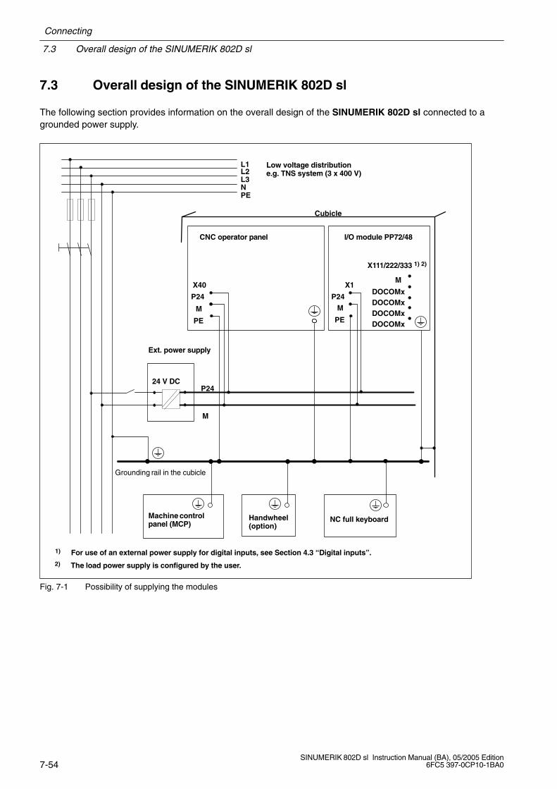
7.3 Overall design of the SINUMERIK 802D sl
The following section provides information on the overall design of the SINUMERIK 802D sl connected to agrounded power supply.
DOCOMx
L1L2L3NPE
CNC operator panel
Grounding rail in the cubicle
M
P24
X40
PE
24 V DC
Cubicle
X1
I/O module PP72/48
M
P24
PE
Low voltage distributione.g. TNS system (3 x 400 V)
Machine controlpanel (MCP)
NC full keyboardHandwheel(option)
P24
M
X111/222/333 1) 2)
M
DOCOMxDOCOMxDOCOMx
1) For use of an external power supply for digital inputs, see Section 4.3 “Digital inputs”.
Ext. power supply
2) The load power supply is configured by the user.
Fig. 7-1 Possibility of supplying the modules
Connecting
7.4 Connecting the protective conductor for the individual components
7-55SINUMERIK 802D sl Instruction Manual (BA), 05/2005 Edition6FC5 397-0CP10-1BA0
7.4 Connecting the protective conductor for the individualcomponents
!Caution
The components shown in Fig. 7-1 require connection to a protective conductor. Theindividual components must be connected to the central grounding point.
Make always sure that a low-resistance connection is provided to the protective conductor.
Minimum cross-section of the cable to the protective conductor: 10 mm2
Whereas all remaining components are grounded via a grounding screw, the PP72/48 I/Omodule must be connected directly to the central grounding point via the mounting plate(installation acc. to EN 60204). If no grounding can be provided via the mounting plate,it must be connected to the central grounding point via an additional line (cross-section> 10 mm2).
Siemens Automation Parts
7.5 Connection overview for the SINUMERIK 802D sl
Connecting
7-56SINUMERIK 802D sl Instruction Manual (BA), 05/2005 Edition
6FC5 397-0CP10-1BA0
7.5 Connection overview for the SINUMERIK 802D sl
SINUMERIK 802D slCNC operator panel (PCU)
X40 24 V DC power supply
X5Ethernet-bus cable
X10
X9 included in the scope ofsupply of the keyboard
X8
X6
X1 and X2
X30
X20andX21
Ethernet node
USB port
NC full keyboard
Electronic hand-wheel (max. 2)
Digital inputs/digital outputs
RS232 COMinterface
X111
X222
X333
X2
PP72/48 I/O module(max. 2)
X1
Machine control panel(MCP)
Terminal stripconverter
SINAMICS S120(max. 5 axes)
DRIVE-CLiQ
24 V DC power supply
Preassembled cableSingle wiring
X200
6FX80021BA01....
2 x 50-pin 2)
1) Delivered length: 50 m2) standard yard ware
Cable6FX8008-1BD61-1FA0 1)
3 mConnector6FC9348-7HX
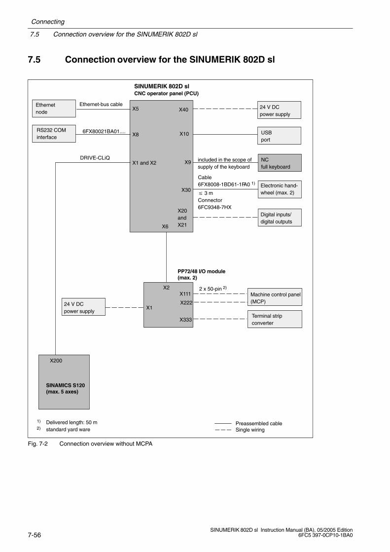
Fig. 7-2 Connection overview without MCPA
Connecting
7.5 Connection overview for the SINUMERIK 802D sl
7-57SINUMERIK 802D sl Instruction Manual (BA), 05/2005 Edition6FC5 397-0CP10-1BA0
SINUMERIK 802D slCNC operator panel (PCU)
X40 24 V DC power supply
X5Ethernet-bus cable
X10
X9 included in the scope ofsupply of the keyboard
X8
X6
X1 and X2
X30
X20andX21
Ethernet bus nodes
USB port
NC full keyboard
Electronic hand-wheel (max. 2)
Digital inputs/digital outputs
RS232 COM port
X111
X222
X333
X2
PP72/48 I/O module(max. 2)
X1Machine control panel(MCP)
MCPA module
SINAMICS S120(max. 5 axes)
DRIVE-CLiQ
24 V DC power supply
Preassembled cableSingle wiring
X200
6FX8002-1BA01-....
1) Delivery length: 50 m
Cable6FX8008-1BD61-1FA0 1)
3 mConnector6FC9348-7HX
Terminal stripconverter
X1201 X1202
X1 X2
X110
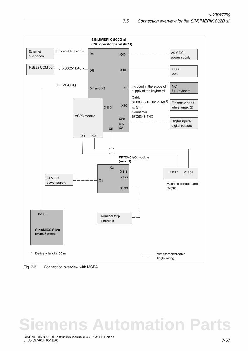
Fig. 7-3 Connection overview with MCPA
Siemens Automation Parts
7.5 Connection overview for the SINUMERIK 802D sl
Connecting
7-58SINUMERIK 802D sl Instruction Manual (BA), 05/2005 Edition
6FC5 397-0CP10-1BA0
Note
Connect the lines as shown in Fig. 7-2 or 7-3.
The preassembled cable sets from Siemens provide optimum interference immunity.
For information regarding the cables (cable designations, connector types, etc.) shown in theillustrations, see:
References: /BU/, Catalog or /Z/, Catalog
For information regarding PROFIBUS DP and Ethernet, see:
References: /IKPI/, Catalog

Connecting
7.6 Connecting the MCPA module
7-59SINUMERIK 802D sl Instruction Manual (BA), 05/2005 Edition6FC5 397-0CP10-1BA0
7.6 Connecting the MCPA module
The MCPA module is connected to the PCU via X110. The new machine control panel(MCP) is connected using the supplied ribbon cable. X1 is connected to X1201, and X2 toX1202 (see Fig. 7-3).
The power supply to the MCPA module is provided via connector X1021 (PIN1 24 V; PIN10 0 V).
Note
The variable assignment of the machine control panel is described in the PLC user interface(please refer to: Description of Functions 802Dsl).
See also: PLC subroutine library V01.07.00 of SINUMERIK 802D sl.
Siemens Automation Parts
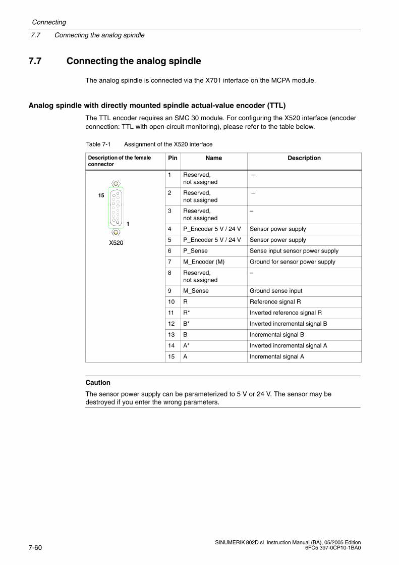
7.7 Connecting the analog spindle
Connecting
7-60SINUMERIK 802D sl Instruction Manual (BA), 05/2005 Edition
6FC5 397-0CP10-1BA0
7.7 Connecting the analog spindle
The analog spindle is connected via the X701 interface on the MCPA module.
Analog spindle with directly mounted spindle actual-value encoder (TTL)
The TTL encoder requires an SMC 30 module. For configuring the X520 interface (encoderconnection: TTL with open-circuit monitoring), please refer to the table below.
Table 7-1 Assignment of the X520 interface
Description of the femaleconnector
Pin Name Description
1 Reserved, not assigned
–
15 2 Reserved, not assigned
–
1
3 Reserved, not assigned
–
14 P_Encoder 5 V / 24 V Sensor power supply
X520 5 P_Encoder 5 V / 24 V Sensor power supplyX5206 P_Sense Sense input sensor power supply
7 M_Encoder (M) Ground for sensor power supply
8 Reserved, not assigned
–
9 M_Sense Ground sense input
10 R Reference signal R
11 R* Inverted reference signal R
12 B* Inverted incremental signal B
13 B Incremental signal B
14 A* Inverted incremental signal A
15 A Incremental signal A
Caution
The sensor power supply can be parameterized to 5 V or 24 V. The sensor may bedestroyed if you enter the wrong parameters.
Connecting
7.8 Connecting the power supply
7-61SINUMERIK 802D sl Instruction Manual (BA), 05/2005 Edition6FC5 397-0CP10-1BA0
7.8 Connecting the power supply
Connect the required 24 V DC load power supply to the following connectors:
to screw-terminal block X40 of the CNC operator panel
to screw-terminal block X1 of the PP72/48 I/O module
Features of the load power supply
!Danger
The 24 V DC protective extra-low voltage must be generated as a protective extra-lowvoltage with safe electrical isolation (to IEC 204-1, Section 6.4, PELV) and grounded by theuser (provide a PELV M signal connection to the central grounding point of the system).
Table 7-2 Electrical parameters of the load power supply for the CNC operator panel (X40) and forthe PP72/48 I/O module (X1)
Parameter Values Conditions
Voltage range mean value 20.4...28.8 V
Ripple 3.6 Vss
Non-periodic overvoltage 35 V500 ms duration50 s recovery time
Rated current consumption
CNC operator panel
PP72/48 I/O module
typically 1 A
–
Starting current
CNC operator panel
PP72/48 I/O module
2.6A
–
Power consumption
CNC operator panel
PP72/48 I/O module
max. 50 W
max. 11 W
Table 7-3 Pin assignment of the screw-terminal blocks X40 (on the PCU) and X1 (on the I/O module)
Terminal Signal Description
1 P24 24 V DC
2 M Ground (GND)
3 PE Protective earth
Note
Make sure that the interconnecting cable between the power supply and the load powersupply connection does not exceed a maximum length of 10 m (with PP72/48 I/O moduleonly).
Siemens Automation Parts
7.8 Connecting the power supply
Connecting
7-62SINUMERIK 802D sl Instruction Manual (BA), 05/2005 Edition
6FC5 397-0CP10-1BA0
Connecting the mains lines
!Warning
Before connecting the modules, first disconnect the equipment from the mains!
For connecting the power supply, use flexible lines with a line cross-section of at least1 mm2.
If you only connect one line per connection, end sleeves are not absolutely necessary.
If you connect several lines per connection, you should use end sleeves.
Remove the isolation from the cable end, fit an end sleeve if necessary, insert the cable end(with end sleeve) into the screw-terminal connection and tighten the fastening screw.
Insert the screw terminal with the cables to connection X40 on the CNC operator panel.
Polarity reversal protection
With correct connection and the power supply turned on, the LEDs “RDY” (PCU) and“POWER” (PP72/48) are lit in green.
Note
In case of polarity reversal, the control system will not work. However, a built-in reversepolarity protection facility protects the electronics against damage.
Fuse
In case of a defect in the control system, an internally installed fuse protects the electronicsfrom collateral damage (e.g. fire). In this case, the entire control system must be replaced.
Connecting
7.9 Connecting the full keyboard to the CNC operator panel
7-63SINUMERIK 802D sl Instruction Manual (BA), 05/2005 Edition6FC5 397-0CP10-1BA0
7.9 Connecting the full keyboard to the CNC operator panel
The interconnecting cable for connecting the NC full keyboard to the CNC operator panel isincluded in the scope of supply. Connect the female connector X9 on the CNC operatorpanel to the PS/2 socket on the rear of the NC full keyboard.
For more information, please refer to:
References: /BU/, Catalog
Siemens Automation Parts

7.10 Connecting the Ethernet interface
Connecting
7-64SINUMERIK 802D sl Instruction Manual (BA), 05/2005 Edition
6FC5 397-0CP10-1BA0
7.10 Connecting the Ethernet interface
Connect the Ethernet connection cable to the CNC operator panel, female connector X5.Make sure that the connector locks into position when connecting.
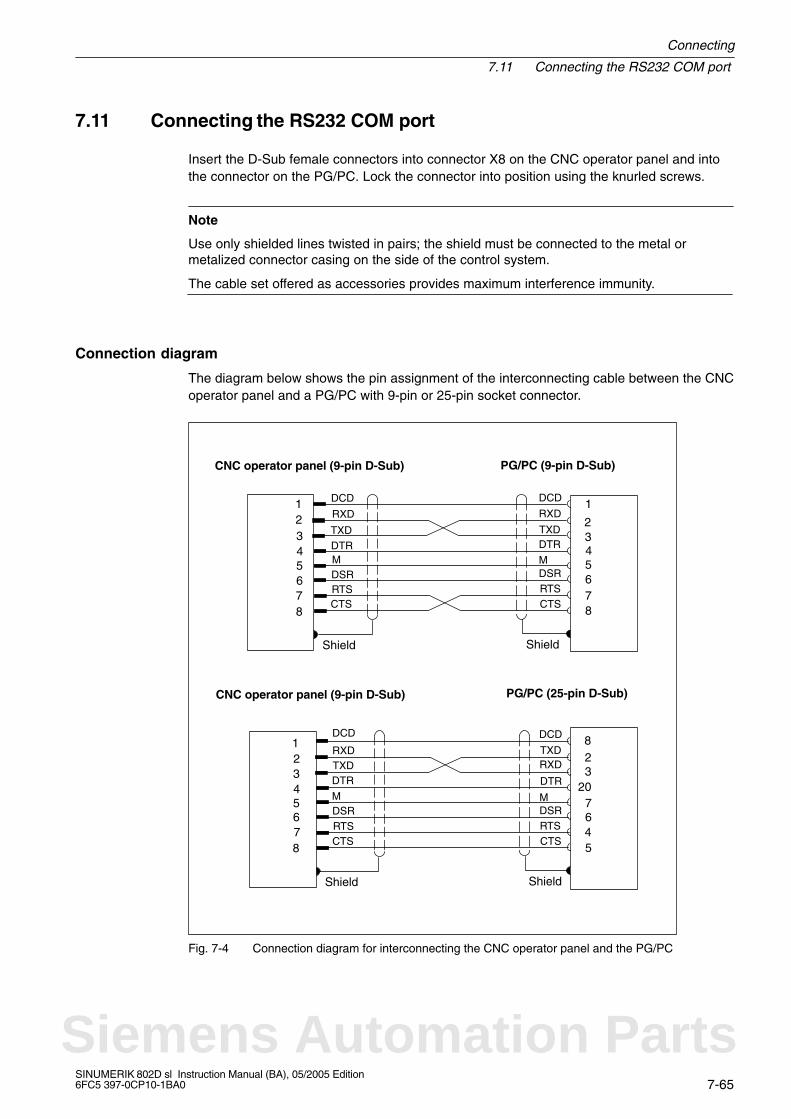
Connecting
7.11 Connecting the RS232 COM port
7-65SINUMERIK 802D sl Instruction Manual (BA), 05/2005 Edition6FC5 397-0CP10-1BA0
7.11 Connecting the RS232 COM port
Insert the D-Sub female connectors into connector X8 on the CNC operator panel and intothe connector on the PG/PC. Lock the connector into position using the knurled screws.
Note
Use only shielded lines twisted in pairs; the shield must be connected to the metal ormetalized connector casing on the side of the control system.
The cable set offered as accessories provides maximum interference immunity.
Connection diagram
The diagram below shows the pin assignment of the interconnecting cable between the CNCoperator panel and a PG/PC with 9-pin or 25-pin socket connector.
CNC operator panel (9-pin D-Sub) PG/PC (9-pin D-Sub)
CNC operator panel (9-pin D-Sub) PG/PC (25-pin D-Sub)
Shield Shield
RXD
TXD
RXD
TXD
MDSRRTSCTS
DSR
DTR
2
543
78
CTSRTS
DCD DCD
MDTR
1
6
Shield Shield
RXDTXDRXD TXD
MDSRRTSCTS
DSR
DTR
CTSRTS
DCD DCD
MDTR
2
720
3
45
8
6
2
543
78
1
6
2
543
78
1
6
Fig. 7-4 Connection diagram for interconnecting the CNC operator panel and the PG/PC
Siemens Automation Parts
7.12 Connecting the PP72/48 I/O module and the drive
Connecting
7-66SINUMERIK 802D sl Instruction Manual (BA), 05/2005 Edition
6FC5 397-0CP10-1BA0
7.12 Connecting the PP72/48 I/O module and the drive
PNO design guidelines
For electrical PROFIBUS networks, observe also the PROFIBUS DP/FMS design guidelinesof the PROFIBUS user organization. The contain important measures with reference to thecable routing and for starting up PROFIBUS networks.
Issued by: PROFIBUS-Nutzerorganisation e.V.Haid-und-Neu-Strasse 7D-76131 KarlsruheTel: +49 721 / 9658 590Fax: +49 721 / 9658 589Internet: http://www.profibus.com
Guideline, order no. 2.112
Bus stations
The following bus stations can be connected via the PROFIBUS DP interface:
CNC operator panel (always master)
PP72/48 I/O module (slave)
Bus connector and bus cable
The PROFIBUS cable is a two-core, stranded and shielded cable which must not be twisted,stretched or squeezed.
For more information regarding the bus connector, the bus cable and the cable length,please refer to:
References: /BU/, Catalog
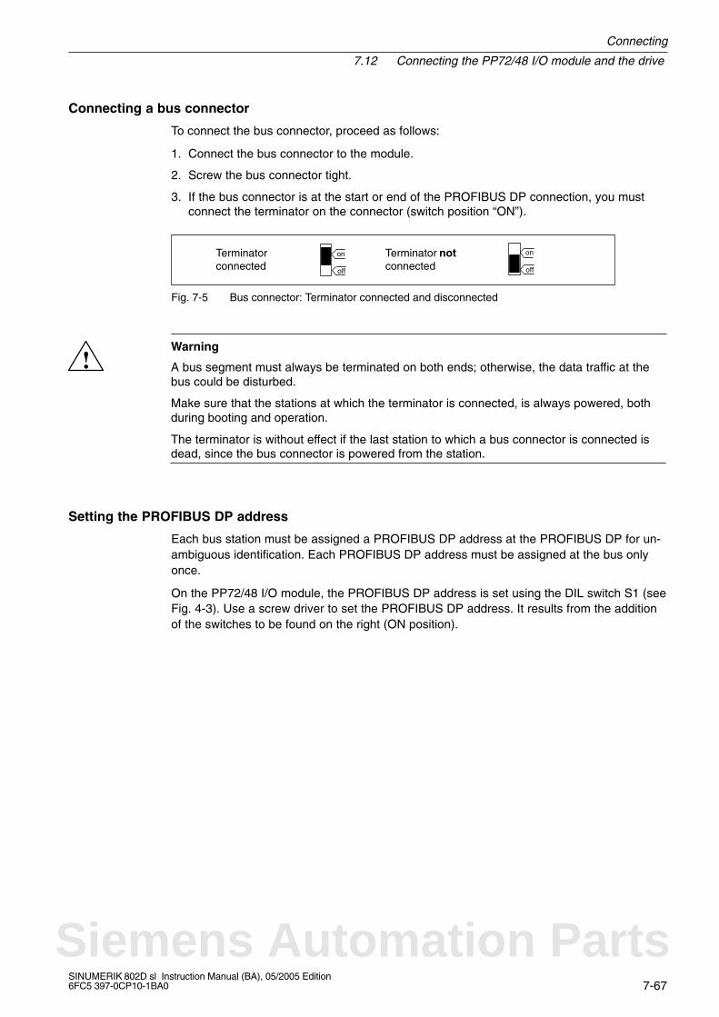
Connecting
7.12 Connecting the PP72/48 I/O module and the drive
7-67SINUMERIK 802D sl Instruction Manual (BA), 05/2005 Edition6FC5 397-0CP10-1BA0
Connecting a bus connector
To connect the bus connector, proceed as follows:
1. Connect the bus connector to the module.
2. Screw the bus connector tight.
3. If the bus connector is at the start or end of the PROFIBUS DP connection, you mustconnect the terminator on the connector (switch position “ON”).
Terminatorconnected
Terminator notconnected
on
off
on
off
Fig. 7-5 Bus connector: Terminator connected and disconnected
!Warning
A bus segment must always be terminated on both ends; otherwise, the data traffic at thebus could be disturbed.
Make sure that the stations at which the terminator is connected, is always powered, bothduring booting and operation.
The terminator is without effect if the last station to which a bus connector is connected isdead, since the bus connector is powered from the station.
Setting the PROFIBUS DP address
Each bus station must be assigned a PROFIBUS DP address at the PROFIBUS DP for un-ambiguous identification. Each PROFIBUS DP address must be assigned at the bus onlyonce.
On the PP72/48 I/O module, the PROFIBUS DP address is set using the DIL switch S1 (seeFig. 4-3). Use a screw driver to set the PROFIBUS DP address. It results from the additionof the switches to be found on the right (ON position).
Siemens Automation Parts
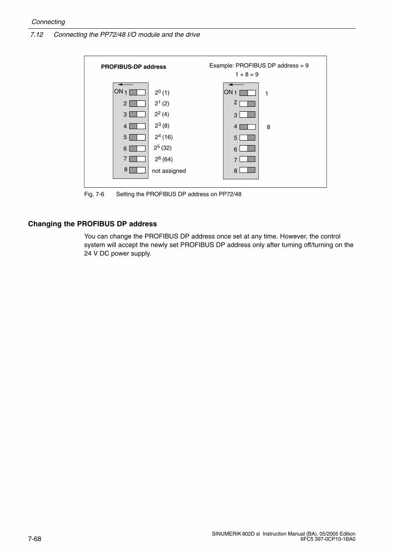
7.12 Connecting the PP72/48 I/O module and the drive
Connecting
7-68SINUMERIK 802D sl Instruction Manual (BA), 05/2005 Edition
6FC5 397-0CP10-1BA0
PROFIBUS-DP address
ÉÉÉÉÉÉÉÉÉÉ
ÉÉÉÉÉÉÉÉÉÉ
ÉÉÉÉ1
2
3
4
5
6
7
8
20 (1)
21 (2)
22 (4)
23 (8)
24 (16)
25 (32)
26 (64)
ON
Example: PROFIBUS DP address = 9
1
ÉÉ
ÉÉÉÉ
ÉÉÉÉ1
2
3
4
5
6
7
8
ON
not assigned
8
1 + 8 = 9
ÉÉÉÉ
ÉÉÉÉÉÉÉÉ
Fig. 7-6 Setting the PROFIBUS DP address on PP72/48
Changing the PROFIBUS DP address
You can change the PROFIBUS DP address once set at any time. However, the controlsystem will accept the newly set PROFIBUS DP address only after turning off/turning on the24 V DC power supply.
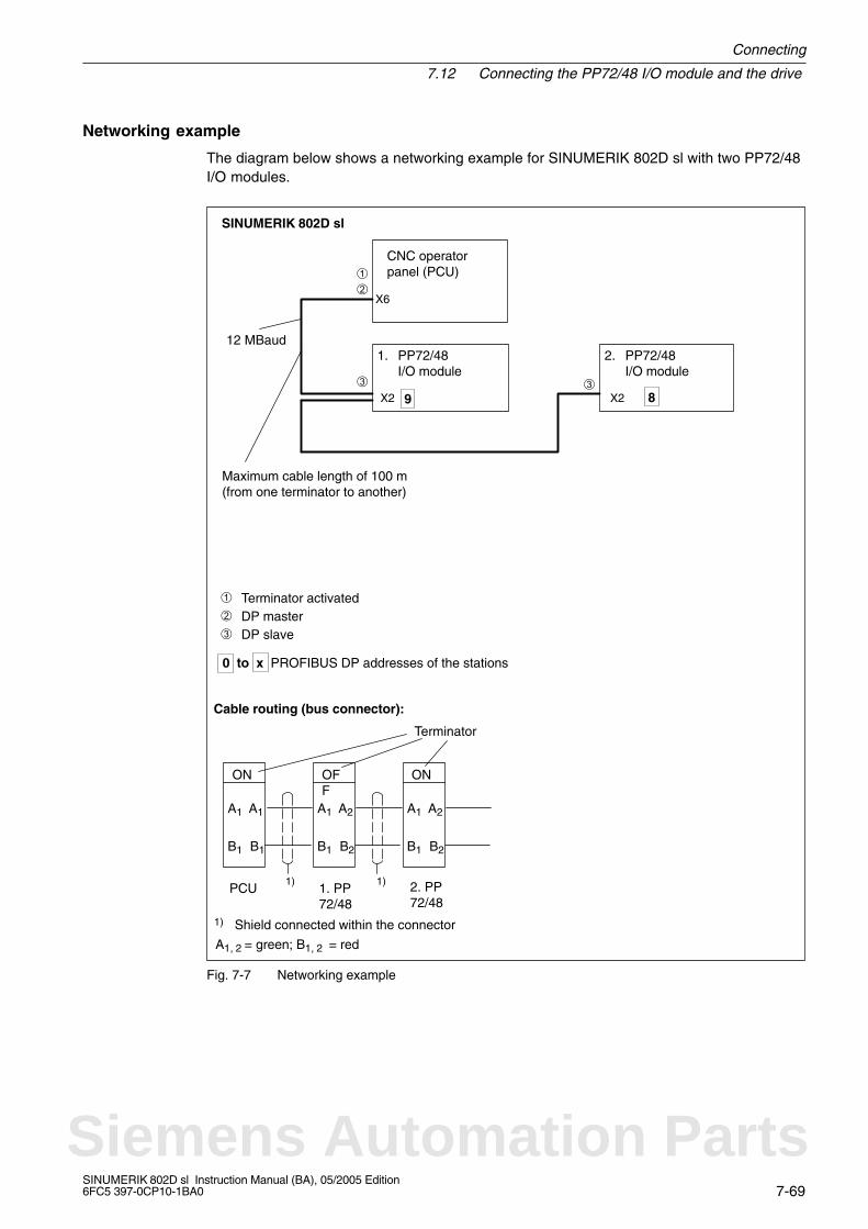
Connecting
7.12 Connecting the PP72/48 I/O module and the drive
7-69SINUMERIK 802D sl Instruction Manual (BA), 05/2005 Edition6FC5 397-0CP10-1BA0
Networking example
The diagram below shows a networking example for SINUMERIK 802D sl with two PP72/48I/O modules.
SINUMERIK 802D sl
X6
0 to x PROFIBUS DP addresses of the stations
CNC operatorpanel (PCU)
X2
1. PP72/48I/O module
X2
2. PP72/48I/O module
DP master DP slave
Terminator activated
Maximum cable length of 100 m (from one terminator to another)
12 MBaud
9 8
Cable routing (bus connector):
Terminator
A1
B1
ON
B1
A1 A1
B1
OFF
B2
A2 A1
B1
ON
B2
A2
PCU 1. PP72/48
2. PP72/48
1)
1) Shield connected within the connector
1)
A1, 2 = green; B1, 2 = red
Fig. 7-7 Networking example
Siemens Automation Parts
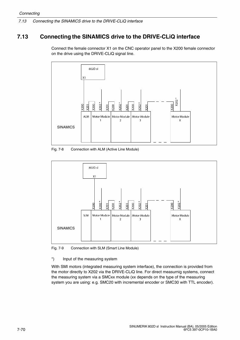
7.13 Connecting the SINAMICS drive to the DRIVE-CLiQ interface
Connecting
7-70SINUMERIK 802D sl Instruction Manual (BA), 05/2005 Edition
6FC5 397-0CP10-1BA0
7.13 Connecting the SINAMICS drive to the DRIVE-CLiQ interface
Connect the female connector X1 on the CNC operator panel to the X200 female connectoron the drive using the DRIVE-CLiQ signal line.
SINAMICS
Fig. 7-8 Connection with ALM (Active Line Module)
SINAMICS
Fig. 7-9 Connection with SLM (Smart Line Module)
*) Input of the measuring system
With SMI motors (integrated measuring system interface), the connection is provided fromthe motor directly to X202 via the DRIVE-CLiQ line. For direct measurnig systems, connectthe measuring system via a SMCxx module (xx depends on the type of the measuringsystem you are using: e.g. SMC20 with incremental encoder or SMC30 with TTL encoder).
Connecting
7.14 Connecting the digital inputs/outputs to the PCU
7-71SINUMERIK 802D sl Instruction Manual (BA), 05/2005 Edition6FC5 397-0CP10-1BA0
7.14 Connecting the digital inputs/outputs to the PCU
Connection cables
To connect the digital inputs and outputs, you should use flexible lines with a cross-sectionof at least 0.5 mm2.
If you only connect one line per connection, end sleeves are not absolutely necessary.
If you connect two lines per connection, lines with a cross-section between 0.25 and0.75 mm2 with end sleeve must be used.
Fasten the lines to the supplied screw terminals and insert the terminals to the connectorsX20 and X21 on the CNC operator panel.
Note
To ensure optimim interference immunity when connecting sensing probes or BEROs, it isimperative to use shielded lines.
The max. line length is 30 m.
Siemens Automation Parts
7.15 Connecting the digital inputs/digital outputs to the PP72/48 I/O module
Connecting
7-72SINUMERIK 802D sl Instruction Manual (BA), 05/2005 Edition
6FC5 397-0CP10-1BA0
7.15 Connecting the digital inputs/digital outputs to the PP72/48I/O module
You can use the I/O interfaces X111, X222, X333 as digital inputs or digital outputs. To thisend, fasten the insulation displacement connector to the ribbon cable and route it from theI/O module to the terminal strip converter. The individual wiring can be performed on the ter-minal strip connectors.
Remove the insulation from the cable end, insert the cable end (with end sleeve) into thescrew terminal connection and tighten the fastening screw.

Connecting
7.16 Connecting the machine control panel to the PP72/48 I/O module
7-73SINUMERIK 802D sl Instruction Manual (BA), 05/2005 Edition6FC5 397-0CP10-1BA0
7.16 Connecting the machine control panel to the PP72/48 I/O module
To connect the machine control panel (X1201 and X1202) to the PP72/48 I/O module (e.g. X222and X333), use two ribbon cables.
For more information, please refer to:
References: /BU/, Catalog
Note
More information regarding the machine control panel and the pin assignment of theconnectors X1201 and X1202 is to be found on the installed toolbox at:
Start > Programs > Toolbox802sl > PLC802slLibrary > Description.
Siemens Automation Parts
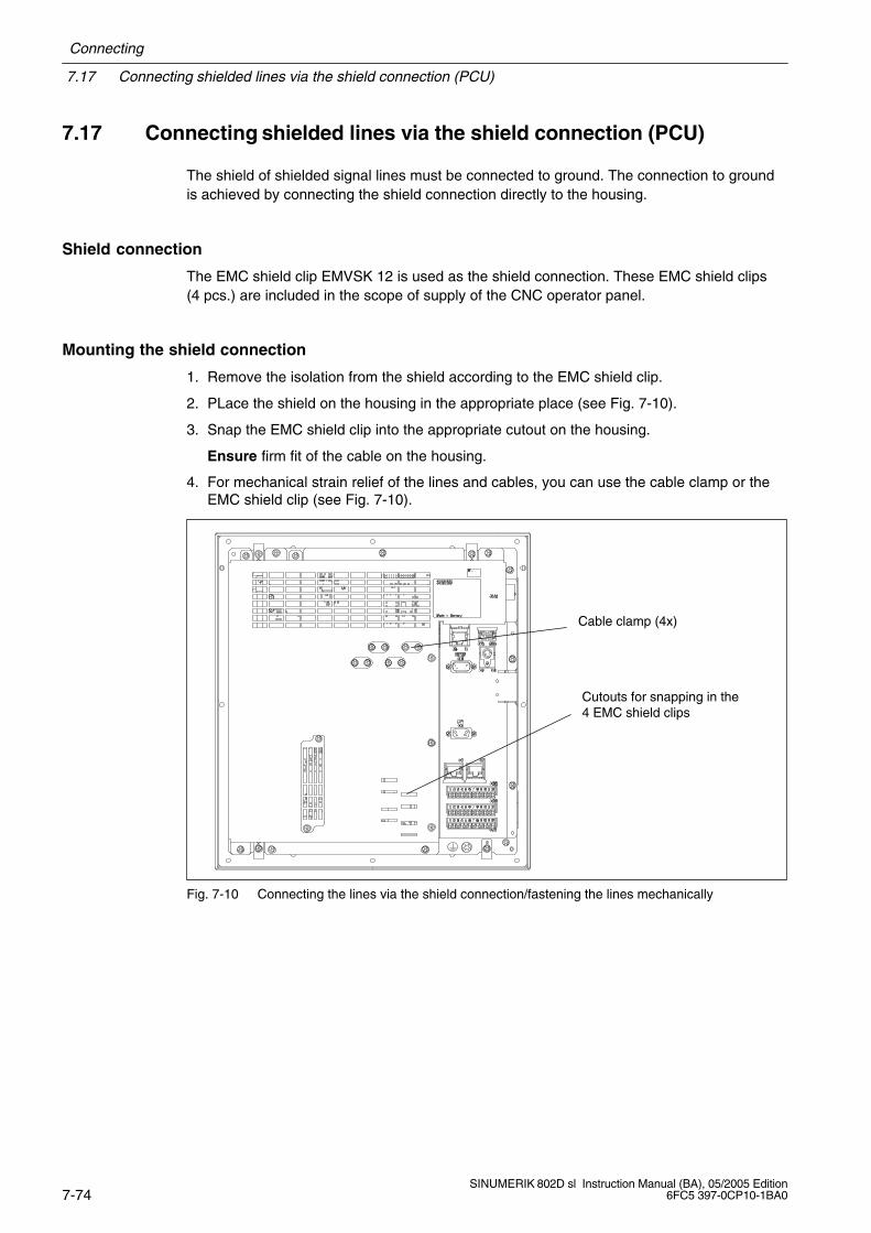
7.17 Connecting shielded lines via the shield connection (PCU)
Connecting
7-74SINUMERIK 802D sl Instruction Manual (BA), 05/2005 Edition
6FC5 397-0CP10-1BA0
7.17 Connecting shielded lines via the shield connection (PCU)
The shield of shielded signal lines must be connected to ground. The connection to groundis achieved by connecting the shield connection directly to the housing.
Shield connection
The EMC shield clip EMVSK 12 is used as the shield connection. These EMC shield clips(4 pcs.) are included in the scope of supply of the CNC operator panel.
Mounting the shield connection
1. Remove the isolation from the shield according to the EMC shield clip.
2. PLace the shield on the housing in the appropriate place (see Fig. 7-10).
3. Snap the EMC shield clip into the appropriate cutout on the housing.
Ensure firm fit of the cable on the housing.
4. For mechanical strain relief of the lines and cables, you can use the cable clamp or theEMC shield clip (see Fig. 7-10).
Cable clamp (4x)
Cutouts for snapping in the4 EMC shield clips
Fig. 7-10 Connecting the lines via the shield connection/fastening the lines mechanically

8-75SINUMERIK 802D sl Instruction Manual (BA), 05/2005 Edition6FC5 397-0CP10-1BA0
Technical Data
User data memory
Compact flash card, type 1 (CF card)
Connected loads of the PCU
Table 8-1 Connected loads
Supply voltage 24 V DC (permissible range: 20.4...28.8 V)
Ripple 3.6 Vss
Current consumption from 24 V Basic configuration
typically 1.5 A (inputs/outputs open)
Power loss
CNC operator panel (PCU) with NC fullkeyboard
Machine control panel
PP72/48 I/O module
max. 50 W
5 W
max. 11 W
Starting current, total 5 A
Dimensions and weight
Table 8-2 Weights and dimensions
CNC operator panel (PCU)
Dimensions W H D [mm] 310 330 85
Weight [g] approx. 4,900
NC full keyboard (upright design)
Dimensions W H D [mm] 310 175 32
Weight [g] approx. 1,700
NC full keyboard (broad format)
Dimensions W H D [mm] 172 330 32
Weight [g] approx. 1,700
8
Siemens Automation Parts
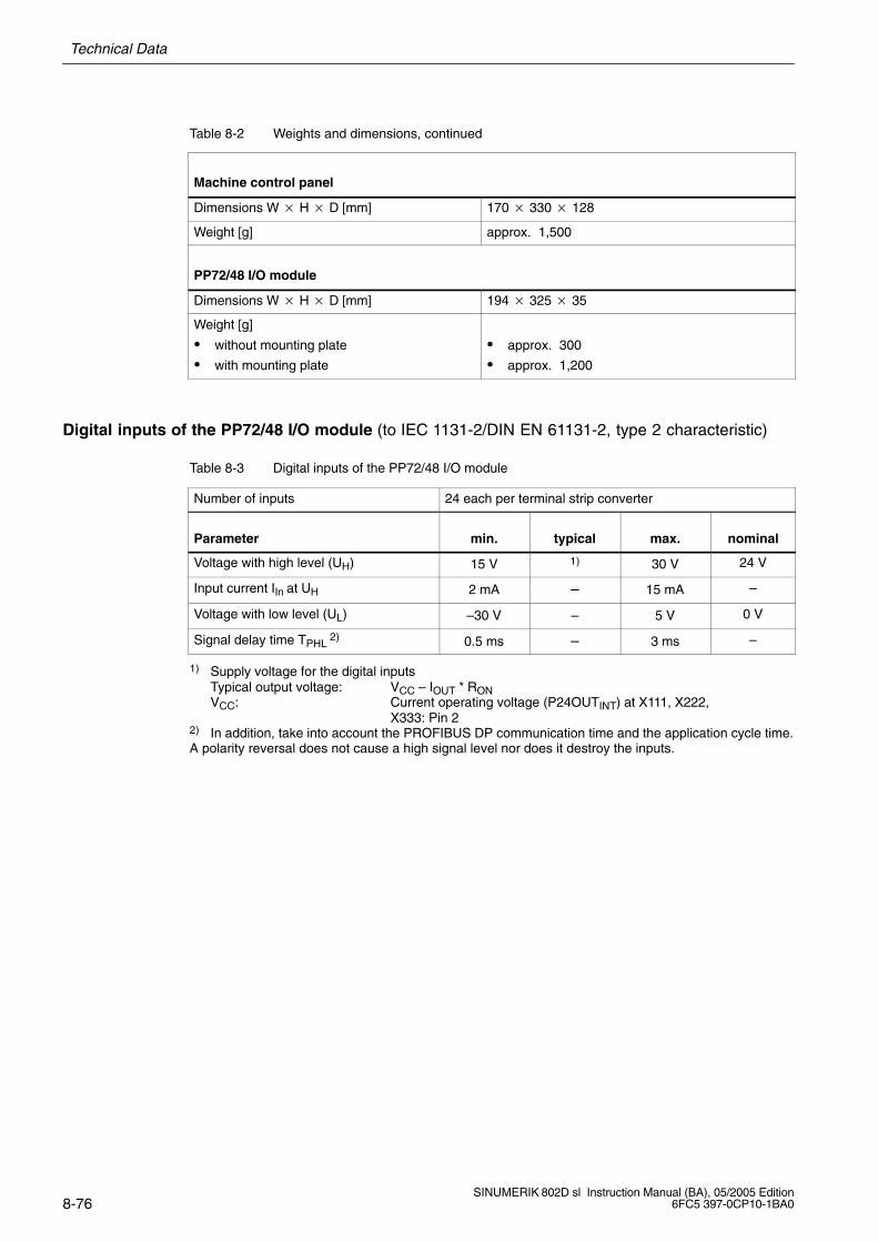
Technical Data
8-76SINUMERIK 802D sl Instruction Manual (BA), 05/2005 Edition
6FC5 397-0CP10-1BA0
Table 8-2 Weights and dimensions, continued
Machine control panel
Dimensions W H D [mm] 170 330 128
Weight [g] approx. 1,500
PP72/48 I/O module
Dimensions W H D [mm] 194 325 35
Weight [g]
without mounting plate
with mounting plate
approx. 300
approx. 1,200
Digital inputs of the PP72/48 I/O module (to IEC 1131-2/DIN EN 61131-2, type 2 characteristic)
Table 8-3 Digital inputs of the PP72/48 I/O module
Number of inputs 24 each per terminal strip converter
Parameter min. typical max. nominal
Voltage with high level (UH) 15 V 1) 30 V 24 V
Input current IIn at UH 2 mA – 15 mA –
Voltage with low level (UL) –30 V – 5 V 0 V
Signal delay time TPHL 2) 0.5 ms – 3 ms –
1) Supply voltage for the digital inputsTypical output voltage: VCC – IOUT * RONVCC: Current operating voltage (P24OUTINT) at X111, X222,
X333: Pin 22) In addition, take into account the PROFIBUS DP communication time and the application cycle time.A polarity reversal does not cause a high signal level nor does it destroy the inputs.
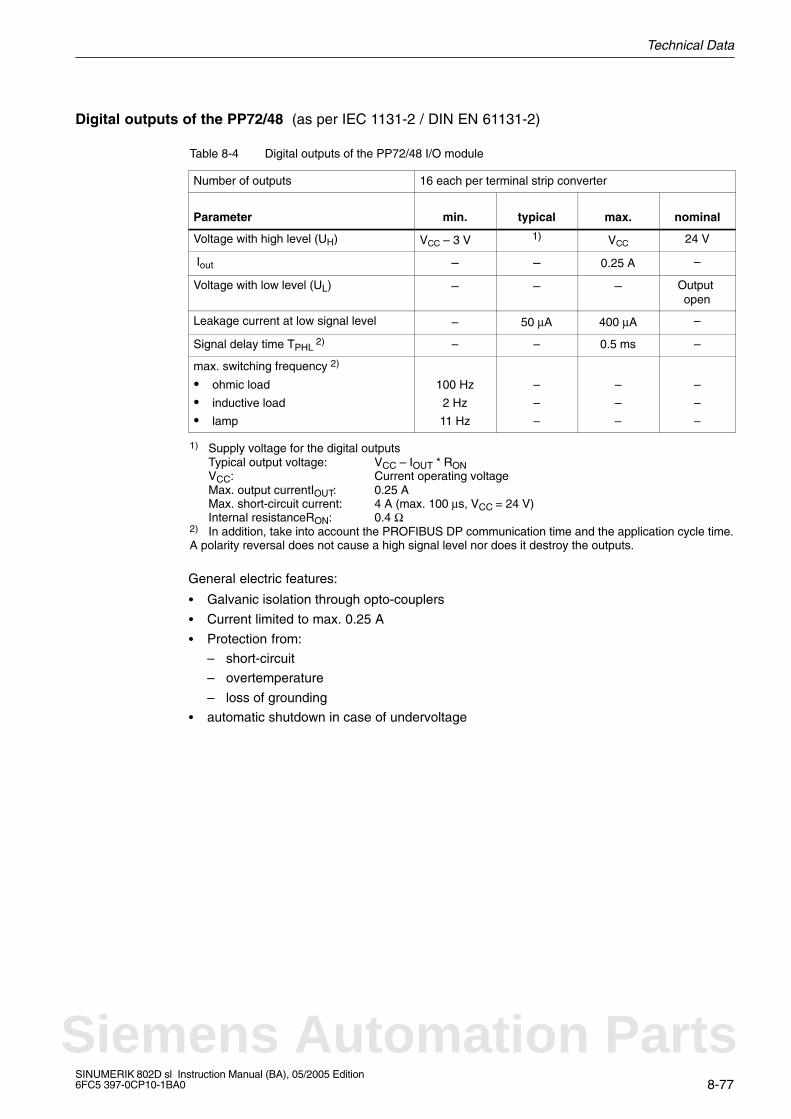
Technical Data
8-77SINUMERIK 802D sl Instruction Manual (BA), 05/2005 Edition6FC5 397-0CP10-1BA0
Digital outputs of the PP72/48 (as per IEC 1131-2 / DIN EN 61131-2)
Table 8-4 Digital outputs of the PP72/48 I/O module
Number of outputs 16 each per terminal strip converter
Parameter min. typical max. nominal
Voltage with high level (UH) VCC – 3 V 1) VCC 24 V
Iout – – 0.25 A –
Voltage with low level (UL) – – – Output open
Leakage current at low signal level – 50 µA 400 µA –
Signal delay time TPHL 2) – – 0.5 ms –
max. switching frequency 2)
ohmic load
inductive load
lamp
100 Hz
2 Hz
11 Hz
–
–
–
–
–
–
–
–
–
1) Supply voltage for the digital outputsTypical output voltage: VCC – IOUT * RONVCC: Current operating voltageMax. output currentIOUT: 0.25 A Max. short-circuit current: 4 A (max. 100 µs, VCC = 24 V)Internal resistanceRON: 0.4 Ω
2) In addition, take into account the PROFIBUS DP communication time and the application cycle time.A polarity reversal does not cause a high signal level nor does it destroy the outputs.
General electric features:
Galvanic isolation through opto-couplers
Current limited to max. 0.25 A
Protection from:
– short-circuit
– overtemperature
– loss of grounding
automatic shutdown in case of undervoltage
Siemens Automation Parts

Technical Data
8-78SINUMERIK 802D sl Instruction Manual (BA), 05/2005 Edition
6FC5 397-0CP10-1BA0
Notes
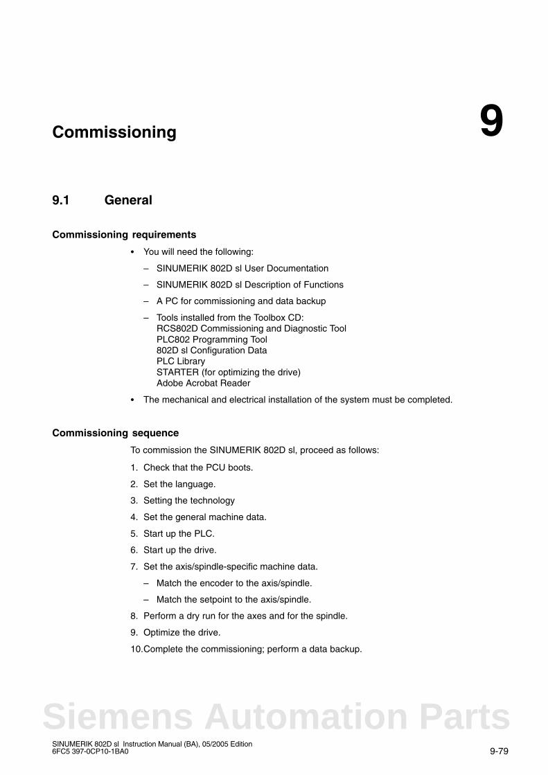
9-79SINUMERIK 802D sl Instruction Manual (BA), 05/2005 Edition6FC5 397-0CP10-1BA0
Commissioning
9.1 General
Commissioning requirements
You will need the following:
– SINUMERIK 802D sl User Documentation
– SINUMERIK 802D sl Description of Functions
– A PC for commissioning and data backup
– Tools installed from the Toolbox CD:RCS802D Commissioning and Diagnostic ToolPLC802 Programming Tool802D sl Configuration DataPLC LibrarySTARTER (for optimizing the drive)Adobe Acrobat Reader
The mechanical and electrical installation of the system must be completed.
Commissioning sequence
To commission the SINUMERIK 802D sl, proceed as follows:
1. Check that the PCU boots.
2. Set the language.
3. Setting the technology
4. Set the general machine data.
5. Start up the PLC.
6. Start up the drive.
7. Set the axis/spindle-specific machine data.
– Match the encoder to the axis/spindle.
– Match the setpoint to the axis/spindle.
8. Perform a dry run for the axes and for the spindle.
9. Optimize the drive.
10.Complete the commissioning; perform a data backup.
9
Siemens Automation Parts
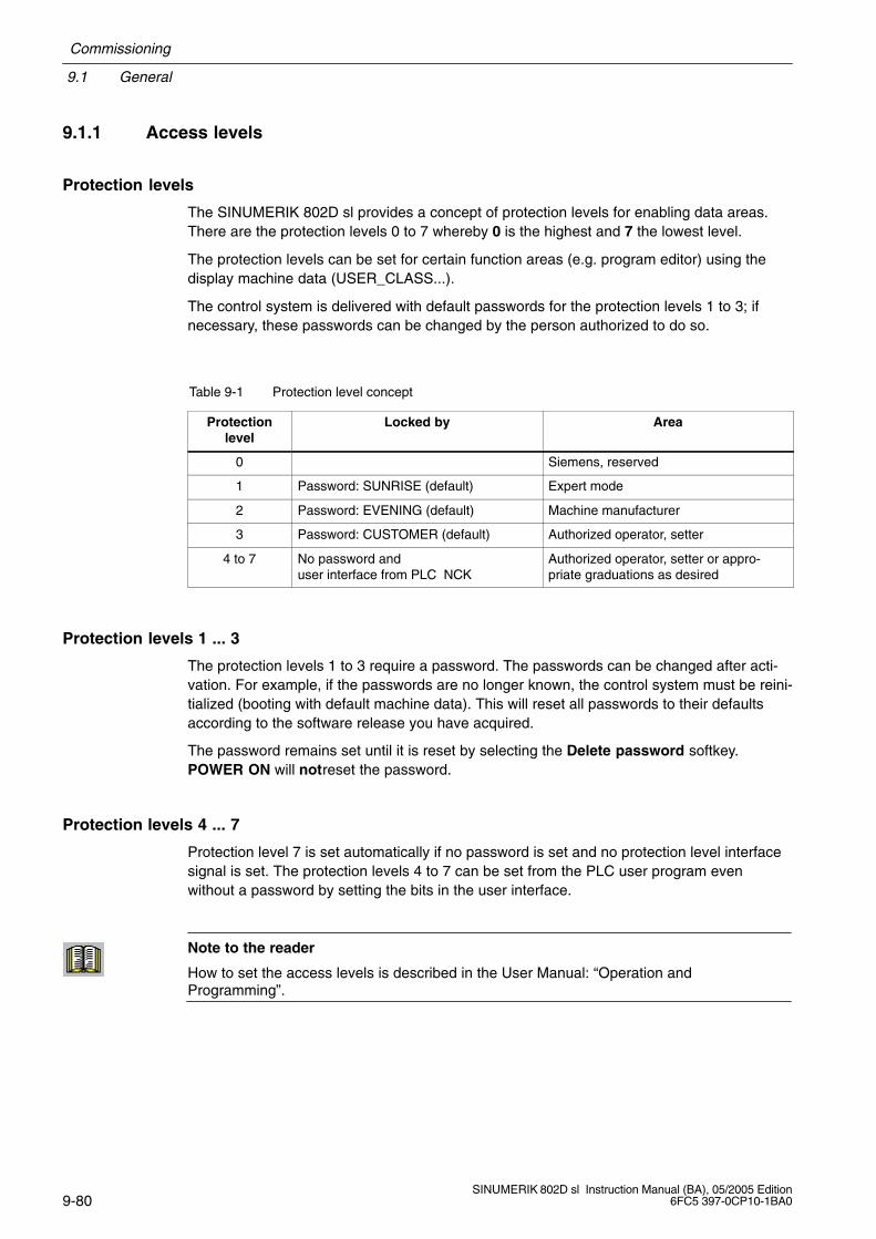
9.1 General
Commissioning
9-80SINUMERIK 802D sl Instruction Manual (BA), 05/2005 Edition
6FC5 397-0CP10-1BA0
9.1.1 Access levels
Protection levels
The SINUMERIK 802D sl provides a concept of protection levels for enabling data areas.There are the protection levels 0 to 7 whereby 0 is the highest and 7 the lowest level.
The protection levels can be set for certain function areas (e.g. program editor) using thedisplay machine data (USER_CLASS...).
The control system is delivered with default passwords for the protection levels 1 to 3; ifnecessary, these passwords can be changed by the person authorized to do so.
Table 9-1 Protection level concept
Protectionlevel
Locked by Area
0 Siemens, reserved
1 Password: SUNRISE (default) Expert mode
2 Password: EVENING (default) Machine manufacturer
3 Password: CUSTOMER (default) Authorized operator, setter
4 to 7 No password anduser interface from PLC NCK
Authorized operator, setter or appro-priate graduations as desired
Protection levels 1 ... 3
The protection levels 1 to 3 require a password. The passwords can be changed after acti-vation. For example, if the passwords are no longer known, the control system must be reini-tialized (booting with default machine data). This will reset all passwords to their defaultsaccording to the software release you have acquired.
The password remains set until it is reset by selecting the Delete password softkey.POWER ON will notreset the password.
Protection levels 4 ... 7
Protection level 7 is set automatically if no password is set and no protection level interfacesignal is set. The protection levels 4 to 7 can be set from the PLC user program evenwithout a password by setting the bits in the user interface.
Note to the reader
How to set the access levels is described in the User Manual: “Operation andProgramming”.
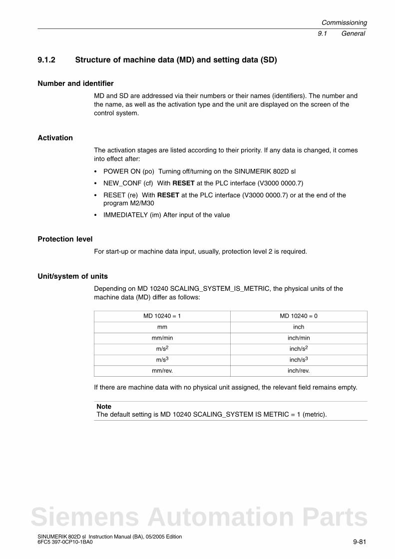
Commissioning
9.1 General
9-81SINUMERIK 802D sl Instruction Manual (BA), 05/2005 Edition6FC5 397-0CP10-1BA0
9.1.2 Structure of machine data (MD) and setting data (SD)
Number and identifier
MD and SD are addressed via their numbers or their names (identifiers). The number andthe name, as well as the activation type and the unit are displayed on the screen of thecontrol system.
Activation
The activation stages are listed according to their priority. If any data is changed, it comesinto effect after:
POWER ON (po) Turning off/turning on the SINUMERIK 802D sl
NEW_CONF (cf) With RESET at the PLC interface (V3000 0000.7)
RESET (re) With RESET at the PLC interface (V3000 0000.7) or at the end of theprogram M2/M30
IMMEDIATELY (im) After input of the value
Protection level
For start-up or machine data input, usually, protection level 2 is required.
Unit/system of units
Depending on MD 10240 SCALING_SYSTEM_IS_METRIC, the physical units of themachine data (MD) differ as follows:
MD 10240 = 1 MD 10240 = 0
mm inch
mm/min inch/min
m/s2 inch/s2
m/s3 inch/s3
mm/rev. inch/rev.
If there are machine data with no physical unit assigned, the relevant field remains empty.
NoteThe default setting is MD 10240 SCALING_SYSTEM IS METRIC = 1 (metric).
Siemens Automation Parts

9.1 General
Commissioning
9-82SINUMERIK 802D sl Instruction Manual (BA), 05/2005 Edition
6FC5 397-0CP10-1BA0
9.1.3 RCS802D Commissioning and Diagnostic tool
For commissioning and diagnostic tasks, the RCS802D tool included on the supplied toolboxCD can be used.
This tool provides the following functions:
File management (deletion of files, creation of directories, etc.)
Reading in/reading out setup files, text files, part programs, DDLs or pictures
Remote diagnosis and remote control
Install the RCS802D tool on the PC/PG which you want to use to access the control system.The starting window will be split into two halves. The drives of the control system and of thePC are displayed in the left-hand half, and the contents of the selected directories are dis-played in the right-hand half. Use the right mouse button to open the context menu dis-playing the “Properties” window. It displays the file size, the creation date and the DLLversion.
Commissioning
9.2 Turning on and booting the control system
9-83SINUMERIK 802D sl Instruction Manual (BA), 05/2005 Edition6FC5 397-0CP10-1BA0
9.2 Turning on and booting the control system
Procedure
Check the system visually for:
– correct mechanical design and check that all electrical connections are performedcorrectly.
– connected voltages
– connection of shielding and grounding.
Connect the control system (booting in the normal mode)
Booting in the normal mode
When the control system is turned on, the boot sequence is displayed on the control systemwith all its individual phases. Once the start screen of the user interface has appeared, thebooting sequence is completed.
Booting in the start-up mode
After POWER ON and once the operating system has been started, the word “SINUMERIK”is displayed filling the whole screen. Once this word has disappeared, press the SELECTkey.
The START UP MENU is displayed. Use the arrow key to select an appropriate power-up/start-up mode and press INPUT to confirm.
The modes specified in the START-UP MENU have the following meanings:
normal startup
If this option is chosen, the control system will boot with the last machine data set andthe previously loaded programs.
reload saved user data
If this option is chosen, the user data (machine data, programs, etc.) backed up to theflash memory are accepted.
start-up with default data (is only displayed if protection level 1 or 2 is set)
If this option is chosen, the control system will boot with default machine data.
software update
In this case, the control system will not boot at all. The software can only be updated if aCF card with a software update is inserted in the slot for the CF card.
PLC stop
Select PLC Stop while the control system is booting if PLC Stop can not be triggered viathe user interface any more.
Siemens Automation Parts
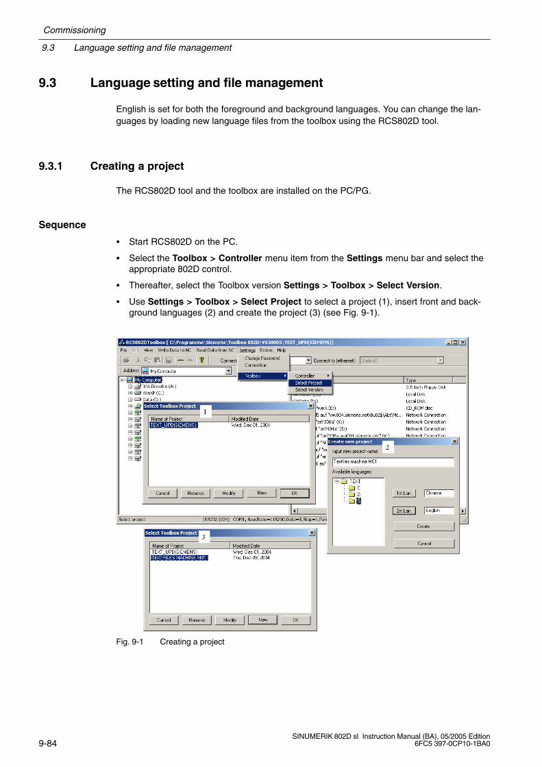
9.3 Language setting and file management
Commissioning
9-84SINUMERIK 802D sl Instruction Manual (BA), 05/2005 Edition
6FC5 397-0CP10-1BA0
9.3 Language setting and file management
English is set for both the foreground and background languages. You can change the lan-guages by loading new language files from the toolbox using the RCS802D tool.
9.3.1 Creating a project
The RCS802D tool and the toolbox are installed on the PC/PG.
Sequence
Start RCS802D on the PC.
Select the Toolbox > Controller menu item from the Settings menu bar and select theappropriate 802D control.
Thereafter, select the Toolbox version Settings > Toolbox > Select Version.
Use Settings > Toolbox > Select Project to select a project (1), insert front and back-ground languages (2) and create the project (3) (see Fig. 9-1).
Fig. 9-1 Creating a project
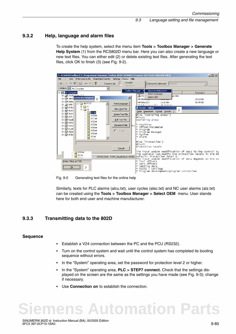
Commissioning
9.3 Language setting and file management
9-85SINUMERIK 802D sl Instruction Manual (BA), 05/2005 Edition6FC5 397-0CP10-1BA0
9.3.2 Help, language and alarm files
To create the help system, select the menu item Tools > Toolbox Manager > GenerateHelp System (1) from the RCS802D menu bar. Here you can also create a new language ornew text files. You can either edit (2) or delete existing text files. After generating the textfiles, click OK to finish (3) (see Fig. 9-2).
Fig. 9-2 Generating text files for the online help
Similarly, texts for PLC alarms (alcu.txt), user cycles (alsc.txt) and NC user alarms (alz.txt)can be created using the Tools > Toolbox Manager > Select OEM menu. User standshere for both end user and machine manufacturer.
9.3.3 Transmitting data to the 802D
Sequence
Establish a V24 connection between the PC and the PCU (RS232).
Turn on the control system and wait until the control system has completed its bootingsequence without errors.
In the “System” operating area, set the password for protection level 2 or higher.
In the “System” operating area, PLC > STEP7 connect. Check that the settings dis-played on the screen are the same as the settings you have made (see Fig. 9-3); changeif necessary.
Use Connection on to establish the connection.
Siemens Automation Parts
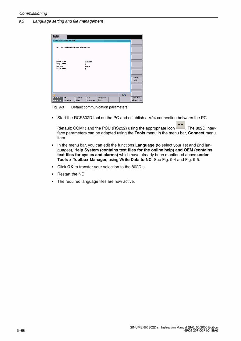
9.3 Language setting and file management
Commissioning
9-86SINUMERIK 802D sl Instruction Manual (BA), 05/2005 Edition
6FC5 397-0CP10-1BA0
Fig. 9-3 Default communication parameters
Start the RCS802D tool on the PC and establish a V24 connection between the PC
(default: COM1) and the PCU (RS232) using the appropriate icon . The 802D inter-face parameters can be adapted using the Tools menu in the menu bar, Connect menuitem.
In the menu bar, you can edit the functions Language (to select your 1st and 2nd lan-guages), Help System (contains text files for the online help) and OEM (containstext files for cycles and alarms) which have already been mentioned above underTools > Toolbox Manager, using Write Data to NC. See Fig. 9-4 and Fig. 9-5.
Click OK to transfer your selection to the 802D sl.
Restart the NC.
The required language files are now active.
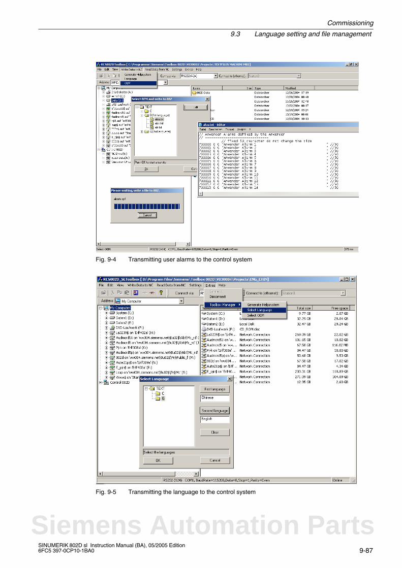
Commissioning
9.3 Language setting and file management
9-87SINUMERIK 802D sl Instruction Manual (BA), 05/2005 Edition6FC5 397-0CP10-1BA0
Fig. 9-4 Transmitting user alarms to the control system
Fig. 9-5 Transmitting the language to the control system
Siemens Automation Parts
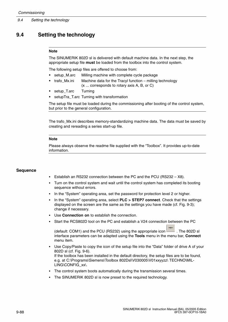
9.4 Setting the technology
Commissioning
9-88SINUMERIK 802D sl Instruction Manual (BA), 05/2005 Edition
6FC5 397-0CP10-1BA0
9.4 Setting the technology
Note
The SINUMERIK 802D sl is delivered with default machine data. In the next step, theappropriate setup file must be loaded from the toolbox into the control system.
The following setup files are offered to choose from:
setup_M.arc Milling machine with complete cycle package
trafo_Mx.ini Machine data for the Tracyl function – milling technology (x ... corresponds to rotary axis A, B, or C)
setup_T.arc Turning
setupTra_T.arc Turning with transformation
The setup file must be loaded during the commissioning after booting of the control system,but prior to the general configuration.
The trafo_Mx.ini describes memory-standardizing machine data. The data must be saved bycreating and rereading a series start-up file.
Note
Please always observe the readme file supplied with the “Toolbox”. It provides up-to-dateinformation.
Sequence
Establish an RS232 connection between the PC and the PCU (RS232 – X8).
Turn on the control system and wait until the control system has completed its bootingsequence without errors.
In the “System” operating area, set the password for protection level 2 or higher.
In the “System” operating area, select PLC > STEP7 connect. Check that the settingsdisplayed on the screen are the same as the settings you have made (cf. Fig. 9-3);change if necessary.
Use Connection on to establish the connection.
Start the RCS802D tool on the PC and establish a V24 connection between the PC
(default: COM1) and the PCU (RS232) using the appropriate icon . The 802D slinterface parameters can be adapted using the Tools menu in the menu bar, Connectmenu item.
Use Copy/Paste to copy the icon of the setup file into the “Data” folder of drive A of your802D sl (cf. Fig. 9-6).If the toolbox has been installed in the default directory, the setup files are to be found,e.g. at C:\Programs\Siemens\Toolbox 802Dsl\V030005\V01xxyyzz\ TECHNO\MIL-LING\CONFIG_xx\.
The control system boots automatically during the transmission several times.
The SINUMERIK 802D sl is now preset to the required technology.
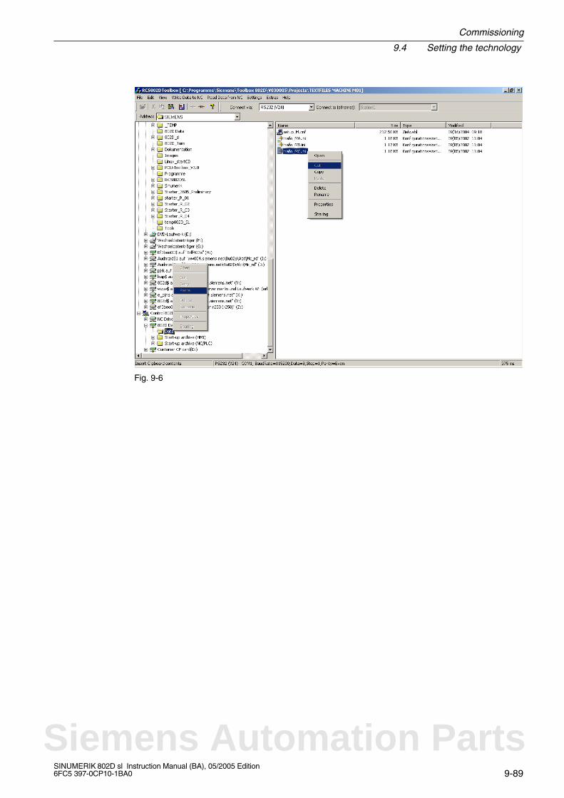
Commissioning
9.4 Setting the technology
9-89SINUMERIK 802D sl Instruction Manual (BA), 05/2005 Edition6FC5 397-0CP10-1BA0
Fig. 9-6
Siemens Automation Parts
9.5 Entering the machine data
Commissioning
9-90SINUMERIK 802D sl Instruction Manual (BA), 05/2005 Edition
6FC5 397-0CP10-1BA0
9.5 Entering the machine data
Overview
The most important machine data of the individual subareas are listed here to assist you.For a detailed description of the machine data and interface signals, please refer to theDescriptions of Functions (cf. cross-references in the tables of Chapter 7 “Machine Data andSetting Data”).
Note
The default values of the machine data have been chosen such that usually no change isrequired.
Entering the machine data (MD)
Before you can enter the machine data, the password for protection level 2 must be set.
Use the relevant softkey to select the following machine data areas and to change the ma-chine data if necessary:
General machine data MD 10000 ... 19999
Channel machine data MD 20000 ... 29999
Axis machine data MD 30000 ... 39999
Display machine data MD 1 ... 999
Drive machine data r0001 ... r9999 (read-only)p0001 ... p9999 (read and write-enabled)
The data you have entered are written to the data memory immediately. An exception is thedrive machine data. To save the drive machine data permanently, set the parameter p971 foreach individual drive object separately or set p977 of the CU (SINAMICS_I) to “1” and waituntil it is reset automatically. If you forget to save the data, the old data is effective againafter the next drive reset.
The machine data is activated depending on the machine data property “Activated”,Section 9.1.2.

Commissioning
9.6 Setting the Profibus address
9-91SINUMERIK 802D sl Instruction Manual (BA), 05/2005 Edition6FC5 397-0CP10-1BA0
9.6 Setting the Profibus address
Certain bus configurations have already been prepared for SINUMERIK 802D sl. Therequired configuration can be set via MD 11240[2]: PROFIBUS_SDB_NUMBER.
Depending on the physical plant configuration, set the relevant setting data bit (SDB) accor-dingly to select the machine data 11240[2] Profibus_SDB_NUMBER. NCK Reset will acceptthe changed machine data.
Table 9-2 SDB number
MD 11240[2] Number of axes
0 2 SINAMICS drive with Smart Line Module (SLM)
1 3 SINAMICS drive with Smart Line Module (SLM)
2 4 SINAMICS drive with Smart Line Module (SLM)
3 5 SINAMICS drive with Smart Line Module (SLM)
4 3 SINAMICS drive with Active Line Modules (ALM)
5 4 SINAMICS drive with Active Line Modules (ALM)
6 5 SINAMICS drive with Active Line Modules (ALM)
Set now the MD 11240[2]: PROFIBUS_SDB_NUMBER according to your particular busconfiguration.
Table 9-3
MD 11240[0] PB station (slave) PB address
0 PP module 1 9
PP module 2 8
PP module 3 7
Another preconfigured PB station: DP-DP coupler 6
PCU
Is master at PROFIBUS; address cannot be changed
PP 72/48
Is slave at PROFIBUS; max. three PP modules can be connected. The addresses are setusing DIL switch S1 on the PP module.
PB address DIL switch S1 (PP module)9 (default setting)
(PP module 1)
1 + 4 = ON
2 + 3 + 5 + 6 + 7 + 8 = OFF8
(PP module 2)
4 = ON
1 + 2 + 3 + 5 + 6 + 7 + 8 = OFF7
(PP module 3)
1+2+3 = ON
4 + 5 + 6 + 7 + 8 = OFF
Siemens Automation Parts

9.7 Starting Up the PLC
Commissioning
9-92SINUMERIK 802D sl Instruction Manual (BA), 05/2005 Edition
6FC5 397-0CP10-1BA0
Note
The newly set PB station address is only active after POWER ON.
9.7 Starting Up the PLC
After starting up the Profibus, the prepared PLC user program is ready to run and can beused for further start-up. To load the PLC user program, use the Programming Tool.
For a description, please refer to Section 11.5.
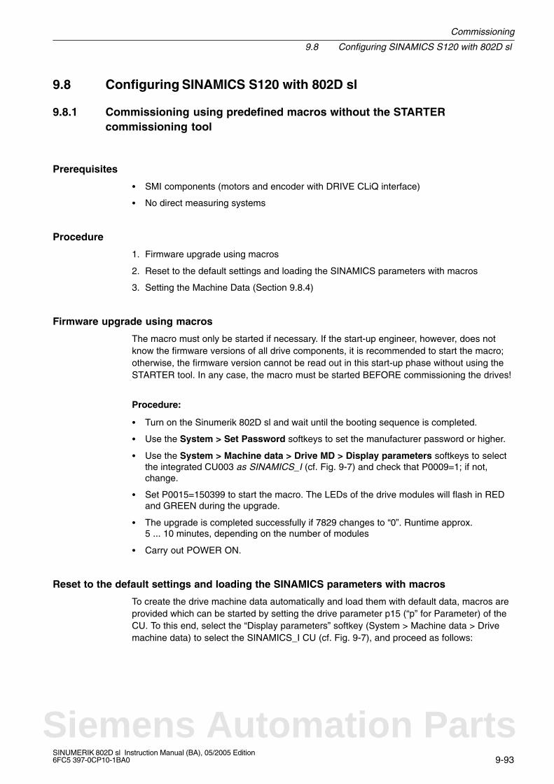
Commissioning
9.8 Configuring SINAMICS S120 with 802D sl
9-93SINUMERIK 802D sl Instruction Manual (BA), 05/2005 Edition6FC5 397-0CP10-1BA0
9.8 Configuring SINAMICS S120 with 802D sl
9.8.1 Commissioning using predefined macros without the STARTERcommissioning tool
Prerequisites
SMI components (motors and encoder with DRIVE CLiQ interface)
No direct measuring systems
Procedure
1. Firmware upgrade using macros
2. Reset to the default settings and loading the SINAMICS parameters with macros
3. Setting the Machine Data (Section 9.8.4)
Firmware upgrade using macros
The macro must only be started if necessary. If the start-up engineer, however, does notknow the firmware versions of all drive components, it is recommended to start the macro;otherwise, the firmware version cannot be read out in this start-up phase without using theSTARTER tool. In any case, the macro must be started BEFORE commissioning the drives!
Procedure:
Turn on the Sinumerik 802D sl and wait until the booting sequence is completed.
Use the System > Set Password softkeys to set the manufacturer password or higher.
Use the System > Machine data > Drive MD > Display parameters softkeys to selectthe integrated CU003 as SINAMICS_I (cf. Fig. 9-7) and check that P0009=1; if not,change.
Set P0015=150399 to start the macro. The LEDs of the drive modules will flash in REDand GREEN during the upgrade.
The upgrade is completed successfully if 7829 changes to “0”. Runtime approx.5 ... 10 minutes, depending on the number of modules
Carry out POWER ON.
Reset to the default settings and loading the SINAMICS parameters with macros
To create the drive machine data automatically and load them with default data, macros areprovided which can be started by setting the drive parameter p15 (“p” for Parameter) of theCU. To this end, select the “Display parameters” softkey (System > Machine data > Drivemachine data) to select the SINAMICS_I CU (cf. Fig. 9-7), and proceed as follows:
Siemens Automation Parts
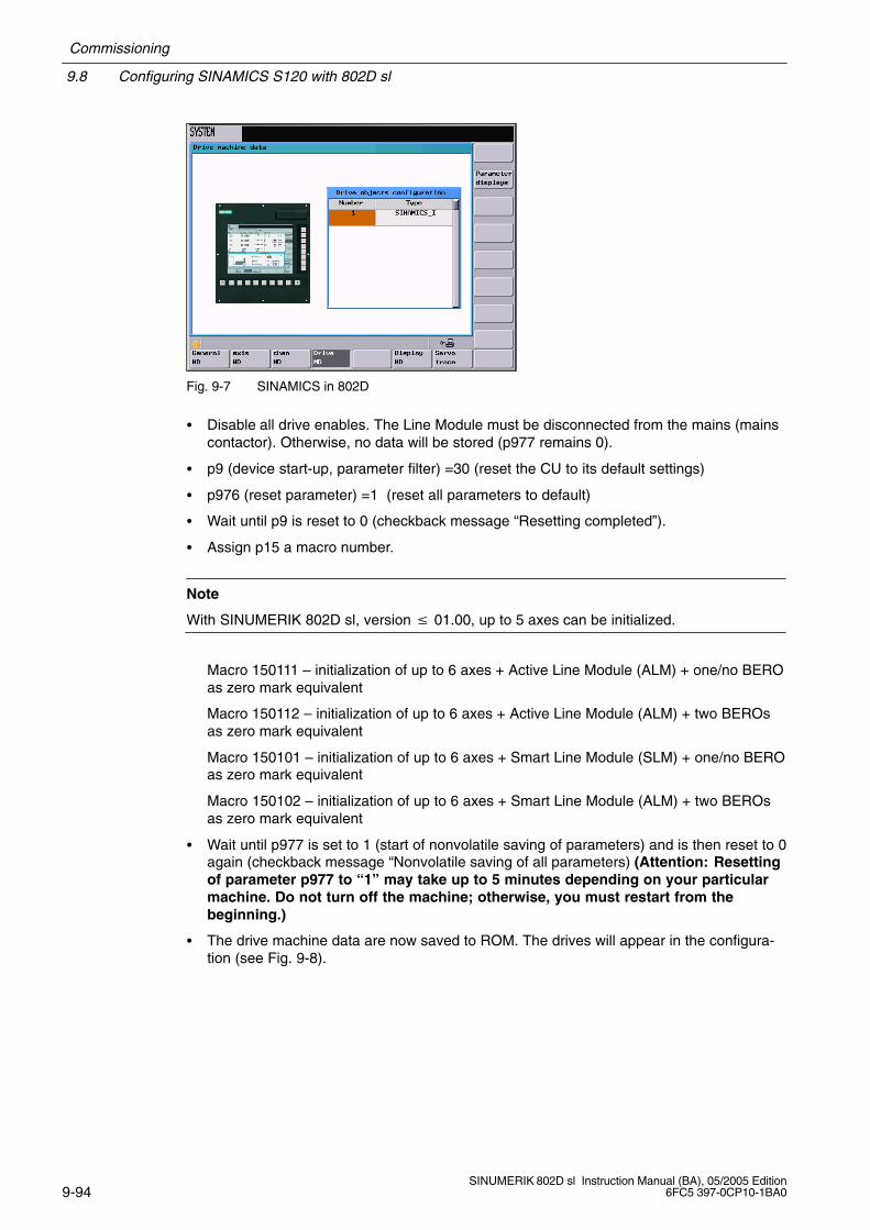
9.8 Configuring SINAMICS S120 with 802D sl
Commissioning
9-94SINUMERIK 802D sl Instruction Manual (BA), 05/2005 Edition
6FC5 397-0CP10-1BA0
Fig. 9-7 SINAMICS in 802D
Disable all drive enables. The Line Module must be disconnected from the mains (mainscontactor). Otherwise, no data will be stored (p977 remains 0).
p9 (device start-up, parameter filter) =30 (reset the CU to its default settings)
p976 (reset parameter) =1 (reset all parameters to default)
Wait until p9 is reset to 0 (checkback message “Resetting completed”).
Assign p15 a macro number.
Note
With SINUMERIK 802D sl, version 01.00, up to 5 axes can be initialized.
Macro 150111 – initialization of up to 6 axes + Active Line Module (ALM) + one/no BEROas zero mark equivalent
Macro 150112 – initialization of up to 6 axes + Active Line Module (ALM) + two BEROsas zero mark equivalent
Macro 150101 – initialization of up to 6 axes + Smart Line Module (SLM) + one/no BEROas zero mark equivalent
Macro 150102 – initialization of up to 6 axes + Smart Line Module (ALM) + two BEROsas zero mark equivalent
Wait until p977 is set to 1 (start of nonvolatile saving of parameters) and is then reset to 0again (checkback message “Nonvolatile saving of all parameters) (Attention: Resettingof parameter p977 to “1” may take up to 5 minutes depending on your particularmachine. Do not turn off the machine; otherwise, you must restart from thebeginning.)
The drive machine data are now saved to ROM. The drives will appear in the configura-tion (see Fig. 9-8).

Commissioning
9.8 Configuring SINAMICS S120 with 802D sl
9-95SINUMERIK 802D sl Instruction Manual (BA), 05/2005 Edition6FC5 397-0CP10-1BA0
Fig. 9-8 SINAMICS in 802D with configured drives
The macro will configure terminal X20/X21 as shown in Tables 9-4 and 9-5. With the ActiveLine Module, the input PIN1 of the CU is linked with parameter p0840 of the Active LineModules; a leading contact must be connected from the main switch or from the mainscontactor.
Connect pin2 of the input to parameter p0849 for all drives. P0849 means AUS3 (rapidstop). This function realizes braking with a configurable AUS3 ramp (p1135,1136,1137);thereafter, pulse suppression and starting lockout. The drive stops controlled. The brakingbehavior of each servo drive can be set separately, also via the main switch or mains con-tactor, but should rather be connected via the PLC I/Os.
Table 9-4 Configuring terminal X20 using system macros
Pin no. Hardwarefeatures
FunctionI/O
Assignment Parameter Macrono.
1Electrically isola-ted input, 50µs,
E0/1 edge
Active Line Moduleenabled
Leading contact from main switch ormains contactor
ALM p840 = 47318016150111150112
p , µ ,smoothed
grequired
SLM hardware ready SERVO p864 = 47318016150101150102
2Electrically isola-ted input, 50µs,smoothed
E0/1 edgerequired
“OFF3 – rapid stop”
Behavior similar to terminal 64
Each SERVO
2nd OFF3, p849 =47318017
150111150112
150101150102
5 Ground for pin 1 .. 4
6 24 P
8Bidir. I/O, 1µs, smoothed
I Bero 1 – zero mark substitute” p945 = 1
150111150112
150101150102
9 Ground for pins 7, 8, 10, 11
Siemens Automation Parts
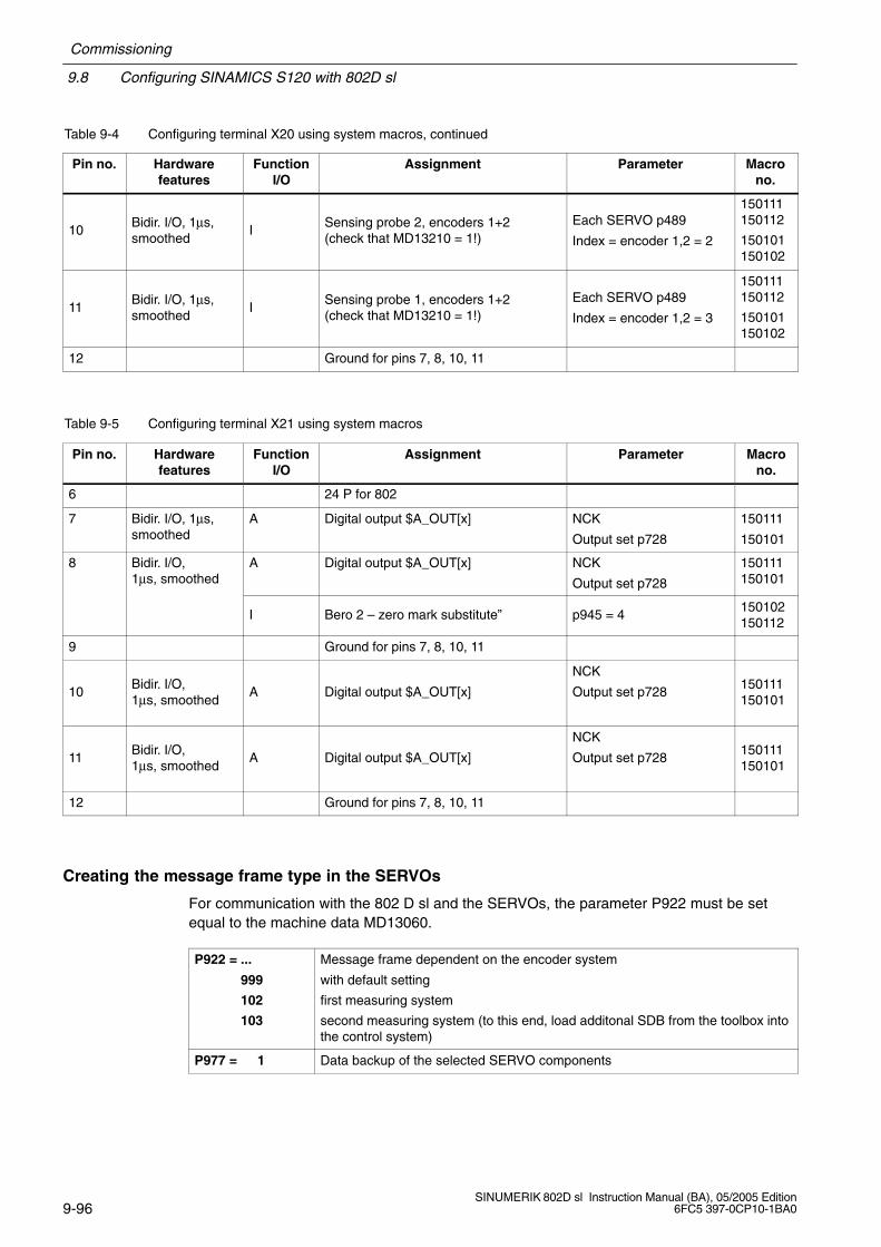
9.8 Configuring SINAMICS S120 with 802D sl
Commissioning
9-96SINUMERIK 802D sl Instruction Manual (BA), 05/2005 Edition
6FC5 397-0CP10-1BA0
Table 9-4 Configuring terminal X20 using system macros, continued
Pin no. Macrono.
ParameterAssignmentFunctionI/O
Hardwarefeatures
10Bidir. I/O, 1µs,smoothed
ISensing probe 2, encoders 1+2 (check that MD13210 = 1!)
Each SERVO p489
Index = encoder 1,2 = 2
150111150112
150101150102
11Bidir. I/O, 1µs,smoothed
ISensing probe 1, encoders 1+2 (check that MD13210 = 1!)
Each SERVO p489
Index = encoder 1,2 = 3
150111150112
150101150102
12 Ground for pins 7, 8, 10, 11
Table 9-5 Configuring terminal X21 using system macros
Pin no. Hardwarefeatures
FunctionI/O
Assignment Parameter Macrono.
6 24 P for 802
7 Bidir. I/O, 1µs,smoothed
A Digital output $A_OUT[x] NCK
Output set p728
150111
150101
8 Bidir. I/O, 1µs, smoothed
A Digital output $A_OUT[x] NCK
Output set p728
150111150101
I Bero 2 – zero mark substitute” p945 = 4150102150112
9 Ground for pins 7, 8, 10, 11
10Bidir. I/O, 1µs, smoothed
A Digital output $A_OUT[x]
NCK
Output set p728150111150101
11Bidir. I/O, 1µs, smoothed
A Digital output $A_OUT[x]
NCK
Output set p728150111150101
12 Ground for pins 7, 8, 10, 11
Creating the message frame type in the SERVOs
For communication with the 802 D sl and the SERVOs, the parameter P922 must be setequal to the machine data MD13060.
P922 = ...
999
102
103
Message frame dependent on the encoder system
with default setting
first measuring system
second measuring system (to this end, load additonal SDB from the toolbox intothe control system)
P977 = 1 Data backup of the selected SERVO components
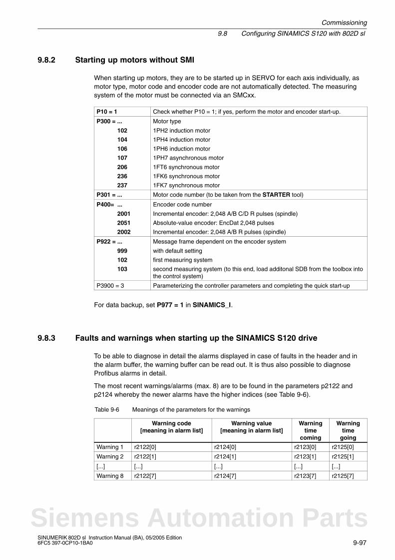
Commissioning
9.8 Configuring SINAMICS S120 with 802D sl
9-97SINUMERIK 802D sl Instruction Manual (BA), 05/2005 Edition6FC5 397-0CP10-1BA0
9.8.2 Starting up motors without SMI
When starting up motors, they are to be started up in SERVO for each axis individually, asmotor type, motor code and encoder code are not automatically detected. The measuringsystem of the motor must be connected via an SMCxx.
P10 = 1 Check whether P10 = 1; if yes, perform the motor and encoder start-up.
P300 = ...
102
104
106
107
206
236
237
Motor type
1PH2 induction motor
1PH4 induction motor
1PH6 induction motor
1PH7 asynchronous motor
1FT6 synchronous motor
1FK6 synchronous motor
1FK7 synchronous motor
P301 = ... Motor code number (to be taken from the STARTER tool)
P400= ...
2001
2051
2002
Encoder code number
Incremental encoder: 2,048 A/B C/D R pulses (spindle)
Absolute-value encoder: EncDat 2,048 pulses
Incremental encoder: 2,048 A/B R pulses (spindle)
P922 = ...
999
102
103
Message frame dependent on the encoder system
with default setting
first measuring system
second measuring system (to this end, load additonal SDB from the toolbox intothe control system)
P3900 = 3 Parameterizing the controller parameters and completing the quick start-up
For data backup, set P977 = 1 in SINAMICS_I.
9.8.3 Faults and warnings when starting up the SINAMICS S120 drive
To be able to diagnose in detail the alarms displayed in case of faults in the header and inthe alarm buffer, the warning buffer can be read out. It is thus also possible to diagnoseProfibus alarms in detail.
The most recent warnings/alarms (max. 8) are to be found in the parameters p2122 andp2124 whereby the newer alarms have the higher indices (see Table 9-6).
Table 9-6 Meanings of the parameters for the warnings
Warning code[meaning in alarm list]
Warning value[meaning in alarm list]
Warningtime
coming
Warningtime
going
Warning 1 r2122[0] r2124[0] r2123[0] r2125[0]
Warning 2 r2122[1] r2124[1] r2123[1] r2125[1]
[...] [...] [...] [...] [...]
Warning 8 r2122[7] r2124[7] r2123[7] r2125[7]
Siemens Automation Parts
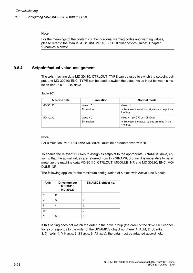
9.8 Configuring SINAMICS S120 with 802D sl
Commissioning
9-98SINUMERIK 802D sl Instruction Manual (BA), 05/2005 Edition
6FC5 397-0CP10-1BA0
Note
For the meanings of the contents of the individual warning codes and warning values,please refer to the Manual /DG/ SINUMERIK 802D sl “Diagnostics Guide”, Chapter“Sinamics Alarms”.
9.8.4 Setpoint/actual-value assignment
The axis machine data MD 30130: CTRLOUT_TYPE can be used to switch the setpoint out-put, and MD 30240: ENC_TYPE can be used to switch the actual-value input between simu-lation and PROFIBUS drive.
Table 9-7
Machine data Simulation Normal mode
MD 30130 Value = 0
Simulation
Value = 1
In this case, the setpoint signals are output viaProfibus.
MD 30240 Value = 0
Simulation
Value = 1 (INCR) or 4 (EnDat)
In this case, the actual values are read in viaProfibus.
Note
For simulation, MD 30130 and MD 30240 must be parameterized with “0”.
To enable the relevant NC axis to assign its setpoint to the appropriate SINAMICS drive, en-suring that the actual values are returned from this SINAMICS drive, it is imperative to para-meterize the machine data MD 30110: CTRLOUT_MODULE_NR and MD 30220: ENC_MO-DULE_NR.
The following applies for the maximum configuration of 5 axes with Active Line Module:
Axis Drive numberMD 30110MD 30220
SINAMICS object no.
X1 2 3
Y1 3 4
Z1 4 5
SP 1 2
A1 5 6
If this setting does not match the order in the drive group (the order of the drive CliQ connec-tions corresponds to the order of the SINAMICS object no., here: 1. ALM, 2. Spindle,3. X1 axis, 4. Y1- axis, 5. Z1 axis, 6. A1 axis), the data must be adapted accordingly.
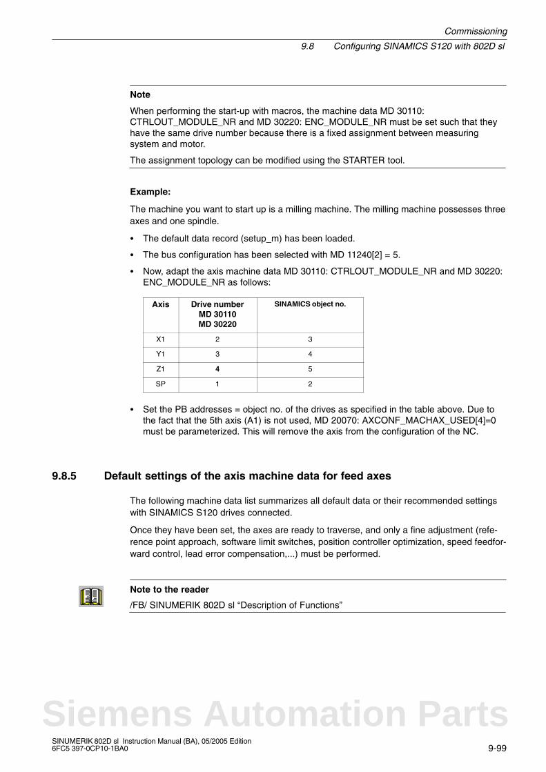
Commissioning
9.8 Configuring SINAMICS S120 with 802D sl
9-99SINUMERIK 802D sl Instruction Manual (BA), 05/2005 Edition6FC5 397-0CP10-1BA0
Note
When performing the start-up with macros, the machine data MD 30110:CTRLOUT_MODULE_NR and MD 30220: ENC_MODULE_NR must be set such that theyhave the same drive number because there is a fixed assignment between measuringsystem and motor.
The assignment topology can be modified using the STARTER tool.
Example:
The machine you want to start up is a milling machine. The milling machine possesses threeaxes and one spindle.
The default data record (setup_m) has been loaded.
The bus configuration has been selected with MD 11240[2] = 5.
Now, adapt the axis machine data MD 30110: CTRLOUT_MODULE_NR and MD 30220:ENC_MODULE_NR as follows:
Axis Drive numberMD 30110MD 30220
SINAMICS object no.
X1 2 3
Y1 3 4
Z1 4 5
SP 1 2
Set the PB addresses = object no. of the drives as specified in the table above. Due tothe fact that the 5th axis (A1) is not used, MD 20070: AXCONF_MACHAX_USED[4]=0must be parameterized. This will remove the axis from the configuration of the NC.
9.8.5 Default settings of the axis machine data for feed axes
The following machine data list summarizes all default data or their recommended settingswith SINAMICS S120 drives connected.
Once they have been set, the axes are ready to traverse, and only a fine adjustment (refe-rence point approach, software limit switches, position controller optimization, speed feedfor-ward control, lead error compensation,...) must be performed.
Note to the reader
/FB/ SINUMERIK 802D sl “Description of Functions”
Siemens Automation Parts
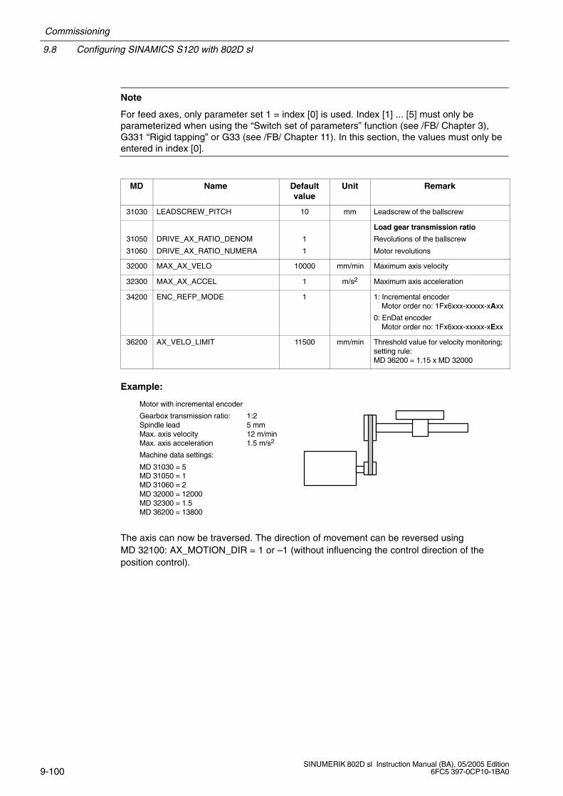
9.8 Configuring SINAMICS S120 with 802D sl
Commissioning
9-100SINUMERIK 802D sl Instruction Manual (BA), 05/2005 Edition
6FC5 397-0CP10-1BA0
Note
For feed axes, only parameter set 1 = index [0] is used. Index [1] ... [5] must only beparameterized when using the “Switch set of parameters” function (see /FB/ Chapter 3),G331 “Rigid tapping” or G33 (see /FB/ Chapter 11). In this section, the values must only beentered in index [0].
MD Name Defaultvalue
Unit Remark
31030 LEADSCREW_PITCH 10 mm Leadscrew of the ballscrew
31050
31060
DRIVE_AX_RATIO_DENOM
DRIVE_AX_RATIO_NUMERA
1
1
Load gear transmission ratio
Revolutions of the ballscrew
Motor revolutions
32000 MAX_AX_VELO 10000 mm/min Maximum axis velocity
32300 MAX_AX_ACCEL 1 m/s2 Maximum axis acceleration
34200 ENC_REFP_MODE 1 1: Incremental encoderMotor order no: 1Fx6xxx-xxxxx-xAxx
0: EnDat encoderMotor order no: 1Fx6xxx-xxxxx-xExx
36200 AX_VELO_LIMIT 11500 mm/min Threshold value for velocity monitoring;setting rule: MD 36200 = 1.15 x MD 32000
Example:
Motor with incremental encoder
Gearbox transmission ratio: 1:2Spindle lead 5 mmMax. axis velocity 12 m/minMax. axis acceleration 1.5 m/s2
Machine data settings:
MD 31030 = 5MD 31050 = 1MD 31060 = 2MD 32000 = 12000MD 32300 = 1.5MD 36200 = 13800
The axis can now be traversed. The direction of movement can be reversed usingMD 32100: AX_MOTION_DIR = 1 or –1 (without influencing the control direction of theposition control).

Commissioning
9.8 Configuring SINAMICS S120 with 802D sl
9-101SINUMERIK 802D sl Instruction Manual (BA), 05/2005 Edition6FC5 397-0CP10-1BA0
9.8.6 Default settings of the axis machine data for the spindle
With SINUMERIK 802D sl, the spindle is a subfunction of the entire axis functionality. Themachine data of the spindle are therefore to be found amongst the axis machine data(MD 35xxx).
For this reason, data must also be entered for a spindle; this data has already beendescribed in conjunction with the start-up of feed axes.
The following variants are offered for the spindle drive:
digital spindle drive (PROFIBUS) with spindle actual-value encoder integrated into themotor
analog spindle drive with directly mounted spindle actual-value encoder
analog spindle drive with directly mounted spindle actual-value encoder
Note
For spindles without gearstage switching, only gear stage 1 = index [1] is taken into account;index [2] ... [5] must only be parameterized when using the “Switch gearstage” function (see/FB/ Chapter 5).
Table 9-8
MD Name Defaultvalue
Unit Remark
30200 NUM_ENCS 1 0: spindle without speed actual-va-lue encoder (AM mode = operationwithout encoder)
1: spindle with speed actual-valueencoder integrated into the motor(1PH7 motor)
31050
31060
DRIVE_AX_RATIO_DENOM[1]
DRIVE_AX_RATIO_NUMERA[1]
1
1
Load gear transmission ratio
Load revolutions
Motor revolutions
35100 SPIND_VELO_LIMIT 10000 r.p.m. Maximum spindle speed
35130 GEAR_STEP_MAX_VELO_LIMIT[1] 500 r.p.m. Max. speed in gear stage 1
35200 GEAR_STEP_SPEEDCTRL_AC-CEL[1]
30 rev/s2 Acceleration in the speed controlledmode
Siemens Automation Parts

9.8 Configuring SINAMICS S120 with 802D sl
Commissioning
9-102SINUMERIK 802D sl Instruction Manual (BA), 05/2005 Edition
6FC5 397-0CP10-1BA0
Digital spindle drive with spindle actual-value encoder integrated into the motor
Parameterize the machine data listed in Table 9-8.
Example:
Motor with incremental encoder
Gearbox transmission ratio: 1:2Max. spindle speed 9,000 r.p.m.Max. spindle acceleration 60 rev./s2
Machine data settings:
MD 31030 = 5MD 31050 = 1MD 31060 = 2MD 35130 = 9000MD 35200 = 60MD 36200 = 9900
For the spindle, it can be necessary to adapt the following additional machine data.
Table 9-9 Additional machine data
MD Name Defaultvalue
Unit Recommendation/remark
34000 REFP_CAM_IS_ACTIVE 1 0: without reference point cam
34060 REFP_MAX_MARKER_DIST 20 degrees 720 = two spindle revolutions
34110 REFP_CYCLE_NR 1 ... 5 0: The spindle is not involved in chan-nel-specific referencing.
35300 SPIND_POSCTRL_VELO 500 r.p.m.
36000 STOP_LIMIT_COARSE 0,04 degrees 0,4
36010 STOP_LIMIT_FINE 0,01 degrees 0,1
36030 STANDSTILL_POS_TOL 0,2 degrees 1
36060 STANDSTILL_VELO_TOL 0,0139 r.p.m. 1 (interface signal “Axis/spindlestopped” V390x 0001.4)
36400 CONTOUR_TOL 1 degrees 3
Digital spindle drive with directly mounted spindle actual-value encoder
The operation of a second measuring system requires changes in the message frame type.To this end, load a reloadable SDB from the toolbox, which allows message frame type 103for the appropriate drives.
In SINAMICS_I, the message frame type must also be set in P922 = 103.
For the actual-value assignment, the following machine data must be set:
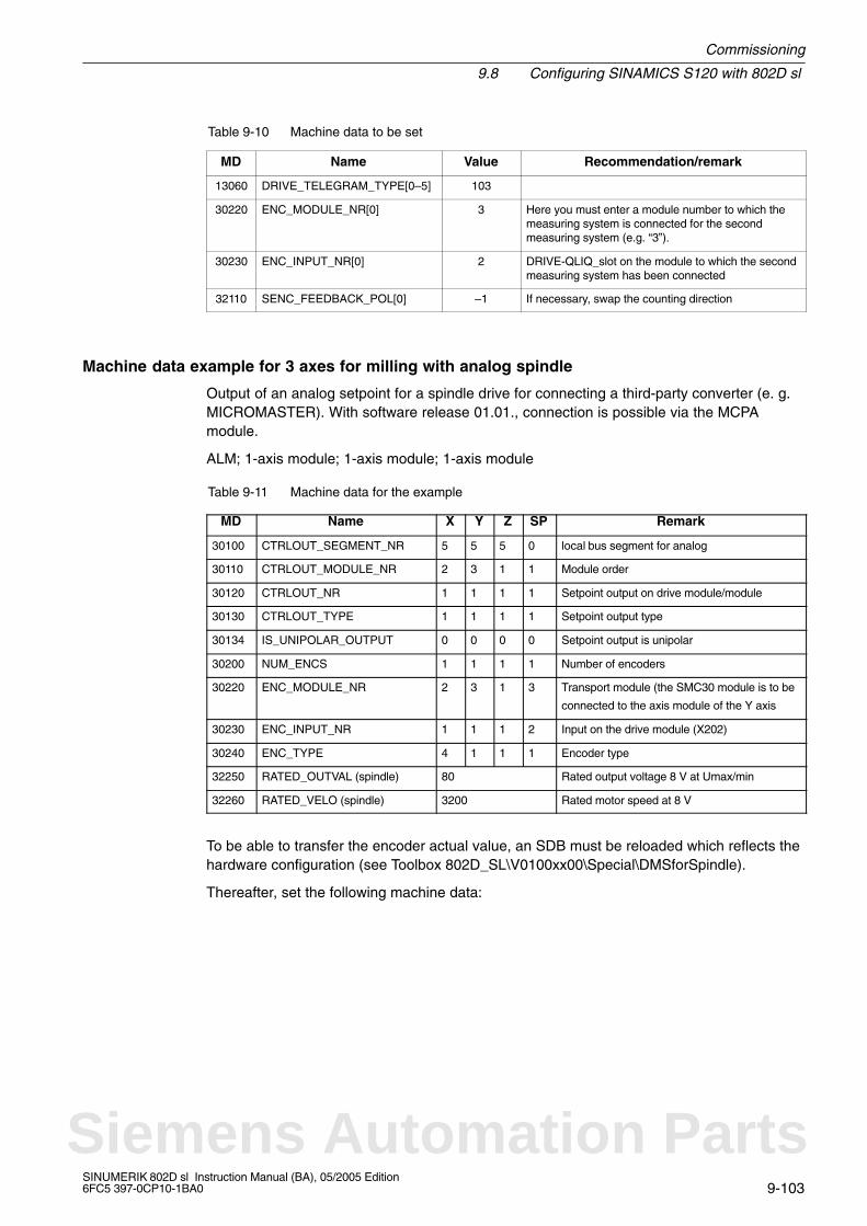
Commissioning
9.8 Configuring SINAMICS S120 with 802D sl
9-103SINUMERIK 802D sl Instruction Manual (BA), 05/2005 Edition6FC5 397-0CP10-1BA0
Table 9-10 Machine data to be set
MD Name Value Recommendation/remark
13060 DRIVE_TELEGRAM_TYPE[0–5] 103
30220 ENC_MODULE_NR[0] 3 Here you must enter a module number to which themeasuring system is connected for the secondmeasuring system (e.g. “3”).
30230 ENC_INPUT_NR[0] 2 DRIVE-QLIQ_slot on the module to which the secondmeasuring system has been connected
32110 SENC_FEEDBACK_POL[0] –1 If necessary, swap the counting direction
Machine data example for 3 axes for milling with analog spindle
Output of an analog setpoint for a spindle drive for connecting a third-party converter (e. g.MICROMASTER). With software release 01.01., connection is possible via the MCPAmodule.
ALM; 1-axis module; 1-axis module; 1-axis module
Table 9-11 Machine data for the example
MD Name X Y Z SP Remark
30100 CTRLOUT_SEGMENT_NR 5 5 5 0 local bus segment for analog
30110 CTRLOUT_MODULE_NR 2 3 1 1 Module order
30120 CTRLOUT_NR 1 1 1 1 Setpoint output on drive module/module
30130 CTRLOUT_TYPE 1 1 1 1 Setpoint output type
30134 IS_UNIPOLAR_OUTPUT 0 0 0 0 Setpoint output is unipolar
30200 NUM_ENCS 1 1 1 1 Number of encoders
30220 ENC_MODULE_NR 2 3 1 3 Transport module (the SMC30 module is to be
connected to the axis module of the Y axis
30230 ENC_INPUT_NR 1 1 1 2 Input on the drive module (X202)
30240 ENC_TYPE 4 1 1 1 Encoder type
32250 RATED_OUTVAL (spindle) 80 Rated output voltage 8 V at Umax/min
32260 RATED_VELO (spindle) 3200 Rated motor speed at 8 V
To be able to transfer the encoder actual value, an SDB must be reloaded which reflects thehardware configuration (see Toolbox 802D_SL\V0100xx00\Special\DMSforSpindle).
Thereafter, set the following machine data:
Siemens Automation Parts
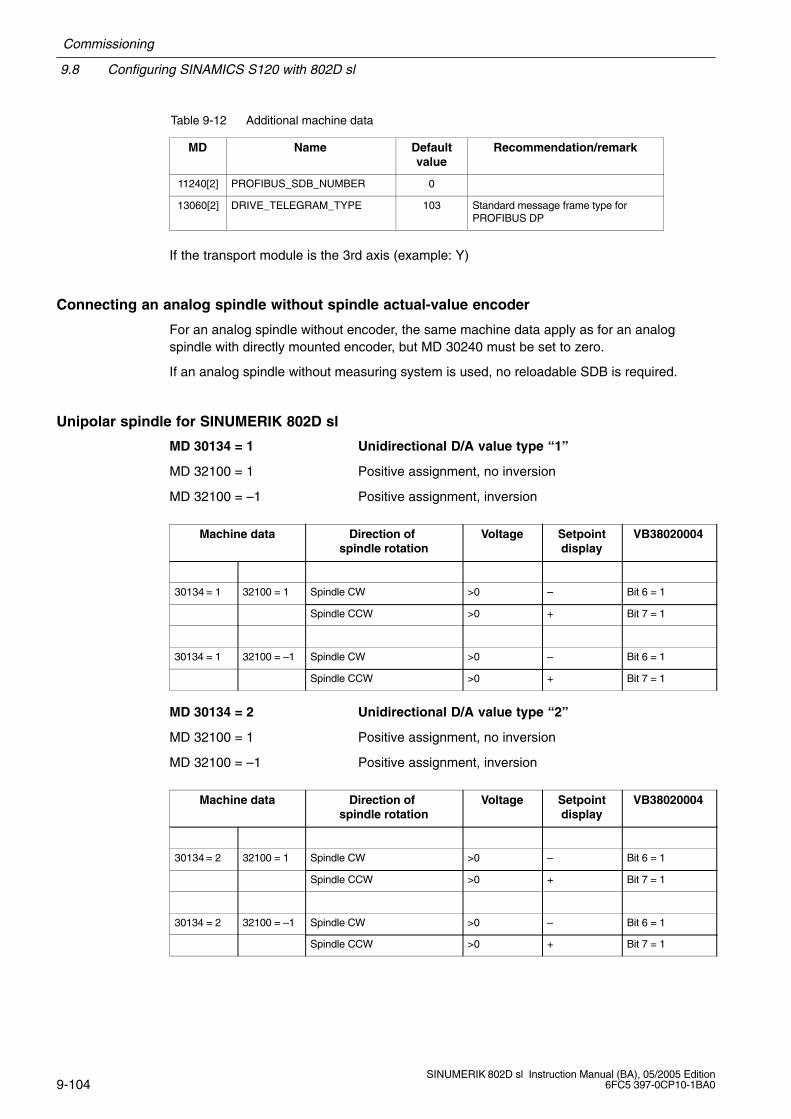
9.8 Configuring SINAMICS S120 with 802D sl
Commissioning
9-104SINUMERIK 802D sl Instruction Manual (BA), 05/2005 Edition
6FC5 397-0CP10-1BA0
Table 9-12 Additional machine data
MD Name Defaultvalue
Recommendation/remark
11240[2] PROFIBUS_SDB_NUMBER 0
13060[2] DRIVE_TELEGRAM_TYPE 103 Standard message frame type forPROFIBUS DP
If the transport module is the 3rd axis (example: Y)
Connecting an analog spindle without spindle actual-value encoder
For an analog spindle without encoder, the same machine data apply as for an analogspindle with directly mounted encoder, but MD 30240 must be set to zero.
If an analog spindle without measuring system is used, no reloadable SDB is required.
Unipolar spindle for SINUMERIK 802D sl
MD 30134 = 1 Unidirectional D/A value type “1”
MD 32100 = 1 Positive assignment, no inversion
MD 32100 = –1 Positive assignment, inversion
Machine data Direction of spindle rotation
Voltage Setpointdisplay
VB38020004
30134 = 1 32100 = 1 Spindle CW >0 – Bit 6 = 1
Spindle CCW >0 + Bit 7 = 1
30134 = 1 32100 = –1 Spindle CW >0 – Bit 6 = 1
Spindle CCW >0 + Bit 7 = 1
MD 30134 = 2 Unidirectional D/A value type “2”
MD 32100 = 1 Positive assignment, no inversion
MD 32100 = –1 Positive assignment, inversion
Machine data Direction of spindle rotation
Voltage Setpointdisplay
VB38020004
30134 = 2 32100 = 1 Spindle CW >0 – Bit 6 = 1
Spindle CCW >0 + Bit 7 = 1
30134 = 2 32100 = –1 Spindle CW >0 – Bit 6 = 1
Spindle CCW >0 + Bit 7 = 1
Commissioning
9.9 STARTER start-up tool
9-105SINUMERIK 802D sl Instruction Manual (BA), 05/2005 Edition6FC5 397-0CP10-1BA0
9.9 STARTER start-up tool
To launch the STARTER program, click the STARTER icon or choose Start > Programs >STARTER > STARTER from the Windows Start menu.
Note
The screenforms of the STARTER tool, version V3.2, are shown in the following. If yourparticular version deviates from the version used here, your screenforms may deviateslightly from those shown here.
9.9.1 Explanations regarding the STARTER user interface
To create the sample project, you can use STARTER (see Fig. 9-9). To perform the indivi-dual configurations, use the user interface areas listed below:
Project navigator: This area displays the elements and objects you will insert into theproject.
Working area: Use this area to perform your task for creating the project:
– When configuring the drive, this area is assigned the wizard useful for configuring thedrive objects.
– If you configure, for example, the parameters for the speed setpoint filter.
– If you switch to the Expert list, a list of all parameters is displayed which you can viewor change.
Detailed view: This area provides detailed information, for example, on faults andwarnings.
Siemens Automation Parts
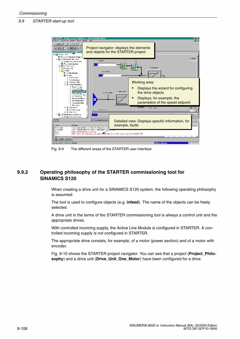
9.9 STARTER start-up tool
Commissioning
9-106SINUMERIK 802D sl Instruction Manual (BA), 05/2005 Edition
6FC5 397-0CP10-1BA0
Project navigator: displays the elementsand objects for the STARTER project.
Working area:
Displays the wizard for configuringthe drive objects
Displays, for example, theparameters of the speed setpointfilter
Detailed view: Displays specific information, forexample, faults
Fig. 9-9 The different areas of the STARTER user interface
9.9.2 Operating philosophy of the STARTER commissioning tool forSINAMICS S120
When creating a drive unit for a SINAMICS S120 system, the following operating philosophyis assumed:
The tool is used to configure objects (e.g. infeed). The name of the objects can be freelyselected.
A drive unit in the terms of the STARTER commissioning tool is always a control unit and theappropriate drives.
With controlled incoming supply, the Active Line Module is configured in STARTER. A con-trolled incoming supply is not configured in STARTER.
The appropriate drive consists, for example, of a motor (power section) and of a motor withencoder.
Fig. 9-10 shows the STARTER project navigator. You can see that a project (Project_Philo-sophy) and a drive unit (Drive_Unit_One_Motor) have been configured for a drive.
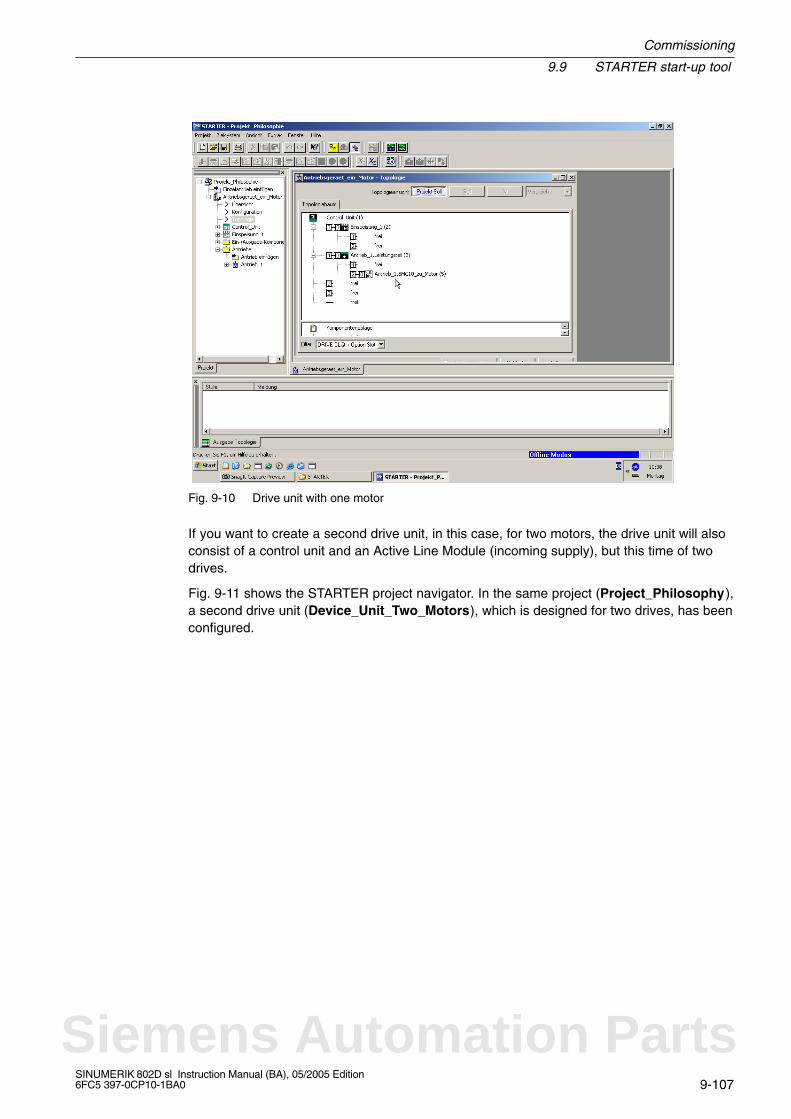
Commissioning
9.9 STARTER start-up tool
9-107SINUMERIK 802D sl Instruction Manual (BA), 05/2005 Edition6FC5 397-0CP10-1BA0
Fig. 9-10 Drive unit with one motor
If you want to create a second drive unit, in this case, for two motors, the drive unit will alsoconsist of a control unit and an Active Line Module (incoming supply), but this time of twodrives.
Fig. 9-11 shows the STARTER project navigator. In the same project (Project_Philosophy),a second drive unit (Device_Unit_Two_Motors), which is designed for two drives, has beenconfigured.
Siemens Automation Parts
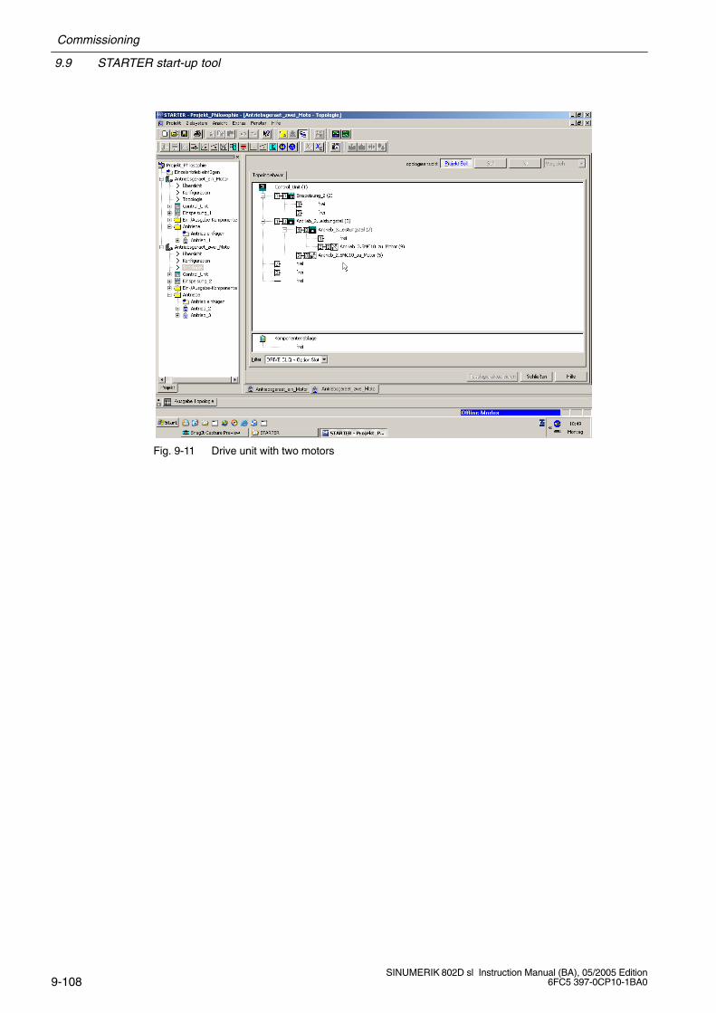
9.9 STARTER start-up tool
Commissioning
9-108SINUMERIK 802D sl Instruction Manual (BA), 05/2005 Edition
6FC5 397-0CP10-1BA0
Fig. 9-11 Drive unit with two motors

Commissioning
9.10 Start-up sequence when working with STARTER
9-109SINUMERIK 802D sl Instruction Manual (BA), 05/2005 Edition6FC5 397-0CP10-1BA0
9.10 Start-up sequence when working with STARTER
STARTER provides two alternative procedures for creating a drive object:
OFFLINE, where you can create and parameterize your drive unit configuration using awizard;
ONLINE, where you load an existing configuration and parameterization of a drive unitinto STARTER using the wizard.
If you have created or loaded a project in STARTER, you can operate the drive using thecontrol panel of STARTER.
9.10.1 Creating a drive object OFFLINE
The following steps are required to create a drive object OFFLINE:
Table 9-13 OFFLINE
Step Procedure Section
1 Start the STARTER commissioning tool and use the STARTER projectWizard to create a new project.
10.1.1
2 Set up the PPI interface. 10.1.1
3 Insert the drive unit. 10.1.1
4 Use the Wizard to configure the drive unit with, for example, the infeed,drive properties, drive with power section, motor, encoder, and so on.
10.1.2
5 Save your project. 10.1.2
6 Continue with “Operating the STARTER control panel (motor rotating)”. 10.2
Siemens Automation Parts
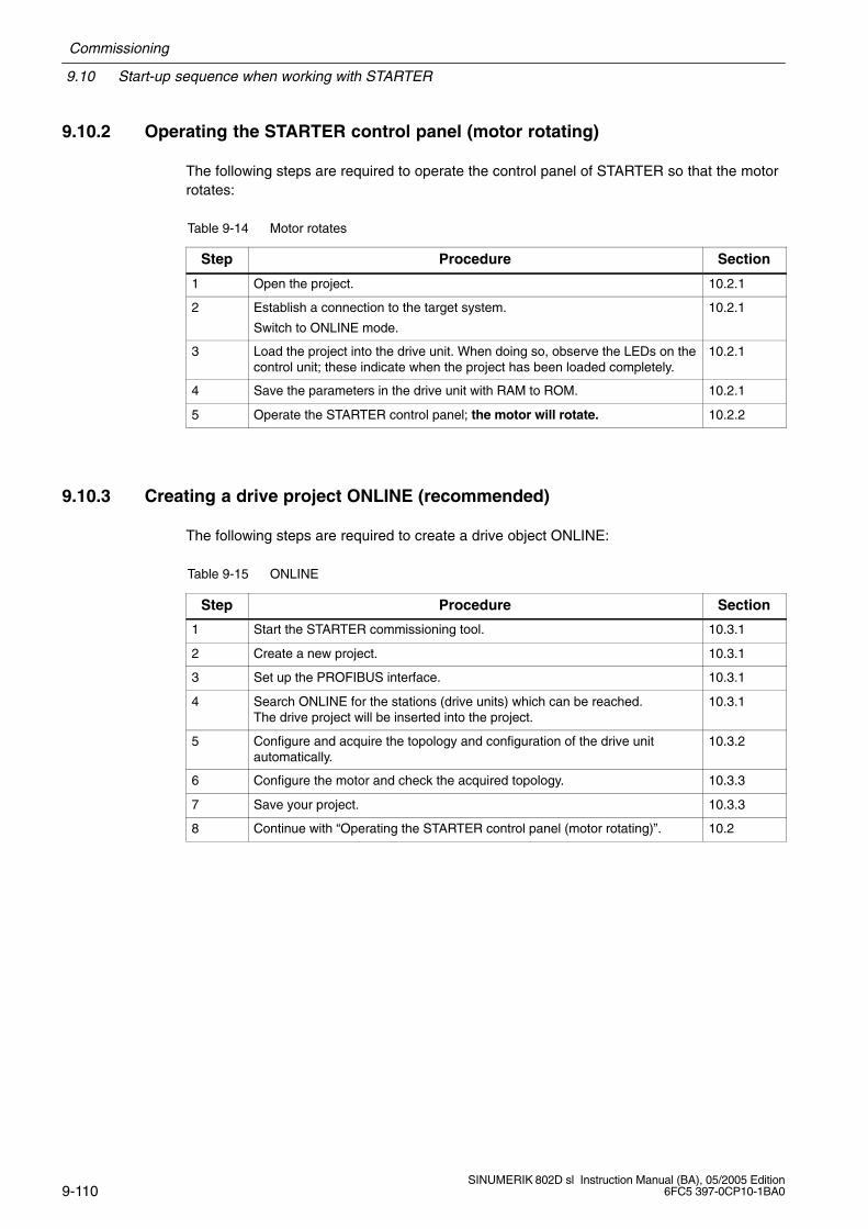
9.10 Start-up sequence when working with STARTER
Commissioning
9-110SINUMERIK 802D sl Instruction Manual (BA), 05/2005 Edition
6FC5 397-0CP10-1BA0
9.10.2 Operating the STARTER control panel (motor rotating)
The following steps are required to operate the control panel of STARTER so that the motorrotates:
Table 9-14 Motor rotates
Step Procedure Section
1 Open the project. 10.2.1
2 Establish a connection to the target system.
Switch to ONLINE mode.
10.2.1
3 Load the project into the drive unit. When doing so, observe the LEDs on thecontrol unit; these indicate when the project has been loaded completely.
10.2.1
4 Save the parameters in the drive unit with RAM to ROM. 10.2.1
5 Operate the STARTER control panel; the motor will rotate. 10.2.2
9.10.3 Creating a drive project ONLINE (recommended)
The following steps are required to create a drive object ONLINE:
Table 9-15 ONLINE
Step Procedure Section
1 Start the STARTER commissioning tool. 10.3.1
2 Create a new project. 10.3.1
3 Set up the PROFIBUS interface. 10.3.1
4 Search ONLINE for the stations (drive units) which can be reached.The drive project will be inserted into the project.
10.3.1
5 Configure and acquire the topology and configuration of the drive unitautomatically.
10.3.2
6 Configure the motor and check the acquired topology. 10.3.3
7 Save your project. 10.3.3
8 Continue with “Operating the STARTER control panel (motor rotating)”. 10.2
Commissioning
9.11 Diagnosis via STARTER
9-111SINUMERIK 802D sl Instruction Manual (BA), 05/2005 Edition6FC5 397-0CP10-1BA0
9.11 Diagnosis via STARTER
Description
The diagnostic functions support commissioning and service personnel during commissio-ning, troubleshooting, diagnostics and service activities.
General
Prerequisites: STARTER is in the online mode.
STARTER provides the following diagnostic functions:
PROFIBUS diagnostic buffer
The message output window shows the states of the control/status words, parametersand drive enable signals for the selected drive/device.
Fault/alarm display in the alarms output window
Faults and warnings can be displayed either for one or for several drives/units. The fault/alarm description is called up by selecting “Help –> Context” or by pressing the SHIFT+ F1 keys.
Diagnostic overview
An overview table of all drives existing in the project is displayed.
– Device: The existing devices and drives are displayed with their names; the devicestatus is displayed in the “Device diagnosis” window.
– Operating status: The operating status (e.g. OFFLINE, ONLINE, STARTUP, STOP,STOP U, RUN) of the device or of the drive is displayed; it can be controlled via themode selector switch.
Signals specified from the function generator (see Section 9.11.1)
Signal recording using the Trace function (see Section 9.11.2)
Analysis of the control behavior using the measuring function (see Section 9.11.3)
Output of voltage signals for external measuring instruments via measuring sockets (seeSection 9.11.4)
Siemens Automation Parts
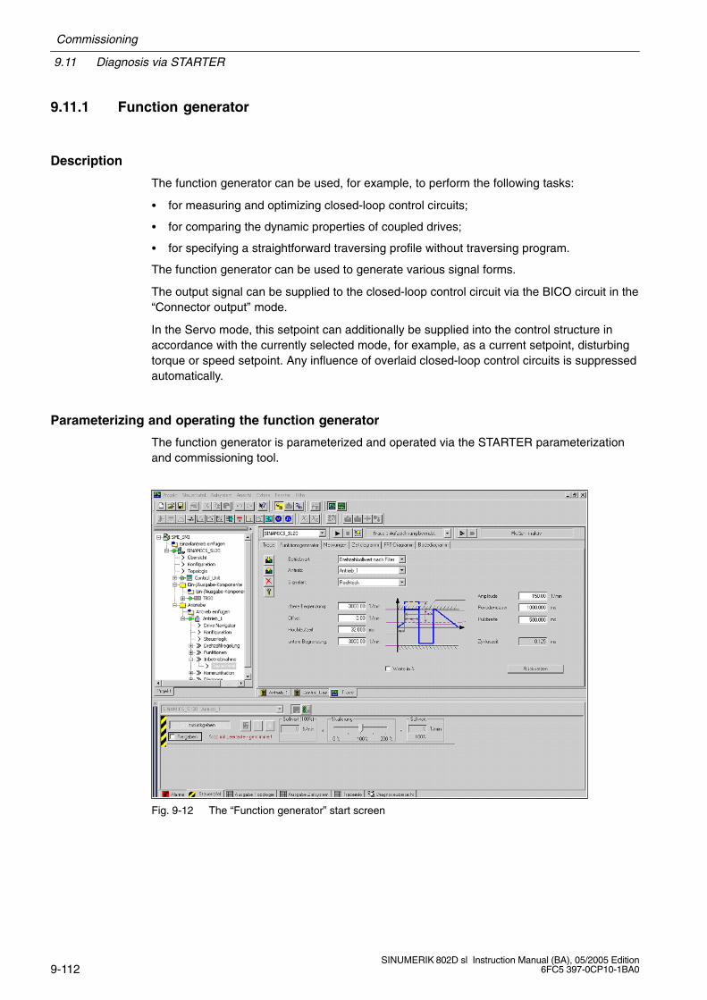
9.11 Diagnosis via STARTER
Commissioning
9-112SINUMERIK 802D sl Instruction Manual (BA), 05/2005 Edition
6FC5 397-0CP10-1BA0
9.11.1 Function generator
Description
The function generator can be used, for example, to perform the following tasks:
for measuring and optimizing closed-loop control circuits;
for comparing the dynamic properties of coupled drives;
for specifying a straightforward traversing profile without traversing program.
The function generator can be used to generate various signal forms.
The output signal can be supplied to the closed-loop control circuit via the BICO circuit in the“Connector output” mode.
In the Servo mode, this setpoint can additionally be supplied into the control structure inaccordance with the currently selected mode, for example, as a current setpoint, disturbingtorque or speed setpoint. Any influence of overlaid closed-loop control circuits is suppressedautomatically.
Parameterizing and operating the function generator
The function generator is parameterized and operated via the STARTER parameterizationand commissioning tool.
Fig. 9-12 The “Function generator” start screen
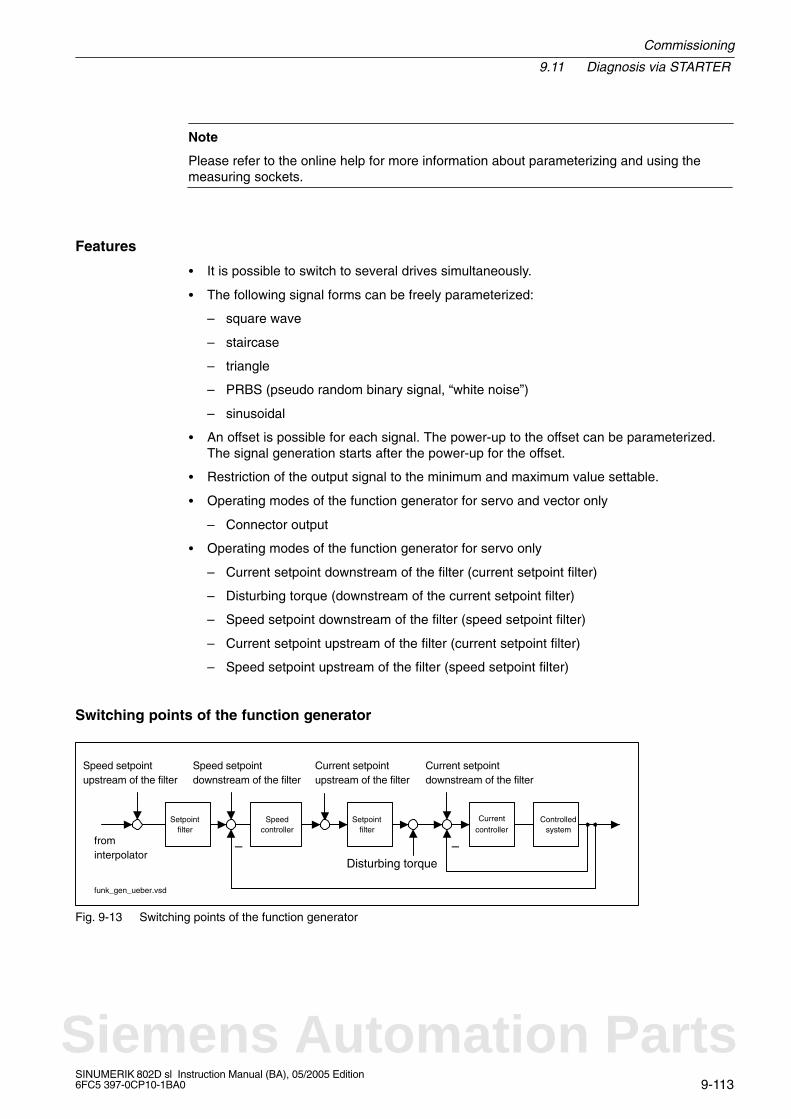
Commissioning
9.11 Diagnosis via STARTER
9-113SINUMERIK 802D sl Instruction Manual (BA), 05/2005 Edition6FC5 397-0CP10-1BA0
Note
Please refer to the online help for more information about parameterizing and using themeasuring sockets.
Features
It is possible to switch to several drives simultaneously.
The following signal forms can be freely parameterized:
– square wave
– staircase
– triangle
– PRBS (pseudo random binary signal, “white noise”)
– sinusoidal
An offset is possible for each signal. The power-up to the offset can be parameterized.The signal generation starts after the power-up for the offset.
Restriction of the output signal to the minimum and maximum value settable.
Operating modes of the function generator for servo and vector only
– Connector output
Operating modes of the function generator for servo only
– Current setpoint downstream of the filter (current setpoint filter)
– Disturbing torque (downstream of the current setpoint filter)
– Speed setpoint downstream of the filter (speed setpoint filter)
– Current setpoint upstream of the filter (current setpoint filter)
– Speed setpoint upstream of the filter (speed setpoint filter)
Switching points of the function generator
funk_gen_ueber.vsd
frominterpolator
Setpointfilter
Speedcontroller
Setpointfilter
Currentcontroller
Controlled
Speed setpointupstream of the filter
Speed setpointdownstream of the filter
Disturbing torque
Current setpointupstream of the filter
Current setpointdownstream of the filter
––system
Fig. 9-13 Switching points of the function generator
Siemens Automation Parts

9.11 Diagnosis via STARTER
Commissioning
9-114SINUMERIK 802D sl Instruction Manual (BA), 05/2005 Edition
6FC5 397-0CP10-1BA0
Further signal forms
Further signal forms can be produced by parameterization.
Example:
The “triangular” signal shape can be parameterized with “upper limitation” to produce atriangle with no peak.
Upper
limiting
Signal form
“Triangular”
Fig. 9-14 “Triangular” signal without peak
Starting/stopping the function generator
!Caution
With the corresponding ramp-function generator parameter settings (e.g. offset), the motorcan “drift” and travel to its end stop.
The motion of the drive is not monitored with the function generator activated.
To start the function generator, proceed as follows:
1. Provide for the prerequisites for starting the function generator.
– Activate the control panel.
Drives –> Drive_x –> Commissioning –> Control board
– Turn on the drive.
Control board –> Issue enable signals –> Switch on
2. Select the appropriate operating mode,
e.g. speed setpoint downstream of the filter.
3. Select the drive (as the control panel).
4. Set the signal form,
e.g. rectangle.
5. Load the settings to the target system (“Download parameters” pushbutton)
6. Start the ramp-function generator (“Start FctGen” pushbutton)
To stop the function generator, proceed as follows:
“Stop FctGen” pushbutton
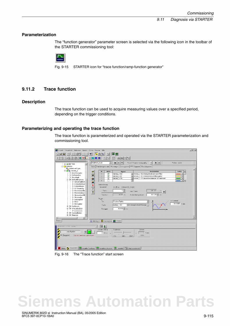
Commissioning
9.11 Diagnosis via STARTER
9-115SINUMERIK 802D sl Instruction Manual (BA), 05/2005 Edition6FC5 397-0CP10-1BA0
Parameterization
The “function generator” parameter screen is selected via the following icon in the toolbar ofthe STARTER commissioning tool:
Fig. 9-15 STARTER icon for “trace function/ramp-function generator”
9.11.2 Trace function
Description
The trace function can be used to acquire measuring values over a specified period,depending on the trigger conditions.
Parameterizing and operating the trace function
The trace function is parameterized and operated via the STARTER parameterization andcommissioning tool.
Fig. 9-16 The “Trace function” start screen
Siemens Automation Parts
9.11 Diagnosis via STARTER
Commissioning
9-116SINUMERIK 802D sl Instruction Manual (BA), 05/2005 Edition
6FC5 397-0CP10-1BA0
Note
Please refer to the online help for more information about parameterizing and using themeasuring sockets.
Features
Four recording channels per recorder
Two independent trace recorders per control unit
Triggering
– Without triggering (recording immediately after start)
– Triggering either to signal with edge or to level
– Trigger delay and pretrigger possible
STARTER parameterization and commissioning tool
– Automatic or settable scaling of the display axes
– Signal measurement via cursor
Settable trace cycle: integers of the base sample time
Parameterization
The “trace function” parameter screen is selected via the following icon in the toolbar of theSTARTER commissioning tool:
Fig. 9-17 STARTER icon for “trace function/ramp-function generator”
9.11.3 Measuring function (SERVO) (available soon)
Note
This functionality is available soon.

Commissioning
9.11 Diagnosis via STARTER
9-117SINUMERIK 802D sl Instruction Manual (BA), 05/2005 Edition6FC5 397-0CP10-1BA0
Description
The measuring function serves to optimize the controller of the drive. The measuring func-tion can also be used to eliminate specifically the influence of overlaid closed-loop controlcircuits by simple parameterization and to analyze the dynamic properties of individualdrives. To this end, function generator and trace are coupled with each other. The controlloop is supplied with the ramp-function generator signal at a given point (e.g. speed setpoint)and recorded by the trace function at another (e.g. speed actual value). The parameteriza-tion of a measuring function automatically also parameterizes the trace. Certain operatingmodes have already been predefined for the trace, which can be used here.
Parameterizing and operating the measuring function
The measuring function is parameterized and operated via the STARTER parameterizationand commissioning tool.
Fig. 9-18 “Measuring function” initial screen
Note
Please refer to the online help for more information about parameterizing and using themeasuring sockets.
Siemens Automation Parts

9.11 Diagnosis via STARTER
Commissioning
9-118SINUMERIK 802D sl Instruction Manual (BA), 05/2005 Edition
6FC5 397-0CP10-1BA0
Features
Measuring functions
– Current controller setpoint step change (downstream of the current setpoint filter)
– Speed controller reference frequency response (downstream of the current setpointfilter)
– Speed controller setpoint step change (downstream of the speed setpoint filter)
– Speed controller disturbance variable step change (fault downstream of the currentsetpoint filter)
– Speed controller reference frequency response (downstream of the speed setpointfilter)
– Speed controller reference frequency response (upstream of the speed setpoint filter)
– Speed controller interference frequency response (fault downstream of the currentsetpoint filter)
– Speed-controlled system (excitation downstream of the current setpoint filter)
Starting / stopping the measuring function
!Caution
With the corresponding measuring function parameter settings (e.g. offset), the motor can“drift” and travel to its end stop.
The motion of the drive is not monitored with the measuring function activated.
To start the function generator, proceed as follows:
1. Provide for the prerequisites for starting the measuring function.
– Activate the control panel.
Drives –> Drive_x –> Commissioning –> Control board
– Turn on the drive.
Control board –> Issue enable signals –> Switch on
2. Select the drive (as the control panel).
3. Set the measuring function,
e.g. current controller setpoint step change.
4. Load the settings to the target system (“Download parameters” pushbutton)
5. Start the measuring function (“Start Measuring Function” pushbutton)
To stop the function generator, proceed as follows:
“Stop Measuring Function” pushbutton

Commissioning
9.11 Diagnosis via STARTER
9-119SINUMERIK 802D sl Instruction Manual (BA), 05/2005 Edition6FC5 397-0CP10-1BA0
Parameterization
The “measuring function” parameter screen is selected via the following icon in the toolbar ofthe STARTER commissioning tool:
Fig. 9-19 STARTER icon for “measuring function”
9.11.4 Measuring sockets (available soon)
Note
This functionality is available soon.
Siemens Automation Parts

9.12 Completing the start-up
Commissioning
9-120SINUMERIK 802D sl Instruction Manual (BA), 05/2005 Edition
6FC5 397-0CP10-1BA0
9.12 Completing the start-up
After the start-up by the machine manufacturer has been completed, it is recommended tocarry out a data backup prior to delivery to the end customer:
1. Performing an internal data backup (at least protection level 3 required):
– Select the Save data softkey in the System operating area.
– To save the drive mmachine data, set parameter p977=1 in the CU (SINAMICS_I).
2. Resetting the access level:
– Select the Delete passw. softkey.
Commissioning
9.13 Service display of the axis drive behavior
9-121SINUMERIK 802D sl Instruction Manual (BA), 05/2005 Edition6FC5 397-0CP10-1BA0
9.13 Service display of the axis drive behavior
Servo trace
For axis service, the SERVO trace function has been implemented in the “Diagnostic” menuto represent axis signals graphically.
The trace function is selected in the System\Service display\SERVO Trace operating area.
Note to the reader
/BH/ SINUMERIK 802D sl “Operation and Programming”, Chapter 7
Siemens Automation Parts

9.13 Service display of the axis drive behavior
Commissioning
9-122SINUMERIK 802D sl Instruction Manual (BA), 05/2005 Edition
6FC5 397-0CP10-1BA0
Notes

10-123SINUMERIK 802D sl Instruction Manual (BA), 05/2005 Edition6FC5 397-0CP10-1BA0
Creating a Drive Project
10.1 Creating a drive project OFFLINE
10.1.1 Creating a project
Creating a project
The first step is to create a new project for your example:
1. Click the STARTER icon or choose Start > Program > STARTER > STARTER from theWindows Start menu to run the STARTER commissioning tool.
When the software is started for the first time, the main screen (see Fig. 10-1) appearswith the following dialog boxes:
– “STARTER Project Wizard”
– “STARTER Getting Started Commissioning Drive”
You can call up the ProjectWizard by choosing Project > New with wizard.
If you deactivate this field,the Project Wizard will notappear any more when theSTARTER is started nexttime.
Fig. 10-1 Main screen of the STARTER parameterization and commissioning tool
10
Siemens Automation Parts
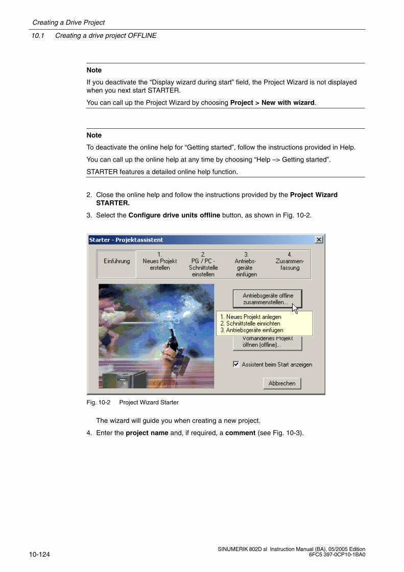
10.1 Creating a drive project OFFLINE
Creating a Drive Project
10-124SINUMERIK 802D sl Instruction Manual (BA), 05/2005 Edition
6FC5 397-0CP10-1BA0
Note
If you deactivate the “Display wizard during start” field, the Project Wizard is not displayedwhen you next start STARTER.
You can call up the Project Wizard by choosing Project > New with wizard.
Note
To deactivate the online help for “Getting started”, follow the instructions provided in Help.
You can call up the online help at any time by choosing “Help –> Getting started”.
STARTER features a detailed online help function.
2. Close the online help and follow the instructions provided by the Project WizardSTARTER.
3. Select the Configure drive units offline button, as shown in Fig. 10-2.
Fig. 10-2 Project Wizard Starter
The wizard will guide you when creating a new project.
4. Enter the project name and, if required, a comment (see Fig. 10-3).

Creating a Drive Project
10.1 Creating a drive project OFFLINE
10-125SINUMERIK 802D sl Instruction Manual (BA), 05/2005 Edition6FC5 397-0CP10-1BA0
Fig. 10-3 Creating a new project
5. Click Continue > to set up a PPI interface in the PC/PG.
Fig. 10-4 Setting up the interface
6. In this example, you need a PPI interface in the PC/PG. Choose Change and test....
Siemens Automation Parts
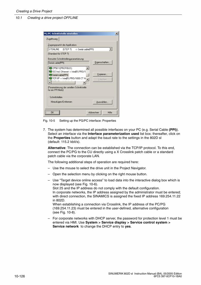
10.1 Creating a drive project OFFLINE
Creating a Drive Project
10-126SINUMERIK 802D sl Instruction Manual (BA), 05/2005 Edition
6FC5 397-0CP10-1BA0
Fig. 10-5 Setting up the PG/PC interface: Properties
7. The system has determined all possible interfaces on your PC (e.g. Serial Cable (PPI)).Select an interface via the Interface parameterization used list box; thereafter, click onthe Properties button and adapt the baud rate to the settings in the 802D sl (default: 115.2 kbit/s).
Alternative: The connection can be established via the TCP/IP protocol. To this end,connect the PC/PG to the CU directly using a X Crosslink patch cable or a standardpatch cable via the corporate LAN.
The following additional steps of operation are required here:
– Use the mouse to select the drive unit in the Project Navigator.
– Open the selection menu by clicking on the right mouse button.
– Use “Target device online access” to load data into the interactive dialog box which isnow displayed (see Fig. 10-6).Slot 25 and the IP address do not comply with the default configuration. In corporate networks, the IP address assigned by the administrator must be entered;with direct connection, the SINAMICS is assigned the fixed IP address 169.254.11.22in 802D.When establishing a connection via Crosslink, the IP address of the PC/PG(169.254.11.23) must be entered in the user-defined, alternative configuration(see Fig. 10-8).
– For corporate networks with DHCP server, the password for protection level 1 must beentered via HMI. Use System > Service display > Service control system >Service network to change the DHCP entry to yes.
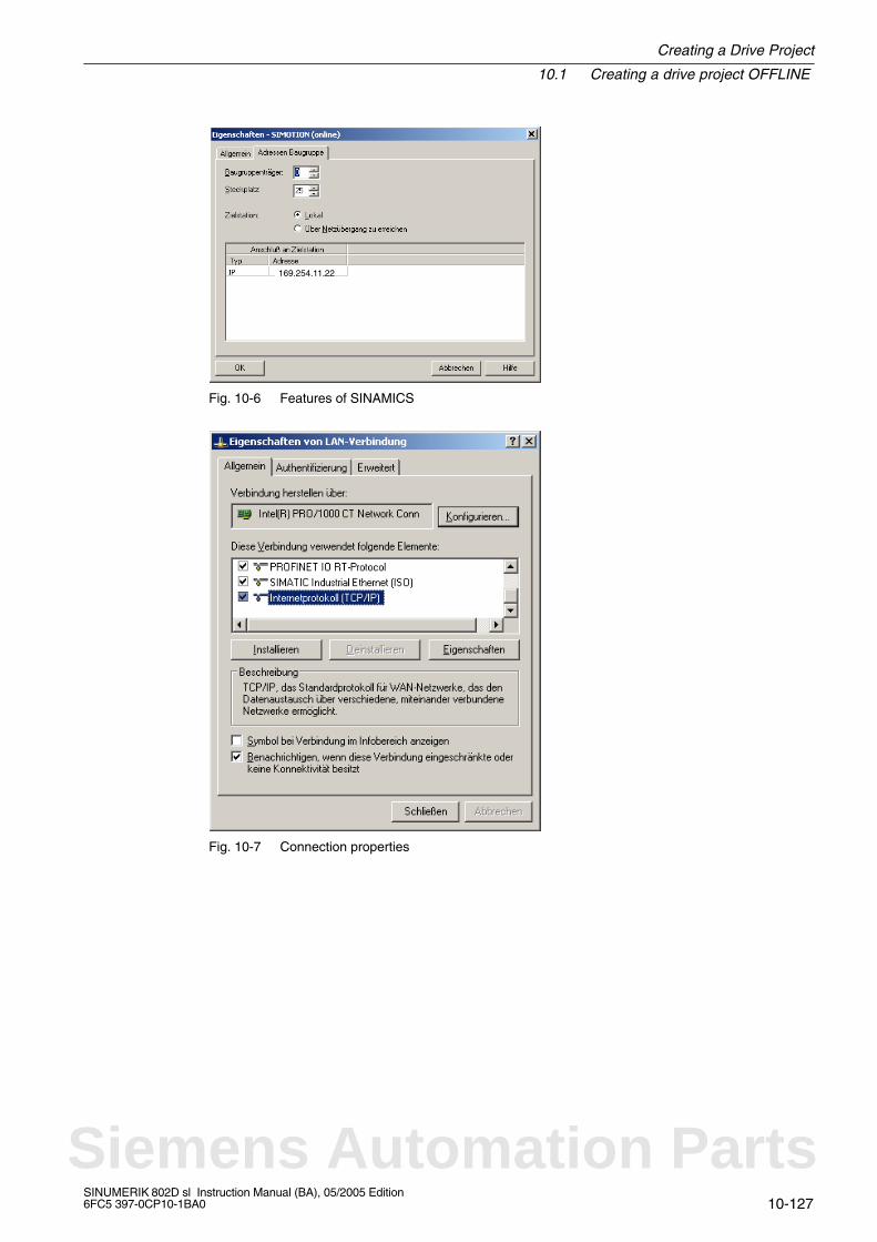
Creating a Drive Project
10.1 Creating a drive project OFFLINE
10-127SINUMERIK 802D sl Instruction Manual (BA), 05/2005 Edition6FC5 397-0CP10-1BA0
169.254.11.22
Fig. 10-6 Features of SINAMICS
Fig. 10-7 Connection properties
Siemens Automation Parts
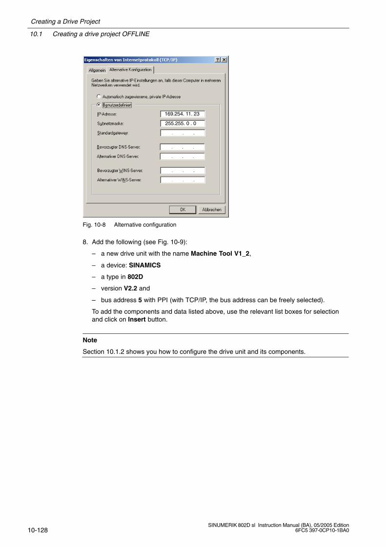
10.1 Creating a drive project OFFLINE
Creating a Drive Project
10-128SINUMERIK 802D sl Instruction Manual (BA), 05/2005 Edition
6FC5 397-0CP10-1BA0
169.254. 11. 23
255.255. 0 . 0
Fig. 10-8 Alternative configuration
8. Add the following (see Fig. 10-9):
– a new drive unit with the name Machine Tool V1_2,
– a device: SINAMICS
– a type in 802D
– version V2.2 and
– bus address 5 with PPI (with TCP/IP, the bus address can be freely selected).
To add the components and data listed above, use the relevant list boxes for selectionand click on Insert button.
Note
Section 10.1.2 shows you how to configure the drive unit and its components.
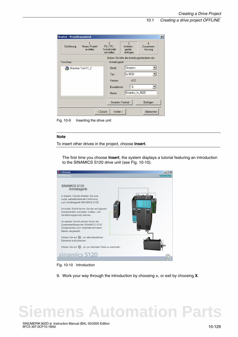
Creating a Drive Project
10.1 Creating a drive project OFFLINE
10-129SINUMERIK 802D sl Instruction Manual (BA), 05/2005 Edition6FC5 397-0CP10-1BA0
5
Fig. 10-9 Inserting the drive unit
Note
To insert other drives in the project, choose Insert.
The first time you choose Insert, the system displays a tutorial featuring an introductionto the SINAMICS S120 drive unit (see Fig. 10-10).
Fig. 10-10 Introduction
9. Work your way through the introduction by choosing >, or exit by choosing X.
Siemens Automation Parts
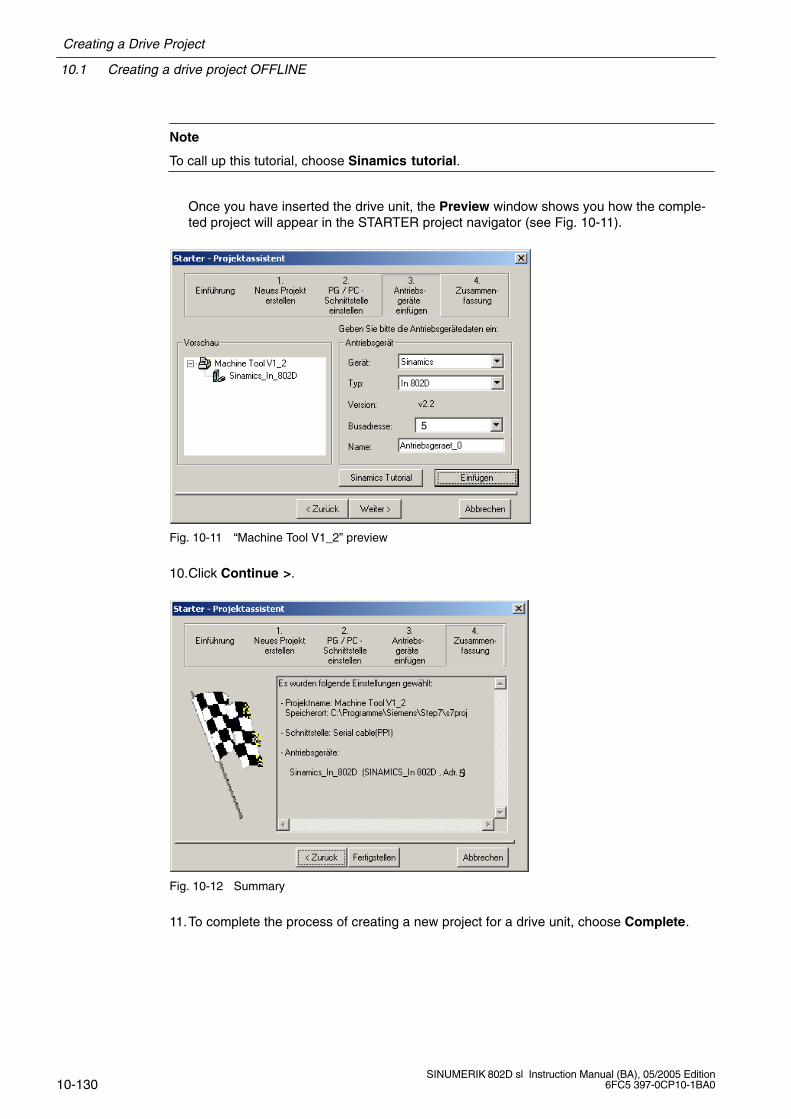
10.1 Creating a drive project OFFLINE
Creating a Drive Project
10-130SINUMERIK 802D sl Instruction Manual (BA), 05/2005 Edition
6FC5 397-0CP10-1BA0
Note
To call up this tutorial, choose Sinamics tutorial.
Once you have inserted the drive unit, the Preview window shows you how the comple-ted project will appear in the STARTER project navigator (see Fig. 10-11).
5
Fig. 10-11 “Machine Tool V1_2” preview
10.Click Continue >.
5
Fig. 10-12 Summary
11.To complete the process of creating a new project for a drive unit, choose Complete.
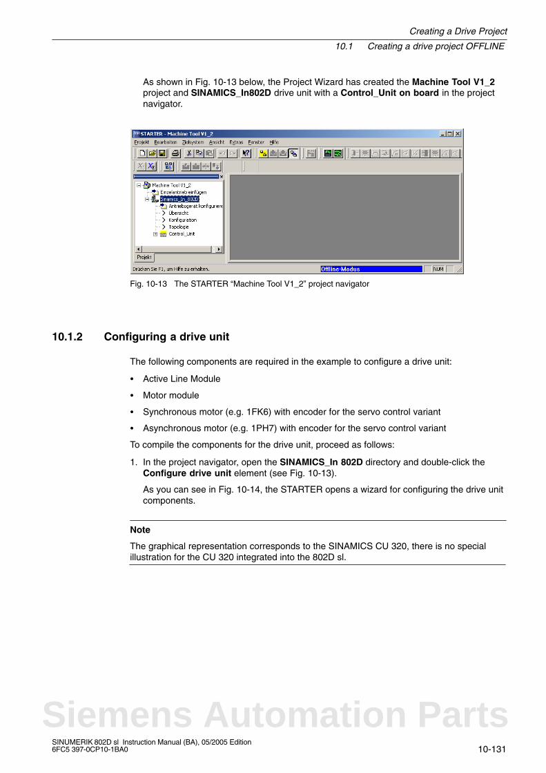
Creating a Drive Project
10.1 Creating a drive project OFFLINE
10-131SINUMERIK 802D sl Instruction Manual (BA), 05/2005 Edition6FC5 397-0CP10-1BA0
As shown in Fig. 10-13 below, the Project Wizard has created the Machine Tool V1_2project and SINAMICS_In802D drive unit with a Control_Unit on board in the projectnavigator.
Fig. 10-13 The STARTER “Machine Tool V1_2” project navigator
10.1.2 Configuring a drive unit
The following components are required in the example to configure a drive unit:
Active Line Module
Motor module
Synchronous motor (e.g. 1FK6) with encoder for the servo control variant
Asynchronous motor (e.g. 1PH7) with encoder for the servo control variant
To compile the components for the drive unit, proceed as follows:
1. In the project navigator, open the SINAMICS_In 802D directory and double-click theConfigure drive unit element (see Fig. 10-13).
As you can see in Fig. 10-14, the STARTER opens a wizard for configuring the drive unitcomponents.
Note
The graphical representation corresponds to the SINAMICS CU 320, there is no specialillustration for the CU 320 integrated into the 802D sl.
Siemens Automation Parts
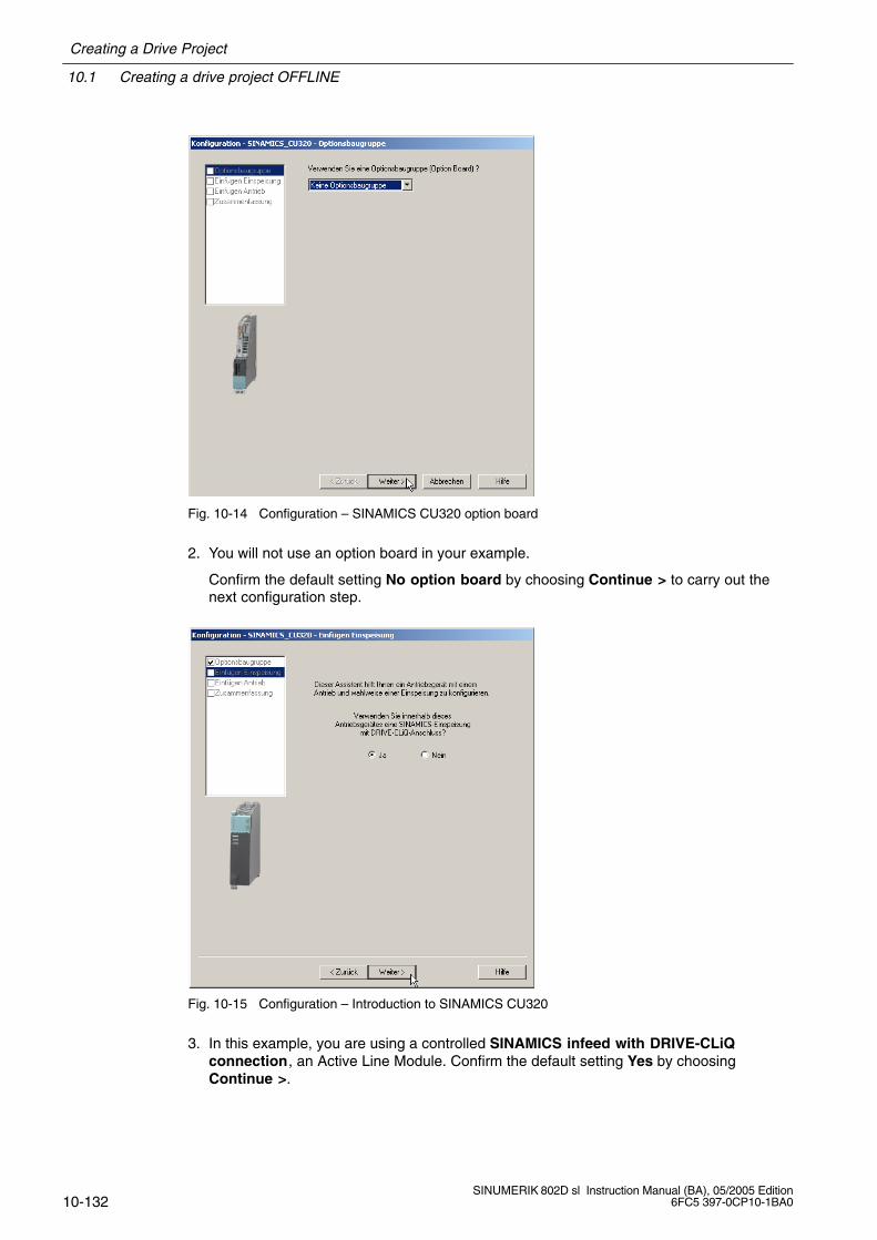
10.1 Creating a drive project OFFLINE
Creating a Drive Project
10-132SINUMERIK 802D sl Instruction Manual (BA), 05/2005 Edition
6FC5 397-0CP10-1BA0
Fig. 10-14 Configuration – SINAMICS CU320 option board
2. You will not use an option board in your example.
Confirm the default setting No option board by choosing Continue > to carry out thenext configuration step.
Fig. 10-15 Configuration – Introduction to SINAMICS CU320
3. In this example, you are using a controlled SINAMICS infeed with DRIVE-CLiQconnection, an Active Line Module. Confirm the default setting Yes by choosingContinue >.

Creating a Drive Project
10.1 Creating a drive project OFFLINE
10-133SINUMERIK 802D sl Instruction Manual (BA), 05/2005 Edition6FC5 397-0CP10-1BA0
Note
If you are using an uncontrolled SINAMICS infeed, click No and then Continue >.
Fig. 10-16 SINAMICS_CU320 configuration for the Active Line Module
4. First choose the appropriate Active Line Module from the Selection listbox according totype (order no.) (see rating plate), assign a name (Supply_1), and click the Line filteravailable field.
5. Click Continue > to select further data for the Active Line Module (infeed)(see Fig. 10-17).
Siemens Automation Parts
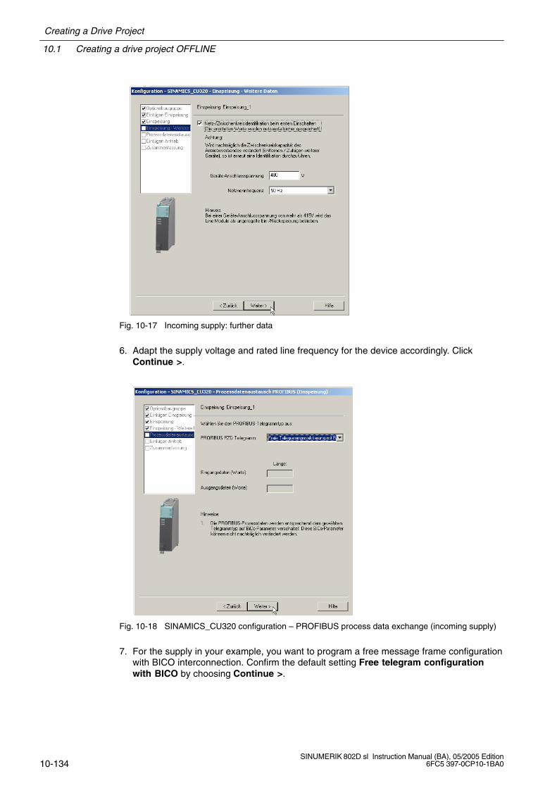
10.1 Creating a drive project OFFLINE
Creating a Drive Project
10-134SINUMERIK 802D sl Instruction Manual (BA), 05/2005 Edition
6FC5 397-0CP10-1BA0
Fig. 10-17 Incoming supply: further data
6. Adapt the supply voltage and rated line frequency for the device accordingly. ClickContinue >.
Fig. 10-18 SINAMICS_CU320 configuration – PROFIBUS process data exchange (incoming supply)
7. For the supply in your example, you want to program a free message frame configurationwith BICO interconnection. Confirm the default setting Free telegram configurationwith BICO by choosing Continue >.
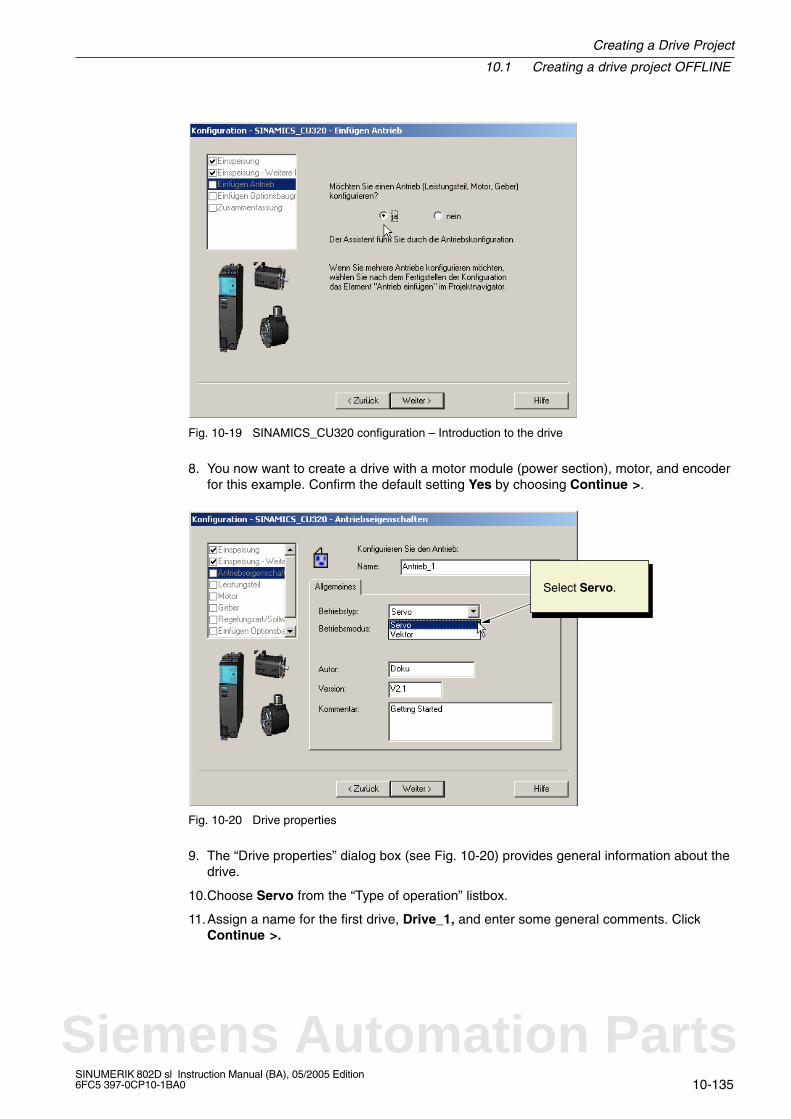
Creating a Drive Project
10.1 Creating a drive project OFFLINE
10-135SINUMERIK 802D sl Instruction Manual (BA), 05/2005 Edition6FC5 397-0CP10-1BA0
Fig. 10-19 SINAMICS_CU320 configuration – Introduction to the drive
8. You now want to create a drive with a motor module (power section), motor, and encoderfor this example. Confirm the default setting Yes by choosing Continue >.
Select Servo.
Fig. 10-20 Drive properties
9. The “Drive properties” dialog box (see Fig. 10-20) provides general information about thedrive.
10.Choose Servo from the “Type of operation” listbox.
11.Assign a name for the first drive, Drive_1, and enter some general comments. ClickContinue >.
Siemens Automation Parts
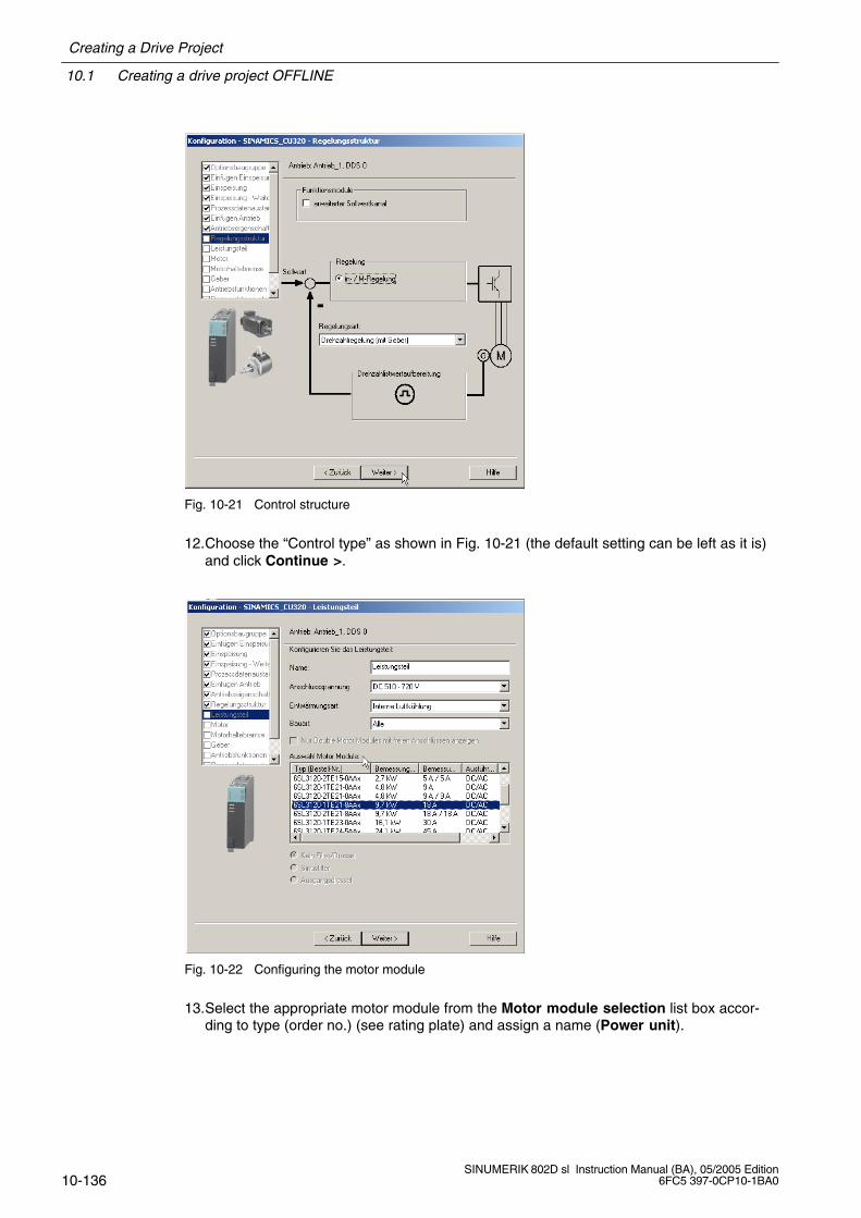
10.1 Creating a drive project OFFLINE
Creating a Drive Project
10-136SINUMERIK 802D sl Instruction Manual (BA), 05/2005 Edition
6FC5 397-0CP10-1BA0
Fig. 10-21 Control structure
12.Choose the “Control type” as shown in Fig. 10-21 (the default setting can be left as it is)and click Continue >.
Fig. 10-22 Configuring the motor module
13.Select the appropriate motor module from the Motor module selection list box accor-ding to type (order no.) (see rating plate) and assign a name (Power unit).
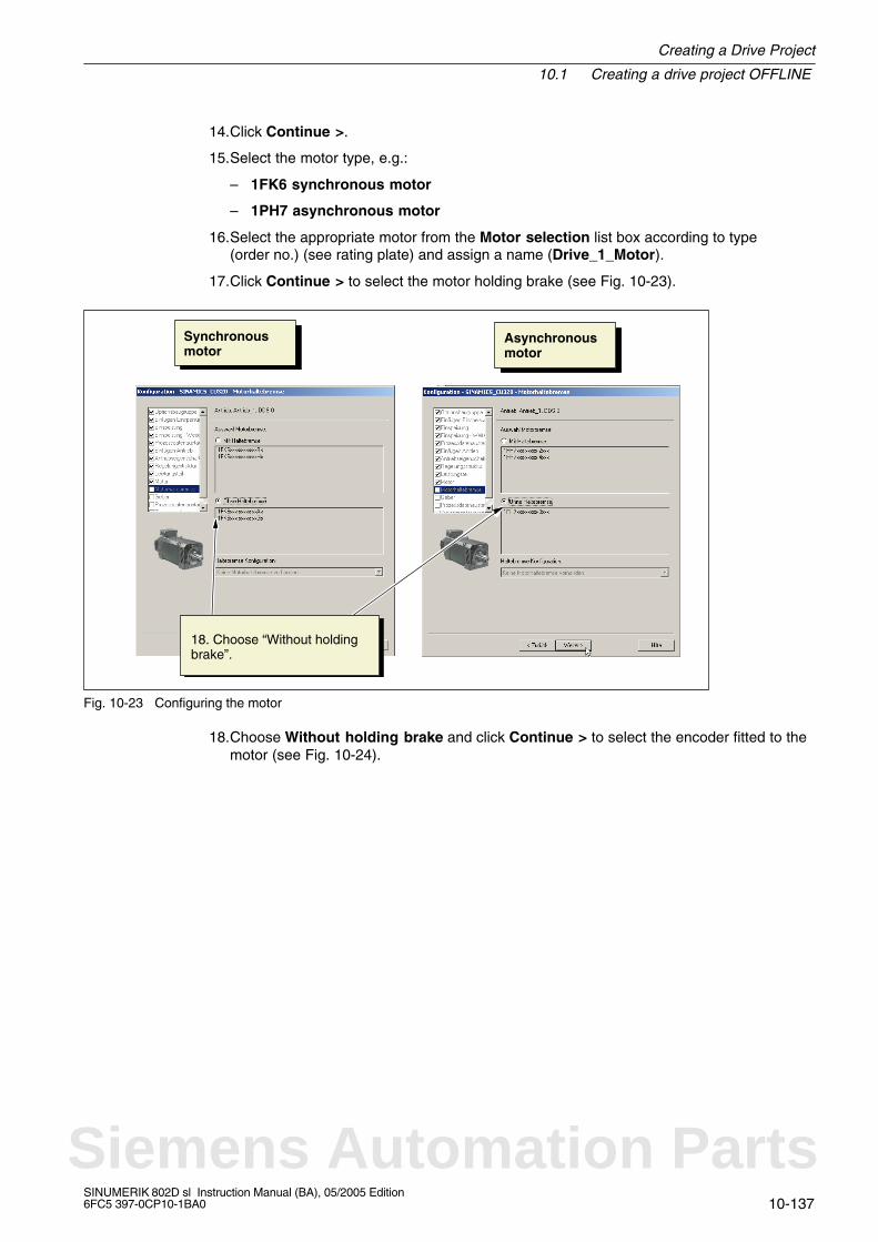
Creating a Drive Project
10.1 Creating a drive project OFFLINE
10-137SINUMERIK 802D sl Instruction Manual (BA), 05/2005 Edition6FC5 397-0CP10-1BA0
14.Click Continue >.
15.Select the motor type, e.g.:
– 1FK6 synchronous motor
– 1PH7 asynchronous motor
16.Select the appropriate motor from the Motor selection list box according to type(order no.) (see rating plate) and assign a name (Drive_1_Motor).
17.Click Continue > to select the motor holding brake (see Fig. 10-23).
Synchronousmotor
Asynchronousmotor
18. Choose “Without holdingbrake”.
Fig. 10-23 Configuring the motor
18.Choose Without holding brake and click Continue > to select the encoder fitted to themotor (see Fig. 10-24).
Siemens Automation Parts
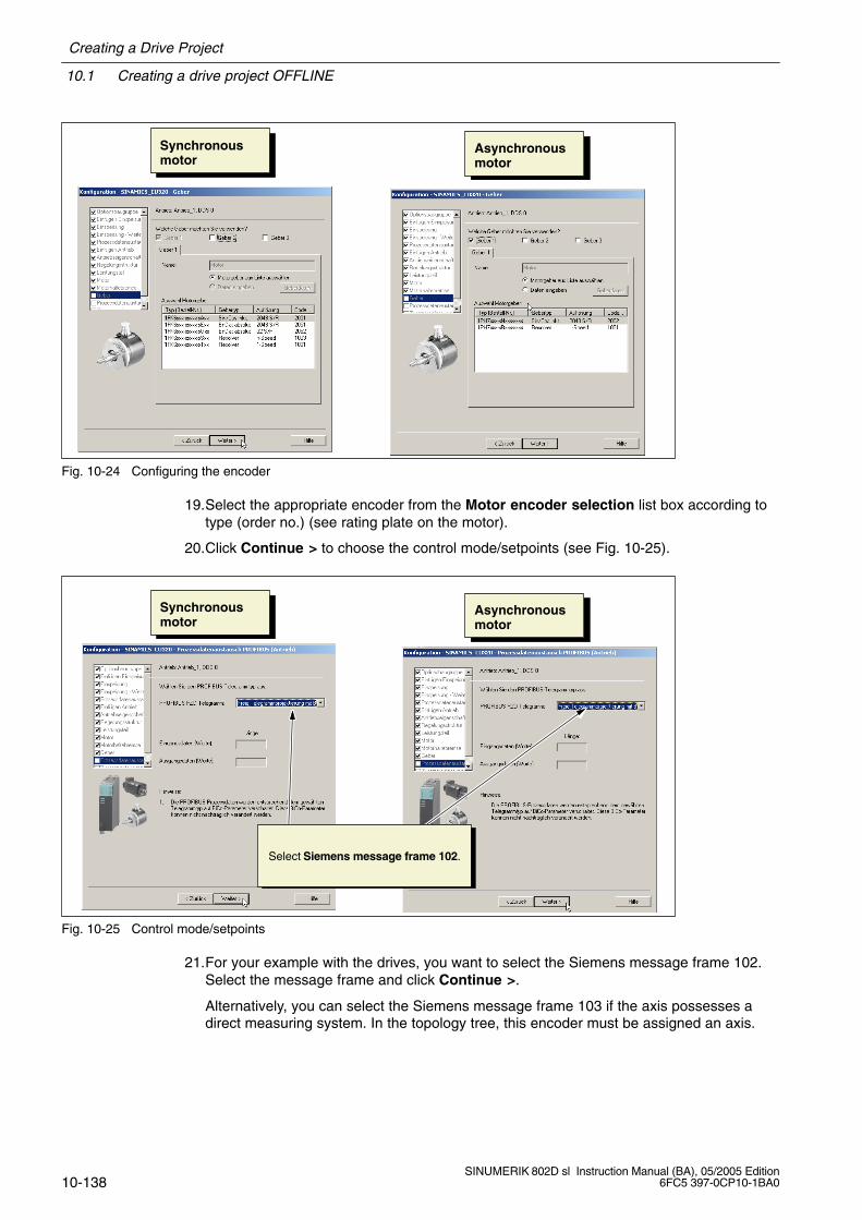
10.1 Creating a drive project OFFLINE
Creating a Drive Project
10-138SINUMERIK 802D sl Instruction Manual (BA), 05/2005 Edition
6FC5 397-0CP10-1BA0
Synchronousmotor
Asynchronousmotor
Fig. 10-24 Configuring the encoder
19.Select the appropriate encoder from the Motor encoder selection list box according totype (order no.) (see rating plate on the motor).
20.Click Continue > to choose the control mode/setpoints (see Fig. 10-25).
Synchronousmotor
Asynchronousmotor
Select Siemens message frame 102.
Fig. 10-25 Control mode/setpoints
21.For your example with the drives, you want to select the Siemens message frame 102.Select the message frame and click Continue >.
Alternatively, you can select the Siemens message frame 103 if the axis possesses adirect measuring system. In the topology tree, this encoder must be assigned an axis.
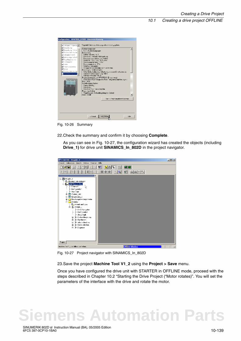
Creating a Drive Project
10.1 Creating a drive project OFFLINE
10-139SINUMERIK 802D sl Instruction Manual (BA), 05/2005 Edition6FC5 397-0CP10-1BA0
Fig. 10-26 Summary
22.Check the summary and confirm it by choosing Complete.
As you can see in Fig. 10-27, the configuration wizard has created the objects (includingDrive_1) for drive unit SINAMICS_In_802D in the project navigator.
Fig. 10-27 Project navigator with SINAMICS_In_802D
23.Save the project Machine Tool V1_2 using the Project > Save menu.
Once you have configured the drive unit with STARTER in OFFLINE mode, proceed with thesteps described in Chapter 10.2 “Starting the Drive Project (“Motor rotates)”. You will set theparameters of the interface with the drive and rotate the motor.
Siemens Automation Parts

10.2 Operating the control panel in STARTER (with the motor rotating)
Creating a Drive Project
10-140SINUMERIK 802D sl Instruction Manual (BA), 05/2005 Edition
6FC5 397-0CP10-1BA0
10.2 Operating the control panel in STARTER (with the motor rotating)
This chapter shows you how to start the motor using the control panel function in theSTARTER commissioning tool. These steps include:
Load the project into the drive unit.
Operate the control panel.
Prerequisites
The following prerequisites must be fulfilled to operate the control panel in STARTER:
The components as described above are assembled.
The drive unit is turned on as prescribed.
You have established a connection from the serial PPI interface of the control unit to aPC/PG with PPI interface.
A project has been created using the STARTER commissioning tool.
10.2.1 Loading the project into the drive unit
Loading the project into the drive unit
To load the project into the drive unit, proceed as follows:
1. If you have not yet created the project “Machine Tool V1_2” (created in Section 10.1.1)in STARTER, open the project using the Project > Open menu.
2. To use the “control panel” function, you have to switch to ONLINE mode. To switch tothe ONLINE mode, click the function key Connect to target system (as shown inFig. 10-28).
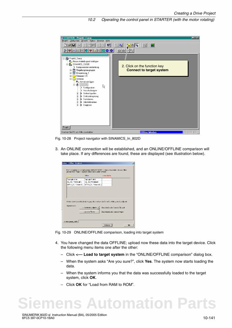
Creating a Drive Project
10.2 Operating the control panel in STARTER (with the motor rotating)
10-141SINUMERIK 802D sl Instruction Manual (BA), 05/2005 Edition6FC5 397-0CP10-1BA0
2. Click on the function key Connect to target system
Fig. 10-28 Project navigator with SINAMICS_In_802D
3. An ONLINE connection will be established, and an ONLINE/OFFLINE comparison willtake place. If any differences are found, these are displayed (see illustration below).
Fig. 10-29 ONLINE/OFFLINE comparison, loading into target system
4. You have changed the data OFFLINE; upload now these data into the target device. Clickthe following menu items one after the other:
– Click <–– Load to target system in the “ONLINE/OFFLINE comparison” dialog box.
– When the system asks “Are you sure?”, click Yes. The system now starts loading thedata.
– When the system informs you that the data was successfully loaded to the targetsystem, click OK.
– Click OK for “Load from RAM to ROM”.
Siemens Automation Parts

10.2 Operating the control panel in STARTER (with the motor rotating)
Creating a Drive Project
10-142SINUMERIK 802D sl Instruction Manual (BA), 05/2005 Edition
6FC5 397-0CP10-1BA0
5. Differences were detected during the ONLINE/OFFLINE comparison again. Click Loadto PG ––> (see screenshot below).
Fig. 10-30 ONLINE/OFFLINE comparison, loading into PG
6. You will load the newly created data from the drive unit into the PG. Click the followingmenu items one after the other:– When the system asks “Are you sure?”, click Yes. The system now starts loading the
data.– When the system informs you that the data was successfully loaded into the PG, click
OK.
7. No further discrepancies are displayed in the ONLINE/OFFLINE comparison dialog box.Click Close (see screenshot below).
Fig. 10-31 ONLINE/OFFLINE comparison, closing
Note
When loading, observe the LEDs on the control unit. The control unit is ready for operationwhen the LED RDY is continuously lit (green).
The hardware configuration of the drive unit is completed. To operate the control panel inSTARTER, proceed as follows:
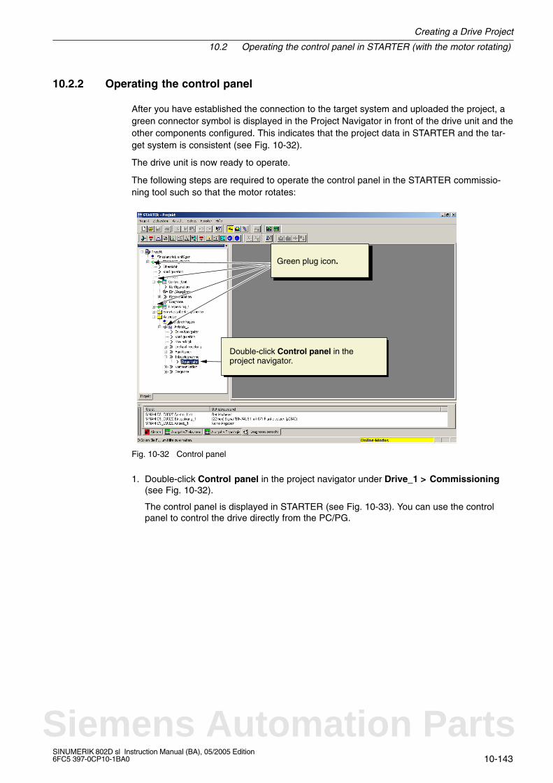
Creating a Drive Project
10.2 Operating the control panel in STARTER (with the motor rotating)
10-143SINUMERIK 802D sl Instruction Manual (BA), 05/2005 Edition6FC5 397-0CP10-1BA0
10.2.2 Operating the control panel
After you have established the connection to the target system and uploaded the project, agreen connector symbol is displayed in the Project Navigator in front of the drive unit and theother components configured. This indicates that the project data in STARTER and the tar-get system is consistent (see Fig. 10-32).
The drive unit is now ready to operate.
The following steps are required to operate the control panel in the STARTER commissio-ning tool such so that the motor rotates:
Double-click Control panel in theproject navigator.
Green plug icon.
Fig. 10-32 Control panel
1. Double-click Control panel in the project navigator under Drive_1 > Commissioning(see Fig. 10-32).
The control panel is displayed in STARTER (see Fig. 10-33). You can use the controlpanel to control the drive directly from the PC/PG.
Siemens Automation Parts
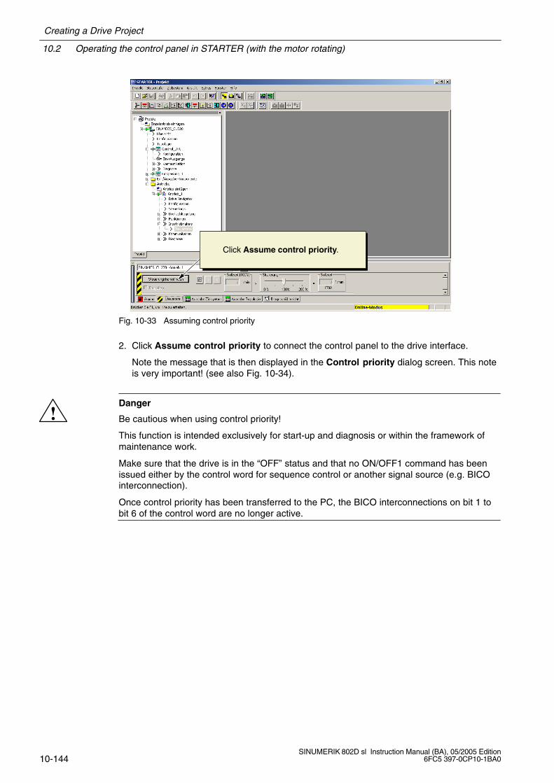
10.2 Operating the control panel in STARTER (with the motor rotating)
Creating a Drive Project
10-144SINUMERIK 802D sl Instruction Manual (BA), 05/2005 Edition
6FC5 397-0CP10-1BA0
Click Assume control priority.
Fig. 10-33 Assuming control priority
2. Click Assume control priority to connect the control panel to the drive interface.
Note the message that is then displayed in the Control priority dialog screen. This noteis very important! (see also Fig. 10-34).
!Danger
Be cautious when using control priority!
This function is intended exclusively for start-up and diagnosis or within the framework ofmaintenance work.
Make sure that the drive is in the “OFF” status and that no ON/OFF1 command has beenissued either by the control word for sequence control or another signal source (e.g. BICOinterconnection).
Once control priority has been transferred to the PC, the BICO interconnections on bit 1 tobit 6 of the control word are no longer active.
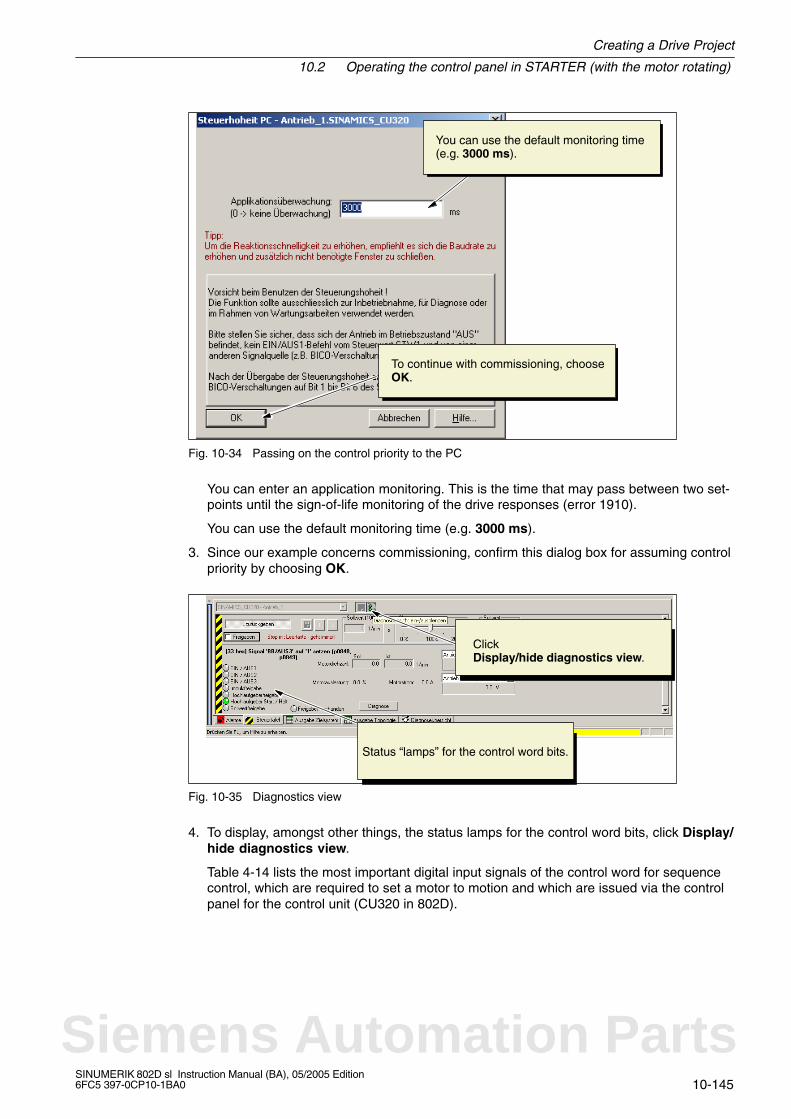
Creating a Drive Project
10.2 Operating the control panel in STARTER (with the motor rotating)
10-145SINUMERIK 802D sl Instruction Manual (BA), 05/2005 Edition6FC5 397-0CP10-1BA0
To continue with commissioning, chooseOK.
You can use the default monitoring time(e.g. 3000 ms).
Fig. 10-34 Passing on the control priority to the PC
You can enter an application monitoring. This is the time that may pass between two set-points until the sign-of-life monitoring of the drive responses (error 1910).
You can use the default monitoring time (e.g. 3000 ms).
3. Since our example concerns commissioning, confirm this dialog box for assuming controlpriority by choosing OK.
Click Display/hide diagnostics view.
Status “lamps” for the control word bits.
Fig. 10-35 Diagnostics view
4. To display, amongst other things, the status lamps for the control word bits, click Display/hide diagnostics view.
Table 4-14 lists the most important digital input signals of the control word for sequencecontrol, which are required to set a motor to motion and which are issued via the controlpanel for the control unit (CU320 in 802D).
Siemens Automation Parts
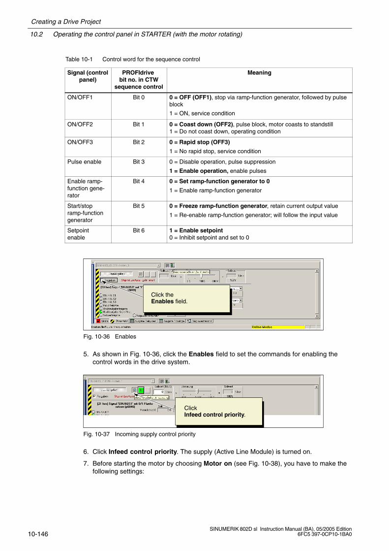
10.2 Operating the control panel in STARTER (with the motor rotating)
Creating a Drive Project
10-146SINUMERIK 802D sl Instruction Manual (BA), 05/2005 Edition
6FC5 397-0CP10-1BA0
Table 10-1 Control word for the sequence control
Signal (controlpanel)
PROFIdrive bit no. in CTW
sequence control
Meaning
ON/OFF1 Bit 0 0 = OFF (OFF1), stop via ramp-function generator, followed by pulseblock
1 = ON, service condition
ON/OFF2 Bit 1 0 = Coast down (OFF2), pulse block, motor coasts to standstill1 = Do not coast down, operating condition
ON/OFF3 Bit 2 0 = Rapid stop (OFF3)
1 = No rapid stop, service condition
Pulse enable Bit 3 0 = Disable operation, pulse suppression
1 = Enable operation, enable pulses
Enable ramp-function gene-rator
Bit 4 0 = Set ramp-function generator to 0
1 = Enable ramp-function generator
Start/stopramp-functiongenerator
Bit 5 0 = Freeze ramp-function generator, retain current output value
1 = Re-enable ramp-function generator; will follow the input value
Setpointenable
Bit 6 1 = Enable setpoint0 = Inhibit setpoint and set to 0
Click the Enables field.
Fig. 10-36 Enables
5. As shown in Fig. 10-36, click the Enables field to set the commands for enabling thecontrol words in the drive system.
Click Infeed control priority.
Fig. 10-37 Incoming supply control priority
6. Click Infeed control priority. The supply (Active Line Module) is turned on.
7. Before starting the motor by choosing Motor on (see Fig. 10-38), you have to make thefollowing settings:
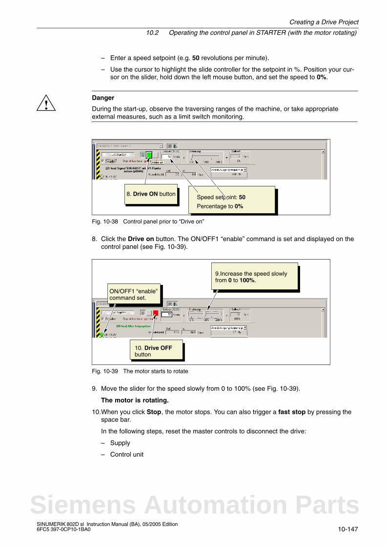
Creating a Drive Project
10.2 Operating the control panel in STARTER (with the motor rotating)
10-147SINUMERIK 802D sl Instruction Manual (BA), 05/2005 Edition6FC5 397-0CP10-1BA0
– Enter a speed setpoint (e.g. 50 revolutions per minute).
– Use the cursor to highlight the slide controller for the setpoint in %. Position your cur-sor on the slider, hold down the left mouse button, and set the speed to 0%.
!Danger
During the start-up, observe the traversing ranges of the machine, or take appropriateexternal measures, such as a limit switch monitoring.
Speed setpoint: 50
Percentage to 0%
8. Drive ON button
Fig. 10-38 Control panel prior to “Drive on”
8. Click the Drive on button. The ON/OFF1 “enable” command is set and displayed on thecontrol panel (see Fig. 10-39).
ON/OFF1 “enable”command set.
10. Drive OFFbutton
9.Increase the speed slowlyfrom 0 to 100%.
Fig. 10-39 The motor starts to rotate
9. Move the slider for the speed slowly from 0 to 100% (see Fig. 10-39).
The motor is rotating.
10.When you click Stop, the motor stops. You can also trigger a fast stop by pressing thespace bar.
In the following steps, reset the master controls to disconnect the drive:
– Supply
– Control unit
Siemens Automation Parts
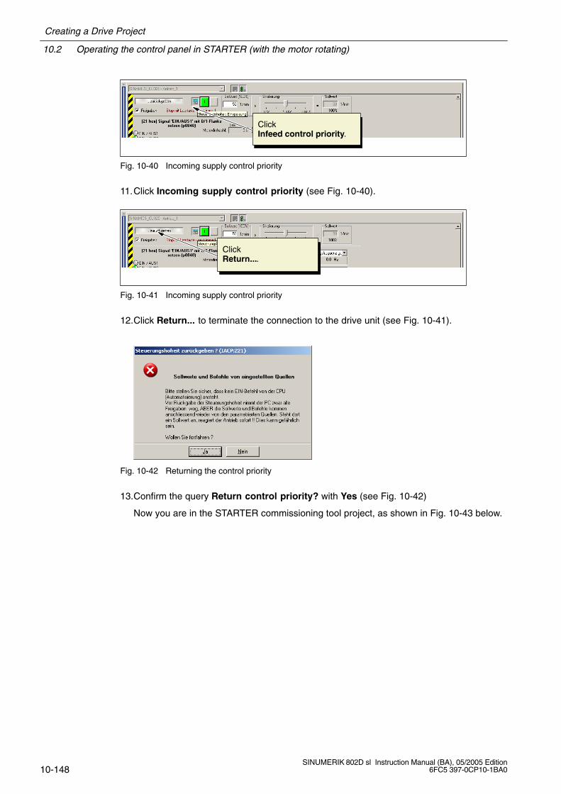
10.2 Operating the control panel in STARTER (with the motor rotating)
Creating a Drive Project
10-148SINUMERIK 802D sl Instruction Manual (BA), 05/2005 Edition
6FC5 397-0CP10-1BA0
Click Infeed control priority.
Fig. 10-40 Incoming supply control priority
11.Click Incoming supply control priority (see Fig. 10-40).
Click Return....
Fig. 10-41 Incoming supply control priority
12.Click Return... to terminate the connection to the drive unit (see Fig. 10-41).
Fig. 10-42 Returning the control priority
13.Confirm the query Return control priority? with Yes (see Fig. 10-42)
Now you are in the STARTER commissioning tool project, as shown in Fig. 10-43 below.
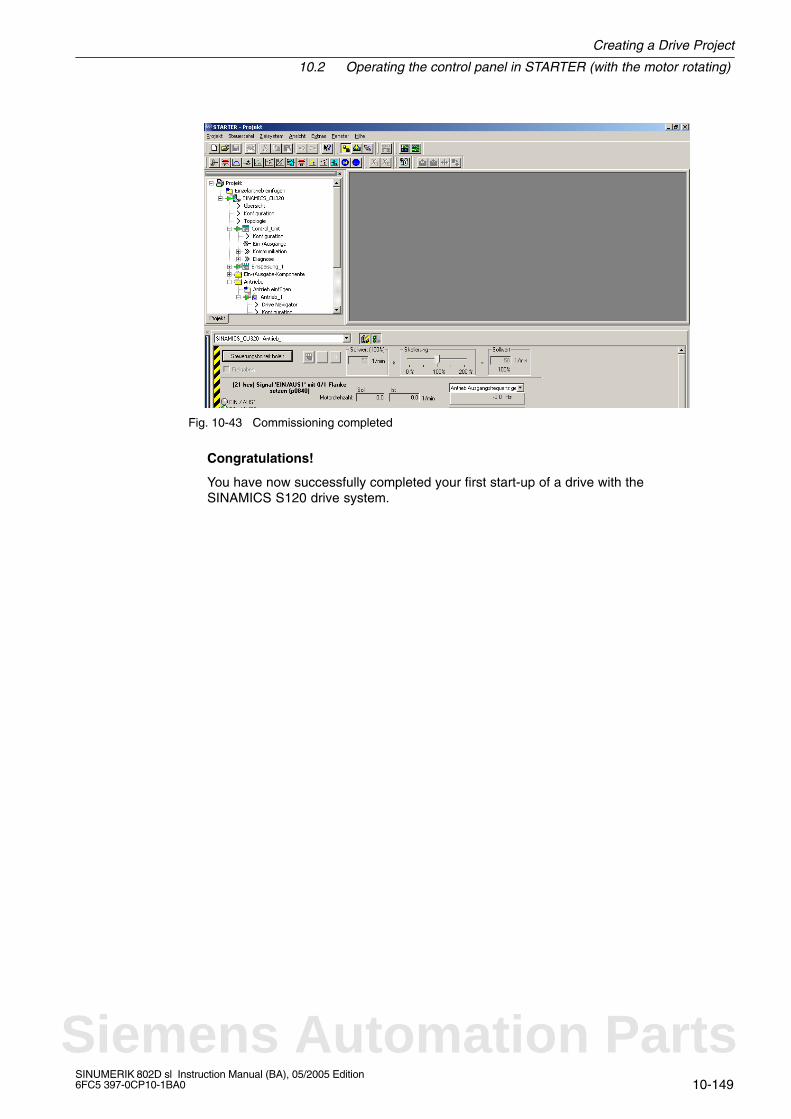
Creating a Drive Project
10.2 Operating the control panel in STARTER (with the motor rotating)
10-149SINUMERIK 802D sl Instruction Manual (BA), 05/2005 Edition6FC5 397-0CP10-1BA0
Fig. 10-43 Commissioning completed
Congratulations!
You have now successfully completed your first start-up of a drive with theSINAMICS S120 drive system.
Siemens Automation Parts
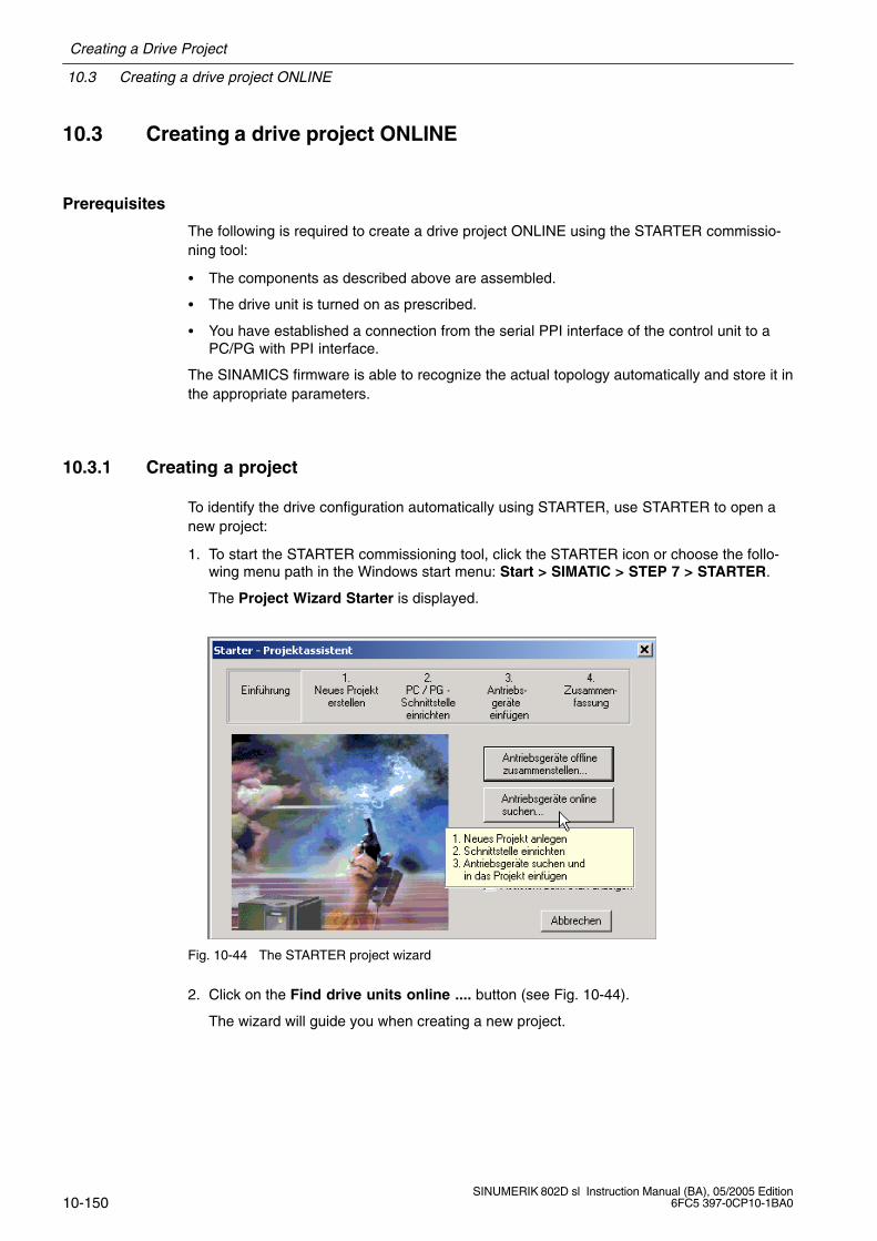
10.3 Creating a drive project ONLINE
Creating a Drive Project
10-150SINUMERIK 802D sl Instruction Manual (BA), 05/2005 Edition
6FC5 397-0CP10-1BA0
10.3 Creating a drive project ONLINE
Prerequisites
The following is required to create a drive project ONLINE using the STARTER commissio-ning tool:
The components as described above are assembled.
The drive unit is turned on as prescribed.
You have established a connection from the serial PPI interface of the control unit to aPC/PG with PPI interface.
The SINAMICS firmware is able to recognize the actual topology automatically and store it inthe appropriate parameters.
10.3.1 Creating a project
To identify the drive configuration automatically using STARTER, use STARTER to open anew project:
1. To start the STARTER commissioning tool, click the STARTER icon or choose the follo-wing menu path in the Windows start menu: Start > SIMATIC > STEP 7 > STARTER.
The Project Wizard Starter is displayed.
Fig. 10-44 The STARTER project wizard
2. Click on the Find drive units online .... button (see Fig. 10-44).
The wizard will guide you when creating a new project.

Creating a Drive Project
10.3 Creating a drive project ONLINE
10-151SINUMERIK 802D sl Instruction Manual (BA), 05/2005 Edition6FC5 397-0CP10-1BA0
Fig. 10-45 Creating a new project
3. As shown in Fig. 10-45, enter the project name, e.g. “Machine Tool V1_2”, and if neces-sary, the author and a comment.
4. Click Continue > to set up the PC/PG interface.
Fig. 10-46 Setting up the interface
5. In this example, you require a PROFIBUS interface on the PC/PG (e.g. Serial Cable(PPI). Choose Change and test and confirm your selection with Continue >.
The Project Wizard will search for the drive unit ONLINE and will insert it into the project.Once the search process is completed, the Project Wizard will display the drive unit withits PPI address Drive_unit_Addr5 in the preview (see Fig. 10-47) (for alternative PC/PGinterface settings, see Figs. 10-6 to 10-8).
Siemens Automation Parts
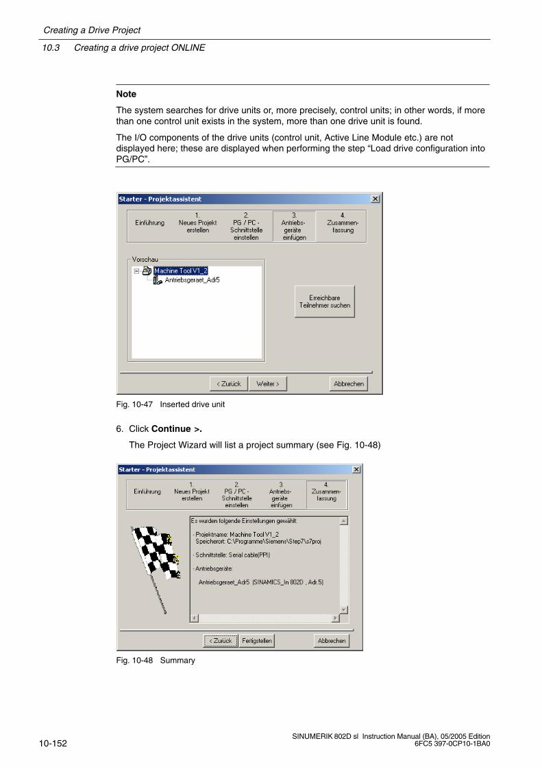
10.3 Creating a drive project ONLINE
Creating a Drive Project
10-152SINUMERIK 802D sl Instruction Manual (BA), 05/2005 Edition
6FC5 397-0CP10-1BA0
Note
The system searches for drive units or, more precisely, control units; in other words, if morethan one control unit exists in the system, more than one drive unit is found.
The I/O components of the drive units (control unit, Active Line Module etc.) are notdisplayed here; these are displayed when performing the step “Load drive configuration intoPG/PC”.
Fig. 10-47 Inserted drive unit
6. Click Continue >.
The Project Wizard will list a project summary (see Fig. 10-48)
Fig. 10-48 Summary
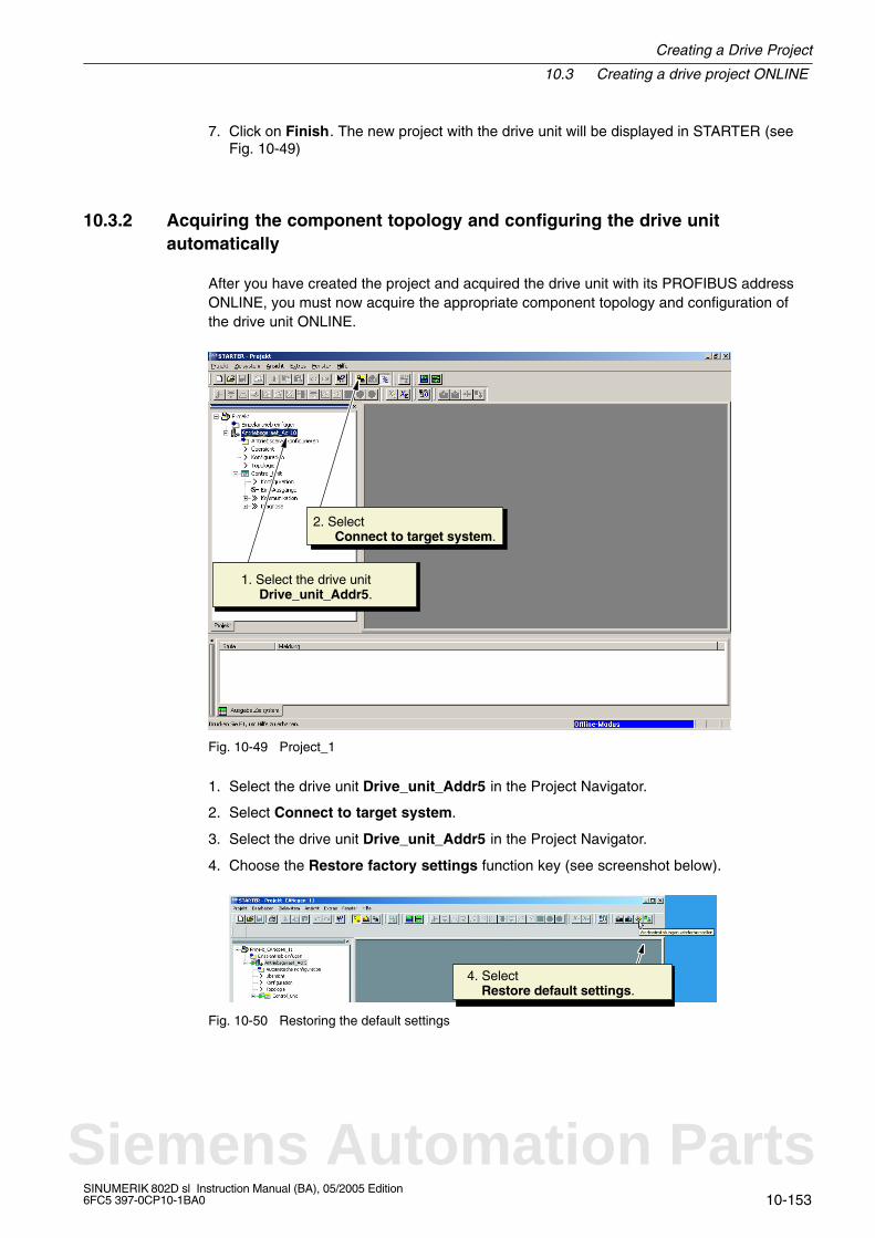
Creating a Drive Project
10.3 Creating a drive project ONLINE
10-153SINUMERIK 802D sl Instruction Manual (BA), 05/2005 Edition6FC5 397-0CP10-1BA0
7. Click on Finish. The new project with the drive unit will be displayed in STARTER (seeFig. 10-49)
10.3.2 Acquiring the component topology and configuring the drive unitautomatically
After you have created the project and acquired the drive unit with its PROFIBUS addressONLINE, you must now acquire the appropriate component topology and configuration ofthe drive unit ONLINE.
1. Select the drive unit Drive_unit_Addr5.
2. Select Connect to target system.
Fig. 10-49 Project_1
1. Select the drive unit Drive_unit_Addr5 in the Project Navigator.
2. Select Connect to target system.
3. Select the drive unit Drive_unit_Addr5 in the Project Navigator.
4. Choose the Restore factory settings function key (see screenshot below).
4. Select Restore default settings.
Fig. 10-50 Restoring the default settings
Siemens Automation Parts
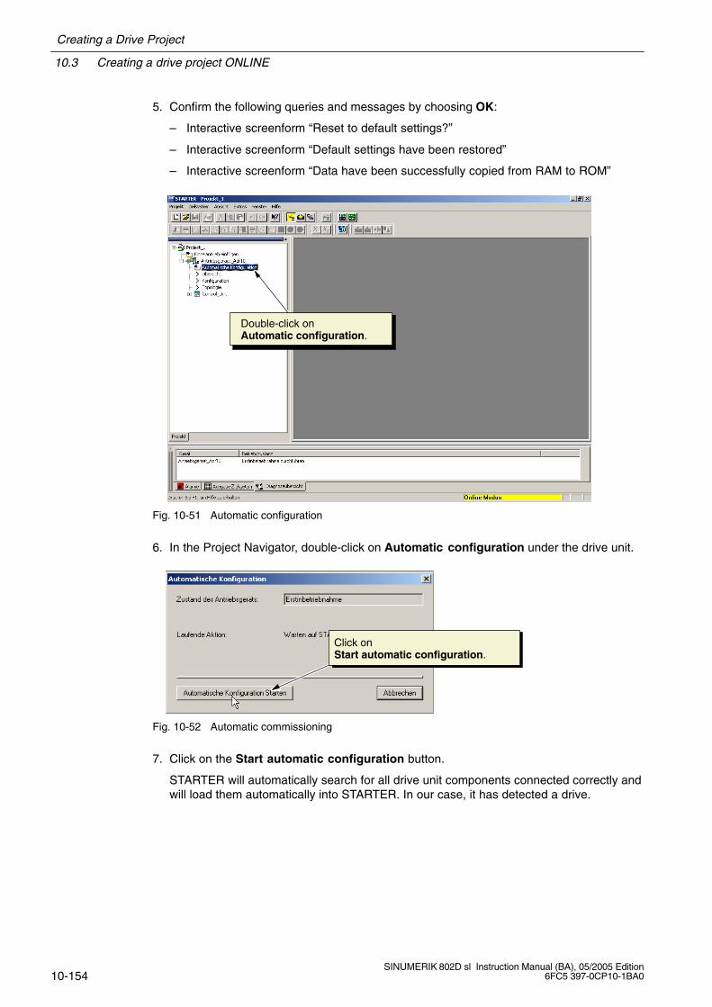
10.3 Creating a drive project ONLINE
Creating a Drive Project
10-154SINUMERIK 802D sl Instruction Manual (BA), 05/2005 Edition
6FC5 397-0CP10-1BA0
5. Confirm the following queries and messages by choosing OK:
– Interactive screenform “Reset to default settings?”
– Interactive screenform “Default settings have been restored”
– Interactive screenform “Data have been successfully copied from RAM to ROM”
Double-click onAutomatic configuration.
Fig. 10-51 Automatic configuration
6. In the Project Navigator, double-click on Automatic configuration under the drive unit.
Click onStart automatic configuration.
Fig. 10-52 Automatic commissioning
7. Click on the Start automatic configuration button.
STARTER will automatically search for all drive unit components connected correctly andwill load them automatically into STARTER. In our case, it has detected a drive.
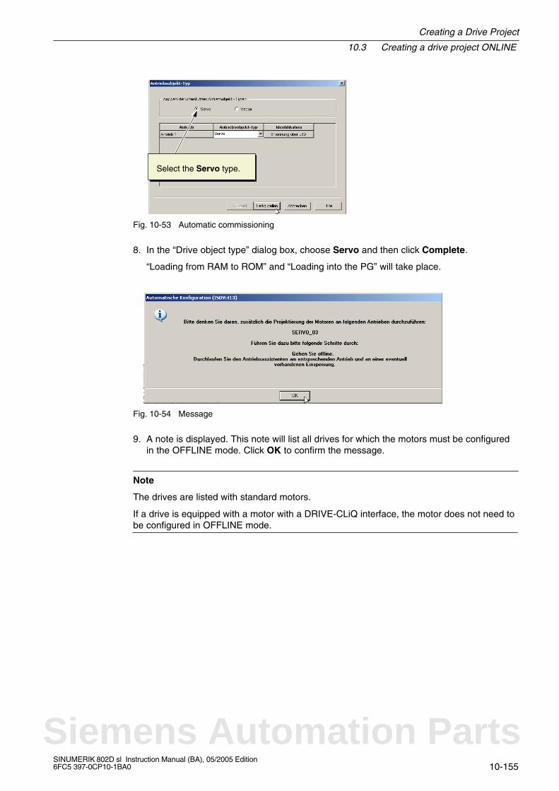
Creating a Drive Project
10.3 Creating a drive project ONLINE
10-155SINUMERIK 802D sl Instruction Manual (BA), 05/2005 Edition6FC5 397-0CP10-1BA0
Select the Servo type.
Fig. 10-53 Automatic commissioning
8. In the “Drive object type” dialog box, choose Servo and then click Complete.
“Loading from RAM to ROM” and “Loading into the PG” will take place.
Fig. 10-54 Message
9. A note is displayed. This note will list all drives for which the motors must be configuredin the OFFLINE mode. Click OK to confirm the message.
Note
The drives are listed with standard motors.
If a drive is equipped with a motor with a DRIVE-CLiQ interface, the motor does not need tobe configured in OFFLINE mode.
Siemens Automation Parts
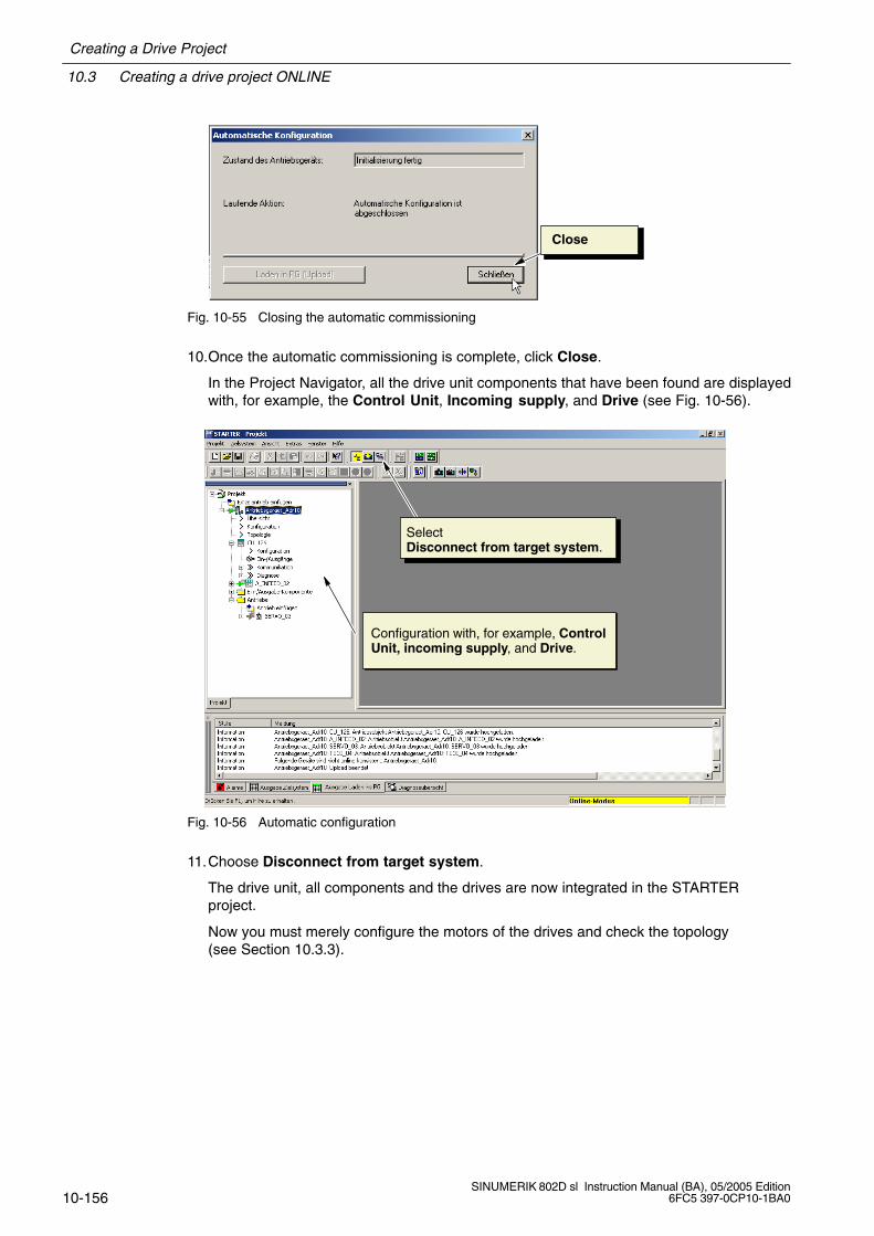
10.3 Creating a drive project ONLINE
Creating a Drive Project
10-156SINUMERIK 802D sl Instruction Manual (BA), 05/2005 Edition
6FC5 397-0CP10-1BA0
Close
Fig. 10-55 Closing the automatic commissioning
10.Once the automatic commissioning is complete, click Close.
In the Project Navigator, all the drive unit components that have been found are displayedwith, for example, the Control Unit, Incoming supply, and Drive (see Fig. 10-56).
Configuration with, for example, ControlUnit, incoming supply, and Drive.
Select Disconnect from target system.
Fig. 10-56 Automatic configuration
11.Choose Disconnect from target system.
The drive unit, all components and the drives are now integrated in the STARTERproject.
Now you must merely configure the motors of the drives and check the topology(see Section 10.3.3).
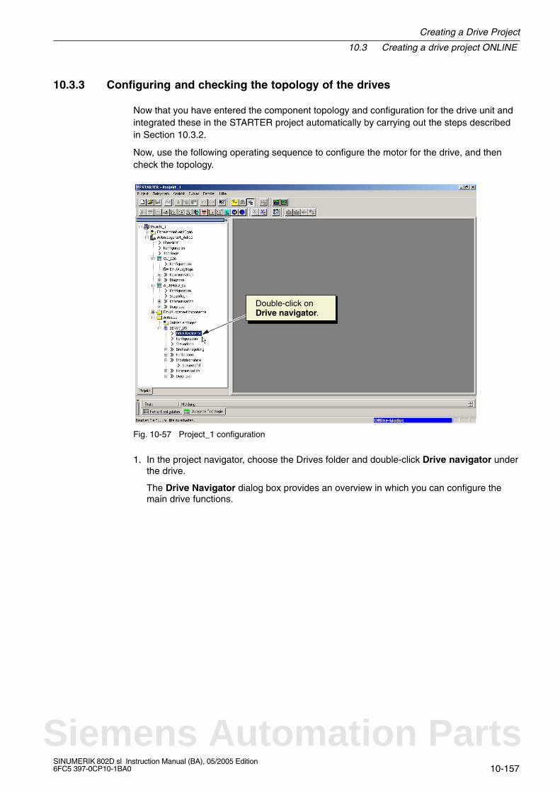
Creating a Drive Project
10.3 Creating a drive project ONLINE
10-157SINUMERIK 802D sl Instruction Manual (BA), 05/2005 Edition6FC5 397-0CP10-1BA0
10.3.3 Configuring and checking the topology of the drives
Now that you have entered the component topology and configuration for the drive unit andintegrated these in the STARTER project automatically by carrying out the steps describedin Section 10.3.2.
Now, use the following operating sequence to configure the motor for the drive, and thencheck the topology.
Double-click on Drive navigator.
Fig. 10-57 Project_1 configuration
1. In the project navigator, choose the Drives folder and double-click Drive navigator underthe drive.
The Drive Navigator dialog box provides an overview in which you can configure themain drive functions.
Siemens Automation Parts

10.3 Creating a drive project ONLINE
Creating a Drive Project
10-158SINUMERIK 802D sl Instruction Manual (BA), 05/2005 Edition
6FC5 397-0CP10-1BA0
Click on Device configuration.
Fig. 10-58 Drive navigator
2. Click on Device configuration to configure the drive motor.
Click onCarry out drive configuration.
Fig. 10-59 Device configuration
3. Click on Carry out drive configuration. The Project Wizard for configuring the drive isdisplayed (see Fig. 10-60).
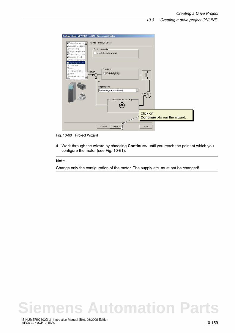
Creating a Drive Project
10.3 Creating a drive project ONLINE
10-159SINUMERIK 802D sl Instruction Manual (BA), 05/2005 Edition6FC5 397-0CP10-1BA0
Click on Continue >to run the wizard.
Fig. 10-60 Project Wizard
4. Work through the wizard by choosing Continue> until you reach the point at which youconfigure the motor (see Fig. 10-61).
Note
Change only the configuration of the motor. The supply etc. must not be changed!
Siemens Automation Parts
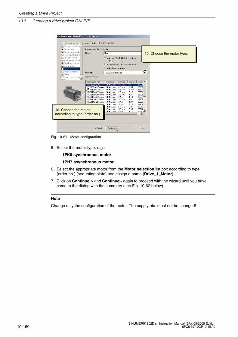
10.3 Creating a drive project ONLINE
Creating a Drive Project
10-160SINUMERIK 802D sl Instruction Manual (BA), 05/2005 Edition
6FC5 397-0CP10-1BA0
15. Choose the motor type.
16. Choose the motoraccording to type (order no.).
Fig. 10-61 Motor configuration
5. Select the motor type, e.g.:
– 1FK6 synchronous motor
– 1PH7 asynchronous motor
6. Select the appropriate motor from the Motor selection list box according to type(order no.) (see rating plate) and assign a name (Drive_1_Motor).
7. Click on Continue > and Continue> again to proceed with the wizard until you havecome to the dialog with the summary (see Fig. 10-62 below).
Note
Change only the configuration of the motor. The supply etc. must not be changed!
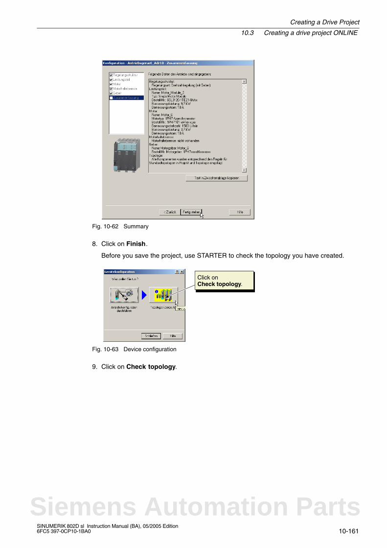
Creating a Drive Project
10.3 Creating a drive project ONLINE
10-161SINUMERIK 802D sl Instruction Manual (BA), 05/2005 Edition6FC5 397-0CP10-1BA0
Fig. 10-62 Summary
8. Click on Finish.
Before you save the project, use STARTER to check the topology you have created.
Click on Check topology.
Fig. 10-63 Device configuration
9. Click on Check topology.
Siemens Automation Parts
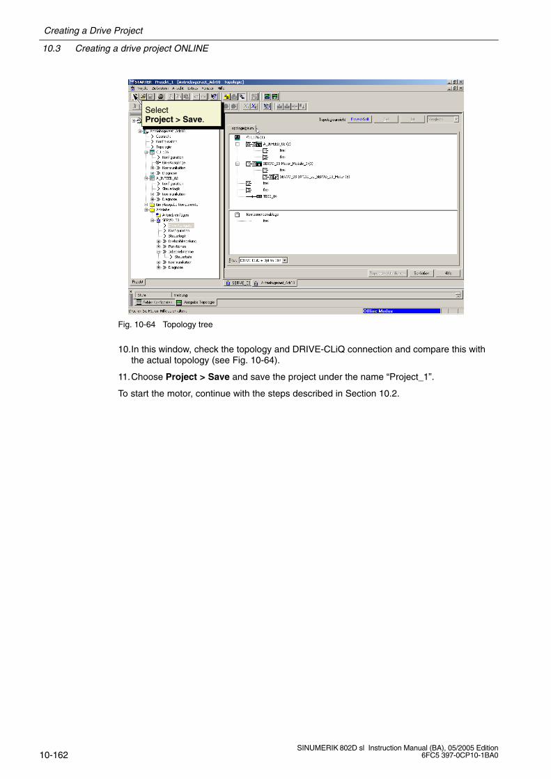
10.3 Creating a drive project ONLINE
Creating a Drive Project
10-162SINUMERIK 802D sl Instruction Manual (BA), 05/2005 Edition
6FC5 397-0CP10-1BA0
SelectProject > Save.
Fig. 10-64 Topology tree
10.In this window, check the topology and DRIVE-CLiQ connection and compare this withthe actual topology (see Fig. 10-64).
11.Choose Project > Save and save the project under the name “Project_1”.
To start the motor, continue with the steps described in Section 10.2.
11-163SINUMERIK 802D sl Instruction Manual (BA), 05/2005 Edition6FC5 397-0CP10-1BA0
Starting Up the PLC
General
The PLC is intended to control machine-related functional sequences. It is realized as a soft-ware PLC.
The user program – a PLC cycle – is always executed in the same order of sequence.
Refresh of the process image (inputs, user interface, timers)
Processing of communication requests (operator panel, PLC 802 programming tool, ver-sion 3.0 and higher)
Editing of the user program
Evaluation of alarms
Output of the process image (outputs, user interface)
During the cycle, the PLC executes the user program from the first to the last operation.The user program accesses the hardware inputs/outputs only via the process image and notdirectly. The PLC refreshes the hardware I/Os at the beginning or end of program execution.Thus, these signals are stable over a whole PLC cycle.
The user program can only be created using the PLC 802 Programming Tool, version 3.1and higher, with the S7-200 programming language using ladder diagram. Ladder diagram isa graphical programming language for representing electric circuit diagrams.
Important
PLC 802 Library with a description, which can be installed from the toolbox CD is offeredas the basis for the PLC user program. This provides a subroutine library and a sample pro-gram for a milling machine.
Note
If the stop and reset buttons on the machine control panel are not realized as normally clo-sed contacts, an open circuit cannot be detected.
Monitoring can be performed using software solutions, as shown in the example MCP_802D(SBR 34) from the subroutine library.
11
Siemens Automation Parts
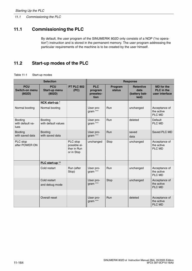
11.1 Commissioning the PLC
Starting Up the PLC
11-164SINUMERIK 802D sl Instruction Manual (BA), 05/2005 Edition
6FC5 397-0CP10-1BA0
11.1 Commissioning the PLC
By default, the user program of the SINUMERIK 802D only consists of a NOP (“no opera-tion”) instruction and is stored in the permanent memory. The user program addressing theparticular requirements of the machine is to be created by the user himself.
11.2 Start-up modes of the PLC
Table 11-1 Start-up modes
Selection Response
PCUSwitch-on menu
(802D)
PCUStart-up menu
(802D)
PT PLC 802(PC)
PLCprogrampreselec-
tion
Programstatus
Retentivedata
(battery bak-ked)
MD for thePLC in the
user interface
NCK start-up *
Normal booting Normal booting User pro-gram ***
Run unchanged Acceptance ofthe activePLC MD
Booting with default va-lues
Booting with default values
User pro-gram ***
Run deleted DefaultPLC MD
Booting with saved data
Booting with saved data
User pro-gram ***
Run saved
data
Saved PLC MD
PLC stopafter POWER ON
PLC stoppossible ei-ther in Runor in Stop
unchanged Stop unchanged Acceptance ofthe activePLC MD
PLC start-up **
Cold restart Run (afterStop)
User pro-gram ***
Run unchanged Acceptance ofthe activePLC MD
Cold restart
and debug mode
User pro-gram ***
Stop unchanged Acceptance ofthe activePLC MD
Overall reset User pro-gram ***
Run deleted Acceptance ofthe activePLC MD
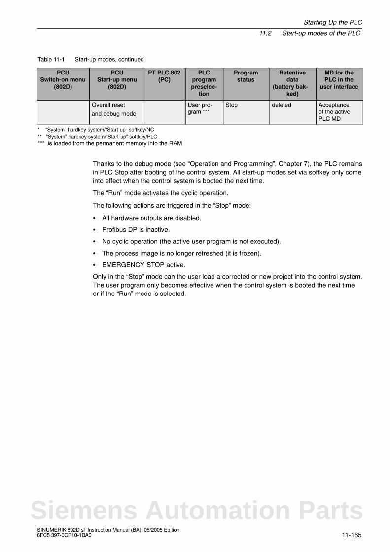
Starting Up the PLC
11.2 Start-up modes of the PLC
11-165SINUMERIK 802D sl Instruction Manual (BA), 05/2005 Edition6FC5 397-0CP10-1BA0
Table 11-1 Start-up modes, continued
MD for thePLC in the
user interface
Retentivedata
(battery bak-ked)
Programstatus
PLCprogrampreselec-
tion
PT PLC 802(PC)
PCUStart-up menu
(802D)
PCUSwitch-on menu
(802D)
Overall reset
and debug mode
User pro-gram ***
Stop deleted Acceptanceof the activePLC MD
* “System” hardkey system/“Start-up” softkey/NC** “System” hardkey system/“Start-up” softkey/PLC*** is loaded from the permanent memory into the RAM
Thanks to the debug mode (see “Operation and Programming”, Chapter 7), the PLC remainsin PLC Stop after booting of the control system. All start-up modes set via softkey only comeinto effect when the control system is booted the next time.
The “Run” mode activates the cyclic operation.
The following actions are triggered in the “Stop” mode:
All hardware outputs are disabled.
Profibus DP is inactive.
No cyclic operation (the active user program is not executed).
The process image is no longer refreshed (it is frozen).
EMERGENCY STOP active.
Only in the “Stop” mode can the user load a corrected or new project into the control system.The user program only becomes effective when the control system is booted the next timeor if the “Run” mode is selected.
Siemens Automation Parts

11.3 PLC alarms
Starting Up the PLC
11-166SINUMERIK 802D sl Instruction Manual (BA), 05/2005 Edition
6FC5 397-0CP10-1BA0
11.3 PLC alarms
The control system displays max. 8 PLC alarms (system alarms or user alarms).
The PLC manages the alarm information per PLC cycle. It saves/cancels the alarms accor-ding to their times of occurrence. The first alarm in the list is always the alarm last occurred.
If more than 8 alarms have occurred, the first seven alarms and the newest alarm with thehighest cancel priority are displayed.
Alarm response and cancel criteria
In addition, the alarm responses are managed by the PLC. The alarm responses alwayscome into effect, irrespective of the number of active alarms. Depending on the type of thealarm response, the PLC will trigger the required action.
A cancel criterion must be defined for each alarm. The PLC uses the cancel criterion SELF-CLEARING by default (see “Configuring user alarms”).
Cancel criteria are:
POWERONCLEAR: The alarm is canceled by turning off/turning on the control system(POWER ON).
CANCELCLEAR: The alarm is canceled by pressing the Cancel key or the Reset key(analogously to the NCK alarms).
SELF-CLEARING: The alarm is canceled, since the alarm cause is no longer present.
The cancel conditions have the following priority:
POWERON CLEAR – system alarms (highest priority)
CANCEL CLEAR – system alarms
SELF–CLEARING – system alarms
POWERON CLEAR – user alarms
CANCEL CLEAR – user alarms
SELF-CLEARING – user alarm (lowest priority)
The responses to be triggered by the alarm in question in the PLC are defined for eachalarm. The PLC uses the alarm response SHOWALARM by default.
Alarm responses are:
PLC stop: The user program is not executed any more, Profibus DP is inactive, and thehardware outputs are disabled.
EMERGENCY STOP: Once the user program is executed, the PLC transmits the EMER-GENCY STOP signal to the NCK via the user interface.
Feed disable: Once the user program is executed, the PLC transmits the feed disablesignal to the NCK via the user interface.
Read-in disable: Once the user program is executed, the PLC transmits the read-in disa-ble signal to the NCK via the user interface.
Starting Up the PLC
11.3 PLC alarms
11-167SINUMERIK 802D sl Instruction Manual (BA), 05/2005 Edition6FC5 397-0CP10-1BA0
NC Start inhibited: Once the user program is executed, the PLC signals the “NC startinhibited” signal to the NCK via the user interface.
SHOWALARM: This alarm has no alarm response.
11.3.1 General PLC alarms
Note to the reader
SINUMERIK 802D sl Diagnostics Guide
11.3.2 User alarms
The user interface ‘’ 1600xxxx ‘’ provides the subareas (0, 1) for the user to define useralarms.
Subarea 0: 8 x 8 bits to set the user alarms (0 –>1 edge)Byte 0 : Bit 0 => 1st user alarm “ 700000 ”Byte 1 : Bit 0 => 9th user alarm “ 700008 ”Byte 7 : Bit 7 => 64th user alarm “ 700063 ”
A new user alarm is activated with the relevant bit (subarea 0) via a 0/1 edge.
Subarea 1: User alarm variables
Subarea 1 is intended for additional user information; it can only be read/written as a dou-bleword.
Subarea 2: Alarm responseByte 0 : Bit 0 => NC start inhibited
Bit 1 => Read-in disableBit 2 => Feed disable for all axesBit 3 => EMERGENCY STOPBit 4 => PLC STOP
By using subarea 2, the user can evaluate the active alarm responses; this subarea isread-only.
Self-clearing user alarms must be canceled by the user by resetting the appropriate bit insubarea 0 (1 –> 0 edge).
Other user alarms are canceled by the PLC after detecting the relevant cancel condition forthe appropriate user alarms. If the bit of the user alarm, however, is still present, the alarmrecurs.
Siemens Automation Parts
11.3 PLC alarms
Starting Up the PLC
11-168SINUMERIK 802D sl Instruction Manual (BA), 05/2005 Edition
6FC5 397-0CP10-1BA0
Type of action of a user alarm
User alarms have a higher priority than the appropriate signal in the user interface(e.g. NC start inhibited, read-in disable, feed disable and EMERGENCY STOP).
Example:MD 14516[0]: USER_DAT_PLC_ALARM = 8If alarm 700000 is present, in addition, alarm 3000 EMERGENCY STOP is also presenteven if the interface signal V26000000.1=0.
Configuring user alarms
A configuration byte is provided for each alarm. The user alarms can be configured by theuser in the machine data 14516: USER_DATA_PLC_ALARM.
Default setting of MD 14516[0...63]: 0 => SHOWALARM/SELF-CLEARING user alarm
Structure of a configuration byte:
Bit0 – bit5 : Alarm responses
Bit6 – bit7 : Cancel criteria
Alarm responses: Bit0 – bit 5 = 0: Showalarm (default)Bit0 = 1: NC start inhibitedBit1 = 1: Read–in disableBit2 = 1: Feed disable for all axesBit3 = 1: EMERGENCY STOPBit4 = 1: PLC stopBit5 = reserved
Cancel criteria: Bit6 + bit7 = 0: SELF-CLEARING alarm (default)Bit6 = 1 : CANCELCLEAR alarmBit7 = 1 : POWERONCLEAR alarm
The alarm response to PLC Stop always has the cancel condition POWER ON.
Alarm texts
The user are offered two options of defining his own alarm texts:
by using the System hardkey \ softkeys PLC \ Edit PLC alarm txt (see ”Operation andProgramming”, Chapter 7)
by using the toolbox: Editing and loading the alarm text file using the text manager
If no alarm text is assigned by the user, only the alarm number is displayed.
The % character in the alarm text denotes an additional variable. The variable type is theform of representation of the variable.
The following variable types are possible:
%D integer decimal number
%I integer decimal number
%U decimal number without sign
Starting Up the PLC
11.3 PLC alarms
11-169SINUMERIK 802D sl Instruction Manual (BA), 05/2005 Edition6FC5 397-0CP10-1BA0
%O integer octal number
%X integer hexadecimal number
%B binary representation of a 32-bit value
%F 4-byte floating point number
Examples of user alarm texts (Note: The text after the ”//” is a comment and is not dis-played.)
700000 ‘’ ‘’ // only the user alarm number
700001 ‘’ Hardware limit switch + of the X axis’’
700002 ‘’ %D ‘’ // only a variable as an integer decimal number
700003 ‘’ Alarm number with a fixed alarm text and the variable %X ‘’
700004 ‘’ %U Alarm number with variable and fixed alarm text ‘’
700005 ‘’Axis monitoring active : %U’’
Display: 700005 Axis monitoring active : 1or 700005 Axis monitoring active : 3
Siemens Automation Parts
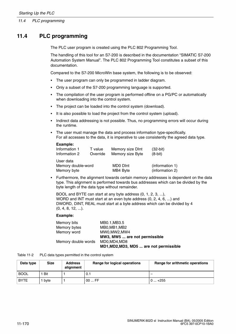
11.4 PLC programming
Starting Up the PLC
11-170SINUMERIK 802D sl Instruction Manual (BA), 05/2005 Edition
6FC5 397-0CP10-1BA0
11.4 PLC programming
The PLC user program is created using the PLC 802 Programming Tool.
The handling of this tool for an S7-200 is described in the documentation “SIMATIC S7-200Automation System Manual”. The PLC 802 Programming Tool constitutes a subset of thisdocumentation.
Compared to the S7-200 MicroWin base system, the following is to be observed:
The user program can only be programmed in ladder diagram.
Only a subset of the S7-200 programming language is supported.
The compilation of the user program is performed offline on a PG/PC or automaticallywhen downloading into the control system.
The project can be loaded into the control system (download).
It is also possible to load the project from the control system (upload).
Indirect data addressing is not possible. Thus, no programming errors will occur duringthe runtime.
The user must manage the data and process information type-specifically.For all accesses to the data, it is imperative to use consistently the agreed data type.
Example: Information 1 T value Memory size DInt (32-bit)Information 2 Override Memory size Byte (8-bit)
User dataMemory double-word MD0 DInt (information 1)Memory byte MB4 Byte (information 2)
Furthermore, the alignment towards certain memory addresses is dependent on the datatype. This alignment is performed towards bus addresses which can be divided by thebyte length of the data type without remainder.
BOOL and BYTE can start at any byte address (0, 1, 2, 3, ...), WORD and INT must start at an even byte address (0, 2, 4, 6, ...) andDWORD, DINT, REAL must start at a byte address which can be divided by 4(0, 4, 8, 12, ...).
Example:
Memory bits MB0.1,MB3.5Memory bytes MB0,MB1,MB2Memory word MW0,MW2,MW4
MW3, MW5 ... are not permissibleMemory double words MD0,MD4,MD8
MD1,MD2,MD3, MD5 ... are not permissible
Table 11-2 PLC data types permitted in the control system
Data type Size Addressalignment
Range for logical operations Range for arithmetic operations
BOOL 1 Bit 1 0.1 –
BYTE 1 byte 1 00 ... FF 0 ... +255
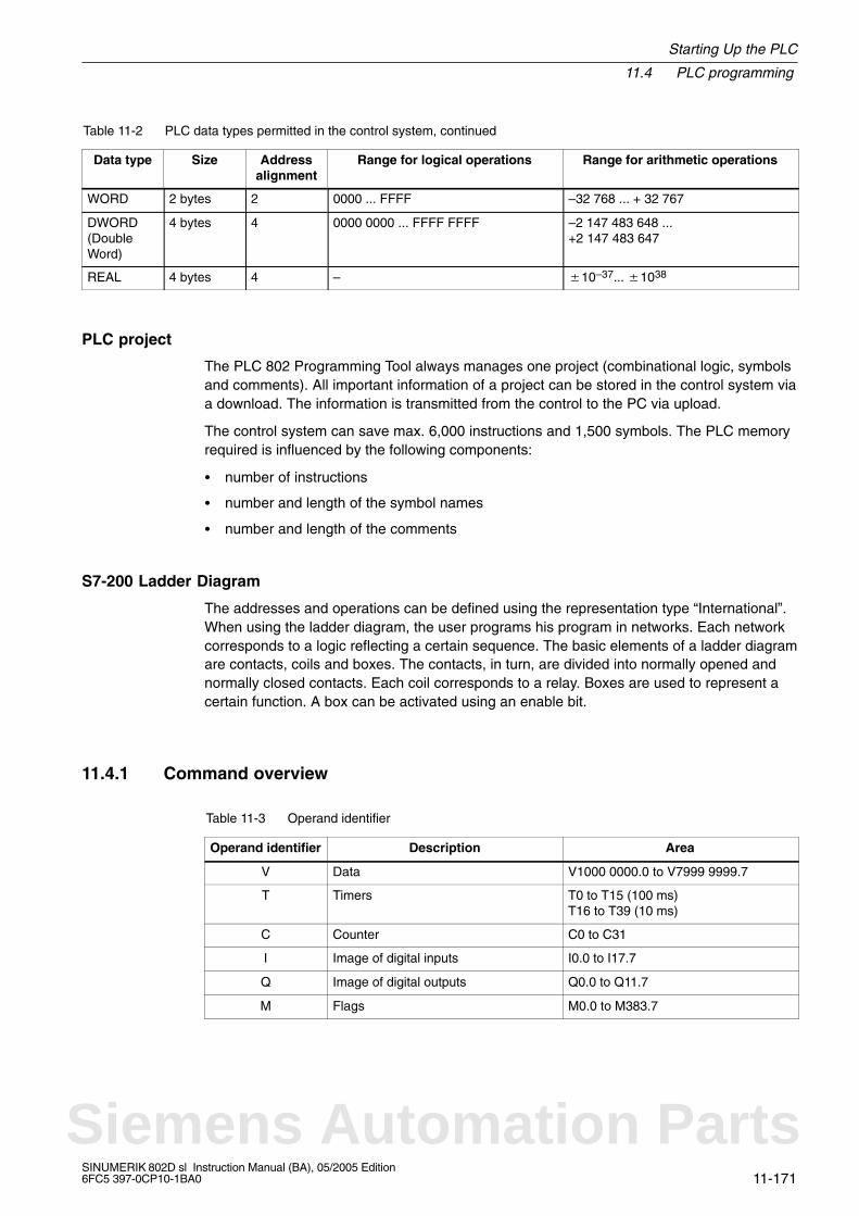
Starting Up the PLC
11.4 PLC programming
11-171SINUMERIK 802D sl Instruction Manual (BA), 05/2005 Edition6FC5 397-0CP10-1BA0
Table 11-2 PLC data types permitted in the control system, continued
Data type Range for arithmetic operationsRange for logical operationsAddressalignment
Size
WORD 2 bytes 2 0000 ... FFFF –32 768 ... + 32 767
DWORD(DoubleWord)
4 bytes 4 0000 0000 ... FFFF FFFF –2 147 483 648 ... +2 147 483 647
REAL 4 bytes 4 – 10–37... 1038
PLC project
The PLC 802 Programming Tool always manages one project (combinational logic, symbolsand comments). All important information of a project can be stored in the control system viaa download. The information is transmitted from the control to the PC via upload.
The control system can save max. 6,000 instructions and 1,500 symbols. The PLC memoryrequired is influenced by the following components:
number of instructions
number and length of the symbol names
number and length of the comments
S7-200 Ladder Diagram
The addresses and operations can be defined using the representation type “International”.When using the ladder diagram, the user programs his program in networks. Each networkcorresponds to a logic reflecting a certain sequence. The basic elements of a ladder diagramare contacts, coils and boxes. The contacts, in turn, are divided into normally opened andnormally closed contacts. Each coil corresponds to a relay. Boxes are used to represent acertain function. A box can be activated using an enable bit.
11.4.1 Command overview
Table 11-3 Operand identifier
Operand identifier Description Area
V Data V1000 0000.0 to V7999 9999.7
T Timers T0 to T15 (100 ms)T16 to T39 (10 ms)
C Counter C0 to C31
I Image of digital inputs I0.0 to I17.7
Q Image of digital outputs Q0.0 to Q11.7
M Flags M0.0 to M383.7
Siemens Automation Parts
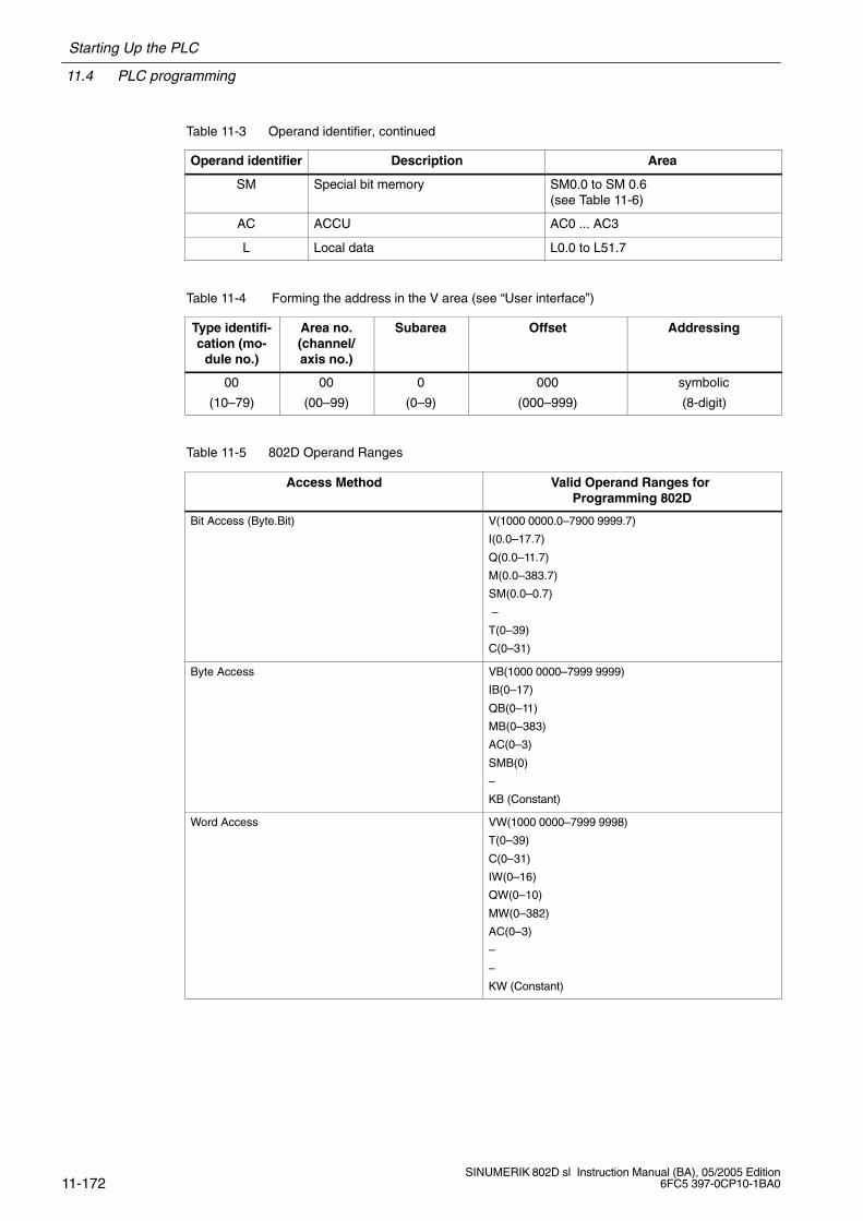
11.4 PLC programming
Starting Up the PLC
11-172SINUMERIK 802D sl Instruction Manual (BA), 05/2005 Edition
6FC5 397-0CP10-1BA0
Table 11-3 Operand identifier, continued
Operand identifier AreaDescription
SM Special bit memory SM0.0 to SM 0.6 (see Table 11-6)
AC ACCU AC0 ... AC3
L Local data L0.0 to L51.7
Table 11-4 Forming the address in the V area (see “User interface”)
Type identifi-cation (mo-
dule no.)
Area no.(channel/axis no.)
Subarea Offset Addressing
00
(10–79)
00
(00–99)
0
(0–9)
000
(000–999)
symbolic
(8-digit)
Table 11-5 802D Operand Ranges
Access Method Valid Operand Ranges for Programming 802D
Bit Access (Byte.Bit) V(1000 0000.0–7900 9999.7)
I(0.0–17.7)
Q(0.0–11.7)
M(0.0–383.7)
SM(0.0–0.7)
–
T(0–39)
C(0–31)
Byte Access VB(1000 0000–7999 9999)
IB(0–17)
QB(0–11)
MB(0–383)
AC(0–3)
SMB(0)
–
KB (Constant)
Word Access VW(1000 0000–7999 9998)
T(0–39)
C(0–31)
IW(0–16)
QW(0–10)
MW(0–382)
AC(0–3)
–
–
KW (Constant)
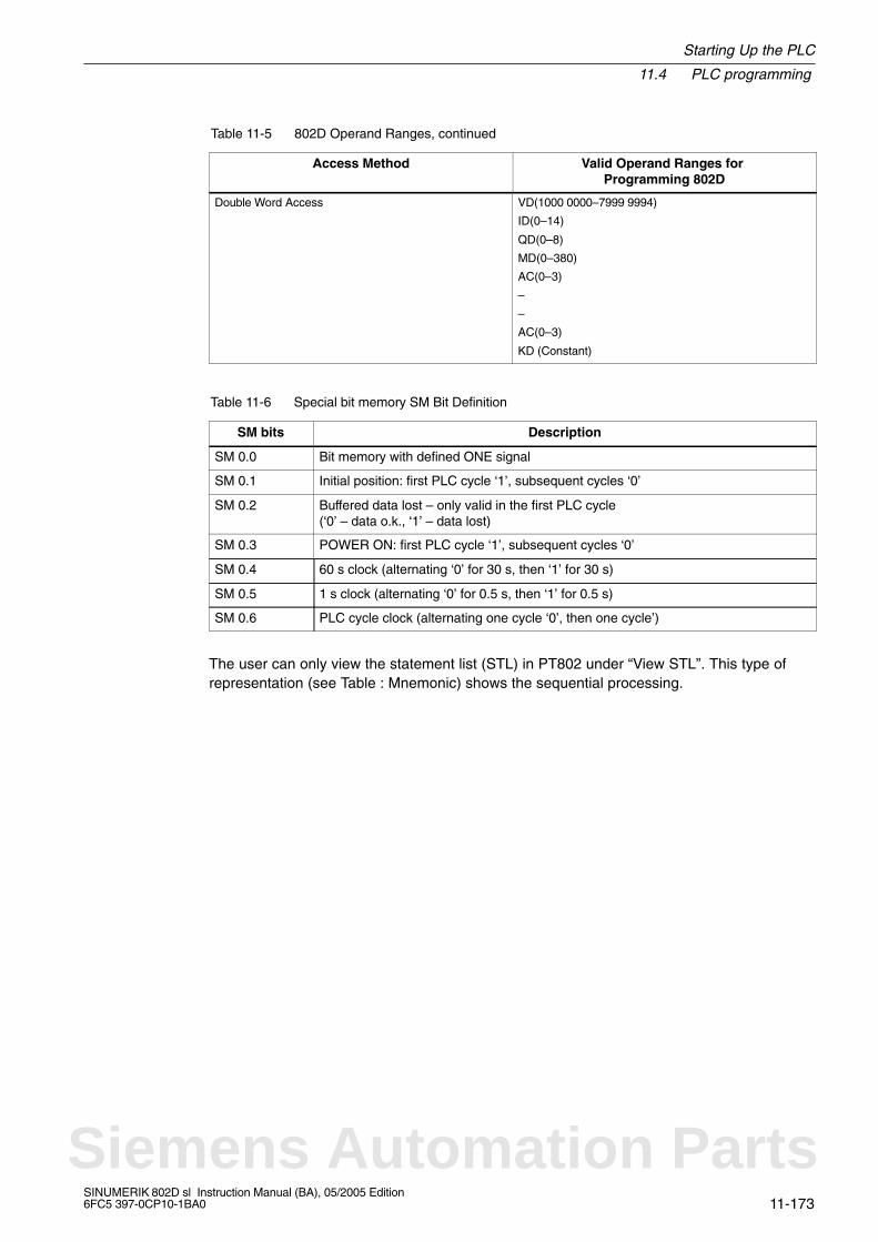
Starting Up the PLC
11.4 PLC programming
11-173SINUMERIK 802D sl Instruction Manual (BA), 05/2005 Edition6FC5 397-0CP10-1BA0
Table 11-5 802D Operand Ranges, continued
Access Method Valid Operand Ranges for Programming 802D
Double Word Access VD(1000 0000–7999 9994)
ID(0–14)
QD(0–8)
MD(0–380)
AC(0–3)
–
–
AC(0–3)
KD (Constant)
Table 11-6 Special bit memory SM Bit Definition
SM bits Description
SM 0.0 Bit memory with defined ONE signal
SM 0.1 Initial position: first PLC cycle ‘1’, subsequent cycles ‘0’
SM 0.2 Buffered data lost – only valid in the first PLC cycle(‘0’ – data o.k., ‘1’ – data lost)
SM 0.3 POWER ON: first PLC cycle ‘1’, subsequent cycles ‘0’
SM 0.4 60 s clock (alternating ‘0’ for 30 s, then ‘1’ for 30 s)
SM 0.5 1 s clock (alternating ‘0’ for 0.5 s, then ‘1’ for 0.5 s)
SM 0.6 PLC cycle clock (alternating one cycle ‘0’, then one cycle’)
The user can only view the statement list (STL) in PT802 under “View STL”. This type ofrepresentation (see Table : Mnemonic) shows the sequential processing.
Siemens Automation Parts
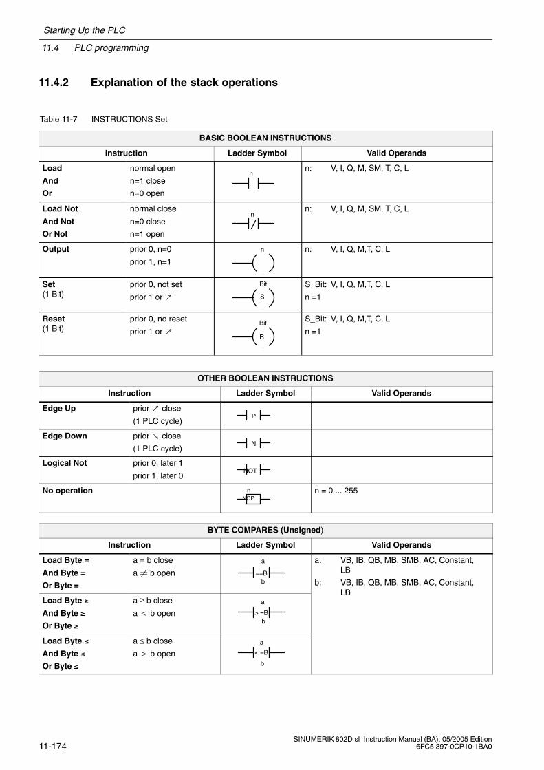
11.4 PLC programming
Starting Up the PLC
11-174SINUMERIK 802D sl Instruction Manual (BA), 05/2005 Edition
6FC5 397-0CP10-1BA0
11.4.2 Explanation of the stack operations
Table 11-7 INSTRUCTIONS Set
BASIC BOOLEAN INSTRUCTIONS
Instruction Ladder Symbol Valid Operands
Load
And
Or
normal open
n=1 close
n=0 open
nn: V, I, Q, M, SM, T, C, L
Load Not
And Not
Or Not
normal close
n=0 close
n=1 open
nn: V, I, Q, M, SM, T, C, L
Output prior 0, n=0
prior 1, n=1
n n: V, I, Q, M,T, C, L
Set(1 Bit)
prior 0, not set
prior 1 or
Bit
S
S_Bit: V, I, Q, M,T, C, L
n =1
Reset(1 Bit)
prior 0, no reset
prior 1 or Bit
R
S_Bit: V, I, Q, M,T, C, L
n =1
OTHER BOOLEAN INSTRUCTIONS
Instruction Ladder Symbol Valid Operands
Edge Up prior close
(1 PLC cycle)P
Edge Down prior close
(1 PLC cycle)N
Logical Not prior 0, later 1
prior 1, later 0NOT
No operationNOP
n n = 0 ... 255
BYTE COMPARES (Unsigned)
Instruction Ladder Symbol Valid Operands
Load Byte =
And Byte =
Or Byte =
a = b close
a b open
a
b==B
a: VB, IB, QB, MB, SMB, AC, Constant, LB
b: VB, IB, QB, MB, SMB, AC, Constant, LB
Load Byte
And Byte
Or Byte
a ≥ b close
a b opena
b> =B
LB
Load Byte
And Byte
Or Byte
a ≤ b close
a b opena
b
< =B
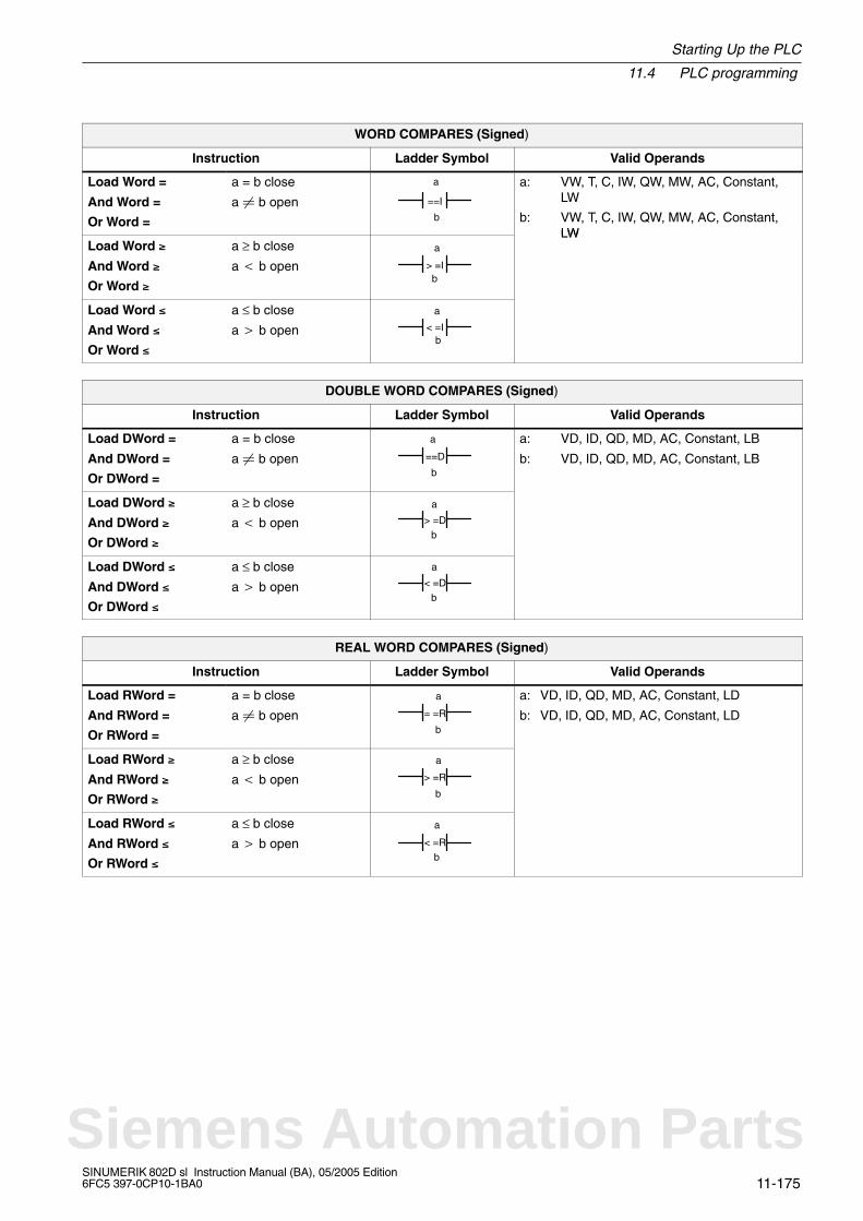
Starting Up the PLC
11.4 PLC programming
11-175SINUMERIK 802D sl Instruction Manual (BA), 05/2005 Edition6FC5 397-0CP10-1BA0
WORD COMPARES (Signed)
Instruction Ladder Symbol Valid Operands
Load Word =
And Word =
Or Word =
a = b close
a b open
a
b
==I
a: VW, T, C, IW, QW, MW, AC, Constant, LW
b: VW, T, C, IW, QW, MW, AC, Constant,LW
Load Word
And Word
Or Word
a ≥ b close
a b open
a
b> =I
LW
Load Word
And Word
Or Word
a ≤ b close
a b open
a
b< =I
DOUBLE WORD COMPARES (Signed)
Instruction Ladder Symbol Valid Operands
Load DWord =
And DWord =
Or DWord =
a = b close
a b open
a
b
==D
a: VD, ID, QD, MD, AC, Constant, LB
b: VD, ID, QD, MD, AC, Constant, LB
Load DWord
And DWord
Or DWord
a ≥ b close
a b open
a
b> =D
Load DWord
And DWord
Or DWord
a ≤ b close
a b open
a
b< =D
REAL WORD COMPARES (Signed)
Instruction Ladder Symbol Valid Operands
Load RWord =
And RWord =
Or RWord =
a = b close
a b open
a
b
= =R
a: VD, ID, QD, MD, AC, Constant, LD
b: VD, ID, QD, MD, AC, Constant, LD
Load RWord
And RWord
Or RWord
a ≥ b close
a b open
a
b
> =R
Load RWord
And RWord
Or RWord
a ≤ b close
a b open
a
b< =R
Siemens Automation Parts

11.4 PLC programming
Starting Up the PLC
11-176SINUMERIK 802D sl Instruction Manual (BA), 05/2005 Edition
6FC5 397-0CP10-1BA0
TIMER
Instruction Ladder Symbol Valid Operands
Timer Retentive OnDelay
EN=1, Start EN=0, Stop
If TValue ≥ PT, Tbit=1
TONR
Txxx
PT
IN
Enable: (IN)S0
Txxx: T0 – T31
Preset: (PT)VW, T, C, IW, QW, MW, AC, Constant
100 ms T0 – T1510 ms T16 – T39
Timer On Delay EN=1, Start EN=0, Stop
If TValue ≥ PT, Tbit=1
TON
Txxx
PT
IN
Enable: (IN)S0
Txxx: T0 – T31
Preset: (PT)VW, T, C, IW, QW, MW, AC, Constant
100 ms T0 – T1510 ms T16 – T39
Timer Of Delay If TValue < PT, Tbit=1
TOF
Txxx
PT
IN
Enable: (IN)S0
Txxx: T0 – T31
Preset: (PT)VW, T, C, IW, QW, MW, AC, Constant
100 ms T0 – T1510 ms T16 – T39
COUNTER
Instruction Ladder Symbol Valid Operands
Count Up CU , Value+1
R=1, Reset
If CValue ≥ PV, Cbit=1
CTU
Cxxx
CU
R
PV
Cnt Up: (CU)S1
Reset: (R)S0
Cxxx: C0 – 31
Preset: (PV)VW, T, C, IW, QW, MW, AC, Constant, LW
Count Up/Down CU , Value+1CD , Value–1
R=1, Reset
If CValue ≥ PV, Cbit=1 CTUD
CD
Cxxx
CU
R
PV
Cnt Up: (CU)S2
Cnt Dn: (CD)S1
Reset: (R)S0
Cxxx: C0 – 31
Preset: (PV)VW, T, C, IW, QW, MW, AC, Constant, LW
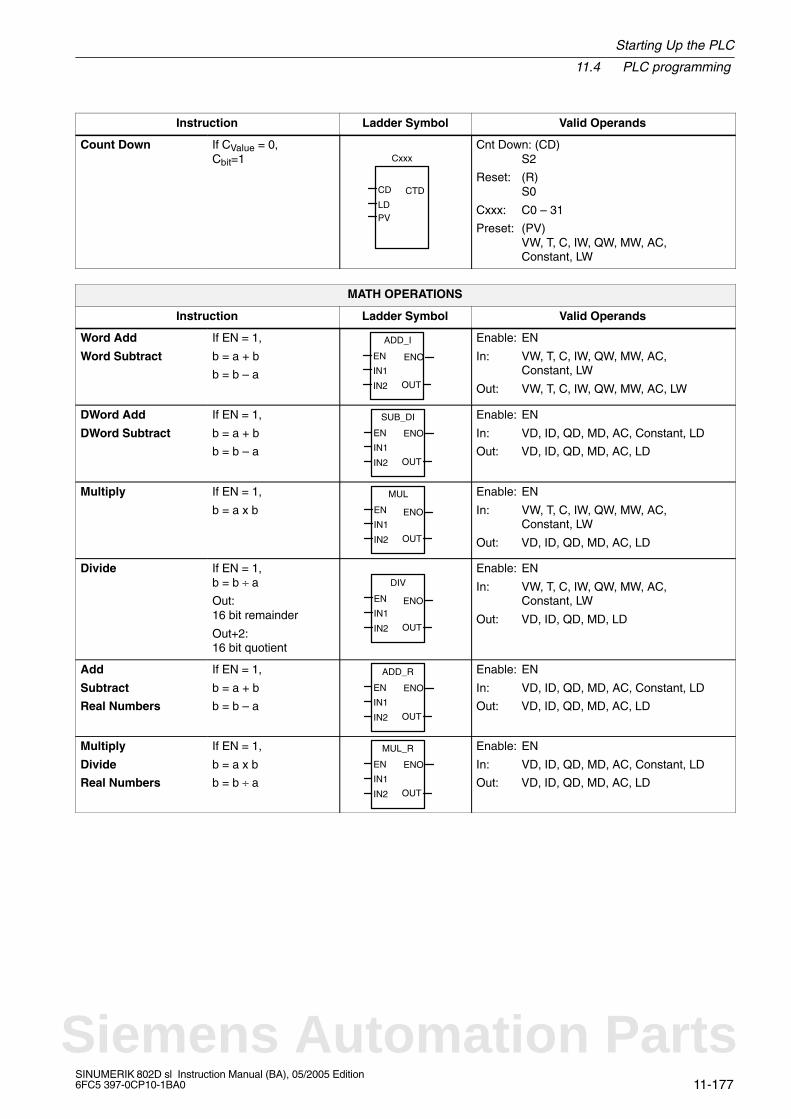
Starting Up the PLC
11.4 PLC programming
11-177SINUMERIK 802D sl Instruction Manual (BA), 05/2005 Edition6FC5 397-0CP10-1BA0
Instruction Valid OperandsLadder Symbol
Count Down If CValue = 0,Cbit=1
CTD
LD
Cxxx
CD
PV
Cnt Down: (CD)S2
Reset: (R)S0
Cxxx: C0 – 31
Preset: (PV)VW, T, C, IW, QW, MW, AC, Constant, LW
MATH OPERATIONS
Instruction Ladder Symbol Valid Operands
Word Add
Word Subtract
If EN = 1,
b = a + b
b = b – a
ADD_I
IN1
IN2 OUT
EN ENO
Enable: EN
In: VW, T, C, IW, QW, MW, AC, Constant, LW
Out: VW, T, C, IW, QW, MW, AC, LW
DWord Add
DWord Subtract
If EN = 1,
b = a + b
b = b – a
SUB_DI
IN1
IN2 OUT
EN ENO
Enable: EN
In: VD, ID, QD, MD, AC, Constant, LD
Out: VD, ID, QD, MD, AC, LD
Multiply If EN = 1,
b = a x bMUL
IN1
IN2 OUT
EN ENO
Enable: EN
In: VW, T, C, IW, QW, MW, AC, Constant, LW
Out: VD, ID, QD, MD, AC, LD
Divide If EN = 1, b = b ÷ a
Out: 16 bit remainder
Out+2: 16 bit quotient
DIV
IN1
IN2 OUT
EN ENO
Enable: EN
In: VW, T, C, IW, QW, MW, AC, Constant, LW
Out: VD, ID, QD, MD, LD
Add
Subtract
Real Numbers
If EN = 1,
b = a + b
b = b – a
ADD_R
IN1
IN2 OUT
EN ENO
Enable: EN
In: VD, ID, QD, MD, AC, Constant, LD
Out: VD, ID, QD, MD, AC, LD
Multiply
Divide
Real Numbers
If EN = 1,
b = a x b
b = b ÷ a
MUL_R
IN1
IN2 OUT
EN ENO
Enable: EN
In: VD, ID, QD, MD, AC, Constant, LD
Out: VD, ID, QD, MD, AC, LD
Siemens Automation Parts
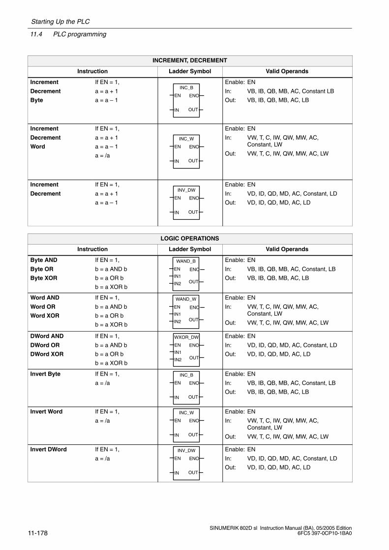
11.4 PLC programming
Starting Up the PLC
11-178SINUMERIK 802D sl Instruction Manual (BA), 05/2005 Edition
6FC5 397-0CP10-1BA0
INCREMENT, DECREMENT
Instruction Ladder Symbol Valid Operands
Increment
Decrement
Byte
If EN = 1,
a = a + 1
a = a – 1
INC_B
IN OUT
EN ENO
Enable: EN
In: VB, IB, QB, MB, AC, Constant LB
Out: VB, IB, QB, MB, AC, LB
Increment
Decrement
Word
If EN = 1,
a = a + 1
a = a – 1
a = /a
INC_W
IN OUT
EN ENO
Enable: EN
In: VW, T, C, IW, QW, MW, AC, Constant, LW
Out: VW, T, C, IW, QW, MW, AC, LW
Increment
Decrement
If EN = 1,
a = a + 1
a = a – 1
INV_DW
IN OUT
EN ENO
Enable: EN
In: VD, ID, QD, MD, AC, Constant, LD
Out: VD, ID, QD, MD, AC, LD
LOGIC OPERATIONS
Instruction Ladder Symbol Valid Operands
Byte AND
Byte OR
Byte XOR
If EN = 1,
b = a AND b
b = a OR b
b = a XOR b
WAND_B
IN1
IN2 OUT
EN ENO
Enable: EN
In: VB, IB, QB, MB, AC, Constant, LB
Out: VB, IB, QB, MB, AC, LB
Word AND
Word OR
Word XOR
If EN = 1,
b = a AND b
b = a OR b
b = a XOR b
WAND_W
IN1
IN2 OUT
EN ENO
Enable: EN
In: VW, T, C, IW, QW, MW, AC, Constant, LW
Out: VW, T, C, IW, QW, MW, AC, LW
DWord AND
DWord OR
DWord XOR
If EN = 1,
b = a AND b
b = a OR b
b = a XOR b
WXOR_DW
IN1
IN2 OUT
EN ENO
Enable: EN
In: VD, ID, QD, MD, AC, Constant, LD
Out: VD, ID, QD, MD, AC, LD
Invert Byte If EN = 1,
a = /aINC_B
IN OUT
EN ENO
Enable: EN
In: VB, IB, QB, MB, AC, Constant, LB
Out: VB, IB, QB, MB, AC, LB
Invert Word If EN = 1,
a = /aINC_W
IN OUT
EN ENO
Enable: EN
In: VW, T, C, IW, QW, MW, AC, Constant, LW
Out: VW, T, C, IW, QW, MW, AC, LW
Invert DWord If EN = 1,
a = /aINV_DW
IN OUT
EN ENO
Enable: EN
In: VD, ID, QD, MD, AC, Constant, LD
Out: VD, ID, QD, MD, AC, LD

Starting Up the PLC
11.4 PLC programming
11-179SINUMERIK 802D sl Instruction Manual (BA), 05/2005 Edition6FC5 397-0CP10-1BA0
SHIFT AND ROTATE OPERATIONS
Instruction Ladder Symbol Valid Operands
Shift Right
Shift Left
If EN = 1,
a = a SR c bits
a = a SL c bits
SHL_R
IN
N OUT
EN ENO
Enable: EN
In: VB, IB, QB, MB, AC, Constant, LB
Out: VB, IB, QB, MB, AC
Count: VB, IB, QB, MB, AC, Constant, LB
Shift Right
Shift Left
If EN = 1,
a = a SR c bits
a = a SL c bits
SHL_W
IN
NOUT
EN ENO
Enable: EN
In: VW, T, C, IW, QW, MW, AC, Constant, LW
Out: VW, T, C, IW, QW, MW, AC, LW
Count: VB, IB, QB, MB, AC, Constant, LB
DWord Shift R
DWord Shift L
If EN = 1,
a = a SR c bits
a = a SL c bits
SHL_DW
IN
N OUT
EN ENO
Enable: EN
In: VD, ID, QD, MD, AC, Constant, LD
Out: VD, ID, QD, MD, AC, LD
Count: VB, IB, QB, MB, AC, Constant, LB
CONVERSION OPERATIONS
Instruction Ladder Symbol Valid Operands
Convert DoubleWord Integer to aReal
If EN = 1, convert thedouble word integer ito a real number o.
DI_REAL
IN OUT
EN ENO
Enable: EN
In: VD, ID, QD, MD, AC, Constant, LD
Out: VD, ID, QD, MD, AC, LD
Convert a Real to aDouble Word Integer
If EN = 1, convert thereal number i to adouble word integer o.
TRUNC
IN OUT
EN ENO
Enable: EN
In: VD, ID, QD, MD, AC, Constant, LD
Out: VD, ID, QD, MD, AC, LD
PROGRAM CONTROL FUNCTIONS
Instruction Ladder Symbol Valid Operands
Jump to Label If EN = 1, go to label n. n
JMP
Enable: EN
Label: WORD: 0–127
Label Label marker for thejump. LBL
n Label: WORD: 0–127
Conditional Returnfrom Subroutine
If EN = 1, exit the sub-routine. RET
Enable: EN
Return from Subrou-tine
Exit subroutine.RET
Conditional End If EN = 1, END termi-nates the main scan. END
Enable: EN
Siemens Automation Parts

11.4 PLC programming
Starting Up the PLC
11-180SINUMERIK 802D sl Instruction Manual (BA), 05/2005 Edition
6FC5 397-0CP10-1BA0
PROGRAM CONTROL FUNCTIONS
Instruction Ladder Symbol Valid Operands
Subroutine If EN , go to subrou-tine n. SBR
x1
x2 x3
EN
n
(x... optional parameters
Label: Constant : 0–63
MOVE, FILL AND FIND OPERATIONS
Instruction Ladder Symbol Valid Operands
Move Byte If EN = 1, copy i to o.
MOV_B
IN OUT
EN ENO
Enable: EN
In: VB, IB, QB, MB, AC, Constant, LB
Out: VB, IB, QB, MB, AC, LB
Move Word If EN = 1, copy i to o.
MOV_W
IN OUT
EN ENO
Enable: EN
In: VW, T, C, IW, QW, MW, AC, Constant, LW
Out: VW, T, C, IW, QW, MW, AC, LW
Move DWord If EN = 1, copy i to o.
MOV_DW
IN OUT
EN ENO
Enable: EN
In: VD, ID, QD, MD, AC, Constant, LD
Out: VD, ID, QD, MD, AC, LD
Move Real If EN = 1, copy i to o.
MOV_R
IN OUT
EN ENO
Enable: EN
In: VD, ID, QD, MD, AC, Constant, LD
Out: VD, ID, QD, MD, AC, LD
Swap Bytes If EN = 1, exchange MSB andLSB of w.
SWAP
IN
EN ENO
Enable: EN
In: VW, IW, QW, MW, T, C, AC, LW

Starting Up the PLC
11.4 PLC programming
11-181SINUMERIK 802D sl Instruction Manual (BA), 05/2005 Edition6FC5 397-0CP10-1BA0
11.4.3 Program organization
A programmer should structure the user program into separate program sections (subrouti-nes). The S7-200 programming language offers the user the possibility to create a structureduser program. There are two program types – main program and subroutine. Eight programlevels are possible.
A PLC cycle can be a multiple of the control-internal interpolation cycle (IPO cycle). The ma-chine manufacturer must set the PLC cycle according to his particular conditions (see ma-chine data “PLC_IPO_TIME_RATIO”). An IPO/ PLC ratio of 1:1 has been proven to providethe fastest possible cyclic program execution.
Example: The programmer will write a sequence control in the main program using a cycledefined by himself. This sequence control will organize all cyclic signals in the subroutine(UP0); UP1/UP2 are called every two cycles, and UP3 controls all signals at an interval ofthree cycles.
11.4.4 Data organization
The data can be divided into three areas:
non-retentive data
retentive data
machine data for the PLC (all these machine data are active after POWER ON).
Most of the machine data, such as process image, timer and counter are non-retentive datawhich are deleted each time when the control system is powered up.
The data area 1400 0000 –1400 0127 is reserved for the retentive data. The user can herestore all data which are to remain valid after POWER OFF/ON.
The user can either load the data in his program with default data using the PLC machinedata (see “User interface”) or parameterize various program sections.
11.4.5 Interface to the control system
This interface can be selected via SYSTEM, softkeys PLC > STEP7-connect.
This V24 interface continues to be active even after cold restart or normal booting. The con-nection (STEP7 connect active) to the control system can be checked in the “PLC/informa-tion” menu of the PLC 802 Programming Tool. If the interface is active, the active PLCmode, for example (Run/Stop) is displayed in this window.
Siemens Automation Parts
11.4 PLC programming
Starting Up the PLC
11-182SINUMERIK 802D sl Instruction Manual (BA), 05/2005 Edition
6FC5 397-0CP10-1BA0
11.4.6 Testing and monitoring your program
A check or error analysis of the user program is possible as follows:
PLC status: Display and change of called operands
Status list: Display and change of three freely selected variable fields
PLC program: Display and monitoring (status) of the whole user program including sym-bols and comments
PT PLC 802: It is possible to connect a PG/PC and to activate the PT connection via mo-dem

Starting Up the PLC
11.5 PLC applications Download/Upload/Copy/Compare
11-183SINUMERIK 802D sl Instruction Manual (BA), 05/2005 Edition6FC5 397-0CP10-1BA0
11.5 PLC applications Download/Upload/Copy/Compare
The user can save, copy or overwrite the PLC project or the PLC applications in the controlsystem.
This is possible using
PLC 802 Programming Tool
RCS802 (binary file)
CF card
The PLC project comprises the PLC user program including all important information (sym-bols, comments, ...). It is loaded by the Programming Tool via upload/download or via File >Import/Export.
The PLC application incorporates the PLC project and PLC user alarm texts. The PLC ap-plication can only be generated by the control system.
PLC project
PLC user
alarm texts
PLCmachine data
PT PLC 802
RCS802
CF card
Toolbox
PLCapplication
Series machine start-up
Series machine start-up
PLCapplication
Download/Upload/Compare
802D Permanentmemory
Export/Import
Fig. 11-1 PLC applications in the control system
Siemens Automation Parts
11.5 PLC applications Download/Upload/Copy/Compare
Starting Up the PLC
11-184SINUMERIK 802D sl Instruction Manual (BA), 05/2005 Edition
6FC5 397-0CP10-1BA0
Download
This function writes the transmitted data to the permanent memory (load memory) of thecontrol system.
Download of a PLC project using the PLC 802 Programming Tool (Step 7 connect on)
Series machine start-up (System > Start-up files > NC/PLC start-up archive) using theRCS802 tool or CF card. For example, CF card:Copy the start-up archive from the customer CF card and paste it into the directory Start-up files > Start-up archive (NC/PLC).
– NC data
– NC directories
– Display machine data
– Leadscrew error compensation (LEC)
– PLC user program
– Drive machine data
Reading in PLC applications using the RCS802 tool or the CF card (PLC project and useralarm texts) analogously to the series machine start-up
Upload
The PLC application can be saved from the permanent memory of the control system usingthe either PLC 802 Programming Tool, RCS802 or the CF card.
Upload from the PLC project using the PLC 802 Programming Tool (Step 7 connect on)
Reading out the project from the control system and thus reconstructing the current pro-ject in the PLC 802 Programming Tool.
Series machine start-up: System > Start-up file > Start-up archive (NC/PL) usingRCS802 (PLC MD, PLC project and user alarm texts) or the CF card
Reading out the PLC application using RCS802 or copying to CF card (PLC project infor-mation and user alarm texts)
Compare
This function compares the project contained in the PLC 802 Programming Tool with the pro-ject loaded in the permanent memory (load memory) in the control system.
Version display
This function is called using the SYSTEM hardkey, softkeys Service Display > Version.
PLC applicationThe transmitted project including the user program which is active in the user memory ofthe PLC after booting of the control system.
The programmer can use the start of the first comment line in the comment of OB1 in thePLC 802 Programming Tool for his own supplementary information in the version display(see “View Properties”).

Starting Up the PLC
11.6 User interface
11-185SINUMERIK 802D sl Instruction Manual (BA), 05/2005 Edition6FC5 397-0CP10-1BA0
11.6 User interface
This interface comprises all signals exchanged between NCK/PLC and HMI/PLC. In addi-tion, the PLC decodes all auxiliary function commands for processing in the user program.
Note to the reader
/FB/ Sinumerik 802D sl Description of Functions, Chapter 20
Siemens Automation Parts

11.6 User interface
Starting Up the PLC
11-186SINUMERIK 802D sl Instruction Manual (BA), 05/2005 Edition
6FC5 397-0CP10-1BA0
Notes
12-187SINUMERIK 802D sl Instruction Manual (BA), 05/2005 Edition6FC5 397-0CP10-1BA0
Data Backup and Series Machine Start-Up
12.1 Data backup
12.1.1 Internal data backup
The data of the limited-buffered memory must be saved via a backup copy to the permanentmemory of the control system. This backup is performed internally and is always necessaryif the control system is switched off for longer than 50 hours.
Recommendation: After changing important data, it is recommended to carry out a databackup immediately.
Note
During the data backup, an image of the limited-buffered memory is produced and storedin the permanent memory. A backup of selected data (e.g. only machine data and no work-piece programs) is not possible.
Performing an internal data backup
Select the Save data softkey in the System operating area (at least protection level 3 requi-red). Press OK to confirm the notes which now appear.
Important
While the internal data backup is running, the control system must neither be operated, norbe turned off.
Loading internally backed-up data
Boot the control system in the start-up mode “Reload saved user data”.
In case of data loss of the buffered memory, the data saved in the permanent memoryare automatically reloaded into the memory with POWER ON.
Note
Message “4062 Data backup copy has been loaded” is displayed on the screen.
12
Siemens Automation Parts
12.1 Data backup
Data Backup and Series Machine Start-Up
12-188SINUMERIK 802D sl Instruction Manual (BA), 05/2005 Edition
6FC5 397-0CP10-1BA0
12.1.2 External data backup
In addition to an internal data backup, the user data of the control system can also be savedexternally. To do so, a PC with V24 interface and the RCS tool (included in the toolbox) or aCF card are required.
An external data backup should be performed if major data changes have been made or al-ways at the end of the start-up.
To create a complete data backup for a machine, it is sufficient to create the series machinestart-up file.
Variants of external data backup
1. Reading out the data completely: Series machine start-up
2. Files are read out/read in for each area individually. The following user data can be selec-ted from the “System” operating area as individual files:
Data in the text format
– All machine data
– Setting data
– Tool data
– R parameters
– Work offset
– Compensation data (LEC)
– GUDs
Data in the start-up archive (NC/PLC)
– NC data
– NC directories
– Display machine data
– Compensation data (LEC)
– PLC user alarm texts
– PLC project (cannot be edited with PT 802)
– Drive machine data
Data in the start-up archive (HMI)
– User cycles
– User directories
– Language file SP1
– Language file SP2
– Start screen
– Online help
– HMI screens
3. Furthermore, the following data can be saved from the “Program Manager” operatingarea:
– Manufacturer cycles
– Standard cycles
Data Backup and Series Machine Start-Up
12.1 Data backup
12-189SINUMERIK 802D sl Instruction Manual (BA), 05/2005 Edition6FC5 397-0CP10-1BA0
– User cycles
– Main programs
– Subroutines
12.1.3 Data backup via V24
Important
Never connect or disconnect the V24 cable when the PCU is connected to the mains.
Make sure that the settings of the RS232 interface of the 802D and of the COM port on thePC are identical.
Creating a start-up archive in the PC (data transfer from the control system to the PC)
For the series machine start-up, please refer to Section 12.2.
Data backup in the 802D data area (text format)
On the PC, one single file will result which contains the data you have selected for backup.
Note to the reader
/BP/ SINUMERIK 802D sl “Operation and Programming”, Chapter 7
Data backup in the “Program Manager” operating area
The data from the Program Manager > NC directory operating area are output to theRS232 in the text format.
12.1.4 External data backup via CF Card
On the CF card, the same data can be saved as those which are saved via the serial inter-face. The selection of the data to be saved is performed in the same way (System > Start-up files > 802D data > Copy)); saving to the card is performed via Customer CF card andPaste.
Siemens Automation Parts
12.2 Series machine start-up
Data Backup and Series Machine Start-Up
12-190SINUMERIK 802D sl Instruction Manual (BA), 05/2005 Edition
6FC5 397-0CP10-1BA0
12.2 Series machine start-up
Functionality
The objective of the series machine start-up is:
to bring another control system at a machine of the same type to the same condition asafter a commissioning
or
to bring a new control system to the initial state in case of servicing (after hardware repla-cement) with lowest possible expenditure.
Start-up archive (NC/PLC)
The start-up archive (NC/PLC) incorporates the following data:
Machine data
R parameters
Setting data
PLC user alarm texts
Display machine data
PLC user project
Part programs
Cycles
Work offsets
Tool offsets
Leadscrew error compensation data
Drive machine data of SINAMICS
Start-up archive (HMI)
The start-up archive (HMI) incorporates the following data:
User cycles
User directories
Language file SP1
Language file SP2
Start screen
Online help
HMI screens
Data Backup and Series Machine Start-Up
12.2 Series machine start-up
12-191SINUMERIK 802D sl Instruction Manual (BA), 05/2005 Edition6FC5 397-0CP10-1BA0
Prerequisites
The prerequisite for the series machine start-up is a PC with V24 interface for data transferfrom/to the control system, or a CF card.
In the PC, the RCStool must be used.
Sequence with PC
1. Creating a start-up archive (NC/PLC) in the PC (data transfer from the control system tothe PC):
– Establish a V24 cable connection between the PC (COM port) and the SINUMERIK802D (RS232).
– Use the RCS tool to make the following settings in the RS232 Config menu in thebinary format (the settings not printed in bold correspond to the default setting whenstarting WINPCIN):
COM port Number of the PC COM to SINUMERIK 802DBaud rate 19,200 (default)Parity noneData bit 8Stop bit 1Software (XON/XOFF) OFFHardware (RTS/CTS) ONTimeout 0sSTOP with EOF no tick
– Call the Receive Data menu in the PC, enter a file name (any archive name) and start the data transfer.The PC switches to “Receive” and is awaiting data from the control system.
– The control system requires the password for protection level 2.
– Configure the interface as above (default settings) using the System > Start-upfiles > RS232 > Settings menu.
– Go back with Back and 802D Data and select the “Start-up archive (NC/PLC)” line;use Copy to paste the contents to the clipboard.
– Back again in RS232,, select the “Binary mode transmission” direction key and thenSend. The series machine start-up is output to the serial interface.
2. Reading in the series start-up file from the PC into the SINUMERIK 802D
– Make the relevant settings for the V24 interface on the PC and on the 802D as speci-fied under 1.
– In the System > Start-up files > RS232 “Binary mode transmission” menu, selectReceive. The control system will now wait for data.
– Use RCS802 on your PC to open the series machine start-up file from the Send Datamenu, starting the data transfer.
– Once reading-in has started, confirm the start of the series machine start-up in thecontrol system.
– A warm start of the NC/PLC is performed several times during the series machinestart-up. At the end of the series machine start-up, the whole control system will re-boot (warm start). After an error-free series machine start-up, the control system willbe in a fully configured operating condition.
Siemens Automation Parts
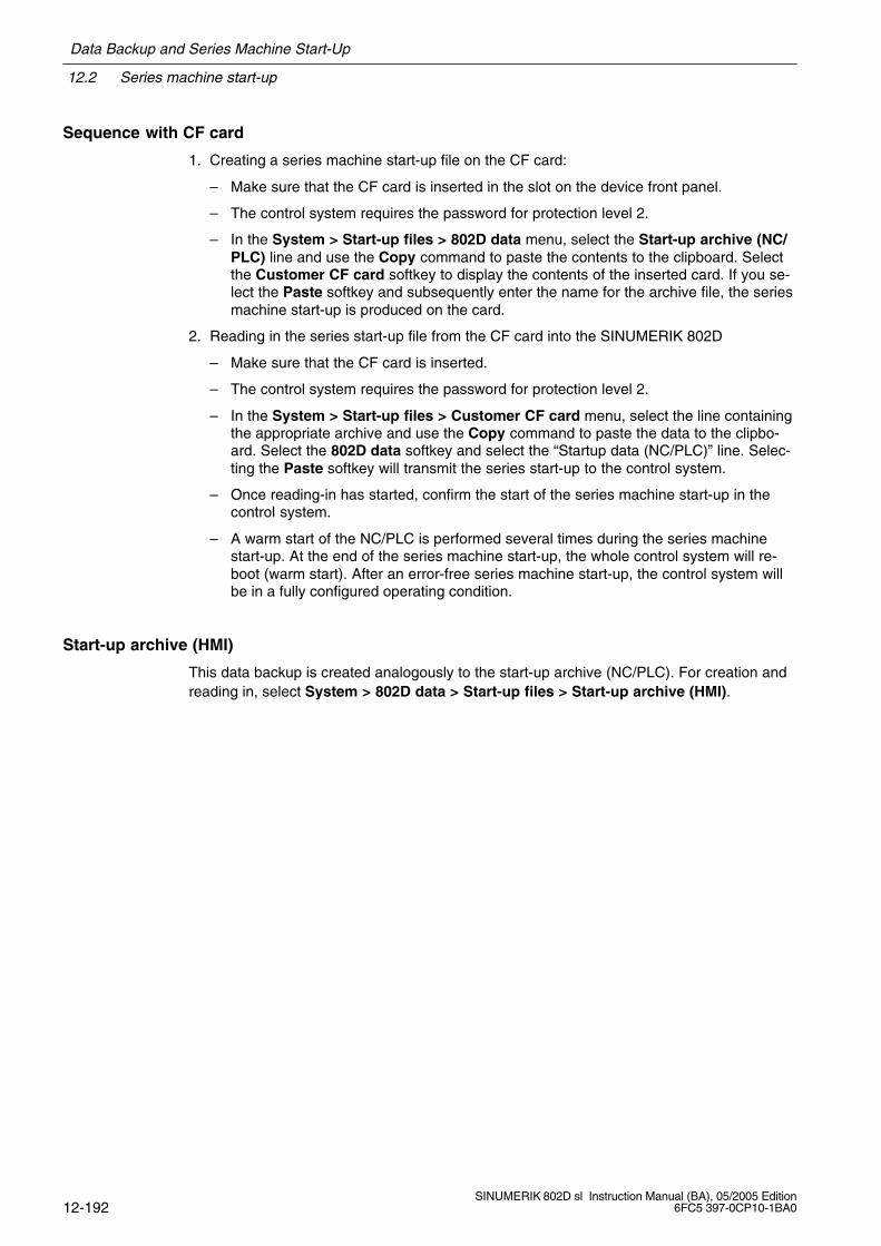
12.2 Series machine start-up
Data Backup and Series Machine Start-Up
12-192SINUMERIK 802D sl Instruction Manual (BA), 05/2005 Edition
6FC5 397-0CP10-1BA0
Sequence with CF card
1. Creating a series machine start-up file on the CF card:
– Make sure that the CF card is inserted in the slot on the device front panel.
– The control system requires the password for protection level 2.
– In the System > Start-up files > 802D data menu, select the Start-up archive (NC/PLC) line and use the Copy command to paste the contents to the clipboard. Selectthe Customer CF card softkey to display the contents of the inserted card. If you se-lect the Paste softkey and subsequently enter the name for the archive file, the seriesmachine start-up is produced on the card.
2. Reading in the series start-up file from the CF card into the SINUMERIK 802D
– Make sure that the CF card is inserted.
– The control system requires the password for protection level 2.
– In the System > Start-up files > Customer CF card menu, select the line containingthe appropriate archive and use the Copy command to paste the data to the clipbo-ard. Select the 802D data softkey and select the “Startup data (NC/PLC)” line. Selec-ting the Paste softkey will transmit the series start-up to the control system.
– Once reading-in has started, confirm the start of the series machine start-up in thecontrol system.
– A warm start of the NC/PLC is performed several times during the series machinestart-up. At the end of the series machine start-up, the whole control system will re-boot (warm start). After an error-free series machine start-up, the control system willbe in a fully configured operating condition.
Start-up archive (HMI)
This data backup is created analogously to the start-up archive (NC/PLC). For creation andreading in, select System > 802D data > Start-up files > Start-up archive (HMI).
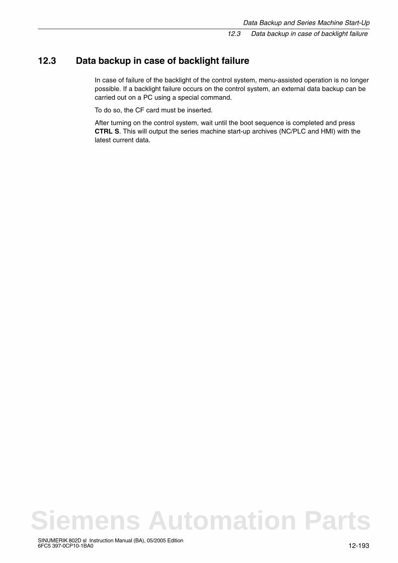
Data Backup and Series Machine Start-Up
12.3 Data backup in case of backlight failure
12-193SINUMERIK 802D sl Instruction Manual (BA), 05/2005 Edition6FC5 397-0CP10-1BA0
12.3 Data backup in case of backlight failure
In case of failure of the backlight of the control system, menu-assisted operation is no longerpossible. If a backlight failure occurs on the control system, an external data backup can becarried out on a PC using a special command.
To do so, the CF card must be inserted.
After turning on the control system, wait until the boot sequence is completed and pressCTRL S. This will output the series machine start-up archives (NC/PLC and HMI) with thelatest current data.
Siemens Automation Parts
12.3 Data backup in case of backlight failure
Data Backup and Series Machine Start-Up
12-194SINUMERIK 802D sl Instruction Manual (BA), 05/2005 Edition
6FC5 397-0CP10-1BA0
Notes

A-195SINUMERIK 802D sl Instruction Manual (BA), 05/2005 Edition6FC5 397-0CP10-1BA0
Machine and Setting Data 802D
Data type
BOOLEAN Boolean value: 1 (TRUE) or 0 (FALSE)
BYTE 8-bit value,as an integer value: –128 ... 127,as a hexadecimal value: 00 ... FFas a character as per ASCII character set, e.g. “a”
STRING Sequence of characters (max. 16)
WORD 16-bit value,as an INTEGER value: –32768 ... 32767,as a hexadecimal value: 0000 ... FFFF
UNSIGNED WORD 16-bit value,as an integer value: 0 ... 65535,as a hexadecimal value: 0000 ... FFFF
INTEGER 16-bit value (here defined locally),integer value: –32768 ... 32767
DWORD 32-bit value,as an integer value: –2147483648 ... 2147483647,as a hexadecimal value: 0000 0000 ... FFFF FFFF
UNSIGNED DWORD 32-bit value,as an integer value: 0 ... 4294967295,as a hexadecimal value: 0000 0000 ... FFFF FFFF
DOUBLE 64-bit value,floating point value: 4.19 10–307 bis 1.67 10308
Range of values (minimum/maximum value)
If no range of values is specified, the data type determines the input limits and the field ismarked with “***”.
A
Siemens Automation Parts

A.1 List of machine data
Machine and Setting Data 802D
A-196SINUMERIK 802D sl Instruction Manual (BA), 05/2005 Edition
6FC5 397-0CP10-1BA0
A.1 List of machine data
A.1.1 Display machine data
Number MD identifier
Cross refe-rence to therelevant sec-tion/chapterin the Des-cription ofFunctions
Schematic view Name, miscellaneous Activation Read/write protection level
Unit Default value Minimum value Maximum value Data type
202 FIRST_LANGUAGE 19decimal Foreground language POWER ON 2/3
0 2 1 2 BYTE
203 DISPLAY_RESOLUTION 19decimal Display resolution immediately 2/3
0 3 0 5 BYTE
204 DISPLAY_RESOLUTION_INCH 19decimal Display resolution immediately 2/3
0 4 0 5 BYTE
205 DISPLAY_RESOLUTION_SPINDLE 19decimal Display resolution immediately 2/3
0 1 0 5 BYTE
208 USER_CLASS_WRITE_TOA_GEOdecimal Protection level write tool geometry immediately 3/3
0 3 0 7 BYTE
209 USER_CLASS_WRITE_TOA_WEARdecimal Protection level write tool wear data immediately 3/3
0 3 0 7 BYTE
210 USER_CLASS_WRITE_ZOAdecimal Protection level for “Write settable work offset” immediately 3/3
0 3 0 7 BYTE
212 USER_CLASS_WRITE_SEAdecimal Protection level for “Write setting data” immediately 3/3
0 7 0 7 BYTE
213 USER_CLASS_READ_PROGRAMdecimal Protection level for “Read part program” immediately 3/3
0 7 0 7 BYTE
214 USER_CLASS_WRITE_PROGRAMdecimal Protection level for “Enter part program” immediately 3/3
0 3 0 7 BYTE
215 USER_CLASS_SELECT_PROGRAMdecimal Protection level for program selection immediately 3/3
0 3 0 7 BYTE
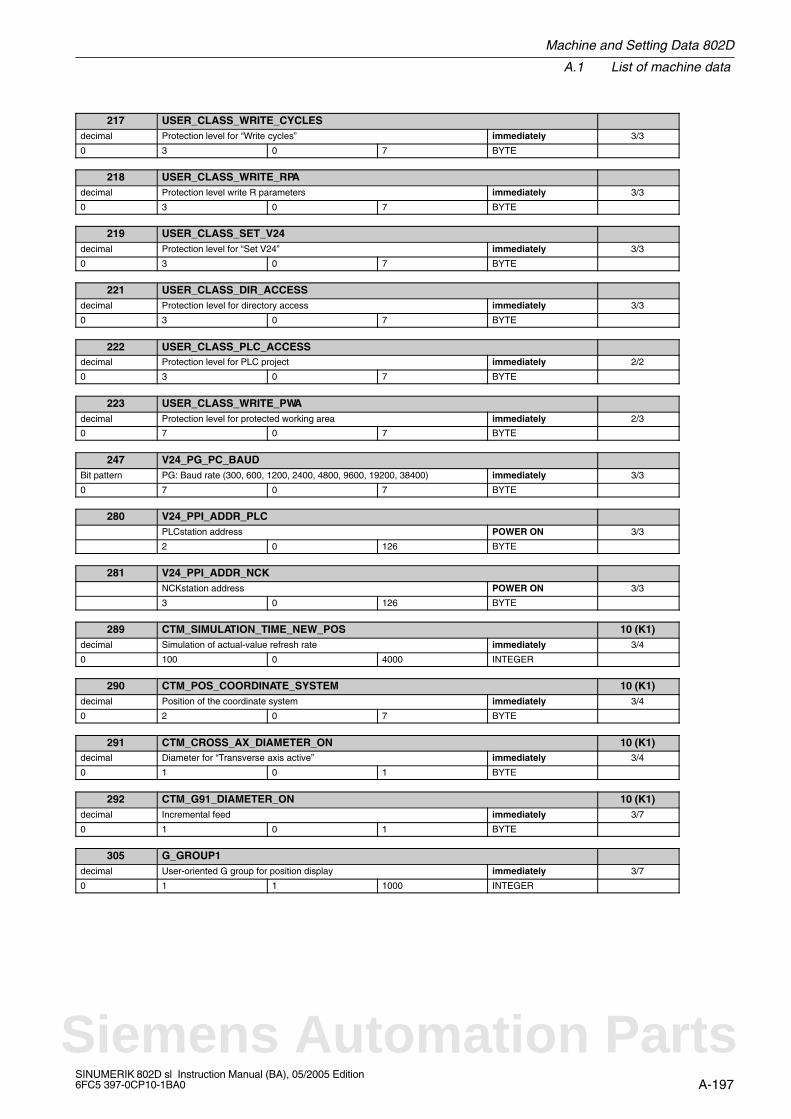
Machine and Setting Data 802D
A.1 List of machine data
A-197SINUMERIK 802D sl Instruction Manual (BA), 05/2005 Edition6FC5 397-0CP10-1BA0
217 USER_CLASS_WRITE_CYCLESdecimal Protection level for “Write cycles” immediately 3/3
0 3 0 7 BYTE
218 USER_CLASS_WRITE_RPAdecimal Protection level write R parameters immediately 3/3
0 3 0 7 BYTE
219 USER_CLASS_SET_V24decimal Protection level for “Set V24” immediately 3/3
0 3 0 7 BYTE
221 USER_CLASS_DIR_ACCESSdecimal Protection level for directory access immediately 3/3
0 3 0 7 BYTE
222 USER_CLASS_PLC_ACCESSdecimal Protection level for PLC project immediately 2/2
0 3 0 7 BYTE
223 USER_CLASS_WRITE_PWAdecimal Protection level for protected working area immediately 2/3
0 7 0 7 BYTE
247 V24_PG_PC_BAUDBit pattern PG: Baud rate (300, 600, 1200, 2400, 4800, 9600, 19200, 38400) immediately 3/3
0 7 0 7 BYTE
280 V24_PPI_ADDR_PLCPLCstation address POWER ON 3/3
2 0 126 BYTE
281 V24_PPI_ADDR_NCKNCKstation address POWER ON 3/3
3 0 126 BYTE
289 CTM_SIMULATION_TIME_NEW_POS 10 (K1)decimal Simulation of actual-value refresh rate immediately 3/4
0 100 0 4000 INTEGER
290 CTM_POS_COORDINATE_SYSTEM 10 (K1)decimal Position of the coordinate system immediately 3/4
0 2 0 7 BYTE
291 CTM_CROSS_AX_DIAMETER_ON 10 (K1)decimal Diameter for “Transverse axis active” immediately 3/4
0 1 0 1 BYTE
292 CTM_G91_DIAMETER_ON 10 (K1)decimal Incremental feed immediately 3/7
0 1 0 1 BYTE
305 G_GROUP1decimal User-oriented G group for position display immediately 3/7
0 1 1 1000 INTEGER
Siemens Automation Parts
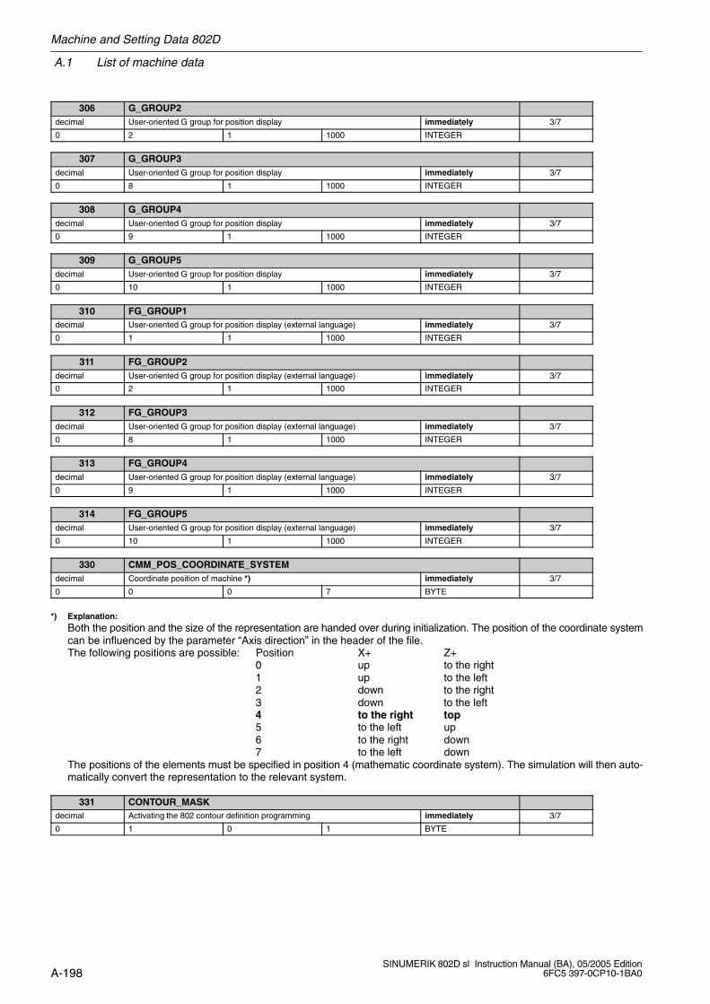
A.1 List of machine data
Machine and Setting Data 802D
A-198SINUMERIK 802D sl Instruction Manual (BA), 05/2005 Edition
6FC5 397-0CP10-1BA0
306 G_GROUP2decimal User-oriented G group for position display immediately 3/7
0 2 1 1000 INTEGER
307 G_GROUP3decimal User-oriented G group for position display immediately 3/7
0 8 1 1000 INTEGER
308 G_GROUP4decimal User-oriented G group for position display immediately 3/7
0 9 1 1000 INTEGER
309 G_GROUP5decimal User-oriented G group for position display immediately 3/7
0 10 1 1000 INTEGER
310 FG_GROUP1decimal User-oriented G group for position display (external language) immediately 3/7
0 1 1 1000 INTEGER
311 FG_GROUP2decimal User-oriented G group for position display (external language) immediately 3/7
0 2 1 1000 INTEGER
312 FG_GROUP3decimal User-oriented G group for position display (external language) immediately 3/7
0 8 1 1000 INTEGER
313 FG_GROUP4decimal User-oriented G group for position display (external language) immediately 3/7
0 9 1 1000 INTEGER
314 FG_GROUP5decimal User-oriented G group for position display (external language) immediately 3/7
0 10 1 1000 INTEGER
330 CMM_POS_COORDINATE_SYSTEMdecimal Coordinate position of machine *) immediately 3/7
0 0 0 7 BYTE
*) Explanation:Both the position and the size of the representation are handed over during initialization. The position of the coordinate systemcan be influenced by the parameter “Axis direction” in the header of the file.The following positions are possible: Position X+ Z+
0 up to the right1 up to the left2 down to the right3 down to the left4 to the right top5 to the left up6 to the right down7 to the left down
The positions of the elements must be specified in position 4 (mathematic coordinate system). The simulation will then auto-matically convert the representation to the relevant system.
331 CONTOUR_MASKdecimal Activating the 802 contour definition programming immediately 3/7
0 1 0 1 BYTE

Machine and Setting Data 802D
A.1 List of machine data
A-199SINUMERIK 802D sl Instruction Manual (BA), 05/2005 Edition6FC5 397-0CP10-1BA0
332 TOOL_LIST_PLACE_NOdecimal Activate location number in tool list immediately 3/3
0 0 0 1 INTEGER
343 V24_PPI_ADDR_MMCdecimal POWER ON 3/3
0 4 0 126
344 V24_PPI_MODEM_ACTIVEdecimal immediately 3/3
0 0 0 1 Byte
345 V24_PPI_MODEM_BAUDdecimal Baud rate for modem connection immediately 3/3
0 7 5 9 Byte
346 V24_PPI_MODEM_PARITYdecimal Parity for modem connection immediately 3/3
0 0 0 2 Byte
356 HMI_COL_TITLE_FOCUS_FOREdecimal Color settings title bar focus window foreground immediately 0/3
15 0 15 Byte
357 HMI_COL_TITLE_FOCUS_BACKdecimal Color settings title bar focus window background immediately 0/3
2 0 15 Byte
358 HMI_COL_SK_FOREdecimal Color settings softkey foreground POWER ON 3/3
0 0 15 Byte
359 HMI_COL_SK_BACKdecimal Color settings softkey background POWER ON 3/3
7 0 15 Byte
360 SPINDLE_LOAD_DISPL1decimal Activate utilization display for spindle 1 immediately 3/3
0 0 1 Integer
361 USER_MEAS_TOOL_CHANGEdecimal Input enable for T/D no. in the “Tool gauging” window immediately 3/3
0 0 1 Byte
362 SPINDLE_LOAD_DISPL2decimal Activate utilization display for spindle 2 immediately 3/3
1 0 1 Integer
363 SPINDLE_LOAD_BAR_LIM2decimal Activate utilization display for the spindle, limit value 2 immediately 2/2
100 0 9999999 Integer
364 SPINDLE_LOAD_BAR_LIM3decimal Activate utilization display for the spindle, limit value 3 immediately 2/2
100 0 9999999 Integer
Siemens Automation Parts
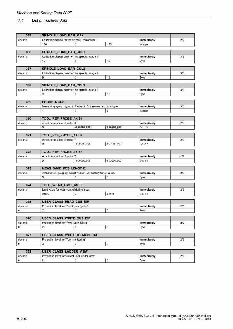
A.1 List of machine data
Machine and Setting Data 802D
A-200SINUMERIK 802D sl Instruction Manual (BA), 05/2005 Edition
6FC5 397-0CP10-1BA0
365 SPINDLE_LOAD_BAR_MAXdecimal Utilization display for the spindle, maximum immediately 2/2
120 0 120 Integer
366 SPINDLE_LOAD_BAR_COL1decimal Utilization display color for the spindle, range 1 immediately 3/3
10 0 15 Byte
367 SPINDLE_LOAD_BAR_COL2decimal Utilization display color for the spindle, range 2 immediately 3/3
9 0 15 Byte
368 SPINDLE_LOAD_BAR_COL3decimal Utilization display color for the spindle, range 3 immediately 3/3
9 0 15 Byte
369 PROBE_MODEdecimal Measuring system type: 1: Probe, 2: Opt. measuring technique immediately 3/3
1 0 2 Integer
370 TOOL_REF_PROBE_AXIS1decimal Absolute position of probe X immediately 2/2
0 –999999.999 999999.999 Double
371 TOOL_REF_PROBE_AXIS2decimal Absolute position of probe Y immediately 2/2
0 –999999.999 999999.999 Double
372 TOOL_REF_PROBE_AXIS3decimal Absolute position of probe Z immediately 2/2
9 –999999.999 999999.999 Double
373 MEAS_SAVE_POS_LENGTH2decimal Activate tool gauging; select “Save Pos” softkey for all values immediately 2/2
0 0 1 Byte
374 TOOL_WEAR_LIMIT_VALUEdecimal Limit value for wear control during input immediately 2/2
9.999 0 9.999 Double
375 USER_CLASS_READ_CUS_DIRdecimal Protection level for “Read user cycles” immediately 2/3
0 7 0 7 Byte
376 USER_CLASS_WRITE_CUS_DIRdecimal Protection level for “Write user cycles” immediately 2/2
0 2 0 7 Byte
377 USER_CLASS_WRITE_TO_MON_DATdecimal Protection level for “Tool monitoring” immediately 2/3
0 3 0 7 Byte
378 USER_CLASS_LADDER_VIEWdecimal Protection level for “Select user ladder view” immediately 2/2
0 2 0 7 Byte
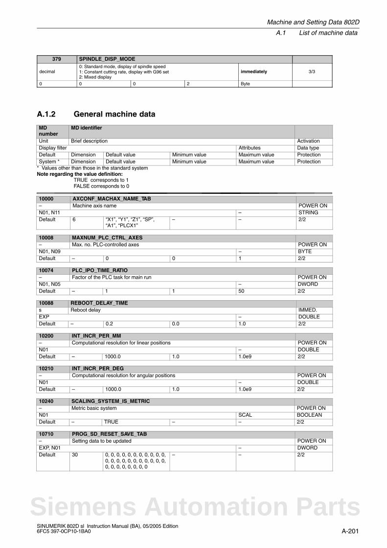
Machine and Setting Data 802D
A.1 List of machine data
A-201SINUMERIK 802D sl Instruction Manual (BA), 05/2005 Edition6FC5 397-0CP10-1BA0
379 SPINDLE_DISP_MODE
decimal0: Standard mode, display of spindle speed1: Constant cutting rate, display with G96 set2: Mixed display
immediately 3/3
0 0 0 2 Byte
A.1.2 General machine data
MDnumber
MD identifier
Unit Brief description ActivationDisplay filter Attributes Data typeDefault Dimension Default value Minimum value Maximum value ProtectionSystem * Dimension Default value Minimum value Maximum value Protection
* Values other than those in the standard systemNote regarding the value definition: TRUE corresponds to 1
FALSE corresponds to 0
10000 AXCONF_MACHAX_NAME_TAB– Machine axis name POWER ONN01, N11 – STRINGDefault 6 “X1”, “Y1”, “Z1”, “SP”,
“A1”, “PLCX1”– – 2/2
10008 MAXNUM_PLC_CTRL_AXES– Max. no. PLC-controlled axes POWER ONN01, N09 – BYTEDefault – 0 0 1 2/2
10074 PLC_IPO_TIME_RATIO– Factor of the PLC task for main run POWER ONN01, N05 – DWORDDefault – 1 1 50 2/2
10088 REBOOT_DELAY_TIMEs Reboot delay IMMED.EXP – DOUBLEDefault – 0.2 0.0 1.0 2/2
10200 INT_INCR_PER_MM– Computational resolution for linear positions POWER ONN01 – DOUBLEDefault – 1000.0 1.0 1.0e9 2/2
10210 INT_INCR_PER_DEG– Computational resolution for angular positions POWER ONN01 – DOUBLEDefault – 1000.0 1.0 1.0e9 2/2
10240 SCALING_SYSTEM_IS_METRIC– Metric basic system POWER ONN01 SCAL BOOLEANDefault – TRUE – – 2/2
10710 PROG_SD_RESET_SAVE_TAB– Setting data to be updated POWER ONEXP, N01 – DWORDDefault 30 0, 0, 0, 0, 0, 0, 0, 0, 0, 0, 0,
0, 0, 0, 0, 0, 0, 0, 0, 0, 0, 0,0, 0, 0, 0, 0, 0, 0, 0
– – 2/2
Siemens Automation Parts
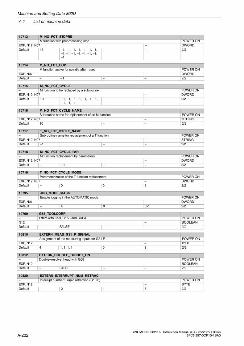
A.1 List of machine data
Machine and Setting Data 802D
A-202SINUMERIK 802D sl Instruction Manual (BA), 05/2005 Edition
6FC5 397-0CP10-1BA0
10713 M_NO_FCT_STOPRE– M function with preprocessing stop POWER ONEXP, N12, N07 – DWORDDefault 15 –1, –1, –1, –1, –1, –1, –1,
–1, –1, –1, –1, –1, –1, –1,–1
– – 2/2
10714 M_NO_FCT_EOP– M function active for spindle after reset POWER ONEXP, N07 – DWORDDefault – –1 – – 2/2
10715 M_NO_FCT_CYCLE– M function to be replaced by a subroutine POWER ONEXP, N12, N07 – DWORDDefault 10 –1, –1, –1, –1, –1, –1, –1,
–1, –1, –1– – 2/2
10716 M_NO_FCT_CYCLE_NAME– Subroutine name for replacement of an M function POWER ONEXP, N12, N07 – STRINGDefault 10 – – 2/2
10717 T_NO_FCT_CYCLE_NAME– Subroutine name for replacement of a T function POWER ONEXP, N12, N07 – STRINGDefault –1 – – 2/2
10718 M_NO_FCT_CYCLE_PAR– M function replacement by parameters POWER ONEXP, N12, N07 – DWORDDefault – –1 – – 2/2
10719 T_NO_FCT_CYCLE_MODE– Parameterization of the T function replacement POWER ONEXP, N12, N07 – DWORDDefault – 0 0 1 2/2
10735 JOG_MODE_MASK– Enable jogging in the AUTOMATIC mode POWER ONEXP, N01 – DWORDDefault – 0 0 0x1 2/2
10760 G53_TOOLCORR– Effect with G53, G153 and SUPA POWER ONN12 – BOOLEANDefault – FALSE – – 2/2
10810 EXTERN_MEAS_G31_P_SIGNAL– Assignment of the measuring inputs for G31 P.. POWER ONEXP, N12 – BYTEDefault 4 1, 1, 1, 1 0 3 2/2
10812 EXTERN_DOUBLE_TURRET_ON– Double–resolver head with G68 POWER ONEXP, N12 – BOOLEANDefault – FALSE – – 2/2
10820 EXTERN_INTERRUPT_NUM_RETRAC– Interrupt number f. rapid retraction (G10.6) POWER ONEXP, N12 – BYTEDefault – 2 1 8 2/2
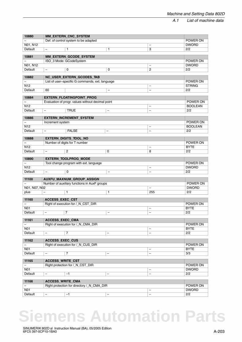
Machine and Setting Data 802D
A.1 List of machine data
A-203SINUMERIK 802D sl Instruction Manual (BA), 05/2005 Edition6FC5 397-0CP10-1BA0
10880 MM_EXTERN_CNC_SYSTEM– Def. of control system to be adapted POWER ONN01, N12 – DWORDDefault – 1 1 3 2/2
10881 MM_EXTERN_GCODE_SYSTEM– ISO_3 Mode: GCodeSystem POWER ONN01, N12 – DWORDDefault – 0 0 2 2/2
10882 NC_USER_EXTERN_GCODES_TAB– List of user–specific G commands, ext. language POWER ONN12 – STRINGDefault 60 – – 2/2
10884 EXTERN_FLOATINGPOINT_PROG– Evaluation of progr. values without decimal point POWER ONN12 – BOOLEANDefault – TRUE – – 2/2
10886 EXTERN_INCREMENT_SYSTEM– Increment system POWER ONN12 – BOOLEANDefault – FALSE – – 2/2
10888 EXTERN_DIGITS_TOOL_NO– Number of digits for T number POWER ONN12 – BYTEDefault – 2 0 8 2/2
10890 EXTERN_TOOLPROG_MODE– Tool change program with ext. language POWER ONN12 – DWORDDefault – 0 – – 2/2
11100 AUXFU_MAXNUM_GROUP_ASSIGN– Number of auxiliary functions in AuxF groups POWER ONN01, N07, N02 – DWORDplus – 1 1 255 2/2
11160 ACCESS_EXEC_CST– Right of execution for /_N_CST_DIR POWER ONN01 – BYTEDefault – 7 – – 2/2
11161 ACCESS_EXEC_CMA– Right of execution for /_N_CMA_DIR POWER ONN01 – BYTEDefault – 7 – – 2/2
11162 ACCESS_EXEC_CUS– Right of execution for /_N_CUS_DIR POWER ONN01 – BYTEDefault – 7 – – 3/3
11165 ACCESS_WRITE_CST– Right protection for /_N_CST_DIR POWER ONN01 – DWORDDefault – –1 – – 2/2
11166 ACCESS_WRITE_CMA– Right protection for directory /_N_CMA_DIR POWER ONN01 – DWORDDefault – –1 – – 2/2
Siemens Automation Parts

A.1 List of machine data
Machine and Setting Data 802D
A-204SINUMERIK 802D sl Instruction Manual (BA), 05/2005 Edition
6FC5 397-0CP10-1BA0
11167 ACCESS_WRITE_CUS– Right protection for directory /_N_CUS_DIR POWER ONN01 – DWORDDefault – –1 – – 3/3
11170 ACCESS_WRITE_SACCESS– Write protection for _N_SACCESS_DEF POWER ONN01 – BYTEDefault – 7 – – 2/2
11171 ACCESS_WRITE_MACCESS– Write protection for _N_MACCESS_DEF POWER ONN01 – BYTEDefault – 7 – – 2/2
11172 ACCESS_WRITE_UACCESS– Write protection for _N_UACCESS_DEF POWER ONN01 – BYTEDefault – 7 – – 3/3
11210 UPLOAD_MD_CHANGES_ONLY– MD backup only for changed MD IMMEDIATEL
YN01, N05 – BYTEDefault – 0xFF – – 7/3plus – 0x0F – – 2/2
11240 PROFIBUS_SDB_NUMBER– SDB1000 number POWER ONN01, N05 – DWORDDefault 4 –1, –1, –1, –1 –1 7 2/2plus – 0, –1, 1, –1 – 1 2/2
11250 PROFIBUS_SHUTDOWN_TYPE– Profibus Shutdown handling POWER ONEXP, N01 – BYTEDefault – 0 0 2 2/2
11310 HANDWH_REVERSE– Threshold for handwheel direction reversal POWER ONN09 – BYTEDefault – 2 – – 2/2
11320 HANDWH_IMP_PER_LATCH– Handwheel pulses per locking position POWER ONN09 – DOUBLEDefault 6 1., 1., 1., 1., 1., 1. – – 2/2
11346 HANDWH_TRUE_DISTANCE– Handwheel travel or speed specification POWER ONN01 – BYTEDefault – 0 0 3 2/2
13060 DRIVE_TELEGRAM_TYPE– Standard message frame type for Profibus DP POWER ONN04, N10 – DWORDDefault 31 102, 102, 102, 102, 102,
102, 102, 102, 102, 102,102, 102, 102, 102, 102,102, 102, 102, 102, 102,102, 102, 102, 102, 102,102, 102, 102, 102, 102,102
– – 2/2

Machine and Setting Data 802D
A.1 List of machine data
A-205SINUMERIK 802D sl Instruction Manual (BA), 05/2005 Edition6FC5 397-0CP10-1BA0
13070 DRIVE_FUNCTION_MASK– Used DP functions POWER ONN04, N10 – DWORDDefault 31 0, 0, 0, 0, 0, 0, 0, 0, 0, 0, 0,
0, 0, 0, 0, 0, 0, 0, 0, 0, 0, 0,0, 0, 0, 0, 0, 0, 0, 0, 0
– – 2/2
13080 DRIVE_TYPE_DP– Drive type with Profibus POWER ONEXP – BYTEDefault 31 0, 0, 0, 0, 0, 0, 0, 0, 0, 0, 0,
0, 0, 0, 0, 0, 0, 0, 0, 0, 0, 0,0, 0, 0, 0, 0, 0, 0, 0, 0
0 4 2/2
13200 MEAS_PROBE_LOW_ACTIVE– Polarity change of the probe POWER ONN10, N09 – BOOLEANDefault 2 FALSE, FALSE – – 3/3
13220 MEAS_PROBE_DELAY_TIMEs Detection of probe deflection delay time POWER ONN10, N09 – DOUBLEDefault 2 0.0, 0.0 0 0.1 3/3
14510 USER_DATA_INT– User data (INT) POWER ONN03 – DWORDDefault 32 0, 0, 0, 0, 0, 0, 0, 0, 0, 0, 0,
0, 0, 0, 0, 0, 0, 0, 0, 0, 0, 0,0, 0, 0, 0, 0, 0, 0, 0, 0, 0
–32768 32767 7/3
14512 USER_DATA_HEX– User data (HEX) POWER ONN03 – DWORDDefault 32 0, 0, 0, 0, 0, 0, 0, 0, 0, 0, 0,
0, 0, 0, 0, 0, 0, 0, 0, 0, 0, 0,0, 0, 0, 0, 0, 0, 0, 0, 0, 0
0 0x0FF 7/3
14514 USER_DATA_FLOAT– User data (FLOAT) POWER ONN03 – DOUBLEDefault 8 0.0, 0.0, 0.0, 0.0, 0.0, 0.0,
0.0, 0.0–3.40e38 3.40e38 7/3
14516 USER_DATA_PLC_ALARM– User data (HEX) POWER ONN03 – BYTEDefault 64 0, 0, 0, 0, 0, 0, 0, 0, 0, 0, 0,
0, 0, 0, 0, 0, 0, 0…– – 7/3
17530 TOOL_DATA_CHANGE_COUNTER– Mark tool data change for HMI POWER ONEXP, N01 – DWORDDefault – 0 0 0xF 2/2
18040 VERSION_INFO– Version and (if necessary) date of PCMCIA card POWER ONN05 READ STRINGDefault 4 – – 7/2plus – “802D–TM2” – – 2/2
Siemens Automation Parts
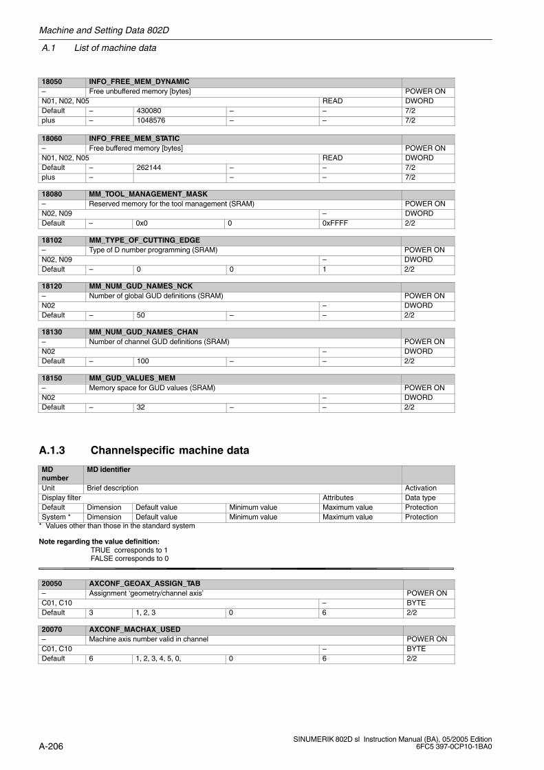
A.1 List of machine data
Machine and Setting Data 802D
A-206SINUMERIK 802D sl Instruction Manual (BA), 05/2005 Edition
6FC5 397-0CP10-1BA0
18050 INFO_FREE_MEM_DYNAMIC– Free unbuffered memory [bytes] POWER ONN01, N02, N05 READ DWORDDefault – 430080 – – 7/2plus – 1048576 – – 7/2
18060 INFO_FREE_MEM_STATIC– Free buffered memory [bytes] POWER ONN01, N02, N05 READ DWORDDefault – 262144 – – 7/2plus – – – 7/2
18080 MM_TOOL_MANAGEMENT_MASK– Reserved memory for the tool management (SRAM) POWER ONN02, N09 – DWORDDefault – 0x0 0 0xFFFF 2/2
18102 MM_TYPE_OF_CUTTING_EDGE– Type of D number programming (SRAM) POWER ONN02, N09 – DWORDDefault – 0 0 1 2/2
18120 MM_NUM_GUD_NAMES_NCK– Number of global GUD definitions (SRAM) POWER ONN02 – DWORDDefault – 50 – – 2/2
18130 MM_NUM_GUD_NAMES_CHAN– Number of channel GUD definitions (SRAM) POWER ONN02 – DWORDDefault – 100 – – 2/2
18150 MM_GUD_VALUES_MEM– Memory space for GUD values (SRAM) POWER ONN02 – DWORDDefault – 32 – – 2/2
A.1.3 Channelspecific machine data
MDnumber
MD identifier
Unit Brief description ActivationDisplay filter Attributes Data typeDefault Dimension Default value Minimum value Maximum value ProtectionSystem * Dimension Default value Minimum value Maximum value Protection
* Values other than those in the standard system
Note regarding the value definition: TRUE corresponds to 1
FALSE corresponds to 0
20050 AXCONF_GEOAX_ASSIGN_TAB– Assignment ‘geometry/channel axis’ POWER ONC01, C10 – BYTEDefault 3 1, 2, 3 0 6 2/2
20070 AXCONF_MACHAX_USED– Machine axis number valid in channel POWER ONC01, C10 – BYTEDefault 6 1, 2, 3, 4, 5, 0, 0 6 2/2
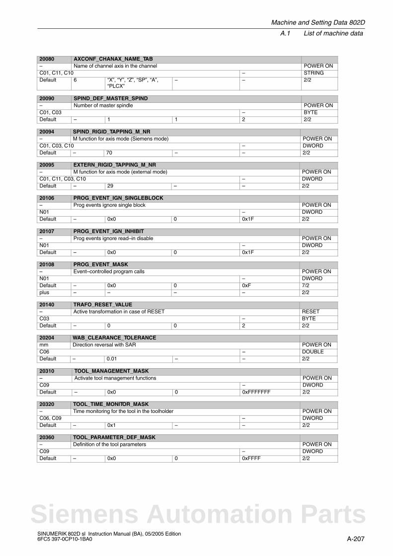
Machine and Setting Data 802D
A.1 List of machine data
A-207SINUMERIK 802D sl Instruction Manual (BA), 05/2005 Edition6FC5 397-0CP10-1BA0
20080 AXCONF_CHANAX_NAME_TAB– Name of channel axis in the channel POWER ONC01, C11, C10 – STRINGDefault 6 “X”, “Y”, “Z”, “SP”, “A”,
“PLCX”– – 2/2
20090 SPIND_DEF_MASTER_SPIND– Number of master spindle POWER ONC01, C03 – BYTEDefault – 1 1 2 2/2
20094 SPIND_RIGID_TAPPING_M_NR– M function for axis mode (Siemens mode) POWER ONC01, C03, C10 – DWORDDefault – 70 – – 2/2
20095 EXTERN_RIGID_TAPPING_M_NR– M function for axis mode (external mode) POWER ONC01, C11, C03, C10 – DWORDDefault – 29 – – 2/2
20106 PROG_EVENT_IGN_SINGLEBLOCK– Prog events ignore single block POWER ONN01 – DWORDDefault – 0x0 0 0x1F 2/2
20107 PROG_EVENT_IGN_INHIBIT– Prog events ignore read–in disable POWER ONN01 – DWORDDefault – 0x0 0 0x1F 2/2
20108 PROG_EVENT_MASK– Event–controlled program calls POWER ONN01 – DWORDDefault – 0x0 0 0xF 7/2plus – – – – 2/2
20140 TRAFO_RESET_VALUE– Active transformation in case of RESET RESETC03 – BYTEDefault – 0 0 2 2/2
20204 WAB_CLEARANCE_TOLERANCEmm Direction reversal with SAR POWER ONC06 – DOUBLEDefault – 0.01 – – 2/2
20310 TOOL_MANAGEMENT_MASK– Activate tool management functions POWER ONC09 – DWORDDefault – 0x0 0 0xFFFFFFF 2/2
20320 TOOL_TIME_MONITOR_MASK– Time monitoring for the tool in the toolholder POWER ONC06, C09 – DWORDDefault – 0x1 – – 2/2
20360 TOOL_PARAMETER_DEF_MASK– Definition of the tool parameters POWER ONC09 – DWORDDefault – 0x0 0 0xFFFF 2/2
Siemens Automation Parts
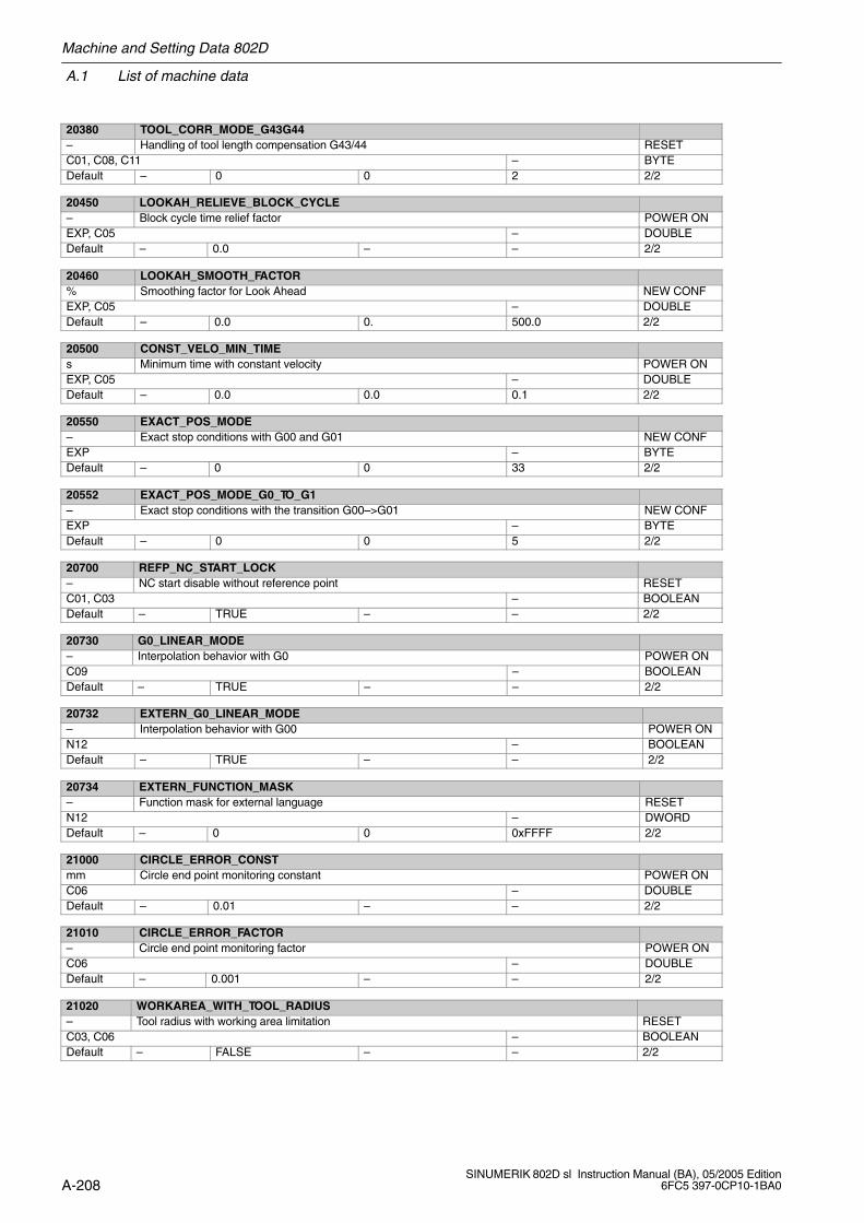
A.1 List of machine data
Machine and Setting Data 802D
A-208SINUMERIK 802D sl Instruction Manual (BA), 05/2005 Edition
6FC5 397-0CP10-1BA0
20380 TOOL_CORR_MODE_G43G44– Handling of tool length compensation G43/44 RESETC01, C08, C11 – BYTEDefault – 0 0 2 2/2
20450 LOOKAH_RELIEVE_BLOCK_CYCLE– Block cycle time relief factor POWER ONEXP, C05 – DOUBLEDefault – 0.0 – – 2/2
20460 LOOKAH_SMOOTH_FACTOR% Smoothing factor for Look Ahead NEW CONFEXP, C05 – DOUBLEDefault – 0.0 0. 500.0 2/2
20500 CONST_VELO_MIN_TIMEs Minimum time with constant velocity POWER ONEXP, C05 – DOUBLEDefault – 0.0 0.0 0.1 2/2
20550 EXACT_POS_MODE– Exact stop conditions with G00 and G01 NEW CONFEXP – BYTEDefault – 0 0 33 2/2
20552 EXACT_POS_MODE_G0_TO_G1– Exact stop conditions with the transition G00–>G01 NEW CONFEXP – BYTEDefault – 0 0 5 2/2
20700 REFP_NC_START_LOCK– NC start disable without reference point RESETC01, C03 – BOOLEANDefault – TRUE – – 2/2
20730 G0_LINEAR_MODE– Interpolation behavior with G0 POWER ONC09 – BOOLEANDefault – TRUE – – 2/2
20732 EXTERN_G0_LINEAR_MODE– Interpolation behavior with G00 POWER ONN12 – BOOLEANDefault – TRUE – – 2/2
20734 EXTERN_FUNCTION_MASK– Function mask for external language RESETN12 – DWORDDefault – 0 0 0xFFFF 2/2
21000 CIRCLE_ERROR_CONSTmm Circle end point monitoring constant POWER ONC06 – DOUBLEDefault – 0.01 – – 2/2
21010 CIRCLE_ERROR_FACTOR– Circle end point monitoring factor POWER ONC06 – DOUBLEDefault – 0.001 – – 2/2
21020 WORKAREA_WITH_TOOL_RADIUS– Tool radius with working area limitation RESETC03, C06 – BOOLEANDefault – FALSE – – 2/2
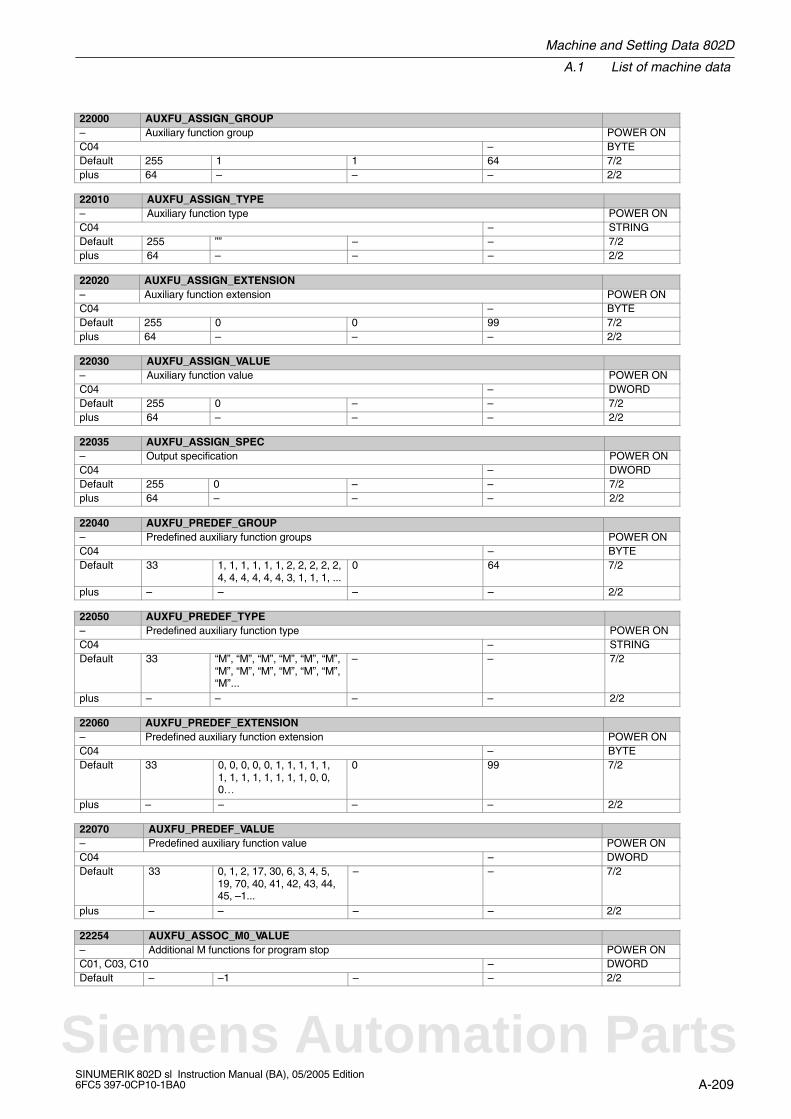
Machine and Setting Data 802D
A.1 List of machine data
A-209SINUMERIK 802D sl Instruction Manual (BA), 05/2005 Edition6FC5 397-0CP10-1BA0
22000 AUXFU_ASSIGN_GROUP– Auxiliary function group POWER ONC04 – BYTEDefault 255 1 1 64 7/2plus 64 – – – 2/2
22010 AUXFU_ASSIGN_TYPE– Auxiliary function type POWER ONC04 – STRINGDefault 255 ”” – – 7/2plus 64 – – – 2/2
22020 AUXFU_ASSIGN_EXTENSION– Auxiliary function extension POWER ONC04 – BYTEDefault 255 0 0 99 7/2plus 64 – – – 2/2
22030 AUXFU_ASSIGN_VALUE– Auxiliary function value POWER ONC04 – DWORDDefault 255 0 – – 7/2plus 64 – – – 2/2
22035 AUXFU_ASSIGN_SPEC– Output specification POWER ONC04 – DWORDDefault 255 0 – – 7/2plus 64 – – – 2/2
22040 AUXFU_PREDEF_GROUP– Predefined auxiliary function groups POWER ONC04 – BYTEDefault 33 1, 1, 1, 1, 1, 1, 2, 2, 2, 2, 2,
4, 4, 4, 4, 4, 4, 3, 1, 1, 1, ...0 64 7/2
plus – – – – 2/2
22050 AUXFU_PREDEF_TYPE– Predefined auxiliary function type POWER ONC04 – STRINGDefault 33 “M”, “M”, “M”, “M”, “M”, “M”,
“M”, “M”, “M”, “M”, “M”, “M”,“M”...
– – 7/2
plus – – – – 2/2
22060 AUXFU_PREDEF_EXTENSION– Predefined auxiliary function extension POWER ONC04 – BYTEDefault 33 0, 0, 0, 0, 0, 1, 1, 1, 1, 1,
1, 1, 1, 1, 1, 1, 1, 1, 0, 0,0…
0 99 7/2
plus – – – – 2/2
22070 AUXFU_PREDEF_VALUE– Predefined auxiliary function value POWER ONC04 – DWORDDefault 33 0, 1, 2, 17, 30, 6, 3, 4, 5,
19, 70, 40, 41, 42, 43, 44,45, –1...
– – 7/2
plus – – – – 2/2
22254 AUXFU_ASSOC_M0_VALUE– Additional M functions for program stop POWER ONC01, C03, C10 – DWORDDefault – –1 – – 2/2
Siemens Automation Parts
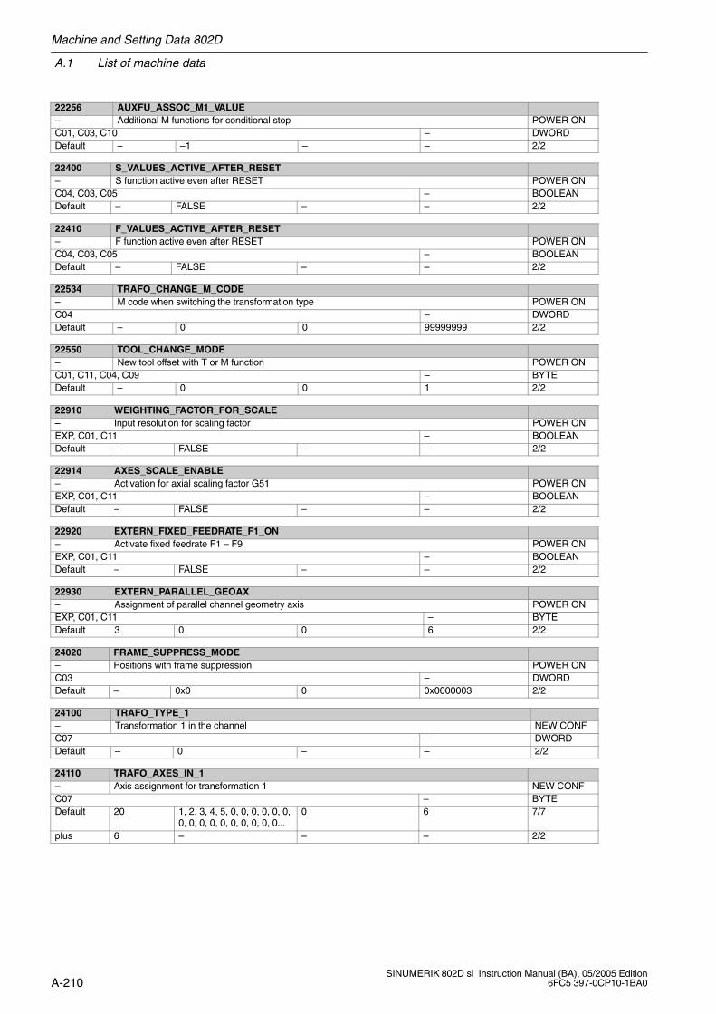
A.1 List of machine data
Machine and Setting Data 802D
A-210SINUMERIK 802D sl Instruction Manual (BA), 05/2005 Edition
6FC5 397-0CP10-1BA0
22256 AUXFU_ASSOC_M1_VALUE– Additional M functions for conditional stop POWER ONC01, C03, C10 – DWORDDefault – –1 – – 2/2
22400 S_VALUES_ACTIVE_AFTER_RESET– S function active even after RESET POWER ONC04, C03, C05 – BOOLEANDefault – FALSE – – 2/2
22410 F_VALUES_ACTIVE_AFTER_RESET– F function active even after RESET POWER ONC04, C03, C05 – BOOLEANDefault – FALSE – – 2/2
22534 TRAFO_CHANGE_M_CODE– M code when switching the transformation type POWER ONC04 – DWORDDefault – 0 0 99999999 2/2
22550 TOOL_CHANGE_MODE– New tool offset with T or M function POWER ONC01, C11, C04, C09 – BYTEDefault – 0 0 1 2/2
22910 WEIGHTING_FACTOR_FOR_SCALE– Input resolution for scaling factor POWER ONEXP, C01, C11 – BOOLEANDefault – FALSE – – 2/2
22914 AXES_SCALE_ENABLE– Activation for axial scaling factor G51 POWER ONEXP, C01, C11 – BOOLEANDefault – FALSE – – 2/2
22920 EXTERN_FIXED_FEEDRATE_F1_ON– Activate fixed feedrate F1 – F9 POWER ONEXP, C01, C11 – BOOLEANDefault – FALSE – – 2/2
22930 EXTERN_PARALLEL_GEOAX– Assignment of parallel channel geometry axis POWER ONEXP, C01, C11 – BYTEDefault 3 0 0 6 2/2
24020 FRAME_SUPPRESS_MODE– Positions with frame suppression POWER ONC03 – DWORDDefault – 0x0 0 0x0000003 2/2
24100 TRAFO_TYPE_1– Transformation 1 in the channel NEW CONFC07 – DWORDDefault – 0 – – 2/2
24110 TRAFO_AXES_IN_1– Axis assignment for transformation 1 NEW CONFC07 – BYTEDefault 20 1, 2, 3, 4, 5, 0, 0, 0, 0, 0, 0,
0, 0, 0, 0, 0, 0, 0, 0, 0, 0...0 6 7/7
plus 6 – – – 2/2
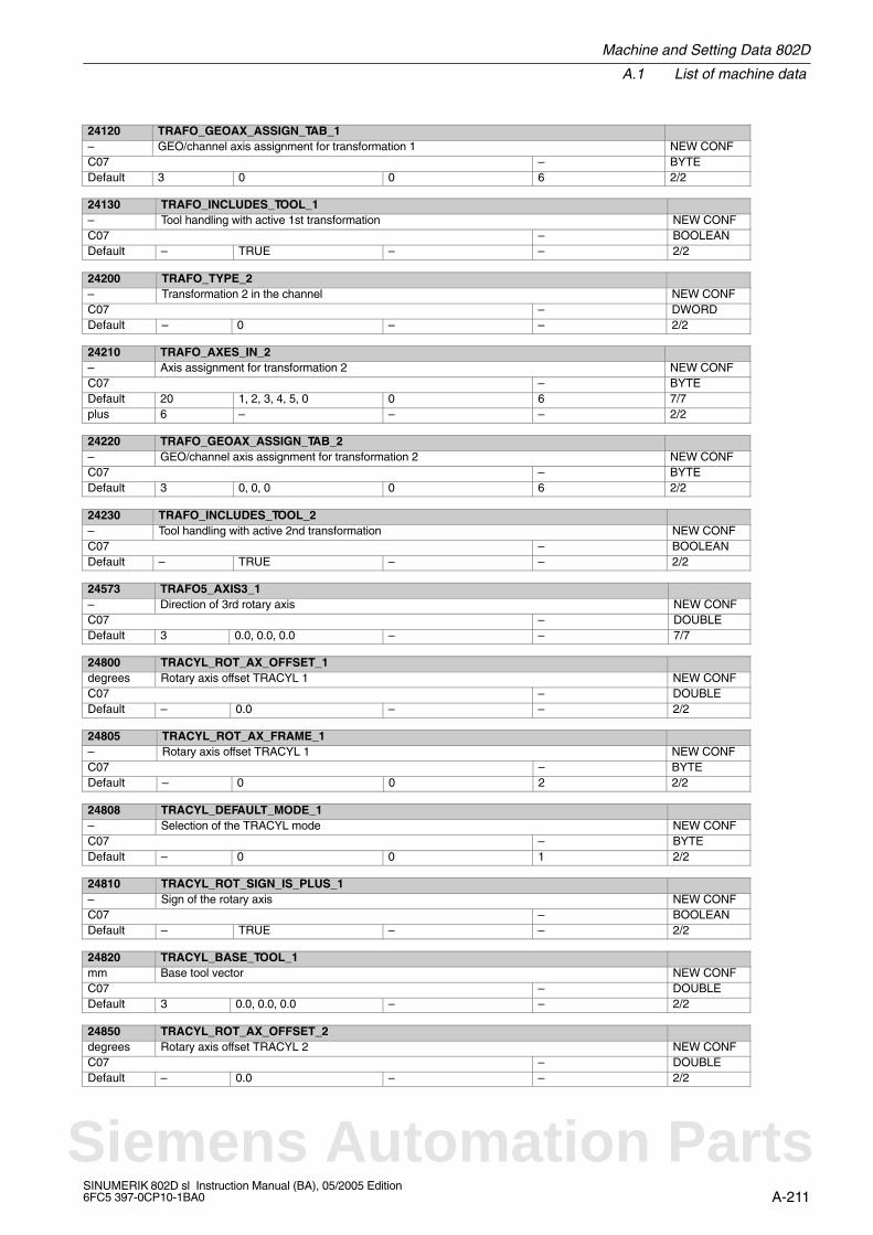
Machine and Setting Data 802D
A.1 List of machine data
A-211SINUMERIK 802D sl Instruction Manual (BA), 05/2005 Edition6FC5 397-0CP10-1BA0
24120 TRAFO_GEOAX_ASSIGN_TAB_1– GEO/channel axis assignment for transformation 1 NEW CONFC07 – BYTEDefault 3 0 0 6 2/2
24130 TRAFO_INCLUDES_TOOL_1– Tool handling with active 1st transformation NEW CONFC07 – BOOLEANDefault – TRUE – – 2/2
24200 TRAFO_TYPE_2– Transformation 2 in the channel NEW CONFC07 – DWORDDefault – 0 – – 2/2
24210 TRAFO_AXES_IN_2– Axis assignment for transformation 2 NEW CONFC07 – BYTEDefault 20 1, 2, 3, 4, 5, 0 0 6 7/7plus 6 – – – 2/2
24220 TRAFO_GEOAX_ASSIGN_TAB_2– GEO/channel axis assignment for transformation 2 NEW CONFC07 – BYTEDefault 3 0, 0, 0 0 6 2/2
24230 TRAFO_INCLUDES_TOOL_2– Tool handling with active 2nd transformation NEW CONFC07 – BOOLEANDefault – TRUE – – 2/2
24573 TRAFO5_AXIS3_1– Direction of 3rd rotary axis NEW CONFC07 – DOUBLEDefault 3 0.0, 0.0, 0.0 – – 7/7
24800 TRACYL_ROT_AX_OFFSET_1degrees Rotary axis offset TRACYL 1 NEW CONFC07 – DOUBLEDefault – 0.0 – – 2/2
24805 TRACYL_ROT_AX_FRAME_1– Rotary axis offset TRACYL 1 NEW CONFC07 – BYTEDefault – 0 0 2 2/2
24808 TRACYL_DEFAULT_MODE_1– Selection of the TRACYL mode NEW CONFC07 – BYTEDefault – 0 0 1 2/2
24810 TRACYL_ROT_SIGN_IS_PLUS_1– Sign of the rotary axis NEW CONFC07 – BOOLEANDefault – TRUE – – 2/2
24820 TRACYL_BASE_TOOL_1mm Base tool vector NEW CONFC07 – DOUBLEDefault 3 0.0, 0.0, 0.0 – – 2/2
24850 TRACYL_ROT_AX_OFFSET_2degrees Rotary axis offset TRACYL 2 NEW CONFC07 – DOUBLEDefault – 0.0 – – 2/2
Siemens Automation Parts
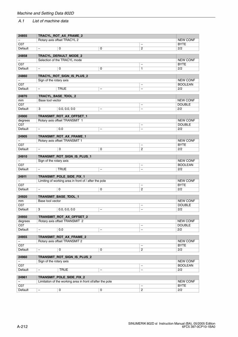
A.1 List of machine data
Machine and Setting Data 802D
A-212SINUMERIK 802D sl Instruction Manual (BA), 05/2005 Edition
6FC5 397-0CP10-1BA0
24855 TRACYL_ROT_AX_FRAME_2– Rotary axis offset TRACYL 2 NEW CONFC07 – BYTEDefault – 0 0 2 2/2
24858 TRACYL_DEFAULT_MODE_2– Selection of the TRACYL mode NEW CONFC07 – BYTEDefault – 0 0 1 2/2
24860 TRACYL_ROT_SIGN_IS_PLUS_2– Sign of the rotary axis NEW CONFC07 – BOOLEANDefault – TRUE – – 2/2
24870 TRACYL_BASE_TOOL_2mm Base tool vector NEW CONFC07 – DOUBLEDefault 3 0.0, 0.0, 0.0 – – 2/2
24900 TRANSMIT_ROT_AX_OFFSET_1degrees Rotary axis offset TRANSMIT 1 NEW CONFC07 – DOUBLEDefault – 0.0 – – 2/2
24905 TRANSMIT_ROT_AX_FRAME_1– Rotary axis offset TRANSMIT 1 NEW CONFC07 – BYTEDefault – 0 0 2 2/2
24910 TRANSMIT_ROT_SIGN_IS_PLUS_1– Sign of the rotary axis NEW CONFC07 – BOOLEANDefault – TRUE – – 2/2
24911 TRANSMIT_POLE_SIDE_FIX_1– Limiting of working area in front of / after the pole NEW CONFC07 – BYTEDefault – 0 0 2 2/2
24920 TRANSMIT_BASE_TOOL_1mm Base tool vector NEW CONFC07 – DOUBLEDefault 3 0.0, 0.0, 0.0 – – 2/2
24950 TRANSMIT_ROT_AX_OFFSET_2degrees Rotary axis offset TRANSMIT 2 NEW CONFC07 – DOUBLEDefault – 0.0 – – 2/2
24955 TRANSMIT_ROT_AX_FRAME_2– Rotary axis offset TRANSMIT 2 NEW CONFC07 – BYTEDefault – 0 0 2 2/2
24960 TRANSMIT_ROT_SIGN_IS_PLUS_2– Sign of the rotary axis NEW CONFC07 – BOOLEANDefault – TRUE – – 2/2
24961 TRANSMIT_POLE_SIDE_FIX_2– Limitation of the working area in front of/after the pole NEW CONFC07 – BYTEDefault – 0 0 2 2/2
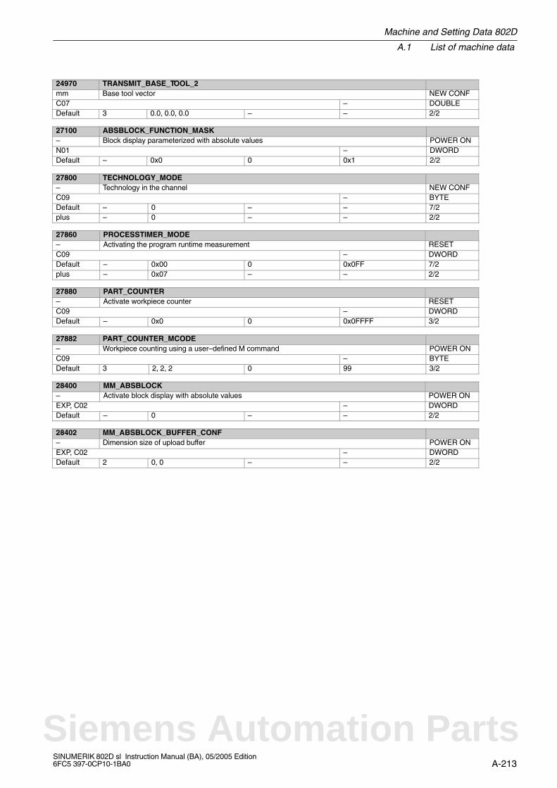
Machine and Setting Data 802D
A.1 List of machine data
A-213SINUMERIK 802D sl Instruction Manual (BA), 05/2005 Edition6FC5 397-0CP10-1BA0
24970 TRANSMIT_BASE_TOOL_2mm Base tool vector NEW CONFC07 – DOUBLEDefault 3 0.0, 0.0, 0.0 – – 2/2
27100 ABSBLOCK_FUNCTION_MASK– Block display parameterized with absolute values POWER ONN01 – DWORDDefault – 0x0 0 0x1 2/2
27800 TECHNOLOGY_MODE– Technology in the channel NEW CONFC09 – BYTEDefault – 0 – – 7/2plus – 0 – – 2/2
27860 PROCESSTIMER_MODE– Activating the program runtime measurement RESETC09 – DWORDDefault – 0x00 0 0x0FF 7/2plus – 0x07 – – 2/2
27880 PART_COUNTER– Activate workpiece counter RESETC09 – DWORDDefault – 0x0 0 0x0FFFF 3/2
27882 PART_COUNTER_MCODE– Workpiece counting using a user–defined M command POWER ONC09 – BYTEDefault 3 2, 2, 2 0 99 3/2
28400 MM_ABSBLOCK– Activate block display with absolute values POWER ONEXP, C02 – DWORDDefault – 0 – – 2/2
28402 MM_ABSBLOCK_BUFFER_CONF– Dimension size of upload buffer POWER ONEXP, C02 – DWORDDefault 2 0, 0 – – 2/2
Siemens Automation Parts
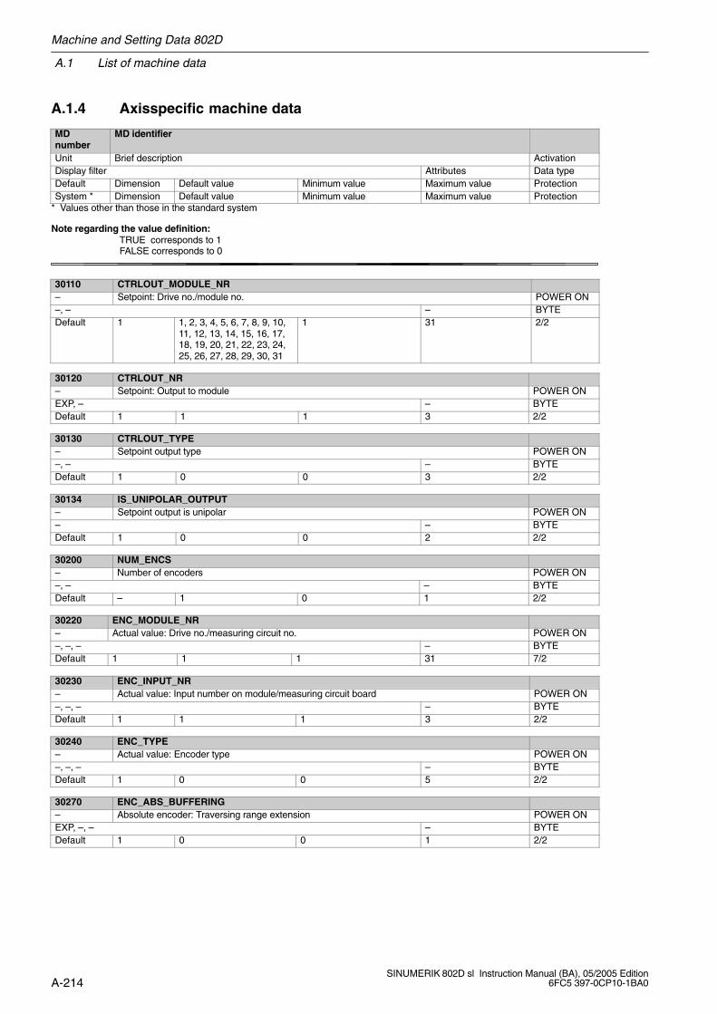
A.1 List of machine data
Machine and Setting Data 802D
A-214SINUMERIK 802D sl Instruction Manual (BA), 05/2005 Edition
6FC5 397-0CP10-1BA0
A.1.4 Axisspecific machine data
MDnumber
MD identifier
Unit Brief description ActivationDisplay filter Attributes Data typeDefault Dimension Default value Minimum value Maximum value ProtectionSystem * Dimension Default value Minimum value Maximum value Protection
* Values other than those in the standard system
Note regarding the value definition: TRUE corresponds to 1
FALSE corresponds to 0
30110 CTRLOUT_MODULE_NR– Setpoint: Drive no./module no. POWER ON–, – – BYTEDefault 1 1, 2, 3, 4, 5, 6, 7, 8, 9, 10,
11, 12, 13, 14, 15, 16, 17,18, 19, 20, 21, 22, 23, 24,25, 26, 27, 28, 29, 30, 31
1 31 2/2
30120 CTRLOUT_NR– Setpoint: Output to module POWER ONEXP, – – BYTEDefault 1 1 1 3 2/2
30130 CTRLOUT_TYPE– Setpoint output type POWER ON–, – – BYTEDefault 1 0 0 3 2/2
30134 IS_UNIPOLAR_OUTPUT– Setpoint output is unipolar POWER ON– – BYTEDefault 1 0 0 2 2/2
30200 NUM_ENCS– Number of encoders POWER ON–, – – BYTEDefault – 1 0 1 2/2
30220 ENC_MODULE_NR– Actual value: Drive no./measuring circuit no. POWER ON–, –, – – BYTEDefault 1 1 1 31 7/2
30230 ENC_INPUT_NR– Actual value: Input number on module/measuring circuit board POWER ON–, –, – – BYTEDefault 1 1 1 3 2/2
30240 ENC_TYPE– Actual value: Encoder type POWER ON–, –, – – BYTEDefault 1 0 0 5 2/2
30270 ENC_ABS_BUFFERING– Absolute encoder: Traversing range extension POWER ONEXP, –, – – BYTEDefault 1 0 0 1 2/2
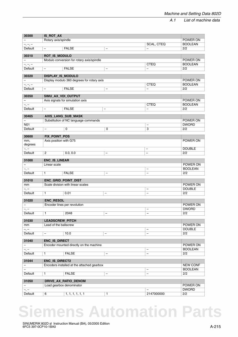
Machine and Setting Data 802D
A.1 List of machine data
A-215SINUMERIK 802D sl Instruction Manual (BA), 05/2005 Edition6FC5 397-0CP10-1BA0
30300 IS_ROT_AX– Rotary axis/spindle POWER ON–, –, – SCAL, CTEQ BOOLEANDefault – FALSE – – 2/2
30310 ROT_IS_MODULO– Modulo conversion for rotary axis/spindle POWER ON–, –, – CTEQ BOOLEANDefault – FALSE – – 2/2
30320 DISPLAY_IS_MODULO– Display modulo 360 degrees for rotary axis POWER ON–, –, – CTEQ BOOLEANDefault – FALSE – – 2/2
30350 SIMU_AX_VDI_OUTPUT– Axis signals for simulation axis POWER ON–, – CTEQ BOOLEANDefault – FALSE – – 2/2
30465 AXIS_LANG_SUB_MASK– Substitution of NC language commands POWER ONN01 – DWORDDefault – 0 0 3 2/2
30600 FIX_POINT_POSmm,degrees
Axis position with G75 POWER ON
–, – – DOUBLEDefault 2 0.0, 0.0 – – 2/2
31000 ENC_IS_LINEAR– Linear scale POWER ON–, – – BOOLEANDefault 1 FALSE – – 2/2
31010 ENC_GRID_POINT_DISTmm Scale division with linear scales POWER ON–, – – DOUBLEDefault 1 0.01 – – 2/2
31020 ENC_RESOL– Encoder lines per revolution POWER ON–, – – DWORDDefault 1 2048 – – 2/2
31030 LEADSCREW_PITCHmm Lead of the ballscrew POWER ON–, – – DOUBLEDefault – 10.0 – – 2/2
31040 ENC_IS_DIRECT– Encoder mounted directly on the machine POWER ON–, – – BOOLEANDefault 1 FALSE – – 2/2
31044 ENC_IS_DIRECT2– Encoders installed at the attached gearbox NEW CONF– – BOOLEANDefault 1 FALSE – – 2/2
31050 DRIVE_AX_RATIO_DENOM– Load gearbox denominator POWER ON–, – – DWORDDefault 6 1, 1, 1, 1, 1, 1 1 2147000000 2/2
Siemens Automation Parts
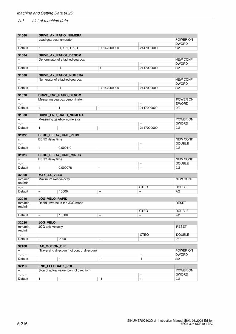
A.1 List of machine data
Machine and Setting Data 802D
A-216SINUMERIK 802D sl Instruction Manual (BA), 05/2005 Edition
6FC5 397-0CP10-1BA0
31060 DRIVE_AX_RATIO_NUMERA– Load gearbox numerator POWER ON–, – – DWORDDefault 6 1, 1, 1, 1, 1, 1 –2147000000 2147000000 2/2
31064 DRIVE_AX_RATIO2_DENOM– Denominator of attached gearbox NEW CONF– – DWORDDefault – 1 1 2147000000 2/2
31066 DRIVE_AX_RATIO2_NUMERA– Numerator of attached gearbox NEW CONF– – DWORDDefault – 1 –2147000000 2147000000 2/2
31070 DRIVE_ENC_RATIO_DENOM– Measuring gearbox denominator POWER ON–, – – DWORDDefault 1 1 1 2147000000 2/2
31080 DRIVE_ENC_RATIO_NUMERA– Measuring gearbox numerator POWER ON–, – – DWORDDefault 1 1 1 2147000000 2/2
31122 BERO_DELAY_TIME_PLUSs BERO delay time NEW CONF–, – – DOUBLEDefault 1 0.000110 – – 2/2
31123 BERO_DELAY_TIME_MINUSs BERO delay time NEW CONF–, – – DOUBLEDefault 1 0.000078 – – 2/2
32000 MAX_AX_VELOmm/min,rev/min
Maximum axis velocity NEW CONF
–, – CTEQ DOUBLEDefault – 10000. – – 7/2
32010 JOG_VELO_RAPIDmm/min,rev/min
Rapid traverse in the JOG mode RESET
–, – CTEQ DOUBLEDefault – 10000. – – 7/2
32020 JOG_VELOmm/min,rev/min
JOG axis velocity RESET
–, – CTEQ DOUBLEDefault – 2000. – – 7/2
32100 AX_MOTION_DIR– Traversing direction (not control direction) POWER ON–, –, – – DWORDDefault – 1 –1 1 2/2
32110 ENC_FEEDBACK_POL– Sign of actual value (control direction) POWER ON–, –, – – DWORDDefault 1 1 –1 1 2/2

Machine and Setting Data 802D
A.1 List of machine data
A-217SINUMERIK 802D sl Instruction Manual (BA), 05/2005 Edition6FC5 397-0CP10-1BA0
32200 POSCTRL_GAIN1,000 r.p.m. Servo gain factor NEW CONF–, – CTEQ DOUBLEDefault 6 16.66666667,
16.66666667,16.66666667,16.66666667,16.66666667,16.66666667
0 2000. 7/2
32210 POSCTRL_INTEGR_TIMEs Integral action time of the position controller NEW CONF– – DOUBLEDefault – 1.0 0 10000.0 2/2
32220 POSCTRL_INTEGR_ENABLE– Activation of the integral portion of the position controller POWER ON– – BOOLEANDefault – FALSE – – 2/2
32230 POSCTRL_CONFIG– Configuration of the position controller structure POWER ON– – BYTEDefault – 0 0 17 7/2
32300 MAX_AX_ACCELm/s, rev/s Axis acceleration NEW CONF–, – CTEQ DOUBLEDefault 1.0 1.0e–3 – 7/2
32420 JOG_AND_POS_JERK_ENABLE– Enable axial jerk limitation RESET– CTEQ BOOLEANDefault – FALSE – – 2/2
32430 JOG_AND_POS_MAX_JERKm/s,deg/s
Axial jerk RESET
– CTEQ DOUBLEDefault – 1000.0 1.e–9 – 2/2
32431 MAX_AX_JERKm/s,deg/s
Maximum axial jerk when traveling along the path NEW CONF
– – DOUBLEDefault 1.e6 1.e–9 – 3/3plus – 1000 – – 3/3
32432 PATH_TRANS_JERK_LIMm/s,deg/s
Max. axial jerk when traveling along the path with block transition NEW CONF
– CTEQ DOUBLEDefault 1.e6 – – 3/3plus – 1.e3 – – /
32440 LOOKAH_FREQUENCY– Smoothing frequency with LookAhead NEW CONFEXP, – – DOUBLEDefault – 10. – – 2/2
32450 BACKLASHmm,degrees
Backlash on reversal NEW CONF
– – DOUBLEDefault 1 0.0, 0.0 – – 2/2
Siemens Automation Parts
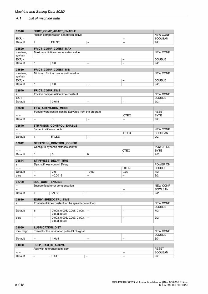
A.1 List of machine data
Machine and Setting Data 802D
A-218SINUMERIK 802D sl Instruction Manual (BA), 05/2005 Edition
6FC5 397-0CP10-1BA0
32510 FRICT_COMP_ADAPT_ENABLE– Friction compensation adaptation active NEW CONFEXP, – – BOOLEANDefault 1 FALSE – – 2/2
32520 FRICT_COMP_CONST_MAXmm/min,rev/min
Maximum friction compensation value NEW CONF
EXP, – – DOUBLEDefault 1 0.0 – – 2/2
32530 FRICT_COMP_CONST_MINmm/min,rev/min
Minimum friction compensation value NEW CONF
EXP, – – DOUBLEDefault 1 0.0 – – 2/2
32540 FRICT_COMP_TIMEs Friction compensation time constant NEW CONFEXP, – – DOUBLEDefault 1 0.015 – – 2/2
32630 FFW_ACTIVATION_MODE– Feedforward control can be activated from the program RESET–, – CTEQ BYTEDefault – 1 – – 2/2
32640 STIFFNESS_CONTROL_ENABLE– Dynamic stiffness control NEW CONF–, – CTEQ BOOLEANDefault 1 FALSE – – 2/2
32642 STIFFNESS_CONTROL_CONFIG– Configure dynamic stiffness control POWER ON–, – CTEQ BYTEDefault 1 0 0 1 2/2
32644 STIFFNESS_DELAY_TIMEs Dyn. stiffness control: Delay POWER ON–, – CTEQ DOUBLEDefault 1 0.0 –0.02 0.02 7/2plus – –0.0015 – – 2/2
32700 ENC_COMP_ENABLE– Encoder/lead error compensation NEW CONF– – BOOLEANDefault 1 FALSE – – 2/2
32810 EQUIV_SPEEDCTRL_TIMEs Equivalent time constant for the speed control loop NEW CONF–, – – DOUBLEDefault 6 0.008, 0.008, 0.008, 0.008,
0.008, 0.008– – 7/2
plus – 0.003, 0.003, 0.003, 0.003,0.003, 0.003
– – 2/2
33050 LUBRICATION_DISTmm, degr. Travel for the lubrication pulse PLC signal NEW CONF–, – – DOUBLEDefault – 1.0e8 – – 3/3
34000 REFP_CAM_IS_ACTIVE– Axis with reference point cam RESET–, – – BOOLEANDefault – TRUE – – 2/2
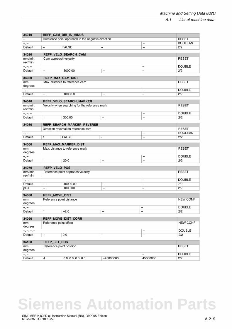
Machine and Setting Data 802D
A.1 List of machine data
A-219SINUMERIK 802D sl Instruction Manual (BA), 05/2005 Edition6FC5 397-0CP10-1BA0
34010 REFP_CAM_DIR_IS_MINUS– Reference point approach in the negative direction RESET–, – – BOOLEANDefault – FALSE – – 2/2
34020 REFP_VELO_SEARCH_CAMmm/min,rev/min
Cam approach velocity RESET
–, –, – – DOUBLEDefault – 5000.00 – – 2/2
34030 REFP_MAX_CAM_DISTmm,degrees
Max. distance to reference cam RESET
–, – – DOUBLEDefault – 10000.0 – – 2/2
34040 REFP_VELO_SEARCH_MARKERmm/min,rev/min
Velocity when searching for the reference mark RESET
–, –, – – DOUBLEDefault 1 300.00 – – 2/2
34050 REFP_SEARCH_MARKER_REVERSE– Direction reversal on reference cam RESET–, – – BOOLEANDefault 1 FALSE – – 2/2
34060 REFP_MAX_MARKER_DISTmm,degrees
Max. distance to reference mark RESET
–, – – DOUBLEDefault 1 20.0 – – 2/2
34070 REFP_VELO_POSmm/min,rev/min
Reference point approach velocity RESET
–, –, – – DOUBLEDefault – 10000.00 – – 7/2plus – 1000.00 – – 2/2
34080 REFP_MOVE_DISTmm,degrees
Reference point distance NEW CONF
–, – – DOUBLEDefault 1 –2.0 – – 2/2
34090 REFP_MOVE_DIST_CORRmm,degrees
Reference point offset NEW CONF
–, –, –, – – DOUBLEDefault 1 0.0 – – 2/2
34100 REFP_SET_POSmm,degrees
Reference point position RESET
–, – – DOUBLEDefault 4 0.0, 0.0, 0.0, 0.0 –45000000 45000000 2/2
Siemens Automation Parts
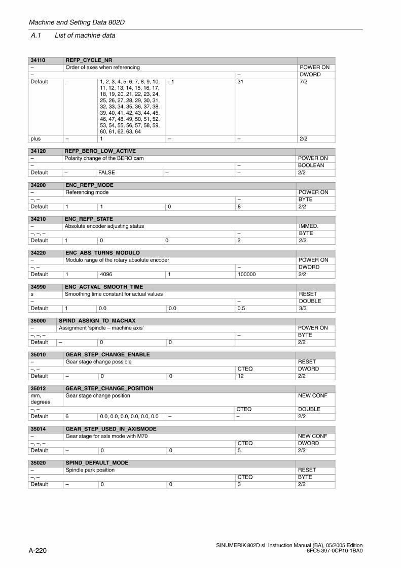
A.1 List of machine data
Machine and Setting Data 802D
A-220SINUMERIK 802D sl Instruction Manual (BA), 05/2005 Edition
6FC5 397-0CP10-1BA0
34110 REFP_CYCLE_NR– Order of axes when referencing POWER ON– – DWORDDefault – 1, 2, 3, 4, 5, 6, 7, 8, 9, 10,
11, 12, 13, 14, 15, 16, 17,18, 19, 20, 21, 22, 23, 24,25, 26, 27, 28, 29, 30, 31,32, 33, 34, 35, 36, 37, 38,39, 40, 41, 42, 43, 44, 45,46, 47, 48, 49, 50, 51, 52,53, 54, 55, 56, 57, 58, 59,60, 61, 62, 63, 64
–1 31 7/2
plus – 1 – – 2/2
34120 REFP_BERO_LOW_ACTIVE– Polarity change of the BERO cam POWER ON– – BOOLEANDefault – FALSE – – 2/2
34200 ENC_REFP_MODE– Referencing mode POWER ON–, – – BYTEDefault 1 1 0 8 2/2
34210 ENC_REFP_STATE– Absolute encoder adjusting status IMMED.–, –, – – BYTEDefault 1 0 0 2 2/2
34220 ENC_ABS_TURNS_MODULO– Modulo range of the rotary absolute encoder POWER ON–, – – DWORDDefault 1 4096 1 100000 2/2
34990 ENC_ACTVAL_SMOOTH_TIMEs Smoothing time constant for actual values RESET– – DOUBLEDefault 1 0.0 0.0 0.5 3/3
35000 SPIND_ASSIGN_TO_MACHAX– Assignment ‘spindle – machine axis’ POWER ON–, –, – – BYTEDefault – 0 0 2/2
35010 GEAR_STEP_CHANGE_ENABLE– Gear stage change possible RESET–, – CTEQ DWORDDefault – 0 0 12 2/2
35012 GEAR_STEP_CHANGE_POSITIONmm,degrees
Gear stage change position NEW CONF
–, – CTEQ DOUBLEDefault 6 0.0, 0.0, 0.0, 0.0, 0.0, 0.0 – – 2/2
35014 GEAR_STEP_USED_IN_AXISMODE– Gear stage for axis mode with M70 NEW CONF–, –, – CTEQ DWORDDefault – 0 0 5 2/2
35020 SPIND_DEFAULT_MODE– Spindle park position RESET–, – CTEQ BYTEDefault – 0 0 3 2/2
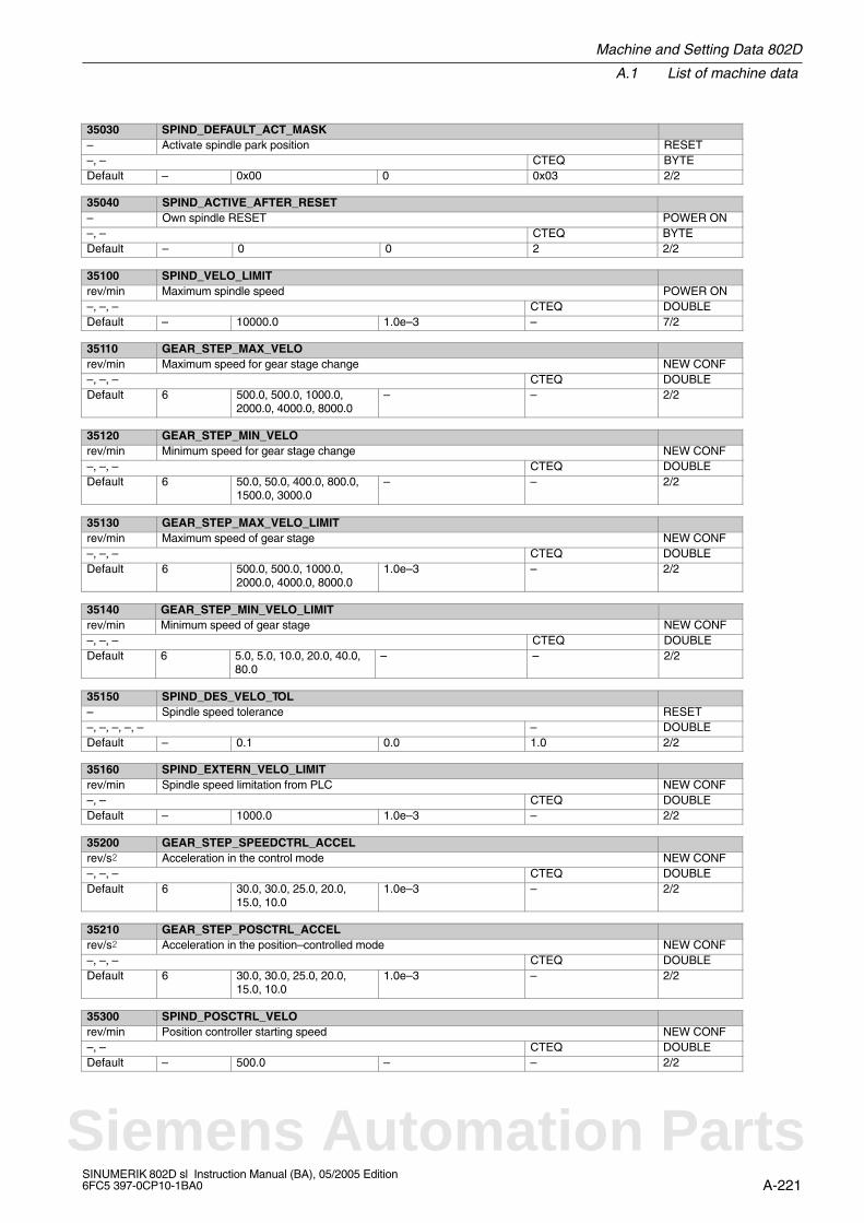
Machine and Setting Data 802D
A.1 List of machine data
A-221SINUMERIK 802D sl Instruction Manual (BA), 05/2005 Edition6FC5 397-0CP10-1BA0
35030 SPIND_DEFAULT_ACT_MASK– Activate spindle park position RESET–, – CTEQ BYTEDefault – 0x00 0 0x03 2/2
35040 SPIND_ACTIVE_AFTER_RESET– Own spindle RESET POWER ON–, – CTEQ BYTEDefault – 0 0 2 2/2
35100 SPIND_VELO_LIMITrev/min Maximum spindle speed POWER ON–, –, – CTEQ DOUBLEDefault – 10000.0 1.0e–3 – 7/2
35110 GEAR_STEP_MAX_VELOrev/min Maximum speed for gear stage change NEW CONF–, –, – CTEQ DOUBLEDefault 6 500.0, 500.0, 1000.0,
2000.0, 4000.0, 8000.0– – 2/2
35120 GEAR_STEP_MIN_VELOrev/min Minimum speed for gear stage change NEW CONF–, –, – CTEQ DOUBLEDefault 6 50.0, 50.0, 400.0, 800.0,
1500.0, 3000.0– – 2/2
35130 GEAR_STEP_MAX_VELO_LIMITrev/min Maximum speed of gear stage NEW CONF–, –, – CTEQ DOUBLEDefault 6 500.0, 500.0, 1000.0,
2000.0, 4000.0, 8000.01.0e–3 – 2/2
35140 GEAR_STEP_MIN_VELO_LIMITrev/min Minimum speed of gear stage NEW CONF–, –, – CTEQ DOUBLEDefault 6 5.0, 5.0, 10.0, 20.0, 40.0,
80.0– – 2/2
35150 SPIND_DES_VELO_TOL– Spindle speed tolerance RESET–, –, –, –, – – DOUBLEDefault – 0.1 0.0 1.0 2/2
35160 SPIND_EXTERN_VELO_LIMITrev/min Spindle speed limitation from PLC NEW CONF–, – CTEQ DOUBLEDefault – 1000.0 1.0e–3 – 2/2
35200 GEAR_STEP_SPEEDCTRL_ACCELrev/s Acceleration in the control mode NEW CONF–, –, – CTEQ DOUBLEDefault 6 30.0, 30.0, 25.0, 20.0,
15.0, 10.01.0e–3 – 2/2
35210 GEAR_STEP_POSCTRL_ACCELrev/s Acceleration in the position–controlled mode NEW CONF–, –, – CTEQ DOUBLEDefault 6 30.0, 30.0, 25.0, 20.0,
15.0, 10.01.0e–3 – 2/2
35300 SPIND_POSCTRL_VELOrev/min Position controller starting speed NEW CONF–, – CTEQ DOUBLEDefault – 500.0 – – 2/2
Siemens Automation Parts
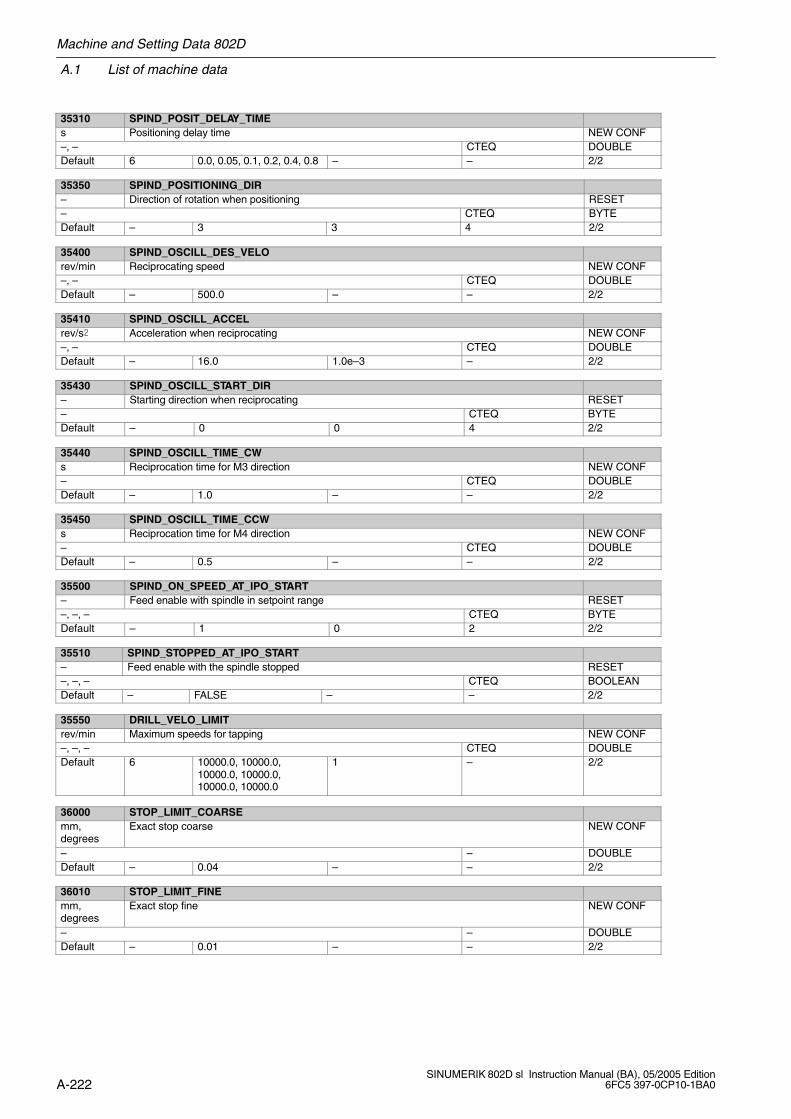
A.1 List of machine data
Machine and Setting Data 802D
A-222SINUMERIK 802D sl Instruction Manual (BA), 05/2005 Edition
6FC5 397-0CP10-1BA0
35310 SPIND_POSIT_DELAY_TIMEs Positioning delay time NEW CONF–, – CTEQ DOUBLEDefault 6 0.0, 0.05, 0.1, 0.2, 0.4, 0.8 – – 2/2
35350 SPIND_POSITIONING_DIR– Direction of rotation when positioning RESET– CTEQ BYTEDefault – 3 3 4 2/2
35400 SPIND_OSCILL_DES_VELOrev/min Reciprocating speed NEW CONF–, – CTEQ DOUBLEDefault – 500.0 – – 2/2
35410 SPIND_OSCILL_ACCELrev/s Acceleration when reciprocating NEW CONF–, – CTEQ DOUBLEDefault – 16.0 1.0e–3 – 2/2
35430 SPIND_OSCILL_START_DIR– Starting direction when reciprocating RESET– CTEQ BYTEDefault – 0 0 4 2/2
35440 SPIND_OSCILL_TIME_CWs Reciprocation time for M3 direction NEW CONF– CTEQ DOUBLEDefault – 1.0 – – 2/2
35450 SPIND_OSCILL_TIME_CCWs Reciprocation time for M4 direction NEW CONF– CTEQ DOUBLEDefault – 0.5 – – 2/2
35500 SPIND_ON_SPEED_AT_IPO_START– Feed enable with spindle in setpoint range RESET–, –, – CTEQ BYTEDefault – 1 0 2 2/2
35510 SPIND_STOPPED_AT_IPO_START– Feed enable with the spindle stopped RESET–, –, – CTEQ BOOLEANDefault – FALSE – – 2/2
35550 DRILL_VELO_LIMITrev/min Maximum speeds for tapping NEW CONF–, –, – CTEQ DOUBLEDefault 6 10000.0, 10000.0,
10000.0, 10000.0,10000.0, 10000.0
1 – 2/2
36000 STOP_LIMIT_COARSEmm,degrees
Exact stop coarse NEW CONF
– – DOUBLEDefault – 0.04 – – 2/2
36010 STOP_LIMIT_FINEmm,degrees
Exact stop fine NEW CONF
– – DOUBLEDefault – 0.01 – – 2/2
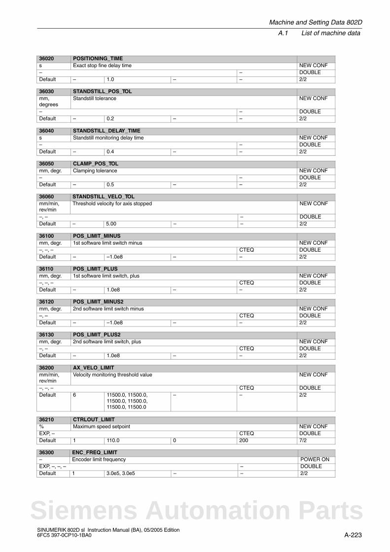
Machine and Setting Data 802D
A.1 List of machine data
A-223SINUMERIK 802D sl Instruction Manual (BA), 05/2005 Edition6FC5 397-0CP10-1BA0
36020 POSITIONING_TIMEs Exact stop fine delay time NEW CONF– – DOUBLEDefault – 1.0 – – 2/2
36030 STANDSTILL_POS_TOLmm,degrees
Standstill tolerance NEW CONF
– – DOUBLEDefault – 0.2 – – 2/2
36040 STANDSTILL_DELAY_TIMEs Standstill monitoring delay time NEW CONF– – DOUBLEDefault – 0.4 – – 2/2
36050 CLAMP_POS_TOLmm, degr. Clamping tolerance NEW CONF– – DOUBLEDefault – 0.5 – – 2/2
36060 STANDSTILL_VELO_TOLmm/min,rev/min
Threshold velocity for axis stopped NEW CONF
–, – – DOUBLEDefault – 5.00 – – 2/2
36100 POS_LIMIT_MINUSmm, degr. 1st software limit switch minus NEW CONF–, –, – CTEQ DOUBLEDefault – –1.0e8 – – 2/2
36110 POS_LIMIT_PLUSmm, degr. 1st software limit switch, plus NEW CONF–, –, – CTEQ DOUBLEDefault – 1.0e8 – – 2/2
36120 POS_LIMIT_MINUS2mm, degr. 2nd software limit switch minus NEW CONF–, – CTEQ DOUBLEDefault – –1.0e8 – – 2/2
36130 POS_LIMIT_PLUS2mm, degr. 2nd software limit switch, plus NEW CONF–, – CTEQ DOUBLEDefault – 1.0e8 – – 2/2
36200 AX_VELO_LIMITmm/min,rev/min
Velocity monitoring threshold value NEW CONF
–, –, – CTEQ DOUBLEDefault 6 11500.0, 11500.0,
11500.0, 11500.0,11500.0, 11500.0
– – 2/2
36210 CTRLOUT_LIMIT% Maximum speed setpoint NEW CONFEXP, – CTEQ DOUBLEDefault 1 110.0 0 200 7/2
36300 ENC_FREQ_LIMIT– Encoder limit frequency POWER ONEXP, –, –, – – DOUBLEDefault 1 3.0e5, 3.0e5 – – 2/2
Siemens Automation Parts
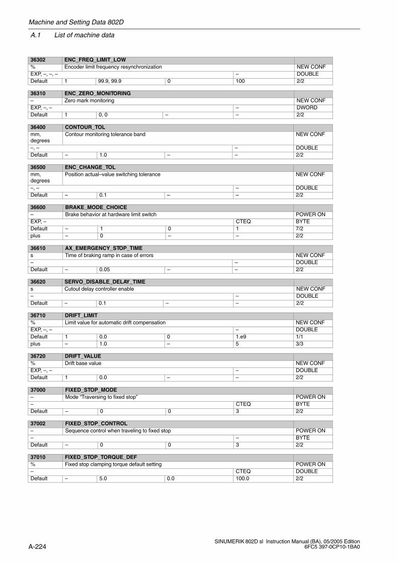
A.1 List of machine data
Machine and Setting Data 802D
A-224SINUMERIK 802D sl Instruction Manual (BA), 05/2005 Edition
6FC5 397-0CP10-1BA0
36302 ENC_FREQ_LIMIT_LOW% Encoder limit frequency resynchronization NEW CONFEXP, –, –, – – DOUBLEDefault 1 99.9, 99.9 0 100 2/2
36310 ENC_ZERO_MONITORING– Zero mark monitoring NEW CONFEXP, –, – – DWORDDefault 1 0, 0 – – 2/2
36400 CONTOUR_TOLmm,degrees
Contour monitoring tolerance band NEW CONF
–, – – DOUBLEDefault – 1.0 – – 2/2
36500 ENC_CHANGE_TOLmm,degrees
Position actual–value switching tolerance NEW CONF
–, – – DOUBLEDefault – 0.1 – – 2/2
36600 BRAKE_MODE_CHOICE– Brake behavior at hardware limit switch POWER ONEXP, – CTEQ BYTEDefault – 1 0 1 7/2plus – 0 – – 2/2
36610 AX_EMERGENCY_STOP_TIMEs Time of braking ramp in case of errors NEW CONF– – DOUBLEDefault – 0.05 – – 2/2
36620 SERVO_DISABLE_DELAY_TIMEs Cutout delay controller enable NEW CONF– – DOUBLEDefault – 0.1 – – 2/2
36710 DRIFT_LIMIT% Limit value for automatic drift compensation NEW CONFEXP, –, – – DOUBLEDefault 1 0.0 0 1.e9 1/1plus – 1.0 – 5 3/3
36720 DRIFT_VALUE% Drift base value NEW CONFEXP, –, – – DOUBLEDefault 1 0.0 – – 2/2
37000 FIXED_STOP_MODE– Mode “Traversing to fixed stop” POWER ON– CTEQ BYTEDefault – 0 0 3 2/2
37002 FIXED_STOP_CONTROL– Sequence control when traveling to fixed stop POWER ON– – BYTEDefault – 0 0 3 2/2
37010 FIXED_STOP_TORQUE_DEF% Fixed stop clamping torque default setting POWER ON– CTEQ DOUBLEDefault – 5.0 0.0 100.0 2/2
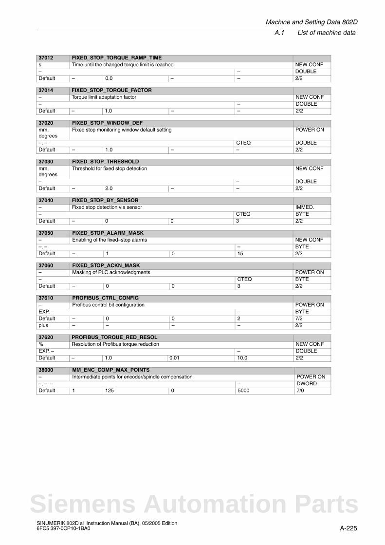
Machine and Setting Data 802D
A.1 List of machine data
A-225SINUMERIK 802D sl Instruction Manual (BA), 05/2005 Edition6FC5 397-0CP10-1BA0
37012 FIXED_STOP_TORQUE_RAMP_TIMEs Time until the changed torque limit is reached NEW CONF– – DOUBLEDefault – 0.0 – – 2/2
37014 FIXED_STOP_TORQUE_FACTOR– Torque limit adaptation factor NEW CONF– – DOUBLEDefault – 1.0 – – 2/2
37020 FIXED_STOP_WINDOW_DEFmm,degrees
Fixed stop monitoring window default setting POWER ON
–, – CTEQ DOUBLEDefault – 1.0 – – 2/2
37030 FIXED_STOP_THRESHOLDmm,degrees
Threshold for fixed stop detection NEW CONF
– – DOUBLEDefault – 2.0 – – 2/2
37040 FIXED_STOP_BY_SENSOR– Fixed stop detection via sensor IMMED.– CTEQ BYTEDefault – 0 0 3 2/2
37050 FIXED_STOP_ALARM_MASK– Enabling of the fixed–stop alarms NEW CONF–, – – BYTEDefault – 1 0 15 2/2
37060 FIXED_STOP_ACKN_MASK– Masking of PLC acknowledgments POWER ON– CTEQ BYTEDefault – 0 0 3 2/2
37610 PROFIBUS_CTRL_CONFIG– Profibus control bit configuration POWER ONEXP, – – BYTEDefault – 0 0 2 7/2plus – – – – 2/2
37620 PROFIBUS_TORQUE_RED_RESOL% Resolution of Profibus torque reduction NEW CONFEXP, – – DOUBLEDefault – 1.0 0.01 10.0 2/2
38000 MM_ENC_COMP_MAX_POINTS– Intermediate points for encoder/spindle compensation POWER ON–, –, – – DWORDDefault 1 125 0 5000 7/0
Siemens Automation Parts
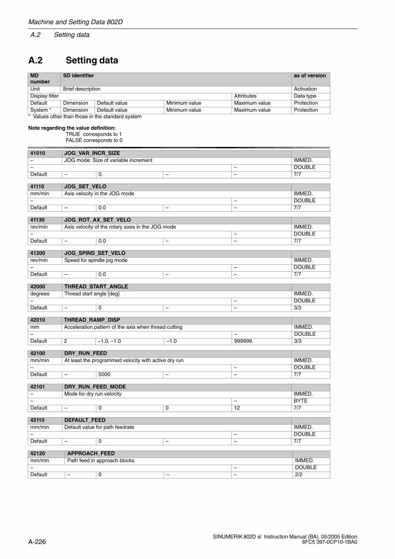
A.2 Setting data
Machine and Setting Data 802D
A-226SINUMERIK 802D sl Instruction Manual (BA), 05/2005 Edition
6FC5 397-0CP10-1BA0
A.2 Setting data
MDnumber
SD identifier as of version
Unit Brief description ActivationDisplay filter Attributes Data typeDefault Dimension Default value Minimum value Maximum value ProtectionSystem * Dimension Default value Minimum value Maximum value Protection
* Values other than those in the standard system
Note regarding the value definition: TRUE corresponds to 1
FALSE corresponds to 0
41010 JOG_VAR_INCR_SIZE– JOG mode: Size of variable increment IMMED.– – DOUBLEDefault – 0. – – 7/7
41110 JOG_SET_VELOmm/min Axis velocity in the JOG mode IMMED.– – DOUBLEDefault – 0.0 – – 7/7
41130 JOG_ROT_AX_SET_VELOrev/min Axis velocity of the rotary axes in the JOG mode IMMED.– – DOUBLEDefault – 0.0 – – 7/7
41200 JOG_SPIND_SET_VELOrev/min Speed for spindle jog mode IMMED.– – DOUBLEDefault – 0.0 – – 7/7
42000 THREAD_START_ANGLEdegrees Thread start angle [deg] IMMED.– – DOUBLEDefault – 0 – – 3/3
42010 THREAD_RAMP_DISPmm Acceleration pattern of the axis when thread cutting IMMED.– – DOUBLEDefault 2 –1.0, –1.0 –1.0 999999. 3/3
42100 DRY_RUN_FEEDmm/min At least the programmed velocity with active dry run IMMED.– – DOUBLEDefault – 5000 – – 7/7
42101 DRY_RUN_FEED_MODE– Mode for dry run velocity IMMED.– – BYTEDefault – 0 0 12 7/7
42110 DEFAULT_FEEDmm/min Default value for path feedrate IMMED.– – DOUBLEDefault – 0 – – 7/7
42120 APPROACH_FEEDmm/min Path feed in approach blocks IMMED.– – DOUBLEDefault – 0 – – 2/2
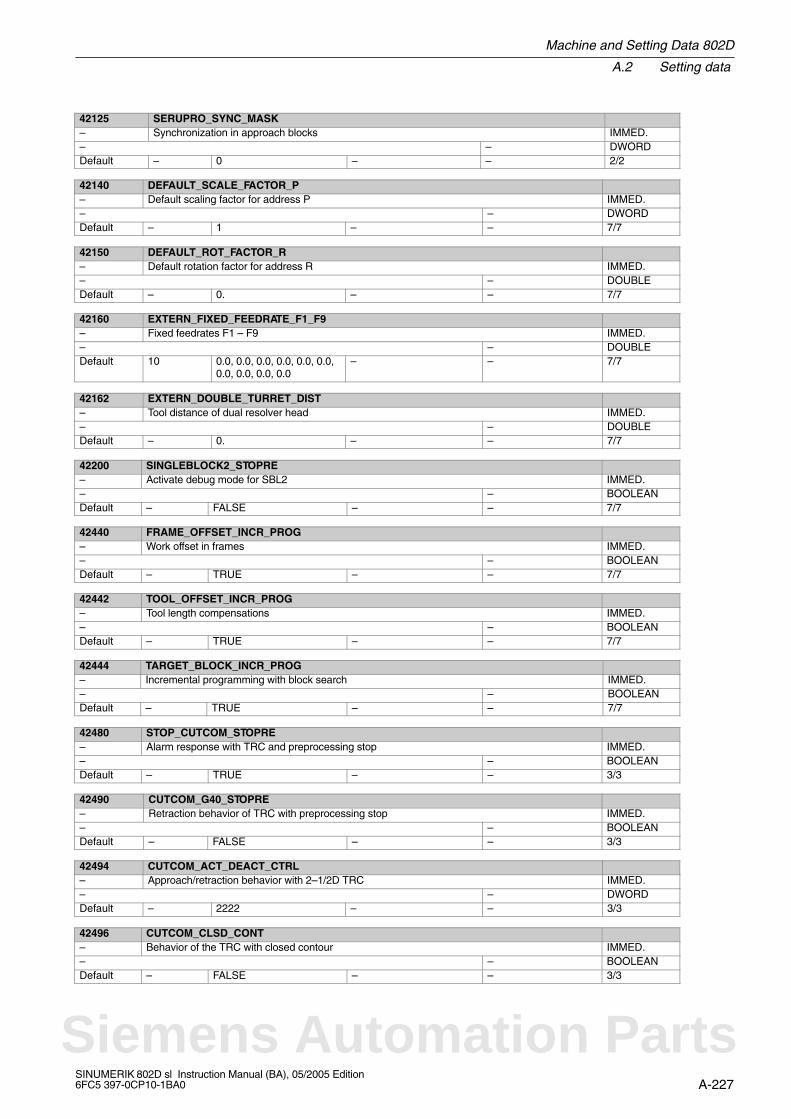
Machine and Setting Data 802D
A.2 Setting data
A-227SINUMERIK 802D sl Instruction Manual (BA), 05/2005 Edition6FC5 397-0CP10-1BA0
42125 SERUPRO_SYNC_MASK– Synchronization in approach blocks IMMED.– – DWORDDefault – 0 – – 2/2
42140 DEFAULT_SCALE_FACTOR_P– Default scaling factor for address P IMMED.– – DWORDDefault – 1 – – 7/7
42150 DEFAULT_ROT_FACTOR_R– Default rotation factor for address R IMMED.– – DOUBLEDefault – 0. – – 7/7
42160 EXTERN_FIXED_FEEDRATE_F1_F9– Fixed feedrates F1 – F9 IMMED.– – DOUBLEDefault 10 0.0, 0.0, 0.0, 0.0, 0.0, 0.0,
0.0, 0.0, 0.0, 0.0– – 7/7
42162 EXTERN_DOUBLE_TURRET_DIST– Tool distance of dual resolver head IMMED.– – DOUBLEDefault – 0. – – 7/7
42200 SINGLEBLOCK2_STOPRE– Activate debug mode for SBL2 IMMED.– – BOOLEANDefault – FALSE – – 7/7
42440 FRAME_OFFSET_INCR_PROG– Work offset in frames IMMED.– – BOOLEANDefault – TRUE – – 7/7
42442 TOOL_OFFSET_INCR_PROG– Tool length compensations IMMED.– – BOOLEANDefault – TRUE – – 7/7
42444 TARGET_BLOCK_INCR_PROG– Incremental programming with block search IMMED.– – BOOLEANDefault – TRUE – – 7/7
42480 STOP_CUTCOM_STOPRE– Alarm response with TRC and preprocessing stop IMMED.– – BOOLEANDefault – TRUE – – 3/3
42490 CUTCOM_G40_STOPRE– Retraction behavior of TRC with preprocessing stop IMMED.– – BOOLEANDefault – FALSE – – 3/3
42494 CUTCOM_ACT_DEACT_CTRL– Approach/retraction behavior with 2–1/2D TRC IMMED.– – DWORDDefault – 2222 – – 3/3
42496 CUTCOM_CLSD_CONT– Behavior of the TRC with closed contour IMMED.– – BOOLEANDefault – FALSE – – 3/3
Siemens Automation Parts

A.2 Setting data
Machine and Setting Data 802D
A-228SINUMERIK 802D sl Instruction Manual (BA), 05/2005 Edition
6FC5 397-0CP10-1BA0
42528 CUTCOM_DECEL_LIMIT– Feedrate reduction at circles with TRC IMMED.– – DOUBLEDefault – 0. 0. 1. 7/7
42940 TOOL_LENGTH_CONST 0– Tool length component when changing the plane IMMED.– – DWORDDefault – 0 – – 3/3
42950 TOOL_LENGTH_TYPE– Tool length component not depending on tool type IMMED.– – DWORDDefault – 0 – – 3/3
42990 MAX_BLOCKS_IN_IPOBUFFER– Max. number of blocks in the IPO buffer IMMED.– – DWORDDefault – –1 – – 2/2
43120 DEFAULT_SCALE_FACTOR_AXIS– Default scaling factor with active G51 IMMED.– – DWORDDefault – 1 – – 7/7
43200 SPIND_Srev/min Speed for spindle start through virtual interface IMMED.– – DOUBLEDefault – 0.0 – – 7/7
43202 SPIND_CONSTCUT_Sm/min Cutting rate for spindle start through virtual interface IMMED.– – DOUBLEDefault – 0.0 – – 7/7
43210 SPIND_MIN_VELO_G25rev/min Limits the spindle speed to the specified minimum value IMMED.– – DOUBLEDefault – 0.0 – – 7/7
43220 SPIND_MAX_VELO_G26rev/min Limits the spindle speed to the specified maximum value IMMED.– – DOUBLEDefault – 1000.0 – – 7/7
43230 SPIND_MAX_VELO_LIMSrev/min Limits the spindle speed to the specified maximum value with G96, G691, G97 IMMED.– – DOUBLEDefault – 100.0 – – 7/7
43240 M19_SPOSdegrees Spindle position with M19 IMMED.–, – – DOUBLEDefault – 0.0 –10000000.0 10000000.0 7/7
43250 M19_SPOSMODE– Approach mode for spindle position with M19 IMMED.–, – – DWORDDefault – 0 0 5 7/7
43340 EXTERN_REF_POSITION_G30_1– Reference point position for G30.1 IMMED.–, – – DOUBLEDefault – 0.0 – – 7/7

Machine and Setting Data 802D
A.2 Setting data
A-229SINUMERIK 802D sl Instruction Manual (BA), 05/2005 Edition6FC5 397-0CP10-1BA0
43400 WORKAREA_PLUS_ENABLE– Working area limitation active in the positive direction IMMED.– CTEQ BOOLEANDefault – FALSE – – 7/7
43410 WORKAREA_MINUS_ENABLE– Working area limitation active in the negative direction IMMED.– CTEQ BOOLEANDefault – FALSE – – 7/7
43420 WORKAREA_LIMIT_PLUSmm,degrees
Axial working area limitation active in the positive direction IMMED.
– – DOUBLEDefault – 1.0e+8 – – 7/7
43430 WORKAREA_LIMIT_MINUSmm,degrees
Axial working area limitation active in the negative direction IMMED.
– – DOUBLEDefault – –1.0e+8 – – 7/7
43500 FIXED_STOP_SWITCH– Selection “Travel to fixed stop” IMMED.– – BYTEDefault – 0 0 1 2/2
43510 FIXED_STOP_TORQUE% Fixed stop clamping torque IMMED.– – DOUBLEDefault – 5.0 0.0 800.0 2/2
Siemens Automation Parts
A.3 SINAMICS parameters
Machine and Setting Data 802D
A-230SINUMERIK 802D sl Instruction Manual (BA), 05/2005 Edition
6FC5 397-0CP10-1BA0
A.3 SINAMICS parameters
Note to the reader
SINAMICS S parameter list

B-231SINUMERIK 802D sl Instruction Manual (BA), 05/2005 Edition6FC5 397-0CP10-1BA0
Standards and Approvals
IEC 1131
The control system meets the requirements and criteria of the IEC 1131 Standard, Part 2.
CE designation
Our products meet the general and safety-related requirements of the following EC guide-lines and conform to the uniform standards (EN) for programmable controllers published inthe official gazettes of the European Union:
89/336/EEC “Electromagnetic Compatibility” (EMC Directive)
EMC guideline
SINUMERIK products are designed for use in industry.
Range of application Requirements in respect of
interference emission interference immunity
Industry EN 50081-2: 1993 EN 61000-6-2: 1999
B
Siemens Automation Parts
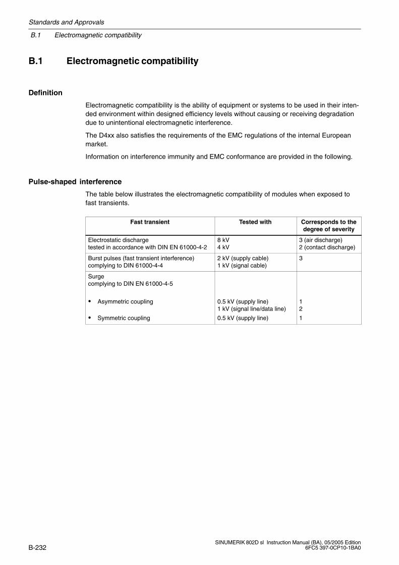
B.1 Electromagnetic compatibility
Standards and Approvals
B-232SINUMERIK 802D sl Instruction Manual (BA), 05/2005 Edition
6FC5 397-0CP10-1BA0
B.1 Electromagnetic compatibility
Definition
Electromagnetic compatibility is the ability of equipment or systems to be used in their inten-ded environment within designed efficiency levels without causing or receiving degradationdue to unintentional electromagnetic interference.
The D4xx also satisfies the requirements of the EMC regulations of the internal Europeanmarket.
Information on interference immunity and EMC conformance are provided in the following.
Pulse-shaped interference
The table below illustrates the electromagnetic compatibility of modules when exposed tofast transients.
Fast transient Tested with Corresponds to thedegree of severity
Electrostatic dischargetested in accordance with DIN EN 61000-4-2
8 kV4 kV
3 (air discharge) 2 (contact discharge)
Burst pulses (fast transient interference)complying to DIN 61000-4-4
2 kV (supply cable)1 kV (signal cable)
3
Surgecomplying to DIN EN 61000-4-5
Asymmetric coupling
Symmetric coupling
0.5 kV (supply line)1 kV (signal line/data line)
0.5 kV (supply line)
12
1

Standards and Approvals
B.1 Electromagnetic compatibility
B-233SINUMERIK 802D sl Instruction Manual (BA), 05/2005 Edition6FC5 397-0CP10-1BA0
Sinusoidal interference
HF radiation on the device in accordance with EN 61000-6-2 requirements:
Electromagnetic HF field, amplitude-modulated
– between 80 and 1,000 MHz
– 10 V/m
– 80 % AM (1 kHz)
Electromagnetic HF field, pulse-modulated
– 900 5 MHz
– 10 V/m
– 50 % duty cycle
– 200 Hz repetition frequency
HF coupling on signal and data cables, etc., in accordance with EN 61000-6-2 require-ments, high frequency, asymmetric, amplitude modulated
– between 0.15 and 80 MHz
– 10 V r.m.s. value, unmodulated
– 80 % AM (1 kHz)
– 150 source impedance
Radio interference emission
Interference emission of electromagnetic fields to EN 55011: Limit value class A, group 1.
between 20 and 230 MHz < 30 dB (V/m)Q
between 230 and 1,000 MHz < 37 dB (V/m)Q
measured at a distance of 30 m
Interference emission via network alternating current supply in accordance with EN 55011:Limit value class A, group 1.
between 0.15 and 0.5 MHz < 79 dB (V)Q
< 66 dB (V)M
between 0.5 and 5 MHz < 73 dB (V)Q
< 60 dB (V)M
between 5 and 30 MHz < 73 dB (V)Q
< 60 dB (V)M
Siemens Automation Parts
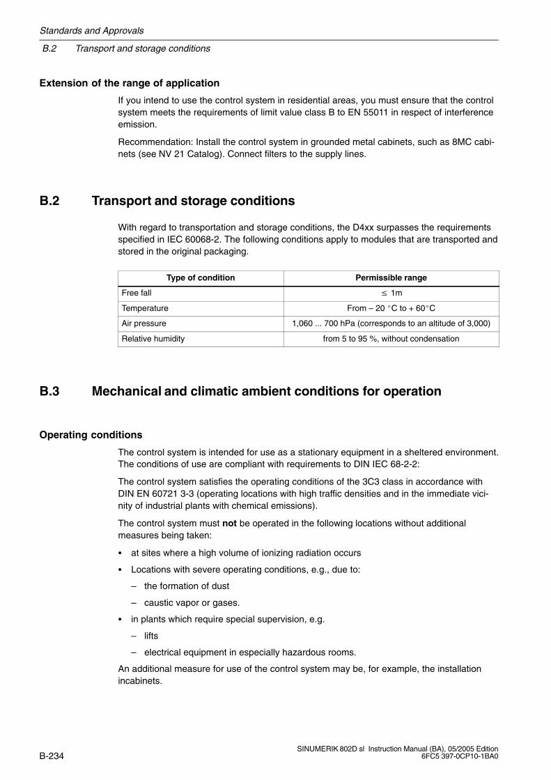
B.2 Transport and storage conditions
Standards and Approvals
B-234SINUMERIK 802D sl Instruction Manual (BA), 05/2005 Edition
6FC5 397-0CP10-1BA0
Extension of the range of application
If you intend to use the control system in residential areas, you must ensure that the controlsystem meets the requirements of limit value class B to EN 55011 in respect of interferenceemission.
Recommendation: Install the control system in grounded metal cabinets, such as 8MC cabi-nets (see NV 21 Catalog). Connect filters to the supply lines.
B.2 Transport and storage conditions
With regard to transportation and storage conditions, the D4xx surpasses the requirementsspecified in IEC 60068-2. The following conditions apply to modules that are transported andstored in the original packaging.
Type of condition Permissible range
Free fall 1m
Temperature From – 20 C to + 60C
Air pressure 1,060 ... 700 hPa (corresponds to an altitude of 3,000)
Relative humidity from 5 to 95 %, without condensation
B.3 Mechanical and climatic ambient conditions for operation
Operating conditions
The control system is intended for use as a stationary equipment in a sheltered environment.The conditions of use are compliant with requirements to DIN IEC 68-2-2:
The control system satisfies the operating conditions of the 3C3 class in accordance withDIN EN 60721 3-3 (operating locations with high traffic densities and in the immediate vici-nity of industrial plants with chemical emissions).
The control system must not be operated in the following locations without additionalmeasures being taken:
at sites where a high volume of ionizing radiation occurs
Locations with severe operating conditions, e.g., due to:
– the formation of dust
– caustic vapor or gases.
in plants which require special supervision, e.g.
– lifts
– electrical equipment in especially hazardous rooms.
An additional measure for use of the control system may be, for example, the installationincabinets.
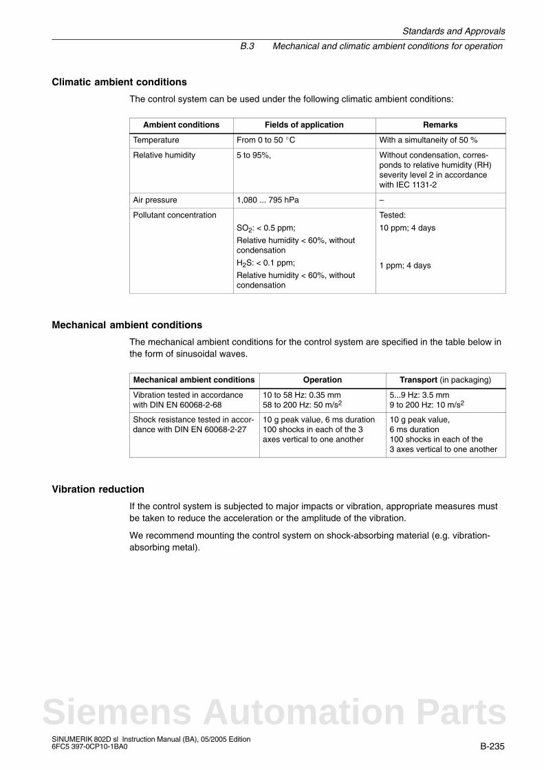
Standards and Approvals
B.3 Mechanical and climatic ambient conditions for operation
B-235SINUMERIK 802D sl Instruction Manual (BA), 05/2005 Edition6FC5 397-0CP10-1BA0
Climatic ambient conditions
The control system can be used under the following climatic ambient conditions:
Ambient conditions Fields of application Remarks
Temperature From 0 to 50 C With a simultaneity of 50 %
Relative humidity 5 to 95%, Without condensation, corres-ponds to relative humidity (RH)severity level 2 in accordancewith IEC 1131-2
Air pressure 1,080 ... 795 hPa –
Pollutant concentration
SO2: < 0.5 ppm;
Relative humidity < 60%, withoutcondensation
H2S: < 0.1 ppm;
Relative humidity < 60%, withoutcondensation
Tested:
10 ppm; 4 days
1 ppm; 4 days
Mechanical ambient conditions
The mechanical ambient conditions for the control system are specified in the table below inthe form of sinusoidal waves.
Mechanical ambient conditions Operation Transport (in packaging)
Vibration tested in accordancewith DIN EN 60068-2-68
10 to 58 Hz: 0.35 mm58 to 200 Hz: 50 m/s2
5...9 Hz: 3.5 mm9 to 200 Hz: 10 m/s2
Shock resistance tested in accor-dance with DIN EN 60068-2-27
10 g peak value, 6 ms duration100 shocks in each of the 3axes vertical to one another
10 g peak value, 6 ms duration100 shocks in each of the3 axes vertical to one another
Vibration reduction
If the control system is subjected to major impacts or vibration, appropriate measures mustbe taken to reduce the acceleration or the amplitude of the vibration.
We recommend mounting the control system on shock-absorbing material (e.g. vibration-absorbing metal).
Siemens Automation Parts

B.4 Information on insulation tests, safety class, and degree of protection
Standards and Approvals
B-236SINUMERIK 802D sl Instruction Manual (BA), 05/2005 Edition
6FC5 397-0CP10-1BA0
B.4 Information on insulation tests, safety class, and degree ofprotection
Test voltages
The insulation resistance is tested in a routine test using the following test voltage toIEC 1131, Part 2:
Circuits with a rated voltage of Ue to othercircuits or ground
Test voltage
0 V < Ue 50 V 500 V DC
Class of protection
Class of protection I to IEC 536 (VDE 0106, Part 1), i.e. connection to protective conductorrequired!
Protection against ingress of solid foreign bodies and water
Degree of protection to IEC 529:
CNC operator panel (PCU) IP65 (front)IP00 (rear)
Machine control panel (MCP) IP54 (front)IP00 (rear)
PP 72/48 I/O module IP00
Standards and Approvals
B.5 Safety of electronic control systems
B-237SINUMERIK 802D sl Instruction Manual (BA), 05/2005 Edition6FC5 397-0CP10-1BA0
B.5 Safety of electronic control systems
Introduction
The information provided here is mainly of general nature and applies irrespective of thetype of the electronic control system and its manufacturer.
Reliability
Comprehensive and cost-effective measures have been taken during development and pro-duction to increase the reliability of the devices and components as far as possible.
These include
the selection of high-quality components;
worst-case design of all circuits;
systematic and computer-controlled testing of all components delivered;
burning in of all LSI circuits (e.g. processors, memories, etc.)
measures preventing static charge when handling MOS ICs;
visual checks and inspections at various stages of production;
continuous heat testing at increased ambient temperature over several days;
careful computer-controlled final testing;
statistic evaluation of all returned goods for immediate introduction of correctivemeasures;
monitoring of the most important control parts by way of online tests (watch dog, etc.).
In terms of safety technology, these measures are called basic measures; they avoid or con-trol most possible errors.
The risk
Special safety standards must be applied to any system – and therefore to the situation aswell – whenever, if a fault occurs, it may cause injury to persons or damage to property. Forthese applications, special, plant-specific regulations exist which must be observed whendesigning the control system (e.g. VDE 0116 for furnaces).
For electronic control systems with safety relevance, the measures to be taken to avoid orcontrol errors depend on the risk resulting from the plant. In this conjunction, the basic mea-sures mentioned above are not sufficient any more for a certain hazard potential. Additionalmeasures (e.g. channel redundance, tests, checksums, etc.) must be implemented and cer-tified for the control system (DIN VDE 0801).
Siemens Automation Parts
B.5 Safety of electronic control systems
Standards and Approvals
B-238SINUMERIK 802D sl Instruction Manual (BA), 05/2005 Edition
6FC5 397-0CP10-1BA0
Division into safe and non-safe areas
Nearly all systems contain parts that perform safety-related tasks (e.g. emergency stopswitch, protective grating, two-hand controls). To avoid having to apply safety-related criteriato the entire controller, it is customary to divide the controller into two areas – one that iscritical to safety and one that is not critical to safety. In the non-safe area of the controlsystem, no special demands are made, since a failure of the electronics will have no effecton the safety of the plant. In the safe area, however, only controls and circuits which complywith the relevant standards and regulations must be used.
Important note
If even a maximum degree of conceptional safety has been achieved when configuring anelectronic control system, e.g. through multichannel design, it is nevertheless imperative toobserve the instructions provided in the relevant instruction manuals exactly; otherwise, im-proper or incorrect handling could put precautions intended to prevent hazardous errors outof service or even create additional hazards.

C-239SINUMERIK 802D sl Instruction Manual (BA), 05/2005 Edition6FC5 397-0CP10-1BA0
Directive for handling electrostatically sensitivedevices (ESD)
C.1 What does ESD mean?
Definition
All electronic modules are equipped with large-scale integrated chips or components. Due totechnological reasons, these electronic components can be damaged easily by overvoltageand thus discharge from static electricity.
The acronym ESD has become the established designation for such ElectrostaticallySensitive Devices. The ESD designation is used internationally to refer to electrostaticallysensitive devices.
Electrostatically sensitive devices are marked with the following symbol:
!Caution
Electrostatically sensitive devices can be destroyed even by voltages which are far belowthe human perceptive limit. These voltages already occur when you touch a component orelectrical connections of a module, without being electrostatically discharged. The damageresulting at a module due to an overvoltage is in most cases not detected immediately, butonly noticed after a longer period of operation.
C
Siemens Automation Parts
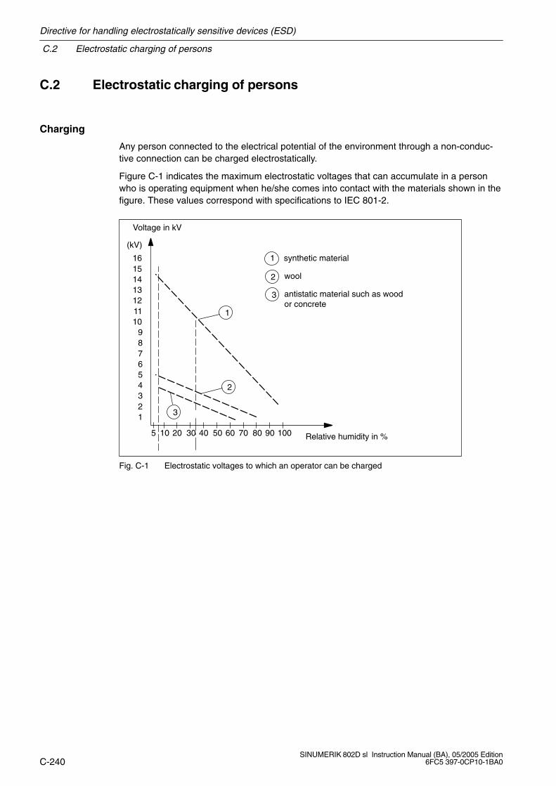
C.2 Electrostatic charging of persons
Directive for handling electrostatically sensitive devices (ESD)
C-240SINUMERIK 802D sl Instruction Manual (BA), 05/2005 Edition
6FC5 397-0CP10-1BA0
C.2 Electrostatic charging of persons
Charging
Any person connected to the electrical potential of the environment through a non-conduc-tive connection can be charged electrostatically.
Figure C-1 indicates the maximum electrostatic voltages that can accumulate in a personwho is operating equipment when he/she comes into contact with the materials shown in thefigure. These values correspond with specifications to IEC 801-2.
Voltage in kV
123456789
10111213141516
(kV)
5 10 20 30 40 50 60 70 80 90 100 Relative humidity in %
1
3
1 synthetic material
2 wool
3 antistatic material such as woodor concrete
2
Fig. C-1 Electrostatic voltages to which an operator can be charged
Directive for handling electrostatically sensitive devices (ESD)
C.3 Basic protective measures against discharge of static electricity
C-241SINUMERIK 802D sl Instruction Manual (BA), 05/2005 Edition6FC5 397-0CP10-1BA0
C.3 Basic protective measures against discharge of static electricity
Ensure proper grounding
When handling electrostatically sensitive devices, ensure that human, workplace and packa-ging are grounded properly to avoid static charging.
Avoid direct contact
Electrostatically sensitive devices should only be touched if this cannot be avoided (e.g.when performing maintenance work). When you touch modules, make sure that you do nottouch either the pins on the modules or the printed conductors. In this way, the dischargeenergy cannot reach and thus damage sensitive devices.
If you must perform measurements at a module, discharge your body first before performingthe work. To do so, touch a grounded metal object. To do so, touch grounded metal objects.Use only grounded measuring and test equipment.
Siemens Automation Parts

C.3 Basic protective measures against discharge of static electricity
Directive for handling electrostatically sensitive devices (ESD)
C-242SINUMERIK 802D sl Instruction Manual (BA), 05/2005 Edition
6FC5 397-0CP10-1BA0
Notes

D-243SINUMERIK 802D sl Instruction Manual (BA), 05/2005 Edition6FC5 397-0CP10-1BA0
SINUMERIK 802D sl License Agreement
License Agreement for the Sinumerik 802D sl Software – in the following referred to as“Software”
D.1 General Terms and Conditions for the Use of Software forSinumerik and Drive Technology
This Software is protected by national and international copyright and treaties. Unauthorizedcopying and illegal distribution of the Software or parts thereof is liable to prosecution bothunder criminal and under civil law and will result in severe penalty and/or damage compen-sation.
Prior to installation and use of the Software, please read the Terms and Conditions of thisLicense Agreement. An extract can be found in the Section D.2.
If you have received this software on a CD with the notice “Trial version” or together withanother software licensed for you, you are only permitted to use the software for test andvalidation purposes according to the attached trial licensing regulations. To this end, it isimperative to install certain programs, software libraries etc. on your computer.
We therefore strictly recommend you to install the Software either on a single-userworkstation or on a computer which is not integrated into the production processand required for storing or managing vital data, since it cannot fully be ruled out thatexisting files are modified or overwritten. We will therefore not assume any liabilityfor damage and/or data loss resulting from installing the program or not observingthis warning notice.
Any use of this Software other than that as prescribed by the present Terms andConditions is only permitted with a valid license from Siemens. If you do not possessa valid license which can be proven by submitting an appropriate Certificate ofLicense/Software Product Form, please cancel the installation immediately andcontact a Siemens branch office immediately to avoid claims for damages.
If the Software contains Free Software, an appropriate note can be found in the readme filefor the Software under License. The Customer is entitled to use the Free Software accordingto the relevant terms and conditions of licensing applying to the Free Software. These areincluded on the data carrier on which the software is supplied to the Customer. If there areany provisions in the terms and conditions of licensing for the Free Software which are incontradiction to these General Terms and Conditions, the terms and conditions of licensingfor the Free Software shall prevail. The Customer shall be entitled to request the sourcecode of the Free Software against payment of the shipping costs at least for a time of threeyears after acquiring the Software from Siemens.
D
Siemens Automation Parts
D.2 General Terms and Conditions for the Use of Software for Sinumerik and Drive Technology
SINUMERIK 802D sl License Agreement
D-244SINUMERIK 802D sl Instruction Manual (BA), 05/2005 Edition
6FC5 397-0CP10-1BA0
D.2 General Terms and Conditions for the Use of Software forSinumerik and Drive Technology
D.2.1 Delivery of the Software to licensees and granting of rights of use in theSoftware
1. The delivery of the Software for automation and drive technology to the Licensee is sub-ject to the applicable mutual written declarations. Any general terms and conditions of theLicensee, however, shall only be valid if we have expressly agreed to them.
We grant the Licensee rights to use the Software mentioned either in the Order Confir-mation or – if the Licensee has not received an Order Confirmation – in the Certificate ofLicense, or – if the Licensee has received a Software Product Form instead of the Certifi-cate of License – in the Software Product Form. The Certificate of License and the Soft-ware Product Form will be referred to in the following as “CoL”. The Licensee will receivethe CoL together with the delivery of the Software or the delivery note.
The form of delivery of the Software also results either directly from the Order Confirma-tion or the Order Number of the Software specified in the Order Confirmation in conjunc-tion with the relevant order data specified in the Catalog valid at the time of order confir-mation (in the following referred to as “Order Data”), or from the CoL. If the Licensee hasnot received a data carrier, he shall be entitled to make copies of the Software he hasalready in his possession to the extent required to use the Software within the rights touse granted to him. This shall apply analogously if the Software is delivered electronically(via download).
If in these Terms and Conditions reference is made to the Order data or the CoL, the re-ference to the CoL will only be relevant if the Licensee has not received an Order Confir-mation. In any case, the data contained in the Order Data are also contained in the CoL.
2. The documentation that belongs to the software is to be acquired separately, unless it isspecified in the order data or the CoL that the documentation is included in the scope ofsupply. If the Licensee is entitled to make copies of the software as it is mentioned inPoint D.2.1, Clause 1 above, this shall also pertain to the documentation so far as inclu-ded in the scope of supply.
3. If the Licensee has received a license key for the software, this must also be installed.
4. The rights granted to the Licensee in the software result from the license type(see Point D.2.2) and the software type (see Point D.2.3). License type and software typeresult from the order data or the CoL.
If the Software is delivered electronically or by granting multi-user license rights, theseshall refer to the rights and duties in the legally created copies mentioned in these Gene-ral Terms and Conditions.
5. If the Licensee is in the legal possession of a previous version/release of the Software(in the following referred to as “Previous Version” ), the Licensee shall be granted theright to exercise the right to use the Software either for the Software itself or – if this istechnically feasible – for the Previous Version (downgrading). If the Software is anupgrade or a PowerPack as mentioned in Point D.2.4 below, Point D.2.4 shall apply inaddition.
SINUMERIK 802D sl License Agreement
D.2 General Terms and Conditions for the Use of Software for Sinumerik and Drive Technology
D-245SINUMERIK 802D sl Instruction Manual (BA), 05/2005 Edition6FC5 397-0CP10-1BA0
6. If the Licensee is to receive only the data carrier, and not a license according to the provi-sions in the Order Data or resulting from the CoL, the Licensee shall only be entitled touse the Software if he acquires a license as mentioned in Point D.2.2 below. The Licen-see shall only be entitled to pass on the Software to third parties if he has acquired thelicense.
D.2.2 License type
Depending on the license type, the Software Licensee is granted the following rights:
1. Single License (One-Off License, Copy License)
The term “One-Off License” or “Copy License” used in the Software Product Form cor-responds to the Single License. The following regulation shall apply to the One-Off Li-cense/Copy License to its full extent:
The Licensee is granted the non-exclusive right unlimited in time and assignable in accor-dance with Point D.2.5, Clause 3 below to install the Software on one (1) device and touse the installed Software as specified in the Order Data or the CoL (see “Type of use”).
2. Floating License
The Licensee is granted the non-exclusive right unlimited in time and assignable in accor-dance with Point D.2.5, Clause 3, to install the Software on any number of devices of theLicensee. The number of persons who are permitted to use the software simultaneously(“users”) results from the order data or the CoL (see
3. Rental License
The Licensee is granted the non-exclusive right limited in time as specified in the OrderData or the CoL (see “Type of Use”) to Point D.2.5, Clause 3, to install and use the Soft-ware on one (1) device. If the time of use is specified in hours, the time used to calculatethe limitation in time shall commence at the time when the Software was started first andend at the time when the use of the Software is finally completed. If the time of use isspecified in days, weeks or months, the specified period shall commence from the timewhen the software was started first, irrespective of whether or not the software is in factused.
4. Trial License
The Licensee is granted the non-exclusive, nontransferable right to install the Softwareon one (1) device and to use the installed Software for validation purposes in the manneras specified in the Order Data or in the CoL (see The time of use shall be limited to14 days, commencing at the time when the Software was started first, unless anothertime of use is specified in the Order Data or in the CoL.
Siemens Automation Parts
D.2 General Terms and Conditions for the Use of Software for Sinumerik and Drive Technology
SINUMERIK 802D sl License Agreement
D-246SINUMERIK 802D sl Instruction Manual (BA), 05/2005 Edition
6FC5 397-0CP10-1BA0
D.2.3 Software type
If the software type is specified neither in the Order Data, nor in the CoL, the Software shallbe subject to the rights specified in Point D.2.3, Clause 2 (Runtime Software).
1. Engineering Software
If the Licensee uses the Engineering Software to create his own programs or data whichcontain parts of the Engineering Software, the Licensee shall have the license-free rightto make copies of these parts of the Engineering Software as a part of his own programsor data, to use them or to deliver them third parties for their use. When delivering to thirdparties, these must be bound in writing to the regulations of Point D.2.5, Clauses 1 and 2in respect of the parts of the Engineering Software mentioned above.
2. Runtime Software
If the Licensee embeds the Runtime Software or parts thereof into his own programs ordata, the Licensee shall acquire a license in the Runtime Software according to the inten-ded type of use in accordance with the Siemens Catalog valid at this time each timewhen installing the Software or making copies, whichever is earlier. If the Licensee deli-vers the programs or data mentioned above for use by third parties, these must be boundin writing to the regulations of Point D.2.5 in respect of the embedded parts of the Run-time Software. This does not affect the obligation for the Licensee to acquire a license inthe Runtime Software,if this software is to be copied in its original form.
If the Runtime Software contains tools for parameterization/configuration and if extendedrights are granted for these tools, this can be derived from the readme file of the RuntimeSoftware.
D.2.4 Upgrade and PowerPack
If it is to be understood from the Order Data or the CoL, for example through appending ofthe suffix “PowerPack” or “Upgrade” to the name of the Software, that the Software servesto upgrade another software (in the following referred to as “Original License”), the rightsgranted to the Licensee in the Software are acquired also in respect of the original softwareas soon as the original software is upgraded with the Upgrade/PowerPack. The rights of useoriginally granted to the Licensee with the Original License are terminated with the upgrade.The Licensee is however entitled to reverse the upgrade at any time (downgrading) – insofaras this is technically feasible – and to exercise the rights of use in the software granted withthe Original License in accordance with Point D.2.1, Clause 5.
SINUMERIK 802D sl License Agreement
D.2 General Terms and Conditions for the Use of Software for Sinumerik and Drive Technology
D-247SINUMERIK 802D sl Instruction Manual (BA), 05/2005 Edition6FC5 397-0CP10-1BA0
D.2.5 Further rights and duties of the Licensee
1. Unless a note to the contrary with specification of a certain number of copies is made onthe data carrier or in the readme file of the Software, the Licensee is permitted to make areasonable number of copies of each copy of the Software which he is entitled to use inaccordance with these Terms and Conditions exclusively for data backup purposes.Furthermore, the Licensee is only permitted to duplicate the Software if and insofar as wehave granted rights of duplication in writing.
2. The Licensee is not permitted to modify, reverse engineer or recompile the Software, noris he permitted to segregate individual parts of the software, except where this is ex-pressly permitted by the provisions of the laws on copyright. The Licensee is furthermorenot permitted to remove alphanumerical IDs, trademarks or copyright notes from the soft-ware or data carrier and undertakes to duplicate such markings and notes unchangedinsofar as he is entitled to duplicate the Software. This provision applies analogously alsoto the documentation provided in accordance with Section D.1.
3. The Licensee is entitled to transfer his rights of use in the Software to a third party, provi-ded a written agreement is reached with this third party to the effect of all provisions ofthis Section D.5 and provided he retains no copies of the Software.
If the Licensee has received a license key for the Software, this key must be passed onto the third party together with the Software. Furthermore, the CoL is to be handed overto the third party, together with these Terms and Conditions.
If requested by us, the Licensee is to be prepared to present the CoL received for theSoftware at any time.
4. If the Software is a PowerPack or an Upgrade, the Licensee is to keep the Certificate ofLicense or the Software Product Form of the Original License and, if requested by us, isto be prepared to present it together with the CoL received for the Software at any time. Ifthe Licensee transfers his rights of use in the PowerPack Software or the Upgrade Soft-ware in accordance with Point D.2.5, Clause 3, the Certificate of License or the SoftwareProduct Form of the Original License is also to be handed over to the third party.
5. If the Licensee receives a data carrier which contains further enabled software productsbesides the Software, he is granted a right limited in time and without fees to use theseenabled software products exclusively for validation purposes. The time of use shall belimited to 14 days, commencing at the time when the Software was started first, unlessanother time of use is specified in the readme file of the software product concerned.
The provisions of these Terms and Conditions apply analogously to these software pro-ducts provided exclusively for validation purposes. The Licensee is not entitled to transferthese software products to a third party separately, i.e. without the Software.
Otherwise, the provisions of the purchase contract shall apply, unless contraryprovisions are specified expressly hereinafter for the Free Software.
Siemens Automation Parts
D.3 License Provisions for Free Software Components
SINUMERIK 802D sl License Agreement
D-248SINUMERIK 802D sl Instruction Manual (BA), 05/2005 Edition
6FC5 397-0CP10-1BA0
D.3 License Provisions for Free Software Components
In the “Sinumerik 802D sl” software, the following free software components (in the followingreferred to as “Free Software”) are used either in unmodified form or after modification byus:
Name License
Linux-Kernel GPL (see gpl.txt)Grub GPL (see gpl.txt)devices GPL (see gpl.txt)glibc LGPL (see lgpl.txt)libstdc++ LGPL (see lgpl.txt)libz Zlib license (see zlib.txt)libgmp LGPL (see lgpl.txt)liboop LGPL (see lgpl.txt)busybox GPL (see gpl.txt)lsh GPL (see gpl.txt)tsort BSD (see bsd.txt)udhcp-server GPL (see gpl.txt)ipledd GPL (see gpl.txt)betaftpd GPL (see gpl.txt)tftpd BSD (see bsd.txt)iptables GPL (see gpl.txt)hotplug GPL (see gpl.txt)ntpd BSD (see bsd.txt)samba-mount GPL (see gpl.txt)
The Free Software is made available without fees. You are entitled to use the Free Softwarein accordance with the corresponding license provisions. These provisions are to be foundunder Point D.2.5 ff. above.BIn case of discrepancies between these license provisions andthe license provisions in accordance with Points D.2.1 and D.2.2, the license provisions inaccordance with Point D.2.5 shall prevail in respect of the Free Software. In case of violationof these license provisions, the named licenser is entitled, alongside us, to assert resultantclaims and rights in his own name.
Where permitted by the relevant license provisions in accordance with Clause 5ff, you areentitled to request the source code of the Free Software from your Siemens sales represen-tative against payment of the shipping costs at least for a period of three years after acqui-ring the Software.
D.4 Liability for Free Software
We assume liability for the Software, including the Free Software contained therein, in accor-dance with the license provisions valid for the Software. All liability is excluded in respect ofuse of the Free Software beyond the program sequences we have designated for the Soft-ware, as well as in respect of defects attributable to modification of the Free Software.
No technical support is provided for the Software if it has been modified.
SINUMERIK 802D sl License Agreement
D.5 see gpl.txt on the Toolbox CD under /licenses
D-249SINUMERIK 802D sl Instruction Manual (BA), 05/2005 Edition6FC5 397-0CP10-1BA0
D.5 see gpl.txt on the Toolbox CD under /licenses
D.6 see bsd.txt on the Toolbox CD under /licenses
D.7 see zlip.txt on the Toolbox CD under /licenses
D.8 see lgpl.txt on the Toolbox CD under /licenses
Siemens Automation Parts

D.8 see lgpl.txt on the Toolbox CD under /licenses
SINUMERIK 802D sl License Agreement
D-250SINUMERIK 802D sl Instruction Manual (BA), 05/2005 Edition
6FC5 397-0CP10-1BA0
Notes
E-251SINUMERIK 802D sl Instruction Manual (BA), 05/2005 Edition6FC5 397-0CP10-1BA0
Abbreviations
CF Compact Flash
CNC Computerized numerical control
COM Communication module
CU Control Unit
DC Direct current
DI Digital input
DIN Deutsche Industrienorm (German industrial standard)
DI/DO Digital input/output, bidirectional
DO Digital output
DP Distributed I/O
ESD Electrostatically sensitive devices
EMC Electromagnetic compatibility
EN Europäische Norm (European Standard)
HMI Human Machine Interface
IEC International Electrotechnical Commission
ISO International Standardization Organization
LED Light Emitting Diode
GND Ground
MCP Machine control panel
NC Numerical control
NCK Numerical Control Kernel
PC/PG Personal computer, programming device
PCU Panel Control Unit
PELV Protective extra-low voltage
PLC Programmable Logic Control
PNO PROFIBUS Nutzer-Organisation (PROFIBUS user organization)
RJ45 Interface standard; describes an 8-pin plug connection for twisted-pair Ethernet
RS232 Serial interface
RS485 Interface standard; describes the physical properties of a digital serial interface
SDB System data block
E
Siemens Automation Parts
Abbreviations
E-252SINUMERIK 802D sl Instruction Manual (BA), 05/2005 Edition
6FC5 397-0CP10-1BA0
TB 30 Terminal Board 30
UL Underwriters Laboratories Inc.
USB Universal Serial Bus
Index
Index-253SINUMERIK 802D sl Instruction Manual (BA), 05/2005 Edition6FC5 397-0CP10-1BA0
IndexNumbers802D machine data802D machine data
Axis-specific, A-214Channel-specific, A-206Display, A-196General, A-201
AAccess levels, 9-80Ambient conditions, B-234
Mechanical, B-235Analog output, Assignment, 4-31Analog spindle, Connecting, 7-60Assuming control priority, 10-144Automatic configuration, 10-154
BBERO, 7-71Bus connector, Setting the terminator, 7-67
CCable clamp, 7-74CE, Identification, B-231Check topology, 10-161Class of protection, B-236CNC full keyboard (installed beneath to the PCU), Dril-
ling pattern, 5-47CNC full keyboard (installed next to the PCU)
Dimension drawing, 5-44, 5-46Drilling pattern, 5-45
CNC full keyboard connection, 2-15CNC operator panel (PCU)
Dimension drawing, 5-40Drilling pattern, 5-41
COM port connection, 7-65Commissioning using predefined macros, 9-93Compact flash card (CF card) slot, 2-15, 4-19Components, 1-11Configuring a drive unit, 10-131Configuring SINAMICS S120, 9-93Connect to target system, 10-140Connected loads, 8-75Connecting, 7-51
Bus connector, 7-67
Connecting the digital inputs/outputs, 7-71, 7-72to the CNC operator panel, 7-71to the I/O module, 7-72
Connecting the Ethernet interface, 7-64Connecting the I/O module, 7-66Connecting the machine control, 7-73Connecting the SINAMICS S drive, 7-70Connection cables, 7-71Connection for the CNC-full keyboard, 7-63Connection overview, 7-56Connection to PROFIBUS DP, 7-66Control panel, 10-140, 10-143Control powerup, 9-83Control word CTW1, 10-146Creating a drive project, 10-123
OFFLINE, 10-123ONLINE, 10-150
DData backup, 12-187Data organization, 11-181Data types, L-195Degree of protection, B-236Description, 2-13Description of the PP 72/48 I/O module
Interfaces, 4-33Operator controls, 4-33
Design, Electrical, Configuring, 7-52Detailed view, 9-105Device configuration, 10-158Diagnosis via STARTER, 9-111Diagnostics function, 9-111
Function generator, 9-112Trace, 9-115
Dielectric strength test, B-236Digital inputs, 4-25
Assignment, 4-26, 4-30, 4-34Description, 4-27, 4-34Technical Specifications, 8-76
Digital inputs/outputs (CPU), 2-15Digital outputs, 4-25
Assignment, 4-26, 4-30, 4-34Description, 4-27, 4-34Technical Specifications, 8-77
Dimension drawings, 5-39, 5-40, 5-42, 5-44, 5-46, 5-48Dimensions, 8-75Drilling patterns, 5-39, 5-41, 5-43, 5-45, 5-47DRIVE CLiQ interface, 2-15, 4-23
Siemens Automation Parts
Index
Index-254SINUMERIK 802D sl Instruction Manual (BA), 05/2005 Edition
6FC5 397-0CP10-1BA0
Drive configuration, 10-158Drive Navigator, 10-157Drive on, 10-147Drive, 10-135
EElectrical design, Configuring, 7-52Electromagnetic compatibility, B-232EMC Directives, 7-51EMC Guidelines, B-231EMERGENCY STOP strategy, 7-51Entering the machine data, 9-90Error displays, 3-18ESD Guideline, C-239Ethernet interface, 2-15, 4-20
Assignment, 4-20External electrical interference, Protection, 7-52
FFast transients, B-232Faults and Alarms, 9-97Feed axes, Initial setting, 9-99File Management, 9-84Find drive units online...., 10-150Function generator, Features, 9-113
GGenerator for signals, 9-112Guideline, ESD, C-239
HHandwheel, 1-10Handwheel connection, 2-15, 4-24
Assignment, 4-24
II/O interface, 4-33, 4-34IEC 1131, B-231Inserting a drive unit, 10-128Installation, 6-49Interfaces, 4-19
CNC operator panel (PCU), 4-19PP 72/48 I/O module, 4-32
Interference sizesPulse-shaped, B-232Sinusoidal, B-233
LLanguage setting, 9-84LEDs on the PP 72/48 I/O module, 3-18
MMachine control, 7-73Machine control panel (MCP)
Dimension drawing, 5-42Drilling pattern, 5-43
Machine data, setting dataActivation, 9-81Structure, 9-81
Macros, 9-95MCPA module, 4-28
Connecting, 7-59Measuring function, 9-116, 9-117Measuring socket, 9-119Modules, Transport and storage conditions, B-234Motor rotates, 10-140Mounting the CNC operator panel (PCU), Interfaces,
2-15Mounting the shield connection, 7-74
OOperating conditions, B-234Operating type, 10-135Operator Controls and Display, 3-17Optional interface, 2-15
PPCU interfaces, 2-15
Compact flash card (CF card) slot, 4-19Digital inputs/outputs, 4-25Ethernet interface, 4-20Handwheel connection, 4-24PROFIBUS DP1 interface, 4-22RS232 COM interface, 4-21USB interface, 4-20
PLC alarms, 11-166PLC command overview, 11-171PLC programming, 11-170Power supply connection, 2-15, 4-33, 7-61PP 72/48 I/O module, 4-32PP 72/48 interfaces, 4-33
I/O interface, 4-34PP72/48 I/O module, Dimension drawing, 5-48Probe, 7-71Product overview, 1-9
Index
Index-255SINUMERIK 802D sl Instruction Manual (BA), 05/2005 Edition6FC5 397-0CP10-1BA0
PROFIBUS address, 9-91PROFIBUS DP interface, 4-33PROFIBUS DP1 interface, 2-15, 4-22Programm organization, 11-181Project navigator, 9-105Protection against external electrical interference, 7-52Protection levels, 9-80Protective conductor, 7-55
RRadio interferences, Emission of, B-233RCS802D Tool, 9-82Recorder, 9-115Returning the control priority, 10-148RS232 COM interface, 2-15, 4-21RS232 COM port, assignment, 4-21
SSafety of electronic control systems, B-237Safety rules, 7-51
EMERGENCY STOP devices, 7-51Servo, 10-135Servo Control, 10-135Setpoint/actual-value assignment, 9-98Setting data, L-226Setting the technology, 9-88Setting the terminator on the bus connector, 7-67Shield connection, 7-74Shielded lines, 7-74Signal recording with the trace function, 9-111Sinusoidal interference, B-233Spindle
Analog, 9-103Initial setting, 9-101Unipolar, 9-104
Spindle actual-value encoderintegrated into the motor, 9-102mounted directly, 9-102
Start automatic configuration, 10-154
Start-up, 9-79Close, 9-120PLC, 11-163Prerequisites, 9-79Sequence, 9-79Series start-up, 12-190
Start-up modes of the PLC, 11-164STARTER start-up tool, 9-105Status displays, 3-18Stop, 10-147Supply, 10-133Switch on, 9-83System overview, 1-9System software, 1-11
TTechnical Specifications, 8-75
Digital inputs, 8-76Digital outputs, 8-77
Terminal strip converter, 4-34Test voltages, B-236Toolbox, 1-12Trace, 9-115Trace function, Signal recording, 9-111
UUSB interface, 4-20USB port, 2-15User alarms, 11-167User interface, 9-105Using the STARTER control panel, 10-140
VVibrations, B-235
WWeight, 8-75Working range, 9-105
Siemens Automation Parts

Index
Index-256SINUMERIK 802D sl Instruction Manual (BA), 05/2005 Edition
6FC5 397-0CP10-1BA0
Notes
From:
Name
Company/Dept.
Address
Zip code: City:
Telephone: /
Suggestions
Corrections
For publication/manual:
SINUMERIK 802D sl
Manufacturer Documentation
Instruction Manual
Order No.: 6FC5397-0CP10-1BA005/2005 Edition
Should you come across any printingerrors when reading this publication,please notify us on this sheet.Suggestions for improvement arealso welcome.
To SIEMENS AGA&D MC BMSPostfach 3180
D–91050 Erlangen(Tel. +49 (0) 180 5050 – 222 [Hotline]Fax +49 (0) 9131 98 – 63315 [Documentation]E-mail: [email protected]
Telefax: /
Suggestions and/or corrections
Siemens Automation Parts


Siemens AGAutomation & DrivesMotion Control SystemsPostfach 3180, D–91050 ErlangenFederal Republic of Germany
www.ad.siemens.com
Siemens AG 2005Subject to change without prior notice
Order No. 6FC5397-0CP10-0BA0
Printed in the Federal Republic of Germany
Related Documents


![Gang Type CNC Turning Center KIT Series · SIEMENS 802D HYUNDAI WIA FANUC i Series HYUNDAI WIA FANUC i Series [SIEMENS 802D] +)8)+1](https://static.cupdf.com/doc/110x72/5ea398622c8a240c2849c16c/gang-type-cnc-turning-center-kit-series-siemens-802d-hyundai-wia-fanuc-i-series.jpg)

