INDEX FOR B / BH TYPE CAM-OPERATED SWITCH Item Features Specifications / Breaking Capacity How to Order Notch code Contact code A1 A2 A3 A4 to 5 A5 Page Page Page Item Handle code Standard Specifications Special Specifications Mounting Hole Dimensions Contact Arrangement Diagram A6 A7 to 11 A12 to 22 A23 A24 to 26 Item Voltmeter / Ammeter Switches Contact Arrangement of Standard Switches Accessories Nameplates Technical Information A27 to 30 A31 to 48 A49 to 50 A51 to 54 A55 to 56 FEATURES ■Heavy-duty mechanical durability against high-frequent switching Since the optimal layout of components and by using materials with high wear resistance for the mechanical section, it can be provides accurate operation feeling and durability against high-frequent switching up to 5 million times. ■Campability both compact body and high breaking capacity and yet greatly improved breaking capacity Larger breaking capacity of the switches generally requires that the main body enlargment. However, Fuji's control switches has achieved downsizing while increasing the breaking capacity. This breakthrough has been made possible by optimally designing the cam shapes and the angle of the movable contact parts for obtaining max. switching speed mechanically. This allows you to determine the setting values (voltage and current) with allowance. ■The terminal arrangement greatly improves wiring efficiency No up-screw terminal is adopted. It can be quickly wired from the back for the alternate terminal arrangement. ■High-performance engineering plastics ensure high quality and high reliability For the body, polycarbonate resin is used, which has a high level of performance among engineering plastics. The material greatly improves strength and resistance against environment (temperature, humidity, vibrations, etc.), which are particularly important for the applications related to heavy electric machineries. The contacts and mechanical parts are transparent to facilitate checking the contacting part. Spring Rolle Lever Notch cam CAM-OPERATED SWITCH B TYPE, BH TYPE ●CONTROL SWITCH A1

Welcome message from author
This document is posted to help you gain knowledge. Please leave a comment to let me know what you think about it! Share it to your friends and learn new things together.
Transcript
600V
5.5㎜2
20A
110
220
440
――
20
15
4
――
15
10
3
――
24
48
110
220
15
10
3
1.2
10
6
1.5
0.8
20
18
4.5
2
20
15
4
1.5
INDEX FOR B / BH TYPE CAM-OPERATED SWITCH
Item
Features
Specifications / Breaking Capacity
How to Order
Notch code
Contact code
A1
A2
A3
A4 to 5
A5
Page Page PageItem
Handle code
Standard Specifications
Special Specifications
Mounting Hole Dimensions
Contact Arrangement Diagram
A6
A7 to 11
A12 to 22
A23
A24 to 26
Item
Voltmeter / Ammeter SwitchesContact Arrangementof Standard Switches
Accessories
Nameplates
Technical Information
A27 to 30
A31 to 48
A49 to 50
A51 to 54
A55 to 56
FEATURES
■Heavy-duty mechanical durability against high-frequent switchingSince the optimal layout of components and by using materials with high wear resistance for the mechanical section, it can be provides accurate operation feeling and durability against high-frequent switching up to 5 million times.
■Campability both compact body and high breaking capacity and yet greatly improved breaking capacityLarger breaking capacity of the switches generally requires that the main body enlargment. However, Fuji's control switches has achieved downsizing while increasing the breaking capacity. This breakthrough has been made possible by optimally designing the cam shapes and the angle of the movable contact parts for obtaining max. switching speed mechanically.This allows you to determine the setting values (voltage and current) with allowance.
■The terminal arrangement greatly improves wiring efficiencyNo up-screw terminal is adopted. It can be quickly wired from the back for the alternate terminal arrangement.
■High-performance engineering plastics ensure high quality and high reliabilityFor the body, polycarbonate resin is used, which has a high level of performance among engineering plastics. The material greatly improves strength and resistance against environment (temperature, humidity, vibrations, etc.), which are particularly important for the applications related to heavy electric machineries. The contacts and mechanical parts are transparent to facilitate checking the contacting part.
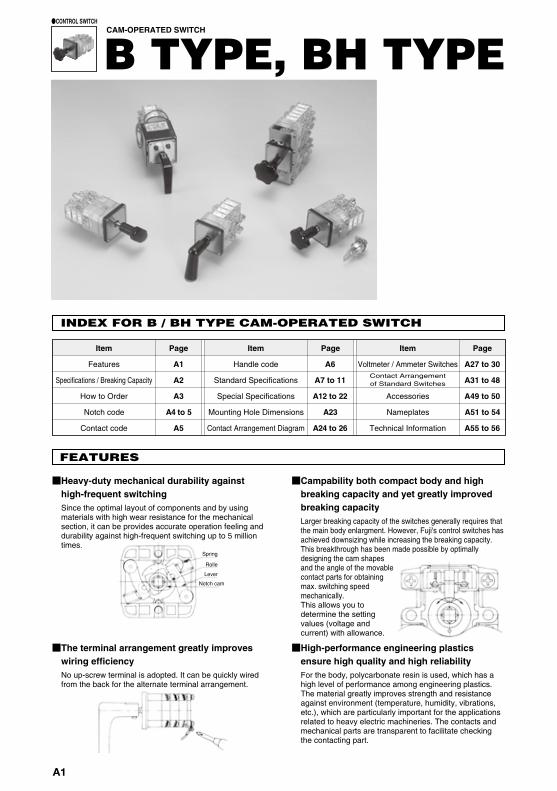
Breaking starts Rolling action
Contact starts Contact completesRolling action
■Rolling action of contact mechanism improves contact stabilityIn the contact mechanism, the movable contact makes contact with the stationary contact at one point and then gradually increases the contact area while rolling on it. This rolling action minimizes the part exposed to the arc that is generated at the first contact or breaking, thereby maintaining much higher contact stability than the former product.
Rated insulation voltage (Ui)
Rated current-carrying capacity (lth)
Max. wire size
Screw size
Withstand voltage
Lightning impulse
Contact resistance
Mechanical life
Electrical life
Shock resistance
Vibration resistance
Min. power requirements
Operating temperature
Storing temperature
Altitude
B TYPE BH TYPETypeSpecification
SPECIFICATIONS (RATINGS, PERFORMANCE)
±7kV (1.2 / 50µs)
2,500V AC / 1 min.
M4×9
50mΩ or less
5,000,000 operations or more, Class 1
500,000 operations or more, Class 1
500m/s2 or more (6 directions)
Range of vibration : 10 to 150Hz, Acceleration : 20m/s2, Time : 1 hour (3 directions)
5V AC 500mA, 5V DC 100mA (operating environment must be good)
–20 to 60°C
–40 to 70°C
2,000 m or less
■Breaking capacity [electrical life of 500,000 operations (class 1)]
AC DC
Rated voltage(V)
Rated operating current(resistance load) (A)
Rated operating current(inductive load) (A)
Rated voltage(V)
Rated operating current(resistance load) (A)
Rated operating current(inductive load) (A)
2 contacts usedin series
Rated operating current(resistance load) (A)
2 contacts usedin series
Rated operating current(inductive load) (A)
� Inductive load: For AC: Power factor 0.6 to 0.7 (Class: AC11)For DC: Time constant 40±6 ms (Class: DC12)
Spring
Rolle
Lever
Notch cam
▲ ▲
▲ ▲
CAM-OPERATED SWITCH
B TYPE, BH TYPE●CONTROL SWITCH
A1
SWITCH
600V
5.5㎜2
20A
110
220
440
――
20
15
4
――
15
10
3
――
24
48
110
220
15
10
3
1.2
10
6
1.5
0.8
20
18
4.5
2
20
15
4
1.5
INDEX FOR B / BH TYPE CAM-OPERATED SWITCH
Item
Features
Specifications / Breaking Capacity
How to Order
Notch code
Contact code
A1
A2
A3
A4 to 5
A5
Page Page PageItem
Handle code
Standard Specifications
Special Specifications
Mounting Hole Dimensions
Contact Arrangement Diagram
A6
A7 to 11
A12 to 22
A23
A24 to 26
Item
Voltmeter / Ammeter SwitchesContact Arrangementof Standard Switches
Accessories
Nameplates
Technical Information
A27 to 30
A31 to 48
A49 to 50
A51 to 54
A55 to 56
FEATURES
■Heavy-duty mechanical durability against high-frequent switchingSince the optimal layout of components and by using materials with high wear resistance for the mechanical section, it can be provides accurate operation feeling and durability against high-frequent switching up to 5 million times.
■Campability both compact body and high breaking capacity and yet greatly improved breaking capacityLarger breaking capacity of the switches generally requires that the main body enlargment. However, Fuji's control switches has achieved downsizing while increasing the breaking capacity. This breakthrough has been made possible by optimally designing the cam shapes and the angle of the movable contact parts for obtaining max. switching speed mechanically.This allows you to determine the setting values (voltage and current) with allowance.
■The terminal arrangement greatly improves wiring efficiencyNo up-screw terminal is adopted. It can be quickly wired from the back for the alternate terminal arrangement.
■High-performance engineering plastics ensure high quality and high reliabilityFor the body, polycarbonate resin is used, which has a high level of performance among engineering plastics. The material greatly improves strength and resistance against environment (temperature, humidity, vibrations, etc.), which are particularly important for the applications related to heavy electric machineries. The contacts and mechanical parts are transparent to facilitate checking the contacting part.
Breaking starts Rolling action
Contact starts Contact completesRolling action
■Rolling action of contact mechanism improves contact stabilityIn the contact mechanism, the movable contact makes contact with the stationary contact at one point and then gradually increases the contact area while rolling on it. This rolling action minimizes the part exposed to the arc that is generated at the first contact or breaking, thereby maintaining much higher contact stability than the former product.
Rated insulation voltage (Ui)
Rated current-carrying capacity (lth)
Max. wire size
Screw size
Withstand voltage
Lightning impulse
Contact resistance
Mechanical life
Electrical life
Shock resistance
Vibration resistance
Min. power requirements
Operating temperature
Storing temperature
Altitude
B TYPE BH TYPETypeSpecification
SPECIFICATIONS (RATINGS, PERFORMANCE)
±7kV (1.2 / 50µs)
2,500V AC / 1 min.
M4×9
50mΩ or less
5,000,000 operations or more, Class 1
500,000 operations or more, Class 1
500m/s2 or more (6 directions)
Range of vibration : 10 to 150Hz, Acceleration : 20m/s2, Time : 1 hour (3 directions)
5V AC 500mA, 5V DC 100mA (operating environment must be good)
–20 to 60°C
–40 to 70°C
2,000 m or less
■Breaking capacity [electrical life of 500,000 operations (class 1)]
AC DC
Rated voltage(V)
Rated operating current(resistance load) (A)
Rated operating current(inductive load) (A)
Rated voltage(V)
Rated operating current(resistance load) (A)
Rated operating current(inductive load) (A)
2 contacts usedin series
Rated operating current(resistance load) (A)
2 contacts usedin series
Rated operating current(inductive load) (A)
� Inductive load: For AC: Power factor 0.6 to 0.7 (Class: AC11)For DC: Time constant 40±6 ms (Class: DC12)
Spring
Rolle
Lever
Notch cam
▲ ▲
▲ ▲
CAM-OPERATED SWITCH
B TYPE, BH TYPE●CONTROL SWITCH
A SWITCH
B PILOT LAMP &
INDICATOR
D ELECTRONIC
DEVICES
C CONNECTING
DEVICES
E CONTROL
CENTER PARTS
A2
BH-T2002-LD-B54-000
B type … Screw side is up / down
BH type … Screw side is right / left
Ex.)T2-2B2A
Terminal No.
Notch position code
The dot shows contact ON (close).
Front (Panel mounting side)
2nd unit⑦
B A T
⑧
⑤ ⑥
③ ④
① ②1st unit
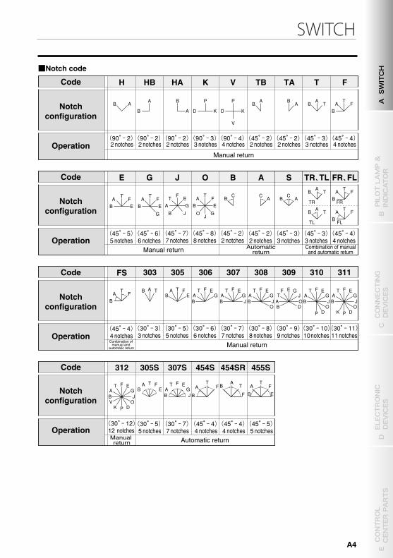
HB HA K V TB TA T F
(9 0° ‐2) 2 notches
(9 0° ‐2) 2 notches
(9 0° ‐2) 2 notches
(9 0° ‐3) 3 notches
(9 0° ‐4) 4 notches
(4 5° ‐2) 2 notches
(4 5° ‐2) 2 notches
(4 5° ‐3) 3 notches
(4 5° ‐4) 4 notches
B A B
A
A
B
D K
P
D K
P
V
A B
B A
B T A
B A F T
H
A G T
J B
E F
B E A
G J
O
F T
B C
(4 5° ‐7) 7 notches
(4 5° ‐8) 8 notches
(4 5° ‐2)2 notches
G J O B
5° ‐5) 5 notches
(4 5° ‐6) 6 notches
B E A F T
(4
B E A
G
F T
E
A C
B A C
B A F B T
TR
B A F T
T
B T
TL
A
A
A S TR 、 TL FR 、 FL
(4 5° ‐2) 2 notches
(4 5° ‐3) 3 notches
(4 5° ‐3) 3 notches
(4 5° ‐4) 4 notches
FR
FL
305S 307S 454S 455S
(3 0° ‐5) 5 notches
(3 0° ‐7) 7 notches
(4 5°‐4) 4 notches
(45°‐4)4 notches
(4 5° ‐5) 5 notches
312
(3 0° ‐12) 12 notches
F
P
T E
B J A G
V O K D
T A F B E
B
A T
F B A T
F B E
A F T F T E
B J A G
454SR
B A F T
FS
5° ‐4) 4 notches (4
305 306 307 308 309 310 311 303
(3 0°‐3) 3 notches
(3 0° ‐5) 5 notches
(3 0° ‐6) 6 notches
(3 0° ‐7) 7 notches
(3 0° ‐8) 8 notches
(3 0° ‐9) 9 notches
(3 0° ‐10) 10 notches
(3 0° ‐11) 11 notches
F
P
T E
B J A G
O K D
F
P
T E
B J A G
O D
E F G
A O T J
B D
F T E
B J A G
O
F T E
B J A G
F T E
B A G
T A F B E
A B T
① ② ⑦ ⑧ ⑨
■Notch code
Code
Operation
Notchconfiguration
Code
Operation
Notchconfiguration
Code
Operation
Notchconfiguration
Code
Operation
Notchconfiguration
Manual return
Manual return
Manual return
Manual return
Automaticreturn
Automatic return
Combination of manualand automatic return
Combination of manual and
automatic return
CAM-OPERATED SWITCH
B TYPE, BH TYPE●CONTROL SWITCH
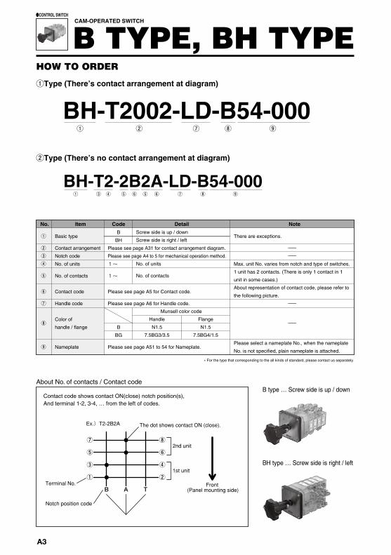
HOW TO ORDER
①Type (There’s contact arrangement at diagram)
BH-T2-2B2A-LD-B54-000① ③ ④ ⑤ ⑥ ⑦⑤⑥ ⑧ ⑨
②Type (There’s no contact arrangement at diagram)
No. Item Code Detail Note
Basic type
Contact arrangement
Notch code
No. of units
No. of contacts
Contact code
Handle code
Color of
handle / flange
Nameplate
Please see page A31 for contact arrangement diagram.
Please see page A4 to 5 for mechanical operation method.
1~
1~
Please see page A5 for Contact code.
Please see page A6 for Handle code.
Please see page A51 to 54 for Nameplate.
There are exceptions.
ーー
Max. unit No. varies from notch and type of switches.
1 unit has 2 contacts. (There is only 1 contact in 1
unit in some cases.)
About representation of contact code, please refer to
the following picture.
ー
ー
Please select a nameplate No., when the nameplate
No. is not specified, plain nameplate is attached.
①
②③④
⑤
⑥
⑦
⑧
⑨
Screw side is up / down
Screw side is right / left
No. of units
No. of contacts
Flange
N1.5
7.5BG4/1.5
Handle
N1.5
7.5BG3/3.5
Munsell color code
� For the type that corresponding to the all kinds of standard, please contact us separately.
Contact code shows contact ON(close) notch position(s),And terminal 1-2, 3-4, … from the left of codes.
About No. of contacts / Contact code
B
BH
B
BG
A3
SWITCH
BH-T2002-LD-B54-000
B type … Screw side is up / down
BH type … Screw side is right / left
Ex.)T2-2B2A
Terminal No.
Notch position code
The dot shows contact ON (close).
Front (Panel mounting side)
2nd unit⑦
B A T
⑧
⑤ ⑥
③ ④
① ②1st unit
HB HA K V TB TA T F
(9 0° ‐2) 2 notches
(9 0° ‐2) 2 notches
(9 0° ‐2) 2 notches
(9 0° ‐3) 3 notches
(9 0° ‐4) 4 notches
(4 5° ‐2) 2 notches
(4 5° ‐2) 2 notches
(4 5° ‐3) 3 notches
(4 5° ‐4) 4 notches
B A B
A
A
B
D K
P
D K
P
V
A B
B A
B T A
B A F T
H
A G T
J B
E F
B E A
G J
O
F T
B C
(4 5° ‐7) 7 notches
(4 5° ‐8) 8 notches
(4 5° ‐2)2 notches
G J O B
5° ‐5) 5 notches
(4 5° ‐6) 6 notches
B E A F T
(4
B E A
G
F T
E
A C
B A C
B A F B T
TR
B A F T
T
B T
TL
A
A
A S TR 、 TL FR 、 FL
(4 5° ‐2) 2 notches
(4 5° ‐3) 3 notches
(4 5° ‐3) 3 notches
(4 5° ‐4) 4 notches
FR
FL
305S 307S 454S 455S
(3 0° ‐5) 5 notches
(3 0° ‐7) 7 notches
(4 5°‐4) 4 notches
(45°‐4)4 notches
(4 5° ‐5) 5 notches
312
(3 0° ‐12) 12 notches
F
P
T E
B J A G
V O K D
T A F B E
B
A T
F B A T
F B E
A F T F T E
B J A G
454SR
B A F T
FS
5° ‐4) 4 notches (4
305 306 307 308 309 310 311 303
(3 0°‐3) 3 notches
(3 0° ‐5) 5 notches
(3 0° ‐6) 6 notches
(3 0° ‐7) 7 notches
(3 0° ‐8) 8 notches
(3 0° ‐9) 9 notches
(3 0° ‐10) 10 notches
(3 0° ‐11) 11 notches
F
P
T E
B J A G
O K D
F
P
T E
B J A G
O D
E F G
A O T J
B D
F T E
B J A G
O
F T E
B J A G
F T E
B A G
T A F B E
A B T
① ② ⑦ ⑧ ⑨
■Notch code
Code
Operation
Notchconfiguration
Code
Operation
Notchconfiguration
Code
Operation
Notchconfiguration
Code
Operation
Notchconfiguration
Manual return
Manual return
Manual return
Manual return
Automaticreturn
Automatic return
Combination of manualand automatic return
Combination of manual and
automatic return
CAM-OPERATED SWITCH
B TYPE, BH TYPE●CONTROL SWITCH
HOW TO ORDER
①Type (There’s contact arrangement at diagram)
BH-T2-2B2A-LD-B54-000① ③ ④ ⑤ ⑥ ⑦⑤⑥ ⑧ ⑨
②Type (There’s no contact arrangement at diagram)
No. Item Code Detail Note
Basic type
Contact arrangement
Notch code
No. of units
No. of contacts
Contact code
Handle code
Color of
handle / flange
Nameplate
Please see page A31 for contact arrangement diagram.
Please see page A4 to 5 for mechanical operation method.
1~
1~
Please see page A5 for Contact code.
Please see page A6 for Handle code.
Please see page A51 to 54 for Nameplate.
There are exceptions.
ーー
Max. unit No. varies from notch and type of switches.
1 unit has 2 contacts. (There is only 1 contact in 1
unit in some cases.)
About representation of contact code, please refer to
the following picture.
ー
ー
Please select a nameplate No., when the nameplate
No. is not specified, plain nameplate is attached.
①
②③④
⑤
⑥
⑦
⑧
⑨
Screw side is up / down
Screw side is right / left
No. of units
No. of contacts
Flange
N1.5
7.5BG4/1.5
Handle
N1.5
7.5BG3/3.5
Munsell color code
� For the type that corresponding to the all kinds of standard, please contact us separately.
Contact code shows contact ON(close) notch position(s),And terminal 1-2, 3-4, … from the left of codes.
About No. of contacts / Contact code
B
BH
B
BG
A SWITCH
B PILOT LAMP &
INDICATOR
D ELECTRONIC
DEVICES
C CONNECTING
DEVICES
E CONTROL
CENTER PARTS
A4
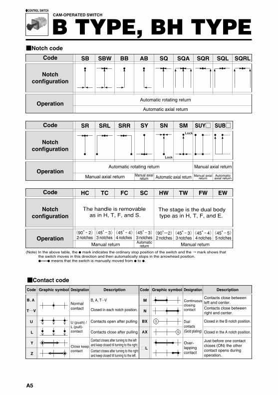
BB SBW AB SQ SQA SQR SB SQL
HC TC FC SC
(9 0° ‐2) 2 notches
(4 5° ‐3) 3 notches
(4 5° ‐4) 4 notches
(4 5° ‐3) 3 notches
HW FW TW EW
(9 0° -2 ) 2 notches
(4 5° ‐3) 3 notches
(4 5° ‐4) 4 notches
(4 5° ‐5) 5 notches
SQRL
SRL SR SRR SN SUY□ SUB□ SY SM
Lock
Lock
■Notch code
■Contact code
U
L
Y
Z
BX
AX
B、 A
T …V
M
N
G
G
L
Code
Operation
Notchconfiguration
Code
Operation
Notchconfiguration
Code
Operation
Notchconfiguration
Code Code
Dualcontacts(Gold plating)
Graphic symbol DescriptionDesignation DesignationGraphic symbol Description
Automatic axial return
Automatic rotating return
Automatic rotating return Manual axial return
Manual axialreturn
Automaticaxial return
Manual axialreturn
Manual return
Manual axial return
Manual return
Automatic axial return
Automaticreturn
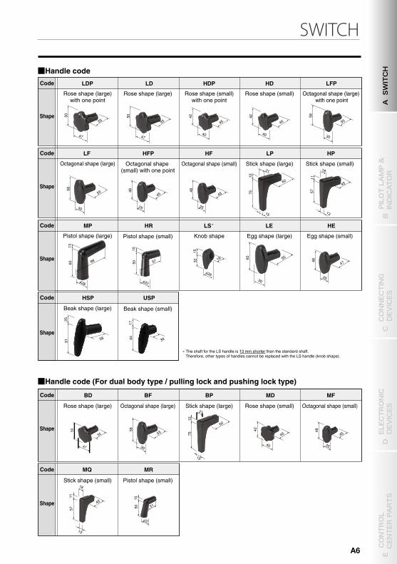
■Handle codeCode
Shape
Code
Shape
Code
Shape
Code
Shape
Code
Shape
Code
Shape
Rose shape (large)with one point
Octagonal shape (small) with one point
Knob shape
Rose shape (small) Octagonal shape (small)
Stick shape (small) Pistol shape (small)
Egg shape (large) Egg shape (small)
Octagonal shape (small) Stick shape (large) Stick shape (small)
Pistol shape (large) Pistol shape (small)
Beak shape (large) Beak shape (small)
Rose shape (large) Rose shape (small)with one point
Rose shape (small) Octagonal shape (large) with one point
Octagonal shape (large)
Rose shape (large) Octagonal shape (large) Stick shape (large)
� The shaft for the LS handle is 13 mm shorter than the standard shaft.Therefore, other types of handles cannot be replaced with the LS handle (knob shape).
■Handle code (For dual body type / pulling lock and pushing lock type)
The handle is removable as in H, T, F, and S.
The stage is the dual bodytype as in H, T, F, and E.
Over-lappingcontact
Normalcontact
U (push) / L (pull)- contact
Contacts open after pulling
B, A, T···V
Closed in each notch position.
Contacts close after pulling
Contact closes after turning to the left and keep closed till turning to the right.Contact closes after turning to the right and keep closed till turning to the left.
Contacts close between left and center.
Closed in the B notch position.
Closed in the A notch position.
Contacts close between right and center.
Close keep contact
Continuous closing contact
(Note) In the above table, the ● mark indicates the ordinary stop position of the switch and the → mark shows that the switch moves in this direction and then automatically stops in the arrowhead position. ●―― ● means that the switch is manually moved from ● to ●.
CAM-OPERATED SWITCH
B TYPE, BH TYPE●CONTROL SWITCH
Just before one contact closes (ON) the other contact opens during operation.
LDP LD HDP HD LFP
LF
50
55
47
50
55
47
42
45
40
42
45
40
58
55
30
58
55
30
48
45
25
48
45
25
HFP HF LP HP
MP HR
75
12
21
60
15
57
11
18
45
13
60
13
88
φ2 8
50
10
57
φ2 2
LS LE HE �
HSP USP
15
φ2 6
32
19 60
30
55
25
48
47
25
51 58
17
44
39
MD MF
MQ MR
BD BF BP
50
55
47
58
55
30
60
75
12
21
15
42
45
40
48
45
25
11
57
45
18
13
φ2 2
50 10
51
A5
SWITCH
BB SBW AB SQ SQA SQR SB SQL
HC TC FC SC
(9 0° ‐2) 2 notches
(4 5° ‐3) 3 notches
(4 5° ‐4) 4 notches
(4 5° ‐3) 3 notches
HW FW TW EW
(9 0° -2 ) 2 notches
(4 5° ‐3) 3 notches
(4 5° ‐4) 4 notches
(4 5° ‐5) 5 notches
SQRL
SRL SR SRR SN SUY□ SUB□ SY SM
Lock
Lock
■Notch code
■Contact code
U
L
Y
Z
BX
AX
B、 A
T …V
M
N
G
G
L
Code
Operation
Notchconfiguration
Code
Operation
Notchconfiguration
Code
Operation
Notchconfiguration
Code Code
Dualcontacts(Gold plating)
Graphic symbol DescriptionDesignation DesignationGraphic symbol Description
Automatic axial return
Automatic rotating return
Automatic rotating return Manual axial return
Manual axialreturn
Automaticaxial return
Manual axialreturn
Manual return
Manual axial return
Manual return
Automatic axial return
Automaticreturn
■Handle codeCode
Shape
Code
Shape
Code
Shape
Code
Shape
Code
Shape
Code
Shape
Rose shape (large)with one point
Octagonal shape (small) with one point
Knob shape
Rose shape (small) Octagonal shape (small)
Stick shape (small) Pistol shape (small)
Egg shape (large) Egg shape (small)
Octagonal shape (small) Stick shape (large) Stick shape (small)
Pistol shape (large) Pistol shape (small)
Beak shape (large) Beak shape (small)
Rose shape (large) Rose shape (small)with one point
Rose shape (small) Octagonal shape (large) with one point
Octagonal shape (large)
Rose shape (large) Octagonal shape (large) Stick shape (large)
� The shaft for the LS handle is 13 mm shorter than the standard shaft.Therefore, other types of handles cannot be replaced with the LS handle (knob shape).
■Handle code (For dual body type / pulling lock and pushing lock type)
The handle is removable as in H, T, F, and S.
The stage is the dual bodytype as in H, T, F, and E.
Over-lappingcontact
Normalcontact
U (push) / L (pull)- contact
Contacts open after pulling
B, A, T···V
Closed in each notch position.
Contacts close after pulling
Contact closes after turning to the left and keep closed till turning to the right.Contact closes after turning to the right and keep closed till turning to the left.
Contacts close between left and center.
Closed in the B notch position.
Closed in the A notch position.
Contacts close between right and center.
Close keep contact
Continuous closing contact
(Note) In the above table, the ● mark indicates the ordinary stop position of the switch and the → mark shows that the switch moves in this direction and then automatically stops in the arrowhead position. ●―― ● means that the switch is manually moved from ● to ●.
CAM-OPERATED SWITCH
B TYPE, BH TYPE●CONTROL SWITCH
Just before one contact closes (ON) the other contact opens during operation.
LDP LD HDP HD LFP
LF
50
55
47
50
55
47
42
45
40
42
45
40
58
55
30
58
55
30
48
45
25
48
45
25
HFP HF LP HP
MP HR
75
12
21
60
15
57
11
18
45
13
60
13
88
φ2 8
50
10
57
φ2 2
LS LE HE �
HSP USP
15
φ2 6
32
19 60
30
55
25
48
47
25
51 58
17
44
39
MD MF
MQ MR
BD BF BP
50
55
47
58
55
30
60
75
12
21
15
42
45
40
48
45
25
11
57
45
18
13
φ2 2
50 10
51
A SWITCH
B PILOT LAMP &
INDICATOR
D ELECTRONIC
DEVICES
C CONNECTING
DEVICES
E CONTROL
CENTER PARTS
A6
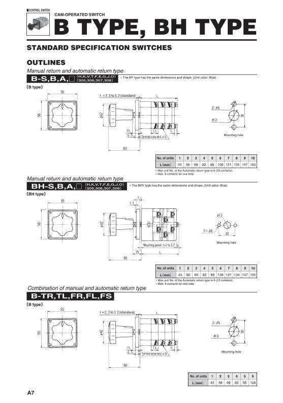
STANDARD SPECIFICATION SWITCHES
CAM-OPERATED SWITCH
B TYPE, BH TYPE●CONTROL SWITCH
OUTLINES
B-S,B,A,□(H,K,V,T,F,E,G,J,O)(305,306,307,308)
1 2 3 4 5 6 7 8 9 10
43 56 69 82 95 108 121 134 147 160L(mm)
(B type)
(BH type)
(B type)
1 2 3 4 5 6
43 56 69 82 95 108L(mm)
B-TR,TL,FR,FL,FS
� Max unit No. of the Automatic return type is 6 (12 contacts).� Max. 6 contacts for one side.
1 2 3 4 5 6 7 8 9 10
43 56 69 82 95 108 121 134 147 160L(mm)
BH-S,B,A,□(H,K,V,T,F,E,G,J,O)(305,306,307,308)
Manual return and automatic return type
Manual return and automatic return type
� The BY type has the same dimensions and shape. (Unit color: Blue)
No. of units
No. of units
No. of units
Mounting hole
� Max unit No. of the Automatic return type is 6 (12 contacts).� Max. 6 contacts for one side.
Mounting holeMounting panel: to=
Combination of manual and automatic return type
Mounting hole
� The BHY type has the same dimensions and shape. (Unit color: Blue)
Terminal screw
t to (standard)
Terminal screw
t to (standard)
A7
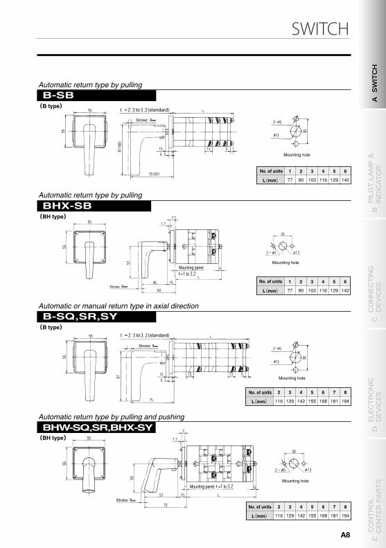
SWITCH
(B type)
(BH type)
(B type)
(BH type)
1 2 3 4 5 6
77 90 103 116 129 142 L (mm)
B-SB
2 3 4 5 6 7 8
116 129 142 155 168 181 194 L (mm)
B-SQ ,SR,SY
1 2 3 4 5 6
77 90 103 116 129 142 L (mm)
BHX-SB
2 3 4 5 6 7 8
116 129 142 155 168 181 194 L (mm)
BHW -SQ ,SR,BHX-SY
STANDARD SPECIFICATION SWITCHES
No. of units
Mounting hole
Stroke:
Automatic return type by pulling
Automatic return type by pulling
Automatic or manual return type in axial direction
Automatic return type by pulling and pushing
No. of units
Mounting hole
Stroke:
No. of units
Mounting hole
Stroke:
No. of units
Mounting hole
CAM-OPERATED SWITCH
B TYPE, BH TYPE●CONTROL SWITCH
t to (standard)
Stroke:
Mounting panel:to=
Mounting panel: to=
t to (standard)
OUTLINES
B-S,B,A,□(H,K,V,T,F,E,G,J,O)(305,306,307,308)
1 2 3 4 5 6 7 8 9 10
43 56 69 82 95 108 121 134 147 160L(mm)
(B type)
(BH type)
(B type)
1 2 3 4 5 6
43 56 69 82 95 108L(mm)
B-TR,TL,FR,FL,FS
� Max unit No. of the Automatic return type is 6 (12 contacts).
1 2 3 4 5 6 7 8 9 10
43 56 69 82 95 108 121 134 147 160L(mm)
BH-S,B,A,□(H,K,V,T,F,E,G,J,O)(305,306,307,308)
Manual return and automatic return type
Manual return and automatic return type
� The BY type has the same dimensions and shape. (Unit color: Blue)
No. of units
No. of units
No. of units
Mounting hole
� Max unit No. of the Automatic return type is 6 (12 contacts).
Mounting holeMounting panel: to=
Combination of manual and automatic return type
Mounting hole
� The BHY type has the same dimensions and shape. (Unit color: Blue)
Terminal screw
t to (standard)
Terminal screw
t to (standard)
A SWITCH
B PILOT LAMP &
INDICATOR
D ELECTRONIC
DEVICES
C CONNECTING
DEVICES
E CONTROL
CENTER PARTS
A8
Conbinationdiagram
Key conbination No.
Key shaft�1
Body
�2
KB1 KB2 KB3 KB4
<Cross-section view>Body
Concave of key shaft
Convex of spring pin Spring pin
Spring pin Handle
Key shaft
Nameplate
Flange
�1, 2 Diagram from right figure shape.
�1
�2
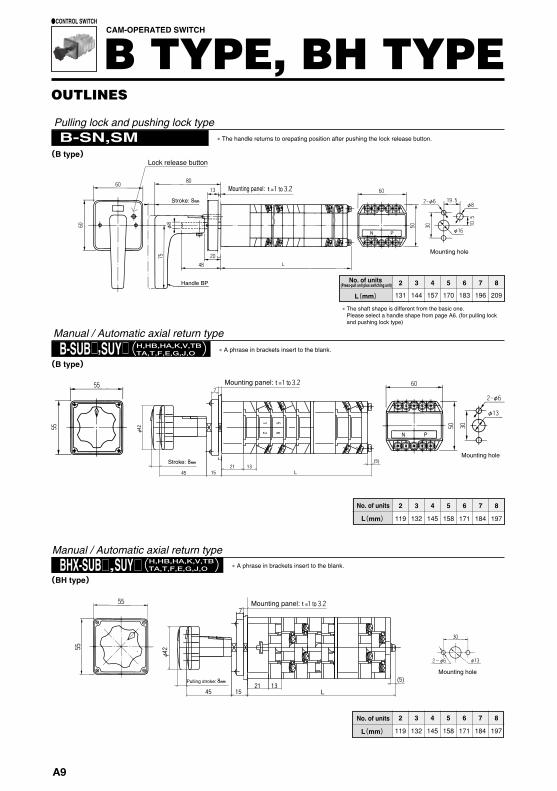
2 3 4 5 6 7 8
119 132 145 158 171 184 197L(mm)
B-SN,SM
2 3 4 5 6 7 8
131 144 157 170 183 196 209L (mm)
H,HB,HA,K,V,TB TA,T,F,E,G,J,O ( ) B-SU B □ , SU Y □
L 45 13 21
2
1
6
5
(5)
15
φ42
7
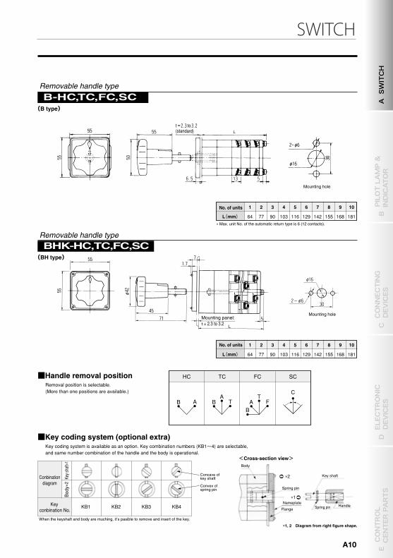
B-H C, TC ,FC ,SC
1 2 3 4 5 6 7 8 9 10
64 77 90 103 116 129 142 155 168 181L (mm)
H,HB,HA,K,V,TB TA,T,F,E,G,J,O ( ) BHX-SUB □ , SU Y □
2 3 4 5 6 7 8
119 132 145 158 171 184 197L (mm)
7
15
(5)
L 45 13 21
φ42
1 2 3 4 5 6 7 8 9 10
64 77 90 103 116 129 142 155 168 181 L (mm)
BHK-HC,TC,FC,SC
SC FC TC
C
F T
A B
T A
B A B
HC ■Handle removal positionRemoval position is selectable.(More than one positions are available.)
■Key coding system (optional extra)Key coding system is available as an option. Key combination numbers (KB1~4) are selectable, and same number combination of the handle and the body is operational.
OUTLINES
No. of units(Press-pull unit plus switching unit)
Mounting hole
Mounting hole
Pulling lock and pushing lock type� The handle returns to orepating position after pushing the lock release button.
Lock release button
� The shaft shape is different from the basic one. Please select a handle shape from page A6. (for pulling lock and pushing lock type)
Handle BP
No. of units
Manual / Automatic axial return type
Mounting hole
No. of units
Manual / Automatic axial return type
Pulling stroke:
Removable handle type
No. of units
Mounting hole
No. of units
Mounting hole
Removable handle type
Mounting panel:
� Max. unit No. of the automatic return type is 6 (12 contacts).
CAM-OPERATED SWITCH
B TYPE, BH TYPE●CONTROL SWITCH
(B type) (B type)
(BH type)(B type)
(BH type)
Stroke:
Mounting panel: to=
Stroke:
Mounting panel: to=
Mounting panel: to=
t to(standard)
= 2.3 to 3.2
� A phrase in brackets insert to the blank.
� A phrase in brackets insert to the blank.
When the keyshaft and body are muching, it’s pasible to remove and insert of the key.
A9
SWITCH
Conbinationdiagram
Key conbination No.
Key shaft �1
Body
�2
KB1 KB2 KB3 KB4
<Cross-section view>Body
Concave of key shaft
Convex of spring pin Spring pin
Spring pin Handle
Key shaft
Nameplate
Flange
�1, 2 Diagram from right figure shape.
�1
�2
2 3 4 5 6 7 8
119 132 145 158 171 184 197L(mm)
B-SN,SM
2 3 4 5 6 7 8
131 144 157 170 183 196 209L (mm)
H,HB,HA,K,V,TB TA,T,F,E,G,J,O ( ) B-SU B □ , SU Y □
L 45 13 21
2
1
6
5
(5)
15
φ42
7
B-H C, TC ,FC ,SC
1 2 3 4 5 6 7 8 9 10
64 77 90 103 116 129 142 155 168 181L (mm)
H,HB,HA,K,V,TB TA,T,F,E,G,J,O ( ) BHX-SUB □ , SU Y □
2 3 4 5 6 7 8
119 132 145 158 171 184 197L (mm)
7
15
(5)
L 45 13 21
φ42
1 2 3 4 5 6 7 8 9 10
64 77 90 103 116 129 142 155 168 181 L (mm)
BHK-HC,TC,FC,SC
SC FC TC
C
F T
A B
T A
B A B
HC ■Handle removal positionRemoval position is selectable.(More than one positions are available.)
■Key coding system (optional extra)Key coding system is available as an option. Key combination numbers (KB1~4) are selectable, and same number combination of the handle and the body is operational.
OUTLINES
No. of units(Press-pull unit plus switching unit)
Mounting hole
Mounting hole
Pulling lock and pushing lock type� The handle returns to orepating position after pushing the lock release button.
Lock release button
� The shaft shape is different from the basic one. Please select a handle shape from page A6. (for pulling lock and pushing lock type)
Handle BP
No. of units
Manual / Automatic axial return type
Mounting hole
No. of units
Manual / Automatic axial return type
Pulling stroke:
Removable handle type
No. of units
Mounting hole
No. of units
Mounting hole
Removable handle type
Mounting panel:
� Max. unit No. of the automatic return type is 6 (12 contacts).
CAM-OPERATED SWITCH
B TYPE, BH TYPE●CONTROL SWITCH
(B type) (B type)
(BH type)(B type)
(BH type)
Stroke:
Mounting panel: to=
Stroke:
Mounting panel: to=
Mounting panel: to=
t to(standard)
= 2.3 to 3.2
� A phrase in brackets insert to the blank.
� A phrase in brackets insert to the blank.
When the keyshaft and body are muching, it’s pasible to remove and insert of the key.
A SWITCH
B PILOT LAMP &
INDICATOR
D ELECTRONIC
DEVICES
C CONNECTING
DEVICES
E CONTROL
CENTER PARTS
A10
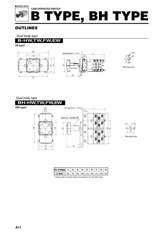
B-HW,TW,FW,EW
BH-HW,TW,FW,EW
1 2 3 4 5 6 7 8 9
63 76 89 102 115 128 141 154 167 L (mm)
64
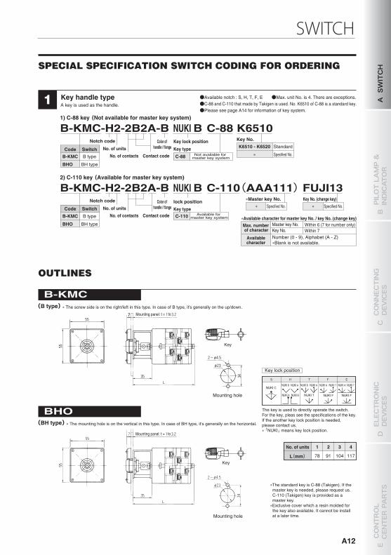
Key handle typeA key is used as the handle.1
B-KMC-H2-2B2A-B NUKI B C-88 K6510Notch code
No. of unitsNo. of contacts
Color of handle / flange
Key lock position
Key type
Key No.
Contact codeCode SwitchB-KMC
BHO
B type
BH type
C-88 Not available for master key system
Available for master key system
K6510 - K6520
∗Standard
Specified No.
1) C-88 key (Not available for master key system)
B-KMC-H2-2B2A-B NUKI B C-110(AAA111) FUJI13Notch code
No. of unitsNo. of contacts
Color of handle / flange
lock position Key No. (change key)
Contact codeCode Switch
B-KMC
BHO
B type
BH type
Key typeC-110
Specified No.
2) C-110 key (Available for master key system)
∗∗Master key No.
Specified No.∗
∗Available character for master key No. / key No. (change key)Max. number of character
Availablecharacter
Master key No.Key No.
Within 6 (7 for number only)Within 7
Number (0 - 9), Alphabet (A - Z)∗Blank is not available.
B-KMC(B type)
1 2 3 4
78 91 104 117 L (mm)
BHO
S
NUKI C
H T E
NUKI A
F
NUKI B NUKI BNUKI A NUKI A NUKI A NUKI T
NUKI F NUKI F
NUKI T
Dual body type
No. of stages
Mounting hole
Dual body type
∗ Please select a handle shape from page A6. (for dual body type)
Mounting panel: t =TOP
No. of units
Key lock position
Mounting hole
Mounting hole
Key
Key
The key is used to directly operate the switch.For the key, pleas see the specifications of the key.If the another key lock position is needed, please contact us.∗ 「NUKI」 means key lock position.
OUTLINES
The standard key is C-88 (Takigen). If the master key is needed, please request us.C-110 (Takigen) key is provided as a master key.
OUTLINES
CAM-OPERATED SWITCH
B TYPE, BH TYPE●CONTROL SWITCH
(B type)
(BH type)
(BH type)
Shaft: Handle: BD
SPECIAL SPECIFICATION SWITCH CODING FOR ORDERING
Mounting panel: t =
Mounting panel: t =
●Available notch : S, H, T, F, E ●Max. unit No. is 4.●C-88 and C-110 that made by Takigen is used. No. K6510 of C-88 is a standard key.●Please see page A14 for information of key system.
NUKI B NUKI TNUKI A
to
to
to
Mounting hole
50
55
L
15
20
7
124Mounting panel: t = to
∗ The screw side is on the right/left in this type. In case of B type, it's generally on the up/down.
∗ The mounting hole is on the vertical in this type. In case of BH type, it's generally on the horizontal.
A11
SWITCH
Key handle typeA key is used as the handle.1
B-KMC-H2-2B2A-B NUKI B C-88 K6510Notch code
No. of unitsNo. of contacts
Color of handle / flange
Key lock position
Key type
Key No.
Contact codeCode SwitchB-KMC
BHO
B type
BH type
C-88 Not available for master key system
Available for master key system
K6510 - K6520
�
Standard
Specified No.
1) C-88 key (Not available for master key system)
B-KMC-H2-2B2A-B NUKI B C-110(AAA111) FUJI13Notch code
No. of unitsNo. of contacts
Color of handle / flange
lock position Key No. (change key)
Contact codeCode Switch
B-KMC
BHO
B type
BH type
Key typeC-110
Specified No.
2) C-110 key (Available for master key system)
�
�Master key No.Specified No.�
�Available character for master key No. / key No. (change key)Max. number of character
Availablecharacter
Master key No.Key No.
Within 6 (7 for number only)Within 7
Number (0 - 9), Alphabet (A - Z)�Blank is not available.
B-KMC(B type)
1 2 3 4
78 91 104 117 L (mm)
BHO
S
NUKI C
H T E
NUKI A
F
NUKI B NUKI BNUKI A NUKI A NUKI A NUKI T
NUKI F NUKI F
NUKI T
No. of units
Key lock position
Mounting hole
Mounting hole
Key
Key
The key is used to directly operate the switch.For the key, pleas see the specifications of the key.If the another key lock position is needed, please contact us.� 「NUKI」 means key lock position.
OUTLINES
�The standard key is C-88 (Takigen). If the master key is needed, please request us.C-110 (Takigen) key is provided as a master key.
�Exclusive cover which a resin molded for the key also available. It cannot be install at a later time.
(BH type)
SPECIAL SPECIFICATION SWITCH CODING FOR ORDERING
Mounting panel: t =
Mounting panel: t =
●Available notch : S, H, T, F, E ●Max. unit No. is 4. There are exceptions.●C-88 and C-110 that made by Takigen is used. No. K6510 of C-88 is a standard key.●Please see page A14 for information of key system.
NUKI B NUKI TNUKI A
to
to
���� The screw side is on the right/left in this type. In case of B type, it's generally on the up/down.
���� The mounting hole is on the vertical in this type. In case of BH type, it's generally on the horizontal.
A SWITCH
B PILOT LAMP &
INDICATOR
D ELECTRONIC
DEVICES
C CONNECTING
DEVICES
E CONTROL
CENTER PARTS
A12
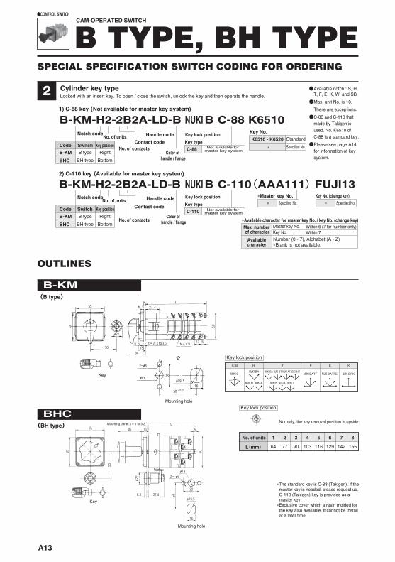
1 2 3 4 5 6 7 8
64 77 90 103 116 129 142 155L(mm)
BHC
S/SB
NUKI C
H
NUKI BA NUKI BA NUKI BT NUKI AT
NUKI B NUKI A
NUKI BAT
NUKI A
T F E
NUKI BATF NUKI BATFE NUKI DPK
K
NUKI B NUKI T
t to
B-KM(B type)
Cylinder key typeLocked with an insert key. To open / close the switch, unlock the key and then operate the handle.21) C-88 key (Not available for master key system)
B-KM-H2-2B2A-LD-B NUKI B C-110(AAA111) FUJI132) C-110 key (Available for master key system)
B-KM-H2-2B2A-LD-B NUKI B C-88 K6510Key No.K6510 - K6520
�
Notch codeNo. of units
No. of contacts
Handle code
Color of handle / flange
Key lock position
Contact codeCode SwitchB-KM
BHC
Key position
Notch codeNo. of units
No. of contacts
Handle code
Color of handle / flange
Contact codeCode SwitchB-KM
BHC
Key position
Key typeC-88 Not available for
master key system
Key lock position
Key typeNot available for
master key systemC-110
Key lock position
Normaly, the key removal position is upside.
Mounting hole
Mounting hole
Key
Key
�The standard key is C-88 (Takigen). If the master key is needed, please request us.C-110 (Takigen) key is provided as a master key.
�Exclusive cover which a resin molded for the key also available. It cannot be install at a later time.
Mounting panel: t = 1 to 3.2
No. of units
OUTLINES
CAM-OPERATED SWITCH
B TYPE, BH TYPE●CONTROL SWITCH
B type
BH type
Right
Bottom
B type
BH type
Right
Bottom
●Available notch : S, H, T, F, E, K, W, and SB.
●Max. unit No. is 10.
There are exceptions.
●C-88 and C-110 that made by Takigen is used. No. K6510 of C-88 is a standard key.
●Please see page A14 for information of key system.
(BH type)
Standard
Specified No.
Key No. (change key)�Master key No.Specified No.� Specified No.�
Key lock position
�Available character for master key No. / key No. (change key)Max. number of character
Availablecharacter
Master key No.Key No.
Within 6 (7 for number only)Within 7
Number (0 - 7), Alphabet (A - Z)�Blank is not available.
SPECIAL SPECIFICATION SWITCH CODING FOR ORDERING
A13
1 1
1
4 3
B-KH-H2-2B2A-LD-B B
B-KH
BHP
BHP
S
NUKI C
H
NUKI BA NUKI BA NUKI BT NUKI AT
NUKI B NUKI A
NUKI BAT
NUKI A
T F E
NUKI BATF NUKI BATFE NUKI DPK
K
NUKI B NUKI T
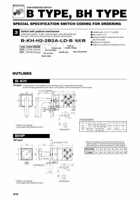
1 2 3 4 5 6 7 8
67 80 93 106 119 132 145 158 L (mm)
B-KH (B type)
BHM
102
1 2 3 4 5 6 7 8 9
65 78 91 104 117 130 143 156 167
BM
102 L
L (mm)
No. of units
Mounting hole
Key lock position
∗ Padlock is not attached.(Use a padlock with diameter of 6 mm).
∗ Padlock is not attached.(Use a padlock with diameter of 6 mm).
Lockreleaselever
Lock release lever
Mounting hole
○Remove the padlock and push the lock release lever for handle operation. The switch will be locked automatically after releasing your hand, then please lock with a padlock.
Mounting panel:
Padlock: 6
OUTLINES OUTLINES
Mounting hole
Mount the flange and main body with M5 × 12 countersunk screws.(at vertical pitches of 30 mm)
Mount the switch directly to the panel with M5 × 10 pan head screws.(at horizontal pitches of 30 mm)
Mounting hole
No. of units
Switch with padlock mechanismLocked with a padlock. To open / close the switch, unlock the padlock and then open / close the key while pushing or pulling the unlocking lever.
Notch code
No. of units
No. of contactsContact code
Handle code Key lock position
Code Switch Unlockinglever type
Pushing typeB type
BH type Pulling type
●Available notch : S, H, T, F, and SB.●Max. unit No. is 10.●Normaly a padlock is attached to the down
side of the switch.●Padlock is not attached.●Please use a padlock with diameter of 6 mm.
Color of handle / flange
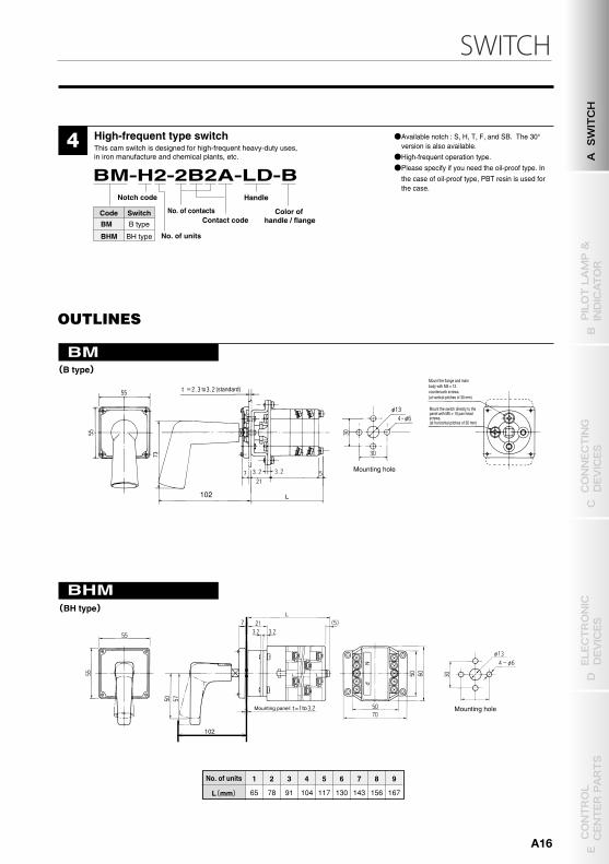
High-frequent type switchThis cam switch is designed for high-frequent heavy-duty uses, in iron manufacture and chemical plants, etc.
BM-H2-2B2A-LD-BNotch code
No. of units
No. of contactsContact code
Handle
Code SwitchBM
BHM
B type
BH type
●Available notch : S, H, T, F, and SB. The 30° version is also available.
●High-frequent operation type.●Please specify if you need the oil-proof type. In
the case of oil-proof type, PBT resin is used for the case.
Color of handle / flange
CAM-OPERATED SWITCH
B TYPE, BH TYPE●CONTROL SWITCH
t to (standard)
(BH type) (BH type)
(B type)
Mounting panel:
t to (standard)
NUKI
∗ The screw side is on the right/left, and the mounting hole is on the horizontal in this type. In case of B type, generally the screw side is on the up/down, and the mounting hole is on the vertical.
to=
to=
SPECIAL SPECIFICATION SWITCH CODING FOR ORDERING
A15
SWITCH
4 3
B-KH-H2-2B2A-LD-B B
B-KH
BHP
BHP
S
NUKI C
H
NUKI BA NUKI BA NUKI BT NUKI AT
NUKI B NUKI A
NUKI BAT
NUKI A
T F E
NUKI BATF NUKI BATFE NUKI DPK
K
NUKI B NUKI T
1 2 3 4 5 6 7 8
67 80 93 106 119 132 145 158 L (mm)
B-KH (B type)
BHM
102
1 2 3 4 5 6 7 8 9
65 78 91 104 117 130 143 156 167
BM
102 L
L (mm)
No. of units
Mounting hole
Key lock position
∗ Padlock is not attached.(Use a padlock with diameter of 6 mm).
∗ Padlock is not attached.(Use a padlock with diameter of 6 mm).
Lockreleaselever
Lock release lever
Mounting hole
○Remove the padlock and push the lock release lever for handle operation. The switch will be locked automatically after releasing your hand, then please lock with a padlock.
Mounting panel:
Padlock: 6
OUTLINES OUTLINES
Mounting hole
Mount the flange and main body with M5 × 12 countersunk screws.(at vertical pitches of 30 mm)
Mount the switch directly to the panel with M5 × 10 pan head screws.(at horizontal pitches of 30 mm)
Mounting hole
No. of units
Switch with padlock mechanismLocked with a padlock. To open / close the switch, unlock the padlock and then open / close the key while pushing or pulling the unlocking lever.
Notch code
No. of units
No. of contactsContact code
Handle code Key lock position
Code Switch Unlockinglever type
Pushing typeB type
BH type Pulling type
●Available notch : S, H, T, F, and SB.●Max. unit No. is 10.●Normaly a padlock is attached to the down
side of the switch.●Padlock is not attached.●Please use a padlock with diameter of 6 mm.
Color of handle / flange
High-frequent type switchThis cam switch is designed for high-frequent heavy-duty uses, in iron manufacture and chemical plants, etc.
BM-H2-2B2A-LD-BNotch code
No. of units
No. of contactsContact code
Handle
Code SwitchBM
BHM
B type
BH type
●Available notch : S, H, T, F, and SB. The 30° version is also available.
●High-frequent operation type.●Please specify if you need the oil-proof type. In
the case of oil-proof type, PBT resin is used for the case.
Color of handle / flange
CAM-OPERATED SWITCH
B TYPE, BH TYPE●CONTROL SWITCH
t to (standard)
(BH type) (BH type)
(B type)
Mounting panel:
t to (standard)
NUKI
∗ The screw side is on the right/left, and the mounting hole is on the horizontal in this type. In case of B type, generally the screw side is on the up/down, and the mounting hole is on the vertical.
to=
to=
SPECIAL SPECIFICATION SWITCH CODING FOR ORDERING
A SWITCH
B PILOT LAMP &
INDICATOR
D ELECTRONIC
DEVICES
C CONNECTING
DEVICES
E CONTROL
CENTER PARTS
A16
5 6
BL
BH
BHS
●Lamp position
1 lamp
2 lamps
3 lamps
●Lamp position
1 lamp
2 lamps
3 lamps
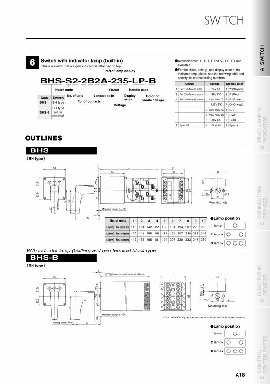
233
246
1 2 3 4 5 6 7 8 9 10
259
L(mm)
L(mm)
L(mm)
116
129
142
129
142
155
142
155
168
155
168
181
168
181
194
181
194
207
194
207
220
207
220
233
220
233
246
BHS-B
OUTLINES OUTLINES
Mounting hole
No. of units
For 1 indicator
For 2 indicators
For 3 indicators
Mounting panel: to=
Mounting hole
Pulling stroke:
Mounting panel: to=
(dimensions with rear terminal block)
No. of units
No. of contactsContact code
Voltage Handle code
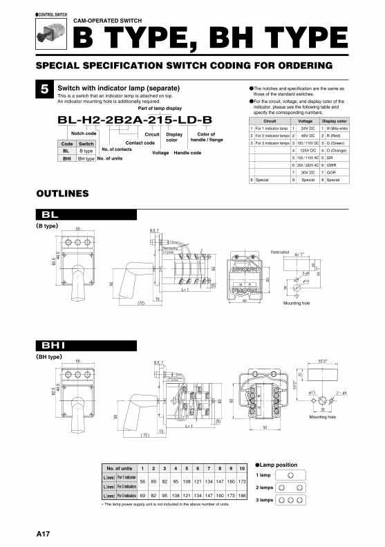
Switch with indicator lamp (separate)This is a switch that an indicator lamp is attached on top.An indicator mounting hole is additionally required.
BL-H2-2B2A-215-LD-B Circuit Display
colorNotch code
Code SwitchBL
BHI
B type
BH type
1
2
3
9
Circuit
For 1 indicator lamp
For 2 indicator lamps
For 3 indicator lamps
Special
1
2
3
4
5
6
7
9
Voltage
24V DC
48V DC
100 / 110V DC
125V DC
100 / 110V AC
200 / 220V AC
30V DC
Special
1
2
3
4
5
6
7
9
Display color
W (Milky white)
R (Red)
G (Green)
O (Orange)
GWR
GR
GOR
Special
Part of lamp display
●The notches and specification are the same as those of the standard switches.
●For the circuit, voltage, and display color of the indicator, please see the following table and specify the corresponding numbers.
Color of handle / flange
Switch with indicator lamp (built-in)This is a switch that a signal indicator is attached on top.
Handle code
BHS-S2-2B2A-235-LP-B Circuit
Part of lamp display
No. of units
Notch code
Voltage
DisplaycolorCode Switch
BHS BH type
BHS-BBH type
(with rearterminal block)
No. of contacts
Contact code
1
2
3
9
Circuit
For 1 indicator lamp
For 2 indicator lamps
For 3 indicator lamps
Special
1
2
3
4
5
6
7
9
Voltage
24V DC
48V DC
100 / 110V DC
125V DC
100 / 110V AC
200 / 220V AC
30V DC
Special
1
2
3
4
5
6
7
9
Display color
W (Milky white)
R (Red)
G (Green)
O (Orange)
GWR
GR
GOR
Special
●Available notch: S, H, T, F and SB, SR, SY also available.
●For the circuit, voltage, and display color of the indicator lamp, please see the following table and specify the corresponding numbers.
Color of handle / flange
With indicator lamp (built-in) and rear terminal block type
� For the BHS-B type, the maximum number of unit is 3. (6 contacts)
CAM-OPERATED SWITCH
B TYPE, BH TYPE●CONTROL SWITCH
(B type) (BH type)
(BH type)
(BH type)
55
82.5 44.5
50
50
78.5
15(72)
(5)L�1
Panel mounting: t=1 to 6mm
Panel mounting: t=1 to 6mm
N P
60
50
5320
30
50
2-φ6
φ13
+0.5 0
+0.5
0
78.555
44.5
82.5
50
15(72)
L�1(5)
60
� The lamp power supply unit is not included in the above number of units.
1 2 3 4 5 6 7 8 9 10
69 82 95 108 121 134 147 160 173 186
No. of units
L(mm)56 69 82 95 108 121 134 147 160 173
For 3 indicators
For 2 indicators
For 1 indicatorL(mm)
L(mm)
●Lamp position
1 lamp
2 lamps
3 lamps
Panel cutout
Mounting hole
Mounting hole
I
SPECIAL SPECIFICATION SWITCH CODING FOR ORDERING
A17
SWITCH
5 6
BL
BH
BHS
●Lamp position
1 lamp
2 lamps
3 lamps
●Lamp position
1 lamp
2 lamps
3 lamps
233
246
1 2 3 4 5 6 7 8 9 10
259
L(mm)
L(mm)
L(mm)
116
129
142
129
142
155
142
155
168
155
168
181
168
181
194
181
194
207
194
207
220
207
220
233
220
233
246
BHS-B
OUTLINES OUTLINES
Mounting hole
No. of units
For 1 indicator
For 2 indicators
For 3 indicators
Mounting panel: to=
Mounting hole
Pulling stroke:
Mounting panel: to=
(dimensions with rear terminal block)
No. of units
No. of contactsContact code
Voltage Handle code
Switch with indicator lamp (separate)This is a switch that an indicator lamp is attached on top.An indicator mounting hole is additionally required.
BL-H2-2B2A-215-LD-B Circuit Display
colorNotch code
Code SwitchBL
BHI
B type
BH type
1
2
3
9
Circuit
For 1 indicator lamp
For 2 indicator lamps
For 3 indicator lamps
Special
1
2
3
4
5
6
7
9
Voltage
24V DC
48V DC
100 / 110V DC
125V DC
100 / 110V AC
200 / 220V AC
30V DC
Special
1
2
3
4
5
6
7
9
Display color
W (Milky white)
R (Red)
G (Green)
O (Orange)
GWR
GR
GOR
Special
Part of lamp display
●The notches and specification are the same as those of the standard switches.
●For the circuit, voltage, and display color of the indicator, please see the following table and specify the corresponding numbers.
Color of handle / flange
Switch with indicator lamp (built-in)This is a switch that a signal indicator is attached on top.
Handle code
BHS-S2-2B2A-235-LP-B Circuit
Part of lamp display
No. of units
Notch code
Voltage
DisplaycolorCode Switch
BHS BH type
BHS-BBH type
(with rearterminal block)
No. of contacts
Contact code
1
2
3
9
Circuit
For 1 indicator lamp
For 2 indicator lamps
For 3 indicator lamps
Special
1
2
3
4
5
6
7
9
Voltage
24V DC
48V DC
100 / 110V DC
125V DC
100 / 110V AC
200 / 220V AC
30V DC
Special
1
2
3
4
5
6
7
9
Display color
W (Milky white)
R (Red)
G (Green)
O (Orange)
GWR
GR
GOR
Special
●Available notch: S, H, T, F and SB, SR, SY also available.
●For the circuit, voltage, and display color of the indicator lamp, please see the following table and specify the corresponding numbers.
Color of handle / flange
With indicator lamp (built-in) and rear terminal block type
� For the BHS-B type, the maximum number of unit is 3. (6 contacts)
CAM-OPERATED SWITCH
B TYPE, BH TYPE●CONTROL SWITCH
(B type) (BH type)
(BH type)
(BH type)
55
82.5 44.5
50
50
78.5
15(72)
(5)L�1
Panel mounting: t=1 to 6mm
Panel mounting: t=1 to 6mm
N P
60
50
5320
30
50
2-φ6
φ13
+0.5 0
+0.5
0
78.555
44.5
82.5
50
15(72)
L�1(5)
60
� The lamp power supply unit is not included in the above number of units.
1 2 3 4 5 6 7 8 9 10
69 82 95 108 121 134 147 160 173 186
No. of units
L(mm)56 69 82 95 108 121 134 147 160 173
For 3 indicators
For 2 indicators
For 1 indicatorL(mm)
L(mm)
●Lamp position
1 lamp
2 lamps
3 lamps
Panel cutout
Mounting hole
Mounting hole
I
SPECIAL SPECIFICATION SWITCH CODING FOR ORDERING
A SWITCH
B PILOT LAMP &
INDICATOR
D ELECTRONIC
DEVICES
C CONNECTING
DEVICES
E CONTROL
CENTER PARTS
A18
Mounting hole
t = 1 to 3.2
Mounting hole
t =2.3 to 3.2 (standard)
7
1 2 3 4 5 6 7 8
104 117 130 143 156 169 182 195L(mm)
BHE
No. of units
OUTLINES
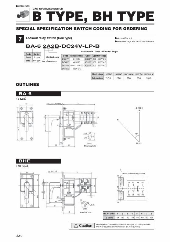
Lockout relay switch (Coil type)
BA-6 2A2B-DC24V-LP-B Handle code
Code SwitchBA-6 B type
BH typeBHE No. of contacts
Contact code
●Max. unit No. is 8.
●Please see page A55 for the operation time.
Color of handle / flange
CAM-OPERATED SWITCH
B TYPE, BH TYPE●CONTROL SWITCH
DC24V
DC48V
DC110V
DC125V
24V DC
48V DC
100 / 110V DC
125V DC
DC220V
AC110V
AC220V
200 / 220V DC
100 / 110V AC
200 / 220V AC
(B type)
(BH type)
24V DC 48V DC 100 / 110V DC 125V DC 200 / 220V DC
5.3Ω 25Ω 55Ω 80Ω 350Ω
Circuit voltage
Coil resistance
Code Operation voltage Code Operation voltage
Reset operation on existence of external signal to coil is prohibited. This may cause severe malfunction. (Ex. Coil burnout)Caution
A
Notch
B
45°
(LOCK)
Protective relay contact(1)
(2)
(5) (7) (9) (11)
(6) (8) (10) (12)
(4)
(3)
Coil
BA-6
SPECIAL SPECIFICATION SWITCH CODING FOR ORDERING
A19
SWITCH
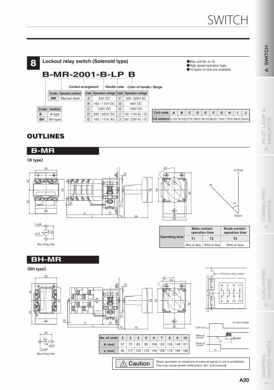
A B C D E F G H I J
3.3Ω16.5Ω 27Ω 60Ω16.5Ω60Ω 13Ω 75Ω 60Ω 240Ω
Coil code
Coil resistance
A
B
C
D
E
24V DC
100 / 110V DC
125V DC
200 / 220V DC
100 / 110V AC
F
G
H
I
J
200 / 220V AC
48V DC
125V DC
100 / 110V AC・DC
200 / 220V AC・DC
Code Operation voltage Code Operation voltage
2 3 4 5 6 7 8 9
94 107 120 133 146 159 172 185
10
198L(mm)
57 70 83 96 109 122 135 148 161A(mm)
No. of units
T1 T2 T3
Make contact operation time
Break contact operation time
8ms or less 16ms or less 8ms or less
Operating time
Reset operation on existence of external signal to coil is prohibited. This may cause severe malfunction. (Ex. Coil burnout)Caution
A
Notch
B
45°
(LOCK)
Protective relay contact(1)
(2)
(5) (7) (9) (11)
(6) (8) (10) (12)
(4)
(3)
Coil
Coil input
Make (a)contact
Break (b)contact
T3
T2T1 Bounce
At rated voltage
L
(5)
A
95
5540
50
45°
55
50
(2)
7
37
58
5515
50
55
30
Mounting hole
2- 6
13
LA
95
5540
45°
55
50
(2)
7
37
58
5515
60
(5)
5055
30
2- 613
Mounting hole
(B type)
(BH type)
B-MR
BH-MR
OUTLINES
Lockout relay switch (Solenoid type)8B-MR-2001-B-LP B
Handle code Color of handle / flangeContact arrangement
Code SwitchB B type
BH typeBH
Code Operation methodMR Manual reset
●Max unit No. is 10.●High speed operation type.●10 types of coils are available. A
SWITCH
B PILOT LAMP &
INDICATOR
D ELECTRONIC
DEVICES
C CONNECTING
DEVICES
E CONTROL
CENTER PARTS
A20
BH-B
9
Ex.)BHY-H2-2BX2AX
Ex.)BY-H2-2BX2A
●Minute current contact is applicable to other standard products.
10
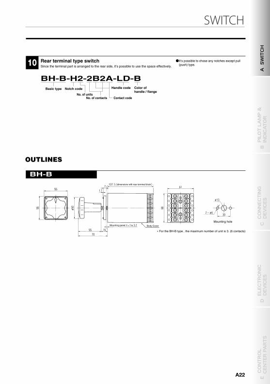
BH-B-H2-2B2A-LD-BHandle code Color of
handle / flange Notch codeBasic type
No. of unitsNo. of contacts
Mounting hole
∗ For the BH-B type , the maximum number of unit is 3. (6 contacts)
Mounting panel: Body Cover
OUTLINES
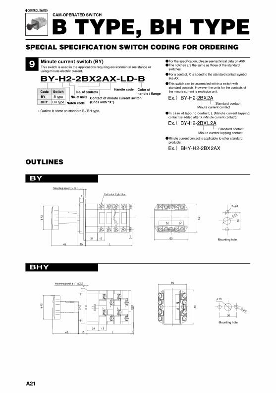
Minute current switch (BY)This switch is used in the applications requiring environmental resistance or using minute electric current.
Rear terminal type switchSince the terminal part is arranged to the rear side, it’s possible to use the space effectively.
BY-H2-2BX2AX-LD-B Handle code
Contact of minute current switch(Ends with “X”)Notch code
No. of unitsNo. of contacts
Contact code
Code SwitchBY B type
BH type Standard contactMinute current contact
BHY
●For the specification, please see technical data on A56.●The notches are the same as those of the standard
switches.
●For a contact, X is added to the standard contact symbol like AX.
●This switch can be assembled within a switch with standard contacts. However the units for the contacts of the minute current is exchisive unit.Color of
handle / flange
CAM-OPERATED SWITCH
B TYPE, BH TYPE●CONTROL SWITCH
∗ Outline is same as standard B / BH type.
Ex.)BY-H2-2BXL2AStandard contact
Minute current lapping contact
●In case of lapping contact, L (Minute current lapping contact) is added after X (Minute current contact).
dimensions with rear terminal block
to=
SPECIAL SPECIFICATION SWITCH CODING FOR ORDERING
Unit color: Light blue
45 15 L
21
φ42 50
305
60
2-φ6
φ13
13
7
BY
BHY
OUTLINES
N P
Mounting hole
Mounting hole
30
2-φ6
N P
15
φ42
7
φ13
451321
L
50
60
5
Mounting panel: to=
Mounting panel: to=
●It’s possible to chose any notches except pull (push) type.
A21
SWITCH
BH-B
9
Ex.)BHY-H2-2BX2AX
Ex.)BY-H2-2BX2A
●Minute current contact is applicable to other standard products.
10
BH-B-H2-2B2A-LD-BHandle code Color of
handle / flange Notch codeBasic type
No. of unitsNo. of contacts
Mounting hole
∗ For the BH-B type , the maximum number of unit is 3. (6 contacts)
Mounting panel: Body Cover
OUTLINES
Minute current switch (BY)This switch is used in the applications requiring environmental resistance or using minute electric current.
Rear terminal type switchSince the terminal part is arranged to the rear side, it’s possible to use the space effectively.
BY-H2-2BX2AX-LD-B Handle code
Contact of minute current switch(Ends with “X”)Notch code
No. of unitsNo. of contacts
Contact code
Code SwitchBY B type
BH type Standard contactMinute current contact
BHY
●For the specification, please see technical data on A56.●The notches are the same as those of the standard
switches.
●For a contact, X is added to the standard contact symbol like AX.
●This switch can be assembled within a switch with standard contacts. However the units for the contacts of the minute current is exchisive unit.Color of
handle / flange
CAM-OPERATED SWITCH
B TYPE, BH TYPE●CONTROL SWITCH
∗ Outline is same as standard B / BH type.
Ex.)BY-H2-2BXL2AStandard contact
Minute current lapping contact
●In case of lapping contact, L (Minute current lapping contact) is added after X (Minute current contact).
dimensions with rear terminal block
to=
SPECIAL SPECIFICATION SWITCH CODING FOR ORDERING
Unit color: Light blue
45 15 L
21
φ42 50
30
560
2-φ6
φ13
13
7
BY
BHY
OUTLINES
N P
Mounting hole
Mounting hole
30
2-φ6
N P
15
φ42
7
φ13
451321
L
50
60
5
Mounting panel: to=
Mounting panel: to=
●It’s possible to chose any notches except pull (push) type.
A SWITCH
B PILOT LAMP &
INDICATOR
D ELECTRONIC
DEVICES
C CONNECTING
DEVICES
E CONTROL
CENTER PARTS
A22
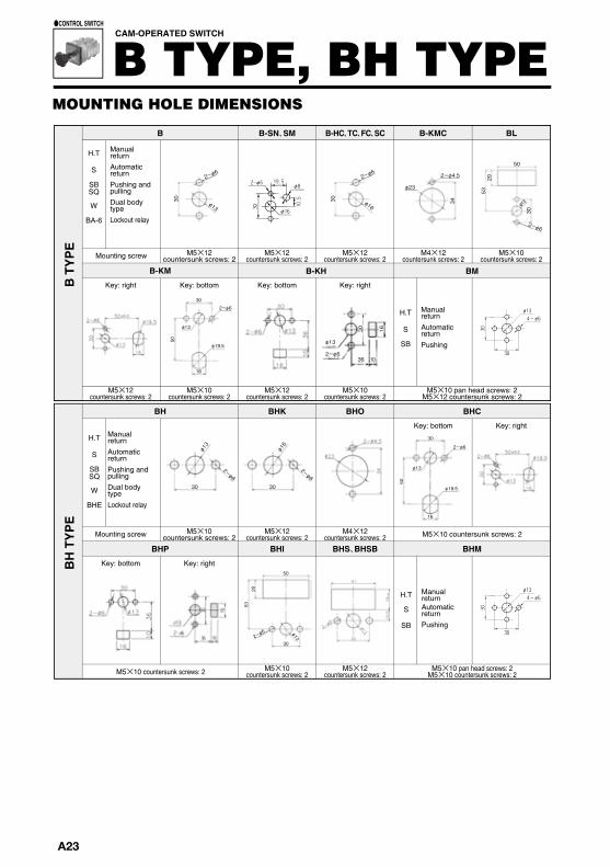
CAM-OPERATED SWITCH
B TYPE, BH TYPE●CONTROL SWITCH
H.T
S
SB
Manual returnAutomatic returnPushing
H.T
S
SB
Manual returnAutomatic returnPushing
Mounting screw
H.T
S
SBSQ
W
BHE
Manual returnAutomatic returnPushing and pullingDual body typeLockout relay
Key: right Key: bottom Key: bottom Key: right
Key: bottom Key: right
Key: bottom Key: right
M5×12countersunk screws: 2
M5×12countersunk screws: 2
M5×12countersunk screws: 2
M5×10countersunk screws: 2
M5×12countersunk screws: 2
M5×10countersunk screws: 2
M5×10 pan head screws: 2M5×12 countersunk screws: 2
M5×10 countersunk screws: 2 M5×10countersunk screws: 2
M5×12countersunk screws: 2
M5×10 pan head screws: 2M5×10 countersunk screws: 2
M5×12countersunk screws: 2
Mounting screw M5×10 countersunk screws: 2M5×10countersunk screws: 2
M5×12countersunk screws: 2
M4×12countersunk screws: 2
M4×12countersunk screws: 2
M5×10countersunk screws: 2
H.T
S
SBSQ
W
BA-6
B-SN、SMB
B-KM
B-HC、TC、FC、SC B-KMC BL
B-KH
BHKBH
BHP
BHO BHC
BHI BHS、BHSB BHM
BM
Manual returnAutomatic returnPushing and pullingDual body typeLockout relay
BH
TY
PE
B T
YP
E
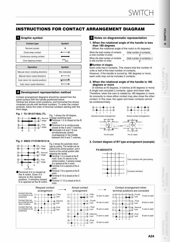
Contact type Symbol
Normal contact
Operation Symbol
Manual return (rotating direction) Not indicated
Close keep contact
Manual return (axial direction)
Continuous closing contact
Auto return (to neutral position)
Over lapping contact
Auto return (axial direction)
Fig. 1 T2-1B1AT1BAL1TL
Fig. 2 SBZ3-1Y1Z1M1N1C1A
Request contactarrangement
Actual contactarrangement
Contact arrangement whenterminal positions are corrected
Thirdunit
Secondunit
Secondstage
Firststage
Secondstage
Thirdstage
Firststage
Firstunit
Fifthunit
Fourthunit
Thirdunit
Secondunit
Firstunit
G cam is used
B cam is used
B cam is used
D cam is used
B cam is used
Fourthunit
Thirdunit
Secondunit
Firstunit
G cam is used
B cam is used
C cam is used
B cam is used
=
=
F3-2B2AX2TX
(total number of contacts)When the total number of contactsis even (number of units) 2
(total number of contacts)+1When the total number of contactsis odd (number of units) 2
G
G
G
G
Twin contacts with gold plating
Contacts standard
Actual contact arrangementDesired contact arrangement
For E notchFor B notch
c cam
Contact that hasno contacts to becombined
Contact that canbe combined withother contacts
Contact that hasno contacts to becombined
Graphic symbol1 Notes on diagrammatic representation3
Development representation method2
Contact arrangement diagrams should be viewed from the panel surface with the handle positioned below.Vertical line shows notch positions, and horizontal line shows conected circuits with terminal numbers. To enter the contact symbols, follow the order of terminal numbers starting with the front stage.
1. When the rotational angle of the handle is less than 180 degrees(When the rotational angle of the notch is 45 degrees)
■Number of stagesEach units has 2 contacts. This means that the number of units is half of the total number of contacts.However, if the handle is turned by 180 degrees or more, each units may not be includes 2 contacts.
2. When the rotational angle of the handle is 180 degrees or more(5 notches at 45 degrees, 3 notches at 90 degrees or more)
A single cam actuates 2 contacts, upper and lower side. Therefore, when the cam is rotated by 180 degrees or more, its concavity to close either contact may also close the other contact. In this case, the upper and lower contacts cannot be combined freely.
3. Contact diagram of BY type arrangement (example)
Fig. 1 shows the 45-degree, 3-stage switching type.●Terminal 1-2 is closed at the B
notch.●Terminal 3-4 is continuously
closed at the A and T notches.●Terminals 5-6 and 7-8 are
simultaneously closed (overlapping) in the middle between the A and T notches.
Fig. 2 shows the automatic return type by pulling. The handle can be pulled at the central position, and it returns to the central position after releasing the handle.●Terminal 1-2 is closed at the B
notch. Even if it returns to the central position, it remains closed. It is opened at the A notch.●Terminal 5-6 is opened at the A
notch.●Terminal 7-8 is opened at the B
notch.●Terminal 9-10 is closed at the C
notch.●Terminal 11-12 is closed at the A
notch.
●Terminal 3-4 is closed at the A notch. Even if it returns to the central position, it remains closed. It is opened at the B notch.
30 φ13
2ーφ6
30 34
30
2053
φ23
50
2ーφ4.5
2ーφ6
φ13φ16
2ーφ6
φ13
φ19.5
16
30
50
2ーφ6
φ13
φ19.5
16
30
50
2ーφ6
50
2053
2ーφ6 φ13
30
30
2ーφ6
φ13
30
2ーφ6
φ16
φ13
30 16
36 102ーφ6
MOUNTING HOLE DIMENSIONS INSTRUCTIONS FOR CONTACT ARRANGEMENT DIAGRAM
A23
SWITCHCAM-OPERATED SWITCH
B TYPE, BH TYPE●CONTROL SWITCH
H.T
S
SB
Manual returnAutomatic returnPushing
H.T
S
SB
Manual returnAutomatic returnPushing
Mounting screw
H.T
S
SBSQ
W
BHE
Manual returnAutomatic returnPushing and pullingDual body typeLockout relay
Key: right Key: bottom Key: bottom Key: right
Key: bottom Key: right
Key: bottom Key: right
M5×12countersunk screws: 2
M5×12countersunk screws: 2
M5×12countersunk screws: 2
M5×10countersunk screws: 2
M5×12countersunk screws: 2
M5×10countersunk screws: 2
M5×10 pan head screws: 2M5×12 countersunk screws: 2
M5×10 countersunk screws: 2 M5×10countersunk screws: 2
M5×12countersunk screws: 2
M5×10 pan head screws: 2M5×10 countersunk screws: 2
M5×12countersunk screws: 2
Mounting screw M5×10 countersunk screws: 2M5×10countersunk screws: 2
M5×12countersunk screws: 2
M4×12countersunk screws: 2
M4×12countersunk screws: 2
M5×10countersunk screws: 2
H.T
S
SBSQ
W
BA-6
B-SN、SMB
B-KM
B-HC、TC、FC、SC B-KMC BL
B-KH
BHKBH
BHP
BHO BHC
BHI BHS、BHSB BHM
BM
Manual returnAutomatic returnPushing and pullingDual body typeLockout relay
BH
TY
PE
B T
YP
E
Contact type Symbol
Normal contact
Operation Symbol
Manual return (rotating direction) Not indicated
Close keep contact
Manual return (axial direction)
Continuous closing contact
Auto return (to neutral position)
Over lapping contact
Auto return (axial direction)
Fig. 1 T2-1B1AT1BAL1TL
Fig. 2 SBZ3-1Y1Z1M1N1C1A
Request contactarrangement
Actual contactarrangement
Contact arrangement whenterminal positions are corrected
Thirdunit
Secondunit
Secondstage
Firststage
Secondstage
Thirdstage
Firststage
Firstunit
Fifthunit
Fourthunit
Thirdunit
Secondunit
Firstunit
G cam is used
B cam is used
B cam is used
D cam is used
B cam is used
Fourthunit
Thirdunit
Secondunit
Firstunit
G cam is used
B cam is used
C cam is used
B cam is used
=
=
F3-2B2AX2TX
(total number of contacts)When the total number of contactsis even (number of units) 2
(total number of contacts)+1When the total number of contactsis odd (number of units) 2
G
G
G
G
Twin contacts with gold plating
Contacts standard
Actual contact arrangementDesired contact arrangement
For E notchFor B notch
c cam
Contact that hasno contacts to becombined
Contact that canbe combined withother contacts
Contact that hasno contacts to becombined
Graphic symbol1 Notes on diagrammatic representation3
Development representation method2
Contact arrangement diagrams should be viewed from the panel surface with the handle positioned below.Vertical line shows notch positions, and horizontal line shows conected circuits with terminal numbers. To enter the contact symbols, follow the order of terminal numbers starting with the front stage.
1. When the rotational angle of the handle is less than 180 degrees(When the rotational angle of the notch is 45 degrees)
■Number of stagesEach units has 2 contacts. This means that the number of units is half of the total number of contacts.However, if the handle is turned by 180 degrees or more, each units may not be includes 2 contacts.
2. When the rotational angle of the handle is 180 degrees or more(5 notches at 45 degrees, 3 notches at 90 degrees or more)
A single cam actuates 2 contacts, upper and lower side. Therefore, when the cam is rotated by 180 degrees or more, its concavity to close either contact may also close the other contact. In this case, the upper and lower contacts cannot be combined freely.
3. Contact diagram of BY type arrangement (example)
Fig. 1 shows the 45-degree, 3-stage switching type.●Terminal 1-2 is closed at the B
notch.●Terminal 3-4 is continuously
closed at the A and T notches.●Terminals 5-6 and 7-8 are
simultaneously closed (overlapping) in the middle between the A and T notches.
Fig. 2 shows the automatic return type by pulling. The handle can be pulled at the central position, and it returns to the central position after releasing the handle.●Terminal 1-2 is closed at the B
notch. Even if it returns to the central position, it remains closed. It is opened at the A notch.●Terminal 5-6 is opened at the A
notch.●Terminal 7-8 is opened at the B
notch.●Terminal 9-10 is closed at the C
notch.●Terminal 11-12 is closed at the A
notch.
●Terminal 3-4 is closed at the A notch. Even if it returns to the central position, it remains closed. It is opened at the B notch.
30 φ13
2ーφ6
30 34
30
2053
φ23
50
2ーφ4.5
2ーφ6
φ13φ16
2ーφ6
φ13
φ19.5
16
30
50
2ーφ6
φ13
φ19.5
16
30
50
2ーφ6
50
2053
2ーφ6 φ13
30
30
2ーφ6
φ13
30
2ーφ6
φ16
φ13
30 16
36 102ーφ6
MOUNTING HOLE DIMENSIONS INSTRUCTIONS FOR CONTACT ARRANGEMENT DIAGRAM
A SWITCH
B PILOT LAMP &
INDICATOR
D ELECTRONIC
DEVICES
C CONNECTING
DEVICES
E CONTROL
CENTER PARTS
A24
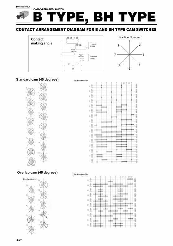
30 ° ±2 ° 3 0° ±2 °
30 ° ±2 °
7° ±2 °
7° ±2 °
45 °
90 °
45 °
1
5
2 8
3 7
6 4
7° ±2 °
7° ±2 °
30 ° 30 °
60 °
Position Number1
7
5
2
8
9
3
10
11
12
6
4
CAM-OPERATED SWITCH
B TYPE, BH TYPE●CONTROL SWITCH
CONTACT ARRANGEMENT DIAGRAM FOR B AND BH TYPE CAM SWITCHES
Standard cam (45 degrees)
Contactmaking angle
Set Position No.
Overlapcontact
Standardcontact
Overlap cam (45 degrees)Set Position No.
30-degrees cam
30°contact
Set Position No.
Overlap cam
Position Number
A25
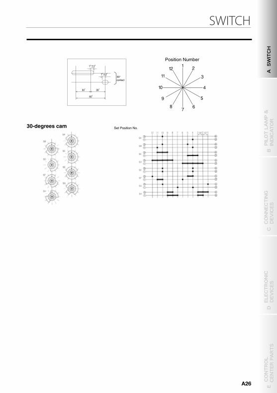
SWITCH
30 ° ±2 ° 3 0° ±2 °
30 ° ±2 °
7° ±2 °
7° ±2 °
45 °
90 °
45 °
1
5
2 8
3 7
6 4
7° ±2 °
7° ±2 °
30 ° 30 °
60 °
Position Number1
7
5
2
8
9
3
10
11
12
6
4
CAM-OPERATED SWITCH
B TYPE, BH TYPE●CONTROL SWITCH
CONTACT ARRANGEMENT DIAGRAM FOR B AND BH TYPE CAM SWITCHES
Standard cam (45 degrees)
Contactmaking angle
Set Position No.
Overlapcontact
Standardcontact
Overlap cam (45 degrees)Set Position No.
30-degrees cam
30°contact
Set Position No.
Overlap cam
Position Number
A SWITCH
B PILOT LAMP &
INDICATOR
D ELECTRONIC
DEVICES
C CONNECTING
DEVICES
E CONTROL
CENTER PARTS
A26
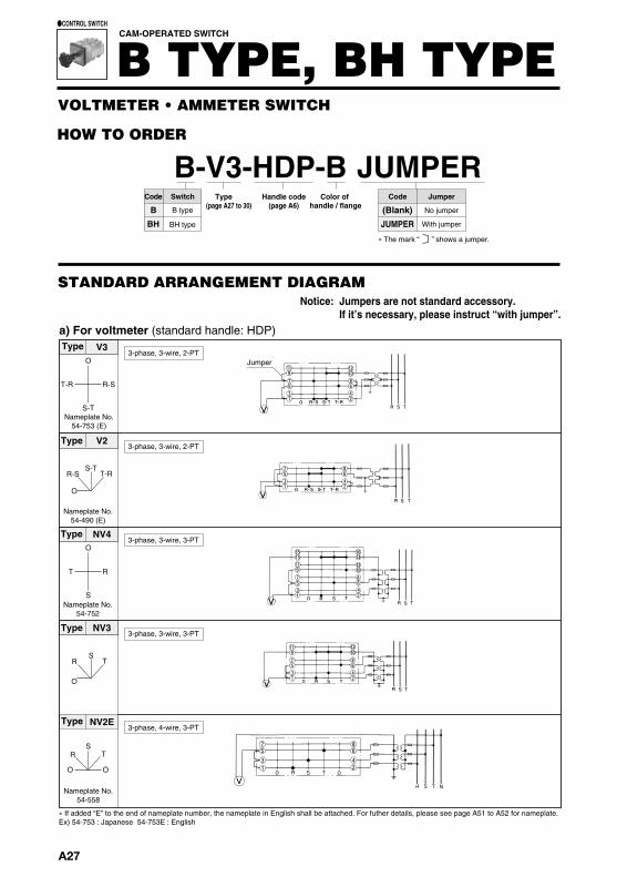
Notice: Jumpers are not standard accessory. If it’s necessary, please instruct “with jumper”.
V2E
O O
S-TR-S T-R
O
S
RT
RT
A2
O
S
A4
C2
ST
O
R
7 5
3 1
8 6
4 2
15 16 14 12 10 8 6 4 2
13 11 9
7 5 3 1
7 5
3 1
8 6
4 2
O
O
S-T
R-S
S-N
T-RT-N
R-N
V5W
19 17
15 13
11 9
7 5
3 1
20 18
16 14
12 10
8 6
4 2
T
J
E
F
B
GO
A
V4O-2
13
57
911
1315
24
68
1012
1416
VU1N1V1 U2N2V2JGEFTABO
V3O
S-T
R-S T-R
V2
O
S-T R-S T-R
NV4O
S
R T
NV3
O
S R T
NV2E
O O
S R T
1 1 9
7 5
1 3
1 2 1 0 8 6
2 4
7 5
3 1
8 6
4 2
1 5 1 3 1 1 9
7 5 3 1
1 6 1 4
1 2 1 0
6 8
4 2
1 1 1 2 1 0
8 6 4 2
9
7 5
3 1
7 5
3 1
8 6
4 2
HOW TO ORDER
B-V3-HDP-B JUMPERHandle code
(page A6)Color of
handle / flangeType
(page A27 to 30)Code JumperCode Switch
B
BH
��The mark “ ” shows a jumper.
STANDARD ARRANGEMENT DIAGRAM
VOLTMETER・AMMETER SWITCH
a) For voltmeter (standard handle: HDP)
●CONTROL SWITCH
Type
Nameplate No.54-753 (E)
3-phase, 3-wire, 2-PTJumper
Type
Nameplate No.54-490 (E)
3-phase, 3-wire, 2-PT
Type
Nameplate No.54-752
3-phase, 3-wire, 3-PT
Type3-phase, 3-wire, 3-PT
Type
Nameplate No.54-558
3-phase, 4-wire, 3-PT
Type
Nameplate No.54-557 (E)
Type
Nameplate No.54-850 (E)
3-phase, 4-wire, 3-PT
Type
Type
Nameplate No.54-755 (E)
3-phase, 3-wire, 2-CT
Type
Nameplate No.54-495 (E)
3-phase, 3-wire, 2-CT
Type
Nameplate No.54-755 (E)
3-phase, 3-wire, 3-CT
b) For ammeter (standard handle: HDP)
3-phase, 3-wire, 2-PT
single 3-wire, 2-PT
CAM-OPERATED SWITCH
B TYPE, BH TYPE
B type
BH type
(Blank)
JUMPER
No jumper
With jumper
a) For voltmeter (standard handle: HDP)
� If added “E” to the end of nameplate number, the nameplate in English shall be attached. For futher details, please see page A51 to A52 for nameplate.Ex) 54-753 : Japanese 54-753E : English
� For details of nameplates, see A51 to A52 and subsequent pages.
A27
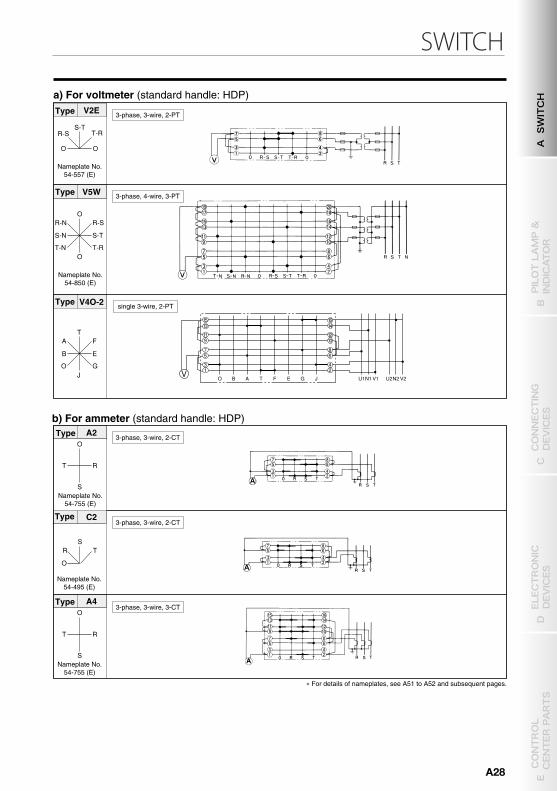
SWITCH
Notice: Jumpers are not standard accessory. If it’s necessary, please instruct “with jumper”.
V2E
O O
S-TR-S T-R
O
S
RT
RT
A2
O
S
A4
C2
ST
O
R
7 5
3 1
8 6
4 2
15 16 14 12 10 8 6 4 2
13 11 9
7 5 3 1
7 5
3 1
8 6
4 2
O
O
S-T
R-S
S-N
T-RT-N
R-N
V5W
19 17
15 13
11 9
7 5
3 1
20 18
16 14
12 10
8 6
4 2
T
J
E
F
B
GO
A
V4O-2
13
57
911
1315
24
68
1012
1416
VU1N1V1 U2N2V2JGEFTABO
V3O
S-T
R-S T-R
V2
O
S-T R-S T-R
NV4O
S
R T
NV3
O
S R T
NV2E
O O
S R T
1 1 9
7 5
1 3
1 2 1 0 8 6
2 4
7 5
3 1
8 6
4 2
1 5 1 3 1 1 9
7 5 3 1
1 6 1 4
1 2 1 0
6 8
4 2
1 1 1 2 1 0
8 6 4 2
9
7 5
3 1
7 5
3 1
8 6
4 2
HOW TO ORDER
B-V3-HDP-B JUMPERHandle code
(page A6)Color of
handle / flangeType
(page A27 to 30)Code JumperCode Switch
B
BH
��The mark “ ” shows a jumper.
STANDARD ARRANGEMENT DIAGRAM
VOLTMETER・AMMETER SWITCH
a) For voltmeter (standard handle: HDP)
●CONTROL SWITCH
Type
Nameplate No.54-753 (E)
3-phase, 3-wire, 2-PTJumper
Type
Nameplate No.54-490 (E)
3-phase, 3-wire, 2-PT
Type
Nameplate No.54-752
3-phase, 3-wire, 3-PT
Type3-phase, 3-wire, 3-PT
Type
Nameplate No.54-558
3-phase, 4-wire, 3-PT
Type
Nameplate No.54-557 (E)
Type
Nameplate No.54-850 (E)
3-phase, 4-wire, 3-PT
Type
Type
Nameplate No.54-755 (E)
3-phase, 3-wire, 2-CT
Type
Nameplate No.54-495 (E)
3-phase, 3-wire, 2-CT
Type
Nameplate No.54-755 (E)
3-phase, 3-wire, 3-CT
b) For ammeter (standard handle: HDP)
3-phase, 3-wire, 2-PT
single 3-wire, 2-PT
CAM-OPERATED SWITCH
B TYPE, BH TYPE
B type
BH type
(Blank)
JUMPER
No jumper
With jumper
a) For voltmeter (standard handle: HDP)
� If added “E” to the end of nameplate number, the nameplate in English shall be attached. For futher details, please see page A51 to A52 for nameplate.Ex) 54-753 : Japanese 54-753E : English
� For details of nameplates, see A51 to A52 and subsequent pages.
A SWITCH
B PILOT LAMP &
INDICATOR
D ELECTRONIC
DEVICES
C CONNECTING
DEVICES
E CONTROL
CENTER PARTS
A28
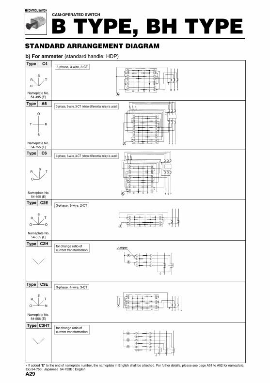
27 28 26
24 22
20 18
16 14
12 10
8 6
4 2
25
23 21
19 17
15 13
11 9
7 5
3 1
C7E
O N
S R T
A6
C6
O
S
RT
C2E
C3E
C2H
O
SR T
C3HT
C4E
C5E
O N
SR T
O O
SR T
O O
S R T
C3HA
O O
S R T
C8O-2
23
18
16 14 12 10
8 6
4 2
20
24 22 21
19 17
15 13
11 9
7 5
3 1
7
4 2
8 6 5
3 1
11
8 6
4 2
12 10 9
7 5
3 1
1 1 9
7 5
3 1
1 5 1 6 1 4
1 2 1 0
8 6
4 2
1 3
23 22
20 18
16 14
12 10
8 6
4 2
24 21
19 17
15 13
11 9
7 5
3 1
7
6
4
2
8
5
3
1
11 12
10
8
6
4
2
9
7
5
3
1
1 1 1 2
1 0
8
6
4
2
9
7
5
3
1
1 9 1 7
1 5 1 3
1 1 9
7 5
3 1
2 0 1 8
1 6 1 4
1 2 1 0
8 6
4 2
C6E
O N
S R T
2 3 2 4 2 2
2 0 1 8
1 6 1 4
1 2 1 0
8 6
4 2
2 1
1 9 1 7
1 5 1 3
1 1 9
7 5
3 1
T
J
E
F
B
G O
A
13
57
911
1315
AU1N1V1 U2N2V2
JGEFTABO
19
2123
17
2931
2527
24
68
1012
1416
20
2224
18
3032
2628
Jumper
STANDARD ARRANGEMENT DIAGRAM
CAM-OPERATED SWITCH
B TYPE, BH TYPE●CONTROL SWITCH
Type
Nameplate No.54-755 (E)
3-phase, 3-wire, 3-CT (when differential relay is used)
Type
Nameplate No.54-495 (E)
3-phase, 3-wire, 3-CT (when differential relay is used)
Type
Nameplate No.54-555 (E)
3-phase, 3-wire, 2-CT
Type
Type
Nameplate No.54-556 (E)
Typefor change ratio of current transformation
Nameplate No.54-555 (E)
Type3-phase, 3-wire, 3-CT
single-phase, 2-lineType
Nameplate No.54-555 (E)
Type3-phase, 3-wire, 2-CT
Nameplate No.54-556 (E)
3-phase, 4-wire, 3-CTType
Nameplate No.54-556 (E)
3-phase, 4-wire, 3-CT
� For details of nameplates, see A51 to A52 and subsequent pages.
Type
Type
b) For ammeter (standard handle: HDP)
for change ratio of current transformation
single 3-wire, 2-CT
ST
O
R
Type C4
Nameplate No.54-495 (E)
15 13
11 9 7 5
3 1
16 14
12 10
8 6
4 2
3-phase, 3-wire, 3-CT
3-phase, 4-wire, 3-CT
� If added “E” to the end of nameplate number, the nameplate in English shall be attached. For futher details, please see page A51 to A52 for nameplate.Ex) 54-753 : Japanese 54-753E : English
A29
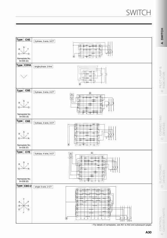
SWITCH
27 28 26
24 22
20 18
16 14
12 10
8 6
4 2
25
23 21
19 17
15 13
11 9
7 5
3 1
C7E
O N
S R T
A6
C6
O
S
RT
C2E
C3E
C2H
O
SR T
C3HT
C4E
C5E
O N
SR T
O O
SR T
O O
S R T
C3HA
O O
S R T
C8O-2
23
18
16 14 12 10
8 6
4 2
20
24 22 21
19 17
15 13
11 9
7 5
3 1
7
4 2
8 6 5
3 1
11
8 6
4 2
12 10 9
7 5
3 1
1 1 9
7 5
3 1
1 5 1 6 1 4
1 2 1 0
8 6
4 2
1 3
23 22
20 18
16 14
12 10
8 6
4 2
24 21
19 17
15 13
11 9
7 5
3 1
7
6
4
2
8
5
3
1
11 12
10
8
6
4
2
9
7
5
3
1
1 1 1 2
1 0
8
6
4
2
9
7
5
3
1
1 9 1 7
1 5 1 3
1 1 9
7 5
3 1
2 0 1 8
1 6 1 4
1 2 1 0
8 6
4 2
C6E
O N
S R T
2 3 2 4 2 2
2 0 1 8
1 6 1 4
1 2 1 0
8 6
4 2
2 1
1 9 1 7
1 5 1 3
1 1 9
7 5
3 1
T
J
E
F
B
G O
A
13
57
911
1315
AU1N1V1 U2N2V2
JGEFTABO
19
2123
17
2931
2527
24
68
1012
1416
20
2224
18
3032
2628
Jumper
STANDARD ARRANGEMENT DIAGRAM
CAM-OPERATED SWITCH
B TYPE, BH TYPE●CONTROL SWITCH
Type
Nameplate No.54-755 (E)
3-phase, 3-wire, 3-CT (when differential relay is used)
Type
Nameplate No.54-495 (E)
3-phase, 3-wire, 3-CT (when differential relay is used)
Type
Nameplate No.54-555 (E)
3-phase, 3-wire, 2-CT
Type
Type
Nameplate No.54-556 (E)
Typefor change ratio of current transformation
Nameplate No.54-555 (E)
Type3-phase, 3-wire, 3-CT
single-phase, 2-lineType
Nameplate No.54-555 (E)
Type3-phase, 3-wire, 2-CT
Nameplate No.54-556 (E)
3-phase, 4-wire, 3-CTType
Nameplate No.54-556 (E)
3-phase, 4-wire, 3-CT
� For details of nameplates, see A51 to A52 and subsequent pages.
Type
Type
b) For ammeter (standard handle: HDP)
for change ratio of current transformation
single 3-wire, 2-CT
ST
O
R
Type C4
Nameplate No.54-495 (E)
15 13
11 9 7 5
3 1
16 14
12 10
8 6
4 2
3-phase, 3-wire, 3-CT
3-phase, 4-wire, 3-CT
� If added “E” to the end of nameplate number, the nameplate in English shall be attached. For futher details, please see page A51 to A52 for nameplate.Ex) 54-753 : Japanese 54-753E : English
A SWITCH
B PILOT LAMP &
INDICATOR
D ELECTRONIC
DEVICES
C CONNECTING
DEVICES
E CONTROL
CENTER PARTS
A30
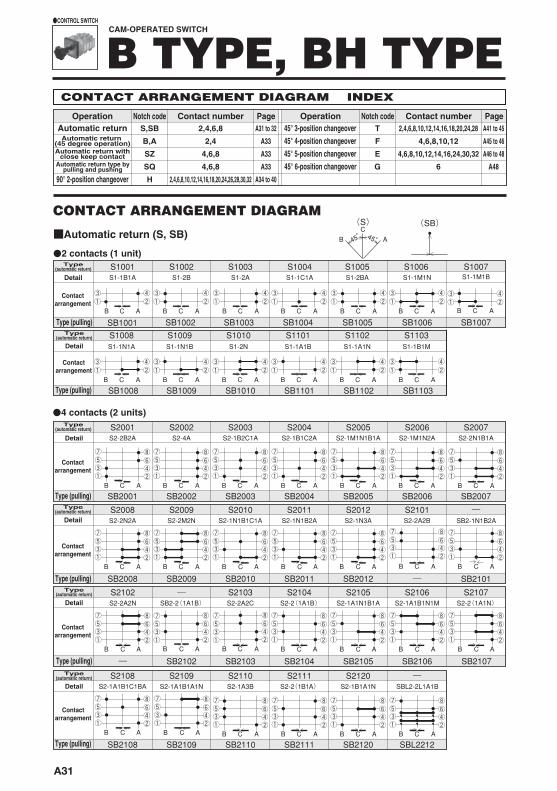
(S) (SB)
S1001S1-1B1A
S1002S1-2B
S1003S1-2A
S1004S1-1C1A
S1005S1-2BA
S1006
SB1001 SB1002 SB1003 SB1004 SB1005 SB1006 SB1007
S1-1M1NS1007S1-1M1B
S1008S1-1N1A
S1009S1-1N1B
S1010S1-2N
S1101S1-1A1B
S1102
SB1008 SB1009 SB1010 SB1101 SB1102
S1-1A1N
BC
A
B ACB AC B AC B AC
B AC B AC
B AC B AC B AC
B AC B AC B AC B AC
S1103
SB1103
S1-1B1M
S2001S2-2B2A
SB2001B AC
S2002S2-4A
SB2002B AC
S2003S2-1B2C1A
SB2003B AC
S2004S2-1B1C2A
SB2004B AC
S2005S2-1M1N1B1A
SB2005B AC
S2006
SB2006
S2-1M1N2A
B AC
S2007S2-2N1B1A
SB2007B AC
S2009S2-2M2N
SB2009B AC
S2008S2-2N2A
SB2008B AC
S2010S2-1N1B1C1A
SB2010B AC
S2011S2-1N1B2A
SB2011B AC
S2012
SB2012
S2-1N3A
B AC
S2101S2-2A2B
B AC
S2102S2-2A2N
B AC
SB2102
SB2-2(1A1B)
B AC
S2103S2-2A2C
SB2103B AC
S2104S2-2(1A1B)
SB2104B AC
S2105S2-1A1N1B1A
SB2105B AC
S2106S2-1A1B1N1M
SB2106B AC
S2107S2-2(1A1N)
S2-1A1B1C1BA
SB2107B AC
S2108
SB2108B AC
S2109
SB2109
S2-1A1B1A1N
B AC
S2110S2-1A3B S2-1B1A1N
SB2110B AC
S2-2(1B1A)
SB2111B AC
SBL2-2L1A1B
SBL2212B AC
S2120
B AC
SB2101
SB2-1N1B2A
B AC
45° 45°
―
―
―
―
―
S2111
SB2120
CONTACT ARRANGEMENT DIAGRAM INDEX
45° 3-position changeover45° 4-position changeover45° 5-position changeover45° 6-position changeover
T
F
E
G
2,4,6,8,10,12,14,16,18,20,24,28
4,6,8,10,12
4,6,8,10,12,14,16,24,30,32
6
OperationAutomatic returnAutomatic return
(45 degree operation)Automatic return with
close keep contactAutomatic return type by
pulling and pushing
90° 2-position changeover
S,SB
B,A
SZ
SQ
H
Notch code Page2,4,6,8 A31 to 32
A33
A33
A33
A34 to 40
A41 to 45
A45 to 46
A46 to 48
A48
2,4
4,6,8
4,6,8
2,4,6,8,10,12,14,16,18,20,24,26,28,30,32
Contact number Operation Notch code PageContact number
●2 contacts (1 unit)
CONTACT ARRANGEMENT DIAGRAM
■Automatic return (S, SB)
Type (pulling)
Type(automatic return)
Detail
Contactarrangement
Type(automatic return)
Contactarrangement
Type (pulling)
Detail
Type(automatic return)
Contactarrangement
Type(automatic return)
Contactarrangement
Type(automatic return)
Contactarrangement
Type(automatic return)
Contactarrangement
Type (pulling)
Detail
Type (pulling)
Detail
Type (pulling)
Detail
Type (pulling)
Detail
●4 contacts (2 units)
CAM-OPERATED SWITCH
B TYPE, BH TYPE●CONTROL SWITCH
A31
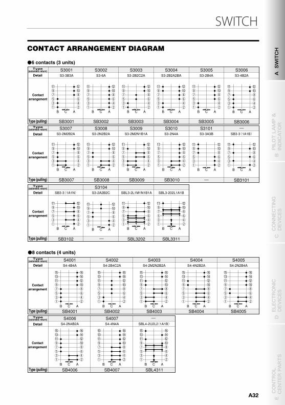
SWITCH
(S) (SB)
S1001S1-1B1A
S1002S1-2B
S1003S1-2A
S1004S1-1C1A
S1005S1-2BA
S1006
SB1001 SB1002 SB1003 SB1004 SB1005 SB1006 SB1007
S1-1M1NS1007S1-1M1B
S1008S1-1N1A
S1009S1-1N1B
S1010S1-2N
S1101S1-1A1B
S1102
SB1008 SB1009 SB1010 SB1101 SB1102
S1-1A1N
BC
A
B ACB AC B AC B AC
B AC B AC
B AC B AC B AC
B AC B AC B AC B AC
S1103
SB1103
S1-1B1M
S2001S2-2B2A
SB2001B AC
S2002S2-4A
SB2002B AC
S2003S2-1B2C1A
SB2003B AC
S2004S2-1B1C2A
SB2004B AC
S2005S2-1M1N1B1A
SB2005B AC
S2006
SB2006
S2-1M1N2A
B AC
S2007S2-2N1B1A
SB2007B AC
S2009S2-2M2N
SB2009B AC
S2008S2-2N2A
SB2008B AC
S2010S2-1N1B1C1A
SB2010B AC
S2011S2-1N1B2A
SB2011B AC
S2012
SB2012
S2-1N3A
B AC
S2101S2-2A2B
B AC
S2102S2-2A2N
B AC
SB2102
SB2-2(1A1B)
B AC
S2103S2-2A2C
SB2103B AC
S2104S2-2(1A1B)
SB2104B AC
S2105S2-1A1N1B1A
SB2105B AC
S2106S2-1A1B1N1M
SB2106B AC
S2107S2-2(1A1N)
S2-1A1B1C1BA
SB2107B AC
S2108
SB2108B AC
S2109
SB2109
S2-1A1B1A1N
B AC
S2110S2-1A3B S2-1B1A1N
SB2110B AC
SB2-2(1B1A)
SB2111B AC
SBL2-2L1A1B
SBL2212B AC
S2120
B AC
SB2101
SB2-1N1B2A
B AC
45° 45°
S3001 S3-3B3A
SB3001
S3007 S3-2M2B2A
SB3007
S3003 S3-2B2C2A S3-2B2A2BA
SB3003
S3008 S3-2N2B2A
S3-2A2B2C
SB3008
S3004
SB3004
S3009 S3-2M2N1B1A
SB3009
S3005 S3-2B4A
SB3005
S3010 S3-2N4A
SB3010
S3104
S4001 S4-4B4A
SB4001
S4002 S4-2B4C2A
SB4002
S4003 S4-2M2N2B2A
SB4003
S4004 S4-4N2B2A
SB4004
S4005 S4-2N2B4A
SB4005
S4006 S4-2N4B2A
SB4006
S4007 S4-4N4A
SB4007
B A C B A C B A C B A C
B A C
B A C
B A C B A C B A C
B A C
B A C B A C
B A C B A C B A C B A C
B A C
S3002 S3-6A
SB3002
B A C
SBL4-2U2L2 (1A1B )
SBL4311
SB3-3 (1A1N )
SB3102
B A C
SBL3-2L1M1N1B1A
SBL3202
B A C
SBL3-202L1A1B
SBL3311
B A C
S3006 S3-4B2A
SB3006
B A C
S3101 S3-3A3B
B A C
SB3-3 (1A1B )
SB3101
B A C
―
―
―
―
―
S2111
SB2120
―
―
―
―
CONTACT ARRANGEMENT DIAGRAM INDEX
45° 3-position changeover45° 4-position changeover45° 5-position changeover45° 6-position changeover
T
F
E
G
2,4,6,8,10,12,14,16,18,20,24,28
4,6,8,10,12
4,6,8,10,12,14,16,24,30,32
6
OperationAutomatic returnAutomatic return
(45 degree operation)Automatic return with
close keep contactAutomatic return type by
pulling and pushing
90° 2-position changeover
S,SB
B,A
SZ
SQ
H
Notch code Page2,4,6,8 A31 to 32
A33
A33
A33
A34 to 40
A41 to 45
A45 to 46
A46 to 48
A48
2,4
4,6,8
4,6,8
2,4,6,8,10,12,14,16,18,20,24,26,28,30,32
Contact number Operation Notch code PageContact number
●2 contacts (1 unit)
CONTACT ARRANGEMENT DIAGRAM
■Automatic return (S, SB)
Type (pulling)
Type(automatic return)
Detail
Contactarrangement
Type(automatic return)
Contactarrangement
Type (pulling)
Detail
Type(automatic return)
Contactarrangement
Type(automatic return)
Contactarrangement
Type(automatic return)
Contactarrangement
Type(automatic return)
Contactarrangement
Type (pulling)
Detail
Type (pulling)
Detail
Type (pulling)
Detail
Type (pulling)
Detail
●4 contacts (2 units)
●6 contacts (3 units)
●8 contacts (4 units)
Type(automatic return)
Contactarrangement
Type(automatic return)
Contactarrangement
Type(automatic return)
Contactarrangement
Type(automatic return)
Contactarrangement
Type(automatic return)
Contactarrangement
Type (pulling)
Detail
Type (pulling)
Detail
Type (pulling)
Detail
Type (pulling)
Detail
Type (pulling)
Detail
CAM-OPERATED SWITCH
B TYPE, BH TYPE●CONTROL SWITCH
CONTACT ARRANGEMENT DIAGRAM
A SWITCH
B PILOT LAMP &
INDICATOR
D ELECTRONIC
DEVICES
C CONNECTING
DEVICES
E CONTROL
CENTER PARTS
A32
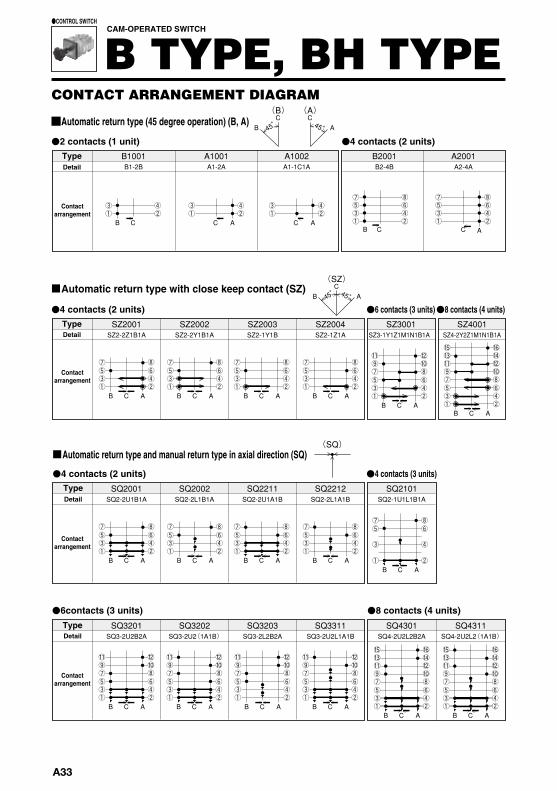
SZ2001SZ2-2Z1B1A
SQ2001SQ2-2U1B1A
SZ2002SZ2-2Y1B1A
SQ2002SQ2-2L1B1A
SZ2003SZ2-1Y1B
SQ2211SQ2-2U1A1B
SZ2004SZ2-1Z1A
SQ2212SQ2-2L1A1B
SZ3001SZ3-1Y1Z1M1N1B1A
SQ2101SQ2-1U1L1B1A
SZ4001SZ4-2Y2Z1M1N1B1A
(SQ)
B1001B1-2B
A1001 A1-2A
A1002 B2001B2-4B
A2001A2-4A
(SZ)
BC
A45° 45°
(B)
BC
45°
(A) C
A45°
B AC
BB
C
B AC B AC B AC
B ACB AC
B AC B AC B AC B ACB AC
CAC C A
C A
SQ3311SQ3-2U2L1A1B
B AC
SQ3203SQ3-2L2B2A
B AC
SQ3202SQ3-2U2(1A1B)
B AC
SQ3201SQ3-2U2B2A
B AC
A1-1C1A
SQ4301SQ4-2U2L2B2A
B AC
SQ4311SQ4-2U2L2(1A1B)
B AC
H2109 H2-1AL1BL1A1B
B A
B A 90 °
(H )
B A
H1001 H1-1B1A
A B
H1002 H1-2B
A B
H1003 H1-2A
A B
H1004 H1-1BL1AL
A B
H1-1B1BA H1005
H1006 H1-1A1BA
B A
H1101 H1-1A1B
B A
H1102 H1-1AL1BL
B A
H2001 H2-2B2A
B A
H2002 H2-4B
B A
H2003 H2-4A
B A
H2004 H2-1B3A
B A
H2005 H2-3B1A
B A
H2006 H2-1B1A2BA
B A
H2008 H2-2BL2AL
B A
H2009 H2-1B1A1BL1AL
B A
H2101 H2-2A2B
B A
H2102 H2-2AL2BL
B A
H2103 H2-2 (1A1B )
B A
H2104 H2-3A1B
B A
H2105 H2-1A1B2A
B A
H2106 H2-1A1B1AL1BL
B A
H2108 H2-2 (1AL1BL )
B A
H2110 H2-2 (1B1A )
B A
H2111 H2-1A1B2BA
B A
H2112 H2-2 (1BL1AL )
B A
H2113 H2-1B1A2B
B A
●4 contacts (2 units)●2 contacts (1 unit)TypeDetail
Contactarrangement
■Automatic return type (45 degree operation) (B, A)
CONTACT ARRANGEMENT DIAGRAM
CAM-OPERATED SWITCH
B TYPE, BH TYPE●CONTROL SWITCH
TypeDetail
Contactarrangement
●4 contacts (2 units) ●6 contacts (3 units)●8 contacts (4 units)
■Automatic return type with close keep contact (SZ)
●4 contacts (3 units)●4 contacts (2 units)
■Automatic return type and manual return type in axial direction (SQ)
TypeDetail
Contactarrangement
●6contacts (3 units) ●8 contacts (4 units)TypeDetail
Contactarrangement
●2 contacts (1 unit)
■90° 2-position changeover (H)
TypeDetail
Contactarrangement
TypeDetail
Contactarrangement
●4 contacts (2 units)TypeDetail
Contactarrangement
TypeDetail
Contactarrangement
TypeDetail
Contactarrangement
TypeDetail
Contactarrangement
A33
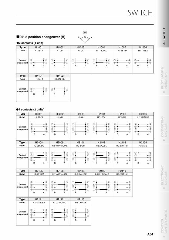
SWITCH
SZ2001SZ2-2Z1B1A
SQ2001SQ2-2U1B1A
SZ2002SZ2-2Y1B1A
SQ2002SQ2-2L1B1A
SZ2003SZ2-1Y1B
SQ2211SQ2-2U1A1B
SZ2004SZ2-1Z1A
SQ2212SQ2-2L1A1B
SZ3001SZ3-1Y1Z1M1N1B1A
SQ2101SQ2-1U1L1B1A
SZ4001SZ4-2Y2Z1M1N1B1A
(SQ)
B1001B1-2B
A1001 A1-2A
A1002 B2001B2-4B
A2001A2-4A
(SZ)
BC
A45° 45°
(B)
BC
45°
(A) C
A45°
B AC
BB
C
B AC B AC B AC
B ACB AC
B AC B AC B AC B ACB AC
CAC C A
C A
SQ3311SQ3-2U2L1A1B
B AC
SQ3203SQ3-2L2B2A
B AC
SQ3202SQ3-2U2(1A1B)
B AC
SQ3201SQ3-2U2B2A
B AC
A1-1C1A
SQ4301SQ4-2U2L2B2A
B AC
SQ4311SQ4-2U2L2(1A1B)
B AC
H2109 H2-1AL1BL1A1B
B A
B A 90 °
(H )
B A
H1001 H1-1B1A
A B
H1002 H1-2B
A B
H1003 H1-2A
A B
H1004 H1-1BL1AL
A B
H1-1B1BA H1005
H1006 H1-1A1BA
B A
H1101 H1-1A1B
B A
H1102 H1-1AL1BL
B A
H2001 H2-2B2A
B A
H2002 H2-4B
B A
H2003 H2-4A
B A
H2004 H2-1B3A
B A
H2005 H2-3B1A
B A
H2006 H2-1B1A2BA
B A
H2008 H2-2BL2AL
B A
H2009 H2-1B1A1BL1AL
B A
H2101 H2-2A2B
B A
H2102 H2-2AL2BL
B A
H2103 H2-2 (1A1B )
B A
H2104 H2-3A1B
B A
H2105 H2-1A1B2A
B A
H2106 H2-1A1B1AL1BL
B A
H2108 H2-2 (1AL1BL )
B A
H2110 H2-2 (1B1A )
B A
H2111 H2-1A1B2BA
B A
H2112 H2-2 (1BL1AL )
B A
H2113 H2-1B1A2B
B A
●4 contacts (2 units)●2 contacts (1 unit)TypeDetail
Contactarrangement
■Automatic return type (45 degree operation) (B, A)
CONTACT ARRANGEMENT DIAGRAM
CAM-OPERATED SWITCH
B TYPE, BH TYPE●CONTROL SWITCH
TypeDetail
Contactarrangement
●4 contacts (2 units) ●6 contacts (3 units)●8 contacts (4 units)
■Automatic return type with close keep contact (SZ)
●4 contacts (3 units)●4 contacts (2 units)
■Automatic return type and manual return type in axial direction (SQ)
TypeDetail
Contactarrangement
●6contacts (3 units) ●8 contacts (4 units)TypeDetail
Contactarrangement
●2 contacts (1 unit)
■90° 2-position changeover (H)
TypeDetail
Contactarrangement
TypeDetail
Contactarrangement
●4 contacts (2 units)TypeDetail
Contactarrangement
TypeDetail
Contactarrangement
TypeDetail
Contactarrangement
TypeDetail
Contactarrangement
A SWITCH
B PILOT LAMP &
INDICATOR
D ELECTRONIC
DEVICES
C CONNECTING
DEVICES
E CONTROL
CENTER PARTS
A34
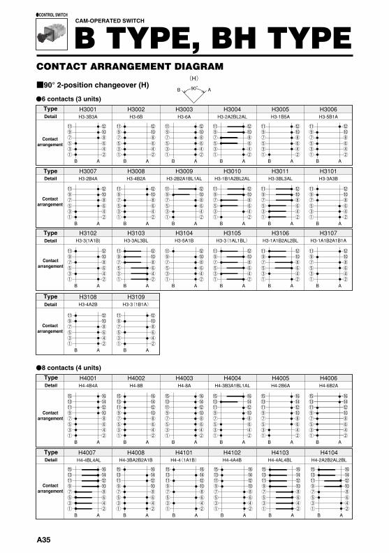
H3001 H3-3B3A
H3102 H3-3(1A1B)
H3002 H3-6B
H3103 H3-3AL3BL
H3003 H3-6A
H3104 H3-5A1B
H3004 H3-2A2BL2AL
H3105 H3-3 (1AL1BL )
H3005 H3-1B5A
H3106
H3006 H3-5B1A
H3107
H3108 H3-4A2B
H3109 H3-3 (1B1A )
H3007 H3-2B4A
H3008 H3-4B2A
H3009 H3-2B2A1BL1AL
H3010 H3-1B1A2BL2AL
H3011 H3-3BL3AL
H3101 H3-3A3B
B A
(H )
H4001 H4-4B4A
H4002 H4-8B
H4003 H4-8A H4-3B3A1BL1AL
H4004 H4005 H4-2B6A
H4006 H4-6B2A
H4-4BL4AL
B A B A B A B A B A B A
B A B A B A B A B A B A
B A
B A
B A
B A
B A B A B A B A B A
B A
B A B A B A B A
H4101 H4-4 (1A1B ) H4-3BA2B2A1B
H4008 H4102 H4-4A4B H4-4AL4BL H4-2A2B2AL2BL
H4103
B A
H4007
B A B A B A
H4104
B A B A
H3-1A1B2AL2BL H3-1A1B2A1B1A
90 °
H4105
H5001 H5-5B5A
H5003 H5-10A
H5005 H5-2B8A H5-5(1A1B)
H5101
H5102
B A
B A
H5-5A5B
H5106
H5105 H5-5(1B1A) H5-5(1AL1BL)
B A B A B A B A
B A B A
H5107 H5-2A8B
B A
H4106 H4107 H4-4(1B1A) H4-4(1AL1BL) H4-2AL2BL2A2B
B A B A
H6001 H6-6B6A
H6002 H6-12B
H6003 H6-12A
H6004 H6-2B10A
H6005 H6-4B8A
H6006 H6-8B4A
B A A B A B A B A B A
H5104 H5-3AL3BL2AL2BL
B A
H5103 H5-1A1B4(1AL1BL)
B A
B
●6 contacts (3 units)
■90° 2-position changeover (H)
CONTACT ARRANGEMENT DIAGRAM
CAM-OPERATED SWITCH
B TYPE, BH TYPE●CONTROL SWITCH
TypeDetail
Contactarrangement
TypeDetail
Contactarrangement
TypeDetail
Contactarrangement
TypeDetail
Contactarrangement
●8 contacts (4 units)TypeDetail
Contactarrangement
TypeDetail
Contactarrangement
●8 contacts (4 units)
●10 contacts (5 units)
●12 contacts (6 units)
TypeDetail
Contactarrangement
TypeDetail
Contactarrangement
TypeDetail
Contactarrangement
TypeDetail
Contactarrangement
A35
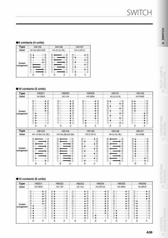
SWITCH
H3001 H3-3B3A
H3102 H3-3(1A1B)
H3002 H3-6B
H3103 H3-3AL3BL
H3003 H3-6A
H3104 H3-5A1B
H3004 H3-2A2BL2AL
H3105 H3-3 (1AL1BL )
H3005 H3-1B5A
H3106
H3006 H3-5B1A
H3107
H3108 H3-4A2B
H3109 H3-3 (1B1A )
H3007 H3-2B4A
H3008 H3-4B2A
H3009 H3-2B2A1BL1AL
H3010 H3-1B1A2BL2AL
H3011 H3-3BL3AL
H3101 H3-3A3B
B A
(H )
H4001 H4-4B4A
H4002 H4-8B
H4003 H4-8A H4-3B3A1BL1AL
H4004 H4005 H4-2B6A
H4006 H4-6B2A
H4-4BL4AL
B A B A B A B A B A B A
B A B A B A B A B A B A
B A
B A
B A
B A
B A B A B A B A B A
B A
B A B A B A B A
H4101 H4-4 (1A1B ) H4-3BA2B2A1B
H4008 H4102 H4-4A4B H4-4AL4BL H4-2A2B2AL2BL
H4103
B A
H4007
B A B A B A
H4104
B A B A
H3-1A1B2AL2BL H3-1A1B2A1B1A
90 °
H4105
H5001 H5-5B5A
H5003 H5-10A
H5005 H5-2B8A H5-5(1A1B)
H5101
H5102
B A
B A
H5-5A5B
H5106
H5105 H5-5(1B1A) H5-5(1AL1BL)
B A B A B A B A
B A B A
H5107 H5-2A8B
B A
H4106 H4107 H4-4(1B1A) H4-4(1AL1BL) H4-2AL2BL2A2B
B A B A
H6001 H6-6B6A
H6002 H6-12B
H6003 H6-12A
H6004 H6-2B10A
H6005 H6-4B8A
H6006 H6-8B4A
B A A B A B A B A B A
H5104 H5-3AL3BL2AL2BL
B A
H5103 H5-1A1B4(1AL1BL)
B A
B
●6 contacts (3 units)
■90° 2-position changeover (H)
CONTACT ARRANGEMENT DIAGRAM
CAM-OPERATED SWITCH
B TYPE, BH TYPE●CONTROL SWITCH
TypeDetail
Contactarrangement
TypeDetail
Contactarrangement
TypeDetail
Contactarrangement
TypeDetail
Contactarrangement
●8 contacts (4 units)TypeDetail
Contactarrangement
TypeDetail
Contactarrangement
●8 contacts (4 units)
●10 contacts (5 units)
●12 contacts (6 units)
TypeDetail
Contactarrangement
TypeDetail
Contactarrangement
TypeDetail
Contactarrangement
TypeDetail
Contactarrangement
A SWITCH
B PILOT LAMP &
INDICATOR
D ELECTRONIC
DEVICES
C CONNECTING
DEVICES
E CONTROL
CENTER PARTS
A36
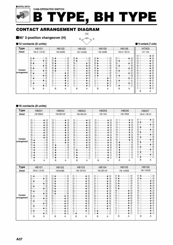
H6101 H6-6(1A1B)
H6102 H6-6A6B
H6103 H6-10A2B
H6105 H6-4A8B
H6106 H6-6 (1B1A )
B A B A B A B A B A B A
H8001 H8-8B8A
H8002 H8-6B10A
H8003 H8-4B12A
H8005 H8-16A
H8006 H8-7B9A
B A B A B A B A B A
H7003 H7-14A
B A
(H )
H8101 H8-8 (1A1B )
H8102 H8-8A8B
H8103 H8-1B15A
H8104 H8-2B14A
B A B A B A B A
B A
H8105 H8-10A6B
90 °
H8107 H8-3B13A
B A
H8108 H8-8BL8AL
B A
B A B A
H9001 H9-9B9A
H9101 H9-1B17A
B A B A
H9102 H9-2B16A
H9103 H9-3B15A
B A B A
H10003 H10-20A
H10101 H10-10 (1A1B )
B A B A
H10102 H10-18A2B
H10103 H10-16A4B
B A
H10104 H10-14A6B
H8007 H8-8(1B1A)
B A
H8106 H8-14A2B
B A
●12 contacts (6 units) ●14 contacts (7 units)
■90° 2-position changeover (H)
CONTACT ARRANGEMENT DIAGRAM
CAM-OPERATED SWITCH
B TYPE, BH TYPE●CONTROL SWITCH
TypeDetail
Contactarrangement
●16 contacts (8 units)TypeDetail
Contactarrangement
TypeDetail
Contactarrangement
●16 contacts (8 units)
●18 contacts (9 units)
TypeDetail
Contactarrangement
TypeDetail
Contactarrangement
●20 contacts (10 units)TypeDetail
Contactarrangement
A37
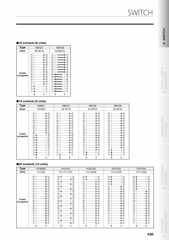
SWITCH
H6101 H6-6(1A1B)
H6102 H6-6A6B
H6103 H6-10A2B
H6105 H6-4A8B
H6106 H6-6 (1B1A )
B A B A B A B A B A B A
H8001 H8-8B8A
H8002 H8-6B10A
H8003 H8-4B12A
H8005 H8-16A
H8006 H8-7B9A
B A B A B A B A B A
H7003 H7-14A
B A
(H )
H8101 H8-8 (1A1B )
H8102 H8-8A8B
H8103 H8-1B15A
H8104 H8-2B14A
B A B A B A B A
B A
H8105 H8-10A6B
90 °
H8107 H8-3B13A
B A
H8108 H8-8BL8AL
B A
B A B A
H9001 H9-9B9A
H9101 H9-1B17A
B A B A
H9102 H9-2B16A
H9103 H9-3B15A
B A B A
H10003 H10-20A
H10101 H10-10 (1A1B )
B A B A
H10102 H10-18A2B
H10103 H10-16A4B
B A
H10104 H10-14A6B
H8007 H8-8(1B1A)
B A
H8106 H8-14A2B
B A
●12 contacts (6 units) ●14 contacts (7 units)
■90° 2-position changeover (H)
CONTACT ARRANGEMENT DIAGRAM
CAM-OPERATED SWITCH
B TYPE, BH TYPE●CONTROL SWITCH
TypeDetail
Contactarrangement
●16 contacts (8 units)TypeDetail
Contactarrangement
TypeDetail
Contactarrangement
●16 contacts (8 units)
●18 contacts (9 units)
TypeDetail
Contactarrangement
TypeDetail
Contactarrangement
●20 contacts (10 units)TypeDetail
Contactarrangement
A SWITCH
B PILOT LAMP &
INDICATOR
D ELECTRONIC
DEVICES
C CONNECTING
DEVICES
E CONTROL
CENTER PARTS
A38
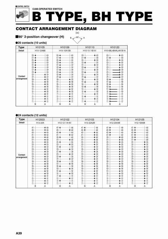
B A
H10105 H10-12A8B
H10110 H10-10 (1B1A )
B A
H10120 H10-6BL4B4AL4A1B1A
B A
H10106 H10-10A10B
B A
B A B A
H12003 H12-24A
B A
H12103 H12-22A2B
B A
H12104 H12-20A4B
B A
H12105 H12-18A6B
H12102 H12-12 (1A1B )
B A
(H )
90 °
B A B A B A
H12107 H12-14A10B
B A
H12106 H12-16A8B
H12108 H12-12A12B
B A B A
H12110 H12-12 (1B1A )
B A
H13001 H13-18A8B
H14101
B A
H16101 H16-16 (1A1B )
B A
H15110 H15-15 (1B1A )
B A
H14-14 (1A1B ) H14102
B A
H14-14 (1B1A )
●20 contacts (10 units)
■90° 2-position changeover (H)
CONTACT ARRANGEMENT DIAGRAM
CAM-OPERATED SWITCH
B TYPE, BH TYPE●CONTROL SWITCH
TypeDetail
Contactarrangement
●24 contacts (12 units)TypeDetail
Contactarrangement
●24 contacts (12 units) ●26 contacts (13 units)
●28 contacts (14 units) ●30 contacts (15 units) ●32 contacts (16 units)
TypeDetail
Detail
Contactarrangement
Type
Contactarrangement
A39
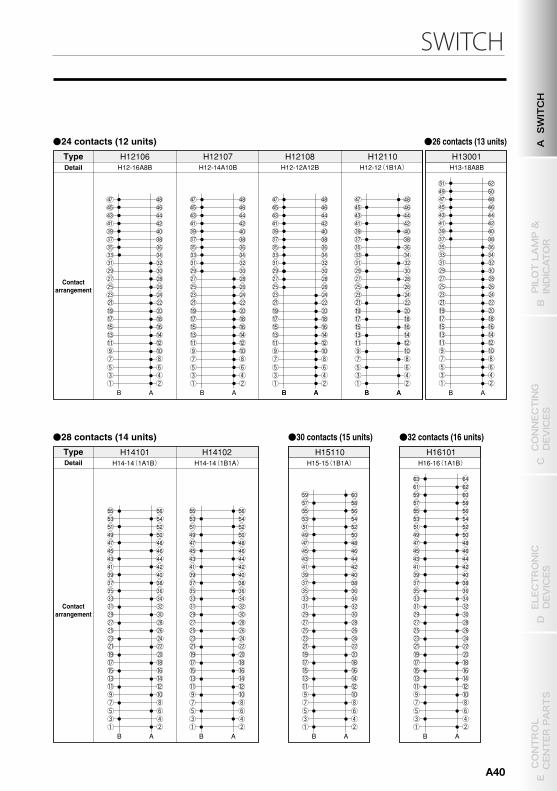
SWITCH
B A
H10105 H10-12A8B
H10110 H10-10 (1B1A )
B A
H10120 H10-6BL4B4AL4A1B1A
B A
H10106 H10-10A10B
B A
B A B A
H12003 H12-24A
B A
H12103 H12-22A2B
B A
H12104 H12-20A4B
B A
H12105 H12-18A6B
H12102 H12-12 (1A1B )
B A
(H )
90 °
B A B A B A
H12107 H12-14A10B
B A
H12106 H12-16A8B
H12108 H12-12A12B
B A B A
H12110 H12-12 (1B1A )
B A
H13001 H13-18A8B
H14101
B A
H16101 H16-16 (1A1B )
B A
H15110 H15-15 (1B1A )
B A
H14-14 (1A1B ) H14102
B A
H14-14 (1B1A )
●20 contacts (10 units)
■90° 2-position changeover (H)
CONTACT ARRANGEMENT DIAGRAM
CAM-OPERATED SWITCH
B TYPE, BH TYPE●CONTROL SWITCH
TypeDetail
Contactarrangement
●24 contacts (12 units)TypeDetail
Contactarrangement
●24 contacts (12 units) ●26 contacts (13 units)
●28 contacts (14 units) ●30 contacts (15 units) ●32 contacts (16 units)
TypeDetail
Detail
Contactarrangement
Type
Contactarrangement
A SWITCH
B PILOT LAMP &
INDICATOR
D ELECTRONIC
DEVICES
C CONNECTING
DEVICES
E CONTROL
CENTER PARTS
A40
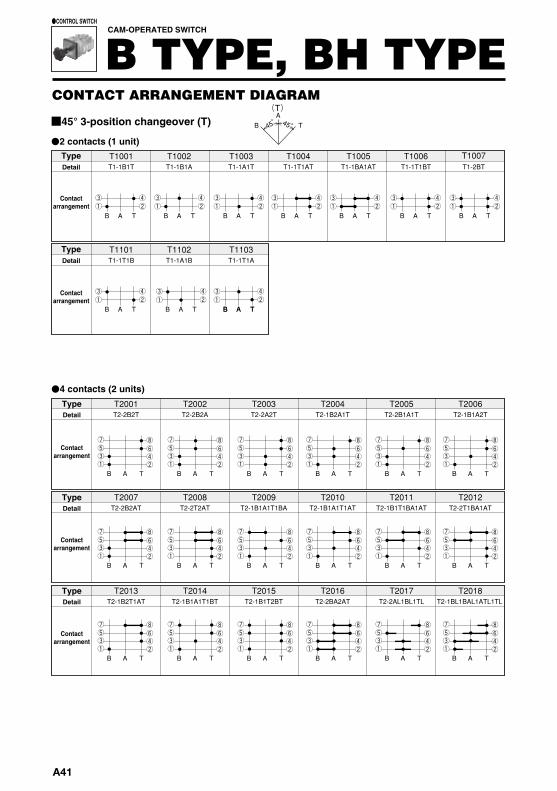
T1001 T1-1B1T
T1002 T1-1B1A
T1003 T1-1A1T
T1004 T1-1T1AT
T1005 T1-1BA1AT T1-1T1BT T1-2BT
T1006
T2001 T2-2B2T
T2013 T2-1B2T1AT
T2002 T2-2B2A
T2014 T2-1B1A1T1BT
T2003 T2-2A2T
T2015 T2-1B1T2BT
T2004 T2-1B2A1T
T2016 T2-2BA2AT
T2005 T2-2B1A1T
T2017 T2-2AL1BL1TL
T2006 T2-1B1A2T
T2018
T2007 T2-2B2AT
T2008 T2-2T2AT
T2009 T2-1B1A1T1BA
T2010 T2-1B1A1T1AT
T2011 T2-1B1T1BA1AT
T2012 T2-2T1BA1AT
B T A B T A B T A B T A B T A
B T A B T A
T1007
B T A
(T )
B A
T
B T A B T A B T A B T A B T A B T A
B T A B T A B T A B T A B T A B T A
B T A B T A B T A B T A B T A B T A
T1101 T1-1T1B
T1102 T1-1A1B
T1103 T1-1T1A
B T A
B T A B T A
45 ° 45 °
T2114 T2-1T1A1AT1T
T2115 T2-1T1A1AT1BA
T2116 T2-2 (1AT1BA )
T2117 T2-1T1A1B1T
T2118 T2-1T1B2A
T2119 T2-1T1A1B1A
T2120 T2-1T1BA1AT1B
T2121 T2-2T1A1B
T2122 T2-1ATL1BAL1BL1TL
T2123 T2-1T1A1B1BA
T2124 T2-2A1T1B
T2125 T2-1T2A1B T2-1B1A1T1A T2-1TL1AL1BL1TL
T3001 T3-3B3T
T3002 T3-2B2A2T
T3003 T3-3B3A
T3004 T3-3A3T
T2-1T3B
T3005 T3-2B4T
T3006 T3-2B2T2BT
B T A B T A B T A B T A
B T A
B T A
B T A B T A B T A B T A
B T A
B T A
T2126 T2-1BAL1BL1TL1ATL
B T A
T2127
B T A
T2128
B T A
T2129
B T A
B T A B T A B T A B T A B T A B T A
T2019
T2101 T2-2 (1T1B )
T2102 T2-2AL1TL1BL
T2103 T2-2T2A
T2104 T2-2T2B
T2105 T2-2 (1T1A )
B T A B T A B T A B T A B T A B T A
T2106 T2-2 (1B1T )
T2107 T2-1T1A1T1AT
T2109 T2-1T1A2B
T2110 T2-1T1A1AT1B
T2111 T2-1T1AT1B1BA
T2112 T2-1T1B1AT1BA
B T A B T A B T A B T A
B T A
B T A
T2108 T2-1T1A2AT
B T A
T2-1BL1BAL1ATL1TL
T2-1BAL1ATL1TL1BL
●2 contacts (1 unit)
■45° 3-position changeover (T)
CONTACT ARRANGEMENT DIAGRAM
CAM-OPERATED SWITCH
B TYPE, BH TYPE●CONTROL SWITCH
TypeDetail
Contactarrangement
TypeDetail
Contactarrangement
●4 contacts (2 units)
TypeDetail
Contactarrangement
TypeDetail
Contactarrangement
TypeDetail
Contactarrangement
●4 contacts (2 units)
●6 contacts (3 units)
TypeDetail
Contactarrangement
TypeDetail
Contactarrangement
TypeDetail
Contactarrangement
TypeDetail
Contactarrangement
TypeDetail
Contactarrangement
TypeDetail
Contactarrangement
A41
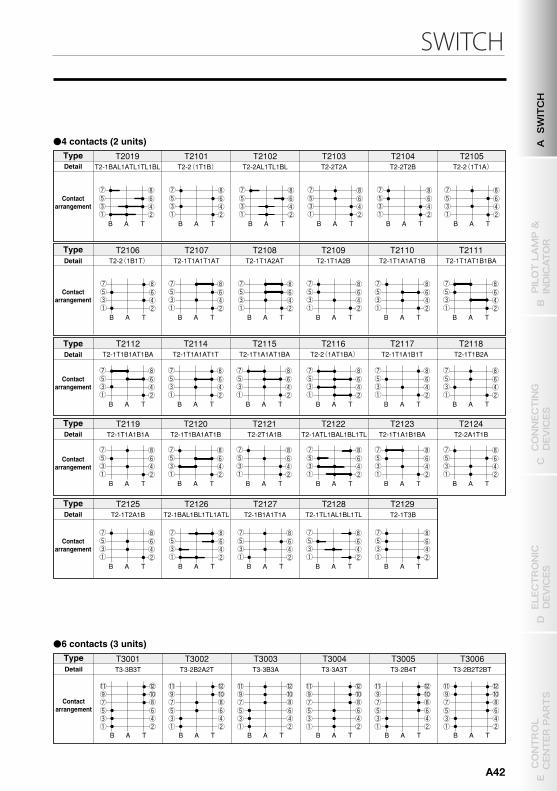
SWITCH
T1001 T1-1B1T
T1002 T1-1B1A
T1003 T1-1A1T
T1004 T1-1T1AT
T1005 T1-1BA1AT T1-1T1BT T1-2BT
T1006
T2001 T2-2B2T
T2013 T2-1B2T1AT
T2002 T2-2B2A
T2014 T2-1B1A1T1BT
T2003 T2-2A2T
T2015 T2-1B1T2BT
T2004 T2-1B2A1T
T2016 T2-2BA2AT
T2005 T2-2B1A1T
T2017 T2-2AL1BL1TL
T2006 T2-1B1A2T
T2018
T2007 T2-2B2AT
T2008 T2-2T2AT
T2009 T2-1B1A1T1BA
T2010 T2-1B1A1T1AT
T2011 T2-1B1T1BA1AT
T2012 T2-2T1BA1AT
B T A B T A B T A B T A B T A
B T A B T A
T1007
B T A
(T )
B A
T
B T A B T A B T A B T A B T A B T A
B T A B T A B T A B T A B T A B T A
B T A B T A B T A B T A B T A B T A
T1101 T1-1T1B
T1102 T1-1A1B
T1103 T1-1T1A
B T A
B T A B T A
45 ° 45 °
T2114 T2-1T1A1AT1T
T2115 T2-1T1A1AT1BA
T2116 T2-2 (1AT1BA )
T2117 T2-1T1A1B1T
T2118 T2-1T1B2A
T2119 T2-1T1A1B1A
T2120 T2-1T1BA1AT1B
T2121 T2-2T1A1B
T2122 T2-1ATL1BAL1BL1TL
T2123 T2-1T1A1B1BA
T2124 T2-2A1T1B
T2125 T2-1T2A1B T2-1B1A1T1A T2-1TL1AL1BL1TL
T3001 T3-3B3T
T3002 T3-2B2A2T
T3003 T3-3B3A
T3004 T3-3A3T
T2-1T3B
T3005 T3-2B4T
T3006 T3-2B2T2BT
B T A B T A B T A B T A
B T A
B T A
B T A B T A B T A B T A
B T A
B T A
T2126 T2-1BAL1BL1TL1ATL
B T A
T2127
B T A
T2128
B T A
T2129
B T A
B T A B T A B T A B T A B T A B T A
T2019
T2101 T2-2 (1T1B )
T2102 T2-2AL1TL1BL
T2103 T2-2T2A
T2104 T2-2T2B
T2105 T2-2 (1T1A )
B T A B T A B T A B T A B T A B T A
T2106 T2-2 (1B1T )
T2107 T2-1T1A1T1AT
T2109 T2-1T1A2B
T2110 T2-1T1A1AT1B
T2111 T2-1T1AT1B1BA
T2112 T2-1T1B1AT1BA
B T A B T A B T A B T A
B T A
B T A
T2108 T2-1T1A2AT
B T A
T2-1BL1BAL1ATL1TL
T2-1BAL1ATL1TL1BL
●2 contacts (1 unit)
■45° 3-position changeover (T)
CONTACT ARRANGEMENT DIAGRAM
CAM-OPERATED SWITCH
B TYPE, BH TYPE●CONTROL SWITCH
TypeDetail
Contactarrangement
TypeDetail
Contactarrangement
●4 contacts (2 units)
TypeDetail
Contactarrangement
TypeDetail
Contactarrangement
TypeDetail
Contactarrangement
●4 contacts (2 units)
●6 contacts (3 units)
TypeDetail
Contactarrangement
TypeDetail
Contactarrangement
TypeDetail
Contactarrangement
TypeDetail
Contactarrangement
TypeDetail
Contactarrangement
TypeDetail
Contactarrangement
A SWITCH
B PILOT LAMP &
INDICATOR
D ELECTRONIC
DEVICES
C CONNECTING
DEVICES
E CONTROL
CENTER PARTS
A42
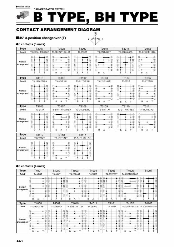
T4001 T4-4B4T
B T A
(T)
B A
T
T3-3 (1T1A ) T3-3T1A1AT1BA T3-2TL2AL2BL T3-1BL1TL1AL1T
T3-2T2B2T
T3107 T3108
B T A B T A
T3109 T3110 T3111
B T A B T A B T A
T3112
B T A
T3113 T3-1B1T1A2T T3-2 (1TL1AL1BL )
T3114
B T A B T A
T3007 T3-2B1A1T1BA1AT
T3008 T3-1B1A2T1BA1AT
T3009 T3-3T3AT
T3010 T3-2T2BA2AT
T3011 T3-2BL2AL2TL T3-2 (1B1T ) 1B1A
T3012
T3-2(1B1A1T) T3-2(1T1A1B) T3-3T3B T3-2T2A2B
T3-3T3A T3-2 (1T1A ) 1AT1BA
B T A B T A B T A B T A B T A B T A
T3101 T3-3 (1T1B )
T3102
B T A
T3013 T3-1B2A2T1BA
B T A B T A
T3103 T3104 T3105
B T A B T A B T A
T3106
B T A
T4-4A4T T4002
B T A
T4-2B2A4T T4003
B T A
T4-3B5T T4004
B T A
T4005
B T A
T4006
B T A
T4007 T4-4B4T
B T A
T4-2B2T4A T4009
T4-2 (1B1A1T ) 2A T4010
B T A
T4-2B2A2T1B1T T4008
B T A B T A
T4-2B3A3T T4011
B T A
T4-4T4B T4-2T2A1AT1BA1A1B T4-2T2A1BA1AT1T1A T4101
B T A
T4102
B T A
T4103
B T A
T4-3B3T2BT T4-2B2T2BA2AT
45 ° 45 °
T 7122
B T A
T9102 T9-6T6A6B T9-10AT4A4T
B A
T9103
B T A T
T5104
B T A
T6001 T6-6B6T T6-4 (1B1A1T )
T8-5 (1B1A1T ) T 7-10AT2A2T
T6-4 (1T1A1B ) T6-8AT2A2T T6101 T6102
B T A B T A B T A B T A
T6103
T8101
B T A
T4-2T6B T4-1T1B6BT T4-1B1T6BT T4-2T2A2B1AT1BA T4-6AT1A1T T4-2 (1B1A1T ) 1BT1T T4105
B T A
T4106
B T A
T4107
B T A
T4108
B T A
T4109
B T A
T4104
B T A
T4110
B T A
T5001 T5-5B5T
T5-1T1B8BT
B T A
T5-6B4T T5-4 (1B1T ) 1B1A T5-2B4A4T T5004
B T A
T5005
B T A
T5006
B T A
T5-3 (1B1A1T ) T5101
B T A B T A
T5102 T5-3 (1T1A1B ) T5-3 (1TL1AL1BL )
T5103
B T A
●6 contacts (3 units)
■45° 3-position changeover (T)
CONTACT ARRANGEMENT DIAGRAM
CAM-OPERATED SWITCH
B TYPE, BH TYPE●CONTROL SWITCH
TypeDetail
Contactarrangement
TypeDetail
Contactarrangement
TypeDetail
Contactarrangement
TypeDetail
Contactarrangement
●8 contacts (4 units)TypeDetail
Contactarrangement
TypeDetail
Contactarrangement
●8 contacts (4 units)
●10 contacts (5 units)
●10 contacts (5 units) ●12 contacts (6 units)
●14 contacts (7 units) ●18 contacts (9 units)●16 contacts (8 units)
TypeDetail
Contactarrangement
TypeDetail
Contactarrangement
TypeDetail
Contactarrangement
TypeDetail
Contactarrangement
TypeDetail
Contactarrangement
TypeDetail
Contactarrangement
TypeDetail
Contactarrangement
A43
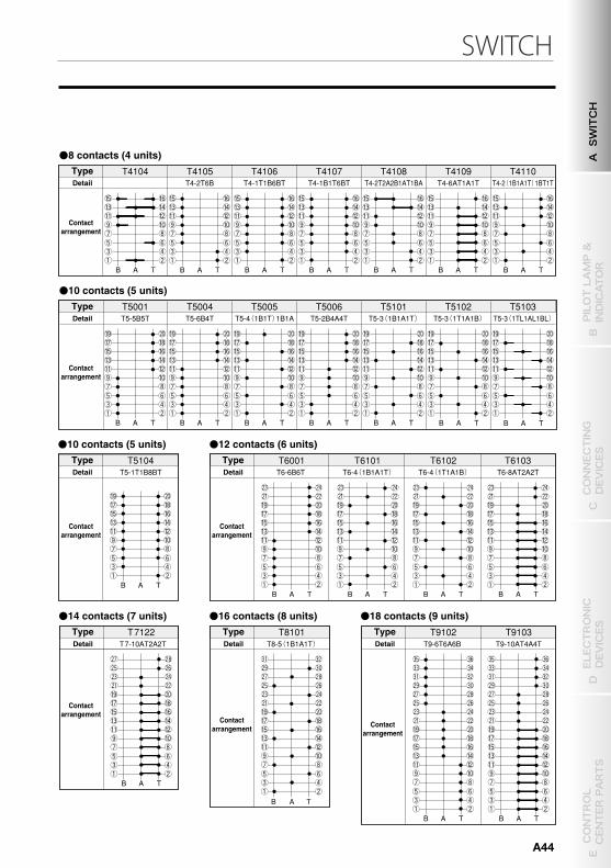
SWITCH
T4001 T4-4B4T
B T A
(T)
B A
T
T3-3 (1T1A ) T3-3T1A1AT1BA T3-2TL2AL2BL T3-1BL1TL1AL1T
T3-2T2B2T
T3107 T3108
B T A B T A
T3109 T3110 T3111
B T A B T A B T A
T3112
B T A
T3113 T3-1B1T1A2T T3-2 (1TL1AL1BL )
T3114
B T A B T A
T3007 T3-2B1A1T1BA1AT
T3008 T3-1B1A2T1BA1AT
T3009 T3-3T3AT
T3010 T3-2T2BA2AT
T3011 T3-2BL2AL2TL T3-2 (1B1T ) 1B1A
T3012
T3-2(1B1A1T) T3-2(1T1A1B) T3-3T3B T3-2T2A2B
T3-3T3A T3-2 (1T1A ) 1AT1BA
B T A B T A B T A B T A B T A B T A
T3101 T3-3 (1T1B )
T3102
B T A
T3013 T3-1B2A2T1BA
B T A B T A
T3103 T3104 T3105
B T A B T A B T A
T3106
B T A
T4-4A4T T4002
B T A
T4-2B2A4T T4003
B T A
T4-3B5T T4004
B T A
T4005
B T A
T4006
B T A
T4007 T4-4B4T
B T A
T4-2B2T4A T4009
T4-2 (1B1A1T ) 2A T4010
B T A
T4-2B2A2T1B1T T4008
B T A B T A
T4-2B3A3T T4011
B T A
T4-4T4B T4-2T2A1AT1BA1A1B T4-2T2A1BA1AT1T1A T4101
B T A
T4102
B T A
T4103
B T A
T4-3B3T2BT T4-2B2T2BA2AT
45 ° 45 °
T 7122
B T A
T9102 T9-6T6A6B T9-10AT4A4T
B A
T9103
B T A T
T5104
B T A
T6001 T6-6B6T T6-4 (1B1A1T )
T8-5 (1B1A1T ) T 7-10AT2A2T
T6-4 (1T1A1B ) T6-8AT2A2T T6101 T6102
B T A B T A B T A B T A
T6103
T8101
B T A
T4-2T6B T4-1T1B6BT T4-1B1T6BT T4-2T2A2B1AT1BA T4-6AT1A1T T4-2 (1B1A1T ) 1BT1T T4105
B T A
T4106
B T A
T4107
B T A
T4108
B T A
T4109
B T A
T4104
B T A
T4110
B T A
T5001 T5-5B5T
T5-1T1B8BT
B T A
T5-6B4T T5-4 (1B1T ) 1B1A T5-2B4A4T T5004
B T A
T5005
B T A
T5006
B T A
T5-3 (1B1A1T ) T5101
B T A B T A
T5102 T5-3 (1T1A1B ) T5-3 (1TL1AL1BL )
T5103
B T A
●6 contacts (3 units)
■45° 3-position changeover (T)
CONTACT ARRANGEMENT DIAGRAM
CAM-OPERATED SWITCH
B TYPE, BH TYPE●CONTROL SWITCH
TypeDetail
Contactarrangement
TypeDetail
Contactarrangement
TypeDetail
Contactarrangement
TypeDetail
Contactarrangement
●8 contacts (4 units)TypeDetail
Contactarrangement
TypeDetail
Contactarrangement
●8 contacts (4 units)
●10 contacts (5 units)
●10 contacts (5 units) ●12 contacts (6 units)
●14 contacts (7 units) ●18 contacts (9 units)●16 contacts (8 units)
TypeDetail
Contactarrangement
TypeDetail
Contactarrangement
TypeDetail
Contactarrangement
TypeDetail
Contactarrangement
TypeDetail
Contactarrangement
TypeDetail
Contactarrangement
TypeDetail
Contactarrangement
A SWITCH
B PILOT LAMP &
INDICATOR
D ELECTRONIC
DEVICES
C CONNECTING
DEVICES
E CONTROL
CENTER PARTS
A44
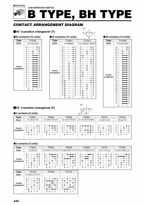
F3001 F3-2A2T2F F3-1B1A1T1F1TF1ATF F3-1B2F1BAT1TF1ATF F3-1T1F1BF2AT1TF F3-2 (1F1B ) 2T
F3002
F3003
F3004
F3102
B F T A B F T A B F T A B F T A B F T
F3-2A2T1BATL1FL
A B F T A
F2001 F2-1B1A1T1F F2-1B1F1TF1ATF F2-1A1F1TF1ATF F2-1TF1ATF1F1BATF
F2002
F2003
F2004 F2101
F3101
F3103 F3-1B1A1T1F1T1F
F3104
F3110
B F T A B F T A B F T A
F2-1B1F1A1F F2102 F2-2A1T1F
B F T A B F T A B F T A B F T A B F T A B F T A
A
B
T
F
(F )
T10101
B T A
T10-16AT2A2T
T14102
B T A
T14-24AT2A2T
45 °
45 ° 45 °
BA
T
(T)
T12001
B T A
T12-8B8A8T T12101
B T A
T12-2 (3B3A3T ) 2B2A2T
45° 45°
B E
(E)
A T
F
E2001 E2-1B1E1A1F
E2101
E2102 E2-1A1F1AT1TF
B F E T A B F E T A B F E T A
F6101
B F T A
E3001 E3-1B1E1A1F2T E3-1A1F1BA1E1FE1B E3-1B1E2 (1A1F ) E3-1T1A1F1T1B1E
E3002
E3003
B F E T A B F E T A
E3004
E3101 E3102 E3103 E3-2A2T2F E3-1F1T1A1ATF
B F E T A B F E T A
B F E T A B F E T A B F E T A
F4001 F4101
B F T A B F T A
B F T A
F5101 F5-1B1F1T1F1BAT1F1A1B1F F4-2B2A2T2F F4-2 (1B1A1T1F ) F6-1B1F1T1F1BAT1F1A2 (1B1F )
45 °
45 °
45 ° 45 °
●20 contacts (10 units) ●24 contacts (12 units) ●28 contacts (14 units)
■45° 3-position changeover (T)
CONTACT ARRANGEMENT DIAGRAM
CAM-OPERATED SWITCH
B TYPE, BH TYPE●CONTROL SWITCH
TypeDetail
Contactarrangement
TypeDetail
Contactarrangement
TypeDetail
Contactarrangement
●6 contacts (3 units)
●4 contacts (2 units)
■45° 4-position changeover (F)
TypeDetail
Contactarrangement
TypeDetail
Contactarrangement
TypeDetail
Contactarrangement
●8 contacts (4 units) ●10 contacts (5 units) ●12 contacts (6 units)
●4 contacts (2 units)
●6 contacts (3 units)
■45° 5-position changeover (E)
TypeDetail
Contactarrangement
TypeDetail
Contactarrangement
TypeDetail
Contactarrangement
TypeDetail
Contactarrangement
TypeDetail
Contactarrangement
TypeDetail
Contactarrangement
A45
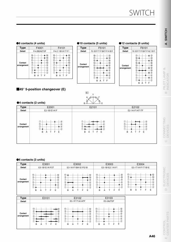
SWITCH
F3001 F3-2A2T2F F3-1B1A1T1F1TF1ATF F3-1B2F1BAT1TF1ATF F3-1T1F1BF2AT1TF F3-2 (1F1B ) 2T
F3002
F3003
F3004
F3102
B F T A B F T A B F T A B F T A B F T
F3-2A2T1BATL1FL
A B F T A
F2001 F2-1B1A1T1F F2-1B1F1TF1ATF F2-1A1F1TF1ATF F2-1TF1ATF1F1BATF
F2002
F2003
F2004 F2101
F3101
F3103 F3-1B1A1T1F1T1F
F3104
F3110
B F T A B F T A B F T A
F2-1B1F1A1F F2102 F2-2A1T1F
B F T A B F T A B F T A B F T A B F T A B F T A
A
B
T
F
(F )
T10101
B T A
T10-16AT2A2T
T14102
B T A
T14-24AT2A2T
45 °
45 ° 45 °
BA
T
(T)
T12001
B T A
T12-8B8A8T T12101
B T A
T12-2 (3B3A3T ) 2B2A2T
45° 45°
B E
(E)
A T
F
E2001 E2-1B1E1A1F
E2101
E2102 E2-1A1F1AT1TF
B F E T A B F E T A B F E T A
F6101
B F T A
E3001 E3-1B1E1A1F2T E3-1A1F1BA1E1FE1B E3-1B1E2 (1A1F ) E3-1T1A1F1T1B1E
E3002
E3003
B F E T A B F E T A
E3004
E3101 E3102 E3103 E3-2A2T2F E3-1F1T1A1ATF
B F E T A B F E T A
B F E T A B F E T A B F E T A
F4001 F4101
B F T A B F T A
B F T A
F5101 F5-1B1F1T1F1BAT1F1A1B1F F4-2B2A2T2F F4-2 (1B1A1T1F ) F6-1B1F1T1F1BAT1F1A2 (1B1F )
45 °
45 °
45 ° 45 °
●20 contacts (10 units) ●24 contacts (12 units) ●28 contacts (14 units)
■45° 3-position changeover (T)
CONTACT ARRANGEMENT DIAGRAM
CAM-OPERATED SWITCH
B TYPE, BH TYPE●CONTROL SWITCH
TypeDetail
Contactarrangement
TypeDetail
Contactarrangement
TypeDetail
Contactarrangement
●6 contacts (3 units)
●4 contacts (2 units)
■45° 4-position changeover (F)
TypeDetail
Contactarrangement
TypeDetail
Contactarrangement
TypeDetail
Contactarrangement
●8 contacts (4 units) ●10 contacts (5 units) ●12 contacts (6 units)
●4 contacts (2 units)
●6 contacts (3 units)
■45° 5-position changeover (E)
TypeDetail
Contactarrangement
TypeDetail
Contactarrangement
TypeDetail
Contactarrangement
TypeDetail
Contactarrangement
TypeDetail
Contactarrangement
TypeDetail
Contactarrangement
A SWITCH
B PILOT LAMP &
INDICATOR
D ELECTRONIC
DEVICES
C CONNECTING
DEVICES
E CONTROL
CENTER PARTS
A46
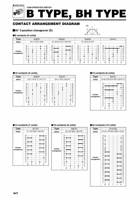
E12102
B F E T A
E7101
B F E T A
B F E T A
E8101
B F E T A
E6101
B F E T A B F E T A
E4001 E4002 E4003
B F E T A B F E T A B F E T A B F E T A
E4101
E5001 E5101
E4-2 (1B1E ) 2A2F
E5-2 (1B1E ) 2 (1A1F ) 2T
E7-1AF1BE5 (1BA1FE ) E8-1AF1BE6 (1BA1FE ) E12-8 (1FE1BA ) 2BE3 (1E1B )
E5-2 (1B1E ) 2A2T2F E6-2A2T1BAT1E2F1BAT1E1BATF1FE
E4-1B1E1A1F2 (1BA1FE ) E4-1B1E1A1F4T
B E
45°
45°
45° 45°
(E)
AT
F
E15101
B F E T A
E16101 E16102
B F E T A B F E T A
B
G
E
(G)
AT
F
G3101G3-1B1E1A1G1T1F G3-1B1E1A1G1F
G3102
B F E GTA B F E GTA
E15-14 (1FE1BA ) 2BE E16-15 (1FE1BA ) 2BE E16-14 (1FE1BA ) 1E1B2BE
45°
45°
45° 45° 45°
●8 contacts (4 units)
■45° 5-position changeover (E)
CONTACT ARRANGEMENT DIAGRAM
CAM-OPERATED SWITCH
B TYPE, BH TYPE●CONTROL SWITCH
●10 contacts (5 units)
●14 contacts (7 units) ●16 contacts (8 units)
●12 contacts (6 units)
●24 contacts (12 units)
TypeDetail
Contactarrangement
TypeDetail
Contactarrangement
TypeDetail
Contactarrangement
TypeDetail
Contactarrangement
TypeDetail
Contactarrangement
TypeDetail
Contactarrangement
●30 contacts (15 units) ●32 contacts (16 units)
●6 contacts (3 units)
■45° 6-position changeover (G)
TypeDetail
Contactarrangement
TypeDetail
Contactarrangement
TypeDetail
Contactarrangement
A47
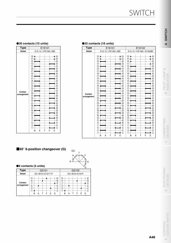
SWITCH
E12102
B F E T A
E7101
B F E T A
B F E T A
E8101
B F E T A
E6101
B F E T A B F E T A
E4001 E4002 E4003
B F E T A B F E T A B F E T A B F E T A
E4101
E5001 E5101
E4-2 (1B1E ) 2A2F
E5-2 (1B1E ) 2 (1A1F ) 2T
E7-1AF1BE5 (1BA1FE ) E8-1AF1BE6 (1BA1FE ) E12-8 (1FE1BA ) 2BE3 (1E1B )
E5-2 (1B1E ) 2A2T2F E6-2A2T1BAT1E2F1BAT1E1BATF1FE
E4-1B1E1A1F2 (1BA1FE ) E4-1B1E1A1F4T
B E
45°
45°
45° 45°
(E)
AT
F
E15101
B F E T A
E16101 E16102
B F E T A B F E T A
B
G
E
(G)
AT
F
G3101G3-1B1E1A1G1T1F G3-1B1E1A1G1F
G3102
B F E GTA B F E GTA
E15-14 (1FE1BA ) 2BE E16-15 (1FE1BA ) 2BE E16-14 (1FE1BA ) 1E1B2BE
45°
45°
45° 45° 45°
●8 contacts (4 units)
■45° 5-position changeover (E)
CONTACT ARRANGEMENT DIAGRAM
CAM-OPERATED SWITCH
B TYPE, BH TYPE●CONTROL SWITCH
●10 contacts (5 units)
●14 contacts (7 units) ●16 contacts (8 units)
●12 contacts (6 units)
●24 contacts (12 units)
TypeDetail
Contactarrangement
TypeDetail
Contactarrangement
TypeDetail
Contactarrangement
TypeDetail
Contactarrangement
TypeDetail
Contactarrangement
TypeDetail
Contactarrangement
●30 contacts (15 units) ●32 contacts (16 units)
●6 contacts (3 units)
■45° 6-position changeover (G)
TypeDetail
Contactarrangement
TypeDetail
Contactarrangement
TypeDetail
Contactarrangement
A SWITCH
B PILOT LAMP &
INDICATOR
D ELECTRONIC
DEVICES
C CONNECTING
DEVICES
E CONTROL
CENTER PARTS
A48
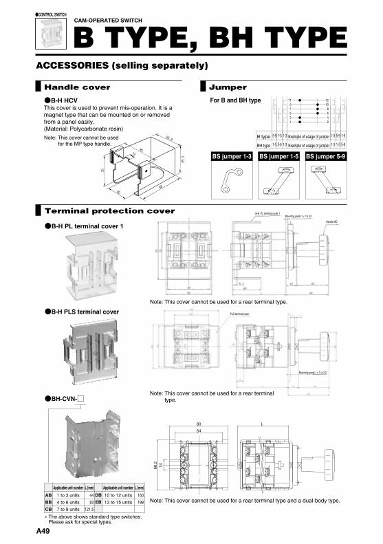
●BH-CVN-□
11
5-9 1-5 1-3 1-3 5-9 1-5
12 9 1 0 7 8 5 6 3 4 1 2
1-5 5-9 1-3 1-3 1-5 5-9
80
64
68.214
L
ABBBCB
1 to 3 units4 to 6 units7 to 9 units
DBEB
10 to 12 units13 to 15 units
Applicable unit number L (mm) Applicable unit number L (mm)
4483
121.5
160199
CAM-OPERATED SWITCH
B TYPE, BH TYPE●CONTROL SWITCH
BS jumper 1-3 BS jumper 1-5 BS jumper 5-9
●B-H HCV For B and BH type
ACCESSORIES (selling separately)
Handle cover Jumper
Example of usage of jumper
Example of usage of jumper
B type
BH type
Note: This cover cannot be used for the MP type handle.
This cover is used to prevent mis-operation. It is a magnet type that can be mounted on or removed from a panel easily.(Material: Polycarbonate resin)
●B-H PL terminal cover 1
●B-H PLS terminal cover
B-H PL terminal cover 1Mounting panel: t = 1 to 3.2
Handle HD
Note: This cover cannot be used for a rear terminal type.
PLS terminal cover
Mounting panel: t = 1 to 3.2
Terminal protection cover
Flange (Nameplate) set
●B flange set□ ●F panel set□ ●Indicator flange set□ ●BA-6 indicator flange set□
Suppliedscrews
Suppliedscrews
Suppliedscrews
Suppliedscrews
① M5×10 countersunk② M4×15 SUS 3-piece③ M2.6×4 tapping
2 pcs.1 pc.4 pcs.
① M5×10 countersunk② M4×15 SUS 3-piece③ M2.6×4 tapping
2 pcs.1 pc.4 pcs.
① M5×10 countersunk② M4×15 SUS 3-piece③ M2.6×4 tapping
2 pcs.1 pc.4 pcs.
① M5×10 countersunk② M4×15 SUS 3-piece
2 pcs.1 pc.
with
dot
with
dot
Handle
LD-BColor Pistol shape (large)
Pistol shape (small) Knob shapeEgg shape (large) Egg shape (small) Beak shape (large) Beak shape (small)
Handlecode
Please check a dimensions from page A6 “Handle”.
□:B(N1.5), BG(7.5BG4/1.5)
LD LP Stick shape (large) HD HP Stick shape (small) LDP MP
HDP HR
LF LS
HF LE
LFP HE
HFP Octagonal shape (small)
Rose shape (large)Rose shape (small)Rose shape (large)Rose shape (small)Octagonal shape (large)Octagonal shape (small)Octagonal shape (large)
HSP
USP
Code Shape Code Shape
BBG
N1.5Code Color
7.5BG3/3.5
��The above shows standard type switches. Please ask for special types.
Note: This cover cannot be used for a rear terminal type and a dual-body type.
Note: This cover cannot be used for a rear terminal type.
Quick nameplate attachment flange
■FEATURES
■HOW TO ORDER
B J Flange set B① ② ③ ④
Item
Basic type
Color
No.
①②③
Specification
Set items
④
B
J
Flange set
B
Code
Rib within the cover can be attach any directions (up or down, left or right) to the flange.
Detail
B/BH type cam operated switch
Quick nameplate attachment flange
Flange + Cover + Screw set
Flamge color : Black (N1.5)
■OUTLINES ■ASSEMBLY DRAWING
Rib
New Product
59.8
8
59.8
58.8
Holding pins
CoverNameplate
Flange
• Screw for the nameplate attachment is unnecessary.
• It’s possible to quick attachment of the flange without attachment screws.
• Decreasing of work time for nameplate attachment is possible.
*Supplied items…SS Countersunk screw M5x10, 4 screws.*Material…Modified PPE (UL94V-0) adapted to the fire laws.* About how to order when attach this item to the main body of the cam
operated switch, please contact us separately.
A49
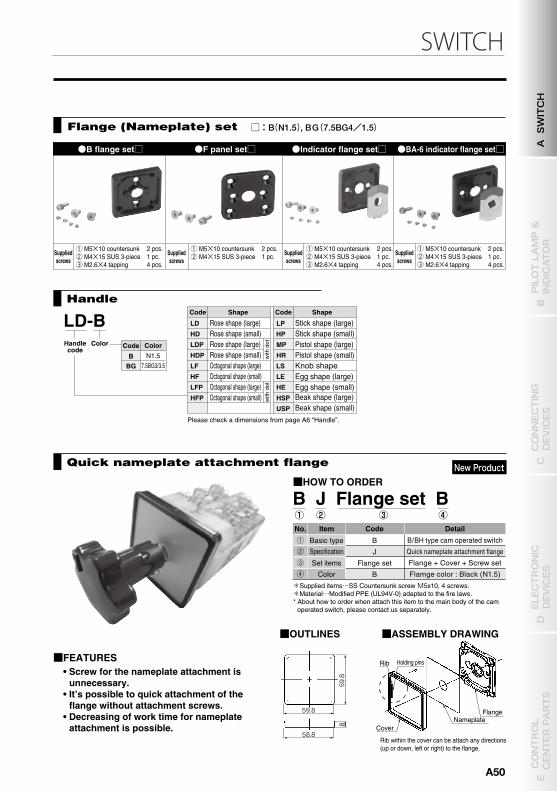
SWITCH
●BH-CVN-□
11
5-9 1-5 1-3 1-3 5-9 1-5
12 9 1 0 7 8 5 6 3 4 1 2
1-5 5-9 1-3 1-3 1-5 5-9
80
64
68.214
L
ABBBCB
1 to 3 units4 to 6 units7 to 9 units
DBEB
10 to 12 units13 to 15 units
Applicable unit number L (mm) Applicable unit number L (mm)
4483
121.5
160199
CAM-OPERATED SWITCH
B TYPE, BH TYPE●CONTROL SWITCH
BS jumper 1-3 BS jumper 1-5 BS jumper 5-9
●B-H HCV For B and BH type
ACCESSORIES (selling separately)
Handle cover Jumper
Example of usage of jumper
Example of usage of jumper
B type
BH type
Note: This cover cannot be used for the MP type handle.
This cover is used to prevent mis-operation. It is a magnet type that can be mounted on or removed from a panel easily.(Material: Polycarbonate resin)
●B-H PL terminal cover 1
●B-H PLS terminal cover
B-H PL terminal cover 1Mounting panel: t = 1 to 3.2
Handle HD
Note: This cover cannot be used for a rear terminal type.
PLS terminal cover
Mounting panel: t = 1 to 3.2
Terminal protection cover
Flange (Nameplate) set
●B flange set□ ●F panel set□ ●Indicator flange set□ ●BA-6 indicator flange set□
Suppliedscrews
Suppliedscrews
Suppliedscrews
Suppliedscrews
① M5×10 countersunk② M4×15 SUS 3-piece③ M2.6×4 tapping
2 pcs.1 pc.4 pcs.
① M5×10 countersunk② M4×15 SUS 3-piece③ M2.6×4 tapping
2 pcs.1 pc.4 pcs.
① M5×10 countersunk② M4×15 SUS 3-piece③ M2.6×4 tapping
2 pcs.1 pc.4 pcs.
① M5×10 countersunk② M4×15 SUS 3-piece
2 pcs.1 pc.
with
dot
with
dot
Handle
LD-BColor Pistol shape (large)
Pistol shape (small) Knob shapeEgg shape (large) Egg shape (small) Beak shape (large) Beak shape (small)
Handlecode
Please check a dimensions from page A6 “Handle”.
□:B(N1.5), BG(7.5BG4/1.5)
LD LP Stick shape (large) HD HP Stick shape (small) LDP MP
HDP HR
LF LS
HF LE
LFP HE
HFP Octagonal shape (small)
Rose shape (large)Rose shape (small)Rose shape (large)Rose shape (small)Octagonal shape (large)Octagonal shape (small)Octagonal shape (large)
HSP
USP
Code Shape Code Shape
BBG
N1.5Code Color
7.5BG3/3.5
��The above shows standard type switches. Please ask for special types.
Note: This cover cannot be used for a rear terminal type and a dual-body type.
Note: This cover cannot be used for a rear terminal type.
Quick nameplate attachment flange
■FEATURES
■HOW TO ORDER
B J Flange set B① ② ③ ④
Item
Basic type
Color
No.
①②③
Specification
Set items
④
B
J
Flange set
B
Code
Rib within the cover can be attach any directions (up or down, left or right) to the flange.
Detail
B/BH type cam operated switch
Quick nameplate attachment flange
Flange + Cover + Screw set
Flamge color : Black (N1.5)
■OUTLINES ■ASSEMBLY DRAWING
Rib
New Product
59.8
8
59.8
58.8
Holding pins
CoverNameplate
Flange
• Screw for the nameplate attachment is unnecessary.
• It’s possible to quick attachment of the flange without attachment screws.
• Decreasing of work time for nameplate attachment is possible.
*Supplied items…SS Countersunk screw M5x10, 4 screws.*Material…Modified PPE (UL94V-0) adapted to the fire laws.* About how to order when attach this item to the main body of the cam
operated switch, please contact us separately.
A SWITCH
B PILOT LAMP &
INDICATOR
D ELECTRONIC
DEVICES
C CONNECTING
DEVICES
E CONTROL
CENTER PARTS
A50
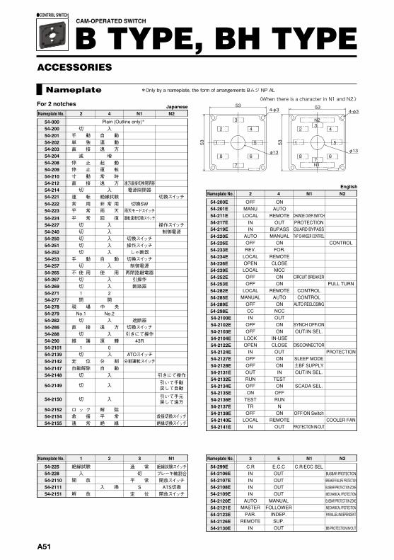
Nameplate
CAM-OPERATED SWITCH
B TYPE, BH TYPE●CONTROL SWITCH
ACCESSORIES
Japanese
English
Nameplate No. N12 4 N2
切手 動単 独直 接減
停 止停 止寸 動直 接切 電源開閉器
運 転常 用 切換SW平 常 雨天モードスイッチ平 常切 操作スイッチ切切切切
手 動切
不 使 用切
入自 動連 動遠 方 増 起 動運 転常 時遠 方 遠方直接切換開閉器入
絶縁試験 切換スイッチ非 常 用雨 天回 復 運転速度切換スイッチ入入 制御電源入入
切換スイッチ操作スイッチ
入 しゃ断器自 動 切換スイッチ入 制御電源
使 用入
Plain (Outline only)*54-000 54-200 54-201 54-202 54-203 54-204 54-20854-20954-21054-21254-21454-22154-22254-22354-22454-22754-24054-25054-25154-25254-25354-257 54-26554-267
1閉
2開
入
再閉路継電器引操作断路器切
現 場
切 入 遮断器
維 護 運 轉
直 接 遠 方 切換スイッチ切 入
43R引きにて操作
1 0切
定 位 分 割
切 入 引きにて操作自動解除 自 動
切 入
切 入
ロ ッ ク 解 除救 援 平 常通 常
引いて手動戻して自動
引いて手元戻して遠方
救援切換スイッチ絶縁切換スイッチ絶 縁
54-26954-27154-27754-27854-27954-28254-28654-28854-29054-210154-213954-214254-214754-2148
54-2149
54-2150
54-215254-215454-2155
No.1 No.2中 央
入分割運転スイッチATOスイッチ
Nameplate No. 31 2 N1
入開 放
解 放
絶縁試験
入 換
54-22554-22854-211054-211154-2151
ATS切換S開放スイッチ定 位
開放スイッチ平 常ブレーキ軸割合切絶縁試験スイッチ通 常
Nameplate No. 2 4 N1 N2
OFF ONMANU AUTOLOCALININAUTOOFFREV.LOCALOPENLOCALOFFOFFLOCALMANUALOFFCCINOFFOFFLOCKOPENINOFFOFFOUTRUNOFF
CHANGE OVER SWITCH
ON
REMOTEPROTECTION
TEST
OUTGUARD BYPASS
TR
BUPASSTAP CHANGER CONTROL
OFF
MANUALCONTROL
LOCAL
ON
IN
FOR.REMOTECLOSEMCC
CIRCUIT BREAKERONPULL TURNON
CONTROLREMOTECONTROLAUTO
AUTO RECLOSINGONNCCOUT
SYNCH OFF/ONONOUT/IN SEL.ON
IN-USEDISCONNECTORCLOSE
PROTECTIONOUTSLEEP MODEON±BF SUPPLYONOUT/IN SEL.IN
TESTSCADA SEL.ON
OFFRUNN
OFF/ON SwitchONCOOLER FANREMOTE
PROTECTION IN/OUTOUT
54-200E54-201E54-211E54-217E54-219E54-220E54-226E54-233E54-234E54-236E54-239E54-252E54-253E54-282E54-285E54-289E
54-2141E
54-298E54-2100E54-2102E54-2103E54-2104E54-2122E54-2124E54-2127E54-2128E54-2131E54-2132E54-2134E54-2135E54-2136E54-2137E54-2138E54-2140E
Nameplate No. 3 5 N1 N2
C.R E.C.CIN OUTINININAUTOMASTERPAR.REMOTEIN
OUT
C.R/ECC SEL
OUTOUT
MANUALMECHANICAL PROTECTION
PARALLEL/INDEPENDENT
BB PROTECTION IN/OUT
BUSBAR PROTECTION ZONE
MECHANICAL PROTECTION
BUSBAR PROTECTION ZONE
BREAKER FAILURE PROTECTION
BUSBAR PROTECTION
FOLLOWERINDEP.SUP.OUT
54-299E54-2106E54-2107E54-2108E54-2109E54-2120E54-2121E54-2123E54-2126E54-2130E
Nameplate No. 2 3 4 N1
OPEN NEUTRALFWD STOPDOWNLOCALMASTERRAISETRIPOPENREMOTE
UPREVCLOSE
STOPREMOTEOFFFOLLOWERSOLOLOWERCLOSECLOSELOCAL
OFF TAP CHANGER CONTROL
TAP CHANGER CONTROL
NEUTRALOFFOFF
54-339E54-340E54-342E54-343E54-389E54-391E54-396E54-398E54-3105E
Nameplate No. 42 3 N1
切手 動整 流 器減RR-S
直 送
自 動閉 停 止
切蓄 電 池
←電圧→
SS-T
出 力 インバータT-RT増
保証負荷自 動手 動開
交流電圧計切換機電圧計電流計電圧設定
直流電圧計切換機切換スイッチ
54-30054-30554-35054-36054-37354-37454-37554-378
For 3 notches
Nameplate No. 1 2 3 N1
O ROPENLOCAL OSAS
NEUTRALS
4
SCADACLOSET
OFFBREAKER CONTROLAMMETER54-495E
O R-S S-T T-R VOLTMETER54-490E
54-498E54-499E
Nameplate No. 1 2 N1
OOO
R-NO R-S
RR
3
N-TS-T
SN
4
T-RT-R
TT
電流計電流計
電圧計電圧計54-490
54-49254-49554-496
Nameplate No. 1 3 5 N1
T OFFOFFB R
R
7
YS
AMMETER SELECTORAMMETER54-755E
T-R O R-S S-T VOLTMETER54-753E
54-767E
Nameplate No. 1 3 N1
TT
OT-R O
O
5
RR-S
R
7
SS-T
N 電流計電流計電圧計54-753
T O R S 電圧計54-752
54-75554-760
For 4 notches
Nameplate No. 1 2 3 N1
OFF RO
UNLOCK
SS
4
TT
5
LOCK
NOFF
R AMMETERAMMETER54-555E
54-556EOFF S-T T-R OFFR-S VOLTMETER54-557E
54-572E
Nameplate No. 1 2 N1
O
OFF0
R-SO R
R-S1
3
S-TS
S-T2
4
T-RT
T-R3
5
ON
OFF0
電圧計電流計
電圧計電流計54-556
O R S T O 電流計54-555
54-557
54-560O R S T O 電圧計54-558
54-5640 1-2 2-3 3-1 0 電圧計54-565OFF R-N N-T T-R OFF 電圧計54-575
For 5 notches
Nameplate No. 1 N1
STS-N切
S
電圧計
54-80054-80154-85054-856
2
TRR-NN
T
3
切O切
切
4
RSR-SR
R
5
STS-T切
S
6
TRT-RS
T
7
切O切
切
8
RST-NT
R
Nameplate No. 1 N1
Y-NESL2
S-NVOLTMETER SELECTOR
VOLTMETER54-850E54-855E54-860E
2
R-NR-N
3
OFFREMOTE
OFF
4
R-YCB1
R-S
5
Y-B89DS1
S-T
6
R-B89DS2
T-R
7
REMOTE
OFF
8
B-NESL1
T-N
For 8 notches
For 2 notches
51
N1
4-φ3
23N2
4
87
6
4-φ3
3
1 5
7
8 6
2 4
53
53
53
53
φ13 φ13
*Only by a nameplate, the form of arrangements Bムジ NP AL
〈When there is a character in N1 and N2.〉English
English
English
English
Japanese
Japanese
Japanese
Japanese
A51
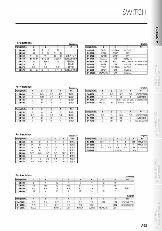
SWITCH
Nameplate
CAM-OPERATED SWITCH
B TYPE, BH TYPE●CONTROL SWITCH
ACCESSORIES
Japanese
English
Nameplate No. N12 4 N2
切手 動単 独直 接減
停 止停 止寸 動直 接切 電源開閉器
運 転常 用 切換SW平 常 雨天モードスイッチ平 常切 操作スイッチ切切切切
手 動切
不 使 用切
入自 動連 動遠 方 増 起 動運 転常 時遠 方 遠方直接切換開閉器入
絶縁試験 切換スイッチ非 常 用雨 天回 復 運転速度切換スイッチ入入 制御電源入入
切換スイッチ操作スイッチ
入 しゃ断器自 動 切換スイッチ入 制御電源
使 用入
Plain (Outline only)*54-000 54-200 54-201 54-202 54-203 54-204 54-20854-20954-21054-21254-21454-22154-22254-22354-22454-22754-24054-25054-25154-25254-25354-257 54-26554-267
1閉
2開
入
再閉路継電器引操作断路器切
現 場
切 入 遮断器
維 護 運 轉
直 接 遠 方 切換スイッチ切 入
43R引きにて操作
1 0切
定 位 分 割
切 入 引きにて操作自動解除 自 動
切 入
切 入
ロ ッ ク 解 除救 援 平 常通 常
引いて手動戻して自動
引いて手元戻して遠方
救援切換スイッチ絶縁切換スイッチ絶 縁
54-26954-27154-27754-27854-27954-28254-28654-28854-29054-210154-213954-214254-214754-2148
54-2149
54-2150
54-215254-215454-2155
No.1 No.2中 央
入分割運転スイッチATOスイッチ
Nameplate No. 31 2 N1
入開 放
解 放
絶縁試験
入 換
54-22554-22854-211054-211154-2151
ATS切換S開放スイッチ定 位
開放スイッチ平 常ブレーキ軸割合切絶縁試験スイッチ通 常
Nameplate No. 2 4 N1 N2
OFF ONMANU AUTOLOCALININAUTOOFFREV.LOCALOPENLOCALOFFOFFLOCALMANUALOFFCCINOFFOFFLOCKOPENINOFFOFFOUTRUNOFF
CHANGE OVER SWITCH
ON
REMOTEPROTECTION
TEST
OUTGUARD BYPASS
TR
BUPASSTAP CHANGER CONTROL
OFF
MANUALCONTROL
LOCAL
ON
IN
FOR.REMOTECLOSEMCC
CIRCUIT BREAKERONPULL TURNON
CONTROLREMOTECONTROLAUTO
AUTO RECLOSINGONNCCOUT
SYNCH OFF/ONONOUT/IN SEL.ON
IN-USEDISCONNECTORCLOSE
PROTECTIONOUTSLEEP MODEON±BF SUPPLYONOUT/IN SEL.IN
TESTSCADA SEL.ON
OFFRUNN
OFF/ON SwitchONCOOLER FANREMOTE
PROTECTION IN/OUTOUT
54-200E54-201E54-211E54-217E54-219E54-220E54-226E54-233E54-234E54-236E54-239E54-252E54-253E54-282E54-285E54-289E
54-2141E
54-298E54-2100E54-2102E54-2103E54-2104E54-2122E54-2124E54-2127E54-2128E54-2131E54-2132E54-2134E54-2135E54-2136E54-2137E54-2138E54-2140E
Nameplate No. 3 5 N1 N2
C.R E.C.CIN OUTINININAUTOMASTERPAR.REMOTEIN
OUT
C.R/ECC SEL
OUTOUT
MANUALMECHANICAL PROTECTION
PARALLEL/INDEPENDENT
BB PROTECTION IN/OUT
BUSBAR PROTECTION ZONE
MECHANICAL PROTECTION
BUSBAR PROTECTION ZONE
BREAKER FAILURE PROTECTION
BUSBAR PROTECTION
FOLLOWERINDEP.SUP.OUT
54-299E54-2106E54-2107E54-2108E54-2109E54-2120E54-2121E54-2123E54-2126E54-2130E
Nameplate No. 2 3 4 N1
OPEN NEUTRALFWD STOPDOWNLOCALMASTERRAISETRIPOPENREMOTE
UPREVCLOSE
STOPREMOTEOFFFOLLOWERSOLOLOWERCLOSECLOSELOCAL
OFF TAP CHANGER CONTROL
TAP CHANGER CONTROL
NEUTRALOFFOFF
54-339E54-340E54-342E54-343E54-389E54-391E54-396E54-398E54-3105E
Nameplate No. 42 3 N1
切手 動整 流 器減RR-S
直 送
自 動閉 停 止
切蓄 電 池
←電圧→
SS-T
出 力 インバータT-RT増
保証負荷自 動手 動開
交流電圧計切換機電圧計電流計電圧設定
直流電圧計切換機切換スイッチ
54-30054-30554-35054-36054-37354-37454-37554-378
For 3 notches
Nameplate No. 1 2 3 N1
O ROPENLOCAL OSAS
NEUTRALS
4
SCADACLOSET
OFFBREAKER CONTROLAMMETER54-495E
O R-S S-T T-R VOLTMETER54-490E
54-498E54-499E
Nameplate No. 1 2 N1
OOO
R-NO R-S
RR
3
N-TS-T
SN
4
T-RT-R
TT
電流計電流計
電圧計電圧計54-490
54-49254-49554-496
Nameplate No. 1 3 5 N1
T OFFOFFB R
R
7
YS
AMMETER SELECTORAMMETER54-755E
T-R O R-S S-T VOLTMETER54-753E
54-767E
Nameplate No. 1 3 N1
TT
OT-R O
O
5
RR-S
R
7
SS-T
N 電流計電流計電圧計54-753
T O R S 電圧計54-752
54-75554-760
For 4 notches
Nameplate No. 1 2 3 N1
OFF RO
UNLOCK
SS
4
TT
5
LOCK
NOFF
R AMMETERAMMETER54-555E
54-556EOFF S-T T-R OFFR-S VOLTMETER54-557E
54-572E
Nameplate No. 1 2 N1
O
OFF0
R-SO R
R-S1
3
S-TS
S-T2
4
T-RT
T-R3
5
ON
OFF0
電圧計電流計
電圧計電流計54-556
O R S T O 電流計54-555
54-557
54-560O R S T O 電圧計54-558
54-5640 1-2 2-3 3-1 0 電圧計54-565OFF R-N N-T T-R OFF 電圧計54-575
For 5 notches
Nameplate No. 1 N1
STS-N切
S
電圧計
54-80054-80154-85054-856
2
TRR-NN
T
3
切O切
切
4
RSR-SR
R
5
STS-T切
S
6
TRT-RS
T
7
切O切
切
8
RST-NT
R
Nameplate No. 1 N1
Y-NESL2
S-NVOLTMETER SELECTOR
VOLTMETER54-850E54-855E54-860E
2
R-NR-N
3
OFFREMOTE
OFF
4
R-YCB1
R-S
5
Y-B89DS1
S-T
6
R-B89DS2
T-R
7
REMOTE
OFF
8
B-NESL1
T-N
For 8 notches
For 2 notches
51
N1
4-φ3
23N2
4
87
6
4-φ3
3
1 5
7
8 6
2 4
53
53
53
53
φ13 φ13
*Only by a nameplate, the form of arrangements Bムジ NP AL
〈When there is a character in N1 and N2.〉English
English
English
English
Japanese
Japanese
Japanese
Japanese
A SWITCH
B PILOT LAMP &
INDICATOR
D ELECTRONIC
DEVICES
C CONNECTING
DEVICES
E CONTROL
CENTER PARTS
A52
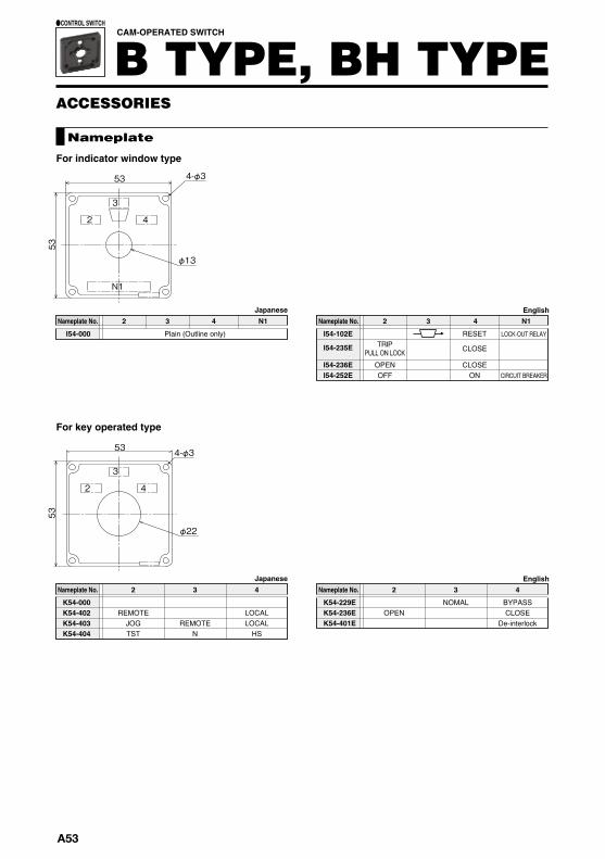
ACCESSORIES
1 lamp2 lamps3 lamps2 lamps2 lamps2 lamps
1 Remark
切 切 切
3
入 入 入
N
しゃ断器断路器遮断器
P54-000
P54-201 P54-202 P54-203
��For handle removal type, please check the removal positions below.
Plain (Outline only)
BRemovalposition A T F
B, A A, T B, T B, A, T
For handle removal type
For BHS type
CAM-OPERATED SWITCH
B TYPE, BH TYPE●CONTROL SWITCH
Nameplate No.
Nameplate
Japanese
Removalposition
N1
1 3
N1
1 3
N1
1 3
φ13
53
53
φ13
53
53
φ13
53
534-φ34-φ34-φ3
53
53
φ13
4-φ3
Nameplate No. 2 3 4 N1
TRIPPULL ON LOCK
OPENOFF
CLOSE
CLOSE
RESET
ON CIRCUIT BREAKER
LOCK-OUT RELAYI54-102E
I54-235E
I54-236EI54-252E
Nameplate No. 42 3 N1
Plain (Outline only)I54-000
For indicator window type
Nameplate No. 2 3 4
NOMALOPEN
De-interlockCLOSEBYPASSK54-229E
K54-236EK54-401E
Nameplate No. 42 3
REMOTEJOGTST
REMOTEN HS
LOCALLOCAL
K54-000K54-402K54-403K54-404
For key operated type
N1
2 4
4-φ3
3
53
53
φ13
2
3
4
53
53
φ22
4-φ3
English
English
Japanese
Japanese
A53
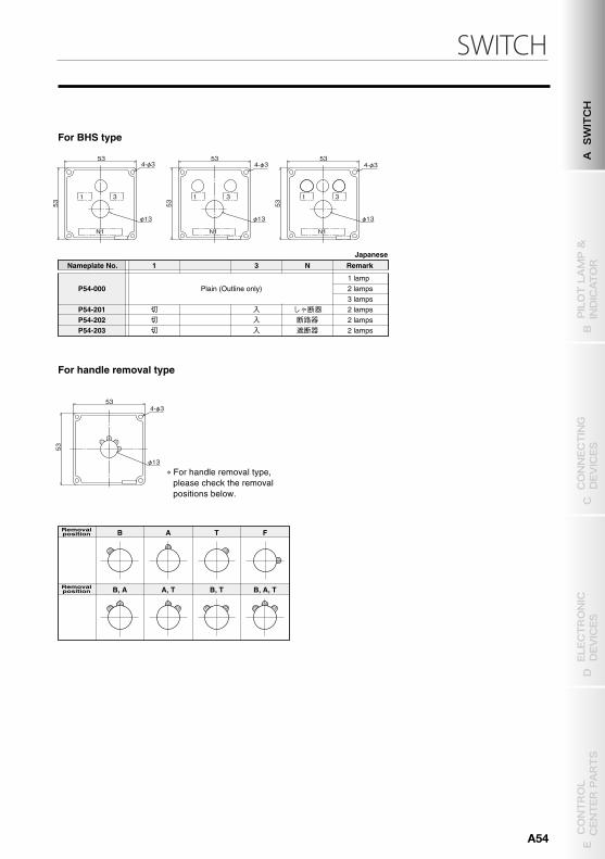
SWITCH
ACCESSORIES
1 lamp2 lamps3 lamps2 lamps2 lamps2 lamps
1 Remark
切 切 切
3
入 入 入
N
しゃ断器断路器遮断器
P54-000
P54-201 P54-202 P54-203
��For handle removal type, please check the removal positions below.
Plain (Outline only)
BRemovalposition A T F
B, A A, T B, T B, A, T
For handle removal type
For BHS type
CAM-OPERATED SWITCH
B TYPE, BH TYPE●CONTROL SWITCH
Nameplate No.
Nameplate
Japanese
Removalposition
N1
1 3
N1
1 3
N1
1 3
φ13
53
53
φ13
5353
φ13
53
534-φ34-φ34-φ3
53
53
φ13
4-φ3
Nameplate No. 2 3 4 N1
TRIPPULL ON LOCK
OPENOFF
CLOSE
CLOSE
RESET
ON CIRCUIT BREAKER
LOCK-OUT RELAYI54-102E
I54-235E
I54-236EI54-252E
Nameplate No. 42 3 N1
Plain (Outline only)I54-000
For indicator window type
Nameplate No. 2 3 4
NOMALOPEN
De-interlockCLOSEBYPASSK54-229E
K54-236EK54-401E
Nameplate No. 42 3
REMOTEJOGTST
REMOTEN HS
LOCALLOCAL
K54-000K54-402K54-403K54-404
For key operated type
N1
2 4
4-φ3
3
53
53
φ13
2
3
4
53
53
φ22
4-φ3
English
English
Japanese
JapaneseA SWITCH
B PILOT LAMP &
INDICATOR
D ELECTRONIC
DEVICES
C CONNECTING
DEVICES
E CONTROL
CENTER PARTS
A54
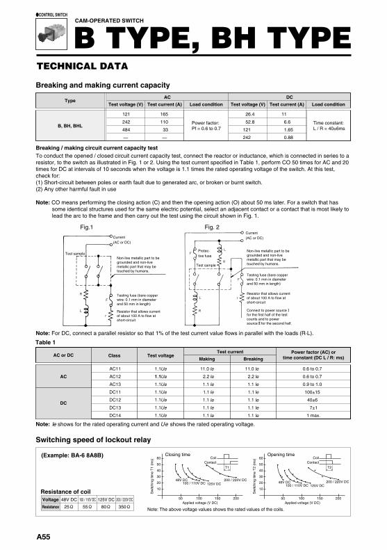
Switching speed of lockout relay
Note: The above voltage values shows the rated values of the coils.
48V DC
25Ω100 / 110V DC
55Ω125V DC
80Ω200 / 220V DC
350Ω
Resistance of coil
(Example: BA-6 8A8B)
10
50
48V DC 200 / 220V DC100 / 110V DC 125V DC
Closing time
100 150 200
20
30
40
50
60
Applied voltage (V DC)
T1Contact
Coil
10
50
48V DC 200 / 220V DC100 / 110V DC 125V DC
Opening time
100 150 200
20
30
40
50
60
Applied voltage (V DC)
T2Contact
Coil
Voltage
Resistance
Sw
itchi
ng ti
me
T1
(ms)
Sw
itchi
ng ti
me
T2
(ms)
1.1 Ue
1.1 Ue
1.1 Ue
1.1 Ue
1.1 Ue
1.1 Ue
1.1 Ue
AC11
AC12
AC13
DC11
DC12
DC13
DC14
11.0
2.2
1.1
1.1
1.1
1.1
1.1
le
le
le
le
le
le
le
11.0
2.2
1.1
1.1
1.1
1.1
1.1
le
le
le
le
le
le
le
、
直 流
交 流
1000
100
10
1
500
50
5
(V)
0.00010.0001 0.001 0.01 0.1 1 10 100(A)
TECHNICAL DATA
CAM-OPERATED SWITCH
B TYPE, BH TYPE●CONTROL SWITCH
Breaking / making circuit current capacity test
Breaking and making current capacityAC
Test voltage (V) Test current (A) Load condition Test voltage (V) Test current (A) Load conditionDC
Type
B, BH, BHL
121 165
242 110
484 33
— —
26.4 11
52.8 6.6
121 1.65
242 0.88
Power factor:Pf = 0.6 to 0.7
Time constant:L / R = 40±6ms
To conduct the opened / closed circuit current capacity test, connect the reactor or inductance, which is connected in series to a resistor, to the switch as illustrated in Fig. 1 or 2. Using the test current specified in Table 1, perform CO 50 times for AC and 20 times for DC at intervals of 10 seconds when the voltage is 1.1 times the rated operating voltage of the switch. At this test, check for:(1) Short-circuit between poles or earth fault due to generated arc, or broken or burnt switch.(2) Any other harmful fault in use
Note: CO means performing the closing action (C) and then the opening action (O) about 50 ms later. For a switch that has some identical structures used for the same electric potential, select an adjacent contact or a contact that is most likely to lead the arc to the frame and then carry out the test using the circuit shown in Fig. 1.
Test current
1.1
Test voltageClassMaking Breaking
0.6 to 0.7
0.6 to 0.7
0.9 to 1.0
100±15
40±6
7±1
1 max.
Power factor (AC) ortime constant (DC L / R: ms)AC or DC
Table 1
DC
AC
Fig.1 Fig. 2
Current(AC or DC)
Test sample
Test sample
Protec-tive fuse
Current(AC or DC)
Note: shows for the rated operating current and shows the rated operating voltage.
Note: For DC, connect a parallel resistor so that 1% of the test current value flows in parallel with the loads (R·L).
Non-live metallic part to be grounded and non-live metallic part that may be touched by humans.
Testing fuse (bare copper wire: 0.1 mm in diameter and 50 mm in length)
Resistor that allows current of about 100 A to flow at short-circuit
Non-live metallic part to be grounded and non-live metallic part that may be touched by humans.
Testing fuse (bare copper wire: 0.1 mm in diameter and 50 mm in length)
Resistor that allows current of about 100 A to flow at short-circuit
Connect to power sourceⅠfor the first half of the test counts and to power sourceⅡfor the second half.
BY type minute electric current switch
Contact spec Twin contacts
Contact resistance (mΩ) 50 max.
Withstand voltage between contacts (V AC) 2,500
Insulation resistance (Ω) 1,000M
Max. current carrying capacity (A) 2.0
Max. breaking voltage (V)�
0.5 DCMax. breaking current (A)�
Min. applicable load
110 DC / 110 AC
5V DC, 1mA
Shock resistance (m/s2) 50
Vibration resistance (m/s2) 2
Operating temperature (°C) –20 to 60
●The specification and performance are shown in the following table.
� Resistance load
■The BY type switch is used to make / break a sequence control current or any other similar low-voltage, minute electric current circuit. It consists of a contact unit that uses twin contacts.■The BY type switch allows for manufacturing an operation
switch that only uses the BY type contact unit. It also allows for manufacturing a switch that incorporates both the BY type contact unit and the standard contact (silver contact) unit (see the right figure).
� A silver contact and gold contact cannot be combined in a single unit.■The contact unit of the BY type switch has its housing
designed as semitransparency blue, so that it can be discriminated from the standard type.
Ele
ctri
cal c
hara
cter
istic
sE
nvir
onm
enta
lch
arac
teri
stic
s
■BY type contact unit
Display example of the above switch:
BY-H5-1B1A1BL1AL2BX2AX1BLX1ALX
■The operating load range is as shown in the following graph.Select a contact type according to your application.
Standardcontact(silver contact)
Minute electric current contact(Twin contacts)
Twin contacts
Terminal screw M4×9
●Standard contact
(Twin contacts)Semitransparency
blue
Unit color
Colorless and clear
: Minute electric current contact
●Load-carrying capacity ●Wiring capacity●Inductive load
■Contact protective circuitIf inductive load or load that causes surge current (rush current) to flow (load-carrying capacity, lamp, long cable, or the like) is used as the load for the twin contacts, a contact protective circuit is required and shown below:
If any electromagnetic relay, solenoid, or counter having an inductance component is used as load, the energy stored in the inductance causes reverse voltage to be generated when the contacts are separated from each other. This reverse voltage reaches even several hundred volt, which can cause remarkable deterioration of the contacts. As a protective circuit, the above method is available.
In this case, a capacitor is connected in parallel or in series in a closed circuit including twin contacts. The rush current that flows when the capacitance is charged or discharged can cause remarkable deterioration of the contacts. To prevent this rush current, the above method is generally known and should be used for your reference.
If wiring is carried out at a long distance between the load and twin contacts, the contacts are affected by the capacitance resulting from the cable. Ls differs depending on the load current, but approximately 0.5 to 5 mH is assumed for the circuit.
LoadLoad
Wiringcapacity
Load
○G
Load area
max.
A55
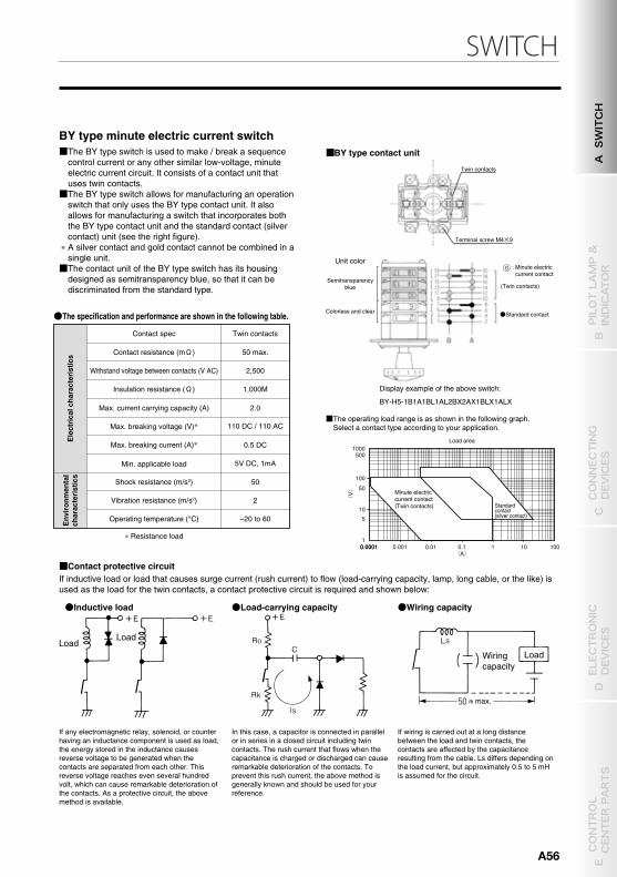
SWITCH
Switching speed of lockout relay
Note: The above voltage values shows the rated values of the coils.
48V DC
25Ω100 / 110V DC
55Ω125V DC
80Ω200 / 220V DC
350Ω
Resistance of coil
(Example: BA-6 8A8B)
10
50
48V DC 200 / 220V DC100 / 110V DC 125V DC
Closing time
100 150 200
20
30
40
50
60
Applied voltage (V DC)
T1Contact
Coil
10
50
48V DC 200 / 220V DC100 / 110V DC 125V DC
Opening time
100 150 200
20
30
40
50
60
Applied voltage (V DC)
T2Contact
Coil
Voltage
Resistance
Sw
itchi
ng ti
me
T1
(ms)
Sw
itchi
ng ti
me
T2
(ms)
1.1 Ue
1.1 Ue
1.1 Ue
1.1 Ue
1.1 Ue
1.1 Ue
1.1 Ue
AC11
AC12
AC13
DC11
DC12
DC13
DC14
11.0
2.2
1.1
1.1
1.1
1.1
1.1
le
le
le
le
le
le
le
11.0
2.2
1.1
1.1
1.1
1.1
1.1
le
le
le
le
le
le
le
、
直 流
交 流
1000
100
10
1
500
50
5
(V)
0.00010.0001 0.001 0.01 0.1 1 10 100(A)
TECHNICAL DATA
CAM-OPERATED SWITCH
B TYPE, BH TYPE●CONTROL SWITCH
Breaking / making circuit current capacity test
Breaking and making current capacityAC
Test voltage (V) Test current (A) Load condition Test voltage (V) Test current (A) Load conditionDC
Type
B, BH, BHL
121 165
242 110
484 33
— —
26.4 11
52.8 6.6
121 1.65
242 0.88
Power factor:Pf = 0.6 to 0.7
Time constant:L / R = 40±6ms
To conduct the opened / closed circuit current capacity test, connect the reactor or inductance, which is connected in series to a resistor, to the switch as illustrated in Fig. 1 or 2. Using the test current specified in Table 1, perform CO 50 times for AC and 20 times for DC at intervals of 10 seconds when the voltage is 1.1 times the rated operating voltage of the switch. At this test, check for:(1) Short-circuit between poles or earth fault due to generated arc, or broken or burnt switch.(2) Any other harmful fault in use
Note: CO means performing the closing action (C) and then the opening action (O) about 50 ms later. For a switch that has some identical structures used for the same electric potential, select an adjacent contact or a contact that is most likely to lead the arc to the frame and then carry out the test using the circuit shown in Fig. 1.
Test current
1.1
Test voltageClassMaking Breaking
0.6 to 0.7
0.6 to 0.7
0.9 to 1.0
100±15
40±6
7±1
1 max.
Power factor (AC) ortime constant (DC L / R: ms)AC or DC
Table 1
DC
AC
Fig.1 Fig. 2
Current(AC or DC)
Test sample
Test sample
Protec-tive fuse
Current(AC or DC)
Note: shows for the rated operating current and shows the rated operating voltage.
Note: For DC, connect a parallel resistor so that 1% of the test current value flows in parallel with the loads (R·L).
Non-live metallic part to be grounded and non-live metallic part that may be touched by humans.
Testing fuse (bare copper wire: 0.1 mm in diameter and 50 mm in length)
Resistor that allows current of about 100 A to flow at short-circuit
Non-live metallic part to be grounded and non-live metallic part that may be touched by humans.
Testing fuse (bare copper wire: 0.1 mm in diameter and 50 mm in length)
Resistor that allows current of about 100 A to flow at short-circuit
Connect to power sourceⅠfor the first half of the test counts and to power sourceⅡfor the second half.
BY type minute electric current switch
Contact spec Twin contacts
Contact resistance (mΩ) 50 max.
Withstand voltage between contacts (V AC) 2,500
Insulation resistance (Ω) 1,000M
Max. current carrying capacity (A) 2.0
Max. breaking voltage (V)�
0.5 DCMax. breaking current (A)�
Min. applicable load
110 DC / 110 AC
5V DC, 1mA
Shock resistance (m/s2) 50
Vibration resistance (m/s2) 2
Operating temperature (°C) –20 to 60
●The specification and performance are shown in the following table.
� Resistance load
■The BY type switch is used to make / break a sequence control current or any other similar low-voltage, minute electric current circuit. It consists of a contact unit that uses twin contacts.■The BY type switch allows for manufacturing an operation
switch that only uses the BY type contact unit. It also allows for manufacturing a switch that incorporates both the BY type contact unit and the standard contact (silver contact) unit (see the right figure).
� A silver contact and gold contact cannot be combined in a single unit.■The contact unit of the BY type switch has its housing
designed as semitransparency blue, so that it can be discriminated from the standard type.
Ele
ctri
cal c
hara
cter
istic
sE
nvir
onm
enta
lch
arac
teri
stic
s
■BY type contact unit
Display example of the above switch:
BY-H5-1B1A1BL1AL2BX2AX1BLX1ALX
■The operating load range is as shown in the following graph.Select a contact type according to your application.
Standardcontact(silver contact)
Minute electric current contact(Twin contacts)
Twin contacts
Terminal screw M4×9
●Standard contact
(Twin contacts)Semitransparency
blue
Unit color
Colorless and clear
: Minute electric current contact
●Load-carrying capacity ●Wiring capacity●Inductive load
■Contact protective circuitIf inductive load or load that causes surge current (rush current) to flow (load-carrying capacity, lamp, long cable, or the like) is used as the load for the twin contacts, a contact protective circuit is required and shown below:
If any electromagnetic relay, solenoid, or counter having an inductance component is used as load, the energy stored in the inductance causes reverse voltage to be generated when the contacts are separated from each other. This reverse voltage reaches even several hundred volt, which can cause remarkable deterioration of the contacts. As a protective circuit, the above method is available.
In this case, a capacitor is connected in parallel or in series in a closed circuit including twin contacts. The rush current that flows when the capacitance is charged or discharged can cause remarkable deterioration of the contacts. To prevent this rush current, the above method is generally known and should be used for your reference.
If wiring is carried out at a long distance between the load and twin contacts, the contacts are affected by the capacitance resulting from the cable. Ls differs depending on the load current, but approximately 0.5 to 5 mH is assumed for the circuit.
LoadLoad
Wiringcapacity
Load
○G
Load area
max.
A SWITCH
B PILOT LAMP &
INDICATOR
D ELECTRONIC
DEVICES
C CONNECTING
DEVICES
E CONTROL
CENTER PARTS
A56
Related Documents