SCHOOL OF ARCHITECTURE, BUILDING & DESIGN Modern Architecture Studies in Southeast Asia (MASSA) Research Unit Bachelor of Science (Honours) (Architecture) BUILDING TECHNOLOGY 1 [ARC 3512] Project 2 – Advanced Roof & Industrialized Building System Tutor: Mr. Siva NAME ID. NO LING TECK ONG 0303127 1

Welcome message from author
This document is posted to help you gain knowledge. Please leave a comment to let me know what you think about it! Share it to your friends and learn new things together.
Transcript
1
SCHOOL OF ARCHITECTURE, BUILDING & DESIGNModern Architecture Studies in Southeast Asia (MASSA)
Research Unit
Bachelor of Science (Honours) (Architecture)
BUILDING TECHNOLOGY 1 [ARC 3512]
Project 2 – Advanced Roof & Industrialized Building System
Tutor: Mr. Siva
NAME ID. NO
LING TECK ONG 0303127
2
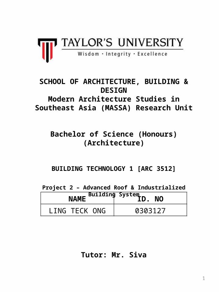
Table of Content:
1.0 ROOF CONSTRUCTION 1.1 COATED FIBRE GLASS MEMBRANE (PTFE) ………………………………………..... 3 1.2 STRUCTURAL DESIGN…………………………………………………………………..... 4 1.3 ROOF SPECIFICATIONS…………………………………………………………………………… . 5
2.0 INDUSTRIALIZED BUILDING SYSTEM 2.1 PRECAST REINFORCED CONCRETE WALL………………………………………………..... 6-8 2.2 PRECAST REINFORCED CONCRETE BEAM &COLUMN…………………............... 9-11 2.3 PRECAST REINFORCED CONCRETE FLOORING (Hollow Core Slab)…............ 12-14 2.4 PRECAST REINFORCED CONCRETE STAIRCASE……………………………………...... 15-16
3.0 PRECAST ROOF SYSTEM 3.1 DESCRIPTION………………………………………………………………………………………………17 3.2 ADVANTAGES………………………………………………………………………………………………17 3.3 SPECIFICATION…………………………………………………………………………………………… 18
4.0 REFERENCES…………………………………………………………………......................... 19

3
1.0 Roof Construction
1.1 Coated Fibre Glass Membrane (PTFE)
Teflon is the registered trade name of the highly useful plastic material polytetrafluoroethylene (PTFE). PTFE is one of a class of plastics known as fluoropolymers. A polymer is a compound formed by a chemical reaction which combines particles into groups of repeating large molecules. Many common synthetic fibers are polymers, such as polyester and nylon. PTFE is the polymerized form of tetrafluoroethylene. PTFE has many unique properties, which make it valuable in scores of applications. It has a very high melting point, and is also stable at very low temperatures. It can be dissolved by nothing but hot fluorine gas or certain molten metals, so it is extremely resistant to corrosion. (derieved from http://www.madehow.com/Volume-7/Teflon.html)
ADVANTAGES
•Outstanding chemical resistance•Low coefficient of friction•High continuous use temperature (180°C / 360°F)•Very high oxygen index
DISADVANTAGES
•High cost•Low strength and stiffness•Cannot be melt processed•Poor radiation resistance
Primary function of the tensile structure
• Daylight gains• Rain protection• Space defining
elements• Sun protection• Wind protection
Typical properties • Density(g/cm3): 2.15• Tensile strength: SD 63• Max. Operating Temp.
(°C): 180• Water Absorption (1%):
0.01
Figure 1.1 Specification

4
Figure 1.2 Detail from the computational model of the structure
The structural system and components are depicted in Fig. 2.2.
1.There are tubular radial and tangential truss girders with welded nodes.2.There are 76 radial truss girders, i.e. one for every two stone facade columns. 3.They are vertical two-flange trusses and are carried by two tangential members: a spatial, three-flange truss sustained by the treed inner columns and an outer spatial beam sustained by the outer columns. 4.At the side of the roof in the vicinity of the joint between the membrane and the glass surfaces there is an inclined two-flange truss to equalize the vertical displacements at the ends of the radial girders. 5.In between the described members there are tangential tubular bars linking the upper nodes of the radial girders and respectively the lower nodes to stabilize the radial girders by carrying the horizontal tangential forces to the bracing.6.The curved lower flange of the radial truss is stabilized vertically by means of a steel cable (see Fig.2.2).
Figure1.2 (a) The upper membrane
The textile membranes were designed by the consultant civil engineers Schlaich, Bergermann and Partners . The upper membrane is supported by steel arches and has a double negative curvature (Fig. 2.3(a)). The lower membrane is open on the perimeter, plane and pre-stressed by means of small springs (Fig. 2.3(b)). A detailed description of the roof construction is given in.
Following German companies were involved with the design and erection of the roof: von Gerkan, Marg and Partners (gmp) as architects, Krebs & Kiefer Consulting Engineers Ltd as structural engineers, Schlaich Bergermann and Partners as designer of the membrane roofing and of some cast nodes, Wacker Engineers and Institute for Industry Aerodynamic Aachen for the Wind Engineering, Institute of Steel Construction (University of Aachen) as expert for special steel, Dillinger Stahlbau Ltd for the steel construction, B&O Hightex Ltd for the membrane construction, MERO Ltd for the glass construction and Prof. M. Specht as proof engineer. For the design of the roof gmp and Krebs & Kiefer have received the Special Award of the German Association of Steel Construction 2004.
1.2 Structural Design
Figure 1.2 (b) The lower membrane (view inside the roof box)

5
Figure 1.3(a) Detail of the truss system
Figure 1.3(b) Detail of the steel truss systemFigure 1.3(c) Detail of structural steel frame
Figure 1.3(e) Detail of the tension rope connect to the membrane
Figure 1.3(d) Detail of connection of tension rope with truss system
1.3 Roof Specification:
6
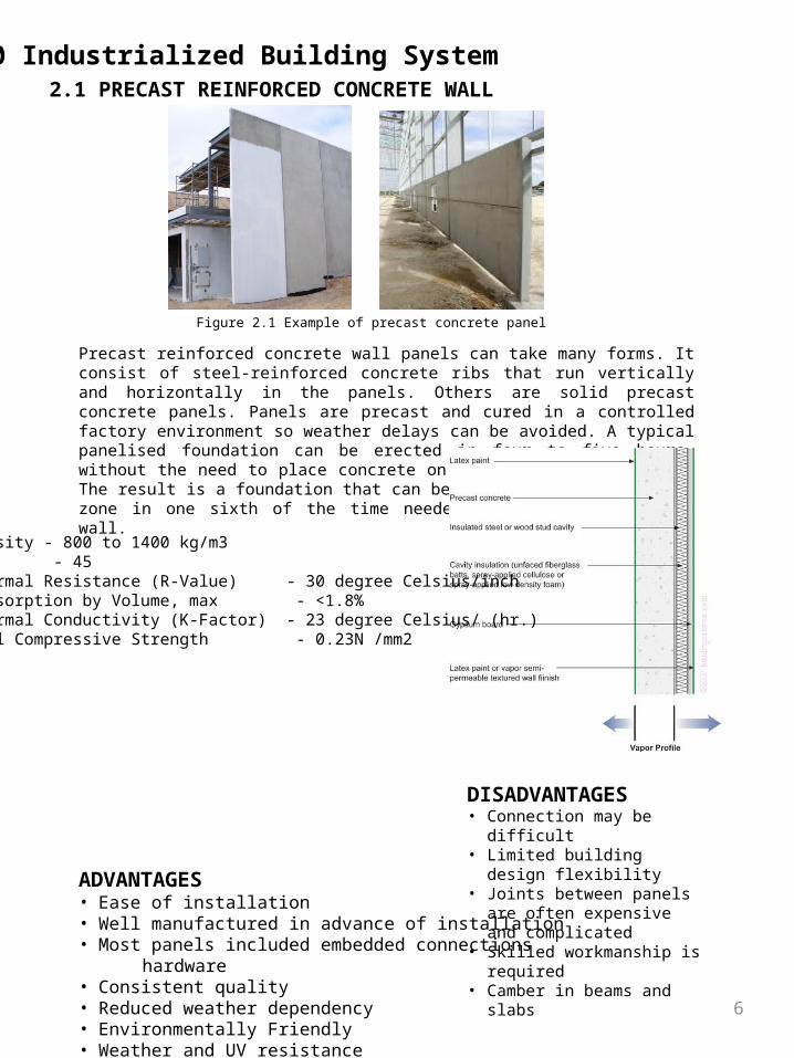
2.1 PRECAST REINFORCED CONCRETE WALL
2.0 Industrialized Building System
Precast reinforced concrete wall panels can take many forms. It consist of steel-reinforced concrete ribs that run vertically and horizontally in the panels. Others are solid precast concrete panels. Panels are precast and cured in a controlled factory environment so weather delays can be avoided. A typical panelised foundation can be erected in four to five hours, without the need to place concrete on site for the foundation. The result is a foundation that can be installed in any climate zone in one sixth of the time needed for a formed concrete wall.
ADVANTAGES• Ease of installation• Well manufactured in advance of installation• Most panels included embedded connections hardware• Consistent quality• Reduced weather dependency• Environmentally Friendly• Weather and UV resistance• Energy Savings• Modularity
DISADVANTAGES• Connection may be difficult• Limited building design flexibility• Joints between panels are often
expensive and complicated• Skilled workmanship is required• Camber in beams and slabs
Density - 800 to 1400 kg/m3STC - 45Thermal Resistance (R-Value) - 30 degree Celsius/inch Absorption by Volume, max - <1.8%Thermal Conductivity (K-Factor) - 23 degree Celsius/ (hr.)Wall Compressive Strength - 0.23N /mm2
Figure 2.1 Example of precast concrete panel
7
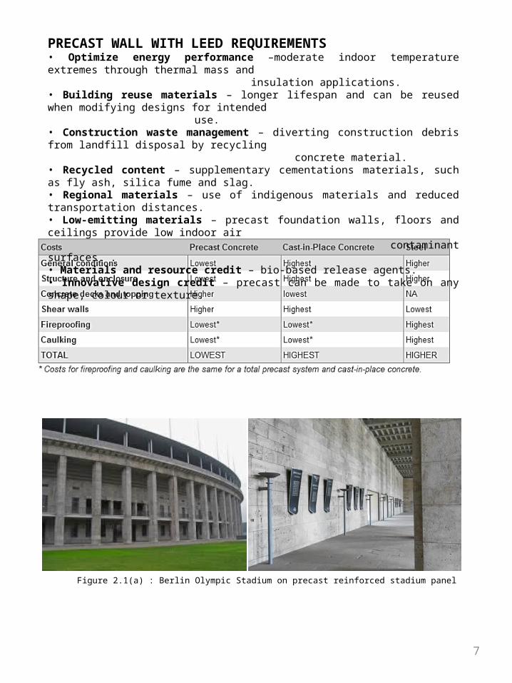
Figure 2.1(a) : Berlin Olympic Stadium on precast reinforced stadium panel
PRECAST WALL WITH LEED REQUIREMENTS• Optimize energy performance –moderate indoor temperature extremes through thermal mass and insulation applications. • Building reuse materials – longer lifespan and can be reused when modifying designs for intended use. • Construction waste management – diverting construction debris from landfill disposal by recycling
concrete material. • Recycled content – supplementary cementations materials, such as fly ash, silica fume and slag. • Regional materials – use of indigenous materials and reduced transportation distances.• Low-emitting materials – precast foundation walls, floors and ceilings provide low indoor air contaminant surfaces. . • Materials and resource credit – bio-based release agents. • Innovative design credit – precast can be made to take on any shape, colour or texture.
8
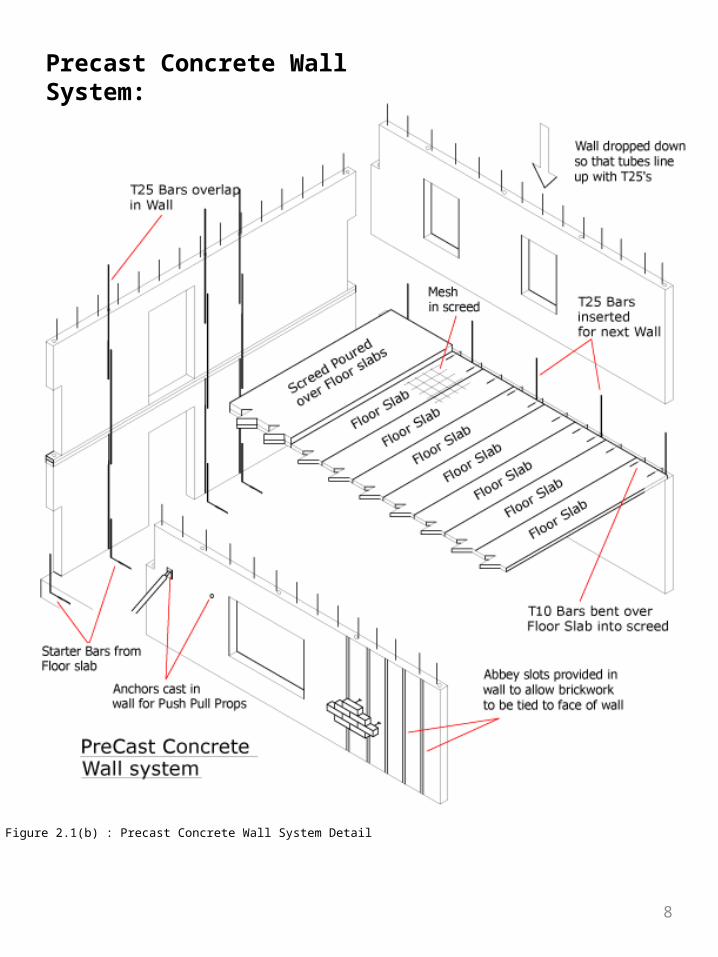
Precast Concrete Wall System:
Figure 2.1(b) : Precast Concrete Wall System Detail
9
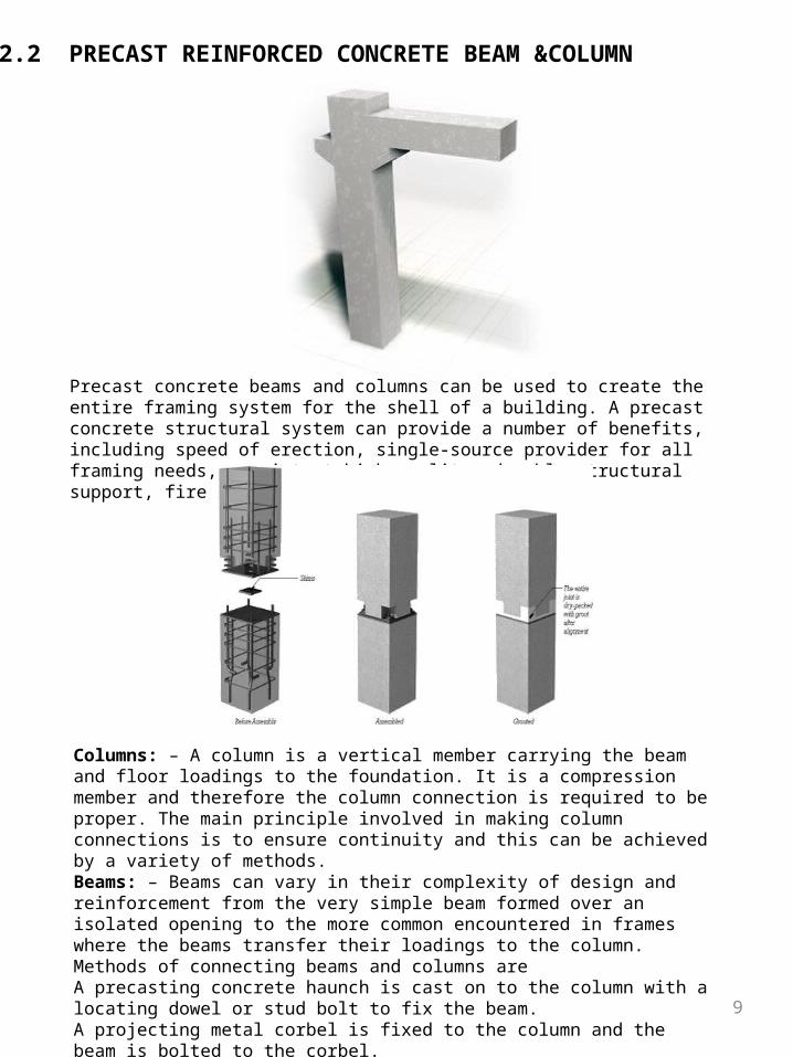
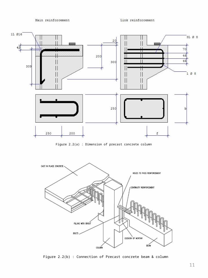
Precast concrete beams and columns can be used to create the entire framing system for the shell of a building. A precast concrete structural system can provide a number of benefits, including speed of erection, single-source provider for all framing needs, consistent high quality, durable structural support, fire resistance and others.
Columns: – A column is a vertical member carrying the beam and floor loadings to the foundation. It is a compression member and therefore the column connection is required to be proper. The main principle involved in making column connections is to ensure continuity and this can be achieved by a variety of methods.Beams: – Beams can vary in their complexity of design and reinforcement from the very simple beam formed over an isolated opening to the more common encountered in frames where the beams transfer their loadings to the column. Methods of connecting beams and columns areA precasting concrete haunch is cast on to the column with a locating dowel or stud bolt to fix the beam.A projecting metal corbel is fixed to the column and the beam is bolted to the corbel.Column and beam reinforcement, generally in the form of hooks, are left exposed. The two members are hooked together and covered with in-situ concrete to complete the joint. This is as shown in the figure.
2.2 PRECAST REINFORCED CONCRETE BEAM &COLUMN

10
Advantages:• Saving in cost, material, time & manpower.• Shuttering and scaffolding is not necessary.• Installation of building services and finishes can be done immediately.• Independent of weather condition.• Components produced at close supervision .so quality is good• Clean and dry work at site.• Possibility of alterations and reuse• Correct shape and dimensions and sharp edges are maintained.• Very thin sections can be entirely precast with precision.
Disadvantages:• Handling and transportation may cause breakages of members during the transit and extra
provision is to be made.• Difficulty in connecting precast units so as to produce same effect as monolithic. This leads to
non-monolithic construction.• They are to be exactly placed in position, otherwise the loads coming on them are likely to get
changed and the member may be affected.• Disadvantages:• High transport cost• Need of erection equipment• Skilled labor and supervision is required.
11
Figure 2.2(a) : Dimension of precast concrete column
Figure 2.2(b) : Connection of Precast concrete beam & column
12
Design Benefits•Flexibility of Design Approach•Enhanced Spans
Manufacturing BenefitsFactory produced to High QualityStandardPreformed Site Services
Construction BenefitsOne or two hour fire resistanceType ‘A’ Finished SoffitShelf Angle BearingCast in lifting hooksSound resistance – Noise transfer performanceReduction of in-situ ConcreteSpeed of ErectionImmediate un-propped Working Platform
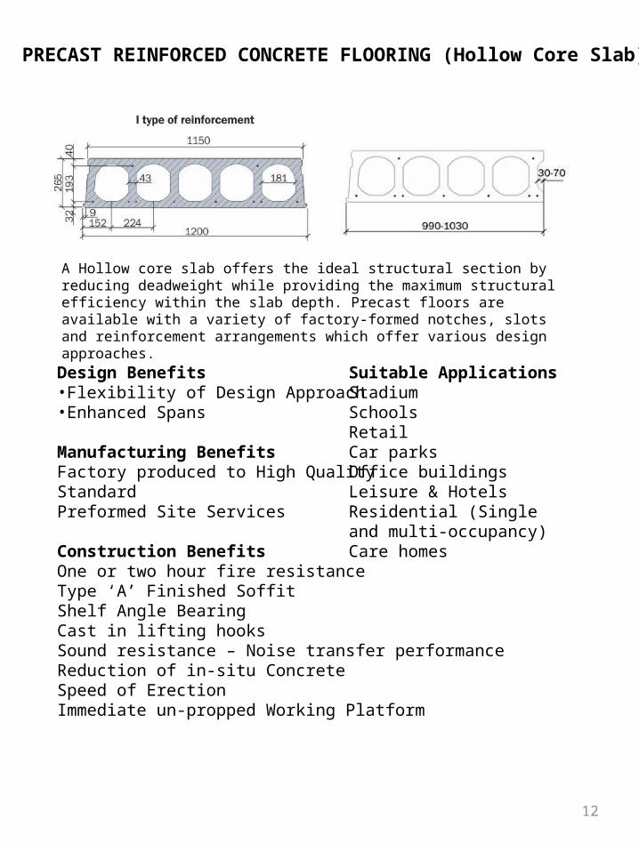
A Hollow core slab offers the ideal structural section by reducing deadweight while providing the maximum structural efficiency within the slab depth. Precast floors are available with a variety of factory-formed notches, slots and reinforcement arrangements which offer various design approaches.
2.3 PRECAST REINFORCED CONCRETE FLOORING (Hollow Core Slab)
Suitable ApplicationsStadiumSchoolsRetailCar parksOffice buildingsLeisure & HotelsResidential (Single and multi-occupancy)Care homes
13
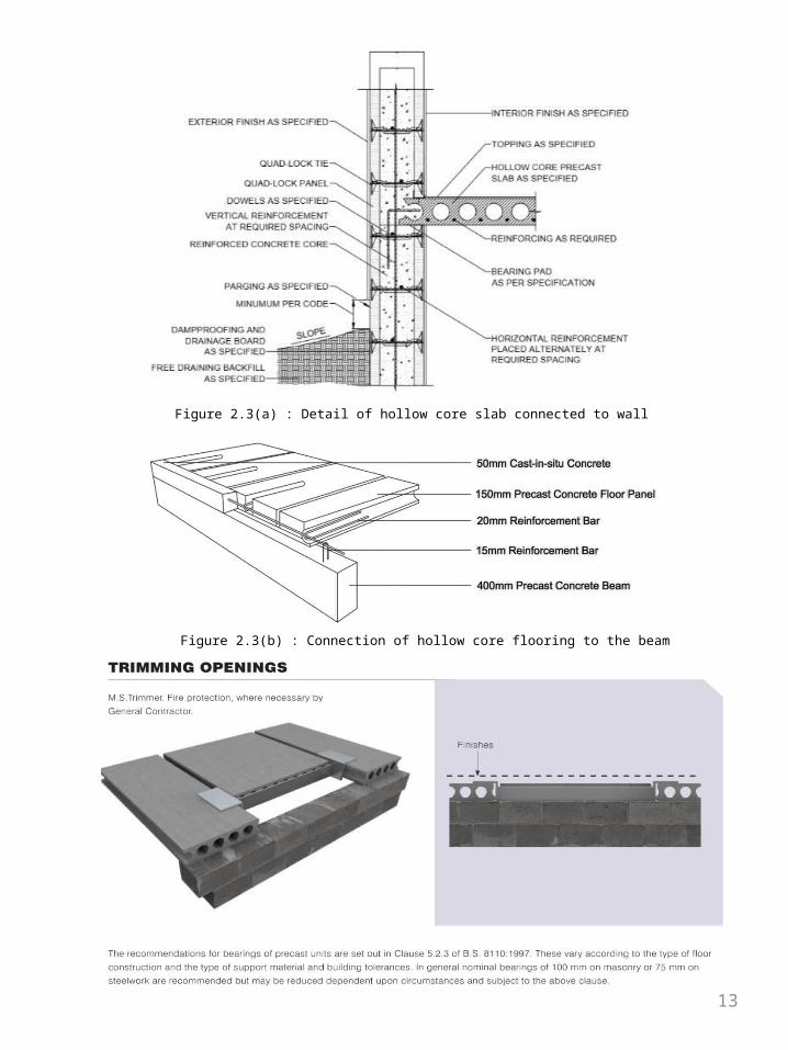
Figure 2.3(a) : Detail of hollow core slab connected to wall
Figure 2.3(b) : Connection of hollow core flooring to the beam
14
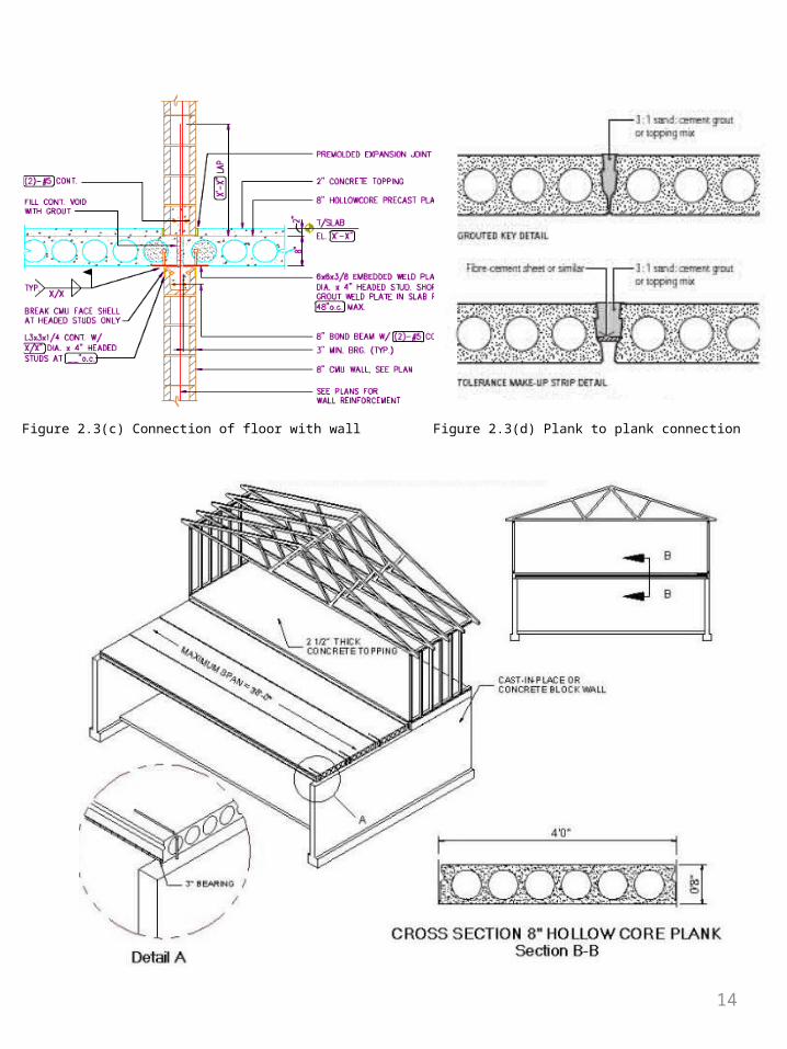
Figure 2.3(d) Plank to plank connectionFigure 2.3(c) Connection of floor with wall

15
2.4 PRECAST REINFORCED CONCRETE STAIRCASE
-Concrete stairs offer a fast, efficient and cost effective option, reducing labour on site, being fast to install and providing immediate access to all floor areas.
THE ADVANTAGES:
-FLEXIBLE CONFIGURATIONS WITH THE ABILITY TO MAKE CUSTOM BUILT MOULDS WE CAN ACCOMMODATE A WIDE VARIETY OF STAIRCASE CONFIGURATIONS AND DESIGNS.-INNOVATIVE DESIGN OUR DESIGNERS WORK HARD TO KEEP APACE WITH LATEST CONSTRUCTION TRENDS EG. STAIRS ARE NOW AVAILABLE THAT ACCOMODATE UNDERFLOOR HEATING PIPES.-QUALITY FINISH MANUFACTURED IN A CONTROLLED FACTORY ENVIRONMENT, USING BESPOKE MOULDS GIVES A PREMIUM QUALITY FINISH.-MMEDIATE ACCESS IMPROVES SITE SAFETY AND EFFICIENCY.-EASE OF PROGRAMMING MANUFACTURED OFFSITE AND DELIVERED AND INSTALLED TO MEET YOUR BUILD PROGRAMME.-LANDINGS CAN INCORPORATE ANY DETAIL THAT THE DESIGN DEMANDS SUCH AS CURVES.-LANDINGS CAN BE DETAILED FOR PROGRESSIVE COLLAPSE IF REQUIRED.
Figure 2.4(a) Precast concrete staircase Figure 2.4(b) Dimension of staircase
16
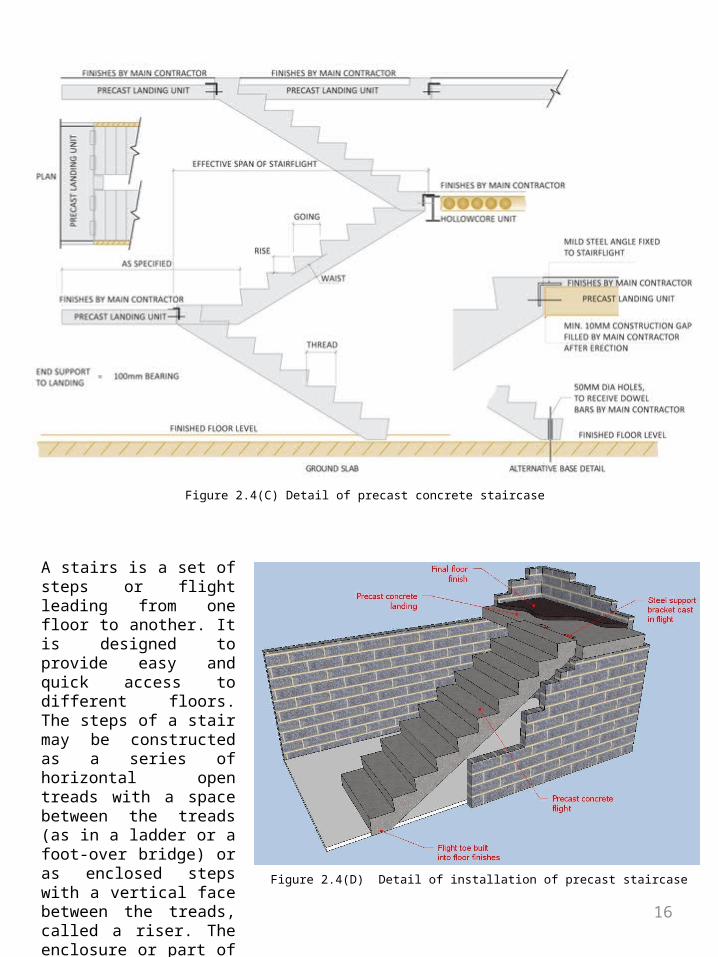
Figure 2.4(C) Detail of precast concrete staircase
Figure 2.4(D) Detail of installation of precast staircase
A stairs is a set of steps or flight leading from one floor to another. It is designed to provide easy and quick access to different floors. The steps of a stair may be constructed as a series of horizontal open treads with a space between the treads (as in a ladder or a foot-over bridge) or as enclosed steps with a vertical face between the treads, called a riser. The enclosure or part of the building containing a stairs is called staircase.
1717
3.0 PRECAST ROOF SYSTEM
3.1 DESCRIPTIONAs one of the leading suppliers of architectural products to the construction industry, Firestone Building Products offers a variety of sustainable, dependable and environmentally friendly metal roofing system options. Available in a wide range of applied finishes and materials, Firestone metal roofs allow for maximum design freedom, while providing long-term peace of mind through warranty coverage.
3.2 ADVANTAGES1. Acts like a monolithic steel surface covering your entire building and providing superior protection
2. Specifically designed with moveable clips to accommodate roof movement under changing temperatures
3. Creates an exclusive 360-degree Pittsburgh double-lock seam, with the final 180 degrees field rolled, for superior performance and protection
4. Factory-punched panels and structural members assure proper alignment and accurate installation
5. Accommodates additional insulation thicknesses to enhance energy efficiency
6. A material-efficient option with compelling sustainability attributes
7. Available in several cool colors for added energy savings
8. Can save up to 90% on roof maintenance costs
Ideal uses:
Adds proven weather tight performance and unmatched peace of mind in virtually any commercial or industrial building application

18
3.3 SPECIFICATION
Figure 3.3(b) Specification of precast concrete roof
Figure 3.3(a) Detail of precast concrete roof

19
4.0 REFERENCES:
Compiled by Legal Research Board. Uniform Building By-Laws 1984, 1997, International Law BookServices, Kuala Lumpur.
CIDB (2014) CIDB Malaysia. Retrieved November 20, 2014, from http://www.cidb.gov.my/cidbv4/index.php?option=com_content&view=article&id=391&Itemid=184&lang=en
Creative (2012) Industrialized Building System. Retrieved November 21, 2014, from http://www.creativeptsb.com/industrialized-building-system-IBS-supplier-Malaysia.htm
Orton, Andrew, 2001, The Way We Build Now: Form Scale and Technique, Spon Press, London. Spon Press
Related Documents