i Technical Report Documentation Page 1. Report No. 2. Government Accession No. 3. Recipient’s Catalog No. ABC-UTC-2013-C1-FIU05-Final 4. Title and Subtitle 5. Report Date Experimental Investigation of Longitudinal Closure Joint Using 90° Hooked Bars in Accelerated Bridge Construction June 2019 6. Performing Organization Code Florida International University 7. Author(s) 8. Performing Organization Report No. Azadeh Jaberi Jahromi https://orcid.org/0000-0003-4843-2745 Atorod Azizinamini 9. Performing Organization Name and Address 10. Work Unit No. (TRAIS) Department of Civil and Environmental Engineering Florida International University 10555 West Flagler Street, EC 3680 Miami, FL 33174 11. Contract or Grant No. Enter the correct number: DTRT13-G-UTC41 (2013) 12. Sponsoring Organization Name and Address 13. Type of Report and Period Covered Accelerated Bridge Construction University Transportation Center Florida International University 10555 W. Flagler Street, EC 3680 Miami, FL 33174 US Department of Transportation Office of the Assistant Secretary for Research and Technology And Federal Highway Administration 1200 New Jersey Avenue, SE Washington, DC 201590 Final Report November 2016- June 2019 14. Sponsoring Agency Code 15. Supplementary Notes Visit www.abc-utc.fiu.edu for other ABC reports. 16. Abstract Several alternatives are used to connect prefabricated bridge deck elements using closure joints but cost and construction considerations limit their use in field applications. In this research, a new detail is proposed to efficiently connect these elements in closure joints. The new detail consists of 90° hooked reinforcement and normal strength concrete in the closure joint. An experimental program was conducted to develop design criteria for the suggested detail. Test results have shown that the longitudinal connection detailed with hooked bars can be a viable alternative for the design and construction of closure joints. This report provides a summary of experimental tests on the new closure joint detail and tentative design recommendations. 17. Key Words 18. Distribution Statement Closure Joint, Development Length, Accelerated Bridge Construction No restrictions. 19. Security Classification (of this report) 20. Security Classification (of this page) 21. No. of Pages 22. Price Unclassified. Unclassified. Total of 41 pages Form DOT F 1700.7 (8-72) Reproduction of completed page authorized

Welcome message from author
This document is posted to help you gain knowledge. Please leave a comment to let me know what you think about it! Share it to your friends and learn new things together.
Transcript

i
Technical Report Documentation Page
1. Report No. 2. Government Accession No. 3. Recipient’s Catalog No.
ABC-UTC-2013-C1-FIU05-Final
4. Title and Subtitle 5. Report Date
Experimental Investigation of Longitudinal Closure Joint Using 90° Hooked Bars in Accelerated Bridge Construction
June 2019
6. Performing Organization Code
Florida International University
7. Author(s) 8. Performing Organization Report No.
Azadeh Jaberi Jahromi https://orcid.org/0000-0003-4843-2745
Atorod Azizinamini
9. Performing Organization Name and Address 10. Work Unit No. (TRAIS)
Department of Civil and Environmental Engineering Florida International University 10555 West Flagler Street, EC 3680 Miami, FL 33174
11. Contract or Grant No.
Enter the correct number:
DTRT13-G-UTC41 (2013)
12. Sponsoring Organization Name and Address 13. Type of Report and Period Covered
Accelerated Bridge Construction
University Transportation Center
Florida International University
10555 W. Flagler Street, EC 3680
Miami, FL 33174
US Department of Transportation
Office of the Assistant Secretary for
Research and Technology
And Federal Highway
Administration
1200 New Jersey Avenue, SE
Washington, DC 201590
Final Report
November 2016- June 2019
14. Sponsoring Agency Code
15. Supplementary Notes
Visit www.abc-utc.fiu.edu for other ABC reports.
16. Abstract
Several alternatives are used to connect prefabricated bridge deck elements using closure joints but cost and construction considerations limit their use in field applications. In this research, a new detail is proposed to efficiently connect these elements in closure joints. The new detail consists of 90° hooked reinforcement and normal strength concrete in the closure joint. An experimental program was conducted to develop design criteria for the suggested detail. Test results have shown that the longitudinal connection detailed with hooked bars can be a viable alternative for the design and construction of closure joints. This report provides a summary of experimental tests on the new closure joint detail and tentative design recommendations.
17. Key Words 18. Distribution Statement
Closure Joint, Development Length, Accelerated Bridge Construction No restrictions.
19. Security Classification (of this report)
20. Security Classification (of this page)
21. No. of Pages 22. Price
Unclassified. Unclassified. Total of 41 pages
Form DOT F 1700.7 (8-72) Reproduction of completed page authorized

ii
(this page is intentionally left blank)

iii
Experimental Investigation of Longitudinal Closure Joint Using 90°
Hooked Bars in Accelerated Bridge Construction
Final Report
June, 2019
Principal Investigator: Dr. Atorod Azizinamini
Department of Civil and Environmental Engineering
Florida International University
Author
Azadeh Jaberi Jahromi
Atorod Azizinamini
Sponsored by
Accelerated Bridge Construction University Transportation Center
A report from
Department of Civil and Environmental Engineering
Florida International University
10555 West Flagler Street, EC 3680
Miami, FL 33174
Phone: 305-348-2824 / Fax: 305-348-2802
https://cee.fiu.edu/

iv
DISCLAIMER
The contents of this report reflect the views of the authors, who are responsible for the facts and
the accuracy of the information presented herein. This document is disseminated in the interest of
information exchange. The report is funded, partially or entirely, by a grant from the U.S.
Department of Transportation’s University Transportation Program. However, the U.S.
Government assumes no liability for the contents or use thereof.

v
ACKNOWLEDGMENTS
This project was supported by the Accelerated Bridge Construction University Transportation
Center (ABC-UTC at www.abc-utc.fiu.edu) at Florida International University (FIU), as lead
institution, and Iowa State University (ISU) and the University of Nevada-Reno (UNR) as partner
institutions. The authors would like to acknowledge the ABC-UTC support.
The author would like to extend special appreciation to the ABC-UTC and the U.S. Department
of Transportation Office of the Assistant Secretary for Research and Technology for funding this
project.
The author would like to thank all the State DOTs that participated in the survey; this work would
not have been possible without their participation.

vi
TABLE OF CONTENTS
PAGE
1.1 Abstract ....................................................................................................................... 10
1.2 Introduction ................................................................................................................. 10
1.3 Objectives ................................................................................................................... 14
1.4 Current Details for Closure Joint ................................................................................ 14
1.5 Description of the Proposed ABC Connection ........................................................... 16
1.6 Experimental Program ................................................................................................ 18
1.7 Construction of Test Specimens .................................................................................. 21
1.8 Test Setup and Loading Procedure .............................................................................. 22
1.9 Material Tests .............................................................................................................. 24
1.10 Experimental Result .................................................................................................. 26
1.10.1 Mode of Failure and Crack Pattern ........................................................................ 26
1.10.2 Load-Displacement Relationship ........................................................................... 29
1.10.3 Measured Ductility................................................................................................. 33
1.11 Tentative Design Recommendations ......................................................................... 35
1.12 Conclusions ............................................................................................................... 37
1.13 References ................................................................................................................. 38

vii
LIST OF TABLES
TABLE PAGE
Specimen Matrix, Unit: in. ............................................................................... 20
Compressive Strength of Outer Sections of Slab Specimens ........................... 24
Bar Test Strengths ............................................................................................. 24
Test Specimens Modes of Failure ..................................................................... 28
Design Recommendations ................................................................................ 36

viii
LIST OF FIGURES
FIGURE PAGE
Details of current options for splicing reinforcement in closure joints [7]. .... 12
Details of headed bar splicing reinforcement in closure joints [7]. ................ 16
Details of hooked bar in the proposed connection (elevation view and
section). ............................................................................................................................. 18
Specimen geometry, reinforcement, and reversed test setup. ......................... 19
Specimen construction procedure a) formwork, b) casting deck portions, c)
spliced hooked bars in closure joint, d) casting closure joint, e) final test setup. ............. 22
Actual experimental test setup. ....................................................................... 23
Schematic experimental test setup. ................................................................. 23
Cylinder test. ................................................................................................... 25
Reinforcing bar test. ........................................................................................ 25
Bond failure. .................................................................................................. 26
Flexure failure. .............................................................................................. 27
Cracking pattern in closure joints region. ..................................................... 29
Group A, Experimental load-displacement result a) Specimens with No. 4
bars and 2-in. gap, b) Specimens with No. 6 bars and 2-in. gap. ...................................... 31
Group B, Experimental load-displacement result a) Specimens with No. 4
bars and 4-in. gap, b) Specimens with No. 6 bars and 4-in. gap. ...................................... 32
Group C, Experimental load-displacement result a) Specimens with No. 4
bars and 2-in. gap, b) Specimens with No. 6 bars and 2-in. gap. ...................................... 32
Group D, Experimental load-displacement result a) Specimens with No. 4
bars and 4-in. gap, b) Specimens with No. 6 bars and 4-in. gap. ...................................... 32

ix
Measuring ductility approach. ....................................................................... 34
Ductility against different lap splice length a) Specimens with No. 4 bars
and 2-in. gap, b) Specimens with No. 6 bars and 2-in. gap. ............................................. 34
Ductility against different lap splice length a) Specimens with No. 4 bars
and 4-in. gap, b) Specimens with No. 6 bars and 4-in. gap .............................................. 34
Design recommendation details. ................................................................... 36

10
1.1 Abstract
Several alternatives are used to connect prefabricated bridge deck elements using closure
joints but cost and construction considerations limit their use in field applications. In this research,
a new detail is proposed to efficiently connect these elements in closure joints. The new detail
consists of 90° hooked reinforcement and normal strength concrete in the closure joint. An
experimental program was conducted to develop design criteria for the suggested detail. 48
specimens were tested to study the effect of lap splice length, the lateral distance between
transverse reinforcement, and bar size. The specimens were tested in flexure and were compared
with control specimens. The objective of the experiment was to obtain optimal lap splice length
based on modes of failure and ductility ratio. Test results have shown that the longitudinal
connection detailed with hooked bars can be a viable alternative for the design and construction of
closure joints. This report provides a summary of experimental tests on the new closure joint detail
and tentative design recommendations.
1.2 Introduction
A major portion of the bridge infrastructures in the United States is approaching their
design life and consequently needs replacement or repair [1]. Many of these bridges are located in
crowded roadways, and closure of these bridges for an extended period of time is not feasible. In
order to minimize traffic disruptions, the bridge can be temporarily closed while performing
construction activities using accelerated bridge construction (ABC) techniques. Minimizing
construction time and activities performed in the field not only decrease detour time and traffic
jams but also increase safety for workers, vehicles, and the traveling public. One of the most
commonly used ABC methodology involves modular bridge systems which consist of precast
girder/slab elements. These precast elements are placed on supports and connected to each other

11
using cast-in-place closure joints. Since these modular sections have a pre-topped deck tributary
area, extensive forming and scaffolding are eliminated.
In modular bridge superstructure, the shear and moment are transferred through the
longitudinal deck joints which run parallel to traffic direction. These joints are functionally
required to connect one modular unit to the adjacent units, however, the performance of these
joints can be affected by environmental attacks and structural degradations [2]. Durability issues
have been encountered in these longitudinal joints with the use of welded steel connectors. In
addition, cracking has been observed in bridge overlays of prestressed concrete bridges. These
cracks are continuous along the length of the bridges and are prone to deterioration of both
superstructure and substructure. A leaking crack can be a potential hazard for vehicular traffic on
bridges with highway underpasses [2],[3],[4]. The water leaking through the deck causes serious
issues such as corroding deck reinforcement, concrete spalling and expansion due to water freezing
and corroding cross-frames if water leaked through the full deck depth [5]. Water leaking is not
causing such traffic hazards as it is a serviceability issue.
In order to control deck cracking, several researchers proposed using distributed
reinforcement [6]. The use of closely spaced reinforcing bar provides better stress distribution
when compared to widely spaced reinforcing bars [7]. In addition, it is desirable to keep the joint
width smaller to reduce cost and construction time. However, this reduction in joint width prevents
the straight and hooked bars from satisfying AASHTO-LRFD development length requirements
[8]. Therefore, special details including spiral wire, U-shaped bar, straight bar, and headed bar
have been developed to meet these requirements as shown in Figure 1-1.
One of the disadvantages of using spiral wire is difficulty in its fabrication, which increases
the cost of installation [6]. For U-shaped bar, AASHTO-LRFD section 5.10.2 (ACI 7.1 and 7.2)
outlines bend diameter which requires the deck to have a thickness greater than 9.5 in [8], [9].

12
However, this value is typically less than 8.5 in. and thus U-shaped detail cannot be used. On the
other hand, headed bars provide satisfactory structural performance but their limited availability,
cost, and reduction in concrete cover at the bar head make them a less feasible option.
Details of current options for splicing reinforcement in closure joints [10].
On the other hand, hooked bars offer benefits of easy fabrication and reasonable cost. In
the past, many studies have been conducted on hooked bar anchorages in beam-column
connections [11],[12],[13]. These studies were conducted on typical beam-column connections
subjected to varying levels of confinement at the connections including side concrete cover,
column axial load, longitudinal column reinforcement, and transverse reinforcement through the
connection. The results showed spalling of concrete cover at hooked anchorage level was the main
reason of failure [11]. It was also concluded that there is no significant difference between the
capacity of 90o hooks and 180o hooks although the slippage at given stress was greater in the case
of 180o hooks [11].
The pullout tests in typical beam-column connections were carried out on hooked bars with
different straight lead embedment lengths, ll, and design recommendations of embedment length,
𝑙𝑑ℎ of bars were suggested based on these results [12]. Test results concluded that the main factors

13
affecting the capacity of beam-column connections are the level of lateral confinement and
embedment length [12]. Limitation values of ldh were provided based on test results in which the
failure mode occurred by spalling of the concrete side cover. However, in the closure joint, the
adjacent concrete provides large confinement to the hook and the spalling of concrete side cover
rarely occurs.
Testing was conducted on hooked bar anchorages with short embedment length (𝑙𝑑ℎ ≤
7𝑑𝑏) and results showed that the failure mode occurred by the loss of concrete cover in front of
the hook. This failure mode is different from typical pullout failure and side-splitting [13]. For the
range of concrete strength considered, the capacity of hooked bar anchorage was proportional to
√𝑓𝑐′ [13].
Many studies have been conducted on tension development length of reinforcing bars in
high strength concrete [14],[15],[16],[17]. The results of these experimental studies showed that
both tension splice length can be designed to prevent brittle failure if a minimum amount of stirrups
are provided over the splice region [14]. This minimum amount of stirrups can be calculated by an
expression given in the literature [15]. The recommendations provided in ACI 318-95 for concrete
strengths above 10,000 psi were made to ensure sufficient ductility and bond which improve the
overall performance of the spliced reinforcement. The lap splice capacity is not increased with any
further increase in development length [16].
Other recommendations include a 20% increase in 𝑙𝑑ℎ value for the anchorage strength in
the case of epoxy coated hooked bars [18]. Also, based on a strut and tie model, recommendations
were made on the development length of standard hook anchorage with high strength corrosion
resistant reinforcement [19].
A 90o hook in a reinforced concrete joint need to meet AASHTO-LRFD requirements. To
develop a bar in concrete, the AASHTO-LRFD code specifies a length of tail extension of 12db
14
for a 90o hook [8]. Previous studies were used as bases for AASHTO-LRFD and ACI requirement
and have shown that the bend portion of the hooks can pop out when either short length of hook
or smaller concrete cover are used [11],[12],[13]. However, this scenario is not common in closure
joint regions where large confinement is provided by the adjacent concrete.
1.3 Objectives
Although the hooked bars have been used extensively in different applications, their use in
closure joints is limited due to lack of experimental data. The objective of this research is focused
on studying a hooked detail in the closure joint region through experimentation. To understand the
mechanism of development of 90o degree hooks, a detailed experimental program was conducted
by incorporating different parameters such as bar size, lap splice length, the lateral distance
between reinforcement, and transverse reinforcement. The experimental research incorporating
these parameters will fill the gaps in the existing studies and will provide additional details that
will help to understand the mechanism of failure in closure joints. This mechanism will be used
for revising existing design provisions and possible incorporation of 90o hooked details in
construction applications. This report summarizes the results of an experimental study which was
conducted to formulate a design procedure for calculating tension development length and tension
lap splice length when the hooked bar is used in closure joints in ABC projects.
The performance of the proposed 90o hooks meets structural requirements and can be
practically implemented in field construction.
1.4 Current Details for Closure Joint
The use of girders with prefabricated deck panels is one of the most commonly used ABC
methods for construction of bridge superstructure. These standalone prefabricated units are
deployed on site and then connected to the other adjacent units using different closure joints [20].

15
One of the possible methods of connecting separate units is the use of straight lap bars in
closure joints. However, straight lap bars require wider closure joints to develop sufficient
development length based on the AASHTO-LRFD design specifications [8]. The other issue with
straight lap bars in wide closure joint is the shrinkage cracking. Alternatively, headed bars are used
which are currently in practice for construction of modular bridge systems. NCHRP 12-69
recommends using of headed bars for easier construction practices [21]. Among the many
shortcomings of headed bars which may cause service life issues, the primary concern is the
increased size of the head at the end, which can cause issues of reducing concrete cover. The
headed bars require careful detailing to avoid interfering with adjacent headed bars during
placement of two modular units as shown in Figure 1-2 [22]. In addition, the cost of headed bars
is relatively higher.
Another common option to reduce the closure joint width is the use of Ultra-High
Performance Concrete (UHPC) between the modular deck units. This material offers high
compressive strength, high tensile strength compared to normal strength concrete, and low
permeable solution to join the prefabricated elements [23]. The higher tensile strength of this
material makes it possible to provide adequate strength over short lap splice length [24]. However,
the higher cost of this material compared to other available concrete mixtures limits its widespread
use.
Lastly, the 180o hooked bars provide detailing of closure joint, which are economical and
constructible. The 180o hooked detail provides a solution to the concrete cover problem
experienced with headed bars. However, this detail limits the designers to use the same
reinforcement size for the top and bottom layers, which is in some cases not the situation for bridge
decks [22]. Moreover, meeting the bent bar requirements as outlined in AASHTO-LRFD section

16
5.10.2 (Section 7.1 and Section 7.2 of the ACI318-08) [8],[9] causes the deck thickness to be
greater than 9.5 in., which is a function of girder spacing which is typically less than 8.5 in.
To overcome the shortcomings of the existing details, a new connection detail is proposed
in this research by using 90o hooked bars which overcome the concrete cover issue associated with
head bars, deck thickness issue associated with 180o hooked bars, and the wide closure joint in
case of the use of straight bars. The new detail should be designed for adequate structural
performance and service life for ABC applications.
Details of headed bar splicing reinforcement in closure joints [10].
1.5 Description of the Proposed ABC Connection
In the proposed closure joint, normal strength concrete along with 90° degree hooked bar
is used to connect the pre-topped deck elements in the ABC application. As a part of the research
performed by the University of Tennessee, Knoxville a survey was sent to various bridge
professionals to determine concerns with current bar details. The primary concerns were the
overall width of the closure joint and constructability of each of the details [22],[25]. In order to
reduce the closure joint width and to achieve better constructability, hooked bars are commonly
used. The objective of the proposed new detail in this study is to investigate the performance of
17
90o hooked bars in closure joint. The hooked bars may be obtained from any local steel fabricator
which greatly reducing the time and cost of fabrication and shipment to the work site. AASHTO
specifies the face of closure joint to be roughened or have shear keys to ensure a proper bond and
shear strength between segments [26],[27]. However, the worst-case scenario is when no surface
preparation is conducted on adjacent segments which leads to a weaker shear interface due to face
smoothness. Based on this assumption, details of the proposed specimens were designed using a
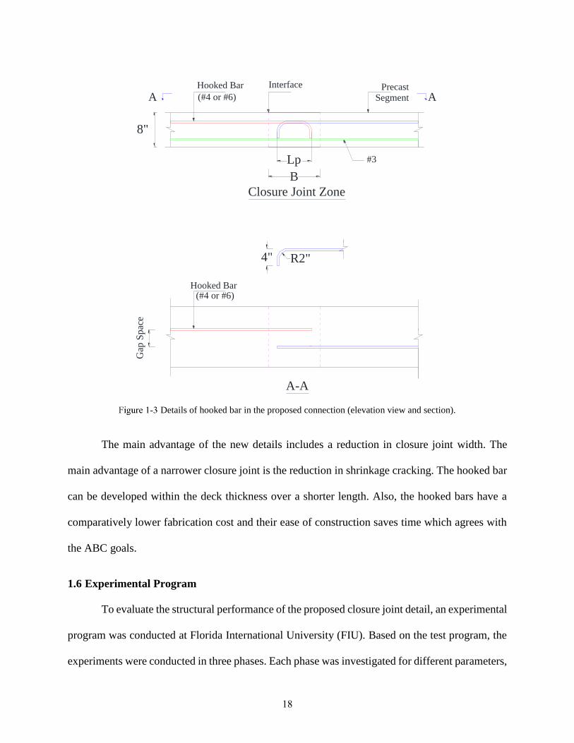
smooth interface, as shown in Figure 1-3. The test specimens are designed for unit width of the
deck in the transverse direction where moments are transferred through closure joint. The thickness
of the slab was chosen to be 8 in. for all specimens, which is a typical thickness for bridge decks.
The gap space in Figure 1-3 represents the transverse spacing of noncontact splices, which is
limited by the smallest value of one-fifth of lap splice length or 6.0 in. [28]. For this reason, a gap
space of 2.0 in. and 4.0 in. are considered as lower and upper limits, respectively. The empirical
design of deck typically uses No. 4 bar, but No. 6 bar was also considered as an upper limit. To
investigate the optimal lap splice length, a spliced length of 2-in. to 10-in. was considered with a
2-in. increment.
18
Details of hooked bar in the proposed connection (elevation view and section).
The main advantage of the new details includes a reduction in closure joint width. The
main advantage of a narrower closure joint is the reduction in shrinkage cracking. The hooked bar
can be developed within the deck thickness over a shorter length. Also, the hooked bars have a
comparatively lower fabrication cost and their ease of construction saves time which agrees with
the ABC goals.
1.6 Experimental Program
To evaluate the structural performance of the proposed closure joint detail, an experimental
program was conducted at Florida International University (FIU). Based on the test program, the
experiments were conducted in three phases. Each phase was investigated for different parameters,
Interface PrecastSegment
Closure Joint Zone
(#4 or #6)
Gap
Spac
e
Hooked Bar(#4 or #6)
A-A
#3
8"
4" R2"
A A
B
Lp
Hooked Bar

19
including lap splice (Lp) length, the lateral distance between hooked bars (Gap Space (GS)) and
the use of transverse bar (TR) (each variable is defined in Figure 1-3). In this detail, lap splice (Lp)
was measured from outside to outside of hooked bars as shown in Figure 1-3. To meet the
requirement of the AASHTO-LRFD Bridge Design Specifications [27] for the confinement of
hooks, the side cover is considered as 2 in. For each bar size, the range of LP is incrementally
varied from 2 in. to 10 in. with 2-in. increment. For bar size (BS), No. 4 and No. 6 are considered
which are commonly used in bridge decks. Each group consists of 12 beams with a length of 8 ft.
and a depth of 8 in. The design procedure for the design of modular bridge deck is similar to a
conventional cast-in-place decks based on the AASHTO-LRFD Bridge Design Specifications
[27]. The specimens were tested in a reverse test setup where the tension side was located at the
top of the specimens due to some limitations in test setups. Figure 1-4 shows an elevation view of
the reversed test setup.
Specimen geometry, reinforcement, and reversed test setup.
During the first phase, hereafter, indicated by Group A, 12 test specimens were constructed
with different lap splices (2 in. LP 10 in.) with 2-in. increment. The bar sizes for lap splice
were No. 4 and No. 6 with a constant gap space of 2 in. In the second phase, hereafter, indicated
by Group B, another 12 specimens were constructed with the details identical to Group A, except
#3
B
Lp
Hooked Bar Interface PrecastSegment(#4 or #6)
LoadLoad
2"
Elevation View
3'6'8'
#3@12"
8"
2"
112"

20
for a gap of 4-in. between the longitudinal hooked bar in the closure joints region. Finally, Groups
C and D test specimens were constructed with details identical to Groups A and B, with additional
transverse reinforcement which is not used in Groups A and B. These transverse bars consisting
of No. 3 bars at a spacing of 2.5 in. were placed over the hooked bars in the closure joint. This
transverse reinforcement represents longitudinal reinforcement that is usually placed in the
longitudinal closure joints. All the test specimens designated as S/ST-GS-BS-Lp
where: S is a notation for the specimens without transverse bars;
ST is a notation for the specimens with transverse bars in closure region;
GS is a notation for the lateral distance between the hooked bars (Gap Space) in inches;
BS is a notation for bar size in terms of bar number; and
LP is a notation for lap splice length in inches.
For instance, S-2-4-2 specifies the specimen with no transverse reinforcement within closure joint,
with a 2-in. lateral distance between the hooked bars, No. 4 bar size, and 2-in. lap splice length.
Table 1-1 shows the specimen matrix details.
Specimen Matrix, Unit: in.
Group ID G S (in.) Bar Size Lp (in.) Transverse Bar Joint Width (in.)
A
S-2-4-2 2 #4 2 NO 6
S-2-4-4 2 #4 4 NO 8
S-2-4-6 2 #4 6 NO 10
S-2-4-8 2 #4 8 NO 12
S-2-4-10 2 #4 10 NO 14
S-2-6-2 2 #6 2 NO 6
S-2-6-4 2 #6 4 NO 8
S-2-6-6 2 #6 6 NO 10
S-2-6-8 2 #6 8 NO 12
S-2-6-10 2 #6 10 NO 14
S-2-4-control 2 #4 Control NO N/A
S-2-6-control 2 #6 Control NO N/A

21
Cont. Table 1-1
B
S-4-4-2 4 #4 2 NO 6
S-4-4-4 4 #4 4 NO 8
S-4-4-6 4 #4 6 NO 10
S-4-4-8 4 #4 8 NO 12
S-4-4-10 4 #4 10 NO 14
S-4-6-2 4 #6 2 NO 6
S-4-6-4 4 #6 4 NO 8
S-4-6-6 4 #6 6 NO 10
S-4-6-8 4 #6 8 NO 12
S-4-6-10 4 #6 10 NO 14
S-4-4-control 4 #4 Control NO N/A
S-4-6-control 4 #6 Control NO N/A
C
ST-2-4-2 2 #4 2 #3 6
ST-2-4-4 2 #4 4 #3 8
ST-2-4-6 2 #4 6 #3 10
ST-2-4-8 2 #4 8 #3 12
ST-2-4-10 2 #4 10 #3 14
ST-2-6-2 2 #6 2 #3 6
ST-2-6-4 2 #6 4 #3 8
ST-2-6-6 2 #6 6 #3 10
ST-2-6-8 2 #6 8 #3 12
ST-2-6-10 2 #6 10 #3 14
ST-2-4-control 2 #4 Control #3 N/A
ST-2-6-control 2 #6 Control #3 N/A
D
ST-4-4-2 4 #4 2 #3 6
ST-4-4-4 4 #4 4 #3 8
ST-4-4-6 4 #4 6 #3 10
ST-4-4-8 4 #4 8 #3 12
ST-4-4-10 4 #4 10 #3 14
ST-4-6-2 4 #6 2 #3 6
ST-4-6-4 4 #6 4 #3 8
ST-4-6-6 4 #6 6 #3 10
ST-4-6-8 4 #6 8 #3 12
ST-4-6-10 4 #6 10 #3 14
ST-4-4-control 4 #4 Control #3 N/A
ST-4-6-control 4 #6 Control #3 N/A
1.7 Construction of Test Specimens
The structural performance of a closure joint was replicated under a flexure test for a unit
width. The closure joint was cast in two stages. During the first stage, the adjoining decks were
cast in a formwork separated by a closure joint. Upon the completion of curing for a minimum of
28 days, the closure joint was cast. The concrete used for both the slab and closure joint had a

22
compressive strength of a minimum of 5 ksi (FDOT CL II deck concrete). Before casting of the
closure joints, no surface preparation was done on cast deck portion. This condition represents the
most unfavorable condition of a cold joint. In addition to the test group specimens, control
specimens of monolithic construction were made. These control specimens replicate the cast-in-
place slab of conventional bridges that have no closure joints and contain straight bars. The test
specimens were painted in white to document crack initiation and propagation during the test.
Construction procedure of test specimens is shown in Figure 1-5.
Specimen construction procedure a) formwork, b) casting deck portions, c) spliced hooked bars in
closure joint, d) casting closure joint, e) final test setup.
1.8 Test Setup and Loading Procedure
The test specimens were tested under a four-point loading setup as the main scope of this
study is to investigate the flexural behavior and lap splice length requirement. A displacement
controlled monotonic loading was applied to determine the moment capacity of the closure joints.
The distance between the hydraulic jacks was 6 ft. and the roller supports were spaced at 3 ft. apart
a) b) c)
d) e)
23
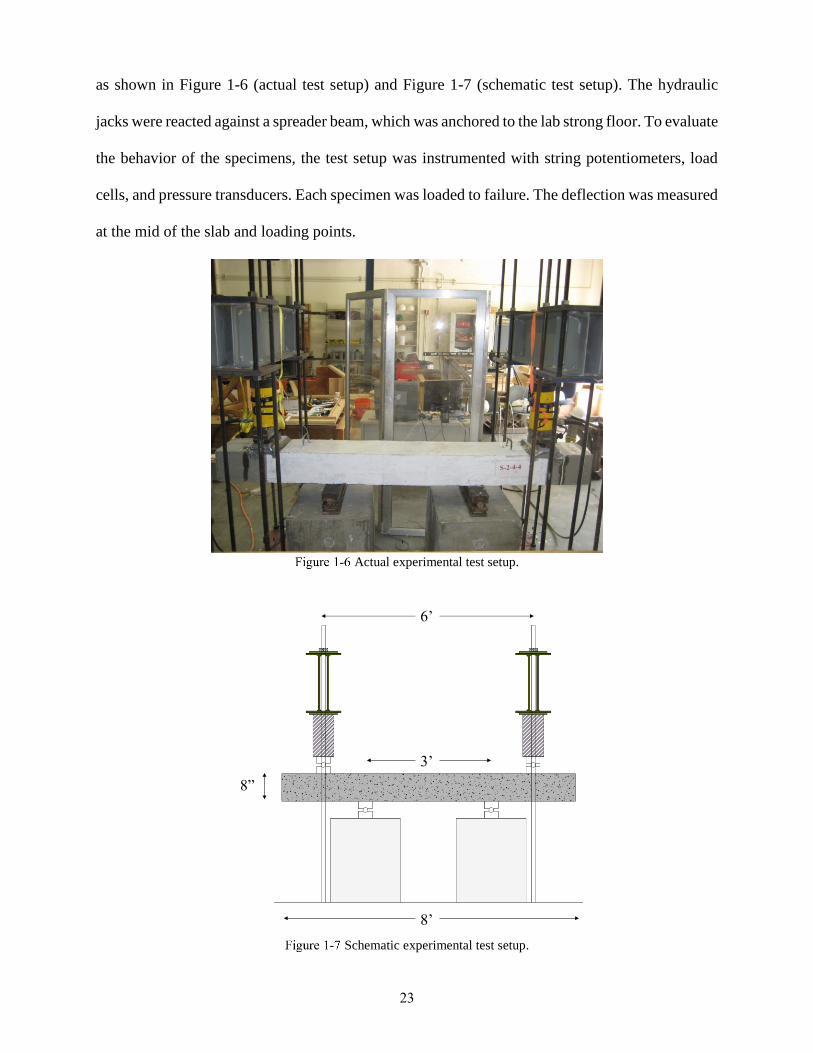
as shown in Figure 1-6 (actual test setup) and Figure 1-7 (schematic test setup). The hydraulic
jacks were reacted against a spreader beam, which was anchored to the lab strong floor. To evaluate
the behavior of the specimens, the test setup was instrumented with string potentiometers, load
cells, and pressure transducers. Each specimen was loaded to failure. The deflection was measured
at the mid of the slab and loading points.
Actual experimental test setup.
Schematic experimental test setup.
6’
3’
8’
8”

24
1.9 Material Tests
Cylinder test of 4x8 in. based on ASTM C39/C39M [29] specification was used to
determine the compressive strength of normal concrete at test days as shown in Figure 1-8. The
compressive strength of conventional concrete for the slab and closure joint regions are
summarized in Table 1-2. All compressive strength values passed 5,000 psi as required.
ASTM A615 Grade 60, No. 3, No. 4, and No. 6 steel reinforcing bars were used for
longitudinal reinforcement in all specimens and transverse bars for specimens in groups C and D.
Four segments of each bar were used for tensile testing as shown in Figure 1-9. The resulting
values of yield and ultimate strength are mentioned in Error! Reference source not found.1-3.
Compressive Strength of Outer Sections of Slab Specimens
Region Sample # Compressive Strength (psi)
Slab 1 7744
2 6230
3 7794
4 7189
5 6080
6
7
8
6974
6852
6021
Average 6860
Closure joint 1 6692
2 6273
3
4
5
6
6130
6127
6772
6525
Average 6420
Bar Test Strengths
Test Specimen Yield Strength (psi) Ultimate Strength (psi)
Straight/Hooked No. 4 64,500 103,800
Straight/Hooked No. 6 68,000 113,000
Straight No. 3 61,700 100,100

25
Cylinder test.
Reinforcing bar test.

26
1.10 Experimental Result
1.10.1 Mode of Failure and Crack Pattern
Resistance against pull-out of deformed reinforcing bars embedded in concrete is mainly
provided by bearing of ribs against concrete. Although adhesion and friction are present when a
deformed bar is loaded, these bond-transfer mechanisms are quickly lost, leaving the bond to be
transferred by bearing on the deformations of the bar [15]. For most structural members, bond
failure is governed by concrete splitting.
The mode of failure for a closure joint with an inadequate splice length occurs at the closure
joint region. by increasing the applied load, the force is transferred to the closure joint and concrete
splits before the yielding occurs due to insufficient lap splice length, which is referred to as a bond
failure as shown in Figure 1-10. However, for the flexure failure, the spliced bars reach their
yielding, and the subsequent cracks are distributed along the tension zone. The flexure failure is a
preferred mode of failure for the closure joints and implies that the splice length is sufficient for
these specimens (Figure 1-11). The modes of failure for all test specimens are summarized in Table
1-4.
Bond failure.
Bond Failure

27
Flexure failure.
The specimens with No. 4 bar in Group A failed in flexure with the exception of the
specimen with 2-in. lap splice length which is not surprising due to short lap splice length of only
four times bars diameter for bar No. 4.
For specimens with No. 6 in Group A, all failure modes were bond failure except for
specimen with 10-in. lap splice length. This concluded that even eleven times the bar diameter of
No. 6 is not sufficient to yield the spliced No. 6 bars. The specimens in Group B with No. 4 bars
failed in flexure except 2-in. and 4-in. splice length. Since the only difference between Group A
and Group B that specimens in Group B have bigger lateral distance between reinforcement which
led to the need of at least twelve times bar diameter instead of eight times bar diameter for the case
of smaller lateral distance between reinforcement for bar No. 4 for specimens in Group A.
For specimens with No. 6 bars in Group B failed in bond which concluded that increasing
the lateral distance between the spliced bars caused that lap splice length to be insufficient even
with over 13 times the bar size.
The specimens with No. 4 bars in Group C failed in bond failure mode except 8-in. and 10-
in. splice length. For specimens with No. 6 bars in the same group, all specimens failed in bond
failure mode except for specimens with 8 in and 10 in. splice length. The specimens with No. 4 in
Flexural Failure

28
Group D bars failed in bond except 10-in. splice length. For specimens with No. 6 bars in the same
group, all specimens failed in bond. The reason Groups C and D failed in bond was due to a weak
plane caused by the presence of transverse bars. The modes of failure for all test specimens are
summarized in Table 1-4.
Test Specimens Modes of Failure
Group ID Bar Size G S (in.) Lp (in.) Transverse Bar Mode of Failure
A
S-2-4-2 #4 2 2 NO Bond Failure
S-2-4-4 #4 2 4 NO Flexural Failure
S-2-4-6 #4 2 6 NO Flexural Failure
S-2-4-8 #4 2 8 NO Flexural Failure
S-2-4-10 #4 2 10 NO Flexural Failure
S-2-4-control #4 N/A N/A NO Flexural Failure
S-2-6-2 #6 2 2 NO Bond Failure
S-2-6-4 #6 2 4 NO Bond Failure
S-2-6-6 #6 2 6 NO Bond Failure
S-2-6-8 #6 2 8 NO Bond Failure
S-2-6-10 #6 2 10 NO Flexural Failure
S-2-6-control #6 N/A N/A NO Flexural Failure
B
S-4-4-2 #4 4 2 NO Bond Failure
S-4-4-4 #4 4 4 NO Bond Failure
S-4-4-6 #4 4 6 NO Flexural Failure
S-4-4-8 #4 4 8 NO Flexural Failure
S-4-4-10 #4 4 10 NO Flexural Failure
S-4-4-control #4 N/A N/A NO Flexural Failure
S-4-6-2 #6 4 2 NO Bond Failure
S-4-6-4 #6 4 4 NO Bond Failure
S-4-6-6 #6 4 6 NO Bond Failure
S-4-6-8 #6 4 8 NO Bond Failure
S-4-6-10 #6 4 10 NO Bond Failure
S-4-6-control #6 N/A N/A NO Flexural Failure
C
ST-2-4-2 #4 2 2 #3 Bond Failure
ST-2-4-4 #4 2 4 #3 Bond Failure
ST-2-4-6 #4 2 6 #3 Bond Failure
ST-2-4-8 #4 2 8 #3 Flexural Failure
ST-2-4-10 #4 2 10 #3 Flexural Failure
ST-2-4-control #4 N/A N/A #3 Flexural Failure
ST-2-6-2 #6 2 2 #3 Bond Failure
ST-2-6-4 #6 2 4 #3 Bond Failure
ST-2-6-6 #6 2 6 #3 Bond Failure
ST-2-6-8 #6 2 8 #3 Flexural Failure
ST-2-6-10 #6 2 10 #3 Flexural Failure
ST-2-6-control #6 N/A N/A #3 Flexural Failure

29
Cont. Table 4-1
D
ST-4-4-2 #4 4 2 #3 Bond Failure
ST-4-4-4 #4 4 4 #3 Bond Failure
ST-4-4-6 #4 4 6 #3 Bond Failure
ST-4-4-8 #4 4 8 #3 Bond Failure
ST-4-4-10 #4 4 10 #3 Flexural Failure
ST-4-4-control #4 N/A N/A #3 Flexural Failure
ST-4-6-2 #6 4 2 #3 Bond Failure
ST-4-6-4 #6 4 4 #3 Bond Failure
ST-4-6-6 #6 4 6 #3 Bond Failure
ST-4-6-8 #6 4 8 #3 Bond Failure
ST-4-6-10 #6 4 10 #3 Bond Failure
ST-4-6-control #6 N/A N/A #3 Flexural Failure
Cracks were mapped during the tests on each specimen to observe the order of cracks
formation. At the onset of longitudinal crack formation, the tests were stopped for safety concerns.
All remaining cracks were mapped upon the completion of testing, as shown in Figure 1-12.
Initiation of cracks with bond failure mode occurred at the cold joints and subsequent crack
formation occurred over supports.
Cracking pattern in closure joints region.
1.10.2 Load-Displacement Relationship
The comparisons of load-deflection curves for all groups are plotted from Figure 1-13 to
Figure 1-16 with fixed horizontal and vertical axes. The test results show that the variables such

30
as the bar diameter, the lateral distance between reinforcement, and lap splice length have a
significant influence on the load carrying capacity of specimens.
In Group A, the deflection specimen with No. 4 bar increased with an increase of lap
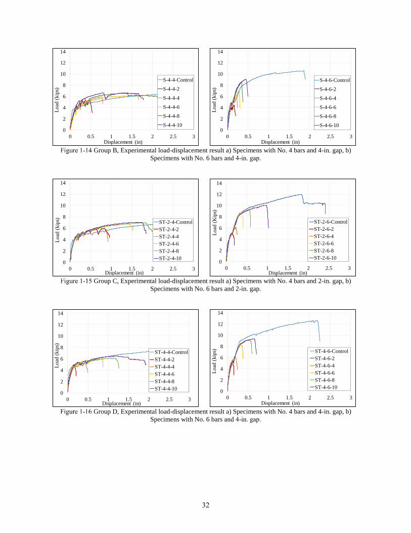
spliced length, while the maximum load carrying capacity of specimens remained the same which
is due to better development length which led to better load transfer between the two adjacent deck
segments. The test specimen S-2-4-2 exhibited the least displacement before the occurrence of
bond failure. For lap splice increments from 2 to 8 in., No. 6 bar was insufficient for tension
development length and bond failure occurred in these specimens. However, for lap splice length
of 10-in., the failure mode was in flexural. Figure 1-13-b shows that the specimens with No. 6 bars
with insufficient lap splice length failed before the bar yielding occurred.
The lateral distance between the reinforcement (Gap Space) for specimens in Group B with
No. 4 and No. 6 bars was increased from 2 in. to 4 in. The results show that increasing this gap
space requires an increase of lap splice length, which is shown in Figure 1-14-a and Figure 1-14-
b. The 4-in. gap space for specimens with No. 6 bars was insufficient for all splice lengths and
failed in bond. Figures 1-13 and 1-14 show that reducing the gap spacing and increasing the bar
diameter can improve the ultimate load capacity of the specimens due to an increase in
reinforcement ratio.
Groups C and D have test parameters similar to Groups A and B but include transverse
reinforcement in closure joint region. The test results of Groups C and D are presented in Figures
1-15 and 1-16. General design practice requires the use of these transverse bars for thermal and
shrinkage requirements.
In Group C, the deflection specimen with No. 4 bar increased with an increase of lap spliced
length, while the maximum load carrying capacity of specimens remained the same which is due
to better development length which led to better load transfer between the two adjacent deck

31
segments. The test specimens ST-2-4-2 and ST-2-4-4 exhibited the least displacement before the
occurrence of bond failure. For lap splice increments from 2 to 6 in., No. 6 bar was insufficient for
tension development length and bond failure occurred in these specimens. However, for lap splice
lengths of 8-in. and 10-in., the failure mode was in flexural. Figure 1-15-b shows that the
specimens with No. 6 bars with insufficient lap splice length failed before the bar yielding
occurred.
The lateral distance between the reinforcement (Gap Space) for specimens in Group D with
No. 4 and No. 6 bars was increased from 2 in. to 4 in. The results show that increasing this gap
space requires an increase of lap splice length, which is shown in Figure 1-16-a and Figure 1-16-
b. The 4-in. gap space for specimens with No. 6 bars was insufficient for all splice lengths and
failed in bond. Figures 1-15 and 1-16 show that reducing the gap spacing and increasing the bar
diameter can improve the ultimate load capacity of the specimens due to an increase in
reinforcement ratio.
Adding transverse reinforcement in the closure joints acts as ties for spliced bars (due to their short
length) to reduce cracks initiation and propagation, however, specimens in groups C and D failed
in bond since the overall width of specimens were small, but in the case of large scale closure
joints, this would not happen.
Group A, Experimental load-displacement result a) Specimens with No. 4 bars and 2-in. gap, b)
Specimens with No. 6 bars and 2-in. gap.
0
2
4
6
8
10
12
14
0 0.5 1 1.5 2 2.5 3
Load
(kip
s)
Displacement (in)
S-2-4-2
S-2-4-4
S-2-4-6
S-2-4-8
S-2-4-100
2
4
6
8
10
12
14
0 0.5 1 1.5 2 2.5 3
Load
(kip
s)
Displaceement (in)
S-2-6-Control
S-2-6-2
S-2-6-4
S-2-6-6
S-2-6-8
S-2-6-10
32
Group B, Experimental load-displacement result a) Specimens with No. 4 bars and 4-in. gap, b)
Specimens with No. 6 bars and 4-in. gap.
Group C, Experimental load-displacement result a) Specimens with No. 4 bars and 2-in. gap, b)
Specimens with No. 6 bars and 2-in. gap.
Group D, Experimental load-displacement result a) Specimens with No. 4 bars and 4-in. gap, b)
Specimens with No. 6 bars and 4-in. gap.
0
2
4
6
8
10
12
14
0 0.5 1 1.5 2 2.5 3
Lo
ad (
kip
s)
Displacement (in)
S-4-4-Control
S-4-4-2
S-4-4-4
S-4-4-6
S-4-4-8
S-4-4-100
2
4
6
8
10
12
14
0 0.5 1 1.5 2 2.5 3
Lo
ad (
kip
s)
Displacement (in)
S-4-6-Control
S-4-6-2
S-4-6-4
S-4-6-6
S-4-6-8
S-4-6-10
0
2
4
6
8
10
12
14
0 0.5 1 1.5 2 2.5 3
Load
(kip
s)
Displacement (in)
ST-2-4-Control
ST-2-4-2
ST-2-4-4
ST-2-4-6
ST-2-4-8
ST-2-4-100
2
4
6
8
10
12
14
0 0.5 1 1.5 2 2.5 3
Load
(K
ips)
Displacement (in)
ST-2-6-Control
ST-2-6-2
ST-2-6-4
ST-2-6-6
ST-2-6-8
ST-2-6-10
0
2
4
6
8
10
12
14
0 0.5 1 1.5 2 2.5 3
Lo
ad (
kip
s)
Displacement (in)
ST-4-4-Control
ST-4-4-2
ST-4-4-4
ST-4-4-6
ST-4-4-8
ST-4-4-100
2
4
6
8
10
12
14
0 0.5 1 1.5 2 2.5 3
Load
(kip
s)
Displacement (in)
ST-4-6-Control
ST-4-6-2
ST-4-6-4
ST-4-6-6
ST-4-6-8
ST-4-6-10

33
1.10.3 Measured Ductility
Since the behavior of the concrete beams is not perfectly elastic-plastic, the ductility
parameters (Δy and Δmax) were obtained from the idealization load-displacement curve. The
idealized curve consists of two regions: linear elastic and plastic. The yield displacement (Δy) was
calculated based on initial stiffness and maximum load applied as shown in Figure 1-17.
Displacement ductility capacity (µ) of a member cab be calculated using the following equation:
µ =𝛥𝑚𝑎𝑥
𝛥𝑦
(1-1)
Where;
Δy: Idealized elastic displacement of the tested beam
Δmax: the maximum displacement of the tested beam
Considering the described equation above, the ductility of the specimens related to lap
splice length is plotted in Figures 1-18 and 1-19. The presence of transverse reinforcement in
closure joint improves displacement ductility and the tension development is possible with shorter
spliced length. Based on the test results, it is concluded that a certain level of displacement ductility
and load carrying capacity is needed for bar development length. These limits control the design
of lap splice length for hooked bar and failure by either flexure or bond is of secondary importance.

34
Measuring ductility approach.
Ductility against different lap splice length a) Specimens with No. 4 bars and 2-in. gap, b) Specimens
with No. 6 bars and 2-in. gap.
Ductility against different lap splice length a) Specimens with No. 4 bars and 4-in. gap, b) Specimens
with No. 6 bars and 4-in. gap
0
2
4
6
8
10
12
14
0 2 4 6 8 10 12
Du
ctil
ity
Lap Splice Length (in)
With TR
Without TR0
2
4
6
8
10
0 2 4 6 8 10 12
Du
ctil
ity
Lap Splice Length (in)
With TR
Without TR
0
2
4
6
8
10
12
14
0 2 4 6 8 10 12
Duct
ilit
y
Lap Splice Length (in)
With TR
Without TR0
0.5
1
1.5
2
2.5
3
0 2 4 6 8 10 12
Duct
ilit
y
Lap Splice Length (in)
With TR
Without TR

35
1.11 Tentative Design Recommendations
The performance of a tension splice is considered similar to that of an identical component
in which the reinforcing bars are continuous. Thus, to comply with general ACI design philosophy
due to the lack of the same requirement in AASHTO-LRFD, the members with tension splice
should exhibit some level of ductility. The ACI requirement specifying 1.25fy (section 12.14)
provides insufficient knowledge of the level of ductility (curvature of displacement) in a member
with tension splice. Therefore, in order to develop design criteria, strength and ductility criteria
should be incorporated. The displacement ductility ratio, described in the previous section, was
used to express the ductility criteria. A displacement ductility ratio greater than one signifies:
firstly, those longitudinal bars are capable of developing at least their actual yield stress, and
secondly, specimens are capable of reaching deformation levels corresponding to limits beyond
the first yield displacement [15].
Each data point in Figures 1-18 and 1-19 represents the displacement ductility ratio
achieved by each of 48 test specimens. Based on the structural performance of the specimens
compared to the calculated ductility ratio, it might be concluded that the specimens achieving a
displacement ductility ratio of greater than 3 shall be considered satisfactory. Graybeal et al [30]
conducted several tests for UHPC closure joints and the corresponding ductility was checked by
the author herein, and it was estimated that the UHPC closure joint specimens reach a ductility
ratio of 3 to 4. Since the UHPC closure joints have been implemented in practice in many bridges,
with same ductility range. It can be concluded that performance of closure joints with 90o degree
hooked reinforcement is satisfactory since it reaches the same ductility range as UHPC closure
joints with straight bars.
Results of the experimental tests are summarized in Table 1-5. Following is a suggested
design recommendation for the closure joint detail recommended in this research. It should be

36
noted that until further tests are performed, this is a conservative recommendation, based on the
results shown in Table 1-5.
For specimens with No. 4 and No. 6 reinforcement, using the 90o degree hook detail, as
shown in Figure 16, lap splice length should be at least 12 times diameter of the reinforcement.
Further, at least three No. 3 reinforcement, acting as confining reinforcement and running parallel
to the closure joints, as shown in Figure 1-20 and should be provided over the spliced hooked
reinforcement. In case of the absence of the transverse bars, lap splice length should be at least 14
times diameter of the reinforcement. The maximum stagger spacing should be limited to 4 in. until
further research is conducted.
Design Recommendations
Bar Size Gap Space
(in.)
Without Transverse
Bar
With Transverse
Bar
#4 2 8db (4 in.) 8db (4 in.)
#6 2 14db (10 in.) 8db (6 in.)
#4 4 12db (6 in.) 8db (4 in.)
#6 4 14db (10 in.) 11db (8 in.)
Design recommendation details.
Transverse Reinforcement (No.3)
Hooked bar
(No.4 and No.6)
Lp = 12db

37
1.12 Conclusions
The main objective of this research was to develop design provisions for 90o degree hooked
reinforcement detail in closure joint regions. An experimental investigation was designed to
develop information that could lead to design recommendations. The parameters investigated
experimentally included reinforcement diameter, the lateral distance between reinforcement,
transverse reinforcement, and lap splice length. Testing was carried out on a four-point setup and
the results are reported in terms of load-deflection curves and ductility ratio.
Based on the conducted research, the following specific conclusions are made:
1. For the reinforcement types and 90o degree hook detail, AASHTO-LRFD (ACI 318-11)
Specification requires 18 times the diameter of the reinforcement as lap splice length, as
compared to 12 times the diameter of the reinforcement recommended in this study. The
main reason for this observed behavior is that AASHTO-LRFD and ACI design
recommendations were developed based on test specimens simulating 90o degree hook
detail in beam-column connections. In the case of deck slab, significant confinement for
hooked detail is provided by concrete to either side of closure joints. This additional
confinement helps to reduce the required tension splice length.
2. The design recommendations in this research are based on providing sufficient ductility by
including confining reinforcement, increasing in tension lap splice length, or decreasing
the lateral distance between spliced reinforcement. The recommended design provisions
ensure achieving acceptable levels of ductility before failure, which could be by either
flexure or bond failures as the mode of failure is considered of secondary importance.
3. Performance of closure joints with 90o degree hooked reinforcement is considered
satisfactory as it reaches a ductility ratio of 3 to 4 range as compared to UHPC closure
joints with straight bars.

38
1.13 References
[1] Amiri GG, Jahromi AJ, Mohebi B. Determination of plastic hinge properties for static nonlinear
analysis of FRP-strengthened circular columns in bridges. Comput Concr 2012.
doi:10.12989/cac.2012.10.5.435.
[2] Graybeal BA. Behavior of Ultra-High Performance Concrete Connections Between Precast Bridge
Deck Elements. 2010 Concr. Bridg. Conf. Achiev. Safe, Smart Sustain. Bridg., 2010.
doi:10.1017/CBO9781107415324.004.
[3] Badie SS, Kamel MR, Tadros MK. Precast pretensioned trapezoidal box beam for short span
bridges. PCI J 1999. doi:10.15554/pcij.01011999.48.59.
[4] Jaberi A, Dickinson M. Development of Manual for Enhanced Service Life of ABC Projects
ABC-UTC Quarterly Research Progress Report Title: Development of Manual for Enhanced
Service Life of ABC Projects. 2016.
[5] Jahromi AJ, Dickinson M, Valikhani A, Azizinamini A. Assessing Structural Integrity of Closure
Pours in ABC Projects 2018.
[6] Li L, Ma Z (John), Griffey ME, Oesterle RG. Improved Longitudinal Joint Details in Decked Bulb
Tees for Accelerated Bridge Construction: Concept Development. J Bridg Eng 2010.
doi:10.1061/(ASCE)BE.1943-5592.0000067.
[7] Gull JH, Yakel A, Azizinamini A. Experimental Investigation of Longitudinal Closure Pour Detail
for Prefabricated Slabs Used in Modular Construction 2014.
[8] American Association of State Highway and Transportation Officials. AASHTO LRFD bridge
design specifications, seventh edition, 2014, U.S. customary units : 2015 interim revisions. 2014.
[9] ACI Committee 318. Building Code Requirements for Structural Concrete ( ACI 318-08 ). 2008.
doi:10.1016/0262-5075(85)90032-6.
[10] Culmo MP. Accelerated Bridge Construction - Experience in Design, Fabrication and Erection of
Prefabricated Bridge Elements and Systems (No. FHWA-HIF-12-013). 2011.
[11] Marques J, Proceedings JJ-J, 1975 undefined. A study of hooked bar anchorages in beam-column

39
joints. ConcreteOrg n.d.
[12] L. Pinc R, D. Watkins M, O. Jirsa J. Strength Of Hooked Bar Anchorages In Beam-Column Joints.
CESRL Rep Univ Tex Austin Dep Civ Eng Struct Res Lab 1977.
[13] Johnson L, Jirsa J. The influence of short embedment and close spacing on the strength of hooked
bar anchorages 1980.
[14] Azizinamini A, Stark M, Roller JJ, Ghosh SK. Bond performance of reinforcing bars embedded in
high-strength concrete. ACI Struct J 1993. doi:10.14359/3951.
[15] Azizinamini A, Chisala M, Ghosh SK. Tension development length of reinforcing bars embedded
in high-strength concrete. Eng Struct 1995;17:512–22. doi:10.1016/0141-0296(95)00096-P.
[16] Azizinamini A, Pavel R, Hatfield E, Ghosh SK. Behavior of Lap-Spliced Reinforcing Bars
Embedded in High-Strength Concrete. ACI Struct J 1999;96:826–35. doi:10.14359/737.
[17] Azizinamini A, Darwin D, Eligehausen R, Pavel R, Ghosh SK. Proposed modifications to ACI
318-95 tension development and lap splice for high-strength concrete. ACI Struct J 1999.
[18] Hamad BS, Jirsa JO, D’Abreu de Paulo NI. Anchorage strength of epoxy-coated hooked bars. ACI
Struct J 1993. doi:10.14359/4127.
[19] Hamilton H, Ciancone G, Michael A. Behavior of Standard Hook Anchorage Made with
Corrosion Resistant Reinforcement. 2008.
[20] Jahromi AJ, Valikhani A, Azizinamini A. Toward Development of Best Practices for Closure
Joints in ABC Projects 2018.
[21] Oesterle RG, Elremaily AF, Ma ZJ. GUIDELINES FOR DESIGN AND CONSTRUCTION OF
DECKED PRECAST, PRESTRESSED CONCRETE GIRDER BRIDGES FINAL REPORT.
2009.
[22] Burner K. Experimental Investigation Of Folded Plate Girders And Slab Joints Used In Modular
Construction. Civ Eng Theses, Diss Student Res 2010.
[23] Valikhani A, Jahromi AJ, Azizinamini A. Retrofitting Damaged Bridge Elements Using Thin
Ultra High Performance Shell Elements 2017.

40
[24] Valikhani A, Jaberi Jahromi A, Azizinamini A. Experimental Investigation of High-Performing
Protective Shell Used for Retrofitting Bridge Elements 2018.
[25] Ma Z. Recent Durability Performance Results in Closure Joints of Modular Bridge Decks 2011.
[26] Barker RM, Puckett JA. Design of Highway Bridges: An LRFD Approach: Third Edition. 2013.
doi:10.1002/9781118411124.
[27] AASHTO LRFD Bridge Design Specifications. American Association of State highway and
transportation officials; 2012.
[28] ACI Committee 318. Building Code Requirements for Structural Concrete (ACI 318-11) and
Commentary. Aci 318-11 2011. doi:10.1016/0262-5075(85)90032-6.
[29] C39/C39M −12 StandardTest Method for Compressive Strength of Cylindrical Concrete
Specimens n.d. doi:10.1520/C0039_C0039M-12.
[30] Graybeal B. Behavior of field-cast ultra-high performance concrete bridge deck connections under
cyclic and static structural loading 2010.
Related Documents