SERVICE MANUAL Parts marked with " " are important for maintaining the safety of the set. Be sure to replace these parts with specified ones for maintaining the safety and performance of the set. This document has been published to be used for after sales service only. The contents are subject to change without notice. CHAPTER 1. SPECIFICATION [1] SPECIFICATION ........................................... 1-1 [2] EXTERNAL DIMENSION .............................. 1-2 [3] WIRING DIAGRM ......................................... 1-3 [4] ELECTRICAL PARTS ................................... 1-3 CHAPTER 2. EXPLAMATION OF CIRCUIT AND OP- ERATION [1] BLOCK DIAGRAMS ...................................... 2-1 [2] MICROCOMPUTER CONTROL SYSTEM ........ 2-3 [3] FUNCTION.................................................... 2-8 CHAPTER 3. FUNCTION AND OPERATION OF PRO- TECTIVE PROCEDURES [1] PROTECTION DEVICE FUNCTIONS AND OPERATIONS ............................................... 3-1 [2] AIR CONDITIONER OPERATION IN THERMISTOR ERROR ................................ 3-3 [3] THERMISTOR TEMPERATURE CHAR- ACTERISTICS .............................................. 3-5 [4] HOW TO OPERATE THE OUTDOOR UNIT INDEPENDENTLY ............................... 3-5 [5] GENERAL TROUBLESHOOTING CHART ........ 3-6 [6] MALFUNCTION (PARTS) CHECK METH- OD ................................................................. 3-8 [7] OUTDOOR UNIT CHECK METHOD........... 3-10 [8] TROUBLESHOOTING GUIDE .................... 3-13 CHAPTER 4. REFRIGERATION CYCLE [1] FLOW FOW REFRIGERANT ........................ 4-1 [2] STANDARD CONDITION .............................. 4-1 [3] TEMPERATURE AT EACH PART AND PRESSURE IN 3-WAY VALVE ...................... 4-1 [4] PERFORMANCE CURVES........................... 4-2 CHAPTER 5. DISASSEMBLING PROCEDURE [1] DISASSEMBLY OF INDOOR UNIT ............... 5-1 [2] DISASSEMBLY OF OUTDOOR UNIT ........... 5-7 Parts Guide TopPage CONTENTS SPLIT TYPE ROOM AIR CONDITIONER INDOOR UNIT AY-XP12GR-N OUTDOOR UNIT AE-X12GR-N MODELS In the interests of user-safety (Required by safety regulations in some countries) the set should be restored to its original condition and only parts identical to those specified should be used.

AY XP12GR N Service Manual 1
Dec 23, 2015
Service manual
Welcome message from author
This document is posted to help you gain knowledge. Please leave a comment to let me know what you think about it! Share it to your friends and learn new things together.
Transcript

SERVICE MANUAL
Parts marked with " " are important for maintaining the safety of the set. Be sure to replace these parts with specified ones for maintaining thesafety and performance of the set.
This document has been published to be used forafter sales service only.The contents are subject to change without notice.
CHAPTER 1. SPECIFICATION[1] SPECIFICATION............................................ 1-1[2] EXTERNAL DIMENSION............................... 1-2[3] WIRING DIAGRM .......................................... 1-3[4] ELECTRICAL PARTS .................................... 1-3
CHAPTER 2. EXPLAMATION OF CIRCUIT AND OP-ERATION[1] BLOCK DIAGRAMS....................................... 2-1[2] MICROCOMPUTER CONTROL SYSTEM........ 2-3[3] FUNCTION..................................................... 2-8
CHAPTER 3. FUNCTION AND OPERATION OF PRO-TECTIVE PROCEDURES[1] PROTECTION DEVICE FUNCTIONS AND
OPERATIONS................................................ 3-1[2] AIR CONDITIONER OPERATION IN
THERMISTOR ERROR ................................. 3-3[3] THERMISTOR TEMPERATURE CHAR-
ACTERISTICS ............................................... 3-5[4] HOW TO OPERATE THE OUTDOOR
UNIT INDEPENDENTLY................................ 3-5[5] GENERAL TROUBLESHOOTING CHART........ 3-6
[6] MALFUNCTION (PARTS) CHECK METH-OD .................................................................3-8
[7] OUTDOOR UNIT CHECK METHOD...........3-10[8] TROUBLESHOOTING GUIDE ....................3-13
CHAPTER 4. REFRIGERATION CYCLE[1] FLOW FOW REFRIGERANT ........................4-1[2] STANDARD CONDITION..............................4-1[3] TEMPERATURE AT EACH PART AND
PRESSURE IN 3-WAY VALVE ......................4-1[4] PERFORMANCE CURVES...........................4-2
CHAPTER 5. DISASSEMBLING PROCEDURE[1] DISASSEMBLY OF INDOOR UNIT...............5-1[2] DISASSEMBLY OF OUTDOOR UNIT...........5-7
Parts Guide
TopPage
CONTENTS
SPLIT TYPEROOM AIR CONDITIONER
INDOOR UNIT
AY-XP12GR-NOUTDOOR UNIT
AE-X12GR-N
MODELS
In the interests of user-safety (Required by safety regulations in somecountries) the set should be restored to its original condition and onlyparts identical to those specified should be used.

AEX12GRN
1 – 1
AEX12GRN Service Manual CHAPTER 1. SPECIFICATION
[1] SPECIFICATION
1. AY-XP12GR-N – AE-X12GR-N
NOTE: The condition of star”✩” marked item are ‘ISO5151’ : 1994(E), contition T1.
MODEL INDOOR UNIT OUTDOOR UNITITEMS AY-XP12GR-N AE-X12GR-NCooling capacity(Min.–Max.) kW 3.5 (0.9 - 4.0)Heating capacity(Min.– Max.) kW 4.6 (0.9 - 6.5)Moisture removal(at cooling) Liters/h 1.1Electrical dataPhase SingleRated frequency Hz 50Rated voltage V 220–240Rated current ✩(Min - Max.)
Cool A 4.2 ( 0.8 –5.7 )Heat A 5.3 ( 0.8 –7.8 )
Rated input ✩(Min - Max.)
Cool W 875 (150–1250 )Heat W 1150 ( 160–1700 )
Power factor ✩ Cool % 95–87Heat % 99–90
Compressor Type Hermetically sealed rotary typeModel DA111A1F22FOil charge 450mL Ester oil VG74
Refrigerant system Evaporator Louver Fin and Grooved tube typeCondenser Corrugate Fin and Grooved tube typeControl Expansion valveRefrigerant (R410A) 1050gDe-lce system Micro computer controled reversed systems
Noise level(at cooling/heating)
High dB(A) 40/44 47/49Low dB(A) 38/38 –Soft dB(A) 27/34 –
Fan systemDrive Direct driveAir flow quantity(at cooling/heating)
High m3/min. 10.5/12.9 32/30Low m3/min. 9.5/10.3 –Soft m3/min. 5.9/8.7 –
Fan Cross flow fan Propeller fanConnectionsRefrigerant coupling Flare typeRefrigerant tube size Gas, Liquid 1/2", 1/4"Drain piping mm O.D φ18OthersSafety device Compressor: Thermal protector
Fan motors: Thermal fuseFuse, Micro computer control
Air filters Polypropylene net (Washable)Net dimensions Width mm 790 780
Height mm 278 540Depth mm 198 265
Net weight kg 10 39
AEX12GRN
1 – 2
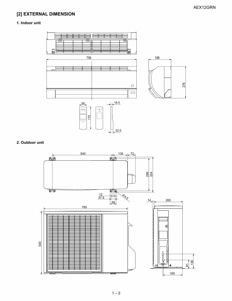
[2] EXTERNAL DIMENSION
1. Indoor unit
2. Outdoor unit
278
198790
22.0
58 18.5
175
INVERTER AIR CONDITIONER
265
780
540
14
165
540
299
72
58
37.512 4.5
324
135
81 136

AEX12GRN
1 – 3
[3] WIRING DIAGRM
1. Indoor unit
2. Outdoor unit
[4] ELECTRICAL PARTS
1. Indoor unit
2. Outdoor Unit
DESCRIPTION MODEL REMARKSIndoor fan motor MLB084 DC MotorIndoor fan motor capacitor – –Transformer – –FUSE1 – QFS-GA062JBZZ (250V, 3.15A)FUSE2 – QFS-GA063JBZZ (250V, 2A)
DESCRIPTION MODEL REMARKSCompressor DA111A1F22F D.C. brush-less motorOutdoor fan motor ML-A902 DC MotorOutdoor fan motor capacitor – –Fu4 – QFS-GA064JBZZ(250V, 1A)Fu3 – QFS-GA051JBZZ(250V, 2A)Fu2 – QFS-GA052JBZZ(250V, 3.15A)Fu1 – QFS-CA001JBZZ(250V, 20A)Fu5, 6 – QFS-CA002JBZZ(250V, 15A)

AEX12GRN
2 – 1
AEX12GRN Service Manual CHAPTER 2. EXPLAMATION OF CIRCUIT AND OPERATION
[1] BLOCK DIAGRAMS
1. Indoor unit
Louvre motor drive circuit(upper)
Louvre motor drive circuit(lower)
LED drive circuit
Flow direction control (louver motor upper)
Flow direction control (louver motor lower)
LED display
AC powerRectification circuit
CPU
SubCPU
3.15AFuse
Serial signals
2AFuse
DC power supply circuit
Fan motor PWM control circuit
Rotation pulse input circuit
AC clock circuit
Remote controller signal reception circuit
Buzzer drive circuit
CPU reset circuit
CPU oscillator circuit
Room temp. detect circuit
Heat exchanger pipe thermo circuit
EEPROM
Select circuit
Serial I/O circuit
Power supply relay drive circuit
Auto restart circuit
Test run circuit
Auxiliary mode
Power on circuit
Cluster generator drive circuit
Indoor fan motor
Fan motor pulse detect
Wireless remote control operation
Audible operation confirmation
Room temp. thermistor
Heat exchanger pipe thermistor
Louvre angle, fan speed
Wireless, preheat, Model select
Indoor/outdoor control signal I/O
Outdoor unit power supply on/off control
Test run (forced operation)
Auxiliary mode button ON/OFF
Self diagnostics, fault diagnosis
Cluster generator
Unit-unit wiring(AC power andserial signals)
AEX12GRN
2 – 2
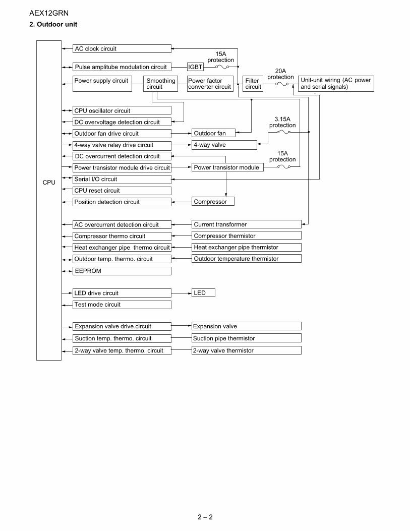
2. Outdoor unit
CPU
20Aprotection
15Aprotection
Expansion valve drive circuit Expansion valve
Suction temp. thermo. circuit Suction pipe thermistor
2-way valve temp. thermo. circuit 2-way valve thermistor
3.15Aprotection
15Aprotection
Power supply circuit
CPU oscillator circuit
DC overvoltage detection circuit
Outdoor fan drive circuit
4-way valve relay drive circuit
Power transistor module drive circuit
Serial I/O circuit
CPU reset circuit
Position detection circuit
AC overcurrent detection circuit
Compressor thermo circuit
Heat exchanger pipe thermo circuit
Outdoor temp. thermo. circuit
LED drive circuit
Test mode circuit
Power factorconverter circuit
Filtercircuit
Smoothingcircuit
Pulse amplitube modulation circuit
EEPROM
AC clock circuit
DC overcurrent detection circuit
IGBT
Unit-unit wiring (AC powerand serial signals)
Outdoor fan
4-way valve
Power transistor module
Compressor
Current transformer
Compressor thermistor
Heat exchanger pipe thermistor
Outdoor temperature thermistor
LED
AEX12GRN
2 – 3
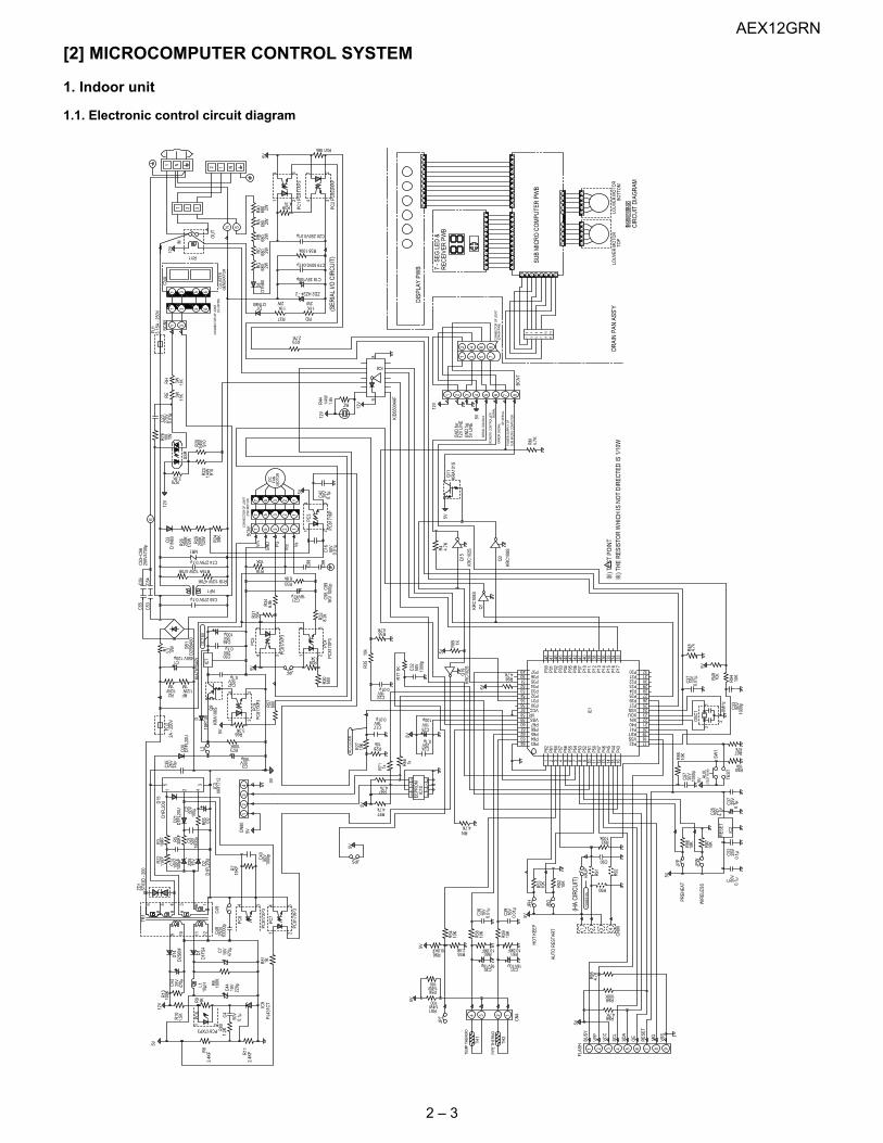
[2] MICROCOMPUTER CONTROL SYSTEM
1. Indoor unit
1.1. Electronic control circuit diagram
0.1μC 50
V
JPF
54
21
54
21
4.7KRN
2.4K5V 10.0KFR96
JPT
9 10 11 12
CIR
CU
ITD
IAG
RAM
DIS
PLAY
PWB
LOU
VER
MO
TOR
TOP
LOU
VER
MO
TOR
BOTT
OM
DR
AIN
PAN
ASS'
Y
MO
TOR
FAN
DC
AUX.
SW1
(TES
TR
UN
)
PIPE
THER
MO
TEM
PTH
ERM
O
POW
ERO
N
10K
R52
(HA
CIR
CU
IT)
AUTO
RES
TAR
T
PREH
EAT
WIR
ELES
S
HO
TKE
EP
FLAS
H
TEST
SUB
MIC
RO
CO
MPU
TER
PWB
REC
EIVE
RPW
B7
-SEG
LED
&
REM
OTE
CO
NTR
OLL
ER SIG
NAL
SER
IAL
SIG
NAL
S
OF
SER
IAL
ERR
OR
SIG
NAL
SUB
MIC
RO
CO
MPU
TER
POW
ERSU
PPLY
OF
12V
LIN
EG
ND
for
GN
Dfo
r5V
LIN
E
CO
NN
ECTO
RO
FJO
INT
(DR
AIN
PAN
)
CO
NN
ECTO
RO
FJO
INT
(FAN
MO
TOR
)
33
98
76
101
23
45
8
R4156k
5V
23 1
4 32
R38100k
C1835V100μ
R39
ZD2HZ24-2
41 4.7k
D1N60D7
R37 RD
4
21
30.
1μC42
25V
12V
R44
1.8k
1/4W
C2116V47μ
R70
Q3
KRC
108S
4.7k
4.7k
(SER
IAL
I/OC
IRC
UIT
)
KRA1
01S
Q11
5V
5VJP
H
R53
JPO
10K
ACC
LOC
K
25V
R90
R55
FU1
3.15
A-2
50V
C57
R85
10K
50V
1000
p
C20250V0.01μ
5V
JPS
470μ
D2S
6M
MQ
R27
10K
10k
R71 1k
1k
R336.8k
8.2k
680
PC5
R34
6.8k
89
5V
12V
87654321
86
75
43
21
1 3 5 7 9
2 4 6 8 10
1112
1 3
5VVs
VccPG
GN
DVm
3 12577 5 2 13
3 1257
PC3
BCN
5
BCN
1 PC81
716P
1210
111
23
45
67
89 9
87
65
43
21
1110
1210
111
23
45
67
899
87
65
43
21
1110
7654321
BCN
7
KRC
102S
Q15
PC1
PC81
7XP3
C16
50V
0.01
μ
10K
R16
275V
0.01
μ
C23
2.7K
RH
RE
R76
100
1W
SSR
12V
2W11K
2W11K
PC2
PC85
3HXP
2W680
680 2W
2W680
680 2W
2W680
D8
D1N
60R
GR
40R
BR
CR
A
C14275V0.1μ
NF1
NR1
200K
200K 39
K
D3
D1N
60
1/2WR26
1/2WR25 R24
C45275V0.1μ
E25
0V47
00p
C53
~C56
C54
C53
C56
C55
CN
801
23
4
BUSY
7654321 8
VPP
VCC
SCL
SDA
OE
RES
ET
9VS
S
5V
321
C90
HAJ
P
4
CN
90R
92
R91
100kR93
1000
p50
V
5V
5V
100μ
C350V
R95
4.7K
R69100K
R684.7K
100μ
DC
15V
D2S
BA60
5V
C2425V
0.1μR
46
DB1
C1
3.3
450V120μ
1M
R2 RF1/2W
1M1/2W
4 321
5V
PC81
7XP3
3.3KR66
100KR73
35VC46
25VC50
0.1μ
0.1μ50VC47
R28
R31
56k
2A-2
50V
142
3
14
5V
FU2
5WR1
47kR67
10kR50
0.1μC
5225
VC
37
0.1μ25
V
5V
JPW
JPP
R87
R86
10K
10K
C26
4.7μ
IC2
RES
ET
0V
ZD1
ST03
D-2
00
5V
1/4W
100
R561/4W
100
R51
C39
16V
0.01
μ
C36
0.01
μ16
V
10K
10K
10K
CN
4
R58
R54
R59
10.0KF
16V10μC31
R61
16V10μC30
R60
34TH
1
12TH
2
321
5V
21
4 3
D1F
S4
0.1μ50
VC4
C44
220μ
10V
C7
470μ
10V
25V
C43
12V IC9
10μHL1
D14 D
1
TR1
6 5 4 3 2 1 4
34
12
IC108
765
EEPR
OM
R97
5V
R47
3
3.3k 2
R29
PC4
R32
C17
0.01μ16V
IC1
64636261605958575655545352515049 P37
P36P35P34P33P32P31P30VCC
VRVSSP67P66P65P64P63
P00
P01
P02
P03
P04
P05
P06
P07
P10
P11
P12
P13
P14
P15
P16
P17
3348 47 46 45 44 43 42 41 40 39 38 37 36 35 34
P20P21P22P23P24P25P26P27VSSXOUXINP40P41RSTVSSP42
20212223242526272829303132
191817
P43
P44
P45
P46
P47
P50
P51
P52
P53
P54
P55
P56
P57
P60
P61
P62
161 2 3 4 15141312111098765
R35
10k 5V
R36
C22
PC81
7XP3
R30
16V0.01μ
4.7K
1000
p50
VC
32
5V
KRC
102S
Q19
C2510V
100μ
C27
16V
0.01
μ4.
7kR
45
R94
5V
10k
R48
C331
3
2OSC
1 8MH
z
KRC
108S
Q1
10.0KF
1 N1 3 65
N S
321
5 6
CN
A
3112
V
IN
RY1
(CLU
STER
)C
ON
NEC
TOR
OF
JOIN
TO
UT
N12
R191/2W470K
R19A1/2W470K
3W11
K3W 11K
C98
C99
1KV
1000
pC
98,C
99
KID
6500
4AF
12V
C1950V0.047μ
IC6
BZ
GEN
ERAT
OR
CLU
STER
4.7K
33p
2KV
RM
1500
p
10KF
15V
100p
F
15KF
1.5KR10
1000
0pM
R17
12
680
PC81
7XP3
PC9
4.7K
R4
3.3KR75
910
1/4WR20
1/4WR23
910
R22
R3
R65
R5
ZD5
C12
50VC5
50VC2
100μ
D2
D1F
L20U
D1F
L20U
C35
IC3
1 2
5 34
R7 10
00p
50VC40
10K
D1F
L20UD
15
D21
KRA1
06S
IC7
R57
D20
D1F
L20U
Q9
PC81
7XP3
1KR81
2.4K
FR8
2.4K
FR11
R80
PC6
1KR9
PC817XP3
R6
100K
PC81
7XP3
R13
100K
PJ43
1CT
250VC48
PC6
PC7
R17
1K
R984.7K
R89 1K
100V
1.2K
C49
11KF
30KF
L2KI
A781
5API
1SR
139D

AEX12GRN
2 – 4
1.2. Display circuit diagram
12V
KID65004AF
M5V
M5V
M5V
M5V
7654321
10 111 2 3 4 5 6 7 8 9
12V
12V
5V
KID65004AF
CN103
CN102
IC105
IC106
CN101
IC104
13
28MHz
P30
19P31
20P32
21P33
22P34
23P35
24P36
25P37
26P00
27P01
28P02
29P03
30P04
31P05
32P06
33P07
34P10
35P11
36
Vss
18Xout
17161 2 3 4 15141312111098765
P12P13P14P20P21P22P23P24P25P26P27Vref
RESET
CNVss
VccXin
IC101
M37542
OSC101
0.1μ25V
C101
C102
4.7μ
IC102
0.1μ25V
C103
C104
16V
47μ
IC103
KID65783AF
R101
R102
R103
R104
R105
R106
R1071W180*7
FLASH
4.7KR115
4.7K
R108
R118
10K
R116
100K
KRA106S KRC106S
KRA106S
R109
R113R110
R114
1/4W
1.2K
*4
LED
LED
LED
LED
LED
LED
LED
LED
LED
LED
LED
101
102
103
104
105
106
107
108
109
110
PC
CN105A
CN104B
CN104A
a b c d e f g
SG201
Q102
Q101
Q104
KRC106S
Q103
CN105B
CN105C
1 2 3
25V
R201
47
IC201
RECEIVERCIRCUIT
SUBMICROCOMPUTERPWB
CIRCUITDAIGRAM
12345
LOUVERMOTOR
BOTTOM
LOUVERMOTOR
TOP
SERIALSIGNALS
REMOTECONTROLLER
SIGNALS
ERRORSIGNAL
OFSERIAL
POWERSUPPLY
OF
SUBMICROCOMPUTER
5VLINE
GNDfor
12VLINE
GNDfor
7-SEGLED&RECEIVERPWB
GNDfor
12VLINE
GNDfor
5VLINE
12VLINE
GNDfor
12VLINE
GNDfor
GNDfor
12VLINE
12VLINE
GNDfor
JP1
GNDfor
5VLINE
DISPLAYPWB
( )B L U E
SIGNALS
REMOTECONTROLLER
GP1U261RK
111B
(COM)5
(COM)10
7(A1)
6(B1)
4(C1)
1(D1)
3(E1)
8(F1)
9(G1)
2(H1)
7(A2)
6(B2)
4(C2)
1(D2)
3(E2)
8(F2)
9(G2)
2(H2)
c d e f g
JP2
0.22μ
50V
C105
KRC106S
Q105
1K
5V
R119
25V
C202
47μ
16V
C201 0.1μ
+
C2
C1
H2
H1
B2
B1
F2
F1
E2
E1
D2
D1
G2
G1
A2
A1
a
b
c
d
e
f
g
g
f
e
d
c
b
a
RESET
987654321 12111010 11 121 2 3 4 5 6 7 8 9
10 9 8 7 6 5 4 3 2 1
543211 2 3 4 5
KID65004AF
12V
12V
8
7
6
5
4
3
2
1
9
1 2 3 4 5 6 7 8
12V
5V

AEX12GRN
2 – 5
1.3. Printed wiring board

AEX12GRN
2 – 6
2. Outdoor unit
2.1. Electronic control circuit diagram
AEX12GRN
2 – 7
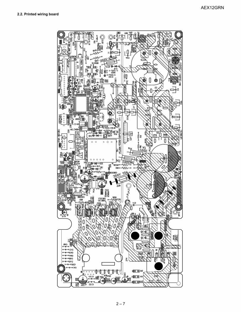
2.2. Printed wiring board

AEX12GRN
2 – 8
[3] FUNCTION
1. Function
1.1. Startup controlThe main relay remains off during the first 45 seconds (first safetytime) immediately after the power cord is plugged into an AC outlet inorder to disable outdoor unit operation and protect outdoor unit electriccomponents.
1.2. Restart controlOnce the compressor stops operating, it will not restart for 180 sec-onds to protect the compressor.
Therefore, if the operating compressor is shut down from the remotecontrol and then turned back on immediately after, the compressor willrestart after a preset delay time.
(The indoor unit will restart operation immediately after the ON switchis operated on the remote control.)
1.3. Cold air prevention controlWhen the air conditioner starts up in heating mode, the indoor unit fanwill not operate until the temperature of the indoor unit heat exchangerreaches about 23°C in order to prevent cold air from blowing into theroom.
Also, the indoor unit fan operates at low speed until the temperature ofthe indoor unit heat exchanger reaches about 38°C so that people inthe room will not feel chilly air flow.
1.4. Odor prevention controlWhen the air conditioner starts up in cooling mode, the discharged airtemperature is lowered slightly, and for the reduction of unpleasantodors the operation of the indoor unit fan is delayed 60 seconds if theautomatic fan speed mode in cooling mode is set.
1.5. Indoor unit heat exchanger freeze prevention controlIf the temperature of the indoor unit heat exchanger remains below0°C for 4 consecutive minutes during cooling or dehumidifying opera-tion, the compressor operation stops temporarily in order to preventfreezing.
When the temperature of the indoor unit heat exchanger rises to 2°Cor higher after about 180 seconds, the compressor restarts andresumes normal operation.
1.6. Outdoor unit 2-way valve freeze prevention controlIf the temperature of the outdoor unit 2-way valve remains below 0°Cfor 10 consecutive minutes during cooling or dehumidifying operation,the compressor operation stops temporarily in order to prevent freez-ing.
When the temperature of the 2-way valve rises to 10°C or higher afterabout 180 seconds, the compressor restarts and resumes normaloperation.
1.7. Indoor unit overheat prevention controlDuring heating operation, if the temperature of the indoor unit heatexchanger exceeds the indoor unit heat exchanger overheat preven-tion temperature (about 45 to 54°C) which is determined by the operat-ing frequency and operating status, the operating frequency isdecreased by about 4 to 15 Hz. Then, this operation is repeated every60 seconds until the temperature of the indoor unit heat exchangerdrops below the overheat protection temperature.
Once the temperature of the indoor unit heat exchanger drops belowthe overheat protection temperature, the operating frequency isincreased by about 4 to 10 Hz every 60 seconds until the normal oper-ation condition resumes.
If the temperature of the indoor unit heat exchanger exceeds the over-heat protection temperature for 60 seconds at minimum operating fre-quency, the compressor stops operating and then restarts after about180 seconds, and the abovementioned control is repeated.
1.8. Outdoor unit overheat prevention controlDuring cooling operation, if the temperature of the outdoor unit heatexchanger exceeds the outdoor unit heat exchanger overheat preven-tion temperature (about 55°C), the operating frequency is decreasedby about 4 to 15 Hz. Then, this operation is repeated every 60 sec-onds until the temperature of the outdoor unit heat exchanger drops toabout 54°C or lower.
Once the temperature of the outdoor unit heat exchanger drops toabout 54°C or lower, the operating frequency is increased by about 4to 10 Hz every 60 seconds until the normal operation conditionresumes.
If the temperature of the outdoor unit heat exchanger exceeds the out-door unit heat exchanger overheat protection temperature for (120 sec: outdoor temperature ≥ 40°C • 60 sec : outdoor temperature < 40°C)at minimum operating frequency, the compressor stops operating andthen restarts after about 180 seconds, and the abovementioned con-trol is repeated.
1.9. Compressor overheat prevention controlIf the temperature of the compressor exceeds the compressor over-heat prevention temperature (110°C), the operation frequency isdecreased by about 4 to 10 Hz. Then, this operation is repeated every60 seconds until the temperature of the compressor drops below theoverheat protection temperature (100°C).
Once the temperature of the compressor drops below the overheatprotection temperature, the operating frequency is increased by about4 to 10 Hz every 60 seconds until the normal operation conditionresumes.
If the temperature of the compressor exceeds the overheat protectiontemperature (for 120 seconds in cooling operation or 60 seconds inheating operation) at minimum operating frequency, the compressorstops operating and then restarts after about 180 seconds, and theabovementioned control is repeated.
Compressor operation
ON operation onremote control
OFF operation onremote control
Compressor ON
Compressor ON Compressor canturn ONCompressor remains OFF
for 180 seconds
Indoor unit heat exchanger temperature
38
23
35
21
Set fan speed
Indoor unit fan at low speed
Indoor unit fan in non-operation
AEX12GRN
2 – 9
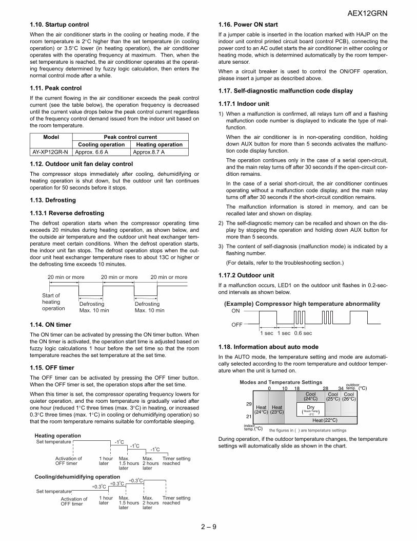
1.10. Startup controlWhen the air conditioner starts in the cooling or heating mode, if theroom temperature is 2°C higher than the set temperature (in coolingoperation) or 3.5°C lower (in heating operation), the air conditioneroperates with the operating frequency at maximum. Then, when theset temperature is reached, the air conditioner operates at the operat-ing frequency determined by fuzzy logic calculation, then enters thenormal control mode after a while.
1.11. Peak controlIf the current flowing in the air conditioner exceeds the peak controlcurrent (see the table below), the operation frequency is decreaseduntil the current value drops below the peak control current regardlessof the frequency control demand issued from the indoor unit based onthe room temperature.
1.12. Outdoor unit fan delay controlThe compressor stops immediately after cooling, dehumidifying orheating operation is shut down, but the outdoor unit fan continuesoperation for 50 seconds before it stops.
1.13. Defrosting
1.13.1 Reverse defrostingThe defrost operation starts when the compressor operating timeexceeds 20 minutes during heating operation, as shown below, andthe outside air temperature and the outdoor unit heat exchanger tem-perature meet certain conditions. When the defrost operation starts,the indoor unit fan stops. The defrost operation stops when the out-door unit heat exchanger temperature rises to about 13C or higher orthe defrosting time exceeds 10 minutes.
1.14. ON timerThe ON timer can be activated by pressing the ON timer button. Whenthe ON timer is activated, the operation start time is adjusted based onfuzzy logic calculations 1 hour before the set time so that the roomtemperature reaches the set temperature at the set time.
1.15. OFF timerThe OFF timer can be activated by pressing the OFF timer button.When the OFF timer is set, the operation stops after the set time.
When this timer is set, the compressor operating frequency lowers forquieter operation, and the room temperature is gradually varied afterone hour (reduced 1°C three times (max. 3°C) in heating, or increased0.3°C three times (max. 1°C) in cooling or dehumidifying operation) sothat the room temperature remains suitable for comfortable sleeping.
1.16. Power ON startIf a jumper cable is inserted in the location marked with HAJP on theindoor unit control printed circuit board (control PCB), connecting thepower cord to an AC outlet starts the air conditioner in either cooling orheating mode, which is determined automatically by the room temper-ature sensor.
When a circuit breaker is used to control the ON/OFF operation,please insert a jumper as described above.
1.17. Self-diagnostic malfunction code display
1.17.1 Indoor unit1) When a malfunction is confirmed, all relays turn off and a flashing
malfunction code number is displayed to indicate the type of mal-function.
When the air conditioner is in non-operating condition, holdingdown AUX button for more than 5 seconds activates the malfunc-tion code display function.
The operation continues only in the case of a serial open-circuit,and the main relay turns off after 30 seconds if the open-circuit con-dition remains.
In the case of a serial short-circuit, the air conditioner continuesoperating without a malfunction code display, and the main relayturns off after 30 seconds if the short-circuit condition remains.
The malfunction information is stored in memory, and can berecalled later and shown on display.
2) The self-diagnostic memory can be recalled and shown on the dis-play by stopping the operation and holding down AUX button formore than 5 seconds.
3) The content of self-diagnosis (malfunction mode) is indicated by aflashing number.
(For details, refer to the troubleshooting section.)
1.17.2 Outdoor unitIf a malfunction occurs, LED1 on the outdoor unit flashes in 0.2-sec-ond intervals as shown below.
1.18. Information about auto modeIn the AUTO mode, the temperature setting and mode are automati-cally selected according to the room temperature and outdoor temper-ature when the unit is turned on.
During operation, if the outdoor temperature changes, the temperaturesettings will automatically slide as shown in the chart.
Model Peak control currentCooling operation Heating operation
AY-XP12GR-N Approx. 6.6 A Approx.8.7 A
20 min or more 20 min or more 20 min or more
DefrostingMax. 10 min
DefrostingMax. 10 min
Start ofheatingoperation
Heating operationSet temperature
Activation ofOFF timer
1 hourlater
Max.1.5 hourslater
Max.2 hourslater
Timer settingreached
1 hourlater
Max.1.5 hourslater
Max.2 hourslater
Timer settingreached
Activation ofOFF timer
Set temperature
-1O
C-1
O
C-1
O
C
0.3O
C0.3
O
C0.3
O
CCooling/dehumidifying operation
1 sec 1 sec 0.6 sec
ON
OFF
(Example) Compressor high temperature abnormality
Modes and Temperature Settings
the figures in ( ) are temperature settings

AEX12GRN
2 – 10
1.19. Airflow controlThe airflow control holds the two upper and lower louvers at specialpositions during operation to prevent discharged air from directly blow-ing onto people in the room.
1.19.1 Cooling/dehumidifying operationWhen the airflow button is pressed the upper louver is set at anupward angle to send the air along the ceiling.
1.19.2 HeatingWhen the airflow button is pressed the lower louver is set at a down-ward angle to send the air directly toward the floor.
1.20. Difference of operation in Auto and Manual modesIn the Auto mode, the temperature setting is automatically determinedbased on the outside air temperature. In addition, the air conditioneroperation differs from the operation in the Manual mode as explainedbelow.
1.20.1 Difference relating to set temperature
1.21. Dehumidifying operation controlIf the room temperature is 26°C or higher when dehumidifying opera-tion starts, the dehumidifying operation provides a low cooling effect inaccordance with the room temperature setting automatically deter-mined based on the outside air operation. (The setting value is thesame as the set temperature for cooling operation in the auto mode.)
If the room temperature is lower than 26°C when dehumidifying opera-tion starts, the dehumidifying operation minimizes the lowering of theroom temperature.
1.22. Self Clean operationHeating or Fan operation and Cluster operation are performed simulta-neously.
The judgment of whether Heating or Fan operation is used is based onthe outside air temperature at 3 minutes after the start of internalcleaning.
The operation stops after 40 minutes. (The air conditioner shows theremaining minutes: 40 → 39 → 38 ... 3 → 2 → 1)
1.23. Plasmacluster Ion functionOperating the Plasmacluster Ion button while the air conditioner is inoperation or in non-operation allows the switching of the operationmode in the following sequence: “Air Clean operation” → “Stop”.
• “Self Clean operation” generates about equal amounts of (+)ionsand (-)ions from the cluster unit to provide clean air.
If the Plasmacluster Ion generation function is operated together withthe air conditioner operation, the indoor unit fan speed and louverdirection are in accordance with the air conditioner settings.
If the Plasmacluster Ion generation function is used without operatingthe air conditioning function, the indoor unit fan operates at a very lowspeed and the upper louver is angled upward and the lower louverremains horizontal. (The airflow volume and direction can be changedby using the remote control.)
1.24. Hot keepWhen the room temperature rises above the set temperature by 0.6°Cor more, the ON/OFF operation of the compressor and indoor unit fanis controlled in order to lower the room temperature.
(The values indicated below, such as "0.6°C" and "1.3°C," varydepending on the outside air temperature.)
1.24.1 Hot keep zone 1With the compressor frequency at the lowest, if the room temperatureis higher than the set temperature by 0.6°C but no more than 1.3°C,the following processes will be activated.
1) The compressor stops temporarily, and restarts after 2 minutes.
2) If the room temperature remains in the hot keep zone, the com-pressor is turned OFF and ON in 3-minute intervals.
3) The indoor unit fan turns OFF and ON with a delay of 30 secondsfrom the compressor OFF/ON.
4) After the above operation in 3-minute intervals is repeated fourtimes, the interval extends to 6 minutes.
1.24.2 Hot keep zone 2If the compressor ON/OFF in hot keep zone 1 fails to bring the roomtemperature within 1.3°C above the set temperature, the following pro-cesses will be activated.
1) The compressor repeats a cycle of 8-minute OFF and 6-minuteON.
2) After the second time, the compressor remains completely OFFand only the indoor unit fan repeats OFF-ON in set intervals.
3) While the compressor is completely OFF in 2), the louvers are sethorizontally to prevent cold air from blowing.
The zone transition and the end of hot keep operation (room tempera-ture lower than the set temperature) are judged when the compressorON period ends.
* This function cannot be repealed.
1.25. Winter coolCooling operation is available during the winter season by the built inwinter cool function.
Lower limit of outdoor temperature range is -10°C DB.
When the outside air temperature is low, the outdoor unit fan operatesat slower speed.
NOTE: Built-in protect device may work when outdoor temperaturefalls below 21°C DB., depending on conditions.
Temperature setting method
Aut
o m
ode Cooling Automatic temperature setting based on
outside air temperature. Can be changed within ±2°C using remote control.
Heating
Dehumidifying
Man
ual m
ode Cooling Can be changed between 18 and 32°C
using remote control.
Heating Can be changed between 18 and 32°C using remote control.
Dehumidifying Automatic setting. Can be changed within ±2°C.
Heating operation Fan operation
24OC Outside air temperature
1.3OC
0.6OC
Set temperature
AEX12GRN
2 – 11
1.26. Auto restartWhen power failure occures, after power is recovered, the unit willautomatically restart in the same setting which were active before thepower failure.
1.26.1 Operating mode (Cool, Heat, Dry)• Temperature adjustment (within 2°C range) automatic operation
• Temperature setting
• Fan setting
• Air flow direction
• Power ON/OFF
• Automatic operation mode setting
• Swing louvre
• Plasmacluster mode
1.26.2 Setting not memorized• Timer setting
• Full power setting
• Internal cleaning
1.26.3 Disabling auto restart functionBy removing (cutting) jumper J (JPJ) on the printed circuit board(PCB), the auto restart function can be disabled.
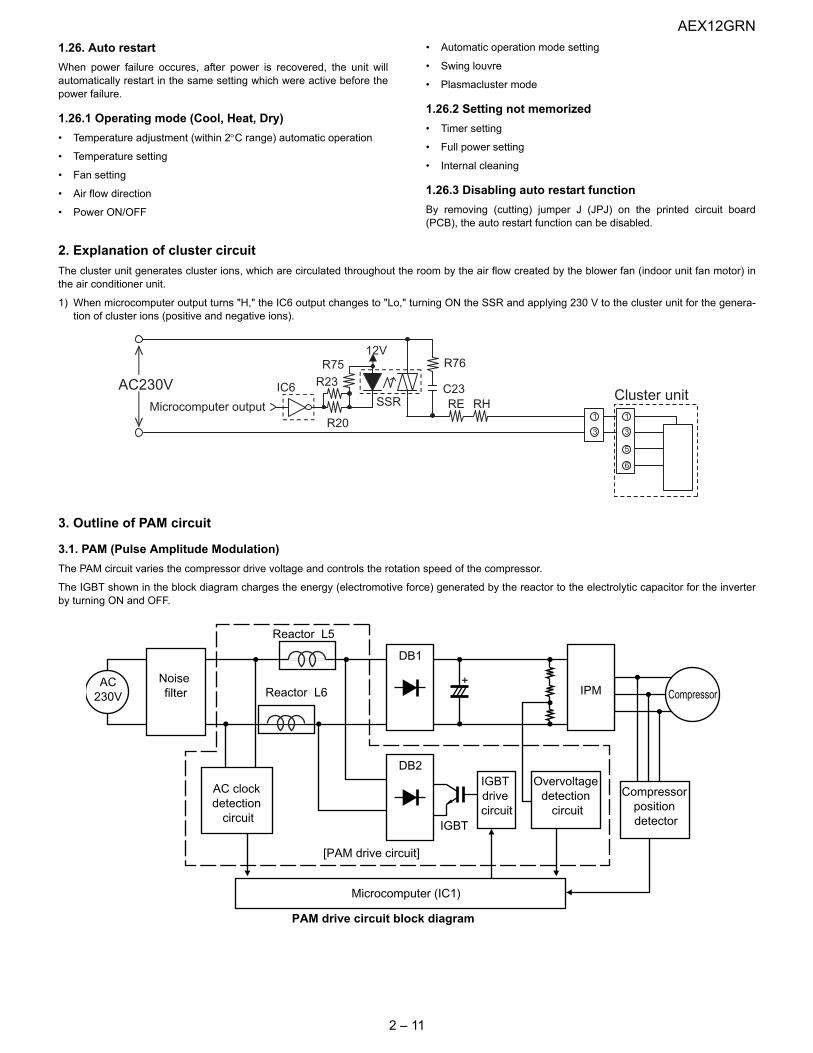
2. Explanation of cluster circuitThe cluster unit generates cluster ions, which are circulated throughout the room by the air flow created by the blower fan (indoor unit fan motor) inthe air conditioner unit.
1) When microcomputer output turns "H," the IC6 output changes to "Lo," turning ON the SSR and applying 230 V to the cluster unit for the genera-tion of cluster ions (positive and negative ions).
3. Outline of PAM circuit
3.1. PAM (Pulse Amplitude Modulation)The PAM circuit varies the compressor drive voltage and controls the rotation speed of the compressor.
The IGBT shown in the block diagram charges the energy (electromotive force) generated by the reactor to the electrolytic capacitor for the inverterby turning ON and OFF.
1
3
12V
SSRC23RE RH
R20
IC6AC230VMicrocomputer output
1
5
3
6
Cluster unitR23R75 R76
PAM drive circuit block diagram
Reactor L5
[PAM drive circuit]
+
Microcomputer (IC1)
AC230V CompressorReactor L6
Noisefilter
AC clockdetection
circuit
DB1
IPM
DB2
Compressorpositiondetector
IGBTdrivecircuit
IGBT
Overvoltagedetection
circuit
AEX12GRN
2 – 12
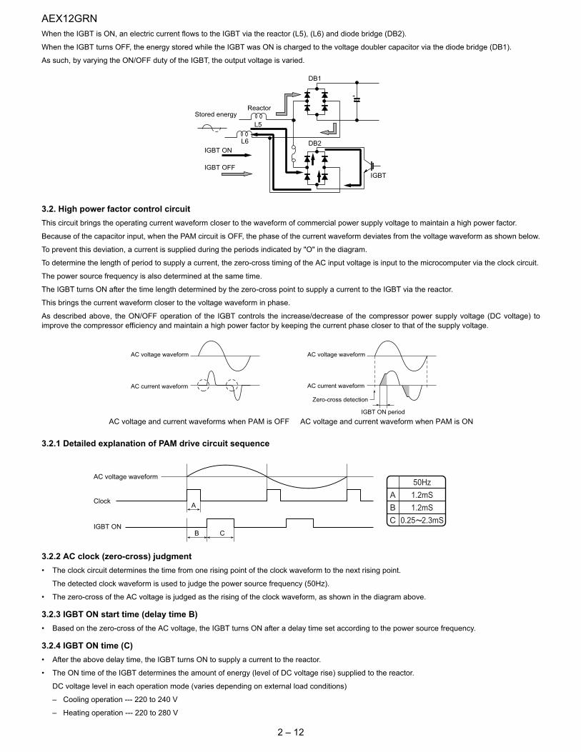
When the IGBT is ON, an electric current flows to the IGBT via the reactor (L5), (L6) and diode bridge (DB2).
When the IGBT turns OFF, the energy stored while the IGBT was ON is charged to the voltage doubler capacitor via the diode bridge (DB1).
As such, by varying the ON/OFF duty of the IGBT, the output voltage is varied.
3.2. High power factor control circuitThis circuit brings the operating current waveform closer to the waveform of commercial power supply voltage to maintain a high power factor.
Because of the capacitor input, when the PAM circuit is OFF, the phase of the current waveform deviates from the voltage waveform as shown below.
To prevent this deviation, a current is supplied during the periods indicated by "O" in the diagram.
To determine the length of period to supply a current, the zero-cross timing of the AC input voltage is input to the microcomputer via the clock circuit.
The power source frequency is also determined at the same time.
The IGBT turns ON after the time length determined by the zero-cross point to supply a current to the IGBT via the reactor.
This brings the current waveform closer to the voltage waveform in phase.
As described above, the ON/OFF operation of the IGBT controls the increase/decrease of the compressor power supply voltage (DC voltage) toimprove the compressor efficiency and maintain a high power factor by keeping the current phase closer to that of the supply voltage.
3.2.1 Detailed explanation of PAM drive circuit sequence
3.2.2 AC clock (zero-cross) judgment• The clock circuit determines the time from one rising point of the clock waveform to the next rising point.
The detected clock waveform is used to judge the power source frequency (50Hz).
• The zero-cross of the AC voltage is judged as the rising of the clock waveform, as shown in the diagram above.
3.2.3 IGBT ON start time (delay time B)• Based on the zero-cross of the AC voltage, the IGBT turns ON after a delay time set according to the power source frequency.
3.2.4 IGBT ON time (C)• After the above delay time, the IGBT turns ON to supply a current to the reactor.
• The ON time of the IGBT determines the amount of energy (level of DC voltage rise) supplied to the reactor.
DC voltage level in each operation mode (varies depending on external load conditions)
– Cooling operation --- 220 to 240 V
– Heating operation --- 220 to 280 V
Stored energyReactor
L5
L6
DB1
DB2
IGBT
IGBT ON
IGBT OFF
AC voltage waveform
AC voltage and current waveform when PAM is ON
AC current waveform
IGBT ON period
Zero-cross detection
AC voltage waveform
AC current waveform
AC voltage and current waveforms when PAM is OFF
AC voltage waveform
Clock
IGBT ON
A
B C
A
B
C
50Hz
1.2mS
1.2mS
0.25 2.3mS
AEX12GRN
2 – 13
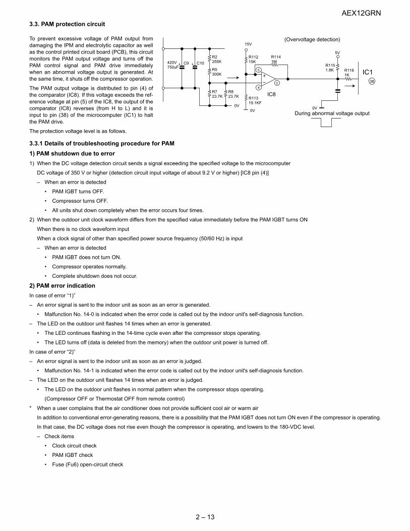
3.3. PAM protection circuit
To prevent excessive voltage of PAM output fromdamaging the IPM and electrolytic capacitor as wellas the control printed circuit board (PCB), this circuitmonitors the PAM output voltage and turns off thePAM control signal and PAM drive immediatelywhen an abnormal voltage output is generated. Atthe same time, it shuts off the compressor operation.
The PAM output voltage is distributed to pin (4) ofthe comparator (IC8). If this voltage exceeds the ref-erence voltage at pin (5) of the IC8, the output of thecomparator (IC8) reverses (from H to L) and it isinput to pin (38) of the microcomputer (IC1) to haltthe PAM drive.
The protection voltage level is as follows.
3.3.1 Details of troubleshooting procedure for PAM1) PAM shutdown due to error1) When the DC voltage detection circuit sends a signal exceeding the specified voltage to the microcomputer
DC voltage of 350 V or higher (detection circuit input voltage of about 9.2 V or higher) [IC8 pin (4)]
– When an error is detected
• PAM IGBT turns OFF.
• Compressor turns OFF.
• All units shut down completely when the error occurs four times.
2) When the outdoor unit clock waveform differs from the specified value immediately before the PAM IGBT turns ON
When there is no clock waveform input
When a clock signal of other than specified power source frequency (50/60 Hz) is input
– When an error is detected
• PAM IGBT does not turn ON.
• Compressor operates normally.
• Complete shutdown does not occur.
2) PAM error indicationIn case of error “1)”
– An error signal is sent to the indoor unit as soon as an error is generated.
• Malfunction No. 14-0 is indicated when the error code is called out by the indoor unit's self-diagnosis function.
– The LED on the outdoor unit flashes 14 times when an error is generated.
• The LED continues flashing in the 14-time cycle even after the compressor stops operating.
• The LED turns off (data is deleted from the memory) when the outdoor unit power is turned off.
In case of error “2)”
– An error signal is sent to the indoor unit as soon as an error is judged.
• Malfunction No. 14-1 is indicated when the error code is called out by the indoor unit's self-diagnosis function.
– The LED on the outdoor unit flashes 14 times when an error is judged.
• The LED on the outdoor unit flashes in normal pattern when the compressor stops operating.
(Compressor OFF or Thermostat OFF from remote control)
* When a user complains that the air conditioner does not provide sufficient cool air or warm air
In addition to conventional error-generating reasons, there is a possibility that the PAM IGBT does not turn ON even if the compressor is operating.
In that case, the DC voltage does not rise even though the compressor is operating, and lowers to the 180-VDC level.
– Check items
• Clock circuit check
• PAM IGBT check
• Fuse (Fu6) open-circuit check
R2255KC10C9420V
750uF R5300K
R723.7K
R823.7K
0V0V
0V
IC8
15V
R11319.1KF
R11215K
5VR1141M
R1151.8K R116
1K5
42
(Overvoltage detection)
During abnormal voltage output
IC138

AEX12GRN
2 – 14
4. Explanation of IPM drive circuitThe IPM for compressor drive is made by Mitsubishi Electric.
The power supply for the IPM drive, the shunt resistance for overcurrent detection, etc., are provided outside the IPM (control PCB).
4.1. IPM drive power supply circuitThe power supply for the upper-phase IGBT (HU, HV, HW) drive employs a bootstrap system, and provides power to the upper-phase IC.
The 15-V power supply for the lower-phase IC is provided by the control printed circuit board (PCB).
4.1.1 Brief explanation of bootstrap system (single power drive system)To supply power to the upper-phase IC, the microcomputer (IC1) turns ON the lower-phase IGBT (LU, LV, LW).
This results in a charging current that flows to the electrolytic capacitor of each upper-phase IC input and charges the bootstrap capacitor with a 15-Vcurrent.
The power supply for the subsequent stages is charged while the lower-phase IGBT is ON in ordinary compressor drive control.
P(Vcc)
U,V,W,
VD
VDB
VCIN(n)
N-sideIGBT
N(GND
Bootstrap capacitor
High-voltage-withstanding,high-speed recovery diode
LVIC(LU,LV,LW)
HVIC(HU,HV,HW)
Bootstrap circuit
Initial charge period
Charging current group

AEX12GRN
2 – 15
4.1.2 DC overcurrent detection circuitWhen a current of about 25 A or higher flows through the shunt resistance (R49) on the control printed circuit board (PCB), the voltage at this resis-tance is input to IPM CIN pin (26). Then, the gate voltage of the lower-phase IGBT (LU, LV, LW) inside the IPM turns OFF to cut off the overcurrent. Atthe same time, an L output of about 1.8 ms is generated from IPM Fo pin (24), and this results in an L input to overcurrent detection input pin (34) ofthe microcomputer (IC1) and turns OFF the PWM signal output (IC1 pins (51) through (56)) to the IGBT gate.
SETRESET
(About 22 A)
SC
SC reference voltage
Delay by CR time constant circuit
About 1.8 ms
a1
Protection circuit status
Output current Ic (A)
Sense voltage relativeto shunt resistance
Error output Fo
(Lower phase)Internal IGBT gate
IPM overcurrentdetection circuit
5V
0V
IC1
R49Overcurrent
Shunt resistance
P
N
CiN
FO
24
26
34

AEX12GRN
2 – 16
5. 120° energizing control (digital position detection control)This control system detects the digital position detection signal and adjusts the rate of acceleration/deceleration accordingly.
The motor's induced voltage waveform is input to the comparator in the form of PWM-switched pulse waveform, and a position detection signal isgenerated as a reference voltage equaling 1/2 of 280 VDC. However, since there is no induced voltage waveform when the PWM waveform is OFF,the microcomputer performs internal processing so that detection is enabled only when it is ON. Based on the detected position signal, actual PWMwaveform output timing is determined. Since it does not use a filter circuit, the detection accuracy is high.
The microcomputer performs internal processing to cancel spike voltage during the regenerative process.
Furthermore, even if the induced voltage is low, position detection is still possible, thus allowing sensor-less operation at low rotation speed in the ini-tial stage of operation. This reduces the starting current and improves the IPM reliability.
Comparator output waveform(Position signal waveform)
Terminal voltage waveform
Reference voltage(1/2 of DC voltage)
Spike voltage(cancelled)

AEX12GRN
3 – 1
AEX12GRN Service Manual CHAPTER 3. FUNCTION AND OPERATION OF PROTECTIVE PROCEDURES
[1] PROTECTION DEVICE FUNCTIONS AND OPERATIONS
Function Operation Self-diagnosis result display
Description Detection period Reset condition Indoor unit error display
Indoor unit
Outdoor unit
1 Indoor unit fan lock Operation stops if there is no input of rotation pulse signal from indoor unit fan motor for 1 minute.
When indoor unit fan is in operation
Operation OFF or ON ✩2 Yes None
Indoor unit fan rota-tion speed error
Operation stops if rotation pulse signal from indoor unit fan indi-cates abnormally low speed (about 300 rpm or slower).
When indoor unit fan is in operation
Operation OFF or ON ✩2 Yes None
2 Indoor unit freeze prevention
Compressor stops if temperature remains below 0°C for 4 minutes.
When in cooling or dehumidifying opera-tion
Automatic reset when heat exchanger tem-perature rises above freeze prevention temperature (2°C or higher)
— None None
3 2-way valve freeze prevention
Compressor stops if temperature of outdoor unit 2-way valve remains below 0°C for 10 continu-ous minutes during cooling or dehumidifying operation.
When in cooling or dehumidifying opera-tion
Automatic reset when temperature of 2-way valve rises above 10°C.
None Yes Yes
4 Indoor unit heat exchanger over-heat shutdown
Operating frequency lowers if indoor unit heat exchanger tem-perature exceeds overheat tem-perature during heating operation.Compressor stops if indoor unit heat exchanger temperature exceeds overheat temperature for 60 seconds at minimum fre-quency.Overheat temperature setting value indoor unit heat exchanger thermistor temperature: about 45 to 54°C
When in heating operation
Automatic reset after safety period (180 sec).
None Yes Yes
5 Outdoor unit heat exchanger over-heat shutdown
Operation frequency lowers if out-door unit heat exchanger temper-ature exceeds about 55°C during cooling operation.Compressor stops if outdoor unit heat exchanger temperature exceeds about 55°C for 120 sec-onds at minimum frequency.
When in cooling or dehumidifying opera-tion
Automatic reset after safety period (180 sec).
None Yes Yes
6 Compressor dis-charge overheat shutdown
Operating frequency lowers if temperature of compressor chamber thermistor (TH1) falls below about 110°C.Compressor stops if temperature of compressor chamber ther-mistor (TH1) remains at about 110°C (for 120 seconds in cooling operation, or 60 seconds in heat-ing operation) at minimum fre-quency.
When compressor is in operation
Automatic reset after safety period (180 sec).
None Yes Yes
7 Dehumidifying oper-ation temporary stop
Compressor stops if outside air temperature thermistor is lower than about 16°C during dehumidi-fying operation.
When in dehumidify-ing operation
Automatic reset when outside air tempera-ture rises above 16°C.
None Yes Yes
8 DC overcurrent error
Compressor stops if electric cur-rent of about 25 A or higher flows in IPM.
When compressor is in operation
Operation OFF or ON Yes ✩1 Yes Yes
AEX12GRN
3 – 2
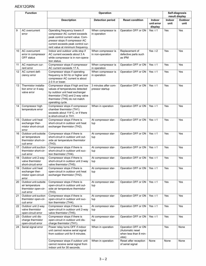
9 AC overcurrent error
Operating frequency lowers if compressor AC current exceeds peak control current value. Com-pressor stops if compressor AC current exceeds peak control cur-rent value at minimum frequency.
When compressor is in operation
Operation OFF or ON Yes ✩1 Yes Yes
10 AC overcurrent error in compressor OFF status
Indoor and outdoor units stop if AC current exceeds about 3 A while compressor is in non-opera-tion status.
When compressor is in non-operation
Replacement of defective parts such as IPM
Yes ✩2 Yes Yes
11 AC maximum cur-rent error
Compressor stops if compressor AC current exceeds 17 A.
When compressor is in operation
Operation OFF or ON Yes ✩1 Yes Yes
12 AC current defi-ciency error
Compressor stops if operating frequency is 50 Hz or higher and compressor AC current is about 2.0 A or lower.
When compressor is in operation
Operation OFF or ON Yes ✩1 Yes Yes
13 Thermistor installa-tion error or 4-way valve error
Compressor stops if high and low values of temperatures detected by outdoor unit heat exchanger thermistor (TH2) and 2-way valve thermistor (TH5) do not match operating cycle.
3 minutes after com-pressor startup
Operation OFF or ON Yes ✩1 Yes Yes
14 Compressor high temperature error
Compressor stops if compressor chamber thermistor (TH1) exceeds about 114°C, or if there is short-circuit in TH1.
When in operation Operation OFF or ON Yes ✩1 Yes Yes
15 Outdoor unit heat exchanger ther-mistor short-circuit error
Compressor stops if there is short-circuit in outdoor unit heat exchanger thermistor (TH2).
At compressor star-tup
Operation OFF or ON Yes ✩1 Yes Yes
16 Outdoor unit outside air temperature thermistor short-cir-cuit error
Compressor stops if there is short-circuit in outdoor unit out-side air temperature thermistor (TH3).
At compressor star-tup
Operation OFF or ON Yes ✩1 Yes Yes
17 Outdoor unit suction thermistor short-cir-cuit error
Compressor stops if there is short-circuit in outdoor unit suc-tion thermistor (TH4).
At compressor star-tup
Operation OFF or ON Yes ✩1 Yes Yes
18 Outdoor unit 2-way valve thermistor short-circuit error
Compressor stops if there is short-circuit in outdoor unit 2-way valve thermistor (TH5).
At compressor star-tup
Operation OFF or ON Yes ✩1 Yes Yes
19 Outdoor unit heat exchanger ther-mistor open-circuit error
Compressor stops if there is open-circuit in outdoor unit heat exchanger thermistor (TH2).
At compressor star-tup
Operation OFF or ON Yes ✩1 Yes Yes
20 Outdoor unit outside air temperature thermistor open-cir-cuit error
Compressor stops if there is open-circuit in outdoor unit out-side air temperature thermistor (TH3).
At compressor star-tup
Operation OFF or ON Yes ✩1 Yes Yes
21 Outdoor unit suction thermistor open-cir-cuit error
Compressor stops if there is open-circuit in outdoor unit suc-tion thermistor (TH4).
At compressor star-tup
Operation OFF or ON Yes ✩1 Yes Yes
22 Outdoor unit 2-way valve thermistor open-circuit error
Compressor stops if there is open-circuit in outdoor unit 2-way valve thermistor (TH5).
At compressor star-tup
Operation OFF or ON Yes ✩1 Yes Yes
23 Outdoor unit dis-charge thermistor open-circuit error
Compressor stops if there is open-circuit in outdoor unit dis-charge thermistor (TH1).
At compressor star-tup
Operation OFF or ON Yes ✩1 Yes Yes
24 Serial signal error Power relay turns OFF if indoor unit cannot receive serial signal from outdoor unit for 8 minutes.
When in operation Operation OFF or ON(Automatic reset when less than 8 min-utes)
Yes None
Compressor stops if outdoor unit cannot receive serial signal from indoor unit for 30 seconds.
When in operation Reset after reception of serial signal
None None None
Function Operation Self-diagnosis result display
Description Detection period Reset condition Indoor unit error display
Indoor unit
Outdoor unit
AEX12GRN
3 – 3
✩1—The outdoor unit restarts four times before the indoor unit error is displayed (complete shutdown).
✩2—A single error judgment results in the display of the indoor unit error (complete shutdown).
✩3—The outdoor unit restarts eight times before the indoor unit error is displayed (complete shutdown).
[2] AIR CONDITIONER OPERATION IN THERMISTOR ERROR
1. Indoor unit
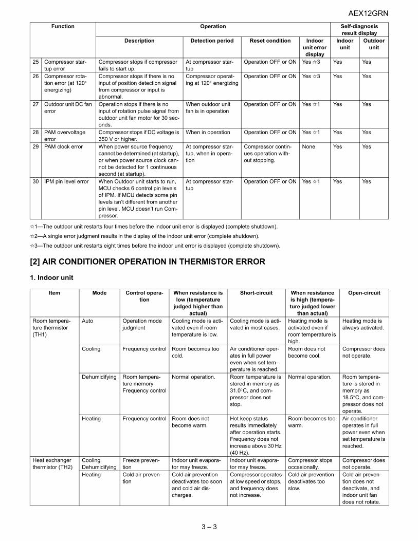
25 Compressor star-tup error
Compressor stops if compressor fails to start up.
At compressor star-tup
Operation OFF or ON Yes ✩3 Yes Yes
26 Compressor rota-tion error (at 120° energizing)
Compressor stops if there is no input of position detection signal from compressor or input is abnormal.
Compressor operat-ing at 120° energizing
Operation OFF or ON Yes ✩3 Yes Yes
27 Outdoor unit DC fan error
Operation stops if there is no input of rotation pulse signal from outdoor unit fan motor for 30 sec-onds.
When outdoor unit fan is in operation
Operation OFF or ON Yes ✩1 Yes Yes
28 PAM overvoltage error
Compressor stops if DC voltage is 350 V or higher.
When in operation Operation OFF or ON Yes ✩1 Yes Yes
29 PAM clock error When power source frequency cannot be determined (at startup), or when power source clock can-not be detected for 1 continuous second (at startup).
At compressor star-tup, when in opera-tion
Compressor contin-ues operation with-out stopping.
None Yes Yes
30 IPM pin level error When Outdoor unit starts to run, MCU checks 6 control pin levels of IPM. If MCU detects some pin levels isn’t different from another pin level. MCU doesn’t run Com-pressor.
At compressor star-tup
Operation OFF or ON Yes ✩1 Yes Yes
Item Mode Control opera-tion
When resistance is low (temperature
judged higher than actual)
Short-circuit When resistance is high (tempera-ture judged lower
than actual)
Open-circuit
Room tempera-ture thermistor (TH1)
Auto Operation mode judgment
Cooling mode is acti-vated even if room temperature is low.
Cooling mode is acti-vated in most cases.
Heating mode is activated even if room temperature is high.
Heating mode is always activated.
Cooling Frequency control Room becomes too cold.
Air conditioner oper-ates in full power even when set tem-perature is reached.
Room does not become cool.
Compressor does not operate.
Dehumidifying Room tempera-ture memoryFrequency control
Normal operation. Room temperature is stored in memory as 31.0°C, and com-pressor does not stop.
Normal operation. Room tempera-ture is stored in memory as 18.5°C, and com-pressor does not operate.
Heating Frequency control Room does not become warm.
Hot keep status results immediately after operation starts.Frequency does not increase above 30 Hz (40 Hz).
Room becomes too warm.
Air conditioner operates in full power even when set temperature is reached.
Heat exchanger thermistor (TH2)
CoolingDehumidifying
Freeze preven-tion
Indoor unit evapora-tor may freeze.
Indoor unit evapora-tor may freeze.
Compressor stops occasionally.
Compressor does not operate.
Heating Cold air preven-tion
Cold air prevention deactivates too soon and cold air dis-charges.
Compressor operates at low speed or stops, and frequency does not increase.
Cold air prevention deactivates too slow.
Cold air preven-tion does not deactivate, and indoor unit fan does not rotate.
Function Operation Self-diagnosis result display
Description Detection period Reset condition Indoor unit error display
Indoor unit
Outdoor unit

AEX12GRN
3 – 4
2. Outdoor unit
Item Mode Control opera-tion
When resistance is low (temperature
judged higher than actual)
Short-circuit When resistance is high (tempera-ture judged lower
than actual)
Open-circuit
Compressor chamber ther-mistor (TH1)
CoolingDehumidifyingHeating
Expansion valve control and com-pressor protection
Compressor oper-ates, but room does not become cool or warm (expansion valve is open).
Compressor high temperature error indication.
Layer short-circuit or open-circuit may result in compres-sor in normal opera-tion.
Outdoor unit ther-mistor open-cir-cuit error indication.
Heat exchanger thermistor (TH2)
CoolingDehumidifying
Outdoor unit heat exchanger over-heat prevention
Compressor operates at low speed or stops.
Outdoor unit ther-mistor short-circuit error indication.
Normal operation. Outdoor unit ther-mistor open-cir-cuit error indication.
Heating Expansion valve controlDefrosting
Defrosting operation is not activated as needed, and frost accumulates on out-door unit (expansion valve is closed).
Outdoor unit ther-mistor short-circuit error indication.
Defrosting opera-tion is activated unnecessarily, and room does not become warm (expansion valve is open).
Outdoor unit ther-mistor open-cir-cuit error indication.
Outside air tem-perature ther-mistor (TH3)
Auto Operation mode judgment
Cooling mode is acti-vated even if room temperature is low.
Outdoor unit ther-mistor short-circuit error indication.
Heating mode is activated even if room temperature is high.
Outdoor unit ther-mistor open-cir-cuit error indication.
CoolingDehumidifying
Operation not affected
Normal operation. Outdoor unit ther-mistor short-circuit error indication.
Normal operation. Outdoor unit ther-mistor open-cir-cuit error indication.
Heating Rating controlDefrosting
Defrosting operation is activated unneces-sarily.
Outdoor unit ther-mistor short-circuit error indication.
Defrosting opera-tion is not acti-vated, and frost accumulates on outdoor unit.
Outdoor unit ther-mistor open-cir-cuit error indication.
Suction pipe ther-mistor (TH4)
CoolingDehumidifying
Expansion valve control
Compressor oper-ates, but room does not become cool (expansion valve is open).
Outdoor unit ther-mistor short-circuit error indication.
Frost accumulates on evaporator inlet section, and room does not become cool (expansion valve is closed).
Outdoor unit ther-mistor open-cir-cuit error indication.
Heating Expansion valve control
Compressor oper-ates, but room does not become warm (expansion valve is open).
Outdoor unit ther-mistor short-circuit error indication.
Frost accumulates on expansion valve outlet section, and room does not become warm (expansion valve is closed).
Outdoor unit ther-mistor open-cir-cuit error indication.
2-way valve ther-mistor (TH5)
CoolingDehumidifying
Expansion valve control
Frost accumulates on indoor unit evapora-tor and room does not become cool (expansion valve is closed).
Outdoor unit ther-mistor short-circuit error indication.
Compressor oper-ates, but room does not become cool (expansion valve is open).
Outdoor unit ther-mistor open-cir-cuit error indication.
Heating Operation not affected
Normal operation. Outdoor unit ther-mistor short-circuit error indication.
Normal operation. Outdoor unit ther-mistor open-cir-cuit error indication.
AEX12GRN
3 – 5
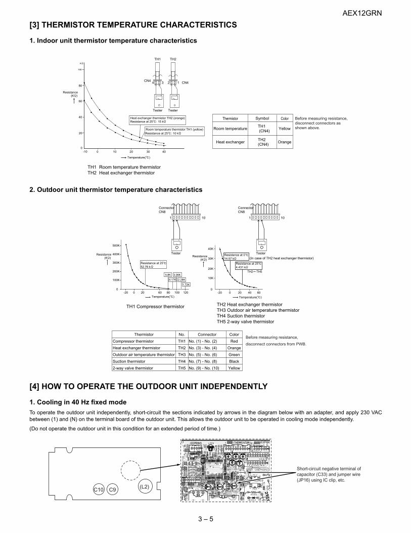
[3] THERMISTOR TEMPERATURE CHARACTERISTICS
1. Indoor unit thermistor temperature characteristics
2. Outdoor unit thermistor temperature characteristics
[4] HOW TO OPERATE THE OUTDOOR UNIT INDEPENDENTLY
1. Cooling in 40 Hz fixed modeTo operate the outdoor unit independently, short-circuit the sections indicated by arrows in the diagram below with an adapter, and apply 230 VACbetween (1) and (N) on the terminal board of the outdoor unit. This allows the outdoor unit to be operated in cooling mode independently.
(Do not operate the outdoor unit in this condition for an extended period of time.)
K
100
80
60
40
20
0-10 0 10 20 30 40
Heat exchanger thermistor TH2 (orange)Resistance at 25 : 15 k
Resistance at 25 : 10 kRoom temperature thermistor TH1 (yellow)
- +
TesterTester
4 3 2 1
- +
Temperature( )
Resistance(K )
CN4
TH1 TH2
CN4
Thermistor
Room temperature
Heat exchanger
Color
Yellow
Orange
Symbol
TH1(CN4)
TH2(CN4)
TH1 Room temperature thermistorTH2 Heat exchanger thermistor
Before measuring resistance,disconnect connectors asshown above.
+ -
TH2 TH5
500K
400K
300K
200K
100K
0-20 0 20 60 80 100 120
Tester
1 10
ConnectorCN8
Resistance at 2552.76 k
5.8K
40K
30K
20K
0
10K
-20 0 20 6040
3.06K
4.17K
1.72K
2.28K
+ -
Tester
(In case of TH2 heat exchanger thermistor)
1 10
ConnectorCN8
Thermistor
Compressor thermistor
Heat exchanger thermistor
Outdoor air temperature thermistor
Suction thermistor
2-way valve thermistor
No.
TH1
TH2
TH3
TH4
TH5
Connector
No. (1) - No. (2)
No. (3) - No. (4)
No. (5) - No. (6)
No. (7) - No. (8)
No. (9) - No. (10)
Color
Red
Orange
Green
Black
Yellow
TH1 Compressor thermistor TH2 Heat exchanger thermistorTH3 Outdoor air temperature thermistorTH4 Suction thermistorTH5 2-way valve thermistor
Resistance(K ) Resistance
(K )
Temperature( ) Temperature( )
Resistance at 014.57 k
Resistance at 254.431 k
Before measuring resistance,
disconnect connectors from PWB.
(L2)C9C10
Connect with IC clipTest mode cooling at 40 HzConnect with IC clipTest mode cooling at 40 Hz
Short-circuit negative terminal ofcapacitor (C33) and jumper wire(JP16) using IC clip, etc.
AEX12GRN
3 – 6
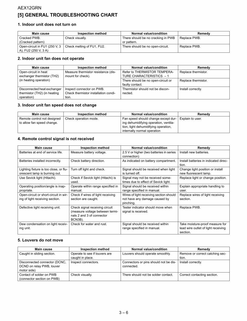
[5] GENERAL TROUBLESHOOTING CHART
1. Indoor unit does not turn on
2. Indoor unit fan does not operate
3. Indoor unit fan speed does not change
4. Remote control signal is not received
5. Louvers do not move
Main cause Inspection method Normal value/condition RemedyCracked PWB.(Cracked pattern)
Check visually. There should be no cracking in PWB or pattern.
Replace PWB.
Open-circuit in FU1 (250 V, 3 A), FU2 (250 V, 3 A)
Check melting of FU1, FU2. There should be no open-circuit. Replace PWB.
Main cause Inspection method Normal value/condition RemedyOpen-circuit in heat exchanger thermistor (TH2) (in heating operation)
Measure thermistor resistance (dis-mount for check).
Refer to THERMISTOR TEMPERA-TURE CHARACTERISTICS – 1
Replace thermistor.
There should be no open-circuit or faulty contact.
Replace thermistor.
Disconnected heat exchanger thermistor (TH2) (in heating operation)
Inspect connector on PWB.Check thermistor installation condi-tion.
Thermistor should not be discon-nected.
Install correctly.
Main cause Inspection method Normal value/condition RemedyRemote control not designed to allow fan speed change.
Check operation mode. Fan speed should change except dur-ing dehumidifying operation, ventila-tion, light dehumidifying operation, internally normal operation
Explain to user.
Main cause Inspection method Normal value/condition RemedyBatteries at end of service life. Measure battery voltage. 2.5 V or higher (two batteries in series
connection)Install new batteries.
Batteries installed incorrectly. Check battery direction. As indicated on battery compartment. Install batteries in indicated direc-tion.
Lighting fixture is too close, or flu-orescent lamp is burning out.
Turn off light and check. Signal should be received when light is turned off.
Change light position or install new fluorescent lamp.
Use Sevick light (Hitachi). Check if Sevick light (Hitachi) is used.
Signal may not be received some-times due to effect of Sevick light.
Replace light or change position.
Operating position/angle is inap-propriate.
Operate within range specified in manual.
Signal should be received within range specified in manual.
Explain appropriate handling to user.
Open-circuit or short-circuit in wir-ing of light receiving section.
Check if wires of light receiving section are caught.
Wires of light receiving section should not have any damage caused by pinching.
Replace wires of light receiving section.
Defective light receiving unit. Check signal receiving circuit (measure voltage between termi-nals 2 and 3 of connector BCN3B).
Tester indicator should move when signal is received.
Replace PWB.
Dew condensation on light receiv-ing unit.
Check for water and rust. Signal should be received within range specified in manual.
Take moisture-proof measure for lead wire outlet of light receiving section.
Main cause Inspection method Normal value/condition RemedyCaught in sliding section. Operate to see if louvers are
caught in place.Louvers should operate smoothly. Remove or correct catching sec-
tion.Disconnected connector (DCNC, DCND on relay PWB, louver motor side)
Inspect connectors. Connectors or pins should not be dis-connected.
Install correctly.
Contact of solder on PWB(connector section on PWB)
Check visually. There should not be solder contact. Correct contacting section.

AEX12GRN
3 – 7
6. There is noise in TV/radio
7. Malfunction occurs
8. Compressor does not start
9. Operation stops after a few minutes and restarts, and this process repeats
CAUTION: If fuse FU1/FU4/FU5 (outdoor unit control circuit board) is blown, be careful of charging voltage in inverter electrolytic capacitor C9, C10.
To discharge stored electricity, unplug the power cord and connect the plug of a soldering iron (100VAC, 50W) between the positive andnegative terminals of inverter electrolytic capacitor C9, C10.
Main cause Inspection method Normal value/condition RemedyGrounding wires not connected properly.
Check grounding wire connec-tions.
Grounding wires should be connected properly.
Connect grounding wires prop-erly.
TV/radio is placed too close to outdoor unit.
Check distance between TV/radio and outdoor unit.
If TV/radio is placed too close, it may become affected by noise.
Move TV/radio away from outdoor unit.
Other than above. Check for radio wave interfer-ence. (See page )
Main cause Inspection method Normal value/condition RemedyMalfunction caused by noise. Check for radio wave interfer-
ence. (See page )
Main cause Inspection method Normal value/condition RemedyErroneous inter-unit connection. Check wiring between indoor and
outdoor units.Terminal board 1-N: 230 VAC, 50 HzTerminal board 2: serial signal
Correct wiring.
Damaged IPM. Check IPM continuity. Refer to IPM check method – 3 Replace IPM.Dried-up electrolytic capacitor. Check electrolytic capacitor. Refer to Inverter electrolytic capacitor
(C9, C10) check method – 2Replace electrolytic capacitor.
Blown outdoor unit fuse. Check 20-A fuse.Check 15-A fuse.
Fuse should not be blown. Replace fuse/diode bridge.Replace fuse.Replace outdoor unit PWB assembly.
Power supply voltage is too low. Measure power supply voltage during startup.
230±10 VAC, 50 Hz Make sure that power supply volt-age is 180 V or higher.
Compressor lock. Supply current and touch com-pressor cover (sound absorbing material) to check if operation starts.
Compressor should start normally. Apply external impact to com-pressor.Replace compressor.
Main cause Inspection method Normal value/condition RemedyDried-up electrolytic capacitor. Measure 320-VDC line voltage. 250 V or higher. Replace electrolytic capacitor.Layer short-circuit in expansion valve coil.
Measure resistance. 46±3Ω in each phase (at 20°C) Replace coil.
AEX12GRN
3 – 8
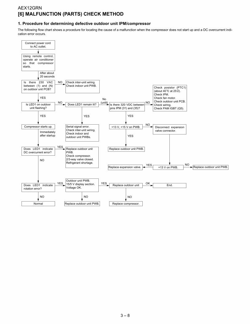
[6] MALFUNCTION (PARTS) CHECK METHOD
1. Procedure for determining defective outdoor unit IPM/compressor The following flow chart shows a procedure for locating the cause of a malfunction when the compressor does not start up and a DC overcurrent indi-cation error occurs.
YES
Immediatelyafter startup
YES
YES
NO
NO
NO
YES
NO
Connect power cordto AC outlet.
Normal
NO
Replace outdoor unit PWB.
Using remote control,operate air conditionerso that compressorstarts.
Is there 230 VACbetween (1) and (N)on outdoor unit PCB?
Is LED1 on outdoorunit flashing?
Compressor starts up.
Does LED1 indicateDC overcurrent error?
Does LED1 indicaterotation error?
Outdoor unit PWB.15/5 V display section.Voltage OK.
Replace compressor.
Check inter-unit wiring.Check indoor unit PWB.
Does LED1 remain lit?
Serial signal error.Check inter-unit wiring.Check indoor andoutdoor unit PWBs.
Replace outdoor unitPWB.Check compressor.2/3-way valve closed.Refrigerant shortage.
Replace outdoor unit
Is there 320 VDC betweenpins IPM (31) and (35)?
+13 V, +15 V on PWB.
+13 V on PWB.
Replace outdoor unit PWB.
Replace expansion valve.
End.
Check posistor (PTC1)(about 40 at 25 ).Check IPM.Check fan motor.Check outdoor unit PCB.Check wiring.Check PAM IGBT (Q5).
Disconnect expansionvalve connector.
Replace outdoor unit PWB.
After about20 seconds
YES
NO
NO
YES
NO
NO
YES
YES YES
No(unlit)
OK
AEX12GRN
3 – 9
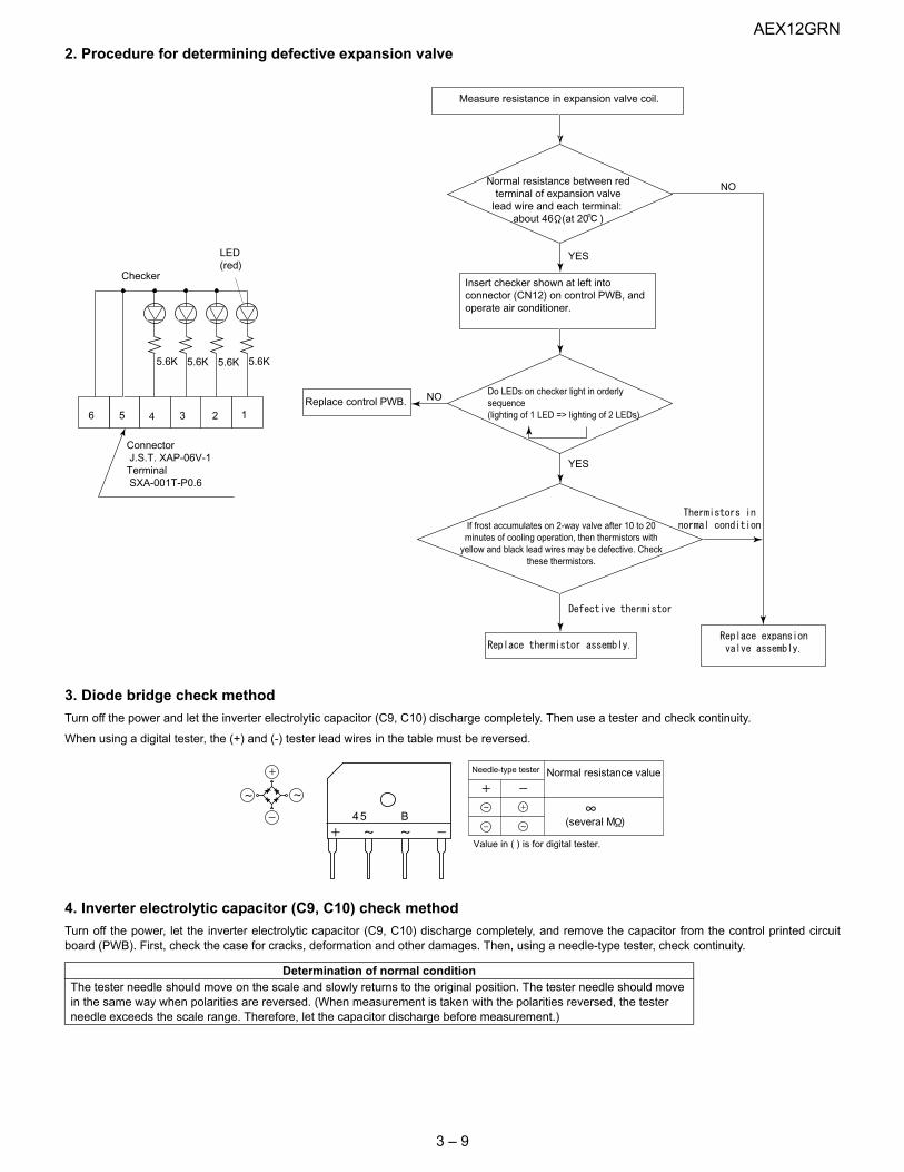
2. Procedure for determining defective expansion valve
3. Diode bridge check methodTurn off the power and let the inverter electrolytic capacitor (C9, C10) discharge completely. Then use a tester and check continuity.
When using a digital tester, the (+) and (-) tester lead wires in the table must be reversed.
4. Inverter electrolytic capacitor (C9, C10) check methodTurn off the power, let the inverter electrolytic capacitor (C9, C10) discharge completely, and remove the capacitor from the control printed circuitboard (PWB). First, check the case for cracks, deformation and other damages. Then, using a needle-type tester, check continuity.
Determination of normal conditionThe tester needle should move on the scale and slowly returns to the original position. The tester needle should move in the same way when polarities are reversed. (When measurement is taken with the polarities reversed, the tester needle exceeds the scale range. Therefore, let the capacitor discharge before measurement.)
Measure resistance in expansion valve coil.
Normal resistance between redterminal of expansion valve
lead wire and each terminal:about 46 (at 20 )
Insert checker shown at left intoconnector (CN12) on control PWB, andoperate air conditioner.
If frost accumulates on 2-way valve after 10 to 20minutes of cooling operation, then thermistors with
yellow and black lead wires may be defective. Checkthese thermistors.
Replace control PWB.
NO
NO
YES
YES
Checker
LED(red)
ConnectorJ.S.T. XAP-06V-1
TerminalSXA-001T-P0.6
4 3 2 156
5.6K 5.6K 5.6K 5.6K
Do LEDs on checker light in orderlysequence(lighting of 1 LED => lighting of 2 LEDs)
45 B
Needle-type tester Normal resistance value
(several M )
Value in ( ) is for digital tester.
AEX12GRN
3 – 10
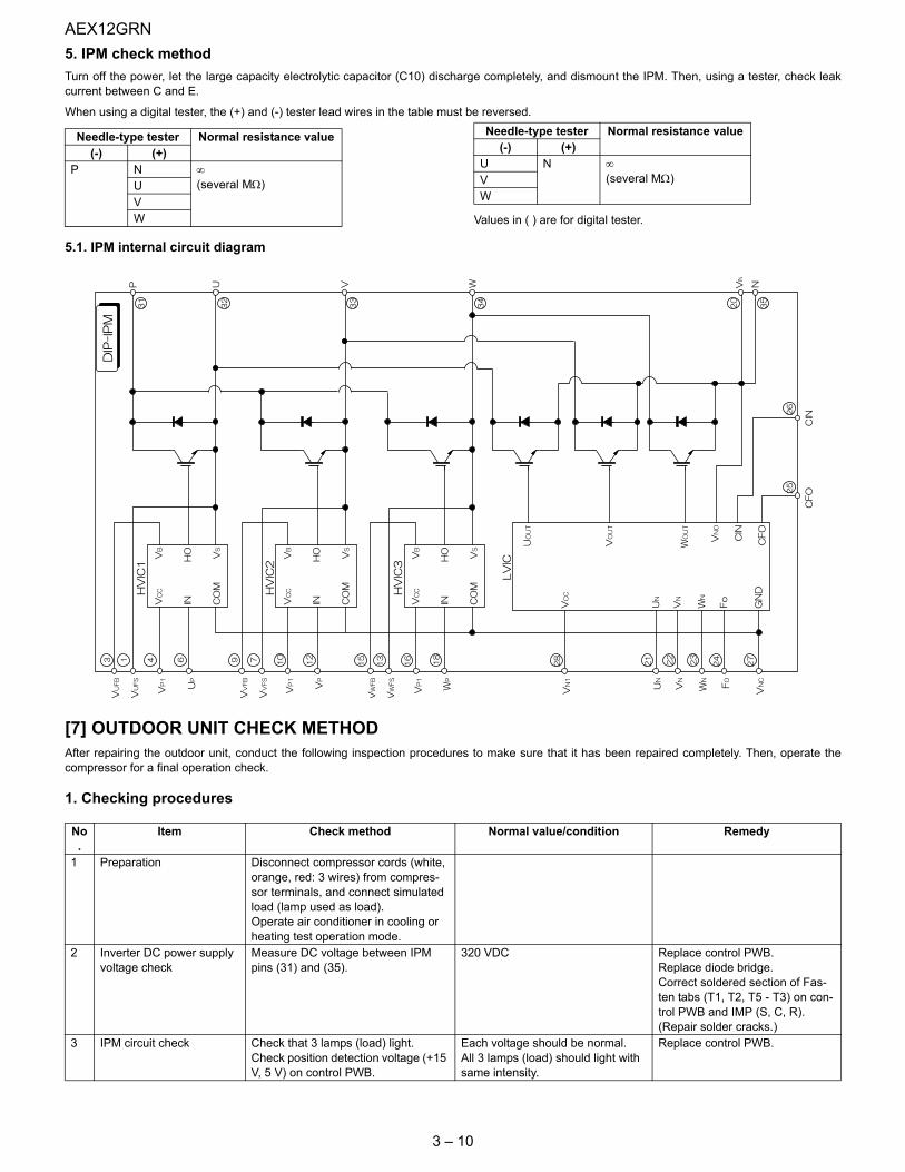
5. IPM check methodTurn off the power, let the large capacity electrolytic capacitor (C10) discharge completely, and dismount the IPM. Then, using a tester, check leakcurrent between C and E.
When using a digital tester, the (+) and (-) tester lead wires in the table must be reversed.
Values in ( ) are for digital tester.
5.1. IPM internal circuit diagram
[7] OUTDOOR UNIT CHECK METHODAfter repairing the outdoor unit, conduct the following inspection procedures to make sure that it has been repaired completely. Then, operate thecompressor for a final operation check.
1. Checking procedures
Needle-type tester Normal resistance value(-) (+)
P N ∞(several MΩ)U
VW
Needle-type tester Normal resistance value(-) (+)
U N ∞(several MΩ)V
W
No.
Item Check method Normal value/condition Remedy
1 Preparation Disconnect compressor cords (white, orange, red: 3 wires) from compres-sor terminals, and connect simulated load (lamp used as load).Operate air conditioner in cooling or heating test operation mode.
2 Inverter DC power supply voltage check
Measure DC voltage between IPM pins (31) and (35).
320 VDC Replace control PWB.Replace diode bridge.Correct soldered section of Fas-ten tabs (T1, T2, T5 - T3) on con-trol PWB and IMP (S, C, R). (Repair solder cracks.)
3 IPM circuit check Check that 3 lamps (load) light.Check position detection voltage (+15 V, 5 V) on control PWB.
Each voltage should be normal.All 3 lamps (load) should light with same intensity.
Replace control PWB.

AEX12GRN
3 – 11
2. Troubleshooting of outdoor unit electric components
4 Compressor check Measure compressor coil resistance (for each phase of U, V and W).Use multi-meter or digital tester capa-ble of displaying two digits right of the decimal point (0.01Ω).
Resistance value at 20°C --- 1.13Ω Correct connections at compres-sor terminals.Replace compressor.
5 Expansion valve check Measure expansion valve coil resis-tance.
Each phase 46±3Ω (at 20°C) Replace expansion valve.
6 Final check Turn off power, and connect compres-sor cords to compressor.Operate air conditioner.Measure DC voltage between IPM pins (31) and (35).
Compressor should operate nor-mally.200 VDC or higher.
Replace control PWB.Replace outdoor unit thermistor.Replace compressor (in case of compressor lock).
No.
Item Check method Normal value/condition Remedy
Does LED light?NO
YES
YES NO
Does LED flash?
Normal
NO
YES
NOYES
NO
YES
NO
YES
Is 230 V appliedbetween 1 andN on outdoorunit terminalboard?
Is voltage betweenIPM pins (31) and(35) 320 V orhigher?
5/ Short-circuit in DC fan motorShort-circuit in IPMShort-circuit in diode bridgeBlown fuseDefective electrolytic capacitorWire disconnection, PWB pattern damageShort-circuit in PAM IGBT (Q5)
Defective switching power supply circuitMalfunction of 3-terminal regulator IC4, IC1Short-circuit in expansion valve coilMalfunction of transistor array IC7Solder contact or other problems
Malfunction of 3-terminal regulator IC4, IC1
Microcomputer oscillator errorMalfunction of microcomputer reset ICMalfunction of microcomputer
Malfunction of serial signal circuitCheck wiring between indoor and outdoor units.
Is switching powersupply output of13 VDC, 15 VDCproduced?
Is 5 VDC outputproduced?
Check indoorunit.

AEX12GRN
3 – 12
3. Caution in checking printed circuit boards (PWB)
3.1. Non-insulated control circuitThe GND terminals of the low-voltage circuits (control circuits for microcomputer and thermistors and drive circuits for expansion valve and relays) onthe control printed circuit board (PWB) are connected to the compressor drive power supply (320-VDC negative terminal). Therefore, exercise utmostcaution to prevent electric shock.
If a measuring instrument used for the test is grounded, its chassis (ground) has the same electric potential as the 0-V probe. Since non-insulated cir-cuits have the following voltage potential difference from the ground, connection of the grounding wire results in a short-circuit between the 0-V lineand the ground, thus allowing an excessive current to flow to the tester to cause damage.
If the sheaths of the thermistor lead wires or expansion valve lead wires inside the outdoor unit become damaged due to pinching by the front panelor other metal parts or contacting a pipe, a high voltage can flow and destroy the circuits. To prevent these problems, carefully conduct assemblywork.
Ground voltage
320-VDC line
0-V line
0-V line voltage (point (F))
Voltage at point (E)
320V
+ 160V
- 160V
Terminal board
Ground0-V line Point (F)
Point (E)Reactor
IPM+-
Compressor motor
2
AC230V
1
3
Outdoor unit circuits
M
ReasonThe oscilloscope (chassis ground) has the same electric potential as the 0-V probe. Theentire electronic control section of the outdoor unit has a voltage potential difference fromthe ground as shown in the above diagram. When the oscilloscope is set up, the 0-V lineand the ground voltage (ground) will be short-circuited, resulting in an excessive currentflow to cause damage to the oscilloscope or indoor electric circuits.
Do not touch thecabinet or bring metalparts into contact withthe cabinet. Danger!!
Do not connectthe groundingwire.
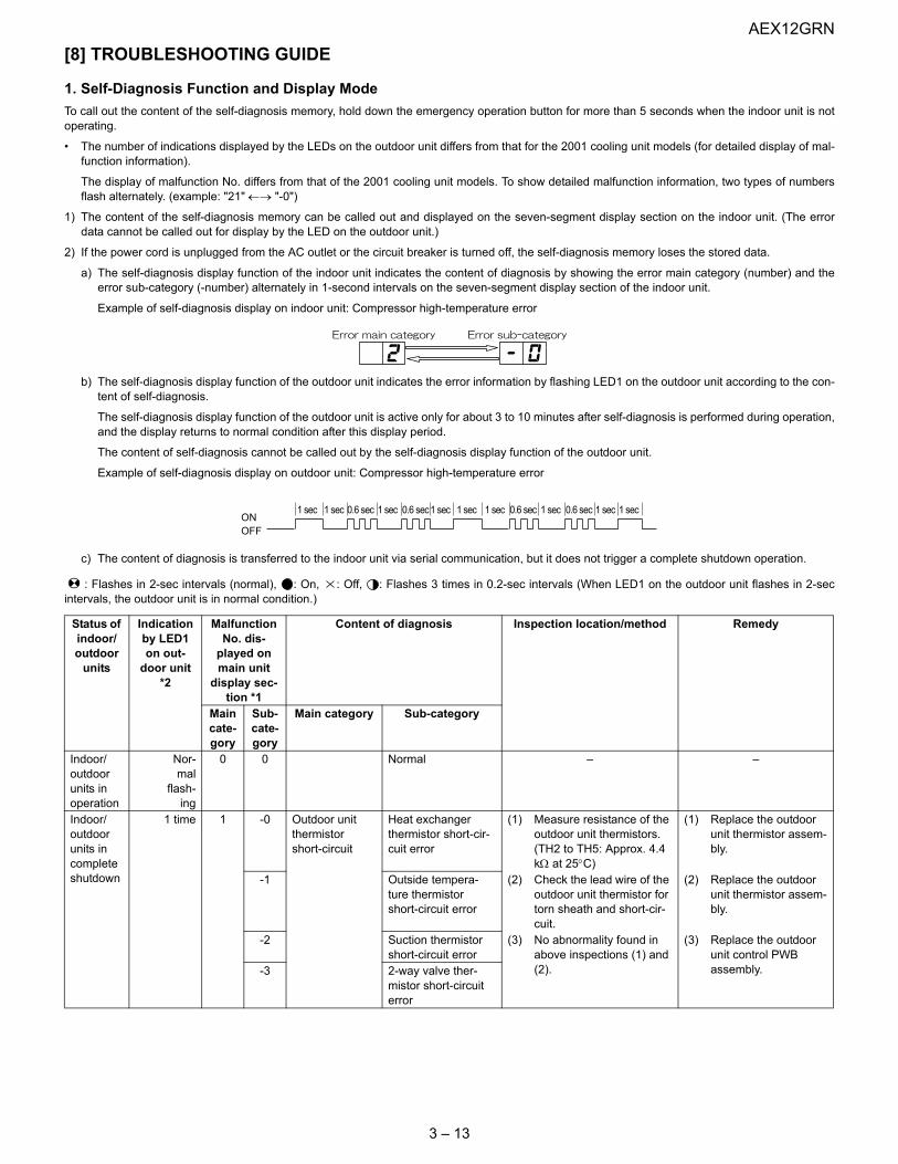
AEX12GRN
3 – 13
[8] TROUBLESHOOTING GUIDE
1. Self-Diagnosis Function and Display ModeTo call out the content of the self-diagnosis memory, hold down the emergency operation button for more than 5 seconds when the indoor unit is notoperating.
• The number of indications displayed by the LEDs on the outdoor unit differs from that for the 2001 cooling unit models (for detailed display of mal-function information).
The display of malfunction No. differs from that of the 2001 cooling unit models. To show detailed malfunction information, two types of numbersflash alternately. (example: "21" ←→ "-0")
1) The content of the self-diagnosis memory can be called out and displayed on the seven-segment display section on the indoor unit. (The errordata cannot be called out for display by the LED on the outdoor unit.)
2) If the power cord is unplugged from the AC outlet or the circuit breaker is turned off, the self-diagnosis memory loses the stored data.
a) The self-diagnosis display function of the indoor unit indicates the content of diagnosis by showing the error main category (number) and theerror sub-category (-number) alternately in 1-second intervals on the seven-segment display section of the indoor unit.
Example of self-diagnosis display on indoor unit: Compressor high-temperature error
b) The self-diagnosis display function of the outdoor unit indicates the error information by flashing LED1 on the outdoor unit according to the con-tent of self-diagnosis.
The self-diagnosis display function of the outdoor unit is active only for about 3 to 10 minutes after self-diagnosis is performed during operation,and the display returns to normal condition after this display period.
The content of self-diagnosis cannot be called out by the self-diagnosis display function of the outdoor unit.
Example of self-diagnosis display on outdoor unit: Compressor high-temperature error
c) The content of diagnosis is transferred to the indoor unit via serial communication, but it does not trigger a complete shutdown operation.
: Flashes in 2-sec intervals (normal), : On, : Off, : Flashes 3 times in 0.2-sec intervals (When LED1 on the outdoor unit flashes in 2-secintervals, the outdoor unit is in normal condition.)
Status of indoor/outdoor
units
Indication by LED1 on out-
door unit *2
Malfunction No. dis-
played on main unit
display sec-tion *1
Content of diagnosis Inspection location/method Remedy
Main cate-gory
Sub-cate-gory
Main category Sub-category
Indoor/outdoor units in operation
Nor-mal
flash-ing
0 0 Normal – –
Indoor/outdoor units in complete shutdown
1 time 1 -0 Outdoor unit thermistor short-circuit
Heat exchanger thermistor short-cir-cuit error
(1) Measure resistance of the outdoor unit thermistors.(TH2 to TH5: Approx. 4.4 kΩ at 25°C)
(1) Replace the outdoor unit thermistor assem-bly.
-1 Outside tempera-ture thermistor short-circuit error
(2) Check the lead wire of the outdoor unit thermistor for torn sheath and short-cir-cuit.
(2) Replace the outdoor unit thermistor assem-bly.
-2 Suction thermistor short-circuit error
(3) No abnormality found in above inspections (1) and (2).
(3) Replace the outdoor unit control PWB assembly.-3 2-way valve ther-
mistor short-circuit error
1 sec 1 sec 1 sec 1 sec 1 sec1 sec0.6 sec 0.6 sec0.6 sec 0.6 sec 1 secONOFF
1 sec 1 sec

AEX12GRN
3 – 14
Indoor/outdoor units in complete shutdown
2 times 2 -0 Cycle tempera-ture
Compressor high-temperature error
(1) Check the outdoor unit air outlet for blockage.
(1) Ensure unobstructed air flow from the out-door unit air outlet.
(2) Check if the power supply voltage is 90 V or higher at full power.
(2) Connect power sup-ply of proper voltage.
(3) Check the pipe connec-tions for refrigerant leaks.
(3) Charge the specified amount of refrigerant.
(4) Measure resistance of the outdoor unit compressor thermistor.(TH1: Approx. 53 kΩ at 25°C)
(4) Replace the outdoor unit compressor ther-mistor assembly.
(5) Check the expansion valve for proper operation.
(5) Replace the expan-sion valve coil, expan-sion valve or outdoor unit control PWB assembly.
Indoor unit in operationOutdoor unit in tempo-rary stop
-1 Temporary stop due to compressor dis-charge overheat *3
(Temporary stop for cycle pro-tection)
–
-2 Temporary stop due to outdoor unit heat exchanger overheat *3
(Temporary stop for cycle pro-tection)
–
-3 Temporary stop due to outdoor unit heat exchanger overheat *3
(Temporary stop for cycle pro-tection)
–
-4 Temporary stop due to 2-way valve freeze *3
(Temporary stop for cycle pro-tection)
–
Indoor unit in operationOutdoor unit in tempo-rary stop
3 times 3 -0 Dry operation Temporary stop due to dehumidifying operation *3
(Temporary stop for cycle pro-tection)
–
Indoor/outdoor units in complete shutdown
5 times 5 -0 Outdoor unit thermistor open-circuit
Heat exchanger thermistor open-cir-cuit error
(1) Check connector CN8 of the outdoor unit ther-mistor for secure installa-tion.
(1) Correct the installa-tion.
-1 Outside tempera-ture thermistor open-circuit error
(2) Measure resistance of out-door thermistors TH1 to TH5.
(2) Replace the outdoor unit thermistor assem-bly.
-2 Suction thermistor open-circuit error
(3) Check the lead wires of thermistors TH1 through TH5 on the outdoor unit control PWB for open-cir-cuit.
(3) Replace the outdoor unit thermistor assem-bly.
-3 2-way valve ther-mistor open-circuit error
(4) No abnormality found in above inspections (1) through (3).
(5) Replace the outdoor unit control PWB assembly.
-4 Discharge ther-mistor open-circuit error
Status of indoor/outdoor
units
Indication by LED1 on out-
door unit *2
Malfunction No. dis-
played on main unit
display sec-tion *1
Content of diagnosis Inspection location/method Remedy
Main cate-gory
Sub-cate-gory
Main category Sub-category

AEX12GRN
3 – 15
Indoor/outdoor units in complete shutdown
6 times 6 -0 Outdoor unit DC DC overcurrent error (1) IPM continuity check (1) Replace the outdoor unit control PWB assembly.
(2) Check the IPM and heat sink for secure installation.
(2) Correct the installation (tighten the screws).
(3) Check the outdoor unit fan motor for proper rotation.
(3) Replace the outdoor unit fan motor.
(4) No abnormality found in above inspections (1) through (3).
(4) Replace the outdoor unit control PWB assembly.
(5) No abnormality found in above inspections (1) through (4).
(5) Replace the compres-sor.
-1 IPM pin level error Check the IPM is attached correctly to the outdoor unit control PWB.
Replace the outdoor unit control PWB assembly.
Indoor/outdoor units in complete shutdown
7 times 7 -0 Outdoor unit AC AC overcurrent error (1) Check the outdoor unit air outlet for blockage.
(1) Ensure unobstructed air flow from the out-door unit air outlet.
(2) Check the outdoor unit fan for proper rotation.
(2) Check the outdoor unit fan motor.
-1 AC overcurrent error in OFF status
(1) IPM continuity check (1) Replace the outdoor unit control PWB assembly.
-2 AC maximum cur-rent error
(1) Check the outdoor unit air outlet for blockage.
(1) Ensure unobstructed air flow from the out-door unit air outlet.
(2) Check the outdoor unit fan for proper rotation.
(1) Check the outdoor unit fan motor.
-3 AC current defi-ciency error
(1) Check if there is an open-circuit in the secondary winding of the current transformer of the outdoor unit control PWB.
(1) Replace the outdoor unit control PWB assembly.
(2) Check if the refrigerant volume is abnormally low.
(2) Charge the specified amount of refrigerant.
(3) Check if the refrigerant flows properly.
(3) Correct refrigerant clogs.(2-way valve, 3-way valve, pipe, expan-sion valve)
Status of indoor/outdoor
units
Indication by LED1 on out-
door unit *2
Malfunction No. dis-
played on main unit
display sec-tion *1
Content of diagnosis Inspection location/method Remedy
Main cate-gory
Sub-cate-gory
Main category Sub-category
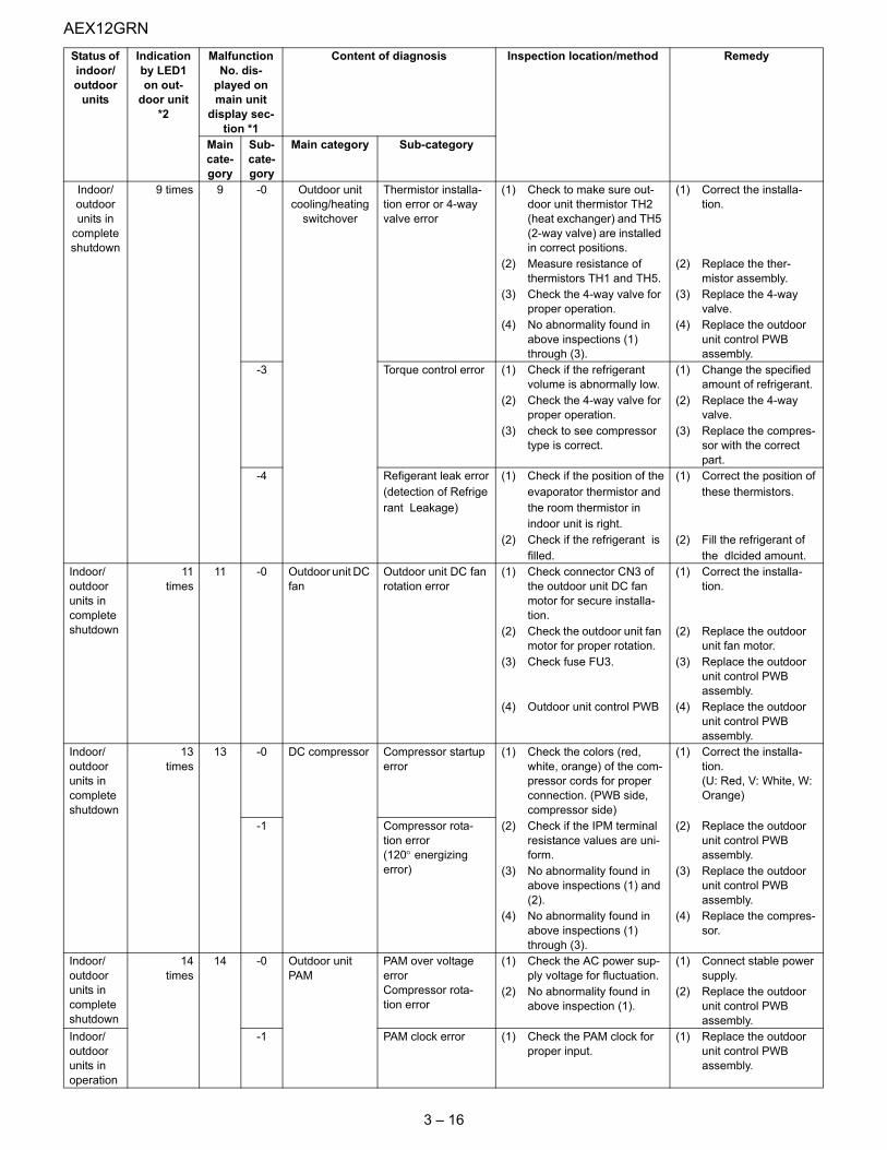
AEX12GRN
3 – 16
Indoor/outdoor units in
complete shutdown
9 times 9 -0 Outdoor unit cooling/heating
switchover
Thermistor installa-tion error or 4-way valve error
(1) Check to make sure out-door unit thermistor TH2 (heat exchanger) and TH5 (2-way valve) are installed in correct positions.
(1) Correct the installa-tion.
(2) Measure resistance of thermistors TH1 and TH5.
(2) Replace the ther-mistor assembly.
(3) Check the 4-way valve for proper operation.
(3) Replace the 4-way valve.
(4) No abnormality found in above inspections (1) through (3).
(4) Replace the outdoor unit control PWB assembly.
-3 Torque control error (1) Check if the refrigerant volume is abnormally low.
(1) Change the specified amount of refrigerant.
(2) Check the 4-way valve for proper operation.
(2) Replace the 4-way valve.
(3) check to see compressor type is correct.
(3) Replace the compres-sor with the correct part.
-4 Refigerant leak error (1) Check if the position of the (1) Correct the position of(detection of Refrige evaporator thermistor and these thermistors.rant Leakage) the room thermistor in
indoor unit is right.(2) Check if the refrigerant is (2) Fill the refrigerant of
filled. the dlcided amount.Indoor/outdoor units in complete shutdown
11times
11 -0 Outdoor unit DC fan
Outdoor unit DC fan rotation error
(1) Check connector CN3 of the outdoor unit DC fan motor for secure installa-tion.
(1) Correct the installa-tion.
(2) Check the outdoor unit fan motor for proper rotation.
(2) Replace the outdoor unit fan motor.
(3) Check fuse FU3. (3) Replace the outdoor unit control PWB assembly.
(4) Outdoor unit control PWB (4) Replace the outdoor unit control PWB assembly.
Indoor/outdoor units in complete shutdown
13times
13 -0 DC compressor Compressor startup error
(1) Check the colors (red, white, orange) of the com-pressor cords for proper connection. (PWB side, compressor side)
(1) Correct the installa-tion.(U: Red, V: White, W: Orange)
-1 Compressor rota-tion error(120° energizing error)
(2) Check if the IPM terminal resistance values are uni-form.
(2) Replace the outdoor unit control PWB assembly.
(3) No abnormality found in above inspections (1) and (2).
(3) Replace the outdoor unit control PWB assembly.
(4) No abnormality found in above inspections (1) through (3).
(4) Replace the compres-sor.
Indoor/outdoor units in complete shutdown
14times
14 -0 Outdoor unit PAM
PAM over voltage errorCompressor rota-tion error
(1) Check the AC power sup-ply voltage for fluctuation.
(1) Connect stable power supply.
(2) No abnormality found in above inspection (1).
(2) Replace the outdoor unit control PWB assembly.
Indoor/outdoor units in operation
-1 PAM clock error (1) Check the PAM clock for proper input.
(1) Replace the outdoor unit control PWB assembly.
Status of indoor/outdoor
units
Indication by LED1 on out-
door unit *2
Malfunction No. dis-
played on main unit
display sec-tion *1
Content of diagnosis Inspection location/method Remedy
Main cate-gory
Sub-cate-gory
Main category Sub-category

AEX12GRN
3 – 17
Malfunction indications due to erroneous wiring during air conditioner installation
Indoor unit in operationOutdoor unit in complete shutdown
17 -0 Wires between units
Serial open-circuit (1) Check the wires between units.
(1) Connect stable power supply.
(2) Check voltage between Nos. 1 and 2 on the indoor/outdoor unit termi-nal boards.
(2) Replace the outdoor unit control PCB assembly.
Outdoor unit does not turn on due to erroneous wiring
(1) Check the wires between units.
(1) Correct the wiring.
(2) Check the outdoor unit fuse.
(2) Replace the fuse/out-door unit control PCB assembly.
(3) Check 15-V, 13-V and 5-V voltages on the PWB.Check resistance between IPM terminals.
(3) Replace the outdoor unit control PCB assembly.
(4) Check pins No. 5 and 7 of connector CN3 of the out-door unit fan motor for short-circuit.
(4) Replace the outdoor unit fan motor.
(5) Outdoor unit control PCB (5) Replace the outdoor unit control PCB board.
18 -0 Serial short-circuit (1) Check the wires between units.
(1) Correct the wiring.
-1 Serial erroneous wir-ing
(1) Check the wires between units.
(1) Correct the wiring.
Indoor/outdoor units in complete shutdown
19 -0 Indoor unit fan Indoor unit fan error (1) Check the indoor fan motor for proper rotating operation.(Check fan lock.)
(1) Replace the indoor fan motor.
(2) Check the lead wire of the indoor fan motor for open-circuit.
(2) Replace the indoor fan motor.
(3) Check CN1 of the indoor unit fan motor for secure installation.
(3) Correct the installation of CN1 of the indoor fan motor.
(4) No abnormality found in above inspections (1) through (3).
(4) Replace the indoor unit control PWB.
Indoor/outdoor units in operation
20 -0 Indoor unit con-trol PCB
EEPROM data error (EEPROM read data error)
Replace the indoor unit control PWB.
Indoor/outdoor units in operation
88 Control and dis-play PCB
Communication error
(1) Check for disconnected connector between control PCB and display PCB, and open-circuit in lead wires.
(1) Insert connectors cor-rectly, or replace con-trol PWB.
(2) Check that control PCB outputs signals correctly.
(2) Replace control PWB.
Inter-unit wiring error mode Symptom1 Indoor unit relay
Malfunction diagnosis displayTurns On momentarily, then turns Off."18-1"
Status of indoor/outdoor
units
Indication by LED1 on out-
door unit *2
Malfunction No. dis-
played on main unit
display sec-tion *1
Content of diagnosis Inspection location/method Remedy
Main cate-gory
Sub-cate-gory
Main category Sub-category
Indoorunit
Outdoorunit
1
N
2
1
N
2

AEX12GRN
3 – 18
2 Indoor unit relayMalfunction diagnosis display
Relays turns Off after about 30 minutes.None(Displays "18-0" when malfunction code is called out.)
3 Indoor unit relayMalfunction diagnosis display
Relays turns Off after about 30 minutes.None(Displays "18-0" when malfunction code is called out.)
4 Indoor unit relayMalfunction diagnosis display
Turns On momentarily, then turns Off."18-1"
5 Indoor unit relayMalfunction diagnosis display
Turns On momentarily, then turns Off."18-1"
Inter-unit wiring error mode Symptom
Indoorunit
Outdoorunit
1
N
2
1
N
2
Indoorunit
Outdoorunit
1
N
2
1
N
2
Indoorunit
Outdoorunit
1
N
2
1
N
2
Indoorunit
Outdoorunit
1
N
2
1
N
2
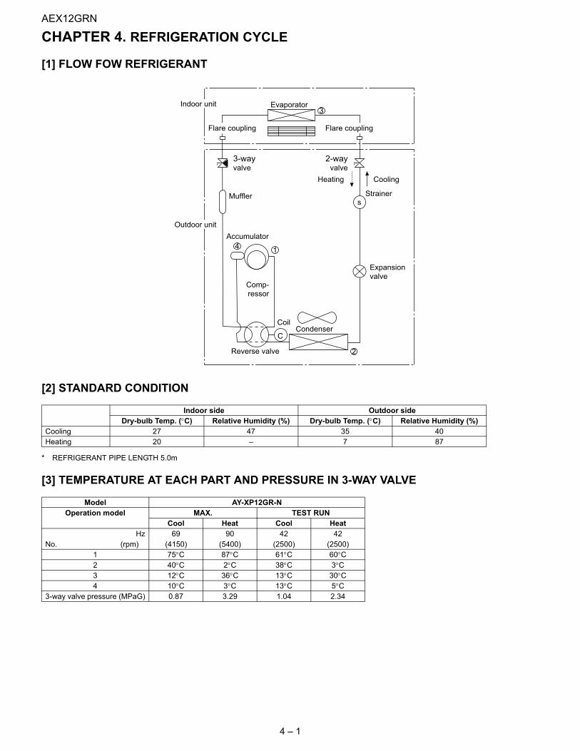
AEX12GRN
4 – 1
AEX12GRN Service Manual CHAPTER 4. REFRIGERATION CYCLE
[1] FLOW FOW REFRIGERANT
[2] STANDARD CONDITION
* REFRIGERANT PIPE LENGTH 5.0m
[3] TEMPERATURE AT EACH PART AND PRESSURE IN 3-WAY VALVE
Indoor side Outdoor sideDry-bulb Temp. (°C) Relative Humidity (%) Dry-bulb Temp. (°C) Relative Humidity (%)
Cooling 27 47 35 40Heating 20 – 7 87
Model AY-XP12GR-NOperation model MAX. TEST RUN
Cool Heat Cool HeatHz 69 90 42 42
No. (rpm) (4150) (5400) (2500) (2500)1 75°C 87°C 61°C 60°C2 40°C 2°C 38°C 3°C3 12°C 36°C 13°C 30°C4 10°C 3°C 13°C 5°C
3-way valve pressure (MPaG) 0.87 3.29 1.04 2.34
s
14
C
2
Accumulator
3
Strainer
Expansion
valve
Heating Cooling
Outdoor unit
Condenser
EvaporatorIndoor unit
Reverse valve
Comp-
ressor
Flare coupling Flare coupling
3-wayvalve
2-wayvalve
Coil
Muffler
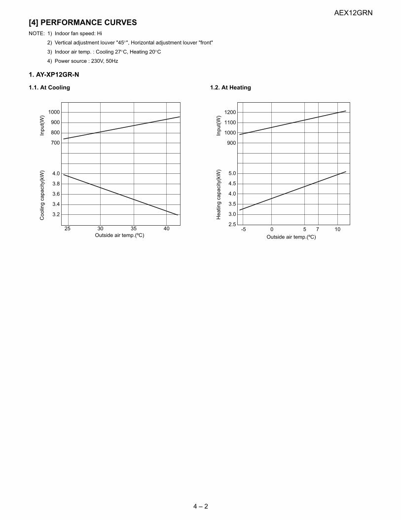
AEX12GRN
4 – 2
[4] PERFORMANCE CURVESNOTE: 1) Indoor fan speed: Hi
2) Vertical adjustment louver "45°", Horizontal adjustment louver "front"
3) Indoor air temp. : Cooling 27°C, Heating 20°C
4) Power source : 230V, 50Hz
1. AY-XP12GR-N
1.1. At Cooling 1.2. At Heating
25 30 35 40
4.0
3.8
3.6
3.4
3.2
1000
900
800
700
Coolingcapacity(kW)
Outside air temp.(ºC)
Input(W)
-5 0 75 10
Heatingcapacity(kW)
Outside air temp.(ºC)
Input(W)
5.0
4.5
4.0
3.5
3.0
2.5
1200
1100
1000
900
Related Documents


