USER GUIDE Mapping Services DML Version 3.0.1 18 February 2016

Welcome message from author
This document is posted to help you gain knowledge. Please leave a comment to let me know what you think about it! Share it to your friends and learn new things together.
Transcript

U S E R G U I D E
Mapping Services DMLVersion 3.0.1
18 February 2016

Copyright © 2016 Axway
All rights reserved.
This documentation describes the following Axway software:
Axway Mapping Services 3.0.1
No part of this publication may be reproduced, transmitted, stored in a retrieval system, or translated into any human or computer language, in any form or by any means, electronic, mechanical, magnetic, optical, chemical, manual, or otherwise, without the prior written permission of the copyright owner, Axway.
This document, provided for informational purposes only, may be subject to significant modification. The descriptions and information in this document may not necessarily accurately represent or reflect the current or planned functions of this product. Axway may change this publication, the product described herein, or both. These changes will be incorporated in new versions of this document. Axway does not warrant that this document is error free.
Axway recognizes the rights of the holders of all trademarks used in its publications.
The documentation may provide hyperlinks to third-party web sites or access to third-party content. Links and access to these sites are provided for your convenience only. Axway does not control, endorse or guarantee content found in such sites. Axway is not responsible for any content, associated links, resources or services associated with a third-party site.
Axway shall not be liable for any loss or damage of any sort associated with your use of third-party content.

Contents
1 Introduction to Mapping Services DML 5
Mapping Services life-cycle 7
2 Create and import Mapping objects in DML 9
About DML Mapping Projects 10
DML Mapping Project Information 14
Create DML Mapping Projects 16
Import a Map Designer project as a DML Mapping Project 16
About Business Documents in DML 19
Business Document structure in DML 20
Create Business Documents in DML 65
Manage Business Document structure in DML 137
Import Business Documents into DML Mapping Projects 152
Use Business Document Validation Rules in DML 162
Business Document data encoding in DML 166
Business Document UML view 167
Use Business Document libraries 169
About Maps in DML Mapping Projects 174
Map editor 175
Create Maps in DML Mapping Projects 177
Use the Table view in a DML Mapping Project 187
Map properties in a DML Mapping Project 188
Manage Auto Mapping in a DML Mapping Project 189
Generate DML Maps 189
About Mapping Flows in DML Mapping Projects 194
Create Mapping Flows in DML Mapping Projects 194
Generate Mapping Flows in DML Mapping Projects 195
Manage channels in DML Mapping Flows 195
Manage DML Mapping Flow properties 197
Manage concatenation and splitting in the DML Mapping Flow 200
Use Mapping Flow design in DML Mapping Projects 201
Import deployment package into a DML Mapping Project 204
Extended Objects in DML Mapping Projects 206
Use Custom Functions in DML Mapping Projects 206
Use Tables in DML Mapping Projects 228
Use Variables in DML Mapping Projects 237
Document Identifiers in DML Mapping Projects 240
Create a Document Identifier in DML Mapping Projects 241
Use the Document Identifier editor in DML Mapping Projects 242
AxwayMapping Services DML 3.0.1 User Guide 3

2 Modify Mapping objects in DML 243
3 Simulate your DML Mapping 245
Create test cases in DML Mapping Projects 245
Configure and launch simulations in DML Mapping Projects 246
Create, configure and launch a simulation suite in a DML Mapping Project 246
Configure a simulation suite in a DML Mapping Project 247
Launch a simulation suite in a DML Mapping Project 248
Use channels with a simulation in a DML Mapping Project 249
Use attributes with a simulation in a DML Mapping Project 250
Generate the documentation in a DML Mapping Project 252
4 Document DML Mapping objects 253
Generate reports in DML Mapping Projects 253
5 Deploy your DML Mappings 255
Object Dependency Browser 255
Deploy Mappings 257
Deployment Packages settings wizard page 258
Deployment Preview Wizard Page 258
Deployment results 258
Runtime Repository Browser 258
Define a Runtime System location 259
Deploy XSD Business Documents to a B2Bi server 260
6 Version your DML Mapping 261
7 Set up Mapping Services DML with Preferences 263
Mapping Services DML Preferences: Connections 263
Mapping Services DML Preferences: Database servers connection 264
Mapping Services DML Preferences: Runtime servers connections 264
Mapping Services DML Preferences: SAP® servers connections 266
Mapping Services DML Preferences: Add an external database driver 269
Mapping Services DML Preferences: Mapping language and version decoration 269
Mapping Services DML Preferences: Business Document Attributes 270
Mapping Services DML Preferences: UML Documentation 270
Mapping Services DML Preferences: General Setting 271
Mapping Services DML Preferences: Schema exporter 271
Mapping Services DML Preferences: Deployment 273
4 User Guide AxwayMapping Services DML 3.0.1

1 Introduction to Mapping Services DML
Axway Mapping Services is a Rich Client Application (RCA) built on the Eclipse framework.
Axway Mapping Services is used to design, simulate, document, and version Mappings, and to deploy these Mappings to a runtime server.
Your purpose on the runtime server is to process your business data wherever it comes from and whatever its format is, and to send it on to recipient applications with the data structure they expect, using the desired transport mode.
For this purpose you must tell the runtime server how the data is configured and what you expect to do with it. In the context of the Axway Mapping Services product this is called a Mapping. To create these Mappings, you use the GUI components of Mapping Services.
For these Mappings, Mapping Services provides two mapping languages:
l Data Manipulation Language (DML)
l Datamapper
Note This user guide only covers the DML mapping language. The Datamapper mapping language is described in detail in the Axway Mapping Services Datamapper User Guide.
About Mapping ServicesMapping Services is a stand-alone Mapping Development Suite that provides the following:
l Offline development and simulation of DML Mappings
l Graphical Mapping development
l A wide range of EDI and XML standards: EDIFACT, X12, XSD, SAP and more
l Database and Web Services Mappings
l Mapping of Any2Any
AxwayMapping Services DML 3.0.1 User Guide 5

1 Introduction to Mapping Services DML
This is an example of the Mapping Services interface:
About DMLDML is a mapping language that tells the integration engine how to generate a value from input data. With DML, you can handle all types of common data regardless of their technical encoding. You can combine numbers, dates, and text to build almost anything you need.
This language has been designed as a very high-level language. Your business generates data without having to understand the technical processes behind the generation events. This is why DML is not truly a complete programming language; it is not concerned with bits, bytes, and memory allocation.
General conceptNote For detailed information about Mapping Services concepts, such as the project structure,
the life-cycle of Mappings, the product architecture, the Meta Data concept, the Global Runtime Objects, the Mapping Services Workbench, and Mapping Services specific terminology, refer to the Axway Mapping Services Overview Guide.
6 User Guide AxwayMapping Services DML 3.0.1

Mapping Services life-cycle
Mapping Services life-cycleThe following graphic visualizes the steps required to create, test and deploy a DML Mapping to the runtime environment with Mapping Services.
The following list gives a brief overview of the steps necessary to create and manage a DML Mapping with Axway Mapping Services.
1. Create DML Mapping Projects on page 16
Start to design your Mapping by creating a DML Mapping Project. The main entry point for each Mapping Project is the project file project.ms.
2. Create Business Documents in DML on page 65
In the second step, create or import Business Documents for holding the input and output message data. These Business Documents are the input objects and output objects of the Mapping Flows.
3. Create Maps in DML Mapping Projects on page 177
After that, create Maps that define how input objects are mapped to output objects.
4. Create Mapping Flows in DML Mapping Projects on page 194
On the basis of the created Business Documents and Maps you create Mapping Flows. These Mapping Flows contain specific instructions on how to route, map, and handle the input data.
AxwayMapping Services DML 3.0.1 User Guide 7

1 Introduction to Mapping Services DML
5. Create test cases in DML Mapping Projects on page 245
To test your Mapping create test cases and test data.
6. Configure and launch simulations in DML Mapping Projects on page 246
After creating Business Documents, Maps, Mapping Flows, and test cases, test your DML Mapping Project with a simulation or a simulation suite.
7. Generate the documentation in a DML Mapping Project on page 252
Create documentation for your DML Mapping Project.
8. Deploy your DML Mappings on page 255
Finally, complete the DML Mapping Project and deploy the Mapping to the runtime server.
8 User Guide AxwayMapping Services DML 3.0.1

2 Create and import Mapping objects in DML
You have two options to start the Mapping Services life-cycle:
l Import existing Mapping objects into your workspace and modify them (see Import a Map Designer project as a DML Mapping Project on page 16 and Import Business Documents into DML Mapping Projects on page 152).
l Create the mapping objects from scratch (see Create DML Mapping Projects on page 16, Create Business Documents in DML on page 65, Create Maps in DML Mapping Projects on page 177, Create Mapping Flows in DML Mapping Projects on page 194, Create Custom Functions in DML Mapping Projects on page 208, Create a Table object in DML Mapping Projects on page 229, and Create Variables in DML Mapping Projects on page 238 ).
Mapping Services provides wizards to create the Mapping objects and import standard document descriptions into your Mapping Project. It is also possible to import an existing Mapping Project into your workspace. This could be an import from a former Axway product workspace, an archive file, or from an SVN repository.
AxwayMapping Services DML 3.0.1 User Guide 9

2 Create and import Mapping objects in DML
About DML Mapping ProjectsA DML Mapping Project is a standard Eclipse project with a default directory structure. A Mapping Project combines all files required for creating, designing, and modifying one or more Mappings. The directory structure of the Mapping Project and the project file itself are automatically generated when creating a new Mapping Project. The Global Runtime Objects is also created automatically by default.
One Mapping Project can contain multiple Mappings. All Mappings that are located in the same Mapping Project can use the same resources, such as Tables and Custom Functions.
Resources that should be reused on the runtime server over multiple Mappings should be located in the Global Runtime Objects.
Note For detailed information about Mapping Services concepts, such as the project structure, the life-cycle of Mappings, the product architecture, the Meta Data concept, the Global Runtime Objects, the Mapping Services Workbench, and Mapping Services specific terminology, refer to the Axway Mapping Services Overview Guide.
Project componentsDepending on the mapping language , the Mapping Project can contain:
l Business Documents
l Maps
l Mapping Flows
l Variables
l Tables
l Functions
l Test data, containing test cases for simulation
l Configurations for the simulation
l Documentation
10 User Guide AxwayMapping Services DML 3.0.1

About DMLMapping Projects
Project fileThe main entry point for each Mapping Project is the project file project.ms.
l The project file defines the used mapping language and version for all Mappings in the project.
l It can contain Meta Data. For details read the Axway Mapping Services Overview Guide.
l The project file allows you to store additional information about all Mappings in the project.
l It provides documenting, deploying, and versioning operations for the Mappings (see Document DML Mapping objects on page 253, Deploy your DML Mappings on page 255, Version your DML Mapping on page 261).
Project directory structureThe project directory structure and the project file itself are created and then all of the necessary steps needed to execute the Mapping are defined and grouped in the correct order. Apart from Mappings and processor files, the project can contain – depending on the Mapping type –XML files, XSL Translets, stylesheets, documentation files, runtime configuration files, SQL scripts for the creation of database tables, and much more (see Project components on page 10).
Directory Contents
Business Documents Source and target message descriptions of the Mappings for details).
Documentation Mapping documentations
Extended Objects Additional files that will be used for the Mappings (Custom Functions, Tables, Variables)
Mapping Flows Mapping Flows, that describe how a Mapping is orchestrated
Maps Maps, that describes the transformation from the source into the target document
Testdata Test messages (e.g. example EDI or XML messages) and the simulation suite
project.ms Mapping description file as the main entry point for the Mapping Project
AxwayMapping Services DML 3.0.1 User Guide 11

2 Create and import Mapping objects in DML
DML versionA DML Mapping Project can be designated as either DML 1.5 or 2.0. All new projects are defined as 2.0.(or higher), providing some new features (enabling justification and padding) that change mapping results. Older projects are generally defined as 1.5., keeping the previous project behaviors (justification and padding are disabled), unless you change the version to 2.0 to use the new features.
These are the main differences between DML 2.0 and DML 1.5:
l Changes in padding behavior:
In DML 2.0, setting the Justification attribute will have the expected effect, in DML 1.5, some settings were ignored.
l Variable Length Output Fields with a fixed Decimal Point Position:
If the field has variable length and the Justification attribute is set to right, and if the input has less fractional digits than the expected output definition, the value will be padded with zero until the value matches the definition of the output field.
l Interactions between the attributes Pad reals with a leading and trailing zero in the Business Document General options and the environment variable DECIMAL_POINT_NOT_MANDATORY:
In DML 2.0, the attribute Pad reals with a leading and trailing zero work independently of the values of the environment variable DECIMAL_POINT_NOT_MANDATORY. In DML 1.5, the padding of trailing zero was not done if the value of the environment variable was set to 1.
l As of DML 2.0, the minimum length for Integer class is checked for variable fields.
These are the main differences between DML 2.1 and DML 2.0:
l In DML 2.1, the precision and scale are taken into account for XML. Prior to DML 2.1, the definition for XML leaves with real data type was not interpreted in a consistent way. That means, if some values did not match the definition, no error was displayed. As of DML 2.1, an error will be displayed if the values do not match the definition.
l In DML 2.1, extra namespaces removed in the generation of XSD business documents.
l In DML 2.1, short real numbers will issue a warning when the option facet check is enabled along with the option accept document with error.
Effects of the DML version on importing and exportingDML versions also affect project and deployment package import and export:
l Importing an older project sets the version to 1.5.
l Exporting a deployment package maintains the existing project version at the time of export, either 1.5 or 2.0.
l Importing a previously deployed deployment package sets the project version to 1.5, even if some of the objects in the project are set to 2.0. A warning does advise you about the mismatch. You can override the version to 2.0 to change the project and resulting behaviors.
12 User Guide AxwayMapping Services DML 3.0.1

About DMLMapping Projects
Changing the DML versionTo change the DML version of the DML Mapping Project :
1. Double-click the project file in the Project Explorer.
2. In the Project Properties list , click Mapping Details.
3. Select the version in the Version drop-down list. You can choose between 1.5 and 2.0.
4. Save the changes.
The mapping language and version is shown as a label in the Project Explorer on the project.ms file, for example[DML-2.0]. To customize the decoration, use the Preferences dialog box (see also Mapping Services DML Preferences: Mapping language and version decoration on page 269).
AxwayMapping Services DML 3.0.1 User Guide 13

2 Create and import Mapping objects in DML
DML Mapping Project InformationWith the help of the Project Information you define a DML Mapping Project. A Mapping Project combines all files required for creating, designing, and modifying one or more DML Mappings.
In the project information you find general information about the Mapping, such as project details and Meta Data. The Project Information opens automatically after you create a new DML Mapping Project or when you double-click an existing DML Mapping Project.
Project Information structureThe Project Information has the following main entries on the left side:
l Project Details on page 14
l Deployment Information on page 14
l Mapping Details on page 14
Project Details l Project Details on the right side display general information about the Mapping Project, such as the creation date, the last modification date, the users who created and modified the Mapping Project, and a description of the project.
l The Project Meta Data on the right side allows you to configure the meta data used for this project. For details about Project Meta Data refer to the Axway Mapping Services Overview Guide.
l On the right side, you can execute specific actions, such as Deployment and Versioning (see Deploy your DML Mappings on page 255, Version your DML Mapping on page 261).
Deployment InformationThe Deployment Information shows where the project was deployed to.
Mapping DetailsIn the Mapping Details you define the mapping language and the DML version (see also About DML Mapping Projects on page 10 and Create DML Mapping Projects on page 16).
All Mapping Flows of the Mapping Project are displayed as child elements of the Mapping Details on the left. For each Mapping Flow a set of specifications can be added and a state can be defined to distinguish between prototypes and productive Mappings. If you select one Mapping Flow on the left, the details of this Mapping Flow are displayed in the right. Furthermore you can assign and generate documentation for this Mapping Flow, test the Mapping Flow, deploy the Mapping, and display the deployment statistics.
14 User Guide AxwayMapping Services DML 3.0.1
About DMLMapping Projects
For more information on Mapping Flows, see About Mapping Flows in DML Mapping Projects on page 194.
AxwayMapping Services DML 3.0.1 User Guide 15

2 Create and import Mapping objects in DML
Create DML Mapping ProjectsA Mapping Project combines all files required for creating, designing, and modifying one or more DML Mappings.
To create a DML Mapping Project:
1. From the main menu, select File > New > Mapping Project.
Alternatively, you can right-click in the Project Explorer and select New > Mapping Project.
A wizard appears to help you create a new Mapping Project.
2. Enter the Project name. It must be a valid project name. That means you cannot use special or space characters.
3. Select the Mapping type: DML
Mapping Services provides two types of Mapping Projects: DML and Datamapper.
4. Optionally, select Add project to working sets to add the Mapping Project to a working set.
In doing so, you can group several Mapping Projects. Click Select to select the path to the working set.
5. Click Finish.
For more information on DML Mapping Projects, see About DML Mapping Projects on page 10.
Import a Map Designer project as a DML Mapping Project
A Mapping Project combines all files required for creating, designing, and modifying one or more DML Mappings.
In Mapping Services you can import older projects from Map Designer.
To import a Map Designer project as a DML Mapping Project:
1. From the main menu, select File > Import.
2. Select Mapping Services > DML > Map Designer Project.
3. Alternatively, you can right-click in the Project Explorer and select Import > Mapping Services > DML > Map Designer Project.
4. Click Next.
5. Select either Import from folder or Import from archive.
Note It is recommended to provide a valid Map Designer workspace to reconstruct the dependencies between the different mapping objects. A valid Map Designer workspace is a workspace on which you run the build. This workspace must necessarily contain the
16 User Guide AxwayMapping Services DML 3.0.1

About DMLMapping Projects
dependencies file (/.metadata/.plugins/com.axway.md.dependency/.dependencies file). Otherwise, if an ordinary folder or archive containing Map Designer projects is provided instead of a valid workspace, the import operation can still take place, but some of the projects might be incorrect because it was not possible to reconstruct the dependencies between the mapping objects.
6. Click Browse to browse to the correct directory where your Map Designer project is located or enter the path to the desired location.
All Map Designer projects that are found in the selected directory are then displayed and preselected.
7. Select the projects to import. To deselect a project, click to clear.
If a Mapping Project with the same name as one of the selected Map Designer projects already exists in your workspace, or if there is a DML name conflict which cannot be solved, you cannot import the Map Designer project.
Note If one of the selected projects has dependencies to another project which is not selected, a warning is displayed.
8. Click Overwrite objects with the same DML name in Global Runtime Objects to overwrite a mapping object in the Global Runtime Objects that has the same name as a dependent object which is to be imported into the Global Runtime Objects. If you do not overwrite this mapping object, the dependent object is not imported and the existing mapping object is used, in the newly imported projects as well.
9. If you import a full Map Designer workspace (either on a folder or on an archive), you can also import the connections preferences defined in the Map Designer workspace. Click Import Map Designer connections preferences to import these connections preferences. After that, all connections preferences are available, except the encrypted password, in the Mapping Services preferences dialog (see Mapping Services DML Preferences: Connections on page 263).
Note If a connection with the same name already exists in the preferences the imported connection will be renamed automatically to avoid the name conflict.
10. Click Finish.
The projects are imported into Mapping Services as DML Mapping Projects. The imported projects have the DML version set in the Map Designer project. If the DML version is not set in the Map Designer project, Mapping Services sets the DML version to 1.5 as default.
For detailed information about the general concept of Global Runtime Objects, refer to the Axway Mapping Services Overview Guide.
For more information on DML Mapping Projects, see About DML Mapping Projects on page 10.
Note The structure of the imported Map Designer project(s) is recreated accordingly to the Mapping Services project structure. That means:
l All Business Documents of the Map Designer project are moved into the Business Documents folder of the Mapping Services projects.
AxwayMapping Services DML 3.0.1 User Guide 17

2 Create and import Mapping objects in DML
l The Map Designer Maps (.map) are transformed to .mdm files and moved into the Maps folder of the Mapping Services projects.
l Projects with dependencies between them:
o All dependent mapping objects except tables and functions are replicated in each Mapping Services project.
o Dependent tables and functions which are used in multiple projects, are moved into the Global Runtime Objects folder in the respective subfolders.
18 User Guide AxwayMapping Services DML 3.0.1

About Business Documents in DML
About Business Documents in DML
In a DML Mapping Project, the Business Document describes the composition and structure of the input and output messages for the Mappings.
Each DML Mapping consists of a Mapping Flow that contains specific instructions on how to route, map or otherwise handle units of input data. To enable the Mapping Flow to locate the units of data, you link the Map to an object that holds the data of the input message in a formally organized structure. In Mapping Services, the structure for holding message data is a Business Document.
For more information on Mapping Flows and Maps, see About Mapping Flows in DML Mapping Projects on page 194 and About Maps in DML Mapping Projects on page 174.
For most Mapping Flows, in addition to the input Business Document, you require one or more output Business Documents.
The following graphic shows the role of Business Documents in the processing sequence.
InputDuring message processing, the Map Engine extracts the data from the input message and writes the data to the appropriate node of the input Business Document.
OutputThe Map Engine uses the instructions contained in Maps to process the data held in an input Business Document. The application then writes the results of this processing to the nodes of an output Business Document. The integration application can then parse this data to a standard or customized file type of a message flow.
AxwayMapping Services DML 3.0.1 User Guide 19

2 Create and import Mapping objects in DML
Output / InputIn some processing contexts, a Business Document may serve both as an output and an input Business Document. For example, when a Mapping Flow contains two Maps that are executed successively, the output Business Document of the first Map may serve as the input Business Document of the second Map.
Business Document structure in DMLIn a DML Mapping Project, the Business Document describes the composition and structure of the input and output messages for the Mappings.
The structure of a Business Document depends on the structure of the input or output message to which it corresponds. Different information systems require different data structures.
In Mapping Services, you can edit any Business Document.
If necessary, you can build a Business Document from scratch (see Create Business Documents in DML on page 65).
You can build Business Documents that conform to standard messages, or you can use the Flat File type Business Document structural elements to construct Business Documents for non-standardized file types (see Define Flat File Business Documents on page 72).
For more information on Business Documents and the different Business Document types, see About Business Documents in DML on page 19 and Business Document types in DML on page 26.
Structural elementsA Business Document includes the following:
l Attributes: Name, type, status and so on
l A set of nodes arranged in a hierarchical tree structure. These nodes fall into one of two categories:
o Nodes with values
Some nodes contain data. In this documentation, these nodes are referred to as nodes with values.
o Nodes without values
Other nodes do not contain data. These nodes group and describe a subset of nodes. In this documentation, these nodes are referred to as nodes without values.
l Validation Rules: Expression that the Map Engine uses to check the Business Document content.
20 User Guide AxwayMapping Services DML 3.0.1

About Business Documents in DML
Business Document cardinality
About cardinalityCardinality is an attribute of a Business Document node in DML. The cardinality attribute indicates the number of times the node can or must occur when Mapping Services processes the Business Document. For most nodes, you set the cardinality in the Attributes section or directly in the tree structure of the Business Document.
For more information, see Business Document structure in DML on page 20 and Define Business Document node cardinality on page 148.
Applying cardinality to nodes
When a node... Use cardinality... Where...
Can occur once or not at all
0 - 1 l 0 indicates that the specified node does not necessarily occur
l 1 indicates that if the specified node does occur, it can occur only once
Can occur many times or not at all
0 - n l 0 indicates that the specified node does not necessarily occur
l n indicates that if the specified node does occur, it can occur up to n times, where n is a positive integer that is defined via a Map
Must occur once and only once
1 - 1 l The first 1 indicates that the specified node must occur
l The second 1 indicates that the specified node can occur only once
Must occur at least once but can occur many times
1 - n l 1 indicates that the specified node must occur at least once
l n indicates that the specified node can occur up to n times, where n is a positive integer that is defined using a Map
AxwayMapping Services DML 3.0.1 User Guide 21

2 Create and import Mapping objects in DML
For convenience, the set of possible cardinalities is grouped into two categories throughout this documentation:
l single: 0-1 and 1-1
l multiple: 0-n and 1-n
Business Document data types in DML
About data typesData type is an attribute of a Business Document that describes the physical structure of the data and belongs to a DML Data Class from which it inherits a set of characteristics. In a Business Document, the DML data class / data type combination that you assign to a node determines how the data can be read in and be written to that node.
Each data type depends on a data class. A data class is an attribute of a node with values that generally describes what kind of data can be stored in the node, for example, Integer, and Date & Time. It does not describe the physical structure of data. For example, the Real number data class indicates that data can be expressed using decimal and exponential values. However, by itself, the data class does not indicate how many significant digits are included in the data. That type of information is specified using the data type.
For more information, see About Business Documents in DML on page 19, Business Document structure in DML on page 20, Business Document structure in DML on page 20, and Axway Mapping Services DML Reference Guide.
When an Integration Process is executed, it applies the data class to validate that the data values contained in nodes correspond to the expected values. If not, then the Map Engine treats the associated Business Document as an exception. For example, if the data class is set to Integer, and the node contains alphabetic characters, the associated Business Document is rejected.
Where do I define the data type attribute of a node with values?You define the data type attribute of individual nodes when the Business Document editor is open, either in the General view of the Attributes section or in the Structure view. In the Structure view, click in the cell of the Data type column to display a drop-down list of the available data types for the selected node.
22 User Guide AxwayMapping Services DML 3.0.1

About Business Documents in DML
About data type attributesSome data types have attributes that you can use to refine the definition of the physical structure of data. In the General view of the Attributes section of a Business Document, you can identify the data types that have values in the Data type field.
Note for the name of the data type:
l Abbreviated names are enclosed in parentheses. For example, String (len).
l Abbreviated formats are enclosed in square brackets. For example, Date [YYYYMMDD].
The way an attribute is enclosed indicates whether you can modify the value that is supplied by the software in the Definition field.
l If the attribute has a default value, then the attribute is enclosed inside parentheses. For example, String (len). You can modify the value supplied in the Definition field.
l If the attribute has a predefined value, then the attribute is enclosed inside square brackets. For example, Date [YYYYMMDD]. You cannot modify the value supplied in the Definition field.
Attributes with default valuesThe following table describes the data type attributes with default values. In most cases, the default values optimize the performance of the Map Engine:
Abbreviation Attribute Details
(dp) date pattern Specifies the format of a date or a date/time.
(len) length In non-XML Business Documents, specifies the maximum number of characters that a node can contain.
In XML Business Documents, specifies:
l The minimum number of characters that a node can contain
l The maximum number of characters that a node can contain
l Both the minimum and the maximum number of characters that a node can contain
(m,e) mantissa, exponent
Specifies:
l Mantissa: the maximum number of significant digits
l Exponent: the maximum number of digits after the decimal sign
AxwayMapping Services DML 3.0.1 User Guide 23

2 Create and import Mapping objects in DML
Abbreviation Attribute Details
(p) precision Specifies:
l The maximum number of numeric characters that an integer can contain
l The Plus sign position is set to Left; and Optional plus sign, if used, is set to Enabled. The maximum number of digits is extended by one if the plus sign is missing. (e.g., +12 and 923 are accepted).
(p,s) precision, scale
Specifies:
l Precision: the maximum number of characters and all numeric characters. The decimal sign is not included in the definition.
l Scale: the maximum number of numeric characters after the decimal sign
(n,v)
or
(n)
whole real, virtual scale or
whole real
Specifies:
l If (n,v): the maximum number of characters and all numeric characters, with implied decimal places (without a decimal separator). The decimal sign is not included in the definition. The explicit sign is only present when negative and is part of the total length of the field.
l Scale: the maximum number of numeric characters after the decimal sign, or
l If (n): the maximum number of characters and all numeric characters, with no decimal places.
Attributes with predefined valuesThe following table lists and describes the data type attributes with predefined values:
Attribute Meaning
[false,true] Expected values for a Boolean expression
[0,1] Expected values for a Boolean expression
[YYMMDD] Six-digit date that begins with a two-digit year
[YYYYMMDD] Eight-digit date that begins with a four-digit year
24 User Guide AxwayMapping Services DML 3.0.1

About Business Documents in DML
Attribute Meaning
[YYYY/MM/DD] Eight-digit date that begins with a four-digit year and separates year, month, and day with slashes
[YY/MM/DD] Six-digit date that begins with a four-digit year and separates year, month, and day with slashes
[DD/MM/YYYY] Eight-digit date that ends with a four-digit year and separates year, month, and day with slashes
[DD/MM/YY] Six-digit date that ends with a two-digit year and separates year, month, and day with slashes
Data type reference tablesThe data types that you can apply depend on the data class. In turn, the possible data classes depend on the structure type of the Business Document. For more information, see Business Document structure in DML on page 20, About Business Documents in DML on page 19, and Axway Mapping Services DML Reference Guide. The tables in this section summarize the possible combinations of data class / data type for each structure type. The tables also indicate the values that are assigned to the data type attributes of each data type listed (see About data type attributes on page 23).
Click the name of the Business Document type to display the table of data class / data type values for each type:
l ANSI X12 Business Document on page 47
l JDBC database Business Document on page 59
l EDIFACT Business Document on page 46
l COBOL Business Document on page 44
l Generic Business Document on page 60
l HL7 Business Document on page 27
l IDoc Business Document on page 52
l Flat File Business Document on page 28
l XML Business Document on page 54
l XSD Business Document on page 58
AxwayMapping Services DML 3.0.1 User Guide 25

2 Create and import Mapping objects in DML
Business Document types in DMLIn Mapping Services DML, you can create or import Business Documents that enable the processing of data for various protocols and file types :
l HL7 Business Document on page 27
l Flat File Business Document on page 28
l COBOL Business Document on page 44 (Fixed/Variable)
l Cargo IMP
l SCRIPT
l EDIFACT Business Document on page 46
l ANSI X12 Business Document on page 47
l TRADACOMS
l IDoc Business Document on page 52
l SWIFT FIN (System/User)
l XML Business Document on page 54
l XSD Business Document on page 58
l JDBC database Business Document on page 59
l Generic Business Document on page 60
For more information on Business Document, see About Business Documents in DML on page 19.
26 User Guide AxwayMapping Services DML 3.0.1

About Business Documents in DML
HL7 Business DocumentThe data types that you can apply depend on the data class. In turn, the possible data classes depend on the structure type of the Business Document. For more information, see Business Document structure in DML on page 20, About Business Documents in DML on page 19, and Axway Mapping Services DML Reference Guide.
About HL7 Business DocumentsHealth Level Seven (HL7) was founded in 1987 to develop standards for the electronic interchange of clinical, financial, and administrative information among independent health care oriented computer systems, such as hospital information systems, clinical laboratory systems, enterprise systems, and pharmacy systems.
Data class Data type Definition field
Boolean Boolean [0,1] 1
Date & Time Date [YYYYMMDD] 8
Date [YYMMDD] 6
Integer Integer (p) 10
Real number Numeric (p,s) 18,6
String String 255
String [fixedlength] (len)
255
Very large object largeBinary (len) 255
For more information on HL7 Business Documents, see Define HL7 Business Documents on page 66.
AxwayMapping Services DML 3.0.1 User Guide 27

2 Create and import Mapping objects in DML
Flat File Business DocumentThe data types that you can apply depend on the data class. In turn, the possible data classes depend on the structure type of the Business Document. For more information, see Business Document structure in DML on page 20, About Business Documents in DML on page 19, and Axway Mapping Services DML Reference Guide.
Data class
Data type Definition field
Physicallength
Plus signin inputs
Plus signin outputs
Boolean Boolean [false,true]
5 5 N/A N/A
Boolean [0,1] 1 1 N/A N/A
Date & Time
Date [YYYYMMDD]
8 (indicates a date)
8 N/A N/A
Date [YYMMDD] 6 (indicates a date)
6 N/A N/A
Date [YYYY/MM/DD]
10 (indicates a date)
10 N/A N/A
Date [YY/MM/DD] 8 (indicates a date)
8 N/A N/A
Date [DD/MM/YYYY]
10 (indicates a date)
10 N/A N/A
Date [DD/MM/YY] 8 (indicates a date)
8 N/A N/A
customDate define your own pattern
equal to number of characters in pattern
N/A N/A
28 User Guide AxwayMapping Services DML 3.0.1

About Business Documents in DML
Data class
Data type Definition field
Physicallength
Plus signin inputs
Plus signin outputs
Integer Integer (p) 10 P+1 Mandatory ... ...alwaysgenerated
customInteger define your own pattern
P+1 Optional. If plus sign = left or RightAND is activated...
...not generated if activated OR if = None
P+1 Mandatory. If plus sign = Left or Right AND is activated...
...generated if activated OR if = None
N/A Forbidden if = None
N/A
AxwayMapping Services DML 3.0.1 User Guide 29

2 Create and import Mapping objects in DML
Data class
Data type Definition field
Physicallength
Plus signin inputs
Plus signin outputs
Real number
Numeric (p,s)
Fixed scale real
numeric (p)
Variable scale real
18,6 P+2 Mandatory ... ...never generated
customNumeric define your own pattern
P+2 N/A N/A
customNumeric (n,v)
Customizable Virtual scale real
6,2; pattern = n,v
P+1 Optional. If plus sign = left or Right(optional plus sign is always activated)...
... generated
N/A Forbidden if = None
N/A
virtualNumeric (n,v)
Virtual scale real
6,2; pattern = n, v
P+1 Optional...
(optional plus sign is always activated)...
...never generated
customNumeric (p,s)
Fixed scale real
customNumeric (p)
Variable scale real
6,2; pattern = p,s
P+2 Optional. If plus sign = Left or RightAND is activated...
...not generated if activated OR if
= None
P+2 Mandatory. If plus sign = Left or Right AND is activated...
...generated if activated OR if = None
N/A Forbidden if = None
N/A
String String (len) 255 255 N/A N/A
customString define your own pattern
define your own pattern
N/A N/A
30 User Guide AxwayMapping Services DML 3.0.1

About Business Documents in DML
Data class
Data type Definition field
Physicallength
Plus signin inputs
Plus signin outputs
Verylarge object
largeBinary (lg) 255 255 N/A N/A
Regarding zeros:
l If the data type calls for an explicit number of decimal places, and there are all zeros to the right of the decimal sign, a valid value will be output. In this case, other data types will generate an error.
l Leading zeros are required for Application Flat File fields that are numeric or real to satisfy the field length requirements. EDI elements should never contain leading zeros, with the exception of fraction values, or to satisfy minimum length requirements.
Note For customNumeric virtual scale real numbers, if the plus sign is not present in input or output fields, it can be replaced by any digit. There is one additional character authorized for positive numbers without plus sign.
For more information on Flat File Business Documents, see Define Flat File Business Documents on page 72.
Numeric attribute exampleWhen reading numeric(p,s):
l The real value has always decimal separator.
l The plus sign is always present.
l The minus sign is always present.
When writing numeric(p,s):
l The decimal separator is always generated. (Except if there are other environment attributes that override this behavior)
l The plus sign is always generated
l The minus sign is always generated.
AxwayMapping Services DML 3.0.1 User Guide 31

2 Create and import Mapping objects in DML
VirtualNumeric attribute exampleYou can map input numbers that meet all of the X12 requirements into output numbers for a Flat File Business Document using the (n,v) pattern. For additional information, see Set node attributes values on page 142.
When reading virtualNumeric (n,v) input:
l The real value has no decimal separator.
l The plus sign is optional and can be replaced with any digit.
l The minus sign is mandatory for a negative value.
l If the scale part defined in the type is equal to zero, it means that there is no decimal part for the real value.
When writing virtualNumeric output:
l The decimal separator is not generated for the output.
l If the real value has a positive value, the plus sign must be omitted and replaced by any digit.
l The minus sign is mandatory for a negative value.
Note For Variable fields, there is no justification for real value. The value is written with significant digits.
CustomNumeric attribute exampleYou can map input numbers that meet all of the X12 requirements into output numbers for a Flat File Business Document using the (p,s) pattern. For additional information, see Set node attributes values on page 142.
When reading customNumeric input:
l The real value has no decimal separator.
l The plus sign is optional and can be replaced with any digit.
l The minus sign is mandatory for a negative value.
l If the scale part defined in the type is equal to zero, it means that there is no decimal part for the real value.
When writing customNumeric output:
l The decimal separator is not generated for the output.
l If the real value has a positive value, the plus sign must be omitted and replaced by any digit.
l The minus sign is mandatory for a negative value.
Note For Variable fields, there is no justification for real value. The value is written with significant digits.
32 User Guide AxwayMapping Services DML 3.0.1

About Business Documents in DML
CustomNumeric attribute exampleYou can map input numbers that meet all of the X12 requirements into output numbers for a Flat File Business Document using the (p,s) pattern. For additional information, see Set node attributes values on page 142.
When reading customNumeric input:
l The real value has a decimal separator.
l The plus sign is optional and can be replaced with any digit.
l The minus sign is mandatory for a negative value.
l The scale part is optional, where the x of Rx is omitted. This means that the decimal part is variable and could be equal to the maximum of the precision.
When writing customNumeric output (for fixed length fields):
l The decimal separator is generated for the output value.
l If the real value is a positive value, the plus sign must be omitted and replaced by any digit.
l The minus sign is mandatory for a negative value.
Note For Variable fields, there is no justification for real value. The value is written with significant digits.
You can use both real and integer numbers to create an Inhouse (Flat file) Business Document and use the values in the following tables to represent the data types from the X12 standard.
l For Fixed field type N, N0, Nx on page 33
l For Fixed field type R, R2 on page 36
l For Variable field type N, N0, Nx on page 38
l For Variable field type R, R2 on page 40
l Variable length output fields with a fixed decimal point position for DML version 2.0 on page 42
For Fixed field type N, N0, Nx
Data type N,N0 N2 N,N0 N2 N2
Properties > General
Pad reals with a leading and trailing zero
Keep decimal separator character
AxwayMapping Services DML 3.0.1 User Guide 33

2 Create and import Mapping objects in DML
Data type N,N0 N2 N,N0 N2 N2
Keep decimal separator
Keep + sign for positive real numbers
Business DocumentLeaf elements
Class (R=Real, I=Integer) I R R R R
Data type (V=virtualNumeric, C=customNumeric, I=customInteger)
I (2) V (2) C (2) V (2) C (2)
Pattern p n,v n,v n,v n,v
Definition 5 5,0 5,0 5,2 5,2
Delimiter Fixed Fixed Fixed Fixed Fixed
Delimiter value leave it blank
leave it blank
leave it blank
leave it blank
leave it blank
Properties > Attributes
Optional plus sign(3)
Plus sign position(4) leave it blank
leave it blank
None or Left
leave it blank
None or Left
Justification leave it blank
leave it blank
RIGHT leave it blank
RIGHT
Padding character leave it blank
leave it blank
0 leave it blank
0
Keep number of fractional digits
Keep decimal separator character
Keep decimal separator
Keep + sign for positive real numbers
34 User Guide AxwayMapping Services DML 3.0.1

About Business Documents in DML
Data type N,N0 N2 N,N0 N2 N2
Input value 01200 01200 01200 01200 01200
Output value 01200 01200 01200 01200 01200
Input value +1200 +1200 +1200 +1200 +1200 (5)
Output value 01200 01200 01200 01200 error, no output
Input value -1200 -1200 -1200 -1200 -1200
Output value -1200 -1200 -1200 -1200 -1200
Input value 11200 11200 11200 11200 11200
Output value 11200 11200 11200 11200 11200
Input value 11222 11222 11222 11222 11222
Output value 11222 11222 11222 11222 11222
(1) Does not apply.
(2) The virtualNumeric with pattern=n,v data types cannot be customized. The customNumeric with pattern=n,v can be customized by changing the pattern, the padding character, and formatting option for the plus sign and minus sign.
(3) For input value, this option allows the plus sign to be replaced by a digit for reading. In a case with a precision of 5,2, it allows for a positive value to read 12345.
(4) Define the position of the plus sign when read or generated. In this case, it must be LEFT or NONE.
(5) Unable to read the data: [CVN - 9012): Invalid sign position.
(6) Does not apply.
Note When you define your flow, you must deselect the Keep exact value of input option.
AxwayMapping Services DML 3.0.1 User Guide 35

2 Create and import Mapping objects in DML
For Fixed field type R, R2
Data type R R2
Properties > General
Pad reals with a leading and trailing zero
Keep decimal separator character
Keep decimal separator
Keep + sign for positive real numbers
Business DocumentLeaf elements
Class (R=Real, I=Integer) R R
Data type (V=virtualNumeric, C=customNumeric)
C (2) C (2)
Pattern p p,s
Definition 5 5,2
Delimiter Fixed Fixed
Delimiter value leave it blank leave it blank
Properties > Attributes
Optional plus sign(3)
Plus sign position(4) Left leave it blank
Justification Right leave it blank
Padding character 0 leave it blank
Keep number of fractional digits
36 User Guide AxwayMapping Services DML 3.0.1

About Business Documents in DML
Data type R R2
Keep decimal separator character
Keep decimal separator
Keep plus sign for positive real numbers
Input value 1234567 0123.45
Output value 1234567 0123.45
Input value 12345.7 1234.56
Output value 12345.7 1234.56
Input value 1234.67 +123.45
Output value 1234.67 123.45
Input value 123.567
Output value 123.567
Input value 12.4567
Output value 12.4567
Input value 1.34567
Output value 1.34567
Input value .234567(6)
Output value error, no output
(1) Does not apply.
(2) The virtualNumeric with pattern=n,v data types cannot be customized. The customNumeric with pattern=n,v can be customized by changing the pattern, the padding character, and formatting option for the plus sign and minus sign.
(3) For input value, this option allows the plus sign to be replaced by a digit for reading. In a case with a precision of 5,2, it allows for a positive value to read 12345.
(4) Define the position of the plus sign when read or generated. In this case, it must be LEFT or NONE.
AxwayMapping Services DML 3.0.1 User Guide 37

2 Create and import Mapping objects in DML
(5) Does not apply.
(6) Unable to read the data: [CVN - 9022): Scale part is too long (6), defined length is 5.
Note When you define your Mapping Flow, you must deselect the Keep exact value of input option.
For Variable field type N, N0, Nx
Data type N,N0 N2 N,N0 N2 N2
Properties > General
Pad reals with a leading and trailing zero(1)
Keep decimal separator character
Keep decimal separator
Keep + sign for positive real numbers
Business DocumentLeaf elements
Class (R=Real, I=Integer) I R R R R
Data type (V=virtualNumeric, C=customNumeric, I=customInteger)
V (2) V (2) C (2) V (2) C (2)
Pattern P n,v n,v n,v n,v
Definition 5 5,0 5,0 5,2 5,2
Delimiter String String String String String
Delimiter value # # # # #
Properties > Attributes
Optional plus sign(3)
Plus sign position(4) leave it blank
None None None None
Justification leave it blank
RIGHT RIGHT RIGHT RIGHT
38 User Guide AxwayMapping Services DML 3.0.1

About Business Documents in DML
Data type N,N0 N2 N,N0 N2 N2
Padding character leave it blank
0 0 0 0
Keep number of fractional digits
Keep decimal separator character
Keep decimal separator
Keep plus sign for positive real numbers
Input value 1200# 1200# 01200# 01200# 01200#
Output value 01200# 1200# 1200# 1200# 1200#
Input value +1200# +1200# +1200# +1200# +1200# (5)
Output value error, no output
error, no output
error, no output
error, no output
error, no output
Input value -1200# -1200# -1200# -1200# -1200#
Output value -1200# -1200# -1200# -1200# -1200#
Input value 11200# 11200# 11200# 11200# 11200#
Output value 11200# 11200# 11200# 11200# 11200#
Input value 11222# 11222# 11222# 11222# 11222#
Output value 11222# 11222# 11222# 11222# 11222#
(1) This option is used to generate the non-significant digit on the right side or left side of the decimal separator. For example, if you have a canonical value of:
l .2 a zero is generated on the left (0.2).
l 2. a zero is generated on the right (2.0)
(2) The virtualNumeric with pattern=n,v data types cannot be customized. The customNumeric with pattern=n,v can be customized by changing the pattern, the padding character, and formatting option for the plus sign and minus sign.
(3) For input value, this option allows the plus sign to be replaced by a digit for reading. In a case with a precision of 5,2, it allows for a positive value to read 12345.
AxwayMapping Services DML 3.0.1 User Guide 39

2 Create and import Mapping objects in DML
(4) Define the position of the plus sign when read or generated. In this case, it must be LEFT or NONE.
(5) Unable to read the data: [CVN - 9012): Invalid sign position.
(6) Does not apply.
Note When you define your flow, you must deselect the Keep exact value of input option.
For Variable field type R, R2
Data type R R2
Properties > General
Pad reals with a leading and trailing zero
Keep decimal separator character
Keep decimal separator
Keep + sign for positive real numbers
Business DocumentLeaf elements
Class (R=Real, I=Integer) R R
Data type (V=virtualNumeric, C=customNumeric)
C (2) C (2)
Pattern p p,s
Definition 5 5,2
Delimiter String String
Delimiter value # #
Properties > Attributes
Optional plus sign(3)
Plus sign position(4) None None
Justification leave it blank leave it blank
40 User Guide AxwayMapping Services DML 3.0.1

About Business Documents in DML
Data type R R2
Padding character leave it blank leave it blank
Keep number of fractional digits
Keep decimal separator character
Keep decimal separator
Keep plus sign for positive real numbers
Input value 1234567# 0123.45#
Output value 1234567# 0123.45#
Input value 12345.7# +123.45#
Output value 12345.7# 123.45#
Input value 1234.67# 1234.56#
Output value 1234.67# 1234.56#
Input value 123.567#
Output value 123.567#
Input value 12.4567#
Output value 12.4567#
Input value 1.34567#
Output value 1.34567#
Input value .234567# (6)
Output value .234567#
(1) Does not apply.
(2) The virtualNumeric with pattern=n,v data types cannot be customized. The customNumeric with pattern=n,v can be customized by changing the pattern, the padding character, and formatting option for the plus sign and minus sign.
(3) For input value, this option allows the plus sign to be replaced by a digit for reading. In a case with a precision of 5,2, it allows for a positive value to read 12345.
AxwayMapping Services DML 3.0.1 User Guide 41

2 Create and import Mapping objects in DML
(4) Define the position of the plus sign when read or generated. In this case, it must be LEFT or NONE.
(5) Does not apply.
(6) Unable to read the data: [CVN - 9022): Scale part is too long (6), defined length is 5.
Note When you define your Mapping Flow, you must deselect the Keep exact value of input option.
Variable length output fields with a fixed decimal point position for DML version 2.0Set the following values:
l The project's DML version to 2.0.
l The Justification to Right
l The Field to Variable; the Delimiter to String
If the output field has the fixed position of the decimal point defined, and the input value has less decimal places than the output value defined, the empty decimal places of the output will be padded with zeros.
Datatype
Field size Input value Datatype
Field size Output value
R min 1, max 10 120 R2 Application(delimited)
120.00
R min 1, max 10 -120 R2 Application(delimited)
-120.00
N2 min 1, max 9 12056 R2 Application(delimited)
120.56
N1 min 1, max 9 12056 R2 Application(delimited)
1205.60
N2 min 1, max 15 12056 R1 Application(delimited)
120.5 (use MD truncation)
N2 min 1, max 15 -12056 R1 Application(delimited)
-120.5 (use MD truncation)
42 User Guide AxwayMapping Services DML 3.0.1

About Business Documents in DML
Change optional plus signTo update the value of the optional plus sign for all or certain elements, use the Find/Replace functionality in the Business Document:
1. Press CTRL+F.
2. In the Find/Replace dialog box, click More.
3. Click Add if you need to include additional find criteria in the Attribute-Value table. If you want to replace all of the elements, regardless of their type or attributes, leave the table empty.
4. In Replace, select Optional plus sign.
5. In With, select either True or False.
6. Click Replace All.
Note The Replace functionality works for all elements that match any criteria you selected if the Optional plus sign attribute is editable. Attributes that are not editable are shown in gray in the Properties view of a Business Document.
AxwayMapping Services DML 3.0.1 User Guide 43

2 Create and import Mapping objects in DML
COBOL Business DocumentThe data types that you can apply depend on the data class. In turn, the possible data classes depend on the structure type of the Business Document. For more information, see Business Document structure in DML on page 20, About Business Documents in DML on page 19, and Axway Mapping Services DML Reference Guide.
About COBOL Business DocumentsCOBOL (Common Business Oriented Language) was the first widely-used high-level programming language for business applications. Many payroll, accounting, and other business application programs written in COBOL over the past 35 years are still in use, and it is possible that there are more existing lines of programming code in COBOL than in any other programming language. While the language has been updated over the years, it is generally perceived as out-of-date and COBOL programs are generally viewed as legacy applications.
Data class Data type Default
Boolean PIC 9 [0,1] 1
Date & Time Date [YYYYMMDD] 8 (indicates YYYYMMDD format)
Date [YYMMDD] 6 (indicatesYYMMDD format)
Date [CYYMMDD] 7 (indicates CYYMMDD format)
Date [Packed, YYMMDD] 6 (indicates YYMMDD format)
Date [Packed, CYYMMDD] 7 (indicates CYYMMDD format)
Date [Packed, YYYYMMDD]
8 (indicates YYYYMMDD format)
Integer PIC S9 (p) 18
PIC S9 [EBCDIC sign] (p) 18
PIC 9 (p) 18
PIC 9 [Packed] (p) 18
PIC S9 [Packed] (p) 18
Integer[9 999+/-](p) 18
Integer[+/-9 999](p) 18
44 User Guide AxwayMapping Services DML 3.0.1

About Business Documents in DML
Data class Data type Default
Real number Float [+/-0999.99] (p,s) 18,6
Float [0999.99+/-] (p,s) 18,6
PIC S9 v9 (p,s) 18,6
PIC S9 v9 [EBCDIC sign] (p,s)
18,6
PIC 9 v9 [Packed] (p,s) 18,6
PIC S9 v9 [Packed] (p,s) 18,6
PIC 9 v9 (p,s) 18,6
String PIC X (len) 255
PIC X [BL left] (len)
(BL = Blank left: space characters are added to the left)
255
PIC X [LV right] (len)
(LV= Low Value: "\0" characters are added to the right)
255
For more information on COBOL Business Documents, see Define COBOL Business Documents on page 82.
AxwayMapping Services DML 3.0.1 User Guide 45

2 Create and import Mapping objects in DML
EDIFACT Business DocumentThe data types that you can apply depend on the data class. In turn, the possible data classes depend on the structure type of the Business Document. For more information, see Business Document structure in DML on page 20, About Business Documents in DML on page 19, and Axway Mapping Services DML Reference Guide.
Data class Data type Definition field
Boolean Boolean [0,1] 1
Date & Time Date [YYYYMMDD] 8 (indicates a date)
Date [YYMMDD] 6 (indicates a date)
Integer Integer (p) 10
Real number Numeric (p) 18
Numeric [fixed length] (p) 18
Numeric (p,s) 18,6
Numeric [fixed length] (p,s) 18,6
String Alphabetic (len) 255
alphaNumeric (len) 255
Alphabetic [fixed length] (len) 255
alphaNumeric [fixed length] (len) 255
Very large object largeBinary (len) 255
46 User Guide AxwayMapping Services DML 3.0.1

About Business Documents in DML
ANSI X12 Business DocumentThe data types that you can apply depend on the data class. In turn, the possible data classes depend on the structure type of the Business Document. For more information, see Business Document structure in DML on page 20, About Business Documents in DML on page 19, and Axway Mapping Services DML Reference Guide.
Data class Data type Definitionfield
Physicallength
Plus sign in inputs
Plus sign in outputs
Boolean Boolean [0,1] 1 1 N/A N/A
Date & Time
Date [YYYYMMDD]
8 (indicates a date)
8 N/A N/A
Date [YYMMDD]
6 (indicates a date)
6 N/A N/A
Time [hhmm]
10 (indicates a time)
10 N/A N/A
Time [hhmmss]
8 (indicates a time)
8 N/A N/A
Time[hhmmssqq]
8 (indicates a time)
8 N/A N/A
Integer Integer (len) 0,10 P+1 if +signpresent,
P if +sign notpresent
Optional. If activated...
...never generated.
AxwayMapping Services DML 3.0.1 User Guide 47

2 Create and import Mapping objects in DML
Data class Data type Definitionfield
Physicallength
Plus sign in inputs
Plus sign in outputs
Real number
Numeric [len],svirtual scale real
[6,18],6 P+1 if +signpresent
P if +sign notpresent
Optional. If activated...
...nevergenerated.
Real (len)virtual scale real
0,10 P+2 if +sign andDecimalcharacterpresent
P if +sign notpresent
P+1 if +sign andDecimalcharacterabsent
P if +sign absent
Optional. If activated...
...never generated
String alphaNumeric (len) 255 255 N/A N/A
Identifier (len) 255 255 N/A N/A
Very large object
Binary (len) 255 255 N/A N/A
Logical data types are defined by a DML data class and a DML data type. The pattern allows you to refine the definition of the data type. For example, pattern p means precision. A precision must be entered in the definition. In the X12 standard, the length of a decimal data type element does not include the optional leading sign or decimal point. The X12 element length is not the physical length of the field, but the precision of the field. It is the total number of digits.
48 User Guide AxwayMapping Services DML 3.0.1

About Business Documents in DML
X12 standard type
DML data class
DML data type Pattern Definition
N0, N I=Integer Integer(len) p X12_maxlen
I=Integer Integer(len) pMin,pMax X12_minlen, X12_maxlen
N1, N2,..., Nx
R=Real number
Numeric [len],s [pMin,pMax],s X12_minlen, X12_maxlen,x
AN S=String Alphanumeric (len)
pMin,pMax X12_minlen, X12_maxlen
R R=Real number
Real (len) pMin,pMax X12_minlen, X12_maxlen
Rx Not currently supported in X12 repository.
You can use both Real and Integer numbers to create an X12 Business Document. You can also use the values in the following table to configure your document for the data types from the X12 standard. For additional information, see Set node attributes values on page 142.
Data type N, N0 N2 R
Properties> General
Pad reals with a leading and trailing zero (2) N/A N/A
Keep decimal separator character
Keep decimal separator
Keep + sign for positive real numbers
Business Document Leaf elements
Class (R=Real, I=Integer) I R R
Data type (R=Real(len); N=Numeric[len],s ; I=Integer(len))
I 1 N 1 R 1
Pattern P [pMin,pMax],s pMin,pMax
Definition 5 [1,5],2 1,5
AxwayMapping Services DML 3.0.1 User Guide 49

2 Create and import Mapping objects in DML
Data type N, N0 N2 R
Optional plus sign (3)
Plus sign position leave it blank leave it blank leave it blank
Justification leave it blank leave it blank leave it blank
Padding character leave it blank leave it blank leave it blank
Keep number of fractional digits
Keep decimal separator character
Keep decimal separator
Keep plus sign for positive real numbers
Input value 12345 12345 123.45
Output value 12345 12345 123.45
Input value +12345 +123.45
Output value 12345 123.45
Input value -12345 -12345 -123.45
Output value -12345 -12345 -123.45
Input value 123456 (4) 123456 (4) 1234.56 (4)
Output value Error, no output
Error, no output
Error, no output
(1) The real(len), numeric[len], integer(len) cannot be customized because they are the default types for X12.
(2) This option is used to generate the non-significant digit on the right side or the left part of the decimal separator. For example, if you have a canonical value of:
l .2 a zero is generated on the left: 0.2, for example.
l 2. a zero is generated on the right: 2.0, for example.
(3) This option replaces the plus sign in the input value with a digit when reading the value.
(4) Unable to read this value because there are more digits than the definition allows.
50 User Guide AxwayMapping Services DML 3.0.1

About Business Documents in DML
Handling incomplete Date/Time fieldsWhen simulating or running on the server a Mapping Flow which has an X12 Business Document as input, the DML version has an impact on padding incomplete Date/Time fields.
ACCEPT_INPUT_DOCUMENTS_WITH_ERRORS should be set to 1, otherwise the input message will fail to be parsed.
The following padding will be applied:
Date type Input Adjuted value DML version 2.1
Adjuted value DML version 1.5/2.0
YYYYMMDD 2014 18000101 20140101
YYYYMMDD 201408 18000101 20140801
YYYYMMDD 20140825 20140825 20140825
hhmmssqq 17 00000000 17000000
hhmmssqq 1735 00000000 17350000
hhmmssqq 173546 00000000 17354600
hhmmssqq 17354689 17354689 17354689
AxwayMapping Services DML 3.0.1 User Guide 51

2 Create and import Mapping objects in DML
IDoc Business DocumentThe data types that you can apply depend on the data class. In turn, the possible data classes depend on the structure type of the Business Document. For more information, see Business Document structure in DML on page 20, About Business Documents in DML on page 19, and Axway Mapping Services DML Reference Guide.
About IDoc Business DocumentsIDoc is an SAP term derived from the term intermediate document. An IDoc is a standard data structure for Electronic Data Interchange (EDI), defined by SAP. You can use IDoc either for exchanges between two application programs written for the SAP business system, or between an SAP application and an external program.
IDoc are useful in multi-application and multi-platform environments. An IDoc encapsulates data so that you can exchange the data between different systems without conversion from one format to another.
IDoc standards provide definitions of IDoc types. Different IDoc types handle different categories of data, such as purchase orders or invoices. Each IDoc type can then be broken down into more specific categories, called message types. An IDoc type is capable of storing only the data required for a particular transaction.
SAP currently supplies over 200 standard IDoc definitions with all SAP R/3 systems. These definitions correspond to the transfer of different types of business data between systems. For example, there is an INVOIC IDoc definition for the transfer of invoice information, and an ORDERS IDoc definition for sales orders. You can modify, or add to the IDoc definitions in the SAP system. For more details, refer to the SAP documentation.
Data class Data type Definition field
Boolean Boolean [x,1] 1
Date & Time DATS [YYYYMMDD] 8
ACCP [YYY.MM] 6
TiMS [hhmmss] 6
Integer Integer 10
INT4 10
NUMC 10
52 User Guide AxwayMapping Services DML 3.0.1

About Business Documents in DML
Data class Data type Definition field
Real number FLOAT (p,s) 18,6
FLTP (p,s) 16
DEC (p,s) 18,6
String String 255
CHAR 255
LCHAR 1000
CLNT (len) 3
Very large object VLO 100
RAW 255
LRAW 1000
AxwayMapping Services DML 3.0.1 User Guide 53

2 Create and import Mapping objects in DML
XML Business DocumentThe data types that you can apply depend on the data class. In turn, the possible data classes depend on the structure type of the Business Document. For more information, see Business Document structure in DML on page 20, About Business Documents in DML on page 19, and Axway Mapping Services DML Reference Guide.
In Mapping Services, you use XML type Business Documents in a Map, where the XML Business Document specifies an XML standardized organization of data that is either received as input, or generated as output by a Map Engine.
Data class
Data type Pattern Definition field value
Boolean Boolean 5 (indicates XML Boolean)
Boolean [false, true]
5 (indicates XML Boolean)
Boolean [0,1] 1 (indicates XML Boolean)
Date & Time
Date_time (dp) YYYY-MM-DD 10
timeInstant (dp) YYYY-MM-DDThh:mm:ss.3zzzzzz
Where:
T = separator
zzzzzz = a time zone that has the syntax: (+|-)hh:mm | Z
29
54 User Guide AxwayMapping Services DML 3.0.1

About Business Documents in DML
Data class
Data type Pattern Definition field value
Integer Integer (p) p 10 (p defines the precision which is the total number of significant digits. It does not include the sign.)
positiveInteger (p) p 10 (p defines the precision which is the total number of significant digits. It does not include the sign.)
nonPositiveInteger (p)
p 10 (p defines the precision which is the total number of significant digits. It does not include the sign.)
negativeInteger (p) p 10 (p defines the precision which is the total number of significant digits. It does not include the sign.)
nonNegativeInteger (p)
p 10 (p defines the precision which is the total number of significant digits. It does not include the sign.)
Long 19 (This precision cannot be greater than 20.)
unsignedLong 20 (This precision cannot be greater than 20.)
Int 10 (This precision cannot be greater than 20.)
unsignedInt 9 (This precision cannot be greater than 10.)
Short 5 (This precision cannot be greater than 5.)
unsignedShort 5 (This precision cannot be greater than 5.)
Byte 19 (This precision cannot be changed.)
AxwayMapping Services DML 3.0.1 User Guide 55

2 Create and import Mapping objects in DML
Data class
Data type Pattern Definition field value
unsignedByte 3 (This precision cannot be greater than 3.)
Real number
Decimal (p,s) p,s 18,6 The p defines the precision which is the total number of significant digits before and after the decimal separator. It does not include the sign or the decimal separator.
Double (p,s)1 p,s 18,6 (s defines the maximum scale part. It does not include the sign or the decimal separator.)
Float (ps)1 p,s 18,6 (s defines the maximum scale part. It does not include the sign or the decimal separator.)
Double (m,e)1 m,e 18,3 (m defines the mantissa which is like a decimal. The e defines the length of the exponent which is like an integer.)
Float (m,e)1 m,e 18,3 (m defines the mantissa which is like a decimal. The e defines the length of the exponent which is like an integer.)
String String (len) 0,255
XMLEmpty __
XMLAny 0,255
Very large object
XMLAny 0,255
1 Both data types, Double (m,e) and Double (p,s) must be merged together to support XML standard.
56 User Guide AxwayMapping Services DML 3.0.1
About Business Documents in DML
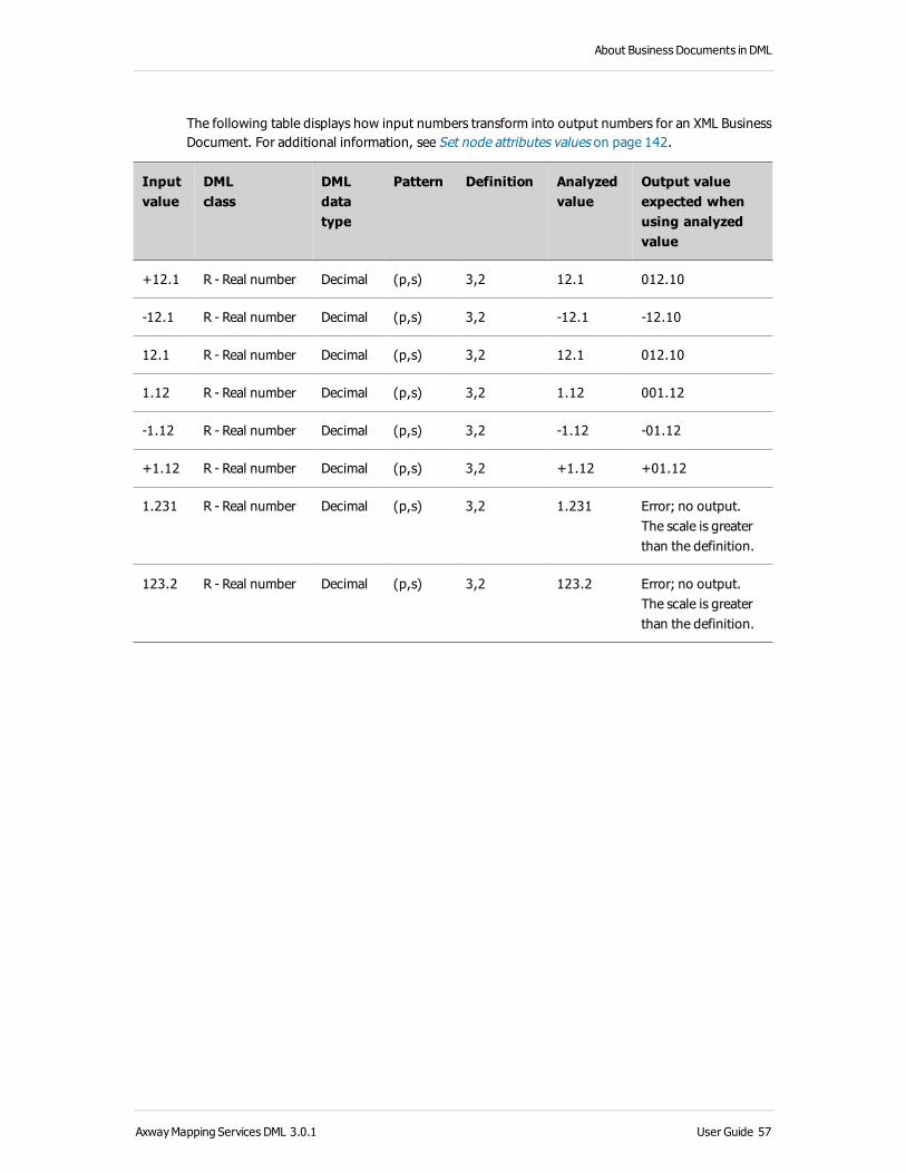
The following table displays how input numbers transform into output numbers for an XML Business Document. For additional information, see Set node attributes values on page 142.
Inputvalue
DMLclass
DMLdatatype
Pattern Definition Analyzedvalue
Output value expected when using analyzed value
+12.1 R - Real number Decimal (p,s) 3,2 12.1 012.10
-12.1 R - Real number Decimal (p,s) 3,2 -12.1 -12.10
12.1 R - Real number Decimal (p,s) 3,2 12.1 012.10
1.12 R - Real number Decimal (p,s) 3,2 1.12 001.12
-1.12 R - Real number Decimal (p,s) 3,2 -1.12 -01.12
+1.12 R - Real number Decimal (p,s) 3,2 +1.12 +01.12
1.231 R - Real number Decimal (p,s) 3,2 1.231 Error; no output. The scale is greater than the definition.
123.2 R - Real number Decimal (p,s) 3,2 123.2 Error; no output. The scale is greater than the definition.
AxwayMapping Services DML 3.0.1 User Guide 57

2 Create and import Mapping objects in DML
XSD Business DocumentXSD Business Documents are used to load XML schemas and create Maps from them, instead of having to import XML files first to keep the structure up-to-date.
XSD Business Document data types are read-only. The XSD Business Document editor does not allow the changing of the element data types, because these are retrieved from the schema from which the Business Document is loaded. XML schema primitive and derived data types are mapped to the corresponding XSD Business Document data types.
58 User Guide AxwayMapping Services DML 3.0.1

About Business Documents in DML
JDBC database Business DocumentThe data types that you can apply depend on the data class. In turn, the possible data classes depend on the structure type of the Business Document. For more information, see Business Document structure in DML on page 20, About Business Documents in DML on page 19, and Axway Mapping Services DML Reference Guide.
Data class Data type Definition field
Boolean Boolean [0,1] 1
Date & Time Date & Time[YYYYMMDDhhmmsshhmm]
18 (indicates a date and time)
Integer Integer (p) 10
Real number Numeric (p,s) 18,6
Numeric (m,e) 18,6
String String 255
Very Large Object
largeBinary (len) 4000
Binary (len) 4000
Varbinary (len) 4000
Blob (len) 4000
Clob (len) 4000
AxwayMapping Services DML 3.0.1 User Guide 59

2 Create and import Mapping objects in DML
Generic Business DocumentThe data types that you can apply depend on the data class. In turn, the possible data classes depend on the structure type of the Business Document. For more information, see Business Document structure in DML on page 20, About Business Documents in DML on page 19, and Axway Mapping Services DML Reference Guide.
Data class Data type Definition field value
Boolean Boolean [false, true] 5 (indicates XML Boolean)
Boolean [0,1] 1 (indicates XML Boolean)
Date & Time Date & Time YYYYMMDDhhmmsshhmm
Integer Integer (p) 10
Real number Numeric (p,s) 18,6
Numeric (m,e) 18,6
String String (len) 255
Very large object largeBinary (len) 4000
60 User Guide AxwayMapping Services DML 3.0.1

About Business Documents in DML
Format options for Real numbersThere are several options for controlling the formatting of output Real numbers in Business Documents for DML. Some of these options are available for XML, X12, EDIFACT, Flat File and SCRIPT Business Documents only.
The options are located in the Business DocumentProperties > General tab, as well as in the Attributes > Definition properties for individual nodes.
Parameter Description
Pad Reals with a leading and trailing zero
Ensures Real numbers always have at least one digit before and after the decimal. For example, selecting this option results in the following:
1 becomes 1.0
.6 becomes 0.6
. becomes 0.0
Keep decimal separator character
Ensures Real numbers in an output Business-Document use the same character for the decimal separator as the input Business-Document.
Keep decimal separator Ensures that if a Real number in an input Business-Document includes a decimal separator (or not), the output Business-Document will also have a decimal separator (or not).
Keep + sign for positive real numbers
Ensures positive Real numbers in an output Business-Document use the same format to indicate a positive value as the input Business-Document.
For example, if the input Business-Document includes a + sign before the value, then there will be a + sign before the value in the output Business-Document.
Keep number of fractional digits
Ensures that if Real numbers in an input Business-Document includes n fractional digits, then Real numbers in the output Business-Document will also have n fractional digits.
Keep number of digits for date
Ensures that if the input and output date patterns are the same, then the number of digits in the output remains the same as the number of digits in the input.
AxwayMapping Services DML 3.0.1 User Guide 61

2 Create and import Mapping objects in DML
ExamplesThis section shows how selecting or de-selecting these options affects the format of Real numbers in the output Business Document.
Keep decimal separator and fractional digitsSelecting the following check boxes ensures the output format of real numbers is the same as their input format.
The following tables show how the different check boxes impact the output (where T = selected, and F = de-selected).
Input value: 1,990
Check box
Keep decimal separator
Keep decimal separator
character
Keep number of fractional digits
Output 1,990 1,99 1.99 1.990 1.99 1.990 1,990 1,99
EDIFACT Output same same 1,99 1,990 1,99 1,990 same same
62 User Guide AxwayMapping Services DML 3.0.1

About Business Documents in DML
Input value: 1
Check box
Keep decimal separator
Keep decimal separator character
Keep number of fractional digits
Output 1 1 1 1 1. 1. 1. 1.
EDIFACT Output same same same same 1, 1, 1, 1,
Input value: 1.0
Check box
Keep decimal separator
Keep decimal separator character
Keep number of fractional digits
Output 1.0 1. 1. 1.0 1. 1.0 1.0 1.
EDIFACT Output same same 1, 1,0 1, 1,0 same same
Keep + sign for positive valuesSelecting this check box ensures that output real numbers use the same format to denote positive numbers as in the input Business Document.
The following tables show how this option impacts the output.
AxwayMapping Services DML 3.0.1 User Guide 63

2 Create and import Mapping objects in DML
When selected:
Input Output
1 1
+1 +1
When de-selected:
Input Output
1 +1
+1 1
64 User Guide AxwayMapping Services DML 3.0.1

About Business Documents in DML
Create Business Documents in DMLIn a DML Mapping Project, the Business Document describes the composition and structure of the input and output messages for the Mappings.
You have two options when you create Business Documents in DML:
l Import and modify an existing Business Document structure (see Import Business Documents into DML Mapping Projects on page 152 and Import a Business Document from a library on page 157))
l Create Business Documents from scratch on page 65
For more information on Business Documents in DML, see About Business Documents in DML on page 19.
Create Business Documents from scratchTo create a new Business Document:
1. From the main menu, select File > New > Business Document.
Alternatively, you can right-click in the Project Explorer and select New > Business Document.
A wizard appears to help you create a new Business Document.
2. Specify where you want to save the Business Document. To select a path either use the directory tree or enter the path directly.
3. Enter a File name for your Business Document. It must be a valid Business Document name. That means you cannot use special or space characters.
4. Click Next.
5. Select the Business Document Type you require. Click Finish.
Mapping Services creates the Business Document in the selected project’s Business Document folder and an entry in the Project Explorer pane tree structure. The Business Document opens on a new tab in the Business Document editor.
AxwayMapping Services DML 3.0.1 User Guide 65

2 Create and import Mapping objects in DML
Define HL7 Business DocumentsWhen you create an HL7 Business Document, you specify values for certain parameters that are common to all Business Document formats and others that are specific to the HL7 format.
For more information on the HL7 Business Document structure, see HL7 Business Document on page 27.
This topic describes all HL7-specific parameters. It contains the following sections:
on page 66
Create an HL7 Business Document from scratch on page 68
Edit an HL7 Business Document on page 68
Properties view on page 68
Modify node attributes on page 69
Business Document editor – define the tree structure on page 69
Node types on page 71
Add nodes to the tree structure on page 71
About HL7 Business DocumentsHealth Level Seven (HL7) was founded in 1987 to develop standards for the electronic interchange of clinical, financial, and administrative information among independent health care oriented computer systems, such as hospital information systems, clinical laboratory systems, enterprise systems, and pharmacy systems.
The HL7 version 3.0 standard defines transactions for transmitting data about:
l Patient registration
l Admissions
l Discharge and transfers
l Insurance
l Charges and payors
l Orders and results for laboratory tests
l Image studies
l Nursing and physician observations
l Diet orders
l Pharmacy orders
66 User Guide AxwayMapping Services DML 3.0.1

About Business Documents in DML
l Supply orders
l Master files
l Appointment
l Scheduling
l Problem lists
l Clinical trial enrollments
l Patient permissions
l Voice dictations
l Advanced directives
l Physiologic signals
AxwayMapping Services DML 3.0.1 User Guide 67

2 Create and import Mapping objects in DML
Create an HL7 Business Document from scratchTo create an HL7 Business Document in an existing DML Mapping Project:
1. From the main menu, select File > New > Business Document.
Alternatively, you can right-click in the Project Explorer and select New > Business Document.
2. Specify where you want to save the Business Document. To select a path either use the directory tree or enter the path directly.
3. Enter a File name for your Business Document. Click Next.
4. Select HL7 as the Business Document type.
5. Click Finish.
Mapping Services generates the HL7 Business Document in the selected project’s Business Document folder.
The generated Business Document opens automatically and is available for editing in the Business Document editor.
Note An alternative to manually creating an HL7 Business Document is to use the Business Document importer tool to generate an HL7 Business Document from a model file. For more information, see Import Business Documents into DML Mapping Projects on page 152 and Import a Business Document from a library on page 157.
Edit an HL7 Business Document
Properties viewIn the Properties view of the Business Document editor, Mapping Services displays a set of configuration fields that define the HL7 Business Document general characteristics.
General propertiesYou can modify the general structural characteristics, including modifying node attributes in the General section of the Properties view.
Parameter Description
Encoding From the drop-down list, select the encoding you want to use. This value can be the default encoding available after the installation, but this can be customized by adding new encoding to the <Mapping Services install
folder>/configuration/encoding.properties file.
68 User Guide AxwayMapping Services DML 3.0.1

About Business Documents in DML
Modify node attributesSome of the HL7 node attributes can be modified in the Attributes section of the Properties view.
Not all of the nodes of the HL7 Business Document have attributes that can be modified. The non-modifiable attributes are highlighted in gray.
For more information on the Business Document structure, see Business Document structure in DML on page 20, Business Document cardinality on page 21, Business Document data types in DML on page 22 and Format options for Real numbers on page 61.
Business Document editor – define the tree structureThe structure of an HL7 Business Document consists of a group of segments in a well-defined sequence. Every HL7 message has a message type attribute that defines the message purpose (admissions, insurance, appointments, and so on).
An HL7 message comprises of segments. A segment is a logical grouping of data fields. The segments of an HL7 message can be mandatory or optional. A segment may occur only once in a message or it may repeat. Each segment has a unique name. It begins with a three-character literal value that identifies it within a message. The HL7 standard assigns a certain number of fields to the different segment types.
MSH segment (Message Header)The Message Header (MSH) segment of an HL7 message is a mandatory segment that contains information about the message structure, type, origin, destination, and acknowledgment requirements.
AxwayMapping Services DML 3.0.1 User Guide 69

2 Create and import Mapping objects in DML
Message body segmentsIn addition to the header segment, each HL7 message comprises of one or more segments that contain information about a specific health organization process.
For example, HL7 standards define the Admit Patient (ADT) message that contains the following segments:
l MSH: Message Header (mandatory)
l EVN: Event Type
l PID: Patient Identification
l PD1: Additional Demographics
l NK1: Next of Kin
l PV1: Patient Visit
l PV2: Patient Visit (Additional Info.)
l DB1: Disability Information
l OBX: Health Information
l AL1: Allergy Information
l DG1: Diagnosis Information
l PR1: Procedures
l ROL: Role
l GT1: Guarantor Information
l IN1: Insurance Information
Each segment type contains a set of standard message components that hold data. These components are known as data fields.
The number and organization of the data fields within a segment vary depending on the HL7 segment type.
You can edit the Business Document structure by using the Business Document editor’s Structure tab, where you can add or delete new nodes.
The default structure of an HL7 Business Document contains the MSH segment. Define your own structure by adding parent and leaf element nodes.
70 User Guide AxwayMapping Services DML 3.0.1

About Business Documents in DML
Node typesYou can use these nodes to create the document structure:
l Field Container
l Component Container
l Sub-Component Container
l Sequence
l Leaf
Add nodes to the tree structureTo add nodes to the tree structure, use one of the following functions in the Business Document editor's context menu:
l Insert a Field Container with Sub-Tree to group other nodes without values.
l Insert a Field Container to group other nodes without values and leaf element nodes.
l Insert a Field as a Child of the selected node.
l Insert a Component Container to group Sub-Component Container nodes and leaf element nodes.
l Insert a Sub-Component Container to group leaf element nodes.
l Insert a Sequence.
l Insert a Sequence as a Child of another Sequence node or of a Field Container node.
AxwayMapping Services DML 3.0.1 User Guide 71

2 Create and import Mapping objects in DML
Define Flat File Business DocumentsWhen you create a Flat File Business Document, you specify values for certain parameters that are common to all Business Document formats and others that are specific to the Flat File format.
For more information on the Flat File Business Document structure, see Flat File Business Document on page 28.
This topic describes all Flat File-specific parameters. It contains the following sections:
Create Flat File Business Documents on page 72
Properties view on page 72
Business Document editor - define the tree structure on page 78
Nodes without values on page 78
Nodes with values on page 79
Create or modify a Flat File Business Document on page 80
Use node attributes on page 81
Create Flat File Business DocumentsAn alternative to manually creating a Flat File Business Document is to use the Business Document importer tool to generate a Flat File Business Document from a model file. The Business Document importer handles CSV-type Flat Files as well as other file types.
For more information, see Import Business Documents into DML Mapping Projects on page 152 and Import a Business Document from a library on page 157.
Properties viewIn the Properties view of the Business Document editor, Mapping Services displays a set of configuration fields that define the Flat File Business Document general structural characteristics, such as delimiters, quote characters, escape characters, and so on.
For more information on the Business Document structure, see Business Document structure in DML on page 20, Business Document cardinality on page 21, Business Document data types in DML on page 22 and Format options for Real numbers on page 61.
The values you select for the fields of the Properties window determine the format of the information that the Flat File Business Document can contain.
72 User Guide AxwayMapping Services DML 3.0.1

About Business Documents in DML
After you define the Flat File Business Document, you can embed it in an Integration Process:
l For input Business Documents
When the Map Engine handles an incoming message, it scans the incoming message and compares the structure of the message with the structure described by the input Business Document. If the incoming message corresponds strictly to the structure described by the Business Document, the Map Engine extracts data from the message and constructs a Business Document instance. If any part of the input message fails to comply to the expected format, the Map Engine rejects the message and does not generate a Business Document instance.
l For output Business Documents
The output Business Document holds the results of the Mapping in a structure that must correspond to the structural characteristics of the intended output message of the Mapping Flow. The Map Engine extracts the structured data content of the output Flat File Business Document to use for the next integration processing event.
Each new node that you create inherits the values specified in the Properties view. If most of your nodes use the same delimiters, it is useful to set the default delimiters in the General section of the Properties view. For nodes that use different values, modify these values in the Business Document editor.
Field Contents
Parent delimiter
Specifies the end delimiter type for parent nodes. The available values are:
l Fixed
l String
l Implicit
Refer to: Delimiter options on page 78
Parent delimiter value
The available values depend on the delimiter type selected in the previous parameter.
Refer to: Delimiter options on page 78
Leaf element delimiter
Specifies the end delimiter type for element nodes. The available values are:
l Fixed
l String
Refer to: Delimiter options on page 78
Leaf element delimiter value
The available values depend on the delimiter type selected in the previous parameter.
Refer to: Delimiter options on page 78
AxwayMapping Services DML 3.0.1 User Guide 73

2 Create and import Mapping objects in DML
Field Contents
Open quote character
Specifies the open quote character to be used to mark the start of a quoted region.
You can enter any of the following characters:
l Empty, meaning none
l Any single character
l Four-character hexadecimal code for a character, for example, 0x0a for a new line character
The Map detects an open quote character in a source data instance. It can be at any position in the field but most often is at the left (beginning) edge of a field. Add an open quote character to a destination data instance to protect a field that contains a character that is the same as a record delimiter or field delimiter character.
Close quote character
Specifies the close quote character to be used to mark the end of a quoted region.
You can enter any of the following characters:
l Empty, meaning none
l Any single character that you can enter from the keyboard
l Four-character hexadecimal code for a character, for example, 0x0a for a new line character
The Map searches for a close quote character if it found an open quote character in a source data instance.
The Map adds a close quote character to a destination data instance if it added an open quote character.
Escape character
Specifies the character to use as the escape character. The Map ignores all characters that follow this character. Use the escape character to hide a single data character that would otherwise be mistaken for an open quote or close quote character.
Enter any of the following characters, on condition that it is not already used as an open or close quote character:
l Empty, meaning none
l Any single character that you can enter from the keyboard
l Four-character hexadecimal code for a character, for example, 0x0a for a new line character
Decimal character
Specifies the character that marks a decimal point.
74 User Guide AxwayMapping Services DML 3.0.1

About Business Documents in DML
Field Contents
Encoding From the drop-down list, select the encoding you want to use. This value can be the default encoding available after the installation, but this can be customized by adding new encoding to the <Mapping Services install folder>/configuration/encoding.properties file.
AxwayMapping Services DML 3.0.1 User Guide 75

2 Create and import Mapping objects in DML
Field Contents
Trim Specify the organization of record and field delimiters that the Map Engine handles in the Business Document. When processing an input message, the Map Engine scans all records and fields in the message to verify that the records and fields are trimmed as described in this attribute. If the trimming does not correspond, the message is rejected.
To set the Business DocumentTrim characteristic, select a trim option from the drop-down list:
l None (default): The Business Document accepts fields and records without trimming.
l Trim field delimiters: The Business Document accepts only trimmed field delimiters.
A trimmed field is a field in which the last field value delimiter of a record is removed.
l Trim record delimiters: The Business Document accepts only trimmed record delimiters.
A trimmed record is a record in which the last leaf element delimiter is removed.
l Trim field and record delimiters: The Business Document accepts only trimmed field and record delimiters.
Example 1: Trimming a record delimiter
Fields have the structure:Code=value;
A record is a series of fields with the structure:"1 to n fields" + "#" + "toto"
Where # is the record separator and toto is the continuation of the message.
If you set the trim value to None, the Business Document accepts:C1=V1;C2=V2;#toto
If you set the trim value to Trim record delimiters, the Business Document accepts:C1=V1;C2=V2toto
Example 2: Trimming a field delimiter
Fields have the structure:Code=value;
A record is a series of fields with the structure:"1 to n fields" + "#" + "toto"
Where # is the record separator and toto is the continuation of the message.
If you set the trim value to None, the Business Document accepts:C1=V1;C2=V2;#toto
If you set the trim value to Trim field delimiters, the Business Document accepts:
76 User Guide AxwayMapping Services DML 3.0.1

About Business Documents in DML
Field Contents
C1=V1;C2=V2#toto
Trim none: a=b;c=d;|e=f;g=h;|@
Trim record: a=b;c=d;|e=f;g=h
Trim record and field: a=b;c=d|e=f;g=h
Trim field: a=b;c=d|e=f;g=h|@
Truncate Select this check box to specify truncation of parent nodes.
Example 1:
A parent node with an exclamation mark (!) as delimiter and with fixed-length (6 characters) leaf elements would appear as:
Without truncation:
TAGone two four five six !
With truncation:
TAGone two four five six !
Example 2:
A parent node with an exclamation mark (!) as delimiter and comma (,) as leaf element delimiter would appear as:
Without truncation:
TAG,one,two,,four,five,six,,,,!
With truncation:
TAG,one,two,,four,five,six,!
A Map does not search for characters defined as parent or leaf delimiters or string delimiters within the quoted region (between the open quote and close quote characters).
Real number formattingYou can use real and integer numbers with X12 data types. For details seeFormat options for Real numbers on page 61 and Flat File Business Document on page 28.
AxwayMapping Services DML 3.0.1 User Guide 77

2 Create and import Mapping objects in DML
Delimiter optionsDelimiters mark the end of parent and child elements in your file structure. You can select different delimiters for parent and child elements. The following table describes the different options and how they appear in the file.
Delimiter type
Value What marks the end of a parent or leaf instance?
Fixed n (Integer greater than 0) A count of n characters.
String Multiple characters. You can mix printable characters with non-printable characters.
Use four-character hexadecimal code for non-printable characters, for example, END0x0a.
The string of characters that the Value field specifies.
Implicit (only applicable on parent level)
None No delimiter is required. The record ends when the Map Engine finds its leaf elements and enclosed parents.
Default (only available from the node Properties view)
Selecting Default inherits the value specified in the General section of the Properties view
-
Business Document editor - define the tree structureTo define the tree structure of a Flat File Business Document, you can use:
l Nodes without values on page 78: group other nodes and describe:
o The hierarchical structure of a Business Document
o The relationship between the nodes that they group
l Nodes with values on page 79: contain data and are frequently grouped in nodes without values.
Nodes without valuesIn a Flat File Business Document, you can use the following node without values:
l Parent: This node groups the nodes that represent the fields in a single parent (or segment) of data.
78 User Guide AxwayMapping Services DML 3.0.1

About Business Documents in DML
Nodes with valuesTo create the document structure you select the Business Document editor. By default, there is a root node in the left pane. Define your own structure by adding parent and leaf element nodes below the root.
You can use the following nodes to create your document structure:
l Leaf nodes on page 79
l Breakpoint nodes on page 79
l Landmark nodes on page 80
Leaf nodesLeaf nodes contain Business Document data. Several leaf nodes are often grouped together in a node without values (a parent node, for example).
The following is an example of leaf nodes that are grouped in a parent node:
Leaf element Description
Items Purchased Two leaf nodes that describe the items a customer purchased are grouped in the parent node Items Purchased.
Title Depending on what a customer purchases, the Title node contains the title of a book or a CD.
Author The Author node contains the name of an author or musical artist.
Breakpoint nodesFor each new breakpoint value a new ORDER_LINE parent is created.
Leaf element Description
ORDER For each new breakpoint value a new ORDER_LINE parent is created.
ORDER_LINE
Number
Item
Price
AxwayMapping Services DML 3.0.1 User Guide 79

2 Create and import Mapping objects in DML
Landmark nodesEach Landmark signifies the start of a new record.
Leaf element Description
ORDER Each landmark signifies the start of a new record.
HEAD
Landmark (Head)
Number
LINE
Landmark (Line)
Line
Cost
TAIL
Landmark (Tail)
Total_Lines
Total_Cost
Create or modify a Flat File Business DocumentTo add nodes to the tree structure, use one of the following functions in the Business Document editor's context menu:
l Insert a Parent node that is a sibling of the selected node
l Insert a Parent node as a Child of the selected node
l Insert a Leaf node:
o to the selected segment node
o that is a sibling of the selected leaf node
l Insert a Breakpoint: This value is used to remember which type of record is worked on. The value of the first instance of the record is kept in memory. Subsequent instances that match this value are assumed to identify the same type of record. When a new value is encountered, the breakpoint is reset to the new value.
l Insert a Landmark : This is a static value that is used to recognize a source record. If the source instance does not match the defined value, the record is not the one defined in the Business Document. This value is used to write a data instance to a destination record. The landmark value overwrites the mapped value.
80 User Guide AxwayMapping Services DML 3.0.1

About Business Documents in DML
Use node attributesAll nodes with values have node attributes that you can modify. Some of these attributes are common to all Business Document formats and some are specific to the Flat File format.
AxwayMapping Services DML 3.0.1 User Guide 81

2 Create and import Mapping objects in DML
Define COBOL Business DocumentsWhen you create a COBOL Business Document (see COBOL Business Document on page 44), you specify values for certain parameters that are common to all Business Document formats and others that are specific to the COBOL format.
For more information on the COBOL Business Document structure, see COBOL Business Document on page 44.
This topic describes all COBOL-specific parameters. It contains the following sections:
on page 82
Create a COBOL Business Document from scratch on page 82
Edit a COBOL Business Document on page 83
Properties view on page 83
General properties on page 83
Modify node attributes on page 84
Business Document editor – define the tree structure on page 84
Node types on page 85
Add nodes to the tree structure on page 85
About COBOL Business DocumentsCOBOL (Common Business Oriented Language) was the first widely-used high-level programming language for business applications. Many payroll, accounting, and other business application programs written in COBOL over the past 35 years are still in use, and it is possible that there are more existing lines of programming code in COBOL than in any other programming language. While the language has been updated over the years, it is generally perceived as out-of-date and COBOL programs are generally viewed as legacy applications.
Create a COBOL Business Document from scratchTo create a COBOL Business Document in an existing DML Mapping Project:
1. From the main menu, select File > New > Business Document.
Alternatively, you can right-click in the Project Explorer and select New > Business Document.
2. Specify where you want to save the Business Document. To select a path either use the directory tree or enter the path directly.
82 User Guide AxwayMapping Services DML 3.0.1

About Business Documents in DML
3. Enter a File name for your Business Document. Click Next.
4. Select COBOL Fixed or COBOL Variable as the Business Document type.
5. Click Finish.
Mapping Services generates the COBOL Business Document in the selected project’s Business Document folder.
The generated Business Document opens automatically and is available for editing in the Business Document editor.
Note An alternative to manually creating a COBOL Business Document is to use the Business Document importer tool to generate a COBOL Business Document from a model file. For more information, see Import Business Documents into DML Mapping Projects on page 152 and Import a COBOL Business Document from Standard on page 158.
Edit a COBOL Business Document
Properties viewIn the Properties view of the Business Document editor, Mapping Services displays a set of configuration fields that define the COBOL Business Document general characteristics.
For more information on the Business Document structure, see Business Document structure in DML on page 20, Business Document cardinality on page 21, Business Document data types in DML on page 22 and Format options for Real numbers on page 61.
General propertiesYou can modify the general structural characteristics, including modifying node attributes in the General section of the Properties view. Each newly-created node inherits the specified values.
Parameter Description
Parent delimiter value
Specifies the end delimiter value.
AxwayMapping Services DML 3.0.1 User Guide 83

2 Create and import Mapping objects in DML
Parameter Description
Escape character
Specifies the character to use as the Escape character. The Map ignores all characters that follow this character. Use the Escape character to hide a single data character that would otherwise be mistaken for an open quote or close quote character. Enter any of the following characters, on condition that it is not already used as an open or close quote character:
l Empty, meaning none
l Any single character that you can enter from the keyboard
l Four character hexadecimal code for a character, for example, 0x0a for a new line character
Encoding From the drop-down list, select the encoding you want to use. This value can be the default encoding available after the installation. The encoding is defined in the <Mapping Services install folder>/configuration/encoding.properties file.
Modify node attributesSome of the COBOL node attributes can be modified in the Attributes section of the Properties view.
Note that not all of the nodes of the COBOL Business Document have attributes that can be modified. The non-modifiable attributes are highlighted in gray.
Business Document editor – define the tree structureYou can modify the Business Document structure by using the Business Document editor’s Structure tab, where you can add or delete new nodes.
By default, the structure of the COBOL Business Document generated by Mapping Services is:
84 User Guide AxwayMapping Services DML 3.0.1

About Business Documents in DML
Node typesYou can use these nodes to create the document structure:
l Segment
l Occurs
l Filler
l Redefinition Element
l Leaf
l Breakpoint
l Landmark
Add nodes to the tree structureTo add nodes to the tree structure, use one of the following functions in the Business Document editor's context menu:
l Insert a Segment to group the nodes that represent the fields of a segment.
l Insert an Occurs.
l Insert a Filler to create a gap in a segment that you can use at a later time to insert leaf element nodes.
l Insert a Redefinition Element that redefines the COBOL data that is stored in a fixed-length field.
l Insert a Leaf that contains values.
l Insert a Breakpoint. This value is used to remember which type of record is worked on.
l Insert a Landmark. This is a static value that is used to recognize a source record.
AxwayMapping Services DML 3.0.1 User Guide 85

2 Create and import Mapping objects in DML
Define Cargo IMP Business DocumentsWhen you create a Cargo IMP Business Document, you specify values for certain parameters that are common to all Business Document formats and others that are specific to the Cargo IMP format.
For more information on Business Document, see About Business Documents in DML on page 19 and Business Document structure in DML on page 20.
This topic describes all Cargo IMP-specific parameters. It contains the following sections:
About Cargo IMP Business Documents on page 86
Create a Cargo IMP Business Document from scratch on page 87
Edit a Cargo IMP Business Document on page 87
Properties view on page 87
General properties on page 87
Modify node attributes on page 88
Business Document editor – define the tree structure on page 88
Node types on page 88
Add nodes to the tree structure on page 89
About Cargo IMP Business DocumentsThe member airlines of the International Air Transport Association (IATA) and the Air Transport Association of America (ATA) have established a standard for the exchange of specific Business Documents for the air cargo transfer industry. This standard is known as the Cargo Interchange Message Procedures (Cargo IMP).
A Cargo IMP document is passed between systems wrapped either as an EDIFACT message or as a pure IATA message with an IATA message header.
A message can be a maximum of 1600 bytes long. If a message exceeds that size it must be split into two or more submessages. If a message is split, an attribute of the IATA envelope indicates that the message is not complete.
A Cargo IMP message consists of two principal parts:
l Standard Message Identifier (SMI)
l Standard Message Text (SMT).
Each line within a Cargo-IMP message is restricted to a maximum of 69 characters.
For more information on the Cargo IMP message format see the official IATA specification.
86 User Guide AxwayMapping Services DML 3.0.1
About Business Documents in DML
Create a Cargo IMP Business Document from scratchTo create a Cargo IMP Business Document from scratch:
1. From the main menu, select File > New > Business Document.
Alternatively, you can right-click in the Project Explorer and select New > Business Document.
2. Specify where you want to save the Business Document. To select a path either use the directory tree or enter the path directly.
3. Enter a File name for your Business Document. Click Next
4. Select Cargo IMP as the Business Document type.
5. Click Finish.
Mapping Services generates the Cargo IMP Business Document in the selected project’s Business Document folder.
The generated Business Documentopens automatically and is available for editing in the Business Document editor.
Note An alternative to manually creating a Cargo IMP Business Document is to use the Business Document importer tool to generate a Cargo IMP Business Document from a model file. For more information, see Import Business Documents into DML Mapping Projects on page 152 and Import a Business Document from a library on page 157, and Import an Axway EDI Business Document into DML Mapping Projects on page 156.
Edit a Cargo IMP Business Document
Properties viewIn the Properties view of the Business Document editor, Mapping Services displays a set of configuration fields that define the Cargo IMP Business Document general characteristics.
For more information on the Business Document structure, see Business Document structure in DML on page 20, Business Document cardinality on page 21, Business Document data types in DML on page 22 and Format options for Real numbers on page 61.
General propertiesYou can modify the general structural characteristics, including modifying node attributes in the General section of the Properties view.
AxwayMapping Services DML 3.0.1 User Guide 87

2 Create and import Mapping objects in DML
Parameter Description
Table From the drop-down list, select the Table you want to use. This value can be Cargo IMP version-specific code lists or code lists that you created yourself.
The code lists contain authorized values for your Business Document.
Encoding From the drop-down list, select the encoding you want to use. This value can be the default encoding available after the installation, but this can be customized by adding new encoding to the <Mapping Services install folder>/configuration/encoding.properties
file.
Disable character validation on t[..N] elements
Modify node attributesYou can modify some of the Cargo IMP node attributes in the Attributes section of the Properties view.
Note that not all the nodes of the Cargo IMP Business Document have attributes that can be modified. The non-modifiable attributes are marked in gray.
Business Document editor – define the tree structureYou can edit the Business Document structure by using the Business Document editor’s Structure tab, where you can add new nodes or delete nodes.
The default structure of a Cargo IMP Business Document contains a Data Element Group element which contains a child element. Define your own structure by adding parent and child element nodes.
Node typesYou can use these nodes to create the document structure:
l Text Element
l Data Element Group
l Choice
l Sequence
l Data Element
88 User Guide AxwayMapping Services DML 3.0.1

About Business Documents in DML
Add nodes to the tree structureTo add nodes to the tree structure, use one of the following functions in the Business Document editor's context menu:
l Insert a Text Element.
l Insert a Data Element Group to group Data Element nodes.
l Insert a Choice.
l Insert a Choice as a Child of the selected node.
l Insert a Sequence.
l Insert a Sequence as a Child of the selected node.
l Insert a Data Element that contains values.
AxwayMapping Services DML 3.0.1 User Guide 89

2 Create and import Mapping objects in DML
Define SCRIPT Business DocumentsWhen you create a SCRIPT Business Document, you specify values for certain parameters that are common to all Business Document formats and others that are specific to the SCRIPT format.
For more information on Business Documents, see About Business Documents in DML on page 19.
This topic describes all SCRIPT-specific parameters. It contains the following sections:
About SCRIPT Business Documents on page 90
Create a SCRIPT Business Document from scratch on page 91
Import a SCRIPT document structure on page 91
Edit a SCRIPT Business Document on page 91
Properties view on page 91
Modify node attributes on page 92
Real number formatting on page 92
Business Document editor – define the tree structure on page 92
Node types on page 93
Add nodes to the tree structure on page 93
About SCRIPT Business DocumentsSCRIPT is a standard created to facilitate the transfer of prescription data between pharmacies, prescribers, intermediaries, and payers. It was first published in 1997 by NPCDP (National Council for Prescription Drug Programs) and since then it went through several updates according to the growing needs in the industry.
You have two options when you create a SCRIPT Business Document:
l Import a SCRIPT document structure on page 91 from library and modify it (see also Import a Business Document from a library on page 157)
l Create a SCRIPT Business Document from scratch on page 91
90 User Guide AxwayMapping Services DML 3.0.1

About Business Documents in DML
Create a SCRIPT Business Document from scratchTo create a SCRIPT Business Document in an existing DML Mapping Project:
1. From the main menu, select File > New > Business Document.
Alternatively, you can right-click in the Project Explorer and select New > Business Document.
2. Specify where you want to save the Business Document. To select a path either use the directory tree or enter the path directly.
3. Enter a File name for your Business Document. Click Next.
4. Select SCRIPT as the Business Document type.
5. Click Finish.
Mapping Services generates the SCRIPT Business Document in the selected project’s Business Document folder.
The generated Business Document opens automatically and is available for editing in the Business Document editor.
Import a SCRIPT document structureTo import an existing SCRIPT Business Document from library:
1. From the main menu, select File > Import.
Alternatively, you can right-click in the Project Explorer and select Import.
2. In the import dialog, select Mapping Services > DML > Business Document from Library.
3. Click Next.
4. In the Library Browser, select the SCRIPT Business Document you want to import.
On the right panel, you can add information about the selected SCRIPT Business Document: Description and Dependencies.
5. Click Next to select the folder in which the SCRIPT Business Document will be imported.
6. Enter a Name for the SCRIPT Business Document and click Finish to import the SCRIPT Business Document.
Edit a SCRIPT Business Document
Properties viewIn the Properties view of the Business Document editor, Mapping Services displays a set of configuration fields that define the SCRIPT Business Document general characteristics.
AxwayMapping Services DML 3.0.1 User Guide 91

2 Create and import Mapping objects in DML
For more information on the Business Document structure, see Business Document structure in DML on page 20, Business Document cardinality on page 21, Business Document data types in DML on page 22 and Format options for Real numbers on page 61.
General propertiesYou can modify the general structural characteristics, including modifying node attributes in the General section of the Properties view.
Parameter Description
Encoding From the drop-down list, select the encoding you want to use. This value can be the default encoding available after the installation, but this can be customized by adding new encoding to the <Mapping Services install
folder>/configuration/encoding.properties file.
Modify node attributesSome of the SCRIPT node attributes can be modified in the Attributes section of the Properties view.
Not all of the nodes of the SCRIPT Business Document have attributes that can be modified. The non-modifiable attributes are highlighted in gray.
Real number formattingFor details see Format options for Real numbers on page 61.
Business Document editor – define the tree structureYou can edit the Business Document structure by using the Business Document editor. On the Structure tab, you can add new nodes or delete nodes.
By default, the structure generated after the creation of the SCRIPT Business Document from scratch is the definition of Get Message Transaction (GETMSG).
92 User Guide AxwayMapping Services DML 3.0.1

About Business Documents in DML
Node typesYou can use these nodes to create the document structure:
l Segment
l Segment Group
l Composite
l Simple Element
Add nodes to the tree structureTo add nodes to the tree structure, use one of the following functions in the Business Document editor's context menu:
l Insert a Segment Group.
A segment group does not contain values. It is a node that groups other segments.
l Insert a Segment Group as a Child of an existing segment group.
l Insert a Segment node.
A segment does not contain values. It groups simple elements or composite elements.
l Insert a Segment as a Child of the selected node.
l Insert a Composite element.
A composite element does not contain values. It groups simple elements.
l Insert a Simple Element node to the selected segment or composite element node.
A simple element contains values.
AxwayMapping Services DML 3.0.1 User Guide 93

2 Create and import Mapping objects in DML
Define EDIFACT Business DocumentsWhen you create an EDIFACT Business Document, you specify values for certain parameters that are common to all Business Document formats and others that are specific to the EDIFACT format.
For more information on the EDIFACT Business Document structure, see EDIFACT Business Document on page 46.
This topic describes all EDIFACT-specific parameters. It contains the following sections:
l Properties view on page 94
l Business Document editor on page 94
l Define simple element properties on page 97
Properties view In the Properties view of the Business Document editor, in the General section, the following parameters can be set to define additional properties for EDIFACT Business Documents.
Parameter Description
Table
From the drop-down list, select the code list table you want to use. This value can be EDIFACT version-specific code lists or code lists that you created yourself. The code lists contain authorized values for your Business Document.
Encoding
From the drop-down list, select the encoding you want to use. This value can be the default encoding available after the installation, but this can be customized by adding new encoding to the <Mapping Services install folder>/configuration/encoding.properties file.
For more information on the Business Document structure, see Business Document structure in DML on page 20, Business Document cardinality on page 21, Business Document data types in DML on page 22 and Format options for Real numbers on page 61.
Business Document editorYou have two options when you create EDIFACT Business Documents:
l Define the structure of an EDIFACT Business Document on page 95
l Import and modify an existing Business Document structure (see Import an Axway EDI Business Document into DML Mapping Projects on page 156)
94 User Guide AxwayMapping Services DML 3.0.1

About Business Documents in DML
To create your own EDIFACT structure, you can use:
l Nodes without values: they group other nodes and describe:
o The hierarchical structure of a Business Document.
o The relationship between the nodes that they group.
l Nodes with values: they contain data and are frequently grouped in nodes without values.
Define the structure of an EDIFACT Business DocumentWhen you create an EDIFACT Business Document, Mapping Services automatically creates an EDIFACT structure in the Business Document editor and populates it with all the mandatory segments. The Insert functions in the Business Document editor's context menu provide alternative ways to insert nodes. The following list describes the different nodes you can add to an EDIFACT tree structure:
l Insert a Segment Group.
A segment group does not contain values. It is a node that groups other segments.
l Insert a Segment Group as a Child of an existing segment group.
l Insert a Segment node.
A segment does not contain values. It groups simple elements or composite elements.
l Insert a Segment as a Child of the selected node.
l Insert a Composite element.
A composite element does not contain values. It groups simple elements.
l Insert a Simple Element node to the selected segment or composite element node.
A simple element contains values.
Segment group nodesThe Segment Group nodes group other segments in a Business Document.The Header in an EDIFACT Business Document is an example of such a node.
Node Description
Header
UNA
UNB
UNG
The header is a segment group. It contains other segments, such as UNA, UNB, and UNG.
The header does not itself contain any value.
AxwayMapping Services DML 3.0.1 User Guide 95

2 Create and import Mapping objects in DML
Segment nodesSegment nodes group composite elements or simple elements. The UNH in an EDIFACT Business Document is an example of a segment node.
Node Description
UNH
00
e01
cmp02
e03
cmp04
e01
e02
The UNH is a segment that groups simple elements, for example e01 and e03.
It also groups composite elements, such as cmp04.
Composite element nodesComposite element nodes group simple elements in an EDIFACT structure.
Node Description
UNH
00
e01
cmp02
e03
cmp04
e01
e02
The node cmp04 is a composite element. It groups simple elements, such as e01 and e02.
96 User Guide AxwayMapping Services DML 3.0.1

About Business Documents in DML
Simple Element nodesSimple Element nodes are nested in segments or composite elements.
Node Description
UNH
00
e01
cmp02
e03
cmp04
e01
e02
The nodes 00 and e01 are examples of simple elements.
These nodes contain values.
Define simple element propertiesSimple element nodes have physical attributes that describe the characteristics of the node. You can modify these attributes.
AxwayMapping Services DML 3.0.1 User Guide 97

2 Create and import Mapping objects in DML
Define X12 Business DocumentsWhen you create an X12 Business Document, you specify values for certain parameters that are common to all Business Document formats and others that are specific to the X12 format.
For more information on the X12 Business Document structure, see ANSI X12 Business Document on page 47.
This topic describes the X12-specific parameters in the following sections:
l Properties view on page 98
l X12 Syntax notes on page 99
l Business Document editor - define the tree structure on page 100
l Add an X12 Business Document on page 101
l Define nodes without values on page 101
l Define nodes with values on page 102
l Modify node properties on page 102
l Optional plus sign on page 103
Properties viewIn the Properties view of the Business Document editor, Mapping Services displays a set of configuration fields that define the X12 Business Document general characteristics.
General propertiesYou can modify the general structural characteristics, including modifying node attributes in the General section of the Properties view.
Parameter Description
Table
From the drop-down list, select the code list Table you want to use. This value can be X12 version-specific code lists or code lists that you created yourself. The X12 code lists are imported by default.
The code lists contain authorized values for your Business Document.
Encoding
From the drop-down list, select the encoding you want to use. This value can be the default encoding available after the installation, but this can be customized by adding new encoding to the <Mapping Services install folder>/configuration/encoding.properties file.
For more information on the Business Document structure, see Business Document structure in DML on page 20, Business Document cardinality on page 21, Business Document data types in DML on page 22 and Format options for Real numbers on page 61.
98 User Guide AxwayMapping Services DML 3.0.1

About Business Documents in DML
X12 Syntax notesAccording to X12 railroads standards, segments have elements and there is a syntax check where each segment has dependencies within the elements. Use this option to enable this syntax check.
Parameter Description
Enable X12 Syntax Notes
Enables the validation of the segment level rules, defined inside the X12 Railroad documents, imported using the EDIFACT/ X12 / TRADACOMS standard importer.
Note If simple elements are added to, or removed from the railroad segments that have such rules, the rule inside the node will not be updated.
For example, a "presence" rule between the second and third element of the segment will not be moved to a location between the second and fourth element if you add a new element the third position.
Also, if you remove the second element from the segment , it will not remove the rule, but instead, it will apply the rule to the "new" second and "new" third element from the segment (formerly the third and fourth element in the segment).
In case the segment contains a composite, the composite will act as an element in the relation validation.
When importing X12 Business Documents from Axway EDI Business Documents the new imported Business Document will have the element index according to the standard.
For example in case of MEA segment the relation
E0803 - Only one of MEA08 or MEA03 may be present
will translate into
Only one of e03_0739 or e08_0936 may be present
The following figure shows this example:
AxwayMapping Services DML 3.0.1 User Guide 99

2 Create and import Mapping objects in DML
Note In projects coming from Mapping Services 3.0.1 SP1 the elements following a composite element have lower indexes:
Business Document editor - define the tree structureYou have two options when you create X12 Business Documents:
l Add an X12 Business Document on page 101
l Import and modify an existing document structure (see Import an Axway EDI Business Document into DML Mapping Projects on page 156)
To create your own X12 structure you can use:
l Define nodes without values on page 101: They group other nodes and describe:
o The hierarchical structure of a Business Document
o The relationship between the nodes that they group
l Define nodes with values on page 102: They contain data and are frequently grouped in nodes without values.
100 User Guide AxwayMapping Services DML 3.0.1

About Business Documents in DML
Add an X12 Business DocumentTo add nodes to the tree structure, use one of the following functions in the Business Document editor's context menu:
l Insert a Segment Group.
A segment group does not contain values. It is a node that groups other segments.
l Insert a Segment Group as a Child of an existing segment group.
l Insert a Segment node.
A segment does not contain values. It groups simple elements or composite elements.
l Insert a Segment as a Child of the selected node.
l Insert a Composite element.
A composite element does not contain values. It groups simple elements.
l Insert a Simple Element node to the selected segment or composite element node.
A simple element contains values.
Define nodes without valuesIn an X12 Business Document, you can define the following nodes without values:
l Segment group: node that groups other segments.
l Segment: node that groups simple elements or composite elements.
l Composite element: node that groups simple elements.
Segment group nodesThe Segment Group nodes group other segments in a Business Document.The header in an X12 Business Document is an example of such a node.
Node Description
Header
ISA
GS
The header is a segment group. It contains other segments, such as ISA and GS. The header does not contain any value.
Segment nodesSegment nodes group composite elements or simple elements. The ST in an X12 Business Document is an example of a segment node.
AxwayMapping Services DML 3.0.1 User Guide 101

2 Create and import Mapping objects in DML
Node Description
ST
D0143
D0329
The ST is a segment that groups simple elements, for example D0143, and D0329. It also groups composite elements.
Composite element nodesComposite element nodes group simple elements in an X12 structure.
Node Description
QTY
00
D0673
D0380
cmp03
e01
e02
The cmp03 is a composite element. It groups simple elements, such as e01 and e02.
Define nodes with valuesIn an X12 Business Document you can define a simple element node that contains a value:
Simple element nodesSimple Element nodes are contained in segments or composite elements.
Node Description
ST
D0143
D0329
The D0143 and D0329 are examples of simple elements.
Modify node propertiesAll nodes with values have physical attributes that describe the characteristics of the node. You can modify these attributes.
102 User Guide AxwayMapping Services DML 3.0.1

About Business Documents in DML
Optional plus signSelecting this check box ensures that real numbers in the output Business Document use the same format as those in the input document to denote positive numbers, provided that the input numbers include a plus sign or a zero in the left digit of the value. The Optional plus sign check box is located in the Definition view of the Attributes section for individual nodes.
Note The plus sign does not display in the output document, but is a positive number.
This option is:
l Displayed only for Integer and Real data types in X12 Business Documents
l Deselected by default
l Designed for use with (n,v) and (r,x) Pattern attributes
See the following sections in Business Document data types in DML on page 22 for more information and examples when using this option:
l Attributes with default values, for information on the n,v and r,x attributes
l Data type reference table, X12 table for information on the real number data class.
Change optional plus signTo update the value of the optional plus sign for all or certain elements, use the Find/Replace functionality in the Business Document editor:
1. Press CTRL+F.
2. In the Find/Replace dialog box, click More.
3. Click Add if you need to include additional find criteria in the Attribute / Value table. If you want to replace all of the elements, regardless of their type or attributes, leave the table empty.
4. For Replace, select Optional plus sign.
5. For With, select either True or False.
6. Click Replace All.
Note The replace functionality works for all elements that match any criteria you selected, if the Optional plus sign attribute is editable. Attributes that are not editable are shown in gray in the Properties view of a Business Document.
AxwayMapping Services DML 3.0.1 User Guide 103

2 Create and import Mapping objects in DML
Define TRADACOMS Business DocumentsWhen you create a TRADACOMS Business Document (see About Business Documents in DML on page 19), you specify values for certain parameters that are common to all Business Document formats and others that are specific to the TRADACOMS format.
For more information on Business Documents, see About Business Documents in DML on page 19.
This topic describes all TRADACOMS-specific parameters. It contains the following sections:
About TRADACOMS Business Documents on page 104
Create a TRADACOMS Business Document from scratch on page 104
Edit a TRADACOMS Business Document on page 105
Properties view on page 105
General properties on page 105
Modify node attributes on page 105
Business Document editor – define the tree structure on page 106
Node types on page 106
Add nodes to the tree structure on page 107
About TRADACOMS Business DocumentsA TRADACOMS Interchange Transmission contains between 1 and 99,999 component messages grouped in files. TRADACOMS files are defined in EDI TRADACOMS standards as being one of 26 file formats.
Create a TRADACOMS Business Document from scratchTo create a TRADACOMS Business Document in an existing DML Mapping Project:
1. From the main menu, select File > New > Business Document.
Alternatively, you can right-click in the Project Explorer and select New > Business Document.
2. Specify where you want to save the Business Document. To select a path either use the directory tree or enter the path directly.
3. Enter a File name for your Business Document. Click Next
4. Select TRADACOMS as Business Document type.
5. Click Finish.
Mapping Services generates the TRADACOMS Business Document in the selected project’s Business Document folder.
104 User Guide AxwayMapping Services DML 3.0.1

About Business Documents in DML
The generated Business Document is automatically opened and is available for editing in the Business Document editor.
Note An alternative to manually creating a TRADACOMS Business Document is to use the Business Document importer tool to generate a TRADACOMS Business Document from a model file. For more information, see Import Business Documents into DML Mapping Projects on page 152 and Import an Axway EDI Business Document into DML Mapping Projects on page 156.
Edit a TRADACOMS Business Document
Properties viewIn the Properties view of the Business Document editor, Mapping Services displays a set of configuration fields that define the TRADACOMS Business Document general characteristics.
General propertiesYou can modify the general structural characteristics, including modifying node attributes in the General section of the Properties view.
Parameter Description
Table From the drop-down list, select the Table you want to use. This value can be TRADACOMS version-specific code lists or code lists that you created yourself.
The code lists contain authorized values for your Business Document.
Encoding From the drop-down list, select the encoding you want to use. This value can be the default encoding available after the installation, but this can be customized by adding new encoding to the <Mapping Services install
folder>/configuration/encoding.properties file.
Modify node attributesSome of the TRADACOMS node attributes can be modified in the Attributes section of the Properties view.
Note that not all of the nodes of the TRADACOMS Business Document have attributes that can be modified. The non-modifiable attributes are highlighted in gray.
For more information on the Business Document structure, see Business Document structure in DML on page 20, Business Document cardinality on page 21, Business Document data types in DML on page 22 and Format options for Real numbers on page 61.
AxwayMapping Services DML 3.0.1 User Guide 105

2 Create and import Mapping objects in DML
Business Document editor – define the tree structureYou can edit the Business Document structure by using the Business Document editor’s Structure tab, where you can add new nodes or delete nodes.
By default, the structure generated by Mapping Services after creation from scratch of the TRADACOMS Business Document is the following:
Node typesYou can use these nodes to create the document structure:
l Segment
l Segment Group
l Composite
l Simple Element
106 User Guide AxwayMapping Services DML 3.0.1

About Business Documents in DML
Add nodes to the tree structureTo add nodes to the tree structure, use one of the following functions in the Business Document editor's context menu:
l Insert a Segment Group.
A segment group does not contain values. It is a node that groups other segments.
l Insert a Segment Group as a Child of an existing segment group.
l Insert a Segment node.
A segment does not contain values. It groups simple elements or composite elements.
l Insert a Segment as a Child of the selected node.
l Insert a Composite element.
A composite element does not contain values. It groups simple elements.
l Insert a Simple Element node to the selected segment or composite element node.
A simple element contains values.
AxwayMapping Services DML 3.0.1 User Guide 107

2 Create and import Mapping objects in DML
Define IDoc V4 Business DocumentsWhen you create an IDoc Business Document, you specify values for certain parameters that are common to all Business Document formats and others that are specific to the IDoc format.
For more information on the IDoc Business Document structure, see IDoc Business Document on page 52.
This topic describes all IDoc-specific parameters. It contains the following sections:
on page 108
Create an IDoc Business Document from scratch on page 109
Edit an IDoc Business Document on page 109
Properties view on page 109
Modify node attributes on page 110
Business Document editor – define the tree structure on page 110
IDoc Business Document structure on page 110
Node types on page 111
Add nodes to the tree structure on page 111
About IDoc Business DocumentsIDoc is an SAP term derived from the term intermediate document. An IDoc is a standard data structure for Electronic Data Interchange (EDI), defined by SAP. You can use IDoc either for exchanges between two application programs written for the SAP business system, or between an SAP application and an external program.
IDoc are useful in multi-application and multi-platform environments. An IDoc encapsulates data so that you can exchange the data between different systems without conversion from one format to another.
IDoc standards provide definitions of IDoc types. Different IDoc types handle different categories of data, such as purchase orders or invoices. Each IDoc type can then be broken down into more specific categories, called message types. An IDoc type is capable of storing only the data required for a particular transaction.
SAP currently supplies over 200 standard IDoc definitions with all SAP R/3 systems. These definitions correspond to the transfer of different types of business data between systems. For example, there is an INVOIC IDoc definition for the transfer of invoice information, and an ORDERS IDoc definition for sales orders. You can modify, or add to the IDoc definitions in the SAP system. For more details, refer to the SAP documentation.
108 User Guide AxwayMapping Services DML 3.0.1

About Business Documents in DML
Create an IDoc Business Document from scratchTo create an IDoc Business Document in an existing DML Mapping Project:
1. From the main menu, select File > New > Business Document..
Alternatively, you can right-click in the Project Explorer and select New > Business Document.
2. Specify where you want to save the Business Document. To select a path either use the directory tree or enter the path directly.
3. Enter a File name for your Business Document. Click Next.
4. Select IDoc V4 as the Business Document type.
5. Click Finish.
Mapping Services generates the IDoc Business Document in the selected project’s Business Document folder.
The generated Business Document opens automatically and is available for editing in the Business Document editor.
Note An alternative to manually creating an IDoc Business Document is to use the Business Document importer tool to generate an IDoc Business Document from a model file. For more information, see Import Business Documents into DML Mapping Projects on page 152 and Import from SAP IDoc V4 on page 159.
Edit an IDoc Business Document
Properties viewIn the Properties view of the Business Document editor, Mapping Services displays a set of configuration fields that define the IDoc Business Document general characteristics.
General propertiesYou can modify the general structural characteristics, including modifying node attributes in the General section of the Properties view.
Parameter Description
Encoding From the drop-down list, select the encoding you want to use. This value can be the default encoding available after the installation, but this can be customized by adding new encoding to the <Mapping Services install
folder>/configuration/encoding.properties file.
AxwayMapping Services DML 3.0.1 User Guide 109

2 Create and import Mapping objects in DML
Modify node attributesSome of the IDoc node attributes can be modified in the Attributes section of the Properties view.
Note that not all of the nodes of the IDoc Business Document have attributes that can be modified. The non-modifiable attributes are highlighted in gray.
The non-modifiable leaf elements have a specific icon: .
For more information on the Business Document structure, see Business Document structure in DML on page 20, Business Document cardinality on page 21, Business Document data types in DML on page 22 and Format options for Real numbers on page 61.
Business Document editor – define the tree structureYou can modify the Business Document structure on the Business Document editor’s Structure tab. You can add new nodes or delete nodes.
IDoc Business Document structureA SAP IDoc is a hierarchically structured file. Each IDoc contains:
l A Control Record
The control record holds data concerning the:
o IDoc sender
o IDoc recipient
o Name of the IDoc
o Version of the IDoc
Additionally, the control record identifies the beginning of the IDoc in a data flow.
110 User Guide AxwayMapping Services DML 3.0.1
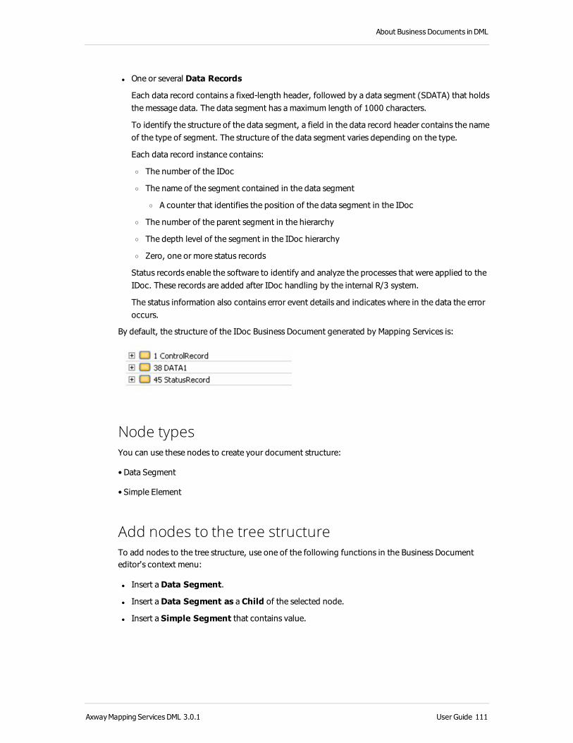
About Business Documents in DML
l One or several Data Records
Each data record contains a fixed-length header, followed by a data segment (SDATA) that holds the message data. The data segment has a maximum length of 1000 characters.
To identify the structure of the data segment, a field in the data record header contains the name of the type of segment. The structure of the data segment varies depending on the type.
Each data record instance contains:
o The number of the IDoc
o The name of the segment contained in the data segment
o A counter that identifies the position of the data segment in the IDoc
o The number of the parent segment in the hierarchy
o The depth level of the segment in the IDoc hierarchy
o Zero, one or more status records
Status records enable the software to identify and analyze the processes that were applied to the IDoc. These records are added after IDoc handling by the internal R/3 system.
The status information also contains error event details and indicates where in the data the error occurs.
By default, the structure of the IDoc Business Document generated by Mapping Services is:
Node typesYou can use these nodes to create your document structure:
• Data Segment
• Simple Element
Add nodes to the tree structureTo add nodes to the tree structure, use one of the following functions in the Business Document editor's context menu:
l Insert a Data Segment.
l Insert a Data Segment as a Child of the selected node.
l Insert a Simple Segment that contains value.
AxwayMapping Services DML 3.0.1 User Guide 111

2 Create and import Mapping objects in DML
Define SWIFT FIN Business DocumentsWhen you create a SWIFT FIN Business Document, you specify values for certain parameters that are common to all Business Document formats and others that are specific to the SWIFT FIN format.
For more information on Business Documents, see About Business Documents in DML on page 19.
This topic describes all SWIFT FIN-specific parameters. It contains the following sections:
About SWIFT FIN Business Documents on page 112
Properties view on page 113
Create a SWIFT FIN Business Document from scratch on page 114
Edit a SWIFT FIN Business Document on page 115
Modify node attributes on page 115
Business Document editor – define the tree structure on page 115
Node types on page 115
Add nodes to the tree structure on page 116
About SWIFT FIN Business DocumentsSWIFT FIN messages are either sent from user-to-user, or exchanged between the system and the user.
Mapping Services provides two types of SWIFT FIN Business Documents:
l SWIFT User Business Documents for user-to-user FIN messages. User-to-user FIN messages are used for the following types of financial information:
o Type 1 - Customer transfers and checks
o Type 2 - Financial institution transfers
o Type 3 - Treasury markets and derivatives (includes FXs)
o Type 4 - Collections and cash letters
o Type 5 - Securities (includes orders, confirmations, reconciliation and corporate actions)
o Type 6 - Precious metals and syndications
o Type 7 - Documentary credits, guarantees
o Type 8 - Travelers checks
o Type 9 - Statements, reports (cash and position holdings reports)
l SWIFT System Business Documents for system-to-user and user-to-system messages. Swift System Business Documents handle the content of type 0 FIN messages.
112 User Guide AxwayMapping Services DML 3.0.1

About Business Documents in DML
Neither of these two default Business Documents corresponds to a standard FIN message type. To be useful, in all cases the default Business Document requires editing.
Because they do not correspond to any standard FIN message type, the FIN default Business Documents do not contain predefined Validation Rules ensuring message structural conformity.
Similarities between SWIFT FIN system and SWIFT FIN userOn the highest level, each FIN message conforms to a defined block structure. The following table describes the principle FIN message structural blocks.
Block name Business Document label
Description
Basic header 1 General information for message identification and control
Application header
2 Application-specific information
User header 3 Message-user identification
Text block 4 Message text
Trailer block 5 Control and security information
S block S -
Only the basic header block is mandatory for all messages.
Differences between SWIFT FIN system and SWIFT FIN user l Trailer Block: The structure of the trailer block (Business Document Block 5) is not the same in FIN user-to-user messages and in FIN system-to-user messages. Consequently, Business Document block 5 has a different structure in the FIN user Business Document then it has in the FIN System Business Documents.
l Text Block: The structure of the text block is different for every FIN message type.
Properties viewIn the Business Document editor, in the General section of the Properties view, the Format real values can be set on both system and user SWIFT FIN Business Documents.
AxwayMapping Services DML 3.0.1 User Guide 113

2 Create and import Mapping objects in DML
Parameter Description
Format real values Select this check box if you want to enable formatting of real values in the output messages of Business Documents that contain fields of real type. These values will be formatted on the right or on the left of the decimal separator if needed. For example:
• 1.0 will be generated as 1.0 and not as 1.
• 0.0 will be generated as 0.0 and not as .
• 1.10 will be generated as 1.1.
For more information on the Business Document structure, see Business Document structure in DML on page 20, Business Document cardinality on page 21, Business Document data types in DML on page 22 and Format options for Real numbers on page 61.
Create a SWIFT FIN Business Document from scratchTo create a SWIFT FIN Business Document in an existing DML Mapping Project:
1. From the main menu, select File > New > Business Document.
Alternatively, you can right-click in the Project Explorer and select New > Business Document.
2. Specify where you want to save the Business Document. To select a path either use the directory tree or enter the path directly
3. Enter a File name for your Business Document. Click Next.
4. Select either SWIFTFIN User or SWIFTFIN System as the Business Document type.
5. Click Finish.
Mapping Services generates the SWIFT FIN Business Document in the selected project’s Business Document folder.
The generated Business Document opens automatically and is available for editing in the Business Document editor.
Note An alternative to manually creating a SWIFT FIN Business Document is to use the Business Document importer tool to generate a SWIFT FIN Business Document from a model file. For more information, see Import Business Documents into DML Mapping Projects on page 152 and Import a Business Document from a library on page 157.
114 User Guide AxwayMapping Services DML 3.0.1

About Business Documents in DML
Edit a SWIFT FIN Business Document
Modify node attributesIn the Properties window of the Business Document editor, Mapping Services displays a set of configuration fields that define the SWIFT FIN Business Document general characteristics.
To modify node attributes, select the Attributes section of the Properties view.
Not all of the nodes of the SWIFT FIN Business Document have attributes that can be modified. The non-modifiable attributes are highlighted in gray.
Business Document editor – define the tree structureNeither SWIFT FIN system nor SWIFT FIN user default Business Documents correspond to a standard FIN message type, the default structure needs to be edited.
You can modify the Business Document structure on the Business Document editor’s Structure tab, where you can add or delete new nodes.
Node typesTo create the document structure for SWIFT FIN System these nodes are available:
l Block
l Choice
l Sequence
l Sub Field
l Component
l Copy Field
To create the document structure for SWIFT FIN User these nodes are available:
l Block
l Choice
l Sequence
l Sequence 16
l Sub Field
l Component
l Copy Field
l Generic Field
AxwayMapping Services DML 3.0.1 User Guide 115

2 Create and import Mapping objects in DML
l Non Generic Field
l EOL Component
Add nodes to the tree structureTo add nodes to the tree structure, use one of the following functions in the Business Document editor's context menu:
l Insert a Block
l Insert a Block as a Child
l Insert a Choice
l Insert a Sequence
l Insert a Sequence 16
l Insert a Component
l Insert a EOL Component
l Insert a Sub-Field
l Insert a Generic Field
l Insert a Non-Generic Field
l Copy Field
116 User Guide AxwayMapping Services DML 3.0.1

About Business Documents in DML
Define XML Business DocumentsIn Mapping Services, you use XML type Business Documents in a Map, where the XML Business Document specifies an XML standardized organization of data that is either received as input, or generated as output by a Map Engine.
This topic describes procedures for using the XML-specific parameters that you may require to create an XML Business Document.
When you create an XML Business Document, you specify certain parameters that are common to all Business Document formats and other parameters that are specific to the XML format.
For more information on the XML Business Document structure, see XML Business Document on page 54
Properties viewIn the Properties view of the Business Document editor, in the General section, the following parameters can be set to define additional properties for XMLBusiness Documents.
Parameter Description
Encoding
From the drop-down list, select the encoding you want to use. This value can be the default encoding available after the installation, but this can be customized by adding new encoding to the <Mapping Services install folder>/configuration/encoding.properties file.
For more information on the Business Document structure, see Business Document structure in DML on page 20, Business Document cardinality on page 21, Business Document data types in DML on page 22 and Format options for Real numbers on page 61.
Create an XML Business Document from scratchTo create an XML Business Document in an existing DML Mapping Project:
1. From the main menu, select File > New > Business Document.
Alternatively, you can right-click in the Project Explorer and select New > Business Document.
2. Specify where you want to save the Business Document. To select a path either use the directory tree or enter the path directly.
3. Enter a File name for your Business Document. Click Next.
4. Select XML as the Business Document type .
5. Click Finish.
Mapping Services generates the XML Business Document in the selected project’s Business Document folder.
AxwayMapping Services DML 3.0.1 User Guide 117

2 Create and import Mapping objects in DML
The generated Business Document opens automatically and is available for editing in the Business Document editor. Mapping Services automatically generates an XML-specific tree structure, populated with a set of mandatory XML nodes.
Note An alternative to manually creating an XML Business Document is to use the Business Document importer tool to generate an XML Business Document from a model file. For more information, see Import Business Documents into DML Mapping Projects on page 152 and Import from schema, DTD or XML on page 160.
The generated default XML Business Document structure has two principal nodes:
l Prolog: The prolog node contains a set of child nodes that you cannot modify.
l Root: By default, the root node contains no subnodes. You can add subnodes to the default XML tree structure. Click the root node and use the Business Document editor's context menu.
The following list describes the nodes you can create descending from the root node of the default XML Business Document structure. The type of node you can add varies, depending on which type subnode you are situated:
l Insert a Parent node to group other nodes.
l Insert a Parent node as a Child of the selected node.
l Insert a Parent All node.
l Insert a Choice node.
l Insert a Choice node as a Child of the selected node.
l Insert a Sequence node.
l Insert a Sequence node as a Child of the selected node.
l Insert a Leaf node (in the first toolbar occurrence) as a:
o Child of the selected node, if the selected node is a Root, All, Choice or Sequence
o Sibling of the selected leaf node
l Insert a Leaf Any node (in the first toolbar occurrence) as a:
o Child of the selected node, if the selected node is a Root, All, Choice or Sequence
o Sibling of the selected leaf node
l Insert an Attribute node
l Insert a Namespace node
Types of XML Business Document nodesThe nodes listed in the preceding table can be grouped in two categories:
l Nodes without values
l Nodes with values
118 User Guide AxwayMapping Services DML 3.0.1

About Business Documents in DML
Nodes without valuesIn an XML Business Document, you can use the following nodes to group other nodes:
l Root
l Prolog
l Parent
l Sequence, All, and Choice
Prolog nodeWhen you create an XML Business Document, Mapping Services adds a single prolog node. The prolog node groups leaf nodes that describe the organization of an XML document.
You cannot modify the structure of a prolog node.
Note: Prologs are not present in subtree type Business Documents
Root nodeWhen you create an XML Business Document, Mapping Services adds a single root node. An XML Business Document contains one and only one root node. The nodes that you add to a Business Document structure are all children of the root node. Initially, the root node contains no child elements.
The root node has the same structural characteristics as a sequence node. That is:
l The root node informs the software that in the input XML file, child nodes of the root must occur in the order that is defined via the Business Document tree structure.
l If the nodes of the input XML file do not occur in this order when the software parses the input XML file, an error is encountered on the Map Engine.
Root nodes can group:
l Parent nodes
l Sequence, All, and choice nodes
l Nodes with values (leaf, attribute and namespace nodes)
Parent nodesA parent node groups nodes that are related to one another. The name of the parent node indicates how the grouped nodes are related to one another. Parent nodes correspond to a tag in an XML document.
AxwayMapping Services DML 3.0.1 User Guide 119

2 Create and import Mapping objects in DML
A parent node has the same structural characteristics as a sequence node. That is:
l The parent node informs the software that in the input XML file, child nodes of the parent must occur in the order that is defined via the Business Document tree structure.
l If the nodes of the input XML file do not occur in this order when the software parses the input XML file, an error is encountered on the Map Engine.
Parent nodes can group:
l Other parent nodes
l Sequence, All, and choice nodes
l Nodes with values (leaf, attribute and namespace nodes)
Sequence, All, and choice nodesSequence, All, and choice nodes group nodes that are related to one another. These nodes indicate the expected order of the grouped nodes in the input XML document. Unlike parent nodes, these nodes do not correspond to a tag in an XML document. For this reason, they do not appear in the input or output production documents that the Map Engine exchanges with partners or applications.
These nodes can group:
l Other sequence, All, and choice nodes
l Parent nodes
l Nodes with values (leaf and attribute nodes)
The following table summarizes when to use the sequence, All and choice nodes:
When... And... Use...
The nodes in a group occur in a fixed and sequenced order
The number of times that each node can occur is fixed
Sequence
The nodes in a group can occur in any order
Each node only occurs once All
Only one of several possible nodes can occur
The number of times each node can occur is fixed
Choice
120 User Guide AxwayMapping Services DML 3.0.1

About Business Documents in DML
The following table provides an example of how to use the sequence, All, and choice nodes:
Nodes Details and examples
Sequence
Order Number
Order Date
The sequence node informs the software that in the input XML file, child nodes of the sequence node must occur in the order that is defined via the Business Document tree structure
In this example, the sequence node informs the software that the Order Number and Order Date nodes must occur in the displayed order: that is, the Order Number node must occur before the Order Date node.
If the nodes (XML tags) do not occur in this order when the software receives the relevant XML document, an error is encountered on the Map Engine.
All
Store Number
Store Name
Example: The data that describes the store in which a customer ordered books or CDs arrive from several different stores. When the software receives the Business Document, sometimes the:
l Store Number occurs before the Store Name
l Store Name occurs before the Store Number
Via the All node, the Business Document can hold values for both the Store Number and Store Name without requiring a fixed order for this data.
Choice
Credit Card
Check
Example: Customers can pay for their orders by credit card or by check. The choice node indicates that only one method of purchase can occur. The Business Document can hold a value fort either Credit Card or Check, but not both.
If the Business Document contains a value for more than one method of purchase, an error is generated on the Map Engine.
Nodes with valuesIn XML Business Documents, you can use:
l Leaf nodes that hold a specified type of data that is contained in a single XML tag
l Any nodes that accept any node name and hold an unspecified type of data that is contained in a single XML tag
l Attribute nodes that hold property definitions that describe another node
l Namespace nodes that define namespaces for leaf and attribute nodes
AxwayMapping Services DML 3.0.1 User Guide 121

2 Create and import Mapping objects in DML
Leaf nodesLeaf nodes are elements of a Business Document that hold data. Several leaf nodes are often grouped together in a node without values (a parent node or an All node, for example). Leaf nodes can group one or more attribute nodes.
After you add a leaf node, you rename the node with the name of the structural element of the XML message to which the leaf node corresponds. If the Map Engine attempts to parse the element "abc" of an XML message to a the leaf node "xyz" of an XML Business Document, the parsing fails and a processing error is generated.
To specify the characteristics of the data that is held in the leaf node (data class, data type, default values, and so on) you use the Attributes section of the Properties view of the node. To enable the leaf node to hold nested data of any data type to correspond to the XML message tag content, you apply the String data class and XMLAny data type to the node.
Example of leaf nodes that are grouped in a parent node:
Nodes Details and examples
Items Purchased
Title
Author
In this example, the parent node Items Purchased groups two leaf nodes that describe the items that a customer purchased.
Depending on what a customer purchases, the Title node can contain the title of a book or a CD, and the Author node can contain the name of an author or musical artist.
Any nodesAn Any node is a leaf node that accepts any node name and holds data of any data type. An Any node corresponds to the wildcard component of an XML schema. During message processing, it can hold any value that is valid in the XML syntax. For this reason, when you create the Any node, you do not preset the values of the following node attributes:
l Name
l Definition
l Default value
You have two choices for the cardinality of the Any node:
1-1 — When the Map Engine parses an input XML message, it creates a single instance of the node and names it with name of the corresponding XML element.
1-N — When the Map Engine parses an input XML message, it creates as many instances of the Any node as it finds consecutive instances of XML elements with the same element name. Each one to N Any node in the Business Document then has the same node name.
Several Any nodes can be grouped together with other leaf nodes in a node without values (a parent node or an All node, for example). An Any node can be a parent of one or more attribute nodes.
122 User Guide AxwayMapping Services DML 3.0.1

About Business Documents in DML
Example of two Any leaf nodes that are grouped in a parent node:
Nodes Details and examples
PersonalData
Any
Any
In this example, the parent node PersonalData groups two Any nodes that can hold any type of information and accept any label.
The node name and the data contained in the node varies depending on the name and content of the data in the input or output message XML data structure.
Attribute nodesAttribute nodes contain property definitions that describe another node. Attribute nodes are nested in the node they describe. They can describe parent and leaf nodes.
Example of attribute nodes that are grouped in a leaf node:
Nodes Details and examples
Items Purchased
Title
Language
CD / Book
Author
In this example, the Title node groups two attribute nodes These nodes hold data that describes the title that a customer purchased. The data in:
l Language describes the language of the title
l CD / Book describes the type of title (CD or Book)
Namespace nodesUse namespace nodes to apply namespaces to a node or set of nodes.
Applying a namespace node in a XML Business Document requires the following two main steps:
l Step 1: Creating the namespace element in the Business Document structure
l Step 2: Applying the namespace to a node with values
AxwayMapping Services DML 3.0.1 User Guide 123

2 Create and import Mapping objects in DML
Step 1: Create the namespace elementTo create a namespace element in an XML Business Document structure:
1. Open an existing XML Business Document, or create a new one.
2. In the Business Document editor window, right-click the node that you want to define a namespace.
3. Mapping Services displays a contextual menu.
4. From the contextual menu, select Insert > Namespace.
If this option is not displayed in the contextual menu, you have chosen a node that cannot contain a namespace definition.
Mapping Services adds a row to the tree structure and creates a name for the namespace element you are creating.
5. Select the Attributes section of the Properties view on the left side.
6. In the Attributes section, select the Definition tab and enter values in the following two fields:
7. URI: Enter a URI to uniquely identify the namespace.
8. Prefix: Enter a prefix to locally identify the namespace.
9. Click Save to save the Attributes section.
Step 2: Apply the namespace to a node with valuesTo apply an existing prefixed namespace to a node in an XML Business Document:
1. Open the Business Document editor in which you have already created a prefixed namespace.
Mapping Services displays the Business Document editor window
2. In the tree structure, select the element where you want to apply the namespace. The element must be situated in the same node or in a child node of the node where the namespace element is situated.
3. Select the Attributes section on the left side.
4. In the Attributes section, select the Definition tab. In the Namespace field, use the drop-down list to select a namespace to link to the current element.
5. Click Save to save the Attributes section.
Use Node AttributesAll nodes with values have node attributes that you can modify in the Properties view in the Attributes section.
124 User Guide AxwayMapping Services DML 3.0.1

About Business Documents in DML
Define XSD Business DocumentsXSD Business Documents are used to load XML schemas and create Maps from them, instead of having to import XML files first to keep the structure up-to-date.
For more information on the XSD Business Document structure, see XSD Business Document on page 58.
When you create an XSD Business Document, you specify the XML schema, which contains the structure of the document and a document element as the Root node. Optionally, you can modify a pattern in a leaf in the XSD Business Document properties to override an attribute.
An alternative to manually creating an XSD Business Document is to use the Business Document importer tool to generate an XSD Business Document from a model file. For more information, see Import Business Documents into DML Mapping Projects on page 152 and Import from schema, DTD or XML on page 160.
Properties viewIn the Properties view of the Business Document editor, in the General section, the following parameters can be set to define additional properties for XSD Business Documents.
Parameter Description
Encoding
From the drop-down list, select the encoding you want to use. This value can be the default encoding available after the installation, but this can be customized by adding new encoding to the <Mapping Services install folder>/configuration/encoding.properties file.
Create an XSD Business Document from scratchTo create a new XSD Business Document based on an XML schema in Mapping Services:
1. From the main menu, select File > New > Business Document.
Alternatively, you can right-click in the Project Explorer and select New > Business Document.
A wizard appears to help you create a new Business Document.
2. Specify where you want to save the Business Document. To select a path either use the directory tree or enter the path directly.
3. Enter a File name for your Business Document. Click Next.
4. Select XSD as the Business Document type. Click Next.
AxwayMapping Services DML 3.0.1 User Guide 125

2 Create and import Mapping objects in DML
5. For XSD Schema Selection, click Search Project… to select the schema from the workspace, or Browse to get it from the file system. If the schema is selected from the file system, then it is copied inside the workspace, including all references. The schema must have at least one root element.
6. Select the root Element, if available.
7. Click Finish.
Mapping Services generates the XSD Business Document in the selected project’s Business Document folder and an entry in the Project Explorer pane tree structure. The XSD Business Document opens automatically in the Business Document editor.
Note If the element on which the pattern is set has a basic or an anonymous simple type, then the pattern is applied to only this element; otherwise, the pattern is set for all the leaves of the same type, based on the name of the type.
126 User Guide AxwayMapping Services DML 3.0.1

About Business Documents in DML
Change an XSD Business Document patternTo modify the pattern for an element:
1. Select the Business Document you want to change.
2. Expand the tree structure of the document and select the leaf node you want to change.
3. Select the Attributessection of the Properties view and the Definition subtab and select the Pattern attribute.
4. Enter a different pattern, and then click Validate to either view or update the value of your pattern. The pattern is validated to ensure it is DML compatible. The following are example fields for the validation:
l Date — The date that you want to test against a DML pattern.
l Time — Time to test.
l UTC — Adjustments to the Coordinated Universal Time for testing.
l Generate test date from pattern — The Date pattern is used to generate the test date.
l Validate pattern based on test date — User-defined date to create your own test date, assuming you know how the date should be formatted. This entry is tested against the XSD restriction as well as the DML Date pattern.
5. Click OK.
Types of XSD Business Document nodesThe nodes listed in the preceding table can be grouped in two categories:
l Nodes without values
l Nodes with values
Nodes without valuesIn an XSD Business Document, you can use the following nodes to group other nodes:
l Root node on page 128
l Prolog node on page 128
l Parent nodes on page 128
l Sequence, All, and choice nodes on page 129
AxwayMapping Services DML 3.0.1 User Guide 127

2 Create and import Mapping objects in DML
Prolog nodeWhen you load an XSD Business Document, Mapping Services reads a single Prolog node from the XML schema. The prolog node groups leaf nodes that describe the organization of an XML document.
You cannot modify the structure of a prolog node.
Note: Prologs are not present in subtree type Business Documents.
Root nodeWhen you create an XSD Business Document, you select a document element from the XML schema that is used by Mapping Services as a single Root node. An XSD Business Document contains one and only one root node. The structure of all children of the root node is based on the definition of its type from the schema. You cannot change the structure of the document by adding or removing child elements in the editor.
The root node has the same structural characteristics as a sequence node. That is:
l The root node informs the software that in the input XML file as instance of the schema, child nodes of the root are grouped as a sequence, choice, or a collection without a strict order, depending on the nodes used for grouping. For example, if you insert a choice or All node inside the root node, this affects the structure of one child or of all children, regardless of their order.
l If the nodes of the input XML file do not occur in this order when the software parses the input XML file, an error is encountered in the Map Engine.
Root nodes can group:
l Parent nodes
l Sequence, All, and choice nodes
l Nodes with values (leaf, attribute, and namespace nodes)
Parent nodesA Parent node groups nodes that are related to one another. The name of the parent node indicates how the grouped nodes are related to one another. Parent nodes correspond to a complex element definition in the associated XML schema.
A parent node has the same structural characteristics as a sequence node. That is:
l The parent node informs the software that in the input XML file, child nodes of the parent are grouped as a sequence, choice, or a collection without a strict order, depending on the nodes used for grouping. For example, if you insert a choice or All node inside the parent node, this affects the structure of one child or of all children, regardless of their order.
128 User Guide AxwayMapping Services DML 3.0.1

About Business Documents in DML
l If the nodes of the input XML file do not occur in this order when the software parses the input XML file, an error is encountered in the Map Engine.
Parent nodes can group:
l Other parent nodes
l Sequence, All, and choice nodes
l Nodes with values (leaf, attribute, and namespace nodes)
Sequence, All, and choice nodesSequence, All, and choice nodes group nodes that are related to one another. These nodes indicate the expected order of the grouped nodes in the input XML document. Unlike parent nodes, these nodes do not correspond to an element definition in the XML schema, but rather to a composition rule that indicates how the input tags should appear in the input XML data. For this reason, they do not appear in the input or output production documents that the Map Engine exchanges with partners or applications.
These nodes can group:
l Other sequence, All, and choice nodes
l Parent nodes
l Nodes with values (leaf, attribute nodes)
Nodes with valuesIn XSD Business Documents, you can have:
l Leaf nodes on page 129 that hold a specified type of data that is contained in a simple element definition that accept an XML tag from the input file
l Any nodes on page 130 that accept any node name and hold an unspecified type of data that is contained in a single XML tag
l Attribute nodes on page 131 that hold property definitions that describe another node
l Namespace nodes on page 131 that define namespaces for leaf and attribute nodes either as target namespace of the schema or as a prefix namespace
Leaf nodesLeaf nodes are elements of a Business Document that hold data. Several leaf nodes are often grouped together in a node without values (a parent node or an All node, for example). Leaf nodes can group one or more attribute nodes. A leaf node corresponds to a simple element definition in the XML schema. A simple element definition has no elements defined inside it and it’s not an extension or a restriction of a base type.
AxwayMapping Services DML 3.0.1 User Guide 129

2 Create and import Mapping objects in DML
Nodes Details and examples
Items Purchased
Title
Author
In this example, the Parent node Items Purchased groups two Leaf nodes that describe the items that a customer purchased. Depending on what a customer purchases, the Title node can contain the title of a book or a CD for example, and the Author node can contain the name of an author or musical artist.
Any nodesAn Any node is a leaf node that accepts any node name and holds data of any data type. An any node corresponds to the wildcard component of an XML schema. During message processing, it can hold any value that is valid in the XML syntax. For this reason, when you create the any node, you do not preset the values of the following node attributes:
l Name
l Definition
l Default value
You have two choices for the cardinality of the Any node:
1-1 — When the Map Engine parses an input XML message, it creates a single instance of the node and names it with name of the corresponding XML element.
1-N — When the Map Engine parses an input XML message, it creates as many instances of the any node as it finds consecutive instances of XML elements with the same element name. Each one to N any node in the Business Document has the same node name.
Several any nodes can be grouped together with other leaf nodes in a node without values (a parent node or an All node, for example). An any node can be a parent of one or more attribute nodes.
Example of two any leaf nodes that are grouped in a parent node:
Nodes Details and examples
PersonalData
Any
Any
In this example, the Parent node PersonalData groups two Any nodes that can hold any type of information and accepts any label.
The node name and the data contained in the node varies depending on the name and content of the data in the input or output message XMLdata structure.
130 User Guide AxwayMapping Services DML 3.0.1

About Business Documents in DML
Attribute nodesAttribute nodes contain property definitions that describe another node. Attribute nodes are nested in the node they describe. They can describe parent and leaf nodes.
Example of attribute nodes that are grouped in a leaf node:
Nodes Details and examples
Items Purchased
Title
Language(Head)
Type
Author
In this example, the Title node groups two Attribute nodes. These nodes hold data that describe the title that a customer purchased. The data in:
• Language describes the language of the title
• CD / Book describes the type of title (CD or Book)
Namespace nodesNamespace nodes display target namespace of the schema or additional prefix namespaces that the schema might contain. However, since the target namespace of the schema is a property which is specific to the deployment target, such as Axway B2Bi , it’s not necessary to have it in the structure of the document as a namespace node. Therefore, you may find the target namespace as an attribute of the document in the Properties view.
AxwayMapping Services DML 3.0.1 User Guide 131

2 Create and import Mapping objects in DML
Define Database Business DocumentsWhen you create a Database Business Document, you specify values for certain parameters that are common to all Business Document formats and others that are specific to the Database format.
For more information on the Database Business Document structure, see JDBC database Business Document on page 59.
This topic describes all Database-specific parameters. It contains the following sections:
Create a Database Business Document from scratch on page 132
Edit a Database Business Document on page 133
Properties view on page 133
Modify node attributes on page 133
Business Document editor – define the tree structure on page 133
Node types on page 134
Add nodes to the tree structure on page 134
Create a Database Business Document from scratchYou can create Database Business Documents from scratch by performing the following steps:
1. From the main menu, select File > New > Business Document.
Alternatively, you can right-click in the Project Explorer and select New > Business Document.
2. Specify where you want to save the Business Document. To select a path either use the directory tree or enter the path directly.
3. Enter a File name for your Business Document. Click Next.
4. Select Database as Business Document type.
5. Select a database connection or create a new one by selecting New Connection in the drop down list and click Next.
6. In the left pane you can select the table columns or the stored procedure parameters to be inserted in the Database Business Document structure. In the right pane you can modify the structure of the Database Business Document:
l Add or edit the root nodes of the Database Business Document
l Add, delete or move the leaf elements
7. Click Finish.
Mapping Services generates the Database Business Document in the selected project’s Business Document folder.
132 User Guide AxwayMapping Services DML 3.0.1

About Business Documents in DML
The generated Business Document opens automatically and is available for editing in the Business Document editor.
Note An alternative to manually creating a Database Business Document is to use the Business Document importer tool to generate a Database Business Document from a model file. For more information, see Import Business Documents into DML Mapping Projects on page 152 and Import a Business Document from a library on page 157.
Edit a Database Business Document
Properties viewIn the Properties view of the Business Document editor, Mapping Services displays a set of configuration fields that define the Database Business Document general characteristics.
General propertiesYou can modify the general structural characteristics, including modifying node attributes in the General section of the Properties view.
Parameter Description
Encoding From the drop-down list, select the encoding you want to use. This value can be the default encoding available after the installation, but this can be customized by adding new encoding to the <Mapping Services install
folder>/configuration/encoding.properties file.
For more information on the Business Document structure, see Business Document structure in DML on page 20, Business Document cardinality on page 21, Business Document data types in DML on page 22 and Format options for Real numbers on page 61.
Modify node attributesSome of the Database node attributes can be modified in the Attributessection of the Properties view.
Note that not all of the nodes of the Database Business Document have attributes that can be modified. The non-modifiable attributes are highlighted in gray.
Business Document editor – define the tree structureYou can edit the Business Document structure by using the Business Document editor’s Structure tab, where you can add new nodes or delete nodes.
AxwayMapping Services DML 3.0.1 User Guide 133

2 Create and import Mapping objects in DML
Node typesYou can use these nodes to create the document structure:
l Parent
l Leaf
The leaf node corresponds to a column name in the database table.
Note that a Database Business Document cannot have nested levels in the tree structure.
Add nodes to the tree structureTo add nodes to the tree structure, use one of the following functions in the Business Document editor's context menu:
l Insert a Parent to group other parent or leaf nodes.
l Insert a Leaf that contains values.
134 User Guide AxwayMapping Services DML 3.0.1

About Business Documents in DML
Define XRDJ Business Documents
Create an XRDJ Business DocumentXRDJ Business Documents can only be imported from Mapping Services in the form of a deployment package. It cannot be edited.
For more information on Business Document, see About Business Documents in DML on page 19.
This type of Business Document is read-only in Mapping Services.
To import an XRDJ Business Document structure perform the following steps:
1. From the main menu, select File > Import >Mapping Services > DML > Mapping Flow.
Alternatively, you can right-click in the Project Explorer and select Import >Mapping Services > DML > Mapping Flow.
2. Click Next.
3. In the Deployment Package folder text box enter the full path to the package folder or click Browse to browse it.
4. Click Finish.
Mapping Services generates the business objects contained in the package. If it contains XRDJ Business Documents, they are imported into the project's Business Document directory.
Visualize an XRDJ Business Document
Properties viewIn the Properties view of the Business Document editor, Mapping Services displays a set of configuration fields that define the XRDJ Business Document general characteristics.
Except for the label and the description of the XRDJ Business Document, all the other properties of the Business Document or of its elements are read-only.
Business Document editor – define the tree structureYou can visualize the Business Document structure by using the Business Document editor’s Structure tab. The structure of the XRDJ Business Document cannot be modified.
AxwayMapping Services DML 3.0.1 User Guide 135

2 Create and import Mapping objects in DML
Manage Tracked ObjectsTracked Objects are Sentinel-specific artifacts that are generated and stored by monitoring agents. These agents generate Tracked-Event Messages that contain data about application and platform events. The agents then send the Tracked-Event Messages to the Sentinel Server environment.
In the server environment, the Acquisition Server contains Tracked Objects. A Tracked Object is a model containing a set of attributes that describe an application event. Each incoming Tracked-Event Message contains a name field that indicates the name of the Tracked Object that is to be used with that message. Using the specified Tracked Object, the Acquisition server extracts the data from the fields of the Tracked-Event Message, and writes the data to a specific table in the Tracking Database.
Every Tracked Object contains a:
l Unique name
l Version number
l List of attributes describing the properties of events. Each attribute has a:
o Name (unique to that object)
o Data type
o Default value
The attributes contained in a Tracked Object can be classed in two categories:
l System attributes that are common to most Tracked Objects. System attributes identify application and platform events and errors.
l User attributes that are not common to all Tracked Objects. User attributes describe the application-specific or platform-specific properties of monitored events.
Additionally, Tracked Objects contain the following secondary properties:
l Storing mode
l Version management mode
l Correlation mode
Together, Tracked-Event Messages and Tracked Objects enable Sentinel to record information about tracked events in the form of Tracked-Event Records. Tracked Objects also indirectly describe the Tracked-Event Messages that tracked applications create. The Acquisition server receives Tracked-Event Messages and analyzes the message content. If the message corresponds to a known model, the Acquisition server records the data contained in the message to the Tracking Database. The data recorded in the database for a single tracked event is referred to as a Tracked-Event Record.
Mapping Services can import Tracked Objects from other integration designers, such as Mapping Services, and then use it in Maps and Mapping Flows to generate tracking artifacts that are sent during the execution of the integration process to the Sentinel task. You can see how to import Tracked Objects by referring to the Import deployment package into a DML Mapping Project on page 204 topic.
136 User Guide AxwayMapping Services DML 3.0.1

About Business Documents in DML
Manage Business Document structure in DMLIn a DML Mapping Project, the Business Document describes the composition and structure of the input and output messages for the Mappings.
View the structure of a Business Document to modify it. You can add, delete and reposition nodes and manage the node attributes:
l View Business Document structure on page 137
l Add and delete Business Document nodes on page 138
l Move Business Document nodes on page 138
l Update X12 Business Documents on page 139
l Manage Business Document node characteristics on page 141
l Search for a specific node on page 150
l Create filters on page 151
For more information, see About Business Documents in DML on page 19 and Business Document structure in DML on page 20.
View Business Document structureIn a DML Mapping Project, the Business Document describes the composition and structure of the input and output messages for the Mappings.
To view the structure of a Business Document, start from the Project Explorer:
1. Double-click the name of the Business Document that you want to modify.
Mapping Services opens the Business Document editor.
2. Select the Structure tab.
Mapping Services displays the structure of the Business Document and a set of tools for modifying the structure. For details, seeView Business Document structure on page 137
The nodes that you can add, modify, or delete depend on the type of Business Document.
Use the tools in the Structure tab to add, delete, or modify the nodes. Right-click the node and select one of the commands that you want to execute.
For more information, see Business Document structure in DML on page 20 About Business Documents in DML on page 19, and Business Document types in DML on page 26).
AxwayMapping Services DML 3.0.1 User Guide 137

2 Create and import Mapping objects in DML
Add and delete Business Document nodesMapping Services displays the structure of the Business Document and a set of tools for modifying the structure. For details, seeView Business Document structure on page 137
The nodes that you can add, modify, or delete depend on the type of Business Document.
Add a node 1. In the Business Document editor Structure view, select the node above the point in the
structure where you want to add the new node.
2. Either:
l Click one of the Insert icons from the Mapping Services toolbar.
l Right-click the node and select one of the Insert commands.
When you do either of these two things, Mapping Services adds a new (blank) node of the selected type, either directly below the selected node, or below the last node in the group (typically, the last child of the selected node).
For more information, see Business Document structure in DML on page 20.
Delete a nodeTo delete a node from the tree structure, select the node you want to delete. Right-click the node
and select Delete .
Move Business Document nodesMapping Services displays the structure of the Business Document and a set of tools for modifying the structure. For details, seeView Business Document structure on page 137
The nodes that you can add, modify, or delete depend on the type of Business Document.
Reposition a node in the Business Document structureUse the following icons to move nodes to new positions within the tree structure.
Click... To...
Move the selected node up in the tree structure.
Move the selected node down in the tree structure.
138 User Guide AxwayMapping Services DML 3.0.1

About Business Documents in DML
Click... To...
Move the selected node out one level in the node that previously nested it.
Move the selected node in one level in the tree structure. This icon nests a node in the node that precedes it in the tree structure.
For more information, see Business Document structure in DML on page 20.
Copy and paste nodesYou can copy and paste nodes in the tree structure:
l In the same Business Document
l In a different Business Document
To copy a node in the tree structure, select the node that you want to copy and right-click it to have
the option to copy .
To paste the node:
l As a child of the selected node, click Paste as Child .
l As a brother of the selected node, click Paste .
If you copy and paste a Parent node, you also copy and paste all the descendants of the selected node.
Update X12 Business DocumentsIf you have X12 Business Documents in Mapping Services that existed prior to an upgrade to B2Bi 2.0, they might not contain X12 syntax notes.
For more information, see the X12 Syntax notes section of Define X12 Business Documents on page 98.
You can use this X12 Update process to validate the relations between the elements inside segments and add those X12 syntax notes. For example, if element 2 is present in a specific EDI segment, element 3 must be present also.
To run the X12 Syntax Notes Update process:
1. In the Project Explorer, locate and right-click the X12 Business Document you want to update.
2. Select Update X12 Syntax Notes. The document you selected is highlighted when the wizard is displayed.
3. In the EDI Version field, select the Business Document version that you want to compare with the Business Document you selected in step 1, if the correct version is not already displayed.
AxwayMapping Services DML 3.0.1 User Guide 139

2 Create and import Mapping objects in DML
4. In the EDI Document field, select the Business Document standard that you want to compare with the Business Document you selected in step 1, if the correct standard is not already displayed.
140 User Guide AxwayMapping Services DML 3.0.1

About Business Documents in DML
5. Click Validate to run the comparison. A progress bar is displayed briefly while the comparison runs:
l If the structures are not the same, you cannot update the Business Document until you correct its structure by importing the clean Business Document again from the repository or by correcting any changes that were made to that Business Document. You would then run this update process again on that Business Document.
l If the structures are the same, the Finish button is displayed.
6. Click Finish to update the Business Document. The EDI syntax notes are added to the Business Document after the process is complete. There should be no errors on the Business Document or on your Map.
Manage Business Document node characteristicsTo view the structure of a Business Document, start from the Project Explorer:
1. Double-click the name of the Business Document that you want to modify.
Mapping Services opens the Business Document editor.
2. Select the Structure tab.
Node characteristic management overviewTo manage the characteristics of the data that each Business Document node contains, select the node and go to the Attributes section of the Properties view on the bottom pane of the Business Document Structure tab.
For more information, see Business Document structure in DML on page 20.
The attributes are grouped in the following views:
l General
l Definition
l Enumeration
l Multibyte
Select one of the tabs and edit the row corresponding to the property you want to set. Use the specific control for the selected property to set the value.
You cannot modify default values that are displayed in grayed cells of the Definition view right pane.
When you add a:
l Node without values to a Business Document, you define only the name and cardinality properties in the appropriate rows of the Definition view.
l Node with values, you can define properties of the data that the node can contain in the cells of the right pane.
AxwayMapping Services DML 3.0.1 User Guide 141

2 Create and import Mapping objects in DML
Set node attributes valuesTo manage the characteristics of the data that each Business Document node contains, view the structure of a Business Document. Start from the Project Explorerand double-click the name of the Business Document that you want to modify. Mapping Services opens the Business Document editor.
Task overviewWhen you open the Structure view of the Business Document in DML, Mapping Services displays a set of sections in the Properties view.
For more information, see Business Document structure in DML on page 20.
To specify node characteristics, from the Properties view, select the Attributes section and enter the values in the fields.
The Attributes section includes:
l General view on page 142
l Definition view on page 143
l Enumeration view on page 147
l Multibyte view on page 147
General view
The following table describes the contents of the General view.
Field Description
Name Enter a name for the selected node.
Label Optionally, enter a description of the type of data that the selected node contains.
Cardinality
(Mandatory)
To indicate how many times the selected node can occur in the Business Document, select the cardinality from the drop-down list displayed when you click in this column. Mapping Services displays only the cardinalities that are appropriate for the selected node.
Class
(Mandatory)
If the selected node contains values, use the drop-down list to select the data class for the node content. The data class describes the data that can be contained in the selected node.
When you choose a data class in this field, Mapping Services sets the following Type field drop-down list with value options that correspond to the selected data class.
142 User Guide AxwayMapping Services DML 3.0.1

About Business Documents in DML
Field Description
Data type Select a data type for the selected node from the drop-down list. Mapping Services only displays the data types that are appropriate for the data class that you selected in the Class on page 142 field.
Mapping Services assigns the data type that you select to every node in the tree structure that has the same name as the selected node.
Nullable If you want the selected node to accept the value null, click this optional check box.
Definition If the Data type on page 143 value selected above includes one or more abbreviations between parentheses - for example, (len) or (p,s) - you can use the optional Definition field to define the physical structure of the data that the node contains. Use commas ( , ) to separate multiple values.
Examples: To specify the value of (len)in XML Business Documents, set:
l A minimum length of ten characters, enter this: 10,
l A maximum length of ten characters, enter this: ,10
l A minimum length of ten characters and a maximum length of 20 characters, enter this: 10,20
Regarding zeros:
l If the data type calls for an explicit number of decimal places, and there are all zeros to the right of the decimal sign, then a valid value will be output. In this case, other data types will generate an error.
l Leading zeros are required for Application Flat File fields that are numeric or real to satisfy the field length requirements. EDI elements should never contain leading zeros, with the exception of fraction values or to satisfy minimum length requirements.
Note For customNumeric virtual scale real numbers, when the plus sign is not present in input or output fields, it can be replaced by any digit: There is one additional character authorized for positive numbers without plus sign.
For more information, see Business Document cardinality on page 21 and Business Document data types in DML on page 22.
Definition view
The following table describes the contents of the Definition view.
The view content varies depending on the Business Document and node types.
AxwayMapping Services DML 3.0.1 User Guide 143

2 Create and import Mapping objects in DML
Field Description
Pattern The pattern property defines how the data is formatted in the node. You can select from predefined patterns or define one yourself.
Default value
You can enter an optional default value that the software inserts in the selected node when no value is otherwise specified for the node.
The value that you enter is a constant that must not conflict with the data class that you assigned to the node.
Min/Max Values
To constrain the values that the selected node can contain, you can optionally enter:
l A minimum value in the first field
l A maximum value in the second field
l A minimum value in the first field and a maximum value in the second field
The values that you enter are constants that must not conflict with the data class that you assigned to the node.
In the drop-down list that is associated with each field, select the symbol that specifies whether the values you enter are:
l Exclusive (greater than, less than)
l Inclusive (greater than or equal to, less than or equal to)
Examples:
A. If you enter 10 in the first field and select < from the first drop-down list, you specify:
10 < node value
The node must contain values that are greater than ten.
B. If you enter 10 in the second field and select < from the second drop-down list, you specify:
node value < 10
The node must contain values that are less than ten.
C. If you enter:
l 10 in the first field and select <= from the first drop-down list
l 20 in the second field and select <= from the second drop-down list, you specify:
10 <= node value <= 20
The node must contain values that are greater than or equal to ten and less than or equal to 20.
144 User Guide AxwayMapping Services DML 3.0.1

About Business Documents in DML
Field Description
Delimiter From the drop-down list, choose from among the delimiter type value options:
l Fixed
l String
l Implicit
l Default
Delimiter value
Specify the character that marks the beginning and end of a unit of data in the selected node.
Open quote character
Specify the character that represents the open quote marks.
Close quote character
Specify the character that represents the close quote marks.
Escape character
Specify the character that represents the escape symbol.
Decimal character
Specify the character that marks a decimal point.
Encoding Select the character set to use for the data in the Business Document from the drop-down list. You can select one of the predefined character sets or define your own.
Padding character
Select a padding character to fill out fixed length elements where the values are shorter than the fixed length specified.
Justification Select from the drop-down list if the position of the value should be:
l Left justified
l Centered
l Right justified
l None
Plus sign character
This property can only be changed if the data type of your node is real number and you select Type= CustomNumeric. CustomNumeric means that you redefine the format of the data type real Number for this node.
AxwayMapping Services DML 3.0.1 User Guide 145

2 Create and import Mapping objects in DML
Field Description
Plus sign position
Select where to position your plus sign character, from the drop-down list. Available values are:
l None - the plus sign is not displayed in the value
l Left - to the left of the value
l Right - to the right of the value
Optional plus sign
Makes the plus sign optional
Minus sign character
This property can only be changed if the data type of your node is real Number and you select Type= CustomNumeric. CustomNumeric means that you redefine the format of the data type real Number for this node.
Sign minus position
Select where to position your minus sign character from the drop-down list. Available values are:
l None - the minus sign is not displayed in the value
l Left - to the left of the value
l Right - to the right of the value
Exponential character
Enter a character to define the exponential character. The default value is e.
URI For XML Business Documents only.
To create a namespace, in a namespace element, enter the URI that defines the present namespace of the node and all dependent (child) nodes.
Prefix For XML Business Documents only.
To create a namespace, in a namespace element, enter a prefix that defines the namespace for the elements in the current node, and elements in all child node descendents of this node.
Namespace For XML Business Documents only.
If the current element is situated in a node that contains a namespace element, or is in a child node of any node that contains a namespace element, you can apply a namespace to the current element by selecting the namespace from the drop-down list of available namespaces.
146 User Guide AxwayMapping Services DML 3.0.1

About Business Documents in DML
Enumeration view
About the Enumeration viewIn the Enumeration view, use the vertical toolbar to enter and modify an optional list of authorized values for the selected node. The values that you enter are constants that must not conflict with the data class that you assigned to the node.
The following table summarizes how to use the icons in the Enumeration view to work with a list of authorized values for the selected node:
Click... To...
Add a line to the Enumeration view. Enter one authorized value per line.
Delete the selected line from the Enumeration view.
Move the selected line up one position in the Enumeration view.
Move the selected line down one position in the Enumeration view.
Multibyte view
Use the Multibyte view to apply special encoding to the data content of the selected node.
The Multibyte view comprises two fields, described in the following table.
Field Description
Valid charset
Enter the name of a valid character set or subset that you have defined using the Copilot Character Set Manager.
The Map Engine uses the specified character set to restrict incoming messages to those that contain only the characters in that set. Messages containing characters outside the set are rejected, and a message appears in the Message Log.
The character set you choose applies only to the data contained in the selected node.
AxwayMapping Services DML 3.0.1 User Guide 147

2 Create and import Mapping objects in DML
Field Description
Allow distortion
When converting from one character set encoding to another it is sometimes impossible to find an exact match in the new format.
In such a case, the Map Engine converts the character anyway, as best as possible, and reports to the conversion program that the characters were not completely and correctly converted.
Select this option to specify that this approximative conversion is allowed. This option is selected by default.
If you deselect this option, inexact character matching results in a conversion failure.
If you select this option it is only valid for the node on which you set the option.
Specify node data typeTo manage the characteristics of the data that each Business Document node contains, view the structure of a Business Document. Start from the Project Explorerand double-click the name of the Business Document that you want to modify. Mapping Services opens the Business Document editor.
You define the Data type property of individual nodes in the Attributes section of the Properties view in theBusiness Document Structure view.
For more information, see Business Document structure in DML on page 20.
1. In the Business Document editor, select the Structure tab.
2. Go to the Properties view and select the Attributes section.
3. In the General view, click in the cell of the Data type row in the right pane, to display a drop-down list of the available data types for the selected node.
Alternatively, you can choose to display Class and the Data type column in the Structure view and select the Class and Data type by opening the drop-down list of the available Class or Data types for the selected node.
Define Business Document node cardinalityTo manage the characteristics of the data that each Business Document node contains, view the structure of a Business Document. Start from the Project Explorerand double-click the name of the Business Document that you want to modify. Mapping Services opens the Business Document editor.
Set the cardinality of a nodeIn the Generalview of the Attributes section of the Properties view, you select the cardinality for most nodes via the drop-down list displayed when you click in the cell of the Cardinality row.
148 User Guide AxwayMapping Services DML 3.0.1

About Business Documents in DML
For more information, see (see Business Document structure in DML on page 20 and Manage Business Document structure in DML on page 137)
1. In the Business Document editor, select the Structure tab
2. Go to the Properties view and select the Attributes section.
3. In the General view, click in the cell of the Cardinality row in the right pane, to display a drop-down list of the available cardinalities for the selected node.
XML Business DocumentsFor each type of node in an XML Business Document, the following table describes how to set the cardinality property. Non-XML Business Document cardinalities are described in the next table.
Type of node
Details
Parent In the Cardinality cell, you can select both single and multiple cardinalities.
SEQ In the Cardinality cell, you can select both single and multiple cardinalities.
ALL In the Cardinality cell, you can select both single and multiple cardinalities.
CHOICE In the Cardinality cell, you can select both single and multiple cardinalities.
Namespace In the Cardinality cell, you can only select single cardinalities.
Leaf Element
In the Cardinality cell, you can select both single and multiple cardinalities. However, leaf element nodes that are nested in an ALL node can only occur once and must therefore take the cardinality 1-1. You cannot modify this cardinality.
Attribute In the Cardinality cell, you can only select single cardinalities.
Non-XML Business DocumentsFor each type of node in a non-XML Business Document, the following table describes how to define the cardinality property:
Type of node Details
Segment In the Cardinality cell, you can select both single and multiple cardinalities.
AxwayMapping Services DML 3.0.1 User Guide 149
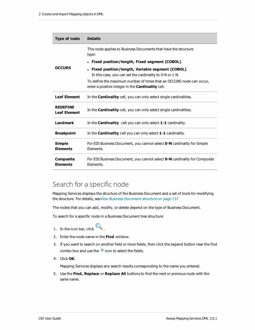
2 Create and import Mapping objects in DML
Type of node Details
OCCURS
This node applies to Business Documents that have the structure type:
l Fixed position/length, Fixed segment (COBOL).
l Fixed position/length, Variable segment (COBOL).In this case, you can set the cardinality to 0-N or 1-N.
To define the maximum number of times that an OCCURS node can occur, enter a positive integer in the Cardinality cell.
Leaf Element In the Cardinality cell, you can only select single cardinalities.
REDEFINE Leaf Element
In the Cardinality cell, you can only select single cardinalities.
Landmark In the Cardinality cell you can only select 1-1 cardinality.
Breakpoint In the Cardinality cell you can only select 1-1 cardinality.
Simple Elements
For EDI Business Document, you cannot select 0-N cardinality for Simple Elements.
Composite Elements
For EDI Business Document, you cannot select 0-N cardinality for Composite Elements.
Search for a specific nodeMapping Services displays the structure of the Business Document and a set of tools for modifying the structure. For details, seeView Business Document structure on page 137
The nodes that you can add, modify, or delete depend on the type of Business Document.
To search for a specific node in a Business Document tree structure:
1. In the icon bar, click .
2. Enter the node name in the Find window.
3. If you want to search on another field or more fields, then click the expand button near the find
combo box and use the icon to select the fields.
4. Click OK.
Mapping Services displays any search results corresponding to the name you entered.
5. Use the Find, Replace or Replace All buttons to find the next or previous node with the same name.
150 User Guide AxwayMapping Services DML 3.0.1

About Business Documents in DML
Create filtersIn a DML Mapping Project, the Business Document describes the composition and structure of the input and output messages for the Mappings.
The structure of a Business Document depends on the structure of the input or output message to which it corresponds. Different information systems require different data structures.
To create filters for Business Document nodes, view the structure of a Business Document. Start from the Project Explorerand double-click the name of the Business Document that you want to modify. Mapping Services opens the Business Document editor.
Create node filterTo create a filter:
1. From the Business Document editor, click the Filter icon .
A wizard opens.
2. Click the plus sign .
3. Select the filter or Business Document from where you want to hide the selected nodes and enter the new for the new filter to be created. Click Next.
4. Use the contextual menu to create the filter.
5. Right click on the Root node and there are two options:
l Extract from here: Makes the selected node the root for the new filter.
l Hide: The selected node is hidden and it will not be displayed in the new filter.
6. Click Finish.
7. Select the newly created filter.
8. Click Finish.
AxwayMapping Services DML 3.0.1 User Guide 151

2 Create and import Mapping objects in DML
Import Business Documents into DML Mapping ProjectsYou have the following options when you create Business Documents in DML:
l Importing a Business Document from a standard library and modify it (see Import a Business Document from a library on page 157)
l Importing a Business Document structure and modify it (see Import a Business Document structure on page 152)
l Creating Business Documents from scratch (see Create Business Documents in DML on page 65)
For more information, see About Business Documents in DML on page 19. and Business Document structure in DML on page 20.
Importing a Business Document enables you to generate Business Document from various model file sources. For example, you can create an XML type Business Document from an XML Schema.
This is particularly useful when you need to create a Business Document for a complex file format. The import wizard automatically creates a valid Business Document for the format and file type you select.
After you import a Business Document, you can edit the Business Document in Mapping Services exactly as you edit a Business Document you build from scratch or copy from another source.
Import a Business Document structureTo import and modify an existing Business Document structure:
1. Select File > Import > Mapping Services > DML.
2. Select the Business Document structure you require. Click Next.
3. Depending on the Business Document structure you selected, select either the message file or the standard message you require.
On the Structure tab, add or edit structural elements of the Business Document. The structural elements that are available vary depending on the type of Business Document you are creating.
For more information, see Manage Business Document structure in DML on page 137 and Business Document types in DML on page 26.
152 User Guide AxwayMapping Services DML 3.0.1

About Business Documents in DML
Import a Flat File description into DML Mapping ProjectsInstead of creating a new Flat File Business Document from scratch, you can import a Flat File description and create Flat File Business Documents out of it.
To import a Flat File descriptor :
1. From the main menu, select File > Import
2. Select Mapping Services > DML > Flat File Description.
3. Click Next.
4. For the input file, select the descriptor file from which the Flat File Business Documents will be created. Click Search Project to search for it in the workspace or Browse to search for it in the file system.
5. Click Check File to check the validity of the file (see Design and parse rules on page 154 and Schema on page 155). If the file is valid the check results will display a confirmation. Otherwise the check results will display a list of errors, notifying the user regarding all the problems encountered when analyzing the input file.
6. Click Next.
7. On the left side, a list of Flat File Business Documents identified in the structure file will be displayed. Select which Business Documents from the structures available are to be imported into the workspace. Click Add to move these Business Document into the right pane. To remove a selected Business Document from the right pane, click Remove.
8. Optionally, click Modify to modify the location and the name of the target Flat File Business Documents in the right pane
9. Click Finish to generate the Flat File Business Document(s).
Mapping Services creates the Flat File Business Document(s) and displays the document(s) in the Business Document folder.
Note To create a valid Flat File Business Document structure which can be used for importing you can either use the Business Document editor, or a description text file (see Example of a valid Flat File Business Document structure in the Business Document editor on page 154 or Example of a valid description text file on page 154).
AxwayMapping Services DML 3.0.1 User Guide 153

2 Create and import Mapping objects in DML
Example of a valid Flat File Business Document structure in the Business Document editor
Example of a valid description text file
Design and parse rules 1. A document definition has a document tag.
2. Multiple document definition can be contained in the same file.
3. The name of the Business Document follows.
154 User Guide AxwayMapping Services DML 3.0.1

About Business Documents in DML
4. Optional attributes may be defined PARENT_DELIMITER, LEAF_DELIMITER.
5. The document structure is described by a set of parent and child elements.
6. The parent containers are identified by { and } as start and end marks.
7. The definition of all attributes of an elements are contained on a single line.
8. Delimiter to STRING requires a delimiter value.
9. TYPE attribute is handled only for date and boolean.
10. Tabulation and white spaces are ignored.
SchemaThe schema below describes the exact syntactical rules that have to be followed when writing a valid flat file description .
(document <document_name> [PARENT_DELIMITER=(FIXED|STRING|IMPLICIT|DEFAULT)[:"<parent_delim_value>"]] [LEAF_DELIMITER=(FIXED|STRING|DEFAULT)[:"<leaf_delim_value>"]]{
([optional] [multiple] <parent_node_name> DELIMITER=(FIXED|STRING|IMPLICIT|DEFAULT)[:"<parent_delim_value>"]
{
([optional] [multiple] [(BREAK|MARK)] (string|boolean|date|integer|real|vlob) <child_node_name> [(<node_definition>)] [DELIMITER=(FIXED|STRING|DEFAULT)[:"<delim_value>"] [FORMAT="<node_special_format>"] [VALUE="<node_default_value>"])(0,n)
([optional] [multiple] <parent_node_name> DELIMITER=(FIXED|STRING|IMPLICIT|DEFAULT)[:"<parent_delim_value>"]
{
...
})(0,n)
})(1,n)
)(1,n)
})(1,n)
For more information, see About Business Documents in DML on page 19 , Flat File Business Document on page 28, Define Flat File Business Documents on page 72
AxwayMapping Services DML 3.0.1 User Guide 155

2 Create and import Mapping objects in DML
Import an Axway EDI Business Document into DML Mapping ProjectsInstead of creating a new Business Document from scratch, you can import a Business Document structure and modify it.
You can import an EDI Business Document structure, such as EDIFACT, X12, TRADACOMS, Cargo IMP, etc from the Axway repository.
1. From the main menu, select File > Import.
2. Select Mapping Services > DML > Axway EDI Business Document .
3. Click Next.
4. Select the EDI Version and the EDI Document.
5. Type the desired name for the output Business Document or click Browse to select the path to an existing output Business Document.
6. Select the option Import Table to to import the associated table directly into the Global Runtime Objects folder. You can modify the path displayed. Either enter the subfolder of the Global Runtime Objects or click Browse to select the subfolder.
In doing so, the Table can be used across several Mappings during runtime and also across several Mapping Projects during the design process in your workspace. Only use Global Runtime Objects when you are absolutely sure, which Mappings are affected by changed Global Runtime Objects during runtime.
For detailed information about the general concept of Global Runtime Objects, refer to the Axway Mapping Services Overview Guide.
7. Select the option Overwrite existing Table to overwrite an existing Table in the Global Runtime Objects folder that has the same name. If the option Import Table to is not selected, you cannot select this overwrite option.
8. Select the option Overwrite existing Business Document to overwrite existing Business Documents that have the same name.
9. Select the option Open imported Business Document to load the Business Documentafter it is imported.
10. Click Next and then Finish to generate the Business Document.
Mapping Services creates the Business Document in the Business Document folder. It opens automatically in the Business Documenteditor if you selected that option.
For more information, see About Business Documents in DML on page 19, EDIFACT Business Document on page 46, ANSI X12 Business Document on page 47.
Note When you have created the new Business Document, you can add and delete elements of the structure depending on your needs. However, because EDI is a standard, you cannot modify the attribute values for existing segments and elements.
156 User Guide AxwayMapping Services DML 3.0.1

About Business Documents in DML
Import a Business Document from a library Instead of creating a new Business Document from scratch, you can import a Business Document from a library into your workspace. Then you can use this Business Document or you can modify it if necessary.
1. From the main menu, select File > Import.
2. Select Mapping Services > DML >> Business Document from Library.
3. Click Next.
4. In the Library Browser, select the Business Document you want to import.
On the right panel, you can add information about the selected Business Document: Description, Dependencies, and Inactive version.
5. Click Next to select the folder in which the Business Document will be imported.
6. Enter a File name for the Business Document.
7. Select the option Save Tables and Custom Functions to Global Runtime Objects to import the associated Tables and Custom Functions directly into the Global Runtime Objects folder. Thereby, the same directory structure is built in the Global Runtime Objects as for the Business Document.
In doing so, these Tables and Custom Functions can be used across several Mappings during runtime and also across several Mapping Projects during the design process in your workspace. Only use Global Runtime Objects when you are absolutely sure, which Mappings are affected by changed Global Runtime Objects during runtime.
For detailed information about the general concept of Global Runtime Objects, refer to the Axway Mapping Services Overview Guide.
8. Select the option Overwrite existing objects to overwrite existing mapping objects that have the same names.
9. Click Finish to import the Business Document.
Mapping Services imports the Business Document into your workspace and displays the document in the Business Documents folder.
Library version informationFor support reasons and for future reference, the version of the standard library is stored within the imported Business Document. To display the standard library information, open the Business Document in the Business Document editor. The Properties view shows the Standard and the Standard Library collection on the General tab.
When the Business Document is deployed, its version from the library will be stored in custom options and remains with the deployed Business Document.
Please note, that this feature only applies to standard libraries and the EDI repository. It is not supported for custom libraries.
AxwayMapping Services DML 3.0.1 User Guide 157

2 Create and import Mapping objects in DML
Note
l In case you have no standard libraries installed, an error message will be displayed when you place the cursor over the Axway libraries entry in the Library Browser. In this case please download and install the libraries from Axway Sphere (see Use Business Document libraries on page 169).
l If standard libraries installed require a higher version of Mapping Services, the blibs in the Library Browser are decorated with an error marker. Place the cursor over the marker to display the error message. This message specifies which version of Mapping Services must be installed.
Alternatively, you can also use the Library Browser to import a Business Document from a library into your workspace. For more information, see Import a Business Document into the workspace on page 172.
For more information, see About Business Documents in DML on page 19, Use Business Document libraries on page 169.
Import a COBOL Business Document from StandardInstead of creating a new Business Document from scratch, you can import a Business Document structure and modify it.
Importing a COBOL document structure is the same for both COBOL Fixed and Variable segment Business Documents.
1. From the main menu, select File > Import.
2. Select Mapping Services > DML > COBOL Standard.
3. Click Next.
4. Browse to the directory where your COBOL copy file is located.
5. Select the type of the target Business Documents, either COBOL Fixed or COBOL Variable.
6. The central panel displays the COBOL Business Documents which can be created from the selected file. From the displayed list, select one or more files to import and convert to a COBOL-type Business Document.
7. Select the option Overwrite existing Business Document to overwrite existing Business Documents that have the same name.
8. Select the option Open imported Business Document to load the Business Documentafter it is imported.
9. Click Next and then Finish to generate the Business Document(s).
Mapping Services creates the new Business Document(s) in the Business Documents folder. It opens automatically in the Business Documenteditor if you selected that option.
For more information, see About Business Documents in DML on page 19, COBOL Business Document on page 44
158 User Guide AxwayMapping Services DML 3.0.1

About Business Documents in DML
Import from SAP IDoc V4Instead of creating a new Business Document from scratch, you can import a Business Document structure and modify it.
You can import a SAP IDoc V4 description into a Business Documentstructure to create a Business Document.
1. From the main menu, select File > Import.
2. Select Mapping Services > DML > SAP IDoc V4 Description.
3. Click Next.
4. Either choose to import a SAP IDoc description from the file system or from a remote SAP system.
l To import a SAP IDoc description from the file system:
o Select the option Import IDoc from file.
o Select the SAP IDoc description file you want to import. Click Search Project to search for it in the workspace or Browse to search for it in the file system.
l To import a SAP IDoc description from a remote SAP system:
o Select the option Import IDoc from SAP server.
o From the Connection combo box, select an existing SAP server connection or select the <New Connection> entry to create a new SAP server connection.
o Select a SAP IDoc description from the displayed tree.
5. Edit the target IDoc Business Document path if desired.
6. Click Rename to rename the target Business Document and provide a different name.
7. Select the option Overwrite existing Business Document to overwrite an existing Business Document that has the same name.
8. Select the option Open imported Business Document to load the Business Documentafter it is imported.
9. Click Finish to generate the Business Document.
Mapping Services creates the new Business Document and displays the document in the Business Document folder. It opens automatically in the Business Documenteditor if you selected that option.
For more information, see About Business Documents in DML on page 19,IDoc Business Document on page 52.
AxwayMapping Services DML 3.0.1 User Guide 159

2 Create and import Mapping objects in DML
Import and export XML Business DocumentsInstead of creating a new Business Document from scratch, you can import a Business Document structure and modify it.
In Mapping Services, you use XML type Business Documents in a Map, where the XML Business Document specifies an XML standardized organization of data that is either received as input, or generated as output by a Map Engine.
You can import a Schema, DTD or XML into an XML Business Document. The other way round you can generate a Schema based on an existing XML Business Document:
l Import from schema, DTD or XML on page 160
l Export XML Schemas from Standard on page 161
For more information, see About Business Documents in DML on page 19.
Import from schema, DTD or XMLInstead of creating a new Business Document from scratch, you can import a Business Document structure and modify it.
In Mapping Services, you use XML type Business Documents in a Map, where the XML Business Document specifies an XML standardized organization of data that is either received as input, or generated as output by a Map Engine.
You can import XML schema, XML DTD, or an XML document into an XML or XSD Business Document.
To import schema, DTD or XML into an XML or XSD Business Document:
1. From the main menu, select File > Import
2. Select Mapping Services > DML > Schema / DTD / XML Description.
3. Click Next.
4. Select the document type (XML Document, XML DTD, or XML Schema).
5. Select the input file you want to import. Click Search Project to search for it in the workspace or Browse to search for it in the file system.
6. If you import an XML schema or an XML DTD you can select DTD and schema options.
7. For the Target Business Document, select XML or XSD. Click Next.
8. Click Next.
9. Select the Business Documents to be imported.
From the displayed list in the left pane, select one or more files to import and convert to an XML-type Business Document. Move them into the right pane by clicking the > button. Optionally, modify the location and the name of the target XML Business Documents in the right pane by clicking the Modify button.
10. Click Finish to generate the Business Document(s).
160 User Guide AxwayMapping Services DML 3.0.1

About Business Documents in DML
Mapping Services creates the XML Business Document(s) and displays the document(s) in the Business Document folder.
For more information, see About Business Documents in DML on page 19, XML Business Document on page 54, XSD Business Document on page 58.
Export XML Schemas from StandardIn Mapping Services, you use XML type Business Documents in a Map, where the XML Business Document specifies an XML standardized organization of data that is either received as input, or generated as output by a Map Engine.
Use the Schema Exporter to generate an XML Schema based on an XML or an EDI Business Document in order to validate output messages.
For more information, see About Business Documents in DML on page 19, XML Business Document on page 54.
1. From the main menu, select File > Export.
2. Select Mapping Services > DML > Schema Exporter.
3. Click Next.
4. Select the XML or EDI Business Document that you want to generate an XML Schema from.
5. Enter where you want to store the XML Schema in the Export to file field.
You can change the path where the XML Schema is generated by using Search Project or Browse to save it either in the workspace or the file system. The path can be entered manually also.
6. Select Open generated schema if you want to open it in the text editor after creation.
7. Click Finish.
Mapping Services generates the XML Schema and displays the XML Schema of the selected Business Document in the default text editor.
Note To customize the generated XML Schema, click Advanced Settings. The Preferences dialogs opens where you can customize the settings for generating an XML Schema. For more information, see Mapping Services DML Preferences: Schema exporter on page 271.
AxwayMapping Services DML 3.0.1 User Guide 161

2 Create and import Mapping objects in DML
Use Business Document Validation Rules in DML
About Validation RulesValidation Rules are sets of Boolean expressions that enable the Map Engine to check the content of a Business Document in DML during message processing.
In a DML Mapping Project, the Business Document describes the composition and structure of the input and output messages for the Mappings.
Some of the prebuilt Business Documents that you import to Mapping Services include a set of default Validation Rules. This is true, for example, for the prebuilt Business Documents provided by the Axway SWIFTNet solution for handling specific SWIFT message types.
In other cases you may choose to add a Validation Rule to detect faulty message structure or content.
Input messagesWhen the Map Engine parses an input message to a Business Document for processing in a Map, it confirms that the message content and/or structure conform to the rules specified by the Validation Rules.
Output messagesWhen the Map Engine builds an output Business Document from the output result of a Map, it confirms that the node content and/or structure conform to any rules set in the Validation Rules.
Add a Validation RuleValidation Rules are sets of Boolean expressions that enable the Map Engine to check the content of a Business Document in DML during message processing.
To add a Validation Rule to a Business Document:
1. Open a Business Document. In the Business Document editor, select the Validation tab to open the Validation Rules view.
2. Either:
l From the toolbar, click Add Validation Rule.
l Right-click on the Validation Rule list and select Add Validation Rule.
Mapping Services adds a Validation Rule entry to the left pane.
162 User Guide AxwayMapping Services DML 3.0.1

About Business Documents in DML
3. Select the new entry in the left pane and then complete the middle pane.
Field Contents
Name Enter a name for the Validation Rule.
Expression Enter a Boolean expression.
The logic of a Validation Rule is similar to that of the DML expression if-then-else. However, to define a Validation Rule, do not include any reserved words.
The reserved word if is implicit in a Validation Rule. Because you do not define what the software does when the if clause returns the value false, the words then and else are not necessary.
To use a node of the Business Document in an expression, you can drag the node from the right frame to the Expression field.
Comments Enter a free-text description of the Validation Rule. This description appears only on this tab.
Validation Rule examplesValidation Rules are sets of Boolean expressions that enable the Map Engine to check the content of a Business Document in DML during message processing.
Validation Rule expression Explanation
!Port of Embarkation! = "Le Havre"
This Validation Rule checks the value that is contained in the Port of Embarkation node.
If the Business Document does not contain the value Le Havre in the Port of Embarkation node, the Business Document is rejected.
The node name is enclosed inside exclamation marks ( ! ).
(!Port of Embarkation! = "Le Havre") and (!Port of Debarkation! = "Brest") and (!Dock Time! > 2)
This Validation Rule checks the values that are contained in three nodes: Port of Embarkation, Port of Debarkation, and Dock Time.
If the Business Document does not contain the values that are specified for all three nodes, the Business Document is rejected.
AxwayMapping Services DML 3.0.1 User Guide 163

2 Create and import Mapping objects in DML
Validation Rule expression Explanation
%varZ:=1;
%varB:=true;
loop (count(Dock Time))
{
if Dock Time [%varZ] >= 2 then %varB:= false;
%varZ := %varZ + 1
};
%varB
This Validation Rule checks the value in the Dock Time node:
l The DML function count returns every occurrence ofDock Time in the Business Document.
l The DML instruction loop repeats the Validation Rule for each occurrence of Dock Time.
l The Variable varB returns the value of the Validation Rule (true or false).
If the Business Document does not contain a value that is greater than or equal to 2 (hours) in the Dock Time node, the Business Document is rejected.
Delete a Validation RuleValidation Rules are sets of Boolean expressions that enable the Map Engine to check the content of a Business Document in DML during message processing.
To delete a Validation Rule, select in the left pane of the list of Validation Rules the entry that corresponds to the Validation Rule you want to delete.
1. On the toolbar, click Delete Validation Rule.
2. Right-click the Validation Rule you want to delete and select Delete.
Mapping Services deletes the Validation Rule and removes the entry from the list.
Manage Map Engine Validation RulesValidation Rules are sets of Boolean expressions that enable the Map Engine to check the content of a Business Document in DML during message processing.
To manage the way the Map Engine applies Validation Rules when handling a message flow, you work in the Mapping Flow Properties view, in the General section.
For more information, see Use Business Document Validation Rules in DML on page 162.
Check box Description
Input
164 User Guide AxwayMapping Services DML 3.0.1

About Business Documents in DML
Check box Description
Check input Validation Rules
Select this option if you want the Map Engine to apply Validation Rules when parsing the message to the input Business Document.
Stop on first input Validation Rule error
By default this option is selected. The Map Engine stops processing the message when it encounters the first Validation Rule error.
If you clear this check box, the Map Engine precedes to the end of the Validation Rules validation for the input message whether or not an error is detected. If one or more errors are returned during Validation Rules validation, the Map Engine suspends the processing of the message at the end of Validation Rules phase, and logs each error to the Message Log.
Outputs
Check output Validation Rules
Select this option if you want the Map Engine to apply Validation Rules when building the output Business Document.
Stop on first output Validation Rule error
By default this option is selected. The Map Engine stops processing the message when it encounters the first Validation Rule error.
If you clear this check box, the Map Engine precedes to the end of the Validation Rules validation for the output message whether or not an error is detected. If one or more errors are returned during Validation Rules validation, the Map Engine suspends the processing of the message at the end of Validation Rules phase, and logs each error to the Message Log.
AxwayMapping Services DML 3.0.1 User Guide 165

2 Create and import Mapping objects in DML
Business Document data encoding in DML
About Business Document data encodingWhen the Map Engine processes an input message for use in a Map, the Map Engine extracts the raw data from the input message and inserts it into structured nodes of a Business Document. As the Map Engine parses the data to the nodes of the Business Document, it assigns an encoding type to the data.
In a DML Mapping Project, the Business Document describes the composition and structure of the input and output messages for the Mappings.
After installing the Map Engine, these default encoding types are available:
l ISO 8859
l UTF-8
l UTF-16
l UTF-32
l UCS-2
l UCS-4
l JIS
l SJIS
l ibmknj
l EUC-JP
l big5
You can change the data encoding for an entire Business Document by selecting one or the other of these encoding types. You can add additional encoding options by editing the <Mapping Services install folder>/configuration/encoding.properties file.
For XML and Flat File type Business Documents, you can set the encoding for individual nodes.
166 User Guide AxwayMapping Services DML 3.0.1

About Business Documents in DML
Business Document UML viewThe UML view is used to see an Object Diagram of the structure of different elements of a Business Document in DML.
To open the UML view of a Business Document, start from the Project Explorer:
1. Double-click the name of the Business Document that you want to modify.
Mapping Services opens the Business Document editor.
2. Select the UML tab.
For more information, see About Business Documents in DML on page 19 and Business Document structure in DML on page 20.
This is an example of a Flat File Business Document and its properties:
Available diagrams:
l Document diagram: Contains the general properties of the Business Document and the attributes of the root nodes. It has links to the signature, validation rules diagrams and Parent element diagrams.
l Parent node diagram: Contains the attributes of the Parent node and those of its children with links to other Parent node diagrams.
l Enumeration leaf diagram: Contains information about the attributes of the leaf and the name, order and values of the enumerations defined in the node.
AxwayMapping Services DML 3.0.1 User Guide 167

2 Create and import Mapping objects in DML
l Validation rules diagram: Contains the list of validation rules and the information available on each of them.
l Signature: Contains information about the version and last modification time of the Business Document.
168 User Guide AxwayMapping Services DML 3.0.1

About Business Documents in DML
Use Business Document librariesA Business Document library is an archive of predefined (provided by Axway) or user-created Business Documents that vendors and users are willing to share as a standard.
In Mapping Services DML, there are two categories of libraries: Axway libraries and Custom libraries.
Axway libraries
Axway libraries are read-only libraries provided by Axway. These are stored in a separate location from custom libraries. You cannot modify or delete these libraries.
Note
Axway Mapping Services supports the message standards that are supported by the respective runtime server (B2Bi or Integrator), such as ANSI X.12 or EDIFACT.
Axway provides the support of message standards with Standards Libraries. A Standard Library is a set of packages (collections) that contain:
l Prebuilt message structures (Business Documents)
l Repositories
l Map and flow components
l Sample maps and flows
You can use these items in Mapping Services to accelerate the definition of message- processing flows for various industry standards and business applications.
Refer to the following documents for information about download, installation and versions of Standard Libraries:
l B2Bi Support Reference Catalog or
l Integrator Support Reference Catalog
All Axway documentation can be downloaded from Axway Sphere: https://support.axway.com.
Custom libraries
Custom libraries are user-created libraries. These are kept in the <Mapping Services install location>/repository folder and are not overwritten when installing a service pack. You can share libraries within the Mapping Services installation by copying the corresponding .blib files from one repository folder into another. You are able to modify or delete custom libraries, if desired.
After creating your own custom library, you can add the appropriate Business Documents into that library. Finally, if you determine that your custom library is correct and no more changes are needed, you can release that library, making it read-only.
You can delete a custom library if you do not need it anymore.
AxwayMapping Services DML 3.0.1 User Guide 169

2 Create and import Mapping objects in DML
You can use Business Document libraries to export Business Documents from the selected library into your workspace. Then you can work with these Business Documents.
To work with Business Document libraries, open the Library Browser in the Tools menu.
For more information, see About Business Documents in DML on page 19, Create a new custom library on page 170, Add Business Documents to a custom library on page 170, Release a custom library on page 172 and Import a Business Document from a library on page 157.
Create a new custom libraryA Business Document library is an archive of predefined (provided by Axway) or user-created Business Documents that vendors and users are willing to share as a standard.
In Mapping Services DML, there are two categories of libraries: Axway libraries and Custom libraries.
If there is a particular standard you want to use and do not have a library designed to use that standard, you can create your own user-defined library. You can then add the appropriate Business Documents into that custom library.
After you define your library and determine that it is correct and no more changes are needed, you can release that library, making it read-only.
For more information, see About Business Documents in DML on page 19, Use Business Document libraries on page 169, Add Business Documents to a custom library on page 170, Release a custom library on page 172 and Import a Business Document from a library on page 157.
To create a new custom library:
1. From the main menu, select Tools > Library Browser.
2. Click the Create Custom Library icon to create a new custom library.
3. Specify the Library name, Description, and Version for the created custom library and then click Finish.
The new custom library is kept in the <Mapping Services install location>/repository folder.
Add Business Documents to a custom libraryA Business Document library is an archive of predefined (provided by Axway) or user-created Business Documents that vendors and users are willing to share as a standard.
In Mapping Services DML, there are two categories of libraries: Axway libraries and Custom libraries.
You can add a Business Document, along with its dependent objects, such as Tables, Variables, Custom Functions, to a custom library, if that library has not yet been released.
You can use the Library Browser to add Business Documents to a custom library:
1. From the main menu, select Tools > Library Browser.
Alternatively, from the main menu, select File > Export
170 User Guide AxwayMapping Services DML 3.0.1

About Business Documents in DML
2. Select the custom library to which to add Business Documents. Click Add Business Documents to Library.
3. Select the custom library to which to add Business Documents. Note that you can add Business Document only to custom libraries which are not yet released.
4. Click Next.
5. Select one or more Business Documents to add to the library.
6. Click Finish.
Alternatively, you can use the Export wizard to export a Business Document from your workspace into a custom library. For more information, see Export Business Documents to a custom library on page 171.
After adding Business Documents to your library and determine that it is correct and no more changes are needed, you can release that library, making it read-only (see Release a custom library on page 172).
For more information, see About Business Documents in DML on page 19, Use Business Document libraries on page 169, Create a new custom library on page 170, and Release a custom library on page 172.
Export Business Documents to a custom libraryA Business Document library is an archive of predefined (provided by Axway) or user-created Business Documents that vendors and users are willing to share as a standard.
In Mapping Services DML, there are two categories of libraries: Axway libraries and Custom libraries.
You can add a Business Document, along with its dependent objects, such as Tables, Variables, Custom Functions, to a custom library, if that library has not yet been released.
To add Business Documents to a custom library:
1. From the main menu, select File > Export.
2. Select Mapping Services > DML > Business Document to Library.
3. Click Next.
4. Select the custom library to which to add Business Documents.
5. Note, that the pane contains only libraries which were not yet released.
6. Click Next.
7. Select one or more Business Documents to add to the library.
8. Click Finish.
You can also use the Library Browser to add Business Documents to a custom library. For more information, see Add Business Documents to a custom library on page 170.
For more information, see also About Business Documents in DML on page 19 and Use Business Document libraries on page 169.
AxwayMapping Services DML 3.0.1 User Guide 171

2 Create and import Mapping objects in DML
Release a custom libraryA Business Document library is an archive of predefined (provided by Axway) or user-created Business Documents that vendors and users are willing to share as a standard.
In Mapping Services DML, there are two categories of libraries: Axway libraries and Custom libraries.
When you manually create a custom library to match a standard, you can still update the library. Then when you release that custom library, it becomes a read-only file, both to yourself and to anyone else who uses it. This means that no Business Documents can be added or deleted.
For more information, see Use Business Document libraries on page 169, Create a new custom library on page 170, Add Business Documents to a custom library on page 170, and About Business Documents in DML on page 19
Note All Axway libraries are already released libraries.
To release an existing custom library:
1. From the main menu, select Tools > Library Browser.
2. Select the custom library to release.
3. Click Release Library.
4. Click Yes to the confirmation message asking if you want to close the library for all modifications.
5. To close the library browser, click Close.
Import a Business Document into the workspaceA Business Document library is an archive of predefined (provided by Axway) or user-created Business Documents that vendors and users are willing to share as a standard.
In Mapping Services DML, there are two categories of libraries: Axway libraries and Custom libraries.
You can use Business Document the Library Browser to import Business Documents from a selected library into your workspace. Then you can work with these Business Documents or modify them.
For more information, see About Business Documents in DML on page 19, Use Business Document libraries on page 169, Create a new custom library on page 170, Add Business Documents to a custom library on page 170, and Release a custom library on page 172.
To import a Business Document from a library into your workspace:
1. From the main menu, select Tools > Library Browser
2. Select the library and the Business Document to import into your workspace.
On the right panel, you can add information about the selected Business Document: Description, Dependencies, and Inactive version.
3. Click Import Business Document into Workspace.
172 User Guide AxwayMapping Services DML 3.0.1

About Business Documents in DML
4. Select the folder into which the Business Document will be imported.
5. Enter a File name for the Business Document.
6. Select the option Save Tables and Custom Functions to Global Runtime Objects to import the associated Tables and Custom Functions directly into the Global Runtime Objects folder. Thereby, the same directory structure is built in the Global Runtime Objects folder as for the Business Document.
In doing so, these Tables and Custom Functions can be used across several Mappings during runtime and also across several Mapping Projects during the design process in your workspace. Only use Global Runtime Objects when you are absolutely sure, which Mappings are affected by changed Global Runtime Objects during runtime.
For detailed information about the general concept of Global Runtime Objects, refer to the Axway Mapping Services Overview Guide.
7. Select the option Overwrite existing objects to overwrite existing mapping objects that have the same names.
8. Click Finish.
Mapping Services imports the Business Document into your workspace and displays the document in the Business Documents folder.
Library version informationFor support reasons and for future reference, the version of the standard library is stored within the imported Business Document. To display the standard library information, open the Business Document in the Business Document editor. The Properties view shows the Standard and the Standard Library collection on the General tab.
When the Business Document is deployed, its version from the library will be stored in custom options and remains with the deployed Business Document.
Please note, that this feature only applies to standard libraries and the EDI repository. It is not supported for custom libraries.
Note
l In case you have no standard libraries installed, an error message will be displayed when you place the cursor over the Axway libraries entry in the Library Browser. In this case please download and install the libraries from Axway Sphere (see Use Business Document libraries on page 169).
l If standard libraries installed require a higher version of Mapping Services, the blibs in the Library Browser are decorated with an error marker. Place the cursor over the marker to display the error message. This message specifies which version of Mapping Services must be installed.
Alternatively, you can use the Import wizard to import a Business Document from a library into your workspace. For more information, see Import a Business Document from a library on page 157
AxwayMapping Services DML 3.0.1 User Guide 173

2 Create and import Mapping objects in DML
About Maps in DML Mapping ProjectsMaps are the central processing units of integration applications. Each Map receives information held in one or more input Business Document and generates information to one output Business Document.
About MapsA Map is a design specification. It specifies which fields or records of a source message will be copied (and if required manipulated) to the target Business Document. Both source and target Business Document formats can either be data format descriptions of specific applications, or Standard Message Descriptions, such as EDIFACT or SAP message descriptions that can be imported from the repository.
Maps have properties and descriptions that identify the general parameters of the Map and that identify the associated documentation (seeMap properties in a DML Mapping Project on page 188) .
A Map is contained in and belongs to a Mapping Flow (see About Mapping Flows in DML Mapping Projects on page 194).
Maps have the file extension .mdm.
Input Business DocumentA Map may have a single input Business Document or none at all. You can directly map the data contained in the node of an input Business Document to nodes of the output Business Document. You can also transform any of the data contained in the input Business Document before writing it to the output.
Output Business DocumentEvery Map is linked to an output Business Document. Maps are sets of expressions that generate values for the nodes of this output Business Document.
174 User Guide AxwayMapping Services DML 3.0.1

About Maps in DMLMapping Projects
Map editorA Map (see About Maps in DML Mapping Projects on page 174) provides instructions for how the content of an output Business Document is generated.
In the Map editor of a DML Mapping Project, each node of the output Business Document is associated with an expression field. The set of expressions in the Expression fields of the Map editor constitutes a single Map.
AxwayMapping Services DML 3.0.1 User Guide 175

2 Create and import Mapping objects in DML
Expression FieldsTo specify how the Map generates the values for the output nodes, you enter the following types of information in the expression fields:
l Constants: You can enter a constant value to be written directly to the output or used in a DML expression.
l Variables: You can retrieve a value from a variable that is to be either written directly to the output node or used in a DML expression.
l Node content of an input Business Document
l DML expressions: You can build DML expressions that manipulate the values of constants, variables, or input Business Document content.
l Functions: You can build and use customized functions that extend the functionality of the delivered set of DML functions.
176 User Guide AxwayMapping Services DML 3.0.1

About Maps in DMLMapping Projects
Create Maps in DML Mapping ProjectsIn an existing DML Mapping Project you can create the following types of Maps (see About Maps in DML Mapping Projects on page 174):
l DML Map: The DML Map uses DML expressions to transform and map one or more input Business Documents to an output Business Document (see Create a DML Map on page 177).
l Database Map: A Database Map is used to map data to or from a database (see Create a Database Map in a DML Mapping Project on page 178).
l Web Service Map: A Web Service Map is used to call a Web Service that contains the input message (see Create a Web Service Map in a DML Mapping Project on page 184).
l SAP Map: The SAP Map is used to map data between SAP metadata objects and other types of data structures (see Create a SAP Map in a DML Mapping Project on page 186).
Create a DML Map
About DML MapsA DML Map (see About Maps in DML Mapping Projects on page 174) uses DML expressions to transform and map one or more input Business Documents to an output Business Document.
Create DML MapsTo create a DML Map in an existing DML Mapping Project:
1. From the main menu, select File > New > Map.
Alternatively, you can right-click in the Project Explorer and select New > Map.
A wizard appears to help you create a new Map.
2. Specify where you want to save the Map. To select a path either use the directory tree or enter the path directly.
3. Enter a File name for your Map. Click Next.
4. For Map Type, choose DML.
5. You can use either the Simple Configuration or Advanced Configuration tab.
If you want to use more than one input Business Document, you must select Advanced Configuration.
In the Advanced Configuration tab click to add more input Business Documents.
6. Click Browse to select the path to the input Business Document(s).
AxwayMapping Services DML 3.0.1 User Guide 177

2 Create and import Mapping objects in DML
7. Click Browse to select the path to the output Business Document.
8. Click Finish.
Mapping Services creates the Map in the selected project’s map folder and an entry in the Project Explorer pane tree structure.
The Map opens on a new tab in the editor. On this tab, in the Filter (out) section, in the Expression column, you can enter DML expressions.
Create a Database Map in a DML Mapping Project
About Database MapsA Database Map (see About Maps in DML Mapping Projects on page 174) is used to map data to or from a database. Database Maps are available for the following database types: SQL Server, MySQL, Oracle. .
The input to, or output of a Database Map is always a Database Business Document. You can create the following types of Database Maps:
l Select
l Insert
l Update
l Delete
l Stored Procedure
Note: You can only use SQL expressions that are transaction-enabled. Do not use any SQL statements that commit the transaction, for example: CREATE TABLE, DROP TABLE, and so on.
You use a Database Map to:
l Update, insert, or delete data in a database
l Select data from the database
l Execute a Stored Procedure
178 User Guide AxwayMapping Services DML 3.0.1

About Maps in DMLMapping Projects
Update, insert or delete data in a databaseYou can write database queries to update, insert, or delete data in a database. These types of Database Maps do not require output Business Documents. The input Business Document is used to provide the lookup value to find what to update, where and what to insert, or what to delete.
Select data from a databaseYou can write SQL queries that select data from a database. The input Business Document is used to provide the lookup value for what to select.
Execute a Stored ProcedureYou can define a SQL Map that executes Stored Procedures on a database. The input Business Document is used to provide the parameters to your Stored Procedure. You cannot create a new Stored Procedure in Mapping Services; you can only execute Stored Procedures that already exist.
Database Map with multiple Select statementsDatabase Maps can contain several Select statements. For this particular case, the output Business Document that is to be generated or used contains a number of root leaves equal to the number of Select statements. This is the only case when a Database Business Document can contain more than one root element.
Create a Database MapTo create a Database Map in an existing DML Mapping Project:
1. From the main menu, select File > New > Map.
Alternatively, you can right-click in the Project Explorer and select New > Map.
A wizard appears to help you create a new Map.
2. Specify where you want to save the Map. To select a path either use the directory tree or enter the path directly.
3. Enter a File name for your Map. Click Next.
4. For Map Type, select Database.
5. Click Next.
6. Optionally, select a database connection or create a new one using the Connection drop-down list. For details see Set up the database connection on page 180
7. From the SQL Statement drop-down list, select the type of Database Map. By default, it is set to SELECT.
AxwayMapping Services DML 3.0.1 User Guide 179
2 Create and import Mapping objects in DML
8. Select the input and output Database Business Documents.
For Source, click Browse to select the path to the input Business Document.
For Target, click Browse to select the path to the output Business Document.
9. If you check Generate, default names for the Source and Target Business Documents to be generated are displayed. You can edit these names.
10. If you want to edit the Join, Where, or Order By statements, click Next. Otherwise click Finish.
11. Optionally, edit the Join statement of the SQL expression of the Database Map (see Create a Join statement on page 180) and click Next.
12. Optionally, edit the Where statement of the SQL expression of the Database Map (see Create a Where statement on page 181) and click Next.
13. Optionally, edit the Order By statement of the SQL expression of the Database Map (see Create an Order By statement on page 181) and click Finish.
Mapping Services generates the Database Map in the selected project’s map folder and creates an entry in the Project Explorer pane tree structure. If the automatic generation for input and/or output Business Documents has been selected, Mapping Services also generates these Business Documents in the Business Document folder.
The Map opens on a new tab in the Database Map editor. For details refer to Use the Database Map editor in a DML Mapping Project on page 182.
Set up the database connectionOptionally, in the New Map wizard, you can select a database connection using the Connection drop-down list. Or, create a new connection by selecting New Connection.
Selecting a connection will fill in the Tables pane with the database schemas containing tables, views, and stored procedures. Check the desired tables, views, and stored procedures to be stored in the map cache, which allows you to work on the Map in disconnected mode.
Create a Join statementOptionally, when creating a Database Map, you can create the Join statement of the Database Map SQL expression if the type of the Database Map is SELECT.
You can add, delete, or move joins. Each join expression allows you to select the join type, the right table to build the join, and the join condition.
The wizard allows you to select from the following Join Types:
l inner join
l left outer join
l right outer join
l full outer join
180 User Guide AxwayMapping Services DML 3.0.1

About Maps in DMLMapping Projects
Note: You can edit the name of the right table or select it from a drop-down list containing the tables you selected previously from the database. If no tables were selected, no list is displayed.
Create a Where statementOptionally, when creating a Database Map, you can also create the Where statement of the Database Map SQL expression if the type of the Database Map is SELECT, UPDATE, or DELETE.
You can add, delete, move, edit, and group where conditions.
Click... To
Insert an AND group. It groups all nested conditions and they will have the AND conditional operator between them.
Insert an OR group. It groups all nested conditions and they will have the OR conditional operator between them.
Insert a NOT AND group. It groups all nested conditions and they will have the AND conditional operator between them and the entire group is negated.
Insert a NOT OR group. It groups all nested conditions and they will have the OR conditional operator between them and the entire group is negated.
Insert a condition.
Create an Order By statementOptionally, when creating a Database Map, you can also modify the Order By statement of the SQL expression.
All of the columns of the tables or views you checked previously for the current Select are on this page. If those tables or views contain primary keys, they will be automatically checked. You can change the selection, meaning the rows obtained from querying the database will be ordered by the columns you check here.
Create a Database Map with multiple Select statementsTo create this particular case of Database Map, follow the same steps as for a normal Database Map. You can add multiple statements and for each one you can define a Join, Where, and Order By expression.
Note The connection you set when creating the Database Map with multiple Select statements is the same for every statement.
AxwayMapping Services DML 3.0.1 User Guide 181

2 Create and import Mapping objects in DML
Use the Database Map editor in a DML Mapping ProjectThe Database Map editor (see Create a Database Map in a DML Mapping Project on page 178) provides you with an easy way to create or edit Database Mappings. The editor is divided into four areas, depending on the database Map type.
Editor overviewThe structure of the input Database Business Document object is shown in tree format on the upper left side. The output Business Document objects are on the right side. In between, the cached database information (database tables with its respective columns) is shown. The database information is stored locally in the workspace when the Database Map is created. If there is no information available about the database structure, the middle section is empty and offers the possibility to connect to the database and to download the corresponding data.
The meaning of the links depends on the chosen database Map type. For instance, for a Select Map the links between table columns and output Business Document elements represent the Select clauses and the links from input elements to table columns represent the Where conditions. The following table gives several meanings of the links, depending on the chosen database Map type. The table shows the arrangement of the design page panels.
182 User Guide AxwayMapping Services DML 3.0.1

About Maps in DMLMapping Projects
Type Left Middle Right
Select Input BDoc (Where clause)
Database Output BDoc (Returned data)
Insert --- Input BDoc (Input data) Database
Update --- Input BDoc (Update data + Where clause)
Database
Delete --- Input BDoc (Where clause) Database
Stored Procedure
Input BDoc (Input parameters)
Database (Stored Procedures)
Output BDoc (Output parameters)
SQL source editorA source editor is located underneath the three structure sections, where you can create and edit SQL expressions. This SQL editor offers you typical source editing functionality, such as syntax highlighting, content assistant support, formatting, undo & redo, etc. Furthermore, you can drag-and-drop table columns or content from the Business Document panels into the editor. The links in the design overview are automatically updated when editing in the source editor.
Properties viewThe properties view lets you specify general settings of the Database Map (such as database settings, label, used Database Business Documents, etc.), as well as the properties of the currently selected Business Document element. See the following example.
AxwayMapping Services DML 3.0.1 User Guide 183

2 Create and import Mapping objects in DML
Outline viewThe outline view gives you an overview of the whole SQL expression. All parts of the statements are displayed in a structure tree. The outline view is bound to the Database Map editor. If you select an element in the outline view, the corresponding element is selected in the editor too and vice versa. See the following example.
Create a Web Service Map in a DML Mapping Project
About Web Service MapsA Web Service Map (see About Maps in DML Mapping Projects on page 174) is used to call a Web Service that contains the input message, and it receives a response from that service. The input to, or output from, a Web Service Map is always an XML Business Document.
Create a Web Service MapTo create a Web Service Map in an existing DML Mapping Project:
1. From the main menu, select File > New > Map. Alternatively, you can right-click in the Project Explorer and select New > Map.
A wizard appears to help you create a new Map.
2. Specify where you want to save the Map. To select a path either use the directory tree or enter the path directly.
3. Enter a File name and select the location of the Map. Click Next.
4. For Map Type, choose Web Service.
5. Click Next.
6. Enter the WSDL URL of the file, or optionally select a file from the file system or project . If you type the URL yourself you must click Parse.
184 User Guide AxwayMapping Services DML 3.0.1

About Maps in DMLMapping Projects
7. Select an operation from the WSDL Structure pane, which will automatically fill the text fields on the right with the proper values. Check the properties of the selected operation.
8. Optionally, search a Web Service using UDDI by clicking UDDI Search. Input the repository URL and search a Business Service or a Business Entity by entering the name in the Search name field. After the search is completed, select a Business Entity from the Search Results list and switch to the Business Service tab. Select the Binding of a Service and click OK. You can now select an operation.
9. Select the input and output Business Documents.
For Source, click Browse to select the path to the input Business Document.
For Target, click Browse to select the path to the output Business Document.
10. Enter a number for the Generate recursivity depth. This refers to the maximum depth to go through in case of XSD elements before stopping to generate the XML Business Document.
11. Select a method to generate your Business Document: Body only or Header and body. For details see Soap faults on page 185
12. Click Finish.
Mapping Services generates the Web Service Map in the selected project’s map folder and an entry in the Project Explorer pane tree structure. Mapping Services also generates the necessary Business Documents in the Business Documentfolder.
Soap faults When creating the Web Services Map, if there are SOAP faults defined in the WSDL file for the selected operation, in addition to the input and output Business Documents, an XML Business Document is created for each fault.
You can use one of the following options to control how the content of the Business Document is generated:
l Body only — the payload content is added to the body.
l Header and Body — the payload content is set as the envelope and the Business Documents contain the entire envelope including the SOAP Envelope element and all the children.
Editor overviewThe structure of the input Business Document object is displayed in tree format on the upper left-hand side. The output Business Document objects are displayed on the right-hand side. The structure of the WSDL file is shown between the two displays. The name of the selected operation is highlighted.
You can change the operation either by double-clicking on another operation or by using the contextual menu. A window displays asking you to confirm the action. If you select YES, the Business Documents and the Map are regenerated. The old Business Documents and Map are overwritten.
AxwayMapping Services DML 3.0.1 User Guide 185

2 Create and import Mapping objects in DML
Properties viewThe Properties view allows you specify general settings of the Web Service Map (such as service name, port name, and so on).
The Web Service Map does not allow changing of the input or output Business Documents, so the buttons in the General tab of the Properties view are disabled.
You can view the fault Business Documents in the Web Services tab of the Properties view.
Create a SAP Map in a DML Mapping Project
About SAP MapsThe SAP Map (see About Maps in DML Mapping Projects on page 174) enables you to map data between the following SAP metadata objects and other types of data structures:
l Functional Modules
l BAPIs
l Transactions
Create a SAP MapTo create a SAP Map in an existing DML Mapping Project:
1. From the main menu, select File > New > Map.
Alternatively, you can right-click in the Project Explorer and select New > Map.
A wizard appears to help you create a new Map.
2. Specify where you want to save the Map. To select a path either use the directory tree or enter the path directly.
3. Enter a File name for your Map. Click Next.
4. For Map Type, choose SAP.
5. Click Next.
6. Select a SAP server connection or create a new one. For details seeSet up the SAP server connection on page 187.
7. Select a SAP metadata from the three categories available: Function Modules, BAPIs and Transactions. Optionally, when you expand a category you can provide a filter (for example, B* will display only SAP metadata starting with B).
8. Select the input and output Database Business Documents.
For Source, click Browse to select the path to the input Business Document.
186 User Guide AxwayMapping Services DML 3.0.1

About Maps in DMLMapping Projects
For Target, click Browse to select the path to the output Business Document.
9. If you check Generate, default names for the Source and Target Business Documents to be generated are displayed. You can edit these names.
10. Click Finish
Mapping Services generates the SAP Map in the selected project’s map folder and an entry in the Project Explorer pane tree structure. If the automatic generation for input and/or output Business Documents has been selected, Mapping Services also generates these Business Documents in the Business Document folder.
Set up the SAP server connectionOptionally, in the New Map wizard, you can select a SAP server connection using the Connection drop-down list. Or, create a new connection by selecting New Connection.
Selecting a connection will fill in the Server and User slots.
Note: Make sure that the SAP connector libraries are installed (see also Mapping Services DML Preferences: SAP® servers connections on page 266).
Use the Table view in a DML Mapping Project
Edit a MapTo edit a Map (see About Maps in DML Mapping Projects on page 174) in a DML Mapping Project:
1. In the Project Explorer
Mapping Services opens the Map editor automatically so that you can modify the Map.
Map editor Table tabThe Map editor Table tab has two sections:
l Left panel: this panel displays the structure of the input Business Document
l Right panel: this table displays the structure of the output Business Document and each node of the output Business Document provides the Expression field
If you are using a DML Map, you can switch sections by clicking the Switch sections icon in the application toolbar.
AxwayMapping Services DML 3.0.1 User Guide 187

2 Create and import Mapping objects in DML
Edit Map expressionsYou use the Expression field to enter constants, variables, table references and DML expressions to specify the rules for generating the content of the output Business Document. The expressions can include data from the nodes of the input Business Document. You can drag-and-drop node content from the input Business Document of the left panel into the Expression fields. Using DML, you can alter, enhance and otherwise map the input node content.
You can expand the Expression field and have more space to edit the expression and comment fields by clicking the Zoom on selected expression icon on the application toolbar.
To delete, copy, paste or expand input and output elements, select a mapping element and right-click to use one of the options in the contextual menu. Alternatively, from the main menu, select the action in the Edit menu.
Map properties in a DML Mapping ProjectIn the Map Properties view of a DML Mapping Project you can add or change input and output Business Documents (see also About Maps in DML Mapping Projects on page 174) .
1. Select Map Settings.
2. To update the input Business Document:
Select the SourceBusiness Document.
Click to update the selected Business Document.
3. To add a new input Business Document:
Click to add a new Source Business Document.
4. To update the output Business Document:
For Target, click Browse to select the path to the output Business Document. Or enter the name of the output Business Document
5. Click Apply to save the changes.
6. Click OK.
188 User Guide AxwayMapping Services DML 3.0.1

About Maps in DMLMapping Projects
Manage Auto Mapping in a DML Mapping ProjectTo use Auto Mapping in a DML Mapping Project:
1. In the Map editor (see About Maps in DML Mapping Projects on page 174), use the Filter combo box to select an input Business Document.
2. Drag an element from the input Business Document and drop it on the output element you want to map with. A popup menu is shown with the following options:
l Paste Relative Path: Used to insert the name of the input element in the mapping expression corresponding to the output element.
l Paste Full Path: Used to insert the DML full path of the input element in the mapping expression corresponding to the output element.
l Map Element: Used to generate mappings between the output and the input elements only, excluding their children. If the output element already contains a mapping expression, the expression will not be changed.
l Map Element and Children: Used to generate mappings for the output element and its children based on the input element and its children. If the output element or some of its children already contain mapping expressions, these expressions will not be changed and the rest will be generated.
An example:
Generate DML MapsMapping Services provides special wizards to create DML Maps (see About Maps in DML Mapping Projects on page 174and Create a DML Map on page 177) automatically and generate the appropriate Mapping Flow.
l 1 to 1 Mapping (see Create a 1 to 1 DML Mapping on page 190)
Creates a DML Map where the selected Business Document is both input and output Business Document.
l EDI to XML Mapping (see Create an EDI to XML Mapping in DML on page 191)
Creates a DML Map where the selected EDI Business Document is mapped to an XML Business Document or vice versa.
AxwayMapping Services DML 3.0.1 User Guide 189

2 Create and import Mapping objects in DML
l EDI to XSD Mapping (see Create an EDI to XSD Mapping in DML on page 192)
Creates a DML Map where the selected EDI Business Document is mapped to an XSD Business Document or vice versa.
Create a 1 to 1 DML Mapping1 to 1 Mapping creates a DML Map (see About Maps in DML Mapping Projects on page 174and Generate DML Maps on page 189) where the selected Business Document is both input and output Business Document. In addition the Map created can be included automatically in a DML Mapping Flow.
To create a 1 to 1 Mapping:
1. From the main menu, select Tools > Generate DML Map > 1 to 1.
2. Select a Business Document using the combo box or expand the tree. If you use the combo box and select a Business Document, the tree expands and you can select the same document and vice versa.
3. Select Generate Mapping Flow to include the 1 to 1 Map in a DML Mapping Flow.
4. Select the option Open generated files to load the Map after it is generated.
5. Click Finish.
The Map is generated in the same project as the Business Document, but in the Map folder. It will open automatically in the Map editor if you selected that option. If the automatic generation for the Mapping Flow has been selected, Mapping Services also generates the Mapping Flow in the Mapping Flow folder.
Create a 1 to 1 DML Mapping for XSD Business DocumentsWhen creating a 1 to 1 Mapping using the Tools > Generate Auto Maps > 1 to 1 Mapping feature should be done with caution for large XSD Business Documents.
This generation feature had been created to help users to easily test a Business Document. It was not intended as a tool for the production environment.
XSD Business Documents based on complex XML schemas can lead to huge Map objects which contain several tens of thousands up to millions of generated mapping expressions. Such large Map objects can fail during simulations or even fail to be imported into the server repository on some UNIX platforms.
To avoid these issues we suggests the following workaround:
190 User Guide AxwayMapping Services DML 3.0.1

About Maps in DMLMapping Projects
Manually create the 1 to 1 Mapping 1. Create a new Map object and select as input and output the same XSD Business Document.
2. Expand elements in the Business Document tree and map only mandatory elements by using drag and drop actions. This means, drag an element from the left to the right panel and select Map element or Map element and children from the context menu.
3. Save the Map and try to simulate it or export it to the runtime server.
4. If the preceding step is successful, you can stop here or map additional optional elements.
5. If the simulation or the deployment of the Flow to the runtime server is not successful, then there are already too many generated expressions. In this case proceed as follows:
6. Expand the document tree and delete mapping expressions for the optional elements.
7. If this is not working either you can restrict the mapping expressions number by starting over with a new Map. This time use only Map element.
8. When the Map is saved and Project > Build automatically is checked errors will be reported in Analyze Problems view. Double clicking with the mouse on each error will select the element that requires a mapping expression. Map all these elements and save again the Map.
9. Repeat this until all the reported problems are resolved.
10. Try again to simulate it or export it to the runtime server. This time it should work because the mapping expressions number is low or moderate.
Create an EDI to XML Mapping in DMLEDI to XML Mapping creates a DML Map (see About Maps in DML Mapping Projects on page 174and Generate DML Maps on page 189) where the selected EDI Business Document is mapped to an XML Business Document or converse. You can create both mappings at the same time.
In addition the Map created can be included automatically in a DML Mapping Flow.
To create an EDI to XML Mapping:
1. From the main menu, select Tools > Generate DML Map > EDI to XML.
2. Select the EDI Business Document to be converted to XML. Enter the name of the EDI Business Documentor click Browse to select the path to the EDI Business Document.
3. Alternatively, you can right-click in the Project Explorer on an EDI Business Document. Select Generate DML Map > EDI to XML. The name of the selected Business Document is now inserted as EDI Business Document.
4. By default, the XML Business Document is generated automatically. A default name of the XML Business Document to be generated is specified.
5. If you have an existing XML Business Document that you want to map to the current EDI Business Document, click Select document and enter the name of the existing Business Documentor click Browse to select the path to the Business Document.
AxwayMapping Services DML 3.0.1 User Guide 191

2 Create and import Mapping objects in DML
6. Optionally, select the Map to be generated: EDI to XML and/or XML to EDI. The names of the Maps to be generated are displayed and can be changed.
7. Optionally, you can select to Generate Mapping Flow according to the selected Map: EDI to XML and/or XML to EDI. In addition you can select to Generate error handling in Mapping Flow for each Mapping Flow.
8. If you select Create complete Interchange, you can apply specific options for Gateway Interchange, like map headers and document mapping depending on the Gateway Interchange scenario.
9. Select Open generated files to load the generated objects.
10. Click Finish.
All the generated objects including the Maps are created in the same subfolder structure as the Business Document. They will open automatically if you selected that option.
Create an EDI to XSD Mapping in DMLEDI to XSD Mapping creates a DML Map (see About Maps in DML Mapping Projects on page 174and Generate DML Maps on page 189) where the selected EDI Business Document is mapped to an XSD Business Document or converse. You can create both mappings at the same time.
In addition the Map created can be included automatically in a DML Mapping Flow.
To create an EDI to XSD Mapping:
1. From the main menu, select Tools > Generate DML Map > EDI to XSD.
2. Select the EDI Business Document to be converted to XSD. Enter the name of the EDI Business Documentor click Browse to select the path to the EDI Business Document
3. Alternatively, you can right-click in the Project Explorer on an EDI Business Document. Select Generate DML Map > EDI to XSD. The name of the selected Business Document is now inserted as EDI Business Document.
4. By default, the XSD Business Document is generated automatically. A default name of the XSD Business Document to be generated is specified.
5. If you have an existing XSD Business Document that you want to map to the current EDI Business Document, click Select document and enter the name of the existing Business Documentor click Browse to select the path to the Business Document.
6. Enter the path in the field Save XML schema as or use the Browse button to select the path for the DML schema that will be generated during conversion.
7. Optionally, select the Map to be generated: EDI to XSD and/or XSD to EDI. The names of the Maps to be generated are displayed and can be changed.
8. Optionally, you can select to Generate Mapping Flowaccording to the selected Map: EDI to XSD and/or XSD to EDI.
9. If you select Create complete Interchange, you can apply specific options for Gateway Interchange, like map headers and document mapping depending on the Gateway Interchange scenario.
192 User Guide AxwayMapping Services DML 3.0.1

About Maps in DMLMapping Projects
10. Select Open generated files to load the generated objects in the associated editors after they are generated.
11. Click Finish.
All the generated objects including the Maps are created in the same subfolder structure as the Business Document. They will open automatically if you selected that option.
AxwayMapping Services DML 3.0.1 User Guide 193

2 Create and import Mapping objects in DML
About Mapping Flows in DML Mapping Projects
Mapping Flows are mapping objects that contain specific instructions on how to route, map, or otherwise handle units of input data.
A Mapping Flow typically contains the following:
l An input object
l One or more output objects
l A Block container to perform mapping of message content or routing
l Business Documents to hold input and output message data for Mappings
l Events to detect content and parsing errors
You can create a Mapping Flow in a DML Mapping Project by:
l Using the specific wizard (see Create Mapping Flows in DML Mapping Projects on page 194)
l Generating a Mapping Flow from a Business Document or Map
l Generating a Mapping Flow when creating an XML to EDIFACT Mapping
l Importing an existing Mapping Flow from a deployment package (see Import deployment package into a DML Mapping Project on page 204)
Create Mapping Flows in DML Mapping ProjectsMapping Flows are mapping objects that contain specific instructions on how to route, map, or otherwise handle units of input data.
A Mapping Flow typically contains the following:
l An input object
l One or more output objects
l A Block container to perform mapping of message content or routing
l Business Documents to hold input and output message data for Mappings
l Events to detect content and parsing errors
To create a Mapping Flow (see About Mapping Flows in DML Mapping Projects on page 194) in an existing Mapping Project by using the specific wizard:
1. From the main menu, select File > New > Mapping Flow.
Alternatively, you can right-click in the Project Explorer and select New > Mapping Flow.
194 User Guide AxwayMapping Services DML 3.0.1

About Mapping Flows in DMLMapping Projects
2. Enter a File name for the Mapping Flow.
3. Click Finish.
Mapping Services creates the Mapping Flow and an entry in the Project Explorer pane tree structure.
In this procedure you work within these areas of Mapping Services:
l Mapping Flow editor
l Outline view
l Expression view
l Properties view
Note You can also create a Mapping Flow by generating a Mapping Flow from an existing Business Document or a Map or by generation the Mapping Flow when creating an XML to EDIFACT Mapping.
Generate Mapping Flows in DML Mapping ProjectsYou have the following options when you create Mapping Flows (see About Mapping Flows in DML Mapping Projects on page 194) in an existing Mapping Project:
l Create Mapping Flows in DML Mapping Projects on page 194 from scratch
l Generating a Mapping Flow from an existing Business Document or a Map
l Generation a Mapping Flow when creating an XML to EDIFACT Mapping (see Create an EDI to XML Mapping in DML on page 191)
l Generation a Mapping Flow when creating a 1 to 1 Mapping (see Create a 1 to 1 DML Mapping on page 190)
To generate a Mapping Flow from an existing Business Document or a Map:
1. From the main menu, select Tools > Generate DML Mapping Flow.
2. Select a Business Document or a Mapfor the Mapping Flow.
3. Select the option Open with Flow editor to load the Mapping Flow after it is generated.
4. Click Finish.
Mapping Services creates the Mapping Flow and an entry in the Project Explorer pane tree structure.
Manage channels in DML Mapping FlowsChannels are managed by Mapping Services or B2Bi and Functions are managed by Mapping Services.
AxwayMapping Services DML 3.0.1 User Guide 195

2 Create and import Mapping objects in DML
You must create a channel alias to associate Mapping Services Functions with runtime channels. The channel alias must have the same name as the channel configured on the runtime server and the same type.
Select channels for BlocksChannels can be any one of the following types: Database, SAP, Web Service, or B2Bi Web Service.
You can define channels at Block level. Select a Block in the Mapping Flow editor, open the Lookup tab in the Properties view, and then define your channel accordingly.
For every DML Block (this is the Block on the diagram that does not have a parent), you can create channel aliases and associate them to Functions. In the Block channel association table, you can select the Block that needs a channel defined for the corresponding alias for every function used, but only if the channel has been created first.
You must define a channel for each Database, SAP and Web Service Block that corresponds to the type of the Block. For example, a Database Block must have a Database channel defined. The channel you use for a Web Service Block depends on the runtime environment where you deploy the project. You would use a Web Service channel if deploying the project to the integration engine or a B2Bi Web Service channel if deploying the project to B2Bi.
Add and delete channelsTo see all of the channels that are defined for the Mapping Flow, click the Show all channels
available in the Mapping Flow icon , and then a list of all the defined channels is displayed in the Properties view on the right.
196 User Guide AxwayMapping Services DML 3.0.1

About Mapping Flows in DMLMapping Projects
Click Add to add new channels or click Delete to delete a selected channel.
You can edit the properties of the channel alias, such as name, description, or type.
Manage DML Mapping Flow propertiesTo manage the error handling and XSD schema validation in a Mapping Flow, you work in the Mapping Flow Properties view, on the General tab.
Checkbox Description
Error handling section
Check input attributes
Select this option if you want the data types to be verified when parsing an incoming message to a Business Document.
Stop on first input attribute check error
By default this option is selected. The processing of the message is stopped when the first data format error is encountered.
If you deselect the check box, the checking proceeds to the end of the attribute checking for the input message whether or not an error is detected. If one or more errors are returned during checking, the processing of the message is suspended at the end of the step.
Check input Validation Rules
Select this option if you want the Validation Rules of the input Business Document to be verified.
Stop on first input Validation Rule error
The processing of the message is stopped when the first Validation Rule error is detected.
Check output attributes
Select this option if you want to verify the data types when building the output Business Document.
AxwayMapping Services DML 3.0.1 User Guide 197

2 Create and import Mapping objects in DML
Checkbox Description
Stop on first output attribute check error
By default this option is selected. The processing of the message is stopped when the first data format error is encountered.
If you deselect the check box, the checking proceeds to the end of attribute checking for the output message whether or not an error is detected. If one or more errors are returned during checking, the processing of the message is suspended at the end of the step.
Check output Validation Rules
Select this option if you want the validation rules of the output Business Documents to be verified.
Stop on first output Validation Rule error
Select this option if you want the processing of the message to be stopped when the first validation rule error is detected.
Continue message processing on error
Select this option if you want to continue the message processing after detecting an error.
Keep exact value of input
Select this option to ensure real numbers in an input Business Documentto retain the exact same format and value in the output Business Document.
This value applies to simple mappings only, where there is no mapping of values in the output Business Document.
Grouping message section
Concatenate all resulting instances
Select this option if you want the resulting output data files to be merged. The concatenation will affect all outputs of the flow.
Refer to Manage concatenation and splitting in the DML Mapping Flow on page 200for information on concatenation of instances for individual outputs or message splitting of individual inputs.
Schema validation section
Input Schema validation
Select this option if you want the schemas for the XSD input Business Documents to be validated.
Output Schema validation
Select this option if you want the schemas for the XSD output Business Documents to be validated.
Flow settings section
198 User Guide AxwayMapping Services DML 3.0.1

About Mapping Flows in DMLMapping Projects
Checkbox Description
Copy all attributes
By default this option is selected. All attributes attached on the input will be copied to the output.
If you deselect the check box, only attributes added during the flow execution (e.g. by using DML function addAttachment() ) will be copied to the output.
AxwayMapping Services DML 3.0.1 User Guide 199

2 Create and import Mapping objects in DML
Manage concatenation and splitting in the DML Mapping Flow The Attributes section of the DML Mapping Flow Properties views contains the attributes of the various Mapping Flow elements. If you select an element in the Mapping Flow, the corresponding attributes are shown in this section.
Input Element
Attributes Meaning
Name Determines the label of the input element in the Mapping Flow.
Split messages into instances If this option is selected, the input message will split into individual instances.
Output Element
Attributes Meaning
Name Determines the label of the output element in the Mapping Flow.
Concatenate instances into messages If this option is selected, the output instances will be concatenated into one message.
200 User Guide AxwayMapping Services DML 3.0.1

About Mapping Flows in DMLMapping Projects
Use Mapping Flow design in DML Mapping ProjectsUse the Palette on page 201
Edit node properties on page 202
Input Business Document structure on page 203
Use Specific Objects on page 203
Mapping Flows are mapping objects that contain specific instructions on how to route, map, or otherwise handle units of input data.
A Mapping Flow typically contains the following:
l An input object
l One or more output objects
l A Block container to perform mapping of message content or routing
l Business Documents to hold input and output message data for Mappings
l Events to detect content and parsing errors
Use the Palette
Add nodesTo add a node:
l Select the node from the palette and drag and drop it to your preferred location.
l If you want to add a Map or a Business Document, you can drag and drop it from the workspace.
Some additional node actions may be performed after you add the node. For example:
If you add a Map, Mapping Services displays the Map object and adds the input and output Business Documents to the Mapping Flow.
You can add some objects from the workspace also:
l If you want to add a Map from the palette, drag and drop it to the container of your choice and a wizard opens so that you can select an existing Map from the workspace.
l In the Palette the nodes are grouped by categories: Conditions, Actions, Advanced and Activities.
The following table illustrates the node icons that you can use to define each type of instruction.
AxwayMapping Services DML 3.0.1 User Guide 201

2 Create and import Mapping objects in DML
Type of Instruction Associated node icon
Details
Condition Decision
Switch
Condition instructions test the content of the input Business Document for certain values. When the software finds the values that you specify, it executes the corresponding Action Instructions.
Action
Map
Route to
Parse
Action instructions execute the actions that generate one or more output Business Documents. Add Action instructions directly below the Condition instructions that can trigger them.
Advanced
Loop
While
Set
Exit
Advanced Instructions handle advanced processing needs:
l Loop: repeats an instruction a fixed number of times
l While: repeats an instruction until a specified instruction is false
l Set: specifies a custom instruction
l Exit: exits from the Decision Path
Activities
Input
Output
Event
Block
Input and Output objects define the links with the input and output channels.
The Block is a container for all the instructions, except the input, output, event and Business Documents.
Edit node propertiesFor many of the nodes that you select in the Mapping Flow, the Properties view displays one or more fields where you define, modify, and view the properties of the selected node. For each type of node, the following table describes Properties view displays.
202 User Guide AxwayMapping Services DML 3.0.1

About Mapping Flows in DMLMapping Projects
Node The middle pane displays:
Decision
While
Loop
Switch
Parse
l The Expression field, where you can define, modify, and view the Instructions (Condition or Advanced) that a node contains.
To enter the expressions in an instruction on separate lines, press the <Enter> key.
To view and work with the expression that you are editing in a full screen window, use CTRL+F2.
To return from the full screen editing window to the normal view, use CTRL+F2 again.
l The Comment field where you can specify, modify, and view a description of what the Expression field contains.
l The Expression field contains the path to the Very Large Object field in the input Business Document that will be parsed in the given structure as output. If no valid output message (according to the Business Document definition) can be generated, an error message is displayed. If an incompatible data is found, the remaining characters are ignored and no error is reported if all mandatory fields are created. If more instances of the Business Document are found, only the first will be parsed (the following characters will be ignored).
Exit Nothing
Map The name of the relevant Map.
Input Business Document structureWhen you select a instruction from a container the input Business Documents of that container are shown in the specific section on the right of the palette.
The Expression field contains the path to the Very Large Object field in the input Business Document that will be parsed in the given structure as output. The Parse step throws an error only if it cannot generate a valid output message (according to the Business document definition).
To use nodes in this tree structure in a Map expression, drag-and-drop them from this pane to the Expression field.
Use Specific ObjectsMapping Flow with Web Service Maps:
l A Web service Map can only be added in a Web Service Block
l Only one Web Service Map can be added in a Web Service Block
l A Web Service Map always has input and output Business Documents
AxwayMapping Services DML 3.0.1 User Guide 203

2 Create and import Mapping objects in DML
Mapping Flow editor usage in DMLThere are some things that you cannot do in the Mapping Flow editor.
Mapping Flow database Maps:
l A database Map can only be added in a Database Block
l Only one database Map can be added in a Database Block
l A database Map cannot have links to an output Business Document
Examples: Insert, Update, Delete, and Stored Procedure Maps
Mapping Flow SAP Maps:
l A SAP Map can only be added in a SAP Block
l Only one SAP Map can be added in a SAP Block
Mapping Flow Web-Services Maps:
l A Web-Services Map can only be added in a Web-Services Block
l Only one Web-Services Map can be added in a Web-Services Block
Mapping Flow database Business Documents:
l A database Business Document cannot be linked to an input or an output
Tracked Object Business Documents:
l A tracked object Business Document cannot be linked to a container because it cannot be an input for a Map
l A tracked object Business Document cannot be linked to an output
Import deployment package into a DML Mapping ProjectInstead of creating a new Mapping you can import an existing deployment package into your workspace. A deployment package contains a specific structure and files generated by a deployment done either with Map Designer 2.x or Mapping Services. For the time being these deployment packages can be generated for DML Mapping Flows or Datamapper maps.
To import a deployment package into your workspace select Import from the File menu or the Project Explorer‘s context menu. The Project Explorer‘s context menu can be opened by a right click with your mouse within the Project Explorer area. In the Import wizard, select Mapping Services > Deployment Package and click Next.
204 User Guide AxwayMapping Services DML 3.0.1

About Mapping Flows in DMLMapping Projects
Deployment Package folder l Click Select directory to import the deployment package from a root folder. Enter the name of the deployment package or click Browse and select the folder containing the deployment package to be imported.
l Click Select archive to import deployment packages from a .ZIP archive, which may contain one or more deployment packages. Enter the archive name or click Browse and select the folder containing the deployment package archive to be imported.
Deployment packages l On the left panel, the deployment packages are displayed. You can deselect deployment packages which you do not want to import.
l On the right panel, a preview of the objects of the selected deployment packages to be imported is displayed.
l The date and version of the selected deployment package are displayed.
l By default, if a mapping object with the same name already exists in your workspace, the object is not imported from the deployment package. To overwrite existing mapping objects, click Overwrite existing files in the workspace.
Click Finish to import the selected deployment package(s).
You can find information about the mapping objects which were imported in the Console view.
AxwayMapping Services DML 3.0.1 User Guide 205

2 Create and import Mapping objects in DML
Extended Objects in DML Mapping ProjectsThe DML Mapping Project provides the Extended Objects folder for Custom Functions, Tables and Variables:
l Use Custom Functions in DML Mapping Projects on page 206: You can add Custom Functions to the standard set of DML functions that are available in Mapping Services after it is installed.
l Use Tables in DML Mapping Projects on page 228: Tables are Mapping Services objects that contain data for use in message processing.
l Use Variables in DML Mapping Projects on page 237: Variables are Mapping Services objects that store and pass values.
Use Custom Functions in DML Mapping Projects
DefinitionA Function is a Mapping Services object that represents a function written in a program language (such as C, Java or SQL). These are functions that you add to the standard set of DML functions that are available in Mapping Services after it is installed.
DevelopingYou can develop your own functions, and you can also use add-on functions provided by Axway.
Using For C function and Java function objects, the file containing the executable code and the data that is bound to the function resides on the Map Engine server.
For SQL function objects, in Mapping Services you enter an SQL SELECT statement in the dedicated SQLExpression text of the function editor.
Functions take an input value and produce a return value.
You use functions in the DML expressions in Maps.
Each Function object is stored in a Mapping Services folder. To reference a function from a DML expression, you use the unique logical name of the function. Each reference instructs the software to consult the relevant property and parameter definitions in the Function object.
206 User Guide AxwayMapping Services DML 3.0.1

Extended Objects in DMLMapping Projects
You can use the following types of Functions:
Custom Function Type
Development environment
Description
C (developed in C)
Map Engine server
Functions that you develop and compile on the Map Engine Server in C programming language.
To use the C Function, the function must be implemented in a dynamic library that resides on the execution server.
To use the Function in a Mapping Services object, you must define its general properties and parameters in Mapping Services.
To execute the Function, the software matches the parameter defined in Mapping Services with the ones on the Map Engine server.
Java (developed in Java)
Map Engine server
Functions that you develop on the Map Engine server in Java programming language.
To use the Java Function, the function must be implemented in a .jar on the execution server.
To use the Function in a Mapping Services object, you must define its parameters in Mapping Services.
To execute the Function, the software matches the parameters defined in Mapping Services with the ones on the Map Engine server.
Optionally you can use Java Functions to return values via:
l JDBC
l RFC interface to SAP
SQL (SQL SELECT instruction)
Mapping Services Function object
Database Functions are SQL instructions that you define in Mapping Services.
The SQL Function object definition includes an SQL SELECT instruction.
Each SQL Function can retrieve one value from a database. SQL Functions require a JDBC channel. This channel provides the middleware that the software uses to connect to and retrieve a value from a database.
Each Function object is a self-contained and reusable unit that you create, access, and work with in a work folder.
AxwayMapping Services DML 3.0.1 User Guide 207

2 Create and import Mapping objects in DML
Create Custom Functions in DML Mapping ProjectsPhase one: Create or import the Custom Function code
Phase two: Create the Custom Function object in Mapping Services
Phase three: Reference a Custom Function from a DML expression
Phase one: Create or import the Custom Function code (C and Java functions only) 1. To create a Develope a Custom Function in C on page 219 or a Develop a Custom Function in
Java on page 212, write the function code in C or Java.
Alternatively, select a prebuilt C or Java function provided by Axway.
(For SQL functions, you define the Custom Function entirely in Mapping Services.)
2. Deposit the C or Java Custom Function on the execution server in the folder:
$CORE_LOCAL\config\runtime\mappingcomponent\running\Generated\Function
Phase two: Create the Custom Function object in Mapping Services 1. In Mapping Services, to create the Custom Function object, select File > New > Integration
> Custom Function.
Mapping Services opens the Custom Function definition window.
2. Complete the General tab
Field Contents
Name Enter a name for the Custom Function that is unique in the folder where you create it. This name is the logical name that is used to reference the Custom Function from DML expressions. The name of the function must begin with an upper case letter. For example: MyFunction.
Label Enter an optional free-text description of the Custom Function. This description appears only on this tab.
Status This field displays the current status of the Custom Function, set to ToBeChecked by default. You cannot directly change the status in this field.
208 User Guide AxwayMapping Services DML 3.0.1

Extended Objects in DMLMapping Projects
Field Contents
Category From the drop-down list, select the type of Custom Function you want to define.
l Develope a Custom Function in C on page 219[function in development]
l Develop a Custom Function in Java on page 212[function in development]
l Develop an SQL Custom Function on page 224 [function in development]
Class Select the of the value that the Custom Function returns. This field is mandatory. You can choose from among the following classes:
l Boolean
l String
l Integer
l Real number
l Data and Time
l Very Large Object
Class name
[For Java functions only]
Enter the name of the Java class that defines the function.
Method name
[For Java functions only]
Name of the method that executes the function.
Use Channel
[For Java functions only]
From the drop-down box select one of the following options:
l None (default)
l SAP: Select this option if the function requires a connection to retrieve a value from SAP via the RFC interface
l JDBC: Select this option if the function requires a connection to a data base via a JDBC Channel
3. Complete the Parameters tab
The Parameters tab, displays a table in which you define and view the parameters of the Custom Function. The Parameters table contains a line for each parameter. You can add a maximum of 128 parameters to a Custom Function.
To add a new parameter to the table, click and complete the table columns.
AxwayMapping Services DML 3.0.1 User Guide 209

2 Create and import Mapping objects in DML
Column Contents
Name Enter a name for each parameter that you define. Although a parameter is not an object, follow the object naming conventions. Each parameter name in a Custom Function must be unique.
Label Enter a description of each parameter. Although a parameter is not an object, respect the conventions for describing objects. This description is optional and appears only on this tab.
Class Select the of the data that the parameter can contain. The of the parameters for Database Functions must be String.
Via String parameters, you can use DML to pass any value to a Custom Function. For example, the parameter can be a Business Document path that contains an integer (/segment Name/leaf element name) or a Mapping Services Variable that stores Real numbers (%MyVariable%).
4. For SQL Functions you also complete the Implementation tab.
Mapping Services displays the Implementation tab of the Custom Function Properties view only when you select the SQL value for the Category field of the General tab.
The Implementation tab comprises a single field in which you enter an SQL SELECT statement to retrieve a single value from a table.
Use the syntax:
Select col1, col2 from mytable where col3=#param0# and col4=#param1#
To refer to the function parameters, place them between hash ("#") characters.
You can enter only one SELECT expression in the Implementation tab. Multiple expressions are not authorized.
The maximum length for an expression is 5000 characters.
When you check the Custom Function object, Mapping Services verifies the syntax of the expression you enter in the Implementation tab. However, this syntax validation is only formal. That is, Mapping Services does not perform an exhaustive check of grammar for all SGBDs. There is no check for the existence of the tables and columns referred to in the expression.
5. In Mapping Services, open an Integration Process object and locate the DML expression in which you want to use the Custom Function. Drag-and-drop the Custom Function from the Mapping Manager panel to the DML expression.
6. When the Integration Process and related objects are complete, send the Integration Task to the execution server. For C and Java functions, the Send to Server command is only successful if the function is present on the destination Map Engine.
210 User Guide AxwayMapping Services DML 3.0.1

Extended Objects in DMLMapping Projects
Phase three: Reference the Custom Function from a DML expression 1. In Mapping Services, display the DML expression field in which you want to refer to a Custom
Function.
2. Open the folder that contains the Custom Function you want to refer to.
To open a folder in...
Perform the following...
Current WorkFolder
On the Mapping Manager tab, double-click the Custom Function folder. Mapping Services displays the list of Functions that are available in the current WorkFolder.
You can also access Functions via the DML Object Browser:
1. On the Tools menu, select DML Object Browser. Mapping Services opens the DML Object Browser and displays the DML Function, Custom Function, Variable, and Table folders.
2. Double-click the Custom Function folder. Mapping Services displays the list of Functions that are available in the current WorkFolder. Mapping Services prefixes the name of the Entity and Folder to the name of each Custom Function.
another Folder
1. On the Tools menu, select Entity Browser. Mapping Services opens the Entity Browser and displays a list of Libraries that are in the local Entity.
2. Double-click the Folder that contains the Custom Function you want to use. Mapping Services displays the Custom Function, Variable, and Table folders.
3. Double-click the Custom Function folder. Mapping Services displays the list of Functions that are available in the selected Folder.
3. Select the Custom Function that you want to use.
4. Drag-and-drop the Custom Function to the appropriate field. Mapping Services adds the name of the Custom Function to the field. If the Custom Function does not belong to the current WorkFolder, Mapping Services prefixes the name of the Folder to the name of the Custom Function: Folder_Name.CustomFunction_Name.
The Custom Function is now referenced in an expression.
5. On the Parameters tab, define the parameters of the Custom Function.
The Parameters tab, displays a table in which you define and view the parameters of the Custom Function. The Parameters table contains a line for each parameter. You can add a
AxwayMapping Services DML 3.0.1 User Guide 211

2 Create and import Mapping objects in DML
maximum of 128 parameters to a Custom Function.
To add a new parameter to the table, click and complete the table columns.
Column Contents
Name Enter a name for each parameter that you define. Although a parameter is not an object, follow the object naming conventions. Each parameter name in a Custom Function must be unique.
Label Enter a description of each parameter. Although a parameter is not an object, respect the conventions for describing objects. This description is optional and appears only on this tab.
Class Select the of the data that the parameter can contain. The data class of the parameters for Database Functions must be String.
Via String parameters, you can use DML to pass any value to a Custom Function. For example, the parameter can be a Business Document path that contains an Integer (/segment name/leaf element name) or a Mapping Services Variable that stores Real numbers (%MyVariable%).
Develop a Custom Function in JavaOverview
Creating the function on the server
Error handling
OverviewGeneral steps:
1. Create the code for the Java function on the integration engine server.
Each Custom Function must be packaged in a dedicated .jar file. This archive file must contain a manifest file that defines the Custom Function class using "Main-Class" entry.
Place the jar file in the folder:
$CORE_LOCAL/java/dmlfunctions
Optionally the manifest can also define the Custom Function class path with additional .jar files. In this case, you place the additional .jar files in this same folder.
Manifest file example:
Manifest-Version: 1.0
Main-Class: com.mycompany.dml.MyCustomFunction
Class-Path: ../lib/mylibrary.jar
212 User Guide AxwayMapping Services DML 3.0.1

Extended Objects in DMLMapping Projects
2. In Mapping Services, create a Custom Function object that references the Java function on the integration engine server.
On the General tab of the Custom Function Properties view, in the Use Channel field:
Select SAP if your Custom Function returns a value via the SAP RFC interface
Select JDBC if your Custom Function requires a connection to a data base via a JDBC channel
Otherwise, use the None default value
3. In Mapping Services, in an Integration Process object, create a Mapping Flow with a DML expression that calls the Custom Function.
4. In Mapping Services, create an Integration Task object to link the Integration Process processing sequence to real server tasks:
5. If your Custom Function returns a value via an RFC to SAP, in the Integration Task Configuration tab, select the Custom Function name and then in the Custom Function Configuration pane, select a SAP Channel from the list of available channels.
6. If your Custom Function requires a connection to a data base via JDBC, in the Integration Task Configuration tab, select the Custom Function name and then in the Custom Function Configuration pane, select a JDBC Channel from the list of available channels.
7. In Mapping Services, Execute a Send to Server command on the Integration Task.
Note The signature of the function is not verified during the Send to Server operation. If the function referenced by the Java Custom Function object does not exist on the server, an error is not generated until the integration is executed.
Create the Java function on the serverTo write the code for a Java function that is referenced by an integration engine Custom Function object, you must create a class that implements the function. This class contains the method that takes an array of java.lang.Object as the entry argument, and returns a java.lang.Object object.
The person who develops the function must retrieve the entry arguments and assign types to them according to what has been defined in the Mapping Services Custom Function definition.
For each DML data type there must be a corresponding standard Java object as shown in the following table:
DML Java
Boolean java.lang.Boolean
Integer java.lang.Integer
String java. lang.String
Real java.lang.Double
AxwayMapping Services DML 3.0.1 User Guide 213

2 Create and import Mapping objects in DML
DML Java
Date java.util.Date
VLO byte[ ]
Notes:
l byte[ ] is seen as a java.lang.Object.
l Java does not distinguish between the values null and absent. If an object in DML is null or absent, in Java we receive the null value in the object array. Similarly, when the null value is received as a return value, it is considered as null in DML.
Example 1: Java codeimport com.axway.xib.api.dml.Function;
public class MyClass implements Function {
public Object isKeyPresent(Object[] args) {
String BIC_LC = (String)args[0] ;
Boolean bResult ;
(…)
return bResult;
..}
}
Access to the JDBC ChannelIf the Java function uses a JDBC Channel, the first element of the argument table must be an object that implements the interface javax.sql.DataSource
This object is defined at the following URL:
http://java.sun.com/j2se/1.5.0/docs/api/javax/sql/DataSource.html
From this object you can use the Map Engine JDBC API to access databases.
214 User Guide AxwayMapping Services DML 3.0.1

Extended Objects in DMLMapping Projects
Example 2: Java code with JDBC database accessimport java.sql.Connection;
import java.sql.ResultSet;
import java.sql.Statement;
import javax.sql.DataSource;
import com.axway.xib.api.dml.Function;
public class JDBC_Class implements Function
{
public Object myJDBCFunction(Object[] args)
{
/* First DML argument is located at index 4 in the Object Array */
/* index 0 is used for DataSource */
/* indexes 1 to 3 are used for delay and retry settings
*/
String dmlArg1 = (String)args[4] ;
(...)
try
{
DataSource dataSource = (DataSource)args[0];
Connection connection = source.getConnection();
Statement requete = connection.createStatement();
ResultSet resultat = requete.executeQuery("select TEST_
NAME from TEST_JDBC where TEST_OID=99");
resultat.next();
String result = resultat.getString(1);
resultat.close();
connection.close();
requete.close();
return result;
}
catch (Throwable e)
{
e.printStackTrace();
return null;
}
}
}
AxwayMapping Services DML 3.0.1 User Guide 215

2 Create and import Mapping objects in DML
RFC access to SAPIf the Java Custom Function requires the RFC interface to SAP, the first element of the argument array is an object that implements the interface JCO.Client(com.sap.mw.jco.JCO).
A SAP-type Java Custom Function takes input values of any of the following types:
l Boolean
l String
l Real
l Integer
From this object you can use SAP JCO to communicate with SAP.
Example 3: Java code with RFC to SAPimport com.axway.xib.api.dml.Function;
public class MyClass
implements Function
{
public Object request(Object[] parameters) throws Exception {
JCO.Client client = (JCO.Client) parameters[0];
// Execute RFC "SWO_QUERY_API_METHODS"
IRepository mRepository = new JCO.Repository
("SAPAdapterRepository",
client);
String functionName = "SWO_QUERY_API_METHODS";
JCO.Function function = this.createFunction(mRepository,
functionName);
if (function == null) {
throw new Exception("Function [" + functionName + "] not
found.");
}
System.out.println("Function:" + function);
client.execute(function);
JCO.ParameterList list = function.getTableParameterList();
if (list == null) {
throw new Exception("No table found for function [" +
functionName
+ "].");
}
JCO.Table table = list.getTable(0);
216 User Guide AxwayMapping Services DML 3.0.1

Extended Objects in DMLMapping Projects
System.out.println("Complete table:" + table.toString());
System.out.println("Only the function names: ");
JCO.Field name = null;
if (table.getNumRows() > 0) {
table.firstRow();
do {
name = table.getField("FUNCTION");
System.out.println(name.getString());
} while(table.nextRow());
}
// something, e.g. the first found entry ==> let's take the
last entry
return name.getString();
}
}
Error handlingAll exceptions that are either returned or not caught by the user Java function provoke an error status on the current transaction. In this case the Java stack is visible in the trace viewer.
Possible errors are listed in the following table.
Cause Error message Solution
The class specified in Mapping Services was not found.
custom class <class> not found. must be in a compiled JAR file in CORE_LOCAL/java/dmlfunctions/
Compile the class to a .jar file and place the .jar in the correct directory folder.
Check to confirm that the .jar file contains a manifest file defining the main class.
The method specified in Mapping Services was not found.
custom method <method> not found.
Confirm that the method is public and has the same name as the name specified in the Mapping Services Custom Function object.
The input argument type of the DML function does not correspond to the type expected by the Java method.
exception occurred in custom function <method>
<method call stack>
Modify the input argument type so that it corresponds to the type specified in the Mapping Services Custom Function object, or in the Java code, modify the object type of the object to be retrieved.
AxwayMapping Services DML 3.0.1 User Guide 217

2 Create and import Mapping objects in DML
Cause Error message Solution
The output argument type does not correspond.
invalid output type for the custom method <method>
Modify the output argument type in the Mapping Services Custom-Funtion, or in the Java code, modify the object type of the object to be returned.
The object passed in the argument to the Java method is null.
exception occurred in custom function <method>
<method call stack>
Confirm that the objects passed to the Java method in input do not contain null values.
The Java function does not have the correct signature.
custom method <method> mismatches. must be like: Object methodName(Object[] args)
Confirm that the Java method uses the prototype:
Object methodName(Object[] args)
The Java function generates an exception.
exception occurred in custom function <method>
<method call stack>
Verify whether or not the Java method handles exceptions.
Communication with JVM has failed
Java C Interface failure: <method jni>
Check the JVM configuration
218 User Guide AxwayMapping Services DML 3.0.1

Extended Objects in DMLMapping Projects
Develope a Custom Function in COverview
Converting between DML registers and simple C types
Compiling for an integration engine
Example C function
OverviewGeneral steps:
1. Develop a C function on the integration engine server that will execute the function.
The user-created function must conform to specific syntax rules and use API functions described in this topic.
After you create the function, you deposit the dynamic library for the function in the folder:
$CORE_LOCAL/config/runtime/mappingcomponent/running/Generated/Function.
2. In Mapping Services, create a Custom Function object that references the C function on the integration engine server.
3. In Mapping Services, in an Integration Process object, create a DML expression that references the Custom-Fuction.
4. In Mapping Services, Execute a Send to Server command on the Integration Task that links the Integration Process object the execution server.
Convert between DML registers and simple C typesDML registers are an internal representation of each data class in Mapping Services. You use the DML registers to allocate memory for the Custom Function return values.
There are six different DML classes and corresponding registers:
l Boolean
l Integer
l String
l Real number
l Date and time
l VLO
Register conversion functions enable the conversion between the DML classes and the simple C types.
AxwayMapping Services DML 3.0.1 User Guide 219

2 Create and import Mapping objects in DML
DML classes/registers correspond to simple C types as shown in the following table:
DML classes/registers Simple C types
B Boolean int
I Integer long
D Date struct tm
S String char*
R Real number double
V Binary char*
Note: The register date conversion functions do not take into account the following C struct tm fields:
l tm_wday
l tm_yday
l tm_isdst
Functions: Convert DML registers to simple C typesThe Register to simple C type conversion functions must not return references to internal objects.
These functions return Void types, because if an error occurs, the instance handling is stopped.
For the classes that are represented by a string, the API includes a size interrogation function.
The following functions map DML registers into simple C types:
void EXE_RegisterToBoolean(EXE_HANDLE hCtx, EXE_hRegister hInput, int *piBoolean)
void EXE_RegisterToInteger(EXE_HANDLE hCtx, EXE_hRegister hInput, long *plInteger)
void EXE_RegisterToReel(EXE_HANDLE hCtx, EXE_hRegister hInput, double *pfFloat)
void EXE_RegisterToDate(EXE_HANDLE hCtx, EXE_hRegister hInput, struct tm *ptDate)
size_t EXE_GetLenRegisterBinary(EXE_HANDLE hCtx, EXE_hRegister hInput)
void EXE_RegisterToBinary( EXE_HANDLE hCtx, EXE_hRegister hInput, char* psBinary)
size_t EXE_GetLenRegisterString(EXE_HANDLE hCtx, EXE_hRegister hInput)
void EXE_RegisterToString(EXE_HANDLE hCtx, EXE_hRegister hInput, char *psString)
220 User Guide AxwayMapping Services DML 3.0.1

Extended Objects in DMLMapping Projects
For performance reasons, reference for the V (Binary) and S (String) classes are read-only.
void EXE_RegisterToRefBinary(EXE_HANDLE hCtx, EXE_hRegister hInput, const char** psBinary)
void EXE_RegisterToRefString(EXE_HANDLE hCtx, EXE_hRegister hInput, const char ** psString)
Functions: Convert simple C types to DML registersThe following functions transform simple C types into DML registers:
void EXE_BooleanToRegister (EXE_HANDLE hCtx, int eBoolean, EXE_hRegister hInput,)
void EXE_IntegerToRegister (EXE_HANDLE hCtx, long iInteger, EXE_hRegister hInput,)
void EXE_ReelFromRegister(EXE_HANDLE hCtx, double iInteger, EXE_hRegister hInput)
void EXE_StringToRegister (EXE_HANDLE hCtx, char *pszString, size_t ileng, EXE_hRegister hInput)
void EXE_BinaryFromRegister(EXE_HANDLE hCtx, char *psBinary, size_t ileng, EXE_hRegister hInput)
void EXE_DateToRegister(EXE_HANDLE hCtx, struct tm tDate, EXE_hRegister hInput)
Functions: Return value propertiesIn DML, the property value of a register can be:
l Null
l Absent
l Valued
To manage the properties of a register, you can use the following functions:
int IsNull(EXE_HANDLE hCtx, EXE_hRegister hInput)
int IsAbsent(EXE_HANDLE hCtx, EXE_hRegister hInput)
int IsValued(EXE_HANDLE hCtx, EXE_hRegister hInput)
void setNull(EXE_HANDLE hCtx, EXE_hRegister hInput)
void setAbsent(EXE_HANDLE hCtx, EXE_hRegister hInput)
void setValued(EXE_HANDLE hCtx, EXE_hRegister hInput)
Compile for an integration engineYou implement the functions you create for integration engine in dynamic libraries. The library filename extension depends on the operating system:
AxwayMapping Services DML 3.0.1 User Guide 221

2 Create and import Mapping objects in DML
l $CORE_ROOT/bin/libXIBcf.so (UNIX)
l $CORE_ROOT\bin\libXIBcf.dll (Windows)
l $CORE_ROOT/bin/libXIBcf.sl (HP-UX)
Before you compile a new version of the library, you must stop the Integration Task that uses the functions in that library.
Alternatively, you can use a new dynamic library.
Use the makefile scriptTo compile a function, use the example makefile script that is delivered with the product in the folder:
$CORE_LOCAL/config/runtime/mappingcomponent/running/Generated/Function/CF_Makefile
You need to adapt this script according to your particular requirements. For example you may need to export symbols or add directories for the includes or libraries.
The following is an example of the makefile script.
222 User Guide AxwayMapping Services DML 3.0.1

Extended Objects in DMLMapping Projects
To execute the script, enter the command make/nmake -f CF_Makefile.
The makefile script compiles and copies the C Custom Function to the target directory.
AxwayMapping Services DML 3.0.1 User Guide 223

2 Create and import Mapping objects in DML
Example C function
Develop an SQL Custom Function l SQL Custom Function development overview
l SQL Custom Function return values
l Error handling
SQL Custom Function development overview
PrerequisiteThe SQL drivers defined in the Channel object must exist on the Map Engine server. In the absence of the appropriate drivers, the execution of the integration fails and an error is generated.
224 User Guide AxwayMapping Services DML 3.0.1

Extended Objects in DMLMapping Projects
Create the SQL Custom Function objectThe creation of an SQL Custom Function involves the following general steps:
1. In Mapping Services, create a Custom Function object.
2. Complete the General tab of the Custom Function properties window.View field descriptions
Field Contents
Name
Enter a name for the Custom Function that is unique in the folder where you create it. This name is the logical name that is used to reference the Custom Function from DML expressions. The name of the Function must begin with an upper case letter. For example: MyFunction.
LabelEnter an optional free-text description of the Custom Function. This description appears only on this tab.
StatusThis field displays the current status of the Custom Function, set to ToBeChecked by default. You cannot directly change the status in this field.
Category From the drop-down list, select SQL.
Use JDBC Channel
Select this option if the function requires a connection to a data base via a JDBC Channel.
Class
Select the of the value that the Custom Function returns. This field is mandatory. You can choose from among the following classes:
l Boolean
l String
l Integer
l Real number
l Data and Time
l Very Large Object
Class name
[For Java functions only]
Enter the name of the Java class that defines the function.
AxwayMapping Services DML 3.0.1 User Guide 225

2 Create and import Mapping objects in DML
Field Contents
Method name
[For Java functions only]
Name of the method that executes the function.
When you select the SQL value for the Category field, Mapping Services adds the Body tab to the Custom Function properties window.
3. Complete the Parameters tab of the Custom Function properties window View tab description
The Parameters tab, displays a table in which you define and view the parameters of the Custom Function. The Parameters table contains a line for each parameter. You can add a maximum of 128 parameters to a Custom Function.
To add a new parameter to the table, click and complete the table columns.
Column Contents
NameEnter a name for each parameter that you define. Although a parameter is not an object, follow the object naming conventions. Each parameter name in a Custom Function must be unique.
LabelEnter a description of each parameter. Although a parameter is not an object, respect the conventions for describing objects. This description is optional and appears only on this tab.
Class
Select the of the data that the parameter can contain. The data class of the parameters for Database Functions must be String.
Via String parameters, you can use DML to pass any value to a Custom Function. For example, the parameter can be a Business Document path that contains an Integer (/segment name/leaf element name) or a Mapping Services Variable that stores Real numbers (%MyVariable%).
4. Complete the Implementation tab of the Custom Function properties window, entering a SELECT statement. View tab descriptions
Mapping Services displays the Implementation tab of the Custom Function properties window only when you select the SQL value for the Category field of the General tab.
The Implementation tab comprises a single field in which you enter an SQL SELECT statement to retrieve a single value from a table.
226 User Guide AxwayMapping Services DML 3.0.1

Extended Objects in DMLMapping Projects
Use the syntax:
Select col1, col2 from mytable where col3=#param0# and col4=#param1#
To refer to the function parameters, place them between hash ("#") characters.
You can enter only one SELECT expression in the Implementation tab. Multiple expressions are not authorized.
The maximum length for an expression is 5000 characters.
When you check the Custom Function object, Mapping Services verifies the syntax of the expression you enter in the Implementation tab. However, this syntax validation is only formal. That is, Mapping Services does not perform an exhaustive check of grammar for all SGBDs. There is no check for the existence of the tables and columns referred to in the expression.
5. In Mapping Services, in an Integration Process object, create a Mapping Flow with a DML expression that references the Custom-Fuction.
You must select the option Use JDBC Channel in the Mapping Flow. It is not possible use a single SQL statement to access to different data sources in the same DML Mapping Flow.
6. In Mapping Services, create an Integration Task in which you associate the Mapping Flow that contains the SQL Custom Function to a JDBC Channel.
7. In Mapping Services, Execute a Send to Server command on the Integration Task.
SQL Custom Function return error valuesIf the SQL SELECT statement:
l Does not return a result, the function generates the error message "No row returned by SQL function"
l Returns a null value, the function generates the value: NULL
l Returns more than one line of results, the function generates the an error message "More than one row is returned by the SQL function"
AxwayMapping Services DML 3.0.1 User Guide 227

2 Create and import Mapping objects in DML
Error handlingIf the SQL SELECT statement fails, (for example, if the referenced table does not exist or the request type is not SELECT) an error is written to the Message Log.
Example Message Log error:[EXE – 12354] error executing SQL function MySQLFct
ORA 2013 : table not found
The Map Engine abandons processing of the current transaction, and either triggers processing via an Event object, or creates a SynchPoint.
Use Tables in DML Mapping Projects
DefinitionTables are Mapping Services objects that contain data for use in message processing. A Table object is a self-contained and reusable unit that you create, access, and work with in a WorkFolder.
Creating TablesYou create Table objects in Mapping Services, in the Extended Object/Table folder located in the Mapping Project.
Retrieving Table dataTo retrieve the data in a Table you use DML Table functions in DML expressions, for example in a Map or in a Validation Rule.
In general, you use the data in Tables to either:
l enrich message data
l validate message data
Table structureLike any table, a Table object comprises vertical columns and horizontal lines. The intersection of a column and a line is a cell.
228 User Guide AxwayMapping Services DML 3.0.1

Extended Objects in DMLMapping Projects
By default, when you create a new Table it is empty and you must add new lines. The lines you add have the following default columns:
l Key: Every Table requires at least one Key column. The values listed in the key column are used by Table Functions as filtering criteria for data searches. You can additional Key columns to a Table in order to add selection criteria..
l Value: Every Table contains at least one Value column. Value columns contain data that is available for retrieval by Table Functions, in order to enrich or to validate message data. You can additional Value columns to a Table.
l Start Date: Contains a date expression that specifies the date from which the data in the Table line is valid.
l End Date: Contains a date expression that specifies the end date at which the data in the Table line is no longer valid.
Create a Table object in DML Mapping ProjectsTable objects are used like dictionaries in which key / value pairs are defined. During the mapping, found keys are replaced by the defined values. When defining a Table, you create as many as columns you want.
The Key column is used for selection only. Examples for keys are currency codes or customer names. The Value column contains the data bound to the keys that you want to retrieve. Examples are exchange rates or specific customer IDs.
In addition to keys and values, the Table contains two columns that state the period during which each row is valid; these are Start Date and End Date.
To create a Table you follow these steps:
1. In Mapping Services, click File > New > Table. Specify a name and a location for the Table. This name is the logical name that is used to reference a given Table.
Mapping Services opens the Table editor where you define the key / value pairs and the validity dates.
The Table Details contain the default validity dates which are automatically applied to all Table entries. You can modify these default dates by clicking on the button next to the date field.
2. Select the check box Send Table contents to the server if you wish to include the Table when you deploy the mapping project to the runtime environment.
3. In the Table area of the editor, click on the green cross icon to activate a new line in the Table. Type in the Key and Value data into the Table. The default validity dates are automatically entered. If you wish to change the validity dates for individual lines in the Table, just type in different dates directly into the Table.
4. Add as many lines to the Table as you wish. You can use the red cross icon to delete lines.
5. Select File > Save, Ctrl+S or the Save icon from the toolbar to save the Table.
AxwayMapping Services DML 3.0.1 User Guide 229

2 Create and import Mapping objects in DML
Manage Tables in DML Mapping ProjectsOverview
Adding a new column
Removing a column
Modifying column properties
Adding a new line
Removing a line
Entering table values
OverviewYou manage the format and content of Tables on the Definition tab of the Tables Properties view.
Add a new column 1. Click the icon.
Mapping Services opens the Column Properties view. Enter values in the fields. View field descriptions
Field Contents
Name Enter a name for the column or accept the default. This name is the logical name that is used to refer to the column throughout the software. Although a column is not an object, follow the object naming conventions.
Label Optionally, enter a free-text description of this column. This text only appears on this tab.
Class Select the of the data that the column can contain. On the Definition tab, Mapping Services displays the letter that represents the DML: data class next to the name of the column and in parentheses.
230 User Guide AxwayMapping Services DML 3.0.1

Extended Objects in DMLMapping Projects
Field Contents
Definition Most data classes have one or two physical properties. When you select a data class in the field, Mapping Services displays the default value of the appropriate physical properties and an abbreviated form of the property name in parentheses.
The default values of most of properties are values that optimize the performance of the Map Engine. You cannot modify a property definition that is displayed in gray.
Data classes have the following corresponding properties:
l String: (max length) describes the maximum number of characters that a column can contain
l Integer: (max precision) describes the maximum number of numeric characters that a column can contain
l Real number:
l (max precision) describes the maximum number of numeric characters that a column can contain
l (max mantissa) describes the maximum number of significant digits that a column can contain
l Date and time (yyyy-dd-mm hh:mm:ss +/- hh:mm) describes the format of dates. [FOR DETAILS: ]
l Boolean: No property applies to Boolean data.
Key Column
By default this option is selected to indicate that the column is a Key column that can be used by Table Functions to select the data in the lines of the Table.
If you want the column to be a:
l Key column, accept the default selection
l Value column, deselect the option
2. Select OK to validate the values.
Mapping Services generates a new column in the Table.
Remove a columnSelect the column you want to remove and click .
Mapping Services deletes the selected column.
AxwayMapping Services DML 3.0.1 User Guide 231

2 Create and import Mapping objects in DML
Modify column properties 1. To modify the properties of a column, click anywhere in the column to select it and then click
the icon.
Mapping Services opens the Column Properties view for the selected column.
2. Modify the fields in the Column Properties view .
View field descriptions
Field Contents
Name Name for the column. This name is the logical name that is used to refer to the column throughout the software.Although a column is not an object, follow the object naming conventions.
Label Free-text description of this column. This text only appears on this tab.
Class of the data that the name that is used to refer to the column throughout the software. Although a column is not an object, follow the object naming conventions.
Label Free-text description of this column. This text only appears on this tab.
Class of the data that the column can contain. On the Definition tab, Mapping Services displays the letter that represents the data class next to the name of the column and in parentheses.
232 User Guide AxwayMapping Services DML 3.0.1

Extended Objects in DMLMapping Projects
Field Contents
Definition Most data classes have one or two physical properties. When you select a data class in the data class field, Mapping Services displays the default value of the appropriate physical properties and an abbreviated form of the property name in parentheses.
The default values of most of properties are values that optimize the performance of the Map Engine. You cannot modify a property definition that is displayed in gray.
Data classes have the following corresponding properties:
l String: (max length) describes the maximum number of characters that a column can contain
l Integer: (max precision) describes the maximum number of numeric characters that a column can contain
l Real number:
l (max precision) describes the maximum number of numeric characters that a column can contain
l (max mantissa) describes the maximum number of significant digits that a column can contain
l Date and time (yyyy-dd-mm hh:mm:ss +/- hh:mm) describes the format of dates.[FOR DETAILS: ]
l Boolean: No property applies to DETAILS: ]
l >Boolean: No property applies to Boolean data.
Key Column
By default this option is selected to indicate that the column is a Key column that can be used by Table Functions to select the data in the lines of the Table.
If you want the column to be a:
l Key column, accept the default selection
l Value column, deselect the option
3. Select OK to validate the modified values.
Mapping Services update the column properties.
Add a new line 1. Click the icon.
Mapping Services adds a new line to the Table.
2. Enter values in the cells of the line.
AxwayMapping Services DML 3.0.1 User Guide 233

2 Create and import Mapping objects in DML
Remove a lineSelect the line you want to delete and click .
Mapping Services deletes the selected line.
Enter Table valuesTo enter values in a Table, select a cell of the Table and directly enter the data. The data must correspond to the data type defined for the cell in the corresponding column properties.
The values you enter in a:
l Key-type column can be used by Table Functions as data selection criteria
l Value-type column, can be used via Table Functions to map or validate messages
l Start Date or End Date column, can be used by Table functions as data selection criteria
Use Table data to process a message in a DML Mapping ProjectAfter you have created one or more Tables you can retrieve the data in the Tables to use in message processing. To do this you use DML Table functions that you add to DML expressions.
To use a Table in Mapping Services, you must complete the following steps:
l Add the Table Function to the DML expression field from which you want to the Table data
l Define the table_name parameter of the Table Function.
l Define the other Table Function parameters.
Add a Table Function to a DML expression 1. Display the Mapping Services expression field in which you want to use a Table Function.
2. On the Tools menu, select DML Object Browser.
Mapping Services opens the DML Object Browser.
3. In the DML Object Browser, double-click the DML Function folder. Mapping Services displays a list of predefined DML Function folders.
4. Double-click the Tables folder. Mapping Services displays a list of Table Functions.
5. Drag-and-drop the Table Function to the expression field in Mapping Services. Then Mapping Services adds the Function to the expression field.
234 User Guide AxwayMapping Services DML 3.0.1

Extended Objects in DMLMapping Projects
Define the table_name parameterAfter you add the Table function to the DML expression you need to edit the function to refer to the appropriate Table. You enter the Table name in the table-name parameter of the function.
If you:
l know the name of the Table and the Table is located in the current Folder, you can type the name of the Table directly into the table-name parameter in the expression. Type the name in the parentheses of the Function.
l do not know the name of the Table or if the Table is not located in the current Folder, complete the following steps:
1. On the Tools menu, select Entity Browser.
Mapping Services opens the Entity Browser and in the Folder tab displays a list of Folders that are in the local Entity.
2. In the Folder tab, double-click the user Folder that contains the Table you want to use.
In the left screen, Mapping Services displays all of the objects available in that folder.
If there are a large number of objects you can use the bottom left screen to filter the types of displayed objects.
3. Drag-and-drop the Table to the table-name parameter parentheses of the Table Function. Mapping Services writes the name of the Table into the parameter. If the Table does not belong to the current WorkFolder, Mapping Services prefixes the name of the Folder to the name of the Table, as follows: Name_Of_Folder.Name_of_Table.
CSV Import/Export in DML Mapping ProjectsOverview
Importing from a CSV file
Exporting to a CSV file
OverviewYou can import data from a CSV file into a table or export data from a table into a CSV file.
Import from a CSV file 1. To import into a table from a CSV file, open the desired table with the table editor and select the
icon from the main toolbar. Alternatively, select File > Import… > Mapping Services > Table > CSV Data Importer and select the table from the project structure displayed in the wizard.
AxwayMapping Services DML 3.0.1 User Guide 235

2 Create and import Mapping objects in DML
Mapping Services opens the wizard to import data from a CSV file into the table.
2. Modify the fields in the Import from CSV dialog window.
Field Contents
File The .csv file contains the data to import into the table. Only a file with the .csv extension can be selected.
Encoding The encoding of the .csv file.
Line Delimiter
The line delimiter used in the .csv file. By default, the Windows-specific line delimiter is selected.
Column Delimiter
The column delimiter used in the .csv file. By default, comma is selected as column identifier. The combo box shows several options, but this field is also editable, so a customized value can be typed.
String Quoted Identifier
The identifier is used to indicate quotes in the .csv file. By default, the selection in the combo box is set to {none}.
Available Columns
The columns in the .csv file. From this list, you can add columns to the Selected columns list on the right pane of the dialog window.
Selected Columns
You can select one or multiple columns from the available columns to import into the table. You can only select columns that are already present in the table. You can add or remove columns to the selected columns list.
Sample File Columns
The first few lines of the .csv file arranged by the columns defined in it. It is intended as an overview of the data of the .csv file. This field is not editable.
3. Click Import.
The data from the .csv file is imported into the table. The data from the .csv file is appended into the table corresponding to the selected columns. If the table contains columns that were not selected in the dialog, the appended information will be empty for those columns.
Export to a CSV file 1. To export from a table into a CSV file, open the desired table with the table editor and select the
icon from the main toolbar. Alternatively, select File > Export… > Mapping Services > Table > CSV Data Exporter and select the table from the project structure displayed in the wizard.
Mapping Services opens the wizard to export data from a table into a CSV file.
2. Modify the fields in the Export to a CSV dialog window.
236 User Guide AxwayMapping Services DML 3.0.1

Extended Objects in DMLMapping Projects
Field Contents
File The .csv file in which the data from the table will be exported to. Only a file with the .csv extension can be selected.
Encoding The encoding of the .csv file.
Line Delimiter
The line delimiter used in the .csv file. By default, the Windows-specific line delimiter is selected.
Column Delimiter
The column delimiter used in the .csv file. By default, comma is selected as column identifier. The combo box shows several options, but this field is also editable, so a customized value can be typed.
String Quoted Identifier
The identifier which is used to indicate quotes in the .csv file. By default, the selection in the combo box is set to {none}.
Contains Column Names
If this option is checked, the .csv file will contain the selected column names also.
Available Columns
The columns in the .csv file. From this list, you can add columns to the Selected columns list on the right pane of the dialog window.
Selected Columns
You can select one or multiple columns from the available columns to import into the table. You can only select columns that are already present in the table. You can add or remove columns to the selected columns list.
3. Click Export.
The data from the selected columns of the table is exported into the .csv file.
Use Variables in DML Mapping ProjectsVariables are Mapping Services objects that store and pass values. Variables are self-contained and reusable units that you create, access, and work with in a WorkFolder.
When you create a Variable, you can use a DML expression to assign an initial value to the Variable. During the execution of a Mapping Flow, this initial value cannot be reinitialized. However, you can define expressions that assign (set) a new value to the Variable.
You can use a Variable to pass one or more values between the objects that the integration application uses to process a given Business Document ,shown in the following graphic:
AxwayMapping Services DML 3.0.1 User Guide 237

2 Create and import Mapping objects in DML
From the moment the integration application parses an input Business Document to the moment the integration application generates the appropriate output Business Documents, it can use one Variable to work with the values in those Business Documents.
You can use a Variable:
In the object... In...
Input Business Document
Validation Rules that verify that the required content is present in the input Business Document.
Output Business Documents
Validation Rules that verify that the required content is present in the output Business Document.
Functions Function parameters.
Create Variables in DML Mapping Projects 1. In Mapping Services, open the Integration Services workbench, and then from the File menu
select New > Integration > Variable.
Mapping Services opens the VariablesProperties view.
2. Complete the General tab. View field descriptions
Field Contents
Name Enter a name for this Variable. The name is the logical name that is used to reference a given Variable throughout the software.
Label Optionally, enter a free-text description for this Variable. This text only displays on this tab.
Status This field displays the current status of the Custom Function, set ToBeChecked by default. You cannot change the status directly in this field.
238 User Guide AxwayMapping Services DML 3.0.1

Extended Objects in DMLMapping Projects
Field Contents
Class Set the of the value that the Variable can store and pass. You can choose from among the following classes:
l Boolean
l String
l Integer
l Real Number
l Date and Time
l Very Large Object
Init expression
Enter an expression that assigns an initial value to the Variable. The expression must correspond to the selected data class type. Throughout Mapping Services you can define expressions that temporarily assign a new value to the Variable, however, these expressions do not reinitialize the value.
Create a reference to a Variable in DML Mapping ProjectsAt least one Variable must exist before you begin.
Refer to a Variable from an expression: 1. Display the Mapping Services expression field in which you want to refer to a Variable.
View list of objects with expression fields that accept Variables
In... Use a reference to a Variable in ...
Input Business DocumentValidation Rule s that check that the required content is present in the input Business Document.
All DML Blocks of every Integration Process in the Integration Task that receives the input Business DocumentDecision Path
and Maps that generate the relevant output Business Documents.
Output Business DocumentsValidation Rule s that check that the required content is present in the output Business Document.Functions
Custom Function parameters.
AxwayMapping Services DML 3.0.1 User Guide 239

2 Create and import Mapping objects in DML
2. In the Mapping Manager tab, locate and expand the folder that contains the Variable you want to refer to.
Alternatively you can locate a Variable using the Entity Browser.
3. Drag-and-drop the Variable to the appropriate field. Mapping Services adds the name of the Variable to the field and prefixes the percent sign to the Variable name, as follows: %Variable_Name. If the Variable does not belong to the current WorkFolder, Mapping Services also prefixes the name of the Folder to the Variable name, as follows: %Folder_Name.Variable_Name
Verify the syntax. View syntax rules
l The Variable name must be preceded by the % character. Example: %VariableName
l If the Variable name is a reserved word or contains only digits, you must enclose the name with the exclamation point character (!).
Examples: %!do! and %!12!
Reset the initial value of a Variable in DML Mapping ProjectsFrom within an expression, to modify the initial value of a Variable, enter :=value after the name of the Variable, where value is the new value for the Variable.
Example:
%Variable_Name:=10
Sets the initial value of the Variable "Variable_Name" to 10.
If value is a String, you must enclose value in double quotation marks ("value").
Document Identifiers in DML Mapping Projects
Document Identifiers are stand-alone objects that identify Business Documents. They contain a reference to a Business Document and a DML expression so that they can be identified . You can deploy the Document Identifiers directly to a runtime server but only on an Integrator Server (the Document Identifier is not supported on B2Bi Servers).
240 User Guide AxwayMapping Services DML 3.0.1

Document Identifiers in DMLMapping Projects
The runtime server executes the expression of the Document Identifier if the input of an integration is an instance of the Business Document referenced by the Document Identifier.
You can create a new Document Identifier object by using the specific wizard. Document Identifiers are located in the Document Identifiers folder. Because the Document Identifier object in not supported on B2Bi the Document Identifiers folder is created on demand (when the first Document Identifier is created in the Mapping Services project).
You can deploy Document Identifiers to the runtime server as a separate container.
Create a Document Identifier in DML Mapping ProjectsTo create a Document Identifier (see Document Identifiers in DML Mapping Projects on page 240) in an existing DML Mapping Project:
1. From the main menu, select File > New > Document Identifier.
Alternatively, you can right-click in the Project Explorer and select New > Document Identifier.
A wizard appears to help you create a new Document Identifier.
2. Enter a File name for the Document Identifier.
AxwayMapping Services DML 3.0.1 User Guide 241

2 Create and import Mapping objects in DML
3. Click Next.
4. Select the Business Document.Then, the new Document Identifier refers to that Business Document.
5. Click Finish.
Mapping Services creates Document Identifier files with a .did extension and an entry in the Document Identifiers folder in the Project Explorer pane tree structure.
Document Identifiers in DML Mapping Projects on page 240
Use the Document Identifier editor in DML Mapping Projects on page 242
Use the Document Identifier editor in DML Mapping ProjectsThe Document Identifier editor provides an easy way to edit a Document Identifier (see Document Identifiers in DML Mapping Projects on page 240). This editor is linked with the Outline view.
Editor overview
To edit a Document Identifier, in the Project Explorer view, double-click the Document Identifier you want to edit.
Mapping Services opens the Document Identifier editor automatically so that you can modify the Document Identifier. The editor allows you to change the Business Document of the Document Identifier and to edit the DML expression.
To select a new Business Document for the Document Identifier:
1. Click Browse to select the Business Document.
2. Select the Business Document and click OK.
3. Save the modified Document Identifier.
To edit the DML expression, use the Expression text box.
Document Identifiers in DML Mapping Projects on page 240
Create a Document Identifier in DML Mapping Projects on page 241
242 User Guide AxwayMapping Services DML 3.0.1

Document Identifiers in DMLMapping Projects
2 Modify Mapping objects in DML
After creating a DML Mapping Project, you can modify the project and the mapping objects. Mapping Services provides a couple of comfortable editors which support you.
You can rename, move, copy and delete mapping objects like files, tables, or even whole Mapping Projects. Mapping Services ensures logic consistency and keeps the integrity and validity of the workspace. Axway Mapping Services provides comfortable editors which enable you to modify Mapping Projects and contained objects.
Note For detailed information about Mapping Services concepts, such as the project structure, the life-cycle of Mappings, the product architecture, the Meta Data concept, the Global Runtime Objects, the Mapping Services Workbench, and Mapping Services specific terminology, refer to the Axway Mapping Services Overview Guide.
To modify an existing DML Mapping Project:
l Select Window > Show View > Project Explorer to open the Project Explorer.
l In the Project Explorer click on the respective Mapping Project you want to modify. Now, you can see the folders of the Mapping Project and the Project file.
l To modify the Mapping Project, double-click the Project file to open it.
l To modify a mapping object, open the respective folder and double-click the mapping object to open it.
l Now, you can start your work and modify whatever you have to in the open mapping object.
AxwayMapping Services DML 3.0.1 User Guide 243

2 ModifyMapping objects in DML
244 User Guide AxwayMapping Services DML 3.0.1

3 Simulate your DML Mapping
After you design a DML Mapping, the next step is to check if the Mapping works as excepted. Therefore Mapping Services provides the simulation functionality where you can test single test messages or a bunch of messages. With the simulation functionality, you can test your DML Mappings before you deploy them.
Mapping Services offers a simulation functionality but also a whole simulation suite which facilitates for example regression tests.
Create test cases in DML Mapping ProjectsYou can save your test cases and other data in the Testdata folder of your DML Mapping Project.
To create a test case in the DML Mapping Project:
1. Click File > New > Other > General > Folder and click Next.
2. Select a path through the directory tree or type the path directly.
3. Type the name of the folder in the Folder name field.
The folder appears in the Project Explorer.
AxwayMapping Services DML 3.0.1 User Guide 245

3 Simulate your DMLMapping
Configure and launch simulations in DML Mapping Projects
A simulation object can be a Business Document, a Map or a Mapping Flow of a DML Mapping Project.
To make a simulation and launch it in Mapping Services:
1. Select Run > Run Configurations.
2. Click the DML Simulation folder on the left side of the screen.
3. To create a new launch configuration, click the icon New launch configuration .
4. In the Simulation object text field:
Enter the name of the simulation object or use Browse to find it and click OK.A simulation object can be a Business Document, a DML Map or a DML Mapping Flow.
5. In the Input text field for the test messages:
Enter the name of the input data file or use Browse to find it and click OK.
6. In the Output text field for the test messages (this is optional - a default is provided):
Enter the name of the destination data file or use Browse to find it and click OK.
7. Click Apply.
8. Click Run to start the simulation.
The simulation completes and the resulting output files are displayed if the option was selected. You can verify the result of the simulation in the Console view. If you do not see the Console view on the screen, you can make it visible by selecting it from the main menu, Window > Show View > Console.
Create, configure and launch a simulation suite in a DML Mapping Project
The simulation suite allows you to define a couple of test cases that are used to simulate the DML Mapping with different test messages to ensure that the Mapping fulfill your requirements.
Create a simulation suite to define the test cases. This will be referenced when launching the simulation. With a simulation suite you can simulate a DML Mapping Flow or a DML Map or a Business Document.
To create a simulation suite:
1. Select File > New > Simulation Suite.
2. Select the Mapping Project.
246 User Guide AxwayMapping Services DML 3.0.1
Create, configure and launch a simulation suite in a DMLMapping Project
3. Enter a File name for your simulation suite.
4. Click Finish.
Mapping Services creates the simulation suite and an entry in the Project Explorer pane tree structure.
After creating the simulation suite you have to configure it. For more information, seeConfigure a simulation suite in a DML Mapping Project on page 247
Configure a simulation suite in a DML Mapping ProjectTo edit a simulation suite in an existing DML Mapping Project:
1. In the Project Explorer, right-click the simulation suite and select Open With > Simulation Suite editor.
The simulation suite editor opens and you can modify the simulation suite.
2. In the General Parameters section, you can select the object for which you define the simulation suite and set the error handling parameters. The simulation object can be:
l Business Document
To simulate a Business Document, select a Business Documentof the same Mapping Project as the simulation suite.
This type of simulation suite helps you to validate if the created Business Document really describes the message in a correct way.
l Map
To simulate a Map, select a Map of the same Mapping Project as the simulation suite.
This simulates just the selected transformation and helps you to check if the excepted output will be generated.
l Mapping Flow
To simulate the whole Mapping Flow, select a Mapping Flow of the same Mapping Project as the simulation suite.
3. In case of a Business Document or a Map as simulation object, you can select the error handling.
4. After you defined the simulation object, add new test cases by pressing the Add button or use the context menu in the lower section of the editor. You can edit or delete the test cases.
l You cad add a test case in the Test Case List section by selecting the button.
l You can delete a test case by selecting it and pressing the button.
l You can change the order of the test cases by pressing the Move up or Move down button.
l To edit a test case, use the Simulation Parameters section.
AxwayMapping Services DML 3.0.1 User Guide 247

3 Simulate your DMLMapping
5. In case of a Business Document as simulation object, you need to select only the input file. You can configure the name of the test case.
6. In case of a Map as simulation object, you need to select the input and output file. You can configure the name of the test case.
7. In case of a Mapping Flow as simulation object, you need to select the input file and the list of the output files.
8. Select Compare output to compare the generated output of the simulation with the specified expected output. You have to provide for each output file also an expected output file.
To specify the expected output, enter the name of the expected output file or use Browse to find it and click OK.
The test case can pass successfully only if the generated output matches the expected output. If not, the test case will be marked as failed.
The input, output and expected output files can be searched either in the workspace or on the disk. You can also enter the path names directly.
Launch a simulation suite in a DML Mapping ProjectTo launch a simulation suite in Mapping Services in an existing DML Mapping Project:
1. Select Run > Run Configurations.
2. Click the DML Simulation Suite folder on the left side of the screen.
3. To create a new launch configuration, double-click the DML Simulation Suite object or click the New launch configuration icon.
4. In the Name text field, enter the name of the launch configuration.
5. In the Simulation Suite text field, enter the simulation suite name you created before or click Browse to find it and click OK. For more information, see Create, configure and launch a simulation suite in a DML Mapping Project on page 246.
6. Specify the Simulation timeout to stop the execution of the simulation after the defined time.
7. Click Apply.
8. Select the Communications tab and enter any required connection settings.
9. To start the simulation, click Run.
The simulations for all the input files are run and the status of each simulation is updated in the Simulation Results view. If you do not see the simulation results on the screen, you can make it visible by selecting it from the main menu: Window > Show View > Simulation Results.
248 User Guide AxwayMapping Services DML 3.0.1

Use channels with a simulation in a DMLMapping Project
Simulation resultsThe Simulation Results view lists on the left side the test case defined in the simulation suite. Each test case displays the execution state:
• Passed
• Failed
• Compare failed
The context menu offers you to open the simulation suite.
Select the test case to display the generated output log on the right side.
l For passed test cases, the generated output opens.
When you configured the Compare Output option in your simulation suite, the compare editor opens with the expected output and the generated output file.
l For failed test cases, click the appropriate links to open the generated log files.
Use channels with a simulation in a DML Mapping Project
If the simulation object (Business Document, Map or Mapping Flow) needs a channel, an error Displays in the Communications tab. In this case, you need to define a connection to an external server to simulate the objects.
To use a channel with simulation:
1. Select the Communications tab. In the Object channels table, you should see the name of the channel(s) defined in the business object.
2. Click the plus button to add a new communication. Click on the type of communication.
A combo box is displayed for you to define the communication type. You can customize the name of the communication.
3. Click the Connection combo box and select the connection defined as in prerequisite 3 or create a new one by selecting <New connection> (a preference page to define your connection will display when New connection is selected. The currently available pages are Remote Database Connection and SAP Server Connection).
4. Click on each of the Object channel Communication <Select communication> text and select the communications you want to use for each channel. You can now run the simulation.
The simulation will use the specified communication channel to retrieve/send specific data.
Note When using one of the following:
l Database Maps containing:
AxwayMapping Services DML 3.0.1 User Guide 249

3 Simulate your DMLMapping
1. Insert
2. Update
3. Delete
4. Stored procedures that change the database content
l SQL functions
l Java functions with a Database channel
After executing the simulation, modifications to the database cannot be reverted. This has to be done manually before running the simulation again with the same input or the results may be different on the second run.
Use attributes with a simulation in a DML Mapping Project
Sometimes, while simulating, you may need to set process-specific values coming from the integration server to test that the flow is working correctly. You can define these attributes in the simulation launcher on the Attributes tab.
To add a simulation attribute:
1. From the Mapping Services menu, select Run > Run Configurations...
2. Select a configuration under one of your Simulation Suites.
3. Select the Attributes tab.
4. Click the plus button to add a new attribute.
l Select the Name.
l Select the Field.
l The default type is displayed.
l Enter a value for this attribute.
The attribute records are read from the files that exist in the following Mapping Services install location: mappingengine/config/attribute. These attributes load every time the application starts. If you update the files in this location so they contain different attributes, you can reload the attributes without restarting by clicking Reload attributes.
Note When a new update is installed, the attribute folder might be overwritten. Make sure that if you make changes to this folder, you back them up outside of the installation.
Default error handling attributesYou can change the default error handling for Flat File and X12 documents. This means that even if the simulator finds an error of the specified type, the whole transaction may still pass, depending on the value of these attributes. Failures for default validation rules are not included.
250 User Guide AxwayMapping Services DML 3.0.1

Use attributes with a simulation in a DMLMapping Project
Parameters Description
ACCEPT_INPUT_DOCUMENT_WITH_ERRORS
Accept no errors: The simulation will fail on any input error.
Accept errors on element level: The simulation will not fail on element errors, but will fail on segment-related errors.
ACCEPT_OUTPUT_DOCUMENT_WITH_ERRORS
Accept no errors: The simulation will fail on any output error.
Accept errors: the simulation will not fail on any error found in the output file regarding the elements.
AxwayMapping Services DML 3.0.1 User Guide 251

3 Simulate your DMLMapping
Note
l You can remove these two attributes if you do not want them to be sent to the simulation engine.
l Since the validation rule errors are not affected by these attributes, the behavior does not change.
Generate the documentation in a DML Mapping Project
To generate Map documentation in an existing DML Mapping Project:
1. Select Tools > Generate Documentation > Map.
2. Click Add and select the Map you want to generate the documentation from. Click OK.
3. Click Next.
4. Select the options that you want (click Next to use templates). Click Finish.
The documentation is automatically opened in the Business Document editor and stored in the Mapping project directory.
252 User Guide AxwayMapping Services DML 3.0.1

4 Document DML Mapping objects
To generate detailed reports about the objects you manage in a DML Mapping Project, use the Generate Documentation tool accessible from the Tools menu.
Generate reports in DML Mapping ProjectsTo generate detailed reports about the objects you manage in Mapping Services, use the document generation tool accessible from the Tools menu .
1. In the Map interface, select Tools > Generate Documentation, and then select the object type for which you want to generate a report:
l Flow
l Business Document
l Map
l Extended Object
o Variable
o Table
o Custom Function
2. Mapping Services opens the object generation wizard for the selected object type.
3. Click Add and use the browser tool to locate one or more objects for reports.
4. Select report document options:
l Use default location – Select this option or use the browsing tool to select new location for the report output.
l Show documentation after creation – Select this option if you want to view the generated report document immediately after it is generated.
5. Click Next and in the Documentation Details screen, select which details you want to appear in the report.
6. Click Next and in the Template Selection screen, select a template to use for report generation.
7. Click Finish to generate the report.
If you selected the Show documentation after creation option, the resulting report is immediately viewable on the screen.
AxwayMapping Services DML 3.0.1 User Guide 253

4 Document DMLMapping objects
254 User Guide AxwayMapping Services DML 3.0.1

5 Deploy your DML Mappings
Finally, make your DML Mappings available on runtime servers by deploying them to the runtime system or the file system. In doing so, you call the runtime system where the DML Mappings will be executed. Mapping Services provides an export wizard, where you can select the target and define the options. After that, the Mappings will be packaged, transferred and compiled. . For the time being the runtime servers Axway B2Bi and Axway Integrator are supported.
Note The design of Mapping Services strictly separates the development and runtime environments architecture. This ensures that only fully functional and tested Mappings are transferred to the runtime environment.
If using Global Runtime Objects mind that they are used across several Mappings after the deployment. With your team, define a process that specifies exactly when and how modified Global Runtime Objects can be deployed to the runtime server. This is extremely important, because a Global Runtime Object may affect hundreds of Mappings on the runtime server side.
Before you deploy Mappings it is recommended to check the dependencies between resources. If resources have dependencies to other resources, then all or none of these must be selected when deploying the Mapping. You can use the Object Dependency Browser to get a dependency overview for each resource in your Mapping Projects (see Object Dependency Browser on page 255).
There are two ways to deploy a Mapping:
l You can export the Mapping to the file system and transfer it to the runtime system. There the deployment package which was generated needs to be installed with the command line.
l Alternatively, you can deploy the generated deployment package directly to the runtime system.
For both cases the Mapping Services Deployment feature within the Project Information is used. You just have to select the target and define further options to deploy a Mapping. The Mapping is then packaged in a deployment package, transferred, and compiled.
Note For detailed information about Mapping Services concepts, such as the project structure, the life-cycle of Mappings, the product architecture, the Meta Data concept, the Global Runtime Objects, the Mapping Services Workbench, and Mapping Services specific terminology, refer to the Axway Mapping Services Overview Guide.
Object Dependency BrowserDependencies between resources are extremely important when it comes to sharing or deploying Mappings. If resources have dependencies to other resources, then all or none of these must be selected when sharing or deploying the Mapping.
The Object Dependency Browser is a helpful tool to give you a dependency overview for each resource in your Mapping Projects.
AxwayMapping Services DML 3.0.1 User Guide 255

5 Deploy your DMLMappings
To show the dependencies of a resource
1. Select a resource in the Project Explorer.
2. Open the context menu and select Object Dependency Browser.
The Hierarchical View of the Object Dependency Browser opens. The title bar shows the name of the selected resource. You can change into a Flat View depiction by clicking on the appropriate tab.
3. The first section shows a list of all objects which use the resource.
4. The second section shows a list of all objects which are used by the resource.
5. If you select an object in the browser, the icons in the tool bar become available.
Use these icons to
l Open the selected object.
l Show the properties of the object.
l Delete the object.
l Show the properties of the object.
l Analyze the relationship in depth.
l Analyze the relationship in another window.
Note The dependencies are accurate only if the build is set to BUILD AUTOMATICALLY or if a clean was done manually on the intended Mapping Projects.
256 User Guide AxwayMapping Services DML 3.0.1

DeployMappings
Deploy MappingsTo deploy a Mapping to the runtime environment select Export from the File menu or the Project Explorer‘s context menu. The Project Explorer‘s context menu can be opened by a right click with your mouse within the Project Explorer area. In the Export wizard, select Mapping Services > Deploy and click on Next.
For every selected Mapping you want to deploy, one or more deployment packages will be generated, depending on the selected options.
Define the following settings on the Deployment wizard:
Project filterThis text box is used to filter out all other projects which do not match the name entered in this text box. Note you can use regex and wildcards.
If there are several mapping engines installed in the product, use the combobox next to the project filter to select the desired mapping engine language.
Active MappingsSelect the Active button to select only the active Mappings.
TargetIn this section, you specify whether you want to deploy the Mapping to a directory in your File System or transfer it directly to a Runtime System. Use Browse to specify the location in the File System or use the dropdown list to select a defined Runtime System location. If no runtime system location has been defined so far, refer to Define a Runtime System location on page 259.
Note If you deploy the Mapping directly to a runtime system, you can visualize the deployment package in the Runtime Repository Browser (see Runtime Repository Browser on page 258).
OptionsIf you are deploying to the Runtime System and have selected that Target you can specify further options.
Update can be used to overwrite an already existing deployment package on the runtime system.
Ignore Date ensures that conflicts with the time stamp of the deployment package will be ignored.
AxwayMapping Services DML 3.0.1 User Guide 257

5 Deploy your DMLMappings
Deployment Packages settings wizard pageThe second wizard page allows you to set name, version, label and description for each deployment package. By default the deployment package Name is identical with the project name, but can be changed here. The Version number is computed automatically with an increment of 1 from the last deployed package with the same name. If required, this may also be changed.
If you select a Mapping Flow the wizard will show a quick overview of its dependencies and the deployment history. Note, that if the Build Automatically option in the Project menu is not set, the dependencies shown may not be accurate. But at deployment time, the dependencies are recomputed before generating the deployment package.
Deployment Preview Wizard PageThe last wizard page shows a preview of the logical structure of the deployment packages.
Deployment resultsIn case of an error during the deployment process an error dialog will be opened with information about the reason of the failure of the deployment process. Click on the Details button for more information.
Details on the logging information will be displayed on the Console view.
In case of a successful deployment a dialog is displayed with the appropriate notification. The details about the deployment operation are also stored in the Mapping Services project file. Open the project section Deployment Information to display all details on the deployment itself.
Furthermore, you can select a deployment package in the list to display any details of the deployed package.
Runtime Repository BrowserAfter a successful deployment to a runtime system, the deployment package can be visualized in the Runtime Repository Browser.
Open the Runtime Repository Browser view, the panel next to the Project Explorer.
l The Runtime Repository Browser displays all server connections defined in the Connections preferences for Runtime Servers.
l Select the target server connection where the required deployment package is deployed.
l Now, all deployment packages deployed on this runtime system are displayed.
258 User Guide AxwayMapping Services DML 3.0.1

Define a Runtime System location
Define a Runtime System locationIn the case of a deployment to the runtime system you can select a runtime system location from the dropdown list of the Deploy Project wizard if one ore more locations have already been defined. A tooltip offers information on any location in this list. If no location has been defined so far, click on Edit. The Preferences page to define the Runtime Server location is displayed:
To define a new location click New and enter a name for the runtime system location in the opened dialog. The next step should be to define the Server Type like B2Bi or Integrator. Enter the Host Name and the Port where the server can be accessed.
Specify if an Authentication e.g. with Passport AM is required for this connection. The User name and Password can be stored as well. However, for security reasons you should consider whether you really want to store it. In case you do not store User Name and Password a dialog will pop up during the deployment process and prompt you for these entries.
If you are prompted for the credentials during the deployment and select the Save password check box in the dialog box, the information will be stored in the preferences and the dialog does not pop up again until the credentials will be changed in the Preferences dialog.
AxwayMapping Services DML 3.0.1 User Guide 259

5 Deploy your DMLMappings
Deploy XSD Business Documents to a B2Bi server
XSD Business Document are used in B2Bi to configure the creation of the WSDL file for the B2Bi Web Service implementation . For this purpose you can deploy XSD Business Document to a B2Bi server. During the deployment you can choose if the XSD Business Document should be used as input or output. If your are not sure about this, choose undefined. You also have this option in B2Bi.
To deploy an XSD Business Document container to a B2Bi server:
1. Select File > Export >Mapping Services> DML > Deploy XSD Business Documents and click Next.
The XSD Business Documents that are present in the container are displayed with their associated paths. The Type of the Business Document is UNDEFINED.
You can use the Add button to add other XSD Business Documents, provided there are no errors, but you cannot add other types of Business Documents. You can use the Remove button to remove any Business Documents from the list you do not want to deploy; this does not delete these Business Documents from your system.
2. Edit the Type for each Business Document as necessary. The UNDEFINED type is displayed on all tabs. The other types are displayed only on tabs of the same type.
3. Select the Runtime system and choose a connection to a B2Bi server that you defined previously on the sConnections Preferences window. Fore more information, see Mapping Services DML Preferences: Runtime servers connections on page 264.
Note You cannot deploy to a file system, only to a B2Bi runtime system of 1.5.1 or higher.
4. To ensure the connection works to the server you selected, click Edit, click Test, click OK, and then OK again.
5. On the Export XSD Business Documents window, click Finish.
260 User Guide AxwayMapping Services DML 3.0.1

6 Version your DML Mapping
To version your work, Mapping Services provides versioning functionality based on SVN. Mapping Services simplifies the SVN-approach and provides team-working functionality. Mapping Services helps to hold your Mappings always on a valid state and introduce the concept of global resources.
Note For detailed instructions, refer to the Axway Mapping Services Version Management Guide.
Particular important for the work on Mapping Projects across global teams is also the concept of sharing resources, described in the Axway Mapping Services Overview Guide.
AxwayMapping Services DML 3.0.1 User Guide 261

6 Version your DMLMapping
262 User Guide AxwayMapping Services DML 3.0.1

7 Set up Mapping Services DML with Preferences
This section describes how to set Axway Mapping Services DML preferences.
1. Select Window > Preferences .
2. In the Preferences dialog on the left side, select Axway.
The following preferences are available:
l Mapping Services DML Preferences: Connections on page 263: These settings are for configuring the parameters for the specific connections you wish to create.
o Mapping Services DML Preferences: Database servers connection on page 264
o Mapping Services DML Preferences: Runtime servers connections on page 264
o Mapping Services DML Preferences: SAP® servers connections on page 266
l Mapping Services DML Preferences: Deployment on page 273
l Documentation: Set the color for the documentation.
l Editors: Preferences for Axway editors. You can change the settings of the Mapping Services editors and views.
o Mapping Services DML Preferences: Business Document Attributes on page 270: Set up the information displayed in different views for the Business Document.
o Mapping Services DML Preferences: UML Documentation on page 270: These settings are for changing the properties for the UML diagrams.
l Lable Decorations: These settings define which information is displayed on the Mapping Project decoration.
l Message Viewer
l Project Meta Data
l Mapping Services DML Preferences: Schema exporter on page 271: Settings for customizing the schema generated.
Mapping Services DML Preferences: Connections
These settings are for configuring the parameters for the specific connections you wish to create for DML Mappings:
AxwayMapping Services DML 3.0.1 User Guide 263

7 Set up Mapping Services DMLwith Preferences
l Mapping Services DML Preferences: Database servers connection on page 264
l Mapping Services DML Preferences: Add an external database driver on page 269
l Mapping Services DML Preferences: Runtime servers connections on page 264
l Mapping Services DML Preferences: SAP® servers connections on page 266
Mapping Services DML Preferences: Database servers connectionYou can define database connection preferences for DML Mappings in:
Select Window > Preferences > Axway > Connections > Database Servers.
You can define the database connections used by Mapping Services to connect to different databases.
l Database servers: A predefined list of servers
l Database type: The type of the selected servers from the list above
l URL:Enter the URL used for the connection
l User: Enter the user name required for the connection
l Password: Enter the password required for the connection
l Add or remove channels by clicking New or Remove
l To test the connection, click Test.
Mapping Services DML Preferences: Runtime servers connectionsIn Mapping Services DML you can define runtime server connection preferences:
l To deploy on a B2Bi server, credentials are required for deployment. When you select the B2Bi option from the Server type combo box, the following options are enabled for editing: Authentication combo box, User, and Password. The Authentication combo box provides two types of authentication, B2BI Authentication and Passport AM. If you selected the Passport AM option, the Domain field also becomes available for editing.
l To deploy on an Integrator standalone server, select the Integrator option from the Server type combo box. The following options are then enabled for editing: Authentication combo box, User, and Password. If you select the No Authentication option from the Authentication combo box, the User, Password and Domain fields are disabled, while the others are enabled for editing.
To set the runtime server connections:
1. Select Window > Preferences > Axway > Connections > Runtime Servers.
2. To define a new runtime server connection, click New.
264 User Guide AxwayMapping Services DML 3.0.1

Mapping Services DMLPreferences: Connections
A dialog box opens to enter the name of the runtime server. Click OK.
3. On the General tab, select the appropriate settings for connecting to your runtime server.
4. Click Apply to save the modified settings of the selected runtime server.
5. Click OK to close the Preferences dialog.
To remove an existing runtime server connection, select that runtime server and click Remove.
To change the order of the displayed runtime server connections, select a runtime server and click Up or Down. Thus, you can adapt the order of the runtime servers according to your requirements.
You can test an existing runtime server connection to verify if your connection is valid. Select the runtime server and click Test . If your connection is not valid, an error message is displayed.
SettingsGeneral tab:
l Server type: Select to deploy either on a B2Bi server or on an Integrator server.
l Host: The host name of the server that handles the runtime server.
l Port: Locate and enter the secure port number that is configured on the runtime server, or in the deployment server settings in B2Bi, on which the runtime server is listening. The following port numbers are the default ports, but they could have been changed on the B2Bi Embedded Servers window so you need to verify the actual port number setting there and possibly change them here:
o 8874 for Integrator standalone
o 6080 for B2Bi non-secure
o 6443 for B2Bi secure
l Use HTTPS: This will enable the encryption of all the information which is transmitted from Mapping Services to the B2Bi machine. This check box is enabled only when using a B2Bi connection (see Server type).
Also, if in the Domain field, http:// or https:// is used before the actual host name, this check box is selected/ cleared accordingly. When selecting the check box (or typing https in the Host field ), change the port to 6443 ( the default HTTPS port in B2Bi). When clearing the check box (or typing http in the host field), change back the port to 6080.
l Authentication: Select if the server supports an authentication mechanism.
o For deploying on a B2Bi server, two options are available: Passport AM and B2BI Authentication. In the case of the Passport AM option, the User, Password and Domain fields are enabled. In the case of B2BI Authentication, only the User and Password fields are enabled.
o For deploying on an Integrator server, two options are available: Passport AM and No Authentication. In the case of the Passport AM option, the User, Password and Domain fields are enabled. Otherwise, none of these fields are enabled.
l User: Enter a user name. This is required for a B2Bi connection, with or without Passport AM authentication.
AxwayMapping Services DML 3.0.1 User Guide 265

7 Set up Mapping Services DMLwith Preferences
l Password: A password is required to connect to a B2Bi server, with or without Passport AM authentication. Note that all passwords are encrypted and stored in a secure location.
l Domain: Enter your Passport AM domain name.
Note The User and Password fields are not compulsory on the Preference page. If you save the connection without providing these values, you will be asked later to provide them. For example, when performing a deploy operation, a server browse operation or a delete deployment package operation, a dialog is displayed to provide these values.
Advanced tab:
l Mapping Proxy version:If you want to change the current Mapping proxy version and use an older one, enter this older version.
Mapping Services DML Preferences: SAP® servers connectionsYou can define SAP® servers connection preferences for DML Mappings in:
Select Window > Preferences > Axway > Connections > SAP Servers.
SAP® servers connector librariesA number of SAP® connector libraries are required to access a SAP® system. These libraries are not distributed with the Mapping Services application. They can be downloaded from the SAP® Web site. A SAP® license is required.
The required libraries to connect to a SAP® system are:sapjco3.dll, sapjco3.jar and sapidoc3.jar.
The library sapjco3.dll must be copied to
l <Mapping Services installation folder>/plugins/com.axway.ms.dml.sap.bundle_3.0.0.vxxxxxxxx-xxxx
l <Mapping Services installation folder>/plugins/com.axway.dml.mapper.standalone_2.5.0.vxxxxxxxx-xxxx/engine/load
Note Use the 64 bit dll version.
sapjco3.jar and sapidoc3.jar must be copied to
l <Mapping Services installation folder>/plugins/com.axway.ms.dml.sap.bundle_3.0.0.vxxxxxxxx-xxxx/lib
l <Mapping Services installation folder>/plugins/com.axway.dml.mapper.standalone_2.5.0.vxxxxxxxx-xxxx/engine/java/lib/ext
266 User Guide AxwayMapping Services DML 3.0.1

Mapping Services DMLPreferences: Connections
After copying the jar and dll files to the corresponding folders, Mapping Services must be restarted for the changes to take effect.
AxwayMapping Services DML 3.0.1 User Guide 267

7 Set up Mapping Services DMLwith Preferences
SAP® servers connection parametersYou can define the SAP® Server connections used by Mapping Services to connect to different SAP® servers.
Option Definition
Host Enter the name of the remote SAP® host. This can take one of two formats:
l TCP/IP host name, or a valid DNS name (if DNS is being used) or an IP address.
l SAP® router address. This takes the format: /H/routername/S/service/…/H/hostname.
System number Enter the system number defined at the SAP® host. This number can be any integer between 0 and 99. This parameter defaults to the SAP® default 0.
Gateway host (Optional) Enter the name of the remote SAP® gateway (TCP/IP address or SAP® router address).
Gateway service Enter the TCP/IP port used on both the local system and the remote SAP® gateway.
Client number Enter the client number for the connection to the remote SAP® system.
User Enter the SAP® login user name.
Password Enter the password for the SAP® user.
Language Optionally, enter the two-digit language code to use when establishing an ALE link. The default language is English.
Connections
Unicode
268 User Guide AxwayMapping Services DML 3.0.1

Mapping Services DMLPreferences: Mapping language andversion decoration
Mapping Services DML Preferences: Add an external database driverYou can define database drivers preferences in:
Select Window > Preferences > Axway > Connections > Database Servers > Database Drivers.
You can define the database drivers used by Mapping Services to connect to different database servers.
l JAR path: Click Browse to select the JAR file which contains the connector.
l Driver class: Select the class that implements the JDBC driver from the connector JAR.
l URL template: Enter the URL template used to define specific connections.
l Database name property: Enter the specific property used to retrieve the name of the current database from an opened connection (see provider documentation).
l Add or remove channels by clicking New or Remove.
Mapping Services DML Preferences: Mapping language and version decoration
In the Mapping Language and Version Decoration page you can set parameters that define which information is displayed on the Mapping Project decoration:
l Resource Level
Define, where the decoration is to be displayed. It can be displayed on Mapping Project level or on the project file level (project.ms).
l Information
Define which information is to be displayed in the Mapping Project decoration. You can display the mapping language or the mapping version or both.
For example, if only one mapping language is installed, it is useful to display only the mapping version.
For more information about enabling the decoration in Eclipse see the general Eclipse preferences.
AxwayMapping Services DML 3.0.1 User Guide 269

7 Set up Mapping Services DMLwith Preferences
Mapping Services DML Preferences: Business Document Attributes
This page allows you to set up the information displayed in different views for the Business Document.
It contains these tabs:
l Structure : You can select the columns to be displayed in the table of the Business Document editor
l ToolTip: You can select the information that is displayed in the ToolTip of the elements in the Business Documents and the ToolTip is available in Business Document editor, Map editor and Outline.
l Mapping: You can select the information to be displayed in the labels of the elements from the structure of the Business Documents in the Map editor.
Mapping Services DML Preferences: UML Documentation
In the UML page you can change the properties for the UML diagrams:
l Color settings for the UML page: these settings affect the whole UML view
o Background: Select the background color of the UML view
l Color settings for the UML view diagrams: these settings affect one generated element in the UML view
o Font color: The color of the text and lines
o Font color for links: The color for the links to other documents
o Background gradient first color: The border color of the gradient
o Background gradient second color: The middle color of the gradient
l Color settings for the documentation UML: This only affects the display of the documentation generation page of the Business Documents
o Font color: The color of the lines and text
o Background color: The color of the background
270 User Guide AxwayMapping Services DML 3.0.1

Mapping Services DMLPreferences: General Setting
Mapping Services DML Preferences: General Setting
In the General Setting page you can set parameters that are general to the Mapping Services application. For example:
l Date and time patterns
Define the formats to display dates and times.
l Maximum number of elements displayed in the outline view
Define how many elements can be displayed in the outline view at most.
l Default temporary folder path
Specify the temporary folder. The temporary folder is used by Mapping Services to write and read temporary files needed for deployment, simulation and other activities.
Mapping Services DML Preferences: Schema exporter
You can customize the schema generated:
l Select Window > Preferences >Axway> Schema Exporter
The following options are available:
Option Definition
Default namespace Defines the default namespace used in the exported schema.
Generate nullable attribute
The nullable attribute is set when an attribute can be nullable.
Generate unique complex types
Complex types are generated once and reused for the same structure, so that two Elements with similar definitions (except documentation) have the same type.
Generate embedded types
Types are generated inside the definition of each Element similar to document-literal wrapped style for WSDL files.
Pretty print Generate the schema with an indentation for each XML tag.
AxwayMapping Services DML 3.0.1 User Guide 271

7 Set up Mapping Services DMLwith Preferences
Option Definition
Convert the values of simple elements to String
All leaf elements are generated as Strings.
Generate envelope using the following template
If you check this option and select a template schema the schema exported is included in this schema and add in the Envelope root identifier selected.
Documentation You can define annotations on Parent elements or Leaf elements for each type of field available in the Business Document.
272 User Guide AxwayMapping Services DML 3.0.1

Mapping Services DMLPreferences: Deployment
Axway B2BiIf you are using the Axway B2Bi solution and you want to generate a schema that is used for the MEC you need to set the following option:
1. Default namespace: http://www.intentia.com/MBM
2. Generate an envelope using the following template: MBM_Envelope.xsd
3. Parent elements:
l Label: http://www.intentia.com/wire/edi/XSD/ElementDescription
4. Leaf elements:
l Label: http://www.intentia.com/wire/edi/XSD/ElementDescription
l Data type ID: http://www.intentia.com/wire/edi/XSD/ElementType
l Max Length: http://www.intentia.com/wire/edi/XSD/ElementLength
Mapping Services DML Preferences: Deployment
You can define the default settings for the DML Mapping deployment (see Deploy your DML Mappings on page 255).
Select Windows > Preferences >Mapping Services > Flow Deployment
l Deployment deployment package version is used by the runtime server to verify if the deployment packagecan be imported into the repository.
l Runtime server version displays the runtime server version.
l The General tab contains various settings that are included in the deployment package. These settings are used by the runtime server when the Mapping Flow is executed:
o Check input attributes
o Stop on first input attribute check error
o Check input validation rules
o Stop on first input validation rule error
o Check output attributes
o Stop of first output attribute check error
o Check output validation rules
o Stop on first output validation rule error
o Continue message processing on error
AxwayMapping Services DML 3.0.1 User Guide 273

7 Set up Mapping Services DMLwith Preferences
o Concatenate all resulting instances
o Input Schema Validation
o Output Schema Validation
l The Error Handling tab contains default settings for the Flow Export Wizard.
o Flow input name
o Flow output name
o Flow error name
274 User Guide AxwayMapping Services DML 3.0.1
Related Documents