AX LE APPLICATION GUIDELINES TP-9441MN7

Welcome message from author
This document is posted to help you gain knowledge. Please leave a comment to let me know what you think about it! Share it to your friends and learn new things together.
Transcript
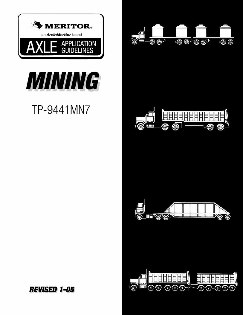
AXLE APPLICATIONGUIDELINES
TP-9441MN7

Mining Vocation – Axle Guidelines
1
TP-9441-MN7
Mining Vocational Definition: Combination vehicles (usually Tractor/Trailer combinations or Trucks with Full Trailers) used in the movement of rock, ore, gravel and minerals in and around mines, between mines and delivery site. Vehicles are typically high powered, specially designed for high loading. Tractor/Trailer Construction vehicles are also included in this vocation.
Two duty cycles have been redefined compared to previous versions of the guideline. Please refer to Page 3.
Mining Vehicles Include:
• Bottom Dump Trailer Combination
• Semi-End Dump
• Transfer dump
• Hopper Trailer Combinations
• Michigan Special Gravel Trains (For Straight Truck configuration vehicles see CONSTRUCTION Application Guideline, TP-9441-CS).

Mining Vocation – Axle Guidelines
2
Intended Use of This Guideline This document addresses the approvable GAW, Axle Input Torque and GVW/GCW Ratings for Meritor Axles used in the Mining vocation (U.S. and Canada only). Conditions for Approval Axles are approved for use in the vocation covered by this document, when the axles meet all the criteria for: • AXLE STRUCTURE • CREEP LOADS • AXLE INPUT TORQUE • GROSS VEHICLE WEIGHT (GVW) or GROSS COMBINATION WEIGHT
(GCW) as described in this publication. IMPORTANT NOTES are considered to be part of the axle approval. For any questions concerning this document (interpretation and calculations) or for loadings, configurations or duty cycles outside the parameters of this guideline, contact ArvinMeritor CVS Axle Customer Support by telephone, by FAX or in writing to the address shown below, using the Meritor Axle Components Application form RA4901-B-040H.
ArvinMeritor, Inc. Attn: CVS Axle Customer Support
2135 W. MAPLE RD TROY, MI 48084 PHONE: 800-535-5560
FAX: 258-435-5580 Warranty For complete details (and specific coverage) refer to Meritor’s Warranty Publication (SP-95155). As previously stated in several Product Information Letters, all RT-185/380 family axles must have an axle application approved by ArvinMeritor CVS Axle Applications Engineering to be eligible for Warranty. Contact ArvinMeritor on questions concerning warranty coverage and application approvals for product used outside of these published guidelines. Note: Axle applications for tire sizes, tracks, mounting centers, other front axle KPIs, other Meritor axle models, engine/transmission torques beyond those listed, or GVW/GCW other than shown within this AXLE GUIDELINE may still be approvable. Contact ArvinMeritor CVS Axle Applications Engineering for possible approval.
Mining Vocation – Axle Guidelines
3
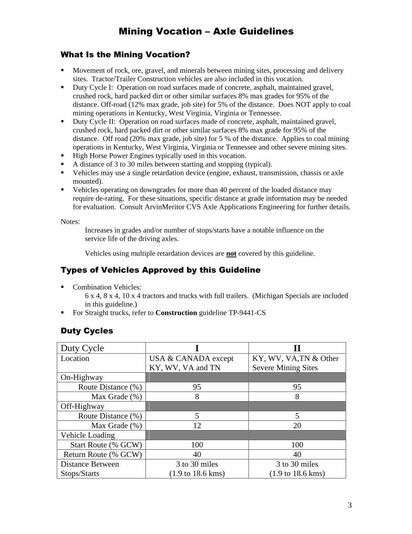
What Is the Mining Vocation? § Movement of rock, ore, gravel, and minerals between mining sites, processing and delivery
sites. Tractor/Trailer Construction vehicles are also included in this vocation. § Duty Cycle I: Operation on road surfaces made of concrete, asphalt, maintained gravel,
crushed rock, hard packed dirt or other similar surfaces 8% max grades for 95% of the distance. Off-road (12% max grade, job site) for 5% of the distance. Does NOT apply to coal mining operations in Kentucky, West Virginia, Virginia or Tennessee.
§ Duty Cycle II: Operation on road surfaces made of concrete, asphalt, maintained gravel, crushed rock, hard packed dirt or other similar surfaces 8% max grade for 95% of the distance. Off road (20% max grade, job site) for 5 % of the distance. Applies to coal mining operations in Kentucky, West Virginia, Virginia or Tennessee and other severe mining sites.
§ High Horse Power Engines typically used in this vocation. § A distance of 3 to 30 miles between starting and stopping (typical). § Vehicles may use a single retardation device (engine, exhaust, transmission, chassis or axle
mounted). § Vehicles operating on downgrades for more than 40 percent of the loaded distance may
require de-rating. For these situations, specific distance at grade information may be needed for evaluation. Consult ArvinMeritor CVS Axle Applications Engineering for further details.
Notes:
Increases in grades and/or number of stops/starts have a notable influence on the service life of the driving axles.
Vehicles using multiple retardation devices are not covered by this guideline.
Types of Vehicles Approved by this Guideline § Combination Vehicles:
6 x 4, 8 x 4, 10 x 4 tractors and trucks with full trailers. (Michigan Specials are included in this guideline.) § For Straight trucks, refer to Construction guideline TP-9441-CS
Duty Cycles
Duty Cycle I II Location USA & CANADA except
KY, WV, VA and TN KY, WV, VA,TN & Other Severe Mining Sites
On-Highway Route Distance (%) 95 95
Max Grade (%) 8 8 Off-Highway
Route Distance (%) 5 5 Max Grade (%) 12 20
Vehicle Loading Start Route (% GCW) 100 100
Return Route (% GCW) 40 40 Distance Between Stops/Starts
3 to 30 miles (1.9 to 18.6 kms)
3 to 30 miles (1.9 to 18.6 kms)
Mining Vocation – Axle Guidelines
4
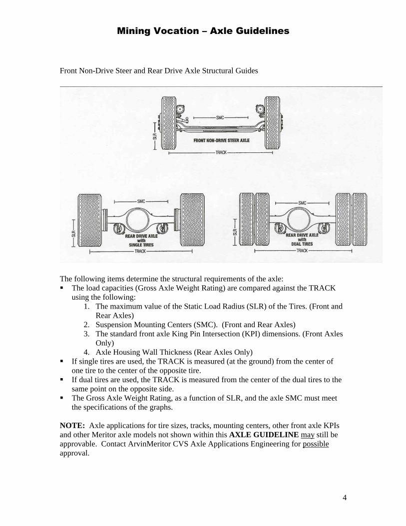
Front Non-Drive Steer and Rear Drive Axle Structural Guides
The following items determine the structural requirements of the axle: § The load capacities (Gross Axle Weight Rating) are compared against the TRACK
using the following: 1. The maximum value of the Static Load Radius (SLR) of the Tires. (Front and
Rear Axles) 2. Suspension Mounting Centers (SMC). (Front and Rear Axles) 3. The standard front axle King Pin Intersection (KPI) dimensions. (Front Axles
Only) 4. Axle Housing Wall Thickness (Rear Axles Only)
§ If single tires are used, the TRACK is measured (at the ground) from the center of one tire to the center of the opposite tire.
§ If dual tires are used, the TRACK is measured from the center of the dual tires to the same point on the opposite side.
§ The Gross Axle Weight Rating, as a function of SLR, and the axle SMC must meet the specifications of the graphs.
NOTE: Axle applications for tire sizes, tracks, mounting centers, other front axle KPIs and other Meritor axle models not shown within this AXLE GUIDELINE may still be approvable. Contact ArvinMeritor CVS Axle Applications Engineering for possible approval.
Mining Vocation – Axle Guidelines
5
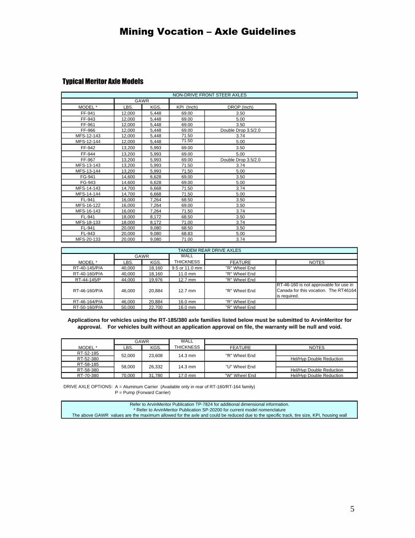
Typical Meritor Axle Models
MODEL * LBS. KGS. KPI (Inch) DROP (Inch)FF-941 12,000 5,448 69.00 3.50FF-943 12,000 5,448 69.00 5.00FF-961 12,000 5,448 69.00 3.50FF-966 12,000 5,448 69.00 Double Drop 3.5/2.0
MFS-12-143 12,000 5,448 71.50 3.74MFS-12-144 12,000 5,448 71.50 5.00
FF-942 13,200 5,993 69.00 3.50FF-944 13,200 5,993 69.00 5.00FF-967 13,200 5,993 69.00 Double Drop 3.5/2.0
MFS-13-143 13,200 5,993 71.50 3.74MFS-13-144 13,200 5,993 71.50 5.00
FG-941 14,600 6,628 69.00 3.50FG-943 14,600 6,628 69.00 5.00
MFS-14-143 14,700 6,668 71.50 3.74MFS-14-144 14,700 6,668 71.50 5.00
FL-941 16,000 7,264 68.50 3.50MFS-16-122 16,000 7,264 69.00 3.50MFS-16-143 16,000 7,264 71.50 3.74
FL-941 18,000 8,172 68.50 3.50MFS-18-133 18,000 8,172 71.00 3.74
FL-941 20,000 9,080 68.50 3.50FL-943 20,000 9,080 68.83 5.00
MFS-20-133 20,000 9,080 71.00 3.74
WALLMODEL * LBS. KGS. THICKNESS FEATURE NOTES
RT-40-145/P/A 40,000 18,160 9.5 or 11.0 mm "R" Wheel EndRT-40-160/P/A 40,000 18,160 11.0 mm "R" Wheel EndRT-44-145/P 44,000 19,976 12.7 mm "R" Wheel End
RT-46-160/P/A 46,000 20,884 12.7 mm "R" Wheel EndRT-46-160 is not approvable for use in Canada for this vocation. The RT46164 is required.
RT-46-164/P/A 46,000 20,884 16.0 mm "R" Wheel EndRT-50-160/P/A 50,000 22,700 16.0 mm "R" Wheel End
WALLMODEL * LBS. KGS. THICKNESS FEATURE NOTES
RT-52-185RT-52-380 Hel/Hyp Double ReductionRT-58-185RT-58-380 Hel/Hyp Double ReductionRT-70-380 70,000 31,780 17.0 mm "W" Wheel End Hel/Hyp Double Reduction
DRIVE AXLE OPTIONS: A = Aluminum Carrier (Available only in rear of RT-160/RT-164 family)P = Pump (Forward Carrier)
GAWR
Applications for vehicles using the RT-185/380 axle families listed below must be submitted to ArvinMeritor for approval. For vehicles built without an application approval on file, the warranty will be null and void.
The above GAWR values are the maximum allowed for the axle and could be reduced due to the specific track, tire size, KPI, housing wall
Refer to ArvinMeritor Publication TP-7824 for additional dimensional information.* Refer to ArvinMeritor Publication SP-20200 for current model nomenclature
GAWR
23,60852,000 14.3 mm "R" Wheel End
NON-DRIVE FRONT STEER AXLES
TANDEM REAR DRIVE AXLES
GAWR
58,000 26,332 14.3 mm "U" Wheel End
Mining Vocation – Axle Guidelines
6
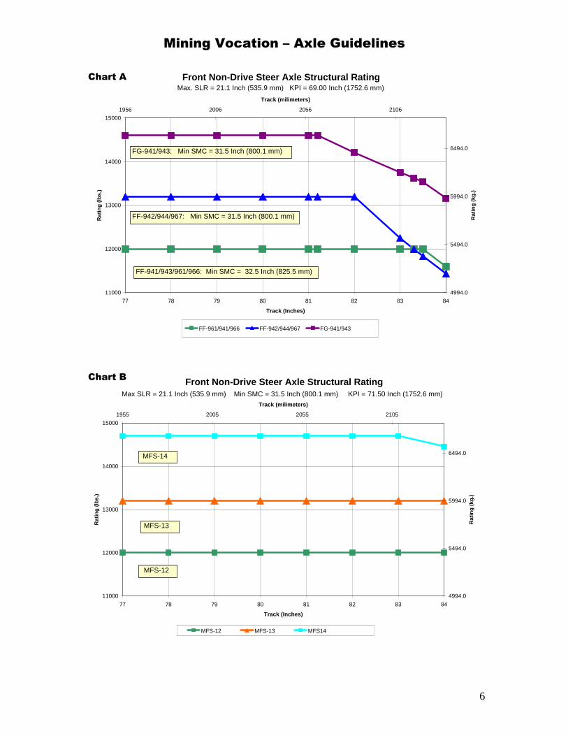
Front Non-Drive Steer Axle Structural Rating
11000
12000
13000
14000
15000
77 78 79 80 81 82 83 84
Track (Inches)
Rat
ing
(lb
s.)
4994.0
5494.0
5994.0
6494.0
1956 2006 2056 2106
Track (milimeters)
Rat
ing
(kg
.)
FF-961/941/966 FF-942/944/967 FG-941/943
Max. SLR = 21.1 Inch (535.9 mm) KPI = 69.00 Inch (1752.6 mm)
FF-941/943/961/966: Min SMC = 32.5 Inch (825.5 mm)
FF-942/944/967: Min SMC = 31.5 Inch (800.1 mm)
FG-941/943: Min SMC = 31.5 Inch (800.1 mm)
Chart A
Front Non-Drive Steer Axle Structural Rating
11000
12000
13000
14000
15000
77 78 79 80 81 82 83 84
Track (Inches)
Rat
ing
(lb
s.)
4994.0
5494.0
5994.0
6494.0
1955 2005 2055 2105
Track (milimeters)
Rat
ing
(kg
.)
MFS-12 MFS-13 MFS14
Max SLR = 21.1 Inch (535.9 mm) Min SMC = 31.5 Inch (800.1 mm) KPI = 71.50 Inch (1752.6 mm)
MFS-12
MFS-13
MFS-14
Chart B
Mining Vocation – Axle Guidelines
7
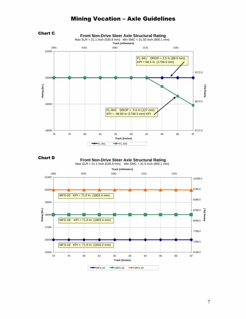
Front Non-Drive Steer Axle Structural Rating
18000
19000
20000
21000
78 79 80 81 82 83 84 85 86 87
Track (Inches)
Rat
ing
(lb
s.)
8172.0
8672.0
9172.0
1981 2031 2081 2131 2181
Track (milimeters)
Rat
ing
(kg
.)
FL-941 FL-943
Max SLR = 21.1 Inch (535.9 mm) Min SMC = 31.50 Inch (800.1 mm)
FL-941: DROP = 3.5 In (88.9 mm) KPI = 68.5 In (1739.9 mm)
FL-943: DROP = 5.0 In (127 mm) KPI = 68.83 In (1748.3 mm) KPI
Chart C
Front Non-Drive Steer Axle Structural Rating
15000
16000
17000
18000
19000
20000
21000
78 79 80 81 82 83 84 85 86 87
Track (Inches)
Rat
ing
(lb
s.)
6798.0
7298.0
7798.0
8298.0
8798.0
9298.0
9798.0
10298.0
1981 2031 2081 2131 2181
Track (milimeters)
Rat
ing
(kg
.)
MFS-16 MFS-18 MFS-20
Max SLR = 21.1 Inch (535.9 mm) Min SMC = 31.5 Inch (800.1 mm)
MFS-16: KPI = 71.5 In. (1816.2 mm)
MFS-18: KPI = 71.0 In. (1803.4 mm)
MFS-20: KPI = 71.0 In. (1803.4 mm)
Chart D
Mining Vocation – Axle Guidelines
8
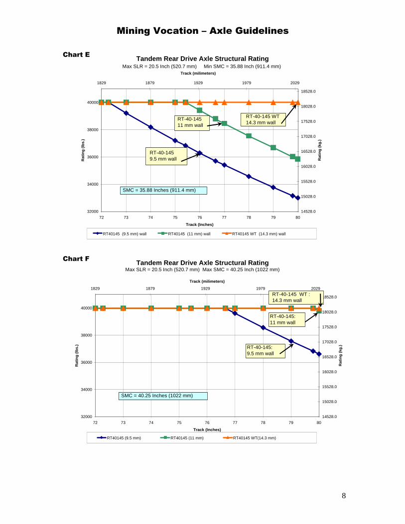
Tandem Rear Drive Axle Structural Rating
32000
34000
36000
38000
40000
72 73 74 75 76 77 78 79 80
Track (Inches)
Rat
ing
(lb
s.)
14528.0
15028.0
15528.0
16028.0
16528.0
17028.0
17528.0
18028.0
18528.0
1829 1879 1929 1979 2029
Track (milimeters)
Rat
ing
(kg
.)
RT40145 (9.5 mm) wall RT40145 (11 mm) wall RT40145 WT (14.3 mm) wall
Max SLR = 20.5 Inch (520.7 mm) Min SMC = 35.88 Inch (911.4 mm)
SMC = 35.88 Inches (911.4 mm)
RT-40-1459.5 mm wall
RT-40-145 WT 14.3 mm wall
RT-40-14511 mm wall
Chart E
Tandem Rear Drive Axle Structural Rating
32000
34000
36000
38000
40000
72 73 74 75 76 77 78 79 80
Track (Inches)
Rat
ing
(lb
s.)
14528.0
15028.0
15528.0
16028.0
16528.0
17028.0
17528.0
18028.0
18528.0
1829 1879 1929 1979 2029
Track (milimeters)
Rat
ing
(kg
.)
RT40145 (9.5 mm) RT40145 (11 mm) RT40145 WT(14.3 mm)
Max SLR = 20.5 Inch (520.7 mm) Max SMC = 40.25 Inch (1022 mm)
SMC = 40.25 Inches (1022 mm)
RT-40-145: 9.5 mm wall
RT-40-145 WT :14.3 mm wall
RT-40-145:11 mm wall
Chart F
Mining Vocation – Axle Guidelines
9
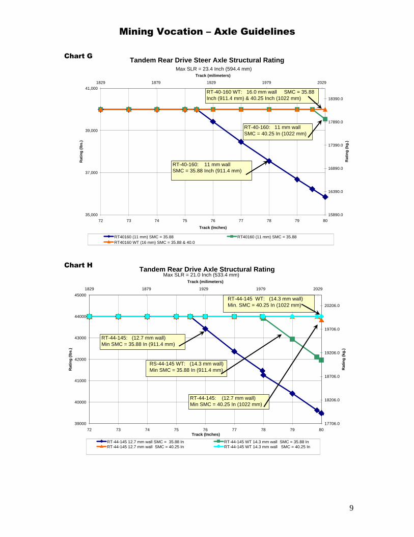
Tandem Rear Drive Steer Axle Structural Rating
35,000
37,000
39,000
41,000
72 73 74 75 76 77 78 79 80
Track (Inches)
Rat
ing
(lb
s.)
15890.0
16390.0
16890.0
17390.0
17890.0
18390.0
1829 1879 1929 1979 2029
Track (milimeters)
Rat
ing
(kg
.)
RT40160 (11 mm) SMC = 35.88 RT40160 (11 mm) SMC = 35.88RT40160 WT (16 mm) SMC = 35.88 & 40.0
Max SLR = 23.4 Inch (594.4 mm)
RT-40-160: 11 mm wall SMC = 35.88 Inch (911.4 mm)
RT-40-160 WT: 16.0 mm wall SMC = 35.88 Inch (911.4 mm) & 40.25 Inch (1022 mm)
RT-40-160: 11 mm wall SMC = 40.25 In (1022 mm)
Chart G
Tandem Rear Drive Axle Structural Rating
39000
40000
41000
42000
43000
44000
45000
72 73 74 75 76 77 78 79 80Track (Inches)
Rat
ing
(lb
s.)
17706.0
18206.0
18706.0
19206.0
19706.0
20206.0
1829 1879 1929 1979 2029
Track (milimeters)
Rat
ing
(kg
.)
RT-44-145 12.7 mm wall SMC = 35.88 In RT-44-145 WT 14.3 mm wall SMC = 35.88 InRT-44-145 12.7 mm wall SMC = 40.25 In RT-44-145 WT 14.3 mm wall SMC = 40.25 In
Max SLR = 21.0 Inch (533.4 mm)
RS-44-145 WT: (14.3 mm wall) Min SMC = 35.88 In (911.4 mm)
RT-44-145 WT: (14.3 mm wall)Min. SMC = 40.25 In (1022 mm)
RT-44-145: (12.7 mm wall) Min SMC = 40.25 In (1022 mm)
RT-44-145: (12.7 mm wall) Min SMC = 35.88 In (911.4 mm)
Chart H
Mining Vocation – Axle Guidelines
10
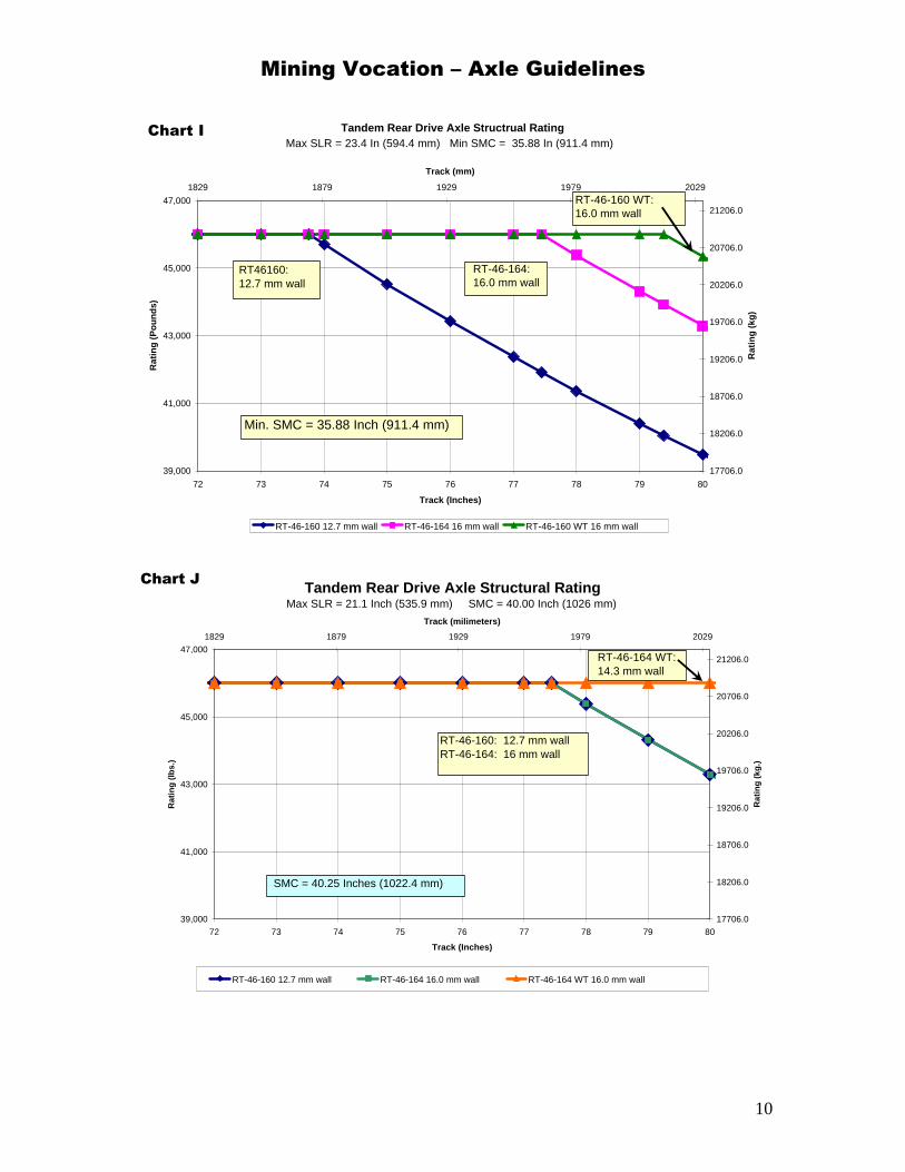
Tandem Rear Drive Axle Structrual Rating
39,000
41,000
43,000
45,000
47,000
72 73 74 75 76 77 78 79 80
Track (Inches)
Rat
ing
(P
ou
nd
s)
17706.0
18206.0
18706.0
19206.0
19706.0
20206.0
20706.0
21206.0
1829 1879 1929 1979 2029
Track (mm)
Rat
ing
(kg
)
RT-46-160 12.7 mm wall RT-46-164 16 mm wall RT-46-160 WT 16 mm wall
Max SLR = 23.4 In (594.4 mm) Min SMC = 35.88 In (911.4 mm)
RT46160: 12.7 mm wall
RT-46-164: 16.0 mm wall
RT-46-160 WT:16.0 mm wall
Min. SMC = 35.88 Inch (911.4 mm)
Chart I
Tandem Rear Drive Axle Structural Rating
39,000
41,000
43,000
45,000
47,000
72 73 74 75 76 77 78 79 80
Track (Inches)
Rat
ing
(lb
s.)
17706.0
18206.0
18706.0
19206.0
19706.0
20206.0
20706.0
21206.0
1829 1879 1929 1979 2029
Track (milimeters)
Rat
ing
(kg
.)
RT-46-160 12.7 mm wall RT-46-164 16.0 mm wall RT-46-164 WT 16.0 mm wall
Max SLR = 21.1 Inch (535.9 mm) SMC = 40.00 Inch (1026 mm)
SMC = 40.25 Inches (1022.4 mm)
RT-46-160: 12.7 mm wallRT-46-164: 16 mm wall
RT-46-164 WT: 14.3 mm wall
Chart J
Mining Vocation – Axle Guidelines
11
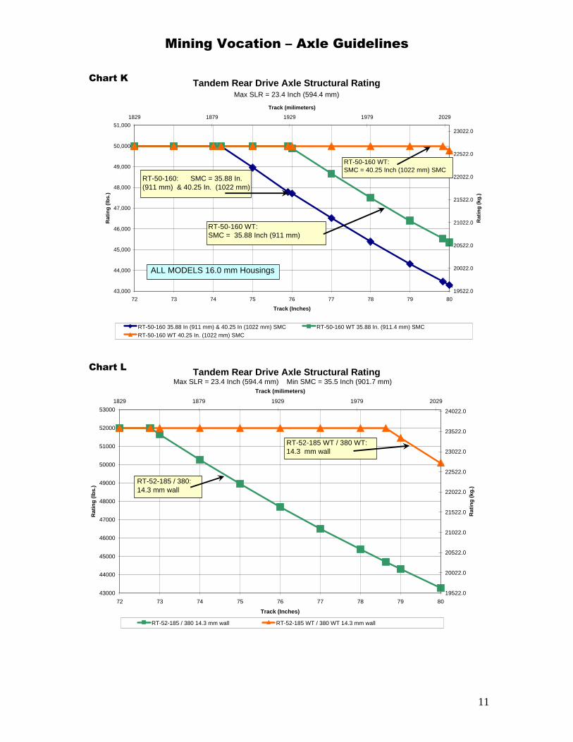
Tandem Rear Drive Axle Structural Rating
43,000
44,000
45,000
46,000
47,000
48,000
49,000
50,000
51,000
72 73 74 75 76 77 78 79 80
Track (Inches)
Rat
ing
(lb
s.)
19522.0
20022.0
20522.0
21022.0
21522.0
22022.0
22522.0
23022.0
1829 1879 1929 1979 2029
Track (milimeters)
Rat
ing
(kg
.)
RT-50-160 35.88 In (911 mm) & 40.25 In (1022 mm) SMC RT-50-160 WT 35.88 In. (911.4 mm) SMCRT-50-160 WT 40.25 In. (1022 mm) SMC
Max SLR = 23.4 Inch (594.4 mm)
ALL MODELS 16.0 mm Housings
RT-50-160 WT: SMC = 35.88 Inch (911 mm)
RT-50-160 WT: SMC = 40.25 Inch (1022 mm) SMC
RT-50-160: SMC = 35.88 In. (911 mm) & 40.25 In. (1022 mm)
Chart K
Tandem Rear Drive Axle Structural Rating
43000
44000
45000
46000
47000
48000
49000
50000
51000
52000
53000
72 73 74 75 76 77 78 79 80
Track (Inches)
Rat
ing
(lb
s.)
19522.0
20022.0
20522.0
21022.0
21522.0
22022.0
22522.0
23022.0
23522.0
24022.0
1829 1879 1929 1979 2029
Track (milimeters)
Rat
ing
(kg
.)
RT-52-185 / 380 14.3 mm wall RT-52-185 WT / 380 WT 14.3 mm wall
Max SLR = 23.4 Inch (594.4 mm) Min SMC = 35.5 Inch (901.7 mm)
RT-52-185 / 380: 14.3 mm wall
RT-52-185 WT / 380 WT: 14.3 mm wall
Chart L

Mining Vocation – Axle Guidelines
12
Tandem Rear Drive Axle Structural Ratings
51000
52000
53000
54000
55000
56000
57000
58000
59000
72 73 74 75 76 77 78 79 80
Track (Inches)
Rat
ing
(lb
s)
23154.0
73154.0
123154.0
173154.0
223154.0
1829 1854 1879 1904 1929 1954 1979 2004 2029
Track (mm)
Rat
ing
(kg
s)
RT58185/380 35.5" (901.7 mm) SMC RT58185/380/380 41.5" (1054 mm) SMC
RT-58-185/380 STD & WT:SMC = 35.5 In. (901.7 mm)Wall = 14.3 mm
RT-58-185/380 STD & WT: SMC = 41.5 In. (1054 mm) Wall = 15.9 mm
Max SLR = 23.4 In (594.4 mm) Chart M
Tandem Rear Drive Axle Structural Rating
68000
69000
70000
71000
72000
72 73 74 75 76 77 78 79 80
Track (Inches)
Rat
ing
(lb
s.)
30872.0
31372.0
31872.0
32372.0
1829 1879 1929 1979 2029
Track (milimeters)
Rat
ing
(kg
.)
RT-70-380 STD & WT 16.8 mm
Max SLR = 23.4 Inch (594.4 mm) SMC = 35.5 Inch (901.7 mm) and 41.5 In ( 1054 mm)
RT-70-380 STD / WT: 16.8 mm wall
Chart N
Mining Vocation – Axle Guidelines
13
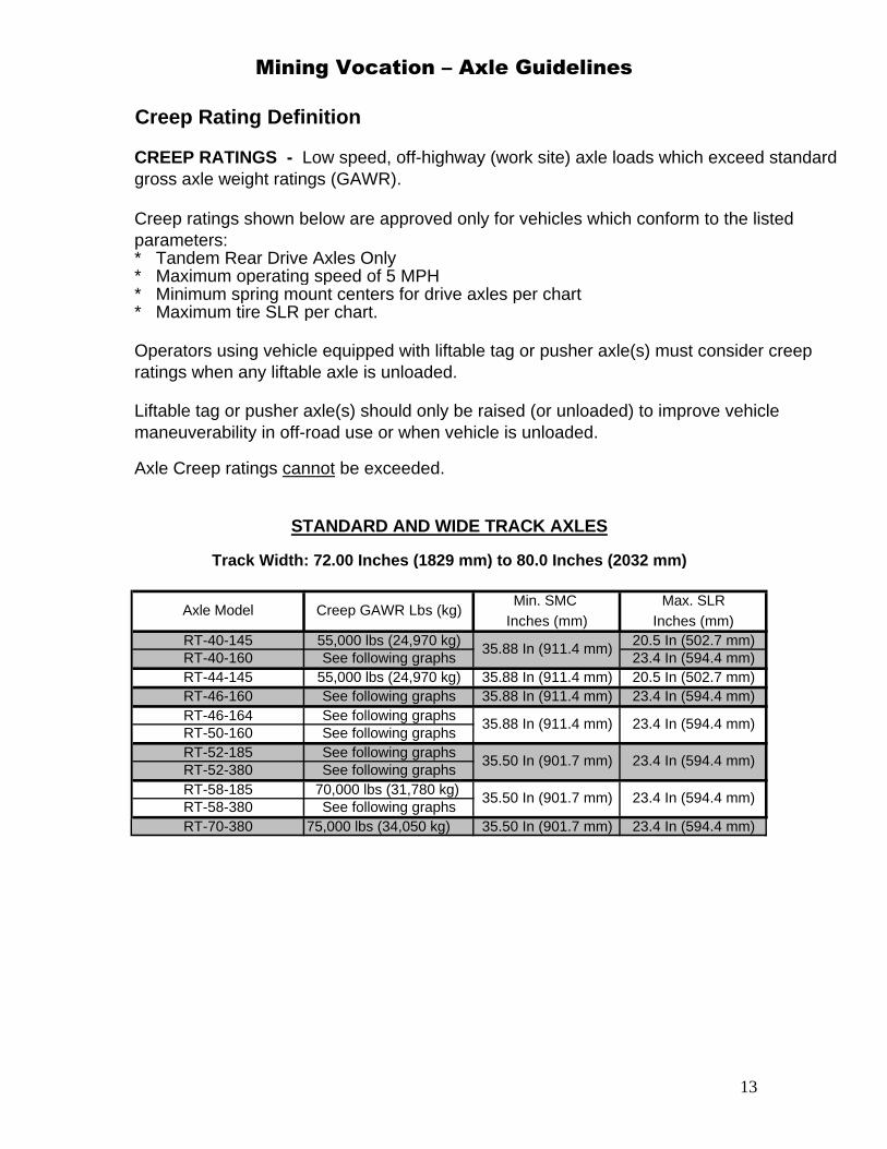
Axle Model Creep GAWR Lbs (kg)
See following graphs35.88 In (911.4 mm)
RT-40-160
23.4 In (594.4 mm)
35.50 In (901.7 mm) 23.4 In (594.4 mm)
Max. SLR
RT-70-380
RT-46-164 35.88 In (911.4 mm)
55,000 lbs (24,970 kg)
See following graphs35.50 In (901.7 mm)
75,000 lbs (34,050 kg)
See following graphs
See following graphsSee following graphs
70,000 lbs (31,780 kg)
See following graphs
Creep Rating Definition
CREEP RATINGS - Low speed, off-highway (work site) axle loads which exceed standard gross axle weight ratings (GAWR).
Liftable tag or pusher axle(s) should only be raised (or unloaded) to improve vehicle maneuverability in off-road use or when vehicle is unloaded.
Operators using vehicle equipped with liftable tag or pusher axle(s) must consider creep ratings when any liftable axle is unloaded.
Axle Creep ratings cannot be exceeded.
Creep ratings shown below are approved only for vehicles which conform to the listed parameters:* Tandem Rear Drive Axles Only
55,000 lbs (24,970 kg)RT-40-145
* Maximum tire SLR per chart.
* Maximum operating speed of 5 MPH* Minimum spring mount centers for drive axles per chart
20.5 In (502.7 mm)
Min. SMC
RT-44-145RT-46-160
STANDARD AND WIDE TRACK AXLES
Track Width: 72.00 Inches (1829 mm) to 80.0 Inches (2032 mm)
Inches (mm) Inches (mm)
35.88 In (911.4 mm)35.88 In (911.4 mm)
23.4 In (594.4 mm)20.5 In (502.7 mm)23.4 In (594.4 mm)
23.4 In (594.4 mm)
23.4 In (594.4 mm)RT-58-380
35.50 In (901.7 mm)
RT-52-185RT-52-380RT-58-185
RT-50-160
See following graphs

Mining Vocation – Axle Guidelines
14
CREEP RATINGS
53000
53500
54000
54500
55000
55500
56000
72 73 74 75 76 77 78 79 80
TRACK (INCHES)
CR
EE
P R
AT
ING
(L
BS
)
24062.0
24262.0
24462.0
24662.0
24862.0
25062.0
25262.0
1829 1854 1879 1904 1929 1954 1979 2004 2029
TRACK (mm)
Cre
ep R
atin
g (
kg)
RT-40-160 11.0 mm wall RT-40-160 WT 16.0 mm wall
RT-40-160:11.0 mm wall
RT-40-160 WT: 16.0 mm wall
5 MPH (8 KPH) MAX. SPEED - LIFTABLE AXLES UPMax SLR = 23.4 In (594.4 mm) Min. SMC = 35.88 In (911.4 mm)
Chart O
CREEP RATING
53,000
55,000
57,000
59,000
61,000
72 73 74 75 76 77 78 79 80
Track (Inches)
Rat
ing
(P
ou
nd
s)
24062.0
24562.0
25062.0
25562.0
26062.0
26562.0
27062.0
27562.0
28062.0
28562.0
1829 1879 1929 1979 2029
Track (mm)
Rat
ing
(kg
)
RT-46-160 12.7 mm
5 MPH (8 KPH) MAX. SPEED - LIFTABLE AXLES UPMax SLR = 23.4 In (594.4 mm) Min. SMC = 35.88 In (911.4 mm)
RT-46-160 12.7 mm wall
Chart P
Mining Vocation – Axle Guidelines
15
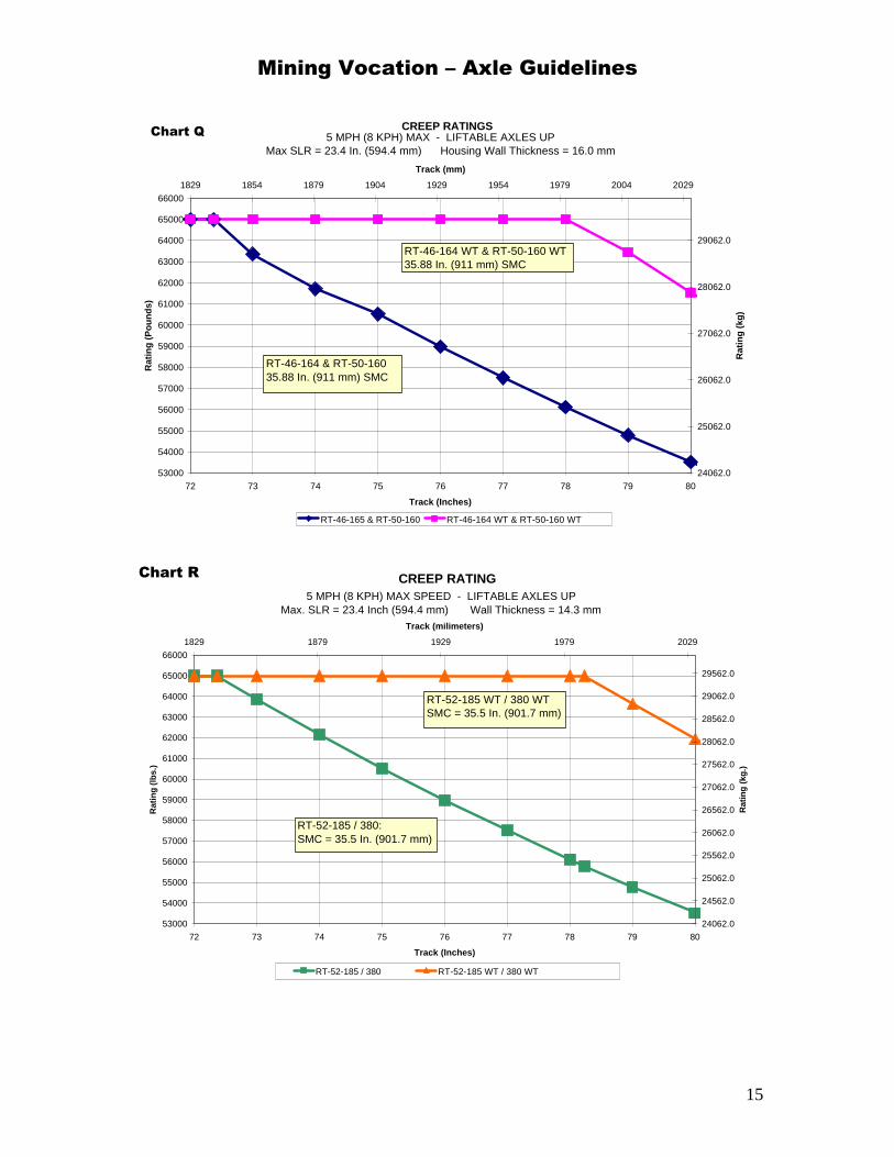
CREEP RATINGS
53000
54000
55000
56000
57000
58000
59000
60000
61000
62000
63000
64000
65000
66000
72 73 74 75 76 77 78 79 80
Track (Inches)
Rat
ing
(P
ou
nd
s)
24062.0
25062.0
26062.0
27062.0
28062.0
29062.0
1829 1854 1879 1904 1929 1954 1979 2004 2029
Track (mm)
Rat
ing
(kg
)
RT-46-165 & RT-50-160 RT-46-164 WT & RT-50-160 WT
RT-46-164 & RT-50-160 35.88 In. (911 mm) SMC
RT-46-164 WT & RT-50-160 WT35.88 In. (911 mm) SMC
5 MPH (8 KPH) MAX - LIFTABLE AXLES UPMax SLR = 23.4 In. (594.4 mm) Housing Wall Thickness = 16.0 mm
Chart Q
CREEP RATING
53000
54000
55000
56000
57000
58000
59000
60000
61000
62000
63000
64000
65000
66000
72 73 74 75 76 77 78 79 80
Track (Inches)
Rat
ing
(lb
s.)
24062.0
24562.0
25062.0
25562.0
26062.0
26562.0
27062.0
27562.0
28062.0
28562.0
29062.0
29562.0
1829 1879 1929 1979 2029
Track (milimeters)
Rat
ing
(kg
.)
RT-52-185 / 380 RT-52-185 WT / 380 WT
5 MPH (8 KPH) MAX SPEED - LIFTABLE AXLES UPMax. SLR = 23.4 Inch (594.4 mm) Wall Thickness = 14.3 mm
RT-52-185 / 380: SMC = 35.5 In. (901.7 mm)
RT-52-185 WT / 380 WT SMC = 35.5 In. (901.7 mm)
Chart R

Mining Vocation – Axle Guidelines
16
Formula 1
Rear Drive Axle where T
N1
N2
= 1.0 for Manual Transmission
= Lowest Transmission Forward Gear Ratio
The following formula is used to determine CALCULATED INPUT TORQUE TO AXLE
CALCULATED INPUT TORQUE TO AXLE = T x N1 x N2= Maximum Gross Engine Torque (LB - FT)
Axle Torque Ratings
= Torque Converter Stall Ratio
= 2.5 or specific value for Automatic Transmission
RT-145 RT-160 / 164 RT-185 RT-380 Ratio3.07 XX 30,000 (40,674) X X3.21 XX 30,000 (40,674) X X3.42 23,000 (31,183) 30,000 (40,674) X X3.58 22,100 (29,963) 30,000 (40,674) X X3.73 22,100 (29,963) 30,000 (40,674) 30,000 (40,674) X3.90 22,100 (29,963) X X X3.91 X 30,000 (40,674) X X4.10 X 30,000 (40,674) 30,000 (40,674) X4.11 22,100 (29,963) X X X4.30 X 30,000 (40,674) 30,000 (40,674) X4.33 21,800 (29,556) X X X4.56 X 30,000 (40,674) 30,000 (40,674) X4.63 20,400 (27,658) X X X4.88 18,000 (24,404) X X X4.89 X 30,000 (40,674) 30,000 (40,674) X5.13 X X X X5.29 16,600 (22,506) X X X5.38 X 26,200 (35,522) 30,000 (40,674) X5.52 X X X 30,000 (40,674)5.63 X 23,000 (31,183) X X5.86 12,200 (16,541) X X X6.07 X X X 30,000 (40,674)6.14 11,800 (15,998) 20,400 (27,658) 24,000 (32,539) X6.37 X X X 27,200 (35,878)6.43 10,800 (14,642) 17,800 (24,133) X X6.75 X X X 26,200 (35,522)6.83 10,200 (13,829) 17,800 (24,133) 20,400 (27,658) X7.17 9,400 (12,744) 16,000 (21,693) 18,400 (24,947) X7.24 X X X 21,200 (28,743)7.83 X X X 20,400 (27,658)9.14 X X X 16,000 (21,693)
10.12 X X X 13,400 (18,168)10.62 X X X 12,200 (16,541)
1650 (2237) 2050 (2788) 2050 (2788) 2050 (2788)
NOTES:
MAXIMUM INPUT TORQUE TO AXLE - LB-FT (N-M)
The chart below is to be used to determine axle input torque limits approved for the identified Meritor axle models by available ratio.
Axle Torque Ratings For Mining Vocation
Axle Models
Tandem Rear Drive
4) X = Ratio not available.
Maximum Gross Engine Torque - LB-FT (N-M)
1) Axle torque ratings charted above are to be used only with guidelines for Mining Vocation.2) XX = Contact ArvinMeritor CVS Axle Applications Engineering for possible approval.3) Calculated Input Torque to Axle (per formula) must be less than Maximum Allowable Input Torque to Axle (per chart).
Mining Vocation – Axle Guidelines
17
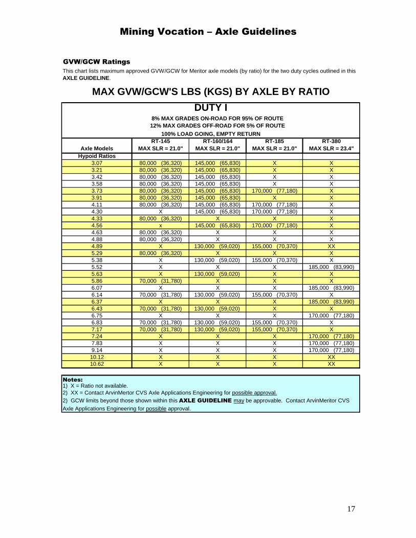
Axle ModelsRT-145
MAX SLR = 21.0"RT-160/164
MAX SLR = 21.0"RT-185
MAX SLR = 21.0" RT-380
MAX SLR = 23.4"Hypoid Ratios
3.07 80,000 (36,320) 145,000 (65,830) X X3.21 80,000 (36,320) 145,000 (65,830) X X3.42 80,000 (36,320) 145,000 (65,830) X X3.58 80,000 (36,320) 145,000 (65,830) X X3.73 80,000 (36,320) 145,000 (65,830) 170,000 (77,180) X3.91 80,000 (36,320) 145,000 (65,830) X X4.11 80,000 (36,320) 145,000 (65,830) 170,000 (77,180) X4.30 X 145,000 (65,830) 170,000 (77,180) X4.33 80,000 (36,320) X X X4.56 x 145,000 (65,830) 170,000 (77,180) X4.63 80,000 (36,320) X X X4.88 80,000 (36,320) X X X4.89 X 130,000 (59,020) 155,000 (70,370) XX5.29 80,000 (36,320) X X X5.38 X 130,000 (59,020) 155,000 (70,370) X5.52 X X X 185,000 (83,990)5.63 X 130,000 (59,020) X X5.86 70,000 (31,780) X X X6.07 X X X 185,000 (83,990)6.14 70,000 (31,780) 130,000 (59,020) 155,000 (70,370) X6.37 X X X 185,000 (83,990)6.43 70,000 (31,780) 130,000 (59,020) X X6.75 X X X 170,000 (77,180)6.83 70,000 (31,780) 130,000 (59,020) 155,000 (70,370) X7.17 70,000 (31,780) 130,000 (59,020) 155,000 (70,370) X7.24 X X X 170,000 (77,180)7.83 X X X 170,000 (77,180)9.14 X X X 170,000 (77,180)10.12 X X X XX10.62 X X X XX
8% MAX GRADES ON-ROAD FOR 95% OF ROUTE 12% MAX GRADES OFF-ROAD FOR 5% OF ROUTE
2) GCW limits beyond those shown within this AXLE GUIDELINE may be approvable. Contact ArvinMeritor CVS Axle Applications Engineering for possible approval.
2) XX = Contact ArvinMertor CVS Axle Applications Engineering for possible approval.
GVW/GCW Ratings
Notes:1) X = Ratio not available.
100% LOAD GOING, EMPTY RETURN
DUTY I
MAX GVW/GCW'S LBS (KGS) BY AXLE BY RATIO
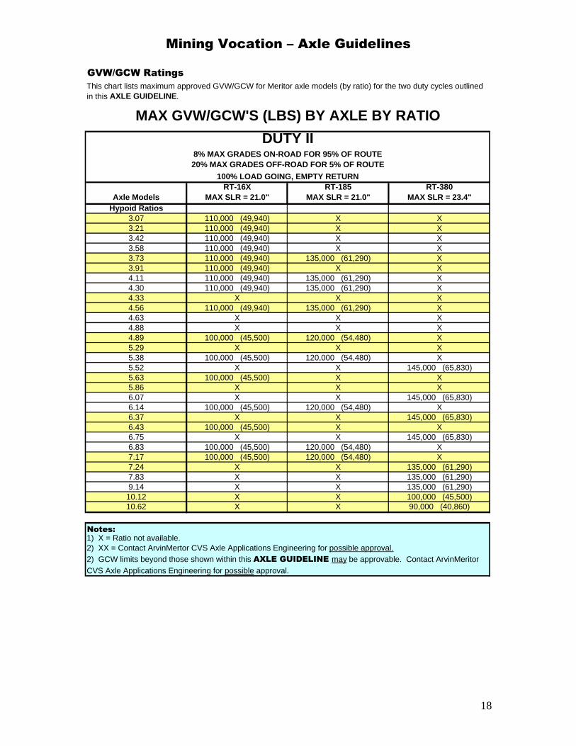
This chart lists maximum approved GVW/GCW for Meritor axle models (by ratio) for the two duty cycles outlined in this AXLE GUIDELINE.
Mining Vocation – Axle Guidelines
18
Axle ModelsRT-16X
MAX SLR = 21.0"RT-185
MAX SLR = 21.0" RT-380
MAX SLR = 23.4"Hypoid Ratios
3.07 110,000 (49,940) X X3.21 110,000 (49,940) X X3.42 110,000 (49,940) X X3.58 110,000 (49,940) X X3.73 110,000 (49,940) 135,000 (61,290) X3.91 110,000 (49,940) X X4.11 110,000 (49,940) 135,000 (61,290) X4.30 110,000 (49,940) 135,000 (61,290) X4.33 X X X4.56 110,000 (49,940) 135,000 (61,290) X4.63 X X X4.88 X X X4.89 100,000 (45,500) 120,000 (54,480) X5.29 X X X5.38 100,000 (45,500) 120,000 (54,480) X5.52 X X 145,000 (65,830)5.63 100,000 (45,500) X X5.86 X X X6.07 X X 145,000 (65,830)6.14 100,000 (45,500) 120,000 (54,480) X6.37 X X 145,000 (65,830)6.43 100,000 (45,500) X X6.75 X X 145,000 (65,830)6.83 100,000 (45,500) 120,000 (54,480) X7.17 100,000 (45,500) 120,000 (54,480) X7.24 X X 135,000 (61,290)7.83 X X 135,000 (61,290)9.14 X X 135,000 (61,290)10.12 X X 100,000 (45,500)10.62 X X 90,000 (40,860)
2) GCW limits beyond those shown within this AXLE GUIDELINE may be approvable. Contact ArvinMeritor CVS Axle Applications Engineering for possible approval.
2) XX = Contact ArvinMertor CVS Axle Applications Engineering for possible approval.
8% MAX GRADES ON-ROAD FOR 95% OF ROUTE 20% MAX GRADES OFF-ROAD FOR 5% OF ROUTE
GVW/GCW Ratings
Notes:1) X = Ratio not available.
100% LOAD GOING, EMPTY RETURN
DUTY II
MAX GVW/GCW'S (LBS) BY AXLE BY RATIO
This chart lists maximum approved GVW/GCW for Meritor axle models (by ratio) for the two duty cycles outlined in this AXLE GUIDELINE.
Mining Vocation – Axle Guidelines
19
Important Notes 1. The following optional features are approved by this AXLE GUIDELINE. All options may not
be available on all axle models. a. Driver-Controlled Differential Lock (DCDL) b. Oil Pump c. Advanced Lube
2. For approval of Transmissions, Clutch, Driveline, Telma Retarders, Brakes, Wheel Ends, Wabco ABS, Trailer Axles, Front Drive Steer Axles, Transfer Cases and other components, contact the appropriate ArvinMeritor engineering function: Phone # 800-535-5560.
3. For details on ArvinMeritor’s Advanced Lubrication Program, refer to ArvinMeritor
Technical Publication TP-9303 or Maintenance Manual # MM-01. 4. For certain suspension models, ArvinMeritor requires the use of an increased housing wall
thickness. See Meritor Product Information Letter # 134 or Contact ArvinMeritor CVS Axle Applications Engineering for clarification.
5. ArvinMeritor’s Axle Application Approval, with respect to the Suspension selected, is limited
to the location or the suspension attaching positions relative to those parameters (track, tire, mounting centers, etc.) specified. Attachment to the axle housing assembly and durability of the axle housing as a result of the suspension loadings on the housing, is the responsibility of the OEM. ArvinMeritor assumes responsibility of the bracket integrity and attachment only if
a. The brackets are attached by ArvinMeritor or, b. ArvinMeritor has established a prior agreement with the OEM.
6. It is the responsibility of the OEM and/or the dealer to accurately convey all approved axle loading information to the Body Builder if the chassis is sold as incomplete. Also, it is the responsibility of the final vehicle builder to ensure the assigned tagged values for GAWR and GVW/GCW do not exceed those limits approvable by this vocational guideline.
7. The OEM has the responsibility to determine Steering Axle Specifics (Maximum Turn
Angle, Tie Rod Arm selection, Steering Arm Selection, Geometry Limits, etc.). ArvinMeritor CVS Axle Applications Engineering can assist the OEM with these parameter selections.
8. Vehicle testing of any nature voids the warranty on Meritor axles. ArvinMeritor does not
approve of automatic transmission stall testing and does not warrant components against these procedures. See Product Information Letter # 368.
9. Driver-Controlled Differential Lock option, when available, is highly recommended for all
mining operations where vehicles operate in off-road areas. 10. The use of NoSPIN “differentials” in any single or tandem rear drive axle will result in the
exclusion of axle shafts from warranty considerations. Certain other carrier components will also be excluded from warranty considerations if their failure is deemed the result of a NoSPIN failure or malfunction. Depending on axle loading, the NoSPIN can cause all differential torque to be directed to one axle shaft, causing overload (and potential failure.) NoSPIN is a product of Tractech Inc.
11. Vehicles equipped with multiple Retardation Devices of any type (engine brake, exhaust
brake, hydraulic transmission, chassis mounted or axle mounted electromagnetic) must be
Mining Vocation – Axle Guidelines
20
approved by ArvinMeritor as well as the manufacturers of the selected retardation devices. Contact ArvinMeritor CVS Axle Applications Engineering for possible approval.
12. The vehicle manufacturer is responsible for providing a design that permits the “Caster
Steer Non-Drive Axle” to be either (1) lifted or (2) locked in the straight ahead position, when operating the vehicle in a reverse direction.
13. Drive axles configured with single tires may require special consideration. Aggressive High
Mobility Single Tires of on/off road and agricultural tread designs are capable of transmitting higher than normal wheel torque into the ground surface. This can result in axle components being stressed beyond allowable limits. If single tires are utilized with other than strict On-Highway tread designs, ArvinMeritor CVS Axle Applications Engineering should be consulted for special consideration of the application.
14. For Straight Truck Vehicle Configuration used in mining, please refer to the Construction
Vocational Axle Guideline, TP-9441-CS. 15. Vehicles operating on downgrades for more than 40 percent of the loaded distance may
require de-rating of allowable GVW or GCW loads. For these situations, specific distance at grade information may be needed for evaluation. Consult ArvinMeritor CVS Axle Applications Engineering for further details.

Information contained in this publication was in effect at the time the publication was approved for printing and is subject to change without notice or liability. Meritor Heavy Vehicle Systems, LLC, reserves the right to revise the information presented or discontinue the production of parts described at any time.
Copyright TP-9441MN7ArvinMeritor, Inc. Revised 1-05All Rights Reserved Printed in the USA
Meritor Heavy Vehicle Systems, LLC2135 West Maple RoadTroy, MI 48084 USA800-535-5560arvinmeritor.com 2005
(16579/Meritor)
Related Documents