USER MANUAL AXIS Camera Station

Welcome message from author
This document is posted to help you gain knowledge. Please leave a comment to let me know what you think about it! Share it to your friends and learn new things together.
Transcript
USER MANUAL
AXIS Camera Station
About This DocumentThis manual is intended for administrators and users of AXIS CameraStation and is applicable for software release 3.50 and later. It coversconfiguration of AXIS Camera Station Server and AXIS Camera StationClient as well as instructions for using and managing AXIS CameraStation on your network. Later versions of this document will be postedon Axis web site, as required. See also the product’s help pages.
Intellectual Property RightsAxis AB has intellectual property rights relating to technology embodiedin the product described in this document. In particular, and withoutlimitation, these intellectual property rights may include one or moreof the patents listed at http://www.axis.com/patent.htm and one ormore additional patents or pending patent applications in the US andother countries.
Legal considerationsVideo and audio surveillance can be regulated by laws that vary fromcountry to country. Check the laws in your local region before usingthis product for surveillance purposes.
LiabilityEvery care has been taken in the preparation of this manual. Pleaseinform your local Axis office of any inaccuracies or omissions. AxisCommunications AB cannot be held responsible for any technical ortypographical errors and reserves the right to make changes to theproduct and manuals without prior notice. Axis Communications ABmakes no warranty of any kind with regard to the material containedwithin this document, including, but not limited to, the impliedwarranties of merchantability and fitness for a particular purpose. AxisCommunications AB shall not be liable nor responsible for incidental orconsequential damages in connection with the furnishing, performanceor use of this material.
Trademark AcknowledgmentsMicrosoft, Windows, Windows Vista, WWW, Internet Explorer, DirectX,Intel, Intel Core, Pentium and Xeon are registered trademarks of therespective holders.
SupportShould you require any technical assistance, please contact your Axisreseller. If your questions cannot be answered immediately, yourreseller will forward your queries through the appropriate channels toensure a rapid response. If you are connected to the Internet, you can:• download user documentation and software updates• find answers to resolved problems in the FAQ database. Search
by product, category, or phrase• report problems to Axis support staff by logging in to your private
support area• chat with Axis support staff (selected countries only)• visit Axis Support at www.axis.com/techsup/
AXIS Camera Station
Table of Contents
System Requirements . . . . . . . . . . . . . . . . . . . . . . . . . . . . . . . . . . . . . . . . 4Overview . . . . . . . . . . . . . . . . . . . . . . . . . . . . . . . . . . . . . . . . . . . . . . . . . . 5
AXIS Camera Station Server . . . . . . . . . . . . . . . . . . . . . . . . . . . . . . . . . . . . . . . 5AXIS Camera Station Client . . . . . . . . . . . . . . . . . . . . . . . . . . . . . . . . . . . . . . . 5Multiple Servers . . . . . . . . . . . . . . . . . . . . . . . . . . . . . . . . . . . . . . . . . . . . . . . . 6
Workspaces . . . . . . . . . . . . . . . . . . . . . . . . . . . . . . . . . . . . . . . . . . . . . . . . 8Live View . . . . . . . . . . . . . . . . . . . . . . . . . . . . . . . . . . . . . . . . . . . . . . . . . . . . . . 8Recordings . . . . . . . . . . . . . . . . . . . . . . . . . . . . . . . . . . . . . . . . . . . . . . . . . . . . . 12Camera Management . . . . . . . . . . . . . . . . . . . . . . . . . . . . . . . . . . . . . . . . . . . . 16Logs . . . . . . . . . . . . . . . . . . . . . . . . . . . . . . . . . . . . . . . . . . . . . . . . . . . . . . . . . . 18Configuration . . . . . . . . . . . . . . . . . . . . . . . . . . . . . . . . . . . . . . . . . . . . . . . . . . 19Alarms and Tasks Tabs . . . . . . . . . . . . . . . . . . . . . . . . . . . . . . . . . . . . . . . . . . . . 20
Licenses . . . . . . . . . . . . . . . . . . . . . . . . . . . . . . . . . . . . . . . . . . . . . . . . . . . 22Registering Licenses . . . . . . . . . . . . . . . . . . . . . . . . . . . . . . . . . . . . . . . . . . . . . 22License Types . . . . . . . . . . . . . . . . . . . . . . . . . . . . . . . . . . . . . . . . . . . . . . . . . . . 22Support License . . . . . . . . . . . . . . . . . . . . . . . . . . . . . . . . . . . . . . . . . . . . . . . . . 22License Transition . . . . . . . . . . . . . . . . . . . . . . . . . . . . . . . . . . . . . . . . . . . . . . . 23Decoders . . . . . . . . . . . . . . . . . . . . . . . . . . . . . . . . . . . . . . . . . . . . . . . . . . . . . . 23
How to... . . . . . . . . . . . . . . . . . . . . . . . . . . . . . . . . . . . . . . . . . . . . . . . . . . 24Add Cameras and Video Encoders . . . . . . . . . . . . . . . . . . . . . . . . . . . . . . . . . . 24Add Auxiliary Devices . . . . . . . . . . . . . . . . . . . . . . . . . . . . . . . . . . . . . . . . . . . . 26Set Up Recording . . . . . . . . . . . . . . . . . . . . . . . . . . . . . . . . . . . . . . . . . . . . . . . . 26Set Up Recording Storage . . . . . . . . . . . . . . . . . . . . . . . . . . . . . . . . . . . . . . . . . 30Create Views . . . . . . . . . . . . . . . . . . . . . . . . . . . . . . . . . . . . . . . . . . . . . . . . . . . 31Add a PTZ Preset Position . . . . . . . . . . . . . . . . . . . . . . . . . . . . . . . . . . . . . . . . . 36Enable Audio in Live View . . . . . . . . . . . . . . . . . . . . . . . . . . . . . . . . . . . . . . . . . 36Enable Audio in Recordings . . . . . . . . . . . . . . . . . . . . . . . . . . . . . . . . . . . . . . . 36Configure a Media Profile . . . . . . . . . . . . . . . . . . . . . . . . . . . . . . . . . . . . . . . . . 37Override Media Profiles in Live View . . . . . . . . . . . . . . . . . . . . . . . . . . . . . . . . 37Use Audio from an Auxiliary Device . . . . . . . . . . . . . . . . . . . . . . . . . . . . . . . . . 38Add Inputs and Outputs . . . . . . . . . . . . . . . . . . . . . . . . . . . . . . . . . . . . . . . . . . 38Set Up Schedules . . . . . . . . . . . . . . . . . . . . . . . . . . . . . . . . . . . . . . . . . . . . . . . . 39Send E-Mail Notification on System Alarm . . . . . . . . . . . . . . . . . . . . . . . . . . . 40Export Recordings . . . . . . . . . . . . . . . . . . . . . . . . . . . . . . . . . . . . . . . . . . . . . . . 40Upgrade Firmware . . . . . . . . . . . . . . . . . . . . . . . . . . . . . . . . . . . . . . . . . . . . . . . 40Assign IP Addresses . . . . . . . . . . . . . . . . . . . . . . . . . . . . . . . . . . . . . . . . . . . . . . 42Register a MyAxis Account . . . . . . . . . . . . . . . . . . . . . . . . . . . . . . . . . . . . . . . . 42
Event Configuration Wizard . . . . . . . . . . . . . . . . . . . . . . . . . . . . . . . . . . . 43Create a Rule . . . . . . . . . . . . . . . . . . . . . . . . . . . . . . . . . . . . . . . . . . . . . . . . . . . 43Add Triggers . . . . . . . . . . . . . . . . . . . . . . . . . . . . . . . . . . . . . . . . . . . . . . . . . . . . 44Add Actions . . . . . . . . . . . . . . . . . . . . . . . . . . . . . . . . . . . . . . . . . . . . . . . . . . . . 45Set a Schedule . . . . . . . . . . . . . . . . . . . . . . . . . . . . . . . . . . . . . . . . . . . . . . . . . . 47Rule Details . . . . . . . . . . . . . . . . . . . . . . . . . . . . . . . . . . . . . . . . . . . . . . . . . . . . 47
Network and Security Configuration . . . . . . . . . . . . . . . . . . . . . . . . . . . . 49NAT and Firewall . . . . . . . . . . . . . . . . . . . . . . . . . . . . . . . . . . . . . . . . . . . . . . . . 49Server Proxy Settings . . . . . . . . . . . . . . . . . . . . . . . . . . . . . . . . . . . . . . . . . . . . 49Client Proxy Settings . . . . . . . . . . . . . . . . . . . . . . . . . . . . . . . . . . . . . . . . . . . . . 50Server Port Configuration . . . . . . . . . . . . . . . . . . . . . . . . . . . . . . . . . . . . . . . . . 51User Permissions . . . . . . . . . . . . . . . . . . . . . . . . . . . . . . . . . . . . . . . . . . . . . . . . 51
Input Devices . . . . . . . . . . . . . . . . . . . . . . . . . . . . . . . . . . . . . . . . . . . . . . 53Hotkeys . . . . . . . . . . . . . . . . . . . . . . . . . . . . . . . . . . . . . . . . . . . . . . . . . . . . . . . 53AXIS T8311 Video Surveillance Joystick . . . . . . . . . . . . . . . . . . . . . . . . . . . . . . 53AXIS T8312 Video Surveillance Keypad . . . . . . . . . . . . . . . . . . . . . . . . . . . . . . 54AXIS T8313 Video Surveillance Jog Dial . . . . . . . . . . . . . . . . . . . . . . . . . . . . . . 56AXIS 295 Video Surveillance Joystick . . . . . . . . . . . . . . . . . . . . . . . . . . . . . . . . 56
AXIS Camera Station Service Control . . . . . . . . . . . . . . . . . . . . . . . . . . . 58Modify Server Settings . . . . . . . . . . . . . . . . . . . . . . . . . . . . . . . . . . . . . . . . . . . 58
AXIS Camera Station Service Administration . . . . . . . . . . . . . . . . . . . . . 61Supported Operations . . . . . . . . . . . . . . . . . . . . . . . . . . . . . . . . . . . . . . . . . . . . 61
Troubleshooting . . . . . . . . . . . . . . . . . . . . . . . . . . . . . . . . . . . . . . . . . . . . 63Contact Customer Support . . . . . . . . . . . . . . . . . . . . . . . . . . . . . . . . . . . . . . . . 67
3
AXIS Camera Station
System Requirements
System Requirements
For best performance and stability these minimum requirements must be met.
AXIS Camera Station Client
• Windows® 7 Professional, Windows Vista® Business, Windows® XP Professional
• CPU: Intel® Pentium® 4, 2 GHz (Intel® Core™ i7 recommended for larger systems)
• RAM: 1 GB (4 GB recommended for larger systems)
• Hard drive: 1 GB free memory
• Screen: 1024 x 768
• Graphics card with DirectX® 9.0c; Onboard video memory of 256 MB
• Microsoft® .NET runtime environment (included in installation package)
NoteUse the latest graphics card driver.
AXIS Camera Station Server
• Windows® 7 Professional, Windows Vista® Business, Windows® XP Professional, Windows® Server 2008 R2,Windows® Server 2008, Windows® Server 2003 (64–bit versions recommended for larger systems)
• CPU: Intel® Pentium® 4, 2 GHz (Intel® Xeon® recommended for larger systems)
• RAM: 1 GB (8 GB recommended for larger systems)
• Microsoft® .NET runtime environment (included in installation package)
Network
• 100 Megabit network (Gigabit network recommended for larger systems)
Hard disk configuration
• At 30 fps in VGA with compression 30 up to 15 cameras per hard disk
NoteMake sure to always have the latest service packs and video drivers installed on your system.
4
AXIS Camera Station
Overview
Overview
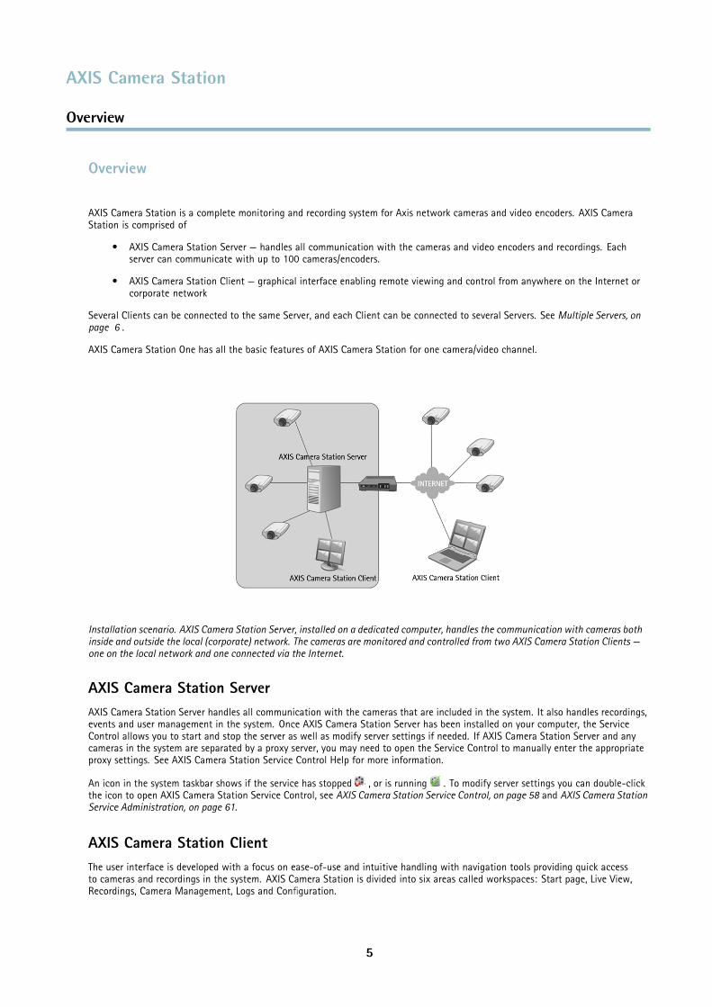
AXIS Camera Station is a complete monitoring and recording system for Axis network cameras and video encoders. AXIS CameraStation is comprised of
• AXIS Camera Station Server — handles all communication with the cameras and video encoders and recordings. Eachserver can communicate with up to 100 cameras/encoders.
• AXIS Camera Station Client — graphical interface enabling remote viewing and control from anywhere on the Internet orcorporate network
Several Clients can be connected to the same Server, and each Client can be connected to several Servers. See Multiple Servers, onpage 6 .
AXIS Camera Station One has all the basic features of AXIS Camera Station for one camera/video channel.
Installation scenario. AXIS Camera Station Server, installed on a dedicated computer, handles the communication with cameras bothinside and outside the local (corporate) network. The cameras are monitored and controlled from two AXIS Camera Station Clients —one on the local network and one connected via the Internet.
AXIS Camera Station ServerAXIS Camera Station Server handles all communication with the cameras that are included in the system. It also handles recordings,events and user management in the system. Once AXIS Camera Station Server has been installed on your computer, the ServiceControl allows you to start and stop the server as well as modify server settings if needed. If AXIS Camera Station Server and anycameras in the system are separated by a proxy server, you may need to open the Service Control to manually enter the appropriateproxy settings. See AXIS Camera Station Service Control Help for more information.
An icon in the system taskbar shows if the service has stopped , or is running . To modify server settings you can double-clickthe icon to open AXIS Camera Station Service Control, see AXIS Camera Station Service Control, on page 58 and AXIS Camera StationService Administration, on page 61.
AXIS Camera Station ClientThe user interface is developed with a focus on ease-of-use and intuitive handling with navigation tools providing quick accessto cameras and recordings in the system. AXIS Camera Station is divided into six areas called workspaces: Start page, Live View,Recordings, Camera Management, Logs and Configuration.
5
AXIS Camera Station
Overview
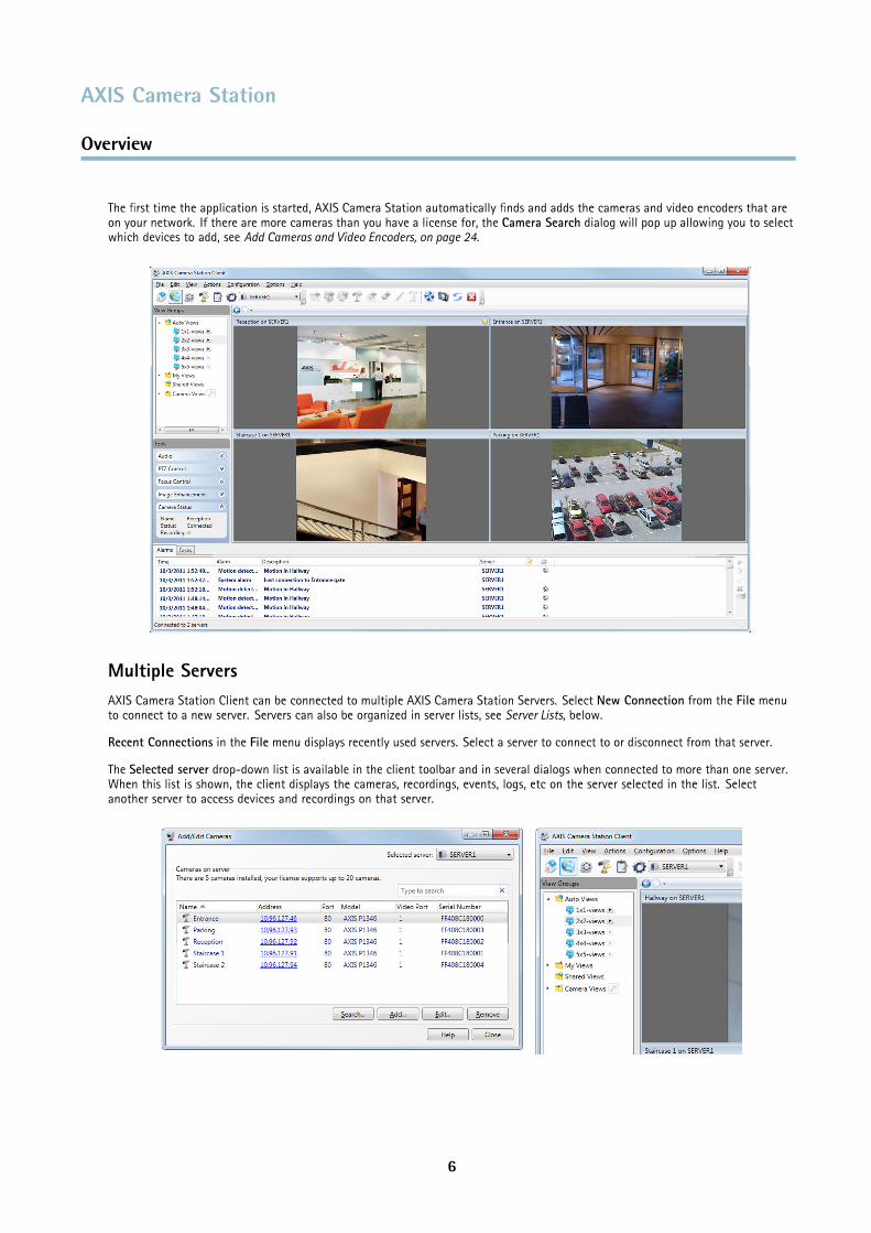
The first time the application is started, AXIS Camera Station automatically finds and adds the cameras and video encoders that areon your network. If there are more cameras than you have a license for, the Camera Search dialog will pop up allowing you to selectwhich devices to add, see Add Cameras and Video Encoders, on page 24.
Multiple ServersAXIS Camera Station Client can be connected to multiple AXIS Camera Station Servers. Select New Connection from the File menuto connect to a new server. Servers can also be organized in server lists, see Server Lists, below.
Recent Connections in the File menu displays recently used servers. Select a server to connect to or disconnect from that server.
The Selected server drop-down list is available in the client toolbar and in several dialogs when connected to more than one server.When this list is shown, the client displays the cameras, recordings, events, logs, etc on the server selected in the list. Selectanother server to access devices and recordings on that server.
6
AXIS Camera Station
Overview
The Camera Management workspace and the Alarms and Tasks tabs at the bottom of the client’s main window, see Alarms and TasksTabs, on page 20, display devices and alarms from all connected servers. In the Live View workspace, you can create split viewswith cameras from different servers.
Server Lists
Server lists are useful when working with a large number of servers, and when using the same servers for clients on differentcomputers.
To create and edit server lists, go to File > Switch to Servers > Server Lists. A server can belong to more than one list.
Once created, you can connect to all servers in a list by selecting the list from the Multiple servers drop-down list in the Connect toAXIS Camera Station dialog displayed when starting the client. To switch between server lists, open the File menu, point to Switch toServers and select the server list to connect to.
Server lists can be exported and imported into other AXIS Camera Station Clients. To export/import a server list, open the File menu,select Import/Export and then Export Server Lists or Import Server Lists.
7
AXIS Camera Station
Workspaces
Workspaces
AXIS Camera Station is divided into workspaces:
The Start page gives an overview of AXIS Camera Station, highlights new features and contains contact information fortechnical support. When disconnected from the server, this is the only workspace available.
The Live View workspace provides a single interface to organize, monitor and control Axis network cameras and videoencoders.
The Recordings workspace handles recording search, playback, export and management.
The Camera Management workspace provides tools for efficient administration and maintenance of connected devices,such as firmware upgrade, assigning IP addresses, setting passwords and date and time settings.
The Logs workspace contains alarm, event and audit logs.
The Configuration workspace is a collection of all the important links for configuring AXIS Camera Station.
The workspaces are easily accessed by clicking on the navigation buttons in the toolbar or by selecting the workspace from the Viewmenu.
Devices and Cameras
In AXIS Camera Station, the terms device and camera are used as follows:
Device A network product that has its own IP address. A device can be:
• a network camera• a video encoder (video server)• an auxiliary device
Camera A video source, that is,
• a network camera• a video port (with a connected analog camera) on a video encoder
Each camera requires one AXIS Camera Station license.
Auxiliary device A network device without video ports, for example an I/O audio module. Auxiliary devices can be addedwithout an additional AXIS Camera Station license.
ExampleA 4–port video encoder is one device with four cameras.
NoteSome video encoders have one IP address for each video port. In this case, each video port is treated as one device withone camera.
Live ViewThe Live View workspace provides a single interface to organize and monitor Axis network cameras and video encoders on yournetwork. You can, for example, set up view groups, record, and control audio and pan/tilt/zoom (PTZ) functionality.
8
AXIS Camera Station
Workspaces
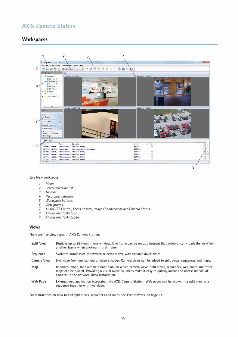
Live View workspace
1 Menu2 Server selection list3 Toolbar4 Recording indicator5 Workspace buttons6 View groups7 Audio, PTZ Control, Focus Control, Image Enhancement and Camera Status8 Alarms and Tasks tabs9 Alarms and Tasks toolbar
Views
There are five view types in AXIS Camera Station:
Split View Displays up to 25 views in one window. One frame can be set as a hotspot that automatically loads the view fromanother frame when clicking in that frame.
Sequence Switches automatically between selected views, with variable dwell times.
Camera View Live video from one camera or video encoder. Camera views can be added to split views, sequences and maps.
Map Imported image, for example a floor plan, on which camera views, split views, sequences, web pages and othermaps can be placed. Providing a visual overview, maps make it easy to quickly locate and access individualcameras in the network video installation.
Web Page External web application integrated into AXIS Camera Station. Web pages can be shown in a split view or asequence together with live video.
For instructions on how to add split views, sequences and maps, see Create Views, on page 31.
9
AXIS Camera Station
Workspaces
Views can be used in event actions, see Event Configuration Wizard, on page 43.
View Groups
Views can be organized into view groups. A view group contains automatic or user-defined views. The following view groups areavailable in the pane in the left hand side of the Live View workspace:
• Auto Views — Automatically created split views for up to 25 cameras.
• My Views — User-created views. These views are available to the current user only.
• Shared Views — Views created by an administrator or operator that are accessible by all users.
• Camera Views — All cameras and video encoders that have been added to AXIS Camera Station.
You can add your own view groups as subgroups to My Views or Shared Views, see Create a New View Group, on page 32.
For instructions on how to add views to My Views and Shared Views, see Create Views, on page 31.
For instructions on how to add cameras and video encoders, see Add Cameras and Video Encoders, on page 24.
Audio
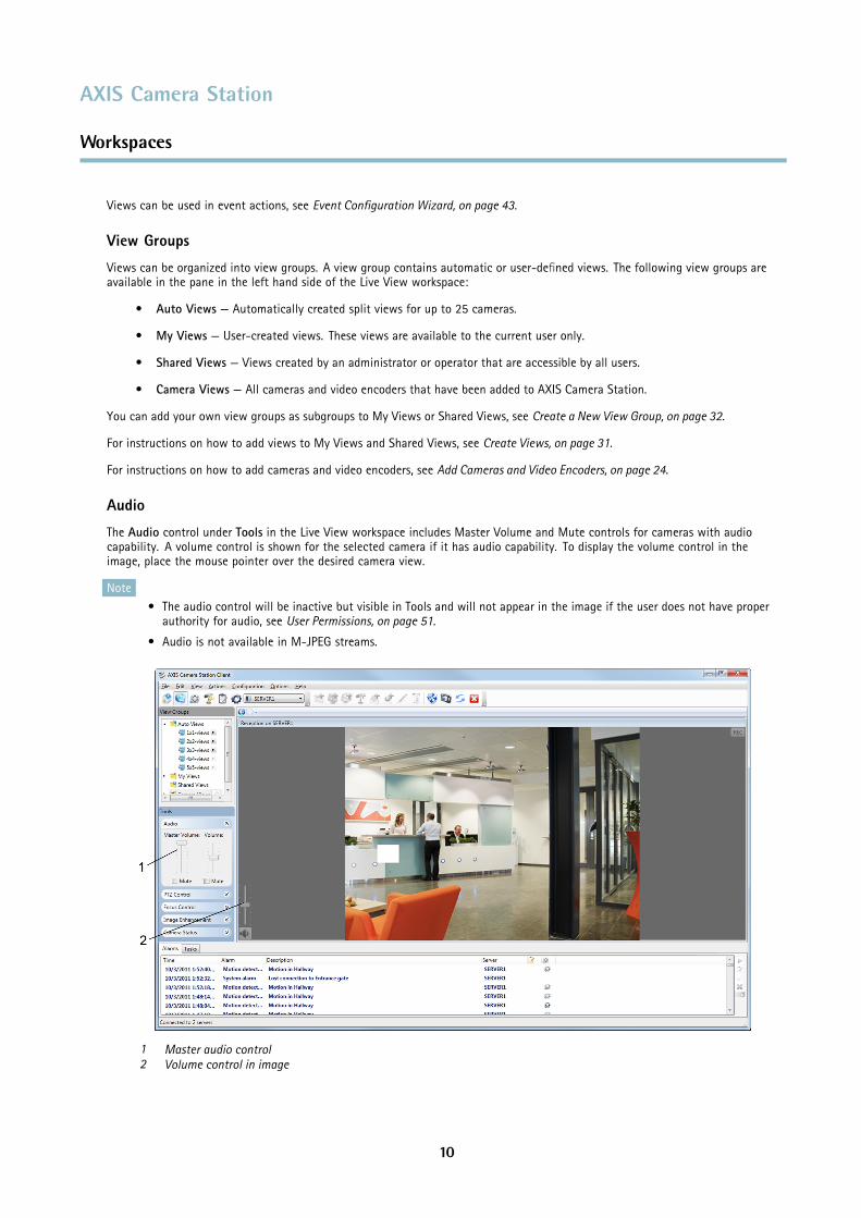
The Audio control under Tools in the Live View workspace includes Master Volume and Mute controls for cameras with audiocapability. A volume control is shown for the selected camera if it has audio capability. To display the volume control in theimage, place the mouse pointer over the desired camera view.
Note• The audio control will be inactive but visible in Tools and will not appear in the image if the user does not have proper
authority for audio, see User Permissions, on page 51.
• Audio is not available in M-JPEG streams.
1 Master audio control2 Volume control in image
10
AXIS Camera Station
Workspaces
PTZ Controls
AXIS Camera Station has two types of pan/tilt/zoom (PTZ) controls:
• Mechanical is for PTZ cameras (including cameras where digital PTZ has been enabled in the camera’s Setup page)
• Digital can be used with any camera
In the Live View workspace, PTZ Control is available under Tools.
Mechanical PTZ Control
The pan, tilt and zoom functionality for PTZ cameras can be controlled:
• using the Mechanical PTZ Control under Tools
• using the mouse
When using the Mechanical PTZ Control, click on the arrow buttons to pan and tilt. Click on the center buttons "+" and "-"to zoom in and out.
To steer the camera view to a preset position, select the position from the Presets drop-down list. For more information onpresets, see Add a PTZ Preset Position, on page 36.
When using the mouse, click in the camera view to pan and tilt. Use the mouse wheel to zoom in and out.
NoteFor information on using a joystick, see Input Devices, on page 53.
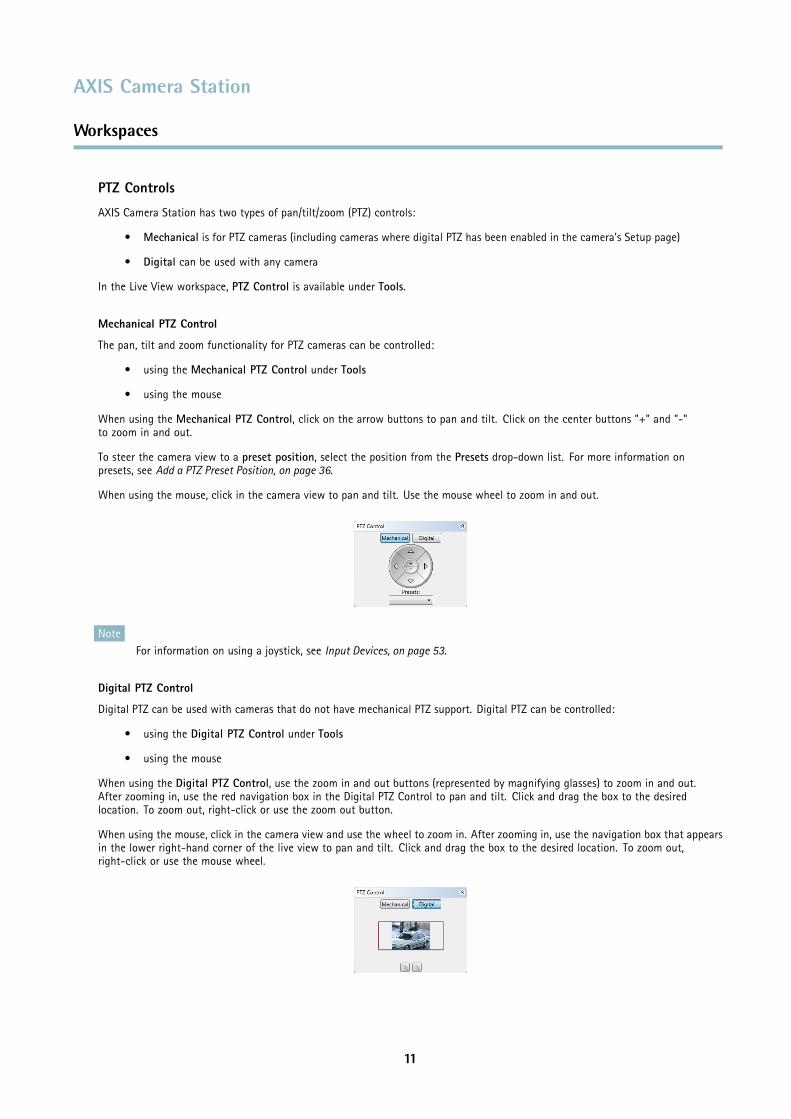
Digital PTZ Control
Digital PTZ can be used with cameras that do not have mechanical PTZ support. Digital PTZ can be controlled:
• using the Digital PTZ Control under Tools
• using the mouse
When using the Digital PTZ Control, use the zoom in and out buttons (represented by magnifying glasses) to zoom in and out.After zooming in, use the red navigation box in the Digital PTZ Control to pan and tilt. Click and drag the box to the desiredlocation. To zoom out, right-click or use the zoom out button.
When using the mouse, click in the camera view and use the wheel to zoom in. After zooming in, use the navigation box that appearsin the lower right-hand corner of the live view to pan and tilt. Click and drag the box to the desired location. To zoom out,right-click or use the mouse wheel.
11
AXIS Camera Station
Workspaces
Focus Control
The Focus Control is available under Tools in the Live View workspace.
Click AF to focus the camera automatically. If the result is not satisfactory, click the Near and Far buttons to adjust focus manually:
• Use the Near buttons to focus on objects close to the camera.
• Use the Far buttons to focus on objects far away from the camera.
The large Near and Far buttons move the focus position in multiple steps and are used for coarse adjustments. Use the smallbuttons to fine-tune focus.
NoteFocus control is not available for all camera models.
Image Enhancement
Image enhancement improves video quality in challenging conditions such as fog, smoke, heavy rain or snow. In the Live Viewworkspace, Image Enhancement is available under Tools. Select Enable and use the slider to adjust the amount of enhancement.
Camera Status
The Camera Status field shows information about the selected camera’s connection and recording status.
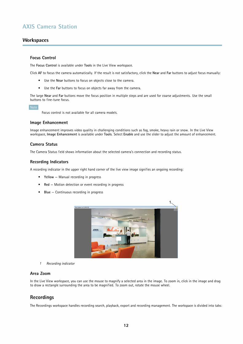
Recording Indicators
A recording indicator in the upper right hand corner of the live view image signifies an ongoing recording:
• Yellow — Manual recording in progress
• Red — Motion detection or event recording in progress
• Blue — Continuous recording in progress
1 Recording indicator
Area Zoom
In the Live View workspace, you can use the mouse to magnify a selected area in the image. To zoom in, click in the image and dragto draw a rectangle surrounding the area to be magnified. To zoom out, rotate the mouse wheel.
RecordingsThe Recordings workspace handles recording search, playback, export and recording management. The workspace is divided into tabs:
12
AXIS Camera Station
Workspaces
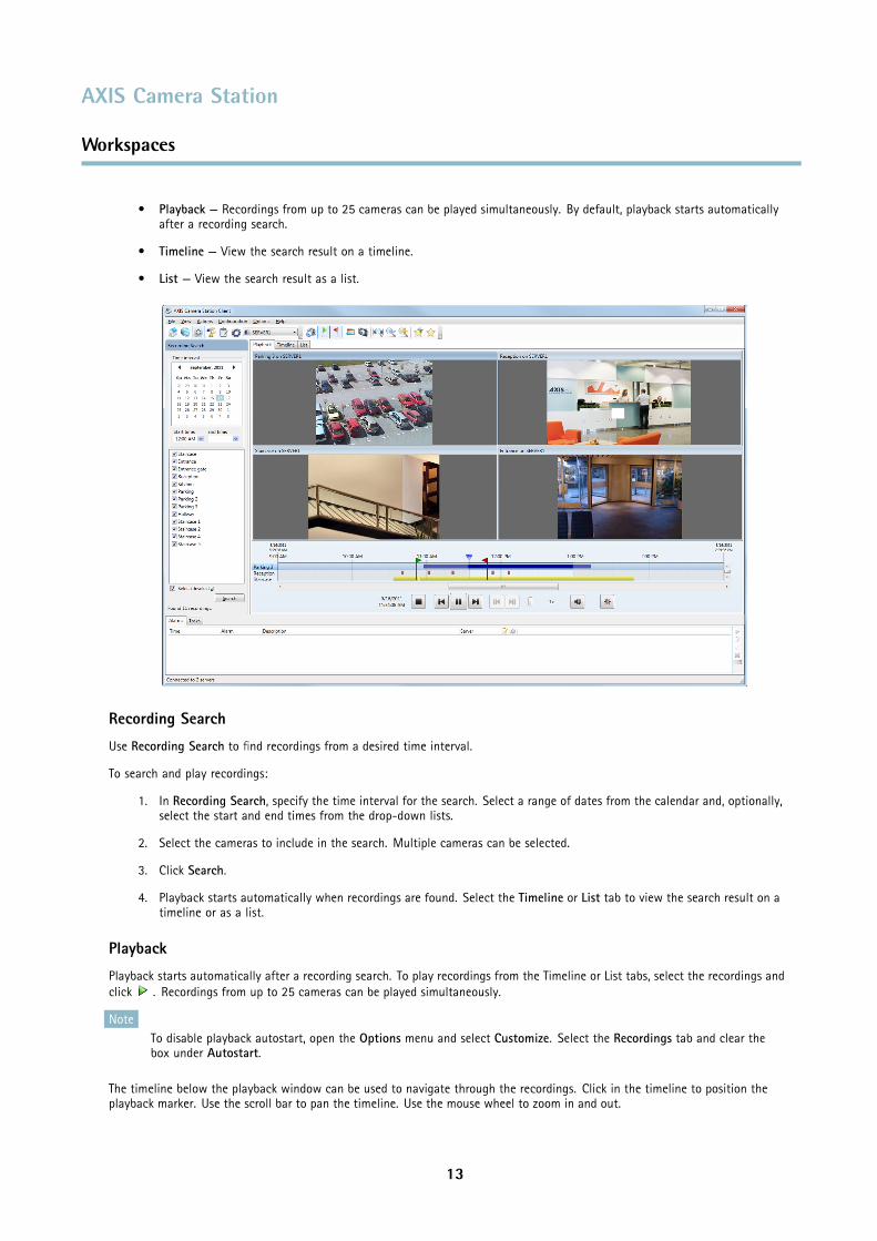
• Playback — Recordings from up to 25 cameras can be played simultaneously. By default, playback starts automaticallyafter a recording search.
• Timeline — View the search result on a timeline.
• List — View the search result as a list.
Recording Search
Use Recording Search to find recordings from a desired time interval.
To search and play recordings:
1. In Recording Search, specify the time interval for the search. Select a range of dates from the calendar and, optionally,select the start and end times from the drop-down lists.
2. Select the cameras to include in the search. Multiple cameras can be selected.
3. Click Search.
4. Playback starts automatically when recordings are found. Select the Timeline or List tab to view the search result on atimeline or as a list.
Playback
Playback starts automatically after a recording search. To play recordings from the Timeline or List tabs, select the recordings andclick . Recordings from up to 25 cameras can be played simultaneously.
NoteTo disable playback autostart, open the Options menu and select Customize. Select the Recordings tab and clear thebox under Autostart.
The timeline below the playback window can be used to navigate through the recordings. Click in the timeline to position theplayback marker. Use the scroll bar to pan the timeline. Use the mouse wheel to zoom in and out.
13
AXIS Camera Station
Workspaces
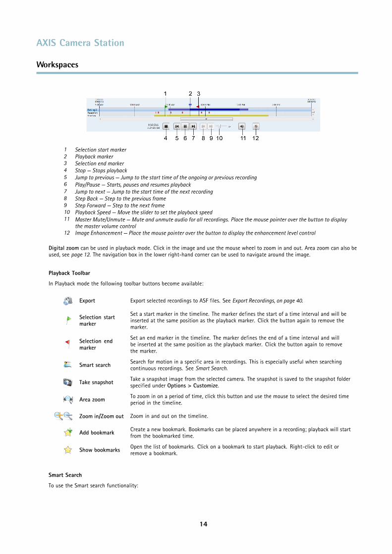
1 Selection start marker2 Playback marker3 Selection end marker4 Stop — Stops playback5 Jump to previous — Jump to the start time of the ongoing or previous recording6 Play/Pause — Starts, pauses and resumes playback7 Jump to next — Jump to the start time of the next recording8 Step Back — Step to the previous frame9 Step Forward — Step to the next frame10 Playback Speed — Move the slider to set the playback speed11 Master Mute/Unmute — Mute and unmute audio for all recordings. Place the mouse pointer over the button to display
the master volume control12 Image Enhancement — Place the mouse pointer over the button to display the enhancement level control
Digital zoom can be used in playback mode. Click in the image and use the mouse wheel to zoom in and out. Area zoom can also beused, see page 12. The navigation box in the lower right-hand corner can be used to navigate around the image.
Playback Toolbar
In Playback mode the following toolbar buttons become available:
Export Export selected recordings to ASF files. See Export Recordings, on page 40.
Selection startmarker
Set a start marker in the timeline. The marker defines the start of a time interval and will beinserted at the same position as the playback marker. Click the button again to remove themarker.
Selection endmarker
Set an end marker in the timeline. The marker defines the end of a time interval and willbe inserted at the same position as the playback marker. Click the button again to removethe marker.
Smart search Search for motion in a specific area in recordings. This is especially useful when searchingcontinuous recordings. See Smart Search.
Take snapshot Take a snapshot image from the selected camera. The snapshot is saved to the snapshot folderspecified under Options > Customize.
Area zoom To zoom in on a period of time, click this button and use the mouse to select the desired timeperiod in the timeline.
Zoom in/Zoom out Zoom in and out on the timeline.
Add bookmark Create a new bookmark. Bookmarks can be placed anywhere in a recording; playback will startfrom the bookmarked time.
Show bookmarks Open the list of bookmarks. Click on a bookmark to start playback. Right-click to edit orremove a bookmark.
Smart Search
To use the Smart search functionality:
14
AXIS Camera Station
Workspaces
1. Click the Smart search button in the toolbar, a Smart search next button will appear in the playback panel, a motionwindow will appear in the image and a sensitivity slider will appear in the lower right-hand corner
2. Drag and size the motion window to the desired area of the image.
3. Adjust slider to the proper sensitivity. A high value indicates high sensitivity to motion.
4. Click the Smart search next button to jump to the place in the recording where motion takes place.
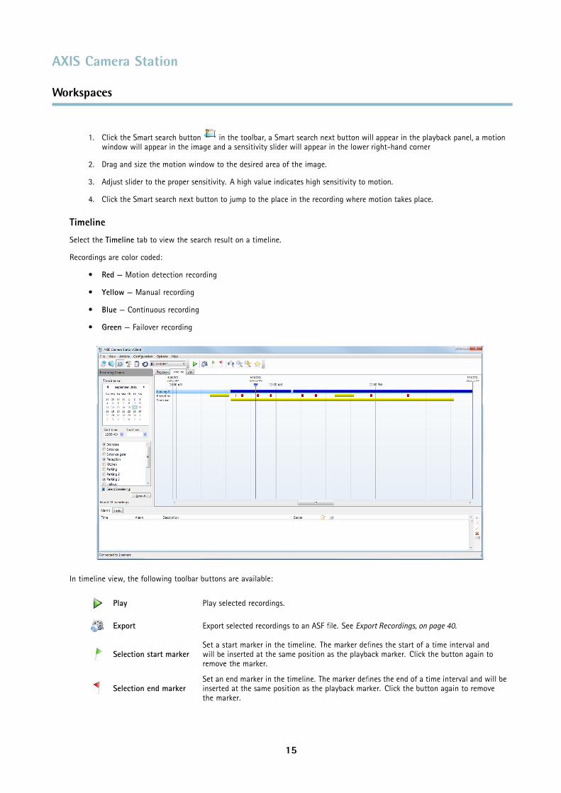
Timeline
Select the Timeline tab to view the search result on a timeline.
Recordings are color coded:
• Red — Motion detection recording
• Yellow — Manual recording
• Blue — Continuous recording
• Green — Failover recording
In timeline view, the following toolbar buttons are available:
Play Play selected recordings.
Export Export selected recordings to an ASF file. See Export Recordings, on page 40.
Selection start markerSet a start marker in the timeline. The marker defines the start of a time interval andwill be inserted at the same position as the playback marker. Click the button again toremove the marker.
Selection end markerSet an end marker in the timeline. The marker defines the end of a time interval and will beinserted at the same position as the playback marker. Click the button again to removethe marker.
15
AXIS Camera Station
Workspaces
Area zoom To zoom in on a period of time, click this button and use the mouse to select the desiredtime period in the timeline.
Zoom in/Zoom out Zoom in or out on the timeline.
Show bookmarks Open the list of bookmarks
Right-click the recording in the timeline to open the Recording Details dialog. The dialog provides information about the recordingand includes options such as start playback, export, bookmark and take a snapshot of the recording.
List
Select the List tab to view the search result as a list.
In List view, the following toolbar buttons become available:
Play Play selected recordings.
Lock/Unlock Lock or unlock selected recordings. Locking prevents the recording from being deleted.Note: Locked recordings will be deleted if the camera is removed from AXIS Camera Station.
Export Export selected recordings to an ASF file. See Export Recordings, on page 40.
Show/Hide Show or hide thumbnail images in the recording search list.
Showbookmarks Opens the list of bookmarks.
Camera ManagementThe Camera Management workspace provides tools for efficient management, administration and maintenance of devices connectedto AXIS Camera Station. Devices can be organized using tags, see Tags, on page 18.
NoteA device is a network product with its own IP address, see page 8 .
Use the search field to locate desired devices, or click on the headings to list devices in the desired order.
16
AXIS Camera Station
Workspaces
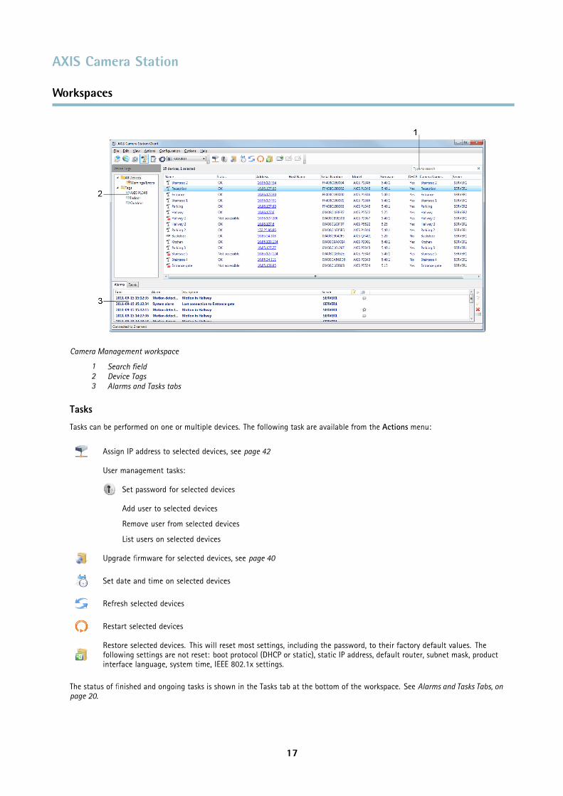
Camera Management workspace
1 Search field2 Device Tags3 Alarms and Tasks tabs
Tasks
Tasks can be performed on one or multiple devices. The following task are available from the Actions menu:
Assign IP address to selected devices, see page 42
User management tasks:
Set password for selected devices
Add user to selected devices
Remove user from selected devices
List users on selected devices
Upgrade firmware for selected devices, see page 40
Set date and time on selected devices
Refresh selected devices
Restart selected devices
Restore selected devices. This will reset most settings, including the password, to their factory default values. Thefollowing settings are not reset: boot protocol (DHCP or static), static IP address, default router, subnet mask, productinterface language, system time, IEEE 802.1x settings.
The status of finished and ongoing tasks is shown in the Tasks tab at the bottom of the workspace. See Alarms and Tasks Tabs, onpage 20.
17
AXIS Camera Station
Workspaces
When connected to multiple AXIS Camera Station Servers, devices on all servers are displayed in the Camera Managementworkspace’s main window. With the exception of assigning IP addresses, tasks can be performed on different servers at the same time.
Tags
For efficient management, devices can be organized using tags. A device can have more than one tag. You can for example createtags for managing different camera models and tags for cameras in different locations.
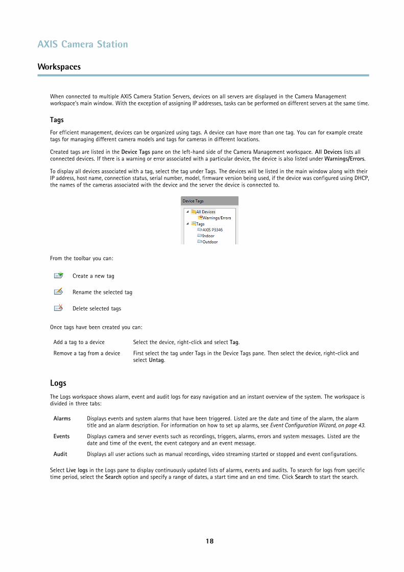
Created tags are listed in the Device Tags pane on the left-hand side of the Camera Management workspace. All Devices lists allconnected devices. If there is a warning or error associated with a particular device, the device is also listed under Warnings/Errors.
To display all devices associated with a tag, select the tag under Tags. The devices will be listed in the main window along with theirIP address, host name, connection status, serial number, model, firmware version being used, if the device was configured using DHCP,the names of the cameras associated with the device and the server the device is connected to.
From the toolbar you can:
Create a new tag
Rename the selected tag
Delete selected tags
Once tags have been created you can:
Add a tag to a device Select the device, right-click and select Tag.
Remove a tag from a device First select the tag under Tags in the Device Tags pane. Then select the device, right-click andselect Untag.
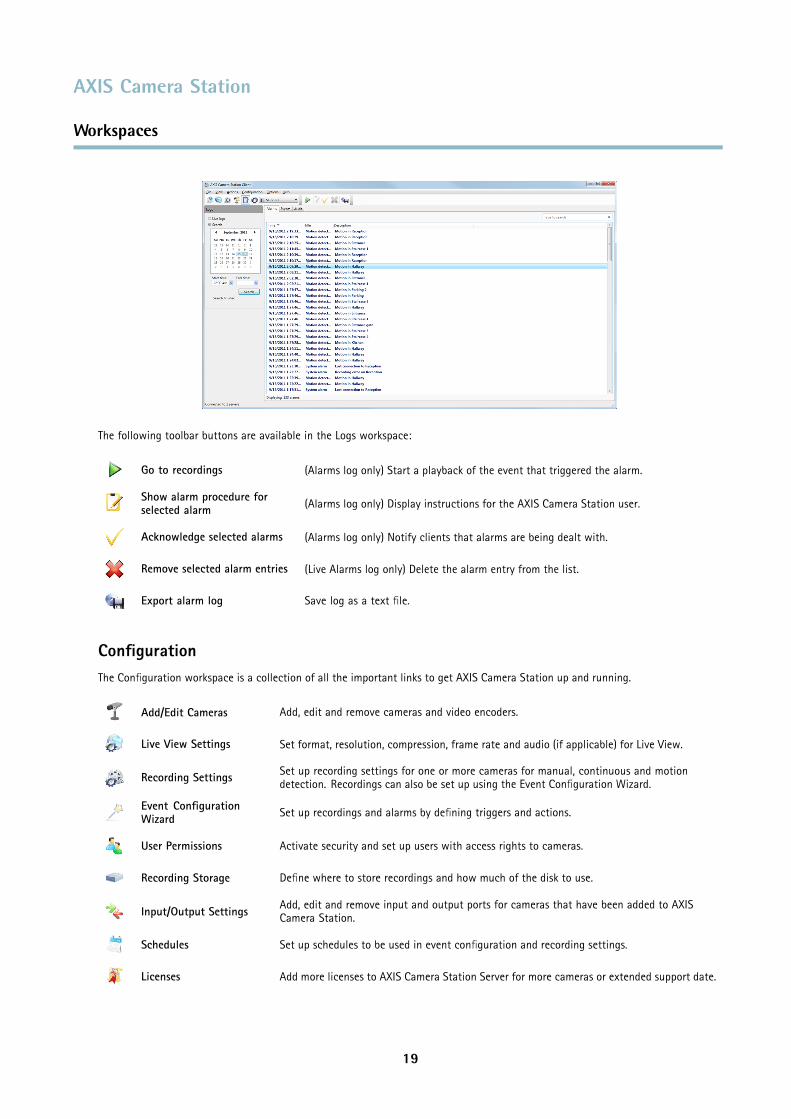
LogsThe Logs workspace shows alarm, event and audit logs for easy navigation and an instant overview of the system. The workspace isdivided in three tabs:
Alarms Displays events and system alarms that have been triggered. Listed are the date and time of the alarm, the alarmtitle and an alarm description. For information on how to set up alarms, see Event Configuration Wizard, on page 43.
Events Displays camera and server events such as recordings, triggers, alarms, errors and system messages. Listed are thedate and time of the event, the event category and an event message.
Audit Displays all user actions such as manual recordings, video streaming started or stopped and event configurations.
Select Live logs in the Logs pane to display continuously updated lists of alarms, events and audits. To search for logs from specifictime period, select the Search option and specify a range of dates, a start time and an end time. Click Search to start the search.
18
AXIS Camera Station
Workspaces
The following toolbar buttons are available in the Logs workspace:
Go to recordings (Alarms log only) Start a playback of the event that triggered the alarm.
Show alarm procedure forselected alarm (Alarms log only) Display instructions for the AXIS Camera Station user.
Acknowledge selected alarms (Alarms log only) Notify clients that alarms are being dealt with.
Remove selected alarm entries (Live Alarms log only) Delete the alarm entry from the list.
Export alarm log Save log as a text file.
ConfigurationThe Configuration workspace is a collection of all the important links to get AXIS Camera Station up and running.
Add/Edit Cameras Add, edit and remove cameras and video encoders.
Live View Settings Set format, resolution, compression, frame rate and audio (if applicable) for Live View.
Recording Settings Set up recording settings for one or more cameras for manual, continuous and motiondetection. Recordings can also be set up using the Event Configuration Wizard.
Event ConfigurationWizard Set up recordings and alarms by defining triggers and actions.
User Permissions Activate security and set up users with access rights to cameras.
Recording Storage Define where to store recordings and how much of the disk to use.
Input/Output Settings Add, edit and remove input and output ports for cameras that have been added to AXISCamera Station.
Schedules Set up schedules to be used in event configuration and recording settings.
Licenses Add more licenses to AXIS Camera Station Server for more cameras or extended support date.
19
AXIS Camera Station
Workspaces
Customize Customize the look of AXIS Camera Station at startup, the sound played when an alarm orevent occurs, where to store snapshots and Playback behavior.
PTZ Settings Add new or modify existing pan/tilt/zoom (PTZ) preset positions.
Bookmarks Edit and remove bookmarks.
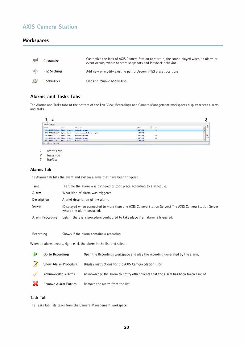
Alarms and Tasks TabsThe Alarms and Tasks tabs at the bottom of the Live View, Recordings and Camera Management workspaces display recent alarmsand tasks.
1 Alarms tab2 Tasks tab3 Toolbar
Alarms Tab
The Alarms tab lists the event and system alarms that have been triggered.
Time The time the alarm was triggered or took place according to a schedule.
Alarm What kind of alarm was triggered.
Description A brief description of the alarm.
Server (Displayed when connected to more than one AXIS Camera Station Server.) The AXIS Camera Station Serverwhere the alarm occurred.
Alarm Procedure Lists if there is a procedure configured to take place if an alarm is triggered.
Recording Shows if the alarm contains a recording.
When an alarm occurs, right-click the alarm in the list and select:
Go to Recordings Open the Recordings workspace and play the recording generated by the alarm.
Show Alarm Procedure Display instructions for the AXIS Camera Station user.
Acknowledge Alarms Acknowledge the alarm to notify other clients that the alarm has been taken care of.
Remove Alarm Entries Remove the alarm from the list.
Task Tab
The Tasks tab lists tasks from the Camera Management workspace.
20
AXIS Camera Station
Workspaces
Task The name of the task
Status Shows if the task is:• Waiting (Waiting for another task to be completed on the server)• Running (Performing the task)• Cancel pending (Clean up after the task when the user pressed cancel)• Canceled (Cleaning is complete and the task is canceled)• Finished (Task completed)• Error (Task completed with errors, i.e. the task failed on one or more of the selected cameras)
Start Time When the task was started
Owner Who initiated the task
Progress Shows how much of the task is left to be completed.
Server (Displayed when connected to more than one AXIS Camera Station Server.) The AXIS Camera Station Serverperforming the task
The toolbar to the right displays the following buttons:
Show Displays additional information about the task.
Cancel Cancel selected tasks.
Remove selected taskentries Remove one or more tasks from the task list.
Auto remove successful Automatically remove the task from the list when it is successfully completed.
21
AXIS Camera Station
Licenses
Licenses
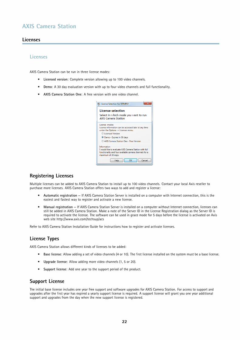
AXIS Camera Station can be run in three license modes:
• Licensed version: Complete version allowing up to 100 video channels.
• Demo: A 30 day evaluation version with up to four video channels and full functionality.
• AXIS Camera Station One: A free version with one video channel.
Registering LicensesMultiple licenses can be added to AXIS Camera Station to install up to 100 video channels. Contact your local Axis reseller topurchase more licenses. AXIS Camera Station offers two ways to add and register a license:
• Automatic registration — If AXIS Camera Station Server is installed on a computer with Internet connection, this is theeasiest and fastest way to register and activate a new license.
• Manual registration — If AXIS Camera Station Server is installed on a computer without Internet connection, licenses canstill be added in AXIS Camera Station. Make a note of the Server ID in the License Registration dialog as the Server ID isrequired to activate the license. The software can be used in grace mode for 5 days before the license is activated on Axisweb site http://www.axis.com/techsup/acs
Refer to AXIS Camera Station Installation Guide for instructions how to register and activate licenses.
License TypesAXIS Camera Station allows different kinds of licenses to be added:
• Base license: Allow adding a set of video channels (4 or 10). The first license installed on the system must be a base license.
• Upgrade license: Allow adding more video channels (1, 5 or 20).
• Support license: Add one year to the support period of the product.
Support LicenseThe initial base license includes one year free support and software upgrades for AXIS Camera Station. For access to support andupgrades after the first year has expired a yearly support license is required. A support license will grant you one year additionalsupport and upgrades from the day when the new support license is registered.
22
AXIS Camera Station
Licenses
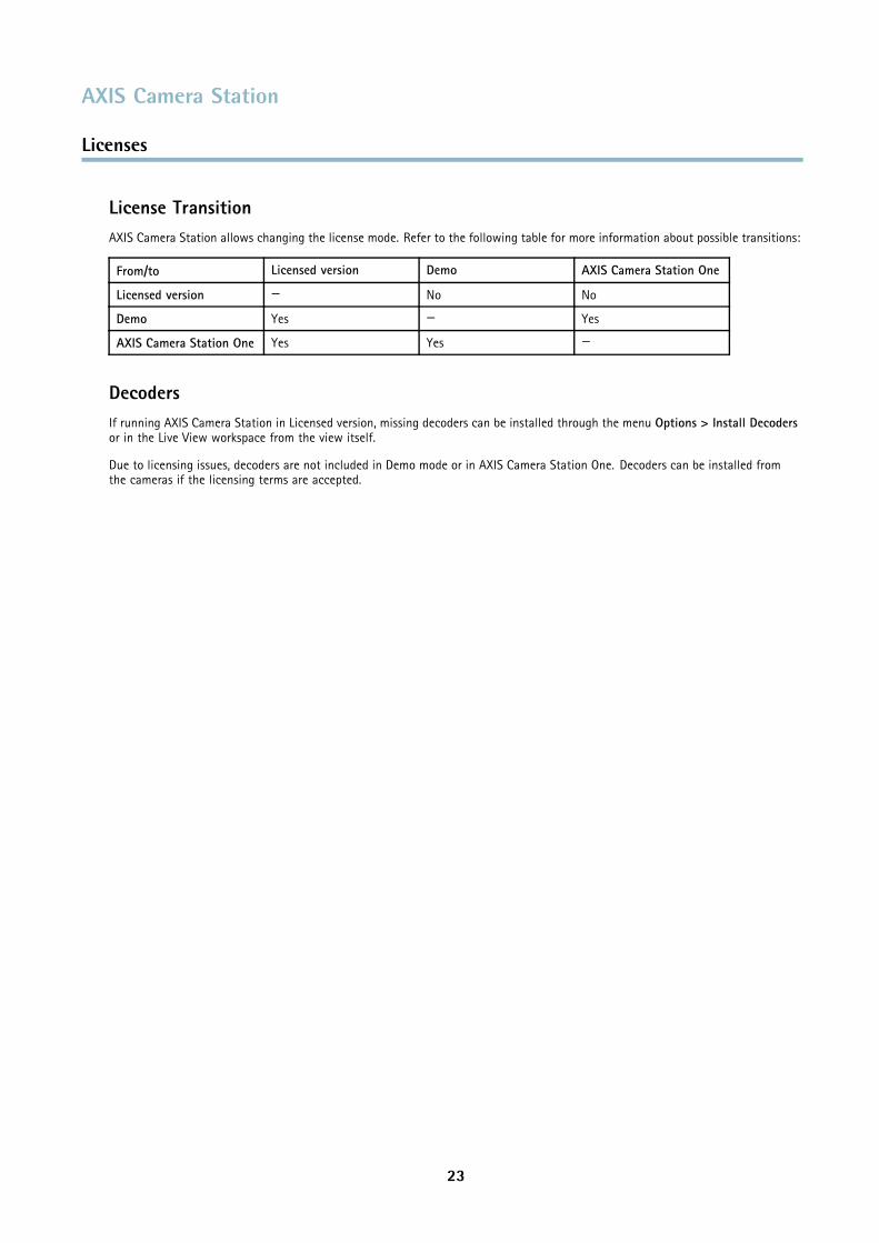
License TransitionAXIS Camera Station allows changing the license mode. Refer to the following table for more information about possible transitions:
From/to Licensed version Demo AXIS Camera Station One
Licensed version — No No
Demo Yes — Yes
AXIS Camera Station One Yes Yes —
DecodersIf running AXIS Camera Station in Licensed version, missing decoders can be installed through the menu Options > Install Decodersor in the Live View workspace from the view itself.
Due to licensing issues, decoders are not included in Demo mode or in AXIS Camera Station One. Decoders can be installed fromthe cameras if the licensing terms are accepted.
23
AXIS Camera Station
How to...
How to...
After installing the software, it must be configured for your cameras and video encoders. Among other things, this chapter describeshow to configure and maintain AXIS Camera Station as well as how to set up recording, motion detection, and alarms. For installationinstructions, refer to AXIS Camera Station Installation Guide.
Add Cameras and Video EncodersCameras and video encoders can be added to AXIS Camera Station in the following ways:
• By searching for devices on the network, see Add Cameras and Video Encoders — Using Search
• By specifying the device IP address or host name manually, see Add Cameras and Video Encoders — Manually
NoteSee page 25 for information on how to add view areas.
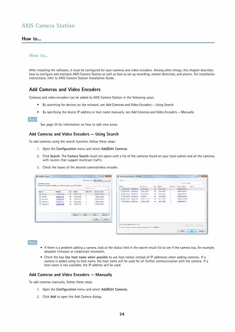
Add Cameras and Video Encoders — Using Search
To add cameras using the search function, follow these steps:
1. Open the Configuration menu and select Add/Edit Cameras.
2. Click Search. The Camera Search result list opens with a list of the cameras found on your local subnet and all the cameraswith routers that support multicast traffic.
3. Check the boxes of the desired camera/video encoder.
Note• If there is a problem adding a camera, look at the status field in the search result list to see if the camera has, for example,
obsolete firmware or credentials mismatch.
• Check the box Use host name when possible to use host names instead of IP addresses when adding cameras. If acamera is added using its host name, the host name will be used for all further communication with the camera. If ahost name is not available, the IP address will be used.
Add Cameras and Video Encoders — Manually
To add cameras manually, follow these steps:
1. Open the Configuration menu and select Add/Edit Cameras.
2. Click Add to open the Add Camera dialog.
24
AXIS Camera Station
How to...
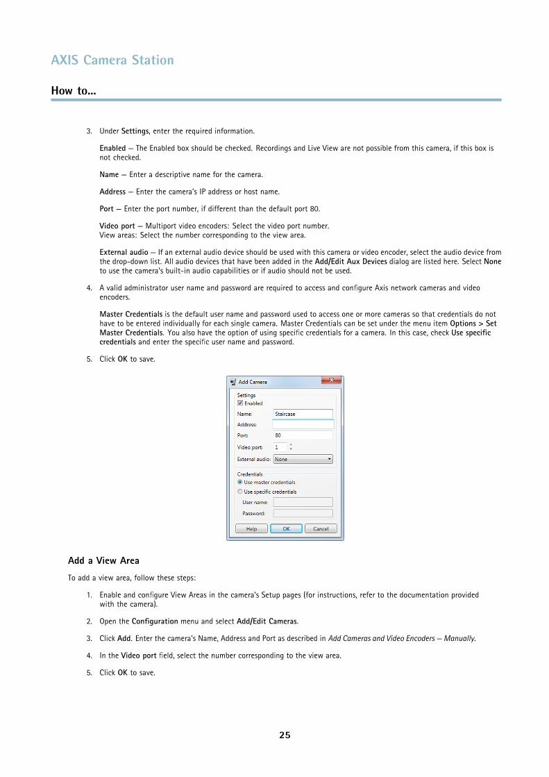
3. Under Settings, enter the required information.
Enabled — The Enabled box should be checked. Recordings and Live View are not possible from this camera, if this box isnot checked.
Name — Enter a descriptive name for the camera.
Address — Enter the camera’s IP address or host name.
Port — Enter the port number, if different than the default port 80.
Video port — Multiport video encoders: Select the video port number.View areas: Select the number corresponding to the view area.
External audio — If an external audio device should be used with this camera or video encoder, select the audio device fromthe drop-down list. All audio devices that have been added in the Add/Edit Aux Devices dialog are listed here. Select Noneto use the camera’s built-in audio capabilities or if audio should not be used.
4. A valid administrator user name and password are required to access and configure Axis network cameras and videoencoders.
Master Credentials is the default user name and password used to access one or more cameras so that credentials do nothave to be entered individually for each single camera. Master Credentials can be set under the menu item Options > SetMaster Credentials. You also have the option of using specific credentials for a camera. In this case, check Use specificcredentials and enter the specific user name and password.
5. Click OK to save.
Add a View Area
To add a view area, follow these steps:
1. Enable and configure View Areas in the camera’s Setup pages (for instructions, refer to the documentation providedwith the camera).
2. Open the Configuration menu and select Add/Edit Cameras.
3. Click Add. Enter the camera’s Name, Address and Port as described in Add Cameras and Video Encoders — Manually.
4. In the Video port field, select the number corresponding to the view area.
5. Click OK to save.
25
AXIS Camera Station
How to...
Note• View areas are supported by selected HDTV and megapixel cameras.
• When using multiple view areas from the same camera, each view area counts as one video channel in the total number ofvideo channels supported by the installed AXIS Camera Station license.
Add Auxiliary DevicesAuxiliary devices are devices that provide additional, non-video-related functionality, for example more I/O ports or audio capabilities.Auxiliary devices cannot be used for video and do not require an additional AXIS Camera Station license.
Auxiliary devices can be added to AXIS Camera Station in the following ways:
• By searching for devices on the network, see Add Auxiliary Devices — Using Search
• By specifying the device IP address or host name manually, see Add Auxiliary Devices — Manually
See also Use Audio from an Auxiliary Device, on page 38.
Add Auxiliary Devices — Using Search
To add auxiliary devices using the search function follow these steps:
1. From the Configuration menu, select Add/Edit Aux Devices.
2. Click Search. The Aux Device Search window opens with a list of all auxiliary devices found on your network.
3. Check the boxes of the desired devices and click OK.
NoteCheck the box Use host name when possible to use host names instead of IP addresses when adding auxiliary devices. If anauxiliary device is added using its host name, the host name will be used for all further communication with the device. If ahost name is not available, the IP address will be used.
Add Auxiliary Devices — Manually
To add auxiliary devices manually follow these steps:
1. From the Configuration menu, select Add/Edit Aux Devices.
2. Click Add to open the Add Aux Device dialog.
3. Under Settings, enter the required information.
Address — Enter the device’s IP address or host name.
Port — Enter the port number, if different than the default port 80.
4. A valid administrator user name and password are required to access and configure the device.
Master Credentials is the default user name and password used to access one or more devices so that credentials do nothave to be entered individually for each single device. Master Credentials can be set under the menu item Options > SetMaster Credentials. You also have the option of using specific credentials for a device. In this case, check Use specificcredentials and enter the specific user name and password.
5. Click OK to save.
Set Up RecordingRecordings can be continuous, manual or triggered by motion. Recordings can also be scheduled. Media profiles can be createdfor each type of recording for, among other settings, optimal frame rate and resolution. See Configure a Media Profile, on page 37for more information.
26
AXIS Camera Station
How to...
AXIS Camera Station also supports failover recordings. When enabled, a failover recording starts automatically if the connectionbetween the camera and AXIS Camera Station is lost during an ongoing recording. See Failover Recordings, on page 30.
For information on how to set up recordings triggered by signals from I/O ports, system alarms, tampering attempts etc, seeEvent Configuration Wizard, on page 43.
Continuous and Scheduled Recordings
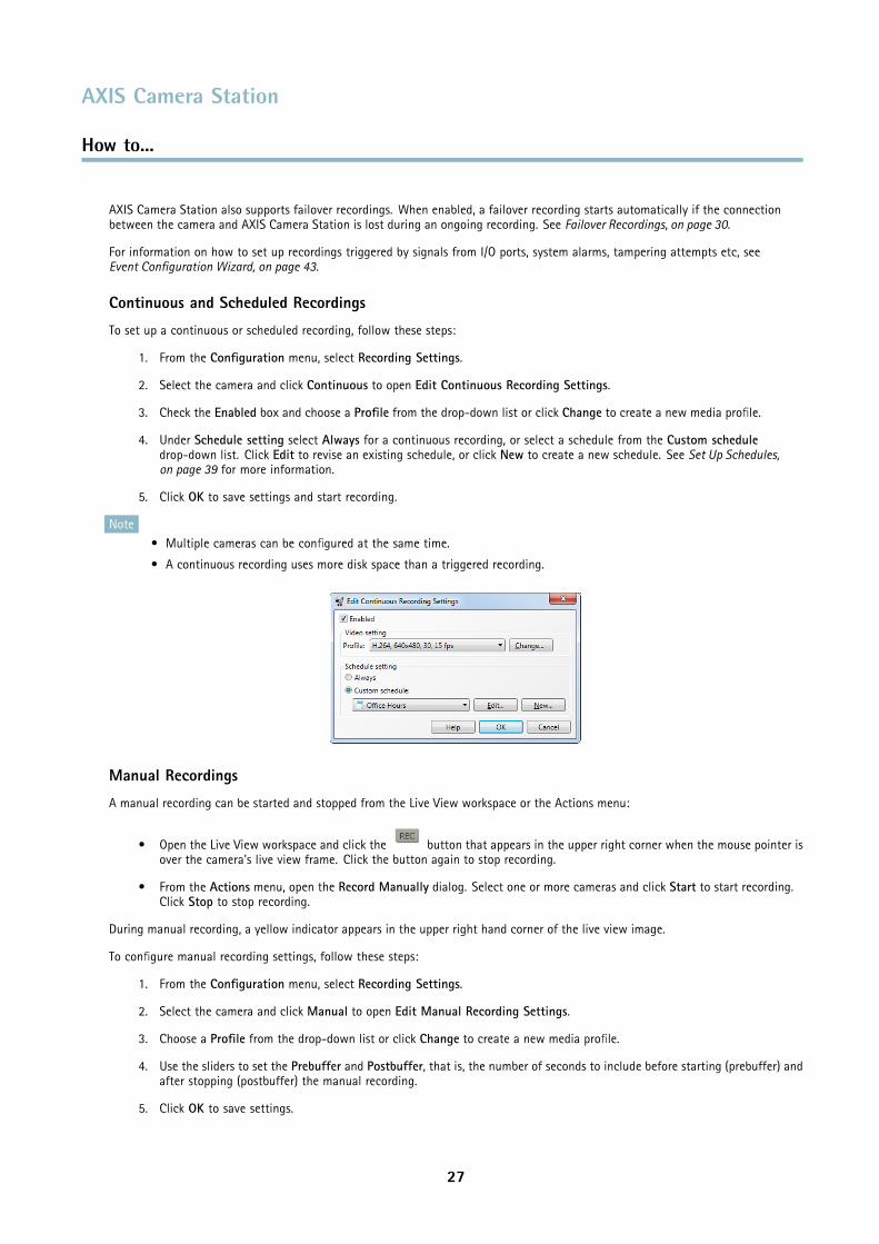
To set up a continuous or scheduled recording, follow these steps:
1. From the Configuration menu, select Recording Settings.
2. Select the camera and click Continuous to open Edit Continuous Recording Settings.
3. Check the Enabled box and choose a Profile from the drop-down list or click Change to create a new media profile.
4. Under Schedule setting select Always for a continuous recording, or select a schedule from the Custom scheduledrop-down list. Click Edit to revise an existing schedule, or click New to create a new schedule. See Set Up Schedules,on page 39 for more information.
5. Click OK to save settings and start recording.
Note• Multiple cameras can be configured at the same time.
• A continuous recording uses more disk space than a triggered recording.
Manual Recordings
A manual recording can be started and stopped from the Live View workspace or the Actions menu:
• Open the Live View workspace and click the button that appears in the upper right corner when the mouse pointer isover the camera's live view frame. Click the button again to stop recording.
• From the Actions menu, open the Record Manually dialog. Select one or more cameras and click Start to start recording.Click Stop to stop recording.
During manual recording, a yellow indicator appears in the upper right hand corner of the live view image.
To configure manual recording settings, follow these steps:
1. From the Configuration menu, select Recording Settings.
2. Select the camera and click Manual to open Edit Manual Recording Settings.
3. Choose a Profile from the drop-down list or click Change to create a new media profile.
4. Use the sliders to set the Prebuffer and Postbuffer, that is, the number of seconds to include before starting (prebuffer) andafter stopping (postbuffer) the manual recording.
5. Click OK to save settings.
27

AXIS Camera Station
How to...
NoteMultiple cameras can be configured at the same time.
Motion Triggered Recording
Motion can be detected by all Axis network cameras. Recording only when motion is detected will save disk space compared to otheroptions such as recording continuously. Motion Detection Recording can be configured using the Event Configuration Wizard, seepage 43, or the Recording Settings dialog as described here.
To set up a motion triggered recording, follow these steps:
1. From the Configuration menu, select Recording Settings.
2. Select the camera and click Motion Detection to open Edit Motion Detection Recording Settings.
3. Check the Enabled box.
4. Use the slider to set the Trigger period, that is, specify the minimum time between two alarms. This setting is used toreduce the number of alarms and recordings if there is a lot of motion in the area.
5. Click Motion Settings to configure motion detection windows. See Motion Settings, below.
6. Choose a Profile from the drop-down list or click Change to create a new media profile.
7. Use the sliders to set the Prebuffer and Postbuffer, that is, specify the number of seconds to record before motion wasdetected (prebuffer) and after motion stopped (postbuffer).
8. Under Schedule setting select Always to always record on motion detection, or select a schedule from the Customschedule drop-down list.
9. Click OK to save settings.
NoteWhen using view areas, motion detection can be configured for view area 1 only and is always set up using the full overviewimage.
28
AXIS Camera Station
How to...
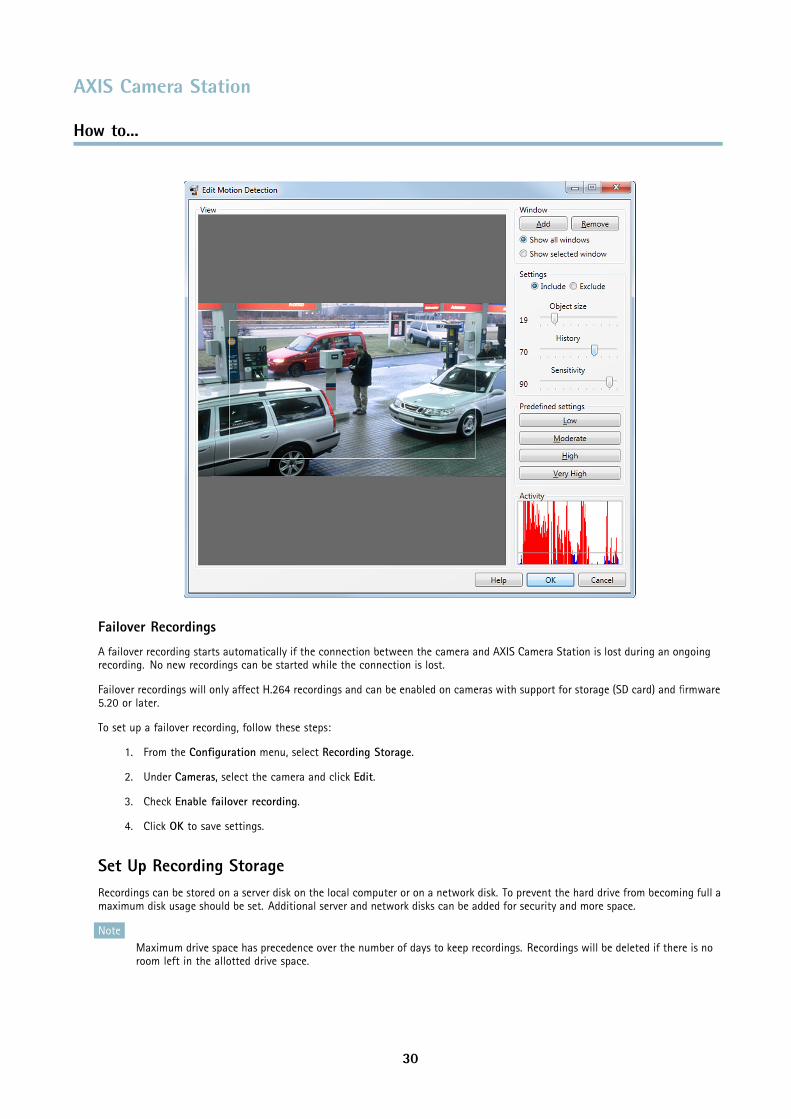
Motion Settings
Moving objects will be detected in the configured motion detection windows:
• Include windows define areas where motion should be detected
• Exclude windows define areas within an include window that should be ignored (areas outside include windows arealways ignored)
For each motion detection window you can configure:
Object size - Object size is relative to the region size. At a high level, only very large objects are detected. At a low level evenvery small objects trigger an event.
History - History defines how long an object needs to be in a region before it is considered to be non-moving. At a high level anobject that appears in the region will trigger the motion detection for a long period before it is considered a non-moving part of theimage. At a low level an object that appears in the region will trigger motion detection for only a very short period.
Sensitivity - Sensitivity defines the difference in luminance between the background and the object. At a high level, an ordinarycolored object on ordinary backgrounds will trigger motion. At a low level, only very bright objects on a dark background orvery dark objects on a light background will trigger an event.
To set up motion detection windows, follow these steps:
1. Click Motion Settings to open the Edit Motion Detection dialog.
2. Click Add to create a new motion detection window. Select Include to create an include window or select Excludeto create an exclude window, as required.
3. Use the mouse to drag the window to the desired area. To resize, drag the sides of the window.
4. Set the Object size, History and Sensitivity. Begin with a predefined setting and if needed fine adjust the settings using thesliders while looking in the Activity window while there is a desired amount of motion in the motion detection window.
5. Click OK to save settings.
29
AXIS Camera Station
How to...
Failover Recordings
A failover recording starts automatically if the connection between the camera and AXIS Camera Station is lost during an ongoingrecording. No new recordings can be started while the connection is lost.
Failover recordings will only affect H.264 recordings and can be enabled on cameras with support for storage (SD card) and firmware5.20 or later.
To set up a failover recording, follow these steps:
1. From the Configuration menu, select Recording Storage.
2. Under Cameras, select the camera and click Edit.
3. Check Enable failover recording.
4. Click OK to save settings.
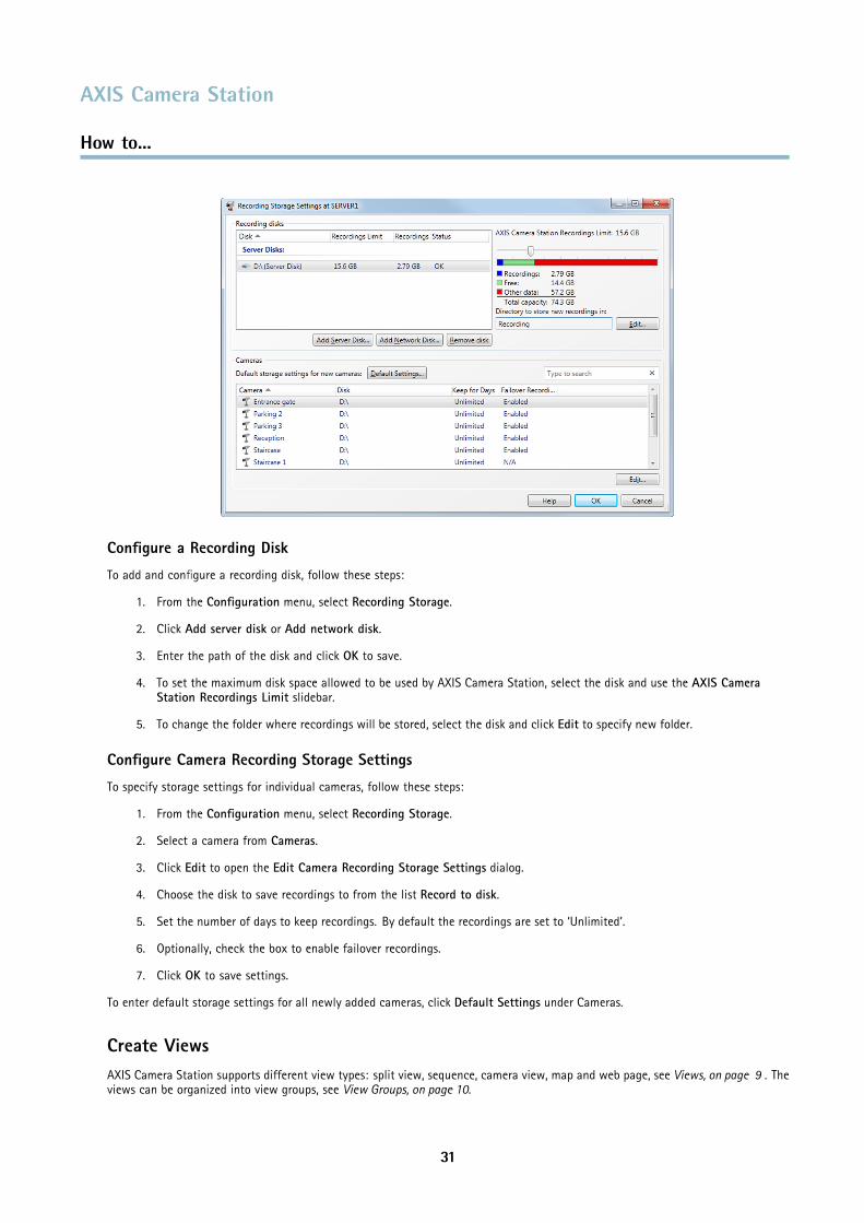
Set Up Recording StorageRecordings can be stored on a server disk on the local computer or on a network disk. To prevent the hard drive from becoming full amaximum disk usage should be set. Additional server and network disks can be added for security and more space.
NoteMaximum drive space has precedence over the number of days to keep recordings. Recordings will be deleted if there is noroom left in the allotted drive space.
30
AXIS Camera Station
How to...
Configure a Recording Disk
To add and configure a recording disk, follow these steps:
1. From the Configuration menu, select Recording Storage.
2. Click Add server disk or Add network disk.
3. Enter the path of the disk and click OK to save.
4. To set the maximum disk space allowed to be used by AXIS Camera Station, select the disk and use the AXIS CameraStation Recordings Limit slidebar.
5. To change the folder where recordings will be stored, select the disk and click Edit to specify new folder.
Configure Camera Recording Storage Settings
To specify storage settings for individual cameras, follow these steps:
1. From the Configuration menu, select Recording Storage.
2. Select a camera from Cameras.
3. Click Edit to open the Edit Camera Recording Storage Settings dialog.
4. Choose the disk to save recordings to from the list Record to disk.
5. Set the number of days to keep recordings. By default the recordings are set to ‘Unlimited’.
6. Optionally, check the box to enable failover recordings.
7. Click OK to save settings.
To enter default storage settings for all newly added cameras, click Default Settings under Cameras.
Create ViewsAXIS Camera Station supports different view types: split view, sequence, camera view, map and web page, see Views, on page 9 . Theviews can be organized into view groups, see View Groups, on page 10.
31
AXIS Camera Station
How to...
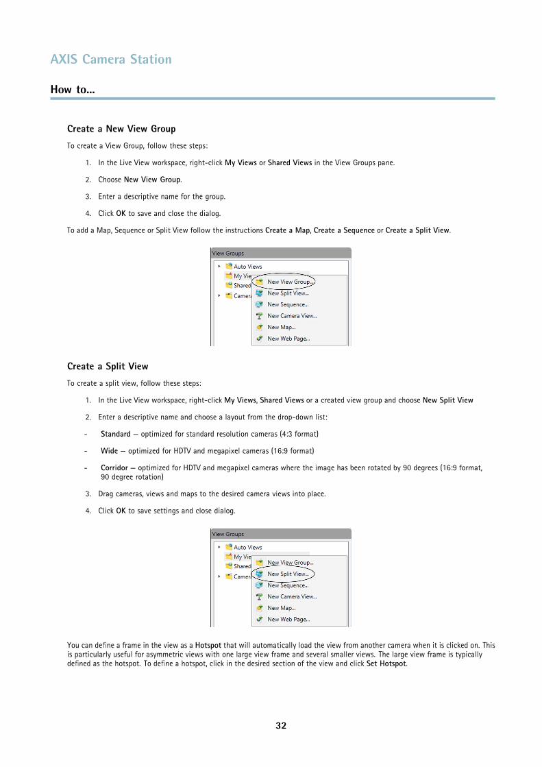
Create a New View Group
To create a View Group, follow these steps:
1. In the Live View workspace, right-click My Views or Shared Views in the View Groups pane.
2. Choose New View Group.
3. Enter a descriptive name for the group.
4. Click OK to save and close the dialog.
To add a Map, Sequence or Split View follow the instructions Create a Map, Create a Sequence or Create a Split View.
Create a Split View
To create a split view, follow these steps:
1. In the Live View workspace, right-click My Views, Shared Views or a created view group and choose New Split View
2. Enter a descriptive name and choose a layout from the drop-down list:
- Standard — optimized for standard resolution cameras (4:3 format)
- Wide — optimized for HDTV and megapixel cameras (16:9 format)
- Corridor — optimized for HDTV and megapixel cameras where the image has been rotated by 90 degrees (16:9 format,90 degree rotation)
3. Drag cameras, views and maps to the desired camera views into place.
4. Click OK to save settings and close dialog.
You can define a frame in the view as a Hotspot that will automatically load the view from another camera when it is clicked on. Thisis particularly useful for asymmetric views with one large view frame and several smaller views. The large view frame is typicallydefined as the hotspot. To define a hotspot, click in the desired section of the view and click Set Hotspot.
32
AXIS Camera Station
How to...
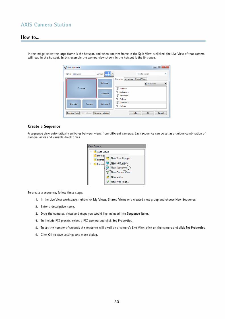
In the image below the large frame is the hotspot, and when another frame in the Split View is clicked, the Live View of that camerawill load in the hotspot. In this example the camera view shown in the hotspot is the Entrance.
Create a Sequence
A sequence view automatically switches between views from different cameras. Each sequence can be set as a unique combination ofcamera views and variable dwell times.
To create a sequence, follow these steps:
1. In the Live View workspace, right-click My Views, Shared Views or a created view group and choose New Sequence.
2. Enter a descriptive name.
3. Drag the cameras, views and maps you would like included into Sequence Items.
4. To include PTZ presets, select a PTZ camera and click Set Properties.
5. To set the number of seconds the sequence will dwell on a camera’s Live View, click on the camera and click Set Properties.
6. Click OK to save settings and close dialog.
33
AXIS Camera Station
How to...
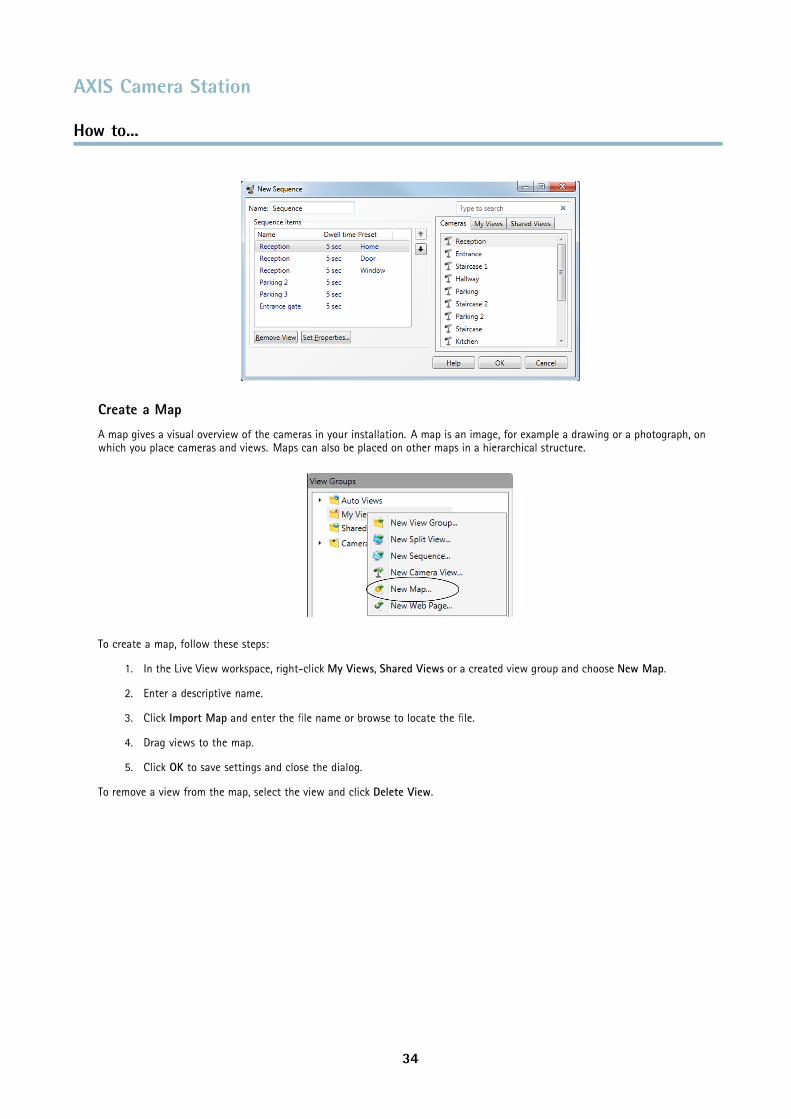
Create a Map
A map gives a visual overview of the cameras in your installation. A map is an image, for example a drawing or a photograph, onwhich you place cameras and views. Maps can also be placed on other maps in a hierarchical structure.
To create a map, follow these steps:
1. In the Live View workspace, right-click My Views, Shared Views or a created view group and choose New Map.
2. Enter a descriptive name.
3. Click Import Map and enter the file name or browse to locate the file.
4. Drag views to the map.
5. Click OK to save settings and close the dialog.
To remove a view from the map, select the view and click Delete View.
34
AXIS Camera Station
How to...
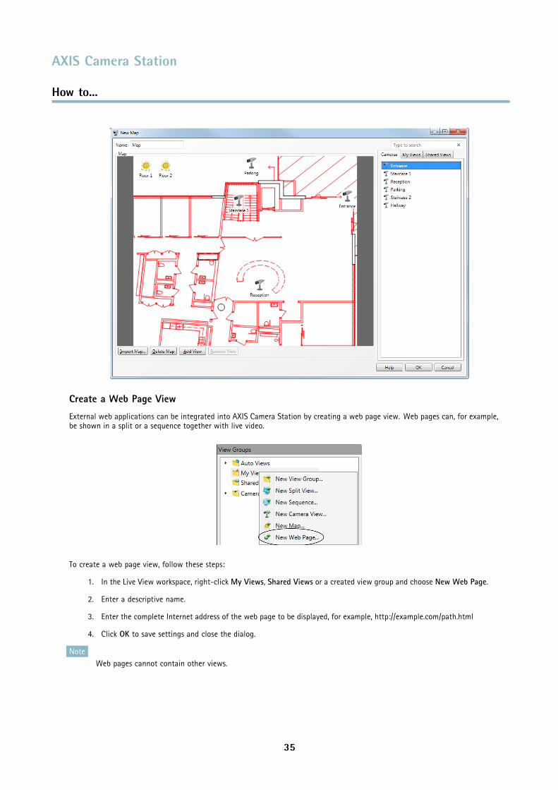
Create a Web Page View
External web applications can be integrated into AXIS Camera Station by creating a web page view. Web pages can, for example,be shown in a split or a sequence together with live video.
To create a web page view, follow these steps:
1. In the Live View workspace, right-click My Views, Shared Views or a created view group and choose New Web Page.
2. Enter a descriptive name.
3. Enter the complete Internet address of the web page to be displayed, for example, http://example.com/path.html
4. Click OK to save settings and close the dialog.
NoteWeb pages cannot contain other views.
35
AXIS Camera Station
How to...
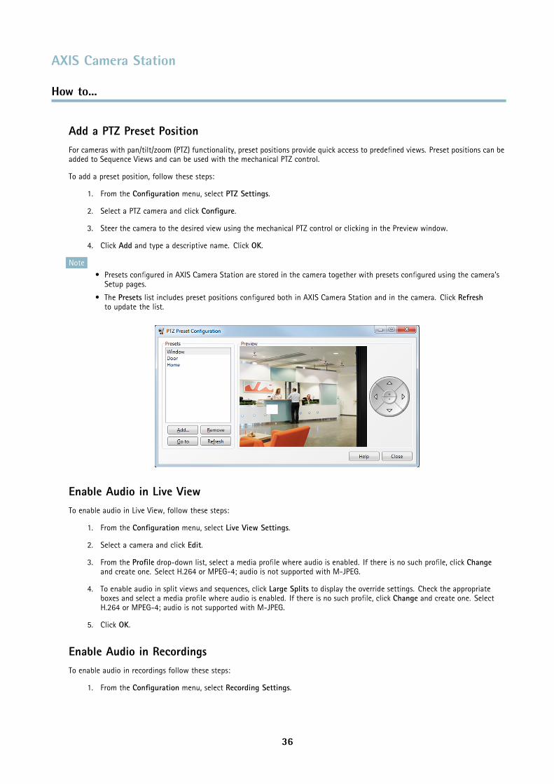
Add a PTZ Preset PositionFor cameras with pan/tilt/zoom (PTZ) functionality, preset positions provide quick access to predefined views. Preset positions can beadded to Sequence Views and can be used with the mechanical PTZ control.
To add a preset position, follow these steps:
1. From the Configuration menu, select PTZ Settings.
2. Select a PTZ camera and click Configure.
3. Steer the camera to the desired view using the mechanical PTZ control or clicking in the Preview window.
4. Click Add and type a descriptive name. Click OK.
Note• Presets configured in AXIS Camera Station are stored in the camera together with presets configured using the camera’s
Setup pages.
• The Presets list includes preset positions configured both in AXIS Camera Station and in the camera. Click Refreshto update the list.
Enable Audio in Live ViewTo enable audio in Live View, follow these steps:
1. From the Configuration menu, select Live View Settings.
2. Select a camera and click Edit.
3. From the Profile drop-down list, select a media profile where audio is enabled. If there is no such profile, click Changeand create one. Select H.264 or MPEG-4; audio is not supported with M-JPEG.
4. To enable audio in split views and sequences, click Large Splits to display the override settings. Check the appropriateboxes and select a media profile where audio is enabled. If there is no such profile, click Change and create one. SelectH.264 or MPEG-4; audio is not supported with M-JPEG.
5. Click OK.
Enable Audio in RecordingsTo enable audio in recordings follow these steps:
1. From the Configuration menu, select Recording Settings.
36
AXIS Camera Station
How to...
2. Select a camera and click Continuous, Motion Detection or Manual.
3. From the Profile drop-down list, select a media profile where audio is enabled. If there is no such profile, click Changeand create one. Select H.264 or MPEG-4; audio is not supported with M-JPEG.
4. Click OK.
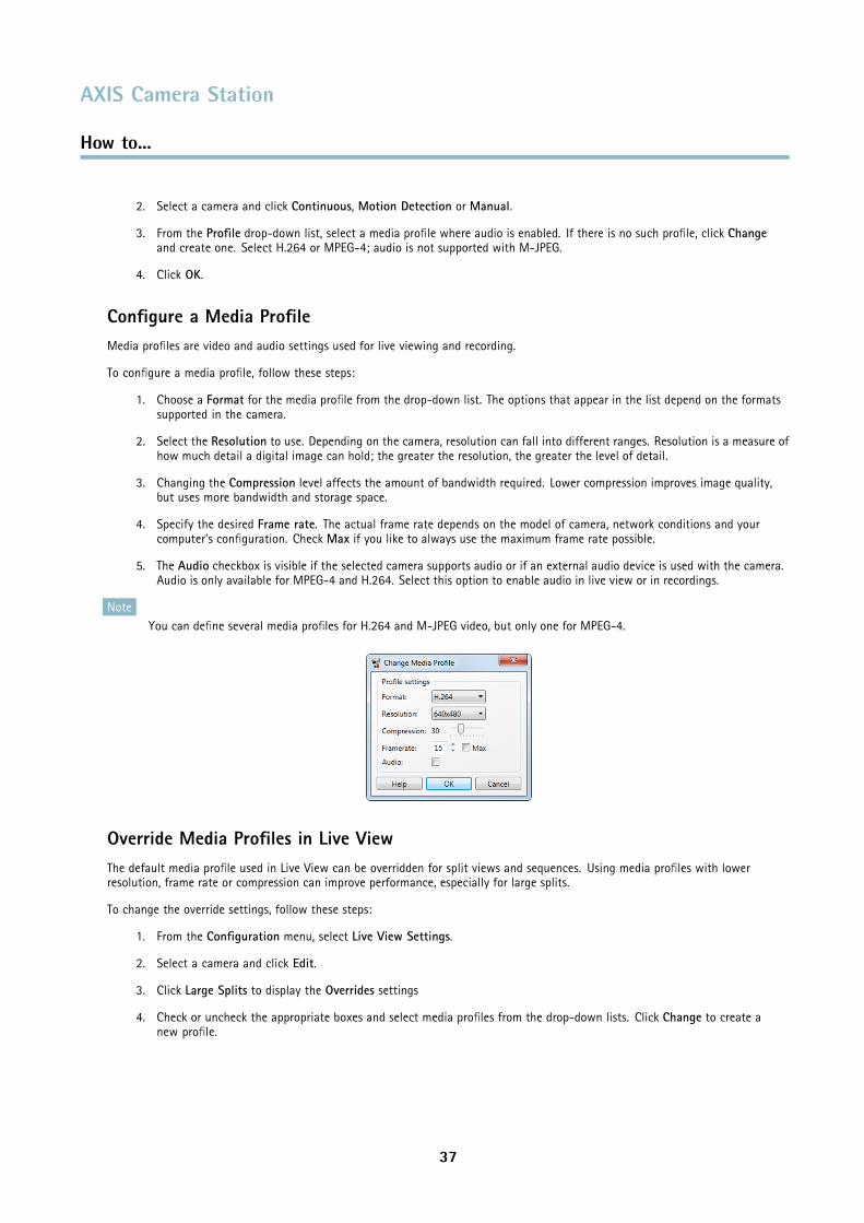
Configure a Media ProfileMedia profiles are video and audio settings used for live viewing and recording.
To configure a media profile, follow these steps:
1. Choose a Format for the media profile from the drop-down list. The options that appear in the list depend on the formatssupported in the camera.
2. Select the Resolution to use. Depending on the camera, resolution can fall into different ranges. Resolution is a measure ofhow much detail a digital image can hold; the greater the resolution, the greater the level of detail.
3. Changing the Compression level affects the amount of bandwidth required. Lower compression improves image quality,but uses more bandwidth and storage space.
4. Specify the desired Frame rate. The actual frame rate depends on the model of camera, network conditions and yourcomputer’s configuration. Check Max if you like to always use the maximum frame rate possible.
5. The Audio checkbox is visible if the selected camera supports audio or if an external audio device is used with the camera.Audio is only available for MPEG-4 and H.264. Select this option to enable audio in live view or in recordings.
NoteYou can define several media profiles for H.264 and M-JPEG video, but only one for MPEG-4.
Override Media Profiles in Live ViewThe default media profile used in Live View can be overridden for split views and sequences. Using media profiles with lowerresolution, frame rate or compression can improve performance, especially for large splits.
To change the override settings, follow these steps:
1. From the Configuration menu, select Live View Settings.
2. Select a camera and click Edit.
3. Click Large Splits to display the Overrides settings
4. Check or uncheck the appropriate boxes and select media profiles from the drop-down lists. Click Change to create anew profile.
37
AXIS Camera Station
How to...
Use Audio from an Auxiliary DeviceAudio from an auxiliary device (for example AXIS P8221 Network I/O Audio Module) can be used together with live or recordedvideo from a network camera.
Follow these steps:
1. Add the auxiliary device to AXIS Camera Station, see Add Auxiliary Devices, on page 26.
2. Add the camera to AXIS Camera Station, see Add Cameras and Video Encoders, on page 24.
3. From the Configuration menu, select Add/Edit Cameras.
4. Select the camera and click Edit.
5. Select the auxiliary device from the External audio drop-down list.
6. Click OK.
7. Enable audio in the live view or recording settings, see Enable Audio in Live View, on page 36 and Enable Audio in Recordings,on page 36.
Add Inputs and OutputsExternal devices such as window sensors, glass break detectors or PIRs (Passive Infrared Detector) can be connected to camera inputsand used for triggering alarms, recordings or messages. An output’s main function is to trigger external devices such as a door relaythat controls door locks, or an alarm siren. For more information about input/output ports, refer to the camera's User Manual.
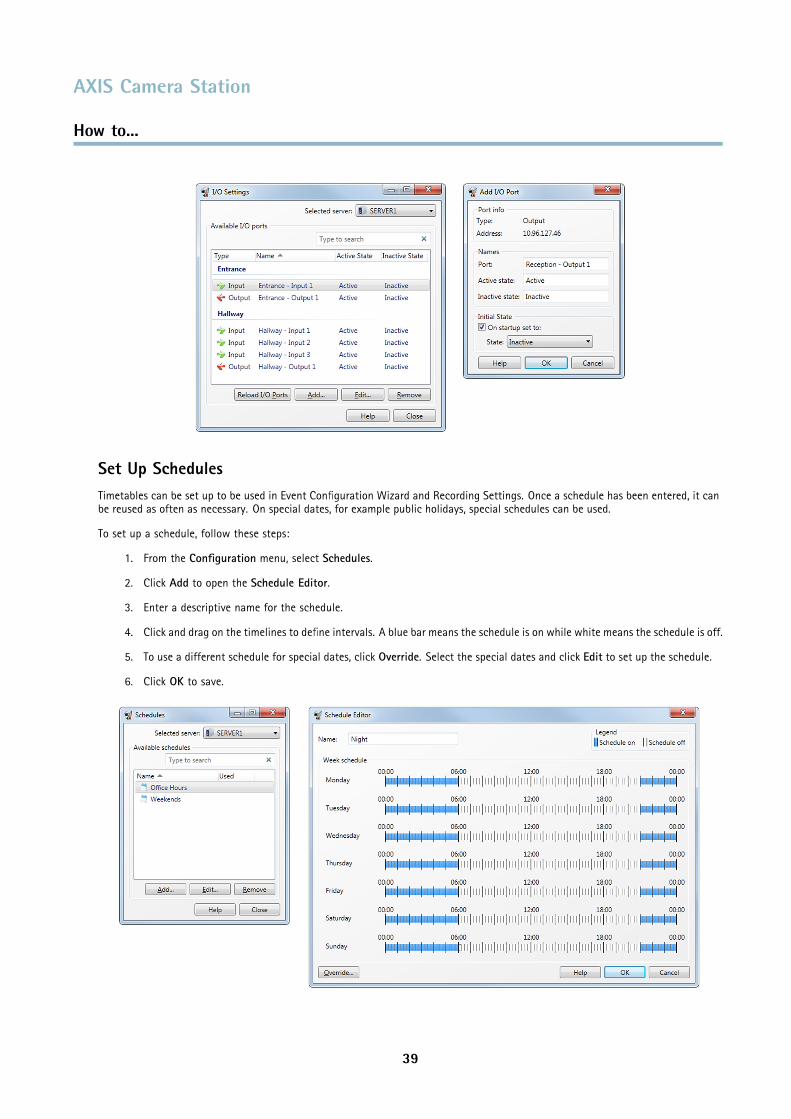
To add an I/O port to AXIS Camera Station, follow these steps:
1. From the Configuration menu, open I/O Settings.
2. Click Add to open a dialog with list of available I/O ports in existing devices.
3. Click to select the desired input or output port.
4. Click OK. The Add I/O Port dialog opens.
5. Enter a descriptive name for the port and for the active and inactive states. The names will appear under Logs, I/OMonitoring dialog and Event Configuration Wizard. Refer to the camera’s User Manual about how the I/O ports were definedfor setting descriptive names to the active/inactive states.
6. For output ports, check On startup set to to set the initial state of the output port. Choose the initial state of the Outputport from the drop-down list.
7. Click OK to save settings.
NoteIf more than one port is selected, the Add I/O Port dialog will not open. The ports will be added using default values.
Output ports can be set to an initial state upon startup and when AXIS Camera Station establishes contact with the camera.
38
AXIS Camera Station
How to...
Set Up SchedulesTimetables can be set up to be used in Event Configuration Wizard and Recording Settings. Once a schedule has been entered, it canbe reused as often as necessary. On special dates, for example public holidays, special schedules can be used.
To set up a schedule, follow these steps:
1. From the Configuration menu, select Schedules.
2. Click Add to open the Schedule Editor.
3. Enter a descriptive name for the schedule.
4. Click and drag on the timelines to define intervals. A blue bar means the schedule is on while white means the schedule is off.
5. To use a different schedule for special dates, click Override. Select the special dates and click Edit to set up the schedule.
6. Click OK to save.
39
AXIS Camera Station
How to...
Send E-Mail Notification on System AlarmA system alarm occurs when connection to a device is lost, when access to a recording disk is denied, when a recording disk is full, onrecording errors, etc. An e-mail notification can be sent when a system alarm occurs.
To set up e-mail notification, follow these steps:
1. From the Configuration menu, open System Alarm
2. Check Send e-mail on system alarm to the following recipients.
3. Enter the e-mail addresses alarm messages should be sent to.
4. Under New recipient, choose if the address should be in the To, Cc or Bcc field of the e-mail and enter the e-mail address.
5. Click Add to enter the e-mail address into the Recipients box.
6. Click OK to save.
NoteTo send emails, an SMTP server must first be added. To add an SMTP server, select SMTP Servers from the Options menu.
Export RecordingsRecordings can be exported to a local disk, a network location or burned to a CD or DVD. Multiple recordings can be exported atthe same time.
Exported recordings are ASF files and can be played by, for example, AXIS File Player and Windows Media Player. AXIS File Player isfree software and can be included with the exported recordings. AXIS File Player can be run without computer administrator rights;no installation is required.
To export a recording, follow these steps:
1. In the Recordings workspace, select the recordings to be exported. To export a part of a recording, set a time intervalusing the selection start and end markers.
2. Open the Actions menu and select Export Selected Recordings.
3. Browse to the local disk or network location, or select Burn recordings to burn to a CD or DVD.
4. Optionally, select include setup file for decoders. Decoders must be installed to view H.264 and MPEG-4 video.
5. Optionally, select Create playlist to create a playlist for Windows Media Player.
6. Optionally, select Include AXIS File Player to include AXIS File Player with the exported recordings.
7. Optionally, add a digital signature.
8. Click OK.
Note• The selection start and end markers are available in the Playback and Timeline tabs.
• Recording export can also be scheduled. Open the Configuration menu and select Scheduled Recording Export.
Upgrade FirmwareFirmware is software that determines the functionality of electronic devices. Always use the latest firmware to ensure that yourdevice has the latest functionality and improvements.
With an Internet connection, you can check for updates and download firmware directly via AXIS Camera Station Client. If theclient is installed on a computer without access to the Internet, new firmware can instead be imported from a file (for example on ahard disk or memory stick).
40
AXIS Camera Station
How to...
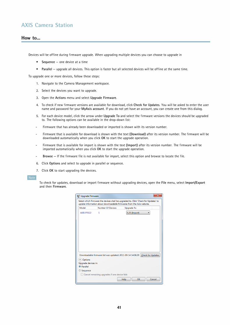
Devices will be offline during firmware upgrade. When upgrading multiple devices you can choose to upgrade in
• Sequence — one device at a time
• Parallel — upgrade all devices. This option is faster but all selected devices will be offline at the same time.
To upgrade one or more devices, follow these steps:
1. Navigate to the Camera Management workspace.
2. Select the devices you want to upgrade.
3. Open the Actions menu and select Upgrade Firmware.
4. To check if new firmware versions are available for download, click Check for Updates. You will be asked to enter the username and password for your MyAxis account. If you do not yet have an account, you can create one from this dialog.
5. For each device model, click the arrow under Upgrade To and select the firmware versions the devices should be upgradedto. The following options can be available in the drop-down list:
- Firmware that has already been downloaded or imported is shown with its version number.
- Firmware that is available for download is shown with the text (Download) after its version number. The firmware will bedownloaded automatically when you click OK to start the upgrade operation.
- Firmware that is available for import is shown with the text (Import) after its version number. The firmware will beimported automatically when you click OK to start the upgrade operation.
- Browse — If the firmware file is not available for import, select this option and browse to locate the file.
6. Click Options and select to upgrade in parallel or sequence.
7. Click OK to start upgrading the devices.
NoteTo check for updates, download or import firmware without upgrading devices, open the File menu, select Import/Exportand then Firmware.
41
AXIS Camera Station
How to...
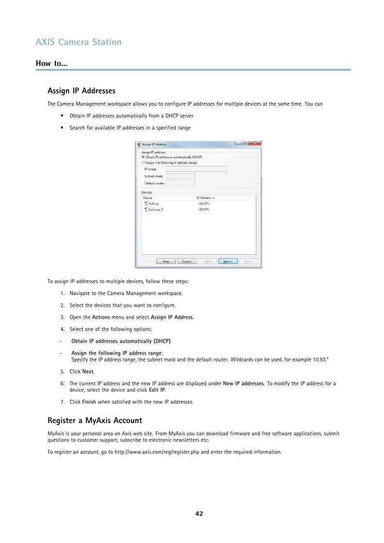
Assign IP AddressesThe Camera Management workspace allows you to configure IP addresses for multiple devices at the same time. You can
• Obtain IP addresses automatically from a DHCP server
• Search for available IP addresses in a specified range
To assign IP addresses to multiple devices, follow these steps:
1. Navigate to the Camera Management workspace.
2. Select the devices that you want to configure.
3. Open the Actions menu and select Assign IP Address.
4. Select one of the following options:
- Obtain IP addresses automatically (DHCP)
- Assign the following IP address range:Specify the IP address range, the subnet mask and the default router. Wildcards can be used, for example 10.93.*
5. Click Next.
6. The current IP address and the new IP address are displayed under New IP addresses. To modify the IP address for adevice, select the device and click Edit IP.
7. Click Finish when satisfied with the new IP addresses.
Register a MyAxis AccountMyAxis is your personal area on Axis web site. From MyAxis you can download firmware and free software applications, submitquestions to customer support, subscribe to electronic newsletters etc.
To register an account, go to http://www.axis.com/reg/register.php and enter the required information.
42
AXIS Camera Station
Event Configuration Wizard
Event Configuration Wizard
Event Configuration Wizard helps you set up rules for triggers and actions in AXIS Camera Station. By setting up a rule you can assignactions to triggers; for instance when motion is detected, a siren will sound and recording will begin on designated cameras.
Triggers are classified as:
Motion Detection A motion detection event is triggered when an Axis camera detects motion within its defined area.Detection is performed by the camera which means no processing load to AXIS Camera Station.
Active Tampering Alarm An active tampering alarm occurs when the camera is repositioned or when the lens is covered,sprayed or severely defocused.
AXIS Cross Line Detection An AXIS Cross Line Detection event is triggered when a camera detects moving objects thatcross a virtual line. See notes below.
System Event and Error A system event and error triggers on recording errors, when connection to a camera is lost, accessto the recording disk is denied or when the recording disk is full.
Advanced triggers:
Input/Output Input/Output is when a camera's I/O port receives a signal from an external device, such as adoorbell, smoke detector or switch.
Device Event Trigger The device event trigger is intended for advanced users and can be used if no other trigger isapplicable. This trigger allows you to select any event available in a camera, for example eventsfrom applications uploaded to cameras with support for AXIS Camera Application Platform. Forinformation about available events, refer to the camera’s help files.Actions are classified as:
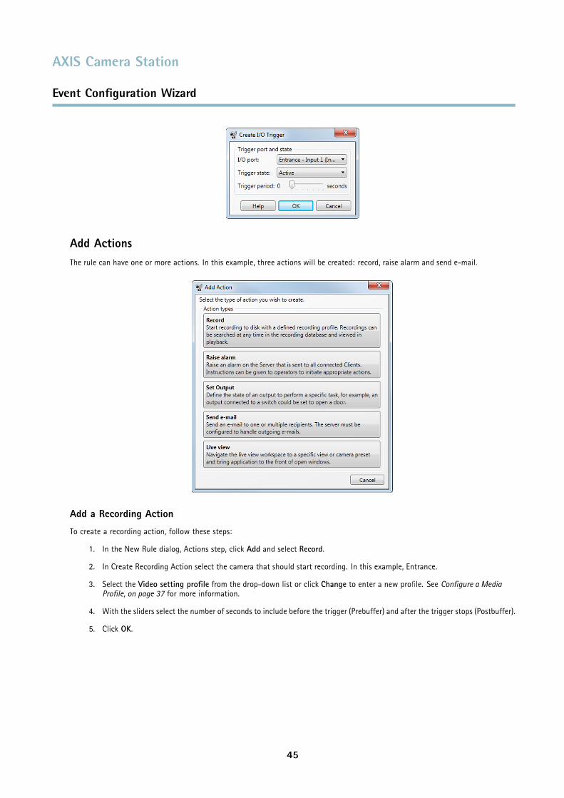
Record Start a recording from a specified camera.
Raise alarm Send an alarm to all connected clients. An alarm procedure can be included.
Set Output Set the state of an output port. This can be used to control an external device connected to the port.
Send e-mail Send an e-mail notification to one or more recipients. Snapshots can be attached.
Live view Open a specific view, camera or PTZ preset position.
Note• I/O ports must be added to AXIS Camera Station before being used in the Event Configuration Wizard. See Add Inputs
and Outputs, on page 38.
• Active Tampering Alarms are supported by products with tampering capabilities and firmware 5.11 and later.
• AXIS Cross Line Detection is an application that must be uploaded to the network camera or video encoder. The applicationcan be uploaded to products with support for AXIS Camera Application Platform. For more information, refer to AXISCross Line Detection User’s Guide.
• Device event triggers are supported by products with firmware 5.40 and later.
Create a RuleThe example described in this chapter demonstrates how to use the Event Configuration Wizard to create a rule that starts arecording, raises an alarm and sends an e-mail each time a door is opened. The door switch is connected to an input port of thecamera monitoring the door.
Start by creating a new rule:
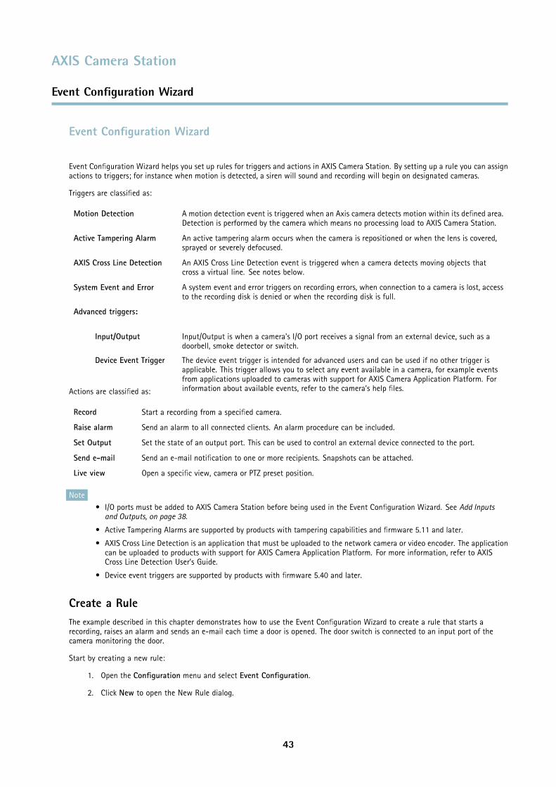
1. Open the Configuration menu and select Event Configuration.
2. Click New to open the New Rule dialog.
43
AXIS Camera Station
Event Configuration Wizard
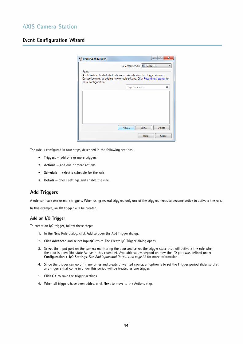
The rule is configured in four steps, described in the following sections:
• Triggers — add one or more triggers
• Actions — add one or more actions
• Schedule — select a schedule for the rule
• Details — check settings and enable the rule
Add TriggersA rule can have one or more triggers. When using several triggers, only one of the triggers needs to become active to activate the rule.
In this example, an I/O trigger will be created.
Add an I/O Trigger
To create an I/O trigger, follow these steps:
1. In the New Rule dialog, click Add to open the Add Trigger dialog.
2. Click Advanced and select Input/Output. The Create I/O Trigger dialog opens.
3. Select the input port on the camera monitoring the door and select the trigger state that will activate the rule whenthe door is open (the state Active in this example). Available values depend on how the I/O port was defined underConfiguration > I/O Settings. See Add Inputs and Outputs, on page 38 for more information.
4. Since the trigger can go off many times and create unwanted events, an option is to set the Trigger period slider so thatany triggers that come in under this period will be treated as one trigger.
5. Click OK to save the trigger settings.
6. When all triggers have been added, click Next to move to the Actions step.
44
AXIS Camera Station
Event Configuration Wizard
Add ActionsThe rule can have one or more actions. In this example, three actions will be created: record, raise alarm and send e-mail.
Add a Recording Action
To create a recording action, follow these steps:
1. In the New Rule dialog, Actions step, click Add and select Record.
2. In Create Recording Action select the camera that should start recording. In this example, Entrance.
3. Select the Video setting profile from the drop-down list or click Change to enter a new profile. See Configure a MediaProfile, on page 37 for more information.
4. With the sliders select the number of seconds to include before the trigger (Prebuffer) and after the trigger stops (Postbuffer).
5. Click OK.
45
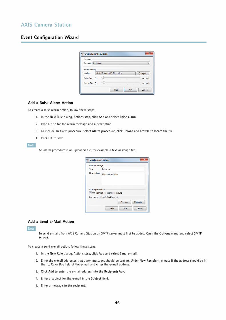
AXIS Camera Station
Event Configuration Wizard
Add a Raise Alarm Action
To create a raise alarm action, follow these steps:
1. In the New Rule dialog, Actions step, click Add and select Raise alarm.
2. Type a title for the alarm message and a description.
3. To include an alarm procedure, select Alarm procedure, click Upload and browse to locate the file.
4. Click OK to save.
NoteAn alarm procedure is an uploaded file, for example a text or image file.
Add a Send E-Mail Action
NoteTo send e-mails from AXIS Camera Station an SMTP server must first be added. Open the Options menu and select SMTPservers.
To create a send e-mail action, follow these steps:
1. In the New Rule dialog, Actions step, click Add and select Send e-mail.
2. Enter the e-mail addresses that alarm messages should be sent to. Under New Recipient, choose if the address should be inthe To, Cc or Bcc field of the e-mail and enter the e-mail address.
3. Click Add to enter the e-mail address into the Recipients box.
4. Enter a subject for the e-mail in the Subject field.
5. Enter a message to the recipient.
46
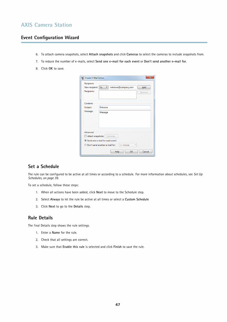
AXIS Camera Station
Event Configuration Wizard
6. To attach camera snapshots, select Attach snapshots and click Cameras to select the cameras to include snapshots from.
7. To reduce the number of e-mails, select Send one e-mail for each event or Don’t send another e-mail for.
8. Click OK to save.
Set a ScheduleThe rule can be configured to be active at all times or according to a schedule. For more information about schedules, see Set UpSchedules, on page 39.
To set a schedule, follow these steps:
1. When all actions have been added, click Next to move to the Schedule step.
2. Select Always to let the rule be active at all times or select a Custom Schedule
3. Click Next to go to the Details step.
Rule DetailsThe final Details step shows the rule settings.
1. Enter a Name for the rule.
2. Check that all settings are correct.
3. Make sure that Enable this rule is selected and click Finish to save the rule.
47
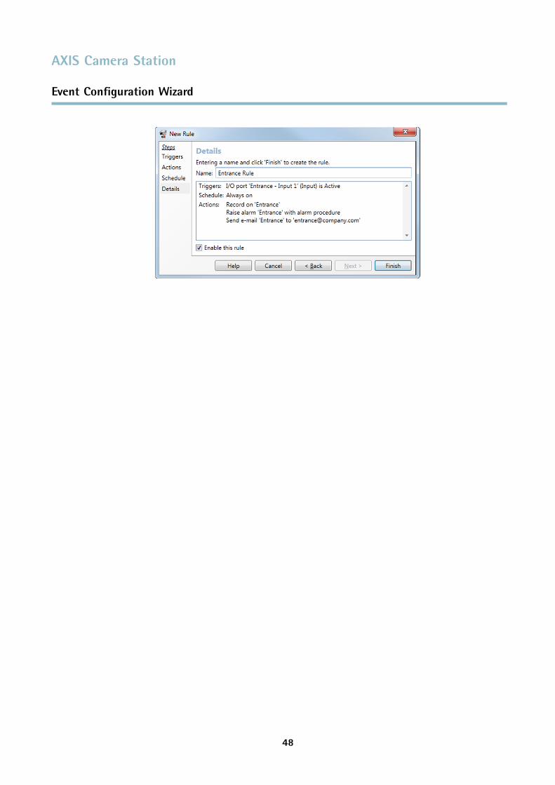
AXIS Camera Station
Event Configuration Wizard
48
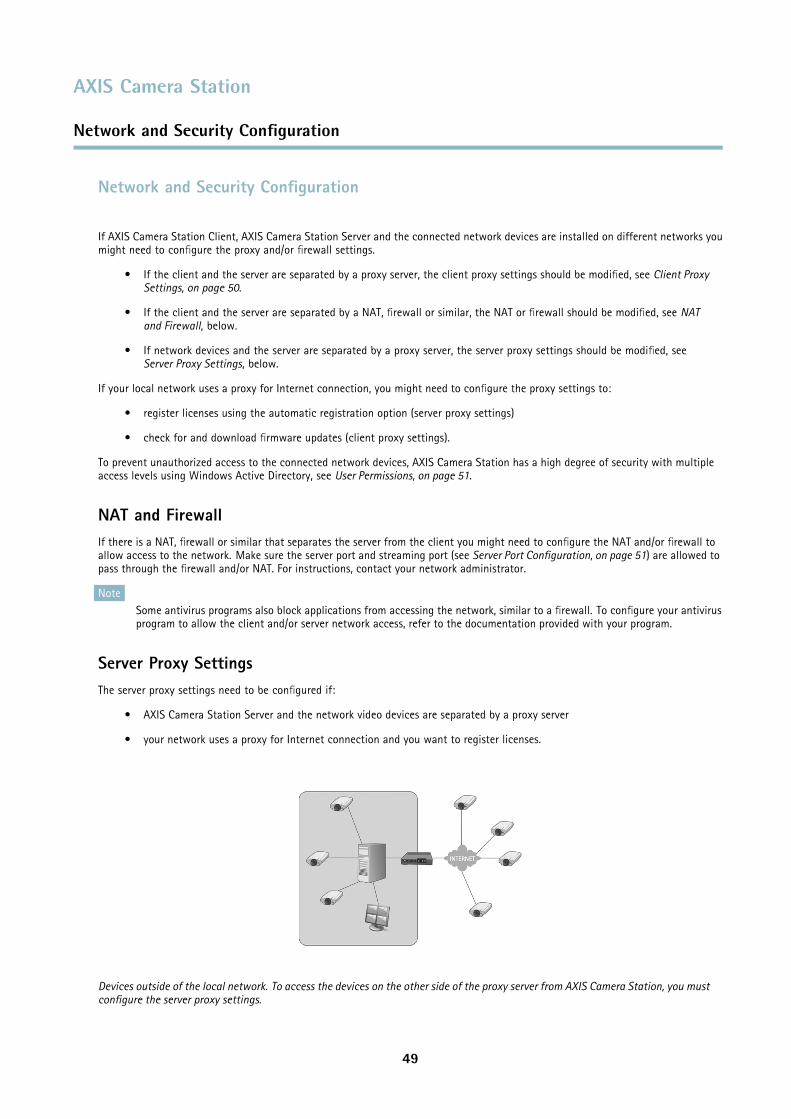
AXIS Camera Station
Network and Security Configuration
Network and Security Configuration
If AXIS Camera Station Client, AXIS Camera Station Server and the connected network devices are installed on different networks youmight need to configure the proxy and/or firewall settings.
• If the client and the server are separated by a proxy server, the client proxy settings should be modified, see Client ProxySettings, on page 50.
• If the client and the server are separated by a NAT, firewall or similar, the NAT or firewall should be modified, see NATand Firewall, below.
• If network devices and the server are separated by a proxy server, the server proxy settings should be modified, seeServer Proxy Settings, below.
If your local network uses a proxy for Internet connection, you might need to configure the proxy settings to:
• register licenses using the automatic registration option (server proxy settings)
• check for and download firmware updates (client proxy settings).
To prevent unauthorized access to the connected network devices, AXIS Camera Station has a high degree of security with multipleaccess levels using Windows Active Directory, see User Permissions, on page 51.
NAT and FirewallIf there is a NAT, firewall or similar that separates the server from the client you might need to configure the NAT and/or firewall toallow access to the network. Make sure the server port and streaming port (see Server Port Configuration, on page 51) are allowed topass through the firewall and/or NAT. For instructions, contact your network administrator.
NoteSome antivirus programs also block applications from accessing the network, similar to a firewall. To configure your antivirusprogram to allow the client and/or server network access, refer to the documentation provided with your program.
Server Proxy SettingsThe server proxy settings need to be configured if:
• AXIS Camera Station Server and the network video devices are separated by a proxy server
• your network uses a proxy for Internet connection and you want to register licenses.
Devices outside of the local network. To access the devices on the other side of the proxy server from AXIS Camera Station, you mustconfigure the server proxy settings.
49
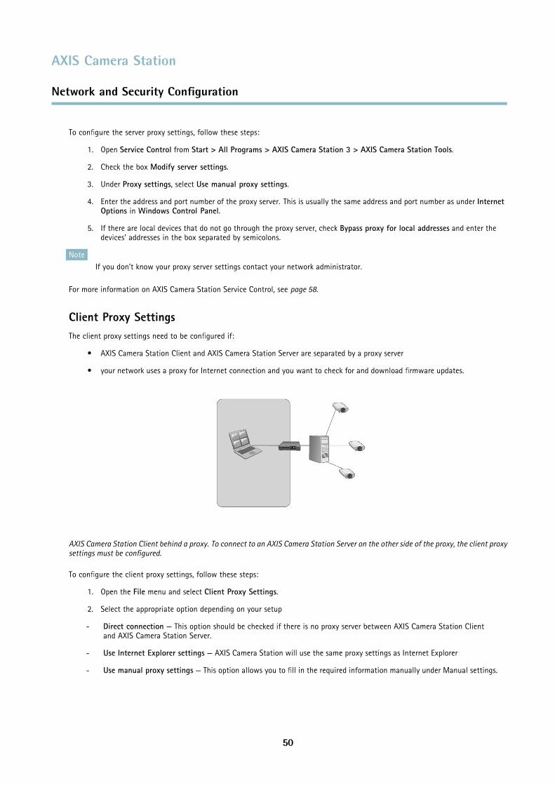
AXIS Camera Station
Network and Security Configuration
To configure the server proxy settings, follow these steps:
1. Open Service Control from Start > All Programs > AXIS Camera Station 3 > AXIS Camera Station Tools.
2. Check the box Modify server settings.
3. Under Proxy settings, select Use manual proxy settings.
4. Enter the address and port number of the proxy server. This is usually the same address and port number as under InternetOptions in Windows Control Panel.
5. If there are local devices that do not go through the proxy server, check Bypass proxy for local addresses and enter thedevices’ addresses in the box separated by semicolons.
NoteIf you don’t know your proxy server settings contact your network administrator.
For more information on AXIS Camera Station Service Control, see page 58.
Client Proxy SettingsThe client proxy settings need to be configured if:
• AXIS Camera Station Client and AXIS Camera Station Server are separated by a proxy server
• your network uses a proxy for Internet connection and you want to check for and download firmware updates.
AXIS Camera Station Client behind a proxy. To connect to an AXIS Camera Station Server on the other side of the proxy, the client proxysettings must be configured.
To configure the client proxy settings, follow these steps:
1. Open the File menu and select Client Proxy Settings.
2. Select the appropriate option depending on your setup
- Direct connection — This option should be checked if there is no proxy server between AXIS Camera Station Clientand AXIS Camera Station Server.
- Use Internet Explorer settings — AXIS Camera Station will use the same proxy settings as Internet Explorer
- Use manual proxy settings — This option allows you to fill in the required information manually under Manual settings.
50
AXIS Camera Station
Network and Security Configuration
3. If Manual settings was selected, enter the proxy server’s IP address/host name and port number. If there are local serversthat do not go through the proxy server, check Bypass proxy for local addresses and enter the servers’ addresses inthe box separated by semicolons.
Server Port ConfigurationThe ports 55752 (control) and 55753 (media streaming) are used on the AXIS Camera Station Server computer for communicationbetween the server and the AXIS Camera Station Client. If required, the ports can be changed from AXIS Camera Station ServiceControl, see AXIS Camera Station Service Control, on page 58.
User PermissionsUsing Windows Active Directory, a high level of security can be implemented in AXIS Camera Station when granting user permissions.Before users can be granted access to AXIS Camera Station, they must be added to the local computer or have an Active Directoryuser account.
A user can be granted access as an individual or as part of a group. In cases where a user is granted access as an individual he willretain this right plus receive the rights he receives as part of a group. For example, a user is given access to camera X as an individual.The user is also a member of a group. The group is given access to cameras Y and Z. The user then has access to cameras X, Y and Z.
Administrators of the computer on which the AXIS Camera Station Server is installed are automatically given administrator privilegesto AXIS Camera Station. It is not possible to change or remove the administrators group's privileges.
To configure user access rights, open the Configuration menu and select User Permissions.
Local Security
By default, local security is Disabled which means all users, who log onto AXIS Camera Station Server installed on the same computeras the AXIS Camera Station Client, will be given Administrator access. When local security is Enabled, access to AXIS Camera Stationis restricted to trusted users and groups for both remote and local clients. For remote clients, local security is always enabled.
To change the local security settings, open the Configuration menu, select User Permissions and click Security Settings.
Add a User or a Group
To add a user or a group, follow these steps:
1. Open the Configuration menu and select User Permissions.
2. Click Add to open the Add User/Group dialog.
3. Select the AXIS Camera Station Server or Domain. The available users and groups are listed under Available domainusers/groups. To narrow the list, select Users or Groups.
4. Select a user or group from the list and click Add to open the User/Group Privileges dialog.
5. Select an authority level for the user:
- Administrator - Full access to all functionality of AXIS Camera Station and added cameras.
- Operator - Full access to all functionality of AXIS Camera Station except Configuration pages, the camera managementworkspace and audit logs. Full access to selected cameras and I/O ports.
- Viewer - Access to selected Live Views and I/O ports.
6. Optionally, select the cameras and I/O ports that the operator or viewer should have access to. Click Advanced to giveaccess to individual features.
51
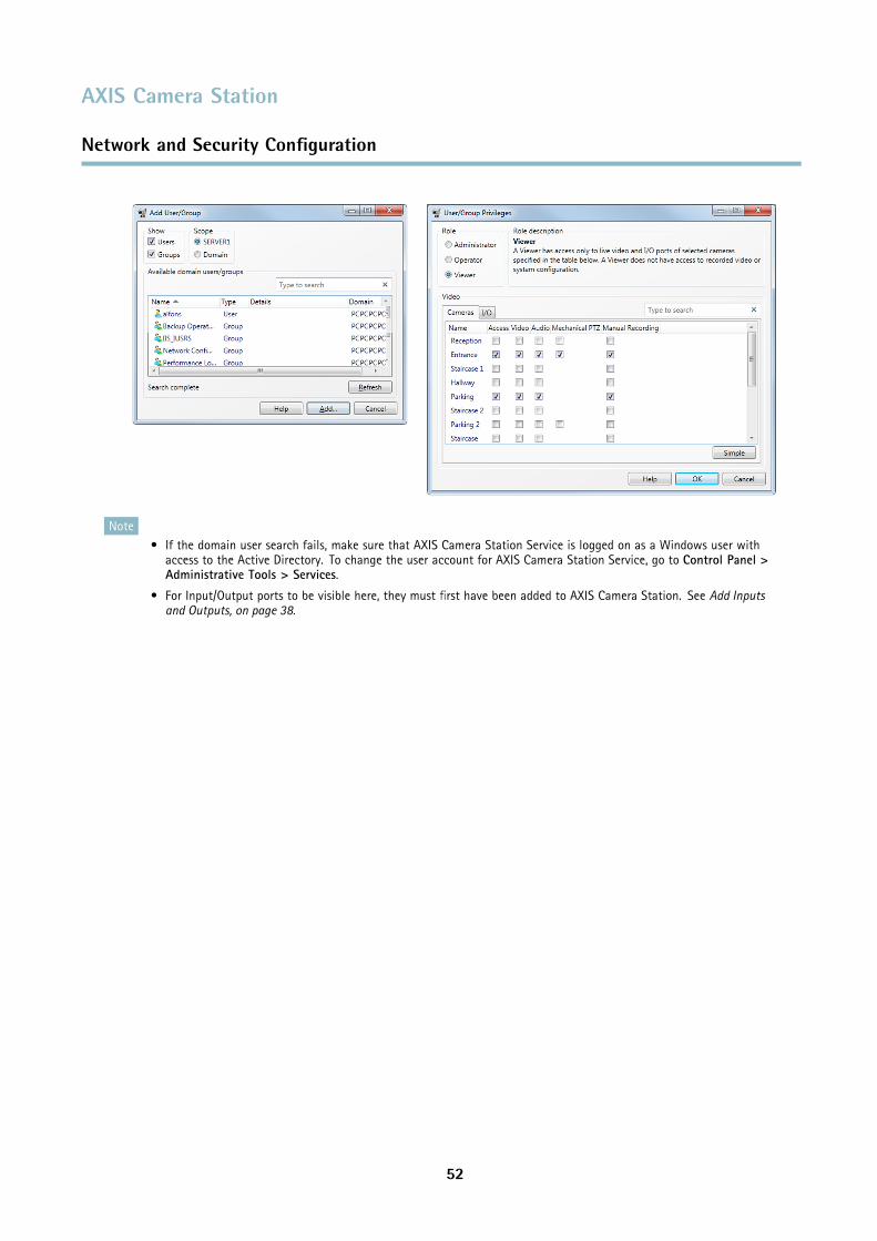
AXIS Camera Station
Network and Security Configuration
Note• If the domain user search fails, make sure that AXIS Camera Station Service is logged on as a Windows user with
access to the Active Directory. To change the user account for AXIS Camera Station Service, go to Control Panel >Administrative Tools > Services.
• For Input/Output ports to be visible here, they must first have been added to AXIS Camera Station. See Add Inputsand Outputs, on page 38.
52
AXIS Camera Station
Input Devices
Input Devices
The following input devices can be used with AXIS Camera Station:
• AXIS T8311 Video Surveillance Joystick
• AXIS T8312 Video Surveillance Keypad
• AXIS T8313 Video Surveillance Jog Dial
• AXIS 295 Video Surveillance Joystick
HotkeysHotkeys give quick access to commonly used actions. A hotkey can be
• a keyboard combination
• a keypad combination
• a joystick button
• a jog dial button
To display a list of all currently assigned hotkeys for all input devices, open Assigned hotkeys from the Help menu.
Hotkeys defined as Global are available in all workspaces; other hotkeys are available in only one workspace.
To add, edit and remove hotkeys, open Hotkeys from the Options menu. Click Restore defaults to reset the hotkey configuration todefault.
AXIS T8311 Video Surveillance JoystickAXIS T8311 Video Surveillance Joystick is a USB device that can used
• to pan, tilt and zoom in the camera view (cameras with mechanical PTZ only)
• as a computer mouse
Connect the joystick before you start AXIS Camera Station. The joystick is detected and installed automatically.
NoteIf the joystick is connected after AXIS Camera Station has been started, click Refresh in the Live View workspace.
You can configure the joystick to toggle between the PTZ and mouse modes. Go top Options > Hotkeys, select Joystick and thenAdd. Select Global, Turn on/off joystick PTZ controlling and assign an unused joystick button.
The table below lists the default configuration for joystick hotkeys.
53
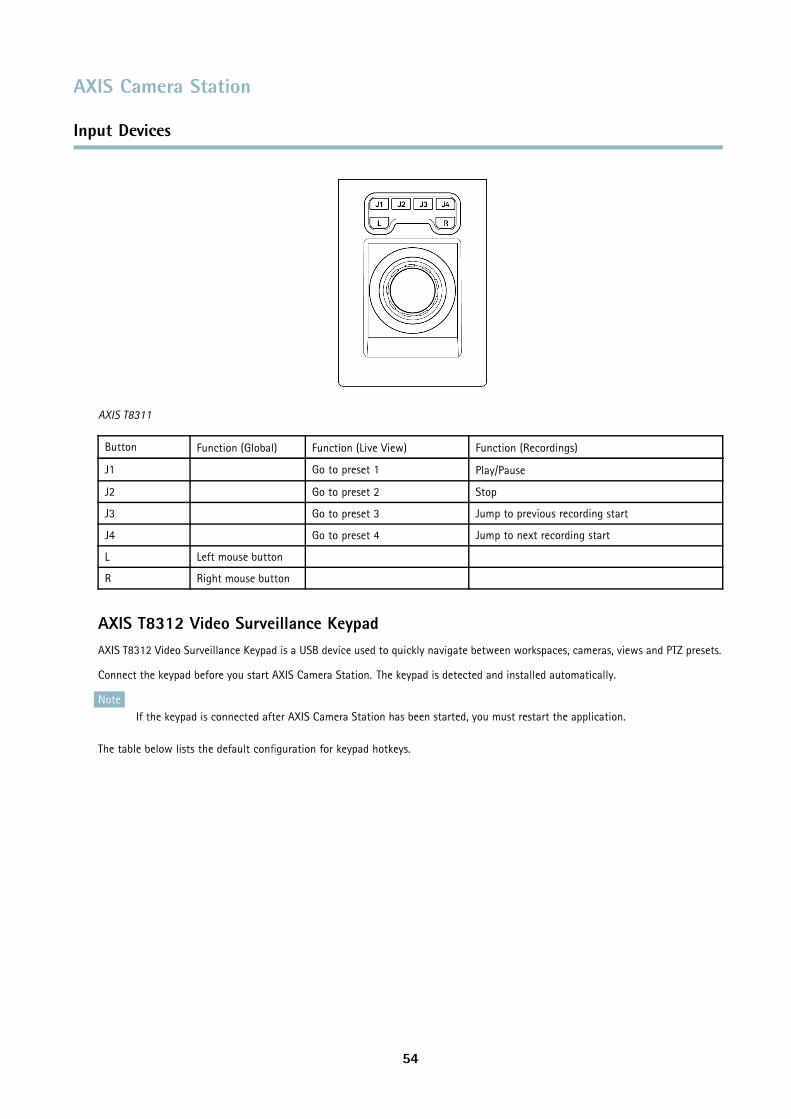
AXIS Camera Station
Input Devices
AXIS T8311
Button Function (Global) Function (Live View) Function (Recordings)
J1 Go to preset 1 Play/Pause
J2 Go to preset 2 Stop
J3 Go to preset 3 Jump to previous recording start
J4 Go to preset 4 Jump to next recording start
L Left mouse button
R Right mouse button
AXIS T8312 Video Surveillance KeypadAXIS T8312 Video Surveillance Keypad is a USB device used to quickly navigate between workspaces, cameras, views and PTZ presets.
Connect the keypad before you start AXIS Camera Station. The keypad is detected and installed automatically.
NoteIf the keypad is connected after AXIS Camera Station has been started, you must restart the application.
The table below lists the default configuration for keypad hotkeys.
54
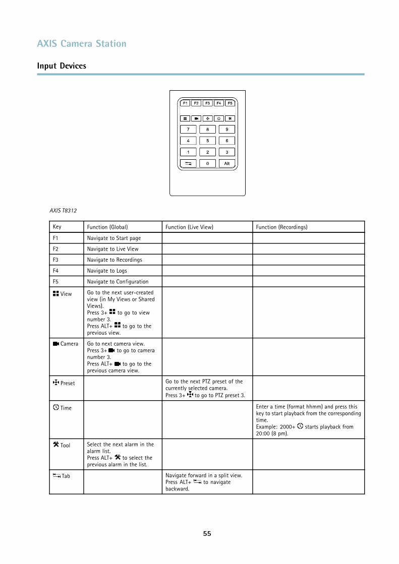
AXIS Camera Station
Input Devices
AXIS T8312
Key Function (Global) Function (Live View) Function (Recordings)
F1 Navigate to Start page
F2 Navigate to Live View
F3 Navigate to Recordings
F4 Navigate to Logs
F5 Navigate to Configuration
View Go to the next user-createdview (in My Views or SharedViews).Press 3+ to go to viewnumber 3.Press ALT+ to go to theprevious view.
Camera Go to next camera view.Press 3+ to go to cameranumber 3.Press ALT+ to go to theprevious camera view.
Preset Go to the next PTZ preset of thecurrently selected camera.Press 3+ to go to PTZ preset 3.
Time Enter a time (format hhmm) and press thiskey to start playback from the correspondingtime.Example: 2000+ starts playback from20:00 (8 pm).
Tool Select the next alarm in thealarm list.Press ALT+ to select theprevious alarm in the list.
Tab Navigate forward in a split view.Press ALT+ to navigatebackward.
55
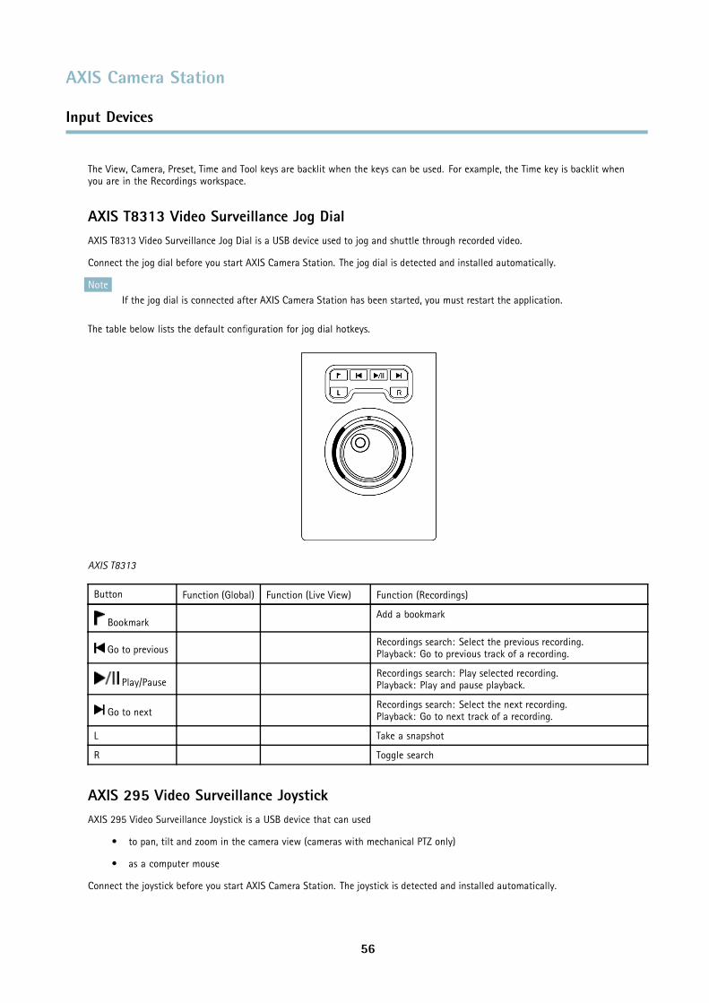
AXIS Camera Station
Input Devices
The View, Camera, Preset, Time and Tool keys are backlit when the keys can be used. For example, the Time key is backlit whenyou are in the Recordings workspace.
AXIS T8313 Video Surveillance Jog DialAXIS T8313 Video Surveillance Jog Dial is a USB device used to jog and shuttle through recorded video.
Connect the jog dial before you start AXIS Camera Station. The jog dial is detected and installed automatically.
NoteIf the jog dial is connected after AXIS Camera Station has been started, you must restart the application.
The table below lists the default configuration for jog dial hotkeys.
AXIS T8313
Button Function (Global) Function (Live View) Function (Recordings)
BookmarkAdd a bookmark
Go to previousRecordings search: Select the previous recording.Playback: Go to previous track of a recording.
Play/PauseRecordings search: Play selected recording.Playback: Play and pause playback.
Go to nextRecordings search: Select the next recording.Playback: Go to next track of a recording.
L Take a snapshot
R Toggle search
AXIS 295 Video Surveillance JoystickAXIS 295 Video Surveillance Joystick is a USB device that can used
• to pan, tilt and zoom in the camera view (cameras with mechanical PTZ only)
• as a computer mouse
Connect the joystick before you start AXIS Camera Station. The joystick is detected and installed automatically.
56
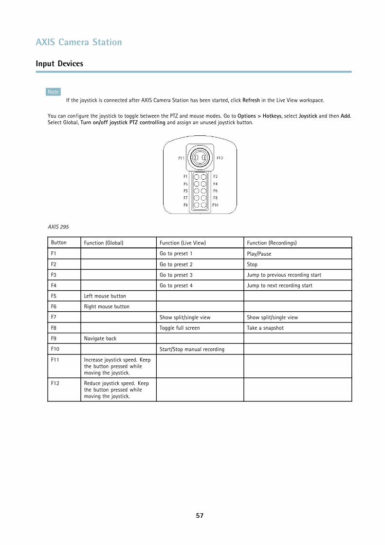
AXIS Camera Station
Input Devices
NoteIf the joystick is connected after AXIS Camera Station has been started, click Refresh in the Live View workspace.
You can configure the joystick to toggle between the PTZ and mouse modes. Go to Options > Hotkeys, select Joystick and then Add.Select Global, Turn on/off joystick PTZ controlling and assign an unused joystick button.
AXIS 295
Button Function (Global) Function (Live View) Function (Recordings)
F1 Go to preset 1 Play/Pause
F2 Go to preset 2 Stop
F3 Go to preset 3 Jump to previous recording start
F4 Go to preset 4 Jump to next recording start
F5 Left mouse button
F6 Right mouse button
F7 Show split/single view Show split/single view
F8 Toggle full screen Take a snapshot
F9 Navigate back
F10 Start/Stop manual recording
F11 Increase joystick speed. Keepthe button pressed whilemoving the joystick.
F12 Reduce joystick speed. Keepthe button pressed whilemoving the joystick.
57
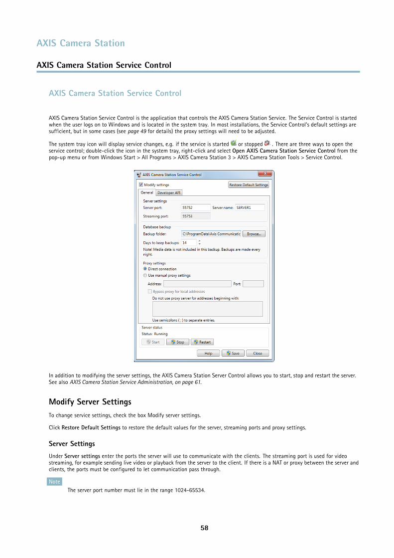
AXIS Camera Station
AXIS Camera Station Service Control
AXIS Camera Station Service Control
AXIS Camera Station Service Control is the application that controls the AXIS Camera Station Service. The Service Control is startedwhen the user logs on to Windows and is located in the system tray. In most installations, the Service Control’s default settings aresufficient, but in some cases (see page 49 for details) the proxy settings will need to be adjusted.
The system tray icon will display service changes, e.g. if the service is started or stopped . There are three ways to open theservice control; double-click the icon in the system tray, right-click and select Open AXIS Camera Station Service Control from thepop-up menu or from Windows Start > All Programs > AXIS Camera Station 3 > AXIS Camera Station Tools > Service Control.
In addition to modifying the server settings, the AXIS Camera Station Server Control allows you to start, stop and restart the server.See also AXIS Camera Station Service Administration, on page 61.
Modify Server SettingsTo change service settings, check the box Modify server settings.
Click Restore Default Settings to restore the default values for the server, streaming ports and proxy settings.
Server Settings
Under Server settings enter the ports the server will use to communicate with the clients. The streaming port is used for videostreaming, for example sending live video or playback from the server to the client. If there is a NAT or proxy between the server andclients, the ports must be configured to let communication pass through.
NoteThe server port number must lie in the range 1024-65534.
58
AXIS Camera Station
AXIS Camera Station Service Control
Once satisfied with the changes click Save. You will be prompted to restart the service for the changes to take effect.
Database Backup
The database stores information about configurations, recordings etc that is needed for AXIS Camera Station to work properly. Thedatabase is backed up every night. The backups are saved to a Backup folder which can be located on the local computer or thenetwork. To change the backup folder, click Browse and navigate to the desired location. The oldest backups will be deletedafter the number of days specified in Days to keep backups.
Note• The backup will be saved to the default location if it cannot be written to the folder specified, for example if the server
cannot access the folder. The default location is
Windows 7/Vista/Server 2008/Server 2003:C:\ProgramData\Axis Communications\AXIS Camera Station Server\backup
Windows XP:C:\Documents and Settings\All Users\Application Data\Axis Communications\AXIS Camera Station Server\backup
• The backup files are named acs_system_<date_time>.fdb and license_system_<date_time>.fdb
• Recordings are stored in the location specified in Configuration > Recording storage and not in the database, see Set UpRecording Storage, on page 30. Recordings should be backed up separately.
For information on how to restore the database, see Lost data, on page 66.
Proxy Settings
If there is a direct connection with the cameras in the system the default Direct connection radio button should be selected. IfAXIS Camera Station Server is behind a proxy server, and devices are outside the proxy server, modify the proxy settings manuallyby selecting Use manual proxy settings. The proxy settings entered here are generally the same as those entered in the InternetOptions in the Control Panel.
Check the box Bypass proxy for local addresses and enter local addresses or host names of local cameras where communication doesnot need to pass through the proxy server. For more information, see Server Proxy Settings, on page 49.
59
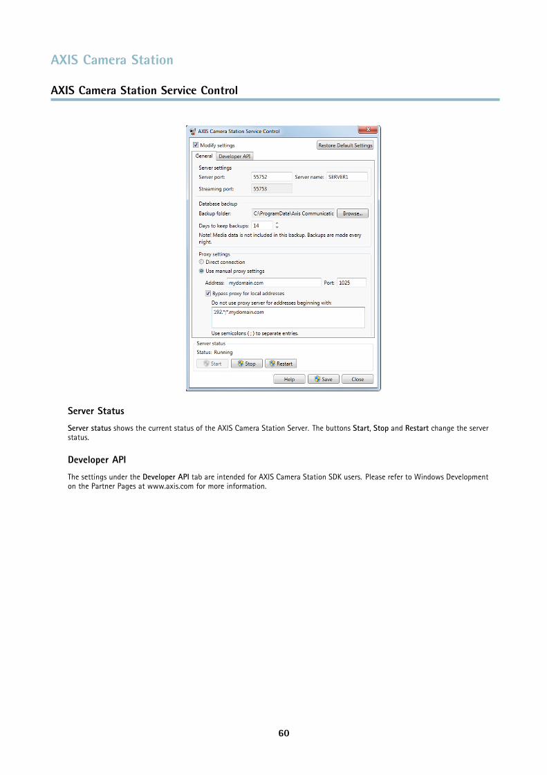
AXIS Camera Station
AXIS Camera Station Service Control
Server Status
Server status shows the current status of the AXIS Camera Station Server. The buttons Start, Stop and Restart change the serverstatus.
Developer API
The settings under the Developer API tab are intended for AXIS Camera Station SDK users. Please refer to Windows Developmenton the Partner Pages at www.axis.com for more information.
60
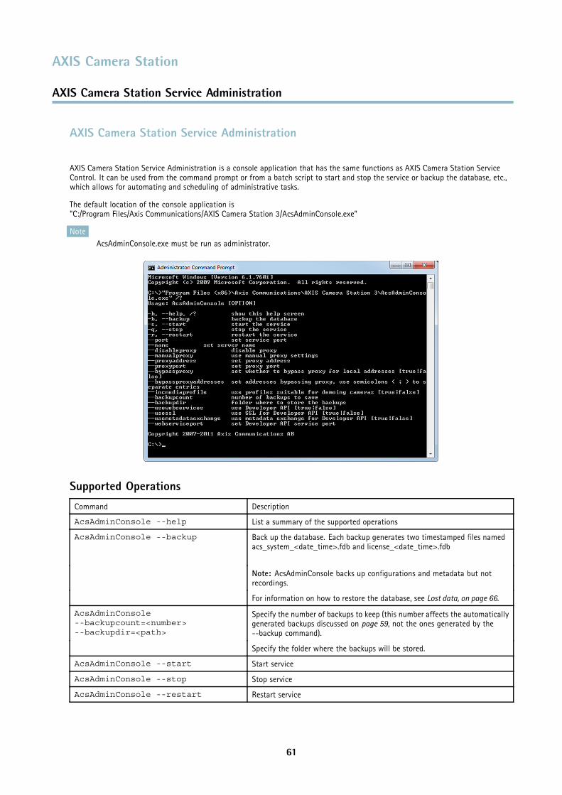
AXIS Camera Station
AXIS Camera Station Service Administration
AXIS Camera Station Service Administration
AXIS Camera Station Service Administration is a console application that has the same functions as AXIS Camera Station ServiceControl. It can be used from the command prompt or from a batch script to start and stop the service or backup the database, etc.,which allows for automating and scheduling of administrative tasks.
The default location of the console application is"C:/Program Files/Axis Communications/AXIS Camera Station 3/AcsAdminConsole.exe”
NoteAcsAdminConsole.exe must be run as administrator.
Supported Operations
Command Description
AcsAdminConsole --help List a summary of the supported operations
AcsAdminConsole --backup Back up the database. Each backup generates two timestamped files namedacs_system_<date_time>.fdb and license_<date_time>.fdb
Note: AcsAdminConsole backs up configurations and metadata but notrecordings.
For information on how to restore the database, see Lost data, on page 66.
AcsAdminConsole--backupcount=<number>--backupdir=<path>
Specify the number of backups to keep (this number affects the automaticallygenerated backups discussed on page 59, not the ones generated by the--backup command).
Specify the folder where the backups will be stored.
AcsAdminConsole --start Start service
AcsAdminConsole --stop Stop service
AcsAdminConsole --restart Restart service
61
AXIS Camera Station
AXIS Camera Station Service Administration
Command Description
AcsAdminConsole--port=<port number>
Set server port (e.g. AcsAdminConsole --port=55762)
Use manual proxy settings.
Set the proxy address and port (default 80).
AcsAdminConsole--manualproxy--proxyaddress=<proxy>--proxyport=<port>--bypassproxy=<true/false>--bypassproxyaddresses=<address-es>--disableproxy
Bypass proxy for local addresses. Example: bypassproxyaddress=192.*,*mydomain.com
62
AXIS Camera Station
Troubleshooting
Troubleshooting
Area zoom
Area zoom does not work Area zoom is not supported by AXIS 209MFD and AXIS 212 PTZ. Use the digital or mechanicalPTZ controls instead.
Audio
There is no audio in Live View Make sure the camera has audio capabilities.
Check that audio is activated in Live view settings:1. From the Configuration menu, select Live View Settings2. Click on the desired camera and then Edit to open Live View Settings3. Click Change to open Change Media Profile.4. Check the Audio box
Note: Audio is not possible in M-JPEG; choose MPEG-4 or H.264.
Make sure the user has access rights to audio.Note: To follow these steps you must have administrator rights to AXIS Camera Station
1. From the Configuration menu, select User Permissions2. Select User or Group and click Edit3. Click Advanced. Make sure that Audio is checked in the desired camera
Check that your computer has an audio card and that the card is not disabled.
There is no audio in split viewslarger then 6 split
Audio is not available in split views larger than 6 splits when using the default Live Viewsettings. To change the default settings:
1. From the Configuration menu, open Live View Settings.2. Select the desired camera and click Edit to open Live View Settings.3. Click Large Splits.4. Change the settings under Overrides. Enable audio by changing the media profiles
or uncheck the appropriate boxes to disable the overrides.Note: Audio is not possible in M-JPEG; choose MPEG-4 or H.264.
There is no audio in sequenceviews
Sequence views use the media profile selected for 2–6 split views. To enable audio in sequence:1. From the Configuration menu, open Live View Settings.2. Select the desired camera and click Edit to open Live View Settings.3. Click Large Splits.4. Check the 2–6 split views box and select a media profile where audio is enabled.5. Repeat steps 2–4 for all cameras included in the sequence.
Note: Audio is not possible in M-JPEG; choose MPEG-4 or H.264.
There is no audio in playback Audio is available in playback only if audio was enabled in the media profile used for therecording.
Continuous, motion detection and manual recordings:To enable audio:
1. From the Configuration menu, open Recording Settings2. Select the desired camera and click Continuous, Motion Detection or Manual3. Select a media profile where audio is enabled. If there is no such profile, click
Change and check the Audio box.
Triggered recordings — EventsTo enable audio in an existing rule:
1. From the Configuration menu, open Event Configuration2. Select the desired rule and click Edit3. Select a media profile where audio is enabled. If there is no such profile, click
Change and check the Audio box4. Click Finish to save.
For information on how to set up rules, see Event Configuration Wizard, on page 43.
63
AXIS Camera Station
Troubleshooting
Note: Audio is not possible in M-JPEG; choose MPEG-4 or H.264.
Missing AAC decoder To use the AAC audio format, a decoder must be installed. Click the link to install the decoder.If using Demo mode or AXIS Camera Station One, download the decoder from the camera’sLive View page.
AXIS Cross Line Detection
AXIS Cross Line Detection doesnot work
AXIS Cross Line Detection can be used with network cameras and video encoders that supportAXIS Camera Application Platform.To use AXIS Cross Line Detection as a trigger, you must first
• upload the application to the camera• start the application in the camera
For instructions, see AXIS Cross Line Detection User’s Guide.
Domain user search fails
Cannot find domain users Make sure that AXIS Camera Station Service is logged on as a Windows user with access toActive Directory. To change the user account for AXIS Camera Station Service, go to ControlPanel > Administrative Tools > Services.
Graphics card
The graphics card driver is morethan 12 months old
For AXIS Camera Station client to run properly, it is important that the graphics card in yourcomputer has been updated with the latest driver.
Graphics card error To find out what graphics card is installed in your computer, a diagnostic program calleddxdiag can be used.
In Windows 7/Vista/Server 2008/Server 2003:1. Open the Start menu2. Enter dxdiag in the Start Search field3. If a prompt appears for the Diagnostic Tool, click Yes4. Select the Display tab. The name of the Graphics card appears under Device
In Windows XP:1. Open the Start menu and select Run2. Enter dxdiag in the Run dialog and click OK3. If a prompt appears for the Diagnostic Tool, click Yes4. Select the Display tab. The name of the Graphics card appears under Device
To download the latest driver you need to visit the graphics card manufacturer's web site.Some of the more common ones are
• nVidia - www.nvidia.com• ATI - www.ati.com• S3 - http://www.s3graphics.com
To upgrade the graphics card drivers on your computer:1. Download the driver from the manufacturers web site to your hard drive2. Make sure that there are no other programs running on your computer.3. Run the installer and follow the wizard to install necessary files4. Reboot to activate the change
Graphics card warning The graphics card does not the minimum system requirements, see System Requirements.
The graphics card must support DirectX 9.0c, be Windows Vista compliant (even if running onWindows XP) and support Windows Presentation Foundation tier 2.
64
AXIS Camera Station
Troubleshooting
To check the graphics card’s tier level, open the Help menu and select Client ConfigurationSheet. Render Capability Tier is listed in the General Configuration Information section.
It is also possible to use the CPU for video rendering, instead of using the graphics card, seeEmpty “ActiveMovieWindow” popup below.
Live view
No image from camera Proper decoders must be installed for MPEG-4 and H.264 video formats. In licensed mode, clickon the link in the empty Live View window to launch the decoder installation. In AXIS CameraStation One or Demo mode, download the proper decoders from the camera’s Live View page.
Repeated error message "MediaFailed"
Try reducing the load to the CPU by modifying the Live View Settings for each camera underConfiguration. Reduce the resolution, increase the compression setting and lower the framerate.
Check that your computer is not running low on memory.
Check that the graphics card has been updated with the latest driver, see Graphics card,on page 64.
Firewall and antivirus software sometimes block video signals. Check that your firewall andantivirus program do not block the following files:
• AcsAdmin.exe• AcsAdminConsole.exe• ACSService.exe• Server.exe• AcsClient.exe• All content of C:\Program Files\Axis Communications\Components
See also NAT and Firewall, on page 49.
Empty “ActiveMovie Window”popup
This indicates problems with the graphics card’s video memory and hardware acceleration.
Possible solutions:• Install the latest graphics card driver, see Graphics card• Upgrade to a graphics card with more video memory and higher performance• Use the CPU for video rendering, see below.
To use the CPU for video rendering, follow these instructions:1. Navigate to the AXIS Camera Station Client installation folder. The default
location is:C:\Program Files\Axis Communications\AXIS Camera Station 3\Client <currentversion>
2. Open the file AcsClient.exe.config in a text editor.3. Find this entry:
<setting name=”ForceCompatibilityVideoMode”serializeAs=”String”><value>False</value></setting>
4. Change “False” to “True”5. Save the file and restart AXIS Camera Station
Logon/connecting to server
User name or password isincorrect
Check that the user name and password are valid
Check that the user has access rights to AXIS Camera Station Server
Check that the clocks in AXIS Camera Station Client and Server are synchronized. For domainusers, check that the domain server clock is synchronized with the server and client.
65
AXIS Camera Station
Troubleshooting
A user who has not been added to the server, but is a member of the local administratorsgroup on the server, must run the client as administrator on Windows 7/Vista. Right-click theAXIS Camera Station Client icon and select Run as administrator.
AXIS Camera Station Server wasunable to verify message security.Please make sure server andclient UTC times are reasonablysynchronized
The clocks in AXIS Camera Station server and client are not synchronized. Adjust the clockin either the server or client so that they have the same date and time properties. For moreinformation on setting up time in your computer consult the Window’s help files.
Unable to connect to server.Please make sure that theserver is running and acceptingconnections.
Check that a NAT/firewall is not blocking a connection to the server
Unable to locate the servercomputer. Please make sure thatthe server computer is connectedto the network.
Check the address and port of the AXIS Camera Station server is correct.
Check that a NAT/firewall is not blocking a connection to the server
Check that the server is running.
Unable to connect to server! Verify that the computer the server and client are installed on is up to date and has thelatest service packs/patches from Microsoft
Verify that the network is correctly installed and configured on the server and clientcomputer(s)Verify that no NAT/firewalls are blocking connection between AXIS Camera Station clientand server
Lost data
Data lost due to hardware failureor other problems
The AXIS Camera Station database contains information about recordings and other metadatathat is needed for the system to work properly. This database is backed up every evening.
Recordings are not stored in the database and should be backed up separately from thelocations designated in Recording Storage, see page 30.
If for some reason the database is lost due to hardware failure or other problems, the databasecan be restored either with the latest backup or you can use a prior backup.
To restore the database follow these instructions:1. Open AXIS Camera Station Service Control and click Stop.2. Navigate to the folder where the backup files are stored. The path to this folder is
found under Database backup in AXIS Camera Station Service Control.The backup folder contains timestamped backup files namedacs_system_<date_time>.fdb and license_system_<date_time>.fdb
3. Copy acs_system_<date_time>.fdb and license_system_<date_time>.fdb toWindows 7/Vista/Server 2008/Server 2003: C:\ProgramData\AXISCommunication\AXIS Camera Station Server\Windows XP: C:\Documents and Settings\All Users\Application Data\AxisCommunication\AXIS Camera Station Server\
4. Delete the files ACS.FDB and LICENSE.FDB.5. Rename acs_system_<date_time>.fdb to ACS.FDB and rename
license_system_<date_time>.fdb to LICENSE.FDB.6. Click Start in AXIS Camera Station Service Control.
66
AXIS Camera Station
Troubleshooting
Menu item
I can't see the Configurationmenu
You do not have administrator privileges. Menu items are hidden from users that are notgranted access under User Permissions.
Playback problems
Not enough disk space to buffer Increase the buffer size:1. From the Options menu, open Customize and select the Recordings tab2. Under Playback buffering select Use at most and use the slider to increase the
buffer size
PTZ problems
Mechanical PTZ does not workPTZ presets cannot be configured
Check that the camera’s PTZ control queue has not been enabled. If the control queue isenabled, mechanical PTZ controls and PTZ presets are not available. To check if the controlqueue is enabled, open the camera’s built-in web pages in a browser. For more information,refer to the camera’s User Manual available from www.axis.com
Recording storage
Network disk is not accessible To use network disks linking to shared folders on other computers, the Local System accountcannot be used to log on to AXIS Camera Station Service. To change the service login account,follow these instructions:
1. Go to Control Panel > Administrative Tools > Services2. Right-click AXIS Camera Station and choose Properties3. Click the Log On tab4. Change from Local System account to This account5. Choose a user with access to Windows Active Directory
Network disk is listed as"Unavailable"
The computer that AXIS Camera Station Server is installed on, should be part of the samedomain as the shared folder that is entered as a network disk.
Move AXIS Camera Station installation
How do I move my AXIS CameraStation installation to anotherserver?
To move your current installation to another server please follow these steps:1. Install AXIS Camera Station (same version) on the new server2. Open AXIS Camera Station at the new location and do a new license registration.3. Stop AXIS Camera Station Service, see page 58.4. Move the file named ACS.FDB to the new location:
In Windows 7/Vista/Server 2008/Server 2003/64–bit versions the file is locatedat C:\ProgramData\AXIS Communication\AXIS Camera Station Server.In Windows XP the file is located at C:\Documents and Settings\AllUsers\Application Data\Axis Communications\AXIS Camera Station Server
5. Move your recordings from the recording paths e.g C:\Recordings\ to the newlocation.Note: The recording paths must be exactly the same on the new server.
Contact Customer SupportTechnical support is available for licensed versions of AXIS Camera Station with a valid support license. Open the Options menuand select Licenses to check if you have a valid support license. If the support license has expired, a new license can be obtainedfrom your Axis reseller.
If you contact Axis Customer Support, please help us resolve your problem expediently by zipping and attaching the following filesto your online support case:
67
AXIS Camera Station
Troubleshooting
Server Report To generate a Server Report, follow these steps:1. Open AXIS Camera Station Client.2. From the Help menu, select Server Report.3. Click OK to save the Server Report as a zip file.
Windows Event Logs:Application andSystem
To generate event logs, follow these steps:Windows 7, Windows Vista, Windows Server 2008, Windows Server 2003
1. Click the Start button, right-click Computer and select Manage to open ComputerManagement.
2. Select Event Viewer > Windows Logs and then Application.3. From the Action menu, select Save All Events As and save as an event log (evt) file.4. Repeat steps 2 and 3 but select System instead of Application.5. Zip both files and attach them to your support case.
Windows XP1. Click the Start button, right-click My Computer and select Manage to open Computer
Management.2. Select System Tools > Event Viewer and then Application.3. From the Action menu, select Save Log File As and save as an event log (evt) file.4. Repeat steps 2 and 3 but select System instead of Application.5. Zip both files and attach them to your support case.
Screenshots To copy what is currently displayed on the screen to a file, follow these steps:1. Press ALT - PRT SCR.2. Open the Paint program included with Microsoft Windows.3. In Paint, open the Edit menu and select Paste.4. Save the file.5. Attach the screenshot to your support case.
If a Server Report cannot be generated, for example if AXIS Camera Station Server does not start, run DirectX Diagnostic Tool asdescribed below and provide debug logs with your support case.
DirectX DiagnosticTool
To generate information about DirectX components and drivers, follow these steps:Windows 7, Windows Vista, Windows Server 2008, Windows Server 2003
1. Click the Start button and type dxdiag in the search box.2. Open the program dxdiag.exe3. Click Save all information and save as a text (txt) file.4. Attach the text file to your support case.
Windows 71. Click the Start button and select Run.2. Type dxdiag in the Open box and click OK.3. Click Save all information and save as a text (txt) file.4. Attach the text file to your support case.
Debug logs To create debug logs, zip the following folder:Windows 7, Windows Vista, Windows Server 2008, Windows Server 2003C:\ProgramData\Axis Communications\AXIS Camera Station\3.xxWindows XPC:\Documents and Settings\All Users\Application Data\Axis Communications\AXIS Camera Station\3.xxNote: ProgramData and Application Data are hidden folders. Activate “Show hidden files and folders”to display them.
68

User Manual Ver. M2.7AXIS Camera Station Date: October 2011
© Axis Communications AB, 2004 - 2011 Part No. 44738
Related Documents