RE 92750/2020-03-03, Bosch Rexroth AG Axial piston variable pump A10VG Series 10 RE 92750/2020-03-03 Replaces: 2019-12-12 Features ▶ Integrated boost pump for boost and pilot oil supply ▶ Flow direction changes when the swashplate is moved through the neutral position ▶ High-pressure relief valves with integrated boost function ▶ Boost-pressure relief valve ▶ Optional with pressure cut-off ▶ Large variety of controls ▶ Swashplate design ▶ Medium pressure pump for closed-circuit applications ▶ Size 18 … 63 ▶ Nominal pressure 300 bar ▶ Maximum pressure 350 bar ▶ Closed circuit Contents Type code 2 Hydraulic fluids 5 Working pressure range 6 Technical data 8 HD – Proportional control, hydr., pilot-pressure related 10 HW – Proportional control, hydr., mechanical servo 12 DA – Automatic control, speed related 14 DG – Hydraulic control, direct operated 17 EP – Proportional control, electric 18 EZ – Two-point control, electric 20 ET – Electric control, direct operated 21 ED – Electric pressure control 22 Dimensions, size 18 24 Dimensions, size 28 27 Dimensions, size 45 32 Dimensions, size 63 37 Dimensions, through drive 41 Overview of mounting options 44 Combination pumps A10VG + A10VG 45 High-pressure relief valves 46 Pressure cut-off 47 Mechanical stroke limiter 48 Stroking chamber pressure port X 3 and X 4 49 Measuring ports M A , M B , M H 50 Filtration in the boost pump suction line 51 Filtration in the boost pump pressure line 51 External boost pressure supply 52 Connector for solenoids 53 Rotary inch valve 54 Installation dimensions for coupling assembly 55 Installation instructions 56 Project planning notes 59 Safety instructions 60

Welcome message from author
This document is posted to help you gain knowledge. Please leave a comment to let me know what you think about it! Share it to your friends and learn new things together.
Transcript
RE 92750/2020-03-03, Bosch Rexroth AG
Axial piston variable pumpA10VG Series 10
RE 92750/2020-03-03Replaces: 2019-12-12
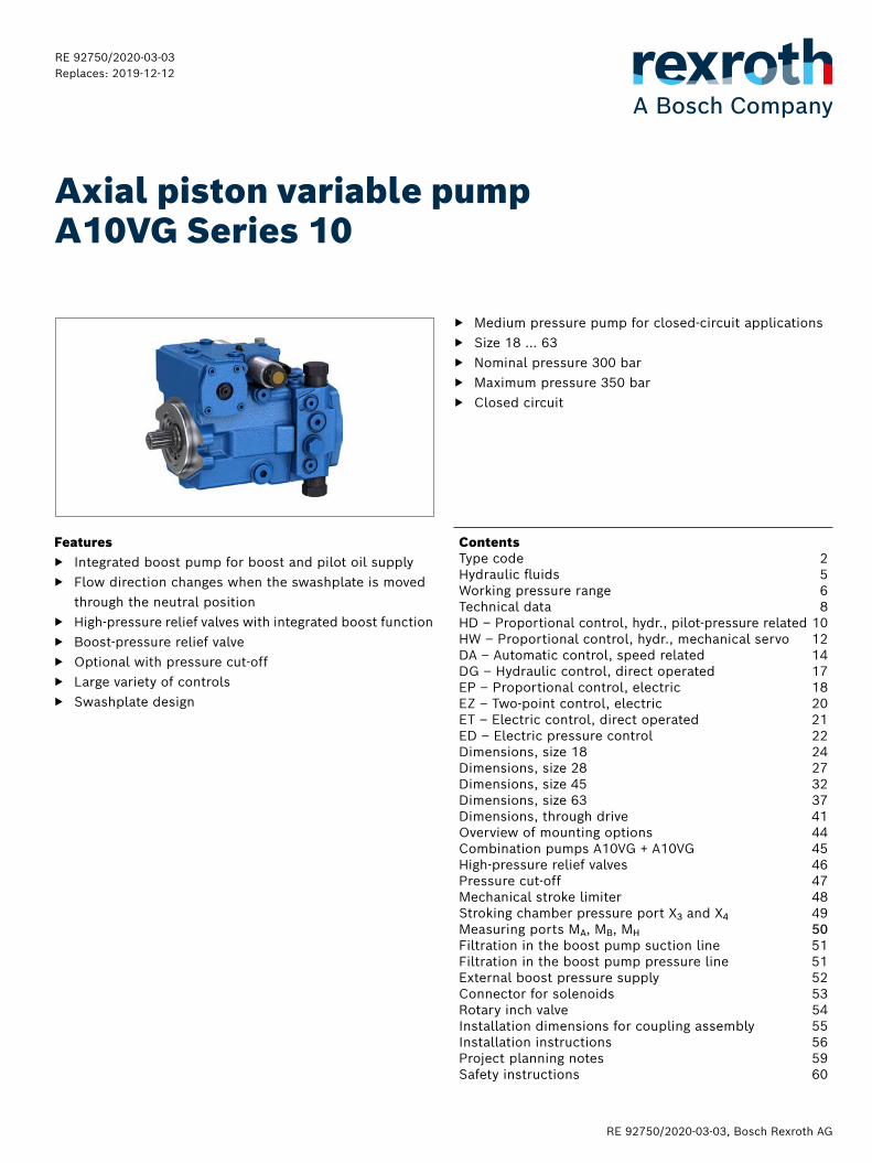
Features ▶ Integrated boost pump for boost and pilot oil supply ▶ Flow direction changes when the swashplate is moved
through the neutral position ▶ High-pressure relief valves with integrated boost function ▶ Boost-pressure relief valve ▶ Optional with pressure cut-off ▶ Large variety of controls ▶ Swashplate design
▶ Medium pressure pump for closed-circuit applications ▶ Size 18 … 63 ▶ Nominal pressure 300 bar ▶ Maximum pressure 350 bar ▶ Closed circuit
ContentsType code 2Hydraulic fluids 5Working pressure range 6Technical data 8HD – Proportional control, hydr., pilot-pressure related 10HW – Proportional control, hydr., mechanical servo 12DA – Automatic control, speed related 14DG – Hydraulic control, direct operated 17EP – Proportional control, electric 18EZ – Two-point control, electric 20ET – Electric control, direct operated 21ED – Electric pressure control 22Dimensions, size 18 24Dimensions, size 28 27Dimensions, size 45 32Dimensions, size 63 37Dimensions, through drive 41Overview of mounting options 44Combination pumps A10VG + A10VG 45High-pressure relief valves 46Pressure cut-off 47Mechanical stroke limiter 48Stroking chamber pressure port X3 and X4 49Measuring ports MA, MB, MH 50Filtration in the boost pump suction line 51Filtration in the boost pump pressure line 51External boost pressure supply 52Connector for solenoids 53Rotary inch valve 54Installation dimensions for coupling assembly 55Installation instructions 56Project planning notes 59Safety instructions 60
Bosch Rexroth AG, RE 92750/2020-03-03
2 A10VG Series 10 | Axial piston variable pumpType code
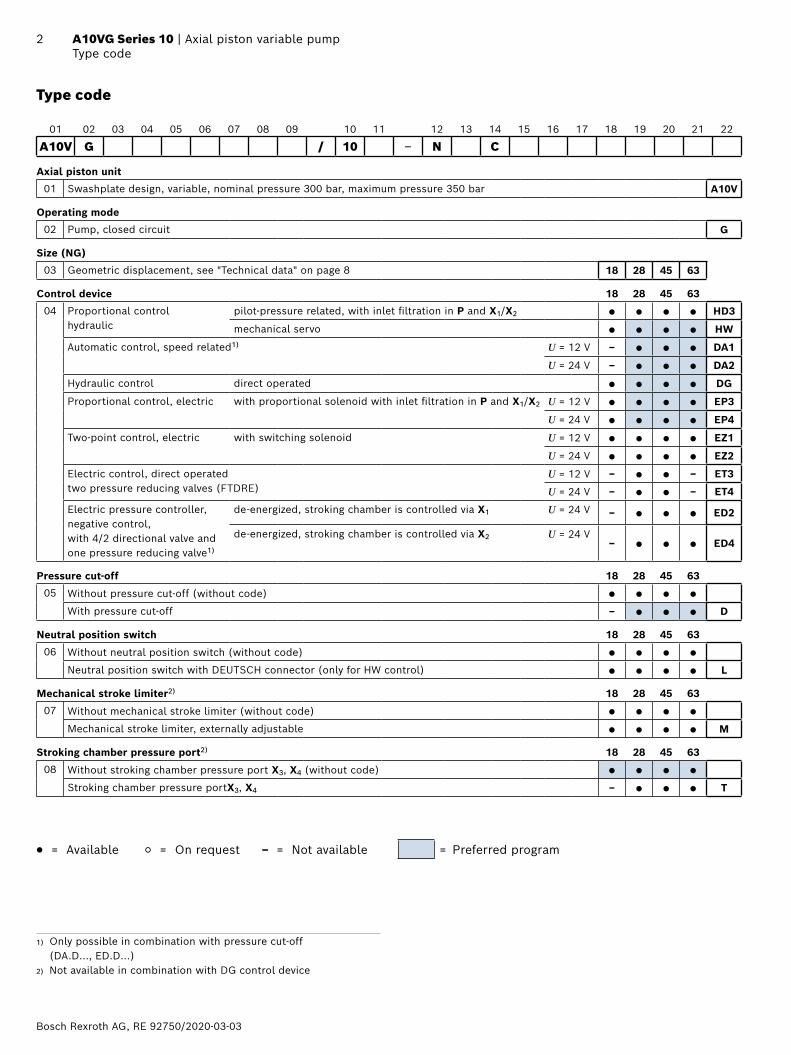
Type code
01 02 03 04 05 06 07 08 09 10 11 12 13 14 15 16 17 18 19 20 21 22
A10V G / 10 ‒ N C
Axial piston unit
01 Swashplate design, variable, nominal pressure 300 bar, maximum pressure 350 bar A10V
Operating mode
02 Pump, closed circuit G
Size (NG)
03 Geometric displacement, see "Technical data" on page 8 18 28 45 63
Control device 18 28 45 63
04 Proportional control hydraulic
pilot-pressure related, with inlet filtration in P and X1/X2 ● ● ● ● HD3
mechanical servo ● ● ● ● HW
Automatic control, speed related1) U = 12 V – ● ● ● DA1
U = 24 V – ● ● ● DA2
Hydraulic control direct operated ● ● ● ● DG
Proportional control, electric with proportional solenoid with inlet filtration in P and X1/X2 U = 12 V ● ● ● ● EP3
U = 24 V ● ● ● ● EP4
Two-point control, electric with switching solenoid U = 12 V ● ● ● ● EZ1
U = 24 V ● ● ● ● EZ2
Electric control, direct operated two pressure reducing valves (FTDRE)
U = 12 V – ● ● – ET3
U = 24 V – ● ● – ET4
Electric pressure controller, negative control, with 4/2 directional valve and one pressure reducing valve1)
de-energized, stroking chamber is controlled via X1 U = 24 V – ● ● ● ED2
de-energized, stroking chamber is controlled via X2 U = 24 V– ● ● ● ED4
Pressure cut-off 18 28 45 63
05 Without pressure cut-off (without code) ● ● ● ●
With pressure cut-off – ● ● ● D
Neutral position switch 18 28 45 63
06 Without neutral position switch (without code) ● ● ● ●
Neutral position switch with DEUTSCH connector (only for HW control) ● ● ● ● L
Mechanical stroke limiter2) 18 28 45 63
07 Without mechanical stroke limiter (without code) ● ● ● ●
Mechanical stroke limiter, externally adjustable ● ● ● ● M
Stroking chamber pressure port2) 18 28 45 63
08 Without stroking chamber pressure port X3, X4 (without code) ● ● ● ●
Stroking chamber pressure portX3, X4 – ● ● ● T
● = Available ○ = On request – = Not available = Preferred program
1) Only possible in combination with pressure cut-off (DA.D..., ED.D...)
2) Not available in combination with DG control device
RE 92750/2020-03-03, Bosch Rexroth AG
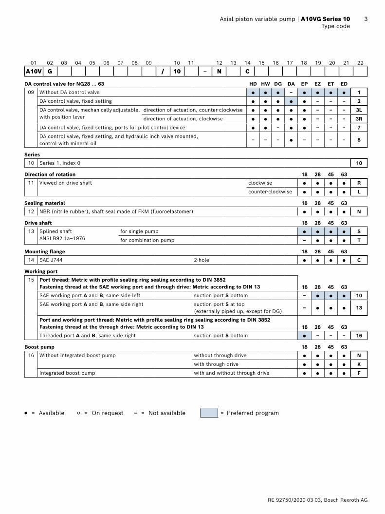
3 Axial piston variable pump | A10VG Series 10 Type code
01 02 03 04 05 06 07 08 09 10 11 12 13 14 15 16 17 18 19 20 21 22
A10V G / 10 ‒ N C
DA control valve for NG28 ... 63 HD HW DG DA EP EZ ET ED
09 Without DA control valve ● ● ● – ● ● ● ● 1
DA control valve, fixed setting ● ● ● ● ● – – – 2
DA control valve, mechanically adjustable, with position lever
direction of actuation, counter-clockwise ● ● ● ● ● – – – 3L
direction of actuation, clockwise ● ● ● ● ● – – – 3R
DA control valve, fixed setting, ports for pilot control device ● ● – ● ● – – – 7
DA control valve, fixed setting, and hydraulic inch valve mounted, control with mineral oil
– – – ● – – – – 8
Series
10 Series 1, index 0 10
Direction of rotation 18 28 45 63
11 Viewed on drive shaft clockwise ● ● ● ● R
counter-clockwise ● ● ● ● L
Sealing material 18 28 45 63
12 NBR (nitrile rubber), shaft seal made of FKM (fluoroelastomer) ● ● ● ● N
Drive shaft 18 28 45 63
13 Splined shaft ANSI B92.1a–1976
for single pump ● ● ● ● S
for combination pump – ● ● ● T
Mounting flange 18 28 45 63
14 SAE J744 2-hole ● ● ● ● C
Working port
15 Port thread: Metric with profile sealing ring sealing according to DIN 3852Fastening thread at the SAE working port and through drive: Metric according to DIN 13 18 28 45 63
SAE working port A and B, same side left suction port S bottom – ● ● ● 10
SAE working port A and B, same side right suction port S at top (externally piped up, except for DG)
– ● ● ● 13
Port and working port thread: Metric with profile sealing ring sealing according to DIN 3852Fastening thread at the through drive: Metric according to DIN 13 18 28 45 63
Threaded port A and B, same side right suction port S bottom ● – – – 16
Boost pump 18 28 45 63
16 Without integrated boost pump without through drive ● ● ● ● N
with through drive ● ● ● ● K
Integrated boost pump with and without through drive ● ● ● ● F
● = Available ○ = On request – = Not available = Preferred program
Bosch Rexroth AG, RE 92750/2020-03-03
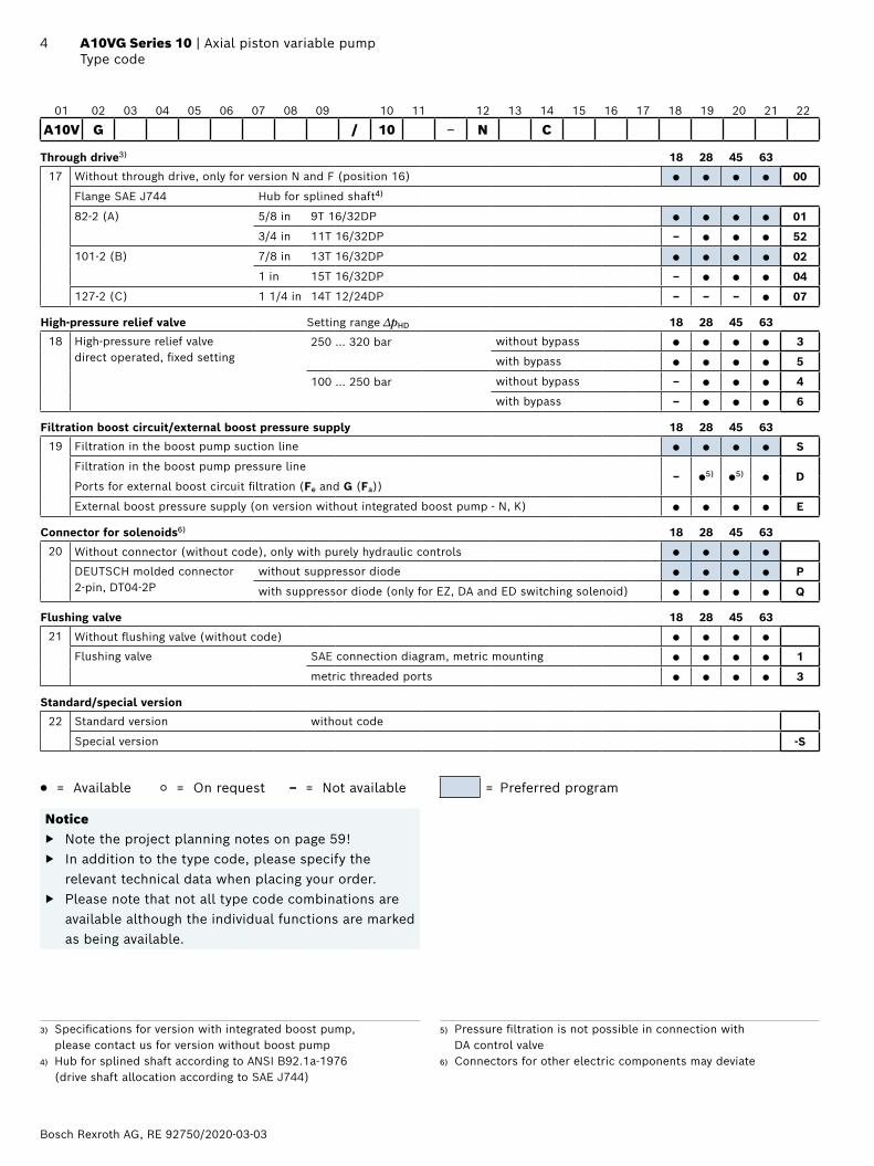
4 A10VG Series 10 | Axial piston variable pumpType code
01 02 03 04 05 06 07 08 09 10 11 12 13 14 15 16 17 18 19 20 21 22
A10V G / 10 ‒ N C
Through drive3) 18 28 45 63
17 Without through drive, only for version N and F (position 16) ● ● ● ● 00
Flange SAE J744 Hub for splined shaft4)
82-2 (A) 5/8 in 9T 16/32DP ● ● ● ● 01
3/4 in 11T 16/32DP – ● ● ● 52
101-2 (B) 7/8 in 13T 16/32DP ● ● ● ● 02
1 in 15T 16/32DP – ● ● ● 04
127-2 (C) 1 1/4 in 14T 12/24DP – – – ● 07
High-pressure relief valve Setting range ∆pHD 18 28 45 63
18 High-pressure relief valve direct operated, fixed setting
250 … 320 bar without bypass ● ● ● ● 3
with bypass ● ● ● ● 5
100 … 250 bar without bypass – ● ● ● 4
with bypass – ● ● ● 6
Filtration boost circuit/external boost pressure supply 18 28 45 63
19 Filtration in the boost pump suction line ● ● ● ● S
Filtration in the boost pump pressure line– ●5) ●5) ● D
Ports for external boost circuit filtration (Fe and G (Fa))
External boost pressure supply (on version without integrated boost pump - N, K) ● ● ● ● E
Connector for solenoids6) 18 28 45 63
20 Without connector (without code), only with purely hydraulic controls ● ● ● ●
DEUTSCH molded connector 2-pin, DT04-2P
without suppressor diode ● ● ● ● P
with suppressor diode (only for EZ, DA and ED switching solenoid) ● ● ● ● Q
Flushing valve 18 28 45 63
21 Without flushing valve (without code) ● ● ● ●
Flushing valve SAE connection diagram, metric mounting ● ● ● ● 1
metric threaded ports ● ● ● ● 3
Standard/special version
22 Standard version without code
Special version -S
● = Available ○ = On request – = Not available = Preferred program
Notice ▶ Note the project planning notes on page 59! ▶ In addition to the type code, please specify the
relevant technical data when placing your order. ▶ Please note that not all type code combinations are
available although the individual functions are marked as being available.
3) Specifications for version with integrated boost pump, please contact us for version without boost pump
4) Hub for splined shaft according to ANSI B92.1a-1976 (drive shaft allocation according to SAE J744)
5) Pressure filtration is not possible in connection with DA control valve
6) Connectors for other electric components may deviate
RE 92750/2020-03-03, Bosch Rexroth AG
5 Axial piston variable pump | A10VG Series 10 Hydraulic fluids
Hydraulic fluids
The axial piston unit is designed for operation with HLP mineral oil according to DIN 51524. Application instructions and requirements for hydraulic fluid selection, behavior during operation as well as disposal and environmental protection should be taken from the following data sheets before the start of project planning:
▶ 90220: Hydraulic fluids based on mineral oils and related hydrocarbons
▶ 90221: Environmentally acceptable hydraulic fluids ▶ 90222: Fire-resistant, water-free hydraulic fluids
(HFDR/HFDU) ▶ 90225:Limited technical data for operation with
waterfree and water-containing fire-resistant hydraulic fluids (HFDR, HFDU, HFAE, HFAS, HFB, HFC)
Selection of hydraulic fluidBosch Rexroth evaluates hydraulic fluids on the basis of the Fluid Rating according to the technical data sheet 90235.Hydraulic fluids with positive evaluation in the Fluid Rating are provided in the following technical data sheet:
▶ 90245: Bosch Rexroth Fluid Rating List for Rexroth hydraulic components (pumps and motors)
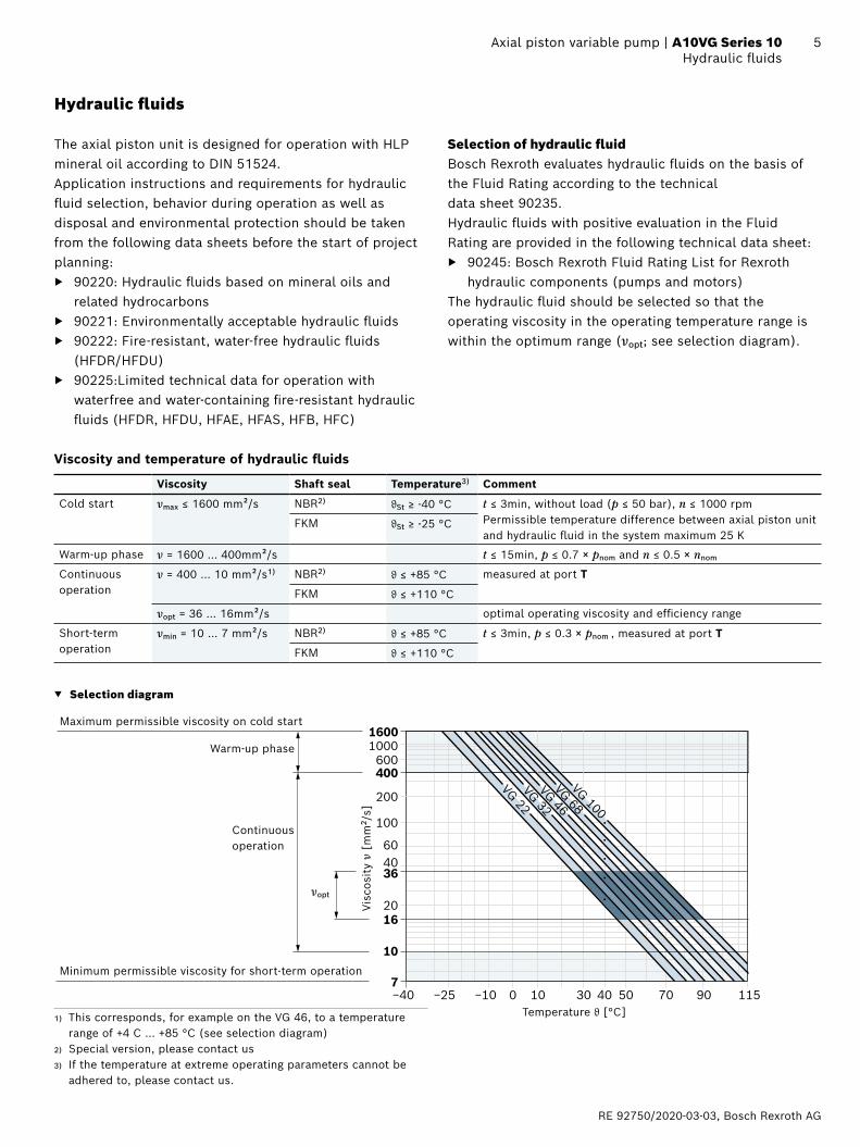
The hydraulic fluid should be selected so that the operating viscosity in the operating temperature range is within the optimum range (νopt; see selection diagram).
Viscosity and temperature of hydraulic fluids
Viscosity Shaft seal Temperature3) Comment
Cold start νmax ≤ 1600 mm²/s NBR2) ϑSt ≥ -40 °C t ≤ 3min, without load (p ≤ 50 bar), n ≤ 1000 rpmPermissible temperature difference between axial piston unit and hydraulic fluid in the system maximum 25 K
FKM ϑSt ≥ -25 °C
Warm-up phase ν = 1600 … 400mm²/s t ≤ 15min, p ≤ 0.7 × pnom and n ≤ 0.5 × nnom
Continuous operation
ν = 400 … 10 mm²/s1) NBR2) ϑ ≤ +85 °C measured at port T
FKM ϑ ≤ +110 °C
νopt = 36 … 16mm²/s optimal operating viscosity and efficiency range
Short-term operation
νmin = 10 … 7 mm²/s NBR2) ϑ ≤ +85 °C t ≤ 3min, p ≤ 0.3 × pnom , measured at port T
FKM ϑ ≤ +110 °C
▼ Selection diagram
−40 −25 −10 10 30 40 50 90 1157007
10
4060
20
100
200
400600
10001600
VG 22VG 32VG 46VG 68VG 100
16
36
Warm-up phase
νopt
Maximum permissible viscosity on cold start
Minimum permissible viscosity for short-term operation
Temperature ϑ [°C]
Visc
osit
y ν
[mm
2 /s]
Continuous operation
1) This corresponds, for example on the VG 46, to a temperature range of +4 C … +85 °C (see selection diagram)
2) Special version, please contact us3) If the temperature at extreme operating parameters cannot be
adhered to, please contact us.
Bosch Rexroth AG, RE 92750/2020-03-03
6 A10VG Series 10 | Axial piston variable pumpWorking pressure range
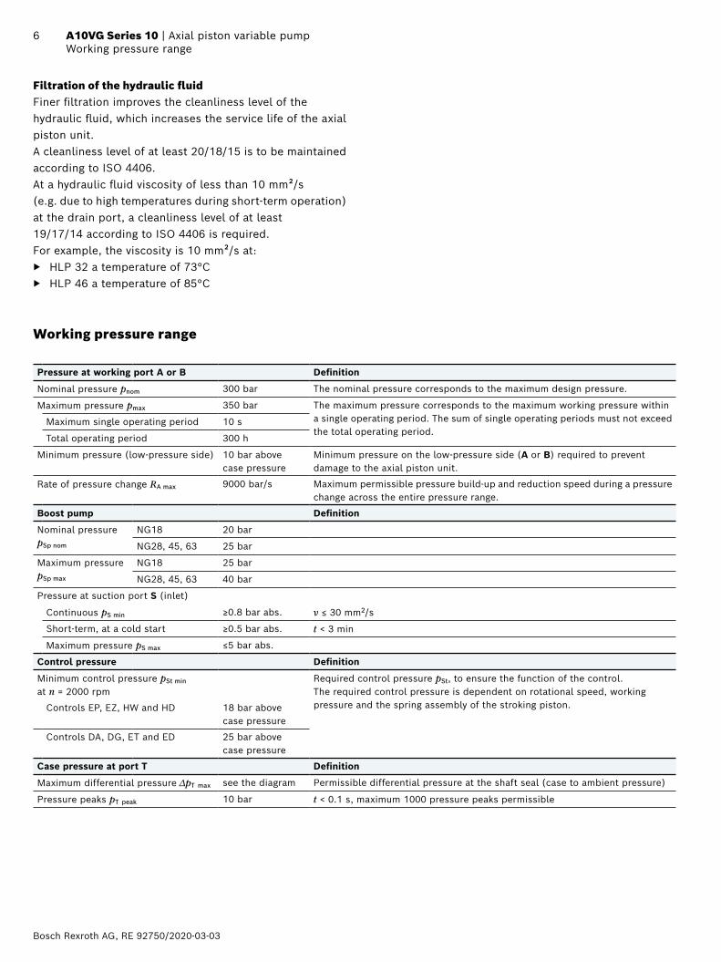
Working pressure range
Pressure at working port A or B Definition
Nominal pressure pnom 300 bar The nominal pressure corresponds to the maximum design pressure.
Maximum pressure pmax 350 bar The maximum pressure corresponds to the maximum working pressure within a single operating period. The sum of single operating periods must not exceed the total operating period.
Maximum single operating period 10 s
Total operating period 300 h
Minimum pressure (low-pressure side) 10 bar above case pressure
Minimum pressure on the low-pressure side (A or B) required to prevent damage to the axial piston unit.
Rate of pressure change RA max 9000 bar/s Maximum permissible pressure build-up and reduction speed during a pressure change across the entire pressure range.
Boost pump Definition
Nominal pressure pSp nom
NG18 20 bar
NG28, 45, 63 25 bar
Maximum pressure pSp max
NG18 25 bar
NG28, 45, 63 40 bar
Pressure at suction port S (inlet)
Continuous pS min ≥0.8 bar abs. ν ≤ 30 mm2/s
Short-term, at a cold start ≥0.5 bar abs. t < 3 min
Maximum pressure pS max ≤5 bar abs.
Control pressure Definition
Minimum control pressure pSt min
at n = 2000 rpmRequired control pressure pSt, to ensure the function of the control. The required control pressure is dependent on rotational speed, working pressure and the spring assembly of the stroking piston.Controls EP, EZ, HW and HD 18 bar above
case pressure
Controls DA, DG, ET and ED 25 bar above case pressure
Case pressure at port T Definition
Maximum differential pressure ∆pT max see the diagram Permissible differential pressure at the shaft seal (case to ambient pressure)
Pressure peaks pT peak 10 bar t < 0.1 s, maximum 1000 pressure peaks permissible
Filtration of the hydraulic fluidFiner filtration improves the cleanliness level of the hydraulic fluid, which increases the service life of the axial piston unit.A cleanliness level of at least 20/18/15 is to be maintained according to ISO 4406.At a hydraulic fluid viscosity of less than 10 mm²/s (e.g. due to high temperatures during short-term operation) at the drain port, a cleanliness level of at least 19/17/14 according to ISO 4406 is required. For example, the viscosity is 10 mm²/s at:
▶ HLP 32 a temperature of 73°C ▶ HLP 46 a temperature of 85°C
RE 92750/2020-03-03, Bosch Rexroth AG
7 Axial piston variable pump | A10VG Series 10 Working pressure range
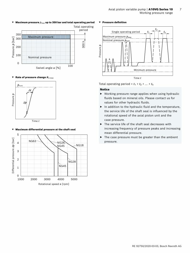
▼ Maximum pressure pmax up to 350 bar and total operating period
100 0
100
200
300350
300
h
Pre
ssur
e p
[bar
]
Swivel angle а [%]
Total operating period
Maximum pressure
Nominal pressure
▼ Rate of pressure change RA max
pnom
∆t
∆p
Time t
Pre
ssur
e p
▼ Maximum differential pressure at the shaft seal
10000
1
2
3
4
5
2000 3000 4000 5000
NG63NG18
NG45NG28
NG28,NG45
Dif
fere
ntia
l pre
ssur
e Δp
[bar
]
Rotational speed n [rpm]
▼ Pressure definition
Pre
ssur
e p
t1t2
tnSingle operating period
Minimum pressure
Maximum pressure pmax
Nominal pressure pnom
Time t
Total operating period = t1 + t2 + ... + tn
Notice ▶ Working pressure range applies when using hydraulic
fluids based on mineral oils. Please contact us for values for other hydraulic fluids.
▶ In addition to the hydraulic fluid and the temperature, the service life of the shaft seal is influenced by the rotational speed of the axial piston unit and the case pressure.
▶ The service life of the shaft seal decreases with increasing frequency of pressure peaks and increasing mean differential pressure.
▶ The case pressure must be greater than the ambient pressure.
Bosch Rexroth AG, RE 92750/2020-03-03
8 A10VG Series 10 | Axial piston variable pumpTechnical data
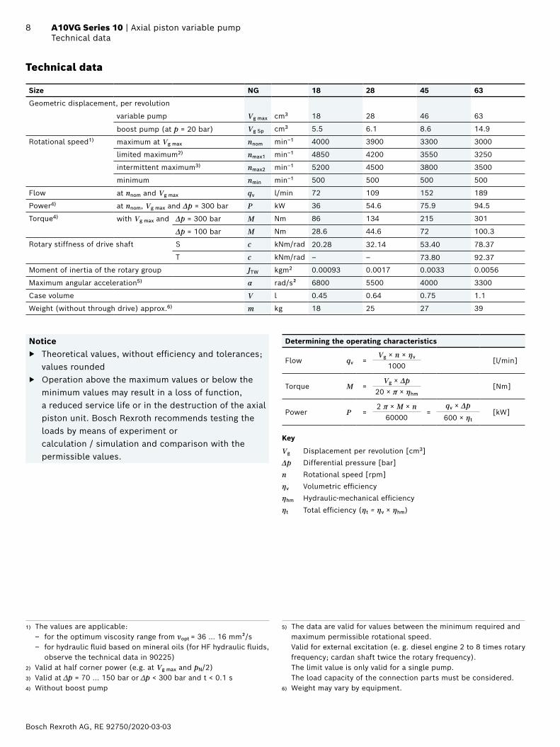
Technical data
Size NG 18 28 45 63
Geometric displacement, per revolution
variable pump Vg max cm3 18 28 46 63
boost pump (at p = 20 bar) Vg Sp cm3 5.5 6.1 8.6 14.9
Rotational speed1) maximum at Vg max nnom min–1 4000 3900 3300 3000
limited maximum2) nmax1 min–1 4850 4200 3550 3250
intermittent maximum3) nmax2 min–1 5200 4500 3800 3500
minimum nmin min–1 500 500 500 500
Flow at nnom and Vg max qv l/min 72 109 152 189
Power4) at nnom, Vg max and Δp = 300 bar P kW 36 54.6 75.9 94.5
Torque4) with Vg max and Δp = 300 bar M Nm 86 134 215 301
Δp = 100 bar M Nm 28.6 44.6 72 100.3
Rotary stiffness of drive shaft S c kNm/rad 20.28 32.14 53.40 78.37
T c kNm/rad ‒ ‒ 73.80 92.37
Moment of inertia of the rotary group JTW kgm2 0.00093 0.0017 0.0033 0.0056
Maximum angular acceleration5) α rad/s² 6800 5500 4000 3300
Case volume V l 0.45 0.64 0.75 1.1
Weight (without through drive) approx.6) m kg 18 25 27 39
Notice ▶ Theoretical values, without efficiency and tolerances;
values rounded ▶ Operation above the maximum values or below the
minimum values may result in a loss of function, a reduced service life or in the destruction of the axial piston unit. Bosch Rexroth recommends testing the loads by means of experiment or calculation / simulation and comparison with the permissible values.
Determining the operating characteristics
Flow qv =Vg × n × ηv [l/min]
1000
Torque M =Vg × Δp
[Nm]20 × π × ηhm
Power P =2 π × M × n
=qv × Δp
[kW]60000 600 × ηt
Key
Vg Displacement per revolution [cm3]
Δp Differential pressure [bar]
n Rotational speed [rpm]
ηv Volumetric efficiency
ηhm Hydraulic-mechanical efficiency
ηt Total efficiency (ηt = ηv × ηhm)
1) The values are applicable: – for the optimum viscosity range from νopt = 36 … 16 mm²/s – for hydraulic fluid based on mineral oils (for HF hydraulic fluids,
observe the technical data in 90225)2) Valid at half corner power (e.g. at Vg max and pN/2)3) Valid at ∆p = 70 ... 150 bar or ∆p < 300 bar and t < 0.1 s4) Without boost pump
5) The data are valid for values between the minimum required and maximum permissible rotational speed. Valid for external excitation (e. g. diesel engine 2 to 8 times rotary frequency; cardan shaft twice the rotary frequency). The limit value is only valid for a single pump. The load capacity of the connection parts must be considered.
6) Weight may vary by equipment.
RE 92750/2020-03-03, Bosch Rexroth AG
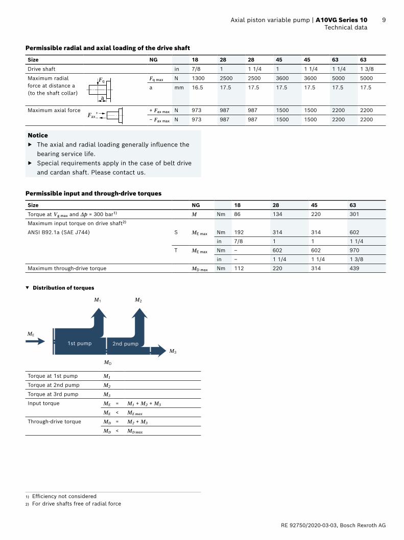
9 Axial piston variable pump | A10VG Series 10 Technical data
Permissible radial and axial loading of the drive shaft
Size NG 18 28 28 45 45 63 63
Drive shaft in 7/8 1 1 1/4 1 1 1/4 1 1/4 1 3/8
Maximum radial force at distance a (to the shaft collar)
[mm][inch]
Fq
a
Fq max N 1300 2500 2500 3600 3600 5000 5000
a mm 16.5 17.5 17.5 17.5 17.5 17.5 17.5
Maximum axial force
[mm]
Fax+–
+ Fax max N 973 987 987 1500 1500 2200 2200
− Fax max N 973 987 987 1500 1500 2200 2200
Notice ▶ The axial and radial loading generally influence the
bearing service life. ▶ Special requirements apply in the case of belt drive
and cardan shaft. Please contact us.
Permissible input and through-drive torques
Size NG 18 28 45 63
Torque at Vg max and Δp = 300 bar1) M Nm 86 134 220 301
Maximum input torque on drive shaft2)
ANSI B92.1a (SAE J744) S ME max Nm 192 314 314 602
in 7/8 1 1 1 1/4
T ME max Nm ‒ 602 602 970
in ‒ 1 1/4 1 1/4 1 3/8
Maximum through-drive torque MD max Nm 112 220 314 439
▼ Distribution of torques
ME
MD
M1 M2
M3
1st pump 2nd pump
Torque at 1st pump M1
Torque at 2nd pump M2
Torque at 3rd pump M3
Input torque ME = M1 + M2 + M3
ME < ME max
Through-drive torque MD = M2 + M3
MD < MD max
1) Efficiency not considered2) For drive shafts free of radial force

Bosch Rexroth AG, RE 92750/2020-03-03
10 A10VG Series 10 | Axial piston variable pumpHD – Proportional control, hydraulic, pilot-pressure related
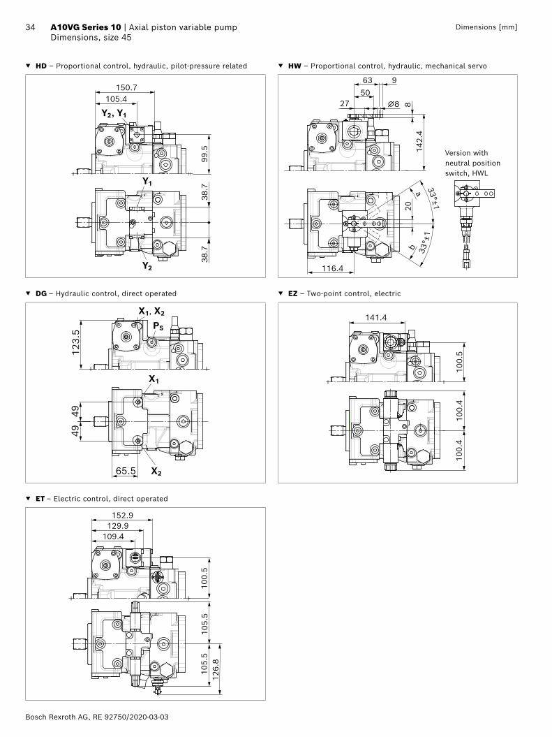
HD – Proportional control, hydraulic, pilot-pressure related
The output flow of the pump is infinitely variable between 0 and 100%, proportional to the difference in pilot pressure applied to the two pilot signal ports (Y1 and Y2).The pilot signal, coming from an external source, is a pressure signal. Flow is negligible, as the pilot signal acts only on the control spool of the control valve.This control spool then directs control oil into and out of the stroking cylinder to adjust pump displacement as required.A feedback lever connected to the stroking piston maintains the pump flow for any given pilot signal within the control range.If the pump is also equipped with a DA control valve (see page 14), automotive operation is possible for travel drives.
0 0.2 0.4 0.6 0.8 1.00.20.40.60.81.0
1816141210864202468
1012141618
Vg
Vg max
Vg
Vg max
NG18
NG28NG45, 63
pSt [bar]
pSt [bar]
Size 18 28 45 63
Beginning of control (Vg 0) pSt bar 6 6 6 6
End of control (Vg max) pSt bar 15.7 16 16.7 16.7
Key
Vg Displacement
Vg 0 Displacement in neutral position
Vg max Maximum displacement
pSt Pilot signal at port Y1, Y2
NoticeIn the neutral position, the HD control module must be unloaded to reservoir via the external pilot control device.
▼ Circuit diagram, version without pressure cut-off
Y1 Y2
MBFePST2T1R
X1 X2 G S MA
B
A
▼ Circuit diagram, version with pressure cut-off
Y1 Y2
MBFePST2T1R
X1 X2 G S MA
B
A
RE 92750/2020-03-03, Bosch Rexroth AG
11 Axial piston variable pump | A10VG Series 10 HD – Proportional control, hydraulic, pilot-pressure related
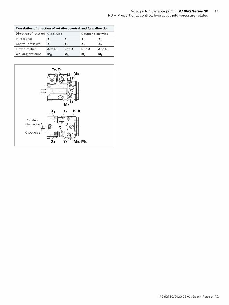
Correlation of direction of rotation, control and flow direction
Direction of rotation Clockwise Counter-clockwise
Pilot signal Y1 Y2 Y1 Y2
Control pressure X1 X2 X1 X2
Flow direction A to B B to A B to A A to B
Working pressure MB MA MA MB
Y1
Y2
X1
X2 MB, MA
MB
MA
B, A
Y2, Y1
Clockwise
Counter-clockwise
Bosch Rexroth AG, RE 92750/2020-03-03
12 A10VG Series 10 | Axial piston variable pumpHW – Proportional control, hydraulic, mechanical servo
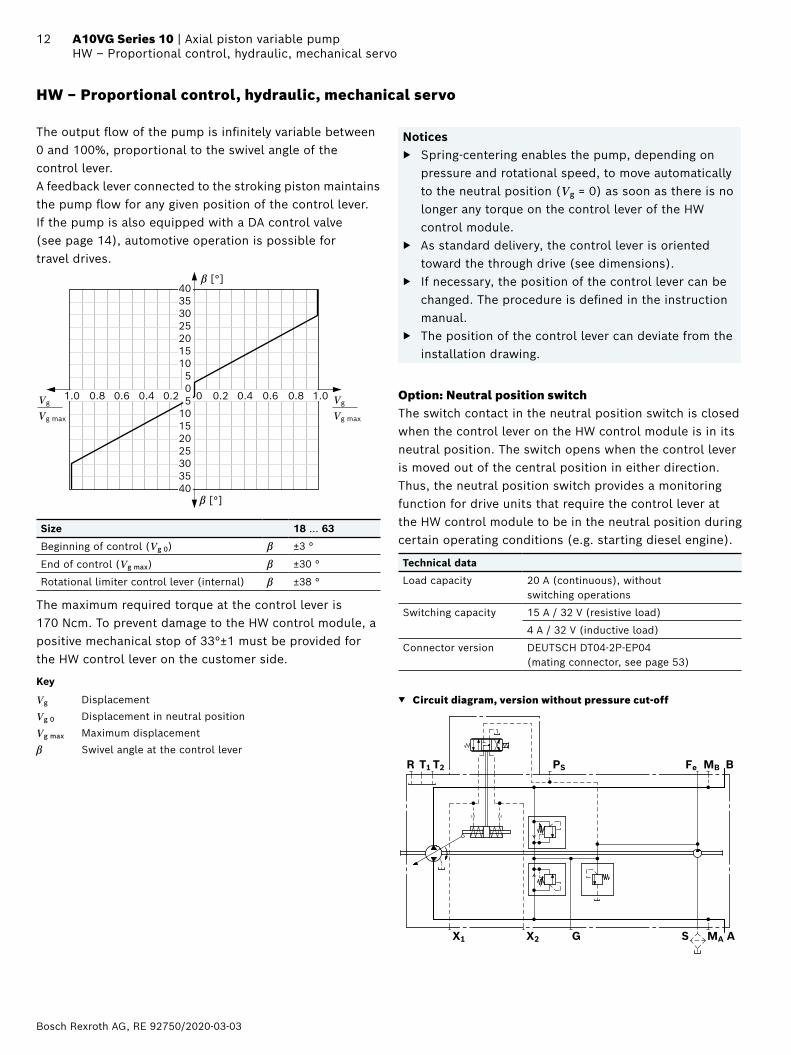
HW – Proportional control, hydraulic, mechanical servo
The output flow of the pump is infinitely variable between 0 and 100%, proportional to the swivel angle of the control lever.A feedback lever connected to the stroking piston maintains the pump flow for any given position of the control lever.If the pump is also equipped with a DA control valve (see page 14), automotive operation is possible for travel drives.
Vg
Vg max
0 0.2 0.4 0.6 0.8 1.00.20.40.60.81.0
β [°]
Vg
Vg max
β [°]
40353025201510505
10152025303540
Size 18 … 63
Beginning of control (Vg 0) β ±3 °
End of control (Vg max) β ±30 °
Rotational limiter control lever (internal) β ±38 °
The maximum required torque at the control lever is 170 Ncm. To prevent damage to the HW control module, a positive mechanical stop of 33°±1 must be provided for the HW control lever on the customer side.
Key
Vg Displacement
Vg 0 Displacement in neutral position
Vg max Maximum displacement
β Swivel angle at the control lever
Notices ▶ Spring-centering enables the pump, depending on
pressure and rotational speed, to move automatically to the neutral position (Vg = 0) as soon as there is no longer any torque on the control lever of the HW control module.
▶ As standard delivery, the control lever is oriented toward the through drive (see dimensions).
▶ If necessary, the position of the control lever can be changed. The procedure is defined in the instruction manual.
▶ The position of the control lever can deviate from the installation drawing.
Option: Neutral position switchThe switch contact in the neutral position switch is closed when the control lever on the HW control module is in its neutral position. The switch opens when the control lever is moved out of the central position in either direction.Thus, the neutral position switch provides a monitoring function for drive units that require the control lever at the HW control module to be in the neutral position during certain operating conditions (e.g. starting diesel engine).
Technical data
Load capacity 20 A (continuous), without switching operations
Switching capacity 15 A / 32 V (resistive load)
4 A / 32 V (inductive load)
Connector version DEUTSCH DT04-2P-EP04 (mating connector, see page 53)
▼ Circuit diagram, version without pressure cut-off
MBFePST2T1R
X1 X2 G S MA
B
A
RE 92750/2020-03-03, Bosch Rexroth AG
13 Axial piston variable pump | A10VG Series 10 HW – Proportional control, hydraulic, mechanical servo
▼ Circuit diagram, version with neutral position switch and pressure cut-off
MBFePST2T1R
X1 X2 G S MA
B
A
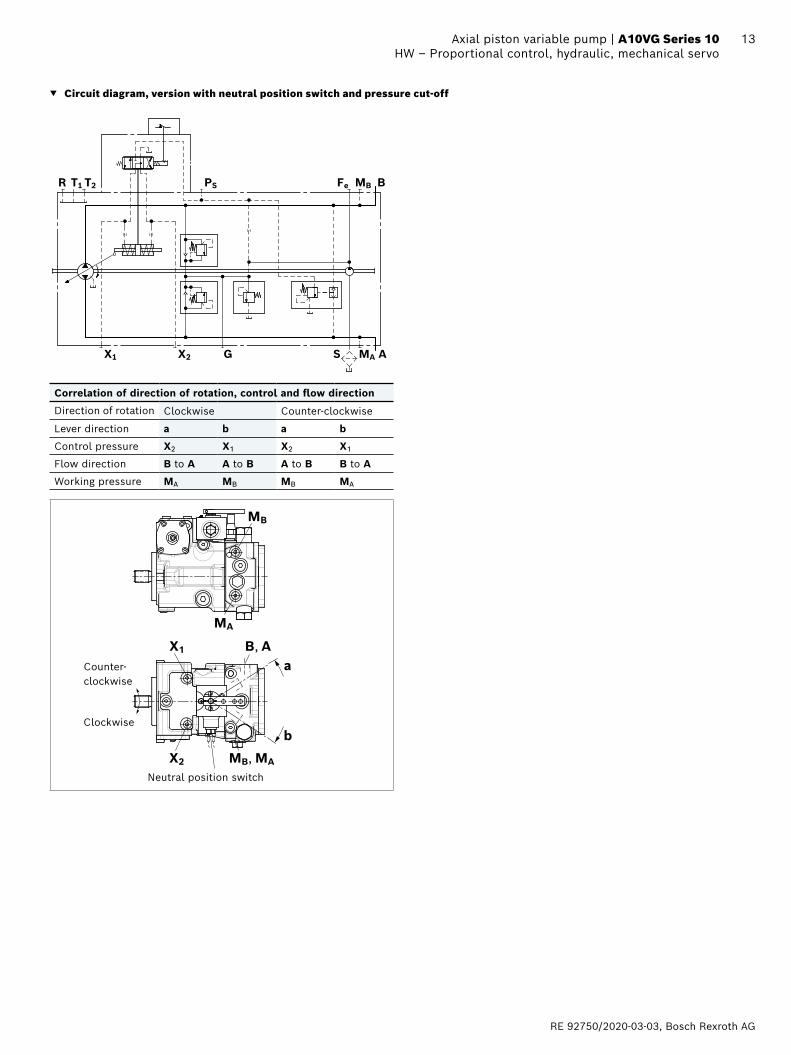
Correlation of direction of rotation, control and flow direction
Direction of rotation Clockwise Counter-clockwise
Lever direction a b a b
Control pressure X2 X1 X2 X1
Flow direction B to A A to B A to B B to A
Working pressure MA MB MB MA
X1
X2 MB, MA
MB
MA
B, Aa
bClockwise
Counter- clockwise
Neutral position switch
Bosch Rexroth AG, RE 92750/2020-03-03
14 A10VG Series 10 | Axial piston variable pumpDA – Automatic control, speed related
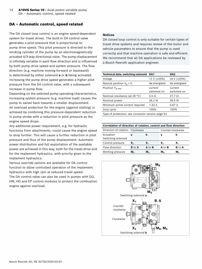
DA – Automatic control, speed related
The DA closed loop control is an engine speed-dependent system for travel drives. The built-in DA control valve generates a pilot pressure that is proportional to pump drive speed. This pilot pressure is directed to the stroking cylinder of the pump by an electromagnetically actuated 4/3-way directional valve. The pump displacement is infinitely variable in each flow direction and is influenced by both pump drive speed and system pressure. The flow direction (e.g. machine moving forward or backward) is determined by either solenoid a or b being activated. Increasing the pump drive speed generates a higher pilot pressure from the DA control valve, with a subsequent increase in pump flow.Depending on the selected pump operating characteristics, increasing system pressure (e.g. machine load) causes the pump to swivel back towards a smaller displacement. An overload protection for the engine (against stalling) is achieved by combining this pressure-dependent reduction in pump stroke with a reduction in pilot pressure as the engine speed drops.Any additional power requirement, e.g. for hydraulic functions from attachments, could cause the engine speed to drop further. This will cause a further reduction in pilot pressure and thus of the pump displacement. Automatic power distribution and full exploitation of the available power are achieved in this way, both for the travel drive and for the implement hydraulics, with priority given to the implement hydraulics.Various override options are available for DA control function to allow controlled operation of the implement hydraulics with high rpm at reduced travel speed.The DA control valve can also be used in pumps with DG, HW, HD and EP control modules to protect the combustion engine against overload.
NoticesDA closed loop control is only suitable for certain types of travel drive systems and requires review of the motor and vehicle parameters to ensure that the pump is used correctly and that machine operation is safe and efficient. We recommend that all DA applications be reviewed by a Bosch Rexroth application engineer.
Technical data, switching solenoid DA1 DA2
Voltage 12 V (±20%) 24 V (±20%)
Neutral position Vg = 0 de-energized de-energized
Position Vg max current switched on
current switched on
Nominal resistance (at 20 °C) 5.5 Ω 21.7 Ω
Nominal power 26.2 W 26.5 W
Minimum active current required 1.32 A 0.67 A
Duty cycle 100% 100%
Type of protection: see connector version page 53
Correlation of direction of rotation, control and flow direction
Direction of rotation Clockwise Counter-clockwise
Actuation Switching solenoid
a b a b
Control pressure X2 X1 X2 X1
Flow direction B to A A to B A to B B to A
Working pressure MA MB MB MA
X1
X2 MB, MA
MB
MA
B, A
Clockwise
Counter- clockwise
Switching solenoid b
Switching solenoid a
RE 92750/2020-03-03, Bosch Rexroth AG
15 Axial piston variable pump | A10VG Series 10 DA – Automatic control, speed related
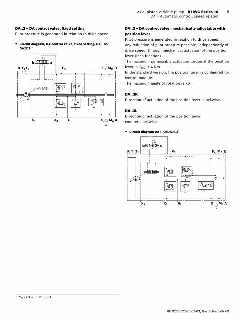
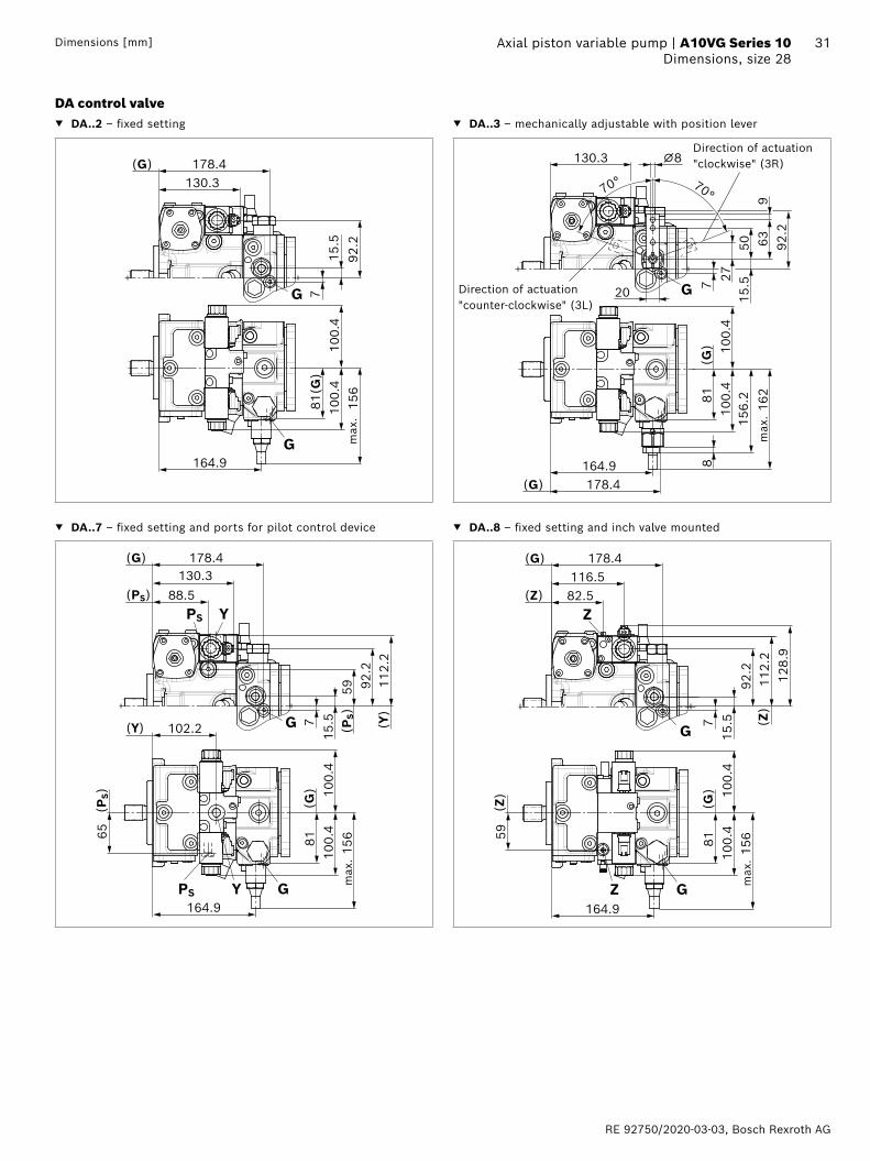
DA..2 − DA control valve, fixed settingPilot pressure is generated in relation to drive speed.
▼ Circuit diagram, DA control valve, fixed setting, DA1D2/DA2D21)
MBFePST2T1R
X1 X2 G S MA
B
A
b a
DA..3 − DA control valve, mechanically adjustable with position leverPilot pressure is generated in relation to drive speed.Any reduction of pilot pressure possible, independently of drive speed, through mechanical actuation of the position lever (inch function). The maximum permissible actuation torque at the position lever is Tmax = 4 Nm.In the standard version, the position lever is configured for control module.The maximum angle of rotation is 70°.
DA..3RDirection of actuation of the position lever: clockwise
DA..3LDirection of actuation of the position lever: counter-clockwise
▼ Circuit diagram DA1D3/DA2D31)
MBFePST2T1R
X1 X2 G S MA
B
A
b a
1) Size 63 with MH port
Bosch Rexroth AG, RE 92750/2020-03-03
16 A10VG Series 10 | Axial piston variable pumpDA – Automatic control, speed related
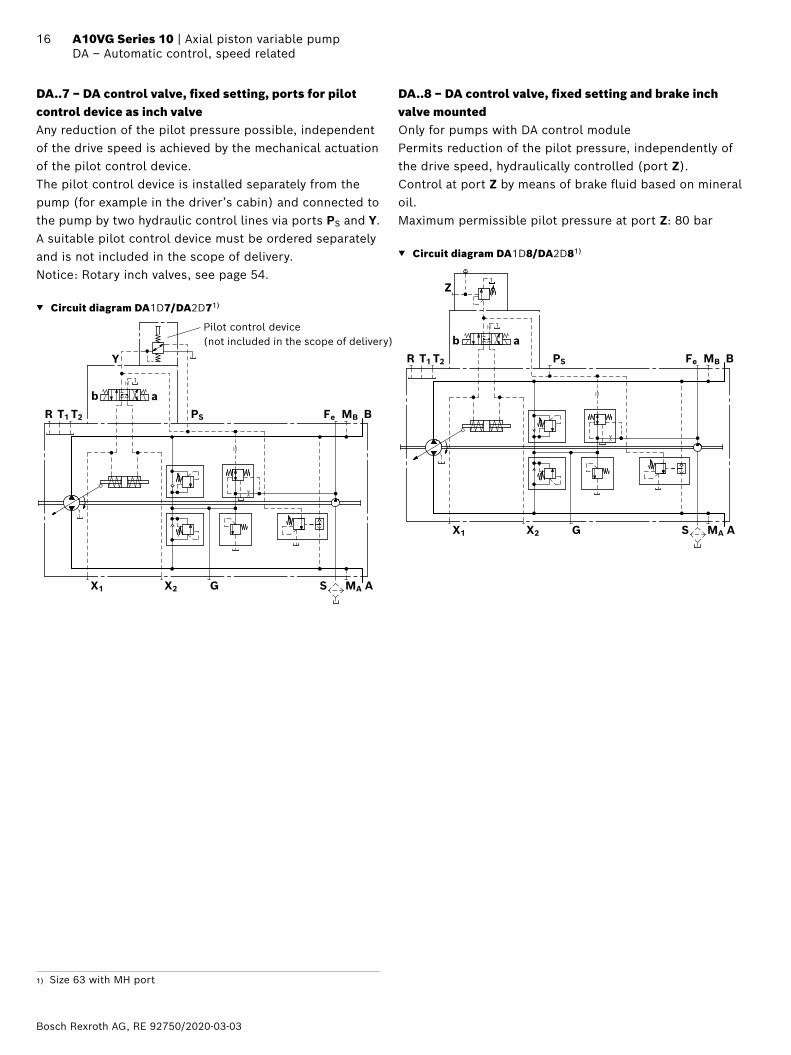
DA..7 − DA control valve, fixed setting, ports for pilot control device as inch valveAny reduction of the pilot pressure possible, independent of the drive speed is achieved by the mechanical actuation of the pilot control device. The pilot control device is installed separately from the pump (for example in the driver’s cabin) and connected to the pump by two hydraulic control lines via ports PS and Y.A suitable pilot control device must be ordered separately and is not included in the scope of delivery.Notice: Rotary inch valves, see page 54.
▼ Circuit diagram DA1D7/DA2D71)
MBFePST2T1R
X1 X2 G S MA
B
A
b a
Y
Pilot control device (not included in the scope of delivery)
DA..8 − DA control valve, fixed setting and brake inch valve mountedOnly for pumps with DA control modulePermits reduction of the pilot pressure, independently of the drive speed, hydraulically controlled (port Z). Control at port Z by means of brake fluid based on mineral oil.Maximum permissible pilot pressure at port Z: 80 bar
▼ Circuit diagram DA1D8/DA2D81)
Z
MBFePST2T1R
X1 X2 G S MA
B
A
b a
1) Size 63 with MH port
RE 92750/2020-03-03, Bosch Rexroth AG
17 Axial piston variable pump | A10VG Series 10 DG – Hydraulic control, direct operated
DG – Hydraulic control, direct operated
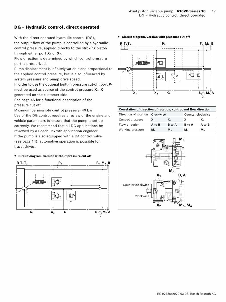
With the direct operated hydraulic control (DG), the output flow of the pump is controlled by a hydraulic control pressure, applied directly to the stroking piston through either port X1 or X2.Flow direction is determined by which control pressure port is pressurized.Pump displacement is infinitely variable and proportional to the applied control pressure, but is also influenced by system pressure and pump drive speed.In order to use the optional built-in pressure cut-off, port PS must be used as source of the control pressure X1, X2 generated on the customer side. See page 46 for a functional description of the pressure cut-off.Maximum permissible control pressure: 40 barUse of the DG control requires a review of the engine and vehicle parameters to ensure that the pump is set up correctly. We recommend that all DG applications be reviewed by a Bosch Rexroth application engineer.If the pump is also equipped with a DA control valve (see page 14), automotive operation is possible for travel drives.
▼ Circuit diagram, version without pressure cut-off
MBFePST2T1R
X1 X2 G S MA
B
A
▼ Circuit diagram, version with pressure cut-off
MBFePST2T1R
X1 X2 G S MA
B
A
Correlation of direction of rotation, control and flow direction
Direction of rotation Clockwise Counter-clockwise
Control pressure X1 X2 X1 X2
Flow direction A to B B to A B to A A to B
Working pressure MB MA MA MB
Clockwise
Counter-clockwise
X1
X2 MB, MA
MB
MAB, A
Bosch Rexroth AG, RE 92750/2020-03-03
18 A10VG Series 10 | Axial piston variable pumpEP – Proportional control, electric
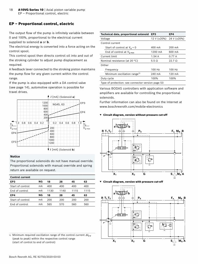
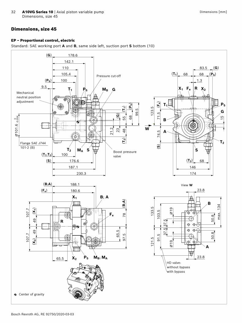
EP – Proportional control, electric
The output flow of the pump is infinitely variable between 0 and 100%, proportional to the electrical current supplied to solenoid a or b.The electrical energy is converted into a force acting on the control spool. This control spool then directs control oil into and out of the stroking cylinder to adjust pump displacement as required.A feedback lever connected to the stroking piston maintains the pump flow for any given current within the control range.If the pump is also equipped with a DA control valve (see page 14), automotive operation is possible for travel drives.
(Solenoid a)
(Solenoid b)
I [mA]
EP3
EP4
I [mA]
0.2 0.4 0.6 0.8 1.00.40.60.81.0
12001000800600400200
000.2 Vg
Vg max
Vg
Vg max 200400600800
10001200
EP4
EP3
NG45, 63
NoticeThe proportional solenoids do not have manual override. Proportional solenoids with manual override and spring return are available on request.
Control current
EP3 NG 18 28 45 63
Start of control mA 400 400 400 400
End of control mA 1130 1140 1115 1115
EP4 NG 18 28 45 63
Start of control mA 200 200 200 200
End of control mA 565 570 560 560
Technical data, proportional solenoid EP3 EP4
Voltage 12 V (±20%) 24 V (±20%)
Control current
Start of control at Vg = 0 400 mA 200 mA
End of control at Vg max 1200 mA 600 mA
Current limit 1.54 A 0.77 A
Nominal resistance (at 20 °C) 5.5 Ω 22.7 Ω
Dither
Frequency 100 Hz 100 Hz
Minimum oscillation range1) 240 mA 120 mA
Duty cycle 100% 100%
Type of protection: see connector version page 53
Various BODAS controllers with application software and amplifiers are available for controlling the proportional solenoids.Further information can also be found on the Internet at www.boschrexroth.com/mobile-electronics
▼ Circuit diagram, version without pressure cut-off
MBFePST2T1R
X1 X2 G S MA
B
A
ba
▼ Circuit diagram, version with pressure cut-off
MBFePST2T1R
X1 X2 G S MA
B
A
ba
1) Minimum required oscillation range of the control current ΔIp-p (peak to peak) within the respective control range (start of control to end of control)
RE 92750/2020-03-03, Bosch Rexroth AG
19 Axial piston variable pump | A10VG Series 10 EP – Proportional control, electric
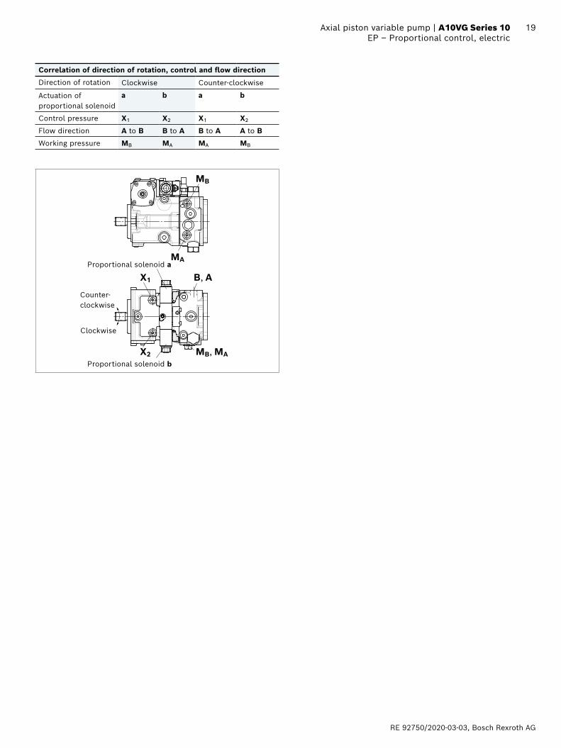
Correlation of direction of rotation, control and flow direction
Direction of rotation Clockwise Counter-clockwise
Actuation of proportional solenoid
a b a b
Control pressure X1 X2 X1 X2
Flow direction A to B B to A B to A A to B
Working pressure MB MA MA MB
Clockwise
Counter- clockwise
X1
X2 MB, MA
MB
MA
B, A
Proportional solenoid b
Proportional solenoid a
Bosch Rexroth AG, RE 92750/2020-03-03
20 A10VG Series 10 | Axial piston variable pumpEZ – Two-point control, electric
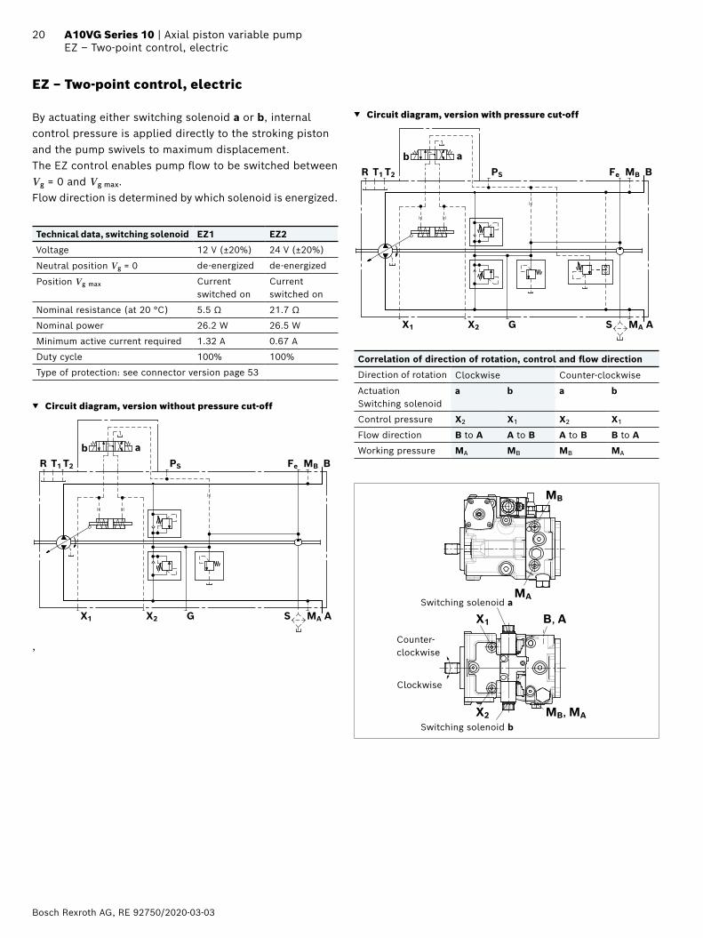
EZ – Two-point control, electric
By actuating either switching solenoid a or b, internal control pressure is applied directly to the stroking piston and the pump swivels to maximum displacement. The EZ control enables pump flow to be switched between Vg = 0 and Vg max. Flow direction is determined by which solenoid is energized.
Technical data, switching solenoid EZ1 EZ2
Voltage 12 V (±20%) 24 V (±20%)
Neutral position Vg = 0 de-energized de-energized
Position Vg max Current switched on
Current switched on
Nominal resistance (at 20 °C) 5.5 Ω 21.7 Ω
Nominal power 26.2 W 26.5 W
Minimum active current required 1.32 A 0.67 A
Duty cycle 100% 100%
Type of protection: see connector version page 53
▼ Circuit diagram, version without pressure cut-off
MBFePST2T1R
X1 X2 G S MA
B
A
b a
,
▼ Circuit diagram, version with pressure cut-off
MBFePST2T1R
X1 X2 G S MA
B
A
b a
Correlation of direction of rotation, control and flow direction
Direction of rotation Clockwise Counter-clockwise
Actuation Switching solenoid
a b a b
Control pressure X2 X1 X2 X1
Flow direction B to A A to B A to B B to A
Working pressure MA MB MB MA
X1
X2 MB, MA
MB
MA
B, A
Clockwise
Counter- clockwise
Switching solenoid b
Switching solenoid a
RE 92750/2020-03-03, Bosch Rexroth AG
21 Axial piston variable pump | A10VG Series 10 ET – Electric control, direct operated
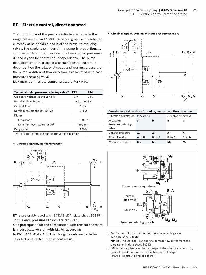
ET – Electric control, direct operated
The output flow of the pump is infinitely variable in the range between 0 and 100%. Depending on the preselected current I at solenoids a and b of the pressure reducing valves, the stroking cylinder of the pump is proportionally supplied with control pressure. The two control pressures X1 and X2 can be controlled independently. The pump displacement that arises at a certain control current is dependent on the rotational speed and working pressure of the pump. A different flow direction is associated with each pressure reducing valve. Maximum permissible control pressure PS: 40 bar.
Technical data, pressure reducing valve1) ET3 ET4
On-board voltage in the vehicle 12 V 24 V
Permissible voltage U 9.6 … 28.8 V
Current limit 1.8 A
Nominal resistance (at 20 °C) 2.4 Ω
Dither
Frequency 100 Hz
Minimum oscillation range2) 360 mA
Duty cycle 100%
Type of protection: see connector version page 53
▼ Circuit diagram, standard version
pU
pUMBFePST2T1R
X1 X2 G SMA
B
A
ba
ET is preferably used with BODAS eDA (data sheet 95315). To this end, pressure sensors are required. One prerequisite for the combination with pressure sensors is a port plate version with MA/MB according to ISO 6149 M14 × 1.5. This design is only available for selected port plates, please contact us.
▼ Circuit diagram, version without pressure sensors
MBFePST2T1R
X1 X2 G S MA
B
A
ba
Correlation of direction of rotation, control and flow direction
Direction of rotation Clockwise Counter-clockwise
Actuation Pressure reducing valve
a b a b
Control pressure X1 X2 X1 X2
Flow direction A to B B to A B to A A to B
Working pressure MB MA MA MB
MAMAMA
MB
B; A
MB; MA
X1
X2
Pressure reducing valve a
Pressure reducing valve b
Clockwise
Counter- clockwise
1) For further information on the pressure reducing valve, see data sheet 58032. Notice: The leakage flow and the control flow differ from the parameter in data sheet 58032.
2) Minimum required oscillation range of the control current ΔIp-p (peak to peak) within the respective control range (start of control to end of control)
Bosch Rexroth AG, RE 92750/2020-03-03
22 A10VG Series 10 | Axial piston variable pumpED – Electric pressure control
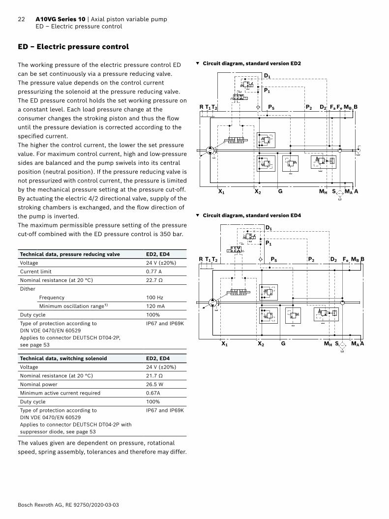
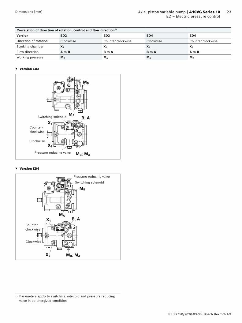
ED – Electric pressure control
The working pressure of the electric pressure control ED can be set continuously via a pressure reducing valve. The pressure value depends on the control current pressurizing the solenoid at the pressure reducing valve.The ED pressure control holds the set working pressure on a constant level. Each load pressure change at the consumer changes the stroking piston and thus the flow until the pressure deviation is corrected according to the specified current.The higher the control current, the lower the set pressure value. For maximum control current, high and low-pressure sides are balanced and the pump swivels into its central position (neutral position). If the pressure reducing valve is not pressurized with control current, the pressure is limited by the mechanical pressure setting at the pressure cut-off.By actuating the electric 4/2 directional valve, supply of the stroking chambers is exchanged, and the flow direction of the pump is inverted.The maximum permissible pressure setting of the pressure cut-off combined with the ED pressure control is 350 bar.
Technical data, pressure reducing valve ED2, ED4
Voltage 24 V (±20%)
Current limit 0.77 A
Nominal resistance (at 20 °C) 22.7 Ω
Dither
Frequency 100 Hz
Minimum oscillation range1) 120 mA
Duty cycle 100%
Type of protection according to DIN VDE 0470/EN 60529Applies to connector DEUTSCH DT04-2P, see page 53
IP67 and IP69K
Technical data, switching solenoid ED2, ED4
Voltage 24 V (±20%)
Nominal resistance (at 20 °C) 21.7 Ω
Nominal power 26.5 W
Minimum active current required 0.67A
Duty cycle 100%
Type of protection according to DIN VDE 0470/EN 60529Applies to connector DEUTSCH DT04-2P with suppressor diode, see page 53
IP67 and IP69K
The values given are dependent on pressure, rotational speed, spring assembly, tolerances and therefore may differ.
▼ Circuit diagram, standard version ED2
Fa
MH
P2 D2
P1
D1
MBFePST2T1R
X1 X2 G S MA
B
A
▼ Circuit diagram, standard version ED4
MBFePST2T1R
X1 X2 G S MA
B
AMH
P2 D2
P1
D1
RE 92750/2020-03-03, Bosch Rexroth AG
23 Axial piston variable pump | A10VG Series 10 ED – Electric pressure controlDimensions [mm]
Correlation of direction of rotation, control and flow direction1)
Version ED2 ED2 ED4 ED4
Direction of rotation Clockwise Counter-clockwise Clockwise Counter-clockwise
Stroking chamber X1 X1 X2 X2
Flow direction A to B B to A B to A A to B
Working pressure MB MA MA MB
▼ Version ED2
MB; MA
B; A
MB
MA
X1
X2
Pressure reducing valve
Switching solenoid
Clockwise
Counter- clockwise
▼ Version ED4
Clockwise
Counter- clockwise
B; A
MB
MA
MB; MA
X1
X2
Switching solenoid
Pressure reducing valve
1) Parameters apply to switching solenoid and pressure reducing valve in de-energized condition
Bosch Rexroth AG, RE 92750/2020-03-03
24 A10VG Series 10 | Axial piston variable pumpDimensions, size 18
Dimensions [mm]
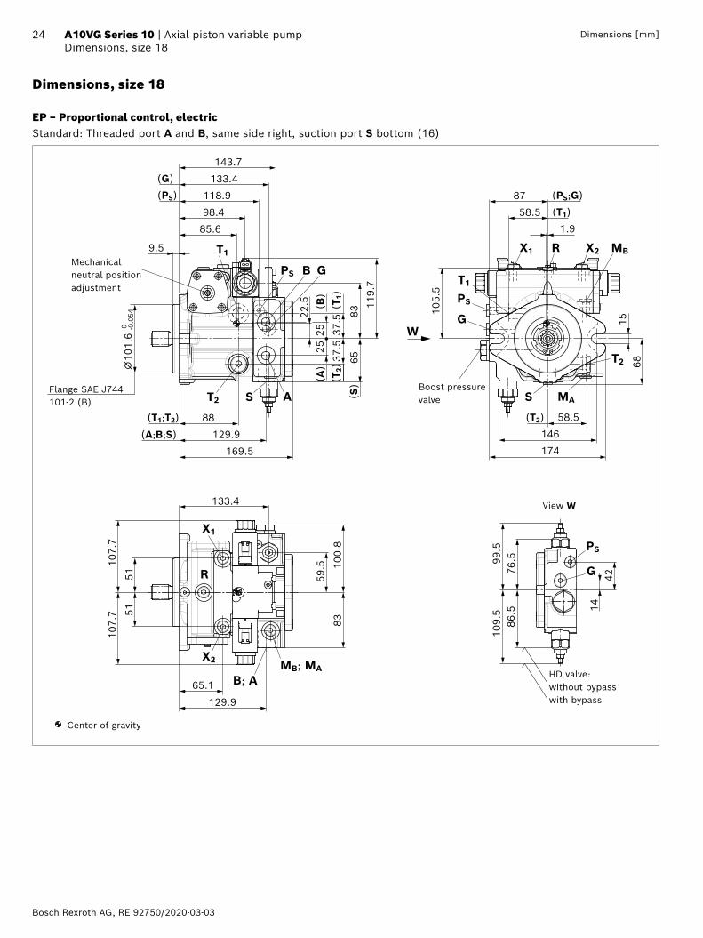
Dimensions, size 18
EP – Proportional control, electricStandard: Threaded port A and B, same side right, suction port S bottom (16)
15
174
9.5
98.4
143.7
88
129.9
169.5
22.5
85.6
2525
6537.5
83 105.
5
87
146
58.5
68
37.5
5151
107.
710
7.7
100.
883
129.9
1442
76.5
86.5
58.5
133.4
118.9
133.4
109.
599
.5
⌀10
1.6
-0.0
54 0
59.5
119.
7
65.1
1.9
G
B
R
W
PS
T1
X1 X2 MB
(T1)
T1
(T1)
(T2)
(B)
(A)
(T1;T2)
(A;B;S)
PS G
(G)
(PS) (PS;G)
(S)
AS
T2
S
(T2)
MAT2
R
X1
MB; MAX2
PS
G
B; A
Boost pressure valve
Flange SAE J744101-2 (B)
Center of gravity
View W
Mechanical neutral position adjustment
HD valve: without bypass with bypass
RE 92750/2020-03-03, Bosch Rexroth AG
25 Axial piston variable pump | A10VG Series 10 Dimensions, size 18Dimensions [mm]
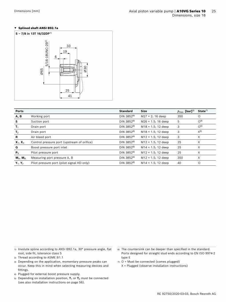
▼ Splined shaft ANSI B92.1a
S ‒ 7/8 in 13T 16/32DP1)
196
41
⌀65
25
5/16
-18U
NC
-2B
2)
⌀30
33
Ports Standard Size pmax [bar]3) State7)
A, B Working port DIN 38526) M27 × 2; 16 deep 350 O
S Suction port DIN 38526) M26 × 1.5; 16 deep 5 O4)
T1 Drain port DIN 38526) M18 × 1.5; 12 deep 3 O5)
T2 Drain port DIN 38526) M18 × 1.5; 12 deep 3 X5)
R Air bleed port DIN 38526) M12 × 1.5; 12 deep 3 X
X1, X2 Control pressure port (upstream of orifice) DIN 38526) M12 × 1.5; 12 deep 25 X
G Boost pressure port inlet DIN 38526) M14 × 1.5; 12 deep 25 X
PS Pilot pressure port DIN 38526) M12 × 1.5; 12 deep 25 X
MA, MB Measuring port pressure A, B DIN 38526) M12 × 1.5; 12 deep 350 X
Y1, Y2 Pilot pressure port (pilot signal HD only) DIN 38526) M14 × 1.5; 12 deep 40 O
1) Involute spline according to ANSI B92.1a, 30° pressure angle, flat root, side fit, tolerance class 5
2) Thread according to ASME B1.13) Depending on the application, momentary pressure peaks can
occur. Keep this in mind when selecting measuring devices and fittings.
4) Plugged for external boost pressure supply.5) Depending on installation position, T1 or T2 must be connected
(see also installation instructions on page 56).
6) The countersink can be deeper than specified in the standard. Ports designed for straight stud ends according to EN ISO 9974-2 type E
7) O = Must be connected (comes plugged) X = Plugged (observe installation instructions)
Bosch Rexroth AG, RE 92750/2020-03-03
26 A10VG Series 10 | Axial piston variable pumpDimensions, size 18
Dimensions [mm]
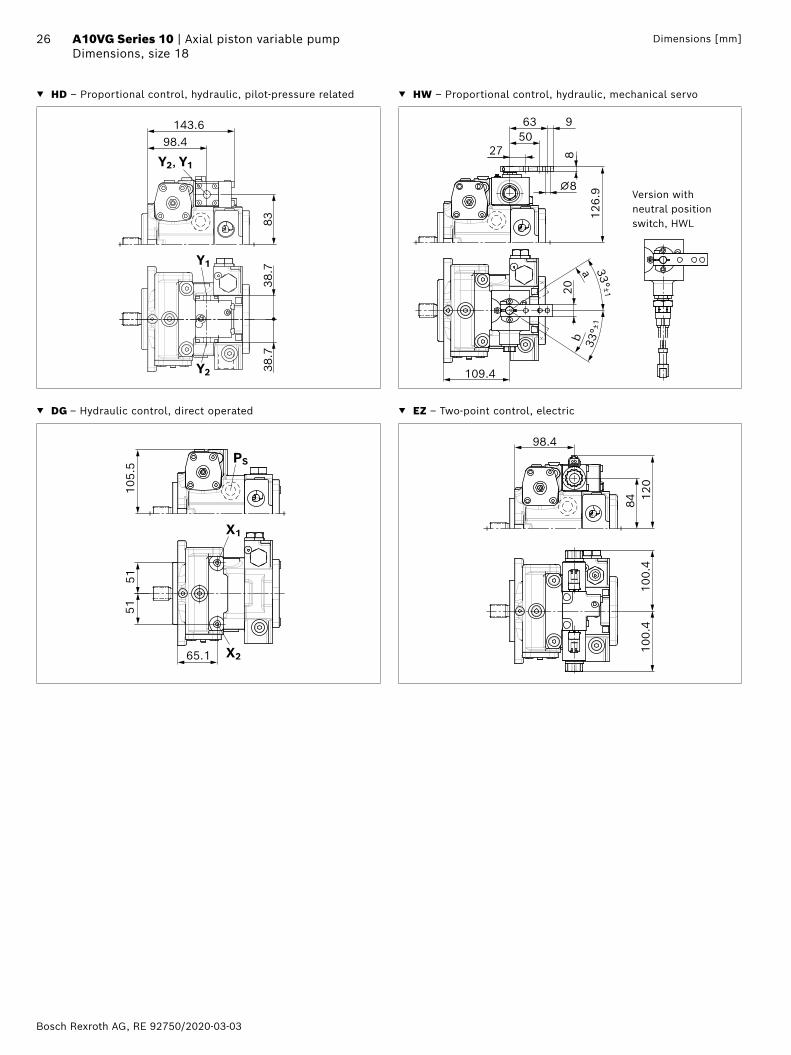
▼ HD – Proportional control, hydraulic, pilot-pressure related ▼ HW – Proportional control, hydraulic, mechanical servo
8338
.738
.7
143.698.4
Y1
Y2
Y2, Y1
63
2750
8
9
⌀8
20
a
b
109.4
126.
9
33° ±1
33°±
1
Version with neutral position switch, HWL
▼ DG – Hydraulic control, direct operated ▼ EZ – Two-point control, electric
5151
X1
105.
5
65.1 X2
PS
98.4
8410
0.4
100.
412
0
RE 92750/2020-03-03, Bosch Rexroth AG
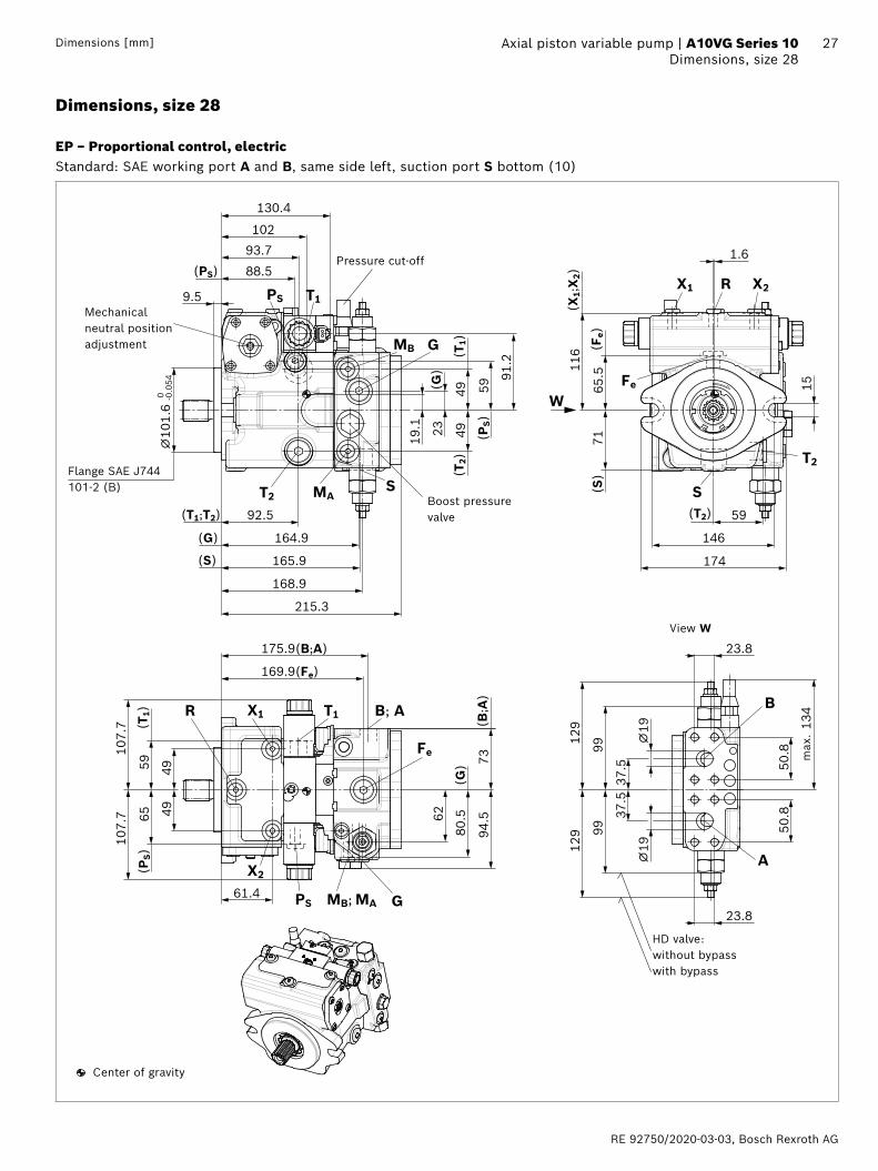
27 Axial piston variable pump | A10VG Series 10 Dimensions, size 28Dimensions [mm]
Dimensions, size 28
EP – Proportional control, electricStandard: SAE working port A and B, same side left, suction port S bottom (10)
92.5
102
88.5
165.9
164.9
215.3
130.4
93.7
⌀10
1.6
-0.0
54 0
9.5
19.1 23
49 59
49
91.2
107.
710
7.7
175.9(B;A)
169.9(Fe)
15
146
59
7165
.5116
174
⌀19
⌀19
37.5
50.8
99
134
99
23.8
50.8
37.5
129
129
23.8
4949
5965 62
61.4
94.5
80.5
73
168.9
1.6
MB
W
(T1)
(T2)
(G)
(T1;T2)
(G)
PS
G
(PS)
(PS)
ST2
T1
MA
(S)
X1 X2R
Fe
(Fe)
T2
(S)
(T1)
(PS)
T1X1
Fe
(B;A
)
X2
PS MB; MA
(T2)
G
B; AR
A
B
S
(X1;
X2)
(G)
Boost pressure valve
Flange SAE J744101-2 (B)
Center of gravity
View W
Mechanical neutral position adjustment
HD valve: without bypass with bypass
max
.
Pressure cut-off
Bosch Rexroth AG, RE 92750/2020-03-03
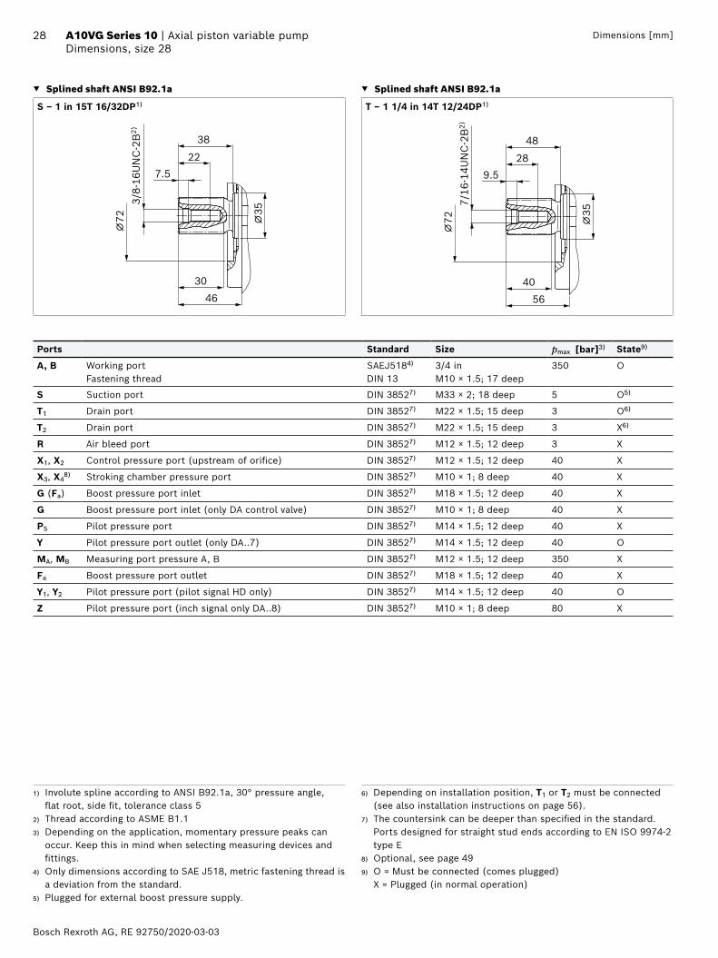
28 A10VG Series 10 | Axial piston variable pumpDimensions, size 28
Dimensions [mm]
▼ Splined shaft ANSI B92.1a ▼ Splined shaft ANSI B92.1a
S ‒ 1 in 15T 16/32DP1) T ‒ 1 1/4 in 14T 12/24DP1)
227.5
46
⌀72
30
3/8-
16U
NC
-2B
2)
⌀35
38
289.5
56
⌀72
40
7/16
-14U
NC
-2B
2)
⌀35
48
Ports Standard Size pmax [bar]3) State9)
A, B Working portFastening thread
SAEJ5184) DIN 13
3/4 in M10 × 1.5; 17 deep
350 O
S Suction port DIN 38527) M33 × 2; 18 deep 5 O5)
T1 Drain port DIN 38527) M22 × 1.5; 15 deep 3 O6)
T2 Drain port DIN 38527) M22 × 1.5; 15 deep 3 X6)
R Air bleed port DIN 38527) M12 × 1.5; 12 deep 3 X
X1, X2 Control pressure port (upstream of orifice) DIN 38527) M12 × 1.5; 12 deep 40 X
X3, X48) Stroking chamber pressure port DIN 38527) M10 × 1; 8 deep 40 X
G (Fa) Boost pressure port inlet DIN 38527) M18 × 1.5; 12 deep 40 X
G Boost pressure port inlet (only DA control valve) DIN 38527) M10 × 1; 8 deep 40 X
PS Pilot pressure port DIN 38527) M14 × 1.5; 12 deep 40 X
Y Pilot pressure port outlet (only DA..7) DIN 38527) M14 × 1.5; 12 deep 40 O
MA, MB Measuring port pressure A, B DIN 38527) M12 × 1.5; 12 deep 350 X
Fe Boost pressure port outlet DIN 38527) M18 × 1.5; 12 deep 40 X
Y1, Y2 Pilot pressure port (pilot signal HD only) DIN 38527) M14 × 1.5; 12 deep 40 O
Z Pilot pressure port (inch signal only DA..8) DIN 38527) M10 × 1; 8 deep 80 X
1) Involute spline according to ANSI B92.1a, 30° pressure angle, flat root, side fit, tolerance class 5
2) Thread according to ASME B1.13) Depending on the application, momentary pressure peaks can
occur. Keep this in mind when selecting measuring devices and fittings.
4) Only dimensions according to SAE J518, metric fastening thread is a deviation from the standard.
5) Plugged for external boost pressure supply.
6) Depending on installation position, T1 or T2 must be connected (see also installation instructions on page 56).
7) The countersink can be deeper than specified in the standard. Ports designed for straight stud ends according to EN ISO 9974-2 type E
8) Optional, see page 499) O = Must be connected (comes plugged)
X = Plugged (in normal operation)
RE 92750/2020-03-03, Bosch Rexroth AG
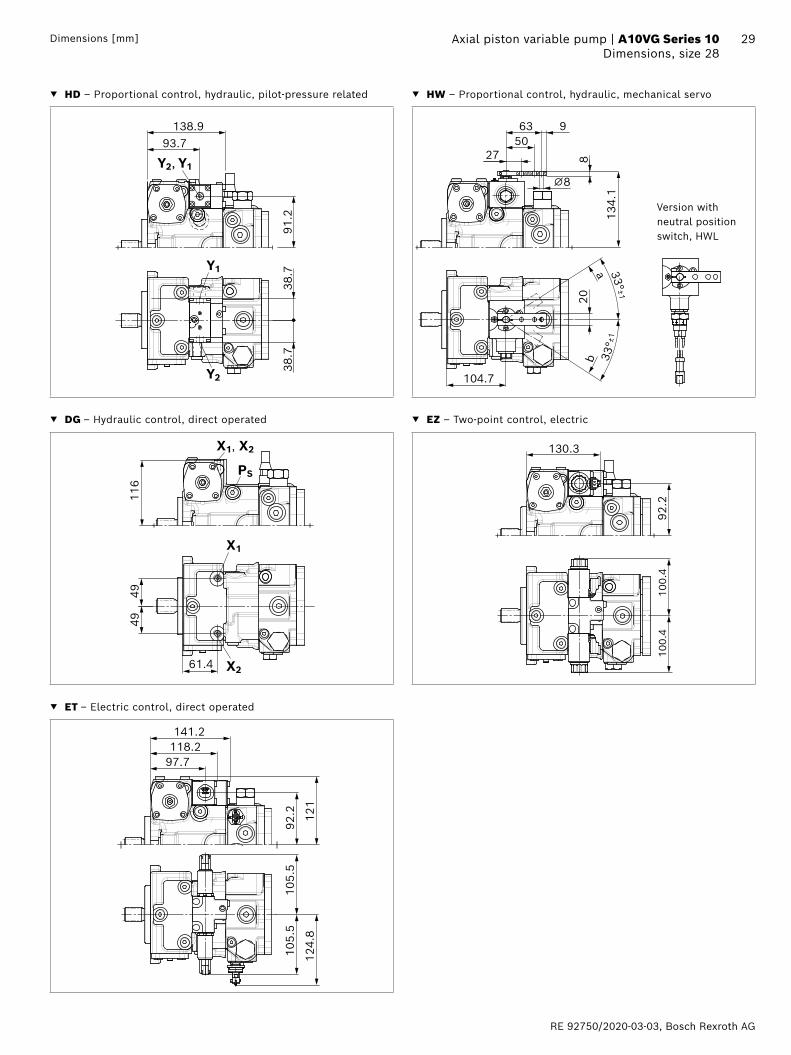
29 Axial piston variable pump | A10VG Series 10 Dimensions, size 28Dimensions [mm]
▼ HD – Proportional control, hydraulic, pilot-pressure related ▼ HW – Proportional control, hydraulic, mechanical servo
138.9
91.2
93.7
38.7
38.7
Y1
Y2
Y2, Y1
Version with neutral position switch, HWL
104.7
63 950
27
20
a
b
33° ±1
33°±
1
8
⌀8
134.
1
▼ DG – Hydraulic control, direct operated ▼ EZ – Two-point control, electric
X1
61.4 X2
4949
116
X1, X2
PS
130.3
92.2
100.
410
0.4
▼ ET – Electric control, direct operated
92.2 12
1
105.
510
5.5
124.
8
141.2
97.7 118.2
Bosch Rexroth AG, RE 92750/2020-03-03
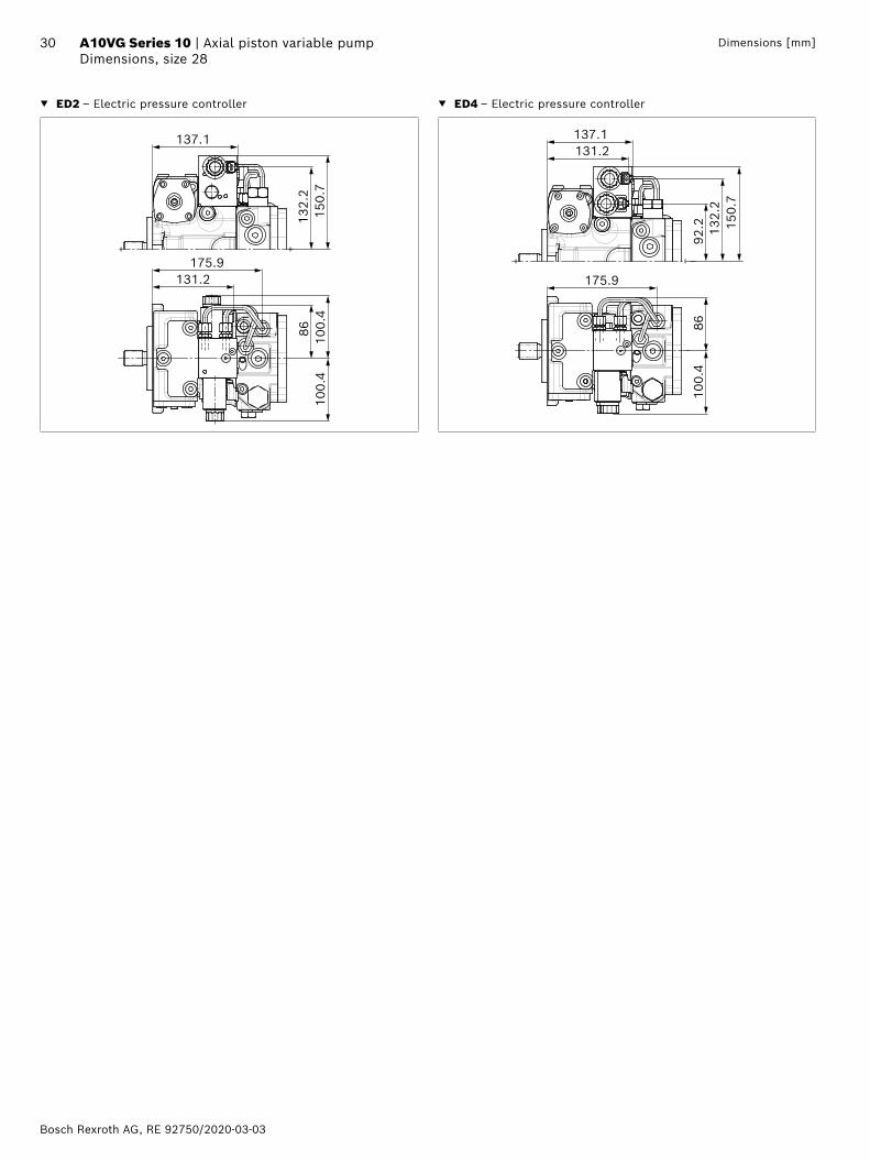
30 A10VG Series 10 | Axial piston variable pumpDimensions, size 28
Dimensions [mm]
▼ ED2 – Electric pressure controller ▼ ED4 – Electric pressure controller
175.9
8610
0.4
100.
4
131.2
132.
215
0.7
137.1
100.
486
175.9
131.2
132.
215
0.7
92.2
137.1
RE 92750/2020-03-03, Bosch Rexroth AG
31 Axial piston variable pump | A10VG Series 10 Dimensions, size 28Dimensions [mm]
DA control valve ▼ DA..2 – fixed setting ▼ DA..3 – mechanically adjustable with position lever
G
130.3178.4
92.2
15.5
156
100.
410
0.4
7G81
(G)
(G)
164.9
max
.
20
130.3
70°
2715
.550 63
992
.2
70°
⌀8
100.
410
0.4
162
8164.9
156.
2
7G
178.4(G)
81(G
)
max
.
Direction of actuation "clockwise" (3R)
Direction of actuation "counter-clockwise" (3L)
▼ DA..7 – fixed setting and ports for pilot control device ▼ DA..8 – fixed setting and inch valve mounted
88.5
92.2
59 112.
2
130.3178.4
715
.5
65 81
102.2
156
100.
410
0.4
G (PS)
PS GY
PS Y(PS)
(G)
(G)
(PS)
(Y)
(Y)
164.9
max
.
164.9
82.5
92.2
128.
911
2.2
116.5
15.5
59
156
100.
410
0.4
81
178.4
7
G
Z G
Z(Z)
(G)
(G)
(Z)
(Z)
max
.
Bosch Rexroth AG, RE 92750/2020-03-03
32 A10VG Series 10 | Axial piston variable pumpDimensions, size 45
Dimensions [mm]
Dimensions, size 45
EP – Proportional control, electricStandard: SAE working port A and B, same side left, suction port S bottom (10)
554823
21.2
100
176.6
187.1
110
100
9.5
178.6
105.4
188.1
180.6
4949
107.
710
7.7 65.5
97.5
78
23.8
23.8
134
50.8
50.8
133.
5
⌀19
37.5
103.
591
.5 37.5
121.
5
⌀19
65.5
⌀10
1.6
-0.0
54 0
230.3
6868
146
174
68
123.
5
71.5
74.5
68 15
99.5
83.5
1.3
142.1
MB
W
(T1)
(T2)
(G)
(T1;T2)
(G)
PS G
(PS)
(PS)
ST2
T1
MA
(S)
X1 X2R
(Fe)
T2
(S)
X1
Fe
(B;A
)
X2 PS
(T2)
G
PS
Fe
T1
S
(X2)
(X1)
MB; MA
(B;A)
(Fe)
A
B
(PS)
(T1)
R
(G)
B
A
B; A
Pressure cut-off
Boost pressure valve
Flange SAE J744101-2 (B)
Center of gravity
View W
Mechanical neutral position adjustment
HD valve: without bypass with bypass
max
.
RE 92750/2020-03-03, Bosch Rexroth AG
33 Axial piston variable pump | A10VG Series 10 Dimensions, size 45Dimensions [mm]
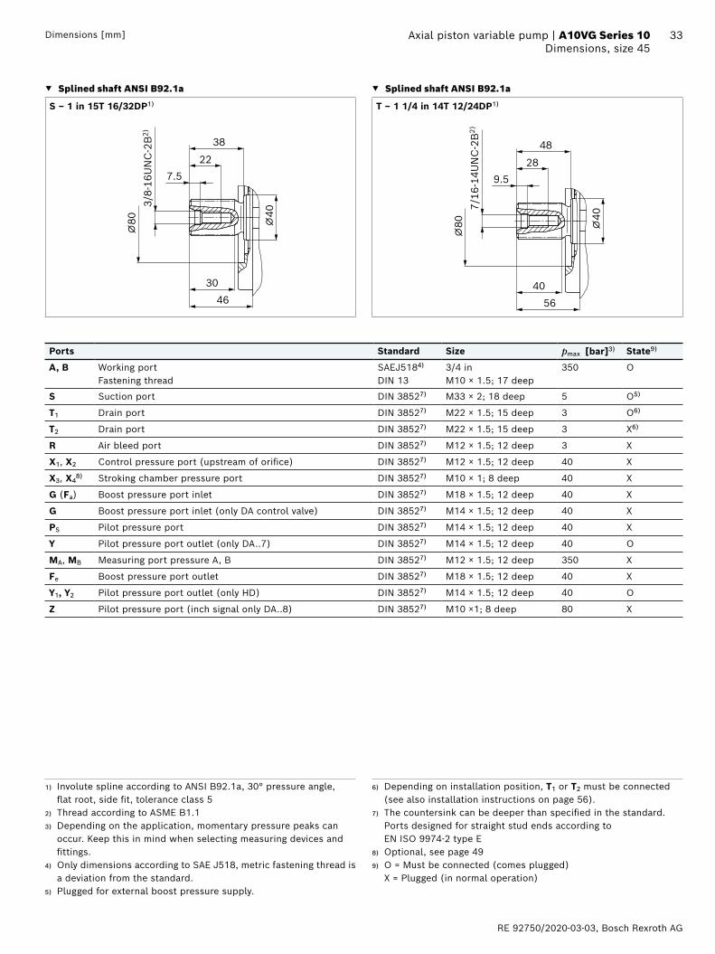
▼ Splined shaft ANSI B92.1a ▼ Splined shaft ANSI B92.1a
S ‒ 1 in 15T 16/32DP1) T ‒ 1 1/4 in 14T 12/24DP1)
227.5
46
⌀80
30
3/8-
16U
NC
-2B
2)
⌀40
38
289.5
56
⌀80
40
7/16
-14U
NC
-2B
2)
⌀40
48
Ports Standard Size pmax [bar]3) State9)
A, B Working portFastening thread
SAEJ5184) DIN 13
3/4 in M10 × 1.5; 17 deep
350 O
S Suction port DIN 38527) M33 × 2; 18 deep 5 O5)
T1 Drain port DIN 38527) M22 × 1.5; 15 deep 3 O6)
T2 Drain port DIN 38527) M22 × 1.5; 15 deep 3 X6)
R Air bleed port DIN 38527) M12 × 1.5; 12 deep 3 X
X1, X2 Control pressure port (upstream of orifice) DIN 38527) M12 × 1.5; 12 deep 40 X
X3, X48) Stroking chamber pressure port DIN 38527) M10 × 1; 8 deep 40 X
G (Fa) Boost pressure port inlet DIN 38527) M18 × 1.5; 12 deep 40 X
G Boost pressure port inlet (only DA control valve) DIN 38527) M14 × 1.5; 12 deep 40 X
PS Pilot pressure port DIN 38527) M14 × 1.5; 12 deep 40 X
Y Pilot pressure port outlet (only DA..7) DIN 38527) M14 × 1.5; 12 deep 40 O
MA, MB Measuring port pressure A, B DIN 38527) M12 × 1.5; 12 deep 350 X
Fe Boost pressure port outlet DIN 38527) M18 × 1.5; 12 deep 40 X
Y1, Y2 Pilot pressure port outlet (only HD) DIN 38527) M14 × 1.5; 12 deep 40 O
Z Pilot pressure port (inch signal only DA..8) DIN 38527) M10 ×1; 8 deep 80 X
1) Involute spline according to ANSI B92.1a, 30° pressure angle, flat root, side fit, tolerance class 5
2) Thread according to ASME B1.13) Depending on the application, momentary pressure peaks can
occur. Keep this in mind when selecting measuring devices and fittings.
4) Only dimensions according to SAE J518, metric fastening thread is a deviation from the standard.
5) Plugged for external boost pressure supply.
6) Depending on installation position, T1 or T2 must be connected (see also installation instructions on page 56).
7) The countersink can be deeper than specified in the standard. Ports designed for straight stud ends according to EN ISO 9974-2 type E
8) Optional, see page 499) O = Must be connected (comes plugged)
X = Plugged (in normal operation)
Bosch Rexroth AG, RE 92750/2020-03-03
34 A10VG Series 10 | Axial piston variable pumpDimensions, size 45
Dimensions [mm]
▼ HD – Proportional control, hydraulic, pilot-pressure related ▼ HW – Proportional control, hydraulic, mechanical servo
150.7
99.5
105.4
38.7
38.7
Y1
Y2
Y2, Y1
116.4
63 950
27
20
a
b
33°±1
33°±
1
8⌀8
142.
4
Version with neutral position switch, HWL
▼ DG – Hydraulic control, direct operated ▼ EZ – Two-point control, electric
65.5
4949
123.
5
X1
X2
X1, X2
PS141.4
100.
510
0.4
100.
4
▼ ET – Electric control, direct operated
105.
510
5.5
100.
512
6.8
152.9
109.4 129.9
RE 92750/2020-03-03, Bosch Rexroth AG
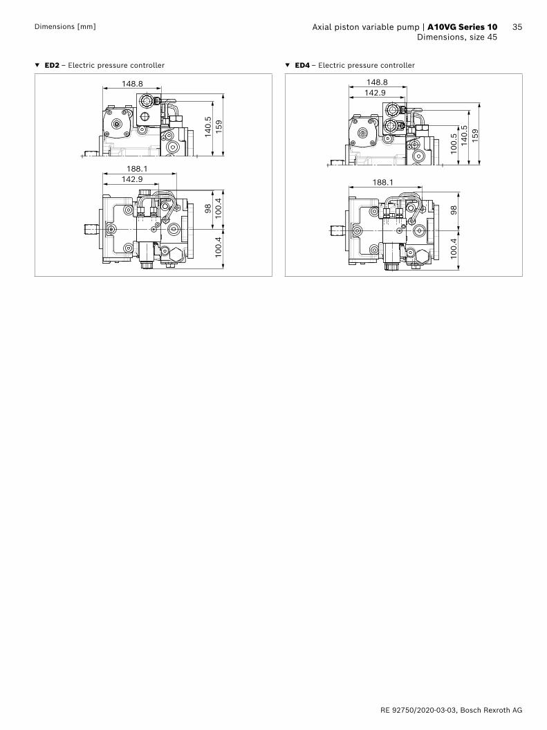
35 Axial piston variable pump | A10VG Series 10 Dimensions, size 45Dimensions [mm]
▼ ED2 – Electric pressure controller ▼ ED4 – Electric pressure controller
140.
5
148.8
159
188.1142.9
9810
0.4
100.
4
9810
0.4
188.1
140.
515
9
100.
5
148.8142.9
Bosch Rexroth AG, RE 92750/2020-03-03
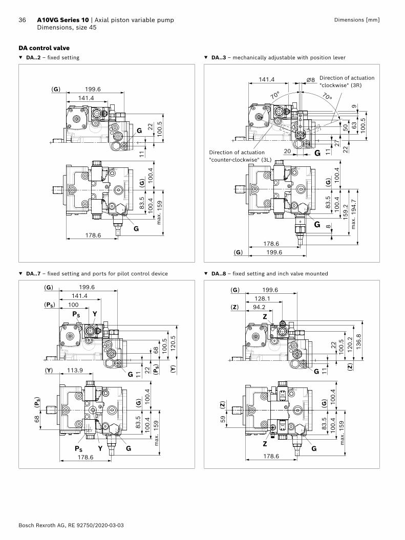
36 A10VG Series 10 | Axial piston variable pumpDimensions, size 45
Dimensions [mm]
DA control valve ▼ DA..2 – fixed setting ▼ DA..3 – mechanically adjustable with position lever
(G)
(G)
141.4199.6
100.
5
22
159
100.
410
0.4
11
G83
.5
G178.6
max
.20
141.4
70°
2722
50 639
100.
5
70°
⌀8
159.
210
0.4
100.
4
194.
7
8
178.6
83.5
199.6
11G
(G)
(G)
G max
.
Direction of actuation "clockwise" (3R)
Direction of actuation "counter-clockwise" (3L)
▼ DA..7 – fixed setting and ports for pilot control device ▼ DA..8 – fixed setting and inch valve mounted
100.
568 12
0.5
100
199.6
1122
68 (P
S)
83.5
113.9
159
100.
410
0.4
141.4
G (PS)
PS GY
PS Y(PS)
(G)
(Y) (Y)
(G)
178.6
max
.
100.
410
0.459
128.194.2
120.
213
6.8
100.
515
9
178.6
2211
83.5
199.6
G
(Z)
Z
Z
(Z)
(Z)
G
(G)
(G)
max
.
RE 92750/2020-03-03, Bosch Rexroth AG
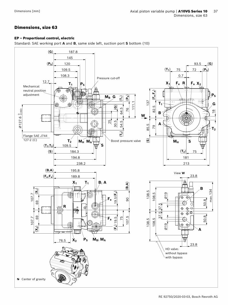
37 Axial piston variable pump | A10VG Series 10 Dimensions, size 63Dimensions [mm]
Dimensions, size 63
EP – Proportional control, electricStandard: SAE working port A and B, same side left, suction port S bottom (10)
64.5
54.5
30.525
109.5
184.3
238.2
120
108.3
12.7
187.8
109.5
⌀12
7.6
-0.0
63 0
195.8
189.8
6969
107.
710
7.7 75
19.5
19.5
107.
590
23.8
23.8
134
50.8
50.8
138.
5
⌀19
37.5
108.
510
8.5 37
.5
138.
5
⌀19
76.5
194.8
76 111.
1
137
82.5
85.5
79
18
7275
93.5
75
181
213
0.7
145
MB
W
(T1)
(T2)
(G)
(T1;T2)
(G)
PS
G
(PS)
(PS)
ST2
T1
MA
(S)
X1 X2R
(Fe,
F a)
T2
(S)
T1X1
Fe
(B;A
)
X2 PS
(T2)
MH
G
PS
Fe Fa
T1
MH S
(X2)
(X1)
MB; MA
Fa
(Fe)
(Fa)
(B;A)
(Fe;Fa)
A
B
(PS)
(T1)
(G)
B
A
B; A
R
Boost pressure valve
Flange SAE J744127-2 (C)
View W
Mechanical neutral position adjustment
max
.
Pressure cut-off
Center of gravity
HD valve: without bypass with bypass
Bosch Rexroth AG, RE 92750/2020-03-03
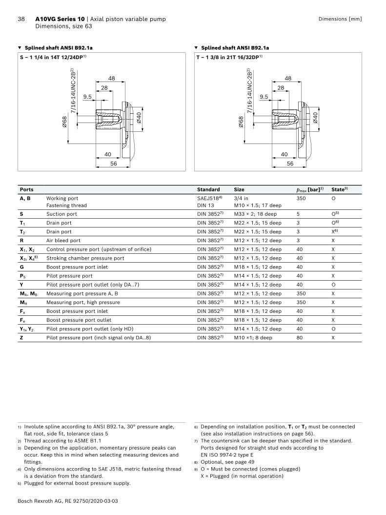
38 A10VG Series 10 | Axial piston variable pumpDimensions, size 63
Dimensions [mm]
▼ Splined shaft ANSI B92.1a ▼ Splined shaft ANSI B92.1a
S ‒ 1 1/4 in 14T 12/24DP1) T ‒ 1 3/8 in 21T 16/32DP1)
289.5
56
⌀68
40
7/16
-14U
NC
-2B
2)
⌀40
48
289.5
56
⌀68
40
7/16
-14U
NC
-2B
2)
⌀40
48
Ports Standard Size pmax [bar]3) State9)
A, B Working portFastening thread
SAEJ5184) DIN 13
3/4 in M10 × 1.5; 17 deep
350 O
S Suction port DIN 38527) M33 × 2; 18 deep 5 O5)
T1 Drain port DIN 38527) M22 × 1.5; 15 deep 3 O6)
T2 Drain port DIN 38527) M22 × 1.5; 15 deep 3 X6)
R Air bleed port DIN 38527) M12 × 1.5; 12 deep 3 X
X1, X2 Control pressure port (upstream of orifice) DIN 38527) M12 × 1.5; 12 deep 40 X
X3, X48) Stroking chamber pressure port DIN 38527) M12 × 1.5; 12 deep 40 X
G Boost pressure port inlet DIN 38527) M18 × 1.5; 12 deep 40 X
PS Pilot pressure port DIN 38527) M14 × 1.5; 12 deep 40 X
Y Pilot pressure port outlet (only DA..7) DIN 38527) M14 × 1.5; 12 deep 40 O
MA, MB Measuring port pressure A, B DIN 38527) M12 × 1.5; 12 deep 350 X
MH Measuring port, high pressure DIN 38527) M12 × 1.5; 12 deep 350 X
Fa Boost pressure port inlet DIN 38527) M18 × 1.5; 12 deep 40 X
Fe Boost pressure port outlet DIN 38527) M18 × 1.5; 12 deep 40 X
Y1, Y2 Pilot pressure port outlet (only HD) DIN 38527) M14 × 1.5; 12 deep 40 O
Z Pilot pressure port (inch signal only DA..8) DIN 38527) M10 ×1; 8 deep 80 X
1) Involute spline according to ANSI B92.1a, 30° pressure angle, flat root, side fit, tolerance class 5
2) Thread according to ASME B1.13) Depending on the application, momentary pressure peaks can
occur. Keep this in mind when selecting measuring devices and fittings.
4) Only dimensions according to SAE J518, metric fastening thread is a deviation from the standard.
5) Plugged for external boost pressure supply.
6) Depending on installation position, T1 or T2 must be connected (see also installation instructions on page 56).
7) The countersink can be deeper than specified in the standard. Ports designed for straight stud ends according to EN ISO 9974-2 type E
8) Optional, see page 499) O = Must be connected (comes plugged)
X = Plugged (in normal operation)
RE 92750/2020-03-03, Bosch Rexroth AG
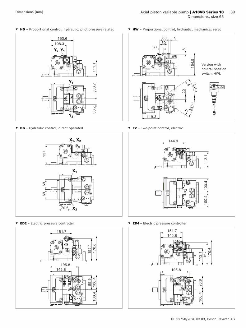
39 Axial piston variable pump | A10VG Series 10 Dimensions, size 63Dimensions [mm]
▼ HD – Proportional control, hydraulic, pilot-pressure related ▼ HW – Proportional control, hydraulic, mechanical servo
153.6
111.
1
108.3
38.7
38.7
Y1
Y2
Y2, Y1
119.3
63 950
27
20
a
b
33° ±1
33°±
1
8
⌀8
154.
5
Version with neutral position switch, HWL
▼ DG – Hydraulic control, direct operated ▼ EZ – Two-point control, electric
76.5
6969
137
X1
X2
X1, X2
PS
144.9
112.
110
0.4
100.
4
▼ ED2 – Electric pressure controller ▼ ED4 – Electric pressure controller
95.9
100.
410
0.4
170.
615
2.1
195.8145.8
151.7 151.7145.8
170.
615
2.1
112.
1
195.8
95.9
100.
4
Bosch Rexroth AG, RE 92750/2020-03-03
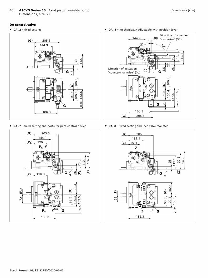
40 A10VG Series 10 | Axial piston variable pumpDimensions, size 63
Dimensions [mm]
DA control valve ▼ DA..2 – fixed setting ▼ DA..3 – mechanically adjustable with position lever
max
.
(G)
(G)
144.9205.3
112.
125
153.
510
0.4
100.
44.
5G93
.5
G
186.3
20
144.9
70°
2725
50 639
112.
1
70°
⌀8
157.
510
0.4
100.
4
189.
5
8
186.3
93.5
205.3
4.5
G
(G)
(G)
G max
.
Direction of actuation "clockwise" (3R)
Direction of actuation "counter-clockwise" (3L)
▼ DA..7 – fixed setting and ports for pilot control device ▼ DA..8 – fixed setting and inch valve mounted
112.
176
132.
1
120
205.3
4.5 25
72 (
PS)
93.5
116.8
153.
510
0.4
100.
4
144.9
G (PS)
PS GY
PS Y(PS)
(G)
(Y) (Y)
(G)
186.3
max
.
max
.
100.
410
0.459
131.197.1
132.
614
8.8
112.
115
3.5
186.3
254.
593
.5(G
)
G
(Z)
Z
Z
(Z)
(Z)
G
205.3(G)
RE 92750/2020-03-03, Bosch Rexroth AG
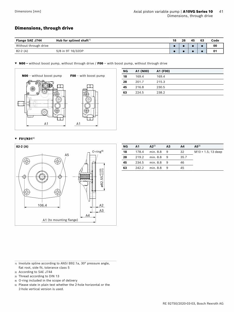
41 Axial piston variable pump | A10VG Series 10 Dimensions, through driveDimensions [mm]
▼ N00 – without boost pump, without through drive / F00 – with boost pump, without through drive
A1 A1
N00 − without boost pump F00 − with boost pumpNG A1 (N00) A1 (F00)
18 169.4 169.4
28 201.7 215.3
45 216.8 230.5
63 224.5 238.2
▼ F01/K015)
82-2 (A) NG A1 A22) A3 A4 A53)
ø82.
55+0
.010
+0.0
35
106.4
A1
A5
A3A4
A2
O-ring4)
(to mounting flange)
18 178.4 min. 8.8 9 32 M10 × 1.5; 13 deep
28 219.2 min. 8.8 9 35.7
45 234.5 min. 8.8 9 46
63 242.2 min. 8.8 9 45
1) Involute spline according to ANSI B92.1a, 30° pressure angle, flat root, side fit, tolerance class 5
2) According to SAE J7443) Thread according to DIN 134) O-ring included in the scope of delivery5) Please state in plain text whether the 2-hole horizontal or the
2-hole vertical version is used.
Dimensions, through drive
Flange SAE J744 Hub for splined shaft1) 18 28 45 63 Code
Without through drive ● ● ● ● 00
82-2 (A) 5/8 in 9T 16/32DP ● ● ● ● 01
Bosch Rexroth AG, RE 92750/2020-03-03
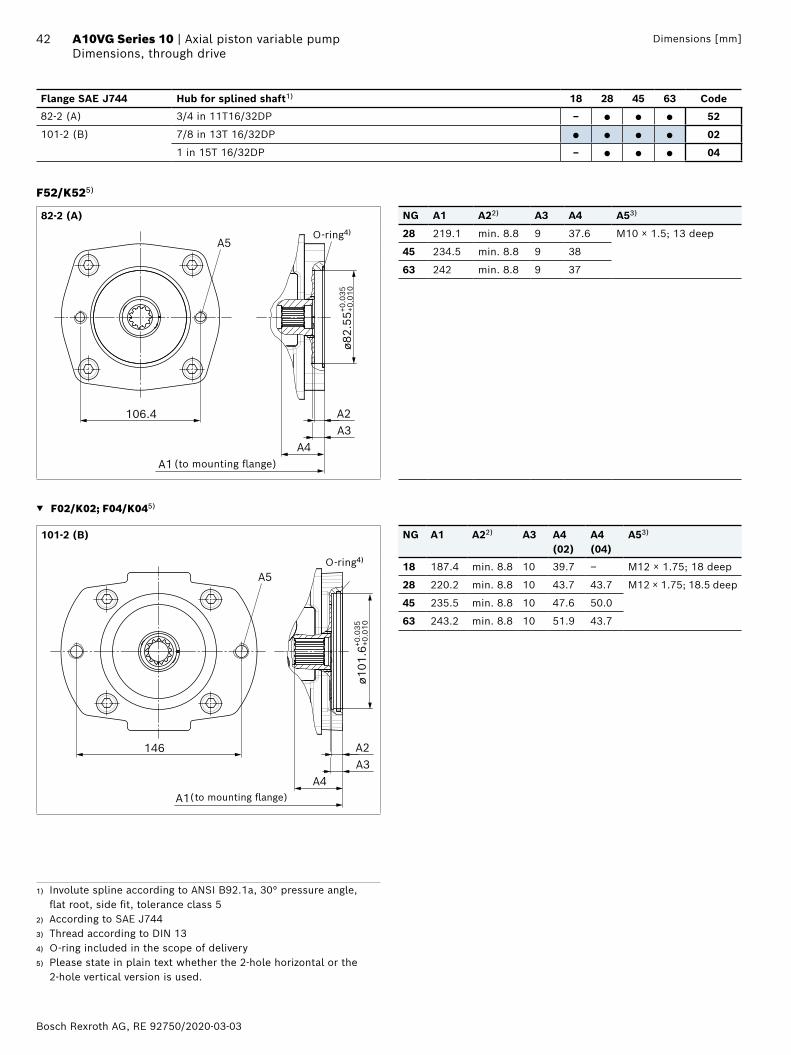
42 A10VG Series 10 | Axial piston variable pumpDimensions, through drive
Dimensions [mm]
F52/K525)
82-2 (A) NG A1 A22) A3 A4 A53)
ø82.
55+0
.010
+0.0
35
106.4
A5
A2A3
A4 A1 (to mounting flange)
O-ring4) 28 219.1 min. 8.8 9 37.6 M10 × 1.5; 13 deep
45 234.5 min. 8.8 9 38
63 242 min. 8.8 9 37
▼ F02/K02; F04/K045)
101-2 (B) NG A1 A22) A3 A4(02)
A4 (04)
A53)
A2146
ø101
.6+0
.010
+0.0
35
A3A4
A1
A5O-ring4)
(to mounting flange)
18 187.4 min. 8.8 10 39.7 – M12 × 1.75; 18 deep
28 220.2 min. 8.8 10 43.7 43.7 M12 × 1.75; 18.5 deep
45 235.5 min. 8.8 10 47.6 50.0
63 243.2 min. 8.8 10 51.9 43.7
1) Involute spline according to ANSI B92.1a, 30° pressure angle, flat root, side fit, tolerance class 5
2) According to SAE J7443) Thread according to DIN 134) O-ring included in the scope of delivery5) Please state in plain text whether the 2-hole horizontal or the
2-hole vertical version is used.
Flange SAE J744 Hub for splined shaft1) 18 28 45 63 Code
82-2 (A) 3/4 in 11T16/32DP – ● ● ● 52
101-2 (B) 7/8 in 13T 16/32DP ● ● ● ● 02
1 in 15T 16/32DP – ● ● ● 04
RE 92750/2020-03-03, Bosch Rexroth AG
43 Axial piston variable pump | A10VG Series 10 Dimensions, through driveDimensions [mm]
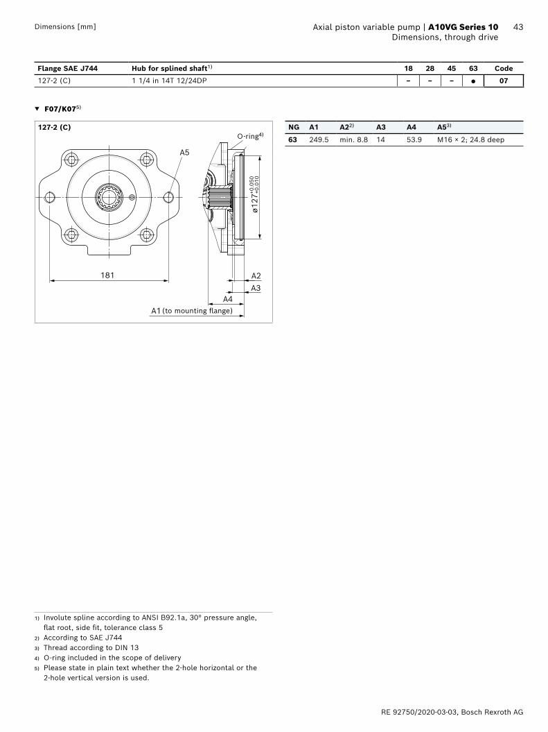
▼ F07/K075)
127-2 (C) NG A1 A22) A3 A4 A53)
ø127
+0.0
10+0
.050
181
A1
A2A3
A4
A5
(to mounting flange)
O-ring4)63 249.5 min. 8.8 14 53.9 M16 × 2; 24.8 deep
Flange SAE J744 Hub for splined shaft1) 18 28 45 63 Code
127-2 (C) 1 1/4 in 14T 12/24DP – – – ● 07
1) Involute spline according to ANSI B92.1a, 30° pressure angle, flat root, side fit, tolerance class 5
2) According to SAE J7443) Thread according to DIN 134) O-ring included in the scope of delivery5) Please state in plain text whether the 2-hole horizontal or the
2-hole vertical version is used.
Bosch Rexroth AG, RE 92750/2020-03-03
44 A10VG Series 10 | Axial piston variable pumpOverview of mounting options
Dimensions [mm]
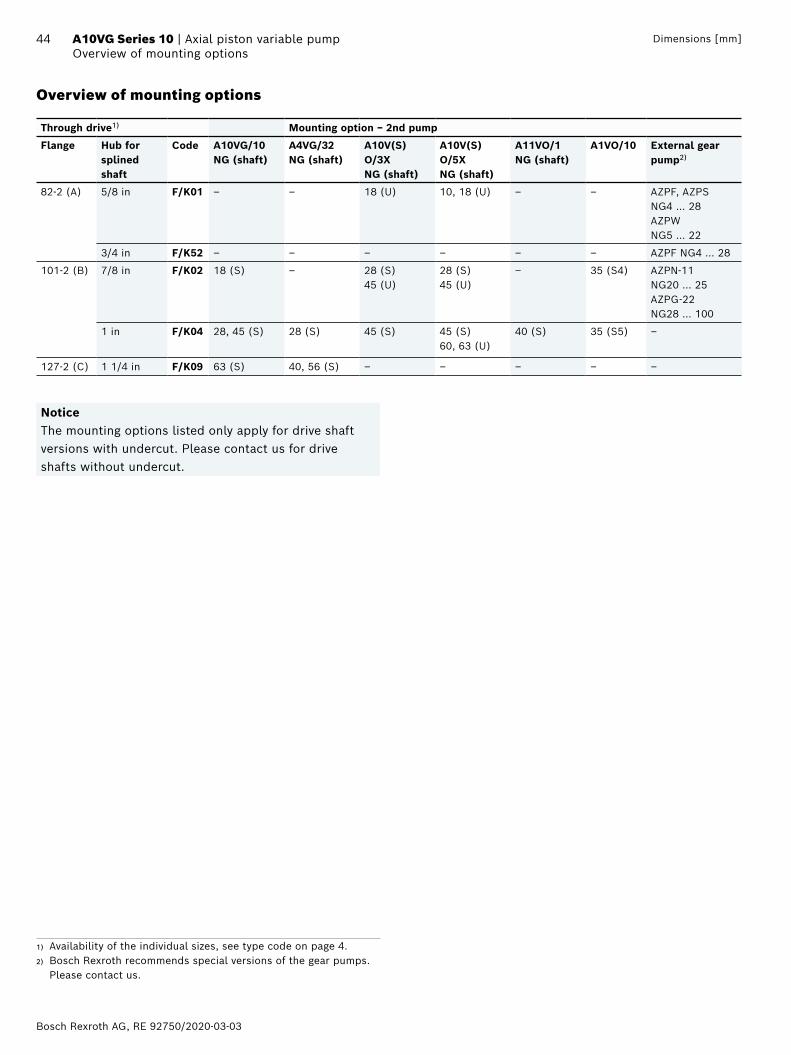
Overview of mounting options
Through drive1) Mounting option − 2nd pump
Flange Hub for splined shaft
Code A10VG/10NG (shaft)
A4VG/32NG (shaft)
A10V(S)O/3XNG (shaft)
A10V(S)O/5XNG (shaft)
A11VO/1NG (shaft)
A1VO/10 External gear pump2)
82-2 (A) 5/8 in F/K01 ‒ ‒ 18 (U) 10, 18 (U) ‒ ‒ AZPF, AZPS NG4 … 28AZPW NG5 … 22
3/4 in F/K52 ‒ ‒ ‒ ‒ ‒ ‒ AZPF NG4 … 28
101-2 (B) 7/8 in F/K02 18 (S) ‒ 28 (S) 45 (U)
28 (S) 45 (U)
‒ 35 (S4) AZPN-11 NG20 … 25AZPG-22 NG28 … 100
1 in F/K04 28, 45 (S) 28 (S) 45 (S) 45 (S)60, 63 (U)
40 (S) 35 (S5) ‒
127-2 (C) 1 1/4 in F/K09 63 (S) 40, 56 (S) ‒ ‒ ‒ ‒ ‒
NoticeThe mounting options listed only apply for drive shaft versions with undercut. Please contact us for drive shafts without undercut.
1) Availability of the individual sizes, see type code on page 4.2) Bosch Rexroth recommends special versions of the gear pumps.
Please contact us.
RE 92750/2020-03-03, Bosch Rexroth AG
45 Axial piston variable pump | A10VG Series 10 Combination pumps A10VG + A10VGDimensions [mm]
1) 2. pump without through drive and with boost pump, F00
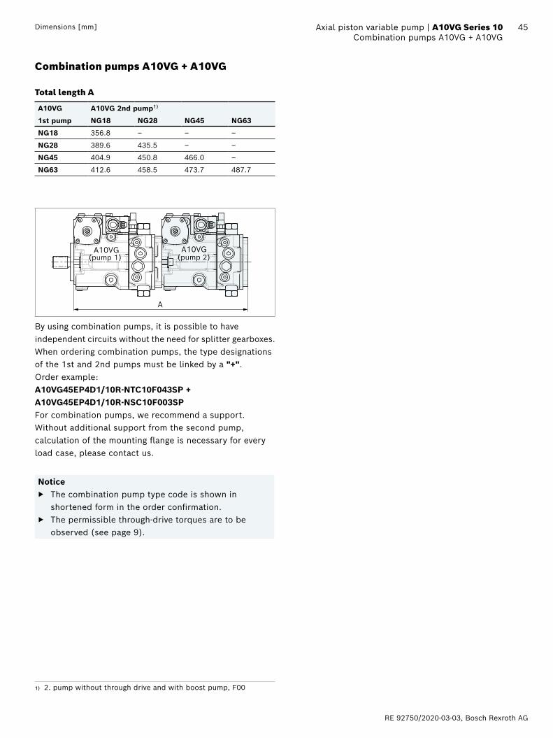
Combination pumps A10VG + A10VG
Total length A
A10VG A10VG 2nd pump1)
1st pump NG18 NG28 NG45 NG63
NG18 356.8 ‒ ‒ ‒
NG28 389.6 435.5 ‒ ‒
NG45 404.9 450.8 466.0 ‒
NG63 412.6 458.5 473.7 487.7
A
A10VG A10VG(pump 1) (pump 2)
By using combination pumps, it is possible to have independent circuits without the need for splitter gearboxes. When ordering combination pumps, the type designations of the 1st and 2nd pumps must be linked by a "+".Order example:A10VG45EP4D1/10R-NTC10F043SP + A10VG45EP4D1/10R-NSC10F003SPFor combination pumps, we recommend a support. Without additional support from the second pump, calculation of the mounting flange is necessary for every load case, please contact us.
Notice ▶ The combination pump type code is shown in
shortened form in the order confirmation. ▶ The permissible through-drive torques are to be
observed (see page 9).
Bosch Rexroth AG, RE 92750/2020-03-03
46 A10VG Series 10 | Axial piston variable pumpHigh-pressure relief valves
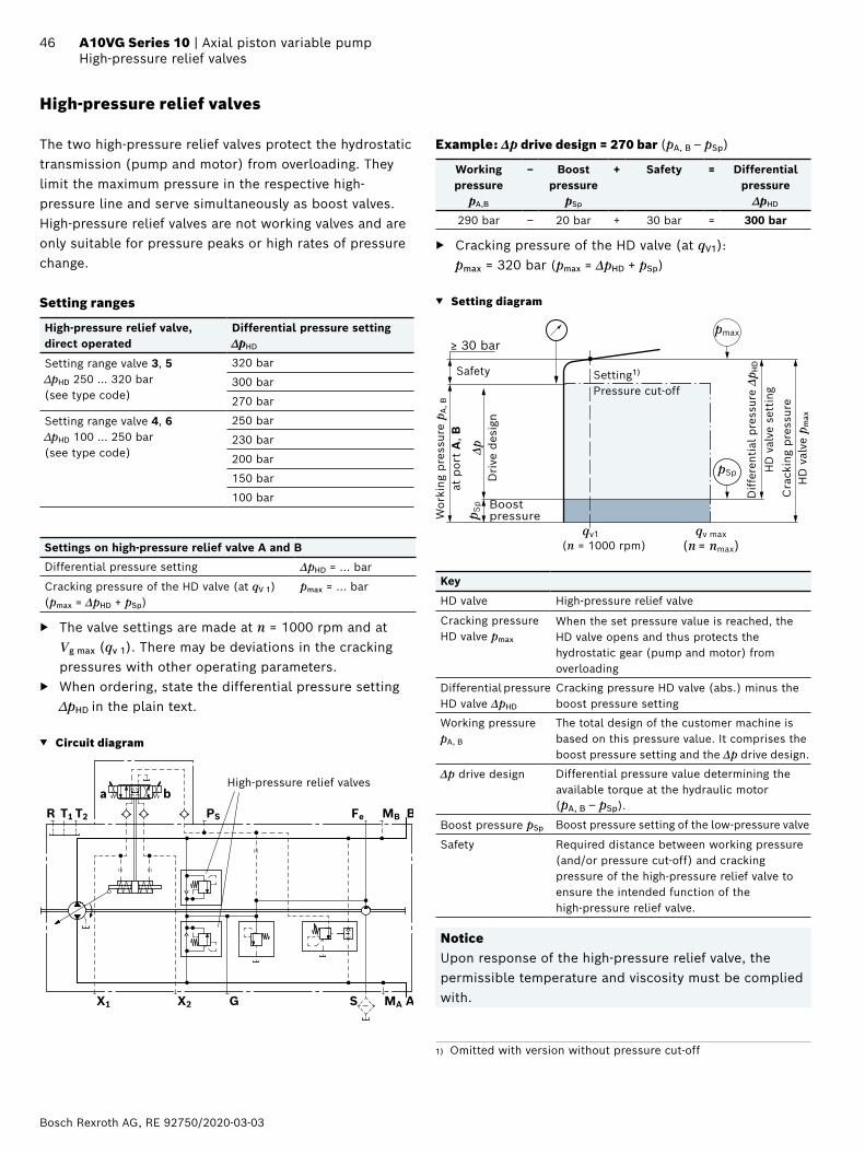
High-pressure relief valves
The two high-pressure relief valves protect the hydrostatic transmission (pump and motor) from overloading. They limit the maximum pressure in the respective high-pressure line and serve simultaneously as boost valves.High-pressure relief valves are not working valves and are only suitable for pressure peaks or high rates of pressure change.
Setting ranges
High-pressure relief valve, direct operated
Differential pressure setting ∆pHD
Setting range valve 3, 5 ∆pHD 250 … 320 bar (see type code)
320 bar
300 bar
270 bar
Setting range valve 4, 6 ∆pHD 100 … 250 bar (see type code)
250 bar
230 bar
200 bar
150 bar
100 bar
Settings on high-pressure relief valve A and B
Differential pressure setting ΔpHD = ... bar
Cracking pressure of the HD valve (at qV 1)(pmax = ΔpHD + pSp)
pmax = ... bar
▶ The valve settings are made at n = 1000 rpm and at Vg max (qv 1). There may be deviations in the cracking pressures with other operating parameters.
▶ When ordering, state the differential pressure setting ∆pHD in the plain text.
▼ Circuit diagram
MBFePST2T1R
X1 X2 G S MA
B
A
baHigh-pressure relief valves
Example: Δp drive design = 270 bar (pA, B – pSp)
Working pressure
pA,B
‒ Boost pressure
pSp
+ Safety = Differential pressure
∆pHD
290 bar ‒ 20 bar + 30 bar = 300 bar
▶ Cracking pressure of the HD valve (at qV1): pmax = 320 bar (pmax = ΔpHD + pSp)
▼ Setting diagram
(п = 1000 rpm)
p Sp
pSp
pmax
qv1 qv max(n = nmax)
≥ 30 bar
Δp
Dri
ve d
esig
n
Safety
Wor
king
pre
ssur
e p A
, B
at p
ort
A, B
Boost pressure
Dif
fere
ntia
l pre
ssur
e Δp
HD
HD
val
ve s
etti
ngC
rack
ing
pre
ssur
e H
D v
alve
pm
ax
Setting1) Pressure cut-off
Key
HD valve High-pressure relief valve
Cracking pressure HD valve pmax
When the set pressure value is reached, the HD valve opens and thus protects the hydrostatic gear (pump and motor) from overloading
Differential pressure HD valve ΔpHD
Cracking pressure HD valve (abs.) minus the boost pressure setting
Working pressure pA, B
The total design of the customer machine is based on this pressure value. It comprises the boost pressure setting and the Δp drive design.
Δp drive design Differential pressure value determining the available torque at the hydraulic motor (pA, B – pSp).
Boost pressure pSp Boost pressure setting of the low-pressure valve
Safety Required distance between working pressure (and/or pressure cut-off) and cracking pressure of the high-pressure relief valve to ensure the intended function of the high-pressure relief valve.
NoticeUpon response of the high-pressure relief valve, the permissible temperature and viscosity must be complied with.
1) Omitted with version without pressure cut-off
RE 92750/2020-03-03, Bosch Rexroth AG
47 Axial piston variable pump | A10VG Series 10 Pressure cut-off
Bypass functionA connection between the two high-pressure passages A and B can be established using the bypass function (e.g. for machine towing).
▶ Towing speed The maximum towing speed depends on the gear ratio in the vehicle and must be calculated by the vehicle manufacturer. The corresponding flow of qv = 30 l/min may not be exceeded.
▶ Towing distance Only tow the vehicle out of the immediate danger zone.
For further information on the bypass function, see the instruction manual.
NoticeThe bypass function is not illustrated in the circuit diagrams.
Pressure cut-off
The pressure cut-off is a pressure control which, after reaching the set pressure, adjusts the displacement of the pump back to Vg min.This valve prevents the operation of the high-pressure relief valves when accelerating or decelerating.The high-pressure relief valves protect against the pressure peaks which occur during fast swiveling of the swashplate and limit the maximum pressure in the system.The setting range of the pressure cut-off may be anywhere within the entire working pressure range. However, it must at least be set 30 bar lower than the setting value of the high-pressure relief valves (see setting diagram, page 46).The function of the pressure cut-off in combination with a DG control is described on page 17.Please state the setting value of the pressure cut-off in plain text when ordering.
▼ Circuit diagram with pressure cut-off Electric control, EP_D
Sizes 28 and 45
Pressure cut-off
MBFePST2T1R
X1 X2 G S MA
B
A
ba
Size 63
Pressure cut-off
MBFePST2T1R
X1 X2 G S MA
B
A
ba
MH
Fa
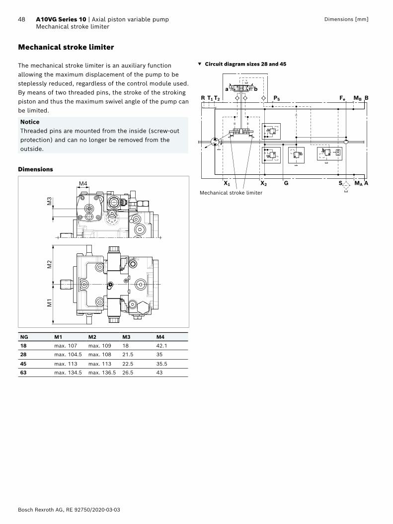
Bosch Rexroth AG, RE 92750/2020-03-03
48 A10VG Series 10 | Axial piston variable pumpMechanical stroke limiter
Dimensions [mm]
Mechanical stroke limiter
The mechanical stroke limiter is an auxiliary function allowing the maximum displacement of the pump to be steplessly reduced, regardless of the control module used.By means of two threaded pins, the stroke of the stroking piston and thus the maximum swivel angle of the pump can be limited.
NoticeThreaded pins are mounted from the inside (screw-out protection) and can no longer be removed from the outside.
Dimensions
M1
M2
M3
M4
NG M1 M2 M3 M4
18 max. 107 max. 109 18 42.1
28 max. 104.5 max. 108 21.5 35
45 max. 113 max. 113 22.5 35.5
63 max. 134.5 max. 136.5 26.5 43
▼ Circuit diagram sizes 28 and 45
MBFePST2T1R
X1 X2 G S MA
B
A
ba
Mechanical stroke limiter
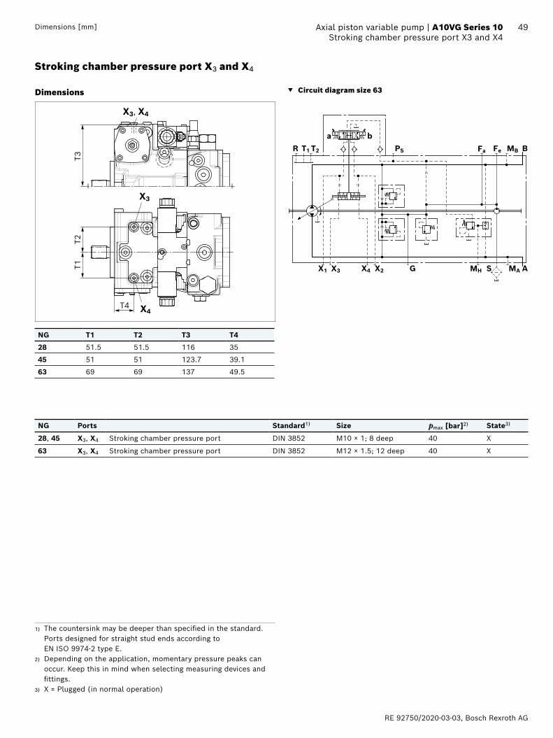
RE 92750/2020-03-03, Bosch Rexroth AG
49 Axial piston variable pump | A10VG Series 10 Stroking chamber pressure port X3 and X4 Dimensions [mm]
Stroking chamber pressure port X3 and X4
Dimensions
T2T1
T3
T4
X3
X4
X3, X4
NG T1 T2 T3 T4
28 51.5 51.5 116 35
45 51 51 123.7 39.1
63 69 69 137 49.5
▼ Circuit diagram size 63
MBFePST2T1R
X1 X4 G S MA
B
A
ba
MHX3 X2
Fa
NG Ports Standard1) Size pmax [bar]2) State3)
28, 45 X3, X4 Stroking chamber pressure port DIN 3852 M10 × 1; 8 deep 40 X
63 X3, X4 Stroking chamber pressure port DIN 3852 M12 × 1.5; 12 deep 40 X
1) The countersink may be deeper than specified in the standard. Ports designed for straight stud ends according to EN ISO 9974-2 type E.
2) Depending on the application, momentary pressure peaks can occur. Keep this in mind when selecting measuring devices and fittings.
3) X = Plugged (in normal operation)
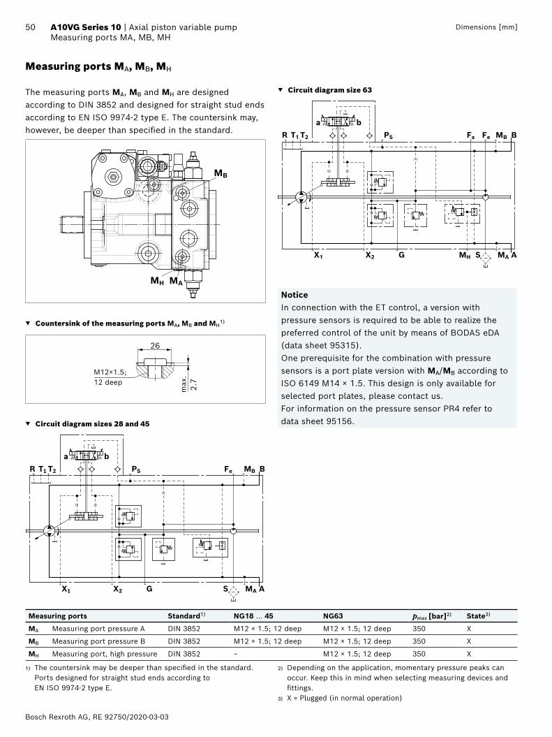
Bosch Rexroth AG, RE 92750/2020-03-03
50 A10VG Series 10 | Axial piston variable pumpMeasuring ports MA, MB, MH
Dimensions [mm]
Measuring ports MA, MB, MH
The measuring ports MA, MB and MH are designed according to DIN 3852 and designed for straight stud ends according to EN ISO 9974-2 type E. The countersink may, however, be deeper than specified in the standard.
MB
MAMH
▼ Countersink of the measuring ports MA, MB and MH1)
26
2.7
M12×1.5;12 deep
max
.
▼ Circuit diagram sizes 28 and 45
MBFePST2T1R
X1 X2 G S MA
B
A
ba
▼ Circuit diagram size 63
MBFePST2T1R
X1 X2 G S MA
B
A
ba
MH
Fa
NoticeIn connection with the ET control, a version with pressure sensors is required to be able to realize the preferred control of the unit by means of BODAS eDA (data sheet 95315).One prerequisite for the combination with pressure sensors is a port plate version with MA/MB according to ISO 6149 M14 × 1.5. This design is only available for selected port plates, please contact us.For information on the pressure sensor PR4 refer to data sheet 95156.
Measuring ports Standard1) NG18 … 45 NG63 pmax [bar]2) State3)
MA Measuring port pressure A DIN 3852 M12 × 1.5; 12 deep M12 × 1.5; 12 deep 350 X
MB Measuring port pressure B DIN 3852 M12 × 1.5; 12 deep M12 × 1.5; 12 deep 350 X
MH Measuring port, high pressure DIN 3852 − M12 × 1.5; 12 deep 350 X
1) The countersink may be deeper than specified in the standard. Ports designed for straight stud ends according to EN ISO 9974-2 type E.
2) Depending on the application, momentary pressure peaks can occur. Keep this in mind when selecting measuring devices and fittings.
3) X = Plugged (in normal operation)
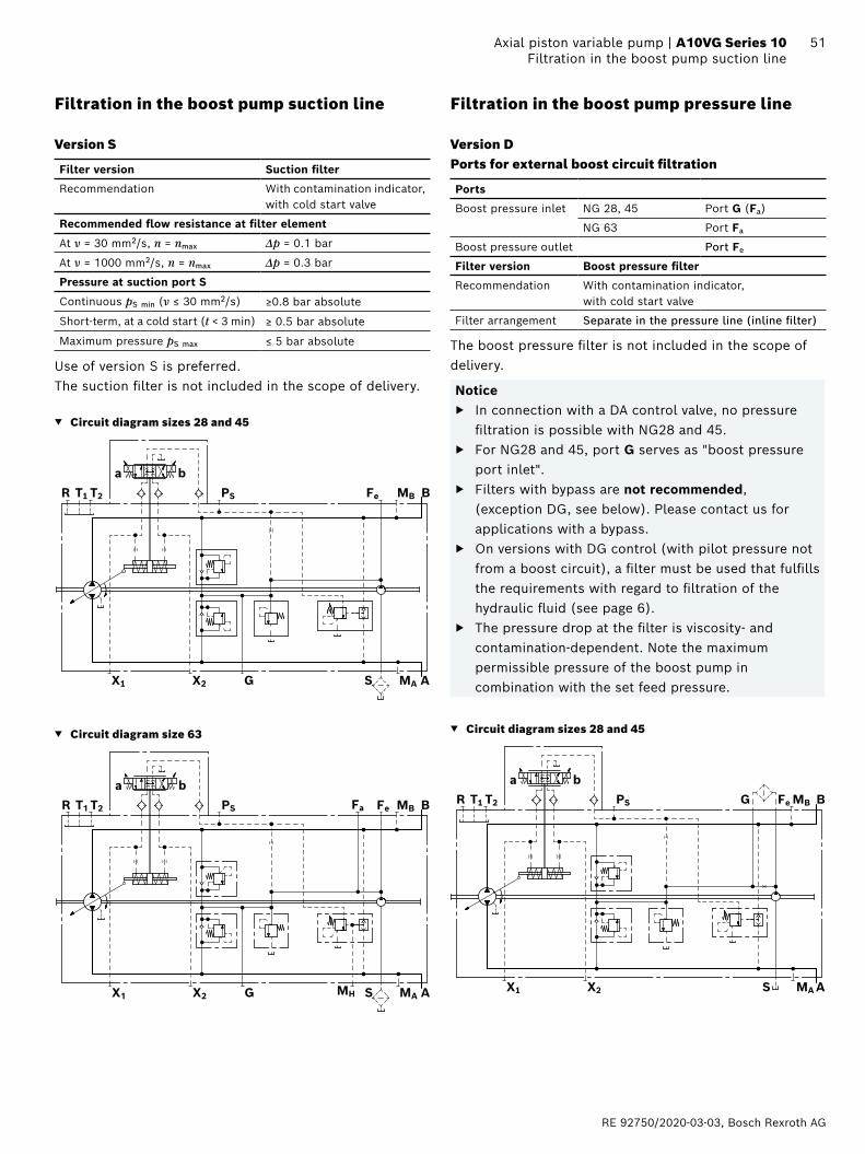
RE 92750/2020-03-03, Bosch Rexroth AG
51 Axial piston variable pump | A10VG Series 10 Filtration in the boost pump suction line
Filtration in the boost pump suction line
Version S
Filter version Suction filter
Recommendation With contamination indicator, with cold start valve
Recommended flow resistance at filter element
At ν = 30 mm2/s, n = nmax Δp = 0.1 bar
At ν = 1000 mm2/s, n = nmax Δp = 0.3 bar
Pressure at suction port S
Continuous pS min (ν ≤ 30 mm2/s) ≥0.8 bar absolute
Short-term, at a cold start (t < 3 min) ≥ 0.5 bar absolute
Maximum pressure pS max ≤ 5 bar absolute
Use of version S is preferred. The suction filter is not included in the scope of delivery.
▼ Circuit diagram sizes 28 and 45
MBFePST2T1R
X1 X2 G S MA
B
A
ba
▼ Circuit diagram size 63
MBFePST2T1R
X1 X2 G S MA
B
A
ba
MH
Fa
Filtration in the boost pump pressure line
Version DPorts for external boost circuit filtration
Ports
Boost pressure inlet NG 28, 45 Port G (Fa)
NG 63 Port Fa
Boost pressure outlet Port Fe
Filter version Boost pressure filter
Recommendation With contamination indicator, with cold start valve
Filter arrangement Separate in the pressure line (inline filter)
The boost pressure filter is not included in the scope of delivery.
Notice ▶ In connection with a DA control valve, no pressure
filtration is possible with NG28 and 45. ▶ For NG28 and 45, port G serves as "boost pressure
port inlet". ▶ Filters with bypass are not recommended,
(exception DG, see below). Please contact us for applications with a bypass.
▶ On versions with DG control (with pilot pressure not from a boost circuit), a filter must be used that fulfills the requirements with regard to filtration of the hydraulic fluid (see page 6).
▶ The pressure drop at the filter is viscosity- and contamination-dependent. Note the maximum permissible pressure of the boost pump in combination with the set feed pressure.
▼ Circuit diagram sizes 28 and 45
MBFePST2T1R
X1 X2 S MA
B
A
baG
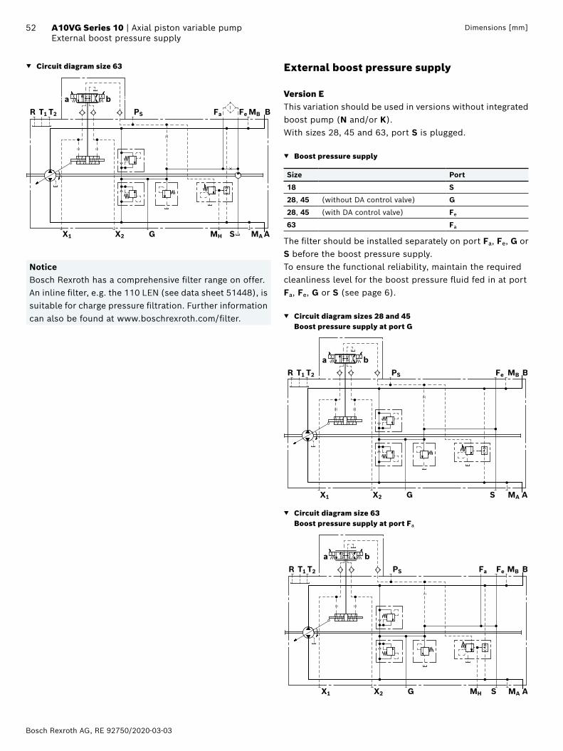
Bosch Rexroth AG, RE 92750/2020-03-03
52 A10VG Series 10 | Axial piston variable pumpExternal boost pressure supply
Dimensions [mm]
▼ Circuit diagram size 63
MBFePST2T1R
X1 X2 G S MA
B
A
ba
MH
Fa
NoticeBosch Rexroth has a comprehensive filter range on offer. An inline filter, e.g. the 110 LEN (see data sheet 51448), is suitable for charge pressure filtration. Further information can also be found at www.boschrexroth.com/filter.
External boost pressure supply
Version EThis variation should be used in versions without integrated boost pump (N and/or K).With sizes 28, 45 and 63, port S is plugged.
▼ Boost pressure supply
Size Port
18 S
28, 45 (without DA control valve) G
28, 45 (with DA control valve) Fe
63 Fa
The filter should be installed separately on port Fa, Fe, G or S before the boost pressure supply.To ensure the functional reliability, maintain the required cleanliness level for the boost pressure fluid fed in at port Fa, Fe, G or S (see page 6).
▼ Circuit diagram sizes 28 and 45 Boost pressure supply at port G
MBFePST2T1R
X1 X2 G S MA
B
A
ba
▼ Circuit diagram size 63 Boost pressure supply at port Fa
MBFePST2T1R
X1 X2 G S MA
B
A
ba
MH
Fa
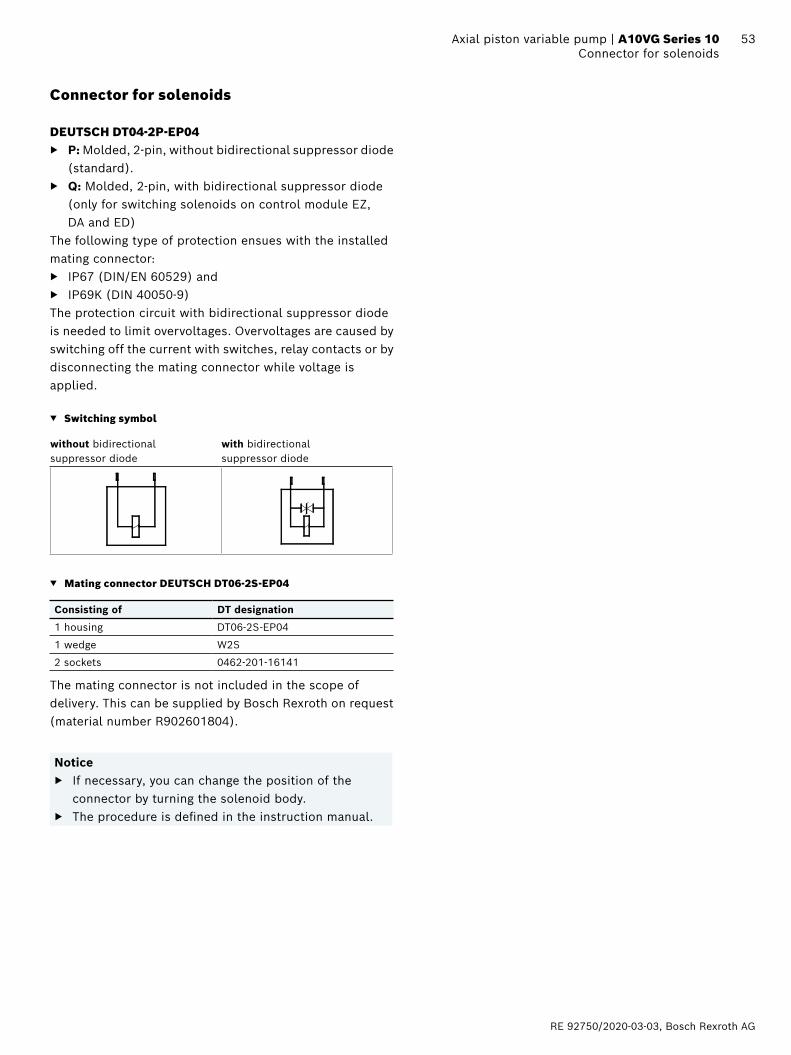
RE 92750/2020-03-03, Bosch Rexroth AG
53 Axial piston variable pump | A10VG Series 10 Connector for solenoids
Connector for solenoids
DEUTSCH DT04-2P-EP04 ▶ P: Molded, 2-pin, without bidirectional suppressor diode
(standard). ▶ Q: Molded, 2-pin, with bidirectional suppressor diode
(only for switching solenoids on control module EZ, DA and ED)
The following type of protection ensues with the installed mating connector:
▶ IP67 (DIN/EN 60529) and ▶ IP69K (DIN 40050-9)
The protection circuit with bidirectional suppressor diode is needed to limit overvoltages. Overvoltages are caused by switching off the current with switches, relay contacts or by disconnecting the mating connector while voltage is applied.
▼ Switching symbol
without bidirectional suppressor diode
with bidirectional suppressor diode
▼ Mating connector DEUTSCH DT06-2S-EP04
Consisting of DT designation
1 housing DT06-2S-EP04
1 wedge W2S
2 sockets 0462-201-16141
The mating connector is not included in the scope of delivery. This can be supplied by Bosch Rexroth on request (material number R902601804).
Notice ▶ If necessary, you can change the position of the
connector by turning the solenoid body. ▶ The procedure is defined in the instruction manual.

Bosch Rexroth AG, RE 92750/2020-03-03
54 A10VG Series 10 | Axial piston variable pumpRotary inch valve
Dimensions [mm]
Rotary inch valve
The rotary inch valve allows for any reduction of pilot pressure, independently of drive speed, through mechanical actuation of the control lever. The control lever is equipped with an internal rotational limiter ±90° (drawing item 1 and 2).The valve is arranged separately from the pump and is connected to the pump by a hydraulic control line via port PS (maximum line length: approx. 2 m).The rotary inch valve must be ordered separately.
Material number
Direction of actuation of the position control lever
Throttle cross-section ⌀
R902048734 Clockwise 4.6
R902048735 Counter-clockwise 4.6
R902070172 Clockwise 2.7
R902066994 Counter-clockwise 2.7
NoticeThe rotary inch valve can be used regardless of the control module. If necessary, the position of the control lever can be changed.
▼ Circuit diagram Hydraulic control, speed related DA with separately attached rotary inch valve
MBFePST2T1R
X1 X2 G S MA
B
A
b aX
T
Rotary inch valve
Dimensions
1
1
2
2
X
T
7263
5027
830
14
364
8
ø8
24.5
ø18M8 × 30; DIN 912
163252
2(T)
162(
X)
24.5
52 32
Tightening torque 25 Nm
Max. angle of rotation 85°
Clockwise
Counter-clockwise
NoticeTo prevent damage to the rotary inch valve, a positive mechanical stop of ±85° must be provided for the control lever on the customer side.
Ports Standard1) Size pmax [bar]2) State3)
X Pilot pressure port DIN 3852 M14 × 1.5; 12 deep 40 O
T Drain port DIN 3852 M14 × 1.5; 12 deep 3 O
1) The countersink may be deeper than specified in the standard. Ports designed for straight stud ends according to EN ISO 9974-2 type E.
2) Depending on the application, momentary pressure peaks can occur. Keep this in mind when selecting measuring devices and fittings.
3) O = Must be connected (plugged on delivery)
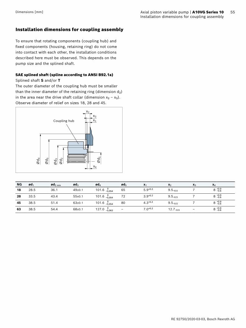
RE 92750/2020-03-03, Bosch Rexroth AG
55 Axial piston variable pump | A10VG Series 10 Installation dimensions for coupling assemblyDimensions [mm]
Installation dimensions for coupling assembly
To ensure that rotating components (coupling hub) and fixed components (housing, retaining ring) do not come into contact with each other, the installation conditions described here must be observed. This depends on the pump size and the splined shaft.
SAE splined shaft (spline according to ANSI B92.1a)Splined shaft S and/or TThe outer diameter of the coupling hub must be smaller than the inner diameter of the retaining ring (dimension d2) in the area near the drive shaft collar (dimension x2 – x3).Observe diameter of relief on sizes 18, 28 and 45.
x2
x1
x4
⌀d 4
⌀d 3
⌀d 2 ⌀d 1
⌀d 5
x3
Coupling hub
NG ød1 ød2 min ød3 ød4 ød5 x1 x2 x3 x4
18 28.5 36.1 49±0.1 101.6 0 65 5.9+0.2 9.5–0.5 7 8 +0.9−0.6−0,054
28 33.5 43.4 55±0.1 101.6 0 72 3.9+0.2 9.5–0.5 7 8 +0.9−0.6−0,054
45 38.5 51.4 63±0.1 101.6 0 80 4.3+0.2 9.5–0.5 7 8 +0.9−0.6−0,054
63 38.5 54.4 68±0.1 127.0 0 ‒ 7.0+0.2 12.7–0.5 ‒ 8 +0.9−0.6−0,063
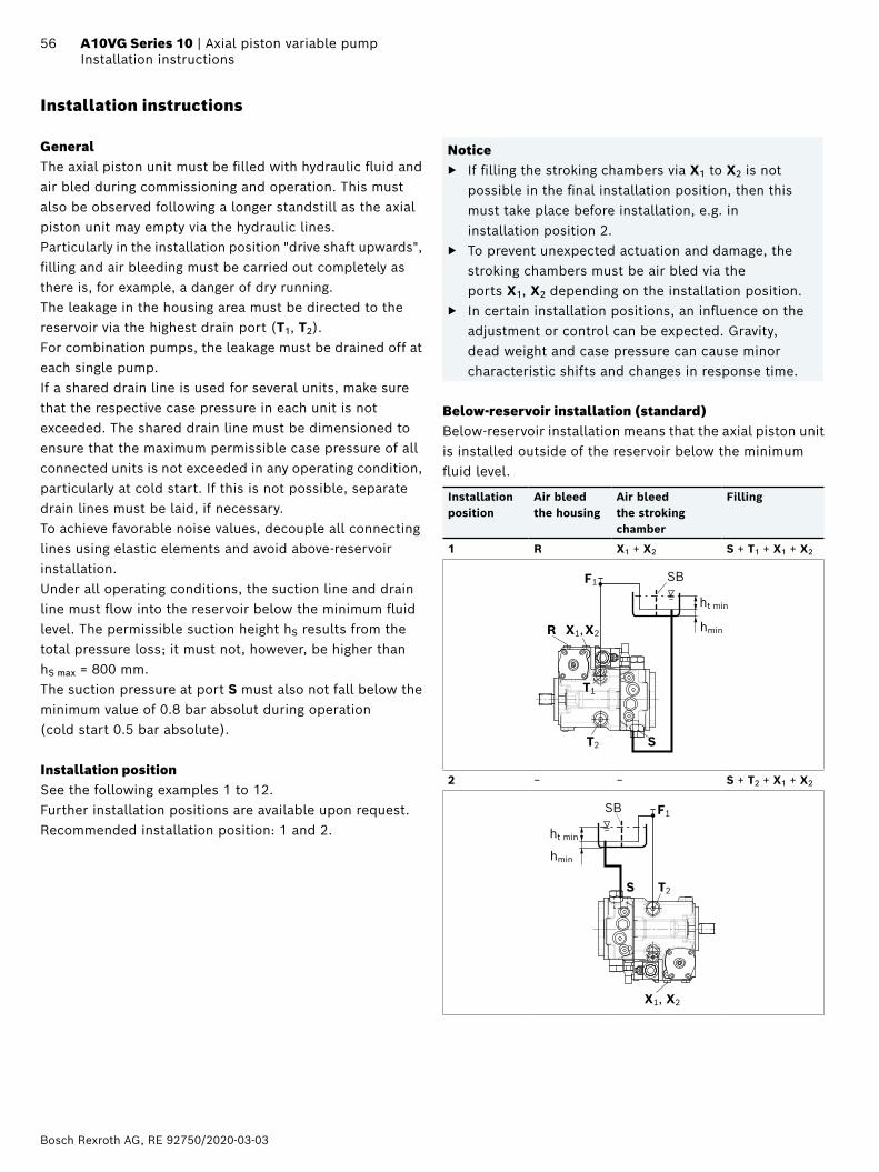
Bosch Rexroth AG, RE 92750/2020-03-03
56 A10VG Series 10 | Axial piston variable pumpInstallation instructions
Installation instructions
GeneralThe axial piston unit must be filled with hydraulic fluid and air bled during commissioning and operation. This must also be observed following a longer standstill as the axial piston unit may empty via the hydraulic lines. Particularly in the installation position "drive shaft upwards", filling and air bleeding must be carried out completely as there is, for example, a danger of dry running.The leakage in the housing area must be directed to the reservoir via the highest drain port (T1, T2). For combination pumps, the leakage must be drained off at each single pump.If a shared drain line is used for several units, make sure that the respective case pressure in each unit is not exceeded. The shared drain line must be dimensioned to ensure that the maximum permissible case pressure of all connected units is not exceeded in any operating condition, particularly at cold start. If this is not possible, separate drain lines must be laid, if necessary.To achieve favorable noise values, decouple all connecting lines using elastic elements and avoid above-reservoir installation. Under all operating conditions, the suction line and drain line must flow into the reservoir below the minimum fluid level. The permissible suction height hS results from the total pressure loss; it must not, however, be higher than hS max = 800 mm. The suction pressure at port S must also not fall below the minimum value of 0.8 bar absolut during operation (cold start 0.5 bar absolute).
Installation positionSee the following examples 1 to 12. Further installation positions are available upon request.Recommended installation position: 1 and 2.
Notice ▶ If filling the stroking chambers via X1 to X2 is not
possible in the final installation position, then this must take place before installation, e.g. in installation position 2.
▶ To prevent unexpected actuation and damage, the stroking chambers must be air bled via the ports X1, X2 depending on the installation position.
▶ In certain installation positions, an influence on the adjustment or control can be expected. Gravity, dead weight and case pressure can cause minor characteristic shifts and changes in response time.
Below-reservoir installation (standard)Below-reservoir installation means that the axial piston unit is installed outside of the reservoir below the minimum fluid level.
Installation position
Air bleedthe housing
Air bleedthe stroking chamber
Filling
1 R X1 + X2 S + T1 + X1 + X2
T1
T2 S
R
SB
ht min
hminX1, X2
F1
2 − − S + T2 + X1 + X2
SB
ht min
hmin
T2S
X1, X2
F1

RE 92750/2020-03-03, Bosch Rexroth AG
57 Axial piston variable pump | A10VG Series 10 Installation instructions
Installation position
Air bleedthe housing
Air bleedthe stroking chamber
Filling
3 − X1 + X2 S + T2 + X1 + X2
T2
S
SB
ht min
hmin
X1, X2
F1
4 R − S + T2 + X1 + X2
T2
S
SB
ht min
hmin
R
X1, X2
F1
5 − X1 S + T1 + X1 + X2
T1
S
SB
ht min
hmin
X1
X2
F1
6 − X2 S + T2 + X1 + X2
S
T2 X2
SB
ht min
hmin
X1
F1
Above-reservoir installationAbove-reservoir installation means that the axial piston unit is installed above the minimum fluid level of the reservoir.Observe the maximum permissible suction height hS max = 800 mm.Recommendation for installation position 10 (drive shaft upward): A check valve in the drain line (cracking pressure 0.5 bar) can prevent the housing area from draining.
Installation position
Air bleedthe housing
Air bleedthe stroking chamber
Filling
7 F2 + R X1 + X2 F2 + F1 + X1 + X2
T2
F2
S
R
SB
ht min
hmin
hS max
F1X1, X2
T1
8 F2 (S) + F1 (T2) − F2 (S) + F1 (T2) + X1 + X2
T2
T1
SF2
ht min
hmin
F1
hS maxSB
X1, X2
9 F2 (S) + F1 (T2) X1 + X2 F2 (S) + F1 (T2) + X1 + X2
T2T1
SF2
SB
ht min
hmin
hS max
F1
X1, X2
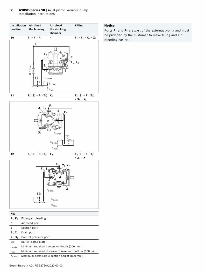
Bosch Rexroth AG, RE 92750/2020-03-03
58 A10VG Series 10 | Axial piston variable pumpInstallation instructions
Installation position
Air bleedthe housing
Air bleedthe stroking chamber
Filling
10 F2 + F1 (R) − F2 + F1 + X1 + X2
T2
S
RF2
SB
ht min
hmin
0.5
bar
hS max
F1
X1, X2
11 F2 (S) + F1 (T1) X1 F2 (S) + F1 (T1) + X1 + X2
X1 T1
X2
S F2
SB
ht min
hmin
hS max
F1
12 F2 (S) + F1 (T2) X2 F2 (S) + F1 (T2) + X1 + X2
X2SF2
SB
ht min
hmin
hS max
F1 T2
X1
Key
F1, F2 Filling/air bleeding
R Air bleed port
S Suction port
T1, T2 Drain port
X1, X2 Control pressure port
SB Baffle (baffle plate)
ht min Minimum required immersion depth (200 mm)
hmin Minimum required distance to reservoir bottom (100 mm)
hS max Maximum permissible suction height (800 mm)
NoticePorts F1 and F2 are part of the external piping and must be provided by the customer to make filling and air bleeding easier.
RE 92750/2020-03-03, Bosch Rexroth AG
59 Axial piston variable pump | A10VG Series 10 Project planning notes
Project planning notes
▶ The pump is designed to be used in a closed circuit. ▶ The project planning, installation and commissioning of
the axial piston unit require the involvement of qualified skilled personnel.
▶ Before using the axial piston unit, please read the corresponding instruction manual completely and thoroughly. If necessary, this can be requested from Bosch Rexroth.
▶ Before finalizing your design, please request a binding installation drawing.
▶ The specified data and notes contained herein must be observed.
▶ Depending on the operating conditions of the axial piston unit (working pressure, fluid temperature), the characteristic curve may shift.
▶ Preservation: Our axial piston units are supplied as standard with preservative protection for a maximum of 12 months. If longer preservation is required (maximum 24 months), please specify this in plain text when placing your order. The preservation periods apply under optimal storage conditions, details of which can be found in data sheet 90312 or in the instruction manual.
▶ Not all versions of the product are approved for use in a safety function according to ISO 13849. Please consult the responsible contact person at Bosch Rexroth if you require reliability parameters (e.g. MTTFD) for functional safety.
▶ Depending on the type of control used, electromagnetic effects can be produced when using solenoids. Applying a direct voltage signal (DC) to solenoids does not create electromagnetic interference (EMI) nor is the solenoid affected by EMI. Electromagnetic interference (EMI) potential exists when operating and controlling a solenoid with a modulated direct voltage signal (e.g. PWM signal). Appropriate testing and measures should be taken by the machine manufacturer to ensure other components or operators (e.g. with pacemaker) are not affected by this potential.
▶ The pressure cut-off is not a safeguard against pressure overload. Be sure to add a pressure relief valve to the hydraulic system.
▶ With dynamic power flow (switch of pumps to operation as a motor) a maximum of 95% Vg max is permissible. We recommend configuring the software accordingly.
▶ For drives that are operated for a long period with constant rotational speed, the natural frequency of the hydraulic system can be stimulated by the stimulator frequency of the pump (rotational speed frequency ×9). This can be prevented with suitably designed hydraulic lines.
▶ Please note the details regarding the tightening torques of port threads and other threaded joints in the instruction manual.
▶ Working ports: – The ports and fastening threads are designed for the
specified maximum pressure. The machine or system manufacturer must ensure the connecting elements and lines correspond to the specified application conditions (pressure, flow, hydraulic fluid, temperature) with the necessary safety factors.
– The working ports and function ports are only intended to accommodate hydraulic lines.
Bosch Rexroth AG, RE 92750/2020-03-03
60 A10VG Series 10 | Axial piston variable pumpSafety instructions
Bosch Rexroth AGGlockeraustraße 489275 ElchingenGermanyPhone +49 7308 [email protected]
© Bosch Rexroth AG 2020. All rights reserved, also regarding any disposal, exploitation, reproduction, editing, distribution, as well as in the event of applications for industrial property rights. The data specified within only serves to describe the product. No statements concerning a certain condition or suitability for a certain application can be derived from our information. The information given does not release the user from the obligation of own judgment and verification. It must be remembered that our products are subject to a natural process of wear and aging.
Safety instructions
▶ During and shortly after operation, there is a risk of getting burnt on the axial piston unit and especially on the solenoids. Take the appropriate safety measures (e.g. by wearing protective clothing).
▶ Moving parts in control equipment (e.g. valve spools) can, under certain ircumstances, get stuck in position as a result of contamination (e.g. contaminated hydraulic fluid, abrasion, or residual dirt from components). As a result, the hydraulic fluid flow and the build-up of torque in the axial piston unit can no longer respond correctly to the operator’s specifications. Even the use of various filter elements (external or internal flow filtration) will not rule out a fault but merely reduce the risk. The machine/system manufacturer must test whether remedial measures are needed on the machine for the application concerned in order to bring the driven consumer into a safe position (e.g. safe stop) and ensure any measures are properly implemented.
▶ Moving parts in high-pressure relief valves may in certain circumstances become stuck in an undefined position due to contamination (e.g. impure hydraulic fluid). This can result in restriction or loss of load-holding functions in lifting winches. The machine/system manufacturer must check whether additional measures are required on the machine for the relevant application in order to keep the load in a safe position and ensure they are properly implemented.
Related Documents