Linear Motion and Assembly Technologies Service Pneumatics Hydraulics Electric Drives and Controls Axial Piston Variable Motor AA6VM (A6VM) RA 91604-A/07.09 1/76 Replaces: 03.09 Series 6 Size Nominal pressure/Peak pressure 28 to 200 5800 ps (400 bar) / 6500 psi (450 bar) 250 to1000 5100 psi (350 bar) / 5800 psi (400 bar) Open and closed circuits Features – Variable motor with an axial tapered piston rotary group of bent-axis design for hydrostatic drives in open and closed circuits – For use in mobile and stationary application areas – The wide control range enables the variable motor to satisfy the requirement for high speed and high torque. – The displacement is infinitely variable from V g max to V g min = 0. – The output speed depends on the flow of the pump and the displacement of the motor. – The output torque increases with the pressure differential between the high and low pressure side and with increasing displacement. – Wide control range with hydrostatic transmission – Wide selection of control devices – Cost savings through elimination of gear shifts and possibility of using smaller pumps – Compact, robust bearing system with long service life – High power density – Good starting characteristics – Low moment of inertia Data sheet Contents Ordering code / Standard program 2 Technical data 5 HD - Hydraulic control, pilot-pressure related 10 HZ - Hydraulic two-point control 13 EP - Electric control with proportional solenoid 14 EZ - Electric two-point control, with switching solenoid 17 HA - Automatic control, high-pressure related 18 DA - Hydraulic control, speed related 23 Electric travel direction valve (for DA, HA.R) 25 Unit dimensions, size 28 (ISO Version) 26 Unit dimensions, size 55 (SAE Version) 30 Unit Dimensions, Size 80 (SAE Version) 34 Unit dimensions, size 107 (SAE Version) 38 Unit dimensions, size 140 (ISO Version) 42 Unit dimensions, size 160 (SAE Version) 46 Unit dimensions, size 200 (SAE Version) 50 Unit dimensions, size 250 (SAE Version) 54 Unit dimensions, size 355 (ISO Version) 57 Unit dimensions, size 500 (ISO Version) 60 Unit dimensions, size 1000 (ISO Version) 63 Flush and boost pressure valve 66 BVD counterbalance valve (sizes 55 to 160) 68 Swivel angle indicator (Sizes 250 to 1000) 71 Speed measurement (sizes 28 to 500) 72 Connectors for solenoids (for EP, EZ, HA.U, HA.R, DA only) 74 Installation instructions 75 General instructions 76

Welcome message from author
This document is posted to help you gain knowledge. Please leave a comment to let me know what you think about it! Share it to your friends and learn new things together.
Transcript

Linear Motion andAssembly Technologies ServicePneumaticsHydraulics
Electric Drives and Controls
Axial Piston Variable MotorAA6VM (A6VM)
RA 91604-A/07.09 1/76Replaces: 03.09
Technical data sheet
Series 6Size Nominal pressure/Peak pressure28 to 200 5800 ps (400 bar) / 6500 psi (450 bar)250 to1000 5100 psi (350 bar) / 5800 psi (400 bar) Open and closed circuits
Features– Variable motor with an axial tapered piston rotary group of
bent-axis design for hydrostatic drives in open and closed circuits
– For use in mobile and stationary application areas
– The wide control range enables the variable motor to satisfy the requirement for high speed and high torque.
– The displacement is infinitely variable from Vg max to Vg min = 0.
– The output speed depends on the flow of the pump and the displacement of the motor.
– The output torque increases with the pressure differential between the high and low pressure side and with increasing displacement.
– Wide control range with hydrostatic transmission
– Wide selection of control devices
– Cost savings through elimination of gear shifts and possibility of using smaller pumps
– Compact, robust bearing system with long service life
– High power density
– Good starting characteristics
– Low moment of inertia
Data sheet
ContentsOrdering code / Standard program 2Technical data 5HD - Hydraulic control, pilot-pressure related 10HZ - Hydraulic two-point control 13EP - Electric control with proportional solenoid 14EZ - Electric two-point control, with switching solenoid 17HA - Automatic control, high-pressure related 18DA - Hydraulic control, speed related 23Electric travel direction valve (for DA, HA.R) 25Unit dimensions, size 28 (ISO Version) 26Unit dimensions, size 55 (SAE Version) 30Unit Dimensions, Size 80 (SAE Version) 34Unit dimensions, size 107 (SAE Version) 38Unit dimensions, size 140 (ISO Version) 42Unit dimensions, size 160 (SAE Version) 46Unit dimensions, size 200 (SAE Version) 50Unit dimensions, size 250 (SAE Version) 54Unit dimensions, size 355 (ISO Version) 57Unit dimensions, size 500 (ISO Version) 60Unit dimensions, size 1000 (ISO Version) 63Flush and boost pressure valve 66BVD counterbalance valve (sizes 55 to 160) 68Swivel angle indicator (Sizes 250 to 1000) 71Speed measurement (sizes 28 to 500) 72Connectors for solenoids (for EP, EZ, HA.U, HA.R, DA only) 74Installation instructions 75General instructions 76
2/76 Bosch Rexroth AG AA6VM RA 91604-A/07.09
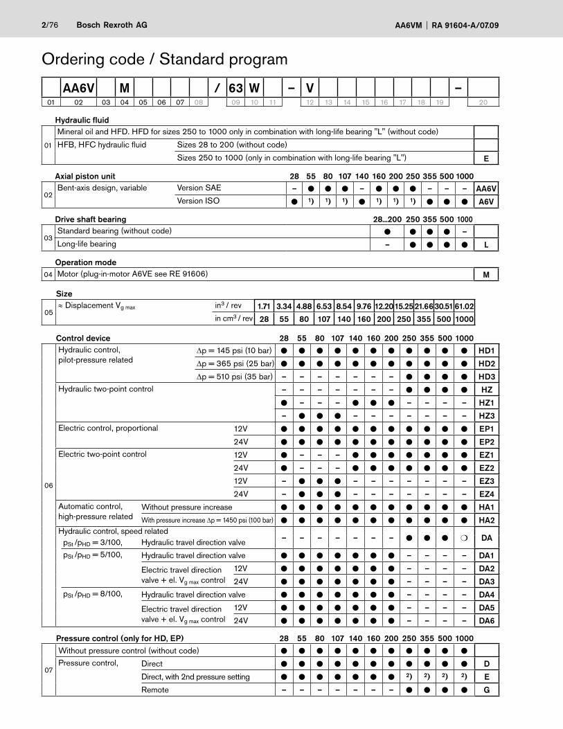
Ordering code / Standard program
Hydraulic fluid
01
Mineral oil and HFD. HFD for sizes 250 to 1000 only in combination with long-life bearing "L" (without code)
HFB, HFC hydraulic fluid Sizes 28 to 200 (without code)
Sizes 250 to 1000 (only in combination with long-life bearing "L") E
Axial piston unit 28 55 80 107 140 160 200 250 355 500 1000
02Bent-axis design, variable Version SAE – ● ● ● – ● ● ● – – – AA6V
Version ISO ● 1) 1) 1) ● 1) 1) 1) ● ● ● A6V
Drive shaft bearing 28...200 250 355 500 1000
03Standard bearing (without code) ● ● ● ● –Long-life bearing – ● ● ● ● L
Operation mode04 Motor (plug-in-motor A6VE see RE 91606) M
Size
05≈ Displacement Vg max in3 / rev 1.71 3.34 4.88 6.53 8.54 9.76 12.2015.2521.6630.51 61.02
in cm3 / rev 28 55 80 107 140 160 200 250 355 500 1000
Control device 28 55 80 107 140 160 200 250 355 500 1000
06
Hydraulic control,pilot-pressure related
Δp = 145 psi (10 bar) ● ● ● ● ● ● ● ● ● ● ● HD1
Δp = 365 psi (25 bar) ● ● ● ● ● ● ● ● ● ● ● HD2
Δp = 510 psi (35 bar) – – – – – – – ● ● ● ● HD3Hydraulic two-point control – – – – – – – ● ● ● ● HZ
● – – – ● ● ● – – – – HZ1
– ● ● ● – – – – – – – HZ3Electric control, proportional 12V ● ● ● ● ● ● ● ● ● ● ● EP1
24V ● ● ● ● ● ● ● ● ● ● ● EP2Electric two-point control 12V ● – – – ● ● ● ● ● ● ● EZ1
24V ● – – – ● ● ● ● ● ● ● EZ2
12V – ● ● ● – – – – – – – EZ3
24V – ● ● ● – – – – – – – EZ4Automatic control,high-pressure related
Without pressure increase ● ● ● ● ● ● ● ● ● ● ● HA1With pressure increase Δp = 1450 psi (100 bar) ● ● ● ● ● ● ● ● ● ● ● HA2
Hydraulic control, speed related– – – – – – – ● ● ● ❍ DApSt /pHD = 3/100, Hydraulic travel direction valve
pSt /pHD = 5/100, Hydraulic travel direction valve ● ● ● ● ● ● ● – – – – DA1
Electric travel direction valve + el. Vg max control
12V ● ● ● ● ● ● ● – – – – DA2
24V ● ● ● ● ● ● ● – – – – DA3pSt /pHD = 8/100, Hydraulic travel direction valve ● ● ● ● ● ● ● – – – – DA4
Electric travel direction valve + el. Vg max control
12V ● ● ● ● ● ● ● – – – – DA5
24V ● ● ● ● ● ● ● – – – – DA6
Pressure control (only for HD, EP) 28 55 80 107 140 160 200 250 355 500 1000
07
Without pressure control (without code) ● ● ● ● ● ● ● ● ● ● ●
Pressure control, Direct ● ● ● ● ● ● ● ● ● ● ● D
Direct, with 2nd pressure setting ● ● ● ● ● ● ● 2) 2) 2) 2) E
Remote – – – – – – – ● ● ● ● G
AA6V M / 63 W – V –01 02 03 04 05 06 07 08 09 10 11 12 13 14 15 16 17 18 19 20

RA 91604-A/07.09 AA6VM Bosch Rexroth AG 3/76
Ordering code / Standard program
Overriding HA control (for HA1, HA2 only) 28 55 80 107 140 160 200 250 355 500 1000
08
Without override (without code) ● ● ● ● ● ● ● ● ● ● ●
Hydraulic override ● ● ● ● ● ● ● ● ● ● ● TElectric override 12V ● ● ● ● ● ● ● – – – – U1
24V ● ● ● ● ● ● ● – – – – U2
Electric override+ electric travel direction valve
12V ● ● ● ● ● ● ● – – – – R124V ● ● ● ● ● ● ● – – – – R2
Series09 Series 6, index 3 63
Direction of rotation10 Viewed from shaft end, alternating W
Setting range for displacement 3) 28 55 80 107 140 160 200 250 355 500 1000
11
Vg min = 0 to 0.7 Vg max (without code) ● ● ● ● ● ● ● – – – –Vg min = 0 to 0.4 Vg max Vg max = Vg max to 0.8 Vg max – – – – – – – ● ● ● ● 1Vg min > 0.4 Vg max to 0.8 Vg max Vg max = Vg max to 0.8 Vg max – – – – – – – ● ● ● ● 2
Seals12 FKM (fluor-caoutchouc) V
Shaft end 28 55 80 107 140 160 200 250 355 500 1000
13
Version SAE (AA6VM) Splined shaft ANSI B92.1a-1976 – ● ● ● – ● ● ● – – – SVersion ISO Splined shaft DIN 5480 ● – – – – – – – – – – A(A6VM) ● – – – ● – – – ● ● ● Z
Parallel keyed DIN 6885 – – – – – – – – ● ● ● P
Mounting flange 28 55 80 107 140 160 200 250 355 500 1000
14
Version SAE SAE J744 – 2-bolt – – ● – – – – – – – – C(AA6VM) SAE J744 – 4-bolt – ● – ● – ● ● ● – – – D
Version ISO ISO 3019-2 – 4-hole ● – – – ● – – – – – – B(A6VM) ISO 3019-2 – 8-hole – – – – – – – – ● ● ● H
Service line port 4) 28 55 80 107 140 160 200 250 355 500 1000
15
Version SAE SAE flange ports 51 0 – ● ● ● – ● ● ● – – – 510(AA6VM) A/B, rear (UN threads) 7 – ● ● ● – ● ● ● – – – 517
SAE flange ports 52 0 – ● ● ● – ● ● ● – – – 520A/B side, opposite (UN threads) 7 – ● ● ● – ● ● ● – – – 527Port plate with pressure-relief valves, 37 0 – – – ● – – – – – – – 370For mounting a counterbalance valve 5)6) 38 0 – ● ● ● ● ● – – – – – 380
Version ISO
(A6VM)
SAE flange ports 01 0 ● – – – ● – – – ● ● ● 010A/B, rear (metric threads) 7 ● – – – ● – – – ● ● ● 017SAE flange ports 02 0 ● – – – ● – – – ● ● ● 020A/B side, opposite (metrics threads) 7 ● – – – ● – – – ● ● ● 027
SAE flange portsA/B side, opposite + rear 15 0 – – – – – – – – ● ● ● 150
ValvesWithout valve 0With flush and boost pressure valve 7
AA6V M / 63 W – V –01 02 03 04 05 06 07 08 09 10 11 12 13 14 15 16 17 18 19 20

4/76 Bosch Rexroth AG AA6VM RA 91604-A/07.09
Speed measurement 28 55 80 107 140 160 200 250 355 500 1000
16
Without speed measurement (without code) ● ● ● ● ● ● ● ● ● ● ●
Prepared for speed measurement (ID) 7) ● ● ● ● ● ● ● – – – – D
Prepared for speed measurement (HDD) 7) – ● ● ● ● ● ● ● ● ● ❍ F
Swivel angle indicator 28 55 80 107 140 160 200 250 355 500 1000
17
Without swivel angle indicator (without code) ● ● ● ● ● ● ● ● ● ● –
With optical swivel angle indicator – – – – – – – ● ● ● ● V
With Electric swivel angle indicator – – – – – – – ● ● ● ● E
Connector for solenoids (only sizes 28 to 200) 8) EP1/2 EZ1/2 EZ3/4 HA.U. HA.R.9) DA.
18
DEUTSCH - molded connector, 2-pin – without suppressor diode ● ● ❍ ❍ ● ● PDEUTSCH - molded connector, 2-pin – with suppressor diode – ❍ – – – ❍ Q
HIRSCHMANN - connector – without suppressor diode ▲ ▲ ▲ ▲ ▲ ▲ H
Start of control 28 55 80 107 140 160 200 250 355 500 1000
19At Vg min (standard for HA) ● ● ● ● ● ● ● ● ● ● ● A
At Vg max (standard for HD, HZ, EP, EZ, DA) ● ● ● ● ● ● ● ● ● ● ● B
Standard / special version9)
20
Standard version (without code)
With attachment part combined -K
Special version -S
With attachment part combined -SK1) ISO-Version see RE 916042) Supplied as standard with version D (sizes 250 to 1000)3) Please specify precise setting for Vg min and Vg max in plain text when ordering: Vg min = ... cm3, Vg max = ... cm3
4) Metric fixing thread5) Only possible in combination with HD, EP, HA control6) Complete order recommended, counterbalance valve pages 68...707) Complete order recommended, speed sensor page 72...738) The HIRSCHMANN connector – without suppressor diode is only standard with sizes 250 to 1000 (without code)9) With HA.R1 and HA.R2 for the 2nd solenoid (DIA 45), the version with DEUTSCH molded connector is available on request.9) Adjustment data are included in the material number
= available ❍ = on request ▲ = not for new projects – = not available
= preferred program
Ordering code / Standard program
AA6V M / 63 W – V –01 02 03 04 05 06 07 08 09 10 11 12 13 14 15 16 17 18 19 20

RA 91604-A/07.09 AA6VM Bosch Rexroth AG 5/76
Hydraulic fluidBefore starting project planning, please refer to our data sheets RE 90220 (mineral oil), RE 90221 (environmentally ac-ceptable hydraulic fluids) and RE 90223 (HF hydraulic fluids) for detailed information regarding the choice of hydraulic fluid and application conditions.
The (A)A6VM variable motor is not suitable for operation with HFA. If HFB, HFC and HFD or environmentally acceptable hy-draulic fluids are being used, the limitations regarding technical data and seals mentioned in RE 90221 and RE 90223 must be observed.
When ordering, please indicate the used hydraulic fluid.
Operating viscosity range
For optimum efficiency and service life, select an operating vis-cosity (at operating temperature) within the optimum range of
νopt = optimum operating viscosity 80...170 SUS (16 to 36 mm2/s)
depending on the circuit temperature (closed circuit) and tank temperature (open circuit).
Limits of viscosity range
The limiting values for viscosity are as follows:
Sizes 28 to 200:
νmin = 42 SUS (5 mm2/s)short-term (t < 3 min) at max. perm. temperature of tmax = +240°F (+115°C)
νmax = 7400 SUS (1600 mm2/s)short-term (t < 3 min) at cold start (p ≤ 435 psi / 30 bar, n ≤ 1000 rpm, tmin = -40°F / -40°C)Only for starting up without load. Optimum operating viscosity must be reached within approx. 15 minutes.
Sizes 250 to 1000:
νmin = 60 SUS (10 mm2/s)short-term (t < 3 min) at max. perm. temperature of tmax = +195°F (+90°C)
νmax = 4600 SUS (1000 mm2/s)short-term (t < 3 min) at cold start (p ≤ 435 psi / 30 bar, n ≤ 1000 rpm, tmin = -13°F / -25°C)Only for starting up without load. Optimum operating viscosity must be reached within approx. 15 minutes.
Note that the maximum hydraulic fluid temperature of 240°F (115°C) (+195°F / +90°C for size 250 to 1000) must not be ex-ceeded locally either (e.g. in the bearing area). The temperature in the bearing area is - depending on pressure and speed - up to 22°F (12 K) higher than the average case drain temperature.
Special measures are necessary in the temperature range from - 40°F and -13°F (-40°C and -25°C). Please contact us.
For detailed information about use at low temperatures, see RE 90300-03-B.
Selection diagram
VG 22VG 32VG 46VG 68VG 100
opt.
80 (16)
170 (36)
(0 ) (20 ) (40 ) (60 ) (80 ) (100 )(-40 ) (-20 )
42 (5)
7400 (1600)
visco
sity
SU
S (m
m2 /
s)
fluid temperature range t in F ( C)tmin = -40 F (-40 C)
tmax = +240 F (+115 C)
(-40 ) (-25 ) (-10 ) (0 ) (10 ) (30 ) (50 ) (70 ) (90 ) (115 )
-40 -13 1200 20 40 60 80 160 195 240
(1600)(1000)(600)(400)
(200)
(100)
(60)
(40)
(20)
(10)
(5)
7000500030002000
1000
500
300
150200
100807060
50
40
Details regarding the choice of hydraulic fluid
The correct choice of hydraulic fluid requires knowledge of the operating temperature in relation to the ambient temperature: in a closed circuit the circuit temperature, in an open circuit the tank temperature.
The hydraulic fluid should be chosen so that the operating vis-cosity in the operating temperature range is within the optimum range (νopt.) - the shaded area of the selection diagram. We recommended that the higher viscosity class be selected in each case.
Example: At an ambient temperature of X°C an operating temperature of 140°F (60°C) is set. In the optimum operating viscosity range (νopt; shaded area) this corresponds to the viscosity classes VG 46 or VG 68; to be selected: VG 68.
Please note: The case drain temperature, which is affected by pressure and speed, is always higher than the circuit temperature or tank temperature. At no point in the system may the temperature be higher than 240°F (115°C) for sizes 28 to 200 or 195°F (90°C) for sizes 250 to 1000.
If the above conditions cannot be maintained due to extreme operating parameters, we recommend flushing the case at port U or using a flush and boost pressure valve (see pages 66-67).
Technical data

6/76 Bosch Rexroth AG AA6VM RA 91604-A/07.09
Technical dataFiltrationThe finer the filtration, the higher the cleanliness level of the hy-draulic fluid and the longer the service life of the axial piston unit.
To ensure functional reliability of the axial piston unit, the hydrau-lic fluid must have a cleanliness level of at least
20/18/15 according to ISO 4406.
At very high hydraulic fluid temperatures (195°F to max. 240°F / 90°C to max. 115°C) at least cleanliness level
19/17/14 according to ISO 4406 is required.
If the classes specified above cannot be maintained, please contact us.
Operating pressure rangeMaximum pressure on port A or B (pressure data in according to DIN 24312)
for sizes 28 to 200
Nominal pressure pN __________________ 5800 psi (400 bar)* Peak pressure pmax ____________________________6500 psi (450 bar)*Total pressure (press. A + press. B) pmax __ 10150 psi (700 bar)
*) Size 80: pN = 5100 psi (350 bar), pmax = 5800 psi (400 bar)
for sizes 250 to 1000
Nominal pressure pN ___________________ 5100 psi (350 bar)
Peak pressure pmax ____________________5800 psi (400 bar)Total pressure (press. A + press. B) pmax __ 10150 psi (700 bar)
Please note:Sizes 28 to 200: With shaft end S or Z, a nominal pressure of pN = 4550 psi (315 bar) (pmax = 5100 psi (pmax = 350 bar)) is permissible for drives with radial loading of the drive shaft (pinions, V-belts)!
Size 80: pN = 2900 psi (200 bar). Please contact us.Sizes 250 to 1000: Please contact us.
In cases of pulsating loading above 4550 psi (315 bar), we re-commend the version with splined shaft Z (sizes 250 to 1000).
Direction of flow
Direction of rotation, viewed from shaft endclockwise counter-clockwise
A to B B to A
Speed rangeNo limit to minimum speed nmin. If uniformity of motion is re-quired, speed nmin must not be less than 50 rpm. See table of values on page 7 for maximum speed.
Long-Life bearing (sizes 250 to 1000)For long service life and use with HF hydraulic fluids. Same external dimensions as motor with standard bearing. A long-life bearing can be specified. Flushing of bearing and case via port U recommended.
Flushing volumes (recommended)
Size 250 355 500 1000
qv flush (gpm) 2.6 4.2 4.2 4.2
(l/min) 10 16 16 16
Shaft seal ringPermissible pressure load
The service life of the shaft seal ring is affected by the speed of the motor and the case drain pressure. It is recommended that the average, continuous case drain pressure at operating temperature 45 psi (3 bar) absolute not be exceeded (max. permissible case drain pressure 90 psi (6 bar) absolute at reduced speed, see dia-gram). Short-term (t < 0.1 s) pressure spikes of up to 145 psi (10 bar) absolute are permitted. The service life of the shaft seal ring decreases with an increase in the frequency of pressure spikes.
The case pressure must be equal to or greater than the external pressure on the shaft seal ring.
Sizes 28 to 200
bar
(6)
(5)
(4)
(3)
(2)
(1)2000 4000 6000 8000 10000
psi
90
75
60
45
30
15
Speed n in rpm
Size 28
Size 55
Sizes 160, 200
Sizes 107, 140
Perm
. pre
ssur
e p a
bs. m
ax.
Size 80
Sizes 250 to 1000
2000 30000 1000 1500 2500500 3500
psi
90
75
60
45
30
15
(bar)
(6)
(5)
(4)
(3)
(2)
(1)Perm
. pre
ssur
e p a
bs. m
ax.
Speed n in rpm
Size 250
Size 500
Size 1000
Size 355
Temperature range
The FKM shaft seal ring is permissible for case temperatures of -13 °F to 240 °F (-25 °C to +115 °C) for sizes 28 to 200 and-13 °F to 195 °F (-25 °C to +90 °C) for sizes 250 to 1000
Note:For application cases below -13 °F (-25 °C), an NBR shaft seal ring is necessary (permissible temperature range: -40 °F to 195 °F (-40 °C to +90 °C.) Please state NBR shaft seal ring in plain text when ordering. Please contact us.
Effect of case pressure on start of controlAn increase in the case pressure has an effect on the following controls when control of the variable motor begins:
HA1T (sizes 28 to 200) _________________________ increaseHD, EP, HA, HA.R, HA.U, HA.T (sizes 250 to 1000) __ increaseDA __________________________________________ decrease
The start of control is set in the factory at a case pressure of pabs = 30 psi (2 bar) for sizes 28 to 200 and pabs = 15 psi (1 bar) for sizes 250 to 1000.
RA 91604-A/07.09 AA6VM Bosch Rexroth AG 7/76
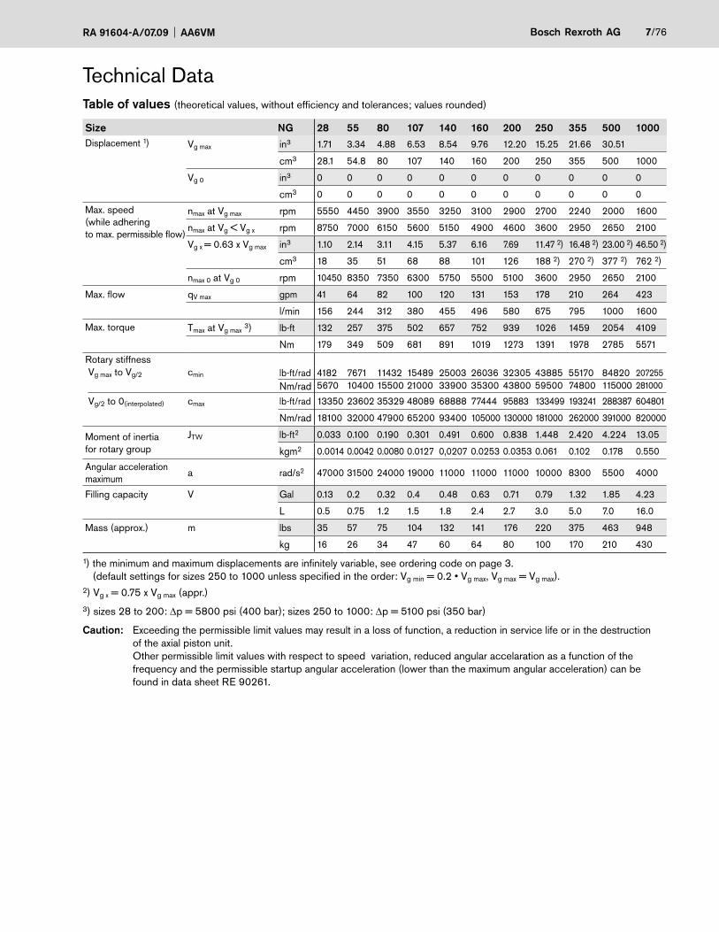
Technical DataTable of values (theoretical values, without efficiency and tolerances; values rounded)
Size NG 28 55 80 107 140 160 200 250 355 500 1000Displacement 1) Vg max in3 1.71 3.34 4.88 6.53 8.54 9.76 12.20 15.25 21.66 30.51
cm3 28.1 54.8 80 107 140 160 200 250 355 500 1000
Vg 0 in3 0 0 0 0 0 0 0 0 0 0 0
cm3 0 0 0 0 0 0 0 0 0 0 0
Max. speed(while adhering to max. permissible flow)
nmax at Vg max rpm 5550 4450 3900 3550 3250 3100 2900 2700 2240 2000 1600
nmax at Vg < Vg x rpm 8750 7000 6150 5600 5150 4900 4600 3600 2950 2650 2100
Vg x = 0.63 x Vg max in3 1.10 2.14 3.11 4.15 5.37 6.16 7.69 11.47 2) 16.48 2) 23.00 2) 46.50 2)
cm3 18 35 51 68 88 101 126 188 2) 270 2) 377 2) 762 2)
nmax 0 at Vg 0 rpm 10450 8350 7350 6300 5750 5500 5100 3600 2950 2650 2100
Max. flow qV max gpm 41 64 82 100 120 131 153 178 210 264 423
l/min 156 244 312 380 455 496 580 675 795 1000 1600
Max. torque Tmax at Vg max 3) lb-ft 132 257 375 502 657 752 939 1026 1459 2054 4109
Nm 179 349 509 681 891 1019 1273 1391 1978 2785 5571
Rotary stiffnessVg max to Vg/2 cmin lb-ft/rad 4182 7671 11432 15489 25003 26036 32305 43885 55170 84820 207255
Nm/rad 5670 10400 15500 21000 33900 35300 43800 59500 74800 115000 281000
Vg/2 to 0(interpolated) cmax lb-ft/rad 13350 23602 35329 48089 68888 77444 95883 133499 193241 288387 604801
Nm/rad 18100 32000 47900 65200 93400 105000 130000 181000 262000 391000 820000
Moment of inertia for rotary group
JTW lb-ft2 0.033 0.100 0.190 0.301 0.491 0.600 0.838 1.448 2.420 4.224 13.05
kgm2 0.0014 0.0042 0.0080 0.0127 0,0207 0.0253 0.0353 0.061 0.102 0.178 0.550
Angular acceleration maximum
a rad/s2 47000 31500 24000 19000 11000 11000 11000 10000 8300 5500 4000
Filling capacity V Gal 0.13 0.2 0.32 0.4 0.48 0.63 0.71 0.79 1.32 1.85 4.23
L 0.5 0.75 1.2 1.5 1.8 2.4 2.7 3.0 5.0 7.0 16.0
Mass (approx.) m lbs 35 57 75 104 132 141 176 220 375 463 948
kg 16 26 34 47 60 64 80 100 170 210 430
1) the minimum and maximum displacements are infinitely variable, see ordering code on page 3. (default settings for sizes 250 to 1000 unless specified in the order: Vg min = 0.2 • Vg max, Vg max = Vg max).2) Vg x = 0.75 x Vg max (appr.)3) sizes 28 to 200: Δp = 5800 psi (400 bar); sizes 250 to 1000: Δp = 5100 psi (350 bar)
Caution: Exceeding the permissible limit values may result in a loss of function, a reduction in service life or in the destruction of the axial piston unit. Other permissible limit values with respect to speed variation, reduced angular accelaration as a function of the frequency and the permissible startup angular acceleration (lower than the maximum angular acceleration) can be found in data sheet RE 90261.

8/76 Bosch Rexroth AG AA6VM RA 91604-A/07.09
Minimum inlet pressure on service line port A(B)
Inle
t pre
ssur
e p a
bs. m
in
n / nmax at Vg max
Vg max
Vg x
0.3 Vg max
1530
60
90
115
145
175
200
230
0 0.41) 0.71) 1.01) 1.31) 1.61)
0 0.22) 0.52) 0.82) 1.12) 1.42)
(1)(2)
(4)
(6)
(8)
(10)
(12)
(14)
(16)
(bar)psi
for NG 28 to 2001)
for NG 250 to 10002)
To prevent damage to the variable motor, there must be a mini-mum inlet pressure in the inlet area. The minimum inlet pressu-re is dependent on the speed and swivel angle (displacement) of the variable motor.
Please contact us if these conditions cannot be satisfied.
Permissible displacement in relation to speed
1.0
0.8
0.630.6
0.4
0.2
00.2 0.4 0.6 0.8 1.0 1.2 1.4 1.58 1.6
n / nmax
Sizes 250 to 1000
Sizes 28 to 200
Dis
plac
emen
t V
g /
Vg
max
Technical data

RA 91604-A/07.09 AA6VM Bosch Rexroth AG 9/76
))
)
)(((
(
Permissible radial and axial loading on the drive shaftThe specified values are maximum values and do not apply to continuous operation.
Size NG 28 55 80 107 140 160 200 250 355 500 1000Radial force, max.1)at distance a(from shaft collar)
a
FqFq max lb 1280 2347 2948 3434 4003 4568 5147 2702) 3372) 4272) 5842)
N 5696 10440 13114 15278 17808 20320 22896 12002) 15002) 19002) 26002)
in 0.49 0.59 0.69 0.79 0.89 0.89 0.98 1.61 2.07 2.07 2.66
a mm 12.5 15 17.5 20 22.5 22.5 25 41 52.5 52.5 67.5Axial force, max.3)
-
+Fax
– Fax max lb 71 112 160 202 231 252 281 270 337 427 584
N 315 500 710 900 1030 1120 1250 1200 1500 1900 2600
+ Fax max lb 71 112 160 202 231 252 281 899 1124 1405 2248
N 315 500 710 900 1030 1120 1250 4000 5000 6250 10000Permissible axial force/baroperating pressure
– Fax per./psi lb/psi 0.07 0.12 0.15 0.18 0.21 0.23 0.26 4) 4) 4) 4)
– Fax per./bar N/bar 4.6 7.5 9.6 11.3 13.3 15.1 17.0 4) 4) 4) 4)1) during intermittent operation (sizes 28 to 200).2) when at a standstill or when axial piston unit operating in depressurized condition. Higher forces are permissible when under pressure. Please contact us.3) max. permissible axial force when at a standstill or when axial piston unit operating in depressurized condition.4) please contact us.
When considering the permissible axial force, the force-transfer direction must be taken into account.
– Fax max = increase in service life of bearings
+ Fax max = reduction in service life of bearings (avoid)
Effect of radial force Fq on the service life of bearings
By selecting a suitable force-transfer direction of Fq, the stress on the bearings caused by the internal transmission forces can be reduced, thus achieving the optimum service life of the bearings. Recommended position of mating gear is dependent on direction of rotation. Examples:
Toothed gear drive V-belt drive
"Counter-clockwise" direction of rotation
Pressure on port B
ϕopt = 45°ϕ opt= 45°
ϕopt = 70°ϕ op
t= 70°
Alternating direction of
rotationAlternating direction of
rotation
"Clockwise"direction of rotation
Pressure on port A
"Counter-clockwise" direction of rotation
Pressure on port B
Determining the size
Flow qv =Vg • n gpm
Vg • n l/min231 • ηv 1000 • ηv
Speed n =qV • 231 • ηv rpm
qV • 1000 • ηv rpmVg Vg
Torque T = Vg • Δp • ηmh
lb-ftVg • Δp • ηmh Nm
24 • π 20 • π
Power P =2 π • T • n
=qv • Δp • ηt HP
qv • Δp • ηt =2 π • T • n
kW33000 1714 600 60000
Technical data
Vg = Displacement per revolution in in3 (cm3)
Δp = Differential pressure in psi (bar)
n = Speed in rpm
ηv = Volumetric efficiency
ηmh = Mechanical-hydraulic efficiency
ηt = Overall efficiency

10/76 Bosch Rexroth AG AA6VM RA 91604-A/07.09
HD - Hydraulic control, pilot-pressure relatedThe pilot-pressure related hydraulic control permits infinite control of the displacement according to the pilot-pressure signal. The displacement is proportional to the pilot pressure applied to port X.
Standard configuration:
– Start of control at Vg max (max. torque, min. speed)
– End of control at Vg min (min. torque, max. permitted speed)
Please note:
– Maximum permissible pilot pressure: 1450 psi (100 bar)
– For reliable control, an operating pressure of at least 435 psi (30 bar) is necessary in A (B). If a control operation is perfor-med at an operating pressure < 435 psi (30 bar), an auxiliary pressure of at least 435 psi (30 bar) must be applied at port G via an external check valve. Lower pressures may be adequate in individual cases.
– Please state the desired start of control in plain text when ordering, e.g.: start of control at 145 psi (10 bar).
The following only applies to sizes 250 to 1000:
– The start of control and the HD characteristic are influenced by the case pressure. An increase in the case pressure causes an increase in the start of control (see page 6) and thus a parallel displacement of the characteristic.
– Fluid escapes from port X at the rate of max. 0.08 gpm (0.3 l/min) due to internal leakage (operating pressure > pilot pressure). To prevent a build-up in pilot pressure, port X must be vented to tank.
HD1 pilot pressure increase ΔpS = 145 psi (10 bar)An increase in pilot pressure of 145 psi (10 bar) on port X causes a reduction in the displacement from Vg max to 0 cm3
(sizes 28 to 200) or from Vg max to 0.2 Vg max (sizes 250 to 1000).
Start of control (setting range) ____ 30 – 290 psi (2 – 20 bar)
Default setting:start of control at 45 psi (3 bar) (end of control at 190 psi (13 bar))
Characteristic HD1psi (bar)470 (32.5)435 (30)405 (28)
350 (24)
290 (20)
230 (16)
175 (12)
115 (8)
60 (4)30 (2)
0 0.2 0.4 0.6 0.8 1.0Vg 0 Vg maxVg / Vg max
Pilo
t pre
ssur
e p S
in p
si (
bar)
Sta
rt o
f con
trol
Set
ting
rang
eP
ilot p
ress
ure
incr
ease
Sizes 28 to 200
Sizes 250 to 1000
Displacement
HD2 pilot pressure increase ΔpS = 365 psi (25 bar)An increase in pilot pressure of 365 psi (25 bar) on port X causes a reduction in the displacement from Vg max to 0 cm3 (sizes 28 to 200) or from Vg max to 0.2 Vg max (sizes 250 to 1000).
Start of control, setting range _____ 75 – 725 psi (5 – 50 bar)
Default setting:start of control at 145 psi (10 bar) (end of control at 510 psi (35 bar))
Characteristic HD2psi (bar)1150 (80)
1000 (70)
870 (60)
725 (50)
580 (40)
435 (30)
290 (20)
145 (10)75 (5)
0 0.2 0.4 0.6 0.8 1.0Vg 0 Vg maxVg / Vg max Displacement
Sta
rt o
f con
trol
Set
ting
rang
eP
ilot p
ress
ure
incr
ease
Sizes 28 to 200Sizes 250 to
Pilo
t pre
ssur
e p S
in p
si (
bar)
HD3 pilot pressure increase ΔpS = 510 psi (35 bar)An increase in pilot pressure of 510 psi (35 bar) on port X causes a reduction in the displacement from Vg max to 0.2 Vg max (sizes 250 to 1000).
Start of control, setting range ____ 100 – 725 psi (7 – 50 bar)
Default setting:start of control at 145 psi (10 bar) (end of control at 650 psi (45 bar))
Characteristic HD3
0 0.2 0.4 0.6 0.8 1.0Vg 0 Vg maxVg / Vg max
psi (bar)1300 (90)
1150 (80)
1000 (70)
870 (60)
725 (50)
580 (40)
435 (30)
290 (20)
145 (10)100 (7)
Pilo
t pre
ssur
e p S
in p
si (
bar)
Sta
rt o
f con
trol
Set
ting
rang
eP
ilot p
ress
ure
incr
ease
Sizes 250 to 1000
Displacement

RA 91604-A/07.09 AA6VM Bosch Rexroth AG 11/76
Circuit diagram HD1, HD2, HD3Sizes 28 to 200
U T1
G
X
B
A
T2
M1
vg min
vg max
Sizes 250 to 1000
U MB B
X
vg min
vg max
G
MT1 AT2 MA
Note
The spring return feature in the control unit is not a safety device
The spool valve inside the control unit can get stuck in an undefined position by internal contamination (contamina-ted hydraulic fluid, abrasion or residual contamination from system components). As a result, the axial piston unit can no longer supply the flow specified by the operator.
Check whether your application requires that remedial mea-sures be taken on your machine in order to bring the driven consumer into a safe position (e. g. immediate stop).
HD - Hydraulic control, pilot-pressure relatedHD.D Pressure control, directThe pressure control overlays the HD function. If the load incre-ases, or a reduction in the swivel angle of the motor causes the system pressure to increase, the motor will start to swivel to a greater angle when the pressure reaches the setpoint value of the pressure control.
The increase in the displacement and the resulting reduction in pressure cause the control deviation to decrease. With the in-crease in displacement the motor develops more torque, while the pressure remains constant.
Setting range on the pressure control valve:Sizes 28 to 200 ____________1150 – 5800 psi (80 – 400 bar)Sizes 250 to 1000 __________ 1150 – 5100 psi (80 – 350 bar)
Circuit diagram HD.DSizes 28 to 200
U T1
GX
B
A
T2
M1
vg min
vg max
Sizes 250 to 1000
U MB B
X
vg min
vg max
G
M
G2
T1 AT2 MA

12/76 Bosch Rexroth AG AA6VM RA 91604-A/07.09
HD - Hydraulic control, pilot-pressure relatedHD.E Pressure control, direct with 2nd pressure setting
Sizes 28 to 200
Connecting an external pilot pressure to port G2 allows the pressure controller setting to be over-ridden and a 2nd pressu-re setting to be used.
Required pilot pressure on port G2:
Sizes 28 to 200 __________ pSt = 290 – 725 psi (20 – 50 bar)
Please specify the 2nd pressure setting in plain text when ordering.
Circuit diagram HD.E Sizes 28 to 200
U T1 G2
XG
B
A
T2
M1
vg min
vg max
Sizes 250 to 1000 (HD.D)
Pressure control with 2nd pressure setting provided as standard with HD.D (see page 10).
Connecting an external pilot pressure to port G2 allows the pressure controller setting to be over-ridden and a 2nd pressu-re setting to be used.
Required pilot pressure on port G2:
Sizes 250 to 1000 _________________pSt ≥ 1450 psi (100 bar)
Please specify the 2nd pressure setting in plain text when ordering.
HD.G Pressure control, remote
Sizes 250 to 1000
When the set pressure value is reached, the remote pressure control regulates the motor continuously up to the maximum displacement Vg max. A pressure-relief valve (not supplied) controls the internal pressure cut-off valve. The pressure-relief valve is separate from the motor and is connected to X3. As long as operating pressure is below the set point of the external pressure-relief valve (1150 – 5100 psi / 80 – 350 bar), the pressure is equal on both sides of the internal pressure cut-off valve, and spring force keeps it closed. The external relief valve opens when the operating pressure exceeds the set point, and the pressure on the spring end of the pressure cut-off valve is reduced.The pressure cut-off valve then modulates the motor displace-ment (i.e.-swivelling towards maximum displacement) to limit operating pressure.
The standard differential pressure setting of the internal pressure cut-off valve is 365 psi (25 bar). We recommend the following for use as the external (i.e.-remote control) pressure-relief valve:
DBD 6 (hydraulic) according to RE 25402
The max. line length must not exceed 6 ft (2 m).
Circuit diagram HD.GSizes 250 to 1000
U MB B
X
vg min
vg max
G2
M
X3
T1 AT2 MA
RA 91604-A/07.09 AA6VM Bosch Rexroth AG 13/76
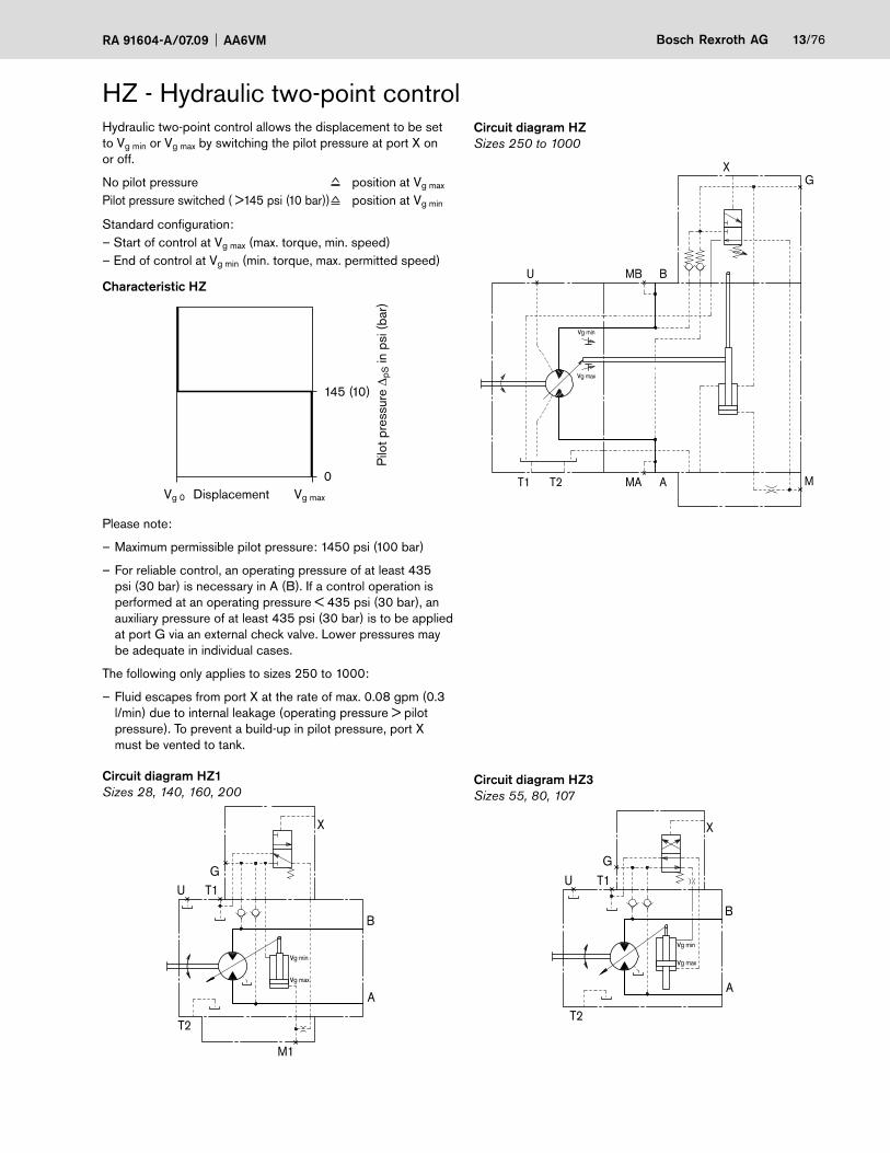
Circuit diagram HZSizes 250 to 1000
U MB B
X
vg min
vg max
G
MT1 AT2 MA
Hydraulic two-point control allows the displacement to be set to Vg min or Vg max by switching the pilot pressure at port X on or off.
No pilot pressure position at Vg max
Pilot pressure switched ( >145 psi (10 bar)) position at Vg min
Standard configuration:– Start of control at Vg max (max. torque, min. speed)– End of control at Vg min (min. torque, max. permitted speed)
Characteristic HZ
Displacement
Pilo
t pre
ssur
e Δ p
S in
psi
(ba
r)
Vg 0 Vg max
0
145 (10)
Please note:
– Maximum permissible pilot pressure: 1450 psi (100 bar)
– For reliable control, an operating pressure of at least 435 psi (30 bar) is necessary in A (B). If a control operation is performed at an operating pressure < 435 psi (30 bar), an auxiliary pressure of at least 435 psi (30 bar) is to be applied at port G via an external check valve. Lower pressures may be adequate in individual cases.
The following only applies to sizes 250 to 1000:
– Fluid escapes from port X at the rate of max. 0.08 gpm (0.3 l/min) due to internal leakage (operating pressure > pilot pressure). To prevent a build-up in pilot pressure, port X must be vented to tank.
Circuit diagram HZ1Sizes 28, 140, 160, 200
U T1
X
G
B
A
T2
M1
vg min
vg max
HZ - Hydraulic two-point control
Circuit diagram HZ3Sizes 55, 80, 107
U T1G
X
B
A
T2
vg min
vg max

14/76 Bosch Rexroth AG AA6VM RA 91604-A/07.09
EP - Electric control with proportional solenoidElectric control using a proportional solenoid (sizes 28 to 200) or proportional valve (sizes 250 to 1000) permits continuous control of the displacement according to an electric signal. The control is proportional to the applied electric control current.For sizes 250 to 1000, an external pressure of pmin = 435 psi (30 bar) is necessary for the control oil supply to port P (pmax = 1450 psi (100 bar)).
Standard configuration:
— Start of control at Vg max (max. torque, min. speed)
— End of control at Vg min (min. torque, max. permitted speed)
Characteristic EP
0 0.2 0.4 0.6 0.8 1.0
1600max
1400
1200
1000
800
600
400
200
Vg 0 VgVg max
Vg max
800max
700
600
500
400
300
200
100
EP1(12 V)
EP2(24 V)
(12 V) (24 V)
Displacement
Con
trol
cur
rent
I in
mA
Sizes 28 to 200Sizes 250 to 1000
Please note:
– For reliable control, an operating pressure of at least 435 psi (30 bar) is necessary in A (B). If a control operation is performed at an operating pressure < 435 psi (30 bar), an auxiliary pressure of at least 435 psi (30 bar) is to be applied at port G via an external check valve. Lower pressures may be adequate in individual cases.
The following only applies to sizes 250 to 1000:
– The start of control and the EP characteristic are influenced by the case pressure. An increase in the case pressure causes an increase in the start of control (see page 6) and thus a parallel displacement of the characteristic.
Technical data, solenoid for EP1, EP2(sizes 28 to 200)
EP1 EP2
Voltage 12 V (±20 %) 24 V (±20 %)
Control current
Start of control at Vgmax 400 mA 200 mA
End of control at Vg min 1200 mA 600 mA
Limiting current 1.54 A 0.77 A
Nominal resistance (at 68°F (20°C)) 5.5 Ω 22.7 Ω
Dither frequency 100 Hz 100 Hz
Actuated time 100 % 100 %
Type of protection See connector design, page 74
The following electronic controllers and amplifiers are available for controlling the proportional solenoids (sizes 28 to 200) (information is also available on the Internet at www.boschrexroth.com/mobile-electronics):
– BODAS controller RC series 20 _______________________________ RE 95200series 21 _______________________________ RE 95201series 22 _______________________________ RE 95202series 30 _______________________________ RE 95203and application software
– Analog amplifier RA ______________________ RE 95230
– VT 2000 electric amplifier, series 5X ________ RE 29904(for stationary application)
Technical data, proportional valve for EP1, EP2(sizes 250 to 1000)
EP1 EP2
Voltage 12 V (±20 %) 24 V (±20 %)
Control current
Start of control at Vg max 900 mA 450 mA
End of control at Vg min 1400 mA 700 mA
Limiting current 2.2 A 1.0 A
Nominal resistance (at 68°F (20°C)) 2.4 Ω 12 Ω
Actuated time 100 % 100 %
Type of protection See connector design, page 74
See also proportional pressure-reduction valve DRE 4K (RE 29 181).
Note
The spring return feature in the control unit is not a safety device
The spool valve inside the control unit can get stuck in an undefined position by internal contamination (contamina-ted hydraulic fluid, abrasion or residual contamination from system components). As a result, the axial piston unit can no longer supply the flow specified by the operator.
Check whether your application requires that remedial mea-sures be taken on your machine in order to bring the driven consumer into a safe position (e. g. immediate stop).

RA 91604-A/07.09 AA6VM Bosch Rexroth AG 15/76
EP - Electric control with proportional solenoidEP.D Electric control with pressure control, directThe pressure control overlays the EP function. If the load incre-ases or a reduction in the swivel angle of the motor causes the system pressure to increase, the motor will start to swivel to a greater angle when the pressure reaches the setpoint value of the pressure control.
The increase in the displacement and the resulting reduction in pressure cause the control deviation to decrease. With the in-crease in displacement the motor develops more torque, while the pressure remains constant.
Setting range on the pressure-control valve:
Sizes 28 to 200 ____________1150 – 5800 psi (80 – 400 bar)
Sizes 250 to 1000 __________ 1160 – 5100 psi (80 – 350 bar)
Circuit diagram EP.DSizes 28 to 200
U T1
B
A
T2
M1
vg min
vg max
G
Sizes 250 to 1000
U MB B
vg min
vg max
G
MST
P
T1 AT2 MAM
G2
Circuit diagram EP1, EP2Sizes 28 to 200
U T1
G
B
A
T2
M1
vg min
vg max
Sizes 250 to 1000
U MB B
vg min
vg max
G
MST
T1 AT2 MA M
PProportional pressure-reduction valve DRE 4K(see RE 29181)

16/76 Bosch Rexroth AG AA6VM RA 91604-A/07.09
EP - Electric control with proportional solenoidEP.E Pressure control, direct with 2nd pressure setting
Sizes 28 to 200
Connecting an external pilot pressure to port G2 allows the pressure controller setting to be overridden and a 2nd pressu-re setting to be used.
Required pilot pressure on port G2:
Sizes 28 to 200 _________ pSt = 290 – 725 psi (20 – 50 bar)
Please specify the 2nd pressure setting in plain text when ordering.
Circuit diagram EP.ESizes 28 to 200
U T1
B
A
T2
M1
vg min
vg max
G
G2
Sizes 250 to 1000 (EP.D)
Pressure control with 2nd pressure setting provided as stan-dard with EP.D (see circuit diagram, page 14).
Connecting an external pilot pressure to port G2 allows the pressure controller setting to be overridden and a 2nd pressu-re setting to be used.
Required pilot pressure on port G2:
Sizes 250 to 1000 ________________________ pSt ≥ 1450 psi (100 bar)
Please specify the 2nd pressure setting in plain text when ordering.
EP.G Electric control with pressure control, remote
Sizes 250 to 1000
When the set pressure value is reached, the remote pressure control regulates the motor continuously up to the maximum displacement Vg max. A pressure-relief valve (not supplied) controls the internal pressure cut-off valve. The pressure-relief valve is separate from the motor and is connected to X3. As long as operating pressure is below the set point of the external pressure-relief valve (1150 – 5100 psi / 80 – 350 bar), the pressure is equal on both sides of the internal pressure cut-off valve, and spring force keeps it closed. The external relief valve opens when the operating pressure exceeds the set point, and the pressure on the spring end of the pressure cut-off valve is reduced.The pressure cut-off valve then modulates the motor displace-ment (i.e.-swivelling towards maximum displacement) to limit operating pressure.
The standard differential pressure setting of the internal pressure cut-off valve is 365 psi (25 bar). We recommend the following for use as the external (i.e.-remote control) pressure-relief valve:
DBD 6 (hydraulic) according to RE 25402
The max. line length must not exceed 6 ft (2 m).
Circuit diagram EP.G Sizes 250 to 1000
U MB B
vg min
vg max
G
X3
MST
T1 AT2 MA M
P

RA 91604-A/07.09 AA6VM Bosch Rexroth AG 17/76
EZ - Electric two-point control, with switching solenoidThe electric control with switching solenoid (sizes 28 to 200) or switching valve (sizes 250 to 1000) permits setting the dis-placement to Vg min or Vg max by switching the electric current to the switching solenoid or switching valve on or off.
Please note:
– For reliable control, an operating pressure of at least 435 psi (30 bar) is necessary in A (B). If a control operation is performed at an operating pressure < 435 psi (30 bar), an auxiliary pressure of at least 435 psi (30 bar) is to be applied at port G via an external check valve. Lower pressures may be adequate in individual cases.
Technical data, solenoid with EZ1, EZ2 with dia. 37(sizes 28, 140, 160, 200)
EZ1 EZ2
Voltage 12 V (±20 %) 24 V (±20 %)
Position Vg max de-energized de-energizedPosition Vg min current
switched oncurrentswitched on
Nominal resistance (at 68°F (20°C)) 5.5 Ω 21.7 Ω
Nominal output 26.2 W 26.5 W
Active current, min. necessary 1.32 A 0.67 A
Actuated time 100 % 100 %
Type of protection See connector design, page 74
Technical data, solenoid with EZ3, EZ4 with dia. 45(sizes 55, 80, 107)
EZ3 EZ4
Voltage 12 V (±20 %) 24 V (±20 %)
Position Vg max de-energized de-energizedPosition Vg min current
switched oncurrentswitched on
Nominal resistance (at 68°F (20°C)) 4.8 Ω 19.2 Ω
Nominal output 30 W 30 W
Active current, min. necessary 1.5 A 0.75 A
Actuated time 100 % 100 %
Type of protection See connector design, page 74
Technical data, switching valve with EZ1, EZ2(sizes 250 to 1000)
EZ1 EZ2
Voltage 12 V (±20 %) 24 V (±20 %)
Position Vg max de-energized de-energizedPosition Vg min current
switched oncurrentswitched on
Nominal resistance (at 68°F (20°C)) 6 Ω 23 Ω
Nominal output 26 W 26 W
Active current, min. necessary 2 A 1.04 A
Actuated time 100 % 100 %
Type of protection See connector design, page 74
Circuit diagram EZ1, EZ2Sizes 28, 140, 160, 200
U T1
B
A
T2
M1
vg max
vg min
G
Circuit diagram EZ3, EZ4Sizes 55, 80, 107
U T1
B
A
T2
vg min
vg max
G
Circuit diagram EZ1, EZ2Sizes 250 to 1000
U MB B
vg min
vg max
G
T1 AT2 MA M

18/76 Bosch Rexroth AG AA6VM RA 91604-A/07.09
HA - Automatic control, high-pressure relatedWith the automatic high-pressure related control, the motor displacement is adjusted automatically depending on the ope-rating pressure.
The control unit internally measures the operating pressure atA or B (no control line required) and, when the pressure reaches the set pressure value, the controller swivels the motor with increasing operating pressure from Vg min to Vg max.
Standard configuration HA1, HA2:
Start of control at Vg min (min. torque, max. speed)End of control at Vg max (max. torque, min. speed)
Please note:
– For safety reasons, winch drives are not permissible with start of control at Vg min (standard for HA).
– For reliable control, an operating pressure of at least 435 psi (30 bar) is necessary in A (B). If a control operation is performed at an operating pressure < 435 psi (30 bar), an auxiliary pressure of at least 435 psi (30 bar) is to be applied at port G via an external check valve. Lower pressures may be adequate in individual cases.
– The start of control and the HA characteristic are influenced by the case pressure. An increase in the case pressure causes an increase in the start of control (see page 6) and thus a parallel displacement of the characteristic. Only with HA1, HA2, HA.T, HA.R, HA.U (sizes 250 to 1000) and with HA1T (sizes 28 to 200).
The following only applies to sizes 250 to 1000:
– Fluid escape from port X at the rate of 0.08 gpm (0.3 l/min) due to internal leakage (operating pressure > pilot pressure). To prevent a build-up in pilot pressure, port X must be vented to tank.Only with HA.T control.

RA 91604-A/07.09 AA6VM Bosch Rexroth AG 19/76
HA - automatic control, high-pressure relatedCircuit diagram HA1Sizes 28 to 200
U T1
B
A
T2
M1
vg max
vg min
X
G
Sizes 250 to 1000
U MB B
vg max
vg min
GX
T1 AT2 MA
M
HA1 Approximate without pressure increaseAn increase in operating pressure of Δp ≤ 145 psi (10 bar) causes an increase in the displacement from 0 cm3 to Vg max (sizes 28 to 200) or from 0.2 Vg max to Vg max (sizes 250 to 1000).
Start of control, setting range
Sizes 28 to 200 ___________ 1160 – 5100 psi (80 – 350 bar)
Sizes 250 to 1000 _________1160 – 4930 psi (80 – 340 bar)
Please state the desired start of control in plain text when orde-ring, e.g.: start of control at 4350 psi (300 bar)
Characteristic HA
Vg 0
(bar)
(350)
(300)
(250)
(200)
(150)
(100)(80)
(50)
0
Vg maxVgVg max
0 0.2 0.4 0.6 0.8 1.0
psi
5100
4350
3600
2900
2200
14501160
725
Displacement
Sta
rt of
con
trol S
ettin
g ra
nge
Ope
ratin
g pr
essu
re p
in p
si (
bar)
Pre
ssur
e in
crea
seΔp
≤ 1
45 p
si (1
0 ba
r)
Sizes 28 to 200Sizes 250 to 1000

20/76 Bosch Rexroth AG AA6VM RA 91604-A/07.09
Circuit diagram HA2Sizes 28 to 200
U T1
B
A
T2
M1
vg max
vg min
X
G
Sizes 250 to 1000
U MB B
Vg max
Vg min
GX
T1 AT2 MA
M
HA - Automatic control, high-pressure relatedHA2 Pressure increase Δp = 1450 psi (100 bar)An increase in operating pressure of Δp = 1450 psi (100 bar) causes an increase in the displacement from 0 cm3 to Vg max (sizes 28 to 200) or from 0.2 Vg max to Vg max (sizes 250 to 1000).
Start of control, setting range
Sizes 28 to 200 ___________ 1160 – 5100 psi (80 – 350 bar)
Sizes 250 to 1000 _________1160 – 3600 psi (80 – 250 bar)
Please state the desired start of control in plain text when orde-ring, e.g.: start of control at 2900 psi (200 bar)
Characteristic HA2
Vg 0 Vg maxVgVg max
0 0.2 0.4 0.6 0.8 1.0
(bar)
(350)
(300)
(250)
(200)
(150)
(100)(80)
(50)
0
psi
5100
4350
3600
2900
2200
14501160
725
Sta
rt o
f con
trol
Set
ting
rang
e
Sizes 28 to 200Sizes 250 to 1000
Pre
ssur
e in
crea
seΔp
≤ 1
450p
si (1
00 b
ar)
Ope
ratin
g pr
essu
re p
in p
si (
bar)
Displacement

RA 91604-A/07.09 AA6VM Bosch Rexroth AG 21/76
HA - Automatic control, high-pressure related (override)
HA.T Hydraulic override of pressure settingWith the HA.T control, the start of control can be influenced by applying a pilot pressure to port X.
For each 15 psi (1 bar) of pilot pressure, the start of control is reduced by 250 psi (17 bar) for sizes 28 to 200 or 115 psi (8 bar) for sizes 250 to 1000.
Examples (sizes 28 to 200):
Start of control adjustment 4350 psi (300 bar) 4350 psi (300 bar)
Pilot pressure at port X 0 psi (0bar) 145 psi (10 bar)
Start of control at 4350 psi (300 bar) 1885 psi (130 bar)
Note:
– Max. permissible pilot pressure 1450 psi (100 bar)
Circuit diagram HA1.TSizes 28 to 200
U T1
B
A
T2
M1
vg max
vg min
X
G
Sizes 250 to 1000
U MB B
vg max
vg min
G
M
X
T1 AT2 MA
HA.U1, Electric override ofHA.U2 pressure settingWith the HA.U1 or HA.U2 control, the start of control can be overridden by an electric signal to an switching solenoid. When the over-ride solenoid is energized, the variable motor swivels to the maximum swivel angle without stopping at an intermedi-ate position. The start of control can be set to between 1160 and 4350 psi (80 and 300 bar) (specify required setting in clear text when ordering).
Technical data, solenoid b with dia. 45 (el. override)
U1 U2
Voltage 12 V (±20 %) 24 V (±20 %)
No override de-energized de-energizedPosition Vg max current
switched oncurrentswitched on
Nominal resistance (at 68°F (20°C)) 4.8 Ω 19.2 Ω
Nominal output 30 W 30 W
Active current, min. necessary 1.5 A 0.75 A
Actuated time 100 % 100 %
Type of protection See connector design, page 74
Circuit diagram HA1U1, HA1U2Sizes 28 to 200
U T1
B
A
T2
M1
vg max
vg min
G
b
Circuit diagram HA2U1, HA2U2Sizes 28 to 200
U T1
B
A
T2
M1
vg max
vg min
G
b

22/76 Bosch Rexroth AG AA6VM RA 91604-A/07.09
HA.R1, Electric override of HA.R2 pressure setting, with elect. travel direction valve (see page 25)With the HA.R1 or HA.R2 control, the high-pressure related closed loop control can be overridden by an electric signal to switching solenoid b. When the over-ride solenoid is energized, the variable motor swivels to the maximum swivel angle without stopping at an intermediate position.
The travel direction valve ensures that the preselected pressure side of the hydraulic motor always controls the swivel angle, even if the high-pressure side changes (e.g. travel drive during a descent). This therefore prevents an undesirable swiveling of the variable motor to a larger displacement.
Depending on the direction of rotation (direction of travel), the travel direction valve (see page 25) can be actuated through the pressure spring or switching solenoid a.
Technical data, solenoid a with dia. 37 (travel direction valve)
R1 R2
Voltage 12 V (±20 %) 24 V (±20 %)
No override de-energized de-energized
Direction of rotation
Operatingpressure in switching solenoid a
counter-clockwise B actuated actuated
clockwise A de-energized de-energized
Nominal resistance (at 68°F (20°C)) 5.5 Ω 21.7 Ω
Nominal output 26.2 W 26.5 W
Active current, min. necessary 1.32 A 0.67 A
Actuated time 100 % 100 %
Type of protection See connector design, page 74
Technical data, solenoid b with dia. 451) (el. override)
R1 R2
Voltage 12 V (±20 %) 24 V (±20 %)
No override de-energized de-energizedPosition Vg max current
switched oncurrentswitched on
Nominal resistance (at 68°F (20°C)) 4.8 Ω 19.2 Ω
Nominal output 30 W 30 W
Active current, min. necessary 1.5 A 0.75 A
Actuated time 100 % 100 %
Type of protection See connector design, page 741) for solenoids with dia. 45, the version "DEUTSCH - molded connector" is available on request.
HA - Automatic control, high-pressure related (override)
Circuit diagram HA1R1, HA1R2Sizes 28 to 200
U T1
B
A
T2
M1
vg max
vg min
G
b a
Circuit diagram HA2R1, HA2R2Sizes 28 to 200
U T1
B
A
T2
M1
vg max
vg min
G
b a

RA 91604-A/07.09 AA6VM Bosch Rexroth AG 23/76
DA - Hydraulic control, speed relatedThe (A)A6VM variable motor with speed-related hydraulic con-trol is best used for hydrostatic drives in combination with the AA4VG variable pump with DA control.
The pilot pressure derived from the drive speed of the AA4VG variable pump, together with the operating pressure, regulate the swivel angle of the hydraulic motor.
Increasing drive speed, i.e. increasing pilot pressure, causes the motor to swivel to a smaller displacement (lower torque, higher speed), depending on the operating pressure.
If the operating pressure increase above the pressure setting of the controller, the variable motor swivels to a larger displace-ment (higher torque, lower speed).
The design of a drive with DA control must be carried out using the technical data relating to the AA4VG variable pump with DA control.
Detailed information can be obtained from our sales depart-ments and on the Internet at www.boschrexroth.com/da-control.
Please note:
– The start of control and the DA characteristic are influenced by the case pressure. An increase in the case pressure causes a drop in the start of control (see page 6) and thus a parallel displacement of the characteristic.
24/76 Bosch Rexroth AG AA6VM RA 91604-A/07.09
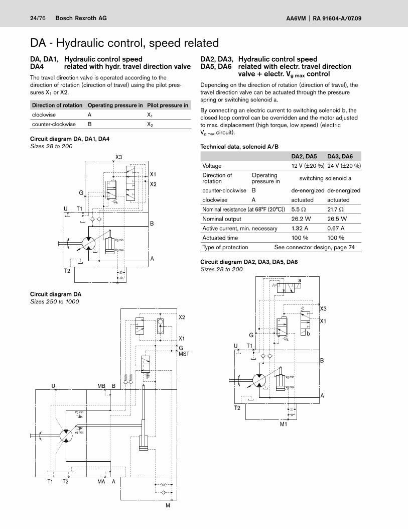
DA, DA1, Hydraulic control speed DA4 related with hydr. travel direction valveThe travel direction valve is operated according to the direction of rotation (direction of travel) using the pilot pres-sures X1 or X2.
Direction of rotation Operating pressure in Pilot pressure in
clockwise A X1
counter-clockwise B X2
Circuit diagram DA, DA1, DA4Sizes 28 to 200
U T1
B
A
T2
M1
vg min
vg max
X1
X2G
X3
Circuit diagram DASizes 250 to 1000
U MB B
vg min
vg max
G
T1 AT2 MA
M
X1
X2
MST
DA - Hydraulic control, speed relatedDA2, DA3, Hydraulic control speed DA5, DA6 related with electr. travel direction valve + electr. Vg max controlDepending on the direction of rotation (direction of travel), the travel direction valve can be actuated through the pressure spring or switching solenoid a.
By connecting an electric current to switching solenoid b, the closed loop control can be overridden and the motor adjusted to max. displacement (high torque, low speed) (electricVg max circuit).
Technical data, solenoid A/B
DA2, DA5 DA3, DA6
Voltage 12 V (±20 %) 24 V (±20 %)
Direction of rotation
Operatingpressure in switching solenoid a
counter-clockwise B de-energized de-energized
clockwise A actuated actuated
Nominal resistance (at 68°F (20°C)) 5.5 Ω 21.7 Ω
Nominal output 26.2 W 26.5 W
Active current, min. necessary 1.32 A 0.67 A
Actuated time 100 % 100 %
Type of protection See connector design, page 74
Circuit diagram DA2, DA3, DA5, DA6Sizes 28 to 200
U T1
B
A
T2
M1
vg min
vg max
X3
X1
G b
a

RA 91604-A/07.09 AA6VM Bosch Rexroth AG 25/76
Application in travel drives in closed circuits. The travel direc-tion valve of the motor is switched using the 4/3-directional valve on the control device of the driving pump.
When the pump (AA4VG, AA10VG) is switched to the neutral position or into reverse, the vehicle may experience impulsive braking depending on the vehicle's mass and current speed.
This impulsive braking is prevented through the use of the following electric circuit.
With this control, when the pump (AA4VG, AA10VG) is switched1. to the neutral position: the previous travel direction is retained.2. to reverse: the motor switches to the other travel direction following a time delay (approx. 0.8 s) with respect to the pump.
Electric travel direction valve circuit diagram
K1.1
K1.2
K1
K2.1
K2
A3 B3
A2
V1
V NR
24 V DC
24 V DC
DA2, DA3, DA5, DA6 control (see page 24)
ba
ba
HA1R., HA2R. control (see page 22)
a
b
Switching solenoid a on travel direction valve
Electric travel direction valve (for DA, HA.R)

26/76 Bosch Rexroth AG AA6VM RA 91604-A/07.09
HD1, HD2 Hydraulic control, pilot-pressure relatedHZ1 Hydraulic two-point controlSAE flange ports A/B side, opposite (02)
View ZSAE flange ports A/B side, opposite (02)
SAE flange portsA/B rear (01)
Unit dimensions, size 28 (ISO Version)
1) With service line ports A/B rear (plate 01)
Before finalizing your design, please request a binding installation drawing. Dimensions in inches and (mm).
max. 0.53 (max.13.4)
12°1
30'
DIA
0.43
(ø11
)4.
65 (1
18)
4.65 (118)
DIA4.92(ø125)
4.29
(109
)
3.50
(89)
5.35
(136
)1.
06 (2
7)1 )
2.28 (58)
7
0.98 (25)
7.20 (183)
7.36 (187)1)
8.38 (213)
6.06 (154)
1.02 (26) 2.28 (58)45°45°
0.94(23.8)
2.36
(60)
2.56
(65)
Z
M1
G
T2
T1U
X
0.63 (16)
DIA
2.44
(ø62
)
DIA
3.93
70D
IA3.
9361
ø100
-0.0
22
DIA
0.75
(ø19
)2.
00 (5
0.8)
0.79
(20)
G
B
M1
X
A
1.40(35.5)
0.94(23.8) 1.77
(45)1.77(45)5.75 (146)
0.75
(ø19
)
2.00
(50.
8)G
B
M1
X
A
5.20 (132)
1.40(35.5)

RA 91604-A/07.09 AA6VM Bosch Rexroth AG 27/76
Unit dimensions, size 28 (ISO Version)Shaft ends
A Splined shaft DIN 5480W30x2x30x14x9g
Z Splined shaft DIN 5480W25x1.25x30x18x9g
PortsA, B Service line ports (high-pressure series) SAE J518 3/4 in Fixing thread A/B DIN 13 M10x1.5; 0.67 (17) deep 2) T1 Case drain port 3) DIN 3852 M18x1.5; 0.47 (12) deep 100 lb-ft (140 Nm) 2)T2 Case drain port DIN 3852 M18x1.5; 0.47 (12) deep 100 lb-ft (140 Nm) 2)X, X1, X3 Pilot-pressure port DIN 3852 M14x1.5; 0.47 (12) deep 60 lb-ft (80 Nm) 2)G Port for synchronous control of multiple DIN 3852 M14x1.5; 0.47 (12) deep 60 lb-ft (80 Nm) 2) units and for remote control pressure 3)G2 Port for 2nd pressure setting 3) DIN 3852 M14x1.5; 0.47 (12) deep 60 lb-ft (80 Nm) 2)U Flow port 3) DIN 3852 M16x1.5; 0.47 (12) deep 70 lb-ft (100 Nm) 2)M1 Gauge port for control pressure 3) DIN 3852 M14x1.5; 0.47 (12) deep 60 lb-ft (80 Nm) 2)1) Center bore according to DIN 332 (thread according to DIN 13)2) Please observe the general notes for the max. tightening torques on page 763) Plugged
Before finalizing your design, please request a binding installation drawing. Dimensions in inches and (mm).
M10
x1.5
1) 2
) DIA
1.38
(ø35
)
1.38 (35)
0.31(8)
0.87(22)
0.30 (7.5)
M8x
1.25
1) 2
)
0.24 (6)
0.75(19)
0.59(15)
1.69 (43)
DIA
1.38
(ø35
)

28/76 Bosch Rexroth AG AA6VM RA 91604-A/07.09
Unit dimensions, size 28 (ISO Version)HD.DHydraulic control, pilot-pressure related, with pressure control, direct
HD.EHydraulic control, pilot-pressure related, with pressure control, direct and 2nd pressure setting
EP1, EP2Electric control with proportional solenoid
EP.DElectric control (proportional solenoid)with pressure control, direct
EP.EElectric control (proportional solenoid) with pressure control, direct and 2nd pressure setting
Before finalizing your design, please request a binding installation drawing. Dimensions in inches and (mm).
Observe the note on page 74
Observe the note on page 74Observe the note on page 74
2.83
(72)
4.80
(122
)3.
43 (8
7)5.
35 (1
36)
9.61 (244)8.03 (204)
1.40(35.5)
7.44 (189)3.48(88.5)
XGG2
M1
XG
G2
M1
AB
5.35
(136
)3.
43 (8
7)4.
69 (1
19)
7.44 (189)8.43 (214)
1.40(35.5)
3.48(88.5)
M1
XGXG
M1
AB
5.35
(136
)2.
83 (7
2)6.
85 (1
74)
9.61 (244)8.03 (204)3.48
(88.5)
GG2
M1
G
G2
M1
AB
G
M1
G
M1
AB
5.35
(136
)6.
85 (1
74)
8.50 (216)3.48(88.5)
6.85
(174
)5.
35 (1
36)
8.50 (216)1.40(35.5)
G
M1
G
M1
AB

RA 91604-A/07.09 AA6VM Bosch Rexroth AG 29/76
EZ1, EZ2Electric two-point control with switching solenoid
HA1, HA2 / HA1T, HA2TAutomatic control, high-pressure related / high-pressure related and hydraulic override
HA1U1, HA2U2Automatic control, high-pressure related and electric override
HA1R1, HA2R2Automatic control, high-pressure related, electric override and electric travel direction valve
DA1, DA4Hydraulic control, speed related and hydraulic travel direction valve
DA2, DA3, DA5, DA6Hydraulic control, speed related, el. travel direction valve and el. Vg max control
Unit dimensions, size 28
X1, X2 with fitting 8B-ST according to DIN 2353-CL
HA1 and HA2, X pluggedHA1T and HA2T, X open
Before finalizing your design, please request a binding installation drawing. Dimensions in inches and (mm).
Observe the note on page 74
Observe the note on page 74
1.40(35.5)
5.83
(148
)3.
78 (9
6)5.
12 (1
30)
8.23 (209)
5.31 (135)
G
M1
X
M1
GX
AB
0.33 (8.5)4.33 (110)
X3
G
X1
M1
X3 G
X1
M1
AB
6.10
(155
)5.
35 (1
36)
5.12
(130
)
6.89 (175)8.50 (216)
8.43 (214)
6.54
(166
)
1.40(35.5)
5.35
(136
)
G
M1
G
M1
AB
8.23 (209)
4.33 (110)
8.50
(216
)3.
78 (9
6)
G
b
a
G
M1M1
AB
8.23 (209)
8.50
(216
)3.
78 (9
6)
G
M1 M1
G
AB
4.72
(120
)5.
35 (1
36)
8.50 (216)
3.66
(93)
5.98 (152)6.30 (160)
X2X1X3, G
X1, X2G X3
M1M1
AB

30/76 Bosch Rexroth AG AA6VM RA 91604-A/07.09
Unit dimensions, size 55 (SAE Version)HD1, HD2 Hydraulic control, pilot-pressure relatedSAE flange ports A/B side, opposite (52)
View ZSAE flange portsA/B side,opposite (52)
SAE flange portsA/B rear (51)
SAE flange portsA/B side, opposite with HZ3, EZ3 (52)
SAE flange portsA/B rear withHZ3, EZ3 (51)
1) With service line ports A/B rear (plate 51)
Before finalizing your design, please request a binding installation drawing. Dimensions in inches and (mm).
T2
Z
M1
GX
T1U
4.51
(114
.5)
DIA6.35(161.2)
45° 45°
0.56
(14.
3)12°3
0'
3.58 (91)
9.29 (236)1)
1.18
(30)
5.94
(151
)
0.94(23.8)
0.50 (12.7)
8.15 (207)3.
11 (7
9)2.
91 (7
4)
0.94
(24)
3.54
(90)
4.25
(108
)
DIA
5.00
00D
IA4.
9980
(ø12
7 -0
.05)
9.21 (234)
10.39 (264)
3.58 (91)
0.79 (20)
DIA
0.75
(ø19
)2.
00 (5
0.8)
5.75
(146
)
4.51 (114.5)
5.75 (146)
DIA
0.75
(ø19
)2.
00 (5
0.8)
1.40(35.5)
2.13(54)
2.13(54)
6.54 (166)
0.94(23.8)
M1
B
X G
A
GX
B
A
6.54 (166)
2.40(61)
2.00(50.8)
DIA
0.75
(ø19
)0.
94 (2
3.8)
1.48(37.5)
1.48(37.5)
B A
XG 2.40
(61)5.98 (152)
M1
B A
X G
1.40(35.5)
5.98 (152)

RA 91604-A/07.09 AA6VM Bosch Rexroth AG 31/76
Unit dimensions, size 55 (SAE Version)Shaft end
S Splined shaft 1 1/4in 14 T 12/24DP 1)(SAE J744 – 32-4 (C))
PortsA, B Service line ports (high-pressure series) SAE J518 3/4 in Fixing thread A/B ISO 68 3/8 in -12 UNC-2B; 0.83 (21) deep 2)T1 Case drain port 3) ISO 11926 1 1/16 in -12 UN-2B; 0.79 (20) deep 265 lb-ft (360 Nm) 2)T2 Case drain port ISO 11926 1 1/16 in -12 UN-2B; 0.79 (20) deep 265 lb-ft (360 Nm) 2)X, X1, X3 Pilot-pressure port ISO 11926 9/16 in -18 UNF-2B; 0.51 (13) deep 60 lb-ft (80 Nm) 2)G Port for synchronous control of multiple ISO 11926 9/16 in -18 UNF-2B; 0.51 (13) deep 60 lb-ft (80 Nm) 2) units and for remote control pressure 3)G2 Port for 2nd pressure setting 3) ISO 11926 9/16 in -18 UNF-2B; 0.51 (13) deep 60 lb-ft (80 Nm) 2)U Flow port 3) ISO 11926 7/8 in -14 UNF-2B; 0.67 (17) deep 180 lb-ft (240 Nm) 2)M1 Gauge port for control pressure 3) ISO 11926 9/16 in -18 UNF-2B; 0.51 (13) deep 60 lb-ft (80 Nm) 2)1) ANSI B92.1a-1976, pressure angle 30°, fl at root, side fi t, tolerance class 52) please observe the general notes for the max. tightening torques on page 763) plugged
Before finalizing your design, please request a binding installation drawing. Dimensions in inches and (mm).
DIA
4.37
(ø11
1)
1.57 (40)
2.20 (56)
7/16
-14U
NC
-2B
1.10(28)
1.89 (48)
0.37(9.5)
DIA
1.77
(ø45
)
32/76 Bosch Rexroth AG AA6VM RA 91604-A/07.09
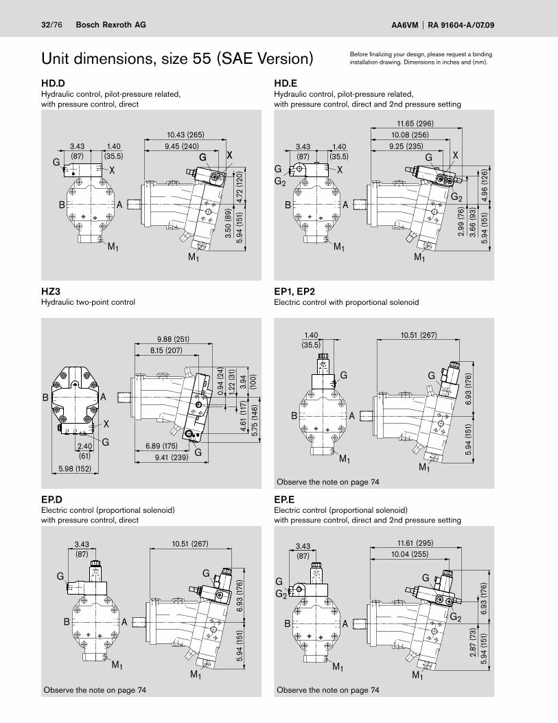
Unit dimensions, size 55 (SAE Version)HD.DHydraulic control, pilot-pressure related, with pressure control, direct
HD.EHydraulic control, pilot-pressure related, with pressure control, direct and 2nd pressure setting
HZ3Hydraulic two-point control
EP1, EP2Electric control with proportional solenoid
EP.DElectric control (proportional solenoid)with pressure control, direct
EP.EElectric control (proportional solenoid) with pressure control, direct and 2nd pressure setting
Before finalizing your design, please request a binding installation drawing. Dimensions in inches and (mm).
Observe the note on page 74
Observe the note on page 74Observe the note on page 74
1.40(35.5)
3.43(87)
5.94
(151
)4.
96 (1
26)
3.66
(93)
2.99
(76)
11.65 (296)
9.25 (235)10.08 (256)
GG2
X
AB
M1
G2
M1
XG
G
5.94
(151
)
M1
6.93
(176
)
G
10.51 (267)3.43(87)
M1
AB
1.40(35.5)
5.94
(151
)
10.51 (267)
6.93
(176
)GG
M1M1
AB
1.40(35.5)
3.43(87)
9.45 (240)10.43 (265)
5.94
(151
)4.
72 (1
20)
3.50
(89)
XGGX
AB
M1
M1
XG
2.87
(73)
5.94
(151
)6.
93 (1
76)
10.04 (255)11.61 (295)
G2
G
M1
GG2
M1
AB
3.43(87)
9.41 (239)6.89 (175)
4.61
(117
)5.
75 (1
46)
3.94
(100
)
1.22
(31)
0.94
(24)
8.15 (207)9.88 (251)
5.98 (152)
2.40(61) G
A
G
X
B

RA 91604-A/07.09 AA6VM Bosch Rexroth AG 33/76
EZ3, EZ4Electric two-point control with switching solenoid
HA1, HA2 / HA1T, HA2TAutomatic control, high-pressure related / high-pressure related and hydraulic override
HA1U1, HA2U2Automatic control, high-pressure related andelectric override
HA1R1, HA2R2Automatic control, high-pressure related, electric override and electric travel direction valve
DA1, DA4Hydraulic control, speed related and hydraulic travel direction valve
DA2, DA3, DA5, DA6Hydraulic control, speed related,el. travel direction valve and el. Vg max control
Unit dimensions, size 55 (SAE Version)
X1, X2 with fitting 8B-ST according to DIN 2353-CL
HA1 and HA2, X pluggedHA1T and HA2T, X open
Before finalizing your design, please request a binding installation drawing. Dimensions in inches and (mm).
Observe the note on page 74
10.47 (266)7.95 (202)
5.94
(151
)4.
80 (1
22)
3.70
(94)
6.30 (160)
G X3X1 ;X2X1 X
X3 ;G
AB
M1
M1
8.90 (226)4.33 (110)
6.14
(156
)5.
94 (1
51)
0.33(8.5)
10.47 (266)
5.20
(132
)
G
X3X1
M1
X3G
X1
M1
AB
3.94
(100
)5.
71 (1
45)
9.88 (251)
4.88 (124)GG
AB
10.27 (261)
M1
G
4.09
(104
)8.
86 (2
25)
1.40(35.5)
G
M1
AB
4.09
(104
)8.
86 (2
25)
10.27 (261)
M1
G
4.33(110)
b
a
M1
G
AB
7.20 (183)
10.27 (261)
6.18
(157
)4.
09 (1
04)
5.59
(142
)
1.40(35.5)
M1
G X
M1
GX
AB

34/76 Bosch Rexroth AG AA6VM RA 91604-A/07.09
Unit Dimensions, Size 80 (SAE Version)HD1, HD2 Hydraulic control, pilot pressure dependentSAE flange ports A/B at side, opposite (52)
Fiew ZSAE flange portsA/B side,opposite (52)
SAE flange portsA/B rear (51)
SAE flange portsA/B side, opposite with HZ3, EZ3 (52)
SAE flange portsA/B rear withHZ3, EZ3 (51)
1) With service line ports A/B rear (plate 51)
Before finalizing your design, please request a binding installation drawing. Dimensions in inches and (mm).
GX
B A
2.40(61)
6.46 (164)
M1
B
GX
A
6.46 (164)
1.40(35.5)
M1
GX
B A
2.13(54)7.01 (178)
DIA
0.98
(ø25
)2.
25 (5
7.2)
1.09(27.8)
1.40(35.5)
2.13(54)
2.25(57.2)
1.65(42)
DIA
0.98
(ø25
)
2.40(61)
7.01 (178)
1.09
(27.
8)
B A
G1.65(42)
XG
Z
M1
U T1
T2
10.35 (263)1)
10.31 (262)
3.78
(96)
4.57
(116
)
12°30'
3.07
(78)
1.34
(34)
3.94 (100)
6.18
(157
)
DIA
0.98
(ø25
)2.
25 (5
7.2)
1.08
(27.
5)
0.91 (23)
9.13 (232)
11.50 (292)
8.39 (213)
7.13 (181)
DIA
0.69
(ø17
.5)
0.5 (12.7)
3.39
(86)
3.94 (100)
6.57
(167
)
DIA
5.00
00D
IA4.
9980
(ø12
7 -0
.05)
RA 91604-A/07.09 AA6VM Bosch Rexroth AG 35/76
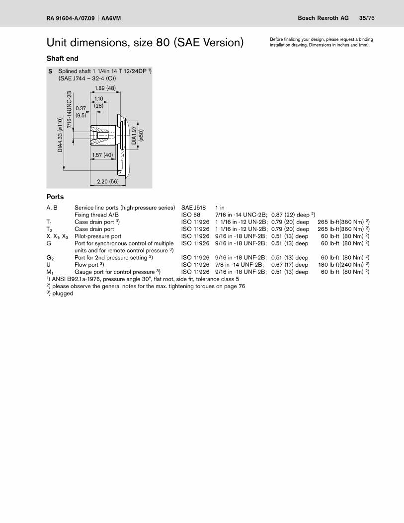
Unit dimensions, size 80 (SAE Version)Shaft end
S Splined shaft 1 1/4in 14 T 12/24DP 1)(SAE J744 – 32-4 (C))
PortsA, B Service line ports (high-pressure series) SAE J518 1 in Fixing thread A/B ISO 68 7/16 in -14 UNC-2B; 0.87 (22) deep 2)T1 Case drain port 3) ISO 11926 1 1/16 in -12 UN-2B; 0.79 (20) deep 265 lb-ft (360 Nm) 2)T2 Case drain port ISO 11926 1 1/16 in -12 UN-2B; 0.79 (20) deep 265 lb-ft (360 Nm) 2)X, X1, X3 Pilot-pressure port ISO 11926 9/16 in -18 UNF-2B; 0.51 (13) deep 60 lb-ft (80 Nm) 2)G Port for synchronous control of multiple ISO 11926 9/16 in -18 UNF-2B; 0.51 (13) deep 60 lb-ft (80 Nm) 2) units and for remote control pressure 3)G2 Port for 2nd pressure setting 3) ISO 11926 9/16 in -18 UNF-2B; 0.51 (13) deep 60 lb-ft (80 Nm) 2)U Flow port 3) ISO 11926 7/8 in -14 UNF-2B; 0.67 (17) deep 180 lb-ft (240 Nm) 2)M1 Gauge port for control pressure 3) ISO 11926 9/16 in -18 UNF-2B; 0.51 (13) deep 60 lb-ft (80 Nm) 2)1) ANSI B92.1a-1976, pressure angle 30°, fl at root, side fi t, tolerance class 52) please observe the general notes for the max. tightening torques on page 763) plugged
Before finalizing your design, please request a binding installation drawing. Dimensions in inches and (mm).
DIA
4.33
(ø11
0)
1.57 (40)
2.20 (56)
7/16
-14U
NC
-2B
1.10(28)
1.89 (48)
0.37(9.5)
DIA
1.97
(ø50
)

36/76 Bosch Rexroth AG AA6VM RA 91604-A/07.09
Unit dimensions, size 80 (SAE Version)HD.DHydraulic control, pilot-pressure related, with pressure control, direct
HD.EHydraulic control, pilot-pressure related, with pressure control, direct and 2nd pressure setting
HZ3Hydraulic two-point control
EP1, EP2Electric control with proportional solenoid
EP.DElectric control (proportional solenoid)with pressure control, direct
EP.EElectric control (proportional solenoid) with pressure control, direct and 2nd pressure setting
Before finalizing your design, please request a binding installation drawing. Dimensions in inches and (mm).
Observe the note on page 74
Observe the note on page 74Observe the note on page 74
11.14 (283)
3.11
(79)
6.57
(167
)5.
08 (1
29)
3.74
(95)
12.80 (325)
10.55 (268)3.43(87)
1.40(35.5)
M1M1
G
G2
XGG2
AB
4.96
(126
)6.
57 (1
67)
XX
3.43(87)
1.40(35.5)
M1
G
11.54 (293)10.55 (268)
G
M1
3.74
(95)AB
G2
G
6.57
(167
)7.1
7 (1
82)
3.11
(79)
M1
11.14 (283)12.72 (323)
3.43(87)
GG2
M1
AB
GG
11.61 (295)
6.57
(167
)7.1
7 (1
82)
M1M1
AB
11.61 (295)
M1
M1
G
3.43(87)
6.57
(167
)7.1
7 (1
82)
AB
5.20
(132
)6.
34 (1
61)
4.49
(114
)
1.06
(27)
1.38
(35)
10.47 (266)7.72 (196)
10.98 (279)9.13 (232)
6.46 (164)
2.40(61) G
G
X
AB
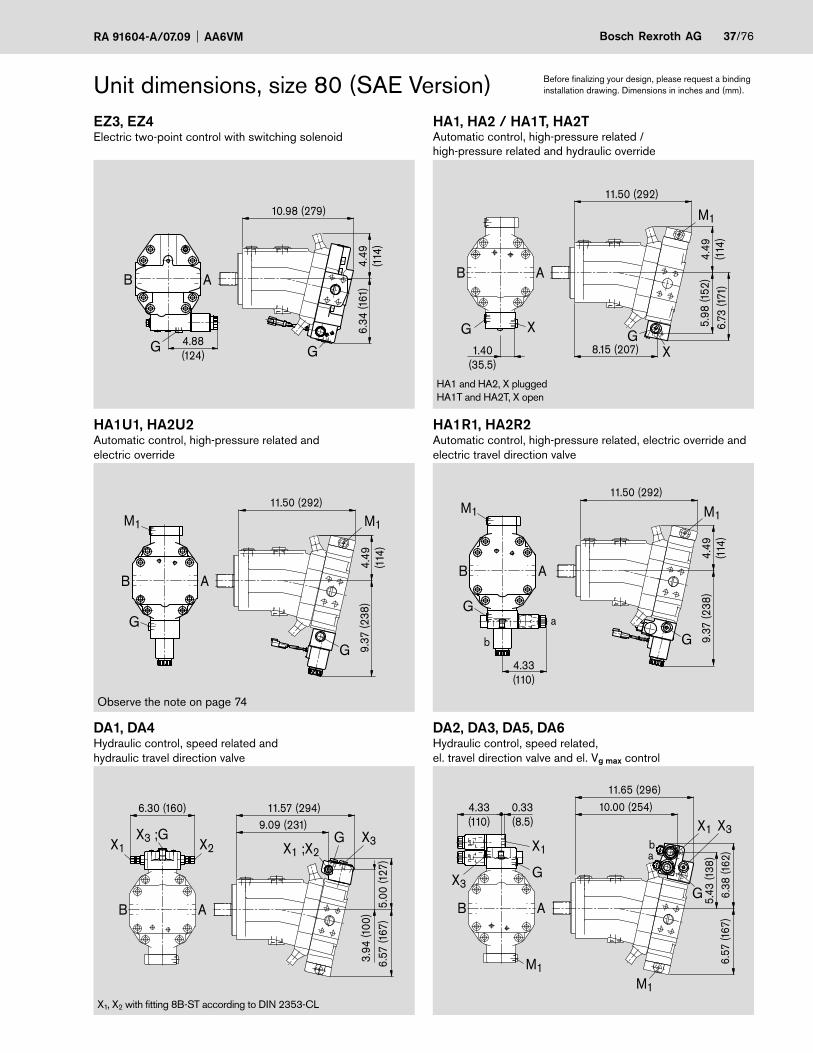
RA 91604-A/07.09 AA6VM Bosch Rexroth AG 37/76
EZ3, EZ4Electric two-point control with switching solenoid
HA1, HA2 / HA1T, HA2TAutomatic control, high-pressure related / high-pressure related and hydraulic override
HA1U1, HA2U2Automatic control, high-pressure related andelectric override
HA1R1, HA2R2Automatic control, high-pressure related, electric override and electric travel direction valve
DA1, DA4Hydraulic control, speed related and hydraulic travel direction valve
DA2, DA3, DA5, DA6Hydraulic control, speed related, el. travel direction valve and el. Vg max control
Unit dimensions, size 80 (SAE Version)
X1, X2 with fitting 8B-ST according to DIN 2353-CL
HA1 and HA2, X pluggedHA1T and HA2T, X open
Before finalizing your design, please request a binding installation drawing. Dimensions in inches and (mm).
Observe the note on page 74
11.50 (292)
1.40(35.5)
8.15 (207)
M1
XGG X 6.
73 (1
71)
5.98
(152
)4.
49(1
14)
AB
G X3X1 ;X2
X3 ;GX1 X2
6.30 (160)
6.57
(167
)5.
00 (1
27)
3.94
(100
)
11.57 (294)9.09 (231)
AB
11.50 (292)
4.49
(114
)9.
37 (2
38)
M1
G
4.33(110)
Ga
M1
b
AB4.49
(114
)
11.50 (292)
9.37
(238
)
G
AB
M1 M1
G
6.38
(162
)6.
57 (1
67)
5.43
(138
)
10.00 (254)11.65 (296)
0.33(8.5)
4.33(110)
M1
X3
G
ba
M1
X3G
X1
AB
X1
10.98 (279)
6.34
(161
)4.
49(1
14)
G4.88(124)
G
AB

38/76 Bosch Rexroth AG AA6VM RA 91604-A/07.09
Unit dimensions, size 107 (SAE Version)HD1, HD2 Hydraulic control, pilot-pressure relatedSAE flange ports A/B side, opposite (52)
View ZSAE flange ports A/B side, opposite (52)
SAE flange ports A/B, rear (51)
SAE flange ports A/B side, opposite with HZ3, EZ3 (52)
SAE flange ports A/B, rear withHZ3, EZ3 (51)
1) With service line ports A/B rear (plate 51)
Before finalizing your design, please request a binding installation drawing. Dimensions in inches and (mm).
M1
X G
AB
7.09 (180)
1.59(40.5)
M1
X G
AB
7.64 (194)
2.56(65)
2.56(65)
1.09(27.8)
DIA
0.98
(ø25
)2.
25 (5
7.2)
1.59(40.5)
XG
AB
2.25(57.2)
DIA
0.98
(ø25
)1.
09 (2
7.8)
1.65(42)7.64 (194)
1.65(42)
2.44(61)
XG
AB
2.40(61)
7.09 (180)
T1
T2
U
0.50 (12.7)
3.82
(97)
3.43
(87)
1.18
(30)
G
Z
M1
X
4.17
(106
)
6.89
(175
)
0.98 (25)
6.36 (161.6)
7.87 (200)
DIA
0.81
(ø20
.6)
6.36
(161
.6)
7.87
(200
)
11.46 (291)
11.38 (289)1)
9.92 (252)
4.33 (110)
12.76 (324)
12°3
0'
1.09(27.8)
2.25
(57.2
)
5.04
(128
)
1.50
(38)
(ø15
2.4
-0.0
5)
DIA
6.00
00D
IA5.
9980
DIA
0.98
(ø25
)
4.33 (110)

RA 91604-A/07.09 AA6VM Bosch Rexroth AG 39/76
Unit dimensions, size 107 (SAE Version)Shaft end
S Splined shaft 1 3/4in 13T 8/16DP 1)(SAE J744 – 44-4 (D))
PortsA, B Service line ports (high-pressure series) SAE J518 1 in Fixing thread A/B ISO 68 7/16 in -14 UNC-2B; 0.87 (22) deep 2)T1 Case drain port 3) ISO 11926 1 1/16 in -12 UN-2B; 0.79 (20) deep 265 lb-ft (360 Nm) 2)T2 Case drain port ISO 11926 1 1/16 in -12 UN-2B; 0.79 (20) deep 265 lb-ft (360 Nm) 2)X, X1, X3 Pilot-pressure port ISO 11926 9/16 in -18 UNF-2B; 0.51 (13) deep 60 lb-ft (80 Nm) 2)G Port for synchronous control of multiple ISO 11926 9/16 in -18 UNF-2B; 0.51 (13) deep 60 lb-ft (80 Nm) 2) units and for remote control pressure 3)G2 Port for 2nd pressure setting 3) ISO 11926 9/16 in -18 UNF-2B; 0.51 (13) deep 60 lb-ft (80 Nm) 2)U Flow port 3) ISO 11926 7/8 in -14 UNF-2B; 0.67 (17) deep 180 lb-ft (240 Nm) 2)M1 Gauge port for control pressure 3) ISO 11926 9/16 in -18 UNF-2B; 0.51 (13) deep 60 lb-ft (80 Nm) 2)1) ANSI B92.1a-1976, pressure angle 30°, fl at root, side fi t, tolerance class 52) please observe the general notes for the max. tightening torques on page 763) plugged
Before finalizing your design, please request a binding installation drawing. Dimensions in inches and (mm).
DIA
5.35
(ø13
6)
2.17 (55)
2.95 (75)
5/8-
11U
NC
-2B
1.42(36)
2.64 (67)
0.47(12)
DIA
2.36
(ø60
)
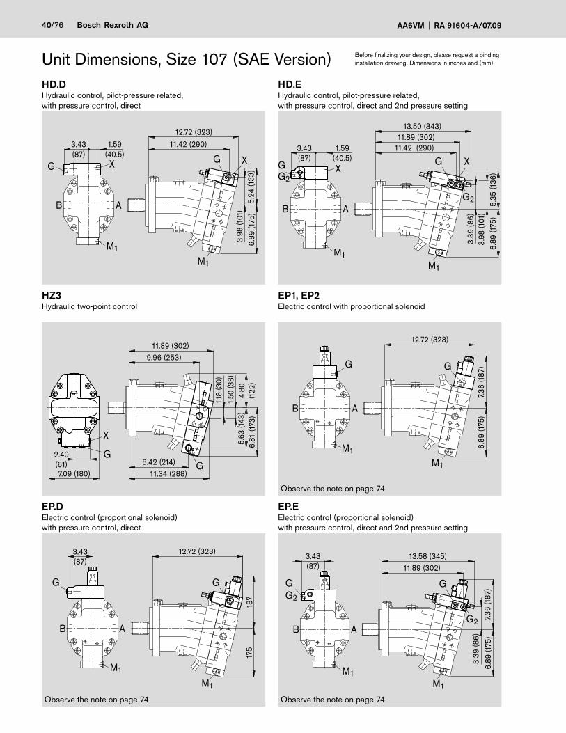
40/76 Bosch Rexroth AG AA6VM RA 91604-A/07.09
Unit Dimensions, Size 107 (SAE Version) Before finalizing your design, please request a binding installation drawing. Dimensions in inches and (mm).
HD.DHydraulic control, pilot-pressure related, with pressure control, direct
HD.EHydraulic control, pilot-pressure related, with pressure control, direct and 2nd pressure setting
HZ3Hydraulic two-point control
EP1, EP2Electric control with proportional solenoid
EP.DElectric control (proportional solenoid)with pressure control, direct
EP.EElectric control (proportional solenoid) with pressure control, direct and 2nd pressure setting
Observe the note on page 74
Observe the note on page 74Observe the note on page 74
11.42 (290)
13.50 (343)11.89 (302)
3.39
(86)
3.98
(101
)5.
35 (1
36)
6.89
(175
)
X
3.43(87)
1.59(40.5)
GG2
M1M1
G
G2
X
AB
12.72 (323)11.42 (290)
3.98
(101
)5.
24 (1
33)
6.89
(175
)
1.59(40.5)
3.43(87) G
M1
G X X
M1
B A
3.43(87)
M1
G
B A
12.72 (323)
187
175
M1
G
12.72 (323)
M1
7.36
(187
)6.
89 (1
75)
G
M1
G
B A
13.58 (345)11.89 (302)
3.39
(86)
7.36
(187
)6.
89 (1
75)
3.43(87)
GG2
M1M1
G
G2AB
7.09 (180) 11.34 (288)8.42 (214)
6.81
(173
)5.
63 (1
43)
4.80
(122
)
1.50
(38)
1.18
(30)
11.89 (302)9.96 (253)
2.40(61)
GG
X

RA 91604-A/07.09 AA6VM Bosch Rexroth AG 41/76
Unit Dimensions, Size 107 (SAE Version) Before finalizing your design, please request a binding installation drawing. Dimensions in inches and (mm).
EZ3, EZ4Electric two-point control with switching solenoid
HA1, HA2 / HA1T, HA2TAutomatic control, high-pressure related / high-pressure related and hydraulic override
HA1U1, HA2U2Automatic control, high-pressure related andelectric override
HA1R1, HA2R2Automatic control, high-pressure related, electric override and electric travel direction valve
DA1, DA4Hydraulic control, speed related and hydraulic travel direction valve
DA2, DA3, DA5, DA6Hydraulic control, speed related, el. travel direction valve and el. Vg max control
X1, X2 with fitting 8B-ST according to DIN 2353-CL
HA1 and HA2, X pluggedHA1T and HA2T, X open
Observe the note on page 74
12.36 (314)
4.80
(122
)
G
M1
B A
9.80
(249
)
G
M1
0.33(8.5)
4.41(112)
6.89
(175
)
12.75 (324)10.67 (271)
6.73
(171
)5.
75 (1
46)
M1
G
X1
X3
M1
B A
X1 X3
G
4.80
(122
)9.
80 (2
49)
12.36 (314)
4.41(112)
a
b
G
M1
B A
G
M1
1.59(40.5)
M1
G X
B A
7.83 (199)
6.46
(164
)7.
20 (1
83)
4.80
(122
)
12.36 (282)M1
X
G
6.85 (174)
M1
X2X3 ;G
X1
B A
4.21
(107
)5.
28 (1
34)
9.76 (248)12.72 (323)
6.89
(175
)
G X3X1 ;X2
M1
4.88(124)
G
B A
4.80
(122
)6.
77 (1
72)
11.89 (302)
G

42/76 Bosch Rexroth AG AA6VM RA 91604-A/07.09
HD1, HD2 Hydraulic control, pilot-pressure relatedHZ1 Hydraulic two-point controlSAE flange ports A/B side, opposite (02)
View ZSAE flange ports A/B side, opposite (02)
SAE flange portsA/B rear (01)
Unit dimensions, size 140 (ISO Version)
1) With service line ports A/B rear (plate 01)
Before finalizing your design, please request a binding installation drawing. Dimensions in inches and (mm).
1.10 (28)
3.82
(97)
1.25(31.8) 8.27 (210)
DIA
0.69
(ø17
.5)
8.27
(210
)
1.65
(42)
1 )1.
30 (3
3)
4.29
(109
)
5.20
(132
)7.
68 (1
95)
DIA
1.26
(ø32
)
1.54 (39) 3.62 (92)
0.30 (7.5)max. 11.38 (max.14.9)
12°3
0'
11.38 (289)12.68 (322)
9.72 (247)11.34 (288)1)
3.62 (92)1.57(40)
DIA
3.70
(ø94
)
DIA
7.08
66D
IA7.
0865
ø180
-0.0
25 3.90
(99)
45° 45°
Z
GT1U
T2
M1
X
2.63
(66.
7)DIA8.82
(ø224)
M1
X G
AB
8.03 (204)
1.59(40.5)
M1
X G
AB
2.99(76)
8.86 (225)
2.63
(66.
7)
1.25(31.8)
2.99(76)
1.26
(32)
1.59(40.5)

RA 91604-A/07.09 AA6VM Bosch Rexroth AG 43/76
Shaft end
Z Splined shaft DIN 5480W45x2x30x21x9g
PortsA, B Service line ports (high-pressure series) SAE J518 1 1/4 in Fixing thread A/B DIN 13 M14x2; 0.75 (19) deep 2) T1 Case drain port 3) DIN 3852 M26x1.5; 0.63 (16) deep 170 lb-ft (230 Nm) 2)T2 Case drain port DIN 3852 M26x1.5; 0.63 (16) deep 170 lb-ft (230 Nm) 2)X, X1, X3 Pilot-pressure port DIN 3852 M14x1.5; 0.47 (12) deep 60 lb-ft (80 Nm) 2)G Port for synchronous control of multiple DIN 3852 M14x1.5; 0.47 (12) deep 60 lb-ft (80 Nm) 2) units and for remote control pressure 3)G2 Port for 2nd pressure setting 3) DIN 3852 M14x1.5; 0.47 (12) deep 60 lb-ft (80 Nm) 2)U Flow port 3) DIN 3852 M22x1.5; 0.55 (14) deep 70 lb-ft (210 Nm) 2)M1 Gauge port for control pressure 3) DIN 3852 M14x1.5; 0.47 (12) deep 60 lb-ft (80 Nm) 2)1) Center bore according to DIN 332 (thread according to DIN 13)2) Please observe the general notes for the max. tightening torques on page 763) Plugged
Unit dimensions, size 140 (ISO Version) Before finalizing your design, please request a binding installation drawing. Dimensions in inches and (mm).
1.97(50)
DIA
2.36
(ø60
)
0.31(8)
0.47 (12)
M16
x2 1
) 2)
1.42(36)

44/76 Bosch Rexroth AG AA6VM RA 91604-A/07.09
Unit dimensions, size 140 (ISO Version)HD.DHydraulic control, pilot-pressure related, with pressure control, direct
HD.EHydraulic control, pilot-pressure related, with pressure control, direct and 2nd pressure setting
EP1, EP2Electric control with proportional solenoid
EP.DElectric control (proportional solenoid)with pressure control, direct
EP.EElectric control (proportional solenoid) with pressure control, direct and 2nd pressure setting
Before finalizing your design, please request a binding installation drawing. Dimensions in inches and (mm).
Observe the note on page 74
Observe the note on page 74Observe the note on page 74
G
M1
M1
G
AB
12.68 (322)
7.68
(195
)7.
68 (1
95)
3.48(88.5)
12.72 (323)
G
M1
M1
G
AB
7.68
(195
)7.
68 (1
95)
11.42 (290)
5.55
(141
)7.
68 (1
95)
3.48(88.5)
1.59(40.5)
12.72 (323)
4.25
(108
)
XGG X
M1
M1
B A 5.67
(144
)
11.42 (290)
7.68
(195
)
3.48(88.5)
1.59(40.5)
11.89 (302)13.46 (342)
4.25
(108
)3.
66 (9
3)
G
G2
GG2
X
M1
X
M1
B A
13.54 (344)
3.66
(93)
11.89 (302)
7.68
(195
)7.
68 (1
95)
3.48(88.5)
M1
G
G2
M1
GG2
AB
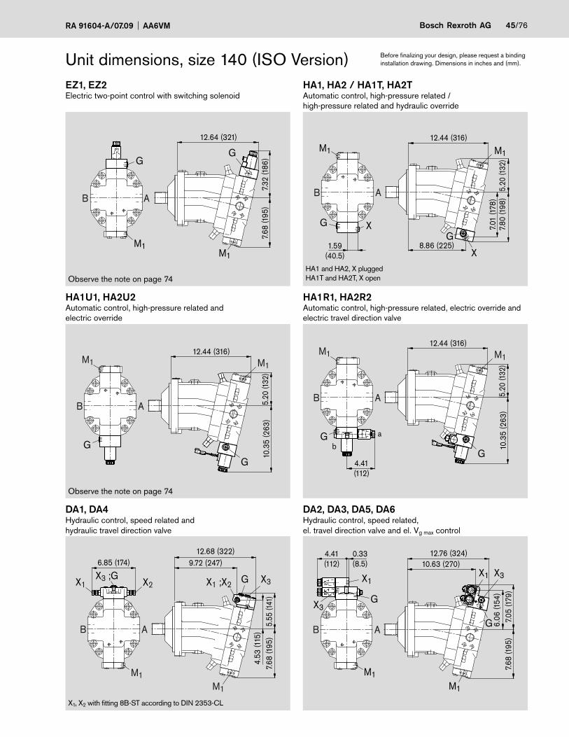
RA 91604-A/07.09 AA6VM Bosch Rexroth AG 45/76
EZ1, EZ2Electric two-point control with switching solenoid
HA1, HA2 / HA1T, HA2TAutomatic control, high-pressure related / high-pressure related and hydraulic override
HA1U1, HA2U2Automatic control, high-pressure related andelectric override
HA1R1, HA2R2Automatic control, high-pressure related, electric override and electric travel direction valve
DA1, DA4Hydraulic control, speed related and hydraulic travel direction valve
DA2, DA3, DA5, DA6Hydraulic control, speed related, el. travel direction valve and el. Vg max control
Unit dimensions, size 140 (ISO Version)
HA1 and HA2, X pluggedHA1T and HA2T, X open
X1, X2 with fitting 8B-ST according to DIN 2353-CL
Before finalizing your design, please request a binding installation drawing. Dimensions in inches and (mm).
Observe the note on page 74
Observe the note on page 74
5.55
(141
)7.
68 (1
95)
9.72 (247)6.85 (174)
4.53
(115
)
12.68 (322)
X2X3 ;G
X1 G X3X1 ;X2
M1M1
AB
4.41(112)
6.06
(154
)7.
05 (1
79)
7.68
(195
)
10.63 (270)0.33(8.5)
12.76 (324)
G
X3X1
G
X1
X3
M1M1
AB
7.01
(178
)
8.86 (225)1.59(40.5)
12.44 (316)
5.20
(132
)7.
80 (1
98)
G X
X
G
M1M1
AB
4.41(112)
a
b
AB 5.20
(132
)
12.44 (316)
10.3
5 (2
63)
G
M1
G
M1
5.20
(132
)
12.44 (316)
10.3
5 (2
63)
G
G
M1M1
AB
12.64 (321)
7.32
(186
)7.
68 (1
95)
GG
M1M1
AB

46/76 Bosch Rexroth AG AA6VM RA 91604-A/07.09
Unit dimensions, size 160 (SAE Version)HD1, HD2 Hydraulic control, pilot-pressure relatedHZ1 Hydraulic two-point controlSAE flange ports A/B side, opposite (52)
View ZSAE flange ports A/B side, opposite (52)
SAE flange portsA/B rear (51)
1) With service line ports A/B rear (plate 51)
Before finalizing your design, please request a binding installation drawing. Dimensions in inches and (mm).
M1
X G
AB
8.86 (225)
1.59(40.5)
2.63
(66.
7)
1.25(31.8)
2.99(76)
DIA
1.26
(ø32
)
2.99(76)
M1
X G
AB
8.03 (204)
1.59(40.5)
DIA
0.81
(ø20
.6)
7.76
(197
)1.25
(31.8)
1.69
(43)
1.34
(34)
12.87 (327)1)
11.26 (286)
12.91 (328)
14.17 (360)
4.92 (125)
12°3
0'4.
01(1
02)
7.87
(200
)
7.87 (200)
6.36 (161.6)
6.36
(161
.6)
Z5.
35 (1
36)
4.25
(108
)
2.63
(66.
7)
DIA
1.26
(ø32
)
DIA
6.00
00D
IA5.
9980
(ø15
2.4
-0.0
5)
4.33
(110
)
4.90 (124.5)
1.08 (27.5)0.50 (12.7)
M1
T1U
T2
G X 45° 45°

RA 91604-A/07.09 AA6VM Bosch Rexroth AG 47/76
Unit dimensions, size 160 (SAE Version)Shaft end
S Splined shaft 1 3/4in 13T 8/16DP 1)(SAE J744 – 44-4 (D))
PortsA, B Service line ports (high-pressure series) SAE J518 1 1/4 in Fixing thread A/B ISO 68 1/2 in -13 UNC-2B; 0.75 (19) deep 2)T1 Case drain port 3) ISO 11926 1 1/16 in -12 UN-2B; 0.79 (20) deep 265 lb-ft (360 Nm) 2)T2 Case drain port ISO 11926 1 1/16 in -12 UN-2B; 0.79 (20) deep 265 lb-ft (360 Nm) 2)X, X1, X3 Pilot-pressure port ISO 11926 9/16 in -18 UNF-2B; 0.51 (13) deep 60 lb-ft (80 Nm) 2)G Port for synchronous control of multiple ISO 11926 9/16 in -18 UNF-2B; 0.51 (13) deep 60 lb-ft (80 Nm) 2) units and for remote control pressure 3)G2 Port for 2nd pressure setting 3) ISO 11926 9/16 in -18 UNF-2B; 0.51 (13) deep 60 lb-ft (80 Nm) 2)U Flow port 3) ISO 11926 7/8 in -14 UNF-2B; 0.67 (17) deep 180 lb-ft (240 Nm) 2)M1 Gauge port for control pressure 3) ISO 11926 9/16 in -18 UNF-2B; 0.51 (13) deep 60 lb-ft (80 Nm) 2)1) ANSI B92.1a-1976, pressure angle 30°, fl at root, side fi t, tolerance class 52) please observe the general notes for the max. tightening torques on page 763) plugged
Before finalizing your design, please request a binding installation drawing. Dimensions in inches and (mm).
DIA
5.35
(ø13
6)
2.17 (55)
2.95 (75)
5/8-
11U
NC
-2B
1.42(36)
2.64 (67)
0.47(12)
DIA
2.76
(ø70
)

48/76 Bosch Rexroth AG AA6VM RA 91604-A/07.09
Unit dimensions, size 160 (SAE Version)HD.DHydraulic control, pilot-pressure related, with pressure control, direct
HD.EHydraulic control, pilot-pressure related, with pressure control, direct and 2nd pressure setting
EP1, EP2Electric control with proportional solenoid
EP.DElectric control (proportional solenoid)with pressure control, direct
EP.EElectric control (proportional solenoid) with pressure control, direct and 2nd pressure setting
Before finalizing your design, please request a binding installation drawing. Dimensions in inches and (mm).
Observe the note on page 74
Observe the note on page 74Observe the note on page 74
7.68
(195
)7.7
6 (1
97)
13.43 (341)15.08 (383)
3.66
(93)
3.43(87)
GG2
M1
G
G2
M1
AB
14.21 (361)
7.68
(195
)7.7
6 (1
97)
3.43(87)
G
M1M1
G
AB
14.21 (361)
7.68
(195
)7.7
6 (1
97)
G
M1
M1
G
AB
4.25
(108
)5.
67 (1
44)
3.66
(93)
7.76
(197
)
1.59(40.5)
12.95 (329)15.00 (381)
G X
G2
3.43(87)G
G2
M1
X
AB
12.95 (329)
4.25
(108
)5.
55 (1
41)
7.76
(197
)
14.21 (361)3.43(87)
1.59(40.5)
M1
G X
AB
XG
M1

RA 91604-A/07.09 AA6VM Bosch Rexroth AG 49/76
Unit dimensions, size 160 (SAE Version)EZ1, EZ2Electric two-point control with switching solenoid
HA1, HA2 / HA1T, HA2TAutomatic control, high-pressure related / high-pressure related and hydraulic override
HA1U1, HA2U2Automatic control, high-pressure related andelectric override
HA1R1, HA2R2Automatic control, high-pressure related, electric override and electric travel direction valve
DA1, DA4Hydraulic control, speed related and hydraulic travel direction valve
DA2, DA3, DA5, DA6Hydraulic control, speed related, el. travel direction valve and el. Vg max control
HA1 and HA2, X pluggedHA1T and HA2T, X open
X1, X2 with fitting 8B-ST according to DIN 2353-CL
Before finalizing your design, please request a binding installation drawing. Dimensions in inches and (mm).
Observe the note on page 74
Observe the note on page 74
11.26 (286)14.21 (361)
7.76
(197
)5.
55 (1
41)
4.53
(115
)
G X3X1 ;X2
M1
6.85 (174)
X2X3 ;G
X1
M1
AB
12.17 (309)14.25 (362)
6.02
(153
)7.
01 (1
78)
7.76
(197
)
0.33(8.5)
4.41(112)
X1
G
X1
G
X3
X3
M1
M1
AB
4.41(112)
10.4
7 (2
66)
5.39
(137
)
13.94 (354)
G
M1 M1
G a
b
AB
10.4
7 (2
66)
5.39
(137
)
M1
G
AB
G
13.94 (354)M1
7.13
(181
)5.
39 (1
37)
7.87
(200
)
1.59(40.5)
13.94 (354)
X10.39 (264)G
M1M1
G X
AB
7.76
(197
)
14.17 (360)
7.32
(186
)
M1M1
G
AB
G

50/76 Bosch Rexroth AG AA6VM RA 91604-A/07.09
Unit dimensions, size 200 (SAE Version)HD1, HD2 Hydraulic control, pilot-pressure relatedHZ1 Hydraulic two-point controlSAE flange ports A/B side, opposite (52)
View ZSAE flange portsA/B side, opposite (52)
SAE flange portsA/B rear (51)
1) With service line ports A/B rear (plate 51)
Before finalizing your design, please request a binding installation drawing. Dimensions in inches and (mm).
1.59(40.5)
M1
X G
AB
DIA
1.26
(ø32
)
9.25 (235)
2.63
(66.
7)
3.23(82)
3.23(82)
1.25(31.8)
8.50 (216)
1.59(40.5)
M1
X G
AB
DIA
1.26
(ø32
)
4.61
(117
)
10.31 (262)
8.84 (224.5)
T1
T2
U
M1
XG
Y
10.3
1 (2
62)
DIA
0.81
(ø20
.6)
8.84
(224
.5)
8.19
(208
)
1.83
(46.
5)
1.26 (32)
DIA
6.50
00D
IA6.
4980
(ø16
5.1
-0.0
5)
13.54 (344)
14.84 (377)
4.21
(107
)
5.04 (128)
13.62 (346)1)
11.77 (299)
0.50 (12.7)
5.04 (128)
2.63
(66.
7)
4.45
(113
)
5.63
(143
)
1.42
(36)
45° 45°
1.25(31.8)

RA 91604-A/07.09 AA6VM Bosch Rexroth AG 51/76
Unit dimensions, size 200 (SAE Version)Shaft end
S Splined shaft 2in 15T 8/16DP 1)Similar to SAE J744 – 50-4 (F) Length (2.64 in) deviats from standard (3.125 in)
PortsA, B Service line ports (high-pressure series) SAE J518 1 1/4 in Fixing thread A/B ISO 68 1/2 in -13 UNC-2B; 0.75 (19) deep 2)T1 Case drain port 3) ISO 11926 1 1/16 in -12 UN-2B; 0.79 (20) deep 265 lb-ft (360 Nm) 2)T2 Case drain port ISO 11926 1 1/16 in -12 UN-2B; 0.79 (20) deep 265 lb-ft (360 Nm) 2)X, X1, X3 Pilot-pressure port ISO 11926 9/16 in -18 UNF-2B; 0.51 (13) deep 60 lb-ft (80 Nm) 2)G Port for synchronous control of multiple ISO 11926 9/16 in -18 UNF-2B; 0.51 (13) deep 60 lb-ft (80 Nm) 2) units and for remote control pressure 3)G2 Port for 2nd pressure setting 3) ISO 11926 9/16 in -18 UNF-2B; 0.51 (13) deep 60 lb-ft (80 Nm) 2)U Flow port 3) ISO 11926 7/8 in -14 UNF-2B; 0.67 (17) deep 180 lb-ft (240 Nm) 2)M1 Gauge port for control pressure 3) ISO 11926 9/16 in -18 UNF-2B; 0.51 (13) deep 60 lb-ft (80 Nm) 2)1) ANSI B92.1a-1976, pressure angle 30°, fl at root side, tolerance class 52) please observe the general notes for the max. tightening torques on page 763) plugged
Before finalizing your design, please request a binding installation drawing. Dimensions in inches and (mm).
DIA
5.51
(ø14
0)
2.17 (55)
2.95 (75)
5/8-
11U
NC
-2B
1.42(36)
2.64 (67)
0.47(12)
DIA
2.76
(ø70
)

52/76 Bosch Rexroth AG AA6VM RA 91604-A/07.09
Unit dimensions, size 200 (SAE Version)HD.DHydraulic control, pilot-pressure related, with pressure control, direct
HD.EHydraulic control, pilot-pressure related, with pressure control, direct and 2nd pressure setting
EP1, EP2Electric control with proportional solenoid
EP.DElectric control (proportional solenoid)with pressure control, direct
EP.EElectric control (proportional solenoid) with pressure control, direct and 2nd pressure setting
Before finalizing your design, please request a binding installation drawing. Dimensions in inches and (mm).
Observe the note on page 74
Observe the note on page 74Observe the note on page 74
7.83
(199
)8.
23 (2
09)
3.43(87)
14.88 (378)
M1
M1
G
AB
7.83
(199
)
3.82
(97)
8.23
(209
)
3.43(87)
15.75 (400)14.06 (325)
M1
M1
G
G2
GG2
AB
GG2
7.83
(199
)
14.88 (378)
8.23
(209
)
G
M1
M1
G
AB
15.51 (394)13.90 (353)13.43 (341)
5.87
(149
)8.
23 (2
09)
3.86
(98)
4.45
(113
)
1.59(40.5)
3.43(87)
GG2
M1
X
AB
G
G2
X
M1
14.88 (378)13.58 (345)
5.71
(145
)8.
23 (2
09)
4.41
(112
)
3.43(87)
1.59(40.5)
G
M1
X
AB
G X
M1

RA 91604-A/07.09 AA6VM Bosch Rexroth AG 53/76
Unit dimensions, size 200 (SAE Version)EZ1, EZ2Electric two-point control witch switching solenoid
HA1, HA2 / HA1T, HA2TAutomatic control, high-pressure related / high-pressure related and hydraulic overrid
HA1U1, HA2U2Automatic control, high-pressure related andElectric override
HA1R1, HA2R2Automatic control, high-pressure related, electric override and electric travel direction valve
DA1, DA4Hydraulic control, speed related and hydraulic travel direction valve
DA2, DA3, DA5, DA6Hydraulic control, speed related, el. travel direction valve and el. Vg max control
HA1 and HA2, X pluggedHA1T and HA2T, X open
X1, X2 with fitting 8B-ST according to DIN 2353-CL
Before finalizing your design, please request a binding installation drawing. Dimensions in inches and (mm).
Observe the note on page 74
Observe the note on page 74
4.69
(119
)5.
75 (1
46)
8.23
(209
)
6.85 (174)
X2X3 ;GX1
AB
M1
M1
G X3X1 ;X2
14.88 (378)11.93 (303)
8.23
(209
)
12.83 (326)4.41(112)
0.33(8.5)
14.92 (379)
6.22
(158
)7.
20 (1
83)
M1
G
X1 X3
G
X1
X3
M1
AB
14.80 (376)
7.48
(190
)8.
23 (2
09)
M1
M1
G
AB
G
10.91 (277)1.59(40.5)
14.65 (372)
8.23
(209
)5.
63 (1
43)
7.48
(190
)
M1 M1
G X
XG
AB
14.65 (372)
10.8
3 (2
75)
5.63
(143
)
4.41(112)
M1 M1
G
G
a
b
AB
10.8
3 (2
75)
14.65 (372)
5.63
(143
)
M1
G
AB
M1
G
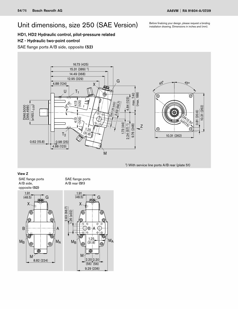
54/76 Bosch Rexroth AG AA6VM RA 91604-A/07.09
Unit dimensions, size 250 (SAE Version)HD1, HD2 Hydraulic control, pilot-pressure relatedHZ - Hydraulic two-point controlSAE flange ports A/B side, opposite (52)
View ZSAE flange portsA/B side, opposite (52)
SAE flange portsA/B rear (51)
1) With service line ports A/B rear (plate 51)
Before finalizing your design, please request a binding installation drawing. Dimensions in inches and (mm).
8.82 (224)
1.91(48.5)
MAMB
M
X
G
AB
MAMB
X
G
AB
M
9.29 (236)
2.20(56)
2.20(56)
1.25(31.8)
1.91(48.5)
2.63
(66.
7)1.
26 (ø
32)
45°45°
10.3
1 (2
62)
10.31 (262)
4.13
(105
)4.
13(1
05)
T1
T2
G
M
X
U
Z1.25
(31.8)
4.84
(123
)
max
. 7.4
0(m
ax. 1
88)
2.63
(66.
7)
9.76
(248
)2.
24 (5
7) 1
)1.7
3 (4
4)
DIA
1.26
(ø32
)
16.73 (425)
4.88 (123)0.98 (25)0.62 (15.8)
15.31 (389) 1)14.49 (368)
13°15
'
DIA
6.50
00D
IA6.
4980
(ø16
5.1 -
0.05
)
4.88 (124)12.95 (329)
0.81
(20.
6)
DIA12.50(ø317.5)

RA 91604-A/07.09 AA6VM Bosch Rexroth AG 55/76
Unit dimensions, size 250 (SAE Version)Shaft end
S Splined shaft 2in 15T 8/16DP 1) Similar to SAE J744 – 50-4 (F) Length (2.64 in) deviats from stan-dard (3.125 in)
PortsA, B Service line ports (high-pressure series) SAE J518 1 1/4 in Fixing thread A/B ISO 68 1/2 in -13 UNC-2B; 0.75 (19) deep 2)T1 Case drain port ISO 11926 7/8 in -14 UNF-2B; 0.67 (17) deep 180 lb-ft (240 Nm) 2)T2 Case drain port 3) ISO 11926 7/8 in -14 UNF-2B; 0.67 (17) deep 180 lb-ft (240 Nm) 2)X Pilot-pressure port ISO 11926 9/16 in -14 UNF-2B; 0.51 (13) deep 60 lb-ft (80 Nm) 2)X3 Port for remote control valve ISO 11926 9/16 in -14 UNF-2B; 0.51 (13) deep 60 lb-ft (80 Nm) 2)P Port for control oil supply ISO 11926 9/16 in -14 UNF-2B; 0.51 (13) deep 60 lb-ft (80 Nm) 2)G Port for synchronous control of multiple ISO 11926 9/16 in -14 UNF-2B; 0.51 (13) deep 60 lb-ft (80 Nm) 2) units and for remote control pressure 3)G2 Port for 2nd pressure setting 3) ISO 11926 9/16 in -14 UNF-2B; 0.51 (13) deep 60 lb-ft (80 Nm) 2)U Flow port 3) ISO 11926 9/16 in -14 UNF-2B; 0.51 (13) deep 60 lb-ft (80 Nm) 2)M Gauge port for control pressure 3) ISO 11926 9/16 in -14 UNF-2B; 0.51 (13) deep 60 lb-ft (80 Nm) 2)MA, MB Gauge port for operating pressure 3) ISO 11926 9/16 in -14 UNF-2B; 0.51 (13) deep 60 lb-ft (80 Nm) 2)MSt Gauge port for pilot pressure 3) ISO 11926 9/16 in -14 UNF-2B; 0.51 (13) deep 60 lb-ft (80 Nm) 2)1) ANSI B92.1a-1976, pressure angle 30°, fl at root side, tolerance class 52) please observe the general notes for the max. tightening torques on page 763) plugged
Before finalizing your design, please request a binding installation drawing. Dimensions in inches and (mm).
DIA
5.51
(ø14
0)
2.08 (53)
2.93 (74.5)
5/8-
11U
NC
-2B
1.42(36)
2.64 (67)
0.47(12)
DIA
2.36
(ø60
)

56/76 Bosch Rexroth AG AA6VM RA 91604-A/07.09
HD.DHydraulic control pilot-pressure related, with pressure control, direct; HD.G remote
EP1, EP2Electric control, with proportional valve
EP.DElectric control (proportional valve)with pressure control, direct; EP.G remote
EZ1, EZ2Electric two-point control with switching valve
HA1, HA2 / HA1T, HA2TAutomatic control, high-pressure related /high-pressure related and hydraulic override
DAHydraulic control, speed related andwith hydraulic travel direction valve
Unit dimensions, size 250
X1, X2 With B-fitting B0-GEV 8L/M14x1.5-WD
EP.D with G2, without X3EP.G with X3, without G2
HD.D with G2, without X3HD.G with X3, without G2
HA1 and HA2, X pluggedHA1T and HA2T, X open
Before finalizing your design, please request a binding installation drawing. Dimensions in inches and (mm).
1.91(48.5)
4.84
(123
)10
.08
(256
)10
.71 (2
72)
max
. 7.4
0(m
ax.18
8)
16.73 (425)14.49 (368)
X G
11.57 (294)
M
G2; X31.38 (35)1.38(35)
XG
M
AB
G2X3
14.76 (375)16.73 (425)
X P G
11.57 (294) G2 ;X3
M
10.0
8 (2
56)
10.71
(272
)m
ax.7.
40(m
ax.18
8)
5.98
(152
)
1.38 (35)
G2X1M
1.38(35)
4.65 (118)1.42 (36)PG
X
AB
5.98
(152
)
16.73 (425)14.76 (375)
PX G
9.76
(248
)m
ax. 7
.40
(max
.188)
M
PGX
M
AB
4.65 (118)1.42 (36)
16.73 (425)
9.76
(248
)6.
69 (1
70)
M
G
5.06(128.5)G
M
AB
8.27
(210
)
11.42 (290)1.91
(48.5)
max
. 10.
83(m
ax.2
75)
6.69
(170
)
16.77 (426)
MAMB
G
XX
M
G
MAB
X2X1
M
GMST
M
GX1
5.51(140) 13.74 (349)
max
. 7.4
0(m
ax. 1
88)
9.76
(248
)
16.73 (425)
4.92
(125
)AB

RA 91604-A/07.09 AA6VM Bosch Rexroth AG 57/76
Unit dimensions, size 355 (ISO Version)HD1, HD2 Hydraulic control, pilot-pressure relatedHZ - Hydraulic two-point controlSAE flange ports A/B side, opposite (02)
View ZSAE flange portsA/B side, opposite (02)
SAE flange portsA/B rear (01)
SAE flange portsA/B side, opposite + A1/B1 rear (15)
1) With service line ports A/B rear (plate 01/15)
Before finalizing your design, please request a binding installation drawing. Dimensions in inches and (mm).
22°30'
DIA12.60(ø320)
DIA14.47
(ø360)
13.19
(335
)
M16
45°
13°15
'
15.19 (386)1)
12.68 (322)
17.01 (432)
1.97 (50)
1.44(36.5)
5.04
(128
)5.
04 (1
28)
14.41 (366)
3.74 (95)1.89 (48)
16.38 (416)
0.55 (14)3.74 (95)
1.10 (28)
T1
T2
G
M
XU
Z
DIA
11.0
236
DIA
11.0
204
(ø28
0 -0
.081
)
3.13
(79.
4)
DIA
1.57
(ø40
)
10.9
8 (2
79)
1.93
(49)
2.52
(64)
1 )m
ax. 7
.99
(max
. 203
)6.
18 (1
57)
5.39
(137
)
8x45°= 360°DIA0.71(ø18)
13.19 (335)
MAMB
M
X
G
AB
2.76(70)
2.76(70)
11.18 (284)
2.13(54)
1.44(36.5)
3.13
(79.
4)1.
57 (ø
40)
2.13(54)
MAMB
M
X
G
AB
10.63 (270)
B A
MAMB
M
X
G
A1B1
2.76(70)
2.76(70)10.63 (270)
1.44(36.5)
2.13(54)
3.13
(79.
4)1.
57 (ø
40)
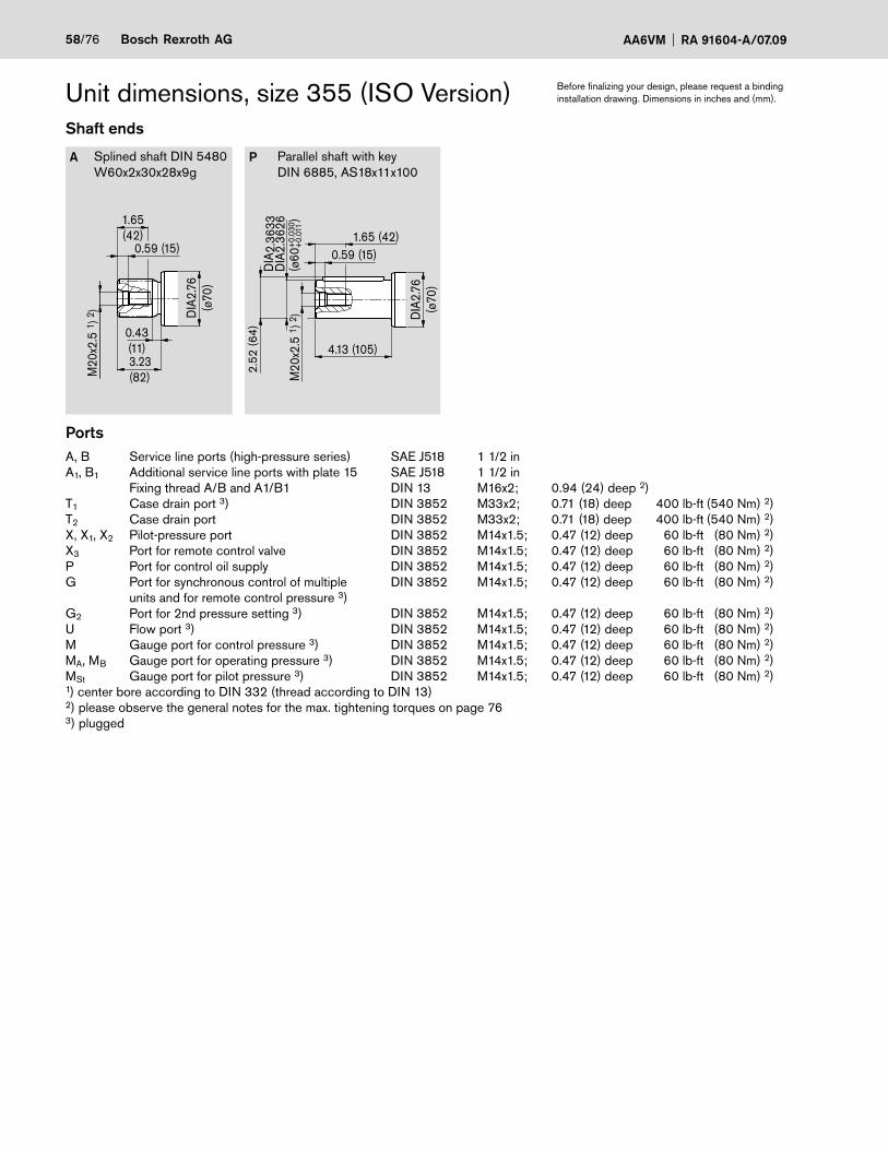
58/76 Bosch Rexroth AG AA6VM RA 91604-A/07.09
Unit dimensions, size 355 (ISO Version)Shaft ends
A Splined shaft DIN 5480W60x2x30x28x9g
P Parallel shaft with keyDIN 6885, AS18x11x100
PortsA, B Service line ports (high-pressure series) SAE J518 1 1/2 inA1, B1 Additional service line ports with plate 15 SAE J518 1 1/2 in Fixing thread A/B and A1/B1 DIN 13 M16x2; 0.94 (24) deep 2)T1 Case drain port 3) DIN 3852 M33x2; 0.71 (18) deep 400 lb-ft (540 Nm) 2)T2 Case drain port DIN 3852 M33x2; 0.71 (18) deep 400 lb-ft (540 Nm) 2)X, X1, X2 Pilot-pressure port DIN 3852 M14x1.5; 0.47 (12) deep 60 lb-ft (80 Nm) 2)X3 Port for remote control valve DIN 3852 M14x1.5; 0.47 (12) deep 60 lb-ft (80 Nm) 2)P Port for control oil supply DIN 3852 M14x1.5; 0.47 (12) deep 60 lb-ft (80 Nm) 2)G Port for synchronous control of multiple DIN 3852 M14x1.5; 0.47 (12) deep 60 lb-ft (80 Nm) 2) units and for remote control pressure 3)G2 Port for 2nd pressure setting 3) DIN 3852 M14x1.5; 0.47 (12) deep 60 lb-ft (80 Nm) 2)U Flow port 3) DIN 3852 M14x1.5; 0.47 (12) deep 60 lb-ft (80 Nm) 2)M Gauge port for control pressure 3) DIN 3852 M14x1.5; 0.47 (12) deep 60 lb-ft (80 Nm) 2)MA, MB Gauge port for operating pressure 3) DIN 3852 M14x1.5; 0.47 (12) deep 60 lb-ft (80 Nm) 2)MSt Gauge port for pilot pressure 3) DIN 3852 M14x1.5; 0.47 (12) deep 60 lb-ft (80 Nm) 2)1) center bore according to DIN 332 (thread according to DIN 13)2) please observe the general notes for the max. tightening torques on page 763) plugged
Before finalizing your design, please request a binding installation drawing. Dimensions in inches and (mm).
M20
x2.5
1) 2
)
4.13 (105)
DIA
2.76
(ø70
)
2.52
(64)
0.59 (15)1.65 (42)
DIA
2.36
33D
IA2.
3626
(ø60
)+
0.03
0+
0.01
1
M20
x2.5
1) 2
)
3.23(82)
DIA
2.76
(ø70
)
0.43(11)
0.59 (15)
1.65(42)
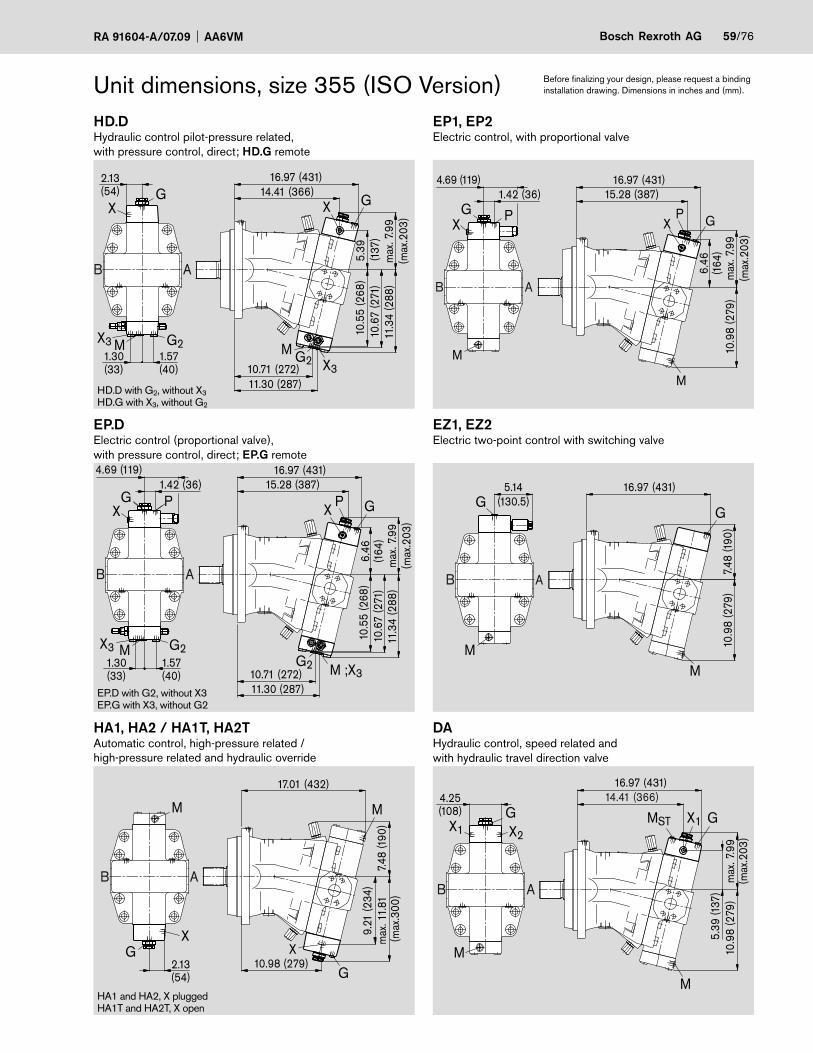
RA 91604-A/07.09 AA6VM Bosch Rexroth AG 59/76
Unit dimensions, size 355 (ISO Version)HD.DHydraulic control pilot-pressure related, with pressure control, direct; HD.G remote
EP1, EP2Electric control, with proportional valve
EP.DElectric control (proportional valve),with pressure control, direct; EP.G remote
EZ1, EZ2Electric two-point control with switching valve
HA1, HA2 / HA1T, HA2TAutomatic control, high-pressure related /high-pressure related and hydraulic override
DAHydraulic control, speed related andwith hydraulic travel direction valve
EP.D with G2, without X3EP.G with X3, without G2
HD.D with G2, without X3HD.G with X3, without G2
HA1 and HA2, X pluggedHA1T and HA2T, X open
Before finalizing your design, please request a binding installation drawing. Dimensions in inches and (mm).
M ;X3
XP G
G210.71 (272)11.30 (287)
15.28 (387)16.97 (431)
11.3
4 (2
88)
10.5
5 (2
68)
10.6
7 (2
71)
max
. 7.9
9(m
ax.2
03)
6.46
(164
)
PGX
4.69 (119)
AB
1.57(40)
1.30(33)
G2X3 M
1.42 (36)
G2M
X3
X G
G2X3
XG
M
11.3
4 (2
88)
10.71 (272)10
.55
(268
)10
.67
(271
)11.30 (287)
max
. 7.9
9(m
ax.2
03)
14.41 (366)
5.39
(137
)
16.97 (431)
AB
2.13(54)
1.57(40)
1.30(33)
7.48
(190
)10
.98
(279
)
5.14(130.5)
MM
GG
AB
16.97 (431)
10.9
8 (2
79)
5.39
(137
)
X1 X2
G
M
X1MST
M
G
AB
16.97 (431)14.41 (366)4.25
(108)
max
. 7.9
9(m
ax.2
03)
max
. 11.
81
(max
.300
)7.
48 (1
90)
9.21
(234
)
10.98 (279)
17.01 (432)
2.13(54)
M M
GX
G
X
AB
10.9
8 (2
79)
M
M
AB
15.28 (387)16.97 (431)
XP G
max
. 7.9
9(m
ax.2
03)
6.46
(164
)
PGX
4.69 (119)1.42 (36)

60/76 Bosch Rexroth AG AA6VM RA 91604-A/07.09
Unit dimensions, size 500 (ISO Version)HD1, HD2 Hydraulic control, pilot-pressure relatedHZ - Hydraulic two-point controlSAE flange ports A/B side, opposite (02)
View ZSAE flange portsA/B side, opposite (02)
SAE flange portsA/B rear (01)
SAE flange portsA/B side, opposite + A1/B1 rear (15)
1) With service line ports A/B rear (plate 01/15)
Before finalizing your design, please request a binding installation drawing. Dimensions in inches and (mm).
0.94(24)
8x45°
ø400
33°45' 22°30'
ø360
M20
13°15
'
T1
T2
G
M
XU
Z
17.28 (439)1)
19.29 (490)
1.89 (48)14.57 (370)
16.42 (417)
18.50 (470)
4.33 (110)
12.0
5 (3
06)
2.17
(55)
2.80
(71)
1 )
3.13
(79.
4)
DIA
1.57
(ø40
)
14.7
6 (3
75)
14.76 (375)
= 360°DIA0.87(ø22)
1.44(36.5)
5.55
(141
)5.
55 (1
41)
8.54
(217
)6.
65 (1
69)
5.83
(148
)
1.18 (30)4.33 (110)
0.55 (14)1.97 (50)
DIA
12.4
016
DIA
12.3
984
(ø31
5 -0
.081
)
MB MA
M
X
G
AB
1.44(36.5)
3.13
(79.
4)1.
57 (ø
40)
3.07(78)
3.07(78)12.20 (310)
2.42(61.5)
A1B1
B A
MB MA
M
X
G
1.44(36.5)
3.13
(79.
4)1.
57 (ø
40)
3.07(78)
3.07(78)11.73 (298)
2.42(61.5)G
AB
11.73 (298)
2.42(61.5)
X
M
MB MA

RA 91604-A/07.09 AA6VM Bosch Rexroth AG 61/76
Unit dimensions, size 500 (ISO Version)Shaft ends
A Splined shaft DIN 5480W70x3x30x22x9g
P Parallel shaft with keyDIN 6885, AS20x12x100
PortsA, B Service line ports (high-pressure series) SAE J518 1 1/2 inA1, B1 Additional service line ports with plate 15 SAE J518 1 1/2 in Fixing thread A/B and A1/B1 DIN 13 M16x2; 0.94 (24 deep) 2)T1 Case drain port DIN 3852 M33x2; 0.71 (18) deep 400 lb-ft (540 Nm) 2)T2 Case drain port 3) DIN 3852 M33x2; 0.71 (18) deep 400 lb-ft (540 Nm) 2)X, X1, X2 Pilot-pressure port DIN 3852 M14x1.5; 0.47 (12) deep 60 lb-ft (80 Nm) 2)X3 Port for remote control valve DIN 3852 M14x1.5; 0.47 (12) deep 60 lb-ft (80 Nm) 2)P Port for control oil supply DIN 3852 M14x1.5; 0.47 (12) deep 60 lb-ft (80 Nm) 2)G Port for synchronous control of multiple DIN 3852 M18x1.5; 0.47 (12) deep 100 lb-ft (140 Nm) 2) units and for remote control pressure 3)G2 Port for 2nd pressure setting 3) DIN 3852 M18x1.5; 0.47 (12) deep 100 lb-ft (140 Nm) 2)U Flow port 3) DIN 3852 M18x1.5; 0.47 (12) deep 100 lb-ft (140 Nm) 2)M Gauge port for control pressure 3) DIN 3852 M14x1.5; 0.47 (12) deep 60 lb-ft (80 Nm) 2)MA, MB Gauge port for operating pressure 3) DIN 3852 M14x1.5; 0.47 (12) deep 60 lb-ft (80 Nm) 2)MSt Gauge port for pilot pressure 3) DIN 3852 M14x1.5; 0.47 (12) deep 60 lb-ft (80 Nm) 2)1) center bore according to DIN 332 (thread according to DIN 13)2) please observe the general notes for the max. tightening torques on page 763) plugged
Before finalizing your design, please request a binding installation drawing. Dimensions in inches and (mm).
3.15(80)
DIA
3.15
(ø80
)
0.51(13)
0.59 (15)
M20
x2.5
1) 2
)
1.65(42)
M20
x2.5
1) 2
)4.13 (105)
DIA
3.15
(ø80
)
2.93
(74.
5)
0.59 (15)1.65 (42)
DIA
2.75
71D
IA2.
7563
(ø70
)+
0.03
0+
0.01
1

62/76 Bosch Rexroth AG AA6VM RA 91604-A/07.09
HD.DHydraulic control pilot-pressure related, with pressure control, direct; HD.G remote
EP1, EP2Electric control, with proportional valve
EP.DElectric control (proportional valve),with pressure control, direct; EP.G remote
EZ1, EZ2Electric two-point control with switching valve
HA1, HA2 / HA1T, HA2TAutomatic control, high-pressure related /high-pressure related and hydraulic override
DAHydraulic control, speed related andwith hydraulic travel direction valve
Unit dimensions, size 500 (ISO Version)
EP.D with G2, without X3EP.G with X3, without G2
HA1 and HA2, X pluggedHA1T and HA2T, X open
HD.D with G2, without X3
HD.G with X3, without G2
Before finalizing your design, please request a binding installation drawing. Dimensions in inches and (mm).
5.83
(148
)
12.48 (317)
19.29 (490)16.46 (418)
11.3
4 (2
88)
G2X3
GX
M
X G
8.54
(217
)12
.05
(306
)
AB
11.3
0 (2
87)
X3; MG212.40 (315)
2.42(61.5)
1.54(39)
0.91(23)
12.68 (322)
10.16
(258
)m
ax. 1
2.79
(max
.325
)8.
54 (2
17)
19.29 (490)
2.42(61.5)
G
M
M
X
GX
AB
1.69 (43)4.96(126)
G2
G2X3 X3; M
PGX
M
X GP
AB
12.48 (317)12.40 (315)
19.29 (490)17.24 (438)
6.93
(176
)11
.34
(288
)8.
54 (2
17)
12.0
5 (3
06)
11.3
0 (2
87)
1.54(39)
0.91(23)
4.96(126)1.69 (43)
6.93
(176
)
M
G P PX
M
X G
AB
19.29 (490)
12.0
5 (3
06)
8.54
(217
)
17.24 (438)
5.94
(151
)
16.46 (418)
8.54
(217
)
4.72(120)
12.0
5 (3
06)
19.29 (490)
M
X2MST GX2X1
G
M
AB
5.41(137.5)
19.29 (490)
8.54
(217
)12
.05
(306
)M
G
M
G
AB

RA 91604-A/07.09 AA6VM Bosch Rexroth AG 63/76
Unit dimensions, size 1000 (ISO Version)HD1, HD2 Hydraulic control, pilot-pressure relatedHZ Hydraulic two-point controlSAE flange ports A/B side, opposite (02)
View ZSAE flange portsA/B side, opposite (02)
SAE flange portsA/B rear (01)
SAE flange portsA/B side, opposite + A1/B1 rear (15)
1) With service line ports A/B rear (plate 01/15)
Before finalizing your design, please request a binding installation drawing. Dimensions in inches and (mm).
7.20
(183
)7.
20 (1
83)
1.97 (555)1)
DIA
1.97
(ø50
)
24.33 (618)
14.8
4 (3
77)
10.7
9 (2
74)
45°
ø500
18.3
1 (4
65)
18.31 (465)
ø450
M24
DIA0.87(ø22)
2.75
(70)
3.50
(89)
1 )8.
15 (2
07)
7.44
(189
)
1.85 (47)18.74 (476)
5.79 (147)1.38 (35)0.55 (14)
DIA
15.74
80D
IA17
.7445
(ø40
0 -0
.089
)
1.75(44.5)
T1
T2
G
M
XU
Z
13°15'
1.97 (50)
22°30'8x45°=360°
21.85 (537)
23.54 (598)
5.79 (147)
3.81
(96.
8)
2.75(70)
14.57 (370)
MAMB
M
XG
AB AB
MAMB
M
X
G
3.81
(96.
8)
2.75(70)
3.86(98)
3.86(98)15.12 (384)
DIA
1.97
(ø50
)
1.75(44.5)
A
B
B1 A1
M3.86(98)
3.86(98)14.57 (370)
MAMB
3.81
(96.
8)D
IA1.
97 (ø
50) X
G2.75(70)
1.75(44.5)

64/76 Bosch Rexroth AG AA6VM RA 91604-A/07.09
Unit dimensions, size 1000 (ISO Version)Shaft ends
A Splined shaft DIN 5480W90x3x30x28x9g
P Parallel shaft with keyDIN 6885, AS25x14x125
PortsA, B Service line ports (high-pressure series) SAE J518 2 inA1, B1 Additional service line ports with plate 15 SAE J518 2 in Fixing thread A/B and A1/B1 DIN 13 M20x2.5; 0.94 (24) deep 2)T1 Case drain port DIN 3852 M42x2; 0.79 (20) deep 530 lb-ft (720 Nm) 2)T2 Case drain port 3) DIN 3852 M42x2; 0.79 (20) deep 530 lb-ft (720 Nm) 2)X Pilot-pressure port DIN 3852 M14x1.5; 0.47 (12) deep 60 lb-ft (80 Nm) 2)X3 Port for remote control valve DIN 3852 M14x1.5; 0.47 (12) deep 60 lb-ft (80 Nm) 2)
P Port for control oil supply DIN 3852 M14x1.5; 0.47 (12) deep 60 lb-ft (80 Nm) 2)
G Port for synchronous control of multiple DIN 3852 M18x1.5; 0.47 (12) deep 100 lb-ft (140 Nm) 2) units and for remote control pressure 3)G2 Port for 2nd pressure setting 3) DIN 3852 M18x1.5; 0.47 (12) deep 100 lb-ft (140 Nm) 2)U Flow port 3) DIN 3852 M18x1.5; 0.47 (12) deep 100 lb-ft (140 Nm) 2)M Gauge port for control pressure 3) DIN 3852 M14x1.5; 0.47 (12) deep 60 lb-ft (80 Nm) 2)
MA, MB Gauge port for operating pressure 3) DIN 3852 M14x1.5; 0.47 (12) deep 60 lb-ft (80 Nm) 2)
MSt Gauge port for pilot pressure 3) DIN 3852 M14x1.5; 0.47 (12) deep 60 lb-ft (80 Nm) 2)
1) center bore according to DIN 332 (thread according to DIN 13)2) please observe the general notes for the max. tightening torques on page 763) plugged
Before finalizing your design, please request a binding installation drawing. Dimensions in inches and (mm).
M24
x3 1
) 2)
5.12 (130)
DIA
3.94
(ø10
0)
3.74
(95)
3.54
473.
5438
(ø90
)+
0.03
5+
0.01
3
0.71 (18)1.97 (50)
0.71 (18)
M24
x3 1
) 2)
1.97(50)
4.13(105)
DIA
3.94
(ø10
0)
0.55(14)

RA 91604-A/07.09 AA6VM Bosch Rexroth AG 65/76
Unit dimensions, size 1000 (ISO Version)HD.DHydraulic control pilot-pressure related, with pressure control, direct; HD.G remote
EP1, EP2Electric control, with proportional valve
EP.DElectric control (proportional valve),with pressure control, direct; EP.G remote
EZ1, EZ2Electric two-point control with switching valve
HA1, HA2 / HA1T, HA2TAutomatic control, high-pressure related /high-pressure related and hydraulic override
HD.D with G2, without X3HD.G with X3, without G2
HA1 and HA2, X pluggedHA1T and HA2T, X open
EP.D with G2, without X3EP.G with X3, without G2
Before finalizing your design, please request a binding installation drawing. Dimensions in inches and (mm).
21.42 (544)
10.79
(274
)
1.22(31)
2.01(51)
24.29 (617)
16.54 (420)
5.31 (135)2.05 (52)
8.62
(219
)
P
14.6
9 (3
73)
15.2
8 (3
88)
MG2X3
PX
XG G
G2, X3
M
AB 10.7
9 (2
74)
14.8
4 (3
77)
5.77(146.5)
24.29 (617)
MM
G G
AB
P P
M
M
X XG G
AB
21.42 (544)
10.79
(274
)
24.29 (617)
8.62
(219
)14
.84
(377
)
5.31 (135)2.05 (52)
10.79
(274
)m
ax. 1
5.55
(max
. 395
)
12.9
1 (3
28)
2.76(70)
24.33 (618)
16.34 (415)
MM
X
XG
G
AB
MG2X3
G2,X3
M
XXG G
AB
21.14 (537)24.29 (617)
10.79
(274
)7.4
4 (18
9)14
.69
(373
)15
.28
(388
)
2.75 (70)
1.22(31)
2.01(51)
16.54 (420)
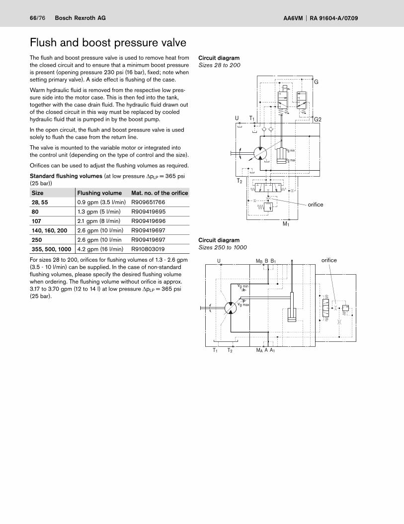
66/76 Bosch Rexroth AG AA6VM RA 91604-A/07.09
The flush and boost pressure valve is used to remove heat from the closed circuit and to ensure that a minimum boost pressure is present (opening pressure 230 psi (16 bar), fixed; note when setting primary valve). A side effect is flushing of the case.
Warm hydraulic fluid is removed from the respective low pres-sure side into the motor case. This is then fed into the tank, together with the case drain fluid. The hydraulic fluid drawn out of the closed circuit in this way must be replaced by cooled hydraulic fluid that is pumped in by the boost pump.
In the open circuit, the flush and boost pressure valve is used solely to flush the case from the return line.
The valve is mounted to the variable motor or integrated into the control unit (depending on the type of control and the size).
Orifices can be used to adjust the flushing volumes as required.
Standard flushing volumes (at low pressure ΔpLP = 365 psi (25 bar))
Size Flushing volume Mat. no. of the orifice
28, 55 0.9 gpm (3.5 l/min) R909651766
80 1.3 gpm (5 l/min) R909419695
107 2.1 gpm (8 l/min) R909419696
140, 160, 200 2.6 gpm (10 l/min) R909419697
250 2.6 gpm (10 l/min R909419697
355, 500, 1000 4.2 gpm (16 l/min) R910803019
For sizes 28 to 200, orifices for flushing volumes of 1.3 - 2.6 gpm (3.5 - 10 l/min) can be supplied. In the case of non-standard flushing volumes, please specify the desired flushing volume when ordering. The flushing volume without orifice is approx. 3.17 to 3.70 gpm (12 to 14 l) at low pressure ΔpLP = 365 psi (25 bar).
Flush and boost pressure valveCircuit diagramSizes 28 to 200
orifice
G
U
T2
T1 G2
vg min
M1
vg max
Circuit diagramSizes 250 to 1000
T1 T2
BMBU
vg min
B1
AMA A1
vg max
orifice

RA 91604-A/07.09 AA6VM Bosch Rexroth AG 67/76
Flush and boost pressure valveDimensionsSizes 28 to 200
A2
A3
A4A1
HA1, HA2 HD, HZ1, DA, HZ3, EP, EZ1, EZ3, EZ2 EZ4
Size A1 A2 A3 A4
A6VM 28 8.43 (214) 4.92 (125) 6.34 (161) –
140 12.64 (321) 6.06 (154) 8.58 (218) –
AA6VM 55 10.51 (267) 5.24 (133) 6.93 (176) 10.24 (260)
80 11.69 (297) 5.59 (142) 7.60 (193) 10.94 (278)
107 12.60 (320) 5.67 (144) 7.87 (200) 11.85 (301)
160 14.17 (360) 6.06 (154) 8.66 (220) –
200 14.84 (377) 6.30 (160) 9.09 (231) –
Sizes 250 to 1000
A2A1
HD, HZ, DA, HA1, HA2EP, EZ,
Size A1 A2
AA6VM 250 15.71 (399) 17.48 (444)
A6VM 355 15.63 (397) 17.56 (446)
500 17.32 (440) 19.84 (504)
1000 21.73 (552) 24.76 (629)
Before finalizing your design, please request a binding installation drawing. Dimensions in inches and (mm).
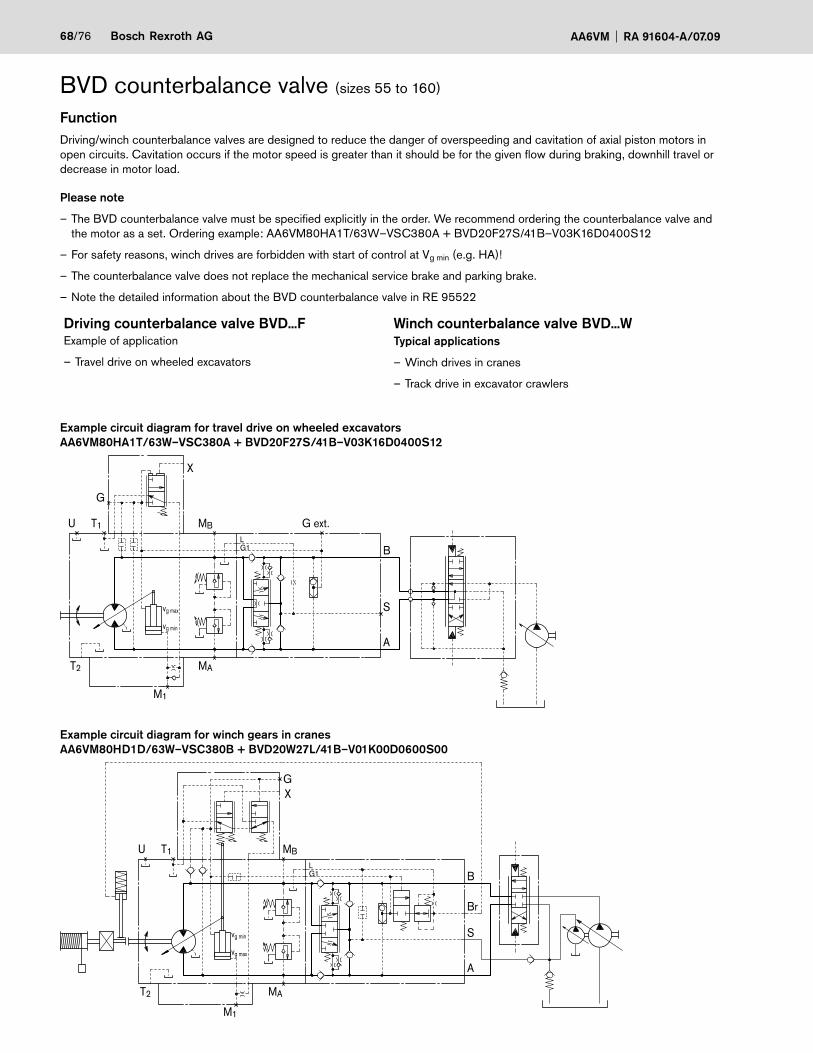
68/76 Bosch Rexroth AG AA6VM RA 91604-A/07.09
BVD counterbalance valve (sizes 55 to 160)
FunctionDriving/winch counterbalance valves are designed to reduce the danger of overspeeding and cavitation of axial piston motors in open circuits. Cavitation occurs if the motor speed is greater than it should be for the given flow during braking, downhill travel or decrease in motor load.
Please note
– The BVD counterbalance valve must be specified explicitly in the order. We recommend ordering the counterbalance valve and the motor as a set. Ordering example: AA6VM80HA1T/63W–VSC380A + BVD20F27S/41B–V03K16D0400S12
– For safety reasons, winch drives are forbidden with start of control at Vg min (e.g. HA)!
– The counterbalance valve does not replace the mechanical service brake and parking brake.
– Note the detailed information about the BVD counterbalance valve in RE 95522
Driving counterbalance valve BVD...F Winch counterbalance valve BVD...WExample of application
– Travel drive on wheeled excavators
Typical applications
– Winch drives in cranes
– Track drive in excavator crawlers
Example circuit diagram for travel drive on wheeled excavatorsAA6VM80HA1T/63W–VSC380A + BVD20F27S/41B–V03K16D0400S12
G
X
MBU T1
T2 MA
M1
B
G ext.
A
S
LG1
vg min
vg max
Example circuit diagram for winch gears in cranesAA6VM80HD1D/63W–VSC380B + BVD20W27L/41B–V01K00D0600S00
GX
MBU T1
T2 MA
M1
B
Br
A
S
LG1
vg max
vg min

RA 91604-A/07.09 AA6VM Bosch Rexroth AG 69/76
Dimensions
(A)A6VM to HA (A)A6VM to HD and EP 1)
A6 A5A7
A3A4
A2A1
A8
B AGext.
S
MB; (MA)
S
A
A
B
B
A8
A5 A6A7
A9A2
A4A1
0
(A)A6VM Counter balance valve
Ports 2) Portson the motor
Size...Plate Type A, B S Gext.
(version S)Gext.
(version L)Br (version L)
MA, MB Gauge port(plugged)
55...38 BVD20...17 3/4 inM22x1.5;
0.55 (14) deepM12x1.5;
0.49 (12.5) deepM14x1.5;
0.31 (8) deep
M12x1.5; 0.49 (12.5) deep
M18x1.5; 0.47 (12) deep
80...38 BVD20...27 1 in
107...37 BVD20...28 1 in
107...38 BVD25...38 1 1/4 inM27x2;
0.63 (16) deepM12x1.5;
0.47 (12) deep140...38 BVD25...38 1 1/4 in
160...38 BVD25...38 1 1/4 in
250...08 on request
(A)A6VM Dimensions
Size...Plate A1 A2 A3 A4 A5 A6 A7 A8 A9 A10
55...38 13.19 12.83 5.63 1.97 3.86 5.47 2.95 8.74 13.78 1.97
(335) (326) (143) (50) (98) (139) (75) (222) (350) (50)
80...38 14.33 13.98 5.83 2.17 3.86 5.47 2.95 8.74 14.92 1.81
(364) (355) (148) (55) (98) (139) (75) (222) (379) (46)
107...37 15.51 15.16 5.98 2.32 3.86 5.47 3.31 9.21 16.10 1.61
(394) (385) (152) (59) (98) (139) (84) (234) (409) (41)
107...38 16.22 15.83 6.50 2.48 4.74 6.89 3.31 9.37 16.81 2.20
(412) (402) (165) (63) (120.5) (175) (84) (238) (427) (56)
140...38 16.18 15.79 6.61 2.64 4.74 6.89 3.31 9.37 17.56 2.09
(411) (401) (168) (67) (120.5) (175) (84) (238) (446) (53)
160...38 17.68 17.28 6.68 2.68 4.74 6.89 3.31 9.37 18.27 2.01
(449) (439) (170) (68) (120.5) (175) (84) (238) (464) (51)
250...08 on request1) In the installation version for the HD and EP controls, the molded connection designations on the brake valve do not correspond
with the connection designation of the A6VM. The designation of the connections on the engine installation drawing is binding!
2) Ports on the counterbalance valveA, B Service line portsS Boosting (plugged)Gext. Brake release, high pressure, pluggedBr Brake release, reduced high pressure, open Version S "Port for brake release with high pressure"Version L "Port for brake release with reduced high pressure"
BVD counterbalance valve (sizes 55 to 160)Before finalizing your design, please request a binding installation drawing. Dimensions in inches and (mm).

70/76 Bosch Rexroth AG AA6VM RA 91604-A/07.09
BVD counterbalance valve (sizes 55 to 160)
Attaching the counterbalance valveWhen delivered, the counterbalance valve is attached to the motor using 2 tacking screws. Do not remove the tacking screws when connecting the service lines. If the counterbalan-ce valve and motor are delivered separately, the counterbalan-ce valve must first be attached to the motor port plate using the provided tacking screws. In both cases, the final attachment of the counterbalance valve to the motor is by the connectio of the service lines, e.g. using SAE 4-bolt flanges. A total of 6 screws with thread lengths B1+B2+B3 and 2 screws with thread lengths B3+B4 are required.
When tightening the screws, it is imperative that the sequence 1 to 8 (as shown in the adjacent diagram) be adhered to and carried out in two phases.
In the first phase the screws should be tightened to 50% of their tightening torque before being tightened to maximum tightening torque in the second phase (see table below).
Thread Property class Tightening torque in lb-ft (Nm)
M10 10.9 55 (75)
M12 10.9 95 (130)
M14 10.9 150 (205)
B4
B1 B2
1)
B358
4
3762
1
1) Flange, e.g. SAE flange
Size...Plate 55...38 80...38107...37
107, 140,160...38
B1 2) M10x1.50.67 (17) deep
M12x1.750.59 (15) deep
M14x20.75 (19) deep
B2 2.68 (68) 2.68 (68) 3.35 (85)
B3 Customer specific
B4 M10x1.50.59 (15) deep
M12x1.75 0.63 (16) deep
M14x20.75 (19) deep
2) Minimum required reach 1 x DIA. thread
Before finalizing your design, please request a binding installation drawing. Dimensions in inches and (mm).

RA 91604-A/07.09 AA6VM Bosch Rexroth AG 71/76
Optical swivel angle indicator (V)The swivel position is indicated by a pin on the side of the port plate. The length of the protruding pin is dependent on the position of the lens plate.
If the pin is flush with the port plate, the motor is positioned at the start of control. At max. swivel, the pin length is 0.31 in (8 mm) (visible after removing the cap nut).
Sizes 250 to 1000
Example: Start of control at Vg min
U
T1 T2 MA A
MB B
Vg max.
Vg min.
Uα
A6A3
A1 A1A5 A5
A4A2 2)
s19
1)
Start of control Vg max
Start of controlVg min
Size A1 A22) A3 A4 A53) A6
AA6- 250 5.37 11.73 2.87 11.02 0.43 0.20
(136.5) (298) (73) (280) (11) (5)
A6VM 350 6.28 11.34 3.31 10.47 0.43 0.31
(159.5) (288) (84) (266) (11) (8)
500 6.79 13.03 3.50 12.17 0.43 0.12
(172.5) (331) (89) (309) (11) (3)
1000 8.21 16.93 4.49 15.83 0.43 0.12
(208.5) (430) (114) (402) (11) (3)
1) Width across flats2) Distance to mounting flange3) Clearance required for removing the cap nut
Swivel angle indicator (Sizes 250 to 1000)
Electric swivel angle indicator (E)The motor position is measured by an inductive pos. transdu-cer. It converts the stroke of the control device to an electric signal.
This signal can be used to pass the swivel position to an elec-tric controller.
Inductive pos. transducer type IW9–03–01Type of protection according to DIN/EN 60529: IP65
Sizes 250 to 1000
Example: Start of control at Vg max
U
T1 T2 MA A
MB B
Vg max.
Vg min.
Uα
A6A3
A1A1 A4A2 2)
Start of control Vg max
Start of control Vg min
PG9
PG9
Size A1 A22) A3 A4 A6
AA6VM 250 7.17 11.73 2.87 11.02 0.20
(182) (298) (73) (280) (5)
A6VM 355 8.07 11.34 3.31 10.47 0.31
(205) (288) (84) (266) (8)
500 8.59 13.03 3.50 12.17 0.12
(218) (331) (89) (309) (3)
1000 10.00 16.93 4.49 15.83 0.12
(254) (430) (114) (402) (3)2) Distance to mounting flange
Before finalizing your design, please request a binding installation drawing. Dimensions in inches and (mm).
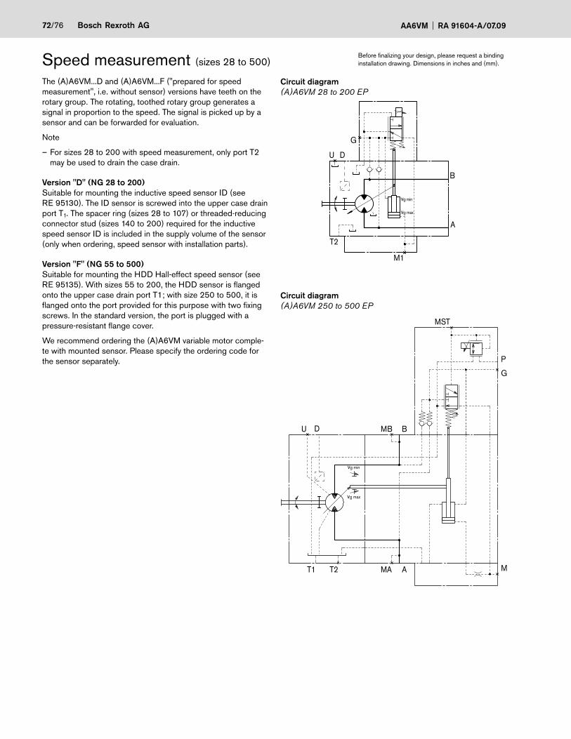
72/76 Bosch Rexroth AG AA6VM RA 91604-A/07.09
The (A)A6VM...D and (A)A6VM...F ("prepared for speed measurement", i.e. without sensor) versions have teeth on the rotary group. The rotating, toothed rotary group generates a signal in proportion to the speed. The signal is picked up by a sensor and can be forwarded for evaluation.
Note
– For sizes 28 to 200 with speed measurement, only port T2 may be used to drain the case drain.
Version "D" (NG 28 to 200)Suitable for mounting the inductive speed sensor ID (see RE 95130). The ID sensor is screwed into the upper case drain port T1. The spacer ring (sizes 28 to 107) or threaded-reducing connector stud (sizes 140 to 200) required for the inductive speed sensor ID is included in the supply volume of the sensor (only when ordering, speed sensor with installation parts).
Version "F" (NG 55 to 500)Suitable for mounting the HDD Hall-effect speed sensor (see RE 95135). With sizes 55 to 200, the HDD sensor is flanged onto the upper case drain port T1; with size 250 to 500, it is flanged onto the port provided for this purpose with two fixing screws. In the standard version, the port is plugged with a pressure-resistant flange cover.
We recommend ordering the (A)A6VM variable motor comple-te with mounted sensor. Please specify the ordering code for the sensor separately.
Speed measurement (sizes 28 to 500)
Circuit diagram(A)A6VM 28 to 200 EP
U D
B
A
T2
M1
vg min
vg max
G
Circuit diagram(A)A6VM 250 to 500 EP
U MB B
vg min
vg max
G
MST
T1 AT2 MA M
P
D
Before finalizing your design, please request a binding installation drawing. Dimensions in inches and (mm).

RA 91604-A/07.09 AA6VM Bosch Rexroth AG 73/76
Size 28 55 80 107 140 160 200 250 355 500Sensor selection IDR 18/20 – L250 IDR 18/20 – L400
HDD.L16.../20 HDD.L32.../20Number of teeth 40 54 58 67 72 75 80 78 90 99HDD A Insertion depth
(tolerance ± 0.1)0.63 0.63 0.63 0.63 0.63 0.63 1.27 1.27 1.27(16) (16) (16) (16) (16) (16) (32.5) (32.5) (32.5)
B Contact surface 2.86 3.02 3.37 3.57 3.69 3.88 4.35 4.82 5.21(72.6) (76.6) (85.6) (90.6) (93.6) (98.6) (110.5) (122.5) (132.5)
C 4.37 4.53 4.88 5.08 5.20 5.39 5.87 6.34 6.73(111) (115) (124) (129) (132) (137) (149) (161) (171)
D 3.58 3.94 4.33 3.62 4.90 5.04 3.23 3.66 4.45(91) (100) (110) (92) (124.5) (128) (82) (93) (113)
E 5.31 5.71 6.06(135) (145) (154)
ID A Insertion depth (tolerance ± 0.1)
0.69 0.69 0.69 0.69 0.96 0.96 0.96(17.5) (17.5) (17.5) (17.5) (24.5) (24.5) (24.5)
B Contact surface 2.36 2.91 3.07 3.43 3.90 4.02 4.21(60) (74) (78) (87) (99) (102) (107)
C without mating connector
4.72 5.28 5.43 5.79 6.18 6.30 6.50(120) (134) (138) (147) (157) (160) (165)
C1 with 90° mating connector
6.89 7.44 7.60 7.95 8.35 8.46 8.66(175) (189) (193) (202) (212) (215) (220)
C2 with 180° mating connector
6.04 6.59 6.75 7.11 7.50 7.62 7.81(153.5) (167.5) (171.5) (180.5) (190.5) (193.5) (198.5)
D 2.28 3.58 3.94 4.33 3.62 4.90 5.04(58) (91) (100) (110) (92) (124.5) (128)
Version "F" (sizes 55 to 200): with HDD sensorC
D
A
X
B
Version "F" (size 250 to 500): with HDD.L32 sensor
X30°
E
DB C
A
Version "D" (sizes 28 to 200): with ID sensor
Y
M18
x1.5
2)
Ansicht Y
BC
D
C1
1)C
2 1)
A
Clearance required for attaching/detaching the mating 1)
connector: min. 0.51 in (13 mm)Tightening torque, max.: 36.9 lb-ft (50 Nm) (ID sensor)2)
View X
DIA
0.72
(ø18
.2) 0.
78(2
0 )
90°
0.86
(22)
0.78
(20)
0.86
(22)
M6x1 (DIN 13) 8 deep
Without HDD sensor With HDD sensor
Speed measurement (sizes 28 to 500)Before finalizing your design, please request a binding installation drawing. Dimensions in inches and (mm).

74/76 Bosch Rexroth AG AA6VM RA 91604-A/07.09
HIRSCHMANN DIN EN 175 301-803-A/ISO 4400(not for new projects with sizes 28 - 200)
Without bidirectional suppressor diode(for EP, EZ, HA.U, HA.R, DA) __________________________H
Type of protection according to DIN/EN 60529: IP65
The seal ring in the cable fitting is suitable for line diameters from 0.18 in to 0.39 in (4.5 mm to 10 mm).
The HIRSCHMANN connector is included in the supply volu-me for the motor.
(2)
1.97 (50)
DIA
1.4
6 ø3
72)
2.70 (68.5)
2.57
(65.
4)
Fixing screw M3Tightening torque
MA = 0.37 lb-ft (0.5 Nm)
Cable fitting M16x1.5Tightening torque MA = 1.11 - 1.84 lb-ft (1.5 - 2.5 Nm)
(1)
2) Solenoid with DIA 1.77 (ø45) for following controls: HA.U, HA.R (for elec. override), EZ3 and EZ4.
Note for cylindric solenoids:
The position of the connector can be changed by turning the solenoid body.
The following procedure is to be observed: 1. Loosen the fixing nut (1)2. Turn the solenoid body (2) to the desired position3. Tighten the fixing nut Tightening torque of the fixing nut: 3.69+0.74 lb-ft (5+1 Nm) (width across flats WAF26, 12-sided DIN 3124)
We reserve the right to change the position of the solenoid connector from that depicted in the brochure or drawing during assembly of the solenoid.
Connectors for solenoids (for EP, EZ, HA.U, HA.R, DA only)
DEUTSCH DT04-2P-EP04, 2-pinMolded, without bidirectional suppressor diode(for EP, EZ1/2, DA) ___________________________________ P
Molded, with bidirectional suppressor diode(for switching solenoid for the EZ1/2, DA control units) ____ Q
Type of protection according to DIN/EN 60529: IP67 and IP69K
The protection circuit with a bidirectional suppressor diode is necessary for limiting overvoltages. Overvoltages are genera-ted by disconnecting the current using switches, relay contacts or by unplugging an energized mating connector.
Switching symbol
Without bidirectionalsuppressor diode
With bidirectionalsuppressor diode
Mating connector
DEUTSCH DT06-2S-EP04Rexroth Mat. No. R902601804
Consisting of: DT-Designation
– 1 case ________________________________DT06-2S-EP04
– 1 wedge _______________________________________W2S
– 2 sockets ____________________________ 0462-201-16141
The mating connector is not included in supply.This can be supplied by Rexroth on request.
1.42
(36)
1.97 (50)
DIA
1.46
(ø
37)
2.70 (68.5)
Before finalizing your design, please request a binding installation drawing. Dimensions in inches and (mm).

RA 91604-A/07.09 AA6VM Bosch Rexroth AG 75/76
General
During commissioning and operation, the axial piston unit must be filled with hydraulic fluid and air bled.This is also to be observed following a relatively long standstill as the system may empty via the hydraulic lines.
The case drain inside the case interior must be drained to the tank via the highest case drain port.
In all operating states, the case drain line must flow into the tank below the minimum fluid level.
Installation position
See examples below. Additional installation positions are available upon request.
Below-tank installation (standard)
Motor below the minimum fluid level of the tank.
Recommended installation positions: 1 and 2.
Above-tank installation
Motor above the min. fluid level of the tank
– Note: Installation position 8 (shaft up)
In this installation position, if the case interior is only partially drained, lubrication of the bearings will no longer be ade-quate. A check valve (opening pressure 7.25 psi (0.5 bar)) in the case drain line can prevent the system emptying through the case drain line.
1 2 5 6
3 4 7 8
Installation position
Air bleeding Filling Installation position
Air bleeding Filling
1 – T1 (L1) 5 – T1 (L1)
2 – T2 (L1) 6 – T2 (L1)
3 – T1 (L1) 7 – T1 (L1)
4 U T1 (L1) 8 U T1 (L1)
Installation instructions
T1 T2
T2
U
U
T1
T1T1
U
T2
T2
L1
L1
L1
L1
0,5
bar
T1 T2
T2
U
U
T1
T1
T1
U
T2
T2
L1
L1
L1
L1

76/76 Bosch Rexroth AG AA6VM RA 91604-A/07.09
© 2009 Bosch Rexroth Corporation
All rights reserved. Neither this document, nor any part of it, may be reproduced, duplicated, circulated or disseminated, whether by copy, electronic format or any other means, without the prior consent and authorization of Bosch Rexroth Corp.
The data and illustrations in this brochure/data sheet are intended only to descri-be or depict the products. No representation or warranty, either express or im-plied, relating to merchantability or fitness for intended use, is given or intended by virtue of the information contained in this brochure/data sheet. The information contained in this brochure/data sheet in no way relieves the user of its obligation to insure the proper use of the products for a specific use or application. All products contained in this brochure/data sheet are subject to normal wear and tear from usage.
Subject to change.
Bosch Rexroth CorporationHydraulicsAxial & Radial Piston Units8 Southchase CourtFountain Inn, SC 29644-9018, USATelephone (864) 967-2777Facsimile (864) 967-8900www.boschrexroth-us.com
General instructions– The (A)A6VM motor is designed to be used in open and closed circuits.
– Project planning, assembly, and commissioning of the motor require the involvement of qualified personnel.
– The service line ports and function ports are only designed to mounting hydraulic lines.
– During and shortly after operation, there is a risk of burns on the motor and especially on the solenoids. Take suitable safety precautions, e.g. wear protective clothing
– There may be shifts in the characteristic depending on the operating state of the motor (operating pressure, fluid temperature).
– Tightening torques:- The tightening torques specified in this data sheet are maximum values and must not be exceeded (maximum values for screw thread). Manufacturer's instruction for the max. permissible tightening torques of the used armatures must be observed!- For ISO68 / DIN 13 fixing screws, we recommend checking the tightening torque individually according to VDI 2230 Edition 2003.
– The data and information contained herein must be adhered to.
Related Documents