Axial Piston Motors Series Fixed Displacement M24 Design D Goldcup M30 Design A Service Information S2-AM121 12-94 replaces SFM-M24 CONTENTS PAGE INTRODUCTION 2 GENERAL 2 DESCRIPTION 2 TABLE I CHARACTERISTICS 2 INSTALLATION 3-4 MOUNTING 3 SHAFT INFORMATION 3 PIPING 3 SERVICE INFORMATION 3 RECOMMENDED FLUIDS 3 VISCOSITY 3 VISCOSITY INDEX 3 TEMPERATURE 3 ALTERNATE FLUIDS 4 MAINTENANCE 4 FLUID CLEANLINESS 4 START UP PROCEDURE 4 TABLE II SOLID CONTAMINATION 4 TABLE III TROUBLE-SHOOTING 5-6 UNIT DISASSEMBLY 7-8 TABLE IV REWORK LIMITS 8 DISASSEMBLY & ASSEMBLY TOOL DRAWING 8 PAGE ASSEMBLY PROCEDURES 9-20 FIGURE 1 DRIVE SHAFT ASSEMBLY 9 FIGURE 2 BARREL, CAM, PISTON @ SHOE ASSEMBLY TO MOUNTING FLANGE 11 FIGURE 3 BARREL AND AUXILIARY SHAFT ASSEMBLY (24 SERIES) 12 FIGURE 3.1 BARREL AND AUXILIARY SHAFT ASSEMBLY (30 SERIES) 13 FIGURE 4 HOUSING ASSEMBLY 14 FIGURE 5 HOUSING ASSEMBLY INSTALLATION 15 FIGURE 6 SHAFT SEAL AND COVER ASSEMBLY 16 FIGURE 7 PORT BLOCK INSTALLATION 18 FIGURE 8 SHUTTLE VALVE ASSEMBLY 20 TEST PROCEDURES 21 GENERAL REQUIREMENTS 21 BASIC MOTOR TEST 21 ORDERING CODE 22 SEAL KIT COMPLETE S23-15128 SHAFT SEAL KITS S23-11516

Welcome message from author
This document is posted to help you gain knowledge. Please leave a comment to let me know what you think about it! Share it to your friends and learn new things together.
Transcript
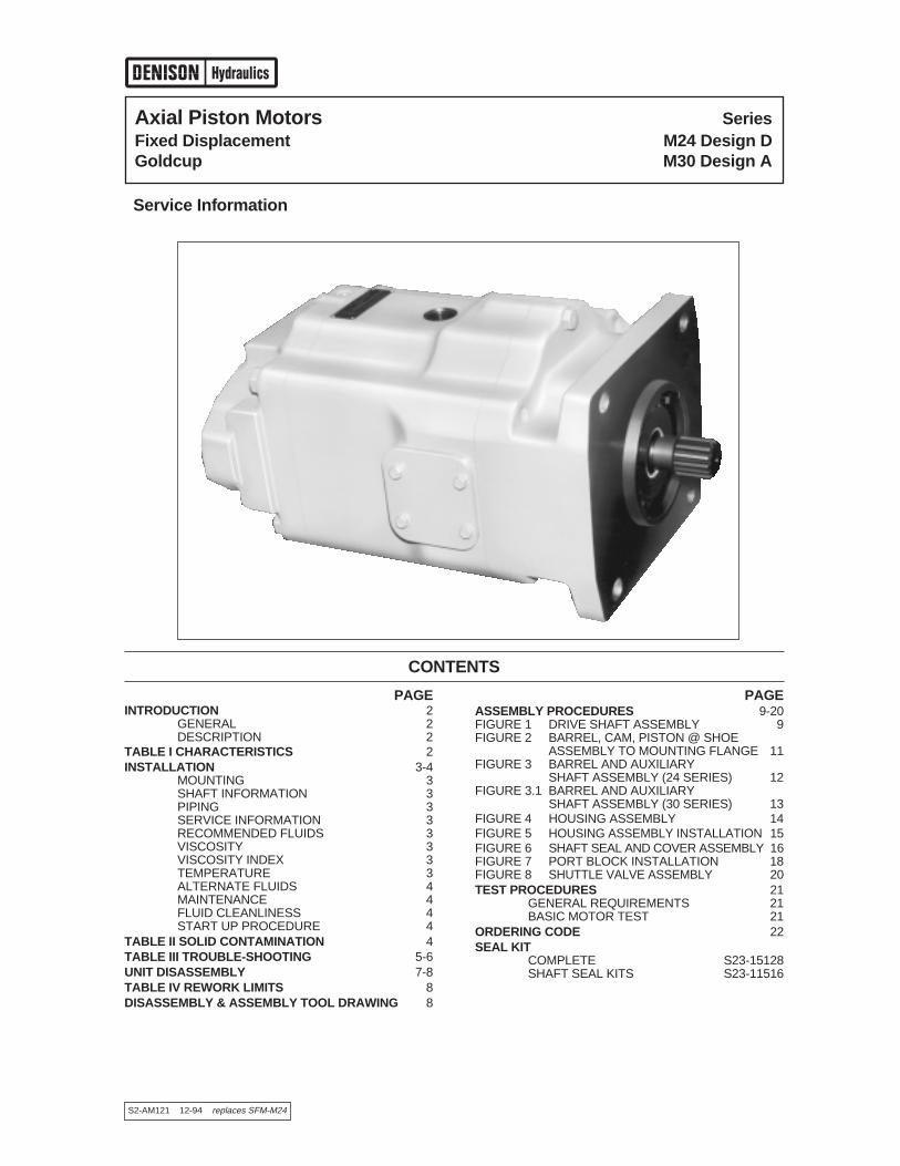
Axial Piston Motors SeriesFixed Displacement M24 Design DGoldcup M30 Design A
Service Information
S2-AM121 12-94 replaces SFM-M24
CONTENTS
PAGEINTRODUCTION 2
GENERAL 2DESCRIPTION 2
TABLE I CHARACTERISTICS 2INSTALLATION 3-4
MOUNTING 3SHAFT INFORMATION 3PIPING 3SERVICE INFORMATION 3RECOMMENDED FLUIDS 3VISCOSITY 3VISCOSITY INDEX 3TEMPERATURE 3ALTERNATE FLUIDS 4MAINTENANCE 4FLUID CLEANLINESS 4START UP PROCEDURE 4
TABLE II SOLID CONTAMINATION 4TABLE III TROUBLE-SHOOTING 5-6UNIT DISASSEMBLY 7-8TABLE IV REWORK LIMITS 8DISASSEMBLY & ASSEMBLY TOOL DRAWING 8
PAGEASSEMBLY PROCEDURES 9-20FIGURE 1 DRIVE SHAFT ASSEMBLY 9FIGURE 2 BARREL, CAM, PISTON @ SHOE
ASSEMBLY TO MOUNTING FLANGE 11FIGURE 3 BARREL AND AUXILIARY
SHAFT ASSEMBLY (24 SERIES) 12FIGURE 3.1 BARREL AND AUXILIARY
SHAFT ASSEMBLY (30 SERIES) 13FIGURE 4 HOUSING ASSEMBLY 14FIGURE 5 HOUSING ASSEMBLY INSTALLATION 15FIGURE 6 SHAFT SEAL AND COVER ASSEMBLY 16FIGURE 7 PORT BLOCK INSTALLATION 18FIGURE 8 SHUTTLE VALVE ASSEMBLY 20TEST PROCEDURES 21
GENERAL REQUIREMENTS 21BASIC MOTOR TEST 21
ORDERING CODE 22SEAL KIT
COMPLETE S23-15128SHAFT SEAL KITS S23-11516

Introduction Series 24, 30
General
This manual contains installation, operation, maintenanceand overhaul instructions for Denison Hydraulics Goldcup24 and Goldcup 30 constant volume motors. The DenisonHydraulics Goldcup 24 and Goldcup 30 axial piston motorsfeature advance design concepts which are time provenand provide for advance pumping and control concepts.The instructions contained in this manual cover completedisassembly and reassembly of the unit. Before proceed-ing with the disassembly or reassembly of any unit, thismanual should be studied in order to become familiar withproper order and parts nomenclature.
Description
The Goldcup motor is a fixed displacement, axial pistondesign which uses hydrostatically balanced piston shoes.This feature serves to lubricate as well as absorb muchof the force generated by the shoes pressing against thecam, thereby increasing service life of the unit. Rotationof the unit is bi-directional.
2
TABLE I TYPICAL CHARACTERISTICS
Specification Term Goldcup 24 Goldcup 30
Displacement in.3/rev 24.6 30.6cm3/rev (403) (501.4)
Pressure Ports A & B max. continuous psi 5000 5000bar (345) (345)
max. intermittent psi 5000 5000bar (345) (345)
Speed, max. continuous @ full stroke RPM 2100* 1800
Flow, Ports A or B GPM @ 2100 RPM 223.6 @ 1800 RPM 238(theoretical) L/min. (846) (901)
Rotary Inertia lb/in2 818 974kg/m2 (0.239) (0.285)
Torque, Theoretical in/lb 392 487per 100 PSI (6.9 bar) N•m (43) (55)
at 5000 PSI (345 bar) in/lb 19576 24351
N•m (2158) (2752)
Power, Theoretical @ 5000 PSI (345 bar) hp 31.1 38.64at 100 RPM kW (23.1) (28.8)
Power, Theoretical at 5000 PSI (345 bar) hp 621.3 695**
at Max. RPM kW (463.5) (518)**
Torque Efficiency approx. stalled % theoretical 81 81
running % theoretical 93 93
Mounting-4 bolt flange SAE F F
Shaft-Spline / Keyed SAE F F
Fluid Connection Ports A & B in 2 2SAE-4 bolt pad for 6000 psi split flange mm (50.8) (50.8)
(414 bar)
Weight lbs. 640 660kg. (290) (300)
*On R & O Oils (Rust and Oxidation Inhibitor)** @ 1800 RPM
3
Installation Series 24, 30
Mounting
This motor is designed to operate in any position. Themounting hub and four bolt mounting flange are in full con-formance with SAE standard. The motor shaft must be inalignment with the shaft of the driven load and should bechecked with a dial indicator. The mounting pad or adap-tor into which the fluid motor pilots must be concentric withthe motor shaft to prevent bearing failure. This concentric-ity is particularly important if the shaft is rigidly connectedto the driven load without a flexible coupling.
Shaft Information
Splined: The shafts will accept a maximum misalignmentof 0.006" TIR (.15 mm). Angular misalignment at the maleand female spline axes must be less than ±.002 (0.05mm) per one inch radius. The coupling interface must belubricated. Denison Hydraulics recommends lithiummolydisulfate or similar grease. The female couplingshould be hardened to 45-50 Rc and must conform toSAE-J498B (1971) Class 1 flat root side fit.
Keyed: High strength heat treated keys must be used.Replacement keys must be hardened to 27-34 Rc. The keycorners must be chamfered .030"-.040" (.75-1 mm) at 45°to clear radii that exist in the keyway.
Keyed types of shafts will accept a side load of 1000 lbs.(454 kg) at the center of the key, with a B10 life of 9,880hours at 1800 RPM or 11,856 hours at 1500 RPM.
Piping
Connect inlet and outlet lines to the port block of the motor.The fluid connections are:
System Ports: 2" (50.8 mm)6000 PSI (414 bar), SAE4 bolt flange
Other: SAE straight thread, O-ring seal.See installation drawing for sizes.
The maximum case pressure is 75 PSI (5.17 bar) contin-uous,125 PSI (8.6 bar) intermittent.
It is recommended that the case leakage line be connect-ed to the port located between the two system ports on theport block, but it may be connected to the top or bottomconnections on the motor housing.
The case leakage line must be of sufficient size to preventback pressure in excess of 75 PSI (5.7 bar) and returned
to the reservoir below the surface of the oil as far from thesupply suction as possible. All fluid lines, whether pipe, tub-ing, or hose must be adequate size to assure free flowthrough the motor. We recommend 20 ft (6.09 M) max. persecond for main flow and 6 ft. (1.8 M) max. limit per sec-ond for drain lines. Pressure rating of piping hose must beadequate for service duty required.
An undersized outline line will create back pressure andcause improper operation. Flexible hose lines are recom-mended. If rigid piping is used, the workmanship must beaccurate to eliminate strain on the port block or to the fluidconnections. Sharp bends in the lines must be eliminatedwherever possible. All system piping must be cleaned withsolvent or equivalent before installing motor. Make sure theentire hydraulic system is free of dirt, lint, scale, or otherforeign material. Flushing with a large temporary high pres-sure loop filter is recommended.
Service Information
These hydraulic products are designed to give longdependable service when properly applied and their sys-tems properly maintained. These general instructions applyto typical systems. Specific instructions for particular equip-ment can be developed from them.
Recommended Fluids
The fluid recommended for use in these pumps and motorshas a petroleum base and contains agents which provideoxidation inhibition and anti-rust, anti-foam and de-aerat-ing properties as described in Denison Hydraulics standardHF-1. Where anti-wear additive fluids are specified, seeDenison Hydraulics standard HF-0.
Viscosity:
Max. at cold start—7500 SUS (1600 Cst)(at low pressure, low speed)
Max. at full power—750 SUS (160 Cst)Optimum for max. life—140 SUS (30 Cst)Minimum at full power—60 SUS (10 Cst)
Viscosity Index:
90 V.I. minimum. Higher values extend the range of oper-ating temperature but may reduce the service life of thefluid.
Temperature
Determined by the viscosity characteristics of the fluidused. Because high temperatures degrade seals, reducethe service life of the fluid and create hazards, fluid tem-peratures should not exceed 180°F (82°C) at the casedrain.
CAUTION: Do not use galvanized pipe. Galvanizedcoating can flake off with continued use.
NOTE: High case pressure will result in reduced B-10 life of the shaft bearing.
NOTE: Do not impact coupling to force it onto theshaft.

Installation Continued Series 24, 30
Alternate Fluids
Some applications require fire-resistant fluids. They willgive good service if the system is originally designed fortheir use. Permissible fire resistant fluids include:
Type Denison Hydraulics StandardWater-in-oil invert emulsions HF-3Water glycol solutions HF-4Phosphate esters HF-5
Consult Denison Hydraulics for design requirements andwarranty limitations for service with this class of fluids.
See Denison Hydraulics bulletin SPO-AM305 for more infor-mation.
Maintenance
This motor is self-lubricating and preventative maintenanceis limited to keeping system fluid clean by changing filtersfrequently. Keep all fittings and screws tight. Do not oper-ate at pressures and speeds in excess of the recommendedlimit. If the motor does not operate properly, check theTrouble Shooting Chart before attempting to overhaul theunit. Overhauling is relatively simple and may be accom-plished by referring to the Disassembly, Rework Limits ofWear Parts and Assembly Procedures.
Fluid Cleanliness
Fluid must be cleaned before and continuously during oper-ation by filters that maintain a cleanliness level of NAS 1638Class 8. This approximately corresponds to ISO 17/14.This fluid level cleanliness can usually be accomplished bythe effective use of 10 micron filters. Better cleanliness lev-els will significantly extend the life of the components. Ascontaminant generation may vary with each application,each must be analyzed to determine proper filtration tomaintain the required cleanliness level.
Start Up Procedure for New Installation
1. Read and understand the instruction manual. Identifycomponents and their functions.
2. Check alignment of drive.
3. Visually inspect components and lines for possibledamage.
4. Check reservoir for cleanliness and clean as required.White glove test on all internal surfaces is recommended.
5. Check fluid level and fill as required with filtered fluid atleast as clean as that recommended. Fill motor case withclean oil prior to starting.
6. Check oil cooler and activate it, if included in circuit.Check fluid temperature.
7. Reduce pressure settings of pressure control. Makesure accurate pressure readings can be made at appro-priate places.
8. If solenoids in system, check for actuation.
9. Start pump drive first by jogging prime mover. Make surepump and motor fill properly.
10. Bleed system of air. Recheck fluid level.
11. Cycle unloaded machine at low pressure and observeactuation (at low speed, if possible).
12. Increase pressure settings gradually in steps. Checkfor leaks in all lines especially in pump and motor inlet lines.
13. Make correct pressure adjustments.
14. Gradually increase speed. Be alert for trouble as indi-cated by changes in sounds, system shocks and air in fluid.Inspect oil surface with a good light while in operation. Theremust be no surface broken with oil surges and limit surfaceair bubbles to occasional.
15. Equipment is operational.
4
TABLE IICOMPARISON OF SOLID CONTAMINATION CLASSIFICATION SYSTEMS
NATIONAL AEROSPACE STANDARD (NAS) 1638
5
Table III Trouble-shooting Chart Series 24, 30
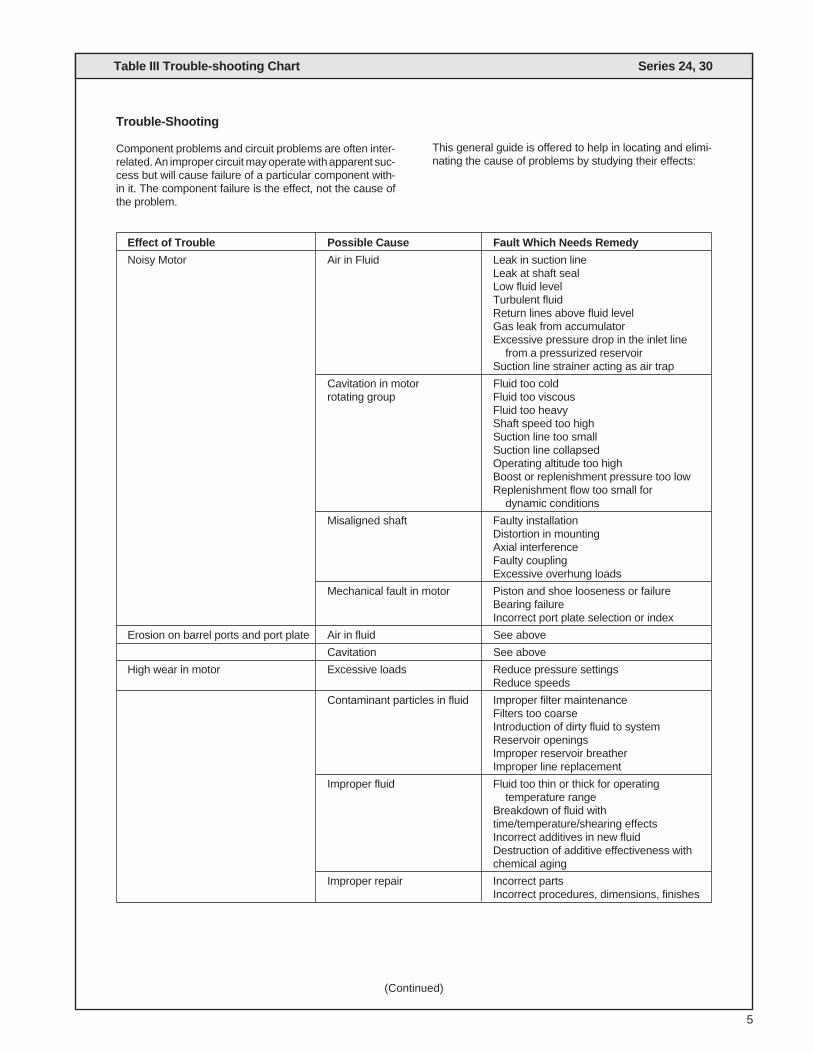
Trouble-Shooting
Component problems and circuit problems are often inter-related. An improper circuit may operate with apparent suc-cess but will cause failure of a particular component with-in it. The component failure is the effect, not the cause ofthe problem.
This general guide is offered to help in locating and elimi-nating the cause of problems by studying their effects:
Effect of Trouble Possible Cause Fault Which Needs Remedy
Noisy Motor Air in Fluid Leak in suction lineLeak at shaft sealLow fluid levelTurbulent fluidReturn lines above fluid levelGas leak from accumulatorExcessive pressure drop in the inlet line
from a pressurized reservoirSuction line strainer acting as air trap
Cavitation in motor Fluid too coldrotating group Fluid too viscous
Fluid too heavyShaft speed too highSuction line too smallSuction line collapsedOperating altitude too highBoost or replenishment pressure too lowReplenishment flow too small for
dynamic conditions
Misaligned shaft Faulty installationDistortion in mountingAxial interferenceFaulty couplingExcessive overhung loads
Mechanical fault in motor Piston and shoe looseness or failureBearing failureIncorrect port plate selection or index
Erosion on barrel ports and port plate Air in fluid See above
Cavitation See above
High wear in motor Excessive loads Reduce pressure settingsReduce speeds
Contaminant particles in fluid Improper filter maintenanceFilters too coarseIntroduction of dirty fluid to systemReservoir openingsImproper reservoir breatherImproper line replacement
Improper fluid Fluid too thin or thick for operatingtemperature range
Breakdown of fluid withtime/temperature/shearing effectsIncorrect additives in new fluidDestruction of additive effectiveness withchemical aging
Improper repair Incorrect partsIncorrect procedures, dimensions, finishes
(Continued)

Table III Continued Series 24, 30
6
Effect of Trouble Possible Cause Fault Which Needs Remedy
High Wear in motor Unwanted water in fluid CondensationFaulty breather/strainerHeat exchanger leakageFaulty clean-up, practiceWater in makeup fluid
Pressure shocks Cogging load Mechanical considerationsWorn relief valve Needed repairs
Worn compensator Needed repairsSlow response in check valves Replace or relocate
Excessive decompression Improve decompression controlenergy rates
Excessive line capacitance Reduce line size or lengths.(line volume, line stretch, Eliminate hoseaccumulator effects)
Barrel blow-off Recheck hold-down, rotating group,drain pressure
Heating of fluid Excessive motor leakage Recheck case drain flow and repair asrequired
Fluid too thinImproper assembly, port timing
Relief valve Set too low (compared to load or to compen-sator)Instability caused by back pressure,
worn parts
Heat exchanger Water turned off or too little flowWater too hotFan clogged or restrictedEfficiency reduced by mud or scale depositsIntermittent hydraulic fluid flow
Reservoir Too little fluidEntrained air in fluidImproper bafflesInsulating air blanket that prevents
heat rejectionHeat pickup from adjacent equipment
7
Unit Disassembly Series 24, 30
Disassembly
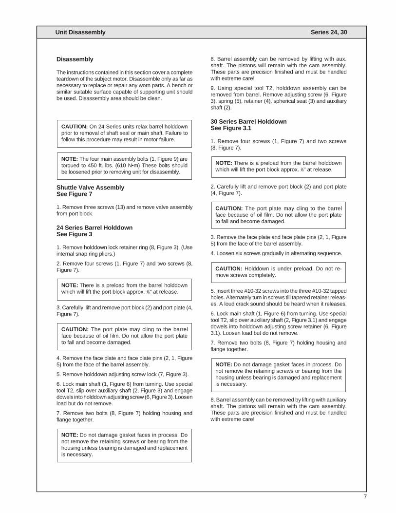
The instructions contained in this section cover a completeteardown of the subject motor. Disassemble only as far asnecessary to replace or repair any worn parts. A bench orsimilar suitable surface capable of supporting unit shouldbe used. Disassembly area should be clean.
Shuttle Valve AssemblySee Figure 7
1. Remove three screws (13) and remove valve assemblyfrom port block.
24 Series Barrel HolddownSee Figure 3
1. Remove holddown lock retainer ring (8, Figure 3). (Useinternal snap ring pliers.)
2. Remove four screws (1, Figure 7) and two screws (8,Figure 7).
3. Carefully lift and remove port block (2) and port plate (4,Figure 7).
4. Remove the face plate and face plate pins (2, 1, Figure5) from the face of the barrel assembly.
5. Remove holddown adjusting screw lock (7, Figure 3).
6. Lock main shaft (1, Figure 6) from turning. Use specialtool T2, slip over auxiliary shaft (2, Figure 3) and engagedowels into holddown adjusting screw (6, Figure 3). Loosenload but do not remove.
7. Remove two bolts (8, Figure 7) holding housing andflange together.
8. Barrel assembly can be removed by lifting with aux.shaft. The pistons will remain with the cam assembly.These parts are precision finished and must be handledwith extreme care!
9. Using special tool T2, holddown assembly can beremoved from barrel. Remove adjusting screw (6, Figure3), spring (5), retainer (4), spherical seat (3) and auxiliaryshaft (2).
30 Series Barrel HolddownSee Figure 3.1
1. Remove four screws (1, Figure 7) and two screws (8, Figure 7).
2. Carefully lift and remove port block (2) and port plate(4, Figure 7).
3. Remove the face plate and face plate pins (2, 1, Figure5) from the face of the barrel assembly.
4. Loosen six screws gradually in alternating sequence.
5. Insert three #10-32 screws into the three #10-32 tappedholes. Alternately turn in screws till tapered retainer releas-es. A loud crack sound should be heard when it releases.
6. Lock main shaft (1, Figure 6) from turning. Use specialtool T2, slip over auxiliary shaft (2, Figure 3.1) and engagedowels into holddown adjusting screw retainer (6, Figure3.1). Loosen load but do not remove.
7. Remove two bolts (8, Figure 7) holding housing andflange together.
8. Barrel assembly can be removed by lifting with auxiliaryshaft. The pistons will remain with the cam assembly.These parts are precision finished and must be handledwith extreme care!
NOTE: Do not damage gasket faces in process. Donot remove the retaining screws or bearing from thehousing unless bearing is damaged and replacementis necessary.
CAUTION: Holddown is under preload. Do not re-move screws completely.
CAUTION: The port plate may cling to the barrelface because of oil film. Do not allow the port plateto fall and become damaged.
NOTE: There is a preload from the barrel holddownwhich will lift the port block approx. 1⁄8" at release.
NOTE: Do not damage gasket faces in process. Donot remove the retaining screws or bearing from thehousing unless bearing is damaged and replacementis necessary.
CAUTION: The port plate may cling to the barrelface because of oil film. Do not allow the port plateto fall and become damaged.
NOTE: There is a preload from the barrel holddownwhich will lift the port block approx. 1⁄8" at release.
NOTE: The four main assembly bolts (1, Figure 9) aretorqued to 450 ft. lbs. (610 N•m) These bolts shouldbe loosened prior to removing unit for disassembly.
CAUTION: On 24 Series units relax barrel holddownprior to removal of shaft seal or main shaft. Failure tofollow this procedure may result in motor failure.
Drive ShaftSee Figure 6
1. Remove four screws (5), seal retainer (2), gaskets (4),and stationary part of shaft seal assembly (4). Refer toview of item 3.
2. Remove the carbon ring and the remainder of the shaftseal from the shaft.
3. Remove shaft and bearing assembly (1).
Cam and Piston/Shoe Assembly
1. Remove the retaining ring (2, figure 2), thrust washer(3), piston and shoe assembly (4) and creep plate (5) fromthe cam (6).
2. Remove the cam from the mounting flange by carefullytilting mounting flange on its side and removing plugs (12,Figure 2) with O-rings (9, Figure 2) using 1⁄4-20 threadedrod as a puller, and removing screws (10, Figure 2) attach-ing cradle to mounting flange.
Unit Disassembly Continued Series 24, 30
8
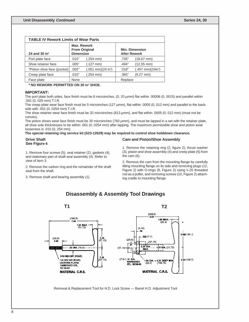
TABLE IV Rework Limits of Wear Parts
Max. ReworkFrom Original Min. Dimension
24 and 30 in3 Dimension After Rework
Port plate face .010" (.254 mm) .735" (18.67 mm)
Shoe retainer face .005" (.127 mm) .494" (12.55 mm)
*Piston shoe face (pocket) .002" (.051 mm)(24 in3) .018" (.457 mm)(24in3)
Creep plate face .010" (.254 mm) .365" (9.27 mm)
Face plate None Replace
* NO REWORK PERMITTED ON 30 in3 SHOE.
IMPORTANT:The port plate both sides, face finish must be 8 microinches, (0, 20 µmm) flat within .00006 (0, 0015) and parallel within.001 (0, 025 mm) T.I.R.The creep plate wear face finish must be 5 microinches (127 µmm), flat within .0005 (0, 012 mm) and parallel to the back-side with .001 (0, 0254 mm) T.I.R.The shoe retainer wear face finish must be 32 microinches (813 µmm), and flat within .0005 (0, 012 mm) (must not beconvex).The piston shoes wear face finish must be 30 microinches (760 µmm), and must be lapped in a set with the retainer plate,all shoe sole thicknesses to be within .001 (0, 0254 mm) after lapping. The maximum permissible shoe and piston axiallooseness is .010 (0, 254 mm).The special retaining ring service kit (S23-12629) may be required to control shoe holddown clearance.
Removal & Replacement Tool for H.D. Lock Screw — Barrel H.D. Adjustment Tool
Disassembly & Assembly Tool Drawings
T1 T2

Drive Shaft AssemblyFigure 1
1. Slide the bearing (2) over the short end of the shaft andseat against the shoulder. Support only the inner race ofthe bearing and press on the long end of the shaft to installbearing.
DO NOT USE EXCESSIVE FORCE. USE EXTREMECARE PASSING THE RING OVER THE SEAL SURFACE.
2. Install the retaining ring (3) in the groove. Be sure thatthe ring is fully seated.
9
Assembly Procedures Series 24, 30
S23-12474 #3 Drive Shaft Assembly (spline)S23-12475 #2 Drive Shaft Assembly (w/keyway)
QTYITEM DESCRIPTION PART NO. #1 #2
1 #3 (splined) Drive shaft 033-91139 1 —
#2 (keyed) Drive shaft 033-91140 — 1
2 Shaft bearing 230-82213 1 1
3 Retaining ring 033-71712 1 1
4 Square key 033-71910 — 1
FIGURE 1
Barrel, Cam to Mounting FlangeFigure 2
3. Position the mounting flange (8) with the large open endfacing up and install two dowel pins (7) in the cradle mount-ing surface and one-3/8" (9.52 mm) dia. dowel pin (11) inthe outer edge of the flange.
4. Install the cam (6) over the dowel pins (7) in the mount-ing flange. Position cam so that the thick part of the cam ison the same side as the 3/8" (9.52 mm) dowel (11).
5. With cam installed, tilt mounting flange on its side andsecure with two Soc. Hd. cap screws (10). Torque to 50 ft.-lbs. (67.8 N•m).
6. Insert plugs (12) with o-rings (9) into Soc. Hd. cap screw(9) c'bores. Be sure tapped hole in plug (12) is visible afterinstallation, this is used for removal.
7 Install shaft and bearing assembly (1) Figure 6 (eithersplined or keyed as specified) by inserting shaft throughbores, a few light taps are required on the bearing outerrace to completely engage and seat bearing.
NOTE: Do not tap on end of shaft.
Seal AssemblyFigure 6
NOTE: See warning information below
1. The shaft seal is available only as a complete assem-bly. Prior to installation examine all the seal parts. Handlethe lapped seal seat and the carbon ring with extreme care.Both parts must be free of scratches, cracks or other dam-age.
2. Install the spring retainer (e) over the shaft and againstthe bearing retaining ring.
3. Install the spring (d) against the retainer.
4. Apply oil to the inner surface of the rubber friction ring(f) and install the shell containing the friction and the car-bon ring (c) over the shaft with the carbon ring exposed.
5. Apply grease to the square section rubber seal (a) andinstall on the seat.
6. Install the seat and seal in the seal retainer (2). Thelapped surface of the seat must face the carbon ring.
7. Install the seal retainer assembly and O-ring (4) over theshaft with the lapped surface against the carbon face.
8. Install the screws (5) and the seal retainer.
9. Depress the seal retainer only far enough to start thescrews and tighten evenly in a criss-cross pattern. Torqueto 30 ft.-lbs. (40.8 N•m).
Seal ReplacementFigure 6
NOTE: 24 Series only–To replace shaft seal only.
1. Remove unit for disassembly.
2. Remove retaining ring (8, Fig. 3).
3. Replace shaft seal. (Follow seal assembly in reverseorder.)
4. After seal is replaced re-install retaining ring (8, Fig. 3).
CAUTION Failure to follow these instructions may result in pump failure.
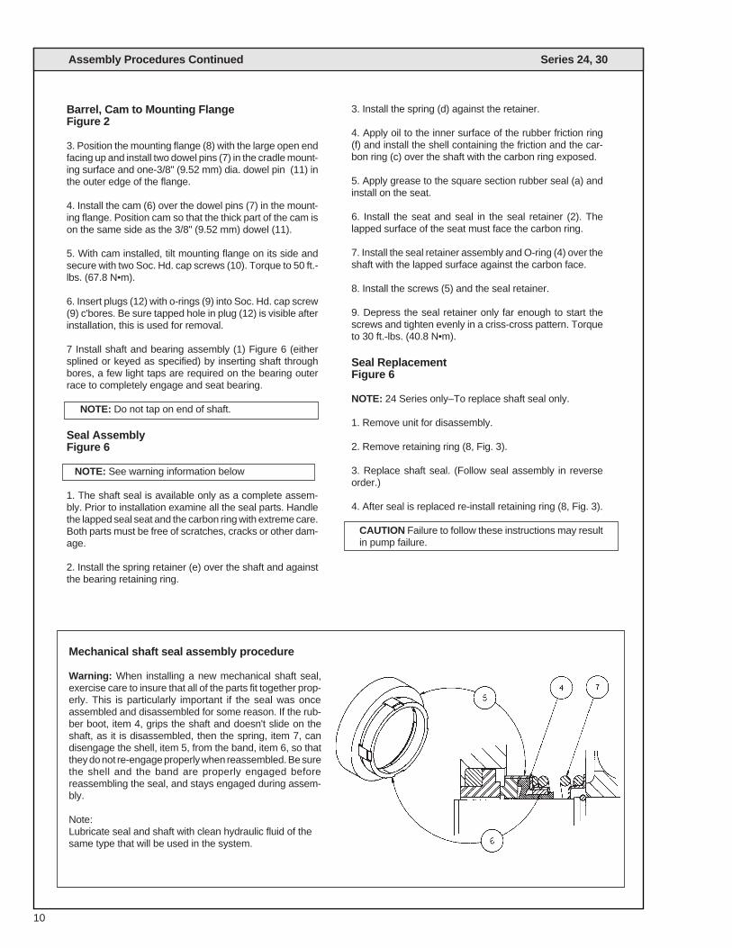
Mechanical shaft seal assembly procedure
Warning: When installing a new mechanical shaft seal,exercise care to insure that all of the parts fit together prop-erly. This is particularly important if the seal was onceassembled and disassembled for some reason. If the rub-ber boot, item 4, grips the shaft and doesn't slide on theshaft, as it is disassembled, then the spring, item 7, candisengage the shell, item 5, from the band, item 6, so thatthey do not re-engage properly when reassembled. Be surethe shell and the band are properly engaged beforereassembling the seal, and stays engaged during assem-bly.
Note:Lubricate seal and shaft with clean hydraulic fluid of thesame type that will be used in the system.
Assembly Procedures Continued Series 24, 30
10
11
Assembly Procedures Continued Series 24, 30
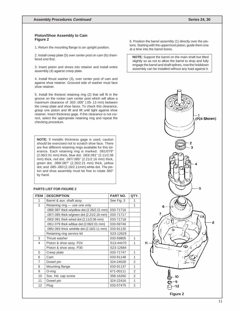
Piston/Shoe Assembly to CamFigure 2
1. Return the mounting flange to an upright position.
2. Install creep plate (5) over center post on cam (6) cham-fered end first.
3. Insert piston and shoes into retainer and install entireassembly (4) against creep plate.
4. Install thrust washer (3), over center post of cam andagainst shoe retainer. Grooved side of washer must faceshoe retainer.
5. Install the thickest retaining ring (2) that will fit in thegroove on the rocker cam center post which will allow amaximum clearance of .002-.005" (.05-.13 mm) betweenthe creep plate and shoe faces. To check this clearance,grasp one piston and lift and lift until tight against shoeretainer. Insert thickness gage. If this clearance is not cor-rect, select the appropriate retaining ring and repeat thechecking procedure.
PARTS LIST FOR FIGURE 2
ITEM DESCRIPTION PART NO. QTY.1 Barrel & aux. shaft assy. See Fig. 3 12 Retaining ring — use one only 1
.089/.087 thick w/yellow dot (2.26/2.21 mm) 033-71716
.087/.085 thick w/green dot (2.21/2.16 mm) 033-71717
.083/.081 thick w/red dot (2.11/2.06 mm) 033-71718
.081/.079 thick w/blue dot (2.06/2.01 mm) 033-59746
.085/.083 thick w/white dot (2.16/2.11 mm) 033-91130Retaining ring service kit S23-12629
3 Thrust washer 033-59805 14 Piston & shoe assy. P24 S13-44470 1
Piston & shoe assy. P30 S23-126845 Creep plate 033-71747 16 Cam 033-91148 17 Dowel pin 324-24028 28 Mounting flange 033-91137 19 O-ring 671-00111 210 Soc. Hd. cap screw 358-16260 211 Dowel pin 324-22416 112 Plug 033-57475 2
NOTE: If metallic thickness gage is used, cautionshould be exercised not to scratch shoe face. Thereare five different retaining rings available for this tol-erance. Each retaining ring is marked: .081/079"(2.06/2.01 mm) thick, blue dot; .083/.081" (2.11/2.06mm) thick, red dot; .087/.085" (2.21/2.16 mm) thick,green dot; .089/.087" (2.26/2.21 mm) thick, yellowdot; and .085-.083 (2.16/2.11mm) white dot. The pis-ton and shoe assembly must be free to rotate 360°by hand.
Figure 2
6. Position the barrel assembly (1) directly over the pis-tons. Starting with the uppermost piston, guide them oneat a time into the barrel bores.
NOTE: Support the barrel on the main shaft but tiltedslightly so as not to allow the barrel to drop and fullyengage the barrel and shaft splines, now the holddownassembly can be installed without any load against it.
Assembly Procedures Continued Series 24, 30
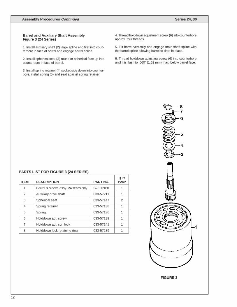
Barrel and Auxiliary Shaft AssemblyFigure 3 (24 Series)
1. Install auxiliary shaft (2) large spline end first into coun-terbore in face of barrel and engage barrel spline.
2. Install spherical seat (3) round or spherical face up intocounterbore in face of barrel.
3. Install spring retainer (4) socket side down into counter-bore, install spring (5) and seat against spring retainer.
4. Thread holddown adjustment screw (6) into counterboreapprox. four threads.
5. Tilt barrel vertically and engage main shaft spline withthe barrel spline allowing barrel to drop in place.
6. Thread holddown adjusting screw (6) into counterboreuntil it is flush to .060" (1.52 mm) max. below barrel face.
12
PARTS LIST FOR FIGURE 3 (24 SERIES)
QTYITEM DESCRIPTION PART NO. P24P
1 Barrel & sleeve assy. 24 series only S23-12091 1
2 Auxiliary drive shaft 033-57211 1
3 Spherical seat 033-57147 2
4 Spring retainer 033-57138 1
5 Spring 033-57136 1
6 Holddown adj. screw 033-57139 1
7 Holddown adj. scr. lock 033-57241 1
8 Holddown lock retaining ring 033-57239 1
FIGURE 3
13
Assembly Procedures Continued Series 24, 30
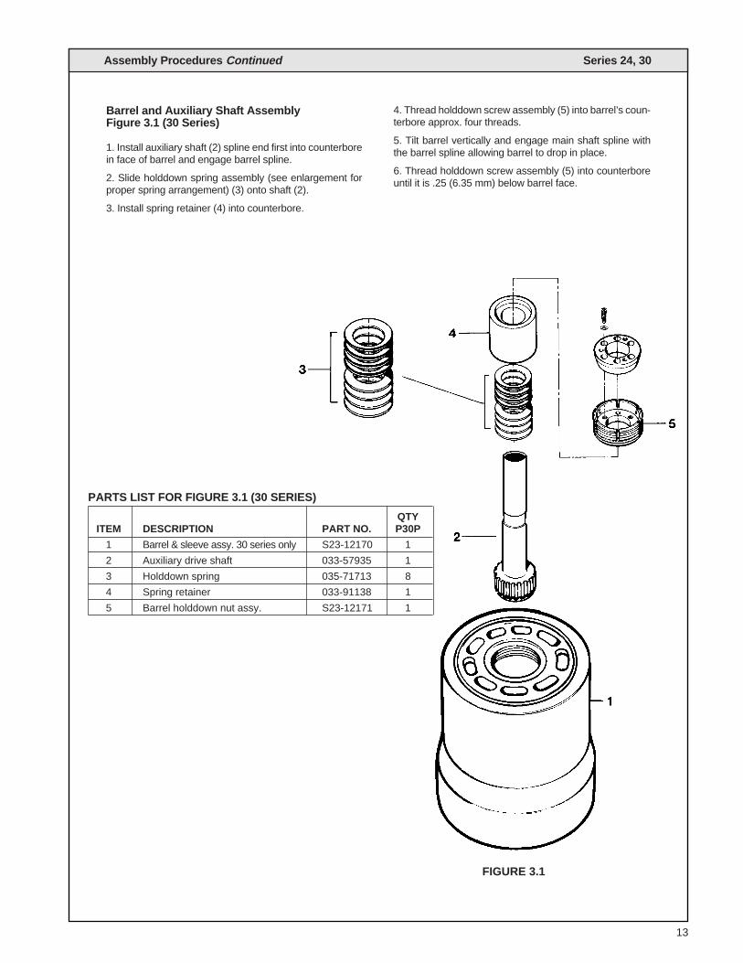
Barrel and Auxiliary Shaft AssemblyFigure 3.1 (30 Series)
1. Install auxiliary shaft (2) spline end first into counterborein face of barrel and engage barrel spline.
2. Slide holddown spring assembly (see enlargement forproper spring arrangement) (3) onto shaft (2).
3. Install spring retainer (4) into counterbore.
4. Thread holddown screw assembly (5) into barrel’s coun-terbore approx. four threads.
5. Tilt barrel vertically and engage main shaft spline withthe barrel spline allowing barrel to drop in place.
6. Thread holddown screw assembly (5) into counterboreuntil it is .25 (6.35 mm) below barrel face.
PARTS LIST FOR FIGURE 3.1 (30 SERIES)
QTYITEM DESCRIPTION PART NO. P30P
1 Barrel & sleeve assy. 30 series only S23-12170 1
2 Auxiliary drive shaft 033-57935 1
3 Holddown spring 035-71713 8
4 Spring retainer 033-91138 1
5 Barrel holddown nut assy. S23-12171 1
FIGURE 3.1

Assembly Procedures Continued Series 24, 30
S23-12566 (P24) P23-12175 (P30)Housing AssemblyFigure 4
1. Clean housing (1) and position on a flat surface with thelarge open end up.
2. Apply Loctite primer grade “T” & Loctite retaining com-pound #609 per A.P. 01433 to bearing O.D. & bearing boreof housing. Immediately align & press bearing into hous-ing bore with a smooth steady force until seated. Installsocket head cap screw (3) with washer (7). Typical twoplaces. Torque to 30 ft. lbs. (40.8 N•m).
3. Install two dowel pins (4) in the blind holes in the controlcover pads.
4. Repeat step 3 on the opposite side of the housing.
5. Install O-ring (5) and plug (6) in the bottom of housing.
14
PARTS LIST FOR FIGURE 4
ITEM DESCRIPTION PART NO. QTY.
1 Housing (P24) 033-57150 1
Housing (P30) 033-57925 1
2 Bearing 033-91150 1
3 Screw Soc Head Cap 358-14106 25⁄16 x 18 x 5⁄8 w/Nylock
4 Dowel pin 324-21608 4
5 O-ring 691-00920 1
6 Plug 488-35019 1
7 Washer 11⁄32 (8.73 mm) 345-10020 2steel
FIGURE 4
15
Assembly Procedures Continued Series 24, 30
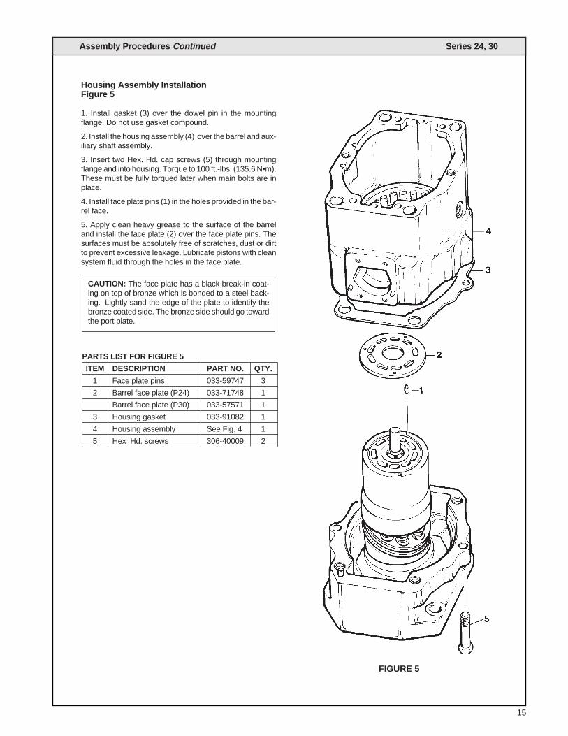
Housing Assembly InstallationFigure 5
1. Install gasket (3) over the dowel pin in the mountingflange. Do not use gasket compound.
2. Install the housing assembly (4) over the barrel and aux-iliary shaft assembly.
3. Insert two Hex. Hd. cap screws (5) through mountingflange and into housing. Torque to 100 ft.-lbs. (135.6 N•m).These must be fully torqued later when main bolts are inplace.
4. Install face plate pins (1) in the holes provided in the bar-rel face.
5. Apply clean heavy grease to the surface of the barreland install the face plate (2) over the face plate pins. Thesurfaces must be absolutely free of scratches, dust or dirtto prevent excessive leakage. Lubricate pistons with cleansystem fluid through the holes in the face plate.
CAUTION: The face plate has a black break-in coat-ing on top of bronze which is bonded to a steel back-ing. Lightly sand the edge of the plate to identify thebronze coated side. The bronze side should go towardthe port plate.
PARTS LIST FOR FIGURE 5
ITEM DESCRIPTION PART NO. QTY.
1 Face plate pins 033-59747 3
2 Barrel face plate (P24) 033-71748 1
Barrel face plate (P30) 033-57571 1
3 Housing gasket 033-91082 1
4 Housing assembly See Fig. 4 1
5 Hex Hd. screws 306-40009 2
FIGURE 5

Assem
bly P
roced
ures C
ontinuedS
eries 24, 30
16
FIGURE 6
PARTS LIST FOR FIGURE 6
ITEM DESCRIPTION PART NO. QTY.
1 No. 3 Splined shaft assy. S23-12474 1(See fig. 1)
No. 2 Keyed shaft assy. S23-12475(See fig. 1)
2 Seal retainer 033-57472
3 Shaft seal 623-00015 1
4 Seal retainer O-ring 671-00246 1
5 Hex. head screw 306-40123 4
6 Nyltite washer 631-45007 8
7 Hex. hd. washer screw 353-25039 8
8 Cover 033-53252 2
9 Gasket 033-91058 2
17
Assembly Procedures Continued Series 24, 30
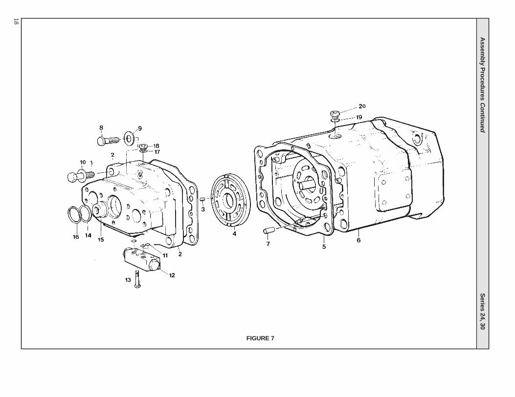
Port Block InstallationFigure 7
1. Position the motor with open end of the housing assem-bly (6) facing up. Install new gasket (5) on the housing. Donot use gasket compound.
2. Install two port plate pins (3) in the face of the port block(2) and the dowel pins (7) into mounting surface of portblock.
3. Insert lifting eyes into tapped holes in each system portmounting surface.
4. Apply heavy grease to the rear of the port plate (4) andinstall over the port plate pins.
5. Temporarily attach port plate to port block by insertinga cord through one of the 2" (50.8 mm) dia. ports downthrough the port block port, around arcuate divider in portplate, back through port block and tie ends of the cord tolifting eye. Repeat this step to the other side of the portplate.
6. Install the port block over the auxiliary shaft and posi-tion onto dowel pins.
7. Install the six bolts (1 & 8) with washers (9, 10). Do notdrop the bolts in place as the threads may be damaged.Torque bolts evenly. Torque bolts (1) in 50 lb. (67.8 N•m)increments to 450 ft.-lbs. (610 N•m) and the two bolts (8)to 120 ft.-lbs. (163 N•m) tightening in turn all six bolts. Re-torque the two bolts (5) Fig. 5 to 120 ft.-lbs (163 N•m).
PARTS LIST FOR FIGURE 7
ITEM DESCRIPTION PART NO. QTY.
1 Hex head cap screw (P24P) 306-40221 4
Hex head cap screw (P30P) 306-40230 4
2 Port block 033-57898 1
3 Port plate pins 324-21610 2
4 Port plate (24) 033-71751 1
Port plate (30) 033-91149 1
5 Port block gasket 033-91085 1
6 Housing assembly (24) S23-12566 1
Housing assembly (30) S23-12175 1
7 Dowel pin 033-57020 2
8 Hex head cap screw 306-40022 2
9 Washer, Hdn. St’l. 350-10136 2
10 Washer, Hdn. St’l. 350-10135 4
11 Seal/shuttle valve 691-10016 3
Seal/cover 691-10014 2
Seal/cover 691-10019 1
12 Shuttle valve/2 orif. S13-48776 1
Shuttle valve/Int. dr. S13-48273
Cover 033-71649
13 Screw-hex hd./shuttle 306-48273 3
Screw-hex hd./cover 306-40071
14 O-ring 671-00147 1
15 End cover 033-72100 1
16 Retaining ring 356-65082 1
17 O-ring 691-00906 1
18 Hex. soc. plug 488-35041 1
19 O-ring 691-00920 1
20 Plug 488-35019 1
Assem
bly P
roced
ures C
ontinuedS
eries 24, 30
18
FIGURE 7
19
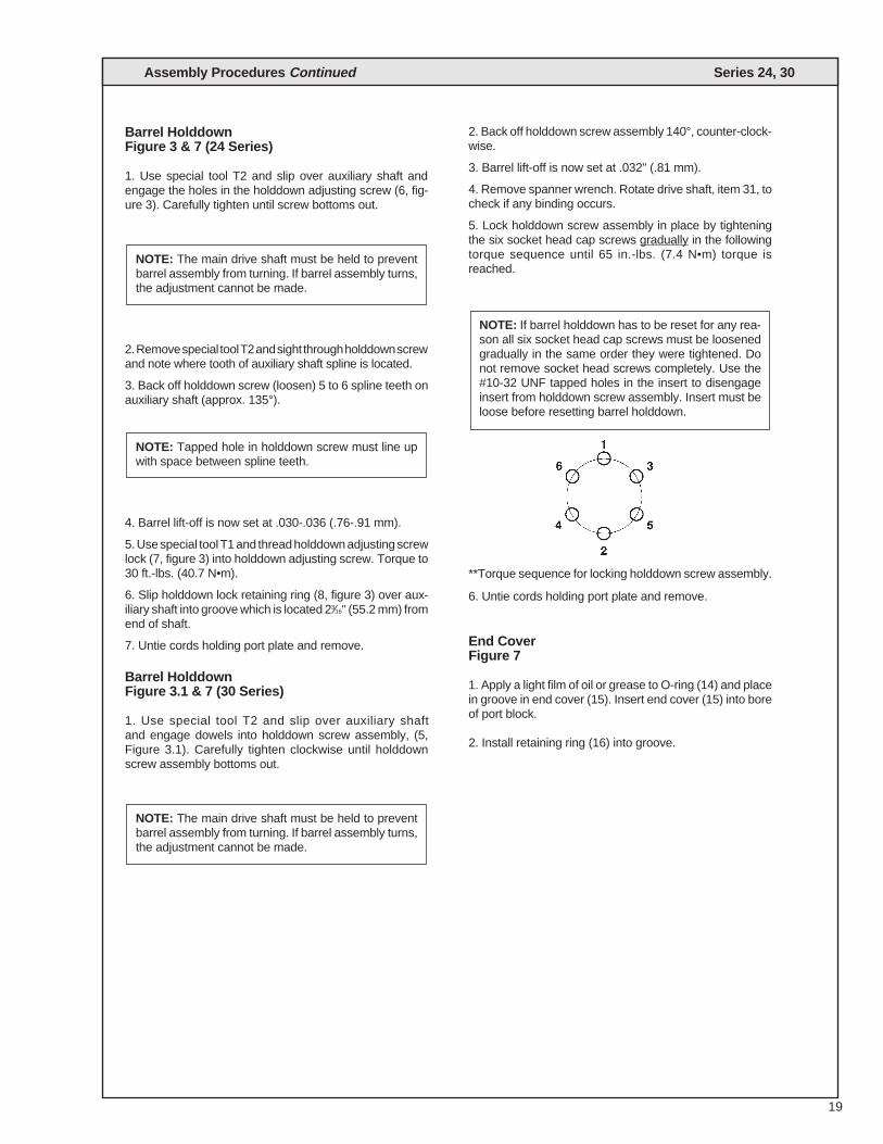
Barrel Holddown Figure 3 & 7 (24 Series)
1. Use special tool T2 and slip over auxiliary shaft andengage the holes in the holddown adjusting screw (6, fig-ure 3). Carefully tighten until screw bottoms out.
2. Remove special tool T2 and sight through holddown screwand note where tooth of auxiliary shaft spline is located.
3. Back off holddown screw (loosen) 5 to 6 spline teeth onauxiliary shaft (approx. 135°).
4. Barrel lift-off is now set at .030-.036 (.76-.91 mm).
5. Use special tool T1 and thread holddown adjusting screwlock (7, figure 3) into holddown adjusting screw. Torque to30 ft.-lbs. (40.7 N•m).
6. Slip holddown lock retaining ring (8, figure 3) over aux-iliary shaft into groove which is located 23⁄16" (55.2 mm) fromend of shaft.
7. Untie cords holding port plate and remove.
Barrel HolddownFigure 3.1 & 7 (30 Series)
1. Use special tool T2 and slip over auxiliary shaft and engage dowels into holddown screw assembly, (5,Figure 3.1). Carefully tighten clockwise until holddownscrew assembly bottoms out.
2. Back off holddown screw assembly 140°, counter-clock-wise.
3. Barrel lift-off is now set at .032" (.81 mm).
4. Remove spanner wrench. Rotate drive shaft, item 31, tocheck if any binding occurs.
5. Lock holddown screw assembly in place by tighteningthe six socket head cap screws gradually in the followingtorque sequence until 65 in.-lbs. (7.4 N•m) torque isreached.
**Torque sequence for locking holddown screw assembly.
6. Untie cords holding port plate and remove.
End CoverFigure 7
1. Apply a light film of oil or grease to O-ring (14) and placein groove in end cover (15). Insert end cover (15) into boreof port block.
2. Install retaining ring (16) into groove.
NOTE: If barrel holddown has to be reset for any rea-son all six socket head cap screws must be loosenedgradually in the same order they were tightened. Donot remove socket head screws completely. Use the#10-32 UNF tapped holes in the insert to disengageinsert from holddown screw assembly. Insert must beloose before resetting barrel holddown.
NOTE: The main drive shaft must be held to preventbarrel assembly from turning. If barrel assembly turns,the adjustment cannot be made.
NOTE: Tapped hole in holddown screw must line upwith space between spline teeth.
NOTE: The main drive shaft must be held to preventbarrel assembly from turning. If barrel assembly turns,the adjustment cannot be made.
Assembly Procedures Continued Series 24, 30

Shuttle Valve Assembly Series 24, 30
20
Shuttle Valve Assembly Internal Drain
1. Place valve assembly (12, fig. 7) in a horizontal positionwith the O-ring groove up.
2. Press seat (11) in the .500" (12.7 mm) diameter boreuntil it is flush with the body surface.
3. Install spring centering washer (4) over each end ofspool.
5. Install springs (3) over ends of spool and into sockets ofcentering washers.
6. Lubricate O-rings (2) and install over plugs (1). Installthe plugs over springs and into body.
7. Install spool (10) in bore against seat (11).
8. Install spring (9) in spool (10).
9. Lubricate O-ring (8) and install on groove of plug (7) oninternally drained shuttle.
10. Install plug (7) over spring (9) and tighten.
11. Install seal (11, fig. 7) in counterbore in center of shut-tle valve assembly. Hold in place with a coating of grease.Install the two seals in remaining counterbores.
12. Install orifices, (15) if required.
13. Install the shuttle valve assembly on port block pad andsecure with screws (13). Torque screws to 20 ft.-lbs. (27.2N•m)
FIGURE 8
S13-48273 Assembly, Shuttle Valve without orificesS13-48776 Assembly, Shuttle Valve with orifices
Item Qty. Part No. Description1 2 488-35002 Plug2 2 691-00908 O-ring3 2 033-70515 Spring4 2 033-70495 Washer, spring centered5 1 033-70529 Spool6 1 033-53117 Body7 1 033-72129 Plug8 1 691-00906 O-ring
Item Qty. Part No. Description9 1 033-71923 Spring, relief valve10 1 033-71925 Spool, relief valve11 1 033-53154 Seat12 3 691-10016 Tetraseal13 3 306-48273 Screws, 5/16-18 x 2 3/414 2 345-20004 Shim washer15 2 033-53523 Orifice .78 (mm) (optional)
21
Test Procedures Series 24, 30
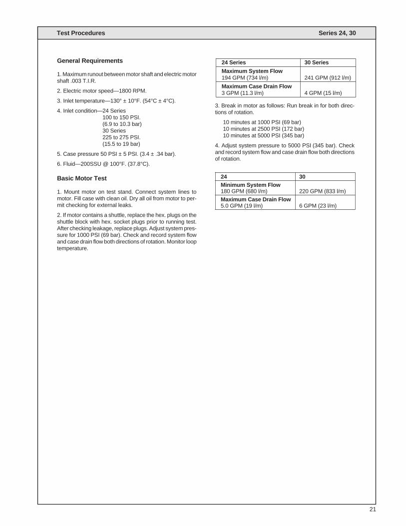
General Requirements
1. Maximum runout between motor shaft and electric motorshaft .003 T.I.R.
2. Electric motor speed—1800 RPM.
3. Inlet temperature—130° ± 10°F. (54°C ± 4°C).
4. Inlet condition—24 Series100 to 150 PSI.(6.9 to 10.3 bar)30 Series225 to 275 PSI.(15.5 to 19 bar)
5. Case pressure 50 PSI ± 5 PSI. (3.4 ± .34 bar).
6. Fluid—200SSU @ 100°F. (37.8°C).
Basic Motor Test
1. Mount motor on test stand. Connect system lines tomotor. Fill case with clean oil. Dry all oil from motor to per-mit checking for external leaks.
2. If motor contains a shuttle, replace the hex. plugs on theshuttle block with hex. socket plugs prior to running test.After checking leakage, replace plugs. Adjust system pres-sure for 1000 PSI (69 bar). Check and record system flowand case drain flow both directions of rotation. Monitor looptemperature.
3. Break in motor as follows: Run break in for both direc-tions of rotation.
10 minutes at 1000 PSI (69 bar)10 minutes at 2500 PSI (172 bar)10 minutes at 5000 PSI (345 bar)
4. Adjust system pressure to 5000 PSI (345 bar). Checkand record system flow and case drain flow both directionsof rotation.
24 Series 30 Series
Maximum System Flow194 GPM (734 l/m) 241 GPM (912 l/m)
Maximum Case Drain Flow3 GPM (11.3 l/m) 4 GPM (15 l/m)
24 30Minimum System Flow180 GPM (680 l/m) 220 GPM (833 l/m)
Maximum Case Drain Flow5.0 GPM (19 l/m) 6 GPM (23 l/m)

Notes Series 24, 30
22

23
Series 24, 30Ordering Code Series 24, 30
M 24 G - 2 N 1 D - 00- M 2 - X X X X X
Motor series
Displacements, max24-24.6 in3/rev., 403 cc/rev.30-30.6 in3/rev., 501.4 cc/rev.
F-Fixed w/o shuttleG-Fixed displ. w/ shuttle
ShaftSAE-F2-Keyed3-Splined
Shaft rotation(viewed from shaft end)N-Bi-directional
Fluid class1-compatible w/Buna N4-compatible w/EPR5-compatible w/Viton
Design letter(assigned by manufacturer)
Designates special
Shuttle FeaturesM * G00-Without orifices
02-With orifices
SALES & SERVICE WORLDWIDE
Related Documents