Champion Check Valves Size Range 1/2” - 54” ASME Class 150 - 2500 Materials: Carbon Steel Stainless Steel Duplex Stainless Steel Metal Alloys Axial Flow Nozzle Check Valves Model NZ & NZS Quality Products, Service & Reliability teel Stainless Steel Duplex Stainless Steel nless Steel Duplex Stainless Ste Metal Alloys eel nless Ste Materials: Carbon St St teel Stain teel Stain

Welcome message from author
This document is posted to help you gain knowledge. Please leave a comment to let me know what you think about it! Share it to your friends and learn new things together.
Transcript
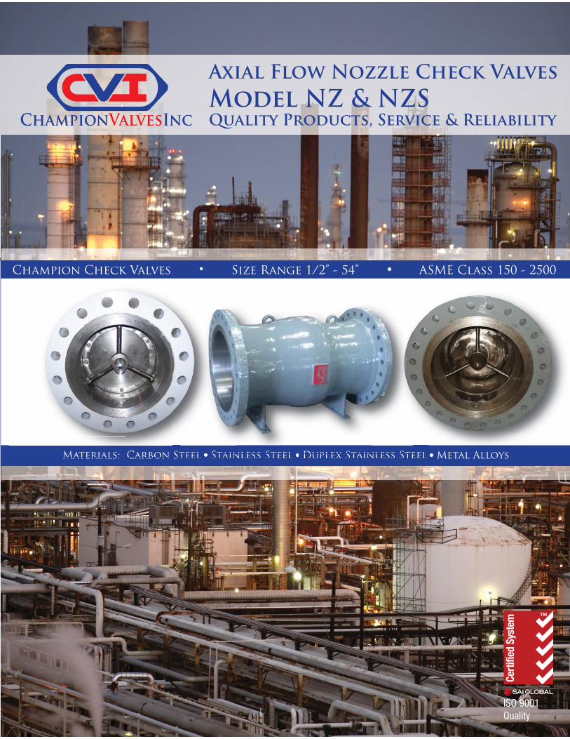
Champion Check Valves Size Range 1/2” - 54” ASME Class 150 - 2500
Materials: Carbon Steel Stainless Steel Duplex Stainless Steel Metal Alloys
Axial Flow Nozzle Check ValvesModel NZ & NZSQuality Products, Service & Reliability
teel Stainless Steel Duplex Stainless Steel nless Steel Duplex Stainless Ste Metal Alloyseelnless SteMaterials: Carbon StStteel Stainteel Stain
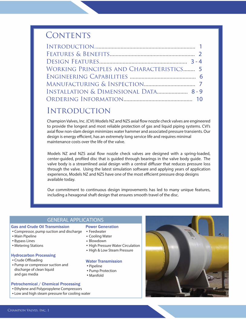
IntroductionChampion Valves, Inc. (CVI) Models NZ and NZS axial flow nozzle check valves are engineered to provide the longest and most reliable protection of gas and liquid piping systems. CVI’s axial flow non-slam design minimizes water hammer and associated pressure transients. Our design is energy efficient, has an extremely long service life and requires minimal maintenance costs over the life of the valve.
Models NZ and NZS axial flow nozzle check valves are designed with a spring-loaded, center-guided, profiled disc that is guided through bearings in the valve body guide. The valve body is a streamlined axial design with a central diffuser that reduces pressure loss through the valve. Using the latest simulation software and applying years of application experience, Models NZ and NZS have one of the most efficient pressure drop designs available today.
Our commitment to continuous design improvements has led to many unique features, including a hexagonal shaft design that ensures smooth travel of the disc.
Contents Introduction..................................................................... 1Features & Benefits.......................................................... 2Design Features............................................................ 3 - 4Working Principles and Characteristics........ 5 Engineering Capabilities ............................................. 6 Manufacturing & Inspection................................... 7Installation & Dimensional Data..................... 8 - 9Ordering Information............................................... 10
Champion Valves, Inc. 1
Gas and Crude Oil Transmission Compressor, pump suction and discharge Main Pipeline Bypass Lines Metering Stations
Hydrocarbon Processing Crude Offloading Pump or compressor suction and discharge of clean liquid and gas media
Petrochemical / Chemical Processing Ethylene and Polypropylene Compressors Low and high steam pressure for cooling water
Power Generation Feedwater Cooling Water Blowdown High Pressure Water Circulation High & Low Steam Pressure
GENERAL APPLICATIONS
Water Transmission Pipeline Pump Protection Manifold
Features & Benefits
Champion Valves, Inc. 2
Size Range
Design Specifications
Flange Type & Size
End Connections
Inspection & Testing
Painting
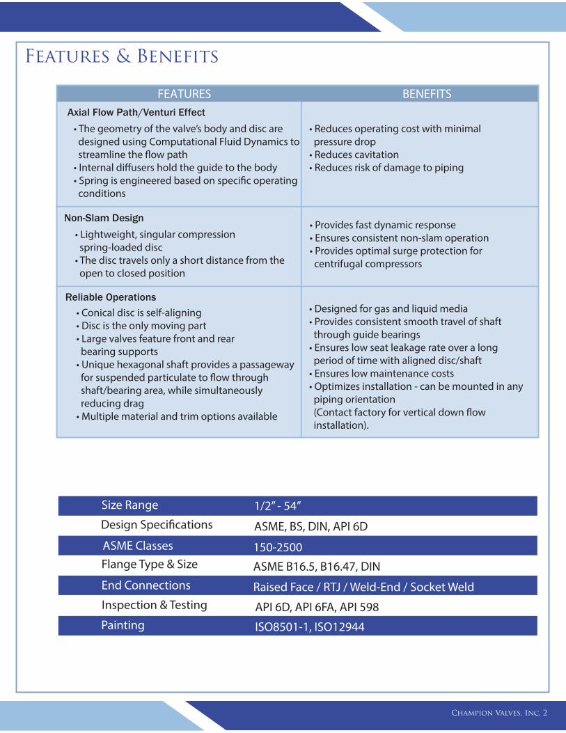
1/2” - 54”
ASME, BS, DIN, API 6D
ASME B16.5, B16.47, DIN
Raised Face / RTJ / Weld-End / Socket Weld
API 6D, API 6FA, API 598
ISO8501-1, ISO12944
ASME Classes 150-2500
FEATURES BENEFITS
• The geometry of the valve’s body and disc are designed using Computational Fluid Dynamics to streamline the flow path • Internal diffusers hold the guide to the body• Spring is engineered based on specific operating conditions
Non-Slam Design
• Lightweight, singular compression spring-loaded disc• The disc travels only a short distance from the open to closed position
Axial Flow Path/Venturi Effect
Reliable Operations
• Conical disc is self-aligning• Disc is the only moving part• Large valves feature front and rear bearing supports• Unique hexagonal shaft provides a passageway for suspended particulate to flow through shaft/bearing area, while simultaneously reducing drag• Multiple material and trim options available
• Reduces operating cost with minimal pressure drop• Reduces cavitation• Reduces risk of damage to piping
• Provides fast dynamic response• Ensures consistent non-slam operation• Provides optimal surge protection for centrifugal compressors
• Designed for gas and liquid media• Provides consistent smooth travel of shaft through guide bearings • Ensures low seat leakage rate over a long period of time with aligned disc/shaft • Ensures low maintenance costs• Optimizes installation - can be mounted in any piping orientation (Contact factory for vertical down flow installation).
Design Features
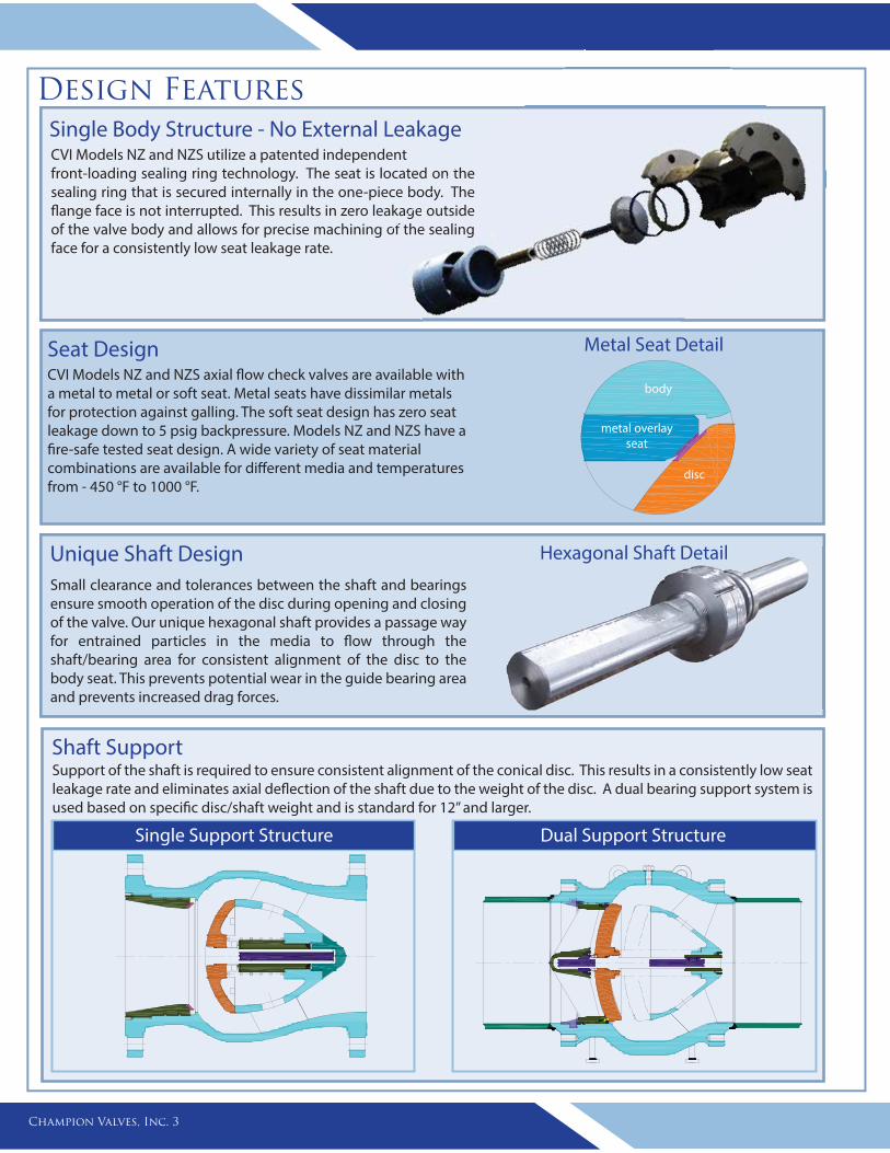
Unique Shaft Design Small clearance and tolerances between the shaft and bearings ensure smooth operation of the disc during opening and closing of the valve. Our unique hexagonal shaft provides a passage way for entrained particles in the media to flow through the shaft/bearing area for consistent alignment of the disc to the body seat. This prevents potential wear in the guide bearing area and prevents increased drag forces.
Shaft SupportSupport of the shaft is required to ensure consistent alignment of the conical disc. This results in a consistently low seat leakage rate and eliminates axial deflection of the shaft due to the weight of the disc. A dual bearing support system is used based on specific disc/shaft weight and is standard for 12” and larger.
Single Body Structure - No External Leakage
Champion Valves, Inc. 3
Hexagonal Shaft Detail
Single Support Structure Dual Support Structure
CVI Models NZ and NZS utilize a patented independent front-loading sealing ring technology. The seat is located on the sealing ring that is secured internally in the one-piece body. The flange face is not interrupted. This results in zero leakage outside of the valve body and allows for precise machining of the sealing face for a consistently low seat leakage rate.
n the dy. The
ge outside of the sealing
Seat DesignCVI Models NZ and NZS axial flow check valves are available with a metal to metal or soft seat. Metal seats have dissimilar metals for protection against galling. The soft seat design has zero seat leakage down to 5 psig backpressure. Models NZ and NZS have a fire-safe tested seat design. A wide variety of seat material combinations are available for different media and temperatures from - 450 °F to 1000 °F.
body
disc
metal overlay seat
Metal Seat Detail
Hexagonal Shaft Detail
Design Features
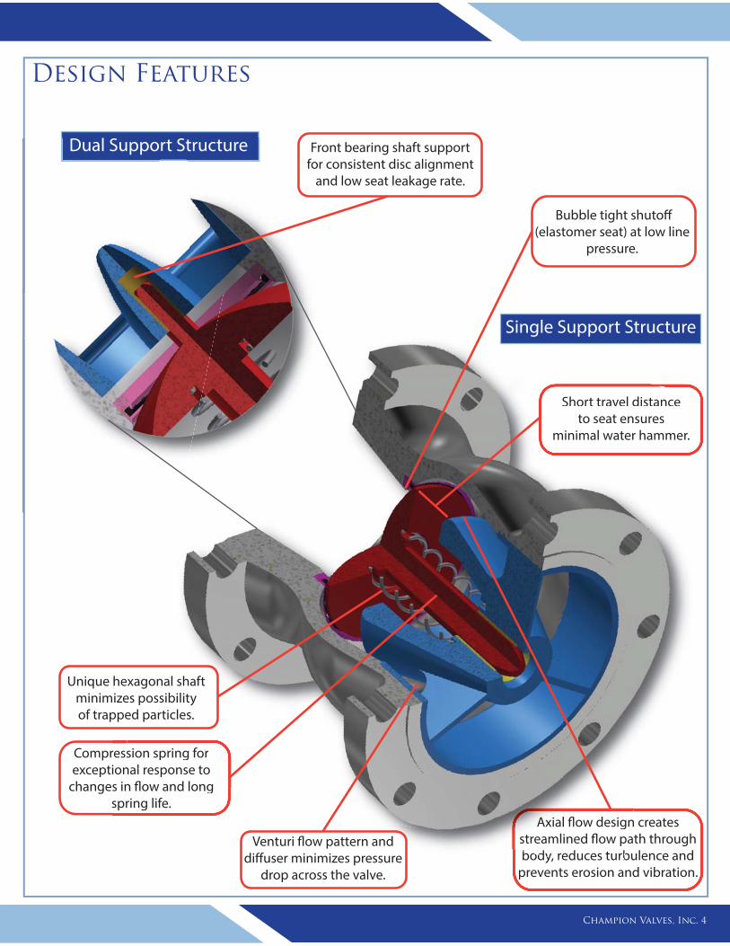
Compression spring for exceptional response to
changes in flow and long spring life.
Short travel distance to seat ensures
minimal water hammer.
Venturi flow pattern and diffuser minimizes pressure
drop across the valve.
Axial flow design creates streamlined flow path through body, reduces turbulence and
prevents erosion and vibration.
resional respons in flow and longspring life.
Venturi flow pattern and diffuser minimizes pressure
drop across the valve.
n creates path through
body, reduces turbulence and prevents erosion and vibration.
ssion spring for nal response to
ong
Short travel distance to seat ensures
minimal water hammer.
Axial flow designstreamlined flow pabody, reduces turb
ion a
Single Support Structure
Champion Valves, Inc. 4
Front bearing shaft support for consistent disc alignment
and low seat leakage rate.
Unique hexagonal shaft minimizes possibility of trapped particles.
Bubble tight shutoff (elastomer seat) at low line
pressure.
Dual Support Structure
x
FR
Relative Motion
FR
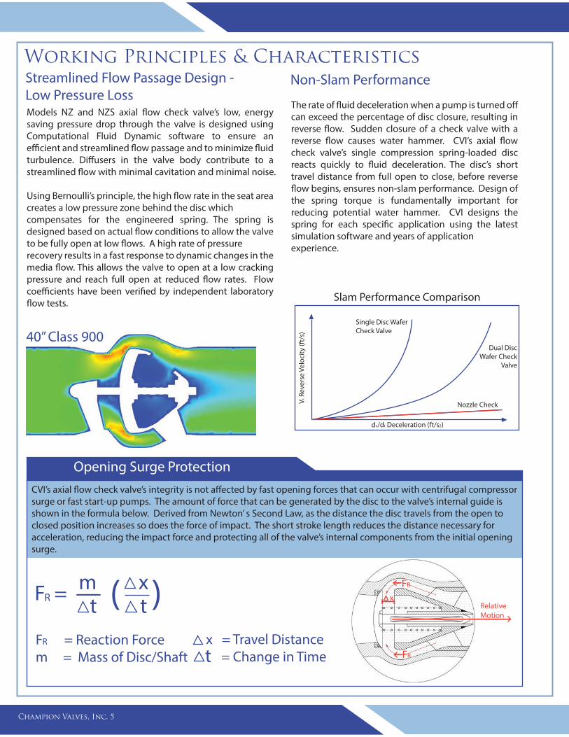
Models NZ and NZS axial flow check valve’s low, energy saving pressure drop through the valve is designed using Computational Fluid Dynamic software to ensure an efficient and streamlined flow passage and to minimize fluid turbulence. Diffusers in the valve body contribute to a streamlined flow with minimal cavitation and minimal noise.
Using Bernoulli’s principle, the high flow rate in the seat area creates a low pressure zone behind the disc which compensates for the engineered spring. The spring is designed based on actual flow conditions to allow the valve to be fully open at low flows. A high rate of pressure recovery results in a fast response to dynamic changes in the media flow. This allows the valve to open at a low cracking pressure and reach full open at reduced flow rates. Flow coefficients have been verified by independent laboratory flow tests.
Working Principles & CharacteristicsStreamlined Flow Passage Design - Low Pressure Loss
Non-Slam Performance
The rate of fluid deceleration when a pump is turned off can exceed the percentage of disc closure, resulting in reverse flow. Sudden closure of a check valve with a reverse flow causes water hammer. CVI’s axial flow check valve’s single compression spring-loaded disc reacts quickly to fluid deceleration. The disc’s short travel distance from full open to close, before reverse flow begins, ensures non-slam performance. Design of the spring torque is fundamentally important for reducing potential water hammer. CVI designs the spring for each specific application using the latest simulation software and years of application experience.
Single Disc Wafer Check Valve
Dual DiscWafer Check
Valve
Nozzle Check
dv/dt Deceleration (ft/s2)
Vr R
ever
se V
eloc
ity (f
t/s)
m F = t
x t ( )
Opening Surge Protection
CVI’s axial flow check valve’s integrity is not affected by fast opening forces that can occur with centrifugal compressor surge or fast start-up pumps. The amount of force that can be generated by the disc to the valve’s internal guide is shown in the formula below. Derived from Newton’ s Second Law, as the distance the disc travels from the open to closed position increases so does the force of impact. The short stroke length reduces the distance necessary for acceleration, reducing the impact force and protecting all of the valve’s internal components from the initial opening surge.
40” Class 900
Champion Valves, Inc. 5
F = Reaction Force m = Mass of Disc/Shaft t
x = Travel Distance = Change in Time
R
R
Slam Performance Comparison
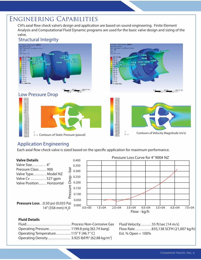
CVI’s axial flow check valve’s design and application are based on sound engineering. Finite Element Analysis and Computational Fluid Dynamic programs are used for the basic valve design and sizing of the valve.
Engineering Capabilities
Champion Valves, Inc. 6
Structural Integrity
Low Pressure Drop
Contours of Static Pressure (pascal) Contours of Velocity Magnitude (m/s)
Each axial flow check valve is sized based on the specific application for maximum performance.
Application Engineering
Valve DetailsValve Size……… . 4”Pressure Class…… 900Valve Type……… . Model NZValve Cv ………… 527 gpmValve Position…… Horizontal
Fluid DetailsFluid……………………………. . Process Non-Corrosive GasOperating Pressure……………. . 1199.8 psig [82.74 barg]Operating Temperature…………115° F [46.1° C]Operating Density……………… 3.925 lbf/ft3 [62.88 kg/m3]
Fluid Velocity………55 ft/sec [14 m/s] Flow Rate . . . . . . . . . . 835,138 SCFH (21,007 kg/h) Est. % Open = 100%
0.E+00 1.E+04 2.E+04 3.E+04 4.E+04 5.E+04 6.E+04 7.E+040.000
0.400
0.350
0.300
0.250
0.200
0.150
0.100
0.050
Flow - kg/h
Pres
sure
Dro
p - b
ar
Pressure Loss Curve for 4” 900# NZ
Pressure Loss . .0.50 psi (0.035 Pa) 14” (358 mm) H20
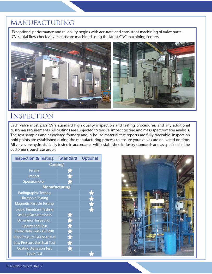
Manufacturing
Each valve must pass CVI’s standard high quality inspection and testing procedures, and any additional customer requirements. All castings are subjected to tensile, impact testing and mass spectrometer analysis. The test samples and associated foundry and in-house material test reports are fully traceable. Inspection hold points are established during the manufacturing process to ensure your valves are delivered on time. All valves are hydrostatically tested in accordance with established industry standards and as specified in the customer’s purchase order.
Inspection & Testing Standard Optional
Tensile
Impact
Spectrometer
Casting
ManufacturingRadiographic Testing
Ultrasonic Testing
Magnetic Particle Testing
Liquid Penetrant Testing
Sealing Face Hardness
Dimension Inspection
Operational TestHydrostatic Test (API 598)
High Pressure Gas Seat Test
Low Pressure Gas Seat Test
Coating Adhesion TestSpark Test
Champion Valves, Inc. 7
Exceptional performance and reliability begins with accurate and consistent machining of valve parts. CVI’s axial flow check valve’s parts are machined using the latest CNC machining centers.
Inspection
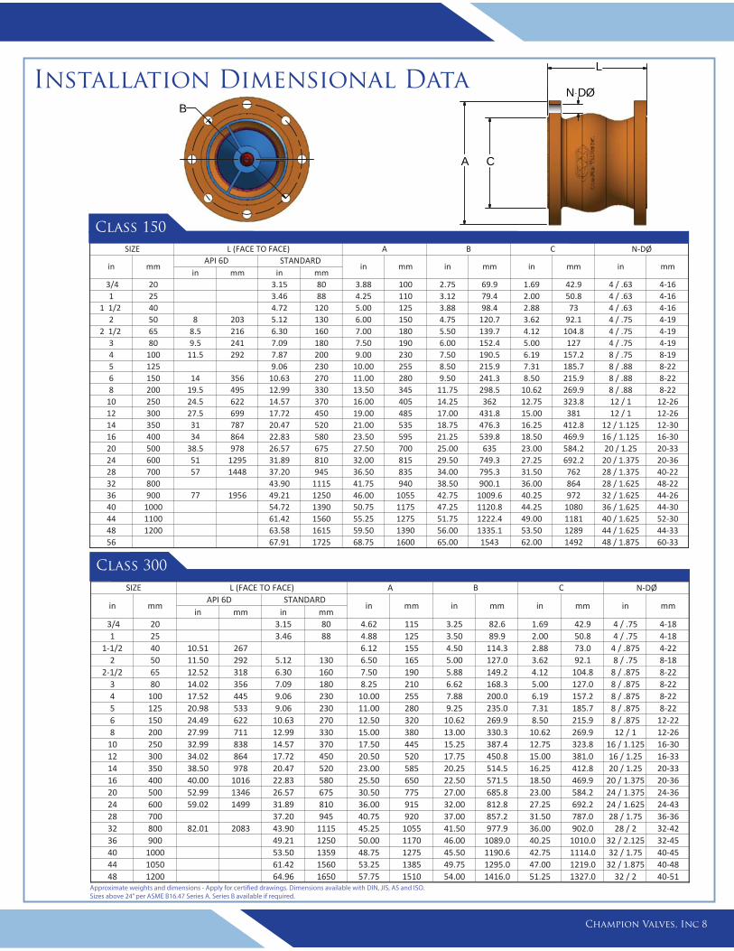
Installation Dimensional Data
Approximate weights and dimensions - Apply for certified drawings. Dimensions available with DIN, JIS, AS and ISO. Sizes above 24” per ASME B16.47 Series A. Series B available if required.
B
A C
L
N- DØ
Champion Valves, Inc 8
in mm in mm 3/4 20 3.15 80 3.88 100 2.75 69.9 1.69 42.9 4 / .63 4-16
1 25 3.46 88 4.25 110 3.12 79.4 2.00 50.8 4 / .63 4-161 1/2 40 4.72 120 5.00 125 3.88 98.4 2.88 73 4 / .63 4-16
2 50 8 203 5.12 130 6.00 150 4.75 120.7 3.62 92.1 4 / .75 4-192 1/2 65 8.5 216 6.30 160 7.00 180 5.50 139.7 4.12 104.8 4 / .75 4-19
3 80 9.5 241 7.09 180 7.50 190 6.00 152.4 5.00 127 4 / .75 4-194 100 11.5 292 7.87 200 9.00 230 7.50 190.5 6.19 157.2 8 / .75 8-195 125 9.06 230 10.00 255 8.50 215.9 7.31 185.7 8 / .88 8-226 150 14 356 10.63 270 11.00 280 9.50 241.3 8.50 215.9 8 / .88 8-228 200 19.5 495 12.99 330 13.50 345 11.75 298.5 10.62 269.9 8 / .88 8-22
10 250 24.5 622 14.57 370 16.00 405 14.25 362 12.75 323.8 12 / 1 12-2612 300 27.5 699 17.72 450 19.00 485 17.00 431.8 15.00 381 12 / 1 12-2614 350 31 787 20.47 520 21.00 535 18.75 476.3 16.25 412.8 12 / 1.125 12-3016 400 34 864 22.83 580 23.50 595 21.25 539.8 18.50 469.9 16 / 1.125 16-3020 500 38.5 978 26.57 675 27.50 700 25.00 635 23.00 584.2 20 / 1.25 20-3324 600 51 1295 31.89 810 32.00 815 29.50 749.3 27.25 692.2 20 / 1.375 20-3628 700 57 1448 37.20 945 36.50 835 34.00 795.3 31.50 762 28 / 1.375 40-2232 800 43.90 1115 41.75 940 38.50 900.1 36.00 864 28 / 1.625 48-2236 900 77 1956 49.21 1250 46.00 1055 42.75 1009.6 40.25 972 32 / 1.625 44-2640 1000 54.72 1390 50.75 1175 47.25 1120.8 44.25 1080 36 / 1.625 44-3044 1100 61.42 1560 55.25 1275 51.75 1222.4 49.00 1181 40 / 1.625 52-3048 1200 63.58 1615 59.50 1390 56.00 1335.1 53.50 1289 44 / 1.625 44-3356 67.91 1725 68.75 1600 65.00 1543 62.00 1492 48 / 1.875 60-33
STANDARDSIZE N-DØCBA
in mm in mmAPI 6D
L (FACE TO FACE)
in mm in mm in mm
Class 150
in mm in mm3/4 20 3.15 80 4.62 115 3.25 82.6 1.69 42.9 4 / .75 4-181 25 3.46 88 4.88 125 3.50 89.9 2.00 50.8 4 / .75 4-18
1-1/2 40 10.51 267 6.12 155 4.50 114.3 2.88 73.0 4 / .875 4-222 50 11.50 292 5.12 130 6.50 165 5.00 127.0 3.62 92.1 8 / .75 8-18
2-1/2 65 12.52 318 6.30 160 7.50 190 5.88 149.2 4.12 104.8 8 / .875 8-223 80 14.02 356 7.09 180 8.25 210 6.62 168.3 5.00 127.0 8 / .875 8-224 100 17.52 445 9.06 230 10.00 255 7.88 200.0 6.19 157.2 8 / .875 8-225 125 20.98 533 9.06 230 11.00 280 9.25 235.0 7.31 185.7 8 / .875 8-226 150 24.49 622 10.63 270 12.50 320 10.62 269.9 8.50 215.9 8 / .875 12-228 200 27.99 711 12.99 330 15.00 380 13.00 330.3 10.62 269.9 12 / 1 12-26
10 250 32.99 838 14.57 370 17.50 445 15.25 387.4 12.75 323.8 16 / 1.125 16-3012 300 34.02 864 17.72 450 20.50 520 17.75 450.8 15.00 381.0 16 / 1.25 16-3314 350 38.50 978 20.47 520 23.00 585 20.25 514.5 16.25 412.8 20 / 1.25 20-3316 400 40.00 1016 22.83 580 25.50 650 22.50 571.5 18.50 469.9 20 / 1.375 20-3620 500 52.99 1346 26.57 675 30.50 775 27.00 685.8 23.00 584.2 24 / 1.375 24-3624 600 59.02 1499 31.89 810 36.00 915 32.00 812.8 27.25 692.2 24 / 1.625 24-4328 700 37.20 945 40.75 920 37.00 857.2 31.50 787.0 28 / 1.75 36-3632 800 82.01 2083 43.90 1115 45.25 1055 41.50 977.9 36.00 902.0 28 / 2 32-4236 900 49.21 1250 50.00 1170 46.00 1089.0 40.25 1010.0 32 / 2.125 32-4540 1000 53.50 1359 48.75 1275 45.50 1190.6 42.75 1114.0 32 / 1.75 40-4544 1050 61.42 1560 53.25 1385 49.75 1295.0 47.00 1219.0 32 / 1.875 40-4848 1200 64.96 1650 57.75 1510 54.00 1416.0 51.25 1327.0 32 / 2 40-51
in
C N-DØ
mm in mm in mm in mm
SIZE L (FACE TO FACE) A B
in mmAPI 6D STANDARD
Class 300
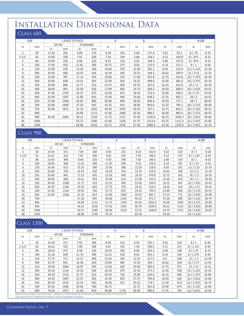
Installation Dimensional Data
Approximate weights and dimensions - Apply for certified drawings. Dimensions available with DIN, JIS, AS and ISO. Sizes above 24” per ASME B16.47 Series A. Series B available if required.
Champion Valves, Inc. 9
in mm in mm2 50 11.50 292 6.69 170 6.50 165 5.00 127.0 3.62 92.1 8 / .75 8-19
2 1/2 65 13.00 330 7.87 200 7.50 190 5.88 148.2 4.12 104.8 8 / .875 8-223 80 14.00 356 8.66 220 8.25 210 6.62 168.3 5.00 127.0 8 / .875 8-224 100 17.00 432 11.81 300 10.75 275 8.50 215.9 6.19 157.2 8 / 1 8-266 150 22.00 559 13.39 340 14.00 355 11.50 292.1 8.50 215.9 12 / 1.125 12-308 200 26.00 660 16.54 420 16.50 420 13.75 349.2 10.62 269.9 12 / 1.25 12-33
10 250 31.00 787 17.13 435 20.00 510 17.00 431.8 12.75 323.8 16 / 1.375 16-3612 300 33.00 838 19.41 493 22.00 560 19.25 489.0 15.00 381.0 20 / 1.375 20-3614 350 35.00 889 21.77 553 23.75 605 20.75 527.0 16.25 412.8 20 / 1.5 20-3916 400 39.00 991 25.59 650 27.00 685 23.75 603.2 18.50 469.9 20 / 1.625 20-4220 500 47.00 1194 26.57 675 32.00 815 28.50 723.9 23.00 584.2 24 / 1.75 24-4524 600 55.00 1397 31.89 810 37.00 940 33.00 838.2 27.25 692.2 24 / 2 24-5126 650 57.00 1448 34.65 880 40.00 890 36.00 806.4 29.50 727.1 28 / 2 28-4528 700 63.00 1600 37.20 945 42.25 955 38.00 863.6 31.50 784.2 28 / 2.125 28-4830 750 65.00 1651 41.14 1045 44.50 1025 40.25 927.1 33.75 841.2 28 / 2.125 28-5132 800 43.90 1115 47.00 1085 42.50 984.5 36.00 895.4 28 / 2.375 28-5536 900 82.00 2083 49.21 1250 51.75 1215 47.00 1105.0 40.25 1009.7 28 / 2.625 28-6040 1000 54.72 1390 52.00 1320 47.75 1213.0 43.75 1111.2 32 / 2.375 32-6048 1200 64.96 1650 62.75 1595 57.50 1460.0 52.50 1333.5 32 / 2.875 32-74
SIZE L (FACE TO FACE) A B
in mmAPI 6D STANDARD
in
C N-DØ
mm in mm in mm in mm
Class 600
in mm in mm2 50 14.50 371 7.09 180 8.50 215 6.50 165.0 3.62 124 8 / 1 8-26
2-1/2 65 16.61 422 7.87 200 9.62 245 7.50 190.5 4.12 137 8 / 1.125 8-303 80 15.00 384 8.66 220 9.50 240 7.50 190.5 5.00 156 8 / 1 8-334 100 18.00 460 11.81 300 11.50 290 9.25 235.0 6.19 181 8 / 1.25 8-336 150 24.00 613 15.35 390 15.00 380 12.50 318.0 8.50 241 12 / 1.25 12-338 200 29.00 740 16.54 420 18.50 470 15.50 319.5 10.62 308 12 / 1.5 12-39
10 250 33.00 841 17.13 435 21.50 545 18.50 470.0 12.75 362 16 / 1.5 16-3912 300 38.00 968 19.41 493 24.00 610 21.00 533.5 15.00 419 20 / 1.5 20-3914 350 40.50 1308 21.77 553 25.25 640 22.00 559.0 16.25 467 20 / 1.625 20-4216 400 44.50 1140 25.59 650 27.75 705 24.25 616.0 18.50 524 20 / 1.75 20-4520 500 52.00 1334 29.92 760 33.75 855 29.50 749.3 23.00 648 20 / 2.125 20-5524 600 61.00 1568 32.24 819 41.00 1040 35.50 901.7 27.25 772 20 / 2.625 20-6828 700 37.20 945 46.00 1105 40.25 971.5 31.50 889 20 / 3.125 20-7432 800 43.90 1115 51.75 1240 45.50 1092.0 36.00 1003 20 / 3.375 20-8036 900 49.21 1250 57.50 1345 50.75 1200.0 40.25 1124 20 / 3.625 20-8040 1000 54.72 1390 59.50 1510 52.75 1340.0 45.75 1162 24 / 3.625 24-9248 1200 68.90 1750 70.25 62.50 54.50 24 / 4.125
inmm in mm
SIZE L (FACE TO FACE) A B C N-DØ
in mmAPI 6D STANDARD
in mm mmin
Class 900
in mm in mm2 50 14.50 371 7.02 180 8.50 215 6.50 165.1 3.62 124 8 / 1 8-26
2-1/2 65 16.61 422 7.80 200 9.62 245 7.50 190.5 4.12 137 8 / 1.125 8-303 80 18.50 473 8.58 220 10.50 265 8.00 203.2 5.00 168 8 / 1.25 8-334 100 21.50 549 11.70 300 12.25 310 9.50 241.3 6.19 194 8 / 1.375 8-366 150 27.75 711 15.21 390 15.50 395 12.50 317.5 8.5 248 12 / 1.5 12-398 200 32.75 841 16.38 420 19.00 485 15.50 393.7 10.62 318 12 / 1.75 12-45
10 250 39.00 1000 16.97 435 23.00 585 19.00 482.6 12.75 371 12 / 2.0 12-5112 300 44.50 1146 19.50 500 26.50 675 22.50 571.5 15.00 438 16 / 2.125 16-5514 350 49.50 1276 21.57 553 29.50 750 25.00 635.0 16.25 489 16 / 2.375 16-6016 400 54.50 1407 25.35 650 32.50 825 27.75 704.8 18.50 546 16 / 2.625 16-6818 450 60.50 1559 25.35 650 36.00 915 30.50 774.7 21.00 613 16 / 2 .875 16-7420 500 65.50 1686 29.64 760 38.75 32.75 831.8 23.00 673 16 / 3.125 16-8024 600 76.50 1972 31.94 819 46.00 1170 39.00 990.6 27.25 794 16 / 3.625 16-94
in mm in mm mminin mmAPI 6D STANDARD
in mm
SIZE L (FACE TO FACE) A B C N-DØ
Class 1500
Ordering Information
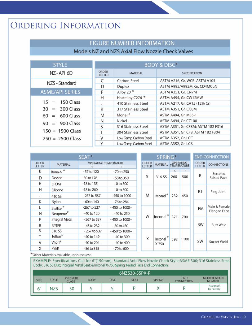
15 = 150 Class30 = 300 Class60 = 600 Class
90 = 900 Class
150 = 1500 Class
250 = 2500 Class
FIGURE NUMBER INFORMATION Models NZ and NZS Axial Flow Nozzle Check Valves
STYLE
NZS - Standard
NZ - API 6D
ASME/API SERIES
ORDERLETTER
BODY & DISC*MATERIAL SPECIFICATION
CDFHJKMNSTVY
Carbon SteelDuplexAlloy 20 ®Hastelloy C276 ®410 Stainless Steel317 Stainless Steel
Monel ®Nickel 316 Stainless Steel304 Stainless SteelLow Temp Carbon SteelLow Temp Carbon Steel
ASTM A216, Gr. WCB; ASTM A105 ASTM A995/A995M, Gr. CD4MCuNASTM A351, Gr. CN7MASTM A494, Gr. CW12MWASTM A217, Gr. CA15 (12% Cr)ASTM A351, Gr. CG8M
ASTM A494, Gr. M35-1ASTM A494, Gr. CZ100ASTM A351, Gr. CF8M; ASTM 182 F316ASTM A351, Gr. CF8; ASTM 182 F304ASTM A352, Gr. LCCASTM A352, Gr. LCB
SPRING*OPERATING ORDER
LETTER MATERIAL
˚C ˚F
S
M
W
X
316 SS
Monel®
Inconel®
Inconel X-750
®
260 500
232 450
371 700
593 1100
SerratedRaised Face
Ring Joint
END CONNECTIONORDERLETTER CONNECTIONS
R
RJ
FM
BW
SW
Male & Female Flanged Face
Butt Weld
Socket Weld
ORDERLETTER MATERIAL OPERATING TEMPERATURE
˚C ˚F
- 57 to 120
-18 to 135
-18 to 260
- 267 to 537
-267 to 537
- 40 to 120
- 267 to 537
- 267 to 537- 40 to 149
- 40 to 204
Buna-N ®
EPDM
Silicone
410 SS
Stellite ®Neoprene®Integral Metal
316 SSTeflon®Viton®
B
EHJ
LNP
STV
- 70 to 250
0 to 300
0 to 500
- 450 to 1000+
- 450 to 1000+
- 40 to 250
- 450 to 1000+
- 450 to 1000+- 40 to 300
- 40 to 400
SEAT*
- 45 to 232RPTFER - 50 to 450
- 60 to 140NylonK - 76 to 284
-50 to 176DevlonD - 58 to 350
- 56 to 315PEEKX - 70 to 600
Champion Valves, Inc. 10
TEMPERATURE
EXAMPLE: Specifications Call for 6”(150mm), Standard Axial Flow Nozzle Check Style;ASME 300; 316 Stainless Steel Body; 316 SS Disc; Integral Metal Seat; & Inconel X-750 Spring; Raised Face End Connection.
6" NZS 30 S S P X RAssigned
by Factory
PRESSURECLASSSIZE STYLE SPRING
ENDCONNECTION
MODIFICATIONNUMBER
6NZS30-SSPX-RBODY DISC SEAT
*Other Materials available upon request.
10 Champion Valves, Inc.
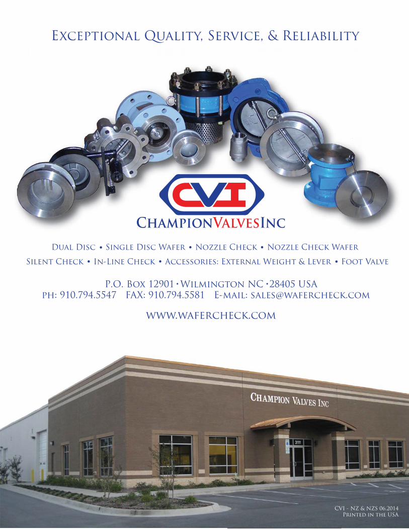
Exceptional Quality, Service, & Reliability
www.wafercheck.com
P.O. Box 12901 Wilmington NC 28405 USAph: 910.794.5547 FAX: 910.794.5581 E-mail: [email protected]
101010101010100101001010101011010111000110111010100101000000000 ChaChaChaChaChaChaChahaChaChaChaChaChaChaChaaChaChaChaChaChaChahaChChahaChahaChaChaCChhChaChaCChhChaC aChaChaChaahahaChaaaChaaaC aC aaaaChaahampimpimpimpimpimpimpimpmpimpiimpimpimpimpmpmpimpimpimpipppipiimpimmpimpmpmppmpimpimmmpimpimmpmpimmpmpmpiiipmpm ipmppmmmppmm onooon oon on ononon onon on on on on on ononononononoononononooon onoonononononoooo ValValValVaValValValValVaVaValValValValValVaVallValalValValValValValValValValValVaValVaValValVVValVVVValVVVVVaVaVaVVaVVVValValVallVaalV vesvesvesvesvesvesvesvesvesvesesvesvesvesvesesvesvesvesvesvevesvesvesvesvesvevesvessssvesveseevesvesvesesvessvesvvevevesveeevveevess, I, I, I, I, I, I, I, I, I, II I, I, I, IIIIII, II, III I, III, IIIIIIIIIII , nc.nc.nc.ncnc.ncncnc.nc.nc.nc.nccnc.nc.nc.nc.nc.ncnnnncncnc.nccnc.nc.nccnnnncccccnccccccnccnncnncnnncncncnccncCVI - NZ & NZS 06.2014
Printed in the USA
Dual Disc Single Disc Wafer Nozzle Check Nozzle Check Wafer
Silent Check In-Line Check Accessories: External Weight & Lever Foot Valve
Related Documents