JOURNAL OF MECHANICS OF MATERIALS AND STRUCTURES Vol. 4, No. 10, 2009 AXIAL COMPRESSION STABILITY OF A CRISSCROSS SECTION COLUMN COMPOSED OF CONCRETE-FILLED SQUARE STEEL TUBES CHEN ZHI - HUA, RONG BIN AND APOSTOLOS FAFITIS A crisscross section column composed of concrete-filled square steel tubes was tested in axial loading up to failure. The column was analyzed by the finite element method and the ultimate load as well as the failure mode were in agreement with the experimental findings. An analytical method was also proposed which when applied to the tested column gave an estimate of the ultimate load about 4% different from the experimental. The analytical method also predicted the mode of failure correctly. 1. Introduction Special-shaped columns have found applications in many structures, especially residential buildings. Compared with regular columns, special-shaped columns have the distinguishing characteristic of flexible sections such as L -shaped, T -shaped, and crisscross sections. The use of special-shaped columns in residential buildings can give more indoor space than regular rectangular or square columns. The behavior of special-shaped reinforced concrete columns has been the subject of investigation and many experimental and analytical studies have been published. Ramamurthy and Hafeez Khan [1983] have proposed a method to determine the theoretical ultimate loads of L -shaped concrete columns based on the concept of an equivalent square or rectangular column. Hsu [1985; 1989] has presented theo- retical and experimental results for L -shaped and T -shaped reinforced concrete sections. Mallikarjuna and Mahadevappa [1992; 1994] have carried out numerical investigations on the strength of L -shaped and T -shaped short reinforced concrete columns that have been subjected to combined axial loading and bending in order to provide design aids for structural engineers. Tsao and Hsu [1993; 1994] have presented an experimental and analytical investigation of the strength and deformation behavior of bi- axially loaded slender and tied columns with L -shaped cross sections. Dundar et al. [2008; Dundar and Sahin 1993] have studied reinforced concrete L -shaped sections under biaxial bending and axial loads. Demagh et al. [2005] have carried out numerical investigations for the analysis and the design of L -shaped short reinforced concrete columns subjected to combined axial loads and bending based on the fiber method. Tokgoz and Dundar [2008] have studied the behavior of concrete-encased composite columns with L -shaped sections under short-term axial loads and biaxial bending by means of both experiment and theoretical analysis. For determination of the behavior of eccentrically loaded short and slender composite columns, a theoretical procedure considering the nonlinear behavior of the materials has been proposed. Keywords: crisscross section composite column, concrete-filled square steel tubes, stability, axial compression experiment, finite element analysis, analytical method. This research was supported by the Chinese Program for New Century Excellent Talents in University. The financial support is greatly appreciated. 1787

Welcome message from author
This document is posted to help you gain knowledge. Please leave a comment to let me know what you think about it! Share it to your friends and learn new things together.
Transcript
JOURNAL OF MECHANICS OF MATERIALS AND STRUCTURESVol. 4, No. 10, 2009
AXIAL COMPRESSION STABILITY OF A CRISSCROSS SECTION COLUMNCOMPOSED OF CONCRETE-FILLED SQUARE STEEL TUBES
CHEN ZHI-HUA, RONG BIN AND APOSTOLOS FAFITIS
A crisscross section column composed of concrete-filled square steel tubes was tested in axial loadingup to failure. The column was analyzed by the finite element method and the ultimate load as well as thefailure mode were in agreement with the experimental findings. An analytical method was also proposedwhich when applied to the tested column gave an estimate of the ultimate load about 4% different fromthe experimental. The analytical method also predicted the mode of failure correctly.
1. Introduction
Special-shaped columns have found applications in many structures, especially residential buildings.Compared with regular columns, special-shaped columns have the distinguishing characteristic of flexiblesections such as L-shaped, T -shaped, and crisscross sections. The use of special-shaped columns inresidential buildings can give more indoor space than regular rectangular or square columns.
The behavior of special-shaped reinforced concrete columns has been the subject of investigation andmany experimental and analytical studies have been published. Ramamurthy and Hafeez Khan [1983]have proposed a method to determine the theoretical ultimate loads of L-shaped concrete columns basedon the concept of an equivalent square or rectangular column. Hsu [1985; 1989] has presented theo-retical and experimental results for L-shaped and T -shaped reinforced concrete sections. Mallikarjunaand Mahadevappa [1992; 1994] have carried out numerical investigations on the strength of L-shapedand T -shaped short reinforced concrete columns that have been subjected to combined axial loadingand bending in order to provide design aids for structural engineers. Tsao and Hsu [1993; 1994] havepresented an experimental and analytical investigation of the strength and deformation behavior of bi-axially loaded slender and tied columns with L-shaped cross sections. Dundar et al. [2008; Dundarand Sahin 1993] have studied reinforced concrete L-shaped sections under biaxial bending and axialloads. Demagh et al. [2005] have carried out numerical investigations for the analysis and the designof L-shaped short reinforced concrete columns subjected to combined axial loads and bending based onthe fiber method. Tokgoz and Dundar [2008] have studied the behavior of concrete-encased compositecolumns with L-shaped sections under short-term axial loads and biaxial bending by means of bothexperiment and theoretical analysis. For determination of the behavior of eccentrically loaded short andslender composite columns, a theoretical procedure considering the nonlinear behavior of the materialshas been proposed.
Keywords: crisscross section composite column, concrete-filled square steel tubes, stability, axial compression experiment,finite element analysis, analytical method.
This research was supported by the Chinese Program for New Century Excellent Talents in University. The financial support isgreatly appreciated.
1787
1788 CHEN ZHI-HUA, RONG BIN AND APOSTOLOS FAFITIS
Bracing
Bracing
Mono column
Mono column
Mono column
Bracing
Mono column
Bracing Mono column
Bracing
Bracing
Bracing
Bracing
Bracing
Bracing
Mono column
Mono column
Bracing
Bracing
Bracing
Bracing
Bracing
Bracing
Mono column
Bracing Bracing
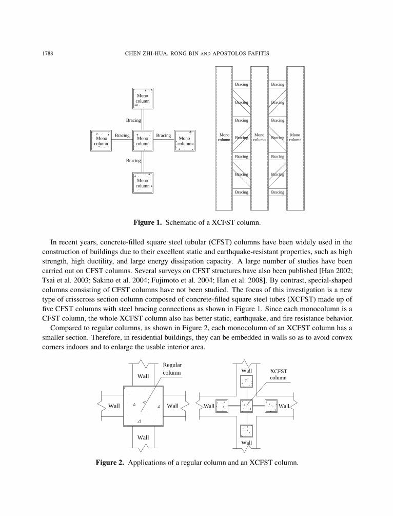
Figure 1. Schematic of a XCFST column.
In recent years, concrete-filled square steel tubular (CFST) columns have been widely used in theconstruction of buildings due to their excellent static and earthquake-resistant properties, such as highstrength, high ductility, and large energy dissipation capacity. A large number of studies have beencarried out on CFST columns. Several surveys on CFST structures have also been published [Han 2002;Tsai et al. 2003; Sakino et al. 2004; Fujimoto et al. 2004; Han et al. 2008]. By contrast, special-shapedcolumns consisting of CFST columns have not been studied. The focus of this investigation is a newtype of crisscross section column composed of concrete-filled square steel tubes (XCFST) made up offive CFST columns with steel bracing connections as shown in Figure 1. Since each monocolumn is aCFST column, the whole XCFST column also has better static, earthquake, and fire resistance behavior.
Compared to regular columns, as shown in Figure 2, each monocolumn of an XCFST column has asmaller section. Therefore, in residential buildings, they can be embedded in walls so as to avoid convexcorners indoors and to enlarge the usable interior area.
Regular column
Wall
Wall
Wall
Wall
XCFSTcolumn
Wall
Wall
Wall
Wall
Figure 2. Applications of a regular column and an XCFST column.
AXIAL COMPRESSION STABILITY OF A CRISSCROSS SECTION COLUMN 1789
The objectives of this study are to determine the maximum load-bearing capacity of an XCFST columnsubjected to axial compression and to investigate the failure pattern up to the ultimate load. We adopteda three-pronged approach: experiment, analytical study, and finite element simulation. Specifically, wereport the experimental test results of an XCFST column under axial compression, use finite elementmodeling to analyze the process, and develop a method for calculating the maximum load-bearing ca-pacity of an XCFST column under axial compression. All three approaches were applied to the samemodel, which we describe in the next section.
2. Experimental work
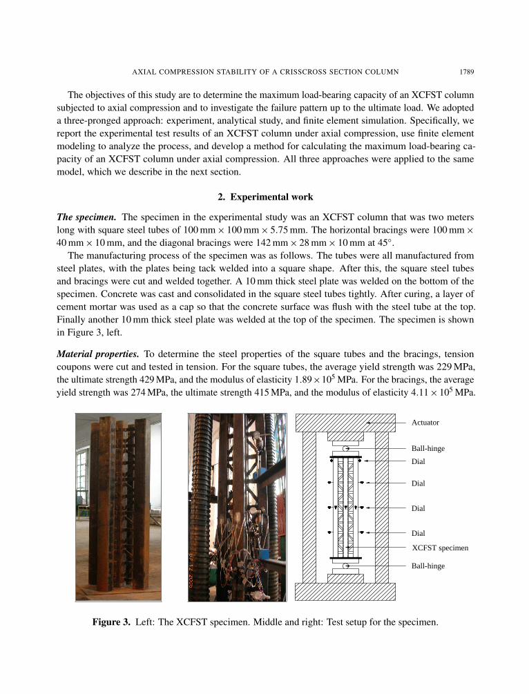
The specimen. The specimen in the experimental study was an XCFST column that was two meterslong with square steel tubes of 100 mm× 100 mm× 5.75 mm. The horizontal bracings were 100 mm×40 mm× 10 mm, and the diagonal bracings were 142 mm× 28 mm× 10 mm at 45◦.
The manufacturing process of the specimen was as follows. The tubes were all manufactured fromsteel plates, with the plates being tack welded into a square shape. After this, the square steel tubesand bracings were cut and welded together. A 10 mm thick steel plate was welded on the bottom of thespecimen. Concrete was cast and consolidated in the square steel tubes tightly. After curing, a layer ofcement mortar was used as a cap so that the concrete surface was flush with the steel tube at the top.Finally another 10 mm thick steel plate was welded at the top of the specimen. The specimen is shownin Figure 3, left.
Material properties. To determine the steel properties of the square tubes and the bracings, tensioncoupons were cut and tested in tension. For the square tubes, the average yield strength was 229 MPa,the ultimate strength 429 MPa, and the modulus of elasticity 1.89×10⁵ MPa. For the bracings, the averageyield strength was 274 MPa, the ultimate strength 415 MPa, and the modulus of elasticity 4.11×10⁵ MPa.
XCFST specimen
Ball-hinge
Dial
Dial
Dial
Dial
Ball-hinge
Actuator
Figure 3. Left: The XCFST specimen. Middle and right: Test setup for the specimen.

1790 CHEN ZHI-HUA, RONG BIN AND APOSTOLOS FAFITIS
To determine the concrete material properties, three 150× 150× 150 mm cubes were cast and curedin conditions similar to that of the experiment. The mix proportions of concrete were cement 353 kg/m3,water 175 kg/m3, sand 696 kg/m3, and coarse aggregate 1088 kg/m3. The average crushing strength ofthese concrete cubes after 28 days was 49.7 MPa and the modulus of elasticity was 4.33× 10⁴ MPa.
Test procedure. The XCFST specimen was tested with pinned conditions at both ends using a 5000 kNcapacity axial actuator. The testing setup for the XCFST specimen is shown in Figure 3, middle andright.
The specimen was loaded until it reached the failure point. A load interval of about one tenth of theestimated carrying load capacity was used. Each load interval was maintained for about 2–3 minutes.The progress of deformation, the mode of failure, and the maximum load taken by the specimen wererecorded continuously.
During the test, the load level was controlled by the actuator. The lateral dials monitored the deflectionof the monocolumns. The vertical dials recorded the displacement of the XCFST column. The locationof the instrumentation is shown in Figure 4, left. The labels 1, 4, 7, and 10 indicate the lateral dialsattached at 1.5 m from the ground plate; 2, 5, 8, and 11 indicate the lateral dials at 1.0 m, which is themiddle height of each monocolumn; 3, 6, 9, and 12 indicate the lateral dials at 0.5 m; and 13 and 14indicate the vertical dials in the top plate of the XCFST column.
Test results. The test was stopped when the XCFST column reached the ultimate bearing capacity. Thedeformation of failure was very small. Figure 4, right, shows the failure mode of the XCFST column,and as shown there were small deformations of each monocolumn.
Load versus axial shortening. The load versus shortening curve provides information on the ultimatecarrying capacity of the XCFST column specimen.
X1X0
X4 14
1, 2, 3
X3
13
X27, 8, 9
10, 11, 12
Figure 4. Left: positions of dial indicators. Right: Deformation of the XCFST specimen.

AXIAL COMPRESSION STABILITY OF A CRISSCROSS SECTION COLUMN 1791
0 2 4 6 8 10 12 14 160
1000
2000
3000
4000
5000
6000
7000
Axi
al f
orce
(kN
)
Axial shortening (mm)
Figure 5. Axial load versus shortening curve of the XCFST specimen.
Figure 5 shows the relation of the axial force and axial shortening of the XCFST specimen. Note thatup to about 6100 kN, the behavior was almost linear. Beyond this load, the XCFST column entered thebulking stage. Finally at a load of 6390 kN, the shortening was 15.2 mm and the test was stopped.
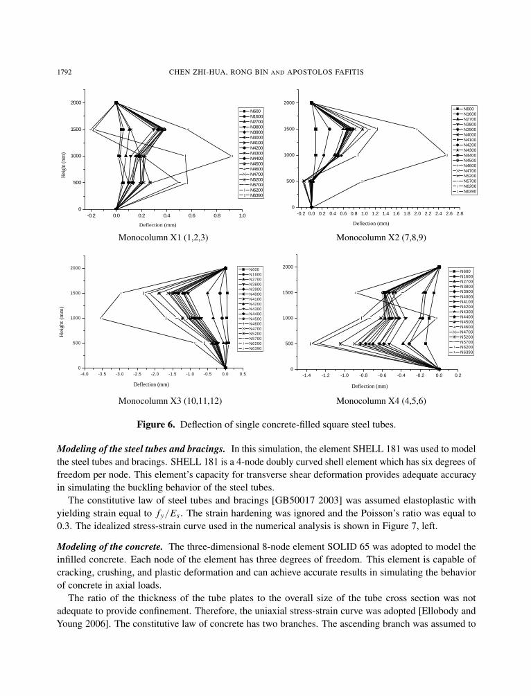
Deflection of monocolumn. Figure 6 shows the deformation history of each monocolumn. The numberin parenthesis identifies the dials (for example, 1, 2, and 3). The load level designation from 600 kN to6390 kN is shown in the box next to the profile of the column.
According to Figure 6, at the failure load of 6390 kN, the deflection of monocolumn X3 was the largestof the four monocolumns. The failure process was initiated by the buckling of monocolumn X3.
Discussions of experimental behavior of specimen. From the load-deformation curve, it is apparent thatfor a load less than about 6100 kN the XCFST column remains in the elastic range. This is true for themonocolumns X2, X3, and X4. For a load above 6100 kN the column enters gradually into the bucklingstage and the load-deformation curve deviates from linearity. At a load of 6390 kN, the XCFST columnhas reached its ultimate capacity. Finally it appears that the failure process is initiated by the bucklingof monocolumn X3.
3. Finite element analysis
General. The commercial finite element software ANSYS has been used to simulate the axial compres-sion experiment of the XCFST specimen as described before. There are three main components thatneed to be modeled in order to simulate the behavior of the XCFST column. These are the steel tubesand bracings, the infilled concrete, and the interface between the concrete and the steel tube. In addition,the choice of the element type, the mesh size, the initial geometric deformation, the boundary conditions,and the load application are also important in simulating the special-shaped column.
1792 CHEN ZHI-HUA, RONG BIN AND APOSTOLOS FAFITIS
Deflection (mm)
Hei
ght (
mm
)
0
500
1000
1500
2000
-0.2 0.0 0.2 0.4 0.6 0.8 1.01
2
3
4
5
N600 N1600 N2700 N3800 N3900 N4000 N4100 N4200 N4300 N4400 N4500 N4600 N4700 N5200 N5700 N6200
1 N6390
Deflection (mm)
0
500
1000
1500
2000
-0.2 0.0 0.2 0.4 0.6 0.8 1.0 1.2 1.4 1.6 1.8 2.0 2.2 2.4 2.6 2.81
2
3
4
5
N600 N1600 N2700 N3800 N3900 N4000 N4100 N4200 N4300 N4400 N4500 N4600 N4700 N5200 N5700 N6200
1 N6390
Monocolumn X1 (1,2,3) Monocolumn X2 (7,8,9)
Hei
ght
(mm
)
Deflection (mm)
0
500
1000
1500
2000
-4.0 -3.5 -3.0 -2.5 -2.0 -1.5 -1.0 -0.5 0.0 0.51
2
3
4
5 N600 N1600 N2700 N3800 N3900 N4000 N4100 N4200 N4300 N4400 N4500 N4600 N4700 N5200 N5700 N6200
1 N6390
Deflection (mm)
0
500
1000
1500
2000
-1.4 -1.2 -1.0 -0.8 -0.6 -0.4 -0.2 0.0 0.21
2
3
4
5
N600 N1600 N2700 N3800 N3900 N4000 N4100 N4200 N4300 N4400 N4500 N4600 N4700 N5200 N5700 N6200
1 N6390
Monocolumn X3 (10,11,12) Monocolumn X4 (4,5,6)
Figure 6. Deflection of single concrete-filled square steel tubes.
Modeling of the steel tubes and bracings. In this simulation, the element SHELL 181 was used to modelthe steel tubes and bracings. SHELL 181 is a 4-node doubly curved shell element which has six degrees offreedom per node. This element’s capacity for transverse shear deformation provides adequate accuracyin simulating the buckling behavior of the steel tubes.
The constitutive law of steel tubes and bracings [GB50017 2003] was assumed elastoplastic withyielding strain equal to fy/Es . The strain hardening was ignored and the Poisson’s ratio was equal to0.3. The idealized stress-strain curve used in the numerical analysis is shown in Figure 7, left.
Modeling of the concrete. The three-dimensional 8-node element SOLID 65 was adopted to model theinfilled concrete. Each node of the element has three degrees of freedom. This element is capable ofcracking, crushing, and plastic deformation and can achieve accurate results in simulating the behaviorof concrete in axial loads.
The ratio of the thickness of the tube plates to the overall size of the tube cross section was notadequate to provide confinement. Therefore, the uniaxial stress-strain curve was adopted [Ellobody andYoung 2006]. The constitutive law of concrete has two branches. The ascending branch was assumed to

AXIAL COMPRESSION STABILITY OF A CRISSCROSS SECTION COLUMN 1793
0
1
f y
�Es
0y
0c
1
fc
0 10 0c
Figure 7. Left: constitutive law of steel tubes and bracings. Right: constitutive law of concrete.
be parabolic up to a strain equal to 0.003 and the descending branch was linear, as shown on the graphon the right in Figure 7.
Modeling of the concrete-steel tube interface. The contact action between the steel tube and the concretewas modeled by the contact elements TARGE 170 and CONTA 173. These surface-to-surface contactelements consist of two matching contact faces of the steel tube and concrete elements. The frictionbetween the two faces is maintained as long as the surfaces remain in contact. The coefficient of frictionbetween the two faces was taken as 0.25 in the analysis. These contact elements allow the surfaces toseparate under the influence of tensile force. However, the contact elements are not allowed to penetrateeach other.
Mesh size and initial geometrical deformation. Different mesh sizes have been tried to choose a rea-sonable mesh that can provide both accurate results and reasonable computational time. It was foundthat a mesh size of approximately 1:1:2 (length:width:depth) for solid elements and 1:1 (length:width)for shell elements can achieve accurate results. The coincident nodes between steel tubes and bracingswere merged after all elements were meshed in order to ensure that the deformations of the steel tubesand bracings in such places were identical.
In practice, there are initial geometrical deformations in the XCFST specimen. Therefore the influenceof initial geometrical deformation was considered in this simulation. For this purpose, a 1‰ initialdeformation resembling the first-order buckling mode was introduced to the finite element modeling.
Boundary conditions and load application. Pinned boundary conditions were assumed. The top andbottom surfaces of the XCFST column were restrained in all translational degrees of freedom except forthe displacement of the top plate in the direction of the applied load.
The load was applied as a static uniform load using the displacement control at each node of the loadedtop surface, and the displacements were applied in incremental steps, which were identical to the stepsof the experimental investigation.
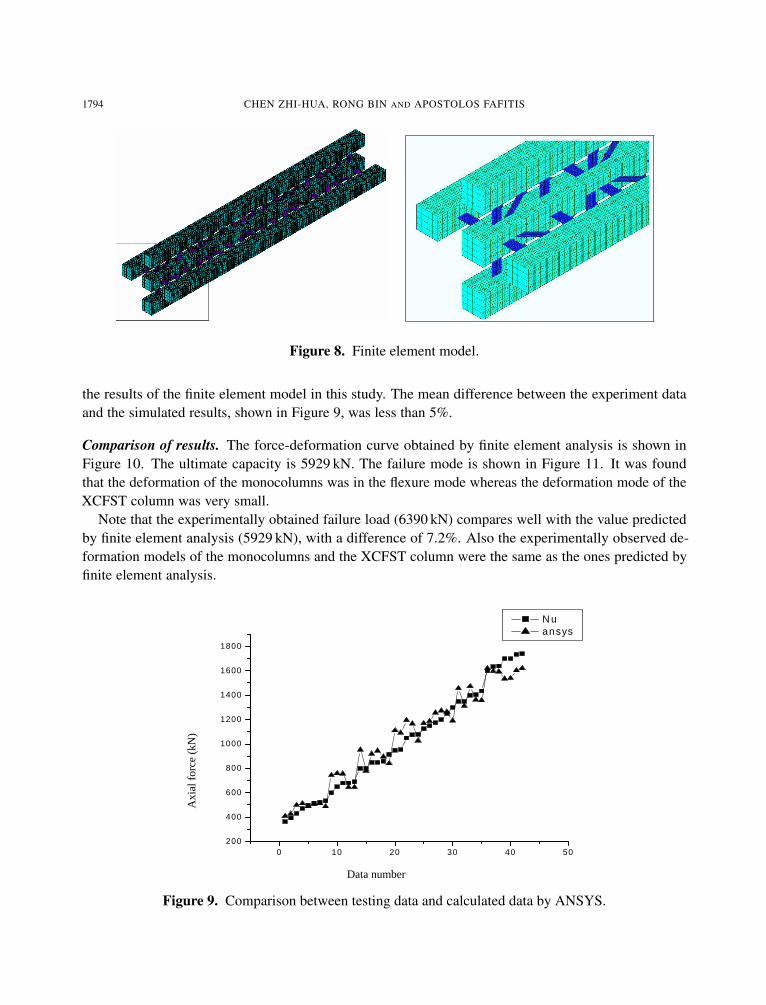
The finite element model is shown in Figure 8.
Procedure verification. In order to validate the finite element analysis, recent axial compression experi-mental results on 42 concrete-filled square steel tubes conducted by Li et al. [1998] were compared with
1794 CHEN ZHI-HUA, RONG BIN AND APOSTOLOS FAFITIS
Figure 8. Finite element model.
the results of the finite element model in this study. The mean difference between the experiment dataand the simulated results, shown in Figure 9, was less than 5%.
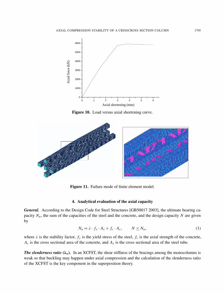
Comparison of results. The force-deformation curve obtained by finite element analysis is shown inFigure 10. The ultimate capacity is 5929 kN. The failure mode is shown in Figure 11. It was foundthat the deformation of the monocolumns was in the flexure mode whereas the deformation mode of theXCFST column was very small.
Note that the experimentally obtained failure load (6390 kN) compares well with the value predictedby finite element analysis (5929 kN), with a difference of 7.2%. Also the experimentally observed de-formation models of the monocolumns and the XCFST column were the same as the ones predicted byfinite element analysis.
0 10 20 30 40 50200
400
600
800
1000
1200
1400
1600
1800
N u ansys
Data number
Axi
al f
orce
(kN
)
Figure 9. Comparison between testing data and calculated data by ANSYS.
AXIAL COMPRESSION STABILITY OF A CRISSCROSS SECTION COLUMN 1795
Axial shortening (mm)
Axi
al f
orce
(kN
)
0 1 2 3 4 5 60
1000
2000
3000
4000
5000
6000
Figure 10. Load versus axial shortening curve.
Figure 11. Failure mode of finite element model.
4. Analytical evaluation of the axial capacity
General. According to the Design Code for Steel Structures [GB50017 2003], the ultimate bearing ca-pacity Nu , the sum of the capacities of the steel and the concrete, and the design capacity N are givenby
Nu = λ · fy · As + fc · Ac, N ≤ Nu, (1)
where λ is the stability factor, fy is the yield stress of the steel, fc is the axial strength of the concrete,Ac is the cross sectional area of the concrete, and As is the cross sectional area of the steel tube.
The slenderness ratio (λo). In an XCFST, the shear stiffness of the bracings among the monocolumns isweak so that buckling may happen under axial compression and the calculation of the slenderness ratioof the XCFST is the key component in the superposition theory.

1796 CHEN ZHI-HUA, RONG BIN AND APOSTOLOS FAFITIS
The formula for λo is derived based on the following assumptions: All three monocolumns have thesame size and material properties for steel and concrete. The horizontal and diagonal bracings have thesame size. The spatial truss model is employed for the analysis.
The slenderness ratio of a truss with pinned supporting condition is given by the theory of elasticstability [Leonard and George 2005]:
λo =
√λ2
1+π2γ1
∑ni=1 (Es Asi + Ec Aci ), (2)
where λo is the slenderness ratio of the XCFST column, λ1 is the slenderness ratio of the unbracedcolumns for the x-x or y-y axis as shown in Figure 12, γ1 is the angle of unit shear as explained later(see (4)), n is the number of monocolumns, Es is the steel modulus of elasticity, As is the cross sectionalarea of the steel tubes, Ec is the concrete modulus of elasticity, and Ac is the cross sectional area of theconcrete.
The derivation of the slenderness ratio for buckling is based on Figure 13. One half of the structure isshown in Figure 13c because of symmetry.
From Figure 13b and c, it can be seen that the axial force of the diagonal bracing Nd is Nd =1
2 sin θ,
where θ is the angle between the steel tube and the diagonal bracing.The axial deformation of the diagonal bracing 1d is:
1d =Ndld
Es A1=
a2Es A1 sin θ cos θ
, (3)
where ld is the length of the diagonal bracing, a is the length of vertical projection for the diagonalbracing, and A1 is the cross sectional area of the diagonal bracing.
Therefore, the angle of the unit shear is:
γ1 ≈1a=
1d
a sin θ=
1
2Es A1 sin2 θ cos θ, (4)
where 1 is the length of horizontal projection of axial deformation for the diagonal bracing 1d .
Figure 12. XCFST section inertia axis.

AXIAL COMPRESSION STABILITY OF A CRISSCROSS SECTION COLUMN 1797
Substituting γ1 from (4) into (2), the equivalent slenderness ratio becomes:
λo =
√λ2
1+5π2(Es As + Ec Ac)
2Es A1 sin2 θ cos θ. (5)
Application of the analytical method. The method explained in the previous paragraph will be appliedto compute the ultimate axial capacity of the tested XCFST column.
With reference to the previous two subsections, the values of the structural parameters involved inEquations (1)–(5) are the following:
n= 5, As = 2167.75 mm2, Ac= 7832.25 mm2, A1= 280 mm2, I = 189526605 mm4,
θ = 45◦, fy = 429 N/mm2, fc= 39.6 N/mm2, Ec= 43300 N/mm2, Es = 189000 N/mm2.
The length of the column is 2 m. The size of the horizontal bracing is 100×40×10 mm, and the diagonalbracing 142× 28× 10 mm.
The slenderness ratios for the x-x and y-y axes respectively are
i =√
I5As= 132 mm, λ1 =
li=
2000132= 15.
With these values, the slenderness ratio in bending buckling is given by (5):
λo =
√λ2
1+5π2(Es As + Ec Ac)
2Es A1 sin2 θ cos θ= 35.
Based on the slenderness ratio λo = 35, the stability factor λ in (1) given as 0.918 in [GB50017 2003].Therefore the ultimate capacity is
Nu = 5λ fy As + 5 fc Ac = 5820 kN.
V=1
�
V=1/2 û
ûd
a
�
(a) (b) (c)
Figure 13. Calculation model of buckling.
1798 CHEN ZHI-HUA, RONG BIN AND APOSTOLOS FAFITIS
5. Conclusions
The ultimate capacity of a crisscross section column composed of concrete-filled square steel tubes(XCFST) was determined experimentally by finite element analysis and by the analytical method ex-plained in this paper. It was found that the results are in agreement.
More specifically, the ultimate capacity of the XCFST specimen was found experimentally to be equalto 6390 kN. By finite element analysis, the ultimate capacity was evaluated to be equal to 5959 kN, adifference of 7.2%. The value of the ultimate capacity predicted by the analytical method was 5820 kN,an 8.9% difference from the experimentally obtained value.
Based on the evidence presented in this paper, the analytical method predicts the ultimate capacitywith adequate accuracy. The axial compression stability of an XCFST was studied, and the results of theanalytical method and finite element analysis all show that the failure process of the XCFST specimenwas initiated by the buckling of the monocolumn.
References
[Demagh et al. 2005] K. Demagh, H. Chabil, and L. Hamzaoui, “Analysis of reinforced concrete columns subjected to biaxialloads”, pp. 433–440 in Concrete for transportation infrastructure (Dundee, 2005), edited by R. K. Dhir et al., Thomas Telford,London, 2005.
[Dundar and Sahin 1993] C. Dundar and B. Sahin, “Arbitrarily shaped reinforced concrete members subject to biaxial bendingand axial load”, Comput. Struct. 49:4 (1993), 643–662.
[Dundar et al. 2008] C. Dundar, S. Tokgoz, A. K. Tanrikulu, and T. Baran, “Behaviour of reinforced and concrete-encasedcomposite columns subjected to biaxial bending and axial load”, Build. Environ. 43:6 (2008), 1109–1120.
[Ellobody and Young 2006] E. Ellobody and B. Young, “Nonlinear analysis of concrete-filled steel SHS and RHS columns”,Thin-Walled Struct. 44:8 (2006), 919–930.
[Fujimoto et al. 2004] T. Fujimoto, A. Mukai, I. Nishiyama, and K. Sakino, “Behavior of eccentrically loaded concrete-filledsteel tubular columns”, J. Struct. Eng. (ASCE) 130:2 (2004), 203–212.
[GB50017 2003] Design code for steel structures, GB50017, China Planning Press, Beijing, 2003. In Chinese.
[Han 2002] L.-H. Han, “Tests on stub columns of concrete-filled RHS sections”, J. Constr. Steel Res. 58:3 (2002), 353–372.
[Han et al. 2008] L.-H. Han, W. Liu, and Y.-F. Yang, “Behaviour of concrete-filled steel tubular stub columns subjected toaxially local compression”, J. Constr. Steel Res. 64:4 (2008), 377–387.
[Hsu 1985] C.-T. T. Hsu, “Biaxially loaded L-shaped reinforced concrete columns”, J. Struct. Eng. (ASCE) 111:12 (1985),2576–2595.
[Hsu 1989] C.-T. T. Hsu, “T-shaped reinforced concrete members under biaxial bending and axial compression”, ACI Struct. J.86:4 (1989), 460–468.
[Leonard and George 2005] S. Leonard and F. George, Appied structural steel design, Tsinghua University Press, Beijing,2005.
[Li et al. 1998] S. P. Li, H. D., Q. Wang, Y. C. Guo, and Y. Y. Huang, “Calculation for the ultimate bearing capacity of concretefilled steel tube columns under eccentric compression”, J. Build. Struct. 19:1 (1998), 41–51. In Chinese.
[Mallikarjuna and Mahadevappa 1992] Mallikarjuna and P. Mahadevappa, “Computer aided analysis of reinforced concretecolumns subjected to axial compression and bending, I: L-shaped sections”, Comput. Struct. 44:5 (1992), 1121–1138.
[Mallikarjuna and Mahadevappa 1994] Mallikarjuna and P. Mahadevappa, “Computer aided analysis of reinforced concretecolumns subjected to axial compression and bending, II: T-shaped sections”, Comput. Struct. 53:6 (1994), 1317–1356.
[Ramamurthy and Hafeez Khan 1983] L. N. Ramamurthy and T. A. Hafeez Khan, “L-shaped column design for biaxial eccen-tricity”, J. Struct. Eng. (ASCE) 109:8 (1983), 1903–1917.

AXIAL COMPRESSION STABILITY OF A CRISSCROSS SECTION COLUMN 1799
[Sakino et al. 2004] K. Sakino, H. Nakahara, S. Morino, and I. Nishiyama, “Behavior of centrally loaded concrete-filled steel-tube short columns”, J. Struct. Eng. (ASCE) 130:2 (2004), 180–188.
[Tokgoz and Dundar 2008] S. Tokgoz and C. Dundar, “Experimental tests on biaxially loaded concrete-encased compositecolumns”, Steel Compos. Struct. 8:5 (2008), 423–438.
[Tsai et al. 2003] K.-C. Tsai, Y.-T. Weng, M.-L. Lin, C.-H. Chen, J.-W. Lai, and P.-C. Hsiao, “Pseudo dynamic tests of a fullscale CFT/BRB composite frame: displacement based seismic design and response evaluations”, pp. 165–176 in Proceedingsof the International Workshop on Steel and Concrete Composite Construction (IWSCCC-2003) (Taipei, 2003), edited by K.-C.Tsai and G.-Y. Liu, National Center for Research on Earthquake Engineering, Taipei, 2003. Report NCREE-03-026.
[Tsao and Hsu 1993] W. H. Tsao and C.-T. T. Hsu, “A nonlinear computer analysis of biaxially loaded L-shaped slenderreinforced concrete columns”, Comput. Struct. 49:4 (1993), 579–588.
[Tsao and Hsu 1994] W. H. Tsao and C.-T. T. Hsu, “Behaviour of biaxially loaded square and L-shaped slender reinforcedconcrete columns”, Mag. Concr. Res. 46:169 (1994), 257–267.
Received 11 Apr 2009. Revised 17 Jun 2009. Accepted 3 Jul 2009.
CHEN ZHI-HUA: [email protected] of Civil Engineering, Tianjin University, Tianjin 300072, Chinahttp://www2.tju.edu.cn/colleges/civil/list.php?cid=23
RONG BIN: [email protected] of Civil Engineering, Tianjin University, Tianjin 300072, China
APOSTOLOS FAFITIS: [email protected] of Civil and Environmental Engineering, Arizona State University, Tempe, AZ 85287, United Stateshttp://engineering.asu.edu/people/35093

Related Documents