AXI Traffic Generator v2.0 LogiCORE IP Product Guide Vivado Design Suite PG125 April 5, 2017

Welcome message from author
This document is posted to help you gain knowledge. Please leave a comment to let me know what you think about it! Share it to your friends and learn new things together.
Transcript

AXI Traffic Generator v2.0
LogiCORE IP Product Guide
Vivado Design Suite
PG125 April 5, 2017

AXI Traffic Generator v2.0 2PG125 April 5, 2017 www.xilinx.com
Table of ContentsIP Facts
Chapter 1: OverviewModes Description. . . . . . . . . . . . . . . . . . . . . . . . . . . . . . . . . . . . . . . . . . . . . . . . . . . . . . . . . . . . . . . . . 7Programming Sequence. . . . . . . . . . . . . . . . . . . . . . . . . . . . . . . . . . . . . . . . . . . . . . . . . . . . . . . . . . . . 27Applications . . . . . . . . . . . . . . . . . . . . . . . . . . . . . . . . . . . . . . . . . . . . . . . . . . . . . . . . . . . . . . . . . . . . . 29Licensing and Ordering Information . . . . . . . . . . . . . . . . . . . . . . . . . . . . . . . . . . . . . . . . . . . . . . . . . . 31
Chapter 2: Product SpecificationPerformance. . . . . . . . . . . . . . . . . . . . . . . . . . . . . . . . . . . . . . . . . . . . . . . . . . . . . . . . . . . . . . . . . . . . . 32Resource Utilization. . . . . . . . . . . . . . . . . . . . . . . . . . . . . . . . . . . . . . . . . . . . . . . . . . . . . . . . . . . . . . . 35Port Descriptions . . . . . . . . . . . . . . . . . . . . . . . . . . . . . . . . . . . . . . . . . . . . . . . . . . . . . . . . . . . . . . . . . 35Register Space . . . . . . . . . . . . . . . . . . . . . . . . . . . . . . . . . . . . . . . . . . . . . . . . . . . . . . . . . . . . . . . . . . . 38
Chapter 3: Designing with the CoreClocking. . . . . . . . . . . . . . . . . . . . . . . . . . . . . . . . . . . . . . . . . . . . . . . . . . . . . . . . . . . . . . . . . . . . . . . . . 49Resets . . . . . . . . . . . . . . . . . . . . . . . . . . . . . . . . . . . . . . . . . . . . . . . . . . . . . . . . . . . . . . . . . . . . . . . . . . 49
Chapter 4: Design Flow StepsCustomizing and Generating the Core . . . . . . . . . . . . . . . . . . . . . . . . . . . . . . . . . . . . . . . . . . . . . . . . 50Constraining the Core . . . . . . . . . . . . . . . . . . . . . . . . . . . . . . . . . . . . . . . . . . . . . . . . . . . . . . . . . . . . . 65Simulation . . . . . . . . . . . . . . . . . . . . . . . . . . . . . . . . . . . . . . . . . . . . . . . . . . . . . . . . . . . . . . . . . . . . . . 66Synthesis and Implementation . . . . . . . . . . . . . . . . . . . . . . . . . . . . . . . . . . . . . . . . . . . . . . . . . . . . . . 66
Chapter 5: Example DesignImplementing the Example Design. . . . . . . . . . . . . . . . . . . . . . . . . . . . . . . . . . . . . . . . . . . . . . . . . . . 68Simulating the Example Design. . . . . . . . . . . . . . . . . . . . . . . . . . . . . . . . . . . . . . . . . . . . . . . . . . . . . . 69
Chapter 6: Test BenchExample Sequences for Custom Mode . . . . . . . . . . . . . . . . . . . . . . . . . . . . . . . . . . . . . . . . . . . . . . . . 71Example Sequences for High Level Traffic (Video, PCIe, Ethernet, USB) Modes . . . . . . . . . . . . . . . 72Example Sequences for High Level Traffic (Data) Mode . . . . . . . . . . . . . . . . . . . . . . . . . . . . . . . . . . 72
Send Feedback
AXI Traffic Generator v2.0 3PG125 April 5, 2017 www.xilinx.com
Appendix A: Migrating and UpgradingMigrating to the Vivado Design Suite. . . . . . . . . . . . . . . . . . . . . . . . . . . . . . . . . . . . . . . . . . . . . . . . . 73Upgrading in the Vivado Design Suite . . . . . . . . . . . . . . . . . . . . . . . . . . . . . . . . . . . . . . . . . . . . . . . . 73
Appendix B: DebuggingFinding Help on Xilinx.com . . . . . . . . . . . . . . . . . . . . . . . . . . . . . . . . . . . . . . . . . . . . . . . . . . . . . . . . . 74Debug Tools . . . . . . . . . . . . . . . . . . . . . . . . . . . . . . . . . . . . . . . . . . . . . . . . . . . . . . . . . . . . . . . . . . . . . 76Hardware Debug . . . . . . . . . . . . . . . . . . . . . . . . . . . . . . . . . . . . . . . . . . . . . . . . . . . . . . . . . . . . . . . . . 76Interface Debug . . . . . . . . . . . . . . . . . . . . . . . . . . . . . . . . . . . . . . . . . . . . . . . . . . . . . . . . . . . . . . . . . . 77
Appendix C: Additional Resources and Legal NoticesXilinx Resources . . . . . . . . . . . . . . . . . . . . . . . . . . . . . . . . . . . . . . . . . . . . . . . . . . . . . . . . . . . . . . . . . . 79References . . . . . . . . . . . . . . . . . . . . . . . . . . . . . . . . . . . . . . . . . . . . . . . . . . . . . . . . . . . . . . . . . . . . . . 79Revision History . . . . . . . . . . . . . . . . . . . . . . . . . . . . . . . . . . . . . . . . . . . . . . . . . . . . . . . . . . . . . . . . . . 80Please Read: Important Legal Notices . . . . . . . . . . . . . . . . . . . . . . . . . . . . . . . . . . . . . . . . . . . . . . . . 83
Send Feedback

AXI Traffic Generator v2.0 4PG125 April 5, 2017 www.xilinx.com Product Specification
IntroductionThe Xilinx® LogiCORE™ IP AXI Traffic Generator core generates traffic over the AXI4 and AXI4-Stream interconnect and other AXI4 peripherals in the system. It generates a wide variety of AXI transactions based on the core programming and selected mode of operation.
Features• AXI4 interface for register access and data
transfers.
• Multi-Mode operation (AXI4 Master, AXI4-Lite Master, and AXI4-Stream Master).
• Flexible data width capability (32/64-bit) on output AXI4 Slave, (32/64/128/256/512-bit) on output AXI4 Master interface
• Flexible address width capability from 32 to 64-bit on AXI4 Master Interface
• Flexible data width capability from 8-bit to 1,024-bit in multiples of eight output AXI4-stream Master/Slave interface
• Supports AXI4-Lite Master interface for system initialization in processor-less system.
• Interrupt support for indicating completion for traffic generation.
• Error interrupt pin indicating error occurred during core operation. Error registers can be read to understand the error occurred. Only supported in Advanced mode.
• Initialization support through Memory initialization files to internal RAM (CMDRAM, PARAMRAM, and MSTRAM) allows you to initialize the contents of all RAMs for a desired traffic profile.
• External global start/stop to synchronize multiple AXI Traffic Generators in the system and to enable AXI Traffic Generator without processor intervention.
• Supports high level traffic generation for different traffic profiles.
IP Facts
LogiCORE IP Facts Table
Core Specifics
Supported Device Family(1)
UltraScale+™ FamiliesUltraScale™ Architecture
Zynq®-7000 All Programmable SoC7 Series
Supported User Interfaces AXI4, AXI4-Stream, AXI4-Lite
Resources Performance and Resource Utilization web page
Provided with CoreDesign Files Verilog
Example Design Verilog
Test Bench Verilog
Constraints File Xilinx Design Constraints (XDC)
Simulation Model Not Provided
Supported S/W Driver(2) Standalone and Linux
Tested Design Flows(3)
Design Entry Vivado® Design Suite
Simulation For supported simulators, see theXilinx Design Tools: Release Notes Guide.
Synthesis Vivado Synthesis
SupportProvided by Xilinx at the Xilinx Support web page
Notes: 1. For a complete listing of supported devices, see the
Vivado IP catalog.2. Standalone driver details can be found in the SDK directory
(<install_directory>/SDK/<release>/data/embeddedsw/doc/xilinx_drivers.htm). Linux OS and driver support information is available from the Xilinx Wiki page.
3. For the supported versions of the tools, see theXilinx Design Tools: Release Notes Guide.
Send Feedback

AXI Traffic Generator v2.0 5PG125 April 5, 2017 www.xilinx.com
Chapter 1
OverviewThe AXI Traffic Generator is fully synthesizable AXI4-compliant core with the following features:
• Configurable option to generate and accept data according to different traffic profiles
• Configurable address width for Master AXI4 interface
• Supports dependent/independent transaction between read/write master port with configurable delays
• Programmable repeat count for each transaction with constant/increment/random address
• External start/stop to generate traffic without processor intervention
• Generates IP-specific traffic on AXI interface for pre-defined protocols
IMPORTANT: This product guide replaces the PG094 LogiCORE™ IP AXI Exerciser.
The core generates AXI4, AXI4-Lite, or AXI4-Stream traffic based on the mode selected. The AXI Traffic Generator core can be configured in six different modes, as detailed in Table 1-1.
The architecture of the core is broadly separated into a Master and Slave block, and each contains the Write and Read blocks. Other support functions are provided by the Control registers and internal RAMs.
Table 1-1: AXI Traffic Generator Modes
Mode Traffic Type Description
Advanced AXI4 Supports all AXI4 features.
Basic AXI4 Lightweight mode with basic AXI4 features support (narrow, unaligned, out-of-order transfers are not supported).
Static AXI4 Simple AXI4 traffic generator mode with Fixed address, incremental transactions based on UI configuration. Minimum processor overhead.
High Level Traffic AXI4 Generates IP specific traffic on AXI4 interface for pre-defined protocols.
System Init/Test AXI4-Lite AXI4-Lite interface for system initialization or simple system testing. Transactions initiated based on memory initialization files.
Streaming AXI4-Stream AXI4-Stream interface with Master, Slave, and Loopback mode option.
Send Feedback
AXI Traffic Generator v2.0 6PG125 April 5, 2017 www.xilinx.com
Chapter 1: Overview
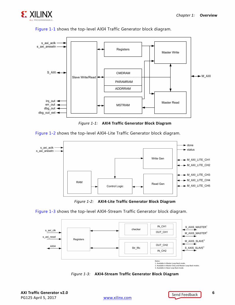
Figure 1-1 shows the top-level AXI4 Traffic Generator block diagram.
Figure 1-2 shows the top-level AXI4-Lite Traffic Generator block diagram.
Figure 1-3 shows the top-level AXI4-Stream Traffic Generator block diagram.
X-Ref Target - Figure 1-1
Figure 1-1: AXI4 Traffic Generator Block Diagram
X-Ref Target - Figure 1-2
Figure 1-2: AXI4-Lite Traffic Generator Block Diagram
X-Ref Target - Figure 1-3
Figure 1-3: AXI4-Stream Traffic Generator Block Diagram
Registers
Slave Write/Read
Master Write
Master ReadMSTRAM
s_axi_aclks_axi_aresetn
irq_outerr_out
S_AXIM_AXI
dbg_outdbg_out_ext
PARAMRAM
CMDRAM
ADDRRAM
RAM
Write Gen
Read GenControl Logic
s_axi_aclks_axi_aresetn
donestatus
M_AXI_LITE_CH1
M_AXI_LITE_CH2
M_AXI_LITE_CH3
M_AXI_LITE_CH4
M_AXI_LITE_CH5
Registers
OUT_CH1
OUT_CH2
IN_CH2Str_fifo
s_axi_clk
s_axi_reset
AXI4
M_AXIS_MASTER2
M_AXIS_SLAVE3
S_AXIS_SLAVE3
S_AXIS_MASTER1
checkerIN_CH1
Notes:1. Available in Master Loop Back mode.2. Available in Master Only and Master Loop Back modes.3. Available in Slave Loop Back mode.
Send Feedback

AXI Traffic Generator v2.0 7PG125 April 5, 2017 www.xilinx.com
Chapter 1: Overview
Modes DescriptionThe AXI Traffic Generator has two major profile selection modes:
• Custom – This mode allows you to select different AXI4 interface traffic generation. The available options are AXI4, AXI4-Stream, and AXI4-Lite that include these modes:
° Advanced Mode
° Basic Mode
° Static Mode
° System Init/Test Mode
° Streaming Mode
• High Level Traffic – This mode allows you to generate IP specific traffic on the AXI interface for pre-defined protocols. The currently supported traffic profiles include:
° Video Mode
° PCIe® Mode
° Ethernet Mode
° USB Mode
° Data Mode
Advanced ModeAdvanced mode allows full control over the traffic generation. Control registers are provided to program the core and generate different AXI4 transactions. For more information on each register, see the Register Space section.
Three internal RAMs are used as follows:
• Command RAM (CMDRAM)
• Parameter RAM (PARAMRAM)
• Master RAM (MSTRAM)
• Address RAM (ADDRRAM)
Command RAM
The CMDRAM is divided into two 4 KB regions, one for reads and one for writes. Each region of CMDRAM can hold 256 commands. Read and write commands are executed simultaneously and independently. CMDRAM is realized using the dual-port block RAM.
Send Feedback

AXI Traffic Generator v2.0 8PG125 April 5, 2017 www.xilinx.com
Chapter 1: Overview
Access to CMDRAM is prohibited after master logic of the core is enabled (Bit[20] MSTEN of Master Control (0x00)).
Reads are issued to the master-read block AR channel from CMDRAM (0x000 to 0xFFF) locations (up to 256 commands of 128 bits each). Writes are issued to the master-write block AW channel from CMDRAM (0x1000 to 0x1FFF) locations (up to 256 commands of 128 bits each). Each command does not indicate whether it is a read or a write because it is implied by its position in the CMDRAM.
CMD Memory Format
Each CMDRAM command in Table 1-2 is 128 bits wide.
Table 1-2: CMDRAM Memory Format
Word Offset Bits Description
+00 31:0 AXI_Address[31:0]: Address to drive on ar_addr or aw_addr (a*_addr[31:0])
+01
31 Valid_cmd(1): When set, this is a valid command. When clear, halt the master logic for this request type (read or write).
30:28 last_addr[2:0]: Should be set to 0 for C_M_AXI_DATA_WIDTH > 64. For writes, indicates the valid bytes in the last data cycle.
64-bit mode:
000 = All bytes valid
001 = Only Byte 0 is valid
010 = Only Bytes 0 and 1 are valid
...
32-bit mode:
000 = All bytes valid
100 = Only Byte 0 is valid
101 = Only Bytes 0 and 1 are valid
110 = Only Bytes 0, 1, and 2 are valid
27:24 Reserved
23:21 Prot[2:0]: Driven to a*_prot[2:0]
20:15 Id[5:0]: Driven to a*_id[5:0]
14:12 Size[2:0]: Driven to a*_size[2:0]
11:10 Burst[1:0]: Driven to a*_burst[1:0]
9 Reserved
8 Lock: Driven to a*_lock
7:0 Len[7:0]: Driven to a*_len[7:0].
Send Feedback

AXI Traffic Generator v2.0 9PG125 April 5, 2017 www.xilinx.com
Chapter 1: Overview
PARAMRAM
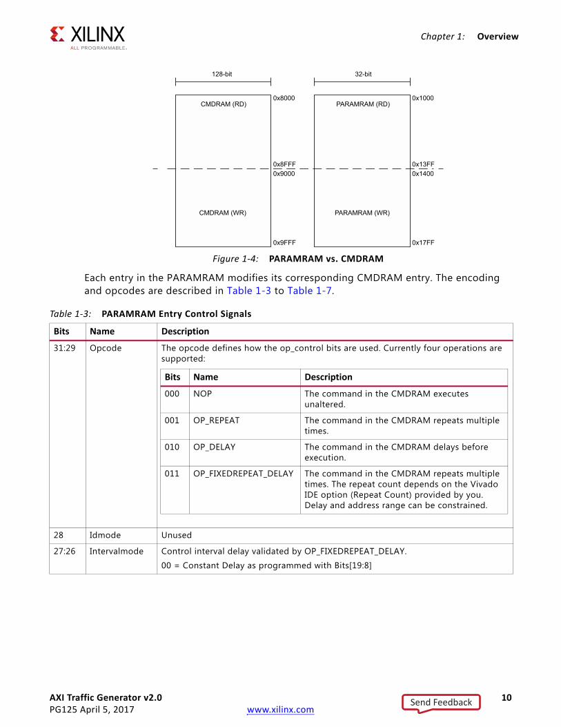
The PARAMRAM extends the command programmability provided through command RAM by adding 32 bits to the decode of each command. Figure 1-4 shows how the PARAMRAM is addressed in relation to the CMDRAM. Only write access is allowed to the PARAMRAM from the slave interface. Reads to PARAMRAM from the slave interface are routed to the register address space.
+02
31 Reserved
30:22 My_depend[8:0]: This command does not begin until this master logic has at least completed up to this command number. A value of zero in this field means do not wait. This allows a command to wait until previous commands have completed for ordering.
21:13 Other_depend[8:0]: This command does not begin until the other master logic has completed up to this command number. For example, if a write command had 0x04 in this field, the write would not begin until the read logic had at least completed its commands (CMDs) 0x00 through 0x03.
A value of 0 in this field means do not wait, but commands can only be started in order for each master type. For example, if Write CMD[0x05] waits for Read 0x03, then Write CMD[0x06] cannot start until Read 0x03 completes as well. A read completes when it receives the last cycle of data, and a write completes when it receives BRESP.
12:0 Mstram_index[12:0](2): Index into MSTRAM for this transaction (reads will write to this MSTRAM address, writes take data from this address)
+03
31:20 Reserved
19:16 qos[3:0]: Driven to a*_qos[3:0]
15:8 user[7:0]: Driven to a*_user[7:0]
7:4 cache[3:0]: Driven to a*_cache[3:0]
3 Reserved
2:0 Expected_resp:
0x0 to 0x1 = Only OKAY is allowed
0x2 = Only EX_OK is allowed
0x3 = EX_OK or OKAY is allowed
0x4 = Only DECERR or SLVERR is allowed
0x7 = Any response is allowed
Notes: 1. Valid_cmd: There should be at least one command with valid_cmd bit set to zero for both reads and writes.2. Mstram_index: MSTRAM is shared by both Read/Write master logic. To avoid memory collision issues, ensure no write
command data overlaps with read-command data by selecting proper index values. MSTRAM index should be aligned the same as the master (Read/Write) address. Example: For a 64-bit aligned transaction, the least three bits should be zero. For a 128-bit aligned transaction, the least four bits should be zero.Address generation for MSTRAM is based on the burst type selected for command.
3. It is recommended to write 0s to the command RAM reserved bits.4. Address and burst length should be selected such that the transaction does not cross the 4K boundary.5. Reads to CMDRAM from slave interface should be burst length 0.
Table 1-2: CMDRAM Memory Format (Cont’d)
Word Offset Bits Description
Send Feedback
AXI Traffic Generator v2.0 10PG125 April 5, 2017 www.xilinx.com
Chapter 1: Overview
Each entry in the PARAMRAM modifies its corresponding CMDRAM entry. The encoding and opcodes are described in Table 1-3 to Table 1-7.
X-Ref Target - Figure 1-4
Figure 1-4: PARAMRAM vs. CMDRAM
CMDRAM (RD)
CMDRAM (WR)
128-bit
0x8000
0x8FFF0x9000
0x9FFF
PARAMRAM (RD)
PARAMRAM (WR)
32-bit
0x1000
0x13FF0x1400
0x17FF
Table 1-3: PARAMRAM Entry Control Signals
Bits Name Description
31:29 Opcode The opcode defines how the op_control bits are used. Currently four operations are supported:
28 Idmode Unused
27:26 Intervalmode Control interval delay validated by OP_FIXEDREPEAT_DELAY.
00 = Constant Delay as programmed with Bits[19:8]
Bits Name Description
000 NOP The command in the CMDRAM executes unaltered.
001 OP_REPEAT The command in the CMDRAM repeats multiple times.
010 OP_DELAY The command in the CMDRAM delays before execution.
011 OP_FIXEDREPEAT_DELAY The command in the CMDRAM repeats multiple times. The repeat count depends on the Vivado IDE option (Repeat Count) provided by you. Delay and address range can be constrained.
Send Feedback

AXI Traffic Generator v2.0 11PG125 April 5, 2017 www.xilinx.com
Chapter 1: Overview
PARAMRAM Opcodes
Each of the four commands uses 24 bits of op_control space to shape the command. Each of the four op_control fields is described in Table 1-3 to Table 1-7.
The OP_NOP command is ignored and the command within the CMDRAM is executed normally.
The entire op_control field of 24 bits is used as a counter for repeating the command in the CMDRAM entry.
25:24 Addrmode Control addressing when a command is being repeated.
23:0 PARAMRAM Opcodes
The definition for Bits[23:0] depend on the selected PARAMRAM opcodes. Details are described in Table 1-3 to Table 1-7.
Notes: 1. When using PARAMRAM in Address increment or random address generation mode, ensure that the address specified is
aligned to burst boundaries. Failing to do so results in gaps being inserted in the address range.For example, in a 32-bit transaction with 16 being the burst length, the last three bits of the address has to be “0.”
2. All transactions in Random mode are generated with data width aligned addresses.
Table 1-3: PARAMRAM Entry Control Signals (Cont’d)
Bits Name Description
Bits Name Description
00 Constant Address does not change
01 Increment Address increments ((BUSWIDTH / 8) × (AXI_LEN + 1)) between repeated transactions
10 Random Address is randomly generated within a address range. Valid only when OP_FIXEDREPEAT_DELAY is selected.
Table 1-4: OP_NOP
Bits Name Description
23:0 Unused N/A
Table 1-5: OP_REPEAT
Bits Name Description
23:0 Repeat Count Command repeats this many times.
Send Feedback

AXI Traffic Generator v2.0 12PG125 April 5, 2017 www.xilinx.com
Chapter 1: Overview
The entire op_control field of 24 bits is used as a delay counter for issuance of the command in the CMDRAM entry.
PARAMRAM should be filled with valid data for corresponding entry in the CMDRAM. CMDRAM should be filled with valid data until the first invalid command entry.
An example programming sequence is to generate a write transaction with 64 beats transferred to slave every 5 µs. When the clock frequency is running at 100 MHz, you could have the awlen (other AXI parameters to be set as per requirement) set to 0x3F which corresponds to decimal value 63 to have 64 beats transferred in one transaction.
Also, you can have the PARAMRAM programmed to value 0x400001F4, which decodes as IP is in OP_DELAY mode. The minimum delay between two transactions is 1F4 cycles, which is 500 cycles. If you want the transaction to be repeated, the PARAMRAM can be programmed as 0x8001F400 to set IP in FIXEDREPEAT_DELAY mode. The repeat count would be dependent on the Vivado IDE value selected.
Table 1-6: OP_DELAY
Bits Name Description
23:0 Delay Count Command execution is delayed for this many cycles.
Notes: 1. Delay observed between two transactions ≥ the programmed value.2. if the programmed valued is ≤ to 6 the minimum delay observed is 6 clock cycles.
Table 1-7: OP_FIXEDREPEAT_DELAY
Bits Name Description
23:20 Addr Range Encoded Core issues a new random address within the range encoded below starting with base address you programmed.
19:8 Delay Count Each command execution is delayed for this many cycles.
7:0 Delay Range Encoded Unused
Notes: 1. Delay observed between two transactions ≥ the programmed value.
Encoded Range (KB) Encoded Range (MB)
0 4 8 1
1 8 9 2
2 16 10 4
3 32 11 8
4 64 12 16
5 128 13 32
6 256 14 64
7 512 15 128
Send Feedback

AXI Traffic Generator v2.0 13PG125 April 5, 2017 www.xilinx.com
Chapter 1: Overview
Address RAM
When the address width is configured in Vivado IDE is > 32, the extended address capability for the Master AXI4 interface in the AXI4 mode is available. In cases when address width is configured to 32, the Address RAM is not present and cannot be accessed.
The Address RAM entries correspond to the MSB bits of address and are concatenated to Bits[31:0] in CMDRAM. All 32 bits of RAM are accessible when the address width is > 32, but only the appropriate bits are considered and driven on the m_axi_*addr pins.
For example, if the address width is configured to be 36 in the Vivado IDE, enter a 32-bit value in the Address RAM such as 0x12345678. The 8 is concatenated to address bits in the CMDRAM and are driven on the address lines in the Master AXI4 interface.
Master RAM
The MSTRAM has 8 KB of internal RAM used for the following:
• Take data from this RAM for write transactions
• Store data to this RAM for read transaction
The RAM address to use for a read/write transaction is controlled through command RAM programming.
X-Ref Target - Figure 1-5
Figure 1-5: Address RAM
ADDRRAM (RD)
32-bit
0xA000
0xA3FF0xA400
0xA7FF
ADDRRAM (WR)
Send Feedback

AXI Traffic Generator v2.0 14PG125 April 5, 2017 www.xilinx.com
Chapter 1: Overview
The Master RAM A and B channels are shown connected in Figure 1-6.
MSTRAM Index defines where to take data from MSTRAM (in case of write) and where to store the data (in case of read) in Advanced/Basic mode of operation. Table 1-8 shows details for the write data.
In the case of Read, the Index definition changes based on data width of the AXI4 Master interface. Table 1-9 shows details for data widths ≤ 64.
For data width > 64, rdata is stored at the 128/256/512 aligned locations (mstram_index should be set in the same manner).
X-Ref Target - Figure 1-6
Figure 1-6: Master RAM Channels
Table 1-8: Write
Address Data MSTRAM Entry Number (Index Entered in CMDRAM Programming)
0xC000 0x111111110
0xC004 0x22222222
0xC008 0x333333331
0xC00C 0x44444444
0xC010 0xABCD12342
0xC014 0xFAAB1234
…
Table 1-9: Read
Address Data MSTRAM Entry Number (Index Entered in CMDRAM Programming)
0xC000 0x111111110
0xC004 0x22222222
0xC008 0x333333331
0xC00C 0x44444444
0xC010 0xABCD12342
0xC014 0xFAAB1234
…
Master RAM
CH A: Write (Master Read Module)
CH A: Read (Slave Read Module)
CH B: Read (Master Write Block)
CH B: Write (Slave Write Block)
Send Feedback
AXI Traffic Generator v2.0 15PG125 April 5, 2017 www.xilinx.com
Chapter 1: Overview
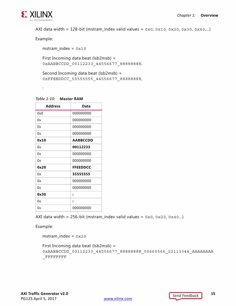
AXI data width = 128-bit (mstram_index valid values = 0x0, 0x10, 0x20, 0x30, 0x40,…)
Example:
mstram_index = 0x10
First Incoming data beat (lsb2msb) = 0xAABBCCDD_00112233_44556677_88888888,
Second Incoming data beat (lsb2msb) = 0xFFEEDDCC_55555555_44556677_88888888,
:
AXI data width = 256-bit (mstram_index valid values = 0x0, 0x20, 0x40…)
Example:
mstram_index = 0x20
First Incoming data beat (lsb2msb) = 0xAABBCCDD_00112233_44556677_88888888_55665566_22113344_AAAAAAAA_FFFFFFFF
Table 1-10: Master RAM
Address Data
0x0 000000000
0x 000000000
0x 000000000
0x 000000000
0x10 AABBCCDD
0x 00112233
0x 000000000
0x 000000000
0x20 FFEEDDCC
0x 55555555
0x 000000000
0x 000000000
0x30 :
0x :
0x 000000000
Send Feedback

AXI Traffic Generator v2.0 16PG125 April 5, 2017 www.xilinx.com
Chapter 1: Overview
Second Incoming data beat (lsb2msb) = 0xFFEEDDCC_55555555_44556677_88888888_55665566_22113344_AAAAAAAA_FFFFFFFF
:
Table 1-11: Master RAM
Address Data
0x0 000000000
0x 000000000
0x 000000000
0x 000000000
0x 000000000
0x 000000000
0x 000000000
0x 000000000
0x20 AABBCCDD
0x 00112233
0x 000000000
0x 000000000
0x 000000000
0x 000000000
0x 000000000
0x 000000000
0x40 FFEEDDCC
0x 55555555
0x 000000000
0x 000000000
0x 000000000
0x 000000000
0x 000000000
0x 000000000
0x60 :
0x :
Send Feedback

AXI Traffic Generator v2.0 17PG125 April 5, 2017 www.xilinx.com
Chapter 1: Overview
Address Generation
The address generation to the MSTRAM from each of the mentioned block is through the addrgen block. Addrgen blocks receive input for the address information, length, and bus size. Then, it generates output for the an index into the MSTRAM for each beat of the transfer. It also tracks the transfer length and signals to other logic when a transfer is complete.
Addrgen block considers the "mstram_index" and "AXI_Address" in the Command RAM entries to generate the MSTRAM address.
Mstram_index should be selected in such a way that it matches AXI_Address offset. The following examples illustrate the mstram_index selection:
• 32-bit Aligned Transfer – Lower Bits[1:0] of AXI_Address are zero. Mstram_index should also be selected in such a way that the lower Bits[1:0] are zero.Example:
AXI_Address = 0xC000_0004Mstram_index = 0x0000_C004
• 32-bit Unaligned Transfer – Lower Bits[1:0] of AXI_Address are offset by the byte from which transfer should start. Mstram_index should also be selected in such a way that the lower Bits[1:0] are offset by the same byte offset as indicated by AXI_Address.Example:
AXI_Address = 0xC000_0005 (offset by 1-byte)Mstram_index = 0x0000_C005 (offset by 1-byte)
• 64-bit Aligned Transfer – Lower Bits[2:0] of AXI_Address are zero. Mstram_index should also be selected in such a way that the lower Bits[2:0] are zero.Example:
AXI_Address = 0xC000_0008Mstram_index = 0x0000_C008
• 64-bit Unaligned Transfer – Lower Bits[2:0] of AXI_Address are offset by the byte from which transfer should start. Mstram_index should also be selected in such a way that the lower Bits[2:0] are offset by the same byte offset as indicated by AXI_Address.Example:
AXI_Address = 0xC000_0005 (offset by 5 bytes)Mstram_index = 0x0000_C005 (offset by 5 bytes)
Similar rules apply for higher data width (128/256/512) transactions. Only aligned transfers are supported for 128/256/512-bit width selection.
Send Feedback

AXI Traffic Generator v2.0 18PG125 April 5, 2017 www.xilinx.com
Chapter 1: Overview
Data Generation
MSTRAM is organized as 64-bit wide, 1024-deep memory. For data widths of 32 and 64, the data from MSTRAM is sent to corresponding modules without any truncation/expansion in data width.
To save multiple RAM instances in data widths > 64, the same 64-bit data is duplicated/truncated based on the current data width selection of master channels.
The following example uses a data width of 128:
• During read access from master write block,
wdata_m[127:0] = 2{read_data_from_mstram[63:0]}
That is, 64-bit data is duplicated on write-data bus to make it 128 bits wide.
• During write access by master read block,
write_data_to_mastram[63:0] = rdata_m[63:0]
That is, lower 64 bits of read data bus are stored in MSTRAM.
For data width of 256:
• During read access from master write block,
wdata_m[255:0] = 4{read_data_from_mstram[63:0]}
That is, 64-bit data is duplicated on write-data bus to make it 256 bits wide.
• During write access by master read block,
write_data_to_mastram[63:0] = rdata_m[63:0]
That is, lower 64 bits of read data bus are stored in MSTRAM.
Send Feedback

AXI Traffic Generator v2.0 19PG125 April 5, 2017 www.xilinx.com
Chapter 1: Overview
Slave Modules
Figure 1-7 shows the slave logic.
• Slave-write – The slave AR, AW, and W ports each have a FIFO to collect data from the switch. The output buses B and R also use a small FIFO to buffer their outgoing data. The write addresses from the AW bus then goes to an Aw_agen block which generates the proper MSTRAM addresses and writes the corresponding data word to the MSTRAM. After a transaction is complete, the ID information is passed to the B_track tracker which writes the completion ID to one of Bfifo0 to BFIFO3. These Bfifos then arbitrate to write the completions into the final Bfifo, allowing the creation of out-of-order write responses.
• Slave-read – Read addresses are placed in the Arfifo which then use the Ar_track tracker to distribute the requests across Ar_agen0 to Ar_agen3. These generate the proper addresses to the MSTRAM for each single request. The Ar_agen0 to Ar_agen3 arbitrates for access to the MSTRAM at each cycle in the Ar_sel block. The data is placed in the small Rfifo and then driven to the switch on the R bus.
X-Ref Target - Figure 1-7
Figure 1-7: AXI_Traffic_Generator Slave
Awfifo
Awfifo
Wfifo
Arfifo
Ar_track
B_t
rack
Bfifo
MSTRAM
Rfifo
Ar_
sel
Bffo0
Bffo1
Bffo2
Bffo3
Ar_agen0
Ar_agen1
Ar_agen2
Ar_agen3
AW
W
AR
B
R
Send Feedback
AXI Traffic Generator v2.0 20PG125 April 5, 2017 www.xilinx.com
Chapter 1: Overview
Table 1-12 shows the address map for different regions accessed by slave-write/slave-read.
Unused memory locations in the memory space (considering 0x00000000 to 0x0000FFFF) with respect to Table 1-12 are reserved; accessing these does not give any error response. Address aliasing applied for memory space is defined in Table 1-12 except PARAMRAM.
For slave logic, the write interleaving depth is one.
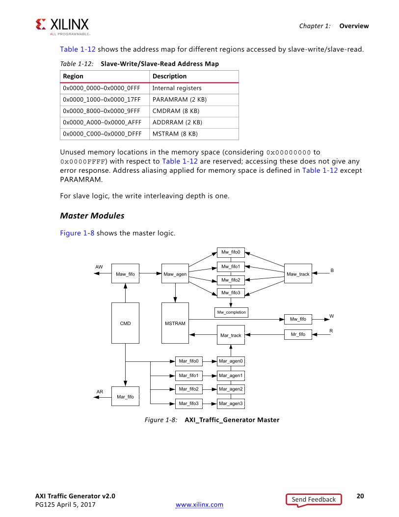
Master Modules
Figure 1-8 shows the master logic.
Table 1-12: Slave-Write/Slave-Read Address Map
Region Description
0x0000_0000–0x0000_0FFF Internal registers
0x0000_1000–0x0000_17FF PARAMRAM (2 KB)
0x0000_8000–0x0000_9FFF CMDRAM (8 KB)
0x0000_A000–0x0000_AFFF ADDRRAM (2 KB)
0x0000_C000–0x0000_DFFF MSTRAM (8 KB)
X-Ref Target - Figure 1-8
Figure 1-8: AXI_Traffic_Generator Master
Maw_fifo
Mar_fifo
Maw_agen
CMD MSTRAM
Maw_track
Mar_track
Mw_fifo0
Mw_fifo
Mr_fifo
Mw_fifo1
Mw_fifo2
Mw_fifo3
Mw_completion
Mar_fifo0
Mar_fifo1
Mar_fifo2
Mar_fifo3
Mar_agen0
Mar_agen1
Mar_agen2
Mar_agen3
AW
AR
B
W
R
Send Feedback

AXI Traffic Generator v2.0 21PG125 April 5, 2017 www.xilinx.com
Chapter 1: Overview
Issuing Read Transactions
For reads, each CMD is read from the CMDRAM and pushed to the 2-deep Mar_fifo. Mar_track decides which Mar_fifo0 to Mar_fifo3 it is also pushed into. The first ID goes to Mar_fifo0, the next ID goes to Mar_fifo1, etc. The Mar_fifo sends the information to the AXI_M AR signals. The Mar_fifo0 to Mar_fifo3 hold the requests before sending them to Mar_agen0 to Mar_agen3. If the Mar_track assigns ID = 0x12 to Mar_fifo1, any further ID = 0x12 transactions are pushed onto Mar_fifo1.
After four unique IDs are valid at once, no further Read CMDs can be processed until one of the Mar_fifo0 to Mar_fifo3 is empty. Read data returned from the switch is placed in Mr_fifo, then popped out. Each ID is searched across each Mar_agen0 to Mar_agen3, which selects the proper Mar_agen and drives the address to the MSTRAM to write in the R data.
On the last data cycle, the corresponding Mar_fifo0 to Mar_fifo3 is popped, and the next entry is prepared. This strategy allows at least four simultaneous reads with any arbitrary ID and often allows more if the same ID is reused in multiple requests.
Issuing Write Transactions
For writes, each CMD is read from the CMDRAM and pushed to the 2-deep Maw_fifo and Maw_fifow. Maw_fifo is connected to the AXI_M AW signals and drives the request to the switch. Maw_fifow holds two requests heading to the Maw_agen block which generates addresses into the MSTRAM. Data read from MSTRAM is pushed into the Mw_fifo, which is connected to the AXI_M W signals.
To return BRESP out of order, Maw_agen feeds into Maw_track which tracks up to four IDs in a similar way to Mar_track. A write ID is assigned to an Mw_fifo0 to 3. When that ID receives a BRESP, it pops the corresponding Mw_fifo0 to 3. This allows the master write logic to handle receiving BRESPs out of order.
Basic ModeBasic mode allows basic AXI4 traffic generation with less resource overhead. This mode is a lightweight version of the Advanced mode with the following AXI features not supported:
• Out-of-order transactions
• Narrow transfers
• Holes in write strobe
Send Feedback
AXI Traffic Generator v2.0 22PG125 April 5, 2017 www.xilinx.com
Chapter 1: Overview
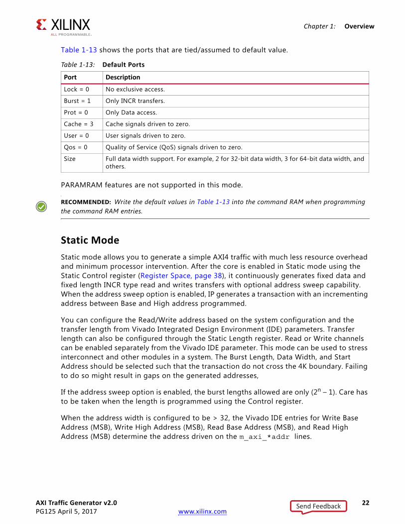
Table 1-13 shows the ports that are tied/assumed to default value.
PARAMRAM features are not supported in this mode.
RECOMMENDED: Write the default values in Table 1-13 into the command RAM when programming the command RAM entries.
Static ModeStatic mode allows you to generate a simple AXI4 traffic with much less resource overhead and minimum processor intervention. After the core is enabled in Static mode using the Static Control register (Register Space, page 38), it continuously generates fixed data and fixed length INCR type read and writes transfers with optional address sweep capability. When the address sweep option is enabled, IP generates a transaction with an incrementing address between Base and High address programmed.
You can configure the Read/Write address based on the system configuration and the transfer length from Vivado Integrated Design Environment (IDE) parameters. Transfer length can also be configured through the Static Length register. Read or Write channels can be enabled separately from the Vivado IDE parameter. This mode can be used to stress interconnect and other modules in a system. The Burst Length, Data Width, and Start Address should be selected such that the transaction do not cross the 4K boundary. Failing to do so might result in gaps on the generated addresses,
If the address sweep option is enabled, the burst lengths allowed are only (2n – 1). Care has to be taken when the length is programmed using the Control register.
When the address width is configured to be > 32, the Vivado IDE entries for Write Base Address (MSB), Write High Address (MSB), Read Base Address (MSB), and Read High Address (MSB) determine the address driven on the m_axi_*addr lines.
Table 1-13: Default Ports
Port Description
Lock = 0 No exclusive access.
Burst = 1 Only INCR transfers.
Prot = 0 Only Data access.
Cache = 3 Cache signals driven to zero.
User = 0 User signals driven to zero.
Qos = 0 Quality of Service (QoS) signals driven to zero.
Size Full data width support. For example, 2 for 32-bit data width, 3 for 64-bit data width, and others.
Send Feedback

AXI Traffic Generator v2.0 23PG125 April 5, 2017 www.xilinx.com
Chapter 1: Overview
System Init/Test ModeSystem Init mode is a special mode where core provides AXI4-Lite Master interface. This mode can be used in a system without a processor to initialize the system peripherals with preconfigured values on system reset or for simple system testing.
After the core comes out of reset in System Init mode, it reads the coefficient (COE) files (address and data) from the ROM and generates AXI4-Lite transactions. You must provide two COE files for this mode. Entries in all of the COE files are 32-bit.
• Address COE File – Provides the sequence of addresses to be issued
• Data COE File – Provides the sequence of data corresponding to the address specified in Address COE File
IMPORTANT: You need to fill the entries in the COE files to match the requirement. First address entry in Address COE file corresponds to first data entry in the Data COE file.
Operation
1. After AXI Traffic Generator (ATG) comes out of reset, it reads the ADDR and DATA ROMs.
2. It initiates AXI4-Lite write transactions to a specified address and data in the COE files.
3. The core goes to idle state after AXI4-Lite transactions are issued.
Figure 1-9 shows the example use-case where ATG (System Init mode) is used to initialize peripherals in a system without a processor.
X-Ref Target - Figure 1-9
Figure 1-9: System Init Mode Block Diagram
ATG
AX
I Interconnect
Peripheral #1
Peripheral #2
Peripheral #16
Send Feedback
AXI Traffic Generator v2.0 24PG125 April 5, 2017 www.xilinx.com
Chapter 1: Overview
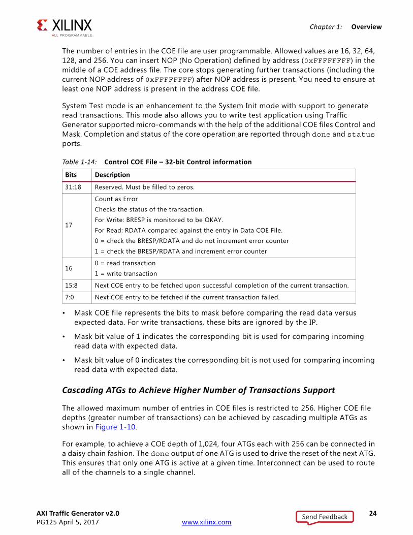
The number of entries in the COE file are user programmable. Allowed values are 16, 32, 64, 128, and 256. You can insert NOP (No Operation) defined by address (0xFFFFFFFF) in the middle of a COE address file. The core stops generating further transactions (including the current NOP address of 0xFFFFFFFF) after NOP address is present. You need to ensure at least one NOP address is present in the address COE file.
System Test mode is an enhancement to the System Init mode with support to generate read transactions. This mode also allows you to write test application using Traffic Generator supported micro-commands with the help of the additional COE files Control and Mask. Completion and status of the core operation are reported through done and status ports.
• Mask COE file represents the bits to mask before comparing the read data versus expected data. For write transactions, these bits are ignored by the IP.
• Mask bit value of 1 indicates the corresponding bit is used for comparing incoming read data with expected data.
• Mask bit value of 0 indicates the corresponding bit is not used for comparing incoming read data with expected data.
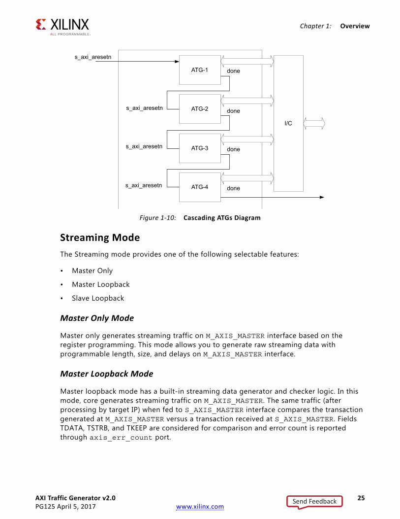
Cascading ATGs to Achieve Higher Number of Transactions Support
The allowed maximum number of entries in COE files is restricted to 256. Higher COE file depths (greater number of transactions) can be achieved by cascading multiple ATGs as shown in Figure 1-10.
For example, to achieve a COE depth of 1,024, four ATGs each with 256 can be connected in a daisy chain fashion. The done output of one ATG is used to drive the reset of the next ATG. This ensures that only one ATG is active at a given time. Interconnect can be used to route all of the channels to a single channel.
Table 1-14: Control COE File – 32-bit Control information
Bits Description
31:18 Reserved. Must be filled to zeros.
17
Count as Error
Checks the status of the transaction.
For Write: BRESP is monitored to be OKAY.
For Read: RDATA compared against the entry in Data COE File.
0 = check the BRESP/RDATA and do not increment error counter
1 = check the BRESP/RDATA and increment error counter
160 = read transaction
1 = write transaction
15:8 Next COE entry to be fetched upon successful completion of the current transaction.
7:0 Next COE entry to be fetched if the current transaction failed.
Send Feedback
AXI Traffic Generator v2.0 25PG125 April 5, 2017 www.xilinx.com
Chapter 1: Overview
Streaming ModeThe Streaming mode provides one of the following selectable features:
• Master Only
• Master Loopback
• Slave Loopback
Master Only Mode
Master only generates streaming traffic on M_AXIS_MASTER interface based on the register programming. This mode allows you to generate raw streaming data with programmable length, size, and delays on M_AXIS_MASTER interface.
Master Loopback Mode
Master loopback mode has a built-in streaming data generator and checker logic. In this mode, core generates streaming traffic on M_AXIS_MASTER. The same traffic (after processing by target IP) when fed to S_AXIS_MASTER interface compares the transaction generated at M_AXIS_MASTER versus a transaction received at S_AXIS_MASTER. Fields TDATA, TSTRB, and TKEEP are considered for comparison and error count is reported through axis_err_count port.
X-Ref Target - Figure 1-10
Figure 1-10: Cascading ATGs Diagram
s_axi_aresetn
done
s_axi_aresetn
s_axi_aresetn
s_axi_aresetn
ATG-1
I/C
done
done
done
ATG-2
ATG-3
ATG-4
Send Feedback

AXI Traffic Generator v2.0 26PG125 April 5, 2017 www.xilinx.com
Chapter 1: Overview
Slave Loopback Mode
Slave loopback mode provides a simple stream loopback function. In this mode, the core receives streaming traffic over the S_AXIS_SLAVE interface and loops back the same traffic over M_AXIS_SLAVE. The core uses an internal FIFO of depth 14 to allow throttling on M_AXIS_SLAVE while still accepting data S_AXIS_SLAVE interface.
High Level TrafficThis mode allows you to generate IP specific traffic on the AXI interface for pre-defined protocols like PCIe, Ethernet, and others. Based on the selected profile, AXI Traffic Generator generates AXI traffic to meet the desired throughput as if a real IP delivering the AXI transactions. This helps to characterize the system without the real IP in hand.
Different pre-defined traffic profiles available include:
• Video – This selection can be used to mimic video IP which processes video information and generates AXI Traffic. Different available options include HSize, VSize, Pixel bits, etc.
• PCIe – This selection mimics PCIe IP which processes PCIe packets and generates AXI Traffic. Different available options include PCIe Lanes, lane rate, etc. PCIe load option can be used to generate a partial load on the bus combined with the PCIe related options.
• Ethernet – This selection mimics Ethernet IP which processes Ethernet packets and generates AXI Traffic. Different available options include Ethernet speed and Ethernet load. Load option can be used to generate a partial load on the bus combined with the Ethernet related options.
• USB – This selection mimics USB IP which processes USB packets and generates AXI Traffic. Options available include USB Mode which can be ISOC or BULK. Load option can be used to generate a partial load on the bus combined with the USB related options.
• Data – This is a generic mode which can be used to generate user intended traffic when one of the above options does not meet the requirements. Options available include read channel/write channel share, minimum, maximum, average constraint on the transaction length generated, etc.
When the address width is configured to be > 32, the Vivado IDE entries for AXI Base Address (MSB) and AXI High Address (MSB) determines the address driven on the m_axi_*addr lines.
Note: All of the High Level Traffic Protocol options (Ethernet, Video, PCIe, USB) do not actually generate the corresponding protocol packets. They mimic the AXI side throughput only. For example, USB outputs a throughput worth 48 MB/s on AXI. So the ATG controls length and gap between the transactions to achieve this throughput. At system-level on the AXI side, this appears as if a real USB is pumping the AXI traffic which helps to model/tune the system further.
Send Feedback

AXI Traffic Generator v2.0 27PG125 April 5, 2017 www.xilinx.com
Chapter 1: Overview
IMPORTANT: A low burst length value might prevent achieving the required throughput. A PCIe mode with data width 512, burst length of two with four PCIe lanes, eight (GT/s) line rate, and 100% channel load, the maximum channel capacity is 6,400 MB/s. The expected throughput would be 3,940 MB/s but this throughput is not achieved by the core as a single transaction. It would at least require four cycles to finish (data transfer + response) to achieve the required data rate with this burst length. The transaction has to finish in two cycles which is incorrect. In this case, the burst length has to be at least four to get the required throughput.
Programming Sequence
Advanced/Basic Mode with Processor1. Load CMDRAM RAM with the required number of commands.
2. Load PARAM RAM with the desired opcodes. PARAM RAM applicable only in Advanced mode.
3. Load MSTRAM memory with data to be issued during write transactions.
4. Enable the desired interrupt/status bits.
5. Enable the core through register control signal.
6. Wait for interrupt (if enabled) or poll Enable register control signal to check for completion of issuing the commands.
Advanced/Basic Mode without Processor Intervention1. Edit the default generated mif files (default_<componentname>_cmdram.mif,
default_<componentname>_prmram.mif, default_<componentname>_mstram.mif) to match desired profile.
2. Generate an input start pulse to the core_ext_start port.
3. Wait for irq_out to check for completion of issuing the commands.
Static Mode with Processor1. Select the desired Address/length from the Vivado IDE while generating the core.
2. Enable the core through register control signal.
3. To change the burst length, disable the core, program new burst length in Static Length register, and re-enable the core.
Send Feedback

AXI Traffic Generator v2.0 28PG125 April 5, 2017 www.xilinx.com
Chapter 1: Overview
Static Mode without Processor Intervention1. Select the desired address/length from the Vivado IDE while generating the core.
2. Generate an input start pulse at the core_ext_start port.
3. Generate an input stop pulse at the core_ext_stop port when you want to stop generating traffic.
Streaming Mode with Processor1. Program Streaming Config and Transfer Length registers as desired.
2. Enable the core through register control.
3. Wait for command completion by polling done status in Control register.
Note: Slave loopback mode does not need any input. The core receives transactions on slave interface and generates them on master interface.
Streaming Mode without Processor Intervention1. Generate an input start pulse at the core_ext_start port.
2. Generate an input stop pulse at the core_ext_stop port when you want to stop generating traffic.
Note: Slave loopback mode does not need any input. The core receives transactions on slave interface and generates them on master interface.
High Level Traffic1. Generate an input start pulse at the core_ext_start port.
2. Generate an input stop pulse at the core_ext_stop port when you want to stop generating traffic.
Note: For Data mode with "Traffic Gen" selected to "One-shot," it is not necessary to provide the core_ext_stop, core automatically stops after one-shot of traffic is generated.
System Init/Test Mode1. Provide the required COE files during core customization from the Vivado IDE.
2. This initiates the AXI4-Lite transactions on the Master interface when the core comes out of reset.
3. Status of the core operation is available on status port (see Table 2-1 for details) when done is asserted.
Send Feedback

AXI Traffic Generator v2.0 29PG125 April 5, 2017 www.xilinx.com
Chapter 1: Overview
Example
Assume a test core operates in the following method when the core is enabled through a register bit:
• Checks for the Configuration register values
• Generates output based on the configuration
• Updates the Status register after completed
This is tested in hardware using the System Test mode of the AXI Traffic Generator by developing the COE files.
After following the example, this can be tested with this test sequence.
1. Program Configuration register (0x4) to a value of 0x12A0_1100.
2. Enable completion status bit in Status Enable register (0x8) with a value 0x0000_000F.
3. Enable the core by writing to Control register (0x0) with a value of 0x0000_0001.
4. Read the Status register (0xC) until the status value is 0x0000_000F.
Based on the test sequence, four COE files need to be developed. Using these COE files the AXI Traffic Generator generates the test sequence and asserts done with the appropriate status.
ApplicationsThe AXI Traffic Generator can be connected to an AXI-based system to stress the modules connected to the interconnect.
Figure 1-11 shows the AXI Traffic Generator connected to a MicroBlaze™ processor. The MicroBlaze programs the AXI Traffic Generator and the AXI Traffic Generator creates traffic to other cores.
Send Feedback

AXI Traffic Generator v2.0 30PG125 April 5, 2017 www.xilinx.com
Chapter 1: Overview
Figure 1-12 shows the AXI Traffic Generator connected to a Zynq®-7000 platform, The AXI Traffic Generator can be programmed from ARM® to the AXI peripherals.
X-Ref Target - Figure 1-11
Figure 1-11: MicroBlaze System
X-Ref Target - Figure 1-12
Figure 1-12: Zynq-7000 All Programmable SoC System
Core #1
Core #2
Core #3
AXI Traffic Generator
AXI4 Interconnect
Core #4
AXI Traffic Generator
Core #5
AXI Traffic Generator
MicroBlaze
AXI4 Interconnect AXI4 Interconnect AXI4 Interconnect AXI4 Interconnect
AXI Traffic Generator
GP_M# × 2General Purpose
32-bit AXI4 Master
GP_S# × 2General Purpose
32-bit AXI4 Master
ACPAXI4 Coherent
64-bit Slave
HP# × 4AXI4 Data
32/64-bit Slave
Other PS Modules
PS
PL
Send Feedback

AXI Traffic Generator v2.0 31PG125 April 5, 2017 www.xilinx.com
Chapter 1: Overview
Licensing and Ordering InformationThis Xilinx® LogiCORE IP module is provided at no additional cost with the Xilinx Vivado® Design Suite under the terms of the Xilinx End User License.
Information about this and other Xilinx LogiCORE IP modules is available at the Xilinx Intellectual Property page. For information on pricing and availability of other Xilinx LogiCORE IP modules and tools, contact your local Xilinx sales representative.
Send Feedback

AXI Traffic Generator v2.0 32PG125 April 5, 2017 www.xilinx.com
Chapter 2
Product Specification
PerformanceFor full details about performance and resource utilization, visit the Performance and Resource Utilization web page.
LatencyThe AXI Traffic Generator has a write and read command issuing latency.
Write Command Issuing Latency
Latency is calculated from the point where the core is enabled by writing to the Master Control register and the awvalid assertion on Master Ports. Latency is nine clock cycles with delay parameters in PARAMRAM set to zero.
X-Ref Target - Figure 2-1
Figure 2-1: Write Command Issuing Latency
Send Feedback
AXI Traffic Generator v2.0 33PG125 April 5, 2017 www.xilinx.com
Chapter 2: Product Specification
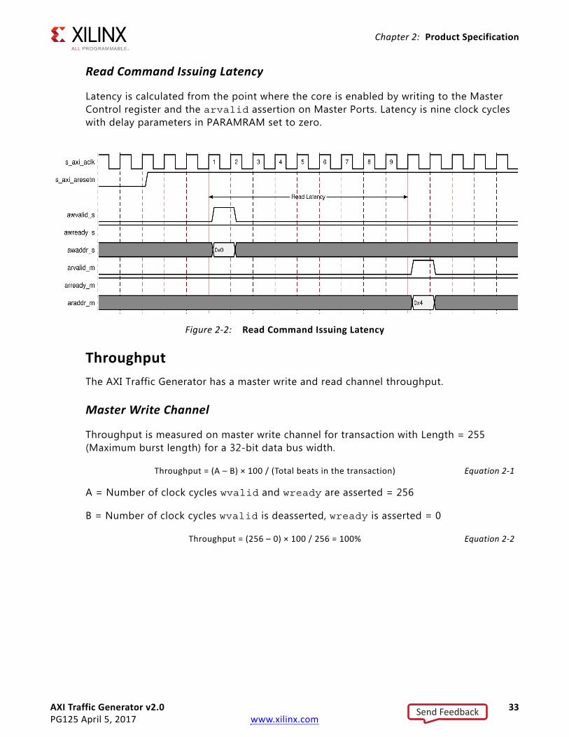
Read Command Issuing Latency
Latency is calculated from the point where the core is enabled by writing to the Master Control register and the arvalid assertion on Master Ports. Latency is nine clock cycles with delay parameters in PARAMRAM set to zero.
ThroughputThe AXI Traffic Generator has a master write and read channel throughput.
Master Write Channel
Throughput is measured on master write channel for transaction with Length = 255 (Maximum burst length) for a 32-bit data bus width.
Throughput = (A – B) × 100 / (Total beats in the transaction) Equation 2-1
A = Number of clock cycles wvalid and wready are asserted = 256
B = Number of clock cycles wvalid is deasserted, wready is asserted = 0
Throughput = (256 – 0) × 100 / 256 = 100% Equation 2-2
X-Ref Target - Figure 2-2
Figure 2-2: Read Command Issuing Latency
Send Feedback

AXI Traffic Generator v2.0 34PG125 April 5, 2017 www.xilinx.com
Chapter 2: Product Specification
Master Read Channel
Throughput is measured on master read channel for transaction with Length = 255 (Maximum burst length) for a 32-bit data bus width.
Throughput = (A – B) × 100 / (Total beats in the transaction) Equation 2-3
A = Number of clock cycles rready and rvalid are asserted = 256
B = Number of clock cycles rready is deasserted, rvalid is asserted = 0
Throughput = (256 – 0) × 100 / 256 = 100% Equation 2-4
X-Ref Target - Figure 2-3
Figure 2-3: Master Write Channel Throughput
X-Ref Target - Figure 2-4
Figure 2-4: Master Read Channel Throughput
Send Feedback

AXI Traffic Generator v2.0 35PG125 April 5, 2017 www.xilinx.com
Chapter 2: Product Specification
Resource UtilizationFor full details about performance and resource utilization, visit the Performance and Resource Utilization web page.
Port DescriptionsThe AXI Traffic Generator signals are listed and described in Table 2-1.
Table 2-1: AXI Traffic Generator I/O Signals
Signal Name Interface I/O Description
System Signals
s_axi_aclk System I Clock
s_axi_aresetn System I Active-Low reset
irq_out System O Interrupt on traffic generation completion
err_out System O Error interrupt
done(2) System O Indicates the completion of the sequence for AXI4-Lite mode selection.
status System O
Status of the core operation in System Init/System Test mode. 32-bit Status Port Definition
core_ext_start(4) System I Active-High pulse. Indicating the system to start generating or accepting the traffic.
core_ext_stop(4) System I Active-High pulse. Indicating the system to stop generating or accepting the traffic.
Bits Description
31:16Test Errors. Accumulates the number of errors seen during the generation of commands.
15:10 Reserved
9:2
Represents the COE index of the core it is currently processing.In a case where core is repeatedly trying to issue the same command and exits after maximum command retry count, this index is useful to debug.
1:0
Status of the Generation00 = Reserved01 = Pass10 = Fail11 = Hang
Send Feedback

AXI Traffic Generator v2.0 36PG125 April 5, 2017 www.xilinx.com
Chapter 2: Product Specification
AXI4 Master Interface Signals
m_axi_* M_AXIAXI4 Master Interface signals. See Appendix A of the Vivado AXI Reference Guide (UG1037) [Ref 2] for AXI4, AXI4-Lite and AXI Stream Signals.
AXI4 Slave Interface Signals
s_axi_* S_AXIAXI4 Slave Interface signals. See Appendix A of the Vivado AXI Reference Guide (UG1037) [Ref 2] for AXI4, AXI4-Lite and AXI Stream Signals.
AXI4-Stream Interface Signals
m_axis_1_tready M_AXIS_MASTER I See AXIS Bus definition
m_axis_1_tvalid M_AXIS_MASTER O See AXIS Bus definition
m_axis_1_tlast M_AXIS_MASTER O See AXIS Bus definition
m_axis_1_tdata M_AXIS_MASTER O See AXIS Bus definition
m_axis_1_tstrb M_AXIS_MASTER O See AXIS Bus definition
m_axis_1_tkeep M_AXIS_MASTER O See AXIS Bus definition
m_axis_1_tuser M_AXIS_MASTER O See AXIS Bus definition
s_axis_1_tready S_AXIS_MASTER O See AXIS Bus definition
s_axis_1_tvalid S_AXIS_MASTER I See AXIS Bus definition
s_axis_1_tlast S_AXIS_MASTER I See AXIS Bus definition
s_axis_1_tdata S_AXIS_MASTER I See AXIS Bus definition
s_axis_1_tstrb S_AXIS_MASTER I See AXIS Bus definition
s_axis_1_tkeep S_AXIS_MASTER I See AXIS Bus definition
s_axis_1_tuser S_AXIS_MASTER I See AXIS Bus definition
s_axis_2_tready S_AXIS_SLAVE O See AXIS Bus definition
s_axis_2_tvalid S_AXIS_SLAVE I See AXIS Bus definition
s_axis_2_tlast S_AXIS_SLAVE I See AXIS Bus definition
s_axis_2_tdata S_AXIS_SLAVE I See AXIS Bus definition
s_axis_2_tstrb S_AXIS_SLAVE I See AXIS Bus definition
s_axis_2_tkeep S_AXIS_SLAVE I See AXIS Bus definition
s_axis_2_tuser S_AXIS_SLAVE I See AXIS Bus definition
m_axis_2_tready M_AXIS_SLAVE I See AXIS Bus definition
m_axis_2_tvalid M_AXIS_SLAVE O See AXIS Bus definition
m_axis_2_tlast M_AXIS_SLAVE O See AXIS Bus definition
m_axis_2_tdata M_AXIS_SLAVE O See AXIS Bus definition
m_axis_2_tstrb M_AXIS_SLAVE O See AXIS Bus definition
m_axis_2_tkeep M_AXIS_SLAVE O See AXIS Bus definition
Table 2-1: AXI Traffic Generator I/O Signals (Cont’d)
Signal Name Interface I/O Description
Send Feedback

AXI Traffic Generator v2.0 37PG125 April 5, 2017 www.xilinx.com
Chapter 2: Product Specification
m_axis_2_tuser M_AXIS_SLAVE O See AXIS Bus definition
AXI4-Lite Master Write Interface
m_axi_lite_ch*_awaddr M_AXI_LITE O See AXI4-Lite Bus definition
m_axi_lite_ch*_awprot M_AXI_LITE O See AXI4-Lite Bus definition
m_axi_lite_ch*_awvalid M_AXI_LITE O See AXI4-Lite Bus definition
m_axi_lite_ch*_awready M_AXI_LITE I See AXI4-Lite Bus definition
m_axi_lite_ch*_wdata M_AXI_LITE O See AXI4-Lite Bus definition
m_axi_lite_ch*_wstrb M_AXI_LITE O See AXI4-Lite Bus definition
m_axi_lite_ch*_wvalid M_AXI_LITE O See AXI4-Lite Bus definition
m_axi_lite_ch*_wready M_AXI_LITE I See AXI4-Lite Bus definition
m_axi_lite_ch*_bresp M_AXI_LITE I See AXI4-Lite Bus definition
m_axi_lite_ch*_bvalid M_AXI_LITE I See AXI4-Lite Bus definition
m_axi_lite_ch*_bready M_AXI_LITE O See AXI4-Lite Bus definition
Notes: 1. AXIS refers to streaming interface.2. The done port now qualifies the sequence completion in AXI4-Lite mode. irq_out is used in the earlier version for this
purpose.3. In System INIT mode, M_AXI_LITE_CH* Read channel is not available as this mode is only intended to initialize the registers
in the connected slave.4. The core_ext_start and core_ext_stop ports can be used to control the traffic generation or reception by the core, without any
processor intervention.
Table 2-1: AXI Traffic Generator I/O Signals (Cont’d)
Signal Name Interface I/O Description
Send Feedback

AXI Traffic Generator v2.0 38PG125 April 5, 2017 www.xilinx.com
Chapter 2: Product Specification
Register SpaceThe AXI Traffic Generator provides registers to control its behavior, provide status or debug information, and to control external signals. The register space is only partially decoded.
IMPORTANT: All registers must be written with full-word writes.
Byte or halfword writes are interpreted as full-word writes (which can have unpredictable results). All bit descriptions use a little endian bit numbering, where 31 is the left-most or MSB, and Bit[0] is the right-most or LSB. All registers reset to default values (except for the read-only bits). Access to read-only registers issue an OKAY response.
Advanced/Basic Mode Register MapTable 2-2 is available only in AXI4 Advanced and Basic mode. For any other mode, these registers are not accessible.
Master Control
Master Control register allows you to configure the master interface ID width and control to enable the AXI traffic.
Table 2-2: Advanced/Basic Mode Register Map
Offset Register Name Description
0x00 Master Control To control master logic.
0x04 Slave Control To control slave logic.
0x08 Error Status Different errors reported during core operation.
0x0C Error Enable Enable register to report intended error.
0x10 Master Error Interrupt Enable To generate/mask external error interrupt.
0x14 Config Status Stores the current configuration of the core.
0x18 to 0x2C Reserved Reserved
0xB4 Slave Error Access to this register returns the SLVERR response.
Table 2-3: Master Control (0x00)
Bits Name Reset Value
Access Type Description
31:24 REV 0x20 R Revision of the core.
23:21 MSTID 0x0 R
M_ID_WIDTH, where:0x0 = Indicates 0 or 1-bit width0x1 = Indicates 2-bit width...0x7 = Indicates 8-bit width
Send Feedback

AXI Traffic Generator v2.0 39PG125 April 5, 2017 www.xilinx.com
Chapter 2: Product Specification
20 MSTEN 0x0 R/W
Master EnableWhen set, the master logic begins. When both the Read and Write state machines complete, this bit is automatically cleared to indicate to software that the AXI Traffic Generator is done.
19 Loop Enable 0x0 R/W
Loop Enable
• Loops through the command set created using CMDRAM and PARAMRAM (as applicable) indefinitely when set to 1.
• When this bit is reset to 0, core stops looping after the current command set of transactions are completed.
• Dependency (if any, both mydepend and otherdepend) is ignored when loop enable is set. Dependency gets honored after the loop enable is reset to 0.
• Both channels loopback to their first command independently without waiting for the outstanding transactions to get completed.
• If interrupt is enabled, core generates irq_out after completing the command set following the reset of loop enable to 0.
Note: Dependency for the last command set run is based on the point at which the loop enable is reset to 0. For example, a command set with 12 writes and 16 reads are present with the 13th read is dependent on sixth write. Now if the loop enable is reset to 0 before sixth write and 13th read of command run, you see the dependency in the last run else the dependency is not seen even after loop enable is reset.For bullet point 4, consider a case of a command set with 50 write commands and two read commands. In such a case, the read command should get repeated more than once before one set of write commands are completed.
18:0 Reserved N/A N/A Reserved
Back to Top
Table 2-3: Master Control (0x00) (Cont’d)
Bits Name Reset Value
Access Type Description
Send Feedback
AXI Traffic Generator v2.0 40PG125 April 5, 2017 www.xilinx.com
Chapter 2: Product Specification
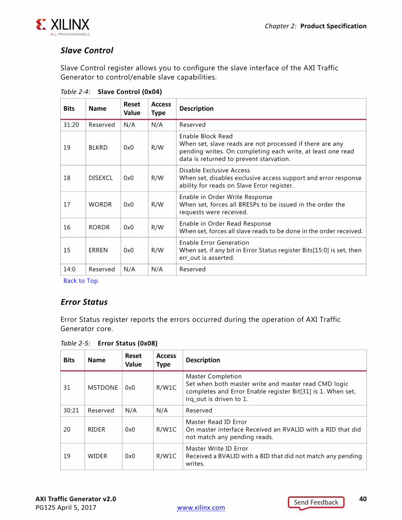
Slave Control
Slave Control register allows you to configure the slave interface of the AXI Traffic Generator to control/enable slave capabilities.
Error Status
Error Status register reports the errors occurred during the operation of AXI Traffic Generator core.
Table 2-4: Slave Control (0x04)
Bits Name Reset Value
Access Type Description
31:20 Reserved N/A N/A Reserved
19 BLKRD 0x0 R/W
Enable Block ReadWhen set, slave reads are not processed if there are any pending writes. On completing each write, at least one read data is returned to prevent starvation.
18 DISEXCL 0x0 R/WDisable Exclusive AccessWhen set, disables exclusive access support and error response ability for reads on Slave Error register.
17 WORDR 0x0 R/WEnable in Order Write ResponseWhen set, forces all BRESPs to be issued in the order the requests were received.
16 RORDR 0x0 R/W Enable in Order Read ResponseWhen set, forces all slave reads to be done in the order received.
15 ERREN 0x0 R/WEnable Error GenerationWhen set, if any bit in Error Status register Bits[15:0] is set, then err_out is asserted.
14:0 Reserved N/A N/A Reserved
Back to Top
Table 2-5: Error Status (0x08)
Bits Name Reset Value
Access Type Description
31 MSTDONE 0x0 R/W1C
Master CompletionSet when both master write and master read CMD logic completes and Error Enable register Bit[31] is 1. When set, irq_out is driven to 1.
30:21 Reserved N/A N/A Reserved
20 RIDER 0x0 R/W1CMaster Read ID ErrorOn master interface Received an RVALID with a RID that did not match any pending reads.
19 WIDER 0x0 R/W1CMaster Write ID ErrorReceived a BVALID with a BID that did not match any pending writes.
Send Feedback

AXI Traffic Generator v2.0 41PG125 April 5, 2017 www.xilinx.com
Chapter 2: Product Specification
Error Enable
Error Enable register allows you to enable the particular error condition in the AXI Traffic Generator. If an error occurs but the corresponding bit in the Error Enable register is not set, then the bit in Error Status register is not set and no error signaling occurs. To enable all errors, set Error Enable register to 0xFFFF_FFFF.
This enables/disables error reporting on Error Status register.
18 WRSPER N/A R/W1CMaster Write Response ErrorOn a master write completion, the response returned was not allowed by expected_resp[2:0].
17 RERRSP 0x0 R/W1CMaster Read Response ErrorOn a master read completion, the response returned was not allowed by expected_resp[2:0].
16 RLENER 0x0 R/W1CMaster Read Length ErrorOn the master interface Rlast either when it was not expected or was not signaled when it was expected.
15:2 Reserved N/A N/A Reserved
1 SWSTRB 0x0 R/W1CSlave Write Strobe ErrorOn the slave interface, a WSTRB assertion was detected on an illegal byte lane.
0 SWLENER 0x0 R/W1CSlave Write Length ErrorOn the slave interface W, Last was signaled either when it was not expected or was not signaled when it was expected.
Notes: 1. W1C – Write 1 to Clear (to clear register bit, you must write 1 to corresponding bits).
Back to Top
Table 2-6: Error Enable (0x0C)
Bits Name Reset Value
Access Type Description
31 MSTIRQEN 0x1 R/W Enables interrupt generation for Master transfer completion.
30:21 Reserved N/A N/A Reserved
20 RIDEREN 0x0 R/W Enables Read ID Error for Error Status register Bit[20].
19 WIDEREN 0x0 R/W Enables Write ID error for Error Status register Bit[19].
18 WRSPER N/A R/W Enables write response error for Error Status register Bit[18].
17 RERRSP 0x0 R/W Enables read response error for Error Status register Bit[17].
16 RLENER 0x0 R/W Enables read length error for Error Status register Bit[16].
15:2 Reserved N/A N/A Reserved
Table 2-5: Error Status (0x08) (Cont’d)
Bits Name Reset Value
Access Type Description
Send Feedback

AXI Traffic Generator v2.0 42PG125 April 5, 2017 www.xilinx.com
Chapter 2: Product Specification
Master Error Interrupt Enable
Master Error Interrupt Enable register enables interrupt generation for AXI4 Master interface based on the Error Status register.
Config Status
Config Status register is a read only register and provides you information on the core configuration.
1 SWSTRBEN 0x0 R/W Enables slave write strobe error for Error Status register Bit[1].
0 SWLENEREN 0x0 R/W Enables slave write length error for Error Status register Bit[0].
Back to Top
Table 2-7: Master Error Interrupt Enable (0x10)
Bits Name Reset Value
Access Type Description
31:16 Reserved N/A N/A Reserved
15 MINTREN 0x0 R/WEnables Master Interrupt When set, if any bit in Error Status register Bits[30:16] is set, then err_out is asserted.
14:0 Reserved N/A N/A Reserved
Back to Top
Table 2-8: Config Status (0x14)
Bits Name Reset Value
Access Type Description
31 Reserved N/A N/A Reserved
30:28 MWIDTH 0x0 R
Master Width0x0 = 32-bit0x1 = 64-bit0x2 = 128-bit0x3 = 256-bit0x4 = 512-bit
27:25 SWIDTH 0x0 N/ASlave Width000 = 32-bit001 = 64-bit
24 MADV 0x0 R ATG Mode is Advanced
23 MBASIC 0x0 R ATG Mode is Basic
22:0 Reserved N/A N/A Reserved
Back to Top
Table 2-6: Error Enable (0x0C) (Cont’d)
Bits Name Reset Value
Access Type Description
Send Feedback

AXI Traffic Generator v2.0 43PG125 April 5, 2017 www.xilinx.com
Chapter 2: Product Specification
Streaming Mode Register MapTable 2-9 is available only in AXI4-Stream mode. For any other mode, these registers are not accessible.
Streaming Control
Streaming Control register provides the current version of the AXI4-Stream interface and allows you to enable the core to generate traffic using the programmed configuration. This register is only available in the Streaming mode of operation.
Table 2-9: Streaming Mode Register Map
Offset Register Name Description
0x30 Streaming Control Provides the current version of the AXI4-Stream interface and to enable/disable the core operation.
0x34 Streaming Config Allows you to configure the streaming master interface (M_AXIS_MASTER) for different traffic parameters.
0x38 Transfer Length Allows you to configure the length of packets and transaction count.
0x3C Transfer Count Reports the number of transactions (tlast count) generated/monitored.
0x40
User STRB/TKEEP Set 1 to 4
Allows you to configure TSTRB/TKEEP value for the last beat of the transfer.
0x44 Allows you to configure TSTRB/TKEEP value for the last beat of the transfer.
0x48 Allows you to configure TSTRB/TKEEP value for the last beat of the transfer.
0x4C Allows you to configure TSTRB/TKEEP value for the last beat of the transfer.
0x50 Extended Transfer Length Extended support to Packet Length
Table 2-10: Streaming Control (0x30)
Bits Name Reset Value
Access Type Description
31:24 Version 0x20 R Version Value
23:2 Reserved N/A N/A Reserved
1 Done 0x0 R/W1C
Transfer Done0 = Indicates core is generating traffic when STREN is 1, else core is in idle mode1 = Indicates traffic generation completedThis bit is set to 1 when the core is disabled by setting STREN to 0 and the current transfer is completed.This bit resets to 0 either writing 1 to this bit or enabling the core with STREN.
Send Feedback

AXI Traffic Generator v2.0 44PG125 April 5, 2017 www.xilinx.com
Chapter 2: Product Specification
Streaming Config
Streaming Config register allows you to configure the Streaming master interface for programmable delays or random delay in transfer length and TDEST value. This register is only available in the Streaming mode of operation.
0 STREN 0x0 R/WStreaming Enable0 = Disable traffic generation1 = Enable traffic generation
Notes: 1. W1C – Write 1 to Clear (to clear register bit, you must write 1 to corresponding bits).2. During traffic generation if the core is forced to stop traffic (either by writing STREN to 0 or using
core_ext_stop pin), the core completes the current transfer gracefully before stopping.
Back to Top
Table 2-11: Streaming Config (0x34)
Bits Name Reset Value
Access Type Description
31:16 PDLY 0x0 R/W Programmable delay (in clocks) between two streaming packets.
15:8 TDEST 0x0 R/W Value to drive on TDEST port.
7:3 Reserved N/A N/A Reserved
2 ETKTS 0x0 R/W
Enable User TSTRB/TKEEP Setting
When set, core places your specified STRB/KEEP value on the last beat of the transfer.
When this bit is 0, core places internally generated STRB/KEEP value on the last beat of the transfer.
You need to set Support Sparse Strobe Keep along with this bit to generate sparse STRB/KEEP values.
1 RANDLY 0x0 R/WEnable Random DelayWhen set, generates random delay between streaming transactions. For example, from TLAST to next TVALID.
0 RANLEN 0x1 R/W
Enable Random LengthWhen set, generates streaming transactions with random length. When this bit is 0, core generates the streaming transaction with the length specified in Transfer Length register.
Back to Top
Table 2-10: Streaming Control (0x30) (Cont’d)
Bits Name Reset Value
Access Type Description
Send Feedback

AXI Traffic Generator v2.0 45PG125 April 5, 2017 www.xilinx.com
Chapter 2: Product Specification
Transfer Length
Transfer Length register allows you to configure the length of packets and transaction count. This register is only available in the Streaming mode of operation.
Transfer Count
Transfer Count register allows you to monitor the number of transactions generated/received based on the mode in which the core is operating. This register is only available in the Streaming mode of operation.
Table 2-12: Transfer Length (0x38)
Bits Name Reset Value
Access Type Description
31:16 TCNT 0x0 R/WTransaction CountCore generates this many transaction on AXI4-Stream master channel and stops. If set to 0, core infinitely generates transactions.
15:0 TLEN 0x0 R/W
Length of TransactionWhen Random Length in Streaming Config register is not set, Length programmed in this register is used.Actual number of beats are one more than the register setting. For example, setting to 0 gives 1 beat, setting to 1 gives 2 beats, and further.
Back to Top
Table 2-13: Transfer Count (0x3C)
Bits Name Reset Value
Access Type Description
31:0 TLSTCNT 0x0 R
Master Only – Reports number of streaming transactions (count of tlast) on master interface
Master Loopback – Reports number of streaming transaction (count of tlast) on slave interface
Slave Loopback – Reports number of streaming transaction (count of tlast) on master interface
Back to Top
Send Feedback

AXI Traffic Generator v2.0 46PG125 April 5, 2017 www.xilinx.com
Chapter 2: Product Specification
User STRB/TKEEP Set 1 to 4
These four registers allow you to set the TSTRB/TKEEP value for the last beat of the transfer. This register along with TLEN allows you to generate transfers with byte level granularity.
Extended Transfer Length
Extended Transfer Length register allows you to extend the length of packets. The value in Bits[7:0] of this register is concatenated to Bits[15:0] of the Transfer Length to determine the Length in a packet. This register is only available in the Streaming mode of operation
Static Mode Register MapTable 2-16 is available only in AXI4 Static mode. For any other mode, this register is not accessible.
Table 2-14: User STRB/TKEEP Set 1 to 4 (0x40 to 0x4C)
Bits Name Reset Value
Access Type Description
31:0 TKTS 0x0 R/W TSTRB/TKEEP value to be appeared on the last beat of the transfer.
Notes: 1. For a 32-bit wide TDATA bus to generate a TKEEP/TSTRB value of 0x3, register 0x40 needs to be written with 0x3.
0x44 to 0x4C can be ignored in 32-bit TDATA width case.Because maximum TDATA width supported is 1,024 bits, 128 bits are needed to specify TSTRB/TKEEP values. In such a case, your value of TSTRB/TKEEP needs to be written to 0x40 to 0x4C with least significant bits set in 0x40.
Back to Top
Table 2-15: Extended Transfer Length (0x50)
Bits Name Reset Value
Access Type Description
31:8 Reserved N/A N/A Reserved
7:0 Ext-TLEN 0x0 R/W
When Random Length in Streaming Config register is not set, Length programmed in this register is used. TLEN in a packet. This value is concatenated to a value in the Transfer Length Bits[15:0] to give a maximum value of 224 – 1 beats in the Streaming packet.
Back to Top
Table 2-16: Static Mode Register Map
Offset Register Name Description
0x60 Static Control Provides the current version of the Static Mode and to enable/disable the core operation.
0x64 Static Length Allows you to configure the burst length generated by AXI Traffic Generator in Static mode.
Send Feedback

AXI Traffic Generator v2.0 47PG125 April 5, 2017 www.xilinx.com
Chapter 2: Product Specification
Static Control
Static Control register allows you to start and stop the AXI Traffic Generator in Static mode.
Static Length
Static Length register allows you to configure the burst length generated by AXI Traffic Generator in Static mode. This register is only available in the Static mode of operation.
Table 2-17: Static Mode Control (0x60)
Bits Name Reset Value
Access Type Description
31:24 Version 0x20 R Version Value
23:2 Reserved N/A N/A Reserved
1 DONE 0x0 R/W1C
Transfer Done0 = Indicates core is generating traffic when STEN is 1, else core is in idle mode1 = Indicates traffic generation completedThis bit is set to 1 when the core is disabled by setting STTEN to 0 and the current transfer is completed.This bit resets to 0 either writing 1 to this bit or enabling the core with STEN.
0 STEN 0x0 R/WStatic Enable0 = Disable traffic generation1 = Enable traffic generation
Notes: 1. W1C – Write 1 to Clear (to clear register bit, you must write 1 to corresponding bits).2. During traffic generation if the core is forced to stop traffic (either by writing STREN to 0 or using
core_ext_stop pin) core completes the current transfer gracefully before stopping.
Back to Top
Table 2-18: Static Length (0x64)
Bits Name Reset Value
Access Type Description
31:8 Reserved N/A N/A Reserved
7:0 BLEN Burst Length R/W
Burst LengthConfigures burst length for AXI4 master interface. Reset value is the value configured for "Burst Length" in the Vivado IDE.
Notes: 1. Value programmed in this register directly appear in awlen/arlen on M_AXI interface.
Back to Top
Send Feedback

AXI Traffic Generator v2.0 48PG125 April 5, 2017 www.xilinx.com
Chapter 2: Product Specification
LFSR Implementation used for Random Generation
The below linear feed-back shift register (LFSR) is used for random address or data generation:
Initially, the C0 to C15 flops are loaded with the input seed value. Later, it behaves as a shift register as per the architecture.
X-Ref Target - Figure 2-5
Figure 2-5: LFSR
Send Feedback

AXI Traffic Generator v2.0 49PG125 April 5, 2017 www.xilinx.com
Chapter 3
Designing with the CoreThis chapter includes guidelines and additional information to facilitate designing with the core.
ClockingThe AXI Traffic Generator has a single input clock for AXI4-Slave, AXI4-Master (Advanced, Basic, Static, High Level Traffic, System Init/Test), and AXI4-Stream mode. You should connect the appropriate clock to this clock input.
ResetsThe s_axi_aresetn is an active-Low synchronous reset to the core. All registers are reset to power-on conditions and all internal logic is returned to power-on conditions.
Send Feedback

AXI Traffic Generator v2.0 50PG125 April 5, 2017 www.xilinx.com
Chapter 4
Design Flow StepsThis chapter describes customizing and generating the core, constraining the core, and the simulation, synthesis and implementation steps that are specific to this IP core. More detailed information about the standard Vivado® design flows and the Vivado IP integrator can be found in the following Vivado Design Suite user guides:
• Vivado Design Suite User Guide: Designing IP Subsystems using IP Integrator (UG994) [Ref 3]
• Vivado Design Suite User Guide: Designing with IP (UG896) [Ref 1]
• Vivado Design Suite User Guide: Getting Started (UG910) [Ref 4]
• Vivado Design Suite User Guide: Logic Simulation (UG900) [Ref 5]
Customizing and Generating the CoreThis section includes information about using Xilinx® tools to customize and generate the core in the Vivado Design Suite.
If you are customizing and generating the core in the Vivado IP integrator, see the Vivado Design Suite User Guide: Designing IP Subsystems using IP Integrator (UG994) [Ref 3] for detailed information. IP integrator might auto-compute certain configuration values when validating or generating the design. To check whether the values change, see the description of the parameter in this chapter. To view the parameter value, run the validate_bd_design command in the Tcl console.
You can customize the IP for use in your design by specifying values for the various parameters associated with the IP core using the following steps:
1. Select the IP from the Vivado IP catalog.
2. Double-click the selected IP or select the Customize IP command from the toolbar or right-click menu.
For details, see the Vivado Design Suite User Guide: Designing with IP (UG896) [Ref 1] and the Vivado Design Suite User Guide: Getting Started (UG910) [Ref 4].
Note: Figures in this chapter are illustrations of the Vivado IDE. This layout might vary from the current version.
Send Feedback

AXI Traffic Generator v2.0 51PG125 April 5, 2017 www.xilinx.com
Chapter 4: Design Flow Steps
Figure 4-1 shows the Customize IP window settings for the AXI Traffic Generator IP core.
X-Ref Target - Figure 4-1
Figure 4-1: Vivado Customize IP Dialog Box
Send Feedback
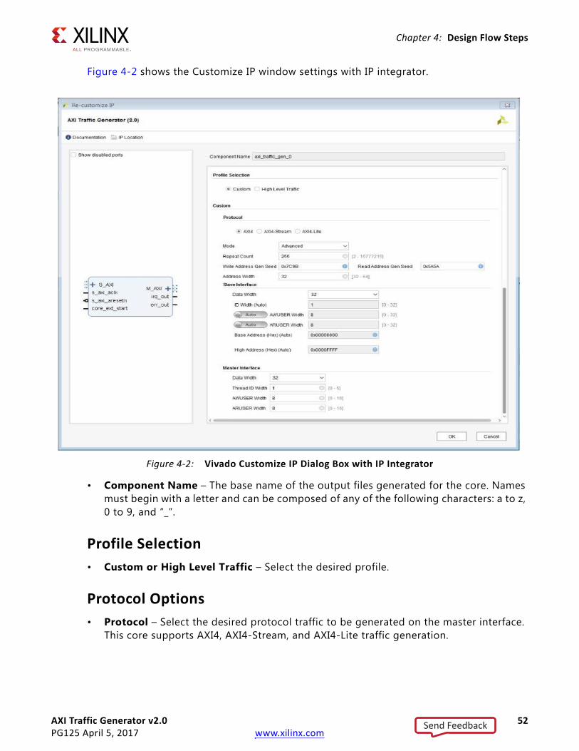
AXI Traffic Generator v2.0 52PG125 April 5, 2017 www.xilinx.com
Chapter 4: Design Flow Steps
Figure 4-2 shows the Customize IP window settings with IP integrator.
• Component Name – The base name of the output files generated for the core. Names must begin with a letter and can be composed of any of the following characters: a to z, 0 to 9, and “_”.
Profile Selection• Custom or High Level Traffic – Select the desired profile.
Protocol Options• Protocol – Select the desired protocol traffic to be generated on the master interface.
This core supports AXI4, AXI4-Stream, and AXI4-Lite traffic generation.
X-Ref Target - Figure 4-2
Figure 4-2: Vivado Customize IP Dialog Box with IP Integrator
Send Feedback

AXI Traffic Generator v2.0 53PG125 April 5, 2017 www.xilinx.com
Chapter 4: Design Flow Steps
AXI4 ProtocolThis protocol supports different mode configuration. The available mode of operations are Advanced, Basic, and Static.
Advanced/Basic Mode
For the Advanced/Basic mode, Advanced mode generates customized traffic on the master interface. Basic mode allows basic AXI4 traffic generation with less resource overhead. Available options are given in the following sections.
Repeat Count
This parameter gives the repeat count for all the transactions with Fixed-Repeat Delay mode set in PARAMRAM.
Note: Earlier, the count was fixed to 255 by the IP core.
Write Address Gen Seed
When the ATG is configured to operate in Advanced mode and with Random Address generation, the provided seed determines the Random Address generated on the Write Address channel. This option is useful in cases where there are multiple ATGs in a system and you need a different address to be generated by each ATG.
This parameter can take any four-digit Hex value except 0xFFFF. If a value of FFFF is set, Address would remain constant on the channel.
Read Address Gen Seed
When the ATG is configured to operate in Advanced mode and with Random Address generation, the provided seed determines the Random Address generated on the Read Address channel. This option is useful in cases where there are multiple ATGs in a system and you need a different address to be generated by each ATG.
This parameter can take any four-digit Hex value except 0xFFFF. If a value of FFFF is set, Address would remain constant on the channel.
Address Width
This parameter determines the width of the read/write address ports on the Master AXI4 interface in the AXI4 mode of operation.
Note: In earlier versions, this value was fixed to 32.
Send Feedback

AXI Traffic Generator v2.0 54PG125 April 5, 2017 www.xilinx.com
Chapter 4: Design Flow Steps
Slave Interface Options
• Data Width – Select the desired slave data width (32 and 64).
• ID Width – ID width of the slave. In IP integrator, it is auto-computed based on the master interface.
• AWUSER – Write channel user signals width. In IP integrator, it is auto-computed based on the master interface.
• ARUSER – Read channel user signals width. In IP integrator, it is auto-computed based on the master interface.
• Base Address – Base address of the core (used by the Vivado tool when creating a system using IP integrator). In IP integrator, it is auto-computed based on the master interface. This allows you to override the auto-compute values.
• High Address – High Address of the core (used by the Vivado tool when creating a system using IP integrator). In IP integrator, it is auto-computed based on the master interface. This allows you to override the auto-compute values.
Master Interface Options
• Data Width – Select the desired master data width (32, 64, 128, 256, and 512).
• ID Width – ID width of the master.
• AWUSER – Write channel user signals width.
• ARUSER – Read channel user signals width.
Static Mode
This mode allows you to generate simple AXI4 traffic with fewer resource overhead compared to the Advanced/Basic mode. Available options are given in the following sections.
Master Interface Options
• Data Width – Select the desired master data width (32, 64, 128, 256, and 512).
Static Mode Options
• Channel Select – Selects desired channel on which traffic to be generated.
• Enable Address Sweep – When enabled, the address sweeps across the specified Base and High address.
• Write Base Address – Base/starting address for write transactions. This has to be configured based on the available memory slaves in the system.
Send Feedback

AXI Traffic Generator v2.0 55PG125 April 5, 2017 www.xilinx.com
Chapter 4: Design Flow Steps
• Write High Address – Only used when Address sweep is enabled. Write transactions generated are between Base and High address, This has to be configured based on available memory slaves in the system.
• Read Base Address – Base/starting address for read transactions. This has to be configured based on the available memory slaves in the system.
• Read High Address – Only used when Address sweep is enabled, Read transactions generated are between Base and High address, This has to be configured based on available memory slaves in the system.
• Write Base Address (MSB) – MSB bits of base/starting address for write transactions. This has to be configured based on the available memory slaves in the system and it is only applicable when the address width is > 32.
• Write High Address (MSB) – MSB bits are only used when address sweep is enabled. Write transactions generated are between base and high address, Only applicable when the address width is > 32.
• Read Base Address (MSB) – MSB bits of base/starting address for read transactions. This has to be configured based on the available memory slaves in the system and it is only applicable when the address width is > 32.
• Read High Address (MSB) – MSB bits are only used when address sweep is enabled, Read transactions generated are between base and high address, Only applicable when address width is > 32.
Note: Though the Vivado IDE allows a complete 32-bit value for *(MSB) parameters, only the applicable bits (determined based on the address width configured) are considered and driven on the address ports.
• Burst Length – Burst length for read/write transactions.
AXI4-Stream ProtocolStreaming mode allows you to generate AXI4-Stream traffic on master interface. It also provides streaming loopback channel.
• Support Sparse Strobe Keep – Allows generation of sparse strobe and keep on the last data beat of the streaming transaction, by picking values from the ‘User STRB/TKEEP set 1 to 4’ register space.
• Channel Type – Streaming mode selection. Allowed values are master only, master loopback, and slave loopback.
• Data Generator Seed – Controls the random data being generated on the TDATA channel in master only and master loopback modes. This parameter can take any four-digit Hex value except 0xFFFF. If a value of FFFF is set, Data remains constant on the channel.
Send Feedback

AXI Traffic Generator v2.0 56PG125 April 5, 2017 www.xilinx.com
Chapter 4: Design Flow Steps
• TDATA Width – Selects the desired streaming data width 8 to 1,024 in multiples of 8 (for example, 8, 16, 32, and so on). In IP integrator when the mode selected in slave loopback, it is auto-computed based on the master interface.
• TUSER Width – Width of streaming user signals. In IP integrator when the mode selected in slave loopback, it is auto-computed based on the master interface.
• TID Width – Data stream identifier width. In IP integrator when the mode selected in slave loopback, it is auto-computed based on the connected master interface.
• TDEST Width – Data stream routing information identifier width. In IP integrator when the mode selected in slave loopback, it is auto-computed based on the connected master interface.
• Burst Count Width – Number of bits used while generating random length value when the core is register configured to generate random length.
For example with a width of 4-bit, maximum transaction length generated in 16.
AXI4-Lite ProtocolSystem Init/Test mode allows you to generate the AXI4 transaction on the master interface. Transactions are generated based on the configuration file you provided. When core generates all transactions, it asserts the done and status signals indicating the status of the generation.
• Transaction Depth – Maximum number of address and data entries supported in COE file. Available transaction depth are 16, 32, 64, 128, and 256.
• Data COE File – Loads/creates the data COE file. Contains data entries for the corresponding address in the Address COE file.
• Address COE File – Loads/creates the address COE file. Contains address entries for the transactions to be generated on the master interface. End of the transaction is defined by NOP (0xFFFFFFFF). The core stops generating any further transaction after processing NOP.
Note: In IP integrator, the addresses in COE files should be updated based on address space allocated by the tool.
• Control COE File – Loads/creates the control COE file. Contains the control information of type of transaction to be generated, next COE entry to fetched, and to count if any errors occurred.
• Mask COE File – Loads/creates the Mask COE File. Contains the Mask bits to be used during read data comparison.
• Mode
° System Init – Generates write transactions.
° System Test – Generates write and read transactions.
Send Feedback

AXI Traffic Generator v2.0 57PG125 April 5, 2017 www.xilinx.com
Chapter 4: Design Flow Steps
• Number of AXI Channels – Number of AXI4-Lite interfaces available on which the transactions are generated. The core compares address entry with each channel Base/High address values and generates transactions on the matching channel.
• CH{n}_Base Address – Base address corresponding to channel {n}.
• CH{n}_High Address – High address corresponding to channel {n}.
• Maximum Command Retry Count – Allows you to limit the Maximum number of times the same transaction can be issued with-out other transactions in between.
• Maximum Clocks to Run – Maximum number of clocks after coming out of reset the total sequence can take after which it is declared Hang.
High Level TrafficFor High Level Traffic mode, there are two options:
• AXI Options – Allows you to configure AXI options like AXI master data width.
• Profile Specific Options – Allows you to configure profile specific options like number of lanes in a PCIe® profile.
AXI Options
• AXI Master Width – Selects the desired master data width (32, 64, 128, 256, and 512).
• Enable Address Sweep – Enables address incrementation based on burst length for consecutive transactions generated.
• AXI Base Address – Base address for the master.
• AXI High Address – High address for the master.
• AXI Base Address (MSB) – MSB bits of the base address for the master.
• AXI High Address (MSB) – MSB bits of the high address for the master.
Note: Though the Vivado IDE allows a complete 32-bit value for *(MSB) parameters, only the applicable bits (determined based on address width configured) are considered and driven on the address ports.
• Burst Length – Burst length of AXI transactions to be generated.
• Channel Select – Selects desired channel on which traffic to be generated.
Profile Specific Options
In the Profile Specific Options, you can configure for five modes.
Video Mode
• Hsize – Hsize of the Video: 640 to 1,920.
Send Feedback

AXI Traffic Generator v2.0 58PG125 April 5, 2017 www.xilinx.com
Chapter 4: Design Flow Steps
• Vsize – Vsize of the video: 480 to 1,080.
• Frame Rate – Number of frames per second: 60,75.
• Pixel Bits – Number of pixel bits: 8, 10, 12.
• Format – Video format: RGB, YUV: 4:4:4, YUV: 4:2:2, YUV: 4:2:0.
PCIe Mode
• PCIe Lanes – Number of PCIe Lanes: 1, 2, 4, 8.
• PCIe Lane Rate (GT/s) – Lane rate of each lane in GT/s: 2.5, 5, 8, 16.
• PCIe Load (%) – Percentage of PCIe traffic load on the bus: 1 to 100.
Ethernet Mode
• Ethernet Speed (Mb/s) – Selects Ethernet speed: 10, 100, 1,000.
• Ethernet Load (%) – Percentage of Ethernet traffic load on the bus: 1 to 100.
USB Mode
• USB Mode – Mode of USB: ISOC, BULK.
• USB Load – Percentage of USB traffic load on the bus: 1 to 100.
a. Throughput generated with a granularity of MB/s.
b. Throughput is rounded to lower integer number.
Data Mode
This is a special case, where you can configure different AXI options to generate the desired AXI traffic for custom protocol.
• Traffic Gen – Generates one set of traffic or a repetitive traffic (One-shot, Repetitive)
Based on your settings, the core internally creates a command set to meet your requirements.
° One-shot – Internally created command set is executed once.
° Repetitive – Internally created command set is executed repeatedly until core receives a stop pulse through core_ext_stop.
• Traffic Pattern – Length of AXI transactions, Random lengths with a minimum, maximum, and average length value or Fixed length transactions.
When Address sweep is enabled, only fixed traffic pattern is supported and all transactions are generated with this burst length.
Send Feedback

AXI Traffic Generator v2.0 59PG125 April 5, 2017 www.xilinx.com
Chapter 4: Design Flow Steps
The core tries to achieve the average length on a channel as the percentage of traffic share on that channel increases.
For example, the average length of transactions generated closely matches with the Vivado IDE setting when percentage of traffic share is 50%. Rather than with a case where a traffic share is 5%.
• Transaction Type – Read Only, Write Only, or Read Write transactions.
• Inter Transfer Gap (ITG) Type – Type of gap between issuance of two AXI transactions. Fixed (Minimum Fixed Gap in clocks) or Random gap with range of 0 to 1,024.
Note: The IP in this mode always has a minimum six cycles delay between transactions, so the values from zero to six have no effect.
• Transaction Seed – Seed value for the traffic generation. This allows you to regenerate the same traffic with the same seed.
User ParametersTable 4-1 shows the relationship between the fields in the Vivado IDE and the User Parameters (which can be viewed in the Tcl Console).
Table 4-1: Vivado IDE Parameter to User Parameter Relationship
Vivado IDE Parameter/Value(1) User Parameter/Value(1) Default Value(1)
Profile Selection
Allowed value are Custom and High Level Traffic.
ATG_OPTIONS Custom
Protocol
Allowed values are AXI, AXI4-Lite, and AXI4-Stream.
C_ATG_MODE AXI4
Mode
Allowed values are Advanced, Basic, and Static.
C_ATG_MODE_L2 Advanced
Repeat Count C_REPEAT_COUNT 255
Slave Interface Data Width
Allowed values are 32 and 64.C_S_AXI_DATA_WIDTH 32
Slave Interface ID Width
Allowed values are from 0 to 32.C_S_AXI_ID_WIDTH 1
Slave Interface AWUSER Width
Allowed values range from 0 to 8.C_S_AXI_AWUSER_WIDTH 8
Slave Interface ARUSER Width
Allowed values range from 0 to 8.C_S_AXI_ARUSER_WIDTH 8
Base Address
Valid HEX Address value for slave interface.C_BASEADDR 0x00000000
Send Feedback

AXI Traffic Generator v2.0 60PG125 April 5, 2017 www.xilinx.com
Chapter 4: Design Flow Steps
High Address
Valid HEX High Address value for slave interface.
C_HIGHADDR 0x0000FFFF
Master Interface Data Width
Allowed values are 32, 64, 128, 256, and 512.
C_M_AXI_DATA_WIDTH 32
Master Interface Thread ID Width
Allowed values range from 0 to 6.C_M_AXI_THREAD_ID_WIDTH 1
Master Interface AWUSER Width
Allowed values range from 0 to 8.C_M_AXI_AWUSER_WIDTH 8
Master Interface ARUSER Width
Allowed values range from 0 to 8.C_M_AXI_ARUSER_WIDTH 8
Static Mode Channel Select
Allowed values are Read_Only, Write_Only, and Read_Write.
C_ATG_STATIC_CH_SELECT Read_Write
Enable Address Sweep
Allowed values are TRUE and FALSE.C_ATG_STATIC_INCR 0
Write Base Address
Valid HEX base address for Write channel.C_ATG_STATIC_WR_ADDRESS 0x12A00000
Write High Address
Valid HEX High base address for Write channel.
C_ATG_STATIC_WR_HIGH_ADDRESS 0x12A00FFF
Read Base Address
Valid HEX base address for Read channelC_ATG_STATIC_RD_ADDRESS 0x13A00000
Read High Address
Valid HEX High base address for Read channel.
C_ATG_STATIC_RD_HIGH_ADDRESS 0x13A00FFF
Burst Length
Allowed values range from 1 to 256.C_ATG_STATIC_LENGTH 16
Support Sparse Strb Keep
Boolean values TRUE or FALSE allowed.C_AXIS_SPARSE_EN 1
Channel Type
Allowed values are Master Only, Master Loopback, and Slave Loopback.
C_AXIS_MODE Master Only
Burst Count Width
Allowed values range from 1 to 16.C_ATG_STREAMING_MAX_LEN_BITS 16
Table 4-1: Vivado IDE Parameter to User Parameter Relationship (Cont’d)
Vivado IDE Parameter/Value(1) User Parameter/Value(1) Default Value(1)
Send Feedback

AXI Traffic Generator v2.0 61PG125 April 5, 2017 www.xilinx.com
Chapter 4: Design Flow Steps
TDATA Width
Allowed values are 8, 16, 24, 32, 40, 48, 56, 64, 72, 80, 88, 96, 104, 112, 120, 128, 136, 144, 152, 160, 168, 176, 184, 192, 200, 208, 216, 224, 232, 240, 248, 256, 264, 272, 280, 288, 296, 304, 312, 320, 328, 336, 344, 352, 360, 368, 376, 384, 392, 400, 408, 416, 424, 432, 440, 448, 456, 464, 472, 480, 488, 496, 504, 512, 520, 528, 536, 544, 552, 560, 568, 576, 584, 592, 600, 608, 616, 624, 632, 640, 648, 656, 664, 672, 680, 688, 696, 704, 712, 720, 728, 736, 744, 752, 760, 768, 776, 784, 792, 800, 808, 816, 824, 832, 840, 848, 856, 864, 872, 880, 888, 896, 904, 912, 920, 928, 936, 944, 952, 960, 968, 976, 984, 992, 1000, 1008, 1016, and 1024.
C_AXIS_DATA_WIDTH 32
TUSER Width
Allowed values range from 0 to 256.C_AXIS_TUSER_WIDTH 8
TID Width
Allowed values range from 0 to 16.C_AXIS_TID_WIDTH 8
TDEST Width
Allowed values range from 0 to 8.C_AXIS_TDEST_WIDTH 8
AXI4-Lite Mode
Allowed values are System_Init and System_Test.
C_ATG_SYSINIT_MODES System_Init
Transaction Depth
Allowed values are 16, 32, 64, 128, and 256.C_ATG_MIF_DATA_DEPTH 16
Number of AXI Channels
Allowed values range from 1 to 5.C_ATG_SYSTEM_MAX_CHANNELS 1
CH*- Base Address
Valid HEX strings for all the channels selected with no overlaps.
C_ATG_SYSTEM_CH*_LOW
0x00000*00
“*” depends on the channel dealt with; varies from 0 to 4 based on channel number.
CH*- High Address
Valid HEX strings for all the channels selected with no overlaps.
C_ATG_SYSTEM_CH*_HIGH
0x00000*FF
“*” depends on the channel dealt with; varies from 0 to 4 based on channel number.
Maximum Command Retry Count
Allowed values range from 1 to 4294967295.
C_ATG_SYSTEM_CMD_MAX_RETRY 256
Table 4-1: Vivado IDE Parameter to User Parameter Relationship (Cont’d)
Vivado IDE Parameter/Value(1) User Parameter/Value(1) Default Value(1)
Send Feedback

AXI Traffic Generator v2.0 62PG125 April 5, 2017 www.xilinx.com
Chapter 4: Design Flow Steps
Maximum Clocks to Run
Allowed values range from 15 to 4294967295.
C_ATG_SYSTEM_TEST_MAX_CLKS 5000
Address COE file should have the complete path of Address COE file to be used by IP. C_ATG_SYSTEM_INIT_ADDR_MIF no_coe_file_loaded
Data COE file should have the complete path of Data COE file to be used by IP. C_ATG_SYSTEM_INIT_DATA_MIF no_coe_file_loaded
Mask COE file should have the complete path of Address COE file to be used by IP. C_ATG_SYSTEM_INIT_MASK_MIF no_coe_file_loaded
Ctrl COE file should have the complete path of Address COE file to be used by IP. C_ATG_SYSTEM_INIT_CTRL_MIF no_coe_file_loaded
Traffic Profile
Allowed values are Video, PCIe, Ethernet, USB, and Data.
TRAFFIC_PROFILE Video
AXI Master Width
Data width of Master AXI interface and allowed values are 32, 64, 128, 256, and 512.
MASTER_AXI_WIDTH 32
Enable Address Sweep in High Level Traffic Profile (HLTP) Mode
Allowed values are boolean TRUE or FALSE.C_ATG_STATIC_HLTP_INCR 0
AXI Base Address
Valid HEX string values for Address.MASTER_BASE_ADDRESS 0x00000000
AXI High Address
Valid HEX string values for Address.MASTER_HIGH_ADDRESS 0xFFFFFFFF
Channel Select
Allowed values are Read_Only, Read_Write, and Write_Only.
ATG_HLT_CH_SELECT Read_Write
Burst Length in HLTP Mode
This parameter is present when Enable Address Sweep is disabled. Allowed values range from 1 to 256.
ATG_HLT_STATIC_LENGTH 16
Burst Length in HLTP Mode
This parameter is present when Enable Address Sweep is enabled. Allowed values are 1, 2, 4, 8, 16, 32, 64, 128, and 256.
ATG_HLT_STATIC_LENGTH_INCR 16
HSIZE
Enabled in VIDEO mode of HLTP. Allowed values range from 640 to 1920.
VIDEO_HSIZE 1920
Table 4-1: Vivado IDE Parameter to User Parameter Relationship (Cont’d)
Vivado IDE Parameter/Value(1) User Parameter/Value(1) Default Value(1)
Send Feedback
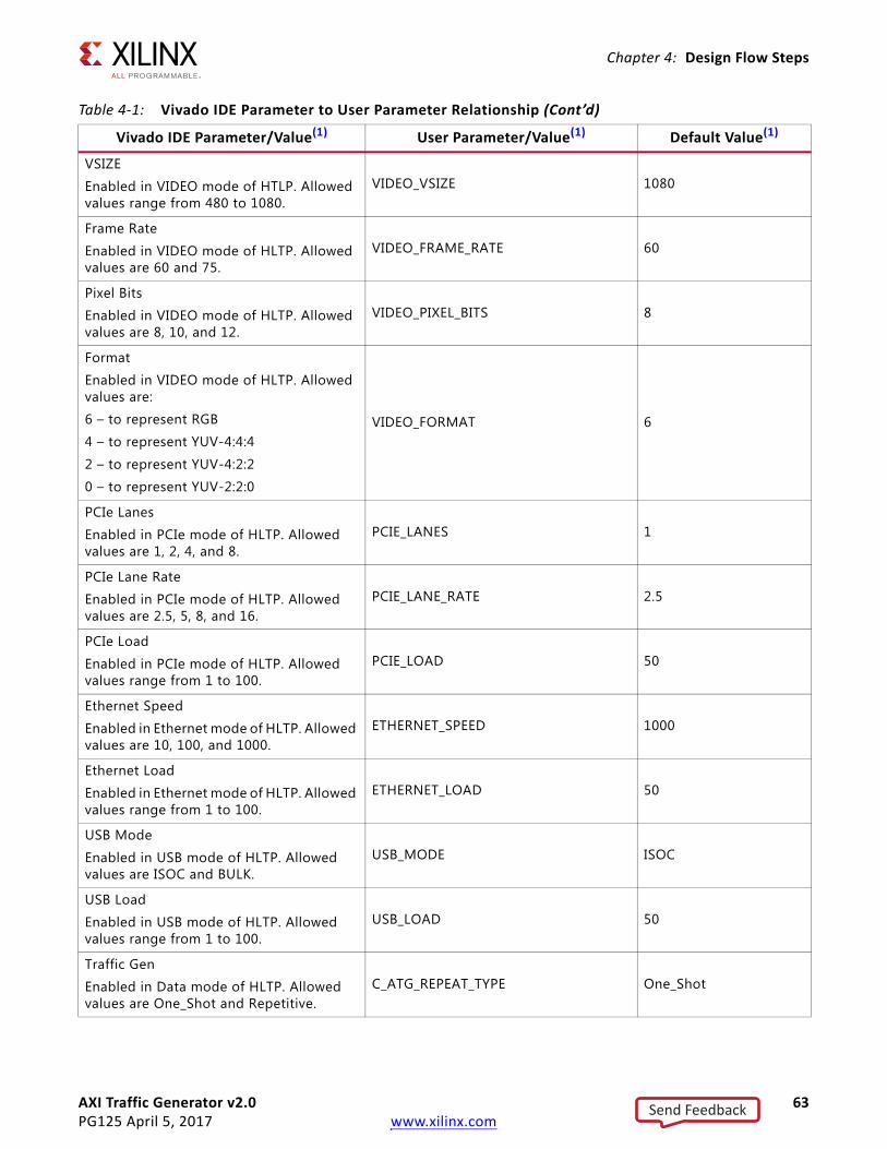
AXI Traffic Generator v2.0 63PG125 April 5, 2017 www.xilinx.com
Chapter 4: Design Flow Steps
VSIZE
Enabled in VIDEO mode of HTLP. Allowed values range from 480 to 1080.
VIDEO_VSIZE 1080
Frame Rate
Enabled in VIDEO mode of HLTP. Allowed values are 60 and 75.
VIDEO_FRAME_RATE 60
Pixel Bits
Enabled in VIDEO mode of HLTP. Allowed values are 8, 10, and 12.
VIDEO_PIXEL_BITS 8
Format
Enabled in VIDEO mode of HLTP. Allowed values are:
6 – to represent RGB
4 – to represent YUV-4:4:4
2 – to represent YUV-4:2:2
0 – to represent YUV-2:2:0
VIDEO_FORMAT 6
PCIe Lanes
Enabled in PCIe mode of HLTP. Allowed values are 1, 2, 4, and 8.
PCIE_LANES 1
PCIe Lane Rate
Enabled in PCIe mode of HLTP. Allowed values are 2.5, 5, 8, and 16.
PCIE_LANE_RATE 2.5
PCIe Load
Enabled in PCIe mode of HLTP. Allowed values range from 1 to 100.
PCIE_LOAD 50
Ethernet Speed
Enabled in Ethernet mode of HLTP. Allowed values are 10, 100, and 1000.
ETHERNET_SPEED 1000
Ethernet Load
Enabled in Ethernet mode of HLTP. Allowed values range from 1 to 100.
ETHERNET_LOAD 50
USB Mode
Enabled in USB mode of HLTP. Allowed values are ISOC and BULK.
USB_MODE ISOC
USB Load
Enabled in USB mode of HLTP. Allowed values range from 1 to 100.
USB_LOAD 50
Traffic Gen
Enabled in Data mode of HLTP. Allowed values are One_Shot and Repetitive.
C_ATG_REPEAT_TYPE One_Shot
Table 4-1: Vivado IDE Parameter to User Parameter Relationship (Cont’d)
Vivado IDE Parameter/Value(1) User Parameter/Value(1) Default Value(1)
Send Feedback

AXI Traffic Generator v2.0 64PG125 April 5, 2017 www.xilinx.com
Chapter 4: Design Flow Steps
Traffic Pattern
Enabled in Data mode of HLTP. Allowed values are Fixed and Random.
DATA_TRAFFIC_PATTERN Random
Transfer Length (Minimum)
Enabled in Data mode of HLTP. Allowed values are 1, 2, 4, 8, 16, 32, 64, 128, and 256.
DATA_SIZE_MIN 1
Transfer Length (Maximum)
Enabled in Data mode of HLTP. Allowed values are 1, 2, 4, 8, 16, 32, 64, 128, and 256.
DATA_SIZE_MAX 256
Transfer Length (Average)
Enabled in Data mode of HLTP. Allowed values are 1, 2, 4, 8, 16, 32, 64, 128, and 256.
DATA_SIZE_AVG 32
Transaction Type
Enabled in Data mode of HLTP. Allowed values are Read_Only, Write_Only, and Read_Write.
DATA_TRANS_TYPE Read_Write
Read Share
Enabled in Data mode of HLTP. Allowed values range from 0 to 100.
DATA_READ_SHARE 50
Write Share
Enabled in Data mode of HLTP. Allowed values range from 0 to 100.
DATA_WRITE_SHARE 50
ITG Type
Enabled in Data mode of HLTP. Allowed values are Fixed and Random.
DATA_TRANS_GAP Fixed
ITG (Clocks)
Enabled in Data mode of HLTP. Allowed values range from 0 to 1023.
DATA_ITG_GAP 5
Transaction Seed
Enabled in Data mode of HLTP. Allowed values range from 1 to 100.
DATA_TRANS_SEED 1
Write Base Address (MSB) C_ATG_STATIC_WR_ADDRESS_EXT 0x00000000
Write High Address (MSB) C_ATG_STATIC_WR_HIGH_ADDRESS_EXT 0x00000000
Read Base Address (MSB) C_ATG_STATIC_RD_ADDRESS_EXT 0x00000000
Read High Address (MSB) C_ATG_STATIC_RD_HIGH_ADDRESS_EXT 0x00000000
AXI Base Address (MSB) MASTER_BASE_ADDRESS_EXT 0x00000000
AXI High Address (MSB) MASTER_HIGH_ADDRESS_EXT 0x00000000
Write Address Gen Seed AXI_WR_ADDR_SEED 0x7C9B
Table 4-1: Vivado IDE Parameter to User Parameter Relationship (Cont’d)
Vivado IDE Parameter/Value(1) User Parameter/Value(1) Default Value(1)
Send Feedback
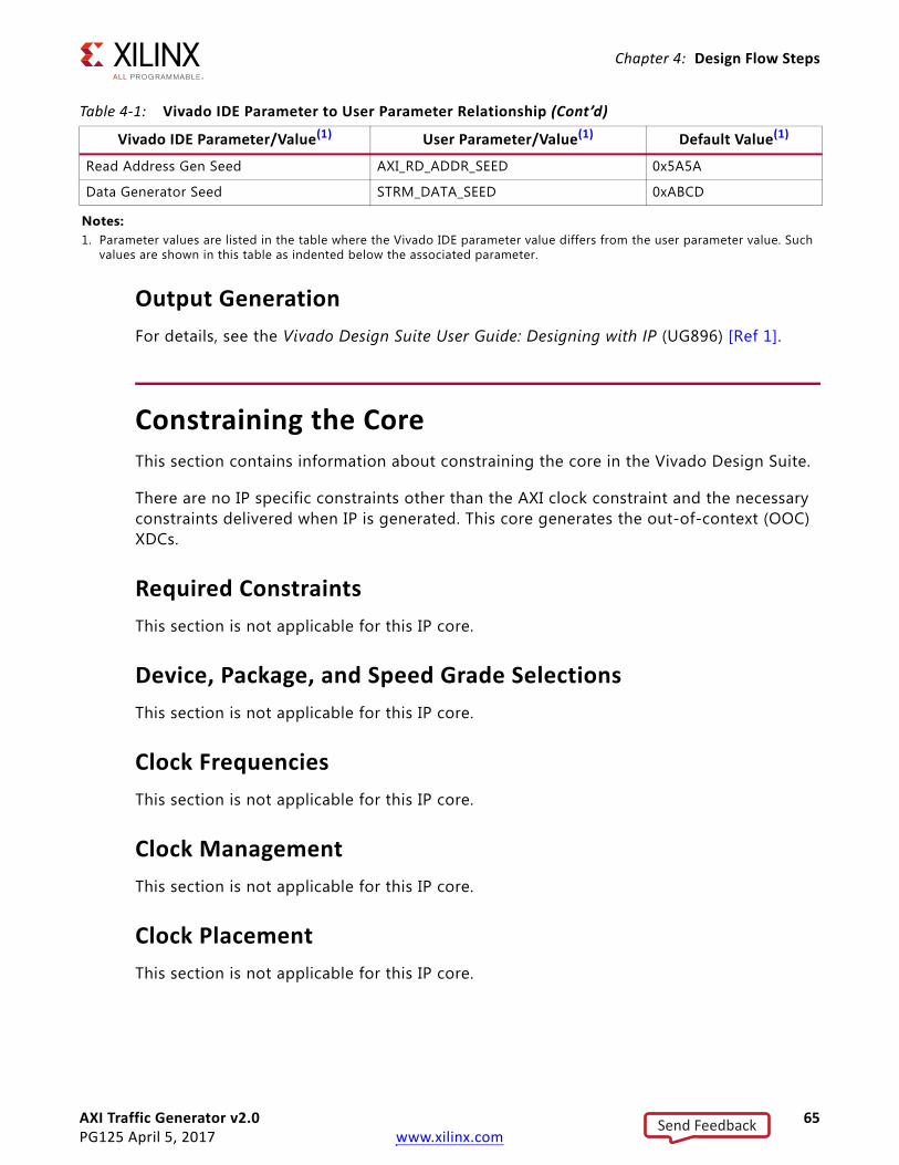
AXI Traffic Generator v2.0 65PG125 April 5, 2017 www.xilinx.com
Chapter 4: Design Flow Steps
Output GenerationFor details, see the Vivado Design Suite User Guide: Designing with IP (UG896) [Ref 1].
Constraining the CoreThis section contains information about constraining the core in the Vivado Design Suite.
There are no IP specific constraints other than the AXI clock constraint and the necessary constraints delivered when IP is generated. This core generates the out-of-context (OOC) XDCs.
Required ConstraintsThis section is not applicable for this IP core.
Device, Package, and Speed Grade SelectionsThis section is not applicable for this IP core.
Clock FrequenciesThis section is not applicable for this IP core.
Clock ManagementThis section is not applicable for this IP core.
Clock PlacementThis section is not applicable for this IP core.
Read Address Gen Seed AXI_RD_ADDR_SEED 0x5A5A
Data Generator Seed STRM_DATA_SEED 0xABCD
Notes: 1. Parameter values are listed in the table where the Vivado IDE parameter value differs from the user parameter value. Such
values are shown in this table as indented below the associated parameter.
Table 4-1: Vivado IDE Parameter to User Parameter Relationship (Cont’d)
Vivado IDE Parameter/Value(1) User Parameter/Value(1) Default Value(1)
Send Feedback
AXI Traffic Generator v2.0 66PG125 April 5, 2017 www.xilinx.com
Chapter 4: Design Flow Steps
BankingThis section is not applicable for this IP core.
Transceiver PlacementThis section is not applicable for this IP core.
I/O Standard and PlacementThis section is not applicable for this IP core.
SimulationFor comprehensive information about Vivado simulation components, as well as information about using supported third-party tools, see the Vivado Design Suite User Guide: Logic Simulation (UG900) [Ref 5].
IMPORTANT: For cores targeting 7 series or Zynq-7000 AP SoC devices, UNIFAST libraries are not supported. Xilinx IP is tested and qualified with UNISIM libraries only.
Synthesis and ImplementationFor details about synthesis and implementation, see the Vivado Design Suite User Guide: Designing with IP (UG896) [Ref 1].
Send Feedback

AXI Traffic Generator v2.0 67PG125 April 5, 2017 www.xilinx.com
Chapter 5
Example DesignThis chapter contains information about the example design provided in the Vivado® Design Suite.
The top module instantiates all components of the core and example design that are needed to implement the design in hardware, as shown in Figure 5-1. This includes the driver, responder and monitor modules.
This example design demonstrates the transactions on AXI4 and AXI4-Stream interfaces of the Device Under Test (DUT) based on the mode in which the DUT is configured.
• Driver – AXI Traffic Generator in System Test is used as a Driver to configure the DUT and checks for the pass/fail condition.
• Responder – AXI block RAM (BRAM) Controller is used to respond to AXI4 transactions generated by the DUT in the applicable modes.
• Monitor – AXI Performance Monitor is used to monitor the AXI4 transactions generated by the DUT in High Level Traffic modes.
X-Ref Target - Figure 5-1
Figure 5-1: AXI Traffic Generator Example Design Block Diagram
s_axi_areset
DUT
s_axi_aclk_ps_axi_aclk_n
DriverAXI4
ResponderAXI4/AXIS
done
status
Monitor
<componentname>_exdes.v (top)
core_ext_start
core_ext_stop
Send Feedback

AXI Traffic Generator v2.0 68PG125 April 5, 2017 www.xilinx.com
Chapter 5: Example Design
Implementing the Example DesignAfter following the steps described in Customizing and Generating the Core, page 50 to generate the core, implement the example design as follows:
1. Right-click the core in the Hierarchy window, and select Open IP Example Design.
2. A new window pops up, asking you to specify a directory for the example design. Select a new directory or keep the default directory.
3. A new project is automatically created in the selected directory and it is opened in a new Vivado window.
4. In the Flow Navigator (left-side pane), click Run Implementation and follow the directions.
Example Design Directory StructureIn the current project directory, a new project with the name <componentname>_example is created. This directory and its subdirectories contain all the source files that are required to create the AXI Traffic Generator example design.
Table 5-1 shows the files delivered in the <componentname>_example/<componentname>_example.srcs/ directory. This <component_name>/example_design directory contains the generated example design top files.
Table 5-1: Example Design Directory
Name Description
<component_name>_exdes.xdc Top-level constraints file for the example design.
<componentname>_exdes.v Top-level HDL file for the example design.
Send Feedback
AXI Traffic Generator v2.0 69PG125 April 5, 2017 www.xilinx.com
Chapter 5: Example Design
Simulating the Example DesignFor more information on Simulation, the Vivado Design Suite User Guide: Logic Simulation (UG900) [Ref 5].
Simulation ResultsThe simulation script compiles the AXI Traffic Generator example design and supporting simulation files. It then runs the simulation and checks to ensure that it completed successfully.
If the test passes, then the following message is displayed:
Test Completed Successfully
If the test fails, then the following message is displayed:
ERROR: Test Failed
If the test hangs, then the following message is displayed:
ERROR: Test did not complete (timed-out)
Send Feedback

AXI Traffic Generator v2.0 70PG125 April 5, 2017 www.xilinx.com
Chapter 6
Test BenchThis chapter contains information about the test bench provided in the Vivado® Design Suite.
Figure 6-1 shows the test bench for the AXI Traffic Generator example design. The top-level test bench generates a 100 MHz clock, external start/stop triggers pulses based on the mode, and drives an initial reset to the example design.X-Ref Target - Figure 6-1
Figure 6-1: AXI Traffic Generator Example Design Test Bench
DUT
Clock, Reset, and External Trigger Generation
<componentname>_tb_top.v (top_tb)
s_axi_areset
s_axi_aclk_ps_axi_aclk_n
done
status
core_ext_start
core_ext_stop
Test Status
Send Feedback

AXI Traffic Generator v2.0 71PG125 April 5, 2017 www.xilinx.com
Chapter 6: Test Bench
Example Sequences for Custom Mode
Protocol – AXI4
Advanced/Basic
1. Configure CMDRAM/MSTRAM with a write and read transactions.
2. Enable interrupt generation for transfer completion.
3. Enable core to start generating traffic.
4. Poll for transfer completion status.
Static
1. Configure Length (0x8) to Static Length register.
2. Enable for to start generating traffic.
3. Perform a dummy read to Static Length register before disabling the core.
4. Disable the core to stop generation of traffic.
5. Poll for done bit in Static Control register.
Protocol – AXI4-Stream
Master Only/Master Loopback
1. Configure Transfer Length (0x40009) to Transfer Length register.
2. Enable the core to start generating streaming traffic.
3. Poll for done bit in Streaming Control register.
4. Read the Status register to compare the number of transactions generated versus programed value.
Slave Loopback
1. Program streaming source (AXI Traffic Generator in Master Only mode used) to generate a four streaming transactions of length nine.
2. Poll for done bit in streaming source.
3. Read the Status register of DUT to compare the number of transactions generated versus programed value.
Send Feedback
AXI Traffic Generator v2.0 72PG125 April 5, 2017 www.xilinx.com
Chapter 6: Test Bench
Protocol – AXI4-Lite
System Init/System Test
1. Poll for done bit from the DUT and report status of AXI4-Lite traffic generation sequence programmed through COE file.
Example Sequences for High Level Traffic (Video, PCIe, Ethernet, USB) Modes1. Program AXI Performance Monitor to count the number of bytes transferred on AXI4
Channels.
2. Generate a start pulse to core through core_ext_start.
3. Wait for 1 ms.
4. Generate a stop pulse to core through core_ext_stop.
5. Poll metric counters of AXI Performance monitor to compare the number of bytes generated versus programmed value based on the throughput required.
Example Sequences for High Level Traffic (Data) Mode1. Program AXI Performance Monitor to count the number of bytes transferred on AXI4
Channels.
2. Generate a start pulse to core through core_ext_start.
3. Wait for 1 ms.
4. Poll metric counters of AXI Performance monitor to compare the number of bytes generated versus programmed value based on the percentage of traffic share on each channel.
Send Feedback

AXI Traffic Generator v2.0 73PG125 April 5, 2017 www.xilinx.com
Appendix A
Migrating and UpgradingThis appendix contains information about upgrading to a more recent version of the IP core.
Migrating to the Vivado Design SuiteFor information on migrating to the Vivado Design Suite, see the ISE to Vivado Design Suite Migration Guide (UG911) [Ref 6].
Upgrading in the Vivado Design SuiteThis section provides information about any changes to the user logic or port designations between core versions.
Port ChangesThe following ports are added in this release:
• core_ext_start
• core_ext_stop
• s_axis_master – Streaming interface
• axis_err_count
• m_axi_lite – Four new AXI4-lite interfaces added
• done
• status
Note: For more information on port descriptions, see Port Descriptions, page 35.
Send Feedback

AXI Traffic Generator v2.0 74PG125 April 5, 2017 www.xilinx.com
Appendix B
DebuggingThis appendix includes details about resources available on the Xilinx® Support website and debugging tools.
Finding Help on Xilinx.comTo help in the design and debug process when using the AXI Traffic Generator, the Xilinx Support web page contains key resources such as product documentation, release notes, answer records, information about known issues, and links for obtaining further product support.
DocumentationThis product guide is the main document associated with the AXI Traffic Generator. This guide, along with documentation related to all products that aid in the design process, can be found on the Xilinx Support web page or by using the Xilinx Documentation Navigator.
Download the Xilinx Documentation Navigator from the Downloads page. For more information about this tool and the features available, open the online help after installation.
Send Feedback

AXI Traffic Generator v2.0 75PG125 April 5, 2017 www.xilinx.com
Appendix B: Debugging
Answer RecordsAnswer Records include information about commonly encountered problems, helpful information on how to resolve these problems, and any known issues with a Xilinx product. Answer Records are created and maintained daily ensuring that users have access to the most accurate information available.
Answer Records for this core can be located by using the Search Support box on the main Xilinx support web page. To maximize your search results, use proper keywords such as:
• Product name
• Tool message(s)
• Summary of the issue encountered
A filter search is available after results are returned to further target the results.
Master Answer Record for the AXI Traffic Generator
AR: 54426
Technical SupportXilinx provides technical support at the Xilinx Support web page for this LogiCORE™ IP product when used as described in the product documentation. Xilinx cannot guarantee timing, functionality, or support if you do any of the following:
• Implement the solution in devices that are not defined in the documentation.
• Customize the solution beyond that allowed in the product documentation.
• Change any section of the design labeled DO NOT MODIFY.
To contact Xilinx Technical Support, navigate to the Xilinx Support web page.
Send Feedback

AXI Traffic Generator v2.0 76PG125 April 5, 2017 www.xilinx.com
Appendix B: Debugging
Debug ToolsThere are many tools available to address AXI Traffic Generator design issues. It is important to know which tools are useful for debugging various situations.
Vivado Design Suite Debug FeatureThe Vivado® Design Suite debug feature inserts logic analyzer and virtual I/O cores directly into your design. The Vivado Design Suite debug feature allows you to set trigger conditions to capture application and integrated block port signals in hardware. Captured signals can then be analyzed. This feature in the Vivado IDE is used for logic debugging and validation of a design running in Xilinx.
The Vivado logic analyzer is used with the logic debug IP cores, including:
• ILA 2.0 (and later versions)
• VIO 2.0 (and later versions)
See the Vivado Design Suite User Guide: Programming and Debugging (UG908) [Ref 7].
Hardware DebugHardware issues can range from link bring-up to problems seen after hours of testing. This section provides debug steps for common issues. The Vivado Design Suite debug feature is a valuable resource to use in hardware debug. The signal names mentioned in the following individual sections can be probed using the Vivado Design Suite debug feature for debugging the specific problems.
Many of these common issues can also be applied to debugging design simulations. Details are provided in the General Checks section.
General ChecksEnsure that all the timing constraints for the core were properly incorporated from the example design and that all constraints were met during implementation.
• Does it work in post-place and route timing simulation? If problems are seen in hardware but not in timing simulation, this could indicate a PCB issue. Ensure that all clock sources are active and clean.
• If using Mixed-Mode Clock Managers (MMCMs) in the design, ensure that all MMCMs have obtained lock by monitoring the locked port.
Send Feedback

AXI Traffic Generator v2.0 77PG125 April 5, 2017 www.xilinx.com
Appendix B: Debugging
• If your outputs go to 0, check your licensing.
• If the core is not generating any transactions on Write/Read master interfaces:
a. Ensure valid_cmd bits are set properly while loading commands to command RAM.
b. Check My_depend, Other depend fields are set correctly to not to cause dead-lock situation.
c. Check delay values programmed to PARAMRAM and wait for sufficient time for the core to insert these delays while generating the transactions.
• If the register control bit (reg0_m_enable) is not getting deasserted:
a. Ensure valid_cmd bits are set properly while loading commands to command RAM.
b. Check Reg0_master_control [18:0] are set to 0.
c. Check delay values programmed to PARAMRAM and wait for sufficient time for the core to insert these delays while generating the transactions.
• In Streaming mode, the core is generating random length of transactions instead of the programed length.
a. Ensure RANLEN is set to 0 in Streaming Config register before enabling the core.
Interface Debug
AXI4 InterfaceRead from a register that does not have all 0s (for example, Reg0_master_control) as a default to verify that the interface is functional. See Figure B-1 for a read timing diagram. Output s_axi_arready asserts when the read address is valid, and output s_axi_rvalid asserts when the read data/response is valid. If the interface is unresponsive, ensure that the following conditions are met:
• The s_axi_aclk input is connected and toggling.
• The interface is not being held in reset, and s_axis_aresetn is an active-Low reset.
• The main core clocks are toggling and that the enables are also asserted.
• If the simulation has been run, verify in simulation and/or a Vivado Design Suite debug feature capture that the waveform is correct for accessing the AXI4 interface.
Send Feedback

AXI Traffic Generator v2.0 78PG125 April 5, 2017 www.xilinx.com
Appendix B: Debugging
X-Ref Target - Figure B-1
Figure B-1: AXI4 Read Timing Diagram
Send Feedback

AXI Traffic Generator v2.0 79PG125 April 5, 2017 www.xilinx.com
Appendix C
Additional Resources and Legal Notices
Xilinx ResourcesFor support resources such as Answers, Documentation, Downloads, and Forums, see Xilinx Support.
ReferencesThese documents provide supplemental material useful with this product guide:
1. Vivado Design Suite User Guide: Designing with IP (UG896)
2. Vivado AXI Reference Guide (UG1037)
3. Vivado Design Suite User Guide: Designing IP Subsystems Using IP Integrator (UG994)
4. Vivado Design Suite User Guide: Getting Started (UG910)
5. Vivado Design Suite User Guide: Logic Simulation (UG900)
6. ISE to Vivado Design Suite Migration Guide (UG911)
7. Vivado Design Suite User Guide: Programming and Debugging (UG908)
8. Vivado Design Suite User Guide: Implementation (UG904)
9. ARM AMBA AXI Protocol Specification, version 2.0 (ARM IHI 0022C)
10. AMBA AXI4-Stream Protocol Specification
Send Feedback

AXI Traffic Generator v2.0 80PG125 April 5, 2017 www.xilinx.com
Appendix C: Additional Resources and Legal Notices
Revision HistoryThe following table shows the revision history for this document.
Date Version Revision
04/05/2017 2.0 • Updated the figures to customize the core.
• Updated the User Parameters table.
• Added the LFSR implementation.
04/06/2016 2.0 • Updated Master RAM section.
• Updated figures in Design Flow Steps chapter.
• Added Write Address Gen Seed and Data Generator Seed descriptions.
• Updated User Parameters table.
11/18/2015 2.0 Added support for UltraScale+ families.
09/30/2015 2.0 • Updated Features description in IP Facts.
• Updated AXI4 Traffic Generator Block Diagram.
• Added Address RAM section.
• Moved Performance and Resource Utilization to HTML.
• Updated Slave-Write/Slave-Read Address Map.
• Added description to Static Mode.
• Added description in High Level Traffic.
• Added Extended Transfer Length register to Streaming Mode Register Map.
• Updated figures in Design Flow Steps chapter.
• Added Address Width section in AXI4 Protocol section.
• Updated description in Static Mode Options section.
• Updated description in AXI Options section.
• Added parameters to Vivado IDE Parameter to User Parameter Relationship.
04/01/2015 2.0 • Updated description in 011 in PARAMRAM Entry Control Signals table.
• Added description in PARAMRAM Opcodes section.
• Updated GUIs in Customizing and Generating the Core section.
• Added Repeat Count section.
• Added User Parameters section.
• Added UNISIM important note in Simulation section.
Send Feedback

AXI Traffic Generator v2.0 81PG125 April 5, 2017 www.xilinx.com
Appendix C: Additional Resources and Legal Notices
10/01/2014 2.0 • Document updates only for revision change.
• Added note #4 in Table 1-2: CMDRAM Memory Format.
• Added notes to Table 1-3: PARAMRAM Entry Control Signals.
• Added note #2 to Table 1-6: OP_DELAY.
• Updated description in Static Mode section.
• Added Note and Important note in High Level Traffic section.
• Added note #3 to Table 2-3: AXI Traffic Generator I/O Signals.
• Added note to Table 2-19: Static Length.
• Updated Static Mode Options section.
• Updated AXI Options section.
04/02/2014 2.0 • Updated Flexible data width capabilities and initialization support in Features section.
• Updated Basic description in AXI Traffic Generator Modes table.
• Updated AXI4-Stream Traffic Generator Block Diagram figure.
• Updated description in Command RAM section.
• Updated Bits[31:29] descriptions in PARAMRAM Entry Control Signals table.
• Updated Mstram_index offsets in Address Generation section.
• Updated CMDRAM and MSTRAM region in Slave-Write/Slave-Read Address Map table and description
• Added entries are 32-bit and Cascading ATGs description in System Init/Test Mode section.
• Added High Level Traffic section and updated System Init/Test Mode status description in Programming Sequence section.
• Updated description in Advanced/Basic Mode without Processor Intervention section.
• Updated Resource Utilization section.
• Updated TDATA Width description in AXI4-Stream Protocol section.
• Updated Bit[19] descriptions in Master Control (0x00) register.
• Added Bit[2] in Streaming Config (0x34) register.
• Added User STRB/TKEEP Set 1 to 4 (0x40 to 0x4C) registers.
• Added traffic generation note to Streaming Control (0x30) and Static Mode Control (0x60) registers.
• Added IP integrator note in AXI4-Lite Protocol section.
• Added One-shot and Repetitive descriptions in Data Mode section.
12/18/2013 2.0 • Added UltraScale support.
• Added loop enable Bit[19] to Master Control register 0x0.
Date Version Revision
Send Feedback

AXI Traffic Generator v2.0 82PG125 April 5, 2017 www.xilinx.com
Appendix C: Additional Resources and Legal Notices
10/02/2013 2.0 Revision number advanced to 2.0 to align with core version number.
• Added new features in IP Facts.
• Added IP Integrator.
• Updated Overview chapter.
• Updated Resource Utilization in Product Specification chapter.
• Updated Streaming Config register.
• Updated Resets section.
• Updated Generating and Customizing the Core chapter.
• Added Simulation, Synthesis, Example Design, and Test Bench chapters.
• Added Port Changes in Migrating Appendix.
• Added Streaming mode to General Checks in Debug Appendix.
03/20/2013 1.0 Initial Xilinx release. This Product Guide replaces PG094 AXI Exerciser.
Date Version Revision
Send Feedback
AXI Traffic Generator v2.0 83PG125 April 5, 2017 www.xilinx.com
Appendix C: Additional Resources and Legal Notices
Please Read: Important Legal NoticesThe information disclosed to you hereunder (the "Materials") is provided solely for the selection and use of Xilinx products. To the maximum extent permitted by applicable law: (1) Materials are made available "AS IS" and with all faults, Xilinx hereby DISCLAIMS ALL WARRANTIES AND CONDITIONS, EXPRESS, IMPLIED, OR STATUTORY, INCLUDING BUT NOT LIMITED TO WARRANTIES OF MERCHANTABILITY, NON-INFRINGEMENT, OR FITNESS FOR ANY PARTICULAR PURPOSE; and (2) Xilinx shall not be liable (whether in contract or tort, including negligence, or under any other theory of liability) for any loss or damage of any kind or nature related to, arising under, or in connection with, the Materials (including your use of the Materials), including for any direct, indirect, special, incidental, or consequential loss or damage (including loss of data, profits, goodwill, or any type of loss or damage suffered as a result of any action brought by a third party) even if such damage or loss was reasonably foreseeable or Xilinx had been advised of the possibility of the same. Xilinx assumes no obligation to correct any errors contained in the Materials or to notify you of updates to the Materials or to product specifications. You may not reproduce, modify, distribute, or publicly display the Materials without prior written consent. Certain products are subject to the terms and conditions of Xilinx's limited warranty, please refer to Xilinx's Terms of Sale which can be viewed at https://www.xilinx.com/legal.htm#tos; IP cores may be subject to warranty and support terms contained in a license issued to you by Xilinx. Xilinx products are not designed or intended to be fail-safe or for use in any application requiring fail-safe performance; you assume sole risk and liability for use of Xilinx products in such critical applications, please refer to Xilinx's Terms of Sale which can be viewed at https://www.xilinx.com/legal.htm#tos.AUTOMOTIVE APPLICATIONS DISCLAIMERAUTOMOTIVE PRODUCTS (IDENTIFIED AS “XA” IN THE PART NUMBER) ARE NOT WARRANTED FOR USE IN THE DEPLOYMENT OF AIRBAGS OR FOR USE IN APPLICATIONS THAT AFFECT CONTROL OF A VEHICLE (“SAFETY APPLICATION”) UNLESS THERE IS A SAFETY CONCEPT OR REDUNDANCY FEATURE CONSISTENT WITH THE ISO 26262 AUTOMOTIVE SAFETY STANDARD (“SAFETY DESIGN”). CUSTOMER SHALL, PRIOR TO USING OR DISTRIBUTING ANY SYSTEMS THAT INCORPORATE PRODUCTS, THOROUGHLY TEST SUCH SYSTEMS FOR SAFETY PURPOSES. USE OF PRODUCTS IN A SAFETY APPLICATION WITHOUT A SAFETY DESIGN IS FULLY AT THE RISK OF CUSTOMER, SUBJECT ONLY TO APPLICABLE LAWS AND REGULATIONS GOVERNING LIMITATIONS ON PRODUCT LIABILITY.© Copyright 2013–2017 Xilinx, Inc. Xilinx, the Xilinx logo, Artix, ISE, Kintex, Spartan, Virtex, Vivado, Zynq, and other designated brands included herein are trademarks of Xilinx in the United States and other countries. All other trademarks are the property of their respective owners.
Send Feedback
Related Documents