Subject : ANTENNAS AND WAVE PROPAGATION Subject Code : EC1352 Academic Year : 2010-11 Semester/Branch: VI/ECE Name of the Faculty & Code: T.ESTHER & NPRCET068 DEFINITION To have deep knowledge of antennas and wave propagation. OBJECTIVES To study antenna fundamentals, loop antenna and antenna arrays. To study the concept of radiation and analyze radiation characteristics of a current element and dipole To study rhombic antenna, yagi antenna and log periodic antenna To learn special antennas such as frequency independent and broad band antennas To study radio wave propagation. TEXT BOOK 1. E.C.Jordan and Balmain, "Electro Magnetic Waves and Radiating Systems", PHI, 1968, Reprint 2003. REFERENCES 2. John D.Kraus and Ronalatory Marhefka, "Antennas", Tata McGraw-Hill Book Company, 2002. 3. R.E.Collins, 'Antennas and Radio Propagation ", McGraw-Hill, 1987. 4. Ballany , "Antenna Theory " , John Wiley & Sons, second edition , 2003 5. K.D.Prasad,‖Antenna and wave propagation‖, N.P.R COLLEGE OF ENGG & TECH (Approved by AICTE, New Delhi & Affiliated by Anna University,Trichy) Natham, Dindigul – 624 401. Ph : 04544-245391 Wesite:www.nprcet.org E.mail:[email protected] LAB EXPERIMENT PLAN Format No. ACD 09A ISO9001:200 8 Isssue No. 01 Rev.No 00

Awp
Nov 08, 2014
notes useful for 6th sem students
Welcome message from author
This document is posted to help you gain knowledge. Please leave a comment to let me know what you think about it! Share it to your friends and learn new things together.
Transcript

Subject : ANTENNAS AND WAVE PROPAGATION
Subject Code : EC1352
Academic Year : 2010-11
Semester/Branch: VI/ECE
Name of the Faculty & Code: T.ESTHER & NPRCET068
DEFINITION
To have deep knowledge of antennas and wave propagation.
OBJECTIVES
To study antenna fundamentals, loop antenna and antenna arrays.
To study the concept of radiation and analyze radiation characteristics of a
current element and dipole
To study rhombic antenna, yagi antenna and log periodic antenna
To learn special antennas such as frequency independent and broad band
antennas
To study radio wave propagation.
TEXT BOOK
1. E.C.Jordan and Balmain, "Electro Magnetic Waves and Radiating Systems",
PHI, 1968, Reprint 2003.
REFERENCES
2. John D.Kraus and Ronalatory Marhefka, "Antennas", Tata McGraw-Hill Book
Company, 2002.
3. R.E.Collins, 'Antennas and Radio Propagation ", McGraw-Hill, 1987.
4. Ballany , "Antenna Theory " , John Wiley & Sons, second edition , 2003
5. K.D.Prasad,‖Antenna and wave propagation‖,
N.P.R COLLEGE OF ENGG & TECH
(Approved by AICTE, New Delhi & Affiliated by Anna
University,Trichy)
Natham, Dindigul – 624 401. Ph : 04544-245391
Wesite:www.nprcet.org E.mail:[email protected]
LAB EXPERIMENT PLAN
Format
No.
ACD 09A
ISO9001:200
8
Isssue
No.
01
Rev.No 00

ANNA UNIVERSITY TIRUCHIRAPPALLI
Regulations 2008 Syllabus
B.E ECE/ SEMESTER VI
EC1352 – ANTENNAS AND WAVE PROPAGATION
Prepared By:
T.ESTHER/SL/ECE

SYLLABUS
EC1352 – ANTENNAS AND WAVE PROPAGATION
UNIT I ANTENNA FUNDAMENTALS 9
Definitions – Radiation intensity – Directive gain – Directivity – Power gain – Beam
width – Band width – Gain and radiation resistance of current element – Half-wave
dipole and folded dipole – Reciprocity principle – Effective length and effective area –
Relation between gain, effective length and radiation resistance.
Loop Antennas: Radiation from small loop and its radiation resistance – Radiation
from a loop with circumference equal to wavelength and resultant circular polarization
Helical antenna. Normal mode and axial mode operation.
Antenna Arrays: Expression for electric field from two and three element arrays –
Uniform linear array – Method of pattern multiplication – Binomial array – End-fire
array.
UNIT II RADIATION FIELDS OF WIRE ANTENNAS 9
Concept of vector potential – Modification for time varying – Retarded case – Fields
associated with Hertzian dipole – Power radiated and radiation resistance of current
element – Radiation resistance of elementary dipole with linear current distribution –
Radiation from half-wave dipole and quarter – Wave monopole – Assumed current
distribution for wire antennas – Use of capacity hat and loading coil for short
antennas.
UNIT III TRAVELLING WAVE (WIDEBAND) ANTENNAS 9
Loop antenna (elementary treatment only) – Helical antenna – Radiation from a
travelingwave on a wire – Analysis of rhombic antenna – Design of rhombic antennas
– Yagi-Udaantenna – Log periodic antenna.
UNIT IV APERTURE AND LENS ANTENNAS 9
Radiation from an elemental area of a plane wave (Huygen‘s source) – Radiation from
the open end of a coaxial line – Radiation from a rectangular aperture treated as an
array
of huygen‘s source – Equivalence of fields of a slot and complementary dipole –
Relation
between dipole and slot impedances – Method of feeding slot antennas – Thin slot in
an
infinite cylinder – Field on the axis of an E-plane sectoral horn – Radiation from
circular
aperture – Beam width and effective area – Reflector type of antennas (dish antennas).
dielectric lens and metal plane lens antennas – Luxemberg lens – Spherical waves and
biconical antenna.
UNIT V PROPAGATION 9
The three basic types of propagation: Ground wave, space wave and sky wave
propagation.
Sky Wave Propagation: Structure of the ionosphere – Effective dielectric constant of

ionized region – Mechanism of refraction – Refractive index – Critical frequency –
Skip
distance – Effect of earth‘s magnetic field – Energy loss in the ionosphere due to
collisions – Maximum usable frequency – Fading and diversity reception.
Space Wave Propagation: Reflection from ground for vertically and horizontally
polarized waves – Reflection characteristics of earth – Resultant of direct and
reflectedray at the receiver – Duct propagation.
Ground Wave Propagation: Attenuation characteristics for ground wave
propagation –Calculation of field strength at a distance.
L:45 T:15 Total: 60
TEXTBOOK
1. John D. Kraus and Ronalatory Marhefka, ―Antennas‖, TMH Book Company,
2002.
REFERENCES
1. Jordan E. C. and Balmain, ―Electro Magnetic Waves and Radiating Systems‖,
PHI, 1968, Reprint 2003
2. Collins R. E., ―Antennas and Radio Propagation‖, TMH, 1987.
3. Balanis, ―Antenna Theory‖, 2nd Edition, John Wiley & Sons, 2003.

UNIT I
ANTENNA FUNDAMENTALS
Definitions – Radiation intensity – Directive gain – Directivity – Power gain – Beam
width – Band width – Gain and radiation resistance of current element – Half-wave
dipole and folded dipole – Reciprocity principle – Effective length and effective area –
Relation between gain, effective length and radiation resistance.
Loop Antennas: Radiation from small loop and its radiation resistance – Radiation
from a loop with circumference equal to wavelength and resultant circular polarization
Helical antenna. Normal mode and axial mode operation.
Antenna Arrays: Expression for electric field from two and three element arrays –
Uniform linear array – Method of pattern multiplication – Binomial array – End-fire
array.
BASIC ANTENNA THEORY
An antenna is a device that provides a transition between electric currents on a
conductor and electromagnetic waves in space. A transmitting antenna transforms
electric currents into radio waves and a receiving antenna transforms an
electromagnetic field back into electric current.
There are several basic properties that are common to all antennas:
Reciprocity: an antenna‘s electrical characteristics are the same whether it is used for
transmitting or receiving. Because this is always true, throughout this lecture, we will
consider antennas as transmitting antennas.
Polarization: polarization is the orientation of the electric field vector of the
electromagnetic wave produced by the antenna. For most antennas, the orientation of
the antenna conductor determines the polarization. Polarization may be vertical,
horizontal or elliptical.

The diagram above shows vertical and horizontal polarization. If the radio wave's
electric field vector points in some other direction, it is said to be obliquely polarized.
If the electric field rotates in space, such that its tip follows an elliptical path, it is
elliptically polarized.
Wavelength: this is the length of one RF wave. It can be computed by either of the
following formulas, depending on the units required:
(in m) = 300/f(in MHz) or (in ft) = 984/f(in MHz)
For more information on wavelength, click here.
Gain (directivity): This is a measure of the degree to which an antenna focuses
power in a given direction, relative to the power radiated by a reference antenna in the
same direction. Units of measure are dBi (isotopic antenna reference) or dBd (half-
wave dipole reference). The two gain measurements can be converted using the
following formula:
dBi = dBd + 2.1

If the directivity of the transmitting and receiving antennas is known, it is possible to
compute the power received by the receiving antenna using either of the formulas
below:
When using dB:
Antenna gain should be expressed in dBi, wavelength and distances in m and powers
in dBm or dBW.
When using gain ratios and powers in W:
Antenna gains should be expressed as a number, distances and wavelengths in m and
powers in W.
Here is an example:
Two dipole antennas 100 km apart are aligned and one transmits a 1 kW signal. The
frequency is 222 MHz. What is the received power?
Solution A using dB
Convert 1 kW to dbm PT = 10log(1kW/1mW) = 10 log(1,000,000) = 60 dBm
Find the wavelength: = 300/f = 300/222 MHz = 1.35 m
This is the same as 9.4*10-10
W
Beamwidth: the angular separation between the half-point (-3dB) points in an
antenna‘s radiation pattern. In general, the beamwidth of the main lobe of the radiation
pattern decreases as the directivity increases.

Near field (induction field): electromagnetic field created by an antenna that is only
significant at distances of less than 2D/ from the antenna, where D is the longest
dimension of the antenna.
Near field region: A spherical region of radius 2D/ centered on the antenna.
Far field (radiation field): electromagnetic field created by the antenna that extends
throughout all space. At distances greater than 2D/ from the antenna, it is the only
field. It is the field used for communications.
Far field region: The region outside the near field region, at distances greater than
2D/ .
Input Impedance: This is the impedance measured at the antenna input terminals. In
general it is complex and has two real parts and one imaginary part:
Radiation resistance: - represents conversion of power into RF waves (real)
Loss resistance – represents conductor losses, ground losses, etc. (real)
reactance – represents power stored in the near field (imaginary)
Efficiency: this is the ratio of radiation resistance to total antenna input resistance:
The loss resistances come from conductor losses and losses in the ground (the near
field of the antenna can interact with the ground and other objects near the antenna).
The efficiency of practical antennas varies from less than 1% for certain types of low
frequency antennas to 99% for some types of wire antennas.
Electrical length. This came up in the section on transmission lines. It is the length or
distance expressed in terms of wavelengths.
Bandwidth: generally the range of frequencies over which the antenna system‘s SWR
remains below a maximum value, typically 2.0
Azimuth and Elevation: These are angles used to describe a specific position in an
antenna's radiation pattern. Azimuth is a horizontal angle, generally measured from
true north. The elevation angle is a vertical angle, ranging from 0 degrees (horizon) to
90 degrees (zenith).

THE HALF WAVE DIPOLE (HERTZ ANTENNA)
The dipole antenna dates back to the early RF experiments of Heinrich Hertz in the
late 19th
century. It consists of a conductor that is broken in the center so that RF
power can be applied to it. One can think of the half wave dipole as an open circuited
transmission line that has been spread out, so that the transmission line can radiate a
signal into space.
A dipole can be any length, but it most commonly is just under 1/2 wavelength long.
A dipole with this length, known as a resonant or half wave dipole, has an input
impedance that is purely resistive and lies between 30 and 80 ohms, which provides a
good match to commercially available 50 ohms coaxial cables as well as commercial
transmitters and receivers, most of which have 50 ohm output and input impedances.
The length of a dipole can be approximately determined from the following formula:
l = 468/f
where:
l is the length in feet and
f is the frequency in MHz.
The radiation pattern of a /2 dipole in free space is shown below

The 3-dimensional radiation pattern in free space is a fat doughnut with the dipole
piercing its central hole. Notice that unlike an isotropic radiator that radiates equally
well in all directions, the dipole radiates more RF in some directions than others. This
means that the dipole has a gain or directivity over an isotropic radiator of
approximately 2.1 dB. That means that the radiation from the dipole is 2.1 dB stronger
in the direction of maximum radiation than the radiation from an isotropic radiator in
the same direction, when both antennas are fed with the same amount of RF power..
The input impedance of a dipole antenna also depends on its electrical length. When
the antenna is approximately an odd multiple of a half wavelength long, the input
impedance is resistive and lies between 50 and 200 ohms. For antennas that are an
even number of half wavelengths long, the input impedance is resistive and extremely
high, between 1000 and 50,000 ohms.
The chart below shows the effect of ground on the input impedance of a dipole.

As a horizontal antenna is brought closer to the surface of the earth, its input
resistance decreases at first because the electric field is being shorted by the ground.
As the antenna is brought closer, the input resistance will rise again because increases
in ground loss resistance overwhelm the decrease due to shorting of the electric field.
Over a good conductor such as sea water, the input resistance drops steadily as the
antenna is lowered, reaching a value of zero when the antenna touches the water's
surface.
As a horizontal dipole is raised above the ground, the input resistance increases until a
maximum value of approximately 90 ohms is reached at a height of 3/8 . As the
antenna is raised even higher, the input resistance slowly oscillates around the free
space value of 73 ohms. Most dipoles in actual installations show an input resistance
of 50 to 75 ohms, depending on the location.
There is a variation of the /2 dipole known as the folded dipole that is often used for
FM and TV reception. A diagram of the folded dipole is shown below.
The folded dipole is the same overall length as the /2 dipole, but has a second
conductor connected to the first only at the ends, and separated from it by

approximately /400. The input impedance of the folded dipole is approximately 300
ohms, which is a perfect match to TV twin lead and to the input of the TV set. The
folded dipole also has a larger bandwidth than the regular dipole, which is important
for proper TV reception.
THE VERTICAL (MARCONI) ANTENNA
In the last unit, we discussed the ground wave, and the necessity that the ground
wave have vertical polarization. A vertical antenna is used to launch a vertically
polarized RF wave. Vertical antennas are most often used in two areas:
1.Low frequency communications – at frequencies below 2 MHz, it is difficult
to use dipole antennas because of their length and the requirement that they be
mounted at least a half wavelength above ground. For example: a 2 MHz dipole
antenna is approximately 234 ft long and needs to be approximately 234 feet above
ground. Also, most communications at frequencies below 2 MHz is via ground wave,
which requires vertical polarization.
2.Mobile communications – it is difficult to mount a horizontally polarized
dipole on a vehicle. A vertical antenna only has one mounting point and less wind
resistance.
The most common vertical antenna is the Marconi antenna. It is a vertical conductor
/4 high, fed at the end near ground. It is essentially a vertical dipole, in which one
side of the dipole is the RF image of the antenna in the ground. This may sound
strange, but remember that ground reflects RF as a mirror reflects light
Simple Marconi Antenna

The image antenna formed in the ground under a Marconi antenna
This type of antenna, unlike the dipole, is an unbalanced antenna, and should be fed
directly with coaxial cable. The shield of the coax is connected to the ground at the
base of the antenna and the center lead of the coax is connected to the vertical radiator.
Because the ground under a vertical antenna is actually part of the antenna, it is
necessary that ground losses be minimized. To minimize the losses, the electrical
conductivity of the ground must be made as high as possible, or an artificial low loss
ground must be provided.
Ground conductivity can be improved by using ground radial wires. These are wires
buried just under the earth‘s surface or laid on the surface that provide a low resistance
path for RF currents flowing in the ground. The ground currents are greatest in the
vicinity of the feed point of a Marconi antenna, so the radials run out from the feed
point, up to a distance of /4 from the antenna, if possible. The ground radials do not
have to be any specific length and the general rule is that a large number of short
radials is preferable to a few long radials. The diagram below shows how current
flows through the ground to the feed point of the Marconi antenna.

The radials should be laid out in a pattern that follows the ground current, that is
running radially out from the feed point of the antenna. The diagram below is a bird's
eye view of typical ground radial layouts. Note that the radials do not all have to be
the same length and that losses may be decreased by adding extra radials near the feed
point. These extra radials can be as short as /40 and still be effective.
When a Marconi antenna cannot be mounted on the ground, an artificial ground
system, called a counterpoise, is used. The counterpoise consists of /4 wires
emanating radially from the antenna feed point as shown below. The shield of the
coax is connected to the counterpoise at the feed point. The counterpoise is not
connected to ground.

Ground losses affect the feed point impedance and antenna efficiency. A Marconi
antenna mounted on a perfectly conducting ground would have an input impedance
that is ½ the impedance of a dipole, or approximately 36 ohms. When mounted on a
real ground, the input impedance can range from 38 ohms for a well designed AM
broadcast antenna mounted over a specially prepared ground, to over 100 ohms for a
Marconi mounted above poor, unprepared ground that has no radials.
Ground loss reduces the antenna's efficiency, because part of the power being
delivered to the antenna is being dissipated in the ground rather than being radiated.
The efficiency can be computed from the measured value of input resistance by using
the following formula:
The radiation pattern of the Marconi antenna is a half doughnut as shown in the figure
below. There is no radiation straight up in the direction of the wire. The bulk of the
radiation occurs at a low elevation angle, which is what is needed to launch a ground
wave.

LOOP ANTENNAS
All antennas discussed so far have used radiating elements that were linear
conductors. It is also possible to make antennas from conductors formed into closed
loops. There are two broad categories of loop antennas:
1. Small loops, which contain no more than 0.085 wavelengths (~/12) of wire
2. Large loops, which contain approximately 1 wavelength of wire.
SMALL LOOP ANTENNAS
A small loop antenna is one whose circumference contains no more than 0.085
wavelengths of wire. In such a short conductor, we may consider the current, at any
moment in time to be constant. This is quite different from a dipole, whose current
was a maximum at the feed point and zero at the ends of the antenna. The small loop
antenna can consist of a single turn loop or a multi-turn loop as shown below:

The radiation pattern of a small loop is very similar to a dipole. The figure below
shows a 2-dimensional slice of the radiation pattern in a plane perpendicular to the
plane of the loop. There is no radiation from a loop

There is no radiation from a loop along the axis passing through the center of the loop,
as shown below.
When the loop is oriented vertically, the resulting radiation is vertically polarized and
vice versa:
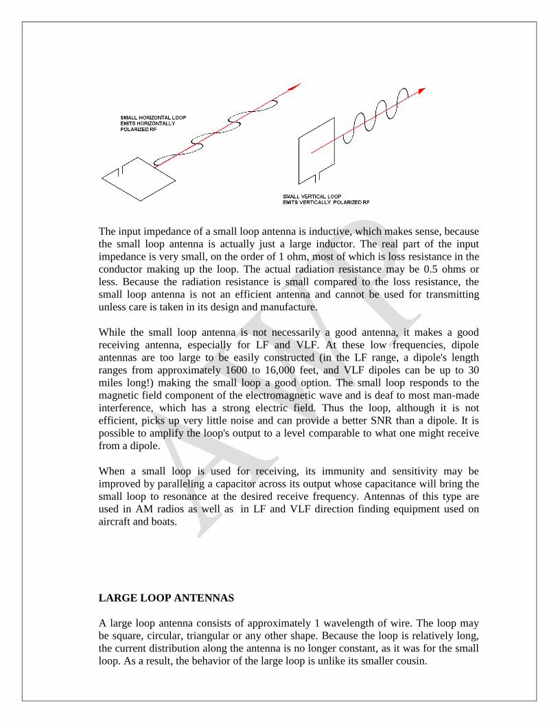
The input impedance of a small loop antenna is inductive, which makes sense, because
the small loop antenna is actually just a large inductor. The real part of the input
impedance is very small, on the order of 1 ohm, most of which is loss resistance in the
conductor making up the loop. The actual radiation resistance may be 0.5 ohms or
less. Because the radiation resistance is small compared to the loss resistance, the
small loop antenna is not an efficient antenna and cannot be used for transmitting
unless care is taken in its design and manufacture.
While the small loop antenna is not necessarily a good antenna, it makes a good
receiving antenna, especially for LF and VLF. At these low frequencies, dipole
antennas are too large to be easily constructed (in the LF range, a dipole's length
ranges from approximately 1600 to 16,000 feet, and VLF dipoles can be up to 30
miles long!) making the small loop a good option. The small loop responds to the
magnetic field component of the electromagnetic wave and is deaf to most man-made
interference, which has a strong electric field. Thus the loop, although it is not
efficient, picks up very little noise and can provide a better SNR than a dipole. It is
possible to amplify the loop's output to a level comparable to what one might receive
from a dipole.
When a small loop is used for receiving, its immunity and sensitivity may be
improved by paralleling a capacitor across its output whose capacitance will bring the
small loop to resonance at the desired receive frequency. Antennas of this type are
used in AM radios as well as in LF and VLF direction finding equipment used on
aircraft and boats.
LARGE LOOP ANTENNAS
A large loop antenna consists of approximately 1 wavelength of wire. The loop may
be square, circular, triangular or any other shape. Because the loop is relatively long,
the current distribution along the antenna is no longer constant, as it was for the small
loop. As a result, the behavior of the large loop is unlike its smaller cousin.

The current distribution and radiation pattern of a large loop can be derived by folding
two half wave dipoles and connecting them as shown in the diagrams below:
We begin with two /2 dipoles separated by /4. RF is fed into the center of each
dipole. The resulting current distribution is shown below as a pink line. Note that the
current is zero at the dipoles' ends,
Now each dipole is folded in towards the other in a "U" shape as shown below. The
current distribution has not changed - the antenna current is still zero at the ends.
Since the current at the ends is zero, it would be OK to connect the ends to make a
loop as shown below.

We have now created a square loop of wire whose circumference is 1 wavelength.
From an electrical point of view, we have just shown that the large loop is equivalent
to two bent dipole antennas.
The radiation pattern of a loop antenna is shown below:

A horizontal slice of the radiation pattern in the XY plane is highlighted in red. It is
similar to the figure-8 pattern of a dipole.
It is possible to create either horizontally or vertically polarized radiation with a large
loop antenna. The polarization is determined by the location of the feed point as
shown below. If the feed point is in a horizontal side of the loop, the polarization is
horizontal. If the feed point is in a vertical side of the loop, the polarization is vertical.
So far we have looked at square loop antennas. One of the interesting things about the
large loop antenna is that the shape is not important. As long as the perimeter of the
antenna is approximately 1 wavelength, the loop antenna will produce a radiation
pattern very similar to the one shown above. The shape of the loop may be circular,
square, triangular, rectangular, or any other polygonal shape. While the shape of the
radiation pattern is not dependent on the shape of the loop, the gain of the loop does
depend on the shape. In particular, the gain of the loop is dependent on the area
enclosed by the wire. The greater the enclosed area, the greater the gain. The circular
loop has the largest gain and the triangular loop has the least. The actual difference
between the gain of the circular loop and triangular loop is less than 1 dB, and is
usually unimportant.
Loop antennas may be combined to form arrays in the same manner as dipoles. Arrays
of loop antennas are called "quad arrays" because the loops are most often square. The
most common type of quad array is a Yagi-Uda array using loops rather than dipoles
as elements. This type of array is very useful at high elevations, where the
combination of high voltage at the element tips of the dipoles in a standard Yagi array
and the lower air pressure lead to corona discharge and erosion of the element . In
fact, the first use of a quad array was by a broadcaster located in Quito, Ecuador (in
the Andes Mountains) in the 1930's.
The input impedance of a loop depends on its shape. It ranges from approximately 100
ohms for a triangular loop to 130 ohms for a circular loop. Unlike the dipole, whose
input impedance presents a good match to common 50 or 75 ohm transmission lines,

the input impedance of a loop is not a good match and must be transformed to the
appropriate impedance.
ANTENNA ARRAYS
An antenna array is an antenna that is composed of more than one conductor. There
are two types of antenna arrays:
Driven arrays – all elements in the antenna are fed RF from the transmitter
Parasitic arrays – only one element is connected to the transmitter. The other elements
are coupled to the driven element through the electric fields and magnetic fields that
exist in the near field region of the driven element
There are many types of driven arrays. The four most common types are:
Collinear array
Broadside array
Log Periodic Array
Yagi-Uda Array
COLLINEAR ARRAY
The collinear array consists of /2 dipoles oriented end-to-end. The center dipole is
fed by the transmitter and sections of shorted transmission line known as phasing lines
connect the ends of the dipoles as shown below.
Feed Line
Phasing Lines
Phasing Lines
The length of the phasing lines are adjusted so that the currents in all the dipole
sections are in phase, as shown below.

The input impedance of a collinear array is approximately 300 ohms. The directivity
of a collinear array slowly increases as the number of collinear sections is increased.
BROADSIDE ARRAY A broadside array consists of an array of dipoles mounted one above another as shown
below. Each dipole has its own feed line and the lengths of all feed lines are equal so
that the currents in all the dipoles are in phase.
Rows of broadside arrays can be combined to form a two dimensional array as shown
below:
The two-dimensional array is used in high performance radar systems. The amplitude
and phase of each input current is adjusted so that the antenna radiates its RF in a
narrow beam. By making changes to the input phase and amplitude, the beam can be
made to scan over a wide range of angles. Electronic scanning is much faster than
mechanical scanning (which uses a rotating antenna) and permits rapid tracking of
large numbers of targets.
A special type of phased array consisting of 2 or more vertical antennas is widely
used in AM broadcasting. Consider an AM transmitter located in a coastal city such as
Charleston, SC. It would make no sense to radiate a signal in all directions; there is
only water to the east of city. Two or more antennas could be used to produce a
directional pattern that would radiate most of the signal to the west.
The design and analysis of phased arrays is quite difficult and will not be covered
further in this unit.
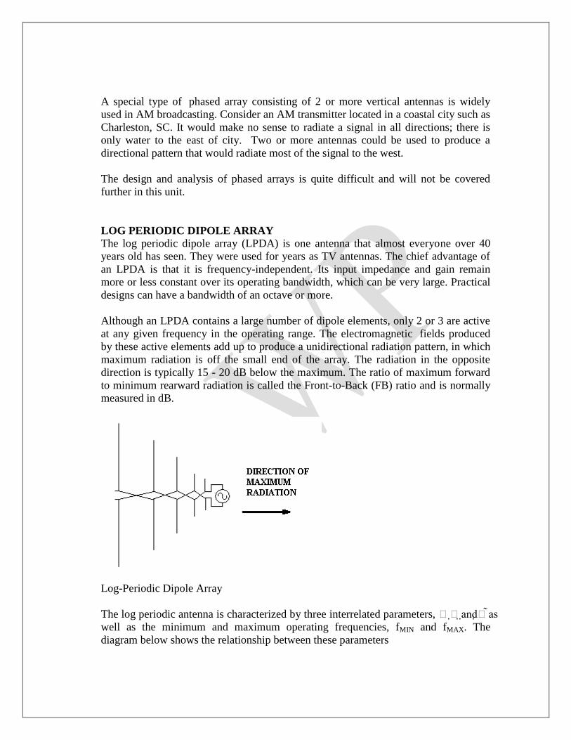
LOG PERIODIC DIPOLE ARRAY The log periodic dipole array (LPDA) is one antenna that almost everyone over 40
years old has seen. They were used for years as TV antennas. The chief advantage of
an LPDA is that it is frequency-independent. Its input impedance and gain remain
more or less constant over its operating bandwidth, which can be very large. Practical
designs can have a bandwidth of an octave or more.
Although an LPDA contains a large number of dipole elements, only 2 or 3 are active
at any given frequency in the operating range. The electromagnetic fields produced
by these active elements add up to produce a unidirectional radiation pattern, in which
maximum radiation is off the small end of the array. The radiation in the opposite
direction is typically 15 - 20 dB below the maximum. The ratio of maximum forward
to minimum rearward radiation is called the Front-to-Back (FB) ratio and is normally
measured in dB.
Log-Periodic Dipole Array
The log periodic antenna is characterized by three interrelated parameters, andas
well as the minimum and maximum operating frequencies, fMIN and fMAX. The
diagram below shows the relationship between these parameters
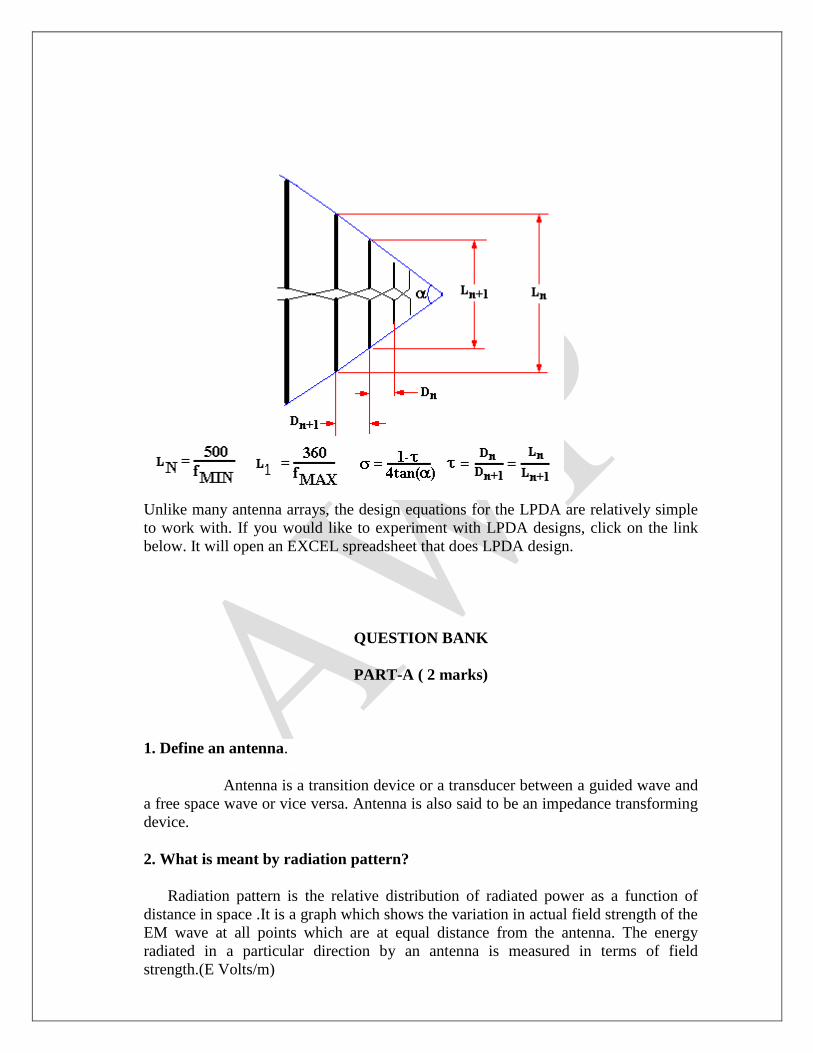
Unlike many antenna arrays, the design equations for the LPDA are relatively simple
to work with. If you would like to experiment with LPDA designs, click on the link
below. It will open an EXCEL spreadsheet that does LPDA design.
QUESTION BANK
PART-A ( 2 marks)
1. Define an antenna.
Antenna is a transition device or a transducer between a guided wave and
a free space wave or vice versa. Antenna is also said to be an impedance transforming
device.
2. What is meant by radiation pattern?
Radiation pattern is the relative distribution of radiated power as a function of
distance in space .It is a graph which shows the variation in actual field strength of the
EM wave at all points which are at equal distance from the antenna. The energy
radiated in a particular direction by an antenna is measured in terms of field
strength.(E Volts/m)

3. Define Radiation intensity?
The power radiated from an antenna per unit solid angle is called the
radiation intensity U (watts per steradian or per square degree). The radiation intensity
is independent of distance.
4. Define Beam efficiency?
The total beam area ( WA) consists of the main beam area (W M ) plus the
minor lobe area (W m) . Thus WA= WM+W m.
The ratio of the main beam area to the total beam area is called beam efficiency.
Beam efficiency = SM=W M/ W A.
5.Define Directivity?
The directivity of an antenna is equal to the ratio of the maximum power
density P(�,π)max to its average value over a sphere as observed in the far field of an
antenna.
D= P(q,j)max / P(q,j)av. Directivity from Pattern.
D=4 π /W A. . Directivity from beam area(WA ).
6.What are the different types of aperture?
i) Effective aperture. ii). Scattering aperture .iii) Loss aperture. iv) collecting aperture.
v). Physical aperture.
7.Define different types of aperture?
Effective aperture(Ae).
It is the area over which the power is extracted from the incident wave and
delivered to the load is called effective aperture.
Scattering aperture(As.)
It is the ratio of the reradiated power to the power density of the incident wave.
Loss aperture. (Ae). It is the area of the antenna which dissipates power as heat.
Collecting aperture. (Ae). It is the addition of above three apertures.
Physical aperture. (Ap). This aperture is a measure of the physical size of the antenna.

8. Define Aperture efficiency?
The ratio of the effective aperture to the physical aperture is the aperture
efficiency. i.e
Aperture efficiency = Ωap = Ae / Ap (dimensionless).
9. What is meant by effective height?
The effective height h of an antenna is the parameter related to the aperture. It
may be defined as the ratio of the induced voltage to the incident field. i.e
H= V / E.
10. What are the field zone?
The fields around an antenna ay be divided into two principal regions.
i. Near field zone (Fresnel zone)
ii. Far field zone (Fraunhofer zone)
11.What is meant by Polarization?
The polarization of the radio wave can be defined by direction in which the
electric vector E is aligned during the passage of at least one full cycle. Also
polarization can also be defined the physical orientation of the radiated
electromagnetic waves in space.
The polarization are three types. They are
Elliptical polarization ,
circular polarization and
linear polarization.
12. What is meant by front to back ratio?
It is defined as the ratio of the power radiated in desired direction to the power
radiated in the opposite direction. i.e
FBR = Power radiated in desired direction / power radiated in the opposite
direction.
13. Define antenna efficiency

The efficiency of an antenna is defined as the ratio of power radiated to the total
input power supplied to the antenna.
Antenna efficiency = Power radiated / Total input power
14. What is radiation resistance ?
The antenna is a radiating device in which power is radiated into space in the
form of electromagnetic wave.
W‘= I2R Rr= W‘/I
2 Where Rr is a fictitious resistance called as radiation resistance.
15. What is meant by antenna beam width?
Antenna beam width is a measure of directivity of an antenna. Antenna beam
width is an angular width in degrees, measured on the radiation pattern (major lobe)
between points where the radiated power has fallen to half its maximum value .This is
called as ―beam width‖ between half power points or half power beam
width.(HPBW).
16. What is meant by reciprocity Theorem.?
If an e.m.f is applied to the terminals of an antenna no.1 and the current measured
at the terminals of the another antenna no.2, then an equal current both in amplitude
and phase will be obtained at the terminal of the antenna no.1 if the same emf is
applied to the terminals of antenna no.2.
17.What is meant by isotropic radiator?
A isotropic radiator is a fictitious radiator and is defined as a radiator which
radiates fields uniformly in all directions. It is also called as isotropic source or omni
directional radiator or simply unipole.
18. Define gain
The ratio of maximum radiation intensity in given direction to the maximum
radiation intensity from a reference antenna produced in the same direction with same
input power. i.e
Maximum radiation intensity from test antenna
Gain (G) = -------------------------------------------------------
Maximum radiation intensity from the reference antenna with same input
power
19. Define self impedance

Self impedance of an antenna is defined as its input impedance with all other antennas
are completely removed i.e away from it.
20 . Define mutual impedance
The presence of near by antenna no.2 induces a current in the antenna no.1
indicates that presence of antenna no.2 changes the impedance of the antenna
no.1.This effect is called mutual coupling and results in mutual impedance.
21. What is meant by cross field.?
Normally the electric field E is perpendicular to the direction of wave propagation.
In some situation the electric field E is parallel to the wave propagation that condition
is called Cross field.
22.Define axial ratio
The ratio of the major to the minor axes of the polarization ellipse is called the
Axial Ratio. (AR).
23. What is meant by Beam Area.?
The beam area or beam solid angle or WA of an antenna is given by the
normalized power pattern over a sphere.
WA = ò ò 4p Pn (q,j) dW
where dW = sin dq .dj
24. What is duality of antenna.?
It is defined as an antenna is a circuit device with a resistance and temperature
on the one hand and the space device on the other with radiation patterns, beam angle
,directivity gain and aperture.
25.What is point source?
It is the waves originate at a fictitious volume less emitter source at the center ‗O ‘of
the observation circle.
26.What is meant by array.?
An antenna is a system of similar antennas oriented similarly to get greater
directivity in a desired direction.
27.What is meant by uniform linear array.?

An array is linear when the elements of the array are spaced equally along the
straight line. If the elements are fed with currents of equal magnitude and having a
uniform progressive phase shift along the line, then it is called uniform linear array .
28.What are the types of array?
a. Broad side array.
b. End fire array
c. Collinear array.
d. Parasitic array.
30.What is Broad side array?
Broad side array is defined as an arrangement in which the principal direction of
radiation is perpendicular to the array axis and also the plane containing the array
element. For Broad side array the phase difference adjacent element is d = 0.
31.Define End fire array
End fire array is defined as an arrangement in which the principal direction of
radiation is coincides with the array axis
For end fire array d = -bd
Where b = 2p/l and d is the distance between the element
32. What is collinear array?
In this array the antenna elements are arranged coaxially by mounting the elements
end to end in straight line or stacking them one over the other with radiation pattern
circular symmetry. Eg. Omni directional antenna.
33. What is Parasitic array?
In this array the elements are fed parasitically to reduce the problem of feed line.
The power is given to one element from that other elements get by electro magnetic
coupling. Eg. Yagi uda antenna.
34. What is the condition on phase for the end fire array with increased
directivity.?
When d = -bd produces a maximum field in the direction of f= 0 but does not
give the maximum directivity. It has been shown by Hansen and woodyard that a large
directivity is obtained by increasing the phase change between the sources so that

d = -(bd + p/n)
This condition will be referred to as the condition for increased directivity.
35.Define array factor.
The normalized value of the total field is given by,
E = (1/n) ( sin (nY/2)/ sin (Y/2))
The field is given by the expression E will be referred to as array factor.
36. Define beam width of major lobe?
It is defined the angle between the first nulls (or) it is defined as twice the
angle between the first null and the major lobe maximum direction.
37. List out the expression of beam width for broad side array and end fire
array.
For broad side array the expression for beam width between the first nulls is given
by,
BWFN = ((+/-)2l/nd)
For End fire array the expression for beam width between the first nulls is given by,
BWFN = ((+/-)2(2l/nd))1/ 2
.
38. Differentiate broad side and End fire array.
S.No Broad side array End fire array
1.
Antenna is fed in phase
d = 0
Antenna elements are fed out of phase d
= -bd
2. Maximum radiation is perpendicular
along the direction of array axis
Maximum radiation is along the array
axis
3.
Beam width of major lobe is twice the
reciprocal of array axis
((+/-)2l/nd)
Beam width is greater than that for that
of a broad side array for same length
((+/-)2(2l/nd))1/ 2
.
39.What is the need for the Binomial array?
The need for a binomial array is

i). In uniform linear array as the array length is increased to increase the
directivity, the secondary lobes also occurs.
ii) For certain applications, it is highly desirable that secondary lobes should be
eliminated completely or reduced to minimum desirable level compared to main lobes.
40. Define power pattern.
Graphical representation of the radial component of the pointing vector Sr
constant radius as a function of angle is called power density pattern or power
pattern.
41. What is meant by similar Point sources?
Whenever the variation of the amplitude and the phase of the field with respect to
the absolute angle for any two sources are same then they are called similar point
sources. The maximum amplitudes of the individual sources may be unequal.
42. What is meant by identical Point sources?
Similar point sources with equal maximum amplitudes are called identical point
sources.
43. What is the principle of the pattern multiplication?
The total field pattern of an array of non isotropic but similar sources is the product
of the
i) individual source pattern and
ii) The array pattern of isotropic point sources each located at the phase center of the
individual source having the same amplitude and phase.
While the total phase pattern is the sum of the phase patterns of the individual
source pattern and array pattern.
44.What is the advantage of pattern multiplication?
Useful tool in designing antenna
It approximates the pattern of a complicated array without making lengthy
computations
45.What is tapering of arrays?

Tapering of array is a technique used for reduction of unwanted side lobes .The
amplitude of currents in the linear array source is non-uniform; hence the central
source radiates more energy than the ends. Tapering is done from center to end.
46.What is a binomial array?
It is an array in which the amplitudes of the antenna elements in the array are
arranged according to the coefficients of the binomial series.
47.What are the advantages of binomial array?
Advantage:
a) No minor lobes
Disadvantages:
a) Increased beam width
b) Maintaining the large ratio of current amplitude in large arrays is difficult
48.What is the difference between isotropic and non-isotropic source
Isotropic source radiates energy in all directions but non-isotropic source radiates
energy only in some desired directions.
Isotropic source is not physically realizable but non-isotropic source is physically
realizable.
49.Define Side Lobe Ratio
Side Lobe Ratio is defined as the ratio of power density in the principal or main
lobe to the power density of the longest minor lobe.
50. List the arrays used for array tapering
Binomial Array: Tapering follows the coefficient of binomial series
Dolph Tchebycheff Array: Tapering follows the coefficient of Tchebycheff
polynomial
51. What are the parameters to be considered for the design of an helical
antenna?
The parameters to be considered for the design of an helical antenna are:
1. Bandwidth

2. Gain
3. Impedance
4. Axial Ratio
52.What are the types of radiation modes of operation for an helical antenna
The two types of radiation modes of operation possible for an helical antenna are:
1. Normal mode of operation
2. Axial mode of operation
53. Which antenna will produce circularly polarized waves
Helical antenna radiates circularly polarized wave.
54.List the applications of helical antenna
The applications of helical antenna are:
1. It became the workhouse of space communications for telephone, television and
data, being employed both on satellites and at ground stations
2. Many satellites including weather satellites, data relay satellites all have helical
antennas
3. It is on many other probes of planets and comets, including moon and mars, being
used
alone, in arrays or as feeds for parabolic reflectors, its circular polarization and
high
gain and simplicity making it effective for space application
PART – B
1. With neat sketch, explain the operation of helical antenna? (16)
2. Obtain the expression for the field and the radiation pattern produced by
a 2 element array of infinitesimal with distance of separation λ/2 and

currents of unequal magnitude and phase shift 180 degree? (16)
3. Derive the expression for far field components of a small loop antenna. (16)
4. Derive the expression for electric field of a broadside array of n sources
and also find the maximum direction minimum direction and half
power point direction? (16)
5. Design a 4 element broadside array of λ/2 spacing between elements the
pattern is to be optimum with a side lobe level 19.1 db. Find main lobe
maximum? (16)
6. Explain pattern multiplication? (8)
7. Derive the expression for electric field of a end fire of n sources and also
find the maximum direction minimum direction and half power point
direction? (16)
8. Write short notes a radiation resistance? (8)
9. Calculate the maximum effective aperture of a λ/2 antenna? (8)
10. .Derive the maxima directions, minima directions, and half power point
direction for an array of two point sources with equal amplitude and
opposite phase? (16)
11. Explain the various types of amplitude distributions in details? (16)
12.Explain in detail different modes of operation of helical antenna and its
Design procedure. (16)

UNIT II
RADIATION FIELDS OF WIRE ANTENNAS
Concept of vector potential – Modification for time varying – Retarded case – Fields
associated with Hertzian dipole – Power radiated and radiation resistance of current
element – Radiation resistance of elementary dipole with linear current distribution –
Radiation from half-wave dipole and quarter – Wave monopole – Assumed current
distribution for wire antennas – Use of capacity hat and loading coil for short antennas.
Vector potential
In vector calculus, a vector potential is a vector field whose curl is a given vector field. This is
analogous to a scalar potential, which is a scalar field whose negative gradient is a given vector
field.
Ampere’s Law in Differential Form
Ampere’s law in differential form implies that the B-field is conservative outside of
regions where current is flowing.
Fundamental Postulates of Magnetostatics
Ampere’s law in differential form
JB 0
No isolated magnetic charges
0B
Vector Magnetic Potential
Vector identity: ―the divergence of the curl of any vector field is identically zero.‖
0A
Corollary: ―If the divergence of a vector field is identically zero, then that vector
field can be written as the curl of some vector potential field.‖
Since the magnetic flux density is solenoidal, it can be written as the curl of a vector
field called the vector magnetic potential.
ABB 0

The general form of the B-S law is
V
vdR
RrJrB
3
0
4)(
Note that 3
1
R
R
R
Furthermore, note that the del operator operates only on the unprimed coordinates
so that
R
rJ
rJR
RrJ
R
RrJ
1
13
Hence, we have
vdR
rJrB
V4
0
rA = vdR
rJ
V4
0
For a surface distribution of current, the vector magnetic potential is given by
For a line current, the vector magnetic potential is given by
L
R
ldIrA
4)( 0
In some cases, it is easier to evaluate the vector magnetic potential and then use B =
A, rather than to use the B-S law to directly find B.
In some ways, the vector magnetic potential A is analogous to the scalar electric potential
V.
In classical physics, the vector magnetic potential is viewed as an auxiliary function with
no physical meaning.
However, there are phenomena in quantum mechanics that suggest that the vector
magnetic potential is a real (i.e., measurable) field.
sdR
rJrA
S
s
4)( 0

Magnetic Dipole
A magnetic dipole comprises a small current carrying loop.
The point charge (charge monopole) is the simplest source of electrostatic field. The
magnetic dipole is the simplest source of magnetostatic field. There is no such thing
as a magnetic monopole (at least as far as classical physics is concerned).
Radiation resistance of elementary dipole with linear current distribution
A dipole antenna, is a radio antenna that can be made by a simple wire, with a center-fed driven
element. These antennas are the simplest practical antennas from a theoretical point of view; the
current amplitude on such an antenna decreases uniformly from maximum at the center to zero at
the ends. Dipole antennas were created by Heinrich Rudolph Hertz around 1886 in his
experiments on electromagnetic radiation.
Elementary doublet
Elementary doublet
An elementary doublet is a small length of conductor (small compared to the wavelength )
carrying an alternating current:
Here is the angular frequency (and the frequency), and is , so that is a phasor.

Note that this dipole cannot be physically constructed because the current needs somewhere to
come from and somewhere to go to. In reality, this small length of conductor will be just one of
the multiple segments into which we must divide a real antenna, in order to calculate its
properties. The interest of this imaginary elementary antenna is that we can easily calculate the
electrical far field of the electromagnetic wave radiated by each elementary doublet. We give just
the result:
Where,
is the far electric field of the electromagnetic wave radiated in the θ direction.
is the permittivity of vacuum.
is the speed of light in vacuum.
is the distance from the doublet to the point where the electrical field is evaluated.
is the wavenumber
The exponent of accounts for the phase dependence of the electrical field on time and the
distance from the dipole.
The far electric field of the electromagnetic wave is coplanar with the conductor and
perpendicular with the line joining the dipole to the point where the field is evaluated. If the
dipole is placed in the center of a sphere in the axis south-north, the electric field would be
parallel to geographic meridians and the magnetic field of the electromagnetic wave would be
parallel to geographic parallels.
Near Field
The above formulas are valid for the far field of the antenna (), and are the only contribution to
the radiated field. The formulas in the near field have additional terms that reduce with r2 and r
3.
These are,
where . The energy associated with the term of the near field flows back and forward out and into
the antenna.
Power Transfer
Antenna Effective Area
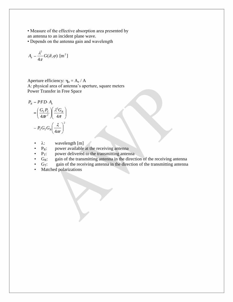
• Measure of the effective absorption area presented by
an antenna to an incident plane wave.
• Depends on the antenna gain and wavelength
][m ),(4
22
GAe
Aperture efficiency: a = Ae / A
A: physical area of antenna‘s aperture, square meters
Power Transfer in Free Space
2
2
2
4
44
rGGP
G
r
PG
APFDP
RTT
RTT
eR
• : wavelength [m]
• PR: power available at the receiving antenna
• PT: power delivered to the transmitting antenna
• GR: gain of the transmitting antenna in the direction of the receiving antenna
• GT: gain of the receiving antenna in the direction of the transmitting antenna
• Matched polarizations

Elements of Radiation Pattern
0-180 180
Emax
Emax / 2
Beamwidth
Sidelobes
Nulls
Main lobe• Gain
• Beam width
• Nulls (positions)
• Side-lobe levels
(envelope)
• Front-to-back ratio

Half-wave Dipole at Harmonics
0
0.5
1
1.5
-180 -90 0 90 180
Re
lati
ve
Fie
ld-s
tre
ng
th
Elevation angle, degrees
3rd harmonic
Fundamental
).1,...(1,0);12/(2cos
cos)2/)(12(max)(
.,...1,0);12/()12(cos
)2/)(12(
cos)2/)(12(0)(
sin
cos)2/)(12(cos)(
)12()2/(
sin
coscoscos
)(
nknk
knf
nknk
k
nf
nf
nL
LL
f
Odd harmonics

Use of capacity hat and loading coil for short antennas
The capacitive hat increases the "effective height". If you just had a monopole antenna, the
antenna current would be maximum at the bottom, and zero at the top. Adding the capacitive hat
makes the current go to zero at the end of the hat, so additional current flows in the vertical part
of the antenna. This increases the VERP (or Vertical Effective Radiated Power).
The Loading Coil provides tuning to the antenna (it will look capacitive when it is electrically
short). Adding the series inductor makes the load look real over a small frequency range,
maximizing the power transfer to the antenna.
QUESTION BANK
PART-A ( 2 marks)
1.What is a Short Dipole?
A short dipole is one in which the field is oscillating because of the oscillating voltage and
current. It is called so, because the length of the dipole is short and the current is almost constant
throughout the entire length of the dipole. It is also called as Hertzian Dipole, which is a
hypothetical antenna and is defined as a short isolated conductor carrying uniform alternating
current.
2.How radiations are created from a short Dipole?
The dipole has two equal charges of opposite sign oscillating up and down in a harmonic
motion. The charges will move towards each other and electric filed lines were created. When the
charges meet at the midpoint, the field lines cut each other and new field are created. This
process is spontaneous and so more fields are created around the antenna. This is how radiations
are obtained from a short dipole.(See Figure from John. D .Kraus Book)
3.Why a short dipole is also called an elemental dipole?

A short dipole that does have a uniform current will be known as the elemental dipole. Such a
dipole will generally be considerably shorter than the tenth wavelength maximum specified for a
short dipole. Elemental dipole is also called as elementary dipole, elementary doublet and
hertzian dipole.
4.What is a Infinitesimal Dipole?
When the length of the short dipole is vanishing small, then such a dipole is called a
infinitesimal dipole. If dl be the infinitesimally small length and I be the current, then Idl is called
as the current element.
5.Why a short dipole is called a oscillating dipole?
A short dipole is initially in neutral condition and the moment a current starts to flow in one
direction, one half of the dipole require an excess of charge and the other a deficit because a
current is a flow of electrical charge. Then ,there will be a voltage between the two halves of the
dipole. When the current changes its direction this charge unbalance will cause oscillations.
Hence an oscillating current will result in an oscillating voltage. Since, in such dipole, electric
charge oscillates ,it may be called as Oscillating electric dipole.
6.What do you understand by retarded current?
Since, the short electric dipole is so short, the current which is flowing through the dipole is
assumed to be constant throughout its length. The effect of this current is not felt instantaneous at
a distance point only after an interval equal to the time required for the wave to propagate over
the distance r is called the retardation time.
The retarded current [I]=Io exp(j w(t-r/c)) Where wr/c is the phase retardation.
7.Define induction field
The induction field will predominate at points close to the current element ,where the distance
from the center of the dipole to the particular point is less. This field is more effective in the
vicinity of the current element only. It represents the energy stored in the magnetic field
surrounding the current element or conductor. This field is also known as near field.
8.Define Radiation field
The radiation field will be produced at a larger distance from the current element, where the
distance from the center of the dipole to the particular point is very large. It is also called as
distant field or far field.
9.At what distance from the dipole is the induction field equal to the radiation field?
As the distance from the current element or the short dipole increases, both induction and
radiation fields emerge and start decreasing. However, a distance reaches from the conductor at
which both the induction and radiation field becomes equal and the particular distance depends

upon the wavelength. The two fields will thus have equal amplitude at that particular distance.
This distance is given by r = 0.159l
10.Define Radiation Resistance
It is defined as the fictitious resistance which when inserted in series with the antenna will
consume the same amount of power as it is actually radiated. The antenna appears to the
transmission line as a resistive component and this is known as the radiation resistance.
11.Give the expression for the effective aperture of a short dipole
The effective aperture of a short dipole is given by Ae = 0.119l2
12.What is a dipole antenna?
A dipole antenna may be defined as a symmetrical antenna in which the two ends are at equal
potential relative to the midpoint.
13.What is a half wave dipole?
A half wave antenna is the fundamental radio antenna of metal rod or tubing or thin wire
which has a physical length of half wavelength in free space at the frequency of operation
14.Give the expression for the effective aperture of a Half wave Dipole
The effective aperture of a half wave dipole is given by Ae = 0.13l2
15.What is the radiation resistance of a half wave dipole
The radiation resistance of a half wave dipole is given by Rr=73 ohm
16.What is a loop antenna?
A loop antenna is a radiating coil of any convenient cross-section of one or more turns
carrying radio frequency current. It may assume any shape (e.g. rectangular, square, triangular
and hexagonal)
17.Give an expression of radiation resistance of a small loop
Radiation resistance of a small loop is given by Rr=31,200 (A/l2) 2
18.How to increase the radiation resistance of a loop antenna
The radiation resistance of a loop antenna can be increased by:
1. increasing the number of turns

2. inserting a ferrite core of very high permeability with loop antenna‘ s circumference which
will rise the magnetic field intensity called ferrite loop.
19.What are the types of loop antennas?
Loop antennas are classified into:
A.Electrically small (circumference <l/10)
B. Electrically large (dimension comparable to l)
20.What are Electrically Small loop antennas?
Electrically Small loop antennas is one in which the overall length of the loop is less than
one-tenth of the wavelength. Electrically Small loop antennas have small radiation resistances
that are usually smaller than their loop resistances. They are very poor radiators and seldom
employed for transmission in radio communication.
21.What are Electrically large loop antennas?
Electrically Large loop antennas is one in which the overall length of the loop approaches the
wavelength.
22.List out the uses of loop antenna
Various uses of loop antenna are:
1) It is used as receiving antenna in portable radio and pagers
2)It is used as probes for field measurements and as directional antennas for radio wave
navigation
3)It is used to estimate the direction of radio wave propagation
23. What is capacitance hat?
The capacitance hat is circular in shape with mast at the center of the circle. There are number
of horizontal conducting wires with their ends joined together by means of a ring. The
capacitance hat is used to increase the electrical length of low frequency antennas.
24. Define top loading
Top loading is a method to increase the effective capacitance at the top of the antenna. This is
accomplished by mounting one or more horizontal conductors at the top of the antenna.

25. Define retardation time
It is the time required for the wave to propagate over the distance r. It is given by r/c where c
is 3*108m/s
PART – B
1. Derive the expression for the radiated field from a short dipole? (16)
2. Starting from first principles obtain the expression for the power radiated
by a half wave dipole? (16)
3. Derive the expression for power radiated and find the radiation resistance
of a half wave dipole? (16)
4. Derive the radian resistance, Directivity and effective aperture of a half
wave dipole? (10)
5. Derive the fields radiated from a quarter wave monopole antenna? (8)
6. Find the radiation resistance of elementary dipole with linear current
distribution? (8)
7. Derive the radian resistance, Directivity and effective aperture of a
Hertzian dipole? (10)
8. Derive the power radiated and radiation resistance of current element. (10)
9. Explain in detail assumed current distribution for wire antennas (8)
10. Write in brief about the use of capacitance hat and loading coil for

PART-B
UNIT III
TRAVELLING WAVE (WIDEBAND) ANTENNAS
Loop antenna (elementary treatment only) – Helical antenna – Radiation from a traveling
wave on a wire – Analysis of rhombic antenna – Design of rhombic antennas – Yagi-Uda
antenna – Log periodic antenna.
Traveling Wave AntennasAntennas with open-ended wires where the current must go to zero
(dipoles, monopoles, etc.) can be characterized as standing wave antennas or resonant antennas. The
current on these antennas can be written as a sum of waves traveling in opposite directions (waves
which travel toward the end of the wire and are reflected in the opposite direction). For example,
the current on a dipole of length l is given by
The current on the upper arm of the dipole can be written as
«¬ «¬
+z directed !z directed
wave wave

Traveling wave antennas are characterized by matched terminations (not open circuits) so that the
current is defined in terms of waves traveling in only one direction (a complex exponential as opposed
to a sine or cosine).

A traveling wave antenna can be formed by a single wire transmission line
(single wire over ground) which is terminated with a matched load (no reflection). Typically, the
length of the transmission line is several wavelengths.
The antenna shown above is commonly called a Beverage or wave antenna. This antenna can be
analyzed as a rectangular loop, according to image theory. However, the effects of an imperfect
ground may be significant and can be included using the reflection coefficient approach. The
contribution to the far fields due to the vertical conductors is typically neglected since it is small if l >>
h. Note that the antenna does not radiate efficiently if the height h is small relative to wavelength. In
an alternative technique of analyzing this antenna, the far field produced by a long isolated wire
of length l can be determined and the overall far field found using the 2 element array factor.
Traveling wave antennas are commonly formed using wire segments with different geometries.
Therefore, the antenna far field can be obtained by superposition using the far fields of the individual
segments. Thus, the radiation characteristics of a long straight segment of wire carrying a traveling
wave type of current are necessary to analyze the typical traveling wave antenna.

Consider a segment of a traveling wave antenna (an electrically long
wire of length l lying along the z-axis) as shown below. A traveling wave current flows in the z-
direction.
" - attenuation constant
$ - phase constant
If the losses for the antenna are negligible (ohmic loss in the conductors,
loss due to imperfect ground, etc.), then the current can be written as
The far field vector potential is

If we let , then
The far fields in terms of the far field vector potential are
(Far-field of a traveling wave segment)

We know that the phase constant of a transmission line wave (guided
wave) can be very different than that of an unbounded medium (unguided wave). However, for a
traveling wave antenna, the electrical height of the conductor above ground is typically large and
the phase constant approaches that of an unbounded medium (k). If we assume that the phase
constant of the traveling wave antenna is the same as an unbounded
medium ($ = k), then
Given the far field of the traveling wave segment, we may determine the time-average radiated
power density according to the definition of the
Poynting vector such that

The total power radiated by the traveling wave segment is found by
integrating the Poynting vector.
and the radiation resistance is
The radiation resistance of the ideal traveling wave antenna (VSWR = 1) is purely real just as the
input impedance of a matched transmission line is purely real. Below is a plot of the radiation
resistance of the traveling wave segment as a function of segment length.
The radiation resistance of the traveling wave antenna is much more uniform than that seen in
resonant antennas. Thus, the traveling wave antenna is classified as a broadband antenna.

The pattern function of the traveling wave antenna segment is given
by
The normalized pattern function can be written as
The normalized pattern function of the traveling wave segment is shown below for segment lengths
of 58, 108, 158 and 208.
l = 58 l = 108

l = 158 l = 208
As the electrical length of the traveling wave segment increases, the main beam becomes
slightly sharper while the angle of the main beam moves slightly toward the axis of the antenna.
Note that the pattern function of the traveling wave segment always
has a null at 2 = 0o. Also note that with l >> 8, the sine function in the
normalized pattern function varies much more rapidly (more peaks and
nulls) than the cotangent function. The approximate angle of the main lobe for the traveling wave
segment is found by determining the first peak of the sine function in the normalized pattern function.

The values of m which yield 0o#2m
#180o (visible region) are negative
values of m. The smallest value of 2m
in the visible region defines the
location of main beam (m = !1)
If we also account for the cotangent function in the determination of the
main beam angle, we find

The directivity of the traveling wave segment is
The maximum directivity can be approximated by
where the sine term in the numerator of the directivity function is assumed to be unity at the main
beam.

Traveling Wave Antenna Terminations
Given a traveling wave antenna segment located horizontally above a ground plane, the
termination RL required to match the uniform
transmission line formed by the cylindrical conductor over ground (radius
= a, height over ground = s/2) is the characteristic impedance of the corresponding one-wire
transmission line. If the conductor height above the ground plane varies with position, the conductor
and the ground plane form a non-uniform transmission line. The characteristic impedance of a non-
uniform transmission line is a function of position. In either case, image theory may be employed
to determine the overall performance characteristics of the traveling wave antenna.
Two-wire transmission line
If s >> a, then
In air,

One-wire transmission line
If s >> a, then
In air,

Vee Traveling Wave Antenna
The main beam of a single electrically long wire guiding waves in one direction (traveling
wave segment) was found to be inclined at an angle relative to the axis of the wire. Traveling wave
antennas are typically formed by multiple traveling wave segments. These traveling wave
segments can be oriented such that the main beams of the component wires combine to enhance the
directivity of the overall antenna. A vee traveling wave antenna is formed by connecting two
matched traveling wave
segments to the end of a transmission line feed at an angle of 22o relative
to each other.
The beam angle of a traveling wave segment relative to the axis of the wire (2max) has been shown to
be dependent on the length of the wire. Given the length of the wires in the vee traveling wave antenna,
the angle 22o may be chosen such that the main beams of the two tilted wires combine to form
an antenna with increased directivity over that of a single wire.

A complete analysis which takes into account the spatial separation effects of the antenna arms (the
two wires are not co-located) reveals that by choosing 2o. 0.8 2max, the total directivity of the
vee traveling wave antenna is approximately twice that of a single conductor. Note that the
overall pattern of the vee antenna is essentially unidirectional given matched conductors. If, on
the other hand, the conductors of the vee traveling wave antenna are resonant conductors (vee
dipole antenna), there are reflected waves which produce significant beams in the opposite
direction. Thus, traveling wave antennas, in general, have the advantage of essentially
unidirectional patterns when compared to the patterns of most resonant antennas.

Rhombic Antenna
A rhombic antenna is formed by connecting two vee traveling wave antennas at their open
ends. The antenna feed is located at one end of the rhombus and a matched termination is located at the
opposite end. As with all traveling wave antennas, we assume that the reflections from the load are
negligible. Typically, all four conductors of the rhombic antenna are assumed to be the same
length. Note that the rhombic antenna is an example of a non-uniform transmission line.
A rhombic antenna can also be constructed using an inverted vee antenna over a ground plane. The
termination resistance is one-half that required for the isolated rhombic antenna.

To produce an single antenna main lobe along the axis of the rhombic antenna, the individual
conductors of the rhombic antenna should be aligned such that the components lobes numbered 2,
3, 5 and 8 are aligned (accounting for spatial separation effects). Beam pairs (1, 7) and (4,6)
combine to form significant sidelobes but at a level smaller than the main lobe.

Yagi-Uda Array
In the previous examples of array design, all of the elements in the array were assumed to
be driven with some source. A Yagi-Uda array is an example of a parasitic array. Any element in
an array which is not connected to the source (in the case of a transmitting antenna) or the
receiver (in the case of a receiving antenna) is defined as a parasitic element. A parasitic array is
any array which employs parasitic elements. The general form of the N-element Yagi-Uda array is
shown below.
Driven element - usually a resonant dipole or folded dipole.
Reflector - slightly longer than the driven element so that it is
inductive (its current lags that of the driven element).
Director - slightly shorter than the driven element so that it is
capacitive (its current leads that of the driven element).
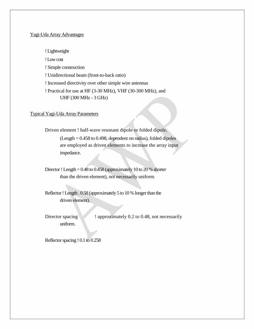
Yagi-Uda Array Advantages
! Lightweight
! Low cost
! Simple construction
! Unidirectional beam (front-to-back ratio)
! Increased directivity over other simple wire antennas
! Practical for use at HF (3-30 MHz), VHF (30-300 MHz), and
UHF (300 MHz - 3 GHz)
Typical Yagi-Uda Array Parameters
Driven element ! half-wave resonant dipole or folded dipole,
(Length = 0.458 to 0.498, dependent on radius), folded dipoles
are employed as driven elements to increase the array input
impedance.
Director ! Length = 0.48 to 0.458 (approximately 10 to 20 % shorter
than the driven element), not necessarily uniform.
Reflector ! Length . 0.58 (approximately 5 to 10 % longer than the
driven element).
Director spacing ! approximately 0.2 to 0.48, not necessarily
uniform.
Reflector spacing ! 0.1 to 0.258

R = sD = 0.18
sR = sD = 0.28
sR = sD = 0.38


sR = sD = 0.18
3-dB beamwidth E-Plane = 62.71o
3-dB beamwidth H-Plane = 86.15o
Front-to-back ratio E-Plane = 15.8606 dB Front-to-back-
ratio H-Plane = 15.8558 dB
Maximum directivity = 7.784 dB
sR = sD = 0.28
3-dB beamwidth E-Plane = 55.84o
3-dB beamwidth H-Plane = 69.50o
Front-to-back ratio E-Plane = 9.2044 dB Front-to-back-
ratio H-Plane = 9.1993 dB
Maximum directivity = 9.094 dB
sR = sD = 0.38
3-dB beamwidth E-Plane = 51.89o
3-dB beamwidth H-Plane = 61.71o
Front-to-back ratio E-Plane = 5.4930 dB Front-to-back-
ratio H-Plane = 5.4883 dB
Maximum directivity = 8.973 dB

Log-Periodic Antenna
A log-periodic antenna is classified as a frequency-independent antenna. No antenna is
truly frequency-independent but antennas capable
of bandwidth ratios of 10:1 ( fmax : fmin ) or more are normally classified as
frequency-independent.
The elements of the log periodic dipole are bounded by a wedge of angle 2". The element
spacing is defined in terms of a scale factor J such
that
(1)

where J < 1. Using similar triangles, the angle " is related to the element
lengths and positions according to
(2)
or
(3)
Combining equations (1) and (3), we find that the ratio of adjacent element lengths and the ratio of
adjacent element positions are both equal to the scale factor.
(4)
The spacing factor F of the log periodic dipole is defined by
where dn is the distance from element n to element n+1 .
(5)
From (2), we may write
(6)
Inserting (6) into (5) yields

(7)
Combining equation (3) with equation (7) gives
(8)
or
(9)
According to equation (8), the ratio of element spacing to element length remains constant for all of
the elements in the array.
(10)
Combining equations (3) and (10) shows that z-coordinates, the element
lengths, and the element separation distances all follow the same ratio.
(11)
Log Periodic Dipole Design
We may solve equation (9) for the array angle " to obtain an equation
for " in terms of the scale factor J and the spacing factor F.
Figure 11.13 (p. 561) gives the spacing factor as a function of the scale factor for a given
maximum directivity Do.
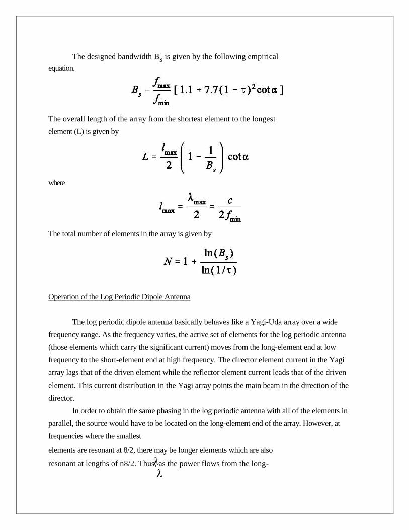
The designed bandwidth Bs is given by the following empirical
equation.
The overall length of the array from the shortest element to the longest
element (L) is given by
where
The total number of elements in the array is given by
Operation of the Log Periodic Dipole Antenna
The log periodic dipole antenna basically behaves like a Yagi-Uda array over a wide
frequency range. As the frequency varies, the active set of elements for the log periodic antenna
(those elements which carry the significant current) moves from the long-element end at low
frequency to the short-element end at high frequency. The director element current in the Yagi
array lags that of the driven element while the reflector element current leads that of the driven
element. This current distribution in the Yagi array points the main beam in the direction of the
director.
In order to obtain the same phasing in the log periodic antenna with all of the elements in
parallel, the source would have to be located on the long-element end of the array. However, at
frequencies where the smallest
elements are resonant at 8/2, there may be longer elements which are also
resonant at lengths of n8/2. Thus, as the power flows from the long-

element end of the array, it would be radiated by these long resonant
elements before it arrives at the short end of the antenna. For this reason, the log periodic dipole
array must be driven from the short element end. But this arrangement gives the exact opposite
phasing required to point the beam in the direction of the shorter elements. It can be shown that by
alternating the connections from element to element, the phasing of the log periodic dipole elements
points the beam in the proper direction.
Sometimes, the log periodic antenna is terminated on the long- element end of the antenna
with a transmission line and load. This is done to prevent any energy that reaches the long-element
end of the antenna from being reflected back toward the short-element end. For the ideal log periodic
array, not only should the element lengths and positions follow the
scale factor J, but the element feed gaps and radii should also follow the
scale factor. In practice, the feed gaps are typically kept constant at a
constant spacing. If different radii elements are used, two or three different radii are used over portions
of the antenna.

Example
Design a log periodic dipole antenna to cover the complete VHF TV band from 54 to 216
MHz with a directivity of 8 dB. Assume that the
input impedance is 50 S and the length to diameter ratio of the elements
is 145.
From Figure 11.13, with Do = 8 dB, the optimum value for the spacing factor F is 0.157
while the corresponding scale factor J is
0.865. The angle of the array is
The computer program "log-perd.for" performs an analysis of the log periodic dipole based on the
previously defined design equations.

QUESTION BANK
PART-A ( 2 marks)
PART - A
1. Name and draw a frequency independent antenna
Log periodic antenna is a frequency independent antenna.
It includes active region and reflective region.
2. What is yagi uda antenna?
It is an array of a driven element, a reflector and one or more directors.
3. What do you mean by parasitic element?
The passive elements which are not connected directly connected to the transmission line but
are electrically coupled are called as parasitic elements.
4. What do you mean by driven elements?
Driven elements are an active element where the power from the transmitter is fed or which
feeds the received power to the receiver.
5. What is the purpose of using more directors in yagi uda antenna?
To increase the gain more directors are used.
6. Draw the structure of yagi uda element.
7. Why folded dipole antenna is used in yagi antenna?
The folded dipole has high input impedance. If the distance between the driven and parasitic
element is decreased, it will load the driven element , so input impedance of driven element
reduces. But this will be compensated.
8. What is beam antenna?
If three-element array are used then such a type of yagi uda is referred to as beam antenna.

9. Which antenna is referred to super gain or super directive antenna?
Yagi uda antenna is referred to super gain antenna.
10. What is a frequency independent antenna?
An antenna in which the impedance, radiation pattern and directivity remain constant as a
function of frequency is called as frequency independent antenna. Eg., Log periodic antenna.
11. Why log periodic antenna is named so far?
The geometry of log periodic antenna is so chosen that electrical properties must repeat
periodically with logarithm of frequency.
12. What is the condition for an antenna to be frequency independent?
The condition is r = ea(F+F0)
f(q) where f(q) is a function of q
13. What is LPDA?
LPDA means log periodic dipole array. It is defined as an antenna whose electrical properties
repeat periodically with logarithm of the frequency.
14. What are the different regions in log periodic antenna and how are they differentiated?
1. Inactive region – L< l
2. Active region – L» l
3. Inactive reflective region – L>l
15. Give the expression for design ratio, spacing factor and frequency ration of log
periodic antenna.
Design ratio or scale factor is given by
t = Rn = Ln
----- -----
Rn+1 Ln+1
Spacing factor
s = Rn+1 - Rn = S

---------- -----
2Ln 2 Ln
Frequency ratio or bandwidth: F = Ln+1
--------
Ln
16. What are the applications of log periodic antenna?
HF communication, Television reception, All round monitoring
17. What are the application of Rhombic antenna?
HF transmission and reception, point to point communication.
18. Define rhombic antenna.
An antenna which consists of four straight wires arranged in the shape of diamond,
suspended horizontally above the surface of the earth is called as a rhombic antenna. It is
otherwise called as diamond antenna or traveling wave antenna.
19. What are the two types of rhombic antenna design?
1. i. Alignment design
2. ii. Maximum field intensity or
maximum output design
20. What are the limitations of rhombic antenna?
1. It needs a larger sp[ace for installation
2. Due to minor lobes transmission efficiency is low.
21. What do you mean by self-impedance?
Self impedance is defined as the ratio of voltage to current at a pair of terminals
Z11 = R11+jX11 where R11 is the radiation resistance, X11 is the self reactance
22. What is mutual impedance?
It is defined as the negative ratio of emf induced in one antenna to the current flowing in the
other antenna

Mutual impedance is Z21 = -V21/I1 or Z12 = -V12/I2
23. What is the effect of decreasing a?
The directivity of the antenna increases by means of decreasing the included angle a
24. Define a raveling wave antenna?
Traveling wave or non resonant antenna are those in which there is no reflected wave, i.e.,
only incident traveling wave travel in the antenna.
25. What is the advantage of traveling wave antenna?
It provides larger bandwidth.
26. What is beverage or wave antenna?
A single wire antenna terminated in its characteristic impedance may have essentially a
uniform traveling wave. This type of antenna is referred to as beverage antenna.
27. What is the type of radiation pattern produced when a wave travels in a wire? Draw
the pattern.
Unidirectional radiation pattern is produced when a wave travels in a wire.
PART – B
1. Explain the radiation from a travelling wave on a wire ? (8)
2. What is Yagi-uda Antenna ?Explain the construction and operation of Yagi-uda Antenna
.Also explain its general characteristics ? (16)
3. Explain the construction, operation and design for a rhombic antenna ? (16)
4. Explain the geometry of a log periodic antenna ?Give the design equations and
uses of log periodic antenna ? (16)
5. Discuss in details about ?(a)Self impedance(b)Mutual impedance ? (8)

PART-B
UNIT IV
APERTURE AND LENS ANTENNAS
Radiation from an elemental area of a plane wave (Huygen‘s source) – Radiation from
the open end of a coaxial line – Radiation from a rectangular aperture treated as an array
of huygen‘s source – Equivalence of fields of a slot and complementary dipole – Relation
between dipole and slot impedances – Method of feeding slot antennas – Thin slot in an
infinite cylinder – Field on the axis of an E-plane sectoral horn – Radiation from circular
aperture – Beam width and effective area – Reflector type of antennas (dish antennas).
dielectric lens and metal plane lens antennas – Luxemberg lens – Spherical waves and
biconical antenna.

Huygens' Principle
Each point on a wavefront acts as a new source of waves
APERTURE AND LENS ANTENNAS
Consider Fraunhofer (far-field) Diffraction from an arbitrary aperture
whose width and height are about the same.
Let A = the source strength per unit area. Then each infinitesimal area
element dS emits a spherical wave that will contribute an amount dE to the
field at P (X, Y, Z) on the screen dSe
rdE krtiA )(
The distance from dS to P is
222 )()( zZyYXr
which must be very large compared
to the size (a) of the aperture and
greater than a2/ in order to satisfy
conditions for Fraunhofer
diffraction. Therefore, as before, for
OP , we can expect A/r A/R
as before (i.e., the behavior is
approximated as that of a plane
wave far from the source).
2222 ZYXR

Fig. 10.19 A rectangular aperture.
2/
2/
/
2/
2/
/)(~a
a
RikZz
b
b
RikYykRtiA dzedyeeR
E
At point P (X, Y), the complex field is
calculated as follows:
222
)(
sinsin)0(
~Re),(
sinsin~
IEZYI
isirradianceaveragedtimetheand
R
eAE
T
kRti
A
R
kaZand
R
kbY
22
LENS ANTENNA.—Another antenna that can change spherical waves into flat plane waves is the lens
antenna. This antenna uses a microwave lens, which is similar to an optical lens to straighten the spherical
wavefronts. Since this type of antenna uses a lens to straighten the wavefronts, its design is based on the laws
of refraction, rather than reflection. Two types of lenses have been developed to provide a plane-wavefront
narrow beam for tracking radars, while avoiding the problems associated with the feedhorn shadow. These
are the conducting (acceleration) type and the dielectric (delay) type. The lens of an antenna is substantially
transparent to microwave energy that passes through it. It will, however, cause the waves of energy to
be either converged or diverged as they exit the lens. Consider the action of the two types of lenses. The
conducting type of lens is illustrated in figure 1-10, view A. This type of lens consists of flat metal strips placed
parallel to the electric field of the wave and spaced slightly in excess of one-half of a wavelength. To the
wave these strips look like parallel waveguides. The velocity of phase propagation of a wave is greater in a
waveguide than in air. Thus, since the lens is concave, the outer portions of the transmitted spherical
waves are accelerated for a longer interval of time than the inner portion. The 1-9 Figure 1-9.—Reflector
with feedhorn. Figure 1-10.—Antenna lenses: A. Conducting (acceleration) type of microwave lens; B. Dielectric (delay) type of microwave lens. Figure 1-8.—Horn radiators.

as a directional radiator. Horn radiators may be fed by coaxial or other types of lines. Horns are constructed in a
variety of shapes, as illustrated in figure 1-8. The shape of the horn, along with the dimensions of the length and
mouth, largely determines the beam‘s shape. The ratio of the horn‘s length to mouth opening size determines
the beamwidth and thus the directivity. In general, the larger the opening of the horn, the more directive is
the resulting field pattern. FEEDHORNS.—A waveguide horn may be used to feed into a parabolic dish. The
directivity of this horn, or feedhorn, is then added to that of the parabolic dish. The resulting pattern (fig. 1-9,
view A) is a very narrow and concentrated beam. Such an arrangement is ideally suited for fire control use. In
most radars, the feedhorn is covered with a window of polystyrene fiberglass to prevent moisture and
dirt from entering the open end of the waveguide. One problem associated with feedhorns is the shadow
introduced by the feedhorn if it is in the path of the beam. (The shadow is a dead spot directly in front of the
feedhorn.) To solve this problem the feedhorn can be offset from center (fig. 1-9, view B). This takes it out of the
path of the RF beam, thus eliminating the shadow. LENS ANTENNA.—Another antenna that can change
spherical waves into flat plane waves is the lens antenna. This antenna uses a microwave lens, which is similar to
an optical lens to straighten the spherical wavefronts. Since this type of antenna uses a lens to straighten the
wavefronts, its design is based on the laws of refraction, rather than reflection. Two types of lenses have
been developed to provide a plane-wavefront narrow beam for tracking radars, while avoiding the
problems associated with the feedhorn shadow. These are the conducting (acceleration) type and
the dielectric (delay) type. The lens of an antenna is substantially transparent to microwave energy that passes
through it. It will, however, cause the waves of energy to be either converged or diverged as they exit
the lens. Consider the action of the two types of lenses. The conducting type of lens is illustrated in figure 1-10,
view A. This type of lens consists of flat metal strips placed parallel to the electric field of the wave and spaced
slightly in excess of one-half of a wavelength. To the wave these strips look like parallel waveguides.
The velocity of phase propagation of a wave is greater in a waveguide than in air. Thus, since the lens is
concave, the outer portions of the transmitted spherical waves are accelerated for a longer interval of
time than the inner portion.

QUESTION BANK
PART-A ( 2 marks)
1. State Huygen’s Principle?
Huygen‘s principle states that each point on a primary wave front can be considered to be a
new source of a secondary spherical wave that a secondary wave front can be constructed as the
envelope of these secondary waves.
2. What is Slot Antenna?
The slot antenna is an opening cut in a sheet of a conductor, which is energized through a
coaxial cable or wave guide.
3. Which antenna is complementary to the slot dipole?
The dipole antenna is the complementary to the slot antenna. The metal and air regions of the
slot are interchanged for the dipole.
4. How will you find the directivity of a large rectangular broadside array?

Directivity , D = 12.56 x Area of the aperture
-----------------------------------
l2
5. What is the relationship between the terminal impedance of slot and dipole antenna?
ZsZd = ho2/4
Where Zs is the terminal impedance of the slot antenna
Zd is the terminal impedance of the dipole antenna
ho is the intrinsic impedance of the free space » 377W\\
6. What is the difference between slot antenna and its complementary dipole antenna?
1. i. Polarization are different
2. ii. The electric field be vertically polarized for
the slot and horizontally polarized for its complementary dipole
3. iii. Radiation form the backside of the conducting
plane of the slot antenna has the opposite polarity from that of the dipole antenna.
7. Define lens antenna?
An antenna, which collimates the incident divergent energy to prevent it from spreading in
undesired directions, is called as lens antenna.
8. What are the different types of lens antenna?
1. i. dielectric lens or H plane metal plate lens
2. ii. E plane metal plate lens antenna
9. What is a dielectric lens antenna?
Dielectric lens antennas are the antennas in which the traveling wave fronts are delayed by
lens media
10. What are the drawbacks of lens antenna?
Lens antennas are used only at higher frequencies (above 3 GHz) because at lower
frequencies they become bulky and heavy. Lens antennas have excessive thickness at low
frequencies.
Thickness, t = l/m-1 = C/ f(m-1)

Costlier for the same gain and beam width in comparison with reflectors
11. What are the field components that are radiated from open end of a coaxial line?
Eq = {-hbwKsinq(b2-a
2)e
-jbro}/8r0
Hf = {-bweKsinq(b2-a
2)e
-jbro}/8r0
12.What are the advantages of stepped dielectric lens antenna?
1. i. It is mechanically strong
2. ii. Reduces weight
3. iii. Less power dissipation
13.What is biconical antenna?
The biconical antenna is a double cone antenna which is driven by potential , charge or an
alternating magnetic field at the vertex. In this antenna both the cones face in the opposite
direction.
14.What is Lunenburg lens?
The Lunenburg lens is a spherical symmetric delay type lens formed from a dielectric
with index of refraction ‗n‘ which varies as a function of radius given by
.n = Ö[2 –{ r/R}2]
where r = radial distance from the center of the sphere
R = radius of the sphere
15.What are the advantages of lens antenna?
1. i. the lens antenna, feed and feed support do not
block the aperture as the rays are transmitted away from the feed
2. ii. It has greater design tolerance
3. iii. It can be used to feed the optical axis and
hence useful in applications where a beam is required to be moved angularly with respect
to the axis.
16.Mention the uses of lens antenna?
1. i. Unstepped dielectric lens is a wide band
antenna as its shape does not depend on the wavelength and hence it can be used over a
wide frequency range, however this is not true for the dielectric lens antenna which is
frequency sensitive.

2. ii. Both reflectors and lens antenna are
commonly used above 1000 MHz. Lens antenna is a microwave device. So it is preferred
to be usually above 3000 MHz and not below it.
17.How spherical waves are generated?
When a voltage V is supplied at the input terminals of a biconical antenna, it will produce
outgoing spherical waves. The biconical antenna acts as a guide for spherical waves.
18.Define the characteristic impedance of biconical antenna?
The Characteristic impedance Zc of a biconical antenna is the ratio of voltage (r ) and current
( r )
Zc = V( r) / I ( r) = 120ln cot(a/4)
19.Bring out the expressions for voltage across the feed points of the biconical antenna and
current flowing through the surface of the cone?
V(r ) = 2hHmln cot(a/4)
I( r) = 2pHmee-jbr
20.What do you meant by sect oral horn?
If flaring (opened out) is done only in one direction, then it is called as a sectoral horn.
21.What do you meant by pyramidal horn?
If flaring is done along both the walls( E & H), then it is called as a pyramidal horn.
22.What is back lobe radiation?
Some radiation from the primary radiator occurs in the forward direction in addition to the
desired parallel beam. This is known as back lobe radiation.
23.What are the various feeds used in reflectors?
1. i. Dipole antenna
2. ii. Horn feed
3. iii. End fire feed
4. iv. Cassegrain feed
24.What are the different types of horn antennas?
1. i. Sectoral horn

2. ii. Pyramidal horn
3. iii. Conical horn
4. iv. Biconical horn antenna
25.Define refractive index of lens antenna?
Refractive index, m = (Velocity of wave in air)/(velocity of wave in lens medium)
26.What are secondary antennas? Give examples?
Antennas that are not radiators by themselves are called secondary antennas. For example
Cassergrain, Hyperbolic antennas.
PART – B
1. Explain the different types of lens antenna? (10)
2. Explain the radiation from a rectangular aperture? (16)
3. Explain the radiation from an elemental area of a plane wave or
explain the radiation from a Huygen‘s source ? (16)
4. Describe the parabolic reflector used at micro frequencies? (16)
5. Write short notes on Lunenburg lens? (16)
6. Discuss about spherical waves and biconical antenna? (16)
7. Derive the various field components radiated from circular aperture
and also find beam width and effective area ? (12)
8. Derive the field components radiated from a thin slot antenna in an
infinite cylinder ? (10)
9. Show the relationship between dipole and slot impedances? (8)
10. Explain the radiation from the open end of a coaxial cable? (8)
PART-B

UNIT V
PROPAGATION
The three basic types of propagation: Ground wave, space wave and sky wave
propagation.
Sky Wave Propagation: Structure of the ionosphere – Effective dielectric constant of
ionized region – Mechanism of refraction – Refractive index – Critical frequency – Skip
distance – Effect of earth‘s magnetic field – Energy loss in the ionosphere due to
collisions – Maximum usable frequency – Fading and diversity reception.
Space Wave Propagation: Reflection from ground for vertically and horizontally
polarized waves – Reflection characteristics of earth – Resultant of direct and reflected
ray at the receiver – Duct propagation.
Ground Wave Propagation: Attenuation characteristics for ground wave propagation –
Calculation of field strength at a distance.
Propagation of Waves
The process of communication involves the transmission of information from one
location to another. As we have seen, modulation is used to encode the information onto
a carrier wave, and may involve analog or digital methods. It is only the characteristics
of the carrier wave which determine how the signal will propagate over any significant
distance. This chapter describes the different ways that electromagnetic waves propagate.
RADIO WAVES
• Electromagnetic radiation comprises both an Electric and a Magnetic
Field.
• The two f ields are at right-angles to each other and the direction of
propagation is at right-angles to both f ields.
• The Plane of the Electric Field def ines the Polarisation of the wave.
z
x
y
Electric Field, E
Magnetic Field, H
Direction of
Propagation

Two types of waves:
Transverse and Longitudinal
Transverse waves:
vibration is from side to side; that is, at right angles to the
direction in which they travel
A guitar string vibrates with
transverse motion. EM waves
are always transverse.
Longitudinal waves:
Vibration is parallel to the direction of propagation. Sound
and pressure waves are longitudinal and oscillate back and
forth as vibrations are along or parallel to their direction of
travel

A wave in a "slinky" is a good visualization
POLARIZATION
• The polarization of an antenna is the orientation of the electric field with respect to
the Earth's surface and is determined by the physical structure of the antenna and
by its orientation
• Radio waves from a vertical antenna will usually be vertically polarized.
• Radio waves from a horizontal antenna are usually horizontally polarized.
LINE OF SIGHT, GROUND WAVE, SKY WAVE
• Ground Wave is a Surface Wave that propagates or travels close to the surface of
the Earth.
• Line of Sight (Ground Wave or Direct Wave) is propagation of waves travelling in a
straight line. These waves are deviated (reflected) by obstructions and cannot travel
over the horizon or behind obstacles. Most common direct wave occurs with VHF
modes and higher frequencies. At higher frequencies and in lower levels of the
RADIO
WAVES
SPACE GROUND
SKY REFLECTED DIRECT SURFACE

atmosphere, any obstruction between the transmitting antenna and the receiving
antenna will block the signal, just like the light that the eye senses.
• Space Waves: travel directly from an antenna to another without reflection on the
ground. Occurs when both antennas are within line of sight of each another,
distance is longer that line of sight because most space waves bend near the ground
and follow practically a curved path. Antennas must display a very low angle of
emission in order that all the power is radiated in direction of the horizon instead of
escaping in the sky. A high gain and horizontally polarized antenna is thus highly
recommended.
• Sky Wave (Skip/ Hop/ Ionospheric Wave) is the propagation of radio waves bent
(refracted) back to the Earth's surface by the ionosphere. HF radio communication
(3 and 30 MHz) is a result of sky wave propagation.
LINE OF SIGHT, GROUND WAVE, SKY WAVE
Ground-Wave Propagation

Radio waves follow the Earth’s surface
AM broadcasts during the day
Works best at lower frequencies (40, 80, and 160 meters)
Relatively short-range communications
Amateur priv’s are higher than broadcast frequencies, thus less ground-wave range
RF Propagation
There are three types of RF (radio frequency) propagation:
Ground Wave
Ionospheric
Line of Sight (LOS)
Ground wave propagation follows the curvature of the Earth. Ground waves have carrier
frequencies up to 2 MHz. AM radio is an example of ground wave propagation.
Ionospheric propagation bounces off of the Earth's ionospheric layer in the upper atmosphere. It
is sometimes called double hop propagation. It operates in the frequency range of 30 - 85 MHz.
Because it depends on the Earth's ionosphere, it changes with the weather and time of day. The
signal bounces off of the ionosphere and back to earth. Ham radios operate in this range.

Line of sight propagation transmits exactly in the line of sight. The receive station must be in the
view of the transmit station. It is sometimes called space waves or tropospheric propagation. It is
limited by the curvature of the Earth for ground-based stations (100 km, from horizon to
horizon). Reflected waves can cause problems. Examples of line of sight propagation are: FM
radio, microwave and satellite.
Ground Wave Signal Propagation
The ground wave used for radio communications signal propagation on the long, and
medium wave bands for local radio communications

Ground wave propagation is particularly important on the LF and MF portion of the radio
spectrum. Ground wave radio propagation is used to provide relatively local radio
communications coverage, especially by radio broadcast stations that require to cover a
particular locality.
Ground wave radio signal propagation is ideal for relatively short distance propagation on these
frequencies during the daytime. Sky-wave ionospheric propagation is not possible during the day
because of the attenuation of the signals on these frequencies caused by the D region in the
ionosphere. In view of this, radio communications stations need to rely on the ground-wave
propagation to achieve their coverage.
A ground wave radio signal is made up from a number of constituents. If the antennas are in the
line of sight then there will be a direct wave as well as a reflected signal. As the names suggest
the direct signal is one that travels directly between the two antenna and is not affected by the
locality. There will also be a reflected signal as the transmission will be reflected by a number of
objects including the earth's surface and any hills, or large buildings. That may be present.
In addition to this there is surface wave. This tends to follow the curvature of the Earth and
enables coverage to be achieved beyond the horizon. It is the sum of all these components that is
known as the ground wave.
Beyond the horizon the direct and reflected waves are blocked by the curvature of the Earth, and
the signal is purely made up from the diffracted surface wave. It is for this reason that surface
wave is commonly called ground wave propagation.
Surface wave
The radio signal spreads out from the transmitter along the surface of the Earth. Instead of just
travelling in a straight line the radio signals tend to follow the curvature of the Earth. This is
because currents are induced in the surface of the earth and this action slows down the wave-
front in this region, causing the wave-front of the radio communications signal to tilt downwards
towards the Earth. With the wave-front tilted in this direction it is able to curve around the Earth
and be received well beyond the horizon.

Ground wave radio propagation
Effect of frequency
As the wavefront of the ground wave travels along the Earth's surface it is attenuated. The degree
of attenuation is dependent upon a variety of factors. Frequency of the radio signal is one of the
major determining factor as losses rise with increasing frequency. As a result it makes this form
of propagation impracticable above the bottom end of the HF portion of the spectrum (3 MHz).
Typically a signal at 3.0 MHz will suffer an attenuation that may be in the region of 20 to 60 dB
more than one at 0.5 MHz dependent upon a variety of factors in the signal path including the
distance. In view of this it can be seen why even high power HF radio broadcast stations may
only be audible for a few miles from the transmitting site via the ground wave.
Effect of the ground
The surface wave is also very dependent upon the nature of the ground over which the signal
travels. Ground conductivity, terrain roughness and the dielectric constant all affect the signal
attenuation. In addition to this the ground penetration varies, becoming greater at lower
frequencies, and this means that it is not just the surface conductivity that is of interest. At the
higher frequencies this is not of great importance, but at lower frequencies penetration means
that ground strata down to 100 metres may have an effect.
Despite all these variables, it is found that terrain with good conductivity gives the best result.
Thus soil type and the moisture content are of importance. Salty sea water is the best, and rich
agricultural, or marshy land is also good. Dry sandy terrain and city centres are by far the worst.
This means sea paths are optimum, although even these are subject to variations due to the
roughness of the sea, resulting on path losses being slightly dependent upon the weather! It
should also be noted that in view of the fact that signal penetration has an effect, the water table
may have an effect dependent upon the frequency in use.

Effect of polarisation
The type of antenna has a major effect. Vertical polarisation is subject to considerably less
attenuation than horizontally polarised signals. In some cases the difference can amount to
several tens of decibels. It is for this reason that medium wave broadcast stations use vertical
antennas, even if they have to be made physically short by adding inductive loading. Ships
making use of the MF marine bands often use inverted L antennas as these are able to radiate a
significant proportion of the signal that is vertically polarised.
At distances that are typically towards the edge of the ground wave coverage area, some sky-
wave signal may also be present, especially at night when the D layer attenuation is reduced.
This may serve to reinforce or cancel the overall signal resulting in figures that will differ from
those that may be expected.
SPACE (DIRECT) WAVE PROPAGATION
Space Waves, also known as direct waves, are radio waves that travel directly from the
transmitting antenna to the receiving antenna. In order for this to occur, the two antennas must be
able to ―see‖ each other; that is there must be a line of sight path between them. The diagram on
the next page shows a typical line of sight. The maximum line of sight distance between two
antennas depends on the height of each antenna. If the heights are measured in feet, the
maximum line of sight, in miles, is given by:

Because a typical transmission path is filled with buildings, hills and other obstacles, it is
possible for radio waves to be reflected by these obstacles, resulting in radio waves that arrive at
the receive antenna from several different directions. Because the length of each path is different,
the waves will not arrive in phase. They may reinforce each other or cancel each other,
depending on the phase differences. This situation is known as multipath propagation. It can
cause major distortion to certain types of signals. Ghost images seen on broadcast TV signals are
the result of multipath – one picture arrives slightly later than the other and is shifted in position
on the screen. Multipath is very troublesome for mobile communications. When the transmitter
and/or receiver are in motion, the path lengths are continuously changing and the signal
fluctuates wildly in amplitude. For this reason, NBFM is used almost exclusively for mobile
communications. Amplitude variations caused by multipath that make AM unreadable are
eliminated by the limiter stage in an NBFM receiver.
An interesting example of direct communications is satellite communications. If a satellite is
placed in an orbit 22,000 miles above the equator, it appears to stand still in the sky, as viewed
from the ground. A high gain antenna can be pointed at the satellite to transmit signals to it. The
satellite is used as a relay station, from which approximately ¼ of the earth‘s surface is visible.
The satellite receives signals from the ground at one frequency, known as the uplink frequency,
translates this frequency to a different frequency, known as the downlink frequency, and
retransmits the signal. Because two frequencies are used, the reception and transmission can
happen simultaneously. A satellite operating in this way is known as a transponder. The satellite
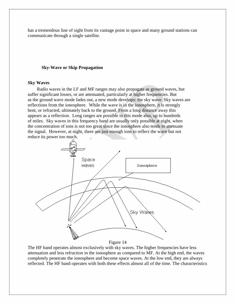
has a tremendous line of sight from its vantage point in space and many ground stations can
communicate through a single satellite.
Sky-Wave or Skip Propagation
Sky Waves
Radio waves in the LF and MF ranges may also propagate as ground waves, but
suffer significant losses, or are attenuated, particularly at higher frequencies. But
as the ground wave mode fades out, a new mode develops: the sky wave. Sky waves are
reflections from the ionosphere. While the wave is in the ionosphere, it is strongly
bent, or refracted, ultimately back to the ground. From a long distance away this
appears as a reflection. Long ranges are possible in this mode also, up to hundreds
of miles. Sky waves in this frequency band are usually only possible at night, when
the concentration of ions is not too great since the ionosphere also tends to attenuate
the signal. However, at night, there are just enough ions to reflect the wave but not
reduce its power too much.
Figure 14
The HF band operates almost exclusively with sky waves. The higher frequencies have less
attenuation and less refraction in the ionosphere as compared to MF. At the high end, the waves
completely penetrate the ionosphere and become space waves. At the low end, they are always
reflected. The HF band operates with both these effects almost all of the time. The characteristics

of the sky wave propagation depend on the conditions in the ionosphere which in turn are
dependent on the activity of the sun. The ionosphere has several well-defined regions in altitude.
Figure 15
D-region: about 75-95 km. Relatively weak ionization. Responsible for strong absorption of MF
during daylight E-region: 95-150 km. An important player in ionospheric scatter of VHF. F-
region: 150-400 km. Has separate F1 and F2 layers during the day. The strongest concentration
of ions. Responsible for reflection of HF radio waves. Since the propagation characteristics
depend on frequency, several key frequencies can de defined: Critical frequency: The minimum
frequency that will penetrate the ionosphere at vertical incidence. The critical frequency
increases during the daylight and decrease at night. At other angles, the wave will be reflected
back. At frequencies above the critical frequency, some range of waves from vertical incidence
and down will become space waves. This will cause a gap in coverage on the ground known as a
skip zone. In figure xx, the skip zone extends to about 1400 miles. The transmitted frequency
was 5 MHz and the critical frequency was 3 MHz in this example. Maximum Useable Frequency
(MUF): defined for two stations. The maximum frequency that will reflect back to the receiving
station from the transmitter. Beyond the MUF, the wave will become a space wave. At MUF the
skip zone extends to just short of the receiver. In figure xx, the MUF for a receiver at 1400 miles
is 5 MHz. Lowest Useable Frequency (LUF): again defined for two stations. At low frequencies,
the signal will be attenuated before it can be reflected. The LUF increases with sunlight and is a
maximum near noon. Optimum Frequency for Traffic (OFT): for two stations, taking into
account the exact conditions in the ionosphere, there will be the perfect frequency that gives the
strongest signal. This can be predicted by powerful modeling programs and is the best guarantee
of success in HF. The diurnal variation if HF propagation is characterized a simple rule-of-
thumb: the frequency follows the sun. At noon, the OFT is generally higher than at night.
Line of Sight
In the VHF band and up, the propagation tends to straighten out into line-of-sight(LOS)
waves. However the frequency is still low enough for some significant effects.

1. Ionospheric scatter. The signal is reflected by the E-region and scattered in all directions.
Some energy makes it back to the earth's surface. This seems to be most effective in the
range of 600-1000 miles.
Figure 16
1. Tropospheric scatter. Again, the wave is scattered, but this time, by the air itself. This can
be visualized like light scattering from fog. This is a strong function of the weather but
can produce good performance at ranges under 400 miles.
Figure 17
1. Tropospheric ducting. The wave travels slower in cold dense air than in warm air.
Whenever inversion conditions exist, the wave is naturally bent back to the ground.
When the refraction matches the curvature of the earth, long ranges can be achieved. This
ducting occurs to some extend always and improves the range over true the line-of-sight
by about 10 %.
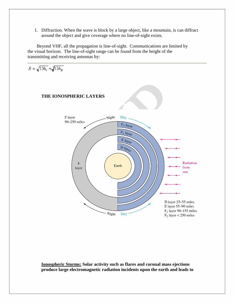
1. Diffraction. When the wave is block by a large object, like a mountain, is can diffract
around the object and give coverage where no line-of-sight exists.
Beyond VHF, all the propagation is line-of-sight. Communications are limited by
the visual horizon. The line-of-sight range can be found from the height of the
transmitting and receiving antennas by:
THE IONOSPHERIC LAYERS
Ionospheric Storms: Solar activity such as flares and coronal mass ejections
produce large electromagnetic radiation incidents upon the earth and leads to
disturbances of the ionosphere; changes the density distribution, electron content,
and the ionospheric current system. These storms can also disrupt satellite
communications and cause a loss of radio frequencies which would otherwise reflect
off the ionosphere. Ionospheric storms can last typically for a day or so.
D layer Absorption: Occurs when the ionosphere is strongly charged (daytime,
summer, heavy solar activity) longer waves will be absorbed and never return to
earth. You don't hear distant AM broadcast stations during the day. Shorter waves
will be reflected and travel further. Absorption occurs in the D layer which is the
lowest layer in the ionosphere. The intensity of this layer is increased as the sun
climbs above the horizon and is greatest at noon. Radio waves below 3 or 4 MHz are
absorbed by the D layer when it is present.
When the ionosphere is weakly charged (night time, winter, low solar activity)
longer waves will travel a considerable distance but shorter waves may pass through
the ionosphere and escape into space. VHF waves pull this trick all the time, hence
their short range and usefulness for communicating with satellites.
Faraday rotation: EM waves passing through the ionosphere may have their
polarizations changed to random directions (refraction) and propagate at different
speeds. Since most radio waves are either vertically or horizonally polarized, it is
difficult to predict what the polarization of the waves will be when they arrive at a
receiver after reflection in the ionosphere.
• Solar radiation, acting on the different compositions of the atmosphere generates
layers of ionization
• Studies of the ionosphere have determined that there are at least four distinct layers
of D, E, F1, and F2 layers.
• The F layer is a single layer during the night and other periods of low ionization,
during the day and periods of higher ionization it splits into two distinct layers, the
F1 and F2.
• There are no clearly defined boundaries between layers. These layers vary in
density depending on the time of day, time of year, and the amount of solar (sun)
activity.
• The top-most layer (F and F1/F2) is always the most densely ionized because it is
least protected from the Sun.
Solar Cycle
Every 11 years the sun undergoes a period of activity called the "solar maximum",
followed by a period of quiet called the "solar minimum". During the solar

maximum there are many sunspots, solar flares, and coronal mass ejections, all of
which can affect communications and weather here on Earth.
The Sun goes through a periodic rise and fall in activity which affects HF
communications; solar cycles vary in length from 9 to 14 years. At solar minimum,
only the lower frequencies of the HF band will be supported by the ionosphere,
while at solar maximum the higher frequencies will successfully propagate, figure
1.4. This is because there is more radiation being emitted from the Sun at solar
maximum, producing more electrons in the ionosphere which allows the use of
higher frequencies.

One way we track solar activity is by observing sunspots. Sunspots are relatively
cool areas that appear as dark blemishes on the face of the sun. They are formed
when magnetic field lines just below the sun's surface are twisted and poke though
the solar photosphere. The twisted magnetic field above sunspots are sites where
solar flares are observed to occur, and we are now beginning to understand the
connection between solar flares and sunspots.
During solar maximum there are many sunspots, and during solar minimum there
are few. The plot at right shows the number of sunspots observed during the last
two solar cycles. The last maximum occurred around 1989, and the next is predicted
to fall in the year 2000. This plot is updated monthly. Click here for a plot of
sunspot numbers from the year 1749 through the present.
How Do Sunspots Affect Earth
The Earth is affected by both solar flares and sunspots. Solar flares emit high-speed
particles which cause auroras, known in the northern hemisphere as Northern
Lights. The image shown here is a real-time satellite image of the Earth's auroral
region above the North Pole. From the ground auroras appear as shimmering
curtains of red and green light in the sky.
Particles from solar flares can also disrupt radio communication, and the radiation
from the flares can give passengers in airplanes a dose of radiation equivalent to a
medical X-ray. Sunspots may have a long-term connection with the Earth's climate.

Scientists are currently debating whether ice ages on Earth are related to the Sun
having fewer sunspots than usual.
How Does HF Radio Work Over Long Distances?
An HF signal transmitted from the earth may travel some way through the
ionosphere before being "bent" back down towards the ground. This occurs due to
the interaction between the HF signal and electrically charged particles in the
ionosphere. The signal can then "bounce" off the ground back into the ionosphere,
return to the earth again, and so on. The distance a given HF signal will travel
depends on the frequency, transmitter power, take-off angle relative to the ground
and the state of the ionosphere through which it is travelling
For any given distance and time, there will be a certain range of HF frequencies that
are most likely to provide successful communications; frequencies outside that
range will work poorly or not at all. Simply increasing the power of an HF signal
will not help if the frequency is too high for the distance required. Increasing the
power may help if the frequency is too low, but using a higher, more suitable
frequency is the best option. The highest frequency which may be used for reliable
HF communications is known as the Maximum Usable Frequency (MUF).
What Kind of Disturbances Can Degrade HF Communications?
Short-Wave Fadeouts - short lived (up to two hours) disturbances, in which solar
flare activity results in the absorption of lower frequency HF signals. These will only
affect signals passing through the daylight ionosphere
Ionospheric Storms - large scale changes in the chemical composition of the ionosphere
resulting in changes to the MUF. Decreased MUFs restrict the frequencies available for use
over a given distance. Ionospheric storms normally last for one to two day
Critical Frequency:
The highest frequency that will be returned to the earth when transmitted
vertically under given ionospheric conditions
Critical Angle:
The highest angle with respect to a vertical line at which a radio wave of a
specified frequency can be propagated and still be returned to the earth from
the ionosphere
Maximum usable frequency (MUF)

The highest frequency that is returned to the earth from the ionosphere
between two specific points on earth
Optimum Working frequency:
The frequency that provides for the most consistent communication path via
sky waves
Maximum usable frequency (MUF)
The highest frequency that is returned to the earth from the ionosphere
between two specific points on earth
Optimum Working frequency:
The frequency that provides for the most consistent communication path via
sky waves
Tropospheric Scattering
Signals are aimed at the troposphere rather than the ionosphere
350 Mhz to 10GHz for paths up to 400 mi
Received signal = 10-6
th of the transmitted power
Fading a problem
Satellite communicatons
Synchronous orbit—when a satellite’s position remains fixed with respect to the
earth’s rotation
Uplink—transmission of signals to the satellite
Downlink—receiving signals from a satellite
Transponder—electronic system on a satellite that performs reception, frequency
translation, and retransmission of received signals

Intelsat III
Uplinks at 5.93 to 6.42 GHz
Translates down to 3.7 to 4.2 GHz
Amplifies signals to 7 watts outout
Downlinks to earth
Frequency change prevents interference between the transmission and receiving
Round trip distance—90000km
Transmission time—300ms
600ms delay in transoceanic telephone communication
Thus routing of international calls ensures that no more than a single satellite hop is
utilized.
Special circuits minimize the echo
Geosynchoronous orbit (GEO)—another name for synchronous orbit
Low earth orbit (LEO)
Launch costs reduced
Signal time delay reduced to 5 to 15 msec
Not stationary—obit time is 90 minutes and visible to earth for 5 to 20
minutes per orbit
LEO
Satellites are linked for real time communication
Subscriber connections between satellites must be passed from one to the other as
the satellites pass over the horizon—somewhat like cellphone
GPS Systems
Global Positioning System
Provides pinpoint geographic location information
Originally used by the government and law enforcement
The satellites transmit position data signals and the receiver processes and
computes the time to receive each one
By using four or more satellites allows the receiver to determine exact
latitude and longitude.
Uses a constellation of 28 satellites orbiting earth at about 11,000 miles
Satellites complete an orbit every 12 hours
Satellites transmit two signals:
Course acquisition signal on 1575.2 MHz
Precision code on 1227.6 MHz and 1575.42 MHz
Requires three satellites for latitude and longitude
Requires four satellites to include elevation
They measure the time it takes for the signals to travel from the satellite to the
receiver.
Civillian GPS has accuracy of 10m
FDMA
Frequency division multiplex access
Early GPS systems
Several channels
Earth station sends a signal requesting permission to transmit, a control signal
responds with the available frequency to transmit on.
TDMA
Time division multiplex access
Single satellite to service multiple earth stations simultaneously
All stations use the same carrier but transmit one or more traffic bursts in
nonoverlapping time frames
TDMA Advantages
1. Single carrier for the transponder to operate on
1. Less subject to intermodulation problems
2. Can operate at a higher power output with smaller range of frequencies
2. Achieve selectivity
1. Simpler
2. Less expensive
3. Suited to digital communications
CDMA
Code division multiple access
Allows use of one carrier
Each station uses a different binary sequence to modulate the carrier
Control uses a correlator that separates and distributes the signals to appropriate
downlink
VSAT
Very small aperture terminal fixed satellite communication systems
Allow multiple inexpensive stations to be linked to a large central installation
Kmart has VSATs at over 2000 stores linked to a mainframe computer in Mi.
Allows them to
Verify checks and credit cards
Convey data such as inventory
Dish is typically 1 m in diameter
Power is just 2 to 3 watts
Immune to optical fiber for another 20 years or until fiber replaces copper

Amateur Satellites
• OSCAR: Orbiting Satellite Carrying Amateur Radio
• Used on VHF (mainly)
• Directional ant.’sare a must!
• The further away a satellite is, the more power you must use
QUESTION BANK
PART-A ( 2 marks)
1.Define Sky wave.
Waves that arrive at the receiver after reflection in the ionosphere is called sky wave.
2.Define Tropospheric wave.
Waves that arrive at the receiver after reflection from the troposphere region is called
Tropospheric wave.(ie 10 Km from Earth surface).
3.Define Ground wave.
Waves propagated over other paths near the earth surface is called ground wave propagation.
4.What are the type of Ground wave.
Ground wave classified into two types.
i. Space wave
ii. Surface wave.
5. What is meant by Space Wave?
It is made up of direct wave and ground reflected wave. Also includes the portion of energy
received as a result of diffraction around the earth surface and the reflection from the upper
atmosphere.
6. What is meant by Surface Wave?
Wave that is guided along the earth‘ s surface like an EM wave is guided by a
transmission is called surface wave. Attenuation of this wave is directly affected by the
constant of earth along which it travels.
7. What is meant by fading?
Variation of signal strength occur on line of sight paths as a result of the atmospheric
conditions and it is called .It can not be predicted properly.
8. What are the type of fading?
Two types. i. Inverse bending.
ii. Multi path fading.
9. What is inverse and multi path fading?
Inverse bending may transform line of sight path into an obstructed one. Multi path fading is
caused by interference between the direct and ground reflected waves as well as interference
between two are more paths in the atmosphere.
10.What is meant by diversity reception?
To minimize the fading and to avoid the multi path interference the technique used are
diversity reception. It is obtained by two ways.
i. Space diversity reception.
ii. Frequency diversity reception.
iii. Polarization diversity.
11. Define Space diversity Reception.

This method exploits the fact that signals received at different locations do not fade together.
It requires antenna spaced at least 100 l apart are referred and the antenna which high signal
strength at the moment dominates.
12 .Define frequency diversity Reception.
This method takes advantage of the fact that signals of slightly different frequencies do not
fade synchronously. This fact is utilized to minimize fading in radio telegraph circuits.
13. Define polarization diversity reception.
It is used in normally in microwave links, and it is found that signal transmitted over the
same path in two polarizations have independent fading patterns. In broad band dish
antenna system, Polarization diversity combined with frequency diversity reception
achieve excellent results.
14.What is meant by Faraday’ s rotation?
Due to the earth‘ s magnetic fields, the ionosphere medium becomes anisotropic and the
incident plane wave entering the ionosphere will split into ordinary and extra ordinary
waves/modes.
When these modes re-emerge from the ionosphere they recombine into a single plane
wave again.
Finally the plane of polarization will usually have changed, this phenomenon is known as
Faraday‘ s rotation.
15. What are the factors that affect the propagation of radio waves?
i. Curvature of earth.
ii. Earth‘ s magnetic field.
iii. Frequency of the signal.
iv. Plane earth reflection.
.16. Define gyro frequency.
Frequency whose period is equal to the period of an electron in its orbit under the influence
of the earths magnetic flux density B.
17. Define critical frequency.

For any layer , the highest frequency that will be reflected back for vertical incidence is fcr =9Ö
max
18. Define Magneto-Ions Splitting.
The phenomenon of splitting the wave into two different components (ordinary and extra-
ordinary) by the earths magnetic field is called Magneto-Ions Splitting.
19. Define LUHF.
The lowest useful HF for a given distance and transmitter power is defined as the lowest
frequency that will give satisfactory reception for that distance and power.
It depends on
i. The effective radiated power
ii. Absorption character of ionosphere for the paths between transmitter and receiver.
iii. The required field strength which in turn depends upon the radio noise at the receiving
location and type of service involved .
20. Define Refractive index.
It is defined as n = c = Velocity of light in vaccum
---- ------------------------------------
Vp Phase velocity in medium
N=Öer
21. Define maximum Usable Frequency.
The maximum Frequency that can be reflected back for a given distance of transmission is
called the maximum usable frequency (MUF) for that distance.
MUF = fcr_secFi
22. Define skip distance.
The distance with in which a signal of given frequency fails to be reflected back is the
skip distance for that frequency.The higher the frequency the greater the skip distance.
23.Define Optimum frequency?

Optimum frequency for transmitting between any two points is therefore selected as some
frequency lying between about 50 and 85 percent of the predicted maximum usable frequency
between those points.
24. What is wave impedance?
h= h0/Ö 1-(fc/f)
i.e., h= 377/Ö 1-(fc/f)
25. Define wave velocity and Group velocity?
Wave velocity vp = c / Ö(fc / f)2
Group velocity, vp vg = c2
vg=c2
/vp
PART –B
1. Explain in details about ionosphere? (8)
2. Explain space wave propagation and sky wave propagation? (16)
3. Explain the ground wave propagation? (8)
4. Discuss the effects of earth‘s magnetic field on ionosphere radio wave
Propagation? (10)
5. Describe the troposphere and explain how ducts can be used for
Microwave propagation? (8)
6. Explain in details, the diversity reception methods? (8)
7. Explain the advantages of Tropospheric wave propagation and sky
wave propagation ? (8)
8. Deduce an expression for the critical frequency of an ionized region in
terms of its maximum ionization density ? (10)
9. Derive an expression for the refractive index of the ionosphere in
terms of the electron number density and frequency ? (10)

EC 1352-Antenna and Wave Propagation (Question bank)
UNIT I
RADIATION FIELDS OF WIRE ANTENNAS
PART – A( 2 Marks)
1. Define a Hertzian dipole?
2. Draw the radiation pattern of a horizontal dipole?
3. What do you mean by induction field and radiation field?
4. What is magnetic vector Potential?
5. Define scalar Potential?
6. What is Retarded Current?
7. Write down the expression for magnetic vector Potential using three standard current
distributions?
8. Define top loading?
9. What is a capacitance hat?
10. What is quarter wave monopole?
11. Write down the expression for radiated fields of a half wave dipole antenna?
12. What is the effective aperture and directivity of a half wave dipole?
13. What is the effective aperture and directivity of a Hertzian dipole antenna?
14. Write down the expression for radiation resistance of a Hertzian dipole?
15. Define retardation time?
16. What is radiation resistance of a half wave dipole?
17. Compare electric scalar potential and magnetic vector potential?
PART – B
1. Derive the expression for the radiated field from a short dipole? (16)
2. Starting from first principles obtain the expression for the power
radiated by a half wave dipole? (16)

3. Derive the expression for power radiated and find the radiation
resistance of a half wave dipole? (16)
4. Derive the radian resistance, Directivity and effective aperture of a
half wave dipole? (10)
5. Derive the fields radiated from a quarter wave monopole antenna? (8)
6. Find the radiation resistance of elementary dipole with linear
current distribution? (8)
7. Derive the radiation resistance, Directivity and effective
aperture of a hertzian dipole? (10)
UNIT II
ANTENNA FUNDAMENTALS AND ANTENNA ARRAYS
PART – A( 2 Marks)
1. Define array factor?
2. What is the relationship between effective aperture and directivity?
3. Write the principle of pattern multiplication?
4. What is meant by broadside array and end fire array?
5. Define radiation intensity?
6. Define an isotropic antenna?
7. Define a broadside array?
8. Define radiation pattern?
9. What are the two types of radiation pattern?
10. Define Beam solid angle or beam area?
11. Define beam efficiency?
12. Define directivity?
13. Define antenna gain?
14. Define effective aperture?
15. What is collecting aperture?
16. Define HPBW?

17. Define FBR?
18. Define BWFN?
19. Write down the expressions for BWFN for both broadside and end fire array?
20. Differentiate broadside array and end fire array?
21. Write down the expressions for minor lobe maxima and minima for both broadside and end
fire array?
22. Define loop antenna?
23. What is axial ratio of a helical antenna?
24. What are advantages of helical antenna?
25. What are the disadvantages of loop antenna?
26. State reciprocity principle?
27. List out the applications helical antenna?
28. Give the expressions for the field components of a helical antenna?
29. Define pitch angle? What happens when =0 and =90?
30. What are applications loop antennas?
PART – B
1. With neat sketch, explain the operation of helical antenna? (16)
2. Obtain the expression for the field and the radiation pattern
produced by a 2 element array of infinitesimal with distance of
separation /2 and currents of unequal magnitude and phase
shift 180 degree? (16)
3. Derive the expression for far field components of a small loop antenna. (16)
4. Derive the expression for electric field of a broadside array of n sources
and also find the maximum direction minimum direction and half power
point direction? (16)
5. Design a 4 element broadside array of /2 spacing between elements
the pattern is to be optimum with a side lobe level 19.1 db.
Find main lobe maximum? (16)
6. Explain pattern multiplication? (8)
7. Derive the expression for electric field of a end fire of n sources

and also find the maximum direction minimum direction and half
power point direction? (16)
8. Write short notes a radiation resistance? (8)
9. Calculate the maximum effective aperture of a /2 antenna? (8)
10. Derive the maxima directions, minima directions, and half
power point direction for an array of two point sources with equal
amplitude and opposite phase? (16)
11. Explain the various types of amplitude distributions in details? (16)
UNIT III
TRAVELING WAVE (WIDE BAND) ANTENNAS
PART – A( 2 Marks)
1. What are traveling wave antenna?
2. What is the type of radiation pattern produced when a wave travels in a wire?
3. Draw the structure of 3-elements yagi-uda antenna and give the dimensions and spacing
between the elements in terms of wavelength?
4. What are the applications of log periodic antenna?
5. What are the applications of rhombic antenna?
6. What do you meant by self impedance?
7. What do you meant by mutual impedance?
8. Define traveling wave impedance?
9. What is the main advantage of traveling wave antenna?
10. What are the limitations of rhombic antenna?
11. What are the two types of rhombic antenna design?
12. Define rhombic antenna?
13. Give the expressions for design ratio, spacing factor and frequency ratio, of log periodic
antenna?
14. What are the three different regions in log periodic antenna and how they are differentiated?
15. What is frequency independent antenna?
16. What is LPDA?
17. What are the applications of log periodic antenna?
PART – B
1. Explain the radiation from a travelling wave on a wire? (8)
2. What is Yagi-uda Antenna ?Explain the construction and operation of
Yagi-uda Antenna .Also explain its general characteristics? (16)
3. Explain the construction, operation and design for a rhombic antenna? (16)
4. Explain the geometry of a log periodic antenna? Give the design equations and uses of log
periodic antenna? (16)
5. Discuss in details about (a) Self impedance (b) Mutual impedance? (8)
UNIT IV
APERTURE AND LENS ANTENNAS
PART – A( 2 Marks)
1. State Huygens Principle?
2. What is Slot Antenna?
3. Which antenna is complementary to the slot dipole?
4. How will you find the directivity of a large rectangular broadside array?
5. What is the relationship between the terminal impedance of slot and dipole antenna?
6. What is the difference between slot antenna and its complementary dipole antenna?
7. Define lens antenna?
8. What are the different types of lens antenna?
9. What is a dielectric lens antenna?
10. What are the drawbacks of lens antenna?
11. What are the field components that are radiated from open end of a coaxial line?
12. What are the advantages of stepped dielectric lens antenna?
13. What is biconical antenna?

14. What is Lunenburg lens?
15. What are the advantages of lens antenna?
16. Mention the uses of lens antenna?
17. How spherical waves are generated?
18. Define the characteristic impedance of biconical antenna?
19. Bring out the expressions for voltage across the feed points of the biconical antenna and
current flowing through the surface of the cone?
20. What do you meant by sect oral horn?
21. What do you meant by pyramidal horn?
22. What is back lobe radiation?
23. What are the various feeds used in reflectors?
24. What are the different types of horn antennas?
25. Define refractive index of lens antenna?
26. What are secondary antennas? Give examples?
PART – B
1. Explain the different types of lens antenna? (10)
2. Explain the radiation from a rectangular aperture? (16)
3. Explain the radiation from an elemental area of a plane wave
(or) explain the radiation from a Huygen‘s source ? (16)
4. Describe the parabolic reflector used at micro frequencies? (16)
5. Write short notes on luneberg lens? (16)
6. Discuss about spherical waves and biconical antenna? (16)
7. Derive the various field components radiated from circular aperture
and also find beamwidth and effective area ? (12)
8. Derive the field components radiated from a thin slot antenna in
an infinite cyclinder ? (10)
9. Show the relationship between dipole and slot impedances? (8)
10. Explain the radiation from the open end of a coaxial cable? (8)

UNIT V
WAVE PROPAGATION
PART – A ( 2 Marks)
1. Define Gyro frequency?
2. What is multihop Propagation?
3. How spherical waves are generated?
4. What are the effects of earth curvature on tropospheric propagation ?
5. Define critical frequency of an ionized layer of ionosphere?
6. What are the factors that affect the propagation of radio waves?
7. Define ground wave?
8. What are the components present in space wave?
9. Define Fading?
10. Define ionosphere?
11. Define Troposphere?
12. How can minimize Fading?
13. What are the various types diversity reception?
14. Define critical frequency?
15. What is virtual height?
16. Define MUF?
17. State secant law?
18. Define space wave?
19. What are height ranges of different regions in the ionosphere?
20. Write down the expression for the refractive index?
21. What is OWF or OTF?
22. Define duct Propagation?
23. What is skip distance?
24. How will you find the range of space wave propagation or line of sight distances?
25. What is sporadic E layer in ionosphere?

PART – B
1. Explain in details about ionosphere? (8)
2. Explain space wave propagation and sky wave propagation? (16)
3. Explain the ground wave propagation? (8)
4. Discuss the effects of earth‘s magnetic field on ionosphere radio wave
propagation? (10)
5. Describe the troposphere and explain how ducts can be used for microwave propagation? (8)
6. Explain in details, the diversity reception methods? (8)
7. Explain the advantages of tropospheric wave propagation and sky wave
propagation? (8)
8. Deduce an expression for the critical frequency of an ionized region in terms of its maximum
ionization density? (10)
9. Derive an expression for the refractive index of the ionosphere in terms of
the electron number density and frequency ? (10)


Related Documents