AVR32807: Getting Started with the AVR UC3 Software Framework USB Classes Features • Full Speed (12Mbit/s) and High Speed (480Mbit/s) data rates • Control, Bulk, Isochronuous and Interrupt transfer types • Device mode: – Standard or custom USB device classes with Atmel ® AVR ® UC3 software Framework • Host mode: – Host pipes auto configuration with device descriptors – Supports for composite devices (multiple interfaces) 1 Description This document describes the software modules of the AVR UC3 Software Framework dedicated to the USB and illustrates how to get started with the USB software from the Software Framework. This document is written for the software developers in order to ease the development of USB applications for the AVR UC3 series. It assumes that readers are familiar with the 32-bit AVR UC3 series. 2 Overview The AVR UC3 USB stack software Framework is designed to hide the complexity of USB development from software designers. The aim of this document is to describe the USB firmware and give an overview of the software and architecture. The main files are described in order to give the user the easiest way to customize the firmware and build his/her own application. The AVR UC3 Software Framework supports dual role (device or host) and high and full speed application examples (template demonstration software) are also provided to illustrate the usage of this USB stack. 32-bit Microcontrollers Application Note Rev. 32140A - AVR32-02/10

Welcome message from author
This document is posted to help you gain knowledge. Please leave a comment to let me know what you think about it! Share it to your friends and learn new things together.
Transcript
AVR32807: Getting Started with the AVR UC3 Software Framework USB Classes
Features • Full Speed (12Mbit/s) and High Speed (480Mbit/s) data rates • Control, Bulk, Isochronuous and Interrupt transfer types • Device mode:
– Standard or custom USB device classes with Atmel® AVR® UC3 software Framework
• Host mode: – Host pipes auto configuration with device descriptors – Supports for composite devices (multiple interfaces)
1 Description This document describes the software modules of the AVR UC3 Software Framework dedicated to the USB and illustrates how to get started with the USB software from the Software Framework.
This document is written for the software developers in order to ease the development of USB applications for the AVR UC3 series. It assumes that readers are familiar with the 32-bit AVR UC3 series.
2 Overview The AVR UC3 USB stack software Framework is designed to hide the complexity of USB development from software designers.
The aim of this document is to describe the USB firmware and give an overview of the software and architecture. The main files are described in order to give the user the easiest way to customize the firmware and build his/her own application.
The AVR UC3 Software Framework supports dual role (device or host) and high and full speed application examples (template demonstration software) are also provided to illustrate the usage of this USB stack.
32-bit Microcontrollers Application Note
Rev. 32140A - AVR32-02/10
2 AVR32807 32140A - AVR32-02/10
3 AVR UC3 Software Framework USB Classes AVR UC3 Software Framework supports popular USB classes including CDC, HID, Mass Storage, and Device Firmware Upgrade.
3.1 CDC The Communication Device Class (CDC) is a general-purpose way to enable all types of communications on the Universal Serial Bus (USB). This class makes it possible to connect telecommunication devices such as digital telephones or analog modems, as well as networking devices like ADSL or Cable modems. While a CDC device enables the implementation of quite complex devices, it can also be used as a very simple method for communication on the USB. For example, a CDC device can appear as a virtual COM port, which greatly simplifies application programming on the host side.
3.2 HID The Human Interface Devices (HID) class extends the USB specification in order to provide a standard way of handling devices manipulated by humans. This includes common computer devices such as keyboards, mice and joysticks, as well as electronic device controllers (e.g., VCR remote) and generic controls (e.g., knobs, switches).
The HID class also encompasses devices which do not require human interaction but provide HID-compatible data, like a thermometer. This flexibility makes it possible to enable generic communications between an HID device and a host system, in a very simple way. HID also allows several functionalities to be multiplexed on the same endpoint. This makes it possible to have a device perform several tasks (e.g. keyboard + mouse + communication) while still only using a single endpoint. This means a device using HID can be very versatile.
3.3 MS The Mass Storage (MS) class is an extension to the USB specification that defines how mass storage devices, such as a hard-disk, a disk-on-key or a USB floppy drive should operate on the USB. Using the USB for a mass storage device has two advantages. First, software development is much faster, since most operating systems (if not all) include a fully functional driver for the MSD class. Thus, only the device-side driver has to be developed to have a working product. In addition, relying on the Mass Storage standard guarantees that a device will be useable on many operating systems without any extra coding.
3.4 DFU The Device Firmware Upgrade class is used for Bootloader applications and allows performing ISP (In-System Programming) from a USB host controller.
AVR UC3 USB DFU Bootloader App Note:
http://www.atmel.com/dyn/resources/prod_documents/doc7745.pdf
AVR32807
3
32140A - AVR32-02/10
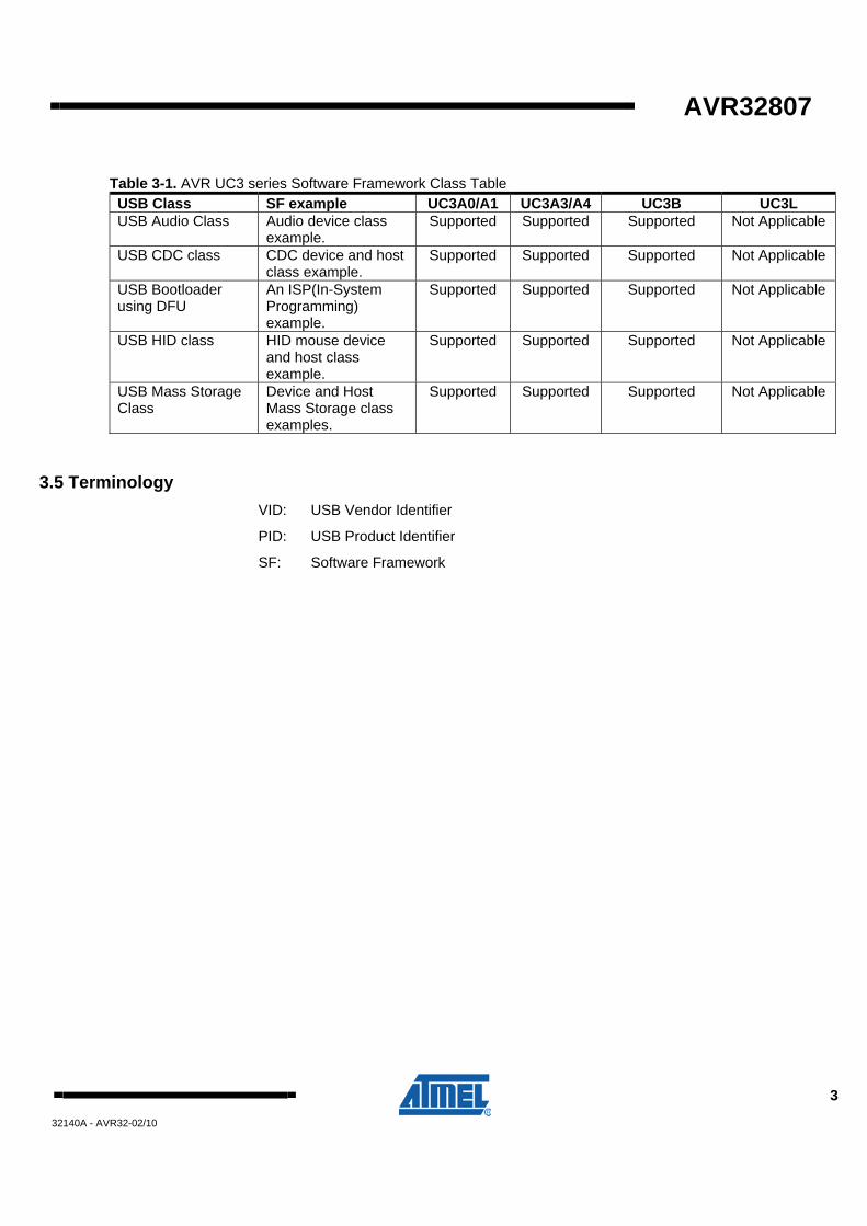
Table 3-1. AVR UC3 series Software Framework Class Table USB Class SF example UC3A0/A1 UC3A3/A4 UC3B UC3L USB Audio Class Audio device class
example. Supported Supported Supported Not Applicable
USB CDC class CDC device and host class example.
Supported Supported Supported Not Applicable
USB Bootloader using DFU
An ISP(In-System Programming) example.
Supported Supported Supported Not Applicable
USB HID class HID mouse device and host class example.
Supported Supported Supported Not Applicable
USB Mass Storage Class
Device and Host Mass Storage class examples.
Supported Supported Supported Not Applicable
3.5 Terminology VID: USB Vendor Identifier
PID: USB Product Identifier
SF: Software Framework
4 AVR32807 32140A - AVR32-02/10
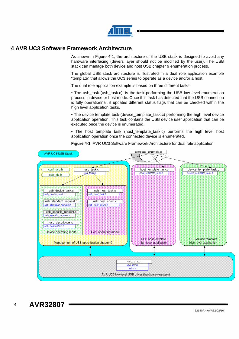
4 AVR UC3 Software Framework Architecture As shown in Figure 4-1, the architecture of the USB stack is designed to avoid any hardware interfacing (drivers layer should not be modified by the user). The USB stack can manage both device and host USB chapter 9 enumeration process.
The global USB stack architecture is illustrated in a dual role application example “template” that allows the UC3 series to operate as a device and/or a host.
The dual role application example is based on three different tasks:
• The usb_task (usb_task.c), is the task performing the USB low level enumeration process in device or host mode. Once this task has detected that the USB connection is fully operationnal, it updates different status flags that can be checked within the high level application tasks.
• The device template task (device_template_task.c) performing the high level device application operation. This task contains the USB device user application that can be executed once the device is enumerated.
• The host template task (host_template_task.c) performs the high level host application operation once the connected device is enumerated.
Figure 4-1. AVR UC3 Software Framework Architecture for dual role application
AVR32807
5
32140A - AVR32-02/10
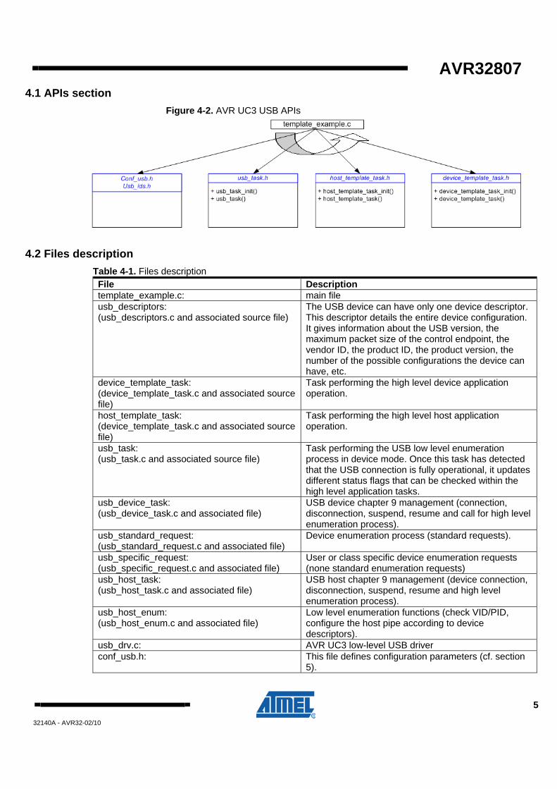
4.1 APIs section Figure 4-2. AVR UC3 USB APIs
4.2 Files description Table 4-1. Files description File Description template_example.c: main file usb_descriptors: (usb_descriptors.c and associated source file)
The USB device can have only one device descriptor. This descriptor details the entire device configuration. It gives information about the USB version, the maximum packet size of the control endpoint, the vendor ID, the product ID, the product version, the number of the possible configurations the device can have, etc.
device_template_task: (device_template_task.c and associated source file)
Task performing the high level device application operation.
host_template_task: (device_template_task.c and associated source file)
Task performing the high level host application operation.
usb_task: (usb_task.c and associated source file)
Task performing the USB low level enumeration process in device mode. Once this task has detected that the USB connection is fully operational, it updates different status flags that can be checked within the high level application tasks.
usb_device_task: (usb_device_task.c and associated file)
USB device chapter 9 management (connection, disconnection, suspend, resume and call for high level enumeration process).
usb_standard_request: (usb_standard_request.c and associated file)
Device enumeration process (standard requests).
usb_specific_request: (usb_specific_request.c and associated file)
User or class specific device enumeration requests (none standard enumeration requests)
usb_host_task: (usb_host_task.c and associated file)
USB host chapter 9 management (device connection, disconnection, suspend, resume and high level enumeration process).
usb_host_enum: (usb_host_enum.c and associated file)
Low level enumeration functions (check VID/PID, configure the host pipe according to device descriptors).
usb_drv.c: AVR UC3 low-level USB driver conf_usb.h: This file defines configuration parameters (cf. section
5).
6 AVR32807 32140A - AVR32-02/10
5 Configuring the AVR UC3 USB Software Framework All common configuration parameters for the application are defined in the “conf_usb.h” file. Module specific parameters are defined in their respective configuration files.
The configuration file is split into three sections for global, host and device configuration parameters.
5.1 Global configuration The global configuration section allows to select if USB stack uses the device and/or host USB mode.
Full Speed and High Speed modes are device dependent and configurable in this section. The Full speed mode is set by default and the High Speed mode can for instance be enabled for the UC3A3 series.
Table 5-1. Global configuration definitions #define Comment USB_HOST_FEATURE To activate the host software framework support USB_DEVICE_FEATURE To activate the device software framework
support USB_HIGH_SPEED_SUPPORT To activate High Speed Mode
5.2 Host configuration The USB stack manages USB chapter 9 for a host controller:
• VBUS generation and monitoring
• Connection of the peripheral
• Disconnection of the peripheral
• Enumeration and identification of the connected peripheral
• Configuration of the host controller pipes according to the device descriptors of the connected peripheral
• Suspend the USB activity
• Resume and remote wake-up management
Similar to the device mode of the library, asynchronous USB events (connection, disconnection, remote wake-up detection) are managed directly within the USB interrupt subroutine located in the “usb_task.c” file. The user application can execute specific functions upon these events thanks to the user defined actions of the “conf_usb.h” file.
The connected device state and its enumeration process are managed in polling mode with the “usb_host_task.c” and “usb_host_enum.c files”. Only critical and asynchronous device events such as device disconnection and remote wake up detection are managed under interrupt (“usb_task.c“ file).
AVR32807
7
32140A - AVR32-02/10
5.2.1 Host specific configuration
To enable the USB host mode of the library the USB_HOST_FEATURE needs to be defined as ENABLED.
The host specific configuration section of “conf_usb.h” file allows to select the following main parameters:
• The VID/PID table of known devices supported by the host application
• The class/subclass/protocol table of interfaces supported by the host application
• The maximum number of interfaces supported for a connected composite device
• The maximum number of endpoints associated to an interface
• The timeout parameters for a USB transfer (number of NAK or time delay)
Table 5-2. Host specific configuration definitions #define Comment VID_PID_TABLE This table contains the VID/PID that are supported by
the reduced host application CLASS_SUBCLASS_PROTOCOL This table contains the
CLASS/SUBCLASS/PROTOCOL that are supported by the host application.
SIZEOF_DATA_STAGE The size of RAM buffer reserved for descriptor handling DEVICE_ADDRESS The address that will be assigned to the connected
device MAX_INTERFACE_SUPPORTED The maximal number of interfaces that can be
supported (composite device) MAX_EP_PER_INTERFACE The maximal number of endpoints per interface
supported HOST_STRICT_VID_PID_TABLE The host controller will be limited to the strict VID/PID
list. HOST_AUTO_CFG_ENDPOINT Try to configure the host pipe according to the device
descriptors received HOST_CONTINUOUS_SOF_INTERRUPT Host Start-of-Frame interrupt always enabled HOST_ERROR_RESTART When host error state detected, go to detached state USB_HOST_PIPE_INTERRUPT_TRANSFER USB host pipes transfers use USB communication
interrupt (allows to use non-blocking functions) ID_PIN_CHANGE_GENERATE_RESET Force CPU reset upon ID pin change TIMEOUT_DELAY_ENABLE Enable time-out delay for host transfer TIMEOUT_DELAY Delay 1/4 s (250 ms) before time-out value NAK_TIMEOUT_ENABLE Enable cpt NAK time-out for host transfer NAK_SEND_TIMEOUT Number of NAK handshakes before time-out for
transmit functions (up to 0xFFFF) NAK_RECEIVE_TIMEOUT Number of NAK handshakes before time-out for receive
functions (up to 0xFFFF)
8 AVR32807 32140A - AVR32-02/10
The host specific configuration section contains a set of user specific actions that can be executed upon special events during the USB communication.
#if HOST_AUTO_CFG_ENDPOINT == DISABLE
//! If no auto configuration of EP, map here user function
#define User_configure_endpoint()
#endif
//! @defgroup host_cst_actions USB host custom actions
//! @{
// Write here the action to associate with each USB host event.
#define Usb_id_transition_action()
#define Host_device_disconnection_action()
(mouse_hid_new_device_connected = FALSE, mouse_hid_connected = FALSE)
#define Host_device_connection_action()
#define Host_sof_action() host_sof_action()
#define Host_suspend_action()
#define Host_hwup_action()
#define Host_device_supported_action()
#define Host_device_not_supported_action()
#define Host_new_device_connection_action()
(mouse_hid_new_device_connected = TRUE)
#define Host_device_class_not_supported_action()
#define Host_device_error_action()
AVR32807
9
32140A - AVR32-02/10
5.3 Device configuration The USB stack manages USB chapter 9 for a device:
• Connection/Disconnection (VBUSsupply monitoring)
• Suspend
• Resume
• Enumeration requests
Asynchronous USB events (connection, suspend, resume, reset) are managed directly within the USB interrupt subroutine located in the “usb_task.c” file. The user application can execute specific functions upon these events thanks to the user defined actions of the “conf_usb.h” file.
Enumeration requests from the host are managed in polling mode with the “usb_device_task.c”, “usb_standard_request.c files” and “usb_specific_request.c”. The usb_task that belongs to the scheduler tasks periodically checks for new control requests from the host.
5.3.1 Configuring the USB stack
To enable the USB device mode of the stack the USB_DEVICE_FEATURE needs to be defined as ENABLED.
Table 5-3. Device configuration definitions #define Comment NB_ENDPOINTS Number of endpoints in the application including control
endpoint EP_HID_MOUSE_IN Write here the action to associate with each USB event.
The device specific configuration section of “conf_usb.h” file contains the physical endpoints numbers definition used by the device application and a set of user specific actions that can be executed upon special events during the USB communication.
#define Usb_sof_action() usb_sof_action()
#define Usb_wake_up_action()
#define Usb_resume_action()
#define Usb_suspend_action()
#define Usb_reset_action()
#define Usb_vbus_on_action()
#define Usb_vbus_off_action()
#define Usb_set_configuration_action()
The user action defines the high level application to execute specific functions. For example the user can map a function executed upon each USB start of frame event or USB bus reset.
10 AVR32807 32140A - AVR32-02/10
5.4 ID configuration Vendor IDs (VIDs) are owned by the vendor company and are assigned and maintained by the USB-IF only. Email [email protected] for more information on USB-IF membership and obtaining a VID (please refer to the FAQ section).
Product IDs (PIDs) are assigned by each vendor as they see fit; the USB-IF recommends each vendor set up a coordinated allocation scheme for PIDs so different teams don't inadvertently choose the same PID for different products. Duplicate numbers may cause driver error.
A list of VID and PID constant are declared in “usb_ids.h’’ and can be filled with new values. Table 5-4. ID configuration definitions
#define Comment Value ATMEL_VID VID 0x03EB ENUM_EXAMPLE_PID PID 0x2300 MS_EXAMPLE_PID PID 0x2301 MS_SDRAM_LOADER_PID PID 0x2302 EVK1100_CTRL_PANEL_DEMO_PID PID 0x2303 HID_EXAMPLE_PID PID 0x2304 EVK1101_CTRL_PANEL_DEMO_HID_PID PID 0x2305 EVK1101_CTRL_PANEL_DEMO_HID_MS_PID PID 0x2306 CDC_EXAMPLE_PID PID 0x2307 AUDIO_MIC_EXAMPLE_PID PID 0x2308 EVK11xx_VIRTUAL_COM_PORT_PID PID 0x2310 AUDIO_SPEAKER_MICRO_EXAMPLE_PID PID 0x2311 ISP_UC3A_PID PID 0x2FF8 ISP_UC3A3_PID PID 0x2FF1 ISP_UC3B_PID PID 0x2FF6
The VID and the PID are defined thanks to the above constants in “usb_descriptor.h”. To change them, the values below, needs to be modify: // USB Device descriptor #define VENDOR_ID ATMEL_VID //! Atmel vendor ID #define PRODUCT_ID EVK1101_CTRL_PANEL_PID Adding to the VID and the PID, the USB device may need a unique serial number. The value is also defined in the “usb_descriptor.h”. To change them, the values below, needs to be modify: // USB Device descriptor #define SN_INDEX 0x03
AVR32807
11
32140A - AVR32-02/10
5.5 USB device descriptors During the enumeration process, the host asks the device several descriptor values to identify it and load the correct drivers. The most difficult part of any USB application is determining what the device descriptors should be. Every USB device communicates its requirements to the host through a process called enumeration. The AVR UC3 Software Framework provides full enumeration process for both device and host mode. During enumeration, the device descriptors are transferred to the host which assigns a unique address to the device. The descriptors are described in detail in Chapter 9 of the USB 2.0 specification.
5.5.1 USB device descriptor
The USB device can have only one device descriptor. This descriptor describes the entire device. It gives information about the USB version, the maximum packet size of the control endpoint, the vendor ID, the product ID, the product version, the number of the possible configurations the device can have, etc. The table 5-5 shows the format of this descriptor Table 5-5. Device descriptor Field Description bLength Descriptor size bDescriptorType Device descriptor bcdUSB USB version bDeviceClass Code class (If 0, the class will be
specified by each interface, if 0xFF, it is specified by the vendor)
bDeviceSubClass Sub class code ( assigned by USB org) bDeviceProtocol Code protocol (assigned by USB org) bMaxPacketSize The maximal packet size in bytes of the
control endpoint. It has to be 8 (Low Speed), 16, 32 or 64 (Full Speed)
idVendor Vendor identification (assigned by USB org)
idProduct Product identification (assigned by the manufacturer)
bcdDevice Device version (assigned by the manufacturer)
iManufacturer Index into a string array of the manufacturer descriptor
iProduct Index into a string array of the product descriptor
iSerialNumber Index into a string array of the serial number descriptor
bNumConfigurations bNumConfigurations defines the number of configurations the device supports at its current speed
12 AVR32807 32140A - AVR32-02/10
5.5.2 USB configuration descriptor
The USB device can have more than one configuration descriptor, however the majority of devices use a single configuration. This descriptor specifies the power-supply mode (self_powered or bus_powered), the maximum power that can be consumed by the device, the interfaces belonging to the device, the total size of all the data descriptors, etc. For example one device can have two configurations, one when it is powered by the bus and the other when it is self-powered. We can imagine also configurations which use different transfer modes. Table 5-6 shows the format of this descriptor: Table 5-6. Configuration descriptor
Field Description bLength Descriptor size bDescriptorType Configuration descriptor type wTotalLength Total descriptors size bNuminterfaces Number of interfaces bConfigurationValue Number of the configuration iConfiguration Index of string descriptor bmAttributes self-powered or bus-powered, remote
wake up Maxpower 2mA by unit
5.5.3 USB Interface Descriptor
A single device can have more than one interface (USB composite device). The main information given by this descriptor is the number of endpoints used by this interface and the USB class and subclass. Table 5-7 shows the format of this descriptor: Table 5-7. Interface descriptor
Field Description bLength Descriptor size bDescriptorType Interface descriptor bInterfaceNumber Interface number bAltenativeSetting Used to select the replacing interface bNumEndpoints Number of endpoints (excluding control
endpoint) bInterfaceClass Class code (assigned by USB org) bInterfaceSubClass Subclass code (assigned by USB org)
0 No subclass 1 Boot interface subclass
bInterfaceProtocol Protocol code (assigned by USB org) iInterface Index into a string array to describe the
used interface
AVR32807
13
32140A - AVR32-02/10
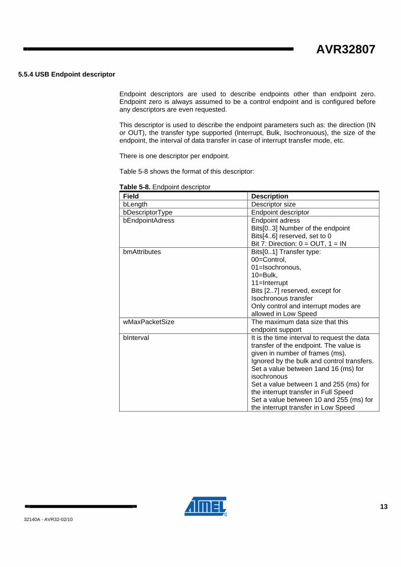
5.5.4 USB Endpoint descriptor
Endpoint descriptors are used to describe endpoints other than endpoint zero. Endpoint zero is always assumed to be a control endpoint and is configured before any descriptors are even requested. This descriptor is used to describe the endpoint parameters such as: the direction (IN or OUT), the transfer type supported (Interrupt, Bulk, Isochronuous), the size of the endpoint, the interval of data transfer in case of interrupt transfer mode, etc. There is one descriptor per endpoint. Table 5-8 shows the format of this descriptor: Table 5-8. Endpoint descriptor Field Description bLength Descriptor size bDescriptorType Endpoint descriptor bEndpointAdress Endpoint adress
Bits[0..3] Number of the endpoint Bits[4..6] reserved, set to 0 Bit 7: Direction: 0 = OUT, 1 = IN
bmAttributes
Bits[0..1] Transfer type: 00=Control, 01=Isochronous, 10=Bulk, 11=Interrupt Bits [2..7] reserved, except for Isochronous transfer Only control and interrupt modes are allowed in Low Speed
wMaxPacketSize The maximum data size that this endpoint support
bInterval
It is the time interval to request the data transfer of the endpoint. The value is given in number of frames (ms). Ignored by the bulk and control transfers. Set a value between 1and 16 (ms) for isochronous Set a value between 1 and 255 (ms) for the interrupt transfer in Full Speed Set a value between 10 and 255 (ms) for the interrupt transfer in Low Speed
14 AVR32807 32140A - AVR32-02/10
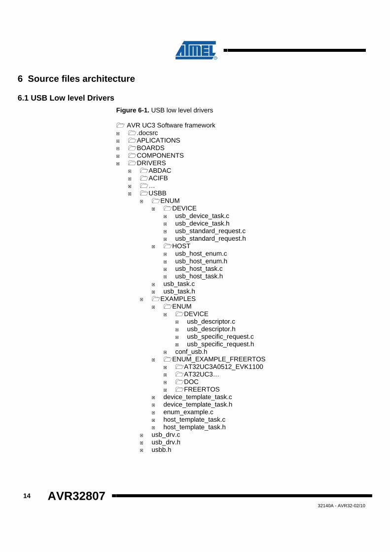
6 Source files architecture
6.1 USB Low level Drivers Figure 6-1. USB low level drivers
AVR UC3 Software framework .docsrc APLICATIONS BOARDS COMPONENTS DRIVERS
ABDAC ACIFB … USBB
ENUM DEVICE
usb_device_task.c usb_device_task.h usb_standard_request.c usb_standard_request.h
HOST usb_host_enum.c usb_host_enum.h usb_host_task.c usb_host_task.h
usb_task.c usb_task.h
EXAMPLES ENUM
DEVICE usb_descriptor.c usb_descriptor.h usb_specific_request.c usb_specific_request.h
conf_usb.h ENUM_EXAMPLE_FREERTOS
AT32UC3A0512_EVK1100 AT32UC3… DOC FREERTOS
device_template_task.c device_template_task.h enum_example.c host_template_task.c host_template_task.h
usb_drv.c usb_drv.h usbb.h
AVR32807
15
32140A - AVR32-02/10
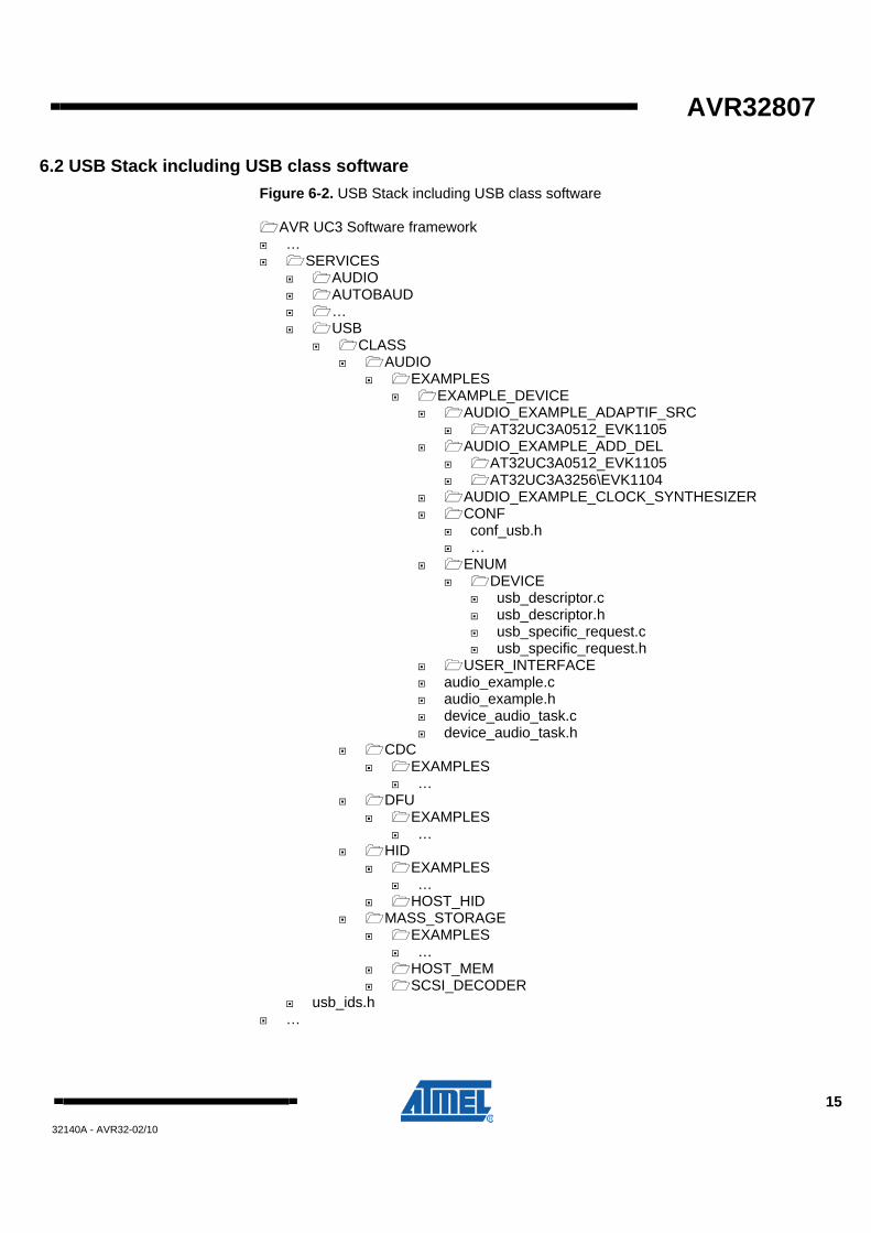
6.2 USB Stack including USB class software Figure 6-2. USB Stack including USB class software
AVR UC3 Software framework … SERVICES
AUDIO AUTOBAUD … USB
CLASS AUDIO
EXAMPLES EXAMPLE_DEVICE
AUDIO_EXAMPLE_ADAPTIF_SRC AT32UC3A0512_EVK1105
AUDIO_EXAMPLE_ADD_DEL AT32UC3A0512_EVK1105 AT32UC3A3256\EVK1104
AUDIO_EXAMPLE_CLOCK_SYNTHESIZER CONF
conf_usb.h …
ENUM DEVICE
usb_descriptor.c usb_descriptor.h usb_specific_request.c usb_specific_request.h
USER_INTERFACE audio_example.c audio_example.h device_audio_task.c device_audio_task.h
CDC EXAMPLES
… DFU
EXAMPLES …
HID EXAMPLES
… HOST_HID
MASS_STORAGE EXAMPLES
… HOST_MEM SCSI_DECODER
usb_ids.h …
16 AVR32807 32140A - AVR32-02/10
7 Getting started flowchart for buiding a Single-Interface (non-Composite) USB Device
This section is a step-by-step guide on how to use the AVR UC3 USB software framework to manage an USB application example:
1. Select a USB Class regarding application requirements (application type, transfer type, data transfer rate, etc…), for example: Mouse application will be related to the HID class,
2. Import the necessary files (src…\SERVICES\USB\CLASS\HID),
3. Configure the USB stack thanks to the section 5 (Global, Device, Host and ID Configuration) into the project,
4. Configure System and USB clocks with the pm_conf_clocks() function managed in the pm_conf_clocks.c file (src…\DRIVERS\PM),
5. Initialize USB tasks with the usb_task_init() function managed in usb_task.c file (src…\DRIVERS\USBB\ENUM),
6. With regard to USB mode requirements, initialize the device and/or host mouse hid tasks with the device_mouse_hid_task_init() and host_mouse_hid_task_init() functions respectively managed in the device_mouse_hid_task.c and host_mouse_hid_task.c (src…\SERVICES\USB\CLASS\HID),
7. Call periodically the USB tasks:
{
usb_task()
device_template_task()
host_template_task()(
}
AVR32807
17
32140A - AVR32-02/10
8 Theoretical Performances
8.1 Max Data Transfer Rates
Low or Normal Speed: 1.5Mbps
Full Speed: 12Mbps
High Speed: 480Mbps
8.2 USB Data Transfer Types The USB device (function) communicates with the host by transferring data through a pipe between a memory buffer on the host and an endpoint on the device. USB supports four different transfer types. A type is selected for a specific endpoint according to the requirements of the device and the software. The transfer type of a specific endpoint is determined in the endpoint descriptor.
8.2.1 Data transfer types used in the AVR UC3 stack
8.2.1.1 Isochronous Transfer used for the Audio class
Isochronous Transfer is most commonly used for time-dependent information, such as multimedia streams and telephony. This transfer type can be used by full-speed and high-speed devices, but not by low-speed devices. Isochronous transfer is periodic and continuous. The isochronous pipe is unidirectional, i.e. a certain endpoint can either transmit or receive information. Bi-directional isochronous communication requires two isochronous pipes, one in each direction. USB guarantees the isochronous transfer access to the USB bandwidth (i.e. it reserves the required amount of bytes of the USB frame) with bounded latency, and guarantees the data transfer rate through the pipe, unless there is less data transmitted. Since timeliness is more important than correctness in this type of transfer, no retries are made in case of error in the data transfer. However, the data receiver can determine that an error occurred on the bus.
8.2.1.2 Interrupt Transfer used for the HID class
Interrupt Transfer is intended for devices that send and receive small amounts of data infrequently or in an asynchronous time frame. This transfer type can be used for low-, full- and high-speed devices. Interrupt transfer type guarantees a maximum service period and that delivery will be re-attempted in the next period if there is an error on the bus. The interrupt pipe, like the isochronous pipe, is unidirectional and periodical. The maximum packet size for interrupt endpoints can be 8 bytes or less for low-speed devices; 64 bytes or less for full-speed devices; and 1,024 bytes or less for high-speed devices.
18 AVR32807 32140A - AVR32-02/10
8.2.1.3 Bulk Transfer used for the CDC and MSC class
Bulk Transfer is typically used for devices that transfer large amounts of non-time sensitive data, and that can use any available bandwidth, such as printers and scanners. This transfer type can be used by full-speed and high-speed devices, but not by low-speed devices. Bulk transfer is non-periodic, large packet, bursty communication. Bulk transfer allows access to the bus on an "as-available" basis, guarantees the data transfer but not the latency, and provides an error check mechanism with retries attempts. If part of the USB bandwidth is not being used for other transfers, the system will use it for bulk transfer. Like the other stream pipes (isochronous and interrupt), the bulk pipe is also unidirectional, so bi-directional transfers require two endpoints. The maximum packet size for bulk endpoints can be 8, 16, 32, or 64 bytes for full-speed devices, and 512 bytes for high-speed devices.
9 Frequently Asked Questions Q: Can I use the VID and PID provided by Atmel ?
A: Customer may keep the Atmel® Vendor Identifier (Atmel VID) and Product Identifier (PID) in their product that integrates an Atmel USB Flash Microcontroller (“Integrated Product”) from one Atmel original example subject to the following acknowledgments and/or conditions:
- Customer must execute Atmel’s Limited License Agreement (Atmel USB Flash Microcontroller Software Suite) and comply with all terms and conditions.
- Customer cannot apply to USB compliance testing with the USB-IF, therefore Customer cannot use the USB logo for an Integrated Product using the Atmel VID.
- All software is provided AS IS and Customer is responsible to insure the USB compliance of the Integrated Product.
- Customer must integrate the Atmel USB Flash Microcontroller Software and the USB descriptors with no changes apart from:
1-The manufacturer string, which must include the Customer’s URL address and finish with “powered by Atmel: e.g. “www.customer.com powered by Atmel”.
2-The maximum power fields, which must be compatible with the actual power consumption of the Integrated Product for each possible USB configuration.
3- When applicable the Endpoint polling Interval fields can be adapted to the application.
-Customer must insure compatibility with all the features of the Atmel original example if a custom host driver is distributed with the Integrated Product.
AVR32807
19
32140A - AVR32-02/10
10 References and Further Information What to do next? What is the next step?
Additional information concerning the AVR UC3 series
• Hardware References,
• Application notes,
• Software Framework,
• Tools,
• Support.
Are described hereunder.
10.1 Detailed Hardware References Hardware information for development kit can be found in 32-bit AVR Studio®: contains the schematics, a logical block diagram and the errata,
The AVR UC3 series datasheet can be found here:
http://www.atmel.com/dyn/products/datasheets.asp?family_id=682
The AVR32 architecture manual can be found here:
http://www.atmel.com/dyn/resources/prod_documents/doc32000.pdf
The AVR32 UC technical reference guide can be found here:
http://www.atmel.com/dyn/resources/prod_documents/doc32002.pdf
10.2 Software Framework To start a development whether for evaluation or rapid prototyping, the UC3 Software Framework is a complete and useful source of existing source code a developer can start from. It has been designed to help develop and glue together the different components of a software design, and to be easily integrable into an operating system (OS) as well as to operate in a stand-alone way.
The AVR UC3 Software Framework is available in two formats:
• As a stand-alone zip package containing IARTM projects and GNU Makefile projects, downloadable from this Atmel web page: http://www.atmel.com/dyn/products/tools_card.asp?tool_id=4192. This web page also contains all Software Framework-related application notes.
• As a plug-in in AVR32 Studio that allows the user to create pre-defined example AVR32 Studio projects and to add pre-written drivers to existing 32-bit AVR Studio projects: http://www.atmel.com/dyn/products/tools_card.asp?tool_id=4116. This web page also contains all AVR32 Studio-related application notes.
To be able to build the software example and program the binary and step through the code in debug mode, other tools are necessary: references to these tools are provided here below.
20 AVR32807 32140A - AVR32-02/10
10.3 Tools To be able to develop applications for 32-bit AVR devices and build binaries for AVR32 targets and program an 32-bit AVR device, Atmel and its partners provide several tools supported on multiple host targets.
10.3.1 IDE and Compilers: Design Software
• 32-bit AVR Studio: 32-bit AVR Studio is a free Integrated Development Environment (IDE) for AVR32 that enables you to write, build, deploy and debug your C/C++ and assembler code. It also includes the AVR32 Software Framework plug-in. http://www.atmel.com/dyn/products/tools_card.asp?tool_id=4116. This web page also contains all AVR32 Studio-related application notes.
• 32-bit AVR GNU Toolchain: AVR32 GNU Toolchain is a set of standalone command line programs used to create applications for AVR32 microcontrollers. http://www.atmel.com/dyn/products/tools_card.asp?tool_id=4118.
• IAR Embedded Workbench®: IAR Embedded Workbench with its optimizing C and C++ compiler provides full support and generates very compact and efficient code for 32-bit AVR devices of the AP7000 and UC3 families. http://www.iar.se/website1/1.0.1.0/124/1/
10.3.2 Programming and On-Chip Debugging Tools : Debug Tools
• AVR JTAGICE mkII: The AVR JTAGICE mkII from Atmel is a powerful development tool for On-chip Debugging of all AVR 8-bit RISC MCUs and 32-bit AVR DSP/MCUs with IEEE 1149.1TM compliant JTAG interface. http://www.atmel.com/dyn/products/tools_card.asp?tool_id=3353
• AVR ONE! : The AVR ONE! is a powerful development tool for on-chip debugging and programming of all 32-bit AVR and AVR XMEGATM devices. http://www.atmel.com/dyn/products/tools_card.asp?tool_id=4279
• AVR Dragon: The AVR Dragon sets a new standard for low cost development tools. AVR Dragon supports all programming modes for the AVR device family. http://www.atmel.com/dyn/Products/tools_card.asp?tool_id=3891
10.4 Support Atmel has several support channels available:
• Web portal: http://support.atmel.no/ All Atmel microcontrollers
• Email: [email protected] All AVR products
• Email: [email protected] All 32-bit AVR products
Please register on the web portal to gain access to the following services:
• Access to a rich FAQ database
• Easy submission of technical support requests
• History of all your past support requests
• Register to receive Atmel microcontrollers’ newsletters
32140A - AVR32-02/10
Disclaimer Headquarters International
Atmel Corporation 2325 Orchard Parkway San Jose, CA 95131 USA Tel: 1(408) 441-0311 Fax: 1(408) 487-2600
Atmel Asia Unit 1-5 & 16, 19/F BEA Tower, Millennium City 5418 Kwun Tong Road Kwun Tong, Kowloon Hong Kong Tel: (852) 2245-6100 Fax: (852) 2722-1369
Product Contact
Atmel Europe Le Krebs 8, Rue Jean-Pierre Timbaud BP 309 78054 Saint-Quentin-en-Yvelines Cedex France Tel: (33) 1-30-60-70-00 Fax: (33) 1-30-60-71-11
Atmel Japan 9F, Tonetsu Shinkawa Bldg. 1-24-8 Shinkawa Chuo-ku, Tokyo 104-0033 Japan Tel: (81) 3-3523-3551 Fax: (81) 3-3523-7581
Web Site www.atmel.com
Technical Support [email protected]
Sales Contact www.atmel.com/contacts
Literature Request www.atmel.com/literature
Disclaimer: The information in this document is provided in connection with Atmel products. No license, express or implied, by estoppel or otherwise, to any intellectual property right is granted by this document or in connection with the sale of Atmel products. EXCEPT AS SET FORTH IN ATMEL’S TERMS AND CONDITIONS OF SALE LOCATED ON ATMEL’S WEB SITE, ATMEL ASSUMES NO LIABILITY WHATSOEVER AND DISCLAIMS ANY EXPRESS, IMPLIED OR STATUTORY WARRANTY RELATING TO ITS PRODUCTS INCLUDING, BUT NOT LIMITED TO, THE IMPLIED WARRANTY OF MERCHANTABILITY, FITNESS FOR A PARTICULAR PURPOSE, OR NON-INFRINGEMENT. IN NO EVENT SHALL ATMEL BE LIABLE FOR ANY DIRECT, INDIRECT, CONSEQUENTIAL, PUNITIVE, SPECIAL OR INCIDENTAL DAMAGES (INCLUDING, WITHOUT LIMITATION, DAMAGES FOR LOSS OF PROFITS, BUSINESS INTERRUPTION, OR LOSS OF INFORMATION) ARISING OUT OF THE USE OR INABILITY TO USE THIS DOCUMENT, EVEN IF ATMEL HAS BEEN ADVISED OF THE POSSIBILITY OF SUCH DAMAGES. Atmel makes no representations or warranties with respect to the accuracy or completeness of the contents of this document and reserves the right to make changes to specifications and product descriptions at any time without notice. Atmel does not make any commitment to update the information contained herein. Unless specifically provided otherwise, Atmel products are not suitable for, and shall not be used in, automotive applications. Atmel’s products are not intended, authorized, or warranted for use as components in applications intended to support or sustain life. © 2010 Atmel Corporation. All rights reserved. Atmel®, Atmel logo and combinations thereof, AVR®, AVR® logo, AVR Studio® and others, are the registered trademarks, XMEGA™ and others are trademarks of Atmel Corporation or its subsidiaries. Other terms and product names may be trademarks of others.
Related Documents