This manual is to be given to the end user 3972 en - 02.2008 / d R448 & R448 V50 A.V.R. Installation and maintenance X2 X1 Z2 E+ E- 0V 110 2Z1 6- R 448 F1 ST5 Field Armature Slow fuse 250V 10 A with LAM without LAM 10 Yellow 11 Red 9 Green 12 Black ST3 50Hz 60Hz ST10 equency

AVR - R448 - Leroy Sommer
Oct 03, 2014
Welcome message from author
This document is posted to help you gain knowledge. Please leave a comment to let me know what you think about it! Share it to your friends and learn new things together.
Transcript

This manual is to be given to
the end user
3972 en - 02.2008 / d
R448 & R448 V50A.V.R.
Installation and maintenance
X2 X1 Z2 E+ E- 0V 110 22Z1
+ 6-
R 448
F1
ST5
Field
Armature
Slow fuse 250V 10 A
with LAM without LAM
10 Yellow
11 Red
9 Green
12 Black
ST350Hz 60Hz
ST10
requency
Installation and maintenance
R448 & R448 V50A.V.R.
2
3972 en - 02.2008 / dLEROY-SOMER
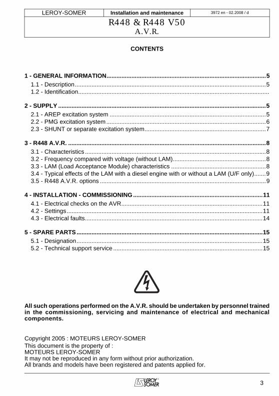
SAFETY MEASURES
Before using your machine for the first time,it is important to read the whole of thisinstallation and maintenance manual.
All necessary operations and interventionson this machine must be performed by aqualified technician.
Our technical support service will bepleased to provide any additional infor-mation you may require.
The various operations described in thismanual are accompanied by recommen-dations or symbols to alert the user topotential risks of accidents. It is vital thatyou understand and take notice of thefollowing warning symbols.
Warning symbol for an operationcapable of damaging or destroying themachine or surround-ing equipment.
Warning symbol for general danger topersonnel.
Warning symbol for electrical danger topersonnel.
Note: LEROY-SOMER reserves the right tomodify the characteristics of its products atany time in order to incorporate the latesttechnological developments. The informationcontained in this document may therefore bechanged without notice.
WARNINGWARNING
This manual concerns the alternator A.V.R. which you have just purchased.
We wish to draw your attention to the contents of this maintenance manual. Byfollowing certain important points during installation, use and servicing of your A.V.R.,you can look forward to many years of trouble-free operation.
Installation and maintenance
R448 & R448 V50A.V.R.
3972 en - 02.2008 / dLEROY-SOMER
3
CONTENTS
1 - GENERAL INFORMATION................................................................................................51.1 - Description...................................................................................................................51.2 - Identification...................................................................................................................
2 - SUPPLY .............................................................................................................................52.1 - AREP excitation system ..............................................................................................52.2 - PMG excitation system................................................................................................62.3 - SHUNT or separate excitation system.........................................................................7
3 - R448 A.V.R. .......................................................................................................................83.1 - Characteristics .............................................................................................................83.2 - Frequency compared with voltage (without LAM)........................................................83.3 - LAM (Load Acceptance Module) characteristics .........................................................83.4 - Typical effects of the LAM with a diesel engine with or without a LAM (U/F only).......93.5 - R448 A.V.R. options ....................................................................................................9
4 - INSTALLATION - COMMISSIONING..............................................................................114.1 - Electrical checks on the AVR.....................................................................................114.2 - Settings......................................................................................................................114.3 - Electrical faults...........................................................................................................14
5 - SPARE PARTS................................................................................................................155.1 - Designation................................................................................................................155.2 - Technical support service ..........................................................................................15
All such operations performed on the A.V.R. should be undertaken by personnel trainedin the commissioning, servicing and maintenance of electrical and mechanicalcomponents.
Copyright 2005 : MOTEURS LEROY-SOMERThis document is the property of :MOTEURS LEROY-SOMERIt may not be reproduced in any form without prior authorization. All brands and models have been registered and patents applied for.
Installation and maintenance
R448 & R448 V50A.V.R.
4
3972 en - 02.2008 / dLEROY-SOMER
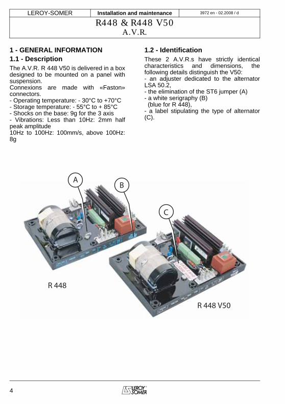
1 - GENERAL INFORMATION1.1 - DescriptionThe A.V.R. R 448 V50 is delivered in a boxdesigned to be mounted on a panel withsuspension.Connexions are made with «Faston»connectors.- Operating temperature: - 30°C to +70°C- Storage temperature: - 55°C to + 85°C- Shocks on the base: 9g for the 3 axis- Vibrations: Less than 10Hz: 2mm halfpeak amplitude10Hz to 100Hz: 100mm/s, above 100Hz:8g
1.2 - IdentificationThese 2 A.V.R.s have strictly identicalcharacteristics and dimensions, thefollowing details distinguish the V50:- an adjuster dedicated to the alternatorLSA 50.2,- the elimination of the ST6 jumper (A)- a white serigraphy (B) (blue for R 448),- a label stipulating the type of alternator(C).
A
R 448
R 448 V50
B
C

Installation and maintenance
R448 & R448 V50A.V.R.
3972 en - 02.2008 / dLEROY-SOMER
5
2 - SUPPLY2.1 - AREP excitation system For both AREP & PMG excitation systems,the alternator voltage regulator is the R448.With AREP excitation, the R 448 electronicAVR is powered by two auxiliary windingswhich are independent of the voltagematch circuit.
The first winding has a voltage in proportionto that of the alternator (characteristicShunt), the second has a voltage inproportion to the stator current (compoundcharacteristic: Booster effect).The power supply voltage is rectified andfiltered before being used by the AVRmonitoring transistor.
X2 X1 Z2 E+ E- 0V 110 220 380Z1
T1 T2 T3
T4 T5 T6
Varisto
r
5+ 6-
T7 T8 T9
T10 T11 T12
R 448
F1
ST5
P5
ST11
ST2
P3
AREP SYSTEM
Field
Armature
MAIN FIELD
Slow fuse 250V 10 A
with LAM without LAM
Excitation
ceiling
knee-point: 65 Hz
open
Response
time
normal
fast
Stability
according voltage
10 Yellow
11 Red
9 Green
12 Black
Aux. windings
STATOR : 6 wires (marked T1 to T6)
STATOR : 12 wires (marked T1 to T12)
ST6 ST146.2/47.2
49.1
P2No ST6 jumperfor R448 V50
4 x holes Ø 5.8
(175 x 115 mm)
200 m
m
140 mm
R731
Option
ST4 Option
T.I.
Option
S1P1
Ph.1
P2S2
Voltage
Single-phase
detection
External potentiometer
for adjusting the voltage
in 3-ph. detection ST1 open
3-ph. detection
ST9AREP/SHUNT
PMG
ST350Hz 60Hz
ST1013 % LAM 25 %
P1
Frequency
Quaddroop
Installation and maintenance
R448 & R448 V50A.V.R.
6
3972 en - 02.2008 / dLEROY-SOMER
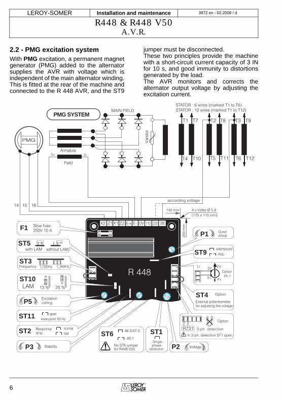
2.2 - PMG excitation systemWith PMG excitation, a permanent magnetgenerator (PMG) added to the alternatorsupplies the AVR with voltage which isindependent of the main alternator winding.This is fitted at the rear of the machine andconnected to the R 448 AVR, and the ST9
jumper must be disconnected.These two principles provide the machinewith a short-circuit current capacity of 3 INfor 10 s, and good immunity to distortionsgenerated by the load.The AVR monitors and corrects thealternator output voltage by adjusting theexcitation current.
ST6 ST146.2/47.2
49.1
P2No ST6 jumperfor R448 V50
4 x holes Ø 5.8
(175 x 115 mm)
200 m
m
140 mm
X2 X1 Z2 E+ E- 0V 110 220 380Z1
T1 T2 T3
T4 T5 T6
Varisto
r
5+ 6-
T7 T8 T9
T10 T11 T12
R 448
F1
ST5
P5
ST11
ST2
P3
R731
Option
ST4 Option
T.I.
Option
S1P1
Ph.1
P2S2
14 15 16
PMG
PMG SYSTEM
Field
Armature
MAIN FIELD
Slow fuse 250V 10 A
with LAM without LAM
Excitation
ceiling
knee-point: 65 Hz
open
Response
time
normal
fast
Stability Voltage
Single-phase
detection
External potentiometer
for adjusting the voltage
according voltage
STATOR : 6 wires (marked T1 to T6)
STATOR : 12 wires (marked T1 to T12)
in 3-ph. detection ST1 open
3-ph. detection
ST9AREP/SHUNT
PMG
ST350Hz 60Hz
ST1013 % LAM 25 %
P1
Frequency
Quaddroop
Installation and maintenance
R448 & R448 V50A.V.R.
3972 en - 02.2008 / dLEROY-SOMER
7
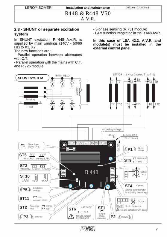
2.3 - SHUNT or separate excitation systemIn SHUNT excitation, R 448 A.V.R. issupplied by main windings (140V - 50/60Hz) to X1, X2.The new functions are :- Parallel operation between alternatorswith C.T.- Parallel operation with the mains with C.T.and R 726 module
- 3-phase sensing (R 731 module)- LAM function integrated in the R 448 AVR.
In this case of LSA 42.2, A.V.R. andmodule(s) must be installed in theexternal control panel.
X2 X1 Z2 E+ E- 0V 110 220 380Z1
T1 T2 T3
T4 T5 T6
Varisto
r
5+ 6-
T7T8
T9
T10 T11 T12
R 448
F1
ST5
P5
ST11
ST2
P3
STATOR : 12 wires (marked T1 to T12)
SHUNT SYSTEM
Field
Armature
MAIN FIELD
Slow fuse 250V 10 A
with LAM without LAM
Excitation
ceiling
knee-point: 65 Hz
open
Response
time
normal
fast
Stability
according voltage
ST6 ST146.2/47.2
49.1
P2No ST6 jumperfor R448 V50
4 x holes Ø 5.8
(175 x 115 mm)
200 m
m
140 mm
R731
Option
ST4 Option
T.I.
Option
S1P1
Ph.1
P2S2
Voltage
Single-phase
detection
External potentiometer
for adjusting the voltage
in 3-ph. detection ST1 open
3-ph. detection
ST9AREP/SHUNT
PMG
ST350Hz 60Hz
ST1013 % LAM 25 %
P1
Frequency
Quaddroop
Installation and maintenance
R448 & R448 V50A.V.R.
8
3972 en - 02.2008 / dLEROY-SOMER
3 - R448 A.V.R. 3.1 - Characteristics - Shunt power supply: max 150V - 50/60 Hz- Rated overload current: 10A - 10s- Electronic protection: (in the event ofoverload, short-circuit, loss of voltage sensing)this acts to restore the value of the excitationcurrent to 1A after 10 s. The alternator must bestopped (or the power switched off) in order toreset the protection.- Fuse: F1 on X1, X2. 10A ; slow - 250V - Voltage sensing : 5 VA isolated via trans-former • 0-110 V terminals = 95 to 140 V • 0-220 V terminals = 170 to 260 V • 0-380 V terminals = 340 to 520 Vfor other voltages, a transformer should beused.- Voltage regulation ± 0.5%- Normal or rapid response time via jumperST2 (see below)- Voltage adjustment via potentiometer P2 orapply a DC voltage of ± 1 V on the terminals ofthe external potentiometer- Current sensing: (parallel operation): inputS1, S2 intended for 1 C.T. Š 2.5 VA cl1,secondary 1A (optional)- Quadrature droop adjustment via potentio-meter P1- Max. excitation current adjustment via P5:4.5 to 10A (see below)- 50/60 Hz selection via ST3 jumper- ST11: Knee-point at 65 Hz for Tractelecapplication and variable speed.
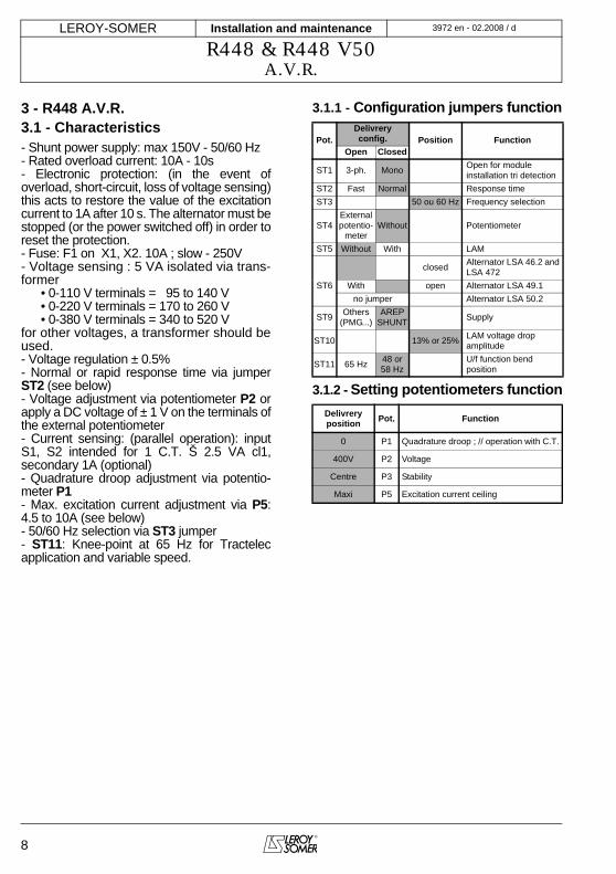
3.1.1 - Configuration jumpers function
3.1.2 - Setting potentiometers function
Pot.Delivreryconfig. Position Function
Open Closed
ST1 3-ph. Mono Open for moduleinstallation tri detection
ST2 Fast Normal Response timeST3 50 ou 60 Hz Frequency selection
ST4Externalpotentio-
meterWithout Potentiometer
ST5 Without With LAM
closed Alternator LSA 46.2 and LSA 472
ST6 With open Alternator LSA 49.1no jumper Alternator LSA 50.2
ST9 Others (PMG...)
AREPSHUNT Supply
ST10 13% or 25% LAM voltage dropamplitude
ST11 65 Hz 48 or 58 Hz
U/f function bendposition
Delivreryposition Pot. Function
0 P1 Quadrature droop ; // operation with C.T.
400V P2 Voltage
Centre P3 Stability
Maxi P5 Excitation current ceiling
Installation and maintenance
R448 & R448 V50A.V.R.
3972 en - 02.2008 / dLEROY-SOMER
9
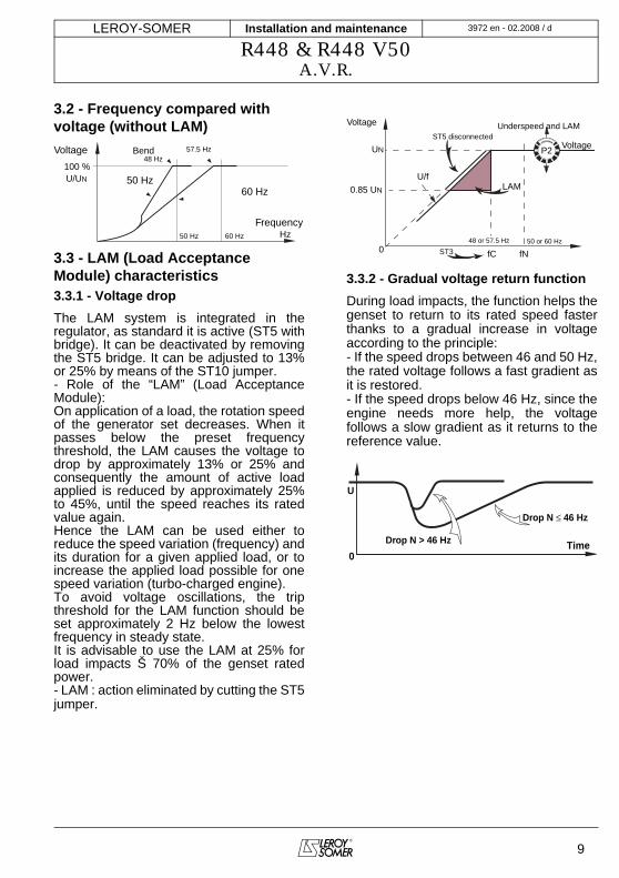
3.2 - Frequency compared with voltage (without LAM)
3.3 - LAM (Load Acceptance Module) characteristics 3.3.1 - Voltage dropThe LAM system is integrated in theregulator, as standard it is active (ST5 withbridge). It can be deactivated by removingthe ST5 bridge. It can be adjusted to 13%or 25% by means of the ST10 jumper.- Role of the “LAM” (Load AcceptanceModule):On application of a load, the rotation speedof the generator set decreases. When itpasses below the preset frequencythreshold, the LAM causes the voltage todrop by approximately 13% or 25% andconsequently the amount of active loadapplied is reduced by approximately 25%to 45%, until the speed reaches its ratedvalue again.Hence the LAM can be used either toreduce the speed variation (frequency) andits duration for a given applied load, or toincrease the applied load possible for onespeed variation (turbo-charged engine).To avoid voltage oscillations, the tripthreshold for the LAM function should beset approximately 2 Hz below the lowestfrequency in steady state.It is advisable to use the LAM at 25% forload impacts Š 70% of the genset ratedpower.- LAM : action eliminated by cutting the ST5jumper.
3.3.2 - Gradual voltage return functionDuring load impacts, the function helps thegenset to return to its rated speed fasterthanks to a gradual increase in voltageaccording to the principle:- If the speed drops between 46 and 50 Hz,the rated voltage follows a fast gradient asit is restored.- If the speed drops below 46 Hz, since theengine needs more help, the voltagefollows a slow gradient as it returns to thereference value.
100 %
50 Hz 60 Hz Hz
50 Hz
48 Hz57.5 Hz
60 Hz
Voltage Bend
U/UN
Frequency
LAM
UN
048 or 57.5 Hz
0.85 UN
Voltage
U/f
50 or 60 Hz
fC fN
VoltageST5 disconnected
ST3
P2
Underspeed and LAM
0Time
Drop N ≤ 46 Hz
U
Drop N > 46 Hz
Installation and maintenance
R448 & R448 V50A.V.R.
10
3972 en - 02.2008 / dLEROY-SOMER
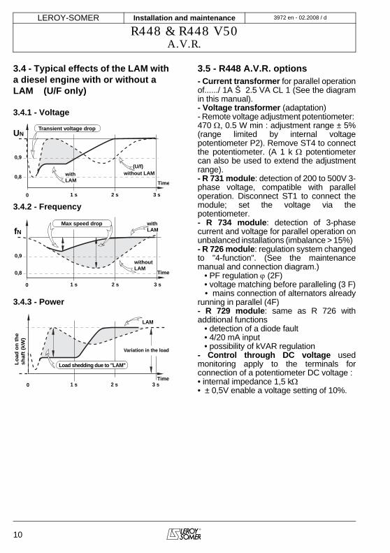
3.4 - Typical effects of the LAM with a diesel engine with or without a LAM (U/F only)
3.4.1 - Voltage
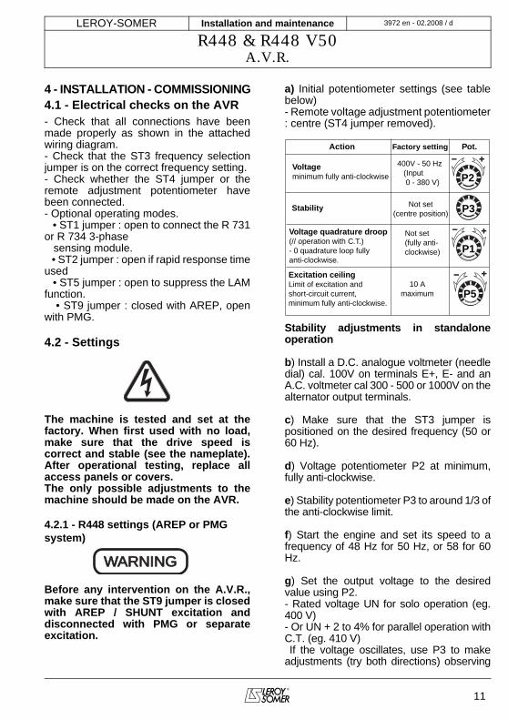
3.4.2 - Frequency
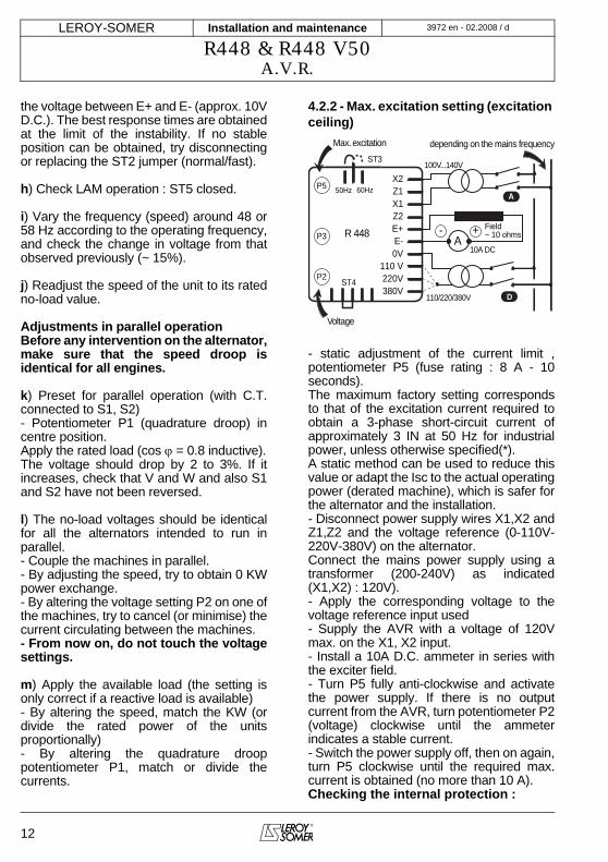
3.4.3 - Power
3.5 - R448 A.V.R. options- Current transformer for parallel operationof....../ 1A Š 2.5 VA CL 1 (See the diagramin this manual).- Voltage transformer (adaptation)- Remote voltage adjustment potentiometer: 470 Ω, 0.5 W min : adjustment range ± 5%(range limited by internal voltagepotentiometer P2). Remove ST4 to connectthe potentiometer. (A 1 k Ω potentiometercan also be used to extend the adjustmentrange).- R 731 module: detection of 200 to 500V 3-phase voltage, compatible with paralleloperation. Disconnect ST1 to connect themodule; set the voltage via thepotentiometer.- R 734 module: detection of 3-phasecurrent and voltage for parallel operation onunbalanced installations (imbalance > 15%) - R 726 module: regulation system changedto "4-function". (See the maintenancemanual and connection diagram.) • PF regulation ϕ (2F) • voltage matching before paralleling (3 F) • mains connection of alternators alreadyrunning in parallel (4F)- R 729 module: same as R 726 withadditional functions • detection of a diode fault • 4/20 mA input • possibility of kVAR regulation- Control through DC voltage usedmonitoring apply to the terminals forconnection of a potentiometer DC voltage :• internal impedance 1,5 kΩ• ± 0,5V enable a voltage setting of 10%.
UN
0
0,9
0,8
(U/f)
with LAM Time
without LAM
1 s 2 s 3 s
Transient voltage drop
0,9
0,8
fN Max speed drop
0
with LAM
Time
without LAM
1 s 2 s 3 s
0 1 s 2 s 3 sTime
LAM
Variation in the load
Lo
ad o
n t
he
shaf
t (k
W)
Load shedding due to "LAM"
Installation and maintenance
R448 & R448 V50A.V.R.
3972 en - 02.2008 / dLEROY-SOMER
11
4 - INSTALLATION - COMMISSIONING4.1 - Electrical checks on the AVR- Check that all connections have beenmade properly as shown in the attachedwiring diagram.- Check that the ST3 frequency selectionjumper is on the correct frequency setting.- Check whether the ST4 jumper or theremote adjustment potentiometer havebeen connected.- Optional operating modes. • ST1 jumper : open to connect the R 731or R 734 3-phase sensing module. • ST2 jumper : open if rapid response timeused • ST5 jumper : open to suppress the LAMfunction. • ST9 jumper : closed with AREP, openwith PMG.
4.2 - Settings
The machine is tested and set at thefactory. When first used with no load,make sure that the drive speed iscorrect and stable (see the nameplate).After operational testing, replace allaccess panels or covers.The only possible adjustments to themachine should be made on the AVR.
4.2.1 - R448 settings (AREP or PMG system)
Before any intervention on the A.V.R.,make sure that the ST9 jumper is closedwith AREP / SHUNT excitation anddisconnected with PMG or separateexcitation.
a) Initial potentiometer settings (see tablebelow)- Remote voltage adjustment potentiometer: centre (ST4 jumper removed).
Stability adjustments in standaloneoperation
b) Install a D.C. analogue voltmeter (needledial) cal. 100V on terminals E+, E- and anA.C. voltmeter cal 300 - 500 or 1000V on thealternator output terminals.
c) Make sure that the ST3 jumper ispositioned on the desired frequency (50 or60 Hz).
d) Voltage potentiometer P2 at minimum,fully anti-clockwise.
e) Stability potentiometer P3 to around 1/3 ofthe anti-clockwise limit.
f) Start the engine and set its speed to afrequency of 48 Hz for 50 Hz, or 58 for 60Hz.
g) Set the output voltage to the desiredvalue using P2.- Rated voltage UN for solo operation (eg.400 V)- Or UN + 2 to 4% for parallel operation withC.T. (eg. 410 V) If the voltage oscillates, use P3 to makeadjustments (try both directions) observing
WARNINGWARNING
P2
P3
P1
P5 10 A
maximum
400V - 50 Hz (Input 0 - 380 V)
Not set(centre position)
Not set(fully anti-clockwise)
Excitation ceilingLimit of excitation andshort-circuit current, minimum fully anti-clockwise.
Voltage quadrature droop(// operation with C.T.)- 0 quadrature loop fullyanti-clockwise.
Voltageminimum fully anti-clockwise
Stability
Action Factory setting Pot.
Installation and maintenance
R448 & R448 V50A.V.R.
12
3972 en - 02.2008 / dLEROY-SOMER
the voltage between E+ and E- (approx. 10VD.C.). The best response times are obtainedat the limit of the instability. If no stableposition can be obtained, try disconnectingor replacing the ST2 jumper (normal/fast).
h) Check LAM operation : ST5 closed.
i) Vary the frequency (speed) around 48 or58 Hz according to the operating frequency,and check the change in voltage from thatobserved previously (~ 15%).
j) Readjust the speed of the unit to its ratedno-load value.
Adjustments in parallel operationBefore any intervention on the alternator,make sure that the speed droop isidentical for all engines.
k) Preset for parallel operation (with C.T.connected to S1, S2)- Potentiometer P1 (quadrature droop) incentre position.Apply the rated load (cos ϕ = 0.8 inductive).The voltage should drop by 2 to 3%. If itincreases, check that V and W and also S1and S2 have not been reversed.
l) The no-load voltages should be identicalfor all the alternators intended to run inparallel.- Couple the machines in parallel.- By adjusting the speed, try to obtain 0 KWpower exchange.- By altering the voltage setting P2 on one ofthe machines, try to cancel (or minimise) thecurrent circulating between the machines.- From now on, do not touch the voltagesettings.
m) Apply the available load (the setting isonly correct if a reactive load is available)- By altering the speed, match the KW (ordivide the rated power of the unitsproportionally)- By altering the quadrature drooppotentiometer P1, match or divide thecurrents.
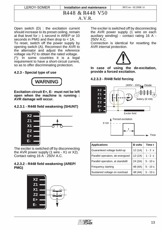
4.2.2 - Max. excitation setting (excitation ceiling)
- static adjustment of the current limit ,potentiometer P5 (fuse rating : 8 A - 10seconds).The maximum factory setting correspondsto that of the excitation current required toobtain a 3-phase short-circuit current ofapproximately 3 IN at 50 Hz for industrialpower, unless otherwise specified(*).A static method can be used to reduce thisvalue or adapt the Isc to the actual operatingpower (derated machine), which is safer forthe alternator and the installation. - Disconnect power supply wires X1,X2 andZ1,Z2 and the voltage reference (0-110V-220V-380V) on the alternator.Connect the mains power supply using atransformer (200-240V) as indicated(X1,X2) : 120V). - Apply the corresponding voltage to thevoltage reference input used- Supply the AVR with a voltage of 120Vmax. on the X1, X2 input.- Install a 10A D.C. ammeter in series withthe exciter field. - Turn P5 fully anti-clockwise and activatethe power supply. If there is no outputcurrent from the AVR, turn potentiometer P2(voltage) clockwise until the ammeterindicates a stable current.- Switch the power supply off, then on again,turn P5 clockwise until the required max.current is obtained (no more than 10 A).Checking the internal protection :
depending on the mains frequencyMax. excitation
Voltage
Field~ 10 ohms
X2Z1X1Z2E+E-0V
110 V220V380V
50Hz 60Hz
P2
P3
P5
ST3
10A DC
100V...140V
110/220/380V
R 448
ST4
A+-
A
D
Installation and maintenance
R448 & R448 V50A.V.R.
3972 en - 02.2008 / dLEROY-SOMER
13
Open switch (D) : the excitation currentshould increase to its preset ceiling, remainat that level for ≥ 1 second in AREP or 10seconds in PMG and then drop to < 1A.To reset, switch off the power supply byopening switch (A). Reconnect the AVR tothe alternator and adjust the referencevoltage via P2 to obtain the rated voltage.(*): In some countries it is a legalrequirement to have a short-circuit current,so as to offer discriminating protection.
4.2.3 - Special type of use
Excitation circuit E+, E- must not be leftopen when the machine is running :AVR damage will occur.
4.2.3.1 - R448 field weakening (SHUNT)
The exciter is switched off by disconnectingthe AVR power supply (1 wire - X1 or X2).Contact rating 16 A - 250V A.C.
4.2.3.2 - R448 field weakening (AREP/PMG)
The exciter is switched off by disconnectingthe AVR power supply (1 wire on eachauxiliary winding) - contact rating 16 A -250V A.C.Connection is identical for resetting theAVR internal protection.
In case of using the de-excitation,provide a forced excitation.
4.2.3.3 - R448 field forcing WARNINGWARNING
X2Z1X1Z2E+E-
X2Z1X1Z2E+E-
Applications B volts Time t
Guaranteed voltage build-up 12 (1A) 1 - 2 s
Parallel operation, de-energized 12 (1A) 1 - 2 s
Parallel operation, at standstill 24 (2A) 5 - 10 s
Frequency starting 48 (4A) 5 - 10 s
Sustained voltage on overload 48 (4A) 5 - 10 s
X2Z1X1Z2E+E-
Battery (B Volt)
+-t
(400V - 10A)
Exciter field
Diode
t
B Volt
Forced excitation
Time

Installation and maintenance
R448 & R448 V50A.V.R.
14
3972 en - 02.2008 / dLEROY-SOMER
4.3 - Electrical faults
Warning : after operational testing,replace all access panels or covers.
Fault Action Effect Check/Cause
No voltage at no load on start-up
Connect a new battery of 4 to 12 volts to terminals E- and E+, respecting the polarity, for 2 to 3 seconds
The alternator builds up and its voltage is still correct when the battery is removed.
- Lack of residual magnetism
The alternator builds up but its voltage does not reach the rated value when the battery is removed.
- Check the connection of the voltage reference to the AVR- Faulty diodes- Armature short-circuit
The alternator builds up but its voltage disappears when the battery is removed
- Faulty AVR- Field windings disconnected- Main field winding open circuit - check the resistance
Voltage too low Check the drive speedCorrect speed
Check the AVR connections (AVR may be faulty)- Field windings short-circuited- Rotating diodes burnt out- Main field winding short-circuited - Check the resistance
Speed too lowIncrease the drive speed(Do not touch the AVR voltage pot. (P2) before running at the correct speed.)
Voltage too high
Adjust AVR voltage potentiometer
Adjustment ineffective Faulty AVR
Voltage oscillations
Adjust AVR stability potentiometer
If no effect : try normal / fast recovery modes (ST2)
- Check the speed : possibility of cyclic irregularity - Loose connections- Faulty AVR- Speed too low when on load (or U/F bend set too high)
Voltage correctat no load and too low when on load (*)
Run at no load and check the voltage between E+ and E- on the AVR
Voltage between E+ and E- SHUNT < 20 V - AREP / PMG < 10V - Check the speed (or U/F bend set too high)
Voltage between E+ and E- SHUNT > 30V - AREP / PMG > 15V
- Faulty rotating diodes- Short-circuit in the main field. Check the resistance- Faulty exciter armature.
(*) Caution : For single-phase operation, check that the sensing wires coming from the AVR are correctly connected to the operating terminalsVoltage disappears during operation (**)
Check the AVR, the surge suppressor, the rotating diodes, and replace any defective components
The voltage does not return to the rated value.
- Exciter winding open circuit- Faulty exciter armature- Faulty AVR- Main field open circuit or short-circuited
(**) Caution : Internal protection may be activated (overload, open circuit, short-circuit)
Installation and maintenance
R448 & R448 V50A.V.R.
3972 en - 02.2008 / dLEROY-SOMER
15
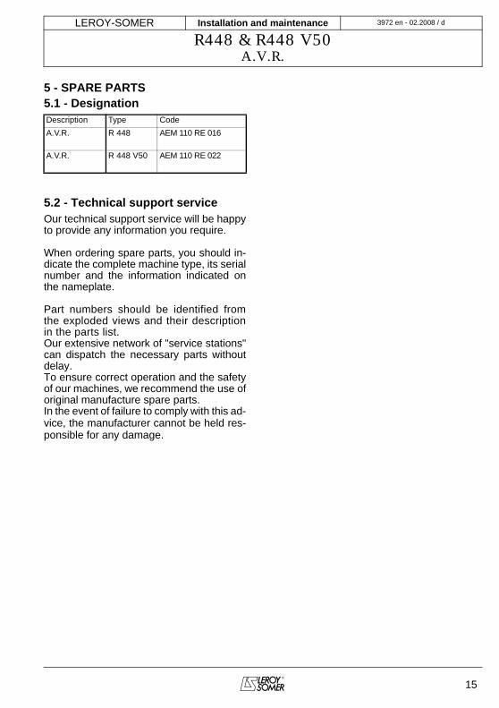
5 - SPARE PARTS5.1 - Designation
5.2 - Technical support serviceOur technical support service will be happyto provide any information you require.
When ordering spare parts, you should in-dicate the complete machine type, its serialnumber and the information indicated onthe nameplate.
Part numbers should be identified fromthe exploded views and their descriptionin the parts list.Our extensive network of "service stations"can dispatch the necessary parts withoutdelay.To ensure correct operation and the safetyof our machines, we recommend the use oforiginal manufacture spare parts.In the event of failure to comply with this ad-vice, the manufacturer cannot be held res-ponsible for any damage.
Description Type CodeA.V.R. R 448 AEM 110 RE 016
A.V.R. R 448 V50 AEM 110 RE 022

MOTEURS LEROY-SOMER 16015 ANGOULÊME CEDEX -
FRANCE
338 567 258 RCS ANGOULÊMES.A. au capital de 62 779 000 euro
Related Documents