Avoiding Collisions Between Aircraft: State of the Art and Requirements for UAVs operating in Civilian Airspace Christopher Geyer, Sanjiv Singh, Lyle Chamberlain CMU-RI-TR-08-03 January 2008 Robotics Institute Carnegie Mellon University Pittsburgh, Pennsylvania 15213 ©Carnegie Mellon University

Welcome message from author
This document is posted to help you gain knowledge. Please leave a comment to let me know what you think about it! Share it to your friends and learn new things together.
Transcript
Avoiding Collisions Between Aircraft:
State of the Art and Requirements for UAVs
operating in Civilian Airspace
Christopher Geyer, Sanjiv Singh, Lyle Chamberlain
CMU-RI-TR-08-03
January 2008
Robotics Institute
Carnegie Mellon University
Pittsburgh, Pennsylvania 15213
©Carnegie Mellon University
Abstract: In this paper we consider the ability of Unmanned Aerial Vehicles (UAVs) to operate safely in civilian airspace. This ability is increasingly important as UAVs proliferate and their usage spreads to non-military applications. According to regulatory requirements by the FAA and others this capability must demonstrate a level of performance that meets or exceeds that of an equivalent human pilot without the use of cooperative communication with other aircraft or prior knowledge of the flight plans. We survey the state of the art in systems, sensors and algorithms that have been investigated for use in ‘Sense and Avoid’ applications and then examine both basic and derived requirements for systems suited for deployment on small UAVs.

Contents
1 Introduction 2
2 Summary of Findings 22.1 Technical Findings . . . . . . . . . . . . . . . . . . . . . . . . . . . . . . .. . . . . . . . . . . . . 2
3 State of the Art 43.1 Current Safety of Manned National Air Space . . . . . . . . . . .. . . . . . . . . . . . . . . . . . . 43.2 Efforts to Mitigate MACs: TCAS and MASS . . . . . . . . . . . . . . .. . . . . . . . . . . . . . . 53.3 Systems Analyses of the Collision Avoidance Problem . . .. . . . . . . . . . . . . . . . . . . . . . 53.4 Sensors Used in Collision Avoidance Systems . . . . . . . . . .. . . . . . . . . . . . . . . . . . . . 5
3.4.1 Electro-Optics . . . . . . . . . . . . . . . . . . . . . . . . . . . . . . . .. . . . . . . . . . 53.4.2 Infrared . . . . . . . . . . . . . . . . . . . . . . . . . . . . . . . . . . . . . .. . . . . . . . 63.4.3 Acoustic . . . . . . . . . . . . . . . . . . . . . . . . . . . . . . . . . . . . . .. . . . . . . 63.4.4 Lidar . . . . . . . . . . . . . . . . . . . . . . . . . . . . . . . . . . . . . . . . .. . . . . . 63.4.5 Radar . . . . . . . . . . . . . . . . . . . . . . . . . . . . . . . . . . . . . . . . .. . . . . . 6
3.5 Controllers Used for Collision Avoidance . . . . . . . . . . . .. . . . . . . . . . . . . . . . . . . . 7
4 Basic Requirements for Collision Avoidance 84.1 User Requirements . . . . . . . . . . . . . . . . . . . . . . . . . . . . . . . .. . . . . . . . . . . . 84.2 Hypothetical See and Avoid Time-line . . . . . . . . . . . . . . . .. . . . . . . . . . . . . . . . . . 9
5 Derived Requirements 115.1 The Minimum Time Required for an Evasive Maneuver . . . . . .. . . . . . . . . . . . . . . . . . . 115.2 Revisit and Staring Periods of a Scanning Sensor . . . . . . .. . . . . . . . . . . . . . . . . . . . . 125.3 Observation: Size vs. Speed Trends . . . . . . . . . . . . . . . . . .. . . . . . . . . . . . . . . . . 135.4 Minimum Detection Arc-width . . . . . . . . . . . . . . . . . . . . . . .. . . . . . . . . . . . . . . 14
A Derivations and Background Material 16A.1 The Minimum Time Required for an Evasive Maneuver . . . . . .. . . . . . . . . . . . . . . . . . . 16A.2 Image Cross Section of a Prototypical GA Aircraft . . . . . .. . . . . . . . . . . . . . . . . . . . . 16
1

1 Introduction
Here we consider the ability of UAVs to operate safely in civilian airspace. This ability is increasingly importantas UAVs proliferate and their usage spreads to non-militaryapplications. “Sense and avoid” and “See and Avoid”are terms used to describe the capability of a UAV to detect airborne traffic and respond with appropriate avoidancemaneuvers in order to maintain minimum separation distances. As reflected in regulatory requirements [1, 2, 3], thiscapability must demonstrate a level of performance that meets or exceeds that of an equivalent human pilot without theuse of cooperative communication with other aircraft or prior knowledge of the flight plans. It is generally understoodthat the widespread usage of UAVs will not be possible unlessthis capability is available.
According to Schaeffer et al. [4], in the U.S. there are approximately 0.5 midair collisions per 1 million flighthours. The majority of these occur near an airport within uncontrolled airspace. A UAV would have to be able toperform with at least this level of reliability. Another data point is that during continued operations in Iraq, there areover 700 UAV flights per day. There have already been several near-misses with UAVs and both the military andcommercial aviation have called for a system that can automatically avoid mid-air collisions [5].
This document surveys the state of the art in systems, sensors and algorithms that have been investigated for use inSee & Avoid applications, and then examines requirements (both basic and derived) for systems suited for deploymenton small UAVs.
2 Summary of Findings
Below is a summary of the general and technical findings of thereport.
• The requirements for a UAV operating safely in civilian airspace have not been formally defined to date exceptto say that the capability must meet that of a human pilot.
• A general agreement is that all aircraft (manned and unmanned) are responsible for maintaining at least 500 ftclearance to any other aircraft in the vicinity without requiring that a cooperative system of communication ispossible between the two aircraft.
• The requirements for sensing other craft vary among variousparts of the UAV community in terms of the sizeof the target, the minimum range at which it must be detected and the environmental conditions in which it mustbe detected.
• Existing sensors that can reliably sense other non cooperative aircraft are not feasible for many UAVs becausetheir weight, size and power requirements exceed constraints for a small UAV by a large margin.
• Of the sensors available that do meet the weight, size and power requirement, none have been shown to bereliable at detecting targets within the specifications necessary. A viable system will likely need several modesof sensing to meet the reliability requirements (both for false positives and false negatives) while operating in awide range of environmental conditions.
2.1 Technical Findings
• The amount of time needed to perform an avoidance maneuver isindependent of the velocities of the vehiclesand depends only on the maximum banking angle of the aircraftperforming the maneuver.
• For most aircraft operating in NAS, as well as UAVs, the cruise speed is correlated with the size of the vehicle.Therefore, we show that smaller vehicles—which are harder to detect—need not be detected at ranges currentlyspecified in order to safely avoid them.
• If someday aircraft exceed current size vs. speed trends, i.e. an extremely fast and small general aviation vehicleis developed, we would expect themanned collision avoidance capability of the current NAS “system”to beless safe than it currently is.
2
• We found that for a typical GA aircraft, the maximum variation of its image cross section (the proportion of thenumber of pixels in its silhouette as a function of its relative heading) from the peak was40%.
• To maintain enough time to prevent a collision, a system operating in air traffic where aircraft speed does notfall below100 km/h (most medium-sized UAVs and GA aircraft) will need to beable to detect obstacles whichsubtend an arc-width of as small as0.125 mrad.
3

3 State of the Art
A complete see-and-avoid (SA) paradigm will require solutions in three main categories. First, a systems-level analysisprovides the requirements for all of the sub-components, aswell how they interact to achieve the SA task. Second, asensory system that is able to detect and correctly interpret dangerous situations. Finally, a control system must guidethe aircraft on a collision-free course. Before delving into these three main categories we consider the safety of thecurrent manned system, and also mention past efforts to improve safety for manned aircraft.
3.1 Current Safety of Manned National Air Space
Since the general principle is for UAVs to avoid other aircraft as well as human are able to achieve, it is worthconsidering the results of a study by the NTSB [6, 7, 8]. This study finds that:
• “Most of the aircraft involved in collisions are engaged in recreational flying, not on any type of flight plan.”
• “Most mid-air collisions occur in VFR weather conditions during weekend daylight hours.”
• “The vast majority of accidents occurred at or near uncontrolled airports and at altitudes below 1000 feet.”
• “Pilots of all experience levels were involved in mid-air collisions, from pilots on their first solo ride, to 20,000-hour veterans.”
• “Flight instructors were on board the aircraft 37 percent ofthe accidents in the study.”
• “Most collisions occur in daylight with visibility greaterthan 3 miles.”
We believe that most of these are not the challenging cases for UAVs. Whereas human pilots can be easily be distracted,an automated sense-and-avoid system can be arbitrarily vigilant. It is the cases where human intelligence normallytakes over that are the hard cases; for example, the pilot knows that a distant object that looks like a an airplane is across on a hill.
Table 1 gives statistics on the number of mid-air collisionsin U.S. airspace between 1991 and 2002. On averagethere are 0.51 mid-air collisions per million hours of flight.
Table 1: Statistics on mid-air collisions in manned flight from 1991 to 2002. This table is from the ASTM F2411Standard Specification for Design and Performance of an Airborne Sense-and-Avoid System.
4
3.2 Efforts to Mitigate MACs: TCAS and MASS
Several fatal accidents between airliners prompted the U.S. Congress to mandate that a system be put in place toreduce the number of mid-air collisions (MACs) between aircraft. This system became known as Traffic CollisionAvoidance System (TCAS). Currently, in all aircraft over5, 700 kg, or capable of carrying more than19 passengers,it is mandated that they carry a TCAS transponder. The on-board transponder alerts other aircraft in range of itspresence, and provides position and heading information. General aviation aircraft under5, 700 kg are not required tohave TCAS devices. The Military Airborne Surveillance System (MASS) is the military counterpart to TCAS.
3.3 Systems Analyses of the Collision Avoidance Problem
First we consider our systems requirements. Duke et al. [9] give an outline of what core competencies would be neededby a human-equivalent system. Le Tallec [10] suggests a system that could leverage existing technology, where allaircraft monitor their own position and communicate cooperatively to build a complete situational awareness includingall nearby vehicles. Unfortunately, the human equivalencemandated by OSD [1] and Air Combat Command (ACC)[2] mean that the vehicles must be able to avoid a non-cooperative vehicle that may or may not have such systems onboard. In the U.S, the GA airspace has many airplanes that fit this category.
Schaeffer et al. [4] considers a standards-based approach to the quantifying the SA problem. They work on methodsof quantifying the idea of “equivalent level of safety” to human pilots found in documents specifying the requirementsof a collision avoidance system in general aviation airspace. They also describe a system known as MARCAT, whichgives a systematic technique for computing the minimum detection distances and reaction times for different scenarioswith an autonomous system, as well as a way to quantitativelycompare these requirements with human performance.The MARCAT system allows for a quantitative comparison of different SA paradigms in the context of equivalentperformance to human pilots, and will be invaluable in doingsystem design of our own SA system.
Suwal et al. [11] have worked on a systems-level design of a complete SA paradigm in simulation. It combinescooperative communication between aircraft with radar andmachine vision into a hardware-in-the-loop simulation.Although they have no flight experiments and don’t divulge data on the results, they do give many simulated flightscenarios that should be considered in a SA design. Defense Research Associates has implemented on a vision-basedS&A system on a Predator UAV system. This vision system (discussed below) can track targets using three high-resolution cameras and custom computer hardware [12].
3.4 Sensors Used in Collision Avoidance Systems
The second category is Sensing/Perception. Sensing involves the actual sensory device (such as a camera), whilePerception is the method of processing the provided by the sensors to identify threats. The systems can be passive(don’t emit energy), active (bounce energy off a target), ora hybrid combination of both.
3.4.1 Electro-Optics
Utt et al. [12] describe a fielded vision-based SA sensory andperception system. They demonstrate a system capable ofreal-time detection of a small aircraft (a Beechcraft Bonanza) approaching in different configurations, with sufficienttime to perform avoidance maneuvers (though they do not divulge the actual detection range). Using three cameras,they achieve high-resolution (about 0.5 milli-radians/pixel), while maintaining a large field of regard (about 90 degrees)on one side of the aircraft. An FPGA system identifies potential targets in real-time, and a high-level system tracksthese candidates and decides when one of them represents a threat. More in-depth tests using varied types of targetaircraft are ongoing. This technology has the benefit of having the potential for small-light implementation suitablefor smaller UAVs. A system based on this research is being implemented on a Predator UAV [13].
McCandless [14] proposes an optical flow method for detecting aircraft but this is suitable only for moving objectsand therefore is not useful for a target on collision course,which will not appear to be moving.
Gandhi [15] propose a two stage approach, an image processing stage followed by a tracking stage. The imageprocessing stage isolates potential features and the tracking stage tracks these features to distinguish the real targetsfrom background clutter. For detecting objects on a collision course morphological filtering is used in the image
5
processing stage and the rate of translation and expansion in the tracking stage. For detecting crossing objects a seriesof filters is applied to the image followed by a tracking algorithm based on Kalman filter.
Carnie et al. [16] implemented a similar approach using morphological filtering followed by a dynamic program-ming algorithm to enhance detection. The use of morphological filtering is popular on computer vision based collisionavoidance systems [15], [16]. However, this approach generates a significant number of false positives and requirestracking of the features over a large number of frames. Corkereports that even after applying dynamic programmingapproach a significant number of false positives are present.
The Paravise Head-onTMby Foster Flight (www.fosterflight.com) is a pilot aid mounted to the interior of anaircraft that detects other aircraft that may be on a collision course. It uses three cameras and technology developed bythe Navy in the 70’s to perform the aircraft detection. No controlled studies have been published about the effectivenessof this device, but anecdotal evidence suggests that it can can detect Cessna 172-sized airplanes at1 statute mile.
3.4.2 Infrared
Soreide et al. [17] describe a hybrid system. They use an infrared camera system that relies on moving targets fordetection. Because the system cannot detect targets with low relative velocity (such as those one a head-on collisioncourse), they augment the passive system with an active laser rangefinder with a 3 milliradian beam-width and 2.2 Kmrange.
3.4.3 Acoustic
Scientific Applications & Research Associates (SARA), Inc.is developing a passive acoustic system for detectingaircraft called Passive Acoustic Non-cooperative Collision-Alert System (PANCAS). The system works by detectingthe noise emanated by aircraft. This system has the advantage that it works under a more difficult weather conditionsthan EO or IR systems can, as well as night conditions. Furthermore it can be made to be lightweight and its field-of-regard is wide. Though its bearing resolution is low, it can be used to cue other higher resolution sensors.
3.4.4 Lidar
An active sensor with time-of-flight or other ranging devicecould replace or supplement image-based sensing whererange is not generally observable. Advanced Scientific Concepts, Inc., based in Santa Barbara, CA, is developing asmall flash lidar system that weighs in at less than3.5lbs, has a small form factor of2.5” × 2.5” × 3”, and consumesless than30 watts—not counting an external laser. A flash lidar uses time-of-flight of a pulsed illuminating laser;individual time-of-flight calculations are performed in each pixel of an imager. In this case their imager is a128× 128array. Their prototypes have a range between10 and22, 000ft. Since the array is small, to achieve resolution targetsat the higher distances requires a narrow field of view. Therefore, to achieve coverage over a220◦ × 30◦ field-of-regard would require scanning the sensor and illuminator. Currently the cost is prohibitive—$200, 000 to create theirprototypes—but Advanced Scientific Concepts expects this cost to come down to$20, 000 in production.
3.4.5 Radar
Radar is the sensor of choice for long range collision avoidance on the ground such as used by trucks traveling at highspeeds on highways. Commercial systems such as developed byEaton Vorad are low-cost (approximately$1, 000)though have a maximum range of only500 ft. In general the problem with radar is that long range sensors require alot of power and localization of the beam requires a large antenna, neither of which are suitable for small UAVs.
Skolnik [18, 19] describes improvements being made to radarwith digital technologies that would eventuallyenable a small vehicle to get high-resolution radar images;however, nothing is currently ready for miniaturized im-plementation.
Amphitech has worked with the NASA ERAST program [20] to develop a new compact55 lb radar system isevaluated as a collision-avoidance tool. In tests with varying configurations with small uncooperative aircraft, theSkyWatch radar system was usually able to successfully detect threats at around4 or 5 nm, which for larger aircraftis adequate for closing speeds of around300 kt. They also reported numerous false alarms from ground reflections.Larger UAVs could use this technology to detect threats in all weather conditions, day and night.
6

3.5 Controllers Used for Collision Avoidance
The final category is control. Once a threat has been perceived, the UAV must be able to react and maneuver appropri-ately. In simple scenarios, moving to avoid a collision is relatively simple; however, in crowded airspace with multipleairplanes and/or obstacles, a good avoidance solution is more difficult to calculate.
In 2004, Frew et al. [21] provided a method for evaluating therelevance of different obstacles and measuringuncertainties; however, it is only theoretical and appliedto situations with only one obstacle. This idea is extended in[22, 23], which gives algorithms for quickly computing a collision-free path using a receding-horizon controller. Thismethod has two benefits: First, it explicitly takes into account the uncertainties in the perceived estimates of obstaclepositions. Second, it gives trajectories that will help to maximize information gain from the sensors and reduce theuncertainty. The technique has only been tested in 2-dimensional simulation, and would require significant work toapply on an actual flight system.
Shakernia et al. [24] at Northrup Grumman leverage the work of Utt et al. [12], and consider how to use maneuversto reduce the intrinsic uncertainty about range when using an image-based detector. They treat and use a resultthat states that the maneuver that decreases the uncertainty in the other vehicles position the most, is to accelerateperpendicular to the line-of-sight of the other vehicle.
Though this gives a good start, this approach has some assumptions which might not make it practical in general.It assumes that—or performs best when—the other vehicle does not changes its speed or heading. This may beproblematic because the other vehicle may start its own evasive maneuver in anticipation of a collision. Furthermore, ifa perturbation of the nominal flight path is required every time there is a possible collision threat, this could potentiallygreatly reduce the efficiency of the vehicle, depending on the frequency of false positives.
On a more immediately applicable side, a spline-generatingtechnique such as [25] could be used to generate akinematically feasible collision-free path. A separate controller would then guide the aircraft to follow this path. Thepath can be recomputed very quickly to account for new information gathered from the sensors. This approach hasthe benefit of low computation latency and ease of implementation; however, at times the trajectories could becomedynamically infeasible in extreme situations.
7
4 Basic Requirements for Collision Avoidance
Here we present some of the requirements from various sources, including the Highly Capable UAVs Payload PlanningDocument, as well as the ASTM F2411 standard on see & avoid technologies.
4.1 User Requirements
In July 2003, manufacturers, members of the Association forUnmanned Vehicle Systems International (AUVSI) andother interested parties voted to create through ASTM International (an international standards body) the InternationalCommittee F38 on UAS Systems. In 2004, this committee released standard F2411-04 which proposed requirementsfor sense-and-avoid systems. F2411 defined classes of S&A systems, as well as functional and non-functional require-ments for collision detection.
The F2411 standard also defines three classes of S&A systems based on their sense and avoid capabilities, andwhere and how they apply them:
Class 1 (Pilot-in-the-loop): A system that warns a remote operator of a potential collision with anothervehicle. The remote operator is responsible for evasive maneuvers.
Class 2 (Automated air): In addition to detecting threats, a Class 2 system initiatesa maneuver to avoid apotential mid-air collision or near mid-air collision autonomously.
Class 3 (Automated Air and Surface): Class 3 systems have the additional capability of detectingand avoid-ing collisions with vehicles while taxiing on the runway.
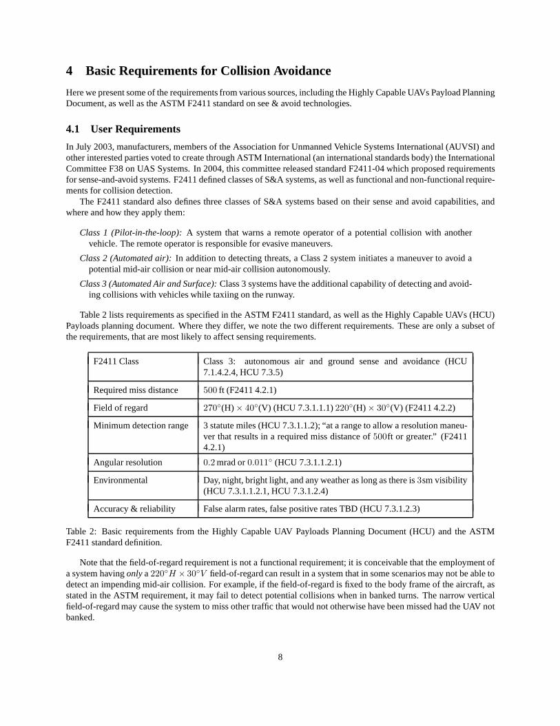
Table 2 lists requirements as specified in the ASTM F2411 standard, as well as the Highly Capable UAVs (HCU)Payloads planning document. Where they differ, we note the two different requirements. These are only a subset ofthe requirements, that are most likely to affect sensing requirements.
F2411 Class Class 3: autonomous air and ground sense and avoidance (HCU7.1.4.2.4, HCU 7.3.5)
Required miss distance 500 ft (F2411 4.2.1)
Field of regard 270◦(H) × 40◦(V) (HCU 7.3.1.1.1)220◦(H) × 30◦(V) (F2411 4.2.2)
Minimum detection range 3 statute miles (HCU 7.3.1.1.2); “at a range to allow a resolution maneu-ver that results in a required miss distance of500ft or greater.” (F24114.2.1)
Angular resolution 0.2 mrad or0.011◦ (HCU 7.3.1.1.2.1)
Environmental Day, night, bright light, and any weather as long as there is3sm visibility(HCU 7.3.1.1.2.1, HCU 7.3.1.2.4)
Accuracy & reliability False alarm rates, false positive rates TBD (HCU 7.3.1.2.3)
Table 2: Basic requirements from the Highly Capable UAV Payloads Planning Document (HCU) and the ASTMF2411 standard definition.
Note that the field-of-regard requirement is not a functional requirement; it is conceivable that the employment ofa system havingonly a220◦H × 30◦V field-of-regard can result in a system that in some scenariosmay not be able todetect an impending mid-air collision. For example, if the field-of-regard is fixed to the body frame of the aircraft, asstated in the ASTM requirement, it may fail to detect potential collisions when in banked turns. The narrow verticalfield-of-regard may cause the system to miss other traffic that would not otherwise have been missed had the UAV notbanked.
8
The affect of a field-of-regard requirement depends on the type of sensing mechanism chosen. For scanningsystems, this will affect the required scan rate, since the entire field-of-regard will need to be covered at some minimumrate. For non-scanning systems—those where the field-of-view equals the field-of-regard—the required minimumfield-of-regard will affect the total number of pixels (or other equivalent measure for other modalities) that are required,as well as the amount of computation that has to be done per second.
4.2 Hypothetical See and Avoid Time-line
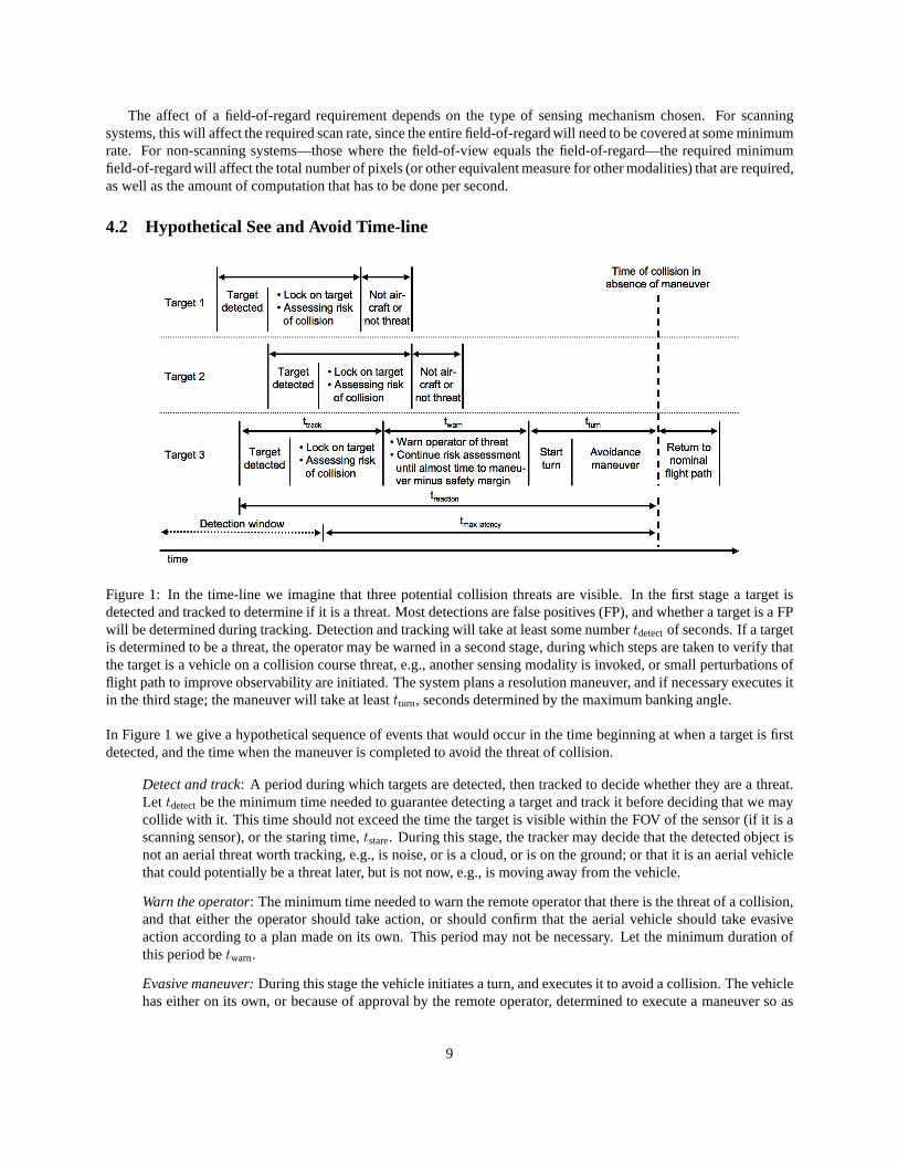
Figure 1: In the time-line we imagine that three potential collision threats are visible. In the first stage a target isdetected and tracked to determine if it is a threat. Most detections are false positives (FP), and whether a target is a FPwill be determined during tracking. Detection and trackingwill take at least some numbertdetectof seconds. If a targetis determined to be a threat, the operator may be warned in a second stage, during which steps are taken to verify thatthe target is a vehicle on a collision course threat, e.g., another sensing modality is invoked, or small perturbations offlight path to improve observability are initiated. The system plans a resolution maneuver, and if necessary executes itin the third stage; the maneuver will take at leasttturn, seconds determined by the maximum banking angle.
In Figure 1 we give a hypothetical sequence of events that would occur in the time beginning at when a target is firstdetected, and the time when the maneuver is completed to avoid the threat of collision.
Detect and track: A period during which targets are detected, then tracked todecide whether they are a threat.Let tdetectbe the minimum time needed to guarantee detecting a target and track it before deciding that we maycollide with it. This time should not exceed the time the target is visible within the FOV of the sensor (if it is ascanning sensor), or the staring time,tstare. During this stage, the tracker may decide that the detectedobject isnot an aerial threat worth tracking, e.g., is noise, or is a cloud, or is on the ground; or that it is an aerial vehiclethat could potentially be a threat later, but is not now, e.g., is moving away from the vehicle.
Warn the operator: The minimum time needed to warn the remote operator that there is the threat of a collision,and that either the operator should take action, or should confirm that the aerial vehicle should take evasiveaction according to a plan made on its own. This period may notbe necessary. Let the minimum duration ofthis period betwarn.
Evasive maneuver: During this stage the vehicle initiates a turn, and executesit to avoid a collision. The vehiclehas either on its own, or because of approval by the remote operator, determined to execute a maneuver so as
9
to avoid the possibility of colliding with another vehicle or threat. Lettturn be the time it takes to complete thelongest avoidance maneuver; see section5.1 to see how this depends on the banking angle.
This sequence of events is similar to the sequence proposed in the white paperSense and Avoid Requirement forRemotely Operated Aircraft [2].
According to this sequence of events, the total time of thesethree stages is
ttotal = tdetect+ twarn + tturn .
If tdetectseconds is the time required to guarantee detecting any target, and if every avoidance maneuver can be executedwithin tturn seconds, then in the worst case we need to be able to detect at leastttotal seconds in advance of a potentialMAC or NMAC.
10
5 Derived Requirements
The requirements below are derived from the basic requirements. We determine the minimum time require to performan evasive maneuver, which determines the distance at whichwe must detect another aircraft. We observe that speedof an aircraft is correlated with its size, and therefore canbe used as a lower bound on how small the target will lookat the distance we need to detect it at. This yields the smallest arc-width of an object that we need to be able to detectto avoid the aircraft, as a function of the minimum traffic speed.
5.1 The Minimum Time Required for an Evasive Maneuver
When a collision threat is detected, the vehicle will need toexecute an avoidance maneuver to avert a collision. Thevehicle’s range of speeds and maximum banking angle determine the avoidance maneuvers that can be executed. Herewe determine the minimum time needed to perform an avoidancemaneuver.
We assume a scenario1 in which the UAV is on a head-on collision course with anothernon-cooperative aircraftthat does not try to avert a collision, possibly because it does not see the UAV. In this case the UAV must take action onits own to avert a collision. To do this, it will need to begin the maneuver at leasttturn seconds before the collision, soas to avert a mid-air collision by at leastrmin = 166 m. We must know the velocity of the UAV (vUAV ), the velocity ofthe other vehicle (vother), which yields their sum, the closing speedvclosing = vUAV + vother. We assume that the aircraftmakes an instantaneous banking turn of bank angleφmax(v)—whose maximum value may depend on the velocity andconstraints on the vehicle. We approximate the maneuver by aTaylor series so that we easily approximate the closestdistance between the aircraft for a given banking angle, closing speed, and distance (dturn) between the aircraft at thestart of the maneuver. It turns out that for distances greater than500 m the time by which an action must be taken isroughly independent of the closing speed:
tturn =
√
2 rmin cotφmax
g≈ 5.6
√
π
2− φmax seconds.
This gives the minimum time needed to avert a collision by at least152.4 m as a function of maximum banking angle.The approximate distance between the two aircraft at the start of the maneuver is:
dturn = vclosingtturn ≈ 5.6 vclosing
√
π
2− φmax .
Both of tturn anddturn are also roughly independent of the ratio between the UAV’s and the other vehicle’s speeds.
Note 1. This is an approximation that is suitable for use as a heuristic for choosing the right sensor and its resolution.It does not give an exact formula for times and distances, andit is an approximation that is not suitable for smalldistances and velocities. Furthermore, it assumes that theother vehicle is non-cooperativebut not adversarial (seeking).
Note 2. The formula suggests that given a maximum banking angle of45◦, we would have just under6 seconds toavertany threat. This is a poor assumption for large threats (since their dimension will occupy a large or even greaterpart of the 500ft, and we do not take into account the other vehicle’s size). It also suggests that since we must detectevery target6 seconds in advance, we may not be able to avoid collisions with small targets which are undetectableat a distance6vclosing away. For example, a minimum passing distance of500 ft may be overly conservative for twosmall unmanned aerial vehicles. Rules for right-of-way should reflect these constraints, and requirements on passingdistances should be commensurate with velocities and vehicle sizes.
1This is not necessarily the worst-case scenario. It remainsto be determined what the actual worst worst-case scenario is. Crossing maneuverswhere the other vehicle has the right of way may be worse than ahead-on collision course with a non-cooperative aircraft,though detection may beeasier.
11

5.2 Revisit and Staring Periods of a Scanning Sensor
For sensors whose cumulative field-of-view (FOV) does not meet the necessary field-of-regard (FOR), it is necessaryto mechanically scan them. For cameras this may be achieved using a pan-tilt gimbal; for a lidar system this iscommonly done using an optical system with mirrors. The sensor will have to be scanned so as to cover the entireFOR. The scanning pattern might zig-zag, it might just spin in a circle; the details of the coverage pattern are not ofinterest to us. We are interested in two quantities: theaverage staring period, or the average duration for which atarget will be covered before it leaves the FOV, which needs to be at least as long as it takes the tracker to lock on to atarget; and second, theaverage revisit period or frequency, which gives the frequency with which a typical location inthe FOR is revisited. Note that during the “staring” period,the sensor may be moving; the point is that the object ofinterest is still within the FOV for some period of time that depends on the area of the FOV, and the rate at which thesensor is scanning.
We make the following assumptions about the sensor, FOV, andFOR:
• Let AFOR be the total area of the FOR in steradians, e.g. a proportion of the surface area of the unit sphere. IfA = 4π, then the FOR is the entire sphere. According to several suggested standards, the necessary FOR for asee and avoid system should be220◦(H) × 30◦(V), or about2
3π steradians.
• Let aFOV be the area of the FOV of the sensor. For a camera this would be the FOV of the camera; for a radarsystem, this would be the angular range of response at a giveninstant, which might be actuated by a mechanicalsystem, or varied in solid state using phased array radar.
At any one instant the coverage of the FOR isaFOV/AFOR. At this point we assume that the sensor has highenough resolution within its FOV to perform detection at theright combinations of target size and distancenecessary for evasive maneuver—we will discuss the resolution issue in greater detail in the next section.
• The revisit and staring periods can determined from the rate∆aFOV of change of the area that the FOV covers,measured in steradians per second. The change of area countsthe amount of new area entering the FOV, whichshould also be equal to the amount of old area leaving the FOV.
The time it takes to cover the entire FOR, which is the same as the average revisit period, is just the area of theFOR divided by the rate:
TFOR = f−1
FOR =AFOR
∆aFOV,
wherefFOR is the frequency of revisit, orTFOR is the revisit period. As an example, assume that we have a camerawith a40◦ × 30◦ FOV. For the case of a FOR of220◦ × 30◦, the entire vertical FOV will be covered without need fortilting the camera. Assume that we pan it at a rate ofω radians per second. The change of area is then the area of aFOV of dimensionω × 30◦, or 0.51 ω. Then the revisit period is about3.8/ω. For a30◦/sec panning rate, the periodbetween revisits is7.3 seconds.
The staring time can be calculated from the time it takes to completely flush the FOV of old area, i.e. the area ofthe FOV divided by the rate of area change:
Tstare =aFOV
∆aFOV.
whereTstare is the staring period. Using the same example from above, thestaring period is0.52/ω. For a30◦/secscanning rate, the average stare time is1 second.
Other considerations, besides the revisit and staring periods, may have to be taken into account when determiningthe scanning rate. For example, in low light conditions, theshutter rate might be low enough that motion blur mightbe a consideration. In addition, power and technological constraints may warrant that the resolution or average staringperiod may vary over the FOR. If the time needed to prevent a collision is less for areas to the side, then lower resolu-tions may suffice for port and starboard directions. Furtherstudy are required to determine a sufficient distribution ofresolution over the FOR.
12
5.3 Observation: Size vs. Speed Trends
1. 1.5 2. 3. 5. 7. 10. 15. 20. 30. 50.Mean of Wingspan, Length, and Height (m)
100.
150.
200.
300.
500.
700.
1000.
Spee
d (
km
/h)
Speed vs. Mean Dimension for UAVs, Military, and Civil Aircraft
Cessna 150
Cessna 205
Cessna 340
B737 F16(cruise)
Predator
Hunter
Shadow
Raven
Global Hawk
Cessna 150
Cessna 205
Cessna 340
B737 F16(cruise)
Predator
Hunter
Shadow
Raven
Global Hawk
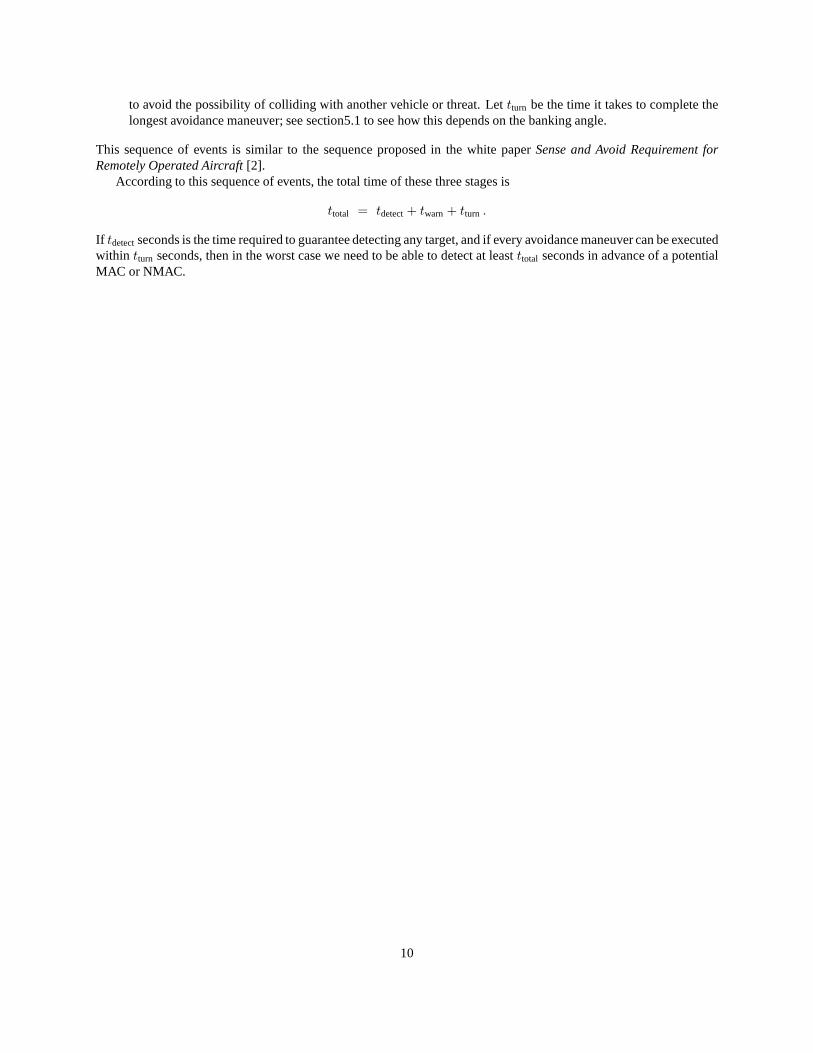
Figure 2: A scatter plot of speeds vs. mean dimensions (mean of wingspan, length and height of the aircraft). Almostall speeds are bounded by a constant times the mean dimension, represented by the line in the graph. For most cases ameter greater in average dimension yields an increase in speed no greater than80km/h.
Requirements state that we must be able to detect aircraft out to 3 sm. Certain classes of vehicles, in particularsmall UAVs such as the Raven or Shadow, will not be detectableat this range with many technologies. Requirementsmay need to be adjusted to reflect these issues. If we relax thestringency of the requirement for smaller vehicles—aslong as we are certain that they are slower—then we may still be able to guarantee a sufficient level of safely. Smallervehicles fly slower, and for a slower on-coming aircraft, we can delay the execution of the evasive maneuver afterbeing within3 sm of the other aircraft.
Figure 2 shows the speeds and mean dimensions of UAVs, GA, commercial and military aircraft. We use meandimension since it gives some measure of the overall size of the vehicle. The graph demonstrates a clear correlationbetween size and speed. Except for the Raven and the F-16, thefollowing is true:
mean(wingspan, height, length) >1
80· vcruise
othersec m
km.
Wherevcruiseother is the cruise speed of the other vehicle in km/h. So on average, the average dimension of the vehicle in
meters is at least as large as 1/80th of the speed in km/h. In general we might assume
w > κsz/spd · vother
wherew is an average width of the target.Note that our purpose is not to define a precise model of size vs. speed to use as an exact model that will be
satisfied all the time. Instead we are attempting to incorporate common sense: fast vehicles are big. We use this simpleheuristic to help inform us about what capabilities are necessary: what resolutions are sufficient and what distances doneed to detect at. Any system will have to be demonstrate an equivalent level of safety in trials.
13
200 400 600 800 1000vother Hkm�hL
0.15
0.2
0.25
0.3
ΑHm
radL
Min. detection arcwidth for Viking 100 cruising at 166 km�h
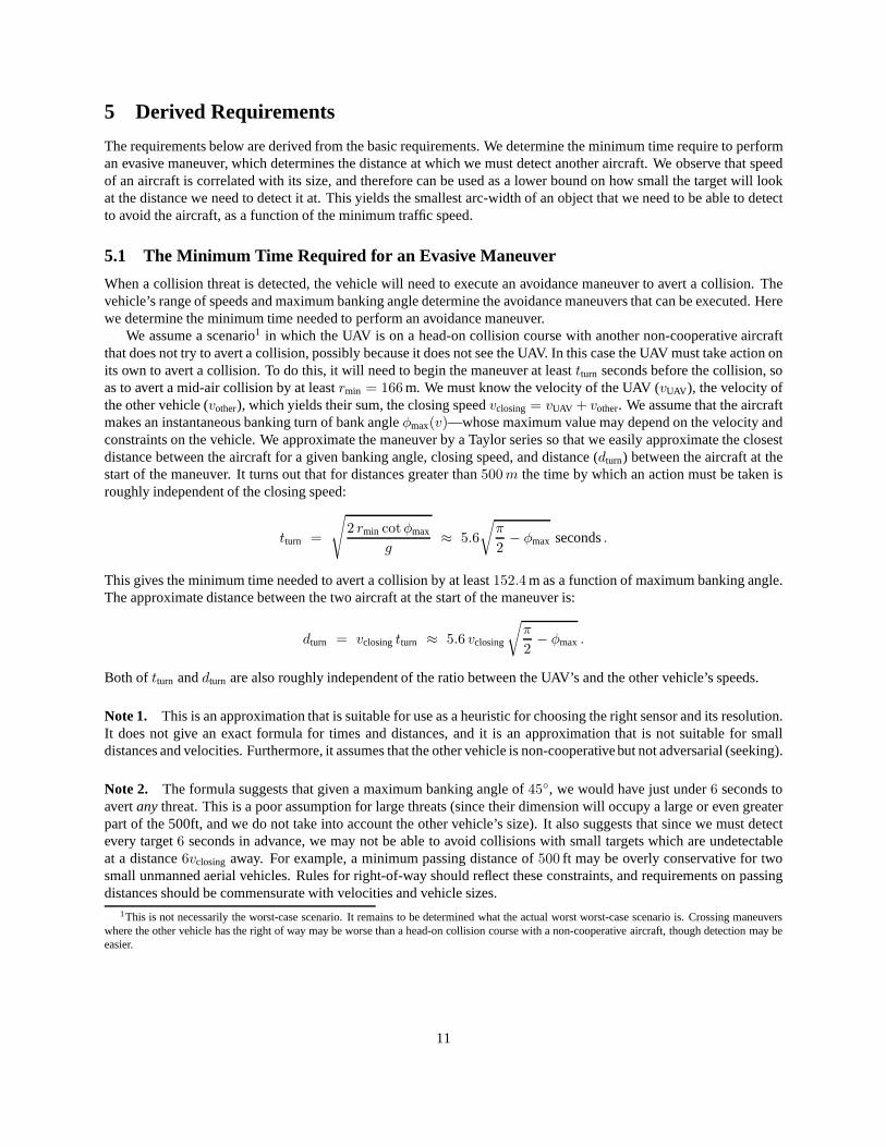
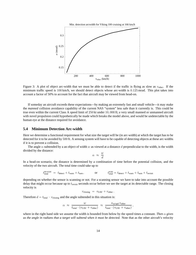
Figure 3: A plot of object arc-width that we must be able to detect if the traffic is flying as slow asvother. If theminimum traffic speed is100 km/h, we should detect objects whose arc-width is0.125 mrad. This plot takes intoaccount a factor of 50% to account for the fact that aircraft may be viewed from head-on.
If someday an aircraft exceeds these expectations—by making an extremely fast and small vehicle—it may makethe manned collision avoidance capability of the current NAS “system”less safe than it currently is. This could betrue even within the current Class A speed limit of250 kt under10, 000 ft; a very small manned or unmanned aircraftwith novel propulsion could hypothetically be made which breaks the model above, and would be undetectable by thehuman eye at the distance required for avoidance.
5.4 Minimum Detection Arc-width
Here we determine a functional requirement for what size thetarget will be (in arc-width) at which the target has to bedetected for it to be avoided by500 ft. A sensing system will have to be capable of detecting objects at these arc-widthsif it is to prevent a collision.
The angleα subtended by a an object of widthw as viewed at a distanced perpendicular to the width, is the widthdivided by the distance:
α ≈ w
d
In a head-on scenario, the distance is determined by a combination of time before the potential collision, and thevelocity of the two aircraft. The total time could take up to
tno-scantotal = tdetect+ twarn + tturn, or tscan
total = tdetect+ twarn + tturn + trevisit
depending on whether the sensor is scanning or not. For a scanning sensor we have to take into account the possibledelay that might occur because up totrevisit seconds occur before we see the target at its detectable range. The closingvelocity is
vclosing = vUAV + vother.
Therefored = ttotal · vclosing and the angle subtended in this situation is:
α ≈ w
ttotal · (vUAV + vother)≈ κsz/spdvother
ttotal · (vUAV + vother),
where in the right hand side we assume the width is bounded from below by the speed times a constant.Then α givesus the angle in radians that a target will subtend when it must be detected. Note that as the other aircraft’s velocity
14
dominates the UAV’s velocity, the subtended angle tends toκsz/spd/ttotal, and for slower UAVs, our requirements couldbe less stringent.
Thus for a given minimum traffic velocityvother, the sensing system needs to be able to detect objects whose arc-widths are at least as small asα calculated above. Figure 3 of this minimum detection arc-width as a function of theminimum traffic velocity. It shows that if we need to track obstacles flying as slow as100 km/h, e.g. the speed of aRaven and the landing speed of a Cessna 152, then we should be able to detect objects whose arc-width are as smallas0.25 mrad.
15
A Derivations and Background Material
In this section we explain how we arrived at some of the figuresin the report, as well as provide some backgroundmaterial. The minimum time required for an evasive maneuverwas a non-trivial derivation, so we include it fordocumentation.
A.1 The Minimum Time Required for an Evasive Maneuver
Here we assume that two vehicles are on a collision course andthat an evasive maneuver is initiated by one of theaircraft. Our aim is to approximate the time it takes to avoida target by500 ft. If the time to collision (in the absenceof executing the evasive maneuver) is less than this time, then the evasive maneuver may result in the two vehiclespassing within500 ft of each other, or may even result in a collision.
Assume that one vehicle has instantaneously initiated a bank at banking angleφ at a velocity ofvUAV , resulting ina turning radius ofv2 cot φ/g. The two vehicles’ positions are:
pUAV (t) =
[
v2
UAV cot φ
g
(
1 − cos
(
g t
vUAV cot φ
))
,v2
UAV cot φ
gcos
(
g t
vUAV cot φ
)]
≈[
g t2 tan φ
2, t vUAV
]
pother(t) = [0, d − t vother]
where the right-most side ofpUAV is a second-order Taylor series approximation. Att = 0, the UAV and the othervehicle are separated by a distanced. In the absence of the maneuver, and in a head-on collision, the time of collisionwould betcollision = d/(vUAV + vother. This is approximately when the vehicles will be closest even if the maneuveris performed, so we substitute the time-to-collision into the square distance between the two vehicles, obtaining anapproximation of the distance at the closest pass:
‖pUAV (tcollision) − pother(tcollision)‖2 =d4g2 tan2 φ
4 (vUAV + vother)4≥ r2
min (1)
We need for this distance not to fall belowrmin = 152.4m, so the maneuver must be executed far enough in advancethat the distance above exceedsrmin. In other words, the time to turn that is equivalent totcollision, which is the timeinto the future at which time a collision would occur in the absence of an evasive maneuver, needs to be at least aslarge as:
tturn ≡ tcollision ≥√
2 rmin cotφ
g≈ 5.6
√
π
2− φ seconds.
We obtain this expression by solving ford in the equality in (1), and substituting intot = d/(vUAV + vother). Thenumerical version is obtained assumingrmin = 152.4m and by Taylor series approximation of
√cotφ atφ = π/2.
A.2 Image Cross Section of a Prototypical GA Aircraft
In a camera, the number of pixels on a target is determined by the distance, the focal length, and what we call theimage cross section (ICS), in analogy with the radar cross section (RCS). The image cross section is simply the areain square meters of a shadow of the aircraft, as cast by a far away light source. IfσICS represents this area, then thenumber of pixels on the target is approximatelyf σICS/d, wheref is the focal length andd is the distance to the target.
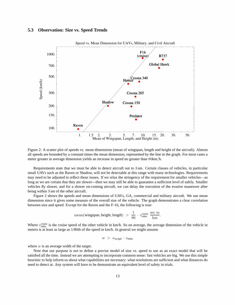
We purchased a 3D model of a typical general aviation aircraft on-line and used it to determine a typicalimagecross-section (ICS),σICS(θ), as a function of its heading. For the purposes of determining the image cross section, weremoved the prop from the model when computing the area (in this 3D model, the prop was represented by a disk). Aprojection of the model is shown in Figure 4. Figure 5 shows that the image cross section varies between5 and8m2.This gives us an idea that the most variation of the image cross section (forthis aircraft) from the maximum is40%.
A study across a broader range of aircraft would be necessaryto determine whether this amount of variation is truein general. Note other characteristics affect the detectability of an aircraft in an image. Contrast of the vehicle withrespect to the background is especially important. In the case of radar the relevant quantity would be the radar crosssection, or the amount of energy reflected by a target as a function of its relative heading.
16

Figure 4: A rendering of a simplified 3D model of a typical GA aircraft. Model obtained fromwww.TurboSquid.com.
-90° 0° 90°Angle
0
2
4
6
8
10
12
Cro
ssS
ectio
nalA
reaHm
^2L
Figure 5: A plot of the cross-sectional area as viewed from different headings. The orange (lighter) curve is a plot ofthe cross-sectional area of a12m2 plane. The blue curve gives the cross-sectional area for theGA aircraft. The ratioof the maximum cross-sectional area to minimum cross-sectional area is5 : 3. For the purposes of computing the area,the disc of the prop was removed from the model.
17

References
[1] Office of the Secretary of Defense, “Airspace integration plan for unmanned aviation,” Nov 2004.
[2] M. D. Ebdon and M. J. Regan, “Sense-and-avoid requirement for remotely operated aircraft (roa),” June 2004.
[3] Federal Aviation Administration, “Order 7610.4,” November 2006.
[4] R. Schaeffer, “A standards-based approach to sense-and-avoid technology,” inAIAA 3rd Unmanned UnlimitedTechnical Conference, Workshop and Exhibit, Sept 2004.
[5] I. D. Gibbs, SRA International, “The predator in opteration iraqi freedom – a pilot’s perspective,” inAIAAInfotech at Aerospace, Sep 2005.
[6] “Annual review of aircraft accident data: U.s. air carrier operations calendar year 1994.” National TransportationSafety Board, Report No. NTSB/ARC/96/01, 1996.
[7] “Midair collisions in u.s. civil aviation: 1969 – 1970.”National Transportation Safety Board, Report No. NTSB-AAS-72-6, June 1972.
[8] “Pilots’ role in collision avoidance.” Federal Aviation Administration, Advisory Circular No. 90-48C, March1983.
[9] E. Duke, C. Vanderpool, and W. Duke, “Turning pinoccio into a real boy: A turing test for UAV operations,” inAIAA Infotech at Aerospace 2007 Conference and Exhibit, May 2007.
[10] C. L. Tallec, “Vfr general aviation aircraft and UAV flights deconfliction,” inAIAA’s 1st Technical Conferenceand Workshop on Unmanned Aerospace Vehicles, May 2002.
[11] K. Suwal, W. Chen, and T. Molnar, “Sefar integration testbed for see and avoid technologies,” inAIAA’s Infotechat Aerospace, Sep 2005.
[12] J. Utt, J. McCalmont, and M. Deschenes, “Development ofa sense and avoid system,” inAIAA Infotech atAerospace, Sep 2005.
[13] P. L. Franchi, “Predator UAV to gain interim sense and avoid capability,”Flight International, June 2006.
[14] J. McCandless, “Detection of aircraft in video sequences using a predictive optical flow algorithm,”OpticalEngineering, vol. 3, pp. 523 – 530, 1999.
[15] T. Gandhi, M. Yang, R. Kasturi, O. Camps, L. Coraror, andJ. McCandless, “Detection of obstacles in the pathof an aircraft,” inProceedings of IEEE CVPR 2000, June 2000.
[16] R. Carnie, R. Walker, and P. Corke, “Image processing algorithms for UAV “sense and avoid”,” inProceedingsof ICRA 2006, May 2006.
[17] D. Soreide, W. Tank, and J. Osborne, “Development of an optical sense and avoid guidance and control systemwith staring infrared cameras,” inAIAA’s 1st Technical Conference and Workshop on Unmanned AerospaceVehicles, May 2002.
[18] M. Skolnik, “Improvements for air-surveillance radar,” in Radar Conference, April 1999.
[19] M. Skolnik, “Opportunities in radar-2002,”Electronics and Communication Engineering Journal, vol. 14, Dec2002.
[20] R. Bernier, M. Bissonnette, and P. Poitevin, “DSA radar- development report,” inUAVSI, 2005, 2005.
[21] E. Frew and R. Rengupta, “Obstacle avoidance with sensor uncertainty for small unmanned aircraft,” in43rd IEEConference on Decision and Control, Dec 2004.
18
[22] E. Frew, “Receding time horizong control using random search for UAV navigation with passive, non-cooperativesensing,” inAIAA Guidance, Navigation, and Control Conference, Aug 2005.
[23] E. Frew, J. Langelaan, and S. Joo, “Adaptive receding horizon control for vision-based navigation of smallunmanned aircraft,” inProceedings 2006 American Control Conference, June 2006.
[24] O. Shakernia, W. Chen, and V. Raska, “Passive ranging for UAV sense and avoid applications,” inAIAA’s Infotechat Aerospace, Sep 2005.
[25] J. Yang, Z. Qu, and J. Wang, “A real-time optimized path planning for a fixed wing vehicle flying in a dynamicand uncertain environment,” inProc. Advanced Robotics, 2005 in conjunction with ICAR’05, 2005.
19
Related Documents