Avid NEXIS ® Setup and Maintenance Guide Version 7.9 November 2017

Welcome message from author
This document is posted to help you gain knowledge. Please leave a comment to let me know what you think about it! Share it to your friends and learn new things together.
Transcript
Avid NEXIS®
Setup and Maintenance GuideVersion 7.9
November 2017

Legal NoticesProduct specifications are subject to change without notice and do not represent a commitment on the part of Avid Technology, Inc.
This product is subject to the terms and conditions of a software license agreement provided with the software. The product may only be used in accordance with the license agreement.
This product may be protected by one or more U.S. and non-U.S patents. Details are available at www.avid.com/patents.
Part of the software embedded in this product is gSOAP software.
Portions created by gSOAP are Copyright (C) 2001-2004 Robert A. van Engelen, Genivia inc. All Rights Reserved.
THE SOFTWARE IN THIS PRODUCT WAS IN PART PROVIDED BY GENIVIA INC AND ANY EXPRESS OR IMPLIED WARRANTIES, INCLUDING, BUT NOT LIMITED TO, THE IMPLIED WARRANTIES OF MERCHANTABILITY AND FITNESS FOR A PARTICULAR PURPOSE ARE DISCLAIMED. IN NO EVENT SHALL THE AUTHOR BE LIABLE FOR ANY DIRECT, INDIRECT, INCIDENTAL, SPECIAL, EXEMPLARY, OR CONSEQUENTIAL DAMAGES (INCLUDING, BUT NOT LIMITED TO, PROCUREMENT OF SUBSTITUTE GOODS OR SERVICES; LOSS OF USE, DATA, OR PROFITS; OR BUSINESS INTERRUPTION) HOWEVER CAUSED AND ON ANY THEORY OF LIABILITY, WHETHER IN CONTRACT, STRICT LIABILITY, OR TORT (INCLUDING NEGLIGENCE OR OTHERWISE) ARISING IN ANY WAY OUT OF THE USE OF THIS SOFTWARE, EVEN IF ADVISED OF THE POSSIBILITY OF SUCH DAMAGE.
This guide is protected by copyright. This guide is for your personal use and may not be reproduced or distributed, in whole or in part, without permission of Avid. Reasonable care has been taken in preparing this guide; however, it may contain omissions, technical inaccuracies, or typographical errors. Avid Technology, Inc. disclaims liability for all losses incurred through the use of this document. Product specifications are subject to change without notice.
Copyright © 2016 Avid Technology, Inc. and its licensors. All rights reserved.
The following disclaimer is required by Apple Computer, Inc.:APPLE COMPUTER, INC. MAKES NO WARRANTIES WHATSOEVER, EITHER EXPRESS OR IMPLIED, REGARDING THIS PRODUCT, INCLUDING WARRANTIES WITH RESPECT TO ITS MERCHANTABILITY OR ITS FITNESS FOR ANY PARTICULAR PURPOSE. THE EXCLUSION OF IMPLIED WARRANTIES IS NOT PERMITTED BY SOME STATES. THE ABOVE EXCLUSION MAY NOT APPLY TO YOU. THIS WARRANTY PROVIDES YOU WITH SPECIFIC LEGAL RIGHTS. THERE MAY BE OTHER RIGHTS THAT YOU MAY HAVE WHICH VARY FROM STATE TO STATE.
The following disclaimer is required by Sam Leffler and Silicon Graphics, Inc. for the use of their TIFF library:Copyright © 1988–1997 Sam Leffler Copyright © 1991–1997 Silicon Graphics, Inc.
Permission to use, copy, modify, distribute, and sell this software [i.e., the TIFF library] and its documentation for any purpose is hereby granted without fee, provided that (i) the above copyright notices and this permission notice appear in all copies of the software and related documentation, and (ii) the names of Sam Leffler and Silicon Graphics may not be used in any advertising or publicity relating to the software without the specific, prior written permission of Sam Leffler and Silicon Graphics.
THE SOFTWARE IS PROVIDED “AS-IS” AND WITHOUT WARRANTY OF ANY KIND, EXPRESS, IMPLIED OR OTHERWISE, INCLUDING WITHOUT LIMITATION, ANY WARRANTY OF MERCHANTABILITY OR FITNESS FOR A PARTICULAR PURPOSE.
IN NO EVENT SHALL SAM LEFFLER OR SILICON GRAPHICS BE LIABLE FOR ANY SPECIAL, INCIDENTAL, INDIRECT OR CONSEQUENTIAL DAMAGES OF ANY KIND, OR ANY DAMAGES WHATSOEVER RESULTING FROM LOSS OF USE, DATA OR PROFITS, WHETHER OR NOT ADVISED OF THE POSSIBILITY OF DAMAGE, AND ON ANY THEORY OF LIABILITY, ARISING OUT OF OR IN CONNECTION WITH THE USE OR PERFORMANCE OF THIS SOFTWARE.
The following disclaimer is required by the Independent JPEG Group:This software is based in part on the work of the Independent JPEG Group.
This Software may contain components licensed under the following conditions:Copyright (c) 1989 The Regents of the University of California. All rights reserved.
Redistribution and use in source and binary forms are permitted provided that the above copyright notice and this paragraph are duplicated in all such forms and that any documentation, advertising materials, and other materials related to such distribution and use acknowledge that the software was developed by the University of California, Berkeley. The name of the University may not be used to endorse or promote products derived from this software without specific prior written permission. THIS SOFTWARE IS PROVIDED ``AS IS'' AND WITHOUT ANY EXPRESS OR IMPLIED WARRANTIES, INCLUDING, WITHOUT LIMITATION, THE IMPLIED WARRANTIES OF MERCHANTABILITY AND FITNESS FOR A PARTICULAR PURPOSE.
Copyright (C) 1989, 1991 by Jef Poskanzer.
Permission to use, copy, modify, and distribute this software and its documentation for any purpose and without fee is hereby granted, provided that the above copyright notice appear in all copies and that both that copyright notice and this permission notice appear in supporting documentation. This software is provided " as is" without express or implied warranty.
Copyright 1995, Trinity College Computing Center. Written by David Chappell.
Permission to use, copy, modify, and distribute this software and its documentation for any purpose and without fee is hereby granted, provided that the above copyright notice appear in all copies and that both that copyright notice and this permission notice appear in supporting documentation. This software is provided " as is" without express or implied warranty.
Copyright 1996 Daniel Dardailler.
Permission to use, copy, modify, distribute, and sell this software for any purpose is hereby granted without fee, provided that the above copyright notice appear in all copies and that both that copyright notice and this permission notice appear in supporting documentation, and that the name of Daniel Dardailler not be used in advertising or publicity pertaining to distribution of the software without specific, written prior permission. Daniel Dardailler makes no representations about the suitability of this software for any purpose. It is provided " as is" without express or implied warranty.
Modifications Copyright 1999 Matt Koss, under the same license as above.
ii

Copyright (c) 1991 by AT&T.
Permission to use, copy, modify, and distribute this software for any purpose without fee is hereby granted, provided that this entire notice is included in all copies of any software which is or includes a copy or modification of this software and in all copies of the supporting documentation for such software.
THIS SOFTWARE IS BEING PROVIDED " AS IS" , WITHOUT ANY EXPRESS OR IMPLIED WARRANTY. IN PARTICULAR, NEITHER THE AUTHOR NOR AT&T MAKES ANY REPRESENTATION OR WARRANTY OF ANY KIND CONCERNING THE MERCHANTABILITY OF THIS SOFTWARE OR ITS FITNESS FOR ANY PARTICULAR PURPOSE.
This product includes software developed by the University of California, Berkeley and its contributors.
The following disclaimer is required by Paradigm Matrix:Portions of this software licensed from Paradigm Matrix.
The following disclaimer is required by Ray Sauers Associates, Inc.:“Install-It” is licensed from Ray Sauers Associates, Inc. End-User is prohibited from taking any action to derive a source code equivalent of “Install-It,” including by reverse assembly or reverse compilation, Ray Sauers Associates, Inc. shall in no event be liable for any damages resulting from reseller’s failure to perform reseller’s obligation; or any damages arising from use or operation of reseller’s products or the software; or any other damages, including but not limited to, incidental, direct, indirect, special or consequential Damages including lost profits, or damages resulting from loss of use or inability to use reseller’s products or the software for any reason including copyright or patent infringement, or lost data, even if Ray Sauers Associates has been advised, knew or should have known of the possibility of such damages.
The following disclaimer is required by Videomedia, Inc.:“Videomedia, Inc. makes no warranties whatsoever, either express or implied, regarding this product, including warranties with respect to its merchantability or its fitness for any particular purpose.”
“This software contains V-LAN ver. 3.0 Command Protocols which communicate with V-LAN ver. 3.0 products developed by Videomedia, Inc. and V-LAN ver. 3.0 compatible products developed by third parties under license from Videomedia, Inc. Use of this software will allow “frame accurate” editing control of applicable videotape recorder decks, videodisc recorders/players and the like.”
The following disclaimer is required by Altura Software, Inc. for the use of its Mac2Win software and Sample Source Code:©1993–1998 Altura Software, Inc.
The following disclaimer is required by Interplay Entertainment Corp.:The “Interplay” name is used with the permission of Interplay Entertainment Corp., which bears no responsibility for Avid products.
This product includes portions of the Alloy Look & Feel software from Incors GmbH.
This product includes software developed by the Apache Software Foundation (http://www.apache.org/).
© DevelopMentor
This product may include the JCifs library, for which the following notice applies:JCifs © Copyright 2004, The JCIFS Project, is licensed under LGPL (http://jcifs.samba.org/). See the LGPL.txt file in the Third Party Software directory on the installation CD.
Avid Interplay contains components licensed from LavanTech. These components may only be used as part of and in connection with Avid Interplay.
Attn. Government User(s). Restricted Rights LegendU.S. GOVERNMENT RESTRICTED RIGHTS. This Software and its documentation are “commercial computer software” or “commercial computer software documentation.” In the event that such Software or documentation is acquired by or on behalf of a unit or agency of the U.S. Government, all rights with respect to this Software and documentation are subject to the terms of the License Agreement, pursuant to FAR §12.212(a) and/or DFARS §227.7202-1(a), as applicable.
TrademarksAvid, the Avid Logo, Avid Everywhere, Avid DNXHD, Avid DNXHR, Avid Nexis, AirSpeed, Eleven, EUCON, Interplay, iNEWS, ISIS, Mbox, MediaCentral, Media Composer, NewsCutter, Pro Tools, ProSet and RealSet, Maestro, PlayMaker, Sibelius, Symphony, and all related product names and logos, are registered or unregistered trademarks of Avid Technology, Inc. in the United States and/or other countries. The Interplay name is used with the permission of the Interplay Entertainment Corp. which bears no responsibility for Avid products. All other trademarks are the property of their respective owners. For a full list of Avid trademarks, see: http://www.avid.com/US/about-avid/legal-notices/trademarks.
The following disclaimer is required by Apple Computer, Inc.:APPLE COMPUTER, INC. MAKES NO WARRANTIES WHATSOEVER, EITHER EXPRESS OR IMPLIED, REGARDING THIS PRODUCT, INCLUDING WARRANTIES WITH RESPECT TO ITS MERCHANTABILITY OR ITS FITNESS FOR ANY PARTICULAR PURPOSE. THE EXCLUSION OF IMPLIED WARRANTIES IS NOT PERMITTED BY SOME STATES. THE ABOVE EXCLUSION MAY NOT APPLY TO YOU. THIS WARRANTY PROVIDES YOU WITH SPECIFIC LEGAL RIGHTS. THERE MAY BE OTHER RIGHTS THAT YOU MAY HAVE WHICH VARY FROM STATE TO STATE.
Avid NEXIS Setup and Maintenance Guide Version 7.9 • Revised November 2017 • This document is distributed by Avid in online (electronic) form only, and is not available for purchase in printed form.
iii
Contents
Using This Guide ................................................................................................................................ vii
Symbols and Conventions .................................................................................................................................. vii
If You Need Help................................................................................................................................................. vii
Accessing the Online Documentation ................................................................................................................ viii
Avid Training Services ....................................................................................................................................... viii
Chapter 1 Avid NEXIS System Overview .................................................................................................... 1
Avid NEXIS Platforms .......................................................................................................................................... 1
Supported Configurations .................................................................................................................................... 2
System Details ..................................................................................................................................................... 3
Engines and System Director Appliance....................................................................................................... 3
Controllers................................................................................................................................................... 12
System Director Functionality ..................................................................................................................... 15
Media Pack and System Drives .................................................................................................................. 15
Power Supplies .......................................................................................................................................... 18
Chapter 2 Connecting the Equipment....................................................................................................... 23
Rack Mounting Guidelines and Requirements................................................................................................... 23
Mounting the Engine or Avid NEXIS | SDA........................................................................................................ 23
Installing the Media Packs (E2, E2 SSD, E4) .................................................................................................... 27
Installing System and Media Pack Drives (E5) .................................................................................................. 27
Connecting Power to Equipment ....................................................................................................................... 28
Connecting the Hardware to a Switch................................................................................................................ 29
Chapter 3 Software Installation and System Setup ................................................................................. 32
System Setup Information.................................................................................................................................. 32
Understanding the Shared Name Space ........................................................................................................... 33
What is DNS? .................................................................................................................................................... 33
What is NTP?..................................................................................................................................................... 34
Installing and Setting Up the System ................................................................................................................. 34
Registering the Avid NEXIS and Downloading the Avid NEXIS Software .................................................. 34
Configuring the Computer’s IP Address...................................................................................................... 35
Installing the Software and Setting up the Avid NEXIS System.................................................................. 38
Upgrading an Engine ......................................................................................................................................... 41
Upgrading an Avid NEXIS System, With or Without a Avid NEXIS | SDA .................................................. 42
Chapter 4 Adding and Replacing Hardware ............................................................................................. 45
Collecting Logs for Customer Care.................................................................................................................... 45
Hardware Faults................................................................................................................................................. 45
About Drive Failures .......................................................................................................................................... 46
iv
Identifying the Slot Number for a Failing or Failed Drive ................................................................................... 46
Removing the Bezel........................................................................................................................................... 47
Replacing a Drive............................................................................................................................................... 47
Removing a Drive (2U and 4U Chassis) ..................................................................................................... 48
Inserting a Drive (2U and 4U Chassis)........................................................................................................ 48
Removing a Drive (E5)................................................................................................................................ 48
Inserting a Drive (E5) .................................................................................................................................. 49
Adding Media Packs .......................................................................................................................................... 49
Adding a Media Pack to an Engine (E4) ..................................................................................................... 49
Adding a Media Pack to an Engine (E5) ..................................................................................................... 50
Power Supply LEDs ........................................................................................................................................... 51
Replacing a Power Supply (2U and 4U) ............................................................................................................ 51
Replacing a Cooling Module (E5 only)............................................................................................................... 51
Replacing a Power Supply (E5) ......................................................................................................................... 52
Installing a Redundant Controller....................................................................................................................... 53
About Controller Failures ................................................................................................................................... 55
Replacing a Controller................................................................................................................................. 55
Removing or Replacing a Chassis..................................................................................................................... 56
Adding an Engine to Your Infrastructure............................................................................................................ 57
Chapter 5 Specifications and Notices....................................................................................................... 59
Physical.............................................................................................................................................................. 59
Electrical and Power .......................................................................................................................................... 59
Altitude and Temperature .................................................................................................................................. 60
Shock, Vibration and Noise................................................................................................................................ 60
Approvals ........................................................................................................................................................... 61
Uninterruptible Power Supply (UPS).................................................................................................................. 61
Warnings and Cautions...................................................................................................................................... 62
Proposition 65 Warning...................................................................................................................................... 62
FCC Notice ........................................................................................................................................................ 62
Class A Equipment...................................................................................................................................... 63
Class B Equipment...................................................................................................................................... 63
Modifications ............................................................................................................................................... 63
Cables ......................................................................................................................................................... 63
Canadian Notice (Avis Canadien)...................................................................................................................... 63
Class A Equipment...................................................................................................................................... 63
Class B Equipment...................................................................................................................................... 63
LED Safety Notices............................................................................................................................................ 64
European Union Declaration of Conformity ....................................................................................................... 64
Disposal of Waste Equipment by Users in the European Union........................................................................ 65
Argentina Conformity ......................................................................................................................................... 66
v

Australia and New Zealand EMC Regulations................................................................................................... 66
Japan EMC Regulations .................................................................................................................................... 66
Class A Equipment...................................................................................................................................... 66
Korean EMC Regulations .................................................................................................................................. 66
Class A Equipment...................................................................................................................................... 66
Taiwan EMC Regulations .................................................................................................................................. 67
Index .................................................................................................................................................... 71
vi

Using This Guide
The Avid NEXIS® media network provides a high-performance distributed file system that contains high-capacity shared media storage for workgroups of connected Avid® editing workstations.
Symbols and Conventions
Avid documentation uses the following symbols and conventions:
If You Need HelpIf you are having trouble using your Avid product:
Symbol or Convention Meaning or Action
nA note provides important related information, reminders, recommendations, and strong suggestions.
cA caution means that a specific action you take could cause harm to your computer or cause you to lose data.
wA warning describes an action that could cause you physical harm. Follow the guidelines in this document or on the unit itself when handling electrical equipment.
nA user tip provides a helpful hint that can aid users in getting the most from their system.
nA shortcut shows the user keyboard or mouse shortcuts for a procedure or command.
> This symbol indicates menu commands (and subcommands) in the order you select them. For example, File > Import means to open the File menu and then select the Import command.
This symbol indicates a single-step procedure. Multiple arrows in a list indicate that you perform one of the actions listed.
(Windows), (Windows only), (Macintosh), or (Macintosh only)
This text indicates that the information applies only to the specified operating system, either Windows or Macintosh OS X.
Bold font Bold font is primarily used in task instructions to identify user interface items and keyboard sequences.
Italic font Italic font is used to emphasize certain words and to indicate variables.
Courier Bold font Courier Bold font identifies text that you type.
Ctrl+key or mouse action Press and hold the first key while you press the last key or perform the mouse action. For example, Command+Option+C or Ctrl+drag.
| (pipe character) The pipe character is used in some Avid product names, such as Interplay | Production. In this document, the pipe is used in product names when they are in headings or at their first use in text.

1. Retry the action, carefully following the instructions given for that task in this guide. It is especially important to check each step of your workflow.
2. Check the latest information that might have become available after the documentation was published.
New information is available in the ReadMe PDF document, available online.
Always check online for the most up-to-date release notes or ReadMe because the online version is updated whenever new information becomes available. To view the online versions, visit the Knowledge Base at www.avid.com/US/support.
3. Check the documentation that came with your Avid application or your hardware for maintenance or hardware-related issues.
4. Visit the online Knowledge Base at www.avid.com/US/support. Online services are available 24 hours per day, 7 days per week. Search this online Knowledge Base to find answers, to view error messages, to access troubleshooting tips, to download updates, and to read or join online message-board discussions.
Accessing the Online Documentation
The Avid online documentation contains all the product documentation in PDF format and Help files where relevant. You can access the documentation on the Knowledge Base page for your release. Download and install Acrobat Reader before you access the PDF documentation.
Avid Training ServicesAvid makes lifelong learning, career advancement, and personal development easy and convenient. Avid understands that the knowledge you need to differentiate yourself is always changing, and Avid continually updates course content and offers new training delivery methods that accommodate your pressured and competitive work environment.
For information on courses/schedules, training centers, certifications, courseware, and books, please visit www.avid.com/support and follow the Training links, or call Avid Sales at 800-949-AVID (800-949-2843).
viii

1 Avid NEXIS System Overview
The Avid NEXIS system is a shared storage solution for acquisition, creative, distribution, and archive media workflows. Avid network storage systems are built for media and entertainment. They enable multiple clients to share, capture, play, and edit video and audio media.
Clients access Avid NEXIS systems through external switch connections. The Avid NEXIS Management Console provides workspace and system management functionality.
This chapter provides an overview of the Avid NEXIS system and the basic function of each component. Other chapters in this guide describe how to install the system in a rack, connect the power and Ethernet cables, and configure the system.
Avid NEXIS PlatformsThe Avid NEXIS system is available in the following hardware platforms. For more information, see “System Details” on page 3.
Model Size Features
Avid NEXIS | PRO 2U One Controller, two 764W power supply/cooling modules (PCMs), two solid state system drives, and one Media Pack (10 drives)
Avid NEXIS | E2 SSD 2U One Controller, two 764W power supply/cooling modules (PCMs), two solid state system drives, and one SSD Media Pack (10 drives)
Avid NEXIS | E2 2U One or two Controllers, two 764W power supply/cooling modules (PCMs), two solid state system drives, and one Media Pack (10 drives)
Avid NEXIS | E4 4U One or two Controllers, four 580W power supply/cooling modules, two solid state system drives, and up to two Media Packs (20 drives)
Empty drive slots must be covered with blank plates to maintain proper airflow and cooling.
Avid NEXIS | E5 5U One or two Controllers, two 2200W power supplies, two solid state system drives, five fan modules, up to eight Media Packs (80 drives) and two spare media drives.
Avid NEXIS | SDA (System Director Appliance)
2U Server built from common hardware modules as other Avid NEXIS products. Contains one or two Controllers, two 764W power supply/cooling modules, and two solid state system drives.
The Avid NEXIS | SDA does not provide media storage; the unused drive slots are covered with blank plates.
The Avid NEXIS | SDA must be used with any E-Series configuration of more than four Media Packs, and with all configurations that include an Avid NEXIS | E5.
Cannot be used with Avid NEXIS | PRO or Avid NEXIS | E2 SSD.

Supported ConfigurationsThe Avid NEXIS hardware can be configured into a single shared storage system, using a single name space, in any of the following ways.
Configurations with an Embedded System Director
All configurations running an embedded System Director use the Avid NEXIS | FS Foundation license.
Configurations with an External System Director (System Director Appliance)
The Avid NEXIS | SDA runs the System Director (but does not provide media storage) for configurations that exceed the limits of the embedded System Director. The Avid NEXIS | SDA uses either the Avid NEXIS | FS Extended license or the Avid NEXIS | FS Advanced license, depending on how many Media Packs or clients you want to manage. See the Avid NEXIS ReadMe for license details.
An Avid NEXIS | SDA is required with an Avid NEXIS | E5 Engine. The Avid NEXIS | E5 cannot run its own System Director.
With Avid NEXIS | SDA and at least three Avid NEXIS E-Series Engines (except Avid NEXIS | E2 SSD), with the same number and capacity of Media Packs, you can create a mirror-capable Storage Group that supports mirrored Workspaces. (Mirrored Workspaces are not supported on systems running an embedded System Director.)
Avid NEXIS Model Functionality
Avid NEXIS | PRO Provides media storage and runs the System Director. Can manage up to four Media Packs (in up to four Avid NEXIS | PRO Engines).
Avid NEXIS | PRO cannot be combined with Avid NEXIS E-series (Enterprise class) Engines or the System Director Appliance
Supports up to 30 connected clients, 24 of which can be active at the same time
Avid NEXIS | E2 SSD Provides media storage and runs the System Director. Can manage up to three Media Packs (in up to three Avid NEXIS | E2 SSD Engines).
Avid NEXIS | E2 SSD cannot be combined with Avid NEXIS | PRO, other Avid NEXIS E-series (Enterprise class) Engines, or the System Director Appliance
Avid NEXIS | E2 System Director runs on the Avid NEXIS | E2 Engine, which also provides storage. Can manage up to four Media Packs, in any of the following combinations:
• Up to four Avid NEXIS | E2 Engines
• Two Avid NEXIS | E2 Engines and one Avid NEXIS | E4 Engine
Supports up to 40 clients
For more than four Media Packs or more than 40 clients, deploy a Avid NEXIS | SDA
Avid NEXIS | E4 System Director runs on the Avid NEXIS | E4 Engine, which also provides storage. Can manage up to four Media Packs in the following combinations:
• Up to two Avid NEXIS | E4 Engines
• One Avid NEXIS | E4 Engine and up to two Avid NEXIS | E2 Engine
Supports up to 40 clients
For more than four Media Packs or more than 40 clients, deploy a Avid NEXIS | SDA
2

All of the Engines and the Avid NEXIS | SDA must be running Avid NEXIS | FS version 7.0 or higher to use this feature. Mirrored Workspaces protect against the failure of an entire Engine (all of its Media Packs) by duplicating (or mirroring) the Workspace data onto other Media Packs in separate Engines. In the event of an Engine failure, the Workspace remains usable with no data loss. Having at least three like Engines allows the system to maintain quorum.
Avid NEXIS | SDA plus any of the following configurations support mirror-capable Storage Groups:
• Three or more Avid NEXIS | E2 Engines, each with one 20TB, 60TB, or 100TB Media Pack (must be the same in all Engines)
• Three or more Avid NEXIS | E4 Engines, each with two 20TB, 60TB, or 100TB Media Packs (must be the same in all Engines)
• Three or more Avid NEXIS | E5 Engines, each with between four and eight 20TB, 60TB, or 100TB Media Packs (must be the same in all Engines)
All of the Media Packs must be added to the same Storage Group, which then becomes mirror capable. In the Management Console on the Storage Groups page, when the Storage Group contains the correct number of Media Packs in equivalent Engines, the Mirror Capable column displays a Yes.
Mirroring requires the use of an Avid NEXIS | SDA, and therefore is not supported in configurations using or restricted to an embedded System Director.
For more information, see the Avid NEXIS Administration Guide.
System DetailsThe Engines and the System Director Appliance are described in more detail in the following sections.
Engines and System Director Appliance
The Avid NEXIS Engines and the System Director Appliance are rack-mountable units housing the other system components (drives, Controllers, and power supplies). If a component fails, the system is designed to remain operational while you replace it. Do not shut down an Engine or the System Director Appliance before replacing a failed part.
Data passes between the Engine and clients through a switch connected to the Engine with one or more 10 Gb or 40 Gb Ethernet connections. These connections provide clients access to the data on the media drives.
Avid NEXIS | E2, Avid NEXIS | E2 SSD, Avid NEXIS | PRO Engine Front View
The front of the 2U chassis has a removable bezel (not shown). Removing the bezel allows access to the drive slots. This Engine supports one Media Pack (10 drives) for media storage and two system drives. As shipped from Avid, the system drives occupy the first two slots (0 and 1). Drive slot numbering is shown below.
3

System Director Appliance Front View
The front of the System Director Appliance has a removable bezel (not shown). Removing the bezel allows access to the drive slots. The System Director Appliance supports two system drives. As shipped from Avid, the system drives occupy the first two slots (0 and 1). The empty slots are covered with blank plates for proper airflow and cooling.
Avid NEXIS | PRO Rear View
The rear of the chassis provides access to the Controller and PCMs.
Avid NEXIS | PRO ships with either 2TB SAS drives and one Controller in slot 0 (top slot), or with 4TB SATA drives and one Controller in the slot 1 (bottom slot).
Avid NEXIS | PRO Controller in Slot 0 (for 2TB SAS Drives)
The 4TB drive version can use one of two types of Controllers, as shown in the following figures:
Avid NEXIS | PRO Controller in Slot 1 (for 4TB SATA Drives)
4

Avid NEXIS | PRO Controller in Slot 1 (for 4TB SATA Drives)
Rear View Features of Avid NEXIS | PRO
Avid NEXIS | E2, Avid NEXIS | E2 SSD, and Avid NEXIS | SDA Rear View
The rear of the chassis provides access to the Controllers and the PCMs.
In Avid NEXIS | E2 and Avid NEXIS | SDA the controller is in slot 0 (top).
Avid NEXIS | E2 and Avid NEXIS | SDA Rear View
In Avid NEXIS | E2 SSD the controller is in slot 1 (bottom), upside down.
Avid NEXIS | E2 SSD Rear View
Component Notes
Power Supply/Cooling Modules (PCM)
764W power supply and cooling fan modules.
The left power supply is numbered 0, the right is numbered 1, in event and error messages.
Controller Avid NEXIS | PRO (2TB drives)—Uses one Controller in slot 0
Avid NEXIS | PRO (4TB drives)—Uses one Controller in slot 1, upside down (can be one of two types of Controllers)
Redundant controllers not supported
5

Rear View Features of Avid NEXIS | E2, Avid NEXIS | E2 SSD, Avid NEXIS | SDA
Avid NEXIS | E4 Front View
The front of the Engine has a removable bezel (not shown). Removing the bezel allows access to the drive slots. The Avid NEXIS | E4 Engine supports two Media Packs (10 drives each) for media storage and two system drives. As shipped from Avid, the system drives occupy the first two slots in the Engine (0 and 1). Drive slot numbering is shown below.
The drives in the Avid NEXIS | E4 Engine are numbered from top left (0) to bottom right (23), as shown.
Avid NEXIS | E4 Rear View
The rear of the Avid NEXIS | E4 provides access to the Controllers and the PCMs. If you use a redundant Controller, it must be installed in the third slot from the top, as shown.
Component Notes
PCM (Power/Cooling Module)
764W power supply and cooling fan modules.
The left power supply is numbered 0, the right is numbered 1, in event and error messages.
Storage Controller Avid NEXIS | E2 SSD uses only one Controller, upside down in slot 1 (bottom slot).
Avid NEXIS | E2 and Avid NEXIS | SDA can use one or two (redundant) Controllers. The second Controller is upside down in slot 1 (bottom slot).
6

Rear View Features of Avid NEXIS | E4
Control Panel for all 2U and 4U Chassis and the System Director Appliance
The following figure shows the control panel on the left side of the chassis on all of the following:
• Avid NEXIS | E2
• Avid NEXIS | E2 SSD
• Avid NEXIS | E4
• Avid NEXIS | PRO
• System Director Appliance
Component Notes
Power/Cooling Module (PCM)
Four 580W PCMs (as viewed from the rear, PCM 0=top left, PCM 1=top right, PCM 2=bottom left, PCM 3=bottom right)
Storage Controller In a single Controller configuration, it must be installed in the top slot (identified in error and status messages as Controller 0).
If a redundant Controller is installed, they divide the system services between them. If one Controller fails, the services fail over to the other. The redundant Controller is identified as Controller 1.
7

Control Panel Features: All 2U and 4U Chassis
Control Panel Features on all 2U and 4U Chassis
Avid NEXIS | E5 Engine Front View
On the Avid NEXIS | E5, the bezels are attached at the factory and do not need to be removed for any system maintenance procedures.
Description Status/Purpose
System Power LED Green when system is on (operational).
Amber when system is in standby mode (not operational).
Module Fault LED Amber when there is a system hardware fault. In that case, another LED on the faulty component may be lit.
Logical Fault LED Amber when something other than the enclosure management system (usually a drive) fails.
Enclosure ID Display Displays the enclosure identification number (optional; useful with multiple enclosure systems)
8
Avid NEXIS | E5 Engine Front View Features
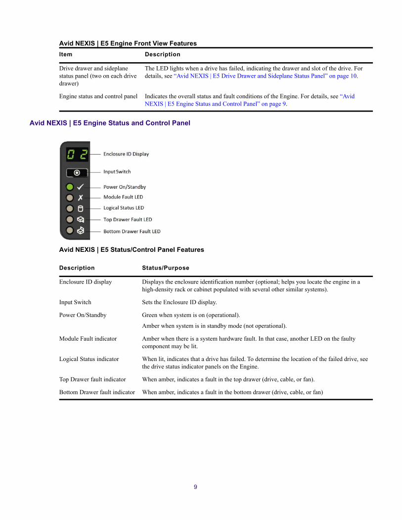
Avid NEXIS | E5 Engine Status and Control Panel
Avid NEXIS | E5 Status/Control Panel Features
Item Description
Drive drawer and sideplane status panel (two on each drive drawer)
The LED lights when a drive has failed, indicating the drawer and slot of the drive. For details, see “Avid NEXIS | E5 Drive Drawer and Sideplane Status Panel” on page 10.
Engine status and control panel Indicates the overall status and fault conditions of the Engine. For details, see “Avid NEXIS | E5 Engine Status and Control Panel” on page 9.
Description Status/Purpose
Enclosure ID display Displays the enclosure identification number (optional; helps you locate the engine in a high-density rack or cabinet populated with several other similar systems).
Input Switch Sets the Enclosure ID display.
Power On/Standby Green when system is on (operational).
Amber when system is in standby mode (not operational).
Module Fault indicator Amber when there is a system hardware fault. In that case, another LED on the faulty component may be lit.
Logical Status indicator When lit, indicates that a drive has failed. To determine the location of the failed drive, see the drive status indicator panels on the Engine.
Top Drawer fault indicator When amber, indicates a fault in the top drawer (drive, cable, or fan).
Bottom Drawer fault indicator When amber, indicates a fault in the bottom drawer (drive, cable, or fan)
9

Avid NEXIS | E5 Drive Drawer and Sideplane Status Panel
Avid NEXIS | E5 Drive Drawer and Sideplane Status Features
Avid NEXIS | E5 Rear View
The rear of the Avid NEXIS | E5 provides access to the Controller, power supplies, and fans. In a single-Controller configuration, the Controller must be installed in the left-hand slot (Controller 0 in the figure below).
Description Status/Purpose
Sideplane and Power OK Green when the sideplane card is working and there are no power problems
Sideplane Fault Amber if a drive has failed
Logical Fault Flashes amber if one or more RAID sets have failed drives
Cable Fault Amber if the cable between the drawer and the back of the enclosure has failed
Activity bar graph Shows the amount of data I/O from zero segments lit (no I/O) to all six segments lit (maximum I/O)
10

Avid NEXIS | E5 Rear View Features
Avid NEXIS | E5 Drive Numbering
The Avid NEXIS | E5 has two drawers for the system and Media Pack drives. The drive numbering is shown in the following figure.
Component Notes
Controller 0, Controller 1
If only one controller is present, it must be installed in the left slot. Controllers are identified in error and status messages as 0 (left) and 1 (right).
If a redundant Controller is installed, they divide the system services between them. If one Controller fails, the services fail over to the other. The redundant Controller is identified as Controller 1.
fans 0 through 4 Five cooling fans, identified in error and status messages as 0 (left) through 4 (right)
PSU 0, PSU 1 Power supply modules, identified in error and status messages as 0 (left) and 1 (right)
11
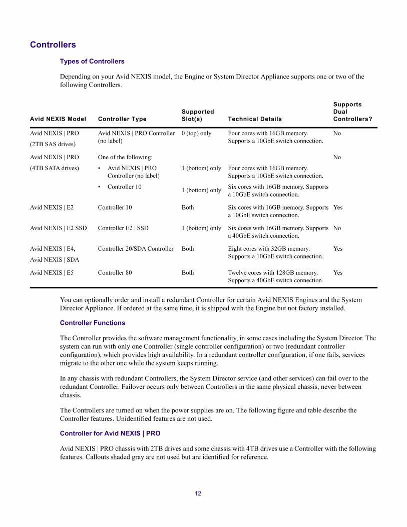
Controllers
Types of Controllers
Depending on your Avid NEXIS model, the Engine or System Director Appliance supports one or two of the following Controllers.
You can optionally order and install a redundant Controller for certain Avid NEXIS Engines and the System Director Appliance. If ordered at the same time, it is shipped with the Engine but not factory installed.
Controller Functions
The Controller provides the software management functionality, in some cases including the System Director. The system can run with only one Controller (single controller configuration) or two (redundant controller configuration), which provides high availability. In a redundant controller configuration, if one fails, services migrate to the other one while the system keeps running.
In any chassis with redundant Controllers, the System Director service (and other services) can fail over to the redundant Controller. Failover occurs only between Controllers in the same physical chassis, never between chassis.
The Controllers are turned on when the power supplies are on. The following figure and table describe the Controller features. Unidentified features are not used.
Controller for Avid NEXIS | PRO
Avid NEXIS | PRO chassis with 2TB drives and some chassis with 4TB drives use a Controller with the following features. Callouts shaded gray are not used but are identified for reference.
Avid NEXIS Model Controller TypeSupported Slot(s) Technical Details
Supports Dual Controllers?
Avid NEXIS | PRO
(2TB SAS drives)
Avid NEXIS | PRO Controller (no label)
0 (top) only Four cores with 16GB memory. Supports a 10GbE switch connection.
No
Avid NEXIS | PRO
(4TB SATA drives)
One of the following:
• Avid NEXIS | PRO Controller (no label)
• Controller 10
1 (bottom) only
1 (bottom) only
Four cores with 16GB memory. Supports a 10GbE switch connection.
Six cores with 16GB memory. Supports a 10GbE switch connection.
No
Avid NEXIS | E2 Controller 10 Both Six cores with 16GB memory. Supports a 10GbE switch connection.
Yes
Avid NEXIS | E2 SSD Controller E2 | SSD 1 (bottom) only Six cores with 16GB memory. Supports a 40GbE switch connection.
No
Avid NEXIS | E4,
Avid NEXIS | SDA
Controller 20/SDA Controller Both Eight cores with 32GB memory. Supports a 10GbE switch connection.
Yes
Avid NEXIS | E5 Controller 80 Both Twelve cores with 128GB memory. Supports a 40GbE switch connection.
Yes
12

Avid NEXIS | PRO Controller Features
Controller for Avid NEXIS E-Series, System Director Appliance, and Avid NEXIS | PRO with 4TB Drives
The Controller in Avid NEXIS E-Series engines and Avid NEXIS | SDA, and Avid NEXIS | PRO with 4TB drives look the same except for the label that identifies the controller type, and which slot it is in.
Component Notes
USB Connectors (Shown for reference only. Not used)
Switch Connector QSFP 10GbE port to connect to a network switch. See “Connecting the Hardware to a Switch” on page 29.
Power/OK, Fault, and ID LEDs
Power/OK: Green when the controller is operating correctly. Flashing green indicates a controller VPD error.
Fault: Amber when the controller has a fault.
ID: Blue when the controller is being identified.
POST LEDs (Shown for reference only.)
Serial Port (Shown for reference only. Not used)
Management Interface Port (left port only)
1GbE port for connecting the Controller to a laptop or other computer to install the NEXIS software and initially configure the system. Default IP address is 169.254.10.10.
The port LEDs indicate status as follows:
Right side:
• Steady green: Link is active
• Flashing green: Network activity
Left side—Network speed:
• Yellow: 1000Mb/s
• Green: 100Mb/s
• Off: 10Mb/s
SAS Port (Shown for reference only. Not used)
13
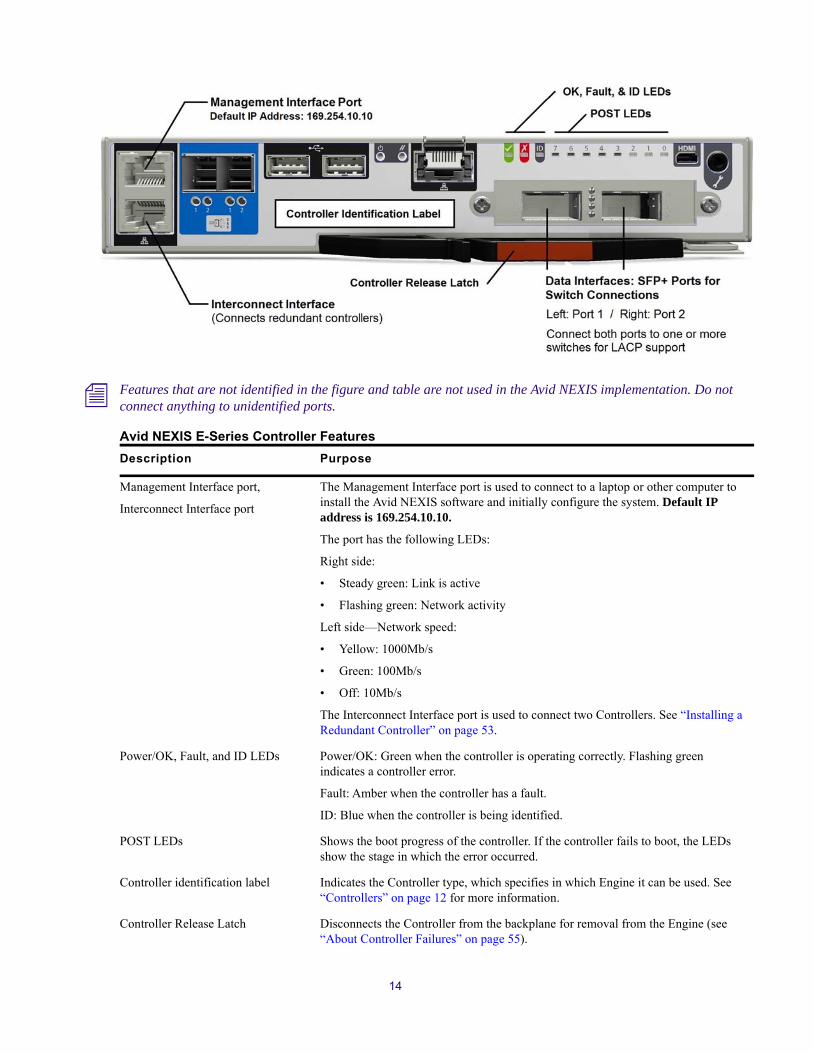
n Features that are not identified in the figure and table are not used in the Avid NEXIS implementation. Do not connect anything to unidentified ports.
Avid NEXIS E-Series Controller Features
Description Purpose
Management Interface port,
Interconnect Interface port
The Management Interface port is used to connect to a laptop or other computer to install the Avid NEXIS software and initially configure the system. Default IP address is 169.254.10.10.
The port has the following LEDs:
Right side:
• Steady green: Link is active
• Flashing green: Network activity
Left side—Network speed:
• Yellow: 1000Mb/s
• Green: 100Mb/s
• Off: 10Mb/s
The Interconnect Interface port is used to connect two Controllers. See “Installing a Redundant Controller” on page 53.
Power/OK, Fault, and ID LEDs Power/OK: Green when the controller is operating correctly. Flashing green indicates a controller error.
Fault: Amber when the controller has a fault.
ID: Blue when the controller is being identified.
POST LEDs Shows the boot progress of the controller. If the controller fails to boot, the LEDs show the stage in which the error occurred.
Controller identification label Indicates the Controller type, which specifies in which Engine it can be used. See “Controllers” on page 12 for more information.
Controller Release Latch Disconnects the Controller from the backplane for removal from the Engine (see “About Controller Failures” on page 55).
14

System Director Functionality
The System Director maintains all information about the file system. The System Director is either embedded on a Controller in an Engine, or runs separately on a System Director Appliance. In any Avid NEXIS configuration, there is only one System Director. If the System Director is embedded, the first Engine configured in a multi-Engine system runs the System Director for the entire system.
The embedded System Director can manage up to four Media Packs.
The System Director Appliance can manage more than four Media Packs, up to the limit described in the Avid NEXIS ReadMe, with either the Avid NEXIS | FS Extended license or the Avid NEXIS | FS Advanced license. The System Director Appliance cannot be used with an Avid NEXIS | PRO.
The System Director:
• Manages the metadata by storing directory information and file attributes.
• Provides a location to coordinate file access modes (read/write), file locking, range locking, performance data collection, logging, file lookup, and directory change tracking for client systems.
• Provides the following information:
- Identity of all connected storage systems
- Information about the drives, power, cooling and Controllers in the configuration
- Names of workspaces
- Lists of users and groups within the system
The System Director does not store client data (media files); these are stored on the Media Packs (drives) within one or more Engines. System Director metadata is mirrored on the system drives in the Engines or in the System Director Appliance.
System Directors, workgroup servers, and clients must all be synchronized with a common time of day. For information on setting the Network Time Protocol (NTP), see “Software Installation and System Setup” on page 32.
Media Pack and System Drives
A Media Pack is a set of 10 drives, all of which are the same capacity and type, as follows:
• 2TB, 6TB, or 10TB HDDs for Avid NEXIS | E2, Avid NEXIS | E4, Avid NEXIS | E5
• 2TB or 4TB HDDs for Avid NEXIS | PRO
• 960GB or 1920GB SSDs for Avid NEXIS | E2 SSD
The Avid NEXIS Engines contain varying numbers of Media Packs. The System Director Appliance contains no Media Packs, as it is not used for client data storage.
Data Interface ports (SFP+) Connects the Engine or System Director Appliance to a network switch (see “Connecting the Hardware to a Switch” on page 29). If using link aggregation (NIC teaming), connect both ports to one or more switches.
Description Purpose
15
When replacing a failed drive in a Media Pack, make sure to use a drive of the same capacity as, or larger than, the others in the Media Pack. For more information, see “Replacing a Drive” on page 47 and the Avid NEXIS Administration Guide.
Each Engine and System Director Appliance also has two SSD system drives, of the following minimum partition size (SSD capacity):
• 200GB in Avid NEXIS | PRO (with 2TB drives), Avid NEXIS | E2, and Avid NEXIS | E4
• 400GB in Avid NEXIS | SDA and Avid NEXIS | E2 SSD
• 480GB in Avid NEXIS | PRO (with 4TB drives)
• 800GB in Avid NEXIS | E5
n If a system drive fails, Avid reserves the right to send a replacement of a size that meets or exceeds the minimum partition requirements.
The System Director, whether running on an Engine or in the System Director Appliance, uses the system drives for metadata, startup files, and other system files. The Engine or System Director Appliance can run with one failed system drive. Avid recommends replacing it as soon as possible.
Typically, the system drives occupy slots 0 and 1, and the Media Pack drives use the remaining slots.
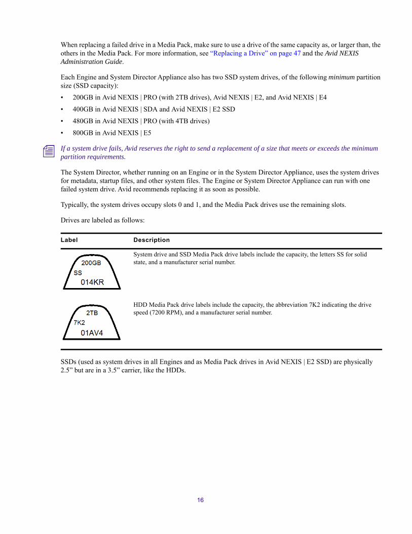
Drives are labeled as follows:
SSDs (used as system drives in all Engines and as Media Pack drives in Avid NEXIS | E2 SSD) are physically 2.5” but are in a 3.5” carrier, like the HDDs.
Label Description
System drive and SSD Media Pack drive labels include the capacity, the letters SS for solid state, and a manufacturer serial number.
HDD Media Pack drive labels include the capacity, the abbreviation 7K2 indicating the drive speed (7200 RPM), and a manufacturer serial number.
16

Drives in the 2U, 4U Chassis and Avid NEXIS | SDA
The drives used in the 2U and 4U chassis and Avid NEXIS | SDA have a lock indicator and two LEDs that show the drive status, explained in the following figure and table.
2U and 4U Drive Features
Feature Status Indicator
Power and activity LED Off—No power
Blinking—I/O activity
Status and identification LED Blinking 1second on, 1 second off—To identify the drive
On—Drive failed
Off—OK
17

Drives in the 5U Chassis
The drives in the Avid NEXIS | E5 Media Packs have one LED that indicates a drive failure.
c Leave failed drives in place until you have a replacement so you maintain the proper airflow. Obtain a replacement as soon as possible.
Power Supplies
Depending on your Avid NEXIS model, the Engine or System Director Appliance has the following number and type of power supply/cooling modules (PCMs) or power supply units (PSUs):
• Two 764W PCMs with integrated fans—All 2U chassis
• Four 580W PCMs with integrated fans—Avid NEXIS | E4
• Two 2200W PSUs and five separate fans—Avid NEXIS | E5
The PCMs or PSUs are turned on when the power cord is plugged in and the power switch is on. They operate as follows:
18

764W PCM (All 2U Chassis including System Director Appliance)
n The bottom two LEDs, marked with battery icons, are not used.
Chassis Operation
Avid NEXIS | PRO,
Avid NEXIS | E2,
Avid NEXIS | E2 SSD,
Avid NEXIS | SDA
1+1 redundant configuration, meaning the system remains running even if one PCM fails.
For maximum protection from power loss, both PCMs must be plugged in to separate electrical circuits or separate UPS devices and turned on. With both PCMs plugged in and turned on, the system balances its power needs between them. If one PCM fails, the system can continue operating.
Avid NEXIS | E4 2+2 redundant configuration, meaning the system remains running even if any two PCMs fail.
For maximum protection from power loss, each pair of PCMs must be plugged in to separate electrical circuits or separate UPS devices (for example, two on circuit A and two on circuit B), and all must be turned on. With all four PCMs plugged in and turned on, the system balances its power needs among them.
Avid NEXIS | E5 1+1 redundant configuration, meaning the system remains running even if one PCM fails.
The Avid NEXIS | E5 can run with only two of the five fans.
19

580W PCM (Avid NEXIS | E4)
The LEDs on the 580W PCM work together to indicate overall module status; in the following table, for each row, all the LEDs must be in the listed state for the definition to apply.
580W Power Supply LED States
AC Fault Fan Fault Power/Module OK DC Fault Definition
n For readability, a series of dashes (---) means the LED is OFF.
--- --- --- --- No AC power on any PCM
On --- --- On No AC power on this PCM
--- --- On --- AC present; PCM OK
--- --- On On PCM fan speed is outside acceptable limits
--- --- --- --- PCM fan has failed
On On --- On PCM fault (over temperature, over voltage, or over current)
--- --- Flashing --- Standby mode
Flashing Flashing --- Flashing PCM firmware download in progress
20

2200W PSU (Avid NEXIS | E5)
2200W PSU Details
2200W PSU LED Status
PSU Fail (Amber)
AC Fail(Amber)
Power OK(Green) Status
Off Off Off No AC power to either PSU
On On Off PSU present but not supplying power
Off Off On Mains AC present, switch on. This PSU is providing power
Off Off Flashing AC power preset, PSU in standby mode (other PSU is providing power)
Flashing Flashing Off PSU firmware download in progress
On On Off PSU alert state (usually due to reaching critical temperature)
21

Avid NEXIS | E5 Fan
Avid NEXIS | E5 Fan LED Status
c Leave failed power supply or cooling modules in place until you have a replacement so you maintain the proper airflow. Obtain a replacement as soon as possible.
Off On Off Mains AC to this PSU is missing (This PSU is on standby, other PSU is OK)
On On On GEM software has lost communication with PSU
On --- Off PSU has failed
2200W PSU LED Status
PSU Fail (Amber)
AC Fail(Amber)
Power OK(Green) Status
Fan OK(Green)
Battery fault(Amber)
Fan fault(Amber) Status
--- --- Off Fan OK
--- --- On Communication lost with fan module controller
--- --- On Reported fan speed is out of tolerance
On Off --- Fan and battery OK
Flashing Off --- Battery charging
Off On --- Battery fault
On --- Off PSU has failed
22

2 Connecting the Equipment
This chapter explains how to rack mount and connect the system hardware.
Rack Mounting Guidelines and Requirements
Avid recommends installing the Avid NEXIS hardware in a rack, using the following guidelines:
• If installed in a closed or multi-unit rack assembly, the operating ambient temperature of the rack environment might be greater than room ambient. Make sure the rack environment is compatible with the maximum ambient temperature (Tma) specified by the manufacturer.
• Avoid uneven mechanical loading.
• Make sure your rack enclosure is stable enough to prevent tipping over if using extending sliding rails.
• Follow the equipment nameplate ratings to avoid overloading the circuits.
• Maintain reliable grounding of rack-mounted equipment, especially regarding supply connections other than direct connections to the branch circuit (for example, power strips).
• Avid airflow is from the front of the enclosure to the rear. Make sure nothing blocks airflow to the front panel surface and the rear.
• For normal operation, maintain approximately 2 feet (0.6 meters) of open space in front of and behind the rack. This allows free access to the components in the rack for operating changes or adjustments. For service, maintain approximately 3 feet (1 meter) of open space in front of the rack and 2 feet (0.6 meters) of open space behind the rack. This allows for the removal of any component that needs to be replaced.
• Allow at least 0.5 in (1.3 cm) clearance on top of the enclosure for cover removal.
w To ensure the stability of the rack enclosure, install the heaviest equipment in the lower sections of the rack enclosure. Install lighter equipment in the middle and upper sections.
c For information about power specification and dimensions see “Specifications and Notices” on page 59.
Mounting the Engine or Avid NEXIS | SDAThe Avid NEXIS Engines are designed for 19-inch (483-mm) rack configurations and need the following amounts of space in the rack:
• Avid NEXIS | E2, Avid NEXIS | E2 SSD, Avid NEXIS | PRO, and Avid NEXIS | SDA each require two vertical rack units of space
• Avid NEXIS | E4 requires four vertical rack units
• Avid NEXIS | E5 requires five vertical rack units
The rack mount kit can accommodate racks with round, square, or threaded holes, sometimes called broadcast racks. Installation instructions are included on a decal located on the side of one of the bracket rails.

n Do not lift the Engine by the handles on the power supply units, cooling modules or Controller – they are not designed to support the weight of the entire system.
w Avid recommends that two people lift the Engine, especially when installing in upper rack units.
To mount a 2U or 4U chassis in the rack:
1. Install the mounting rails using the instructions on the attached label.
2. If you have a redundant Controller, insert it fully into the chassis before installing the chassis in the rack.
3. Slide the chassis onto the mounting rails and secure to the rack using the two supplied screws.
4. Insert the Media Pack drives into the empty drive slots (see “Installing the Media Packs (E2, E2 SSD, E4)” on page 27).
5. Remove the plastic end cap covers from the front of the chassis. (These cover the screws that secure the chassis to the rack in the absence of a bezel.)
6. Attach the bezel to the front of the chassis.
To mount a 5U chassis in the rack:
1. (Option) If using racks with threaded holes, unscrew and remove the five round pegs on each end of the bracket rail.
2. Loosen the four slide adjustment screws so to adjust the bracket rail to the depth of your rack.
The adjustment screws are highlighted in a colored circle around the screw.
3. Position the bracket rail between your rack mount rails and adjust the length of the bracket so that it meets the inside of both the front and rear rails as shown in the following figure.
Slide adjustment screws
Round pegs
Bracket rail
24

4. Secure the bracket rail to the front and rear mounting rails using either the screws that come with the rack mount kit of your rack screws (five screws in the front and the rear).
n Leave the top holes on the front of the rail empty so you can use those holes to secure the Engine to keep it from sliding forward once racked.
5. Tighten the four slide adjustment screws.
6. Repeat steps 1 through 5 to install the other bracket rail on the opposite side of the rack.
7. Make sure that the media drives are not installed in the Engine.
8. With an assistant, lift the Engine and place the rear of the Engine onto the brackets as shown in the following figure.
9. Position the bracket extender on the outside of the rear mounting rail so that the sliding nut in the bracket extender inserts into the rack mounting tab on the Engine. Using the short screws included in the rack mount kit, secure the bracket extender to the rack mounting tab on the Engine as shown in the following figure.
The rack mount kit provides two sets of bracket extenders: a long pair and short pair. Use the pair of bracket extenders that are most appropriate for your rack. For shallower racks use the longer bracket extenders.
Rack mount screws
Bracket rail
Rack enclosureMounting rails
25

10. Using the screws from the rack mount kit, secure the Engine to the front of the rack through top and bottom holes of the plastic end caps as shown in the following figure.
11. Using the screws from the rack mount kit or screws you supply, secure the rear stabilizer brackets to the rear rack mount rails through top and bottom holes in the extender bracket as shown in the preceding figure.
12. Snap the left and right plastic covers over the plastic end caps on the front Engine as shown in the preceding figure.
Bracket extender
Rack mounting tab
Sliding nut
Plastic covers
Plastic end caps
26

Installing the Media Packs (E2, E2 SSD, E4)A Media Pack consists of ten drives. See “Media Pack and System Drives” on page 15 for more information. You can optionally install up to two spare media drives in Avid NEXIS | E4 Engines.
To install the Media Pack (and optional spare) drives:
1. Make sure the anti-tamper lock is not engaged (see “Media Pack and System Drives” on page 15). The red lock indicator is visible if the lock is engaged. Unlock the drive using a screwdriver with a Torx T20 bit by rotating the lock counterclockwise until the lock indicator is completely hidden.
2. Insert the drive into the slot, with the lock mechanism facing left.
3. Push the drive in until the release latch starts to pull inward.
4. Push the release latch in you hear it click shut.
5. Lock the drive with the Torx T20 bit; make sure the red lock icon is fully visible in the viewing window.
Installing System and Media Pack Drives (E5)The Avid NEXIS | E5 comes with at least one pack of 40 drives (four Media Packs), and additional 10-packs of drives if you ordered more. In some cases, the system drives are preinstalled. In other cases, the system drives are shipped in a separate box from the Media Packs and the Engine.
The Avid NEXIS | E5 supports between four (minimum) and eight Media Packs, and up to two (optional) spare drives.
If starting with fewer than eight Media Packs, populate the front rows of both drawers first (starting with the top drawer), for correct airflow. Insert any spare drives in the slots immediately after the last Media Pack drive. As you purchase and install more Media Packs and spares, fill the slots in the remaining rows. Avid recommends putting the two system drives into different drawers, but there is no technical restriction on where they are placed. The following procedure assumes the system drives are not preinstalled, and describes installing them into different drawers. If the drives were installed at the factory, they are likely already in separate drawers.
To install the System and Media Pack drives:
1. Open the top drawer.
2. If the system drives are not preinstalled, install one of them into slot 0; see “Avid NEXIS | E5 Drive Numbering” on page 11. Lower the drive into the slot with the drive capacity label facing towards you.
3. Push the drive downwards and hold it down while sliding the drive carrier plate in the direction shown in the following figure. This locks the drive in place.
27

4. Install 20 of the Media Pack drives into slots 1 through 20.
Make sure the drives are securely locked into place.
5. Close and lock the drawer.
6. Open the bottom drawer.
7. Install the other system drive (if not preinstalled) into slot 42.
8. Install the remaining 20 Media Pack drives, and any optional spares, in slots 43 through 62. These are the rows of slots closest to the front of the Engine in the bottom drawer.
9. Close and lock the drawer.
Connecting Power to Equipment
Avid NEXIS | E2, Avid NEXIS | E2 SSD, Avid NEXIS | E4, Avid NEXIS | PRO, and Avid NEXIS | SDA come with two 10A power cables (North America standard) in the shipping box. You might need to obtain power cords from your local reseller or support depot suitable for your locale.
The Avid NEXIS | E5 Engine comes with two C19 to C20 power cables in the shipping box. The C19 end is a female connector which plugs into the power supply on the Avid NEXIS | E5 Engine. The C20 end is a male connector, which plugs into a Power Distribution Unit (PDU) with C19 style connectors.
For information about the APC® Basic Rack PDU with C19 208-240V outputs and a twist lock NEMA LP6-30 input), see: http://www.apc.com/products/resource/include/techspec_index.cfm?base_sku=AP9570
Avid does not recommend any specific vendor or model of PDU. A PDU is a rack mount ready, high current power strip that can offer a variety of plug types. Purchase a model that suits the needs of the equipment in your rack.
For the Avid NEXIS | E5, connect each power supply in the Engine to a different 30-amp circuit. This allows the system to continue running if one circuit fails.
Plug the power cords into the power supplies on the back of the Engine (and the back of the Avid NEXIS | SDA, if using one) and then plug the other ends into power outlets on separate circuits. If they are not already in the ON position, turn on the switches on the power supplies.
n The system takes a few minutes to perform some internal processes before the fans start running.
28

Connecting the Hardware to a SwitchBasic Switch Connections
See the Avid NEXIS Network and Switch Guide for the currently supported switches, cables, and transceivers for use with an Avid NEXIS Engine or the Avid NEXIS | SDA.
c You must connect each Engine and, if applicable, the Avid NEXIS | SDA, to supported switches, which must be networked together. You cannot set up the Engine or the Avid NEXIS | SDA until they are connected to suitable switches in your network.
Connect the Engine or Avid NEXIS | SDA to a suitable switch, as follows:
• Avid NEXIS | PRO, Avid NEXIS | E2, Avid NEXIS | E4, Avid NEXIS | SDA — 10GbE switch
• Avid NEXIS | E2 SSD, Avid NEXIS | E5 — 40GbE switch
The following figures show sample connections between an Avid NEXIS Engine and a switch.
n All the Avid NEXIS | E-Series Controllers and some models of Avid NEXIS | PRO use the same ports to connect to a switch. The following figures are examples only; your configuration may vary depending on how many Controllers are installed, how many switches you are connecting to, and whether LACP is enabled.
10 Gb Network Connection from Dell N3024 Switch to Avid NEXIS E-Series Controller (E2 Shown)
29

40 Gb Network Connections from Cisco Nexus 9372PX Switch to Avid NEXIS | E5
10 Gb Network Connection from Switch to Avid NEXIS | PRO Controller
Using Link Aggregation (LACP) on the Switch and the Avid NEXIS
In the Avid NEXIS v7.0 release (and higher), you can enable link aggregation (also called NIC teaming) on the Controllers in an Engine or Avid NEXIS | SDA. The Ethernet ports on all installed Controllers must be connected to one or more supported switches. You cannot enable link aggregation on only one Controller in a pair.
30

To use LACP (NIC teaming) on the Avid NEXIS system and the switches:
1. Enable LACP on the switch (or switches) you plan to use with the Avid NEXIS. (See the Avid NEXIS Network and Switch Guide and your switch vendor documentation for full instructions.)
2. Connect both ports on all installed Controllers (in all Engines and the Avid NEXIS | SDA, if applicable, in a shared storage system) to those switches.
3. In the Avid NEXIS Agent, enable LACP on the shared storage system. See the Avid NEXIS Administration Guide for more information.
c To avoid making the Avid NEXIS unresponsive and unable to communicate with the network, do not enable LACP on the Avid NEXIS system until it is configured on all the relevant switches, and the cables are connected.
31

3 Software Installation and System Setup
This chapter describes how to install or upgrade and configure the Avid software on a new Avid NEXIS system.
If you have questions, call your Avid representative or your local ACSR.
c Before you start the procedures in this chapter, familiarize yourself with the information in Avid NEXIS System Overview, and make sure the Avid NEXIS Engine is connected to a switch, which is in turn connected to your network. See “Connecting the Hardware to a Switch” on page 29 and the Avid Network and Switch Guide.
System Setup InformationTo complete the initial software installation and system setup, you will need the following information.
The following information is optional, if your environment supports its use.
Required Information Notes
Storage System Name—Identifies the Avid NEXIS system to clients and to all the Engines, and the Avid NEXIS | SDA if applicable, that belong to the same Avid NEXIS system.
See “Understanding the Shared Name Space” on page 33.
Names can be up to 64 English alphanumeric characters long, can contain a dash or hyphen (-), must start with a letter, and cannot end with a dash.
Engine Name—Name for the Engine or Avid NEXIS | SDA, if applicable.
See “Understanding the Shared Name Space” on page 33.
Names can be up to 25 English alphanumeric characters long, can contain a dash or hyphen (-), must start with a letter, and cannot end with a dash.
Controller IP addresses In a multi-Engine configuration, you will need a separate IP address for each Controller in each Engine, all of which must be on the same subnet.
Netmask and Gateway IP address Must be the same for all the Controllers in all Engines in a multi-Engine configuration
Optional Information Notes
DNS domain, server list and search list If your environment uses DNS, you can enter that information to allow you to use either the System Director name or the IP address to connect to the Avid NEXIS system.
For more information, see “What is DNS?” on page 33.
NTP server IP addresses You can configure up to two. These must be entered on all Engines in a multi-Engine configuration. For more information, see “What is NTP?” on page 34.
Alternatively, enter the local time and time zone information.

Understanding the Shared Name SpaceThe NEXIS shared storage system uses several names to identify its physical and virtual components.
Storage System Name
The Storage System Name represents all the physical Engines, and the Avid NEXIS | SDA if applicable, operating as one shared storage group. This name is displayed in the bottom of the Management Console to distinguish one collective Avid NEXIS group from another. Clients see and connect to the Storage System name through the Client Manager UI. You enter the Storage System Name in the Remote Host Settings dialog box in the Client Manager if the Avid NEXIS system is not in the same subnet as the client system (use the System Director IP address if your environment does not use a DNS server; see System Director Name and IP Address).
Engine and Controller Names
Each Engine, and the Avid NEXIS | SDA if applicable, has an Engine name. The Engine name is used to generate the hostnames of the Controllers in that chassis. This helps associate a particular Controller with the physical chassis it resides in.
System Director Name and IP Address
The shared storage system has one System Director, which runs either on an Engine (if no Avid NEXIS | SDA is present) or on the Avid NEXIS | SDA. Specifically, the System Director runs on one of the Controllers in the Engine or Avid NEXIS | SDA.
The System Director is a service that can fail over to the redundant Controller in an Engine or Avid NEXIS | SDA, if two Controllers are present. The System Director name, therefore, can change based on where it is running at the time:
• In a multi-Engine configuration that does not include a Avid NEXIS | SDA, the System Director runs on the first Controller in the first configured Engine. Therefore, that Controller name is initially also the System Director name.
• In a configuration with a Avid NEXIS | SDA, the first Controller in the Avid NEXIS | SDA runs the System Director, and its name initially becomes the System Director name.
Because the System Director service can migrate between the Controllers, the System Director uses an IP address different from the IP addresses assigned to the Controllers. This functions as a virtual IP address, and allows you to connect to the System Director any time, without needing to know the IP address or hostname of the Controller currently serving the System Director process.
What is DNS?
DNS, or Domain Name System, is a distributed naming system that lets you use human-readable and -memorable names for computers in your environment. The Internet uses the same principle; for example, to go to Avid’s website, you enter www.avid.com into a browser. If the Internet did not have the ability to resolve that name to an IP address, you would have to remember and enter the IP address for Avid’s website: namely, 198.37.38.15.
Because most people find it easier to remember a name than a number, with a DNS service in your environment, you can use the name you assign to your Avid NEXIS system (for example, MyAvidStorage) instead of the IP address. Then you can enter the name into a browser to open the Management Console and log in. Using DNS is not required; however, the Avid NEXIS supports its use.
33

What is NTP?
NTP, or Network Time Protocol, is a means of synchronizing the system clocks for all the computers in your environment. This can be important in cases where network-wide operations must happen at the same time, or for logging accuracy, or simply to eliminate potential human error when setting system times manually. Using NTP is not required; however the Avid NEXIS supports its use.
Installing and Setting Up the SystemThe process of installing and setting up the Avid NEXIS Engine and Avid NEXIS | SDA, if applicable, consists of the following overall steps:
1. Rack mount the hardware, connect the hardware to power and to a switch, and turn on the power supplies. See “Connecting the Equipment” on page 23.
When you turn on the power supplies, the hardware begins its internal startup processes; it can take several minutes before the system becomes available to log in. The LEDs on the Engine (or Avid NEXIS | SDA) and power supplies light up. After a few minutes, the power supply fans run at their maximum RPM for the next couple minutes, then slow down to normal RPM.
While the system is performing its startup routines, complete steps 2 and 3.
2. Register the system and download the software onto a computer you can physically connect to the Avid NEXIS hardware. See “Registering the Avid NEXIS and Downloading the Avid NEXIS Software” on page 34.
3. For each piece of hardware, connect the computer to the hardware and set its IP address to be compatible with the hardware. See “Configuring the Computer’s IP Address” on page 35.
4. Log into the hardware and run the setup wizard, which lets you install the software and configure the system, starting with the Avid NEXIS | SDA, if applicable. See “Installing the Software and Setting up the Avid NEXIS System” on page 38.
5. Log into the Management Console and create the file system. See the Avid NEXIS Administration Guide.
6. Bind the Media Packs to the Avid NEXIS file system. See the Avid NEXIS Administration Guide.
Registering the Avid NEXIS and Downloading the Avid NEXIS Software
You must register your system before you can download the Avid NEXIS software, then connect a computer to the Avid NEXIS Engine (or Avid NEXIS | SDA) to install the software and configure the system. Avid suggests downloading the software onto the same computer you will connect to the hardware.
To register the hardware and download the software:
1. Open a browser and go to www.avid.com/activationcard and register your Avid NEXIS system using the System ID card shipped with your system.
2. After you register, the software will be available in your Avid.com account. Download the Avid NEXIS software kit (a zip file) to a computer that you can physically connect to the Engine or Avid NEXIS | SDA.
3. Unzip the software kit. You will see several files and folders. The file you will install on the Engine is named AvidNEXISSetup_<version>-xxxxx.bin.
34
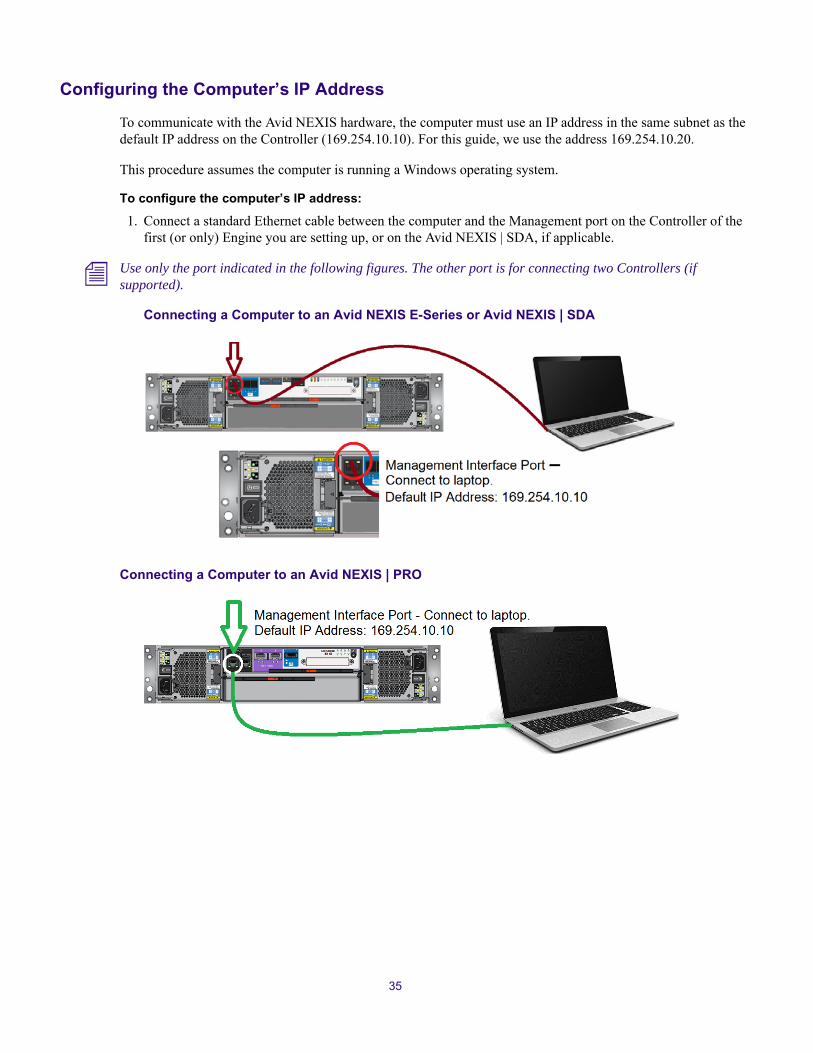
Configuring the Computer’s IP Address
To communicate with the Avid NEXIS hardware, the computer must use an IP address in the same subnet as the default IP address on the Controller (169.254.10.10). For this guide, we use the address 169.254.10.20.
This procedure assumes the computer is running a Windows operating system.
To configure the computer’s IP address:
1. Connect a standard Ethernet cable between the computer and the Management port on the Controller of the first (or only) Engine you are setting up, or on the Avid NEXIS | SDA, if applicable.
n Use only the port indicated in the following figures. The other port is for connecting two Controllers (if supported).
Connecting a Computer to an Avid NEXIS E-Series or Avid NEXIS | SDA
Connecting a Computer to an Avid NEXIS | PRO
35

2. Open the Windows Control Panel Network and Sharing Center, then do the following:
a. Click Local Area Connection.
b. Click Properties.
c. On the Network tab, select Internet Protocol Version 4 (TCP/IPv4), then click Properties.
36

d. Click Use the following IP address: and enter 169.254.10.20, with a subnet mask of 255.255.255.0, then click OK.
n By default, the Controller IP address on every Avid NEXIS system is set to 169.254.10.10. You must set the IP address of the computer to 169.254.10.xx, where xx can be anything except 10. For this example, we chose 169.254.10.20.
e. Click Close to exit the Local area Network Properties dialog.
f. Click Close to exit the Local area Network Status dialog.
g. Close the Control Panel.
37

Installing the Software and Setting up the Avid NEXIS System
Through the setup wizard, you can configure multiple Engines, both with and without a Avid NEXIS | SDA, identified by a single Storage System Name. You can also configure a redundant Controller in specific Avid NEXIS Engines or Avid NEXIS | SDA, effective with Avid NEXIS v6.1 and higher.
See “Supported Configurations” on page 2 for configurations that can share the same name space and see “Controllers” on page 12 for systems that support redundant controllers.
g If you are deploying a Avid NEXIS | SDA, configure it first, then configure the Engines.
This procedure covers all cases and indicates which of these steps applies to configuring multiple Engines.
c Each Avid NEXIS Engine and the Avid NEXIS | SDA, if applicable, must be connected to a switch for the software installation and configuration to work. If you have not yet connected the Avid NEXIS to a switch, see the Avid Network and Switch Guide.
To configure the system:
1. Open a browser and go to https://169.254.10.10:5015
n You might see a warning about the site’s security certificate. Double-check the IP address, and if it is correct, click Continue to this website.
2. At the login screen, enter the default password, se-admin
The wizard starts on the Install page.
38

a. Click Choose File to navigate to the location on the computer where you downloaded and extracted the Avid NEXIS software kit contents.
b. Select the file named AvidNEXISSetup_<version>-xxxxx.bin.
c. Click Submit.
The Engine installs the software and reboots, displaying messages about the installation progress and the time until the system will reboot.
3. When the system reboots, the Agent login screen is displayed again. Log back in to the Agent.
The CONFIGURE screen is displayed.
39
4. In the Engine area do the following:
a. (Required) Enter a Storage System Name. This is the name of the shared storage system containing one or more Avid NEXIS Engines, including the Avid NEXIS | SDA, if applicable.
(In a multi-Engine system with a Avid NEXIS | SDA, configure the Avid NEXIS | SDA first and enter the same Storage System Name for it and each Engine in the shared-storage system.)
b. (Optional) Enter a value for the Enclosure ID, which will be displayed on the Engine control panel; see “Avid NEXIS | E2, Avid NEXIS | E2 SSD, Avid NEXIS | PRO Engine Front View” on page 3. For example, in a four-Engine configuration, you could number them 01 through 04. If you do not enter a value, the default value (two dashes, or --) is displayed.
c. (Required) Enter a name for the Engine. The Engine name is used to generate the hostnames for the Controllers, which appear in the fields below for Top and Bottom Controllers (in the Avid NEXIS | E2, Avid NEXIS | E4, and Avid NEXIS | SDA) or Left and Right Controllers (in the Avid NEXIS | E5).
5. In the System Director area, do the following:
a. (Required) If you are not deploying a Avid NEXIS | SDA and want this Engine to function as the System director, check the box next to Run System Director. (This checkbox is not present on a Avid NEXIS | SDA, which is configured as the System Director automatically, or on an Avid NEXIS | E5 Engine, which cannot run as its own System Director. The Avid NEXIS | E5 requires the use of a Avid NEXIS | SDA.)
b. (Required) Enter an IP address for the System Director. This must be different from the IP addresses you will assign to the individual Controllers. For more information, see “System Director Name and IP Address” on page 33.
6. (Required) In the Data Interfaces area, enter the IP address, netmask, and gateway you received from your IT administrator for the Controllers present (or those you plan to install) in the Engine or Avid NEXIS | SDA.
This sets the address for the interface that communicates with the switch. If you have two Controllers, each must have a unique IP address, but the redundant Controller inherits the netmask and gateway from the first.
In a multi-Engine configuration, each Controller (in each Engine and the Avid NEXIS | SDA, if applicable) requires a unique IP address but must use the same netmask and gateway.
n In some systems only one controller is supported. If two controllers are detected, a radio button is displayed next to each controller. Select which controller you want to configure. See “Controllers” on page 12 for information about which controller (slot) to select for your system.
c Make a note of the System Director IP address you entered here; you will need it in a later step.
7. (Optional) In the Domain Name Service area, do the following:
a. Enter the DNS domain name for your environment.
b. In the DNS Server list field, enter the IP addresses, separated by spaces, for the DNS servers in your environment.
c. In the DNS Search List field, you can enter alternate DNS names, separated by spaces, that are used in your environment. These will be used to help resolve the System Director name in a browser.
8. Click Next.
The Time setup screen is displayed. Setting the system time is required, but you can choose between the following methods:
t To use a Network Time server, check the box and enter IP addresses for up to two NTP servers in your environment.
n In a multi-Engine configuration, enter NTP server or time information on all Engines.
40

t To manually set the date and time on the Engine, enter the current date, time, and select your time zone from the drop-down list.
If you configure one or more NTP servers and also manually set the date and time, the NTP servers take precedence.
9. Click Next.
The Administration password screen is displayed.
Changing the Agent password is optional. The password can be up to 8 ASCII characters long. If you do change the password, enter the same password on all Engines and the Avid NEXIS | SDA, if applicable, in the shared storage system.
c Be very careful when entering the passwords. If you mistype the new password you will not be able to log in again.
10. Click Finish.
The system reboots again to complete the configuration.
11. To configure another Avid NEXIS Engine, disconnect the computer from the Management Port on the first Engine and connect it to the Management Port on the next Engine.
The computer is still set to the IP address you configured earlier, which is standard for all Avid NEXIS Engines you are configuring. You do not need to change the computer’s IP address again.
12. Repeat this procedure until you have configured all the Engines that will be in the Avid NEXIS system.
c Make sure all the Engines that will belong to the same Avid NEXIS system have the same Storage System Name.
13. When you have configured all the Engines, disconnect the computer from the Engine. You can optionally restore the computer’s IP address to what it was originally. (Repeat the steps in “Configuring the Computer’s IP Address” on page 35, but at step 2d, instead of manually entering an IP address for the computer, click Obtain an IP address automatically.)
If you want to run the wizard again, open the Agent and click Wizard on the CONFIGURE tab. You can re-run the Wizard either to confirm your entries, or to make changes before you create the file system and bind Media Packs.
For information on those tasks, see the Avid NEXIS Administration Guide.
Upgrading an EngineWhen new releases of the Avid NEXIS software are available, you can upgrade the Avid NEXIS clients and Engines to take advantage of new features and bug fixes.
As of Avid NEXIS v7.0 and higher, the Management Console allows you to enter custom options to the installation. Use this field only with guidance from Avid Customer Care.
n If you are adding an Engine to an existing shared storage system, see “Adding an Engine to Your Infrastructure” on page 57.
Avid recommends upgrading the Avid NEXIS clients first, then upgrading the Avid NEXIS system. Clients can run a higher version of the Avid NEXIS software than the systems they are connecting to, according to the compatibility chart on the Avid NEXIS Documentation Knowledge Base. (For information on upgrading clients, see the Avid NEXIS Client Manager Installation and User’s Guide.)
41

Depending on your system and the version running, you upgrade the system components through either the Management Console or the Agent, as follows:
n In a multi-Engine configuration, all the Engines (all Storage Controllers) and the Avid NEXIS | SDA, if applicable, must be running the same version before the system can resume normal operation. Upgrading an Engine or the Avid NEXIS | SDA causes it to reboot; plan to do upgrades during a maintenance window with no client I/O occurring.
Upgrading an Avid NEXIS System, With or Without a Avid NEXIS | SDA
To upgrade an Avid NEXIS | PRO or any other Avid NEXIS Engine, including the Avid NEXIS | SDA, you can use the Management Console, System Settings page. This lets you upgrade all the system components through one interface and one operation. This is the recommended method for upgrading a multi-Engine Avid NEXIS system.
n Do not upgrade Engines or Controllers individually on the Engines or Storage Controllers pages.
To upgrade an Avid NEXIS System:
1. On your local computer, download the new software from Avid, using your support account.
2. Unzip the software on your computer.
3. In the Management Console, click System Settings under the Advanced heading.
4. On the System Settings page, click the Upgrade link.
System and Version to Upgrade From How to Upgrade
Avid NEXIS, single Engine system running v6.x or higher
Use the Management Console, System Settings page.
See “Upgrading an Avid NEXIS System, With or Without a Avid NEXIS | SDA” on page 42.
Avid NEXIS, multiple Engines with embedded System Director, running v6.x or higher
Use the Management Console, System Settings page.
See “Upgrading an Avid NEXIS System, With or Without a Avid NEXIS | SDA” on page 42.
Avid NEXIS | SDA and one or more Engines, running v6.x or higher
Use the Management Console, System Settings page.
See “Upgrading an Avid NEXIS System, With or Without a Avid NEXIS | SDA” on page 42.
42

5. Click Choose File, and navigate to the location of the software kit contents that you just unzipped.
6. Click Apply.
The kit is installed on each member of the system, and each reboots in turn. The Management Console remains open, displaying a series of status updates about the upgrade process, and a reboot countdown, until the last component has rebooted. (The countdown text is always centered on the display; if it obscures the Results panel, try resizing your browser window.)
43

The current login session ends, closing the Management Console. The login screen is displayed.
You can log back in to the Agent or the Management Console and confirm all the system components are running the new version. The version information is visible at the bottom of the Management Console and in the Agent page.
44

4 Adding and Replacing Hardware
The system is designed to remain operational if a component fails. You can expand your system (add an Engine, add more Media Packs) in real time, within the limits specified by your system configuration (see the Avid NEXIS ReadMe for configuration limits).
However, do not add any hardware if there are any issues with the system. Correct all problems before adding new hardware or making changes to the system, and perform quick checks to verify that the system is in good working order.
c Do not lift the chassis by the handles on the power supply units—they are not designed to support the weight.
c Always have available a replacement or blank module before removing the old module. When you replace a module, do not leave a bay empty for more than 10 minutes.
w Use a suitable anti-static wrist or ankle strap and observe all conventional ESD precautions when handling plug-in modules and components.
You can replace most hardware components without disrupting the system operation.
Collecting Logs for Customer Care
To help Avid evaluate returned components, collect any available system logs from the time the failure occurred, including any event or error messages, and send them to your Customer Care representative when ordering a replacement part.
To collect system logs:
1. In the Management Console, click System Status History.
2. Click Download.
A file named history.zip is created and saved to your default downloads directory.
3. Mention this file when ordering a replacement part. Your Customer Care representative can provide information on how to send that file to Avid.
Hardware Faults
LED colors are used consistently throughout the Engine and its components for indicating status:
• Green – good or positive indication
• Flashing green/amber – non-critical condition
• Amber – fault
Make sure that you have obtained a replacement module before removing any faulty module.

c Observe all conventional ESD precautions when handling Engine modules and components.
If the optional Avid NEXIS | SDA and Engine are not communicating:
• Verify that the network cables from the Engine and the System Director are connected to the same switch.
• Check the indicators on the Controller (see “Engines and System Director Appliance” on page 3).
About Drive FailuresWhen a drive fails, the drive fault LED illuminates (see “Media Pack and System Drives” on page 15) and the Management Console and Agent display an error (see the Avid NEXIS Administration Guide).
If the failed drive is part of a Media Pack and a spare drive is available, the Media Pack status changes to Drive rebuilding. The Media Pack is also rebuilt when a drive is removed from the Engine, whether or not it has failed.
If a system drive fails, the Avid NEXIS Engine continues to operate, but you should replace the failed drive as soon as possible. If both system drives in the same Engine fail, the Engine stops operating because no metadata for writes can be recorded. If the Engine is part of a multi-Engine configuration, the whole shared storage system fails due to the loss of the Engine.
For non-mirrored Workspaces, when one or more drives in the same Media Pack fail, the impact depends on the number of Workspaces using storage on the Media Pack and the Media Pack Protection Mode on the Workspaces. For example, if three Workspaces are using space on the same Media Pack (in an Avid NEXIS | E2 Engine, for example), and the Workspaces use 0, one-, and two-drive protection respectively, drive failures have the following impact:
When the new drive is inserted, Avid NEXIS automatically rebuilds the Media Pack or formats and partitions the new system drive, as applicable.
Identifying the Slot Number for a Failing or Failed DriveWhen a drive is failing or has failed, its status is displayed in several places:
• In the System Status panel of the Management Console.
• On the Engines page in the Management Console. Open the Details pane, and click Disks. The slot number is shown in the disk details table.
Workspace Protection Type(in Non-Mirrored Storage Group Only)
Number of Drives Failed Result
0 (unprotected) 1 Workspace unusable
1 1 Workspace remains online
1 2 Workspace unusable
2 1 Workspace remains online
2 2 Workspace remains online
2 3 Workspace unusable
46

• On the Media Packs pane in the Management Console. Open the Details pane and click Disks. The slot number is shown in the disk details table.
• On the STATISTICS tab in the Agent. Click Disk under the Media Pack heading.
• On the ADVANCED tab in the Agent. Select a Media Pack and click Disks, or click All Disks under the Storage Engine heading.
Removing the BezelOn the 2U and 4U chassis, you must remove the bezel to access the media drives.
To remove the bezel:
t Insert your fingers into the rectangular openings on the front of the bezel and gently pull. The bezel is held in place by small plastic tabs that latch onto the face of the Engine. On the 2U chassis, there are also two small metal posts that snap into holes on the front of the chassis.
t To reattach the bezel, gently snap it onto the front of the chassis.
Replacing a DriveAlways replace a system drive or Media Pack drive with an appropriate drive from Avid of the same size as the failed drive. For more information, see “Media Pack and System Drives” on page 15.
c Do not use a system drive from another Engine or System Director Appliance as a replacement. The system drives operate as a pair, and contain metadata from the original system they belonged to. Using a system drive from another chassis, even if new and never deployed, will cause problems because the system drives are initialized as a mirrored pair during the manufacturing process.
You can use a Media Pack drive from another Avid NEXIS Engine, but if it previously belonged to a Media Pack, you must clear its configuration before the new Engine can use it. See the Avid NEXIS Administration Guide for information about clearing a foreign disk error.
The replacement drive must be the same size as the failed drive, with the following exception: In a Media Pack, you can replace a smaller drive with a larger one (for example, use a 6TB HDD to replace a failed 2TB HDD). The Media Pack uses only 2TB of the space on the larger drive, however. You cannot replace a larger drive with a smaller one.
If you accidentally remove the wrong media drive while the Media Pack is reconstructing data for a failed drive, and client I/O is active, all client activity might stop after a brief delay as the system starts another reconstruction process. You can safely reinsert the drive within five minutes of removing it, and then remove the failed drive.
If a system drive fails, the system remains running as long as the other system drive is operating. If both system drives fail, the system shuts down.
After you replace a failed system drive, metadata reconstruction starts. The rebuild progress is displayed on the System Status Console in the Management Console. On an idle system, the rebuild typically completes within 20 minutes for a 400 GB drive. If the system is busy, the rebuild time can increase significantly, up to 40 hours if clients are performing heavy I/O (especially writes) during the entire rebuild process.
47

Removing a Drive (2U and 4U Chassis)
To remove a drive:
1. Remove the bezel; see “Removing the Bezel” on page 47.
2. Identify the drive to be replaced by looking for the amber LED on the drive that indicates a fault; see “Media Pack and System Drives” on page 15.
3. Make sure the anti-tamper locks are not engaged. The red arrows on the locks point inwards if the locks are disengaged. Unlock them if necessary by rotating them counterclockwise using a screwdriver with a Torx T20 bit.
4. Push the drive carrier latch in the direction of the white arrow.
5. Open the drive latch and pull the drive out of the slot.
Inserting a Drive (2U and 4U Chassis)
To insert a drive:
1. Fully open the drive latch.
2. Insert the drive into the slot with the latch facing left.
3. Push the drive in and push the latch inward until the drive locks in place.
4. Lock the drive.
5. Reattach the bezel.
Removing a Drive (E5)
To remove a drive:
1. Identify the drawer containing the failed drive; see “Avid NEXIS | E5 Drive Drawer and Sideplane Status Panel” on page 10.
2. Open the appropriate drive drawer and identify the failed drive by its LED. (See “Media Pack and System Drives” on page 15.)
3. Push the drive carrier latch in the direction shown in the following illustration to unlock the drive.
4. Pull the drive upwards and out of the drawer.
48

n If you are not going to replace the drive immediately, close the drawer so that correct airflow and cooling are maintained in the Engine.
Inserting a Drive (E5)
To insert a drive:
1. Open the appropriate drawer.
2. Lower the drive into the slot with the drive capacity label facing towards you.
3. Push the drive downwards and hold it down while sliding the drive carrier plate in the direction shown in the following figure. This locks the drive in place.
Make sure the drive is securely locked into place before closing the drawer.
4. Close and lock the drawer.
Adding Media Packs
Within the limits proscribed by your system configuration, you can add Media Packs to an existing, running system.
As a best practice, add Media Packs with the same capacity drives as the other Media Packs in your system. However, if you want to increase the total capacity of a Storage Group, you can add larger Media Packs and remove the smaller Media Packs. After you remove the last smaller-capacity Media Pack, the Storage Group expands to use the extra space. See the Avid NEXIS Administration Guide for more information.
If your system contains spare drives and you plan to add more drives of a different capacity, Avid recommends temporarily removing the spare drives before installing the new Media Pack drives. This prevents the system from assembling a Media Pack from mixed drive sizes, resulting in a Media Pack capacity based on the smallest of its drives.
Adding a Media Pack to an Engine (E4)
The Avid NEXIS | E4 Engine can contain up to two Media Packs of 10 drives each, and two optional spares. Two drive slots are reserved for the system drives. If your Avid NEXIS | E4 contains only one Media Pack, you can add another, inserting the drives in any order, in any available slots. The system combines any 10 unassigned drives into a Media Pack automatically.
49

To add a Media Pack to a Avid NEXIS | E4 Engine:
1. Remove the bezel; see “Removing the Bezel” on page 47.
2. For each drive, do the following:
a. Remove the blank drive plate.
b. Fully open the drive latch.
c. Insert the media drive into the slot with the latch facing left.
d. Push the media drive in and push the latch inward until the drive locks in place.
e. Lock the media drive.
3. Reattach the bezel.
Adding a Media Pack to an Engine (E5)
Avid NEXIS | E5 Engine has 84 drive slots, and can contain up to eight Media Packs of 10 drives each, and two optional spares. Two drive slots are reserved for the system drives. You can insert new Media Pack drives into any available slots; see “Installing System and Media Pack Drives (E5)” on page 27 for recommendations on how to populate the drive drawers. The system combines any 10 unassigned drives into a Media Pack automatically.
To add a Media Pack to an Avid NEXIS | E5 Engine:
1. Open the appropriate drawer.
2. For each drive in the Media Pack, and each (optional) spare:
a. Remove the blank drive plate.
b. Lower the drive into the slot with the drive capacity label facing towards you.
c. Push the drive downwards and hold it down while sliding the drive carrier plate in the direction shown in the following figure. This locks the drive in place.
Make sure the drive is securely locked into place before closing the drawer.
3. When all the drives are installed, close and lock the drawer.
50
Power Supply LEDs
When you encounter a problem with the power supply, check for:
• Missing or damaged power cords
• Incorrect or ungrounded circuits
• Proper power is supplied to the Engine
n When the Engine is turned on, all LEDs are lit for a short period to ensure that they are working. This does not indicate a fault unless the LEDs remain lit after a few seconds.
n If a power supply’s firmware is being programmed and the download fails, the power supply LEDs will flash.
See “Power Supplies” on page 18 for more information.
Replacing a Power Supply (2U and 4U)The power supplies in the 2U and 4U chassis include cooling fans as well as supplying power to the system. The power supplies are bi-directional; you can insert a power supply into either the left or right slot. When installed on the left side of the Engine, the plug is below the ON/OFF switch. When installed on the right side, the plug is above the ON/OFF switch.
To remove a power supply:
1. Open the strain relief and unplug the power cord.
2. Press the black release latch (see “Power Supplies” on page 18) towards the center of the module.
3. Open the silver latch, which disengages the power supply module from the Engine.
To insert a power supply:
1. Position the power supply so that the release latch and handle are closest to the Controller.
2. Slide the power supply into its slot and close the handle until the latch clicks in place.
3. Reconnect the power cord and secure the strain relief.
Replacing a Cooling Module (E5 only)
The Avid NEXIS | E5 is the only Avid NEXIS Engine with cooling modules that are not built in to the power supply. The Avid NEXIS | E5 designed to continue working with at least two of the five cooling modules.
n Make sure you have a replacement before removing a failed component to maintain proper airflow. When the Engine power is left on, insert the new cooling module within two minutes after removing the defective cooling module.
To remove a cooling module:
1. Identify the cooling module to be removed. If the module has failed, the fan fault LED will be lit amber (see “Avid NEXIS | E5 Rear View” on page 10).
2. Push down and hold the red release latch (callout 1 in the following figure) and pull the module out by its handle (callout 2).
51

To insert a cooling module:
1. Position the cooling module so that the red release latch and handle are on the right-hand side.
2. Slide the cooling module into its slot until the latch clicks in place. The Engine will automatically detect and make use of the new unit.
Replacing a Power Supply (E5)
The Avid NEXIS | E5 is the only Avid NEXIS Engine with power supplies that are separate from the cooling modules. The Avid NEXIS | E5 is designed to continue working with only one of the two power supplies.
n Make sure you have a replacement before removing a failed component to maintain proper airflow. When the Engine power is left on, insert the new power supply within two minutes after removing the defective power supply.
To remove a power supply:
1. Identify the power supply to be removed. If the module has failed, the fan fault LED will be lit amber.
2. Push the red release latch to the right and hold it (callout 1 in the following figure), then pull the module out by its handle (callout 2).
52
To insert a power supply:
1. Position the power supply so that the red release latch and handle are on the left-hand side.
2. Slide the power supply into its slot until the latch clicks in place. The Engine will automatically detect the new unit.
Installing a Redundant ControllerYou can order and install a redundant Controller for an Avid NEXIS Engine or the Avid NEXIS | SDA. You can install the redundant Controller at any time, even if the Engine or Avid NEXIS | SDA is already mounted in a rack.
For highest availability, Avid recommends installing a redundant Controller in all the Engines and Avid NEXIS | SDA, if applicable, in the entire shared storage system. However, you can install a redundant Controller in the Avid NEXIS | SDA alone, to ensure the System Director fails over if a Controller fails.
n Avid NEXIS | PRO and Avid NEXIS | E2 SSD do not support redundant controllers.
Repeat this procedure for each Engine and the Avid NEXIS | SDA if applicable.
To install and use a redundant Controller:
1. Upgrade the Engine or the Avid NEXIS | SDA to at least v6.1. See the Avid NEXIS Administration Guide for more information on upgrading your system.
Avid NEXIS v6.1 is the minimum release to support redundant Controllers.
2. Open the Agent and go to the CONFIGURE tab.
3. Enter the IP address for the redundant Controller before you physically install it.
4. Remove the blank plate covering the empty Controller slot.
5. Install the redundant Controller as follows:
a. Open the release latch on the new Controller all the way.
b. Note the correct orientation of the Controller for the system you are adding it to:
- In the 2U chassis the redundant Controller is installed upside down. See “Avid NEXIS | E2, Avid NEXIS | E2 SSD, and Avid NEXIS | SDA Rear View” on page 5.
- In the 4U chassis the redundant Controller is installed right side up, in the third slot from the top (leaving a one-slot gap between the first and redundant Controllers). See “Avid NEXIS | E4 Rear View” on page 6.
- In the 5U chassis the redundant Controller is installed in the right-hand slot. See “Avid NEXIS | E5 Rear View” on page 10.
c. Slide the replacement Controller into its slot until it will go no further.
d. Close the lever until it clicks in place.
The Controller engages with the connector on the midplane.
e. Check the Power/OK LED on the Controller to make sure it is lit; see “Controller for Avid NEXIS E-Series, System Director Appliance, and Avid NEXIS | PRO with 4TB Drives” on page 13 for more information.
6. Connect the two Controllers with the supplied cable between the ports indicated in the following figures. The cable provides ongoing communication between the Controllers and must remain in place.
53

As soon as the Controllers are connected, the original Controller sends the necessary firmware and configuration data to the redundant Controller, bringing them into sync.
Connecting Two Controllers in an Avid NEXIS | E2
Connecting Two Controllers in an Avid NEXIS | E4
Connecting Two Controllers in an Avid NEXIS | E5
54

7. Log in to the management Console and verify that both Controllers are displayed and running the same version. For more information see the Avid NEXIS Administration Guide.
About Controller FailuresWhen a Controller fails, the fault LED will be lit red.
In an Engine with a single Controller, clients cannot access Workspaces until the Controller is replaced.
c In an Avid NEXIS | E5 with a single controller, the replacement controller will work only in the same slot as the original factory-installed controller; by default, slot 0, or the slot on the left of the Engine looking at the rear.
n Make sure you have a replacement before removing a failed component. When the Engine power is left on, insert the new Controller within two minutes of removing the defective Controller.
Make sure you have an appropriate replacement for the failed Controller. See “Avid NEXIS Platforms” on page 1 for more details.
Replacing a Controller
To replace a Controller:
1. Make note of the locations of all cables (between the two Controllers, if applicable, and to the switch) and disconnect them from the failed Controller.
2. Pinch the latch on the Controller and pull the handle toward you.
The controller disengages from the connector on the midplane.
3. Pull the Controller out of the Engine.
4. Hold the replacement Controller in the same orientation as the one you removed.
5. Open the release latch lever all the way.
6. Slide the replacement Controller into its slot until it will go no further.
7. Close the lever until it clicks in place.
The Controller engages with the connector on the midplane. The Controller automatically detects the new receives the software and all the other system information from the system drives. In a single-Controller configuration, if the failed Controller was functioning as the System Director, the new Controller becomes the System Director.
55

8. Connect the cables to the replacement Controller (if necessary, refer to the notes you made before removing the cables).
Removing or Replacing a ChassisIf you have a system problem that cannot be fixed by replacing the other hardware components, the problem might be a faulty chassis. You can move the existing Media Packs, system drives, and Controllers to a new chassis.
c Make sure to move the two system drives (SSDs) along with the Media Packs to the new chassis.
For Avid NEXIS Engines using media mirroring (engine protection), mirrored Workspaces can operate with one Engine offline. All media is available and accessible but not fully mirrored. If a replacement chassis is not available, perform a Remove Redistribution of the failed Engine to recreate the mirrored Workspaces, assuming there is enough free space on the remaining Engines. See the Avid NEXIS Administration Guide for information about performing redistribution.
To replace a chassis:
1. Log in to the Agent.
n The default Agent Administrator password is “se-admin.”
2. Write down the hostname, IP address, and other important network details, to reuse if you are replacing the failed chassis with a new one.
3. Click the ADVANCED tab.
4. Under System Tools, click Shutdown.
5. Type the Administrator password into the password field and click Shutdown.
Allow one minute for the buffers to clear.
6. Make note of the locations of all Ethernet cables and disconnect them from the Controllers in the failed chassis.
7. Turn off the switches on all the power supply modules.
8. Disconnect all Ethernet cables and power cables from the failed chassis.
9. Carefully remove all the media drives, system drives, Controllers, and the power supplies and fans, if applicable, and put them in a safe place.
10. Remove the failed chassis from the rack.
To replace a chassis:
1. Install the new empty chassis into the rack.
2. Insert all the media drives and system drives from the old chassis into the new one.
3. Insert the Controllers and power supplies from the old chassis into the new one (see “Avid NEXIS System Overview” on page 1 for the proper orientation of Controllers in the chassis).
n When re-using a Controller in the same shared storage system, the IP address and software is recognized by the System Director and needs no reconfiguration.
4. Connect all Ethernet and power cables to the new chassis.
5. Turn on the new chassis.
56

Allow two minutes for the new chassis to initialize.
n If any of the LEDs indicate an error, call Avid Customer Care.
6. Open the Management Console and verify that the Media Packs are online with a green icon and no status messages on the Media Packs page.
n If any Status errors are listed, call Avid Customer Care.
7. Verify that media is available to the clients.
Adding an Engine to Your InfrastructureYou can add more Avid NEXIS Engines to your infrastructure to increase available space and allow for more flexible configurations. See “Supported Configurations” on page 2 for information about the number of Engines and Media Packs supported in configurations with and without an Avid NEXIS | SDA.
The Media Packs in a newly-added Engine can be added to an existing Storage Group or used to create a new Storage Group.
Before You Begin:
t Open the Agent of the existing system and make a note of the following information:
- Storage System Name (on the STATUS tab)
- Avid NEXIS version (also on the STATUS tab)
- IP Address, netmask, and gateway assigned to the Controllers in all Engines in the shared storage system (on the CONFIGURE tab for each Engine, or on the Storage Controllers page [Details pane] in the Management Console)
To add Engines to an existing Avid NEXIS shared storage system:
1. Rack-mount the chassis and connect the power cables as described in Chapter 2.
2. Connect a 10Gb network cable (or two cables if you have redundant controllers and are using LACP) to the same subnet on the switch currently used by the existing Avid NEXIS system.
3. Turn on the new chassis.
4. Connect the Management Port on the Controller (the top or left Controller, if there are two) to a laptop or local computer and configure the computer’s IP address to 169.254.10.20 and the subnet to 255.255.255.0.
5. Launch a browser and open the Agent on the new chassis: https://169.254.10.10:5015.
6. Download and install the same Avid NEXIS software version that is running on the existing shared storage system. As part of the software installation, the chassis reboots.
7. After the chassis restarts, reopen the Agent and configure the new system, with the following information:
a. Enter the same Storage System Name as the existing shared storage system it is joining.
b. Enter a name for the new chassis in the Engine Name field, and optionally enter an Enclosure ID.
c. Do not check the box to “Run as System Director.”
d. In the Data Interfaces section, enter an IP address for the Controller (or both Controllers, if applicable) in the same subnet as the existing shared storage system. If using redundant Controllers and LACP, check the Link Aggregation box.
e. Click Submit.
57

The system reboots again.
8. When it has restarted, log in to the Management Console for the shared storage system. The new Engine appears in the Engines list with unbound Media Packs.
9. Bind the Media Pack (or Packs) to the existing file system. See the Avid NEXIS Administration Guide for more information.
10. Add the Media Pack (or Packs) to an existing Storage Group or you can create a new Storage Group. See the Avid NEXIS Administration Guide for more information.
If you add the Media Packs to an existing Storage Group, redistribution will begin.
58

5 Specifications and Notices
This section provides information on the physical and electrical specifications for the Avid NEXIS Engines and the optional external System Director. Avid recommends the use of an Uninterruptible Power Supply (UPS) and supported network cabling.
Physical
Electrical and Power
UPS systems must specify a transfer time of <10ms in order to prevent power loss to the power supply modules. The power supply modules for an Engine should not be connected to the same UPS.
Component Width Depth Height Weight
Avid NEXIS | SDA 483 mm (19 in) 630 mm (24.8 in) 88.9 mm (3.5 in) 16.7 kg (37 lb)
Avid NEXIS | E2,
Avid NEXIS | E2 SSD,
Avid NEXIS | PRO
483 mm (19 in) 630 mm (24.8 in) 88.9 mm (3.5 in) 26 kg (57.2 lb) with drives
Avid NEXIS | E4 483 mm (19 in) 630 mm (24.8 in) 177.8 mm (7 in) 46 kg (101.41 lb) with drives
Avid NEXIS | E5 483 mm (19 in) 933 mm (36.75 in) 220 mm (8.65 in) 128 kg (282 lb) with drives
Avid NEXIS | SDA
Avid NEXIS | E2, Avid NEXIS | E2 SSD, Avid NEXIS | PRO Avid NEXIS | E4 Avid NEXIS | E5
Power Supplies Dual 764W Dual 764W Quad 580W Dual 2200W
Voltage 100 to 240 Vac 100 to 240 Vac 100 to 240 Vac 200 to 240 Vac
Frequency 60/50 Hz 60/50 Hz 60/50 Hz 60/50 Hz
Power Conversion Efficiency or Power Consumption
>80% @ 100V, >80% @ 240V (>30% load)
>80% @ 100V, >80% @ 240V (>30% load)
>83% @ 100V, >85% @ 240V (>30% load)
92% @ 240V (50% load)
Maximum Start-Up Power 764W 764W 1160W 2200W
BTU/Hr 2607 2607 3958 7507
Average Load Power 200Wa
a. Estimated
253W 512W Not measured
BTU/Hr 683a 863 1747 Not measured

Altitude and Temperature
Shock, Vibration and Noise
ComponentOperating Temperature
Operating Humidity
Operating Altitude Non-operating Altitude
Avid NEXIS | SDA 5° to 40° C
(41° to 104° F)
8% to 80% non-condensing
0 to 3000 m (0 to 10,000 ft)
-300 to 12,192 m (-1000 to 40,000 ft)
Avid NEXIS | E2, Avid NEXIS | E2 SSD, Avid NEXIS | PRO
5° to 40° C
(41° to 104° F)
8% to 80% non-condensing
0 to 3000 m (0 to 10,000 ft)
-300 to 12,192 m (-1000 to 40,000 ft)
Avid NEXIS | E4 5° to 40° C
(41° to 104° F)
20% to 80% non-condensing
0 to 3000 m (0 to 10,000 ft)
-300 to 12,192 m (-1000 to 40,000 ft)
Avid NEXIS | E5 5º to 35ºC
(41° to 95° F)
20% to 80% non-condensing
0 to 3000 m (0 to 10,000 ft)
-300 to 12,192 m (-1000 to 40,000 ft)
ComponentOperational Shock
Operational Vibration
Non-operational Shock
Non-operational Vibration
Relocation Vibration Acoustics
Avid NEXIS | SDA 5g 10ms ½ Sine Random 0.21g RMS 5-500Hz
20g 10ms ½ Sine Random 1.04g RMS 2-200Hz
Swept Sine 0.3g 2-200Hz
Sound power operating < 6.5 Bels LWAd @ 23°C
Avid NEXIS | E2,Avid NEXIS | E2 SSD,Avid NEXIS | PRO
5g 10ms ½ Sine Random 0.21g RMS 5-500Hz
20g 10ms ½ Sine Random 1.04g RMS 2-200Hz
Swept Sine 0.3g 2-200Hz
Sound power operating < 6.5 Bels LWAd @ 23°C
Avid NEXIS | E4 5g 10ms ½ Sine Random 0.21g RMS 5-500Hz
30g 10ms ½ Sine Random 1.04g RMS 2-200Hz
Swept Sine 0.3g 2-200Hz
Sound power operating < 7.2Bels LWAd @ 23°C
Avid NEXIS | E5 5g 10ms ½ Sine Random 0.21g RMS 5-500Hz
30g 10ms ½ Sine Random 1.04g RMS 2-200Hz
Swept Sine 0.3g 2-200Hz
Sound power operating < 8.0Bels LWAd @ 23°C
60

Approvals
Uninterruptible Power Supply (UPS)
Avid highly recommends you create a separate derived power system for your Avid NEXIS. This provides protection against sudden power surges or losses that could cause you to lose files or experience data corruption. The power outlets must be served by the same distribution panel. This helps prevent ground loops that can be caused by plugging equipment into power sources with different ground potentials.
See “Power Supplies” on page 18 for more information, and provide a UPS that meets the power requirements of each individual power supply module in the Engines in your environment. Make sure there is adequate, dedicated power for each UPS.
w Make sure all the electrical work at your site is done by a licensed electrician. The electrical changes must meet country, state, and local electrical codes.
Component EMC Safety
Avid NEXIS | SDA FCC pt15B Class A, EN55022 Class A, CISPR 22 Class A, EN 55024, CISPR24, EN61000-3-2/3, CNS13438
EN/IEC/UL 60950-1, CNS14336 CB report: CE, UL, cUL, FCC, BSMI, VCCI, CCC (PSU only)
Avid NEXIS | PRO FCC pt15B Class A, EN55022 Class A, CISPR 22 Class A, EN 55024, CISPR24, EN61000-3-2/3, CNS13438
EN/IEC/UL 60950-1, CNS14336 CB report: CE, UL, cUL, FCC, BSMI, VCCI, CCC (PSU only)
Avid NEXIS | E2, Avid NEXIS | E2 SSD
FCC pt15B Class A, EN55022 Class A, CISPR 22 Class A, EN 55024, CISPR24, EN61000-3-2/3, CNS13438
EN/IEC/UL 60950-1, CNS14336 CB report: CE, UL, cUL, FCC, BSMI, VCCI, CCC (PSU only)
Avid NEXIS | E4 FCC pt15B Class A, EN55022 Class A, CISPR 22 Class A, EN 55024, CISPR24, EN61000-3-2/3, CNS13438
EN/IEC/UL 60950-1, CNS14336 CB report: CE, UL, cUL, FCC, BSMI, VCCI, CCC (PSU only)
Avid NEXIS | E5 FCC pt15B Class A, EN55022 Class A, CISPR 22 Class A, EN 55024, CISPR24, EN61000-3-2/3, CNS13438
EN/IEC/UL 60950-1, CNS14336 CB report: CE, UL, cUL, FCC, BSMI, VCCI, CCC (PSU only)
61

6 Safety and Regulatory Information
This document contains safety and regulatory information for Avid NEXIS hardware.
Warnings and Cautions
c This equipment is intended only for installation in a RESTRICTED ACCESS LOCATION.
c Never install equipment if it appears damaged.
c Disconnect the power cord before servicing unit.
c Only perform the services explicitly described in this document. For services or procedures not outlined in this document, speak with authorized Avid service personnel.
c Follow all warnings and cautions in the procedures.
c Operate the device within its marked electrical ratings and product usage instructions.
c If you need to replace a battery in an Avid hardware unit, be sure to use the correct battery type. There might be a risk of explosion if a battery is replaced by an incorrect type. Dispose of used batteries according to the manufacturer's instructions.
c For products with a power switch the main power switch should remain accessible after installation.
Proposition 65 Warning
This product contains chemicals known to the State of California to cause cancer and birth defects or other reproductive harm.
FCC NoticePart 15 of the Federal Communication Commission Rules and Regulations has established Radio Frequency (RF) emission limits to provide an interference free radio frequency spectrum. Many electronic devices produce RF energy incidental to their intended purpose. These rules place electronic equipment into two classes, A and B, depending on the intended use.
Class A devices are those that may be expected to be installed in a business or commercial environment. Class B devices are those that may be expected to be installed in a home or residential environment. The FCC requires devices in both classes to be labeled with the interference likelihood and additional operating instructions. The rating label on the equipment will show which class the product is (A or B). Class A product will not have an FCC logo. Class B equipment will have an FCC logo. The information statements differ on the two classes.

Class A Equipment
This equipment has been tested and found to comply with the limits for a Class A digital device, pursuant to Part 15 of the FCC rules. These limits are designed to provide reasonable protection against harmful interference when the equipment is operated in a commercial environment. This equipment generates, uses, and can radiate radio frequency energy and, if not installed and used in accordance with the instructions, may cause harmful interference to radio communications. Operation of this equipment in a residential area is likely to cause harmful interference, in which case the user will be required to correct the interference at personal expense.
Class B Equipment
This equipment has been tested and found to comply with the limits for a Class B digital device, pursuant to Part 15 of the FCC Rules. These limits are designed to provide reasonable protection against harmful interference in a residential installation. This equipment generates, uses, and can radiate radio frequency energy and, if not installed and used in accordance with the instructions, may cause harmful interference to radio communications. However, there is no guarantee that interference will not occur in a particular installation. If this equipment does cause harmful interference to radio or television reception, which can be determined by turning the equipment off and on, the user is encouraged to try to correct the interference by one or more of the following measures:
• Reorient or relocate the receiving antenna
• Increase the separation between the equipment and receiver
• Connect the equipment into an outlet on a circuit different from that to which the receiver is connected
• Consult the dealer or an experienced radio or television technician for help
Modifications
The FCC requires the user to be notified that any changes or modifications made to Avid hardware that are not expressly approved by Avid Technology may void the user’s authority to operate the equipment.
Cables
Connections to Avid hardware must be made with shielded cables with metallic RFI/EMI connector hoods in order to maintain compliance with FCC Rules and Regulations.
Canadian Notice (Avis Canadien)
Class A Equipment
This Class A digital apparatus meets all requirements of the Canadian Interference-Causing Equipment Regulations.
Cet appareil numérique de la classe A respecte toutes les exigences du Règlement sur le matériel brouilleur du Canada.
Class B Equipment
This Class B digital apparatus meets all requirements of the Canadian Interference-Causing Equipment Regulations.
63

Cet appareil numérique de la classe B respecte toutes les exigences du Règlement sur le matériel brouilleur du Canada.
LED Safety Notices
Avid hardware might contain LED or Laser devices for communication use. These devices are compliant with the requirements for Class 1 LED and Laser Products and are safe in the intended use. In normal operation the output of these laser devices does not exceed the exposure limit of the eye and cannot cause harm.
Standard to which conformity is declared: (Class 1 LED Product per IEC 60825-1:2007)
European Union Declaration of Conformity
Declaration of conformityKonformitätserklärungDéclaration de conformitéDeclaración de ConfomidadVerklaring de overeenstemmingDichiarazione di conformità
We/Wir/Nous/WIJ/Noi:
Avid Technology75 Network DriveBurlington, MA, 01803 USA
European Contact: Nearest Avid Sales and Service Office orAvid Technology International B.V.Sandyford Industrial EstateUnit 38, Carmanhall RoadDublin 18, Ireland
declare under our sole responsibility that the product,erklären, in alleniniger Verantwortung,daß dieses Produkt,déclarons sous notre seule responsabilité que le produit,declaramos, bajo nuestra sola responsabilidad, que el producto,verklaren onder onze verantwoordelijkheid, dat het product,dichiariamo sotto nostra unica responsabilità, che il prodotto,
64

Product Option(s): This declaration covers all options for the above product(s).
to which this declaration relates is in conformity with the following standard(s) or other normative documents.auf das sich diese Erklärung bezieht, mit der/den folgenden Norm(en) oder Richtlinie(n) übereinstimmt.auquel se réfère cette déclaration est conforme à la (aux) norme(s) ou au(x) document(s) normatif(s).al que se refiere esta declaración es conforme a la(s) norma(s) u otro(s) documento(s) normativo(s).waarnaar deze verklaring verwijst, aan de volende norm(en) of richtlijn(en) beantwoordt.a cui si riferisce questa dichiarazione è conforme alla/e seguente/i norma/o documento/i normativo/i.
The requirements of the European Council:
Safety: Directive 2006/95/EC
UL 60950-1, 2nd editionCAN/CSA-C22.2 No. 60950-1-07; 2007IEC 60950-1, 2nd editionEN 60950-1:2006
EMC: Directive 2004/108/EC
EN55022:2006 /A1:2007EN55024:1998 /A1:2001 /A2:2003EN61000-3-2:2006EN61000-3-3:2008
Issued In Burlington MA, USA 2011
Disposal of Waste Equipment by Users in the European Union
This symbol on the product or its packaging indicates that this product must not be disposed of with other waste. Instead, it is your responsibility to dispose of your waste equipment by handing it over to a designated collection point for the recycling of waste electrical and electronic equipment. The separate collection and recycling of your waste equipment at the time of disposal will help conserve natural resources and ensure that it is recycled in a manner that protects human health and the environment. For more information about where you can drop off your waste equipment for recycling, please contact your local city recycling office or the dealer from whom you purchased the product.
Product Name Model Number
Avid NEXIS | PRO 9900-65604-XX, 9900-71318-XX
Avid NEXIS | E2 9900-65696-XX
Avid NEXIS | E2 SSD 9900-71283-00
Avid NEXIS | E4 9900-65603-XX
Avid NEXIS | E5 9900-65605-XX
Avid NEXIS | SDA 9900-65697-XX
65

Argentina Conformity
Made in USA
Australia and New Zealand EMC Regulations
Ken HopkinsAvid Technology (Aust) Pty Ltdc/o – Elliot HouseSuite 810, Level 8140 Arther StNorth SydneyNSW – 2060
Japan EMC Regulations
Class A Equipment
This is a Class A product. In a domestic environment this product may cause radio interference in which case the user may be required to take corrective actions. VCCI-A
Korean EMC Regulations
Class A Equipment
Please note that this equipment has obtained EMC registration for commercial use. In the event that it has been mistakenly sold or purchased, please exchange it for equipment certified for home use.
66

Taiwan EMC RegulationsTaiwan EMC Regulations BSMI Class A EMC Warning
Warning Statement
1. UV ray radiation
- Following statement or equivalent:
- Following marking or other equivalent marking:
2. Operator touchable area protection
Operation manual should have following statement and statement should be shown on device, or put on similar sentence:
3. Heat-related hazards
67

Injury may result from high temperatures under normal operating conditions, causing:
- Burns due to contact with hot accessible parts
- Degradation of insulation and of safety-critical components
- Ignition of flammable liquids
Examples of measures to reduce risks include:
- Taking steps to avoid high temperature of accessible parts
- Avoiding temperatures above the ignition point of liquids
- Provision of marking to warn USERS where access to hot parts is unavoidable
High temperature warning marking — you may use the following high temperature warning marking:
4. Mechanical hazards
Injury may result from:
- Sharp edges and corners
- Moving parts which have the potential to cause injury
- Equipment instability
- Flying particles from imploding cathode ray tubes and exploding high pressure lamps
Examples of measures to reduce risks include:
- Rounding of sharp edges and corners
- Guarding
- Provision of SAFETY INTERLOCKS
- Providing sufficient stability to free-standing equipment
- Selecting cathode ray tubes and high pressure lamps that are resistant to implosion and explosion respectively
- Provision of markings to warn USERS where access is unavoidable
5. Radiation
Injury to USERS and to SERVICE PERSONS may result from some forms of radiation emitted by equipment.
Examples are sonic (acoustic), radio frequency, infra-red, ultraviolet and ionizing radiation, and high intensity visible and coherent light (lasers).
Examples of measures to reduce risks include:
- Limiting the energy level of potential radiation sources
- Screening radiation sources
- Provision of SAFETY INTERLOCKS
- Provision of markings to warn USERS where exposure to the radiation hazard is unavoidable
6. Chemical hazards
68
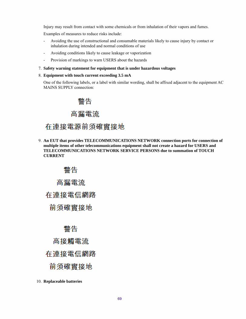
Injury may result from contact with some chemicals or from inhalation of their vapors and fumes.
Examples of measures to reduce risks include:
- Avoiding the use of constructional and consumable materials likely to cause injury by contact or inhalation during intended and normal conditions of use
- Avoiding conditions likely to cause leakage or vaporization
- Provision of markings to warn USERS about the hazards
7. Safety warning statement for equipment that is under hazardous voltages
8. Equipment with touch current exceeding 3.5 mA
One of the following labels, or a label with similar wording, shall be affixed adjacent to the equipment AC MAINS SUPPLY connection:
9. An EUT that provides TELECOMMUNICATIONS NETWORK connection ports for connection of multiple items of other telecommunications equipment shall not create a hazard for USERS and TELECOMMUNICATIONS NETWORK SERVICE PERSONS due to summation of TOUCH CURRENT
10. Replaceable batteries
69

If an equipment is provided with a replaceable battery, and if replacement by an incorrect type could result in an explosion (for example, with some lithium batteries), the following applies:
- If the battery is placed in an OPERATOR ACCESS AREA, there shall be a marking close to the battery or a statement in both the operating and the servicing instructions
- If the battery is placed elsewhere in the equipment, there shall be a marking close to the battery or a statement in the servicing instructions
The marking or statement shall include the following or similar text:
11. Warning to service persons
Suitable markings shall be provided on the equipment or a statement shall be provided in the servicing instructions to alert a SERVICE PERSON to a possible hazard, where both of the following conditions exist:
- Where a fuse is used in the neutral of single-phase equipment either permanently connected or provided with a non-reversible plug
- Where, after operation of the fuse, parts of the equipment that remain energized might represent a hazard during servicing
The following or similar wording is regarded as suitable:
70

Index
AAccidental drive removal 47Adding Engines to system 57Agent
access to Setup Wizard 41default password 56
anti-static wrist or ankle strap 45Argentina Conformity 66Attaching the bezel 47Australia EMC regulations 66Avid
online support viitraining services viii
Avid NEXIS E2Control panel 7drive numbering 3front view 3rear view 5
Avid NEXIS E2 SSDdrive numbering 3front view 3rear view 5
Avid NEXIS E4Control panel 7drive numbering 6front view 6rear view 6
Avid NEXIS E5control panel 9drive drawer panel 10drive numbering 11Engine status and control panel 9front view 8rear view 10sideplane panel 10
Avid NEXIS platformsdescriptions 1
Avid NEXIS PROControl panel 7drive numbering 3front view 3rear view 4
Avid NEXIS SDAControl panel 7front view 4rear view 5
BBezel
attaching 47removing 47
CCables
between controllers 53space for connecting 23
Canadianinterference causing equipment regulations 63, 66
Chassis See EngineClearance around equipment 23Computer
configuring IP address 34, 35connecting to Avid NEXIS Engine 34, 35
ConfiguringEngine 38IP address on computer for setup 34, 35
Connecting cables 23Control panel 7
Avid NEXIS E2 7Avid NEXIS E2 SSD 7Avid NEXIS E4 7Avid NEXIS E5 9Avid NEXIS PRO 7Avid NEXIS SDA 7
ControllersAvid NEXIS E2 12Avid NEXIS E2 SSD 12Avid NEXIS E4 12Avid NEXIS E5 12Avid NEXIS PRO 12Avid NEXIS SDA 12connecting 53function 12installing redundant 53IP addresses 32location
Avid NEXIS E2 5Avid NEXIS E2 SSD 5Avid NEXIS E4 6Avid NEXIS E5 10Avid NEXIS PRO 4Avid NEXIS SDA 5
name, about 33redundant 12replacing 55shutting down 56types of 12valid replacement 55
Cooling modules

LEDs 18status 18
DDNS
domain namesearch listservers
Domain Name ServiceSee DNS
Downloading software kit 34, 35Drive drawer panel (5U) 10Drive failures
and Workspace protection 46finding slot number 46indicators 46system behavior 46
Drive numbering2U 34U 65U 11
Drivesanti-tamper lock 15capacity 15installing 27label 15LEDs 15, 17Media Packs 15removing 47removing by accident 47replacing 47slot locations 15status 15type 15
EEIA rack units 23Engine
adding to existing storage system 57configuring 38connecting to switch 29cooling modules 18front view (2U) 3front view (4U) 6front view (5U) 8input/mute switch 7installing software 38LEDs 8name 33power supplies 5, 6, 10rear view (2U, SDA) 5rear view (4U) 6rear view (5U) 10unit ID LED 7
upgrading 41Engine protection for Workspaces 2ESD precautions 46European Union notice 64Extracting software kit 34, 35
FFCC notice 62Front view
Avid NEXIS E2 3Avid NEXIS E2 SSD 3Avid NEXIS E4 6Avid NEXIS E5 8Avid NEXIS PRO 3System Director Appliance 4
GGateway and netmask 32
HHardware
faults 45status LEDs 45
Hostnameallowed characters 32max length 32System Director 32
IInstallation overview 34Installing
Media Packs (2U, 4U) 27Media Packs (5U) 27redundant Controller 53software 38system drives (5U) 27
IP addressfor computer used in setup 34, 35NTP servers 32System Director 33
LLACP 29LEDs
drives 17Engine 8Engine ID 7hardware status 45
Link aggregation 29ports 15

MManagement port, connecting computer to 34, 35Media Pack drives
capacity 15label 15replacement size 48slot locations 15type 15
Media Packsabout 15
NNetmask and gateway 32New Zealand EMC regulations 66NIC teaming 29NTP servers, IP addresses 32
OOnline support vii
PPower supplies
Engines 18LEDs 18location 5, 6, 10status 18
RRack requirements 23Rear view
Avid NEXIS E2 5Avid NEXIS E2 SSD 5Avid NEXIS E4 6Avid NEXIS E5 10
rear viewAvid NEXIS PRO 4
Regulatory information 62Removing
bezel 47Controller 55drives 47Engine 56power supply 51
Replacingbezel 47Controller 55drives 47Engine 56power supply 51
Requirements for rack mounting 23Running Setup Wizard 41
SSafety information 62Servicing, space for 23Setup Wizard 41Shutdown 56Sideplane panel (5U) 10Software
installing 38upgrading 41
Software kitcontents 34downloading 34, 35extracting 34, 35
Space for accessing components 23Storage System Name
about 33allowed characters 32defined 32length 32
Supported configurationsEngine protection for Workspaces 2with embedded System Director 2with System Director Appliance 2
Switchconnecting to Engine 29link aggregation (LACP) 29required hardware 29
System details 3System Director 15
functions 15IP address 33name (hostname) 32, 33upgrading 41
System Director ApplianceSee Avid NEXIS SDA
System drivescapacity 15installing (5U) 27label 15replacement size 48slot locations 15
TTaiwan EMC regulations 67Training services viiiTroubleshooting vii
UUpgrading
Engines 41software 41

WWizard, Setup 41
74

Avid75 Network DriveBurlington, MA 01803-2756 USA
Technical Support (USA)Visit the Online Support Center at www.avid.com/support
Product InformationFor company and product information, visit us on the web at www.avid.com
Related Documents