МИНИСТЕРСТВО НАУКИ И ВЫСШЕГО ОБРАЗОВАНИЯ РОССИЙСКОЙ ФЕДЕРАЦИИ ФЕДЕРАЛЬНОЕ ГОСУДАРСТВЕННОЕ АВТОНОМНОЕ ОБРАЗОВАТЕЛЬНОЕ УЧРЕЖДЕНИЕ ВЫСШЕГО ОБРАЗОВАНИЯ «САМАРСКИЙ НАЦИОНАЛЬНЫЙ ИССЛЕДОВАТЕЛЬСКИЙ УНИВЕРСИТЕТ ИМЕНИ АКАДЕМИКА С.П. КОРОЛЕВА» (САМАРСКИЙ УНИВЕРСИТЕТ) MINISTRY OF SCIENCE AND HIGHER EDUCATION OF THE RUSSIAN FEDERATION SAMARA NATIONAL RESEARCH UNIVERSITY (SAMARA UNIVERSITY) N.M. BORGEST AVIATION POWER PLANTS Рекомендовано редакционно-издательским советом федерального государственного автономного образовательного учреждения высшего образования «Самарский национальный исследовательский университет имени академика С.П. Королева» в качестве учебного пособия для обучающихся по основной образовательной программе высшего образования по направлению подготовки 24.03.04 Авиастроение SAMARA SAMARA UNIVERSITY PUBLISHING HOUSE 2020

Welcome message from author
This document is posted to help you gain knowledge. Please leave a comment to let me know what you think about it! Share it to your friends and learn new things together.
Transcript

МИНИСТЕРСТВО НАУКИ И ВЫСШЕГО ОБРАЗОВАНИЯ РОССИЙСКОЙ ФЕДЕРАЦИИ
ФЕДЕРАЛЬНОЕ ГОСУДАРСТВЕННОЕ АВТОНОМНОЕ ОБРАЗОВАТЕЛЬНОЕ УЧРЕЖДЕНИЕ ВЫСШЕГО ОБРАЗОВАНИЯ
«САМАРСКИЙ НАЦИОНАЛЬНЫЙ ИССЛЕДОВАТЕЛЬСКИЙ УНИВЕРСИТЕТ ИМЕНИ АКАДЕМИКА С.П. КОРОЛЕВА»
(САМАРСКИЙ УНИВЕРСИТЕТ)
MINISTRY OF SCIENCE AND HIGHER EDUCATION OF THE RUSSIAN FEDERATION
SAMARA NATIONAL RESEARCH UNIVERSITY (SAMARA UNIVERSITY)
N.M. BORGEST
AVIATION POWER PLANTS
Рекомендовано редакционно-издательским советом федерального государственного автономного образовательного учреждения высшего образования «Самарский национальный исследовательский университет имени академика С.П. Королева» в качестве учебного пособия для обучающихся по основной образовательной программе высшего образования по направлению подготовки 24.03.04 Авиастроение
SAMARA SAMARA UNIVERSITY PUBLISHING HOUSE
2020

2
УДК 629.7.03(075) ББК 39.55я7 B78
Reviewers:
Ph.D. Smirnov S.V., Deputy Director, ICCS RAS Ph.D. Falaleev S.V., Head of the Aircraft Engines Design Department,
Samara University Borgest, Nikolay Mihailovich
B78 Aviation power plants: text book / N.M. Borgest. – Samara: Samara University Publishing House. – 2020. – 84 p.
ISBN 978-5-7883-1562-1
Теxt book “Aviation power plants” for English-speaking students studying under the curriculum of preparation of bachelors in the direction “Aircraft industry”, training profile – “Aircraft construction”.
Educational-methodical complex of discipline (EMCD) "Aviation power plants" is prepared for students studying under the curriculum of preparation of bachelors in the direction 24.03.04 Aircraft industry, training profile – Aircraft construction. The main purpose of this discipline is the acquisition by students of knowledge about aviation power plants and the formation of their skills in selecting and evaluating the engine for the aircraft, taking into account the norms of the Aviation Regulations. EMCD "Aviation power plants" includes the following: a working program, a summary of lectures, methodological instructions for laboratory works and questions for credit.
In the process of studying the discipline, students should become acquainted with the purpose, composition, types, classifications of aircraft power plants, the main elements of the design of aircraft GTE and the parameters of modern aircraft power plants, the basic terms and concepts of aviation power plants, learn how to work with regulatory documentation (FAR, Interstate Standards) for aircraft engines and implement a choice of engine for the aircraft.
УДК 629.7.03(075) ББК 39.55я7
ISBN 978-5-7883-1562-1 © Samara University, 2020

3
CONTENTS Part 1. Illustrations1 to the lectures for the discipline "Aviation power plants" ................................................................ 5 Basic mechanics ................................................................................ 5 Working cycle and airflow ............................................................... 8 Сompressors .................................................................................... 12 Combustion chambers .................................................................... 17 Turbines .......................................................................................... 19 Exhaust system ............................................................................... 23 Accessory drives ............................................................................. 25 Lubrication ..................................................................................... 28 Internal air system .......................................................................... 31 Fuel system ..................................................................................... 34 Starting and ignition ....................................................................... 37 Controls and instrumentation .......................................................... 39 Ice protection .................................................................................. 42 Fire protection ................................................................................. 44 Thrust reversal ................................................................................. 46 Afterburning ................................................................................... 48 Vertical/short take-off and landing ................................................. 50 Noise suppression ........................................................................... 53 Thrust distribution .......................................................................... 55 Performance .................................................................................... 55 Manufacture .................................................................................... 56 Power plant installation .................................................................. 57 1 © Rolls-Royce plc 1986. Fifth edition. Reprinted 1996 with revisions. ISBN 0902121235

4
Part 2. Training aids and regulatory documents for aircraft engines for the discipline "Aviation power plants" ................... 60 Aircraft Engine Design, Second Edition (AIAA Education) ........... 60 The Design of High-Efficiency Turbomachinery and Gas Turbines .......................................................................................... 61 Aircraft Propulsion 2nd Edition ..................................................... 62 Jet Engines: Fundamentals of Theory, Design and Operation ........ 63 Aircraft Powerplants, Eighth Edition 8th Edition............................ 64 The Jet Engine 5th Edition .............................................................. 65 Gas Turbines: A Handbook of Air, Land and Sea Applications ..... 66 Gas Turbine Engineering Handbook, Fourth Edition ..................... 67 Elements of Propulsion: Gas Turbines and Rockets (AIAA Education) ........................................................................... 68 Part 3. Excerpts from aviation standards for power plants .......... 14 CFR Chapter I, Subchapter C – AIRCRAFT ............................. 69 Part 33 – Airworthiness Standards: Aircraft Engines ...................... 69 Part 23 – Airworthiness Standards: Normal Category Airplanes Subpart E – Powerplant ................................................................... 72 Part 25 – Airworthiness Standards: Transport Category Airplanes, Subpart E – Powerplant ................................................................... 77 Part 27 – Airworthiness Standards: Normal Category Rotorcraft, Subpart E – Powerplant ................................................................... 81

5
Part 1. Illustrations to the lectures for the discipline "Aviation power plants"
BASIC MECHANICS Hero’s engine – probably the earliest form of jet reaction
(The earliest known example of jet reaction is that of Hero’s engine produced as a toy in 120 B.C.)
Propeller and jet propulsion
Lorin’s jet engine (A French engineer, René Lorin, 1913)
A Whittle-type turbo-jet engine

6
A ram Jet engine
A pulse jet engine
A turbo/ram jet engine

7
Mechanical arrangement of gas turbine engines

8
WORKING CYCLE AND AIRFLOW
A comparison between the working cycle of a turbo-jet engine and a piston engine
The working cycle on a pressure-volume diagram

9
An airflow through divergent and convergent ducts
Supersonic airflow through a convergent-divergent nozzle
or venture

10
Airflow systems

11

12
COMPRESSORS
A typical centrifugal flow compressor and Typical impellers for centrifugal compressors
Pressure and velocity changes through a centrifugal
compressor and Airflow at entry to diffuser

13
Typical axial flow compressors
Typical triple spool compressor

14
Pressure and velocity changes through an axial compressor
Rotors of drum and disc Construction

15
Methods of securing blades to disc
Methods of securing vanes to compressor casing
Typical variable stator vanes

16
A typical rotor blade showing twisted contour and Typical types of fan blades
Wide chord fan blade construction
Future Rolls-Royce engines will have composite blades
and fan housings

17
COMBUSTION CHAMBERS An early combustion chamber
Apportioning the airflow
Flame stabilizing and general airflow pattern

18
Multiple combustion chambers
Tubo-annular combustion chamber
Annular combustion chamber

19
TURBINES
A triple-stage turbine with single shaft system
A twin turbine and shaft arrangement

20
A triple turbine and shaft arrangement
A typical free power turbine

21
Comparison between a pure Impulse turbine and an impulse/reaction turbine
A typical turbine blade showing twisted contour
Typical nozzle guide vanes showing their shape and location
Gas flow pattern through nozzle and blade

22
Various methods of attaching blades to turbine discs
Free power contra-rotating turbine
Comparison of turbine blade life properties and Ceramic turbine blades

23
EXHAUST SYSTEM
A basic exhaust system
Exhaust system with thrust reverser, noise suppressor and two position propelling nozzle

24
A low by-pass air mixer unit and High by-pass ratio engine exhaust systems
An insulating blanket

25
ACCESSORY DRIVES
Accessory units provide the power for aircraft hydraulic, pneumatic and electrical systems in addition to providing various pumps and control systems for efficient engine operation. The high level of dependence upon these units requires an extremely reliable drive system/
Mechanical arrangement of accessory drives

26
Mechanical arrangement of internal gearboxes
An internal gearbox

27
An external gearbox and accessory units
An external gearbox with auxiliary gearbox drive
28
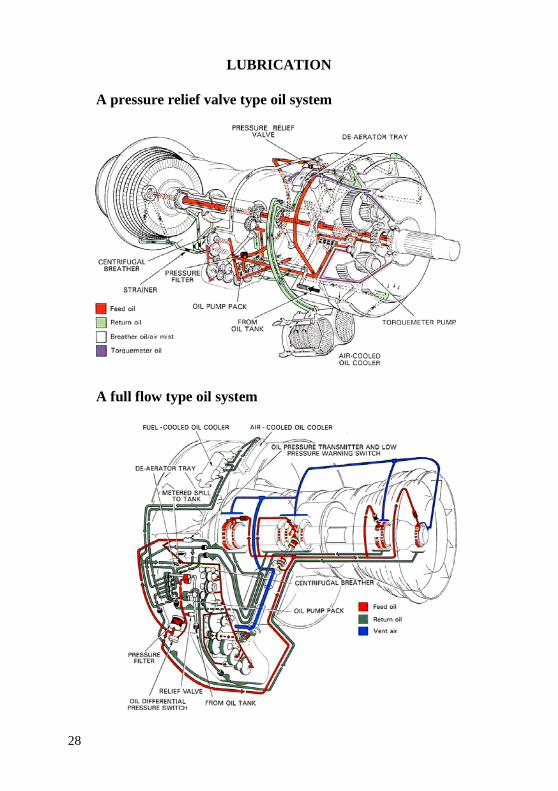
LUBRICATION
A pressure relief valve type oil system
A full flow type oil system

29
A total loss (expendable) oil system
An oil tank

30
Principle of a gear pump and A single-shot oil pump
A low pressure fuel-cooled oil cooler and A typical pressure and scavenge filter

31
INTERNAL AIR SYSTEM
General internal airflow pattern
Nozzle guide vane and turbine blade cooling arrangement
and High pressure nozzle guide vane construction and cooling

32
Development of high pressure turbine blade cooling
A hypothetical turbine cooling and sealing arrangement

33
A generator cooling system
Control of axial bearing load
Typical seals

34
FUEL SYSTEM Airflow changing with altitude and Fuel flow changing with
altitude
Simplified fuel systems for turbo-propeller and turbo-jet engines

35
A pressure control system (turbo-propeller engine)
A pressure control system (turbo-jet engine)

36
A low pressure system
A plunger-type fuel pump
A Simplex fuel spray nozzle

37
STARTING AND IGNITION
An electric starter
A low voltage electrical starting system

38
A triple-breech cartridge starter
An air starter motor
A gas turbine starter

39
CONTROLS AND INSTRUMENTATION
Pilot’s instrument panel – turbo-jet engines
Diagrammatic arrangement of engine control and instrumentation

40
A simple torquemeter system
Oil temperature and pressure transmitters and indicators
Vibration transmitter and indicator and Fuel flow transmitter and indicator

41
Turbine thermocouple installation
Typical electronic indicating display

42
ICE PROTECTION Areas typically considered for ice protection
Hot air ice protection

43
Combination of hot air, oil and electrical ice protection
Electrical ice protection

44
FIRE PROTECTION
A typical cooling and ventilation system
Cooling and ventilation – turbo-fan engine

45
A continuous element fire detecting system
A typical fire extinguishing system

46
THRUST REVERSAL
Methods of thrust reversal
Hot stream thrust reverser installations and A cold stream thrust reverser installation

47
A typical thrust reverser system using clamshell doors
A typical fan cold stream thrust reversal system

48
AFTERBURNING
Afterburning and its effect on the rate of climb
Principle of afterburning
Typical afterburning jet pipe equipment

49
Methods of afterburning ignition
Simplified control system

50
VERTICAL/SHORT TAKE-OFF AND LANDING
Lift/Propulsion engine
Thrust deflector systems
Deflector nozzle

51
Switch-In deflector system
Vectored thrust engine
Lift-fan engine configurations

52
Jet lift with swivelling nozzles
Flap blowing engine
Plenum chamber burning

53
NOISE SUPPRESSION
Comparative noise levels of various engine types
Change of exhaust jet pattern to reduce noise level
Comparative noise sources of low and high by-pass engines

54
Types of noise suppressor
Noise absorbing materials and location

55
THRUST DISTRIBUTION
Thrust distribution of a typical single-spool axial flow engine
PERFORMANCE
Propulsive efficiencies and aircraft speed

56
MANUFACTURE
Arrangements of a triple-spool turbo-jet engine

57
POWER PLANT INSTALLATION
Wing-mounted pod installation and Pitot-type intake
Fuselage – mounted pod installation
Tail and wing-mounted pod installation
Wing leading edge intakes

58
Single engined aircraft with fuselage intakes
External/internal compression intake and Variable throat area
intake

59
Engine accessibility, turbo-fan and turbo-propeller engines
Typical turbo-jet engine mountings

60
Part 2. Training aids and regulatory documents on aircraft engines for the discipline "Powerplants"
Aircraft Engine Design, Second Edition (AIAA Education) by University of Washington J. Mattingly (Author), U.S. Air Force Academy W. Heiser (Author), University of Washington and D. Pratt (Author) eISBN: 978-1-60086-144-4 print ISBN: 978-1-56347-538-2 https://doi.org/10.2514/4.861444 Dates/copyright year: January 1, 2002– 692 p. ©2002 Published by American Institute of Aeronautics and Astronautics
Winner of the Summerfield Book Award! The text presents a complete and realistic aircraft engine design experience. From the request for proposal for a new aircraft to the final engine layout, the book provides the concepts and procedures required for the entire process. It is a significantly expanded and modernized version of the best-selling first edition that emphasizes recent developments impacting engine design such as theta break-throttle ratio, life management, controls, and stealth. The key steps of the process are detailed in 10 chapters that encompass aircraft constraint analysis, aircraft mission analysis, engine parametric (design point) analysis, engine performance (off-design) analysis, engine installation drag and sizing, and the design of inlets, fans, compressors, main combustors, turbines, afterburners, and exhaust nozzles.The AEDsys software that accompanies the text provides comprehensive computational support for every design step. The software has been carefully integrated with the text to enhance both the learning process and productivity, and allows effortless transfer between British engineering and SI units. The AEDsys software is furnished on CD-ROM and runs on the Windows operating system. A user’s manual is provided with the software, along with the complete data files used for the Air-to-Air Fighter and Global Range Airlifter design examples of the book.

61
The Design of High-Efficiency Turbomachinery and Gas Turbines (MIT Press) second edition, with a new preface Edition by David Gordon Wilson (Author), Theodosios Korakianitis (Author) ISBN-13: 978-0262526685 ISBN-10: 0262526689 MIT Press. 2014 – 593 p.
This comprehensive textbook is
unique in its design-focused approach to turbomachinery and gas turbines. It offers students and practicing engineers methods for configuring these machines to perform with the highest possible efficiency. Examples and problems are based on the actual design of turbomachinery and turbines.
After an introductory chapter that outlines the goals of the book and provides definitions of terms and parts, the book offers a brief review of the basic principles of thermodynamics and efficiency definitions. The rest of the book is devoted to the analysis and design of real turbomachinery configurations and gas turbines, based on a consistent application of thermodynamic theory and a more empirical treatment of fluid dynamics that relies on the extensive use of design charts. Topics include turbine power cycles, diffusion and diffusers, the analysis and design of three-dimensional free-stream flow, and combustion systems and combustion calculations. The second edition updates every chapter, adding material on subjects that include flow correlations, energy transfer in turbomachines, and three-dimensional design. A solutions manual is available for instructors. This new MIT Press edition makes a popular text available again, with corrections and some updates, to a wide audience of students, professors, and professionals.

62
Aircraft Propulsion 2nd Edition by Saeed Farokhi (Author) ISBN-13: 978-1118806777 ISBN-10: 1118806778 Wiley ©2014. – 1043 p.
Aircraft Propulsion, Second
Edition follows the successful first edition textbook with comprehensive treatment of
the subjects in airbreathing propulsion, from the basic principles to more advanced treatments in engine components and system integration.
This new edition has been extensively updated to include a number of new and important topics. A chapter is now included on General Aviation and Uninhabited Aerial Vehicle (UAV) Propulsion Systems that includes a discussion on electric and hybrid propulsion. Propeller theory is added to the presentation of turboprop engines. A new section in cycle analysis treats Ultra-High Bypass (UHB) and Geared Turbofan engines. New material on drop-in biofuels and design for sustainability is added to refl ect the FAA’s 2025 Vision.
In addition, the design guidelines in aircraft engine components are expanded to make the book user friendly for engine designers. Extensive review material and derivations are included to help the reader navigate through the subject with ease.
Key features: • General Aviation and UAV Propulsion Systems are presented
in a new chapter • Discusses Ultra-High Bypass and Geared Turbofan engines • Presents alternative drop-in jet fuels • Expands on engine components' design guidelines

63
• The end-of-chapter problem sets have been increased by nearly 50% and solutions are available on a companion website
• Presents a new section on engine performance testing and instrumentation
• Includes a new 10-Minute Quiz appendix (with 45 quizzes) that can be used as a continuous assessment and improvement tool in teaching/learning propulsion principles and concepts
• Includes a new appendix on Rules of Thumb and Trends in aircraft propulsion
Aircraft Propulsion, Second Edition is a must-have textbook for graduate and undergraduate students, and is also an excellent source of information for researchers and practitioners in the aerospace and power industry.
Jet Engines: Fundamentals of Theory, Design and Operation by Klaus Hunecke (Author) Hardcover – April 15, 2010. – 224 p. Crowood Press UK ISBN 1853108340, 9781853108341
This book is intended for those who
wish to broaden their knowledge of jet engine technology and associated subjects. It covers turbojet, turboprop and turbofan
designs and is applicable to civilian and military usage. It commences with an overview of the main design types and fundamentals and then looks at air intakes, compresors, turbines and exhaust systems in great detail.

64
Aircraft Powerplants, Eighth Edition 8th Edition by Thomas W. Wild (Author), Michael J Kroes (Author) ISBN-13: 978-0071799133 ISBN-10: 0071799133
The most comprehensive, current
guide to aircraft powerplants. Fully revised to cover the latest
industry advances, Aircraft Powerplants, Eighth Edition, prepares you for certification as an FAA powerplant technician in accordance with the Federal Aviation Regulations (FAR). This authoritative text has been updated to reflect recent changes in FAR Part 147.
This new edition features expanded coverage of turbine-engine theory and nomenclature; current models of turbofan, turboprop, and turboshaft engines; and up-to-date details on turbine-engine fuel, oil, and ignition systems. Important information on how individual components and systems operate together is integrated throughout the text. Clear photos of various components and a full-color insert of diagrams and systems are included. Review questions at the end of each chapter enable you to check your knowledge of the topics presented in this practical resource.
Aircraft Powerplants, Eighth Edition, covers: • Aircraft powerplant classification and progress • Reciprocating-engine construction and nomenclature • Internal-combustion engine theory and performance • Lubricants and lubricating systems • Induction systems, superchargers, turbochargers, and cooling
and exhaust systems • Basic fuel systems and carburetors • Fuel injection systems

65
• Reciprocating-engine ignition and starting systems • Operation, inspection, maintenance, and troubleshooting of
reciprocating engines • Reciprocating-engine overhaul practices • Gas-turbine engine: theory, jet propulsion principles, engine
performance, and efficiencies • Principal parts of a gas-turbine engine, construction, and
nomenclature • Gas-turbine engine: fuels and fuel systems • Turbine-engine lubricants and lubricating systems • Ignition and starting systems of gas-turbine engines • Turbofan, turboprop, and turboshaft engines • Gas-turbine operation, inspection, troubleshooting,
maintenance, and overhaul • Propeller theory, nomenclature, and operation • Turbopropellers and control systems • Propeller installation, inspection, and maintenance • Engine indicating, warning, and control systems
The Jet Engine 5th Edition ISBN-13: 978-1119065999 ISBN-10: 1119065992 Wiley. Rolls Royce. 1986, 1996. – 292 p. 2015. – 288 p. http://airspot.ru/book/file/485/166837_EB161_rolls_royce_the_jet_engine_fifth_edition_gazoturbinnyy_dviga.pdf.
The Jet Engine provides a complete, accessible description of the working and underlying principles of the gas turbine. Accessible, non-technical approach explaining the workings of jet engines, for readers of all levels. Full colour diagrams, cutaways and photographs throughout. Written by RR specialists in all the respective fields. Hugely popular and well-reviewed book, originally published in 2005 under Rolls Royce’s own imprint.

66
Gas Turbines, Second Edition: A Handbook of Air, Land and Sea Applications by Claire Soares EMM Systems Dallas Texas USAPrincipal Engineer (P. E.) (Author)
Covering basic theory, components,
installation, maintenance, manufacturing, regulation and industry developments, Gas
Turbines: A Handbook of Air, Sea and Land Applications is a broad-based introductory reference designed to give you the knowledge needed to succeed in the gas turbine industry, land, sea and air applications.
Providing the big picture view that other detailed, data-focused resources lack, this book has a strong focus on the information needed to effectively decision-make and plan gas turbine system use for particular applications, taking into consideration not only operational requirements but long-term life-cycle costs in upkeep, repair and future use.
With concise, easily digestible overviews of all important theoretical bases and a practical focus throughout, Gas Turbines is an ideal handbook for those new to the field or in the early stages of their career, as well as more experienced engineers looking for a reliable, one-stop reference that covers the breadth of the field.
• Covers installation, maintenance, manufacturer's specifications, performance criteria and future trends, offering a rounded view of the area that takes in technical detail as well as well as industry economics and outlook
• Updated with the latest industry developments, including new emission and efficiency regulations and their impact on gas turbine technology

67
• Over 300 pages of new/revised content, including new sections on microturbines, non-conventional fuel sources for microturbines, emissions, major developments in aircraft engines, use of coal gas and superheated steam, and new case histories throughout highlighting component improvements in all systems and sub-systems.
Gas Turbine Engineering Handbook, Fourth Edition by Meherwan P. Boyce Fellow American Society of Mechanical Engineers (ASME USA) and Fellow The Institute of Diesel and Gas Turbine Engineers (IDGTE U.K.) (Author) ISBN-13: 978-0123838421 ISBN-10: 0123838428
Written by one of the field’s most well known experts, the Gas Turbine Engineering Handbook has long been the standard for engineers involved in the design, selection, maintenance and operation of gas turbines. With far reaching, comprehensive coverage across a range of topics from design specifications to maintenance troubleshooting, this one-stop resource provides newcomers to the industry with all the essentials to learn and fill knowledge gaps, and established practicing gas turbine engineers with a reliable go-to reference. This new edition brings the Gas Turbine Engineering Handbook right up to date with new legislation and emerging topics to help the next generation of gas turbine professionals understand the underlying principles of gas turbine operation, the economic considerations and implications of operating these machines, and how they fit in with alternative methods of power generation.
• The most comprehensive one-stop source of information on industrial gas turbines, with vital background, maintenance information, legislative details and calculations combined in an essential all-in-one reference
• Written by an industry-leading consultant and trainer and suitable for use as a training companion or a reliable dip-in guide

68
• Includes hard-won information from industry experts in the form of case histories that offer practical trouble-shooting guidance and solutions
Elements of Propulsion: Gas Turbines and Rockets (AIAA Education)
by J. Mattingly (Author), H. von Ohain (Author) ISBN-13: 978-1563477799 ISBN-10: 1563477793 Publisher AIAA. 2006.– 869 p.
This text provides a complete introduction to gas turbine and rocket propulsion for aerospace and mechanical engineers. Building
on the very successful Elements of Gas Turbine Propulsion, textbook coverage has been expanded to include rocket propulsion and the material on gas dynamics has been dramatically improved. The text is divided into four parts: basic concepts and gas dynamics; analysis of rocket propulsion systems; parametric (design point) and performance (off-design) analysis of air breathing propulsion systems; and analysis and design of major gas turbine engine components (fans, compressors, turbines, inlets, nozzles, main burners, and afterburners).
Design concepts are introduced early (aircraft and rocket performance in an introductory chapter) and integrated throughout. Written with extensive student input on the design of the book, the book builds upon definitions and gradually develops the thermodynamics, gas dynamics, rocket engine analysis, and gas turbine engine principles. The book contains over 100 worked examples and numerous homework problems so concepts are applied after they are introduced. Over 600 illustrations and pictures show basic concepts, trends, and design examples.
Eight computer programs accompany the text, which allow for rapid calculation of trends, “what if” questions, conceptual design, homework problems, and homework verification. The software runs in the Windows operating system on PC-compatible systems.

69
Part 3. Excerpts from aviation standards for power plants
14 CFR CHAPTER I, SUBCHAPTER C – AIRCRAFT
https://www.law.cornell.edu/cfr/text/14/chapter-I/subchapter-C
Part 33 – AIRWORTHINESS STANDARDS: AIRCRAFT ENGINES
https://www.law.cornell.edu/cfr/text/14/part-33
Subpart A – General o § 33.1 Applicability. o § 33.3 General. o § 33.4 Instructions for Continued Airworthiness. o § 33.5 Instruction manual for installing and operating the
engine. o § 33.7 Engine ratings and operating limitations. o § 33.8 Selection of engine power and thrust ratings.
Subpart B – Design and Construction; General o § 33.11 Applicability. o § 33.13 [Reserved] o § 33.15 Materials. o § 33.17 Fire protection. o § 33.19 Durability. o § 33.21 Engine cooling. o § 33.23 Engine mounting attachments and structure. o § 33.25 Accessory attachments. o § 33.27 Turbine, compressor, fan, and turbosupercharger
rotor overspeed. o § 33.28 Engine control systems. o § 33.29 Instrument connection.

70
Subpart C – Design and Construction; Reciprocating Aircraft Engines o § 33.31 Applicability. o § 33.33 Vibration. o § 33.34 Turbocharger rotors. o § 33.35 Fuel and induction system. o § 33.37 Ignition system. o § 33.39 Lubrication system.
Subpart D – Block Tests; Reciprocating Aircraft Engines o § 33.41 Applicability. o § 33.42 General. o § 33.43 Vibration test. o § 33.45 Calibration tests. o § 33.47 Detonation test. o § 33.49 Endurance test. o § 33.51 Operation test. o § 33.53 Engine system and component tests. o § 33.55 Teardown inspection. o § 33.57 General conduct of block tests.
Subpart E – Design and Construction; Turbine Aircraft Engines o § 33.61 Applicability. o § 33.62 Stress analysis. o § 33.63 Vibration. o § 33.64 Pressurized engine static parts. o § 33.65 Surge and stall characteristics. o § 33.66 Bleed air system. o § 33.67 Fuel system. o § 33.68 Induction system icing. o § 33.69 Ignitions system. o § 33.70 Engine life-limited parts. o § 33.71 Lubrication system. o § 33.72 Hydraulic actuating systems.

71
o § 33.73 Power or thrust response. o § 33.74 Continued rotation. o § 33.75 Safety analysis. o § 33.76 Bird ingestion. o § 33.77 Foreign object ingestion – ice. o § 33.78 Rain and hail ingestion. o § 33.79 Fuel burning thrust augmentor.
Subpart F – Block Tests; Turbine Aircraft Engines o § 33.81 Applicability. o § 33.82 General. o § 33.83 Vibration test. o § 33.84 Engine overtorque test. o § 33.85 Calibration tests. o § 33.87 Endurance test. o § 33.88 Engine overtemperature test. o § 33.89 Operation test. o § 33.90 Initial maintenance inspection test. o § 33.91 Engine system and component tests. o § 33.92 Rotor locking tests. o § 33.93 Teardown inspection. o § 33.94 Blade containment and rotor unbalance tests. o § 33.95 Engine-propeller systems tests. o § 33.96 Engine tests in auxiliary power unit (APU) mode. o § 33.97 Thrust reversers. o § 33.99 General conduct of block tests.
Subpart G – Special Requirements: Turbine Aircraft Engines Appendix A to Part 33 – Instructions for Continued Airworthiness Appendix B to Part 33 – Certification Standard Atmospheric
Concentrations of Rain and Hail Appendix D to Part 33 – Mixed Phase and Ice Crystal Icing
Envelope (Deep Convective Clouds)

72
Part 23 – AIRWORTHINESS STANDARDS: NORMAL CATEGORY AIRPLANES
14 CFR Part 23, Subpart E – Powerplant
https://www.law.cornell.edu/cfr/text/14/part-23/subpart-E
§ 23.2400 Powerplant installation.
(a) For the purpose of this subpart, the airplane powerplant installation must include each component necessary for propulsion, which affects propulsion safety, or provides auxiliary power to the airplane. (b) Each airplane engine and propeller must be type certificated, except for engines and propellers installed on level 1 low-speed airplanes, which may be approved under theairplane type certificate in accordance with a standard accepted by the FAA that contains airworthiness criteria the Administrator has found appropriate and applicable to the specific design and intended use of the engine or propeller and provides a level of safety acceptable to the FAA. (c) The applicant must construct and arrange each powerplant installation to account for - (1) Likely operating conditions, including foreign object threats; (2) Sufficient clearance of moving parts to other airplane parts and their surroundings; (3) Likely hazards in operation including hazards to ground personnel; and (4) Vibration and fatigue. (d) Hazardous accumulations of fluids, vapors, or gases must be isolated from the airplane and personnel compartments, and be safely contained or discharged. (e) Powerplant components must comply with their component limitations and installation instructions or be shown not to create a hazard.

73
§ 23.2405 Automatic power or thrust control systems.
(a) An automatic power or thrust control system intended for in-flight use must be designed so no unsafe condition will result during normal operation of the system. (b) Any single failure or likely combination of failures of an automatic power or thrust control system must not prevent continued safe flight and landing of the airplane. (c) Inadvertent operation of an automatic power or thrust control system by the flightcrew must be prevented, or if not prevented, must not result in an unsafe condition. (d) Unless the failure of an automatic power or thrust control system is extremely remote, the system must - (1) Provide a means for the flightcrew to verify the system is in an operating condition; (2) Provide a means for the flightcrew to override the automatic function; and (3) Prevent inadvertent deactivation of the system.
§ 23.2410 Powerplant installation hazard assessment.
The applicant must assess each powerplant separately and in relation to other airplane systems and installations to show that any hazard resulting from the likely failure of any powerplant system, component, or accessory will not - (a) Prevent continued safe flight and landing or, if continued safe flight and landing cannot be ensured, the hazard has been minimized; (b) Cause serious injury that may be avoided; and (c) Require immediate action by any crewmember for continued operation of any remaining powerplant system.
§ 23.2415 Powerplant ice protection.
(a) The airplane design, including the induction and inlet system, must prevent foreseeable accumulation of ice or snow that adversely affects powerplant operation.

74
(b) The powerplant installation design must prevent any accumulation of ice or snow that adversely affects powerplant operation, in those icing conditions for which certification is requested.
§ 23.2420 Reversing systems.
Each reversing system must be designed so that - (a) No unsafe condition will result during normal operation of the system; and (b) The airplane is capable of continued safe flight and landing after any single failure, likely combination of failures, or malfunction of the reversing system.
§ 23.2425 Powerplant operational characteristics.
(a) The installed powerplant must operate without any hazardous characteristics during normal and emergency operation within the range of operating limitations for the airplaneand the engine. (b) The pilot must have the capability to stop the powerplant in flight and restart the powerplant within an established operational envelope.
§ 23.2430 Fuel systems.
(a) Each fuel system must - (1) Be designed and arranged to provide independence between multiple fuel storage and supply systems so that failure of any one component in one system will not result in loss of fuel storage or supply of another system; (2) Be designed and arranged to prevent ignition of the fuel within the system by direct lightning strikes or swept lightning strokes to areas where such occurrences are highly probable, or by corona or streamering at fuel vent outlets; (3) Provide the fuel necessary to ensure each powerplant and auxiliary power unit functions properly in all likely operating conditions;

75
(4) Provide the flightcrew with a means to determine the total useable fuel available and provide uninterrupted supply of that fuel when the system is correctly operated, accounting for likely fuel fluctuations; (5) Provide a means to safely remove or isolate the fuel stored in the system from the airplane; (6) Be designed to retain fuel under all likely operating conditions and minimize hazards to the occupants during any survivable emergency landing. For level 4 airplanes, failure due to overload of the landing system must be taken into account; and (7) Prevent hazardous contamination of the fuel supplied to each powerplant and auxiliary power unit. (b) Each fuel storage system must - (1) Withstand the loads under likely operating conditions without failure; (2) Be isolated from personnel compartments and protected from hazards due to unintended temperature influences; (3) Be designed to prevent significant loss of stored fuel from any vent system due to fuel transfer between fuel storage or supply systems, or under likely operating conditions; (4) Provide fuel for at least one-half hour of operation at maximum continuous power or thrust; and (5) Be capable of jettisoning fuel safely if required for landing. (c) Each fuel storage refilling or recharging system must be designed to - (1) Prevent improper refilling or recharging; (2) Prevent contamination of the fuel stored during likely operating conditions; and (3) Prevent the occurrence of any hazard to the airplane or to persons during refilling or recharging.
§ 23.2435 Powerplant induction and exhaust systems.
(a) The air induction system for each powerplant or auxiliary power unit and their accessories must -

76
(1) Supply the air required by that powerplant or auxiliary power unit and its accessories under likely operating conditions; (2) Be designed to prevent likely hazards in the event of fire or backfire; (3) Minimize the ingestion of foreign matter; and (4) Provide an alternate intake if blockage of the primary intake is likely. (b) The exhaust system, including exhaust heat exchangers for each powerplant or auxiliary power unit, must - (1) Provide a means to safely discharge potential harmful material; and (2) Be designed to prevent likely hazards from heat, corrosion, or blockage.
§ 23.2440 Powerplant fire protection.
(a) A powerplant, auxiliary power unit, or combustion heater that includes a flammable fluid and an ignition source for that fluid must be installed in a designated fire zone. (b) Each designated fire zone must provide a means to isolate and mitigate hazards to the airplane in the event of fire or overheat within the zone. (c) Each component, line, fitting, and control subject to fire conditions must - (1) Be designed and located to prevent hazards resulting from a fire, including any located adjacent to a designated fire zone that may be affected by fire within that zone; (2) Be fire resistant if carrying flammable fluids, gas, or air or required to operate in event of a fire; and (3) Be fireproof or enclosed by a fire proof shield if storing concentrated flammable fluids. (d) The applicant must provide a means to prevent hazardous quantities of flammable fluids from flowing into, within or through each designated fire zone. This means must -

77
(1) Not restrict flow or limit operation of any remaining powerplant or auxiliary power unit, or equipment necessary for safety; (2) Prevent inadvertent operation; and (3) Be located outside the fire zone unless an equal degree of safety is provided with a means inside the fire zone. (e) A means to ensure the prompt detection of fire must be provided for each designated fire zone - (1) On a multiengine airplane where detection will mitigate likely hazards to the airplane; or (2) That contains a fire extinguisher. (f) A means to extinguish fire within a fire zone, except a combustion heater fire zone, must be provided for - (1) Any fire zone located outside the pilot's view; (2) Any fire zone embedded within the fuselage, which must also include a redundant means to extinguish fire; and (3) Any fire zone on a level 4 airplane.
Part 25 – AIRWORTHINESS STANDARDS:
TRANSPORT CATEGORY AIRPLANES
http://www.engineerstoolkit.com/Airworthiness%20Standards%20%20FAA%20FAR%20Part%2025.pdf
https://www.law.cornell.edu/cfr/text/14/part-25
14 CFR PART 25, SUBPART E – POWERPLANT
https://www.law.cornell.edu/cfr/text/14/part-25/subpart-E
General (§§ 25.901 – 25.945)
o § 25.901 Installation. o § 25.903 Engines. o § 25.904 Automatic takeoff thrust control system (ATTCS). o § 25.905 Propellers. o § 25.907 Propeller vibration and fatigue.

78
o § 25.925 Propeller clearance. o § 25.929 Propeller deicing. o § 25.933 Reversing systems. o § 25.934 Turbojet engine thrust reverser system tests. o § 25.937 Turbopropeller-drag limiting systems. o § 25.939 Turbine engine operating characteristics. o § 25.941 Inlet, engine, and exhaust compatibility. o § 25.943 Negative acceleration. o § 25.945 Thrust or power augmentation system.
Fuel System (§§ 25.951 – 25.981)
o § 25.951 General. o § 25.952 Fuel system analysis and test. o § 25.953 Fuel system independence. o § 25.954 Fuel system lightning protection. o § 25.955 Fuel flow. o § 25.957 Flow between interconnected tanks. o § 25.959 Unusable fuel supply. o § 25.961 Fuel system hot weather operation. o § 25.963 Fuel tanks: general. o § 25.965 Fuel tank tests. o § 25.967 Fuel tank installations. o § 25.969 Fuel tank expansion space. o § 25.971 Fuel tank sump. o § 25.973 Fuel tank filler connection. o § 25.975 Fuel tank vents and carburetor vapor vents. o § 25.977 Fuel tank outlet. o § 25.979 Pressure fueling system. o § 25.981 Fuel tank ignition prevention.
Fuel System Components (§§ 25.991 – 25.1001)
o § 25.991 Fuel pumps. o § 25.993 Fuel system lines and fittings. o § 25.994 Fuel system components. o § 25.995 Fuel valves.

79
o § 25.997 Fuel strainer or filter. o § 25.999 Fuel system drains. o § 25.1001 Fuel jettisoning system.
Oil System
o § 25.1011 General. o § 25.1013 Oil tanks. o § 25.1015 Oil tank tests. o § 25.1017 Oil lines and fittings. o § 25.1019 Oil strainer or filter. o § 25.1021 Oil system drains. o § 25.1023 Oil radiators. o § 25.1025 Oil valves. o § 25.1027 Propeller feathering system.
Cooling
o § 25.1041 General. o § 25.1043 Cooling tests. o § 25.1045 Cooling test procedures.
Induction System
o § 25.1091 Air induction. o § 25.1093 Induction system icing protection. o § 25.1101 Carburetor air preheater design. o § 25.1103 Induction system ducts and air duct systems. o § 25.1105 Induction system screens. o § 25.1107 Inter-coolers and after-coolers.
Exhaust System
o § 25.1121 General. o § 25.1123 Exhaust piping. o § 25.1125 Exhaust heat exchangers. o § 25.1127 Exhaust driven turbo-superchargers.

80
Powerplant Controls and Accessories
o § 25.1141 Powerplant controls: general. o § 25.1142 Auxiliary power unit controls. o § 25.1143 Engine controls. o § 25.1145 Ignition switches. o § 25.1147 Mixture controls. o § 25.1149 Propeller speed and pitch controls. o § 25.1153 Propeller feathering controls. o § 25.1155 Reverse thrust and propeller pitch settings below the flight regime. o § 25.1157 Carburetor air temperature controls. o § 25.1159 Supercharger controls. o § 25.1161 Fuel jettisoning system controls. o § 25.1163 Powerplant accessories. o § 25.1165 Engine ignition systems. o § 25.1167 Accessory gearboxes.
Powerplant Fire Protection
o § 25.1181 Designated fire zones; regions included. o § 25.1182 Nacelle areas behind firewalls, and engine pod attaching structures containing flammable fluid lines. o § 25.1183 Flammable fluid-carrying components. o § 25.1185 Flammable fluids. o § 25.1187 Drainage and ventilation of fire zones. o § 25.1189 Shutoff means. o § 25.1191 Firewalls. o § 25.1192 Engine accessory section diaphragm. o § 25.1193 Cowling and nacelle skin. o § 25.1195 Fire extinguishing systems. o § 25.1197 Fire extinguishing agents. o § 25.1199 Extinguishing agent containers. o § 25.1201 Fire extinguishing system materials. o § 25.1203 Fire detector system. o § 25.1207 Compliance.

81
Part 27 – AIRWORTHINESS STANDARDS: NORMAL CATEGORY ROTORCRAFT
14 CFR PART 27, SUBPART E – POWERPLANT
https://www.law.cornell.edu/cfr/text/14/part-27/subpart-E
General
o § 27.901 Installation. o § 27.903 Engines. o § 27.907 Engine vibration. Rotor Drive System o § 27.917 Design. o § 27.921 Rotor brake. o § 27.923 Rotor drive system and control mechanism tests. o § 27.927 Additional tests. o § 27.931 Shafting critical speed. o § 27.935 Shafting joints. o § 27.939 Turbine engine operating characteristics.
Fuel System
o § 27.951 General. o § 27.952 Fuel system crash resistance. o § 27.953 Fuel system independence. o § 27.954 Fuel system lightning protection. o § 27.955 Fuel flow. o § 27.959 Unusable fuel supply. o § 27.961 Fuel system hot weather operation. o § 27.963 Fuel tanks: general. o § 27.965 Fuel tank tests. o § 27.967 Fuel tank installation. o § 27.969 Fuel tank expansion space. o § 27.971 Fuel tank sump. o § 27.973 Fuel tank filler connection. o § 27.975 Fuel tank vents. o § 27.977 Fuel tank outlet.

82
Fuel System Components
o § 27.991 Fuel pumps. o § 27.993 Fuel system lines and fittings. o § 27.995 Fuel valves. o § 27.997 Fuel strainer or filter. o § 27.999 Fuel system drains.
Oil System
o § 27.1011 Engines: General. o § 27.1013 Oil tanks. o § 27.1015 Oil tank tests. o § 27.1017 Oil lines and fittings. o § 27.1019 Oil strainer or filter. o § 27.1021 Oil system drains. o § 27.1027 Transmissions and gearboxes: General.
Cooling
o § 27.1041 General. o § 27.1043 Cooling tests. o § 27.1045 Cooling test procedures.
Induction System
o § 27.1091 Air induction. o § 27.1093 Induction system icing protection.
Exhaust System
o § 27.1121 General. o § 27.1123 Exhaust piping.
Powerplant Controls and Accessories
o § 27.1141 Powerplant controls: general. o § 27.1143 Engine controls. o § 27.1145 Ignition switches. o § 27.1147 Mixture controls. o § 27.1151 Rotor brake controls. o § 27.1163 Powerplant accessories.

83
Powerplant Fire Protection
o § 27.1183 Lines, fittings, and components. o § 27.1185 Flammable fluids. o § 27.1187 Ventilation and drainage. o § 27.1189 Shutoff means. o § 27.1191 Firewalls. o § 27.1193 Cowling and engine compartment covering. o § 27.1194 Other surfaces. o § 27.1195 Fire detector systems.

84
Учебное издание
Nikolay Mihailovich Borgest
AVIATION POWER PLANTS
Учебное пособие
Редактор И.И. Спиридонова Компьютерная верстка И.И. Спиридоновой
Подписано в печать 4.12.2020. Формат 60×84 1/16.
Бумага офсетная. Печ. л. 5,25. Тираж 25 экз. Заказ . Арт. – 10(Р3У)/2020.
ФЕДЕРАЛЬНОЕ ГОСУДАРСТВЕННОЕ АВТОНОМНОЕ
ОБРАЗОВАТЕЛЬНОЕ УЧРЕЖДЕНИЕ ВЫСШЕГО ОБРАЗОВАНИЯ «САМАРСКИЙ НАЦИОНАЛЬНЫЙ ИССЛЕДОВАТЕЛЬСКИЙ
УНИВЕРСИТЕТ ИМЕНИ АКАДЕМИКА С.П. КОРОЛЕВА» (САМАРСКИЙ УНИВЕРСИТЕТ)
443086, САМАРА, МОСКОВСКОЕ ШОССЕ, 34.
Издательство Самарского университета. 443086, Самара, Московское шоссе, 34.
Related Documents