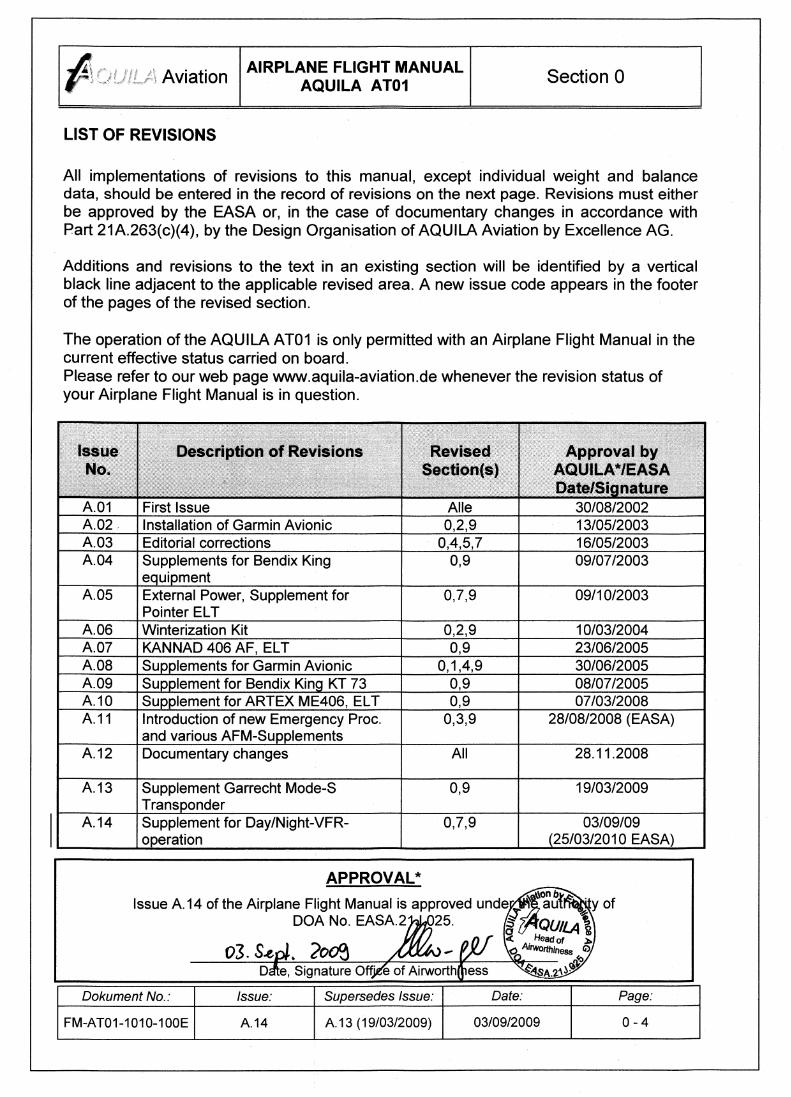
Aviation by Excellence AG AIRPLANE FLIGHT MANUAL AQUILA AT01 LBA Approved in Normal Category based on JAR-VLA. This Airplane Flight Manual must be carried on board of the aircraft at all times and be kept within the reach of the pilot during all flight operations. The amendment history and revision status of each section of the Airplane Flight Manual are provided in the list of effective pages and in the list of revisions. This aircraft must be operated in compliance with the procedures and operating limits specified herein. SERIAL NO.: AQUILA AT01- REGIST. NO.: Revision A.01 was approved by the Luftfahrt-Bundesamt (LBA) on 30/08/2002 within the scope of the type-certification. All revisions of section 2, 3, 4 and 5 beyond the scope of documentary changes are subject to EASA-approval. Doc. No. FM-AT01-1010-100E First Issued: 05/06/2002 Cover Page Issue No.: A.14

Welcome message from author
This document is posted to help you gain knowledge. Please leave a comment to let me know what you think about it! Share it to your friends and learn new things together.
Transcript

Aviation by Excellence AG
AIRPLANE FLIGHT MANUAL
AQUILA AT01
LBA Approved in Normal Category based on JAR-VLA.This Airplane Flight Manual must be carried on board of the aircraft at all times and be keptwithin the reach of the pilot during all flight operations. The amendment history and revisionstatus of each section of the Airplane Flight Manual are provided in the list of effective pagesand in the list of revisions.
This aircraft must be operated in compliance with the procedures and operating limits specifiedherein.
SERIAL NO.: AQUILA AT01-
REGIST. NO.:
Revision A.01 was approved by the Luftfahrt-Bundesamt (LBA) on 30/08/2002 within the scopeof the type-certification. All revisions of section 2, 3, 4 and 5 beyond the scope of documentarychanges are subject to EASA-approval.
Doc. No. FM-AT01-1010-100E
First Issued: 05/06/2002
Cover Page Issue No.: A.14

AviationAIRPLANE FLIGHT MANUAL
AQUILA AT01Section 0
Dokument No.: Issue: Supersedes Issue: Date: Page:
FM-AT01-1010-100E A.14 A.13 (19/03/2009) 03/09/2009 0 - 1
INTRODUCTION
With the AQUILA AT01 you acquired a very efficient training and utility aircraft, which canbe operated very easily and exhibit excellent handling qualities.
Reliable operation, handling and maintenance guarantee always trouble-free flights andcontinued airworthiness.For that, we recommend to read this Airplane Flight Manual thoroughly and adhere to theoperating instructions and recommendations given herein.Furthermore, we recommend attending a type training course held by AQUILA companytrained personnel to obtain a "feeling" for the optimal operation of the aircraft within ashorter period of time.
NOTE
All limitations, procedures and performance data contained in this handbook are EASA-/LBA-approved and mandatory. Not paying attention to the procedures and limits of the
handbook can lead to a loss of liability by the manufacturer.
THE HANDBOOK
The Airplane Flight Manual has been prepared using the recommendations of JAR-VLAAppendix H (issue 26/4/90) “Specimen Flight Manual for a Very Light Aeroplane”.The handbook is presented in loose-leaf form to ease the substitution of revisions and issized in A5-format for convenient storage in the airplane. Tab dividers throughout thehandbook allow quick reference to each section. Tables of Contents are located at thebeginning of each section to aid locating specific data within that section.
All rights reserved.Reproduction or disclosure to third parties of this document or any part thereof is not
permitted, except with the prior and express written permission of the AQUILA Aviation byExcellence AG.
Copyright © by Aviation by Excellence AG
Schönhagen, Germany

AviationAIRPLANE FLIGHT MANUAL
AQUILA AT01Section 0
Dokument No.: Issue: Supersedes Issue: Date: Page:
FM-AT01-1010-100E A.14 A.13 (19/03/2009) 03/09/2009 0 - 2
TABLE OF CONTENTS
SECTION
GENERAL 1
OPERATING LIMITATIONS 2
EMERGENCY PROCEDURES 3
NORMAL PROCEDURES 4
PERFORMANCE 5
WEIGHT AND BALANCE 6
DESCRIPTION OF THE AIRCRAFT AND ITS SYSTEMS 7
HANDLING, SERVICE AND MAINTENANCE 8
SUPPLEMENTS 9

AviationAIRPLANE FLIGHT MANUAL
AQUILA AT01Section 0
Dokument No.: Issue: Supersedes Issue: Date: Page:
FM-AT01-1010-100E A.14 A.13 (19/03/2009) 03/09/2009 0 - 3
LIST OF EFFECTIVE PAGES
Section IssueNo.
Page Date Section IssueNo.
Page Date
0 A.14 0-1 to 0-6 03/09/09
1 A.12 1-1 to 1-12 17/09/08
2 A.12 2-1 to 2-20 17/09/08
3 A.12 3-1 to 3-16 17/09/08
4 A.12 4-1 to 4-20 17/09/08
5 A.12 5-1 to 5-23 17/09/08
6 A.12 6-1 to 6-14 17/09/08
7 A.14 7-1 to 7-32 03/09/09
8 A.12 8-1 to 8-8 17/09/08
9 A.14 9-1 to 9-2 03/09/09

AviationAIRPLANE FLIGHT MANUAL
AQUILA AT01Section 0
Dokument No.: Issue: Supersedes Issue: Date: Page:
FM-AT01-1010-100E A.14 A.13 (19/03/2009) 03/09/2009 0 - 5
RECORD OF REVISIONS
When a new revision to the Airplane Flight Manual is issued, the corresponding sectionshave to be removed and replaced by the pages of the revised sections.Only entire sections will be changed and have to be replaced. Each time, when theincorporation of a revision is accomplished, an endorsement has to be made in the recordof revisions shown below.
Issue No.RevisedSections
Date of IssueDate of
insertion:Inserted by:
A.01 All 05/06/2002
A.02 0,2,9 20/11/2002
A.03 0,4,5,7 15/04/2003
A.04 0,9 19/05/2003
A.05 0,7,9 30/09/2003
A.06 0,2,9 10/02/2004
A.07 0,9 30/07/2004
A.08 0,1,4,9 30/06/2005
A.09 0,9 05/07/2005
A.10 0,9 05/03/2006
A.11 0,3,9 30/11/2007
A.12 All 17/09/2008
A.13 0,9 19/03/2009
A.14 0,7,9 03/09/09

AviationAIRPLANE FLIGHT MANUAL
AQUILA AT01Section 0
Dokument No.: Issue: Supersedes Issue: Date: Page:
FM-AT01-1010-100E A.14 A.13 (19/03/2009) 03/09/2009 0 - 6
Purchase of Technical Publications
To guarantee safe operation and correct maintenance of the aircraft AQUILA AT01, allmanuals and technical publications must be kept in the current effective status.
All manuals and technical publications relating to the aircraft AQUILA AT01 are availablefrom the companies listed below:
(a) AQUILA AT01 related Manuals and Publications
AQUILA Aviation by Excellence AGFlugplatzD-14959 SCHÖNHAGEN
Tel: +49 (0)33731 707-0Fax: +49 (0)33731 707-11E-Mail: [email protected]: http://www.aquila-aviation.de
(b) Engine ROTAX 912 S related Manuals and Publications
ROTAX® authorized distributor for ROTAX® Aircraft Engines of the applicabledistribution area.For contact details of the local authorized distributor for ROTAX Aircraft Engines,please refer to chapter 13 of the ROTAX® Operator’s Manual for 912 S Engines.
(c) Propeller MTV-21 related Manuals and Publications
mt-Propeller Entwicklung GmbHFlugplatz Straubing- WallmühleD-94348 ATTING
Tel: +49 (0)9429 9409-0Fax: +49 (0)9429 8432Internet: www.mt-propeller.comE-mail: [email protected]

AviationAIRPLANE FLIGHT MANUAL
AQUILA AT01Section 7
SYSTEM DESCRIPTION
Document No.: Issue: Supersedes Issue: Date: Page:
FM-AT01-1010-100E A.14 A.12 (17/09/2008) 03/09/2009 7 - 1
SECTION 7
DESCRIPTION OF THE AIRCRAFT AND ITS SYSTEMS
Page
7.1 INTRODUCTION 7-4
7.2 AIRFRAME 7-5
7.2.1
7.2.2
7.2.3
Fuselage
Wing
Empennage
7-5
7-5
7-6
7.3 FLIGHT CONTROLS 7-6
7.3.1
7.3.2
7.3.3
7.3.4
7.3.5
Aileron Control
Elevator Control and Trim System
Rudder Control
Flap Control and Flap Position Indication
Control Stick Lock
7-6
7-7
7-7
7-8
7-8
7.4 INSTRUMENT PANEL (Standard Equipment) 7-9
7.4.1
7.4.2
7.4.3
7.4.4
Flight Instruments
Switches and Other Controls
Cabin Heat
Cabin Ventilation
7-10
7-10
7-11
7-11
7.5 UNDERCARRIAGE 7-11
7.5.1
7.5.2
7.5.3
Nose Landing Gear and Nose Gear Steering
Main Landing Gear and Brake System
Parking Brake
7-11
7-12
7-12

AviationAIRPLANE FLIGHT MANUAL
AQUILA AT01Section 7
SYSTEM DESCRIPTION
Document No.: Issue: Supersedes Issue: Date: Page:
FM-AT01-1010-100E A.14 A.12 (17/09/2008) 03/09/2009 7 - 2
7.6 SEATS, SEATBELTS AND HARNESSES 7-12
7.6.1 Seat Adjustment 7-13
7.7 BAGGAGE COMPARTMENT 7-13
7.8 CANOPY 7-14
7.9 POWER PLANT 7-15
7.9.1
7.9.2
7.9.3
7.9.4
Engine
Throttle and Choke
Propeller and Propeller Control
Carburettor Heat
7-16
7-17
7-18
7-18
7.10 FUEL SYSTEM 7-19
7.10.1
7.10.2
7.10.3
7.10.4
7.10.5
Fuel storage and Ventilation
Fuel Selector / Shut-Off Valve
Electrical Fuel Pump and Fuel Strainer
Fuel Level Indication
Fuel Tank Drainage System
7-21
7-21
7-22
7-22
7-23
7.11 ELECTRICAL SYSTEM 7-24
7.11.1
7.11.2
7.11.3
7.11.4
7.11.5
7.11.6
7.11.7
7.11.8
Power Supply and Battery System
Ignition System and Starter
Electrical Equipment and Circuit Breakers
Voltmeter and Ammeter
Alternator Warning Light
Fuel Pressure Warning Light
Engine Instruments and Fuel Level Indicator
External Power Unit
7-24
7-25
7-27
7-27
7-27
7-28
7-28
7-28

AviationAIRPLANE FLIGHT MANUAL
AQUILA AT01Section 7
SYSTEM DESCRIPTION
Document No.: Issue: Supersedes Issue: Date: Page:
FM-AT01-1010-100E A.14 A.12 (17/09/2008) 03/09/2009 7 - 3
7.12 PITOT-STATIC SYSTEM 7-29
7.13 STALL WARNING SYSTEM 7-30
7.14 AVIONICS 7-31
7.15 RESERVED (Intentionally left blank) 7-32

AviationAIRPLANE FLIGHT MANUAL
AQUILA AT01Section 7
SYSTEM DESCRIPTION
Document No.: Issue: Supersedes Issue: Date: Page:
FM-AT01-1010-100E A.14 A.12 (17/09/2008) 03/09/2009 7 - 4
7.1 INTRODUCTION
Section 7 of the Airplane Flight Manual contains a general description of and operatinginstructions for the aircraft and its systems.
Refer to Section 9 for the description of and operating instructions for the optionalequipment and systems.

AviationAIRPLANE FLIGHT MANUAL
AQUILA AT01Section 7
SYSTEM DESCRIPTION
Document No.: Issue: Supersedes Issue: Date: Page:
FM-AT01-1010-100E A.14 A.12 (17/09/2008) 03/09/2009 7 - 5
7.2 AIRFRAME
The majority of the aircraft structure is constructed in composite design. Glass fibre(GFRP) as well as carbon fibre materials (CFRP) are used that are bedded into anepoxy resin matrix. The aircraft structure consists of both, monolithic GFRP or CFRPshells / structural components and sandwich shells with a structural foam core based onPVC.
7.2.1 Fuselage
The fuselage forms one structural unit along with the vertical and horizontal stabilizers.The fuselage and vertical stabilizer as a monolithic component consists of two half-shells. While the fuselage portion of the half-shells is fabricated from solid fibreglasslaminate, the vertical stabilizer portion has a sandwich structure. The GFRP-skin of thefuselage is reinforced by four carbon fibre stringers, arranged lengthwise along theentire fuselage.Four ring frames and a baggage compartment bulkhead support and stiffen the fuselageshells in the tail boom section. In the forward fuselage section adjacent to the wing-body-intersection, the landing gear frame, seat frame and the shear frame of the wing-body-joint are positioned for the transmission of the several loads into the fuselagestructure and to stiffen the structure in these sections. At its front side, the fuselageends with the firewall at which the engine is attached to. The firewall, designed as aGFRP/CFRP sandwich composite, has on its front side in the engine compartment a fireprotection lining that consists of a special fire-resistant ceramic fleece and a stainlesssteel sheet.The landing gear frame, which supports together with the seat frame the main landinggear struts, is supplemented in the upper section by a compact CFRP/GFRP roll-overbar.
7.2.2 Wing
The wing is designed with a triple trapezoid planform that tapers off in winglets at itswing tips. The wing consists of an upper and a lower shell in GFRP sandwich compositedesign that are both locally reinforced by CFRP unidirectional straps in the region of thewing spar bonding area. Both, the left and the right wing form one structural unit whichare connected by a rigid wing main spar in the middle section. The wing spar is acontinuous unit from wing tip to wing tip and has a “double-T” (I-beam) cross-sectionwith chords manufactured from CFRP unidirectional fibres (rovings) and a GFRPsandwich web.
Each wing half ends on its inboard side with a forward and rearward root rib, separatedby the wing spar, which are joined to the shear frame in the fuselage mid section by ashear bolt on each fwd and rearward root rib. The four shear bolts are installed from thecabin through the fuselage bushings into the wing bolt housings in the wing root ribsand axially secured with bolts.

AviationAIRPLANE FLIGHT MANUAL
AQUILA AT01Section 7
SYSTEM DESCRIPTION
Document No.: Issue: Supersedes Issue: Date: Page:
FM-AT01-1010-100E A.14 A.12 (17/09/2008) 03/09/2009 7 - 6
The outboard end of each wing half is shaped into a winglet, which contains the NAV-Lights, Anti-Collision Lights as well as the outlets of the fuel tank vents, to reduce theinduced drag of the airplane. The inboard third of each wing half contains an integralfuel tank with a fuel capacity of 60 Litres which is integrated into the structure fwd of thewing spar.
The ailerons are located at the wing trailing edge in the outboard section of the wingnear the wing tips. The ailerons are designed as semi-monocoque sandwich compositestructures with an upper and lower shell consisting of structural foam cores embeddedinto a glass fibre laminate reinforced by carbon fibre plies.
In the inboard section of the trailing edge adjacent to the inboard end of the aileron,each wing is equipped with a single slotted flap that is attached on hinged lever arms tothe trailing edge structure of the wing. Each flap is designed as a semi-monocoquesandwich composite structure with an upper and lower shell consisting of a structuralfoam core embedded into a glass and carbon fibre hybrid laminate.The fulcrums of the flaps are located below the lower surface of the wing enabling anincreasing gap between the wing trailing edge and the leading edge of the flap while theflaps are extending. As a result, the airflow over the upper surface of the flap isstabilized and higher angles of attack can be flown before stall sets in. Consequently,the lift of the aircraft is increased associated with a rise in drag as a detrimental effect.
7.2.3 Empennage
The vertical and horizontal stabilizers as well as the elevator and rudder are constructedin semi-monocoque sandwich composite design consisting of shells fabricated fromGFRP sandwich composites reinforced by carbon fibre plies.Both, the vertical and horizontal stabilizer are stiffened by a main spar and a rear webwhere hinge joints for the rudder and elevator attachment are integrated.The horizontal stabilizer assembly is firmly bonded into the fuselage and cannot beremoved. The VHF-NAV/COM antenna is located inside of the vertical stabilizer bondedon the inner surface of the shell.
7.3 FLIGHT CONTROLS
7.3.1 Aileron Control
The ailerons are operated by side deflections of both control sticks which aremechanically linked together to form a dual flight control system.The control input is transferred to the control surfaces solely by push rods. In the midsection of the wing spar, the differentiation lever for the aileron control is mounted toadjust the deflection ratio between positive and negative deflection of the aileron controlsurfaces (differentiation). The deflections of the aileron control surfaces are effectivelylimited by adjustable stops that confine the travel of the control sticks.

AviationAIRPLANE FLIGHT MANUAL
AQUILA AT01Section 7
SYSTEM DESCRIPTION
Document No.: Issue: Supersedes Issue: Date: Page:
FM-AT01-1010-100E A.14 A.12 (17/09/2008) 03/09/2009 7 - 7
7.3.2 Elevator Control and Trim System
The elevator is operated by forward and rearward deflections of either control stick ofthe dual flight control system.The control input is transferred to the control surfaces solely by push rods. Thedeflections of the elevator control surfaces are effectively limited by adjustable stopsthat confine the travel of the control stick.
An electrical trim system is installed into the aircraft that adjusts the pitch control forceby modifying spring loads exerted on the elevator push rod. A failure of the trim system,such as trim-runaway, does not affect the aircraft controllability, only the control stickforces may become higher. The aircraft is trimmed nose down by pressing down theforward end of the trim switch whereas a nose up trimming is accomplished by pressingdown the rear end of the switch. The actual trim position of the aircraft is indicated onthe LED-bar of the Trim Position Indicator located in the upper centre section of theinstrument panel.The trim switch activates an electrical trim actuator that is mounted parallel to theelevator pushrod under the floor panel of the baggage compartment. The trim actuatorchanges the preload of a pair of springs that exerts a defined force to the elevator pushrod to adjust the pitch control force as selected by the pilot.The electrical circuit of the trim system is protected by a circuit breaker that can bepulled in the case of a trim system malfunction. For the LEDs of the Trim PositionIndicator, a separate circuit breaker is provided. All related circuit breakers are installedwell accessible in the right section of the instrument panel.
7.3.3 Rudder Control
The rudder is operated by the rudder pedals in such a way that a left pedal input istransferred into a movement of the aircraft nose towards the left side and vice versa.Both, the right-hand rudder pedals as well as the left-hand rudder pedals of each seatare linked together by separated rudder control coupling shafts. The pedals themselvesare attached at the end of the actuator arms of each control coupling shaft. In this way,a dual rudder control system is achieved.Rudder control inputs are transferred by control cables that are specially guided tominimize friction. The control surface travel is limited by stops at the lower rudderattachment fitting.
Precise control and a good manoeuvrability during taxiing on ground is accomplished bya direct linkage of the nose wheel steering mechanism with the rudder pedals (refer alsoto para. 7.5.1 of this manual). To gain a minimum turn radius the brakes may beadditionally used as a supportive measure.
The distance between the seat and the rudder pedals can be easily adjusted to thepilot’s need by a seat adjustment that is in a wide range continuously adjustable foreand aft (for seat adjustment, refer to para. 7.5.1 of this handbook).

AviationAIRPLANE FLIGHT MANUAL
AQUILA AT01Section 7
SYSTEM DESCRIPTION
Document No.: Issue: Supersedes Issue: Date: Page:
FM-AT01-1010-100E A.14 A.12 (17/09/2008) 03/09/2009 7 - 8
CAUTION
Check the proper seat position before every engine start-up to ensure the availability otthe full operating range of the nose wheel steering and the toe brakes.
7.3.4 Flap Control and Flap Position Indication
The flaps are operated and fixed in the selected position by an electrical flap actuator. Athree-position selector switch is incorporated in the instrument panel for flap operation.The switch position in combination with the associated indicator light correlates in itsorientation to the position of the trailing edge of the flap when extended in the 35°landing position, in the 17° take-off position and when retracted (three-position selectorswitch is in its most up position).
If the flap switch is brought into another position, the flaps will extend until the selectedflap position is reached and the flap movement will be automatically stopped. As the flapactuator has a reduction gear and a self-locking spindle, the flaps will be fixed inposition in case of an electrical power failure.
Colour markings on the flap leading edge (see also page 2-10) offer an additionalreliable possibility for a visual check of the flap position. The flap position correspond tothe coloured bar that is barely visible between the leading edge of the flap and thetrailing edge of the upper wing shell (for the colour code, refer to section 2.16 whichcontains all placards and markings).
The electrical circuit of the flap control system is protected by a 10A circuit breaker thatcan be manually pulled if required.For the LED’s of the flap position indication, a separate circuit breaker is provided. Allrelated circuit breakers are installed well accessible in the right section of the instrumentpanel.
7.3.5 Control Stick Lock
While parking, the control stick should be secured to prevent damage to the parkedaircraft by gusts or strong winds. For that purpose, pull the stick up to the control stopand secure the stick in this position with the safety belt by closing the safety belt lockingmechanism and tightening the belt straps.

AviationAIRPLANE FLIGHT MANUAL
AQUILA AT01Section 7
SYSTEM DESCRIPTION
Document No.: Issue: Supersedes Issue: Date: Page:
FM-AT01-1010-100E A.14 A.12 (17/09/2008) 03/09/2009 7 - 9
7.4 INSTRUMENT PANEL (Standard Equipment)
For minimum instrument requirements, refer to Section 2, Paragraph 2.12, of this manual.
No. Description No. Description No. Description No. Description No. Description No. Description
1 Cockpit Watch 9 Variometer 17 Voltmeter 25 Ventilation Nozzle 33 Instrument Light Switch 41 Reserved.
2 Airspeed Indicator 10 Manifold Press. Indicator 18 Ampèremeter 26 Ignition Switch 34 Cabin Light Switch 42 ELT-Rem. Contr. (opt.)
3 Turn Coordinator 11 RPM-Indicator (Prop.) 19 Engine Hour Meter 27 ALT/BAT-Switch 35 Flap Control Switch 43 Instr. Panel Light Switch
4 OAT-Indicator 12 Intercom PM 501 (opt.) 20 Cyl. Head Temp. Indicator 28 Electrical Fuel Pump 36 Trim Position Indicator 44 FLARM Display (opt.)
5 Attitude Gyro (ADI) 13 COM/NAV 21 Oil Temp. Indicator 29 Master Switch Avionics 37 Alternator Warning Light
6 Directional Gyro (HSI) 14 Transponder 22 Oil Pressure Indicator 30 NAV-Light Switch 38 Fuel Press. Warn. Light
7 Compass 15 Multifunctional Display 23 Engine Hour Meter 31 Anti-Collision-Light Sw. 39 12VDC-Receptacle
8 Altimeter 16 Fuel Level Indicator 24 Course Dev. Ind. (opt.) 32 Landing Light Switch 40 Circuit Breakers
15
3836
37
33
3534323130292827
2625
24
41
4039
25
40
4141
23
NOTE:Items 13, 14 and 15 may be arrangedinterchanged among each other withregard to their installation position.
Note:The Engine Hour Meter is either installedon position 23 as a circular instrument oron position 19 as a rectangularinstrument. The respective other positionis then covered with a plate.
42
43
44

AviationAIRPLANE FLIGHT MANUAL
AQUILA AT01Section 7
SYSTEM DESCRIPTION
Document No.: Issue: Supersedes Issue: Date: Page:
FM-AT01-1010-100E A.14 A.12 (17/09/2008) 03/09/2009 7 - 10
7.4.1 Flight Instruments
The flight instruments are located in the instrument panel in front of the pilot’s seat.
7.4.2 Switches and Other Controls
The switches for all electrical systems are arranged in a row below the flight instrumentson the right side adjacent to the ignition switch.On the control panel below the midsection of the instrument panel, the control elementsfor the Carburettor Heat, Choke and the Cabin Heat are located. The Throttle Lever andthe Propeller Control Lever (with a blue star-shaped knob) are located well accessible inthe forward section of the centre pedestal. Rearward of the fore-mentioned controlelements, the Trim Switch, the Fuel Selector/Shut-off Valve and the Parking BrakeControl Lever are positioned in the rear section of the centre pedestal between theseats.
The pulling of the control elements for the Carburettor Heat, Choke, Cabin Heat andParking Brake causes the activation of the respective system.For example, if the control element for the Choke is pulled the starting carburettors willbe opened to enrich the mixture for the start-up of the cold engine, but only if theThrottle Lever is in the IDLE position (rear stop). The choke control element is springloaded, i.e. if the control knob is released the control element goes automatically backinto the off-position.Full power and minimum propeller pitch (Take-off Position) is adjusted by moving boththe Throttle and Propeller Control to its most forward positions (up to the stops).
No. Description
1 Choke Control Element
2Carburettor Heat ControlElement
3 Cabin Heat Control Element
4 Propeller Control Lever
5 Throttle Lever
6 Trim Switch
7 Fuel Selector/Shut-off Valve
8 Reserved
9 Parking Brake Control Element
3
4
5
2 1
9
6
7
8
SwitchSetting:
Left Tank
Right Tank
Fuel supply isshut off

AviationAIRPLANE FLIGHT MANUAL
AQUILA AT01Section 7
SYSTEM DESCRIPTION
Document No.: Issue: Supersedes Issue: Date: Page:
FM-AT01-1010-100E A.14 A.12 (17/09/2008) 03/09/2009 7 - 11
7.4.3 Cabin Heat
For the cabin heating, ram air is heated in a shrouded chamber at the exhaust mufflerand flows through a duct into the cabin if the heat control valve is opened. Behind thefirewall, the heated air is subdivided for windshield defrosting and cabin heating.The control element to open or close the heat control valve is located in the controlpanel below the midsection of the instrument panel.
7.4.4 Cabin Ventilation
Two adjustable ventilation nozzles are located on both sides of the instrument panel tosupply the cabin with fresh air. The amount and direction of fresh airflow can beadjusted individually for each seat by pivot-mounted nozzle outlets. If required, the sashwindows of the canopy may additionally be opened for the ventilation of the cabin.
7.5 UNDERCARRIAGE
The landing gear consists of a steerable nose gear that is equipped with a shockabsorber and a main landing gear. To provide precise control of the aircraft while taxiingon ground, the nose gear strut is directly linked with the rudder pedals.The main gear struts are designed as leaf springs to absorb the touch-down loadsduring landing. Hydraulically actuated disc brakes are provided on the main gear wheelswhich are activated by tilting the rudder pedals in the forward direction.
Because of the robust landing gear and the 5.00 x 5 wheels on the nose and mainlanding gear in combination with sturdy wheel fairings, the aircraft is suitable for theoperation on airfields with grass runway.
7.5.1 Nose Landing Gear and Nose Gear Steering
The nose landing gear consists of a tubular steel strut that is attached pivot-mounted tothe engine frame support.A portion of the nose gear loads is directly transferred into the front structure of thefuselage via the lower attachment fittings of the engine frame support by two supportstruts.Good shock absorption and suspension characteristics are provided by a shockabsorber unit equipped with stacked rubber springs which acts directly on the nosewheel fork.
The steering of the nose wheel is accomplished by a spring loaded steering rodassembly that connects the nose gear steering arm at the upper end of the nose gear

AviationAIRPLANE FLIGHT MANUAL
AQUILA AT01Section 7
SYSTEM DESCRIPTION
Document No.: Issue: Supersedes Issue: Date: Page:
FM-AT01-1010-100E A.14 A.12 (17/09/2008) 03/09/2009 7 - 12
strut to the cantilever arms on the rudder control coupling shaft. That direct linkage ofthe nose wheel with the rudder control is also active during flight.
The direct linkage between the nose wheel steering and rudder operation allows a swifttaxiing, precise taxi manoeuvres and small turn radii, also in crosswind conditionswithout braking. To gain minimum turn radii, the brakes may be supplementary used asa supportive measure.
7.5.2 Main Landing Gear and Brake System
The main landing gear consists of two cantilever struts which act as leaf-springs toabsorb the touch-down loads on the undercarriage. The main wheels are equipped withhydraulically actuated disc brakes. The brakes are individually activated on each side bytilting the corresponding rudder pedal in the cockpit backwards with the toe. Theactuation of the left and right wheel brake occurs independently of each other by twoseparate brake circuits.
During the pre-flight check in the cockpit make sure that the feet are well positioned onthe combined rudder/toe brake pedals by an adequate seat adjustment to allow fullrudder deflection of the pedals while simultaneously applying maximum brakes.Furthermore, make sure that full pedal deflection to each side (full rudder and maximumbraking) is not hindered by the firewall or any other attached parts in the direct vicinity.
7.5.3 Parking Brake
The parking brake mechanism uses the hydraulic disc brakes and brake circuits of themain landing gear wheels. For this purpose, a manually operated valve locks theapplied rudder pedal tilt and hence the applied brake pressures in the left and rightwheel brake system when activated.The parking brake control element is located between the seats in the rear section ofthe centre pedestal. To set parking brake, the wheel brakes have to be applied with therudder pedals and, when the desired brake power is achieved, the control element hasto be pulled into the lock position and held. After releasing the toe pressure on the pedaltips, the pedals should remain in their tilted position.To release the parking brake, push down the control knob up to its end stop.
7.6 SEATS, SEATBELTS AND HARNESSES
The seats of the AQUILA AT01 are fabricated from composite materials and areequipped with integrated safety head rests and removable hard-wearing seat cushions.
A stepless fore and aft seat adjustment meets the ergonomic requirements of a widepilot spectrum. In addition, the seat tracks are inclined upwards in the forward direction

AviationAIRPLANE FLIGHT MANUAL
AQUILA AT01Section 7
SYSTEM DESCRIPTION
Document No.: Issue: Supersedes Issue: Date: Page:
FM-AT01-1010-100E A.14 A.12 (17/09/2008) 03/09/2009 7 - 13
so that smaller pilots will be positioned slightly higher as they adjust the seat forward.An oil/gas spring strut with locking mechanism holds the seat in the adjusted position.The seats as well as the floor panels that cover the control system and other underfloorinstalled devices and systems may be removed for visual inspections and maintenance.
Both seats are equipped with four-part seat belts with a central rotary buckle. Theshoulder harnesses are connected with inertia reel units. While the shoulder harnessestighten automatically, the lap belts have to be manually tightened at the adjuster buckle.A slight tilting of the adjustor buckle is necessary for the extension of the lap belts.To fasten the seat belts, click each belt fitting successively into the associatedreceptacles of the rotary buckle until a distinctive “snap” sound is audible to lock themtogether. The seat belts can be opened by turning the handle of the rotary buckle in theclockwise direction.
7.6.1 Seat Adjustment
The seats should be adequately adjusted before the seat belts and shoulder harnessesare fastened. With the seat in the desired position, it has to be verified that all controlelements and especially the rudder pedals are well accessible and can be properlyoperated. To position the seat, a Push Knob has to be pushed to unlock the oil/gasspring strut. The push knob is located underneath the forward edge of the thigh rest ofeach seat adjacent to the control stick cut-out.
Due to the gas springs of the seat adjustment system in combination with the rollingbearings in the seat track, only small forces are necessary to move the seats into thedesired direction. The seats are locked in place by releasing the push knob.
7.7 BAGGAGE COMPARTMENT
The AQUILA AT01 incorporates a large baggage compartment behind the seats whichcan be loaded through a lockable baggage door. The baggage compartment is alsoaccessible through the cabin. To ease the stowing of bulky baggage through the cabin,the seats may be moved in their forward position.
The baggage compartment floor with the exception of a small centre tunnel is equippedwith an anti-skid carpet. The maximum permissible load is 40 kilograms. The weightand centre of gravity limits of the airplane (refer to Section 6 of this handbook) must beobserved when loading the airplane. The baggage door must be locked during flight.
Tie-down rings for straps are provided on the floor panels of the baggage compartmentto strap down baggage and other payload. Suitable tie-down straps may be purchased

AviationAIRPLANE FLIGHT MANUAL
AQUILA AT01Section 7
SYSTEM DESCRIPTION
Document No.: Issue: Supersedes Issue: Date: Page:
FM-AT01-1010-100E A.14 A.12 (17/09/2008) 03/09/2009 7 - 14
from the manufacturer. For small or loose articles, a baggage net is recommended thatis available as spare part.
CAUTION
During the pre-flight check, verify that the baggage door is closed and locked.
CAUTION
The aircraft mass and centre of gravity position must be within the approved range afterthe loading of the aircraft is completed.
7.8 CANOPY
The big canopy of the AQUILA AT01 offers an excellent all around view. It consists of arear portion with a window which is bonded into the fuselage structure and a large one-piece acrylic glass dome bonded into a composite frame that can be swivelled forwardto open for a comfortable cabin entry. Small sash windows on both sides serve asemergency view windows and can be used for additional cabin ventilation. The canopyis connected to the fuselage at its forward end by a hinge assembly that is attached tothe firewall structure. The canopy is rotated upwards around this fixed hinge whenopened.Opening, closing and locking of the canopy can be achieved by a hand lever in thecanopy frame which is located on the left side. In case of emergency, this hand levermay also be operated from the right seat. Pulling and turning the hand lever backwards(to the pilot) unlocks the canopy for opening. The reverse action, pushing and turningthe lever forward is locking the canopy for flight. From outside the canopy lockingmechanism is operated in the same manner but with opposite direction.To ease the opening and closing of the canopy, a handle located on the inner side ofthe canopy frame in the centre section of its rearward end above and between the pilotsis provided. A gas spring strut provides effective assistance while opening the canopy.Although the canopy frame and its support as well as the hinge assembly are of stabledesign, the load on the hinge mechanism and the attachment brackets, however, maybecome considerably in strong wind conditions due to the size and geometry of thecanopy, when it is opened. To prevent an inadvertent closing and damage to thecanopy, never leave the canopy open under such conditions. In addition, always securethe canopy by hand while moving the canopy in strong wind conditions.To evacuate the aircraft in an emergency case, an emergency hammer to smash theacrylic glass is attached to the co-pilot’s seat back.
AviationAIRPLANE FLIGHT MANUAL
AQUILA AT01Section 7
SYSTEM DESCRIPTION
Document No.: Issue: Supersedes Issue: Date: Page:
FM-AT01-1010-100E A.14 A.12 (17/09/2008) 03/09/2009 7 - 15
CAUTION
When locking the canopy make sure that the canopy frame rests flush on the fuselage.Push the handle on the top of the canopy frame upwards and check the position of thelocking handle to make sure that it is locked and can not be unlocked during flight due
to vibrations.
7.9 POWER PLANT
The AQUILA AT01 is powered by a ROTAX® 912S engine which is a four-stroke cycleengine with four cylinders horizontally opposed. The normal aspirated engine is instandard configuration equipped with a dual breakerless capacitor discharge ignitionsystem and a reduction gearbox with integrated shock absorbers and overload clutch.The engine drives a propeller manufactured by mt-propeller that is controlled by ahydraulic constant speed governor.
The displacement of the engine is 1352 cm3, the compression ratio 10.5 : 1. The enginemay be operated with AVGAS 100 LL, with unleaded EN 228 Premium and with EN 228Premium plus fuel. The engine manufacturer recommends the use of unleaded fuels inaccordance with EN 228 (MOGAS).
During the installation process into the AQUILA AT01, the maximum engine speed isadjusted to 5500 RPM by limiting the lowest possible propeller pitch setting whichresults in a propeller speed of 2263 RPM to reduce noise emission level. This RPM-value corresponds to the maximum continuous speed authorized by the enginemanufacturer. For the operation of the AQUILA AT01, a maximum continuous power of69 kilowatt (kW) is available.Due to the installation of the 2-blade MTV-21-A/175-05 propeller manufactured by mt-Propeller in wood-composite-hybrid design and an especially designed exhaust system,the AQUILA AT01 exhibits an extremely low noise and vibration level. The aircraft hasdemonstrated a noise level of 64.6 dB(A) which is 7.7 dB(A) below the noise level limitin accordance with the “Noise Requirements for Aircraft” (LSL) Chapter X (refer also toparagraph 5.2.14 of this manual).
The integration of the engine into the fuselage structure is achieved with a framesupport designed as a truss which in addition serves as the support of the NoseLanding Gear Strut, the battery as well as miscellaneous engine accessories. Theengine is flanged on the frame support with its original ROTAX ring frame support usingvibration absorbing Shock-Mounts in the attachment points. The engine frame supportitself, in turn, is mounted to the firewall at four attachment points. All engine relatedloads (engine, gearbox, propeller) and the nose gear loads are transferred into thefirewall of the fuselage structure via the described engine suspension arrangement.

AviationAIRPLANE FLIGHT MANUAL
AQUILA AT01Section 7
SYSTEM DESCRIPTION
Document No.: Issue: Supersedes Issue: Date: Page:
FM-AT01-1010-100E A.14 A.12 (17/09/2008) 03/09/2009 7 - 16
7.9.1 Engine
The ROTAX® 912S engine is equipped with liquid cooled cylinder heads, ram-air cooledcylinders and a dry sump forced lubrication system. The engine has two carburettors,one for the right cylinders and one for the left cylinders of the engine. For oil and enginecoolant cooling, a combined oil cooler/radiator is installed in the front part of the lowerengine cowling behind the main cooling air intake. The cooling air baffle for cylindercooling is connected through a flexible duct with a round air inlet in the front part of thelower engine cowling. The cooling air is discharged out of the engine compartment byan opening at the bottom rear edge of the cowling where also the exhaust end pipe isguided to the exterior of the aircraft.The exhaust system components are connected through ball joints that are joined withtwo springs on each side to allow movements due to heat expansion and normaloperating loads at the connections and to prevent fatigue fracture due to vibrations.Carburettor induction air enters the system through a NACA air inlet on the left side ofthe lower engine cowling and is carried through an air filter box and a flexible duct to thecarburettor airbox. The ignition harness of the dual capacitor discharge ignition systemis connected through plug connectors (spark plug connectors) to the spark plugs of thecylinders. Each cylinder is equipped with 2 spark plugs which are supplied by differentignition circuits (left and right ignition circuit, refer also to ROTAX Operator’s Manual).
The engine coolant is refilled in the expansion tank, located on top of the engine. Atransparent overflow bottle, mounted on the right engine side, is connected with theexpansion tank by a hose. The overflow bottle is accessible through a service doorlocated on the right side of the upper engine cowling. This service door also allows thechecking of the engine oil and coolant levels and their replenishing, if necessary,without removing the engine cowling. These checks are described in Section 4 of thismanual, paragraph “Daily Pre-flight Check”.
The propeller reduction gearbox includes an integrated torsion shock absorber and anoverload clutch. A support is incorporated on the backside of the gearbox housingwhere the propeller governor is flanged on.
The propeller governor and the reduction gearbox are integrated into the oil circuit of theengine. For this reason, the engine oil must fulfil a series of specific characteristics. Theuse of semi- or full synthetic oils for four-stroke motor cycle engines classified accordingto the API-system as “SG” or higher with gearbox additives and a wide temperaturerange is recommended. Friction modifier additives must not be contained in the oil asthis could result in an undue slipping of the overload clutch during normal operation.Never use aviation grade engine oil or diesel engine oil. For complete informationregarding engine oil and oil change intervals, refer to ROTAX® Operator’s Manual andto the ROTAX® Service Instruction SI-912-016.

AviationAIRPLANE FLIGHT MANUAL
AQUILA AT01Section 7
SYSTEM DESCRIPTION
Document No.: Issue: Supersedes Issue: Date: Page:
FM-AT01-1010-100E A.14 A.12 (17/09/2008) 03/09/2009 7 - 17
CAUTION
The specifications for operating fluids issued by ROTAX® Aircraft Engines Inc. for the912S engine must be adhered to.
CAUTION
Before every takeoff, a functional check of both ignition circuits must be performed.For more information on the engine, refer to ROTAX® Operator’s Manual.
7.9.2 Throttle and Choke
The throttle control lever is well accessible for both, the pilot as well as the co-pilot,located in the front section of the centre pedestal adjacent to the left of the propellercontrol lever (blue star-shaped knob). During throttle lever operation, the throttle valvesof both carburettors are actuated synchronously by two bowden cables.For full engine power (max. manifold pressure), both, the throttle and the propellercontrol lever, should be placed in full forward position. Idle power is adjusted by movingthe throttle lever to the full aft position.
The starting carburettor is actuated by pulling the control element for the choke which islocated on the control panel below the midsection of the instrument panel adjacent tothe control elements for the carburettor and cabin heat. When the choke is activated,the starting carburettor enriches the fuel mixture for the start-up of the cold engine. Thestarting carburettor is only operating if the throttle lever is in the IDLE position.
The choke should only be used for a short period of time during the start-up of the coldengines. After releasing, the spring loaded control knob returns automatically into theOFF position.
CAUTION
During the daily pre-flight check, verify that the throttle and starting carburettor controlarms are able to reach their stops.
Before every takeoff, check if the choke control element has completely returned into itsOFF position.

AviationAIRPLANE FLIGHT MANUAL
AQUILA AT01Section 7
SYSTEM DESCRIPTION
Document No.: Issue: Supersedes Issue: Date: Page:
FM-AT01-1010-100E A.14 A.12 (17/09/2008) 03/09/2009 7 - 18
7.9.3 Propeller and Propeller Control
The AQUILA AT01 is equipped with a two-blade hydraulically controlled variable pitchpropeller (constant speed propeller) in wood-composite-hybrid design for thrustgeneration. The propeller blades are constructed with a wooden core covered by glassfibre reinforced epoxy layers and are equipped with a stainless steel leading edgeprotection in the outer section of the blade and in the inner section with a self-adhesivePU-strip.
The adjustment of the propeller blade pitch is accomplished by a hydraulically operatedpropeller governor that increases the pitch against a spring load. The oil-hydraulicgovernor keeps the pre-selected propeller speed at a constant value regardless ofmanifold pressure and airspeed (constant-speed-control). In the case of oil pressureloss, the blades will be automatically set into lowest pitch position. This ensures thefurther availability of full power. A feathering system is not provided in this type ofpropeller.
The propeller speed is selected by the propeller control lever that is located in view ofthe pilot and well accessible in the front section of the centre pedestal adjacent to theride side of the throttle lever. Lowest pitch and highest propeller speed is adjusted bymoving the control lever into the full forward position. With the control lever in thisposition in combination with the throttle fully opened, maximum engine power isobtained which is normally required during take-off and initial climb. In the finalapproach for landing, the low pitch setting is also used in order to increase the propellerdrag force with low power setting and to have full climb power in case of a missedapproach. During the climb and cruise segment, the manifold pressure (throttle position)and the propeller pitch are normally adjusted on each other. Refer to Section 5 of thismanual and to ROTAX® 912S Operator’s Manual for more information.
CAUTION
Prior to every take-off, the propeller control lever should be continuously switchedbetween the end positions several times. Besides of transferring oil into the governorwhile simultaneously conducting a functional checking of the system, an additionalflushing of the governor is achieved during this procedure to avoid the formation ofdeposits (e.g. lead contained in the fuel).
7.9.4 Carburettor Heat
The Carburettor heat system supplies the carburettors with preheated air. Thecarburettor heat push-pull type control element is located on the control panel below themidsection of the instrument panel adjacent to the control elements for the Choke andCabin Heat actuation. By pulling the carburettor heat control element, two coupled flap

AviationAIRPLANE FLIGHT MANUAL
AQUILA AT01Section 7
SYSTEM DESCRIPTION
Document No.: Issue: Supersedes Issue: Date: Page:
FM-AT01-1010-100E A.14 A.12 (17/09/2008) 03/09/2009 7 - 19
valves in the air inlet duct of the airbox are actuated which stop the direct air supplyfrom the air intake and simultaneously open the supply of preheated air from theexhaust muffler area to enter the carburettors. The correct use of carburettor heatprevents the forming of carburettor ice that may cause rough engine operationculminating in a total engine failure in the worst case. If carburettor icing is alreadyencountered, it normally can be slowly removed by activating the carburettor heat and,at the same time, the engine power setting isn't changed.
Carburettor heat must be used in accordance with the common rules and procedures.
A carburettor heat functional check has to be performed during every pre-flight check.After engaging the carburettor heat at a Propeller Speed of 1700 RPM, the RPM dropshould be at least 20 – 50 RPM.
CAUTION
The activated Carburettor Heat reduces the engine power.
7.10 FUEL SYSTEM
The AQUILA AT01 is equipped with a drainable integral fuel tank in each wing. The fuelcapacity of each tank is approximately 60 Litres, the unusable fuel portion is 5.2 Litresper tank.The fuel tanks are located in the inboard third of each wing half, forward of the mainspar. Each fuel tank is confined by the upper and lower wing skin structure which isreinforced and specially sealed in this area, the wing spar as well as the inboard andoutboard fuel tank rib on each span-wise side. Each fuel tank is furnished with alockable fuel filler cap unit which is bonded into the wing structure flush with the upperwing skin. Both fuel filler cap units are grounded to the airframe.
The fuel supply of the carburettors is accomplished by the engine driven mechanicalfuel pump from the fuel tank that is pre-selected at the fuel selector/shut-off valve. Anadditional electrical fuel pump is provided as a backup system in case of the failure ofthe engine driven fuel pump or for situations where the supplied fuel pressure is too low.Excess fuel flows back to the pre-selected fuel tank through return lines and the fuelselector/shut-off valve. The fuel return line is connected to the inboard fuel tank rib ofeach fuel tank.Low fuel pressure in the fuel supply lines of the carburettors (below 0.15 bar / 2.2 PSI)is detected by a fuel pressure sensor and indicated on the instrument panel by a redwarning light. In the case of too low fuel pressure, the electrical fuel pump has to beengaged as well.
The fuel system schematic is shown on the next page.

AviationAIRPLANE FLIGHT MANUAL
AQUILA AT01Section 7
SYSTEM DESCRIPTION
Document No.: Issue: Supersedes Issue: Date: Page:
FM-AT01-1010-100E A.14 A.12 (17/09/2008) 03/09/2009 7 - 20
CAUTION
The electrical fuel pump must be switch on during all take-offs and landings as well asin those cases where too low fuel pressure is indicated by the fuel pressure warninglight.
Fuel System Schematic
1 NN2 Drain-Valve3 Coarse Fuel Filter Element4 Fuel Strainer5 Electrical Fuel Pump6 Fuel Selector/Shut-Off Valve7 Engine Driven Mechanical Fuel Pump8 Carburettor9 Fuel Pressure Warning Light
10 Dual Fuel Level Indicator11 Fuel Filler12 Firewall13 Engine14 Fuel Return Line15 Capacitive Fuel Level Probe16 Fuel Distributor on engine side17 Fuel Supply Line
14
2 3 14 32 11
12
10
9
6
2
4
5
7
16
8
13
11
Left FuelTank
Right FuelTank
15 15
Fuel Vent Fuel Vent
17

AviationAIRPLANE FLIGHT MANUAL
AQUILA AT01Section 7
SYSTEM DESCRIPTION
Document No.: Issue: Supersedes Issue: Date: Page:
FM-AT01-1010-100E A.14 A.12 (17/09/2008) 03/09/2009 7 - 21
7.10.1 Fuel Storage and Ventilation
The inner surfaces of the composite integral tanks are coated with a special fuel tanksealant to protect the fibre composite structure against decomposition. To dampen,harmonize and smooth the fuel motion in the fuel supply outlet nozzle and fuel probearea, an anti-sloshing baffle with special perforation is integrated into the fuel tanks nearthe fuel supply outlet.
The fuel tanks are vented at the topmost point of each fuel tank through a vent line thatis connected to the fuel tank at the upper edge of the outboard fuel tank rib and isguided through the outboard section of the wing to the vent line outlet located in thewinglets.
The fuel supply outlet nozzle of each tank, which is equipped with a removable coarsefuel filter element, is located in the lower rearward corner of the inboard fuel tank ribabove the fuel sump level. From this outlet nozzle, the fuel flows in the fuel supply linesthrough the Fuel Selector/Shut-Off Valve located in the fuselage below the centrepedestal, the electrical fuel pump that is attached to the firewall adjacent to its loweredge, the engine driven mechanical fuel pump and the fuel distributor to the floatchambers of the carburettors. Fuel that is supplied in excess returns from the fueldistributor in Fuel Return Lines through the Fuel Selector/Shut-off Valve back into thepre-selected fuel tank.
The installations in the inboard fuel tank ribs are well accessible for maintenancethrough an access opening on the lower wing surface.
Each fuel tank is equipped with an individual manually operated drain valve located atthe lowest point of the fuel tank sump to check the fuel for water and deposits duringpre-flight checks. A further drain valve is installed at the lowest point of the entire fuelsystem which is at the outlet of the electrical fuel pump. This drain valve is accessible atthe bottom of the fuselage in front of the firewall.
7.10.2 Fuel Selector / Shut-Off Valve
For the selection of the fuel tank and to interrupt the fuel supply in the case of anemergency, a Fuel Selector/Shut-off Valve is provided within the fuel system. Theselector handle is mounted well accessible and well visible for both pilots on the centrepedestal between the seats (see also the picture on page 7-10).
The red, arrow shaped handle has a LEFT, RIGHT, and OFF-position. Each positionhas a positive detent and is self-actuating centred in its switch setting by a spring-loaded pin. To switch the valve into the OFF-position, a knob located at the top of thehandle must be pulled simultaneously while turning the handle clockwise into the OFF-position. With the valve in this position which is indicated by the selector pointing in theright rearward diagonal direction, the fuel flow in the supply and return lines isinterrupted.

AviationAIRPLANE FLIGHT MANUAL
AQUILA AT01Section 7
SYSTEM DESCRIPTION
Document No.: Issue: Supersedes Issue: Date: Page:
FM-AT01-1010-100E A.14 A.12 (17/09/2008) 03/09/2009 7 - 22
In both normal operating positions (LEFT/RIGHT), the fuel supply and correspondingreturn line of the selected fuel tank are opened, whereas the fuel supply and return lineof the other fuel tank are closed. The valve-handle points towards the direction of thefuel tank being selected.
It is recommended to keep the fuel level in both tanks approximately on same levels.For this reason, a switch-over from one tank to the other should be performed in anhourly interval.
7.10.3 Electrical Fuel Pump and Fuel Strainer
The electrical fuel pump is incorporated into the fuel system without a bypass line. Inthis arrangement, the fuel passes through the electrical fuel pump and a fuel strainerelement integrated into its housing even if the electrical fuel pump is switched off. Thisfuel strainer element is replaceable when the housing of the electrical fuel pump isdisassembled.The electrical fuel pump is installed inside the engine compartment attached to thefirewall near its lower edge. Below the electrical fuel pump, the lowest point of the entirefuel system, a fuel drain valve is provided for the drainage of water and deposits fromthe fuel system. The drain valve is accessible at the lower surface of the fuselagebottom adjacent to the firewall section. A further filter element is integrated into theengine driven mechanical fuel pump which is only renewable by replacing the entire fuelpump unit.
The 12 VDC electrical power supply for the electrical fuel pump is provided by the mainelectrical bus. The operation of the electrical fuel pump can be controlled by a rockerswitch located in the row of switches in the lower left section of the instrument panel.During all take-offs, landings and other critical flight phases as well as in those caseswhere too low fuel pressure is indicated, the electrical fuel pump has to be switched ON.The proper function of the pump motor can be identified on ground by the distinctive"ticking" sound when the fuel pump is activated. Refer also to Section 4.4 “Pre-flightInspections” of this manual for more details.
7.10.4 Fuel Level Indication
A Capacitance fuel level probe installed in the inboard fuel tank rib of each fuel tankgenerates and transmits an electrical signal, depending on the fuel level in the tank, to adual fuel level indicator located in the right section of the instrument panel. The fuellevel indicator has the markings FULL, ¾, ½, ¼, and EMPTY for each tank. The fuellevel indication is calibrated and adjusted on the basis of the actual fuel tank contentafter its installation. Through access openings located on the lower wing surface the fuelprobes are well accessible for readjustment, maintenance or replacement.
The aircraft attitude has only a minor effect on the well readable fuel level indication.However, measuring systems never work without error and must be accepted as notsafe in the absence of redundancies because of possible defects. Therefore, a marked

AviationAIRPLANE FLIGHT MANUAL
AQUILA AT01Section 7
SYSTEM DESCRIPTION
Document No.: Issue: Supersedes Issue: Date: Page:
FM-AT01-1010-100E A.14 A.12 (17/09/2008) 03/09/2009 7 - 23
dipstick for verifying the fuel level manually is delivered with the aircraft. With the aircraftin a horizontally and laterally level position, the dip-stick should be perpendicularlyinserted into the fuel tank in such a way that the handle of the dipstick is completelyseated on the upper surface of the wing. After pulling the dipstick out of the fuel tank,the fuel level can be determined by the “wetted” area of the dipstick in comparison withthe respective engraved markings and may be compared with the electrical fuel levelindication on the instrument in the cockpit. This check has to be performed at leastduring every daily pre-flight check. For this reason, the dip-stick should always becarried in the aircraft. It is stowed at the inboard side of the baggage compartment door.
CAUTION
The fuel level indication on the instrument has to be cross-checked with the fuel dipstickdaily. For that, level out the aircraft horizontally and laterally as much as possible. The
dipstick markings show ½ and ¾ of the maximum fuel tank content.
CAUTION
During the refuelling, the aircraft must be electrically grounded at the marked groundingpoint (outlet of the exhaust tail pipe, refer also to placard 39 pg. 2-17).
7.10.5 Fuel Tank Drainage System
Each fuel tank is equipped with its own, manually operated, drain valve at the lowestpoint of the fuel tank located in the inboard rear corner adjacent to the tank rib. A furtherdrain valve is installed at the lowest point of the entire fuel system which is located at
Handle
Fuel Level: 3/4
Fuel Level: 1/2
Fuel Level: 1/4
Notch 1 Notch 2
IMPORTANT NOTE:There is no FULL marking on the dipstick as afull fuel tank is visually apparent without any
supportive means.

AviationAIRPLANE FLIGHT MANUAL
AQUILA AT01Section 7
SYSTEM DESCRIPTION
Document No.: Issue: Supersedes Issue: Date: Page:
FM-AT01-1010-100E A.14 A.12 (17/09/2008) 03/09/2009 7 - 24
the base of the electrical fuel pump. This drain valve is accessible at the lower surfaceof the nose section without the removal of any components.The attachment clip for the fuel sample cup is located at the inboard side of thebaggage compartment door.
CAUTION
The check of the fuel sump for water and deposits has to be performed during everydaily pre-flight inspection. Samples have to be taken at all three drain valves BEFORE
the aircraft is moved and hence the fuel sump intermixed.
7.11 ELECTRICAL SYSTEM
The AT01 is equipped with a 12 V direct current (DC) electrical system that is poweredby an engine driven alternator and a battery. The electrical equipment is operated andcontrolled by rocker switches which are located on the lower left section of theinstrument panel provided that the red “ALT/BAT”-Master Switch is engaged. Allelectrical circuits are protected with circuit breakers which are all well accessiblyarranged in the right section of the instrument panel.The control and operation of the engine ignition system as well as the tachometer workcompletely independent of the aircraft power supply system.
7.11.1 Power Supply and Battery System
The 12 V lead-acid battery with a capacity of 19 Ah (Moll or Varta LF 12V, respectively),28 Ah (Licence CTX30L) or 30 Ah (Multipower MP30/12C), depending of the installedoption, is connected to the electrical system of the aircraft via a 50-amp circuit breakerand the red BAT-Switch. With engine operating, the battery is charged by a 40-ampalternator that is equipped with an internal regulator and protected by the 50-ampalternator circuit breaker. The air-cooled alternator is driven via V-belt drive geareddown from the propeller shaft.In the case of insufficient charging by the alternator, the “Alternator” warning lightlocated in the upper mid-section of the instrument panel will illuminate. In addition, anammeter and voltmeter are installed in the right section of the instrument panel formonitoring the battery charging rate and its charging condition.In the event of an alternator failure, the battery is able to supply the complete electricalsystem with all electrical accessories for at least half an hour provided that it is correctlymaintained and in a good condition.

AviationAIRPLANE FLIGHT MANUAL
AQUILA AT01Section 7
SYSTEM DESCRIPTION
Document No.: Issue: Supersedes Issue: Date: Page:
FM-AT01-1010-100E A.14 A.12 (17/09/2008) 03/09/2009 7 - 25
7.11.2 Ignition System and Starter
The engine is equipped with an electronically controlled ignition system of a breakerlesscapacitor discharge design that has two separate ignition circuits which are independentof each other. The ignition system needs no external power supply and is activated bythe ignition switch. The internal control unit interrupts the ignition if the propeller speedis below 100 RPM.
The ignition switch is operated clockwise from the OFF-Position via the R, L, BOTHpositions into the START-Position. When the switch is turned into the spring loadedSTART-Position the engine starter is activated and cranks the engine. When the switchis released, it will automatically return to the BOTH-Position and the engine starter isdeactivated. The BOTH-Position is the setting for normal operation with both ignitioncircuit activated and hence both spark plugs in each cylinder operating.
With the positions R and L selected, one of the two ignition circuits is deactivated whichis the case during the functional check of the ignition system. With a propeller speed of1700 RPM the RPM-drop on either magneto should not exceed 120 RPM and thedifference between the L and R settings should not exceed 50 RPM.Further information for engine operation and pre-flight checks are contained in theOperator’s Manual for all versions of ROTAX® 912 engines.

AviationAIRPLANE FLIGHT MANUAL
AQUILA AT01Section 7
SYSTEM DESCRIPTION
Document No.: Issue: Supersedes Issue: Date: Page:
FM-AT01-1010-100E A.14 A.12 (17/09/2008) 03/09/2009 7 - 26
Fig.: Electrical System Schematic

AviationAIRPLANE FLIGHT MANUAL
AQUILA AT01Section 7
SYSTEM DESCRIPTION
Document No.: Issue: Supersedes Issue: Date: Page:
FM-AT01-1010-100E A.14 A.12 (17/09/2008) 03/09/2009 7 - 27
7.11.3 Electrical Equipment and Circuit Breakers
All electrical equipment may be separately turned on or off by circuit breakers of push-pull type or by rocker switches with built-in circuit breaker function.NAV/COM-equipment as well as other avionic equipment is supplied with electricalpower via the avionic master switch and the avionic main bus and is protected withseparate circuit breakers. For each electrical system that must be turned on and offseveral times during normal operation (electrical fuel pump, anti-collision lights etc.), aseparate rocker switch located in the lower left section of the instrument panel isprovided for their operation. The circuit breakers for all other electrical equipment arelocated in the right section of the instrument panel (refer also to the figure on page 7-9).
7.11.4 Voltmeter and Ammeter
The voltmeter shows the system voltage generated by the power sources.The voltmeter indication scale is subdivided into three different coloured voltage ranges:
Red Arc 8-11.0 VoltRed-green crosshatched Arc 11-12 VoltGreen Arc 12-15 VoltRed line 15-16 Volt
The ammeter indicates the amount of current flow, in amperes, from the alternator tothe battery or from the battery to the electrical system of the aircraft, depending on thealgebraic sign of the indication. An indication in the (+)-range of the instrument scaledisplays the charging current to the battery, whereas an indication in the (-)-range of theinstrument scale shows the discharging current of the battery. This means that thebattery is supplying the electrical system of the aircraft and might be a sign of analternator malfunction if such an indication occurs during normal engine operatingconditions.
7.11.5 Alternator Warning Light
The red alternator warning light does not illuminate during normal operation.The warning light will illuminate only if:
- An alternator failure (Loss of external alternator output) occurs
In these cases, all electrical power is supplied solely by the battery.This does not affect the operation of the engine ignition system because it dependsexclusively on the function of the engine internal generator.

AviationAIRPLANE FLIGHT MANUAL
AQUILA AT01Section 7
SYSTEM DESCRIPTION
Document No.: Issue: Supersedes Issue: Date: Page:
FM-AT01-1010-100E A.14 A.12 (17/09/2008) 03/09/2009 7 - 28
7.11.6 Fuel Pressure Warning Light
If the fuel pressure at the fuel distributor in the fuel supply line to the carburettors dropsbelow 0.15 bar, a pressure-controlled switch activates the red fuel pressure warninglight located in the upper mid-section of the instrument panel.Probable causes may be:
- insufficient fuel supply;- Fuel vapour in the system.
7.11.7 Engine Instruments and Fuel Level Indicator
Cylinder head temperature and oil temperature as well as oil pressure are indicated onanalogue pointer instruments. These instruments receive their electrical signals fromresistance-type probes located in the engine, and translate them in appropriatereadings.The analogue dual fuel level indicator receives its measuring signals by twocapacitance-type fuel level probes, one in each tank.
7.11.8 External Power Unit
It is recommended to use an External Power Unit (EPU) for engine start-up at outsideair temperatures below –10° C. The EPU receptacle and the related circuits which areboth optionally installed provide the opportunity to connect an external power source tothe aircraft for engine start-up. The receptacle is mounted on the right fuselage sidebelow the battery. Access is provided by a service door in the lower cowling.
Electrical power for the engine starter and the electrical buses is provided via a threepole receptacle with protection for reverse polarity by a relay circuit. A second relay isdisconnecting the on-board battery as long as the external power source is connectedto the aircraft. This second relay prevents an uncontrolled charging or discharging of thebattery during the EPU operation.
WARNING
Before starting the engine with external power, make sure that NO persons or objectsare near the propeller disk area.
Procedure for starting up the engine with an external power source:1. Plug in the external power source at the receptacle2. ALT/BAT switch ON3. Engine Start-up (in accordance with paragraph 4.5.2 “Engine Start-up”)4. Disconnect external power source

AviationAIRPLANE FLIGHT MANUAL
AQUILA AT01Section 7
SYSTEM DESCRIPTION
Document No.: Issue: Supersedes Issue: Date: Page:
FM-AT01-1010-100E A.14 A.12 (17/09/2008) 03/09/2009 7 - 29
7.12 PITOT-STATIC SYSTEM
Total and Static Pressure are taken from a pitot-static tube installed on the lowersurface of the left wing and are transferred through the interior of the wing to the wing-body intersection by total and static pressure lines. At the wing-body-joint, the pressurelines are connected to water separators and disconnection couplings to enable a simpleand easy demounting of the wing.
Figure: Pitot-Static System Schematic
Another disconnection point for the pressure lines is provided behind the instrumentpanel at the location of the dust filters. Behind the disconnection point and the dustfilters, the total pressure line is connected to the airspeed indicator and the staticpressure line is distributed using tee connectors to supply the airspeed indicator, thealtimeter, the vertical speed indicator and the altitude blind encoder with static pressure.
The vertical speed indicator is additionally connected via a pressure line to anexpansion tank that is installed below the cockpit floor panel.

AviationAIRPLANE FLIGHT MANUAL
AQUILA AT01Section 7
SYSTEM DESCRIPTION
Document No.: Issue: Supersedes Issue: Date: Page:
FM-AT01-1010-100E A.14 A.12 (17/09/2008) 03/09/2009 7 - 30
The pitot-static system error may be ignored for the altitude measurement. An airspeedcalibration chart is provided in Section 5 of this manual.
While the aircraft is parked on the ground, the pitot-static tube cover delivered with theaircraft and labelled with the tag “Remove Before Flight” should always be placed overthe pitot-static tube to prevent insects, water and dirt entering and clogging the orificesof the pitot-static tube.
If erroneous instrument readings are suspected, an inspection of the pitot-static systemfor obstructions, damages, clogging (water, foreign objects, damaged pressure linesetc.) and leakage must be performed. A defective instrument is rather rarely the cause.
CAUTION
During daily pre-flight inspection, the pitot-static tube cover must be removed, and asystem check should be conducted. For this purpose, a person may momentarily blowinto the direction of the pitot-static tube from a distance of approximately 10 cm. Asecond person has to monitor the indication of the appropriate instruments (airspeedindicator, altimeter, vertical speed indicator) in the cockpit for associated pointerdeflections.
During the pre-flight check, verify the pitot-static tube cover is removed from the tube.
7.13 STALL WARNING SYSTEM
An approach to stalling condition at 1.1 times the stalling speed is indicated for all flapsettings by a loud audible alarm signal.
As the aircraft approaches stalling condition, a switch in the sensor unit is activated dueto the change in airflow and local pressure distribution at the wing leading edge withincreasing angle-of-attack. The airflow deflects a micro plate in the sensor upwardsclosing a mechanical contact and a circuit which sends an electrical signal to thewarning buzzer in the cockpit. The warning buzzer generates an alarm signal as long asthe stalling situation and the corresponding flight condition is maintained.
CAUTION
The stall warning sensor is sensitive to excessive splash water and mechanicaldamages. Be careful when cleaning the wing in the vicinity of the stall warning sensor to
prevent damage to the stall warning system especially due to excessive waterexposure.
AviationAIRPLANE FLIGHT MANUAL
AQUILA AT01Section 7
SYSTEM DESCRIPTION
Document No.: Issue: Supersedes Issue: Date: Page:
FM-AT01-1010-100E A.14 A.12 (17/09/2008) 03/09/2009 7 - 31
7.14 AVIONICS
Depending on the installed optional avionic equipment, a NAV/COM Transceiver, aTransponder or a Multi-functional Display might be located in the centre section of theinstrument panel. Detailed information on the operation of this equipment anddescriptions of its systems are provided in the associated Airplane Flight ManualSupplements in Section 9.
The COM Transmitter is activated by a push-to-talk button which is integrated into eachcontrol stick. The microphone and headphone jacks are located in the rear section ofthe centre pedestal between the seats.

AviationAIRPLANE FLIGHT MANUAL
AQUILA AT01Section 7
SYSTEM DESCRIPTION
Document No.: Issue: Supersedes Issue: Date: Page:
FM-AT01-1010-100E A.14 A.12 (17/09/2008) 03/09/2009 7 - 32
7.15 RESERVED
[Intentionally left blank]

AviationAIRPLANE FLIGHT MANUAL
AQUILA AT01Section 9
SUPPLEMENTS
Document No.: Issue: Supersedes Issue: Date: Page:
FM-AT01-1010-100E A.14 A.13 (19/03/2009) 03/09/2009 9 - 1
SECTION 9
SUPPLEMENTS
Page
9.1 INTRODUCTION 9 -1
9.2 INDEX OF SUPPLEMENTS 9 -2
9.1 INTRODUCTION
In this section, all equipment that is optionally installed in your aircraft is described interms of AFM-Supplements. Each individual supplement may be related to either acomplete modification or a single built-in component or electrical equipment. Only thoseAFM-Supplements that apply directly to the effective equipment configuration of youraircraft must be contained in this section following paragraph 9.2.
Paragraph 9.2 “Index of Supplements” lists all existing approved AFM-Supplementsestablished for the AQUILA AT01. This table may be also used as a directory for thissection adapted to your aircraft.If your aircraft is modified at a Maintenance Organisation outside of the AQUILAAviation on the basis of a STC, it is within the owner’s responsibility to ensure that therespective AFM-Supplement, if applicable, is inserted in this manual and properlyrecorded in the index of supplements in paragraph 9.2.

AviationAIRPLANE FLIGHT MANUAL
AQUILA AT01Section 9
SUPPLEMENTS
Document No.: Issue: Supersedes Issue: Date: Page:
FM-AT01-1010-100E A.14 A.13 (19/03/2009) 03/09/2009 9 - 2
9.2 INDEX OF SUPPLEMENTS
SupplementNo.
Title Pages Issue Installed
AVE1 Bendix King NAV/COM KX 125 AVE1-1 to 8 A.01
AVE2 Bendix King Transponder KT 76A AVE2-1 to 6 A.01
AVE3 Emergency Locator Transmitter(ELT) ACK E-01
AVE3-1 to 4 A.01
AVE4 Garmin GMA 340 Audio System AVE4-1 to 6 A.02
AVE5 Garmin GNS 430 GPS Navigator AVE5-1 to 6 A.02
AVE6 Garmin GTX 327 Transponder AVE6-1 to 8 A.02
AVE7 Bendix King Transponder KT 76C AVE7-1 to 6 A.04
AVE8 Multifunction Display/GPS KMD 150 AVE8-1 to 6 A.04
AVE9 Emergency Locator TransmitterPointer Model 3000-11 (ELT)
AVE9-1 to 8 A.05
AVE10 Winterization Kit AVE10-1 to 4 A.06
AVE11 Emergency Locater TransmitterKANNAD 406 AF/AF-Compact
AVE11-1 to 10 A.11
AVE12 Garmin GTX 330 Mode STransponder
AVE-12-1 to 11 A.08
AVE13 Garmin GNS 530 GPS Navigator AVE13-1 to 8 A.08
AVE14 Bendix King Transponder KT 73 AVE14-1 to 8 A.09
AVE15 ARTEX ME406 Locater Transmitter(ELT)
AVE15-1 to 8 A.10
AVE16 NAV/COM Transceiver GARMINSL 30
AVE16-1 to 12 A.11
AVE17 GPS and Multifunctional DisplayFLYMAP L
AVE17-1 to 12 A.11
AVE18 FLARM Collision Warning System AVE18-1 to 10 A.11
AVE19 Flight Data Logger KAPI Air ControlFDR 07
AVE19-1 to 8 A.11
AVE20 Mode S Transponder GARMINGTX 328
AVE20-1 to 10 A.11
AVE21 COM Transceiver GARMIN SL 40 AVE21-1 to 10 A.11
AVE22GARRECHT VT-02 Mode STransponder
AVE22-1 to 9 A.01
AVE23 Day-VFR and Night-VFR-Operation AVE23-1 to 18 A.02
Related Documents


