Aviation Boatswain's Mate E NAVEDTRA 14310 NONRESIDENT TRAINING COURSE July 2001 DISTRIBUTION STATEMENT A: Approved for public release; distribution is unlimited.

Welcome message from author
This document is posted to help you gain knowledge. Please leave a comment to let me know what you think about it! Share it to your friends and learn new things together.
Transcript

Aviation Boatswain'sMate ENAVEDTRA 14310
NONRESIDENTTRAININGCOURSE
July 2001
DISTRIBUTION STATEMENT A: Approved for public release; distribution is unlimited.
pjt
Text Box
http://www.globalsecurity.org/military/library/policy/navy/nrtc/14310.pdf

Although the words “he,” “him,” and“his” are used sparingly in this course toenhance communication, they are notintended to be gender driven or to affront ordiscriminate against anyone.
DISTRIBUTION STATEMENT A: Approved for public release; distribution is unlimited.

PREFACE
By enrolling in this self-study course, you have demonstrated a desire to improve yourself and theNavy. Remember, however, this self-study course is only one part of the total Navy trainingprogram. Practical experience, schools, selected reading, and your desire to succeed are alsonecessary to successfully round out a fully meaningful training program.
COURSE OVERVIEW: When you complete this course you will be familiar with commonmaintenance tools and their uses, measuring tools and techniques, aircraft recovery equipment,steam catapults, and associated launching equipment. You will also learn about the aircraftlaunch and recovery equipment maintenance program (ALREMP) and maintenance planningand administration.
THE COURSE: This self-study course is organized into subject matter areas, each containinglearning objectives to help you determine what you should learn along with text and illustrationsto help you understand the information. The subject matter reflects day-to-day requirements andexperiences of personnel in the rating or skill area. It also reflects guidance provided by EnlistedCommunity Managers (ECMs) and other senior personnel, technical references, instructions,etc., and either the occupational or naval standards, which are listed in the Manual of NavyEnlisted Manpower Personnel Classifications and Occupational Standards, NAVPERS 18068.
THE QUESTIONS: The questions that appear in this course are designed to help youunderstand the material in the text.
VALUE: In completing this course, you will improve your military and professional knowledge.Importantly, it can also help you study for the Navy-wide advancement in rate examination. Ifyou are studying and discover a reference in the text to another publication for furtherinformation, look it up.
2001 Edition Prepared byABECS(AW) Johnny Eggleston
Published byNAVAL EDUCATION AND TRAINING
PROFESSIONAL DEVELOPMENTAND TECHNOLOGY CENTER
i
NAVSUP Logistics Tracking Number
0504-LP-026-4030

ii
Sailor’s Creed
“I am a United States Sailor.
I will support and defend theConstitution of the United States ofAmerica and I will obey the ordersof those appointed over me.
I represent the fighting spirit of theNavy and those who have gonebefore me to defend freedom anddemocracy around the world.
I proudly serve my country’s Navycombat team with honor, courageand commitment.
I am committed to excellence andthe fair treatment of all.”

TABLE OF CONTENTS
APPENDIX
iii
CHAPTER PAGE
INDEX .................................................................................................................................. INDEX-1
1. Common Maintenance Tools and their Uses.......................................................... 1-1
2. Measuring Tools and Techniques.......................................................................... 2-1
3. Mk 7 Aircraft Recovery Equipment and Emergency Recovery Equipment ............ 3-1
4. Steam Catapults.................................................................................................... 4-1
5. Associated Launching Equipment ......................................................................... 5-1
6. The Aircraft Launch and Recovery Equipment Maintenance Program................... 6-1
7. Maintenance Planning and Administration ............................................................ 7-1
I. Glossary .......................................................................................................... AI-1
II. References....................................................................................................... AII-1
III. Answers to Review Questions ........................................................................ AIII-1

CHAPTER 3
MK 7 AIRCRAFT RECOVERYEQUIPMENT
Present-day aircraft normally require the use ofrunways that are 5,000 to 8,000 feet long in order toland ashore. On an aircraft carrier, these same aircraftare stopped within 350 feet after contacting the deck.This feat is accomplished through the use of aircraftrecovery equipment, including an emergency barricadethat brings a landing aircraft to a controlled stop byabsorbing and dispelling the energy developed by thelanding aircraft. This recovery equipment is commonlycalled arresting gear.
The sole purpose of an aircraft carrier is to providea means of launching a strike against an enemyanywhere in the world. After the aircraft complete theirmission, the carrier must provide a means of safelyrecovering them. The Mk 7 arresting gear provides thismeans.
AIRCRAFT RECOVERY
LEARNING OBJECTIVE: Describe aircraftarrestments aboard aircraft carriers. Describeprerecovery preparations. Describe normalaircraft recovery operations. Describeemergency aircraft recovery operations.
Aircraft arrestments aboard carriers are classifiedas either a normal arrestment or an emergencyarrestment. Simply stated, arrestment is accomplishedin the following manner: the arresting hook of theincoming aircraft engages a wire rope cable, called adeck pendant, that spans the flight deck in the landingarea. The force of the forward motion of the aircraft istransferred to purchase cables that are reeved around amovable crosshead of sheaves and a fixed sheaveassembly of the arresting engine (see fig. 3-1). Themovable crosshead is moved toward the fixed sheaveassembly as the aircraft pulls the purchase cables offthe arresting engine, forcing a ram into the cylinderholding pressurized hydraulic fluid (ethylene glycol).This fluid is forced out of the cylinder through a controlvalve that meters the flow to an accumulator until theaircraft is brought to a smooth, controlled arrestedlanding (see fig. 3-2).
After arrestment, the aircraft's arresting hook isdisengaged from the deck pendant. A retract valve is
then opened, allowing fluid to be forced from theaccumulator back into the engine cylinder, forcing theram out. As the ram moves out of the cylinder, thecrosshead is forced away from the fixed sheaveassembly, pulling the purchase cables back onto theengine until the crosshead is returned to its BATTERYposition and the crossdeck pendant is in its normalposition on the flight deck.
PRERECOVERY PREPARATIONS
Prior to recovery of aircraft, all recovery equipmentand landing area must be made ready and all personnelproperly positioned. The following is a general listingof the events that must be accomplished prior to therecovery of aircraft:
• All operational retractable sheaves raised to thefull up position
• All aft deckedge antennas positioned, asrequired
• Ready barricade, including deck ramps, in aready status with a clear route to the landing areaand a tractor with driver standing by
• All launching accessories clear of the landingarea
• Appropriate catapult shuttle(s) (as applicable)are aft with the grab latch disengaged and theshuttle spreader cover installed
• The catapult centerdeck hatch and any otherhatches in the waist catapult area closed anddogged down
• Jet Blast Deflectors (JBDs) completely loweredand hydraulics secured
• Waist catapult safety light in the down position,if applicable
• Catapult #3 track slot buttons installed
• Waist catapult Integrated Catapult ControlStation (ICCS) fully lowered, if applicable
3-1

3-2
RETRACTABLESHEAVE
WIRE ROPE SUPPORT
THRU-DECK SHEAVE
FAIRLEADSHEAVES
ANCHORDAMPER
FLUID COOLER
CONSTANT RUNOUT CONTROL VALVE
MAIN ENGINE CYLINDER
CONTROL VALVE DRIVE SYSTEM
ACCUMULATOR
SHEAVEDAMPER
AIR FLASKS
CROSSHEAD
ABEf0301
CROSS DECK PENDANT
PURCHASE CABLEFIXED SHEAVE ASSEMBLY
Figure 3-1.—General arrangement of Mk 7 arresting engine with cooler.

• Landing area clear of aircraft or any otherobstructions
• Aircraft recovery green rotating beacon on
• All stations manned and ready with voicecommunication established and reports made tothe air officer
• Sheave and anchor damper in the batteryposition
• All engines fully retracted and crossdeckpendant at the proper height
• Engine fluid levels in the battery range andaccumulator pressure at 400 psi
• Received from the air officer; aircraft type to berecovered
• Determine proper aircraft weight setting inaccordance with applicable aircraft recoverybulletin
• Direct the engine room operators to set theirrespective engine and verify that correct weighthas been set
• Pickle switch is actuated, lighting the green cleardeck landing status light
NORMAL RECOVERY OPERATIONS
Normal recovery operations involve the recovery ofaircraft with no equipment failure or damage thatprecludes the aircraft from recovering at the prescribedair speed or proper landing configuration.
3-3
DECK SHEAVE
ABEf0302
DAMPER SHEAVEINSTALLATION
ACCUMULATOR
AIR EXPANSIONFLASK
COOLERCONSTANT RUNOUT
CONTROL VALVE
FILTER
CABLE ANCHORDAMPER
CROSSHEAD
RAMCYLINDER
RETRACTION VALVE
FIXED SHEAVE
AIR
FLUIDZERO PRESSURE
750 PSI TO1500 PSI
400 PSI TO650 PSI
750 PSI TO3000 PSI
400 PSI TO10000 PSI
LEGEND
AIR
FLUID
AIR
FLUID
FLUID
FLUID
Figure 3-2.—Mk 7 Mod 3 fluid flow diagram during arrestment.

Prior to commencing aircraft recovery operations,the following considerations apply:
All arresting gear equipment is in normal operatingcondition and all Maintenance Requirement Cards(MRCs) preoperational requirements have been met.
All personnel involved in recovery operations havecompleted the applicable Personnel QualificationStandards (PQS) and are fully qualified to perform theirassigned tasks. Personnel not yet qualified may beutilized, but only if under the direct supervision of afully PQS qualified crewmember.
EMERGENCY RECOVERY OPERATIONS
An emergency arrestment is accomplished in thesame manner as a normal arrestment except that abarricade webbing assembly transmits the aircraft'slanding force to the purchase cable instead of acrossdeck pendant.
ARRESTING ENGINE
LEARNING OBJECTIVE: Describe thecomponents of the arresting engine.
The Mk 7 arresting engine is a hydropneumaticsystem composed of the engine structure, a cylinderand ram assembly, a crosshead and fixed sheaves, acontrol valve system, an accumulator system, air flasks,and a sheave and cable arrangement.
Improvements are continuously being made toincrease the capabilities of carrier-based aircraft. As thecapabilities of the aircraft are increased, the weight andspeed also increase. Therefore, the equipment used torecover the aircraft aboard carriers must also beimproved to keep pace with aircraft advancement. Suchimprovements have brought about the recoveryequipment installed on our carriers in the fleettoday—the Mk 7 Mod 3.
All pendant and barricade engines are Mk 7 Mod 3,except the barricade engines installed on CV-64 andCVN-65, which are Mk 7 Mod 2. For more informationon the Mk 7 Mod 2 refer to Operational andOrganizational/Intermediate Maintenance Manual,NAVAIR 51-5BBA-2.1 and 2.2. Table 3-1 lists theleading particulars of the Mk 7 Mod 3 recoveryequipment.
ENGINE STRUCTURE
The engine structure is a framework for supportingthe engine and most of its components and for securingthe entire assembly to the ship's structure. It iscomposed of a welded steel base made in twolongitudinal box sections with the necessary ties,plates, and other structural members. The two sectionsare bolted together near the center. See figure 3-1.
Two pairs of saddles are mounted on the base forsupporting the engine cylinder. Vertical stands arewelded on these saddles to support the saddles for theaccumulator. Between these two stands is a frame ofwelded channels, angles, and gusset plates to providetrusses and ties for the frame.
On the crosshead end of the welded base supportplates, webs and gussets support the rails for thecrosshead. On this end of the base are weldedlongitudinal guides for the accumulator assembly. Nearthe end of this frame and bolted to it is the crossheadstop, which is removed when the crosshead is installedor removed.
CONSTANT RUNOUT VALVE (CROV)ASSEMBLY
The constant runout valve (CROV) is installed atthe fixed sheave end of the Mk 7 arresting engine, asillustrated in figure 3-1. It is designed to stop all aircraftwith the same amount of runout regardless of theaircraft's weight and speed (within the limits specifiedin current recovery bulletins).
The CROV is the heart of the equipment. It controlsthe flow of fluid from the cylinder of the arrestingengine to the accumulator. The other components of thevalve are used either to adjust the initial opening of thisvalve for aircraft of different weight or to activate thevalve during the arresting stroke.
CONSTANT RUNOUT VALVE (CROV) DRIVESYSTEM
When a landing aircraft engages a deck pendant, orbarricade, it withdraws purchase cable from the arrest-ing engine. This action causes the crosshead to movetoward the fixed sheave end of the engine. In addition tocausing fluid displacement from the engine cylinder,the movement of the crosshead causes the CROV drive
3-4

3-5
MAXIMUM ENERGY ABSORPTION 47,500,000 ft-lb
ENGINE DRIVE SYSTEM CABLES:
Breaking strength/diameterDeck pendant (6 × 30 flat strand hemp core)Purchase cable (6 × 25 round strand hemp core)Deck pendant (6 × 30 flat strand polyester core)Purchase cable (6 × 31 flat strand polyester core)
188,000 lb/1 3/8 in.195,000 lb/1 7/16 in.205,000 lb/1 7/16 in.215,000 lb/1 7/16 in.
Reeving ratio 18 to 1
3312DAMPER SHEAVE INSTALLATION:
Damper sheave service strokeEffective piston area of damper sheave piston
10 ft39.27sq. in.
ARRESTING ENGINE:
Length 50 ft
Weight 43 tons
Engine fluid Ethylene glycol
Engine fluid capacity (without cooler) 380 gal
Engine fluid capacity (with cooler) 560 gal
Type of coolant Sea water
Ram diameter 20.000 in.
Effective ram area 314.16 sq. in.
Length of two-stroke 195 in.
Length of service strokePendant engineBarricade engine
183 in.160 in.
Crosshead battery position
(distance from stop)
1 to 7 in. (new cable)
1 to 6 in. (old cable)
Accumulator operating mediumInitial working pressureMaximum pressure
Hydraulic fluid — Air400psi650 psi
Length of deck pendant runout 344 ft (to tail hook)
Length of barricade runout 388 ft (to nose wheel)
Cable anchor damper piston service stroke 15 ft 8 in.
Effective piston area of cable anchor damper piston 7.85 sq. in.
BARRICADE POWER PACKAGE
Power package fluid Catapult hydraulic fluid
Power package fluid capacity 125 gal
Power package operating mediumInitial working pressurePressure switch minimum pressureRelief valve maximum pressure
Hydraulic fluid — Air1,500 psi1,250 psi1,750 psi
Table 3-1.—Leading Particulars of Mk 7 Mod 3 Recovery Equipment

system (fig. 3-3) to rotate the CROV cam. Rotation ofthis cam forces a plunger down onto a set of levers (fig.3-4), which in turn forces a valve sleeve and valve stemdown to mate with a valve seat to close the valve,shutting off the flow of fluid from the engine cylinder tothe engine accumulator, bringing the aircraft to a stop.
As stated earlier, the CROV is designed to bring allaircraft, regardless of weight, to a controlled stop whileusing approximately the same amount of flight decklanding area. This is accomplished by adjusting theallowable opening of the CROV, a smaller, morerestrictive opening to arrest a heavy aircraft or a largevalve opening to arrest a light aircraft.
CONSTANT RUNOUT VALVE (CROV)WEIGHT SELECTOR
The aircraft weight selector makes it possible toadjust the CROV for aircraft of different weights byvarying the valve opening. See figure 3-4.
The size of the initial valve opening is adjustedwhile the arresting engine is in the BATTERY position.The lead screw receives rotary motion from the motorunit or handwheel and converts it into linear motion.This linear motion positions the upper lever and drivesthe local and remote indicators.
In each of the two levers (upper and lower), thedistance between the fulcrum and roller is constant. Onthe upper lever, the distance between the fulcrum and
the point of application of force from the cam isvariable, its greatest length being twice that of the lowerlever. The lever arm ratio of each lever, therefore, isvariable between 1:1 and 2:1.
When the upper lever is fully extended, the ratio ofeach lever is 1:1. In this setting the initial opening of thecontrol valve upon engagement of an aircraft ismaximum. The resulting rotation of the cam, caused bythe crosshead moving inward, forces the plungerdownward. A plunger movement of 1 inch, actingthrough the upper lever, would move the lower lever 1inch; the lower lever, in turn, would move the valvesleeve and stem 1 inch downward.
The cam is a disc plate type with the desiredcontour machined on its periphery. As the cam rotates,it forces the plunger down. The plunger is fitted withrollers, top and bottom.
The bottom roller on the plunger acts against thetop flat bearing surface of the upper lever. The pivot endof the upper lever has a bushed hole that mates with theclevis end of the lead screw yoke. The upper lever isconnected to the clevis end of the yoke by a pin. Thispin extends beyond the sides of the yoke and acts as ashaft and has a bushed roller mounted on each extendedend. The rollers ride inside the guide attached to thehousing. The block end of the yoke is connected to thelead screw by two dowel pins. This connection providesthe means by which the lead screw adjusts (moves) theupper lever.
3-6
INDICATOR PLATECONTROL
VALVE
CAM
RAM TRAVELAND DECK
RUNOUT DIAL
CONTROL VALVEREF (CROV)
DRIVECHAINS
PULLEY
PULLEYS
CONTROL VALVEDRIVE CABLE
MOVEABLE CROSSHEAD
PULLEYS
ADJUSTABLEANCHOR
ABE3f0303
Figure 3-3.—Constant runout valve drive system.

The bottom of the upper lever is fitted with a rollerthat bears against the flat surface of the lower lever. Oneend of the lower lever has a bushed hole to receive apivot pin. The pivot pin passes through the lever andthrough two mounting holes in the stanchion.
The bottom of the lower lever is fitted with a rollerthat bears on the stem screw on top of the valve sleeve.The vertical position of the roller on the lower leverdetermines the vertical distance that the valve sleevemay move. Thus, it controls the size of the initialopening of the control valve.
The levers are mounted in such a way that, as theupper lever is withdrawn, the lever arm ratio of bothlevers is increased by an equal amount. When the upperlever is fully withdrawn, the ratio of each lever is 2:1,and the ratio through the lever system (upper and lowerlevers) is 4:1. In this case the initial control valve
opening is minimum. A plunger movement of 1 inch,acting through the upper lever, would move the lowerlever 1/2 inch; the lower lever, in turn, would move thevalve sleeve and stem 1/4 inch downward.
A critical point to consider is the position of thelevers when the valve stem is seated by cam action atthe termination of each arrestment stroke. The leversare so mounted and adjusted that the bearing surfaces ofthe levers are level when the valve is seated. When thebearing surfaces are level, the distance across the leversystem is the same regardless of the ratio setting.Because of this, the point of closing of the valve isindependent of the aircraft weight selector. It is afunction of the cam only; therefore, it is constant.
As the engine is retracted, the upper lever rises adistance equal to the movement of the plunger. If theratio is 1:1, the valve sleeve rises the same distance. In
3-7
WEIGHT SELECTORUNIT
LOCAL INDICATOR
LEAD SCREW
CAM
PLUNGER
UPPERLEVER
LOWERLEVER
LOWERLEVER
PIVOT PIN
LOWERLEVER
VALVE SLEEVE
WEIGHT SELECTORUNIT
VALVESTEM
VALVEBODY
ARRESTINGVALVE
VALVEBODY
STANCHION
VALVESEAT
ABEf0304
Figure 3-4.—Sectional view of Mk 7 CROV.

this case the initial valve opening is maximum. If theratio is 4:1, however, the valve sleeve rises onlyone-fourth the distance that the plunger moves. In thiscase the initial valve opening is minimum.
The lever setting may be adjusted to any settingwithin the two extremes previously discussed; theparticular setting used is dependent upon the weight ofthe aircraft to be arrested. The weight setting is madewith the engine in battery position prior to landing theaircraft.
Adjustment of the setting determines the positionof the valve sleeve. Therefore, it also sets the amountthe valve will open at the beginning of the arrestmentstroke. Similarly, it determines the rate of closureduring the stroke so that the valve will always seat at thesame runout.
The valve stem sleeve allows a relatively unloadedand cushioned opening at the beginning of the stroke.
The lever system, if set for a heavy aircraft, reducesthe allowable valve stem opening and thus increases theresistance of the valve to the flow of fluid. The energyof the aircraft is dissipated by forcing fluid through therestricted valve opening.
ELECTRICAL SYSTEM
The electrical system provides, controls, andsafeguards the distribution of electrical energy to theweight selector motor and the synchro indicators. The
electrical circuits (fig. 3-5) are the control valve weightselector circuit and the indicator circuit.
AIRCRAFT WEIGHT SELECTOR SYSTEMAND ELECTRICAL CIRCUIT
Due to the varying weights and landing speeds ofcarrier-based aircraft, it is necessary to vary the initialopening of the CROV and have a smaller initial openingfor heavier aircraft than for lighter aircraft. Thevariation of the setting of the CROV is the function ofthe aircraft weight selector motor unit. (See fig. 3-5.)Normally, the settings are made electrically bydepressing an increase or decrease push button locatedat the control valve. The settings can also beaccomplished manually by a handwheel at the controlvalve.
The aircraft weight selector is motor operated fromthe 440-volt, 60-hertz, 3-phase ship's power supply. Afused switch box or breaker is provided to energize orde-energize the control circuit. To increase anddecrease settings, the direction of the aircraft weightselector motor rotation is controlled by the motorcontroller. Should an electrical failure occur, thesettings can be made manually by pulling out on thehandwheel and turning in either the increase or thedecrease direction.
Settings on the aircraft weight selector aremonitored locally at the control valve motor unit dialand remotely by synchro receivers located at Pri-Flyand the deckedge control station.
3-8
FUSED SWITCH BOX
FUSED SWITCH BOX
AWISDECKEDGE
STATION
AWIS ATPRI-FLY
CONTROLSTATION
SYNCHRO
SYNCHRO
MINIMUMSETTING
MAXIMUMSETTING
POINTERASSEMBLY
ENGINE 440VTERMINAL BOX
MOTOR CONTROLLER
AIRCRAFT WEIGHTSELECTOR MOTOR
UNIT , 440V
ABE30305
12
2030
40
50
6070
AIRCRAFT WEIGHTSELECTOR DIAL
INDICATOR CIRCUITPOWER SUPPLY110V, 60 , 10
MOTOR CIRCUITPOWER SUPPLY400V, 60 , 30
ENGINE 110VTERMINAL BOX
AIRCRAFT WEIGHTSELECTOR PUSHBUTTON
STATION
Figure 3-5.—Aircraft weight selector system.

PUSH-BUTTON STATIONS
The function of the push-button station is to selectthe proper contact of the weight selector motorcontroller so as to rotate the shaft of the motor in theproper direction to increase or decrease the weightsetting
DECKEDGE CONTROL STATION
The deckedge control station (fig. 3-6) is located onthe starboard side aft, where the operator has a clear,unobstructed view of the landing area.
The deckedge control station is equipped withcontrol levers to retract each of the pendant engines and
3-9
INDICATOR &MOUNTINGASSEMBLY
RETRACT VALVECONTROL INSTALLATION
(TYP)
ARRESTING GEAROFFICER ENCLOSURE
ASSEMBLY
LIGHT BOXASSEMBLY (TYP)
INDICATOR CIRCUITBREAKER ENCLOSURE
MAIN CIRCUITBREAKER ENCLOSURE
ABE30306
RETRVGP1
ENG I
RETRVGP2
ENG 2
RETRVGP3
ENG3
RETRVGP4
ENG 4
RETRVGB1
ENG 5
RETRACTABLESHEAVE & DIMMER
SWITCH ENCLOSURE
INDICATOR ASSEMBLY (AWIS)(WITHOUT S/C 417, REFER
TO WP 039 00)
Figure 3-6.—Deckedge control station.

the barricade; a pressure gauge for the barricadehydraulic system; a control lever to raise or lower thebarricade stanchions; push buttons to raise, lower, orstop the retractable sheaves; an indicator light toindicate their position; a battery position indicator lightfor the damper sheaves; and synchro receivers tomonitor settings on the aircraft weight selector unit ofeach engine.
The deckedge control operator operates thecontrols from the gallery walkway and is equipped withsound-powered phones to maintain voice com-munications with the engine-room operator andPri-Fly.
RETRACTING VALVE
The retracting valve permits the controlled returnof fluid from the accumulator to the cylinder, therebyreturning the engine to the BATTERY position. Thegeneral location of the retracting valve is shown infigure 3-7.
The retracting valve is a self-containedpoppet-valve assembly composed principally of ahousing, a plunger, an operating lever, a valve stem, anda valve seat.
The retracting valve operates as a check valveagainst the flow of fluid from the accumulator to theengine cylinder. Fluid at accumulator pressure entersthe housing and bears on the stem in the direction thatwould open the valve; however, the pressure also bearsagainst the base of the plunger, which tends to close thevalve. Since the area of the plunger end is greater thanthat of the stem, the differential in force keeps the valveclosed.
The retracting valve has piping that providespassage for engine fluid flow from the arresting engine,by way of the retracting valve, to the cable anchordampers. A discharge port is provided where theretracting valve and pressure valve body are boltedtogether to allow fluid flow from the accumulator orfluid cooler into the main engine cylinder duringretraction.
Retracting Valve Body
The retracting valve body is a hollow steel castingwith an inlet port, connected by piping to the engineaccumulator/fluid cooler manifold, a discharge portthat is flanged and bolted to the engine cylinder outletelbow, and a port connected by piping to the cableanchor dampers.
3-10
TO DECKEDGECONTROL
LOCK NUTS
TO ACCUMULATOR
V-RINGPACKINGS
STEM
TO ENGINECYLINDER
SEAT
SHOCKABSORBER
DECKEDGECONTROL
ABEf0307
Figure 3-7.—General location of the retracting valve.

The valve body is bored and machined smoothinside to receive the valve seat. O-rings are provided asa seal between the valve body and the seat. The lowerportion of the valve body has an inside machined recessfor insertion of a V-ring packing assembly. The V-ringpacking prevents leakage between the stem and valvebody.
Valve Seat
The valve seat is a hollow, machined, cylindricalpiece of bronze. One end is flanged and is bolted to thevalve body, and the opposite end is machined to form amating surface (seat) for the valve stem. Four verticalelongated holes are machined in the seat to allow fluidto enter the valve from the accumulator.
Valve Stem
The valve stem is a round piece of machined steelwith a shoulder machined midway between the top andbottom. This shoulder mates with the valve seat andblocks fluid flow through the retract valve duringarrestment and from the accumulator to the enginecylinder until retraction is desired.
Plunger
The plunger is a round piece of machined steel thatis blind bored at one end to receive the shank of thevalve stem. The plunger and valve stem are connectedby a dowel pin. The opposite end of the plunger has amachined clevis and is externally threaded just belowthe clevis. The threaded portion is for an adjusting nutand a locknut used to adjust the stroke of the plungerand valve stem. The stroke is adjusted to 0.678 (11/16)of an inch. The clevis connects the operating lever andthe plunger. The opposite end of the operating lever isconnected to a tie rod, a return spring, and a controlcable by another clevis. The control cable is attached tothe T-shaped retracting handle at the deckedge controlstation. See figure 3-7.
RETRACTING LEVER
There is a retracting lever (fig. 3-8) for eacharresting engine located at the deckedge control station.The retracting lever provides a remote means ofopening the retracting valve from a location where theoperator will have full visibility of recovery operations.
3-11
AIR VALVE(PENDANTENGINES)
ABE30308
RETRACT LEVER
PULLEY
CONTROLCABLE
RETURN SPRING
TURNBUCKLE
VALVE BODY
Figure 3-8.—Retracting valve and controls.

When the operator pulls down on the retractinglever, the force transmitted through the control cablelifts the end of the retracting lever that is attached to thereturn spring and tie rod. The retracting lever has a pivotpoint on the block mounting of the valve. As the oneend of the retracting lever is lifted, the end connected tothe plunger pushes down on the plunger and valve stem,allowing fluid flow through the valve from theaccumulator or fluid cooler to the engine cylinder, thusforcing the ram and crosshead back to their batteryposition. After retraction is complete, the retractinglever is released and the return spring pulls down on theretracting lever, which in turn pulls up on the plungerand valve stem, which closes the valve. See figure 3-7.
The ideal condition is that tension be kept on thepurchase cable from the beginning of the retractingstroke until the ram is in its battery position. Aninterruption of the stroke generally disrupts thiscondition and creates cable backlash, which results incable slack on the engine.
If an emergency arises involving the safety ofpersonnel or equipment, and an interruption offull-speed retraction is necessary, the followingprocedures are recommended to prevent possibledamage, such as a tight kink, to the purchase cable:
1. Resume retracting very slowly at first to rid thecable system of slack.
2. Resume full-speed retraction only after thecable slack has been eliminated and the cablehas tension.
3. Inspect sheave damper sheaves for properseating of the purchase cable on completion ofretraction.
A shock absorber like the one found onautomobiles is installed on the operating lever toeliminate chattering of the retracting valve duringclosing.
ACCUMULATOR SYSTEM
LEARNING OBJECTIVE: Describe theaccumulator system.
The Mk 7 Mod 3 arresting engine has arecirculating-type hydraulic system. During arrest-ment, the hydraulic fluid is forced from the main enginecylinder, through the CRO valve, to the accumulator.An initial air charge of 400 psi in the accumulatorbuilds up to approximately 650 psi during arrestment.This increased pressure is used to force the fluid fromthe accumulator into the fluid cooler, thus forcing fluidfrom the previous arrestment, already cooled by thecooler, out of the cooler, through the retracting valve,and into the main engine cylinder, returning the engineto its BATTERY position.
The accumulator (fig. 3-9) is a long, steel cylindermounted horizontally in saddles on the enginestructure, with the fluid end toward the fixed sheaves.Inside the accumulator is a floating piston thatseparates the air side of the accumulator from the fluidside. The air end of the accumulator is flanged and
3-12
ROD
NOZZLE
SHAFT
FLUID INDICATOR ROD PISTON
RETAINER RING
SLIPPER AND CAGE ASSEMBLY
CYLINDER
A
STOP
LEVEL INDICATOR PLATE
ABEf0309
Figure 3-9.—The Mk 7 accumulator.

bolted to the air expansion flask manifold. The fluidend of the accumulator is flanged and bolted to theaccumulator nozzle, which contains a fluid-levelindicator, a device used to indicate to the engine-roomoperator whether the system has the proper amount offluid. The fluid indicator registers the following threeconditions—DRAIN (excessive amount of fluid in thesystem), BATTERY (proper amount of fluid in thesystem), and FILL (insufficient amount of fluid in thesystem).
The floating air-fluid separator piston is made ofaluminum alloy and has two sets of V-ring packing (onefor the air side and one for the fluid side), which preventair from leaking past the piston into the fluid side of theaccumulator, or fluid from leaking into the air side. Twoslipper cages with phenolic slippers are fitted onto thepiston to act as a bearing surface between the piston andthe cylinder wall. The phenolic slippers are replaceableand must be replaced when the maximum allowablewear has been reached. This is to preventmetal-to-metal wear between the piston and theaccumulator wall. An eyebolt is provided on the air sideof the piston to aid in removing the piston from theaccumulator when maintenance is required. The fluidside of the piston has a striker rod that actuates afluid-level indicator located in the accumulator nozzle.
The fluid-level indicator has a drive shaft thatextends through the nozzle from side to side and issecured in place by flanges and bolts. O-rings provide aseal against leakage of fluid around the drive shaft.Gears are secured onto the shaft inside the nozzle.These gears mate with teeth on the actuator rod, whichextends fore and aft in the nozzle, and thefluid-indicator rod, which is vertical and extendsthrough the top of the nozzle. An O-ring preventsleakage around the indicator rod. When the striker rodon the piston makes contact with the actuator rod, thedrive shaft rotates, causing the indicator rod to movedown. See figure 3-9.
An indicator plate is mounted on top of the nozzle.The plate has the readings DRAIN, BATTERY, andFILL. The indicator rod is a differential rod; and anytime the piston striker rod is not in contact with theactuator rod, accumulator pressure working on thedifferential area of the indicator rod will cause theindicator rod to rise to the DRAIN position. The enginecrosshead must always be in its BATTERY positionwhen the fluid level of the arresting engine is checked.
FLUID REPLENISHMENTSYSTEM
LEARNING OBJECTIVE: Describe thecomponents of the fluid replenishment system.
In any hydraulic system, small amounts of fluid arelost due to leakage. Fluid also contracts when cold andexpands when hot. To compensate for leakage andexpansion or contraction of the hydraulic fluid in thehydraulic system of the Mk 7 arresting engines, a fluidreplenishment system is provided. See figure 3-10.
The fluid replenishment system consists of a smallhand pump, mounted on the lower engine frame that isconnected by piping to the engine accumulator and a6-gallon stowage tank. If, because of leakage or fluidcontraction while the engine crosshead is in BATTERY,the fluid-level indicator reads FILL, the supply valve inthe piping is opened and the hand pump is operateduntil the indicator reads BATTERY. A fluid filter islocated in the supply line to filter the fluid beingpumped into the accumulator. If the fluid-levelindicator reads DRAIN, the return valve located in thereturn line is opened, and fluid from the accumulatordrains into the replenishment tank. When the fluid-levelindicator reads BATTERY, the return valve is closed.
3-13
VALVE(RETURN)
STRAINER
FILTER
TANK
HANDPUMP
FLUIDLEVEL
INDICATOR
VALVE(SUPPLY)
ABEf0310
Figure 3-10.—Fluid replenishment system.

FLUID STOWAGE SYSTEM
A fluid stowage system (fig. 3-11) is provided tostow fluid from the arresting engine duringmaintenance and to transfer fluid back to the engineafter maintenance is complete. The fluid stowagesystem consists of one common, steel stowage tank thatserves all the arresting engines installed on a particularship. It is equipped with piping valves from theaccumulator to the stowage tank.
The capacity of the fluid stowage tanks is 700gallons. The stowage tank is capable of storing all thefluid in the system of one arresting engine. Ship'slow-pressure air is used to force the fluid to and fromthe stowage tank. A pressure relief valve, which is set at120 psi, is provided to prevent excessive pressurebuildup. The relief valve is located on the stowage tank.In addition, a 90-gallon stowage tank is installed oneach side for the port and starboard sheave damperassemblies. The 90-gallon stowage tank is a repositoryto transfer and replenish hydraulic fluid for the sheavedamper assemblies.
FLUID RECLAMATION SYSTEM
The fluid reclamation system (fig. 3-12) provides ameans of reclaiming hydraulic fluid removed from anyengine due to venting or through leaks or spills. The
fluid reclamation system consists of a stainless steel90-gallon tank located in close proximity to the fluidstowage tank, a centrifugal 1/3 hp pump, filter andpiping connections. The piping connects thereclamation tank to the existing stowage tank line.During fluid transfer from the reclamation system,hydraulic fluid is filtered to ensure that only cleanuncontaminated fluid enters the fluid stowage tank.
FLUID COOLER
During continuous arresting operations, the enginefluid temperature rises because of friction of the fluidmoving through the engine, control valve, and piping.To maintain extended pendant engine operation, thefluid temperature is reduced by the fluid cooler. (Seefig. 3-13.) The maximum operating temperature for thearresting engines is 170ºF. Prolonged operation at thistemperature limit is not recommended.
The fluid cooler is mounted in saddles on top of theengine structure adjacent to the accumulator.
Fluid coolers are used on all Mk 7 arresting enginesserving a pendant engine. Engine fluid, as it is returnedfrom the accumulator to the main engine cylinderduring retraction of the engine, flows through the fluidcooler body. Heat from the engine fluid is transferred tocool service water (salt water) flowing at 100 gallonsper minute through tubes within the cooler body.
3-14
PRESSURERELIEF VALVE
(SET AT 120 PSI)
MANHOLECOVER 700-GALLON
TANK
CHECKVALVE
FILTER316077-2
AIR STRAINER
MOISTURESEPARATOR
MAIN AIRSHUTOFFVALVE
TO OTHERENGINES
MOISTURESEPARATOR
AIR STRAINER
TO OTHERENGINES
FROM LOW-PRESSUREAIR SUPPLY
LEGEND
CLOSED VALVE
OPEN VALVE
PLUG COCK
FLANGE
ABEf0311
Figure 3-11.—Fluid stowage system—secured condition.

3-15
RECLAMATIONTANK
SHUTOFFVALVE (TYP)
PUMP CHECK VALVE
DRAIN VALVE(TYP)
FILTER
TO FLUIDSTOWAGE
TANK
FROM FLIGHTDECK FILLOPTIONAL
ABEf0312
Figure 3-12.—Fluid reclamation system
ANODE
FLUID INTAKE VALVE FLUID MANIFOLDFROM ACCUMULATOR
BYPASSVALVE
FLUIDFILTER
FLUID MANIFOLDTO RETRACTING VALVE
LEGEND
FLUID- INTERMEDIATE PRESSURE(400 PSI INCREASING TO 650 PSIDURING ENGAGEMENT)
WATER- LOW PRESSURE (200 PSI)
OPEN VALVE
CLOSED VALVE
SERVICE WATEROUTLET
SERVICE WATERINLET
SERVICE WATERINTAKE VALVE
SERVICE WATERDISCHARGE VALVEOPEN AS NEEDED
(3) FLUID OUTLETVALVE
ABEf0313
Figure 3-13.—Fluid cooler assembly.

The fluid cooler body is a cylindrical steel shellwith two flanged ends. The body of the cooler has fourequally spaced holes in each end to provide a means ofdraining and venting the cooler. These holes arenormally closed with pipe plugs or vent valves. Oneend of the cooler has a cooler head assembly that formsa cap for one end of the body and provides an inlet forengine fluid coming from the accumulator. The coolerhead assembly is a disc-shaped steel casting with anopening in the center, which is flanged to the fluid inletpiping.
A copper annealed gasket is used as a seal betweenthe cooler head and the body to prevent fluid leakage.The head is bolted to the body. The coolant (salt-water)flows through a tube assembly that consists of 107U-shaped copper tubes supported inside the coolerbody by three circular baffle plates. A tube head isbolted to the end of the cooler, opposite of the coolerhead. A copper annealed gasket is used as a seal againstfluid leakage between the tube head and the coolerbody. Cooled fluid passes through the center of the tubehead, through piping, to the retract valve. Twokidney-shaped manifolds (one inlet and one outletmanifold for the coolant to flow) are bolted to the outerface of the tube head.
Saltwater piping leading to and from the inlet andoutlet manifolds has shutoff valves, one intake and one
discharge, that are used to throttle the flow of salt waterand maintain the desired fluid temperature. Shutoffvalves are also provided in the fluid inlet and outletlines to provide a means of isolating the fluid cooler inthe event of cooler leakage, and a bypass valve isprovided to direct the fluid from the accumulator to theretract valve when the cooler is isolated. To preventcorrosion within the cooler, replaceable anodes areinstalled at both the saltwater inlet and outletmanifolds. These anodes are periodically inspected andreplaced according to the applicable maintenancerequirement card (MRC). A fluid temperature indicatoris located on the engine control panel.
AUXILIARY AIR FLASKS
The auxiliary air flask provides a means of storingship's air at 3,000 psi. In the event of a ship's air systemfailure, the air stored in the auxiliary air flask can beused to recharge the arresting engine.
The air flask is a cylindrical container withhemispherical ends. One end of the air flask is providedwith a pipe tap for connecting an air line, which is usedfor charging and venting. A drainage vent is located onthe underside of the air flask to drain condensate water.
Air can be supplied to the air unit of the arrestingengine from the auxiliary air flask by use of thecharging valve mounted on the main control panel.
3-16
FROMAIR
EXPANSIONFLASK
FUSEDSWITCH
BOX
TOVENT
FROMHIGH-PRESSURE
AIR SUPPLY
CABLE ANCHORDAMPER
LIGHT BOX
FROMAUXILIARY
AIRSUPPLY
ABEf0314
Figure 3-14.—Engine control panel.

MAIN CONTROL PANEL
The control panel is the control center for thearresting engine. (See fig. 3-14.) It provides a means forthe operator to centrally regulate the air pressure in thesystem, keep a check on the fluid temperature, andenergize the electrical system. The control panel is alsoequipped with a cable anchor damper light box.
The control panel is a rectangular sheet of steelmounted on the engine structure on the CRO-valve sideof the engine.
Three air manifolds are located on the controlpanel: a main air-charging manifold with high-pressureair piping leading from the ship's high-pressure airsupply system; an air manifold for the auxiliary airflasks; and a manifold for the accumulator. The mainair-charging manifold is equipped with an air-chargingvalve, which is closed except when taking on air fromthe ship's high-pressure air supply system to charge theauxiliary air flasks and accumulator.
High-pressure air piping is provided from the mainair-charging manifold to the auxiliary air flaskmanifold and the accumulator manifold. The auxiliaryair flask and accumulator manifolds each have
air-charging valves, gauge valves, and a pressuregauge. The auxiliary air flask charging valve allows forcharging the auxiliary air flasks or emergency chargingof the accumulator from the air flasks. The auxiliary airflask pressure gauge monitors the air pressure of theauxiliary air flasks. The accumulator charging valveallows for charging of the accumulator and airexpansion flask. The accumulator pressure gaugemonitors the air pressure of the accumulator and airexpansion flask.
A fuse switch box is mounted at the end of thecontrol panel and contains the main switches foractivating the electrical system of the arresting gear.
The cable anchor damper battery position indicatorlight box on the control panel contains a power ON andOFF switch and three indicator lights. A white lightindicates the power switch is on. Two green lights givebattery position indication of the cable anchor dampers.
CYLINDER AND RAM ASSEMBLIES
The cylinder acts as a receiver for the ram and as areservoir for the fluid to be displaced by the ram. Figure3-15 illustrates the cylinder and ram assembly of theMod 3 arresting engine.
3-17
ELBOWASSEMBLY
CYLINDER
CAGE RETAINER
RAM
RAM SLIPPERCAGE
RETAINERWIPERRETAINER
RAM CAGE
SLIPPER
V-RINGPACKING
SPLITWIPER
ABEf0315
Figure 3-15.—Cylinder and ram assembly.

The cylinder and ram assembly constitutes theactual engine of the arresting gear. It is located withinthe engine structure between the movable crossheadand the cylinder outlet elbow on the engines.
The cylinder is a machined, forged steel,smooth-bore tube, open on both ends and large enoughto provide a working area for the ram and to house thefluid necessary for aircraft arrestments. It is supportedwithin the engine structure by cylinder support saddles.One end of the cylinder is clamped and bolted with fourcylinder clamps and Allen bolts to the cylinder outletelbow. The other end receives the ram
The ram is a large, hollow steel piston that is movedin and out of the cylinder by the crosshead. It is bored toreduce the weight, although it is not bored completelythrough. The inner end (the end that fits in the mouth ofthe cylinder) is solid and provides a working areabetween the ram and engine fluid during arrestments.
The inner end of the ram contains a set of V-ringpacking to provide a seal for the engine fluid betweenthe cylinder wall and the ram also the inner end of theram is stepped to accommodate a cage and slippers,which provide a bearing surface for the ram as it slidesin and out of the cylinder.
The outer (open) end of the hollow steel ram isclamped into a socket on the crosshead by a split flange,which fits into an annular groove near the end of theram.
CROSSHEAD AND FIXED SHEAVEINSTALLATION
The principle involved in the operation of thecrosshead and fixed sheaves is that of a block andtackle. The purchase cables are reeved around thesheaves of the crosshead and fixed sheave assemblies.The crosshead is a three-piece welded structure withtwo hollow steel shafts clamped between its outersections and the center section. The crosshead body isclamped to the outer end of the ram by a split flange,which fits into an annular groove around the end of theram. Figure 3-16 illustrates the crosshead.
The crosshead contains two similar banks ofsheaves, with nine sheaves in each bank. The sheaveslocated outboard on the crosshead are 33-inch pitchdiameter, and the sheaves located on the inboard shaftare 28-inch pitch diameter. The difference in the pitchdiameter of the two banks of sheaves is necessary sothat the purchase cable reeved around the outboard
3-18
CAUTIONPLATE
FAIRLEAD TUBES
SHEAVE (28” P.D.)
DEPTH GAUGE BRACKETS
FAIRLEAD
SHEAVE (33” P.D.)
ROLLER BEARING
SHAFT
SLIPPERS
LUBRICATION PORTS FORLUBRICATION SYSTEM
ABEf0316
Figure 3-16.—Crosshead assembly.

(33-inch pitch diameter) sheaves will clear the inboard(28-inch pitch diameter) sheaves.
The crosshead sheaves are made of an aluminumalloy casting and have three sections: an inner race, acage and roller assembly, and an outer race. All thesheaves in the crosshead and the fixed sheaveinstallation rotate on roller bearings with the exceptionof the 28-inch pitch diameter high-speed sheave thatfairleads the purchase cable from the engine to theflight deck. This sheave rotates on a ball thrust bearing.The sheaves are separated by two-section concentricdisc spacers. Each spacer has an inner and an outer disc.The inner disc is made of steel and provides lubricationchannels from the shaft to each cage roller assembly.The outer disc is made of phenolic and acts as a bearingsurface for the outer sheave race; it also retains thegrease.
Phenolic spacers are bonded to the sheaves on thehigh-speed side only. The low-speed side has loose
phenolic spacers. The sheaves are lubricated through10 zerk fittings located on the end of each of the twohollow steel shafts (20 zerks total).
The crosshead is provided with slipper liners as abearing surface between the crosshead and thecrosshead tracks. There is a total of 16 slipper liners—2on each side at the top, to prevent side thrust, and 3 oneach corner at the bottom, for a bearing surface. Brassretainers hold the slipper liners in place.
The fixed sheave assembly is identical inconstruction to the crosshead, and all movable parts areinterchangeable. The fixed sheave assembly acts as thestationary half of the reeve system and therefore doesnot require liners. See figure 3-17.
AUTOMATIC LUBRICATION SYSTEM
LEARNING OBJECTIVE: Describe theautomatic lubrication system.
3-19
AFT SECTION
CENTER SECTION
FORWARD SECTION
SHAFT
BALL THRUSTBEARING
ROLLERBEARING
SHEAVE (28” P.D.)
FAIRLEAD
SHEAVE (33” P.D.)
DEPTH GAUGE BRACKET
ABEf0317
CAUTIONPLATE
Figure 3-17.—Fixed sheave assembly.

An automatic lubrication system (fig. 3-18) ensuresthat lubricant is automatically provided to the arrestingengine crosshead and fixed sheave assembly duringarrestment operations (pendant engines only). Theship's low-pressure air, is piped to a regulator, whichreduces the air to the required operating pressure ofbetween 75 and 85 psi. Air is fed through a rubber hoseto a pump mounted on top of a 120-pound drum oflubricant. Lubricant is pumped from the drum throughhoses to control valves mounted on the enginestructure. These control valves adjust the rate of flow oflubricant to the high-speed sheaves.
The control valves are operated by plunger rollers,which are cam-actuated at a set position of the enginecrosshead arrestment stroke. An ounce of lubricant ispumped to the high-speed sheaves during thearrestment and the retraction cycles. A hose reel with aflexible rubber hose is mounted on the crosshead end ofthe engine structure, with the hose connected to metaltubing on the engine crosshead. As the crossheadmoves toward the fixed sheaves during arrestment, thehose pays out and spring tension in the hose reel takes
up the hose during retraction. The spring tension on thehose reel must be 9 pounds (±1/2 pound), with the hosefully retracted, at all times.
The automatic lubrication controller (fig. 3-19)allows the engine room operator to set both a pulsecounter and a timer unit which deliver a predeterminedamount of lubricant to every lubrication point. Thecontroller signals when the system is ready, when it isoperation or when a malfunction occurs. The controllercan be operated manually to initiate a lubrication cyclewithout movement of the crosshead and cal reset itselfafter a malfunction has been corrected in the lubricationsystem.
The 28-inch pitch diameter sheave containing theball thrust bearing is not lubricated with the automaticlubricating system. The ball thrust bearing eliminatesthe need for constant lubrication. Lubricating the ballthrust bearing sheave is accomplished with a manuallyoperated grease gun after every 20 to 30 arrestments.(See fig. 3-18 for an illustration of the automaticlubrication system.)
3-20
PRIMARYDISTRIBUTION
BLOCK(HIGH-SPEED)
(FIXED SHEAVE END)
LUBRICANT CONTROLLER
SECONDARYDISTRIBUTION
BLOCKS MASTER DISTRIBUTIONBLOCK ASSEMBLY
LUBRICANTFILTER
LUBRICANTPUMP
LUBRICANTGREASE
DRUM
ISOLATIONSHUTOFF
VALVE
PRESSUREREGULATOR
(CROSSHEAD END)
HOSEREEL
SECONDARYDISTRIBUTION
BLOCKS
PRIMARYDISTRIBUTION BLOCK
(LOW SPEED)
SOLENOIDVALVE
ABEf0318
Figure 3-18.—Automatic lubrication system.

CABLE ANCHOR DAMPER
LEARNING OBJECTIVE: Describe thecomponents of the cable anchor damper.
The cable anchor damper installation consists oftwo identical anchor damper assemblies. In most casesone cable anchor damper assembly is deck mounted
and the second assembly is overhead mounted (fig.3-20). Compartment configuration determines how theunits are installed.
The purpose of the cable anchor damper is toeliminate excessive purchase cable slack between thecrosshead and fixed sheave assembly at the beginningof the arrestment stroke. Through service use andexperimental testing, it was found that when this cableslack was taken up by the landing aircraft, excessivevibrations occurred in the engines. The cable anchordamper removes this slack as it occurs, therebyeliminating vibration of the purchase cable. The cableanchor damper assembly is used with pendant enginesonly.
Referring to figure 3-20, note that each cableanchor damper assembly includes a cylinder thatconnects to an operating end head and a cushioning endhead. Piping connects the engine cylinder to theoperating end head through a manifold tee. Two linesbranch from the manifold tee, one to each damperassembly operating head. Each of these lines contains aflow control valve. A cover is placed over the operatingpiston rod and coupling assembly for safety ofoperation and protection against foreign matter. Eachdamper assembly is mounted on a base beforeinstallation.
A battery positioner, actuated by the retractinglever, is provided to ensure the return of the damperassembly to the BATTERY position after anarrestment. A battery-position indicator is provided toindicate when the cable anchor damper is in theBATTERY position, ready for aircraft engagement.The limit switch and cam actuator for thebattery-position indicator are located on the cableanchor damper assembly, and the indicator lights arelocated on the arresting engine control panel.
The end of the purchase cable is attached to theoperating end piston rod by an anchor damper coupling.When the force on the operating piston, due to enginecylinder pressure, is greater than the tensile force in thepurchase cable, the piston moves away from itsBATTERY position. Movement of the operating pistoninto the cylinder removes the cable slack during the firstportion of the arrestment. When the slack is taken up,the operating piston resists the return of the cable, thuskeeping it taut and preventing excessive cablevibration.
3-21
MONITORTIMER
(DETAIL A)
COUNTER(DETAIL B)
ON/OFFSWITCH
FAULT(RED)
MANUAL RUN
READY(GREEN)
RESET
LUBE(AMBER)
LUBRICANT CONTROLLER
RED CYCLE PROGRESS POINTERREGISTERS COUNTS
REMAINING TRAVELS TO"0" DURING COUNT
ORANGE CYCLE PROGRESSPOINTER REGISTERS TIMEREMAINING TRAVELS TO
"0" DURING COUNT
LOCKINGSCREW
LOCKING SCREW
BLACK TIME SETPOINTER HASFULL SCALE
ADJUSTABILITYTHROUGH 320
o
BLACK SETPOINTER HASFULL SCALE
ADJUSTABILITYTHROUGH 320
o
DETAIL A
DETAIL B
ABEf0319
Figure 3-19.—Automatic lubrication controller.

3-22
TORQUE RELEASECOUPLING
ABEf0320
KEYTRACK
OPERATION PISTONROD
WING NUT
HINGED COVER
GLAND
OPERATING ENDHEAD
CYLINDER SADDLE
CYLINDER
CUSHIONING PISTON
CUSHIONING PISTONROD
CUSHIONING ENDHEAD
COTTER PIN
AIR CONTAINER
GLAND VENT VALVE
CLAMP
SHEAR BLOCK
VENT VALVE
OPERATING PISTON
REMOVABLETRACKSECTION
LIMIT SWITCH
CAM
ROD GUIDE
Figure 3-20.—Cable anchor damper installation.

Upon engagement of the deck pendant by theaircraft, the engine crosshead is accelerated toward thefixed sheaves. This movement forces the ram into thearresting engine cylinder, increasing the fluid pressurein both the engine cylinder and the operating head ofeach cable anchor damper. See figure 3-21.
Because of the acceleration rate of the enginecrosshead, the tension in the purchase cable (2)between the engine sheaves and the cable anchordampers decreases momentarily. The instant the tensileforce in the cable becomes less than the force on theoperating piston (4), fluid pressure moves the operatingpiston away from its BATTERY position until all slackis removed and the cable tension is again greater thanthe fluid pressure force acting on the operating piston.
The flow control valve is a clapper-type checkvalve that allows free flow of the fluid one way and arestricted flow in the opposite direction. The enginefluid has free flow through the flow control valve (1) to
the operating end of each cable anchor damper. Whenthe tension of the purchase cable is transmitted to thecable anchor ends, the fluid pressure on the operatingpistons is overcome by this cable tension, and theoperating pistons are pulled back toward BATTERYposition. Resistance to their return is furnished by theengine fluid pressure and the controlled flow of fluidthrough the flow control valves back to the enginecylinder.
CUSHIONING PISTON
The sole function of the cushioning piston is toprevent the operating piston from slamming into theopposite end of the cable anchor damper assembly ifthe purchase cable should break or in the event of anextreme off-center landing. In either situation, theoperating piston accelerates away from its BATTERYposition and rams the cushioning piston.
3-23
TO ARRESTING ENGINEHYDRAULIC CYLINDER
TO ACCUMULATORHYDRAULIC SYSTEM
TO
EN
GIN
ES
HE
AV
ES
23456654
1 1
RETRACTING VALVE
TO ACCUMULATORHYDRAULIC SYSTEM
32
TO
EN
GIN
ES
HE
AV
ES
TO 3-WAYAIR VALVE
1. FLOW CONTROL VALVE2. PURCHASE CABLE3. OPERATING HEAD
4. OPERATING PISTON5. CYLINDER6. CUSHIONING PISTON ABEf0321
Figure 3-21.—Cable anchor damper fluid flow (arrestment).

BATTERY POSITIONER
The battery positioner (fig. 3-22) functions toreturn the cable anchor damper piston to its BATTERYposition during the retracting cycle of the arrestingengine.
The battery positioner includes a three-way airvalve (3), which is connected to a 100-psi air supplyand to the air container mounted on the cushioning endof each damper assembly. An air strainer (4) is locatedin the supply line ahead of the three-way valve. Thethree-way air valve is mounted on a base plate (5),secured to the arresting engine retracting valve, andoperated by means of a cam (1) mounted on theretracting valve actuating lever.
When the actuating lever is moved to its retractposition, the cam positions the three-way air valve toadmit 100-psi air to the air containers. From the aircontainer, the 100-psi air passes through a hole in thecushioning piston rod and acts against the operatingpiston, moving it to its fully retracted position. As soonas the actuating lever is released, the air pressure is shutoff, and the air container is vented through an exhaustline (2) at the three-way air valve. A line containing aliquid sight indicator (7) and a drain plug (6) isprovided at each container. The fluid sight indicatorpermits detection of fluid leakage into the air container.
ARRESTING ENGINE DRIVESYSTEM
LEARNING OBJECTIVE: Describe thecomponents of the arresting engine drivesystem.
The function of the drive system is to provide ameans of transferring energy from an arresting aircraftto the arresting engine components that provide themeans of dissipating and absorbing that energy. Thedrive system consists essentially of sheave damper,purchase cable, fairlead and deck sheaves, crossdeckpendants, and wire supports (fig. 3-23).
SHEAVE DAMPER
Because of the high engaging velocities of moderncarrier-based aircraft, cable tension and vibrationwould be excessive unless eased by the shockabsorption provided by the sheave damper. The sheavedamper reduces peak cable tension and lessens cablevibration.
In figure 3-24, a sheave damper assembly ismounted to the ship's structure below each port andstarboard retractable or fixed horizontal deck sheave.The port and starboard assemblies are identical;therefore, only one will be discussed.
3-24
6
AIR CONTAINER
RETRACTINGVALVE
100 PSI AIRSUPPLY
54
3
2
1
7
1. CAM2. EXHAUST3. THREE-WAY AIR VALVE4. STRAINER
5. BASE PLATE6. DRAIN PLUG7. SIGHT INDICATOR
ABEf0322
Figure 3-22.—Battery positioner.

3-25
THRU-DECK SHEAVE
THRU-DECK SHEAVE
FORWARD
PURCHASE CABLE
CROSS-DECK PENDANT
RETRACTABLE SHEAVEINSTALLATION
FAIRLEAD SHEAVE
FAIRLEADSHEAVE
PURCHASE CABLE
RETRACTABLE SHEAVEINSTALLATION
FAIRLEADSHEAVE
FAIRLEADSHEAVES
DAMPER SHEAVEINSTALLATION
DAMPER SHEAVEINSTALLATION
TO OPPOSITEANCHOR DAMPER
ABEf0323
Figure 3-23.—Arresting engine drive system.
CAM
LIMITSWITCH
CROSSHEAD
STOWAGE TANKVENT
750 PSI
FROMHIGH-PRESSUREAIR SUPPLY
AIR
AIR
FLUID
FLUID
AIR
HIGH PRESSURE (3000 PSI)
MEDIUM PRESSURE750 PSI TO ZERO)
ZERO PRESSURE
OPEN VALVE
CLOSED VALVE
FLOW CONTROLVALVE
BUFFERASSEMBLY
FLUID LEVEL RANGE
ACCUMULATOR
LEGEND
ON OFF
POWER SWITCH
POWER ONBATTERY POS
BATTERY POS
STBD SHEAVE
PORT SHEAVE
ABEf0324
AIR SUPPLY VENT VALVE
DAMPING ACCUMULATOR
AIR CHANGING VALVE GAGE VALVE
Figure 3-24.—Sheave damper installation.

Description
Each sheave damper assembly consists of amovable crosshead assembly, damper cylinderassembly, damper piston, damper accumulator andfluid piping, buffer assembly, and charging panel. Thesystem is also equipped with a common fluid stowagetank, which provides a stowage space for fluid in thesheave damper assembly while maintenance is beingperformed. The tank is capable of stowing all the fluidin one sheave damper installation.
The crosshead assembly consists of one rollerbearing sheave mounted between a steel base plate anda side plate that are bolted together. A sheave shaft,mounted through the bottom of the base plate, issecured to the side plate by a cap and setscrew. A yokeis bolted between the side plate and the base plate andprovides a means of connecting the crosshead to aclevis that is screwed onto the end of a piston rod. Thecrosshead rides in a track mounted in a horizontalposition on the bulkhead.
Phenolic slippers, at all four corners of the baseplate, provide a bearing surface between the crossheadand the track. Attached to the crosshead is a cam thatactuates a limit switch when the crosshead is fullyretracted and causes a green light to light at thedeckedge control station. This indicates to thedeckedge operator that the sheave damper is in itsBATTERY position.
The damper cylinder assembly is secured to theship's structure by brackets, which are welded to thebulkhead and bolted to the cylinder. A cylinder cap isscrewed onto the crosshead end of the cylinder and heldin place by setscrews. The cap provides a fluid passagebetween the cylinder and the fluid manifold pipingleading to the damper accumulator. The damper pistonrod extends through the cap at the crosshead end of thecylinder. The damper piston is secured onto theopposite end of the piston rod and held in place by acastle nut and cotter pin.
The fluid manifold is bolted to the top and bottomof the cylinder cap. A reducing tee connects the upperand lower manifold piping and serves to divert fluidflow from the accumulator equally into the upper andlower manifolds. A flow control valve is locatedbetween the reducing tee and the accumulator. The flowcontrol valve has a flapper-type (swing gate) orificeplate, which allows free flow of fluid from the cylinderto the accumulator and a restricted flow through anorifice in the center of the plate from the accumulator tothe cylinder.
The accumulator acts as a fluid stowage tank andhas a high-pressure air connection from the upper headto the charging panel. The charging panel has acharging valve and a gauge valve with a gauge mountedbetween them, a high-pressure air supply valve, and avent valve. The accumulator is charged to 750 psi andmust have a reading of 2 (±1) inches of fluid on the fluidsight indicator when the sheave damper is in itsBATTERY position.
The end of the cylinder opposite the crosshead endhas a flange threaded on it that mate with a flange on thebuffer assembly. The two flanges are bolted together.The buffer assembly consists of a cylinder, buffer ram,spring, and fluid sight indicator. The purpose of thebuffer assembly is to buffer the damper piston whenreturning to its BATTERY position.
Operation
An incoming aircraft engages the deck pendant,causing an increase of tension on the purchase cable.The purchase cable is reeved around the sheave dampercrosshead in a manner that any increased tensionexperienced by the purchase cable will cause the sheavedamper crosshead to move away from its BATTERYposition. As the sheave damper crosshead moves, thedamper piston moves, forcing fluid from the cylinder,through the fluid manifold, flow control valve, andfluid piping, into the accumulator. The resultingpressure buildup in the accumulator will be equal to thepurchase cable pull.
Retraction of the sheave damper is automatic andoccurs when accumulator pressure becomes greaterthan cable tension. Retraction normally occurs prior tofull runout of the aircraft. The pressure buildup in theaccumulator forces the fluid from the accumulator,through the fluid piping, the orifice in the flapper of theflow control valve, the reducing tee, and the fluidmanifold, to the damper cylinder, therefore forcing thedamper piston back to its BATTERY position. Justbefore the damper piston reaches its BATTERYposition, the end of the damper piston rod comes incontact with the buffer ram.
The force of the damper piston rod pushing on thebuffer ram compresses a spring inside the buffercylinder. The spring is held in place by the buffercylinder end plug. The compression of the springbuffers the return of the damper piston to its BATTERYposition.
As the sheave damper crosshead reaches itsBATTERY position, the battery-position indicator limit
3-26

switch is engaged, and lights the battery-positionindicator light at deck edge.
Purchase cable
The purchase cable is the wire rope reeved onto thearresting engine sheaves and fed through fairleadtubing and over the fairlead sheave to the deck gear onthe flight deck. The purchase cable transmits the forceof the landing aircraft from the deck gear to thearresting engine.
The polyester-core purchase cable is 1 7/16-inchdiameter, 6 × 31 die-formed polyester-core construc-tion with no filler wires, all wires are consideredloading bearing, with a minimum breaking strength of215,000 pounds. The die-formed construction is suchthat the outer wires present a relatively flat surface,giving it the appearance of being worn even when new.
As a result Q reading, as performed on the sisal-corepurchase cable, are not possible. Inspection andreplacement will be based on broken wire criteria.
The sisal-core purchase cable is 1 7/16-inchdiameter, 6 × 25 filler wire construction, right-hand lay,lang lay cables with a minimum breaking strength of195,000 pounds. The 6 × 25 filler wire constructionmeans that the cable is made up of 6 strands with 19major wires and 6 filler wires per strand. (See fig. 3-25.)The filler wires provide shape and stability to thestrand. Lang lay denotes cables in which the wires ofthe strand and the strand are twisted in the samedirection so that the outer wires in the lang lay cablesrun diagonally across the longitudinal axis of thecables.
The purchase cable is made from high-strength,uncoated plow steel. A hemp center, made fromresilient oil-impregnated hemp, serves as a foundationfor the strands, keeps the strands evenly spaced, andprevents them from bearing against each other. Thehemp center also aids in lubrication of the inner wires.Within the hemp center is buried a paper or plastic stripbearing the name of the manufacturer. New purchasecables are provided on a double reel with each reelcontaining 1100 feet of cable. The purchase cable usedon a barricade engine is of the same wire ropeconstruction but is provided as a single cable, 2100 feetin length with a poured terminal on one end.
Poured threaded terminals are fitted on each end ofthe purchase cables. A clevis socket is screwed onto thethreaded terminals to connect the purchase cables to thecrossdeck pendants one end, the other end is connectedto a coupling on the cable anchor damper operatingpiston rod (fig. 3-26.)
3-27
MANUFACTURER’SIDENTIFICATION TAPE
6 STRANDSPER CABLE
25 WIRES PER STRAND(19 MAJOR WIRES)
6 FILLER WIRESCORE
(HEMP, FIBER)
INTERFACE
5
4
3
2
1
6
ABEf0325
Figure 3-25.—Cross section of preformed sisal core purchasecable.
ANCHOR SCREW
LOCK RING
CLEVIS PIN
CLEVIS SOCKET
CDP SWAGED TERMINAL
CLEVIS PIN
CLEVISSOCKETANCHOR
SCREW
ANCHOR NUT
ANCHOR DAMPERCOUPLING
ANCHOR NUT
ABEf0326
Figure 3-26.—Purchase cable attachments.

The Mk 7 arresting engines have an 18:1 reeveratio, which means for every foot of ram travel there are18 feet of purchase cable payout. The number ofsheaves on the crosshead determines the reeve ratio.The types of reeves used on the Mk 7 arresting enginesare 18:1 single reeve on pendant engines, and 18:1endless reeve on barricade engines. The endless reevebarricade engines use only one purchase cable with thetwo bitter ends terminating on the flight deck andconnected to the barricade. The single-reeved pendantengines require two purchase cables, one reeved aroundthe 28-inch pitch diameter sheaves and one reevedaround the 33-inch pitch diameter sheaves of the fixedsheave and crosshead assemblies.
FAIRLEAD SYSTEM SHEAVES
Three types of sheaves are used in Mk 7 arrestinggear. They are the horizontally mounted retractablesheave, the vertical through-deck sheave, and thefairlead sheave. All these sheaves are designed toaccommodate 1 7/16-inch diameter purchase cable andare made of forged aluminum alloy.
A typical sheave includes a base and cover thatretains the sheave assembly. See figure 3-27. Twogrease fittings provide access for lubricating the sheavebearing and spacers. The sheave assembly has threeraces: an inner race, a bearing race, and an outer race.Mounted with each sheave is a two-piece concentricspacer. The inner spacer is made of steel and is thelubricant distributor. The outer spacer, made ofphenolic, is bonded to the sheave, provides a bearingsurface, and is a lubricant retainer for the sheave. Thehorizontal and vertical sheaves are identical except fortheir mounting arrangement.
The function of a retractable sheave is to provide ameans of lowering deck sheaves that would interferewith the passage of aircraft and deck equipment whenin the raised operating position. Figure 3-28 is anexample of a retractable sheave installation.
Each retractable sheave is operated by an electricmotor unit controlled by a deckedge push-buttonstation. In addition, an indicator light box is installedadjacent to the deckedge push-button station to showthe position of the sheave—a green light when thesheave is fully raised, or a red light in all positions otherthan fully raised. The retractable sheaves may also beoperated by means of handwheels in case ofemergency. The handwheel is located below decks onthe operating unit. To eliminate the chance of theretractable sheave being lowered inadvertently during
landing operations, the handwheel is removed from theunit whenever it is not actually being used.
The retractable sheave operating unit is bolted tothe bottom of the retractable sheave assembly. It isaccessible for maintenance and manual operation fromthe compartment that is directly below the retractablesheave.
The retractable sheave operating unit is aself-contained unit consisting of a high-torque electricmotor, a geared drive system, and limit switches. Seefigure 3-29.
The motor is coupled to the wormshaft, which has aworm splined to the shaft. The worm engages the wormgear, which is free to rotate on the sleeve. There are twolugs on the back of the worm gear that, after some freerotation, engage two lugs on the back of the clutchbevel gear. The free rotation is to prevent putting animmediate load on the electric motor. The clutch bevelgear is splined to the sleeve, so that any rotation of theclutch bevel gear rotates the sleeve.
3-28
ABEf0327
COVER
INSERT
INNERSPACER
INNERRACE
OUTER SPACER(BONDED)
SHEAVE
INNERSPACER
GREASEFITTINGS
BASE
BEARINGRACE
Figure 3-27.—Typical sheave assembly.

3-29
RETRACTABLESHEAVE
THRU DECKSHEAVE
INDICATOR LIGHTCIRCUIT SWITCH
(OFF-ON)
RED
AMBER
GREEN
PUSHBUTTONSTATION
INDICATORBOX
MOTORCONTROLLER
TO POWERSUPPLY
GREEN LIGHT INDICATESREADY CONDITION
ARRESTING GEAR OFFICER'S SHEAVESSTATUS-UP INDICATOR LIGHT
NOTE: SEE FIGURE 1-3 FORELECTRICAL EQUIPMENTWHICH SERVES AIRCRAFTRECOVERY EQUIPMENT.
ABEf0328
Figure 3-28.—Retractable sheave installation.
5
7
9
1510
13
1211
1718
19
6
25
22
23
21
20
14
DRIVESLEEVE
BUSHING
8
16
ABEf0329
1. Geared limit switch2. Motor3. Housing4. Sleeve
5. Lower bevel gear6. Pinion7. Clutch fork spring8. Clutch bevel gear
9. Tripping plate washer10. Worm gear11. Handwheel12. Wormshaft
13. Torque spring14. Declutch lever15. Worm16. Torque limit switch
Figure 3-29.—Retractable sheave operating unit.

The sleeve is directly keyed to the lead screw of theretractable sheave so that rotation of the sleeve raises orlowers the sheave. The amount of sleeve rotation whilethe sheave is rising is governed by the adjustable gearedlimit switch, which opens the motor circuit when thesheave is fully up. An adjustable torque limit switch,actuated by the tripping plate washer, opens the motorcircuit when the sheave is fully lowered and furtherprovides overload protection for the unit. The worm isnormally held in position with a heavy torque spring. Ifan obstruction under the sheave prevents the sheavefrom lowering, the sleeve cannot turn. Then the torqueexerted by the worm exceeds the normal torque,causing the worm to slide along the wormshaft, pushingthe tripping plate washer, and opening the torqueswitch. A handwheel is provided for manual operation,and a declutch lever is provided to change from motorto hand operation.
It is imperative that the deckedge operator knowswhether the retractable sheave is in the UP positionduring landing operations. During night operations,visual sighting of the retractable sheave is impossible.
An arresting gear SHEAVE-UP and BY-PASSswitch and indicator panel (fig. 3-30) is located aft ofthe arresting gear deckedge control station to indicatethe status of the retractable sheave. The panel is wiredinto the clear/foul deck light and will prevent the
arresting gear officer from giving a clear deck signal ifone or more of the retractable sheaves is not in the fullyup position.
If a retractable sheave cannot be raised, thearresting gear officer directs that the affected deckpendant be removed from the deck. A CLEAR DECKsignal can now be activated by closing the respectiveby-pass switch and thus overriding the shutdownarresting engine. An amber warning light on theby-pass switch and indicator panel visually indicatesthe by-pass condition. In addition, a three-lamp,deckedge indicator panel with red, amber, and greenlenses, mounted aft of the deckedge control station, willindicate the retractable-sheave status. This panel willilluminate red when any of the retractable sheaves aredown and green when all sheaves are up. In case one ormore arresting engine and retractable sheave isbypassed, the deckedge indicator light will display thegreen and amber lights.
SEQUENCE OF OPERATION
Energizing the motor to raise the retractablesheave, by pressing the RAISE push button, causes themotor to rotate a helical gear keyed to its shaft. Thistransmits the motor force to another helical gear on thewormshaft. The wormshaft turns the worm and drives
3-30
ON
OFFBY-PASS SW
PENDANT NO.1
ON
OFFBY-PASS SW
PENDANT NO.2
ON
OFFBY-PASS SW
PENDANT NO.3
ON
OFFBY-PASS SW
PENDANT NO.4
A/G SHEAVE-UP & BY-PASSSWITCH & INDICATOR PANEL
NAEC PART NO. 617488-1MFD BY NAEC, PHILA, PA.
CAUTION: ALL BY-PASS SWITCHES TO REMAIN IN THE"OFF" POSITION UNLESS OTHERWISE
DIRECTED BY THE A/G OFFICER.
ABEf0330
INDICATOR LIGHTS
Figure 3-30.—Sheave-up and by-pass switch and indicator panel.

the worm gear on the sleeve. The worm gear rotatesfreely on the sleeve for part of the rotation, thuspermitting the motor to gain speed before full loading.As the worm gear rotates, the lugs on its face engage thelugs on the face of the clutch bevel gear. Rotation of theclutch bevel gear, which is splined to the sleeve, rotatesthe sleeve, which is directly connected to the screw ofthe retractable sheave, thus raising the sheave. Whenthe sleeve rotates, the limit bevel gear, keyed to thesleeve, rotates to turn the pinion of the geared limitswitch. This is the only function of the limit bevel gear.When a predetermined point is reached by the rotor ofthe geared limit switch, the RAISE circuit is broken andthe raising operation ceases. As the geared limit switchis actuated, the green lamp (sheave UP lamp) will lightin the deckedge light box.
Energizing the motor to lower the retractablesheave, by depressing the LOWER push button, causesthe motor and the drive system to operate in the reversedirection. Again there is free rotation until the lugs onthe worm gear make a complete revolution beforestriking the other side of the lugs on the clutch bevelgear. The sheave lowers until it is completely seated andopens the torque limit switch to break the motor circuit.If an obstruction prevents the sheave from descending,the worm, which is still rotating because of the force ofthe motor, does not turn the worm gear. The worm isdriven axially along the wormshaft until the torquelimit switch is opened by the tripping plate washer. Thetorque limit switch may be adjusted to permit thesheave to seal with a predetermined force before thecircuit is interrupted. The torque spring then absorbsthe remaining inertia of the system after the circuit isbroken. During the time the sheave is lowered andraised up until the time the RAISE geared limit switchis tripped, the red (sheave NOT UP) lamp glows on thedeckedge light box.
For manual operation, the handwheel must bemounted on its shaft and secured to the shaft with asetscrew. The declutch lever must then be thrown in acounterclockwise direction. This movement will slidethe clutch bevel gear along the splined section of thesleeve to engage a gear on the handcrank shaft. Whenthe handcrank is turned, the sleeve turns, rotating thesheave screw to raise or lower the sheave. The declutchlever remains in the clutch position until operationunder motor power is resumed, at which time thehandwheel is disconnected automatically by the clutchtrippers. There is no danger to an operator if he or she isturning the handwheel when the motor is started,because the handwheel is disengaged instantly withoutshock or jolt.
Thru-deck Sheave
The thru-deck sheave (fig 3-23) is mountedvertically and it guides the purchase cable between thesheave damper and the retractable sheave installation.
Fairlead Sheaves
Fairlead sheaves (fig. 3-23) are single sheaves thatare installed at points in the drive system where thepurchase cable require a change of direction. Thenumber of fairlead sheaves varies based on enginelocation in relation to the location of the anchor andsheave dampers.
Crossdeck Pendants
The polyester-core crossdeck pendant are made of1 7/16-inch diameter, 6 × 30 flattened strand polyestercore construction with no filler wires, all wires areconsidered loading bearing with a minimum breakingstrength of 205,000 pounds. To differentiatepolyester-core CDPs from sisal-core CDPs thepolyester-core terminals have a groove around the endwhere the cable enters the terminal. The deck pendantcable ends are equipped with swaged-type terminals.These terminals are pinned to the clevis and socketassembly at the purchase cable coupling for quickdetachment during replacement.
The sisal-core crossdeck pendant are made of1 3/8-inch diameter, 6 × 30 flattened strand construc-tion, preformed, uncoated lang lay wire rope with aminimum breaking strength of 188,000 pounds. Eachwire rope is made up of 6 steel strands, each of which isa bundle of 12 major and 12 intermediate wires twistedaround a triangular core of 3 to 9 wires. (See fig. 3-31.)The strands are twisted about an oiled-hemp center
3-31
TRIANGULARCORE
CORE(HEMP, FIBER)
12 MAJORWIRES
6 STRANDSPER CABLE
12 INTERMEDIATEWIRES
MANUFACTURER'SIDENTIFICATION TAPE
INTERFACE2
1
6
5
4
3
ABEf0331
Figure 3-31.—Cross section of preformed sisal core 6 × 30crossdeck pendant.

core, within which is contained a paper or plastic tapestrip bearing the name of the wire rope manufacturer.The function of the oiled hemp center is to provide a"cushion" for each strand and also to supply lubricationwhen the cable is under tension. The deck pendantcable ends are equipped with swaged-type terminals.These terminals are pinned to the clevis and socketassembly at the purchase cable coupling for quickdetachment during replacement.
To remove a pendant, it is necessary to put slack inthe cable. If the pendant has been retrieved and must bereplaced, reduce the accumulator pressure to 200 psiand pull the pendant out a few feet, using a deck tractor.Hold the retracting valve open while the tractor is
pulling, then block the valve in the closed position toprevent retraction. It may be necessary to clamp a blockon the purchase cable to prevent its slipping back due toits own weight. If a pendant is badly damaged during anarrestment and must be replaced immediately, either doNOT retract the pendant or retract the pendant onlypartially so that slack is left in the cable system.
Refer to figure 3-32, and perform the followingtask to replace a deck pendant. Screw the lockscrewinto the clevis end socket, remove the anchor nut andpull out the clevis pin. Secure the eye end of theterminal of the new deck pendant to the clevis endsocket of the purchase cable socket assembly by meansof the clevis pin, anchor nut, and the lockscrew.Recharge the accumulator and retract the engine.
Deck pendants are provided as assemblies—notmade up on board ship. Suitable handling facilitiesshould be available. Spare pendants should beconveniently stowed, ready for quick rigging, sincereplacement of a deck pendant is sometimes anemergency procedure that must be performed quickly.
The replacement operation can best be performedby four separate crews. One crew is needed to pull outthe pendant, one at each of the two couplings, and oneto bring the new pendant on deck and roll it out and inposition.
Impact Pads
Impact pads (fig. 3-33) are made up of severalsections of polyurethane pads laid side by side andsecured within an outer steel frame. The frame is both
3-32
LOCKSCREW
ANCHOR NUT
DECK PENDANTTERMINAL
CLEVIS SOCKET
CLEVIS PINTACK WELD
ABEf0332
Figure 3-32.—Deck pendant terminal and clevis socketassembly.
IMPACT PADS
ABEf0333
Figure 3-33.—Terminal impact pads.

welded and bolted to the flight deck inboard of each ofthe deck sheaves at an approximate 45 degrees forwardfacing angle. The bolted section of the frame isremovable in order to replace worn impact pads asneeded. Upon initial arrestment by an aircraft theterminal will impact on the pads instead of the steeldeck, minimizing damage to the fittings, purchasecable, and crossdeck pendants.
Wire Supports
The wire supports provide a method of raising thecrossdeck pendant off the flight deck to ensure arresting(tail) hook engagement of the incoming aircraft.
These wire supports are actually preshaped leafsprings that are designed to maintain a crossdeckpendant height of 2 inches minimum, measured fromthe bottom of the pendant to deck at its lowest point,and 5 1/2 inches maximum, measured from the top ofthe pendant to the deck at its highest point (fig. 3-34).The crossdeck pendant height is regulated by adjustingthe wire support's contour height.
Each wire support is mounted directly to the flightdeck. The forward end of the wire support spring isrigidly secured by use of a cam mounted in a deckrecess and a follower and pin at the end of the wiresupport. The forward end of the spring is then held in
3-33
CABLE HEIGHT GAGE
CHECKING MINIMUM HEIGHT
CABLE HEIGHT GAGE
CHECKING MAXIMUM HEIGHT
2"
ABEf0334
Figure 3-34.—Checking crossdeck pendant height.

the deck recess by the cam-end disc and the cam-endforward stop (fig. 3-35).
Adjustment of the wire support spring height ismade at its aft end. The aft end of the wire support isalso pinned, and set between adjustable forward stopsas required (fig. 3-35).
Wire supports are replaced when they becomedeformed or damaged or when they fail to maintain therequired crossdeck pendant height of 2 inchesminimum and 5 1/2 inches maximum as measuredusing a cable height gauge (fig. 3-34).
REVIEW QUESTIONS
Q1. What is considered the heart of the arrestingengine?
Q2. What permits the return of hydraulic fluidfrom the accumulator to the main enginecylinder?
Q3. What is the capacity of the fluid stowagetank?
Q4. What is the pitch diameter of the sheaves onthe outboard shaft of the crossheadassembly?
Q5. What system transfers energy from anarresting aircraft to the arresting engine?
Q6. What reduces peak cable tension?
EMERGENCY RECOVERYEQUIPMENT
LEARNING OBJECTIVES: Describe thecomponents of the emergency recoveryequipment. Describe the operation of theemergency recovery equipment.
The emergency recovery equipment (barricadeinstallation) is used when an aircraft cannot make anormal (pendant) arrestment. Emergency recoveryequipment consists of the following:
• Barricade power package
• Pendant and anchor installation
• Barricade stanchions and controls
• Barricade webbing assembly
• Deck ramp installation
The arresting engines used for barricadearrestments are identical to those used for deck pendant
3-34
AFT COVER
ABEf0335
PIVOT END BASE
LOCK PLATE
FORWARD ADJUSTING SCREW
SPRINGCAM
CAM-ENDFORWARD STOP
CAM-END DISC
SPRING
FORWARD STOP
FORWARD ADJUSTINGSCREW (TURN
SCREW IN)
AFT STOP
AFT ADJUSTINGSCREW (TURNSCREW OUT)
FORWARD
FORWARD STOP
SPRING
FORWARD ADJUSTINGSCREW (TURNSCREW OUT)
AFT STOP
AFT ADJUSTINGSCREW (TURN
SCREW IN)
TO LOWER SPRING TO RAISE SPRING
FWD
Figure 3-35.—Adjusting the wire support leaf spring height.

arrestment with four exceptions: (1) no fluid coolers areinstalled, (2) barricade engines are endless reeved, (3)no anchor dampers are installed, and (4) a short-strokecontrol valve cam is used on most carriers.
BARRICADE WEBBING ASSEMBLY
Since barricade arrestments are emergencysituations, barricade-rigging operations must be swiftand efficient. The barricade webbing assemblies (fig.3-36) are assembled and stored in an area where thewebbing assemblies will be readily accessible when anemergency situation arises. The barricade storage roomis equipped with a rack designed to stow threebarricades simultaneously:
• READY— Jet Barricade
• STANDBY— Jet Barricade
• PRACTICE— Jet Barricade
The E2/C2 barricade is also stowed in the stowageroom. The storage area for the webbing assembliesmust be dry and must protect the webbing fromexposure to direct sunlight. The effects of water on abarricade webbing assembly will result in the loss ofapproximately 10 to 15 percent of the webbing'sstrength and its weight increases by approximately 40to 45 percent. However the strength loss and increase inweight are not permanent. When the webbing is dry tothe touch the original barricade strength and weight areregained .
3-35
ENGAGING STRAPS
ANCHOR
HOLDDOWN
DECK RAMP
PARALLELPENDANT
SHACKLEASSEMBLY
EXTENSION PENDANT
EXTENSION LOOP
CONNECTINGSTRAP
MULTIPLE RELEASESTRAPS
UPPER TENSIONINGPENDANT(DECK GEAR)
LOWER TENSIONINGPENDANT
(DECK GEAR)
THREE WEBBING ASSEMBLIES(MODIFIED 91' ASSEMBLIES,REGULAR 108' ASSEMBLIES ORA MIXTURE OF EACH)
ABEf0336
FWD
Figure 3-36.—Barricade webbing installation.

Newly constructed barricade webbing assembliesmay be brought out of storage and used as follows:
• If used for three practice rigs, it can still be usedas a "ready" barricade for engagements.
• If used for four or more practice rigs, it cannot beused as a "ready" barricade.
When an aircraft is required to make an emergencylanding, the nose of the aircraft passes through thebarricade and allows the vertical (engaging) straps tocontact the leading edges of the wings and wrap aboutthe aircraft (fig. 3-37). The barricade installation thenpasses the force of arrestment through the purchasecable to the arresting engine. After arrestment, thebarricade and attached hardware are discarded.
Currently, there are two types of barricades (twoconfigurations) available to the fleet. Both types consistof all-nylon webbing assemblies, placed one on top of
the other and bundled together to make up onebarricade installation (see fig. 3-36).
The polyurethane semicoated barricade uses threeseparate webbing systems to make one main webbingassembly
Each semicoated barricade webbing system iscomposed of upper and lower horizontal load straps(see fig. 3-36) joined together at the ends by nylonvelcro tie-down straps. (The rolled edges of the upperand lower load straps are coated with polyurethane toreduce wear and damage caused when the barricade isdragged into position for use.)
Vertical engaging straps, are looped around theupper and lower load strap of each webbing system andsewn.. The spacing between the vertical engagingstraps affords equalized loading of the barricade duringarrestment. One webbing assembly, effects equalizedloading every 4 feet along the wing's leading edge
3-36
ABE3f0337
RELEASE STRAPS
VELCRO TIE-DOWNSTRAPS
THREE WEBBINGASSEMBLIES
ANCHORASSEMBLY
ENGAGING STRAPS
REFER TO VIEW A
LOAD STRAPSEXTENSIONLOOPS
EXTENSIONPENDANT
U-SHACKLE
PARALLELPENDANT
WINCH
DECK RAMP
VIEW A
BOOT
PELICAN HOOKASSEMBLY
Figure 3-37.—Emergency arrestment.

because of the staggered arrangement of the verticalengaging straps.
The second barricade configuration (fig. 3-38) isthe E-2/C-2 barricade. A 40 foot opening in the centerof the webbing is designed so that props of the E-2/C-2aircraft can pass through it with minimal damage toaircraft during arrestment. The E-2/C-2 barricadeinstallation is comprised of an uncoated, doublewebbing assembly which is factory preassembled,boxed and shipped ready to rig.
DECK RAMPS
There are 12 portable deck ramps. They should benumbered 1 through 12 from port to starboard. Thenumbering should be large enough to facilitate easyidentification and placement in correspondingpositions on the flight deck.
The purpose of the deck ramps is to secure thelower load straps in place and cause the aircraft nosewheel to ride up and into the barricade assembly. Thisprotects the lower load straps and also prevents theaircraft from nosing under them during a barricadearrestment.
Deck ramps are normally installed by V-1 divisionpersonnel during barricade rig evolutions.
MULTIPLE-RELEASE ASSEMBLY
The multiple-release assemblies provide theconnection between the upper and lower load straps ofthe barricade and the tensioning pendants of thebarricade stanchions. They serve to release the webbingassembly during an aircraft engagement (figs. 3-36 and3-38.)
The multiple-release assembly consists of anumber of release straps attached to loops at the ends of
3-37
PELICAN HOOK ASSEMBLYAND UPPER TENSIONPENDANTTWO
WEBBINGASSEMBLIES
40'
LOADING STRAPS
STRAP CLIPS
RELEASE STRAPS
ENGAGING STRAPS
PARALLEL PENDANT
U-SHACKLE
EXTENSION LOOPSEXTENSIONPENDANT
PURCHASE CABLE
RED MARKER STRAPS
DECK RAMPS
CONNECTIONS STRAPS
LOWER TENSIONINGPENDANT
BOOT
STANCHION
ABEf0338
Figure 3-38.—E2/C2 aircraft barricade installation.

the load straps. They are then attached to the tensioningpendants by a pelican hook assembly. During anemergency arrestment, the force of the aircraftengaging the barricade breaks the multiple-releasestraps, releasing the barricade from the tensioningpendants allowing it to fall over the aircraft. The energyof the engagement is then transferred from thebarricade through the purchase cable to the arrestingengine.
BARRICADE STANCHIONS
Barricade stanchions house the winches thattension and support the barricades. They furtherprovide the structure on which the barricade is raised orlowered.
Except for differences of location and position ofthe actuating apparatus—deckedge, above or belowdeck—port and starboard stanchions are identical. The
port stanchions with their actuating apparatus aredescribed in this chapter. Barricade stanchions (fig.3-39) are welded steel, tray-shaped assemblies thatconsist essentially of a base on which is hinged theframe. Each barricade frame contains the winches,sheaves, and pendants used to tension the upperbarricade webbing load strap.
Each barricade stanchion is provided with a slot, atthe top of the inboard side, through which passes theupper tensioning pendant. The frame moves as a hingearound the two stanchion shafts, the barrel of the hingebeing the base and the knuckles of the hinge being thehubs of the stanchion frame. The two shafts act as thepins of the hinge. The actuating arm is keyed andpinned on the outer shaft and is pinned to a holder onthe stanchion. Rubber bumper pads are bolted in thedeck recess to cushion the shock of lowering thestanchions.
3-38
STANCHION LATCH ASSEMBLY
COUNTERBALANCESPRING ASSEMBLY
CYLINDERASSEMBLY
DECKEDGECONTROL VALVE
PRESSURE GAUGE
STANCHION
POWERPACKAGE
ABEf0339
Figure 3-39.—Barricade stanchion installation.

PENDANT AND ANCHOR INSTALLATION
The pendant and anchor installation (fig. 3-40) isthe means by which the barricade webbing issuspended and tensioned to maintain its 20-footmidspan height above the flight deck. Componentscomprising the pendant and anchor installation are:four wire rope tensioning pendants, two stanchionmounted winches. A deck mounted winch assembly,and an anchor assembly.
Stanchion mounted winches
One winch is mounted in each barricade stanchionand is attached to the tensioning pendant of the upperloading strap of the barricade.
Deck winch
The deck winch, through the tensioning pendantsprovide a means of tensioning the starboard side lowerloading strap of the barricade webbing (see fig. 3-40).
Anchor assembly
The anchor assembly, through the tensioningpendants provides a means of tensioning the port side
lower loading strap of the barricade webbing (see fig.3-40).
Tensioning pendants
Tensioning pendants provide the link between thewinches, anchor and loading straps to keep the straps inthe correct position when a barricade is rigged (see fig.3-40).
STANCHION HYDRAULIC CYLINDER
The hydraulic cylinder (fig. 3-41) raises and lowersthe barricade stanchion when hydraulic fluid underpressure is introduced into the cylinder on either theraising side of the piston or the lowering side of thepiston. A front cap (3) and a rear cap (4) are eachattached to the cylinder ends by bolts and sealed by anO-ring (13) and backup rings. Contained in the cylinder(2) are a piston (1), a piston rod (5), and two plungers(6), one on each side of the piston. The piston andplungers are held in position on the rod by a castellatednut and secured by a cotter pin. The piston and pistonrod are sealed by an O-ring (13) and backup rings. Thepiston is fitted with two packing followers, two sets ofV-ring packings (12), four rings each, and two piston
3-39
TENSIONING PENDANTS
BARRICADEINSTALLATION
ANCHORFWD
WINCHASSEMBLY
ABEf0340
Figure 3-40.—Pendant and anchor installation.

glands (11) secured by bolts, each safety wired. Shims(14) are provided between the piston face and pistongland to obtain the proper packing float. The piston rodis sealed where it extends through the front cap (3) byfour V-ring packings (12), a spacer, and piston rodgland (10) secured by bolts and washers. Shims (14) areprovided to obtain proper packing float. A terminal isattached to the end of the piston rod and is secured by asetscrew. The front cap and rear face are each fitted witha tailpiece, an adapter, an orifice plate, a union nut, andan elbow to attach hose; joints are sealed by O-rings
and packing. A vent valve assembly (8) and plug (9) arelocated at each end of the hydraulic cylinder to vent airor drain fluid.
COUNTERBALANCING SPRING
The counterbalancing spring supplements the forceof the stanchion cylinder in raising the stanchion, andcushions the contact of the stanchion with the deck.
The counterbalancing spring (fig. 3-42) is a groupof three compression spring units (5) comprising five
3-40
14
129
1313
14
121 13
13
4
7
11
6
2
5
83
10
1. PISTON2. CYLINDER3. FRONT CAP4. REAR CAP5. PISTON ROD6. PLUNGER7. HOSE
8. VENT VALVE ASSEMBLY9. PLUG
10. PISTON ROD GLAND11. PISTON GLAND12. PACKING13. 0-RING14. SHIM
ABEf0341
Figure 3-41.—Hydraulic cylinder assembly.
1 23
4
6
7
5
1. EQUALIZING PLATE2. CLEVIS3. ROD
4. SPRING5. COUNTERBALANCING SPRING UNIT
6. TERMINAL7. CABLE
ABEf0342
Figure 3-42.—Counterbalancing spring assembly.

individual springs (4) each. It is designed to act as asingle spring by means of rods (3) that pass througheach set of springs and end in eyed terminals (6). Theinboard ends of the rods are bolted to clevises (2),which are welded to an equalizing plate (1). The platehas a threaded adjustable rod that is secured to the ship'sstructure to hold the inboard ends of the spring unit.
The outboard ends of the rods are bolted to a similarplate, which has a welded clevis outboard, throughwhich is bolted the eyed terminal of thecounterbalancing spring cable. The cable (7) runsthrough two sheaves and is then bolted through itsterminal to the actuator arm of the barricade stanchion,below the point of attachment for the cylinder.
When the stanchion is lowered by the cylinder, thesets of springs are uniformly compressed and resist theforce of the descent, and cushions its fall against thedeck. Raising the stanchion slackens the spring cableand decompresses the spring, but this release ofcompression has no appreciable effect on raising thestanchion.
STANCHION LATCH
Stanchion latches are used to secure the stanchionsto the deck in their DOWN position. Stanchion latches(fig. 3-43) are spring-loaded latches bolted to thesubdeck and provided with a slotted frame, designed toallow the latch (5) to be retracted against the force of aspring (2), and turned to lock the latch open. When thestanchion is lowered, the latch may be engaged in a holeprovided in the stanchion, and a spring will hold thelatch in.
3-41
1. END PLATE2. SPRING3. PIN
4. BODY5. LATCH
1
2
3
4
5
ABEf0343
Figure 3-43.—Stanchion latch assembly.
STOWAGETANK
CONTROLPANEL
SIGHTGLASS
PUMP/MOTOR
CONTROLLER
ACCUMULATOR
ABEf0344
Figure 3-44.—Barricade power package.

POWER PACKAGE
The power package (fig. 3-44) provides andmaintains the fluid pressure required by the hydrauliccylinders to raise and lower the barricade stanchions. Itconsists of a base weldment, gravity tank assembly,control panel assembly, accumulator, motor controller,pump, electric motor, electrical system, and pipingsystem.
The gravity tank assembly has a capacity ofapproximately 125 gallons and is the fluid reservoir inthe power package assembly. Displaced fluid from thecylinder assemblies is returned to the gravity tank, andfrom there it is pumped back to the accumulator. Thegravity tank is welded steel, closed at the top andbottom by flat plates. The top cover plate has an accesshole, which is covered by a cap plate and gasket held inplace by bolts. Tapped bosses welded to the cap plateare for breather vents. A liquid-level gauge is connectedto the side of the gravity tank. An indicator plate isattached to the tank at the level gauge to show theproper fluid level.
The control panel assembly (fig. 3-45) is attachedto the gravity tank by four bolts.
The panel consists of the panel frame (1), twopiping support brackets (9), accumulator pressuregauge (6), pressure sensing switch (7), gauge valve (3),air-charging valve (5), vent valve (2), air supply valve(4), caution plate (8), and operating instruction plate(10). Necessary copper tubing and sil-braze fittingsconnect the panel to the accumulator assembly, to aship's exhaust line, and to the ship's high-pressure airsupply line. The accumulator pressure gauge (6) is usedto indicate pressures ranging from 0 to 2,000 psi in theaccumulator.
The pressure-sensing switch (7) is a piston type,contained in a splashproof housing. It is connected tothe pressure line from the accumulator with a threadedadapter and a coil of tubing between the adapter and teein the pressure line. The function of thepressure-sensing switch is to maintain accumulatorpressure between 1,250 psi and 1,500 psi. It does thisby opening or closing to stop or start the pump motor.
3-42
1 8 2
9
457610
3
AIR SUPPLY
AIR CHARGING VALVE
VENT VALVE
CAUTION
ACCUMULATOR PRESSGAUGE VALVE
1. FRAME2. VENT VALVE3. GAUGE VALVE4. AIR SUPPLY VALVE5. AIR-CHARGING VALVE
6. ACCUMULATOR PRESSURE GAUGE7. PRESSURE-SENSING SWITCH8. CAUTION PLATE9. BRACKET
10. INSTRUCTION PLATE
ABEf0345
Figure 3-45.—Control panel assembly.

The pressure switch operates only when the motorcontroller switch is set at the AUTOMATIC position.The caution plate (8) is located next to the vent valve(2). It cautions all concerned to keep the vent valveopen at all times except when charging theaccumulator, and contains instructions for closing thevent valve when charging the accumulator.
A gauge valve (3) is furnished to maintain pressurein the accumulator when it is necessary to remove thepressure gauge (6). The air-charging valve (5) regulatesthe charging flow. The air supply valve (4) controls theflow intake of air to the control panel and accumulator.The operating instruction plate (10) contains basicoperating instructions and a piping schematic.
The motor controller regulates the starting andstopping of the pump motor in conjunction with thepressure-sensing switch. The controller, operatingmagnetically, provides a switch control for OFF,AUTOMATIC, or RUN positions. The OFF position isused when the power package is secured. TheAUTOMATIC position is used when the powerpackage is to be operated, and the RUN position is usedwhen it is necessary to bypass the pressure-sensingswitch. Protective features of the controller includepilot circuit and motor overload protection andundervoltage release. A white light is mounted on thecontroller to indicate when power is available. Whenthe switch is in the OFF position, the circuits from thecontroller to the motor and the pressure-sensing switchremain open, or dead. In the AUTOMATIC position,the motor starts when the contacts are closed in thepressure-sensing switch, and the motor stops when thecontacts open. The RUN position is spring returned,and the motor runs only as long as the switch ismanually depressed.
In the piping system, manual valves are placed inthe lines to provide for operating and standbyconditions and for maintenance. Each valve is taggedwith a nameplate giving its number and normaloperating position (OPEN or CLOSED). Mis-cellaneous equipment includes a check valve, fluidstrainer, hydraulic pressure relief valve, and an airsafety head. The check valve between the accumulatorand pump prevents fluid pressure from backing up tothe pump. The fluid strainer in the line between thegravity tank and the pump removes foreign matterbefore it enters the pump. The hydraulic relief valveconnected to the line between the check valve andpump provides for pressure relief. The hydraulic reliefvalve is adjusted to crack open at 1,600 psi (minimum)
and open full at 1,750 psi. This line is equipped with aliquid sight indicator for visual checking of fluid flow,which would indicate an open relief valve. The airsafety head, which ruptures at approximately 2,000 psi,is connected to the air line between the accumulator andcontrol panel. It acts as a safety to prevent charging theaccumulator and related components above their designlimits. Two breather vents at the top of the gravity tankprovide for passage of air out of or into the tank as theliquid level rises or lowers. A screen in the breather ventremoves any foreign matter from incoming air.
BARRICADE OPERATION
During normal operations the system is put in theREADY condition. The power package, which islocated below deck and includes an accumulator andgravity tank, is to be placed in a READY condition asfollows:
• Place accumulator pressure at 1,500 psi.
• Fill accumulator and gravity tank liquid tooperating level.
• Open or close proper valves.
• Place motor controller switch on AUTOMATIC.
• Check controls for proper operation.
• Inspect barricade-tensioning pendants for fray-ing.
As shown in figure 3-46, after the latch at the top ofthe stanchion is released, the deckedge control valvelever is placed in the Raise position (No. 1), and thestanchions will raise simultaneously. Raising opera-tions may be stopped and stanchions held in anyposition by placing the deckedge control valve lever inthe Neutral position (No. 2).
To lower the stanchions, place the deckedge controlvalve lever in the Lower position (No. 3). Stanchionswill lower simultaneously. Lowering operations may bestopped and stanchions held in any position by placingthe deckedge control valve lever in mid-position(No. 2).
The deckedge control valve lever in mid-position(No. 2) is the standby position. It blocks all valve ports,and any passage of fluid is stopped when the valve is inthis position. This position should be used to stopstanchions during raising or lowering or to hold thestanchions either up or down.
3-43

CAUTION
The control valve lever must never be held orleft in any position between 1 and 2 or 2 and 3,since this allows fluid to drain from theaccumulator, through the system, to the gravitytank.
The power package accumulator does not containsufficient fluid to raise and lower the stanchions morethan three times without the pump operating.Approximately 20 minutes is required for the pump toreplenish fluid to the operating level in the accumulator,if stanchions are cycled three times without the pumpoperating. The READY CONDITION for normal
operation specifies 1,500 psi accumulator pressure;however, stanchions will raise and lower, taking alonger period of time with a lower pressure, as isexperienced if stanchions are cycled without the pumpoperating. Pressure at the start of the third cycle will beapproximately 850 psi without the pump operating.
If the stanchions are cycled more than three timeswithout the pump operating, air will enter the pipingand cylinders, and fluid will overflow the gravity tank.It is then necessary to fill, vent, and charge the systemas specified in the applicable operating manual.
During the READY and SECURE conditions, thefollowing checks are to be made:
3-44
BARRICADE
UP
BARRICADE
NEUTRAL
BARRICADE
DOWN
CONTROLLEVER
DECKEDGE
CONTROL VALVE(4-WAY)
ABEf0346
Figure 3-46.—Barricade stanchion controls.

During the READY condition at 1-hour intervals,check the accumulator pressure, accumulator andgravity tank liquid levels, controller switch forAUTOMATIC setting, and make sure the pump is notoperating when accumulator pressure is 1,500 psi orabove.
During the SECURE condition, make a daily checkof the accumulator pressure, accumulator and gravitytank liquid level, valves for position (open or closed),and controller switch for OFF setting.
The system must be operated WEEKLY to raiseand lower the stanchions, to vent air from both ends ofthe hydraulic cylinders, and to check the operations ofthe system. It is not necessary to attach the barricadewebbing during this exercise.
REVIEW QUESTIONS
Q7. List the four differences between a pendantengine and a barricade engine.
Q8. What connects the upper and lower loadsstraps to the barricade stanchions?
Q9. When are the counterbalancing springscompressed?
Q10. What secures the barricade stanchions to thedeck?
Q11. What is the barricade power packageaccumulator operating pressure?
Q12. What are three positions of the motorcontroller switch?
MAINTENANCE PROCEDURES
LEARNING OBJECTIVES: Describe theprocedures for replacing purchase cables.Describe the procedures for replacingpackings.
Arresting gear must be kept ready for instant use.There is only one way such a condition may be effected;that is, by constant inspection, repair, and maintenance.Preoperational and postoperational inspection of allcomponents is mandatory, as directed by the applicableMRC. Every section, topside, below deck, engine areas,and ready stowage must be prepared to function oncommand.
Maintenance can be divided into two broadcategories: preventive maintenance and correctivemaintenance. Preventive maintenance consists ofroutine shipboard procedures designed to increase the
effective life of equipment or to forewarn of impendingtroubles. Corrective maintenance includes proceduresdesigned to analyze and correct material defects andtroubles. The main objective of shipboard preventivemaintenance is the prevention of breakdown,deterioration, and malfunction of equipment. If,however, this objective is not reached, the alternativeobjective of repairing or replacing failedequipment—corrective maintenance—must beaccomplished.
Maintenance by the arresting gear crew must gobeyond a wipedown and periodic lubrication. Thearresting gear personnel must be instructed to alert theofficer in charge to any signs of malfunction, wear,looseness, leakage, damage, or any other irregularconditions in the arresting gear equipment. They shouldalso learn the physical location of all operating parts,cable runs, air supply lines, valves, electrical supplylines, switches, fuse boxes, tools, and spare parts.
Engine inspection should be visual, mechanical,and operational. The following general notes apply tomaintenance throughout the arresting gear equipment:
• Mechanical inspection is performed while theengine is at rest. It consists of a security check,exercising the engine, and manipulating thecontrols. This inspection is a check forlooseness, excessive play, improper operation ofhidden parts, lack of lubrication, or anyabnormal resistance to motion.
• Operational inspection consists of running alloperable systems through a full cycle ofoperation, checking for smoothness ofoperation, proper timing, and synchronization.
• All maintenance performed on recoveryequipment should be noted in the maintenancelog for that particular unit.
• Changes in critical measurements should belogged so that they can be used to predict trendsand avoid possible troubles.
• Wipe down all arresting gear equipment daily toremove dirt and grime.
• Remove rust; paint when necessary.
• Do not paint threads or finished machinedsurfaces.
• Check for loose or damaged bolts, nuts, andscrews. Tighten or replace as required.
3-45

Replacement bolts should be of equal or greaterstrength than the original.
• All bolts should be tightened to the propertorque value.
• Check for hydraulic and pneumatic leaks.
• Be alert for any unusual sounds that mayindicate malfunctioning equipment. Reportthese conditions to the officer in charge.
• Check spares on hand against allowable spareslist. Replenish spare parts monthly.
• Maintenance personnel must establish andcarefully maintain the Recovery Wire RopeHistory Chart, recording all wire rope data.
• The replacement of any O-ring, V-ring, or otherpressure seal necessitates a high-pressure test ofthe equipment before resuming arrestingoperations. Before you can pressure test newlyinstalled seals, it is necessary that the unit standfor a period of 1 hour before the seals can beaccepted.
Once each year (or as modified by appropriatetechnical publications), drain the ethylene glycol fromthe system and replace with fresh fluid.
REPLACING PURCHASE CABLES
During recovery operations, malfunctions maydevelop in the engine and cable system, causing thepurchase cable to pull out of the sheave arrangement orbreak below deck, close to or at the engine, resulting inshutdown of the system. Also, conditions occur inwhich initial reeving of the engine is necessary or oldpurchase cable is required to be replaced by newpurchase cable. Any or all of these conditions can occuron single or endless reeved engines.
If the old cable is still reeved, do not pull it out.When possible, the old cable should be used to pull inthe new. Even if the old cable is only partially reeved, itwill prove useful. Reeving is very much simplified ifcable already reeved in the proper way can be used. Adecision must be made for each particular engine as towhether it is easier to feed the new cable from theengine and pull from the flight deck level with a tractor,or feed from the flight deck and pull from the enginewith block and tackle. In either case, the cable shouldbe pulled very slowly, and communication should bemaintained between engine and flight deck, so that thepulling can be stopped quickly if there is danger of
pulling a kink into the line. If the purchase cable issevered below deck but still reeved, isolate the breakand thread a 9/16-inch cable through the system andbutt braze this to the longer length to provide acontinuous line for pulling in the new cable.
The following procedures should be followed inreplacing purchase cables:
1. Initial reeving of an engine is facilitated byhand-threading the complete fairlead systemand engine with a length of 9/16-inch cable.After reeving the 9/16-inch cable, splice andbraze the end to the purchase cable and pull thelarger into the system with the smaller. Thissmaller-diameter cable is easier to pushthrough the fairlead pipes and wrap around thesheaves before pulling in the purchase cable.
2. To thread the cable through the deck andfairlead sheaves, remove the sheave covers andpull out the sheaves. Push the cable through thefairlead pipes from sheave housing to sheavehousing. Then slip the cable into the sheavegroove as the sheave is replaced in the housing.When the cable is fully threaded, replace thecovers.
3. In reeving the engine, use only the original,approved reeving pattern. Study the reevingdiagram in the applicable NAVAIR main-tenance manuals, and be careful to pass thecable over the sheaves in the approvedsequence and through the appropriate fairleadsand guides.
4. After the cable is reeved, the next step is toconnect the anchor end of each length. Thenthe cable must be stretched taut to determinethe correct location for the terminal of theopposite end.
New cables acquire a stretch over the course of thefirst several engagements. This lengthening of cablesdecreases the distance between crosshead andcrosshead stop in the BATTERY position, and this inturn increases the fluid capacity of the hydraulic systemand makes it necessary to add fluid to maintain the fluidlevel. If the distance from crosshead to crosshead stopin the BATTERY position becomes less than theminimum allowable clearance of 1 inch between thecrosshead and the crosshead stop, it becomes necessaryto crop the cable and repour a terminal to readjust theclearance to 6 inches between the crosshead and thestop. The clearance between the crosshead andcrosshead stop with newly installed purchase cables is
3-46

set at 7 inches. New purchase cables will stretch veryrapidly during the first few arrestments. The initial7-inch dimension between the crosshead and the stopallows for this structural stretch, which causes aprogressive narrowing of the gap distance between thecrosshead and crosshead stop. After the purchase cablehas been stretched and reaches the minimum allowableclearance of 1 inch between the crosshead andcrosshead stop, a 6-inch dimension is used thereafter.
When it becomes necessary to rereeve asingle-reeved engine, both purchase cables must bereplaced. Reeving only one purchase cable on asingle-reeved engine result in unequal length of the twocables, because of the initial stretch of the new cable.An offcenter deck pendant is an indication of one cablestretching more than the other. This condition couldcause one of the purchase cable terminals to rest in thedeck sheave. To correct this condition, you will have tocrop the longer cable and repour the terminal.
During arrestment operations, torque builds up inthe purchase cables. Failure to remove this torqueresults in accelerated wear and bird-caging of thecables, with vastly increased susceptibility to failure.Compliance to detorquing methods at specifiedintervals is mandatory. Newly installed purchase cablesshould be detorqued after the initial 50 landings (nomore than 60) and every 200 landings thereafter.
WARNING
Keep hands free of spinning parts whenreleasing torque from cables.
Purchase cable torque can be removed in thefollowing ways. During flight operations, disconnectone side of the crossdeck pendant at the completion ofan arrestment and partially retract the engine. Thisallows the cables to untwist. If time allows, blow theengine down to 200 psi and pull the engine out to its fullstroke; disconnect one side of the crossdeck pendant;and retract the engine slowly to approximately 20 feetout of battery.
If torque buildup is greater than normal, it isrecommended that the crossdeck pendant be discon-
nected from both topside terminals to allow a moreefficient detorque of the cable system.
Preparing Cable and Terminal for Pouring
When working around an arresting gear engine,make sure the arresting engine retracting system isdepressurized before performing any of the followingsteps involving the handling of the wire rope.
Preparing Wire Rope
When it is necessary to cut the wire rope, place twoseizings of approximately 15 or 20 turns of soft steelseizing wire on the cable, approximately 1 inch apart.(See fig. 3-47, view A.) Cut the cable between the twoseizings.
Remove the seizing from the cut end of the cableand, with the use of a marlinespike, unlay three strandsof the cable. Using a pocketknife, cut and remove thehemp center a distance equal to the length of theterminal plus 1 inch. (See view B of fig. 3-47.) Re-laythe strands of the cable.
Make a seizing a distance equal to the length of theterminal plus 1 inch. The seizing should be made withthe use of a serving tool and be 15 or 20 turns of softsteel seizing wire. (See fig. 3-47, view C.) Place twowraps of seizing wire immediately above the largeseizing, as shown in view D.
Loop and tighten one or two turns of0.047-inch-diameter copper wire on the end of allstrands, as shown in view D. Using a marlinespike andtubing, unlay and straighten the strands of the cable tothe top of the seizing. Pull the strands in toward thecenter to ensure a good distribution when the individualwires of each strand are straightened. (See view D offig. 3-47.) After all the strands are straightened, removethe two turns of seizing previously placed at the top ofthe large seizing. Do NOT remove the large seizing;this seizing remains in place until pouring proceduresare completed.
Do NOT use pliers to straighten the wires; pliersmay damage or weaken the wires.
3-47

3-48
CUT BETWEEN SEIZING
1 INCH APPROXIMATE
UNLAY 3 STRANDS
HEMP CENTER
15 TO 20 TURNS3/32 DIA. WIRE
TERMINALLENGTH
PLUS1 INCH
STRANDSTRAIGHTENING
TUBE
1 OR 2 TURNS0.047 DIA. WIREON ALL STRANDS
2 TURNS3/32 DIA.
WIRE
TERMINAL LENGTHPLUS 1 INCH
15 OR 20 TURNS3/32 DIA. WIRE
(A) (B)
( )C (D)
ABEf0347
Figure 3-47.—Wire rope preparation.

Make certain that the large seizing is tight; removethe copper wire seizing from one strand at a time, andstraighten the individual wires, using the powerstraightening device, shown in figure 3-48.
Repeat the straightening procedure on each strand,working on one strand at a time, until all the wires arecompletely broomed out as shown in figure 3-48.
Cleaning Wire Rope and Terminal Pouring
The cleaning and preparation of wire rope andterminals requires the use of chlorinated degreasingsolvents, grit blasting, and the heating and melting ofzinc.
WARNING
Personnel cleaning wire rope and pouringterminals must use chemical respirators and
make sure the area is properly ventilated. Forcomplete safety procedures concerning zincterminal pouring and wire rope preparation,consult the current arresting gear NAVAIRoperation, maintenance, and overhaulinstructions.
In a well-ventilated space, prepare the ultrasonicdegreaser unit by filling it with GRISOLVE PEG-2, towithin 1 inch of the tank top. The ultrasonic degreasermust then be energized for 2 hours before degreasingoperations begin; this degasses and removes oxygenfrom the solvent, which increases its cleaning ability.One hour before the degreasing operation is to start,turn on the ultrasonic unit's heaters to heat theGRISOLVE PEG-2 to a temperature of 90 to 100°F. Astainless steel bucket (14-quart) will also be filled with3 gallons of GRISOLVE PEG-2; this is used to rinse thebroomed cable end after it has been cleaned in theultrasonic degreaser unit.
3-49
SEE DETAIL ASOFTJAWS
WIRE ROPE
SEIZING
BROOMED WIRE ROPE
INSTALL BENT END OF TUBEAWAY FROM DRILL. (SEE NOTE)
443" (LENGTH OF BEND)
BENT TUBE
PUSH TUBE ON AND PULL OFF EACH WIRE(ONE TIME ONLY) WITH DRILL SPEED ATANY RPM BETWEEN 450 RPM MINIMUM TO700 RPM MAXIMUM FOR A PERIOD OF 2 TO5 SECONDS PER STRAND.
DIRECTIONOF DRILL
DETAIL A
NOTE
IF DIFFICULTY IS ENCOUNTEREDIN STRAIGHTENING THE INDIVIDUALWIRES IT IS SUGGESTED THAT THELENGTH OF THE BEND IN THE BENTTUBE BE SHORTENED TO 2 1/4" FROM 3"
ABEf0348
VISE
Figure 3-48.—Straightening individual wires with power straightening device.

To degrease, immerse the broomed end andapproximately 1 inch of the seizing into the solvent inthe ultrasonic degreaser unit tank (see fig. 3-49).
• The cleaning solution must be changed after 10uses.
• Replace the rinsing solution when it becomescloudy.
After cleaning the broomed end, slowly lift it out ofthe solution, allowing it to drain over the tank. Now,rinse the broomed end in the bucket of cleanGRISOLVE PEG-2 then remove it and allow it toair-dry for 5 minutes as shown in figure 3-49. After thebroomed end has dried, inspect it to ensure that all dirt,grease, and all other foreign matter have been removed.If necessary repeat the cleaning/degreasing operation.Following degreasing, the cleaner residues must berinsed from the wire broom. Heat a 3-gallon bucket ofclean, potable water to a temperature of 160º to 200ºF.Immerse the broom in the rinse bucket of hot water untilhalf of the seizing is immersed. Allow the broom torinse for 2 or 3 minutes, gently swirling the terminal toagitate the water. Remove the terminal from the waterand shake off the excess.
Following the rinse, examine the broom for anypreservative remaining on the wires, especially wherewires touch. If preservative accumulations are stillapparent, reimmerse the broom into the degreaser,
repeat this cycle using clean rinse water each time untilthe broom appear clean.
After the broomed out wires have been thoroughlycleaned, wrap the end of the wire rope with twolongitudinal strips of pressure-sensitive tape for adistance of 2 feet, leaving the broomed out wires and1/2 inch of the seizing exposed (fig. 3-50).
The method used in preparing wire rope andterminals for zinc-poured terminals includes a grit blastmethod for etching the cables and terminals prior topouring.
The following steps are used in the grit blast method:
1. Fill the cabinet hopper with loose grit, 100pounds minimum to 200 pounds maximum.
2. Install the applicable inserts in the cabinet,depending on the size of the purchase cablebeing cleaned.
3-50
IMMERSE TOTHIS POINT0NLY
CLEANING SOLUTION
(1) ULTRASONIC DEGREASER (P/N 521566-1).IMMERSE THE BROOMED WIRE ROPE INDEGREASING SOLUTION, GRISOLVE PEG-2OR IMPACT INDUSTRIAL, (REPLACEDEGREASING SOLUTION EVERY 10 USES.)
(2) RINSE BROOMED WIRE ROPE IN 14 QTCONTAINER FILLED WITH 3 GALLONSOF GRISOLVE PEG-2 OR IMPACTINDUSTRIAL DEGREASING SOLUTION.
(3) DRAIN AND AIR DRY FOR FIVEMINUTES IN DOWN POSITION.
CLEANING SOLUTION RINSING SOLUTION
ABEf0349
1"
Figure 3-49.—Cleaning broomed-out wires.
2 FT½ IN.
2 STRIPS 3-INCH WIDE TAPE
ABEf0350
Figure 3-50.—Adhesive cloth tape applied to wire rope.

3. Open the door of the grip blast cabinet byholding two thumbscrews and lifting. Place theprepared end of the wire rope into the grit blastcabinet to a convenient working location.Support the wire rope externally so that itenters horizontally. Secure the door with thewire rope in position. The wire rope should fitsnugly. If the inserts used do not effect a snugfit, apply tape or cloth to that area of the wirerope.
An 80-100 psi dry-air source must beconnected to an air filter located in the grit blastcabinet. Turn on the air source when ready toblast the wire rope.
4. With hands in the gloves of the cabinet, graspthe blasting gun in one hand; and with the otherhand, hold the siphon tube 1 inch or morebelow the surface of the grit. See figure 3-51.
5. Blast the broomed-out wires with the gunnozzle tip 1/4 inch away from the wires. Use aback and forth motion over the entire length ofexposed broomed-out wires, from the top ofthe wires to the bottom of the wires. Continueuntil a dull nonreflective surface appears on thewires. Rotate the wire rope 90°, using theapplicable twisting wrench. See figure 3-52.
NOTE: If during the grit blast operation the gunbecomes clogged, it may be necessary to sift foreignmatter from the grit. This is accomplished by using asieve furnished with the grit blasting cabinet.
6. Repeat the process until the entire exposed areaof wire rope has been grit blasted. Finally,direct the nozzle into the open end of thebroomed-out wires at about 30° from thelongitudinal, and rotate the wire rope slowlythrough 360° while blasting with a circularmotion. See figure 3-53. Remove the wire ropefrom the cabinet and inspect it forcompleteness of grit blasting. Any evidence ofshine will indicate a need for additional gritblasting. After being grit blasted, the wiresshould not be touched with hands, rags, gloves,and so on, or the cleanliness required for soundterminals will be impaired.
3-51
ABEf0351
Figure 3-51.—Grit blasting of wire rope.
ABEf0352
Figure 3-52.—Rotating the cable in the grit blast cabinet.
ABEf0353
Figure 3-53.—Blasting inner wires.

7. Shake the wire rope vigorously, broomed-outend down, to remove any grit between thewires or in the hemp center. Only air from thecabinet supply is used to remove grit; do NOTuse any other source, because other sourcesmay be contaminated with oil or water.
8. Remove the grit-siphon tube from the gritsupply, and air blast the wire rope to removethe remaining grit.
NOTE: After grit blasting a total of 15 broomed-outends, drain off 10 pounds of used grit from the bottomof the hopper and replace it with 10 pounds of new grit.
9. Remove the tape from the wire rope.
10. Prepare a solution and flux the wire rope.
Fluxing
For solution preparation and fluxing, the followingprocedures are used:
1. Heat the pre-mixed solution until thetemperature is between 160 and 210°F, usingthe hotplate provided. Measure thetemperature of the solution with the bimetallicthermometer. Allow the solution to remain atthis temperature for 5 minutes, then remove itfrom the hotplate and allow it to cool to roomtemperature.
2. Remove any scum or foreign matter from thesurface of the cooled solution with cleannapkins or wiping towels. Do NOT agitate thesolution during this operation.
3. Carefully pour the clear, cooled solution intoanother stainless steel container. Avoid pouringany foreign matter into this container. If thehot-air drying method is used, the solution can
be used cold. If the cable is to be dried bynatural air, use the procedures listed in step 4.
4. Heat the clear flux solution until thetemperature is between 160 and 210°F.Immerse wires carefully so the flux solutiondoes not enter the core of hemp-center-typewire rope.
WARNING
Do NOT flux wire rope terminals.
5. Immerse the grit-blasted wires in the solutionto within 1 inch of the top of the seizing for 5minutes.
6. Remove the wire rope from the solution, shake,and turn the broomed end upright at once. Thenallow it to dry for 5 minutes. Any evidence ofrust on the wires after the flux-dry period willnecessitate refluxing.
3-52
WARNING-DANGEROUS AREA
PROVIDE ADEQUATE VENTILATION
WHEN POURING TERMINALS, ONLY AUTHORIZED A. G. PERSONNEL,FOLLOWING THE PROPER POURING INSTRUCTIONS OUTLINED IN A.G.MANUALS AND LATEST BULLETINS, AND WEARING SPECIFIED PROTECTIVEGEAR, ARE PERMITTED IN POURING ROOM/AREA.
1-1/2"
3/4"
AMEf0354
Figure 3-54.—Safety placard for terminal-pouring rooms.
ABEf0355
CAMP BELOWSEIZING
INSTALLING TERMINAL ON BROOMEDEND OF WIRE
NOTE: USE LEAD ORWOOD BLOCKS TOPROTECT CABLE INJAWS OF VISE.
Figure 3-55.—Installing the terminal.

Preparing the Terminals
Using a degreased length of seizing wire, suspendthe terminal from the top of the ultrasonic degreaser soit is submerged in the solution. Inspect the terminal andrepeat the procedure if necessary. Rinse the terminal ina bucket of clean GRISOLVE PEG-2 for 30 seconds,then let air-dry for 5 minutes.
Replace the solution in the ultrasonic degreaserafter 10 terminals have been cleaned/degreased.Replace the rinsing solution after 10 terminals havebeen rinsed or as soon as the solution becomes cloudy.
Lay the terminal in the grit blast cabinet. Plug thecable entry hole with the rubber plug hanging from thecabinet. Secure the doors on the side. Grit blast theinternal surfaces of the terminal from both ends. Rotatethe terminal so that the entire internal surface is blasted.
Remove the terminal, invert it, and shake itthoroughly to remove residual grit.
To keep arresting gear crews constantly aware ofthe health hazards associated with the present terminalpouring procedures, safety warning placards,fabricated by ship's forces, will be posted in clearlyvisible locations in the arresting gear terminal pouringrooms/area. (See fig. 3-54.)
Preparing and Pouring Zinc
Make certain to use the special high-grade zincingot (NAEC PN323822-2), which comes intwo-pound slugs. Personnel engaged in preparingand/or pouring molten zinc must wear protectiveclothing, such as goggles and gloves. A protectivescreen must be provided around the pouring station.
A ladle and heating furnace are used to melt thezinc. Use a ladle that is thoroughly dry and free fromrust, scale, slag, or any other foreign matter. Place aminimum of five pure zinc ingots into a clean ladle.
The zinc must be heated to a range of 950 to1,000°F for pouring. The temperature may not exceed1,075°F. Discard zinc that has been heated above1,075°F. Measure the temperature frequently with aportable pyrometer. Preheat the ladle prior toimmersing it in the molten zinc.
Clamp the wire rope vertically, below the seizing,in a vise having copper- or lead-protected jaws. Thewire rope should be clamped sufficiently tight to holdthe wire firmly but not so tight as to deform the lay.
Attach wooden handles to each end of a length ofsoft steel wire that has been cleaned in the same way asthe broomed-out cable and terminal. Loop this wireonce around the broomed-out wires. Pull the wire totighten the loop, and compress the broomed-out wirestogether. See figure 3-55. Do NOT touch broomed-outwires with greasy rags or hands.
Start the terminal on the compressed wires andslide it onto the wire rope until the bottom rests on theseizing. See figure 3-55.
Reclamp the wire rope in the vise in a verticalposition. Make sure the terminal is not tilted in any way.
Degrease and secure two turns of copper wirearound the broomed-out wire rope, 1/2 inch beyond thetop of the terminal. Draw the broomed-out wiresinward and away from contact with the terminal so thatthere is approximately 1/16-inch clearance between thewire and the inner wall or the terminal.
Wet a roll of plaster of paris bandage in lukewarmwater and squeeze out the excess water. Wrap theplaster of paris bandage around the base of the terminalat a distance of about 4 inches. Press the bandage firmlyto the contour of the terminal and wire rope. (See fig.3-56.) Dampen a textile cloth with water and wrap it
3-53
APPROX.3 INCHES
APPROX.4 INCHES
SEIZING WIRE
RIPCORD
DAMPENED TEXTILECLOTH
SEIZING WIRE
ABEf0356
Figure 3-56.—Textile cloth applied to the terminal.

around the plaster of paris and secure it with seizingwire. The textile cloth may extend far enough to protectthe wire rope from the torch while the terminal is beingheated.
Heat the terminal carefully and uniformly with thetorch, making certain the flame is not directed on theexposed wire rope at the bottom of the asbestos cloth.(See fig. 3-57.) Continue heating the terminal until itbegins to radiate heat waves. Remove the torch from theterminal and leave the terminal undisturbed for 30seconds. Make a mark on the thickest portion of theterminal with a 550 and 600°F Tempilstik. Repeat thisat four areas, 90 degrees apart, to ensure an averagetemperature.
The zinc should be at the proper temperature at thistime so that the pouring can take place when theterminal is heated to the correct temperature. Do NOTattempt to measure terminal temperature with theportable pyrometer.
If the 550°F Tempilstik leaves a wet mark and the600°F Tempilstik leaves a chalk mark at the four areas,pour the zinc immediately. If the four areas show a wetmark for both the 550 and 600°F Tempilstik, continuechecking the four areas every 20 seconds until the600°F Tempilstik leaves a chalk mark and the 550°FTempilstik leaves a wet mark; then pour the zincimmediately.
If the temperature has fallen below 550°F (550°FTempilstik leaves a chalk mark), reheat the terminal andproceed again as previously described.
Skim the dross (impurities) from the top of themolten zinc before pouring. Use the portable pyrometerto measure the temperature of the molten zinc and todetermine, thereby, if the zinc has reached its propertemperature for pouring. (See fig. 3-58.) Thetemperature of the zinc must be accurately measuredwith a portable pyrometer.
Do not handle the portable pyrometer carelessly,because the millivoltmeter on it is a sensitive, precisioninstrument. When the portable pyrometer is not in use,keep it in the carrying case.
Measure the temperature of the molten zinc byholding the portable pyrometer in one hand and dippingthe iron tube of the portable pyrometer in the moltenzinc, being sure to keep the thermocouple in the centerof the molten zinc and not touching the bottom of thepot. The temperature of the molten zinc will then beindicated on the portable pyrometer dial. Pour zinc at atemperature of 950 to 1,000°F.
Pour the zinc into the terminal. Fill it to within 1/2inch from the top of the textile cloth to provide asufficient "hot top."
Tap the sides of the terminal lightly with woodensticks during and after pouring of the zinc, until asurface crust forms. See figure 3-59.
3-54
HEATING TORCH
HEAT TERMINALTO 500 F - 600 FO O
ABEf0357
Figure 3-57.—Heating the terminal.
ABEf0358
Figure 3-58.—Pyrometer.
ABEf0359
WOOD STICKS
TAP TERMINALUNTIL SURFACE
CRUST HARDENS
Figure 3-59.—Tapping the terminal during pouring.

Using a short piece of seizing wire thoroughlydegreased, pierce the bubbles that rise to the surface ofthe hot top. Do not poke the wire into the zinc more than1/2 inch. Skim the surface of the hot top with the end ofthe seizing wire to allow the gas bubbles to rise and beaccessible for piercing.
After the zinc has solidified, allow the pouredterminal to air-cool at room temperature for 30 minutes.During this time the zinc will harden. After the coolingperiod, proceed as follows:
1. Remove the textile cloth and plaster theterminal.
2. Pour 4 gallons of preservative oil into a clean5-gallon metal container.
3. With the preservative oil at room temperature,immerse the entire poured terminal for 30minutes. This will rapidly cool the terminal.
4. Immediately after the 30-minute oil quenchperiod, remove the terminal and allow theexcess oil to drain into the container.
5. Using the hot-top cutter assembly, cut off thehot top flush with the top of the terminal afterthe terminal has cooled (fig. 3-60).
Finishing and Inspecting the Terminal
Round off the sharp edges of the terminal with afile. File the zinc down to a smooth surface flush withthe end of the terminal. Clean the terminal with a wirebrush. Remove all traces of residual flux, plaster, andsuperficial rust (using the wire brush) from the wirerope for a distance of 6 inches from the base of theterminal. Chase the threads with an applicablethreading die.
Inspect the zinc face of the terminal for soundnessof zinc and good wire distribution. The presence of anycavities in the face of the zinc indicates that the strengthof the terminal is questionable. The criteria foracceptance of cavities are as follows:
1. A maximum of five cavities up to 1/32-inchwide and 1/32-inch deep scattered randomlyover the zinc face. Figure 3-61, view A,
3-55
HOT TOP
CUTTER
ABEf0360
Figure 3-60.—Cutting the hot top.
1/32 WIDE X 1/32 DEEP CAVITY(MAX OF 5)
ACCEPTABLE
UNACCEPTABLE
UNACCEPTABLE
ACCEPTABLE
3/4 DIA 1/8 WIDE X 1/8 DEEP CAVITY(MAX OF 1)
3/4 DIA
CONDITION A
CONDITION B
ABEf0361
Figure 3-61.—Inspection of zinc face.

illustrates an acceptable face. Crop and repourif six or more cavities are found.
2. A cavity up to 1/8-inch wide and 1/8-inch deepcaused by breaching of several wires mustNOT be in the center of the zinc face within thearea of 3/4-inch diameter. An acceptable face isshown in view B. A 1/8-inch cavity by 1/8-inchcavity caused by any other factor thanbreaching wires is not acceptable. Thisbreaching is several wires coming together atthe surface, which does not permit the zinc tofill the area. These allowable cavities are theresult of pouring, and not that of a pull test.
Inspect around the base of the terminal for apenetration of zinc. This penetration must be present tohave an acceptable terminal. It is also a good indication
of a well-poured terminal. The wires of the strands ofthe wire rope below the terminal must not show anydeformity due to having been held too tightly in the viseduring the pouring and finishing operations.
Testing the Terminal
During an arrestment, the wire rope system musttake a very high impact load; therefore, all fittings ofthe system must be carefully poured. It is imperativethat the fitting be strong and well made. To determinetheir condition and strength, the terminals must betested for soundness of the poured joint.
Terminals poured by a naval activity or bypersonnel aboard ship are tested for reliability. Thecable terminal proof-loading machine is a self-
3-56
1
23
4
5
6
7
8
910
1112
13
14
15
16
ABEf0362
1. Wedge set2. Safety lock pin3. Grip assembly lid4. Retracting cables5. Tension gauge6. Hand hydraulic pump7. Hose assembly8. Ram (cylinder)
9. Connecting pin10. Clevis socket11. Lock ring12. Cable terminal13. Tension rod14. Purchase cable15. Needle valve16. External load release valve
Figure 3-62.—Wedge-type proof-loading machine (single ram).

contained hand-operated unit designed specifically forproof loading poured terminals on both deck cables andpurchase cables.
Cable Terminal Proof-loading Machine
The cable terminal proof-loading machine iscapable of providing a test load that substantiallyexceeds the test load required for testing the reliabilityof terminals used by ABEs. The test load is read on thetension gauge, which is calibrated in pounds, and ispositioned in the line leading from the pump to the ram(see figs. 3-62 and 3-63).
The machine operating procedure is as follows(refer to fig. 3-63).
1. Thoroughly clean the portion of cable (19) thatwill be in contact with the wedge set (1) duringthe test. Do NOT use solvent for this cleaningoperation.
2. Relieve all pressure in the hydraulic system bycracking open the external load-release valve(21) to slowly release the proof-load on thegauge. Slowly releasing the gauge load willprevent rapid snapback, with resultant possiblebreakage of the gauge pointer.
3. Manually move the crosshead away from ramsand install the crosshead terminal.
4. Remove the safety lock pin and slide the lidtoward the cylinders to open.
5. Install the wedge set, Lucker ManufacturingCompany Part No. 3130-143 (for testing 17/16-inch-diameter purchase cable). Do notlubricate the cable gripping surface or the lidsliding surface.
6. Retract the wedges by pulling on the retractingcables. Lubricate the wedge sliding surfaceswith PRELUB-6 before each test.
3-57
1
2
3
4
4
5
6
7
89
10
11
12
13
14
15
16
171819
20
ABEf0363
1. WEDGE SET2. SAFETY LOCK PIN3. GRIP ASSEMBLY LID4. RETRACTING CABLES5. TENSION GAUGE6. HAND HYDRAULIC PUMP7. HOSE ASSEMBLY8. RAM (CYLINDER)
9. CONNECTING PIN10. CLEVIS SOCKET11. LOCK RING12. CABLE TERMINAL13. TENSION ROD14. PURCHASE CABLE15. NEEDLE VALVE16. EXTERNAL LOAD RELEASE VALVE
Figure 3-63.—Wedge-type proof-loading machine (dual ram).

7. Screw the clevis socket on the cable terminal.
8. Place the cable between the wedges andconnect the clevis socket to the crossheadterminal with the pin.
9. Manually move the crosshead into the rams,making certain that the adapter attached toeach end of the ram engages its respectiveguide hole in the face of the crosshead.
10. Release the wedges, close the lid, and insert thesafety lock pin.
11. Using chalk, masking tape, or some othermeans, mark the cable a measured distancefrom the wedge set. This procedure provides ameans for checking cable slippage while thesystem is being pressurized.
12. Visually inspect the socket tester to makecertain that all components are securelyattached. Do not open the choker valve duringoperation of the hand pump, as this will resultin excessive pressurization of the socket testerafter the desired proof-load has been reached.
13. Open the choker valve (20) on the hand pump,and close the external load-release valve.Never apply proof-loading with the lid open,and keep hands clear of pin and crosshead area.
14. Using the hand pump, pressurize the system toincrease the test load to 120,000 pounds. Holdthe test pressure for 2 minutes.
15. As the pressure is gradually increased, observethe cable for evidence of slippage. If the cablebegins to slip, proceed as follows:
a. Relieve the pressure as in step 2.
b. Remove the safety lock pin and open thelid. It may be necessary to first strike the lidwith a soft mallet before it can be slidforward to open.
c. Retract the wedges.
d. Remove the cable and clean it thoroughly.
e. Clean and inspect the wedge grippingsurfaces. Replace the wedges if necessary.
f. Lubricate the wedge sliding surfaces.
g. Repeat proof-loading procedures
h. Remove the cable from the socket testerand examine the poured terminal.
REPLACING PACKINGS
The efficiency of any hydraulic equipment isdirectly dependent on the proper selection, preparationand installation of its packing. The replacementpacking shall be only those that are called out in theassembly parts list. No substitutes or deviation in sizeor number shall be made. Prior to installation, the age ofnatural or synthetic rubber packing shall be checked todetermine whether these parts are acceptable for use. Apositive identification indicating the source, cure date,and expiration date shall be made. This informationshall be available for all packing used.
The age control of all natural or synthetic packingshall be based upon the “cure date” stamped on themanufacturer’s unit package, intermediate package,and shipping container. The cure date means the date ofmanufacture and is designated by the quarter of the yearand year of manufacture. The cure date forms the basisfor determining the age of the V-ring, O-ring packing,therefore, it becomes important that the cure date benoted on all packages. Packing manufactured duringany given quarter will be considered one quarter old atthe end of the succeeding quarter. For the purposes ofexplaining the coding used by manufacturers todesignate the cure date, each year is divided intoquarters as follows:
• First quarter: January, February, March
• Second quarter: April, May, June
• Third quarter: July, August, September
• Fourth quarter: October, November, December
The shelf-life control of all packing shall be governedby the “expiration date” stamped beside themanufacturer’s cure date on each package. Theexpiration date is the date after which packingCANNOT BE USED IN-SERVICE. Synthetic andnatural rubber packing and V-rings shall have ashelf-life limit of three years (12 quarters). Syntheticand natural rubber O-rings shall have a shelf-life limitof five years (20 quarters). Fluorocarbon O-rings,M83248/1-, have a shelf-life of twenty years (80quarters). Thus, packing and V-rings shall be scrappedif not put into service within three years after the curedate, and O-rings shall be scrapped five years (twentyyears for fluorocarbon O-rings) after the cure date. Allpacking shall be scrapped if not put into use before thetime of the expiration date.
3-58

Removing Old Packings
If practical, remove the shaft, ram, or other sealedmembers from the installation, since this permitsinspection and correction of any defects in the shaft orpacking assembly. Although it is preferable to removethe sealed member, limitations of time, design of theinstallation, or problems of reassembly often make theremoval impractical. After the gland or flange isremoved, the chief problem usually encountered isremoving the female adapter. If this ring is providedwith holes, insert a suitable hoop of bent and flattenedwire, or a threaded rod if the holes are tapped, and pullthe ring back along the shaft. The packing can beremoved using a U-shaped pick made of copper or brasswire. The pick should be small enough to enter thestuffing box, and the ends should be bent and flattened.The pick should be inserted behind the ring, and thering removed. It is usually not necessary to remove themale adapter. If the adapters are not provided with holesor if removal is difficult, they may be removed byalternate methods, such as inserting a wire or piece offlat stock behind the adapter and pulling it out (ifsufficient space exists), or by bumping the shaft orstuffing box to dislodge the adapter. All traces of thepacking must be removed and the stuffing box cleanedand inspected for scratches, burrs, or sharp edges.Rough spots or sharp edges must be honed down with afine Carborundum stone. It is usually not necessary toreplace the metal support rings or adapters whenpackings are replaced unless inspection shows failure,defects, or excessive wear.
Installing New Packings
A V-ring packing housing generally consists ofmale adapters and female adapters. Either or both of theadapters may be designed as part of the gland orstuffing box. The adapters position and support theV-rings and form an efficient seal only when pressurespreads the lips of the rings firmly against the shaft,ram, or piston and against the walls of the stuffing box.To function properly, the female (open) side of the ringsmust face the pressure.
In double-acting installations, two opposing sets ofpackings are used with the open sides of each set facingaway from each other. The female adapter must beinserted into the stuffing box first and seated properly.Each packing ring must then be inserted individually.Each ring must be seated carefully before the next ringis inserted. The rings must be seated with the aid of aflat tool or stick. To eliminate air trapped between the
rings as they are being inserted, collapse a short sectionof the ring by placing a thin rod of brass or other softmetal between the lips and the stuffing box wall. Themale adapter, if used, must then be properly seated.
Extreme care must be exercised on installation toinsure that the rings are not forced over sharp edges. Alight coating of petrolatum conforming to the properspecification may be used if necessary, but excessiveuse must be avoided. Care is also taken that the rings orstuffing box wall is not damaged in any way.
Gland Installation
Some of the packings of the engine may bespring-loaded. No gland adjustment is necessary on thistype, since the springs normally allow sufficient float ofthe packing. If the gland is other than spring-tensioned,insert the gland and apply easy hand pressure until thegland touches the packing. Do not force it. If there isclearance between the flange of the gland and the bodysurface, withdraw the gland and insert one or moregaskets with a total thickness of from 1/64 to 3/64 inchgreater than the distance between the gland flange andbody surface. If there is metal-to-metal contact betweengland flange and body upon application of handpressure, the gland must be removed and the depth ofthe stuffing box must be measured. The length of thegland from the inner face of the flange to the surfacethat contacts the packing must be measured. This lengthmust be subtracted from the depth of the stuffing box; ifthe difference exceeds 3/64 inch, a shim of thethickness of the excess must be removed or the glandflange must be machined to take up the excess. If thegland is the screw-in type, the procedure is the sameexcept that the gland must be screwed in until contactwith the packing is made and then backed offsufficiently to give a minimum of 1/64-inch and amaximum of 3/64-inch clearance between the glandand the packing. The amount of backup may bedetermined by counting the number of gland nutthreads to the inch. For instance, if there are 10 threadsto the inch, one revolution of the gland will give1/10-inch clearance. If possible, the gland nuts shouldbe lock-wired to prevent rotation.
General Precautions Regarding V-Ring Packing
If leakage appears at the V-ring packing joint,check the gland flange for metal-to-metal contact withthe body. Rework or replace parts as necessary, and ifleakage continues, remove and examine the packing fordamage or wear. A small leakage or "weeping"
3-59

generally appears when a V-ring packing has beenreplaced, but it usually ceases after operation. Ifleakage persists after operation, the packing may haveunseated itself and the gland should be readjusted. Ifleakage persists after a reasonable adjustment,disassemble and check the stuffing box walls and thepistons for scoring, and check the packing for damage.Leaking packing must be replaced when adjustmentdoes not stop the leakage. Excessive gland pressuremust not be applied. V-ring packing under pressurefrom the gland not only functions improperly or wearsout faster but also applies uncalculated forces on theram, shaft, or piston, which may cause improperoperation of the machinery. A clearance of 1/64 to 3/64inch must be maintained to allow the packing freedomof movement. When there is clearance between thebody and the gland flange, check the clearance at fourpoints, 90° apart, to ensure that the packing or gland isnot cocked before installing the gasket.
REVIEW QUESTIONS
Q13. What is the minimum allowable clearancebetween the crosshead and the crossheadstop?
Q14. What is the age of all packing based on?
Q15. What is the shelf life of V-ring packing?
Q16. When installing V-ring packing, what sidefaces the pressure?
SAFETY PRECAUTIONS
LEARNING OBJECTIVES: List the safetyprecautions associated with topside anddeckedge areas. List the safety precautionsassociated with the arresting engine belowdecks. List the safety precautions associatedwith maintenance of aircraft recoveryequipment.
Safety is not an accident. Safety is the result oftrained personnel knowing their jobs and doing thosejobs to the utmost of their ability. Attention to everydetail, concern over every function, and awareness ofmalfunction will nullify the possibility of accident fromimproper operational procedures. Mechanical failurecannot be completely neutralized, but trained personnelcan make such a failure a rarity.
Recovering aircraft involves various inherentdangers, due to the complex coordination of personneland machinery. Personnel engaged in the operation ofthe arresting gear equipment must be thoroughly
trained and indoctrinated in the operations. Disregardfor the fundamentals of caution and safety createshazards far in excess of the previously mentionedinherent danger factors.
All operating personnel must understand theimportance of accurate commands, attention tocommands, and proper care of communicationssystems. The system may be phones, synchro signals,or lights, and must be operational at the time of use.Accuracy in making proper settings of gears, indicatorsystems, tension, and pressure tests must beemphatically impressed on all personnel.
The following general safety observations arearranged according to location, and copies should besupplied to all applicable stations.
TOPSIDE AND DECKEDGE AREAS
During arrestment, all topside and deckedgepersonnel should be aware of all movement on andabout the deck, with strict attention paid to the landingaircraft. Deckedge control operators should duck belowdeck level during pendant arrestment in the event ofpendant breakage or failure that would cause cablewhip or the aircraft to go over the deck edge.
Hook Runners
Hook runners should approach aircraft from thefront and side. This will place them away from dangerof jet blast or broken cable backlash.
Overcrowding
Catwalk personnel should be held to a minimum sothey can exit quickly should they be placed in jeopardy.
Barricade Readiness
Rapid fuel consumption by jet aircraft requireshighly trained, responsible crews for rigging thebarricades. Regular drills in rigging should be held toreduce rigging time to a minimum.
Walkback
Air in the main engine cylinder or the CRO valvedoes not seat properly are the major causes ofwalkback. This is an extremely dangerous occurrence,as the pilots have no control over the aircraft in additionto being unable to see where they are going, thus theaircraft may go overboard, endanger deckedge
3-60

personnel, or cause injury to personnel on deck notpaying attention to what is happening around them.
Pendant Retraction
The retracting cycle of the deck pendant isnormally executed at full speed. The operator, prior topulling the retracting lever, must ascertain that nopersonnel or equipment are in a position to be struckduring retraction. If for any reason a suddeninterruption of the retracting cycle occurs, the sameprecaution must be taken prior to the resumption of theretraction cycle.
Wire Supports
Broken or deformed wire supports should bereplaced as soon as practical.
Stanchions
Personnel should stay clear of areas wherestanchions are being raised or lowered, and particularlywhen barricades are being raised or lowered. Whenstanchion repair is to be effected, the stanchions safetybrace must be installed.
Terminals, Fittings, and Cables
Frequent inspection of all cables, terminals, andfittings should be maintained. Any indication (nomatter how slight) of failure should be correctedimmediately. Particular attention should be given toterminals jamming sheaves. Any condition where thisis evident is extremely critical. The unit involvedshould not be operated until correction of the conditionis made.
Sheaves and Winches
Generally all sheaves should be free running, haveno indication of turning of the lips, or indication ofjamming by terminals. No slippage of the sheave onraces should be evident, and any fault of this natureshould be corrected. Winches should be checked forrunning and positioning. Both sheaves and winchesshould be kept clean of debris or foreign matter, and beregularly lubricated.
BELOW DECKS—THE ARRESTING ENGINE
The greatest safety factor in the operation of thearresting engine is constant attention to inspection,maintenance, and overhaul. Preventive maintenance is
particularly necessary. Daily inspection, inspectionafter each arrestment, and depending on the unitinvolved, inspection and maintenance at regularintervals nullify many of the conditions that might ariseto endanger operating and flight personnel. Alwayskeep hands and body clear when engine is operating orin a condition to become operable.
Weight Selector Settings
The safe arrestment of incoming aircraft can bedirectly attributed to proper setting of the aircraftweight selector. Aircraft weight selector settings shouldalways be made according to current aircraft recoverybulletins. Maximum efficiency is obtained from thearresting engine through proper weight settings. Thereis one distinct error in arrestment that can be directlyattributed to improper weight settings or error in thegross weight estimate. This error results inTWO-BLOCKING the engine.
TWO-BLOCKING is a condition in which theweight selector is set too light for the incoming aircraft.This condition causes the ram to ride forward into thecylinder until the crosshead bangs into the mouth of thecylinder. A wooden block assembly, called a ram block,is positioned at the crosshead end of the ram to act as ashock absorber by preventing metal-to-metal contactbetween the crosshead and the mouth of the cylinder.
BOUNCEBACK is the movement of an arrestedaircraft backward and is caused by the stretch inherentin the purchase cables. Bounceback is desirablebecause the hook is disengaged, allowing rapid deckclearance for future landings. Pilots are instructed toallow for bounceback before braking.
Control Valve Failure
Prime failure, with resultant disastrousconsequences, could be failure of the drive system thatwould result in improper opening or closing of the CROvalve. Cam alignment is equally important, as improperalignment would result in fluid flow through the CROvalve at a ratio different from that indicated on theaircraft weight selector indicator. Thus, while theoperator would have an indication of a proper setting,actual flow control would be different.
Drive System Hazards
Much of the cable system is contained behindU-channels to protect personnel during operation. Thiscable, with connections, is subject to wear and fatigue
3-61

and should be checked against failure. Failure of thedrive system could cause serious injury to operatingand aircraft personnel.
Excessive Pressures
The accumulator is built to take a 400-psi initialcharge and such additional pressure as is developedduring arrestment. This capacity provides for anoverloading factor. However, it is most important thatthe accumulator blow-down valve on the chargingpanel be kept open. Should leakage occur fromhigh-pressure piping as the result of inadequatevalving, this, with the additional compression loadingduring arrestment, could cause an extremely dangerousaccumulator pressure. One operating indication ofexcessive accumulator pressure is retraction thatexceeds normal speed. Initial accumulator pressuremust be held at 400 psi. A safety diaphragm is installedon the air side of the accumulator to eliminate thepossibility of an accumulator explosion.
Fluid Level Indicator Safety
When the engine is in BATTERY position, the fluidlevel indicator must read BATTERY. Should any otherreading be indicated, the engine must not be operateduntil a battery indication is effected.
Malfunctions and Safety
Personnel must always be certain that their methodof operation is not responsible for a malfunction.Possible malfunctions, causes, effects, and remedialaction are listed in Operational andOrganizational/Intermediate Maintenance Manualwith Illustrated Parts Breakdown, for all ShipboardAircraft Recovery Equipment, NAVAIR 51-5BBA-2.1and 2.2.
SAFETY IN MAINTENANCE
Any engine not operable or shutdown because ofmalfunctions, breakdown, needed adjustment, or repairshould have the deck pendant removed and alloperating pressures relieved. Leaks indicate poorfittings or bad packing and result in pressure losses andprobable malfunction. Every leak must be immediatelyinvestigated to determine the cause and the correctiveaction to be taken. Cleanliness concerning debris, wastewiping materials, and tools must be very strictlyadhered to, particularly where involvement withoperable parts may occur. A jammed up engine as a
result of carelessness with work materials could resultin injury and/or loss of life. Lubrication tables for allequipment must be strictly adhered to. Venting thevarious lines to remove entrapped air, foam, or wastefluids is a preoperational and operational requirement.Safe operations depend upon strict adherence to theseand all other pertinent safety instructions.
Molten Metal and Heating Methods
A detailed description of heating and using moltenmetal for pouring sockets is contained earlier in thischapter. Particular attention should be given to thewarning notes and instructions regarding personnelsafety. All personnel involved in terminal pouringoperations or in any operations where molten metalsare involved should wear goggles, gloves, aprons, andsuch other protective clothing as is necessary. Ampleventilation must be provided against fumes given off bymolten metals.
Cables, Pendants, and Taut Lines
In running pendants, cables, or taut lines, personnelshould be familiar with procedures so that equipment isplaced without kinking, twisting, or unnaturalpositioning. Improper handling of cables will causestrand breakage and subsequent weakening and failure.Whenever deck tractors are used for pulling outpendants, all personnel must be on guard for cable lash.
Improper Landings
Personnel at deckedge stations or on deck dutymust be alert during landing operations to stay clear ofany aircraft and particularly those making offcenter orexcessive-speed landings. Either type can lead topendant failures, unequal stanchion loading in the eventof barricade landings, and the possibility that suchaircraft will go over the deck edge.
Safety Checklist
The following safety checklist should be posted atapplicable locations:
• Replace broken, worn, or kinked deck pendantsand barricade deck cables as soon as operationspermit.
• Inspect deck pendants after each group oflandings and after each excessive-load landing,such as extreme offcenter landings or extremerunout to two-blocking.
3-62

• Lubricate deck pendants and barricade cablesproperly and frequently.
• Replace broken wire supports.
• Raise the barricade webbing to the properheight.
• Replace loose or damaged cable fittings andcouplings.
• Do not allow terminal jamming of deck sheavehousing.
• Remove debris and dirt from all areas.
• Remove the deck pendants from engines that areinactive.
• Keep stanchion area clear of personnel whenraising and lowering cables and webbingassemblies.
• Do not reuse the barricade webbing system afteran arrestment.
• Hookrunners should approach all arrestedaircraft from the front to avoid jet blast andpossible broken cable backlash.
• Keep flight deck clear of personnel until aircrafthas come to a stop.
• Install barricade stanchion safety brace beforemaking repairs.
REVIEW QUESTIONS
Q17. How should hook runners approach anaircraft?
Q18. What can cause walkback?
Q19. Before making repairs to the barricadestanchions, what must be installed?
Q20. What is the condition that can causetwo-blocking?
Q21. What is an indication of excessive arrestingengine accumulator pressure?
SUMMARY
You should now be able to describe the operationand function of the arresting gear engine systems;various operational and maintenance procedures;procedures to remove and replace crossdeck pendants;the barricade webbing to the stanchions; proceduresused to dereeve and rereeve arresting gear enginepurchase cables and the procedures used to prepare,pour, and conduct proof-load tests on the wire ropeterminals.
As important as the procedures are, you should nowknow to keep safety uppermost in mind. The safetyprecautions in force today have been bought manytimes over through reduction in damaged equipment,personnel injuries, and fatalities.
For complete recovery equipment operation,maintenance, overhaul, and safety instructions refer toOperational and Organizational/IntermediateMaintenance Manual with Illustrated PartsBreakdown, for all Shipboard Aircraft RecoveryEquipment, NAVAIR 51-5BBA-2.1 and 2.2.
3-63

CHAPTER 4
STEAM-POWERED CATAPULTS
Steam is the principal source of energy and issupplied to the catapults by the ship's boilers. Thesteam is drawn from the ship's boilers to the catapultwet steam accumulator, where it is stored at the desiredpressure. From the wet accumulator, it is directed to thelaunch valve, and provides the energy to launch aircraft.The most significant differences between the varioustypes of steam catapults are the length and capacity. Seetable 4-1 for the differences.
Each steam catapult consists of eight major systems:
• Steam System
• Launching Engine System
• Lubrication System
• Bridle Tensioning System
• Hydraulic System
• Retraction Engine System
• Drive System
• Catapult Control System
STEAM SYSTEM
LEARNING OBJECTIVES: Describe thecomponents of the steam system. Describe thefunction of the steam system.
The catapult steam system (fig. 4-1) consists of thesteam wet accumulator, accumulator fill and blowdownvalves, trough warm-up system, steam smotheringsystem and the associated valves and piping. The seamsystem is under the technical cognizance ofNAVSEASYSCOM and is operated and maintained byengineering department personnel. An explanation of
the steam system major components will provide abetter understanding of catapult operations. Figure 4-2is a simplified schematic of a typical catapult steampiping arrangement. The schematic only shows thepiping and valves associated with a single catapultwhen lined up with the steam plant that normallysupplies that catapult. Valves and piping that allowcross connecting of catapults with all steam plants arenot shown. Cross connecting provides the capability ofoperating any catapult from any power plant.
WET ACCUMULATOR WARM-UP
The accumulator warm-up procedure allows valvesand piping between the steam plant and the catapult toinitially slowly warm up to bring the metaltemperatures to operating level. Hot feed water isadmitted into the steam accumulator to approximate thelow operating level. The launch valve is opened topurge air from the accumulator and steam is slowlyadmitted into the accumulator feed water to raise thewater temperature. When the water temperaturereaches approximately 225 degrees, the launch valve isclosed and accumulator heating continues. Steampressure is increased in increments allowing enoughtime at each increment for the water temperature toincrease to a predetermined temperature. This slowincrease in temperature and pressure will ensure athermally stable accumulator when operatingparameters are reached.
TROUGH WARM -UP
The trough warm-up procedure allows valves andpiping between the steam plant and the catapult toslowly warm -up to bring the metal temperatures tooperating level. When steam is directed to a catapult for
4-1
Item C-13-0 C-13-1 C-13-2
Power stroke (in feet) 249-10" 309-8 3/4" 306-9"
blTrack length (in feet) 264-10" 324-10" 324-10"
Weight of shuttle and pistons (in pounds) 6,350 6,350 6,350
Cylinder bore (in inches) 18 18 21
Power stroke displacement (in cubic feet) 910 1,148 1,527
Table 4-1.—Steam Catapult Data

4-2
LAUNCHING VALVEASSEMBLY
PRESSURE-BREAKINGORIFICE ELBOW
EXHAUST VALVE
STEAM CUTOFFPRESSURE SWITCHES
STEAM SUPPLY FROMSHIP'S BOILERS
NAVSHIPSSYSCOM STEAMWET-RECIEVER SYSTEM
WATER-CHARGING VALVEWATER SUPPLY
STEAMFILL
VALVE
ABEf0402
THRUST-EXHAUSTUNIT
Figure 4-1.—Steam system.
DEAERATINGFEED TANK
RELIEFVALVE
STEAM FROM ENGINEERING PLANT
SUPPLYVALVE
(ST
EA
M)
CROSS CONNECTLINE TO OTHERSTEAM PLANTS
MANUALSHUTOFF
VALVEACCUMULATOR FILL VALVES
FEED WATERBLOWDOWN VALVE
CATAPULTWET
ACCUMULATOR
FEED WATERFILL VALVE
STEAMBLOWDOWN
VALVE
ABEf0403
STEAM SMOTHERING LINETO CATAPULT TROUGH
FINNEDTUBING INCATAPULTTROUGHFOREXTERNALPREHEATING
(STEAM) TO CATAPULTLAUNCH VALVE
Figure 4-2.—Steam system schematic.

accumulator warm-up, steam is available through abranch line and valves to the trough warm-up system(fig. 4-3). The launching engine cylinders are heated tooperating temperature by a pair of trough heaterslocated below each row of launching engine cylinders.The rough heaters are installed in two sections referredto as the forward and aft legs. Each trough heaterconsists of a pipe within a larger pipe that is capped atthe forward end. Steam is admitted into the inner pipe,them flows through the inner pipe into the outer pipe,heating the outer pipe. Fins installed on the outer pipeprovide even radiation of heat to the launching enginecylinders, condensation from each outlet pipe isremoved by drains lines which are equipped with fixedorifices. The orifices are sized so that water is removedat a rate that will maintain enough steam flow to heatand maintain the launching engine cylinders atoperating temperature, bypass valves are providedaround each orifice to remove excess water if required.
STEAM SMOTHERING SYSTEM
The steam smothering system (see fig. 4-3)provides a rapid means of extinguishing a fire in thecatapult trough or in the launch valve compartment.The launch valve steam smothering is accomplished byadmitting steam into a pair of lines encircling thelaunch valve area, holes in these lines direct steam tocover the area.
Trough steam smothering is accomplished byadmitting main steam into a pipe located between thelaunching engine cylinders, holes in the pipe directseam to all of the trough area. Trough steam smotheringcan be actuated pneumatically by a valve at deckedge ormanually by a bypass valve located near thepneumatically operated steam supply valve.
WET ACCUMULATOR OPERATION
The steam accumulator provides a volume of steamunder pressure to the launch valve assembly. Atoperating temperatures, when the launch valve opensand steam is released to the launch engine cylinders,steam pressure within the accumulator drops, when thepressure drop in the accumulator occurs, the steam fillvalve open and admit steam into the accumulator bymeans of a perforated manifold submerged in the water,this will rapidly heat the water back to the operatingtemperature. Water level will return its pre-establishedlevel.
LAUNCHING ENGINE SYSTEM
LEARNING OBJECTIVES: Describe thecomponents of the launching engine system.Describe the function of the launching enginesystem.
4-3
ABEf0404
CATSTEAMSUPPLY
COMPTSTEAM
SMOTHER
CONSTANT STEAMHEATING SUPPLY
CAT DKEDGE STA
RESERVOIRNOT ON ALL
INSTALLATIONS
THROUGH HEATFINNED PIPES
(AFT LEGS)
TO FWDLEGS
FROM FWDLEGS
STEAM SMOTHERINGPIPING
ORIFICE
TO SERVICESTM DRAIN
DISCH OVBDTO ATMO
TO HPDRAINS
Figure 4-3.—Trough heat and steam smothering.

The launching engine system (fig. 4-4) consists ofmost of the major components that are used in applyingsteam to the launching engine pistons during launchoperation and stopping the launch engine pistons at thecompletion of a launch. The major components thatcomprise the launching engine system are as follows:
• Launch Valve Assembly
• Thrust/Exhaust Unit
• Launch Valve Control Valve
• Exhaust Valve Assembly
• Pressure Breaking Orifice Elbow Assembly
• Keeper Valve
• Launch Valve Hydraulic Lock valve PanelAssembly
• Exhaust Valve Hydraulic Lock Valve
• Launching Engine Cylinders
• Cylinder Covers
• Sealing Strip
• Sealing Strip Tensioner Installation
• Sealing Strip Anchor and Guide
• Launching Engine Pistons
• Shuttle Assembly
• Water Break Installation
• Water break Piping and Pressure SwitchInstallation
• Steam Cutoff Switch Installation
LAUNCH VALVE ASSEMBLY
The launch valve assembly (fig. 4-5) is locatedbetween the two steam lines from the steamaccumulator and the thrust/exhaust unit. Its consistsmainly of a steam valve assembly, a hydraulic cylinderassembly, an operation control assembly, and thelaunch valve stroke timer electrical installation. Aclosed plate and an open plate are located on theoperation controls frame and an increment plate islocated on the operation controls crosshead. Theposition of the valve can be determined by therelationship of the increment plate to the closed andopen plates.
4-4
SEALING STRIP
CYLINDER COVER
SEALING-STRIPANCHOR
THRUST-EXHAUSTUNIT (REF)
EXHAUST VALVE
PRESSURE-BREAKINGORIFICE ELBOW
LAUNCHING-ENGINECYLINDER
PISTONASSEMBLY
WATERBREAK
SHUTTLE
SHUTTLETRACK
SEALING-STRIPTENSIONER
LAUNCHING VALVEASSEMBLY
ABEf0405
Figure 4-4.—Launching engine system (typical).

4-5
STEAM VALVE
HYDRAULICCYLINDER
LV-STROKE-TIMERSTOP TIMING LIMIT
SWITCH(CLOCK NO. 2)
COLUMN
LV-STROKE-TIMER STOPTIMING LIMIT
SWITCH(CLOCK NO. 1)
OPERATIONCONTROLSASSEMBLY
LV-STROKE-TIMERSTART TIMING PRESSURE
SWITCH
CLOSEDPLATEOPEN
PLATE
INCREMENTPLATE
ABEf0406
Figure 4-5.—Launch valve assembly (rotary).

STEAM VALVE
The steam valve (fig. 4-6) admits and shuts off theflow of steam to the launching engine cylinders duringcatapult operations. With the valve in the CLOSEDposition, two plugs in the valve are in full contact withthe valve body seats, providing a tight seal. When thevalve is opened, the plugs are moved away from thevalve body seats and rotated 90 degrees. In the OPENposition, the circular openings in the plugs are in linewith the valve body passages.
OPERATION CONTROLS ASSEMBLY
The operation controls assembly (fig. 4-7) isattached to the bottom of the steam valve assembly. Theassembly provides vertical movement needed forseating and unseating the steam valve plugs androtational movement needed for opening and closingthe steam valve. Vertical movement of the plugs isobtained by the action of the lift nuts. Each lift nut has asteep angle thread that mates on each steam valve plug
shaft. Each lift nut is connected to the crosshead by alifter lever and a lifter link. Movement of the crosshead,which is connected to the hydraulic cylinder piston rod,causes the lift nuts to rotate and the plugs to movetoward or away from the steam valve body seats.Movement of the crosshead also obtains rotationalmovement of the plugs. Each plug shaft is connected tothe crosshead by a rotator lever and a rotator link. Withthe steam valve in the CLOSED position, the plugs arefully seated. When the crosshead starts to move to theOPEN position, the lift nuts move the plugs downward,and the links and levers begin to rotate. Due to thegeometrical arrangement of the levers, the plugs aremoved away from the body seats before rotation begins.As the crosshead stroke approaches the FULL OPENposition, the plugs move toward the valve body seats.When the valve is fully opened, the plugs are not incontact with the body seats, because of the unequallengths of the links, and the plugs and body parts are inperfect alignment. As the crosshead moves to theCLOSED position, the links and levers rotate the plugsupward to seat the plugs against the seats.
4-6
BUSHING
LUBRICATIONPORT
STEAM-VALVEBODY
OUTLETFLANGE
STEAM-VALVEPLUG
LUBRICATIONPORT
BUSHING
PLUG SEAT
STEAM-VALVEHEAD
INLETFLANGE
ABEf0407
Figure 4-6.—Launching valve steam valve.

HYDRAULIC CYLINDER ASSEMBLY
The hydraulic cylinder assembly (fig. 4-8) isconnected to the operation control assembly. Thehydraulic cylinder assembly is actuated by pressurized
hydraulic fluid to open and close the steam valveassembly. When pressurized fluid is applied to port E,the piston moves to the opposite end of the cylinder toopen the steam valve. The rate of movement of thepiston is faster at the beginning of the stroke, because of
4-7
FRAME
LIFTERLINK
LIFTER LEVER
LIFT NUT
THRUST RINGADJUSTING NUT
HEAD-COVERPLATE
ROTATORLEVER
ROTATORLINK
CROSSHEAD
ABEf0408
Figure 4-7.—Launch valve operation control assembly.
ORIFICESNUBBER
PISTON
CYLINDER
FLANGE
PISTON ROD
PORT E(OPENING PORT)
METERING ROD
PORT A(CLOSING PORT)
PORT B
FLANGE
ABEf0409
Figure 4-8.—Launch valve hydraulic cylinder.

the effect of the metering rod. At the beginning of theopening stroke, fluid flows out of port A and port B.When the piston has moved approximately 1 inch intothe cylinder, the metering rod shuts off the flow of fluidfrom within the cylinder to port B. At the end of theopening stroke, the orifice snubber controls the escapeof fluid from the cylinder, this prevents the movingparts from slamming to a stop and possibly beingdamaged.
When pressurized fluid is applied to port A, thepiston moves toward the opposite end of the cylinder toclose the steam valve. At the end of the closing stroke,the tapered end of the piston rod enters the flange. Thisprevents the moving parts from slamming to a stop andpossibly being damaged.
LAUNCH VALVE STROKE TIMERELECTRICAL SYSTEM
The launch valve stroke timer electrical system (seefig. 4-5) provides a means of measuring the launchvalve performance by timing the stroke from fullyclosed position to the point at which the crosshead hasmoved 9 inches. When the catapult is fired, fluidpressure from the hydraulic cylinder opening port Eactuates the start timing pressure switch. This starts two
clocks which measure and displays time in seconds andhundredths of seconds. When the valve opens 3 1/2inches, a limit switch on the crosshead opens and clocknumber one stops and display time elapsed. At the9-inch stroke, a second switch opens, stopping anddisplaying elapsed time.
The timer clocks are located on the main controlconsole for CV-64, CVN-65, and CV-67 and the centralcharging panel for CVN-68 through CVN 76.Variations in the launching valve stroke rates mayseriously affect catapult performance. The launchingvalve stroke timers provide a means of detectingdifferences in the launching valve stroke. Deviations inthe launching valve stroke can be detected bycomparing current timer readings with previouslyestablished timer readings.
THRUST EXHAUST UNIT
The thrust/exhaust units (fig. 4-9) absorbs thethrust of the launch engine pistons and shuttleassembly, connects the launch valve to the powercylinders and to the exhaust valve, anchors the aft endof the launching, engine and prevents aft expansion ofthe launching engine cylinders.
4-8
STEAM FROM
LAUNCHING VALVE
ASSEMBLY
STEAM TO AND FROM
LAUNCHING-ENGINE
CYLINDERS
STEAM TOEXHAUST VALVE
ABEf0410
Figure 4-9.—Thrust exhaust unit.

In ships preceding CV-67, a thrust unit anchors theaft end of the launching engine and connects the steamaccumulator to the launch valve. An exhaust teemounted between the launch valve and the aft powercylinders also provides connection to the exhaust valve.
CAPACITY SELECTOR VALVE (CSV)
The CSV (fig. 4-10) provides the means of varyingthe energy output of the catapult by controlling theopening rate of the launch valve for aircraft of varioustypes and weights. An electric motor unit assembly isused to position the CSV spindle, which meters theflow of fluid from the operating cylinder when thelaunch valve is opening, changing the valve setting fordifferent capacity launchings. A handwheel is providedto change the valve setting should the automatic controlbecome inoperative. For complete informationconcerning the CSV assembly, refer to technicalmanual NAVAIR 51-15ABE-1.
LAUNCH-VALVE CONTROL VALVE
The launching-valve control valve (fig. 4-11)directs pressurized hydraulic fluid to the launch valvehydraulic cylinder to open or close the launch valve.The control valve consists of a valve body enclosed onboth ends by glands. A piston within the valve dividesthe control valve into seven chambers. Piping connectseach chamber of the control valve to other components.As the launching valves go through their opening andclosing cycles, fluid is being directed to the operatingchambers by the action of the sliding piston, lining upthe ports and allowing pressurized fluid to enter onechamber while venting the other chamber to gravity. Atailrod is attached to each end of the piston. The tailrodsextend through the gland and provide a visualindication of the position of the control valve.Pressurized fluid used to shift the control valve issupplied through the launch valve solenoid-operatedhydraulic lock valve.
4-9
ELECTRIC MOTOR
ENCODER
VENT VALVE
INSTRUCTIONPLATE
LUBRICATIONFITTING
REVOLUTIONCOUNTER
CAPACITYSELECTOR
VALVE OUTLET(PORT M)
INLET (PORT L)
DECLUTCH LEVER
MOTOR UNIT
LOCKPINLUBRICATION
FITTING
HANDWHEELABEf0411
ENCODER
Figure 4-10.—Capacity selector valve assembly.

BUTTERFLY EXHAUST VALVE
The butterfly exhaust valve (fig. 4-12) provide themeans to direct spent steam from the launching enginecylinders overboard after the launch valve closes at thecompletion of a launch. The exhaust valve is attached tothe bottom flange of the thrust/exhaust unit or exhausttee; it consists primarily of a valve body, a disc, and ahydraulic actuator. Prior to launch, hydraulic pressureis directed from the exhaust valve hydraulic lock valveto the closing port of the hydraulic actuator causing thepiston to move downward and the disk within the valvebody to move onto its seat. A switch is then actuatedthat energizes a portion of the electrical circuitry thatallows the launch sequence to continue. After a launch,when the launch valve closes, hydraulic pressure isdirected from the exhaust valve hydraulic lock valve tothe opening port of the hydraulic actuator causing thepiston to move upward and the disk within the valvebody to move off its seat and release the spent steamoverboard. The limit switch is released and allows for aportion of the electrical circuitry necessary to allowretraction of the launching engine pistons.
PRESSURE-BREAKING ORIFICE ELBOW
The pressure-breaking orifice elbow (fig. 4-13)prevents a buildup of steam pressure behind the
launching engine pistons when the launch valve isclosed. The pressure breaking orifice elbow is attachedto a flange on the thrust/exhaust unit or exhaust teeabove the exhaust valve assembly and contains anorifice that is large enough to allow the escape of launchvalve steam leakage but small enough to have nodetrimental effect on catapult performance. Any steam,which may leak through the closed launch valve whenthe exhaust valve is closed, is permitted to escapethrough the pressure-breaking orifice. This prevents abuild -up of pressure that could cause premature releaseof an aircraft from its holdback bar restraint.
KEEPER VALVE
The keeper valve (fig. 4-14) prevents the exhaustvalve from opening while the launch valve is open. Thekeeper valve is located in the piping between the launchand exhaust valve lock valves and the closing chamberof the exhaust valve actuator. The valve consists of ablock with an internal cylinder containing a movablepiston. The keeper valve is actuated by hydraulic fluidfrom the launch-valve hydraulic lock valve. When thelaunch valve opens, the piston of the keeper valve shiftsand blocks the flow of hydraulic fluid to the exhaustvalve hydraulic actuator. This prevents the exhaustvalve from opening until the launch valve is closed andthe keeper valve piston is shifted.
4-10
FROM OPERATING CYLINDERCLOSING CHAMBER
(PORT D)
FROM LAUNCHING-VALVEHYDRAULIC-LOCK VALVE
(PORT B)
PISTON
TO OPERATING CYLINDEROPENING CHAMBER
(PORT A)
FROM LAUNCHING-VALVEHYDRAULIC-LOCK VALVE
(PORT C)
PISTON CROSS SECTION
TO OPERATING CYLINDERCLOSING CHAMBER
(PORT E)
FROM MAIN HYDRAULICACCUMULATOR(PORT G)
TO GRAVITY TANK(PORT F)
ABEf0412
Figure 4-11.—Launch-valve control valve.

4-11
CRANK
CAM
EXHAUST-VALVELIMIT SWITCH
DISK
VALVE BODY
OPENING PORT (FROMEXHAUST-VALVE
LOCK VALVE)
PISTON
CLOSINGCHAMBER
CLOSING PORT
HYDRAULICACTUATOR
ABEf0413
Figure 4-12.—Butterfly exhaust valve.
ORIFICE
TO OVERBOARD EXHAUST LINE
ABEf0414
Figure 4-13.—Pressure-breaking orifice elbow.
PISTON
VALVE BODY
ABEf0415
Figure 4-14.—Keeper valve.

HYDRAULIC-LOCK-VALVE PANELS
There are two hydraulic-lock-valve panels, one forthe launch valve (fig. 4-15) and one for the exhaustvalve (fig. 4-16). The launch-valve hydraulic-lock-valve panel consists of two air-solenoid valves, ahydraulic lock valve with lock positioner, the launchpilot latch solenoid, and piping connections. Thelaunch-valve hydraulic lock valve (fig. 4-17) provides ahydraulic lock to hold the launch-valve control valve inthe FIRED position until launch is completed or untilthe launch-valve emergency cutout valve is placed inthe EMERGENCY position, by controlling the flow offluid to the launch-valve control valve.
The launch pilot latch solenoid controls a plungerthat prevents the lock valve from being shifted to theFIRED position unless the catapult control system is inthe FINAL READY phase of operation. (A manual lockscrew [fig. 4-17] is provided to secure the valve duringnonoperational periods.) When the catapult FIRE
circuit is energized, the fire air-solenoid valve directsair pressure to shift the lock valve to the fired position.This causes pressurized fluid to be directed from port Athrough port B to the launching-valve control valve, thekeeper valve, and port D via the launch-valveemergency cutout valve. Fluid pressure in port Dhydraulically locks the valve in the fired position.When the catapult LAUNCH COMPLETE circuit isenergized, the close launch valve air-solenoid directsair pressure to again shift the lock valve, venting port Dto gravity and directing pressurized fluid from port Athrough port C to the launch-valve control valve andclosing the launch valves. (During a HANGFIREcondition, port D is vented and port C is pressurizedwhen the launch-valve emergency cutout valve isplaced in its EMERGENCY position, ensuring that thelaunch valves remain closed.)
The exhaust-valve hydraulic-lock-valve panel (seefig. 4-16) consists of the exhaust-valve hydraulic lockvalve, two air-solenoid valves, and piping connections.
4-12
SOLENOID VALVE (FIRE SOLENOID FS)
MANUAL LOCK
LOCK POSITIONER
LAUNCHING-VALVEHYDRAULIC-LOCK-VALVE
HYDRAULIC-LOCK-VALVESOLENOID (LAUNCH-
PILOT-LATCH LPL)
INDICATOR FLAG
CAUTION PLATE
SOLENOID VALVE(CLOSE-LAUNCHING-VALVE
SOLENOID CL)
ABEf0416
Figure 4-15.—Launch-valve hydraulic-lock-valve panel.

4-13
EXHAUST-VALVEHYDRAULIC-LOCK-VALVE
SOLENOID VALVE (OPEN-EXHAUST-VALVE SOLENOID OE)
SOLENOID VALVE (CLOSE-EXHAUST-VALVE SOLENOID CE)
ABEf0417
Figure 4-16.—Exhaust-valve hydraulic-lock-valve panel.
PORT C
PISTON
MANUAL LOCK
LOCK POSITIONER(SHOWN IN UNLOCKED
POSITION)
HOLE FOR PLUNGER(FROM LPL SOLENOID)
FROM CLOSINGSOLENOID (CL)
PORT A
PORT BPORT D
FROM OPENING (FIRE)SOLENOID (FS)
PORT E
ABEf0418
Figure 4-17.—Launch-valve hydraulic lock valve.

4-14
PORT E
PORT C
FROM CLOSINGSOLENOID (CE)
PORT A
PORT BPORT D
FROM OPENING (FIRE)SOLENOID (OE)
PISTON
ABEf0419
Figure 4-18.—Exhaust-valve hydraulic lock valve.
2
3
4
56
7
8
27
9
101112
13
14
15
16
17
18
19
20
2122
23 24
2526
SEALING STRIP
ABEf0420
1. Thick spacer2. Shim3. Cylinder outer block4. Thin spacer5. Cylinder outer-block spacer6. Cover support bracket7. Shim8. Cylinder cover9. Dowel pin
10. Flange11. Aligning ring12. Cable support plate13. Cable support spacer14. Cable support shim15. Guide16. Clamp17. Shim (NAVSHIP)18. Lubrication fitting
19. Pad (NAVSHIP)20. Baseplate21. Bolt22. Bearing pad23. Cylinder base24. Screw25. Launching engine cylinder26. Track supporting bar27. Cylinder slot
Figure 4-19.—Typical Cylinder Section.

The exhaust-valve hydraulic lock valve (fig. 4-18)opens and closes the exhaust valve by controlling theflow of hydraulic fluid to the exhaust-valve actuator.When the exhaust-valve open solenoid is energized, airpressure is directed to the opening side of the lockvalve, causing it to shift. This allows fluid to flow fromport A, out port B, through the keeper valve, and intothe opening chamber of the actuator. Fluid also flowsfrom port D to lock the valve in the OPEN position.When the exhaust-valve closed solenoid is energized,air pressure shifts the lock valve to the closed position,allowing fluid to flow from port A, out port C, and intothe closing chamber of the exhaust-valve actuator. Thevalve is locked in this position by pressure from port Aacting on the larger working area of the lock valvepiston.
LAUNCHING ENGINE CYLINDERS
Each catapult has two rows of launching enginecylinders (see fig. 4-4) mounted parallel to each other inthe catapult trough. Each row of cylinders is made up ofsections that are slotted on the top and flanged at eachend, with the number of sections determined by theoverall length of the catapult. The cylinder sections arebolted together at their flanges (fig. 4-19) by means oflong stud bolts, spacers, and nuts. The spacers and long
stud bolts are designed to minimize bolt failure due touneven thermal stress within the cylinders during pre-heating and operation. Each cylinder is identified by aserial number stamped on the outer surface of its flange.
Base pads are welded in the bottom of the catapulttrough at specified intervals to match the bearing padsfastened to the cylinder bases. Shims are then used toproperly align each cylinder section, and then thecylinder sections are secured to the trough base pads bybolts and clamps, which prevent the lateral movementof the cylinders while allowing smooth elongation ofthe cylinders due to thermal expansion. Lubricatorfittings are provided for lubrication of the slidingsurfaces.
CYLINDER COVERS
The cylinder cover (fig. 4-20) acts as clampsholding the slotted portion of the cylinder in position toprevent radial spreading when steam pressure isapplied. Space is provided in the cylinder covers for thesealing strip. Lubrication oil is supplied to thelaunching engine cylinders through lubrication portsand lubricators in each cover. Cylinder cover supportbrackets, screwed to the cylinder, hold the cylindercover in place. Cover seals are used to seal and maintainalignment of each cylinder cover section.
4-15
COVER SUPPORTBRACKET
TIE BOLT
PLUGGED PORT
PLUGGED PORT
PLUGGED PORT
LUBRICATOR
LUBRICATOR
LUBRICATOR
REAR COVER
CYLINDERCOVER SEAL
SCREW
67-INCHINTERMEDIATECOVER
FORWARDCOVER
12-FOOTINTERMEDIATECOVER
ABEf0421
Figure 4-20.—Launching engine cylinder covers.

CYLINDER SEALING STRIPS
The sealing strip (fig. 4-21) prevents the loss ofsteam from the cylinders by sealing the space betweenthe cylinder lip and the cylinder cover. As the steampiston assemblies move through the cylinders, the
piston connectors lift the sealing strips and the sealingstrip guides reseat them. Action of the sealing strip isshown in figure 4-22. View A shows the strip positionforward of the piston assembly. View B shows theconnector lifting the strip to permit the piston-shuttleconnector to pass under it. View C shows the guide
4-16
SHUTTLE SEALING STRIP
RIGHT-HANDEDCYLINDER
TROUGH
LEFT-HANDEDCYLINDER
PISTONASSEMBLY
ABEf0422
CYLINDERCOVER
Figure 4-21.—Cross section of launching engine cylinders (typical).
CYLINDER COVER SEAL
GUIDE
CYLINDER COVER
CONNECTOR
SEALING STRIP
CYLINDER SHUTTLE
E D C B A
ABEf0423
Figure 4-22.—Sealing strip action.

re-laying the strip into its sealing position. View Dshows the final step in seating. View E shows the stripfully seated with steam pressure keeping it seated.
SEALING STRIP TENSIONER
The sealing strip tensioner (fig. 4-23) is mountedon the end of the most forward cylinder cover on eachcylinder. It applies constant tension to the sealing stripand holds the forward end of the strip in place. Thetensioning force applied to the sealing strip is provided
by a compressed spring. This force is transmitted to thesealing strip through the tensioner guide, which is freeto slide back and forth on rollers.
SEALING STRIP ANCHOR AND GUIDEINSTALLATION
The sealing strip anchor and guide installation (seefig. 4-24) is mounted on the forward flange of eachthrust/exhaust unit or exhaust tee. It anchors the afterend of the sealing strip by gripping the strip between a
4-17
SPRING ROLLER GUIDE
SEALING STRIP (REF)
SEALING - STRIPCONNECTING LINK
GUIDE LINK
ABEf0424
Figure 4-23.—Sealing strip tensioner.
SEALINGSTRIP (REF)
SLEEVE
CAP
JAWCOVER
ABEf0425
Figure 4-24.—Sealing strip anchor and guide.

set of jaws wedged into a hollow sleeve and held inplace by a threaded cap
STEAM PISTON ASSEMBLY
The launching engine piston assembly (see fig.4-25) consists of left and right hand launching pistonsand attaching parts. The launching engine pistons areinstalled side by side in the launching engine cylindersthe shuttle assembly provides the connection for onelaunching piston to the other along with the connectionto the aircraft. The pressurized steam in the launchingengine cylinders drives the launching engine steampiston assemblies. They, in turn, drive the shuttle.Component parts of each piston assembly are the steampiston, the barrel, the connector, the strip guide, thepiston guide, and the tapered spear
The barrel serves as the chassis for the othercomponents of the assembly. The piston is bolted to theaft end of the barrel; the piston rings installed on thepiston seal the space between the piston and thecylinder wall. The cylinder cover segmented sealassembly acts as an extension of the piston into andthrough the cylinder slot. This seal assembly consists ofa housing, three upper seal segments, and six lower sealsegments. The upper seal segments press against thecylinder covers, and the lower seal segments pressagainst the sides of the cylinder slot to prevent the lossof steam pressure from behind the steam pistons as thepiston assemblies move through the cylinders during
the power stroke. The connector and the strip guide arebolted to the top of the barrel. The connector lifts thesealing strip off its seat to permit passage of the shuttleassembly along the cylinder. The strip guide returns thesealing strip to its seat after the connector passes underit, minimizing loss of steam pressure as the pistonassembly advances through the power stroke. Inaddition, the connector has interlocking "dogs," whichcouple with matching "dogs" on the shuttle assembly toeffect the connection between the connectors and theshuttle assembly.
The tapered spear and bronze piston guide arebolted to the forward end of the barrel. The piston guideacts as a bearing surface for the piston assembly andkeeps it centered with respect to the cylinder walls. Thetapered spear works in conjunction with thewater-brake cylinder assemblies to stop the pistonassemblies and shuttle at the end of the power stroke.
SHUTTLE ASSEMBLY
The shuttle assembly (see fig. 4-26) carries theforward motion of the pistons to the aircraft by meansof a launch bar attached to the aircraft nose gear andconnected to the nose gear launch shuttle spreader. Themeshing of interlocking “dogs” of the piston assemblyconnectors and the shuttle frame connect the shuttleand the piston assemblies.
The shuttle is essentially a frame mounted onrollers. Two pairs of rollers fitted with roller bearings
4-18
NUT
BOLTCOTTER PIN
RUBBINGSTRIP
CONNECTOR
DEFLECTORRING
SPEAR
SUPPORTGUIDE
BOLT
PISTONGUIDE
STUD
BARREL
PISTON
CYLINDERCOVER SEAL
SEALING-STRIPGUIDE
ABEf0426PISTONRINGS
Figure 4-25.—Launching engine steam piston assembly.

are installed on hubs mounted at each end of the shuttleframe. The shuttle is installed in a track between andabove the launching engine cylinders. The troughcovers form the shuttle track, which supports andguides the shuttle.
The bearings of the rollers are lubricated throughfittings, which are accessible through the slot in theshuttle track. The shuttle blade is part of the shuttle
frame and is the only part that protrudes above theshuttle track. The nose gear launch spreader is attachedto the shuttle blade.
WATER-BRAKE CYLINDERS
The water-brake cylinders (fig. 4-27) are installedat the forward end of the launching engine cylinders.
4-19
BRIDLE SPREADER
GUIDESRAMP
PINFRAME
DOGS
RETAINERNUT
ROLLER
REAR SWEEPERPLATE AND CLEVIS
NOSE GEAR LAUNCHSPREADER
ABEf0427
Figure 4-26.—Shuttle assembly.
LAUNCHINGENGINE CYLINDER
JET RINGCHOKE RING
FWD
END PLUG
CHOKE
VANE
ANNULUS RING
STRIKER RINGWATERSUPPLY
ABEf0428
Figure 4-27.—Water-brake cylinder installation.

The water brakes stop the forward motion of the shuttleand pistons at the end of the catapult power stroke. Theafter end of each water-brake cylinder is supported andaligned by the most forward section of each launchingengine cylinder, which telescopes over the after end ofthe water-brake cylinder. The forward end of eachcylinder is anchored in place by an upper bracket andlower support saddle and chock.
The open end of each cylinder holds four rings.They are the choke ring, the annulus ring, the jet ring,and the striker ring.
The choke ring is the innermost ring and is threadedinto the water-brake cylinder. The annulus ring hasangled holes machined in it to direct pressurized waterinto the cylinder and forms a vortex (whirlpool) at theopen end of the cylinder. The jet ring is bolted to the endof the cylinder and holds the annulus ring in place. Thestriker ring, the outermost of the four rings, aredesigned to absorb the impact of any metal-to- contactbetween the launching engine piston assemblies andthe aft end of the water brakes.
WARNING
To prevent damage to the water brakes andpiston assembly components, a water-brakepump must be running any time the shuttle andpiston assemblies are not fully bottomed in thewater brakes.
A vane is keyed to the end plug (see fig. 4-27). Itspurpose is to break up the vortex caused by the annulusring and to create a solid head of water in the cylinder,
which is maintained by the continued vortex action atthe mouth of the cylinder.
Braking action occurs at the end of the power runwhen the tapered spear on the piston assembly entersthe water brake. Water in the brake is displaced by thespear and forced out the after end of the cylinderbetween the choke ring and the spear (fig. 4-28). Sincethe spear is tapered, the space between the choke ringand the spear is gradually decreased as the spear movesinto the brake cylinder. This arrangement provides acontrolled deceleration and energy absorption, whichstops the piston assembly within a distance of about 5feet without damage to the ship's structure.
WATER-BRAKE TANK
The water-brake tank is installed below thewater-brake cylinders to supply water to and reclaimwater spillage from the water brakes during operation.It has a minimum capacity of 3,000 gallons of freshwater. Overflow and oil-skimming funnels and bottomdrains are provided in the tank to maintain proper waterlevel and to remove excess oil used in the lubrication ofthe launching engine cylinders.
WATER-BRAKE PUMPS
Water is supplied to the water-brake cylinders bytwo electric-motor-driven, rotary-vane-type pumpsinstalled in the immediate vicinity of the water-braketank. They are capable of producing 650 gallons ofwater per minute at 80 psi. The pumps are electricallyinterlocked so that if the running pump breaks down,
4-20
PISTON SPEARWATER BRAKE CYLINDER
ABEf0429
Figure 4-28.—Water brakes.

the alternate pump automatically starts running. Agauge board within the pump room contains gauges forpump suction and discharge pressure and for measuringthe water pressure at the connectors (elbow pressure).
WATER-BRAKE WATER SUPPLY PIPING
The suction inlets of the pumps (fig. 4-29) aresubmerged in the water-brake tanks. The pumpdischarges each with appropriate valves and aflow-limiting orifice plate, are tied together andconnected via flexible hoses to strainer flanges at thebottom of the water supply pipes. Hoses and rigidpiping connect the pressure switches to the supplypipes. A pump suction gauge and a pump dischargegauge are located on the gauge panel for each pump.These are in addition to the gauges for the pressuresensing switches. The suction side of the pump consistsof an inlet with a gate type shutoff valve, a gauge valve,and a Macomb strainer immediately ahead of the pumpinlet. A petcock for venting is mounted at the top of thestrainer. The discharge side of each pump includes aflow limiting orifice plate, a check valve, and a gatetype shutoff valve. Two discharge lines merge into a
single line, which later splits into two lines.High-pressure, flexible hoses lead to and connect to thebrake cylinder water supply connectors, which areattached to the water-brake cylinders. A drain valve forthe water-brake tank leads to an overboard discharge.Fresh water from the ship's system is added to the tankvia fill and shutoff valves in the water-brake pumproom.
WATER-BRAKE PRESSURE-SENSINGSWITCHES
Two pressure switches are connected to the pipingleading from the pumps to the brake cylinders (see fig.4-29). They usually are installed on the bulkheadadjacent to the tank. The switches are electrically tiedin with the main control console/ICCS/CCP to preventoperation in case the pressure falls below normal. Waterpressure keeps the switch contacts closed, thuscompleting a circuit. Should the pressure fall belownormal, either one or both of the switches will dropopen, breaking the circuit. There are also two pressuregauges in the lines to give a visual indication of thepressure, commonly referred to as "elbow pressure."
4-21
STRAINER VALVEPRESSURESENSING HOSES
GAUGEPANELPRESSURE
SWITCHES
TO CHARGE PANEL
GATE VALVE MACOMBSTRAINER
MACOMBSTRAINER
CHECK VALVES
GATEVALVE
PUMPNO. 2
PUMPNO. 1
GATE VALVE
DRAIN COCKS
THERMOMETER
ORIFICE FLANGES
MOTORCONTROLLERS
GATEVALVE
BAFFLES
STRAINERS
PLATFORMFLEX HOSES
OVERFLOW FUNNEL
SKIMMING FUNNEL
FLIGHT DECK
OVERBOARD DRAIN
WATER LEVEL
ABEf0430
FILL FUNNEL
Figure 4-29.—Water-brake piping and pressure switch installation.

STEAM CUTOFF PRESSURE-SWITCHINSTALLATION
The steam cutoff switch installation (fig. 4-30)consists of two pressure switches and associated pipingmounted in an intrusion-proof enclosure. The steamcutoff pressure-switch installation is located at a pointin the catapult power stroke determined during thecatapult certification program. Flexible tubing connectsthe steam cutoff pressure switch assembly to a port inone of the launching engine cylinders. After thecatapult is fired, when the launching engine pistonpasses the port that is connected to the cutoff switches,steam pressure actuates each switch. This initiates the
launch complete phase of operation and the subsequentclosing of the launch valve. The pressure switches arepreset to close at an increasing pressure ofapproximately 20 psi and open at decreasing pressureof approximately 10 psi.
CATAPULT TROUGH INSTALLATION
The catapult trough installation (fig. 4-31) providesa means of covering the catapult trough and providing atrack within which the shuttle and grab rollers ride. Inaddition, it covers the launching engine componentsand seals the launch valve area from fluid spills anddebris.
4-22
ADAPTERFLANGE
DISK ORIFICE
INTRUSION-PROOFENCLOSURE (REF)
SWITCH
ABEf0431
Figure 4-30.—Steam cutoff pressure switches.

Aft Portable Trough Cover
The aft portable cover or Flush Deck Nose GearLaunch (FDNGL) cover, covers the launch valve areaand houses the bridle tensioner cylinder and NGL unit.Access covers are provided for the bridle tensionerhydraulic lines.
Shroud and Periphery Drain
On most ships, a shroud and periphery drainassembly is installed directly below the FDNGL coverand on top of the launch valve to further protect thelaunch valve and its associated piping from corrosion
4-23
RETAINERBAR
FILLERBAR
INTERMEDIATETROUGH COVER
CATAPULT TROUGHCENTERLINE
CYLINDER CENTERLINE
CLCYLINDER
CLCYLINDER
FOOTSTOOLS
UPPER SUPPORTBAR
LOWER SUPPORTBAR
STEAM SMOTHERINGPIPING
TROUGH STEAMPREHEAT PIPING
TROUGH, FORWARD OF STATION 0 (TYPICAL)
SHROUD ANDPERIPHERY DRAIN
FLUSH DECK NOSE GEARLAUNCH COVER
TROUGH, AFT OF STATION 0 (TYPICAL)ABEf0432
Figure 4-31.—Catapult trough installation.

resulting from water or other fluids leaking past theFDNGL cover.
Intermediate Tough Covers
The intermediate trough covers bridge the catapulttrough to provide a smooth continuous flight deck andare manufactured with a track section (channel) whichsupports and guides the shuttle and grab during catapultoperations. All trough covers are designed to withstanda vertical rolling load of 264,000 pounds total (132,000pounds to each cover) in upward directional force and100,000 pounds wheel-load in downward directionalforce. The standard trough covers are made in variouslengths.
Forward Trough Covers
The forward trough covers are nothing more thanintermediate covers, machined to receive a splash bar toprevent water from splashing up out of the water braketank when the spears enters the water brakes
Forward Portable Trough Covers
The forward portable trough cover is commonlyknown as the water brake cover plate. In covers thewater brake area and contains access plates to allow forsealing strip tensioner inspection. Slots and attachedscales are provided for cylinder expansion indicators.
Upper and Lower Support Bars
The upper and lower support bars are bolted to thecatapult trough wall and serve to support and align thetrough covers. In addition, the upper support barsprovide a means of securing the trough covers in place
Retainer Bars
The retainer bars bolt to and secure the troughcovers to the upper support bars
Slots Seals
The slots seals are “T” shaped rubber seals that areinstalled in the trough cover slots during allnon-operation periods. The slot seals aid in maintainingproper catapult cylinder elongation, as well aspreventing deck wash, fuel and debris from entering thecatapult trough.
Track Slot ButtonS
Track slot buttons (fig. 4-32) are provided toprevent the arresting gear purchase cables from fallinginto catapult number three’s trough cover slot duringrecovery operations. Track slot buttons must beremoved prior to any catapult operations
Track Slot Button Installation
1. Removed the button from the designated readystorage area and install 12 buttons at 12 feetintervals beginning with the first button 12 feetforward of catapult position.
2. Insert speed wrench in each button latchcapscrew and turn one full turn counter-clockwise. This will align the latches with thebutton.
3. Place the button in the track slot and turn eachlatch capscrew clockwise until it is fullytightened. Insure each latch turns to a positionperpendicular to the track slot.
4-24
3
1. COTTER PIN2. NUT3. CAPSCREW4. LATCH5. SPRING PIN
5 4
1
2
ABEf0433
Figure 4-32.—Track slot button.

Track Button Removal
1. Turn the latch capscrew of each buttoncounterclockwise until the latches are alignedwith the buttons. The button can then be liftedout of the slot with the speed wrench.
2. Perform a count of the buttons to ensure theyhave all been removed.
3. Return the buttons to their storage cart andreturn the cart to their designated storage area.
4. Any missing or damaged button shall bereported to the catapult officer.
5. After the catapult slot has been cleared ofbuttons, stow the shuttle forward.
Cylinder Expansion Indicator
The cylinder expansion indicators (fig. 4-33)provide a flight deck visual indication of cylinderthermal expansion. There are two expansion indicators,each connected to the forward end of each launchingengine cylinder. The indicator support is fastened to thecylinder cover inner male guide, and supports thepointer assembly. The pointers normally extendthrough slots in the deck, but are spring loaded toprevent damage during deck access cover removal.Recessed in the deck beside each deck slot is a scalewith 0.10-inch graduations. The expansion indicatorsmove with the cylinders, and expansion can bemeasured directly by reading the scale beside thepointer.
4-25
3
2
7
6
5
4
1. Inner male guide2. Deck3. Slot
4. Scale5. Pointer assembly
6. Support7. 9-foot Cylinder
ABEf0434
Figure 4-33.—Expansion indicator.

4-26
MAGNETIC SENSORS
SHUTTLE MAGNETASSEMBLY
DESI CONSOLE
THERMALPRINTER
ABEf0435
CHANNEL 1 ENCODERJUNCTION BOX
DESI REMOTEREADOUT
INTERFACEJUNCTION BOX
2
Figure 4-34.—Digital endspeed indicator system.

Digital Endspeed Indicator System
The Digital Endspeed Indicator System (DESI)(fig. 4-34) provides a means for measuring theendspeed of the steam catapult shuttle during operation.The endspeed is measured when a shuttle-mountedmagnet passes three magnetic sensors mounted in thecatapult track near the water break end. The endspeed isdigitally displayed for visual readout on a consoleassembly. In addition, on CVN-68 through CVN-76, aremote readout is provided in the catapult officerconsole. A thermal printer permanently records thisalong with other information such as Capacity SelectorValve (CSV) setting, date, time, and shot count. Formore detailed information on the DESI installation,refer to technical manual NAVAIR 51-15ABE-2.
LUBRICATION SYSTEM
LEARNING OBJECTIVES: Describe thecomponents of the lubrication system.Describe the function of the lubricationsystem.
The lubrication system (fig. 4-35) provides a meansof lubricating the launching engine cylinder and sealingstrip prior to firing the catapult, by injecting lubricatingoil through the cylinder covers with a spray pattern thatensures even lubrication of the cylinder walls beforepassage of the launching engine pistons. The majorcomponents of the lubrication system consists of thefollowing:
LUBE PUMP MOTOR SET
The lube pump motor set delivers lube oil from thelube tank to the lube side of the metering pumps/injectors. The pump motor is left running continuouslyduring operations.
LUBE STORAGE TANK
The lube storage tank stores lubricating oil for usedduring operations. The lube oil tank holdsapproximately 220 gallons and is located in closeproximity to the lube pump. The lube oil tank is pipedto the ship’s lube oil stowage tank, which enables easyand convenient lube oil replenishment.
4-27
METERINGPUMP
RELIEFVALVE
RELIEFVALVE
CHECKVALVE
LUBE OILSUPPLY
GAUGE LINE
LUBECONTROL
VALVE
TO OTHERMETERING
PUMPS
TO OTHERMETERING
PUMPS
TO OTHERMETERING PUMPS
TO OTHERMETERING PUMPS
LP AIR
LUBE AIRSOLENOID
LUBEPUMP/MOTOR
LUBE TANK
TOGRAVITYTANK
TOOPPOSITEMETERINGPUMP
ABEf0436
FROMHYDACCUM-ULATOR
Figure 4-35.—Lubrication system.

AIR-OPERATED LUBE CONTROL VALVE
The lube control valve when actuated, directsaccumulator pressure to the high pressure or actuatingside of the metering pumps.
AIR-SOLENOID VALVE
The air-solenoid valve, when energized, directs lowpressure air to an air cylinder on the lube control valve.
4-28
LUBRICATION OILFROMLUBRICATION PUMP
LUBRICATION OIL TOLUBRICATOR HOUSINGAND PISTON
HYDRAULIC FLUID FROMLUBRICATION CONTROL VALVE
B
A
BLEED VALVE
RELIEF VALVE
O-RING
CHECK VALVE
PISTON
BACKUPRINGS
HOUSINGABEf0437
Figure 4-36.—Metering pump.
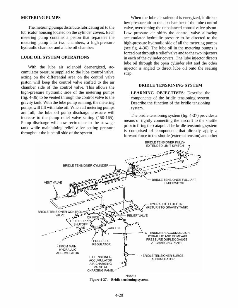
METERING PUMPS
The metering pumps distribute lubricating oil to thelubricator housing located on the cylinder covers. Eachmetering pump contains a piston that separates themetering pump into two chambers, a high-pressurehydraulic chamber and a lube oil chamber.
LUBE OIL SYSTEM OPERATIONS
With the lube air solenoid deenergized, ac-cumulator pressure supplied to the lube control valve,acting on the differential area on the control valvepiston will keep the control valve shifted to the airchamber side of the control valve. This allows thehigh-pressure hydraulic side of the metering pumps(fig. 4-36) to be vented through the control valve to thegravity tank. With the lube pump running, the meteringpumps will fill with lube oil. When all metering pumpsare full, the lube oil pump discharge pressure willincrease to the pump relief valve setting (150-165).Pump discharge will now recirculate to the stowagetank while maintaining relief valve setting pressurethroughout the lube oil side of the system.
When the lube air solenoid is energized, it directslow pressure air to the air chamber of the lube controlvalve, overcoming the unbalanced control valve piston.Low pressure air shifts the control valve allowingaccumulator hydraulic pressure to be directed to thehigh-pressure hydraulic side of all the metering pumps(see fig. 4-36). The lube oil in the metering pumps isforced out through a relief valve and to the two injectorsin each of the cylinder covers. One lube injector directslube oil through the open cylinder slot and the otherinjector is angled to direct lube oil onto the sealingstrip.
BRIDLE TENSIONING SYSTEM
LEARNING OBJECTIVES: Describe thecomponents of the bridle tensioning system.Describe the function of the bridle tensioningsystem.
The bridle tensioning system (fig. 4-37) provides ameans of tightly connecting the aircraft to the shuttleprior to firing the catapult. The bridle tensioning systemis comprised of components that directly apply aforward force to the shuttle (external tension) and other
4-29
VENT VALVE
BRIDLE TENSIONER CYLINDER
BRIDLE TENSIONER FULLY-EXTENDED LIMIT SWITCH
BRIDLE TENSIONER FULL-AFTLIMIT SWITCH
HYDRAULIC FLUID LINE(RETURN TO GRAVITY TANK)
RELIEF VALVE
AIR LINE
PRESSUREREGULATOR
BRIDLE TENSIONER SURGEACCUMULATOR
TO TENSIONER-ACCUMULATORAIR-CHARGING
VALVE ATCHARGING PANEL
FROM MAINHYDRAULIC
ACCUMULATOR
FLUID SUPPLYSHUTOFF
VALVE
ORIFICE
BRIDLE TENSIONER CONTROLVALVE
TO TENSIONER-ACCUMULATOR-HYDRAULIC AND DOME-AIRPRESSURE DUPLEX GAUGE
AT CHARGING PANEL
ABEf0438
Figure 4-37.—Bridle tensioning system.

components that cause the retraction engine motor toslowly rotate (internal tension). The components of theexternal tensioning system is comprised of a bridletensioner pilot valve, a pressure regulator, a tensionercontrol valve, a tensioner cylinder, a relief valve, and afull aft limit switch.
NOTE
The Mk 2 nose gear launch unit is an integralpart of the bridle tensioning system. Itsdescription and operation is discussed later inthis manual.
TENSIONER PILOT VALVE
The tensioner pilot valve is located on theretraction engine manifold and is used to actuate thebridle tensioner control valve, internal tensioning inlet,and outlet valve.
PRESSURE REGULATOR
The pressure regulator is used to reduce ac-cumulator pressure to the pressure required for theproper application (4000 plus or minus 250-ft lbs.)through the grab to the shuttle. Reduced pressure fromthe regulator is directed to the bridle tensioner controlvalve and to the forward end of the bridle tensionercylinder.
BRIDLE TENSIONER CONTROL VALVE
The tensioner control valve directs reducedhydraulic pressure from the pressure regulator to the aft
end of the tensioner cylinder during the bridle tensionphase. At other times the control valve provides a ventto the gravity tank for the aft end of the tensionercylinder.
BRIDLE TENSIONER CYLINDER
The purpose of the tensioner cylinder is to exertforce on the catapult shuttle, via the shuttle grabassembly, to tension the aircraft launching hardwareprior to launching. The bridle tensioner cylinder (fig.4-38) is mounted directly below the nose gear launch(NGL) track and in line with the aft trough covers. Thecylinder contains a piston with a rod extending out ofthe forward end of the cylinder. The end of the rod isfitted with a crosshead containing rollers, whichsupports and aligns the piston rod within the trackformed by the two trough covers. A cam on thecrosshead is used to actuate the bridle tensioner full aftlimit switch.
RELIEF VALVE
The external tensioning relief valve is set to relieveat 150 psi over the normally required pressure.
BRIDLE TENSIONER FULL AFT LIMITSWITCH
The full aft limit switch in the bridle tensioningsystem is located in the aftermost trough cover, and areactuated by a cam on the bridle tensioner piston rodcrosshead. The fully aft limit switch, when actuated,allows completion of the RETRACT PERMISSIVEcircuit. This prevents retraction of the grab and shuttle
4-30
ABEf0439
Figure 4-38.—Tensioner cylinder assembly.

into an extended bridle tensioner piston rod. This limitswitch is also part of the MANEUVER AFT circuit.This circuit ensures that the tensioner piston rod is fullyaft, allowing the grab latch to remain locked to theshuttle in an aircraft-launch-abort situation.
Internal Tensioning Components
The internal tensioning is comprised of com-ponents that cause the retraction engine motor to slowlyrotate and consists of a pressure regulator, and a inletand outlet valve.
Pressure Regulator
The pressure regulator is used to reduce ac-cumulator pressure to the pressure required to move thegrab and shuttle forward (creep rate) a distance of sixfeet in 30-50 seconds.
Internal Tensioning Inlet and Outlet Valve
The internal tensioning inlet and outlet valvecontrols the flow of reduced pressure hydraulic fluid toand from the hydraulic motor and orifice bypass pipingduring the tensioning phase. When actuated by the
bridle tensioner pilot valve, reduced pressure hydraulicfluid flows through the inlet valve to the hydraulicmotor and orifice bypass piping. Hydraulic fluid fromthe motor and bypass piping is routed to the gravitytank through the outlet valve. This enables thehydraulic motor to rotate the drum slowly so that staticfriction in the retraction engine and drive system isovercome.
Internal Tension Relief Valve
The relief valve is set to relieve at 225 psi over thenormal internal tension pressure.
HYDRAULIC SYSTEM
LEARNING OBJECTIVES: Describe thecomponents of the hydraulic system. Describethe function of the hydraulic system.
The hydraulic system (fig. 4-39) suppliespressurized fluid to the hydraulic components of thecatapult. The system consists of a main hydraulicaccumulator, an air flask, three main hydraulic pumps,a booster pump and filter unit, a gravity tank, a 90gallon auxiliary tank, and a circulating pump.
4-31
TO MAIN HYDRAULICACCUMULATOR(NOT SHOWN)
DELIVERYCONTROL
UNIT
SUCTION LINESTRAINER
TO FLUID COOLER/GRAVITY TANK
MAIN HYDRAULIC PUMP
GRAVITY TANK
AUXILIARYTANK
FLUIDFILTER
CIRCULATINGPUMP
BOOSTER PUMP
BOOSTER PUMPFILTER
ABEf0440
Figure 4-39.—Retraction engine hydraulic system.
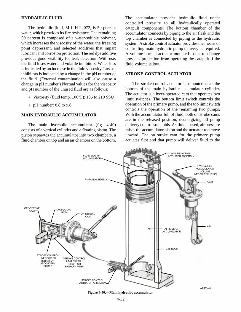
HYDRAULIC FLUID
The hydraulic fluid, MIL-H-22072, is 50 percentwater, which provides its fire resistance. The remaining50 percent is composed of a water-soluble polymer,which increases the viscosity of the water, the freezingpoint depressant, and selected additives that impartlubricant and corrosion protection. The red dye additiveprovides good visibility for leak detection. With use,the fluid loses water and volatile inhibitors. Water lossis indicated by an increase in the fluid viscosity. Loss ofinhibitors is indicated by a change in the pH number ofthe fluid. (External contamination will also cause achange in pH number.) Normal values for the viscosityand pH number of the unused fluid are as follows:
• Viscosity (fluid temp. 100°F): 185 to 210 SSU
• pH number: 8.8 to 9.8
MAIN HYDRAULIC ACCUMULATOR
The main hydraulic accumulator (fig. 4-40)consists of a vertical cylinder and a floating piston. Thepiston separates the accumulator into two chambers, afluid chamber on top and an air chamber on the bottom.
The accumulator provides hydraulic fluid undercontrolled pressure to all hydraulically operatedcatapult components. The bottom chamber of theaccumulator connects by piping to the air flask and thetop chamber is connected by piping to the hydraulicsystem. A stroke control actuator provides the means ofcontrolling main hydraulic pump delivery as required.A volume normal actuator mounted to the top flangeprovides protection from operating the catapult if thefluid volume is low.
STROKE-CONTROL ACTUATOR
The stroke-control actuator is mounted near thebottom of the main hydraulic accumulator cylinder.The actuator is a lever-operated cam that operates twolimit switches. The bottom limit switch controls theoperation of the primary pump, and the top limit switchcontrols the operation of the remaining two pumps.With the accumulator full of fluid, both on stroke camsare in the released position, deenergizing all pumpdelivery control solenoids. As fluid is used, air pressureraises the accumulator piston and the actuator rod moveupward. The on stroke cam for the primary pumpactuates first and that pump will deliver fluid to the
4-32
FLUID SIDE OFACCUMULATOR
VOLUME-NORMALACTUATOR ASSEMBLY
PISTON ASSEMBLYCAM
ARM
HYDRAULIC-ACCUMULATOR
VOLUMELIMIT SWITCH (S130)
CYLINDER
AIR SIDE OFACCUMULATOR
OFF-STROKECAM
ACTUATORROD
ON-STROKECAM
STROKE CONTROLLIMIT SWITCH
(S855) FORSECONDARY
PUMPS
STROKE CONTROLLIMIT SWITCH
(S857) FORPRIMARY PUMP
STROKE CONTROLACTUATOR ASSEMBLY
ABEf0441
Figure 4-40.—Main hydraulic accumulator.

accumulator. If the system fluid use is in excess of theprimary pump output, the accumulator piston willcontinue to rise causing actuation of the onstroke camfor the other two pumps. The delivery control solenoidof those pumps energizes and all pumps then deliverfluid to the accumulator. As the accumulator fills, thepiston move downward reversing the movement of theactuating arm and sequentially opening the circuits tothe delivery control solenoids of the three pumps.
VOLUME-NORMAL ACTUATOR
The volume-normal actuator is located in the top ofthe cylinder (see fig. 4-39). During launchingoperations, if hydraulic fluid volume in theaccumulator becomes dangerously low, the concave topsurface on the accumulator piston will come in contactwith the arm on the actuator. The arm will rotate andcause the cam to release the limit switch. The limitswitch contacts shift, lighting a malfunction light andbreaking the circuit to the cat/first ready phase ofoperation.
AIR FLASK
The air flask (fig. 4-41) is a 70 cubic foot containerof compressed air, which is used to maintain nearlyconstant hydraulic-fluid pressure in the accumulator.As the fluid in the accumulator is used, the air pressureforces the piston upward, displacing the fluid. Becauseof the large volume of air in the air flask, the pressurechange in the accumulator is relatively small.
MAIN HYDRAULIC PUMPS
The main hydraulic pumps (see fig. 4-39) deliverhydraulic fluid to the main hydraulic accumulator. Thehydraulic pumps are connected in parallel. The intakeline to each pump is provided with a strainer. Eachpump discharge line is fitted with a delivery controlunit, which has a built-in relief valve. When the hydrau-lic fluid leaves the pumps, the delivery control unitdirects it either through a fluid cooler to the gravity tank(pump offstroke), or through the pressure line to themain accumulator. This pressure line is equipped withone-way check valves to prevent the backing up of fluidfrom the accumulator when the pumps are offstroke.
BOOSTER PUMP AND FILTER UNIT
The booster pump and filter unit (fig. 4-42) consistsof a pump and motor assembly and a filter unit installedbetween the gravity tank and the main hydraulicpumps. The booster pump is operated anytime that amain hydraulic pump is running. During operation thebooster pump maintains a positive head of hydraulicpressure at the inlet to the main hydraulic pumps. Thefilter unit ensures that a clean supply of hydraulic fluidis always available. A means is provided to drain thefilter housing to facilitate changing of filter elements. Abypass line, containing a check valve, is installed topermit the main hydraulic pumps to take suctiondirectly from the gravity tank in the event of a cloggedfilter unit of booster pump failure.
GRAVITY TANK
The gravity tank is the storage reservoir for catapulthydraulic fluid. The tank is made up of internal bafflesto minimize fluid surging and foaming. The tank isvented at the top and all low-pressure fluid return lineslead into the top portion of the tank. The tank capacitiesmay vary slightly but the minimum operating tank levelwith a full hydraulic system and piping is 800 gallons.
AUXILIARY TANK
The auxiliary tank (see fig. 4-39) provides a meansto return hydraulic fluid to the gravity tank or replenishwith new fluid. The tank consists of a cylindricalshaped container with a top strainer and a lid. A line atthe bottom connects to the suction side of thecirculating pump. A flexible hose connects the top ofthe tank to a flight deck fill connection. All new orrecycled hydraulic fluid must pass through the auxiliarytank in order to get to the gravity tank.
4-33
TO MAIN HYDRAULICACCUMULATOR ANDMEDIUM-PRESSUREAIR SUPPLY VALVE
AT CHARGING PANEL TO PRESSURE GAUGEON CHARGING PANEL
CONDENSATE DRAINVALVE
ABEf0442
Figure 4-41.—Air flask.

CIRCULATING PUMP
The circulating pump (see fig. 4-39) is utilized toreturn hydraulic fluid from the auxiliary tank to thegravity tank. The fluid passes through a filter between
the discharge side of the circulating pump and thegravity tank. This ensures that all new or recycledhydraulic fluid is filtered prior to entering the gravitytank.
4-34
TO MAIN PUMPS
FROMGRAVITY TANK
FILTER UNIT
BOOSTERPUMP
SAMPLEPETCOCK
SAMPLEPETCOCK
VENT VALVE
HANDWHEEL
DUPLEX GAUGE
TO MAINPUMPS
FLEXIBLEHOSE
SHUTOFF VALVE
QUICKDISCONNECT
FILTER UNIT
DRAINLINE
ABEf0443
Figure 4-42.—Booster pump and filter installation.

RETRACTION ENGINE AND DRIVESYSTEMS
LEARNING OBJECTIVES: Describe thecomponents of the retraction engine and drivesystems. Describe the function of the retractionengine and drive systems
The retraction engine and drive system (fig. 4-43)consists of the components that are used to return thelaunching engine pistons and shuttle to the batteryposition after each launch or to maneuver the grab,whenever necessary
4-35
PIPING TO ADVANCEDUMP VALVE
PORT TO RETRACTDIRECTIONAL VALVE
CABLE TENSIONER
DRUMTENSIONERACCUMULATORPORT-TO-ADVANCE
DIRECTIONAL VALVEMANIFOLDASSEMBLY
PIPING TORETRACT
DUMP VALVE
VENTVALVES
VENT VALVEPANEL (REF)
ABEf0444
GRAB ASSEMBLY
LEAD SHEAVEASSEMBLY
ADVANCE CABLE
ADVA
NCE
RETR
ACT
RETRACT CABLE
HYDRAULICMOTOR
Figure 4-43.—Retraction engine and drive system.

HYDRAULIC MOTOR
The hydraulic motor (see fig. 4-43) is rotated bypressurized fluid from the main hydraulic accumulator.Various directional valves located on the retractionengine manifold control speed and direction of rotation.The hydraulic motor is coupled directly to the drumassembly, causing the drum to rotate in the samedirection and speed as the motor.
DRUM ASSEMBLY
The drum is a grooved, cylindrical shaped as-sembly which winds and unwinds the drive systemcables to either advance or retract the grab, based ondirectional rotation of the hydraulic motor. The drum isdirectly coupled to the hydraulic motor and is geared tothe screw and traverse carriage installation.
SCREW AND TRAVERSE CARRIAGEINSTALLATION
The screw and traverse carriage installation (fig.4-44) is mounted on the retraction engine frame abovethe drum and is driven by a gear arrangement connectedto the drum. Rotation of the drum causes the traversecarriage to slide along tracks mounted on the engineframe. A sheave and adapter assembly, bolted to thecarriage body, acts as a guide for the advance andretract cables as they wind and unwind on and off thedrum preventing the cables from becoming tangled. Asthe carriage assembly moves along the length of theretraction engine, cams mounted on top of the carriagebody come in contact with valves and switchesmounted within the retraction engine frame. The camsactuate the advance and retract dump valves, advanceand retract cutoff limit switches, grab fully aft limit
4-36
TRACK
SHEAVE AND ADAPTERASSEMBLY
CAMS SCREW
SHEAVE AND ADAPTERASSEMBLY
DRUM
GEARING
ABEf0445
Figure 4-44.—Screw and traverse carriage.

switch, and grab fully advanced limit switch. The campositions are adjusted for individual installations.
RETRACTION ENGINE MANIFOLD
The retraction engine manifold (fig. 4-45) ismounted on the retraction engine frame and providesinternal fluid passages for various control valvefunctions. The manifold contains the bridle tensionerpilot valve and the internal tensioning inlet and outletvalves for the bridle tensioning system. The manifoldalso contains the advance and retract pilot valve, retractdirectional valve, advance directional valve, andmaneuvering valve.
ADVANCE AND RETRACT PILOT VALVE
Used to control the advance directional valve andretract directional valve, through the advance dumpvalve and retract dump valve respectively. When theadvance solenoid (SA) is energized, the pilot shifts,directing hydraulic fluid flow through the pilot valve,through the advance dump valve to shift the advance
directional valve. When the retract solenoid (SR) isenergized, the pilot shifts, directing hydraulic fluidflow through the pilot valve, through the retract dumpvalve to shift the retract directional valve
RETRACT DIRECTIONAL VALVE
The retract directional valve (see fig. 4-45) controlsthe hydraulic motor during retract. When actuated byfluid flow from the pilot valve, the retract directionalvalve piston shifts, directing fluid flow through thedirectional valve to the hydraulic motor. The fluidreturns from the motor and flows through thedirectional valve to the gravity tank. When the retractdirectional valve is not actuated, no fluid flow isallowed through the valve. As the traverse carriagenears the end of a retract stroke, a cam mounted on thecarriage actuates the retract dump valve. This drains thepressure in the retract directional valve actuatingchamber back to the gravity tank through the dumpvalve. The retract directional valve piston then closes,causing a gradual cutoff of hydraulic fluid from thehydraulic motor, initiating retraction engine braking.
4-37
INTERNAL-TENSIONINGOUTLET VALVE
INTERNAL-TENSIONINGINLET VALVE
TENSIONERPILOT VALVE
ADVANCE DIRECTIONALVALVE
RETRACT DIRECTIONALVALVE
MANEUVERINGVALVE
ADVANCE ANDRETRACT
PILOT VALVE
ABEf0446
Figure 4-45.—Retraction engine manifold.
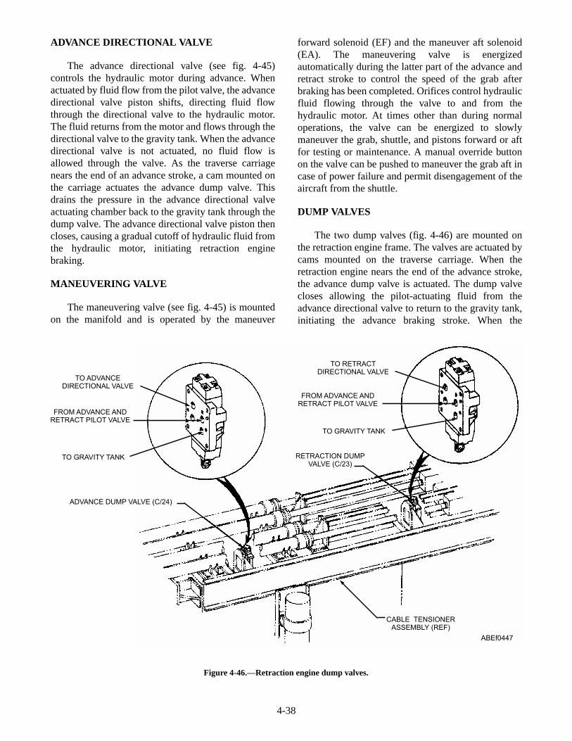
ADVANCE DIRECTIONAL VALVE
The advance directional valve (see fig. 4-45)controls the hydraulic motor during advance. Whenactuated by fluid flow from the pilot valve, the advancedirectional valve piston shifts, directing fluid flowthrough the directional valve to the hydraulic motor.The fluid returns from the motor and flows through thedirectional valve to the gravity tank. When the advancedirectional valve is not actuated, no fluid flow isallowed through the valve. As the traverse carriagenears the end of an advance stroke, a cam mounted onthe carriage actuates the advance dump valve. Thisdrains the pressure in the advance directional valveactuating chamber back to the gravity tank through thedump valve. The advance directional valve piston thencloses, causing a gradual cutoff of hydraulic fluid fromthe hydraulic motor, initiating retraction enginebraking.
MANEUVERING VALVE
The maneuvering valve (see fig. 4-45) is mountedon the manifold and is operated by the maneuver
forward solenoid (EF) and the maneuver aft solenoid(EA). The maneuvering valve is energizedautomatically during the latter part of the advance andretract stroke to control the speed of the grab afterbraking has been completed. Orifices control hydraulicfluid flowing through the valve to and from thehydraulic motor. At times other than during normaloperations, the valve can be energized to slowlymaneuver the grab, shuttle, and pistons forward or aftfor testing or maintenance. A manual override buttonon the valve can be pushed to maneuver the grab aft incase of power failure and permit disengagement of theaircraft from the shuttle.
DUMP VALVES
The two dump valves (fig. 4-46) are mounted onthe retraction engine frame. The valves are actuated bycams mounted on the traverse carriage. When theretraction engine nears the end of the advance stroke,the advance dump valve is actuated. The dump valvecloses allowing the pilot-actuating fluid from theadvance directional valve to return to the gravity tank,initiating the advance braking stroke. When the
4-38
TO ADVANCEDIRECTIONAL VALVE
TO RETRACTDIRECTIONAL VALVE
FROM ADVANCE ANDRETRACT PILOT VALVE
FROM ADVANCE ANDRETRACT PILOT VALVE
RETRACTION DUMPVALVE (C/23)
CABLE TENSIONERASSEMBLY (REF)
ADVANCE DUMP VALVE (C/24)
TO GRAVITY TANK
TO GRAVITY TANK
ABEf0447
Figure 4-46.—Retraction engine dump valves.

retraction engine nears the end of the retract stroke, theretract dump valve is actuated. The dump valve closesallowing the pilot-actuating fluid from the retractdirectional valve to return to the gravity tank, initiatingthe retract braking stroke.
VENT VALVE PANEL
The vent valve panel is located on top of theretraction engine manifold assembly. Vent valves aremounted on the panel and are connected to variouspoints in the retraction engine hydraulic system. Thesevalves are used to bleed (vent) air and air saturatedhydraulic fluid from various retraction enginecomponents. A hydraulic fluid reservoir is located atthe bottom of the vent valve panel. The reservoir is usedto collect vented fluid and provide the outlet to returnvented fluid to the hydraulic system.
CABLE TENSIONER ASSEMBLY
The cable tensioner assembly (fig. 4-47) consists ofthe four cable tensioners required to keep the retractionengine drive system taut. Each cable tensioners consistsof a hydraulic cylinder containing a piston with athreaded rod extending from one end and a rodattaching a clevis/sheave from the other end. Fluidunder pressure from the cable tensioner accumulatorforces the tensioner sheaves toward the cylindersapplying tension to the drive system cables. Thethreaded rods with adjusting nut on the other end ofeach tensioner provide a stop for sheave stroke whenthe pressure in the tensioner cylinders is overcome bythe braking action which occurs during dump valveactuation.
4-39
PISTON ROD
CLEVIS ASSEMBLYSHEAVE ASSEMBLY
RETRACT CYLINDER ASSEMBLY
ADVANCE CYLINDER ASSEMBLY
STOP NUT
LOCKING NUT
TENSIONER ACCUMULATOR (REF)
ABEf0448
Figure 4-47.—Retraction-engine cable tensioners.

SHEAVES
The sheave assembly (fig. 4-48) is a type of pulleyused to guide and change direction of the drive systemcables. Sheaves are located on the traverse carriage tofeed the cable on and off the drum when the retractionengine is in motion. Fixed sheaves on the retractionengine guide the cables to the fairlead sheaves. Thefairlead sheaves are those sheaves that lead the drivesystem from the retraction engine to the forward and aftends of the catapult trough.
CABLES
The drive system cables are 9/16-inch wire ropewith a swage type fitting on one end for attachment tothe grab. Two advance cables and two retract cablesattach to the forward and aft end of the grab. The cablesare then fairleaded to the retraction engine, around thetraverse carriage sheaves and then a predeterminedlength is wound onto the drum. The drum ends of thecables are held in place by bolted clamps. Duringretraction engine operation, as the drum rotates, one
4-40
CABLE-TENSIONERSHEAVE ASSEMBLY(OUTBOARD SIDE) LEAD SHEAVE
ASSEMBLY
CABLE-TENSIONERSHEAVE ASSEMBLY
(INBOARD SIDE)
TRAVERSE-CARRIAGESHEAVE AND
ADAPTER ASSEMBLY
CABLE-TENSIONERCLEVIS ASSEMBLY
ABEf0449
Figure 4-48.—Sheaves.

pair of cables winds onto the drum while towing thegrab. The other pair of cables is unwound from thedrum by movement of the grab. The traverse carriagemoves in proportion with the drum rotation and feed thecables on and off the drum.
GRAB
The grab (fig. 4-49) is a spring-loaded latch,mounted on a wheel frame and installed within theshuttle track behind the shuttle. The two retract cablesare fastened to the aft end of the grab, and the twoadvance cables to the forward end. After a launch, thegrab is pulled forward the length of the shuttle track bythe drive system, and automatically latches to theshuttle with a positive-locking device. Diagram A offigure 4-50 shows the grab in the UNLOCKEDposition, approaching the shuttle. When the grab latch(5) comes in contact with the shuttle clevis pin (6), thelatch rotates and the latch cam follower (8) moves outof the cam detent (7) in the lock block (9) and continuesupward until it reaches the top surface of the lock block.The spring-loaded lock block then moves under the
cam follower, trapping the latch and locking the grab tothe shuttle clevis pin, as shown in diagram B. The grabwill not release the shuttle until both have been returnedto the BATTERY position and the grab unlockingmechanism is actuated by the bridle tensioner. Whenthe bridle-tensioner piston rod moves forward, thebridle-tensioner buffer cap (11) pushes the grabpushrod (1) inward until the buffer cap contacts thegrab block (2). When the pushrod is pushed inward, thelock block (9) is pulled from under the latch camfollower and the latch is free to rotate and release theshuttle, as shown in diagram C. When the shuttle andbridle tensioner move away from the grab, the grabremains in the UNLOCKED position, as shown indiagram A. During no-load tests, the grab and shuttlemust be unlatched. The grab is manually released fromthe shuttle, as shown in diagram D. A manual-releasedisengaging lever (12) is placed over themanual-release arm (3), which is accessible through thetrack slot, lifted up and pushed forward. This motionpulls the lock block from under the latch cam followerand frees the latch so that the grab and shuttle can beseparated.
4-41
1
23
4 5
67 8
910 11 12 13
14
15
16
17
18
19
20
ABEf0450
1. Pushrod2. Block3. Spring4. Manual-release arm5. Slide shaft
6. Link7. Lubrication fitting8. Spring9. Plate
10. Support
11. Block12. Cam follower13. Upper tie bracket14. Latch15. Buffer plate
16. Bracket17. Shaft18. Wheel assembly19. Link20. Lever
Figure 4-49.—Grab.

CATAPULT CONTROL SYSTEMS
LEARNING OBJECTIVES: Describe thecomponents of the catapult control systems.Describe the function of the catapult controlsystems.
The control system of a steam catapult consists ofthose panels, lights, and switches that are used tooperate a catapult throughout the various operationalphases.
ELECTRICAL CONTROL SYSTEMCOMPONENTS
The electrical control system for a steam catapultconsists of various control panels that govern theoperation of the catapult in conjunction with controlcomponents of other systems.
Included among the components of the catapultelectrical control system are various push buttons,switches, solenoids, relays, circuit breakers, fuses, andlights. The ICCS, CCP, and the main control console isthe focal point of all functions of the catapult electricalcontrol systems.
Electrically operated solenoid valves producemechanical operation of valves throughout the catapult.Buttons actuate some solenoid valves, while others
function automatically during catapult operation.Various changes that occur during catapult operationare sensed by limit switches and pressure switches.Operation of these switches actuates lights at variouscontrol panels. The following paragraphs brieflydescribe some of these components. For information onthe function and interrelationship of the electricalcomponents in a specific system, study the schematicdiagrams in the technical manual for that particulartype of catapult.
Solenoids
A solenoid (fig. 4-51) is an electromagnet formedby a conductor wound in a series of loops in the shapeof a helix (spiral). Inserted within this spiral or coil are asoft-iron core and a movable plunger. The soft-ironcore is pinned or held in position and therefore is notmovable. This movable plunger (also soft iron) is heldaway from the core by a spring in the de-energizedposition.
When current flows through the conductor, amagnetic field is produced. This field acts in everyrespect like a permanent magnet having both a northand south pole.
As shown in figure 4-51, the de-energized positionof the plunger is partially out of the coil, because of the
4-42
1 2 3 4 5
678910
1 2 3 4 5
678910
3 4 5
6910
1 2 3 4 5
67891011
12
DECK LINE DECK LINE
DECK LINE DECK LINE
DIAGRAM A DIAGRAM B
DIAGRAM C DIAGRAM D
UNLOCKED POSITION - APPROACHING SHUTTLE LATCHED & LOCKED TO SHUTTLE
UNLOCKED - SHUTTLE FREE TO MOVE FORWARD MANUALLY UNLOCKED
ABEf0451
1. Pushrod2. Block3. Manual-release arm4. Latch spring
5. Grab latch6. Shuttle clevis pin7. Cam detent8. Cam follower
9. Lock block10. Manual-release-arm stop11. Bridle-tensioner buffer cap12. Manual-release disengaging lever
Figure 4-50.—Grab operation sequence.

action of the spring. When voltage is applied, thecurrent through the coil produces a magnetic field,which draws the plunger within the coil, therebyresulting in mechanical motion. When the coil isde-energized, the plunger returns to its normal positionby the spring action.
Solenoids are used in steam catapult systems forelectrically operating bridle tensioning valves,lubrication valves, engine retraction valves, and relays,and for various other mechanisms where only smallmovements are required. One of the distinct advantagesin the use of solenoids is that a mechanical movementcan be accomplished at a considerable distance fromthe control station. The only link necessary between thecontrol and the solenoid is the electrical wiring for thecoil current.
Relays
One of the principal uses of relays is the remotecontrol of circuits. Circuits may be energized by controlrelays from one or more stations simply by closing aswitch. Switches used to energize relays requirelightweight wire only, and may thereby eliminate thenecessity of running heavy power cable to the variouscontrol points. An additional advantage resulting fromrelay control is the removal of safety hazards, sincehigh-voltage equipment can be switched remotelywithout danger to the operator.
In general, a relay consists of the followingcomponents: a magnetic core and associated coil, thecontacts, springs, armature, and the mounting. Figure4-52 illustrates the fundamental construction of a relay.When the circuit is energized, the flow of currentthrough the coil creates a strong magnetic field, whichpulls the armature to a position that closes the contacts.When the coil is energized, it moves the armature to
contact C1, which completes the circuit from thecommon terminal to C1. At the same time, it hasopened the circuit to contact C2.
The relay is one of the most dependableelectromechanical devices in use; but like any othermechanical or electrical equipment, relays occasionallywear out or become inoperative for one reason oranother. Should inspection determine that a relay hasexceeded its safe life, the relay should be removedimmediately and replaced with one of the same type.
Fuses And Circuit Breakers
The electrical control system is protected fromoverloading by fuses and circuit breakers.
4-43
CORE
PIN COIL
DE-ENERGIZED
PLUNGER
SPRING
ENERGIZED
S N S
ABEf0452
N
Figure 4-51.—Solenoid.
COMMON TERMINAL
PIVOT
C
C
2
1
RELAY COIL TERMINALSABEf0453
Figure 4-52.—Relay construction.

The fuse is the simplest protective device. A fuse ismerely a short length of wire or metal ribbon within asuitable container. This wire or metal ribbon is usuallymade of an alloy that has a low melting point and isdesigned to carry a given amount of currentindefinitely. A larger current causes the metal to heatand melt, opening the circuit to be protected. Inreplacing a burned-out fuse, you should be sure that thenew fuse is the same size (capacity in amperes) as theoriginal.
The circuit breaker serves the same purpose as thefuse, but it is designed to open the circuit underoverload conditions without injury to itself. Thus, thecircuit breaker can be used again and again after theoverload condition has been corrected.
Limit Switches
Limit switches are used as remote indicators of theposition of various components throughout the system.They are actuated mechanically by the movement of thecomponent. Electrical contacts within the switchchange the mechanical action to an electrical signalindicated by lights on the various operating panels.
Microswitches
Microswitches serve the same function as limitswitches except they are used where a very limitedmechanical movement is required (1/16 inch or less).While the term Microswitch suggests the function ofthe switch, it is nothing more than the brand name of theparticular type of switch.
PUSH BUTTON CONTROLS
The sequence of operations on the C-13-0, C-13-1,and C-13-2 catapults is controlled by push buttons. Thetwo types of push buttons are the momentary-contactand holding-circuit push buttons. The momentary-contact push button has to be held in the depressedposition to keep the particular circuit energized. Themaneuver forward and maneuver aft push buttons, are
examples. The push button used in a holding circuitstays energized once it is depressed until that particularcircuit is de-energized by the normal sequence ofoperations or one of the suspend switches is actuated.All the push buttons associated with the normaloperation of the catapult are incorporated into holdingcircuits.
CATAPULT CONTROL SYSTEM FOR CVN-68THROUGH CVN-76 (INTEGRATEDCATAPULT CONTROL STATION(ICCS))
The controls for the ICCS are mainly dividedbetween the ICCS at the flight deck level and theCentral Charging Panel (CCP) below deck. The ICCS isan enclosure that may be retracted into the deck whennot in use. It contains the catapult-officer controlconsole and the monitor control console, and controlsthe operation of two adjacent catapults. Sound-poweredphones and a system of indicator lights link the ICCS tothe remote panels for individual catapults. In anemergency, the functions of the ICCS can betransferred to the emergency deckedge control panel orthe central charging panel, and the catapult officer candirect operations on the flight deck.
Catapult-Officer Control Console
The catapult-officer control console (fig. 4-53) isused in conjunction with the monitor control consoleand the central charging panel to direct catapultoperations. The control console is of wraparounddesign for ease of operation and located facing aft in theICCS. The console is made up of panels containing allof the lights, switches and other controls necessary forthe operation of two adjacent catapults. The operatingpanels and lower end operating panels contain the lightsand switches for operation of the associated catapult.The remaining panels located between the operatingpanels and lower end operating panels provide thelaunching officer with all of the other information orswitches.
4-44

4-45
LEFT WEDGEOPERATING PANEL
DESI REMOTEREADOUTS
INTERMEDIATE SLOPEWEDGE PANEL
INTERMEDIATE SLOPEWEDGE PANEL
OPERATING PANEL(REFER TO VIEW A) OPERATING PANEL
(REFER TO VIEW A)
LOWER ENDOPERATING PANEL(REFER TO VIEW B)
LOWER ENDOPERATING PANEL(REFER TO VIEW B)
AMBIENT TEMPERATUREREADOUT PANEL
LOWER CENTEROPERATING PANEL
CROSSWIND ANDHEADWIND INDICATOR
ABEf0454
VIEW B
VIEW A
STEAM PRESSURE
CAPACITY SELECTOR VALVENO GOGO
OFF
B/
/A
NGL
COMMAND
CSV MATCH
CSV M3 MATCH
CSVCONF
AUTOP.B.
DEFEATINTERLK
JOGP.B.
HANDWHEEL
BRIDLETENSION
CATREADY
CATAPULTSUSPEND
LOCAL
MILITARYPOWER
FIREFINAL
READY
COMBATPOWER
MANGRABAFT
CAT. SUSPENDMONITORING STA.
CAT. SUSPENDPRE-FLT
CAT. SUSPENDWATER BRAKE
Figure 4-53.—Catapult-officer control console.

4-46
LOWER MONITOR PANEL
MONITOR WEDGE PANELLOWER MONITOR PANEL
MONITOR PANEL MONITOR PANEL
ABEf0455
Figure 4-54.—Monitor control console.
MILITARYPOWER LIGHT
COMBATPOWER LIGHT
ABEf0456
Figure 4-55.—Military and combat power lights (typical).
ABEf0457
Figure 4-56.—Deckedge control panel.

Monitor Control Console
The monitor control console (fig. 4-54) is used inconjunction with the catapult-officer control consoleand central charging panel during catapult operations.The control console is of wraparound design and islocated facing forward in the ICCS. The consoleconsists of a monitor panel and a lower monitor panelfor each of the two adjacent catapults. The centersection consists of a wedge panel containing a 24-hourclock. The switches and lights on the monitor panel andlower monitor panel enable the monitor control consoleoperator to keep the launching officer advised of anymalfunction occurring on that pair of catapults. Duringnormal operation the green status lights are on. If amalfunction occurs, the green lights go out and the redlights come on. The malfunction lights will indicate redonly when a malfunction occurs. A gauge on themonitor panel also indicates steam pressure. In additionto monitoring catapult status, the monitor operatorretracts both shuttles and operates the NGL bufferduring aircraft abort procedures.
Military Power Lights and Combat Power Lights
Military-power and combat-power lights (fig.4-55) are located on the deck where they are visible to
the pilot when an aircraft is in launch position. Thelights are used to signal the pilot when to apply fullmilitary power or combat power (afterburner) toaircraft engines during launching operations. Theselights are used when operating in the normal (ICCS)mode.
Deckedge Control Panel
The deckedge control panel (fig. 4-56) is located onthe bulkhead in the catwalk outboard of the associatedcatapult. The panel is located such that a clear andunimpeded view of the launching officer and hook upcrew is assured. The deckedge control panel is usedwhen launching operation are conducted in thedeckedge mode with the launching officer directingoperations from the center deck station.
Deckedge Signal Box
The deckedge signal box (fig. 4-57) is located atflight deck level adjacent to the deckedge control panel.Its function is to indicate the readiness of the catapult tothe launching officer during operations. The deckedgesignal box is only used when operating in the deckedgeor central charging panel mode.
4-47
CATREADY
MILPOWER
FINALREADY
FIRE
ABEf0458
Figure 4-57.—Deckedge signal box.

Deck Catapult-Suspend Light
The deck catapult-suspend light (fig. 4-58) islocated on the edge of the flight deck outboard of itsassociated catapult and in clear view of all topsidecatapult crew members. The light flashes red during asuspend situation to indicate to personnel on the flightdeck that a catapult-suspend situation exists.
Water Brake Control Panel
The water brake control panel (fig. 4-59) is locatedin the water brake pump room. In the event of anemergency or malfunction of the water brakes, a switchon the panel is used to suspend catapult operations andit further protection for personnel when access to thelaunching engine cylinders or water brake cylinder isrequired.
Central Charging Panel
The central charging panel (CCP) (fig. 4-60)provides a single, centralized station from whichvirtually all below decks catapult functions areaccomplished. The CCP consists of left-front panel,left-intermediate-front panel, right-intermediate-frontpanel, right-front panel, transfer-switch enclosure, andlaunch-valve-emergency-cutout-valve, which aredescribed in the following paragraphs. The deck-signal-light panel is located inside the central chargingpanel, below the left-intermediate front panel. Controlson the deck-signal-light panel are used to adjust the
intensity of the deck signal lights. The panel enclosurealso contains pressure switches, gauge shutoff valves,and other piping components.
LEFT-FRONT PANEL.—The left-front panelcontains the switches and pressure gauges for theoperation and monitoring of the catapult hydraulicsystem. The panel contains pressure gauges andOFF-ON switches for the main hydraulic pumps, thebooster pump, the circulating pump, and the lubricationpump. Also included are a gravity-tank fluidtemperature gauge, three main hydraulic accumulatorhydraulic-pressure gauges, an off-on pump deliverycontrol switch, a primary pump selector switch, aretraction-engine suspend switch, a blowdown valvefor the retraction-engine hydraulic fluid, and deliverycontrol fuses.
LEFT-INTERMEDIATE-FRONT PANEL.—The left-intermediate-front-panel contains the valvesand pressure gauges for charging or blowing downcatapult components that require air pressure for theiroperation. Gauges on the panel indicate the air pressurein the air side of the main hydraulic accumulator, the airflask, the air side of the cable-tensioner accumulator,the low-pressure-air supply, medium-pressure-airsupply, and the air side of the tensioner surgeaccumulator. A dual gauge indicates the air pressure at
4-48
ABEf0459
Figure 4-58.—Deck catapult-suspend light.
BOX
LIGHT
SWITCH
ABEf0460
CATAPULT
SUSPENSION
WATERBRAKE
Figure 4-59.—Water brake control panel.

the dome of the tensioner regulator and the pressure inthe hydraulic fluid side of the tensioner surgeaccumulator. Valves on the panel are used for chargingand blowing down the air flask, the air side of the mainhydraulic accumulator, the air side of thecable-tensioner accumulator, the dome of the tensionerregulator, and the air side of the tensioner surgeaccumulator. There is also a valve to shut off thelow-pressure-air supply. A bank of red and greenindicator lights on the panel indicates go and no-goindication for various catapult functions.
RIGHT-INTERMEDIATE-FRONT PANEL.—The top portion of the right-intermediate-front panelcontains the pressure gauges and valves monitoring,charging, and blowing down the nose gear launchaccumulators. The lower portion of the panel contains a24-hour clock and the CSV setting controls.
RIGHT-FRONT PANEL.—The right-front paneltop portion contains the launch valve timer readout,water brake elbow pressure gauges, the wetaccumulator pressure gauge, the main power (RC)on/off switch and a panel with the steam fill/blowdownvalve selectors. The lower portion of this panel containslights and switches for operating and monitoring
catapult and wet steam accumulator components. Thelowest row of lights and switches provide emergencyoperational capability at the charging panel.
Transfer Switch Enclosure
The transfer switch enclosure is located on thelower right end of the central charging panel. Theswitch enclosure contains switches that provides ameans of transferring catapult control functions foroperating in either the deckedge or central chargingpanel emergency mode. The other switches provide ameans of transferring pri-fly, deck signal lights, centralcontrol station, and the catapult interlock switch out ofthe catapult control circuit.
Launch Valve Emergency Cutout Valve
The launch valve emergency cutout valve is locatedon the lower left end of the central charging panel. Theemergency cutout valve provides the central chargingpanel operator with a positive control to prevent thelaunch valve from opening during a HANGFIREcondition. When placed in the emergency position, thecutout valve electrically and hydraulically shifts thelaunch valve control system to the closed position.
4-49
LEFT-FRONT PANEL
LEFT-INTERMEDIATE-FRONT PANEL
RIGHT-INTERMEDIATE-FRONT PANEL
RIGHT-FRONT PANEL
TRANSFER SWITCHENCLOSURE-BOX
DECK SIGNAL LIGHT CONTROL
ABEf0461
Figure 4-60.—Central charging panel.

Central Junction Box
The central junction box (fig. 4-61) provides asingle location for the catapult control system wiringand relays. The terminal board and all wires are clearlymarked for easy identification. Relay status lights and arelay tester aid in troubleshooting electricalmalfunctions.
CATAPULT CONTROL SYSTEM FOR CV-63,CVN-65, and CV-67
The control system consists of those panels, lights,and switches that are used to operate a catapult
throughout the various operational phases. Thefollowing is a description of the control systemcomponents.
Deckedge Control Panel
The deckedge control panel (figs. 4-62 and 4-63) islocated on the bulkhead in the catwalk outboard of theassociated catapult. The panel is located such that aclear and unimpeded view of the launching officer andhook up crew is assured. The deckedge control panelcontains lights and switches used for catapult controlduring launching, retraction, and bridle tensioningphases.
4-50
FUSE LIGHTUNIT
RELAY LIGHTS
RELAYTESTER
RELAY
TERMINALBOARD
ABEf0462
Figure 4-61.—Central junction box.

4-51
NIGHT LIGHTING
CAT INTERLOCKRELEASE RETRACTION PERMISSIVE
RETRACTION COMPLETE
FIRE
FINAL READY
STANDBY
BRIDLE TENSION
FIRST READYCAT'S INTERLOCKED
CAT SUSPENDDECK
CAT SUSPENDWATER BRAKECAT SUSPEND
PRI-FLY
RET ENG SUSPEND
RETRACT
MANEUVERSHUTTLE FWD
MANEUVERSHUTTLE AFT
ABEf0463
CAT SUSPENDCONSOLE
Figure 4-62.—Deckedge control panel (CVN-65 and CV-67).
CATAPULT
SUSPENSION
WATER BRAKE
CATAPULT
INTERLOCK
RELEASE
FIRST
READY
BRIDLE
TENSION
FINAL
READY
CATAPULT
SUSPENSION
PRI-FLY
CATAPULTS
INTERLOCKED
STANDBY
STANDBY
RETRACT
CATAPULT
SUSPENSION
DECK
CATAPULT
SUSPENSION
FIRE
FIRE
CATAPULT
SUSPENSION
CONSOLE
RETRACTION
COMPLETE
RETRACTION
PERMISSIVE
RETRACTION
ENGINE
SUSPENSION
RETRACTION ENG
SUSPENSION
MANEUVER
ENGINE FWD
MANEUVER
SHUTTLE AFT
ABEf0464
Figure 4-63.—Deckedge control panel (CV-63).

Main Control Console (CVN-65 and CV-67)
The main control console (fig. 4-64) is used inconjunction with the deckedge control panel duringcatapult operation. The control console consists of amonitor panel, operating panel, steam panel, the launchvalve cutout valve, and the transfer switch enclosure.
MONITOR PANEL.—The monitor panel con-sists of a series of status lights on the top right side forvarious catapult system pressures. These lights willindicate green for pressure within safe operating limitsor red for out-of-limit pressures. Malfunction lights arelocated down the right side of the panel. These lightswill indicate red in the event of a malfunction. Theswitches that energize these lights will also interruptthe launching sequence. The monitor panel alsocontains the launch vale stroke timers, and the digitalendspeed indicator.
OPERATING PANEL.—The operating panel isused in conjunction with the deckedge panel duringlaunching operations. It contains the lights,push buttons, and switches that are used for catapultcontrol during launching, retraction, and bridletensioning phases. The operating panel also containsthe CSV setting controls.
STEAM CHARGING PANEL.—The steamcharging panel contains steam pressure and tem-perature gauges, status lights, and setting controls. Thesetting controls provide a means of operating the fillvalves automatically or by a manually set air signal. Innormal operations, the fill valves are operated inautomatic charge. With automatic charge and chargevalve selected, the air signal to the fill valves is preset toclosely control the opening rates of the fill valves. Themanually loading air regulator is used to control the airsignal to the blowdown valve and to the fill valves whenin manual charge.
Transfer Switch Enclosure
The transfer switch enclosure is located on thelower right side of the main control console. Thetransfer switch enclosure provides a means of isolatingremote panels and switching control to the controlconsole. The transfer switches are rotated fromNORMAL to EMERGENCY, as required, to isolate aremote panel that has malfunctioned.
Launch Valve Emergency Cutout Valve
The launch valve emergency cutout valve is locatedon the lower left side of the main control console. The
4-52
MONITOR PANEL(REFER TO VIEW A)
OPERATING PANEL(REFER TO VIEW B)
STEAM CHARGING PANEL(REFER TO VIEW C)
TRANSFER SWITCHENCLOSURE
LAUNCH VALVEEMERGENCY
CUTOUT VALVEABEF0465
Figure 4-64.—Main control console (CVN-65 and CV-67).

emergency cutout valve provides the console operator apositive control to prevent the launch valve fromopening during a HANGFIRE condition. When placedin the emergency position, the cutout valve electricallyand hydraulically shifts the launch valve control systemto the closed position.
Central Junction Box
The central junction provides a single location forthe catapult control system wiring and relays. Theterminal board and all wires are clearly marked for easyidentification. Relay status lights and a relay tester aidin troubleshooting electrical malfunctions.
Deckedge Signal Box
The deckedge signal box (fig. 4-65) is located atflight deck level adjacent to the deckedge control panel.Its function is to indicate the readiness of the catapult tothe launching officer during operations.
Water Brake Control Panel
The water brake control panel (see fig. 4-59) islocated in the water brake pump room. In the event ofan emergency or malfunction of the water brakes, aswitch on the panel is used to suspend catapultoperations and it is further protection for personnelwhen access to the launching engine cylinders or waterbrake cylinder is required.
Main Control Console (CV-63)
The main control console (fig. 4-66) is used inconjunction with the deckedge control panel duringcatapult operation. The control console consists of anoperating panel, an emergency panel, a malfunctionpanel, two gauge panels, a launch valve cutout valve,and the transfer switch enclosure.
OPERATING PANEL.—The operating panel isused in conjunction with the deckedge panel duringlaunching operations. It contains the lights,push buttons, and switches that are used for catapultcontrol during the launching sequence.
EMERGENCY PANEL.—The emergency panelcontains all the lights, push buttons, and switches arerequired to provide complete control during thelaunching, retraction, and bridle tensioning phases.
STEAM GAUGE PANEL.—The steam gaugepanel contains a steam pressure gauge, CSV settingcontrols, digital endspeed indicator and launch valvetimer displays.
GAUGE PANEL.—The gauge panel provides ameans of monitoring steam and hydraulic temperatureand pressures.
MALFUNCTION PANEL.—The malfunctionpanel contains lights that indicate the status of certaincatapult components or systems. The hydraulicpressure and the valve position malfunction lights are
4-53
INTER
LOCK
ON
FIRST
READY
STAND
BY
FINAL
READY
FIRE
ABEf0466
Figure 4-65.—Deckedge signal box.

red and will illuminate in the event of a malfunction.The blow through no-load light is amber and willilluminate when the blow through circuit is energized.All other lights on this panel are green and will fail toilluminate in the event of a malfunction.
Transfer Switch Enclosure
The transfer switch enclosure is located on thelower right side of the main control console. Thetransfer switch enclosure provides a means of isolatingremote panels and switching control to the controlconsole. The transfer switches are rotated from
NORMAL to EMERGENCY, as required, to isolate aremote panel that has malfunctioned.
Launch Valve Emergency Cutout Valve
The launch valve emergency cutout valve is locatedon the lower left side of the main control console. Theemergency cutout valve provides the console operator apositive control to prevent the launch valve fromopening during a HANGFIRE condition. When placedin the emergency position, the cutout valve electricallyand hydraulically shifts the launch valve control systemto the closed position.
4-54
CVS SETTINGCONTROLS AND DIGITALEND SPEED INDICATOR
LAUNCH VALVESTROKE TIMERINSTALLATION
GAUGE PANEL(VIEW C)
MALFUNCTIONPANEL
(VIEW D)
TRANSFERSWITCH
ENCLOSURE
STEAM GAUGEPANEL
OPERATING PANEL( VIEW A)
EMERGENCYPANEL
(VIEW B)
LAUNCH VALVECUTOUT VALVE
ABEf0467
Figure 4-66.—Main control console (CV-63).

Central Charging Panel
The central charging panel (fig. 4-67) provides asingle centralized station from which pneumatic andhydraulic systems are controlled and monitored.
LEFT-FRONT PANEL.—The left-front panelcontains the switches and pressure gauges for theoperation and monitoring of the catapult hydraulicsystem. The panel contains pressure gauges andOFF-ON switches for the main hydraulic pumps, thebooster pump, the circulating pump, and the lubricationpump. Also included are a gravity-tank fluidtemperature gauge, three main hydraulic accumulatorhydraulic-pressure gauges, an off-on pump deliverycontrol switch, a primary pump selector switch, aretraction-engine suspend switch, a blowdown valvefor the retraction-engine hydraulic fluid, and deliverycontrol fuses.
LEFT-INTERMEDIATE-FRONT PANEL.—The left-intermediate-front-panel contains the valvesand pressure gauges for charging or blowing downcatapult components that require air pressure for theiroperation. Gauges on the panel indicate the air pressurein the air side of the main hydraulic accumulator, the airflask, the air side of the cable-tensioner accumulator,the low-pressure-air supply, medium-pressure-airsupply, and the air side of the tensioner surge
accumulator. A dual gauge indicates the air pressure atthe dome of the tensioner regulator and the pressure inthe hydraulic fluid side of the tensioner surgeaccumulator. Valves on the panel are used for chargingand blowing down the air flask, the air side of the mainhydraulic accumulator, the air side of thecable-tensioner accumulator, the dome of the tensionerregulator, and the air side of the tensioner surgeaccumulator. There is also a valve to shut off thelow-pressure-air supply. A bank of red and greenindicator lights on the panel indicates go and no-goindication for various catapult functions.
RIGHT-INTERMEDIATE-FRONT PANEL.—The top portion of the right-intermediate-front panelcontains the pressure gauges and valves monitoring,charging, and blowing down the nose gear launchaccumulators. The right-intermediate-front panel isinstalled on CVN-65 only.
REVIEW QUESTIONS
Q1. How are the launching engine cylindersheated?
Q2. How is the catapult trough steam smotheringactuated?
Q3. What is the purpose of the launch valve steamvalve?
4-55
ABEf0468
Figure 4-67.—Central charging panel.

Q4. What provides a means of measuring launchvalve performance?
Q5. What is the purpose of the keeper valve?
Q6. What component transfers the forwardmotion of the pistons to the aircraft?
Q7. What system provides a means of lubricatingthe launching engine cylinders?
Q8. The bridle tensioning system full-aft limitswitch is part of what catapult circuit?
Q9. The auxiliary tank of the hydraulic system hasa capacity of how many gallons?
Q10. What is the function of the retraction engineand drive system?
Q11. The controls for the ICCS are dividedbetween what panels?
Q12. During operation, what indicates thereadiness of the catapult to the launchingofficer?
OPERATIONS
LEARNING OBJECTIVE: Describe theoperation of a steam catapult.
A steam fill-valve system controls the amount ofsteam from the ship's boilers to the wet-steamaccumulator. Steam from the steam accumulator is thenreleased into the launching engine cylinders throughthe launch valve (the amount of steam used is varied bya capacity selector valve [CSV] assembly that controlsthe launch valve opening rate).
This surge of steam acts on a set of steam pistonsinside the launching engine cylinders. These pistons areconnected to a shuttle that is attached to an aircraft. Theforce of the steam being released from the steamaccumulator pushes the pistons forward, towing theshuttle and aircraft at an increasing speed until aircrafttake-off is accomplished.
The shuttle and steam pistons are stopped at the endof their "power stroke" as a tapered spear (fig. 4-68)enters a set of water-filled cylinders, forcing the waterto be "metered" out of the cylinders as the tapered spearmoves into them.
After the shuttle and pistons have been stopped, agrab is advanced forward along the catapult troughcovers by means of the retraction engine, and attachesto the shuttle assembly. The retraction engine is thenreversed and returns the grab, shuttle, and piston
assembly to the battery position in preparation for thenext aircraft launch.
A integrated catapult control station (ICCS),central charging panel (CCP), main control console,deckedge control panel, retraction enginecontrol/charging panel, and water brake panel are usedin conjunction to direct and integrate the catapultelectrical and hydraulic systems functions and tocontrol the sequence of operations through a normalcatapult launching cycle.
Preliminary functional tests are performed by alloperating personnel. These tests consist of at least twono-load launchings, during which the control system isoperated through its complete cycle. The functioning ofas many component parts of the catapult as possibleshould be observed by personnel at the various stations
4-56
SHUTTLESHUTTLE TRACK
PISTONGRAB
1. SHUTTLE IN BATTERY POSITION2. AIRCRAFT ATTACHED TO SHUTTLE AND HOLDBACK UNIT3. TENSIONER AND GRAB EXERT FORWARD PRESSURE ON
SHUTTLE FOR TENSIONING. GRAB AND SHUTTLE UNLOCK
A
B
CATAPULT FIRES
1. HOLDBACK UNIT RELEASES2. SHUTTLE TOWS AIRCRAFT FORWARD
WATERBRAKE
REACTIONSYSTEM
PISTONS AND SHUTTLE HALTEDBY WATER BRAKES
C
D
E
GRAB ADVANCES AND LATCHES TO SHUTTLE
GRAB RETRACTS SHUTTLE TO BATTERY POSITION
ABEf0401
AIRCRAFT PREPARED FOR LAUNCH
Figure 4-68.—Catapult operation.

during the preliminary functional tests. Allmalfunctions must be reported to the maintenanceofficer, catapult officer, or catapult captain.
INTEGRATED CATAPULT CONTROLSTATION (ICCS) NO-LOAD LAUNCHINGPROCEDURES
No-load launches are conducted during theaccomplishment of the preoperational MRCs. No-loadlaunches may also be required for post maintenancecatapult checkout.
WARNING
NO-load tests shall be conducted under thesupervision of a qualified launching officer. Toprevent injury to personnel, safety lines shallbe rigged along the deck inboard of the catapultand safety personnel shall be stationed in thecatwalk to keep unauthorized personnel clearof the catapult area.
Perform the following steps for no-load test launchings:
1. With the catapult track clear, the safetyobserver signals the monitor operator toretract.
2. With the grab and shuttle in battery position,the safety observer signals the monitor tomaneuver forward a sufficient distance toallow grab/shuttle separation (one to two feet isadequate).
3. With a crewmember manually releasing thegrab latch, the safety observer signals themonitor operator to maneuver the grab to thefully aft position.
4. The charging panel operator closes the fluidsupply valve to the bridle tensioner pressureregulator and blows off the air pressure in thedome of the bridle tensioner regulator, surgeaccumulator, and from the dome of the internaltensioning pressure regulator.
5. The launching officer shall set the CSVcommand setting to the required value andensure that the CSV is confirmed and that theCSV match lights come on.
6. The charging panel operator shall ensure thatthe CSV command setting is in the no-loadrange, and if in agreement with the commandsetting, depresses the set pushbutton, andensures that command, position, and
mechanical counter all match. If indisagreement with the command setting, thecharging panel operator shall not depress theset pushbutton until the setting discrepancy isresolved.
7. The launching officer notifies pri-fly to make a5MC warning announcement of the impendingno load launches.
8. The launching officer depresses the bridletensioning pushbutton, military power, andfinal ready pushbuttons.
9. The safety observer shall ensure that thecatapult track is clear and all safety personnelare indicating thumbs up and signal thelaunching officer to fire the catapult.
10. The launching officer shall check for a clearlaunching area and depress the fire pushbutton.
11. Repeat the above procedures if necessary forsubsequent no loads.
INTEGRATED CATAPULT CONTROLSTATION (ICCS) LAUNCHING PROCEDURES
Where the ICCS is the primary mode of controllingfixed-wing-aircraft launching operations, the followingprocedures apply:
As the ship approaches the launch course, the airofficer monitors the wind repeater and keeps thelaunching officer(s) advised of the relative windvelocity. When permission to launch aircraft is receivedfrom the bridge, a final check must be made to ensurerelative wind is within the limits prescribed in theapplicable launching bulletin. This is accomplishedbefore changing the rotating beacon(s) from red togreen, which lights the pri-fly "go light" on the catapultofficers ICCS console, thereby clearing the launchingofficer(s) to begin launching.
The following steps must be completed before thelaunching officer assumes control of the aircraft.
1. Before aircraft tension, the topside safety pettyofficer performs the following:
1) Ensures that appropriate jet blastdeflectors are raised.
2) Supervises the attachment of the holdbackto aircraft.
3) Checks the catapult area forward.
4) Gives the tension signal to the director.
4-57

2. The catapult director performs the following:
1) Checks the catapult area forward.
2) Ensures that the appropriate jet blastdeflectors are raised and that all personnelare clear of the jet blast and prop wash.
3) Signals the launching officer in the ICCSto take tension, while signaling the pilot torelease brakes; the pilot in turn appliespower as specified in the NATOPS Manualfor that type of aircraft.
4) After the aircraft is tensioned on thecatapult, signals the pilot, if required, toraise the aircraft launch bar.
5) Turns the aircraft over to the ICCS decksignal lights.
3. After tension is taken, the top side safety pettyofficer performs the following:
1) Inspects for proper aircraft hookup andalignment.
2) Ensures that all personnel are clear of theaircraft on the catapult.
3) Inspects the launch bar to ensure properengagement with the catapult shuttle afterfull power application and catapulttensioning are completed.
4) Signals "thumbs up" to the catapult safetyobserver with a hand or wand signal if allconditions are satisfactory for launch.
4. The squadron aircraft inspector performs thefollowing:
1) Makes a final inspection of the aircraft forproper configuration; flaps; trim settings;leaks; and loose panels, doors, or hatches.
2) Signals "thumbs up" to the catapult safetyobserver with a hand or wand signal if allconditions are satisfactory for launch.
CAUTION
If there is any doubt in the mind of the topsidesafety petty officer, director, or squadronaircraft inspector as to satisfactory hookup oraircraft configuration, he or she must soindicate to the catapult safety observer byinitiating a crossed arm suspend signal (day) ora horizontal wand movement (night). The
catapult safety observer then signals “suspend”to the launching officer in the ICCS.
5. The catapult safety observer performs thefollowing:
1) Visually checks for proper aircraft hookupand alignment.
2) Ensures that the appropriate jet blastdeflectors are raised and that all personnelare clear of the aircraft, jet blast, and propwash.
6. The launching officer signals for final turnupsby lighting the military power (green) light andthe combat power (amber) light, if applicable,in that order. The pilot shall apply full powerand afterburner, if applicable, as these lightsare illuminated. When the pilot is ready forlaunch, he or she signifies by saluting thecatapult safety observer or, at night, by turningthe navigation lights on steady. The pilotensures that no exterior lights are on before themilitary power/combat power (afterburnerlaunch) lights are illuminated.
7. The catapult safety observer, after observingthe pilot's ready to launch signal performs thefollowing:
1) Makes a final scan of the aircraft.
2) Checks for a "thumbs up" signal from thecatapult topside safety petty officer and thesquadron's aircraft inspector.
3) Signals "thumbs up" to the launchingofficer in the ICCS with a hand or greenwand signal if all conditions aresatisfactory for the launch.
8. Upon receiving the catapult safety observer's"thumbs up" signal and before firing thecatapult, the launching officer performs thefollowing:
1) Checks for a pri-fly go light on his or herconsole.
2) Scans the normal area of visibility.
3) Checks the catapult officer console forsatisfactory catapult launch condition.
4) Checks deck and traffic forward.
5) Checks deck pitch.
6) Ensures the catapult safety observer isgiving the "thumbs up" signal.
4-58

9. After ensuring that all conditions aresatisfactory, the launching officer depresses thefire button. If, after coming to full power on thecatapult, the pilot desires to stop the launch, heor she does so by shaking the head negatively,rather than by giving the "thumbs down"signal. At the same time, the pilot transmits"suspend, suspend." At night, the visual signalalso consists of not turning on the navigationlights. The catapult safety observer signalssuspend to the launching officer in the ICCS,using standard hand or wand signals.
NON-INTEGRATED CATAPULT CONTROLSTATION (ICCS) NO-LOAD LAUNCHINGPROCEDURES
No-load launches are conducted during theaccomplishment of the preoperational MRCs. No-Loads launches may also be required for postmaintenance catapult checkout.
WARNING
NO-Loads tests shall be conducted under thesupervision of a qualified launching officer. Toprevent injury to personnel, safety lines shallbe rigged along the deck inboard of the catapultand safety personnel shall be stationed in thecatwalk to keep unauthorized personnel clearof the catapult area.
Perform the following steps for no-load testlaunchings:
1. With the catapult track clear, the launchingofficer signals the deckedge operator to retract.
2. With the grab and shuttle in battery position,the topside safety petty officer signals thedeckedge operator to maneuver forward asufficient distance to allow grab/shuttleseparation (one to two feet is adequate).
3. With a crewmember manually releasing thegrab latch, the topside petty officer signals thedeck edge operator to maneuver the grab to thefully aft position.
4. The retraction engine operator closes the fluidsupply valves to the bridle tensioner pressureregulator and the internal tensioning pressureregulator.
5. The launching officer shall set the CSVcommand setting to the no load value.
WARNING
The main control console operator shall notplace the catapult in first ready until the CSVsetting has been made, verified and the catapultis ready for no load launches.
6. The console operator shall ensure that the CSVcommand setting is in the no-load range anddepress the set pushbutton. The consoleoperator then ensures that command, position,and mechanical counter all matches and placesthe catapult in first ready. If in disagreementwith the command setting, the console operatorshall not depress the set pushbutton and shallleave the catapult in safe until the settingdiscrepancy is resolved.
7. The launching officer shall ensure that the CSVhas been properly set by ensuring a green CSVstatus light.
8. The launching officer notifies pri-fly to make a5MC warning announcement of the impendingno load launches.
9. The launching officer checks that safety linesare properly rigged and safety personnel are onstation. The launching officer then signals thedeckedge operator to place the catapult in finalready.
10. The deckedge operator presses the bridletensioning and standby pushbuttons.
11. The console operator observes the standbylight come on, ensures that all conditions aresatisfactory and depresses the final readypushbutton.
12. The deckedge operator observes the final readylight come on and gives the final ready signal.
13. The launching officer shall check for a clearlaunching area and give the fire signal.
14. The deckedge operator first looks forward andaft to ensure a clear launch area and thenpresses the fire pushbutton.
15. Repeat the above procedures if necessary forsubsequent no loads.
NON-INTEGRATED CATAPULT CONTROLSTATION (ICCS) LAUNCHING PROCEDURES
The following steps must be completed before thelaunching officer assumes control of the aircraft.
4-59

1. Before aircraft tension, the topside safety pettyofficer performs the following:
1) Ensures that appropriate jet blastdeflectors are raised.
2) Checks the catapult area forward.
3) Supervises the attachment of the holdbackto aircraft.
4) Gives the tension signal to the director.
2. The catapult director performs the following:
1) Checks the catapult area forward.
2) Ensures that the appropriate jet blastdeflectors are raised and that all personnelare clear of the jet blast and prop wash.
3) Signals the deckedge operator to taketension, while signaling the pilot toRELEASE BRAKES; the pilot in turnapplies power as specified in the NATOPSManual for that type of aircraft.
3. When the catapult director gives the handsignal that tension is to be taken, the deckedgeoperator immediately presses the BRIDLETENSION button and verbally relays themessage to the console operator via thesound-powered phone by saying the wordsTAKING TENSION. Under normal conditionsthis is the last word spoken until the launch iscomplete. This is to prevent misunderstanding;for example, misfire, hangfire, fire.
4. Only after correct bridle tension has beenapplied is control of the aircraft passed, asfollows: The director, upon completing bridletension, immediately passes control of theaircraft by pointing both hands toward thecatapult officer.
NOTE
Aircraft to be launched receive a preliminaryengine check before being spotted on thecatapult; therefore, normal operationalprocedure is for the catapult officer to godirectly into the full power turnup signal afterthe aircraft has been tensioned.
5. The catapult officer verifies steam pressurereadings on the gauges at the center deck panel.The catapult officer observes the first readysignal from the deckedge operator, andacknowledges the signal by holding twofingers overhead, hesitates, and then rotates the
hand rapidly for full engine turnup of theaircraft.
6. When the catapult officer starts giving the fullpower turnup (two-finger) signal, thelaunching operation proceeds.
7. The deckedge operator, observing the catapultofficer's full power turnup signal, immediatelypresses the standby button. As soon as thestandby (green) light comes on at the deckedgepanel, he or she holds two fingers overhead.The console operator, observing that thestandby (green) light is on at his or her console,immediately checks all gauges and lights. Ifeverything is ok, he or she puts the catapult intofinal ready condition.
8. When the final ready condition is reached, allfinal ready (red) lights come on, and thelaunching operation continues. As soon as thefinal ready (red) light comes on at the deckedgepanel, the deckedge operator immediatelyholds both hands open above his or her head.
9. With the aircraft at full power, the pilot checksall instruments and gauges. If everything is ok,he or she gets set and indicates ready by turninghis or her head slightly toward the catapultofficer, executes a right- or left-hand salute,and then positions his or her head against thecockpit headrest. The pilot may refuse to belaunched by shaking his or her head negatively,in which case the catapult officer gives thesuspension signal.)
10. The launch signal is given only after thecatapult has reached final ready and the pilot ofthe aircraft indicates he or she is ready. Thecatapult officer ensures that the pilot's head isback against the headrest, checks that the deckis clear forward, and then executes the firesignal. Upon receiving the fire signal, thedeckedge operator makes a final check of theflight deck and catwalks. If they are clear, he orshe depresses the fire push button.
CAUTION
The deckedge operator must not anticipate thefire signal; if any discrepancy in aircrafthookup is noted or if the deck and catwalks arenot clear, he or she must NOT fire but mustsuspend and notify the catapult officer of thediscrepancy.
4-60

INTEGRATED CATAPULT CONTROLSTATION (ICCS) SUSPENDPROCEDURES
A catapult launch can be halted at any time up untilthe fire pushbutton has been depressed by actuating acatapult suspend switch. Suspend switches are locatedat pri-fly, launching officer’s console, monitor console,central charging panel, and at the water brake station.
NOTE
If the suspend switch at the water brake stationis actuated during catapult operations,breaking tension by energizing maneuver aftcannot occur. If this switch initiated a suspendaction, the charging panel operator shallactuate suspend and direct the water brakestation to release the water brake suspend.
Actuation of any catapult suspend switch lights ared flashing light mounted at the edge of the flight decknear the battery position for the associated catapult. Theoperator initiating the suspend must immediatelyinform the launching officer of the reason for thesuspend. The launching officer shall determine theaction to be taken for resolution. If the suspend actionoccurs prior to aircraft hookup, the aircraft shall be heldshort of the hookup position until the problem has beenrectified or the catapult is placed in the down status. If asuspend occurs after an aircraft has been tensioned, thefollowing apply:
1. The safety observer signals suspend to the pilotand other members of the aircraft launchingteam.
2. The launching officer shall immediatelydepress the suspend pushbutton.
3. The safety observer shall ensure that the decksuspend light is on and signal the launchingofficer to maneuver aft.
4. The launching officer depresses and holds themaneuver aft pushbutton until the grab andshuttle are moved fully aft.
5. After the shuttle has moved aft, the safetyobserver signals the pilot to raise launch bar.
6. For aircraft with NGL selector switch (F/A 18and S-3):
1) With the launch bar raised, the safetyobserver gives the bridle tension signal tothe launching officer.
2) The launching officer depresses the bridletension pushbutton to position the shuttleforward of the launch bar. When the shuttlehas moved forward of the launch bar, thelaunching officer shall momentarily pressthe maneuver aft pushbutton.
3) The safety observer shall step in front ofthe aircraft and in view of the pilot, give thethrottle back signal.
7. For aircraft with manual launch bar (E-2 andC-2):
1) After the shuttle has moved aft, the safetyobserver shall ensure that the catapult is inthe suspend condition, step in front of theaircraft and in full view of the pilot, givethe throttle back signal.
2) With the aircraft at idle power the safetyobserver directs the topside safety pettyofficer to approach the aircraft andmanually hold the launch bar high enoughto permit shuttle clearance.
3) With the launch bar held clear, the safetyobserver gives the bridle tension signal tothe launching officer.
4) The launching officer depresses the bridletension pushbutton to position the shuttleforward of the launch bar. When the shuttlehas moved forward of the launch bar, thelaunching officer shall momentarilydepress the maneuver aft pushbutton.
8. At this time, if the condition that initiated thesuspend action has been corrected and theaircraft and catapult are both up, the shuttlemay be maneuvered aft, launch bar loweredand the aircraft hooked up to the catapult.
NON-INTEGRATED CATAPULT CONTROLSTATION (ICCS) SUSPEND PROCEDURES
A catapult launch can be halted at any time up untilthe fire pushbutton has been depressed by actuating acatapult suspend switch. Suspend switches are locatedat pri-fly, deckedge, main control console, and thewater brake station.
NOTE
If the suspend switch at the water brake stationis actuated during catapult operations,breaking tension by energizing maneuver aftcannot occur. If this switch initiated a suspendaction, the main control console operator shall
4-61

actuate suspend and direct the water brakestation to release the water brake suspend.
The operator initiating the suspend mustimmediately inform the launching officer of the reasonfor the suspend. The launching officer shall determinethe action to be taken for resolution. If the suspendaction occurs prior to aircraft hookup, the aircraft shallbe held short of the hookup position until the problemhas been rectified or the catapult is placed in the downstatus. If a suspend occurs after an aircraft has beentensioned, the following apply:
1. The launching officer signals suspend to thepilot and other members of the aircraftlaunching team.
2. The deckedge operator shall immediatelyactuate the suspend switch and give thesuspend signal.
3. The launching officer signals the deckedgeoperator to maneuver aft.
4. After the shuttle has moved aft, the launchingofficer signals the pilot to raise launch bar.
5. For aircraft with NGL selector switch (F/A 18and S-3):
1) With the launch bar raised, the launchingofficer gives the bridle tension signal to thedeckedge operator.
2) The deckedge operator depresses thebridle tension pushbutton to position theshuttle forward of the launch bar. When theshuttle has moved forward of the launchbar, the deckedge operator shall momen-tarily press the maneuver aft pushbutton.
3) The launching officer shall step in front ofthe aircraft and in view of the pilot, give thethrottle back signal.
6. For aircraft with manual launch bar (E-2 andC-2):
1) After the shuttle has moved aft, thelaunching officer shall ensure that thecatapult is in the suspend condition, step infront of the aircraft and in full view of thepilot, give the throttle back signal.
2) With the aircraft at idle power thelaunching officer directs the topside safetypetty officer to approach the aircraft andmanually hold the launch bar high enoughto permit shuttle clearance.
3) With the launch bar held clear, thelaunching officer gives the bridle tensionsignal to the deckedge operator.
4) The deckedge operator depresses thebridle tension pushbutton to position theshuttle forward of the launch bar. When theshuttle has moved forward of the launchbar, the deckedge operator shallmomentarily depress the maneuver aftpushbutton.
7. At this time, if the condition that initiated thesuspend action has been corrected and theaircraft and catapult are both up, the shuttlemay be maneuvered aft, launch bar loweredand the aircraft hooked up to the catapult.
INTEGRATED CATAPULT CONTROLSTATION (ICCS) HANGFIREPROCEDURES
In the event the catapult does not fire within 10seconds after the fire pushbutton is depressed, ahangfire exists. At this time, the launch sequence mustbe safety stopped and the aircraft removed from thecatapult. The actions to be taken and the order in whichthey are accomplished are paramount to the success ofthe procedure.
WARNING
If a hangfire occurs, the execution of thehangfire procedure must be accomplished.Even if the cause of the hangfire is quicklydetermined and can be easily resolved, theactions of all topside crew members and pilotare not known and interrupted firing of thecatapult could have catastrophic consequences.The only corrective action authorized is theperformance of the hangfire procedure.
1. The launching officer depresses the suspendswitch and transmits to the charging paneloperator via the monitor operator, “rotate theemergency cutout valve, rotate the emergencycutout valve.” The launching officer shall theninform the safety observer of the hangfirecondition verbally and by hand signals indaytime or the red wand hangfire signal atnight.
2. The safety observer shall remain in thecrouched position and shall not take any actiontoward the removal of the aircraft until the
4-62

shuttle has moved aft and assurance is receivedthat the catapult is safe.
3. The charging panel operator shall perform thefollowing actions in exact order:
1) Depress the suspend pushbutton.2) Remove the cotter pin and unscrew the pin
from the emergency cutout valve.3) Rotate the emergency cutout valve to the
emergency position.4) Depress and hold the maneuver aft
pushbutton for 15 seconds.5) Report to the launching officer via the
monitor operator that the catapult is safe.
4. The launching officer transmits verbally thatthe catapult is safe and signals the safetyobserver a thumbs up in daytime or a red wandsignal at night.
5. If the shuttle did not move aft during thepreceding steps, the launching officer shalldirect the charging panel/retraction engineoperator, via the monitor operator, to depressand hold the manual override on the maneuveraft valve for 15 seconds.
6. After receiving assurance that the catapult issafe and observing that the shuttle is aft, thesafety observer steps in front of the aircraft andin view of the pilot, gives the throttle backsignal. The normal suspend/abort areaccomplished for aircraft removal from thecatapult.
7. After aircraft removal from the catapult hasbeen accomplished, the launching officer shallset the CSV command to a no-load setting andensure that CSV confirmed and match lightscome on.
8. The emergency cutout valve shall remain in theemergency position until the maintenanceofficer authorizes rotation of the valve to thenormal position.
9. The catapult is placed in a down status until thecause of the hangfire is determined, corrected,and two satisfactory no-load launchesaccomplished.
NON-INTEGRATED CATAPULT CONTROLSTATION (ICCS) HANGFIRE PROCEDURES
In the event the catapult does not fire within 10seconds after the fire pushbutton is depressed, a
hangfire exists. At this time, the launch sequence mustbe stopped and the aircraft removed from the catapult.The actions to be taken and the order in which they areaccomplished are paramount to the success of theprocedure.
WARNING
If a hangfire occurs, the execution of thehangfire procedure must be accomplished.Even if the cause of the hangfire is quicklydetermined and can be easily resolved, theactions of all topside crew members and pilotare not known and interrupted firing of thecatapult could have catastrophic consequences.The only corrective action authorized is theperformance of the hangfire procedure.
1. The launching officer shall remain in thecrouched position and signals in exact order:
1) Suspend
2) Hangfire
3) Maneuver aft
2. The launching officer shall remain in thecrouched position and shall not take any actiontoward the removal of the aircraft until theshuttle has moved aft and assurance is receivedthat the catapult is safe.
3. The deckedge operator depresses the suspendswitch and transmits to the main controlconsole operator, “rotate the emergency cutoutvalve, rotate the emergency cutout valve.”
4. The main control console operator shallperform the following actions in exact order:
1) Depress the suspend pushbutton.
2) Remove the cotter pin and unscrew the pinfrom the emergency cutout valve.
3) Rotate the emergency cutout valve to theemergency position.
4) Depress and hold the maneuver aftpushbutton for 15 seconds.
5) Report verbally to the deckedge operatorthat the catapult is safe.
5. The deckedge operator upon receiving theassurance from the main control consoleoperator, signals to the launching officer, thehangfire signal followed by thumbs up indaytime or a red wand signal at night.
4-63

6. If the shuttle did not move aft during thepreceding steps, the deckedge operator shalldirect the retraction engine operator to depressand hold the manual override on the maneuveraft valve for 15 seconds.
7. After receiving assurance that the catapult issafe and observing that the shuttle is aft, thelaunching officer steps in front of the aircraftand in view of the pilot, gives the throttle backsignal. The normal suspend/abort areaccomplished for aircraft removal from thecatapult.
8. After aircraft removal from the catapult hasbeen accomplished, the launching officer shallset the CSV command to a no-load setting.
9. The main control console operator shalldepress the set pushbutton.
10. The emergency cutout valve shall remain in theemergency position until the maintenanceofficer authorizes rotation of the valve to thenormal position.
11. The catapult is placed in a down status until thecause of the hangfire is determined, corrected,and two satisfactory no-load launchesaccomplished.
SAFETY PRECAUTIONS
There are certain safety precautions that must beobserved by catapult-operating personnel, maintenancepersonnel, deck personnel, pilots, and other personnelstationed in the catapult area.
Flight Deck
Bridle (deck) tensioner pressure, as determined bycalibration, must be precisely adjusted and maintainedat all times. Pressures in excess of those specified maycause premature holdback.
In the event of a malfunction, suspend, or hangfire,the signal for throttle back must NOT be given to thepilot until bridle tension has been released and thelaunch bar is raised.
When attaching the aircraft to the shuttle, extremecare must be taken so that the launch bar properlyengages the shuttle. The catapult officer must ensurethat the aircraft is properly tensioned prior to launching.
Precaution should be taken by the pilot not to taxihard against the holdback unit. This may result in apremature release.
At no time are personnel to walk in front of atensioned aircraft.
If operation of the catapult is suspended for anyreason, bridle tension should be released and theaircraft released from the shuttle.
The shuttle and grab must not be moved along thecatapult track until the track slot has been inspected andfound to be clear of obstructions and all adjacent areasare clear of loose gear. Using the maneuver forward andaft push buttons, slowly move pistons forward and aftwhile all sheaves are visually checked to ensure thecables are not sliding over any locked sheaves.
All personnel must be kept out of areas forward ofan aircraft positioned on the catapult, and clear of theshuttle track area during a no-load firing. All personnelmust be kept clear of the area immediately behind thejet blast deflectors during aircraft turnups andlaunching.
During night operations, do not attempt to speed upthe prelaunch check of catapult components or takeunnecessary chances in an effort to maintain rapidaircraft launching intervals. Sufficient time should betaken to double-check each step to prevent accidentsdue to faulty hookups, misinterpreted signals, and othercauses.
ICCS, CCP, Deckedge and/or Main ControlConsole
Retraction must not be undertaken unless the waterbrakes are operating properly and the grab and shuttleare latched. During preheating and throughoutlaunching operations, the difference in elongationbetween the two launching engine cylinders must NOTexceed 1 inch. The catapult must NOT be fired with theshuttle out of BATTERY.
The shuttle must NOT be retracted with steam inaccumulators unless the water brakes are functioning.
Do not advance the grab with spears out of thewater brakes because possible grab latch damage mayresult, due to impact. Therefore, use the maneuverforward push button to advance the grab until it engagesthe shuttle.
4-64
Water Brakes
If the water-brake cylinder elbow pressure dropsbelow minimum value the water brakes should besuspended and the CCP/main control console operatornotified immediately. The malfunctioning water-brakepump should be secured and the standby pump started.
Do not allow excessive oil to accumulate on top ofthe water in the water-brake reservoir. Skim off the oil,or remove it by adding fresh water and allowing the oilto flow out the overflow drain.
NOTE
During in-port periods, do not skim thewater-brake tanks or allow the water level toreach the overflow pipe. Maintain the waterlevel by use of bottom tank drains. This is toprevent oil from being dumped into harbors.
Retraction Engine
All loose gear and tools must be kept clear of theretraction engine and cable system. Maintain allpressures at predetermined settings.
If any malfunction is observed during the advanceof the grab or the retraction of the shuttle and grab,immediately SUSPEND the retract engine and notifythe CCP/main console operator. All sheaves must beinspected for freedom of motion before beginning aseries of launchings.
General
Operating personnel should wear appropriateprotective clothing to prevent burns from steam or fromcontact with hot metallic surfaces. Earplugs should beworn in areas of high noise level.
The entire hydraulic system must be ventedthoroughly and frequently, particularly after extendedperiods of idleness. Air in the fluid system may causeunpredictable variations in catapult performance anddelays in actuation of operating components.
Combustible and volatile fluids and materials mustbe kept away from heated catapult parts to reduce thehazard of fire and explosion. Adequate ventilation mustbe provided below flight deck level to prevent theaccumulation of explosive vapors.
If a hangfire occurs, personnel must not passforward of the aircraft until all danger of a delayedlaunching has passed.
The catapult must NOT be operated with anyknown broken lockwires, loose or cracked components,major hydraulic leakage, defective reeving, or electricalcontrol malfunction.
During any type of launching, live steam escapesfrom the track and brake areas. As this steam can causesevere scalding of exposed areas of the body, personnelin the area must avoid contact with it. When the catapultis in operating status, exposed metallic parts, such astrack covers, launching and exhaust valves, and steamsupply piping, may be hot enough to burn exposedareas of the body on contact. Therefore, operatingpersonnel with duties in these areas should be equippedwith appropriate protective clothing.
Aircraft launchings must NOT be made if therequired minimum cylinder elongation has not beenattained. An exception to this rule may be made underemergency conditions when wind-over-deckrequirements have been increased as specified inapplicable Aircraft Launching Bulletins.
Aircraft must not be launched at weights and windrequirements other than those specified in applicableAircraft Launching Bulletins. Maximum loading ofaircraft as specified in the NATOPS Manual for eachtype of aircraft, must be adhered to at all times.
Inspect all pumps and their limit switches andsafety valves. Failure of safety devices can result indangerous overpressures if the pump continues tooperate. This condition may result in rupture ofhydraulic pneumatic lines and danger to personnel.
SECURING THE CATAPULT
At the completion of aircraft launching operations,the catapult officer shall decide what state of catapultreadiness will be maintained. Depending onoperational requirements, one of the followingreadiness conditions will be established:
Ready
The order to maintain the catapult in a READYcondition should be given when launching operationsare intermittent or when certain conditions make itnecessary to keep the catapult in a state of preparednessfor launching within seconds after an order is given.
In the READY condition, the catapult is kept in afully operational status, as between launching cycles.
4-65

Standby
If the order for the STANDBY condition ofsecuring is given, it usually comes after the day'slaunching operations are completed and there is nopossibility of additional launching within 12 hours.
The post-launch duties and inspection must beperformed according to the MRCs.
Shutdown
The order for SHUTDOWN condition of securingthe catapult is given when the catapult is placed out ofservice for maintenance or when the ship is in port.
Cold Iron
When the catapult will not be required forlaunching operations for an extended period of time, orthe steam system and preheat system must be securedand the components allowed to cool down.
INSPECTIONS AND MALFUNCTIONS
The entire catapult should be kept as clean aspossible. It should be wiped down daily to removeexcess grease, oil, and dirt. All catapult personnelshould be constantly alert for any unusual sound oraction of the machinery. Report any unusual conditionto the catapult officer for immediate investigation.
Periodic Inspections
Prior to the first launching of each day's operations,execute the PMS preoperational inspection accordingto the MRCs.
After each day's operation, perform the PMSpostoperational inspection according to the MRCs.
Other inspections must be conducted in addition topreoperational and postoperational. These inspectionsare also accomplished through the use of MRCs.
Prior to conducting an inspection or maintenanceon catapult equipment where an injury could occurfrom careless operation, make sure the following safetyprecautions have been accomplished in the orderindicated:
1. Disconnect the grab from the shuttle and moveit fully aft.
2. Close the main steam supply to the steamaccumulator.
3. Reduce steam pressure in the steamaccumulator to atmospheric pressure.
4. Open the retraction-engine accumulatorblowdown valve.
5. Station a safety person at the ICCS, CCP, maincontrol console and deckedge control manningsound-powered telephones to preventtampering with catapult controls.
6. Station a safety person at the retraction engineand the water-brake tank, manningsound-powered telephones.
7. Tag the steam-smothering valve "out ofservice."
8. Station a safety person on the flight deck (in theshuttle area) to prevent accidental movement ofthe shuttle while personnel are in thewater-brake tank.
The preceding safety instructions must be strictlyfollowed. Under any conditions when inspection of thewater brakes area is undertaken, it is imperative that thecontrol system remain in a SAFE position (exhaustvalve open, grab aft).
Malfunctions
This section provides operating personnel with aguide to assist in isolating and correcting causes ofmalfunctions. During aircraft launch operations,malfunctions may occur that can be rapidly corrected ifthe cause is correctly determined. In other cases,corrective action may require extensive repairs, and it isimportant that operating personnel rapidly isolate thecause of the malfunction in order to inform the catapultofficer if the catapult must be placed out of service.
When a malfunction occurs, the catapult must beput in a SAFE condition before corrective action isattempted, to prevent accidental launching of aircraft orinjury to personnel.
To property correct any malfunction(s) all primarycauses should be checked first to quickly isolate themalfunction to a specific system. The secondary causescan then be checked to determine which component(s)within the system caused the malfunction.
All preoperational and post operational inspectionprocedures that apply to a specific system or station ofthe catapult are to be conducted and completed by theperson or persons assigned the duty. For detailedinspection procedures, the ABE must consult theapplicable MRCs or technical manuals.
4-66

CHAPTER 5
ASSOCIATED LAUNCHING EQUIPMENT
The associated launching equipment discussed inthis chapter is used in conjunction with catapults andarresting gear. This equipment includes the jet blastdeflectors and nose gear launch equipment.
JET BLAST DEFLECTORS
LEARNING OBJECTIVES: Identify thecomponents of the jet blast deflectors.Describe the operation of the jet blastdeflectors. Describe the emergency operationsof the jet blast deflectors.
The jet blast deflector (JBD) installation consists ofwater-cooled panels that are mounted flush with theflight deck. The panels are raised and lowered byhydraulic cylinders connected to mechanical operatinggear. When raised, the JBDs serve to protect personnel,equipment and other aircraft from the hot jet exhaustcreated by an aircraft spotted on the catapult. Seawater,supplied from the ship’s firemain, is continuouslycirculated through the modules of each panel assemblyto prevent overheating. Figure 5-1 shows the basicoperation of JBDs.
5-1
WATER IN
WATER RETURN
PRESSURIZEDHYDRAULIC FLUID
HYDRAULIC FLUIDRETURN
ABEF0501
Figure 5-1.—Jet blast deflector operations.

Jet Blast Deflector Assembly
The JBD assembly (fig. 5-2) consists of a series ofwater-cooled panels and operating gear assemblies.The Mk 7 Mod 0/2 JBD assembly is comprised of sixpanel assemblies with three sets of operating gear while
the Mk 7 Mod 1 JBD assembly has four panelassemblies and two sets of operating gear. The Mk 7Mod 2 JBD contain two additional sideplate coolingpanels. The sideplate cooling panels provide additionalcooling which helps to prevent warping of the JBDpanels.
5-2
WATER-COOLED PANEL ASSEMBLY
OPERATING GEAR ASSEMBLY(MK 7 MOD 0/2)
WATER-COOLED PANEL ASSEMBLY
OPERATING GEAR ASSEMBLY(MK 7 MOD 1)
ABEF0502
Figure 5-2.—Jet blast deflector assembly.

Regardless of the JBD installation, the operation isthe same. A pair of JBD panels is connected to a set ofoperating gear. The panel assemblies can be raisedindependently or simultaneously with others in thesame installation. By connecting a pair of panels to a setof operating gear, one cylinder can raise or lower a pairof JBD panels in the event of a failure to the othercylinder.
Operating Gear Assembly
The operating gear assembly (fig. 5-3) provides themeans of physically raising and lowering the JBDpanels. A set of operating gear consists of two hydrauliccylinders, three bearing blocks, one trunnion shaft, twocrank assemblies and four linkage assemblies. Eachlinkage assembly consists of an arm, strut and eye. Thelinkage for two JBD panels is connected to a single
shaft. This method of attachment permits raising andlowering the JBD panels in pairs. The trunnion shaft ismounted and supported by the three bearing blockassemblies. The two hydraulic cylinders are connectedto the to the trunnion shaft by means of the crankassemblies.
Movement of the hydraulic cylinder piston rodsrotates the shaft. Rotation of the trunnion shaft extendsor retracts the linkage to raise or lower the JBD panels.Magnets, attached to the linkage arm and eyeassemblies, actuate limit switches mounted to bracketson the side of the operating gear deck cutouts toindicate position of the panel assemblies. Removablepanel supports can be attached to the operating gear andflight deck to lock panels in the raised position formaintenance, or if access to the area beneath the panelsis required.
5-3
LUBRICATION LINEAND FITTING
LINKAGE(ARM, STRUT, AND EYE
HYDRAULICCYLINDER
EMERGENCYPANEL SUPPORT
FLIGHT DECK(REF)
HYDRAULICCYLINDERSHAFT
CRANK
BEARINGBLOCK
LUBRICATIONFITTINGS
ABEf0503
LUBRICATIONFITTING
Figure 5-3.—Operating gear assembly.

Water-Cooled Panel Assembly
A water-cooled panel assembly (fig. 5-4) is areinforced ribb-based aluminum alloy structurecontaining water inlet and outlet piping. Each panelassembly contains 14 tube assemblies and 7 removablemodule assemblies and attached hinge and lift fittings.
The module assemblies are fastened to the panel baseby screws, thereby permitting easy removal in the eventof module failure. Each module contains waterpassages connected to inlet and outlet water manifoldsby tube assemblies. Seawater, supplied from the ship’sfiremain is continuously circulated through theindividual module assemblies to dissipate heat
5-4
LIFT FITTING
ORIFICELOCATION
NO. 7
HOSE(PREFORMED)
RETURN PIPE
PANEL BASE(STRUCTURE)
INLET PIPE
ORIFICE LOCATION NO. 1
VACUUM-BREAKERVALVE LOCATIONS
SWIVELJOINT
ASSEMBLY
SALT WATERHOSE
LUBRICATIONFITTING
A
HINGE LEAF
COOLINGWATERINLET
(SEE DETAIL A)
MODULEASSEMBLY
COOLINGWATER
DISCHARGE
ABEF0504
Figure 5-4.—Water-cooled panel assembly.

generated by jet exhaust. An orifice located in thereturn line connection of each module controls the flowrate of cooling water within the module assemblies. Aremovable hinge protector plate located below thebottom module of each panel assembly, permits easyaccess to the hinge bearing and fitting for maintenance.
Cooling Water Piping Installation
The cooling water piping installation (fig. 5-5)consists of a strainer, swivel joint assemblies, orificeflange assemblies, temperature switch, pressure switch,pressure gauges and associated piping and connections.Seawater, supplied by the ship’s firemain, iscontinuously circulated through each module assemblyand then discharged overboard. The strainer removesparticles, which could clog water passages in themodules. The swivel joint assemblies provide a meansof connecting the water manifolds, via hoses, to theseawater supply piping. The swivel joint also permitsrotational movement of the piping as the JBD is raisedor lowered. Two orifices flange assemblies are providedto regulate the cooling water flow rate. The inlet orifice
flange is not used and cooling water flow at thatlocation is line sized. The outlet flange assembly orificeis sized to provide a flow rate of approximately 1,200gallons per minute.
A temperature switch, located near the waterdischarge of one of the center JBD panels, will close ifthe cooling water reaches 210°F and alert the JBDoperator by lighting a red temperature light on thecontrol panel. A pressure switch, located in the lineleading to the overboard discharge, will close if thewater pressure drops below the setting that determinedadequate flow rate and alert the JBD operator bylighting a red pressure light on the control panel.Pressure gauges, located on the control panel, providean indication of cooling water pressure being suppliedby the ship’s firemain. The cooling water pressure mustbe maintained at a minimum of 90 psi. An additionalpressure gauge, located upstream of the dischargeorifice, is provided. A drop in pressure at this gaugeindicates blockage within the cooling water system orinadequate firemain pressure. During JBDcertification, the normal discharge pressure andpressure switch setting is determined.
5-5
LUBRICATIONFITTING
SWIVELJOINTASSEMBLYSALT
WATERHOSE
SALT WATERDISCHARGEOVERBOARD
VALVE
OUTLET FLANGE ASSEMBLYWITH ORIFICE PLATE
PRESSURESWITCH
PRESSUREGAUGE PIPING
DECKEDGE CONTROLPANEL (IF USED)
AUXILIARYCONTROL
PANEL (REF)
VALVE
PRESSUREGAUGE
STRAINER (REF)
INLET FLANGE ASSEMBLYWITH ORIFICE PLATE
TEMPERATURESWITCH
VIEW AABEf0505
A
Figure 5-5.—Cooling water piping installation.

Hydraulic Control Piping Assembly
The hydraulic control piping assembly (fig. 5-6)consists of the control valves (stack valves), hoseconnections, and associated piping and fittings.Hydraulic fluid is provided to the JBDs by an inlet lineand shutoff valve connected to the main catapulthydraulic system. The inlet branches off into three lines(Mk 7 Mod 0/2) or two lines (Mk 7 Mod 1) with eachline connecting to a stack valve. The stack valvecontrols the flow of hydraulic fluid to and from thehydraulic cylinders. Emergency-lowering bypass linesand valves are connected to the raising side of each
cylinder and to the gravity tank return lines. The bypasslines permit routing of fluid around the stack valve andare only used during an emergency situation to lowerthe JBD panels.
An orifice assembly is provided in the line to theraising side of the hydraulic cylinders which maintainscontrol of fluid flow for both the raising and loweringsequence. Shutoff valves are located in each line of thehydraulic cylinders for emergency and maintenancepurposes. Hose assemblies provide a flexible con-nection between the hydraulic cylinders and piping tocompensate for movement of the cylinders duringraising and lowering operations.
5-6
PORT B
PORT A
REFER TO VIEW D
TO ATMOSPHEREEMERGENCY LOWERING
BYPASS LINEAUXILIARYCONTROL
PANEL
VIEW A VIEW B VIEW C VIEW D
TO GRAVITY TANK
FROM CATAPULT HYDRAULIC SYSTEM
FOUR-WAY CONTROLVALVE (STACK VALVE)
TO ATMOSPHERE TO ATMOSPHERE
REFER TOVIEW A
REFER TO VIEW C
REFER TOVIEW B
PRESSUREGAUGEPIPING
EMERGENCY LOWERING BYPASSSHUTOFF VALVE
CYLINDER PORTS A AND BSHUTOFF VALVE ORIFICE ASSEMBLY HOSE ASSEMBLY
ABEF0506
DECKEDGECONTROL PANEL
(IF USED)SYSTEM
SHUTOFFVALVE
Figure 5-6.—Hydraulic control piping assembly.

Four-way Control Valve (Stack Valve)
A four-way control valve (stack valve) (fig. 5-7)controls the flow of hydraulic fluid to and from a pair ofhydraulic cylinders. The stack valve is a solenoidcontrolled, pilot-operated valve assembly. The stackvalve consists of a solenoid-operated valve, apilot-operated main valve, and a sequence valve. Allthree valves are secured together to conserve space andsimplify connection to a subplate or manifold. Onestack valve controls fluid flow for a pair of panelassemblies. Three stack valves are required for Mk 7Mod 0/2 and two stack valves for Mk 7 Mod 1 JBDs.Hydraulic fluid at 2,500 psi from the associatedcatapult is supplied to the stack valve with all fluidreturn lines going to that catapult gravity tank. Theoperation of a stack valve is described as follows:
1. With hydraulic fluid at normal operatingpressure and neither solenoid B (raise) norsolenoid A (lower) energized, fluid flowsthrough the sequence valve and pilot valve toboth sides of the slide in the main valve. Thispressure to both sides of the slide keeps itcentered and blocks fluid flow into and out ofboth ends of the hydraulic cylinders.
2. When a raise switch is actuated, solenoid B inthe pilot valve energizes, shifting the spool anddirecting pressure to a pilot port at the main
valve side. The slide shifts and directs fluid toport A of both hydraulic cylinders. Thehydraulic cylinder pistons extend, pushing thecrank assembly of the operating gear aft androtating the shaft. Rotation of the shaft extendsthe operating gear linkage and raises theassociated panel assemblies. During the raisecycle, fluid in the cylinder lower port B vents tothe gravity tank through the main valve. If theraise switch is released during the raise cycle,solenoid B deenergizes, a spring returns thesolenoid spool to the centered position, andpanel movement will stop. Fluid flow will be asdescribed above in step a.
3. When a lower switch is actuated, solenoid A inthe pilot valve energizes, shifting the spool anddirecting pressure to a pilot port at the mainvalve slide. The slide shifts in the opposite(from raising) direction and directs fluid to portB of both hydraulic cylinders. The pistonsretract, pulling the crank assembly of theoperating gear forward and rotating the shaft.The rotation of the shaft retracts the operatinggear linkage and lowers the panels. During thelower cycle, fluid in the raise port A vents tothe gravity tank through the main valve. . If thelower switch is released during the lower cycle,solenoid A deenergizes, a spring returns the
5-7
SOLENOID-OPERATEDPILOT VALVE
SOLENOID B
MANUAL PUSH PIN(BOTH ENDS)
SOLENOID A
THREADED FITTINGFOR CONDUITCONNECTION
PILOT-OPERATEDMAIN VALVE
SEQUENCEVALVE
ABEf0507
Figure 5-7.—Four-way control valve.

5-8
BLEEDVALVE
VENTPIPING
HOSEASSEMBLY
CAPASSEMBLY
BLEEDVALVE
ABEF0508
Figure 5-8.—Cylinder vent piping installation.
TRANSFERSWITCH
TO SALTWATERSHUTOFF VALVES
COOLING WATERPRESSURE SALTWATER (REF)
COOLING WATER TEMPERATURE SALTWATER (REF)
FOUR WAY CONTROL VALVES(STACK VALVES)
MACHINERY ROOMENCLOSURE PANEL
LIMIT SWITCH(REF)
CUTOUTSWITCH
28VDCON/OFFSWITCH
AUXILIARY CONTROLPANEL
RELAYTERMINAL
BOX
SALTWATERVALVE
JUNCTION BOX
(PORTABLE AND AUXILIARY)
ABEf0509
CHESTPACK
Figure 5-9.—Electrical control assembly.

solenoid spool to the centered position andpanel movement will stop. Fluid flow will be asdescribed earlier in step a.
Cylinder Vent Piping Installation
The cylinder vent piping installation (fig. 5-8)consists of bleed valves, flexible hose assemblies,piping, and associated fittings. Each JBD hydrauliccylinder is vented through flexible hoses connected tovent ports directly above the cylinder raising andlowering ports. The hoses also connect the piping to anearby vent station and bleed valves.
ELECTRICAL CONTROL ASSEMBLY
The electrical assembly consists of the deckedge,auxiliary and portable (chestpack) control panels, atransfer switch, relay terminal box, cutout switch, andassociated wiring and connectors. All JBD assembliesare electrically controlled by means of the individualcontrol panels. Each control panel and chestpack has itsown electrical installation and each is operatedindependently of the other. An auxiliary control paneland transfer switch, located below deck, is provided foremergency operating purposes. The auxiliary controlpanel is identical to the deckedge panel.
Deckedge and Auxiliary Control Panels
The deckedge and auxiliary control panels (fig.5-10) are identical in design. The Mk 7 Mod 0/2 controlpanels contain nine light switches while the Mk 7 Mod1 panels contain seven light switches. Each panel alsocontains four fuse lights, a power on light switch,double indicator light, a cooling water and hydraulicfluid shutoff valve, and a cooling water and hydraulicpressure gauge. Six switches (Mk 7 Mod 0/2) or fourswitches (Mk 7 Mod 1) are used to raise and lower theJBD panels. Two switches are push-to-test and the lastswitch is an emergency cooling water shut off valvelight switch (water-emer-off). The water-emer-offswitch, when actuated, closes a remote-controlledshutoff valve in the saltwater line leading to theapplicable JBD assembly. The fuse light will provide anindication of a blown fuse and possible trouble in theapplicable circuitry. The double indicator lights willprovide an indication of low cooling water pressure orhigh cooling water temperature. A plastic guard,mounted over the up and down switches, preventsaccidental operation of the panels.
Chestpack Portable Control Assembly
The chestpack (fig. 5-11) contains three individualraise and lower toggle switches, an “all” raise and lowertoggle switch, a defeat interlock toggle switch, anemergency cooling water toggle switch, and a yellowwater indicator light. Electrical power is provided by anumbilical cable connected to a receptacle on the rear ofthe chestpack and another receptacle located in thedeck. The defeat interlock switch permits raising andlowering the JBDs during emergencies, such as lowcooling water pressure or high cooling watertemperature. The emergency cooling water switch,when actuated, closes a motor operated shutoff valve inthe saltwater line leading to the applicable JBDassembly. The yellow cooling water indicator light,when lit, indicates a malfunction within the coolingwater system. The three individual raise and lowerswitches allow the operator to raise individual pairs ofpanels while the “all” raise switch permits raising andlowering of all panels simultaneously. The red (port)and green (stbd) indicator lights show the operator towhich JBD the chestpack is connected. All JBDinstallations currently use the deckedge control for JBDnumber four. Handles are provided on each chestpackto attach a harness worn by the JBD operator.
Transfer Switch (Chestpack Portable ControlSystem)
The transfer switch (fig. 5-12) for the chestpackportable control is a rotary type with a rotary dial. Thedial face is identified with two “portable” and two“aux” positions. The transfer switch is located near theapplicable auxiliary control panel. When the transferswitch is in the portable position, the chestpack isoperable. Moving the dial to the aux position shiftselectrical power from the chestpack to the auxiliarypanel.
Transfer Switch (Deckedge Control System)
The transfer switch is a rotary type switch with arotary dial. The dial face is identified with two“deckedge” and two “aux” positions. The transferswitch is located near the applicable auxiliary controlpanel. When the transfer switch is in the deckedgeposition, the deckedge control panel is operable.Moving the dial to the aux position shifts electricalpower from the deckedge panel to the auxiliary panel.The only difference between the chestpack and thedeckedge transfer switch is the dial face.
5-9

5-10
COOLING-WATERPRESSURE
CONNECTION
SWITCHGUARD
JET BLAST DEFLECTORDOWN SWITCHES
COOLING-WATERPRESSURE
FUSELIGHT
SW PRESSURESW TEMPERATURE
PUSH-TO-TESTLIGHT SWITCHES
COVER
(MK 7 MOD 0/2)
COOLING-WATERPRESSURE
HYDRAULICPRESSURE
FUSELIGHT
EMERGENCYCOOLING-WATERSHUTOFF SWITCH
SW PRESSURESW TEMPERATURE
POWER-ONSWITCH
PUSH-TO-TESTLIGHT SWITCH
COVER
JET BLAST DEFLECTORDOWN SWITCHES
JET BLAST DEFLECTORUP SWITCHES
SWITCHGUARD
COOLING-WATERPRESSURE
CONNECTION
POWER-ONSWITCH
HYDRAULICPRESSURE
EMERGENCYCOOLING-WATERSHUTOFF SWITCH
JET BLAST DEFLECTORUP SWITCHES
ABEf0510(MK 7 MOD 1)
Figure 5-10.—Deckedge and auxiliary control panels.
LIGHT STBD(GREEN)
LIGHT PORT(RED) SWITCH DEFEAT
INTERLOCK LIGHT WATER(YELLOW)
SWITCH WATER
PROTECTIVECOVER
SWITCHALL RAISE
SWITCHRIGHT
SWITCHCENTER
SWITCH LEFT
SWITCH PANEL
HANDLE
ABEf0511
STBD PORT
WATER
OFF
RAISE
LOWER
RAISE
LOWER
RAISE
LOWER
RAISE
LOWER ALL
DEFEATINTERLOCK
Figure 5-11.—Chestpack portable control assembly.

PANEL SUPPORT INSTALLATION ANDEMERGENCY LOWERING DEVICEINSTALLATION
The panel support and emergency lowering deviceinstallation (fig. 5-13) consists of the panel supportstanchions, panel supports, and an emergency loweringdevice. Panel support stanchions are to be used anytimepanel supports are being installed or removed. Thepanel support stanchions are positioned between theraised JBD panel and lip of the flight deck. The panelsupport stanchion is designed to support the weight of apair of fully raised JBD panels; however, the stanchionwill not prevent the lowering of JBDs under pressure.
To provide a total margin of safety, panel supportsmust be property installed prior to any maintenance
5-11
ROTARY DIAL
ABEF0512
Figure 5-12.—Transfer switch (Chestpack control system).
INSTALLQUICK-RELEASE PINTHRU BRACKETAND THRU PANELSUPPORT AS SHOWN
PANELSUPPORT
EYE ON LINKAGE
FLIGHT DECK
SEE VIEW B
PANELSUPPORT
STRUCTURALSTOP PANEL SUPPORT
(SEE VIEW A)
PANEL SUPPORTSTANCHION
JBD PANEL
FLIGHT DECK
OPERATING LINKAGE
VIEW B
VIEW A
ABEf05013
JBD PIT
EMERGENCYLOWERINGBAR
EMERGENCY LOWERING DEVICE
Figure 5-13.—Panel support and emergency lowering installation.

being conducted under JBD panels. The panel supportsattache to the JBD operating linkage arm assembly,with a quick release pin and fit into an indentation in thedepressed deck area (JBD pit) at the forward end. Thepanel supports are used to lock panels in the raisedposition for maintenance purposes or emergencies. Apanel support is provided for each set of operating gear,three supports for Mk 7 Mod 0/2 and two for Mk7 Mod1 JBDs.
The emergency lowering device connects to a towtractor on one end and fits against the operating linkagearm assembly at the other end. This allows the tractor topush the operating linkage “over-center”. With theemergency bypass valves open, the weight of the panelswill then force fluid from the raise end of the hydrauliccylinders through the emergency bypass valvepermitting the panels to slowly lower.
Preparation for Use
When the JBDs are put in operation for the firsttime or after being idle, use the following procedures:
1. Perform the preoperational inspection accord-ing to the applicable maintenance requirementcard (MRC).
2. Ensure that personnel, aircraft, and flight deckequipment are clear of the panel area beforeattempting to raise the JBDs.
CAUTION
Damage by excessive heat can result fromjet engine exhaust if cooling water is notflowing at the correct pressure.
3. Check to ensure salt water supplied from theship's fire main is flowing through thewater-cooled panels.
4. Functionally test the JBD hydraulic andelectrical system for proper operation andleaks.
EMERGENCY OPERATION PROCEDURES
In the event of an emergency or a malfunction, theprocedures discussed in the following paragraphs mustbe followed. The emergency lowering of a JBD willrequire a minimum of eight personnel:
• Topside Safety Petty Officer (overall in charge)
• Topside JBD phone talker
• Below decks phone talker/Valve operator
• Two personnel to install emergency loweringdevice
• Two safety observers (stationed at the port andstarboard sides of the JBD panels)
• Tractor driver
Electrical Control Failure
Should the chestpack, deckedge, and auxiliarycontrol panels become affected by an electrical powerfailure and the hydraulic system is functional, proceedas follows:
1. Station a crewperson to act as a valve operatorat the stack valves. The valve operator shall beequipped with a sound-powered phone set. Thechestpack or JBD deckedge operator shallremain at his or her station and relayinstructions to the valve operator. The JBDdeckedge or auxiliary panel operator shall alsomonitor the pressure gauges.
2. The valve operator, when instructed by thechestpack or JBD deckedge operator, shallraise or lower the JBD panels by the manualpush pins of the A and B solenoids of the stackvalves. The B solenoid controls the raising ofthe panels, and the A solenoid controls thelowering.
Hydraulic Control Failure
Should the JBD hydraulic system fail with theJBDs in the FULL-UP position, the followingprocedures must be used to lower the panels:
1. Establish sound-powered phone communica-tion between the valve operator and thechestpack or deckedge operator.
WARNING
Ensure all tag-out procedures areaccording to current shipboard instructions.
2. Close the main supply valve and attach a safetytag.
3. Open the applicable emergency bypass valvesone-quarter turn or as necessary to control thelowering speed of the panel.
4. Using the panel emergency-lowering device,place the fitted end against the panel linkage
5-12

arm and attach the ring end to a tractor towhook. Push with the tractor until the operatinggear linkage unlocks.
WARNING
Once the emergency lowering device isinstalled, all hands shall stand back at a safedistance from the JBD and around tractor. Asthe JBD begins to lower, the emergencylowering device will be dragged out of the JBDpit by the tractor utilizing reverse gear.
5. Adjust the panel lowering speed byopening/closing the emergency bypass valve.
6. Once the strut is over-center, the JBD panelswill fall under its own weight until it is flushwith the deck.
Inoperative Deckedge Control Panel or PortableElectrical System Control Box
In the event of an emergency where the chestpackor the deckedge control panel cannot be used, theauxiliary control panel becomes operational.
1. Station a crewperson at the flight deck ordeckedge to man the phone and relayinstructions to the auxiliary-control-paneloperator.
WARNING
The crewperson, acting as a safetyobserver, should ensure that the area around theJBD is clear of aircraft, support equipment, andpersonnel.
2. With the transfer switch in the AUX position,the auxiliary-control-panel operator shalloperate the panel by the instructions relayed tohim or her from the flight deck or deck edgepersonnel.
CAUTION
Repair and checkout of the faulty panel orcontrol box operation shall be accomplished attimes when the raising or lowering of the JBDwould not be prohibited by aircraft movementon the flight deck.
3. Continue operation of the auxiliary controlpanel until the faulty chestpack or deckedge
control panel is completely checked out andrestored to proper operating condition.
WARNING
Prior to returning control back to deckoperation, verify with the flight deck safetyobserver that the area around the JBD is clearof aircraft, support equipment, and personnel.
4. Return control of the JBD to the chestpack ordeckedge operator.
MAINTENANCE
This section contains preventive and correctivemaintenance information and procedures, some ofwhich are general and apply to various items of thesystem and others which are specific and apply to aparticular part of the equipment.
Planned Maintenance
The planned maintenance system furnishes allvessels and stations with MRCs containing specificmaintenance instructions. These cards are used atrequired frequencies to maintain JBD equipment inoperating condition and to prevent breakdown andsubsequent shutdown of operations. The plannedmaintenance system and the maintenance datacollection system are described in OPNAVINST4790.4.
Current MRCs include the following inspectionand cleaning procedures:
1. Preoperational inspections
2. Postoperational inspections
3. Cleaning and inspecting hydraulic pipingorifice plate(s)
WARNING
Before performing any maintenanceprocedures behind a JBD panel in the raisedposition, install the panel supports to preventthe panel from lowering. Failure to do thiscould result in serious injury to personnel.
To ensure dependable operation of the JBDequipment, proper lubrication of the mechanicallinkage is essential. Lubrication is part of thepreoperational checks given in the MRC. Extensiontubes are provided on trunnion bearings and hydraulic
5-13

cylinder bracket assemblies so that all lube fittings canbe reached from the deck.
PROTECTING OPEN EQUIPMENT.—Whenremoving a component from the hydraulic system, capor plug all openings to prevent entry of foreign matter.Use tape to protect pipe threads.
CLEANING.—Hydraulic system componentsmust be disassembled, cleaned, repaired, andreassembled as specified in the operation, maintenance,and overhaul instructions manual for the specific typeof JBD installation on your ship.
WARNING
Before repairing or removing anycomponents connected to hydraulic or waterlines, make sure the lines are depressurized.Also, before repairing or removing any elec-trical component, de-energize the electricalcircuit and attach an out-of-service tag.
HOSES, SEALS, AND O-RINGS.—Hoses,seals, and O-rings are selected on the basis of theircompatibility with the hydraulic fluid. Therefore,replacement parts should be of the same material asoriginal parts. O-rings must be removed and replacedwith care to avoid damage to the O-ring and O-ringsealing surfaces of the various parts. O-rings must befree of cuts and not deformed. New O-rings must beinstalled at every reassembly of components. Beforeassembly, all O-rings must be lightly lubricated withthe system hydraulic fluid. Hoses are subject to wearand require periodic replacement. When installinghoses, take care to avoid unnecessary bends andoverstressing.
To restore the JBD system to operating conditionafter a down period that required draining fluid,perform preoperational inspection procedures given inthe applicable MRC.
For most repairs to the hydraulic system, onlyportions of the system need be drained. Isolation valvesin each of the hydraulic cylinder lines and a shutoffvalve between the stack valve and the catapult pumpspermit isolation of portions of the JBD hydraulicsystem.
Troubleshooting
Most problems that occur on JBDs can berecognized as a failure of one of threesystems—namely, hydraulic, electrical, or water.
Information that allows operating and maintenancepersonnel to locate the source of problems orequipment failure is found in the JBD technical manual,in the section covering trouble shooting.
SAFETY PRECAUTIONS
The energy required to operate the JBD is suppliedby fluid under pressure; therefore, when operating withfluid under pressure, observe standard safetyprecautions that apply.
All moving parts and equipment should be checkedfor rags, tools, or other foreign material beforeoperating any of the machinery. Only qualifiedoperators shall be allowed to operate the JBDs.
The parking of aircraft on the deflector panelshould be avoided. The panels are designed towithstand only the temporary weight of the aircrafttaxiing over them.
When you perform maintenance on the JBD,comply with the safety precautions listed on the MRC.
Personnel and equipment shall be clear of the JBDmachinery enclosure and depressed deck when thepanels are being raised or lowered. This includes thetimes when the panels are being operated duringpreoperational inspections and maintenance oroverhaul tests and inspections.
REVIEW QUESTIONS
Q1. What provides the means of physically raisingand lowering the JBD panels?
Q2. Each Mk 7 Mod 0 JBD panel assemblyconsists of how many tube assemblies?
Q3. What permits rotational movement of thepiping as the JBD is raised and lowered?
Q4. What is the maximum temperature of thecooling water?
Q5. What controls the hydraulic fluid to and fromthe hydraulic cylinders?
Q6. What type of valve is the stack valve?
Q7. What is the differences between the deckedgeand the auxiliary control panel?
Q8. The double indicator light will provide whatindication?
Q9. What is the function of the “all” raise switchon the chestpack portable control?
5-14

Q10. What is the function of the panel support?
Q11. List the personnel required to perform a JBDemergency lowering?
MK 2 NOSE-GEAR-LAUNCH (NGL)SYSTEM
LEARNING OBJECTIVES: Describe thecomponents of the Mk 2 nose gear launchsystem. Describe the operations of the Mk 2nose gear launch system.
The nose-gear-launch (NGL) equipment isdesigned to assist in the launching of aircraft byproviding a positive and automatic means of attachingthe aircraft launch bar to the catapult shuttle andspreader. This method of launching permits a positive,automatic engagement of aircraft to catapult.Automatic engagement of the aircraft launch bar to thecatapult reduces the number of personnel required to bein close proximity to the aircraft during catapulthookup.
The major components of the Mk 2 NGL systeminclude the flush-deck guide track, slide assembly,
actuator reset assembly, shuttle spreader, and buffercylinder assembly. These components and theiroperation are discussed in the following paragraphs.
NOSE-GEAR-LAUNCH GUIDE TRACKS
The guide tracks (fig. 5-14), which guides theaircraft launch bar into engagement with the catapultshuttle spreader assembly consists of an approachtrack, buffer-cylinder track, aft slide-access track,forward slide-access track, and a forward track. Theapproach track contains a V-shaped mouth, whichguides the aircraft launch bar into the guide track.Grooves constructed in the individual tracks and topsurface of the buffer cylinder guide the launch bar as theaircraft moves forward. Inserts installed in the forwardslide-access tracks provide a camming surface, whichensures that the launch bar makes positive contact thebuffer hook actuator roller. Inserts installed in theforward track guide the launch bar up and over thespreader assembly for proper launch bar to shuttlehookup.
Wheel guides bars are provided to guide the aircraftnose wheel along the guide track. The inner wheel
5-15
INSERTSSTATION 1
TROUGH COVER(REF)
FWD TRACKFWDSLIDE-ACCESSTRACK
INSERTS
AFTSLIDE-ACCESSTRACK
NOSEWHEEL TIREINNER GUIDE BARS
BUFFER CYLINDERTRACK
AFT PORTABLETROUGH COVER
(REF)
END OF INNERGUIDE BARS
NOSEWHEEL TIREOUTER GUIDE BARS
(REF)
STATION 0(REF)
REMOVABLE INNERWHEEL GUIDE BARS
APPROACH TRACK
ABEf0514
Figure 5-14.—Nose-gear-launch guide tracks.

guide bars keep the nosewheel straight during forwardmovement. The outer wheel guide bars prevent the nosewheel from sliding side to side once the nosewheelclears the inner guide bars and aid in proper alignmentof launch bar to spreader assembly.
NOSE-GEAR-LAUNCH (NGL) ASSEMBLY
The NGL assembly consists of the slide assembly,reset assembly, forward and aft slide-access tracks,buffer cylinder assembly, tensioner cylinder assembly,housing, drain pan assembly, and a shock absorber.
Slide Assembly
The slide assembly (fig. 5-15) consists of a bodycontaining rollers, which reduce friction duringforward and aft movement of the assembly; the bufferhook, which engages the aircraft hold-back bar; and thebuffer-hook actuator assembly, which raises the bufferhooks to flight deck level. The slide assembly ismechanically connected to the buffer-cylinder pistonrods by three links.
5-16
LAUNCH BAR
BUFFER HOOK
ACTUATOR LEVER
RESETASSEMBLY
RESETSLIDER
ROLLER
BUFFER HOOKACTUATOR ASSEMBLY
VIEW BBUFFER HOOK RESET
VIEW ABUFFER HOOK ACTUATION
RESET ASSEMBLY
ABEf0515
BUFFER HOOK
Figure 5-15.—Slide assembly.

During operation, (see view A, fig. 5-15) as theaircraft moves forward, the launch bar, sliding in thetrack-guide grooves, contacts the buffer- hook-actuator-assembly roller, forcing it to rotate forwardand down. When the buffer hook actuator is forceddown, its forces against the underside of the buffer hookand raises the hook into position to engage the aircraftholdback bar. As the aircraft continues forward, theholdback bar engages the buffer hook and pulls theslide assembly forward. The slide assembly, connectedto the buffer cylinder piston rods, pulls the three rodsfrom the buffer cylinder assembly. Hydraulic resistancewithin the buffer cylinder assembly decelerates theaircraft. When the aircraft stops, it is in position forcatapult shuttle hookup.
After launch, the piston rods are retracted into thebuffer cylinder assembly automatically. As the slideassembly moves aft, the buffer hook assembly contactsthe reset assembly slider (see view B, fig. 5-15),causing the actuator lever to rotate down. This actionpermits the buffer hook to drop below deck levelthrough an opening in the track into the deck housing.The slide assembly is now ready for the next aircrafthookup.
Reset Assembly
The reset assembly (fig. 5-16), which resets thebuffer hook, causing it to drop below deck at the end ofthe buffer-cylinder-assembly retract stroke, is locatedbelow the slide assembly in the deck housing. The resetassembly consists of a housing, slider, slider actuatingspring, and retainer. The slider contains a stellite
surface that reduces wear due to contact with the bufferhook actuator lever. Grooves machined in the top of theslider provide a path for the flow of lubricant betweenthe slider and the inner walls of the housing. Thehousing is chrome-plated to prevent corrosion. Theactuating spring is housed in a hole in the bottom of theslider. The slider and spring are secured in the housingby means of the retainer.
During operation when the slide assembly isforward, the reset-assembly slider is not restrained bythe actuator assembly but is held above the surface ofthe housing by the slider actuating spring. After launch,as the slide assembly retracts, the buffer hook actuatorcontacts the extended reset slider, causing the actuatorassembly to rotate downward. This action permit thebuffer hook to drop below the deck through the trackopening into the deck housing cavity (see view B, fig.5-15). When the buffer hook is below deck, the actuatorassembly lever holds the reset-assembly slider down inthe reset assembly housing.
Forward and Aft Slide-Access Tracks
The slide-access tracks retain the slide assembly inthe housing. They also serve to guide the aircraft launchbar to ensure proper engagement with the catapultshuttle spreader. Inner and outer guide wheel bars areattached to the aft and forward slide-access track tokeep the aircraft nosewheel straight during forwardmovement of the aircraft. Inserts installed in theforward slide-access tracks provide a camming surface,which ensure that the launch bar contacts the bufferhook actuator roller.
5-17
LUBE FITTING
HOUSING
SLIDER
ACTUATINGSPRING
RETAINER
SLIDER
RETAINER
LUBEFITTING
HOUSING
VIEW AABEF0516
Figure 5-16.—Reset assembly.

Buffer Cylinder Assembly
The NGL buffer cylinder (fig. 5-17) is located inthe deck housing between the approach track and the aftslide-access track. The buffer-cylinder body hasintegral guide tracks on its top surface and containsthree hydraulic cylinders. The two outer cylinderscontain hollow piston rods; the center cylinder pistonrod is solid. The forward end of each piston rod isattached to the slide assembly. Within each outer pistonrod is an orifice tube, which meters fluid flow throughthe outer cylinders to absorb the forward energy of theaircraft during the buffering stroke.
Prior to aircraft holdback bar/buffer hookengagement, the buffer cylinder assembly is in thestandby cycle (fig. 5-18) with the three piston rods fullyretracted into the buffer cylinders. While in the standbycycle, hydraulic fluid is constantly circulated betweenthe hydraulic system and the buffer cylinder assemblythrough two metering orifice screws at a rate ofapproximately 8.5 gpm. This metered flow, which isnonadjustable, is to maintain the hydraulic fluid in thesystem at the proper temperature.
When the aircraft holdback bar engages the bufferhook, the slide assembly moves forward, pulling thethree piston rods from the cylinders. As the piston rodsmove forward, fluid in front of each outer-cylinderpiston is forced through the holes around the peripheryof each outer-cylinder piston and through the meteringholes in the two orifice tubes. As the pistons continueforward, the number of metering holes in the orifice
tubes is progressively reduced, causing an increasingresistance to forward motion of the slide assembly, thusdecelerating and bringing the aircraft to a smooth stopat the end of the buffing stroke.
During the buffing stroke, fluid in front of thecenter-cylinder piston is forced through a port in thecylinder and through the hydraulic line into the NGLvalve-manifold accumulator, which acts as a cushionand fluid reservoir. After launch, the fluid pressureestablished by the valve-manifold reducing valveacting on the forward side of the center cylinder forcesthe center piston aft, thus retracting the three rods intothe cylinders.
Buffer Accumulator Assembly
The buffer accumulator assembly (fig. 5-19) islocated below deck in line with and aft of the buffercylinder assembly. The buffer accumulator consists of ahydraulic accumulator mounted in a support with a teefitting and associated hardware.
During operation, as the buffer cylinder piston rodsare pulled forward, hydraulic fluid flows from theaccumulator, through the tee fitting and associatedpiping into the aft end of the buffer cylinder assemblyfilling the void created as the piston rods move forward.
After the launch, the buffer piston rods retract intothe buffer cylinder forcing fluid from the buffercylinder back to the accumulator. Fluid continues toflow into the accumulator until the pressure buildupexceeds the spring-load of the check valve located
5-18
BLEEDER PLUG
METER SCREW BODY
METER SCREW
PISTON RODS
ABEf0517
Figure 5-17.—Buffer cylinder assembly.

down stream from the accumulator. Opening of thecheck valve permits excess fluid from the buffercylinder to be returned to the catapult gravity tank.
Drain Pan Assembly
The drain pan assembly (fig. 5-20) is located on theunderside of the NGL assembly directly below thetensioner cylinder. The drain pan supports and protectsthe two quick disconnect, self sealing hydraulic
5-19
HLP RETURN
HMP SUPPLY
NORMAL SYS PRESSURE
DRAIN
PILOT PRESSURE
HY
DH
YD
SOL BSOL A
HYDHYD
ABEf0518
Figure 5-18.—Standby cycle.
SUPPORT
AIR FILTER
ACCUMULATOR
PIPE FITTING
ABEf0519
Figure 5-19.—Buffer accumulator assembly.
DRAIN PAN ASSEMBLY
ABEf0520
Figure 5-20.—Drain pan assembly.

coupling which connects the tensioner cylinder to thecatapult hydraulic system. The drain also provides areservoir and drain for all fluids entering the track slot.
Shock Absorber (Soft-Stop) Assembly
The shock absorber assembly (fig. 5-21) ismounted horizontally at the forward end of the NGLassembly. During the catapult retract cycle, the shockabsorber provides uniform deceleration of the shuttle tobring it to a smooth, soft stop, eliminating impact forcesthat could cause damage to the grab assembly or theNGL assembly. The shock absorber is a compact,self-contained, sealed unit consisting of an all steelbody with an inner pressure chamber and an all steelchrome-plated piston rod that requires no maintenanceor adjustments.
Valve Manifold Assembly
The valve manifold assembly (fig. 5-22) controlsthe flow of fluid from the catapult hydraulic system tothe buffer cylinder assembly. The valve manifoldassembly is located below decks and consists of asupport structure, two two-way flow control valves,two four-way solenoid control valves, a reducing valve,a piston-type accumulator, a terminal box to houseelectrical connections, and associated piping.
5-20
ABEf0521
Figure 5-21.—Shock absorber assembly.
PORT RREDUCED PRESSURE
TO BUFFERCYLINDER
CHECK VALVE
PORT TRETURN
TO GRAVITYTANK
PORT SFROM BUFFERACCUMULATOR
CHECKVALVE
FLOWCONTROL
VALVE
SUPPORTSOLENOID A
SOLENOID CONTROLVALVE
ACCUMULATOR
SOLENOID B
DRAIN
FLOWCONTROL
VALVE
PORT PHYDRAULIC
SUPPLY
REDUCINGVALVE
ABEf0522
Figure 5-22.—Valve manifold assembly.

NOSE-GEAR-LAUNCH CONTROL SYSTEM
On ICCS ships the operation of the NGLequipment is automatic under normal operatingconditions. The only controls provided are the bufferfwd and the buffer aft push buttons installed on themonitor control console, deckedge, and the centralcharging panel (CCP).
On non-ICCS ships, the operation of the NGLequipment is automatic under normal operatingconditions. Two control panels (fig. 5-23) are providedfor the operation of the NGL system. One panel islocated adjacent to the catapult deckedge station for useduring normal operations. A second panel is located inclose proximity to the aft end of the catapult trough foremergency operations. The control panels are identicaland houses a relay, terminal board, power on indicatorlight, buffer fwd and buffer aft switches with integralindicator lights and associated wiring. Panel selectionis made by rotating a transfer switch (fig. 5-24) from itsnormal position to its emergency position.
OPERATIONS
Buffer Forward
The buffer forward push button is used during anaircraft launch abort operation to move the buffer hookforward of the holdback bar so that the release elementand holdback bar can be removed from the aircraft.
When the BUFFER FWD push button is pressed,the buffer forward solenoid (A) is energized (fig. 5-25),shifting the buffer forward solenoid valve, allowingmedium-pressure hydraulic fluid to shift the piston ofthe flow control valve. When the piston of the flowcontrol valve shifts, fluid flow from the aft end of thebuffer cylinder assembly to the gravity tank is shut off.This causes a pressure buildup on the aft end of thebuffer cylinder assembly pistons. Since the area on theaft side of the pistons is larger than the area on theforward side, the pistons, piston rods, and attached slideassembly are driven forward.
Buffer Aft
The buffer aft push button is pressed during anabort operation when the aircraft holdback bar isconnected to the buffer hook; the fluid pressure actingon the forward side of the buffer pistons will tow theaircraft aft. When the buffer has moved back 4 to 10inches, the abort force is reduced because hydraulicpressure is bled off through exposed holes in thebuffer-cylinder assembly orifice tubes. Aircraft brakingis required prior to releasing the push button to hold theaircraft against its thrust load. When the NGL BUFFERAFT push button is pressed after the aircraft is removedfrom the catapult and the buffer hook is forward,hydraulic fluid pressure will return the pistons, pistonrods, and slide assembly fully aft. When the slideassembly is retracted, the buffer hook returns to aposition below deck.
When the BUFFER AFT pushbutton is pressed, thebuffer aft solenoid (B) is energized (fig. 5-26), shiftingthe buffer aft solenoid valve, allowing medium-pressure hydraulic fluid to shift the piston of the flowcontrol valve. Medium-pressure hydraulic fluid flowsthrough the flow control valve to the buffer cylinder
5-21
ABEf0523
Figure 5-23.—Deckedge and emergency control panel.
ABEf0524
Figure 5-24.—Transfer switch.

5-22
HLP RETURN
HMP SUPPLY
NORMAL SYS PRESSURE
DRAIN
PILOT PRESSURE
HY
DH
YD
SOL BSOL A
HYDHYD
ABEf0525
Figure 5-25.—Abort aircraft-buffing forward cycle.
HLP RETURN
HMP SUPPLY
NORMAL SYS PRESSURE
DRAIN
PILOT PRESSURE
HY
DH
YD
SOL BSOL A
HYDHYD
ABEf0526
HLP RETURN
HMP SUPPLY
NORMAL SYS PRESSURE
DRAIN
PILOT PRESSURE
HY
DH
YD
SOL BSOL A
HYDHYD
Figure 5-26.—Abort aircraft-buffing aft cycle.

assembly. Fluid pressure is applied to the forward sideof the buffer pistons; and the pistons, piston rods, andslide assembly move aft. As the pistons move aft, fluidis forced out of the aft end of the buffer cylinderassembly, through a check valve and the other flowcontrol valve, to the gravity tank.
REVIEW QUESTIONS
Q12. List the NGL guide tracks.
Q13. The slide is mechanically connected to whatcomponent?
Q14. What component resets the buffer hooks?
Q15. What ensures the launch bar makes contactswith the buffer hook actuator roller?
Q16. The orifice tube is located in which cylinderof the buffer cylinder assembly?
Q17. The void created as the piston rods moveforward is filled with hydraulic fluid fromwhat assembly?
Q18. On ICCS ships, the buffer fwd and buffer aftpushbuttons are installed on what controlpanels?
SUMMARY
In this chapter we have discussed the functions andoperating procedures for the JBDs and Mk 2 NGLequipment. For additional, in-depth descriptions of thisequipment, see the applicable NAVAIR technical man-uals.
5-23

APPENDIX I
GLOSSARY
ABE—Aviation Boatswain's Mate (Launching andRecovery Equipment).
ABRASION—Wearing away of a surface by friction,either by motion while in contact with another partor by mechanical cleaning or resurfacing withabrasive cloth or compound.
ac—Alternating current.
ACHO—Aircraft Handling Officer.
ACNO—Assistant Chief of Naval Operations.
ACTIVATE—To put into action mechanically.
ACTUATE—To put into action electrically.
ADP—Automated Data Processing.
AEL—Allowance Equipage List.
AIMD—Aircraft Intermediate Maintenance Depart-ment.
ALINEMENT—Parts in correct related positions asspecified on manufacturing drawings.
ALRE—Aircraft Launch and Recovery Equipment.
ALREMP—Aircraft Launch and RecoveryEquipment Maintenance Program.
AMBIENT TEMPERATURE—The surroundingtemperature.
APL—Allowance Parts List.
ASG—Afloat Shopping Guide.
ATMOSPHERIC PRESSURE—The normal pres-sure of the air at sea level (14.7 psi).
AWM—Awaiting Maintenance.
AWP—Awaiting Parts.
AWR—Automated Work Request.
BACK OUT—To remove a screw or other threadedpart from its fully torqued or set position.
BINDING—The stopping or the slowing down ofmotion between two surfaces because of foreignmatter, poor alinement of ports, unequal expansion,or unequal wear between surfaces.
BRAZE—To join two metals by intense heat and theapplication of a hard solder containing brass.
BRINELLING—A displacement or flow of metalrather than a loss of metal due to wear.
BULB SIDE—The side of the launching-enginecylinders that mates directly with the cylindercovers and is opposite the sealing-strip side.
BUR—A sharp projection of metal from an edge,usually the result of drilling, boring, counter-sinking, and so forth, but may also be caused byexcessive wear of one or both surfaces adjacent tothe burred edge.
CAFSU—Carrier and field service unit.
CALIBRATION—To check, fix, or correct thegraduation of a measuring instrument.
CALIPERS—An instrument composed of two curvedhinged legs, used for measuring internal andexternal dimensions.
CASREP—Casualty Report.
CAUTION—An emphatic notice requiring correctoperating or maintenance procedures to preventdamage to equipment.
CDI—Collateral Duty Inspector.
CDP—Cross Deck Pendant.
CDQAI—Collateral Duty Quality Assurance In-spector.
CHAMFER—To bevel to a sharp external edge.
CHARGE—To pressurize a hydraulic or pneumaticsystem with fluid or air.
CHATTER—Vibration caused by uneven motion of amachine, possibly resulting in damage to parts.
CIRCUMFERENCE—A line around a closed figureof area.
CNO—Chief of Naval Operations.
COGNIZANT—Pertaining to the responsible upperauthority who can make a final decision on aspecific matter.
AI-1

COH—Complex Overhaul.
COMCARGRU—Commander Carrier Group.
COME-ALONG—Ratchet hoist.
COMFAIRMED—Commander Fleet Air, Mediter-ranean.
COMFAIRWESTPAC—Commander Fleet Air,Western Pacific.
COMNAVAIRLANT—Commander Naval Air Force,U.S. Atlantic Fleet.
COMNAVAIRPAC—Commander Naval Air Force,U.S. Pacific Fleet.
COMNAVAIRSYSCOM—Commander Naval AirSystems Command.
COMNAVSEASYSCOM—Commander Naval SeaSystems Command.
COMNAVSURFLANT—Commander Naval SurfaceForce, U.S. Atlantic Fleet.
COMNAVSURFPAC—Commander Naval SurfaceForce, U.S. Pacific Fleet.
COMPONENT—A part of an assembly or sub-assembly.
CONCENTRICITY—Having a common axis orcenter. Usually refers to the closeness of tolerancesbetween the common center of two or more circles(bore and outside diameter, bore and bolt circlediameters, and so forth).
CONDENSATE—The liquid that forms when a gas orvapor, such as steam, is cooled.
CONTINUITY—The completeness of an electricalcircuit.
CORROSION—Deterioration of a metal surface,usually caused by moist, salty air.
COSAL—Coordinated Shipboard Allowance List.
CROV—Constant Run Out Valve.
CSMP—Current Ship's Maintenance Project.
CSV—Capacity Selector Valve.
CV—Multi-purpose aircraft carrier.
CVN—Nuclear-powered multi-purpose aircraft car-rier.
DLA—Defense Logistics Agency.
D-LEVEL—Depot level.
DEAD LOAD—A wheeled vehicle used instead of anaircraft during catapult testing.
DEENERGIZE—To remove from operation elec-trically.
DEFORMATION—A change in the shape ordimensions of a body, due to overstressing orrepeated usage.
DEPRESSURIZE—To remove air or hydraulic fluidfrom a system.
DIAMETER—The width or thickness of a part.
DIAMETRAL CLEARANCE—The differencebetween the inside diameter (ID) of one part andthe outside diameter (OD) of another part whenboth parts have the same axis.
DOD—Department of Defense.
DON—Department of the Navy.
DSCC—Defense Supply Center Columbus.
DSCP—Defense Supply Center Philadelphia.
DYNAMOMETER—A device used to measure force.
EI—Engineering Investigation.
EIC—Equipment Identification Code.
ELONGATION—An increase in the length of amaterial due to heating, stretching, hammering,and so forth.
EM—Electrician's Mate.
ENERGIZE—To put into operation electrically.
EROSION—Pitting or eating away of metal due to theaction of steam, chemicals, water, or atmosphere.
ERRATIC—Operating in an unusual manner that mayresult in possible breakdown or failure.
FATIGUE—A major breakdown of the surface metalover a large area, resulting in the surface metal'sbecoming loose and detached from the basematerial.
FBR—Feedback Report.
FED LOG—Federal Logistic.
FLOLS—Fresnel Lens Optical Landing System.
FMSO—Fleet Material Support Office.
FOD—Foreign Object Damage.
FREEZING—Stopping of motion between twocontacting surfaces because of lack of lubrication.
AI-2

GALLING—Tearing away of a metal surface byfriction.
HERTZ—Cycles per second.
HMR—Hazardous Material Report.
HONE—To grind with an abrasive stone to removesurface imperfections.
HUD—Heads-Up Display.
HYDRAULIC—That which is operated or moved bythe use of pressurized fluid.
HYDROSTATIC TEST—A test to determine whethera part can withstand certain hydraulic pressureswithout deforming or leaking.
I-LEVEL—Intermediate level.
IC—Interior Communications.
ICCS—Integrated Catapult Control Station.
ICP—Inventory Control Point.
IEM—Inactive Equipment Maintenance.
ILARTS—Integrated Launch and Recovery TelevisionSurveillance System.
IMA—Intermediate Maintenance Activity.
INSURV—Inspection and survey.
IPB—Illustrated Parts Breakdown.
IRAC—Interim Rapid Action Change.
JBD—Jet Blast Deflector.
JCN—Job Control Number.
JSN—Job Sequence Number.
LAGGING—The material used to insulate steampipes or boilers to prevent the loss of heat byradiation.
LANG LAY—The lay in the strands and the lay in therope are in the same direction.
LAY—That length of rope in which one strand makesone complete revolution about the core.
LOEP—List of Effective Pages.
MC—Maintenance Control.
MAF—Maintenance Action Form.
MAGNETIC PARTICLE INSPECTION—Anondestructive method of inspecting areas on ornear the surface of iron or steel. The part is
magnetized and then sprinkled with iron powder tolocate discontinuities, such as hairline cracks.
MALFUNCTION—Any failure of a system orcomponent that prevents normal operation of thecatapult.
MCRL—Master Cross Reference List.
MDS—Maintenance Data System.
MEGGER—An instrument used for checking theinsulation of electrical cables.
MEGOHM—A unit of electrical resistance equal to amillion ohms.
METCAL—Meteorology and Calibration (program).
MICROINCH—A unit of measurement equal to amillionth of an inch.
MIOCROMETER—A device used for measuringminute distances.
MILSTRIP—Military Standard Requisition and IssueProcedures.
MIP—Maintenance Index Page.
MISALINEMENT—The condition of not beingalong a fixed straight line; cocked to one side withrespect to other parts.
MOVLAS—Manually Operated Visual Landing AidSystem.
MR—Maintenance Requirement.
MRC—Maintenance Requirement Card.
MRIL—Master Repairable Item List.
MS—Maintenance Support.
NATTC—Naval Air Technical Training Center.
NATO—North Atlantic Treaty Organization.
NAVAIRWARCEN—Naval Air Warfare Center.
NAVSHIPYD—Naval Shipyard.
NAVSUP—Naval Supply System Command.
NDI—Non-destructive inspection.
NECKING-DOWN—A reduction in diameter, as in abolt or stud, caused by wear from vibration ofanother part.
NGL—Nose Gear Launch.
NPC—Naval Personnel Command.
AI-3

NSN—National Stock Number.
NTP—Navy Training Plan.
O-LEVEL—Organizational Level.
OHM—A measurement of electrical resistance.
OJT—On-the-job training.
OPNAV—Office of the Chief of Naval Operations.
OPTAR—Operations (or Operating) Target (funding).
OSI—Operating space item.
PARALLEL—Being arranged so that two or morelines, such as centerlines or lines along outsideedges, can all be at right angles to one commonline.
PEB—Pre-Expended Bin.
PEEN—To change the shape of a metal part by strikingwith a hammer.
pH NUMBER—A number used to measure the acidityor alkalinity of a solution; pH values run from 0through 14. A value of 7 indicates neutrality;numbers less than 7 indicate acidity, and numbersgreater than 7 indicate alkalinity.
PICKLE—To clean castings or forgings in a hot weak-sulfuric-acid bath.
PITTING—Small deep cavities with sharp edges.May be caused in metal surfaces by high impacts orby oxidation.
PME—Precision Measuring Equipment.
PMS—Planned Maintenance System.
PNEUMATIC—That which is operated or moved bythe use of pressurized air.
POWER PACKAGE—Provides and maintains thehydraulic pressure to raise and lower the barricadestanchions.
PQS—Personnel Qualification Standards.
PRESSURIZE—To compress air or hydraulic fluid toa pressure greater than normal.
QA—Quality Assurance.
QAI—Quality Assurance Inspector.
QDR—Quality Deficiency Report.
RAC—Rapid Action Change.
REEVE—To pass a cable or rope through a sheave,hole, ring, or similar object.
REMOVAL TORQUE—The minimum torque re-quired to remove an installed screw, measured withno axial load in the screw and while the screw is inmotion.
SATURATED STEAM—Steam that contains mois-ture.
SAYBOLT SECONDS UNIVERSAL—A unit ofmeasurement of fluid viscosity as determined by aSaybolt viscometer. (The higher the SSU number,the more viscous the fluid.)
SCORING—Deep grooves in a surface caused byrubbing when fine, hard particles are forcedbetween moving surfaces (as in a bearing andjournal), or when a moving part is not supplied withlubricant.
SE—Support Equipment.
SECDEF—Secretary of Defense.
SECNAV—Secretary of the Navy.
SECURE—Tighten joints or fasteners.
SEIZING—A wrapping, consisting of several turns oflight line or wire, placed around the cut end of awire rope to prevent the strands of the rope fromunraveling.
SEIZING—The stopping of motion between twocontacting surfaces because of lack of lubrication.
SFOMS—Ship's Force Overhaul Management Sys-tem.
SFWP—Ship's Force Work Package.
SHEAR—A break in a part caused by an externalpressure.
SHIPALT—Ship Alteration.
SI—Ship Installation,
SIMA—Shore Intermediate Maintenance Activity.
SLEP—Service Life Extension Program.
SM&R—Source, Maintenance, and Recovery Code.
SNAP—Shipboard Non-tactical ADP Program.
SPALLING OR FLAKING—A breakdown of thesurface metal over a small area, resulting in thesurface metal's becoming loose and detached fromthe base material.
AI-4

SRA—Selected Restricted Availability.
STAKE—To spread the head of a fastener, while inplace, with a center punch or similar tool to preventrotation of the fastener.
STELLITE—A very hard metal composition used forfacings.
STRAIN—That force within a part that is caused by anexternal pressure.
STRIP SIDE—The side of the launching-enginecylinders on which the sealing strip is located.
SUPERHEATED STEAM—Steam that is hotter thanthe boiling point of water and contains no moisture.
SWAGE—To make a binding between a fitting andwire rope by hammering the fitting until itsdiameter over the wire rope is reduced so that thefitting holds the wire rope tightly.
SWLIN—Ship's Work Line Item Number.
TAV—Technical Availability.
TCP—Tool Control Program.
TD—Technical Directive.
TFBR—Technical Feedback Report.
THERMAL—Relating to or caused by heat.
3-M—Maintenance and Material Management.
TMDER—Technical Manual Deficiency/EvaluationReport.
TOLERANCE—The amount of variation permitted inthe size of a part.
TORQUE—A force applied to a part, using a twistingor rotating motion.
TPDR—Technical Publication Deficiency Report.
TPL—Technical Publications Library.
TYCOM—Type Commander.
UIC—Unit Identification Code.
VENT—To remove air or other gas or vapor from asystem.
VIDS—Visual Information Display System.
V-RING PACKING—Chevron Packing.
VISCOSITY—Measure of resistance of a fluid toflow. (Thick liquids, such as syrup or glue, wouldhave a higher viscosity than water.)
VLA—Visual Landing Aid.
VOLATILE—Passing off readily in the form of avapor.
VR—Voyage Repair.
VRT—Voyage Repair Team.
W/C—Work Center.
WARNING—An emphatic notice requiring correctoperating or maintenance procedures and theensuring of safe conditions to prevent injury or lossof life.
WARPING—Bending or twisting out of shape.
WDC—Work Definition Conference.
WET STEAM—Steam mixed with free water par-ticles.
AI-5

APPENDIX II
REFERENCES USED TO DEVELOP THISNONRESIDENT TRAINING COURSE
NOTE: Although the following references were current whenthis NONRESIDENT TRAINING COURSE was published, theircontinued currency cannot be assured. Therefore, you need to besure that you are studying the latest revision.
Chapter 1
Blueprint Reading and Sketching, NAVEDTRA 12144, Naval Education andTraining Professional development and Technology Center, Pensacola, Fla.,1994.
Use and Care of Hand Tools and Measuring Tools, NAVEDTRA 12085, NavalEducation and Training Professional development and Technology Center,Pensacola, Fla., 1994.
Aircraft Launch and Recovery Equipment (ALRE) Tool Control Manual,NAEC-51-OR732.
Operational and Organizational/Intermediate Maintenance Manual with IllustratedParts Breakdown, For All Shipboard Steam Catapults, NAVAIR 51-15ABB-4.1.
Chapter 2
Use and Care of Hand Tools and Measuring Tools, NAVEDTRA 12085, NavalEducation and Training Professional development and Technology Center,Pensacola, Fla., 1994.
Aircraft Launch and Recovery Equipment (ALRE) Tool Control Manual,NAEC-51-OR732.
Chapter 3
Operational and Organizational/Intermediate Maintenance Manual with IllustratedParts Breakdown, For All Shipboard Aircraft Recovery Equipment, NAVAIR51-5BBA-2.1.
Operational and Organizational/Intermediate Maintenance Manual with IllustratedParts Breakdown, For All Shipboard Aircraft Recovery Equipment, NAVAIR51-5BBA-2.2.
Chapte r 4
Operational and Organizational/Intermediate Maintenance Manual with IllustratedParts Breakdown, For All Shipboard Steam Catapults, NAVAIR 51-15ABB-4.1.
Operational and Organizational/Intermediate Maintenance Manual with IllustratedParts Breakdown, For All Shipboard Steam Catapults, NAVAIR 51-15ABB-4.2.
AII-1

Operational and Organizational/Intermediate Maintenance Manual with IllustratedParts Breakdown, For All Shipboard Steam Catapults, NAVAIR 51-15ABB-4.3.
Organizational and Intermediate Operation, Service, and Maintenance Instructionswith Illustrated Parts Breakdown, Digital Endspeed Indicator System (DESI),NAVAIR 51-15ABE-2.
Chapter 5
Organizational/Intermediate Maintenance Manual with Illustrated Parts Breakdown,Jet Blast deflector, Mk7 Mod 0, Mk7 Mod 1, Mk7 Mod 2, NAVAIR 51-70-13.
Operational and Organizational/Intermediate Maintenance Manual with IllustratedParts Breakdown, For All Shipboard Steam Catapults, NAVAIR 51-15ABB-4.3.
Operation, Service, Maintenance and Overhaul Instructions with Illustrated PartsBreakdown, Nose Gear Launch Equipment Mark 2 Mod 0 (Flush Deck Type),NAVAIR 51-25-19.
Chapter 6
Aircraft Launch and Recovery Equipment (ALRE) Tool Control Manual,NAEC-51-OR732.
The Aircraft Launch and Recovery Equipment Maintenance Program (ALREMP),OPNAVINST 4790.15 (Series).
Chapter 7
Ships Maintenance Material Management Manual (3-M), OPNAVINST 4790.4(Series).
Naval Supply Procedures, Afloat Supply, Volume I, NAVSUP Publication 485.
Operational and Organizational/Intermediate Maintenance Manual with IllustratedParts Breakdown, For All Shipboard Steam Catapults, NAVAIR 51-15ABB-4.1.
Operational and Organizational/Intermediate Maintenance Manual with IllustratedParts Breakdown, For All Shipboard Aircraft Recovery Equipment, NAVAIR51-5BBA-2.1.
AII-2
Related Documents


![UNITED STATES NAVY AND BASES, DOMESTIC · 2021. 3. 15. · [Aviation Boatswain'S Mates] on TAP," Naval Aviation News , Sept. 1973, pp. 28-31; "CAWSPS [Computer Aided Weapons Stowage](https://static.cupdf.com/doc/110x72/612765c3c5622d19604ec9a1/united-states-navy-and-bases-2021-3-15-aviation-boatswains-mates-on-tap.jpg)
