02-300358 Issue 1.0 May 2013 Avaya Aura® Application Enablement Services Device, Media and Call Control API XML Programmer’s Guide Release 6.3

Welcome message from author
This document is posted to help you gain knowledge. Please leave a comment to let me know what you think about it! Share it to your friends and learn new things together.
Transcript
02-300358 Issue 1.0
May 2013
Avaya Aura® Application Enablement Services Device, Media and Call Control API
XML Programmer’s Guide
Release 6.3

Application Enablement Services Device, Media and Call Control XML Programmer‟s Guide
© 2013 Avaya Inc.
All Rights Reserved
Notice
While reasonable efforts were made to ensure that the information in this document was complete and accurate at the time of printing, Avaya Inc. can assume no liability for any errors. Changes and corrections to the information in this document may be incorporated in future releases.
For full support information, please see the complete document, Avaya Support Notices for Software Documentation, document number 03-600758. To locate this document on our Web site, simply go to http://www.avaya.com/support and search for the document number in the search box.
Documentation disclaimer
Avaya Inc. is not responsible for any modifications, additions, or deletions to the original published version of this documentation unless such modifications, additions, or deletions were performed by Avaya. Customer and/or End User agree to indemnify and hold harmless Avaya, Avaya's agents, servants and employees against all claims, lawsuits, demands and judgments arising out of, or in connection with, subsequent modifications, additions or deletions to this documentation to the extent made by the Customer or End User.
Link disclaimer
Avaya Inc. is not responsible for the contents or reliability of any linked Web sites referenced elsewhere within this documentation, and Avaya does not necessarily endorse the products, services, or information described or offered within them. We cannot guarantee that these links will work all of the time and we have no control over the availability of the linked pages.
Warranty
Avaya Inc. provides a limited warranty on this product. Refer to your sales agreement to establish the terms of the limited warranty. In addition, Avaya‟s standard warranty language, as well as information regarding support for this product, while under warranty, is available through the following Web site: http://www.avaya.com/support.
Copyright
Except where expressly stated otherwise, the Product is protected by copyright and other laws respecting proprietary rights. Unauthorized reproduction, transfer, and or use can be a criminal, as well as a civil, offense under the applicable law.
Avaya support
Avaya provides a telephone number for you to use to report problems or to ask questions about your product. The support telephone number is 18002422121 in the United States. For additional support telephone numbers, see the Avaya Web site: http://www.avaya.com/support.

Application Enablement Services Device, Media and Call Control XML Programmer‟s Guide
Contents
Contents
About this document
Scope of this document ........................................................................ 7
Intended Audience ................................................................................. 8
Conventions used in this document .................................................... 8
Related documents ................................................................................ 9
ECMA documents ................................................................................ 9
Providing documentation feedback ..................................................... 9
New in AE Services 6.3
Chapter 1: API Services
Supported CSTA services ..................................................................... 11
Application Session Services ............................................................... 13
Capability Exchange Services ............................................................. 13
Physical Device Services and Events .................................................. 14
Voice Unit Services and Events ........................................................... 17
Call Control Services and Events ........................................................ 18
Logical Device Services and Events .................................................... 22
Snapshot Services ............................................................................... 23
Monitoring Services ............................................................................. 24
Routeing Services................................................................................ 25
System Services .................................................................................. 26
Call Associated Services ..................................................................... 27
Avaya Extensions .................................................................................. 28
Call Information Services and Events .................................................. 29
Device Services and Events ................................................................ 30
Extended Voice Unit Services ............................................................. 31
Media Control Events .......................................................................... 32
Registration Services ........................................................................... 32
E164 Conversion Service .................................................................... 37
Tone Collection Services and Events .................................................. 37
Tone Detection Events ........................................................................ 38
Differences between Avaya API and ECMA-269 ................................. 38
Voice Unit Services perspective .......................................................... 38
Chapter 2: Getting Started
Setting up the development environment ........................................... 40
iv Issued: May 2013
Downloading the Application Enablement Services Device, Media and Call Control XML API SDK ................................................................... 40
Setting up your test environment ......................................................... 41
Understanding basic CSTA concepts .................................................. 41
Devices ................................................................................................ 42
Physical Elements ............................................................................... 42
Logical Elements ................................................................................. 42
Calls ..................................................................................................... 43
Request and response framework ....................................................... 43
Call Recording ..................................................................................... 44
Cell phone recording ............................................................................ 45
Recording warning tone ....................................................................... 46
Signaling Encryption ............................................................................. 46
Media Encryption ................................................................................... 46
Accessing the client API reference documentation ............................ 47
Using the Device, Media and Call Control Dashboard ........................ 48
Learning from sample code .................................................................. 48
Chapter 3: Writing a client application
Setup ....................................................................................................... 50
The CSTA Header ............................................................................... 52
Establish a connection to the AE Services server .............................. 53
Setting up the IO Streams ..................................................................... 54
Receiving negative acknowledgements .............................................. 54
Establishing an application session .................................................... 56
SessionCharacteristics ......................................................................... 59
DeviceID Type ..................................................................................... 59
Event Filter Mode................................................................................. 60
Maintaining a Session ........................................................................... 62
Getting device identifiers ...................................................................... 63
Requesting notification of events ......................................................... 71
Device and Media Control versus Call Control ................................... 74
Multiple DeviceIDs ............................................................................... 75
DeviceIDs and Device Instances ......................................................... 75
Registering devices ............................................................................. 76
Telephony Logic .................................................................................... 91
Device and Media Control ................................................................... 92
Call Control .......................................................................................... 97
Getting ANI information for a call ......................................................... 101
Recording and playing voice media ..................................................... 101
Contents
Issued: May 2013 v
Playing a Warning Tone ...................................................................... 108
Detecting and collecting DTMF tones .................................................. 110
Determining when far-end RTP media parameters change ................. 113
Recovery ................................................................................................. 114
Recovering a Session using StartApplication Session......................... 115
Transfer Monitor Objects ..................................................................... 117
Cleanup ................................................................................................... 119
Media Encryption ................................................................................... 120
The AES Encryption Scheme .............................................................. 120
Specifying the Devices‟ Encryption Capability ..................................... 124
MediaStartEvent Handling ................................................................... 126
Encrypting and Decrypting the RTP Stream ........................................ 128
Security considerations ........................................................................ 137
Advanced Authentication and Authorization Policies ........................ 138
User Authentication Policies ................................................................ 139
User Authorization Policies .................................................................. 139
AA policy use cases ............................................................................. 141
IPv6 Support ........................................................................................... 142
Usage of IPv6 addresses in AE Services ............................................ 144
Mixed IPv4 and IPv6 networks ............................................................ 145
Chapter 4: High Availability
Application Enablement Services High Availability Offers ................ 146
Fast Reboot High Availability (FRHA) .................................................. 147
Machine Preserving High Availability (MPHA) ..................................... 147
DMCC Service Recovery ....................................................................... 150
Why is DMCC Service Recovery needed? .......................................... 150
When is DMCC Service Recovery used? ............................................ 150
DMCC Support of ESS & LSP ............................................................... 153
Why is ESS & LSP support needed? ................................................... 154
What has changed? ............................................................................. 154
How is ESS & LSP support administered? .......................................... 154
Programming Considerations for High Availability ............................ 155
Chapter 5: Debugging
Common negative acknowledgements ................................................ 156
Possible race conditions ....................................................................... 158
Improving performance ......................................................................... 159
Getting support ...................................................................................... 160
Appendix A: Communication Manager Features

vi Issued: May 2013
Appendix B: Constant Values
Physical Device Constants ................................................................... 164
Registration Constants ......................................................................... 174
Appendix C: Server Logging
Appendix D: TSAPI Error Code Definitions
CSTA Universal Failures ....................................................................... 182
ACS Universal Failures ......................................................................... 184
Appendix E: Routeing Services
Routeing Services Sequence Diagram ................................................ 186
RouteRegister ........................................................................................ 188
RouteRequest......................................................................................... 188
RouteSelect ............................................................................................ 189
RouteUsed Event ................................................................................... 191
RouteEnd Request ................................................................................. 192
RouteEnd Event: .................................................................................... 192
RouteRegisterAbort ............................................................................... 196
RouteRegisterCancel ............................................................................. 197
Appendix F: ACS Universal Error Codes
Glossary
Index ....................................................................................................... 203
Application Enablement Services Device, Media and Call Control XML Programmer‟s Guide 7
About this document
This chapter describes the:
Scope of this document
Intended Audience
Conventions used in this document
Related documents
Providing documentation feedback
Scope of this document
This document instructs you on how to use the Avaya Aura® Application Enablement Services Device, Media and Call Control API to develop and debug XML applications that require device, media and call Control.
Chapter 1: API Services provides background information about the Application Enablement Services Device, Media and Call Control API and CSTA.
Chapter 2: Getting Started gets you ready to program to this API.
Chapter 3: Writing a client application and Chapter 5: Debugging guide you in developing and debugging applications.
Chapter 4: High Availability provides information on what you can expect from the AE Services High Availability feature. It discusses the various strategies used by AE Services to ensure that applications have reliable access to the server and its components.
Appendix A: Communication Manager Features lists the switch features that your application can take advantage of.
Appendix B: Constant Values lists the values for the XML messages parameters which take a constant value and that are switch specific.
Appendix C: Server Logging gives instructions on increasing the detail of server logging.
Appendix D: TSAPI Error Code Definitions lists all of the values for the TSAPI error codes that may be present in the DMCC/TSAPI log files when employing DMCC Call Control Servces.Appendix E: Routeing Services describes the Routeing Services requests and responses.
Appendix F: ACS Universal Error Codes lists the ACS error codes and their meaning.
The Glossary defines the terminology and acronyms used in this book.

8
Intended Audience
This document is written for XML applications developers. A developer must:
know basic XML concepts
be familiar with XML programming
be familiar with XML Schema Definition (XSD)
understand telephony concepts You do not need to fully understand CSTA concepts or all of the Avaya Aura®Communication Manager features; however a working knowledge or, at least, some familiarity of both would be most helpful. If you are new to CSTA, you may wish to start by reading ECMA-269, section 6.1, “CSTA Operational Model: Switching Sub-Domain Model”. Also become familiar with the table of contents so that you know the kinds of information available there. All of the descriptions of the CSTA services implemented by this API are also found in Avaya Aura® Application Enablement Services Device, Media and Call Control XML Programmer’s Reference (called here XMLdoc), found online on the Avaya Support Centre website (http://www.avaya.com/support).
For those new to Avaya Communication Manager, you may wish to take a course from Avaya University (http://www.avaya.com/learning) to learn more about Communication Manager and its features. It is recommended that you start with the Avaya Communication Manager Overview course.You may also wish to peruse Appendix A: Communication Manager Features in this guide to get some ideas of how applications can take advantage of Communication Manager‟s abilities.
Conventions used in this document
The following fonts are used in this document:
To represent… This font is used…
Code and Linux commands <?xml version="1.0"
encoding="UTF-8"?>
XML requests, responses, events and field names
the GetDeviceId request
Window names The buttons are assigned on the Station form.
Browser selections Select Member Login
Hypertext links Go to the http://www.avaya.com/support
website.
The term connector can be found in the glossary.
About this document
Application Enablement Services Device, Media and Call Control XML Programmer‟s Guide 9
Related documents
Documents can be found on the Avaya Support Centre website (http://www.avaya.com/support)
The Avaya Aura® Application Enablement Services Overview (02-300360). This contains a complete list of all Application Enablement Services documents.
ECMA documents
The Avaya Aura® Application Enablement Services Device, Media and Call Control XML Programmer’s Reference (XMLdoc) contains much of what you need to know about CSTA services. For CSTA details not found in the XMLdoc or this document, please refer to the following documents. They are found in the Publications section of the ECMA web site (http://www-ecma-international.org/).
ECMA-269: Services for Computer Supported Telecommunications Applications (CSTA) Phase III
o ECMA-323: XML Protocol for Computer Supported Telecommunications Applications (CSTA) Phase III
o ECMA-354: Application Session Services
o ECMA Technical Report TR/72: Glossary of Definitions and Terminology for Computer Supported Telecommunications Applications (CSTA) Phase III
Providing documentation feedback
Let us know what you like or do not like about this book. Although we cannot respond personally to all your feedback, we promise we read each response we receive.
Please email feedback to [email protected]
Thank you.

10
New in AE Services 6.3
New features and capabilities in AE Services 6.3 are:
o Additions to the DMCC API
o Monitoring Services – enhanced to allow the monitoring of
registration status changes for an H.323 endpoint on
Communication Manager.
o Registration Services – enhanced to allow the user to request the
current registration status of an H.323 endpoint on Communication
Manager.
o System Services – enhanced to allow the user to get the date and
time, according to Communication Manager.
o Call Associated Services – this is a new service that allows the user
to generate a recording warning tone on calls for a DMCC device.
Chapter 1: API Services
Application Enablement Services Device, Media and Call Control XML Programmer‟s Guide 11
Chapter 1: API Services
This chapter provides an overview of what CSTA services the API supports and what extensions Avaya has implemented. This API supports the following telephony services:
device control
media control
call control
call recording, message playing and dubbing
DTMF tone detection
TTY character detection
media session control and TTY
routeing
These services are provided through an XML protocol. Some of the interfaces conform to the CSTA III standard (ECMA-269) and some are Avaya extensions to the CSTA standard.
CSTA specifies that for any given service some parameters are mandatory and some parameters are optional. To determine which of the optional parameters Avaya supports or which of the field values Avaya supports, refer to the requests and responses detailed in the programmer‟s reference (XMLdoc).
NOTE: The ECMA standards body requests that CSTA-compliant implementations reflect conformance to the standard through a Protocol Implementation Conformance Statement (PICS). The Application Enablement Services Device, Media and Call Control API PICS is reflected in the programmer‟s reference.
This chapter lists:
Supported CSTA Services
Avaya extensions
Differences between Avaya API and ECMA-269
Supported CSTA services
In CSTA, each service is defined to be a request that either comes from the application to a switch or from a switch to the application. This API, however, is based on a client/server model where the application is the client and the AE Services server software and Communication Manager together act as the server. Thus, this API allows an application:
12
to request services of Communication Manager
to request notification of asynchronous events on Communication Manager
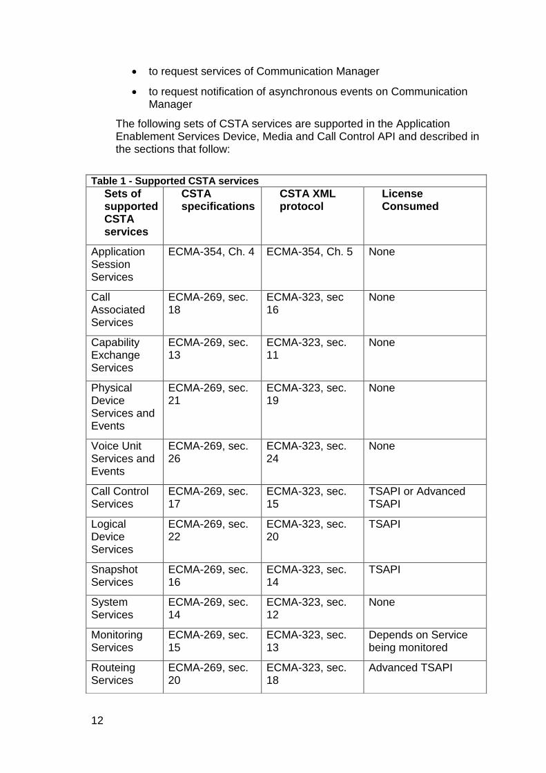
The following sets of CSTA services are supported in the Application Enablement Services Device, Media and Call Control API and described in the sections that follow:
Table 1 - Supported CSTA services
Sets of supported CSTA services
CSTA specifications
CSTA XML protocol
License Consumed
Application Session Services
ECMA-354, Ch. 4 ECMA-354, Ch. 5 None
Call Associated Services
ECMA-269, sec. 18
ECMA-323, sec 16
None
Capability Exchange Services
ECMA-269, sec. 13
ECMA-323, sec. 11
None
Physical Device Services and Events
ECMA-269, sec. 21
ECMA-323, sec. 19
None
Voice Unit Services and Events
ECMA-269, sec. 26
ECMA-323, sec. 24
None
Call Control Services
ECMA-269, sec. 17
ECMA-323, sec. 15
TSAPI or Advanced TSAPI
Logical Device Services
ECMA-269, sec. 22
ECMA-323, sec. 20
TSAPI
Snapshot Services
ECMA-269, sec. 16
ECMA-323, sec. 14
TSAPI
System Services
ECMA-269, sec. 14
ECMA-323, sec. 12
None
Monitoring Services
ECMA-269, sec. 15
ECMA-323, sec. 13
Depends on Service being monitored
Routeing Services
ECMA-269, sec. 20
ECMA-323, sec. 18
Advanced TSAPI
Chapter 1: API Services
Application Enablement Services Device, Media and Call Control XML Programmer‟s Guide 13
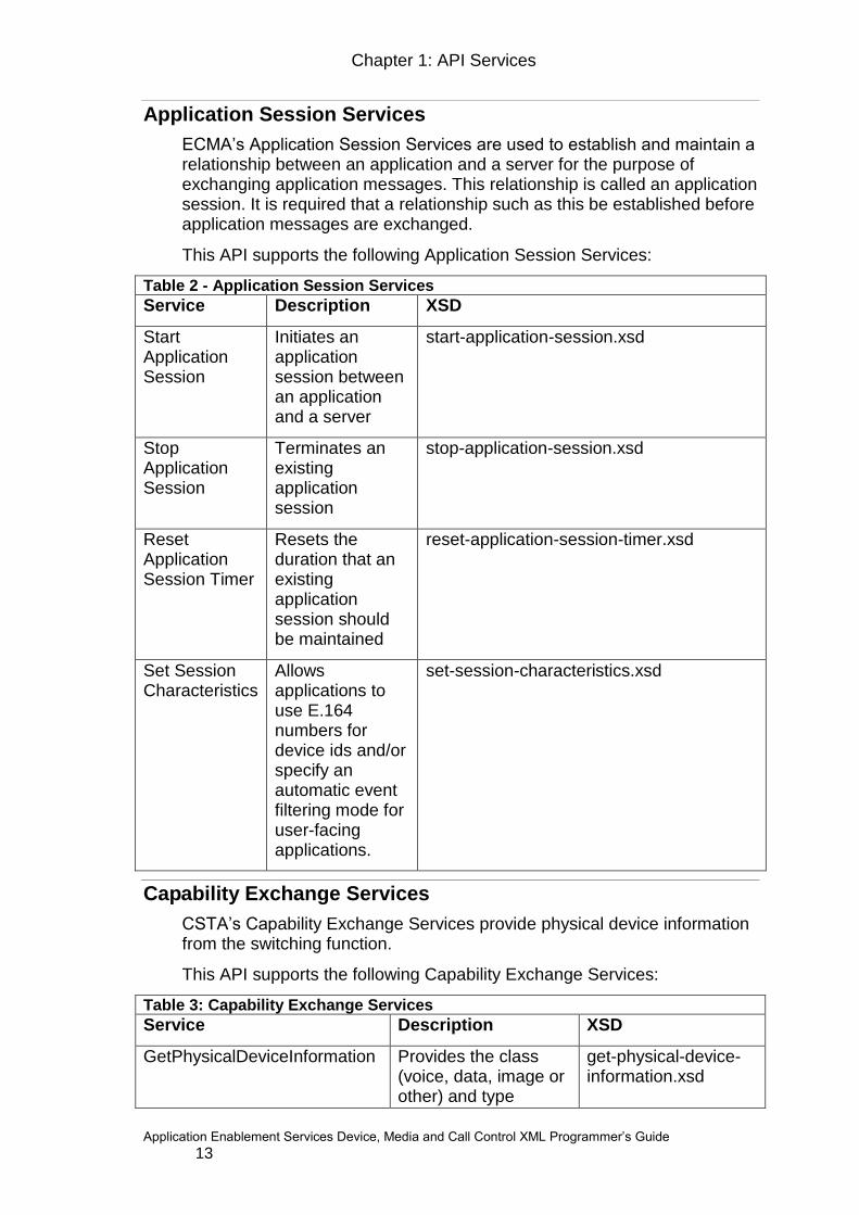
Application Session Services
ECMA‟s Application Session Services are used to establish and maintain a relationship between an application and a server for the purpose of exchanging application messages. This relationship is called an application session. It is required that a relationship such as this be established before application messages are exchanged.
This API supports the following Application Session Services:
Table 2 - Application Session Services
Service Description XSD
Start Application Session
Initiates an application session between an application and a server
start-application-session.xsd
Stop Application Session
Terminates an existing application session
stop-application-session.xsd
Reset Application Session Timer
Resets the duration that an existing application session should be maintained
reset-application-session-timer.xsd
Set Session Characteristics
Allows applications to use E.164 numbers for device ids and/or specify an automatic event filtering mode for user-facing applications.
set-session-characteristics.xsd
Capability Exchange Services
CSTA‟s Capability Exchange Services provide physical device information from the switching function.
This API supports the following Capability Exchange Services:
Table 3: Capability Exchange Services
Service Description XSD
GetPhysicalDeviceInformation
Provides the class (voice, data, image or other) and type
get-physical-device-information.xsd

14
Table 3: Capability Exchange Services
Service Description XSD
(station, ACD, ACD Group or other) of a device.
GetPhysicalDeviceName Allows applications to obtain the name assigned to a device in the Communication Manager Integrated Directory Database.
get-physical-device-name.xsd
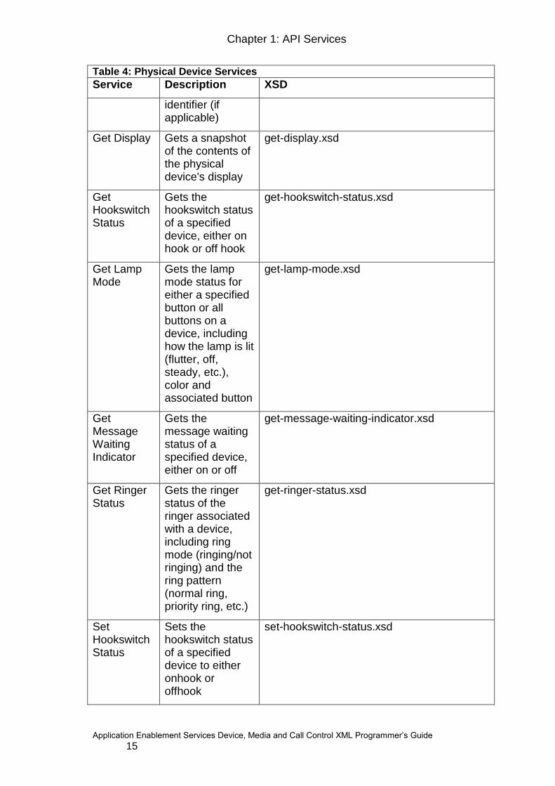
Physical Device Services and Events
CSTA‟s Physical Device Services provide physical device control. The device must be (or represent) an IP phone or DCP station equipped with a speaker-phone1.The control allows an application to manipulate and monitor the physical aspects of a device, which includes buttons, lamps, the display, and the ringer. The services simulate manual action on a device as well as provide the ability to request status of physical elements. The events provide notification of changes to the physical elements of the device. To learn how to use Physical Device Services and Events, see Monitoring and controlling physical elements.
This API supports the following Physical Device Services:
Table 4: Physical Device Services
Service Description XSD
Button Press
Simulates the depression of a specified button on a device
button-press.xsd
Get Button Information
Gets the button information for either a specified button or all buttons on a device, including the button identifier, button function, associated extension (if applicable), and associated lamp
get-button-information.xsd
1 Devices that are not equipped with a speaker-phone (e.g. CallMaster) are not supported.
Chapter 1: API Services
Application Enablement Services Device, Media and Call Control XML Programmer‟s Guide 15
Table 4: Physical Device Services
Service Description XSD
identifier (if applicable)
Get Display
Gets a snapshot of the contents of the physical device's display
get-display.xsd
Get Hookswitch Status
Gets the hookswitch status of a specified device, either on hook or off hook
get-hookswitch-status.xsd
Get Lamp Mode
Gets the lamp mode status for either a specified button or all buttons on a device, including how the lamp is lit (flutter, off, steady, etc.), color and associated button
get-lamp-mode.xsd
Get Message Waiting Indicator
Gets the message waiting status of a specified device, either on or off
get-message-waiting-indicator.xsd
Get Ringer Status
Gets the ringer status of the ringer associated with a device, including ring mode (ringing/not ringing) and the ring pattern (normal ring, priority ring, etc.)
get-ringer-status.xsd
Set Hookswitch Status
Sets the hookswitch status of a specified device to either onhook or offhook
set-hookswitch-status.xsd

16
This API supports the following CSTA Physical Device events:
Table 5: Physical Device Events
Event Description XSD
Display Updated
Occurs if the contents of a device's display has changed
display-updated-event.xsd
Hookswitch Status Changed
Occurs if the switch has changed the device's hookswitch status
hookswitch-event.xsd
Lamp Mode Changed
Occurs if the lamp mode status of a particular lamp has changed
lamp-mode-event.xsd
Ringer Status Changed
Occurs if the ringer attribute associated with a device has changed status
ringer-status-event.xsd
E 911 Call Blocked
Occurs if the switch has blocked the 911 emergency request
physical-device-feature-private-events.xsd
Service Link Status Changed
Occurs if the service link status associated with a device has changed.
physical-device-feature-private-events.xsd
Chapter 1: API Services
Application Enablement Services Device, Media and Call Control XML Programmer‟s Guide 17
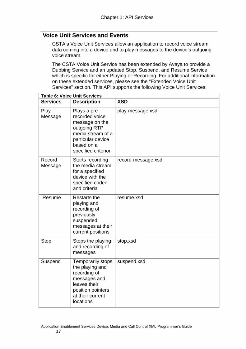
Voice Unit Services and Events
CSTA‟s Voice Unit Services allow an application to record voice stream data coming into a device and to play messages to the device‟s outgoing voice stream.
The CSTA Voice Unit Service has been extended by Avaya to provide a Dubbing Service and an updated Stop, Suspend, and Resume Service which is specific for either Playing or Recording. For additional information on these extended services, please see the "Extended Voice Unit Services" section. This API supports the following Voice Unit Services:
Table 6: Voice Unit Services
Services Description XSD
Play Message
Plays a pre-recorded voice message on the outgoing RTP media stream of a particular device based on a specified criterion
play-message.xsd
Record Message
Starts recording the media stream for a specified device with the specified codec and criteria
record-message.xsd
Resume
Restarts the playing and recording of previously suspended messages at their current positions
resume.xsd
Stop
Stops the playing and recording of messages
stop.xsd
Suspend
Temporarily stops the playing and recording of messages and leaves their position pointers at their current locations
suspend.xsd
18
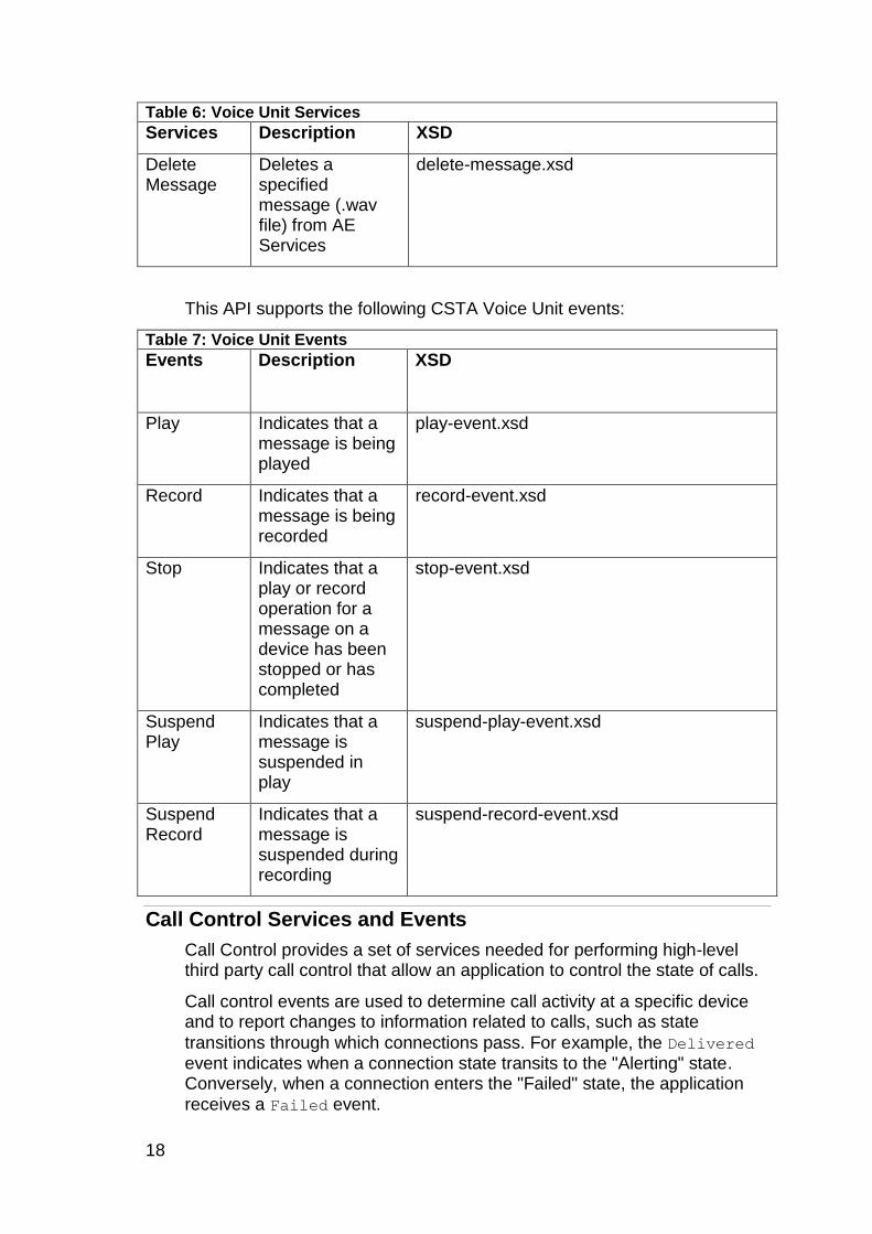
Table 6: Voice Unit Services
Services Description XSD
Delete Message
Deletes a specified message (.wav file) from AE Services
delete-message.xsd
This API supports the following CSTA Voice Unit events:
Table 7: Voice Unit Events
Events
Description XSD
Play
Indicates that a message is being played
play-event.xsd
Record
Indicates that a message is being recorded
record-event.xsd
Stop
Indicates that a play or record operation for a message on a device has been stopped or has completed
stop-event.xsd
Suspend Play
Indicates that a message is suspended in play
suspend-play-event.xsd
Suspend Record
Indicates that a message is suspended during recording
suspend-record-event.xsd
Call Control Services and Events
Call Control provides a set of services needed for performing high-level third party call control that allow an application to control the state of calls.
Call control events are used to determine call activity at a specific device and to report changes to information related to calls, such as state
transitions through which connections pass. For example, the Delivered event indicates when a connection state transits to the "Alerting" state. Conversely, when a connection enters the "Failed" state, the application
receives a Failed event.
Chapter 1: API Services
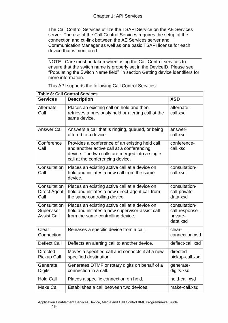
Application Enablement Services Device, Media and Call Control XML Programmer‟s Guide 19
The Call Control Services utilize the TSAPI Service on the AE Services server. The use of the Call Control Services requires the setup of the connection and cti-link between the AE Services server and Communication Manager as well as one basic TSAPI license for each device that is monitored.
NOTE: Care must be taken when using the Call Control services to ensure that the switch name is properly set in the DeviceID. Please see “Populating the Switch Name field” in section Getting device identifiers for more information.
This API supports the following Call Control Services:
Table 8: Call Control Services
Services Description XSD
Alternate Call
Places an existing call on hold and then retrieves a previously held or alerting call at the same device.
alternate-call.xsd
Answer Call Answers a call that is ringing, queued, or being offered to a device.
answer-call.xsd
Conference Call
Provides a conference of an existing held call and another active call at a conferencing device. The two calls are merged into a single call at the conferencing device.
conference-call.xsd
Consultation Call
Places an existing active call at a device on hold and initiates a new call from the same device.
consultation-call.xsd
Consultation Direct Agent Call
Places an existing active call at a device on hold and initiates a new direct-agent call from the same controlling device.
consultation-call-private-data.xsd
Consultation Supervisor Assist Call
Places an existing active call at a device on hold and initiates a new supervisor-assist call from the same controlling device.
consultation-call-response-private-data.xsd
Clear Connection
Releases a specific device from a call. clear-connection.xsd
Deflect Call Deflects an alerting call to another device. deflect-call.xsd
Directed Pickup Call
Moves a specified call and connects it at a new specified destination.
directed-pickup-call.xsd
Generate Digits
Generates DTMF or rotary digits on behalf of a connection in a call.
generate-digits.xsd
Hold Call Places a specific connection on hold. hold-call.xsd
Make Call Establishes a call between two devices. make-call.xsd

20
Table 8: Call Control Services
Services Description XSD
Make Direct Agent Call
Originates a call between two devices: a user station and an ACD agent logged into a specified split.
make -call-private-data.xsd
Make Supervisor Assist Call
Originates a call between two devices: an ACD agent‟s extension and another station extension (typically a supervisor) device.
make -call-private-data.xsd
Make Predictive Call
Originates a call between two devices by first creating a connection to the called device.
make-predictive-call-private-data.xsd
Reconnect Call
Clears an existing connection and then connects a previously held connection at the same device.
reconnect-call.xsd
Retrieve Call
Connects to a call that had previously been placed on hold.
retrieve-call.xsd
Selective Listening Hold
Allows a client application to prevent a specific party on a call from hearing anything said by another specific party or all other parties on the call. It allows a client application to put a party‟s listening path to a selected party on listen-hold, or all parties on an active call on listen-hold.
selective-listening-hold.xsd
Selective Listening Retrieve
Allows a client application to retrieve a party from listen-hold for another party or for all parties that were previously being listen-held.
selective-listening-retrieve.xsd
Single Step Conference Call
Adds a device to an existing call. single-step-conference-call.xsd
Single Step Transfer Call
Replaces a device in an existing call with another device.
single-step-transfer.xsd
Transfer Call
Transfers a held call to the consulted party. transfer-call.xsd
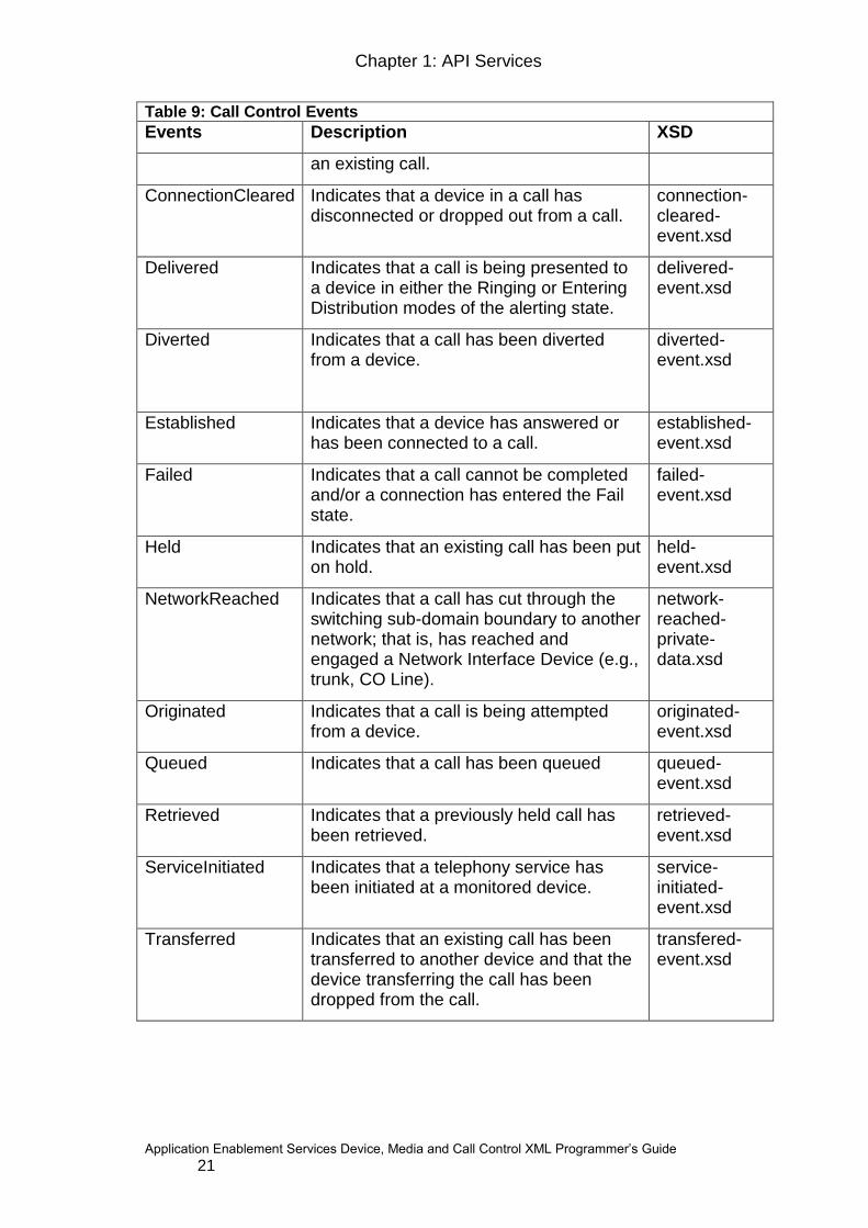
This API supports the following Call Control events:
Table 9: Call Control Events
Events Description XSD
CallCleared Indicates that a call has been cleared and no longer exists within the switching sub-domain.
call-cleared-event.xsd
Conferenced Indicates that the conferencing device has conferenced itself or another device with
conferenced-event.xsd
Chapter 1: API Services
Application Enablement Services Device, Media and Call Control XML Programmer‟s Guide 21
Table 9: Call Control Events
Events Description XSD
an existing call.
ConnectionCleared Indicates that a device in a call has disconnected or dropped out from a call.
connection-cleared-event.xsd
Delivered Indicates that a call is being presented to a device in either the Ringing or Entering Distribution modes of the alerting state.
delivered-event.xsd
Diverted Indicates that a call has been diverted from a device.
diverted-event.xsd
Established Indicates that a device has answered or has been connected to a call.
established-event.xsd
Failed Indicates that a call cannot be completed and/or a connection has entered the Fail state.
failed-event.xsd
Held Indicates that an existing call has been put on hold.
held-event.xsd
NetworkReached Indicates that a call has cut through the switching sub-domain boundary to another network; that is, has reached and engaged a Network Interface Device (e.g., trunk, CO Line).
network-reached-private-data.xsd
Originated Indicates that a call is being attempted from a device.
originated-event.xsd
Queued Indicates that a call has been queued queued-event.xsd
Retrieved Indicates that a previously held call has been retrieved.
retrieved-event.xsd
ServiceInitiated Indicates that a telephony service has been initiated at a monitored device.
service-initiated-event.xsd
Transferred Indicates that an existing call has been transferred to another device and that the device transferring the call has been dropped from the call.
transfered-event.xsd
22
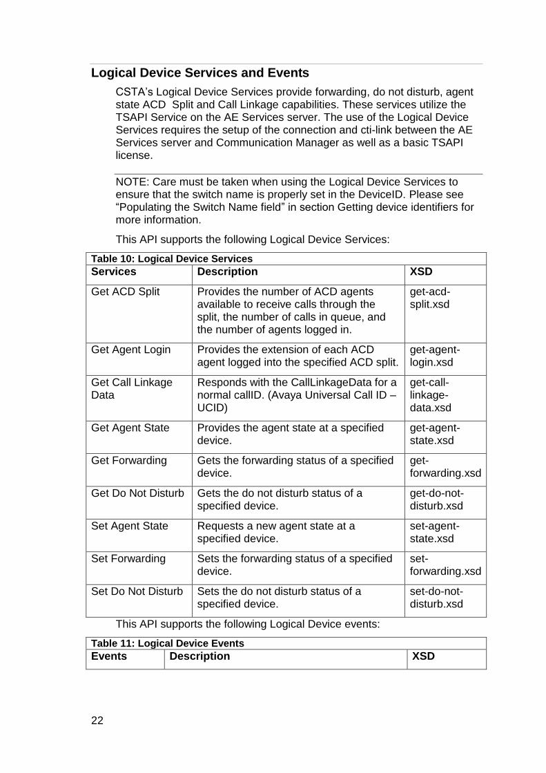
Logical Device Services and Events
CSTA‟s Logical Device Services provide forwarding, do not disturb, agent state ACD Split and Call Linkage capabilities. These services utilize the TSAPI Service on the AE Services server. The use of the Logical Device Services requires the setup of the connection and cti-link between the AE Services server and Communication Manager as well as a basic TSAPI license.
NOTE: Care must be taken when using the Logical Device Services to ensure that the switch name is properly set in the DeviceID. Please see “Populating the Switch Name field” in section Getting device identifiers for more information.
This API supports the following Logical Device Services:
Table 10: Logical Device Services
Services Description XSD
Get ACD Split Provides the number of ACD agents available to receive calls through the split, the number of calls in queue, and the number of agents logged in.
get-acd-split.xsd
Get Agent Login Provides the extension of each ACD agent logged into the specified ACD split.
get-agent-login.xsd
Get Call Linkage Data
Responds with the CallLinkageData for a normal callID. (Avaya Universal Call ID – UCID)
get-call-linkage-data.xsd
Get Agent State Provides the agent state at a specified device.
get-agent-state.xsd
Get Forwarding Gets the forwarding status of a specified device.
get-forwarding.xsd
Get Do Not Disturb Gets the do not disturb status of a specified device.
get-do-not-disturb.xsd
Set Agent State Requests a new agent state at a specified device.
set-agent-state.xsd
Set Forwarding Sets the forwarding status of a specified device.
set-forwarding.xsd
Set Do Not Disturb Sets the do not disturb status of a specified device.
set-do-not-disturb.xsd
This API supports the following Logical Device events:
Table 11: Logical Device Events
Events Description XSD

Chapter 1: API Services
Application Enablement Services Device, Media and Call Control XML Programmer‟s Guide 23
Table 11: Logical Device Events
Events Description XSD
Agent Login Extension
A private event that is sent after a GetAgentLogin Request/Response.
agent-login-extension-event.xsd
Agent Logged Off
Indicates that an agent has logged off an ACD device or an ACD group.
agent-logged-off-event.xsd
Agent Logged On
Indicates that an agent has logged on to an ACD device or an ACD group.
agent-logged-on-event.xsd
Agent Ready Indicates that an agent is now available on an ACD device or an ACD group
agent-ready-event.xsd
Agent Not Ready
Indicates that an agent is unavailable on an ACD device or an ACD group
agent-not-ready-event.xsd
Agent Working After Call
Indicates that an agent is following up on a call on an ACD device
agent-working-after-call-event.xsd
Forwarding Indicates that the forwarding status has changed. Note that the “forwardTo” parameter is not supported for this event. In order to get the “forwardTo” information, you must use the “Get Forwarding” request.
forwarding-event.xsd
Do Not Disturb
Indicates that the do not disturb status has changed.
do-not-disturb-event.xsd
Snapshot Services
CSTA‟s Snapshot Services allow an application to obtain 3rd party information about a call or a device.
The use of the Snapshot Services requires the setup of the connection and cti-link between the AE Services server and Communication Manager as well as a basic TSAPI license.
NOTE: Care must be taken when using the Snapshot Services to ensure that the switch name is properly set in the DeviceID. Please see “Populating the Switch Name field” in section Getting device identifiers for more information.
This API supports the following Snapshot Services:
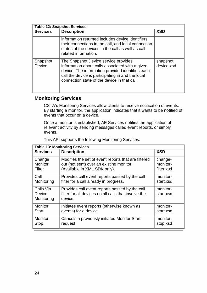
Table 12: Snapshot Services
Services Description XSD
Snapshot Call
Provides information about the devices participating in a specified call. The
snapshot call.xsd
24
Table 12: Snapshot Services
Services Description XSD
information returned includes device identifiers, their connections in the call, and local connection states of the devices in the call as well as call related information.
Snapshot Device
The Snapshot Device service provides information about calls associated with a given device. The information provided identifies each call the device is participating in and the local connection state of the device in that call.
snapshot device.xsd
Monitoring Services
CSTA‟s Monitoring Services allow clients to receive notification of events. By starting a monitor, the application indicates that it wants to be notified of events that occur on a device.
Once a monitor is established, AE Services notifies the application of relevant activity by sending messages called event reports, or simply events.
This API supports the following Monitoring Services:
Table 13: Monitoring Services
Services Description XSD
Change Monitor Filter
Modifies the set of event reports that are filtered out (not sent) over an existing monitor. (Available in XML SDK only).
change-monitor-filter.xsd
Call Monitoring
Provides call event reports passed by the call filter for a call already in progress.
monitor-start.xsd
Calls Via Device Monitoring
Provides call event reports passed by the call filter for all devices on all calls that involve the device.
monitor-start.xsd
Monitor Start
Initiates event reports (otherwise known as events) for a device
monitor-start.xsd
Monitor Stop
Cancels a previously initiated Monitor Start request
monitor-stop.xsd

Chapter 1: API Services
Application Enablement Services Device, Media and Call Control XML Programmer‟s Guide 25
Routeing Services
CSTA‟s Routeing Services allow the Communication Manager to request and receive routing instructions for a call. These instructions, issued by a client routing server application, are based on the incoming call information provided by the Communication Manager.
This API supports the following Routeing Services:
Table 14 - Routeing Services
Services Description XSD
Route Register Request
The Route Register Request service is used to register the application as a routeing server for a specific routeing device or as a routeing server for all routeing devices within the switching sub-domain.
route-register.xsd
Route Register Abort
This service is used by the switching function to asynchronously cancel an active routeing registration. There is no positive acknowledgement defined for this service.
route-register-abort.xsd
Route Register Cancel
The Route Register Cancel service is used to cancel a previous route registration.
route-register-cancel.xsd
Route End The Route End service ends a routeing dialogue. This service is bi-directional. There is no positive acknowledgement defined for this service.
route-end.xsd
Route Request
The Route Request service requests that the application provide a destination for a call.
route-request.xsd
Route Select
The Route Select service is used by the application to provide the destination requested by a previous Route Request.
route-select.xsd
Route Used The Route Used service provides the actual destination for a call that has been routed using the Route Select service.
route-used.xsd
26
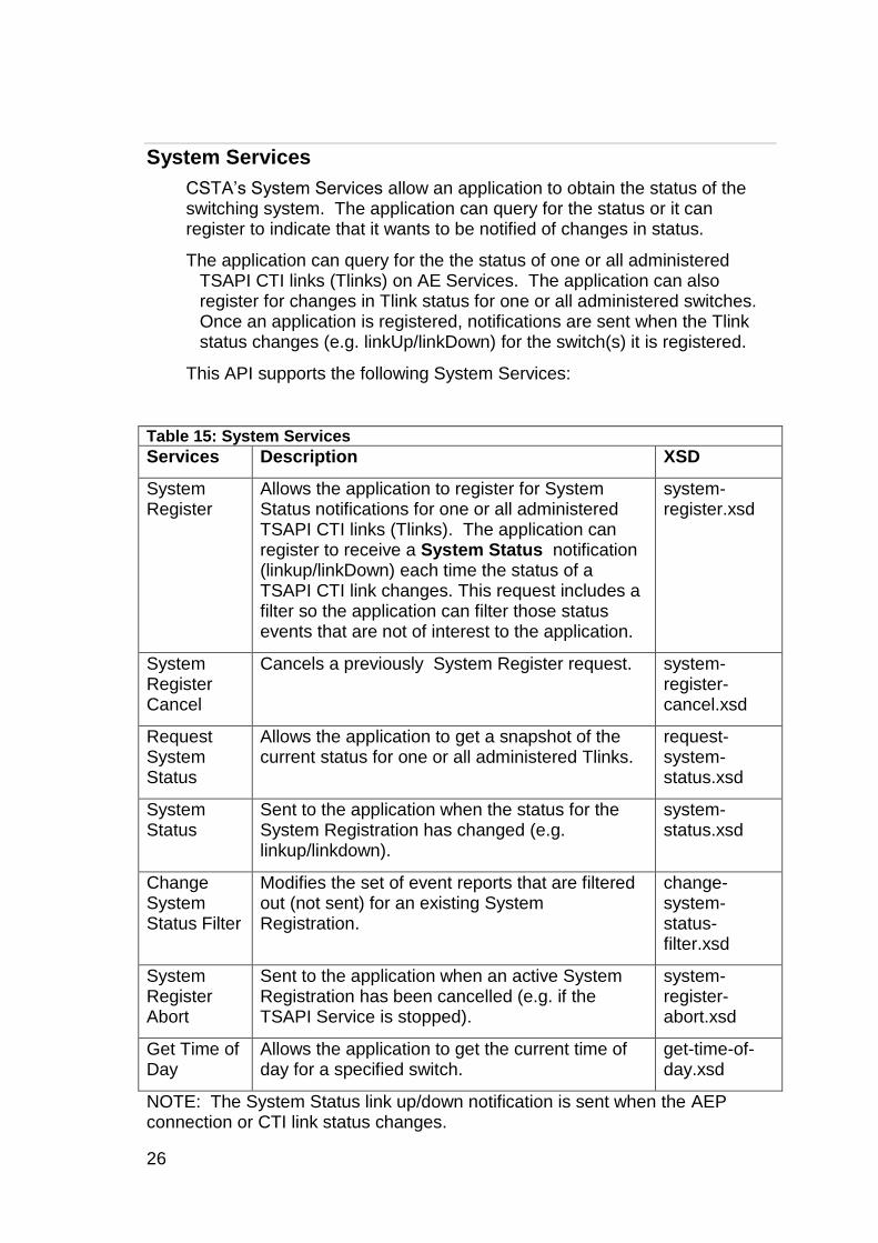
System Services
CSTA‟s System Services allow an application to obtain the status of the switching system. The application can query for the status or it can register to indicate that it wants to be notified of changes in status.
The application can query for the the status of one or all administered TSAPI CTI links (Tlinks) on AE Services. The application can also register for changes in Tlink status for one or all administered switches. Once an application is registered, notifications are sent when the Tlink status changes (e.g. linkUp/linkDown) for the switch(s) it is registered.
This API supports the following System Services:
Table 15: System Services
Services Description XSD
System Register
Allows the application to register for System Status notifications for one or all administered TSAPI CTI links (Tlinks). The application can register to receive a System Status notification (linkup/linkDown) each time the status of a TSAPI CTI link changes. This request includes a filter so the application can filter those status events that are not of interest to the application.
system-register.xsd
System Register Cancel
Cancels a previously System Register request. system-register-cancel.xsd
Request System Status
Allows the application to get a snapshot of the current status for one or all administered Tlinks.
request-system-status.xsd
System Status
Sent to the application when the status for the System Registration has changed (e.g. linkup/linkdown).
system-status.xsd
Change System Status Filter
Modifies the set of event reports that are filtered out (not sent) for an existing System Registration.
change-system-status-filter.xsd
System Register Abort
Sent to the application when an active System Registration has been cancelled (e.g. if the TSAPI Service is stopped).
system-register-abort.xsd
Get Time of Day
Allows the application to get the current time of day for a specified switch.
get-time-of-day.xsd
NOTE: The System Status link up/down notification is sent when the AEP connection or CTI link status changes.
Chapter 1: API Services
Application Enablement Services Device, Media and Call Control XML Programmer‟s Guide 27
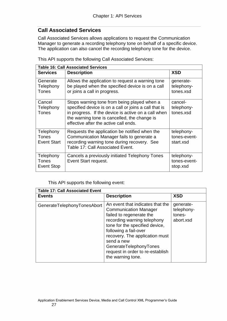
Call Associated Services
Call Associated Services allows applications to request the Communication Manager to generate a recording telephony tone on behalf of a specific device. The application can also cancel the recording telephony tone for the device. This API supports the following Call Associated Services:
Table 16: Call Associated Services
Services Description XSD
Generate Telephony Tones
Allows the application to request a warning tone be played when the specified device is on a call or joins a call in progress.
generate-telephony-tones.xsd
Cancel Telephony Tones
Stops warning tone from being played when a specified device is on a call or joins a call that is in progress. If the device is active on a call when the warning tone is cancelled, the change is effective after the active call ends.
cancel-telephony-tones.xsd
Telephony Tones Event Start
Requests the application be notified when the Communication Manager fails to generate a recording warning tone during recovery. See Table 17: Call Associated Event.
telephony-tones-event-start.xsd
Telephony Tones Event Stop
Cancels a previously initiated Telephony Tones Event Start request.
telephony-tones-event-stop.xsd
This API supports the following event:
Table 17: Call Associated Event
Events Description XSD
GenerateTelephonyTonesAbort
An event that indicates that the Communication Manager failed to regenerate the recording warning telephony tone for the specified device, following a fail-over recovery. The application must send a new GenerateTelephonyTones request in order to re-establish the warning tone.
generate-telephony-tones-abort.xsd
28
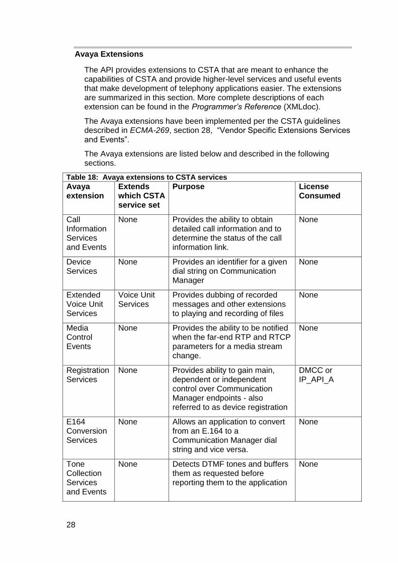
Avaya Extensions
The API provides extensions to CSTA that are meant to enhance the capabilities of CSTA and provide higher-level services and useful events that make development of telephony applications easier. The extensions are summarized in this section. More complete descriptions of each extension can be found in the Programmer’s Reference (XMLdoc).
The Avaya extensions have been implemented per the CSTA guidelines described in ECMA-269, section 28, “Vendor Specific Extensions Services and Events”.
The Avaya extensions are listed below and described in the following sections.
Table 18: Avaya extensions to CSTA services
Avaya extension
Extends which CSTA service set
Purpose License Consumed
Call Information Services and Events
None Provides the ability to obtain detailed call information and to determine the status of the call information link.
None
Device Services
None Provides an identifier for a given dial string on Communication Manager
None
Extended Voice Unit Services
Voice Unit Services
Provides dubbing of recorded messages and other extensions to playing and recording of files
None
Media Control Events
None Provides the ability to be notified when the far-end RTP and RTCP parameters for a media stream change.
None
Registration Services
None Provides ability to gain main, dependent or independent control over Communication Manager endpoints - also referred to as device registration
DMCC or IP_API_A
E164 Conversion Services
None Allows an application to convert from an E.164 to a Communication Manager dial string and vice versa.
None
Tone Collection Services and Events
None Detects DTMF tones and buffers them as requested before reporting them to the application
None

Chapter 1: API Services
Application Enablement Services Device, Media and Call Control XML Programmer‟s Guide 29
Table 18: Avaya extensions to CSTA services
Avaya extension
Extends which CSTA service set
Purpose License Consumed
Tone Detection Events
Replaces Data Collection Services
Detects DTMF tones and reports each tone as it is detected
None
Call Information Services and Events
Avaya‟s Call Information Services allow applications to get detailed call information and to determine the status of the call information link. The call information link must be operational to get the call information. The call information link is one of the communication links between Communication Manager and the AE Services.
This API supports the following Call Information Services:
Table 19: Call Information Services
Services Description XSD
Get Call Information
Used to get detailed call information for a device.
get-call-information.xsd
Get Link Status
Used to get the status of the call information link from AE Services to a specified switch name (Communication Manager).
get-link-status.xsd
Call Information Events Start
Used to start events notification on the status of the Call Information link.
call-information-events-start.xsd
Call information Events Stop
Used to stop events notification on the status of the Call Information link.
call-information-events-stop.xsd
Get SIP Header
Used to get SIP customer information of the active call on the specified device
sip-header-information.xsd
SIP Header Events Start
Requests a listener to be established to receive the SIP header information
sip-header-information.xsd
SIP Header Events Stop
Requests an established listener to be removed. No SIP Header event will be received after this.
sip-header-information.xsd

30
This API supports the following Call Information Events:
Table 20: Call Information Events
Events Description XSD
Link Up Occurs when a link has come up (transport level) and is now active. Occurs the first time the link is brought up, as well as every time the link is brought up after being down.
call-information-events.xsd
Link Down Occurs when a link has gone down (transport level) and is now inactive. Occurs when it is determined that Communication Manager is not responding or Communication Manager and Device, Media and Call Control API are out of sync. Response will indicate which link is down and whether AE Services will attempt to reconnect automatically.
call-information-events.xsd
SIP Header Notify
Occurs when the SIP header data has been retrieved.
sip-header-information.xsd
Device Services and Events
All services that operate on a particular device use a device identifier to specify the device. Avaya‟s Device Services provide up to three instances of a device identifier for a given dial string on Communication Manager. The device instance is an existing field in the DeviceID which has been supported since AE Services 5.2. The device instance may be in the range 0 – 2, with a default value of 0 for backwards compatibility. A device can be controlled by more than one application session or transferred between application sessions that belong to the same authenticated and authorized user.
This API supports the following Device Services:
Table 21: Device Services
Services Description XSD
Get Device ID
Gets the device identifier that represents the device described by its extension number and the Communication Manager upon which it resides and the instance of the device. You may get up to three instances of the device identifier.
get-device.xsd
GetThird Party Device ID
Gets a third party device identifier for use with Call Control Services and Snapshot Services
get-device.xsd

Chapter 1: API Services
Application Enablement Services Device, Media and Call Control XML Programmer‟s Guide 31
Table 21: Device Services
Services Description XSD
Get Device ID List
Retrieves the list of DeviceIDs for a given session.
get-deviceid-list.xsd
Release Device ID
Releases the deviceID and the respective memory resources associated with a DeviceID.
release-deviceid.xsd
Get Monitor List
Retrieves the list of cross reference identifiers, monitor filters and events filters for a given session.
get-monitor-list.xsd
Transfer Monitor Objects
Transfers the DeviceIDs for a given session to another session belonging to the same user. Transfers the monitors that were added for each DeviceID.
transfer-monitorobject.xsd
NOTE: The GetDeviceIdList, GetMonitorList and
TransferMonitorObjects requests are applicable to DeviceIDs which are obtained from both the GetDeviceID and GetThirdPartyDeviceID requests.
Extended Voice Unit Services
Avaya‟s Extended Voice Unit Services are used in conjunction with CSTA‟s Voice Unit Services.
These Extended Voice Unit services are provided:
Table 22: Extended Voice Unit Services
Services Descriptions XSD
Start Dubbing Starts replacing an existing recording session with the specified file
start-dubbing.xsd
Stop Dubbing Stops replacement of an existing recording session
stop-dubbing.xsd
Stop Playing Stops only the player, not the recorder
stop-playing.xsd
Stop Recording Stops only the recorder, not the player
stop-recording.xsd
Suspend Playing Suspends only the player, not the recorder
suspend-playing.xsd
Suspend Recording Suspends only the recorder, not the player
suspend-recording.xsd

32
Table 22: Extended Voice Unit Services
Services Descriptions XSD
Resume Playing Resume playing, but not recording
resume-playing.xsd
Resume Recording Resumes recording, but not playing
resume-recording.xsd
Media Control Events
Avaya‟s Media Control events provide a way for an application to respond to changes in the far-end RTP/RTCP parameters of a media stream.
This API supports the following Media Control events:
Table 23: Media Control Events
Events Descriptions XSD
Media Start Indicates when the far-end RTP parameters have changed and an RTP session has been established. Also provides the media encryption keys if media encryption is enabled for the device.
media-events.xsd
Media Stop Indicates when the far-end RTP parameters have changed to null and the RTP session has been disconnected
media-events.xsd
Registration Services
Avaya‟s Registration Services provide the ability to gain Main, Dependent or Independent control over a device and to specify the desired media mode for that device through a registration process. Communication Manager allows up to three instances of the same extension to be registered with it. Only one of these instances can be the Main – the other instances (if registered) must be Dependent or Independent. Main, Dependent and Independent control are described in Registration modes.
Registering a terminal gives the application access to the signalling and possibly the media of a DCP (digital) or IP telephone or extension that is administered for softphone access on Communication Manager. The device type administered on Communication Manager must be one that is equipped with a speaker-phone. Devices that are not speaker-phone equipped (e.g. CallMaster) are not supported.

Chapter 1: API Services
Application Enablement Services Device, Media and Call Control XML Programmer‟s Guide 33
Unregistering a device gives up control of the device. A terminal must be registered with Communication Manager before acting upon it with any of the API services. If the application, used the Registration Services to register a device on Communicaion Manager, the application must unregister the device once it is through with it
The desired media parameters are also specified at registration time. The options for the Media parameters are described in Media modes.
Registration Services requests can take some time to process and send a response. It is recommended that you write your application such that your thread will not be blocked while waiting for the response to these requests.
Endpoint Registration Events
Endpoint Registration events are new for AE Services 6.3 and Communication Manager 6.3 and can be monitored just like any other DMCC Registration Services event. The main difference between Endpoint Registration events and the existing Registration and Terminal events is that Endpoint Registration events can be monitored for any H.323 endpoint that can be registered to Communication Manager. The endpoints do not have to be registered using DMCC, as is the case for the existing Registration and Terminal events. For Endpoint Registration events, the endpoints can be registered to Communication Manager via any current means, provided they use the H.323 protocol for registering. Endpoint Registration events can be monitored by a DMCC application in the same manner that other DMCC events are monitored - by using DMCC Monitoring services. Similarly to the existing Registration events, Endpoint Registration events are monitored on a "per device" basis. When the endpoint registers or unregisters against the Communication Manager switch, the appropriate “registrationEventNotify()” method will be called, enabling the DMCC application to handle the event and the data contained within it. The Endpoint Registration event contains the following data: 1. Monitored DeviceID2 2. Endpoint DeviceID2 3. IP address of the endpoint. In the case where an endpoint was
registered via DMCC, this will be the IP address of the AE Services server.
2 The Monitored DeviceID is the DeviceID specified in the original Monitoring Services request,
while the Endpoint DeviceID is the DeviceID of the endpoint being registered/unregistered. These two DeviceIDs may be different (usually in the value of the “instance” field), since up to 3 endpoints can be registered to the same extension number.

34
4. MAC address of the endpoint. In the case where an endpoint was registered via DMCC, the MAC address wil be all zeros.
5. Product Type – the product type as provisioned in Communication Manager.
6. Network Region – the network region for the extension as provisioned in Communication Manager2
7. Dependency Mode – the dependency mode used during registration: main, dependent or independent.
8. Media Mode – the media mode used during registration: client, telecommuter or none.
9. Unicode Script – the Unicode script options as provisioned in Communication Manager.
10. Set Type – the model of the phone as provisioned in Communication Manager.
11. Signaling Protocol Type – the protocol used to register: H.323 or unknown. The Endpoint Unregistration event contains the following data:
1. Monitored DeviceID 2. Endpoint DeviceID. 3. IP address of the endpoint. In the case where an endpoint was registered
via DMCC, this will be the IP address of the AE Services server. 4. Dependency Mode – the dependency mode used during registration:
main, dependent or independent. 5. Reason – a string value indicating the reason for the unregistration. 6. Code – an integer value indicating the reason for the unregistration. 7. Set Type – the model of the phone as provisioned in Communication
Manager
Endpoint Registration Information
Not only can the DMCC application be notified whenever an endpoint registers or unregisters against the Communication Manager switch, it can also send a request to get the current registration state and data of an endpoint. This request may be sent at any time after the DMCC client has acquired the DeviceID. Thus, the device may, or may not, be registered against Communication Manager at the time of the request for Endpoint Registration Information. If the specified device has one or more endpoints registered against Communication Manager, then the response will contain a set of data for each of the registered endpoints. The set of data for each registered endpoint is identical to the data outlined in the Endpoint RegisteredEvent. However, if there are no endpoints registered against Communication Manager for the specified device, then the response will be empty.

Chapter 1: API Services
Application Enablement Services Device, Media and Call Control XML Programmer‟s Guide 35
The Registration Services are:
Table 24: Registration Services
Services Descriptions XSD
Get Registration State
Returns the registration state for the requested instance of a device.
get-registration-state.xsd
Redirect Media Redirects the media stream of the previously registered instance of a device to a new address.
redirect-media.xsd
Change Device Security Code
Allows a DMCC client to change the security code of an extension on Communication Manager.
change-device-security- code.xsd
Validate Device Security Code
Allows a DMCC client to validate the security code of an extension on Communication Manager.
validate-device-security- code
Register Terminal
Registers a specific instance of a device with Communication Manager in order to control the device.
register-terminal.xsd
Unregister Terminal
Unregisters the specified instance of a device from Communication Manager in order to give up control of the device.
unregister-terminal.xsd
Endpoint Registration Information
Retrieves the current registration information for the specified device. Registration data for up to 3 endpoints may be included in the response. Note that the device does not have to be registered through DMCC, but it must be registered to Communication
endpoint-registration-info.xsd
36
Table 24: Registration Services
Services Descriptions XSD
Manager using the H.323 protocol.
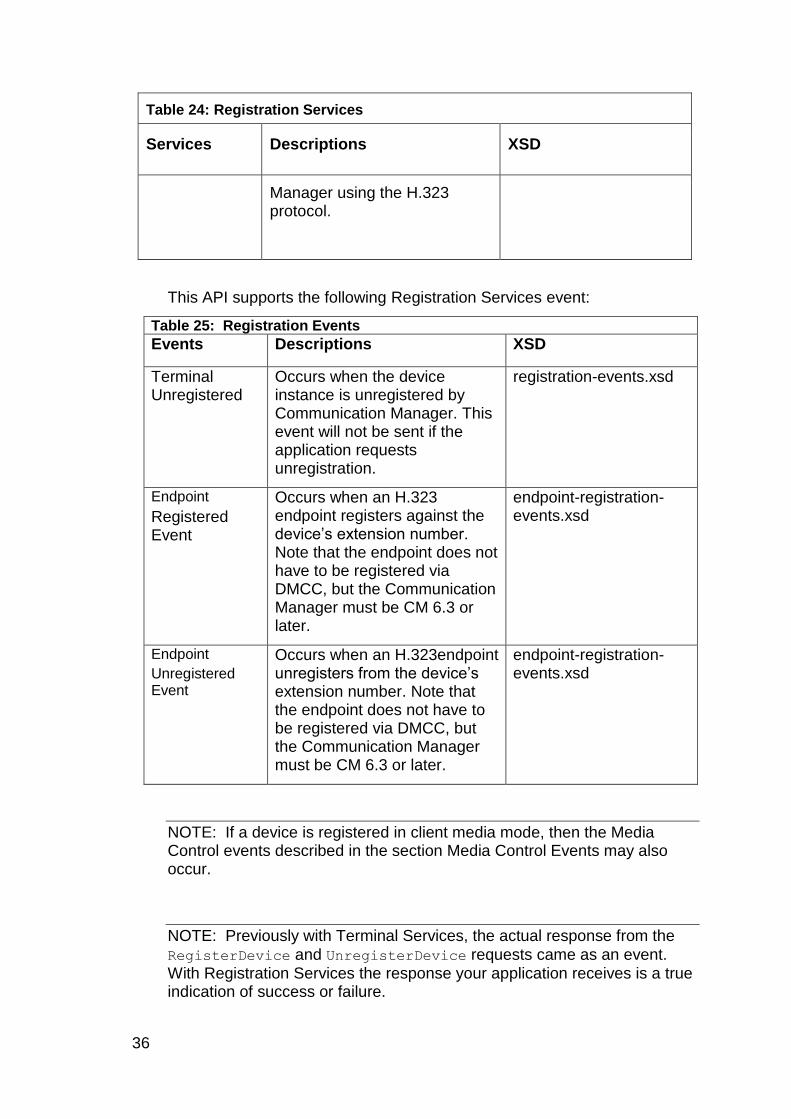
This API supports the following Registration Services event:
Table 25: Registration Events
Events Descriptions XSD
Terminal Unregistered
Occurs when the device instance is unregistered by Communication Manager. This event will not be sent if the application requests unregistration.
registration-events.xsd
Endpoint
Registered Event
Occurs when an H.323 endpoint registers against the device‟s extension number. Note that the endpoint does not have to be registered via DMCC, but the Communication Manager must be CM 6.3 or later.
endpoint-registration-events.xsd
Endpoint
Unregistered Event
Occurs when an H.323endpoint unregisters from the device‟s extension number. Note that the endpoint does not have to be registered via DMCC, but the Communication Manager must be CM 6.3 or later.
endpoint-registration-events.xsd
NOTE: If a device is registered in client media mode, then the Media Control events described in the section Media Control Events may also occur.
NOTE: Previously with Terminal Services, the actual response from the
RegisterDevice and UnregisterDevice requests came as an event. With Registration Services the response your application receives is a true indication of success or failure.
Chapter 1: API Services
Application Enablement Services Device, Media and Call Control XML Programmer‟s Guide 37
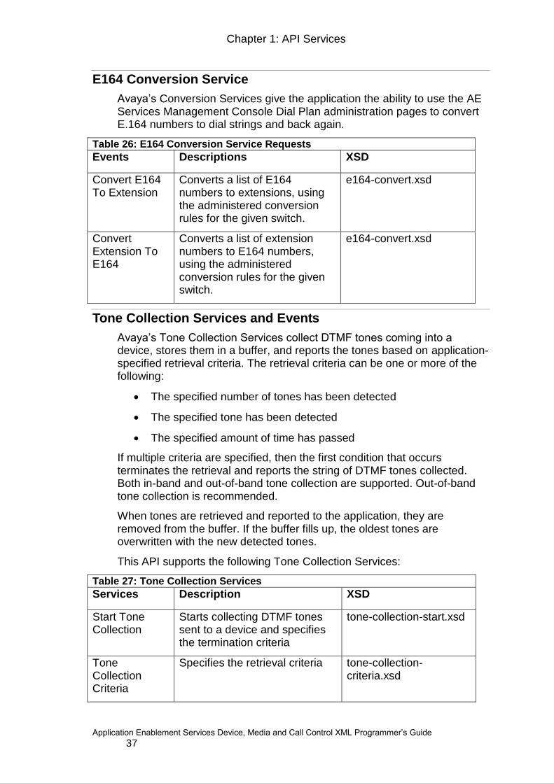
E164 Conversion Service
Avaya‟s Conversion Services give the application the ability to use the AE Services Management Console Dial Plan administration pages to convert E.164 numbers to dial strings and back again.
Table 26: E164 Conversion Service Requests
Events Descriptions XSD
Convert E164 To Extension
Converts a list of E164 numbers to extensions, using the administered conversion rules for the given switch.
e164-convert.xsd
Convert Extension To E164
Converts a list of extension numbers to E164 numbers, using the administered conversion rules for the given switch.
e164-convert.xsd
Tone Collection Services and Events
Avaya‟s Tone Collection Services collect DTMF tones coming into a device, stores them in a buffer, and reports the tones based on application-specified retrieval criteria. The retrieval criteria can be one or more of the following:
The specified number of tones has been detected
The specified tone has been detected
The specified amount of time has passed
If multiple criteria are specified, then the first condition that occurs terminates the retrieval and reports the string of DTMF tones collected. Both in-band and out-of-band tone collection are supported. Out-of-band tone collection is recommended.
When tones are retrieved and reported to the application, they are removed from the buffer. If the buffer fills up, the oldest tones are overwritten with the new detected tones.
This API supports the following Tone Collection Services:
Table 27: Tone Collection Services
Services Description XSD
Start Tone Collection
Starts collecting DTMF tones sent to a device and specifies the termination criteria
tone-collection-start.xsd
Tone Collection Criteria
Specifies the retrieval criteria tone-collection-criteria.xsd

38
Table 27: Tone Collection Services
Services Description XSD
Stop Tone Collection
Stops collecting DTMF tones sent to a device and reports the tones that have been buffered. This flushes the buffer
tone-collection-stop.xsd
Flush Buffer Reports the tones received since the last time the buffer was flushed and flushes the buffer
tone-collection-flushbuffer.xsd
Tone Collection Services generates these events:
Table 28: Tone Collection Events
Events Description XSD
Tones Retrieved
Occurs when tones are retrieved from the buffer. This event reports the retrieved tones to the application.
tone-collection-events.xsd
Tone Detection Events
Avaya‟s Tone Detection Events notify an application whenever a DTMF tone has been detected coming into a device. Both in-band and out-of-band tone detection is supported. Out-of-band tone detection is recommended.
When the application requests monitoring for DTMF tones, the following event will be generated when a DTMF has been sent to the device:
Table 29: Tone Detection Events
Events Description XSD
Tone Detected Occurs when a DTMF digit has been sent to the device
tone-detection-events.xsd
Differences between Avaya API and ECMA-269
The Avaya API differs from the ECMA specification in the following ways:
Voice Unit Services perspective
Voice Unit Services perspective
The mechanism for call control in this API is to register a dial string with Communication Manager using Registration Services and then to use Physical Device Services to manipulate that dial string. Therefore this API follows a device-based call control model. There are a few subtle side effects of using the device-based control model that are worth noting.
Chapter 1: API Services
Application Enablement Services Device, Media and Call Control XML Programmer‟s Guide 39
CSTA specifies that the Voice Unit Play Message service “plays a voice message on a particular connection”. While this is an ambiguous description, the apparent intent was to play a message to a particular device, which is a third party perspective. This API‟s implementation of the Play Message service is just the opposite of this. This API‟s Play Message service plays a message from the device, a first party perspective. It plays the message as if coming from the device and going to everyone else on the call.
Similarly, CSTA specifies that the Voice Unit Record Message service “starts recording a new message from a specified connection.” The apparent intent was to record the data coming from the device. This API implementation records the data coming to the device. It records what the device hears instead of what someone says at the device.
Since Avaya‟s implementation of Voice Unit Services are relative to a device instead of a connection, only the device identifier portion of a connection identifier is used.
40
Chapter 2: Getting Started
This section describes what you need to do and what you need to know before you begin programming to this API, including:
Setting up the development environment
Understanding basic CSTA concepts
Call recording
Signaling Encryption
Media Encryption
Accessing the client API reference documentation
Learning from sample code
Setting up the development environment
XML developers must have the necessary tools to traverse an XML message, such as an XML parser. We also strongly recommend that the developer use tools that automatically parse/build XML messages and validate them based on the XSDs. The developer should consider using an XML binding tool that can automatically build objects from XSDs, then automatically marshall these objects to XML and vice/versa.
Downloading the Application Enablement Services Device, Media and Call Control XML API SDK
The Application Enablement Services Device, Media and Call Control API SDK contains the XSD files that you will need to reference as you write your application, as well as several sample applications.
To download the Application Enablement Services Device, Media and Call Control XML API SDK from the Avaya DevConnect Web site:
1. Go to www.avaya.com/devconnect.
2. Select Member Login.
3. Log in with your email address and password.
4. Download the SDK (cmapixml-sdk-6_2_x.zip).from the
DevConnect Web site by navigating to the Application Enablement Services page and selecting the appropriate SDK from the Technical Resources section.
NOTE: The Application Enablement Services page can be located through the SDK and API Index link under the left-hand DevConnect Search.

Chapter 2: Getting Started
Application Enablement Services Device, Media and Call Control XML Programmer‟s Guide 41
The download location defaults to the desktop, but it does not matter where you download the files in your directory system. The SDK file is:
cmapixml-sdk-6_2.zip
where x is the load number.
Expand the SDK ZIP file using any application or tool that recognizes the ZIP file format. All of the SDK files are placed into a directory named cmapixml-sdk.
The directories where the XSD files are:
cmapixml-sdk/xsd/csta-schemascmapixml-sdk/xsd/avaya-
csta-schemas
The location of the primary XSDs used to validate the data you will send to the server is:
cmapixml-sdk/xsd/csta.xsd
cmapixml-sdk/xsd/avaya-csta-schemas/avaya-csta.xsd
The location of the sample applications provided with the SDK is:
cmapixml-sdk/examples/src/samplefiles
Setting up your test environment
Before running an application you will need to have an AE Services server machine setup. For instructions see the appropriate Avaya Aura® Application Enablement Services Installation and Upgrade Guide for the offer you have purchased (AE Services on System Platform, bundled server or software only).
Understanding basic CSTA concepts
CSTA stands for Computer-Supported Telecommunications Applications. It is a standard produced by ECMA, an international standards body (http://www.ecma-international.org ). CSTA provides a standard for Computer-Telephony Integration (CTI). When fully implemented, CSTA allows an application to:
monitor calls on dial strings, lines or trunks
modify the behavior of calls
make a call between two parties
The Avaya Application Enablement Services Device, Media and Call Control API implements a subset of CSTA. The API supports monitoring and making calls at the physical device level. Applications using this API have first party device control and media control and third-party call control.
42
The following sections describe what you need to know about the CSTA concepts of:
Devices
Physical elements and Logical elements
Calls
Service requests and Service responses
Events
Negative acknowledgements
Devices
In the context of this API, a device refers to a software instantiation of a phone or dial string that is registered on Communication Manager. Such a device is also referred to as a softphone. A device has physical and logical elements.
Physical Elements
The physical element of a device encompasses the set of attributes, features, and services that have any association with physical components of the device that make up the user interface of the device. Physical elements can be manipulated, such as pushing buttons or going offhook, or they can be observed, such as observing the ringer or whether a lamp is lit. The physical elements of a device include:
Buttons
Hookswitch
Display
Lamps
Message waiting indicator
Ringer
This API supports all of these physical elements.
Logical Elements
A logical element is the part of a device that is used to manage and interact with calls at a device. This element represents the media stream channels and associated call handling facilities that are used by the device when involved in a call. The logical elements that this API supports are:
DTMF tones coming into the device
Media stream coming into and out of the device
Do Not Disturb
Chapter 2: Getting Started
Application Enablement Services Device, Media and Call Control XML Programmer‟s Guide 43
Call Forwarding
Calls
Calls can be:
made from and received by a device
or
made using Call Control Services
CSTA performs most telephony services against a connection that identifies a particular call. For Voice Unit Services and Extended Voice Unit Services, services are requested for a device instead of a connection. For these services, only the device portion of the connection ID is used.
Request and response framework
Your application will need to be able to:
make service requests
process service responses
parse error codes
monitor for and parse events
This section describes what requests, responses, negative acknowledgements and events are and how to use them.
Service Requests
In this API an application requests services of the AE Services server. Examples of a request are “give me a device identifier”, “press a button”, “give me information about a lamp‟s status”, or “notify me when a tone comes into the device”.
Each request is processed by the AE Services server. The server may complete a request synchronously in one logical step or it may take additional steps to pass the request to Communication Manager and handle the response(s) before responding asynchronously to the application with the request‟s results in an event or negative acknowledgement.
To make a request, the application must construct the appropriate XML message and send that to AE Services.

44
Service responses
Each service request is acknowledged with a service response (positive or negative acknowledgement). Some service requests, particularly those that request information, are completed in a single logical step, thus the results of the request are reported in the service response (single-step requests follow CSTA‟s atomic model). Other service requests, particularly those that require AE Services to pass on a request to Communication Manager, take multiple steps to complete. (These follow CSTA‟s multi-step model.) Responses to multi-step requests merely indicate that the request was received and is being processed.
In some cases, response data values may indicate an error in the request or in the processing of a single-step request.
Service responses are in the form of XML messages. You must have the necessary tools to traverse an XML message in order to get the information out of the XML message.
Events
Events are asynchronous occurrences on a device that an application can choose to monitor for and respond to. Examples of events are the
DisplayUpdatedEvent, which indicates that the device‟s display has
changed, or TerminalUnregisteredEvent, which indicates that the device has been unregistered by Communication Manager.
An application indicates its desire to be notified of events by starting a
monitor using the MonitorStart request. Once a monitor is established,
the AE Services server notifies the application of relevant activity by sending messages called event reports, or simply events.
NOTE: Once you receive an event, release the event thread immediately and continue to do event processing on a different thread.
Negative acknowledgements
The AE Services server may respond to a service request with a negative acknowledgement. The XML message received will have the XML tag
<CSTAErrorCode> present. It will be up to the application as to how it chooses to handle such messages. The application does not need to send back a message to the AE Services server when such a message is received. Review the server logs to make sure that other adverse conditions have not transpired.
Call Recording
Call recording provides the ability to record phone calls by employing the DMCC Registration Services (see the “Registering Devices” section in chapter 3) and, optionally, the DMCC Voice Unit Services (see the “Recording and Playing Voice Media” section in chapter 3). If the client recording application chooses not to employ the DMCC Voice Unit Services,

Chapter 2: Getting Started
Application Enablement Services Device, Media and Call Control XML Programmer‟s Guide 45
then the application is responsible for directing the RTP stream to a suitable recording application capable of handling the media.
NOTE: That the Call Recording feature is supported for calls that are handled by DCP, H.323 and SIP endpoints, or by a mobile device. The available methods for recording phone calls, via AE Services, include the following:
Service observing method
A DMCC service client recording application registers as a Communication Manager Service Observing extension in independent (or dependent) mode. When a call is accepted by the user the service observer recording client is added to the call.
Single step conference method
A DMCC service client recording application registers as a standard Communication Manager extension in independent (or dependent) mode. A JTAPI, TSAPI or DMCC client application can monitor the user‟s extension and, when a call is accepted by the user, it conferences the recording client extension into the call.
Multiple registrations method
A DMCC service client recording application registers as the same extension (either in dependent or independent mode) as that of the user who is taking the calls. Since the incoming media in all of the extension‟s RTP streams is the same as for the main registrant (i.e., the user), the client application receives the same RTP as the user, and can record the RTP. The DMCC service call recording client is also able to register and connect after the user is already on the call. Note that Communication Manger does not play any warning tones into the call while recording is in progress. It is up to the customer to warn the calling parties via an announcement. It should be noted that when the extension of the user taking the call is associated with a SIP endpoint, the DMCC service client application must register in Independent mode. Also, this feature does not increase the number of parties on a call.
Cell phone recording
New for AE Services 6.2 is the ability to record calls originating or terminating at an off-PBX phone (for example a SIP phone or a cell phone). This feature combines the AE Services Multiple Registrations method with the Avaya EC500 or the Avaya One-X Mobile (OPTIM) applications. The DMCC service client application is able to connect to, and record, calls:
answered either at the desk set or at the mobile device

46
answered at the desk set and then extended to the mobile device
answered at the mobile device and then retrieved at the desk set
Note: For mobile calls and SIP endpoint calls, the Cell Phone Recording feature does not use the call control aspect of the Multiple Registration feature.
Recording warning tone
New for AE Services 6.3 is the ability to request Communication Manager to insert a tone into the audio stream of the parties in a call. This tone serves to indicate that the audio stream is being recorded using either the Single Step Conferencing method or the Multiple Registrations method. The tone that is played is inserted by Communication Manager and is identical to that already used by the Service Observing feature. See Playing a Warning Tone for more information.
Signaling Encryption
AE Services offers the ability to encrypt the signaling channel between the AE Services server and Communication Manager. However, the option to encrypt this link is not under the direct control of your application. Instead, it is an option that is provisioned on Communication Manager, via the “set network-region” page. See the "Setting up a network region for Device and Media Control" subsection of the "Administering Communication Manager for AE Services" chapter of the Avaya Aura® Application Enablement Services Administration and Maintenance Guide.
The encryption of the signaling link is automatically negotiated between the AE Services server and Communication Manager during the device registration, and the resultant encryption used is dependent on the options set for the network region. The following encryption types are supported:
Challenge
Pin-Eke
When registering the device, the negotiated signaling encryption type is
included as a parameter in the RegisterTerminalResponse message. However, if the device is registered using the older (deprecated) Terminal Services, the negotiated signalling encryption type is not included.
Media Encryption
You have the ability to encrypt the RTP (media) stream between the application and the other endpoint of the call.

Chapter 2: Getting Started
Application Enablement Services Device, Media and Call Control XML Programmer‟s Guide 47
The option to encrypt the RTP stream is provisioned on the Communication Manager, this time via the “change ip-codec-set” page. See the "Creating the Device and Media Control codec set" subsection of the "Administering Communication Manager for AE Services" chapter of the Avaya Aura® Application Enablement Services Administration and Maintenance Guide. However, in this case, the application does have some (albeit limited) control over the type of encryption used. Media encryption will be one of the following types:
Advanced Encryption Scheme (AES)
no media encryption
When registering the device, the application may specify which media encryption schemes that it supports. For more details see “Choosing the media encryption”.
This list of application-supported media encryption schemes is matched to the list of encryption schemes provisioned on Communication Manager‟s “change ip-codec-set” page for the device‟s codec set. Communication Manager will pick an encryption scheme that is common to both lists, if possible.
Note that the encryption scheme and encryption keys (if any) chosen by
Communication Manager will be indicated in the MediaStartEvent message.
Accessing the client API reference documentation
You may need to reference the XML Programmer’s Reference((XMLdoc) provided with this API. It is available on the Avaya Support site (www.avaya.com/support) as both a viewable HTML document and a downloadable zip file.
This HTML documentation will also ship with the SDK. This documentation describes all of the interfaces and their parameters.
In addition, the SDK ship with a "Dashboard" application which documents all of the capabilities of the API and provides the ability to get detailed help about every interface. This Dashboard application can greatly reduce the learning curve.
For information on getting started with using the Dashboard tool, see Avaya Aura® Application Enablement Services Device, Media, and Call Control .NET API Programmer‟s Guide, which is available on the Avaya Support site.
If you choose to download the zip file, then do the following to browse the HTML-based XMLdoc:
1. Expand the ZIP file using any application or tool that recognizes the ZIP file format. All of the XMLdoc files are placed into a directory named XMLdoc

48
2. Go to the XMLdoc directory.
3. Double click on index.html (or open this file with a browser).
Using the Device, Media and Call Control Dashboard
The Device, Media and Call Control .NET SDK ships with a "Dashboard" tool that is very useful for developers just learning about the API and its capabilities. The Dashboard tool allows you to easily try out all of the capabilities of the .NET SDK without having to write any code.
For developers using the XML SDK, this tool allows you to easily see and capture all of the XML messages being exchanged with the AE Services server.
In addition, Visual Studio will provide help with the parameters as you are writing the code.
For more details on using the Dashboard tool, see the Device, Media and Call Control .NET Services Programmer Guide.
Learning from sample code
Another key learning tool is the set of sample code files that are provided with this API. This sample code is located in the following directory:
cmapixml-sdk/examples/src/
CmapiXML.cs - a C# example
CmapiXMLCpp.cpp - a C++ .NET example
samplefiles/ExampleCmapiXML.java - a Java example
Each of the examples simply show how to connect to the AE Services server and how to send very basic XML messages.

Chapter 3: Writing a client application
Application Enablement Services Device, Media and Call Control XML Programmer‟s Guide 49
Chapter 3: Writing a client application
This chapter describes how to write an application using the Application Enablement Services Device, Media and Call Control API. It will frequently refer to the details in the XMLdoc, so you may wish to have ready access to the XMLdoc while reading this chapter. Read Accessing the client API reference documentation to find out how to get access to the XMLdoc.
Your application may have these different parts:
Setup
o The CSTA Header
o Establish a connection to the AE Services server
o Setting up the IO Streams
o Receiving negative acknowledgements
o Establishing an application session
o Getting device identifiers
o Requesting notification of events
Device and Media Control versus Call Control
o Registering devices
Telephony Logic for performing actions after various events occur
o Device and Media Control
Monitoring and controlling physical elements
o Call Control
Monitoring and Controlling Calls
o Recording and playing voice media
o Detecting and collecting DTMF tones
o Determining when far-end RTP media parameters change
Recovery
Cleanup
o Stop collecting tones
o Stop recording or playing
o Unregister the device
o Stop monitoring for events
o Release the device identifier
o Stop the application session
50
Each part is described in the sections below.
Setup
This section describes the different setup steps that must be taken by every application. Applications using the Device, Media and Call Control XML protocol require some infrastructure pieces to be built. Such facilities are:
connection to the Application Enablement Services server
socket management
negative acknowledgement handling
synchronous and asynchronous message handling and event notification
Creating such facilities are very technology-specific and beyond the scope of this document.
The following sections provide several code fragments to illustrate one implementation. These fragments are provided in C#, C++ and VB and come from various.NET applications. These code samples are for illustration purposes only, and as such, should not be taken as the optimal choice for your application. The following sections provide many sample XML messages that will be sent between the application and AE Services. The content of the messages are for illustration purposes only and will vary depending on your environment and application needs. However, the structure of the message is important to note.
The following figure shows the four specific XML messages that must be constructed by the application and sent to AE Services in order to get started.They are:
Start Application Session
GetDeviceId
MonitorStart
RegisterTerminal
NOTE: The RegisterTerminal message is required for device/media
applications. The RegisterTerminal message is not required for applications that use third party call control only.

Chapter 3: Writing a client application
Application Enablement Services Device, Media and Call Control XML Programmer‟s Guide 51
You must send these messages in the order shown. The figure also shows what XML messages your application will receive from the server in response. You must wait for a response for each of these requests before moving on to the next. You must receive a positive response to your
StartApplicationSession message, indicating that a session was successfully established between your application and the server, before you can exchange any subsequent message with the server. After you
send the RegisterTerminal message you will receive the corresponding
RegisterTerminalResponse, however, it is not guaranteed that the
response message will come back in the order expected. At this point the connector can begin to send asynchronous messages. The use of each of these requests is described in further detail in later sections of this chapter.
Figure 1: Required XML API messages
XML API Client Connector Server
<GetDeviceId>
<GetDeviceIdResponse>
<RegisterTerminal>
<RegisterTerminalResponse>
<LampModeEvent>
<StartApplicationSession>
<StartApplicationSessionResponse>
<MonitorStartResponse>
<MonitorStart>

52
The CSTA Header
Proper construction of the XML messages is very important. All XML messages must have prepended the appropriate header as specified by CSTA. The CSTA header consists of a two byte version field; a two byte length field and a four byte invoke ID as illustrated in the following figure. All data is sent using network byte ordering (most significant byte first).
0 | 1 2 | 3 4 | 5 | 6 | 7 8........
Version Length Invoke ID XML Message Body
Version
The version indicates the format of the XML instance message. The following header format is defined:
00 - indicates that the message body consists of an Invoke ID component followed by an XML instance message.
Length
The length is defined as the length of the full message which is the length of the message body plus the length of the message header.
The invoke ID
A four byte Invoke ID is provided in order to correlate a CSTA service request with the corresponding response message. This Invoke ID is provided in the message body that precedes the XML instance message. It is encoded as four ASCII numerical characters. You will need to populate the Invoke ID field in the CSTA header with a unique value for every request you send. That same value will be returned in the Invoke ID field of the corresponding service response message (positive or negative). Responses to requests might not be sent to your application in the same order that the application sent the requests. Use the Invoke ID to correlate each response with the request.
Request and response XML messages must use Invoke IDs between 0 and 9998. A value of "9999" is used by AE Services when sending events to your application.
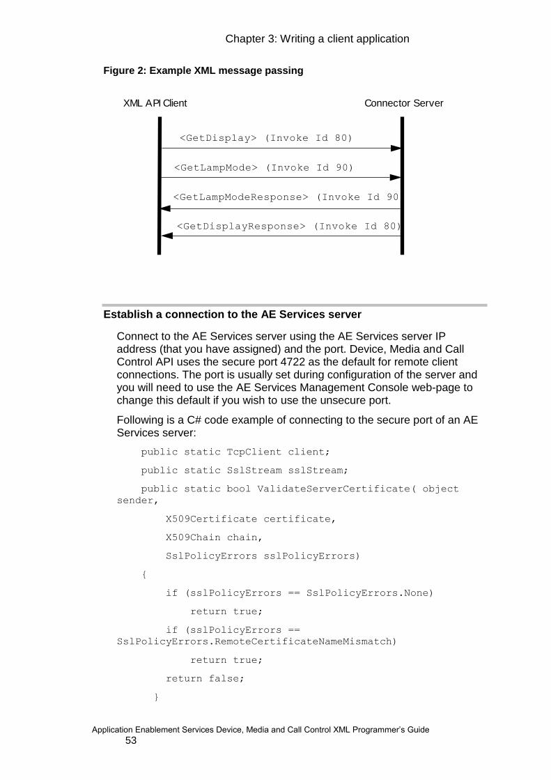
Chapter 3: Writing a client application
Application Enablement Services Device, Media and Call Control XML Programmer‟s Guide 53
Figure 2: Example XML message passing
XML API Client Connector Server
<GetDisplay> (Invoke Id 80)
<GetLampMode> (Invoke Id 90)
<GetDisplayResponse> (Invoke Id 80)
<GetLampModeResponse> (Invoke Id 90)
Establish a connection to the AE Services server
Connect to the AE Services server using the AE Services server IP address (that you have assigned) and the port. Device, Media and Call Control API uses the secure port 4722 as the default for remote client connections. The port is usually set during configuration of the server and you will need to use the AE Services Management Console web-page to change this default if you wish to use the unsecure port.
Following is a C# code example of connecting to the secure port of an AE Services server:
public static TcpClient client;
public static SslStream sslStream;
public static bool ValidateServerCertificate( object
sender,
X509Certificate certificate,
X509Chain chain,
SslPolicyErrors sslPolicyErrors)
{
if (sslPolicyErrors == SslPolicyErrors.None)
return true;
if (sslPolicyErrors ==
SslPolicyErrors.RemoteCertificateNameMismatch)
return true;
return false;
}
54
client = new TcpClient(server, port);
sslStream = new SslStream(
client.GetStream(),
false,
new
RemoteCertificateValidationCallback(ValidateServerCertificat
e),
null
);
NOTE: The Avaya Product Root CA (which is stored in the file avaya.crt in the XML SDK) must be added to the local trusted repository. If you double-
click avaya.crt, a wizard walks you through the process of adding the
certificate to the local trusted repository.
NOTE: You must have version 2.0 of the .NET framework
Setting up the IO Streams
Set up the IO streams. Depending on what programming language you are using to develop your application, this step may already be taken care of by the language itself.
Following is a C# code fragment:
BinaryWrite writer = new BinaryWriter(stream);
BinaryReader reader = new BinaryReader(stream);
Receiving negative acknowledgements
Each service request may generate a negative acknowledgement. When AE Services responds with one, the XML message sent will have the XML
tag <CSTAErrorCode> present. It will be up to the application as to how to
handle such messages. The application does not need to send back a message to the Application Enablement server when such a message is received.
An example of the structure of the XML message your application may receive is:
<?xml version="1.0" encoding="UTF-8"?>
<CSTAErrorCode xmlns="http://www.ecma-
international.org/ecma-323/csta/ed3">
<operation>invalidCallingDeviceID</operation>
</CSTAErrorCode>

Chapter 3: Writing a client application
Application Enablement Services Device, Media and Call Control XML Programmer‟s Guide 55
Note: This is an example of a Negative Acknowledgement that could be received as a response to a MakeCall request.
We recommend that the application log all possible negative acknowledgements since this will be an important source of information for debugging the application. Look at the server side logs for more information about what happened (Appendix C: Server Logging). The logs will contain helpful information that you may need to provide to
DevConnect.
For more information on negative acknowledgements please see section 9.2.2 and 9.3 in the ECMA-269: Services for Computer Supported Telecommunications Applications (CSTA) Phase III found in the Publications section of the ECMA web site (http://www.ecma-international.org/ ):
The CSTA specification provides a long list of standard error messages that a request could return. This list of standard CSTA errors is somewhat limiting in that it does not cover all the possible errors. The latest version of the CSTA specification extended the error message capability by allowing the creation of vendor specific errors. To utilize this new capability an XSD,
avaya-error.xsd, was created. This XSD specifies an enumeration of all
the extended error codes. Private error codes were added to convert TSAPI ACS Universal errors. These errors will be sent to the application instead of the generic CSTAErrorCode „unspecified‟ when applicable. Appendix D: TSAPI Error Code Definitions contains a table of the errors that were added and their meaning. The use of an XSD will make it easy for any client (Java, C#, etc.) to have a programmatic way of knowing what AE Services extended error codes are possible.
The sample applications included in the Java SDK for Device, Media and CallControl API are more extensive than those for the XML SDK. If you want to see examples of a wider variety of XML requests and responses, you may want to examine the XML messages generated and received by these sample applications. In order to do so, follow the instructions in Appendix C: Server Logging to increase the log level on the AE Services server so that it will trace XML message to its log files. Then follow the
instructions in the example/bin/README.txt file in the Java SDK to run
the Java sample applications. The /var/log/avaya/aes/dmcc-
trace.log.x files will now show every XML message sent and received by the server. See also Using the Device, Media and Call Control Dashboard.

56
Establishing an application session
Establish an application session between your application and the server for the purpose of exchanging application messages. It is required that an application session be established before application messages can be
exchanged. Construct the StartApplicationSession XML message and
send it to AE Services. You must specify the cleanup delay and the application session duration in this request.
The following is the structure of the XML message you send:
<?xml version="1.0" encoding="utf-8"?>
<StartApplicationSession
xmlns:xsi="http://www.w3.org/2001/XMLSchema-instance"
xmlns:xsd="http://www.w3.org/2001/XMLSchema"
xmlns="http://www.ecma-international.org/standards/ecma-
354/appl_session">
<applicationInfo>
<applicationID>someApp</applicationID>
<applicationSpecificInfo>
<SessionLoginInfo
xmlns="http://www.avaya.com/csta">
<userName xmlns="">user1</userName>
<password xmlns="">password1</password>
<sessionCleanupDelay
xmlns="">60</sessionCleanupDelay>
<sessionID xmlns="" />
</SessionLoginInfo>
</applicationSpecificInfo>
</applicationInfo>
<requestedProtocolVersions>
<protocolVersion>http://www.ecma-
international.org/standards/ecma-323/
csta/ed3/priv2</protocolVersion>
</requestedProtocolVersions>
<requestedSessionDuration>180</requestedSessionDuration>
</StartApplicationSession>
Each release adds functionality to the previous releases. Specify the
following protocol strings in the protocolVersion element of the message:
To access release 3.0 functionality use the string "3.0"
Chapter 3: Writing a client application
Application Enablement Services Device, Media and Call Control XML Programmer‟s Guide 57
To access release 3.1 functionality use the string "http://www.ecma-international.org/standards/ecma-
323/csta/ed2/priv1"
To access release 4.0 functionality use the string "http://www.ecma-international.org/standards/ecma-
323/csta/ed3/priv1"
To access release 4.1 functionality use the string http://www.ecma-international.org/standards/ecma-323/csta/ed3/priv2
To access release 4.2 functionality use the string "http://www.ecma-international.org/standards/ecma-
323/csta/ed3/priv3"
To access release 5.2 functionality use the string http://www.ecma-
international.org/standards/ecma-323/csta/ed3/priv4"
To access release 6.1 functionality use the string http://www.ecma-international.org/standards/ecma-323/csta/ed3/priv5
To access release 6.2 functionality use the string "http://www.ecma-international.org/standards/ecma-
323/csta/ed3/priv6"
To access release 6.3 functionality use the string "http://www.ecma-international.org/standards/ecma-
323/csta/ed3/priv7"
If the requested version is not valid or supported by the server, then a
StartApplicationSessionNegResponse shall be sent back and the error
code shall be set to RequestedProtocolVersionNotSupported
AE Services 3.x, 4.x and 5.x applications are expected to run against the AE Services 6.2 as long as the protocol version associated with the SDK is specified correctly. Appendix A in the Avaya Aura® Application Enablement Services Overview document contains more information on API and client compatibility.
NOTE: There is a limitation of one session per socket. if you attempt to initiate a new session on the same socket you will receive a
StartApplicationSessionNegResponse.
NOTE: The following URL: http://www.ecma-international.org/standards/ecma-323/csta/ed2/priv1, used throughout the code samples in the Application Session sections of this book is not a reachable URL. This URL was obtained by taking the CSTA namespace for the XML schemas and adding an Avaya private data version to the end.
Once the StartApplicationSession message is processed by the AE Services server, a response will be returned. This response from the
service will be either a StartApplicationSessionPosResponse, or a
StartApplicationSessionNegResponse.
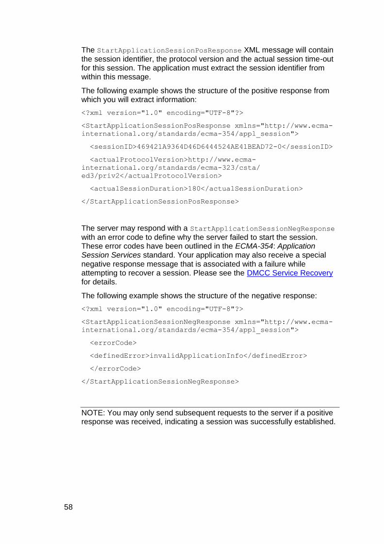
58
The StartApplicationSessionPosResponse XML message will contain the session identifier, the protocol version and the actual session time-out for this session. The application must extract the session identifier from within this message.
The following example shows the structure of the positive response from which you will extract information:
<?xml version="1.0" encoding="UTF-8"?>
<StartApplicationSessionPosResponse xmlns="http://www.ecma-
international.org/standards/ecma-354/appl_session">
<sessionID>469421A9364D46D6444524AE41BEAD72-0</sessionID>
<actualProtocolVersion>http://www.ecma-
international.org/standards/ecma-323/csta/
ed3/priv2</actualProtocolVersion>
<actualSessionDuration>180</actualSessionDuration>
</StartApplicationSessionPosResponse>
The server may respond with a StartApplicationSessionNegResponse with an error code to define why the server failed to start the session. These error codes have been outlined in the ECMA-354: Application Session Services standard. Your application may also receive a special negative response message that is associated with a failure while attempting to recover a session. Please see the DMCC Service Recovery for details.
The following example shows the structure of the negative response:
<?xml version="1.0" encoding="UTF-8"?>
<StartApplicationSessionNegResponse xmlns="http://www.ecma-
international.org/standards/ecma-354/appl_session">
<errorCode>
<definedError>invalidApplicationInfo</definedError>
</errorCode>
</StartApplicationSessionNegResponse>
NOTE: You may only send subsequent requests to the server if a positive response was received, indicating a session was successfully established.
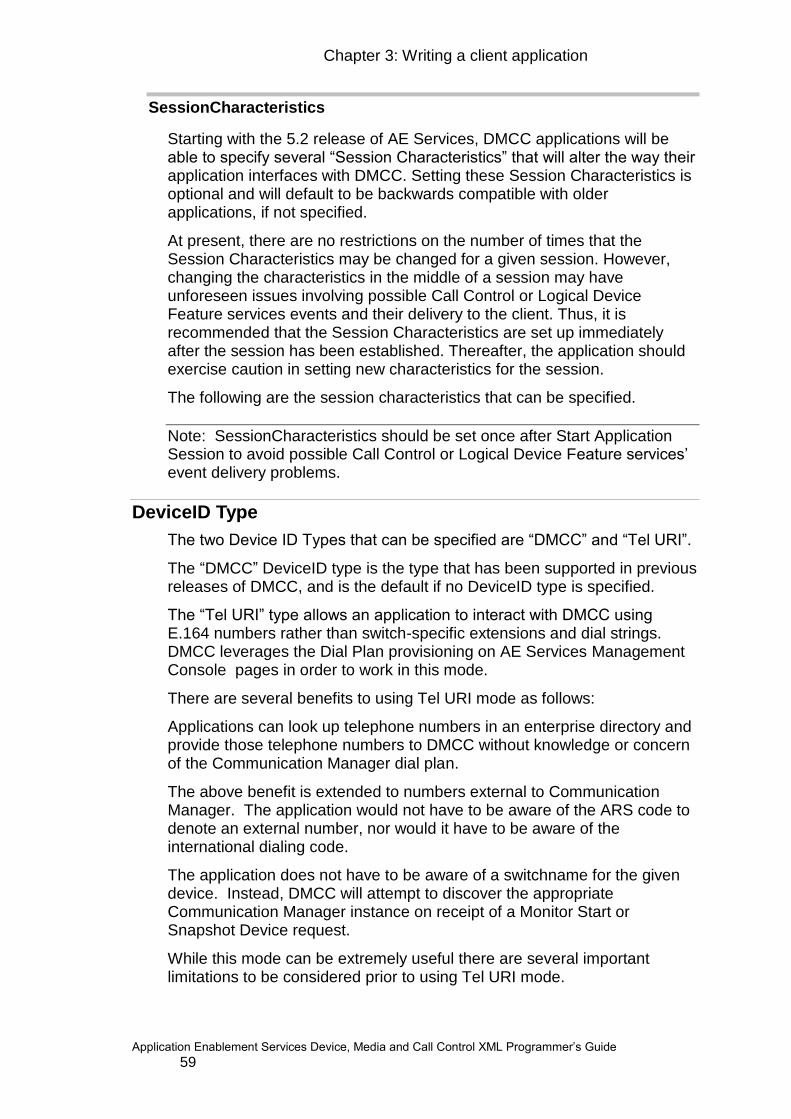
Chapter 3: Writing a client application
Application Enablement Services Device, Media and Call Control XML Programmer‟s Guide 59
SessionCharacteristics
Starting with the 5.2 release of AE Services, DMCC applications will be able to specify several “Session Characteristics” that will alter the way their application interfaces with DMCC. Setting these Session Characteristics is optional and will default to be backwards compatible with older applications, if not specified.
At present, there are no restrictions on the number of times that the Session Characteristics may be changed for a given session. However, changing the characteristics in the middle of a session may have unforeseen issues involving possible Call Control or Logical Device Feature services events and their delivery to the client. Thus, it is recommended that the Session Characteristics are set up immediately after the session has been established. Thereafter, the application should exercise caution in setting new characteristics for the session.
The following are the session characteristics that can be specified.
Note: SessionCharacteristics should be set once after Start Application Session to avoid possible Call Control or Logical Device Feature services‟ event delivery problems.
DeviceID Type
The two Device ID Types that can be specified are “DMCC” and “Tel URI”.
The “DMCC” DeviceID type is the type that has been supported in previous releases of DMCC, and is the default if no DeviceID type is specified.
The “Tel URI” type allows an application to interact with DMCC using E.164 numbers rather than switch-specific extensions and dial strings. DMCC leverages the Dial Plan provisioning on AE Services Management Console pages in order to work in this mode.
There are several benefits to using Tel URI mode as follows:
Applications can look up telephone numbers in an enterprise directory and provide those telephone numbers to DMCC without knowledge or concern of the Communication Manager dial plan.
The above benefit is extended to numbers external to Communication Manager. The application would not have to be aware of the ARS code to denote an external number, nor would it have to be aware of the international dialing code.
The application does not have to be aware of a switchname for the given device. Instead, DMCC will attempt to discover the appropriate Communication Manager instance on receipt of a Monitor Start or Snapshot Device request.
While this mode can be extremely useful there are several important limitations to be considered prior to using Tel URI mode.

60
Only Monitoring Services, Call Control Services, Snapshot Services and Logical Device Feature Services may be used when working in this mode.
If Monitoring Services is used in Tel URI mode, the application must take care to only subscribe to Call Control and Logical Device Feature events.
The first request issued by the application must be a Monitor Start or Snapshot Device request as those requests are used to associate the Tel URI with a particular administered Switch.
The Dial Plan must have been provisioned in the AE Services Management Console pages for the Communication Manager(s) of interest.
A given AE Services instance may only serve users in a single country, even if the Communication Manager is a multi-national deployment. This is because the dial plan rules do not take the calling number into account when determining how to convert a called number.
For more details on how to provision Dial Plan rules, please see the section on Dial Plan Administration in the “Avaya MultiVantage® Application Enablement Services Implementation Guide for Microsoft Office Live Communications Server 2005 or Microsoft Office Communications Server 2007”
Event Filter Mode
An Event Filtering Mode of “None” corresponds to the “regular” DMCC behavior applications are used to receiving, and is the default if no Event Filter mode is specified. Note that filters specified in a Monitor Start request will continue to be applied even if the default Event Filtering Mode of “None” is requested.
“Desktop Call Control” event filtering may be leveraged by applications that are directly representing call state to end-users. In this mode, DMCC will filter out events that would otherwise lead to confusing call states for the user. The following events filtering is applied in this mode:
Delivered and Established events that would reveal the presence of a silent observer. When Single Step Conference is used to add a participant to a call, an application can optionally specify that the participant be added in “listen-only” mode. This is generally used to add automata such as virtual call recording extensions. A participant that has been added using the Communication Manager Service Observing feature would also be a silent participant. It is generally beneficial to hide the presence of such silent observers from an end-user application that otherwise shows all parties on the call.
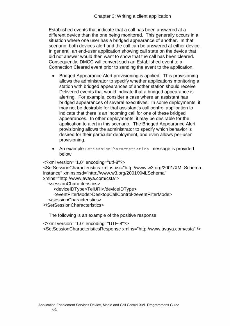
Chapter 3: Writing a client application
Application Enablement Services Device, Media and Call Control XML Programmer‟s Guide 61
Established events that indicate that a call has been answered at a different device than the one being monitored. This generally occurs in a situation where one user has a bridged appearance of another. In that scenario, both devices alert and the call can be answered at either device. In general, an end-user application showing call state on the device that did not answer would then want to show that the call has been cleared. Consequently, DMCC will convert such an Established event to a Connection Cleared event prior to sending the event to the application.
Bridged Appearance Alert provisioning is applied. This provisioning allows the administrator to specify whether applications monitoring a station with bridged appearances of another station should receive Delivered events that would indicate that a bridged appearance is alerting. For example, consider a case where an assistant has bridged appearances of several executives. In some deployments, it may not be desirable for that assistant‟s call control application to indicate that there is an incoming call for one of these bridged appearances. In other deployments, it may be desirable for the application to alert in this scenario. The Bridged Appearance Alert provisioning allows the administrator to specify which behavior is desired for their particular deployment, and even allows per-user provisioning.
An example SetSessionCharacteristics message is provided below
<?xml version="1.0" encoding="utf-8"?> <SetSessionCharacteristics xmlns:xsi="http://www.w3.org/2001/XMLSchema-instance" xmlns:xsd="http://www.w3.org/2001/XMLSchema" xmlns="http://www.avaya.com/csta"> <sessionCharacteristics> <deviceIDType>TelURI</deviceIDType> <eventFilterMode>DesktopCallControl</eventFilterMode> </sessionCharacteristics> </SetSessionCharacteristics>
The following is an example of the positive response:
<?xml version="1.0" encoding="UTF-8"?> <SetSessionCharacteristicsResponse xmlns="http://www.avaya.com/csta" />
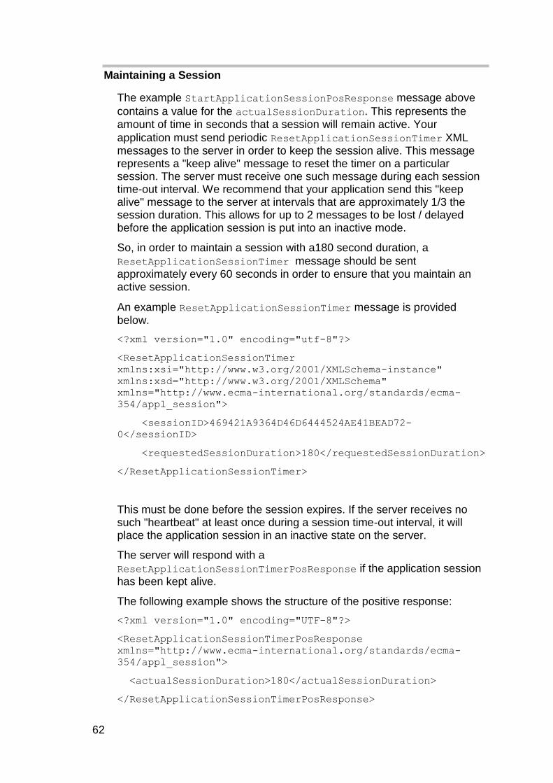
62
Maintaining a Session
The example StartApplicationSessionPosResponse message above
contains a value for the actualSessionDuration. This represents the amount of time in seconds that a session will remain active. Your
application must send periodic ResetApplicationSessionTimer XML messages to the server in order to keep the session alive. This message represents a "keep alive" message to reset the timer on a particular session. The server must receive one such message during each session time-out interval. We recommend that your application send this "keep alive" message to the server at intervals that are approximately 1/3 the session duration. This allows for up to 2 messages to be lost / delayed before the application session is put into an inactive mode.
So, in order to maintain a session with a180 second duration, a
ResetApplicationSessionTimer message should be sent approximately every 60 seconds in order to ensure that you maintain an active session.
An example ResetApplicationSessionTimer message is provided below.
<?xml version="1.0" encoding="utf-8"?>
<ResetApplicationSessionTimer
xmlns:xsi="http://www.w3.org/2001/XMLSchema-instance"
xmlns:xsd="http://www.w3.org/2001/XMLSchema"
xmlns="http://www.ecma-international.org/standards/ecma-
354/appl_session">
<sessionID>469421A9364D46D6444524AE41BEAD72-
0</sessionID>
<requestedSessionDuration>180</requestedSessionDuration>
</ResetApplicationSessionTimer>
This must be done before the session expires. If the server receives no such "heartbeat" at least once during a session time-out interval, it will place the application session in an inactive state on the server.
The server will respond with a
ResetApplicationSessionTimerPosResponse if the application session
has been kept alive.
The following example shows the structure of the positive response:
<?xml version="1.0" encoding="UTF-8"?>
<ResetApplicationSessionTimerPosResponse
xmlns="http://www.ecma-international.org/standards/ecma-
354/appl_session">
<actualSessionDuration>180</actualSessionDuration>
</ResetApplicationSessionTimerPosResponse>
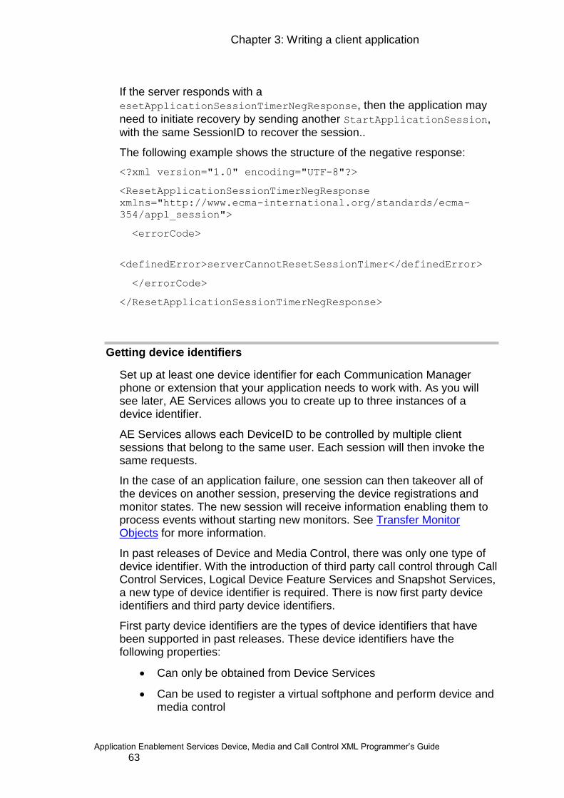
Chapter 3: Writing a client application
Application Enablement Services Device, Media and Call Control XML Programmer‟s Guide 63
If the server responds with a
esetApplicationSessionTimerNegResponse, then the application may
need to initiate recovery by sending another StartApplicationSession,
with the same SessionID to recover the session..
The following example shows the structure of the negative response:
<?xml version="1.0" encoding="UTF-8"?>
<ResetApplicationSessionTimerNegResponse
xmlns="http://www.ecma-international.org/standards/ecma-
354/appl_session">
<errorCode>
<definedError>serverCannotResetSessionTimer</definedError>
</errorCode>
</ResetApplicationSessionTimerNegResponse>
Getting device identifiers
Set up at least one device identifier for each Communication Manager phone or extension that your application needs to work with. As you will see later, AE Services allows you to create up to three instances of a device identifier.
AE Services allows each DeviceID to be controlled by multiple client sessions that belong to the same user. Each session will then invoke the same requests.
In the case of an application failure, one session can then takeover all of the devices on another session, preserving the device registrations and monitor states. The new session will receive information enabling them to process events without starting new monitors. See Transfer Monitor Objects for more information.
In past releases of Device and Media Control, there was only one type of device identifier. With the introduction of third party call control through Call Control Services, Logical Device Feature Services and Snapshot Services, a new type of device identifier is required. There is now first party device identifiers and third party device identifiers.
First party device identifiers are the types of device identifiers that have been supported in past releases. These device identifiers have the following properties:
Can only be obtained from Device Services
Can be used to register a virtual softphone and perform device and media control

64
Can also be used for third party call control operations, but only if they contain a Communication Manager connection name
Must be released to be cleaned up
Third party device identifiers have the following properties:
Are not exclusive to session
Can be obtained from Device Services or may be returned by Call Control Services/Logical Device Feature Services/Snapshot Services
Can only be used with Call Control Services, Logical Device Feature Services and Snapshot Services
Need not be released
There are several valid ways to get a first party device ID. It is recommended that the application take advantage of the H.323 Gatekeeper List feature so that both first party device IDs and third party device IDs are acquired in the same way: by giving a switch name and an extension number. This feature requires the administrator to administer through the AE ServicesManagement Console web pages a list of IP addresses that can be used for H.323 registrations. See the "Administering Switch Connections" section of the "AE Services OAM Administration and CTI OAM Admin" chapter of the Avaya Aura® Application Enablement Services Administration and Maintenance Guide.
If an application is not using Call Information Services, Call Control Services or Snapshot Services, it is also valid to include only a
switchIPInterface and dial string in the getDeviceID message, and thereby not administer the H.323 Gatekeeper list.
Construct the GetDeviceId XML message and send it to AE Services. The following is the structure of the XML message you send:
<?xml version="1.0" encoding="utf-8"?>
<GetDeviceId xmlns:xsi="http://www.w3.org/2001/XMLSchema-
instance" xmlns:xsd="http:// www.w3.org/2001/XMLSchema"
xmlns="http://www.avaya.com/csta">
<switchName>MySwitch</switchName>
<switchIPInterface>111.2.33.444</switchIPInterface>
<extension>4750</extension>
</GetDeviceId>
The AE Services server responds with the GetDeviceIdResponse XML message. The application must extract the device identifier from within this message.
The following example shows the structure of the response from which you will extract information:

Chapter 3: Writing a client application
Application Enablement Services Device, Media and Call Control XML Programmer‟s Guide 65
<?xml version="1.0" encoding="UTF-8"?>
<GetDeviceIdResponse xmlns="http://www.avaya.com/csta">
<device typeOfNumber="other" mediaClass="voice"
bitRate="constant">4750::111.2.33.444:0</device>
</GetDeviceIdResponse>
Note: The XML tags for the device identifier are not consistent throughout the XML messages. This inconsistency is CSTA-related. In the sample
above of the GetDeviceIdResponse XML message, the device identifier is
bracketed by the <device> tags. In the MonitorStart XML message, the
device identifier is bracketed by the <deviceObject> tags.
Note: The DeviceID and ConnectionID formats are subject to change in future releases. Your applications should not be parsing these IDs, but rather should be using them as keys in their requests.
Note: According to the call-connection-identifiers.xsd schema, it is valid to have a ConnectionID that consists of only a DeviceID or a CallID. This is a standard CSTA schema and is general to many implementations in addition to Avaya‟s. Though the schema states that the DeviceID or CallID are optional, this is not always true for Avaya‟s implementation. For connection ID‟s received from Call Control Services or Snapshot Services, the application should treat ConnectionID opaquely and should send the exact XML content that was received from the Device Media and Call Control Service. This will always include both a DeviceID and a CallID.
Comparing Device Identifiers
Depending on how you obtained the DeviceIDs, there may be small formatting differences between two DeviceIDs that you might think should be equal. A DeviceID comprises of four main parts:
1. the phone extension – normally consists of 4-13 digits.
2. the name of the switch associated with the extension – this should match one of the “Switch Connections” provisioned via the AE Services Management Console web-pages.
3. the IP address of the CLAN or Processor Ethernet interface used to connect the phone to the switch (optional)
4. the instance of the phone extension – ranges from 0-2 (default = 0)
Parts 1, 3 & 4 are comprised of numeric digits and normally pose no comparison problems. However, part 2 (switchname) consists of alphanumeric characters and can contain either upper-case or lower-case alphabetic letters. Thus, for example, it is possible to obtain the DeviceIDs:
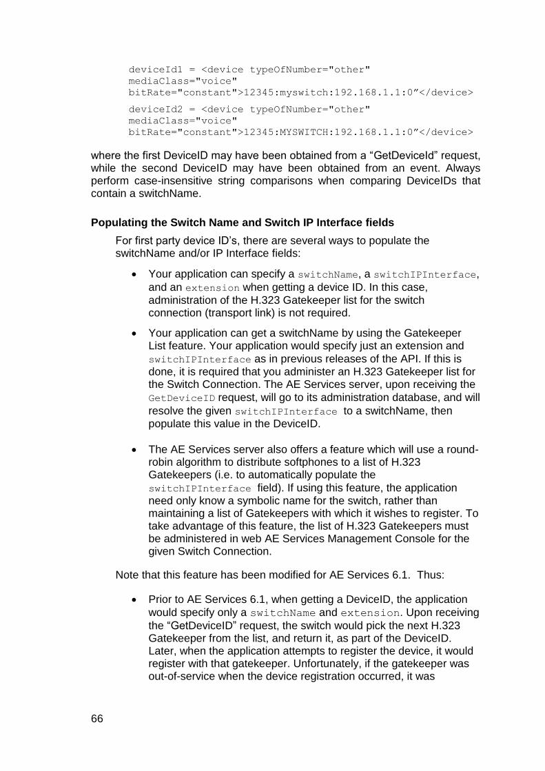
66
deviceId1 = <device typeOfNumber="other"
mediaClass="voice"
bitRate="constant">12345:myswitch:192.168.1.1:0”</device>
deviceId2 = <device typeOfNumber="other"
mediaClass="voice"
bitRate="constant">12345:MYSWITCH:192.168.1.1:0”</device>
where the first DeviceID may have been obtained from a “GetDeviceId” request, while the second DeviceID may have been obtained from an event. Always perform case-insensitive string comparisons when comparing DeviceIDs that contain a switchName.
Populating the Switch Name and Switch IP Interface fields
For first party device ID‟s, there are several ways to populate the switchName and/or IP Interface fields:
Your application can specify a switchName, a switchIPInterface,
and an extension when getting a device ID. In this case,
administration of the H.323 Gatekeeper list for the switch connection (transport link) is not required.
Your application can get a switchName by using the Gatekeeper List feature. Your application would specify just an extension and
switchIPInterface as in previous releases of the API. If this is done, it is required that you administer an H.323 Gatekeeper list for the Switch Connection. The AE Services server, upon receiving the
GetDeviceID request, will go to its administration database, and will
resolve the given switchIPInterface to a switchName, then populate this value in the DeviceID.
The AE Services server also offers a feature which will use a round-robin algorithm to distribute softphones to a list of H.323 Gatekeepers (i.e. to automatically populate the
switchIPInterface field). If using this feature, the application need only know a symbolic name for the switch, rather than maintaining a list of Gatekeepers with which it wishes to register. To take advantage of this feature, the list of H.323 Gatekeepers must be administered in web AE Services Management Console for the given Switch Connection.
Note that this feature has been modified for AE Services 6.1. Thus:
Prior to AE Services 6.1, when getting a DeviceID, the application
would specify only a switchName and extension. Upon receiving
the “GetDeviceID” request, the switch would pick the next H.323 Gatekeeper from the list, and return it, as part of the DeviceID. Later, when the application attempts to register the device, it would register with that gatekeeper. Unfortunately, if the gatekeeper was out-of-service when the device registration occurred, it was
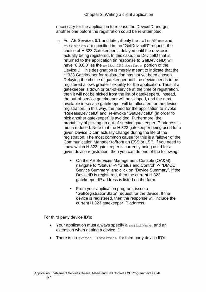
Chapter 3: Writing a client application
Application Enablement Services Device, Media and Call Control XML Programmer‟s Guide 67
necessary for the application to release the DeviceID and get another one before the registration could be re-attempted.
o For AE Services 6.1 and later, if only the switchName and
extension are specified in the “GetDeviceID” request, the
choice of H.323 Gatekeeper is delayed until the device is actually being registered. In this case, the DeviceID that is returned to the application (in response to GetDeviceID) will
have “0.0.0.0” as the switchIPInterface portion of the
DeviceID. This designation is merely meant to indicate that the H.323 Gatekeeper for registration has not yet been chosen. Delaying the choice of gatekeeper until the device needs to be registered allows greater flexibility for the application. Thus, if a gatekeeper is down or out-of-service at the time of registration, then it will not be picked from the list of gatekeepers. Instead, the out-of-service gatekeeper will be skipped, and the next available in-service gatekeeper will be allocated for the device registration. In this way, the need for the application to invoke “ReleaseDeviceID” and re-invoke “GetDeviceID” (in order to pick another gatekeeper) is avoided. Furhermore, the probability of picking an out-of-service gatekeeper IP address is much reduced. Note that the H.323 gatekeeper being used for a given DeviceID can actually change during the life of the registration. The most common cause for this is a failover of the Communication Manager to/from an ESS or LSP. If you need to know which H.323 gatekeeper is currently being used for a given device registration, then you can do one of the following:
On the AE Services Management Console (OA&M), navigate to “Status” -> “Status and Control” -> “DMCC Service Summary” and click on “Device Summary”. If the DeviceID is registered, then the current H.323 gatekeeper IP address is listed on the form.
From your application program, issue a “GetRegistrationState” request for the device. If the device is registered, then the response will include the current H.323 gatekeeper IP address.
For third party device ID‟s:
Your application must always specify a switchName, and an extension when getting a device ID.
There is no switchIPInterface for third party device ID‟s.

68
Note: The switchName field is only required for Call Information, Call
Control Services, Snapshot Services and Logical Device Feature Services. If an application is not using one of these services and does not wish to take advantage of the round-robin H.323 Gatekeeper assignment feature, it is not required to administer an H.323 gatekeeper list or specify a
switchName in the GetDeviceID request. In this case, the switchName field of the DeviceID is simply not populated, and any calls with this DeviceID to Call Information Services, Call Control Services or Snapshot Services will fail.
Using E.164 conversion services
E.164 is an ITU-T recommendation defining the international public telecommunication numbering plan used in the PSTN and other data networks. E.164 numbers can have a maximum of 15 digits and are usually written with a + prefix. To actually dial such numbers from a normal fixed line phone the appropriate international call prefix must be used.
Many organizations use E.164 format when storing employee‟s telephone numbers in their directory (for example, Microsoft Active Directory or Lotus Domino). If your application performs directory queries based on an individual‟s name, it may receive E.164 format numbers in return. In such cases, you must convert the E.164 number to a Communication Manager extension or dial string before getting a Device ID to use with the Device, Media and Call Control services.
Likewise, if you need to perform a directory query to resolve an extension number received from Device, Media and Call Control into a name, you must convert the extension number to an E.164 number before performing your query.
E.164 Conversion Services, in conjunction with the AE Services Dial Plan rules, can help your application perform both of these conversions. The following code snippet shows how you can convert E.164 numbers into Communication Manager extensions / dial strings.
E164ToDialString Request
<ConvertE164ToDialString
xmlns:xsi="http://www.w3.org/2001/XMLSchema-instance"
xmlns:xsd="http://www.w3.org/2001/XMLSchema"
xmlns="http://www.avaya.com/csta">
<switchName>MySwitch</switchName>
<e164List>
<e164Number>+13035381212</e164Number>
<e164Number>+13035381234</e164Number>
<e164Number>+17205554321</e164Number>
</e164List>

Chapter 3: Writing a client application
Application Enablement Services Device, Media and Call Control XML Programmer‟s Guide 69
</ConvertE164ToDialString>
E164ToDialString Response
<?xml version="1.0" encoding="UTF-8"?>
<ConvertE164ToDialStringResponse
xmlns="http://www.avaya.com/csta">
<switchName>MySwitch</switchName>
<resultList>
<result>
<resultType>CONVERTED</resultType>
<e164>+13035381212</e164>
<dialString>5381212</dialString>
</result>
<result>
<resultType>CONVERTED</resultType>
<e164>+13035381234</e164>
<dialString>5381234</dialString>
</result>
<result>
<resultType>CONVERTED</resultType>
<e164>+17205554321</e164>
<dialString>917205554321</dialString>
</result>
</resultList>
</ConvertE164ToDialStringResponse>
Note: This example presumes that dial plan rules have been administered to indicate that numbers starting with "+1303538" are Communication Manager extensions that should be converted to 7 digit numbers, and that any other numbers starting with "+1" should have an ARS code (for example, ‟9‟ for an outside number) placed in front. The resulting converted numbers would then be "5381212", "5381234" and "917205554321".
Converting from dial strings to E.164 is done in a very similar fashion.
For more information on administering dial plan rules, see the Administering Dial Plan Settings chapter of the Avaya Aura® Application Enablement Services Administration and Maintenance Guide.
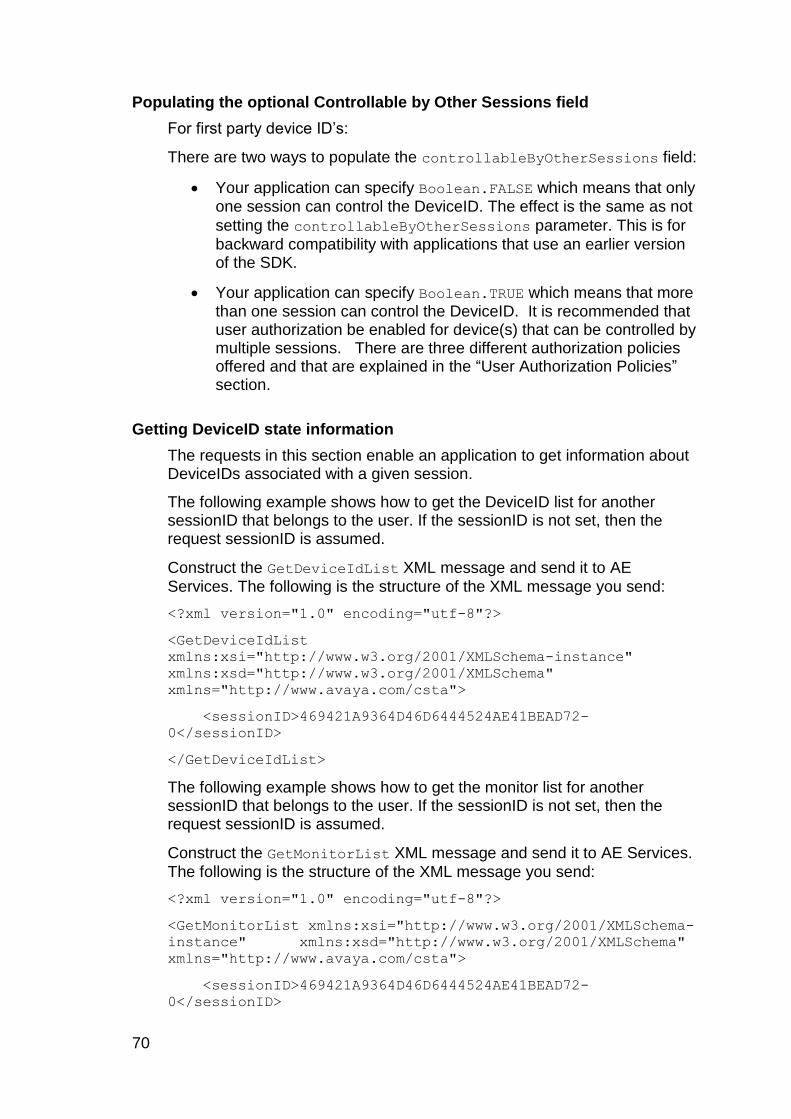
70
Populating the optional Controllable by Other Sessions field
For first party device ID‟s:
There are two ways to populate the controllableByOtherSessions field:
Your application can specify Boolean.FALSE which means that only one session can control the DeviceID. The effect is the same as not
setting the controllableByOtherSessions parameter. This is for
backward compatibility with applications that use an earlier version of the SDK.
Your application can specify Boolean.TRUE which means that more than one session can control the DeviceID. It is recommended that user authorization be enabled for device(s) that can be controlled by multiple sessions. There are three different authorization policies offered and that are explained in the “User Authorization Policies” section.
Getting DeviceID state information
The requests in this section enable an application to get information about DeviceIDs associated with a given session.
The following example shows how to get the DeviceID list for another sessionID that belongs to the user. If the sessionID is not set, then the request sessionID is assumed.
Construct the GetDeviceIdList XML message and send it to AE
Services. The following is the structure of the XML message you send:
<?xml version="1.0" encoding="utf-8"?>
<GetDeviceIdList
xmlns:xsi="http://www.w3.org/2001/XMLSchema-instance"
xmlns:xsd="http://www.w3.org/2001/XMLSchema"
xmlns="http://www.avaya.com/csta">
<sessionID>469421A9364D46D6444524AE41BEAD72-
0</sessionID>
</GetDeviceIdList>
The following example shows how to get the monitor list for another sessionID that belongs to the user. If the sessionID is not set, then the request sessionID is assumed.
Construct the GetMonitorList XML message and send it to AE Services.
The following is the structure of the XML message you send:
<?xml version="1.0" encoding="utf-8"?>
<GetMonitorList xmlns:xsi="http://www.w3.org/2001/XMLSchema-
instance" xmlns:xsd="http://www.w3.org/2001/XMLSchema"
xmlns="http://www.avaya.com/csta">
<sessionID>469421A9364D46D6444524AE41BEAD72-
0</sessionID>
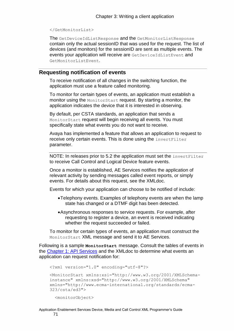
Chapter 3: Writing a client application
Application Enablement Services Device, Media and Call Control XML Programmer‟s Guide 71
</GetMonitorList>
The GetDeviceIdListResponse and the GetMonitorListResponse contain only the actual sessionID that was used for the request. The list of devices (and monitors) for the sessionID are sent as multiple events. The
events your application will receive are GetDeviceIdListEvent and
GetMonitorListEvent.
Requesting notification of events
To receive notification of all changes in the switching function, the application must use a feature called monitoring.
To monitor for certain types of events, an application must establish a
monitor using the MonitorStart request. By starting a monitor, the application indicates the device that it is interested in observing.
By default, per CSTA standards, an application that sends a
MonitorStart request will begin receiving all events. You must
specifically state what events you do not want to receive.
Avaya has implemented a feature that allows an application to request to
receive only certain events. This is done using the invertFilter
parameter.
NOTE: In releases prior to 5.2 the application must set the invertFilter
to receive Call Control and Logical Device feature events.
Once a monitor is established, AE Services notifies the application of relevant activity by sending messages called event reports, or simply events. For details about this request, see the XMLdoc.
Events for which your application can choose to be notified of include:
Telephony events. Examples of telephony events are when the lamp state has changed or a DTMF digit has been detected.
Asynchronous responses to service requests. For example, after requesting to register a device, an event is received indicating whether the request succeeded or failed.
To monitor for certain types of events, an application must construct the
MonitorStart XML message and send it to AE Services.
Following is a sample MonitorStart message. Consult the tables of events in
the Chapter 1: API Services and the XMLdoc to determine what events an application can request notification for:
<?xml version="1.0" encoding="utf-8"?>
<MonitorStart xmlns:xsi="http://www.w3.org/2001/XMLSchema-
instance" xmlns:xsd="http://www.w3.org/2001/XMLSchema"
xmlns="http://www.ecma-international.org/standards/ecma-
323/csta/ed3">
<monitorObject>
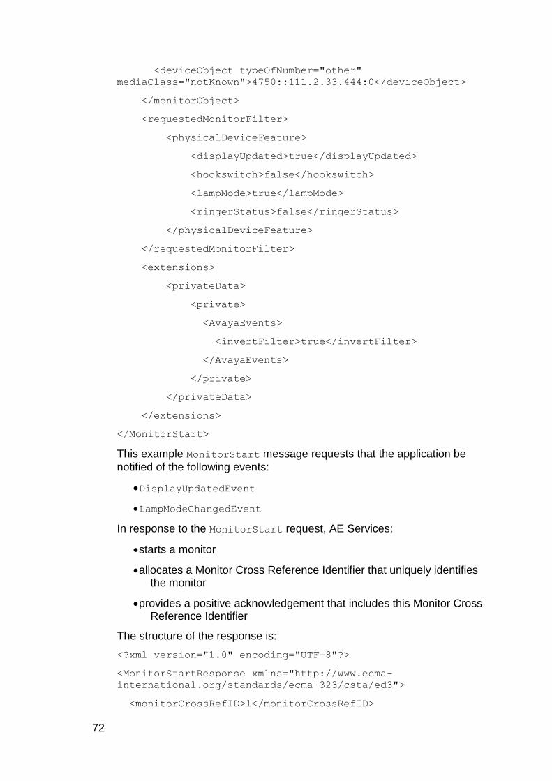
72
<deviceObject typeOfNumber="other"
mediaClass="notKnown">4750::111.2.33.444:0</deviceObject>
</monitorObject>
<requestedMonitorFilter>
<physicalDeviceFeature>
<displayUpdated>true</displayUpdated>
<hookswitch>false</hookswitch>
<lampMode>true</lampMode>
<ringerStatus>false</ringerStatus>
</physicalDeviceFeature>
</requestedMonitorFilter>
<extensions>
<privateData>
<private>
<AvayaEvents>
<invertFilter>true</invertFilter>
</AvayaEvents>
</private>
</privateData>
</extensions>
</MonitorStart>
This example MonitorStart message requests that the application be
notified of the following events:
DisplayUpdatedEvent
LampModeChangedEvent
In response to the MonitorStart request, AE Services:
starts a monitor
allocates a Monitor Cross Reference Identifier that uniquely identifies the monitor
provides a positive acknowledgement that includes this Monitor Cross Reference Identifier
The structure of the response is:
<?xml version="1.0" encoding="UTF-8"?>
<MonitorStartResponse xmlns="http://www.ecma-
international.org/standards/ecma-323/csta/ed3">
<monitorCrossRefID>1</monitorCrossRefID>
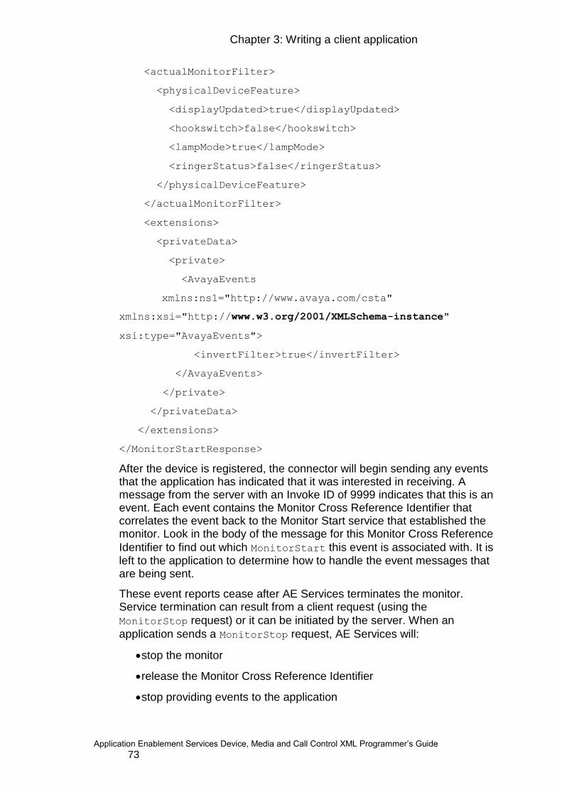
Chapter 3: Writing a client application
Application Enablement Services Device, Media and Call Control XML Programmer‟s Guide 73
<actualMonitorFilter>
<physicalDeviceFeature>
<displayUpdated>true</displayUpdated>
<hookswitch>false</hookswitch>
<lampMode>true</lampMode>
<ringerStatus>false</ringerStatus>
</physicalDeviceFeature>
</actualMonitorFilter>
<extensions>
<privateData>
<private>
<AvayaEvents
xmlns:ns1="http://www.avaya.com/csta"
xmlns:xsi="http://www.w3.org/2001/XMLSchema-instance"
xsi:type="AvayaEvents">
<invertFilter>true</invertFilter>
</AvayaEvents>
</private>
</privateData>
</extensions>
</MonitorStartResponse>
After the device is registered, the connector will begin sending any events that the application has indicated that it was interested in receiving. A message from the server with an Invoke ID of 9999 indicates that this is an event. Each event contains the Monitor Cross Reference Identifier that correlates the event back to the Monitor Start service that established the monitor. Look in the body of the message for this Monitor Cross Reference
Identifier to find out which MonitorStart this event is associated with. It is left to the application to determine how to handle the event messages that are being sent.
These event reports cease after AE Services terminates the monitor. Service termination can result from a client request (using the
MonitorStop request) or it can be initiated by the server. When an
application sends a MonitorStop request, AE Services will:
stop the monitor
release the Monitor Cross Reference Identifier
stop providing events to the application
74
Once the monitor is terminated, the monitor cross reference ID is no longer valid. See ECMA-269, section 6.7.2, “Monitoring” for an overview of monitoring and related concepts such as monitor objects, monitor types, monitor call types, and monitor filters.
Device and Media Control versus Call Control
The differences between Device and Media Control and Call Control, are the differences between first-party and third-party call control.
Device and Media Control use first-party call control, where an application interacts with an endpoint using the model of a person physically manipulating a phone. For example, to make a call a person picks up a handset and presses each digit, one after the other. Similarly, to make a call an application invokes a method to cause the endpoint to go off hook
and invokes a PressButton method once for each digit. This gives an application fine-grained control of and information about an endpoint‟s state.
Call Control uses third-party call control, where an application issues higher level instructions. To make a call an application only has to invoke a
single MakeCall method, which causes one endpoint to call another. It is somewhat inexact, but you can think of the model of third-party call control as a graph in which endpoints are nodes and calls are edges. The methods of the API reconfigure the graph by adding, deleting, or moving edges.
Applications using Device and Media control require registration of devices used in the application. Registration of an end point associated with the
Device, Media and Call Control API requires an IP_API_A license.
Applications using Call Control Services do not need to register devices,
and thus do not consume IP_API_A licenses; however, they do need a
TSAPI license in order to use the Call Control service.
NOTE: It is important to consider license consumption when deciding which style of call control to use. If your application uses Device and Media control for other reasons than controlling calls (for example, to record media or to push feature buttons on a telephone) then you may want to consider using first party call control in order to not consume an additional license. If, on the other hand, your application is primarily concerned with call control, consider using Call Control Services as its higher level operations and events are often easier to use.
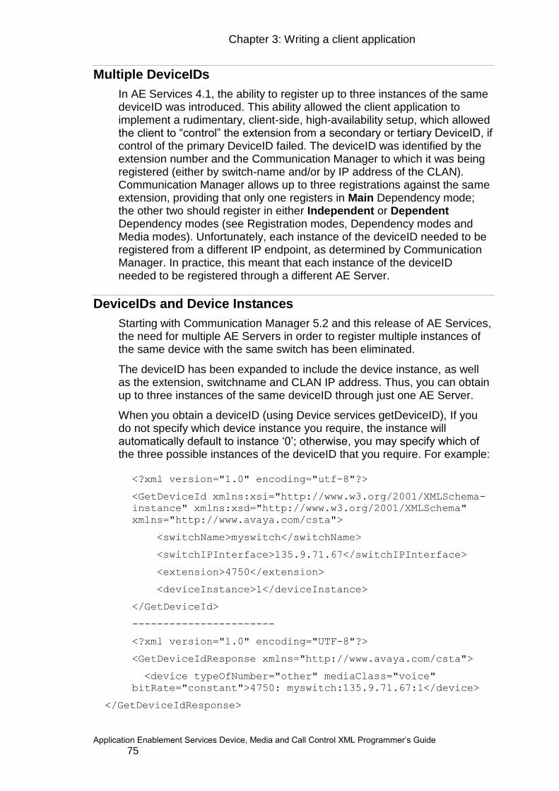
Chapter 3: Writing a client application
Application Enablement Services Device, Media and Call Control XML Programmer‟s Guide 75
Multiple DeviceIDs
In AE Services 4.1, the ability to register up to three instances of the same deviceID was introduced. This ability allowed the client application to implement a rudimentary, client-side, high-availability setup, which allowed the client to “control” the extension from a secondary or tertiary DeviceID, if control of the primary DeviceID failed. The deviceID was identified by the extension number and the Communication Manager to which it was being registered (either by switch-name and/or by IP address of the CLAN). Communication Manager allows up to three registrations against the same extension, providing that only one registers in Main Dependency mode; the other two should register in either Independent or Dependent Dependency modes (see Registration modes, Dependency modes and Media modes). Unfortunately, each instance of the deviceID needed to be registered from a different IP endpoint, as determined by Communication Manager. In practice, this meant that each instance of the deviceID needed to be registered through a different AE Server.
DeviceIDs and Device Instances
Starting with Communication Manager 5.2 and this release of AE Services, the need for multiple AE Servers in order to register multiple instances of the same device with the same switch has been eliminated.
The deviceID has been expanded to include the device instance, as well as the extension, switchname and CLAN IP address. Thus, you can obtain up to three instances of the same deviceID through just one AE Server.
When you obtain a deviceID (using Device services getDeviceID), If you do not specify which device instance you require, the instance will automatically default to instance „0‟; otherwise, you may specify which of the three possible instances of the deviceID that you require. For example:
<?xml version="1.0" encoding="utf-8"?>
<GetDeviceId xmlns:xsi="http://www.w3.org/2001/XMLSchema-
instance" xmlns:xsd="http://www.w3.org/2001/XMLSchema"
xmlns="http://www.avaya.com/csta">
<switchName>myswitch</switchName>
<switchIPInterface>135.9.71.67</switchIPInterface>
<extension>4750</extension>
<deviceInstance>1</deviceInstance>
</GetDeviceId>
-----------------------
<?xml version="1.0" encoding="UTF-8"?>
<GetDeviceIdResponse xmlns="http://www.avaya.com/csta">
<device typeOfNumber="other" mediaClass="voice"
bitRate="constant">4750: myswitch:135.9.71.67:1</device>
</GetDeviceIdResponse>
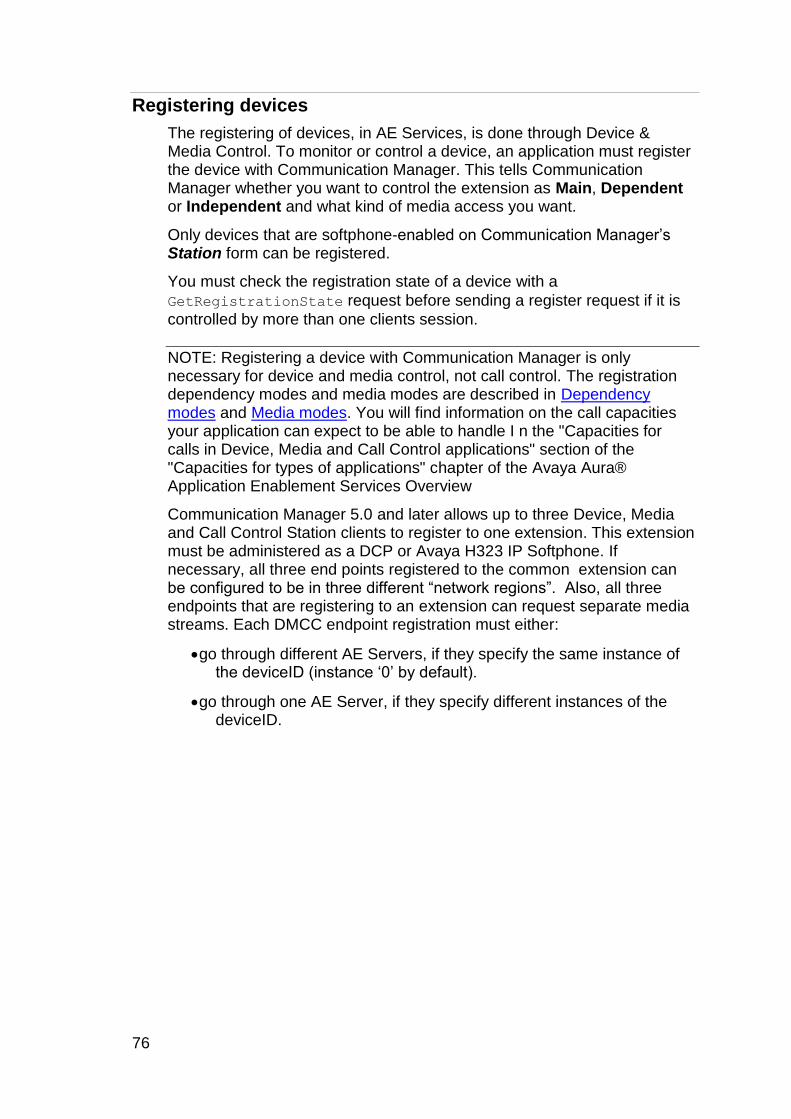
76
Registering devices
The registering of devices, in AE Services, is done through Device & Media Control. To monitor or control a device, an application must register the device with Communication Manager. This tells Communication Manager whether you want to control the extension as Main, Dependent or Independent and what kind of media access you want.
Only devices that are softphone-enabled on Communication Manager‟s Station form can be registered.
You must check the registration state of a device with a
GetRegistrationState request before sending a register request if it is
controlled by more than one clients session.
NOTE: Registering a device with Communication Manager is only necessary for device and media control, not call control. The registration dependency modes and media modes are described in Dependency modes and Media modes. You will find information on the call capacities your application can expect to be able to handle I n the "Capacities for calls in Device, Media and Call Control applications" section of the "Capacities for types of applications" chapter of the Avaya Aura® Application Enablement Services Overview
Communication Manager 5.0 and later allows up to three Device, Media and Call Control Station clients to register to one extension. This extension must be administered as a DCP or Avaya H323 IP Softphone. If necessary, all three end points registered to the common extension can be configured to be in three different “network regions”. Also, all three endpoints that are registering to an extension can request separate media streams. Each DMCC endpoint registration must either:
go through different AE Servers, if they specify the same instance of the deviceID (instance „0‟ by default).
go through one AE Server, if they specify different instances of the deviceID.

Chapter 3: Writing a client application
Application Enablement Services Device, Media and Call Control XML Programmer‟s Guide 77
The first option provides a measure of high availability with standalone (not in a standard High-Availability configuration) Application Enablement Servers. For example, the client could register the same endpoint through two different AE Servers and have recorded media flowing to both. The second option also provides the ability to record dual feeds for recorded media, but provides High-Availability through the standard Application Enablement Services 5.2 paired-servers configuration. Each media (RTP) stream is the summed stream of all the participants in the call. For example, if an Agent using a physical phone with extension 1000, is talking to extension 1001 and extension 1002. And a DMCC endpoint is registered to extension 1000 as Dependent in Client media mode, at the time of the call, the DMCC endpoint will receive the summed talk streams of Agent (at extension 1000) and extensions 1001 and 1002. Note that the DMCC endpoint registered in Dependent (or Independent mode when a physical set is registered/present), is connected to the call in listen only mode. Therefore no additional talk time slot is allocated for this DMCC endpoint. Also, this DMCC endpoint does not count toward the number of participants that can be in a conference call.
Registration is performed through the RegisterTerminalRequest of
Registration Services. In the RegisterTerminalRequest you must at a
minimum specify which device to register and the password that is administered for the device on the Communication Manager Station form. There are also a number of options to choose from.
An application must construct the RegisterTerminalRequest XML
message and send it to AE Services.
<?xml version="1.0" encoding="utf-8"?>
<RegisterTerminalRequest
xmlns:xsi="http://www.w3.org/2001/XMLSchema-instance"
xmlns:xsd="http://www.w3.org/2001/XMLSchema"
xmlns="http://www.avaya.com/csta">
<device typeOfNumber="other"
mediaClass="notKnown">4750::111.2.33.444:0</device>
<loginInfo>
<forceLogin>true</forceLogin>
<sharedControl>false</sharedControl>
<password>1234</password>
<mediaMode>SERVER</mediaMode>
<dependencyMode>MAIN</dependencyMode>
</loginInfo>
</RegisterTerminalRequest>

78
In previous releases of Device and Media Control, the RegisterDevice request of the Terminal Services interface (now deprecated) was used to register a device/station. Using the RegisterDevice request, responses to registration / unregistration requests were simply acknowledgements by the server of receipt of the request. The actual outcome of the request was reflected through events that arrived later.
This has been changed with Registration Services. The responses to registration requests indicate the outcome of the request.
The following is a response to the above request showing that AES encryption was granted and that signaling encryption is enabled (as indicated by the "pin-eke" response).
<?xml version="1.0" encoding="UTF-8"?>
<RegisterTerminalResponse xmlns="http://www.avaya.com/csta">
<device>
<deviceIdentifier xmlns:ns1="http://www.ecma-
international.org/standards/ecma-323/ csta/ed3"
typeOfNumber="other" mediaClass="voice"
bitRate="constant">4750::111.2.33.444:0</deviceIdentifier>
</device>
<signalingEncryption>pin-eke</signalingEncryption>
<code>1</code>
</RegisterTerminalResponse>
The only registration event supported with Registration Services is the
TerminalUnregisteredEvent. This event is sent if the AE Services
server automatically unregisters the device. The typical cause is when the network or Communication Manager is unresponsive. The reason for unregistration is reflected in the event‟s cause code. Its value is one of the Registration Constants listed in Appendix B: Constant Values. If a device becomes automatically unregistered, it is up to the application to reregister.
The following is an example of a TerminalUnregisteredEvent:
<?xml version="1.0" encoding="UTF-8"?>
<TerminalUnregisteredEvent
xmlns="http://www.avaya.com/csta">
<monitorCrossRefID xmlns:ns1="http://www.ecma-
international.org/standards/ecma-
323/csta/ed3">6</monitorCrossRefID>
<device>
<deviceIdentifier xmlns:ns2="http://www.ecma-
international.org/standards/ecma-323/csta/ed3"
typeOfNumber="other" mediaClass="voice"
bitRate="constant">4750::111.2.33.444:0</deviceIdentifier>
</device>

Chapter 3: Writing a client application
Application Enablement Services Device, Media and Call Control XML Programmer‟s Guide 79
<reason>Received unregistration request from switch
reason=2018 text=2018-Rebooting Ext released</reason>
<code>-1</code>
</TerminalUnregisteredEvent>
As part of the registration initialization process, multiple physical device events are sent by the Communication Manager indicating the initial states of the lamps, ringer, hookswitch and display.
Note: If your application needs to register many devices, we recommend you spread out the registration of the devices. Register no more than 50 stations at one time and wait until your application has received all of the responses before attempting to register more stations.
Some important decisions you will need to make when registering a device include:
What registration dependency mode to choose
What registration media mode to choose
What codecs to choose
What media encryption to choose
Controllable telephone types
For Device and Media Control, any DCP or H323 IP Softphone that can be enabled for IP Softphone can be controlled by the AE Services server. The device type administered on Communication Manager must be one that is equipped with a speaker-phone. Devices that are not speaker-phone equipped (e.g. CallMaster) are not supported.In the case of DCP and H323 IP softphones, it is not necessary to have a physical set present. Device, Media and Call Control end points can register in any registration dependency mode. An end point registered in Main mode (see Registration modes, Dependency modes) is usually a physical set, but a DMCC end point can also register as Main.
DMCC client application can register using only MAIN and INDEPENDENT dependency mode against an extension that is provisioned as a SIP set. DEPENDENT dependency mode is not supported for SIP sets.
The MAIN dependency mode use case would be that the user has a SIP station on their desk but also wants to use a DMCC application to register in media mode set to TELECOMMUTER when they‟re at home. However, a special Feature Name Extension (FNE) has to be dialed to tell CM whether another TSAPI-based client can be controlling / monitoring the H.323 set or the SIP set at any given time. For more information on FNE, please refer to Avaya Aura Communication Manager Administration manual.
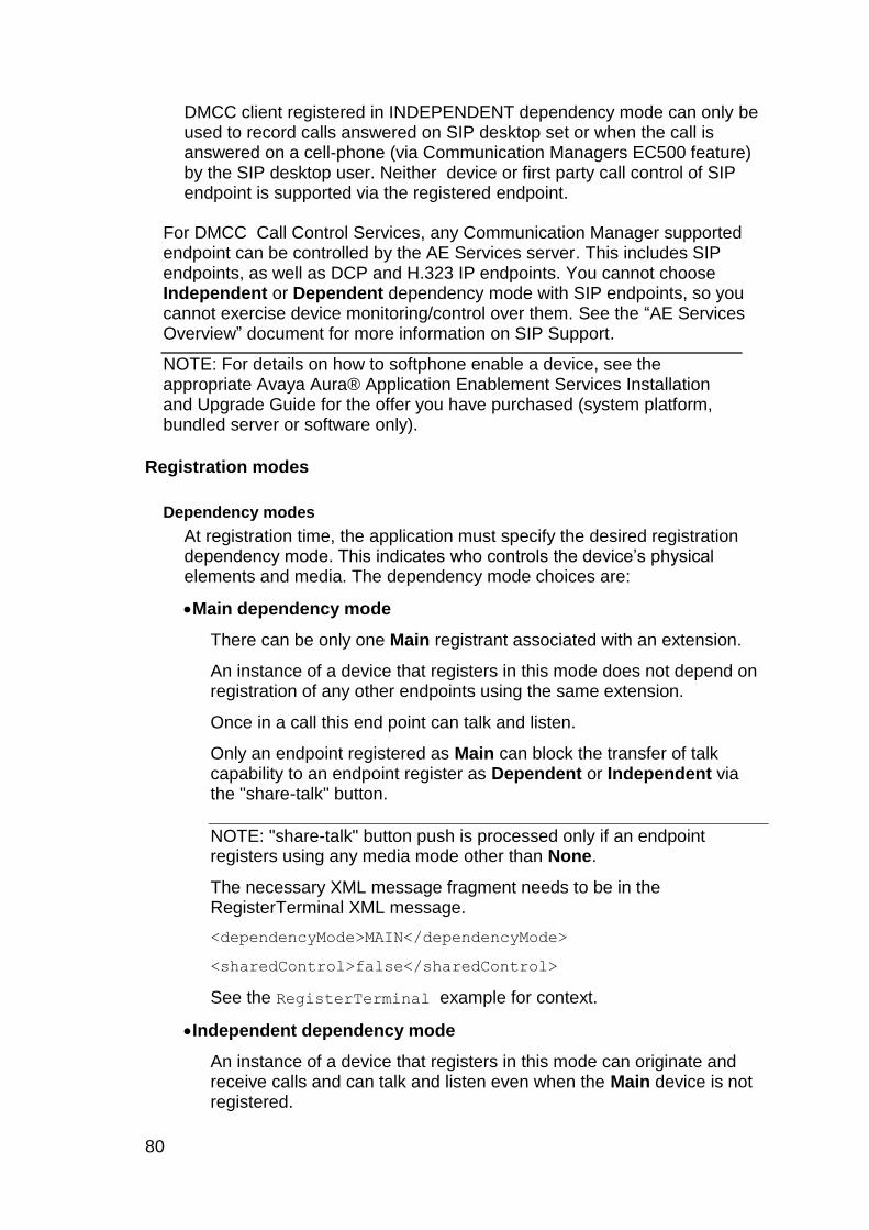
80
DMCC client registered in INDEPENDENT dependency mode can only be used to record calls answered on SIP desktop set or when the call is answered on a cell-phone (via Communication Managers EC500 feature) by the SIP desktop user. Neither device or first party call control of SIP endpoint is supported via the registered endpoint.
For DMCC Call Control Services, any Communication Manager supported endpoint can be controlled by the AE Services server. This includes SIP endpoints, as well as DCP and H.323 IP endpoints. You cannot choose Independent or Dependent dependency mode with SIP endpoints, so you cannot exercise device monitoring/control over them. See the “AE Services Overview” document for more information on SIP Support.
NOTE: For details on how to softphone enable a device, see the appropriate Avaya Aura® Application Enablement Services Installation and Upgrade Guide for the offer you have purchased (system platform, bundled server or software only).
Registration modes
Dependency modes
At registration time, the application must specify the desired registration dependency mode. This indicates who controls the device‟s physical elements and media. The dependency mode choices are:
Main dependency mode
There can be only one Main registrant associated with an extension.
An instance of a device that registers in this mode does not depend on registration of any other endpoints using the same extension.
Once in a call this end point can talk and listen.
Only an endpoint registered as Main can block the transfer of talk capability to an endpoint register as Dependent or Independent via the "share-talk" button.
NOTE: "share-talk" button push is processed only if an endpoint registers using any media mode other than None.
The necessary XML message fragment needs to be in the RegisterTerminal XML message.
<dependencyMode>MAIN</dependencyMode>
<sharedControl>false</sharedControl>
See the RegisterTerminal example for context.
Independent dependency mode
An instance of a device that registers in this mode can originate and receive calls and can talk and listen even when the Main device is not registered.

Chapter 3: Writing a client application
Application Enablement Services Device, Media and Call Control XML Programmer‟s Guide 81
If an end point registers as Main after an endpoint registers as Independent on the same extension, talk capability is transferred to the endpoint registered as Main.
An endpoint registered as Independent cannot block transfer of talk capability by pressing the "share-talk" button.
The necessary XML message fragment needs to be in the RegisterTerminal XML message.
<dependencyMode>INDEPENDENT</dependencyMode>
<sharedControl>false</sharedControl>
See the RegisterTerminal example for context.
Dependent dependency mode
A device will be allowed to register in this mode only if another instance of a device is already registered to Communication Manager (using the same extension) in Main mode.
A request to register using Dependent mode will fail unless another endpoint is already registered to that extension in Main mode.
Communication Manager will unregister a device registered in Dependent mode if the Main endpoint unregisters.
When on a call, endpoints registered as Dependent will be in listen-only mode.
An endpoint registered as Dependent cannot block transfer of talk capability by pressing the "share-talk" button.
The necessary XML message fragment needs to be in the RegisterTerminal XML message.
<dependencyMode>DEPENDENT</dependencyMode>
<sharedControl>false</sharedControl>
See the RegisterTerminal example for context.
For further information on the "share-talk" button see the "share-talk" button
When to use:
Main
Use this mode when you need to be able to answer calls, make calls, talk, or listen, regardless of the presence of other registrants.
This mode can be used with any Media Mode including No Media.
A simple IVR application would use Main mode.
Independent
Use this mode when you wish registration to succeed regardless of whether a Main registrant already exists.

82
This mode can be useful when two instances of an application register an extension that doesn‟t have an associated end-user telephone. One instance of the application would register in Main mode and the other in Independent mode. Communication Manager will allow either application to answer calls, make calls, talk (one at a time) or listen, immediately after they register.
Dependent
Use this mode when you wish registration to succeed only if a Main registrant already exists and you want to unregister when the Main registrant unregisters.
This mode can be useful if you wish to listen to a call whose device is already registered as Main.
This mode would also be useful if you wish to monitor/control a physical device.
Media modes
When a device is registered by an application, the application has access to the real-time protocol (RTP) media stream coming into and going out from the softphone.
There are four media modes available when a device is registered in Main dependency mode: server media, client media, telecommuter, and No Media.
When the device is registered in either Dependent or Independent dependency mode, then only server media, client media or No media is available to control the media stream.
The following table, Registration Dependency and Media modes, illustrates what media modes are allowed with each dependency mode.
Table 30: Registration Dependency and Media modes
Client Telecommuter Server No Media
Main Allowed3 Allowed2 Allowed2 Allowed
Dependent Allowed Not Allowed Allowed Allowed4
Independent Allowed Not Allowed Allowed Allowed
When multiple endpoints are registered to the same extensions, all endpoints see activity on other endpoints when status changes to the device‟s hookswitch, lamps, ringer, and display. An endpoint in this case would not be aware of the following action taken by another endpoint:
3 Corresponds to Exclusive Control in previous releases
4 Corresponds to Shared Control in previous releases. In this mode, the user of a telephone is
not notified of actions initiated by an application except through resulting status changes to the device‟s lamps and display. Also in this mode, the application is not notified of actions initiated by a user of the telephone except by status changes to device‟s hookswitch, lamps, ringer, and display.
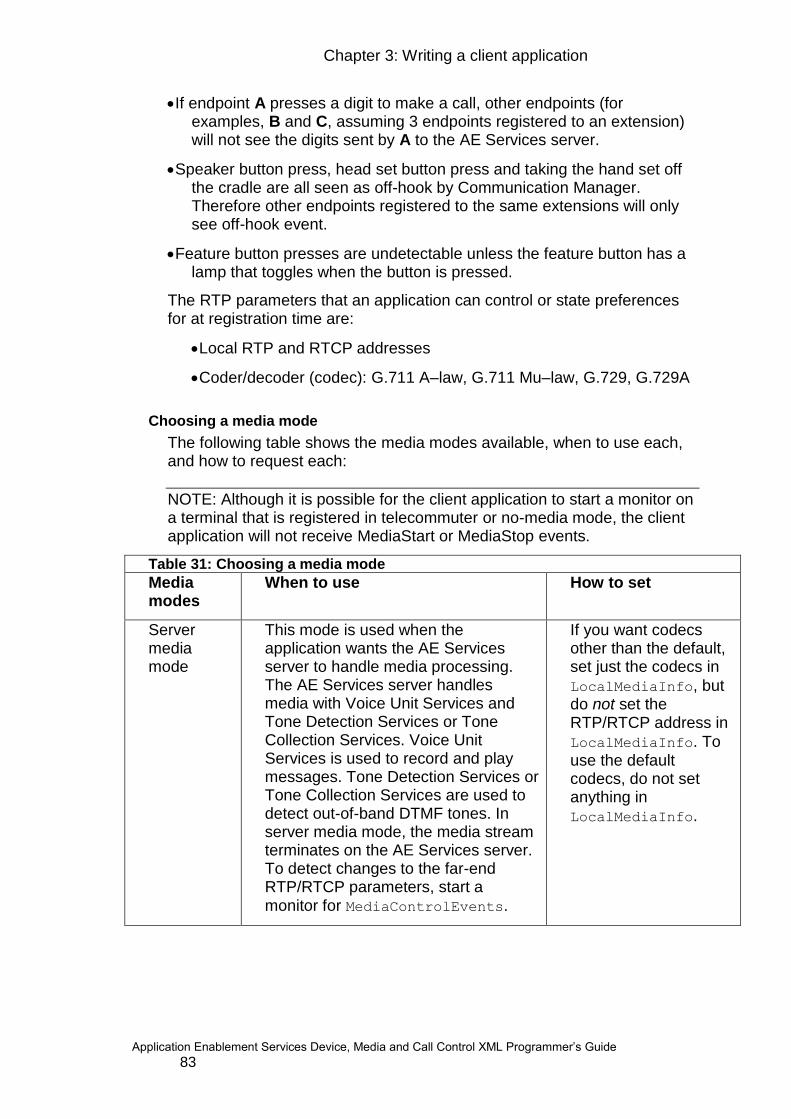
Chapter 3: Writing a client application
Application Enablement Services Device, Media and Call Control XML Programmer‟s Guide 83
If endpoint A presses a digit to make a call, other endpoints (for examples, B and C, assuming 3 endpoints registered to an extension) will not see the digits sent by A to the AE Services server.
Speaker button press, head set button press and taking the hand set off the cradle are all seen as off-hook by Communication Manager. Therefore other endpoints registered to the same extensions will only see off-hook event.
Feature button presses are undetectable unless the feature button has a lamp that toggles when the button is pressed.
The RTP parameters that an application can control or state preferences for at registration time are:
Local RTP and RTCP addresses
Coder/decoder (codec): G.711 A–law, G.711 Mu–law, G.729, G.729A
Choosing a media mode
The following table shows the media modes available, when to use each, and how to request each:
NOTE: Although it is possible for the client application to start a monitor on a terminal that is registered in telecommuter or no-media mode, the client application will not receive MediaStart or MediaStop events.
Table 31: Choosing a media mode
Media modes
When to use How to set
Server media mode
This mode is used when the application wants the AE Services server to handle media processing. The AE Services server handles media with Voice Unit Services and Tone Detection Services or Tone Collection Services. Voice Unit Services is used to record and play messages. Tone Detection Services or Tone Collection Services are used to detect out-of-band DTMF tones. In server media mode, the media stream terminates on the AE Services server. To detect changes to the far-end RTP/RTCP parameters, start a monitor for MediaControlEvents.
If you want codecs other than the default, set just the codecs in
LocalMediaInfo, but do not set the RTP/RTCP address in
LocalMediaInfo. To use the default codecs, do not set anything in
LocalMediaInfo.

84
Table 31: Choosing a media mode
Media modes
When to use How to set
Client media mode
This mode is used when application wants to process the media itself. The RTP stream can be terminated on any machine that can be controlled by the application. To detect out-of-band DTMF tones, start a monitor for
ToneDetectionEvents or
ToneCollectionEvents.
Set LocalMediaInfo's
RTP/RTCP address to the IP address and port where the media stream is to be terminated. If you want codecs other than the default, set the codecs
in LocalMediaInfo.
May also set media encryption. The media can be terminated on any machine that can be controlled by the application.
Telecommuter mode
This mode is used when an application wants the media to go to a real telephone. The real telephone can be an internal dial string to Communication Manager or a PSTN telephone number.
Although it is possible for the client application to start a monitor on a terminal that is registered in telecommuter mode, the client application will not receive events.
Set LocalMediaInfo's
telecommuter to the
telephone number of the real telephone that you are directing the media to.
No Media This mode is used when the application does not want an RTP stream to be setup to it by Communication Manager.
Note: Although it is possible for the client application to start a monitor on a terminal that is registered in no media mode, the client application will not receive events
Following are two examples of how to choose main dependency mode and server media mode:
<?xml version="1.0" encoding="utf-8"?>
<RegisterTerminalRequest
xmlns:xsi="http://www.w3.org/2001/XMLSchema-instance"
xmlns:xsd="http://www.w3.org/2001/XMLSchema"
xmlns="http://www.avaya.com/csta">

Chapter 3: Writing a client application
Application Enablement Services Device, Media and Call Control XML Programmer‟s Guide 85
<device typeOfNumber="other"
mediaClass="notKnown">4750::111.2.33.444:0</device>
<loginInfo>
<forceLogin>true</forceLogin>
<sharedControl>false</sharedControl>
<password>1234</password>
<mediaMode>SERVER</mediaMode>
<dependencyMode>MAIN</dependencyMode>
</loginInfo>
<localMediaInfo>
<codecs>g729</codecs>
</localMediaInfo>
</RegisterTerminalRequest>
or
<?xml version="1.0" encoding="utf-8"?>
<RegisterTerminalRequest
xmlns:xsi="http://www.w3.org/2001/XMLSchema-instance"
xmlns:xsd="http://www.w3.org/2001/XMLSchema"
xmlns="http://www.avaya.com/csta">
<device typeOfNumber="other"
mediaClass="notKnown">4751::111.2.33.444:0</device>
<loginInfo>
<forceLogin>true</forceLogin>
<sharedControl>false</sharedControl>
<password>1234</password>
<mediaMode>SERVER</mediaMode>
<dependencyMode>MAIN</dependencyMode>
</loginInfo>
</RegisterTerminalRequest>
Following is an example of how to choose main dependency mode and client media mode:
<?xml version="1.0" encoding="utf-8"?>
<RegisterTerminalRequest
xmlns:xsi="http://www.w3.org/2001/XMLSchema-instance"
xmlns:xsd="http://www.w3.org/2001/XMLSchema"
xmlns="http://www.avaya.com/csta">
<device typeOfNumber="other"
mediaClass="notKnown">4750::111.2.33.444:0</device>
<loginInfo>

86
<forceLogin>true</forceLogin>
<sharedControl>false</sharedControl>
<password>1234</password>
<mediaMode>CLIENT</mediaMode>
<dependencyMode>MAIN</dependencyMode>
</loginInfo>
<localMediaInfo>
<rtpAddress>
<address>111.2.33.444</address>
<port>4725</port>
</rtpAddress>
<rtcpAddress>
<address>111.2.33.444</address>
<port>4726</port>
</rtcpAddress>
<codecs>g729</codecs>
<codecs>g729A</codecs>
<packetSize>20</packetSize>
<encryptionList>aes</encryptionList>
<encryptionList>none</encryptionList>
</localMediaInfo>
</RegisterTerminalRequest>
Following is an example of how to choose main dependency mode and telecommuter media mode:
<?xml version="1.0" encoding="utf-8"?>
<RegisterTerminalRequest
xmlns:xsi="http://www.w3.org/2001/XMLSchema-instance"
xmlns:xsd="http://www.w3.org/2001/XMLSchema"
xmlns="http://www.avaya.com/csta">
<device typeOfNumber="other"
mediaClass="notKnown">4750::111.2.33.444:0</device>
<loginInfo>
<forceLogin>true</forceLogin>
<sharedControl>false</sharedControl>
<password>1234</password>
<telecommuterExtension>3035551234</telecommuterExtension>

Chapter 3: Writing a client application
Application Enablement Services Device, Media and Call Control XML Programmer‟s Guide 87
<mediaMode>TELECOMMUTER</mediaMode>
<dependencyMode>MAIN</dependencyMode>
</loginInfo>
</RegisterTerminalRequest>
The following table shows the media control capabilities of the Application Enablement Services server for both server media mode and client media mode.
Table 32: Media Control Capabilities
Media control capabilities server media mode
client media mode
Record media from a call into a WAV file
provided by the server
provided by the application
Dub a recording with the contents of another compatible WAV file
provided by the server
provided by the application
Play a voice announcement or tone from a prerecorded WAV file
provided by the server
provided by the application
Play a list of prerecorded announcements from separate WAV files
provided by the server
provided by the application
Stop, pause, or resume outstanding play or record operations
provided by the server
provided by the application
Detect out-of-band DTMF tones provided by the server
provided by the application
Detect inband DTMF tones provided by the server
provided by the application
Manage media related event monitors
provided by the server
provided by the application
Originate and terminate RTP streams on any machine that the application has control of
provided by the applicationa
Media encryption provided by the server
provided by the applicationa
a. Media encryption must be done by the application unless the application is using the Avaya provided client media stack in which case it will be provided by the server.
Redirecting media
This request is provided by Registration Services. It allows an application that has registered a device in client media mode, to redirect the media to any destination, even in the middle of a call.
88
If a call is underway, redirecting the media stream causes the current media stream to be directed to the requested location; otherwise, it causes any future media stream to be directed to the requested location.
Note that there is a known limitation in the implementation of this feature in Communication Manager. The CM expectation is that the media will be directed to a new IP destination. Thus, when CM checks the RedirectMedia request for a new destination, it only checks if the IP address has changed (not the port number). Thus, a RedirectMedia request that specifies the same IP address, but a different port number, will not be redirected for the call in progress. However, there is a workaround for this scenario. This workaround requires the application to send two RedirectMedia requests, instead of one. For example, if the media is currently going to IP address 10.9.20.17 and port 4725, and you want to redirect it to port 4730 at the same IP address, you could do the following: 1) RedirectMedia to IP address 0.0.0.0 and port 4725 (specifying a null IP address will effectively stop the media to the device, but will not end the call) 2) RedirectMedia to IP address 10.9.20.17 and port 4730 (since the IP address has now changed, Communication Manager will correctly process this request)
The "share-talk" button
Although Communication Manager 5.0 (and later releases) allows up to three Device, Media and Call Control station clients to register to one extension, for each extension only one "Talk" time slot is used. If there are three endpoints registered with that extension, only one at a time will be able to talk, but all three can listen.
If your application wants the ability to share the talk capability, you will use the "share-talk" button. The "share-talk" button must have been administered in Communication Manager. For information on how to administer the share-talk button on Communication Manager, please see
the Avaya Aura Application Enablement Services Administration and Maintenance Guide.
Communication Manager will process a "share-talk" button push only if the media mode of that endpoint is not No Media and the extension is in a call.
Once in a call, an endpoint registered as Main can press this button to block any endpoint registered as Dependent or Independent from taking over the talk capability. The Main endpoint can then unblock it by pushing this button again.
If a Main endpoint has not blocked the talk capability, a Dependent or Independent endpoint can press this button to acquire the "Talk" capability. The Dependent or Independent endpoint can press this button a second time to move the talk capability back to the Main endpoint.
Chapter 3: Writing a client application
Application Enablement Services Device, Media and Call Control XML Programmer‟s Guide 89
Interpretation of the ’share-talk’ button lamp state
By an endpoint registered as Main:
Steady On
The Main endpoint currently has the Talk capability. If Main presses the button while in this state, the Talk capability will be blocked (see Flutter).
Flutter
The Main has blocked the talk capability from being taken over by a Dependent or Independent endpoint. Main can unblock by pressing this button one more time and the lamp will transit back to "Steady On".
Off
A Dependent or Independent endpoint has taken over the talk capability. If a Main endpoint wants to talk it can take over the talk capability at any time by pressing the button (lamp will transit back to "Steady On" after the button push).
By an endpoint registered as Dependent or Independent:
Steady On
The Dependent or Independent endpoint currently has the Talk capability. When this transition happens Communication Manager will turn the "share-talk" button lamp off at other endpoints associated with this extension. While in this state, a Dependent or Independent endpoint can transfer the talk capability back to Main by pushing the button.
Flutter
The Main has blocked the talk capability from being taken over; The Dependent or Independent endpoint cannot obtain the talk capability.
Off
A Dependent or Independent endpoint has no Talk capability, however it can take over the Talk capability if it desires.
Choosing a codec
A codec is the algorithm used to encode and decode audio media. For devices choosing media modes of either client-media or server-media, the application can optionally specify at registration time what codecs are preferred for the device. The codec options are:
G.711 A-law (g711A)
G.711 Mu-law (g711U)
G.729 (g729)
G.729 Annex A (g729A)
G.723 (client media mode only)
90
Specify the set of codecs your application supports using the
Registerterminal request as shown below. If you do not specify a set of
codecs in the RegisterTerminal request, AE Services will default to G.711 A-law as the first choice and G.711 Mu-law as the second choice. If Communication Manager cannot satisfy your request for specific codecs, then calls will still go through, but there will be no media.
NOTE: For server media mode you cannot specify a mixture of G.711 and G.729 codecs for a single device. This is because there is no conversion offered by the server.
The necessary XML message fragment needs to be in the
RegisterTerminal XML message.
<localMediaInfo>
<codecs>g729</codecs>
</localMediaInfo>
See the RegisterTerminal example for context.
For more information about selecting and administering network regions and their codecs, see the "Administering Communication Manager" chapter of the appropriate Avaya Aura® Application Enablement Services Installation and Upgrade Guide for the offer you have purchased (AE Services System Platform, bundled server or software only).
Choosing the media encryption
For devices choosing media modes of either client or server media, the application can optionally specify, at registration time, what media encryption is preferred for the device‟s media stream.
The media encryption options are:
Advanced Encryption Scheme (AES)
none (that is no encryption of the media stream)
Specify the set of encryption options your application supports using the
RegisterTerminal request as shown below. If you do not specify a set of
encryption options the AE Services server will default to "none" (no media encryption).
The necessary XML message fragment needs to be in the
RegisterTerminal XML message.
<localMediaInfo>
<encryption>aes</encryption>
</localMediaInfo>
See the RegisterTerminal example for context.

Chapter 3: Writing a client application
Application Enablement Services Device, Media and Call Control XML Programmer‟s Guide 91
The following is the associated response showing that AES encryption was granted and signaling encryption is enabled (as indicated by the "pin-eke" response).
<?xml version="1.0" encoding="UTF-8"?>
<RegisterTerminalResponse xmlns="http://www.avaya.com/csta">
<device typeOfNumber="other"
mediaClass=""
bitRate="constant">
2100::192.123.45.67:0</device>
<signalingEncryption>pin-eke</signalingEncryption>
<code>1</code>
</RegisterTerminalResponse>
Telephony Logic
AE Services notifies your application when requested telephony events occur:
Registration events indicate unregistration by Communication Manager.
Physical Device events indicate changes to the status of the ringer, display, and lamps.
Media Control events indicate when the media stream parameters have changed.
Voice Unit events indicate the status of recording and playing messages.
Tone Detection events indicate when a DTMF digit is received and when collection begins and ends.
Tone Collection events indicate when specified tone retrieval criteria are met.
Call Control events indicate changes to the status of the call.
Logical Device Feature events indicate when forwarding and do not disturb events occur.
System Status events indicate when a TSAPI Tlink comes up or goes down.
Call Associated events indicate when a regenerated telephony tone request fails

92
Device and Media Control
Monitoring and controlling physical elements
Physical elements of a device are monitored and controlled with Physical Device Services..
To monitor for physical device events, you must request notification of
these events through the MonitorStart XML message as described in Requesting notification of events.
Device based call control can be accomplished with a combination of:
determining the current status of physical elements on a device, such as requesting the list of buttons administered for the device
monitoring for particular physical device events, such as when the phone starts ringing
activating physical elements of the device, such as going offhook
Knowing what buttons are administered
If your application needs to press any buttons or determine which lamps have changed state, you will need to know what buttons are administered on the device. Buttons are assigned to devices during station administration via the Communication Manager system access terminal
(SAT) interface. Your application must send the GetButtonInformation
request in order to get the list of buttons administered for a device. Each button item in the list includes the following information:
button identifier - indicates the address or location of the button. Its value is one of the Button ID Constants listed in Appendix C: Constant Values. Constants are available for both administered buttons and fixed buttons (those buttons that are preset and pre-labeled on a telephone set).
button function - indicates what the button does when pressed. Its value is one of the Button Function Constants listed in Appendix C: Constant Values.
associated extension - indicates whether there is an extension number associated with this button and what the extension number is.
associated lamp - indicates whether there is a lamp associated with the button. If there is, its lamp identifier is the same as the button identifier.
Chapter 3: Writing a client application
Application Enablement Services Device, Media and Call Control XML Programmer‟s Guide 93
NOTE: There is no direct indication provided by the API to the application of changes to the provisioned information for a monitored device. Thus collecting the device's configuration when the application initializes is an incomplete solution. A robust application should periodically validate that the current configuration of the device is aligned with the representation of that configuration as derived by the application. In order to do so, an audit of the information should be developed and run at some recurring cycle, or when unexpected feedback to button presses is received. An audit can be realized by utilizing the GetButtonInformation request and comparing the results with the previously obtained information.
Detecting an incoming call
When a call comes into a device, these three changes occur to the physical device:
The phone rings.
A green call appearance lamp flashes.
The display changes to show caller information.
The following events are sent to an application that requested notification of these events:
RingerStatusEvent - The ring pattern is supplied in the event structure. For a list of possible ring patterns see Appendix C: Constant Values for Ringer Pattern Constants. Following is an
example of the structure of the RingerStatusEvent that a client application may receive. Since this message is an asynchronous
message sent by the server there is a MonitorCrossRefID which
is very important for correlating the message to the MonitorStart.
<?xml version="1.0" encoding="UTF-8"?>
<RingerStatusEvent xmlns="http://www.ecma-
international.org/standards/ecma-323/csta/ ed3">
<monitorCrossRefID>17</monitorCrossRefID>
<device>
<deviceIdentifier typeOfNumber="other"
mediaClass="voice"
bitRate="constant">4750::111.2.33.444:0</deviceIdentifier>
</device>
<ringer>0000</ringer>
<ringMode>ringing</ringMode>
<ringPattern>11</ringPattern>
</RingerStatusEvent>
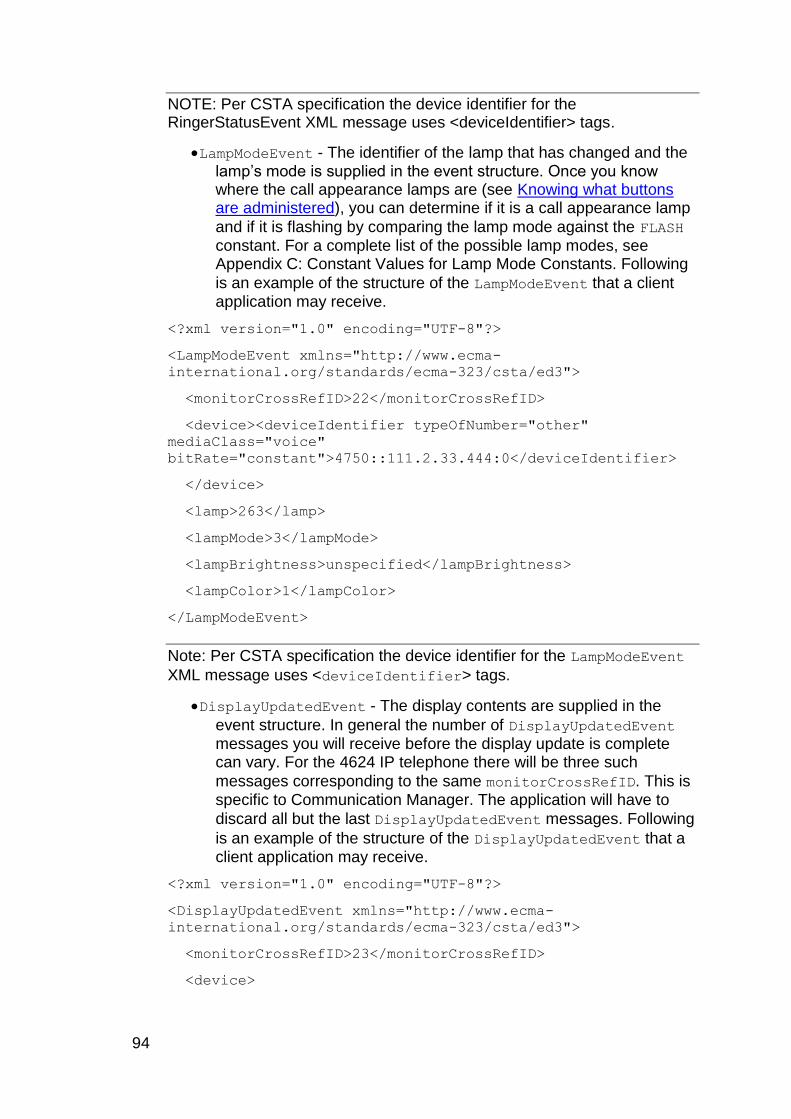
94
NOTE: Per CSTA specification the device identifier for the RingerStatusEvent XML message uses <deviceIdentifier> tags.
LampModeEvent - The identifier of the lamp that has changed and the lamp‟s mode is supplied in the event structure. Once you know where the call appearance lamps are (see Knowing what buttons are administered), you can determine if it is a call appearance lamp
and if it is flashing by comparing the lamp mode against the FLASH constant. For a complete list of the possible lamp modes, see Appendix C: Constant Values for Lamp Mode Constants. Following
is an example of the structure of the LampModeEvent that a client application may receive.
<?xml version="1.0" encoding="UTF-8"?>
<LampModeEvent xmlns="http://www.ecma-
international.org/standards/ecma-323/csta/ed3">
<monitorCrossRefID>22</monitorCrossRefID>
<device><deviceIdentifier typeOfNumber="other"
mediaClass="voice"
bitRate="constant">4750::111.2.33.444:0</deviceIdentifier>
</device>
<lamp>263</lamp>
<lampMode>3</lampMode>
<lampBrightness>unspecified</lampBrightness>
<lampColor>1</lampColor>
</LampModeEvent>
Note: Per CSTA specification the device identifier for the LampModeEvent
XML message uses <deviceIdentifier> tags.
DisplayUpdatedEvent - The display contents are supplied in the
event structure. In general the number of DisplayUpdatedEvent messages you will receive before the display update is complete can vary. For the 4624 IP telephone there will be three such
messages corresponding to the same monitorCrossRefID. This is specific to Communication Manager. The application will have to
discard all but the last DisplayUpdatedEvent messages. Following
is an example of the structure of the DisplayUpdatedEvent that a client application may receive.
<?xml version="1.0" encoding="UTF-8"?>
<DisplayUpdatedEvent xmlns="http://www.ecma-
international.org/standards/ecma-323/csta/ed3">
<monitorCrossRefID>23</monitorCrossRefID>
<device>
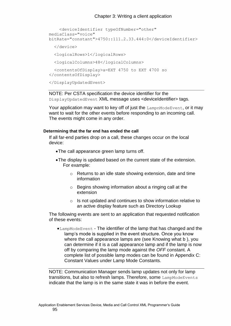
Chapter 3: Writing a client application
Application Enablement Services Device, Media and Call Control XML Programmer‟s Guide 95
<deviceIdentifier typeOfNumber="other"
mediaClass="voice"
bitRate="constant">4750::111.2.33.444:0</deviceIdentifier>
</device>
<logicalRows>1</logicalRows>
<logicalColumns>48</logicalColumns>
<contentsOfDisplay>a=EXT 4750 to EXT 4700 so
</contentsOfDisplay>
</DisplayUpdatedEvent>
NOTE: Per CSTA specification the device identifier for the
DisplayUpdatedEvent XML message uses <deviceIdentifier> tags.
Your application may want to key off of just the LampnModeEvent, or it may want to wait for the other events before responding to an incoming call. The events might come in any order.
Determining that the far end has ended the call
If all far-end parties drop on a call, these changes occur on the local device:
The call appearance green lamp turns off.
The display is updated based on the current state of the extension. For example:
o Returns to an idle state showing extension, date and time information
o Begins showing information about a ringing call at the extension
o Is not updated and continues to show information relative to an active display feature such as Directory Lookup
The following events are sent to an application that requested notification of these events:
LampModeEvent - The identifier of the lamp that has changed and the lamp‟s mode is supplied in the event structure. Once you know where the call appearance lamps are (see Knowing what b ), you can determine if it is a call appearance lamp and if the lamp is now off by comparing the lamp mode against the OFF constant. A complete list of possible lamp modes can be found in Appendix C: Constant Values under Lamp Mode Constants.
NOTE: Communication Manager sends lamp updates not only for lamp
transitions, but also to refresh lamps. Therefore, some LampModeEvents indicate that the lamp is in the same state it was in before the event.
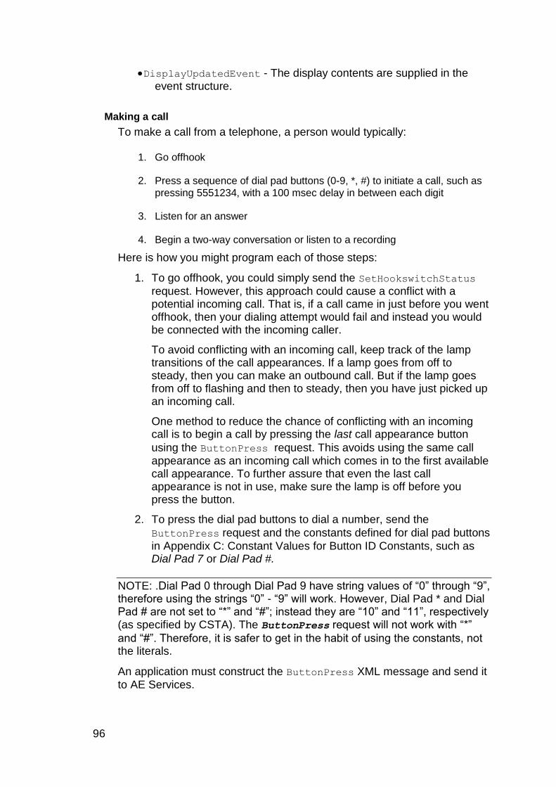
96
DisplayUpdatedEvent - The display contents are supplied in the event structure.
Making a call
To make a call from a telephone, a person would typically:
1. Go offhook
2. Press a sequence of dial pad buttons (0-9, *, #) to initiate a call, such as
pressing 5551234, with a 100 msec delay in between each digit
3. Listen for an answer
4. Begin a two-way conversation or listen to a recording
Here is how you might program each of those steps:
1. To go offhook, you could simply send the SetHookswitchStatus
request. However, this approach could cause a conflict with a potential incoming call. That is, if a call came in just before you went offhook, then your dialing attempt would fail and instead you would be connected with the incoming caller.
To avoid conflicting with an incoming call, keep track of the lamp transitions of the call appearances. If a lamp goes from off to steady, then you can make an outbound call. But if the lamp goes from off to flashing and then to steady, then you have just picked up an incoming call.
One method to reduce the chance of conflicting with an incoming call is to begin a call by pressing the last call appearance button
using the ButtonPress request. This avoids using the same call appearance as an incoming call which comes in to the first available call appearance. To further assure that even the last call appearance is not in use, make sure the lamp is off before you press the button.
2. To press the dial pad buttons to dial a number, send the
ButtonPress request and the constants defined for dial pad buttons
in Appendix C: Constant Values for Button ID Constants, such as Dial Pad 7 or Dial Pad #.
NOTE: .Dial Pad 0 through Dial Pad 9 have string values of “0” through “9”, therefore using the strings “0” - “9” will work. However, Dial Pad * and Dial Pad # are not set to “*” and “#”; instead they are “10” and “11”, respectively (as specified by CSTA). The ButtonPress request will not work with “*”
and “#”. Therefore, it is safer to get in the habit of using the constants, not the literals.
An application must construct the ButtonPress XML message and send it to AE Services.
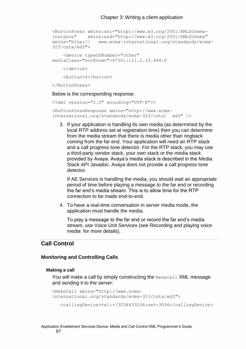
Chapter 3: Writing a client application
Application Enablement Services Device, Media and Call Control XML Programmer‟s Guide 97
<ButtonPress xmlns:xsi="http://www.w3.org/2001/XMLSchema-
instance" xmlns:xsd="http://www.w3.org/2001/XMLSchema"
xmlns="http:// www.ecma-international.org/standards/ecma-
323/csta/ed3">
<device typeOfNumber="other"
mediaClass="notKnown">4750::111.2.33.444:0
</device>
<button>4</button>
</ButtonPress>
Below is the corresponding response:
<?xml version="1.0" encoding="UTF-8"?>
<ButtonPressResponse xmlns="http://www.ecma-
international.org/standards/ecma-323/csta/ ed3" />
3. If your application is handling its own media (as determined by the local RTP address set at registration time) then you can determine from the media stream that there is media other than ringback coming from the far end. Your application will need an RTP stack and a call progress tone detector. For the RTP stack, you may use a third-party vendor stack, your own stack or the media stack provided by Avaya. Avaya‟s media stack is described in the Media Stack API Javadoc. Avaya does not provide a call progress tone detector.
If AE Services is handling the media, you should wait an appropriate period of time before playing a message to the far end or recording the far end‟s media stream. This is to allow time for the RTP connection to be made end-to-end.
4. To have a real-time conversation in server media mode, the application must handle the media.
To play a message to the far end or record the far end‟s media stream, use Voice Unit Services (see Recording and playing voice media for more details).
Call Control
Monitoring and Controlling Calls
Making a call
You will make a call by simply constructing the MakeCall XML message and sending it to the server:
<MakeCall xmlns="http://www.ecma-
international.org/standards/ecma-323/csta/ed3">
<callingDevice>tel:+13034433036;ext=3036</callingDevice>
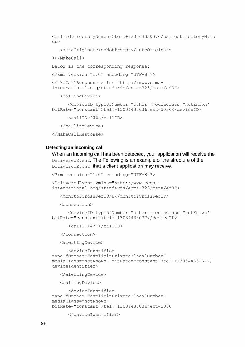
98
<calledDirectoryNumber>tel:+13034433037</calledDirectoryNumb
er>
<autoOriginate>doNotPrompt</autoOriginate
></MakeCall>
Below is the corresponding response:
<?xml version="1.0" encoding="UTF-8"?>
<MakeCallResponse xmlns="http://www.ecma-
international.org/standards/ecma-323/csta/ed3">
<callingDevice>
<deviceID typeOfNumber="other" mediaClass="notKnown"
bitRate="constant">tel:+13034433036;ext=3036</deviceID>
<callID>436</callID>
</callingDevice>
</MakeCallResponse>
Detecting an incoming call
When an incoming call has been detected, your application will receive the
DeliveredEvent. The Following is an example of the structure of the
DeliveredEvent that a client application may receive.
<?xml version="1.0" encoding="UTF-8"?>
<DeliveredEvent xmlns="http://www.ecma-
international.org/standards/ecma-323/csta/ed3">
<monitorCrossRefID>8</monitorCrossRefID>
<connection>
<deviceID typeOfNumber="other" mediaClass="notKnown"
bitRate="constant">tel:+13034433037</deviceID>
<callID>436</callID>
</connection>
<alertingDevice>
<deviceIdentifier
typeOfNumber="explicitPrivate:localNumber"
mediaClass="notKnown" bitRate="constant">tel:+13034433037</
deviceIdentifier>
</alertingDevice>
<callingDevice>
<deviceIdentifier
typeOfNumber="explicitPrivate:localNumber"
mediaClass="notKnown"
bitRate="constant">tel:+13034433036;ext=3036
</deviceIdentifier>
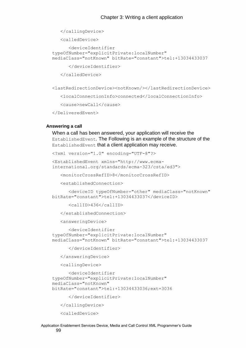
Chapter 3: Writing a client application
Application Enablement Services Device, Media and Call Control XML Programmer‟s Guide 99
</callingDevice>
<calledDevice>
<deviceIdentifier
typeOfNumber="explicitPrivate:localNumber"
mediaClass="notKnown" bitRate="constant">tel:+13034433037
</deviceIdentifier>
</calledDevice>
<lastRedirectionDevice><notKnown/></lastRedirectionDevice>
<localConnectionInfo>connected</localConnectionInfo>
<cause>newCall</cause>
</DeliveredEvent>
Answering a call
When a call has been answered, your application will receive the
EstablishedEvent. The Following is an example of the structure of the
EstablishedEvent that a client application may receive.
<?xml version="1.0" encoding="UTF-8"?>
<EstablishedEvent xmlns="http://www.ecma-
international.org/standards/ecma-323/csta/ed3">
<monitorCrossRefID>8</monitorCrossRefID>
<establishedConnection>
<deviceID typeOfNumber="other" mediaClass="notKnown"
bitRate="constant">tel:+13034433037</deviceID>
<callID>436</callID>
</establishedConnection>
<answeringDevice>
<deviceIdentifier
typeOfNumber="explicitPrivate:localNumber"
mediaClass="notKnown" bitRate="constant">tel:+13034433037
</deviceIdentifier>
</answeringDevice>
<callingDevice>
<deviceIdentifier
typeOfNumber="explicitPrivate:localNumber"
mediaClass="notKnown"
bitRate="constant">tel:+13034433036;ext=3036
</deviceIdentifier>
</callingDevice>
<calledDevice>
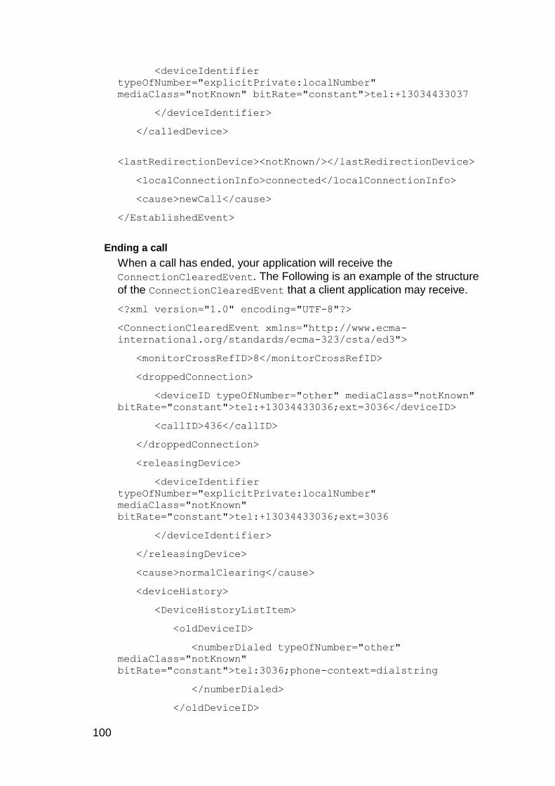
100
<deviceIdentifier
typeOfNumber="explicitPrivate:localNumber"
mediaClass="notKnown" bitRate="constant">tel:+13034433037
</deviceIdentifier>
</calledDevice>
<lastRedirectionDevice><notKnown/></lastRedirectionDevice>
<localConnectionInfo>connected</localConnectionInfo>
<cause>newCall</cause>
</EstablishedEvent>
Ending a call
When a call has ended, your application will receive the
ConnectionClearedEvent. The Following is an example of the structure
of the ConnectionClearedEvent that a client application may receive.
<?xml version="1.0" encoding="UTF-8"?>
<ConnectionClearedEvent xmlns="http://www.ecma-
international.org/standards/ecma-323/csta/ed3">
<monitorCrossRefID>8</monitorCrossRefID>
<droppedConnection>
<deviceID typeOfNumber="other" mediaClass="notKnown"
bitRate="constant">tel:+13034433036;ext=3036</deviceID>
<callID>436</callID>
</droppedConnection>
<releasingDevice>
<deviceIdentifier
typeOfNumber="explicitPrivate:localNumber"
mediaClass="notKnown"
bitRate="constant">tel:+13034433036;ext=3036
</deviceIdentifier>
</releasingDevice>
<cause>normalClearing</cause>
<deviceHistory>
<DeviceHistoryListItem>
<oldDeviceID>
<numberDialed typeOfNumber="other"
mediaClass="notKnown"
bitRate="constant">tel:3036;phone-context=dialstring
</numberDialed>
</oldDeviceID>
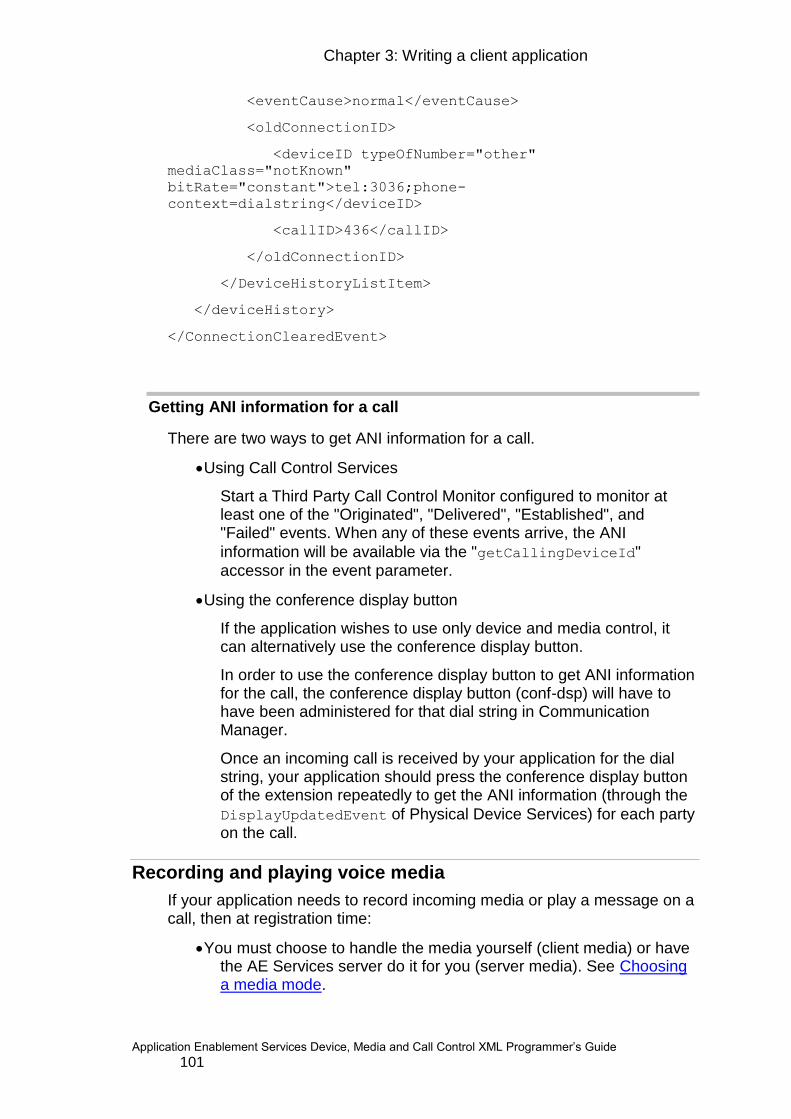
Chapter 3: Writing a client application
Application Enablement Services Device, Media and Call Control XML Programmer‟s Guide 101
<eventCause>normal</eventCause>
<oldConnectionID>
<deviceID typeOfNumber="other"
mediaClass="notKnown"
bitRate="constant">tel:3036;phone-
context=dialstring</deviceID>
<callID>436</callID>
</oldConnectionID>
</DeviceHistoryListItem>
</deviceHistory>
</ConnectionClearedEvent>
Getting ANI information for a call
There are two ways to get ANI information for a call.
Using Call Control Services
Start a Third Party Call Control Monitor configured to monitor at least one of the "Originated", "Delivered", "Established", and "Failed" events. When any of these events arrive, the ANI
information will be available via the "getCallingDeviceId" accessor in the event parameter.
Using the conference display button
If the application wishes to use only device and media control, it can alternatively use the conference display button.
In order to use the conference display button to get ANI information for the call, the conference display button (conf-dsp) will have to have been administered for that dial string in Communication Manager.
Once an incoming call is received by your application for the dial string, your application should press the conference display button of the extension repeatedly to get the ANI information (through the
DisplayUpdatedEvent of Physical Device Services) for each party on the call.
Recording and playing voice media
If your application needs to record incoming media or play a message on a call, then at registration time:
You must choose to handle the media yourself (client media) or have the AE Services server do it for you (server media). See Choosing a media mode.

102
This section describes how to use Voice Unit Services to have the AE Services server record and play media for you.
Some basic rules of Voice Unit Services are:
Wave files
All digital audio files that are created or played using Voice Unit Services are in the Wave Resource Interchange File Format (RIFF). The standard Wave file structure is used for all encoded media types. See http://www.sonicspot.com/guide/wavefiles.html for a description of the Wave structure.
G.729 formatted files, however, use non-standard field values in some of the standard format chunk fields. They are:
o The compression code value is 131 (0x0083).
o The block align value is 10 (0x000A).
o The bits per sample value is 1 (0x0001).
An external G.729 converter is required to convert a G.729 Wave file into a standard RIFF Wave file that can be played.
Files on AE Services
All Wave files are assumed to be on the AE Services server machine in the directories specified in the AE Services Management Console under the media properties as the player directory and the recorder directory.
Note: These two directories do not have to be the same. These directories
are the root directory of the relative paths specified in the PlayMessage
and RecordMessage requests.
Encoding algorithms
Files to be played can be encoded in these formats:
o PCM 8 bit or 16 bit
o G.711 A-law
o G.711 Mu-law
o G.729
o G.729A
Recordings can be made of calls in these formats
o PCM 8 bit or 16 bit
o G.711 A-law
o G.711 Mu-law
o G.729
Chapter 3: Writing a client application
Application Enablement Services Device, Media and Call Control XML Programmer‟s Guide 103
Note: Codecs must be specified at registration time.While in server media mode you cannot specify a mixture of G.711 and G.729 codecs for a single device. This is because there is no conversion offered by the server.
Conversions between encoding algorithms
Files to be played can be converted from any PCM type to any G.711. No other conversions are supported for playing.
Messages to be recorded can be converted from G.711 to PCM. No other conversions are supported for recording.
Using with Tone Detection or Tone Collection Services
The Voice Unit Services player and recorder may be setup to detect DTMF tones at the same time Tone Detection or Tone Collection Services is being used. However, there is no guarantee which service will detect a tone first.
Note: While in server or client mode, the MediaStartEvent, contains the
codec that CM has selected to be used by the endpoint.
Recording
To record the RTP media stream of a device, send the Voice Unit Services
RecordMessage request. This request records only the media coming from other parties on the call to the device; not the media that is being played
from this device using the Voice Unit Services PlayMessage request. Only
media packets that are received are recorded; lost packets are not replaced.
The application can specify an alphanumeric filename for the recording or let the filename default to a format of <timestamp><extension>.wav. The alphanumeric filename may contain a relative directory path. Filenames specified for recorded files must be relative to the configured directory, their directories must already exist, and recordings cannot overwrite an existing file. If it is defaulted, then the resulting filename is returned in the
RecordMessageResponse message.
Since recording is associated with a device rather than a call, a recording could contain the incoming media from multiple calls. Recording continues until one of the following occurs:
o Application explicitly stops the recording by sending a Voice Unit Services Stop request (stops both playing and recording) or by sending
an Extended Voice Unit Services StopRecording request.
o Application requests that AE Services automatically stop the recording when a specified termination criterion is met. Multiple termination criteria can be specified in which case the first criterion that is met stops the recording. Termination criteria options include:
o When a DTMF tone is received by the device.

104
To request this termination criterion, set the termination
parameter‟s terminating conditions so that DTMFDigitDetected is set to true.
o When recording reaches a specified duration.
To request this termination criterion, set the maxDuration parameter to the maximum number of milliseconds allowed for the recording.
If you wish to record one entire call and only one call, then your application can monitor the lamp events to determine when the call has ended and explicitly stop the recording after the call has ended.
NOTE: No negative acknowledgement is received if the application requests that recording stop when there is no active recording.
Once an active recording on a device has been stopped, a StopEvent sent to the application indicates that the recording has finished and the recorded file is ready for the application.
The recording can also be:
o suspended temporarily - with the Voice Unit Services Suspend request (suspends both recording and playing) or with the Extended Voice Unit
Services SuspendRecording request.
o dubbed with another recording - with the Extended Voice Unit Service
StartDubbing and StopDubbing requests. See next section for more information on dubbing.
o resumed - with the Voice Unit Services Resume request (resumes both recording and playing) or with the Extended Voice Unit Services
ResumeRecording request.
o stopped - with the Voice Unit Services Stop request (stops both recording and playing) or the Extended Voice Unit Services
StopRecording request.
o deleted - with the Voice Unit Services DeleteMessage request.
To record a message an application must construct the RecordMessage
XML message and send it to AE Services.
<?xml version="1.0" encoding="UTF-8"?>
<RecordMessage xmlns="http://www.ecma.ch/standards/ecma-
323/csta/
ed2">
<callToBeRecorded>
<deviceID typeOfNumber="other" mediaClass=""
bitRate="constant">4750::111.2.33.444:0</deviceID>
</callToBeRecorded>
</RecordMessage>

Chapter 3: Writing a client application
Application Enablement Services Device, Media and Call Control XML Programmer‟s Guide 105
Below is the corresponding response:
<?xml version="1.0" encoding="UTF-8"?>
<RecordMessageResponse xmlns="http://www.ecma-
international.org/standards/ecma-323/ csta/ed3">
<resultingMessage>0</resultingMessage>
<extensions>
<privateData>
<private>
<RecordMessageResponsePrivateData
xmlns:ns1="http://www.avaya.com/csta"
xmlns:xsi="http://www.w3.org/2001/XMLSchema-instance"
xsi:type="RecordMessageResponsePrivateData">
<timestamp>1080520327543</timestamp>
<filename>200403281732074750</filename>
</RecordMessageResponsePrivateData>
</private>
</privateData>
</extensions>
</RecordMessageResponse>
NOTE: Per CSTA specification the device identifier for the RecordMessage XML message uses the tag <deviceID>
Dubbing
A recording can be dubbed with another Wave file by sending the
Extended Voice Unit Services StartDubbing and StopDubbing requests. Dubbing records the specified Wave file over the recording repeatedly from
the time the StartDubbing request is sent until the StopDubbing request is sent. This may be helpful to avoid recording sensitive information such as a spoken password or other private or security-based information.
Since the application must explicitly stop the dubbing, the application must have the logic to know when to stop. It may be based on time, or an incoming DTMF tone such as “#”, or a manual action by an agent who is monitoring events.
Playing
To play one or more messages to the RTP stream of a call as if the message(s) are coming from the device, send the Voice Unit Services
PlayMessage request. The message(s) can be played once, multiple
times, for a particular duration or until a DTMF tone is received by the device.

106
The filename of the file to be played can be alphanumeric. The alphanumeric filename may contain a relative directory path. One or more files can be specified as long as they are of the same encoding type.
To play a message an application must construct the PlayMessage XML
message and send it to AE Services.
<?xml version="1.0" encoding="utf-8"?>
<PlayMessage xmlns:xsi="http://www.w3.org/2001/XMLSchema-
instance" xmlns:xsd="http://www.w3.org/2001/XMLSchema"
xmlns="http:// www.ecma-international.org/standards/ecma-
323/csta/ed3">
<messageToBePlayed>0</messageToBePlayed>
<overConnection>
<deviceID typeOfNumber="other"
mediaClass="notKnown">4750::111.2.33.444:0</deviceID>
</overConnection>
<extensions>
<privateData>
<private><PlayMessagePrivateData><fileList>0001.wav</fileLis
t>
</PlayMessagePrivateData></private>
</privateData>
</extensions>
</PlayMessage>
Below is the corresponding response:
<?xml version="1.0" encoding="UTF-8"?><PlayMessageResponse
xmlns="http://www.ecma-international.org/standards/ecma-
323/csta/ed3" />
Since playing is associated with a device rather than a call, the playing of the message(s) may continue across multiple calls to which the device is a party. Playing continues until one of the following occurs:
Application explicitly stops the playing with a Voice Unit Services Stop request (stops both playing and recording) or with an Extended
Voice Unit Services StopPlaying request.
A specified termination criterion is met.
Multiple termination criteria can be specified in which case the first criterion that is met stops the playing. Termination criteria options include:
When a DTMF digit is received by the device.
To request this termination criterion, set the termination parameter‟s
terminating conditions so that DTMFDigitDetected is set to true.
Chapter 3: Writing a client application
Application Enablement Services Device, Media and Call Control XML Programmer‟s Guide 107
When playing occurs for a specified duration.
To request this termination criterion, set the duration parameter to the maximum number of milliseconds allowed for the playing.
When the played message(s) have been repeated a specified number of times with a specified interval in between.
To request this termination criterion, set playCount and playInterval in
the extensions parameter.
If you wish to play message(s) to one entire call and only one call, then your application can watch the lamp events to determine when the call has ended and explicitly stop the playing after the call has ended.
Once active playing on a device has stopped, a StopEvent indicates that
the playing has finished.
NOTE: No negative acknowledgement is returned and no event is generated if the application requests that playing stop when there is no active playing.
The playing of the message can also be:
o suspended temporarily- with the Voice Unit Services Suspend request (suspends both recording and playing) or the Extended
Voice Unit Services SuspendPlaying request
o resumed - with the Voice Unit Services Resume request (resumes both recording and playing) or the Extended Voice Unit Services
ResumePlaying request
o stopped - with the VoiceUnitServices Stop request (stops both recording and playing) or the Extended Voice Unit Services
StopPlaying request
Monitoring Voice Unit Events
Your application can receive and respond to Voice Unit events by
requesting to be notified of those events through the MonitorStart XML
message as described in Req. The events indicate when your Voice Unit Service requests have been accepted and processing has begun, and when processing has ended.
The following example shows the structure of the asynchronous message
RecordEvent that a client application may receive. The
monitorCrossRefID is to be used by the application to correlate messages.
<?xml version="1.0" encoding="UTF-8"?>
<RecordEvent xmlns="http://www.ecma-
international.org/standards/ecma-323/csta/ed3">
<monitorCrossRefID>29</monitorCrossRefID>

108
<connection><deviceID typeOfNumber="other"
mediaClass="voice"
bitRate="constant">4750::111.2.33.444:0</deviceID></connecti
on>
<message>200711290914424750</message>
<length>0</length>
<currentPosition>0</currentPosition>
<cause>normal</cause>
<extensions><privateData><private>
<RecordMessagePrivateData
xmlns:ns1="http://www.avaya.com/csta" xmlns:xsi="http://
www.w3.org/2001/XMLSchema-instance"
xsi:type="RecordMessagePrivateData">
<filename>200711290914424750.wav</filename>
<timestamp>1196352882605</timestamp>
</RecordMessagePrivateData>
</private></privateData></extensions>
</RecordEvent>
NOTE: Per CSTA specifications the device identifier tag in the above example of the RecordEvent XML message is <deviceID>.
Playing a Warning Tone
Beginning in AE Services 6.3 and Avaya Aura Communications Manager 6.3 is the ability to request Communication Manager to insert a tone into the audio stream of the parties in a call. This tone serves to indicate that the audio stream is being recorded using either the Single Step Conferencing method or the Multiple Registrations method. The tone that is played is inserted by Communication Manager and is identical to that already used by the Service Observing feature.
Note that, for AE Services 6.3, the client application requests the recording warning tone for a specific device, not a specific call. Thus, if the recording warning tone has been activated for a device, any time that the specified device is included in a call, the recording warning tone will be inserted into the call. This will continue to be the case for every call in which the device is a party, until such time that the client application requests that Communication Manager deactivate the recording warning tone.
To use this feature, a recording application sends a GenerateTelephonyTones request for a specific device to AE Services. A warning tone is played each time the device from the GenerateTelephonyTones request joins a call. The recording application can stop warning tones from being played by sending a CancelTelephonyTones request for the device.
Chapter 3: Writing a client application
Application Enablement Services Device, Media and Call Control XML Programmer‟s Guide 109
Also note that, if the client application requests the activation of the recording warning tone while the specified device is already in a call, the tone will not be applied to the existing call. However, the tone will be applied to all subsequent calls in which the device is a party.
Similarly, if the client application requests the deactivation of the recording warning tone while the specified device is already in a call, the tone will not be removed from the existing call. However, the tone will be removed from all subsequent calls.
In the case of an AE Services server fail-over (or Communication Manager fail-over), AE Services will automatically re-establish the recording warning tone for all devices on which the tone is currently activated. However, there is a very small chance that the tone may not be re-established for some reason. In this rare case, AE Services will send a GenerateTelephonyTonesAbort event to the client application. In order to receive this event, the application must send a TelephonyTonesEventStart request for each device it wants to receive notification (i.e. an event) when AE Services fails to re-establish GenerateTelephonyTones. An event id is sent to the application in the TelephonyTonesEventStartResponse. If AE Services fails to re-establish the GenerateTelephonyTones, a GenerateTelephonyTonesAbort event (containing the event id from the TelephonyTonesEventStartResponse) is sent to the recording application. The application can then send a GenerateTelephonyTones request for the device to have the warning tone played on subsequent calls. The application sends a TelephonyTonesEventStop request to cancel the notification.
Playing a Warning Tone - Single Step Conference Method
To use the Single Step Conference method, a recording application registers to Aura Communications Manager extension “A” and monitors a user‟s extension “B” that will be recorded. Prior to the user accepting any calls, the recording application sends a GenerateTelephonyTones request for the extension to which it is registered (“A”). When the user‟s extension (“B”) accepts a call, the recording application joins the call using Single Step Conference and begins recording the call. The warning tone is played when the recording application extension (“A”) joins the call at the user‟s extension (“B”).
After the final call to be recorded has finished, the recording application sends a CancelTelephonyTones request to the extension to which it is registered (“A”) to stop the warning tone from being played.
Playing a Warning Tone - Multiple Registration Method
To use the Multiple Registration method, a recording application registers to the same extension (in either dependent or independent DependencyMode) of the user that is taking the calls to be recorded. Prior to the user accepting any calls, the recording application sends a GenerateTelephonyTone request for the extension to which it is registered. When the (Main) user answers a call,

110
the recording application is automatically connected to the call and a warning tone is played.
After the final call to be recorded has finished, the recording application sends a CancelTelephonyTones request to the extension to which it is registered, to stop the warning tone from being played.
Detecting and collecting DTMF tones
If your application needs to detect DTMF tones coming to a device from another party on the call, then you can use Tone Detection Services or Tone Collection Services. To use these services, you must do the following:
o Register the device in server media mode to detect both out-of-band and in-band tones or in client media mode to detect only out-of-band tones.
DTMF tones are generated by parties on a call by pressing the dial pad digits 0 through 9 and * and # during the call. If the device that is being monitored is on a call and another party on the call presses a dial pad digit, then Tone Detection Services can be used to report each DTMF tone to the application.
In contrast, Tone Collection Services can be used to buffer the received tones and report them to the application when the specified retrieval criteria are met. The retrieval criteria may be one or more of the following:
o a specified number of tones has been detected
o a specified tone (called a “flush character”) has been detected
o a specified amount of time (called a “time-out interval”) has elapsed
When at least one of the retrieval criteria is met, the following retrieval steps are performed by the AE Services server:
1. The buffered tones, up to and including the tone which met the retrieval criteria, are removed from the buffer.
2. The retrieval criteria are cleared (optional).
3. The application is notified of the retrieved tones with the
TonesRetrievedEvent.
If more than one retrieval criterion is specified, the first one to occur causes the retrieval criteria to be met.
Some basic rules of these services are:
o Touch tone detection mode
Both sets of services can detect in-band and out-of-band DTMF tones. In-band tones are transmitted within the media stream. Out-of-band tones are transmitted in the signalling channel. The AE Services server always detects out-of-band tones. If the application wishes to also detect in-band tones (not recommended), then the tone detection mode must be explicitly set to in-band.

Chapter 3: Writing a client application
Application Enablement Services Device, Media and Call Control XML Programmer‟s Guide 111
Set the tone detection mode before the AE Services server is started up. The mode is provisioned in the AE Services Management Console
interface under the media properties as the ttd_mode
To detect only out-of-band, set the mode to OUT_BAND. To detect both
in-band and out-of-band, set to IN_BAND. See the appropriate Avaya Aura® Application Enablement Services Installation and Upgrade Guide for the offer you have purchased (AE Services System Platform, bundled server or software only) for instructions of how to choose between in-band and out-of-band for AE Services and Communication
Manager and how to setup the ttd_mode property.
o Using with Voice Unit Services tone detection
The Voice Unit Services player and recorder may be setup to detect DTMF tones at the same time Tone Detection or Tone Collection Services is being used. However, there is no guarantee which service will detect a tone first.
Detecting individual tones
To detect tones one at a time:
o Request to be notified of the ToneDetectedEvent through the
MonitorStart XML message as described in Req .
o Now each time a tone is detected by AE Services, the application
will receive a ToneDetectedEvent.
o When you no longer wish to be notified of detected tones, send a
MonitorStop request.
Collecting multiple tones
To have the AE Services server collect multiple tones and report them to the application based on specified retrieval criteria, send the
ToneCollectionServices requests in this order:
1. Request to be notified of the TonesRetrievedEvent through the
MonitorStart XML message as described in Req.
2. Start tone collection by sending the Tone Collection Services
ToneCollectionStart request. This causes each detected tone to be put
in a buffer. Following is an example ToneCollectionStart XML
message:
<?xml version="1.0" encoding="UTF-8"?>
<?xml version="1.0" encoding="utf-8"?>
<ToneCollectionStart
xmlns:xsi="http://www.w3.org/2001/XMLSchema-instance"
xmlns:xsd="http://www.w3.org/2001/XMLSchema"
xmlns="http://www.avaya.com/csta">
<object>
112
<device typeOfNumber="other" mediaClass="notKnown"
xmlns="http:// www.ecma-
international.org/standards/ecma-323/csta/
ed3">4750::111.2.33.444:0</device>
</object>
</ToneCollectionStart>
Following is the corresponding response:
<?xml version="1.0" encoding="UTF-8"?>
<ToneCollectionStartResponse
xmlns="http://www.avaya.com/csta" />
3. Set the retrieval criteria with the Tone Collection Services
ToneRetrievalCriteria request. Following is an example
ToneRetrievalCriteria XML message.
<?xml version="1.0" encoding="utf-8"?>
<ToneRetrievalCriteria
xmlns:xsi="http://www.w3.org/2001/XMLSchema-instance"
xmlns:xsd="http://www.w3.org/2001/XMLSchema"
xmlns="http://www.avaya.com/csta">
<object>
<device typeOfNumber="other" mediaClass="notKnown"
xmlns="http:// www.ecma-
international.org/standards/ecma-323/csta/
ed3">4750::111.2.33.444:0</device>
</object>
<numberOfTones>5</numberOfTones>
<flushCharacter>#</flushCharacter>
</ToneRetrievalCriteria>
Following is the corresponding response:
<?xml version="1.0" encoding="UTF-8"?>
<ToneRetrievalCriteriaResponse
xmlns="http://www.avaya.com/csta" />
When one of the retrieval criteria is met, you will receive the
TonesRetrievedEvent. This event will contain the cause of the event. The cause of the event may be any of the following:
o BUFFERFLUSHED - when the ToneCollectionFlushBuffer request is sent
o CHARCOUNTRECEIVED - when the number of tones specified in the
retrieval criteria is received
o FLUSHCHARRECEIVED - when the tone specified in the retrieval
criteria is received
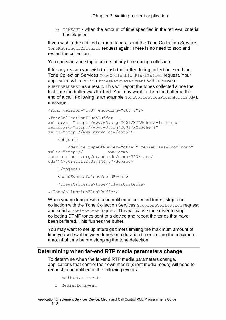
Chapter 3: Writing a client application
Application Enablement Services Device, Media and Call Control XML Programmer‟s Guide 113
o TIMEOUT - when the amount of time specified in the retrieval criteria has elapsed
If you wish to be notified of more tones, send the Tone Collection Services
ToneRetrievalCriteria request again. There is no need to stop and restart the collection.
You can start and stop monitors at any time during collection.
If for any reason you wish to flush the buffer during collection, send the
Tone Collection Services ToneCollectionFlushBuffer request. Your
application will receive a TonesRetrievedEvent with a cause of
BUFFERFLUSHED as a result. This will report the tones collected since the
last time the buffer was flushed. You may want to flush the buffer at the
end of a call. Following is an example ToneCollectionFlushBuffer XML message.
<?xml version="1.0" encoding="utf-8"?>
<ToneCollectionFlushBuffer
xmlns:xsi="http://www.w3.org/2001/XMLSchema-instance"
xmlns:xsd="http://www.w3.org/2001/XMLSchema"
xmlns="http://www.avaya.com/csta">
<object>
<device typeOfNumber="other" mediaClass="notKnown"
xmlns="http:// www.ecma-
international.org/standards/ecma-323/csta/
ed3">4750::111.2.33.444:0</device>
</object>
<sendEvent>false</sendEvent>
<clearCriteria>true</clearCriteria>
</ToneCollectionFlushBuffer>
When you no longer wish to be notified of collected tones, stop tone
collection with the Tone Collection Services StopToneCollection request
and send a MonitorStop request. This will cause the server to stop collecting DTMF tones sent to a device and report the tones that have been buffered. This flushes the buffer.
You may want to set up interdigit timers limiting the maximum amount of time you will wait between tones or a duration timer limiting the maximum amount of time before stopping the tone detection
Determining when far-end RTP media parameters change
To determine when the far-end RTP media parameters change, applications that control their own media (client media mode) will need to request to be notified of the following events:
o MediaStartEvent
o MediaStopEvent
114
Here is the sequence of media control events an application should be prepared to receive:
1. When media is first established for a call, the application receives a
MediaStartEvent. However, it does not guarantee that the call has been
established end-to-end yet.
2. If the switch changes the far-end RTP parameters for a call, the application
receives a MediaStopEvent. At that point the current far-end RTP
parameters should no longer be used. A MediaStopEvent could indicate
that the call has ended, but do not depend on that event alone to determine
the end of a call; the call appearance lamp will also change if it is the end of a
call.
3. If there are new far-end RTP parameters, then the application will
subsequently receive a MediaStartEvent.
One scenario in which a MediaStopEvent and then a MediaStartEvent may be received is when the switch shuffles a call. Shuffling occurs when the switch changes the path of the media. For example, if the media is going from calling party A to the switch and then to called party B, the switch may choose to change the media path such that it goes directly between endpoints A and B. In this case, the switch would tell both A and B to stop using the switch address as the far-end address and to start using the other endpoint as the far-end address. In other words, A would be notified that B is now the far end and B would be notified that A is the far end. Later the switch may choose to change the path again due to some change in the call, such as a conference or transfer. Each time the path changes, the endpoints are notified via media control events to stop using the current far-end address and to start using the new far-end address.
In server media mode all of this is usually transparent to the user, unless the codec happens to change. In this case you may need to play a different wav file in the codec of the new form. For this reason it is recommended that you give a single codec when registering devices.
Recovery
Chapter 4: High Availability contains more information on the high availability feature DMCC provides.
The "keep alive" messages that are sent periodically by the application to the AE Services server provide a way for the application to verify that the AE Services server is operational even if there is no other activity from the application. In addition, the session cleanup delay provides a mechanism for the application to reestablish its session after a short network interruption without having to reestablish their state (e.g. register devices again). This section tells you how to take advantage of these new features to design a more robust Device, Media and Call Control application.
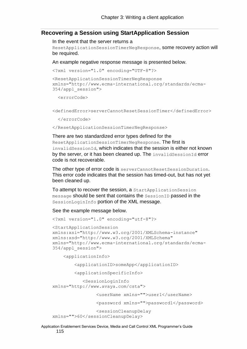
Chapter 3: Writing a client application
Application Enablement Services Device, Media and Call Control XML Programmer‟s Guide 115
Recovering a Session using StartApplication Session
In the event that the server returns a
ResetApplicationSessionTimerNegResponse, some recovery action will
be required.
An example negative response message is presented below.
<?xml version="1.0" encoding="UTF-8"?>
<ResetApplicationSessionTimerNegResponse
xmlns="http://www.ecma-international.org/standards/ecma-
354/appl_session">
<errorCode>
<definedError>serverCannotResetSessionTimer</definedError>
</errorCode>
</ResetApplicationSessionTimerNegResponse>
There are two standardized error types defined for the
ResetApplicationSessionTimerNegResponse. The first is
invalidSessionId, which indicates that the session is either not known
by the server, or it has been cleaned up. The invalidSessionId error code is not recoverable.
The other type of error code is serverCannotResetSessionDuration. This error code indicates that the session has timed-out, but has not yet been cleaned up.
To attempt to recover the session, a StartApplicationSession
message should be sent that contains the SessionID passed in the
SessionLoginInfo portion of the XML message.
See the example message below.
<?xml version="1.0" encoding="utf-8"?>
<StartApplicationSession
xmlns:xsi="http://www.w3.org/2001/XMLSchema-instance"
xmlns:xsd="http://www.w3.org/2001/XMLSchema"
xmlns="http://www.ecma-international.org/standards/ecma-
354/appl_session">
<applicationInfo>
<applicationID>someApp</applicationID>
<applicationSpecificInfo>
<SessionLoginInfo
xmlns="http://www.avaya.com/csta">
<userName xmlns="">user1</userName>
<password xmlns="">password1</password>
<sessionCleanupDelay
xmlns="">60</sessionCleanupDelay>
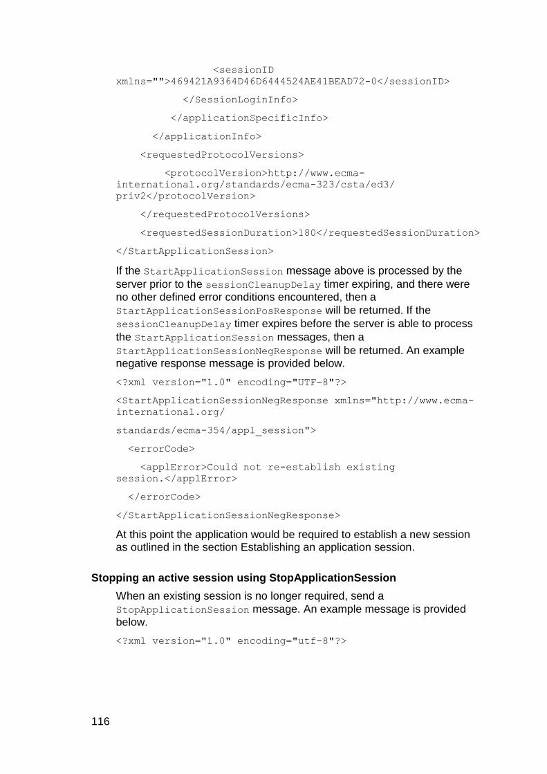
116
<sessionID
xmlns="">469421A9364D46D6444524AE41BEAD72-0</sessionID>
</SessionLoginInfo>
</applicationSpecificInfo>
</applicationInfo>
<requestedProtocolVersions>
<protocolVersion>http://www.ecma-
international.org/standards/ecma-323/csta/ed3/
priv2</protocolVersion>
</requestedProtocolVersions>
<requestedSessionDuration>180</requestedSessionDuration>
</StartApplicationSession>
If the StartApplicationSession message above is processed by the
server prior to the sessionCleanupDelay timer expiring, and there were no other defined error conditions encountered, then a
StartApplicationSessionPosResponse will be returned. If the
sessionCleanupDelay timer expires before the server is able to process
the StartApplicationSession messages, then a
StartApplicationSessionNegResponse will be returned. An example negative response message is provided below.
<?xml version="1.0" encoding="UTF-8"?>
<StartApplicationSessionNegResponse xmlns="http://www.ecma-
international.org/
standards/ecma-354/appl_session">
<errorCode>
<applError>Could not re-establish existing
session.</applError>
</errorCode>
</StartApplicationSessionNegResponse>
At this point the application would be required to establish a new session as outlined in the section Establishing an application session.
Stopping an active session using StopApplicationSession
When an existing session is no longer required, send a
StopApplicationSession message. An example message is provided
below.
<?xml version="1.0" encoding="utf-8"?>

Chapter 3: Writing a client application
Application Enablement Services Device, Media and Call Control XML Programmer‟s Guide 117
<StopApplicationSession
xmlns:xsi="http://www.w3.org/2001/XMLSchema-instance"
xmlns:xsd="http://www.w3.org/2001/XMLSchema"
xmlns="http://www.ecma-international.org/standards/ecma-
354/appl_session">
<sessionID>469421A9364D46D6444524AE41BEAD72-
0</sessionID>
<sessionEndReason>
<appEndReason>Application Request</appEndReason>
</sessionEndReason>
</StopApplicationSession>
The server will return either a positive or negative response to this request. A negative response can safely be ignored.
General Event Response to an Inactive Session
There are four types of negative acknowledgements that an application can expect to receive. The section below will list the type and provide the required recovery steps.
invalidSessionID - The sessionID given by the application is not valid or not known by the server. This could mean that the session has timed out or was placed in an inactive state. It is possible that the session could be recovered by sending a
StartApplicationSession message with the SessionID as outlined in Recovering a Session using StartApplicationSession
SessionTimerExpired – The session terminated due to the session timing out. At this point the application should start a new session as outlined in the section Establishing an application session
ResourceLimitation – The session terminated due to a resource constraint. At this point the application should start a new session as outlined in the section Establishing an application session
Transfer Monitor Objects
The TransferMonitorObjectRequest of Device Services is used to
transfer the DeviceIDs for a given session to another session belonging to the same user. This request will also transfer the monitors that were added for each DeviceID. This allows one application instance to take over for another application instance in the event of a failure.
Each deviceID and its established monitors is returned in a
MonitorObjectData. A list of MonitorObjectData is returned in the
TransferMonitorObjectsResponse.
118
The processing of a TransferMonitorObjects request may cause event notification to be interrupted if the client application has not set up the to session to receive the from session's events. This can be achieved by retrieving the established cross reference identifiers from the
TransferMonitorObjects response. The response will contain a
MonitorStartResponse for each valid monitor that is associated with a
transferred device ID.
Important side effects and recommended client application actions:
All the monitors for each device ID will be transferred from the from to the to session.
The from session will be removed at the end of the transfer.
The client application must set up the to session to receive the events from the transferred monitors.
The client application must release the resources that were allocated for the from session.
The following example demonstrates how to transfer the monitor objects between two ID‟s that belong to the user. A monitor object can be either a device ID or a call object.
<?xml version="1.0" encoding="utf-8"?>
<TransferMonitorObjects
xmlns:xsi="http://www.w3.org/2001/XMLSchema-instance"
xmlns:xsd="http://www.w3.org/2001/XMLSchema"
xmlns="http://www.avaya.com/csta">
<fromSessionID>2E7EE0A185BF2C1F71902BF8888B67AF-
16</fromSessionID>
<toSessionID>28860932245E4EE8AC961D040459D8E7-
17</toSessionID>
</TransferMonitorObjects>
Following is the corresponding response:
<?xml version="1.0" encoding="UTF-8"?>
<TransferMonitorObjectsResponse
xmlns="http://www.avaya.com/csta">
<fromSessionID>2E7EE0A185BF2C1F71902BF8888B67AF-
16</fromSessionID>
<toSessionID>28860932245E4EE8AC961D040459D8E7-
17</toSessionID>
</TransferMonitorObjectsResponse>
NOTE: The Java SessionManagementApp sample application shows how a client application can transfer device ID‟s from one session to another and shows how to reconstruct the transferred objects which is a necessary step in addition to the code shown above.
Chapter 3: Writing a client application
Application Enablement Services Device, Media and Call Control XML Programmer‟s Guide 119
Cleanup
If the cleanup session timer expires, resources are reclaimed. It is important to free resources when they are no longer needed. This is most likely to occur when your application:
Detects the end of a call
Is finished with a device
Is about to exit
Cleanup should occur in this order:
1. Stop collecting tones
At the end of a call, you can choose to stop collecting DTMF tones for the device. Alternatively, you can let the collection and the retrieval criteria continue across calls. In that case you might just flush the buffer at the end of each call.
When finished with a device, stop the tone collection for that device.
When the application is about to exit, stop tone collection on all devices.
2. Stop recording or playing
At the end of a call, you can choose to stop recording or playing, or let the recording or playing continue across calls on the device.
When finished with a device, stop both recording and playing on that device.
When the application is about to exit, stop both recording and playing on all registered devices.
Both recording and playing can be stopped on a device by sending the Voice Unit Services Stop request or can be individually stopped by
sending the Extended Voice Unit Services StopRecording request or
StopPlaying request.
3. Unregister the device
When finished with a device, unregister it by sending the Registration
Services UnregisterTerminal request.
When the application is about to exit, unregister each registered device. If you fail to unregister a device, Communication Manager will keep the device registered to AE Services indefinitely.

120
NOTE: It is possible that this device is being controlled by more than this application session. If this device is controlled by more than one session, the various application sessions that are working with the device should be communicating to determine whether or not the device should be released before sending an unregister request. If this session is the only session controlling the device, a negative
acknowledgement will be thrown from the ReleaseDeviceID request,
indicating that unregistration is required before the device can be released.
4. Stop monitoring for events
When your application no longer needs to receive events for a device,
send a MonitorStop request.
5. Release the device identifier
When finished with a device identifier, release it by sending the Device
Services ReleaseDeviceID request.
When the application is about to exit, release each device identifier.
6. Stop the application session
This must be done as the last thing before closing the socket. Close the application session by sending the Application Session Services
StopApplicationSession request. You will receive either a
StopApplicationSessionPosResponse or a
StopApplicationSessionNegResponse.
Media Encryption
Application Enablement Services offers the user the ability to encrypt the voice RTP streams between the DMCC softphone and the far end of the call.
For Application Enablement Services, the only encryption scheme available is the Advanced Encryption Standard (AES) media encryption.
NOTE: All of the code in the following sections on encryption is in Java. This is meant to serve as a guideline to aid you. If your application is written in another programming language, you may transcribe the code into the appropriate language.
The AES Encryption Scheme
1. Encrypting the Voice Stream
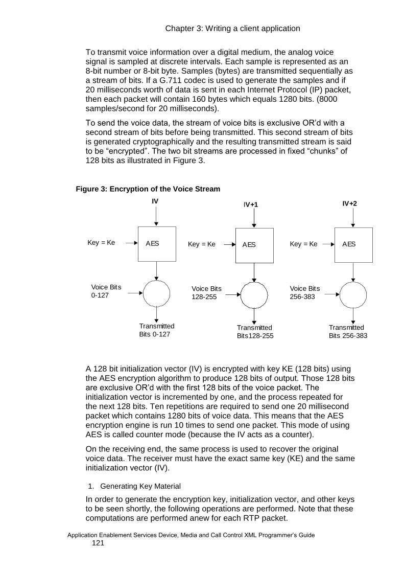
Chapter 3: Writing a client application
Application Enablement Services Device, Media and Call Control XML Programmer‟s Guide 121
To transmit voice information over a digital medium, the analog voice signal is sampled at discrete intervals. Each sample is represented as an 8-bit number or 8-bit byte. Samples (bytes) are transmitted sequentially as a stream of bits. If a G.711 codec is used to generate the samples and if 20 milliseconds worth of data is sent in each Internet Protocol (IP) packet, then each packet will contain 160 bytes which equals 1280 bits. (8000 samples/second for 20 milliseconds).
To send the voice data, the stream of voice bits is exclusive OR‟d with a second stream of bits before being transmitted. This second stream of bits is generated cryptographically and the resulting transmitted stream is said to be “encrypted”. The two bit streams are processed in fixed “chunks” of 128 bits as illustrated in Figure 3.
Figure 3: Encryption of the Voice Stream
AES
IV
Transmitted
Bits 0-127
Key = Ke
Voice Bits
0-127
IV+1
Transmitted
Bits128-255
Key = Ke
Voice Bits
128-255
IV+2
Transmitted
Bits 256-383
Key = Ke
Voice Bits
256-383
AES AES
A 128 bit initialization vector (IV) is encrypted with key KE (128 bits) using the AES encryption algorithm to produce 128 bits of output. Those 128 bits are exclusive OR‟d with the first 128 bits of the voice packet. The initialization vector is incremented by one, and the process repeated for the next 128 bits. Ten repetitions are required to send one 20 millisecond packet which contains 1280 bits of voice data. This means that the AES encryption engine is run 10 times to send one packet. This mode of using AES is called counter mode (because the IV acts as a counter).
On the receiving end, the same process is used to recover the original voice data. The receiver must have the exact same key (KE) and the same initialization vector (IV).
1. Generating Key Material
In order to generate the encryption key, initialization vector, and other keys to be seen shortly, the following operations are performed. Note that these computations are performed anew for each RTP packet.

122
Let the packet index “i” be defined as:
i = (32-bit ROC) || (SEQ for RTP)
where ROC is the roll over counter, SEQ is the 16-bit sequence number from the RTP packet and || indicates concatenation. This is shown in Figure 4..
Figure 4: Structure of the Packet Index
Let
r = i DIV key_derivation_rate
where DIV denotes integer division rounded down with the convention that dividing by 0 equals 0. The SRTP algorithm supports changing the keys periodically, even while the voice stream is active. The key derivation rate is the rate of this change. A value of zero indicates that the keys are not
changed periodically. When the rate is zero, “r” is also zero (48 bits). Note
that in the first computation of “r”, the value of SEQ used in the computation of “i” is the initial value at the beginning of the media stream.
Let
key_id = <label> || r
where <label> = 0x00 for RTP packet encryption and 0x02 for the salting key used to generate the IV as illustrated in Figure 5.
Figure 5: key_id Structure
Now let x = key_id XOR master_salt
This is shown in Figure 6.
Figure 6: Computation of ’"x"
32 bits of ROC 16 bits of SEQ 48 bit packet index, i
48 bits of "i" DIV key_derivation_rate
8 bits of label
56 bits of key_id

Chapter 3: Writing a client application
Application Enablement Services Device, Media and Call Control XML Programmer‟s Guide 123
8 bits of label
Implicit 56 bit s of zero 48 bits of "i" DIV key_derivation_rate
XOR
gives
112 bits of master_salt
112 bits of "x"
The keys for encryption and IV generation are the result of encryption of
(“x” * 216) with a key called the master key. (The master key is distributed by the Media Gateway Controller for each voice IP media link as the link is established.)
The values of “x” for Avaya‟s implementation are shown in figure 6. Note
that two values of “x” are computed, one (xe) is used to compute the value
of KE and a second value of “x” (xs) is used in the computation of the IV.
For Avaya‟s implementation: Key_derivation_rate = 0 Master_salt = 0
Figure 7: Values of "x" for Avaya’s Implementation
112 bits of zeroXe
to generate
Ke
8 bits of label =0000 0010
56 bits of zero 48 bits of zeroXs
to generate
Ks
2. Creating the Initialization Vector
The Initialization Vector (IV) changes for each packet (1280 voice bits for 20ms G.711) according to the following equation:
IV = (SSRC * 264) XOR (KS * 2
16) XOR (i * 2
16)
where KS is known as the session salting key and SSRC is the synchronization source from the RTP packet currently being encrypted. Note that “i” contains the packet sequence number SEQ and therefore the IV must be recalculated for each RTP packet.
The 112 bit KS is computed from xs using the pseudo random function (PRF) as follows.
KS = PRF_112 (master_key, xs * 216)

124
The pseudo random function is defined to be AES in counter mode with its output stream truncated as necessary (left most bits are retained).
The process for IV generation is shown in Figure 8..
Figure 8: 128-bit IV Generation SSRC * 2 64
Ks * 216
i * 216
Initialization
vector
gives
XOR
XOR
64 bits of zeroSSRC
64 bits of zero 16 bits of zero
IV
16 bits of zero
counter
112 bits of Ks
32 bits of zero
48 bits of packet_index "i"
3. Creating the Encryption Key KE
The process for generating the session key (KE) uses the pseudo random function (AES in counter mode) to produce a 128 bit value as follows:
KE = PRF_128 (master_key, xE * 216)
Specifying the Devices’ Encryption Capability
You may control whether your CMAPI softphone will support media encryption or not by specifying the supported encryption types in the local MediaInfo structure:
// specify either AES or no encryption for this device (let
CM choose)
String [] encryptionList = {MediaConstants.AES,
MediaConstants.NOENCRYPTION};
MediaInfo localMediaInfo = new MediaInfo();
localMediaInfo.setEncryptionList(encryptionList);
station.register (password, false, localMediaInfo, new
MyAsyncRegistrationCallback());
Using the RegisterTerminal XML, this becomes, for example:
<?xml version=”1.0” encoding=”UTF-8”?>
<RegisterTerminalRequest xmlns=”http://www.avaya.com/csta”>
<device typeOfNumber=”other” mediaClass=”voice”
bitRate=”constant”>
4750:mySwitch:111.2.33.4:0
</device>
Chapter 3: Writing a client application
Application Enablement Services Device, Media and Call Control XML Programmer‟s Guide 125
<loginInfo>
<forceLogin>true</forceLogin>
<dependencyMode>MAIN</dependencyMode>
<mediaMode>CLIENT</mediaMode>
<password>1234</password>
</loginInfo>
<localMediaInfo>
<rtpAddress>
<address>55.6.7.88</address>
<port>4123</port>
</rtcpAddress>
<rtpAddress>
<address>55.6.7.88</address>
<port>4124</port>
</rtcpAddress>
<codecs>g711U</codecs>
<packetSize>20</packetSize>
<encryptionList>aes</encryptionList>
<encryptionList>none</encryptionList>
</localMediaInfo>
</RegisterTerminalRequest>
This specifies that the CMAPI softphone will support both AES encryption and no media encryption. In this case, the decision to encrypt the media stream is left up to the Communication Manager (as specified in the CM‟s “change ip-codec” form).
Alternatively, you may force AES media encryption to be chosen by specifying a supported encryption type of only AES:
// must use AES encryption
String [] encryptionList = {MediaConstants.AES};
or in XML:
<encryptionList>aes</encryptionList>
and, of course, you may force no encryption to be chosen by specifying:
// encryption not supported
String [] encryptionList = {MediaConstants.NOENCRYPTION};
and in XML:

126
<encryptionList>none</encryptionList>
MediaStartEvent Handling
If you have chosen to receive and handle the media stream as part of your application (you have chosen client-media mode), you will receive the
media encryption information in the MediaStartEvent. In addition to the
usual “RTP address”, “RTP port”, “codec” etc., the MediaStartEvent will also contain an “Encryption” object containing the encryption protocol and keys chosen by Communication Manager.
The MediaStartEvent looks like this:
<?xml version=”1.0” encoding=”UTF-8”?>
<MediaStartEvent xmlns="http://www.avaya.com/csta">
<ns1:monitorCrossRefID xmlns:ns1="http://www.ecma-
international.org/standards/ecma-323/csta/ed3"> 32
</ns1:monitorCrossRefID>
<connection>
<ns2:deviceID xmlns:ns2="http://www.ecma-
international.org/standards/ecma-323/csta/ed3"
typeOfNumber="other" mediaClass="voice" bitRate="constant">
4700:cmapichawk:135.9.71.250:0
</ns2:deviceID>
</connection>
<rtpAddress>
<address>135.9.71.201</address>
<port>2082</port>
</rtpAddress>
<rtcpAddress>
<address>135.9.71.201</address>
<port>2083</port>
</rtcpAddress>
<codec>g711U</codec>
<packetSize>20</packetSize>
<encryption>
<protocol>aes</protocol>
<transmitKey>{38,4F,0B,34,DF,00,2A,BE,F0,C7,55,80,1D,1D,33,A
8}
</transmitKey>

Chapter 3: Writing a client application
Application Enablement Services Device, Media and Call Control XML Programmer‟s Guide 127
<receiveKey>{38,4F,0B,34,DF,00,2A,BE,F0,C7,55,80,1D,1D,33,A8
}
</receiveKey>
<payloadType>-1</payloadType>
</encryption>
</MediaStartEvent>
and, to obtain the encryption parameters from the event (in Java):
String protocol = startEvent.getEncryption().getProtocol();
String transmitKey =
startEvent.getEncryption().getTransmitKey();
String receiveKey =
startEvent.getEncryption().getReceiveKey();
int payloadType =
startEvent.getEncryption().getPayloadType().intValue();
When you start to process the RTP stream, you need to pass the encryption information to your RTP stream read/write methods to enable them to do the media encryption/decryption. On receipt of a new MediaStartEvent, you must use the new encryption keys provided in the event, recalculate the Initialization vector (IV), and reset the Roll Over Counter (ROC).
If you are using Avaya‟s client-media-stack, you may call the Audio “start” method (as usual) passing the encryption information as an extra parameter:
In Java, this would be:
MediaEncryption encryption = new MediaEncryption();
encryption.setProtocol(protocol);
encryption.setTransmitKey(transmitKey);
encryption.setReceiveKey(receiveKey);
encryption.setPayloadType(payloadType);
audio.start(rtpAddress, rtcpAddress, codec, packetSize,
encryption);
Media Encryption Information
The Encryption object in the MediaStartEvent contains the following
information:
o Encryption protocol
o Separate media encryption transmit and receive keys

128
o Payload type
The encryption keys and the payload type are only required if the encryption protocol is “MediaConstants.AES”.
For SDK compatibility reasons, the transmit and receive keys are formatted as Strings. For example, the transmit key may be in the form:
String transmitKey =
“{38,4F,0B,34,DF,00,2A,BE,F0,C7,55,80,1D,1D,33,A8}”
and similarly for the receive key. The curly braces and commas are actually part of the String. In order to be used by the encryption/decryption routines, the keys need to be converted to byte arrays of the form (for example):
byte[] txKey = { 0x38, 0x4F, 0x0B, 0x34, 0xDF, 0x00, 0x2A,
0xBE,
0xF0, 0xC7, 0x55, 0x80, 0x1D, 0x1D, 0x33, 0xA8 };
If you use Avaya‟s client-media-stack, the Audio “start” method will automatically do the String to byte[] conversion for you.
Encrypting and Decrypting the RTP Stream
The encryption transmit and receive keys, along with the roll over counter (ROC) plus the RTP header‟s SSRC and sequence number, are used to calculate the Initialization Vector.
Roll Over Counter (ROC)
The ROC (initially set to zero) is a 32-bit unsigned integer which records how many times the 16-bit RTP sequence number (SEQ) has been reset to zero within the same SSRC (after incrementing up through 65,535) Unlike the sequence number (SEQ), which your secure RTP implementation (SRTP) extracts from the RTP packet header, the ROC is maintained by the header of each RTP packet. The ROC must also be knowledgeable of the SSRC that is included in the header of each RTP packet. The SSRC is a 32 bit randomly chosen value in an RTP packet that is used to represent the synchronization source (RFC1889). From one
MediaStartEvent to the next MediaStopEvent, the SSRC will remain the
same. If the SSRC changes, this is usually an indication that a new RTP stream has started. However, note that it is also possible for a new RTP stream to start without changing the SSRC. Thus, if a new
MediaStartEvent is received, then a new RTP stream is deemed to have started. When this situation occurs the new encryption keys (included in the event) must be used, the Initialization Vector (IV) must be recalculated, and the ROC must be reset to zero.
// Increment the ROC whenever the sequence number rolls
over
incomingReadSSRC = rtpHdr.ssrc;
incomingSeqNum = rtpHdr.seqNum;

Chapter 3: Writing a client application
Application Enablement Services Device, Media and Call Control XML Programmer‟s Guide 129
if (currentReadSSRC == incomingReadSSRC) {
if (incomingSeqNum > currentSeqNum) {
// Do nothing
} else if (incomingSeqNum < (currentSeqNum - 100)) {
// Sequence number has probably rolled over
++readROC;
} else {
// out of sequence RTP packet - ignore it
return 0;
}
} else if (incomingReadSSRC == prevReadSSRC) {
// very late RTP packet from previous call - ignore
it
return 0;
} else {
// New SSRC (that is new call) - reset ROC
readROC = 0;
prevReadSSRC = currentReadSSRC;
currentReadSSRC = incomingReadSSRC;
}
currentSeqNum = incomingSeqNum;
and similarly for writeROC.
Creating the Encryption Keys Using the Pseudo Random Function
The pseudo random function PRF_n(key,x) produces a bit string of length “n” from a string “x” which is encrypted using the encryption key named “key”. The AES Symmetric algorithm mode is “ECB” with no padding.
private static final byte XeRx[] =
{0,0,0,0,0,0,0,0,0,0,0,0, 0,0,0,0};
String algorithm = “aes”;
String modeECB = “ECB”;
String modeCTR = “CTR”;
String padding = “NoPadding”;
Cipher cipher = null;
SecretKey key = null;
byte[] KeRx = null;

130
// Set up and initialize JCE Engine
try {
String cipherSpec = algorithm + "/" + modeECB + "/"
+ padding;
cipher = Cipher.getInstance(cipherSpec);
} catch (Exception e) {
e.printStackTrace();
}
// Generate the symmetric key using the JCE Engine and
the readMasterKey from the
// MediaStartEvent and then use the Avaya XeRx value to
calculate the KeRx value
key = new SecretKeySpec(readMasterKey, algorithm);
/************ Calculate the KeRX value
*****************/
try {
cipher.init(Cipher.ENCRYPT_MODE, key);
KeRx = cipher.doFinal(XeRx);
} catch (IllegalStateException e) {
// Attempting to encrypt before the cipher has been
initialized.
// Probably a race condition resulting in the 1st
packet not being encrypted.
// Ignore for now.
} catch (Exception e) {
e.printStackTrace();
}
dump0x("KeRx", KeRx, 0,KeRx.length);
And, similarly for KeTx based on the writeMasterKey.
Once the media receive and transmit encryption keys (KeRx and KeTx) are created, they will be used within the AES algorithm to encrypt and decrypt the RTP stream.
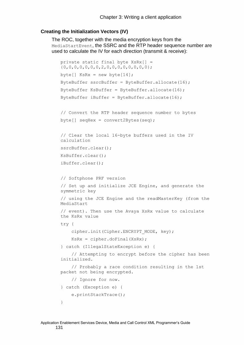
Chapter 3: Writing a client application
Application Enablement Services Device, Media and Call Control XML Programmer‟s Guide 131
Creating the Initialization Vectors (IV)
The ROC, together with the media encryption keys from the
MediaStartEvent, the SSRC and the RTP header sequence number are used to calculate the IV for each direction (transmit & receive):
private static final byte XsRx[] =
{0,0,0,0,0,0,0,2,0,0,0,0,0,0,0,0};
byte[] KsRx = new byte[14];
ByteBuffer ssrcBuffer = ByteBuffer.allocate(16);
ByteBuffer KsBuffer = ByteBuffer.allocate(16);
ByteBuffer iBuffer = ByteBuffer.allocate(16);
// Convert the RTP header sequence number to bytes
byte[] seqHex = convert2Bytes(seq);
// Clear the local 16-byte buffers used in the IV
calculation
ssrcBuffer.clear();
KsBuffer.clear();
iBuffer.clear();
// Softphone PRF version
// Set up and initialize JCE Engine, and generate the
symmetric key
// using the JCE Engine and the readMasterKey (from the
MediaStart
// event). Then use the Avaya XsRx value to calculate
the KsRx value
try {
cipher.init(Cipher.ENCRYPT_MODE, key);
KsRx = cipher.doFinal(XsRx);
} catch (IllegalStateException e) {
// Attempting to encrypt before the cipher has been
initialized.
// Probably a race condition resulting in the 1st
packet not being encrypted.
// Ignore for now.
} catch (Exception e) {
e.printStackTrace();
}

132
dump0x("KsRx", KsRx, 0,KsRx.length);
KsBuffer.put(KsRx, 0, KsRx.length-2);
And, similarly for Ks-Tx based on the writeMasterKey.
Next, we can continue to calculate the read buffer IV (ivRx):
// Grab the SSRC from the RTP header and populate
// the SSRCbuffer
ssrcBuffer.position(4);
ssrcBuffer.putInt(ssrc);
// Setup and populate the iBuffer - this will currently
// make the roll over counter to be zero always
iBuffer.position(8);
iBuffer.putInt(readROC);
iBuffer.put(seqHex[2]);
iBuffer.put(seqHex[3]);
byte[] ssrcBytes = ssrcBuffer.array();
byte[] ksBytes = KsBuffer.array();
byte[] iBytes = iBuffer.array();
byte[] ivRx = new byte [16];
// XOR all 3 buffers
for (int ii = 0; ii < ivRx.length; ii++) {
ivRx[ii] = (byte)(ssrcBytes[ii] ^ ksBytes[ii] ^
iBytes[ii]);
dump0x("ivRx", ivRx, 0,ivRx.length);
and similarly for calculating the write buffer IV (ivTx).
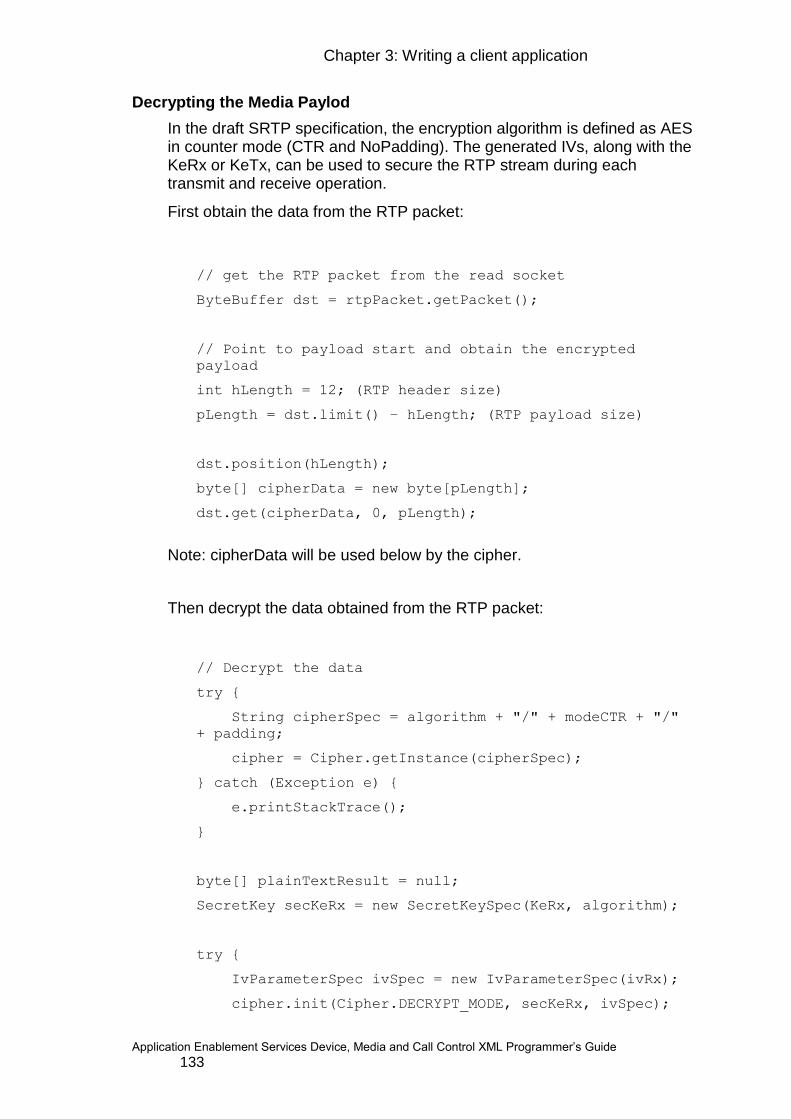
Chapter 3: Writing a client application
Application Enablement Services Device, Media and Call Control XML Programmer‟s Guide 133
Decrypting the Media Paylod
In the draft SRTP specification, the encryption algorithm is defined as AES in counter mode (CTR and NoPadding). The generated IVs, along with the KeRx or KeTx, can be used to secure the RTP stream during each transmit and receive operation.
First obtain the data from the RTP packet:
// get the RTP packet from the read socket
ByteBuffer dst = rtpPacket.getPacket();
// Point to payload start and obtain the encrypted
payload
int hLength = 12; (RTP header size)
pLength = dst.limit() – hLength; (RTP payload size)
dst.position(hLength);
byte[] cipherData = new byte[pLength];
dst.get(cipherData, 0, pLength);
Note: cipherData will be used below by the cipher.
Then decrypt the data obtained from the RTP packet:
// Decrypt the data
try {
String cipherSpec = algorithm + "/" + modeCTR + "/"
+ padding;
cipher = Cipher.getInstance(cipherSpec);
} catch (Exception e) {
e.printStackTrace();
}
byte[] plainTextResult = null;
SecretKey secKeRx = new SecretKeySpec(KeRx, algorithm);
try {
IvParameterSpec ivSpec = new IvParameterSpec(ivRx);
cipher.init(Cipher.DECRYPT_MODE, secKeRx, ivSpec);
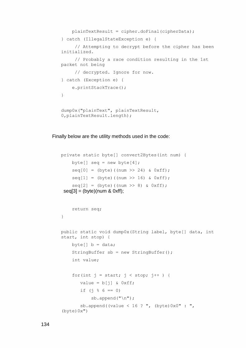
134
plainTextResult = cipher.doFinal(cipherData);
} catch (IllegalStateException e) {
// Attempting to decrypt before the cipher has been
initialized.
// Probably a race condition resulting in the 1st
packet not being
// decrypted. Ignore for now.
} catch (Exception e) {
e.printStackTrace();
}
dump0x("plainText", plainTextResult,
0,plainTextResult.length);
Finally below are the utility methods used in the code:
private static byte[] convert2Bytes(int num) {
byte[] seq = new byte[4];
seq[0] = (byte)((num >> 24) & 0xff);
seq[1] = (byte)((num >> 16) & 0xff);
seq[2] = (byte)((num >> 8) & 0xff);
seq[3] = (byte)(num & 0xff);
return seq;
}
public static void dump0x(String label, byte[] data, int
start, int stop) {
byte[] b = data;
StringBuffer sb = new StringBuffer();
int value;
for(int j = start; j < stop; j++ ) {
value = b[j] & 0xff;
if (j % 6 == 0)
sb.append("\n");
sb.append((value < 16 ? ", (byte)0x0" : ",
(byte)0x")

Chapter 3: Writing a client application
Application Enablement Services Device, Media and Call Control XML Programmer‟s Guide 135
+Integer.toHexString(b[j] &
0xff));
}
System.out.println(label+": "+sb.toString());
}
Test Data
In order to validate your code, we present here some test data against which you may run your decipher code. Following that is the expected output.
Input Data:
// From the MediaStart event, we get
byte[] readMasterKey = {
(byte)0xaa,(byte)0xaa,(byte)0xaa,(byte)0xaa,
(byte)0xaa,(byte)0xaa,(byte)0xaa,(byte)0xaa,
(byte)0xaa,(byte)0xaa,(byte)0xaa,(byte)0xaa,
(byte)0xaa,(byte)0xaa,(byte)0xaa,(byte)0xaa
};
// From the RTP packet, we get
int ssrc = 987011809;
int seq = 3;
int roc = 0;
// And the data to decipher is:
cipherData =
{(byte)0xbb,(byte)0xbb,(byte)0xbb,(byte)0xbb };
Expected Output:
KeRx:
(byte)0xba, (byte)0xeb, (byte)0xc6, (byte)0x18, (byte)0xa5,
(byte)0x5c, (byte)0x35, (byte)0x1f, (byte)0x25, (byte)0xce,
(byte)0xdf, (byte)0x37, (byte)0xbf, (byte)0x70, (byte)0xf3,
(byte)0x90
KsRx:
(byte)0x98, (byte)0x12, (byte)0xf4, (byte)0x3c, (byte)0x17,
(byte)0xc5, (byte)0xd4, (byte)0x0e, (byte)0xe3,
(byte)0x8f, (byte)0x09, (byte)0xe1, (byte)0x7f, (byte)0xa8,
(byte)0xba, (byte)0xb7
IVRx:

136
(byte)0x98, (byte)0x12, (byte)0xf4, (byte)0x3c, (byte)0x2d,
(byte)0x11, (byte)0x4e, (byte)0xef, (byte)0xe3,
(byte)0x8f, (byte)0x09, (byte)0xe1, (byte)0x7f, (byte)0xab,
(byte)0x00, (byte)0x00
// And the deciphered data should be:
plainData = {(byte)0x05, (byte)0x43, (byte)0x2a, (byte)0x3d
};
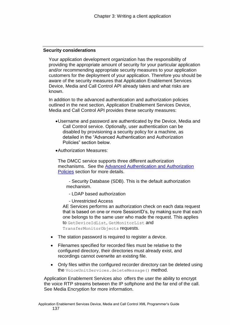
Chapter 3: Writing a client application
Application Enablement Services Device, Media and Call Control XML Programmer‟s Guide 137
Security considerations
Your application development organization has the responsibility of providing the appropriate amount of security for your particular application and/or recommending appropriate security measures to your application customers for the deployment of your application. Therefore you should be aware of the security measures that Application Enablement Services Device, Media and Call Control API already takes and what risks are known.
In addition to the advanced authentication and authorization policies outlined in the next section, Application Enablement Services Device, Media and Call Control API provides these security measures:
Username and password are authenticated by the Device, Media and Call Control service. Optionally, user authentication can be disabled by provisioning a security policy for a machine, as detailed in the “Advanced Authentication and Authorization Policies” section below.
Authorization Measures:
The DMCC service supports three different authorization mechanisms. See the Advanced Authentication and Authorization Policies section for more details.
- Security Database (SDB). This is the default authorization mechanism.
- LDAP based authorization
- Unrestricted Access AE Services performs an authorization check on each data request that is based on one or more SessionID‟s, by making sure that each one belongs to the same user who made the request. This applies
to GetDeviceIdList, GetMonitorList and
TransferMonitorObjects requests.
The station password is required to register a device.
Filenames specified for recorded files must be relative to the configured directory, their directories must already exist, and recordings cannot overwrite an existing file.
Only files within the configured recorder directory can be deleted using the VoiceUnitServices.deleteMessage() method.
Application Enablement Services also offers the user the ability to encrypt the voice RTP streams between the IP softphone and the far end of the call. See Media Encryption for more information.

138
If you are using encryption, AE Services Device, Media and Call Control API provides these additional security measures:
The signaling and bearer channels are encrypted.
XML messages transmitted between the client application and the AE Services server software are encrypted.
The station password is passed encrypted.
Username and password are encrypted.
Username and password are authenticated by the Device, Media and Call Control service.
NOTE: If you do not use encryption on the client link, the signaling and bearer channels are unencrypted, there is no encryption of XML messages transmitted between the client application and the AE Services server software. In this case, the station password is passed unencrypted and, similarly, the username and password are also sent in unencrypted.
For a complete discussion of the security guidelines for AE Services, see
White-paper on Security in Avaya Aura® Application Enablement Services for the Bundled, Software Only and System Platform Solutions.. This white paper is available on the Avaya support site along with the customer documents.
Advanced Authentication and Authorization Policies
AE Services provides options for provisioning of authentication and authorization policies to specific application servers based on PKI (Public Key Infrastructure). The User Authentication and Authorization(AA) policies will first be detailed separately, then several use cases will be provided to illustrate how these policies can be applied to provide new AA models for applications to leverage.
Note that in order to apply AA policies to a machine, it is necessary to have checked the “Require Trusted Host Entry” field in the AE Services Management Console pages. It is critical to the security model that the identity of the application machine be validated and that they are considered a trusted host in order to suspend otherwise required user authentication / authorization administration.
Chapter 3: Writing a client application
Application Enablement Services Device, Media and Call Control XML Programmer‟s Guide 139
It is also important to note that in order for DMCC to properly authenticate the application machine, that application must have been provisioned with a certificate and associated private key that identify that machine. The machine‟s identity can be provided in either the Common Name field or the Subject Alternative Name (SAN) field. DNS and IP Address SAN types are accepted. The provided certificate must have been signed by a certificate authority (CA) that has been provisioned in AE Services as being a trusted CA.
User Authentication Policies
The User Authentication policy setting allows an administrator to specify whether or not user-level authentication is required for sessions originating from the application machine. If the administrator disables user-level authentication, the far end machine can still supply a username through the normal mechanisms, but the password will be ignored. This allows the application machine to assert a user identity that could still be used for authorization purposes. In order to assert a user identity, the application machine should have somehow authenticated the user.
User Authorization Policies
There are three different authorization policies that can be applied: SDB, Enterprise Directory, and Unrestricted Access.
SDB
This authorization policy states that the AE Services Security Database (SDB) shall be used for authorization. When this policy is applied, DMCC applies SDB-based authorization exactly as it did in previous releases of AE Services.
AE Services can optionally enforce an authorization policy as specified in the Security Database (SDB) to ensure that only authorized users can monitor and control a given device.
The SDB allows an administrator to give a user control of a specific device or list of devices. An administrator can also allow a user to monitor/control any device by granting them "Unrestricted Access". The administrator can also disable the SDB entirely, which turns off all authorization enforcement and allows any user to monitor or control any device. See the Avaya Aura® AE Services Administration and Maintenance Guide for more information about SDB administration.
For AE Services with Communication Manager 5.1 or later, the client application does not have to know the extension password to register a device, provided the following is true:
The DeviceID contains the administered switch name associated with a valid switch connection to Communication Manager
The switch connection to the Communication Manager is active and talking

140
The SDB on the AE Services server is enabled
The CTI user has “Unrestricted Access” in the SDB. (A CTI user can be administered for "Unrestricted Access" via the "Edit CTI User" web page on the AE Services Management Console.)
The extension‟s class of restriction (COR) on the Communication manager has:
o “Can Be Service Observed” set to “y”
o “Can Be a Service Observer” set to “y”
A CTI user can be administered for "Unrestricted Access" via the "Edit CTI User" web page on the AE Services Management Console.
Note that if the “Enabled SDB for DMCC Service” is not checked on the “Security Database -> Control” page, no authorization enforcement will occur even if an SDB authorization policy has been specified for a given host.
Enterprise Directory
This authorization policy states that an LDAP enterprise directory shall be used for authorization. This authorization mechanism leverages the “Enterprise Directory” OAM page. In addition to specifying basic connection parameters, this page contains the following fields that are critical to this authorization method:
Search Filter Attribute Name: This indicates the attribute name in the user record that corresponds to username. DMCC will attempt to match a username to the contents of this attribute. An example is “SAM-Account-Name” in Windows Active Directory.
Device ID Attribute: This indicates the attribute name in the user record that corresponds to the device ID to be authorized for the user. A primary example here would be an attribute such as “Phone Number” that contains a provisioned E.164 number for users.
When this authorization mechanism is selected, DMCC will use LDAP to query the user record for the provisioned Device ID (e.g. Phone Number) and will cache the retrieved Device ID. When DMCC attempts to authorize a request, it will verify that the Device ID retrieved from the user record is a substring of the Device ID specified in the request. This allows per-user authorization without per-user provisioning on AE SERVICES. The substring match accounts for a very common scenario where a Tel URI is specified in the request (e.g. tel:+13035381234) but the user record contains an E.164 number (+13035381234) or extension (5381234).

Chapter 3: Writing a client application
Application Enablement Services Device, Media and Call Control XML Programmer‟s Guide 141
Unrestricted Access
This authorization policy states that DMCC shall not apply any authorization checks to sessions originating from the specified host. This allows the administrator to give a specific application unrestricted access to all devices without provisioning a “user” for that application.
AA policy use cases
The following are some use cases that illustrate the value in AA policy provisioning.
Server based applications without enterprise user identities
In many cases for server based applications that are not associated with an enterprise user identity, provisioning a user for the application is rather artificial. It makes more sense to authenticate the machine instead of using PKI. Certificate based authentication is generally accepted as being far more secure than username / password based authentication. In general, this type of application would have access to a large number of devices on Communication Manager, and would therefore be given unrestricted access to all devices.
This scenario is supported in releases prior to 5.2 by provisioning a “user” for the application in AE Services User Management, and then either the SDB would have to be disabled or that user would have to be granted unrestricted access in the SDB.
In release 5.2, the administrator is not required to provision a user at all for this scenario. Instead the administrator can provision a User Authentication policy of “Not Required” and a User Authorization policy of “Unrestricted Access” for the application host. The username and password supplied by the application to DMCC are completely ignored in this case. The SDB or Enterprise Directory can still be used to authorize other users / applications but would not be used for this particular application.
Enterprise user based applications where user controls only their own telephone
Many “personal productivity” applications are directly associated with an enterprise user that wishes to monitor / control their telephone / softphone through a DMCC-based application. In such scenarios it is desirable to ensure that the user can only monitor / control their own Device ID, but it is not desirable to add every enterprise user to the SDB in order to perform this authorization.
An administrator can now authorize such requests against the provisioned Phone Number / Extension in the LDAP enabled Enterprise Directory (e.g., Active Directory or Domino). For example, if a user has a provisioned E.164 Phone Number of +13035381234 and DMCC retrieves a request with a Tel URI type Device ID of tel:+13035381234, it would perform a substring match and authorize this request.

142
Two authentication mechanisms could be used in order to enable this scenario without the need to add users to the AE Services User Management database. For both of these mechanisms, an administrator would choose a User Authorization policy of “Enterprise Directory”.
User Authentication Required. With this mechanism, AE Services would still be responsible for authenticating the username / password supplied by the application, but the administrator would ensure that this authentication would not use the internal User Management database. Instead the authentication would be performed against the enterprise directory using the provisioned Enterprise Directory configuration, or would be performed using Kerberos as specified in the Avaya Aura® AE Services Administration and Maintenance guide.
User Authentication Not Required: With this mechanism, DMCC trusts the application to have properly authenticated the user, and allows the application to assert a user identity. This sort of mechanism would make sense for a web app where the user has already authenticated with the web app and AE Services has been provisioned to trust the web app host with respect to user identity.
IPv6 Support
Network layer Internet Protocol version 6 (IPv6) increases the IP address field from 32 bits wide to 128 bits, allowing a greater number of addressable nodes (among other improvements). With the internet migrating to IPv6 addressing, AE Services support for it will ensure Application Enablement Services‟ compatibility with the new Internet Protocol.
Thus, in release 6.1 of Application Enablement Services, support for IPv6 networks has been added. This includes:
Support for “pure” IPv6 networks
Support for mixed IPv4 & IPv6 networks
IPv6 addresses are normally written as eight groups of four hexadecimal digits. There are 3 defined forms for representing IPv6 addresses as text strings:
1. The preferred form is x:x:x:x:x:x:x:x, where the 'x's are one to four hexadecimal digits of the eight 16-bit pieces of the address. Examples include:
ABCD:EF01:2345:6789:ABCD:EF01:2345:6789
2001:DB8:0:0:8:800:200C:417A
Chapter 3: Writing a client application
Application Enablement Services Device, Media and Call Control XML Programmer‟s Guide 143
2. It may be common for addresses to contain long strings of zeroes. In order to make writing addresses containing zero bits easier, a special syntax is available to compress the zeros. The use of "::" indicates one or more groups of 16 bits of zeros. The "::" can only appear once in an address. The "::" can also be used to compress leading or trailing zeros in an address. For example, the following addresses:
2001:DB8:0:0:8:800:200C:417A a unicast address
FF01:0:0:0:0:0:0:101 a multicast address
0:0:0:0:0:0:0:1 the loopback address
0:0:0:0:0:0:0:0 the unspecified (wildcard) address
may be represented as:
2001:DB8::8:800:200C:417A a unicast address
FF01::101 a multicast address
::1 the loopback address
:: the unspecified (wildcard) address
3. An alternative form that may be convenient when dealing with a mixed environment of IPv4 and IPv6 nodes is ::FFFF:d.d.d.d, where the 'd's are the decimal values of the four low-order 8-bit pieces of the address (standard IPv4 representation). Examples include:
0:0:0:0:0:FFFF:13.1.68.3
0:0:0:0:0:FFFF:129.144.52.38
which are compressed to:
::FFFF:13.1.68.3
::FFFF:129.144.52.38
This form, also known as an “IPv4-mapped address”, is not commonly used at the user application layer. There are security concerns associated with this form, and several Microsoft Windows implementations do not support it. To address these concerns and limitations, the network stacks specifically require either an IPv4 address or an IPv6 address. Thus, the use of this form in Application Enablement Services is discouraged.
To use a literal IPv6 address in a URL, the literal address should be enclosed in “[“ and “]” characters. For example the literal IPv6 address “1080:0:0:0:8:800:200C:417A” would be represented as: “[1080:0:0:0:8:800:200C:417A]”. This notation allows parsing a URL with no confusion between the IPv6 address and port number. For example:
https://[2001:0db8:85a3:08d3:1319:8a2e:0370:7344]:443/index.html
144
Sun Java version 1.4 and later releases are IPv6-enabled with the extending of the InetAddress class to the Inet6Address and Inet4Address classes. The JVM determines whether to use Inet4Address or Inet6Address automatically which is transparent to the developer. For example:
InetAddress ip = InetAddress.getByName(“java.sun.com”); or:
InetAddress ip = InetAddress.getByName(“135.9.30.40”); or:
InetAddress ip = InetAddress.getByName(“2001:db8::1428:57ab”); then:
Socket s = new Socket(ip, 80);
Usage of IPv6 addresses in AE Services
IP addresses are prevalent throughout AE Services. For example, they can be found in:
AE Services Management Console web pages
Switch Connections
DMCC DeviceIDs
Real Time Transport Protocol (RTP)
Client applications
and for other uses within DMCC.
In fact, wherever an IPv4 address can be used in AE Services, an IPv6 address can now also be employed - assuming, of course, that it makes sense for the target network topography. Thus, IPv6 addresses can be used for such things as:
The AE Server address, including:
o DMCC unsecured port (4721)
o DMCC secured port (4722)
o DMCC TR87 port (4723)
o AE Services Management Console web pages (443)
Communication Manager addresses of various types, including:
o Processor Ethernet addreses
o Media Gateway addresses
o Media Processor addresses
Client application addresses, including:
o The client server
o Endpoint RTP address (for client media mode)

Chapter 3: Writing a client application
Application Enablement Services Device, Media and Call Control XML Programmer‟s Guide 145
Note that Communication Manager 6.0 or later is required for IPv6 connections between AE Services and CM. Also note that there is no official support of IPv6 for the CLANs. Processor Ethernet connections to Communication Manager should be used in IPv6 networks.
Mixed IPv4 and IPv6 networks
Beginning with AE Services 6.1 and Communication Manager 6.0, a dual stack implementation will be provided that will allow AE Services to communicate with CM using either IPv4 or IPv6. An IPv6 server on a dual-stack host is capable of servicing both IPv4 clients and IPv6 clients. IPv4 clients send IPv4 datagrams to the server, and the server‟s protocol stack converts the client‟s address into an IPv4-mapped IPv6 address. Similarly, an IPv6 client on a dual-stack host can communicate with an IPv4 server. The client‟s resolver returns an IPv4-mapped IPv6 address for the server. When the client calls connect() for one of these addresses, the dual stack sends an IPv4 SYN segment.
Both IPv4 and IPv6 address formats may be used on a single AE Services installation. For example, if multiple switch connections are administered, the PE IP addresses for one switch connection may be in IPv4 format, while the PE IP addresses for another switch connection may be in IPv6 format. It is the administrator‟s responsibility to enter the correct IP address for each entity.
Note that, when working within a mixed network that includes both IPv4 and IPv6 subnets, it is your responsibility to ensure that the network infrastructure (routers, Ethernet switches, etc.) is capable of handling IPv4 and/or IPv6 traffic as needed.
146
Chapter 4: High Availability
AE Services 5.2 introduced a number of High Availability feature enhancements to the platform. One of these feature enhancements is the AE Services 5.2 DMCC Service Recovery feature.
For AE Services 6.1, another High Availability feature was added to provide better support of Avaya Aura Communication Manager failover strategies – particularly, failover to an Enterprise Survivable Server (ESS) and/or to a Local Survivable Processor (LSP).
For AE Services 6.2, another enhancement offers faster and smoother recovery whenever AE Services fails over to the standby server of a System Platform High Availability configuration.
This chapter describes all of the High Availability features now available with AE Services 6.2:
Application Enablement Services High Availability Offer
DMCC Service Recovery
DMCC Support of ESS & LSP
Programming Considerations for High Availability
Application Enablement Services High Availability Offers
The AE Services Virtual Appliance on System Platform offer provides the High Availability feature. With the High Availability feature, you can install two identical servers that can be addressed and administered as a single entity. If one server fails, the second server quickly and automatically becomes available to client applications. High Availability is synonymous with Automatic Failover of AE Services server. This feature applies to the AE Services on System Platform offer only. It is not provided with the AE Services Software-Only offer or the AE Services Bundled Server Upgrade (Dell 1950 and IBM x306 and x306m platforms). For more information on the AE Services High Availability feature, see the document: “Implementing AE Services on System Platform”. To use the Application Enablement Services on System Platform High Availability feature, you must have purchased the high availability option when ordering Application Enablement Services 6.2.
One portion of the AE Services High Availability feature that is available on all AE Server platforms is the DMCC Service Recovery subsystem.
For AE Services 6.2 on System Platform, the following High Availability modes (for hardware-related failures) are supported:

Chapter 4: High Availability
Application Enablement Services Device, Media and Call Control XML Programmer‟s Guide 147
Fast Reboot High Availability (FRHA)
Machine Preserving High Availability (MPHA)
Fast Reboot High Availability (FRHA)
FRHA mode has been available on the AE Services on System Platform offer since AE Services 5.2. In FRHA mode, the standby server monitors the active server and quickly takes over when the active server fails. Immediately following the failover, the new active server reboots the AE Services virtual machine (VM). Once the operating system of the VM has booted up, the AE Services are started. The DMCC Services then procedes to re-create the following entities:
all established DMCC sessions
all DMCC DeviceIDs currently in use
all registered DMCC devices
all DMCC device and/or call monitors
Since the AE Services VM is rebooted and the above entities must be re-created, it may take several minutes before the new active server is ready to accept new requests from the client applications. The amount of time required will depend on the number of entities that need to be re-created. In practical terms the failover should appear to the client applications as a brief loss of the network connection to the AE Services server. On detecting a loss of network connection, it is recommended that the client application should try to reconnect to the AE Services server every few seconds (say 30 secs) for up to 5 or more minutes.
Finally, note that only DMCC entities are re-created after the failover. The TSAPI, CVLAN and DLG services will lose all existing associations and data on failover.
Machine Preserving High Availability (MPHA)
MPHA mode is new for AE Services 6.2, and incorporates Avaya‟s Virtual Server Synchronization Technology (VSST). As is the case with FRHA, the MPHA mode is only available on the AE Services on System Platform offer – it is not available on the Bundled or Software-Only offers. In MPHA mode, the standby server monitors the active server and quickly takes over when the active server fails.
This feature is based on check pointing a running Virtual Machine (VM) at frequent intervals (usually every 50millisecs). At each check point, Memory (including CPU registers) and Disk state of a protected VM is synchronized with the standby server. In case of a failover (e.g., Active server dies abruptly), the Standby server becomes Active and in the process activates the replicated (synchronized at the latest check point) Application VM.
148
Unlike FRHA, in MPHA mode, failovers from the active server to the standby are less likely to be service-affecting. In fact, in most cases, the MPHA failover is completely transparent to client applications.
Thus, MPHA mode has several advantages over FRHA mode, including:
no reboot of the AE Services virtual machine is performed
there is no need to re-create any DMCC sessions, DeviceIDs, registrations or monitors
the existing TSAPI, CVLAN and DLG associations are not lost 5
automatic recovery from a split-brain condition
adaptive checkpointing
the failover is much faster
Controlled failover requests can be made by the system administrator (from the CDOM Web console) or can be requested by the “State of Health” monitoring daemon (running on dom0 of each server), if it detects hardware health deterioration on the active server. However, the “State of Health” monitoring daemon will not request a failover if the standby health is same, or worse, as the active server.
An uncontrolled failover can happen if the current active server fails suddenly or is not reachable over the cross-over link or via the switched IP network. In this case, the previously checkpointed VM is activated on the new active server and any changes that occurred in the last 50-100msecs may be lost. Active server failures that could lead to an uncontrolled failover include:
Memory chips gone bad on the current active server
All disks have failed (Note SP has RAID configured)
Motherboard failure
CPU failure
Kernel panics (a kernel bug)
Both power supplies/sources go bad
5 If the failure is uncontrolled, then the TSAPI, CVLAN and DLG associations may be lost. In
which case the DMCC monitors will also be lost

Chapter 4: High Availability
Application Enablement Services Device, Media and Call Control XML Programmer‟s Guide 149
Although MPHA mode is much faster to recover from a server failover and more transparent to the client applications than FRHA, there is a price to be paid for this. The constant replication of data from the active server to the standby required to support MPHA means that more CPU time, and other server resources, must be allocated to this task. Consequently, there is likely to be a performance hit to the AE Services. However, the exact performance hit is hard to quantify, since it depends on many factors. In the most severe case, no more than a 50% reduction in performance of AE Services is expected. In the more typical scenario, the performance hit should be much less.Effect of uncontrolled failover on AE Services
When an AES VM that is ~100ms old, is activated on new active server, the AES VM will be ready for service within 1 second of the previous active server disappearing. The ability for the clients to continue to receive service seamlessly depends on whether the clients (and the SDKs they depend on) can reconnect to AES, if sockets drop.
Clients and Communication Manager are ~100ms ahead of time with respect to newly active AE Services VM
If there was any TCP traffic during the last incomplete check point (~100ms) TCP sockets between AES and its clients may drop.
Clients may lose some events.
Data written to disk since last checkpoint may be lost
To preserve Transport link, Communication Manger must have CM6.2 Service Pack 2 (or newer) installed
Effect on DMCC and TR87 clients (minimal)
DMCC clients can re-connect to AE Services VM and resume the session. DMCC clients may lose events that were generated during failover. For first party call control communication manager will refresh the current state of display and lamps state associated with various buttons.
For TR87 clients, SIP dialogs survive a socket drop. Therefore all association created will remain intact after failover.
Effect on TSAPI, CVLAN and DLG clients
If TSAPI, CVLAN and DLG client sockets drop, they have to reestablish all associations.
In the future, TSAPI/JTAPI SDKs will re-establish these sockets upon a socket failure and preserve the previous session. It will also launch an audit and recover from the lost state in AE Services VM
150
DMCC Service Recovery
DMCC Service Recovery is an implementation within the DMCC subsystem of AE Services. It is a software feature designed to recover one or more DMCC devices‟ previous states, following a software fault (or shutdown) that does not allow the DMCC Java Virtual Machine (JVM) to exit normally. The recovery procedure attempts to re-create the state of the DMCC service prior to the fault. It does this by reading from a persisted store that contains selected state information for each DMCC session, device, monitors and registration. The DMCC Service Recovery feature was introduced for AE Services 5.2 and is available on all AE Services offers, including the single server “Bundled” and “Software-Only” offers, as well as the dual-server System Platform offer. Note that on a single server, the feature will not guard against a hardware failure, but it will allow your application to retrieve its state when a software failure leads to a restart of the DMCC service. Alternatively, when used in conjunction with the AE Services virtual appliance on System Platform High Availability (HA) feature, this combination of features will allow your application to retrieve its state even when there is a hardware failover to the standby server.
Note: In order to recover DMCC registrations, the device(s) must be registered using the Communication Manager Time-to-Service (TTS) feature for TCP socket registration. This does not affect the way that the client application registers the device(s) via the AE Services server. However, the Time-to-Service feature must be enabled for the appropriate “IP network region” on Communication Manager, otherwise DMCC will not be able to perform a service recovery of the device registration(s. For more information on enabling the Time-to-Service feature, see the “AE Services Administration Guide”.
Note: Service requests, responses and events currently being processed may be lost during recovery/failover.
Why is DMCC Service Recovery needed?
DMCC Service Recovery increases the availability of the DMCC Service to a client application. This is achieved by reducing the time needed to reconstruct runtime state information within DMCC, following a JVM restart. Also, since the reconstruction is done automatically, it relieves the client application of the responsibility of reconstructing the state. Finally, it reduces the traffic between the client application and DMCC service when recovery actions are needed.
When is DMCC Service Recovery used?
The DMCC Service goes through its life cycle management steps whenever its Java Virtual Machine (JVM) platform is restarted. The initialization step of life cycle management is responsible for using the DMCC Service Recovery feature. The JVM may be restarted due to:
An unrecoverable software error condition.
Chapter 4: High Availability
Application Enablement Services Device, Media and Call Control XML Programmer‟s Guide 151
An administrator initiated restart of AE Services.
A reboot of an AE Services server.
A failover operation from one AE Services Virtual Machine (AES VM) to another one in the same System Platform (SP) High-Availability cluster.
How does DMCC Service Recovery work?
As usual, a session is created for a client application when it is authenticated by the DMCC service. Information about the session is added to persistent storage before the StartApplicationSession response is sent to the client. This persisted information is used to reconstruct the session in the event of a JVM restart. Similarly, the session information is removed from persistent storage when a StopApplicationSession request or an administrator request or a session cleaned up event is processed by the DMCC service.
Similarly for DMCC Device Services, (as usual) a device is created for a client when a GetDeviceID request is processed by the DMCC service. The device information is added to persistent storage before the response is sent to the client. This persisted information is used to reconstruct the deviceID in the event of a JVM restart. Again, the device information is removed from persistent storage when a ReleaseDeviceID request or an administrator request or a session cleaned up event is processed by the DMCC service.
Again, (as usual) a monitor is created for a client when a MonitorStart request is processed by the DMCC service, and a ChangeMonitorFilter request changes the filter configuration of the monitor.
The monitor information is added to persistent storage before the response is sent to the client, and removed from persistent storage when a MonitorStop request or a session cleaned up event is processed by the DMCC service.
Finally, (as usual) a registration is created for an endpoint (extension) when a RegisterTerminal request is processed by the DMCC service. Again the registration information is added to persistent storage before the response is sent to the client, and the registration information is removed from persistent storage when an UnregisterTerminal request or a session cleaned up event is processed by the DMCC service.
Following a DMCC JVM restart, the initialization of DMCC follows the same order of precedence as for the original creation of the session etc. In other words, when DMCC is restarted, it will read any state information available in the persistent store. Then, it will proceed to recover the runtime state, from this persisted data, by reconstructing its internal data objects, and thus reproducing the previous state that the client applications were aware of. The recovered session data is applied first, followed by device data, and then concurrently for monitor and registration data.
152
To a client application, a DMCC JVM restart should manifest itself as a temporary outage of the connection between the client and the AE Server. Thus, on detecting such an outage, the client application should attempt to re-establish the connection and its associated DMCC session(s).
NOTE: In order to recover DMCC registrations, the device(s) must be registered using the Time-to-Service (TTS) feature of Communication Manager. This feature must be enabled for the appropriate “IP network region” on Communication Manager, or DMCC recovery of the device registration(s) will not be possible. For more information on enabling the Time-to-Service feature, see the “AE Services Administration Guide”.
How does DMCC Service Recovery differ from releases prior to AE Services 5.2?
Note that the DMCC Service Recovery subsystem may cause the AE Services server to act a little differently to previous releases. The following is a list of points to keep in mind when dealing with AE Services 6.1
The DMCC Service recovery time will vary depending on the number of call control service monitors and H.323 registrations that need to be recovered. This is because such recovery actions require asynchronous protocol messaging to the Communication Manager across an IP network.
A recovered session that is not re-established by the client application will be released:
o Immediately if the cleanup timeout value equals 0 mins.
o After 5 minutes if the cleanup timeout value is less than 5 mins.
o After the cleanup timeout expires if it is more than 5 mins.
There is no event to indicate that DMCC service recovery has completed. However, there are events to indicate that a registration or a monitor was lost during recovery. In contrast, the loss of a session will be detected when an attempt to re-establish it fails. Similarly, the loss of a device will be detected when a device based API service request fails. Note that, for the AE Services Virtual Appliance Offer, the System Platform failover takes approximately 3 mins, and so, any session re-establishment failures within this interval will not be valid.
In general, a recovered session can be re-established before the reconstruction of its associated runtime state is completed. This can lead to undesirable behavior, if the client application assumes that all reconstruction was completed. A client application may explicitly determine whether a given resource is ready to be used, through the existing API methods GetSessionIdList, GetDeviceIdList, GetMonitorList and GetRegistrationState. It can implicitly determine readiness of a resource from the responses to other API service requests.

Chapter 4: High Availability
Application Enablement Services Device, Media and Call Control XML Programmer‟s Guide 153
Only Time-to-Service (TTS) H.323 registrations can be recovered by the DMCC service. The client application is responsible for recovering (that is re-registering) all non-TTS registrations.
DMCC Service Recovery will not preserve an “in-progress” server-media recording or playback of a “wav” file. However, following the successful recovery of the device registration(s) after a fault, a new recording or playback may be started on the device(s).
How does Time-to-Service Support differ from releases prior to AE Services 5.2?
Note that the DMCC Service Recovery subsystem relies on the Time-to-Service feature of Communication Manager to allow the recovery of device registrations. Some side-effects of TTS registration may include:
The RAS keep-alive messages between the AE Server and Communication Manager, for each device registration, are much less frequent. Instead of occurring every minute (as for non-TTS registrations), the keep-alive messages will be sent only every 7 hours, under some conditions.
The Q931 signaling channel between the AE Server and Communication Manager, for each device registration, may be torn down by Communication Manager, and re-established when needed. If a client application makes a request that requires the Q931 signaling channel (e.g. an off-hook or on-hook request), there may be a slight delay (usually milliseconds) while the signaling channel is re-established.
The client application makes a request that requires the Q931 signalling channel (e.g. on on-hook or off-hook request), there may be a slight delay (usually milliseconds) while the signalling channel is re-established.
DMCC Support of ESS & LSP
This feature is available on a single server platform, in addition to the dual-server System Platform. Note that it does not guard against a failover of the AE Server itself; instead, it guards against the possibly unfortunate consequences of a failover of the Communication Manager Server.
Like “DMCC Service Recovery”, DMCC ESS & LSP Support is a software feature designed to recover one or more DMCC devices‟ previous states, following a software fault (or shutdown) that causes the Communication Manager to failover to an Enterprise Survivable Server (ESS) or to a Local Survivable Processor (LSP). The recovery attempts to restore the registration state of the DMCC stations prior to the fault.
154
Why is ESS & LSP support needed?
Prior to AE Services 6.1, the failover of Communication Manager from the Main to an ESS or an LSP would result in all previously registered DMCC stations becoming unregistered. The client application would receive an UnregisterTerminalEvent for each station, with an indication that connection to the CM had been lost - but no further information was included. It was then up to the application to attempt to re-register with the Main and, if that failed, to re-register with an ESS or LSP. The application would need to know the IP addresses of the CLANs or Processor Ethernet connections to each ESS and LSP, since registration to anything other than the Main, using the
switchName, was not possible.
What has changed?
In AE Services 6.1, this situation has been greatly improved. If ESS/LSP support has been properly administered, then:
A failover of CM from Main to ESS or LSP will be detected by the AE Services Transport server. This information will be automatically passed on to DMCC.
DMCC will then unregister the stations from that particular Main, and re-register them with the appropriate ESS or LSP node. This is done automatically by DMCC, and no intervention from the client application is required.
If the re-registration is successful, it is completely transparent to the client application. If a re-registration fails (for any reason), then the client application will receive a normal UnregisterTerminalEvent for that station.
Similarly, a switch from the ESS or LSP back to the Main CM will be detected by the AE Services Transport server, and DMCC will be informed. Note that this switch back to Main can be administered to be either automatic or controlled.
Again, DMCC will then unregister the stations from that particular ESS or LSP node, and re-register them with Main. This is done automatically by DMCC, and no intervention from the client application is required. The re-registration is completely transparent to the client application, unless a failure occurs.
Note that, in all cases in which a re-registration must be performed, any active call on the device will be terminated.
How is ESS & LSP support administered?
In AE Services 6.1, the user has the option of administering a survivability hierarchy for each “Switch Connection”, via the AE Services MANAGEMENT CONSOLE web pages. The AE Services Transport server will manage all of the connections to the ESS and LSP nodes (as well as to the Main).
Chapter 4: High Availability
Application Enablement Services Device, Media and Call Control XML Programmer‟s Guide 155
From the “Switch Connections” page, the user can still specify the IP address(es) of the Processor Ethernet or the CLANs used by the Main Communication Manager server (as previously in AE Services 5.2). However, additionally, the user may specify:
a list of ESS and/or LSP nodes, including their Processor Ethernet IP addresses.
a priority order/hierarchy for the nodes.
This list and its hierarchy will be used by the AE Services Transport server (in conjunction with the Communication Manager nodes themselves) to determine which Switch Connection is active, at any given time, and (hence) which nodes are providing service.
Programming Considerations for High Availability
As mentioned earlier, an AE Services failover to a standby server or a DMCC JVM restart on the same server should manifest itself as a temporary outage of the connection between the client and the AE Server.
The duration of the outage depends on a number of factors:
the type of failover
the number of DMCC sessions currently established
the number of DeviceIDs currently in use
the number of devices currently registered
the number of device and/or call monitors currently in use
Typically, the outage can last anywhere from a few seconds to several minutes depending on the factors mentioned above. In the case of a failover using MPHA, the event may be completely transparent to the client applications.
On detecting such an outage, the client application should attempt to re-establish the connection and its associated DMCC session(s). See the section on Recovery for more information.
The DMCC Dashboard can be used to simulate session recovery and failover by unchecking the “Auto Cleanup” checkbox at the top of the Main dashboard screen.

156
Chapter 5: Debugging
This chapter describes:
Common negative acknowledgements
Possible race conditions
Improving performance
Getting support
In debugging your application, you will rely on:
1. Negative Acknowledgements that your application received and logs. See Receiving negative acknowledgements.
2. Server-side logs found at /var/log/avaya/aes. See the Avaya Aura® Application Enablement Services Administration and Maintenance Guide guide to learn more about the server‟s logs.
Client applications receive negative acknowledgements when errors occur. Debugging is highly dependent on viewing the server logs to get more detailed information about what went wrong. Appendix C: Server Logging contains more information.
The CSTA standard allows the ability to define some private, proprietary negative acknowledgements. In most cases the AE Services platform attempts to utilize the negative acknowledgements specified in the CSTA standard. However, there is not always a perfect match so we have created
private ones. There are only a few so far which can be found in avaya-
error.xsd.
The remainder of this chapter describes:
o Common negative acknowledgements
o Possible race conditions
o Improving performance
o Getting support
Common negative acknowledgements
Common negative acknowledgements that you may encounter are listed below along with their potential solutions:
Table 33: Common negative acknowledgements
Negative Acknowledgement Potential cause and solution

Chapter 5: Debugging
Application Enablement Services Device, Media and Call Control XML Programmer‟s Guide 157
Table 33: Common negative acknowledgements
<CSTAErrorCode>
<privateErrorCode>
castorException
</privateErrorCode>
</CSTAErrorCode>
This typically means there was a problem on the server when attempting to parse the XML the client sent to the server. It is recommended that you double check the sent XML to verify it is valid.
<CSTAErrorCode>
<privateErrorCode>
validationError
</privateErrorCode>
</CSTAErrorCode>
This likely means the server was unable to unmarshal the XML sent to it from the client application. This could be because of a missing required attribute. Double check the sent XML to verify it is valid.
<CSTAErrorCode>
<privateErrorCode>
invalidSessionID
</privateErrorCode>
</CSTAErrorCode>
The sessionID given by the application is not valid or not known by the server. This could mean that the session has timed out or was placed in an inactive state. It is possible that the session could be recovered by sending a StartApplicationSession message with the SessionID as outlined in Recovering a Session using StartApplication Session
<CSTAErrorCode>
<privateErrorCode>
sessionTimerExpired
</privateErrorCode>
</CSTAErrorCode>
The session terminated due to the session timing out.
<CSTAErrorCode>
<privateErrorCode>
resourceLimitation
</privateErrorCode>
</CSTAErrorCode>
The session terminated due to a resource constraint.
<CSTAErrorCode>
<privateErrorCode>
sessionCleanedUpByAdmin
</privateErrorCode>
</CSTAErrorCode>
The session was manually terminated by an administrative user via the AE SERVICES Management Console.

158
Table 33: Common negative acknowledgements
<CSTAErrorCode>
<operation>
invalidConnectionIdentifier
</operation>
</CSTAErrorCode>
Device specified in the Voice Unit Services
PlayMessage or RecordMessage request is unregistered. It may have been automatically unregistered due to a loss of communication with Communication Manager. Check the health of Communication Manager and the network and then try again.
<CSTAErrorCode>
<stateIncompatibility>
notAbleToPlay
</ stateIncompatibility >
</CSTAErrorCode>
Two different threads of the application may be trying to play messages to the same device at the same time. Modify the application so that this does not occur.
<CSTAErrorCode>
unspecifiedError
</CSTAErrorCode>
When one of these is sent to the client then it is best to look at the server logs in order to determine what the problem is.
<CSTAErrorCode>
<operation>
generic
</operation>
</CSTAErrorCode>
Error codes like this or similar where the error value is “generic” are the result of there not being a very good mapping of the server‟s internal problem to the CSTA negative acknowledgement specification. Typically there was an error message attached to the negative acknowledgement on the server that could not be sent over to the client. Look at the server logs in order to view the error message.
Possible race conditions
You should be aware of some scenarios in which two different threads may be acting in opposition to one another, against a single device. Some known race conditions are described below:

Chapter 5: Debugging
Application Enablement Services Device, Media and Call Control XML Programmer‟s Guide 159
o When AE Services detects through its “keep-alive” mechanism that it can no longer communicate with a Communication Manager C-LAN (CLAN) or processor C-LAN (PROCR) that has devices registered to it (possibly due to a network failure or congestion), AE Services automatically unregisters the devices; any media sessions for those devices are
cleaned up; and an UnregisterEvent is sent to all the applications that requested to be notified of these events. If, at the same time, an application is in the middle of sending a media request to play a file, start tone detection, or start recording on one of those automatically unregistered devices, a negative acknowledgement is sent indicating that the media session is unavailable.
o If one thread is actively playing a message to a device and a second thread attempts to play a message to the same device, the second
thread will receive a NotAbleToPlayException.
o If an application simultaneously uses both of the following:
o Voice Unit Services to request that playing or recording terminate when a specified DTMF digit is detected
o Tone Detection Services or Tone Collection Services to listen for DTMF tones
there is no guarantee of which of the following occurs first when the termination digit is received:
o the Voice Unit Services player/recorder terminates and a StopEvent is generated.
o the Tone Detection Services/Tone Collection Services generates
a ToneDetectedEvent/TonesRetrievedEvent
If the application assumes the player or recorder has stopped playing/recording
when the ToneDetectedEvent/TonesRetrievedEvent is received and requests another play/record request, a negative acknowledgement may be received if the play/record is still in progress on that device. If the application wants to be certain that the player/recorder is finished, it should wait for the
StopEvent before making another play/record request.
Improving performance
Many different factors can potentially affect the performance of your system. The system has three main parts that may be affected:
the AE Services server
Communication Manager
the network
An excessive load on any of these has the potential to slow down the overall system. Here are other factors to check that also may affect your system performance.
160
On the AE Services server:
Ensure that your AE Services server machine meets the minimum requirements specified in the appropriate Avaya Aura® Application Enablement Services Installation and Upgrade Guide for the offer you have purchased (AE Services System Platform, bundled server or software only).
Avoid running any other applications on the AE Services server machine.
Check that the AE Services servers‟ Linux operating system resources are tuned correctly for your application needs. The server software makes no assumptions concerning your application needs and therefore does not tune the kernel for you. Refer to Linux “Performance Tuning” chapter in the Deployment Guide found at
http://docs.redhat.com/docs/en-US/Red_Hat_Enterprise_Linux/5/
Update the Linux kernel with the latest updates available.
On Communication Manager:
Ensure that Communication Manager is properly configured for your network and business needs. Misconfigured Communication Manager elements can lead to performance issues.
On the network:
Ensure that your network traffic is properly balanced. One way to do this professionally is to ask Avaya to perform a network assessment. There is also a VoIP Readiness Guide available from the Avaya Support Centre (http://www.avaya.com/support ). For more information about improving the performance of your network, see the “Network Quality and Management” section of Administration for Network Connectivity for Avaya Communication Manager (555-233-504).
Getting support
Development support is only available through Avaya's DevConnect Program at this time. As an Innovator/Premier/Strategic level member of the DevConnect Program, technical support questions can be answered through the DevConnect Portal at www.avaya.com/devconnect.
As a Registered member of the program, support is not available. If you require support as a Registered member, you can apply for a higher level of membership that offers support and testing opportunities through the DevConnect Portal. Membership at the Innovator/Premier/Strategic level is not open to all companies. Avaya determines membership status above the “Registered” level.
Appendix A: Communication Manager Features
Application Enablement Services Device, Media and Call Control XML Programmer‟s Guide 161
Appendix A: Communication Manager
Features
Here is a list of key features in Communication Manager that you may wish to take advantage of in developing your applications. This is not an exhaustive list - just a subset of features most likely to be used in applications. For descriptions of these features, see any of the Communication Manager administration guides.
AAR/ARS Partitioning
Abbreviated Dialing
Abbreviated and Delayed Ringing
Abbreviated Programming
Administration Without Hardware
Authorization Codes
Automatic Alternate Routing (AAR)
Automatic Call Distribution (ACD) Features
o Announcements
o Automatic Answering With Zip Tone
o Multiple Call Handling
o Service Observing
Observe Digital Sets/IP Phones
Observe Logical Agent IDs
Automatic Call Distribution (ACD) Features:
o Basic Hunt Group Call
o Agents in Multiple Splits
o Agent Login/Out
o Display - Agent Terminal
Automatic Callback (on Busy)
Automatic Callback on Don‟t Answer
Automatic Route Selection (ARS)
Bridged Call Appearance (single-line, multi-appearance)
o Hunt Group Redirect Coverage
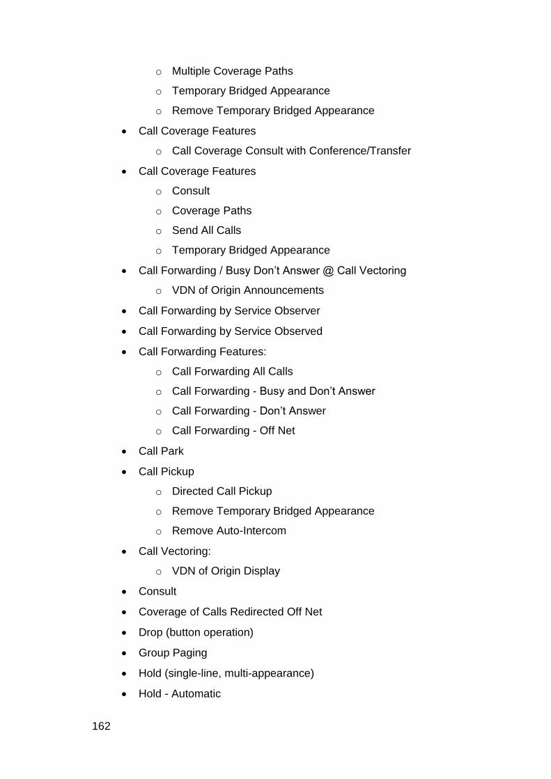
162
o Multiple Coverage Paths
o Temporary Bridged Appearance
o Remove Temporary Bridged Appearance
Call Coverage Features
o Call Coverage Consult with Conference/Transfer
Call Coverage Features
o Consult
o Coverage Paths
o Send All Calls
o Temporary Bridged Appearance
Call Forwarding / Busy Don‟t Answer @ Call Vectoring
o VDN of Origin Announcements
Call Forwarding by Service Observer
Call Forwarding by Service Observed
Call Forwarding Features:
o Call Forwarding All Calls
o Call Forwarding - Busy and Don‟t Answer
o Call Forwarding - Don‟t Answer
o Call Forwarding - Off Net
Call Park
Call Pickup
o Directed Call Pickup
o Remove Temporary Bridged Appearance
o Remove Auto-Intercom
Call Vectoring:
o VDN of Origin Display
Consult
Coverage of Calls Redirected Off Net
Drop (button operation)
Group Paging
Hold (single-line, multi-appearance)
Hold - Automatic

Appendix A: Communication Manager Features
Application Enablement Services Device, Media and Call Control XML Programmer‟s Guide 163
Hold (single-line, multi-appearance)
Hold - Automatic [from IR1V4 WCC]
Hunting/Hunt Groups
IP Trunks
Last Number Dialed
Leave Word Calling - Switch
Malicious Call Trace
Message Waiting Indication
Music-on-Hold Access
o Held Calls
o Conference-Terminal Calls
o Transferred Trunk Calls
Personalized Ringing
Personal Station Access
Priority Calling
Recorded Announcement
Terminal Translation Initialization (TTI)
Tone on Hold
Transfer (single-line, multi-appearance)
Voice Terminal Display
o Calling Number Display (SID/ANI/Extn ID)
o Called Number Display (internal & DCS)
o Stored Button Display
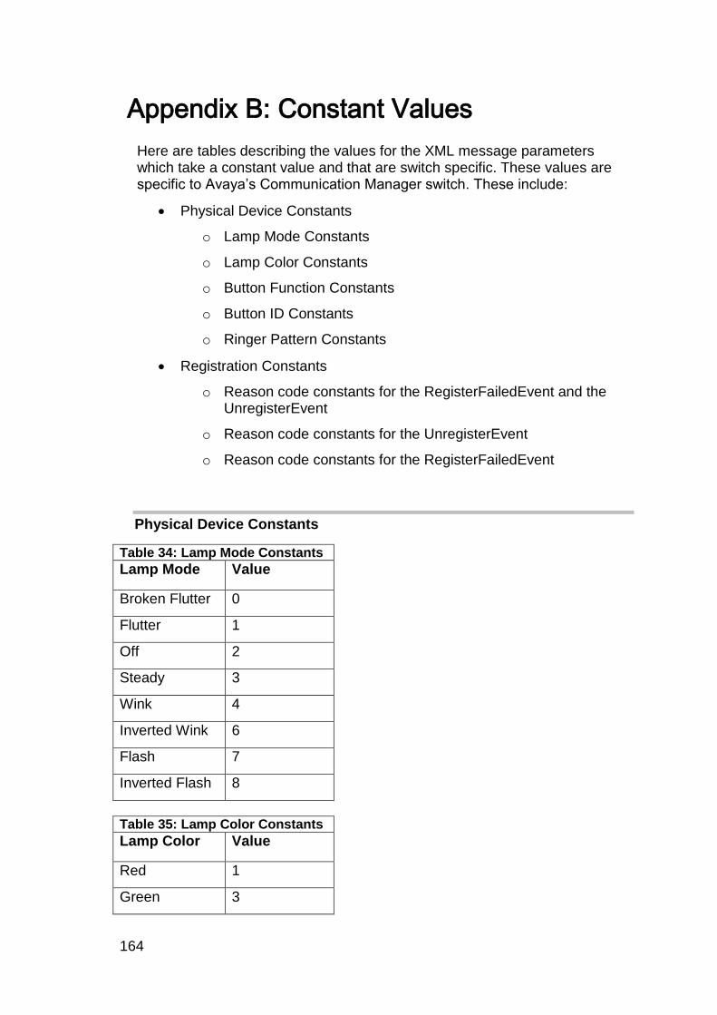
164
Appendix B: Constant Values
Here are tables describing the values for the XML message parameters which take a constant value and that are switch specific. These values are specific to Avaya‟s Communication Manager switch. These include:
Physical Device Constants
o Lamp Mode Constants
o Lamp Color Constants
o Button Function Constants
o Button ID Constants
o Ringer Pattern Constants
Registration Constants
o Reason code constants for the RegisterFailedEvent and the UnregisterEvent
o Reason code constants for the UnregisterEvent
o Reason code constants for the RegisterFailedEvent
Physical Device Constants
Table 34: Lamp Mode Constants
Lamp Mode Value
Broken Flutter 0
Flutter 1
Off 2
Steady 3
Wink 4
Inverted Wink 6
Flash 7
Inverted Flash 8
Table 35: Lamp Color Constants
Lamp Color Value
Red 1
Green 3
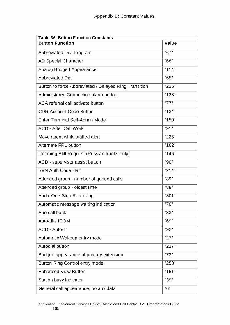
Appendix B: Constant Values
Application Enablement Services Device, Media and Call Control XML Programmer‟s Guide 165
Table 36: Button Function Constants
Button Function Value
Abbreviated Dial Program "67"
AD Special Character "68"
Analog Bridged Appearance "114"
Abbreviated Dial "65"
Button to force Abbreviated / Delayed Ring Transition "226"
Administered Connection alarm button "128"
ACA referral call activate button "77"
CDR Account Code Button "134"
Enter Terminal Self-Admin Mode "150"
ACD - After Call Work "91"
Move agent while staffed alert "225"
Alternate FRL button "162"
Incoming ANI Request (Russian trunks only) "146"
ACD - supervisor assist button "90"
SVN Auth Code Halt "214"
Attended group - number of queued calls "89"
Attended group - oldest time "88"
Audix One-Step Recording "301"
Automatic message waiting indication "70"
Auo call back "33"
Auto-dial ICOM "69"
ACD - Auto-In "92"
Automatic Wakeup entry mode "27"
Autodial button "227"
Bridged appearance of primary extension "73"
Button Ring Control entry mode "258"
Enhanced View Button "151"
Station busy indicator "39"
General call appearance, no aux data "6"
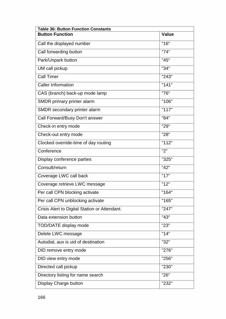
166
Table 36: Button Function Constants
Button Function Value
Call the displayed number "16"
Call forwarding button "74"
Park/Unpark button "45"
UM call pickup "34"
Call Timer "243"
Caller Information "141"
CAS (branch) back-up mode lamp "76"
SMDR primary printer alarm "106"
SMDR secondary printer alarm "117"
Call Forward/Busy Don't answer "84"
Check-in entry mode "29"
Check-out entry mode "28"
Clocked override-time of day routing "112"
Conference "2"
Display conference parties "325"
Consult/return "42"
Coverage LWC call back "17"
Coverage retrieve LWC message "12"
Per call CPN blocking activate "164"
Per call CPN unblocking activate "165"
Crisis Alert to Digital Station or Attendant. "247"
Data extension button "43"
TOD/DATE display mode "23"
Delete LWC message "14"
Autodial, aux is uid of destination "32"
DID remove entry mode "276"
DID view entry mode "256"
Directed call pickup "230"
Directory listing for name search "26"
Display Charge button "232"

Appendix B: Constant Values
Application Enablement Services Device, Media and Call Control XML Programmer‟s Guide 167
Table 36: Button Function Constants
Button Function Value
NORMAL/LOCAL mode button "124"
User do not disturb button "99"
Drop the last party on a conference call "1"
EC500 Feature plus timer "335"
Manual exclusion "41"
Do not disturb - ext. "95"
OPTIM Extend call "345"
Conf Select Far End Mute "328"
Flash button for station on CAS MAIN call OR a call using Trunk Flash
"110"
Goto coverage button "36"
Do not disturb - grp. "96"
Group Paging button "135"
Headset in use "241"
Hold "4"
Hunt night service button "101"
Inspect display mode "21"
Internal Automatic Answer button "108"
Last number dialed "66"
License error "312"
Link alarm button "103"
SVN login security violation "144"
Cancel LWC "19"
Lockout LWC "18"
LWC store message "10"
Major alarm button "104"
Manual message waiting button "38"
Manual override-time of day routing "113"
ACD - Manual-In "93"
MCT: Malicious Call Trace Activate "160"
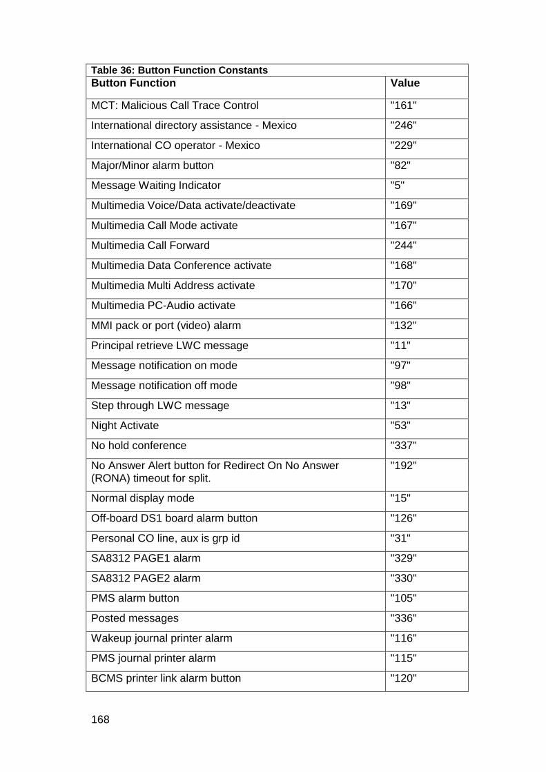
168
Table 36: Button Function Constants
Button Function Value
MCT: Malicious Call Trace Control "161"
International directory assistance - Mexico "246"
International CO operator - Mexico "229"
Major/Minor alarm button "82"
Message Waiting Indicator "5"
Multimedia Voice/Data activate/deactivate "169"
Multimedia Call Mode activate "167"
Multimedia Call Forward "244"
Multimedia Data Conference activate "168"
Multimedia Multi Address activate "170"
Multimedia PC-Audio activate "166"
MMI pack or port (video) alarm “132"
Principal retrieve LWC message "11"
Message notification on mode "97"
Message notification off mode "98"
Step through LWC message "13"
Night Activate "53"
No hold conference "337"
No Answer Alert button for Redirect On No Answer (RONA) timeout for split.
"192"
Normal display mode "15"
Off-board DS1 board alarm button "126"
Personal CO line, aux is grp id "31"
SA8312 PAGE1 alarm "329"
SA8312 PAGE2 alarm "330"
PMS alarm button "105"
Posted messages "336"
Wakeup journal printer alarm "116"
PMS journal printer alarm "115"
BCMS printer link alarm button "120"

Appendix B: Constant Values
Application Enablement Services Device, Media and Call Control XML Programmer‟s Guide 169
Table 36: Button Function Constants
Button Function Value
Priority calling button "81"
Hunt group - number of queued calls "87"
Hunt group - oldest queued time "86"
ACD - Release "94"
Ringer status "259"
Ringer cut button for stations "80"
System reset alert "109"
SVN remote access security violation "145"
SCROLL mode button "125"
Send all calls button "35"
Terminating extension group SAC button "72"
Service observing button "85"
Share Talk “331”
Manual signalling "37"
SVN station security call activate button "231"
Station Lock "300"
Start Billing "257"
STORED-NUMBER display mode "22"
Single-Digit Stroke Counts "129"
Secondary extensions "40"
ELAPSED-TIME display mode "24"
Conf/Transfer Toggle Swap "327"
Transfer "3"
Facility acc test trunk access alert "121"
Trunk ID button "63"
Trunk name when DCS (also DCS CAS MN) "111"
Trunk night service button "102"
Add FBI to station "239"
Remove FBI from station "240"
UUI-info button "228"

170
Table 36: Button Function Constants
Button Function Value
VC pack or port (audio) alarm "133"
Busy verification button "75"
VIP check-in "277"
Reschedule VIP wakeup as regular wakeup "148"
Place VIP wakeup call "147"
VDN of Origin Annc. Repeat Button "208"
Engen fixed voice mail "326"
Vu-Stats Station Displays "211"
Warn alarm "107"
Activate Whisper Page "136"
Answerback for Whisper Page "137"
Whisper Page Off "138"
Multi-Digit Stroke Count "140"
Table 37: Button Id Constants for 4624, 6424, 8410D & 8434D phones
Button Id Value
Dial Pad 0 "0"
Dial Pad 1 "1"
Dial Pad 2 "2"
Dial Pad 3 "3"
Dial Pad 4 "4"
Dial Pad 5 "5"
Dial Pad 6 "6"
Dial Pad 7 "7"
Dial Pad 8 "8"
Dial Pad 9 "9‟
Dial Pad * "10"
Dial Pad # "11"
Principal Module "256"
Redial button on IP phone sets "257"
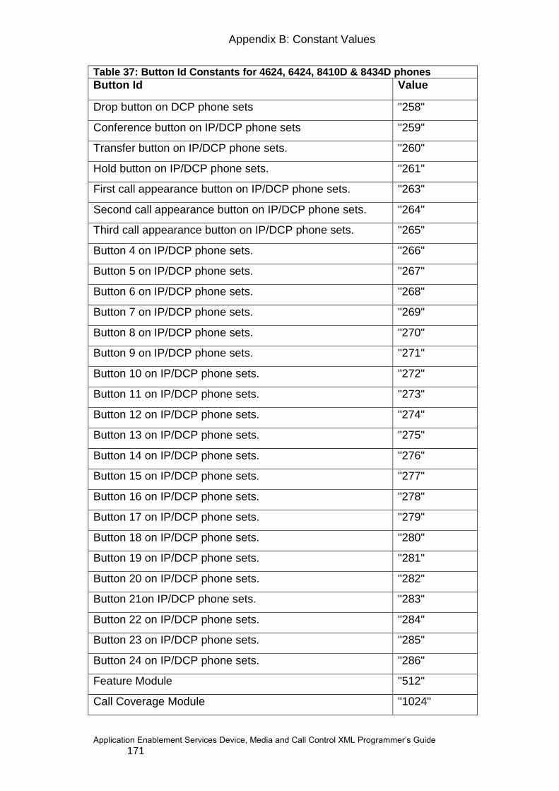
Appendix B: Constant Values
Application Enablement Services Device, Media and Call Control XML Programmer‟s Guide 171
Table 37: Button Id Constants for 4624, 6424, 8410D & 8434D phones
Button Id Value
Drop button on DCP phone sets "258"
Conference button on IP/DCP phone sets "259"
Transfer button on IP/DCP phone sets. "260"
Hold button on IP/DCP phone sets. "261"
First call appearance button on IP/DCP phone sets. "263"
Second call appearance button on IP/DCP phone sets. "264"
Third call appearance button on IP/DCP phone sets. "265"
Button 4 on IP/DCP phone sets. "266"
Button 5 on IP/DCP phone sets. "267"
Button 6 on IP/DCP phone sets. "268"
Button 7 on IP/DCP phone sets. "269"
Button 8 on IP/DCP phone sets. "270"
Button 9 on IP/DCP phone sets. "271"
Button 10 on IP/DCP phone sets. "272"
Button 11 on IP/DCP phone sets. "273"
Button 12 on IP/DCP phone sets. "274"
Button 13 on IP/DCP phone sets. "275"
Button 14 on IP/DCP phone sets. "276"
Button 15 on IP/DCP phone sets. "277"
Button 16 on IP/DCP phone sets. "278"
Button 17 on IP/DCP phone sets. "279"
Button 18 on IP/DCP phone sets. "280"
Button 19 on IP/DCP phone sets. "281"
Button 20 on IP/DCP phone sets. "282"
Button 21on IP/DCP phone sets. "283"
Button 22 on IP/DCP phone sets. "284"
Button 23 on IP/DCP phone sets. "285"
Button 24 on IP/DCP phone sets. "286"
Feature Module "512"
Call Coverage Module "1024"

172
Table 37: Button Id Constants for 4624, 6424, 8410D & 8434D phones
Button Id Value
Display Module "768"
DTDM "1280"
DXS/BLF Module "1536"
Terminal Module (Type 2) "1792"
Menu Button on IP/DCP phone sets. "785"
Exit Button on IP/DCP phone sets. "782"
First Button on the first row on IP/DCP phone sets. "770"
Second Button on the first row on IP/DCP phone sets. "771"
Third Button on the first row on IP/DCP phone sets. "772"
Fourth Button on the first row on IP/DCP phone sets. "773
First Button on the second row on IP/DCP phone sets "774"
Second Button on the second row on IP/DCP phone sets "775"
Third Button on the second row on IP/DCP phone sets "776"
Fourth Button on the second row on IP/DCP phone sets "777"
First Button on the third row on IP/DCP phone sets "778"
Second Button on the third row on IP/DCP phone sets "779
Third Button on the third row on IP/DCP phone sets "780"
Fourth Button on the third row on IP/DCP phone sets "781"
Exit Button on DCP 8410D phone sets. "273"
First Button on the first row on DCP8410 phone sets. "274
Second Button on the first row on DCP8410 phone sets. "275"
Third Button on the first row on DCP8410 phone sets. "276"
Fourth Button on the first row on DCP8410 phone sets. "277"
First Button on the second row on DCP8410 phone sets. "278"
Second Button on the second row on DCP8410 phone sets.
"279"
Third Button on the second row on DCP8410 phone sets. "280"
Fourth Button on the second row on DCP8410 phone sets. "281"
First Button on the third row on DCP8410 phone sets. "282
Second Button on the third row on DCP8410 phone sets. "283"
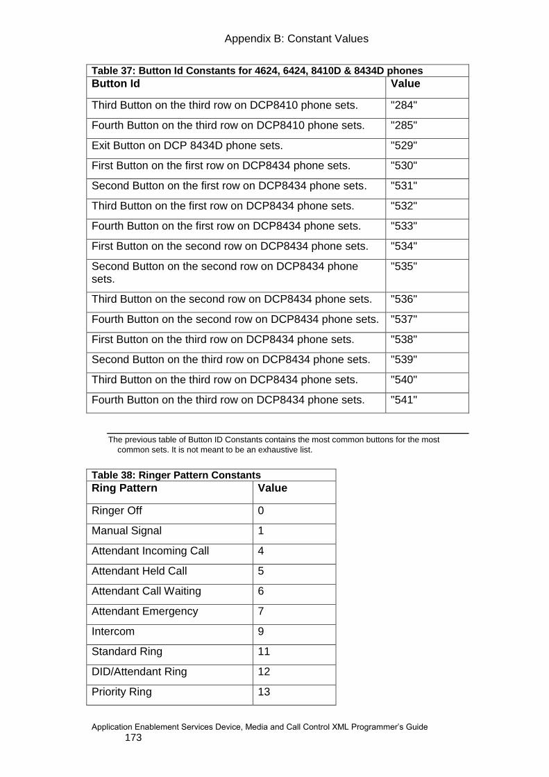
Appendix B: Constant Values
Application Enablement Services Device, Media and Call Control XML Programmer‟s Guide 173
Table 37: Button Id Constants for 4624, 6424, 8410D & 8434D phones
Button Id Value
Third Button on the third row on DCP8410 phone sets. "284"
Fourth Button on the third row on DCP8410 phone sets. "285"
Exit Button on DCP 8434D phone sets. "529"
First Button on the first row on DCP8434 phone sets. "530"
Second Button on the first row on DCP8434 phone sets. "531"
Third Button on the first row on DCP8434 phone sets. "532"
Fourth Button on the first row on DCP8434 phone sets. "533"
First Button on the second row on DCP8434 phone sets. "534"
Second Button on the second row on DCP8434 phone sets.
"535"
Third Button on the second row on DCP8434 phone sets. "536"
Fourth Button on the second row on DCP8434 phone sets. "537"
First Button on the third row on DCP8434 phone sets. "538"
Second Button on the third row on DCP8434 phone sets. "539"
Third Button on the third row on DCP8434 phone sets. "540"
Fourth Button on the third row on DCP8434 phone sets. "541"
The previous table of Button ID Constants contains the most common buttons for the most
common sets. It is not meant to be an exhaustive list.
Table 38: Ringer Pattern Constants
Ring Pattern Value
Ringer Off 0
Manual Signal 1
Attendant Incoming Call 4
Attendant Held Call 5
Attendant Call Waiting 6
Attendant Emergency 7
Intercom 9
Standard Ring 11
DID/Attendant Ring 12
Priority Ring 13

174
Table 38: Ringer Pattern Constants
Ring Pattern Value
Ring Ping 14
Registration Constants
Table 39: Registration Constants
Reason code constants for the RegisterFailedEvent and the UnregisterEvent
Value
Unknown -1
Non-specific -2
Internal failure -3
Network timeout 1000
Table 40: Registration Constants
Reason code constants for the UnregisterEvent only
Value
Client application requested unregistration. 2000
Lost connection to Communication Manager switch unregistration.
2001
Administrator initiated unregistration via AE Services Management Console.
2002
Table 41: Registration Constants
Reason code constants for the RegisterFailedEvent only Value
A bad password/DeviceID combination was sent in the register request
3000
A non-existent extension on the switch was specified. 3001
The phone/extension is already registered with the switch and the forceLogin option was set to false
3002
The limit of allowed CMAPI softphones has been reached 3003
The limit of allowed IP phones has been reached 3004
The license file indicates that no IP_API_A licenses have been purchased
3005
The 911 registration parameters did not match the 911 settings of the station on the switch
3006
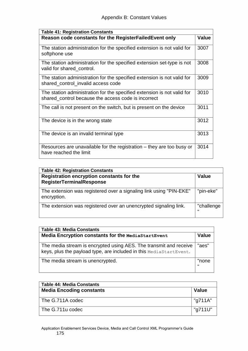
Appendix B: Constant Values
Application Enablement Services Device, Media and Call Control XML Programmer‟s Guide 175
Table 41: Registration Constants
Reason code constants for the RegisterFailedEvent only Value
The station administration for the specified extension is not valid for softphone use
3007
The station administration for the specified extension set-type is not valid for shared_control.
3008
The station administration for the specified extension is not valid for shared_control_invalid access code
3009
The station administration for the specified extension is not valid for shared_control because the access code is incorrect
3010
The call is not present on the switch, but is present on the device 3011
The device is in the wrong state 3012
The device is an invalid terminal type 3013
Resources are unavailable for the registration – they are too busy or have reached the limit
3014
Table 42: Registration Constants
Registration encryption constants for the RegisterTerminalResponse
Value
The extension was registered over a signaling link using "PIN-EKE" encryption.
"pin-eke"
The extension was registered over an unencrypted signaling link. "challenge"
Table 43: Media Constants
Media Encryption constants for the MediaStartEvent Value
The media stream is encrypted using AES. The transmit and receive
keys, plus the payload type, are included in this MediaStartEvent.
"aes"
The media stream is unencrypted. "none"
Table 44: Media Constants
Media Encoding constants Value
The G.711A codec "g711A"
The G.711u codec "g711U"

176
Table 44: Media Constants
Media Encoding constants Value
The G.729 codec "g729"
The G.729A codec "g729A"
The G.723 codec (client media only) "g723"
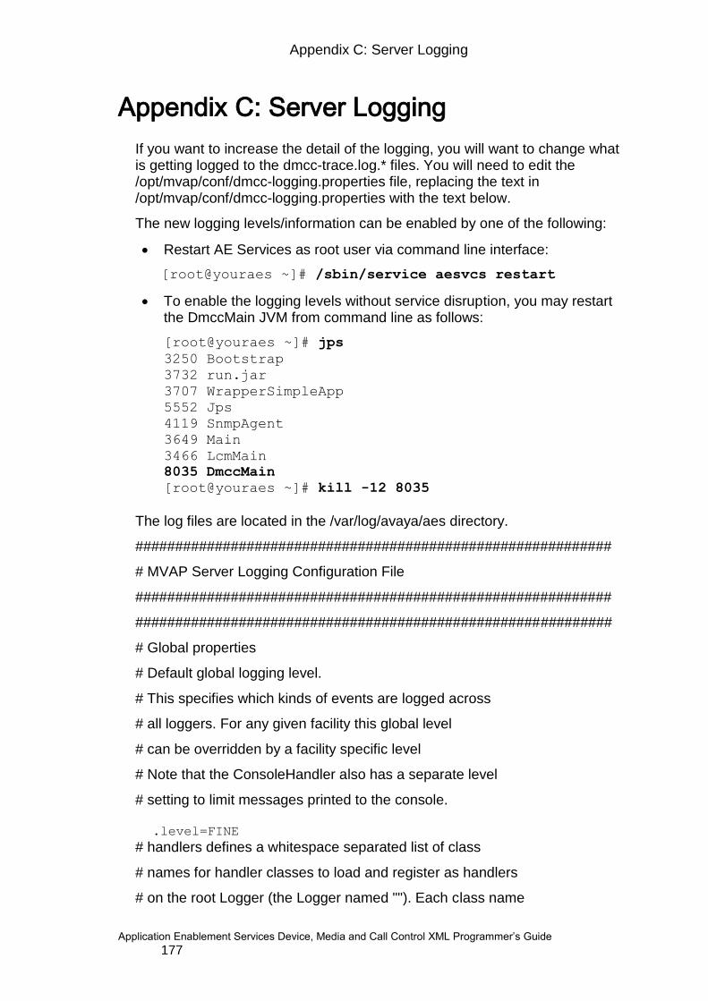
Appendix C: Server Logging
Application Enablement Services Device, Media and Call Control XML Programmer‟s Guide 177
Appendix C: Server Logging
If you want to increase the detail of the logging, you will want to change what is getting logged to the dmcc-trace.log.* files. You will need to edit the /opt/mvap/conf/dmcc-logging.properties file, replacing the text in /opt/mvap/conf/dmcc-logging.properties with the text below.
The new logging levels/information can be enabled by one of the following:
Restart AE Services as root user via command line interface:
[root@youraes ~]# /sbin/service aesvcs restart
To enable the logging levels without service disruption, you may restart the DmccMain JVM from command line as follows:
[root@youraes ~]# jps
3250 Bootstrap
3732 run.jar
3707 WrapperSimpleApp
5552 Jps
4119 SnmpAgent
3649 Main
3466 LcmMain
8035 DmccMain
[root@youraes ~]# kill -12 8035
The log files are located in the /var/log/avaya/aes directory.
############################################################
# MVAP Server Logging Configuration File
############################################################
############################################################
# Global properties
# Default global logging level.
# This specifies which kinds of events are logged across
# all loggers. For any given facility this global level
# can be overridden by a facility specific level
# Note that the ConsoleHandler also has a separate level
# setting to limit messages printed to the console.
.level=FINE
# handlers defines a whitespace separated list of class
# names for handler classes to load and register as handlers
# on the root Logger (the Logger named ""). Each class name
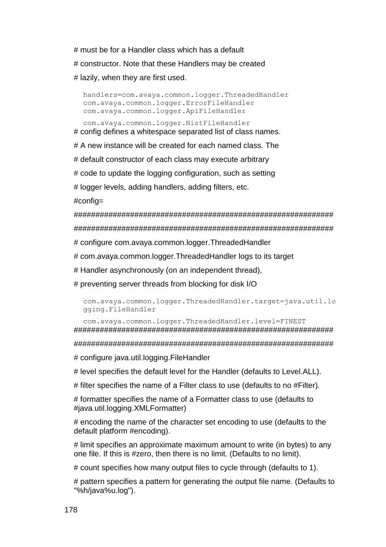
178
# must be for a Handler class which has a default
# constructor. Note that these Handlers may be created
# lazily, when they are first used.
handlers=com.avaya.common.logger.ThreadedHandler
com.avaya.common.logger.ErrorFileHandler
com.avaya.common.logger.ApiFileHandler
com.avaya.common.logger.NistFileHandler
# config defines a whitespace separated list of class names.
# A new instance will be created for each named class. The
# default constructor of each class may execute arbitrary
# code to update the logging configuration, such as setting
# logger levels, adding handlers, adding filters, etc.
#config=
############################################################
############################################################
# configure com.avaya.common.logger.ThreadedHandler
# com.avaya.common.logger.ThreadedHandler logs to its target
# Handler asynchronously (on an independent thread),
# preventing server threads from blocking for disk I/O
com.avaya.common.logger.ThreadedHandler.target=java.util.lo
gging.FileHandler
com.avaya.common.logger.ThreadedHandler.level=FINEST
############################################################
############################################################
# configure java.util.logging.FileHandler
# level specifies the default level for the Handler (defaults to Level.ALL).
# filter specifies the name of a Filter class to use (defaults to no #Filter).
# formatter specifies the name of a Formatter class to use (defaults to #java.util.logging.XMLFormatter)
# encoding the name of the character set encoding to use (defaults to the default platform #encoding).
# limit specifies an approximate maximum amount to write (in bytes) to any one file. If this is #zero, then there is no limit. (Defaults to no limit).
# count specifies how many output files to cycle through (defaults to 1).
# pattern specifies a pattern for generating the output file name. (Defaults to "%h/java%u.log").

Appendix C: Server Logging
Application Enablement Services Device, Media and Call Control XML Programmer‟s Guide 179
# append specifies whether the FileHandler should append onto any existing files (defaults to #false).
java.util.logging.FileHandler.level=FINEST
java.util.logging.FileHandler.pattern=../logs/dmcc-
trace.log
java.util.logging.FileHandler.limit=10485760
java.util.logging.FileHandler.count=20
java.util.logging.FileHandler.formatter=com.avaya.common.lo
gger.MillisecFormatter
############################################################
############################################################
# configure com.avaya.common.logger.ErrorFileHandler
# This handler contains code that uses a MemoryHandler that
# pushes to a ThreadedHandler whose target is a FileHandler
# with the pattern specified here. The level set here
# is propagated through the entire Handler chain.
# The result is a log containing detailed error pretext.
com.avaya.common.logger.ErrorFileHandler.level=WARNING
com.avaya.common.logger.ErrorFileHandler.pattern=../logs/mv
ap-error.log
############################################################
############################################################
# configure java.util.logging.MemoryHandler
# filter specifies the name of a Filter class to use (defaults to no Filter).
# level specifies the level for the Handler (defaults to Level.ALL)
# size defines the buffer size (defaults to 1000).
# push defines the pushLevel (defaults to level.SEVERE).
# target specifies the name of the target Handler class. (no default).
java.util.logging.MemoryHandler.level=FINEST
java.util.logging.MemoryHandler.size=1000
java.util.logging.MemoryHandler.push=WARNING
############################################################
############################################################
# configure com.avaya.common.logger.ApiFileHandler
# This handler is a ThreadedHandler whose target is a
# FileHandler with the pattern specified here. The level set

180
# here is propagated to the FileHandler. By default, this
# Handler is configured with a filter to log all API calls.
# filter specifies the name of a Filter class to use (defaults to no Filter).
com.avaya.common.logger.ApiFileHandler.level=FINE
com.avaya.common.logger.ApiFileHandler.pattern=../logs/mvap
-api.log
com.avaya.common.logger.ApiFileHandler.filter=com.avaya.com
mon.logger.RegExFilter
############################################################
############################################################
# configure com.avaya.common.logger.RegExFilter
# Filters LogRecords by matching their Logger name using the
# regular expression specified in the pattern property.
com.avaya.common.logger.RegExFilter.pattern=^com\.avaya\.ap
i.*
############################################################
############################################################
# Facility specific properties (extra control per logger)
#com.xyz.foo.level = SEVERE
sun.rmi.level = WARNING
com.avaya.platform.jmx.Mx4jXSLTProcessor.level = WARNING
############################################################ # configure com.avaya.common.logger.NistFileHandler # It is configured with a filter to log nist sip stack output. # NIST SIP Stack log level : FINEST, FINER, INFO, WARNING, OFF ############################################################ com.avaya.common.logger.NistFileHandler.level=OFF
com.avaya.common.logger.NistFileHandler.pattern=/var/log/avaya/a
es/dmcc-nist.log
com.avaya.common.logger.NistFileHandler.filter=com.avaya.common.
logger.NistRegExFilter
com.avaya.common.logger.NistRegExFilter.pattern=^gov\.nist\.java
x\.sip\.stack\.ServerLog
com.avaya.common.logger.NistFileHandler.LOG_MESSAGE_CONTENT=true
############################################################
# #################################################

Appendix C: Server Logging
Application Enablement Services Device, Media and Call Control XML Programmer‟s Guide 181
# Enable tracing of all XML messages into the dmcc-trace.log.* files
com.avaya.mvcs.proxy.CstaMarshallerNode.level=FINEST
com.avaya.mvcs.proxy.CstaUnmarshallerNode.level=FINEST
############################################################
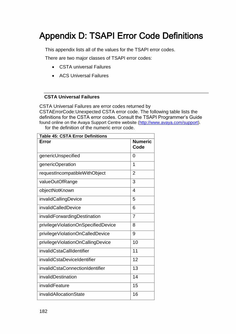
182
Appendix D: TSAPI Error Code Definitions
This appendix lists all of the values for the TSAPI error codes.
There are two major classes of TSAPI error codes:
CSTA universal Failures
ACS Universal Failures
CSTA Universal Failures
CSTA Universal Failures are error codes returned by CSTAErrorCode:Unexpected CSTA error code. The following table lists the definitions for the CSTA error codes. Consult the TSAPI Programmer‟s Guide found online on the Avaya Support Centre website (http://www.avaya.com/support).
for the definition of the numeric error code.
Table 45: CSTA Error Definitions
Error Numeric Code
genericUnspecified 0
genericOperation 1
requestIncompatibleWithObject 2
valueOutOfRange 3
objectNotKnown 4
invalidCallingDevice 5
invalidCalledDevice 6
invalidForwardingDestination 7
privilegeViolationOnSpecifiedDevice 8
privilegeViolationOnCalledDevice 9
privilegeViolationOnCallingDevice 10
invalidCstaCallIdentifier 11
invalidCstaDeviceIdentifier 12
invalidCstaConnectionIdentifier 13
invalidDestination 14
invalidFeature 15
invalidAllocationState 16

Appendix D: TSAPI Error Code Definitions
Application Enablement Services Device, Media and Call Control XML Programmer‟s Guide 183
Table 45: CSTA Error Definitions
Error Numeric Code
invalidCrossRefId 17
invalidObjectType 18
securityViolation 19
genericStateIncompatibility 21
invalidObjectState 22
invalidConnectionIdForActiveCall 23
noActiveCall 24
noHeldCall 25
noCallToClear 26
noConnectionToClear 27
noCallToAnswer 28
noCallToComplete 29
genericSystemResourceAvailability 31
serviceBusy 32
resourceBusy 33
resourceOutOfService 34
networkBusy 35
networkOutOfService 36
overallMonitorLimitExceeded 37
conferenceMemberLimitExceeded 38
genericSubscribedResourceAvailability 41
objectMonitorLimitExceeded 42
externalTrunkLimitExceeded 43
outstandingRequestLimitExceeded 44
genericPerformanceManagement 51
performanceLimitExceeded 52
unspecifiedSecurityError 60
sequenceNumberViolated 61
timeStampViolated 62

184
Table 45: CSTA Error Definitions
Error Numeric Code
pacViolated 63
sealViolated 64
genericUnspecifiedRejection 70
genericOperationRejection 71
duplicateInvocationRejection 72
unrecognizedOperationRejection 73
mistypedArgumentRejection 74
resourceLimitationRejection 75
acsHandleTerminationRejection 76
serviceTerminationRejection 77
requestTimeoutRejection 78
requestsOnDeviceExceededRejection 79
unrecognizedApduRejection 80
mistypedApduRejection 81
badlyStructuredApduRejection 82
initiatorReleasingRejection 83
unrecognizedLinkedidRejection 84
linkedResponseUnexpectedRejection 85
unexpectedChildOperationRejection 86
mistypedResultRejection 87
unrecognizedErrorRejection 88
unexpectedErrorRejection 89
mistypedParameterRejection 90
nonStandard 100
ACS Universal Failures
ACS Universal Failures are error codes returned by CSTAErrorCode: Unexpected ACS error code. The following table lists the definitions for the ACS error codes. Consult the TSAPI Programmer‟s Guide for the definition of the numeric error code

Appendix D: TSAPI Error Code Definitions
Application Enablement Services Device, Media and Call Control XML Programmer‟s Guide 185
Table 46: ACS Error Definitions
Error Numeric Code
Description
ACSERR_APIVERDENIED -1 This return indicates that the API Version requested is invalid and not supported by the existing API Client Library.
ACSERR_BADPARAMETER -2 One or more of the parameters is invalid.
ACSERR_DUPSTREAM -3 This return indicates that an ACS Stream is already established with the requested Server.
ACSERR_NODRIVER -4 This error return value indicates that no API Client Library Driver was found or installed on the system.
ACSERR_NOSERVER -5 This indicates that the requested Server is not present in the network.
ACSERR_NORESOURCE -6 This return value indicates that there are insufficient resources to open a ACS Stream.
ACSERR_UBUFSMALL -7 The user buffer size was smaller than the size of the next available event.
ACSERR_NOMESSAGE -8 There were no messages available to return to the application.
ACSERR_UNKNOWN -9 The ACS Stream has encountered an unspecified error.
ACSERR_BADHDL -10 The ACS Handle is invalid.
ACSERR_STREAM_FAILED -11 The ACS Stream has failed due to network problems. No further operations are possible on this stream.
ACSERR_NOBUFFERS -12 There were not enough buffers available to place an outgoing message on the send queue. No message has been sent.
ACSERR_QUEUE_FULL -13 The send queue is full.
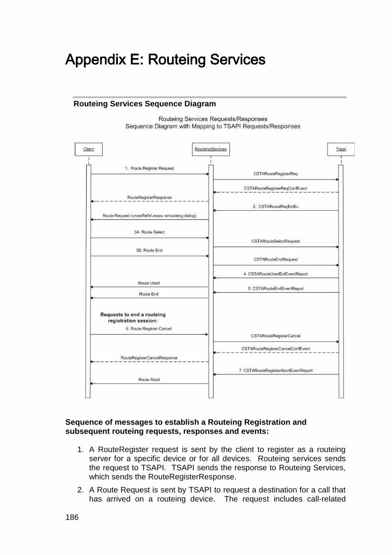
186
Appendix E: Routeing Services
Routeing Services Sequence Diagram
Sequence of messages to establish a Routeing Registration and subsequent routeing requests, responses and events:
1. A RouteRegister request is sent by the client to register as a routeing server for a specific device or for all devices. Routeing services sends the request to TSAPI. TSAPI sends the response to Routeing Services, which sends the RouteRegisterResponse.
2. A Route Request is sent by TSAPI to request a destination for a call that has arrived on a routeing device. The request includes call-related
Appendix E: Routeing Services
Application Enablement Services Device, Media and Call Control XML Programmer‟s Guide 187
information that the routing server (ie client application) uses to determine the destination of the call. RouteingServices sends the Route Request to the client.
3. The client can respond in one of the following ways to the Route Request:
a. Send a Route Select Request that provides a destination, in which case the request is sent to TSAPI.
b. Send a Route End request to terminate the routeing dialog for the call and Routeing Services sends the request to TSAPI. The client may send this if it cannot provide a route for the call in question, in which case the switch provides the default routing for the call.
4. A RouteUsed Event is sent by TSAPI that contains the actual destination of a call for which the application previously sent a Route Select Request containing a destination. RouteingServices sends the RouteUsed event to the client.
5. A Route End Event is sent by TSAPI to terminate a routing dialog for a call and to inform the client of the outcome of the call routing. RouteingServices sends the Route End Request to the client. The errorValue parameter in the request specifies the reason for the route end request.
Requests to end a routeing registration session:
The following requests end a routeing registration session.
6. Client Application->Server Request: A Route Register Cancel request is sent by the client application to Routeing Services which sends the request to TSAPI. TSAPI de-allocates a routeRegisterRequestID and returns a response to RouteingServices which sends a RouteRegisterCancel response.
7. Server->Client application Request: A Route Register Abort event is sent by TSAPI and a Route Register Abort request is sent to the client application that contains the Route Register Request Id.
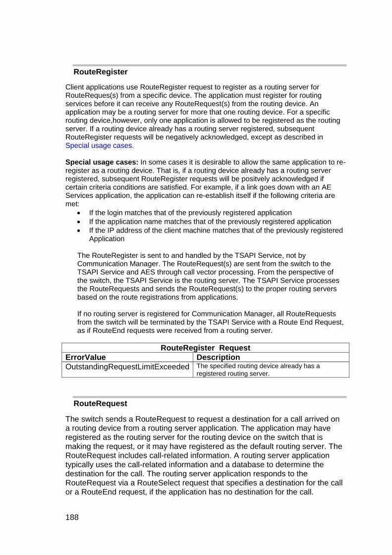
188
RouteRegister
Client applications use RouteRegister request to register as a routing server for RouteReques(s) from a specific device. The application must register for routing services before it can receive any RouteRequest(s) from the routing device. An application may be a routing server for more that one routing device. For a specific routing device,however, only one application is allowed to be registered as the routing server. If a routing device already has a routing server registered, subsequent RouteRegister requests will be negatively acknowledged, except as described in Special usage cases. Special usage cases: In some cases it is desirable to allow the same application to re-register as a routing device. That is, if a routing device already has a routing server registered, subsequent RouteRegister requests will be positvely acknowledged if certain criteria conditions are satisfied. For example, if a link goes down with an AE Services application, the application can re-establish itself if the following criteria are met:
If the login matches that of the previously registered application
If the application name matches that of the previously registered application
If the IP address of the client machine matches that of the previously registered Application
The RouteRegister is sent to and handled by the TSAPI Service, not by Communication Manager. The RouteRequest(s) are sent from the switch to the TSAPI Service and AES through call vector processing. From the perspective of the switch, the TSAPI Service is the routing server. The TSAPI Service processes the RouteRequests and sends the RouteRequest(s) to the proper routing servers based on the route registrations from applications. If no routing server is registered for Communication Manager, all RouteRequests from the switch will be terminated by the TSAPI Service with a Route End Request, as if RouteEnd requests were received from a routing server.
RouteRegister Request
ErrorValue Description
OutstandingRequestLimitExceeded The specified routing device already has a registered routing server.
RouteRequest
The switch sends a RouteRequest to request a destination for a call arrived on a routing device from a routing server application. The application may have registered as the routing server for the routing device on the switch that is making the request, or it may have registered as the default routing server. The RouteRequest includes call-related information. A routing server application typically uses the call-related information and a database to determine the destination for the call. The routing server application responds to the RouteRequest via a RouteSelect request that specifies a destination for the call or a RouteEnd request, if the application has no destination for the call.
Appendix E: Routeing Services
Application Enablement Services Device, Media and Call Control XML Programmer‟s Guide 189
The Routing Request Service can only be administered through the Basic Call Vectoring feature. The switch initiates the Routing Request when the Call Vectoring processing encounters the adjunct routing command in a call vector. The vector command will specify a CTI link‟s extension through which the switch will send the RouteRequest to AES DMCC through the TSAPI Service. Multiple adjunct routing commands are allowed in a call vector. In G3V3, the Multiple Outstanding Route Requests feature allows 16 outstanding Route Requests per call. The Route Requests can be over the same or different CTI links. The requests are all made from the same vector. They may be specified back-to-back, without intermediate (wait, announcement, goto, or stop) steps. If the adjunct routing commands are not specified back-to-back, pre-G3V3 adjunct routing functionality will apply. This means that previous outstanding RouteRequests are canceled when an adjunct routing vector step is executed. The first RouteSelect response received by the switch is used as the route for the call, and all other Route Requests for the call are canceled via RouteEnd event(s). If an application terminates the RouteRequest via a RouteEnd request, the switch continues vector processing. A RouteRequest will not affect the Call Event Reports. Like Delivered or Established Event, the RouteRequest currentRoute parameter contains the called device. The currentRoute in Route Request contains the originally called device if there is no distributing device, or the distributing device if the call vectoring with VDN override feature of the PBX is turned on. In the later case, the originally called device is not reported. The distributingDevice feature is not supported in the RouteRequest private data.
RouteSelect
The routing server application uses RouteSelect to provide a destination to the switch in response to a RouteRequest for a call. An application may receive one RouteEnd event and one Error for a RouteSelect request for the same call in one of the following call scenarios:
A RouteRequest is sent to the application.
Caller drops the call.
Application sends a RouteSelect request.
A RouteEnd event (errorValue = NoActiveCall) is sent to the application.
The RouteSelect request is sent, but the call has been dropped.
An Error is sent for the RouteSelect request (errorValue = InvalidCrossRefId) to application.
RouteSelect Request
ErrorValue Description

190
RouteSelect Request
ErrorValue Description
InvalidDeviceId An invalid routeRegisterReqID has been specified in the RouteEndInv() request
InvalidCrossRefId An invalid routeCrossRefID has been specified in the Route Select request.

Appendix E: Routeing Services
Application Enablement Services Device, Media and Call Control XML Programmer‟s Guide 191
RouteUsed Event
The switch uses a RouteUsed event to provide a destination to the routing server application with the actual destination of a call for which the application previously sent a request containing a destination. The routeUsed and destRoute parameters contain the same information specified in the routeSelected and destRoute parameters of the previous RouteSelect request of this call, respectively. The callingDevice parameter contains the same calling device number provided in the previous RouteRequest of this call. Note that the number provided in the routeUsed parameter is from the routeSelected parameter of the previous RouteSelect request of this call received by the TSAPI Service. This information in routeUsed is not from Communication Manager and it may not represent the true route that Communication Manager used. Note that the number provided in the destRoute parameter is from the destRoute parameter of the previous RouteSelect request of this call received by the TSAPI Service. This information in destRoute is not from the Communication Manager and it may not represent the true route that the Communication Manager used.
The number provided in the callingDevice parameter is from the callingDevice parameter of the previous RouteRequest of this call sent by the TSAPI Service.
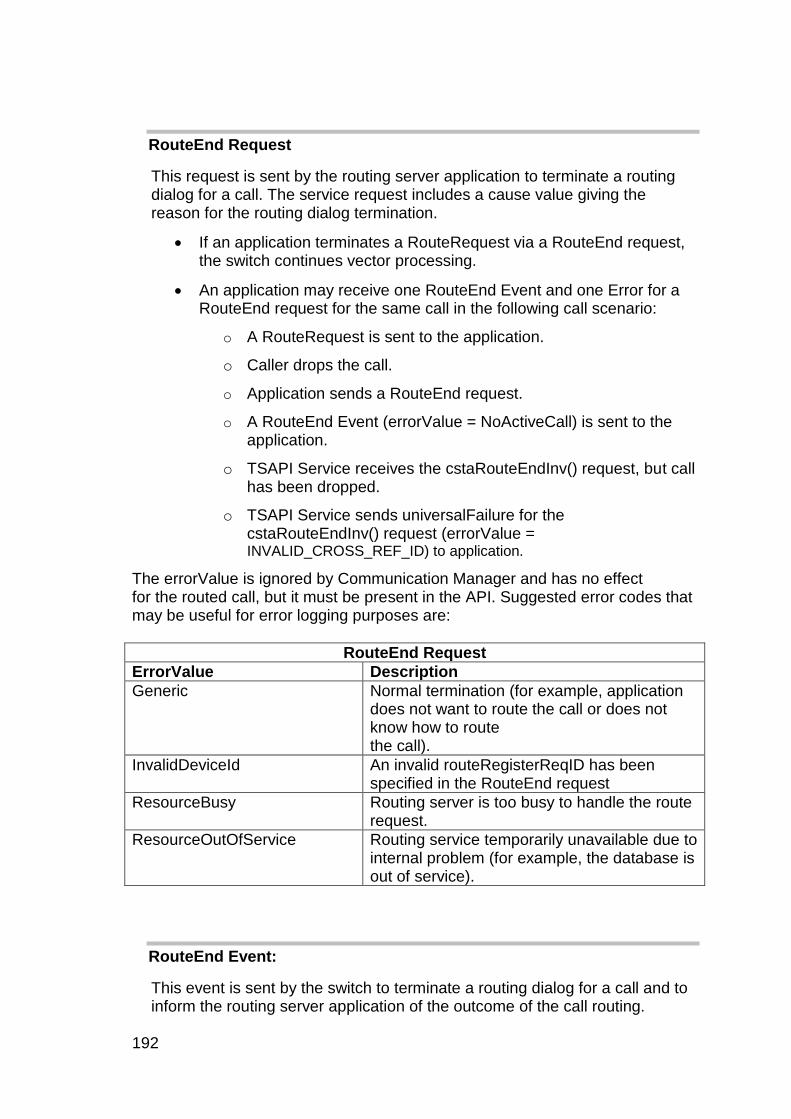
192
RouteEnd Request
This request is sent by the routing server application to terminate a routing dialog for a call. The service request includes a cause value giving the reason for the routing dialog termination.
If an application terminates a RouteRequest via a RouteEnd request, the switch continues vector processing.
An application may receive one RouteEnd Event and one Error for a RouteEnd request for the same call in the following call scenario:
o A RouteRequest is sent to the application.
o Caller drops the call.
o Application sends a RouteEnd request.
o A RouteEnd Event (errorValue = NoActiveCall) is sent to the application.
o TSAPI Service receives the cstaRouteEndInv() request, but call has been dropped.
o TSAPI Service sends universalFailure for the cstaRouteEndInv() request (errorValue = INVALID_CROSS_REF_ID) to application.
The errorValue is ignored by Communication Manager and has no effect for the routed call, but it must be present in the API. Suggested error codes that may be useful for error logging purposes are:
RouteEnd Request
ErrorValue Description
Generic
Normal termination (for example, application does not want to route the call or does not know how to route the call).
InvalidDeviceId An invalid routeRegisterReqID has been specified in the RouteEnd request
ResourceBusy Routing server is too busy to handle the route request.
ResourceOutOfService Routing service temporarily unavailable due to internal problem (for example, the database is out of service).
RouteEnd Event:
This event is sent by the switch to terminate a routing dialog for a call and to inform the routing server application of the outcome of the call routing.
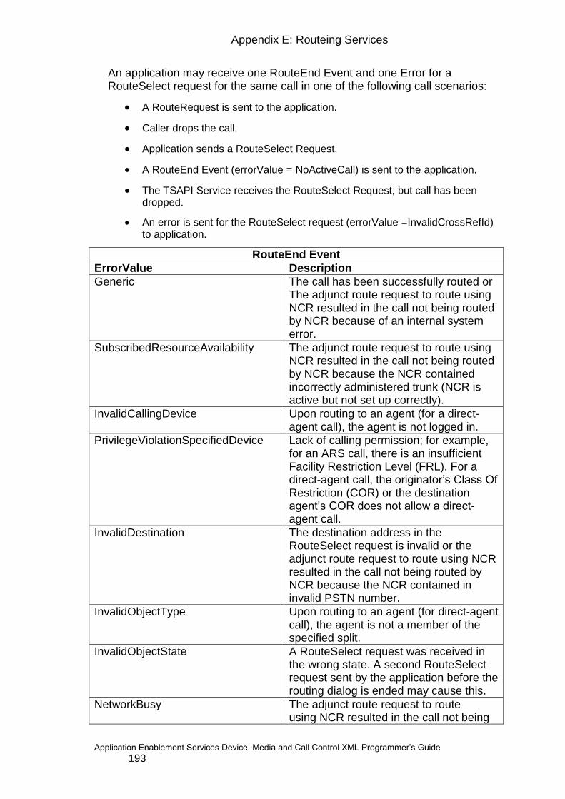
Appendix E: Routeing Services
Application Enablement Services Device, Media and Call Control XML Programmer‟s Guide 193
An application may receive one RouteEnd Event and one Error for a RouteSelect request for the same call in one of the following call scenarios:
A RouteRequest is sent to the application.
Caller drops the call.
Application sends a RouteSelect Request.
A RouteEnd Event (errorValue = NoActiveCall) is sent to the application.
The TSAPI Service receives the RouteSelect Request, but call has been dropped.
An error is sent for the RouteSelect request (errorValue =InvalidCrossRefId) to application.
RouteEnd Event
ErrorValue Description
Generic
The call has been successfully routed or The adjunct route request to route using NCR resulted in the call not being routed by NCR because of an internal system error.
SubscribedResourceAvailability The adjunct route request to route using NCR resulted in the call not being routed by NCR because the NCR contained incorrectly administered trunk (NCR is active but not set up correctly).
InvalidCallingDevice Upon routing to an agent (for a direct-agent call), the agent is not logged in.
PrivilegeViolationSpecifiedDevice Lack of calling permission; for example, for an ARS call, there is an insufficient Facility Restriction Level (FRL). For a direct-agent call, the originator‟s Class Of Restriction (COR) or the destination agent‟s COR does not allow a direct-agent call.
InvalidDestination The destination address in the RouteSelect request is invalid or the adjunct route request to route using NCR resulted in the call not being routed by NCR because the NCR contained in invalid PSTN number.
InvalidObjectType Upon routing to an agent (for direct-agent call), the agent is not a member of the specified split.
InvalidObjectState A RouteSelect request was received in the wrong state. A second RouteSelect request sent by the application before the routing dialog is ended may cause this.
NetworkBusy The adjunct route request to route using NCR resulted in the call not being
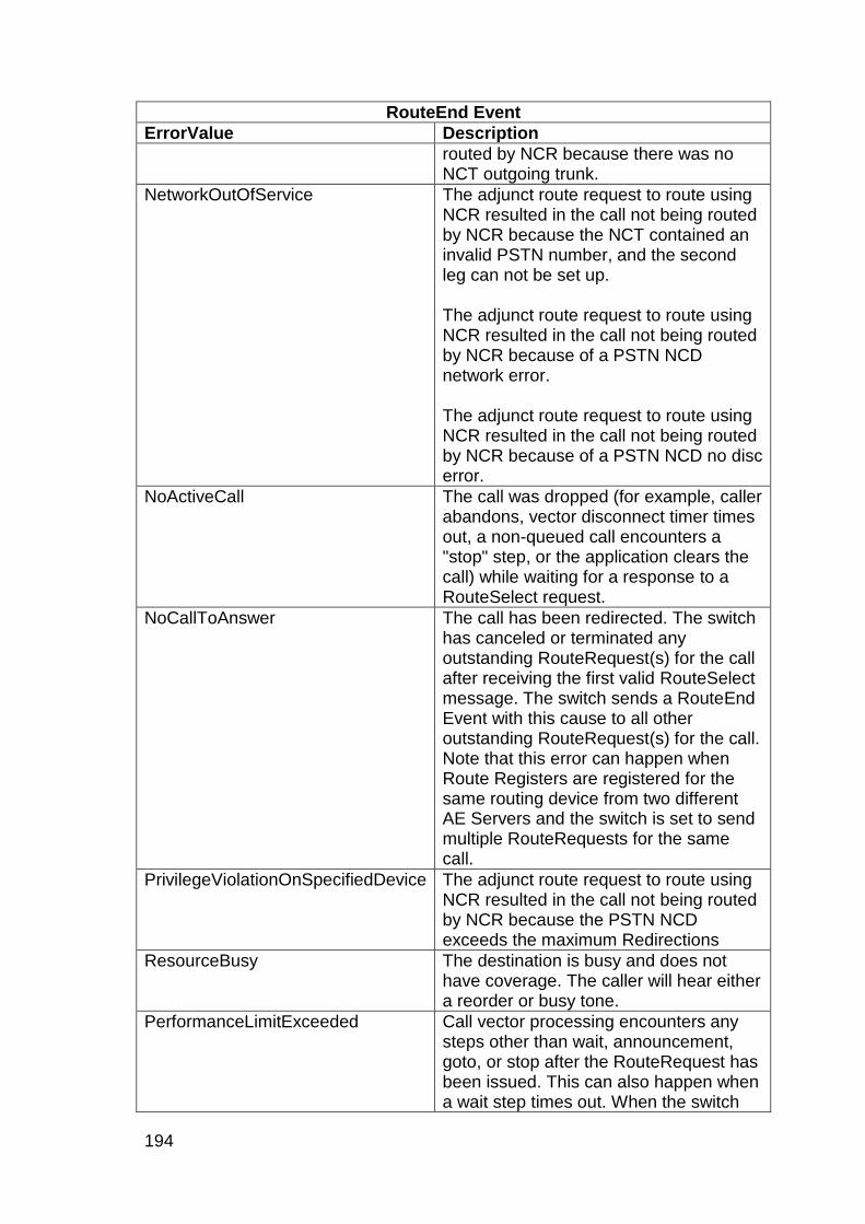
194
RouteEnd Event
ErrorValue Description
routed by NCR because there was no NCT outgoing trunk.
NetworkOutOfService The adjunct route request to route using NCR resulted in the call not being routed by NCR because the NCT contained an invalid PSTN number, and the second leg can not be set up. The adjunct route request to route using NCR resulted in the call not being routed by NCR because of a PSTN NCD network error. The adjunct route request to route using NCR resulted in the call not being routed by NCR because of a PSTN NCD no disc error.
NoActiveCall The call was dropped (for example, caller abandons, vector disconnect timer times out, a non-queued call encounters a "stop" step, or the application clears the call) while waiting for a response to a RouteSelect request.
NoCallToAnswer The call has been redirected. The switch has canceled or terminated any outstanding RouteRequest(s) for the call after receiving the first valid RouteSelect message. The switch sends a RouteEnd Event with this cause to all other outstanding RouteRequest(s) for the call. Note that this error can happen when Route Registers are registered for the same routing device from two different AE Servers and the switch is set to send multiple RouteRequests for the same call.
PrivilegeViolationOnSpecifiedDevice The adjunct route request to route using NCR resulted in the call not being routed by NCR because the PSTN NCD exceeds the maximum Redirections
ResourceBusy The destination is busy and does not have coverage. The caller will hear either a reorder or busy tone.
PerformanceLimitExceeded Call vector processing encounters any steps other than wait, announcement, goto, or stop after the RouteRequest has been issued. This can also happen when a wait step times out. When the switch

Appendix E: Routeing Services
Application Enablement Services Device, Media and Call Control XML Programmer‟s Guide 195
RouteEnd Event
ErrorValue Description
sends RouteEnd event with this cause, call vector processing continues.
ValueOutOfRange The adjunct route request to route using NCR resulted in the call not being routed by NCR because RouteSelect does not contain a called number.

196
RouteRegisterAbort
This event notifies the application that the TSAPI Service or switch aborted a routing registration session. After the abort occurs, the application receives no more
RouteRequest(s) from this routing registration session and the routeRegisterReqID is no longer valid. The routing requests coming from the routing device will be sent to the default routing server, if a default routing registration is still active.
If no CTI link has ever received any RouteRequest(s) for the registered routing device and all of the CTI links are down, this event is not sent.
In a multi-link configuration, if at least one link that has received at least one RouteRequest for the registered routing device is up, this event is not sent. It is sent only when all of the CTI links that have received at least one RouteRequest for the registered routing device are down.
Note: How Communication Manager sends the RouteRequest (s) for the registered routing device, via which CTI links, is controlled by the call vectoring administered on the switch. A routing device can receive RouteRequest (s) from different CTI links. It is possible that links are up and down without generating this event.
If the application wants to continue the routing service after the CTI link is up, it must issue a RouteRegister request to re-establish a routing registration session for the routing device.
The RouteRegisterAbort Event is sent when a competing application sends a RouteRequest and it has the same criteria (login, application name, and IP address).

Appendix E: Routeing Services
Application Enablement Services Device, Media and Call Control XML Programmer‟s Guide 197
RouteRegisterCancel
Client applications use RouteRegisterCancel to cancel a previously registered RouteRegister session. When this service request is positively acknowledged, the client application is no longer a routing server for the specific routing device and the RouteRequest(s) are not longer sent for the specific routing device associated with the routeRegisterReqID to the requesting client application. Any further RouteRequest(s) from the routing device will be sent to the default routing server application, if there is one registered. An application may receive RouteRequest(s) after a RouteRegisterCancel request is sent and before a RouteRegisterCancelResponse is received. The application should ignore the RouteRequest. If a RouteSelect request is sent for the RouteRequest, a RouteEnd response will be received with error InvalidDeviceId. If a RouteEnd request is sent for the RouteRequest, it will be ignored. The outstanding RouteRequest will receive no response and will be timed out eventually.
RouteRegisterCancel Request
ErrorValue Description
InvalidDeviceId An invalid routeRegisterReqID has been specified in the RouteEndInv() request

198
Appendix F: ACS Universal Error Codes
ACS Error Code
ACS Error Code
Description
acsError
TSAPI ACS Error
acsError0
TSAPI No Thread
acsError1
TSAPI Bad Driver
acsError2
TSAPI Bad Driver ID
acsError3
TSAPI Dead Driver
acsError5
TSAPI Free Buffer Failed
acsError6
TSAPI Send to Driver
acsError7
TSAPI Receive From Driver
acsError8
TSAPI Registration Failed
acsError11
TSAPI No Memory
acsError12
TSAPI Encode Failed
acsError13
TSAPI Decode Failed
acsError19
TSAPI No Security Database
acsError23
TSAPI Bad Server ID
acsError24
TSAPI Bad Stream Type
acsError25
TSAPI Bad Password or Login
acsError26
TSAPI No User Record
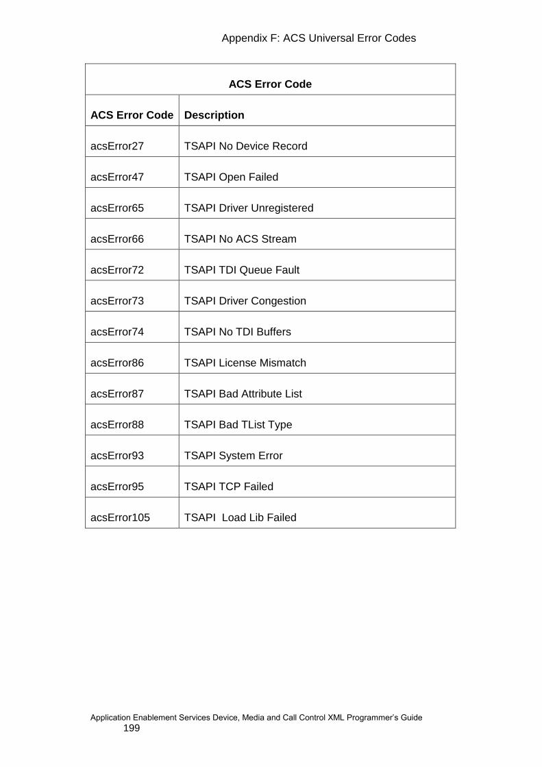
Appendix F: ACS Universal Error Codes
Application Enablement Services Device, Media and Call Control XML Programmer‟s Guide 199
ACS Error Code
ACS Error Code
Description
acsError27
TSAPI No Device Record
acsError47
TSAPI Open Failed
acsError65
TSAPI Driver Unregistered
acsError66
TSAPI No ACS Stream
acsError72
TSAPI TDI Queue Fault
acsError73
TSAPI Driver Congestion
acsError74
TSAPI No TDI Buffers
acsError86
TSAPI License Mismatch
acsError87
TSAPI Bad Attribute List
acsError88
TSAPI Bad TList Type
acsError93
TSAPI System Error
acsError95
TSAPI TCP Failed
acsError105
TSAPI Load Lib Failed
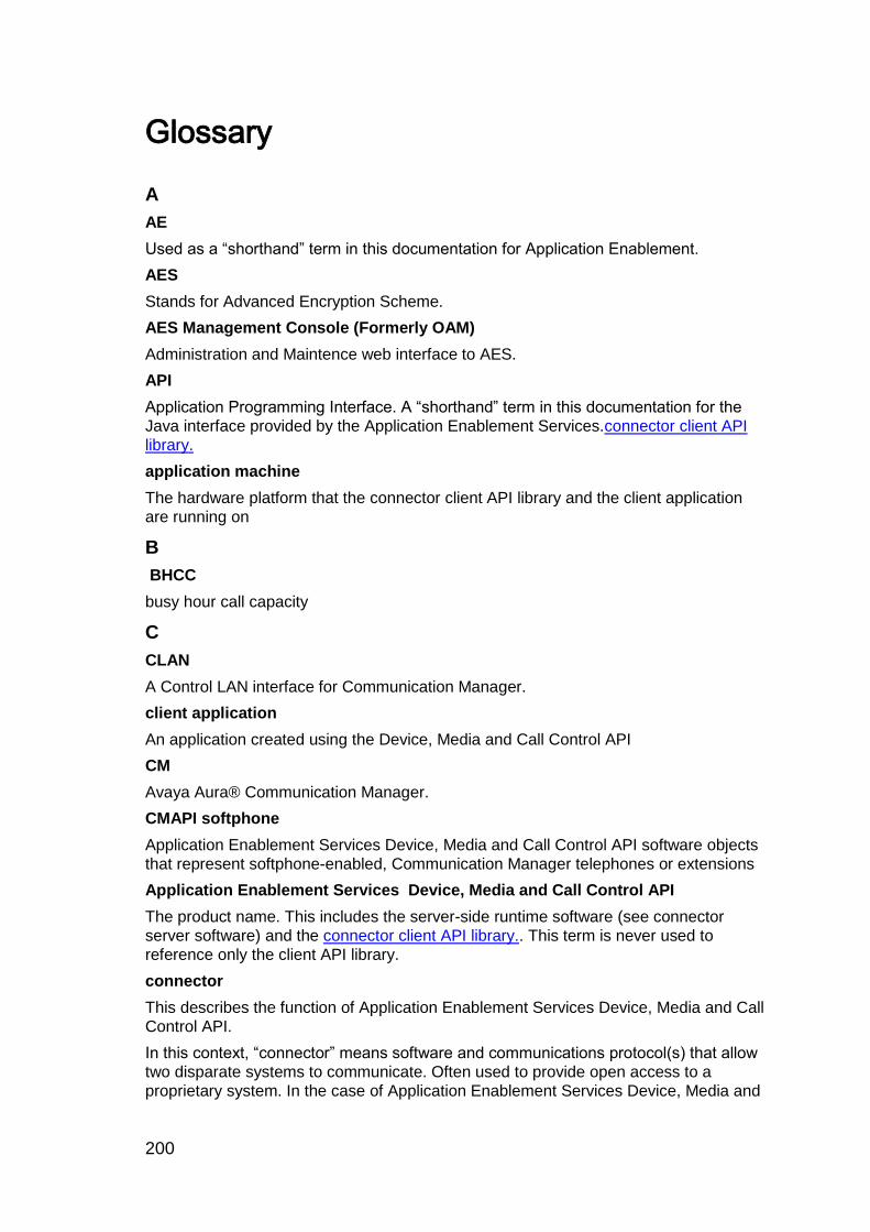
200
Glossary
A
AE
Used as a “shorthand” term in this documentation for Application Enablement.
AES
Stands for Advanced Encryption Scheme.
AES Management Console (Formerly OAM)
Administration and Maintence web interface to AES.
API
Application Programming Interface. A “shorthand” term in this documentation for the
Java interface provided by the Application Enablement Services.connector client API
library.
application machine
The hardware platform that the connector client API library and the client application
are running on
B
BHCC
busy hour call capacity
C
CLAN
A Control LAN interface for Communication Manager.
client application
An application created using the Device, Media and Call Control API
CM
Avaya Aura® Communication Manager.
CMAPI softphone
Application Enablement Services Device, Media and Call Control API software objects
that represent softphone-enabled, Communication Manager telephones or extensions
Application Enablement Services Device, Media and Call Control API
The product name. This includes the server-side runtime software (see connector
server software) and the connector client API library.. This term is never used to
reference only the client API library.
connector
This describes the function of Application Enablement Services Device, Media and Call
Control API.
In this context, “connector” means software and communications protocol(s) that allow
two disparate systems to communicate. Often used to provide open access to a
proprietary system. In the case of Application Enablement Services Device, Media and
Glossary
Application Enablement Services Device, Media and Call Control XML Programmer‟s Guide 201
Call Control API, the connector enables applications running on a computing platform
to incorporate telephony functionality through interaction with Communication Manager.
connector client API library
The Application Enablement Services Device, Media and Call Control Java API, also
referred to as the AE
connector server machine
The hardware platform that the connector server software is running on. In these
documents, the term “connector server” by itself never refers to the connector server
machine. See connector server software.
connector server software
The Application Enablement Services server-side runtime software, often referred to as
the “connector server” in these documents
CSTA
Computer-Supported Telecommunications Applications
CTI
Computer Telephony Integration.
D
DMA
Direct memory access
E
ECMA
European Computer Manufacturers Association. A European association for
standardizing information and communication systems in order to reflect the
international activities of the organization.
ESS
Enterprise Survivable Server.
F
Feature Name Extension (FNE)
Certain features are made available both inside and outside the enterprise network by
simply dialing an extension. This allows some mobile phones and third-party SIP
phones to activate certain features. These are called Feature Named Extensions
(FNE‟s).
H
hold time
The total length of time in minutes and seconds that a facility is used during a call
J
JDK
Java Developers Kit
J2SE
202
Java 2 Platform, Standard Edition
JMX
JMX (Java Management Extensions) is a set of specifications for application and
network management in the J2EE development and application environment. JMX
defines a method for Java developers to integrate their applications with existing
network management software by dynamically assigning Java objects with
management attributes and operations
JSW
Java Service Wrapper
JVM
Java Virtual Machine. Interprets compiled Java binary code for a computer‟s processor
so that is can perform a Java program‟s instructions
O
P
PE
Processor Ethernet interface.
PLDS
Product Licensing and Delivery System.
R
RPM
Red Hat Package Manager
S
SAT
System Access Terminal (for Communication Manager)
SDK
Software Development Kit. An SDK typically includes API library, software platform,
documentation, and tools.
T
TLS
Transport Layer Security.
TCP
Transmission Control Protocol. A connection-oriented transport-layer protocol, IETF
STD 7. RFC 793, that governs the exchange of sequential data. Whereas the Internet
Protocol (IP) deals only with packets, TCP enables two hosts to establish a connection
and exchange streams of data. TCP guarantees delivery of data, and also guarantees
that packets are delivered in the same order in which the packets are sent.
TSAPI
Telephony Services Application Programming Interface. A service that provides 3rd
party call control.
TTI
Glossary
Application Enablement Services Device, Media and Call Control XML Programmer‟s Guide 203
Terminal Translation Initialization. This is a feature in Communication Manager that
allows administrators, when initially administering new DCP stations, to not initially bind
the extension number to a port. When the technician is installing the stations, they then
use the TTI feature access code to bind the extension number to the station.
V
VoIP
Voice over IP. A set of facilities that use the Internet Protocol (IP) to manage the
delivery of voice information. In general, VoIP means to send voice information in
digital form in discrete packets instead of in the traditional circuit-committed protocols
of the public switched telephone network (PSTN). Users of VoIP and Internet telephony
avoid the tolls that are charged for ordinary telephone service.
X
XML
Extensible Markup Language
XSD
XML Schema Definition. Specifies how to formally describe the elements in an Extensible Markup Language (XML) document. This description can be used to verify that each item of content in a document adheres to the description of the element in which the content is to be placed. This protocol uses these instead of DTD‟s.
Index
This is a dummy index, left here purely to store the format.
client application ......................... 201
<$nopage>coder/decoder, see codecs .......................................... 84
PICS ............................................. 12
RTP;RTP:media stream ............... 83
<$nopage>Resource Interchange File Format, see RIFF ................ 103
positive acknowledgement ........... 45
client API library:using reference documentation ........................ 41, 48
performance ....................... 157, 160
asynchronous responses ............. 72
bearer channels:unencrypted ..... 139
BHCC ......................................... 201
buttons:associated extension ....... 93
buttons:function .................... 93, 166
buttons:ID constants .................. 171
buttons:identifier .......................... 93
buttons:knowing ..................... 93, 96
buttons:get information ................ 15
dial pad buttons ........................... 97
call appearances:detecting incoming call ............................................... 94
call appearances:green lamp turns off ................................................ 96
call appearances:lamp changes .. 95
device-based call control ............. 39
call progress tone detector .......... 98
incoming call:detecting;detecting incoming call .......................... 94, 99
calls ............................................. 44
calls:ended by far end ................. 96
204
calls:end-of-call cleanup ............. 120
calls:making a call ........................ 97
cleanup ...................................... 120
client media mode ........................ 85
client/server model ....................... 12
CM Link ...................................... 201
CMAPI softphone ....................... 201
codecs:choosing .......................... 90
encoding algorithms ................... 103
codecs:recordings ...................... 103
Communication Manager:features ................................................... 162
Communication Manager:loss of communication with ...................... 79
Communication Manager:network configuration............................... 161
Communication Manager:performance ................ 160
connector ................................... 201
CSTA:atomic model ..................... 45
CSTA:Avaya extensions to .......... 29
CSTA:concepts ...................... 41, 42
CSTA:multi-step model ................ 45
CSTA:services supported ............ 12
deployment:security ................... 138
development environment ............ 41
Device Services ........................... 31
device:automatic unregistration .. 160
device:cleanup ........................... 120
device:unregistering ................ 120
device:identifier ............................ 29
device:identifier:getting ... 20, 23, 24, 50, 64
logical elements ........................... 43
device:registration ........................ 29
Display Updated event:after call ends ............................................. 97
display:contents change ............... 95
display:for incoming call ............... 94
display:get contents ..................... 16
display:updated event .................. 17
DMA .......................................... 202
downloading:Communication Manager API SDK ....................... 41
dropped call ................................. 96
DTMF digits:collecting ......... 50, 111
DTMF digits:start collecting ......... 38
DTMF digits:stop collecting.. 39, 114
DTMF digits:Tone Detected event 39
dub over a recording .................. 105
ECMA ........................................ 202
events .......................................... 45
Display Updated event ................ 17
Hookswitch Status Changed event .................................................... 17
Lamp Mode event ........................ 17
Media Start event ........................ 33
Media Stop event ......................... 33
events:order of ............................. 96
Play event .............................. 19, 24
Record event ......................... 19, 24
Register Failed event ............. 37, 38
events:requesting notification of .. 72
Ringer Status event ..................... 17
Stop event ................................... 19
Suspend Play event ..................... 19
Suspend Record event ................ 19
Tone Detected event ................... 39
Tones Retrieved event ................ 39
exceptions:common ................... 157
exceptions:used for debugging .. 157
exiting application ...................... 120
Extended Voice Unit Services ..... 32
Extended Voice Unit Services:using .................................................. 106
extension:specifying for a device . 31
extensions to CSTA ..................... 29

Glossary
Application Enablement Services Device, Media and Call Control XML Programmer‟s Guide 205
far-end RTP parameters .............. 33
flush buffer ................................... 39
freeing up resources .................. 120
G.711 ........................................... 84
G.711:specifying during registration ..................................................... 90
G.729 ........................................... 84
G.729:converter ......................... 103
G.729:non-standard RIFF values ................................................... 103
G.729:specifying during registration ..................................................... 90
hold time .................................... 202
hookswitch:get status ................... 16
hookswitch:set status ................... 16
hookswitch:status changed event 17
ideas .......................................... 162
in-band DTMF digits ................... 111
J2SE .......................................... 202
Javadoc:using .............................. 48
JDK ............................................ 202
JVM ............................................ 203
keep-alive mechanism ............... 160
Lamp Mode event:after call ends . 96
lamps:associated with a button .... 93
lamps:color ................................. 165
lamps:mode.................. 95, 165, 183
lamps:status change .............. 17, 95
lamps:transitions .......................... 97
Linux kernel:updates .................. 161
Linux operating system:tuning.... 161
listeners:adding ............................ 77
listeners:implementing ................. 77
far-end RTP media parameters;RTP:parameters;media:when far-end RTP parameters change ................................. 50, 114
LocalMediaInfo ............................. 84
server-side logs .......................... 157
Media API Javadoc ...................... 98
Media Start event:using 50, 114, 115
Media Stop event:using ............. 115
media:controlling ......................... 83
media:encoding ........................... 90
media:handling ............................ 98
lost packets................................ 104
media:modes ............................... 84
server media mode ...................... 84
media:packets ........................... 104
playing messages ........................ 18
recording ..................................... 18
Record Message service;services:Record Message;recording messages ..... 18
message waiting indicator:get status .................................................... 16
delete message ......................... 105
Monitoring Services ..................... 25
network regions ........................... 91
network:failure ..................... 79, 160
network:performance ................. 160
out-of-band DTMF digits ............ 111
password:specifying for station.... 78
phones:device identifier ............... 64
Physical Device Services ............ 15
device:physical element .............. 43
physical elements ........................ 15
physical elements:monitoring and controlling .................................... 50
Play Message service:using ...... 106
resume playing;Resume service:using;playing message:resume; ...................... 108
suspend playing;Suspend service:using.............................. 108
media stream:recording messages from;media stream:playing messages to;recording .............. 102

206
stop recording;stop playing;Stop service:using .............................. 108
race conditions ................... 157, 159
recording:how to ......................... 104
resume recording ....................... 105
stop recording ............................ 105
suspend recording ...................... 105
recordMessage method:using .... 104
Register Device service:initialization process ........................................ 80
device:registering ......................... 77
requests:errors on ........................ 45
responses:asynchronous vs. synchronous ................................. 44
RIFF ........................................... 103
ringer:detecting incoming call ....... 94
ringer:get status ........................... 16
ringer:pattern ........................ 94, 174
ringer:status changed event ......... 17
RPM ........................................... 203
RTP stack..................................... 98
RTP:parameter changes ........ 33, 84
RTP:parameters ........................... 84
demonstration source code .......... 49
SAT ............................................ 203
SDK ............................................ 203
security:considerations ............... 138
Service Provider ........................... 38
Button Press service .............. 14, 15
ButtonPress request ..................... 97
Delete Message service ............... 19
Get Button Information service ..... 15
GetButtonInformation request:using ............................................... 93, 94
Get Display service ...................... 16
Get Hookswitch Status service..... 16
Get Lamp Mode service ............... 16
Get Message Waiting Indicator service ......................................... 16
Get Ringer Status service ............ 16
Play Message service .................. 18
Register Device service ............... 36
RegisterDevice request ............... 78
Resume service ........................... 18
Resume Playing service .............. 33
Resume Recording service ......... 33
Set Hookswitch Status service .... 16
SetHookswitchStatus method ...... 97
Start Dubbing service .................. 32
Start Monitor service: using ......... 72
Start Tone Collection service ....... 38
Stop service ................................. 18
Stop Dubbing service .................. 32
Stop Playing service .................... 32
Stop Recording services .............. 32
Stop Tone Collection service ....... 39
Suspend service .......................... 18
Suspend Playing service ............. 32
Suspend Recording service ......... 32
Unregister Device service ............ 36
shuffling ..................................... 115
signaling channel:unencrypted .. 139
# dial pad button;* dial pad button;pound sign dial pad button;asterisk dial pad button;star dial pad button; ............................ 97
Start Dubbing service:using ....... 106
station administration:button assignments ................................ 93
extension:device identifier ........... 64
Stop Dubbing service:using ....... 106
test environment .......................... 42
third party call control .................. 40
interdigit timers .......................... 114
tone collection criteria .................. 38
Glossary
Application Enablement Services Device, Media and Call Control XML Programmer‟s Guide 207
Tone Detection Services:using ... 111
touch tones:detection .............. 111
Tone Detection Services .............. 39
Voice Unit Services:using with Tone Collection Services;Tone Collection Services:using with Voice Unit Services ..................................... 160
TTI .............................................. 203
vendor-specific extensions to CSTA ..................................................... 29
Voice Unit Services ..........18, 23, 24
Voice Unit Services:using .......... 103
VoIP ........................................... 204
VOIP:readiness guide ................ 161
Wave files:file structure ............. 103
ECMA .......................................... 56
XML messages:security ............ 139
XMLdoc ....................................... 48
Related Documents