AV-17 VERSION 3.00 and up - Starting November 2017 AV-17 PROFESSIONAL RAMP TESTER USERS MANUAL AV-17 Software Version 3.00 up

Welcome message from author
This document is posted to help you gain knowledge. Please leave a comment to let me know what you think about it! Share it to your friends and learn new things together.
Transcript

AV-17 VERSION 3.00 and up - Starting November 2017
AV-17 PROFESSIONAL RAMP TESTER USERS MANUAL
AV-17
Software Version 3.00 up
Edz
Typewriter
To buy, sell, rent or trade-in this product please click on the link below:
Edz
Typewriter
https://www.avionteq.com/Sun-Avionics-AV-17-Ramp-Tester.aspx
Edz
Typewriter
www.avionteq.com

POWER The AV-17 can be powered by batteries or via the micro USB port.
If the AV-17 is always going to be USB powered then the batteries are notrequired.
For battery operation, please install the (4) AA batteries. Remove four rubber
feet using small phillips screwdriver. Use care to install batteries in correct
orientation (neg battery to springs). When shipping or when storing it is recommended
to remove the batteries.
Due to customs problems we are unable to send batteries or USB charger out of the USA.
TESTING PROCEDURE The transmit power of the AV-17 is very low - at approximately 1/4 of
one thousandth of a watt (0.25 milliwatt) - so you will need to be close (15-40 ft)
to the aircraft for most testing. The power was designed to be very small
so that the likelihood of interference is low and so that the sensitivity
of the aircraft receivers can be checked. However, when using the AV-17,
be sure that you do not interfere with any other aircraft or ATC system.
Note that when testing the ILS marker beacon, the AV-17 antenna will need
to be within a inch or two of the aircraft marker antenna. The aircraft
marker receiver was intentionally designed with 100 times lower sensitivity than your
other receivers so that it only picks up the marker when the plane is close to
the marker transmitter. Make sure the aircraft marker receiver is set to high
sensitivity if available. The ADF receiver may also require the AV-17 to be close
due to the poor antenna match at its low frequencies. For other test modes allow
at least 3 foot spacing betweenthe AV-17 and the aircraft antennas.
When performing transponder testing do a MODE-C only all-call test first so that the
AV-17 can adjust its receiver to the current RF conditions. It is
also a good way to find a useable RF location due to hangar reflections. Sometimes moving
only a few inches will change the signal strength quite a bit due to reflections and
shadowing of the signal. When doing ADS-B squitter testing, first find
a good reception location using the mode-s only all-call command. Testing on the ramp
outside the hangar will eliminate most reflection problems but be sure the aircrafts
transmitter signal does not interfere with ATC.
******* 20 dbm = 0.1 watt is the MAX allowed input *******
To test a transponder using direct connection, you must use an external attenuator
to reduce the 54dbm, or so, power out to +20dbm or less into the AV-17. An optional 40db
attenuator kit is available. Exceeding the 20dbm input level will cause damage to the
AV-17.
SCOPE TRIGGER OUTPUT The AV-17 provides a scope trigger output to support bench testing. The AV-17 is
supplied with a MCX to BNC female adapter to allow connection to an oscilloscopes
trigger input. The nominal output is 3.3 volt with 270 ohm source impedance.
It's best to use a high impedance scope input but a 50 ohm input will not cause harm.
(****} signifies new AV17 command not in the AV-10 or AV-15
Note 1;when testing do not overload the AV-17 front end. The AV-17 was designed for input signals to the antenna port of +20db or less. When testing with
the AV17, stay 3 foot or more away from the DME and transponder antennas,
and a couple feet or more from Comm antennas. To perform direct connect
transponder testing, 40 db or more, of power appropriate, attenuation MUST be
used. Sun offers an optional 25 watt 40 db attenuator kit.
FRONT PANEL OPERATION To operate the AV-17, turn on unit and wait for its self test to finish. It will display
the software version then;

PUSH TO SEL MODE
< VOR >
The AV-17 is controlled using the 3 keys just below the 2 line LCD display. The center
key has two functions based on how long the key is pressed. A short normal press is used
to select the currently displayed menu item. A long (approx 2 seconds) press causes the
unit to stop the current operation and jump back to the < VOR > beginning menu item.
The Left and Right keys just move you through the menu's or adjust selection values.
NOTE; The menu’s are circular. From the VOR item, a left key press will move to the
TRANSPONDER While a right key press will move you to ILS
The blue LED just above the 2 line LCD display will turn on to indicate that the AV-17
is transmitting. Connect the antenna to the BNC connector that is above the display.
For VOR, ILS, NDB functions you may extend the antenna to full length since they run in
the 100-400 MHz range or lower. During DME and TRANSPONDER operation collapse the antenna
to its shortest length.
-----------------------------------------
AV-17 OPERATION:
The AV-17 aircraft avionics ramp tester provides test functions for
the following aircraft avionic equipment:
1. Generates VOR test signal's at each 45 deg radial
or at 0, 45, 90, 135, 180, 225, 270, 315 deg's from the station.
carrier frequencies 108.0, 110.2, 112.4, 113.6 MHz are selectable.
The station ID tone is a 1020 hZ on/off beep.
When the AV-17 is powered on it does its self test and shows its software version.
Then the display shows;
PUSH TO SEL MODE
< VOR >
To activate the VOR test mode press & release the center key. The display will show;
PUSH TO SEL FREQ
< 108.0 >
If you wish to use 108 MHz then select it with the center key, else use right and left
keys to step to another frequency. When the desired frequency is displayed then select
it with the center key. The display shows;
PUSH TO SEL MODE
Start VOR test?
To start push the center key, left and right keys allow selection of 30Hz modulation off
And carrier only test modes that may be useful during bench VOR alignment. Then;
<- VOR RADIAL ->
0 deg FROM
The AV-17 is now transmitting the VOR signal with the 9960 FM subcarrier and the 30 Hz
AM signal in phase so that your NAV receiver should display 0 deg from or 180 deg to on
its OBS. The AV-17 modulation is generated digitally and is quite accurate. The scope
trigger output provides a narrow pulse at the 0 deg phase point of both modulation
signals. The blue led above the display is on to show that the AV-17 is in transmit
mode. Use the right key to select the 45 deg from radial. The display shows;
<- VOR RADIAL ->
45 deg FROM
The AV-17 now is transmitting the VOR signal with 45 deg phase shift between the 9960
subcarrier reference and the 30 Hz AM modulation. The NAV OBS should show 45 deg FROM
or 225 TO the station. The scope trigger output provides a pulse that always goes high
at the 0 deg 9960 reference point and low at the 30 Hz 0 deg point. By using the left
or right keys other radials can be selected at 45 deg intervals. When finished with
VOR testing, press and hold the center key down for about 2 seconds until the blue
led blinks, then release the key to return to start of the main menu.
2. ILs test signals.

a) Localizer
108.1 or 110.3 MHz carrier frequency
center, 1/2 and full deflection right and left
no 150Hz or no 90Hz modulation to check NAV flag.
Also generates 1020 Hz beep station ID.
Example; Use right or left keys to move to;
PUSH TO SEL MODE
< ILS >
Select with center key. To do localizer, select it with center key.
Use left right keys to select carrier frequency, then the display shows;
SEL LOC DDM
DDM=0 or CENTER
Your NAV indicator should show a centered needle for the ILS localizer. DDM stands
for difference in depth of modulation between the 90 and 150 Hz AM modulation. Press
the right key and the display gives
SEL LOC DDM
1/2 RIGHT .078 Your NAV indicator should show half deflection, DDM=.078. Use the left right keys to
select half, full deflection left and right as well as having only 90 or 150 Hz
modulation. When you are finished do a long center key push to return to main menu.
The glide slope works in a similar fashion.
b) GLIDE SLOPE
108.1 - 334.7, or 110.3 - 335.0 MHz carrier frequency.
Center, 1/2 and Full deflection up and down as well as
no 150HZ or no 90Hz modulation to check flag. No ID.
c) MARKER BEACON
A 75MHz AM modulated RF signal. The beep rate is slowest at outer marker. The AV-17 provides OUTER, MIDDLE, and INNER marker beacon signals.
As noted above, the marker receiver, in the aircraft, has low sensitivity so you will
need to place the AV-17 antenna within a few inches of the marker antenna.
3. DME test signal.
VOR paired 108.00 =17X mode or 108.05=17Y mode selectable. It Generates a fixed 20NM distance signal to the DME.
After selection the DME should lock to the AV-17 signal within a few seconds.
4. ADF signals.
Provides AM modulated low frequency signals to test that the aircraft
ADF-NDB receiver is picking up the radio signal. As explained in the theory
section, for direction finding the transmitter needs to be a long way from
the aircraft receiver. The signal is small so the AV17 antenna must be close to
the NDB's antenna.
5. COMM RADIO TEST.
a) Generates AM modulated test signal that can be heard on the aircraft
communication radio. This providesa simple radio receiver check. The AV-17 sends
-17dbm +/-1db to its antenna. With a 3db antenna and 45db path loss the radio
should see about -65dbm. Thus a crude check is made of the radio sensitivity.
Two channels for the new 8.333 KHz radios are also provided.
b) Receive the comm radio carrier and display the frequency difference between
theAV-17 reference and the comm radios carrier frequency. By keying the comm
radio this feature allows for checking the comm radios transmitter frequency accuracy.
The AV-17 requires at about -15dbm at its antenna to read the carrier. So the
Communication radios output power is also crudely checked. Example; given 10 watt (40db)
Output and 45db path loss and 3db AV-17 antenna loss the AV-17 will see about -8dbm.
The maximum useful frequency range is about +/- 50,000Hz difference. The minimum
Frequency difference is about +/- 50Hz or the display shows zero.
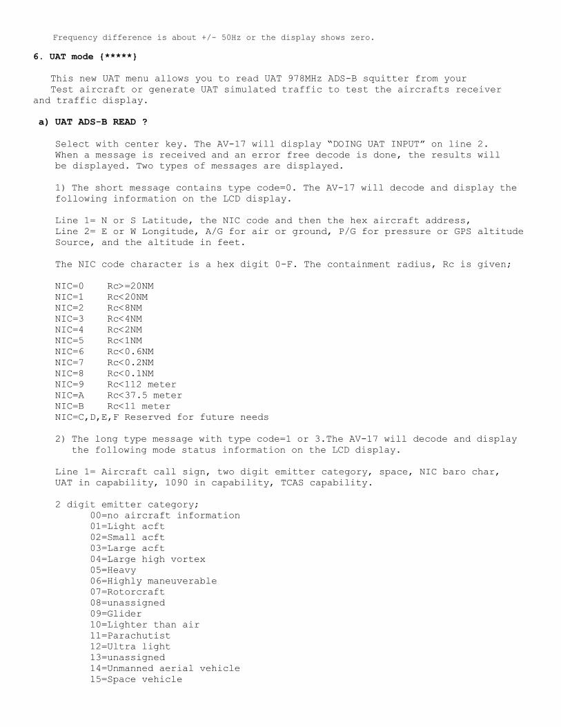
6. UAT mode {*****}
This new UAT menu allows you to read UAT 978MHz ADS-B squitter from your
Test aircraft or generate UAT simulated traffic to test the aircrafts receiver
and traffic display.
a) UAT ADS-B READ ?
Select with center key. The AV-17 will display “DOING UAT INPUT” on line 2.
When a message is received and an error free decode is done, the results will
be displayed. Two types of messages are displayed.
1) The short message contains type code=0. The AV-17 will decode and display the following information on the LCD display.
Line 1= N or S Latitude, the NIC code and then the hex aircraft address,
Line 2= E or W Longitude, A/G for air or ground, P/G for pressure or GPS altitude
Source, and the altitude in feet.
The NIC code character is a hex digit 0-F. The containment radius, Rc is given;
NIC=0 Rc>=20NM
NIC=1 Rc<20NM
NIC=2 Rc<8NM
NIC=3 Rc<4NM
NIC=4 Rc<2NM
NIC=5 Rc<1NM
NIC=6 Rc<0.6NM
NIC=7 Rc<0.2NM
NIC=8 Rc<0.1NM
NIC=9 Rc<112 meter
NIC=A Rc<37.5 meter
NIC=B Rc<11 meter
NIC=C,D,E,F Reserved for future needs
2) The long type message with type code=1 or 3.The AV-17 will decode and display the following mode status information on the LCD display.
Line 1= Aircraft call sign, two digit emitter category, space, NIC baro char,
UAT in capability, 1090 in capability, TCAS capability.
2 digit emitter category;
00=no aircraft information
01=Light acft
02=Small acft
03=Large acft
04=Large high vortex
05=Heavy
06=Highly maneuverable
07=Rotorcraft
08=unassigned
09=Glider
10=Lighter than air
11=Parachutist
12=Ultra light
13=unassigned
14=Unmanned aerial vehicle
15=Space vehicle
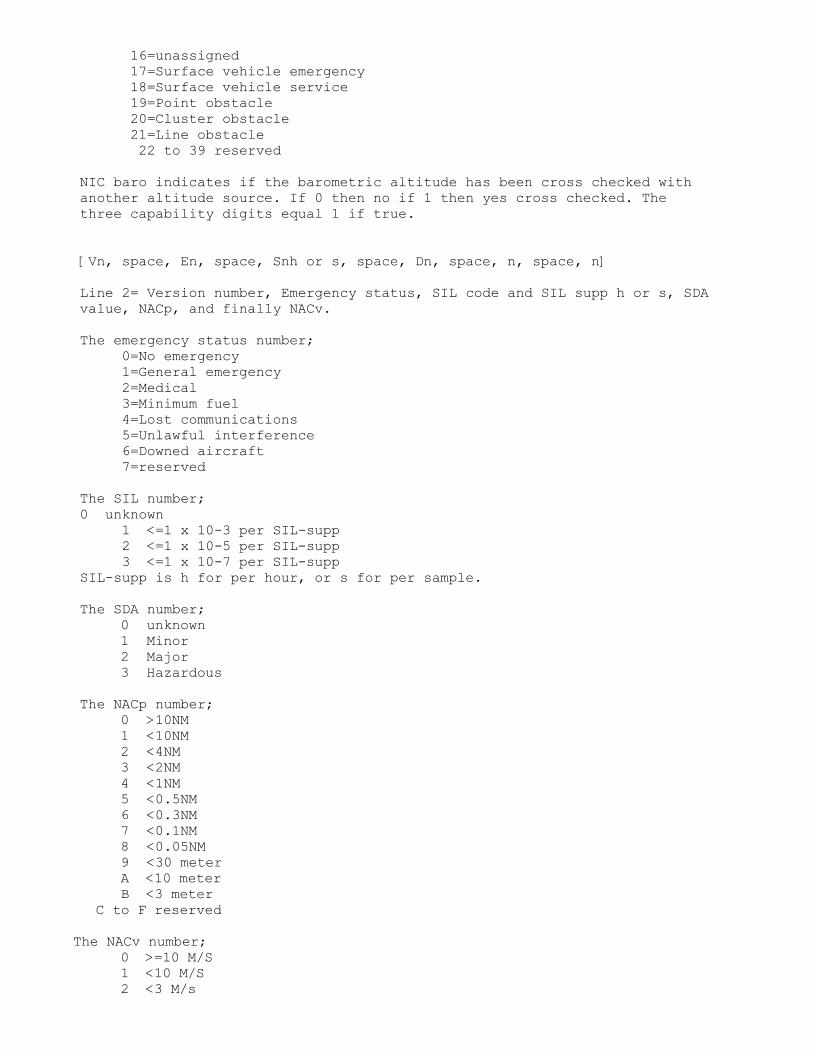
16=unassigned
17=Surface vehicle emergency
18=Surface vehicle service
19=Point obstacle
20=Cluster obstacle
21=Line obstacle
22 to 39 reserved
NIC baro indicates if the barometric altitude has been cross checked with
another altitude source. If 0 then no if 1 then yes cross checked. The
three capability digits equal 1 if true.
[Vn, space, En, space, Snh or s, space, Dn, space, n, space, n]
Line 2= Version number, Emergency status, SIL code and SIL supp h or s, SDA
value, NACp, and finally NACv.
The emergency status number;
0=No emergency
1=General emergency
2=Medical
3=Minimum fuel
4=Lost communications
5=Unlawful interference
6=Downed aircraft
7=reserved
The SIL number;
0 unknown
1 <=1 x 10⁻³ per SIL-supp
2 <=1 x 10⁻⁵ per SIL-supp
3 <=1 x 10⁻⁷ per SIL-supp
SIL-supp is h for per hour, or s for per sample.
The SDA number;
0 unknown
1 Minor
2 Major
3 Hazardous
The NACp number;
0 >10NM
1 <10NM
2 <4NM
3 <2NM
4 <1NM
5 <0.5NM
6 <0.3NM
7 <0.1NM
8 <0.05NM
9 <30 meter
A <10 meter
B <3 meter
C to F reserved
The NACv number;
0 >=10 M/S
1 <10 M/S
2 <3 M/s

3 <1 M/s
4 <0.3 M/S
5,6,7 reserved
b) UAT TRAFFIC SIM
This function will simulate an aircraft sending 978 MHz UAT squitter
as it fly’s an south-north-south path. You control the center Lat, Lon, and Altitude.
This function can be used to test your aircrafts ADS-B receiver and traffic display system.
After the UAT TRAFFIC SIM mode is selected, you are prompted to change location and
altitude. The AV-17 will automatically save latitude, longitude and altitude
as data is read by UAT, Mode-C/S transponder functions. Mode-C and DF=4 saves altitude info
and while reading the GPS airbourne location, Latitude and Longitude are saved.
When this function is selected, you are allowed to modify the saved values.
To modify Latitude for example. When the AV17 displays;
LAT=N 32.45 deg
MODIFY LAT ? NO
use the left or right key to change the NO to yes, then use the center key to select.
The LCD will then display;
LAT=N 32.45 deg
^
the pointer is pointing at the N for North. To change to South press the left/right key.
then to accept the change and go to the next element press the center key.
the LCD line 2 pointer will then move under the 10’s place 3 digit. Change it using
the right/left keys and accept using the center key. If a value element doesn’t need to
be changed, just press the center key to keep it as is. When you are done changing location
and altitude the AV17 will send a UATsquitters at every step;
The AV17 will start at a position about ¼ degree (15 mile) south of the set location and
each time you short press the center key the simulated aircraft will step north until it is
about ¼ degree north then turn around and step back south. The north-south-north-south stepping
will continue until the center key is given a long press to take you back to the main menu.
16 step points are generated for each direction. The transmitted altitude will be within 100
foot of the adjusted altitude. AV17UAT is the aircraft ID and 123456 is the HEX code sent.
Remember the AV-17 transmits a very low output power so its signal will only be heard
Within a 25 foot or so radius.

7. 1090 TRAFFIC SIMULATION
This function will simulate an aircraft sending 1090MHz ADS-B squitter
as it fly’s an east-west-east path. You control the center Latitude, Longitude, and Altitude.
This function can be used to test your aircrafts ADS-B receiver and traffic display system.
After the 1090 TRAFFIC SIM mode is selected, you are prompted to change location and
altitude. The AV-17 will automatically save latitude, longitudeand altitude
as data is read by Mode-C/S transponder functions. Mode-C and DF=4 saves altitude info
andwhile reading the GPS airbourne location, Latitude and Longitude are saved.
When this function is selected, you are allowed to modify the saved values.
To modify Latitude for example. When the AV17 displays;
LAT=N 32.45 deg
MODIFY LAT ? NO
use the left or right key to change the NO to yes, then use the center key to select.
The LCD will then display;
LAT=N 32.45 deg
^
the pointer is pointing at the N for North. To change to South press the left/right key.
then to accept the change and go to the next element press the center key.
the LCD line 2 pointer will then move under the 10’s place 3 digit. Change it using
the right/left keys and accept using the center key. If a value element doesn’t need to
be changed, just press the center key to keep it as is. When you are done changing location
and altitude the AV17 will send the following ADS-B squitters at every step;
Even Airbourne location ADS-B squitter
Odd Airbourne location ADS_B squitter
Aircraft Velocity squitter

Aircraft ID squitter
Short Acquisition squitter message
The AV17 will start at a position about ¼ degree (15 mile) west of the set location and
each time you short press the center key the simulated aircraft will step east until it is
about ¼ degree east then turn around and step back west. The east-west-east-west stepping
will continue until the center key is given a long press to take you back to the main menu.
16 step points are generated for each direction. The transmitted altitude will be within 100
foot of the adjusted altitude.AV17ES is the aircraft ID and 123456 is the HEX code sent.
Remember the AV-17 transmits a very low output power so its signal will only be heard
Within a 25 foot or so radius.
8. TRANSPONDER A/C/S ADS-B
a)Generates MODE-Atest signal and display's squawk code and
reply percentage. Also allows sidelobe suppression check.
If the transponder IDENT is activated then the AV-17 will
display IDENT. The AV-17 sends about 235 MODE-A interrogations
per second. The AV-17 sends 1030MHz P1 and P3 pulses spaced
8.0uS apart. The P2 sidelobe suppression pulse can be selected off,
the same amplitude as P1-P3, or -9db. The suppression pulse
is sent 2.0uS after the P1 pulse if enabled. No P4 pulse is sent.
The top LCD line display's the squawk code then F1=nn.
The hex number nn is the approx transponders F1 pulse width. The hex
number times 50nS equates to the measured F1. If the transponder is sending
ident then the word IDENT replaces the F1 display. Reply percent is
on the bottom LCD line.
Example; After turning on the AV17 and waiting for the self
test to run, the display will read
PUSH TO SEL MODE
< VOR >
push left push button so that display line 2 reads;
< TRANSPONDER >
now push center button to select transponder testing.
The display will now show
SEL TXPDR MODE
MODE A SQUAWK
If we wanted to do a different transponder test we would
use the right or left buttons to step through the tests available
Since we wish to do the Mode-A test we press the center button
to select it. The display will show
SIDELOBE SUPPRES
NO SLS P2 OFF ?
If we wish to do Mode-A with the SLS off then press center
select button. If you wish to send a P2 pulse that is equal
in amplitude or -9db to the P1 pulse then use the right or left buttons
Once the center button is pressed the AV-17 will begin
sending Mode-A interrogations and looking for replies. The
AV-17 will display something like;
SQ=1200 F1=08
Reply%=100
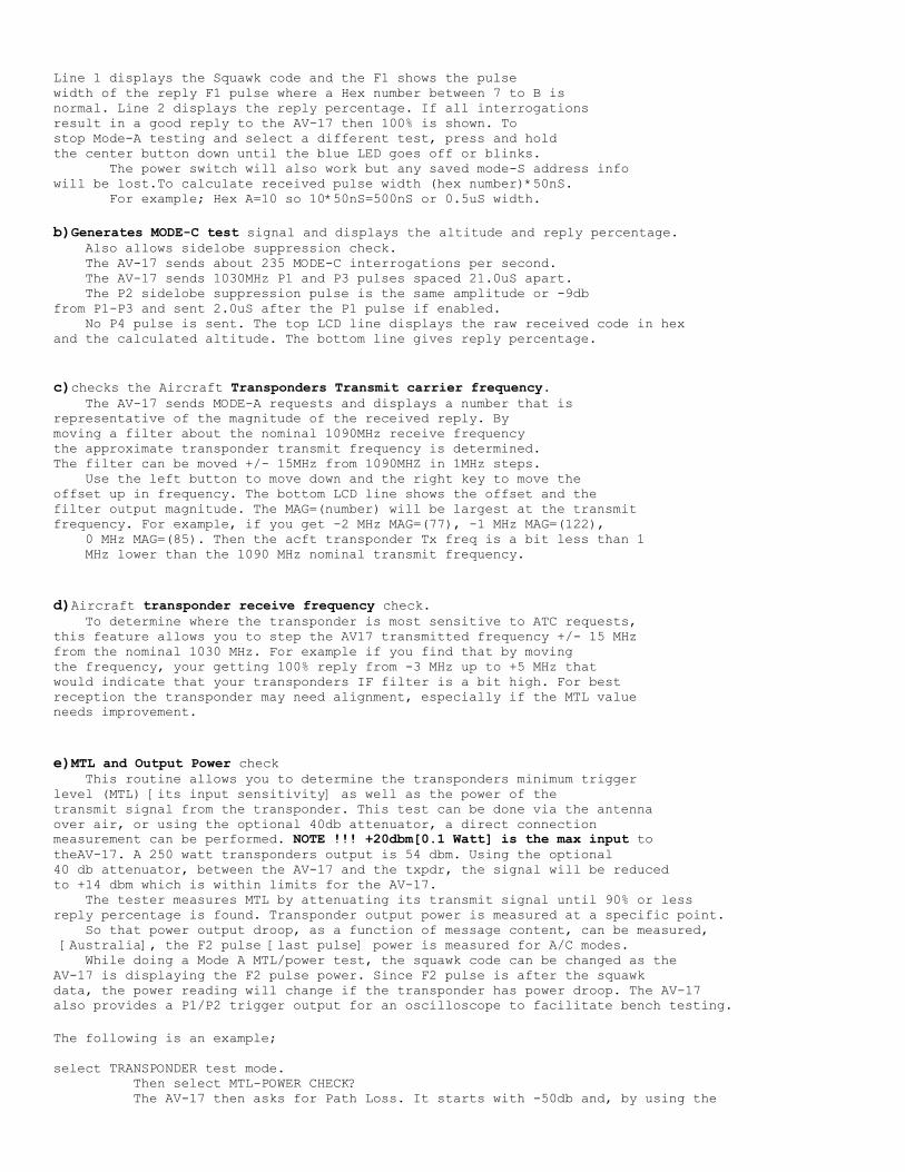
Line 1 displays the Squawk code and the F1 shows the pulse
width of the reply F1 pulse where a Hex number between 7 to B is
normal. Line 2 displays the reply percentage. If all interrogations
result in a good reply to the AV-17 then 100% is shown. To
stop Mode-A testing and select a different test, press and hold
the center button down until the blue LED goes off or blinks.
The power switch will also work but any saved mode-S address info
will be lost.To calculate received pulse width (hex number)*50nS.
For example; Hex A=10 so 10*50nS=500nS or 0.5uS width.
b)Generates MODE-C test signal and displays the altitude and reply percentage.
Also allows sidelobe suppression check.
The AV-17 sends about 235 MODE-C interrogations per second.
The AV-17 sends 1030MHz P1 and P3 pulses spaced 21.0uS apart.
The P2 sidelobe suppression pulse is the same amplitude or -9db
from P1-P3 and sent 2.0uS after the P1 pulse if enabled.
No P4 pulse is sent. The top LCD line displays the raw received code in hex
and the calculated altitude. The bottom line gives reply percentage.
c)checks the Aircraft Transponders Transmit carrier frequency.
The AV-17 sends MODE-A requests and displays a number that is
representative of the magnitude of the received reply. By
moving a filter about the nominal 1090MHz receive frequency
the approximate transponder transmit frequency is determined.
The filter can be moved +/- 15MHz from 1090MHZ in 1MHz steps.
Use the left button to move down and the right key to move the
offset up in frequency. The bottom LCD line shows the offset and the
filter output magnitude. The MAG=(number) will be largest at the transmit
frequency. For example, if you get -2 MHz MAG=(77), -1 MHz MAG=(122),
0 MHz MAG=(85). Then the acft transponder Tx freq is a bit less than 1
MHz lower than the 1090 MHz nominal transmit frequency.
d)Aircraft transponder receive frequency check.
To determine where the transponder is most sensitive to ATC requests,
this feature allows you to step the AV17 transmitted frequency +/- 15 MHz
from the nominal 1030 MHz. For example if you find that by moving
the frequency, your getting 100% reply from -3 MHz up to +5 MHz that
would indicate that your transponders IF filter is a bit high. For best
reception the transponder may need alignment, especially if the MTL value
needs improvement.
e)MTL and Output Power check
This routine allows you to determine the transponders minimum trigger
level (MTL) [its input sensitivity] as well as the power of the
transmit signal from the transponder. This test can be done via the antenna
over air, or using the optional 40db attenuator, a direct connection
measurement can be performed. NOTE !!! +20dbm[0.1 Watt] is the max input to
theAV-17. A 250 watt transponders output is 54 dbm. Using the optional
40 db attenuator, between the AV-17 and the txpdr, the signal will be reduced
to +14 dbm which is within limits for the AV-17.
The tester measures MTL by attenuating its transmit signal until 90% or less
reply percentage is found. Transponder output power is measured at a specific point.
So that power output droop, as a function of message content, can be measured,
[Australia], the F2 pulse [last pulse] power is measured for A/C modes.
While doing a Mode A MTL/power test, the squawk code can be changed as the
AV-17 is displaying the F2 pulse power. Since F2 pulse is after the squawk
data, the power reading will change if the transponder has power droop. The AV-17
also provides a P1/P2 trigger output for an oscilloscope to facilitate bench testing.
The following is an example;
select TRANSPONDER test mode.
Then select MTL-POWER CHECK?
The AV-17 then asks for Path Loss. It starts with -50db and, by using the

left / right keys, that value can be modified between -40 to -60 db.
If you are doing a direct connect via a 40+ db attenuator, then you know
exactly what the path loss between the AV-17 and the txpdr is. If you are
doing an over air measurement, a well established procedure is 40db path loss
and about 4 foot spacing from the transponder antenna. Another good choice is
-50db if you are about 15 foot from the txpdr antenna. If your location is
poor due to reflections, you can find a better local or average as follows;
You don't know the path loss exactly but, since the transponder Tx and Rx
frequencies are less than 6% different, most of the timethe path losses will
be about same. Not always the same, due to reflections, but on average they will
be about equal.
Use center key to select your Path Loss value.
Next you will select the type of transponder mode to use for the measurement.
You can choose between Mode A [best for power droop test]
Mode C or Mode S only all-call. Therefore Power/MTL for all modes, A/C/S, can
easily be measured.
When the test is started, the AV-17 will slowly move MTL power down until
a drop in reply percentage is found. The AV-17 will continue to vary Tx output
to hold around 90% reply. The Po=nnn will slowly show the measured Power
from the transponder. If reflections are a problem, Move around to find an average MTL
and Power reading. As we said before, the path loss will on average
be the same for Tx and Rx directions. If your Loss guess was to high, then
both MTL and Power will be less than spec. If your Loss guess was low, then
both MTL and Power will be better than spec. A little common sense here and
you will determine MTL and Power with adequate accuracy.
RF POWER TABLE;
45 dbm = 15 db watt = 32 watts
46 dbm = 16 db watt = 40 watts
47 dbm = 17 db watt = 50 watts
48 dbm = 18 db watt = 63 watts
49 dbm = 19 db watt = 80 watts
50 dbm = 20 db watt = 100 watts
51 dbm = 21 db watt = 126 watts
52 dbm = 22 db watt = 158 watts
53 dbm = 23 db watt = 200 watts
54 dbm = 24 db watt = 251 watts
55 dbm = 25 db watt = 316 watts
56 dbm = 26 db watt = 398 watts
57 dbm = 27 db watt = 501 watts
f)All ATCRBS transponders are required to go inactive or suppress
for 35 +/- 10 microseconds (uS) after receiving the P1-P2 sidelobe
suppression signal. This ATCRBS suppression feature is now also
used by the mode-s system. The ground stations mode-s interrogation
begins with two pulses spaced 2.0 uS apart just like the SLS pulses.
The mode-s message then continues while the ATCRBS transponders are
in suppression. Therefore it is nice to know if your transponder
is being suppressed as it should.
The AV-17 provides this "SLS TIME CHECK ?" function to measure
the actual suppression time. The AV-17 sends out a SLS pulse pair
then sends a mode A inquiry after the variable delay time. The time
between the SLS pulse pair and the inquiry is adjustable by you.
So by decreasing the delay time until the reply percentage begins
to fall, the transponder suppression time is determined. The top LCD
line display's the squawk code and reply percentage. The bottom line
display's the delay time in microseconds. Use the left and right keys
to change the delay time.
g)A/C/S ALL-CALL and READs mode-S reply message.
ATCRBS MODE-A/C transponders will send a normal MODE-A reply.
MODE-S transponders will send an S reply. The AV-17 will
display the HEX Aircraft ID and a all 0's CRC error code

for good received S reply's. The AV-17 sends 1030MHz P1 and P3
pulses spaced 8.0uS apart. A 1.6uS wide P4 pulse is sent
2.0uS after P3. The reply from an old ATCRBS transponder is
ignored by the AV-17.
h)ATCRBS only ALL-CALL message,
The AV-17 sends MODE-A 1030MHz P1 and P3 pulses spaced 8.0uS.
The 0.8 uS P4 pulse is sent 2.0uS after P3. The mode-S transponder
should not reply due to the short P4 pulse. The AV-17 looks for
erroneous mode-s reply's. When working with an old ATCRBS transponder
the top LCD line will display the squawk code and F1 pulse width
while line 2 shows "OK; no S reply". When testing a MODE-S unit the
top LCD line should display "SQ=0000 F1=(small)". The second line
should be the same "OK; no S reply". If the AV-17 finds a MODE-S
all-call reply then it will display "MODE-S ERROR" on LCD line 1
and "ALL-CALL REPLY" on line 2.
i)sendMODE-S only ALL-CALL.
The AV-17 will send a differential phase-shift keyed (DPSK)
MODE=S ALL-CALL interrogation. ATCRBS MODE-A/C will not
respond since the interrogation starts with two 1030MHz pulses
spaced 2.0uS apart that is seen as a sidelobe suppression.
Since an all 1's ALL-Call address is sent, any MODE-S transponder
will send a MODE-S reply. The AV-17 will display the HEX
aircraft address and all 0's CRC for a good reply. The Hex address is
also saved to RAM for use by following discrete addressed commands.
The top LCD line display's the calculated CRC and L= the capability
number 1 to 7.
0=level 1 unit. 4-7=level 2 transponder unit. This command
runsaprox 50 times per second.
Info;when the transponder is set to on ground status it should not provide all-call reply's. The aircraft hex address must be entered
into the AV-17 manually or from a ADS-B ID squitter if available.
j)Mode-S DF=4 discrete addressed altitude request.
The saved address from (i) or (n) is used as a starting point of
the adjustable address. The AV-17 sends a UF=4 Altitude request
command with the 24 bit Address as defined by you. So to see if
the Transponder responds with its Altitude, that should match
its mode C altitude reply, just use the saved address. To insure that
it does not reply to other addresses, change the saved address before
sending the command. After the address is selected the AV-17 will
display the hex ID on top LCD line and the calculated altitude on the
bottom line. This command runs at aprox 50 times per second.
Info:The Aircraft hex address must be manually entered if the all-call or ADS-B ID are not functioning. To set the hex address,
select yes to modify address. Then use the right and left buttons to
change a digits hex value and the center button to enter each hex character.
The AV-17 starts with a $000000 hex address after power on and it must
equal the aircraft hex address, as set in the transponder, for commands
h, i, j, or k to function.
k)Mode-S DF=5 discrete addressed Squawk code request.
The saved address from i or n is used as a starting point of
the adjustable address. The AV-17 sends a UF=5 ID request
command with the 24 bit Address as defined by you. So to see if
thethe Transponder responds with its SQUAWK, that should match
its mode-A SQUAWK reply, just use the saved address. To insure that
it does not reply to other addresses, change the hex address before
sending the command. The AV-17 will display the hex ID on the top line
and the squawk code and the Flight Status on the bottom line.
This command runs at aprox 50 Hz.

Flight Status decode
FS=0 no alert no SPI Airborne
FS=1 no alert no SPI On Ground
FS=2 alert no SPI Airborne
FS=3 alert no SPI On Ground
FS=4 alert SPI Either
FS=5 no alert SPI Either
FS=6 RESETVED
FS=7 NOT USED
l)Mode-s DF=20 discrete addressed Tail number (ID) request. The transponder
should reply with its flight number or tail number. The AV17 will display
the tail number on line 1. The hex aircraft code is displayed on line 2.
m)Mode-s DF=21 discrete addressed capability report request. The AV17
will display the raw transponder reply in hex as well as the received
aircraft hex address. All of line 1 gives 16 hex char's or the first 8
bytes and line 2 provides 6 hex char's or 3 bytes giving the first 11
message bytes in hex. Line 2, second half, provides the decoded aircraft
hex address given by 6 hex char's. If the address is correct then the parity
was good and the first 11 bytes are OK. The meaning of each bit can be found
in the standard documents. The first two hex characters of the top line should
be A8 through AF to signify that a DF=21 command was received.
Note 2;For the following Squitter functions, the squitter messages are sent by the transponder without being requested by the AV-17 and
may be sent infrequently. The best way to check squitter is to
first run the mode-s only all-call command and find a good location.
After finding a location where AV17 reception is good, then run
the squitter functions. Sometimes when testing in a hangar with lots of reflections off walls other equipment and even people, a few
inches of AV17 movement can change the reception dramatically. The
AV17 antenna can also be mounted on our tripod-25 foot cable accessory
which can help in keeping the antenna stationary or while allowing you
to operate the equipment while in the cockpit.
n)ADS-B MODE-S ID SQUITTER
The AV-17 will listen for the ID-SQUITTER AND display the
HEX Address and 0's CRC for good reply. The HEX aircraft
address is also saved in RAM for use by commands h to k above.
o)AIRCRAFT TAIL NUMBER SQUITTER
The AV-17 will listen for the flight number - tail number
squitters and display the Emitter Cat, Tail number and the HEX ID. Note that
this squitter is only sent a couple times per minute. It is necessary
to be sure you have a good reception location before running this command

see note above.
EXAMPLE display will show;
Cn ID=N12345
HEX ADD=3ABD9F +
C = THE EMITTER CLASS A,B,C,D
n = NUMBER IN CLASS
The Emitter Category code definitions;
A0=NO INFO B0=NO INFO C0=NO INFO D0=NO INFO
A1=LIGHT ACFT B1=GLIDER C1=EMER SURFACE D1 to D7 RESERVED
A2=SMALL ACFT B2=BLIMP C2=SERFACE VEHICLE
A3=LARGE ACFT B3=SKYDIVE C3=POINT OBSTACLE
A4=HIGH VORTEX B4=ULTRALIGHT C4=CLUSTER OBSTACLE
A5=HEAVY B5=RESERVED C5=LINE OBSTACLE
A6=HIGH PERFOR B6=UAV C6,C7 RESERVED
A7=ROTORCRAFT B7=SPACE VEHICLE
p} AIRCRAFT STATUS MESSAGE
The squitter type code 31 will be found and parsed to give the
Following LCD 2 line display;
ANTgSDAhVERi
NACp j SILk/time
THE g NUMBER 0 or 1 ;IS 1 for single antenna
h equals 0 to 3 giving SDA value
i is the version; 0=DO-260, 1=DO-260A, 2=DO-260B
j provides the NAC position information
k is the SIL value and time will list per Hr or Smp = sample
q) AIR VELOCITY SQUITTER
The squitter type code 19 subtype 1 to 4 will be found and parsed to
Show following 2 line display
NACv=n VSI=svvvv
Del_Alt=saaaa +
The NACv is the Navigation accuracy category for velocity and
The value is given by the following table;
0 >= 10m/s 1 < 10m/s 2 < 3m/s 3 < 1m/s 4 < 0.3m/s
The VSI is vertical rate in foot/minute and NONE signifies none available
From the transponder.
Del_Alt provides the difference between GNSS or INS altitude from the barometric
Altitude in feet. NONE signifies that none available from transponder.
r)LOCATION SQUITTER
The AV-17 will listen for the GPS derived location squitter
and display the calculated LATitude and LONgitude in decimal
degrees.
To convert from decimal degrees to Deg, Minute;
Use the whole number part for Deg, the fractional part times 60 for Minutes
Example 27.37 decimal deg = 27 Deg, 0.37*60=22.2 Minutes
The AV17 uses lower precision math when calculating the position, so if its
Within a couple minutes of theTxpdr readout its good.
Ground location
Due to the way position data is sent, It takes atleast 2 received squitters
to calculate the AIRBOURNE GLOBAL and SURFACE relative GLOBALposition.
This position command includes 2 additional characters during location
squitter display:
An S or A (Surface or Airborne), followed by a hex value from 0 to B
that represents the NIC (Navigational Integrity Category) Value.
The NIC value represents a radius of containment value defined as follows:

0 = unknown
1 = < 20 NM
2 = < 8 NM
3 = < 4 NM
4 = < 2 NM
5 = < 1 NM
6 = < .6 NM
7 = < .2 NM
8 = < .1 NM
9 = < 75 meter
A = < 25 meter
B = < 7.5 meter
NOTE;The way the ground position is coded in Compact Position Reports (CPR),
It requires 2 messages to calculate position as in the airborne case. However
In order to provide 4 times the ground location resolution, the upper 2 bits
Of coded latitude and longitude are not sent. Therefore the calculated ground
Position always assumes North latitude and 0-90 deg east of the prime meridian.
To get your actual position one must know in which quadrant you are in. Rather
Than asking you for that information the AV-17 keeps track of it for you.
When airborne positions are found the AV-17 will save quadrant data for use
by the ground position calculations. The quadrant information will saved in battery
backed memory. So if you see odd ground position data, be sure that an air
position has been done at your location.
s)TEST SQUITTER function.
The AV-17 will display the first squitter transmission it finds
each time you short press the center key. This can be used to manually
decode squitter DF=17 messages or to check that squitters are being sent.
----------------------------------------------
ABOUT CALIBRATION
The AV-17 has been designed using today's most advanced electronics. Sun Avionic's
custom designed digital circuitry resides in a large gate array. The chip contains
Sun's proprietary micro-computer and what would have been a couple of PC boards full
of parts only a few years ago. The AV-17 design is digital where all timing and
RF frequencies used in the unit are derived from a high precision crystal
oscillator that is compensated to +/- 1.0 parts per million over 0 to 50 deg C.
The AV-17 is calibrated to be NIST traceable and is supplied with a
statement of calibration document and a calibration sticker that attests that factory
calibration was done and it will meet its published specifications.
There are no user adjustable parts in the unit as all calibration variables reside
in firmware. Of course, anything can and will break. If you suspect a problem, check
another aircraft to see if the problem persists. Make sure batteries are good
(unit may act up as batteries fail). Check that a line of sight RF path exists between
theAV-17 and the aircraft antenna. Try turning the unit off for a few seconds. Read the
operating manual for the aircraft equipment to be sure it's set up correctly.
Contact Sun if needed and we will attempt to help.
The AV17 factory calibration is valid for 1 year and we offer a 2 day turn
Re-cal service at the factory for $150 US plus shipping and any repairs if required.
We also have a calibration procedure on this web site for guidance if you wish
to do recalibration.
BATTERY REPLACEMENT and USB POWER
The AV-17 is powered by (4) AA batteries. Heavy duty alkaline
or equivalent should provide over 2 hours of continuous operation.
To replace the batteries, remove the four rubber feet using a #1 phillips
Screwdriver to access the battery holder. Make sure battery negative goes to
spring end of holder positions. Before long term storage it's best to remove the
batteries to prevent battery leakage damage. Also promptly replace expended batteries.
The AV-17 can also be powered by a micro USB power adapter. A standard
1/2 amp or greater adapter will work fine. Turn the unit to off position and
plug in the adapter to turn on the unit under USB power.
REGULATIONS
Sun Avionics has done its best to provide a useful piece of test
equipment; Please understand your requirements when using the AV-17.
Your country's aviation authority has rules that determine who may work
on or repair avionic equipment. Please understand and follow those
requirements. Your aviation authority also has determined what needs to be tested
to return equipment to airworthiness status. Based on our understanding of
( part 43 appendix F ATC Transponder Tests and Inspections ), the AV-17 can perform
all the tests required. Proper use also requires that the operator
understand the operation of the avionics device he is testing.
A great deal of information can be found on our website
(see ourNavigation and Transponder Principles <../NavTransPrinciples.html> link)
, the internet or from manufacturers manuals. It is the operators responsibility to
insure safe use of the AV-17. We hope you find the AV-17 to be a useful
tool for avionic system testing and trouble shooting, hopefully making flying safer
and a bit more cost effective.
NOTE; See App Note on home page that covers AV-17 command use.
For updated information, questions, or to send your comments please see our web site:
www.sunavionics.com<http://www.sunavionics.com> e-mail us at:
[email protected]<mailto:[email protected]>
Phone:321-383-9488
Thank you for selecting Sun Avionics
Related Documents


