[email protected] Page 1 Autotransformer The working principle of autotransformer and construction is similar to that of conventional two winding transformers. However, it differs in the way in which the primary and the secondary are inter- related. In a two-winding transformer, primary and secondary are only magnetically linked by a common core but are completely insulated from each other. But in the case of an auto transformer windings are connected electrically as well as magnetically. It consists of only one winding wound on a laminated magnetic core, with a rotary movable contact. The same auto transformer can be used as a step-down or a step-up transformer. Working Principle of Autotransformer The circuit diagram of an auto transformer is shown in Figure. When the single phase AC supply is connected between A and D terminals and output is taken from C and E terminals, this auto transformer will operate as a step-down transformer. Because the number of turns in winding between A and D terminal (i.e. primary winding) is more than the number of turns in winding between C and E terminal (i.e. secondary winding). On the other hand, when the single phase AC supply is connected between B and D terminals and output is taken from C and E terminals, the same auto transformer will operate as a step-up transformer. Because the number of turns in winding between B and D terminal (i.e. primary winding) is less than the number of turns in winding between C and E terminal (i.e. secondary winding). We can make small variations in output voltage by taking the output from different tapings of the auto transformer.

Welcome message from author
This document is posted to help you gain knowledge. Please leave a comment to let me know what you think about it! Share it to your friends and learn new things together.
Transcript

[email protected] Page 1
Autotransformer The working principle of autotransformer and construction is similar to that of conventional two winding transformers. However, it differs in the way in which the primary and the secondary are inter-related. In a two-winding transformer, primary and secondary are only magnetically linked by a common core but are completely insulated from each other. But in the case of an auto transformer windings are connected electrically as well as magnetically. It consists of only one winding wound on a laminated magnetic core, with a rotary movable contact. The same auto transformer can be used as a step-down or a step-up transformer.
Working Principle of Autotransformer The circuit diagram of an auto transformer is shown in Figure. When the single phase AC supply is connected between A and D terminals and output is taken from C and E terminals, this auto transformer will operate as a step-down transformer. Because the number of turns in winding between A and D terminal (i.e. primary winding) is more than the number of turns in winding between C and E terminal (i.e. secondary winding). On the other hand, when the single phase AC supply is connected between B and D terminals and output is taken from C and E terminals, the same auto transformer will operate as a step-up transformer. Because the number of turns in winding between B and D terminal (i.e. primary winding) is less than the number of turns in winding between C and E terminal (i.e. secondary winding). We can make small variations in output voltage by taking the output from different tapings of the auto transformer.
[email protected] Page 2
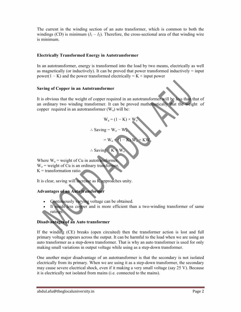
The current in the winding section of an auto transformer, which is common to both the windings (CD) is minimum (I1 – I2). Therefore, the cross-sectional area of that winding wire is minimum.
Electrically Transformed Energy in Autotransformer
In an autotransformer, energy is transformed into the load by two means, electrically as well as magnetically (or inductively). It can be proved that power transformed inductively = input power(1 − K) and the power transformed electrically = K × input power
Saving of Copper in an Autotransformer
It is obvious that the weight of copper required in an autotransformer will be less than that of an ordinary two winding transformer. It can be proved mathematically that the weight of copper required in an autotransformer (Wa) will be: Wa = (1 − K) × Wo
∴ Saving = Wo − Wa
= Wo − (1 − K) Wo = KWo
∴ Saving = K × Wo
Where Wa = weight of Cu in autotransformer, Wo = weight of Cu is an ordinary transformer, K = transformation ratio. It is clear, saving will increase as K approaches unity. Advantages of an Auto transformer
Continuously varying voltage can be obtained. It needs less copper and is more efficient than a two-winding transformer of same
ratings. Disadvantages of an Auto transformer If the winding (CE) breaks (open circuited) then the transformer action is lost and full primary voltage appears across the output. It can be harmful to the load when we are using an auto transformer as a step-down transformer. That is why an auto transformer is used for only making small variations in output voltage while using as a step-down transformer. One another major disadvantage of an autotransformer is that the secondary is not isolated electrically from its primary. When we are using it as a step-down transformer, the secondary may cause severe electrical shock, even if it making a very small voltage (say 25 V). Because it is electrically not isolated from mains (i.e. connected to the mains).
[email protected] Page 3
To understand these concepts more clearly, suppose we want to get a 30 AC supply form the 220 V mains. We can get 30 V AC supply by using a 220/30 V step down transformer or by a 220/30 V autotransformer. But the latter option is generally avoided because:
Saving in copper will be very small. If any fault occurs, 220 V will appear across the secondary terminals and will destroy
the devices connected to the secondary. When our system is working properly i.e. giving 30 V supply, even then anybody
touches the secondary terminal of the transformer (30 V) can get a severe electric shock is some situations because he is not isolated from the mains.
Whereas when we use a step-down transformer, we can easily touch the secondary terminal of the operating transformer because its voltage level is very low (30 V) and its primary and secondary is completely isolated electrically from each other. That is, there is no electrical connection between the primary and the secondary. The power is transferred from one circuit to the second circuit only by magnetic flux. Applications of an Auto transformer The auto transformers are used
as starters for induction motors and synchronous motors which are known as auto transformer starters.
in labs for obtaining a continuously varying voltage. in voltage stabilizers as regulating transformers. as booster transformer to raise the voltage in AC feeders.

[email protected] Page 1
Buchholz Relay Construction & Working Buchholz relay is a gas actuated relay. It is generally used on all oil immersed transformers having a rating more than 500 KVA. It is installed between the conservator and main tank. Therefore, such relay can only be installed in the transformers equipped with conservator tanks. The Buchholz relay construction is shown in Figure. It consists of two hinged floats in a metallic chamber. One of the floats actuates the mercury switch connected to the external alarm circuit and the other float actuates the mercury switch connected to the tripping circuit. Whenever a fault occurs inside the transformer, the oil of the tank gets overheated and gases are generated. The generation of gases may be slow or violent according to nature of the fault. When a predetermined amount of gases accumulate in the top of the chamber of the relay, the mercury type switch attached to the float is tilted, closes the alarm circuit and rings the bell. When a severe fault occurs, a large volume of gas is generated, the lower float is tilted and the trip coil is energized. This opens the circuit breaker and supply to the transformer is switched off. Buchholz relay is a very simple device used for transformer protection. Moreover, it detects the developing faults at a much earlier stage and enables us to protect transformer before serious damage occurs.

Construction of the Transformer
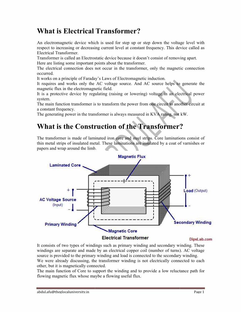
The transformer is made of laminated iron core and steel strips. Core laminations consist of thin metal strips of insulated metal. These laminations are insulated by a coat of varnishes or papers and wrap around the limb.
You can easily understand the foll
It consists of two types of windings such as primary winding and secondary winding. These windings are separate and made by an electrical copper coil (number of turns). AC voltage source is provided to the primary winding and load is connected to the secondary winding.
We were already discussing, the transformer winding is not electrically connected to each other, but it is magnetically connected.
The main function of Core to support thflowing magnetic flux whose maybe a flowing useful flux
Types of Transformer
There are many types of transformersFollowing are the main types of transformers
On the basis of core and winding arrangement, following are the main types of transformers:
Core type transformer Shell type transformer Berry type transformer
Construction of the Transformer
The transformer is made of laminated iron core and steel strips. Core laminations consist of thin metal strips of insulated metal. These laminations are insulated by a coat of varnishes or
wrap around the limb.
You can easily understand the following figure.
It consists of two types of windings such as primary winding and secondary winding. These windings are separate and made by an electrical copper coil (number of turns). AC voltage
ce is provided to the primary winding and load is connected to the secondary winding.
We were already discussing, the transformer winding is not electrically connected to each other, but it is magnetically connected.
The main function of Core to support the winding and to provide a low reluctance path for flowing magnetic flux whose maybe a flowing useful flux.
transformers. These can be classified on the different basis. Following are the main types of transformers.
On the basis of core and winding arrangement, following are the main types of transformers:
Page 1
The transformer is made of laminated iron core and steel strips. Core laminations consist of thin metal strips of insulated metal. These laminations are insulated by a coat of varnishes or
It consists of two types of windings such as primary winding and secondary winding. These windings are separate and made by an electrical copper coil (number of turns). AC voltage
ce is provided to the primary winding and load is connected to the secondary winding.
We were already discussing, the transformer winding is not electrically connected to each
e winding and to provide a low reluctance path for
. These can be classified on the different basis.
On the basis of core and winding arrangement, following are the main types of transformers:

[email protected] Page 2
Core Type Transformer
In the core type transformer magnetic core is made from ‘L’ shape strips. The core type transformer consists of an iron core surrounded by windings. The core of this transformer has two limbs. Each limb carries the same flux. Therefore, the area of both limbs is equal. The low voltage winding is placed next to the core and high voltage winding is placed over it. Proper insulation is provided in between core, low voltage winding and high voltage windings.
Shell Type Transformer In the core type transformer, the iron core is surrounded by the windings whereas, in the shell type transformer, the windings are surrounded by the iron core. The core of shell type transformer is made from ‘E’ and ‘I’ strips. The laminations of this transformer have three limbs. The side limbs carry half of the flux whereas central limb carries the whole of the flux. Therefore, the width of the central limb is more than that of the outer limbs. Both the windings are placed on the central limb concentrically or side by side. The low voltage winding is placed next to the core and high voltage winding is placed over it. Proper insulation is provided in between core, low voltage winding and high voltage windings.

[email protected] Page 1
Cooling Methods of a Transformer No transformer is truly an 'ideal transformer' and hence each will incur some losses, most of which get converted into heat. If this heat is not dissipated properly, the excess temperature in transformer may cause serious problems like insulation failure. It is obvious that transformer needs a cooling system. Transformers can be divided in two types as
(i) dry type transformers and (ii) oil immersed transformers.
Different cooling methods of transformers are - For dry type transformers
Air Natural (AN) Air Blast
For oil immersed tranformers Oil Natural Air Natural (ONAN) Oil Natural Air Forced (ONAF) Oil Forced Air Forced (OFAF) Oil Forced Water Forced (OFWF)
Cooling methods for Dry type Transformers Air Natural or Self air cooled transformer This method of transformer cooling is generally used in small transformers (upto 3 MVA). In this method the transformer is allowed to cool by natural air flow surrounding it. Air Blast For transformers rated more than 3 MVA, cooling by natural air method is inadequate. In this method, air is forced on the core and windings with the help of fans or blowers. The air supply must be filtered to prevent the accumulation of dust particles in ventilation ducts. This method can be used for transformers upto 15 MVA. Cooling methods for Oil Immersed Transformers Oil Natural Air Natural (ONAN) This method is used for oil immersed transformers. In this method, the heat generated in the core and winding is transferred to the oil. According to the principle of convection, the heated oil flows in the upward direction and then in the radiator. The vacant place is filled up by cooled oil from the radiator. The heat from the oil will dissipate in the atmosphere due to the natural air flow around the transformer. In this way, the oil in transformer keeps circulating due to natural convection and dissipating heat in atmosphere due to natural conduction. This method can be used for transformers upto about 30 MVA.
[email protected] Page 2
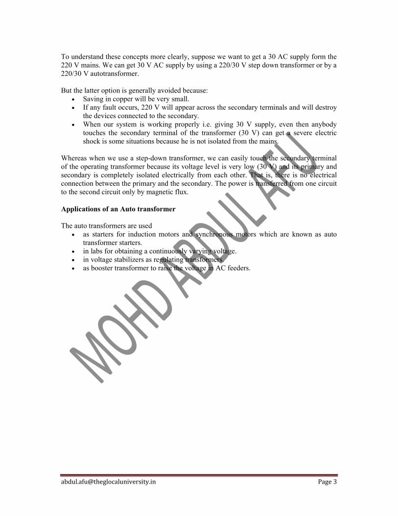
Oil Natural Air Forced (ONAF) The heat dissipation can be improved further by applying forced air on the dissipating surface. Forced air provides faster heat dissipation than natural air flow. In this method, fans are mounted near the radiator and may be provided with an automatic starting arrangement, which turns on when temperature increases beyond certain value. This transformer cooling method is generally used for large transformers upto about 60 MVA. Oil Forced Air Forced (OFAF) In this method, oil is circulated with the help of a pump. The oil circulation is forced through the heat exchangers. Then compressed air is forced to flow on the heat exchanger with the help of fans. The heat exchangers may be mounted separately from the transformer tank and connected through pipes at top and bottom as shown in the figure. This type of cooling is provided for higher rating transformers at substations or power stations. Oil Forced Water Forced (OFWF) This method is similar to OFAF method, but here forced water flow is used to dissipate hear from the heat exchangers. The oil is forced to flow through the heat exchanger with the help of a pump, where the heat is dissipated in the water which is also forced to flow. The heated water is taken away to cool in separate coolers. This type of cooling is used in very large transformers having rating of several hundreds MVA.

[email protected] Page 1
Power Losses in Transformer The power losses in transformer can be divided into two types namely the copper losses and the iron losses. The iron losses in a transformer can be further classified into two types namely the hysteresis losses and eddy current losses.
Copper Power Losses in Transformer The total losses that take place in the winding resistance of a transformer are known as the ‘Copper losses’. These losses in a transformer should be kept as low as possible to increases the efficiency of the transformer. To reduce the copper losses, it is essential to reduce the resistance of primary and secondary winding coils of the transformer i.e., size of the winding conductor is selected very carefully. These are also known as the variable losses as these are dependent on the square of load current. To determine the copper losses, short circuit test on transformer is performed. The total copper losses in transformer are: = I1
2R1 + I22R2
= I12R01
= I22R02
Where, I1 , I2 = primary and secondary currents respectively, R1, R2 = primary and secondary resistances respectively, R01, R02 = equivalent resistances referred to primary and secondary respectively. Example: The primary and the secondary windings of a 500kVA transformer have resistance of 0.42 ohms and 0.0011 ohms respectively. The primary and the secondary voltages are 6600V and 400V respectively. Calculate copper losses at the full load and the half load. Solution: Transformer rating = 500kVA Primary resistance, R1 = 0.42Ω Secondary resistance, R2 = 0.0011Ω Primary voltage, E1 = 6600V Secondary voltage, E2 = 400V Transformation ratio, K = E2/E1 = 400/6600 = 2/33 Primary resistance referred to secondary, R1’ = K2R1 = (2/33)2 x 0.42 = 0.00154 Ω Total resistance referred to secondary, R02 = R2 + R1’ = 0.0011 + 0.00154 = 0.00264 Ω Full load secondary current, I2 = (kVA x 103)/E2 = (500 x 103)/400 = 1250A Copper losses at full load = I2
2R02 = (1250)2 x 0.00264 = 4125W Secondary current at half load = 1250/2 = 625A Copper losses at half load = (625)2 x 0.00264 = 1031.25W

[email protected] Page 1
Why current transformer secondary should not be opened? The current transformers are always used with the secondary windings circuit closed through ammeters, current coils of watt-meters or relay coils. Its secondary winding circuit should not be opened while its primary winding is energized. A violation of this precaution may lead to serious consequences. In a power transformer,
the current flowing in the primary winding depends upon the current in the secondary winding whereas,
in a current transformer current flowing in the primary winding depends upon the current flowing through the line whose current is being measured.
This current is no way controlled by the conditions of the secondary winding circuit of the CT.
Under normal conditions, both primary and secondary windings produce MMF which opposes each other. The primary MMF is slightly more than the secondary MMF and consequently, the resultant MMF is small. This resultant MMF is responsible for the production of flux in the core and as this MMF is small under normal operating conditions, a small voltage is induced in the secondary winding of the CT.

[email protected] Page 2
Why current transformer secondary should not be opened. If the secondary winding is open-circuited with energized primary, the primary MMF remains the same while the opposing secondary winding MMF reduces to zero. In this condition, the resultant MMF becomes very large. This large MMF produces a large flux in the core till it saturates. This large flux links with secondary winding and induces a high voltage in the secondary winding. This could be dangerous to the transformer insulation and to the person who has opened the circuit. Also, the eddy current and hysteresis losses would be very high under these conditions and due to this the CT may be overheated and damaged. Even it does not occur, the core may become magnetized permanently and this gives considerable ratio and phase angle errors. Mostly, CTs are provided with a switch or short-circuiting link at the secondary winding terminals. If such a link is available, it should always be short-circuited before any change is made in the secondary winding circuit with primary winding energized. When a CT is used for measurement, its secondary winding can be short-circuited safely since it is practically short-circuited the impedance of the burden (i.e. an ammeter, CC of wattmeter etc.) is very small.
[email protected] Page 1
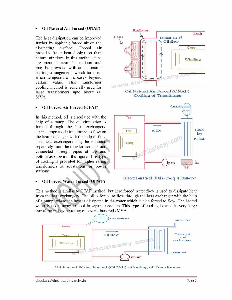
E.M.F. Equation of a Transformer
Consider that an alternating voltage V1 of frequency f is applied to the primary as shown in Figure.
The sinusoidal flux produced by the primary can be represented as:
= m sint
The instantaneous e.m.f. e1 induced in the primary is
E N d N d ( sin t) 1 dt
1 dt m 1
N1 m cos t 2 f N1 m cos t
2 f N1 m sin(t 90) (i)
It is clear from the above equation that maximum value of induced e.m.f. in the primary is
E m1 2 f N1 m The r.m.s. value E^ of the primary e.m.f. is
E1 E m1 2 f N1 m
2 2
or E1 4.44 f N1 m
Similarly E 2 4.44 f N2 m
In an ideal transformer, E1 = V1 and E2 =V2.
Note. It is clear from exp. (i) above that e.m.f. E1 induced in the primary lags
behind the flux by 90°. Likewise, e.m.f. E2 induced in the secondary lags behind flux by 90°.
[email protected] Page 1
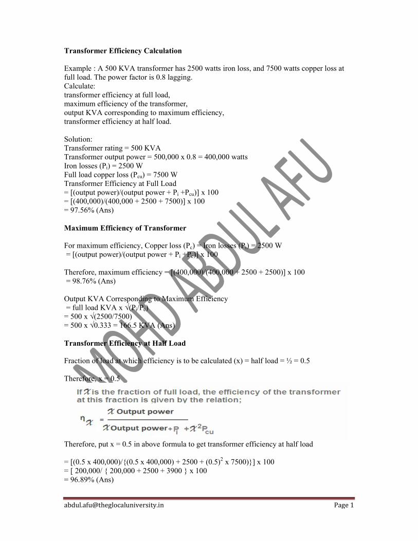
Transformer Efficiency Calculation Example : A 500 KVA transformer has 2500 watts iron loss, and 7500 watts copper loss at full load. The power factor is 0.8 lagging. Calculate: transformer efficiency at full load, maximum efficiency of the transformer, output KVA corresponding to maximum efficiency, transformer efficiency at half load. Solution: Transformer rating = 500 KVA Transformer output power = 500,000 x 0.8 = 400,000 watts Iron losses (Pi) = 2500 W Full load copper loss (Pcu) = 7500 W Transformer Efficiency at Full Load = [(output power)/(output power + Pi +Pcu)] x 100 = [(400,000)/(400,000 + 2500 + 7500)] x 100 = 97.56% (Ans) Maximum Efficiency of Transformer For maximum efficiency, Copper loss (Pc) = Iron losses (Pi) = 2500 W = [(output power)/(output power + Pi +Pc)] x 100 Therefore, maximum efficiency = [(400,000)/(400,000 + 2500 + 2500)] x 100 = 98.76% (Ans) Output KVA Corresponding to Maximum Efficiency = full load KVA x √(Pi/Pc) = 500 x √(2500/7500) = 500 x √0.333 = 166.5 KVA (Ans) Transformer Efficiency at Half Load Fraction of load at which efficiency is to be calculated (x) = half load = ½ = 0.5 Therefore, x = 0.5
Therefore, put x = 0.5 in above formula to get transformer efficiency at half load = [(0.5 x 400,000)/{(0.5 x 400,000) + 2500 + (0.5)2 x 7500)}] x 100 = [ 200,000/ { 200,000 + 2500 + 3900 } x 100 = 96.89% (Ans)
[email protected] Page 2
Calculate All-day Efficiency of Transformer Example: A 20 KVA transformer on domestic load, which can be taken as of unity power factor, has a full load efficiency of 95.3%, the copper loss then being twice the iron loss. Calculate its ail-day efficiency at following daily cycle: no load for 10 hours, half load for 8 hours, full load for 6 hours. Solution: Full load output = 20 x 1 = 20 kW Full load input = output/efficiency = (20/95.3) x 100 = 20.986 kw Total losses = Pi + Pcu = Input – Output = 20.986 – 20 = 0.986 kw Now Pcu = 2Pi (given) Therefore, Pi + 2Pi = 0.986 kW Or Iron losses (Pi) = 0.3287 kW Full load copper losses (Pcu) = 2 x 0.3287 = 0.6574 kW kWh output in 24 hours = {(1/2) x 20 x 8} + (1 x 20 x 6) = 200 kWH Iron losses for 24 hours = 0.3287 x 24 = 7.89 kW Copper losses for 24 hours = Cu losses for 8 hours at half load + Cu losses for 6 hours at full load = {(1/2)2 x 0.6574 x 8} + (0.6574 x 6) = 5.259 kWH Input in 24 hours = kWh output in 24 hours + iron and copper losses for 24 hours = 200 + 7.89 + 5.259 = 213.149 kWH All day efficiency of transformer = (kWH output in 24 hours/ kWH input in 24 hours) x 100 = (200/213.149) = 93.83% (Ans)

[email protected] Page 1
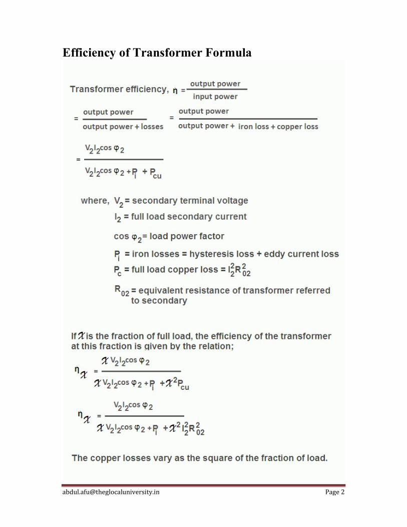
Efficiency of Transformer The efficiency of transformer is defined as the ratio of output power to input power. It is denoted by ἠ. As the output power is always less than the input power due to losses in the transformer, practically the transformer efficiency is always between 0 and 1 i.e. 0% and 100% but it can never be 1 or 100%. The efficiency of an ideal transformer is equal to 1 or 100% since the losses in the ideal transformer are zero. The graph of output power versus efficiency of transformer is shown in the figure. The figure shows that the efficiency increases with the increase in the output power up to a certain value and after a particular value of output power, the transformer efficiency decreases. The value of transformer efficiency will be maximum when the copper losses will be equal to iron losses in the transformer. The value of maximum efficiency can be found by taking total losses equal to 2Pi. It also depends on load power factor and has the maximum value at a power factor of unity. The transformer on which load is variable (like distribution transformer) is designed to give maximum efficiency at about 75% of full load. And if it is continuously operated near the full load (like power transformers), then it is designed to give maximum efficiency at or near the full load.

[email protected] Page 3
The transformer has no moving parts so the losses due to friction and windage are absent therefore its efficiency is very high. It can be at least equal to 90%. Its output and input are almost of the same value. Hence their ratio cannot be found accurately by measuring input and output power. To overcome this problem it is better to measure the transformer losses separately and then find the transformer efficiency by the transformer efficiency formula. The iron losses and copper losses of can be determined very easily and accurately by no-load test and short-circuit test on transformer respectively.
All Day Efficiency of Transformer The efficiency discussed so far is the ordinary or commercial or power efficiency of the transformer. But for the distribution transformer, it does not give the true idea about the transformer performance because the load on distribution transformer fluctuates throughout the day. This transformer is energized for twenty-four hours, but for the major portion of the day, it delivers the very light load. Thus iron losses take place for the whole day but copper losses take place only when the transformer is loaded. Hence, the performance of such transformer (like distribution transformer) cannot be judged by the power efficiency. But it can be judged by the special type of transformer efficiency known as energy efficiency or all-day efficiency. The all-day efficiency is computed on the basis of energy consumed during the period of twenty-four hours. The all day efficiency of transformer is defined as the ratio of output energy (in kWh) to input energy (in kWh) for twenty-four hours. To find all day efficiency of transformer, we have to know the load cycle of the transformer.

[email protected] Page 1
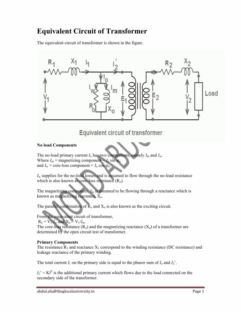
Equivalent Circuit of Transformer The equivalent circuit of transformer is shown in the figure.
No load Components The no-load primary current Io has two components, namely Im and Iw. Where Im = magnetizing component = Io sin φo and Iw = core-loss component = Io cos φo. Iw supplies for the no-load losses and is assumed to flow through the no-load resistance which is also known as core-loss resistance (Ro). The magnetizing component, Im is assumed to be flowing through a reactance which is known as magnetizing reactance, Xo. The parallel combination of Ro and Xo is also known as the exciting circuit. From the equivalent circuit of transformer, Ro = V1/Iw and Xo = V1/Im. The core-loss resistance (Ro) and the magnetizing reactance (Xo) of a transformer are determined by the open circuit test of transformer. Primary Components The resistance R1 and reactance X1 correspond to the winding resistance (DC resistance) and leakage reactance of the primary winding. The total current I1 on the primary side is equal to the phasor sum of Io and I2’. I2’ = KI2 is the additional primary current which flows due to the load connected on the secondary side of the transformer.

[email protected] Page 2
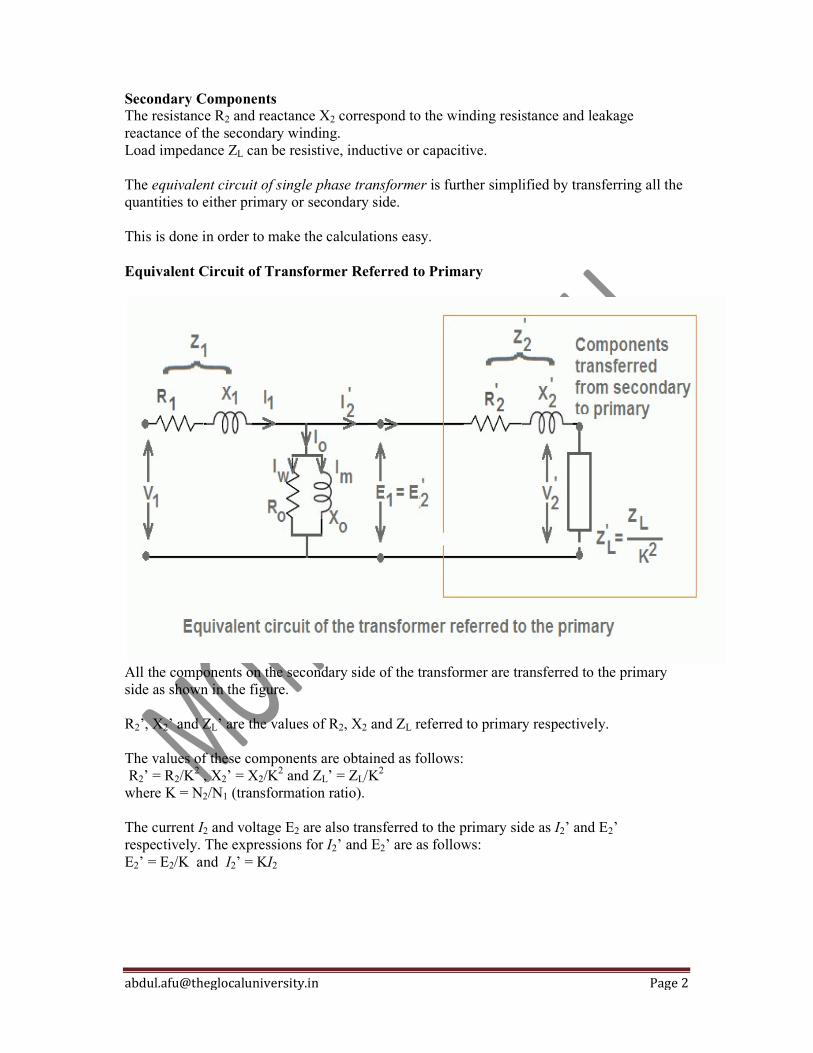
Secondary Components The resistance R2 and reactance X2 correspond to the winding resistance and leakage reactance of the secondary winding. Load impedance ZL can be resistive, inductive or capacitive. The equivalent circuit of single phase transformer is further simplified by transferring all the quantities to either primary or secondary side. This is done in order to make the calculations easy. Equivalent Circuit of Transformer Referred to Primary
All the components on the secondary side of the transformer are transferred to the primary side as shown in the figure. R2’, X2’ and ZL’ are the values of R2, X2 and ZL referred to primary respectively. The values of these components are obtained as follows: R2’ = R2/K
2 , X2’ = X2/K2 and ZL’ = ZL/K2
where K = N2/N1 (transformation ratio). The current I2 and voltage E2 are also transferred to the primary side as I2’ and E2’ respectively. The expressions for I2’ and E2’ are as follows: E2’ = E2/K and I2’ = KI2
[email protected] Page 1
Equivalent Circuit of Transformer The equivalent circuit of transformer is shown in the figure.
No load Components The no-load primary current Io has two components, namely Im and Iw. Where Im = magnetizing component = Io sin φo and Iw = core-loss component = Io cos φo. Iw supplies for the no-load losses and is assumed to flow through the no-load resistance which is also known as core-loss resistance (Ro). The magnetizing component, Im is assumed to be flowing through a reactance which is known as magnetizing reactance, Xo. The parallel combination of Ro and Xo is also known as the exciting circuit. From the equivalent circuit of transformer, Ro = V1/Iw and Xo = V1/Im. The core-loss resistance (Ro) and the magnetizing reactance (Xo) of a transformer are determined by the open circuit test of transformer. Primary Components The resistance R1 and reactance X1 correspond to the winding resistance (DC resistance) and leakage reactance of the primary winding. The total current I1 on the primary side is equal to the phasor sum of Io and I2’. I2’ = KI2 is the additional primary current which flows due to the load connected on the secondary side of the transformer.
[email protected] Page 2
Secondary Components The resistance R2 and reactance X2 correspond to the winding resistance and leakage reactance of the secondary winding. Load impedance ZL can be resistive, inductive or capacitive. The equivalent circuit of single phase transformer is further simplified by transferring all the quantities to either primary or secondary side. This is done in order to make the calculations easy. Equivalent Circuit of Transformer Referred to Primary
All the components on the secondary side of the transformer are transferred to the primary side as shown in the figure. R2’, X2’ and ZL’ are the values of R2, X2 and ZL referred to primary respectively. The values of these components are obtained as follows: R2’ = R2/K
2 , X2’ = X2/K2 and ZL’ = ZL/K2
where K = N2/N1 (transformation ratio). The current I2 and voltage E2 are also transferred to the primary side as I2’ and E2’ respectively. The expressions for I2’ and E2’ are as follows: E2’ = E2/K and I2’ = KI2
[email protected] Page 1
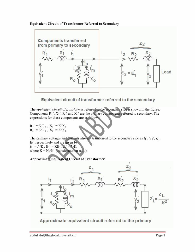
Equivalent Circuit of Transformer Referred to Secondary
The equivalent circuit of transformer referred to the secondary side is shown in the figure. Components R1’, X1’, Ro’ and Xo’ are the primary components referred to secondary. The expressions for these components are as follows: R1’ = K2R1 , X1’ = K2X1 Ro’ = K2Ro , Xo’ = K2Xo The primary voltages and currents also get transferred to the secondary side as I1’, V1’, Io’, E1’ respectively and are given by: I1’ = I1/K , E1’ = KE1 , Io’ = Io/K where K = N2/N1 (transformation ratio). Approximate Equivalent Circuit of Transformer
[email protected] Page 2
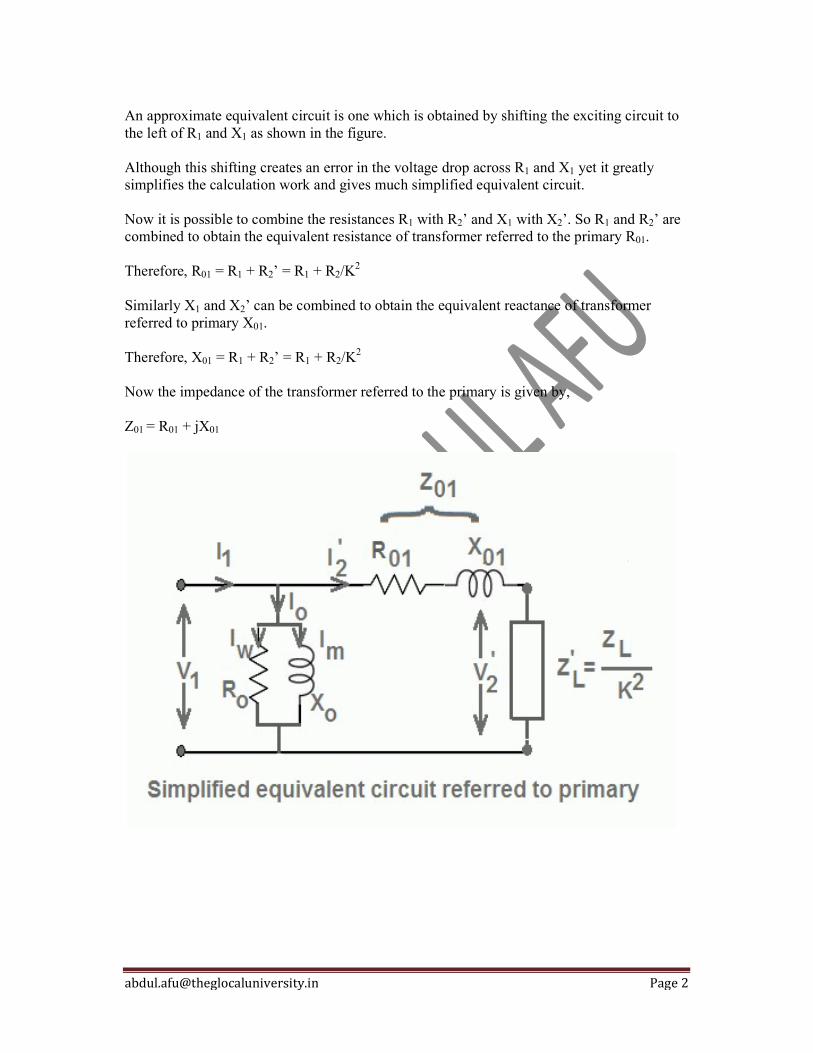
An approximate equivalent circuit is one which is obtained by shifting the exciting circuit to the left of R1 and X1 as shown in the figure. Although this shifting creates an error in the voltage drop across R1 and X1 yet it greatly simplifies the calculation work and gives much simplified equivalent circuit. Now it is possible to combine the resistances R1 with R2’ and X1 with X2’. So R1 and R2’ are combined to obtain the equivalent resistance of transformer referred to the primary R01. Therefore, R01 = R1 + R2’ = R1 + R2/K
2 Similarly X1 and X2’ can be combined to obtain the equivalent reactance of transformer referred to primary X01. Therefore, X01 = R1 + R2’ = R1 + R2/K
2 Now the impedance of the transformer referred to the primary is given by, Z01 = R01 + jX01
[email protected] Page 1
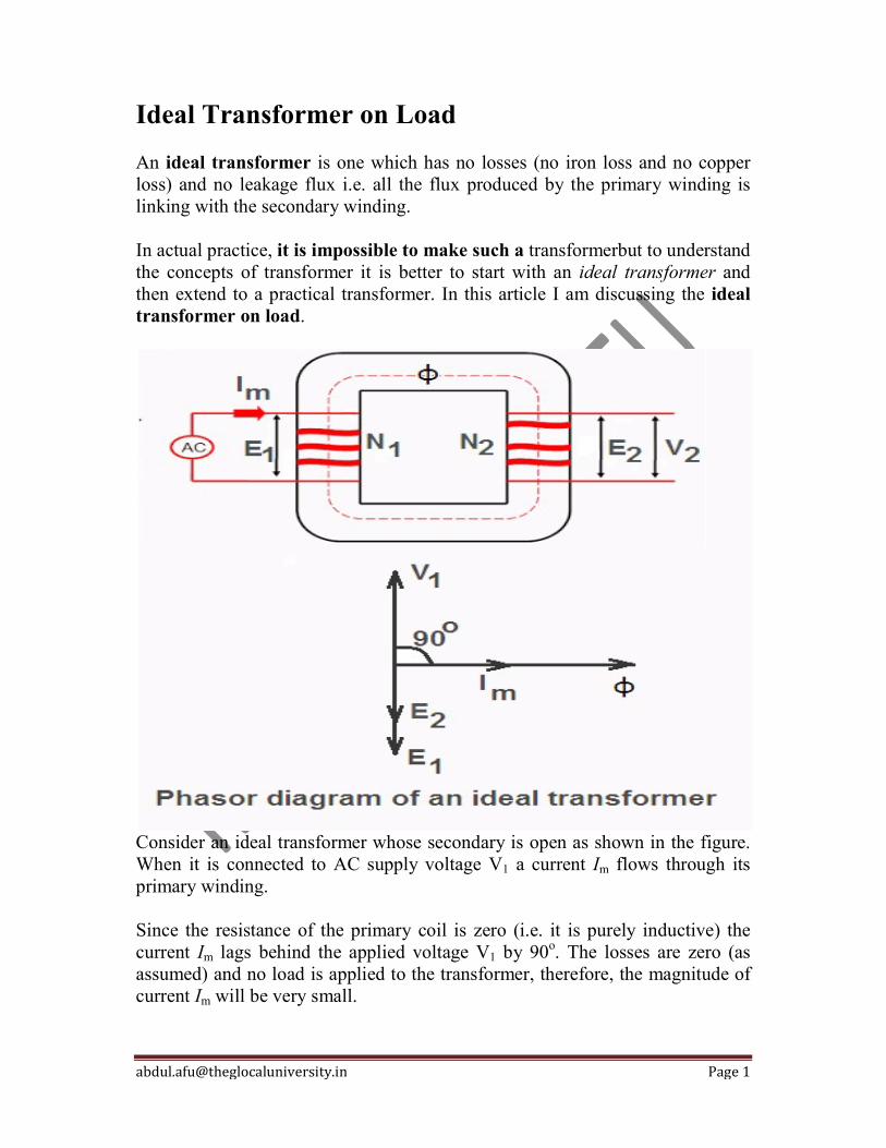
Ideal Transformer on Load An ideal transformer is one which has no losses (no iron loss and no copper loss) and no leakage flux i.e. all the flux produced by the primary winding is linking with the secondary winding. In actual practice, it is impossible to make such a transformerbut to understand the concepts of transformer it is better to start with an ideal transformer and then extend to a practical transformer. In this article I am discussing the ideal transformer on load.
Consider an ideal transformer whose secondary is open as shown in the figure. When it is connected to AC supply voltage V1 a current Im flows through its primary winding. Since the resistance of the primary coil is zero (i.e. it is purely inductive) the current Im lags behind the applied voltage V1 by 90o. The losses are zero (as assumed) and no load is applied to the transformer, therefore, the magnitude of current Im will be very small.
[email protected] Page 2
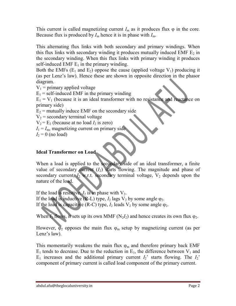
This current is called magnetizing current Im as it produces flux φ in the core. Because flux is produced by Im hence it is in phase with Im. This alternating flux links with both secondary and primary windings. When this flux links with secondary winding it produces mutually induced EMF E2 in the secondary winding. When this flux links with primary winding it produces self-induced EMF E1 in the primary winding. Both the EMFs (E1 and E2) oppose the cause (applied voltage V1) producing it (as per Lenz’s law). Hence these are shown in opposite direction in the phasor diagram. V1 = primary applied voltage E1 = self-induced EMF in the primary winding E1 = V1 (because it is an ideal transformer with no resistance and reactance on primary side) E2 = mutually induce EMF on the secondary side V2 = secondary terminal voltage V2 = E2 (because at no load I2 is zero) I1 = Im, magnetizing current on primary side I2 = 0 (no load) Ideal Transformer on Load When a load is applied to the secondary side of an ideal transformer, a finite value of secondary current (I2) starts flowing. The magnitude and phase of secondary current, I2 w.r.t. secondary terminal voltage, V2 depends upon the nature of the load. If the load is resistive, I2 is in phase with V2. If the load is inductive (R-L) type, I2 lags V2 by some angle φ2. If the load is capacitive (R-C) type, I2 leads V2 by some angle φ2. When I2 flows, it sets up its own MMF (N2I2) and hence creates its own flux φ2. However, φ2 opposes the main flux φm setup by magnetizing current (as per Lenz’s law). This momentarily weakens the main flux φm and therefore primary back EMF E1 tends to decrease. Due to the reduction in E1, the difference between V1 and E1 increases and the additional primary current I2’ starts flowing. The I2’ component of primary current is called load component of the primary current.
[email protected] Page 3
The current component I2’, sets up an MMF N1I2’ to counter the effect of secondary produced MMF N2I2
i.e N1I2’ = N2I2 or I2’ = N2I2 / N1 = KI2 and it is 180o out of phase with I2. The net primary current I1 is phasor sum of I2’ and Im (because Iw is zero in an ideal transformer). Thus due to load on the secondary side, the primary current of the transformer increases to supply the additional power to the load. Since, winding resistance of an ideal transformer is zero, therefore, its voltage regulation will be zero and its efficiency will be 100%.

[email protected] Page 1
Instrument Transformer Construction & Working For measurement of large currents and high voltages in AC circuits, specially constructed accurate ratio transformers are used in conjunction with low range AC instruments. These specially constructed transformers are known as instrument transformers and are of two types:
Potential Transformers (PTs) Current Transformers (CTs)
These instrument transformers are also used in power system in conjunction with protective relays. For safety purposes, the secondaries of these transformers are grounded.
Current Transformer Construction & Working Current transformers are used in AC power circuits to feed the current coils of indicting and metering instruments (ammeters, watt-meters, energy-meters) and protective relays. These transformers make the ordinary low current instruments suitable for measurement of high current and isolate them from high voltage. The current transformer basically consists of an iron core on which a primary and one or two secondary windings are wound. The primary winding has one or two turns of thick wire and is connected in series with the load. It carries the actual power system current. Primary current ratings vary from 10 A to 3000 A or more. The secondary winding has a large number of turns of fine wire. It is connected across current coils of indicting and metering instruments and protective relays. The secondary current ratings are of the order of 5 A, 1 A, and 0.1 A. The latter is used for static relays. If for any reason the instrument connected to the secondary of CT is to be removed then the secondary of CT must be short-circuited by a fairly thick wire. The ratio of primary current to the secondary current is known as transformation ratio of the CT. The transformation ratio of a CT is usually high. The product of voltage and current on the secondary side when it is supplying its maximum rated value of current is known as the rated burden and is measured in volt-amperes (VA). The volt-ampere rating of CTs is low (5 – 150 VA) as compared to that of power transformers. Also current in the secondary of CTs is governed by the current in the primary winding i.e. power circuit current. But in the case of power transformers, it is governed by load impedance.

[email protected] Page 2
Potential Transformers Construction & Working Potential transformers are used in AC power circuits to feed the potential coils of indicting and metering instruments (voltmeters, watt-meters, energy-meters) and protective relays. These transformers make the ordinary low voltage instruments suitable for measurement of high voltage and isolate them from high voltage. The PTs are highly accurate ratio step down transformers. Its primary winding has a large number of turns and is always connected across the supply system. Its secondary winding has few number of turns and is connected to the potential coil of indicting and metering instruments and protective relays. The primaries of PT are rated from 400 V to several thousand volts and secondaries always for 110 V. The ratio of the rated primary voltage to the rated secondary voltage is known as turn or transformation ratio of PT. The burden is the total external volt-ampere load on the secondary at rated secondary voltage. The rated burden of a PT is the VA burden which must not exceed if the transformer is to operate with its rated accuracy. The maximum burden is the greatest VA load at which the PT will operate continuously without overheating its winding beyond the permissible limits. Let the voltage to be measured of a power system is 11 kV. It is impossible to measure such a high voltage directly by a voltmeter. Therefore, a PT having secondary to primary turn ratio 1:100 is used in conjunction with a voltmeter which steps down the voltage from 11 kV to 110 V as shown in the figure.

[email protected] Page 3
For measurement of power in a high voltage power system, both CT and PT are used. The CT is used to step down the system current and the PT is used to step down the system voltage up to the required value. The potential coil (PC) of the wattmeter is connected across the secondary of PT and the current coil (CC) of the wattmeter is connected across the secondary of CT as shown in the figure.

[email protected] Page 1
Iron Losses(Pi) in Transformer The power losses that take place in its iron core are known as the ‘Iron losses’. These losses occur due to alternating flux set up in the core. In a transformer, flux set up in the core remains constant from no load to full load. Hence these power losses are independent of load and also known as constant losses of a transformer. These losses have two components named hysteresis losses and eddy current losses. To determine the iron losses, open circuit test of transformer is performed. Hysteresis Power Losses in Transformer
When a magnetic material is subjected to reversal of flux, power is required for the continuous reversal of molecular magnets. This power is dissipated in the form of heat and is known as ‘Hysteresis Loss’. The hysteresis loss of a magnetic material depends upon its area of the hysteresis loop. Hence the magnetic materials such as silicon steel, which has very small hysteresis loop area, are used for the construction of the core to minimize the hysteresis loss in a transformer.
[email protected] Page 2
The hysteresis loss (Ph = KhVfBm1.6) is frequency dependent. As we
increase the frequency of operation, this loss increases proportionally. Eddy Current Losses in Transformer
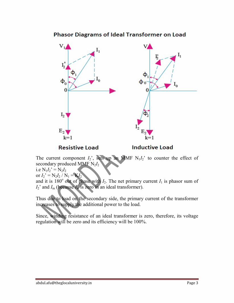
Due to alternating flux in a transformer, some EMF is induced in the transformer core. This induced EMF causes some currents to flow through the core of the transformer. These currents are known as eddy currents. The core of transformer has some finite resistance. Hence due to the flow of eddy currents, some power losses take place and are known as ‘Eddy current losses’ (Pe = KeVft2Bm
2). The eddy current losses in transformer are minimized by using the laminated core. These laminations are insulated from each other by mean of a thin varnish coating. Hence each lamination acts as a separate core of a small cross sectional area, offers a high resistance to the flow of eddy currents. Therefore, with the use of laminations in the core, eddy currents and eddy current losses are reduced. These losses are also frequency dependent. They are directly proportional to the square of operating frequency.
[email protected] Page 1
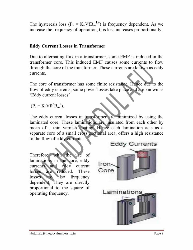
Leakage Reactance Both primary and secondary currents produce flux. The flux f which links both the windings is the useful flux and is called mutual flux. However, primary current would produce some flux f which would not link the secondary winding see in figure. Similarly, secondary current would produce some flux f that would not link the primary winding. The flux such as f1 or f2 which links only one winding is called leakage flux. The leakage flux paths are mainly through the air. The effect of these leakage fluxes would be the same as though inductive reactance were connected in series with each winding of transformer that had no leakage flux as shown in Figure. In other words, the effect of primary leakage flux f1 is to introduce an inductive reactance X1 in series with the primary winding as shown in Figure. Similarly, the secondary leakage flux f2 introduces an inductive reactance X2 in series with the secondary winding. There will be no power loss due to leakage reactance. However, the presence of leakage reactance in the windings changes the power factor as well as there is voltage loss due to IX drop. Note. Although leakage flux in a transformer is quite small (about 5% of f) compared to the mutual flux f, yet it cannot be ignored. It is because leakage flux paths are through air of high reluctance and hence require considerable e.m.f. It may be noted that energy is conveyed from the primary winding to the secondary winding by mutual flux f which links both the windings.
What is Electrical Transformer An electromagnetic device which is used for step up or step down the voltagerespect to increasing or decreasing current level at constantElectrical Transformer. Transformer is called an ElectrostaticHere are listing some important points about the transformer.The electrical connection does not occur in the transformer, only the magnetic connection occurred. It works on a principle of Faraday’sIt requires and works only the AC voltage source. And AC source helps to generate the magnetic flux in the electromagnetic field.It is a protective device by regulating (raising or lowering) voltage in an electrical power system. The main function transformer is to transform ta constant frequency. The generating power in the transformer is always measured in KVA rating, not kW.
What is the Construction of the Tra The transformer is made of laminated iron core and steel strips. Core laminations consist of thin metal strips of insulated metal. These laminations are insulated by a coat of varnishes or papers and wrap around the limb.
It consists of two types of windings such as primary winding and secondary winding. These windings are separate and made by an electrical copper coil (number of turns). AC voltage source is provided to the primary windinWe were already discussing, the transformer winding is not electrically connected to each other, but it is magnetically connected.The main function of Core to support the winding and to provide a low relucflowing magnetic flux whose maybe a flowing useful flux.
What is Electrical Transformer?
An electromagnetic device which is used for step up or step down the voltagerespect to increasing or decreasing current level at constant frequency. This device called as
Electrostatic device because it doesn’t consist of removing apart.Here are listing some important points about the transformer. The electrical connection does not occur in the transformer, only the magnetic connection
Faraday’s Laws of Electromagnetic induction. only the AC voltage source. And AC source helps to generate the
magnetic flux in the electromagnetic field. It is a protective device by regulating (raising or lowering) voltage in an electrical power
The main function transformer is to transform the power from one circuit to another circuit at
in the transformer is always measured in KVA rating, not kW.
What is the Construction of the Transformer?
The transformer is made of laminated iron core and steel strips. Core laminations consist of thin metal strips of insulated metal. These laminations are insulated by a coat of varnishes or
wrap around the limb.
It consists of two types of windings such as primary winding and secondary winding. These windings are separate and made by an electrical copper coil (number of turns). AC voltage source is provided to the primary winding and load is connected to the secondary winding.We were already discussing, the transformer winding is not electrically connected to each other, but it is magnetically connected. The main function of Core to support the winding and to provide a low reluctance path for flowing magnetic flux whose maybe a flowing useful flux.
Page 1
An electromagnetic device which is used for step up or step down the voltage level with frequency. This device called as
it doesn’t consist of removing apart.
The electrical connection does not occur in the transformer, only the magnetic connection
only the AC voltage source. And AC source helps to generate the
It is a protective device by regulating (raising or lowering) voltage in an electrical power
he power from one circuit to another circuit at
in the transformer is always measured in KVA rating, not kW.
?
The transformer is made of laminated iron core and steel strips. Core laminations consist of thin metal strips of insulated metal. These laminations are insulated by a coat of varnishes or
It consists of two types of windings such as primary winding and secondary winding. These windings are separate and made by an electrical copper coil (number of turns). AC voltage
g and load is connected to the secondary winding. We were already discussing, the transformer winding is not electrically connected to each
tance path for

[email protected] Page 2
What are the Main Parts of a Transformer? Laminated Iron Core Transformer Winding Insulating Material Tap Changer Transformer Tank Oil Conservator Tank Breather Buchholz Relay Bushing Cooling Tube and Radiator Explosion Vent 1. Laminated Iron Core The transformer’s core is made up of iron or silicon steel or ferromagnetic materials. The iron core made by thin metal strips and lamination insulated by a coat of varnishes or papers. Each metal strip has thickness near about the o.5mm. In the figure, you can see the number of metal strips connected to each other with the lamination layer and form a single core. Basically, ‘L’ and ‘E’ shaped laminations are used in different types of transformer. In the core type transformer, ‘L’ or ‘U’ shaped lamination is used. And shell types transformer ‘E’ or ‘I’ shaped
lamination is used. These core lamination helps to reduce the eddy current loss and hysteresis loss. And It provides a low reluctance path and high permeability for the flux in the magnetic circuit. 2. The winding of the Transformer The transformer winding is consists of several turns of the copper coil. It is wrapped around the limb or core with the lamination. These windings laminated by the insulation coating because it prevents the short circuit condition. The winding of the transformer is separated by the primary side and secondary side. On the bases of supply two types as High voltage winding Low voltage winding Simply two types of winding are used as Concentric types winding Sandwich types winding
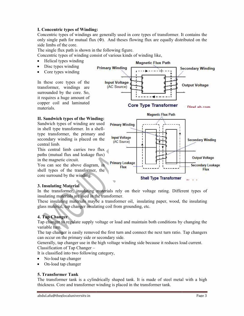
I. Concentric types of Winding:Concentric types of windings are generally used in core types of transformer. It contains the only single path for mutual flux (Φ).side limbs of the core. The single flux path is shown in the following figConcentric types of winding consist of various kinds of winding like, Helical types winding Disc types winding Core types winding In these core types of the transformer, windings are surrounded by the core. So, it requires a huge amount of copper coil and laminated materials. II. Sandwich types of the Winding:Sandwich types of winding are used in shell type transformer. In a shelltype transformer, the primary and secondary winding is placed on the central limb. This central limb carries two flux paths (mutual flux and leakage flux) in the magnetic circuit. You can see the above diagram, in shell types of the transformer, the core surround by the winding. 3. Insulating Material In the transformer, insulating materials rely on their voltage rating. Different types of insulating materials are used in the transformer.These insulating materials maybe a transformer oil,glass material, tap changer insulating coil from grounding, etc. 4. Tap Changer Tap changer to regulate supply voltage or load and maintain both conditions by changing the variable turn. The tap changer is easily removed the first turn and connect the next turn ratio. Tap changercan occur on the primary side or secondary side.Generally, tap changer use in the high voltage winding side because it reduces load current.Classification of Tap Changer – It is classified into two following category, No-load tap changer On-load tap changer 5. Transformer Tank The transformer tank is a cylindrically shaped tank. It is made of steel metal with a high thickness. Core and transformer winding is placed in the transformer tank.
Winding: tric types of windings are generally used in core types of transformer. It contains the
only single path for mutual flux (Φ). And theses flowing flux are equally distributed on the
The single flux path is shown in the following figure. Concentric types of winding consist of various kinds of winding like,
Winding: ndwich types of winding are used
in shell type transformer. In a shell-type transformer, the primary and secondary winding is placed on the
This central limb carries two flux paths (mutual flux and leakage flux)
You can see the above diagram, in shell types of the transformer, the
In the transformer, insulating materials rely on their voltage rating. Different types of insulating materials are used in the transformer. These insulating materials maybe a transformer oil, insulating paper, wood, the insulating
ger insulating coil from grounding, etc.
Tap changer to regulate supply voltage or load and maintain both conditions by changing the
The tap changer is easily removed the first turn and connect the next turn ratio. Tap changercan occur on the primary side or secondary side. Generally, tap changer use in the high voltage winding side because it reduces load current.
It is classified into two following category,
The transformer tank is a cylindrically shaped tank. It is made of steel metal with a high thickness. Core and transformer winding is placed in the transformer tank.
Page 3
tric types of windings are generally used in core types of transformer. It contains the And theses flowing flux are equally distributed on the
In the transformer, insulating materials rely on their voltage rating. Different types of
insulating paper, wood, the insulating
Tap changer to regulate supply voltage or load and maintain both conditions by changing the
The tap changer is easily removed the first turn and connect the next turn ratio. Tap changers
Generally, tap changer use in the high voltage winding side because it reduces load current.
The transformer tank is a cylindrically shaped tank. It is made of steel metal with a high

[email protected] Page 4
The transformer tank is needed to store the oil especially mineral oil. This oil provides insulation and cooling to the transformer winding. 6. Oil Conservator Tank The oil conservator tank looks like a rectangular tank. It stores the extra oil and directly connected with the transformer tank. The oil conservator tank is played an important role in the transformer. The purpose of the conservator tank is to protect the expansion of oil in the main tank of the transformer. The oil is used in the transformer two purposes- Insulation Cooling When the oil level reduces due to losses or leakage, the conservator will be delivering oil to the transformer. Thus, It acts as reservoir oil. 7. Breather Breather is connected with the conservator tank. It is a cylindrical vessel which filled blue color silica gel. They have two purposes -remove the moisture from the air and to have the capacity to absorb the moisture in a transformer. It plays a role to act as the air filter and provide the free moisturizing air to the conservator tank. 8. Buchholz Relay Buchholz relay is a protective device that is oil and gas-operated the relay. It is connected to the main transformer tank and conservator tank. When the internal fault occurs in the transformer due to leakage flux, insulation core, core connection, breakdown core, etc. by producing excess heat. This excess heat decomposes oil in the transformer and gas bubbles formed. Gas bubbles flow in the upward direction to the conservator and collected in the relay. Buchholz relay is a fault detected by the amount of nature of gas and oil level in a transformer. During several fault conditions, an alarm is alert then this command send to the circuit breaker and isolates the transformer. 9. Bushing The bushing is an insulating device that is made up of porcelain materials. The terminal of the bushing is provided a path of the conductor to the transformer tank. With the help of the terminal, the transformer gives and provides the supply to another system. In the transformer, two types of the bushing are mostly used- high voltage (HV) bushing and low voltage (LV) bushing. Its rely on voltage ratings may be a high voltage or low voltage. 10. Cooling Tube and Radiator The cooling tube is necessary for maintaining the temperature and circulating cooling oil in the transformer. And the radiator is connected with the transformer tank. It is also made of a number of metal strips or pipes. Both the cooling tube and the radiator provide the same function in a different way. When losses occur in the transformer, heat is produced. This heat absorbs by the cooling tube and radiator in the form of cooling systems.
[email protected] Page 5
It is divided into two types of cooling systems. Natural cooling system Forced cooling system In the natural cooling system, a cooling tube and radiator are used. And In the forced cooling system, we can connect the extra air fan to the transformer. 11. Explosion Vent The explosion vent is located at the topmost position on the transformer. The conservator tank is directly connected to the explosion tank with the help of a pipe. The main purpose to prevent damage transformer oil tank by expelling boiling oil during an internal fault. And it is necessary to remove heated oil (in the form of gas) in the transformer. This explosion tank use only for emergency purposes. It mostly works when a breather and Buchholz relay will not doing work properly.

[email protected] Page 1
On-Load Tap-Changing Transformer The transformer which is not disconnected from the main supply when the tap setting is to be changed such type of transformer in known as on-load tap changing transformer. The tap setting arrangement is mainly used for changing the turn ratio of the transformer to regulate the system voltage while the transformer is delivering the load. The main feature of an on-load tap changer is that during its operation the main circuit of the switch should not be opened. Thus, no part of the switch should get the short circuit. In tap changing transformer different types of an impedance circuit are used for limiting the current during the operation of a tap changing. The impedance circuit may be resistor or reactor type, and by the impedance circuit, the tap changer can be classified as the resistor and reactor type. Nowadays the current limiting is carried out by using a pair of resistors. Location of Tapping The tapping is provided at the HV winding of the transformer because the high voltage winding is wound on the low-voltage winding. Also, the current in the HV winding of the transformer is smaller due to which small contacts and leads are required for tapping connections. The tapping on the windings is taken out through the house board to separate the oil-filled compartment in which the on-load tap changer switch is housed. The tap changer is operated by a motor operated driving mechanism of local or remote control. The handle is operated for manual operation in case of an emergency. Needs For Tapping Frequently change in load changes the voltage of the system. The tap changing in the power transformer is mainly done for keeping the output voltage within the prescribed limit. Nowadays almost all the large power transformer is provided with on-load tap changer. On-Load Tap Changing Transformer Using a Resistor The on-load tap changing gear with the resistor transition, in which one winding is changed for each operating position as shown in the figure below. The sequence of operation during the shifting of one tap into the next is shown in the figure below. The backup main contactor is provided which short-circuit the resistors for normal operation.
[email protected] Page 2
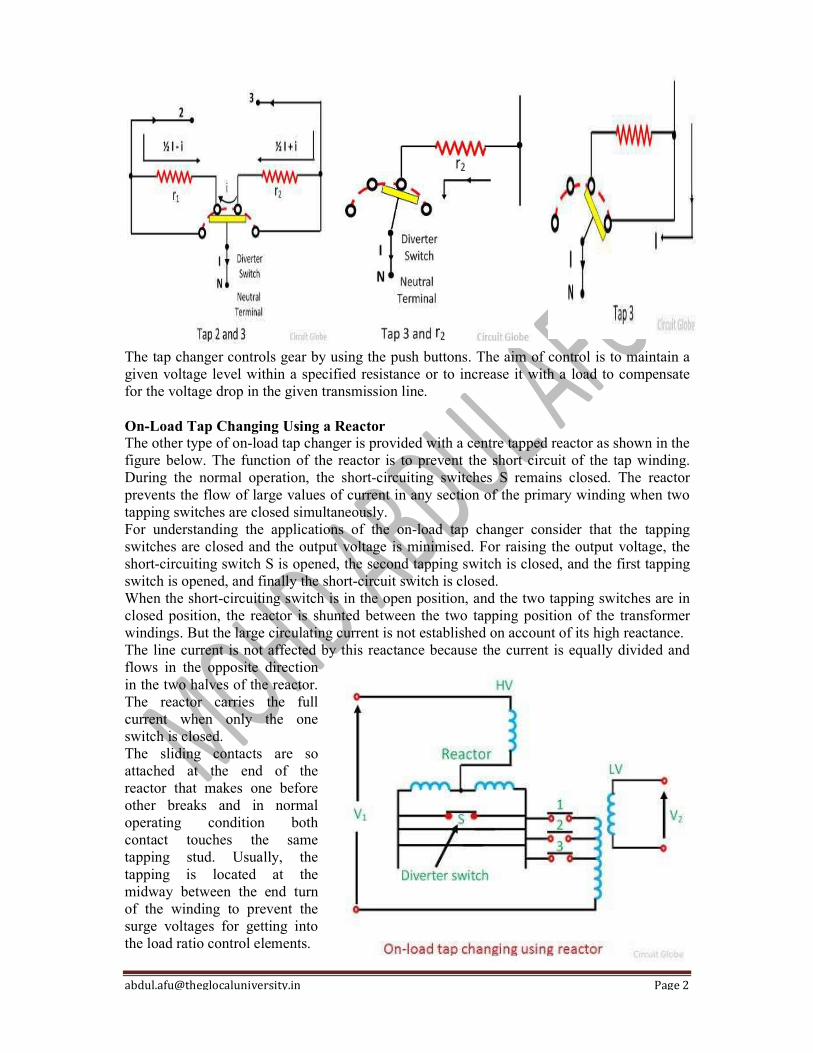
The tap changer controls gear by using the push buttons. The aim of control is to maintain a given voltage level within a specified resistance or to increase it with a load to compensate for the voltage drop in the given transmission line. On-Load Tap Changing Using a Reactor The other type of on-load tap changer is provided with a centre tapped reactor as shown in the figure below. The function of the reactor is to prevent the short circuit of the tap winding. During the normal operation, the short-circuiting switches S remains closed. The reactor prevents the flow of large values of current in any section of the primary winding when two tapping switches are closed simultaneously. For understanding the applications of the on-load tap changer consider that the tapping switches are closed and the output voltage is minimised. For raising the output voltage, the short-circuiting switch S is opened, the second tapping switch is closed, and the first tapping switch is opened, and finally the short-circuit switch is closed. When the short-circuiting switch is in the open position, and the two tapping switches are in closed position, the reactor is shunted between the two tapping position of the transformer windings. But the large circulating current is not established on account of its high reactance. The line current is not affected by this reactance because the current is equally divided and flows in the opposite direction in the two halves of the reactor. The reactor carries the full current when only the one switch is closed. The sliding contacts are so attached at the end of the reactor that makes one before other breaks and in normal operating condition both contact touches the same tapping stud. Usually, the tapping is located at the midway between the end turn of the winding to prevent the surge voltages for getting into the load ratio control elements.
[email protected] Page 1
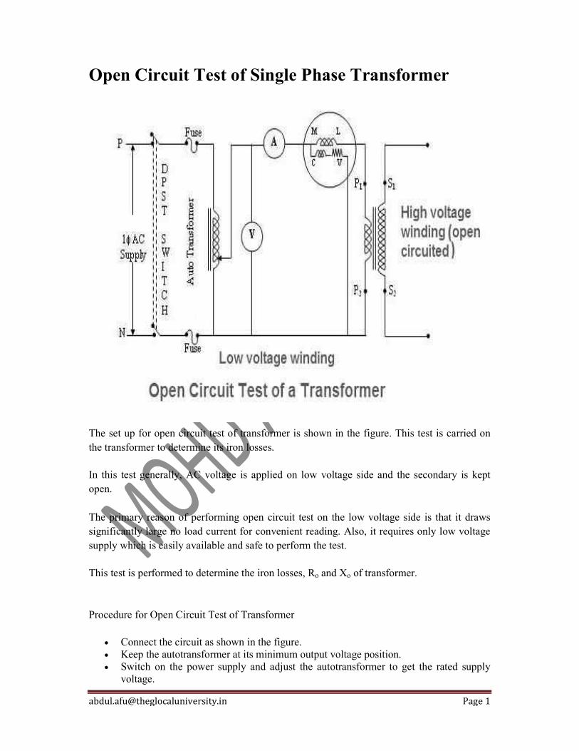
Open Circuit Test of Single Phase Transformer
The set up for open circuit test of transformer is shown in the figure. This test is carried on the transformer to determine its iron losses.
In this test generally, AC voltage is applied on low voltage side and the secondary is kept open. The primary reason of performing open circuit test on the low voltage side is that it draws significantly large no load current for convenient reading. Also, it requires only low voltage supply which is easily available and safe to perform the test.
This test is performed to determine the iron losses, Ro and Xo of transformer.
Procedure for Open Circuit Test of Transformer
Connect the circuit as shown in the figure. Keep the autotransformer at its minimum output voltage position. Switch on the power supply and adjust the autotransformer to get the rated supply
voltage.
[email protected] Page 2
Now note down the current and power shown by the ammeter and wattmeter respectively. Let these are Io and Wo.
The wattmeter reads the no load input power to the transformer. The no load current of the transformer is very small as compared to full load current (about 3 to 5% of the full load value) and hence the copper loss in the winding connected to the supply is small. As the high voltage winding is kept open therefore the copper loss in that winding is zero. Therefore the total copper loss is very small and can be neglected. Hence the watt meter reading represents the iron losses. i.e Wo = Pi = Iron losses
While performing the open circuit test of a single phase transformer, high voltage winding should not be touched because it may cause a serious electric shock. Calculation of Parameters
The two parameters which can be calculated from the open circuit test of transformer are Ro and Xo. They are calculated as follows. Step 1: Calculate no load power factor (cos φo) The wattmeter reads the real power input. Therefore, Wo = VoIocos φo
or cosφo = Wo/VoIo We can calculate φo from this. Step 2: Calculate Im and Iw : Im = Iosin φo Iw = Iocos φo Step 3: Calculate Ro and Xo
Ro = Vo/Iw Ω Xo = Vo/Im Ω The value of power factor of a transformer at no load is very small. Therefore the watt meter used while performing the open circuit test of a single phase transformer should be able to show accurate readings on small power factors.
[email protected] Page 1
Parallel Operation of Transformers If two or more transformers are connected to a same supply on the primary side and to a same load on the secondary side, then it is called as parallel operation of transformers. Why parallel operation of transformers is needed? Increased Load: When load is increased and it exceeds the capacity of existing transformer, another transformer may be connected in parallel with the existing transformer to supply the increased load. Non-availability of large transformer: If a large transformer is not available which can meet the total requirement of load, two or more small transformers can be connected in parallel to increase the capacity. Increased reliability: If multiple transformers are running in parallel, and a fault occurs in one transformer, then the other parallel transformers still continue to serve the load. And the faulty transformer can be taken out for the maintenance. Transportation is easier for small transformers: If installation site is located far away, then transportation of smaller units is easier and may be economical.
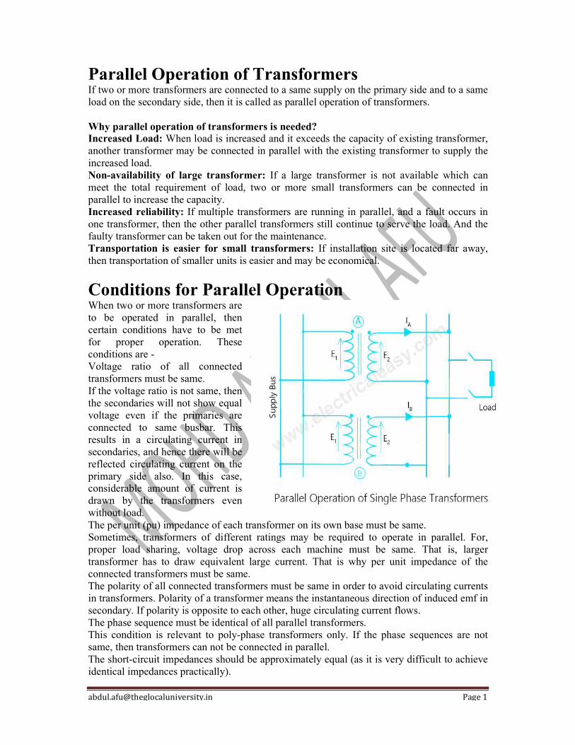
Conditions for Parallel Operation When two or more transformers are to be operated in parallel, then certain conditions have to be met for proper operation. These conditions are - Voltage ratio of all connected transformers must be same. If the voltage ratio is not same, then the secondaries will not show equal voltage even if the primaries are connected to same busbar. This results in a circulating current in secondaries, and hence there will be reflected circulating current on the primary side also. In this case, considerable amount of current is drawn by the transformers even without load. The per unit (pu) impedance of each transformer on its own base must be same. Sometimes, transformers of different ratings may be required to operate in parallel. For, proper load sharing, voltage drop across each machine must be same. That is, larger transformer has to draw equivalent large current. That is why per unit impedance of the connected transformers must be same. The polarity of all connected transformers must be same in order to avoid circulating currents in transformers. Polarity of a transformer means the instantaneous direction of induced emf in secondary. If polarity is opposite to each other, huge circulating current flows. The phase sequence must be identical of all parallel transformers. This condition is relevant to poly-phase transformers only. If the phase sequences are not same, then transformers can not be connected in parallel. The short-circuit impedances should be approximately equal (as it is very difficult to achieve identical impedances practically).
[email protected] Page 1
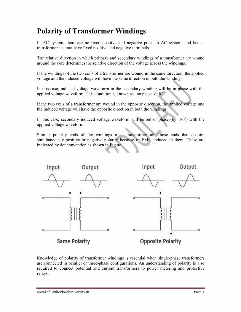
Polarity of Transformer Windings In AC system, there are no fixed positive and negative poles in AC system, and hence, transformers cannot have fixed positive and negative terminals. The relative direction in which primary and secondary windings of a transformer are wound around the core determines the relative direction of the voltage across the windings. If the windings of the two coils of a transformer are wound in the same direction, the applied voltage and the induced voltage will have the same direction in both the windings. In this case, induced voltage waveform in the secondary winding will be in phase with the applied voltage waveform. This condition is known as “no phase shift.” If the two coils of a transformer are wound in the opposite direction, the applied voltage and the induced voltage will have the opposite direction in both the windings. In this case, secondary induced voltage waveform will be out of phase (by 180o) with the applied voltage waveform. Similar polarity ends of the windings of a transformer are those ends that acquire simultaneously positive or negative polarity because of EMfs induced in them. These are indicated by dot convention as shown in Figure.
Knowledge of polarity of transformer windings is essential when single-phase transformers are connected in parallel or three-phase configurations. An understanding of polarity is also required to connect potential and current transformers to power metering and protective relays.
[email protected] Page 2
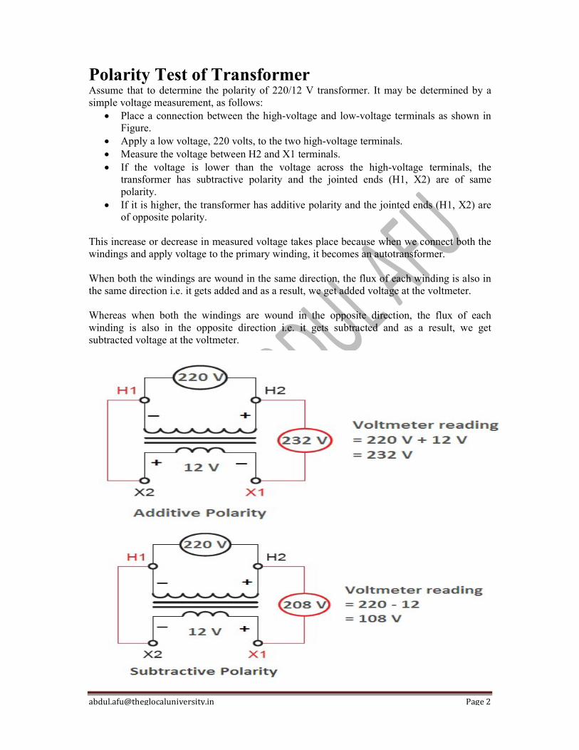
Polarity Test of Transformer Assume that to determine the polarity of 220/12 V transformer. It may be determined by a simple voltage measurement, as follows:
Place a connection between the high-voltage and low-voltage terminals as shown in Figure.
Apply a low voltage, 220 volts, to the two high-voltage terminals. Measure the voltage between H2 and X1 terminals. If the voltage is lower than the voltage across the high-voltage terminals, the
transformer has subtractive polarity and the jointed ends (H1, X2) are of same polarity.
If it is higher, the transformer has additive polarity and the jointed ends (H1, X2) are of opposite polarity.
This increase or decrease in measured voltage takes place because when we connect both the windings and apply voltage to the primary winding, it becomes an autotransformer. When both the windings are wound in the same direction, the flux of each winding is also in the same direction i.e. it gets added and as a result, we get added voltage at the voltmeter. Whereas when both the windings are wound in the opposite direction, the flux of each winding is also in the opposite direction i.e. it gets subtracted and as a result, we get subtracted voltage at the voltmeter.

[email protected] Page 1
Difference between Power Transformer and Distribution Transformer The difference is categorized on the factors like the type of network used, location of installation, usage either for low voltages or high voltages., the various ratings in which the power and the distribution transformers are available in the market. Along with this, the designing efficiency and the designing of the core, the types of losses occurring in the transformer, their operating conditions, and various applications are also important parameters. The difference between the two transformers is given below:
BASIS OF DIFFERENCE
POWER TRANSFORMER DISTRIBUTION TRANSFORMER
Type of network It is used in transmission network of higher voltages
It is used in the distribution network for lower voltages.
Availability of ratings
400 kV, 200 kV, 110 kV , 66 kV, 33 kV. 11 Kv, 6.6 Kv, 3.3 Kv, 440 V,230 V
Maximum rating of usage
Power transformers are used for rating above 200 MVA
Distribution transformers are used for rating less than 200 MVA
Size Larger in size as compared of distribution transformers
Smaller in size
Designed Efficiency
Designed for maximum efficiency of 100%
Designed for 50-70% efficiency
Efficiency formula
Efficiency is measured as the ratio of output to the input power
Here All Day Efficiency is considered. It is the ratio of output in kilowatt hour (kWh) or watt hour (Wh) to the input in kWh or Wh of a transformer over 24 hours.
Application Used in generating stations and transmission substations
Used in distribution stations, also for industrial and domestic purposes
Losses Copper and iron losses take place throughout the day
Iron losses take place for 24 hours and copper losses are based on load cycle
Load fluctuation In power transformer the load fluctuations are very less
Load fluctuations are very high
Operating condition
Always operated at full load Operated at load less than full load as load cycle fluctuates
Considering time It is independent of time It is time dependent
Flux density In power transformer flux density is higher As compared to power transformer the flux density is lower in distribution transformer
Designing of the core
Designed to utilize the core for maximum and will operate near to the saturation point of the B-H curve, which helps to bring down the mass of core
As compared to power transformer the flux density is lower in distribution transformer
Usage Used to step up and step down voltages Used as an end user connectivity

[email protected] Page 2
Those transformers installed at the ending or receiving point of long and high voltage transmission lines are the power transformers (mostly Step up). At the other hand, The distribution transformers (generally pole mounted) are those installed nearby the load terminals (City and villages) to provide utilization voltage at the consumer terminals (mostly step down).
Power Transformer The Power Transformer is installed at various power stations for generation and transmission of power. It acts as a step-up or a step-down transformer for increasing and decreasing the level of voltages as per the requirement, and it’s also used as an interconnection between two power stations.
Distribution Transformer The Distribution Transformer is used to bring down or step down the voltage and current level of a transmission line to a predefined level, which is called safety level for the end-user consumer in domestic and industrial purpose. Key Difference Between Power Transformer and Distribution Transformer Power transformers are used in the transmission network of higher voltages whereas the
Distribution Transformers are used in the distribution network of lower voltages. The power transformers are available in various ratings of 400 kV, 200 kV, 110 kV, 66
kV, 33 kV in the market and the distribution transformer are available in 11 kV, 6.6 kV, 3.3 kV, 440 V, 230 Volts.
The power transformer always operates on rated full load as the load fluctuation is very less but the distribution transformer is operated at the load less than full load as the variation in the loads are very high.
The power transformers are designed for maximum efficiency of 100%, and the efficiency is simply calculated by the ratio of output power to the input power, whereas the distribution transformer the maximum efficiency varies between 50-70% and calculated by All Day Efficiency.
Power transformers are used in power generating stations and transmission substations, and the distribution transformer is installed at the distribution stations from where the power is distributed for the industrial and domestic purposes.
The size of the power transformer is large as compared to the distribution transformers. In Power Transformer, the iron and copper losses take place throughout the day but in
distribution transformer, the iron loss takes place 24 hours i.e., throughout the day, and the copper losses depend on the load cycle.
Power transformers are used in transmission network of higher voltages for step-up and step down application (400 kV, 200 kV, 110 kV, 66 kV, 33kV) and are generally rated above 200MVA.
Distribution transformers are used for lower voltage distribution networks as a means to end user connectivity. (11kV, 6.6 kV, 3.3 kV, 440V, 230V) and are generally rated less than 200 MVA.
A power transformer usually has one primary and one secondary as well as one input and output setup. A distribution transformer may have one primary and one divided or “Tapped” secondary, or two or more secondaries.
Power transformers generally operate at nearly full – load. However, a distribution transformer operates at light loads during major parts of the day.
[email protected] Page 3
The performance of the power transformers is generally analyzed by commercial or maximum efficiency because they are designed for maximum efficiency at full load. Whereas, the performance of a distribution transformer is judged by all day efficiency of transformer because they are designed to be operated for maximum efficiency at 60-70% load as they are normally doesn’t operate at full load all the day as there are peak hours for load in 24 hrs which are not same at once all the time.
The rating of a high transformer is many times greater than that of distribution transformer.
In Power Transformer, the flux density is higher than the distribution transformer. Power transformers, primary winding always connected in star and secondary winding in
delta connections while in distribution transformers, primary winding connected in delta and secondary in star connection. read more about the comparison between star & delta connections.
In The Sub station, at the end of the transmission line, The power transformer connection is in Star-Delta.(to step down the level of voltage)
At the beginning of the transmission line (H-T), the connection of the power Transformer is in Delta – Star (to step up the level of voltage). Also, not that the same connection i.e Delta – Star connection is used in three phase step down distribution transformer

Short Circuit Test of Transformer
The set up for short circuit test ofused in the circuit to adjust the input voltage precisely to The ammeter, voltmeter and watt meter are connected in the circuit to measure the current, voltage and power respectively. In this test generally, the high voltageside is short circuited with the help Procedure for Short Circuit Test of Transformer
Connect the circuit as shown in the figure. Keep the auto transformer
AC supply. Increase the applied voltage very slowly, and adjust it to get the current equal to the
rated value of the winding. Do not increase the applied voltage further. Note down the watt meter, voltmeter and ammeter readings. Let these are
and Isc
Parameter Calculations
The short circuit test on transformer is performed at the primary and secondary rated currents. Therefore the total copper As the iron losses are supply voltage dependent and iron losses will be negligibly small
Short Circuit Test of Transformer
of transformer is shown in the figure. An auto transformerused in the circuit to adjust the input voltage precisely to the rated voltage
The ammeter, voltmeter and watt meter are connected in the circuit to measure the current,
voltage side is connected to the AC supply and thehelp of thick copper wire.
Procedure for Short Circuit Test of Transformer
Connect the circuit as shown in the figure. transformer output at its minimum voltage position and switch on the
Increase the applied voltage very slowly, and adjust it to get the current equal to the rated value of the winding. Do not increase the applied voltage further. Note down the watt meter, voltmeter and ammeter readings. Let these are
The short circuit test on transformer is performed at the primary and secondary rated currents. copper loss is the full load copper loss
are supply voltage dependent and supply voltage in this test is small, the iron losses will be negligibly small.
Page 1
transformer is the rated voltage.
The ammeter, voltmeter and watt meter are connected in the circuit to measure the current,
the low voltage
output at its minimum voltage position and switch on the
Increase the applied voltage very slowly, and adjust it to get the current equal to the
Note down the watt meter, voltmeter and ammeter readings. Let these are Wsc, Vsc
The short circuit test on transformer is performed at the primary and secondary rated currents. is the full load copper loss.
supply voltage in this test is small, the

[email protected] Page 2
Hence the reading (Wsc) shown by the wattmeter is almost entirely corresponding to the full load copper loss. We know that Wsc = VscIsccos φsc or cos φsc = Wsc / (VscIsc) The wattmeter reading Wsc indicates the full load copper loss. Therefore, Wsc = Copper loss = I2
scR01
or R01 = Wsc / I2
sc Where R01 is the total equivalent resistance of the transformer referred to the primary. Similarly Z01 = Vsc / Isc = (R2
01 + X201)
1/2 or X01 = (Z2
01 – R201)
1/2 Where X01 is the total equivalent reactance of the transformer referred to primary. In this way parameters R01, X01, Z01 and full load copper losses can be calculated from the short circuit test on transformer. If the transformation ratio K is known, it is possible to obtain these parameters referred to the secondary side. Efficiency Calculation from Short Circuit Test of Transformer
Example: A 250/500V transformer gave the following test results: Short circuit test with low voltage winding short circuited; 20V, 12A 100W. Open circuit test on low voltage side; 250V, 1A, 80W.
Determine the efficiency of the transformer when the output is 10A, 500V at 0.8 p.f. lagging. Solution: From the short circuit test (on H.V. side) Voltmeter reading, V2sc = 20V Ammeter reading, I2sc = 12A Wattmeter reading, Wc = 100W In the short circuit test of transformer, the wattmeter measures the copper losses of the transformer on short circuit secondary current(I2sc). Output secondary current, I2 = 10A Copper losses at this current, Pc = (I2/I2sc)
2Wc = (10/12)2 x 100 = 69.44W From open circuit test: In the open circuit test of transformer, the wattmeter measures the iron losses occurred in the transformer. Therefore, iron losses in the transformer (Pi) = 80W Output power at given load = V2I2cosɸ2 = 500 x 10 x 0.8 = 4000W Efficiency of transformer = [output/(output + Pi + Pc)] x 100 = [4000/(4000 + 80 + 69.44)] x 100 = 96.4%

[email protected] Page 1
Significance of Vector Group of Transformer The internal connections of transformer windings can be made in a number of ways. Accordingly, different types of connections have been standardized depending upon the phase displacement. There are four vector groups and each group includes three methods of connection of high voltage and low voltage windings. Phase displacement between EMFs of high voltage and low voltage windings is expressed as the clock hour number and is designated by symbols 0, 6, 1, and 11. For example, the clock hour number 0 represents zero degrees phase displacement between primary and secondary EMFs. The clock hour number 6 is for 1800 phase displacement, 1 for – 300, 11 for +300. On the nameplate of three-phase transformer vector group is printed as Yy0, Dd1 etc. Here Yy0 will mean it’s both the windings are star-connected and phase displacement between primary and secondary EMFs is zero degree. It is belonging to Group No.1 (refer to table).
Group No.
Winding Connection (Primary)
Winding Connection (Secondary)
Phase Displacement
Clock – Hour Number
Vector Symbol
1
Star Delta Delta
Star Delta Zig-zag 0o 0
Yy0 Dd0 Dz0
2
Star Delta Delta
Star Delta Zig-zag 180o 6
Yy6 Dd6 Dz6
3
Delta Star Star
Star Delta Zig-zag – 30o 1
Dy1 Yd1 Yz1
4
Delta Star Star
Star Delta Zig-zag +30o 11
Dy11 Yd11 Yz11

[email protected] Page 2
Similarly, Dy1 will mean its primary winding is connected in delta, secondary winding in the star, phase displacement is – 300 and belonging to Group No. 3. Information of vector group of a transformer is very significant when it has to operate in parallel. For a transformer working in isolation, the arrangement of its internal connections is of little importance. Transformers will operate in parallel satisfactory if they have,
the same primary and secondary voltages the same tap ratio the same percentage impedance, and, belonging to the same vector groups.
The two transformers may have their windings connected in star/star and yet it will not be possible to operate in parallel if one belongs to Group 1 and the other to group 2, unless the internal connections of the secondary winding of one of the transformers are changed.
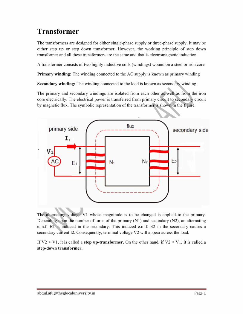
[email protected] Page 1
Transformer
The transformers are designed for either single-phase supply or three-phase supply. It may be either step up or step down transformer. However, the working principle of step down transformer and all these transformers are the same and that is electromagnetic induction.
A transformer consists of two highly inductive coils (windings) wound on a steel or iron core.
Primary winding: The winding connected to the AC supply is known as primary winding
Secondary winding: The winding connected to the load is known as secondary winding.
The primary and secondary windings are isolated from each other as well as from the iron core electrically. The electrical power is transferred from primary circuit to secondary circuit by magnetic flux. The symbolic representation of the transformer is shown in the figure.
The alternating voltage V1 whose magnitude is to be changed is applied to the primary. Depending upon the number of turns of the primary (N1) and secondary (N2), an alternating e.m.f. E2 is induced in the secondary. This induced e.m.f. E2 in the secondary causes a secondary current I2. Consequently, terminal voltage V2 will appear across the load.
If V2 > V1, it is called a step up-transformer. On the other hand, if V2 < V1, it is called a step-down transformer.

[email protected] Page 1
Three-Phase Transformer Connections The three phase transformer consists three transformers either separate or combined with one core. The primary and secondary of the transformer can be independently connected either in star or delta. There are four possible connections for a 3-phase transformer bank. Δ – Δ (Delta – Delta) Connection Υ – Υ (Star – Star) Connection Δ – Υ (Delta – Star) Connection Υ – Δ (Star – Delta ) Connection The choice of connection of three phase transformer depends on the various factors likes the availability of a neutral connection for grounding protection or load connections, insulation to ground and voltage stress, availability of a path for the flow of third harmonics, etc. The various types of connections are explained below in details. 1. Delta-Delta (Δ-Δ) Connection The delta-delta connection of three identical single phase transformer is shown in the figure below. The secondary winding a1a2 is corresponding to the primary winding A1A2, and they have the same polarity. The polarity of the terminal a connecting a1 and c2 is same as that connecting A1 and C2. The figure below shows the phasor diagram for lagging power factor cosφ.

[email protected] Page 2
The magnetizing current and voltage drops in impedances have been neglected. Under the balanced condition, the line current is √3 times the phase winding current. In this configuration, the corresponding line and phase voltage are identical in magnitude on both primary and secondary sides. The secondary line-to-line voltage is in phase with the primary line-to-line voltage with a voltage ratio equal to the turns ratio. If the connection of the phase windings is reversed on either side, the phase difference of 180° is obtained between the primary and the secondary system. Such a connection is known as an 180º connection. The delta-delta connection with 180º phase shift is shown in the figure below. The phasor diagram of a three phase transformer shown that the secondary voltage is in phase opposition with the primary voltage.
The delta-delta transformer has no phase shift associated with it and problems with unbalanced loads or harmonics. Advantages of delta–delta connection of transformer The following are the advantages of the delta-delta configuration of transformers. The delta-delta transformer is satisfactory for a balanced and unbalanced load. If one transformer fails, the remaining two transformers will continue to supply the three-phase power. This is called an open delta connection. If third harmonics present, then it circulates in a closed path and therefore does not appear in the output voltage wave. The only disadvantage of the delta-delta connection is that there is no neutral. This connection is useful when neither primary nor secondary requires a neutral and the voltage are low and moderate.

[email protected] Page 3
2. Star-Star (Υ-Υ) Connection The star-star connection of three identical single phase transformer on each of the primary and secondary of the transformer is shown in the figure below.The phasor diagram is similar as in delta-delta connection. The phase current is equal to the line current, and they are in phase. The line voltage is three times the phase voltage. There is a phase separation of 30º between the line and phase voltage.The 180º phase shift between the primary and secondary of the transformer is shown in the figure above. Problems Associated With Star-Star Connection The star-star connection has two very serious problems. They are The Y-Y connection is not satisfactory for the unbalance load in the absence of a neutral connection. If the neutral is not provided, then the phase voltages become severely unbalance when the load is unbalanced. The Y-Y connection contains a third harmonics, and in balanced conditions, these harmonics are equal in magnitude and phase with the magnetising current. Their sum at the neutral of star connection is not zero, and hence it will distort the flux wave which will produce a voltage having a harmonics in each of the transformers The unbalanced and third harmonics problems of Y-Y connection can be solved by using the solid ground of neutral and by providing tertiary windings. 3. Delta-Star (Δ-Υ) Connection The ∆-Y connection of the three winding transformer is shown in the figure below. The primary line voltage is equal to the secondary phase voltage. The relation between the secondary voltages is VLS= √3 VPS.
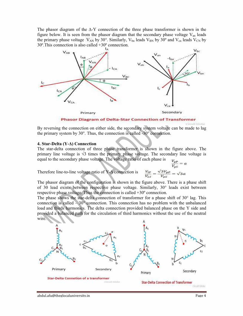
[email protected] Page 4
The phasor diagram of the ∆-Y connection of the three phase transformer is shown in the figure below. It is seen from the phasor diagram that the secondary phase voltage Van leads the primary phase voltage VAN by 30°. Similarly, Vbn leads VBN by 30º and Vcn leads VCN by 30º.This connection is also called +30º connection.
By reversing the connection on either side, the secondary system voltage can be made to lag the primary system by 30°. Thus, the connection is called -30° connection. 4. Star-Delta (Υ-Δ) Connection The star-delta connection of three phase transformer is shown in the figure above. The primary line voltage is √3 times the primary phase voltage. The secondary line voltage is equal to the secondary phase voltage. The voltage ratio of each phase is
Therefore line-to-line voltage ratio of Y-∆ connection is The phasor diagram of the configuration is shown in the figure above. There is a phase shift of 30 lead exists between respective phase voltage. Similarly, 30° leads exist between respective phase voltage. Thus the connection is called +30º connection. The phase shows the star-delta connection of transformer for a phase shift of 30° lag. This connection is called – 30° connection. This connection has no problem with the unbalanced load and thirds harmonics. The delta connection provided balanced phase on the Y side and provided a balanced path for the circulation of third harmonics without the use of the neutral wire.

[email protected] Page 5
Open delta or V-V Connection If one transformer of delta-delta connection is damaged or accidentally opened, then the defective transformer is removed, and the remaining transformer continues to work as a three phase bank. The rating of the transformer bank is reduced to 58% of that of the actual bank. This is known as the open delta or V-V delta. Thus, in open winding transformer, two transformers are used instead of three for the 3-phase operation. Let the Vab, Vbc and Vca be the voltage applied to the primary winding of the transformer. The voltage induced in the transformer secondary or on winding one is Vab. The voltage induced on the low voltage winding two is Vbc. There is no winding between points a and c. The voltage may be found by applying KVL around a closed path made up of point a, b, and c. Thus,
Let, Where Vp is the magnitude of the line on the primary side.
On substituting the value of Vab and Vbc in equation, we get
The Vca is equal in magnitude from the secondary terminal voltage and 120º apart in time from both of them. The balanced three phase line voltage produced balanced 3-phase voltage on the secondary side. If the three transformers are connected in delta-delta configuration and are supplying rated load and if the connection becomes V-V transformer, the current in each phase winding is increased by √3 times. The full line current flows in each of the two phase windings of the transformer. Thus the each transformer in the V-V system is overloaded by 73.2%. The load should be reduced by √3 times in case of an open delta connected transformer. Otherwise, serious overheating and breakdown of the two transformers may take place.

[email protected] Page 1
Transformer Moisture Removal Process Transformer absorbs moisture sometimes which is very harmful to its health. Presence of moisture can be detected by two following tests:
dielectric strength test of oil insulation resistance test of the winding
Checking Insulation Resistance of Winding Insulation resistance of winding should be checked with a 1000 V megger, the voltage should be applied for one minute. All the windings except the winding under test should be earthed during this test. The insulation resistance should not be less than the recommended value for the corresponding temperature.
At room temperature, the insulation resistance may be high even though the winding is not completely dry. In such a case the insulation resistance drops rapidly when the winding gets hot. Insulation resistance is halved for every 10° C rise in temperature. Therefore for a proper comparison of insulation resistance, all readings should be taken at nearly the same temperature. Transformer Moisture Removal Process If the insulation resistance of the winding is satisfactory but the dielectric strength of the oil is low then the treatment of oil in filtering and drying plant will improve its dielectric strength. If the insulation resistance of winding is lower than the specified value then the core and winding have to be dried.Transformer moisture removal process can be performed with or without removing the oil from the transformer. Transformer Moisture Removal Process in Oil In this method of drying, one winding is short-circuited and low voltage usually of the order of 5% for even less is applied to the other winding to circulate 70% to 80% full load current through the shorted winding. To prevent loss of heat through cooling tubes the oil level may be lowered just below the top of the tubes. If there is a radiator the valve in the pipe leading to the radiator may be

[email protected] Page 2
closed.All air vent should be kept open to allow the free escape of hot air. Inspection and manhole cover if any may also be removed during the drying process. The tap changing switch should be so set as to have all the windings in the circuit. The voltage and current should be so adjusted that the temperature of the oil does not exceed 80oC and the transformer is in no case subjected to a temperature beyond 85oC as damage can be caused by overheating. The tank cover should be covered with lagging during the drying process to prevent condensation of moisture on the inside. Simultaneous filtration of oil through a plant will help in the drying process.It should be noted that the drying process may take several days to obtain satisfactory results. Transformer Moisture Removal Process Without Oil It can be accomplished by one of the four methods listed below:
By Internal Heat By External Heat Drying Under Vacuum Drying In Oven
By Internal Heat: This method is similar to the short circuit method already discussed except that the voltage required to be applied will be only 0.5 – 1.5% of normal voltage.The temperature measured by the resistance method should not exceed 80 – 90oC.The method is not very satisfactory as it results in slow and superficial drying only. By External Heat: In this method, hot air about 115 oC is blown through the transformer if the core is to be dried in the tank itself. The success of the method depends largely upon the efficient circulation of hot air through the various openings and ducts in the coils. Drying Under Vacuum: It is quick and at the same time the most effective method of drying provided the transformer tank can withstand the external pressure resulting from a vacuum of 635 mm or more inside. The temperature of the oil is raised to 80 – 85oC gradually for 24 hours; hot oil is then drained and vacuum of the order of 635 – 710 mm is created with a vacuum pump.The transformer is maintained in this condition until the temperature drops to 50oC.The whole process is repeated until satisfactory insulation readings are obtained. Drying In Oven: The core and windings of medium-sized transformers can be conveniently dried in a drying oven.The temperature of the oven is maintained at 85 – 90oC and hot air is allowed to escape through the vents at the top. The drying is continued until the required results are obtained. Measurement of Insulation Resistance During Drying The success of transformer moisture removal process will depend upon the accurate measurement of insulation resistance at regular intervals of say 2 hours throughout the drying process at, particularly constant temperature.

[email protected] Page 3
The insulation resistance may fall at first as the moisture spreads and work its way outwards or it may rise gradually in the beginning and rapidly as the drawing proceeds.The drawing should be continued until the insulation resistance remains constant for at least 12 hours. Plotting of a curve with resistance as ordinate and time as abscissa will help incorrect interpretation of the results. Precautions During Drying of Transformer
Drawing of a transformer must be done under continuous and competent supervision. The Transformer should never be left unattended during the drying process.
Careful observation of temperature is essential during drying as high temperature can result in damage to the insulation.
No spark and smoking should be allowed in the vicinity of a transformer being dried. Low voltage hand lamps should be used for inspection of the tanks from inside.
On the completion of transformer moisture removal process, the transformer should be filled with tested oil only with the help of a filter plant through the drain or sample valve located near the bottom and not from the top or through the conservator. All the vents should be open during filling. Filling the tank in this way will ensure the escape of all air from within the tank and prevent the formation of air pockets.The tank should be gently stroke with a mallet as the oil is filled. The rate of filling should be reduced as the oil level approaches the top cover.Oil may be filled under partial vacuum if the tank is designed to withstand vacuum. The transformer should be kept energized for 6 hours at no load at the end of which air cork should be opened to allow the released air to escape.

[email protected] Page 1
Transformer on Load There are two cases (i) when such a transformer is assumed to have no winding resistance and leakage flux. (ii) when the transformer has winding resistance and leakage flux.
(i) No winding resistance and leakage flux Figure shows a transformer with the assumption that resistances and leakage reactances of the windings are negligible. With this assumption, V2 = E2 and V1 = E1. Let us take the usual case of inductive load which causes the secondary current I2 to lag the secondary voltage V2 by 2. The total primary current I1 must meet two requirements viz.
It must supply the no-load current I0 to meet the iron losses in the transformer and to provide flux in the core. It must supply a current I'0 to counteract the demagnetizing effect of secondary currently I2. The magnitude of I'2 will be such that:
N1I'2 N2I2
or I'2 N2 I2 KI2
N1 The total primary current I1 is the phasor sum of I'2 and I0 i.e.,
I1 I'2 I0
where I'2 KI2
Note that I'2 is 180° out of phase with I2.
Phasor diagram. Figure shows the phasor diagram for the usual case of inductive load. Both E1 and E2 lag behind the mutual flux by 90°. The current I'2 represents the primary current to neutralize the demagnetizing effect of secondary current I2. Now I'2 = K I2 and is antiphase with I2. I0 is the no-load current of the transformer. The phasor sum of I'2 and I0 gives the total primary current I1. Note that in

[email protected] Page 2
drawing the phasor diagram, the value of K is assumed to be unity so that primary phasors are equal to secondary phasors.
Primary p.f. = cos 1
Secondary p.f. = cos 2 Primary input power = V1 I1 cos 1 Secondary output power = V1 I2 cos 2
(ii) Transformer with resistance and
leakage reactance Fig. (7.10) shows a practical transformer having winding resistances and leakage reactances. These are the actual conditions that exist in a transformer. There is voltage drop in R1 and X 1 so that primary e.m.f. E1 is less than the applied voltage V1. Similarly, there is voltage drop in R2 and X2 so that secondary terminal voltage V2 is less than the secondary e.m.f. E2. Let us take the usual case of inductive load which causes the secondary current I2 to lag behind the secondary voltage V2 by 2. The total primary current I1 must meet two requirements viz. It must supply the no-load current I0 to meet the iron losses in the transformer and to provide flux in the core. It must supply a current I'2 to counteract the demagnetizing effect of secondary current I2. The magnitude of I'2 will be such that:
N1I'2 N2I2
or I'2 N2 I2 KI2
N1
Fig.(7.10)
The total primary current I1 will be the phasor sum of I'2 and I0 i.e.,
I1 = I'2 + I0 where I'2 = KI2
V1 = E1 + I1(R1 + jX1)

[email protected] Page 3
Where I1 = I0 + (KI2)= E1 + I1Z1
V2 = E2 - I2(R2 + jX2)
= E2 - I2Z2 Phasor diagram. Figure shows the phasor diagram of a practical transformer for the usual case of inductive load. Both E1 and E2 lag the mutual flux f by 90°. The current I'2 represents the primary current to neutralize the demagnetizing effect of secondary current I2. Now I'2 = K I2 and is opposite to I2. Also I0 is the no-load current of the transformer. The phasor sum of I'2 and I0 gives the total primary current I1. Note that counter e.m.f. that opposes the applied voltage V1 is -E1. Therefore, if we add I 1R1 (in phase with I1) and I1 X1 (90° ahead of I1) to -E1, we get the applied primary voltage V1. The phasor E2 represents the induced e.m.f. in the secondary by the mutual flux f. The secondary terminal voltage V2 will be what is left over after subtracting I2R2 and I2X2 from E2.
Load power factor = cos f2
Primary power factor = cos f1 Input power to transformer, P1 = V1I1 cos f1 Output power of transformer, P2 = V2I2 cos f2
Note: The reader may draw the phasor diagram of a loaded transformer for (i) unity p.f. and (ii) leading p.f. as an
exercise.
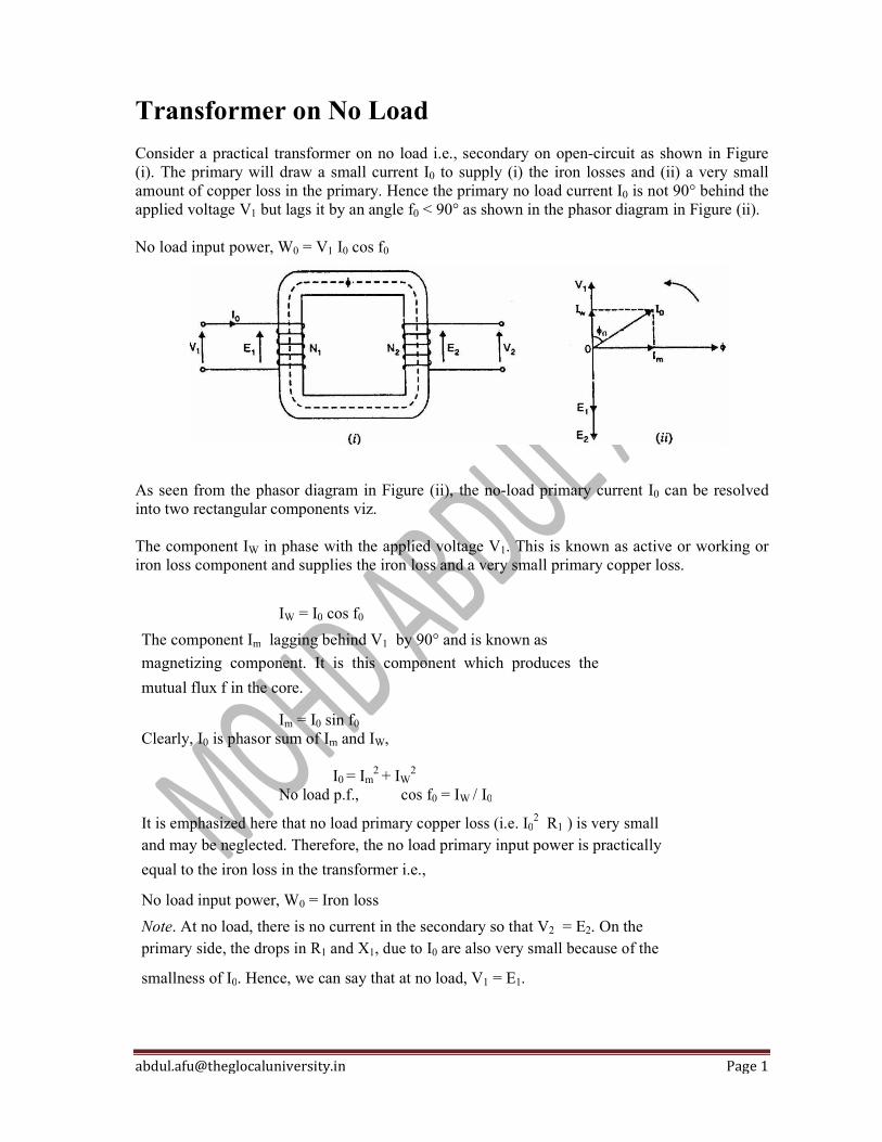
[email protected] Page 1
Transformer on No Load Consider a practical transformer on no load i.e., secondary on open-circuit as shown in Figure (i). The primary will draw a small current I0 to supply (i) the iron losses and (ii) a very small amount of copper loss in the primary. Hence the primary no load current I0 is not 90° behind the applied voltage V1 but lags it by an angle f0 < 90° as shown in the phasor diagram in Figure (ii). No load input power, W0 = V1 I0 cos f0
As seen from the phasor diagram in Figure (ii), the no-load primary current I0 can be resolved into two rectangular components viz. The component IW in phase with the applied voltage V1. This is known as active or working or iron loss component and supplies the iron loss and a very small primary copper loss.
IW = I0 cos f0
The component Im lagging behind V1 by 90° and is known as
magnetizing component. It is this component which produces the
mutual flux f in the core.
Im = I0 sin f0
Clearly, I0 is phasor sum of Im and IW, I0 = Im
2 + IW2
No load p.f., cos f0 = IW / I0
It is emphasized here that no load primary copper loss (i.e. I02 R1 ) is very small
and may be neglected. Therefore, the no load primary input power is practically
equal to the iron loss in the transformer i.e.,
No load input power, W0 = Iron loss
Note. At no load, there is no current in the secondary so that V2 = E2. On the primary side, the drops in R1 and X1, due to I0 are also very small because of the
smallness of I0. Hence, we can say that at no load, V1 = E1.

[email protected] Page 1
Transformer on the Basis of Applications The transformers are often classified on the basis of the purposes for which they are used. Following are the important types of transformers on the basis of applications:
Power Transformers
These transformers are used at the power plants to step-up the generated voltage for transmission purposes and to step down the voltage at the receiving substations. These are large size transformers.
These transformers are usually operated near the full load which would cause high copper loss. Thus, to have minimum losses, such transformers are designed with low copper losses and to give maximum efficiency at near the full load.
Distribution Transformers
These transformers are used to step down the voltage at the distribution substations. The load on such transformers varies for all the 24 hours from no load to full load. Such transformers are designed with low iron loss and to give maximum efficiency at about 75% of the full load to obtain high efficiency. Autotransformers An Auto Transformer is a transformer with only one winding wound on a laminated core. An auto transformer is similar to a two winding transformer but differ in the way the primary and secondary winding are interrelated. A part of the winding is common to both primary and secondary sides. Instrument Transformers
These transformers are used to measure high voltage, high current and to operate protective devices. To measure high voltage, it is stepped down with an instrument transformer which is known as the potential transformer (PT) and then applied to a voltmeter. Similarly, to measure high current, it is stepped down with an instrument transformer which is known as the current transformer (CT) and then applied to an ammeter. Testing Transformers To carry out the tests under high, voltages testing transformers are used to step-up the voltage to a very high value. Special Transformers These are used to operate welding sets, rectifiers, electric furnaces etc.
[email protected] Page 1
Types of Transformer on the Basis of Transformation Ratio The transformation ratio of the transformer may be defined as the ratio of the secondary voltage to the primary voltage of the transformer. It is denoted by K. Therefore, transformation ratio K = V2/V1
And K = E2/E1 = N2/N1 = I1/I2 also. Where V1, E1, N1 are the supply voltage, induced EMF, winding turns of the primary winding respectively. And V2, E2, N2 are output voltage, induced EMF, winding turns of secondary winding respectively. On the basis of the value of K, types of transformers are as follows:
Step-up Transformer The transformers having K > 1 i.e. N2 > N1 are known as the step-up transformer. In such type of transformers, we get high output voltage as compared to the applied voltage, hence the name step-up.
Step-down Transformer The transformers having K < 1 i.e. N2 < N1 are known as the step-down transformer. In such type of transformers, we get low output voltage as compared to the applied voltage, hence the name step-down.
One-to-one Transformer The transformers having K = 1 i.e. N2 = N1 are known as the one-to-one transformer. In such type of transformers output voltage is equal to the input voltage. The main function of such transformer is to provide isolation between input and output circuit, hence this transformer is also known as the isolation transformer.
[email protected] Page 1
Voltage Regulation The voltage regulation of a transformer is the arithmetic difference (not phasor
difference) between the no-load secondary voltage (0V2) and the secondary
voltage V2 on load expressed as percentage of no-load voltage i.e.
%age voltage regulation = 0V2 - V2 X 100
0 V
2
where 0V2 = No-load secondary voltage = K V1
V2 = Secondary voltage on load
0V2 - V2 = I2R 02 cos f2 ± I2X02 sin f2
The +ve sign is for lagging p.f. and -ve sign for leading p.f.
It may be noted that %age voltage regulation of the transformer will be the
same whether primary or secondary side is considered.
Why Transformer Rating in kVA? An important factor in the design and operation of electrical machines is the
relation between the life of the insulation and operating temperature of the
machine. Therefore, temperature rise resulting from the losses is a determining
factor in the rating of a machine. We know that copper loss in a transformer
depends on current and iron loss depends on voltage. Therefore, the total loss in
a transformer depends on the volt-ampere product only and not on the phase
angle between voltage and current i.e., it is independent of load power factor.
For this reason, the rating of a transformer is in kVA and not kW.

[email protected] Page 1
Voltage Drop in a Transformer
The approximate equivalent circuit of transformer referred to secondary is shown in Fig. (1). At no-load, the secondary voltage is K V1. When a load having a lagging p.f. cos 2 is applied, the secondary carries a current I2 and voltage drops occur in (R2 + K
2 R1) and (X2 + K
2 X1). Consequently, the
secondary voltage falls from K V1 to V2. Referring to Fig. (1), we have,
=KV1 V2 I2Z02
Drop in secondary voltage KV1 V2 I2 Z02
The phasor diagram is shown in Fig. (2). It is clear from the phasor diagram that drop in secondary voltage is AC = I2 Z02. It can be found as follows. With O as centre and OC as radius, draw an arc cutting OA produced at M. Then AC = AM = AN. From B, draw BD perpendicular to OA produced. Draw CN perpendicular to OM and draw BL || OM.
Fig.(1) Fig.(2)
Approximate drop in secondary voltage
ANADDN
ADBL (Q BLDN)
I2 R 02 cos 2 I2 X02 sin 2
For a load having a leading p.f. cos 2, we have,
Approximate voltage drop I2R 02 cos 2 I2X02 sin 2 Note: If the circuit is referred to primary, then it can be easily established that:
Approximate voltage drop I1R 01 cos 2 I1X01 sin 2
V KV I R 2 K
2R
1 j X 2K
2X
2 1 2 1
KV1 I2 R 02 j X02

[email protected] Page 1
Voltage Regulation of Transformer The voltage regulation of transformer is defined as the change in secondary terminal voltage (V2) from no-load to full load at constant primary voltage and temperature. It is expressed as a percentage of the secondary no-load voltage. Mathematically, % Regulation of transformer = (E2 – V2) x 100 / E2 No-load voltage: The secondary terminal voltage of transformer when no load is connected to the transformer is known as the no-load voltage of the transformer. At no load, the secondary terminal voltage will be equal to induced EMF in the secondary winding. So, no-load voltage = E2 volts Full load voltage: It is the secondary terminal voltage of transformer when a rated load is connected to the transformer. We will denote it by V2. When a transformer is loaded a voltage drop in primary and secondary impedances of transformer takes place. As the load current increases, this voltage drop will increase. This will reduce the secondary terminal voltage V2. The ideal value of voltage regulation of transformer is 0%. Voltage Regulation Formula The approximate expression for the total voltage drop (E2 – V2) in a transformer as referred to secondary is given by
[email protected] Page 2
Where, R02 = equivalent resistance of transformer referred to secondary X02 = equivalent reactance of transformer referred to secondary R01 = equivalent resistance of transformer referred to primary X01 = equivalent resistance of transformer referred to primary Here it has been assumed that φ1 = φ2 = φ. The positive sign is used for a lagging power factor and the negative sign for a leading power factor. It is clear from the above expressions, the voltage regulation of transformer does not depend only on the magnitude of load current. But it also depends on the type of load. The transformer regulation is positive for the resistive and inductive loads but it can be negative for the capacitive loads. We can determine the values of R01, X01, R02, X02 of a transformer from short circuit test and calculate percentage regulation of transformer. Calculate Voltage Regulation of Transformer Example: A 100 kVA transformer has 400 turns on the primary and 80 turns on the secondary. The primary and secondary resistances are 0.3 Ω and 0.01 Ω respectively and the corresponding leakage reactances are 1.1 and 0.035 Ω respectively. The supply voltage is 2200 V. Calculate: equivalent impedance referred to primary and,the voltage regulation and the secondary terminal voltage for full load having a power factor of 0.8 leading. Solution: K = 80/400 = 1/5, R1 = 0.3 Ω, R01 = R1 + R2/K
2 = 0.3 + 0.01/(1/5)2 = 0.55 Ω X01 = X1 + X2/K
2 = 1.1 + 0.035/(1/5)2 = 1.975 Ω Z01 = 0.55 + j 1.975 = 2.05 ∠74.44o Z02 = K2Z01 = (1/5)2 (0.55 + j 1.975) = (0.022 + j 0.079) No-load secondary voltage = KV1 = (1/5) × 2200 = 440 V, I2 = 10 × 103/440 = 227.3 A Full-load voltage drop as referred to secondary= I2 (R02 cos φ − X02 sin φ) = 227.3 (0.022 × 0.8 − 0.079 × 0.6 ) = − 6.77 V % regn. = − 6.77 × 100/440 = − 1.54 Secondary terminal voltage on load = 440 − (− 6.77) = 446.77 V
[email protected] Page 1
Working Principle of Step Down Transformer
When the primary winding is connected to the AC supply an AC current starts flowing through it.
The AC current of primary winding produces an alternating flux φ in the core.
Most of this alternating flux links with secondary winding through the core.
This alternating flux induces a voltage into the secondary winding according to the Faraday’s law of electromagnetic induction.
The EMF is induced in the secondary winding is due to mutual induction hence it is known as mutually induced EMF.
The induced EMF in the secondary and primary depends upon the rate of change of flux linkages (Ndφ/dt).
The rate of change of flux in secondary and primary circuit is the same. Therefore, induced EMF in secondary is proportional to number of turns of the secondary winding (E2 α N2) and in primary is proportional to number of turns of primary (E1 α N1).
If the secondary turns (N2) are less than primary turns (N1), the secondary induced EMF will be less than primary and transformer is called step down transformer. Whereas if N2 > N1, the secondary induced EMF will be more than primary and transformer is called step up transformer.
A transformer changes only current and voltage levels of AC supply. It does not have any effect on the frequency of AC supply. It can be operated only on AC supply.
If a transformer is connected to the DC supply, a large amount of current will flow through the primary winding and it can damage the transformer winding.
[email protected] Page 1
Working Principle of Transformer
When an alternating voltage V1 is applied to the primary, an alternating flux φ is set up in the core. This alternating flux links both the windings and induces e.m.f.s E1 and E2 in them according to Faraday’s laws of electromagnetic induction. The e.m.f. E1 is termed as primary e.m.f. and e.m.f. E2 is termed as secondary e.m.f.
Clearly, E1 = -N1[dɸ/dt]
and E2 = -N2[dɸ/dt]
∴ E2/E1 = N2/N1
Note that magnitudes of E2 and E 1 depend upon the number of turns on the secondary and primary respectively. If N2 > N1, then E2 > E1 (or V2 > V1) and we get a step-up transformer. On the other hand, if N2 < N1, then E2 < E1 (or V2 < V 1) and we get a step-down transformer. If load is connected across the secondary winding, the secondary e.m.f. E2 will cause a current I2 to flow through the load. Thus, a transformer enables us to transfer a.c. power from one circuit to another with a change in voltage level.
The following points may be noted carefully:
(i) The transformer action is based on the laws of electromagnetic induction.
(ii) There is no electrical connection between the primary and secondary. The a.c. power is transferred from primary to secondary through magnetic flux.
(iii) There is no change in frequency i.e., output power has the same frequency as the input power.
(iv) The losses that occur in a transformer are:
(a) core losses—eddy current and hysteresis losses
(b) copper losses—in the resistance of the windings
In practice, these losses are very small so that output power is nearly equal to the input primary power. In other words, a transformer has very high efficiency.
Related Documents