PROYECTO DE DISEÑO DE UNA BOMBA-TURBINA INTEGRAL Autor: Álvaro Ruiz de Galarreta López Director: Antonio Arenas Alonso Entidad colaboradora: Escuela Técnica Superior de Ingeniería ICAI (U. P. Comillas) RESUMEN DEL PROYECTO El concepto de Bomba-Turbina Integral surge de la idea de una turbomáquina hidráulica combinada trabajando al mismo tiempo como bomba y como turbina. La turbomáquina se diseña para ser instalada bajo un pequeño salto hidráulico que acciona una turbina axial mediante parte del flujo, mientras que el resto del mismo es bombeado a través de una bomba. Esta bomba va físicamente integrada en el mismo cuerpo de la turbina formando los respectivos rodetes un sólo cuerpo rígido, por lo que ambos giran a la misma velocidad. Mediante este sistema se pretende el diseño de una máquina que bombee agua de forma autónoma, es decir, sin aporte exterior de energía. Para el diseño de la misma se decidió proyectarla para ser instalada en un río real en un punto donde poder alcanzar la altura de 4 metros de agua embalsada y determinando la altura de destino en 14 metros.

Welcome message from author
This document is posted to help you gain knowledge. Please leave a comment to let me know what you think about it! Share it to your friends and learn new things together.
Transcript
PROYECTO DE DISEÑO DE UNA BOMBA-TURBINA INTEGRAL
Autor: Álvaro Ruiz de Galarreta López
Director: Antonio Arenas Alonso
Entidad colaboradora: Escuela Técnica Superior de Ingeniería ICAI (U. P. Comillas)
RESUMEN DEL PROYECTO
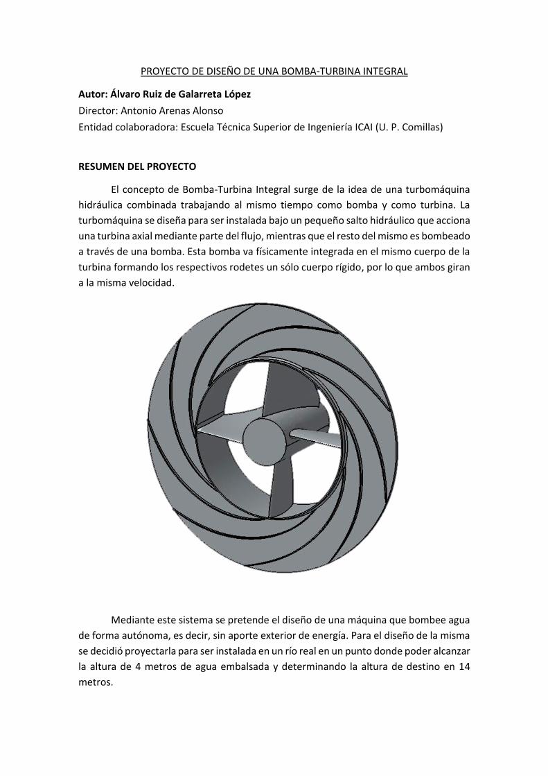
El concepto de Bomba-Turbina Integral surge de la idea de una turbomáquina
hidráulica combinada trabajando al mismo tiempo como bomba y como turbina. La
turbomáquina se diseña para ser instalada bajo un pequeño salto hidráulico que acciona
una turbina axial mediante parte del flujo, mientras que el resto del mismo es bombeado
a través de una bomba. Esta bomba va físicamente integrada en el mismo cuerpo de la
turbina formando los respectivos rodetes un sólo cuerpo rígido, por lo que ambos giran
a la misma velocidad.
Mediante este sistema se pretende el diseño de una máquina que bombee agua
de forma autónoma, es decir, sin aporte exterior de energía. Para el diseño de la misma
se decidió proyectarla para ser instalada en un río real en un punto donde poder alcanzar
la altura de 4 metros de agua embalsada y determinando la altura de destino en 14
metros.

PROYECTO DE DISEÑO DE UNA BOMBA-TURBINA INTEGRAL
2
Los objetivos marcados para la realización del proyecto son los siguientes:
- Diseño hidráulico de la máquina. Objetivo principal del proyecto en el que
se deben diseñar tanto los rodetes de la turbina y de la bomba como el
sistema difusor de la máquina.
- Diseño mecánico del conjunto. Una vez realizado el diseño hidráulico es
necesario el diseño mecánico de todos componentes necesarios.
- Presupuesto económico. Se estudiarán los costes de fabricación y de
mantenimiento de la máquina.
- Indicaciones para la instalación. Donde se dan orientaciones para la
construcción de la presa.
Para comenzar el diseño se debe partir de los datos iniciales que nos proporciona
la localización del proyecto. Para ello se hace uso de la información hidrográfica y
topográfica pertinente. Las alturas útil de la turbina y efectiva de la bomba que se toman
para el diseño son más desfavorables que las que proporciona la información
topográfica para, así, tener margen ante las pérdidas de la instalación y conductos
ajenos a la máquina.
DATOS DE PARTIDA
Altura útil de la turbina 3,5 m
Altura efectiva de la bomba 16 m
Caudal medio 0,8 m3/s
Caudal máximo histórico 2,15 m3/s
Caudal mínimo histórico 0,05 m3/s
Con estos datos, y teniendo en cuenta la condición de que los rodetes de la
turbina y de la bomba giran a la misma velocidad y que, por lo tanto, la potencia
absorbida por la turbina se restituye a la bomba se obtienen los diferentes caudales:
PARÁMETROS DE DISEÑO
Turbina 𝑄𝑇 = 0,71588 𝑚3 𝑠⁄
𝐻𝑇 = 3,5 𝑚
𝑛 = 458 𝑟𝑝𝑚
𝜂𝑇 = 0,79
𝑃𝑎𝑇 = 19,42 𝐾𝑊
Bomba 𝑄𝐵 = 0,08412 𝑚3 𝑠⁄
𝐻𝐵 = 16 𝑚
𝑛 = 458 𝑟𝑝𝑚
𝜂𝐵 = 0,68
𝑃𝑎𝐵 = 19,42 𝐾𝑊
RESUMEN
3
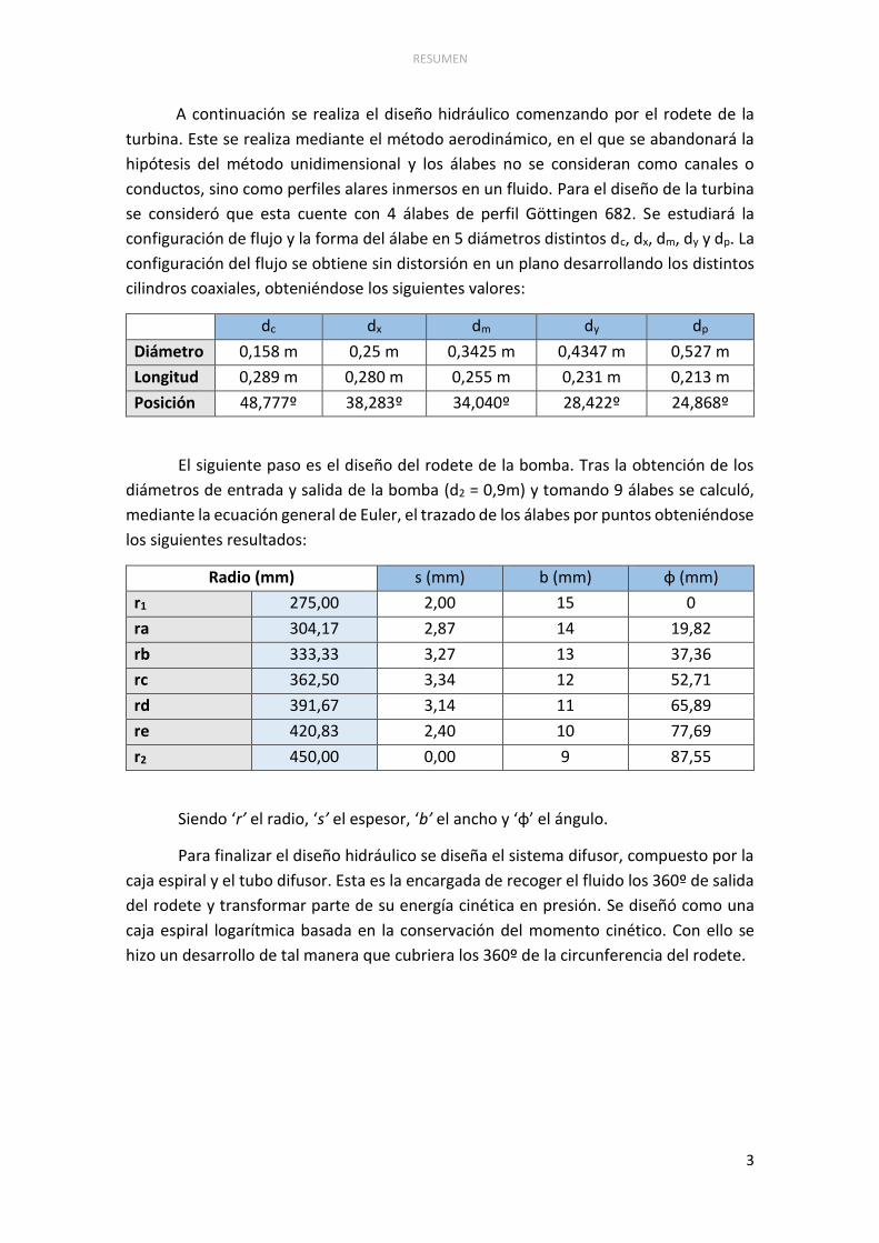
A continuación se realiza el diseño hidráulico comenzando por el rodete de la
turbina. Este se realiza mediante el método aerodinámico, en el que se abandonará la
hipótesis del método unidimensional y los álabes no se consideran como canales o
conductos, sino como perfiles alares inmersos en un fluido. Para el diseño de la turbina
se consideró que esta cuente con 4 álabes de perfil Göttingen 682. Se estudiará la
configuración de flujo y la forma del álabe en 5 diámetros distintos dc, dx, dm, dy y dp. La
configuración del flujo se obtiene sin distorsión en un plano desarrollando los distintos
cilindros coaxiales, obteniéndose los siguientes valores:
dc dx dm dy dp
Diámetro 0,158 m 0,25 m 0,3425 m 0,4347 m 0,527 m
Longitud 0,289 m 0,280 m 0,255 m 0,231 m 0,213 m
Posición 48,777º 38,283º 34,040º 28,422º 24,868º
El siguiente paso es el diseño del rodete de la bomba. Tras la obtención de los
diámetros de entrada y salida de la bomba (d2 = 0,9m) y tomando 9 álabes se calculó,
mediante la ecuación general de Euler, el trazado de los álabes por puntos obteniéndose
los siguientes resultados:
Radio (mm) s (mm) b (mm) φ (mm)
r1 275,00 2,00 15 0
ra 304,17 2,87 14 19,82
rb 333,33 3,27 13 37,36
rc 362,50 3,34 12 52,71
rd 391,67 3,14 11 65,89
re 420,83 2,40 10 77,69
r2 450,00 0,00 9 87,55
Siendo ‘r’ el radio, ‘s’ el espesor, ‘b’ el ancho y ‘φ’ el ángulo.
Para finalizar el diseño hidráulico se diseña el sistema difusor, compuesto por la
caja espiral y el tubo difusor. Esta es la encargada de recoger el fluido los 360º de salida
del rodete y transformar parte de su energía cinética en presión. Se diseñó como una
caja espiral logarítmica basada en la conservación del momento cinético. Con ello se
hizo un desarrollo de tal manera que cubriera los 360º de la circunferencia del rodete.

PROYECTO DE DISEÑO DE UNA BOMBA-TURBINA INTEGRAL
4
Una vez terminado el diseño hidráulico se procedió a realizar el diseño mecánico
del conjunto. En primer lugar se dimensionó el eje. Dado que este no transmite potencia,
ya que la energía absorbida por la turbina se restituye directamente a la bomba sin pasar
por el eje, este se dimensionó partiendo de la hipótesis de bloqueo de uno de los
rodamientos, comportándose así el eje como una viga en voladizo soportando un
momento torsor y un momento flector. Se obtuvo un diámetro de 40 mm.
Posteriormente se han de diseñar dos troncos cónicos para acoplar a los dos
lados del rodete, en el eje, para la correcta circulación del fluido a la turbina y se escogen
los rodamientos adecuados. En este caso, rodamientos con recubrimiento de níquel
para resistir la corrosión a la que están expuestos trabajando inmersos en agua.
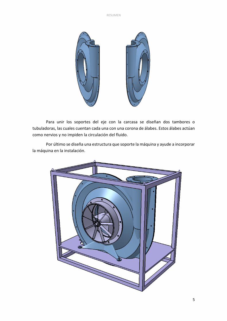
Posteriormente se diseña la carcasa. Esta alberga la caja espiral, el cono difusor
y además tiene la función de soportar el conjunto de la máquina. Se fabrica en dos partes
para poder montar el rodete en su interior.
RESUMEN
5
Para unir los soportes del eje con la carcasa se diseñan dos tambores o
tubuladoras, las cuales cuentan cada una con una corona de álabes. Estos álabes actúan
como nervios y no impiden la circulación del fluido.
Por último se diseña una estructura que soporte la máquina y ayude a incorporar
la máquina en la instalación.

PROYECTO DE DISEÑO DE UNA BOMBA-TURBINA INTEGRAL
6
Los materiales para la fabricación han sido acero inoxidable F-1250 para el eje y
fundición gris para el resto de componentes. Las uniones entre las dos partes de la
carcasa y entre la carcasa y los tambores se realizan mediante pernos de rosca métrica
y el resto de uniones se realizan mediante soldadura. Con ello, el presupuesto de
fabricación asciende a 2234 euros.
Este proyecto sólo es una primera aproximación al diseño de una Bomba-
Turbina. En cualquier proceso de diseño de una máquina es necesario el ensayo con un
prototipo con el fin de encontrar errores no detectables teóricamente.

RESUMEN
7
DESIGN PROYECT OF AN INTEGRAL PUMP-TURBINE
Author: Álvaro Ruiz de Galarreta López
Director: Antonio Arenas Alonso
Collaborating Organization: Escuela Técnica Superior de Ingeniería ICAI (U. P. Comillas)
ABSTRACT
The concept of the integral Pump-Turbine comes from the idea of a combined
hydraulic turbomachine, working at the same time as a pump and as a turbine. The
turbomachine is design to be installed under a small hydraulic jump that activates an
axial turbine with a portion of the flow, while the rest of it is pumped through a pump.
This pump is physically integrated in the turbine, forming the two impellers a single rigid
body, so both impellers turn at the same speed.
By following this idea it is expected to design a machine that pumps water in an
autonomous way, that is to say, without an external energy input. To design the machine
it has been decided to project it in a real river where it is possible to generate a height
of 4 meters of stored water, setting the destination of the pumped flow to a height of
14 meters.
PROYECTO DE DISEÑO DE UNA BOMBA-TURBINA INTEGRAL
8
The objectives of the project are:
- The hydraulic design of the machine. This is the main objective of the
project where the pump and turbine impellers, as well as the diffuser
system are designed.
- Mechanical design of the set. Once the hydraulic design is done, it is
necessary to design all the mechanical components.
- Construction budget. Manufacturing, material and assembly costs.
- Guidelines for the installation. Provide guidance for the design of the
dam.
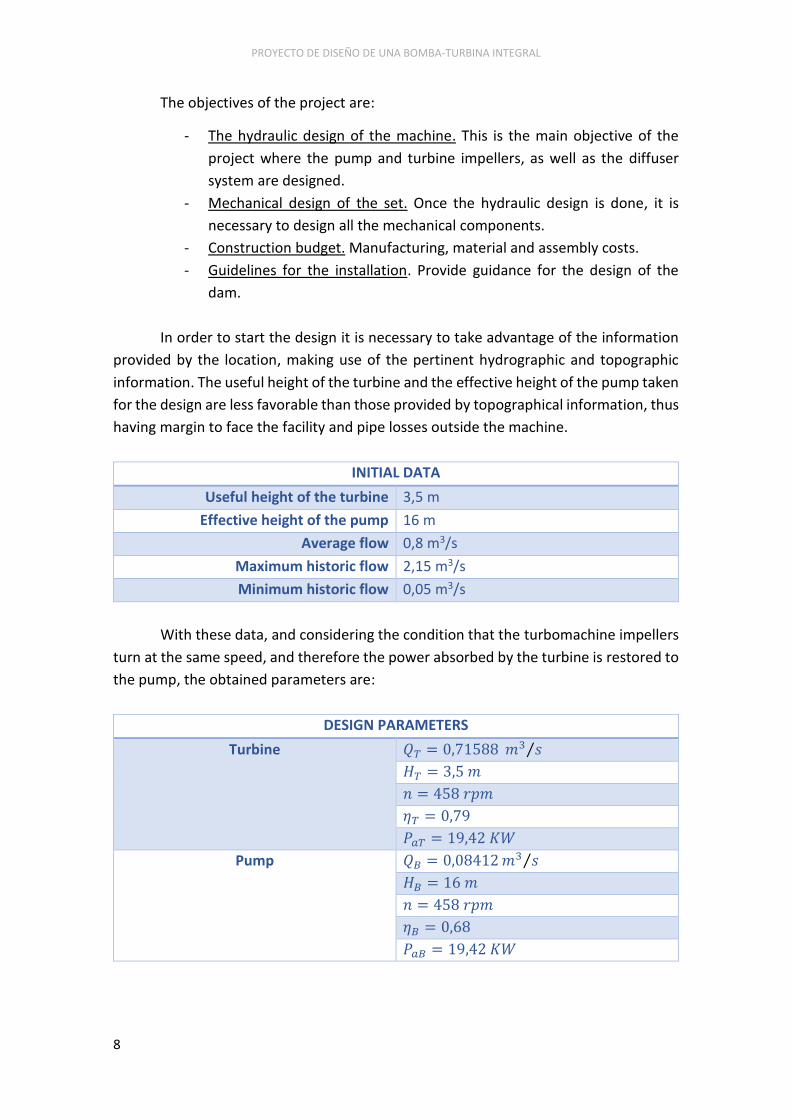
In order to start the design it is necessary to take advantage of the information
provided by the location, making use of the pertinent hydrographic and topographic
information. The useful height of the turbine and the effective height of the pump taken
for the design are less favorable than those provided by topographical information, thus
having margin to face the facility and pipe losses outside the machine.
INITIAL DATA
Useful height of the turbine 3,5 m
Effective height of the pump 16 m
Average flow 0,8 m3/s
Maximum historic flow 2,15 m3/s
Minimum historic flow 0,05 m3/s
With these data, and considering the condition that the turbomachine impellers
turn at the same speed, and therefore the power absorbed by the turbine is restored to
the pump, the obtained parameters are:
DESIGN PARAMETERS
Turbine 𝑄𝑇 = 0,71588 𝑚3 𝑠⁄
𝐻𝑇 = 3,5 𝑚
𝑛 = 458 𝑟𝑝𝑚
𝜂𝑇 = 0,79
𝑃𝑎𝑇 = 19,42 𝐾𝑊
Pump 𝑄𝐵 = 0,08412 𝑚3 𝑠⁄
𝐻𝐵 = 16 𝑚
𝑛 = 458 𝑟𝑝𝑚
𝜂𝐵 = 0,68
𝑃𝑎𝐵 = 19,42 𝐾𝑊

RESUMEN
9
Then the hydraulic design is made, starting with the turbine impeller. This is done
following the aerodynamic method, in which the hypothesis of one-dimensional method
is no longer valid and the blades are not considered as channels or conduits, but as
airfoils immersed in a fluid. The turbine has 4 blades with a Göttingen 682 profile. The
flow configuration and shape of the blades will be studied in 5 different diameters dc,
dx, dm, dy and dp, obtaining the length and angle values for each one:
dc dx dm dy dp
Diameter 0,158 m 0,25 m 0,3425 m 0,4347 m 0,527 m
Length 0,289 m 0,280 m 0,255 m 0,231 m 0,213 m
Position 48,777º 38,283º 34,040º 28,422º 24,868º
The next step is the design of the pump impeller. Upon obtaining the entry and
exit diameters of the pump (d2 = 0,9m) and taking 9 blades the layout of blades by points
are calculated by the general Euler´s equation. These are the obtained results:
Radius (mm) s (mm) b (mm) φ (mm)
r1 275,00 2,00 15 0
ra 304,17 2,87 14 19,82
rb 333,33 3,27 13 37,36
rc 362,50 3,34 12 52,71
rd 391,67 3,14 11 65,89
re 420,83 2,40 10 77,69
r2 450,00 0,00 9 87,55
Being ‘r’ the radius, ‘s’ thickness, ‘b’ wide and ‘φ’ angle.
The final step in the hydraulic design is the diffusor system, composed by the
volute and the diffuser cone. The volute is used to transform the kinetic energy of the
fluid into pressure energy and also to collect fluid exiting the 360 ° of the circumference
of the impeller. It was designed as a logarithmic spiral case based on the conservation
of angular momentum. This development was done so as to cover 360° of the impeller
circumference.

PROYECTO DE DISEÑO DE UNA BOMBA-TURBINA INTEGRAL
10
Once completed the hydraulic design proceed to perform the mechanical design
of the set. Firstly the axis is dimensioned. Given that the axis does not transmit any
power, because of the energy absorbed by the turbine going directly to the pump
without going through the axis, this was dimensioned considering the blocking of the
bearing hypothesis, thus behaving the axis like a cantilever supports a torsor and a
bending moment. A 40 nm diameter was obtained.
Afterwards two truncated cones have to be designed in order to attach on both
sides of the impeller, in the axis, so as to allow the correct fluid circulation to the turbine.
The chosen bearings are covered with nickel in order to resist corrosion.
The case contains the volute, the diffusor cone and has also to support the set of
the machine. It is produced in two parts so as to assemble the impeller inside it.

RESUMEN
11
In order to connect the axis supports with the case two drums are designed, each
one with its own blade crown. These blades act like nerves and do not block the fluid
circulation.
Finally, the structure that supports the machine and helps incorporing the
machine in the installation is designed.

PROYECTO DE DISEÑO DE UNA BOMBA-TURBINA INTEGRAL
12
The making materials are stainless steel F-1250 for the axis and casting for the
other components. The connections between the two parts of the housing and between
the housing and the drums are made by bolts, and the other connections are made by
welding.
The production budget is €2.234. This budget is made for a small series of 15 units.
This project is a first design of the Pump-Turbine. In any design process of a
machine is necessary to test a prototype in order to find any errors.
Related Documents