AUTONOMOUS UAV FINAL REPORT Senior Design Team 10 Faculty Advisor Matthew Nelson Client Space Systems & Controls Laboratory (SSCL) Team Members Anders Nelson (EE) Kshira Nadarajan (CprE) Mathew Wymore (CprE) Mazdee Masud (EE) Date Submitted: April 27, 2011

Welcome message from author
This document is posted to help you gain knowledge. Please leave a comment to let me know what you think about it! Share it to your friends and learn new things together.
Transcript
0 | P a g e
AUTONOMOUS UAV FINAL REPORT
Senior Design
Team 10
Faculty Advisor
Matthew Nelson
Client
Space Systems & Controls Laboratory
(SSCL)
Team Members
Anders Nelson (EE) Kshira Nadarajan (CprE)
Mathew Wymore (CprE) Mazdee Masud (EE)
Date Submitted:
April 27, 2011
1 | P a g e
Table of Contents
List of Figures 3
List of Tables 3
List of Symbols 4
List of Definitions 4
1. Introductory Material 5
1.1 Executive Summary 5
1.2 Acknowledgement 5
1.3 Problem Statement 5
1.3.1 General Problem Statement 5
1.3.2 General Solution Approach 6
1.4 Operating Environment 7
1.5 Intended Users and Uses 7
1.5.1 Intended Users 7
1.5.2 Intended Uses 7
1.6 Assumptions and Limitations 7
1.6.1 Updated Assumptions List 7
1.6.2 Updated Limitations List 8
1.7 Expected End Product and Other Deliverables 8
2. Approach and Product Design Results 9
2.1 Approach Used 9
2.1.1 Design Objectives 9
2.1.2 Functional Requirements 9
2.1.3 Design Constraints 9
2.1.4 Technical Approach Considerations and Results 10
2.1.5 Testing Approach Considerations 10
2.2 Detailed Design 10
2.2.1 Software System 10
2.2.2 Control System – Controllers 12
2.2.3 Sensor System 20
2.2.4 Power System 21
3. Resources and Schedules 23
3.1 Resources Requirements 23
3.1.1 Personnel Effort Requirements 23
3.1.2 Other Resource Requirements 24
3.1.3 Financial Requirements 24
3.2 Schedules 25
3.2.1 Project Schedule 25
4. Implementation 27
4.1 Hardware Implementation 27
4.1.1 Gumstix Implementation 27
4.1.2 PIC Implementation 28
4.1.3 PCB Implemention 29
4.2 Software Implementation 30
4.2.1 Obstacle Detection Module 30
4.3 Power System 36
5. Testing 38
5.1 Hardware Testing 38
5.1.1 Gumstix Testing 38
2 | P a g e
5.1.2 PIC Testing 38
5.2 Sensors Testing 39
5.2.1 Laser Range Finder Testing 39
5.2.2 Sonar Testing 40
5.3 Power Testing 40
5.3.1 Endurance Test 40
6. Future Work 42
6.1 Current Status 42
6.2 Future Implementations 42
7. Lessons Learned 43
7.1 Importance of Communication 43
7.2 Full Team from Start 43
7.3 Attention to Detail 43
7.4 Too Much in Too Little Time 44
8. Closure Material 45
8.1 Project Team Information 45
8.1.1 Client Information 45
8.1.2 Faculty Advisor Information 45
8.1.3 Student Team Information 45
8.2 Closing Summary 46
8.3 References 47
8.4 Appendices 48
8.4.1 Appendix I – Competition Rules 48
8.4.2 Appendix II – Gumstix AngelStrike Change Log 50
8.4.3 AppendixIII – Gumstix User Manual 53
8.4.4 Appendix IV – PICstix Communication Protocol 55
3 | P a g e
List of Figures
Figure 1.3.2 a) System Block Diagram
Figure 2.2.1 a) Software Flow Diagram
Figure 2.2.2 a) Main Control Board – Initial Design
Figure 2.2.2 b) Option 1: System-On-Chip
Figure 2.2.2 c) Option 2: All in one MCU
Figure 2.2.2 d) Option 3: Divide and Conquer MCUs
Figure 2.2.2 e) Draft System Design with Gumstix
Figure 2.2.2 f) Controller Design
Figure 3.2.1 a) Project Schedule
Figure 4.1.3 a) PCB Schematic
Figure 4.2.1 a) Overall System Level Software Block Diagram
Figure 4.2.1 b) Visualization of range scanning
Figure 4.2.1 c) Laser Range Scanning Resolution and Area Coverage
Figure 4.2.1 d) Urg Viewer Tool and its Visual Output
Figure 4.3 a) Image of LiPo Battery
Figure 4.3 b) Power System Block Diagram
Figure 5.1.2 a) Sonar Range Testing
List of Tables
Table 2.2.2 a) Hardware Options Scoring
Table 3.1.1 a) Documentation Expected Labor
Table 3.1.1 b) Design Expected Labor
Table 3.1.1 c) Implementation Expected Labor
Table 3.1.1 d) Labor Totals
Table 3.1.2 a) Components Estimate
Table 3.1.3 a) Financial Summary
Table 5.2.1 a) Testing Results for Laser Range Finder Obstacle Detection Module
4 | P a g e
List of Symbols
C – capacity of a battery
kg – kilograms (unit of mass)
LiPo – Lithium Polymer, a type of battery
mAh – milli-Ampere hours (unit of electric charge)
V – Volts (unit of electromotive force)
List of Definitions
466 team – a team of mechanical and aerospace engineers responsible for creating the quadrotor platform
API – Application Programming Interface
GPS – Global Positioning System
IARC – International Aerial Robotics Competition
IMU – Inertial Measurement Unit
JAUS – Joint Architecture for Unmanned Systems
MCU – Microcontroller Unit
RC – Radio Control
RF – Radio Frequency
SSCL – Space Systems and Control Laboratory at Iowa State University
TI – Texas Instruments, an electronic components manufacturer
UAV – Unmanned Aerial Vehicle

5 | P a g e
1. Introductory Material
1.1 Executive Summary
The team will be working on developing the electronics on an autonomous unmanned aerial
vehicle (UAV) for use in the International Aerial Robotics Competition. This competition involves using
the vehicle to penetrate and navigate an office environment to complete tasks outlined in the competition
rules.
Our team will be working with the Space Systems and Control Lab (SSCL) of Iowa State
University as well as two multidisciplinary senior design teams from other departments. The other two
teams will be in charge of developing the platform on which to put the control electronics, and designing
the controls including navigation algorithm and vision system. The SSCL will act as an advising element
to the senior design teams and will be providing the funding for the development of the project.
While designing the electronics of the platform, we conducted research into past competitions and
competitors, and we considered several possible solutions. In this document we will be describing the
decisions we made in choosing the optimal solution for the various problems and its subsequent
implementation. Our design consists of five main modules that will be described later in this document.
The general outline is that the UAV will use sensors such as a laser range finder and an inertial
measurement unit (IMU) to collect the data to be used by the microcontroller system to be used in the
stability and flight control. In addition to these sensors, we will also include a communication system to
communicate sensor and control data to a base station that will process the computation-intensive
navigation and decision-making algorithms.
1.2 Acknowledgement
We would like to acknowledge our advisor, Matthew Nelson of the SSCL, for technical advice
and oversight. In addition, Koray Celik, a PhD student in the SSCL, was a major advisor for our team.
His experience in aerial robotics was a unparalleled source of experience all the teams on this project
would have been lost without. We would also like to acknowledge the Engineering 466 and 467 teams for
their help, patience, and efforts on this project.
1.3 Problem Statement
1.3.1 General Problem Statement
The International Aerial Robotics Competition states in its mission that the main motivation
behind this competition is to promote and push the research and implementation of efficient indoor
navigation systems, flight control and autonomy in aerial robots. The problem is that the UAV must be
6 | P a g e
capable of flying autonomously, i.e., without any real time human control, within an indoor environment
without the aid of GPS navigation techniques. The robot will also be expected to complete a basic set of
tasks, such as identifying and replacing a USB drive (as in previous competitions). These tasks must be
completed within ten minutes. The robot must weigh no more than 1.5kg. Our specific challenge within
the scope of the senior design project is that we have to design and build the on-board electronics and
power systems for a platform that will fly autonomously and implement obstacle avoidance and stability
control.
1.3.2 General Solution Approach
Our solution to this problem is to build a platform that will be able to make most of the important
decisions required for sensor support, communication, and power management on board. It will send
information such as the range finder and image/video data through a wireless link to a remote base station
where the heavy computations such as localization and search algorithms will be implemented. A control
system shall be developed by the Engr466, Controls team, which the base station will be able to
wirelessly command the robot to move according to the instructions based on an API developed for this
purpose. This API will allow implementation of important mapping and search algorithms to enable
complete autonomy. The robot will be tested in a controlled environment where the behavior can be
observed and improved. It is to be noted that our platform will only enable the implementation of
localization algorithms and serve as a functional platform but not implement it.
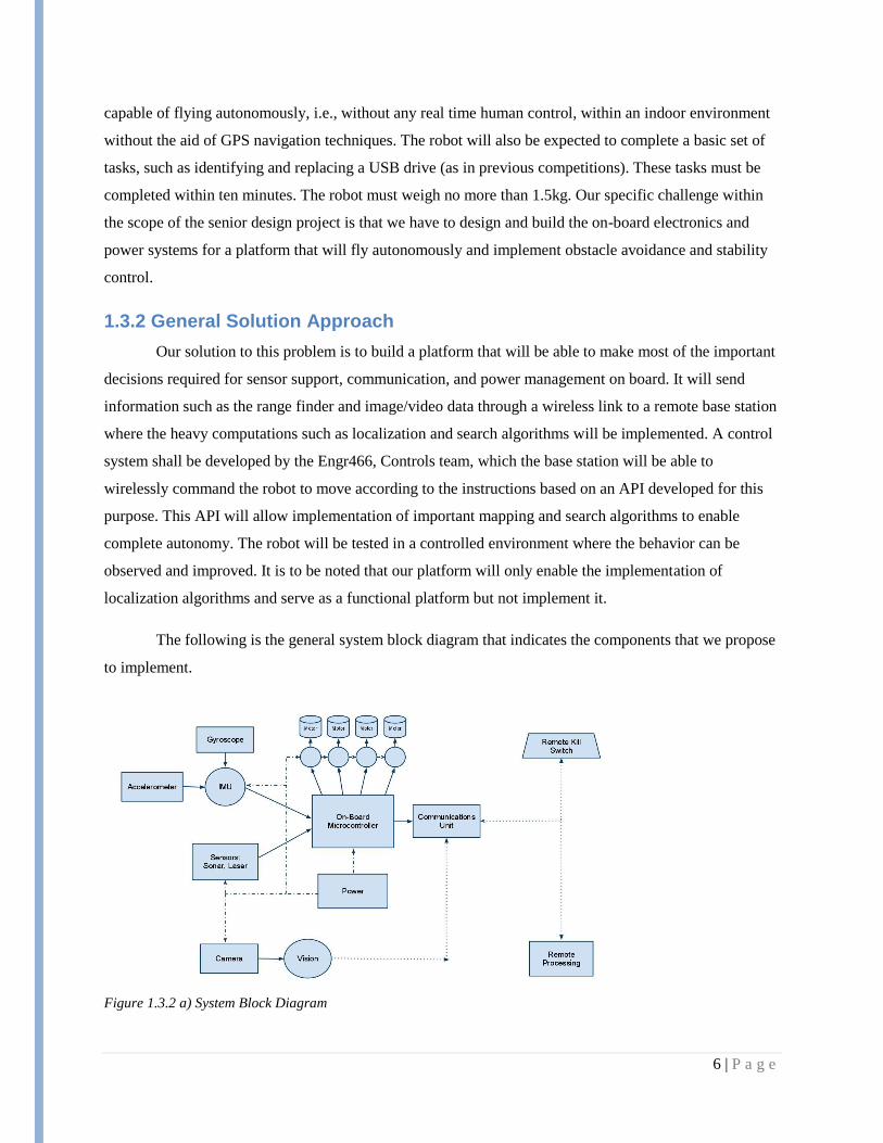
The following is the general system block diagram that indicates the components that we propose
to implement.
Figure 1.3.2 a) System Block Diagram
7 | P a g e
1.4 Operating Environment
The operating environment will be based on the competition set up which imitates the interior of
an office. The environment will be completely indoors as the main objective of the competition is to
achieve efficient indoor navigation. There will not be external factors such as wind or rain since it will be
completely indoors. The robot will also have to navigate without the use of a GPS system. The missions
is intended to be a stealthy one so there shall be no human beings inside the actual office setting where the
robot has to operate.
1.5 Intended Users and Uses
1.5.1 Intended Users
The system will be used by the SSCL team for the IARC competition.
1.5.2 Intended Uses
The system will have a specific purpose of doing the mission outlined in the competition, i.e.
getting inside the secured compound and retrieving the flash drive. However, the scope for this senior
design team is to design the electronics platform to be capable of expansion, without implementation of
the systems that will make it autonomous, mainly, the object recognition and mapping systems of the base
station.
1.6 Assumptions and Limitations
1.6.1 Updated Assumptions List
1) The platform delivered to us by the 467 team will be capable of stable flight.
2) No additional money apart from that provided from the SSCL will be required.
3) No major change in the competition mission will take place.
4) This project will be picked up by another team after this year to expand it to the full
autonomy required for the competition.
5) The parts and components that we have agreed upon shall integrate into the system without
any major compatibility issues.
6) The resolution of the inertial unit and other sensors will allow for adequate accuracy in
implementation of complex obstacle avoidance algorithms.

8 | P a g e
1.6.2 Updated Limitations List
1) The delivered platform will not be able to perform object recognition, but it will enable future
addition of an object recognition system.
2) The robot will not be able to bear any additional weight other than the on-board components.
3) The robot will not be able to hover or stay powered beyond a time period of 12 minutes if the
need for such a situation arises.
4) There will be a single robot platform developed and there will be no backup structure.
5) After the first semester, major changes in the platform itself will not be easily possible.
6) The team has limited time for implementation due to other course studies.
1.7 Expected End Product and Other Deliverables
The deliverable for this project is electronics for a quadcopter that is capable of stable flight,
obstacle avoidance and remote termination in case of emergency. The platform will also be easily
expandable to enable autonomous navigation. The steps taken to ensure ease of expansion have been
indicated in our design decisions, choice of sensors and the overall physical structure of the platform. For
example, the processor has USB host capabilities to allow for the use of devices such as laser range
detectors and portable camera and vision sensors. The chassis also has been designed to accommodate the
weight and volume of the laser range finder. This platform will hold power for at least 12 minutes while
operating in an indoor environment. The electronics will be able to interact and take in data as required by
the system. The robot will be able to communicate with a base station which will receive sensor data and
send back navigation commands.
A complete documentation manual along with the detailed API specifications will be provided to
the client for ease of control through the base station. The API will specify functions required for the base
station to command the robot to take necessary decisions through a wireless RF communication link.
9 | P a g e
2. Approach and Product Design Results
2.1 Approach Used
2.1.1 Design Objectives
Design the onboard electronics and power systems for an autonomous unmanned aerial vehicle
capable of competing in the IARC
Design the basic onboard software for the abovementioned UAV
Design systems that can be integrated with the vehicle platform designed by the Platform team
Design systems that can be expanded as part of a competition-worthy UAV by a separate team
2.1.2 Functional Requirements
Lightweight
o Entire platform under 1.5kg
Low power
o Battery powered
o 10 minutes minimum flight time (12 minute goal)
Four brushless motors at 11V
Electronics systems
Operational
o Able to handle onboard stability control
o Wireless base station communication
Wireless link capable of at least 42 meters
Expandable
o Potential for navigation in a GPS-denied environment
Connectivity for laser range finder
Considerations for computer vision system
o Potential for executing remote autonomous commands
o Connectivity for manual remote kill switch
o Connectivity for wire-burn USB stick drop-off system
2.1.3 Design Constraints
Compatibility
o Must integrate into Platform team‘s vehicle platform
o Must potentially fulfill competition requirements
Time
o Deliverables due in May 2011
o Team has other time-consuming obligations
Experience
10 | P a g e
o Team has limited design experience
o Team has limited implementation experience
Cost
o Budget is supplied by SSCL
o Budget is not definite but definitely limited
2.1.4 Technical Approach Considerations and Results
The design of the systems of the platform will be simulated and analyzed. The results of each
simulation will determine the designs and specs that will be considered. The considered design will be
approved and then it will be implemented to get the prototype. The prototype will be tested further and
follow the testing approaches. Upon passing all the testing the final platform will be delivered.
2.1.5 Testing Approach Considerations
The testing will contain several different approaches. They are the following:
Communication – This test is on the communication between the platform and the remote base
station. The distance and the speed of communication will be tested.
Integration – This test is to determine the proper connections have been made and
communication between components is fully functioning.
Obstacle avoidance- This is the test on the sensors. The reliability and the accuracy of obstacle
avoidance will be tested from the movements of the platform in various directions.
Endurance (Power) - this is the battery testing. The battery will be run under expected load and
voltage over time will be monitored during testing
2.2 Detailed Design
2.2.1 Software System
The software system consists of modules that run of different controllers but work in unison to
provide the end user a friendly API. Currently the software system consists of the following modules:
1. Positioning System: This system serves as the part of the navigation block that will be used for
single waypoint navigation. This will be implemented on the base station controller. The
positioning module will eventually require an implemented Simultaneous Localization and
Mapping Algorithm, but our end deliverable will only issue basic commands directing the robot
to move in a given direction for a given distance or speed. The current position and the desired
11 | P a g e
final position are not determined through mapping, the platform will provide an API to such an
algorithm that will now be able call our functions as long as it provides key information
parameters like speed and direction of motion.
2. Heading: This module will be implemented on the main on- board controller on the robot. It
acquires information from the positioning system and sends commands to the motor controller.
3. Motion Controller: This is the module which controls the motors to achieve the desired
speed/motion. The feedback about the percentage thrust achieved from this module is also sent to
the heading module.
4. Dynamic Stability Control Module: This module uses the data from the internal sensor
consisting of the inertial unit to maintain stability of the robot. It is also possible to integrate
information from external sensors like range detection units such as the IR to combine the
stability control and the obstacle avoidance, but we wanted to modularize our design to minimize
interdependence.
5. Obstacle avoidance module: This module reads the current sensor data and identifies if there is
any obstacle to avoid. If there is, the system is sent back to the motion control state where the
motion parameters are re-calculated based on odometry information. If there is no obstacle, then
the system returns to positioning with a ―Final Met‖ feedback.
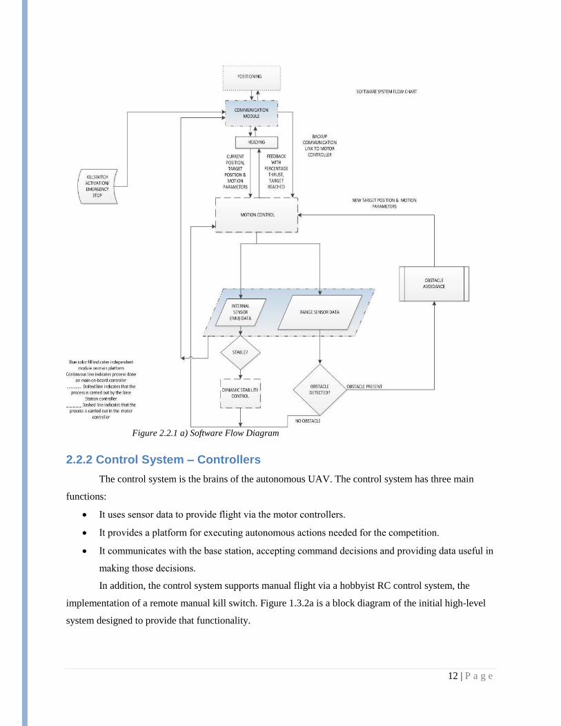
Here is a graphical view of the software block diagram consisting of all the modules mentioned above.
12 | P a g e
Figure 2.2.1 a) Software Flow Diagram
2.2.2 Control System – Controllers
The control system is the brains of the autonomous UAV. The control system has three main
functions:
It uses sensor data to provide flight via the motor controllers.
It provides a platform for executing autonomous actions needed for the competition.
It communicates with the base station, accepting command decisions and providing data useful in
making those decisions.
In addition, the control system supports manual flight via a hobbyist RC control system, the
implementation of a remote manual kill switch. Figure 1.3.2a is a block diagram of the initial high-level
system designed to provide that functionality.
13 | P a g e
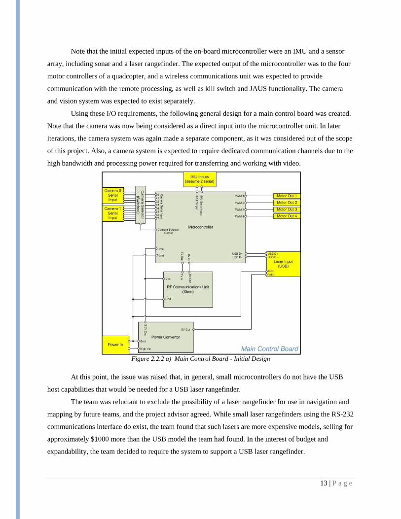
Note that the initial expected inputs of the on-board microcontroller were an IMU and a sensor
array, including sonar and a laser rangefinder. The expected output of the microcontroller was to the four
motor controllers of a quadcopter, and a wireless communications unit was expected to provide
communication with the remote processing, as well as kill switch and JAUS functionality. The camera
and vision system was expected to exist separately.
Using these I/O requirements, the following general design for a main control board was created.
Note that the camera was now being considered as a direct input into the microcontroller unit. In later
iterations, the camera system was again made a separate component, as it was considered out of the scope
of this project. Also, a camera system is expected to require dedicated communication channels due to the
high bandwidth and processing power required for transferring and working with video.
Figure 2.2.2 a) Main Control Board - Initial Design
At this point, the issue was raised that, in general, small microcontrollers do not have the USB
host capabilities that would be needed for a USB laser rangefinder.
The team was reluctant to exclude the possibility of a laser rangefinder for use in navigation and
mapping by future teams, and the project advisor agreed. While small laser rangefinders using the RS-232
communications interface do exist, the team found that such lasers are more expensive models, selling for
approximately $1000 more than the USB model the team had found. In the interest of budget and
expandability, the team decided to require the system to support a USB laser rangefinder.

14 | P a g e
This decision became crucial to the microcontroller system design. System-on-chip/computer-on-
module options were now considered, with the other option being a smaller microcontroller with USB
host capabilities, such as the TI Stellaris. At this point, the following three high-level system options were
proposed.
Figure 2.2.2 b) Option 1: System-on-chip
15 | P a g e
Option 1 featured a system-on-chip module that could run Linux connected to a smaller
microcontroller that would handle flight stability calculations and the output to the motor controllers. This
option was initially thought to be overly large and power-hungry for the project.
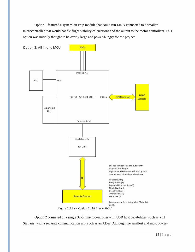
Figure 2.2.2 c) Option 2: All in one MCU
Option 2 consisted of a single 32-bit microcontroller with USB host capabilities, such as a TI
Stellaris, with a separate communication unit such as an XBee. Although the smallest and most power-
16 | P a g e
efficient of the three options, this option was considered too rigid, with little room to expand an already-
busy microcontroller.
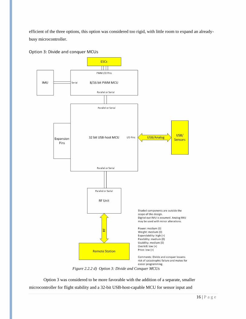
Figure 2.2.2 d) Option 3: Divide and Conquer MCUs
Option 3 was considered to be more favorable with the addition of a separate, smaller
microcontroller for flight stability and a 32-bit USB-host-capable MCU for sensor input and
17 | P a g e
communications with the RF unit. This option would provide the advantage of sandboxing the flight
stability, allowing the UAV to stay aloft even if the main controller should fail. Also, the flight control
unit could be programmed and then left alone, aside from minor performance tweaks, which would be a
major usability boost for a future group implementing autonomous functionality with no knowledge of
the flight control details.
While the team was initially in favor of Option 3, the project advisor encouraged further research
into system-on-chip options. Part of the reasoning behind this decision was that a controller running
Linux would already have USB drivers, hugely simplifying I/O programming. Further research indicated
that many other elements, including wireless communications, power, programming, implementation and
general expandability and usability would be simplified with a system-on-chip device running Linux.
Additionally, the power budget indicated that the power required by the electronics, even a
system-on-chip, would be minor compared to the power used by the motors. The weight budget showed
considerable room for play as well, so those factors, while still important, were of less concern than
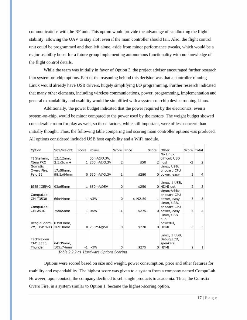
initially thought. Thus, the following table comparing and scoring main controller options was produced.
All options considered included USB host capability and a WiFi module.
Table 2.2.2 a) Hardware Options Scoring
Options were scored based on size and weight, power consumption, price and other features for
usability and expandability. The highest score was given to a system from a company named CompuLab.
However, upon contact, the company declined to sell single products to academia. Thus, the Gumstix
Overo Fire, in a system similar to Option 1, became the highest-scoring option.
18 | P a g e
Meanwhile, a 16-bit PIC MCU from Microchip‘s PIC24 series was chosen as the flight controller.
Since many companies offer similar MCUs, a PIC was chosen because of the SSCL‘s history of work
with PICs, allowing the team to tap into existing equipment resources and an experienced knowledge
base.
The selected PIC fits its purpose well. It features nanoWatt XLP low-power technology and a
wide variety of I/O options, including 25 remappable I/O pins which will allow the team to accommodate
for any sensors which may be connected to the flight controller for basic obstacle detection. Additionally,
the PIC supports the major serial I/O options for interfacing with the main controller and the IMU, as well
as five PWM channels for the motor controllers. And the PIC has five input capture lines, which can be
used for processing signals from a hobbyist RC receiver for manual flight control.
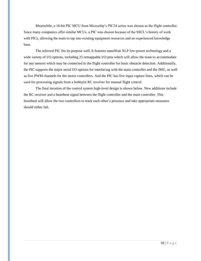
The final iteration of the control system high-level design is shown below. New additions include
the RC receiver and a heartbeat signal between the flight controller and the main controller. This
heartbeat will allow the two controllers to track each other‘s presence and take appropriate measures
should either fail.
19 | P a g e
Figure 2.2.2 e) Draft System Design with Gumstix
As proof-of-concept, the team‘s research has showed that previous IARC competitors have used
similar systems. The team has arrived at the proposed design independently, so the similarity with other
competitors‘ systems is encouraging. Also, the project advisor, who has previous experience in this type
of design, has approved the choices made.
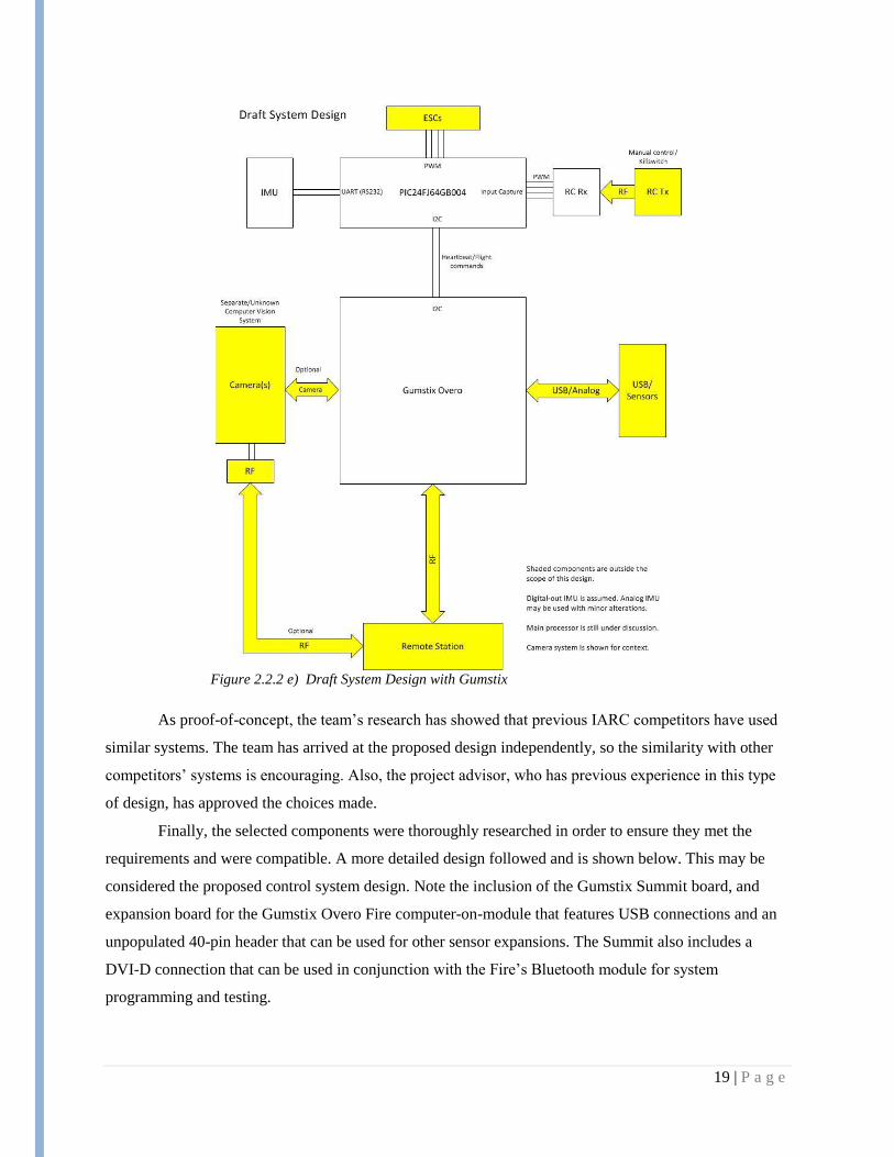
Finally, the selected components were thoroughly researched in order to ensure they met the
requirements and were compatible. A more detailed design followed and is shown below. This may be
considered the proposed control system design. Note the inclusion of the Gumstix Summit board, and
expansion board for the Gumstix Overo Fire computer-on-module that features USB connections and an
unpopulated 40-pin header that can be used for other sensor expansions. The Summit also includes a
DVI-D connection that can be used in conjunction with the Fire‘s Bluetooth module for system
programming and testing.
20 | P a g e
Figure 2.2.2 f) Controller Design
2.2.3 Sensor System
The sensor system is composed of two types of sensors: internal sensors that measure the
characteristics of the platform, and external sensors that take measurements of the environment around
the platform.
The internal sensors category is composed of the inertial measurement unit (IMU). The IMUs
looked at for this project were those with a minimum of 6 degrees of freedom. This means that the IMU
allows measurement of acceleration along each of the axis and measurement of rotation about the axis in
3 dimensions. These work as feedback for stable flight control. The IMU that was selected is a 9 degree
of freedom IMU from Analog devices called ADIS16400. This IMU has temperature calibration on the
device and a very high degree of sensitivity. In addition, speaking with Koray Celik, a PhD student in the
SSCL with extensive aerial robotics experience recommended this IMU very highly for our use. This
option serves the project well.
21 | P a g e
The external sensors needed for this project would be a laser range finder for use in navigation, 2
cameras for navigation and object recognition, and sonar for altitude measurements. The range finder and
cameras were originally eliminated from our project scope since navigation algorithms and object
recognition are to be implemented by later teams. However, at the start of the second semester, a new
Engr 466 team was added to our project. They became the Controls team for the project and thus were
able to add input into what sensors were needed for the project. From their input and Koray‘s suggestions,
it was decided to go with the Hoguyo URG-04LX Laser range finder, Logitech C905A webcams, and
MaxSonar EZ4 with serial interface.
The Hoguyo URG-04LX range finder was selected for its large field of view and the capability to
interface with either USB or RS232 interfacing. The field of view is a sweep of 240 degrees with a 4
meter range. This large area sweep is necessary for a robust navigation algorithm and easy collision
avoidance. The webcams were a recommendation from Koray. From his past experience using vision
systems on RC helicopter navigation, the Logitech C905A webcams are light, have high resolution, and
can auto-adjust through circuitry on the camera. The EZ4 sonar was selected due to its output through a
serial connection. This eliminates the need to do analog to digital conversion and also send a ping to the
sonar that many systems require. This part lowers the complexity of the connection that much further and
saves time in programming.
2.2.4 Power System
The power system is the main source of operating all the equipment in the autonomous UAV. The
main focus is using a LiPo (Lithium Polymer Battery). This battery will be used for three reasons:
High charge/discharge efficiency
Lightweight
Adaptability to a wide variety of packaging shapes and ruggedness
The power system will be powering the On-Board Micro-controller, the motors of the quad copter, the
IMU, the Sensors and the camera. The block diagram in figure 1.3.2a shows a view of what the power
system connects to.
The LiPo battery that is considered ideal is a 3-cell pack with 11.1V voltage, 6500mAh capacity, and
20C maximum for the continuous current output. There are three main battery options for the quadcopter.
These options were:
Single Pack
In this pack the ideal battery that is considered will be in the form of one single pack. It
can be found off the shelf or it can be ordered with the required specifications. The single pack
22 | P a g e
will consist of 3 cells packed together. Since, this is a huge pack with everything together the
amount of space needed to fit it will be larger.
Series Pack
This is one form of combination pack to meet the requirement of the ideal package. Here,
three separate single cell packs, or 2 cells and 1 single-cell pack will be combined. This will be
done by combination of the different packs to make it a 3 cell pack with 11.1V combined from
each of them. The 6500mAh capacity will be same for all the separate packs with the 20 C
maximum continuous current. This form of packaging will help putting the three cells separately
by accommodating them in suitable space on the platform.
Parallel Pack
This is another form of combination pack that has the similar specifications as the serial
packaging. Also, it will have all the advantages as the serial packaging. In this form of
packaging, 3 single cells will be combined again to form a 3 cell package. Again, 3 single cell
packs, or 2 cell and 1 cell pack will be combined. Every single cell will have the same voltage
i.e. 11.1 V, but the capacity of them will be different and it will be combined to get 6500 mAh,
with a 20C maximum continuous current.
From these options, the parallel pack was the best option. Taking a recommendation from Koray,
it was decided to wait until the platform was completed before batteries were selected. As such, we would
be able to measure the exact current draw of the system and so choose exactly the capacity that would be
needed to provide the flight time that is desired.

23 | P a g e
3. Resources and Schedules
3.1 Resources Requirements
3.1.1 Personnel Effort Requirements
The requirements in labor that will be used for this project can be broken into 3 main sections.
The sections of labor are in Documentation, Design, and Implementation. These sections can each be
further divided into subtasks that must be accomplished for the overall project. The tables below list out
how the tasks were estimated to be split between members of the senior design team as well as the totals
for each section of labor.
Documentation Expected Labor
Team Member Project Plan Plan Presentation Design Document Design Presentation Final Documentation Total
Anders Nelson 10 10 15 10 15 60
Mazdee Masud 10 10 15 10 15 60
Mathew Wymore 10 10 15 10 15 60
Kshira Nadarajan 10 10 15 10 15 60
Total 40 40 60 40 60 240
Design Expected Labor
Team Member Past Competitor Research Parts Research&Selection Sensors System Power System Control System Software System Total
Anders Nelson 10 10 15 10 5 0 50
Mazdee Masud 10 10 10 15 5 0 50
Mathew Wymore 10 10 5 0 20 5 50
Kshira Nadarajan 10 10 5 0 5 20 50
Total 40 40 35 25 35 25 200
Implementation Expected LaborTeam Member Control System On-Board Programming Sensor Integration Power System Communication System Parts&Integration Testing Final System Testing Total
Anders Nelson 20 10 15 10 5 40 60 160
Mazdee Masud 20 10 10 15 5 40 60 160
Mathew Wymore 15 30 5 0 10 40 60 160
Kshira Nadarajan 15 30 5 0 10 40 60 160
Total 70 80 35 25 30 160 240 640
Labor TotalsTeam Member Documentation Design Implementation Total
Anders Nelson 60 50 160 270
Mazdee Masud 60 50 160 270
Mathew Wymore 60 50 160 270
Kshira Nadarajan 60 50 160 270
Total 240 200 640 1080
Table 3.1.1 a) Documentation Expected Labor
Table 3.1.1 b) Design Expected Labor
Table 3.1.1 c) Implementation Expected
Table 3.1.1 d) Labor Totals
24 | P a g e
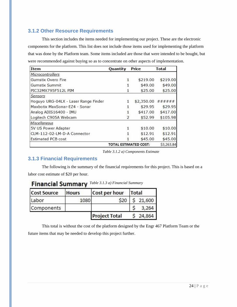
3.1.2 Other Resource Requirements
This section includes the items needed for implementing our project. These are the electronic
components for the platform. This list does not include those items used for implementing the platform
that was done by the Platform team. Some items included are those that were intended to be bought, but
were recommended against buying so as to concentrate on other aspects of implementation.
3.1.3 Financial Requirements
The following is the summary of the financial requirements for this project. This is based on a
labor cost estimate of $20 per hour.
This total is without the cost of the platform designed by the Engr 467 Platform Team or the
future items that may be needed to develop this project further.
Table 3.1.2 a) Components Estimate
Table 3.1.3 a) Financial Summary
25 | P a g e
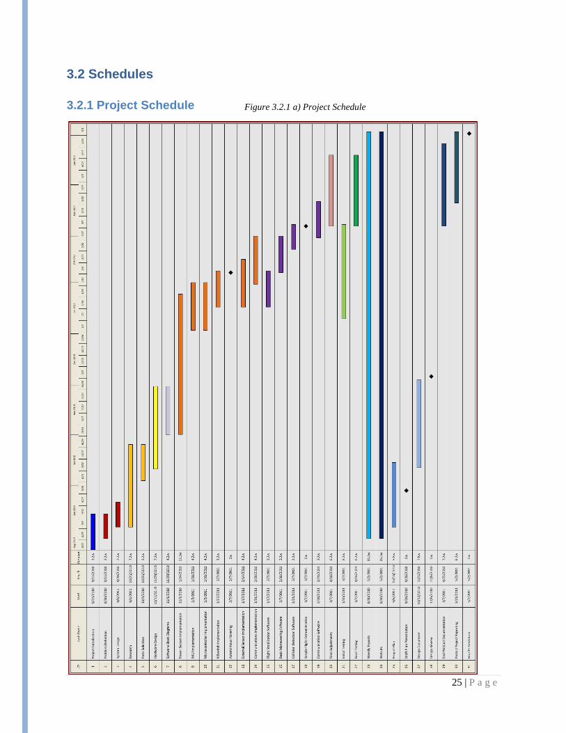
3.2 Schedules
3.2.1 Project Schedule
Figure 3.2.1 a) Project Schedule
26 | P a g e
On this schedule it is important to make note that this is the original schedule for the setup from
the first semester. After the new team came on board second semester, different priorities were changed.
For example, basic maneuvering and flight stability became part of the new Engr 466 Controls team.
Thus, it is no longer a viable part of our schedule. Even removing such items, our schedule slipped much
during the second semester. The first several weeks were spent bring the new team up to speed, defining
roles of the teams, reevaluating decisions, and so on. Some of these items causing the change in the
original schedule plan are included in the implementation section below.

27 | P a g e
4. Implementation
4.1 Hardware Implementation
4.1.1 Gumstix Implementation
The Gumstix module is composed of a Gumstix Overo Fire computer-on-module unit and a
Gumstix Summit expansion board. These components have been received, assembled and successfully
booted. The default Gumstix rootfs and Angstrom Linux kernel have been modified, rebuilt and
redeployed to the Gumstix nonvolatile memory. The modified kernel includes user-space SPI support
through the spidev protocol driver, as well as a stable version of gcc for native compilation on the
Gumstix.
The Gumstix has also been configured to automatically set up an ad-hoc WiFi network on bootup,
complete with a DHCP server that allows for easy connection from a development machine. All changes
made to the Gumstix kernel and configuration have been documented and included in Appendix II and
III.
Additionally, the physical connections required for testing the SPI connection from the Gumstix
to the PIC and the RS-232 connection from the laser rangefinder to the Gumstix have been soldered to the
appropriate through-hole pins on the Summit expansion board. A communications protocol designed for
the SPI connection between the Gumstix and the PIC, dubbed the PICstix protocol, has been designed and
is included in Appendix IV.
SPI communication between the Gumstix and the PIC is still under development. Such low-level
communication between a Linux kernel and an embedded microcontroller is proving to be difficult to
implement. On the Gumstix, the connection is implemented in software using the spidev protocol driver,
which is included in the Gumstix kernel and available once SPI is enabled.
The unimplemented items for the Gumstix include the direct interrupt request line to the PIC, the
connection from the cameras to the Gumstix and the implementation of the PICstix communications
protocol. The implementation of these items was omitted due to complications with higher-priority items,
such as reliable SPI data transfer between the PIC and the Gumstix.
Early in the implementation process, the Gumstix was discovered to be a temperamental device.
While it works well enough once it is set up correctly, setting it up can be difficult, and much of its

28 | P a g e
documentation is written by users with considerable amounts of experience with such systems. Issues
encountered included:
Failure to boot with factory-installed image
Difficulty connecting to Iowa State‘s WiFi to download packages
Failure to set up a stable gcc installation with the Gumstix‘s package manager
The need to rebuild the kernel to support SPI
The overlooking of the non-standard 1.8V logic level on the GPIO pins
All of these issues have since been resolved.
4.1.2 PIC Implementation
The final choice for the microcontroller to be used in the system is a PIC32MX795F512L. This
PIC has been received in the form of a plug-in module (PIM) that can be used with the Explorer 16
development board. A PicTail daughter board is used with the Explorer 16 to bring out the pins necessary
for the PIC‘s SPI, PWM and sonar connections. A custom PCB is expected to eventually replace the
Explorer 16 and daughter board.
The connection to and parsing of data from the MaxBotix LV-MaxSonar EZ4 sonar module, used
to determine altitude, has been successfully implemented. This includes a data connection to the receive
input for one of the PIC‘s UART modules, as well as a connection from the sonar to ground and power.
The sonar module sends serial data in the form of an ASCII ‗R‘ character, three ASCII numerical
digits forming an integer representing the range in inches, up to 255, and a carriage return. The UART
module is programmed to trigger an interrupt when its receive buffer is half full. The PIC‘s UART
receive buffer has 8 entries, so this means the interrupt will fire when the UART has received at least 4
entries. If the data can be parsed according to the above-described format, a global altitude variable is
updated with the new data. This variable will eventually be used in the altitude control loop. For testing,
this variable has been outputted in binary to the eight LEDs of the Explorer 16 board.
Pulse-Width Modulation (PWM) outputs have also been successfully programmed. These signals
will eventually be used to execute flight commands with the Gaui flight controller. The outputs of the PIC
have been set up to be programmable with a duty cycle ranging from 1ms to 2ms, which is 0 to 100% of
the recognized range of the Gaui. Adjustments in duty cycle can be made in steps as small as 0.2% of this
range.

29 | P a g e
The unimplemented items for the PIC currently include the input from the IMU, the direct
interrupt request line from the Gumstix, the implementation of the PICstix communication protocol, the
input from the RC receiver and the programming of the flight control loops. The failure to meet these
implementation goals stems from two main reasons.
The first major issue that delayed PIC development was that the PIC was upgraded from a PIC24
to a PIC32 approximately two-thirds of the way through the semester. This design change was made
based on the recommendation of a project leader more experienced with aerial robotics systems. From an
engineering standpoint, the upgrade provided significant performance increase, especially for floating-
point calculations, allowing more flexibility in the control loop programming. Additionally, the upgrade
had nearly negligible changes on the power, cost and weight budget. At the time, the upgrade was not
expected to slow development much, but in retrospect, it did slow development considerably.
The second issue plaguing PIC development was the voltage difference with the Gumstix, which
caused many items to be ignored in the last weeks in an attempt to obtain reliable communications
between the two controllers the system is based around.
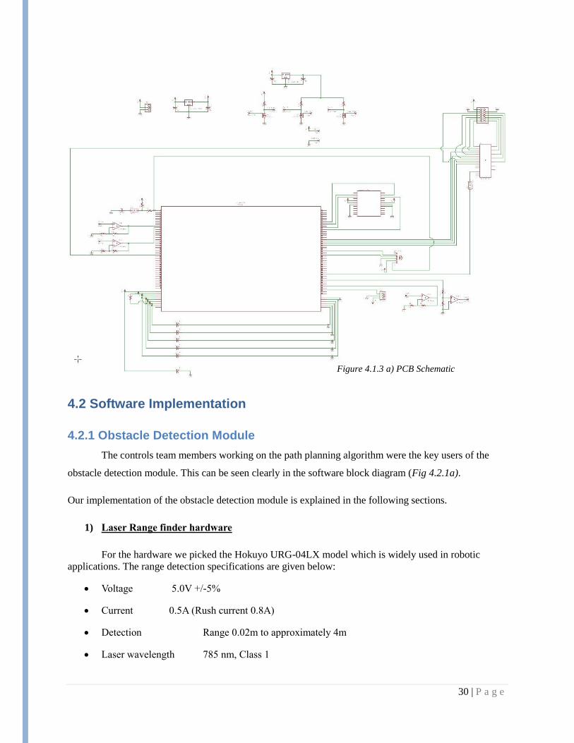
4.1.3 PCB Implementation
A part of the circuitry needed for the overall system is to be implemented on a custom PCB. On
the PCB is the IMU, PIC, connections for sonar input, RC controller, motor control out, Gumstix to Laser
conversion, among others. The schematic for the system that utilizes the smallest items possible to
achieve the task was created and is given in 4.1.3a. The layout of the PCB is to implemented at a later
time. If any changes in connection is needed at a later date, through hole connections will be added with
connection to the PIC.
30 | P a g e
4.2 Software Implementation
4.2.1 Obstacle Detection Module
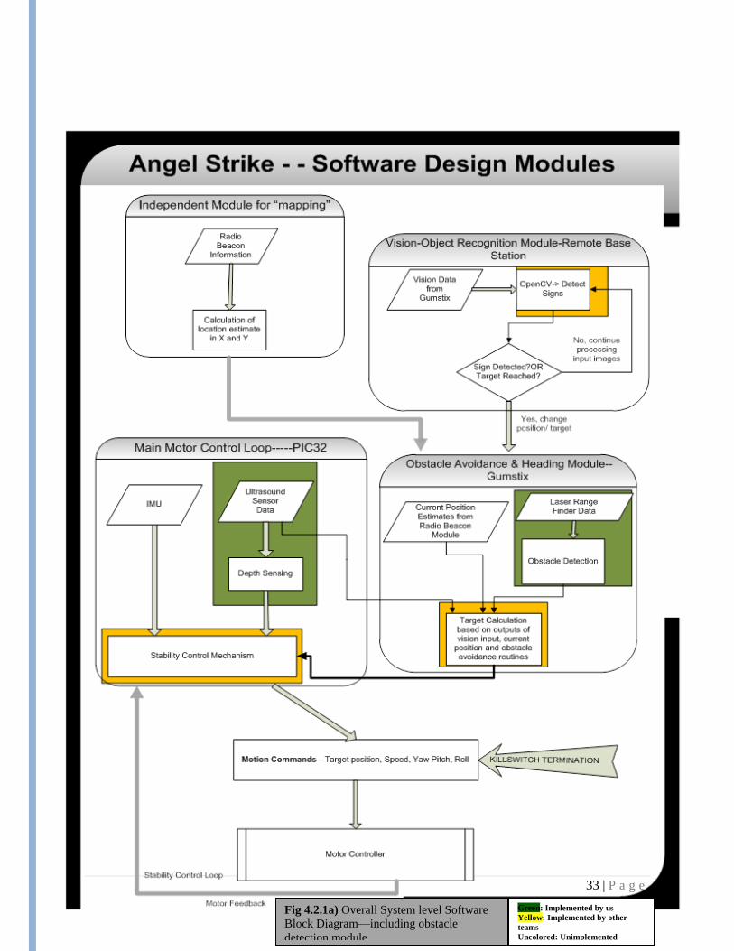
The controls team members working on the path planning algorithm were the key users of the
obstacle detection module. This can be seen clearly in the software block diagram (Fig 4.2.1a).
Our implementation of the obstacle detection module is explained in the following sections.
1) Laser Range finder hardware
For the hardware we picked the Hokuyo URG-04LX model which is widely used in robotic
applications. The range detection specifications are given below:
Voltage 5.0V +/-5%
Current 0.5A (Rush current 0.8A)
Detection Range 0.02m to approximately 4m
Laser wavelength 785 nm, Class 1
Figure 4.1.3 a) PCB Schematic
31 | P a g e
Scan angle 240°
Scan time 100msec/scan (10.0Hz)
Resolution 1mm
Angular Resolution 0.36°
Interface USB 2.0, RS232
Weight 5.0 oz (141 gm)
2) Laser Range finder Gumstix Interface
The interface preferred was the serial communication link because this would minimize the
power consumption on the Gumstix and also reserve the USB host for other sensors like cameras.
Since the URG works at 5V and the Gumstix IO pins read at 1.8V, some additional circuitry was
to be added later to adjust the communication channel. A circuit was built using the Sipex 232acp chip
was used to pull down the voltage and enable communication at the TTL level, but since this chip was
designed for pulling down the voltage to a range of 2V – 4 V, the communication with the Gumstix serial
pins were not possible. A PCB design has been created in which this issue is addressed. For testing the
software, the Urg was just connected on plug and play mode with a laptop computer running 32-bit
Linux.
3) Obstacle Detection Software
The algorithm for obstacle detection module is described in the following section
Algorithm:
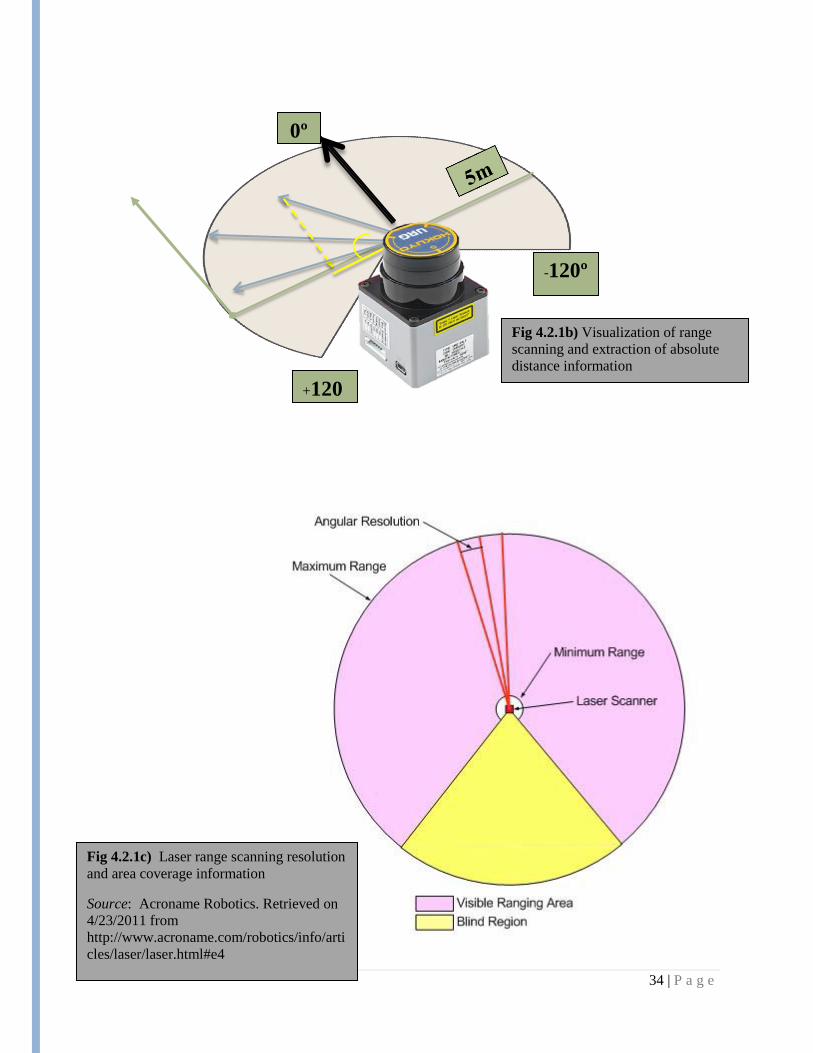
1) For each <angle, range > pair,
a. Calculate the absolute distance relative to the center(refer to Fig 1.2)
Distance = cos (90-angle)*range
b. If(distance < 2m && distance >1m)
probabilityOfObstacle = (2-distance)/1
//Since the probability that it is an obstacle is weighted based on how close it is.
c. If(distance > 2m) //Not considered an obstacle
probabilityOfObstacle = 0.0
32 | P a g e
d. If(distance < 12m) //Surely an obstacle
probabilityOfObstacle = 1.0
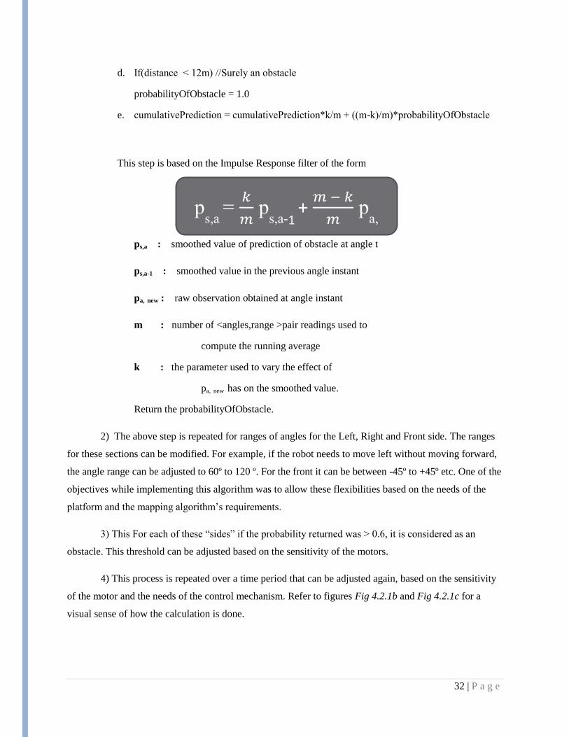
e. cumulativePrediction = cumulativePrediction*k/m + ((m-k)/m)*probabilityOfObstacle
This step is based on the Impulse Response filter of the form
ps,a : smoothed value of prediction of obstacle at angle t
ps,a-1 : smoothed value in the previous angle instant
pa, new : raw observation obtained at angle instant
m : number of <angles,range >pair readings used to
compute the running average
k : the parameter used to vary the effect of
pa, new has on the smoothed value.
Return the probabilityOfObstacle.
2) The above step is repeated for ranges of angles for the Left, Right and Front side. The ranges
for these sections can be modified. For example, if the robot needs to move left without moving forward,
the angle range can be adjusted to 60º to 120 º. For the front it can be between -45º to +45º etc. One of the
objectives while implementing this algorithm was to allow these flexibilities based on the needs of the
platform and the mapping algorithm‘s requirements.
3) This For each of these ―sides‖ if the probability returned was > 0.6, it is considered as an
obstacle. This threshold can be adjusted based on the sensitivity of the motors.
4) This process is repeated over a time period that can be adjusted again, based on the sensitivity
of the motor and the needs of the control mechanism. Refer to figures Fig 4.2.1b and Fig 4.2.1c for a
visual sense of how the calculation is done.
ps,a
= 𝑘
𝑚 p
s,a-1 + 𝑚 − 𝑘
𝑚 p
a,
33 | P a g e
Fig 4.2.1a) Overall System level Software
Block Diagram—including obstacle
detection module
Green: Implemented by us
Yellow: Implemented by other
teams
Uncolored: Unimplemented
34 | P a g e
Fig 4.2.1b) Visualization of range
scanning and extraction of absolute
distance information
Fig 4.2.1c) Laser range scanning resolution
and area coverage information
Source: Acroname Robotics. Retrieved on
4/23/2011 from
http://www.acroname.com/robotics/info/arti
cles/laser/laser.html#e4
-120º
0º
+120
35 | P a g e
4) Interface with other modules
The obstacle detection module was designed exactly to the specification of the navigation module
implemented by the controls team. The algorithm implemented by them is a ―Follow the left wall‖
algorithms. The mission of the robot in the competition is to detect a USB drive and replace it with a
decoy; a searching task. During the large group meetings, this was discussed and chosen based on
different considerations.
We worked closely with the other team for this and their algorithm required a discrete input: Is
there an obstacle on the left? On the right? In the front? This was based on a certain minimum distance
that could be adjusted but is currently estimated at 1.8m because the platform spans close to a meter and a
clearance of 400 cm on either side was kept in mind. This estimate can be further adjusted based on the
sensitivity of the motor and the platform‘s motion behavior.
The obstacle detection module therefore is designed to give these outputs as required by the
inputs of the navigation algorithm. More on the navigation team‘s algorithms can be found in the manual
of the Controls team‘s report.
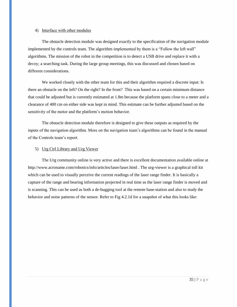
5) Urg Ctrl Library and Urg Viewer
The Urg community online is very active and there is excellent documentation available online at
http://www.acroname.com/robotics/info/articles/laser/laser.html . The urg-viewer is a graphical toll kit
which can be used to visually perceive the current readings of the laser range finder. It is basically a
capture of the range and bearing information projected in real time as the laser range finder is moved and
is scanning. This can be used as both a de-bugging tool at the remote base-station and also to study the
behavior and noise patterns of the sensor. Refer to Fig 4.2.1d for a snapshot of what this looks like:
36 | P a g e
Fig 4.2.1 d) Urg Viewer Tool and its visual
output
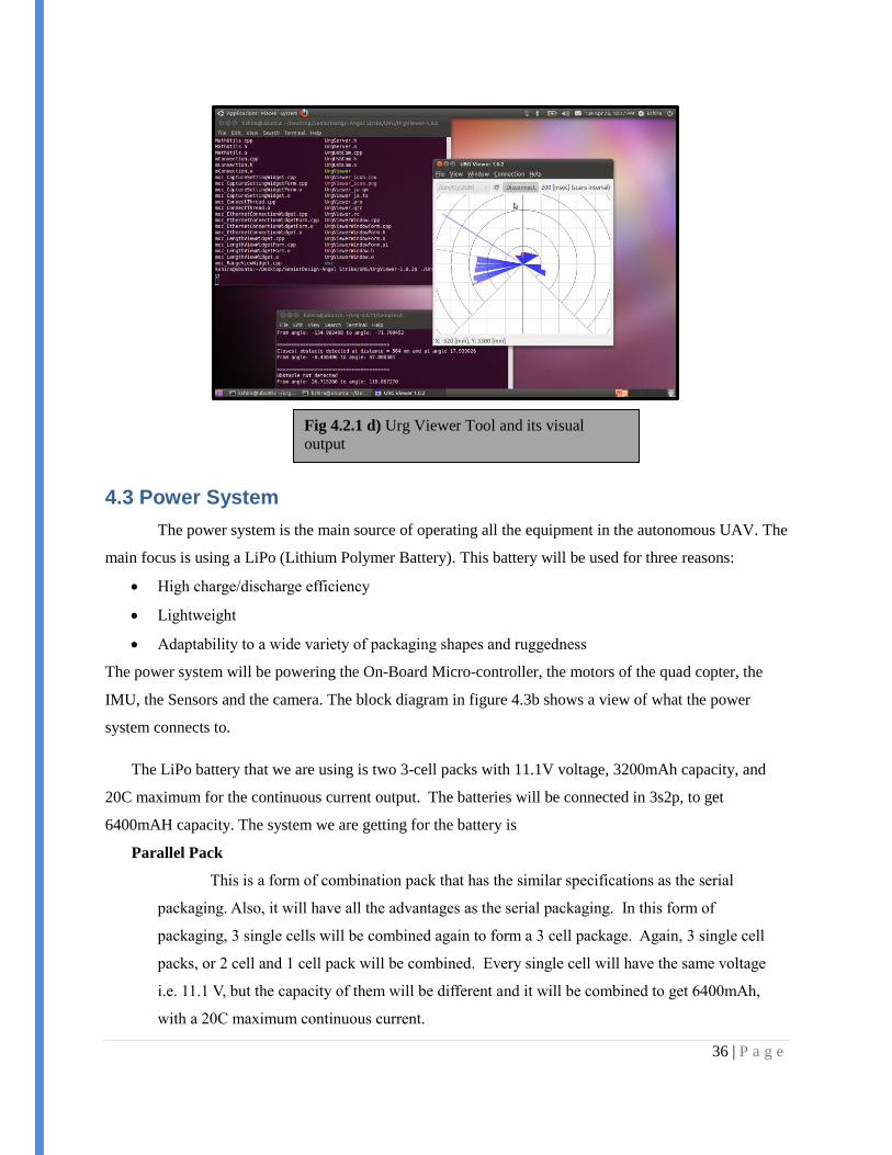
4.3 Power System
The power system is the main source of operating all the equipment in the autonomous UAV. The
main focus is using a LiPo (Lithium Polymer Battery). This battery will be used for three reasons:
High charge/discharge efficiency
Lightweight
Adaptability to a wide variety of packaging shapes and ruggedness
The power system will be powering the On-Board Micro-controller, the motors of the quad copter, the
IMU, the Sensors and the camera. The block diagram in figure 4.3b shows a view of what the power
system connects to.
The LiPo battery that we are using is two 3-cell packs with 11.1V voltage, 3200mAh capacity, and
20C maximum for the continuous current output. The batteries will be connected in 3s2p, to get
6400mAH capacity. The system we are getting for the battery is
Parallel Pack
This is a form of combination pack that has the similar specifications as the serial
packaging. Also, it will have all the advantages as the serial packaging. In this form of
packaging, 3 single cells will be combined again to form a 3 cell package. Again, 3 single cell
packs, or 2 cell and 1 cell pack will be combined. Every single cell will have the same voltage
i.e. 11.1 V, but the capacity of them will be different and it will be combined to get 6400mAh,
with a 20C maximum continuous current.
37 | P a g e
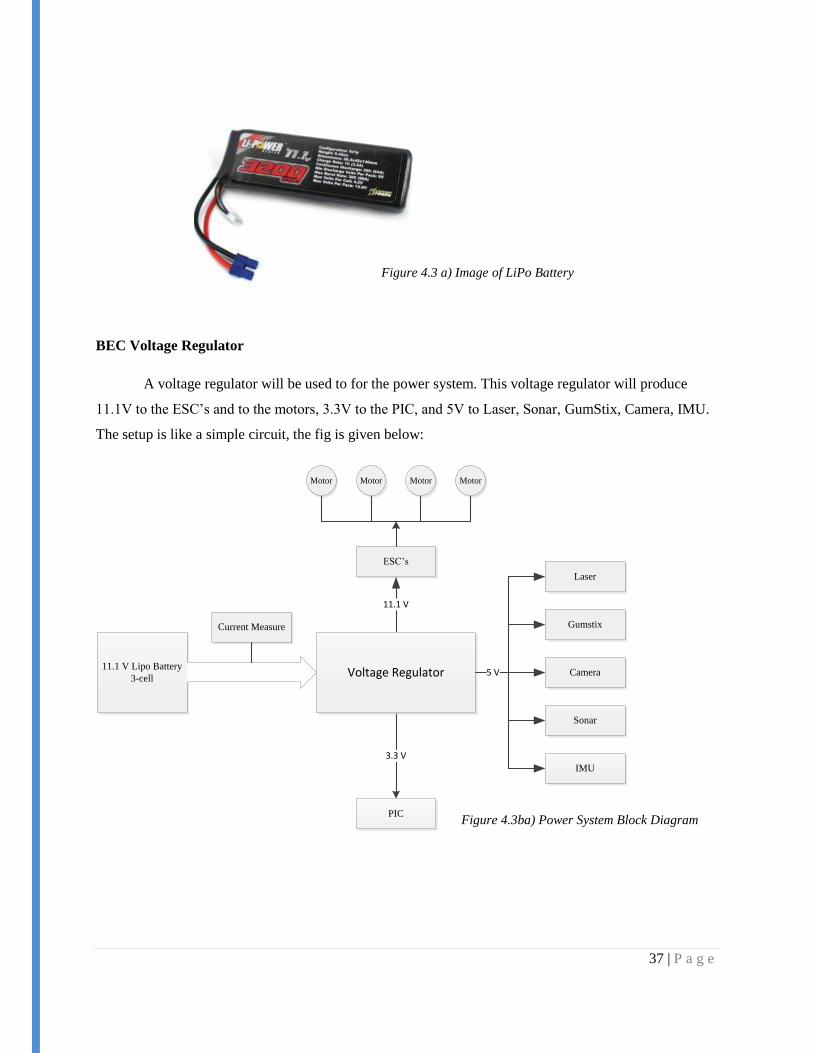
BEC Voltage Regulator
A voltage regulator will be used to for the power system. This voltage regulator will produce
11.1V to the ESC‘s and to the motors, 3.3V to the PIC, and 5V to Laser, Sonar, GumStix, Camera, IMU.
The setup is like a simple circuit, the fig is given below:
11.1 V Lipo Battery
3-cell
ESC‘s
Motor Motor Motor Motor
Laser
Gumstix
Camera
Sonar
IMU
PIC
11.1 V
3.3 V
Voltage Regulator 5 V
Current Measure
Figure 4.3 a) Image of LiPo Battery
Figure 4.3ba) Power System Block Diagram
38 | P a g e
5. Testing
5.1 Hardware Testing
5.1.1 Gumstix Testing
The Gumstix‘s ad-hoc WiFi network has been tested through extensive normal use. Throughout
the implementation process, the WiFi connection has been constantly used for configuring and testing
other aspects of the Gumstix. Not once has the connection been unexplainably dropped or found to be
non-responsive. Thus, the stability of the connection has been tested and found to be satisfactory.
However, constant use has also shown that establishing the connection to the Gumstix can
sometimes require several attempts. This is believed to be an issue that occurs only shortly after the
Gumstix has been booted. Allowing the Gumstix to run for around a minute before attempting to connect
to it reliably yields a successful connection.
The SPI connection between the PIC and the Gumstix has been tested using a readily-available
spidev test program, an oscilloscope, the register watch function of the MPLAB IDE used to program the
PIC, and the console output of the Gumstix. Thus far, the both the PIC and the Gumstix have been shown
to be receiving data from each other. However, the PIC is not processing the data correctly, and the data
between the PIC and the Gumstix is not being accurately transferred. At best, the Gumstix has been
shown to correctly receive a repetitive bit pattern from the PIC. These issues are still being worked on by
the current team.
5.1.2 PIC Testing
The pulse-width modulation output component of the PIC has been tested with an oscilloscope to
ensure that the outputs are of the expected duty cycle and the waveforms are clean and stable. These tests
have been successful. PWM outputs have not been tested with the Gaui, as the PIC has not yet been
integrated with the flight platform.
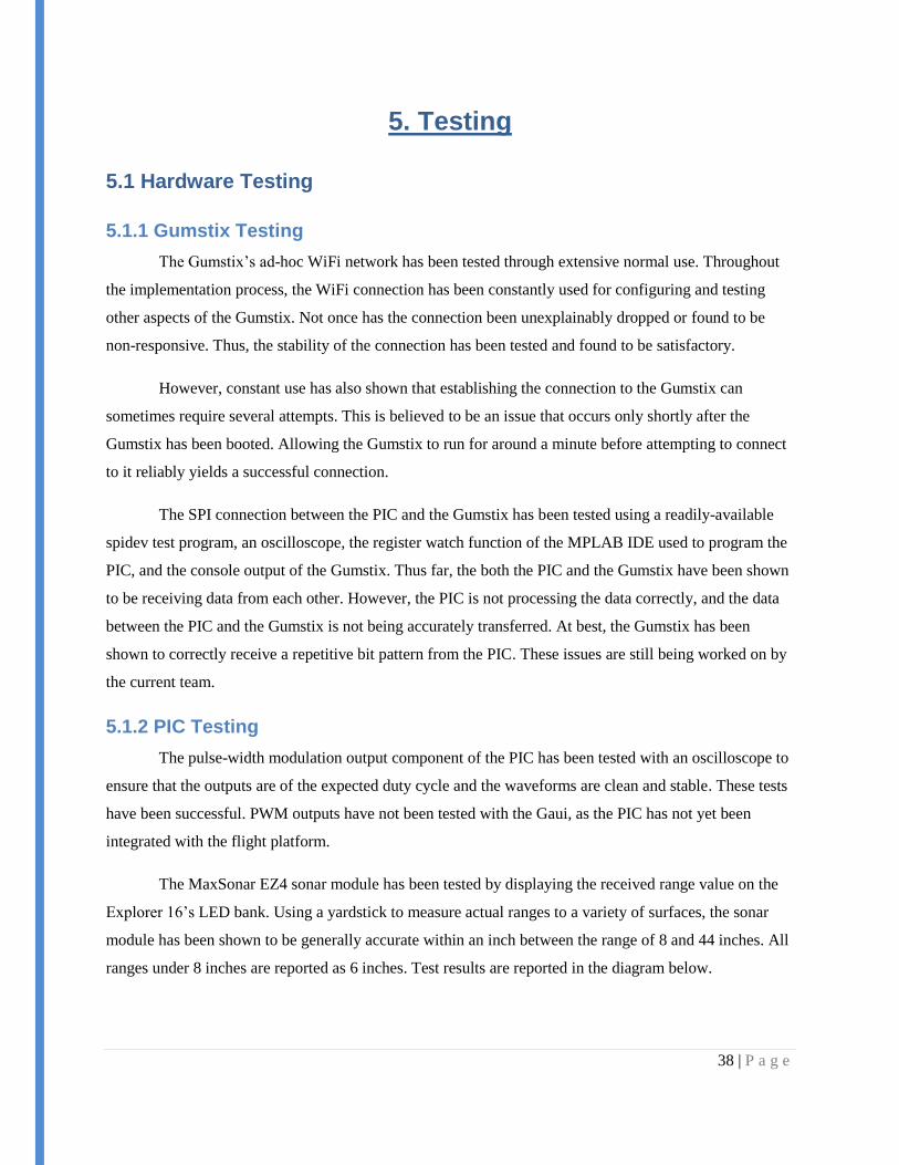
The MaxSonar EZ4 sonar module has been tested by displaying the received range value on the
Explorer 16‘s LED bank. Using a yardstick to measure actual ranges to a variety of surfaces, the sonar
module has been shown to be generally accurate within an inch between the range of 8 and 44 inches. All
ranges under 8 inches are reported as 6 inches. Test results are reported in the diagram below.
39 | P a g e
Please see the Gumstix testing section for details on testing the SPI connection from the PIC to
the Gumstix.
5.2 Sensors Testing
5.2.1 Laser Range Finder Testing
In the initial plan as per our design document submitted last semester, the obstacle detection
module was to be tested on the autonomous system by introducing obstacles at different sides and
comparing the output of the module (0/1) with the desired answer (obstacle present/ not present – a binary
value that can be encoded as 1 and 0 respectively.) Since the platform itself is not being controlled by the
pic or gumstix yet, the test plan shifted a little bit from our original plan. The test was run without running
the module on a flying platform. Although it is very likely that the vibrations on the platform due to flight
and the noise in motion might introduce more errors in the algorithm, the goal was to first test this on a
stationary system.
40 | P a g e
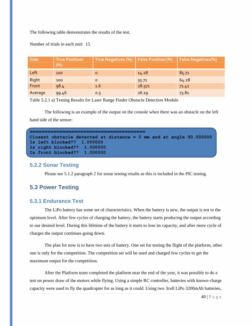
The following table demonstrates the results of the test.
Number of trials in each unit: 15
Table 5.2.1 a) Testing Results for Laser Range Finder Obstacle Detection Module
The following is an example of the output on the console when there was an obstacle on the left
hand side of the sensor:
=======================================
Closest obstacle detected at distance = 0 mm and at angle 90.000000
Is left blocked?? 1.000000
Is right blocked?? 1.000000
Is front blocked?? 1.000000
5.2.2 Sonar Testing
Please see 5.1.2 paragraph 2 for sonar testing results as this is included in the PIC testing.
5.3 Power Testing
5.3.1 Endurance Test
The LiPo battery has some set of characteristics. When the battery is new, the output is not to the
optimum level. After few cycles of charging the battery, the battery starts producing the output according
to our desired level. During this lifetime of the battery it starts to lose its capacity, and after more cycle of
charges the output continues going down.
The plan for now is to have two sets of battery. One set for testing the flight of the platform, other
one is only for the competition. The competition set will be used and charged few cycles to get the
maximum output for the competition.
After the Platform team completed the platform near the end of the year, it was possible to do a
test on power draw of the motors while flying. Using a simple RC controller, batteries with known charge
capacity were used to fly the quadcopter for as long as it could. Using two 3cell LiPo 3200mAh batteries,
Side True Positives (%)
True Negatives (%) False Positives(%) False Negatives(%)
Left 100 0 14.28 85.71
Right 100 0 35.71 64.28
Front 98.4 1.6 28.571 71.42
Average 99.46 0.5 26.19 73.81

41 | P a g e
with the platform weight at 1278g, the platform was able to fly for 20min 52 sec. The platform weight
was slightly less than the possible amount of the competition, but this gives a good estimate for us to use
on the motor power draw. It can be concluded that 2 standard 3200mAh LiPo batteries will be a sufficient
investment for achieving the desired flight time with room for error.
42 | P a g e
6. Future Work
6.1 Current Status
Here at the end of the semester, there is still much work to be done on this project. We have
managed to set the foundation for future teams to pick up where we left off and continue towards the
overall end goal. Currently, the parts implemented are:
Parts selected and overall design setup
Custom PCB has been designed
Gumstix
o Ad Hoc Network automatically sets up
o Connections wired for PIC and RS-232 to Laser
o Communication protocol with PIC created
PIC
o Receives sonar data in
o PWM output established with simple functions created
Laser Range Finder
o Data communication established
o Call functions created for ease of use
o Obstacle detection algorithms created
o Viewer for data available for user
Power System
o Voltage regulation circuit designed
o Batteries to be ordered selected
6.2 Future Implementations
Determine final layout of PCB
o Order PCB
Gumstix
o Setup frame grabber for cameras
o Setup communication protocol with base station
o Implement software for control of all system
o Send data to base station through software
PIC
o Make connection with IMU
o Implement control algorithms
o Test stability of control and find drift
o Test interchange between RC and PIC to Gaui
Implement the navigation and vision algorithms
Test and debug entire system
43 | P a g e
7. Lessons Learned
7.1 Importance of Communication
This senior design project was extensive. There were 3 senior design teams all working on this
one project. Finding the correct level of communication was very difficult. Although staying in touch
with what the other teams were doing, sometimes the detail at which it was discussed proved to be
detrimental to the accomplishing of the work. For example, at the start of the second semester, new
people were added to the project in the form of a new Engr 466 team, later the Controls team, and the
PhD student, Koray, mentioned previously in this report. With the new people came new ideas. We spent
the first few weeks going over the design decisions of the past semester, and fielding the different
thoughts and visions that came up. In the end, only the PIC version changed with all the rest remaining
the same. However, this took much time that could have been spent actual implementation.
Just like too much, too little can also be a bad thing. Differing visions of the system and styles of
implementation can lead to the ―But I thought…‖ sentence started that means something went wrong in
communications. For our team, communication was a large problem, both too much and too little. With
so many people all working on different yet related things, communication had to be good to make it all
work out as planned. We learned that communication was the most important part of our project.
Unfortunately, we were not able to improve until it was too late to slow the loss of time.
7.2 Full Team from Start
As mentioned in the previous section, we gained team members in the middle of the year. At this
point, we lost valuable time defining the roles of the teams and catching the new ones up on the system
we spend the past semester designing. What would have been best would have been to have the full team
at the start. That way it would have been easier to say exactly who did what and know the thoughts of the
full team on a solution before starting the actual design process. We lost time when the newer members of
the team joined.
7.3 Attention to Detail
As much as we would like it to be so, components don‘t always work the way we want or expect
them to. For example, the little detail of voltages. The Gumstix takes in a voltage of 5V. However, it only
outputs logic at 1.8V. This small detail created problems for us when we looked at a communication
channel between it and the PIC. The PIC at 3.3V did not see the small voltages. So, this adds another

44 | P a g e
circuit to be included on the custom PCB. In turn, it means not being able to order the PCB when you
may want. Little details in a large project can slow it down.
7.4 Too Much in Too Little Time
This project was more complex than most of the other projects in senior design. It required
working with a large team, working out a bunch of details and doing things we had never worked with
before. We have learned a great deal through this project, but we still have much we would have liked to
be able to do. But, we set ourselves up to do more than we had time to do. It reaches appoint in which we
had to select, with the help of our advisor, what the most important items were to have for future teams.
Although we didn‘t complete all we planned to do, we learned how to prioritize to the things we could do.
45 | P a g e
8. Closure Material
8.1 Project Team Information
8.1.1 Client Information
The client for this project is the Space systems and Controls Lab. This is a multi-disciplinary lab
in the aerospace department at Iowa State University which runs multiple projects such as High Altitude
Balloon Experiments in Technology, (CySAT) Cyclone SATellite cubesat project, and the Mars Analog
Vehicle for Robotic Inspection & Construction.
The Director of the Lab is Matthew Nelson and he is also the Advisor for our team. The contact
information for the client is:
Space Systems and Controls Lab
2362 Howe Hall
Ames, IA 50011-2271
515-294-2640
8.1.2 Faculty Advisor Information
Our faculty advisor is Matthew Nelson, the Director of the Space Systems and Controls Lab. His
contact information is:
Chief Design & Operations Engineer
Department of Aerospace Engineering
Space Systems & Controls Laboratory
2271 Howe Hall, Room 2331
Iowa State University
Ames, IA 50011-2271
Office: (515) 294-2640
Fax: (515) 294-3262
8.1.3 Student Team Information
The ECpE 491 Senior Design Team website is located at http://seniord.ece.iastate.edu/may1110/.
This site will be updated as the school year continues. The team members are:
46 | P a g e
Mazdee Masud
Iowa State University
Electrical Engineering
131 N. Hyland Avenue #14
Ames, IA-50014
319-431-5804
Anders Nelson
Iowa State University
Electrical Engineering
504 ½ Lynn Avenue
Ames, IA 50014
515-447-8359
Mathew Wymore
Iowa State University
Computer Engineering
1019 Delware Avenue #17
Ames, IA 50014
641-295-5522
Kshira Nadarajan
Iowa State University
Computer Engineering
Ames, IA
8.2 Closing Summary
The IARC is an exciting, challenging and educational opportunity for its participants. Prize
money aside, Iowa State University and the SSCL stand to gain good reputation if their team fields a
competition-worthy vehicle. This project is an integral part of such a vehicle. The proposed design has
been carefully crafted to meet the requirements set forth by the competition rules, as well as the
constraints imposed by the physical platform.
Furthermore, the design has been created with expandability and usability in mind. Although we
were not able to create a full competition worthier vehicle, the ground work that has been laid is done
with the hope of future teams completing the project. We have learned valuable lessons through the
design and implementation of this project. It was an eye opening experience about the true nature of
engineering within the limitations of the real world.

47 | P a g e
8.3 References
International Aerial Robotics Competition (IARC) Site. Association for Unmanned Vehicle Systems
International (AUVSI). Web. Retrieved 10 October, 2010. <http://iarc.angel-strike.com/>
Overo Fire COM Product Page. Gumstix Corp. Web. Retrieved 2 December 2010.
<http://www.gumstix.com/store/catalog/product_info.php?products_id=227>
Summit Expansion Board Product Page. Gumstix Corp. Web. Retrieved 2 December 2010.
<http://www.gumstix.com/store/catalog/product_info.php?products_id=215>
Powerizer High Power Polymer Battery Product Page. BatterySpace.com. Web. Retrieved 2 December
2010. <http://www.batteryspace.com/Powerizer-High-Power-Polymer-Battery-11.1v-3300mAh-
36.63Wh-40A-rate.aspx>
ADIS16405: High Precision IMU Product Page. Analog Devices Inc. Web. Retrieved 2 December 2010.
<http://www.analog.com/en/mems/imu/adis16405/products/product.html#ppa_print_table>
48 | P a g e
8.4 Appendices
8.4.1 Appendix I – Competition Rules
The following is an excerpt of the rules from the International Aerial Robotics Competition (IARC)
Mission 6 outline. Mission 6 is the current mission, being held in August 2011.
―General Rules Governing Entries
1. Vehicles must be unmanned and autonomous. They must compete based on their ability to
sense the semi-structured environment of the Competition Arena. They may be intelligent or
pre-programmed, but they must not be flown by a remote human operator. Any number of air
vehicles may be deployed so long as the gross aggregate weight of each air vehicle does not
exceed 1.50 kg.
2. Computational power need not be carried by the air vehicle. Computers operating from
standard commercial power may be set up outside the Competition arena boundary and uni- or
bi-directional data may be transmitted to/from the vehicles in the arena however there shall be
no human intervention with any ground-based systems necessary for autonomous operation
(computers, navigation equipment, links, antennas, etc.).
3. Data links will be by means of radio frequencies in any legal band for the location of the
arena.
4. The air vehicle(s) must be free-flying, autonomous, and have no entangling encumbrances
such as tethers. The air vehicle(s) can be of any type. During flight, the maximum dimension
of the air vehicle can not exceed one (1) meter. The maximum takeoff weight of the vehicle
cannot exceed 1.50 kg. The vehicle must be powered by means of an electric motor using
a battery, capacitor, or fuel cell as a source of energy. The vehicle must be equipped with a
method of manually-activated remote override of the primary propulsion system.
5. A maximum of two (2) non-line-of-sight (NLOS) navigation aids may be used external to
the designated flight area. It will be assumed that these navigation aids were positioned by a
mother ship around the building (but not on top) prior to a aerial robotic sub vehicle launch. The
navigation aids must be portable, and must be removed once the team leaves the competition
area. GPS is not allowed as a navigation aid.
6. The aerial robotic system is required to be able to send vehicle status and navigation solutions
to the Judge‘s remote JAUS-compliant data terminal via the JAUS protocol. This will be done
according to the JAUS Standard Set which will be provided to all official teams. Imagery may
be delivered to a separate team-supplied terminal using JAUS protocols but other signal formats
will also be acceptable. Similarly, kill switch transmissions may use JAUS protocols, but can be
achieved by other means without penalty. If more than one aerial robot is deployed simultaneously,
intercommunication between the aerial robots may be by any means and any protocol desired.
7. Upon entering the arena under autonomous control, aerial robots must remain within the
bounds of the arena or the attempt will end. Vehicles leaving the arena or in the Judges‘ opinion, are
about the leave the arena, will have their flight terminated by a Judge. Flight termination
actuation will be controlled by a Judge, not the team. Each team will supply the designated
Judge with its manually-actuated kill device as they enter the arena prior to their attempt(s),
and must demonstrate that the kill switch is functional for the Judge. Either separate kill
switches can be provided for each vehicle in multiple vehicle swarms, or a single kill switch
that disables all vehicles in the swarm simultaneously is deemed acceptable.
8. The ground station equipment other than the optional navigation aids, manual kill switch
mechanisms, and Judges‘ JAUS-compliant terminal interface must be portable such that it can
be setup and removed from the arena quickly. A suggestion would be to setup the equipment
49 | P a g e
on a roll-cart similar to that shown in Figure 1.
Figure 1. Roll-Cart.
Operations
Teams will be given four (4) flight attempts. The team with the highest static judging score will be
given one (1) additional attempt. Each team will be given 15 minutes to setup their system and adjust
parameters. If the team is unable to launch an aerial robot within the 15 minute window, the attempt
is forfeited. Each team is granted one (1) pass. Once a set of attempts has been completed by a given
team, the entire team will be required to leave the arena. No hardware may be left in place.
During the static display of the vehicle(s), the vehicle(s) will be measured to verify the 1 meter
maximum dimension constraint. The vehicle(s), in takeoff configuration will be weighed to verify
the 1.50 kg maximum weight restriction. The vehicle(s) will also be examined to assure that all
kill switch functions are fully operational prior to flight.
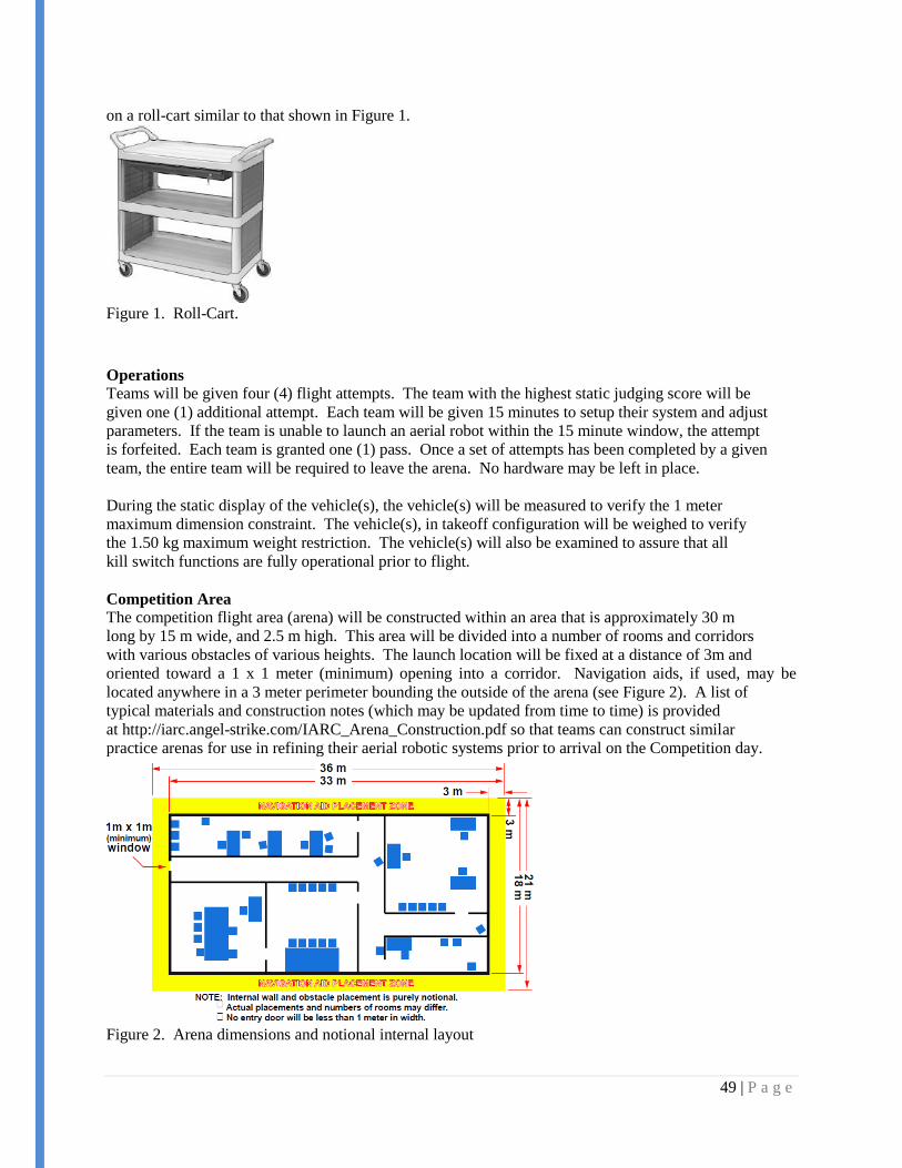
Competition Area
The competition flight area (arena) will be constructed within an area that is approximately 30 m
long by 15 m wide, and 2.5 m high. This area will be divided into a number of rooms and corridors
with various obstacles of various heights. The launch location will be fixed at a distance of 3m and
oriented toward a 1 x 1 meter (minimum) opening into a corridor. Navigation aids, if used, may be
located anywhere in a 3 meter perimeter bounding the outside of the arena (see Figure 2). A list of
typical materials and construction notes (which may be updated from time to time) is provided
at http://iarc.angel-strike.com/IARC_Arena_Construction.pdf so that teams can construct similar
practice arenas for use in refining their aerial robotic systems prior to arrival on the Competition day.
Figure 2. Arena dimensions and notional internal layout

50 | P a g e
8.4.2 Appendix II – Gumstix AngelStrike Change Log
WiFi
(gumstix.net) To set up an ad-hoc network on bootup, edit the Gumstix's /etc/network/interfaces to
include the following lines:
allow-hotplug wlan0
auto wlan0
iface wlan0 inet static
address 192.168.2.2
netmask 255.255.255.0
wireless-mode ad-hoc
wireless-essid gumstix-network
Set up a DHCP server on the Gumstix to make connecting to it easier. To do this, create /etc/udhcpd.conf
with the contents:
start 192.168.2.3
end 192.168.2.254
interface wlan0
max_leases 64
Use this command to run the DHCP server:
udhcpd /etc/udhcpd.conf
(sdmay11-10) Finally, set the DHCP server to run on bootup by adding the following lines to
/etc/rcS.d/S40networking:
(after echo -n "Configuring network interfaces... "
ifup -a
echo "done.")
echo -n "Starting DHCP server..."
udhcpd /etc/udhcpd.conf
echo "done."
Creating and deploying a new build
The Gumstix kernel and rootfs source can be downloaded, modified and rebuilt using OpenEmbedded.
Instructions for obtaining the Gumstix source can be found at http://gumstix.org/access-source-code.html.
To deploy a new build, you will need a bootable microSD card. Instructions for creating one can be found
at http://gumstix.org/create-a-bootable-microsd-card.html. A bootable microSD should also be included
with the AngelStrike project materials.
The images for the new build need to be copied to the microSD card. Instructions for doing this are
included on the page for creating a bootable microSD card.

51 | P a g e
Finally, you can flash the images on the microSD card into the Gumstix's nonvolatile memory using a
script, as described at http://gumstix.org/how-to/70-writing-images-to-flash.html.
gcc
You can try using opkg to install gcc with:
opkg install task-native-sdk
However, this method has been found to be unreliable. A better method is to include gcc in the rootfs
build. Assuming you have OpenEmbedded set up on your system, you can do this by editing:
/org.openembedded.dev/recipes/images/omap3-console-image.bb
Add this line in the tools section:
task-native-sdk /
Then rebuild the image using:
bitbake omap3-console-image
SPI
To enable spidev for use in connecting with the PIC, you need to disable the SPI devices built into the
kernel by default. This section assumes you have OpenEmbedded set up on your system. Please note that
version numbers may change.
The devices can be disabled by editing the board-overo.c file. First, navigate to the file.
cd ~/overo-oe/tmp/work/overo-angstrom-linux-gnueabi/linux-omap3-2.6.36-r97
cd git/arch/arm/mach-omap2/
Make a copy, just in case.
cp board-overo.c board-overo.c-orig
And edit board-overo.c. A copy of the edited version of board-overo.c has been included with the
AngelStrike project materials. Then from /linux-omap3-2.6.36-r97 make a patch file:
git diff –no-prefix git/arch/arm/mach-omap2/board-overo.c-orig \ git/arch/arm/mach-
omap2/board-overo.c > my-board-overo.patch
Now edit the bitable recipe to use the patch. Open:
~/overo-oe/org.openembedded.dev/recipes/linux/linux-omap3_2.6.36.bb
In the SRC_URI declaration, add the line:
file://my-board-overo.patch \

52 | P a g e
Then rebuild the kernel and rootfs:
bitbake -c clean virtual/kernel; bitbake virtual/kernel
bitbake omap3-console-image
Finally, deploy the new build.
Other Gumstix resources:
http://www.jumpnowtek.com/
http://old.nabble.com/Gumstix-f22543.html

53 | P a g e
8.4.3 Appendix III - Gumstix User Manual
Connecting to the Gumstix via console session
See the documentation at http://gumstix.org/connect-to-my-gumstix-system.html.
Connecting to the Gumstix via WiFi
Plug in the Gumstix and give it time to boot. If it was properly shutdown last time, it should set up an ad-
hoc network called "gumstix-network." Use your computer's wireless utility to connect to this network.
You should be automatically assigned an IP similar to 192.168.2.3 with a subnet mask of 255.255.255.0.
If not, try setting your IP manually.
Once the WiFi connection is established, use ssh to connect to the Gumstix:
If you get a warning about adding an RSA key to the list of known hosts, type "yes." If you get a warning
about the host key conflicting with the current known key, that is probably due to a reinstallation of the
Gumstix kernel. The previous known key for the Gumstix should be able to be removed using the
command:
ssh-keygen -R overo.local
Once you are connected to the Gumstix, you will find that there is currently no password. To get back to
your local machine, use:
exit
To get a file from the Gumstix to your local machine, use:
scp [email protected]:<file-path> <destination-path>
Using the Gumstix
To edit a text file when you're logged into the Gumstix, use
vi <file-path>
If you are unfamiliar with vi, it is a text editor that runs within the shell. It does not support mouse clicks.
Press "i" to enter insert mode so you can edit the file. To exit insert mode, press escape. Commands are
entered preceded by a colon. Type ":w" to save or ":q" to quit. Use ":q!" to quit and discard unsaved
changes. Since vi does not echo changes immediately, developers may wish to edit source files on their
development machine and use scp to transfer them to the Gumstix.
You can use gcc to natively compile programs on the Gumstix. Gcc was included in the latest version of
the rootfs flashed to the Gumstix. The documentation for gcc can be found on the Internet or entering
"man gcc" into the terminal of the development machine.
Note: The Gumstix kernel does not include manual pages, so the "man" command will not work from
within a Gumstix session.

54 | P a g e
Finally, when you're finished with the Gumstix, always shut it down properly! Connect to the Gumstix
and enter:
shutdown now
Wait at least five seconds, then you can safely unplug the power from the Gumstix board.
NOTE: The PICstix protocol has not yet been implemented and is provided as a resource and suggestion
for future teams.

55 | P a g e
8.4.4 Appendix IV - PICstix Communications Protocol
Overview
The PICstix Communications Protocol, in the scope of our project, is used to define the serial
communications between the Gumstix single-board computer and the 32-bit PIC microcontroller.
The PIC is used for reading in IMU data and sonar data and outputting PWM signals used to drive motor
controllers. The PIC can switch between autonomous and manual flight control modes.
The Gumstix is responsible for assembling the data gathered from the environment and making macro
control choices, i.e., move forward x distance. The Gumstix also uses a laser range finder to monitor
obstacle proximity. The Gumstix can quickly halt platform movement via an interrupt request signal to
the PIC. That signal is not part of the serial communications but will be discussed at the end of this
document.
Details
The PICstix protocol is designed for 32-bit word communication between the two controllers. Each 32-bit
word will be referred to as an instruction. Instructions use little endian format. The Gumstix is the host
and the PIC is the slave device. Instructions come in two categories, host instructions (from the Gumstix
to the PIC) and device instructions (from the PIC to the Gumstix).
Instructions of both types use a 5-bit opcode, defined as the least significant bits of the instruction. The
leading four bits are left at 0. In general, the remaining 23 bits are used to carry data.
Lead Zeros Data Opcode
31 30 29 28 [27...5] 4 3 2 1 0
Some of the data is sent in a signed fixed-point number format, with one sign bit, 12 bits for the whole
part and 10 bits for the fractional part.
signed fixed => 13bits.10bits
Ex.
3.75 => 000000000011.110000000
The idea here is to eliminate the need for floating point data to be sent between host and device. Data with
a whole part larger than 512 or a fractional part smaller than 0.1 is not expected, but clearly supported.
Host Instructions
All of the following instructions are sent from the Gumstix to the PIC.
Flight Control – These instructions cause the PIC to adjust motor speeds and make the platform move.
Horizontal Motion Opcodes:
Forward – 01000
Backward – 01001
Strafe right – 01110
Strafe left – 01111
Lead Distance (signed fixed, cm) Opcode
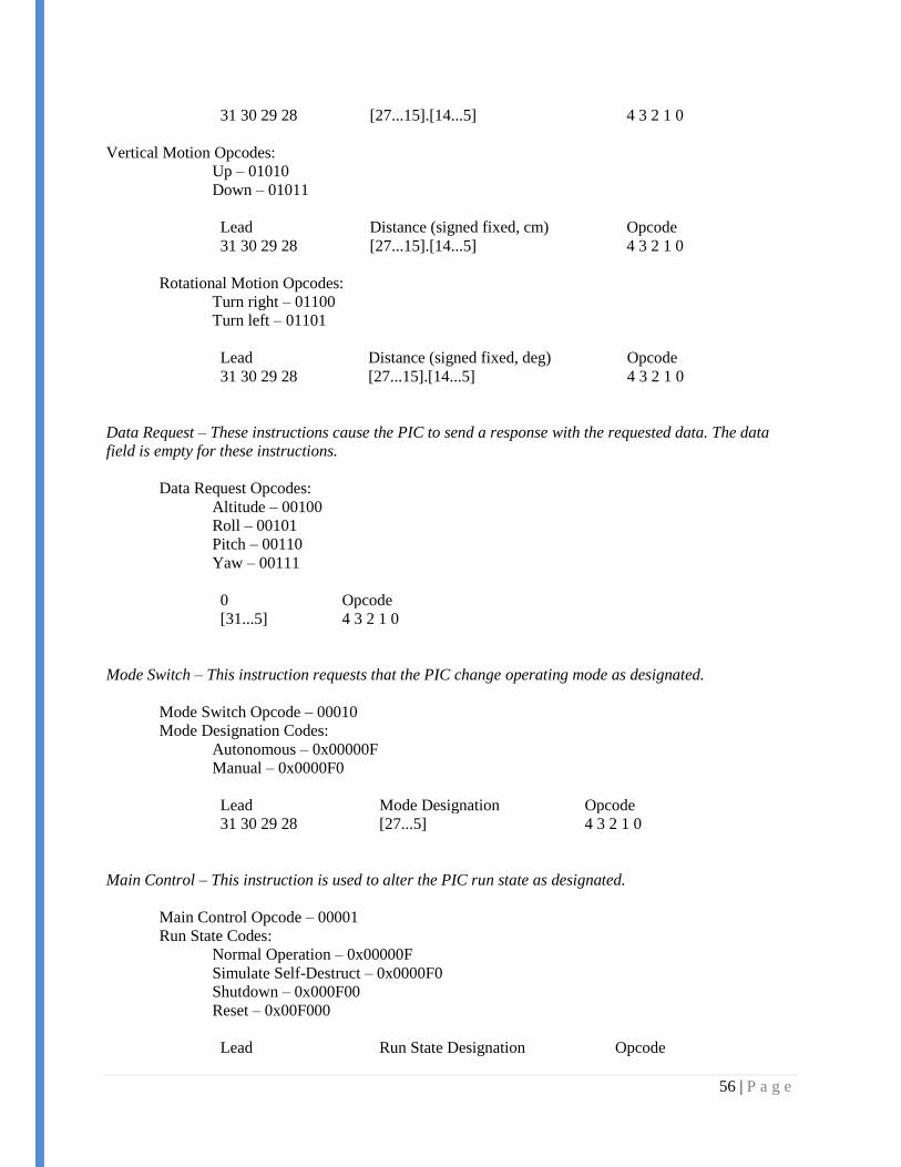
56 | P a g e
31 30 29 28 [27...15].[14...5] 4 3 2 1 0
Vertical Motion Opcodes:
Up – 01010
Down – 01011
Lead Distance (signed fixed, cm) Opcode
31 30 29 28 [27...15].[14...5] 4 3 2 1 0
Rotational Motion Opcodes:
Turn right – 01100
Turn left – 01101
Lead Distance (signed fixed, deg) Opcode
31 30 29 28 [27...15].[14...5] 4 3 2 1 0
Data Request – These instructions cause the PIC to send a response with the requested data. The data
field is empty for these instructions.
Data Request Opcodes:
Altitude – 00100
Roll – 00101
Pitch – 00110
Yaw – 00111
0 Opcode
[31...5] 4 3 2 1 0
Mode Switch – This instruction requests that the PIC change operating mode as designated.
Mode Switch Opcode – 00010
Mode Designation Codes:
Autonomous – 0x00000F
Manual – 0x0000F0
Lead Mode Designation Opcode
31 30 29 28 [27...5] 4 3 2 1 0
Main Control – This instruction is used to alter the PIC run state as designated.
Main Control Opcode – 00001
Run State Codes:
Normal Operation – 0x00000F
Simulate Self-Destruct – 0x0000F0
Shutdown – 0x000F00
Reset – 0x00F000
Lead Run State Designation Opcode
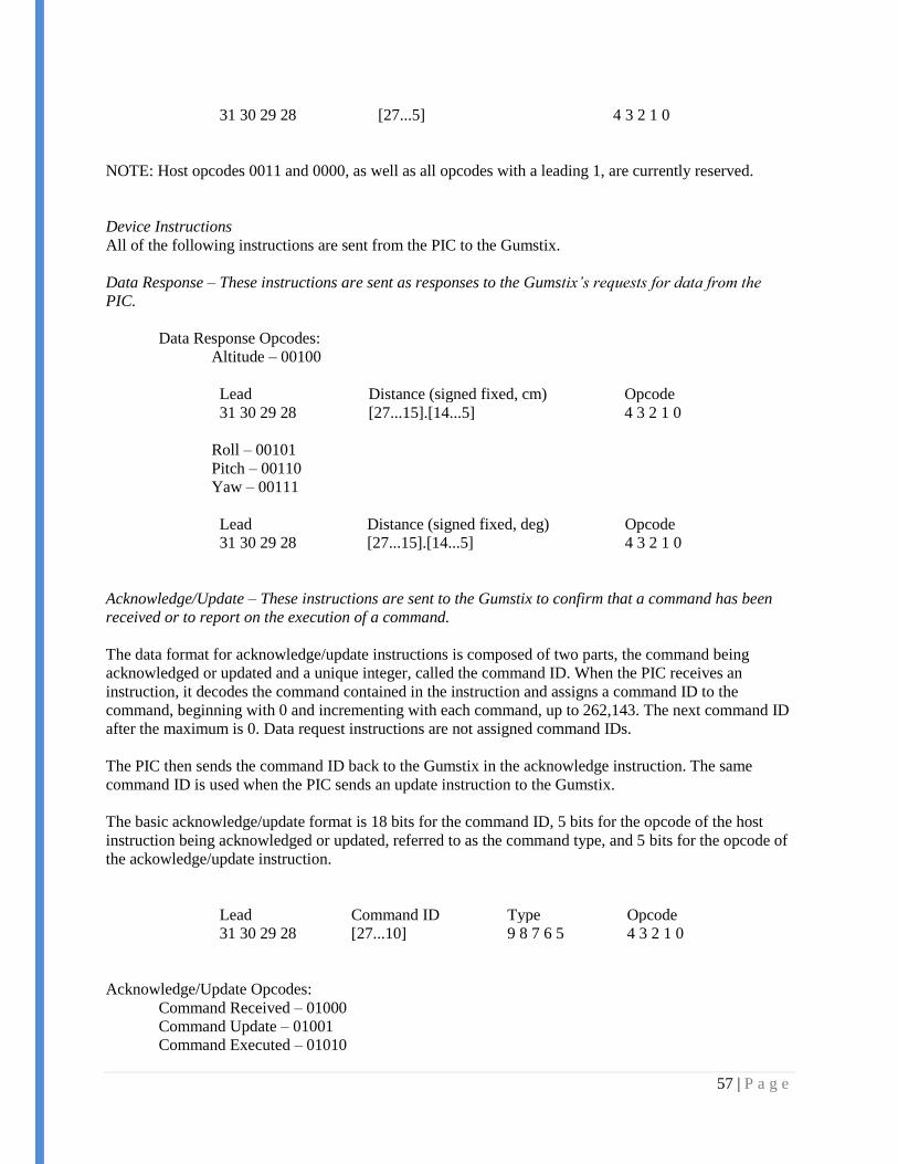
57 | P a g e
31 30 29 28 [27...5] 4 3 2 1 0
NOTE: Host opcodes 0011 and 0000, as well as all opcodes with a leading 1, are currently reserved.
Device Instructions
All of the following instructions are sent from the PIC to the Gumstix.
Data Response – These instructions are sent as responses to the Gumstix’s requests for data from the
PIC.
Data Response Opcodes:
Altitude – 00100
Lead Distance (signed fixed, cm) Opcode
31 30 29 28 [27...15].[14...5] 4 3 2 1 0
Roll – 00101
Pitch – 00110
Yaw – 00111
Lead Distance (signed fixed, deg) Opcode
31 30 29 28 [27...15].[14...5] 4 3 2 1 0
Acknowledge/Update – These instructions are sent to the Gumstix to confirm that a command has been
received or to report on the execution of a command.
The data format for acknowledge/update instructions is composed of two parts, the command being
acknowledged or updated and a unique integer, called the command ID. When the PIC receives an
instruction, it decodes the command contained in the instruction and assigns a command ID to the
command, beginning with 0 and incrementing with each command, up to 262,143. The next command ID
after the maximum is 0. Data request instructions are not assigned command IDs.
The PIC then sends the command ID back to the Gumstix in the acknowledge instruction. The same
command ID is used when the PIC sends an update instruction to the Gumstix.
The basic acknowledge/update format is 18 bits for the command ID, 5 bits for the opcode of the host
instruction being acknowledged or updated, referred to as the command type, and 5 bits for the opcode of
the ackowledge/update instruction.
Lead Command ID Type Opcode
31 30 29 28 [27...10] 9 8 7 6 5 4 3 2 1 0
Acknowledge/Update Opcodes:
Command Received – 01000
Command Update – 01001
Command Executed – 01010

58 | P a g e
Error Executing Command – 01111
Autonomous Mode Acknowledged – 00010
Manual Mode Acknowledged – 00011
Normal Operation Acknowledged – 00001
Self-Destruct Acknowledged – 00100
Reset Acknowledged – 00101
Shutdown Acknowledged – 00000
NOTE: Device opcodes 0110, 0111 and 1011, as well as all opcodes with a leading 1, are currently
reserved.
Related Documents